JP7271113B2 - Imaging equipment and accessory equipment - Google Patents
Imaging equipment and accessory equipment Download PDFInfo
- Publication number
- JP7271113B2 JP7271113B2 JP2018164778A JP2018164778A JP7271113B2 JP 7271113 B2 JP7271113 B2 JP 7271113B2 JP 2018164778 A JP2018164778 A JP 2018164778A JP 2018164778 A JP2018164778 A JP 2018164778A JP 7271113 B2 JP7271113 B2 JP 7271113B2
- Authority
- JP
- Japan
- Prior art keywords
- power
- lens
- power mode
- accessory device
- camera
- Prior art date
- Legal status (The legal status is an assumption and is not a legal conclusion. Google has not performed a legal analysis and makes no representation as to the accuracy of the status listed.)
- Active
Links
Images


Classifications
-
- H—ELECTRICITY
- H04—ELECTRIC COMMUNICATION TECHNIQUE
- H04N—PICTORIAL COMMUNICATION, e.g. TELEVISION
- H04N23/00—Cameras or camera modules comprising electronic image sensors; Control thereof
- H04N23/60—Control of cameras or camera modules
- H04N23/66—Remote control of cameras or camera parts, e.g. by remote control devices
- H04N23/663—Remote control of cameras or camera parts, e.g. by remote control devices for controlling interchangeable camera parts based on electronic image sensor signals
-
- H—ELECTRICITY
- H04—ELECTRIC COMMUNICATION TECHNIQUE
- H04N—PICTORIAL COMMUNICATION, e.g. TELEVISION
- H04N23/00—Cameras or camera modules comprising electronic image sensors; Control thereof
- H04N23/50—Constructional details
-
- G—PHYSICS
- G06—COMPUTING; CALCULATING OR COUNTING
- G06F—ELECTRIC DIGITAL DATA PROCESSING
- G06F1/00—Details not covered by groups G06F3/00 - G06F13/00 and G06F21/00
- G06F1/26—Power supply means, e.g. regulation thereof
- G06F1/32—Means for saving power
- G06F1/3203—Power management, i.e. event-based initiation of a power-saving mode
- G06F1/3206—Monitoring of events, devices or parameters that trigger a change in power modality
- G06F1/3212—Monitoring battery levels, e.g. power saving mode being initiated when battery voltage goes below a certain level
-
- G—PHYSICS
- G03—PHOTOGRAPHY; CINEMATOGRAPHY; ANALOGOUS TECHNIQUES USING WAVES OTHER THAN OPTICAL WAVES; ELECTROGRAPHY; HOLOGRAPHY
- G03B—APPARATUS OR ARRANGEMENTS FOR TAKING PHOTOGRAPHS OR FOR PROJECTING OR VIEWING THEM; APPARATUS OR ARRANGEMENTS EMPLOYING ANALOGOUS TECHNIQUES USING WAVES OTHER THAN OPTICAL WAVES; ACCESSORIES THEREFOR
- G03B17/00—Details of cameras or camera bodies; Accessories therefor
- G03B17/02—Bodies
- G03B17/12—Bodies with means for supporting objectives, supplementary lenses, filters, masks, or turrets
- G03B17/14—Bodies with means for supporting objectives, supplementary lenses, filters, masks, or turrets interchangeably
-
- G—PHYSICS
- G06—COMPUTING; CALCULATING OR COUNTING
- G06F—ELECTRIC DIGITAL DATA PROCESSING
- G06F1/00—Details not covered by groups G06F3/00 - G06F13/00 and G06F21/00
- G06F1/26—Power supply means, e.g. regulation thereof
- G06F1/32—Means for saving power
- G06F1/3203—Power management, i.e. event-based initiation of a power-saving mode
- G06F1/3234—Power saving characterised by the action undertaken
- G06F1/325—Power saving in peripheral device
-
- H—ELECTRICITY
- H04—ELECTRIC COMMUNICATION TECHNIQUE
- H04N—PICTORIAL COMMUNICATION, e.g. TELEVISION
- H04N23/00—Cameras or camera modules comprising electronic image sensors; Control thereof
- H04N23/50—Constructional details
- H04N23/54—Mounting of pick-up tubes, electronic image sensors, deviation or focusing coils
-
- H—ELECTRICITY
- H04—ELECTRIC COMMUNICATION TECHNIQUE
- H04N—PICTORIAL COMMUNICATION, e.g. TELEVISION
- H04N23/00—Cameras or camera modules comprising electronic image sensors; Control thereof
- H04N23/50—Constructional details
- H04N23/55—Optical parts specially adapted for electronic image sensors; Mounting thereof
-
- H—ELECTRICITY
- H04—ELECTRIC COMMUNICATION TECHNIQUE
- H04N—PICTORIAL COMMUNICATION, e.g. TELEVISION
- H04N23/00—Cameras or camera modules comprising electronic image sensors; Control thereof
- H04N23/60—Control of cameras or camera modules
- H04N23/65—Control of camera operation in relation to power supply
-
- H—ELECTRICITY
- H04—ELECTRIC COMMUNICATION TECHNIQUE
- H04N—PICTORIAL COMMUNICATION, e.g. TELEVISION
- H04N23/00—Cameras or camera modules comprising electronic image sensors; Control thereof
- H04N23/60—Control of cameras or camera modules
- H04N23/67—Focus control based on electronic image sensor signals
-
- G—PHYSICS
- G03—PHOTOGRAPHY; CINEMATOGRAPHY; ANALOGOUS TECHNIQUES USING WAVES OTHER THAN OPTICAL WAVES; ELECTROGRAPHY; HOLOGRAPHY
- G03B—APPARATUS OR ARRANGEMENTS FOR TAKING PHOTOGRAPHS OR FOR PROJECTING OR VIEWING THEM; APPARATUS OR ARRANGEMENTS EMPLOYING ANALOGOUS TECHNIQUES USING WAVES OTHER THAN OPTICAL WAVES; ACCESSORIES THEREFOR
- G03B2217/00—Details of cameras or camera bodies; Accessories therefor
- G03B2217/007—Details of energy supply or management
Description
本発明は、交換レンズ等のアクセサリ装置の着脱が可能な撮像装置に関する。 TECHNICAL FIELD The present invention relates to an imaging apparatus to which an accessory device such as an interchangeable lens can be attached and detached.
撮像装置のアクセサリ装置である交換レンズは、フォーカスレンズ、変倍レンズおよび絞りを駆動するアクチュエータやこれらを制御する制御回路を備えており、撮像装置のバッテリから供給される電力を用いてこれらアクチュエータや制御回路を動作させる。この場合、撮像装置のバッテリ残量が少ない状態で交換レンズが過度な電力を消費すると、撮像装置において急激な電圧降下が発生して撮像動作が不可能になってしまう。このため、交換レンズは撮像装置から供給可能な電力の範囲内で動作することが求められる。 An interchangeable lens, which is an accessory device for an image pickup device, includes actuators for driving a focus lens, a variable power lens, and a diaphragm, and a control circuit for controlling them. Activate the control circuit. In this case, if the interchangeable lens consumes excessive power when the battery of the imaging device is low, a sudden voltage drop will occur in the imaging device, making the imaging operation impossible. Therefore, the interchangeable lens is required to operate within the range of power that can be supplied from the imaging device.
特許文献1には、交換レンズから撮像装置に交換レンズでの使用電力レベルが送信され、撮像装置は自身のバッテリの状態と交換レンズから受信した使用電力レベルとから交換レンズに供給する電力を決定する撮像システムが開示されている。
In
撮像装置と交換レンズは、電源オフの状態からできるだけ短時間で起動して撮像可能な状態になることが望ましい。また、撮像装置と交換レンズは、それぞれが供給可能な電力と消費する電力が異なる組合せで使用されることが多い。このため、撮像装置のバッテリが供給可能な電力の範囲内で撮像装置と交換レンズが動作するためには、撮像装置が交換レンズに供給可能な電力と交換レンズが消費する電力とが適切に設定される必要がある。 It is desirable that the imaging device and the interchangeable lens be activated in as short a time as possible from a power-off state and ready for imaging. In addition, the image pickup device and the interchangeable lens are often used in combinations that differ in the power they can supply and the power they consume. Therefore, in order for the imaging device and the interchangeable lens to operate within the range of power that the battery of the imaging device can supply, the power that the imaging device can supply to the interchangeable lens and the power that the interchangeable lens consumes are set appropriately. need to be
本発明は、起動時間が短く、かつ撮像装置がアクセサリ装置に供給可能な電力に対してアクセサリ装置の動作電力を適切に設定できるようにした撮像装置およびアクセサリ装置を提供する。 SUMMARY OF THE INVENTION The present invention provides an imaging device and an accessory device that have a short startup time and can appropriately set the operating power of the accessory device with respect to the power that the imaging device can supply to the accessory device.
本発明の一側面としての撮像装置は、アクセサリ装置が着脱可能および通信可能に装着可能である。該撮像装置は、アクセサリ装置に電力を供給する電力供給手段と、電力供給手段を制御するカメラ制御手段と、アクセサリ装置と通信を行うカメラ通信手段とを有する。カメラ通信手段は、アクセサリ装置から、該アクセサリ装置に設定可能な1又は複数の設定可能電力モードを示す情報を受信し、アクセサリ装置に対して電力供給手段がアクセサリ装置に供給可能な電力に対応する指示電力モードを示す情報を送信する。カメラ制御手段は、指示電力モードに対応する電力が1又は複数の設定可能電力モードのいずれかに対応する電力と一致するかどうかを判定する。そして、電力供給手段は、1又は複数の設定可能電力モードのいずれかに対応する電力が指示電力モードに対応する電力と一致する場合に、指示電力モードに対応する電力を供給することを特徴とする。 An imaging device as one aspect of the present invention is detachably and communicatively attachable to an accessory device. The imaging device has power supply means for supplying power to the accessory device, camera control means for controlling the power supply means, and camera communication means for communicating with the accessory device. The camera communication means receives information from the accessory device indicating one or more configurable power modes that can be set for the accessory device, corresponding to the power that the power supply means can supply to the accessory device. Transmit information indicating the indicated power mode. The camera control means determines whether the power corresponding to the indicated power mode matches the power corresponding to any of the one or more settable power modes. The power supply means supplies power corresponding to the indicated power mode when the power corresponding to one of the one or more settable power modes matches the power corresponding to the indicated power mode. do.
また、本発明の他の一側面としてのアクセサリ装置は、撮像装置に着脱可能および通信可能に装着可能である。該アクセサリ装置は、撮像装置から電力の供給を受ける電力受給手段と、アクセサリ装置の動作を制御するアクセサリ制御手段と、撮像装置と通信を行うアクセサリ通信手段とを有する。アクセサリ通信手段は、撮像装置に、アクセサリ装置に設定可能な1又は複数の設定可能電力モードを示す情報を送信し、撮像装置から、該撮像装置がアクセサリ装置に供給可能な電力に対応する指示電力モードを示す情報を受信する。アクセサリ制御手段は、指示電力モードに対応する電力が1又は複数の設定可能電力モードのいずれかに対応する電力と一致するかどうかを判定する。そして、アクセサリ制御手段は、1又は複数の設定可能電力モードのいずれかに対応する電力が指示電力モードに対応する電力と一致する場合に、1又は複数の設定可能電力モードのうち、該指示電力モードと対応する電力が一致する設定可能電力モードでアクセサリ装置を動作させることを特徴とする。 In addition, an accessory device as another aspect of the present invention can be detachably and communicatively attached to the imaging device. The accessory device has power receiving means for receiving power from the imaging device, accessory control means for controlling the operation of the accessory device, and accessory communication means for communicating with the imaging device. The accessory communication means transmits information indicating one or more settable power modes that can be set in the accessory device to the imaging device, and the imaging device transmits instruction power corresponding to power that the imaging device can supply to the accessory device. Receive information indicating the mode. The accessory control means determines whether the power corresponding to the indicated power mode matches the power corresponding to any of the one or more settable power modes. Then, when the power corresponding to one of the one or more settable power modes matches the power corresponding to the indicated power mode, the accessory control means selects the indicated power among the one or more settable power modes. The accessory device is operated in a configurable power mode in which the mode and corresponding power match .
また、本発明の他の一側面としての制御方法は、アクセサリ装置が着脱可能および通信可能に装着可能な撮像装置に適用される。該制御方法は、アクセサリ装置から、該アクセサリ装置に設定可能な1又は複数の設定可能電力モードを示す情報を受信し、アクセサリ装置に対して撮像装置がアクセサリ装置に供給可能な電力に対応する指示電力モードを示す情報を送信するステップと、指示電力モードに対応する電力が1又は複数の設定可能電力モードのいずれかに対応する電力と一致するかどうかを判定するステップと、1又は複数の設定可能電力モードのいずれかに対応する電力が指示電力モードに対応する電力と一致する場合に、指示電力モードに対応する電力を供給するステップとを有することを特徴とする。 Further, a control method as another aspect of the present invention is applied to an imaging device to which an accessory device can be detachably and communicatively attached. The control method includes receiving information from the accessory device indicating one or more configurable power modes configurable for the accessory device, and providing instructions to the accessory device corresponding to power that the imaging device can supply to the accessory device. transmitting information indicating a power mode; determining whether the power corresponding to the indicated power mode matches the power corresponding to any of the one or more configurable power modes; and supplying power corresponding to the indicated power mode when the power corresponding to any of the possible power modes matches the power corresponding to the indicated power mode.
さらに、本発明の他の一側面としての制御方法は、撮像装置に着脱可能および通信可能に装着可能なアクセサリ装置に適用される。該制御方法は、撮像装置に、アクセサリ装置に設定可能な1又は複数の設定可能電力モードを示す情報を送信し、撮像装置から該撮像装置がアクセサリ装置に供給可能な電力に対応する指示電力モードを示す情報を受信するステップと、指示電力モードに対応する電力が1又は複数の設定可能電力モードのいずれかに対応する電力と一致するかどうかを判定するステップと、1又は複数の設定可能電力モードのいずれかに対応する電力が指示電力モードに対応する電力と一致する場合に、1又は複数の設定可能電力モードのうち、該指示電力モードと対応する電力が一致する設定可能電力モードでアクセサリ装置を動作させるステップとを有することを特徴とする。
Furthermore, a control method as another aspect of the present invention is applied to an accessory device detachably and communicatively attachable to an imaging device. The control method includes transmitting information to the imaging device indicating one or more configurable power modes that can be set for the accessory device, and an indicated power mode corresponding to power that the imaging device can supply to the accessory device from the imaging device. determining whether the power corresponding to the indicated power mode matches the power corresponding to any of the one or more configurable power modes; and When the power corresponding to any of the modes matches the power corresponding to the directed power mode, the accessory in one or more settable power modes in which the power corresponding to the directed power mode matches the directed power mode. and operating the apparatus.
なお、撮像装置またはアクセサリ装置のコンピュータに、上記制御方法に従う処理を実行させるコンピュータプログラムも、本発明の他の一側面を構成する。 A computer program that causes a computer of an imaging device or an accessory device to execute processing according to the control method also constitutes another aspect of the present invention.
本発明によれば、起動時において撮像可能な状態となるまでの時間を短くしつつ、アクセサリ装置の動作電力状態を撮像装置で許容できる電力供給範囲内で適切に設定することができる。 According to the present invention, it is possible to appropriately set the operating power state of the accessory device within the power supply range that the imaging device can tolerate while shortening the time until the imaging device becomes ready for imaging at startup.
以下、本発明の実施例について図面を参照しながら説明する。 BEST MODE FOR CARRYING OUT THE INVENTION Hereinafter, embodiments of the present invention will be described with reference to the drawings.
図1は、本発明の実施例1であるアクセサリ装置としての交換レンズ100と、該交換レンズ100が着脱可能に装着される撮像装置(以下、カメラ本体という)200とにより構成されるレンズ交換式撮像システムの構成を示している。
FIG. 1 shows an interchangeable lens system comprising an
交換レンズ100において、撮像光学系は、被写体側から像側に順に、固定のフロントレンズ101、変倍レンズ102、絞り103、防振(像振れ補正)レンズ104およびフォーカスレンズ105を含む。なお、図1ではそれぞれのレンズ101,102,104,105が1つのレンズ素子により構成されているように記載されているが、実際には1つ又は複数のレンズ素子を含む。
In the
変倍レンズ102は撮像光学系の少なくとも一部の光学素子であり、ステッピングモータやDCモータ等により構成されるズームアクチュエータ106によって撮像光学系の光軸方向に駆動される。これにより、交換レンズ100は、撮像光学系の変倍を行う。ズーム駆動回路107は、ズームアクチュエータ106に駆動電圧と電流を供給する。絞り103は、ステッピングモータやDCモータ等により構成される絞りアクチュエータ108によって絞り開口径を変化させる。絞り駆動回路109は絞りアクチュエータ108に駆動電圧と電流を供給する。
A
防振レンズ104は、ステッピングモータやボイスコイルモータ等により構成される防振アクチュエータ110によって光軸方向に直交するシフト方向に駆動されて像振れを低減(補正)する。防振駆動回路111は、防振アクチュエータ110に駆動電圧と電流を供給する。フォーカスレンズ105は、ステッピングモータやボイスコイルモータ等により構成されるフォーカスアクチュエータ112によって光軸方向に駆動され、焦点調節を行う。フォーカス駆動回路113は、フォーカスアクチュエータ112に駆動電圧と電流を供給する。ズーム駆動回路107、絞り駆動回路109、防振駆動回路111およびフォーカス駆動回路113を、以下の説明ではまとめて、アクチュエータ駆動回路ともいう。
The
図1に示すように、交換レンズ100がカメラ本体200に装着されると、交換レンズ100に設けられた電気接点119a,119b,119cとカメラ本体200に設けられた電気接点209a,209b,209cとが互いに接続される。これにより、交換レンズ100とカメラ本体200との間での各種情報の通信を行う。図1では、交換レンズ100とカメラ本体200が3線式シリアル通信を行う場合を示している。通信方式については後述する。
As shown in FIG. 1, when the
また、交換レンズ100に設けられた電源接点120a,120b,120c,120dと、カメラ本体200に設けられた電源接点210a,210b,210c,210dとが互いに接続されることで、カメラ本体200から交換レンズ100に電源(電力)子が供給される。
Also, the
電源接点120a,210aは、交換レンズ100に設けられた各種センサやレンズCPU114に電源を供給するための電源端子であり、電源接点120b,210bはこの電源のグランド端子である。また、電源接点120c,210cは、交換レンズ100に設けられたアクチュエータ駆動回路107,109,111,113に電源を供給するための電源端子であり、電源接点120d,210dはこの電源のグランド端子である。カメラ本体200に搭載されたリチウムイオン電池等の二次バッテリ212からの電源が、DCDCコンバータ等を含むカメラ電源回路(電力供給手段)211で所定の電圧に変換されて上記電源接点を介して交換レンズ100に供給される。交換レンズ100に設けられたレンズ電源回路(電力受給手段)118は、DCDCコンバータ等を含み、カメラ電源回路211から供給される電圧を、各種センサや各アクチュエータ駆動回路に適した電圧に変換してこれらに電力を分配する。
The
カメラ本体200には、CCDセンサやCMOSセンサにより構成される光電変換素子としての撮像素子201が設けられている。撮像素子201は、その撮像面に撮像光学系により形成された光学像(被写体像)を光電変換する。光電変換によって撮像素子201に蓄積された電荷は、所定のタイミングで撮像信号(アナログ信号)として出力され、映像信号処理回路202に入力される。
The
映像信号処理回路202は、撮像素子201からのアナログ撮像信号をデジタル撮像信号に変換し、該デジタル撮像信号に対して増幅やガンマ補正等の各種信号処理を行って映像信号を生成する。映像信号は、カメラCPU206、液晶ディスプレイパネル等により構成される表示装置205および光ディスクや半導体メモリ等により構成される記録装置204に出力される。
A video
また、映像信号処理回路202内には、焦点情報生成部としてのAF信号処理回路203が設けられている。AF信号処理回路203は、撮像素子201から出力された撮像信号(または撮像信号を用いて生成された映像信号)から、焦点検出領域であるAFエリア内の画素群により得られた高周波成分や輝度成分を抽出し、焦点情報としての焦点評価値信号を生成する。焦点評価値信号は、撮影映像のコントラスト状態(撮像コントラスト)、つまりは鮮鋭度を示し、フォーカスレンズ105の移動に伴って変化する。そして、焦点評価値信号の値、つまりは焦点評価値が最大(ピーク)となるフォーカスレンズ105の1が、そのAFエリアで合焦状態が得られるフォーカスレンズ105の位置、すなわち合焦位置となる。
Also, in the video
カメラCPU(カメラ制御手段)206は、カメラ通信部207およびレンズ指示電力決定部208を含む。カメラ通信部207は、前述した電気接点119a~119cおよび電気接点209a~209cを介してレンズCPU114との間で各種情報を通信する。ここで通信される情報には、レンズCPU114からカメラCPU206に送信される、交換レンズ100が設定可能な電力モードであるレンズ電力モードが含まれる。さらに、カメラCPU205からレンズCPU114に送信される、カメラCPU205が交換レンズ100へ通知する所定の電力モード(カメラ指示電力モード)等が含まれる。
A camera CPU (camera control means) 206 includes a
また、レンズ指示電力決定部208は、交換レンズ100に対して指示する電力モード(指示電力モード:以下、カメラ指示電力モードという)を決定する。カメラ指示電力モードは、カメラ電源回路211から、カメラ本体200の動作を損なわずに交換レンズ100に供給可能な電力、すなわち交換レンズ100での消費が許容される電力に応じて決定される。
Also, the lens instruction
さらにカメラCPU206は、カメラ電源回路211から交換レンズ100に対して供給する電力を制御する。
Further, the camera CPU 206 controls power supplied from the camera
レンズCPU(アクセサリ制御手段)114は、レンズ通信部115、電力モード記憶部116およびアクチュエータ(ACT)電力決定部117を含む。レンズ通信部115は、前述した電気接点119a~119cおよび電気接点209a~209cを介してカメラCPU206と各種情報を通信する。電力モード記憶部116は、交換レンズ100が対応している、すなわち交換レンズ100が設定可能な電力モードであるレンズ電力モード(設定可能電力モード)を記憶している。レンズ電力モードについては、後述する。また、ACT電力決定部117は、カメラ本体200(カメラCPU206)から受信するカメラ指示電力モードに応じて、上記アクチュエータ106,108,110,112で消費する電力を決定する。
A lens CPU (accessory control unit) 114 includes a
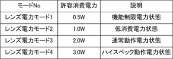
図2は、レンズ電力モードの例を示している。図2は、消費電力が大きい上記アクチュエータ駆動回路107,109,111,113に供給する電力についてのレンズ電力モードを示している。
FIG. 2 shows an example of a lens power mode. FIG. 2 shows lens power modes for power supplied to the
レンズ電力モード1は、防振機能の停止やフォーカスアクチュエータ112(フォーカスレンズ105)の駆動速度の低下等、交換レンズ100の機能を制限することで電力消費を抑える機能制限電力状態である。レンズ電力モード2は、交換レンズ100の機能は停止しないが、上記アクチュエータ106,108,110,112の駆動速度や可動範囲を制限することで消費電力を低減する低消費電力状態である。なお、アクチュエータの消費電力の低減方法は既知であるため、説明を省略する。
レンズ電力モード3は、交換レンズ100の機能を停止したり制限したりすることなく、上記アクチュエータ106,108,110,112の通常駆動を行うことが可能な通常動作電力状態である。レンズ電力モード4は、上記アクチュエータ106,108,110,112の通常駆動に加え、各アクチュエータに供給する電力を増加させる(例えば、印加電圧を高くする)ことで、交換レンズ100の機能を向上させるハイスペック動作電力状態である。このレンズ電力モード4では、例えば、防振レンズ104のシフト可能領域を拡大してより大きな像振れを補正したり、オートフォーカスにおけるフォーカスレンズ105やパワーズームにおける変倍レンズ102の駆動速度を速くしたりすることができる。
電力モード記憶部116は、これらのレンズ電力モード1~4のうち、交換レンズ100が設定可能な1又は複数のレンズ電力モードが、該レンズ電力モードでの許容消費電力(例えば、0.5W,1.0W,2.0W,3.0W)と対応づけて記憶されている。なお、各レンズ電力モードでの許容消費電力との対応がレンズCPU114において分かる場合は、電力モード記憶部116にレンズ電力モードのみ記憶させてもよいし、またレンズ電力モードに代えて許容消費電力を記憶させてもよい。レンズCPU114は、電力モード記憶部116に記憶されたレンズ電力モード(または許容消費電力)をレンズ通信部115を介してカメラCPU206に送信する。
The power
次に、交換レンズ100が設定可能な1又は複数のレンズ電力モードをレンズCPU114からカメラCPU206に送信し、カメラCPU206からレンズCPU114にカメラ指示電力モードを通知する通信方法について図6(a),(b)を用いて説明する。
Next, a communication method for transmitting one or a plurality of lens power modes that can be set by the
カメラCPU206とレンズCPU114との間の通信は、前述のように電気接点119a~119cおよび電気接点209a~209cを介して行う。電気接点119aと電気接点209aにより通知チャネルRTSを形成している。通知チャネルRTSは、カメラCPU206からレンズCPU114に対して通信開始を要求するためのチャネルとして機能する。カメラCPU206は通知チャネルRTSの電圧レベルを制御する。電気接点119bと電気接点209bによりカメラCPU206からレンズCPU114にデータを送信するためのデータ通信チャネルDCLを形成し、電気接点119cと電気接点209cによりレンズCPU114からカメラCPU206にデータを送信するためのデータ通信チャネルDLCを形成している。
Communication between camera CPU 206 and
カメラCPU206とレンズCPU114の通信は、図6(a),(b)に示すように調歩同期通信により行われる。本実施例の調歩同期通信において、カメラCPU206により通知チャネルRTSの電圧レベルのHighからLowへの変化を検知することに応じて、レンズCPU114がデータ通信チャネルDLCを介してカメラCPU206にデータ800を送信する。そして、カメラCPU206は、レンズCPU114からデータ通信チャネルDLCを介して受信するデータのスタートビットSTを検出することに応じてデータ通信チャネルDCLを介してレンズCPU114にデータ801を通信するように構成している。また、カメラCPU206は、データ801の送信時に、通知チャネルRTSの電圧レベルをLowからHighに変化させるように構成している。
Communication between the camera CPU 206 and the
図6(a)は、交換レンズ100がカメラ本体200に装着された後の最初の通信において、設定可能なレンズ電力モードをカメラCPU206に送信するという取り決めになっている場合を示している。この場合、カメラCPU206からレンズ電力モードの要求通知は不要である。したがって、通知チャネルRTSの電圧レベルがHighからLowに変化したことに応じて、レンズCPU114は、データ800として、1又は複数のレンズ電力モードをカメラCPU206に送信する。そして、カメラCPU206は、データ801として、レンズ指示電力決定部208が決定したカメラ指示電力モードをレンズCPU114に送信する。
FIG. 6A shows a case in which it is agreed that the lens power modes that can be set are transmitted to the camera CPU 206 in the first communication after the
図6(b)は、交換レンズ100がカメラ本体200に装着された後の最初の通信において、設定可能なレンズ電力モードをカメラCPU206に送信するという取り決めがない場合を示している。この場合、カメラCPU206はレンズCPU114に対してレンズ電力モードの送信を要求する。まず、通知チャネルRTSの電圧レベルの変化に応じてレンズCPU114がカメラCPU206に送信するデータ802は、カメラCPU206からデータを受信可能であるという合図である。データ802のスタートビットSTを検出したことに応じて、カメラCPU206は、データ803として、レンズCPU114にレンズ電力モードの送信を要求する旨のデータを送信する。次に、通知チャネルRTSの電圧レベルの変化に応じて、レンズCPU114は、データ804として、設定可能なレンズ電力モードをカメラCPU206に送信する。そして、カメラCPU206は、データ805として、レンズ指示電力決定部208が決定したカメラ指示電力モードをレンズCPU114に送信する。
FIG. 6B shows a case where there is no agreement to transmit the settable lens power modes to the camera CPU 206 in the first communication after the
以上説明したように、本実施例では、カメラCPU206は、レンズCPU114から送信されたレンズ電力モードの内容を解釈し終える前に、レンズCPU114にカメラ指示電力モードを送信している。
As described above, in this embodiment, the camera CPU 206 transmits the camera instruction power mode to the
次に、図3のフローチャートを用いて、本実施例においてカメラCPU206とレンズCPU114が行う起動処理(制御方法)について説明する。カメラ本体200と交換レンズ100にはそれぞれ、メモリ230とメモリ130が設けられており、これらにはコンピュータプログラムが記憶されている。カメラCPU206とレンズCPU114はそれぞれ、メモリ230とメモリ130からコンピュータプログラムを読み出し、該プログラムに従って本起動処理を行う。
Next, startup processing (control method) performed by the camera CPU 206 and the
カメラ本体200の電源がオンされると、カメラCPU206およびレンズCPU114はそれぞれ本処理を開始する。
When the power of the
まず、レンズCPU114が行う処理について説明する。ステップS201では、レンズCPU114は、交換レンズ100が設定可能な1又は複数のレンズ電力モードを電力モード記憶部116から読み出して、カメラCPU206に送信する。また、レンズCPU114は、カメラCPU206からカメラ指示電力モードを受信する。
First, processing performed by the
次にステップS202では、レンズCPU114は、ステップS201でカメラCPU206から受信したカメラ指示電力モードが、レンズ電力モード記憶部116に記憶された1又は複数のレンズ電力モードのいずれかに一致するか否かを判定する。言い換えれば、交換レンズ100が非対応(設定不可)のカメラ指示電力モードを受信したか否かを判定する。カメラ指示電力モードがレンズ電力モードのいずれにも一致しない場合は、レンズCPU114は、ステップS201に戻り、カメラCPU206から、いずれかのレンズ電力モードに一致するカメラ指示電力モードが通知される(ステップS202)のを待つ。一方、カメラ指示電力モードがレンズ電力モードのいずれかに一致した場合は、レンズCPU114は、ステップS203に進む。
Next, in step S202, the
ステップS203では、レンズCPU114は、交換レンズ100で使用するレンズ電力モードを決定する。例えば、図2に示したレンズ電力モード4(ハイスペック動作電力状態)が指示された場合には、前述したように交換レンズ100の機能を向上させる設定を行う。
In step S<b>203 , the
その後のステップS204では、レンズCPU114は、カメラ本体200からの電力供給が開始されるまで待つ。これは、電力供給がない状態で交換レンズ100内のアクチュエータ駆動回路をアクチュエータの駆動が可能な状態にしておくと、電力供給が開始された際にアクチュエータに過電流が流れ、レンズ電源回路118や該アクチュエータが破損するおそれがあるためである。電力供給が開始されると、レンズCPU114は本処理を終了する。
In subsequent step S204, the
次に、カメラCPU206が行う処理について説明する。ステップS101では、カメラCPU206は、カメラ本体200に交換レンズ100が装着されたか否かを検出する。この検出は、上述した電気接点を介した通電を検出したり、レンズ装着検出用の専用電気接点またはセンサを搭載したりすることで行うことができる。
Next, processing performed by the camera CPU 206 will be described. In step S<b>101 , the camera CPU 206 detects whether or not the
次にステップS102では、カメラCPU206は、レンズ指示電力決定部208において交換レンズ100に対するカメラ指示電力モードを決定する。そして、次のステップS103では、カメラCPU206は、ステップS102で決定したカメラ指示電力モードをレンズCPU114に通知するとともに、レンズCPU114から1又は複数のレンズ電力モードを受信する。
Next, in step S<b>102 , the camera CPU 206 determines the camera instruction power mode for the
次にステップS104では、カメラCPU206は、レンズ指示電力決定部208で決定したカメラ指示電力モードとステップS103で受信したレンズ電力モードとが一致しているか否かを判定する。カメラCPU206は、カメラ指示電力モードとレンズ電力モードとが一致する場合はステップS106に進む。
Next, in step S104, the camera CPU 206 determines whether or not the camera instruction power mode determined by the lens instruction
一方、カメラ指示電力モードとレンズ電力モードとが一致しない場合は、カメラCPU206は、このまま交換レンズ100に電力を供給することができない。このため、ステップS105に進んで、ステップS103で受信したレンズ電力モードに一致するカメラ指示電力モードを再選択(設定)する。そして、ステップS103に戻って、再設定したカメラ指示電力モードをレンズCPU114に通知する。
On the other hand, if the camera instruction power mode and the lens power mode do not match, the camera CPU 206 cannot supply power to the
ステップS106では、カメラCPU206は、カメラ電源回路211からレンズ電源回路118に対してレンズ電力モードに一致するカメラ指示電力モードに対応する電力の供給を開始する。そして、本処理を終了する。
In step S106, the camera CPU 206 starts supplying power from the camera
以上の処理では、最大でも2回のカメラ本体200と交換レンズ100との間での電力モードの送受信によってレンズ電力モードとカメラ指示電力モードとを一致させることができる。これらの電力モードを一致させるための条件として、1または複数のレンズ電力モードのうち少なくとも1つとカメラ本体200が交換レンズ100に許容(指示)できる電力モードのうち少なくとも1つとが一致するように予め取り決めておく必要がある。
In the above processing, the power mode transmission/reception between the
本実施例によれば、交換レンズ100がカメラ本体200に装着されると、カメラ本体200はカメラ指示電力モードを交換レンズ100に通知する。交換レンズ100は、自身が設定可能なレンズ電力モードのいずれかにカメラ指示電力モードが一致する場合はそのレンズ電力モードに対応する電力の供給をカメラ本体200から受ける。また、交換レンズ100が設定可能なレンズ電力モードのいずれにもカメラ指示電力モードが一致しない場合は、カメラ本体200は上記レンズ電力モードのいずれかに一致するカメラ指示電力モードを再設定する。これにより、撮像システムの起動時において撮像可能な状態となるまでの時間を短くしつつ、交換レンズ100の動作電力状態をカメラ本体200で許容できる電力供給範囲内にて適切に設定することができる。
According to this embodiment, when the
次に、本発明の実施例2として、カメラ本体200と交換レンズ100との間で電力モードを一致させるための予めの取り決めがない場合に交換レンズ100の電力モードを設定する起動処理について、図4のフローチャートを用いて説明する。本実施例におけるカメラ本体200と交換レンズ100の構成は、実施例1と同じであり、実施例1と共通する構成要素には実施例1と同符号を付す。カメラ本体200の電源がオンされると、カメラCPU206およびレンズCPU114はそれぞれ本処理を開始する。
Next, as a second embodiment of the present invention, startup processing for setting the power mode of the
まず、レンズCPU114が行う処理について説明する。ステップS401では、レンズCPU114は、交換レンズ100が設定可能な1又は複数のレンズ電力モードを電力モード記憶部116から読み出して、カメラCPU206に送信する。また、レンズCPU1114は、カメラCPU206からカメラ指示電力モードを受信する。
First, processing performed by the
次にステップS402では、レンズCPU114は、ステップS401でカメラCPU206から受信したカメラ指示電力モードが、レンズ電力モード記憶部116に記憶された1又は複数のレンズ電力モードのいずれかに一致するか否かを判定する。言い換えれば、交換レンズ100が非対応(設定不可)のカメラ指示電力モードを受信したか否かを判定する。カメラ指示電力モードがレンズ電力モードのいずれにも一致しない場合は、レンズCPU114は、S404に進む。一方、カメラ指示電力モードがレンズ電力モードのいずれかに一致した場合は、レンズCPU114は、ステップS403に進む。
Next, in step S402, the
ステップS404では、レンズCPU114は、レンズデフォルト電力モード(所定のアクセサリ動作電力状態)を独自に設定する。このレンズデフォルト電力モードは、交換レンズ100の動作電力状態として、カメラ本体200のカメラ電源回路211に過電流が発生しない必要最小限の動作電力状態であることが望ましい。ただし、交換レンズ100の機能を制限すると、ユーザが希望する撮像操作に支障が生じるおそれがある。このため、レンズCPU114は、図2に示したレンズ電力モード2(低消費電力状態)をレンズデフォルト電力モードとして選択(決定)するとよい。この後、レンズCPU114はステップS405に進む。
In step S404, the
一方、ステップS403では、レンズCPU114は、交換レンズ100で使用するレンズ電力モードとして、ステップS401でカメラCPU206から受信したカメラ指示電力モードを決定する。この後、レンズCPU114はステップS405に進む。
On the other hand, in step S<b>403 , the
ステップS405では、レンズCPU114は、実施例1のステップS204と同様に、カメラ本体200からの電力供給が開始されるまで待ち、電力供給が開始されると本処理を終了する。
In step S405, the
次に、カメラCPU206が行う処理について説明する。ステップS301では、カメラCPU206は、実施例1のステップS101と同様に、カメラ本体200に交換レンズ100が装着されたか否かを検出する。
Next, processing performed by the camera CPU 206 will be described. In step S301, the camera CPU 206 detects whether or not the
次にステップS302では、カメラCPU206は、レンズ指示電力決定部208において交換レンズ100に対するカメラ指示電力モードを決定する。そして、次のステップS303では、カメラCPU206は、ステップS302で決定したカメラ指示電力モードをレンズCPU114に通知するとともに、レンズCPU114から1又は複数のレンズ電力モードを受信する。
Next, in step S<b>302 , the camera CPU 206 determines the camera instruction power mode for the
次にステップS304では、カメラCPU206は、レンズ指示電力決定部208で決定したカメラ指示電力モードとステップS303で受信したレンズ電力モードとが一致しているか否かを判定する。カメラCPU206は、カメラ指示電力モードとレンズ電力モードとが一致する場合はステップS306に進む。一方、カメラ指示電力モードとレンズ電力モードとが一致しない場合は、カメラCPU206は、このまま交換レンズ100に電力を供給することができないため、ステップS305に進む。
Next, in step S304, the camera CPU 206 determines whether or not the camera instruction power mode determined by the lens instruction
ステップS305では、カメラCPU206は、カメラ指示電力モードとして、カメラCPU206が予め記憶しているデフォルト電力モード(所定の電力供給状態:以下、カメラデフォルト電力モードという)を選択(設定)する。このカメラデフォルト電力モードは、交換レンズ100が消費する電力が不明であるため、所定の電力として、二次バッテリ212やカメラ電源回路211が供給可能な最大限の電力を供給する電力モードとすることが望ましい。この後、カメラCPU206はステップS306に進む。
In step S305, the camera CPU 206 selects (sets) a default power mode (predetermined power supply state: hereinafter referred to as camera default power mode) stored in advance by the camera CPU 206 as the camera instruction power mode. Since the power consumed by the
ステップS306では、カメラCPU206は、カメラ電源回路211からレンズ電源回路118に対して、ステップS304でレンズ電力モードに一致したカメラ指示電力モードまたはステップS305で設定したカメラデフォルト電力モードに対応する電力の供給を開始する。そして、本処理を終了する。
In step S306, the camera CPU 206 supplies power from the camera
本実施例では、交換レンズ100はカメラ指示電力モードに一致するレンズ電力モードがない場合に自身に適切なレンズデフォルト電力モードを設定し、カメラ本体200は交換レンズ100に適切な電力を供給するカメラデフォルト電力モードを設定する。これにより、撮像システムが撮像可能な状態となるまでの時間を短くしつつ、交換レンズ100の動作電力状態をカメラ本体200で許容できる電力供給範囲内にて適切に設定することができる。
In this embodiment, the
なお、本実施例を実施例1とは別に説明したが、実施例1においてカメラ本体200と交換レンズ100との通信が正常に行われない等のイレギュラーな状況が生じた場合に本実施例の処理を行ってもよい。例えば、カメラCPU206は、実施例1のステップS104での電力モードの不一致が3回以上となった場合に、本実施例で説明したカメラデフォルト電力モードを設定する。また、レンズCPU114は、実施例1のステップS204で非対応のカメラ指示電力モードを3回以上受信した場合に、本実施例で説明したレンズデフォルト電力モードを設定する。
Although the present embodiment was described separately from the first embodiment, when an irregular situation occurs in the first embodiment, such as communication between the
次に、本発明の実施例3について説明する。本実施例では、上述したようなイレギュラーな状況が発生してカメラ本体200からカメラ指示電力モードを受信していない状態で、交換レンズ100内のアクチュエータの駆動指示がなされた場合の処理について図5のフローチャートを用いて説明する。本実施例におけるカメラ本体200と交換レンズ100の構成は、実施例1と同じであり、実施例1と共通する構成要素には実施例1と同符号を付す。
Next, Example 3 of the present invention will be described. In the present embodiment, a process when an instruction to drive the actuator in the
カメラCPU206は、ステップS501において、変倍レンズ102、絞り103、防振レンズ104またはフォーカスレンズ105を駆動するためにアクチュエータ駆動命令(交換レンズ100の動作命令)をレンズCPU114に送信する。レンズCPU114は、ステップS601にて、カメラ本体200からアクチュエータ駆動命令を受信する。
次にステップS602では、レンズCPU114は、図3で説明した処理によりカメラCPU206からカメラ指示電力モードを受信し、これに一致するレンズ電力モードを既に決定しているか否かを判定する。レンズ電力モードを既に決定している場合には、レンズCPU114は、ステップS604に進み、決定したレンズ電力モードに適した駆動方法や駆動速度で、ズームアクチュエータ106、絞りアクチュエータ108、防振アクチュエータ110、フォーカスアクチュエータ112の少なくともいずれかを駆動する。
In step S<b>501 , the camera CPU 206 transmits an actuator drive command (an operation command for the interchangeable lens 100 ) to the
Next, in step S602, the
一方、ステップS602にてレンズ電力モードが未決定であると判定した場合は、レンズCPU114は、実施例2で説明したレンズデフォルト電力モードを設定する。そして、ステップS604にて、レンズデフォルト電力モードに適した駆動方法や駆動速度でアクチュエータを駆動する。この後、レンズCPU114は本処理を終了する。
On the other hand, if it is determined in step S602 that the lens power mode has not been determined, the
本実施例によれば、カメラ本体200からカメラ指示電力モードを受信していない状態でも、交換レンズ100は必要最小限の動作を行うことができる。
According to this embodiment, the
次に、本発明の実施例4について説明する。実施例1~3では、電力モード記憶部116が記憶している図4に示すような1又は複数のレンズ電力モードをカメラ本体200に通知する場合について説明した。このようなレンズが新式の交換レンズであり、旧式の交換レンズでは自身のレンズ電力モードを通知することができない場合に、カメラ本体200と旧式の交換レンズとの組み合わせでは旧式の交換レンズを動作させることができなくなる。そこで、実施例4では、カメラ本体200が、交換レンズが装着された後に該交換レンズの種類を確認し、その確認結果に応じて指示電力モードの通知の仕方を変える。これにより、ユーザが、新旧の交換レンズに関わらずカメラ本体200を使用できるようにしている。
Next, Example 4 of the present invention will be described. In Examples 1 to 3, the case of notifying the
図7は、カメラ本体200においてカメラCPU206が行う起動処理を示すフローチャートである。本実施例は、カメラ本体200内のメモリ230は、図3のフローチャートで示したコンピュータプログラムの代わりに、図7のフローチャートに示す本起動処理を実行するためのコンピュータプログラムを記憶しる点で実施例1と異なる。その他の構成は実施例1のカメラ本体200と同様であり、共通する構成要素には実施例1と同符号を付す。
FIG. 7 is a flowchart showing activation processing performed by the camera CPU 206 in the
実施例4では、新式の交換レンズ100は、前述の調歩同期通信およびクロック信号に同期したクロック同期通信に対応しており、選択された一方の通信方式でカメラ本体200と通信可能な交換レンズとする。また、旧式の交換レンズは調歩同期通信に対応しておらずクロック同期通信によりカメラ本体200と通信可能なレンズとする。
In the fourth embodiment, the new type
図7のステップS701では、カメラCPU206は、カメラ本体200に交換レンズ100が装着されたこと検出する。検出方法は実施例1で説明したとおりである。
In step S701 of FIG. 7, the camera CPU 206 detects that the
次にステップS702では、レンズCPU114に電力を供給しレンズCPU114との通信を開始する。通信に際しての消費電力は、各種アクチュエータを駆動するための消費電力よりも小さく、通信のために電力が供給されたとしても前述したような過電流等は発生しない。ステップS702の段階ではカメラCPU206は、装着された交換レンズの新旧を把握してないため、いずれの交換レンズとも通信可能なクロック同期通信により通信を開始する。
Next, in step S702, power is supplied to the
次にステップS703では、カメラCPU206はレンズCPU114からレンズ情報を取得する。この処理は、カメラCPU206が、装着された交換レンズ100が新式の交換レンズが旧式の交換レンズかを判断可能とするために行う。例えば、装着されたレンズのシリアルNo.であったり、新式または旧式であることを示す情報であったり、新式の交換レンズのみに搭載されている機能を有することを示す情報であったりする。新式の交換レンズのみに搭載されている機能を有することを示す情報とは、例えば、調歩同期通信への対応可能であることを示す情報であったり、新式の交換レンズのみに搭載されている操作部材を有することを示す情報であったりする。
Next, in step S<b>703 , the camera CPU 206 acquires lens information from the
次にステップS704では、カメラCPU206は、装着された交換レンズ100が新式の交換レンズであるか否かを判断する。新式である(Yes)と判断した場合は、ステップS705に進み、新式ではない(No)と判断した場合はS706に進む。
Next, in step S704, the camera CPU 206 determines whether or not the mounted
ステップS705では、カメラCPU206は、レンズCPU114と連携しながら、クロック同期通信から調歩同期通信に通信方式を切り替える。これにより、以降の制御において、クロック同期通信の場合よりも高速に交換レンズ100と通信を行うことができる。ステップS705で通信方式を切り替えた後は、実施例1のステップS102以降の処理と同様の処理を行う。
In step S<b>705 , the camera CPU 206 switches the communication method from clock-synchronous communication to asynchronous communication in cooperation with the
一方、ステップS706に進んだ場合、カメラCPU206は通信方式の切り替えは行わずにクロック同期通信を継続する。そして、装着された交換レンズに対して、電力モードの問い合わせをすることなく、交換レンズが消費可能なカメラ指示電力モードをレンズCPU114に通知する。
On the other hand, when proceeding to step S706, the camera CPU 206 continues clock-synchronous communication without switching the communication method. Then, the
そして、ステップS707では、カメラCPU206は、カメラ本体200から交換レンズ100への駆動電力供給を開始する。この場合、交換レンズ100はカメラ指示電力モードに従って各種アクチュエータを駆動する。
Then, in step S<b>707 , the camera CPU 206 starts supplying drive power from the
旧式の交換レンズに、電力モードAに対応可能な交換レンズと電力モードBに対応可能な交換レンズ等、複数種類の交換レンズがある場合は、カメラCPU206はステップS703で受信したレンズ情報に対応するカメラ指示電力モードを通知してもよい。また、レンズ情報が既知のものではなくそれに対応する電力モードが不明な場合は、カメラCPUは装着された交換レンズに対して電力モードを通知しなくてもよい。 If there are multiple types of interchangeable lenses, such as an interchangeable lens compatible with power mode A and an interchangeable lens compatible with power mode B, among the old interchangeable lenses, the camera CPU 206 responds to the lens information received in step S703. A camera directed power mode may be notified. Also, if the lens information is not known and the corresponding power mode is unknown, the camera CPU does not need to notify the attached interchangeable lens of the power mode.
このように、ステップS703でレンズ情報を取得することにより、1または複数の電力モードを記憶している交換レンズ100とそうではない交換レンズ100とに関わらず、ユーザはカメラ本体200を使用することができる。また、新式の交換レンズ100に対しては、実施例1と同様に、新式の交換レンズ100の電力モードに応じた電力供給を行うことができる。
In this way, by acquiring the lens information in step S703, the user can use the
なお、図7に示すフローチャートでは、カメラCPU06が、ステップS705の後にステップS102以降の処理を実行する例を説明したが、ステップS705の後に、実施例2または実施例3で説明した処理を実行してもよい。 In the flowchart shown in FIG. 7, the camera CPU 06 executes the processing from step S102 onward after step S705. may
また、新式の交換レンズと旧式の交換レンズとで対応可能な通信方式が異なる場合について説明したが、新式の交換レンズと旧式の交換レンズとで対応可能な通信方式が同じ場合は、ステップS705の処理は実行されなくてもよい。 Also, the case where the compatible communication method differs between the new model interchangeable lens and the old model interchangeable lens has been described, but if the compatible communication method is the same for the new model interchangeable lens and the old model interchangeable lens, the No processing need be performed.
次に、本発明の実施例5について説明する。実施例5は、カメラCPU206からレンズCPU114に初めて送信するカメラ指示電力モードを、レンズCPU114から受信した1または複数のレンズ電力モードを考慮した後に送信する点で実施例1~4とは異なる。実施例5について図6(b)を用いて説明する。
Next, Example 5 of the present invention will be described. Example 5 differs from Examples 1 to 4 in that the camera instruction power mode transmitted from camera CPU 206 to
実施例5では、カメラCPU206からレンズCPU114に、レンズ電力モードの送信を要求済みであるものとする。そして、データ802は、設定可能な1または複数のレンズ電力モードである。データ802のスタートビットSTを検出することに応じてカメラCPU206がレンズCPU114に送信するデータは803は、データ802を受け取っていることを示す応答データである。
In the fifth embodiment, it is assumed that the camera CPU 206 has requested the
次の通知チャネルRTSの電圧レベルの変化に応じてレンズCPU114がカメラCPU206に送信するデータ802は、カメラCPU206からデータを受信可能であるという合図である。データ804のスタートビットSTを検出することに応じて、カメラCPU206は、データ805として、受信したレンズ電力モードに基づいて決定したカメラ指示電力モードをレンズCPU114に送信する。ACT電力決定部117は、データ805で受けたカメラ指示電力モードを交換レンズ100の電力モードとして設定する。
The
実施例5では、カメラCPU206から送信するカメラ指示電力モードとレンズCPU114が設定可能なレンズ電力モードとが不一致になることがない。そのため、実施例1のカメラ指示電力モードの再選択(ステップS105)が必要なくなり、実施例1のステップS105を経由した場合よりも早いタイミングで、交換レンズ100電力供給を開始する(ステップS106)ことができる。したがって、撮像開始可能な状態になるまでのユーザ待機時間を短縮することができる。
In Example 5, the camera instruction power mode transmitted from the camera CPU 206 and the lens power mode that can be set by the
なお、実施例5の通信方法は、実施例4と組み合わせて適用してもよい。 Note that the communication method of the fifth embodiment may be applied in combination with the fourth embodiment.
上記各実施例では、1または複数のレンズ電力モードの送受信を調歩同期通信により行う例を説明したが、カメラCPU206をクロックマスターとしたクロック同期通信によりデータの送受信を行ってもよい。このとき、電気接点119a,209aを接続する通信線にカメラCPU206はクロック信号を重畳する。そして、電気接点119,209bを接続する通信線をカメラCPU206からレンズCPU114へデータ送信する通信線とし、電気接点119c,209cを接続する通信線をレンズCPU114からカメラCPU206へデータ送信する通信線とする。このような全二重式の通信とすれば、レンズCPU114とカメラCPU206のそれぞれの電力モードを送受信することが可能である。
In each of the above embodiments, an example in which transmission and reception of one or a plurality of lens power modes is performed by asynchronous communication has been described. At this time, the camera CPU 206 superimposes a clock signal on the communication line connecting the
上記各実施例では、交換レンズ100をアクセサリ装置の例として説明したが、フラッシュ(照明)装置等、カメラ本体に着脱可能および通信可能に装着される他のアクセサリ装置を用いてもよい。
(その他の実施例)
本発明は、上述の実施形態の1以上の機能を実現するプログラムを、ネットワーク又は記憶媒体を介してシステム又は装置に供給し、そのシステム又は装置のコンピュータにおける1つ以上のプロセッサーがプログラムを読出し実行する処理でも実現可能である。また、1以上の機能を実現する回路(例えば、ASIC)によっても実現可能である。
In each of the above embodiments, the
(Other examples)
The present invention supplies a program that implements one or more functions of the above-described embodiments to a system or device via a network or a storage medium, and one or more processors in the computer of the system or device reads and executes the program. It can also be realized by processing to It can also be implemented by a circuit (for example, ASIC) that implements one or more functions.
以上説明した各実施例は代表的な例にすぎず、本発明の実施に際しては、各実施例に対して種々の変形や変更が可能である。 Each embodiment described above is merely a representative example, and various modifications and changes can be made to each embodiment in carrying out the present invention.
100 交換レンズ
114 レンズCPU
118 レンズ電源回路
200 カメラ本体
206 カメラCPU
211 カメラ電源回路
100
118 lens
211 camera power circuit
Claims (13)
前記アクセサリ装置に電力を供給する電力供給手段と、
前記電力供給手段を制御するカメラ制御手段と、
前記アクセサリ装置と通信を行うカメラ通信手段とを有し、
前記カメラ通信手段は、前記アクセサリ装置から、該アクセサリ装置に設定可能な1又は複数の設定可能電力モードを示す情報を受信し、前記アクセサリ装置に対して、前記電力供給手段が前記アクセサリ装置に供給可能な電力に対応する指示電力モードを示す情報を送信し、
前記カメラ制御手段は、前記指示電力モードに対応する電力が前記1又は複数の設定可能電力モードのいずれかに対応する電力と一致するかどうかを判定し、
前記電力供給手段は、前記1又は複数の設定可能電力モードのいずれかに対応する電力が前記指示電力モードに対応する電力と一致する場合に、前記指示電力モードに対応する電力を供給することを特徴とする撮像装置。 An imaging device to which an accessory device is detachably and communicatively attachable,
power supply means for supplying power to the accessory device;
camera control means for controlling the power supply means;
a camera communication means for communicating with the accessory device;
The camera communication means receives, from the accessory device, information indicating one or more configurable power modes that can be set for the accessory device, and the power supply means supplies power to the accessory device. transmitting information indicating an indicated power mode corresponding to the possible power;
The camera control means determines whether the power corresponding to the indicated power mode matches the power corresponding to any one of the one or more settable power modes;
The power supply means supplies power corresponding to the indicated power mode when the power corresponding to one of the one or more settable power modes matches the power corresponding to the indicated power mode. An imaging device characterized by:
前記撮像装置から電力の供給を受ける電力受給手段と、
前記アクセサリ装置の動作を制御するアクセサリ制御手段と、
前記撮像装置と通信を行うアクセサリ通信手段とを有し、
前記アクセサリ通信手段は、前記撮像装置に、前記アクセサリ装置に設定可能な1又は複数の設定可能電力モードを示す情報を送信し、前記撮像装置から、該撮像装置が前記アクセサリ装置に供給可能な電力に対応する指示電力モードを示す情報を受信し、
前記アクセサリ制御手段は、前記指示電力モードに対応する電力が前記1又は複数の設定可能電力モードのいずれかに対応する電力と一致するかどうかを判定し、
前記アクセサリ制御手段は、前記1又は複数の設定可能電力モードのいずれかに対応する電力が前記指示電力モードに対応する電力と一致する場合に、前記1又は複数の設定可能電力モードのうち、該指示電力モードと対応する電力が一致する設定可能電力モードで前記アクセサリ装置を動作させることを特徴とするアクセサリ装置。 An accessory device detachably and communicatively attachable to an imaging device, comprising:
power receiving means for receiving power from the imaging device;
accessory control means for controlling the operation of the accessory device;
an accessory communication means for communicating with the imaging device;
The accessory communication means transmits information indicating one or more settable power modes that can be set in the accessory device to the imaging device, and transmits power that the imaging device can supply to the accessory device from the imaging device. receiving information indicating an indicated power mode corresponding to the
The accessory control means determines whether the power corresponding to the indicated power mode matches the power corresponding to any of the one or more settable power modes;
The accessory control means selects one of the one or more settable power modes when the power corresponding to one of the one or more settable power modes matches the power corresponding to the indicated power mode. An accessory device, wherein the accessory device operates in a configurable power mode that matches an indicated power mode and a corresponding power .
前記アクセサリ装置から、該アクセサリ装置に設定可能な1又は複数の設定可能電力モードを示す情報を受信し、前記アクセサリ装置に対して、前記撮像装置が前記アクセサリ装置に供給可能な電力に対応する指示電力モードを示す情報を送信するステップと、
前記指示電力モードに対応する電力が前記1又は複数の設定可能電力モードのいずれかに対応する電力と一致するかどうかを判定するステップと、
前記1又は複数の設定可能電力モードのいずれかに対応する電力が前記指示電力モードに対応する電力と一致する場合に、前記指示電力モードに対応する電力を供給するステップとを有することを特徴とする撮像装置の制御方法。 A control method for an imaging device to which an accessory device is detachably and communicatively attachable, comprising:
receiving from the accessory device information indicating one or more configurable power modes that can be set for the accessory device, and instructing the accessory device corresponding to power that the imaging device can supply to the accessory device; transmitting information indicating the power mode;
determining whether the power corresponding to the indicated power mode matches the power corresponding to any of the one or more configurable power modes;
and supplying power corresponding to the indicated power mode when the power corresponding to any one of the one or more configurable power modes matches the power corresponding to the indicated power mode. A control method for an image pickup device.
前記撮像装置に、前記アクセサリ装置に設定可能な1又は複数の設定可能電力モードを示す情報を送信し、前記撮像装置から、該撮像装置が前記アクセサリ装置に供給可能な電力に対応する指示電力モードを示す情報を受信するステップと、
前記指示電力モードに対応する電力が前記1又は複数の設定可能電力モードのいずれかに対応する電力と一致するかどうかを判定するステップと、
前記1又は複数の設定可能電力モードのいずれかに対応する電力が前記指示電力モードに対応する電力と一致する場合に、前記1又は複数の設定可能電力モードのうち、該指示電力モードと対応する電力が一致する設定可能電力モードで前記アクセサリ装置を動作させるステップとを有することを特徴とするアクセサリ装置の制御方法。 A control method for an accessory device detachably and communicatively attachable to an imaging device, comprising:
transmitting to the imaging device information indicating one or more configurable power modes that can be set for the accessory device, and from the imaging device, an indicated power mode corresponding to power that the imaging device can supply to the accessory device; receiving information indicative of
determining whether the power corresponding to the indicated power mode matches the power corresponding to any of the one or more configurable power modes;
When the power corresponding to one of the one or more settable power modes matches the power corresponding to the indicated power mode, one of the one or more settable power modes corresponds to the indicated power mode. operating the accessory device in a power matching configurable power mode.
Priority Applications (4)
| Application Number | Priority Date | Filing Date | Title |
|---|---|---|---|
| JP2018164778A JP7271113B2 (en) | 2018-09-03 | 2018-09-03 | Imaging equipment and accessory equipment |
| US16/552,325 US11093015B2 (en) | 2018-09-03 | 2019-08-27 | Imaging apparatus, accessory apparatus, control method, and storage medium |
| EP19194883.5A EP3618421B1 (en) | 2018-09-03 | 2019-09-02 | Imaging apparatus, accessory apparatus, control method, and program |
| CN201910826769.1A CN110876009B (en) | 2018-09-03 | 2019-09-03 | Image pickup apparatus, accessory apparatus, control method, and storage medium |
Applications Claiming Priority (1)
| Application Number | Priority Date | Filing Date | Title |
|---|---|---|---|
| JP2018164778A JP7271113B2 (en) | 2018-09-03 | 2018-09-03 | Imaging equipment and accessory equipment |
Publications (3)
| Publication Number | Publication Date |
|---|---|
| JP2020038267A JP2020038267A (en) | 2020-03-12 |
| JP2020038267A5 JP2020038267A5 (en) | 2021-10-07 |
| JP7271113B2 true JP7271113B2 (en) | 2023-05-11 |
Family
ID=67875236
Family Applications (1)
| Application Number | Title | Priority Date | Filing Date |
|---|---|---|---|
| JP2018164778A Active JP7271113B2 (en) | 2018-09-03 | 2018-09-03 | Imaging equipment and accessory equipment |
Country Status (4)
| Country | Link |
|---|---|
| US (1) | US11093015B2 (en) |
| EP (1) | EP3618421B1 (en) |
| JP (1) | JP7271113B2 (en) |
| CN (1) | CN110876009B (en) |
Families Citing this family (1)
| Publication number | Priority date | Publication date | Assignee | Title |
|---|---|---|---|---|
| US11803100B2 (en) * | 2021-11-03 | 2023-10-31 | Shenzhen Dongzheng Optical Technology Co., Ltd | Method and system for acquiring operating parameters of photographic lens |
Family Cites Families (9)
| Publication number | Priority date | Publication date | Assignee | Title |
|---|---|---|---|---|
| JPH1164957A (en) * | 1997-08-25 | 1999-03-05 | Canon Inc | Camera system, camera and accessory for camera |
| JPH1184499A (en) * | 1997-09-11 | 1999-03-26 | Canon Inc | Camera system and camera accessory |
| JP5037886B2 (en) | 2006-09-21 | 2012-10-03 | キヤノン株式会社 | Imaging system, imaging apparatus, and lens apparatus |
| JP5688541B2 (en) | 2009-08-18 | 2015-03-25 | パナソニックIpマネジメント株式会社 | Imaging device |
| US9151929B2 (en) | 2012-04-04 | 2015-10-06 | Canon Kabushiki Kaisha | Image pickup apparatus and lens unit |
| TW201413440A (en) * | 2012-09-26 | 2014-04-01 | Wistron Corp | Method for controlling power mode switching |
| JP6173034B2 (en) | 2013-05-20 | 2017-08-02 | キヤノン株式会社 | Imaging device, lens, power transmission device, control method, and program |
| US9524453B2 (en) | 2014-09-16 | 2016-12-20 | Ricoh Company, Limited | Image forming device, method of switching modes, and computer-readable recording medium |
| JP7330753B2 (en) * | 2019-05-14 | 2023-08-22 | キヤノン株式会社 | LENS DEVICE, IMAGING DEVICE, ACCESSORY, LENS DEVICE CONTROL METHOD, IMAGING DEVICE CONTROL METHOD, AND PROGRAM |
-
2018
- 2018-09-03 JP JP2018164778A patent/JP7271113B2/en active Active
-
2019
- 2019-08-27 US US16/552,325 patent/US11093015B2/en active Active
- 2019-09-02 EP EP19194883.5A patent/EP3618421B1/en active Active
- 2019-09-03 CN CN201910826769.1A patent/CN110876009B/en active Active
Also Published As
| Publication number | Publication date |
|---|---|
| US20200073462A1 (en) | 2020-03-05 |
| CN110876009B (en) | 2021-12-21 |
| US11093015B2 (en) | 2021-08-17 |
| JP2020038267A (en) | 2020-03-12 |
| EP3618421B1 (en) | 2022-04-27 |
| CN110876009A (en) | 2020-03-10 |
| EP3618421A1 (en) | 2020-03-04 |
Similar Documents
| Publication | Publication Date | Title |
|---|---|---|
| US11892754B2 (en) | Camera, interchangeable lens apparatus, adapter apparatus, control method, and storage medium | |
| JP7409623B2 (en) | Accessory devices, cameras, communication control programs, and camera systems | |
| JP7071446B2 (en) | Imaging devices, accessory devices and their communication control methods | |
| US11159708B2 (en) | Imaging apparatus, accessory apparatus, and control method | |
| CN111953869B (en) | Lens apparatus, image pickup apparatus, accessory, and storage medium | |
| WO2018221591A1 (en) | Accessory device, camera, and communication control program | |
| JP6479242B2 (en) | Camera and communication control method thereof | |
| JP6427288B1 (en) | Accessory device, camera and communication control program | |
| JP7271113B2 (en) | Imaging equipment and accessory equipment | |
| EP4284011A1 (en) | Image pickup apparatus, accessory apparatus, and communication control method | |
| EP3570105B1 (en) | Accessory apparatus, camera system having the same, and program | |
| WO2018221558A1 (en) | Camera and communication control method for same | |
| JP2013054119A (en) | Lens barrel, camera, and camera system |
Legal Events
| Date | Code | Title | Description |
|---|---|---|---|
| A521 | Request for written amendment filed |
Free format text: JAPANESE INTERMEDIATE CODE: A523 Effective date: 20210824 |
|
| A621 | Written request for application examination |
Free format text: JAPANESE INTERMEDIATE CODE: A621 Effective date: 20210824 |
|
| A131 | Notification of reasons for refusal |
Free format text: JAPANESE INTERMEDIATE CODE: A131 Effective date: 20220920 |
|
| A521 | Request for written amendment filed |
Free format text: JAPANESE INTERMEDIATE CODE: A523 Effective date: 20221118 |
|
| TRDD | Decision of grant or rejection written | ||
| A01 | Written decision to grant a patent or to grant a registration (utility model) |
Free format text: JAPANESE INTERMEDIATE CODE: A01 Effective date: 20230328 |
|
| A61 | First payment of annual fees (during grant procedure) |
Free format text: JAPANESE INTERMEDIATE CODE: A61 Effective date: 20230426 |
|
| R151 | Written notification of patent or utility model registration |
Ref document number: 7271113 Country of ref document: JP Free format text: JAPANESE INTERMEDIATE CODE: R151 |