JP7270830B2 - Rotating electric machine - Google Patents
Rotating electric machine Download PDFInfo
- Publication number
- JP7270830B2 JP7270830B2 JP2022502766A JP2022502766A JP7270830B2 JP 7270830 B2 JP7270830 B2 JP 7270830B2 JP 2022502766 A JP2022502766 A JP 2022502766A JP 2022502766 A JP2022502766 A JP 2022502766A JP 7270830 B2 JP7270830 B2 JP 7270830B2
- Authority
- JP
- Japan
- Prior art keywords
- flexible lead
- rotor
- layer side
- flexible
- inner layer
- Prior art date
- Legal status (The legal status is an assumption and is not a legal conclusion. Google has not performed a legal analysis and makes no representation as to the accuracy of the status listed.)
- Active
Links
Images


Classifications
-
- H—ELECTRICITY
- H02—GENERATION; CONVERSION OR DISTRIBUTION OF ELECTRIC POWER
- H02K—DYNAMO-ELECTRIC MACHINES
- H02K3/00—Details of windings
- H02K3/46—Fastening of windings on the stator or rotor structure
- H02K3/50—Fastening of winding heads, equalising connectors, or connections thereto
- H02K3/51—Fastening of winding heads, equalising connectors, or connections thereto applicable to rotors only
-
- H—ELECTRICITY
- H02—GENERATION; CONVERSION OR DISTRIBUTION OF ELECTRIC POWER
- H02K—DYNAMO-ELECTRIC MACHINES
- H02K2203/00—Specific aspects not provided for in the other groups of this subclass relating to the windings
- H02K2203/06—Machines characterised by the wiring leads, i.e. conducting wires for connecting the winding terminations
Landscapes
- Engineering & Computer Science (AREA)
- Power Engineering (AREA)
- Windings For Motors And Generators (AREA)
- Insulation, Fastening Of Motor, Generator Windings (AREA)
Description
本願は、回転電機に関するものである。 The present application relates to a rotating electric machine.
タービン発電機などの回転電機は、回転子および固定子を有する。回転子には界磁巻線が巻回されている。この界磁巻線に電流を流し、原動機の動力で回転子を回転させることで回転磁界が発生し、固定子巻線に出力電流を発生させる。回転子は、通常、2極あるいは4極の界磁極を有しており、回転子端部に取り付けた極間渡り線により極同士を電気的に接続している。この極間渡り線は円環状であり、極間中心部にフレキシブルリードを有する。フレキシブルリードは、湾曲した形状の同じ板厚の銅板を複数枚積層した構造であり可撓性を有する。フレキシブルリードの両端はロウ付けにより極間渡り線と接続されている。極間渡り線およびフレキシブルリードの外径側は、回転子端部に焼嵌められた円環状の保持環で覆われる。極間渡り線およびフレキシブルリードと保持環の間には絶縁ブロックが挟まれている。 A rotating electric machine such as a turbine generator has a rotor and a stator. A field winding is wound around the rotor. A current is passed through this field winding, and the power of the prime mover rotates the rotor to generate a rotating magnetic field, causing the stator winding to generate an output current. The rotor typically has two or four field poles, and the poles are electrically connected by crossover wires attached to the rotor ends. This crossover wire between electrodes has an annular shape and has a flexible lead in the central part between electrodes. The flexible lead has a structure in which a plurality of curved copper plates having the same thickness are laminated and has flexibility. Both ends of the flexible lead are connected to inter-electrode connecting wires by brazing. The outer diameter side of the interpolar connecting wire and the flexible lead is covered with an annular retaining ring shrink-fitted to the rotor end. An insulating block is interposed between the inter-electrode connecting wire and flexible lead and the retaining ring.
上記の回転電機は、回転時の遠心力により、その保持環は円環半径が広がり、絶縁ブロックは外径側に移動する。これに伴い極間渡り線は絶縁ブロックに沿って円環半径が広がり、フレキシブルリードが周方向の伸びを吸収する。周方向に伸びることで、フレキシブルリードの中央部には曲げモーメントが発生する。曲げモーメントによりフレキシブルリード各層の中央部には内径側引張、及び外径側圧縮の曲げ応力が発生する。この場合、曲率の大きい内層側ほど曲げ応力は大きく、最大応力の発生箇所は最内層の中央部である。
この最大応力が過大になると、起動停止の繰返しにより、極端な場合には、疲労破壊を生ずる可能性が出てくる。In the rotating electric machine described above, centrifugal force during rotation widens the ring radius of the retaining ring and moves the insulating block toward the outer diameter side. Accompanying this, the inter-electrode connecting wire has a wider circular ring radius along the insulating block, and the flexible lead absorbs the expansion in the circumferential direction. A bending moment is generated in the central portion of the flexible lead by extending in the circumferential direction. Due to the bending moment, bending stresses of tension on the inner diameter side and compression on the outer diameter side are generated in the central portion of each layer of the flexible lead. In this case, the bending stress increases as the curvature of the inner layer increases, and the maximum stress occurs at the central portion of the innermost layer.
If this maximum stress becomes excessive, repeated starting and stopping may, in extreme cases, cause fatigue failure.
このような結果が生じないようにするため、従来の回転電機では、フレキシブルリードに変形防止部材を当接させ、フレキシブルリード中央部に発生する応力を低減しているものがある(特許文献1)。また、他の例として、フレキシブルリードの径方向の長さを長くとり、フレキシブルリード中央部に発生する応力を低減しているものがある(特許文献2)。 In order to prevent such a result from occurring, there is a conventional rotating electric machine in which a deformation prevention member is brought into contact with the flexible lead to reduce the stress generated in the central portion of the flexible lead (Patent Document 1). . As another example, there is one in which the radial length of the flexible lead is increased to reduce the stress generated in the central portion of the flexible lead (Patent Document 2).
このような回転電機においては、フレキシブルリードに発生する最大応力を低減するため、部材の追加、あるいはフレキシブルリードの形状変更が実施されているが、従来の通風経路が維持できず、冷却の妨げになり発電効率が低下する。また、フレキシブルリード周辺のスペースに制約がある場合には適用できない。 In order to reduce the maximum stress generated in the flexible leads in such a rotating electric machine, additional members or changes in the shape of the flexible leads are implemented, but the conventional ventilation paths cannot be maintained, hindering cooling. power generation efficiency decreases. Moreover, it cannot be applied when the space around the flexible lead is restricted.
本願は、上記のような課題を解決するための技術を開示するものであり、従来通りの冷却性能を維持し、かつフレキシブルリードに与えられるスペースを変更することなく、フレキシブルリードに発生する最大応力を低減することによる強度信頼性の向上を目的としている。 The present application discloses a technique for solving the above problems, maintaining the cooling performance as before and without changing the space given to the flexible lead, the maximum stress generated in the flexible lead The purpose is to improve strength reliability by reducing
本願に開示される回転電機は、
回転子に嵌合し前記回転子の回転子コイルを保持する保持環、
導電性の金属板を積層して形成したフレキシブルリードと、前記フレキシブルリードに接続された金属線と、により構成され、前記回転子の界磁極同士を電気的に接続する極間渡り線、
を備え、
前記フレキシブルリードの金属板の半径方向の配置位置を内層側と外層側に2分する場合に、前記金属板の全積層枚数が奇数の場合のみ前記半径方向の中央に配置された1枚を除き内層側と外層側に2分するとともに、前記内層側に配置された各金属板の板厚の平均値が、前記外層側に配置された各金属板の板厚の平均値よりも小さくなるよう構成されていることを特徴とするものである。The rotating electric machine disclosed in the present application is
a retaining ring fitted to the rotor and retaining the rotor coil of the rotor;
Interpolar connecting wires for electrically connecting the field poles of the rotor, each comprising a flexible lead formed by laminating conductive metal plates and a metal wire connected to the flexible lead,
with
When the radial arrangement position of the metal plate of the flexible lead is divided into inner layer side and outer layer side, only when the total number of laminated metal plates is an odd number, except for one plate arranged in the center in the radial direction It is divided into an inner layer side and an outer layer side, and the average value of the plate thickness of each metal plate arranged on the inner layer side is made smaller than the average value of the plate thickness of each metal plate arranged on the outer layer side. It is characterized by:
本願に開示される回転電機によれば、従来通りの冷却性能を維持し、かつフレキシブルリードに与えられるスペースを変更することなく、フレキシブルリードに発生する最大応力を低減することによる強度信頼性の向上を実現できる。 According to the rotating electric machine disclosed in the present application, the strength reliability is improved by reducing the maximum stress generated in the flexible leads while maintaining the conventional cooling performance and without changing the space given to the flexible leads. can be realized.
本願は、回転電機(例えばタービン発電機)に関わり、界磁巻線の極同士を電気的に接続する極間渡り線を備えた回転電機に関するものである。以下、この回転電機に関わる実施の形態について、図を用いて説明する。 TECHNICAL FIELD The present application relates to a rotating electric machine (for example, a turbine generator), and relates to a rotating electric machine having inter-pole connecting wires that electrically connect poles of a field winding. Hereinafter, embodiments related to this rotating electric machine will be described with reference to the drawings.
実施の形態1.
図1は、実施の形態1による発電機の全体構成を示す断面図である。図1において、回転子1は、回転子軸2と、回転子軸2に設けられている回転子本体3とを有している。回転子本体3は、回転子鉄心4、複数の回転子コイル(図示せず)、及び一対の保持環5を有している。回転子鉄心4には、複数の回転子スロット(図示せず)が設けられている。回転子コイルは、この回転子スロットに設けられている。保持環5は、回転子鉄心4の両端部を囲繞しており、回転子コイルを保持している。
1 is a cross-sectional view showing the overall configuration of a generator according to
ここで、回転子1は回転子コイルに界磁電流を流すことで電磁石化され、回転子軸2に接続された原動機により回転する。これにより固定子コイルに流れる出力電流を取り出すことで発電する。
Here, the
回転子軸2は、枠体6に回転可能に支持されている。回転子軸2には、一対の送風ファン7が設けられている。送風ファン7は、回転子本体3の軸方向の両端部で、それぞれ、保持環5に対向して配置されており、回転子軸2と一体で回転する。
また、枠体6の内部には、固定子8が設置されている。この固定子8は、円筒状の固定子鉄心9と、固定子鉄心9に設けられている複数の固定子コイル10とを有している。固定子8は、回転子鉄心4を囲繞するように配置されている。ここで、固定子8の内周面は、回転子1の外周面に対向している。The
A
枠体6内には、冷却ガス11が封入されている。冷却ガス11としては、例えば水素または空気が用いられる。枠体6内における固定子8の径方向外側には、ガス冷却器12が設けられている。回転子1が回転すると送風ファン7が回転し、冷却ガス11が枠体6内を循環する。これにより、枠体6内の各部が冷却される。
A
図1に示した回転子ラジアルベント式の冷却方式では、冷却ガス11は、送風ファン7により送り出され、回転子本体3および固定子8を通過して高温となる。この後、冷却ガス11は、ガス冷却器12を通過して低温となり、送風ファン7に戻る。
In the rotor radial vent type cooling method shown in FIG. 1, the
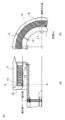
図2(a)は、実施の形態1による発電機の回転子端部の構成を示す断面図、図2(b)は、この図2(a)のAA断面図である。また、図3は、図2(a)を拡大して示した模式図である。図3に示したように、回転子軸2には保持環が焼嵌められている。また、図2(a)、図3に示したように、保持環5の機外側端部には、エンドリング16が内嵌されており、保持環5の機外側の変形を防いでいる。また、保持環5の内径側には回転子コイル15、極間渡り線13および絶縁ブロック14が配置されている。回転子端部の保持環5の機外側の内径側には極間渡り線13が取り付けられている。この極間渡り線13は回転子の極同士を電気的に接続する役割をもつ。回転子の極数は、2極または4極である。保持環5と極間渡り線13の間は絶縁ブロック14で絶縁されている。タービン発電機(以下では、省略して単に発電機と呼ぶ)の場合、発電機の回転子軸2は、その両端部分で、それぞれ、原動機と励磁機に接続される。この場合において、上記極間渡り線13は、励磁機側の回転子端部の保持環5の内径側に設けられている。なお、発電機1機につき、極間渡り線の数は1個であり、原動機側の保持環の内径側には、極間渡り線は設けられていない。
2(a) is a cross-sectional view showing the configuration of the rotor end portion of the generator according to
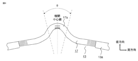
図4は実施の形態1による発電機の回転子端部を軸方向から見た拡大断面図であり、先に説明した図2(b)の一部である破線で囲んだB部の拡大図である。極間渡り線13は円環形状であり、回転子の極間中心部1a(上記図2(b)で示した破線で囲んだB部内の領域であって、図4に示した極間中心線に対して線対称となる領域(図中の2つの点線で挟まれた長さLで示した範囲)であり、下記金属線の一部を極間中心線の左右両側に含む)のうち、回転子軸に近い内周側に配置されているとともに、フレキシブルリード17、および金属線13aを有する。以上説明したように、極間中心部1a内にフレキシブルリード17を有するため、極間渡り線は、円周上の2箇所にフレキシブルリードを有する。
FIG. 4 is an enlarged cross-sectional view of the rotor end of the generator according to
ここで、フレキシブルリード17は、回転子の外径側に凸となる湾曲した形状を持つ導電性を有する金属板である銅板が、複数枚積層された構造となっており、可撓性を有する。この銅板として、例えば、タフピッチ銅材が用いられる。一方、金属線13aは積層構造でなく、同様の材質からなる一本の導電性のある線である。
なお、以上のフレキシブルリードの材質は、タフピッチ銅などに代表される銅合金に限らず、導電性を有する材料であればよい。
また、フレキシブルリード17の湾曲部分の形状は、極間中心線を対称軸として、ほぼ左右対称である(この部分を以降、形状中心部17aと呼ぶ。これについては、後程、詳しく説明する)。また、フレキシブルリード17の径方向に隣り合う層同士は当接しており、当接面ではすべり及び分離が許容されている。さらに、フレキシブルリード17の両端部は、金属線13aと、ろう付けまたは溶接により固定されている。製造段階で応力が発生しないようにするためである。
さらに、以上においては、フレキシブルリードは2箇所あるとして説明したが、1箇所であってもよい。Here, the
The material of the flexible lead is not limited to a copper alloy such as tough pitch copper, and may be any material as long as it has conductivity.
Also, the shape of the curved portion of the
Furthermore, in the above description, it is assumed that there are two flexible leads, but the number of flexible leads may be one.
ここで、図示したように、極間渡り線の金属線13aおよびフレキシブルリード17の外径側には、絶縁ブロック14が当接している。絶縁ブロック14の外径側は、回転子端部に焼嵌められた円環状の保持環5で覆われている。絶縁ブロック14は周方向に複数個配置されている。回転時の遠心力により、上記保持環5は円環半径が広がる。これに伴い、保持環5と極間渡り線13との間に周方向に複数個配置されている絶縁ブロック14は、外径側に移動する。この時、極間渡り線13は絶縁ブロック14の内径面に沿って円環半径が広がるが、可撓性を有するフレキシブルリード17が金属線13aの周方向の伸びを吸収する。
Here, as shown in the figure, the insulating
図5は、フレキシブルリードの変形状態を説明するための図である。この図に示すように、フレキシブルリードが均等な板厚の銅板を積層した構造である場合、回転子の回転時において、フレキシブルリードの両端部が図に示すように、周方向にそれぞれδだけ変位することで、フレキシブルリードの各層の凸状に形成された極間中心線を含む形状中心部17a(図中、2つの二点鎖線で挟まれた角θで示した領域。この領域内では各層の曲率の符号は同一となっている。なお、ここでいう曲率は符号付き曲率のことである。以下同様)には曲げモーメントMが発生する。この曲げモーメントMにより、フレキシブルリードの各層の頂点部分(極間中心線を含み、この極間中心線の近傍領域。以下同様)においては、内径側には引張の曲げ応力、外径側には圧縮の曲げ応力が、それぞれ発生する。この結果、フレキシブルリードの全層のうち、頂点部分に最も大きな応力が発生するのは、最も曲率の大きい最内層である。
FIG. 5 is a diagram for explaining the deformed state of the flexible lead. As shown in this figure, if the flexible lead has a structure in which copper plates of uniform thickness are laminated, when the rotor rotates, both ends of the flexible lead are displaced in the circumferential direction by δ as shown in the figure. By doing so, the shape
図6は実施の形態1によるフレキシブルリード17の構成の一例を示す正面図である。実施の形態1におけるフレキシブルリード17は、内層側と外層側とを全積層枚数の半分で区分した場合に、内層側の板厚の平均値が外層側よりも小さい。
FIG. 6 is a front view showing an example of the configuration of the
なお、フレキシブルリードの全積層枚数が奇数である場合には、中央の層を除いて、中央の層よりも内径側の層を内層側、中央の層よりも外径側の層を外層側として、各々の板厚の平均値を比較する。この場合において、フレキシブルリード17を構成する層の数は2層以上である。
If the total number of layers of flexible leads is an odd number, the layers on the inner diameter side of the central layer are treated as inner layers, and the layers on the outer diameter side of the central layer are treated as outer layers, except for the central layer. , compare the average value of each plate thickness. In this case, the number of layers constituting the
ここで、フレキシブルリード17を構成する層の板厚は2種類以上である。また、フレキシブルリード全体の板厚は周方向に一様である。また、フレキシブルリード17の軸方向の板幅は、従来のフレキシブルリードと同じであり、導体断面積も従来と同じである。(金属線13aおよびフレキシブルリード17で構成される)極間渡り線13の内径側には、(図示しない)回転子軸が配置されている。極間渡り線13と回転子軸との間には、空隙が設けられている。フレキシブルリード17の形状中心部と回転子軸の間にも同様に空隙が設けられている。そして、極間渡り線13と回転子軸との間の空隙には、回転電機が運転中、機外側から機内側に向かって通風ファンにより冷却ガスが送られる。
Here, the thicknesses of the layers forming the
このような発電機では、通風による冷却ガスの効果により、従来通りの冷却性能を維持し、かつフレキシブルリードに与えられるスペースを変更することなく、フレキシブルリードに発生する最大応力を従来よりも低減し、強度信頼性を向上できる。 In such a generator, the cooling gas effect generated by ventilation maintains the same cooling performance as before, and without changing the space given to the flexible leads, the maximum stress generated in the flexible leads is reduced more than before. , can improve strength reliability.
実施の形態2.
図7は実施の形態2による発電機のフレキシブルリード17の構成の一例を示す正面図である。図に示すように、実施の形態2におけるフレキシブルリード17は、外層側から内層側に向かって段階的に板厚が薄くなる。ここで、フレキシブルリード17を構成する層の数は2層以上である。また、フレキシブルリード17を構成する層の板厚の種類は全積層枚数と同じである。さらに、フレキシブルリード全体の板厚は周方向に同じである。なお、その他の構成は実施の形態1と同様である。なお、フレキシブルリード17の軸方向の板幅は、従来のフレキシブルリードと同じであり、導体断面積も従来と同じである。
また、極間渡り線13と回転子軸との間には、空隙が設けられている。また、フレキシブルリード17の凸状部と回転子軸の間にも同様に空隙が設けられている。ここで、極間渡り線13と回転子軸との間の空隙には、回転電機が運転中においては、機外側から機内側に向かって、通風ファンにより冷却ガスが送られる。
FIG. 7 is a front view showing an example of the configuration of the
Further, a gap is provided between the interpolar connecting
フレキシブルリード17は、回転子の外径側に凸となる湾曲した形状を持つ導電性を有する金属板である銅板が、複数枚積層された構造となっており、可撓性を有する。この銅板として、例えば、タフピッチ銅材が用いられる。一方、金属線13aは、フレキシブルリードと異なり、積層構造でなく一体の線である。
なお、このフレキシブルリード17の材質は、上記タフピッチ銅などの銅合金に限らず、導電性を有する材料であればよい。金属線の材質も同様である。The
The material of the
また、フレキシブルリード17は、図中、角θで示した形状中心部で、外径側に凸の湾曲した形状となっており、極間中心線を対称軸として、ほぼ左右対称である。ここで、フレキシブルリード17の径方向に隣り合う層同士は当接しており、当接面ではすべりおよび分離が許容されている。
Further, the
フレキシブルリード17の両端部は極間渡り線13の金属線13aと、ろう付けまたは溶接で固定されている。製造段階で応力が発生しないようにするためである。
Both ends of the
このような発電機では、通風による冷却ガスの効果により、従来通りの冷却性能を維持し、かつフレキシブルリードに与えられるスペースを変更することなく、フレキシブルリードに発生する最大応力を従来よりも低減し、強度信頼性を向上できる。 In such a generator, the cooling gas effect generated by ventilation maintains the same cooling performance as before, and without changing the space given to the flexible leads, the maximum stress generated in the flexible leads is reduced more than before. , can improve strength reliability.
実施の形態3.
図8は、実施の形態3による発電機のフレキシブルリード17の構成を示す正面図である。実施の形態3におけるフレキシブルリード17は、内層側と外層側とを全積層枚数の半分で区分した場合に、形状中心部17aにおいて、内層側の板厚の平均値が外層側よりも小さい領域を有する。例えば、極間中心線を含む頂点部分が該当する。
FIG. 8 is a front view showing the configuration of the
なお、フレキシブルリードの全積層枚数が奇数である場合には、中央の層を除いて、中央の層よりも内径側の層を内層側、中央の層よりも外径側の層を外層側として、各層の板厚の平均値を比較する。この場合には、形状中心部17a以外は、均等な板厚の銅板を積層している。ここで、各金属板の板厚は、フレキシブルリードの形状中心部においては極間中心線から(形状中心部の)周辺部分である端部に向かって連続的に変化する。
If the total number of layers of flexible leads is an odd number, the layers on the inner diameter side of the central layer are treated as inner layers, and the layers on the outer diameter side of the central layer are treated as outer layers, except for the central layer. , compare the average thickness of each layer. In this case, copper plates of uniform thickness are laminated except for the shape
また、フレキシブルリード17は、極間中心線を対称軸として、ほぼ左右対称な形状である。フレキシブルリード17を構成する層の数は2層以上である。フレキシブルリード17の各層の頂点部分の板厚の種類は2種類以上である。なお、フレキシブルリード全体の板厚は周方向に一様である。その他の構成は実施の形態1と同様である。また、フレキシブルリード17の軸方向の板幅は、従来のフレキシブルリードと同じであり、導体断面積も従来と同じである。
In addition, the
本実施の形態の発電機においても、極間渡り線13と(図示しない)回転子軸との間には、空隙が設けられている。また、フレキシブルリード17の形状中心部17aと回転子軸の間にも同様に空隙が設けられている。ここで、極間渡り線13と回転子軸との間の空隙には、回転電機が運転中においては、機外側から機内側に向かって、通風ファンにより冷却ガスが送られる。
In the generator of the present embodiment as well, a gap is provided between the pole-to-
ここでも、フレキシブルリード17は、回転子の外径側に凸状となる湾曲した形状を持つ導電性を有する金属板である銅板が、複数枚積層された構造となっており、可撓性を有する。この銅板として、例えば、タフピッチ銅材が用いられる。そして、積層構造ではなく、一本の(太い)線である金属線とフレキシブルリードの周辺部分で接続され、この両者で極間渡り線13を構成している。
Here, too, the
なお、実施の形態3のフレキシブルリードの上記以外の構造、構成、あるいは材質は、実施の形態1、あるいは実施の形態2と同様であるので、ここでは説明を省略する。
The structure, configuration, or material of the flexible lead of
上記のように構成された発電機においても、通風による冷却ガスの効果により、従来通りの冷却性能を維持し、かつフレキシブルリードに与えられるスペースを変更することなく、フレキシブルリードに発生する最大応力を従来よりも低減し、強度信頼性を向上できる。 Even in the generator configured as described above, the cooling gas effect from ventilation maintains the same cooling performance as before, and the maximum stress generated in the flexible leads can be reduced without changing the space given to the flexible leads. It is possible to reduce it more than before and improve the strength reliability.
実施の形態4.
図9は、実施の形態4による発電機のフレキシブルリード17の構成を示す正面図である。実施の形態4におけるフレキシブルリード17は、凸状に湾曲した形状中心部の頂点部分において、外層側から内層側に向かって段階的に板厚が薄くなる。フレキシブルリード17の形状中心部以外は均等な板厚の銅板を積層している。そして、フレキシブルリード17の各々の層の板厚は、凸状に湾曲した頂点部分から形状中心部の端部に向かって連続的に変化する。ここで、フレキシブルリード17を構成する層の数は2層以上である。フレキシブルリード17の各層の頂点部の板厚の種類は全積層枚数と同じである。なお、フレキシブルリード全体の板厚は周方向に一様である。その他の構成は実施の形態1と同様である。また、フレキシブルリード17の軸方向の板幅は、従来のフレキシブルリードと同じであり、導体断面積も従来と同じである。
FIG. 9 is a front view showing the structure of the
また、極間渡り線13と(図示しない)回転子軸との間には、空隙が設けられている。また、フレキシブルリード17の形状中心部17aと回転子軸の間にも同様に空隙が設けられている。そして、極間渡り線13と回転子軸との間の空隙には、回転電機が運転中においては、機外側から機内側に向かって、通風ファンにより冷却ガスが送られる。
Further, a gap is provided between the pole-to-
また、フレキシブルリード17の径方向に隣り合う層同士は当接しており、当接面ではすべりおよび分離が許容されている。フレキシブルリード17の両端部は極間渡り線13と、ろう付けまたは溶接で固定されている。製造段階で応力が発生しないようにするためである。
In addition, radially adjacent layers of the
本実施の形態における発電機では、上記以外のフレキシブルリード17の構造、あるいは材質は、他の実施の形態と同じである。 In the generator of this embodiment, the structure or material of the flexible leads 17 other than those described above are the same as those of the other embodiments.
上記のように構成された発電機においても、通風による冷却ガスの効果により、従来通りの冷却性能を維持し、かつフレキシブルリードに与えられるスペースを変更することなく、フレキシブルリードに発生する最大応力を従来よりも低減し、強度信頼性を向上できる。 Even in the generator configured as described above, the cooling gas effect from ventilation maintains the same cooling performance as before, and the maximum stress generated in the flexible leads can be reduced without changing the space given to the flexible leads. It is possible to reduce it more than before and improve the strength reliability.
ここで、上記の各実施の形態では、フレキシブルリードを構成する銅板の枚数が多いほど、電流の流れる導体断面積あたりの、冷却ガスとの間で熱伝達の発生する表面積が大きくなり、フレキシブルリードの発熱が低減されるため、温度上昇による材料の引張強度および疲労強度の低下が抑えられ強度信頼性が向上する。 Here, in each of the above-described embodiments, as the number of copper plates constituting the flexible lead increases, the surface area for generating heat transfer with the cooling gas per cross-sectional area of the conductor through which the current flows increases, and the flexible lead increases. Since the heat generation of the material is reduced, the deterioration of the tensile strength and fatigue strength of the material due to the temperature rise is suppressed, and the strength reliability is improved.
また、上記の各実施の形態で示したフレキシブルリードの最も薄い板厚を有する層は、少なくとも自重または遠心力で座屈を生じない程度の板厚を有する。
以上の例では、回転電機としてタービン発電機を例に説明したが、その他の発電機、および電動機にも適用できる。Also, the thinnest layer of the flexible lead shown in each of the above embodiments has a thickness that does not cause buckling due to its own weight or centrifugal force.
In the above example, a turbine generator was described as an example of a rotating electric machine, but the present invention can also be applied to other generators and electric motors.
本願は、様々な例示的な実施の形態及び実施例が記載されているが、1つ、または複数の実施の形態に記載された様々な特徴、態様、及び機能は特定の実施の形態の適用に限られるのではなく、単独で、または様々な組み合わせで実施の形態に適用可能である。
従って、例示されていない無数の変形例が、本願明細書に開示される技術の範囲内において想定される。例えば、少なくとも1つの構成要素を変形する場合、追加する場合または省略する場合、さらには、少なくとも1つの構成要素を抽出し、他の実施の形態の構成要素と組み合わせる場合が含まれるものとする。While this application describes various exemplary embodiments and examples, various features, aspects, and functions described in one or more embodiments may not apply to particular embodiments. can be applied to the embodiments singly or in various combinations.
Accordingly, numerous variations not illustrated are envisioned within the scope of the technology disclosed herein. For example, modification, addition or omission of at least one component, extraction of at least one component, and combination with components of other embodiments shall be included.
1 回転子、1a 極間中心部、2 回転子軸、3 回転子本体、4 回転子鉄心、5 保持環、6 枠体、7 送風ファン、8 固定子、9 固定子鉄心、10 固定子コイル、11 冷却ガス、12 ガス冷却器、13 極間渡り線、13a 金属線、14 絶縁ブロック、15 回転子コイル、16 エンドリング、17 フレキシブルリード、17a 形状中心部
REFERENCE SIGNS
Claims (4)
導電性の金属板を積層して形成したフレキシブルリードと、前記フレキシブルリードに接続された金属線と、により構成され、前記回転子の界磁極同士を電気的に接続する極間渡り線、
を備え、
前記フレキシブルリードの金属板の半径方向の配置位置を内層側と外層側に2分する場合に、前記金属板の全積層枚数が奇数の場合のみ前記半径方向の中央に配置された1枚を除き内層側と外層側に2分するとともに、前記内層側に配置された各金属板の板厚の平均値が、前記外層側に配置された各金属板の板厚の平均値よりも小さくなるよう構成されていることを特徴とする回転電機。a retaining ring fitted to the rotor and retaining the rotor coil of the rotor;
Interpolar connecting wires for electrically connecting the field poles of the rotor, each comprising a flexible lead formed by laminating conductive metal plates and a metal wire connected to the flexible lead,
with
When the radial arrangement position of the metal plate of the flexible lead is divided into inner layer side and outer layer side, only when the total number of laminated metal plates is an odd number, except for one plate arranged in the center in the radial direction It is divided into an inner layer side and an outer layer side, and the average value of the plate thickness of each metal plate arranged on the inner layer side is made smaller than the average value of the plate thickness of each metal plate arranged on the outer layer side. A rotating electric machine characterized by:
Applications Claiming Priority (1)
| Application Number | Priority Date | Filing Date | Title |
|---|---|---|---|
| PCT/JP2020/008259 WO2021171544A1 (en) | 2020-02-28 | 2020-02-28 | Rotating electric machine |
Publications (3)
| Publication Number | Publication Date |
|---|---|
| JPWO2021171544A1 JPWO2021171544A1 (en) | 2021-09-02 |
| JPWO2021171544A5 JPWO2021171544A5 (en) | 2022-07-19 |
| JP7270830B2 true JP7270830B2 (en) | 2023-05-10 |
Family
ID=77491265
Family Applications (1)
| Application Number | Title | Priority Date | Filing Date |
|---|---|---|---|
| JP2022502766A Active JP7270830B2 (en) | 2020-02-28 | 2020-02-28 | Rotating electric machine |
Country Status (5)
| Country | Link |
|---|---|
| US (1) | US11742712B2 (en) |
| JP (1) | JP7270830B2 (en) |
| CN (1) | CN115176402A (en) |
| DE (1) | DE112020006819T5 (en) |
| WO (1) | WO2021171544A1 (en) |
Citations (1)
| Publication number | Priority date | Publication date | Assignee | Title |
|---|---|---|---|---|
| JP6026425B2 (en) | 2010-11-02 | 2016-11-16 | プロビオドルグ エージー | Crystal structure of isoglutaminyl cyclase |
Family Cites Families (9)
| Publication number | Priority date | Publication date | Assignee | Title |
|---|---|---|---|---|
| JPS55144737A (en) | 1979-04-26 | 1980-11-11 | Hitachi Ltd | Interpole connecting device for field coil |
| JPS58182441A (en) * | 1982-04-19 | 1983-10-25 | Hitachi Ltd | Field winding device for rotor |
| JPS6026425A (en) * | 1983-07-22 | 1985-02-09 | Hitachi Ltd | Interpole connecting device of revolving-field winding |
| JPS62104446A (en) | 1985-10-30 | 1987-05-14 | Hitachi Ltd | Interpole connection structure for rotary electric machine |
| JPS63103636A (en) * | 1986-10-20 | 1988-05-09 | Toshiba Corp | Slot armor for rotor |
| US4870308A (en) * | 1988-06-17 | 1989-09-26 | Westinghouse Electric Corp. | Flexible conductor and dynamoelectric machine incorporating the same |
| US5111097A (en) * | 1990-11-30 | 1992-05-05 | Westinghouse Electric Corp. | Rotor pole crossover |
| US7247966B2 (en) * | 2004-06-24 | 2007-07-24 | Siemens Power Generation, Inc. | Flexible rotor pole crossover for a generator |
| US6930434B1 (en) * | 2004-11-04 | 2005-08-16 | Siemens Westinghouse Power Corporation | Generator rotor pole crossover |
-
2020
- 2020-02-28 DE DE112020006819.6T patent/DE112020006819T5/en active Pending
- 2020-02-28 JP JP2022502766A patent/JP7270830B2/en active Active
- 2020-02-28 US US17/781,744 patent/US11742712B2/en active Active
- 2020-02-28 WO PCT/JP2020/008259 patent/WO2021171544A1/en active Application Filing
- 2020-02-28 CN CN202080097295.2A patent/CN115176402A/en active Pending
Patent Citations (1)
| Publication number | Priority date | Publication date | Assignee | Title |
|---|---|---|---|---|
| JP6026425B2 (en) | 2010-11-02 | 2016-11-16 | プロビオドルグ エージー | Crystal structure of isoglutaminyl cyclase |
Also Published As
| Publication number | Publication date |
|---|---|
| US20230014443A1 (en) | 2023-01-19 |
| US11742712B2 (en) | 2023-08-29 |
| CN115176402A (en) | 2022-10-11 |
| JPWO2021171544A1 (en) | 2021-09-02 |
| WO2021171544A1 (en) | 2021-09-02 |
| DE112020006819T5 (en) | 2022-12-15 |
Similar Documents
| Publication | Publication Date | Title |
|---|---|---|
| JP5038595B2 (en) | Method and apparatus for reducing hot spot temperature of laminated field winding | |
| US7619332B2 (en) | Permanent magnet type electric rotating machine and wind turbine electric power generation system | |
| JP5842856B2 (en) | Rotating electric machine stator | |
| EP0881747B2 (en) | Alternator for vehicle | |
| EP2136455A1 (en) | An electric motor provided with a cooling arrangement | |
| US10164490B2 (en) | Rotary electric machine and manufacturing method therefor | |
| JP2013188034A (en) | Rotary electric machine | |
| US4453101A (en) | Amortisseur bar with improved interface between free conductor bars and amortisseur ring | |
| JP2010041795A (en) | Stator for rotating electric machine | |
| JP2015533471A (en) | Synchronous electric motor with permanent magnet and electric compressor comprising this type of electric motor | |
| US20180205302A1 (en) | Permanent magnet (pm) brushless machine with outer rotor | |
| JP2007244065A (en) | Stator structure of concentrated winding motor | |
| JP2016208757A (en) | Rotary electric machine for vehicle | |
| US5408152A (en) | Method of improving heat transfer in stator coil cooling tubes | |
| JP7270830B2 (en) | Rotating electric machine | |
| US20110278981A1 (en) | Rotor for electric rotating machine | |
| WO2021199376A1 (en) | Stator and dynamo-electric machine | |
| JP2010035381A (en) | Stator for rotating electric machine | |
| US9509194B2 (en) | Generator assembly | |
| JP2012080764A (en) | Dynamoelectric machine coil space block having flow deflecting structure in coil facing surface thereof | |
| JP5129518B2 (en) | Rotating electric machine | |
| JP2004282858A (en) | Stator and rotary machine using the same | |
| TW202011672A (en) | Cage rotor and rotary motor | |
| EP4092885A1 (en) | Cooling at the axial ends of an electric generator | |
| JP2015130774A (en) | Permanent magnet type rotary electric machine |
Legal Events
| Date | Code | Title | Description |
|---|---|---|---|
| A521 | Request for written amendment filed |
Free format text: JAPANESE INTERMEDIATE CODE: A523 Effective date: 20220519 |
|
| A621 | Written request for application examination |
Free format text: JAPANESE INTERMEDIATE CODE: A621 Effective date: 20220519 |
|
| TRDD | Decision of grant or rejection written | ||
| A01 | Written decision to grant a patent or to grant a registration (utility model) |
Free format text: JAPANESE INTERMEDIATE CODE: A01 Effective date: 20230328 |
|
| A61 | First payment of annual fees (during grant procedure) |
Free format text: JAPANESE INTERMEDIATE CODE: A61 Effective date: 20230425 |
|
| R151 | Written notification of patent or utility model registration |
Ref document number: 7270830 Country of ref document: JP Free format text: JAPANESE INTERMEDIATE CODE: R151 |