JP7269846B2 - Vehicle driving support method and vehicle driving support system - Google Patents
Vehicle driving support method and vehicle driving support system Download PDFInfo
- Publication number
- JP7269846B2 JP7269846B2 JP2019162309A JP2019162309A JP7269846B2 JP 7269846 B2 JP7269846 B2 JP 7269846B2 JP 2019162309 A JP2019162309 A JP 2019162309A JP 2019162309 A JP2019162309 A JP 2019162309A JP 7269846 B2 JP7269846 B2 JP 7269846B2
- Authority
- JP
- Japan
- Prior art keywords
- vehicle
- lane change
- lane
- driver
- driving support
- Prior art date
- Legal status (The legal status is an assumption and is not a legal conclusion. Google has not performed a legal analysis and makes no representation as to the accuracy of the status listed.)
- Active
Links
Images


Description
本発明は、車両運転支援方法及び車両運転支援システムに関する。 The present invention relates to a vehicle driving assistance method and a vehicle driving assistance system.
特許文献1には、第1レーンを走行中の自車両の第2レーンへの合流を支援する合流支援装置が提案されている。この合流支援装置は、自車両から基準地点までの距離を取得し、当該距離から自車両の車速に基づく停車するまでの走行距離を差し引いた値が予め設定された閾値より小さいと合流を中止する。 Japanese Laid-Open Patent Publication No. 2002-100003 proposes a merging support device that supports the merging of the own vehicle traveling in the first lane into the second lane. This merging support device obtains the distance from the own vehicle to the reference point, and if the value obtained by subtracting the traveling distance until the vehicle stops based on the vehicle speed of the own vehicle from the obtained distance is smaller than a preset threshold value, discontinues the merging. .
特許文献1の合流支援装置では、自車両の車速などの自車両の走行状態に基づいて合流を行うことができない場合にこれを中止するものである。しかしながら、合流ができるか否かの判定にあたり、合流先の他車両の状況を考慮したものではない。特に、合流を含む車線変更時において、変更先の車線で自車両の後方を走行する他車両(以下、「後方車両」と称する)の運転者が自車両の存在に気が付かないことが想定される。したがって、後方車両に対して、車線変更動作を意図する自車両の存在をより確実に認識させることが望まれる。
The merging support device of
このような事情に鑑み、本発明は、車線変更動作を意図する自車両の存在を後方車両の運転者により確実に認識させることのできる車両運転支援方法及び車両運転支援システムを提供することを目的とする。 SUMMARY OF THE INVENTION In view of such circumstances, it is an object of the present invention to provide a vehicle driving assistance method and a vehicle driving assistance system capable of making the driver of the vehicle behind the vehicle reliably recognize the presence of the own vehicle intending to change lanes. and
本発明のある態様によれば、自車両を走行車線から隣接車線に移動させる車線変更動作を実行する車両運転支援方法が提供される。この車両運転支援方法では、隣接車線における目標車線変更位置を設定し、目標車線変更位置を設定すると、該目標車線変更位置に後方で隣接して走行する後方車両の運転者の有効視野を規定する有効視野角の推定値として推定有効視野角を求める有効視野推定処理を実行する。そして、推定有効視野角に基づいて自車両が後方車両の運転者の有効視野内に入る車線変更待機位置を設定する待機位置設定処理を実行し、自車両を車線変更待機位置まで移動させる移動処理を実行し、自車両を前記車線変更待機位置に待機させる待機処理を実行し、待機処理の完了後に車線変更動作を実行する。 According to one aspect of the present invention, there is provided a vehicle driving assistance method for executing a lane change operation for moving a host vehicle from a driving lane to an adjacent lane. In this vehicle driving support method, a target lane change position in an adjacent lane is set, and when the target lane change position is set, the effective field of view of the driver of the rear vehicle traveling behind and adjacent to the target lane change position is defined. An effective visual field estimation process is executed to obtain an estimated effective visual field angle as an estimated value of the effective visual field angle. Then, on the basis of the estimated effective viewing angle, a standby position setting process is executed to set a lane change standby position where the vehicle is within the effective visual field of the driver of the vehicle behind, and a movement process is performed to move the vehicle to the lane change standby position. is executed, a standby process for causing the host vehicle to wait at the lane change standby position is executed, and a lane change operation is executed after completion of the standby process.
本発明によれば、自車両の車線変更動作を後方車両により確実に認識させることができる。 ADVANTAGE OF THE INVENTION According to this invention, the lane change operation|movement of the own vehicle can be made to recognize reliably by the back vehicle.
以下、図面等を参照して、本発明の実施形態について説明する。なお、本明細書における「車線変更」は、所定の目的地に向かうための交差点における左折若しくは右折、又は高速道路の出口に近い車線への移動などを意図して現在走行している車線から隣接する車線へ移動する通常の車線変更に加え、高速道路の入口における車線から本線への移動などのいわゆる合流も含む概念である。 BEST MODE FOR CARRYING OUT THE INVENTION Hereinafter, embodiments of the present invention will be described with reference to the drawings. In this specification, the term "lane change" means a left or right turn at an intersection toward a predetermined destination, or a lane adjacent to the current lane with the intention of moving to a lane near the exit of a highway. In addition to the normal lane change to move to the lane where the vehicle is moving to, the concept includes so-called merging such as moving from the lane to the main lane at the entrance of the expressway.
また、本明細書における「運転支援」は、車両のドライバによる運転操作の一部を補助する車両の動作制御(自動運転レベル1~4)の他、ドライバによる操作無しの車両の動作制御(自動運転レベル5)も含む概念である。
In addition, "driving assistance" in this specification includes vehicle operation control (
(第1実施形態)
図1は、本実施形態に係る車両運転支援システム10の構成図である。
(First embodiment)
FIG. 1 is a configuration diagram of a vehicle
図示のように、車両運転支援システム10は、外部センサ1と、内部センサ2と、ナビゲーションシステム3と、アクチュエータ4と、コントローラ20と、を備える。車両運転支援システム10は、本実施形態の車両運転支援方法を実行すべき対象となる車両(以下では、「自車両α」と称する)に搭載される。
As illustrated, the vehicle
外部センサ1は、自車両αの周辺状況を検出する検出機器である。特に、外部センサ1は、車載カメラ1a、及びレーダー1bを含む。
The
車載カメラ1aは、自車両αの周辺を撮像する撮像機器である。車載カメラ1aは、例えば、自車両αのフロントガラスの車室内側に設けられる。なお、車載カメラ1aは、単眼カメラ又はステレオカメラにより構成される。車載カメラ1aは、撮像した自車両αの周辺に関する情報コントローラ20へ出力する。
The in-
レーダー1bは、電波を利用して自車両αの外部の物体を検出する。電波は、例えばミリ波である。より詳細には、レーダー1bは、電波を自車両αの周囲に送信し、物体で反射された電波を受信して物体を検出する。レーダー1bは、例えば物体までの距離又は方向を物体情報として出力することができる。レーダー1bは、検出した物体情報をコントローラ20へ出力する。なお、レーダー1bに代えて、又はレーダー1bとともに、光を利用して自車両αの外部の物体を検出するライダー(LIDER:Laser Imaging Detection and Ranging)を外部センサ1として搭載しても良い。
The
内部センサ2は、自車両αの走行状態に応じた各種情報を検出する検出器である。特に、内部センサ2は、自車両αの車速(以下では、「自車両車速Vα」とも称する)を検出する車速センサ及び加速度を検出する加速度センサなどを含む。 The internal sensor 2 is a detector that detects various information according to the running state of the own vehicle α. In particular, the internal sensor 2 includes a vehicle speed sensor that detects the vehicle speed of the own vehicle α (hereinafter also referred to as “own vehicle speed Vα”), an acceleration sensor that detects acceleration, and the like.
ナビゲーションシステム3は、自車両αのドライバ等の乗員によって地図上に設定された目的地までの案内を自車両αの乗員に対して行う装置である。ナビゲーションシステム3は、GPS(Global Positioning System)によって測定された自車両αの位置情報と図示しない地図データベースの地図情報とに基づいて、自車両αの走行するルートを算出する。ルートは、例えば複数車線の区間において自車両αが走行する走行車線La1を特定したルートでもよい。ナビゲーションシステム3は、例えば、自車両αの位置から目的地に至るまでの目標ルートを演算し、ディスプレイの表示及びスピーカの音声出力により目標ルート情報の報知を乗員に対して行う。ナビゲーションシステム3は、自車両αの位置情報、地図情報、及び目標ルート情報を含むナビゲーション情報をコントローラ20へ出力する。
The
なお、ナビゲーションシステム3は、自車両αと通信可能な情報処理センターなどの車両外部の施設のコンピュータに記憶された情報を用いてもよい。例えば、ナビゲーションシステム3は、施設のコンピュータから通信を介して道路の混雑を示す渋滞情報を上記ナビゲーション情報として取得してもよい。また、ナビゲーションシステム3が実行する処理を、自車両αに搭載されるコンピュータと、車両外部のコンピュータと、で分散して実行する構成をとっても良い。
The
アクチュエータ4は、コントローラ20からの指令に基づいて自車両αの走行制御を実行する装置である。アクチュエータ4は、駆動アクチュエータ4a、ブレーキアクチュエータ4b、及びステアリングアクチュエータ4cを含む。
The
駆動アクチュエータ4aは、自車両αの駆動力を調節するための装置である。
The driving
特に、自車両αが走行駆動源としてのエンジンを搭載している内燃機関自動車である場合には、駆動アクチュエータ4aはエンジンに対する空気の供給量(スロットル開度)を調節するスロットルアクチュエータなどで構成される。
In particular, when the own vehicle α is an internal combustion engine vehicle equipped with an engine as a drive source, the
一方、自車両αが走行駆動源としてのモータを搭載しているハイブリッド車両又は電気自動車である場合には、駆動アクチュエータ4aはモータに供給する電力を調節可能な回路(インバータ及びコンバータなど)などで構成される。
On the other hand, when the own vehicle α is a hybrid vehicle or an electric vehicle equipped with a motor as a drive source, the
ブレーキアクチュエータ4bは、コントローラ20からの指令に応じてブレーキシステムを操作し、自車両αの車輪へ付与する制動力を調節する装置である。ブレーキアクチュエータ4bは、油圧ブレーキ又は回生ブレーキなどで構成される。
The brake actuator 4b is a device that operates the brake system according to a command from the
ステアリングアクチュエータ4cは、電動パワーステアリングシステムのうちステアリングトルクを制御するアシストモータなどで構成される。
The
運転支援制御装置としてのコントローラ20は、中央演算装置(CPU)、読み出し専用メモリ(ROM)、ランダムアクセスメモリ(RΑM)及び入出力インタフェース(I/Oインタフェース)を備えたコンピュータで構成される。なお、コントローラ20は一つの装置として構成されていても良いし、複数の装置に分けられ、本実施形態の各処理を当該複数の装置で分散処理するように構成されていても良い。
A
本実施形態のコントローラ20は、例えば自車両αの運転支援に関する処理を行うコントローラ(ADコントローラ)により構成される。なお、コントローラ20は、ADコントローラ以外に自車両αに搭載されるECU(Engine Control Unit)又は統合コントローラなどの制御装置により構成されても良い。
The
コントローラ20は、外部センサ1、内部センサ2、及びナビゲーションシステム3との間で各種信号を通信可能に構成される。
The
そして、コントローラ20は、取得した各センサの検出値及びナビゲーションシステム情報に基づいてアクチュエータ4を操作して自車両αの走行を制御するようにプログラムされている。特に、コントローラ20は、自車両αの車線変更要求を検出すると、後述する車両運転支援方法にかかる処理を開始する。
The
なお、コントローラ20には、いわゆるHDマップ(ダイナミックマップ)を搭載しても良い。特に、コントローラ20がHDマップを搭載する場合には、各センサの検出値及びナビゲーションシステム情報に代えて又はこれとともに、HDマップのデータから自車両αの周辺状況(車線数若しくは路肩の大きさなどの道路の態様、他車両の走行量、又は障害物の有無など)を取得することができる。
Note that the
以下、本実施形態の車両運転支援方法の詳細について説明する。 Details of the vehicle driving support method of the present embodiment will be described below.
図2は、本実施形態の車両運転支援方法を説明するフローチャートである。 FIG. 2 is a flowchart for explaining the vehicle driving assistance method of this embodiment.
先ず、ステップS100において、コントローラ20は、車線変更要求があるか否かを判定する。具体的に、コントローラ20は、ナビゲーションシステム情報に基づいて自車両αに予め設定された走行ルートに応じて車線変更が必要であるか否かを判定する。
First, in step S100, the
なお、このナビゲーションシステム情報に基づく車線変更要求の有無の判定以外の判定態様を採用しても良い。例えば、自車両αのドライバが車線変更を指示する操作を検出したか否か、又は上位コントローラからの車線変更の指令信号を受信したか否かに基づいて車線変更要求があるか否かを判定する構成を採用しても良い。 It should be noted that a determination mode other than the determination of whether or not there is a lane change request based on this navigation system information may be employed. For example, it is determined whether or not there is a lane change request based on whether or not the driver of the own vehicle α has detected an operation instructing a lane change, or whether or not a lane change command signal has been received from the host controller. You may adopt the structure which carries out.
そして、コントローラ20は、車線変更要求があると判断すると、ステップS110の処理に移行する。
Then, when the
ステップS110において、コントローラ20は、他車情報を取得する。特に、コントローラ20は、外部センサ1の検出値などに基づいて、走行車線La1に隣接する車線変更先の隣接車線La2を走行する他車両(特に後述の前方車両β及び後方車両γ)の位置及び車速を含む情報を取得する。
In step S110, the
ステップS120において、コントローラ20は、隣接車線La2における自車両αの目標車線変更位置P2を設定する。具体的に、コントローラ20は、隣接車線La2において、自車両αの現在の走行位置(以下、「通常走行位置P0」とも称する)に近く、且つ自車両αが進入する十分なスペースがあるかなどの基準に基づいて適切な隣接車線La2上の位置を目標車線変更位置P2に設定する。
In step S120, the
なお、以下では、隣接車線La2においてこの目標車線変更位置P2の前方で隣接して走行する車両を「前方車両β」とも称する。また、隣接車線La2においてこの目標車線変更位置P2の後方で隣接して走行する車両を「後方車両γ」とも称する。 In the following description, the vehicle that runs in front of and adjacent to the target lane change position P2 in the adjacent lane La2 is also referred to as the "front vehicle β". In addition, the vehicle running behind and adjacent to the target lane change position P2 in the adjacent lane La2 is also referred to as a "rear vehicle γ".
次に、ステップS130において、コントローラ20は、後方車両γの運転者Dγの有効視野efvを規定する有効視野角θの推定値として推定有効視野角θeを求める。
Next, in step S130, the
図3は、有効視野角θについて説明するための図である。ここで、有効視野efvとは、人の生理学的視野中心付近に固定点(注視点)を設けている場合に外界から有効に情報を得ることのできる範囲を意味する。特に、本実施形態における有効視野efvは、後方車両γの車幅方向における中心軸と略一致する軸線ax1の延長線上に運転者Dγの前方注視点が存在するとみなし、当該軸線ax1を中心角の二等分線として所定の半径長さを有する略扇形の領域(図3にハッチングで示す領域)として定義される。そして、この有効視野efvを決定付けるパラメータである中心角が有効視野角θとして定義される。 FIG. 3 is a diagram for explaining the effective viewing angle θ. Here, the effective visual field efv means a range in which information can be effectively obtained from the outside world when a fixed point (gazing point) is provided near the physiological visual field center of a person. In particular, the effective field of view efv in the present embodiment assumes that the forward gaze point of the driver Dγ exists on an extension of the axis ax1 that substantially coincides with the central axis of the vehicle γ in the vehicle width direction, and the axis ax1 is the center angle. It is defined as a substantially fan-shaped area (hatched area in FIG. 3) having a predetermined radial length as a bisector. A central angle, which is a parameter that determines this effective visual field efv, is defined as an effective visual field angle θ.
有効視野角θは、後方車両γの車速(以下、単に「後方車両車速Vγ」とも称する)、隣接車線La2における後方車両γの走行路の混雑度合、隣接車線La2の道路形状(直線又はカーブ)などの後方車両γの走行環境、並びに後方車両γの運転者Dγの運転技能及び運転者Dγに作用する運転負荷などの運転者状態などの要因によって、例えば4°~20°の範囲で変動する。 The effective viewing angle θ is determined by the vehicle speed of the rear vehicle γ (hereinafter also simply referred to as the “rear vehicle speed Vγ”), the degree of congestion of the traveling road of the rear vehicle γ in the adjacent lane La2, and the road shape (straight or curved) of the adjacent lane La2. The driving environment of the rear vehicle γ such as the driving skill of the driver Dγ of the rear vehicle γ and the driver condition such as the driving load acting on the driver Dγ. .
特に、本実施形態では、これらの各要因を総合的に考慮した平均的な有効視野角θを基準有効視野角θ0として予め設定しておく。そして、コントローラ20は、後方車両車速Vγに基づいて基準有効視野角θ0を補正した値を以降の処理で用いる有効視野角θの推定値(以下、「推定有効視野角θe」とも称する)として演算する。
In particular, in the present embodiment, an average effective viewing angle θ that comprehensively considers these factors is preset as the reference effective viewing angle θ 0 . Then, the
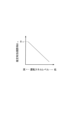
図4は、後方車両車速Vγに応じた推定有効視野角θeの補正について説明する図である。図示のように、本実施形態では、上記基準有効視野角θ0を、後方車両車速Vγが大きいほど小さくなるように補正して推定有効視野角θeを求める。 FIG. 4 is a diagram for explaining correction of the estimated effective viewing angle θ e according to the vehicle speed Vγ of the rear vehicle. As shown in the figure, in this embodiment, the estimated effective viewing angle θe is obtained by correcting the reference effective viewing angle θ 0 so that it decreases as the vehicle speed Vγ of the rear vehicle increases.
図2に戻り、ステップS140において、コントローラ20は、求めた推定有効視野角θeに基づいて、車線変更待機位置P1を算出する待機位置設定処理を実行する。
Returning to FIG. 2, in step S140, the
図5は、車線変更待機位置P1の設定について説明する図である。 FIG. 5 is a diagram illustrating setting of the lane change waiting position P1.
図5から理解されるように、本実施形態では、自車両αが車線変更待機位置P1に移動した際に、推定有効視野角θeで特定される運転者Dγの有効視野efvの少なくとも一部に自車両αが進入するように、自車両αの通常走行位置P0からの横方向における移動距離(以下、単に「横移動距離Bα」とも称する)及び前後方向における移動距離(以下、単に「前後移動距離Lα」とも称する)を定める。 As can be understood from FIG. 5, in this embodiment, when the own vehicle α moves to the lane change standby position P1, at least a portion of the effective visual field efv of the driver Dγ specified by the estimated effective visual field angle θ e so that the own vehicle α enters the normal traveling position P0 of the own vehicle α in the lateral direction (hereinafter also simply referred to as the “lateral movement distance Bα”) and in the longitudinal direction (hereinafter simply referred to as the “forward and backward distance Bα”). (also referred to as "movement distance Lα") is determined.
特に、本実施形態では、横移動距離Bαを推定有効視野角θeが小さいほど大きく設定する。 In particular, in the present embodiment, the smaller the estimated effective viewing angle θe , the larger the lateral movement distance Bα is set.
図6は、推定有効視野角θeに応じて設定される横移動距離Bαについて説明する図である。図示のように、本実施形態では、横移動距離Bαを推定有効視野角θeが小さいほど大きく設定する。 FIG. 6 is a diagram for explaining the lateral movement distance Bα set according to the estimated effective viewing angle θe . As shown, in the present embodiment, the smaller the estimated effective viewing angle θe , the larger the lateral movement distance Bα is set.
これにより、後方車両γの運転者Dγの有効視野efvが狭いほど車線変更待機位置P1が横方向において後方車両γに近い位置に設定されることとなる。 As a result, the narrower the effective visual field efv of the driver Dγ of the rear vehicle γ is, the closer the lane change waiting position P1 is set to the rear vehicle γ in the lateral direction.
図2に戻り、ステップS150において、コントローラ20は、ステップS140で設定した車線変更待機位置P1に自車両αを移動させる移動処理を実行する。具体的に、コントローラ20は、自車両αを通常走行位置P0から横移動距離Bα及び前後移動距離Lαの分移動させるようにアクチュエータ4を操作する。
Returning to FIG. 2, in step S150, the
そして、ステップS160において、コントローラ20は、待機処理を実行する。具体的に、コントローラ20は、自車両αが車線変更待機位置P1で走行する状態を維持するようにアクチュエータ4を操作する。また、本実施形態において、コントローラ20は、待機処理中に、方向指示器(いわゆるウィンカー)による方向指示表示を行う。
Then, in step S160, the
特に、本実施形態においてコントローラ20は、所定の暴露時間Δtexの間、自車両αの車線変更待機位置P1における待機状態を維持する。なお、暴露時間Δtexは、車線変更待機位置P1に移動して来た自車両αを後方車両γの運転者Dγに認識させる観点から適宜定まる時間である。特に、本実施形態では、待機処理中において方向指示表示を行うところ、暴露時間Δtexは少なくとも方向指示表示から車線変更動作を開始するまでの一般的な時間間隔(数秒程度)以上の時間に設定されることが好ましい。
In particular, in this embodiment, the
そして、ステップS170において、コントローラ20は、待機処理の完了後に自車両αを目標車線変更位置P2に移動させる車線変更動作を実行する。具体的に、コントローラ20は、自車両αを車線変更待機位置P1から目標車線変更位置P2に移動させるようにアクチュエータ4を操作する。
Then, in step S170, the
以上説明した構成を有する本実施形態によれば、以下の作用効果を奏する。 According to this embodiment having the configuration described above, the following effects are obtained.
本実施形態車両運転支援方法では、自車両αを走行車線La1から隣接車線La2に移動させる車線変更動作を実行する車両運転支援方法が提供される。 In the vehicle driving assistance method of the present embodiment, a vehicle driving assistance method is provided that executes a lane change operation for moving the host vehicle α from the driving lane La1 to the adjacent lane La2.
この車両運転支援方法では、隣接車線La2における目標車線変更位置P2を設定し(図2のステップS120)、目標車線変更位置P2を設定すると、該目標車線変更位置P2に後方で隣接して走行する後方車両γの運転者Dγの有効視野efvを規定する有効視野角θの推定値である推定有効視野角θeを求める有効視野推定処理を実行する(ステップS130)。そして、推定有効視野角θeに基づいて自車両αが後方車両γの運転者Dγの有効視野efv内に入る車線変更待機位置P1を設定する待機位置設定処理(ステップS140)を実行し、自車両αを車線変更待機位置P1まで移動させる移動処理(ステップS150)を実行し、自車両αを車線変更待機位置P1に待機させる待機処理(ステップS160)を実行し、待機処理の完了後に車線変更動作を実行する(ステップS170)。 In this vehicle driving support method, a target lane change position P2 in the adjacent lane La2 is set (step S120 in FIG. 2), and when the target lane change position P2 is set, the vehicle travels behind and adjacent to the target lane change position P2. An effective visual field estimation process is executed to obtain an estimated effective visual field angle θe, which is an estimated value of the effective visual field angle θ that defines the effective visual field efv of the driver Dγ of the rear vehicle γ (step S130). Then, a standby position setting process (step S140) is executed to set a lane change standby position P1 where the own vehicle α is within the effective visual field efv of the driver Dγ of the rear vehicle γ based on the estimated effective viewing angle θ e . A movement process (step S150) is executed to move the vehicle α to the lane change standby position P1, a standby process (step S160) is executed to cause the own vehicle α to wait at the lane change standby position P1, and after the completion of the standby process, the lane is changed. An operation is performed (step S170).
これにより、車線変更動作を実行する前に、自車両αが後方車両γの運転者Dγの有効視野efv内に入る車線変更待機位置P1に移動して待機した後に車線変更動作を開始することとなる。すなわち、車線変更待機位置P1で走行する自車両αを後方車両γの運転者Dγに認識させる過程を経て車線変更動作が開始される。したがって、車線変更動作を意図する自車両αの存在を後方車両γの運転者Dγにより確実に認識させることができる。 As a result, before executing the lane change operation, the own vehicle α moves to the lane change waiting position P1 within the effective visual field efv of the driver Dγ of the rear vehicle γ, waits, and then starts the lane change operation. Become. That is, the lane change operation is started through the process of making the driver Dγ of the following vehicle γ recognize the host vehicle α traveling at the lane change standby position P1. Therefore, it is possible to make the driver Dγ of the following vehicle γ reliably recognize the presence of the own vehicle α that intends to change lanes.
特に、本実施形態の車両運転支援方法では、待機処理中に、車線変更待機位置P1において自車両の方向指示器による方向指示表示を実行する(ステップS160)。 In particular, in the vehicle driving support method of the present embodiment, during the standby process, the direction indication display is performed by the direction indicator of the own vehicle at the lane change standby position P1 (step S160).
これにより、後方車両γの運転者Dγの有効視野efv内に自車両αが入る位置状態で方向指示表示が実行されることとなるので、後方車両γの運転者Dγに対してこれから自車両αが車線変更動作を実行する意図であることをより確実に認識させることができる。 As a result, the direction indication display is executed in a position state in which the own vehicle α is within the effective visual field efv of the driver Dγ of the rear vehicle γ. is intended to perform a lane change operation.
また、本実施形態の車両運転支援方法において、待機位置設定処理(ステップS140)では、推定有効視野角θeが小さいほど自車両αの横移動距離Bαが大きくなるように車線変更待機位置P1を設定する(図6)。 Further, in the vehicle driving support method of the present embodiment, in the standby position setting process (step S140), the lane change standby position P1 is set so that the lateral movement distance Bα of the vehicle α increases as the estimated effective viewing angle θ e decreases. set (Fig. 6).
すなわち、運転者Dγの有効視野角θが小さいほど有効視野efvは狭くなるので、この狭まった有効視野efvに合わせて自車両αが横方向において後方車両γにより近づくように車線変更待機位置P1が設定されることとなる。このため、後方車両γの運転者Dγに自車両αを認識させる効果をより高めることができる。 That is, the smaller the effective visual field angle θ of the driver Dγ, the narrower the effective visual field efv. to be set. Therefore, the effect of making the driver Dγ of the rear vehicle γ recognize the host vehicle α can be further enhanced.
さらに、本実施形態の車両運転支援方法では、後方車両γの車速である後方車両車速Vγを取得し(ステップS110)、有効視野推定処理(ステップS130)では後方車両車速Vγが大きいほど推定有効視野角θeを小さくする(図4)。 Furthermore, in the vehicle driving support method of the present embodiment, the vehicle speed Vγ behind the vehicle γ is acquired (step S110), and in the effective field estimation process (step S130), the larger the vehicle speed Vγ behind the vehicle, the more the estimated effective field of view. Decrease the angle θ e (FIG. 4).
すなわち、後方車両車速Vγが大きいほど運転者Dγの有効視野efvが狭くなると考えられるため、これを考慮して、後方車両車速Vγが大きいほど推定有効視野角θeが小さくする。これにより、自車両αを横方向において後方車両γにより近づけるように車線変更待機位置P1が調節されることとなるので、後方車両γの運転者Dγに自車両αを認識させる効果をより高めることができる。 That is, it is thought that the greater the rear vehicle speed Vγ, the narrower the effective visual field efv of the driver Dγ. Taking this into account, the higher the rear vehicle speed Vγ, the smaller the estimated effective viewing angle θ e . As a result, the lane change waiting position P1 is adjusted so that the own vehicle α is brought closer to the rear vehicle γ in the lateral direction, thereby further enhancing the effect of making the driver Dγ of the rear vehicle γ recognize the own vehicle α. can be done.
また、本実施形態によれば、上記車両運転支援方法を実行するための車両運転支援システム10が提供される。この車両運転支援システム10は、自車両αを走行車線La1から隣接車線La2に移動させる車線変更動作を実行する制御装置としてのコントローラ20を有する。
Further, according to this embodiment, a vehicle driving
そして、コントローラ20は、隣接車線La2における目標車線変更位置P2を設定する目標車線変更位置設定部(図2のステップS120)、目標車線変更位置P2が設定されると、該目標車線変更位置P2に後方で隣接して走行する後方車両γの運転者Dγの有効視野efvを規定する有効視野角θの推定値である推定有効視野角θeを求める有効視野算出部(ステップS130)、推定有効視野角θeに基づいて自車両αが後方車両γの運転者Dγの有効視野efv内に入る車線変更待機位置P1を設定する車線変更待機位置設定部(ステップS140)、自車両αを車線変更待機位置P1まで移動させる移動処理を実行する移動処理部(ステップS150)、自車両αを車線変更待機位置P1に所定の暴露時間Δtex待機させる待機処理を実行する待機処理部(ステップS160)、及び待機処理の完了後に車線変更動作を実行する車線変更動作実行部(ステップS170)として機能する。
Then, the
これにより、上記車両運転支援方法を実行するための好適なシステム構成が実現される。 As a result, a suitable system configuration for executing the vehicle driving support method is realized.
(第2実施形態)
以下、第2実施形態について説明する。なお、第1実施形態と同様の要素には同一の符号を付し、その説明を省略する。本実施形態では、特に、隣接車線La2の混雑度Cgdに基づいて推定有効視野角θeを演算する。
(Second embodiment)
A second embodiment will be described below. Elements similar to those of the first embodiment are assigned the same reference numerals, and descriptions thereof are omitted. In the present embodiment, the estimated effective viewing angle θ e is calculated particularly based on the degree of congestion Cgd of the adjacent lane La2.
図7は、本実施形態の車両運転支援方法を説明するフローチャートである。 FIG. 7 is a flowchart for explaining the vehicle driving support method of this embodiment.
図7に示すように、本実施形態の車両運転支援方法では、コントローラ20は、ステップS110とステップS120の間においてステップS210を実行する。そして、ステップS210において、コントローラ20は、後方車両γが走行する隣接車線La2における道路情報を取得する。
As shown in FIG. 7, in the vehicle driving support method of this embodiment, the
具体的に、コントローラ20は、上記道路情報として、隣接車線La2の混雑の度合を表すパラメータである混雑度Cgdを取得する。例えば、コントローラ20は、自車両αの外部センサ1の検出値から走行車線La1及び隣接車線La2において後方車両γの前方の所定距離範囲において走行する車両台数を特定し、当該所定距離範囲あたりの車両台数として混雑度Cgdを演算する。なお、走行車線La1又は隣接車線La2に並列する他の車線が存在し、且つ他の車線を走行する車両が後方車両γの運転者Dγの有効視野efvに入る可能性がある場合には、混雑度Cgdの演算において他の車線を走行する車両の台数を考慮しても良い。
Specifically, the
そして、コントローラ20は、ステップS130の有効視野推定処理において混雑度Cgdに基づいて推定有効視野角θeを演算する。
Then, the
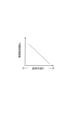
図8は、混雑度Cgdに応じた推定有効視野角θeの補正を説明する図である。図示のように、本実施形態では、混雑度Cgdが大きいほど推定有効視野角θeを小さくする。すなわち、混雑度Cgdが大きいほど、後方車両γの運転者Dγが受ける心理的ストレスが高くなって有効視野efvが狭くなると考えられるところ、この点を考慮して混雑度Cgdの大きさに応じて補正された推定有効視野角θeを演算する。 FIG. 8 is a diagram illustrating correction of the estimated effective viewing angle θ e according to the degree of congestion Cgd. As shown, in this embodiment, the estimated effective viewing angle θ e is reduced as the degree of congestion Cgd increases. That is, it is thought that the greater the degree of congestion Cgd, the greater the psychological stress that the driver Dγ of the following vehicle γ receives and the narrower the effective field of view efv. A corrected estimated effective viewing angle θ e is calculated.
以上説明した構成を有する本実施形態の車両運転支援方法によれば、以下の作用効果を奏する。 According to the vehicle driving support method of this embodiment having the configuration described above, the following effects are obtained.
本実施形態の車両運転支援方法は、後方車両γの前方における車両の混雑度合を示す混雑度Cgdを取得し(図7のステップS210)、混雑度Cgdが高いほど推定有効視野角θeを小さくする(図8)。 In the vehicle driving support method of the present embodiment, the degree of congestion Cgd indicating the degree of congestion of vehicles in front of the rear vehicle γ is obtained (step S210 in FIG. 7), and the higher the degree of congestion Cgd, the smaller the estimated effective viewing angle θ e . (Fig. 8).
すなわち、後方車両γの運転者Dγの前方における混雑度合が大きくなるほど、当該後方車両γの運転者Dγへの心理的負荷が大きくなり、有効視野efvが狭くなる傾向にある。このような傾向を考慮して、後方車両γの運転者Dγの前方の混雑度合を指標化した混雑度Cgdを取得して、当該混雑度Cgdが大きいほど推定有効視野角θeが小さくなるように演算する。これにより、後方車両γの前方における交通量が多いことで当該後方車両γの運転者Dγの有効視野efvが狭くなるシーンにおいて自車両αを横方向において後方車両γにより近づけるように車線変更待機位置P1が調節して、当該運転者Dγに自車両αを認識させる効果をより高めることができる。 That is, as the degree of congestion in front of the driver Dγ of the following vehicle γ increases, the psychological load on the driver Dγ of the following vehicle γ increases, and the effective field of view efv tends to narrow. In consideration of such a tendency, a congestion degree Cgd indexing the degree of congestion in front of the driver Dγ of the rear vehicle γ is acquired, and the estimated effective viewing angle θ e decreases as the congestion degree Cgd increases. Calculate to As a result, in a scene in which the effective field of view efv of the driver Dγ of the following vehicle γ is narrow due to a large amount of traffic in front of the following vehicle γ, the lane change standby position is set so that the own vehicle α can be brought closer to the following vehicle γ in the lateral direction. By adjusting P1, the effect of making the driver Dγ recognize the host vehicle α can be further enhanced.
(第3実施形態)
以下、第3実施形態について説明する。なお、第1実施形態又は第2実施形態と同様の要素には同一の符号を付し、その説明を省略する。本実施形態では、特に、後方車両γの運転者Dγに係る運転者状態情報に基づいて推定有効視野角θeを求める。
(Third embodiment)
A third embodiment will be described below. Elements similar to those of the first embodiment or the second embodiment are assigned the same reference numerals, and descriptions thereof are omitted. In the present embodiment, the estimated effective viewing angle θ e is calculated particularly based on the driver state information related to the driver Dγ of the rear vehicle γ.
図9は、本実施形態の車両運転支援方法を説明するフローチャートである。 FIG. 9 is a flowchart for explaining the vehicle driving support method of this embodiment.
図9に示すように、本実施形態の車両運転支援方法では、コントローラ20は、ステップS110とステップS120の間においてステップS310を実行する。そして、ステップS310において、コントローラ20は、運転者状態情報を取得する。
As shown in FIG. 9, in the vehicle driving assistance method of this embodiment, the
具体的に、コントローラ20は、車車間通信(V2V)などにより、後方車両γから当該後方車両γの運転者状態情報として、運転者Dγの運転技能及び運転者Dγに作用する運転負荷を取得する。
Specifically, the
ここで、運転者Dγの運転技能とは、後方車両γに搭載される情報機器類に予め入力されている運転者Dγの運転技能の高低を表す数値化指標(以下、「運転スキルレベル」とも称する)である。 Here, the driving skill of the driver Dγ is a quantified index (hereinafter also referred to as “driving skill level”) representing the level of the driving skill of the driver Dγ, which is input in advance into the information equipment installed in the rear vehicle γ. is called).
また、運転者Dγに作用する運転負荷とは、後方車両γに搭載される検出装置の検出値から推定可能な運転者Dγの心理的又は身体的負荷の高低を表す数値化指標(以下、単に「ワークロード」とも称する)である。例えば、ワークロードとしては、後方車両γのステアリングセンサの検出値に基づいて推定されるステアリングエントロピー(操舵動作の滑らかさ)が想定される。なお、ステアリングエントロピーはその値が低いほど操舵動作が滑らかであると判定するパラメータである。このため、ステアリングエントロピーを採用する場合には、ワークロードとしてステアリングエントロピーの逆数が設定される。 Further, the driving load acting on the driver Dγ is a numerical index representing the level of the psychological or physical load on the driver Dγ that can be estimated from the detection value of the detection device mounted on the rear vehicle γ (hereinafter simply referred to as (also referred to as “workload”). For example, the workload is assumed to be steering entropy (smoothness of steering operation) estimated based on the detected value of the steering sensor of the rear vehicle γ. Note that the steering entropy is a parameter that determines that the steering operation is smoother as the value of the steering entropy decreases. Therefore, when the steering entropy is adopted, the inverse of the steering entropy is set as the workload.
そして、コントローラ20は、ステップS130の有効視野推定処理において、ステップS310で取得した運転スキルレベル及びワークロードに基づいて推定有効視野角θeを補正する。
Then, in the effective visual field estimation process of step S130, the
図10は、運転スキルレベルに応じた推定有効視野角θeの補正について説明する図である。図示のように、本実施形態では、基準有効視野角θ0を運転スキルレベルが低いほど小さくなるように補正して推定有効視野角θeを求める。すなわち、運転スキルレベルが相対的に低い場合には、運転者Dγが運転操作に集中して視野が狭くなる傾向にある。本実施形態では、この点を考慮して、運転スキルレベルの高低に応じて補正された推定有効視野角θeを演算する。 FIG. 10 is a diagram explaining correction of the estimated effective viewing angle θ e according to the driving skill level. As shown, in this embodiment, the estimated effective viewing angle θe is obtained by correcting the reference effective viewing angle θ 0 so that it decreases as the driving skill level decreases. That is, when the driving skill level is relatively low, the driver Dγ tends to concentrate on the driving operation and have a narrow field of view. In this embodiment, in consideration of this point, the estimated effective viewing angle θ e corrected according to the driving skill level is calculated.
また、図11は、ワークロードに応じた推定有効視野角θeの補正について説明する図である。図示のように、本実施形態では、基準有効視野角θ0をワークロードが高いほど小さくなるように補正して推定有効視野角θeを求める。すなわち、ワークロードが相対的に高い場合には、運転者Dγの身体的又は精神的疲労が高く周辺への注意が散漫になり易く有効視野efvが狭くなる傾向にあると考えられる。本実施形態では、この点を考慮して、ワークロードの高低に応じて補正された推定有効視野角θeを演算する。 FIG. 11 is a diagram for explaining correction of the estimated effective viewing angle θ e according to workload. As shown, in this embodiment, the estimated effective viewing angle θe is obtained by correcting the reference effective viewing angle θ 0 so that it decreases as the workload increases. In other words, when the workload is relatively high, the driver Dγ is likely to be physically or mentally fatigued, and his/her attention to the surroundings tends to be distracted, which tends to narrow the effective field of view efv. In this embodiment, taking this point into account, the estimated effective viewing angle θ e corrected according to the level of the workload is calculated.
以上説明した構成を有する本実施形態の車両運転支援方法によれば、以下の作用効果を奏する。 According to the vehicle driving support method of this embodiment having the configuration described above, the following effects are obtained.
本実施形態の車両運転支援方法は、後方車両γの運転者Dγの運転技能(運転スキルレベル)又は該運転者Dγに作用する運転負荷(ワークロード)を含む運転者状態情報を取得し(図9のステップS310)、運転者状態情報に基づいて推定有効視野角θeを求める(図10及び図11)。 The vehicle driving support method of the present embodiment acquires driver state information including the driving skill (driving skill level) of the driver Dγ of the rear vehicle γ or the driving load (workload) acting on the driver Dγ (Fig. 9 step S310), the estimated effective viewing angle θ e is obtained based on the driver state information (FIGS. 10 and 11).
すなわち、後方車両γの運転者Dγの有効視野efvの広狭に影響を与える要素である運転技能又は運転負荷を含む運転者状態情報に基づいて推定有効視野角θeの大きさが適宜調節されることとなる。これにより、後方車両γの運転者Dγの状態に依る有効視野efvの広狭に応じた車線変更待機位置P1を調節して、当該運転者Dγに自車両αを認識させる効果をより高めることができる。 That is, the size of the estimated effective viewing angle θ e is appropriately adjusted based on driver state information including driving skill or driving load, which is an element that affects the width of the effective visual field efv of the driver Dγ of the rear vehicle γ. It will happen. As a result, the lane change standby position P1 can be adjusted according to the width of the effective visual field efv depending on the state of the driver Dγ of the rear vehicle γ, and the effect of making the driver Dγ recognize the own vehicle α can be further enhanced. .
(第4実施形態)
以下、第4実施形態について説明する。なお、上記第1~第3実施形態のいずれかと同様の要素には同一の符号を付し、その説明を省略する。本実施形態では、特に、隣接車線La2の道路態様を表す道路態様情報に基づいて車線変更待機位置P1を調節する例を説明する。
(Fourth embodiment)
A fourth embodiment will be described below. Elements similar to those in any one of the first to third embodiments are denoted by the same reference numerals, and description thereof will be omitted. In this embodiment, in particular, an example of adjusting the lane change standby position P1 based on road condition information representing the road condition of the adjacent lane La2 will be described.
図12は、本実施形態の車両運転支援方法を説明するフローチャートである。 FIG. 12 is a flowchart for explaining the vehicle driving support method of this embodiment.
図12に示すように、本実施形態の車両運転支援方法では、コントローラ20は、ステップS110とステップS120の間のステップS410において、隣接車線La2に係る道路態様情報を取得する。
As shown in FIG. 12, in the vehicle driving assistance method of the present embodiment, the
ここで、道路態様情報とは、隣接車線La2の道路形状(直線、カーブ、トンネル、及び路面状況など)、及び道路状況(雨、雪、若しくは晴れなどの天候又は日中、若しくは夜間などの時間帯など)を含む情報である。 Here, the road state information includes the road shape of the adjacent lane La2 (straight line, curve, tunnel, road surface condition, etc.) and road conditions (weather such as rain, snow, or fine weather, or time such as daytime or nighttime). band, etc.).
具体的に、コントローラ20は、外部センサ1の検出値、ナビゲーションシステム3から得られるナビゲーション情報、又はHDDマップから隣接車線La2の道路態様情報を取得する。
Specifically, the
そして、コントローラ20は、ステップS140の待機位置設定処理において、ステップS310で取得した道路態様情報に基づいて横移動距離Bαを補正する。以下、この横移動距離Bαの詳細について説明する。
Then, in the standby position setting process of step S140, the
先ず、コントローラ20は、道路態様情報に基づいて隣接車線La2における後方車両γの走行路がカーブであるか否かを判定する。例えば、コントローラ20は、道路態様情報から後方車両γの走行路の曲率半径Rが予め定められる一定値以上である場合、又はナビゲーション情報に含まれる地図情報から後方車両γの走行路がカーブであると特定できる場合に、当該走行路がカーブであると判断する。
First, the
さらに、コントローラ20は、後方車両γの走行路がカーブであると判断すると、後方車両γの走行する隣接車線La2が自車両αの走行車線La1に対してカーブの内側に位置するか否かを判定する。
Further, when the
そして、コントローラ20は、隣接車線La2が走行車線La1に対してカーブの内側に位置すると判断すると、後方車両γの走行路の曲率半径Rに基づいて横移動距離Bαを補正する。
Then, when the
図13は、曲率半径Rに応じた横移動距離Bαの補正について説明する図である。図示のように、本実施形態では、横移動距離Bαの基準値である基準横移動距離Bα0を、曲率半径Rが小さいほど大きくなるように補正して横移動距離Bαを定める。以下では、この曲率半径Rに基づいて横移動距離Bαの補正に関する技術的意義を説明する。 13A and 13B are diagrams for explaining correction of the lateral movement distance Bα according to the radius of curvature R. FIG. As shown in the figure, in the present embodiment, the reference lateral movement distance Bα0 , which is the reference value of the lateral movement distance Bα, is corrected such that the smaller the curvature radius R, the larger the lateral movement distance Bα. The technical significance of correcting the lateral movement distance Bα based on this radius of curvature R will be described below.
図14Aは、後方車両γがカーブである場合の運転者Dγの有効視野efvについて説明する図である。特に、図14Aにおいては、隣接車線La2が走行車線La1に対してカーブの外側に位置するシーンを想定している。 FIG. 14A is a diagram illustrating the effective field of view efv of the driver Dγ when the vehicle γ behind is curved. In particular, FIG. 14A assumes a scene in which the adjacent lane La2 is located outside the curve with respect to the driving lane La1.
後方車両γがカーブを走行している際には運転者Dγは自己の移動先であるカーブの先に視線を向ける傾向にある。すなわち、運転者Dγの前方注視点は、直線道路走行時において想定されていた軸線ax1に対して曲率半径Rの大きさに応じた角度分ずれた軸線ax2上に移ることとなる。このため、図14Aに示すように、後方車両γのカーブ走行時における運転者Dγの有効視野efvは、軸線ax1の延長線上に運転者Dγの前方注視点が存在するとした場合の有効視野efv(図14Aにおいて一点鎖線で示す)に比べ、全体としてカーブの内側にオフセットすることとなる。 When the vehicle γ behind the vehicle γ is traveling on a curve, the driver Dγ tends to direct his or her line of sight to the destination of the curve. That is, the driver's Dγ forward gaze point shifts to the axis ax2, which is shifted by an angle corresponding to the radius of curvature R from the axis ax1 that was assumed when the vehicle was traveling on a straight road. Therefore, as shown in FIG. 14A, the effective visual field efv of the driver Dγ when the backward vehicle γ is traveling on a curve is the effective visual field efv ( 14A), the offset is to the inside of the curve as a whole.
ここで、図14Aに示すように、隣接車線La2が走行車線La1に対してカーブの内側に位置することで、後方車両γが自車両αに対してカーブの外側を走行している場合には、カーブの内側にオフセットしても有効視野efv内に車線変更待機位置P1での自車両αが入る状態が維持される。このため、有効視野efvのオフセットを考慮したとしても、横移動距離Bαの補正を実行せずに車線変更待機位置P1を維持することができる。 Here, as shown in FIG. 14A, when the adjacent lane La2 is located inside the curve with respect to the traveling lane La1, the following vehicle γ is traveling outside the curve with respect to the own vehicle α. , the vehicle α at the lane change standby position P1 is kept within the effective visual field efv even if the vehicle is offset to the inside of the curve. Therefore, even if the offset of the effective field of view efv is considered, the lane change waiting position P1 can be maintained without correcting the lateral movement distance Bα.
一方、図14Bには、後方車両γがカーブの内側を走行している場合の車線変更待機位置P1の設定について説明する。図14Bに示すように後方車両γがカーブの内側を走行している場合には、上述のように運転者Dγの有効視野efvがカーブの内側にオフセットすると、有効視野efvから補正前の車線変更待機位置P1で走行している自車両α(図14Bに破線で示す)が外れることとなる。 On the other hand, FIG. 14B describes the setting of the lane change standby position P1 when the rear vehicle γ is traveling on the inside of the curve. As shown in FIG. 14B, when the rear vehicle γ is traveling on the inside of the curve, if the effective visual field efv of the driver Dγ is offset to the inside of the curve as described above, the lane change before correction from the effective visual field efv The own vehicle α (indicated by the dashed line in FIG. 14B) running at the standby position P1 is detached.
したがって、本実施形態では、このようなシーンを考慮し、後方車両γの走行路がカーブであって後方車両γが自車両αに対してカーブの内側を走行する場合には、当該カーブの曲率半径Rが小さいほど横移動距離Bαを大きくする。すなわち、図14Bに示すように、カーブの急さに応じて自車両αが横方向においてより後方車両γに近づくように車線変更待機位置P1を調節する。 Therefore, in this embodiment, considering such a scene, when the traveling road of the following vehicle γ is a curve and the following vehicle γ is traveling on the inside of the curve with respect to the own vehicle α, the curvature of the curve The smaller the radius R, the larger the lateral movement distance Bα. That is, as shown in FIG. 14B, the lane change standby position P1 is adjusted according to the steepness of the curve so that the own vehicle α approaches the rear vehicle γ in the lateral direction.
以上説明した構成を有する本実施形態の車両運転支援方法によれば、以下の作用効果を奏する。 According to the vehicle driving support method of this embodiment having the configuration described above, the following effects are obtained.
本実施形態の車両運転支援方法は、隣接車線La2の道路態様を表す道路態様情報を取得する(図12のステップS410)。そして、待機位置設定処理(ステップS140)では、道路態様情報に基づいて隣接車線La2における後方車両γの走行路がカーブであるか否かを判定し、該判定の結果が肯定的であって且つ隣接車線La2が走行車線La1に対してカーブの内側に位置する場合には、隣接車線La2における後方車両γの走行路の曲率半径Rが小さいほど横移動距離Bαを大きくする(図13及び図14B)。 The vehicle driving assistance method of the present embodiment acquires road condition information representing the road condition of the adjacent lane La2 (step S410 in FIG. 12). Then, in the standby position setting process (step S140), it is determined whether or not the traveling road of the following vehicle γ in the adjacent lane La2 is curved based on the road condition information. When the adjacent lane La2 is located inside the curve with respect to the driving lane La1, the smaller the radius of curvature R of the travel path of the following vehicle γ in the adjacent lane La2, the larger the lateral movement distance Bα (FIGS. 13 and 14B). ).
すなわち、後方車両γの運転者Dγの有効視野efvがカーブの内側にオフセットして、当該有効視野efvから車線変更待機位置P1で走行している自車両αが外れ得るシーンにおいて、自車両αの車線変更待機位置P1を後方車両γにより近づけるように車線変更待機位置P1を調節する。 That is, in a scene in which the effective visual field efv of the driver Dγ of the rear vehicle γ is offset to the inside of the curve, and the own vehicle α traveling at the lane change waiting position P1 may deviate from the effective visual field efv, The lane change standby position P1 is adjusted so that the lane change standby position P1 is closer to the rear vehicle γ.
これにより、後方車両γが自車両αに対してカーブの内側を走行するシーンにおいて、より確実に、車線変更待機位置P1で待機する自車両αを後方車両γの運転者Dγの有効視野efvに入れることができ、当該運転者Dγに自車両αを認識させる効果をより高めることができる。 As a result, in a scene where the following vehicle γ is traveling on the inside of the curve with respect to the own vehicle α, the own vehicle α waiting at the lane change waiting position P1 is more reliably placed in the effective visual field efv of the driver Dγ of the following vehicle γ. It is possible to increase the effect of making the driver Dγ recognize the own vehicle α.
(第5実施形態)
以下、第5実施形態について説明する。なお、上記第1~第4実施形態のいずれかと同様の要素には同一の符号を付し、その説明を省略する。本実施形態では、特に、隣接車線La2の道路態様を表す道路態様情報に基づいて推定有効視野角θeの補正を実行する例を説明する。
(Fifth embodiment)
The fifth embodiment will be described below. Elements similar to those in any one of the first to fourth embodiments are denoted by the same reference numerals, and description thereof will be omitted. In this embodiment, in particular, an example will be described in which the estimated effective viewing angle θ e is corrected based on road condition information representing the road condition of the adjacent lane La2.
先ず、本実施形態のコントローラ20は、第4実施形態と同様に、道路態様情報に基づいて隣接車線La2における後方車両γの走行路がカーブであるか否かを判定する。
First, as in the fourth embodiment, the
そして、この判定結果が肯定的である場合に、コントローラ20は有効視野推定処理において後方車両γの走行路の曲率半径Rに基づいて推定有効視野角θeを補正する。
Then, when the determination result is affirmative, the
図15は、曲率半径Rに応じた推定有効視野角θeの補正について説明する図である。図示のように、本実施形態では、上記基準有効視野角θ0を、曲率半径Rが小さいほど小さくなるように補正して推定有効視野角θeを求める。 FIG. 15 is a diagram illustrating correction of the estimated effective viewing angle θ e according to the radius of curvature R. FIG. As shown, in this embodiment, the estimated effective viewing angle θe is obtained by correcting the reference effective viewing angle θ 0 so that it decreases as the radius of curvature R decreases.
すなわち、本実施形態では、後方車両γの走行路のカーブが急であるほど後方車両γの運転者Dγに生じる心理的負担が高く、当該心理的負担に起因して運転者Dγの有効視野efvが狭まることを考慮し、基準有効視野角θ0を補正して推定有効視野角θeを求める。 That is, in the present embodiment, the steeper the curve of the traveling road of the rear vehicle γ, the higher the psychological burden on the driver Dγ of the rear vehicle γ. is narrowed, the reference effective viewing angle θ 0 is corrected to obtain the estimated effective viewing angle θ e .
以上説明した構成を有する本実施形態の車両運転支援方法によれば、以下の作用効果を奏する。 According to the vehicle driving support method of this embodiment having the configuration described above, the following effects are obtained.
本実施形態の車両運転支援方法は、隣接車線La2の道路態様を表す道路態様情報を取得する(ステップS410)。そして、有効視野推定処理(ステップS130)では、道路態様情報に基づいて隣接車線La2における後方車両γの走行路がカーブであるか否かを判定し、該判定の結果が肯定的であって且つ隣接車線La2が走行車線La1に対してカーブの内側に位置する場合には、隣接車線La2における後方車両γの走行路の曲率半径Rが小さいほど推定有効視野角θeを小さくする(図15)。 The vehicle driving assistance method of the present embodiment acquires road condition information representing the road condition of the adjacent lane La2 (step S410). Then, in the effective field of view estimation process (step S130), it is determined based on the road condition information whether or not the traveling road of the following vehicle γ in the adjacent lane La2 is curved. When the adjacent lane La2 is located on the inside of the curve with respect to the driving lane La1, the smaller the radius of curvature R of the travel path of the following vehicle γ in the adjacent lane La2, the smaller the estimated effective viewing angle θ e (FIG. 15). .
すなわち、後方車両γの運転者Dγの有効視野efvがカーブの内側にオフセットして、当該有効視野efvから車線変更待機位置P1で走行している自車両αが外れ得るシーンにおいて、自車両αの車線変更待機位置P1を後方車両γにより近づけるように車線変更待機位置P1を調節する。 That is, in a scene in which the effective visual field efv of the driver Dγ of the rear vehicle γ is offset to the inside of the curve, and the own vehicle α traveling at the lane change waiting position P1 may deviate from the effective visual field efv, The lane change standby position P1 is adjusted so that the lane change standby position P1 is closer to the rear vehicle γ.
これにより、後方車両γが自車両αに対してカーブの内側を走行するシーンにおいて、より確実に、車線変更待機位置P1で待機する自車両αを後方車両γの運転者Dγの有効視野efvに入れることができ、当該運転者Dγに自車両αを認識させる効果をより高めることができる。 As a result, in a scene where the following vehicle γ is traveling on the inside of the curve with respect to the own vehicle α, the own vehicle α waiting at the lane change waiting position P1 is more reliably placed in the effective visual field efv of the driver Dγ of the following vehicle γ. It is possible to increase the effect of making the driver Dγ recognize the own vehicle α.
(第6実施形態)
以下、第6実施形態について説明する。なお、上記第1~第5実施形態のいずれかと同様の要素には同一の符号を付し、その説明を省略する。
(Sixth embodiment)
The sixth embodiment will be described below. Elements similar to those in any one of the first to fifth embodiments are denoted by the same reference numerals, and descriptions thereof are omitted.
本実施形態では、ステップS140における待機位置設定処理において、後方車両γの運転者Dγに与えるリスク感を表すリスクパラメータPrを定め、当該リスクパラメータPr及び後方車両車速Vγから横移動距離Bαを設定する。 In this embodiment, in the standby position setting process in step S140, a risk parameter Pr representing a sense of risk given to the driver Dγ of the rear vehicle γ is determined, and the lateral movement distance Bα is set from the risk parameter Pr and the vehicle speed Vγ of the rear vehicle. .
ここで、リスクパラメータPrとは、後方車両γの運転者Dγに対して自車両αとの接触の可能性など、自車両αが後方車両γに近づくことにより運転者Dγに不安を与える可能性の高さを数値化したものである。 Here, the risk parameter Pr refers to the possibility that the driver Dγ of the following vehicle γ will be intimidated by the vehicle α approaching the following vehicle γ, such as the possibility of the driver Dγ coming into contact with the own vehicle α. It is a numerical representation of the height of
特に、本実施形態のリスクパラメータPrは、後方車両車速Vγから車線変更待機位置P1の自車両αと後方車両γの間の横方向離間距離ΔBαγを除して必要に応じて適切な補正係数を乗じた値として定義する。すなわち、リスクパラメータPrは、横方向離間距離ΔBαγが小さいほど(車線変更待機位置P1が後方車両γに近いほど)、又は後方車両車速Vγが高いほど大きい値として演算される。 In particular, the risk parameter Pr of the present embodiment is obtained by dividing the lateral separation distance ΔBαγ between the own vehicle α and the rear vehicle γ at the lane change standby position P1 from the vehicle speed Vγ of the rear vehicle, thereby obtaining an appropriate correction coefficient as necessary. Defined as a multiplied value. That is, the risk parameter Pr is calculated as a larger value as the lateral separation distance ΔBαγ is smaller (the lane change waiting position P1 is closer to the rear vehicle γ) or as the rear vehicle speed Vγ is higher.
なお、本実施形態では説明の簡略化のため、自車両αと後方車両γの間の前後方向離間距離を考慮しないリスクパラメータPrを用いる例を説明する。しかしながら、適宜、当該前後方向離間距離を考慮してリスクパラメータPrを設定しても良い。 In this embodiment, for the sake of simplification of explanation, an example will be explained in which the risk parameter Pr is used without considering the distance between the own vehicle α and the following vehicle γ in the front-rear direction. However, the risk parameter Pr may be set in consideration of the distance in the longitudinal direction as appropriate.
そして、コントローラ20は、予め定められたリスクパラメータPrの値として許容される上限値(以下、「リスク上限Prup」とも称する)を用いて、後方車両車速Vγから適切な自車両αの横移動距離Bαを定める。
Then, the
図16には、本実施形態における横移動距離Bαを定めるためのマップの一例を示す。 FIG. 16 shows an example of a map for determining the lateral movement distance Bα in this embodiment.
図16における直線CPrは、リスクパラメータPrのリスク上限Prupを表す。すなわち、直線CPr以下の領域は、リスクパラメータPrがリスク上限Prup以下となるところ、後方車両γの運転者Dγに不安を与えるリスクが許容できる程度と言える。 A straight line C Pr in FIG. 16 represents the risk upper limit Prup of the risk parameter Pr. That is, in the region below the straight line C Pr , the risk parameter Pr is below the upper risk limit Prup, and it can be said that the risk of giving anxiety to the driver Dγ of the rear vehicle γ is tolerable.
また、曲線Cθは、車線変更待機位置P1の自車両αが後方車両γの運転者Dγの有効視野efvに入る自車両αと後方車両γの横方向離間距離ΔBαγの上限を定める。すなわち、曲線Cθ以下の領域では、車線変更待機位置P1の自車両αが後方車両γの運転者Dγの有効視野efvに入るところ、後方車両γの運転者Dγにより自車両αが認識可能な領域と言える。特に、横方向離間距離ΔBαγが曲線Cθに比べて小さいほど、後方車両γの運転者Dγによる自車両αに対する認識の可能性が高くなる。 Further, the curve Cθ defines the upper limit of the lateral separation distance ΔBαγ between the vehicle α and the vehicle behind γ at which the vehicle α at the lane change waiting position P1 enters the effective visual field efv of the driver Dγ of the vehicle behind γ. That is, in the area below the curve Cθ, the own vehicle α at the lane change waiting position P1 enters the effective visual field efv of the driver Dγ of the following vehicle γ, and the area where the own vehicle α can be recognized by the driver Dγ of the following vehicle γ. I can say. In particular, the smaller the lateral distance ΔBαγ is compared to the curve Cθ, the higher the possibility that the driver Dγ of the following vehicle γ will recognize the host vehicle α.
ここで、後方車両γの運転者Dγに車線変更待機位置P1の自車両αをより確実に認識させる観点で言えば、曲線Cθに対して横方向離間距離ΔBαγを小さくするほど(車線変更待機位置P1を後方車両γに近くするほど)好ましい。一方で、後方車両γの運転者Dγに不安を与えるリスクを考慮して自車両αを後方車両γに過度に近づけないようにする観点から、横方向離間距離ΔBαγを直線CPr以下とすることが好ましい。
ことが望ましい。
Here, from the viewpoint of making the driver Dγ of the following vehicle γ recognize the host vehicle α at the lane change standby position P1 more reliably, the smaller the lateral separation distance ΔBαγ with respect to the curve Cθ (the lane change standby position The closer P1 is to the rear vehicle γ), the better. On the other hand, considering the risk of giving anxiety to the driver Dγ of the rear vehicle γ, the lateral separation distance ΔBαγ is set to be equal to or less than the straight line C Pr from the viewpoint of preventing the own vehicle α from approaching the rear vehicle γ excessively. is preferred.
is desirable.
したがって、本実施形態では、上記2つの観点のバランスを考慮し、コントローラ20が曲線Cθ以下且つ直線CPr以下の領域内(図16においてハッチングで示す領域内)において横方向離間距離ΔBαγを定める。
Therefore, in the present embodiment, considering the balance between the above two points of view, the
さらに、コントローラ20は、このように求めた横方向離間距離ΔBαγから、自車両αの初期位置である通常走行位置P0及びその他の車幅等の要素を適宜考慮して、自車両αの横移動距離Bαを演算する。
Further, the
以上説明した構成を有する本実施形態の車両運転支援方法によれば、以下の作用効果を奏する。 According to the vehicle driving support method of this embodiment having the configuration described above, the following effects are obtained.
本実施形態の車両運転支援方法において、待機位置設定処理(ステップS140)では、横移動距離Bα及び後方車両車速Vγに基づいて後方車両γの運転者Dγに与えるリスク感の数値指標であるリスクパラメータPrを演算する。そして、車線変更待機位置P1に位置する自車両αが後方車両γの運転者Dγの有効視野efv内に入り、且つリスクパラメータPrが所定の上限値であるリスク上限Prup以下となるように横移動距離Bαを定める(図16)。 In the vehicle driving support method of the present embodiment, in the standby position setting process (step S140), a risk parameter, which is a numerical index of the sense of risk given to the driver Dγ of the rear vehicle γ, is based on the lateral movement distance Bα and the vehicle speed Vγ of the rear vehicle. Compute Pr. Then, the host vehicle α located at the lane change waiting position P1 enters the effective field of view efv of the driver Dγ of the rear vehicle γ, and moves laterally so that the risk parameter Pr is equal to or lower than the upper risk limit Prup, which is a predetermined upper limit value. Determine the distance Bα (FIG. 16).
これにより、後方車両γの運転者Dγに与える不安を軽減しつつ、自車両αを当該運転者Dγに認識させ得る車線変更待機位置P1を設定することができる。 As a result, it is possible to set the lane change standby position P1 at which the driver Dγ of the following vehicle γ can recognize the own vehicle α while reducing the anxiety given to the driver Dγ.
なお、リスクパラメータPrの具体的な設定方法は本実施形態で説明した態様に限られない。すなわち、リスクパラメータPrは、自車両αが後方車両γに近づくことにより運転者Dγに不安を与える可能性の高さの定量化という機能を果たす量ならば、他の種々のパラメータ(THW又はTTCなど)を用いて定義されても良い。 Note that the specific method of setting the risk parameter Pr is not limited to the mode described in this embodiment. That is, if the risk parameter Pr is an amount that quantifies the degree of possibility that the vehicle α approaches the rear vehicle γ and gives anxiety to the driver Dγ, then other various parameters (THW or TTC etc.) may be defined using
(第7実施形態)
以下、第7実施形態について説明する。なお、上記第1~第6実施形態のいずれかと同様の要素には同一の符号を付し、その説明を省略する。
(Seventh embodiment)
The seventh embodiment will be described below. Elements similar to those in any one of the first to sixth embodiments are denoted by the same reference numerals, and description thereof will be omitted.
本実施形態において、コントローラ20は、待機位置設定処理(ステップS140)において、自車両αの前後移動が横移動に対して優先されるように車線変更待機位置P1を設定する。
In the present embodiment, the
図17は、本実施形態の車線変更待機位置P1の設定について説明する図である。既に説明したように、後方車両γの運転者Dγの有効視野efvは当該後方車両γの前方に略扇形状に広がる。このため、図17に示すように、自車両αの通常走行位置P0から前後移動のみで当該自車両αを運転者Dγの有効視野efvに入るようにすることのできるシーンが想定される。 FIG. 17 is a diagram illustrating setting of the lane change waiting position P1 according to the present embodiment. As already explained, the effective field of view efv of the driver Dγ of the rear vehicle γ extends in a substantially fan shape in front of the rear vehicle γ. Therefore, as shown in FIG. 17, a scene is assumed in which the own vehicle α can be brought into the effective visual field efv of the driver Dγ only by moving the own vehicle α back and forth from the normal running position P0.
このようなシーンを想定して、本実施形態では、コントローラ20は、先ず、ステップS130で推定した推定有効視野角θeに基づいて、自車両αが後方車両γの運転者Dγの有効視野efvに入るまでの通常走行位置P0からの前後移動距離Lαを求める。そして、当該前後移動距離Lαに相当する走行位置を車線変更待機位置P1として設定する。
Assuming such a scene, in the present embodiment, first, based on the estimated effective viewing angle θ e estimated in step S130, the
なお、コントローラ20は、自車両αの前後移動のみの前提とした車線変更待機位置P1の設定が適切ではないと判断した場合には、適宜、自車両αの横移動距離Bαも設定した上で車線変更待機位置P1を設定する。
If the
自車両αの前後移動のみの前提とした車線変更待機位置P1の設定が適切ではない場合とは、例えば、自車両αの前後移動のみでは推定有効視野角θeに基づく有効視野efvに入らない場合、又は隣接車線La2における前方車両βと後方車両γの車間が狭いため後の車線変更動作を適切に行う観点から上記前後移動距離Lαの大きさに制限をかける必要がある場合である。 A case in which the setting of the lane change standby position P1 based on only the forward and backward movement of the own vehicle α is not appropriate is, for example, when only the forward and backward movement of the own vehicle α does not enter the effective visual field efv based on the estimated effective visual field angle θ e . , or when the distance between the forward vehicle β and the rearward vehicle γ in the adjacent lane La2 is narrow, and it is necessary to limit the size of the longitudinal movement distance Lα from the viewpoint of appropriately performing the subsequent lane change operation.
以上説明した構成を有する本実施形態の車両運転支援方法によれば、以下の作用効果を奏する。 According to the vehicle driving support method of this embodiment having the configuration described above, the following effects are obtained.
本実施形態の車両運転支援方法において、待機位置設定処理(ステップS140)では、自車両αの前後移動が横移動に対して優先されるように車線変更待機位置P1を設定する。 In the vehicle driving support method of the present embodiment, in the standby position setting process (step S140), the lane change standby position P1 is set such that the longitudinal movement of the vehicle α has priority over the lateral movement.
これにより、自車両αが後方車両γに横方向において近づかずに運転者Dγの有効視野efvに入る車線変更待機位置P1が設定されることとなる。すなわち、自車両αを隣接車線La2に寄せることなく、当該自車両αを後方車両γの運転者Dγに認識させる効果を発揮することができる。 As a result, the lane change standby position P1 is set such that the own vehicle α does not approach the rear vehicle γ in the lateral direction and is within the effective visual field efv of the driver Dγ. That is, the effect of making the driver Dγ of the following vehicle γ recognize the own vehicle α can be exhibited without causing the own vehicle α to pull over to the adjacent lane La2.
特に、走行車線La1及び隣接車線La2の交通量が比較的少ないシーンなどにおいては、自車両αの前後移動を優先して車線変更待機位置P1を設定することで、走行車線La1上において運転者Dγの有効視野efvに入る観点から十分な前後方向スペースが確保されているにもかかわらず、待機処理(ステップS160)中に自車両αが後方車両γに比較的近い位置で待機するという事態の発生を回避することができる。 In particular, in a scene where the traffic volume of the driving lane La1 and the adjacent lane La2 is relatively small, priority is given to the forward and backward movement of the own vehicle α, and the lane change waiting position P1 is set so that the driver Dγ In spite of the fact that sufficient space is secured in the longitudinal direction from the viewpoint of entering the effective field of view efv of , the vehicle α waits at a position relatively close to the rear vehicle γ during the standby process (step S160). can be avoided.
以上、本発明の実施形態について説明したが、上記各実施形態及び各変形例は本発明の適用例の一部を示したに過ぎず、本発明の技術的範囲を上記実施形態の具体的構成に限定する趣旨ではない。 Although the embodiments of the present invention have been described above, the above-described embodiments and modifications merely show a part of the application examples of the present invention, and the technical scope of the present invention is limited to the specific configurations of the above-described embodiments. It is not intended to be limited to
例えば、上記各実施形態では、方向指示表示を待機処理(ステップS160)に実行する例を説明した。しかしながら、方向指示表示をステップS100で車線変更要求があると判断された以降であって、待機処理の前の任意のタイミングで実行する構成を採用しても良い。 For example, in each of the above-described embodiments, an example in which the direction instruction display is performed during the standby process (step S160) has been described. However, it is also possible to adopt a configuration in which the direction indication display is performed at an arbitrary timing after it is determined in step S100 that there is a lane change request and before the standby process.
さらに、上記各実施形態における車両運転支援方法におけるコントローラ20は、一台のコンピュータで構成しても良いし、当該車両運転支援方法の各工程を分散処理する複数台のコンピュータで構成しても良い。さらに、上記各実施形態では、コントローラ20の機能を自車両αに搭載されるECUで実現する例を説明した。しかしながら、コントローラ20は、自車両αに搭載されるECU以外の任意の制御装置で実現することができる。さらに、上記各実施形態における車両運転支援方法の各工程を実行するコントローラ20の機能の少なくとも一部を、自車両α内の制御装置と通信する外部の任意のコンピュータで実行しても良い。
Furthermore, the
また、上記各実施形態は、矛盾を生じない範囲の任意の組み合わせで相互に組み合わせることが可能である。例えば、第1実施形態の後方車両車速Vγに応じて設定された推定有効視野角θeを基準有効視野角θ0として他の実施形態における混雑度Cgd、運転スキルレベル、ワークロード、及び曲率半径Rの少なくとも一つによる補正を適用しても良い。また、第1~第5実施形態と第6実施形態における横移動距離Bαの設定を組み合わせても良い。 Moreover, the above-described embodiments can be combined with each other in arbitrary combinations within a range that does not cause contradiction. For example, with the estimated effective viewing angle θ e set according to the vehicle speed Vγ of the rear vehicle in the first embodiment as the reference effective viewing angle θ 0 , the degree of congestion Cgd, the driving skill level, the workload, and the radius of curvature in the other embodiments A correction by at least one of R may be applied. Also, the setting of the lateral movement distance Bα in the first to fifth embodiments and the sixth embodiment may be combined.
なお、上記各実施形態で説明した車両運転支援方法をコンピュータであるコントローラ20に実行させるための車両走行制御プログラム、及び当該車両走行制御プログラムを記憶した記憶媒体も、本出願における出願時の明細書等に記載された事項の範囲内に含まれる。
The vehicle driving control program for causing the
1 外部センサ
1a 車載カメラ
1b レーダー
2 内部センサ
3 ナビゲーションシステム
4 アクチュエータ
4a 駆動アクチュエータ
4b ブレーキアクチュエータ
4c ステアリングアクチュエータ
10 車両運転支援システム
20 コントローラ
REFERENCE SIGNS
Claims (11)
前記隣接車線における目標車線変更位置を設定し、
前記目標車線変更位置を設定すると、該目標車線変更位置に後方で隣接して走行する後方車両の運転者の有効視野を規定する有効視野角の推定値として推定有効視野角を求める有効視野推定処理を実行し、
前記推定有効視野角に基づいて前記自車両が前記後方車両の運転者の有効視野内に入る車線変更待機位置を設定する待機位置設定処理を実行し、
前記自車両を前記車線変更待機位置まで移動させる移動処理を実行し、
前記自車両を前記車線変更待機位置に待機させる待機処理を実行し、
前記待機処理の完了後に前記車線変更動作を実行する、
車両運転支援方法。 A vehicle driving support method for executing a lane change operation for moving the own vehicle from a driving lane to an adjacent lane,
setting a target lane change position in the adjacent lane;
When the target lane change position is set, an effective field of view estimation process for obtaining an estimated effective field of view angle as an estimated value of the effective field of view defining the effective field of view of the driver of the vehicle behind the vehicle traveling behind and adjacent to the target lane change position. and run
executing standby position setting processing for setting a lane change standby position where the own vehicle is within the effective visual field of the driver of the vehicle behind the vehicle based on the estimated effective viewing angle;
executing movement processing for moving the host vehicle to the lane change waiting position;
executing standby processing for causing the host vehicle to wait at the lane change standby position;
Performing the lane change operation after completion of the waiting process;
Vehicle driving assistance method.
前記待機処理中に、前記車線変更待機位置において前記自車両の方向指示器による方向指示表示を実行する、
車両運転支援方法。 The vehicle driving assistance method according to claim 1,
During the standby process, performing direction indication display by the direction indicator of the host vehicle at the lane change standby position;
Vehicle driving support method.
前記待機位置設定処理では、前記推定有効視野角が小さいほど前記自車両の横移動距離が大きくなるように前記車線変更待機位置を設定する、
車両運転支援方法。 The vehicle driving support method according to claim 1 or 2,
In the standby position setting process, the lane change standby position is set such that the smaller the estimated effective viewing angle, the greater the lateral movement distance of the vehicle.
Vehicle driving support method.
前記後方車両の車速を取得し、
前記有効視野推定処理では、前記後方車両の車速が大きいほど前記推定有効視野角を小さくする、
車両運転支援方法。 The vehicle driving assistance method according to claim 2,
obtaining the vehicle speed of the rear vehicle;
In the effective field of view estimation process, the estimated effective field of view angle is reduced as the vehicle speed of the vehicle behind increases.
Vehicle driving support method.
前記後方車両の前方における車両の混雑度合を示す混雑度を取得し、
前記有効視野推定処理では、前記混雑度が高いほど前記推定有効視野角を小さくする、
車両運転支援方法。 The vehicle driving support method according to any one of claims 1 to 4,
Acquiring a degree of congestion indicating the degree of congestion of vehicles in front of the rear vehicle,
In the effective field of view estimation process, the estimated effective field of view angle is made smaller as the degree of congestion is higher.
Vehicle driving support method.
前記後方車両の運転者の運転技能又は該運転者に作用する運転負荷を含む運転者状態情報を取得し、
前記有効視野推定処理では、前記運転者状態情報に基づいて前記推定有効視野角を求める、
車両運転支援方法。 The vehicle driving support method according to any one of claims 1 to 5,
Acquiring driver state information including the driving skill of the driver of the rear vehicle or the driving load acting on the driver;
In the effective visual field estimation process, the estimated effective visual field angle is obtained based on the driver state information;
Vehicle driving support method.
前記隣接車線の道路態様を表す道路態様情報を取得し、
前記道路態様情報に基づいて前記後方車両の前方における前記隣接車線がカーブであるか否かを判定し、
該判定の結果が肯定的であって且つ前記隣接車線が前記走行車線に対して前記カーブの内側に位置する場合には、
前記待機位置設定処理において、前記隣接車線における前記後方車両の走行路の曲率半径が小さいほど前記自車両の横移動距離を大きくする、
車両運転支援方法。 The vehicle driving support method according to any one of claims 1 to 6,
Acquiring road condition information representing the road condition of the adjacent lane;
determining whether the adjacent lane in front of the vehicle behind is a curve based on the road condition information;
If the result of the determination is affirmative and the adjacent lane is located inside the curve with respect to the driving lane,
In the standby position setting process, the lateral movement distance of the own vehicle is increased as the radius of curvature of the travel path of the following vehicle in the adjacent lane is smaller.
Vehicle driving assistance method.
前記隣接車線の道路態様を表す道路態様情報を取得し、
前記道路態様情報に基づいて前記後方車両の前方における前記隣接車線がカーブであるか否かを判定し、
該判定の結果が肯定的である場合には、前記有効視野推定処理において、前記隣接車線における前記後方車両の走行路の曲率半径が小さいほど前記推定有効視野角を小さくする、
車両運転支援方法。 The vehicle driving support method according to any one of claims 1 to 7,
Acquiring road condition information representing the road condition of the adjacent lane;
determining whether the adjacent lane in front of the vehicle behind is a curve based on the road condition information;
If the result of the determination is affirmative, in the effective field of view estimation process, the estimated effective field of view angle is reduced as the radius of curvature of the roadway of the vehicle behind in the adjacent lane is smaller.
Vehicle driving assistance method.
前記待機位置設定処理では、
前記自車両の横移動距離及び前記後方車両の車速に基づいて該後方車両の運転者に与えるリスク感の数値指標であるリスクパラメータを演算し、
前記車線変更待機位置に位置する前記自車両が前記後方車両の運転者の有効視野内に入り、且つ前記リスクパラメータが所定の上限値以下となるように前記自車両の横移動距離を定める、
車両運転支援方法。 The vehicle driving support method according to any one of claims 1 to 8,
In the standby position setting process,
calculating a risk parameter, which is a numerical index of the sense of risk given to the driver of the rear vehicle, based on the lateral movement distance of the own vehicle and the vehicle speed of the rear vehicle;
determining the lateral movement distance of the own vehicle so that the own vehicle positioned in the lane change standby position is within the effective field of view of the driver of the rear vehicle and the risk parameter is equal to or less than a predetermined upper limit;
Vehicle driving assistance method.
前記待機位置設定処理では、
前記自車両の前後移動が横移動に対して優先されるように前記車線変更待機位置を設定する、
車両運転支援方法。 The vehicle driving support method according to any one of claims 1 to 9,
In the standby position setting process,
setting the lane change waiting position so that forward and backward movement of the own vehicle has priority over lateral movement;
Vehicle driving support method.
前記制御装置は、
前記隣接車線における目標車線変更位置を設定する目標車線変更位置設定部と、
前記目標車線変更位置が設定されると、該目標車線変更位置に後方で隣接して走行する後方車両の運転者の有効視野を規定する有効視野角の推定値として推定有効視野角を求める有効視野算出部と、
前記推定有効視野角に基づいて前記自車両が前記後方車両の運転者の有効視野内に入る車線変更待機位置を設定する車線変更待機位置設定部と、
前記自車両を前記車線変更待機位置まで移動させる移動処理を実行する移動処理部と、
前記自車両を前記車線変更待機位置に待機させる待機処理を実行する待機処理部と、
前記待機処理の完了後に前記車線変更動作を実行する車線変更動作実行部と、を備える、
車両運転支援システム。 A vehicle driving support system having a control device that executes a lane change operation for moving the own vehicle from a driving lane to an adjacent lane,
The control device is
a target lane change position setting unit that sets a target lane change position in the adjacent lane;
When the target lane change position is set, the effective field of view is obtained as an estimated value of the effective field of view defining the effective field of view of the driver of the vehicle behind the vehicle traveling adjacent to the target lane change position. a calculation unit;
a lane change standby position setting unit that sets a lane change standby position where the own vehicle is within the effective field of view of the driver of the rear vehicle based on the estimated effective viewing angle;
a movement processing unit that executes movement processing for moving the own vehicle to the lane change standby position;
A standby processing unit that executes standby processing for causing the host vehicle to wait at the lane change standby position;
A lane change operation execution unit that executes the lane change operation after the completion of the standby process,
Vehicle driving assistance system.
Priority Applications (1)
| Application Number | Priority Date | Filing Date | Title |
|---|---|---|---|
| JP2019162309A JP7269846B2 (en) | 2019-09-05 | 2019-09-05 | Vehicle driving support method and vehicle driving support system |
Applications Claiming Priority (1)
| Application Number | Priority Date | Filing Date | Title |
|---|---|---|---|
| JP2019162309A JP7269846B2 (en) | 2019-09-05 | 2019-09-05 | Vehicle driving support method and vehicle driving support system |
Publications (2)
| Publication Number | Publication Date |
|---|---|
| JP2021039690A JP2021039690A (en) | 2021-03-11 |
| JP7269846B2 true JP7269846B2 (en) | 2023-05-09 |
Family
ID=74847161
Family Applications (1)
| Application Number | Title | Priority Date | Filing Date |
|---|---|---|---|
| JP2019162309A Active JP7269846B2 (en) | 2019-09-05 | 2019-09-05 | Vehicle driving support method and vehicle driving support system |
Country Status (1)
| Country | Link |
|---|---|
| JP (1) | JP7269846B2 (en) |
Families Citing this family (1)
| Publication number | Priority date | Publication date | Assignee | Title |
|---|---|---|---|---|
| JP7307660B2 (en) | 2019-10-24 | 2023-07-12 | 日産自動車株式会社 | Driving support method and driving support device |
Citations (6)
| Publication number | Priority date | Publication date | Assignee | Title |
|---|---|---|---|---|
| JP2010203886A (en) | 2009-03-03 | 2010-09-16 | Alpine Electronics Inc | Vehicle traveling support system |
| JP2014222421A (en) | 2013-05-14 | 2014-11-27 | 株式会社デンソー | Driving assisting device |
| JP2016203745A (en) | 2015-04-20 | 2016-12-08 | トヨタ自動車株式会社 | Vehicle traveling control device |
| JP2017102839A (en) | 2015-12-04 | 2017-06-08 | 株式会社デンソー | Driving support device |
| WO2017159509A1 (en) | 2016-03-15 | 2017-09-21 | 本田技研工業株式会社 | Vehicle control system, vehicle control method, and vehicle control program |
| JP2019117494A (en) | 2017-12-27 | 2019-07-18 | クラリオン株式会社 | Driving support device |
Family Cites Families (3)
| Publication number | Priority date | Publication date | Assignee | Title |
|---|---|---|---|---|
| JP6634637B2 (en) * | 2017-08-14 | 2020-01-22 | 本田技研工業株式会社 | Vehicle control system and vehicle control method |
| JP6592852B2 (en) * | 2017-09-07 | 2019-10-23 | 本田技研工業株式会社 | Vehicle control device, vehicle control method, and program |
| JP6662828B2 (en) * | 2017-09-08 | 2020-03-11 | 本田技研工業株式会社 | Driving support system, driving support device, and driving support method |
-
2019
- 2019-09-05 JP JP2019162309A patent/JP7269846B2/en active Active
Patent Citations (6)
| Publication number | Priority date | Publication date | Assignee | Title |
|---|---|---|---|---|
| JP2010203886A (en) | 2009-03-03 | 2010-09-16 | Alpine Electronics Inc | Vehicle traveling support system |
| JP2014222421A (en) | 2013-05-14 | 2014-11-27 | 株式会社デンソー | Driving assisting device |
| JP2016203745A (en) | 2015-04-20 | 2016-12-08 | トヨタ自動車株式会社 | Vehicle traveling control device |
| JP2017102839A (en) | 2015-12-04 | 2017-06-08 | 株式会社デンソー | Driving support device |
| WO2017159509A1 (en) | 2016-03-15 | 2017-09-21 | 本田技研工業株式会社 | Vehicle control system, vehicle control method, and vehicle control program |
| JP2019117494A (en) | 2017-12-27 | 2019-07-18 | クラリオン株式会社 | Driving support device |
Also Published As
| Publication number | Publication date |
|---|---|
| JP2021039690A (en) | 2021-03-11 |
Similar Documents
| Publication | Publication Date | Title |
|---|---|---|
| US11010624B2 (en) | Traffic signal recognition device and autonomous driving system | |
| CN110770105B (en) | Target vehicle speed generation method and target vehicle speed generation device for driving assistance vehicle | |
| WO2023139867A1 (en) | Vehicle movement control device and vehicle movement control method | |
| JP6687165B2 (en) | Driving control method and driving control device for driving assistance vehicle | |
| CN111497834B (en) | Driving assistance system | |
| JP6647361B2 (en) | Vehicle driving support device | |
| US11827218B2 (en) | Control of the speed of a vehicle when cornering in accordance with the speed setpoint | |
| JP7004080B2 (en) | Driving support method and driving support device | |
| CN112384419B (en) | Vehicle driving support control device, vehicle driving support system, and vehicle driving support control method | |
| JP7163729B2 (en) | vehicle controller | |
| JP7204437B2 (en) | VEHICLE DRIVING CONTROL METHOD AND VEHICLE DRIVING CONTROL SYSTEM | |
| JPWO2019150525A1 (en) | Vehicle control devices, vehicles, and vehicle control methods | |
| JP2009070254A (en) | Vehicle risk estimation device | |
| JPWO2019106788A1 (en) | Vehicle control device, vehicle, and vehicle control method | |
| JPWO2020095636A1 (en) | Parking support device and parking support method | |
| US20210061356A1 (en) | Vehicle control device | |
| JP7269846B2 (en) | Vehicle driving support method and vehicle driving support system | |
| JP7077870B2 (en) | Autonomous driving system | |
| JP2023088592A (en) | travel control device | |
| JP7226238B2 (en) | vehicle control system | |
| JP7285179B2 (en) | Vehicle driving support method and vehicle driving support system | |
| JP2020032783A (en) | Vehicle stop support apparatus | |
| JP2020032781A (en) | Vehicle stop support apparatus | |
| US11912275B2 (en) | Autonomous driving control method and autonomous driving control device | |
| JP7448370B2 (en) | Driving support device |
Legal Events
| Date | Code | Title | Description |
|---|---|---|---|
| A621 | Written request for application examination |
Free format text: JAPANESE INTERMEDIATE CODE: A621 Effective date: 20220510 |
|
| A977 | Report on retrieval |
Free format text: JAPANESE INTERMEDIATE CODE: A971007 Effective date: 20230320 |
|
| TRDD | Decision of grant or rejection written | ||
| A01 | Written decision to grant a patent or to grant a registration (utility model) |
Free format text: JAPANESE INTERMEDIATE CODE: A01 Effective date: 20230328 |
|
| A61 | First payment of annual fees (during grant procedure) |
Free format text: JAPANESE INTERMEDIATE CODE: A61 Effective date: 20230424 |
|
| R150 | Certificate of patent or registration of utility model |
Ref document number: 7269846 Country of ref document: JP Free format text: JAPANESE INTERMEDIATE CODE: R150 |