JP7268577B2 - working machine - Google Patents
working machine Download PDFInfo
- Publication number
- JP7268577B2 JP7268577B2 JP2019198307A JP2019198307A JP7268577B2 JP 7268577 B2 JP7268577 B2 JP 7268577B2 JP 2019198307 A JP2019198307 A JP 2019198307A JP 2019198307 A JP2019198307 A JP 2019198307A JP 7268577 B2 JP7268577 B2 JP 7268577B2
- Authority
- JP
- Japan
- Prior art keywords
- boom
- work
- load
- predicted load
- posture
- Prior art date
- Legal status (The legal status is an assumption and is not a legal conclusion. Google has not performed a legal analysis and makes no representation as to the accuracy of the status listed.)
- Active
Links
- 230000036544 posture Effects 0.000 description 78
- 239000004576 sand Substances 0.000 description 43
- 238000001514 detection method Methods 0.000 description 28
- 238000004364 calculation method Methods 0.000 description 14
- 230000006870 function Effects 0.000 description 10
- 239000010720 hydraulic oil Substances 0.000 description 7
- 238000000034 method Methods 0.000 description 7
- 238000009412 basement excavation Methods 0.000 description 6
- 230000005484 gravity Effects 0.000 description 6
- 238000005259 measurement Methods 0.000 description 4
- 206010034719 Personality change Diseases 0.000 description 3
- 238000010586 diagram Methods 0.000 description 3
- 239000000463 material Substances 0.000 description 3
- 238000013459 approach Methods 0.000 description 2
- 239000012530 fluid Substances 0.000 description 2
- 230000001186 cumulative effect Effects 0.000 description 1
- 230000003247 decreasing effect Effects 0.000 description 1
- 230000000694 effects Effects 0.000 description 1
- 239000003921 oil Substances 0.000 description 1
- 230000004044 response Effects 0.000 description 1
- 230000000630 rising effect Effects 0.000 description 1
- 239000013049 sediment Substances 0.000 description 1
- 239000002689 soil Substances 0.000 description 1
- 239000002699 waste material Substances 0.000 description 1
Images


Classifications
-
- E—FIXED CONSTRUCTIONS
- E02—HYDRAULIC ENGINEERING; FOUNDATIONS; SOIL SHIFTING
- E02F—DREDGING; SOIL-SHIFTING
- E02F3/00—Dredgers; Soil-shifting machines
- E02F3/04—Dredgers; Soil-shifting machines mechanically-driven
- E02F3/28—Dredgers; Soil-shifting machines mechanically-driven with digging tools mounted on a dipper- or bucket-arm, i.e. there is either one arm or a pair of arms, e.g. dippers, buckets
-
- E—FIXED CONSTRUCTIONS
- E02—HYDRAULIC ENGINEERING; FOUNDATIONS; SOIL SHIFTING
- E02F—DREDGING; SOIL-SHIFTING
- E02F9/00—Component parts of dredgers or soil-shifting machines, not restricted to one of the kinds covered by groups E02F3/00 - E02F7/00
- E02F9/26—Indicating devices
- E02F9/264—Sensors and their calibration for indicating the position of the work tool
-
- E—FIXED CONSTRUCTIONS
- E02—HYDRAULIC ENGINEERING; FOUNDATIONS; SOIL SHIFTING
- E02F—DREDGING; SOIL-SHIFTING
- E02F3/00—Dredgers; Soil-shifting machines
- E02F3/04—Dredgers; Soil-shifting machines mechanically-driven
- E02F3/28—Dredgers; Soil-shifting machines mechanically-driven with digging tools mounted on a dipper- or bucket-arm, i.e. there is either one arm or a pair of arms, e.g. dippers, buckets
- E02F3/30—Dredgers; Soil-shifting machines mechanically-driven with digging tools mounted on a dipper- or bucket-arm, i.e. there is either one arm or a pair of arms, e.g. dippers, buckets with a dipper-arm pivoted on a cantilever beam, i.e. boom
-
- E—FIXED CONSTRUCTIONS
- E02—HYDRAULIC ENGINEERING; FOUNDATIONS; SOIL SHIFTING
- E02F—DREDGING; SOIL-SHIFTING
- E02F3/00—Dredgers; Soil-shifting machines
- E02F3/04—Dredgers; Soil-shifting machines mechanically-driven
- E02F3/28—Dredgers; Soil-shifting machines mechanically-driven with digging tools mounted on a dipper- or bucket-arm, i.e. there is either one arm or a pair of arms, e.g. dippers, buckets
- E02F3/34—Dredgers; Soil-shifting machines mechanically-driven with digging tools mounted on a dipper- or bucket-arm, i.e. there is either one arm or a pair of arms, e.g. dippers, buckets with bucket-arms, i.e. a pair of arms, e.g. manufacturing processes, form, geometry, material of bucket-arms directly pivoted on the frames of tractors or self-propelled machines
-
- E—FIXED CONSTRUCTIONS
- E02—HYDRAULIC ENGINEERING; FOUNDATIONS; SOIL SHIFTING
- E02F—DREDGING; SOIL-SHIFTING
- E02F3/00—Dredgers; Soil-shifting machines
- E02F3/04—Dredgers; Soil-shifting machines mechanically-driven
- E02F3/28—Dredgers; Soil-shifting machines mechanically-driven with digging tools mounted on a dipper- or bucket-arm, i.e. there is either one arm or a pair of arms, e.g. dippers, buckets
- E02F3/36—Component parts
- E02F3/40—Dippers; Buckets ; Grab devices, e.g. manufacturing processes for buckets, form, geometry or material of buckets
-
- E—FIXED CONSTRUCTIONS
- E02—HYDRAULIC ENGINEERING; FOUNDATIONS; SOIL SHIFTING
- E02F—DREDGING; SOIL-SHIFTING
- E02F3/00—Dredgers; Soil-shifting machines
- E02F3/04—Dredgers; Soil-shifting machines mechanically-driven
- E02F3/28—Dredgers; Soil-shifting machines mechanically-driven with digging tools mounted on a dipper- or bucket-arm, i.e. there is either one arm or a pair of arms, e.g. dippers, buckets
- E02F3/36—Component parts
- E02F3/42—Drives for dippers, buckets, dipper-arms or bucket-arms
- E02F3/43—Control of dipper or bucket position; Control of sequence of drive operations
- E02F3/435—Control of dipper or bucket position; Control of sequence of drive operations for dipper-arms, backhoes or the like
-
- E—FIXED CONSTRUCTIONS
- E02—HYDRAULIC ENGINEERING; FOUNDATIONS; SOIL SHIFTING
- E02F—DREDGING; SOIL-SHIFTING
- E02F9/00—Component parts of dredgers or soil-shifting machines, not restricted to one of the kinds covered by groups E02F3/00 - E02F7/00
- E02F9/20—Drives; Control devices
-
- E—FIXED CONSTRUCTIONS
- E02—HYDRAULIC ENGINEERING; FOUNDATIONS; SOIL SHIFTING
- E02F—DREDGING; SOIL-SHIFTING
- E02F9/00—Component parts of dredgers or soil-shifting machines, not restricted to one of the kinds covered by groups E02F3/00 - E02F7/00
- E02F9/20—Drives; Control devices
- E02F9/2025—Particular purposes of control systems not otherwise provided for
-
- E—FIXED CONSTRUCTIONS
- E02—HYDRAULIC ENGINEERING; FOUNDATIONS; SOIL SHIFTING
- E02F—DREDGING; SOIL-SHIFTING
- E02F9/00—Component parts of dredgers or soil-shifting machines, not restricted to one of the kinds covered by groups E02F3/00 - E02F7/00
- E02F9/20—Drives; Control devices
- E02F9/22—Hydraulic or pneumatic drives
- E02F9/2203—Arrangements for controlling the attitude of actuators, e.g. speed, floating function
-
- E—FIXED CONSTRUCTIONS
- E02—HYDRAULIC ENGINEERING; FOUNDATIONS; SOIL SHIFTING
- E02F—DREDGING; SOIL-SHIFTING
- E02F9/00—Component parts of dredgers or soil-shifting machines, not restricted to one of the kinds covered by groups E02F3/00 - E02F7/00
- E02F9/20—Drives; Control devices
- E02F9/22—Hydraulic or pneumatic drives
- E02F9/2253—Controlling the travelling speed of vehicles, e.g. adjusting travelling speed according to implement loads, control of hydrostatic transmission
-
- E—FIXED CONSTRUCTIONS
- E02—HYDRAULIC ENGINEERING; FOUNDATIONS; SOIL SHIFTING
- E02F—DREDGING; SOIL-SHIFTING
- E02F9/00—Component parts of dredgers or soil-shifting machines, not restricted to one of the kinds covered by groups E02F3/00 - E02F7/00
- E02F9/20—Drives; Control devices
- E02F9/22—Hydraulic or pneumatic drives
- E02F9/2264—Arrangements or adaptations of elements for hydraulic drives
- E02F9/2267—Valves or distributors
-
- G—PHYSICS
- G01—MEASURING; TESTING
- G01G—WEIGHING
- G01G19/00—Weighing apparatus or methods adapted for special purposes not provided for in the preceding groups
- G01G19/08—Weighing apparatus or methods adapted for special purposes not provided for in the preceding groups for incorporation in vehicles
- G01G19/083—Weighing apparatus or methods adapted for special purposes not provided for in the preceding groups for incorporation in vehicles lift truck scale
Description
本発明は、油圧ショベルなどの作業機械に関する。 The present invention relates to working machines such as hydraulic excavators.
従来、例えば油圧ショベルなどの作業機械が知られている。前記油圧ショベルは、機体と、この機体に対して相対移動することが可能な作業装置とを備え、この作業装置は、ブーム、アーム及びバケットを含む。前記油圧ショベルは、作業現場において、土砂などの作業の対象物をバケットなどのアタッチメントにより保持する保持作業と、保持された前記対象物を例えばダンプトラックなどの積込目標に積み込むための積込作業とを行う。この積込作業は、保持された前記対象物を前記積込目標の上で解放する解放作業を含む。このような油圧ショベルとして、いわゆるペイロード機能を搭載するものも知られている。このペイロード機能は、前記バケットに保持される前記土砂の荷重を計測する機能である。前記油圧ショベルは、前記積込作業が行われるときにこのペイロード機能を機能させることで、前記積込作業によって前記ダンプトラックに積み込まれる土砂の量を演算することができる。前記油圧ショベルは、例えば、複数回繰り返される前記積込作業ごとに前記土砂の量を演算し、前記ダンプトラックに排土された前記土砂の合計量を演算し、演算された前記土砂の合計量を表示装置などに表示することができる。これにより、オペレータは、前記ダンプトラックに積み込まれた土砂の合計量を把握することができる。 Conventionally, working machines such as hydraulic excavators are known. The hydraulic excavator includes a machine body and a working device that can move relative to the machine body, and the working device includes a boom, an arm, and a bucket. The hydraulic excavator performs, at a work site, a holding operation of holding a work object such as earth and sand by an attachment such as a bucket, and a loading operation of loading the held object onto a loading target such as a dump truck. and The loading operation includes a release operation for releasing the held object onto the loading target. As such a hydraulic excavator, there is also known one equipped with a so-called payload function. This payload function is a function of measuring the load of the earth and sand held in the bucket. The hydraulic excavator operates the payload function when the loading work is performed, thereby calculating the amount of earth and sand to be loaded onto the dump truck by the loading work. The hydraulic excavator, for example, calculates the amount of the earth and sand for each loading operation that is repeated multiple times, calculates the total amount of the earth and sand discharged to the dump truck, and calculates the calculated total amount of the earth and sand. can be displayed on a display device or the like. This allows the operator to grasp the total amount of earth and sand loaded onto the dump truck.
ところで、前記油圧ショベルは、前記作業現場において前記積込作業の他にも種々の動作を行う。従って、前記オペレータが前記ダンプトラックに積み込まれる土砂の合計量を正確に把握するためには、前記油圧ショベルは、前記土砂の量を演算するときの当該油圧ショベルの作業が前記積込作業であるか否かを判定する必要がある。 By the way, the hydraulic excavator performs various operations other than the loading operation at the work site. Therefore, in order for the operator to accurately grasp the total amount of earth and sand to be loaded onto the dump truck, the work of the hydraulic excavator when calculating the amount of earth and sand is the loading work. It is necessary to determine whether
特許文献1は、ダンプトラックへの積込作業(積込動作)を精度よく検出することにより、ダンプトラックに積み込まれた掘削物の荷重を正確に把握するための技術を開示している(特許文献1の段落0005)。この特許文献1の油圧ショベルでは、バケットが基準高さを通過したことを条件に、油圧ショベルの作業がダンプトラックに対する掘削物の積込作業であると判定され、積込荷重値決定部によって積込荷重値が決定される(特許文献1の段落0104~段落0107)。前記基準高さは、油圧ショベルのユーザによって設定される(引用文献1の段落0044)。 Patent Document 1 discloses a technique for accurately grasping the load of an excavated material loaded on a dump truck by accurately detecting the loading operation (loading operation) on the dump truck (Patent Document 1). Paragraph 0005 of Document 1). In the hydraulic excavator of Patent Document 1, on the condition that the bucket has passed the reference height, it is determined that the work of the hydraulic excavator is the work of loading the excavated material onto the dump truck. A loaded load value is determined (paragraphs 0104 to 0107 of Patent Document 1). The reference height is set by the user of the hydraulic excavator (Paragraph 0044 of Cited Document 1).
特許文献2は、ブームの角度がブーム境界角度を下から通過した場合に、土砂の入ったバケットをホッパへ移動する作業であると判断する技術を開示している。前記ブーム境界角度は、油圧ショベルの水平位置から上位方向又は下位方向の何れかの方向に設定された所定角度である(特許文献2の段落0033)。前記ブーム境界角度は、前記油圧ショベルのオペレータによって設定される(特許文献2の段落0033,0047)。 Patent Literature 2 discloses a technique for determining that the work is to move a bucket containing earth and sand to a hopper when the boom angle passes the boom boundary angle from below. The boom boundary angle is a predetermined angle set in either an upward direction or a downward direction from the horizontal position of the hydraulic excavator (paragraph 0033 of Patent Document 2). The boom boundary angle is set by the operator of the hydraulic excavator (paragraphs 0033 and 0047 of Patent Document 2).
しかしながら、前記油圧ショベルなどの作業機械が配置される地面の高さ(作業機械配置高さ)と前記ダンプトラックが配置される地面の高さ(トラック配置高さ)との高低差は、作業現場の状況によって異なる。このため、前記積込作業において、前記ダンプトラックに土砂を積み込むために前記バケットを上昇させる高さ、すなわち、前記機体に対する前記バケットの高さは、作業現場の状況に応じて異なる。従って、前記特許文献1の技術では、前記油圧ショベルのオペレータは前記作業現場の状況に応じて前記基準高さの設定を変更するという煩雑な設定作業が必要である。また、前記積込作業において、前記ダンプトラックに土砂を積み込むために前記ブームを起立させるブームの角度、すなわち、前記機体に対する前記ブームの角度は、作業現場の状況に応じて異なる。従って、前記特許文献2の技術では、前記油圧ショベルのオペレータは前記作業現場の状況に応じて前記ブーム境界角度の設定を変更するという煩雑な設定作業が必要である。 However, the height difference between the height of the ground where the work machine such as the hydraulic excavator is arranged (working machine arrangement height) and the height of the ground where the dump truck is arranged (track arrangement height) is depending on the situation. Therefore, in the loading operation, the height at which the bucket is lifted to load the dump truck with earth and sand, that is, the height of the bucket with respect to the machine body, varies depending on the situation at the work site. Therefore, in the technique disclosed in Patent Document 1, the operator of the hydraulic excavator needs to perform a complicated setting work of changing the setting of the reference height according to the conditions of the work site. Further, in the loading operation, the angle of the boom at which the boom is erected to load the earth and sand onto the dump truck, that is, the angle of the boom with respect to the machine body, varies depending on the conditions of the work site. Therefore, in the technique disclosed in Patent Document 2, the operator of the hydraulic excavator needs to perform a complicated setting operation of changing the setting of the boom boundary angle according to the conditions of the work site.
本発明は、作業現場の状況に応じた設定作業に起因するオペレータの負担を軽減しつつ、前記解放作業において前記積込目標の上で解放されると予測される前記対象物の荷重に関する情報を出力することができる作業機械を提供することを目的とする。 The present invention provides information on the load of the object predicted to be released on the loading target in the release work while reducing the burden on the operator due to the setting work according to the situation of the work site. An object of the present invention is to provide a work machine capable of outputting.
提供されるのは、作業の対象物を保持する保持作業と保持された前記対象物を積込目標の上で解放する解放作業とを行う作業機械であって、機体と、前記機体に対して起立方向及び倒伏方向に起伏可能に支持されるブームと前記保持作業において前記対象物を保持することが可能なアタッチメントとを含む作業装置と、前記作業装置の姿勢を取得する姿勢取得部と、前記アタッチメントにより保持される前記対象物の荷重を取得する荷重取得部と、前記保持作業における前記作業装置の姿勢の中から設定される姿勢を基点姿勢として設定する基点姿勢設定部と、予め設定された予測荷重決定条件が満たされた場合に、前記解放作業において前記積込目標の上で解放されると予測される前記対象物の荷重である予測荷重を、前記荷重取得部により取得される前記荷重に基づいて決定する予測荷重決定部と、前記予測荷重決定部により決定される前記予測荷重に関する情報である予測結果を出力する出力部と、を備え、前記予測荷重決定条件は、前記基点姿勢からの前記作業装置の姿勢の変化の度合いを示す値である姿勢変化量が、前記予測荷重を決定するために予め設定された変化量閾値以上になるという条件が満たされることを含む。 Provided is a work machine for holding a work object and releasing the held object on a loading target, comprising: a vehicle; a working device including a boom supported so as to be able to rise and fall in a standing direction and a laying down direction; and an attachment capable of holding the object in the holding work; a load acquiring unit that acquires the load of the object held by the attachment; a base point posture setting unit that sets a posture set from postures of the working device in the holding work as a base posture; The load obtained by the load obtaining unit is the predicted load, which is the load of the object that is predicted to be released from the loading target in the releasing operation when a predicted load determination condition is satisfied. and an output unit that outputs a prediction result that is information about the predicted load determined by the predicted load determination unit, wherein the predicted load determination condition is determined from the reference point posture A posture change amount, which is a value indicating the degree of change in the posture of the working device, is greater than or equal to a change amount threshold value set in advance for determining the predicted load.
この作業機械では、上記のような姿勢変化量が予め設定された前記変化量閾値以上になるという条件に基づいて前記予測荷重が決定される。このことは、前記作業現場の状況に応じて前記変化量閾値の設定を変更する設定作業の頻度を従来に比べて減少させること又は前記設定作業を省略することを可能にする。よって、前記作業機械では、作業現場の状況に応じた設定作業に起因するオペレータの負担を軽減しつつ、前記対象物を前記積込目標の上で解放する解放作業により解放されると予測される前記予測荷重に関する情報である予測結果を出力することができる。 In this work machine, the predicted load is determined based on the condition that the amount of change in posture as described above is greater than or equal to the preset change amount threshold. This makes it possible to reduce the frequency of the setting work for changing the setting of the variation threshold according to the situation of the work site, or to omit the setting work. Therefore, in the work machine, it is expected that the load on the operator due to the setting work according to the situation of the work site will be reduced, and the object will be released by the release work of releasing the object on the loading target. A prediction result, which is information about the predicted load, can be output.
前記作業機械において、前記姿勢取得部は、前記機体に対する前記ブームの角度であるブーム角度を取得するブーム角度取得部を含み、前記基点姿勢設定部は、前記保持作業において設定される前記ブーム角度を前記基点姿勢として設定し、前記姿勢変化量は、前記基点姿勢からの前記起立方向への前記ブーム角度の増加量であることが好ましい。 In the work machine, the posture acquisition unit includes a boom angle acquisition unit that acquires a boom angle that is the angle of the boom with respect to the machine body, and the base point posture setting unit acquires the boom angle set in the holding work. It is preferable that the boom angle is set as the base posture, and the posture change amount is an increase amount of the boom angle in the standing direction from the base posture.
前記対象物を前記積込目標の上で解放する前記解放作業は、多くの場合、前記対象物を保持する前記アタッチメントが前記積込目標の高さを超える高さまで上昇するように前記ブームを起立方向へ起立させて前記ブーム角度を増加させるブーム上げ動作を含む。この態様では、前記予測荷重が、前記基点姿勢からの前記ブーム角度の増加量に基づいて決定される。このことは、前記作業装置の姿勢を検出して前記アタッチメントの高さを演算することにより前記予測荷重を決定する場合と比べて演算負荷を低減する。 The release operation of releasing the object above the loading target often involves raising the boom such that the attachment holding the object is raised to a height above the height of the loading target. It includes a boom raising operation that raises the boom in a direction to increase the boom angle. In this aspect, the predicted load is determined based on the amount of increase in the boom angle from the base attitude. This reduces the computational load compared to determining the predicted load by detecting the attitude of the work implement and computing the height of the attachment.
前記作業機械は、前記ブームを前記起立方向に作動させるためのブーム上げ操作を受けることが可能なブーム操作装置をさらに備え、前記基点姿勢設定部は、前記保持作業において前記ブーム上げ操作が開始されたときの前記ブーム角度を前記基点姿勢として設定することが好ましい。 The work machine further includes a boom operating device capable of receiving a boom raising operation for operating the boom in the rising direction, and the base point attitude setting unit is adapted to operate the boom raising operation in the holding work. It is preferable to set the boom angle when the boom is set as the base point posture.
前記アタッチメントが前記対象物を保持する前記保持作業が行われる過程では、多くの場合、前記アタッチメントにより保持した前記対象物を掬い上げるために前記ブーム上げ動作が開始される。この態様では、前記保持作業において前記ブーム上げ動作が開始されるときの前記ブーム角度を前記基点姿勢として設定することができる。前記対象物を前記積込目標の上で解放する前記解放作業が予測される可能性の高い状況である前記ブーム上げ動作の開始時の前記ブーム角度が前記基点姿勢として設定されるため、前記予測荷重の決定を適切に行うことができる。 In many cases, the boom raising operation is started in order to scoop up the object held by the attachment during the holding operation of holding the object by the attachment. In this aspect, the boom angle at which the boom raising operation is started in the holding work can be set as the base position. Since the boom angle at the start of the boom raising operation, which is a situation in which the release work for releasing the object on the loading target is likely to be predicted, is set as the base position, the predicted Load determinations can be made appropriately.
前記作業機械において、前記予測荷重決定条件は、前記ブーム角度の前記増加量が前記変化量閾値に達するまで前記基点姿勢からの前記ブーム角度の増加が継続するという条件が満たされることをさらに含んでいてもよい。 In the work machine, the predicted load determination condition further includes satisfying a condition that the boom angle continues to increase from the base position until the amount of increase in the boom angle reaches the change amount threshold. You can
前記対象物を積込目標の上で解放する前記解放作業は、多くの場合、前記ブーム角度が連続的に増加するような前記ブーム上げ動作を含む。前記ブーム角度が連続的に増加しない場合は前記アタッチメントの位置を調整する作業などの前記解放作業に相当しない作業が行われることが予測される。従って、この態様では、前記予測荷重の決定がより適切に行われる。 The release operation to release the object over the loading target often includes the boom raising motion such that the boom angle is continuously increased. If the boom angle does not continuously increase, it is expected that work that does not correspond to the release work, such as work to adjust the position of the attachment, will be performed. Therefore, in this aspect, the predicted load is determined more appropriately.
前記作業機械において、前記出力部は、前記予測荷重決定条件が満たされた場合に、前記荷重取得部により取得される前記荷重を前記予測荷重として出力することが好ましい。 In the work machine, it is preferable that the output section outputs the load acquired by the load acquisition section as the predicted load when the predicted load determination condition is satisfied.
この態様では、オペレータは、前記解放作業により前記積込目標に解放されると予測される前記対象物の荷重を把握することができる。これにより、前記オペレータによる前記作業現場の作業が効果的に支援される。 In this aspect, the operator can grasp the load of the object predicted to be released to the loading target by the release operation. As a result, the operator's work at the work site is effectively assisted.
前記作業機械は、オペレータが行う入力操作を受けることが可能な入力操作受付部をさらに備え、前記基点姿勢設定部は、前記入力操作受付部が前記入力操作を受けた時点よりも後の前記作業装置の姿勢を前記基点姿勢として設定することが好ましい。 The work machine further includes an input operation receiving section capable of receiving an input operation performed by an operator, and the base point attitude setting section performs the work after the input operation receiving section receives the input operation. It is preferable to set the orientation of the device as the base orientation.
この態様では、前記基点姿勢設定部による前記基点姿勢の設定が前記オペレータによる前記入力操作の後に限られるので、前記オペレータは、前記予測荷重の決定を行う制御を、必要に応じて有効にすることができる。 In this aspect, since the setting of the base point attitude by the base point attitude setting unit is limited to after the input operation by the operator, the operator enables the control for determining the predicted load as necessary. can be done.
前記作業機械において、前記予測荷重決定条件は、前記荷重取得部により取得される前記対象物の荷重が予め設定された予測荷重決定閾値以上であるという条件が満たされることをさらに含んでいてもよい。 In the working machine, the predicted load determination condition may further include satisfying a condition that the load of the object acquired by the load acquisition unit is equal to or greater than a preset predicted load determination threshold. .
通常、前記対象物を積込目標の上で解放する前記解放作業が行われるときには、前記アタッチメントにはある程度の量の前記対象物が保持されている。一方、前記アタッチメントに対象物が保持されていない場合や対象物が保持されていても微少量である場合には、前記解放作業が行われる可能性が低い。この態様では、前記アタッチメントにより保持される前記対象物の荷重が予め設定された予測荷重決定値以上であるという条件を前記予測荷重決定条件が含んでいる。従って、前記予測荷重の決定がより適切に行われる。 Typically, the attachment holds a certain amount of the object when the release operation of releasing the object over the stowage target is performed. On the other hand, when no object is held by the attachment, or when the object is held but in a very small amount, the release work is less likely to be performed. In this aspect, the predicted load determination condition includes a condition that the load of the object held by the attachment is greater than or equal to a preset predicted load determination value. Therefore, determination of the predicted load is performed more appropriately.
前記作業機械において、前記基点姿勢設定部は、前記基点姿勢が設定された後で前記予測荷重決定条件が満たされる前に、前記基点姿勢を更新するか否かを判定するために予め設定された更新条件が満たされた場合に、その後に行われる前記保持作業における前記作業装置の姿勢の中から設定される姿勢を前記基点姿勢として更新し、前記予測荷重決定部は、更新された前記基点姿勢に基づいて前記予測荷重決定条件が満たされているか否かを判定することが好ましい。 In the working machine, the base position setting unit is set in advance to determine whether or not to update the base position after the base position is set and before the predicted load determination condition is satisfied. When the update condition is satisfied, the posture set from among the postures of the working device in the holding work to be performed thereafter is updated as the base posture, and the predicted load determining unit determines the updated base posture. It is preferable to determine whether the predicted load determination condition is satisfied based on.
オペレータは、前記保持作業により保持された前記対象物を前記積込目標の上に移動させるための操作を開始した後、前記解放作業を行う前に、当該操作を中断したり、前記保持作業をやり直したりする場合がある。このような場合には、その時点で既に設定されている前記基点姿勢に基づいて前記予測荷重の決定を行うのは不適である。従って、この態様では、前記基点姿勢が一旦設定された後であっても、前記更新条件が満たされた場合には、前記基点姿勢が更新され、更新された当該基点姿勢に基づいて前記予測荷重決定条件が満たされているか否かが判定される。すなわち、本態様では、前記作業装置の動作状況に応じて適切な基点姿勢を更新することが可能になり、更新された基点姿勢に基づいて前記予測荷重決定条件が満たされたか否かが適切に判定される。 After starting the operation for moving the object held by the holding work onto the loading target, the operator interrupts the operation or completes the holding work before performing the release work. You may have to redo it. In such a case, it is inappropriate to determine the predicted load based on the reference point attitude already set at that time. Therefore, in this aspect, even after the base point attitude is once set, if the update condition is satisfied, the base point attitude is updated, and the predicted load is calculated based on the updated base point attitude. It is determined whether a decision condition is met. That is, in this aspect, it is possible to update an appropriate reference point attitude according to the operation status of the work device, and it is possible to appropriately determine whether or not the predicted load determination condition is satisfied based on the updated reference point attitude. be judged.
前記作業機械において、前記更新条件は、前記基点姿勢が設定された後で前記予測荷重決定条件が満たされる前に、前記荷重取得部により取得される前記対象物の荷重が予め設定された更新判定荷重閾値以下になるという条件が満たされることを含んでいてもよい。 In the work machine, the update condition is an update determination in which the load of the object acquired by the load acquisition unit is preset before the predicted load determination condition is satisfied after the base position is set. It may include satisfying a condition that the load is less than or equal to a threshold.
前記対象物の荷重が前記更新判定荷重閾値以下になった場合には、例えば、前記保持作業において前記対象物が前記アタッチメントに一旦保持された後、前記予測荷重決定条件が満たされる前に、保持された前記対象物の一部又は全部が前記アタッチメントから解放されるという状況が想定される。この場合、前記保持作業が再度行われる可能性が比較的高い。従って、この態様では、前記対象物の荷重と前記更新判定荷重閾値とを比較することにより、前記基点姿勢の更新の要否を判定することができる。 When the load of the object becomes equal to or less than the update determination load threshold, for example, after the object is once held by the attachment in the holding operation, before the predicted load determination condition is satisfied, a holding A situation is envisioned in which part or all of the object that has been detached is released from the attachment. In this case, there is a relatively high possibility that the holding operation will be performed again. Therefore, in this aspect, by comparing the load of the object and the update determination load threshold value, it is possible to determine whether or not the base point posture needs to be updated.
また、前記作業機械において、前記更新条件は、前記基点姿勢が設定された後で前記予測荷重決定条件が満たされる前に、前記ブームが前記倒伏方向に動作するという条件が満たされることを含んでいてもよい。 Further, in the work machine, the update condition includes satisfying a condition that the boom operates in the lofting direction after the base position is set and before the predicted load determination condition is satisfied. You can
前記ブーム上げ動作から前記ブームが前記倒伏方向に動作するブーム下げ動作に転じた場合には、前記保持作業が再度行われるという状況が想定される。従って、この態様では、前記ブームが前記倒伏方向に動作するという条件が満たされるか否かの判定に基づいて、前記基点姿勢の更新の要否を判定することができる。 When the boom is moved from the boom raising operation to the boom lowering operation in which the boom moves in the lofting direction, a situation is assumed in which the holding operation is performed again. Therefore, in this aspect, it is possible to determine whether or not to update the base point posture based on determination of whether or not the condition that the boom moves in the lofting direction is satisfied.
以上のように、本発明によれば、作業現場の状況に応じた設定作業に起因するオペレータの負担を軽減しつつ、解放作業により解放されると予測される予測荷重に関する情報である予測結果を出力することができる作業機械が提供される。 As described above, according to the present invention, while reducing the operator's burden caused by the setting work according to the situation of the work site, the prediction result, which is the information on the predicted load that is predicted to be released by the release work, can be obtained. A work machine capable of output is provided.
本発明の好ましい実施形態を、図面を参照しながら説明する。 Preferred embodiments of the present invention will be described with reference to the drawings.
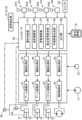
図1は、本発明の実施形態に係る作業機械の一例である油圧ショベルを示す。図2は、前記油圧ショベルに搭載されるコントローラ及びこれにより制御される回路の構成を示す図である。 FIG. 1 shows a hydraulic excavator which is an example of a working machine according to an embodiment of the present invention. FIG. 2 is a diagram showing a configuration of a controller mounted on the hydraulic excavator and a circuit controlled by the controller.
図1及び図2に示すように、油圧ショベル10は、下部走行体11と、前記下部走行体11に旋回可能に搭載される上部旋回体12と、前記上部旋回体12に搭載される作業装置13と、複数の油圧アクチュエータと、少なくとも一つの油圧ポンプ21と、パイロットポンプ22と、複数の操作装置と、複数の制御弁と、複数の圧力センサと、姿勢検出部と、スイッチ80と、コントローラ50と、を備える。
As shown in FIGS. 1 and 2, the
前記下部走行体11及び前記上部旋回体12は、前記作業装置13を支持する機体を構成する。前記下部走行体11は、前記油圧ショベル10を走行させるための図略の走行装置を有し、地面Gの上を走行することができる。前記上部旋回体12は、旋回フレーム12Aと、その上に搭載されるエンジンルーム12B及びキャブ12Cとを含む。前記エンジンルーム12Bはエンジンを収容し、前記キャブ12Cには、オペレータが着座する座席、種々の操作レバー、操作ペダルなどが配置されている。
The
前記作業装置13は、土砂を保持する保持作業と、保持された前記土砂をダンプトラックの荷台に積み込むための積込作業とを行うことが可能な複数の可動部を含む。前記複数の可動部は、ブーム14、アーム15及びバケット16を含む。前記土砂は、作業の対象物の一例であり、前記ダンプトラックの荷台は、積込目標の一例であり、前記バケット16は、アタッチメントの一例である。
The working
本実施形態では、前記保持作業は、作業現場の地面の土砂を前記バケット16により掘削して当該バケット16に保持するための作業(掘削作業)である。前記積込作業は、前記土砂を保持した前記バケット16を、前記保持作業が行われた前記地面付近から前記ダンプトラックの荷台の真上に移動し、前記ダンプトラックの上で前記土砂を前記バケット16から解放する作業である。前記バケット16から解放された前記土砂は、前記バケット16から落下して前記ダンプトラックの前記荷台に積み込まれる。すなわち、前記積込作業は、前記土砂が保持された前記バケット16を前記地面付近から前記ダンプトラックの荷台の真上に移動する移動作業と、前記バケット16に保持された前記土砂を前記ダンプトラックの上で解放する解放作業と、を含む。
In the present embodiment, the holding work is work (excavation work) for excavating earth and sand on the ground of the work site with the
前記ブーム14は、図1の矢印A1に示されるように起伏可能すなわち水平軸回りに回動可能となるように前記旋回フレーム12Aの前部に支持される基端部と、その反対側の先端部と、を有する。具体的に、前記ブーム14は、起立方向A11に作動するブーム上げ動作と、倒伏方向A12に作動するブーム下げ動作とを行う。
The
前記アーム15は、図1の矢印A2に示されるように水平軸回りに回動可能となるように前記ブーム14の先端部に取り付けられる基端部と、その反対側の先端部と、を有する。前記バケット16は、図1の矢印A3に示されるように水平軸周りに回動可能となるように前記アーム15の先端部に取り付けられる基端部を有する。
The
前記複数の油圧アクチュエータは、複数の油圧シリンダと、旋回モータ20と、を含む。前記複数の油圧シリンダは、前記ブーム14を動かすための少なくとも一つのブームシリンダ17と、前記アーム15を動かすためのアームシリンダ18と、前記バケット16を動かすためのバケットシリンダ19と、を含む。図2では、1つの油圧ポンプ21のみが図示されているが、前記油圧ショベル10は、複数の油圧ポンプを備えていてもよい。
The plurality of hydraulic actuators include a plurality of hydraulic cylinders and
前記少なくとも一つのブームシリンダ17は、前記上部旋回体12と前記ブーム14との間に介在し、前記油圧ポンプ21から吐出される作動油の供給を受けることにより伸長又は収縮し、これにより、前記ブーム14を前記起立方向A11又は倒伏方向A12に回動させる。前記起立方向A11は、前記ブーム14の前記先端部が前記地面Gから離れる方向であり、前記倒伏方向A12は、前記ブーム14の前記先端部が前記地面Gに近づく方向である。
The at least one
前記アームシリンダ18は、前記ブーム14と前記アーム15との間に介在し、前記作動油の供給を受けることにより伸長又は収縮し、これにより、前記アーム15を前記矢印A2で示すアーム引き方向又はアーム押し方向に回動させる。前記アーム引き方向は、前記アーム15の前記先端部が前記ブーム14に近づく方向であり、前記アーム押し方向は、前記アーム15の前記先端部が前記ブーム14から離れる方向である。
The
前記バケットシリンダ19は、前記アーム15と前記バケット16との間に介在し、前記作動油の供給を受けることにより伸長又は収縮し、これにより、前記バケット16を前記矢印A3で示すバケット引き方向又はバケット押し方向に回動させる。前記バケット引き方向は、図1に示す前記アーム15の長手方向を示す直線15aと、前記バケット16の方向を示す直線16aとのなす角度θ3が小さくなる方向であり、前記バケット押し方向は、前記角度θ3が大きくなる方向である。
The
前記旋回モータ20は、前記作動油の供給を受けることにより前記上部旋回体12を旋回させるように作動する油圧モータである。当該旋回モータ20は、前記作動油の供給を受けて回転する図略の出力軸を有し、当該出力軸は上部旋回体12を左右双方向に旋回させるように上部旋回体12に連結されている。具体的に、前記旋回モータ20は、一対のポートを有し、これらのうちの一方のポートへの作動油の供給を受けることにより当該一方のポートに対応する方向に前記出力軸が回転するとともに他方のポートから作動油を排出する。
The
図2に示すように、前記複数の操作装置は、ブーム操作装置61と、アーム操作装置62と、バケット操作装置63と、旋回操作装置64と、を含む。これらの操作装置61~64のそれぞれは、オペレータの操作を受ける操作レバーを有する。具体的に、前記ブーム操作装置61はブーム操作レバー61Aを有し、前記アーム操作装置62はアーム操作レバー62Aを有し、前記バケット操作装置63はバケット操作レバー63Aを有し、前記旋回操作装置64は旋回操作レバー64Aを有する。各操作装置は、油圧式の操作装置により構成されていてもよく、電気式の操作装置により構成されていてもよい。図2は、前記操作装置61~64が電気式の操作装置により構成される場合の回路構成を示している。
As shown in FIG. 2 , the plurality of operating devices include a
前記複数の操作装置の具体例を図3に示す。図3は、前記油圧ショベル10に搭載される右側操作レバー65及び左側操作レバー66を示す斜視図である。図3に示す具体例では、一つの操作レバーが複数の操作レバーの機能を兼ねている。オペレータが着座する座席67の右側に前記右側操作レバー65が設けられ、前記座席67の左側に前記左側操作レバー66が設けられる。前記右側操作レバー65は、前後方向に操作された場合に前記ブーム操作レバー61Aとして機能し、かつ、左右方向に操作された場合に前記バケット操作レバー63Aとして機能する。前記左側操作レバー66は、前後方向に操作された場合に前記アーム操作レバー62Aとして機能し、かつ、左右方向に操作された場合に前記旋回操作レバー64Aとして機能する。前記右側操作レバー65及び前記左側操作レバー66のそれぞれが受け持つ機能(レバーパターン)は、オペレータの操作指示によって任意に変更されてもよい。
A specific example of the plurality of operating devices is shown in FIG. FIG. 3 is a perspective view showing a
前記複数の制御弁は、ブーム制御弁41と、アーム制御弁42と、バケット制御弁43と、旋回制御弁44と、一対のブーム電磁比例弁45と、一対のアーム電磁比例弁46と、一対のバケット電磁比例弁47と、一対の旋回電磁比例弁48と、を含む。
The plurality of control valves include a boom control valve 41, an
例えば、前記ブーム操作レバー61Aが操作されると、前記ブーム操作レバー61Aの操作量及び操作方向に関する情報は電気信号(操作信号)に変換されてコントローラ50に入力される。コントローラ50は、前記操作信号に対応した指令信号(指令電流)を、前記一対のブーム電磁比例弁45のうちの前記ブーム操作レバー61Aの操作方向に対応するブーム電磁比例弁45に入力する。当該ブーム電磁比例弁45は、前記パイロットポンプ22が吐出するパイロット油の圧力を前記指令信号に応じて減圧し、減圧されたパイロット圧を、前記ブーム制御弁41における一対のパイロットポートの一方に導く。これにより、前記ブーム制御弁41は、前記パイロット圧が入力される前記パイロットポートに対応する方向に、前記パイロット圧の大きさに対応するストロークで開弁する。その結果、前記油圧ポンプ21から吐出される作動油が、前記ストロークに対応する流量で前記ブームシリンダ17のヘッド側室又はロッド側室に供給されることが許容される。なお、他の操作装置62,63,64の操作レバー62A,63A,64Aが操作された場合の動作は、上記と同様であるので説明を省略する。
For example, when the
なお、各操作装置が油圧式である場合の油圧回路図は省略するが、その場合、前記油圧ショベル10の油圧回路は次のように動作する。例えば前記ブーム操作レバー61Aが操作されると、前記パイロットポンプ22からのパイロット一次圧が前記ブーム操作装置61のリモコン弁において前記ブーム操作レバー61Aの操作量に応じて減圧され、減圧されたパイロット圧が前記リモコン弁から出力される。出力されたパイロット圧は、前記ブーム制御弁41における一対のパイロットポートの一方に入力される。これにより、前記ブーム制御弁41は、前記パイロット圧が入力される前記パイロットポートに対応する方向に、前記パイロット圧の大きさに対応するストロークで開弁する。その結果、前記油圧ポンプ21から吐出される作動油が、前記ストロークに対応する流量で前記ブームシリンダ17のヘッド側室又はロッド側室に供給されることが許容される。
Although a hydraulic circuit diagram is omitted when each operating device is of a hydraulic type, in that case, the hydraulic circuit of the
前記複数の圧力センサは、図2に示すように、前記ブームシリンダ17のヘッド圧を検出するための圧力センサ35と、前記ブームシリンダ17のロッド圧を検出するための圧力センサ36と、を含む。
The plurality of pressure sensors includes a
前記姿勢検出部は、前記機体を構成する前記上部旋回体12に対する前記作業装置の姿勢に関する姿勢情報を検出する。前記姿勢検出部は、前記ブーム14の姿勢情報を検出可能なブーム姿勢検出装置31と、前記アーム15の姿勢情報を検出可能なアーム姿勢検出装置32と、前記バケット16の姿勢情報を検出可能なバケット姿勢検出装置33と、を含む。本実施形態では、これらの姿勢検出装置31,32,33のそれぞれは、例えば、慣性計測装置(Inertial Measurement Unit:IMU)により構成される。
The attitude detection unit detects attitude information about the attitude of the working device with respect to the upper revolving
なお、これらの姿勢検出装置31,32,33のそれぞれは、ストロークセンサにより構成されていてもよく、角度センサにより構成されていてもよく、衛星測位システムを利用した位置検出装置により構成されていてもよい。すなわち、前記ブーム14の姿勢、前記アーム15の姿勢、及び前記バケット16の姿勢は、例えば、前記ブームシリンダ17、前記アームシリンダ18、及び前記バケットシリンダ19のストロークを検出する前記ストロークセンサにより得られるストローク値に基づいて演算されてもよい。また、前記ブーム14の姿勢、前記アーム15の姿勢、及び前記バケット16の姿勢は、例えば、前記ブーム14の前記基端部の回動軸、前記アーム15の前記基端部の回動軸、及び前記バケット16の前記基端部の回動軸にそれぞれ設けられた前記角度センサにより得られる角度値に基づいて演算されてもよい。また、前記ブーム14の姿勢、前記アーム15の姿勢、及び前記バケット16の姿勢は、例えば、GNSSセンサのような衛星測位システムを利用した前記位置検出装置により得られる検出値に基づいて演算されてもよい。
Each of these
上記のような姿勢検出部により検出された前記ブーム14の姿勢、前記アーム15の姿勢、及び前記バケット16の姿勢に関する姿勢情報(姿勢信号)は、コントローラ50に入力される。
Posture information (posture signals) regarding the posture of the
前記スイッチ80は、オペレータが行う入力操作を受けることが可能な入力操作受付部の一例である。前記スイッチ80は、前記予測荷重の決定を行うための後述の制御をオペレータが開始させるときにオペレータにより押されるボタンを有する。本実施形態では、前記スイッチ80は、図3に示すように前記左側操作レバー66の上部に設けられている。ただし、前記スイッチ80は、前記キャブ12Cにおいてオペレータが操作可能な位置に設けられていればよいので、前記スイッチ80が設けられる位置は、前記左側操作レバー66に限られない。また、前記スイッチ80の前記ボタンは、例えば表示装置の画面上に表示されたものであってもよい。
The
前記コントローラ50(メカトロコントローラ)は、例えばCPU、メモリなどを備えるコンピュータにより構成され、操作判定部51と、姿勢演算部52と、荷重演算部53と、基点姿勢設定部54と、予測荷重決定部55と、出力部56と、を有する。
The controller 50 (mechatronics controller) is configured by a computer including, for example, a CPU, a memory, etc., and includes an
前記操作判定部51は、前記複数の操作装置61~64のそれぞれの操作レバーに操作が与えられたか否かを判定する。前記複数の操作装置61~64のそれぞれが図2に示すような前記電気式の操作装置である場合、前記操作装置61~64のそれぞれは、対応する操作レバーに与えられる操作量及び操作方向に応じた前記操作信号を前記コントローラ50に入力する。前記操作判定部51は、入力された前記操作信号に基づいて、対応する操作装置の操作レバーに操作が与えられたこと、具体的には、前記操作レバーに与えられた前記操作量及び前記操作方向を判定することができる。
The
具体的に、本実施形態では、前記操作判定部51は、前記ブーム操作装置61の前記操作レバー61Aに前記ブームシリンダ17を伸長させるブーム上げ操作又は前記ブームシリンダ17を収縮させるブーム下げ操作が与えられたこと、前記アーム操作装置62の前記操作レバー62Aに前記アームシリンダ18を伸長させるアーム引き操作又は前記アームシリンダ18を収縮させるアーム押し操作が与えられたこと、前記バケット操作装置63の前記操作レバー63Aに前記バケットシリンダ19を伸長させるバケット引き操作及び前記バケットシリンダ19を収縮させるバケット押し操作が与えられたこと、前記旋回操作装置64の前記操作レバー64Aに前記上部旋回体12を旋回させる右旋回操作又は左旋回操作が与えられたこと、をそれぞれ判定することができる。前記複数の操作装置61~64のそれぞれが前記電気式の操作装置である場合、前記操作判定部51は、前記複数の操作装置61~64の操作レバー61A~64Aに与えられる操作を検出可能な操作検出部を構成する。
Specifically, in the present embodiment, the
前記操作装置61~64のそれぞれが前記油圧式の操作装置である場合、前記油圧ショベル10は、前記複数の操作装置61~64のそれぞれの前記操作レバーに与えられる操作量に応じて前記リモコン弁から出力されるパイロット圧を検出する図略の複数のパイロット圧センサを備える。複数のパイロット圧センサのそれぞれは、検出したパイロット圧に対応する信号である操作信号を前記コントローラ50に入力する。前記操作判定部51は、入力された前記操作信号に基づいて、対応する操作装置の操作レバーに操作が与えられたこと、具体的には、前記操作レバーに与えられた前記操作量及び前記操作方向を判定することができる。前記複数の操作装置61~64のそれぞれが前記油圧式の操作装置である場合、前記複数のパイロット圧センサと前記操作判定部51は、前記複数の操作装置61~64の操作レバー61A~64Aに与えられる操作を検出可能な操作検出部を構成する。
When each of the operating
前記姿勢演算部52は、前記姿勢検出部から入力される前記姿勢信号に基づいて、前記ブーム14の姿勢、前記アーム15の姿勢、及び前記バケット16の姿勢のそれぞれを演算する。前記姿勢演算部52は、前記ブーム14の姿勢、前記アーム15の姿勢、及び前記バケット16の姿勢として、例えば図1に示すブーム角度θ1、アーム角度θ2、及びバケット角度θ3を、前記姿勢信号に基づいてそれぞれ演算してもよい。
The
前記ブーム角度θ1は、例えば、前記ブーム14の方向を示す直線14aと、前記上部旋回体12の旋回中心軸Cに直交する平面Pとのなす角度であってもよい。この場合、前記直線14aが前記平面Pよりも上方にあるときには、前記ブーム角度θ1は正の値となり、前記直線14aが前記平面Pよりも下方にあるときには、前記ブーム角度θ1は負の値となる。
The boom angle θ1 may be, for example, an angle between a
前記アーム角度θ2は、前記アーム15の方向を示す前記直線15aと、前記直線14aとのなす角度であってもよい。前記バケット角度θ3は、前記バケット16の方向を示す前記直線16aと、前記直線15aとのなす角度であってもよい。前記直線14aは、前記ブーム14の前記基端部の回動軸と、前記ブーム14の前記先端部の回動軸(前記アーム15の前記基端部の回動軸)とを結ぶ直線であってもよい。前記直線15aは、前記アーム15の前記基端部の回動軸と前記アーム15の前記先端部の回動軸(前記バケット16の前記基端部の回動軸)とを結ぶ直線であってもよい。前記直線16aは、前記バケット16の前記基端部の回動軸と前記バケット16の先端部16Eとを結ぶ直線であってもよい。
The arm angle θ2 may be an angle formed by the straight line 15a indicating the direction of the
本実施形態では、前記姿勢演算部52と前記姿勢検出部は、前記作業装置の姿勢を取得する姿勢取得部を構成する。また、本実施形態では、前記姿勢演算部52と前記ブーム姿勢検出装置31は、前記上部旋回体12に対する前記ブーム14の角度である前記ブーム角度θ1を取得するブーム角度取得部を構成する。
In the present embodiment, the
具体的に、前記ブーム姿勢検出装置31が前記慣性計測装置により構成される場合、当該慣性計測装置は、例えば水平面に対する前記ブーム14の角度を検出する。前記姿勢演算部52は、前記慣性計測装置により検出される前記水平面に対する前記ブーム14の角度と、図略の傾斜センサにより検出される水平面に対する上部旋回体12の傾斜角度とに基づいて、前記上部旋回体12に対する前記ブーム14の角度(前記ブーム角度θ1)を演算する。前記ブーム姿勢検出装置31が前記ストロークセンサにより構成される場合、前記ブームシリンダ17におけるピストンのストローク位置は前記ブーム角度θ1の変化に対応して変化するので、前記姿勢演算部52は、前記ストロークセンサにより検出される前記ストローク位置に基づいて、前記ブーム角度θ1を演算する。前記ブーム姿勢検出装置31が前記位置検出装置により構成される場合、例えば、前記姿勢演算部52は、当該位置検出装置により検出される前記ブームの位置に関する位置情報と、図略の位置検出装置により検出される前記上部旋回体12の位置に関する位置情報とに基づいて、前記ブーム角度θ1を演算する。なお、前記ブーム姿勢検出装置31が前記角度センサにより構成される場合、当該角度センサは、前記ブーム角度取得部を構成する。
Specifically, when the boom
前記荷重演算部53は、前記バケット16に保持される前記対象物の荷重を例えば以下のようにして算出する。なお、前記対象物の荷重は、以下の演算方法に限られず、他の公知の手段を用いて演算することが可能である。
The
本実施形態では、前記荷重演算部53は、前記バケット16に保持される前記対象物の荷重を次の式(1)に基づいて算出する。
In this embodiment, the
M=M1+M2+M3+W×L ・・・(1)
式(1)において、Mは、前記ブームシリンダ17のブームフートピン回りのモーメントである。M1は、前記ブーム14の前記ブームフートピン回りのモーメントである。M2は、前記アーム15の前記ブームフートピン回りのモーメントである。M3は、前記バケット16の前記ブームフートピン回りのモーメントである。Wは、前記バケット16に保持される土砂等の対象物の荷重である。Lは、前記ブームフートピンから前記バケット16の基端部までの水平方向の距離である。
M=M1+M2+M3+W×L (1)
In equation (1), M is the moment of the
前記モーメントMは、ブームシリンダ17のヘッド圧とロッド圧とから算出される。前記モーメントM1は、前記ブーム14の重心と前記ブームフートピンとの間の距離と、前記ブーム14の重量との積により算出される。前記モーメントM2は、前記アーム15の重心と前記ブームフートピンとの間の距離と、前記アーム15の重量との積により算出される。前記モーメントM3は、前記バケット16の重心と前記ブームフートピンとの間の距離と、前記バケットの重量との積により算出される。
The moment M is calculated from the head pressure and rod pressure of the
前記ブーム14の重心の位置、前記アーム15の重心の位置、及び前記バケット16の重心の位置のそれぞれは、前記姿勢検出部により検出される前記作業装置13の姿勢に関する情報に基づいて算出される。前記ブームシリンダ17の前記ヘッド圧は、圧力センサ35により検出され、前記ブームシリンダ17の前記ロッド圧は、圧力センサ36により検出される。前記水平方向の距離Lは、前記姿勢検出部により検出される前記作業装置13の姿勢に関する情報に基づいて算出される。
Each of the position of the center of gravity of the
なお、本実施形態では、前記圧力センサ35,36及び前記荷重演算部53は、前記バケット16により保持される前記対象物の荷重を取得する荷重取得部を構成する。前記アタッチメントにより保持される前記対象物の荷重は、例えば、前記アタッチメントに取り付けられたロードセル等のセンサにより検出された値に基づいて演算されてもよい。この場合、前記荷重取得部は、前記ロードセル等のセンサと、当該センサにより検出された値に基づいて前記対象物の荷重を演算する前記荷重演算部53と、を含む。
In addition, in the present embodiment, the
前記基点姿勢設定部54は、前記保持作業において設定されるブーム角度θ1を基点姿勢として設定する。すなわち、前記基点姿勢設定部54は、前記保持作業における前記ブーム角度のうちの何れかのブーム角度を前記基点姿勢として設定する。具体的な基点姿勢の設定方法については後述する。この基点姿勢は、次に説明する姿勢変化量を演算するときの基点となる姿勢であり、本実施形態では、前記保持作業における前記ブーム角度θ1に設定されるが、この態様に限られない。
The base
前記予測荷重決定部55は、前記解放作業において前記ダンプトラックの上で解放されると予測される前記対象物の荷重である予測荷重を決定するために予め設定された予測荷重決定条件が満たされているか否かを判定し、前記予測荷重決定条件が満たされている場合に、前記予測荷重を、前記荷重取得部により取得される前記荷重に基づいて決定する。本実施形態では、前記予測荷重決定条件は、前記基点姿勢からの前記作業装置の姿勢の変化の度合いを示す値である姿勢変化量が、前記予測荷重を決定するために予め設定された変化量閾値以上になるという条件が満たされることを含む。
The predicted
本実施形態では、前記姿勢変化量は、前記基点姿勢からの前記起立方向A11への前記ブーム角度θ1の増加量であり、前記変化量閾値は、前記ブーム角度θ1の増加量に基づいて、前記油圧ショベル10の作業が前記積込作業であることを判定できる値αに予め設定されている。また、前記姿勢変化量がブーム角度θ1の増加量であり、当該ブーム角度θ1の増加量を前記変化量閾値αと比較する制御が行われる本実施形態では、作業装置の姿勢を検出することにより前記姿勢変化量としての前記バケット16の高さの増加量を演算する場合と比べて演算負荷を低減することができる。
In this embodiment, the posture change amount is the amount of increase in the boom angle θ1 in the standing direction A11 from the base posture, and the change amount threshold is based on the amount of increase in the boom angle θ1. The value α is set in advance so that it can be determined that the work of the
この変化量閾値αは、例えば、前記油圧ショベル10が過去に行った複数の解放作業を含む前記積込作業を記録したデータに基づいて、前記油圧ショベル10の作業が前記積込作業であることを判定可能な値に設定される。この場合、前記データにおいて保持作業から解放作業に至るまでの作業を特定し、前記保持作業の終了後のブーム上げ量(ブーム角度θ1の増加量)を特定し、特定された前記ブーム角度θ1の増加量を前記変化量閾値αとして採用することが出来る。また、積込目標であるダンプトラックのタイヤの下端から荷台の上端までの上下方向の長さ(荷台高さ)を前記変化量閾値αとして採用してもよい。具体的に、前記ブーム14の前記先端部の高さが前記荷台高さと同程度に変化するときの前記ブーム角度θ1の変化量が、前記変化量閾値αに設定されうる。前記変化量閾値αの設定方法は、上記の具体例に限られず、当該変化量閾値αに基づいて前記解放作業の予測を行うことができるものが設定される。
The change amount threshold value α is determined, for example, based on data recording the loading work including a plurality of release works performed by the
前記出力部56は、前記予測荷重決定部55により決定される前記予測荷重に関する情報である予測結果を出力する。前記出力部56により出力される前記予測結果は、例えば、図2に示す表示装置70に入力され、当該表示装置70は、当該予測結果を表示する。
The
前記出力部56は、前記予測荷重に関する情報である前記予測結果として、例えば、前記対象物を積込目標の上で解放する解放作業により解放されると予測される前記予測荷重を出力する。また、前記出力部56は、前記保持作業、前記移動作業及び前記解放作業が行われているときに前記バケット16が保持する土砂(対象物)の荷重をリアルタイムで出力してもよい。また、前記出力部56は、前記解放作業において、前記ダンプトラックの荷台に排土された土砂の荷重の累積値、前記ダンプトラックの荷台に排土する土砂の目標積み込み量、前記ダンプトラックの荷台に排土した回数などを出力してもよい。
The
前記表示装置70は、前記油圧ショベル10のキャブ12Cにおいてオペレータが視認可能な位置に配置されていてもよい。前記表示装置70が上記のような各種情報を表示することにより、オペレータは、前記ダンプトラックへの目標積み込み量(積込み目標)に対するその時点での差分(排土可能な対象物の残量)と、その時点でバケット16が保持している土砂(対象物)の荷重と、をリアルタイムで把握することができる。
The
なお、前記表示装置70は、前記油圧ショベル10とは別の場所にあるパーソナルコンピュータやモバイル情報端末などの表示装置を構成するものであってもよい。
Note that the
上記のような構成を備える油圧ショベル10では、前記保持作業における前記作業装置の姿勢である前記基点姿勢からの前記作業装置の姿勢の変化の度合いに基づいて前記積込作業の判定が行われるので、作業現場の状況に応じた設定作業に起因するオペレータの負担を軽減しつつ、前記予測荷重を決定し、出力することができる。
In the
図4は、前記油圧ショベル10による前記ダンプトラックの前記荷台への前記移動作業及び前記解放作業を含む前記積込作業が行われる作業現場の一例を示す側面図であり、図5は、前記油圧ショベル10による前記ダンプトラックの前記荷台への前記移動作業及び前記解放作業を含む前記積込作業が行われる作業現場の他の例を示す側面図である。図4では、前記油圧ショベル10が配置される地面G1の高さ(作業機械配置高さ)と前記ダンプトラック90が配置される地面G2の高さ(トラック配置高さ)との高低差は、ほぼゼロである。一方、図5では、前記作業機械配置高さは前記トラック配置高さよりも大きく、前記作業機械配置高さと前記トラック配置高さとの高低差が大きい。
FIG. 4 is a side view showing an example of a work site where the loading work including the work of moving the dump truck to the bed and the work of releasing the dump truck by the
図4及び図5に示すように、通常、作業現場では、前記土砂を積み込むダンプトラック90の荷台91(前記積込目標)は、作業効率の観点で、前記保持作業において保持される土砂(前記対象物)が存在する地面に隣接した地面G2に配置される。従って、前記解放作業が行われる高さまで前記バケット16が移動したときの前記姿勢変化量は、前記地面G2から前記ダンプトラック90の荷台91の上端までの高さに応じて決まる。このため、前記解放作業が行われる高さまで前記バケット16が移動したときの前記姿勢変化量は、作業現場の状況に応じて変わる前記作業機械配置高さと前記トラック配置高さとの高低差の影響をほとんど受けない。
As shown in FIGS. 4 and 5, usually, at a work site, the loading platform 91 (the loading target) of the
前記油圧ショベル10では、上記のような姿勢変化量が、前記予測荷重を決定するために予め設定された前記変化量閾値α以上になるという条件に基づいて前記予測荷重が決定される。このことは、前記作業現場の状況に応じて前記変化量閾値αの設定を変更する設定作業の頻度を従来に比べて減少させること又は前記設定作業を省略することを可能にする。具体的には次の通りである。
In the
図4及び図5に示すように、前記保持作業から前記解放作業までの作業は、前記ブーム14の前記ブーム上げ動作、前記アーム15の前記アーム押し動作などを含む。これにより、前記土砂を保持する前記バケット16が、前記保持作業において前記土砂が保持された地面の高さ(保持高さ)から前記ダンプトラック90の荷台91の高さを超える高さまで上昇する。すなわち、前記保持作業から前記解放作業までの作業では、前記ブーム14の前記ブーム角度θ1が前記保持作業における前記基点姿勢から前記移動作業に伴って増加する。このブーム角度θ1の増加量θ(前記姿勢変化量θ)は、前記ダンプトラック90の荷台91の地面G2からの高さに応じて決まる。
As shown in FIGS. 4 and 5, the work from the holding work to the release work includes the boom raising operation of the
従って、図4及び図5に示すように、前記作業現場の状況に応じて前記作業機械配置高さと前記トラック配置高さとの高低差が変化しても、ブーム角度θ1の増加量θ(前記姿勢変化量θ)のばらつきは比較的小さく抑えられる。前記油圧ショベル10では、前記姿勢変化量θと前記変化量閾値αとの比較に基づいて前記油圧ショベル10の作業が前記積込作業であるか否かが判定され、その判定結果に基づいて前記予測荷重が決定されるので、従来のように積込作業が前記機体に対する前記アタッチメントの高さ又は前記機体に対する前記ブームの角度に基づいて判定される場合に比べて、前記高低差の変化の影響を受けにくくなる。このことは、前記作業現場の状況に応じて前記変化量閾値の設定を変更する設定作業の頻度を従来に比べて減少させること又は前記設定作業を省略することを可能にする。
Therefore, as shown in FIGS. 4 and 5, even if the height difference between the working machine arrangement height and the truck arrangement height changes according to the situation of the work site, the increase amount θ of the boom angle θ1 (the attitude Variations in the amount of change θ) can be kept relatively small. In the
図6は、前記コントローラ50により実行される制御動作を示すフローチャートである。図6に示す制御動作では、前記予測荷重決定部55により前記予測荷重決定条件の判定が行われ、前記予測荷重決定条件が満たされていると判定されると、前記出力部56により前記予測荷重に関する予測結果が出力される。具体的には以下の通りである。
FIG. 6 is a flow chart showing control operations performed by the
前記油圧ショベル10のオペレータは、前記予測荷重の決定を行うための制御を開始させるときに、前記左側操作レバー66に設けられた前記スイッチ80を押す入力操作を行う。この入力操作が行われると、当該入力操作が行われたことを示す入力操作信号が前記コントローラ50に入力される(ステップS1)。
The operator of the
前記オペレータは、前記入力操作を、例えば、作業現場において前記油圧ショベル10による前記保持作業を開始させるときに行う。具体的には、前記オペレータは、前記作業装置の姿勢が、前記保持作業(掘削作業)が開始されるときの姿勢(保持作業開始姿勢)になるように、前記操作レバー61A~64Aの少なくとも一部を操作する。前記保持作業開始姿勢は、例えば、前記バケット16が掘削対象箇所の真上で且つ当該掘削対象箇所の近傍に配置されるような姿勢である。前記作業装置の姿勢が前記保持作業開始姿勢に調節された後、前記オペレータは、前記スイッチ80を押す前記入力操作を行う。前記スイッチ80により、前記オペレータは、前記積込作業の判定を行う制御(前記予測荷重の決定を行う制御)を、必要に応じて有効にすることができる。
The operator performs the input operation, for example, when starting the holding work by the
次に、前記姿勢演算部52は、前記ブーム角度θ1の演算を開始する(ステップS2)。前記姿勢演算部52は、前記ブーム姿勢検出装置31から前記コントローラ50に入力される前記姿勢信号に基づいて前記ブーム角度θ1を演算する。前記姿勢演算部52による前記ブーム角度θ1の演算は、図6に示す前記制御動作が行われる間、連続的に行われてもよい。
Next, the
次に、前記基点姿勢設定部54は、前記保持作業における前記ブーム角度θ1を基点姿勢として設定する(ステップS3,S4)。具体的に、前記基点姿勢設定部54は、前記スイッチ80が前記入力操作を受けた時点よりも後の前記ブーム角度θ1を基点姿勢として設定する。
Next, the base
具体的に、前記基点姿勢設定部54は、前記保持作業において前記ブーム上げ操作が開始されたか否かを判定する(ステップS3)。前記保持作業において前記ブーム上げ操作が開始された場合(ステップS3においてYES)、前記基点姿勢設定部54は、前記保持作業において前記ブーム上げ操作が開始されたときの前記ブーム角度θ1を前記基点姿勢として設定する(ステップS4)。
Specifically, the base point
前記基点姿勢設定部54は、前記保持作業において前記ブーム上げ操作が開始されたことを、例えば次のように判定することができる。前記基点姿勢設定部54は、前記保持作業の開始時点を、保持作業の開始時点を示す信号(保持作業開始信号)に基づいて判定し、前記保持作業の終了時点を、保持作業の終了時点を示す信号(保持作業終了信号)に基づいて判定してもよい。こうすることで、前記解放作業が予測される可能性の高い状況である前記ブーム上げ動作の開始時の前記ブーム角度θ1が前記基点姿勢として設定されるため、前記解放作業の判定を適切に行うことができる。
The base point
前記保持作業開始信号は、前記保持作業の具体的な内容に応じて種々の態様を取り得るため、特に限定されるものではないが、具体例を挙げると次の通りである。 Since the holding work start signal can take various forms according to the specific content of the holding work, it is not particularly limited, but specific examples are as follows.
すなわち、前記保持作業開始信号としては、例えば、前記スイッチ80が受ける前記入力操作に伴って前記コントローラ50に入力される前記入力操作信号であってもよく、また、前記入力操作信号が入力された後に、前記バケット操作レバー63Aが前記バケット引き操作を受けたことを示すバケット引き操作信号であってもよい。
That is, the holding work start signal may be, for example, the input operation signal that is input to the
また、前記保持作業終了信号は、前記保持作業の具体的な内容に応じて種々の態様を取り得るため、特に限定されるものではないが、具体例を挙げると次の通りである。 Further, since the holding work end signal can take various forms according to the specific content of the holding work, it is not particularly limited, but a specific example is as follows.
すなわち、前記保持作業(掘削作業)が行われるときには、通常、前記上部旋回体12の前記旋回動作は行われない。一方、前記積込作業は、通常、前記ブーム上げ動作と前記旋回動作とを含む。従って、前記基点姿勢設定部54は、前記入力操作信号が前記コントローラ50に入力された後、前記旋回操作レバー64Aが前記旋回操作を受けたことを示す旋回操作信号が前記コントローラ50に入力された時点を、前記保持作業の終了時点として判定できる。この場合、前記保持作業終了信号は、前記旋回操作信号である。そして、前記保持作業の開始時点の後で、且つ、前記保持作業の終了時点の前に、前記ブーム操作レバー61Aが前記ブーム上げ操作を受けたことを示すブーム上げ操作信号が前記コントローラ50に入力されると、前記基点姿勢設定部54は、前記保持作業において前記ブーム上げ操作が開始されたと判定することができる。
That is, when the holding work (excavation work) is performed, the revolving motion of the upper revolving
また、前記基点姿勢設定部54は、前記保持作業の終了時点を、例えば次のように判定してもよい。前記保持作業(掘削作業)が行われると、前記バケット16は掘削した土砂を保持するので、前記荷重取得部により取得される荷重は、前記保持作業の開始前に比べて大きくなる。従って、前記基点姿勢設定部54は、前記入力操作信号が前記コントローラ50に入力された後、前記荷重取得部により取得される荷重が予め設定された閾値(保持作業終了判定閾値)以上になった時点を、前記保持作業の終了時点として判定できる。
Further, the base point
次に、前記予測荷重決定部55は、前記予測荷重決定条件が満たされているか否かを判定する(ステップS5,S7)。本実施形態では、前記予測荷重決定条件は、前記基点姿勢からの前記ブーム角度θ1の増加量が前記変化量閾値α以上になるという条件(角度条件)が満たされること、及び、前記バケット16に保持される荷重が予め設定された予測荷重決定閾値以上であるという条件(荷重条件)が満たされることである。
Next, the predicted
従って、まず、前記予測荷重決定部55は、前記基点姿勢からの前記ブーム角度θ1の増加量が前記変化量閾値α以上になったか否かを判定する(ステップS5)。前記ブーム角度θ1の前記増加量が前記変化量閾値α以上である場合(ステップS5においてYES)、前記荷重取得部は、そのときの前記バケット16に保持される前記土砂の荷重を取得する(ステップS6)。
Therefore, first, the predicted
次に、前記予測荷重決定部55は、前記荷重取得部により取得される前記荷重が前記予測荷重決定閾値以上であるか否かを判定する(ステップS7)。前記予測荷重決定閾値は、例えば、前記バケット16に前記土砂が実質的に保持されているか否かを判定することができる値に設定される。具体的に、通常、前記解放作業が行われる直前には、前記バケット16にはある程度の量の前記土砂が保持されている。一方、前記バケット16に前記土砂が保持されていない場合や保持されていても微少量である場合には、前記解放作業が行われない可能性が高い。この態様では、前記バケット16により保持される前記土砂の荷重が前記予測荷重決定閾値以上であるという条件を予測荷重決定条件が含んでいるので、前記予測荷重の決定がより適切に行われる。
Next, the predicted
前記荷重取得部により取得される前記荷重が前記予測荷重決定閾値以上である場合(ステップS7においてYES)、前記予測荷重決定部55は、そのときに前記荷重取得部により取得される前記土砂の荷重、すなわち、前記予測荷重決定条件が満たされたときに前記荷重取得部により取得される前記土砂の荷重を前記予測荷重として決定する。
When the load acquired by the load acquisition unit is equal to or greater than the predicted load determination threshold value (YES in step S7), the predicted
前記出力部56は、前記予測荷重決定部55により決定された前記予測荷重を予測結果として出力する(ステップS8)。一方、前記荷重取得部により取得される前記荷重が前記予測荷重決定閾値未満である場合(ステップS7においてNO)、前記出力部56は、その荷重を予測結果として出力しない。
The
本発明は、以上説明した実施形態に限定されない。本発明は、例えば次のような態様を包含する。 The invention is not limited to the embodiments described above. The present invention includes, for example, the following aspects.
(A)基点姿勢の更新について
オペレータは、前記保持作業により保持された前記対象物を前記積込目標の上に移動させるための操作を開始した後、前記解放作業を行う前に、当該操作を中断したり、前記保持作業をやり直したりする場合がある。このような場合には、その時点で既に設定されている前記基点姿勢に基づいて前記予測荷重の決定を行うのは不適である。従って、このような場合には、前記作業機械において、前記基点姿勢設定部54は、前記基点姿勢が設定された後で予測荷重決定条件が満たされる前に、前記基点姿勢を更新するか否かを判定するために予め設定された更新条件が満たされた場合に、その後に行われる前記保持作業における前記油圧ショベル10の前記ブーム角度の中から設定される前記ブーム角度θ1を前記基点姿勢として更新してもよい。この場合、前記予測荷重決定部55は、更新された前記基点姿勢に基づいて前記予測荷重決定条件が満たされているか否かを判定する。前記基点姿勢が一旦設定された後であっても、前記更新条件が満たされた場合には、前記基点姿勢が更新され、更新された当該基点姿勢に基づいて前記予測荷重決定条件が満たされたか否かが判定される。すなわち、本態様では、前記油圧ショベル10の動作状況に応じて適切な基点姿勢を更新することが可能になり、更新された基点姿勢に基づいて前記予測荷重決定条件が満たされたか否かが適切に判定される。
(A) Updating the base position After starting the operation to move the object held by the holding work onto the loading target, the operator performs the operation before performing the release work. It may be interrupted or the holding operation may be redone. In such a case, it is inappropriate to determine the predicted load based on the reference point attitude already set at that time. Therefore, in such a case, in the working machine, the base point
前記更新条件は、例えば次のような態様を挙げることができる。 Examples of the update conditions include the following aspects.
前記更新条件は、前記基点姿勢が設定された後で前記予測荷重決定条件が満たされる前に、前記荷重取得部により取得される前記土砂の荷重が予め設定された更新判定荷重閾値以下になるという条件が満たされることを含んでいてもよい。例えば、一旦は積込作業が開始されたものの、前記バケット16により保持される前記土砂がオペレータの予想よりも少ない場合には前記積込作業をやり直す場合がある。この場合、前記予測荷重決定条件が満たされる前に、保持された前記対象物の一部又は全部が前記バケット16から解放されるという状況が想定され、その後、前記保持作業が再度行われる可能性が比較的高い。このように前記対象物の荷重と前記更新判定荷重閾値とを比較することにより、前記基点姿勢の更新の要否を適切に判定することができる。なお、前記土砂が前記バケット16から排土されても前記バケット16に付着した土砂が残存することがあるため、この更新判定荷重閾値は、前記バケット16に付着した土砂が残存する場合であっても、前記基点姿勢の更新が行われるようなゼロより大きな値に設定されてもよい。
The update condition is that the sediment load acquired by the load acquisition unit becomes equal to or less than a preset update determination load threshold after the base position is set and before the predicted load determination condition is satisfied. It may include that a condition is met. For example, although the loading work has been started once, the loading work may be restarted if the amount of earth and sand held by the
また、前記更新条件は、前記基点姿勢が設定された後で前記予測荷重決定条件が満たされる前に、前記ブーム14が前記倒伏方向A12に動作するという条件が満たされることを含んでいてもよい。前記積込作業において前記ブーム操作レバー61Aが前記ブーム上げ操作を受けて前記ブーム14がブーム上げ動作を行うのは前記土砂を掬い上げるためであるが、一方で前記ブーム操作レバー61Aが前記ブーム下げ操作を受けて前記ブーム14がブーム下げ動作を行う場合、前記積込作業がやり直される可能性が高いと予測することが出来る。従って、例えば、前記操作判定部51が前記ブーム操作レバー61Aに前記ブーム下げ操作が与えられたと判定した場合に、前記基点姿勢設定部54は、前記ブーム14が前記倒伏方向A12に動作したと判定することができる。
Further, the update condition may include satisfying a condition that the
また、前記更新条件は、前記基点姿勢が設定された後で前記予測荷重決定条件が満たされる前に、前記倒伏方向A12への前記ブーム角度θ1の減少量が予め設定された減少量閾値以上になるという条件が満たされることを含んでいてもよい。この態様では、前記ブーム上げ動作から前記ブームが前記倒伏方向に動作するブーム下げ動作に転じた場合に前記保持作業が再度行われるという状況を想定することができるので前記基点姿勢の更新の要否がより適切に判定される。 Further, the update condition is such that the amount of decrease in the boom angle θ1 in the lofting direction A12 becomes equal to or greater than a preset decrease amount threshold after the base position is set and before the predicted load determination condition is satisfied. It may also include satisfying the condition that In this aspect, it is possible to assume a situation in which the holding operation is performed again when the boom is moved from the boom raising operation to the boom lowering operation in which the boom moves in the lofting direction. is better determined.
また、前記更新条件は、前記基点姿勢が設定された後で前記予測荷重決定条件が満たされる前に、前記バケット16により保持される前記土砂の量を減少させるための予め設定された減少操作が検出されるという条件が満たされることを含んでいてもよい。前記減少操作としては、例えば、前記バケット押し操作、前記アーム押し操作などを例示できる。この態様では、前記基点姿勢の更新の要否がより適切に判定される。
Further, the update condition is such that a preset reduction operation for reducing the amount of earth and sand held by the
(B)作業装置の姿勢について
前記実施形態では、前記基点姿勢設定部54は、前記保持作業における前記ブーム角度θ1を前記基点姿勢として設定し、前記姿勢変化量は、前記基点姿勢からの前記起立方向A11への前記ブーム角度θ1の増加量であるが、このような態様に限られない。
(B) Posture of Work Device In the above-described embodiment, the base
例えば、前記基点姿勢設定部54は、前記保持作業における前記アタッチメントの高さ(上下方向の位置)を前記基点姿勢として設定し、前記姿勢変化量は、前記基点姿勢からの前記上方への前記アタッチメントの高さの増加量であってもよい。すなわち、本発明における前記基点姿勢設定部は、前記保持作業における前記作業装置の姿勢のうちの何れかの姿勢を基点姿勢として設定するものであればよい。
For example, the base
(C)予測荷重決定条件について
前記実施形態では、前記予測荷重決定条件は、前記基点姿勢からの前記ブーム角度θ1の増加量が前記変化量閾値α以上になるという条件(角度条件)が満たされること、及び、前記バケット16に保持される荷重が予め設定された予測荷重決定閾値以上であるという条件(荷重条件)が満たされることであるが、このような態様に限られない。
(C) Predicted load determination condition In the above embodiment, the predicted load determination condition satisfies the condition (angle condition) that the amount of increase in the boom angle θ1 from the base posture is equal to or greater than the change amount threshold value α. and that a condition (load condition) that the load held by the
前記予測荷重決定条件は、少なくとも前記角度条件が含まれていればよいので、前記荷重条件が含まれていなくてもよい。 The predicted load determination condition may include at least the angle condition, and may not include the load condition.
また、前記予測荷重決定条件は、例えば、前記ブーム角度θ1の前記増加量が前記変化量閾値に達するまで前記基点姿勢からの前記ブーム角度θ1の増加が継続するという条件が満たされることをさらに含んでいてよい。前記ブーム角度θ1が連続的に増加しない場合は前記アタッチメントの位置を調整する作業などの前記記解放作業に相当しない作業が行われることが予測される。従ってこの態様では、前記予測荷重の決定がより適切に行われる。 Further, the predicted load determination condition further includes, for example, satisfying a condition that the boom angle θ1 continues to increase from the base position until the amount of increase in the boom angle θ1 reaches the change amount threshold. can be If the boom angle θ1 does not continuously increase, it is predicted that work that does not correspond to the release work, such as work for adjusting the position of the attachment, will be performed. Therefore, in this aspect, the predicted load is determined more appropriately.
(D)基点姿勢設定部について
前記実施形態では、前記基点姿勢設定部54は、前記保持作業において前記ブーム上げ操作が開始されたときの前記ブーム角度θ1を前記基点姿勢として設定するが、このような態様に限られない。
(D) Reference Point Posture Setting Unit In the above-described embodiment, the reference point
前記基点姿勢設定部54は、前記保持作業が行われている間に前記ブーム角度取得部により取得される複数の前記ブーム角度θ1のうち最小値を前記基点姿勢として設定してもよい。
The base
また、前記基点姿勢設定部54は、前記スイッチ80(入力操作受付部の一例)が前記入力操作を受けたときの前記ブーム角度θ1を前記基点姿勢として設定してもよい。
Further, the base
また、前記基点姿勢設定部54は、前記保持作業の終了時点における前記ブーム角度θ1を前記基点姿勢として設定してもよい。
Further, the base
(E)出力部について
前記実施形態では、出力部56は、前記予測荷重決定部55により前記予測荷重決定条件が満たされた場合に、前記対象物を積込目標の上で解放する解放作業により解放されると予測される前記予測荷重を予測結果として出力するが、このような態様に限られない。前記出力部により出力される前記予測結果は、前記作業機械による作業を支援するものであればよい。このような予測結果としては、例えば、前記予測荷重決定部による判定結果に基づいて前記作業機械の作業において前記解放作業が予測されること又は前記解放作業が予測されないことをオペレータに知らせるための情報を出力であってもよく、当該情報は例えば前記表示装置に表示されてもよい。
(E) Regarding the output unit In the above embodiment, the
(F)作業機械について
前記実施形態では、前記作業機械は、油圧ショベル10であるが、これに限られず、例えばホイールローダーなどの他の作業機械であってもよい。
(F) Working Machine In the above embodiment, the working machine is the
(G)アタッチメントについて
前記実施形態では、前記アタッチメントが前記バケット16であるが、これに限られない。前記アタッチメントは、例えば、フォーク、グラップルなどの他のアタッチメントであってもよい。前記フォーク及び前記グラップルのそれぞれは、作業の対象物を保持することが可能なアタッチメントである。前記フォーク及び前記グラップルのそれぞれは、運搬物、廃材などの作業の対象物を把持するための開閉可能な複数のアームを備える。
(G) Attachment In the above embodiment, the attachment is the
(H)その他
前記油圧ショベル10において、前記スイッチ80は省略可能である。
(H) Others In the
10 油圧ショベル(作業機械の一例)
11 下部走行体(機体の一部を構成する構成要素の一例)
12 上部旋回体(機体の一部を構成する構成要素の一例)
13 作業装置
14 ブーム
15 アーム
16 バケット(アタッチメントの一例)
31 ブーム姿勢検出装置
32 アーム姿勢検出装置
33 バケット姿勢検出装置
35 圧力センサ
36 圧力センサ
50 コントローラ
54 基点姿勢設定部
55 予測荷重決定部
56 出力部
61 ブーム操作装置
80 スイッチ(入力操作受付部の一例)
90 ダンプトラック
91 ダンプトラックの荷台(積込目標の一例)
A11 起立方向
A12 倒伏方向
α 変化量閾値
θ1 ブーム角度
10 Hydraulic excavator (an example of a working machine)
11 Undercarriage (an example of a component that constitutes part of the airframe)
12 Upper revolving structure (an example of a component that constitutes part of the fuselage)
13
31 Boom
90
A11 Standing direction A12 Laying down direction α Variation threshold θ1 Boom angle
Claims (10)
機体と、
前記機体に対して起立方向及び倒伏方向に起伏可能に支持されるブームと前記保持作業において前記対象物を保持することが可能なアタッチメントとを含む作業装置と、
前記作業装置の姿勢を取得する姿勢取得部と、
前記アタッチメントにより保持される前記対象物の荷重を取得する荷重取得部と、
前記保持作業における前記作業装置の姿勢の中から設定される姿勢を基点姿勢として設定する基点姿勢設定部と、
予め設定された予測荷重決定条件が満たされた場合に、前記解放作業において前記積込目標の上で解放されると予測される前記対象物の荷重である予測荷重を、前記荷重取得部により取得される前記荷重に基づいて決定する予測荷重決定部と、
前記予測荷重決定部により決定される前記予測荷重に関する情報である予測結果を出力する出力部と、を備え、
前記予測荷重決定条件は、前記基点姿勢からの前記作業装置の姿勢の変化の度合いを示す値である姿勢変化量が、前記予測荷重を決定するために予め設定された変化量閾値以上になるという条件が満たされることを含む、作業機械。 A working machine that performs a holding operation of holding a work object and a release operation of releasing the held object on a loading target,
Airframe and
a working device including a boom supported to be able to rise and fall with respect to the fuselage in a standing direction and a laying down direction, and an attachment capable of holding the object in the holding work;
an attitude acquisition unit that acquires the attitude of the working device;
a load acquisition unit that acquires the load of the object held by the attachment;
a base position setting unit that sets a position set from among the positions of the working device in the holding work as a base position;
The load acquisition unit acquires the predicted load, which is the load of the object that is predicted to be released from the loading target in the release operation when a preset predicted load determination condition is satisfied. a predicted load determination unit that determines based on the load that is applied;
an output unit that outputs a prediction result that is information about the predicted load determined by the predicted load determination unit;
The predicted load determination condition is that a posture change amount, which is a value indicating the degree of change in the posture of the working device from the base posture, is greater than or equal to a change amount threshold set in advance for determining the predicted load. Working machine, including conditions met.
前記姿勢取得部は、前記機体に対する前記ブームの角度であるブーム角度を取得するブーム角度取得部を含み、
前記基点姿勢設定部は、前記保持作業において設定される前記ブーム角度を前記基点姿勢として設定し、
前記姿勢変化量は、前記基点姿勢からの前記起立方向への前記ブーム角度の増加量である、作業機械。 A work machine according to claim 1,
The attitude acquisition unit includes a boom angle acquisition unit that acquires a boom angle, which is the angle of the boom with respect to the airframe,
The base position setting unit sets the boom angle set in the holding operation as the base position,
The work machine, wherein the posture change amount is an increase amount of the boom angle in the standing direction from the base posture.
前記ブームを前記起立方向に作動させるためのブーム上げ操作を受けることが可能なブーム操作装置をさらに備え、
前記基点姿勢設定部は、前記保持作業において前記ブーム上げ操作が開始されたときの前記ブーム角度を前記基点姿勢として設定する、作業機械。 A working machine according to claim 2,
further comprising a boom operating device capable of receiving a boom raising operation for operating the boom in the erecting direction;
The working machine, wherein the base position setting unit sets the boom angle when the boom raising operation is started in the holding work as the base position.
前記予測荷重決定条件は、前記ブーム角度の前記増加量が前記変化量閾値に達するまで前記基点姿勢からの前記ブーム角度の増加が継続するという条件が満たされることをさらに含む、作業機械。 The working machine according to claim 2 or 3,
The work machine, wherein the predicted load determination condition further includes satisfying a condition that the increase in the boom angle from the base position continues until the amount of increase in the boom angle reaches the change amount threshold.
前記出力部は、前記予測荷重決定条件が満たされた場合に、前記荷重取得部により取得される前記荷重を前記予測荷重として出力する、作業機械。 The working machine according to any one of claims 1 to 4,
The work machine, wherein the output unit outputs the load acquired by the load acquiring unit as the predicted load when the predicted load determination condition is satisfied.
オペレータが行う入力操作を受けることが可能な入力操作受付部をさらに備え、
前記基点姿勢設定部は、前記入力操作受付部が前記入力操作を受けた時点よりも後の前記作業装置の姿勢を前記基点姿勢として設定する、作業機械。 The working machine according to any one of claims 1 to 5,
further comprising an input operation receiving unit capable of receiving an input operation performed by an operator,
The working machine, wherein the base position setting section sets, as the base position, a position of the working device after the input operation receiving section receives the input operation.
前記予測荷重決定条件は、前記荷重取得部により取得される前記対象物の荷重が予め設定された予測荷重決定閾値以上であるという条件が満たされることをさらに含む、作業機械。 The working machine according to any one of claims 1 to 6,
The working machine, wherein the predicted load determination condition further includes satisfying a condition that the load of the object acquired by the load acquisition unit is equal to or greater than a preset predicted load determination threshold.
前記基点姿勢設定部は、前記基点姿勢が設定された後で前記予測荷重決定条件が満たされる前に、前記基点姿勢を更新するか否かを判定するために予め設定された更新条件が満たされた場合に、その後に行われる前記保持作業における前記作業装置の姿勢の中から設定される姿勢を前記基点姿勢として更新し、
前記予測荷重決定部は、更新された前記基点姿勢に基づいて前記予測荷重決定条件が満たされているか否かを判定する、作業機械。 The working machine according to any one of claims 1 to 7,
The base point attitude setting unit determines whether or not to update the base point attitude after the base point attitude is set and before the predicted load determination condition is satisfied. updating the attitude set from among the attitudes of the working device in the holding work to be performed thereafter as the base attitude,
The work machine, wherein the predicted load determination unit determines whether the predicted load determination condition is satisfied based on the updated reference point posture.
前記更新条件は、前記基点姿勢が設定された後で前記予測荷重決定条件が満たされる前に、前記荷重取得部により取得される前記対象物の荷重が予め設定された更新判定荷重閾値以下になるという条件が満たされることを含む、作業機械。 A work machine according to claim 8,
The update condition is such that the load of the object acquired by the load acquisition unit becomes equal to or less than a preset update determination load threshold after the reference point posture is set and before the predicted load determination condition is satisfied. working machine, including that the condition of
前記更新条件は、前記基点姿勢が設定された後で前記予測荷重決定条件が満たされる前に、前記ブームが前記倒伏方向に動作するという条件が満たされることを含む、作業機械。 A working machine according to claim 8 or 9,
The work machine, wherein the update condition includes satisfying a condition that the boom moves in the lofting direction after the base position is set and before the predicted load determination condition is satisfied.
Priority Applications (4)
| Application Number | Priority Date | Filing Date | Title |
|---|---|---|---|
| JP2019198307A JP7268577B2 (en) | 2019-10-31 | 2019-10-31 | working machine |
| EP20880762.8A EP4029999A4 (en) | 2019-10-31 | 2020-10-16 | Work machine |
| PCT/JP2020/039030 WO2021085167A1 (en) | 2019-10-31 | 2020-10-16 | Work machine |
| CN202080074085.1A CN114555890B (en) | 2019-10-31 | 2020-10-16 | Engineering machinery |
Applications Claiming Priority (1)
| Application Number | Priority Date | Filing Date | Title |
|---|---|---|---|
| JP2019198307A JP7268577B2 (en) | 2019-10-31 | 2019-10-31 | working machine |
Publications (3)
| Publication Number | Publication Date |
|---|---|
| JP2021070977A JP2021070977A (en) | 2021-05-06 |
| JP2021070977A5 JP2021070977A5 (en) | 2022-04-22 |
| JP7268577B2 true JP7268577B2 (en) | 2023-05-08 |
Family
ID=75712676
Family Applications (1)
| Application Number | Title | Priority Date | Filing Date |
|---|---|---|---|
| JP2019198307A Active JP7268577B2 (en) | 2019-10-31 | 2019-10-31 | working machine |
Country Status (4)
| Country | Link |
|---|---|
| EP (1) | EP4029999A4 (en) |
| JP (1) | JP7268577B2 (en) |
| CN (1) | CN114555890B (en) |
| WO (1) | WO2021085167A1 (en) |
Citations (4)
| Publication number | Priority date | Publication date | Assignee | Title |
|---|---|---|---|---|
| JP2000064360A (en) | 1998-08-19 | 2000-02-29 | Hitachi Constr Mach Co Ltd | Load measuring device for hydraulic backhoe |
| JP2017166232A (en) | 2016-03-16 | 2017-09-21 | 住友重機械工業株式会社 | Shovel |
| JP2018188831A (en) | 2017-04-28 | 2018-11-29 | 株式会社小松製作所 | Work machine and control method of the same |
| JP2019049103A (en) | 2017-09-07 | 2019-03-28 | 日立建機株式会社 | Load weight measuring system for work machine |
Family Cites Families (7)
| Publication number | Priority date | Publication date | Assignee | Title |
|---|---|---|---|---|
| JP2002021122A (en) | 2000-07-10 | 2002-01-23 | Hitachi Constr Mach Co Ltd | Load measuring device for back hoe |
| JP2003073078A (en) * | 2001-09-05 | 2003-03-12 | Hitachi Constr Mach Co Ltd | Method and device for compensating error of lifted load for upper part turning construction machinery |
| JP2008037562A (en) * | 2006-08-04 | 2008-02-21 | Shin Caterpillar Mitsubishi Ltd | Load error correcting device and load error correcting method for working machine |
| US9221659B2 (en) * | 2011-11-04 | 2015-12-29 | Komatsu Ltd. | Loading system and transporter |
| US10745889B2 (en) * | 2016-11-09 | 2020-08-18 | Komatsu Ltd. | Work machine and method for controlling work machine |
| JP6807293B2 (en) * | 2017-09-26 | 2021-01-06 | 日立建機株式会社 | Work machine |
| JP6970581B2 (en) * | 2017-10-04 | 2021-11-24 | 株式会社小松製作所 | Work machines, systems including work machines, and control methods for work machines |
-
2019
- 2019-10-31 JP JP2019198307A patent/JP7268577B2/en active Active
-
2020
- 2020-10-16 WO PCT/JP2020/039030 patent/WO2021085167A1/en unknown
- 2020-10-16 EP EP20880762.8A patent/EP4029999A4/en active Pending
- 2020-10-16 CN CN202080074085.1A patent/CN114555890B/en active Active
Patent Citations (4)
| Publication number | Priority date | Publication date | Assignee | Title |
|---|---|---|---|---|
| JP2000064360A (en) | 1998-08-19 | 2000-02-29 | Hitachi Constr Mach Co Ltd | Load measuring device for hydraulic backhoe |
| JP2017166232A (en) | 2016-03-16 | 2017-09-21 | 住友重機械工業株式会社 | Shovel |
| JP2018188831A (en) | 2017-04-28 | 2018-11-29 | 株式会社小松製作所 | Work machine and control method of the same |
| JP2019049103A (en) | 2017-09-07 | 2019-03-28 | 日立建機株式会社 | Load weight measuring system for work machine |
Also Published As
| Publication number | Publication date |
|---|---|
| EP4029999A1 (en) | 2022-07-20 |
| CN114555890B (en) | 2023-05-23 |
| JP2021070977A (en) | 2021-05-06 |
| WO2021085167A1 (en) | 2021-05-06 |
| EP4029999A4 (en) | 2022-11-30 |
| CN114555890A (en) | 2022-05-27 |
Similar Documents
| Publication | Publication Date | Title |
|---|---|---|
| JP6807293B2 (en) | Work machine | |
| KR102268035B1 (en) | working machine | |
| KR102402518B1 (en) | working machine | |
| CN109689978B (en) | Working machine | |
| JP7276056B2 (en) | working machine | |
| JP7306201B2 (en) | working machine | |
| JP7268577B2 (en) | working machine | |
| EP4101990A1 (en) | Operating machine and method for controlling operating machine | |
| JP7234891B2 (en) | working machine | |
| US20230122177A1 (en) | Work machine | |
| CN115997061A (en) | Work machine | |
| JP7452342B2 (en) | Information presentation equipment and working machines | |
| EP4092201B1 (en) | Work machine | |
| JP2024057328A (en) | Abnormality determination device for a work machine and work machine equipped with the same |
Legal Events
| Date | Code | Title | Description |
|---|---|---|---|
| A521 | Request for written amendment filed |
Free format text: JAPANESE INTERMEDIATE CODE: A523 Effective date: 20220414 |
|
| A621 | Written request for application examination |
Free format text: JAPANESE INTERMEDIATE CODE: A621 Effective date: 20220725 |
|
| TRDD | Decision of grant or rejection written | ||
| A01 | Written decision to grant a patent or to grant a registration (utility model) |
Free format text: JAPANESE INTERMEDIATE CODE: A01 Effective date: 20230322 |
|
| A61 | First payment of annual fees (during grant procedure) |
Free format text: JAPANESE INTERMEDIATE CODE: A61 Effective date: 20230404 |
|
| R150 | Certificate of patent or registration of utility model |
Ref document number: 7268577 Country of ref document: JP Free format text: JAPANESE INTERMEDIATE CODE: R150 |