CN109689978B - Working machine - Google Patents
Working machine Download PDFInfo
- Publication number
- CN109689978B CN109689978B CN201780055146.8A CN201780055146A CN109689978B CN 109689978 B CN109689978 B CN 109689978B CN 201780055146 A CN201780055146 A CN 201780055146A CN 109689978 B CN109689978 B CN 109689978B
- Authority
- CN
- China
- Prior art keywords
- limit value
- control
- target surface
- intervention
- magnitude
- Prior art date
- Legal status (The legal status is an assumption and is not a legal conclusion. Google has not performed a legal analysis and makes no representation as to the accuracy of the status listed.)
- Active
Links
Images


Classifications
-
- E—FIXED CONSTRUCTIONS
- E02—HYDRAULIC ENGINEERING; FOUNDATIONS; SOIL SHIFTING
- E02F—DREDGING; SOIL-SHIFTING
- E02F3/00—Dredgers; Soil-shifting machines
- E02F3/04—Dredgers; Soil-shifting machines mechanically-driven
- E02F3/28—Dredgers; Soil-shifting machines mechanically-driven with digging tools mounted on a dipper- or bucket-arm, i.e. there is either one arm or a pair of arms, e.g. dippers, buckets
- E02F3/36—Component parts
- E02F3/42—Drives for dippers, buckets, dipper-arms or bucket-arms
- E02F3/43—Control of dipper or bucket position; Control of sequence of drive operations
- E02F3/435—Control of dipper or bucket position; Control of sequence of drive operations for dipper-arms, backhoes or the like
-
- E—FIXED CONSTRUCTIONS
- E02—HYDRAULIC ENGINEERING; FOUNDATIONS; SOIL SHIFTING
- E02F—DREDGING; SOIL-SHIFTING
- E02F9/00—Component parts of dredgers or soil-shifting machines, not restricted to one of the kinds covered by groups E02F3/00 - E02F7/00
- E02F9/20—Drives; Control devices
- E02F9/2004—Control mechanisms, e.g. control levers
-
- E—FIXED CONSTRUCTIONS
- E02—HYDRAULIC ENGINEERING; FOUNDATIONS; SOIL SHIFTING
- E02F—DREDGING; SOIL-SHIFTING
- E02F9/00—Component parts of dredgers or soil-shifting machines, not restricted to one of the kinds covered by groups E02F3/00 - E02F7/00
- E02F9/20—Drives; Control devices
- E02F9/2025—Particular purposes of control systems not otherwise provided for
- E02F9/2033—Limiting the movement of frames or implements, e.g. to avoid collision between implements and the cabin
-
- E—FIXED CONSTRUCTIONS
- E02—HYDRAULIC ENGINEERING; FOUNDATIONS; SOIL SHIFTING
- E02F—DREDGING; SOIL-SHIFTING
- E02F9/00—Component parts of dredgers or soil-shifting machines, not restricted to one of the kinds covered by groups E02F3/00 - E02F7/00
- E02F9/20—Drives; Control devices
- E02F9/22—Hydraulic or pneumatic drives
- E02F9/2264—Arrangements or adaptations of elements for hydraulic drives
- E02F9/2271—Actuators and supports therefor and protection therefor
-
- E—FIXED CONSTRUCTIONS
- E02—HYDRAULIC ENGINEERING; FOUNDATIONS; SOIL SHIFTING
- E02F—DREDGING; SOIL-SHIFTING
- E02F9/00—Component parts of dredgers or soil-shifting machines, not restricted to one of the kinds covered by groups E02F3/00 - E02F7/00
- E02F9/26—Indicating devices
-
- E—FIXED CONSTRUCTIONS
- E02—HYDRAULIC ENGINEERING; FOUNDATIONS; SOIL SHIFTING
- E02F—DREDGING; SOIL-SHIFTING
- E02F9/00—Component parts of dredgers or soil-shifting machines, not restricted to one of the kinds covered by groups E02F3/00 - E02F7/00
- E02F9/26—Indicating devices
- E02F9/264—Sensors and their calibration for indicating the position of the work tool
- E02F9/265—Sensors and their calibration for indicating the position of the work tool with follow-up actions (e.g. control signals sent to actuate the work tool)
Abstract
A hydraulic excavator (1) is provided with a steering controller (40), the steering controller (40) is provided with a machine control unit (43) which executes machine control for operating a work machine (1A) in accordance with a predetermined condition when operating devices (45a, 45b, 46c) are operated, and the hydraulic excavator (1) is provided with an intervention intensity input device (96) which is operated by an operator. The steering controller has a correction degree calculation unit (43m), and the correction degree calculation unit (43m) calculates a correction amount of intervention strength indicating the degree of the intervention of the mechanical control on the operation of the working machine instructed by the operation of the operation device, based on the operation amount of the intervention strength input device. The machine control unit causes the machine control unit to intervene in the operation of the working machine instructed by the operation of the operation device, with intervention strength corrected based on the correction amount calculated by the correction degree calculation unit.
Description
Technical Field
The present invention relates to a working machine capable of executing machine control.
Background
Hydraulic excavators sometimes include a control system for assisting an excavation operation by an operator. Specifically, the following control system is provided: when an excavation operation (for example, an instruction to retract the arm) is input via the operation device, control for forcibly operating at least one of the boom cylinder, the arm cylinder, and the bucket cylinder that drive the work implement (for example, forcibly raising the boom by extending the boom cylinder) is executed based on the positional relationship between the target surface and the tip end of the work implement (for example, the tip of the bucket) so that the position of the tip end of the work implement (also referred to as a front work implement) is maintained in a region on and above the target surface. By using such a control system for limiting the movable region of the working machine tip, the working of dressing the excavation face and the working of forming the slope are facilitated. Hereinafter, such Control may be referred to as "area restriction Control", "intervention Control (for operator operation)" or "Machine Control (MC)".
In association with this technique, it is pointed out in japanese patent No. 3056254 that: when the bucket tip approaches the target surface (intrusion prevention area), if the speed of the bucket tip is reduced regardless of the movement direction of the bucket tip, the excavation speed in the direction along the target surface is also reduced, and the efficiency is reduced. As a solution to this problem, the following control method is described: only a component perpendicular to the target surface in the moving speed of the bucket tip is limited by the intervention control, and the operation signal of the operator is directly supplied as a front action command without intervention control with respect to the speed component parallel to the target surface.
Documents of the prior art
Patent document
Patent document 1: japanese patent No. 3056254
Disclosure of Invention
An excavator having a machine control function as in the above-described prior art document (hereinafter, sometimes referred to as an "MC machine") can also be applied to a so-called information construction scenario in which excavation and forming of a design surface are performed by controlling a machine body so that a bucket tooth tip position moves along the design surface (target surface) to which electronic information is provided. In this case, the bucket tooth tip position set in the coordinate system of the machine (excavator coordinate system) is calculated from the detection value of the attitude sensor of the working machine, the position and orientation of the machine set in the earth coordinate system (world coordinate system) are calculated by using a global satellite navigation system (GNSS) or the like, and the tooth tip position in the world coordinate system can be calculated by combining the two (the tooth tip position in the excavator coordinate system and the position and orientation of the machine in the world coordinate system). Further, excavation and forming of the target surface (design surface) can be performed by controlling the machine body so that the tooth tip position in the world coordinate system moves along the target surface.
In the work of excavating and shaping the target surface in this way, a reinforcement work called side slope tamping, which is a work of performing a boom lowering operation and pressing the excavation surface substantially vertically with the bucket back surface, is performed in order to level the excavation surface along the target surface. In the slope tamping work, it is desired to repeatedly perform slope tamping with a substantially constant pressing force suitable for soil, but skill is required for the operation. Therefore, a work machine capable of adjusting and maintaining the pressing force for slope tamping regardless of the skill of the operator is desired. Further, even if the boom lowering operation is performed for the purpose of tamping the side slope during the MC execution, the operation of the front working machine beyond the target surface is suppressed, so that the pressure cannot be applied to the excavation surface by the bucket back surface. That is, since the MC cannot be compacted during execution of the MC, the excavator according to the related art needs to close the MC every time the MC is compacted. In addition, since the trimming work for moving the bucket tooth point along the target surface is usually performed by the MC after the slope tamping work is completed, the MC function that is temporarily closed during the slope tamping work must be turned on, and this series of switching operations becomes a burden on the operator.
The present invention has been made in view of the above circumstances, and an object thereof is to provide a work machine which has a machine control function and can adjust and maintain a pressing force in real time of a slope tamper.
The present application includes a plurality of solutions to the above problem, and a working machine includes, as an example,: a working machine driven by a plurality of hydraulic actuators; an operation device that instructs an operation of the work machine in accordance with an operation by an operator; and a control device including a machine control unit that executes machine control for operating the work machine in accordance with a predetermined condition when the operation device is operated, wherein the work machine includes intervention strength input means operated by an operator, the control device further includes a correction degree calculation unit that calculates a correction amount of intervention strength indicating a degree of intervention of the machine control in the operation of the work machine instructed by the operation of the operation device based on an operation amount of the intervention strength input means, and the machine control unit causes the machine control to intervene in the operation of the work machine instructed by the operation of the operation device with the intervention strength corrected based on the correction amount calculated by the correction degree calculation unit.
Effects of the invention
According to the present invention, the adjustment and maintenance of the pressing force in real time of the slope tamping can be realized in the working machine having the machine control function.
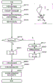
Drawings
Fig. 1 is a configuration diagram of a hydraulic excavator according to an embodiment of the present invention.
Fig. 2 is a diagram showing a steering controller of the hydraulic excavator together with a hydraulic drive device.
Fig. 3 is a detailed view of the front control hydraulic unit of the hydraulic excavator.
Fig. 4 is a hardware configuration diagram of a steering controller of the hydraulic excavator.
Fig. 5 is a diagram showing a coordinate system and a target surface in the hydraulic excavator.
Fig. 6 is a functional block diagram of a steering controller of the hydraulic excavator.
Fig. 7 is a functional block diagram of the machine control unit in fig. 6.
Fig. 8A is a top view of a joystick with an interventional intensity input device.
Fig. 8B is a side view of a joystick with an interventional intensity input device.
Fig. 8C is a front view of the operation lever with the intervention strength input device.
Fig. 9 is a diagram showing a relationship between the limit value ay of the vertical component of the bucket tooth tip speed and the distance D.
Fig. 10 is a diagram showing a relationship between the limit value ay and the distance D and the intervention strength.
Fig. 11 is a flowchart of the mode determination process executed by the mode determination section of the steering controller.
Fig. 12 is a flowchart of the boom-down deceleration mode executed by the control signal calculation unit of the steering controller.
Fig. 13 is a comparison diagram of the boom pilot pressure, the distance D, the boom speed, and the boom pilot pressure in the case where the intervention strength is changed.
Fig. 14 is a flowchart of a boom raising/lowering mode executed by a control signal arithmetic unit of the steering controller.
Fig. 15 is a diagram showing an example of display contents of the display device.
Fig. 16 is a diagram showing a relationship between the limit value ay and the distance D and the intervention strength.
Fig. 17 is a diagram showing a relationship between the limit value ay and the distance D and the intervention strength.
Fig. 18A is a top view of a joystick with an interventional intensity input device.
Fig. 18B is a side view of the lever with the intervention strength input device.
Fig. 18C is a front view of the operation lever having the intervention strength input device.
Detailed Description
Embodiments of the present invention will be described below with reference to the drawings. Further, a hydraulic excavator having the bucket 10 as an attachment at the front end of the working machine is exemplified below, but the present invention may be applied to a hydraulic excavator having an attachment other than a bucket. Further, the present invention can be applied to a working machine other than a hydraulic excavator as long as the working machine has an articulated working machine configured by connecting a plurality of driven members (an attachment, an arm, a boom, and the like) and is operated on a predetermined operation plane.
In the present specification, the terms "upper", "upper" and "lower" used together with terms (for example, a target surface, a control target surface, and the like) indicating a certain shape mean that "upper" denotes a "surface" of the certain shape, "upper" denotes a position higher than the "surface" of the certain shape, and "lower" denotes a position lower than the "surface" of the certain shape. In the following description, when there are a plurality of identical components, a letter may be given to the end of a reference numeral (numeral), but the letter may be omitted and the plurality of components may be expressed collectively. For example, when there are three pumps 300a, 300b, 300c, they are sometimes collectively referred to as a pump 300.
< basic Structure >
Fig. 1 is a configuration diagram of a hydraulic excavator according to an embodiment of the present invention, fig. 2 is a diagram showing a steering controller of the hydraulic excavator according to the embodiment of the present invention together with a hydraulic drive device, and fig. 3 is a detailed diagram of front control hydraulic unit 160 in fig. 2.
In fig. 1, a hydraulic excavator 1 is constituted by an articulated front work machine 1A and a vehicle body 1B. The vehicle body 1B is constituted by a lower traveling structure 11 that travels by the left and right traveling motors 3a, 3B, and an upper rotating body 12 that is rotatably attached to the lower traveling structure 11. The front working machine 1A is configured by coupling a plurality of driven members (a boom 8, an arm 9, and a bucket 10) that rotate in the vertical direction, respectively, and the base end of the boom 8 of the front working machine 1A is supported by the front portion of the upper swing structure 12.
The engine 18 as a prime mover mounted on the upper swing structure 12 drives the hydraulic pump 2 and the pilot pump 48. The hydraulic pump 2 is a variable displacement pump whose displacement is controlled by a regulator 2a, and the pilot pump 48 is a fixed displacement pump. In the present embodiment, a shuttle valve block (shuttle block)162 is provided in the middle of the pilot lines 144, 145, 146, 147, 148, 149. Hydraulic signals output from the operation devices 45, 46, and 47 that instruct the operation of the front work machine 1A in accordance with the operation of the operator are also input to the regulator 2a via the shuttle valve block 162. Although the detailed structure of the shuttle valve block 162 is omitted, a hydraulic signal is input to the regulator 2a via the shuttle valve block 162, and the discharge flow rate of the hydraulic pump 2 is controlled according to the hydraulic signal.
After passing through pilot operated check valve 39, pump line 148a, which is a discharge pipe of pilot pump 48, branches into a plurality of lines and is connected to operation devices 45, 46, and 47 and the respective valves in front control hydraulic unit 160. The pilot operated check valve 39 is an electromagnetic switching valve in this example, and an electromagnetic driving portion thereof is electrically connected to a position detector of a door lock lever (not shown) disposed in the cab (fig. 1). The position of the door lock lever is detected by a position detector, and a signal corresponding to the position of the door lock lever is input to the pilot operated check valve 39 from the position detector. When the position of the door lock lever is at the lock position, the pilot operated check valve 39 closes to block the pump line 148a, and when the position is at the unlock position, the pilot operated check valve 39 opens to open the pump line 148 a. That is, in a state where the pump line 148a is disconnected, the operation by the operation devices 45, 46, and 47 is invalidated, and the operation such as the rotation and the excavation is prohibited.
The boom 8, the arm 9, the bucket 10, and the upper swing structure 12 constitute driven members that are driven by the boom cylinder 5, the arm cylinder 6, the bucket cylinder 7, and the swing hydraulic motor 4 (hydraulic actuator), respectively. The operation instructions to the driven members 8, 9, 10, and 12 are output based on the operation of the right travel lever 23a, the left travel lever 23b, the right operation lever 1a, and the left operation lever 1b (which may be collectively referred to as operation levers 1 and 23) in the cabin mounted on the upper swing structure 12 by the operator.
An operation device 47a having a travel right lever 23a, an operation device 47b having a travel left lever 23b, operation devices 45a and 46a for operating the right lever 1a in common, and operation devices 45b and 46b for operating the left lever 1b in common are provided in the cab. The travel levers 23a and 23b and the operation levers 1a and 1b are grip portions on which the hands of the operator are placed during the excavator operation. The operating devices 45, 46, and 47 are of a hydraulic pilot type, and generate pilot pressures (sometimes referred to as operating pressures) corresponding to the operation amounts (for example, lever strokes) and the operation directions of the operating levers 1 and 23 operated by the operator, respectively, based on hydraulic oil discharged from a pilot pump. The pilot pressure thus generated is supplied to the hydraulic pressure driving portions 150a to 155b of the corresponding flow rate control valves 15a to 15f (see fig. 2) in the control valve unit 20 via the pilot conduits 144a to 149b (see fig. 2), and is used as a control signal for driving the flow rate control valves 15a to 15 f.
The hydraulic oil discharged from the hydraulic pump 2 is supplied to the travel right hydraulic motor 3a, the travel left hydraulic motor 3b, the swing hydraulic motor 4, the boom cylinder 5, the arm cylinder 6, and the bucket cylinder 7 via flow rate control valves 15a, 15b, 15c, 15d, 15e, and 15f (see fig. 2). The boom cylinder 5, the arm cylinder 6, and the bucket cylinder 7 are expanded and contracted by the supplied hydraulic oil, whereby the boom 8, the arm 9, and the bucket 10 are rotated, respectively, and the position and the posture of the bucket 10 are changed. The hydraulic swing motor 4 is rotated by the supplied hydraulic oil, whereby the upper swing structure 12 is rotated relative to the lower traveling structure 11. The traveling right hydraulic motor 3a and the traveling left hydraulic motor 3b are rotated by the supplied hydraulic oil, and the lower traveling structure 11 travels.
On the other hand, in order to measure the pivot angles α, β, γ of the boom 8, the arm 9, and the bucket 10 (see fig. 5), a boom angle sensor 30 is attached to a boom pin, an arm angle sensor 31 is attached to an arm pin, a bucket angle sensor 32 is attached to the bucket link 13, and a vehicle body inclination angle sensor 33 that detects the front-rear direction inclination angle θ (see fig. 5) of the upper rotating body 12 (the vehicle body 1B) with respect to a reference plane (e.g., a horizontal plane) is attached to the upper rotating body 12.
The hydraulic excavator according to the present embodiment includes a control system for executing machine control for assisting the excavation operation by the operator, in which when the operation devices 45a, 45b, and 46c are operated, the front work implement 1A is operated by an operation different from the operation instructed by the operation of the operation devices in accordance with a predetermined condition. Specifically, the following excavation control system is provided: when an excavation operation (specifically, at least one instruction of boom retracting, bucket scooping, and bucket unloading) is input via the operation devices 45b and 46a, a control signal (for example, a control signal for forcibly moving the boom cylinder 5 to perform a boom raising operation) for forcibly moving at least one of the hydraulic actuators 5, 6, and 7 so as to hold the position of the tip end of the work implement 1A on and above the target surface 60 (see fig. 5) based on the positional relationship between the target surface 60 and the tip end of the work implement 1A (in the present embodiment, the tip end of the bucket 10) is output to the corresponding flow control valves 15a, 15b, and 15 c. In this specification, the control may be referred to as "area limitation control" or "mechanical control". Since the tips of the bucket 10 are prevented from penetrating below the target surface 60 by this control, excavation along the target surface 60 can be performed regardless of the skill level of the operator. In the present embodiment, the control point related to the area limitation control is set to the tip of the bucket 10 of the hydraulic excavator (the tip of the work machine 1A). If the control point is a point at the tip end portion of the working machine 1A, the control point can be changed to a point other than the bucket point. For example, the bottom surface of the bucket 10 or the outermost portion of the bucket link 13 can also be selected.
< switch 17, input device 96, display device 53 >
An excavation control system capable of executing area limitation control (machine control) includes: a display device (e.g., a liquid crystal display) 53 provided in the cab and capable of displaying a positional relationship between the target surface 60 and the work machine 1A; a mechanical control ON/OFF switch 17 provided ON the operation lever 1a for alternately switching the activation and deactivation of the mechanical control; an intervention strength input device 96 (input device) provided in the operation lever 1a and adjusting an intervention strength for a machine control operated by an operator inputted via the operation devices 45a, 45b, and 46a (operation levers 1a and 1 b); and a manipulation controller (control device) 40, which is a computer capable of performing machine control. Here, "intervention strength" indicates the degree of intervention of the machine control with respect to the operation of the front work implement 1A instructed by the operation of the operation device.
Fig. 8A, 8B, and 8C are structural diagrams of the operation lever 1a having the mechanical control ON/OFF switch 17 and the intervention strength input device 96 (input device). Fig. 8A is a plan view, fig. 8B is a side view, and fig. 8C is a front view of the operation lever 1 a.
The mechanical control ON/OFF switch 17 is provided at an upper end portion of a front surface of the joystick-shaped operation lever 1a, and is pressed by, for example, a thumb of an operator who holds the operation lever 1 a. The mechanical control ON/OFF switch 17 is a momentary switch and switches the mechanical control ON and OFF as soon as it is pressed. The location of the switch 17 is not limited to the operating lever 1a (1b), and may be provided in other places.
The intervention strength input device 96 is provided beside the mechanical control ON/OFF switch 17 and is operated by the thumb of the operator who holds the operation lever 1a, similarly to the switch 17. The intervention strength input device 96 is an Analog Stick (Analog Stick) having a Stick portion that is tilted in the inward direction and the forward direction (see fig. 8B) with respect to the surface of the operation lever 1a, and outputs the tilt direction and tilt amount of the Stick portion to the steering controller 40 (the machine control unit 43). The position of the rocker portion in fig. 8B is an initial position, and when the operator takes the hand off, the rocker portion is returned to the initial position by the biasing force of a biasing mechanism (not shown) provided inside the lever. When the rocker portion is tilted inward, the intervention strength increases in accordance with the tilt amount (operation amount) from the initial position, and when the rocker portion is tilted forward, the intervention strength decreases in accordance with the tilt amount (operation amount) from the initial position.
< Hydraulic Unit for front control 160 >
As shown in fig. 3, the front control hydraulic unit 160 includes: pressure sensors 70a and 70b (see fig. 3) provided in pilot conduits 144a and 144b of an operation device 45a for the boom 8 and detecting a pilot pressure (1 st control signal) as an operation amount of the operation lever 1 a; an electromagnetic proportional valve 54a (see fig. 3) having a primary port side connected to the pilot pump 48 via a pump line 148a, and configured to reduce the pilot pressure from the pilot pump 48 and output the reduced pressure; a shuttle valve (shuttle valve)82a (see fig. 3) connected to the pilot line 144a of the operation device 45a for the boom 8 and the secondary port side of the electromagnetic proportional valve 54a, selecting a high pressure side of the pilot pressure in the pilot line 144a and the control pressure (2 nd control signal) output from the electromagnetic proportional valve 54a, and guiding the selected high pressure side to the hydraulic pressure driving unit 150a of the flow control valve 15 a; an electromagnetic proportional valve 54b (see fig. 3) that is provided in a pilot conduit 144b of the operation device 45a for the boom 8, and that reduces and outputs a pilot pressure (1 st control signal) in the pilot conduit 144b based on a control signal from the steering controller 40; an electromagnetic proportional valve 54c (see fig. 3) having a primary port side connected to the pilot pump 48 and configured to reduce the pilot pressure from the pilot pump 48 and output the reduced pressure; and a shuttle valve 82b (see fig. 3) that selects a high pressure side of the pilot pressure in the pilot conduit 144b and the control pressure output from the electromagnetic proportional valve 54c and guides the selected high pressure side to the hydraulic pressure driving unit 150b of the flow control valve 15 a.
The front control hydraulic unit 160 includes: pressure sensors 71a and 71b (see fig. 3) provided in the pilot conduits 145a and 145b for the arm 9, for detecting a pilot pressure (1 st control signal) as an operation amount of the operation lever 1b and outputting the pilot pressure to the steering controller 40; a solenoid proportional valve 55b (see fig. 3) that is provided in the pilot line 145b, reduces the pilot pressure (1 st control signal) based on a control signal from the steering controller 40, and outputs the reduced pilot pressure to the hydraulic drive unit 151b of the flow control valve 15 b; a solenoid proportional valve 55a (see fig. 3) that is provided in the pilot line 145a and that reduces the pilot pressure (1 st control signal) in the pilot line 145a based on a control signal from the steering controller 40 and outputs the reduced pilot pressure; an electromagnetic proportional valve 55c (see fig. 3) having a primary port side connected to the pilot pump 48 and configured to reduce the pilot pressure from the pilot pump 48 and output the reduced pressure; and a shuttle spool 84a (see fig. 3) that selects the high pressure side of the control pressures output from the electromagnetic proportional valve 55a and the electromagnetic proportional valve 55c and guides the selected high pressure side to the hydraulic pressure driving unit 151a of the flow rate control valve 15 b.
In addition, the front control hydraulic pressure unit 160 is provided with the following components in the pilot lines 146a and 146b for the bucket 10: pressure sensors 72a and 72b (see fig. 3) for detecting a pilot pressure (1 st control signal) as an operation amount of the operation lever 1a and outputting the pilot pressure to the steering controller 40; electromagnetic proportional valves 56a and 56b (see fig. 3) that reduce the pilot pressure (1 st control signal) based on a control signal from the steering controller 40 and output the reduced pilot pressure; electromagnetic proportional valves 56c and 56d (see fig. 3) each having a primary port side connected to the pilot pump 48 and configured to reduce the pilot pressure from the pilot pump 48 and output the reduced pilot pressure; and shuttle valves 83a and 83b (see fig. 3) for selecting a high pressure side of the control pressures output from the electromagnetic proportional valves 56a and 56b and the electromagnetic proportional valves 56c and 56d and guiding the selected high pressure side to the hydraulic pressure driving portions 152a and 152b of the flow rate control valve 15 c. In fig. 3, connection lines between the pressure sensors 70, 71, and 72 and the steering controller 40 are omitted due to the paper surface.
The electromagnetic proportional valves 54b, 55a, 55b, 56a, and 56b have the maximum opening degree when not energized, and the opening degree decreases as the control signal from the steering controller 40, i.e., the current, increases. On the other hand, the electromagnetic proportional valves 54a, 54c, 55c, 56c, and 56d have an opening degree of zero when not energized and an opening degree when energized, and the opening degree increases as the current (control signal) from the steering controller 40 increases. The opening degrees 54, 55, and 56 of the respective electromagnetic proportional valves correspond to control signals from the steering controller 40.
In the front control hydraulic pressure unit 160 configured as described above, when the control signal is output from the steering controller 40 and the electromagnetic proportional valves 54a, 54c, 55c, 56c, and 56d are driven, the pilot pressure (the 2 nd control signal) can be generated even when the operator does not operate the operation devices 45a and 46a, and therefore the boom raising operation, the boom lowering operation, the arm retracting operation, the bucket loading operation, and the bucket unloading operation can be forcibly generated. Similarly, when the solenoid proportional valves 54b, 55a, 55b, 56a, and 56b are driven by the steering controller 40, the pilot pressure (the 2 nd control signal) can be generated after the pilot pressure (the 1 st control signal) generated by the operator operation on the operation devices 45a, 45b, and 46a is reduced, and the speed of the boom lowering operation, the arm retracting/releasing operation, and the bucket loading/unloading operation can be forcibly reduced by the operator operation.
In the present specification, the pilot pressure generated by the operation of the operation devices 45a, 45b, and 46a among the control signals to the flow rate control valves 15a to 15c is referred to as a "1 st control signal". Of the control signals for the flow rate control valves 15a to 15c, the pilot pressure generated by correcting (decreasing) the 1 st control signal by driving the electromagnetic proportional valves 54b, 55a, 55b, 56a, and 56b by the steering controller 40 and the pilot pressure newly generated separately from the 1 st control signal by driving the electromagnetic proportional valves 54b, 55a, 55b, 56a, and 56b by the steering controller 40 are referred to as "the 2 nd control signal".
As will be described in detail later, the 2 nd control signal is generated when the velocity vector at the tip end of the working machine 1A generated by the 1 st control signal violates a predetermined limit, and is generated as a control signal for generating the velocity vector at the tip end of the working machine 1A that does not violate the predetermined limit. When the 1 st control signal is generated for one hydraulic drive unit and the 2 nd control signal is generated for the other hydraulic drive unit of the same flow rate control valves 15a to 15c, the 2 nd control signal is preferentially applied to the hydraulic drive unit, the 1 st control signal is blocked by the electromagnetic proportional valve, and the 2 nd control signal is input to the other hydraulic drive unit. Therefore, the flow control valve for which the 2 nd control signal is calculated out of the flow control valves 15a to 15c is controlled based on the 2 nd control signal, the flow control valve for which the 2 nd control signal is not calculated is controlled based on the 1 st control signal, and the flow control valve for which both the 1 st and 2 nd control signals are not generated is not controlled (driven). When the 1 st control signal and the 2 nd control signal are defined as described above, the "area limitation control" or the "machine control" can be also referred to as control of the flow rate control valves 15a to 15c based on the 2 nd control signal.
< manipulation controller 40 >
Fig. 4 shows a hardware configuration of the steering controller 40. The steering controller 40 has: an input section 91, a Central Processing Unit (CPU)92 as a processor, a Read Only Memory (ROM)93 and a Random Access Memory (RAM)94 as storage devices, and an output section 95. The input unit 91 inputs signals from the angle sensors 30 to 32 and the inclination angle sensor 33 as the work machine posture detection device 50, a signal from the target surface setting device 51 as a device for setting an arbitrary target surface 60, a signal from the machine control ON/OFF switch 17, a signal from the operator operation detection device 52a as a pressure sensor (including the pressure sensors 70, 71, 72) for detecting the operation amount from the operation devices 45a, 45b, 46a, and a signal from the intervention strength input device 96, and converts them so that the CPU92 can perform calculation. The ROM93 is a recording medium in which a control program for executing the area limitation control including the processing according to the flow described later, various information required for executing the flow, and the like are stored, and the CPU92 performs predetermined arithmetic processing on the signals taken in from the input unit 91 and the memories 93 and 94 in accordance with the control program stored in the ROM 93. The output unit 95 generates an output signal corresponding to the calculation result of the CPU92, and outputs the signal to the electromagnetic proportional valves 54 to 56 or the display device 53, thereby driving and controlling the hydraulic actuators 5 to 7, and displaying images of the vehicle body 1B, the bucket 10, the target surface 60, and the like on a display screen of a monitor as the display device 53.
The steering controller 40 in fig. 4 includes semiconductor memories such as a ROM93 and a RAM94 as storage devices, but the storage devices are not particularly limited to the semiconductor memories and may be replaced with other storage devices, for example, a magnetic storage device such as a hard disk drive.
Fig. 6 is a functional block diagram of the steering controller 40 of the embodiment of the present invention. The steering controller 40 has a mechanical control portion 43, a solenoid proportional valve control portion 44, and a display control portion 374.
Work implement posture detection device 50 is configured from boom angle sensor 30, arm angle sensor 31, bucket angle sensor 32, and vehicle body inclination angle sensor 33.
The target surface setting device 51 is an interface capable of inputting information (including position information and tilt angle information of each target surface) about the target surface 60. The input of the target surface via the target surface setting device 51 may be manually performed by an operator or may be externally input via a network or the like. A satellite communication antenna (not shown) such as a GNSS receiver is connected to the target plane setting device 51. When the excavator is capable of data communication with an external terminal storing three-dimensional data of a target surface defined on a global coordinate system (absolute coordinate system), the three-dimensional data of the external terminal can be retrieved for the target surface corresponding to the excavator position based on the global coordinate of the excavator specified by the satellite communication antenna and the target surface can be fetched.
The operator operation detection device 52a is constituted by pressure sensors 70a, 70b, 71a, 71b, 72a, 72b that acquire an operation pressure (1 st control signal) that is generated in the pilot pipe paths 144, 145, 146 by the operation of the operation levers 1a, 1b (the operation devices 45a, 45b, 46a) by the operator. That is, the operation of the hydraulic cylinders 5, 6, and 7 of the working machine 1A is detected.
< display device >
The display control unit 374 controls the display device 53 based ON information ON the posture of the work implement, the target surface, the ON/OFF state of the machine control, and the intervention intensity of the machine control with respect to the operator operation, which are output from the machine control unit 43. The display control unit 374 includes a display ROM in which a large amount of display-related data including icons is stored, and the display control unit 374 reads a predetermined program based on a flag included in the input information and controls the display on the display device 53.
Specifically, as shown in fig. 15, display control portion 374 displays intervention strength (the degree of change in limit value ay based on intervention strength input device 96) on display portion 395 based on the tilt direction and tilt amount of the rocker portion of intervention strength input device 96. In the example of fig. 12, the numerical value of the intervention strength in the display portion 395 is changed in proportion to the tilt amount (operation amount) of the rocker portion, the intervention strength when the rocker portion is tilted in the inner direction in which the intervention strength becomes stronger is displayed as positive (+), and the intervention strength when the rocker portion is tilted in the front direction in which the intervention strength becomes weaker is displayed as negative (-). The intervention intensity displayed on the display portion 395 may be displayed not only by the numerical value illustrated in fig. 15 but also by a meter indicating the degree thereof.
When information indicating that the ON/OFF state of the machine control is ON is input from the machine control unit 43, the display control unit 374 displays an icon 393 indicating that the ON/OFF state of the machine control is ON the display screen 391. ON the other hand, when information indicating that the ON/OFF state of the machine control is OFF is input, the display controller 374 causes the icon 394 not to be displayed ON the display screen 391. On the display screen 391 of fig. 15, a vertical cross-sectional view of the target surface 60 (a side view of the bucket 10) for notifying the operator of the positional relationship between the target surface 60 and the bucket 10 and a horizontal cross-sectional view of the target surface 60 at the tooth tip position of the bucket 10 are displayed based on the work implement posture and the target surface information.
< mechanical control part 43, electromagnetic proportional valve control part 44 >
Fig. 7 is a functional block diagram of the machine control unit 43 in fig. 6. When the operation devices 45a, 45b, and 46c are operated, the machine control unit 43 executes machine control for operating the front work implement 1A in accordance with predetermined conditions. The machine control unit 43 includes an operation amount calculation unit 43a, a posture calculation unit 43b, a target surface calculation unit 43c, a cylinder speed calculation unit 43d, a bucket tip speed calculation unit 43e, a target bucket tip speed calculation unit 43f, a target cylinder speed calculation unit 43g, a target pilot pressure calculation unit 43h, a correction degree calculation unit 43m, and a mode determination unit 43 n. Here, the cylinder speed calculation unit 43d, the bucket tip end speed calculation unit 43e, the target bucket tip end speed calculation unit 43f, the target cylinder speed calculation unit 43g, and the target pilot pressure calculation unit 43h may be collectively referred to as a "control signal calculation unit 43X".
The operation amount calculation unit 43a calculates the operation amounts of the operation devices 45a, 45b, and 46a (the operation levers 1a and 1b) based on the input from the operator operation detection device 52 a. The operation amounts of the operation devices 45a, 45b, and 46a can be calculated from the detection values of the pressure sensors 70, 71, and 72.
The calculation of the operation amount by the pressure sensors 70, 71, and 72 is only an example, and the operation amount of the operation lever may be detected by a position sensor (for example, a rotary encoder) that detects the rotational displacement of the operation lever of each of the operation devices 45a, 45b, and 46 a.
The posture calculator 43b calculates the posture of the work implement 1A and the position of the tooth tip of the bucket 10 based on information from the work implement posture detector 50. The posture of work implement 1A can be defined on the excavator coordinate system of fig. 5. The excavator coordinate system of fig. 5 is a coordinate system set in the upper swing structure 12, and the Z axis is set in the vertical direction and the X axis is set in the horizontal direction in the upper swing structure 12 with the base portion of the boom 8 rotatably supported by the upper swing structure 12 as the origin. The inclination angle of the boom 8 with respect to the X axis is a boom angle α, the inclination angle of the arm 9 with respect to the boom 8 is an arm angle β, and the inclination angle of the bucket tooth tip with respect to the arm is a bucket angle γ. The inclination angle of the vehicle body 1B (upper rotating body 12) with respect to the horizontal plane (reference plane) is set to an inclination angle θ. The boom angle α is detected by a boom angle sensor 30, the arm angle β is detected by an arm angle sensor 31, the bucket angle γ is detected by a bucket angle sensor 32, and the tilt angle θ is detected by a vehicle body tilt angle sensor 33. When the lengths of the boom 8, the arm 9, and the bucket 10 are set to L1, L2, and L3, respectively, as defined in fig. 5, the coordinates of the bucket tooth tip position and the posture of the work implement 1A in the excavator coordinate system can be expressed as L1, L2, L3, α, β, and γ.
The target surface calculation unit 43c calculates the position information of the target surface 60 based on the information from the target surface setting device 51, and stores the position information in the ROM 93. In the present embodiment, as shown in fig. 5, an intersection line where a three-dimensional target surface intersects a plane (working machine operation plane) on which working machine 1A moves is used as target surface 60 (a target line on a two-dimensional plane on which working machine 1A moves).
The mode determination unit 43n determines the mode of the control signal calculation process performed by the control signal calculation unit 43X based on the positional relationship between the bucket tooth tip and the target surface 60 obtained from the calculation results of the posture calculation unit 43b and the target surface calculation unit 43c and the operation contents of the operation devices 45b and 46a input from the operation amount calculation unit 43 a. The control signal calculation mode includes a "boom-down deceleration mode" in which the boom-down operation by the operator is decelerated by the machine control, and a "boom-up/down mode" in which the boom 8 is operated so that the bucket 10 is positioned on or above the target surface 60 by the machine control. The specific contents of the mode determination process performed by the mode determination unit 43n will be described later with reference to fig. 11, and the specific contents of the control signal calculation process (pilot pressure calculation process) in these two modes will also be described later with reference to fig. 12 and 14. The mode determination unit 43n in fig. 7 is not connected to a control line, but is connected to the operation amount calculation unit 43a, the posture calculation unit 43b, the target surface calculation unit 43c, and the control signal calculation unit 43X.
The correction degree calculation unit 43m calculates a correction amount of the intervention strength of the machine control with respect to the operator operation based on the information on the tilt direction and the tilt amount (the operation direction and the operation amount) of the joystick portion input from the intervention strength input device 96. The correction degree calculation unit 43m calculates the numerical value of the correction amount of the intervention strength in proportion to the tilt amount (operation amount) of the rocker portion. The sign of the correction amount of the intervention strength is positive (+) when the rocker portion is tilted in the inner direction in which the intervention strength becomes stronger, and negative (-) when the rocker portion is tilted in the near-front direction in which the intervention strength becomes weaker. The correction amount of the intervention strength in the present embodiment is ten levels for positive and negative, but this is merely an example, and the number of levels may be arbitrarily increased or decreased. The sign of the correction amount of intervention intensity may be limited to either positive or negative. At this time, the tilting direction of the rocker portion of the input device 96 can be restricted.
The cylinder speed calculation unit 43d calculates the operating speed (cylinder speed) of each of the hydraulic cylinders 5, 6, and 7 based on the operation amount (1 st control signal) calculated by the operation amount calculation unit 43 a. The operating speed of each of the hydraulic cylinders 5, 6, and 7 can be calculated from the pump flow rate (discharge rate) obtained by multiplying the operation amount calculated by the operation amount calculation unit 43a, the characteristics of the flow control valves 15a, 15b, and 15c, the cross-sectional area of each of the hydraulic cylinders 5, 6, and 7, the capacity (tilt angle) of the hydraulic pump 2, and the rotation speed, and the like.
The bucket tip speed calculation unit 43e calculates a speed vector B of the bucket tip (tooth tip) generated by the operator operation (1 st control signal) based on the operation speeds of the hydraulic cylinders 5, 6, and 7 calculated by the cylinder speed calculation unit 43d and the posture of the work implement 1A calculated by the posture calculation unit 43B. The bucket tip speed vector B can be decomposed into a component bx horizontal to the target surface 60 and a component by vertical to the target surface 60 based on the information of the target surface 60 input from the target surface calculation unit 43 c.
The target bucket tip speed calculation unit 43f calculates a target speed vector T of the bucket tip (tooth tip). To this end, the target bucket tip speed calculation unit 43f first calculates the lower limit value ay of the component perpendicular to the target surface 60 of the bucket tip speed vector based on the distance D (see fig. 5) from the bucket tip to the target surface 60 of the control target and the line graph of fig. 9. Hereinafter, the "lower limit" of the lower limit value ay is omitted and referred to as the "limit value ay". The limit value ay can also be referred to as a maximum value of the magnitude of the vertical direction component from above the target surface 60 toward the target surface 60 in the speed vector of the bucket tip. The calculation of the limit value ay is performed by storing in advance a function or a table defining the relationship between the limit value ay and the distance D as shown in fig. 9 in a ROM (storage device) 93 of the steering controller 40 and appropriately reading the relationship. The distance D can be calculated from the position (coordinates) of the tip of the bucket 10 calculated by the posture calculating unit 43b and the distance of the straight line including the target surface 60 stored in the ROM 93. In the diagram of fig. 9, the limit value ay is set for each distance D, and is set so that the absolute value of the distance D decreases as the distance D approaches zero. When the rocker portion of the intervention strength input device 96 is in the initial position, the limit value ay is determined based on the line graph of fig. 9. Further, the relationship of the limit value ay to the distance D preferably has a characteristic that the limit value ay monotonically decreases with an increase in the distance D, but is not limited to the relationship shown in fig. 9. For example, the distance D may be equal to or greater than a normal constant value or equal to or less than a negative predetermined value, and the limit value ay may be maintained at a single predetermined value.
Next, the target bucket tip speed calculation unit 43f changes the relationship between the limit value ay and the distance D based on the correction amount of the intervention strength input from the correction degree calculation unit 43m, thereby changing the limit value ay at the same distance D according to the correction amount of the intervention strength. Specifically, when the rocker portion of the intervention strength input device 96 is operated in the inward direction (one direction), the target bucket tip speed calculation unit 43f changes the limit value ay for each distance D to a value equal to or greater than the value of the initial position (i.e., changes in a direction in which the degree of intervention of the machine control is greater than the state of the initial position). Conversely, when the intervention strength input device 96 is operated in the near-forward direction (the other direction), the target bucket tip speed calculation unit 43f changes the limit value ay for each distance D to a value equal to or less than the value of the initial position (i.e., changes in a direction in which the degree of intervention in the machine control is smaller than the state of the initial position). The limit value ay of the present embodiment changes as shown in the line graph of fig. 10 according to the intervention intensity (intervention intensity corrected by the correction amount calculated from the tilting direction and the tilting amount of the input device 96). The limit value ay is corrected so as to become larger as the magnitude of the intervention intensity increases when the intervention intensity is positive, and is corrected so as to become smaller as the magnitude of the intervention intensity increases when the intervention intensity is negative. In the example of fig. 10, the distribution of the limit value ay at the positive intervention intensity is in a V-shape, and the distribution at the negative intervention intensity is in an inverted V-shape. Fig. 10 shows a diagram in which the correction amount of the neutral strength is on five levels of-10, -5, 0, +5, and +10, but it is needless to say that a diagram on another level is stored. In the example of fig. 10, the limit values ay of the respective intervention strengths are distributed in a straight line or a broken line passing through the origin, but may be distributed in a curved line passing through the origin. In addition, the limit value ay may be calculated directly from fig. 10 without going through fig. 9.
The target bucket tip speed calculation unit 43f acquires a component by of the bucket tip speed vector B that is perpendicular to the target surface 60, and selects an equation that is necessary for calculating a component cy of the bucket tip speed vector C that should be generated during the operation of the boom 8 by the machine control that is perpendicular to the target surface 60, based on the magnitude relationship between the perpendicular component by and the positive and negative and absolute values of the limit value ay (the process of selecting the equation will be described later using fig. 12 and 14). Then, a vertical component cy is calculated from the selected equation, a horizontal component cx is calculated from the movement allowed by the boom at the time of generation of the vertical component cy, and a target velocity vector T is calculated from the velocity vector B, C and the limit value ay. Hereinafter, the process of deriving the target vector T will be described later using fig. 12 and 14, and the like, where ty is a component perpendicular to the target surface 60 and tx is a component horizontal to the target surface 60 in the target velocity vector T.
The target cylinder speed calculation unit 43g calculates the target speed of each of the hydraulic cylinders 5, 6, and 7 based on the target speed vector T (tx, ty) calculated by the target bucket tip speed calculation unit 43 f. In the present embodiment, the target velocity vector T is defined as the sum of the velocity vector B generated by the operator operation and the velocity vector C generated by the machine control, and therefore the target velocity of the boom cylinder 5 can be calculated from the velocity vector C. Thus, the target speed vector T of the bucket tip becomes a composite value of the speed vectors appearing at the bucket tip when the hydraulic cylinders 5, 6, and 7 are operated at the target speed.
The target pilot pressure calculation unit 43h calculates the target pilot pressures for the respective hydraulic cylinders 5, 6, and 7 to the flow control valves 15a, 15b, and 15c based on the target speeds of the respective cylinders 5, 6, and 7 calculated by the target cylinder speed calculation unit 43 g. The calculated target pilot pressures of the hydraulic cylinders 5, 6, and 7 are output to the electromagnetic proportional valve control unit 44.
The electromagnetic proportional valve control unit 44 calculates commands to the electromagnetic proportional valves 54 to 56 based on the target pilot pressures to the flow rate control valves 15a, 15b, and 15c calculated by the target pilot pressure calculation unit 43 h.
When the pilot pressure (1 st control signal) generated by the operator operation and the target pilot pressure calculated by the target pilot pressure calculation unit 43h match, the current value (command value) to the corresponding solenoid proportional valves 54 to 56 becomes zero, and the corresponding solenoid proportional valves 54 to 56 are not operated.
< flow diagram for mechanical control >
[ Pattern determination processing ]
Fig. 11 is a flowchart of the mode determination process executed by the mode determination unit 43n of the steering controller 40. This flow is repeated at a predetermined control cycle while the power of hydraulic excavator 1 is on. When the flow of fig. 11 starts, the mode determination unit 43n first determines whether or not there is an arm retracting operation by the operator based on an input from the operation amount calculation unit 43a in S110. Here, the process proceeds to S112 without the arm retracting operation. On the other hand, when the arm retracting operation is performed, the process proceeds to S118, and the control signal calculation unit 43X executes the boom raising/lowering mode shown in fig. 14.
In S112, the mode determination unit 43n determines whether or not there is a boom lowering operation by the operator based on the input from the operation amount calculation unit 43 a. If there is a boom lowering operation, the process proceeds to S114. On the other hand, if there is no boom lowering operation, the routine proceeds to S118, and the control signal calculation unit 43X executes the boom raising/lowering mode.
In S114, the mode determination unit 43n determines whether or not the bucket tooth tip is on or above the target surface 60 based on the posture of the work machine 1A input from the posture calculation unit 43b and the position information of the target surface 60 input from the target surface calculation unit 43 c. When the tooth tip is on or above the target surface 60, the process proceeds to S116, and the control signal calculation unit 43X executes the boom-down deceleration mode shown in fig. 12. On the other hand, if the tooth tip is below the target surface 60, the process proceeds to S118, and the control signal calculation unit 43X executes the boom raising/lowering mode.
After S116 or S118 ends and a predetermined control cycle has elapsed, the process returns to S110 and the same process is repeated.
[ boom-down deceleration pattern ]
Fig. 12 is a flowchart of the boom-down deceleration mode (S116 in fig. 11) executed by the control signal calculation unit 43X of the steering controller 40. When the flow chart of fig. 11 reaches S116, the control signal calculation unit 43X starts the flow chart of fig. 12.
In S410, the cylinder speed calculation unit 43d calculates the operating speed (cylinder speed) of each of the hydraulic cylinders 5, 6, and 7 based on the operation amount calculated by the operation amount calculation unit 43 a.
In S420, the bucket tip speed calculation unit 43e calculates a speed vector B of the bucket tip (tooth tip) based on the operator operation, based on the operating speeds of the hydraulic cylinders 5, 6, and 7 calculated by the cylinder speed calculation unit 43d and the posture of the work implement 1A calculated by the posture calculation unit 43B.
In S430, the bucket tip speed calculation unit 43e calculates a distance D from the bucket tip to the target surface 60 of the control target (see fig. 5) based on the tooth tip position (coordinates) of the bucket 10 calculated by the posture calculation unit 43b and the distance of the straight line including the target surface 60 stored in the ROM 93. Then, the limit value ay of the component perpendicular to the target surface 60 of the bucket tip speed vector is calculated based on the distance D and the line graph of fig. 9. The limit value ay is calculated based on the correction amount of the intervention strength input from the correction degree calculation unit 43m, the line graph of fig. 10, and the distance D. Note that, when the boom-down deceleration mode is selected in the flowchart of fig. 11, the distance D is positive (+), and in this case, the limit value ay becomes negative (-) from fig. 10.
In S440, the bucket tip speed calculation unit 43e acquires a component by perpendicular to the target surface 60 from the speed vector B of the bucket tip generated by the operator operation calculated in S420.
In S470, the target bucket tip speed calculation unit 43f compares the limit value ay with the absolute value of the vertical component by, and proceeds to S600 when the absolute value of the limit value ay is equal to or greater than the absolute value of the vertical component by. On the other hand, S610 is entered in the case where the absolute value of the limit value ay is smaller than the absolute value of the vertical component by.
In the case of proceeding to S600, since the magnitude of the vertical component by in the velocity vector B is equal to or smaller than the magnitude of the limit value ay, there is no need to decelerate the velocity vector B by mechanical control. That is, the target velocity vector T when S600 is reached coincides with the velocity vector B generated based on the operation of the operator. Therefore, when ty is a component of the target velocity vector T perpendicular to the target plane 60 and tx is a component of the target velocity vector T horizontal to the target plane 60, ty may be expressed as by and tx may be expressed as bx.
On the other hand, when S610 is entered, since the magnitude of the vertical component by in the velocity vector B exceeds the magnitude of the limit value ay, the vertical component of the velocity vector B must be decelerated to the limit value ay by mechanical control. Then, the target bucket tip speed calculation unit 43f sets the vertical component ty of the target speed vector T to ay (S610). Then, a velocity vector a capable of outputting the limit value ay at the deceleration of boom lowering by the machine control is calculated, and the horizontal component (ax) thereof is set as the horizontal component tx of the target velocity vector T (S620). As a result of S610 and S620, the target velocity vector T finally becomes "ty ═ ay and tx ═ ax" (S630).
S610 to S630 are processes in the case where the direction of the speed vector at the bucket tip as a result of the machine control matches the direction of the speed vector generated by the operation of the operator. In addition, a method is also considered in which a speed component in a direction parallel to the target surface is not involved in the machine control. In this case, S610 and S620 are omitted, and ty is ay and tx is bx in S630.
In S550, the target cylinder speed calculation unit 43g calculates the target speed of each of the hydraulic cylinders 5 and 7 based on the target speed vector T (ty, tx) determined in S600 or S630. When the vertical component ty of the target velocity vector T is ay and the horizontal component tx is ax (that is, when the vehicle passes through S630), the target velocity vector T is set to be achieved without intervening in the machine control for the operation (operation) of the arm and the bucket or intervening in the machine control for the operation of lowering the boom in the present embodiment. That is, at this time, the 2 nd control signal is calculated for the flow rate control valve 15a of the boom 8, but the 2 nd control signal is not calculated for the flow rate control valves 15b and 15c of the arm 9 and the bucket 10.
In S560, the target pilot pressure calculation unit 43h calculates the target pilot pressures for the respective hydraulic cylinders 5, 7 to the flow control valves 15a, 15c based on the target speeds for the respective cylinders 5, 7 calculated in S550.
In S590, the target pilot pressure calculation unit 43h outputs the target pilot pressures of the hydraulic cylinders 5 and 7 to the flow rate control valves 15a and 15c to the electromagnetic proportional valve control unit 44. The electromagnetic proportional valve control unit 44 controls the electromagnetic proportional valves 54 and 56 so that the target pilot pressure acts on the flow rate control valves 15a and 15c of the hydraulic cylinders 5 and 7, thereby performing a boom lowering operation including a slope tamping operation. In particular, when S630 is passed, the vertical component ty of the target velocity vector is limited to the limit value ay, and deceleration of boom lowering by the machine control is started.
The operation in the case where the slope tamping work (the horizontal plane reinforcing operation) is performed using the hydraulic excavator 1 configured as described above will be described with reference to fig. 13. Fig. 13 (a) shows an operation in which the intervention intensity is set to the initial position, and fig. 13 (b) shows an operation in the case where the intervention intensity is reduced (for example, -5). In either case, the operator performs the boom lowering operation at time T1, and the boom 8 is lowered, so that the distance D from the target surface 60 is reduced. Then, assuming that the vertical component by of the velocity vector B reaches the limit value ay when the distance D1 is reached at time T2, the boom lowering velocity is limited by the mechanical control from time T2, and the boom lowering pilot pressure becomes 0 when the distance D between time T3 and the target surface 60 becomes 0.
When the intervention intensity is the value (reference value) of the initial position, as shown in fig. 13 (a), the distance D1 at which the boom lowering speed starts to be limited is relatively large, and the rate of change of the distance D is relatively small. In this case, as shown in the third diagram, the deviation between the command value of the boom lowering speed and the actual value is small, and the bucket 10 smoothly reaches the target surface 60. Therefore, the degree of increase in the boom pilot pressure immediately after time T3 is small.
On the other hand, when the intervention strength is made smaller than the value at the initial position, as shown in fig. 13 (b), the distance D1 at which the boom lowering speed starts to be limited is relatively small, and the rate of change of the distance D is relatively large. In this case, the deviation between the command value and the actual value of the boom lowering speed is large, and the boom lowering speed immediately before reaching the target surface 60 is larger than that in the case of fig. 13 (a). Therefore, the bucket 10 collides with the target surface 60 and stops, and the degree of increase in the boom pilot pressure immediately after the time T3 is greater than that in the case of fig. 13 (a).
That is, in the excavator which performs control according to the flow of fig. 12, if the limit value ay for each distance D is made smaller than the value of the initial position by changing the amount of tilt in the forward direction of the intervention strength input device 96, the bucket 10 can press the target surface 60 (that is, slope tamping can be performed) by lowering the boom even in the state where the machine control ON/OFF switch 17 is ON. The pressing force at this time can be adjusted by changing the amount of inclination in the forward direction of intervention strength input device 96. Further, the intervention intensity of the machine control is adjusted by the intervention intensity input device 96 according to the skill and preference of the operator, and the effect of reducing the man-hour and mental load can be achieved.
[ boom raising/lowering mode ]
Fig. 14 is a flowchart of the boom raising/lowering mode (S118 in fig. 11) executed by the control signal calculation unit 43X of the steering controller 40. When the flow chart of fig. 11 reaches S118, the control signal calculation unit 43X starts the flow chart of fig. 14. Hereinafter, the same processing as that in fig. 12 will not be described, and the description of S450 will be started.
In S450, the target bucket tip speed calculation unit 43f determines whether or not the limit value ay calculated in S430 is 0 or more. Further, xy coordinates are set as shown in the upper right of fig. 14. In the xy coordinate, the x-axis is parallel to the target surface 60 and positive to the right in the drawing, and the y-axis is perpendicular to the target surface 60 and positive to the upper side in the drawing. In the example in fig. 14, the vertical component by and the limit value ay are negative, and the horizontal component bx and the horizontal component cx and the vertical component cy are positive. As is clear from fig. 9 and 10, when the limit value ay is 0, the distance D is 0, that is, when the tooth tip is located on the target surface 60, when the limit value ay is positive, the distance D is negative, that is, when the tooth tip is located below the target surface 60, and when the limit value ay is negative, the distance D is positive, that is, when the tooth tip is located above the target surface 60. If it is determined in S450 that limit value ay is 0 or more (i.e., if the tooth tip is located on or below target surface 60), the routine proceeds to S460, and if limit value ay is less than 0, the routine proceeds to S480.
In S460, the target bucket tip speed calculation unit 43f determines whether or not the vertical component by of the speed vector B of the tooth tip generated by the operator operation is 0 or more. The case where by is positive indicates that the vertical component by of the velocity vector B is upward, and the case where by is negative indicates that the vertical component by of the velocity vector B is downward. If it is determined in S460 that the vertical component by is 0 or more (that is, if the vertical component by is upward), the process proceeds to S470, and if the vertical component by is less than 0, the process proceeds to S500.
In S470, the target bucket tip speed calculation unit 43f compares the limit value ay with the absolute value of the vertical component by, and proceeds to S500 when the absolute value of the limit value ay is equal to or greater than the absolute value of the vertical component by. On the other hand, S530 is entered in the case where the absolute value of the limit value ay is smaller than the absolute value of the vertical component by.
In S500, the target bucket tip speed calculation unit 43f selects "cy ═ ay-by" as an equation for calculating a component cy perpendicular to the target surface 60 of the speed vector C of the bucket tip to be generated in the movement of the boom 8 by the machine control, and calculates the perpendicular component cy based on the equation, the limit value ay of S430, and the perpendicular component by of S440. Then, based on the posture of the front work implement 1A and the vertical component cy at this point in time, the velocity vector C of the boom 8 which can output the calculated vertical component cy only by the movement of the boom 8 is calculated, and the horizontal component thereof is cx (S510).
In S520, the target velocity vector T is calculated. When ty is a component of the target velocity vector T perpendicular to the target plane 60 and tx is a component of the target velocity vector T horizontal to the target plane 60, the components can be expressed as "ty ═ by + cy and tx ═ bx + cx", respectively. When the formula (cy, ay-by) of S500 is substituted, the target speed vector T finally becomes "ty, ay, tx, bx + cx". That is, the vertical component ty of the target velocity vector when reaching S520 is limited to the limit value ay, and the forced boom raising by the machine control is started.
In S480, the target bucket tip speed calculation unit 43f determines whether or not the vertical component by of the speed vector B of the tooth tip generated by the operator operation is 0 or more. If it is determined in S480 that the vertical component by is 0 or more (that is, if the vertical component by is oriented upward), the process proceeds to S530, and if the vertical component by is less than 0, the process proceeds to S490.
In S490, the target bucket tip speed calculation unit 43f compares the limit value ay with the absolute value of the vertical component by, and proceeds to S530 when the absolute value of the limit value ay is equal to or greater than the absolute value of the vertical component by. On the other hand, S500 is entered in the case where the absolute value of the limit value ay is smaller than the absolute value of the vertical component by.
When S530 is reached, since the boom 8 does not need to be operated by the machine control, the target bucket tip speed calculation unit 43f sets the speed vector C to zero. In this case, the target speed vector T is "ty ═ by, tx ═ bx", based on the formula (ty ═ by + cy, tx ═ bx + cx) used in S520, and matches the speed vector B generated by the operation of the operator (S540).
In S550, the target cylinder speed calculation unit 43g calculates the target speed of each of the hydraulic cylinders 5, 6, and 7 based on the target speed vector T (ty, tx) determined in S520 or S540. As is clear from the above description, in the case of fig. 14, when the target velocity vector T does not match the velocity vector B, the velocity vector C generated in the movement of the boom 8 by the machine control is added to the velocity vector B, thereby realizing the target velocity vector T.
In S560, the target pilot pressure calculation unit 43h calculates the target pilot pressures for the respective hydraulic cylinders 5, 6, 7 to the flow control valves 15a, 15b, 15c based on the target speeds for the respective cylinders 5, 6, 7 calculated in S550.
In S590, the target pilot pressure calculation unit 43h outputs the target pilot pressures of the hydraulic cylinders 5, 6, and 7 to the flow rate control valves 15a, 15b, and 15c to the electromagnetic proportional valve control unit 44. The electromagnetic proportional valve control unit 44 controls the electromagnetic proportional valves 54, 55, and 56 so that the target pilot pressure acts on the flow rate control valves 15a, 15b, and 15c of the hydraulic cylinders 5, 6, and 7, thereby performing excavation by the work implement 1A. For example, when the operator operates the operation device 45b to perform horizontal excavation by the arm retracting operation, the electromagnetic proportional valve 55c is controlled so that the tip end of the bucket 10 does not intrude into the target surface 60, and the boom 8 is automatically lifted.
Note that, although the configuration proceeds to S530 if yes in S480 for simplicity of explanation here, the configuration may be changed so as to proceed to S500 instead of S530. With this configuration, when the arm retracting operation is further performed from the position at which the attitude of the arm 9 becomes substantially vertical, excavation along the target surface 60 is performed by starting the forced boom lowering operation based on the machine control, and therefore the excavation distance along the target surface 60 can be extended. Further, although the example of the case of performing the forced boom raising is described in the flowchart of fig. 14, a control for decelerating the speed of the arm 9 as necessary may be added to the machine control in order to improve the excavation accuracy. Further, the following control may be added: the electromagnetic proportional valves 56c and 56d are controlled to maintain the angle of the bucket 10 at a desired angle so that the angle B of the bucket 10 with respect to the target surface 60 becomes a fixed value, thereby facilitating leveling work.
In the excavator that performs control in accordance with the flow of fig. 14, the intervention strength of the machine control is adjusted by the intervention strength input device 96 in accordance with the skill and preference of the operator, and the effect of reducing the man-hour and mental burden can be exhibited.
< modification of relationship between intervention Strength, Limit value ay and distance D >
The relationship between the intervention strength and the limit value ay and the distance D may be, for example, the relationship shown in fig. 16 and 17, in addition to the relationship shown in fig. 10.
The example of fig. 16 is a mode in which the range of the distance D for limiting the component by of the velocity vector B perpendicular to the target surface 60 is determined, and is set so that the range changes according to a change in the intervention intensity. By setting in this manner, the range in which the limitation is imposed on by can be changed directly. Further, displaying the distance that limits by on the display unit 375 of the display device 53 also has an advantage that the operator can easily and intuitively understand the range in which the limit is applied to by.
The example of fig. 17 is a mode in which the range of the distance D for limiting the component by of the velocity vector B perpendicular to the target surface 60 is determined as in fig. 16, but the range is set so that the limit value changes in accordance with the change in the intervention intensity without changing in accordance with the change in the intervention intensity. By setting in this manner, the limit value for starting to limit by can be changed directly.
< modification of intervention strength input device 96 >
Fig. 18A, 18B, and 18C are structural diagrams of the operation lever 1a having the mechanical control ON/OFF switch 17 and also functioning as the intervention strength input device 96 (input device). Fig. 18A is a plan view, fig. 18B is a side view, and fig. 18C is a front view of the operation lever 1 a.
As shown in fig. 18A, the control lever 1a in fig. 18 is configured to be rotatable left and right in the lever axis direction, and outputs the rotational direction and the amount of rotation (the operation direction and the operation amount) thereof to the steering controller 40 (the mechanical control unit 43) as the intervention strength. With the operating lever 1a configured as described above, since the intervention strength that the operator adjusts by himself/herself can be grasped by the sense of twisting of the hand that operates the operating lever 1a, rather than by visual recognition, it is easy to perform the slope tamping work while maintaining a desired pressing force. Further, since the intervention strength can be adjusted without detaching the hand from the operation lever 1a during the operation, the operation efficiency can be prevented from being lowered.
The input device 96 illustrated in fig. 8 and 18 can be configured by a linear operation type variable resistor or the like. The variable resistor may be provided with a detent (detent) or the like, and the strength may be set to be continuously free and may be easily set to be fixed.
< Effect >
The effects of the above embodiments are summarized.
(1) In the above embodiment, hydraulic excavator 1 includes: a working machine 1A driven by a plurality of hydraulic actuators 5, 6, 7; operation devices 45a, 45b, and 46c that instruct the operation of the front work machine 1A in accordance with the operation by the operator; and a steering controller 40 having a machine control unit 43, the machine control unit 43 executing machine control for operating the front work implement 1A in accordance with a predetermined condition when the operation devices 45a, 45b, and 46c are operated, the hydraulic excavator 1 having an intervention strength input device 96 operated by an operator, the steering controller 40 further having a correction degree calculation unit 43m for calculating a correction amount of an intervention strength indicating a degree of intervention of the machine control in the operation of the front work implement 1A instructed by the operation devices 45a, 45b, and 46c based on an operation amount of the intervention strength input device 96, the machine control unit 43 causing the machine control to intervene in the operation devices 45a, 45b, and 46c based on the intervention strength corrected based on the correction amount calculated by the correction degree calculation unit 43m, 46c, the operation of the front working machine 1A.
In the case where the intervention strength of the machine control with respect to the operation by the operator (the limit value with respect to the velocity vector B at the distal end of the working machine 1A) can be changed in this manner, the intervention strength is adjusted in a range smaller than the value of the initial position by the intervention strength input device 96, whereby the boom lowering speed at the time of collision with the target surface 60 can be adjusted, and the pressing force in the time of the side-slope tamping can be adjusted. Further, since the intervention strength that the operator adjusts by himself/herself can be grasped by the body feeling such as the extension of the finger when operating the intervention strength input device 96, not by visual recognition, it is easy to perform the slope tamping work while maintaining a desired pressing force.
In addition, in the excavator having the conventional machine control function (area limiting control function), since the operation of the work implement exceeding the target surface is suppressed, the bucket 10 cannot be pressed against the target surface during the execution of the machine control. Therefore, in a scenario where a series of operations including (a) an excavation operation of half-finishing in a certain trip, (B) a reinforcement operation by slope tamping, (C) an excavation operation of finishing in the next trip, and (D) a parallel movement of the excavator with respect to the designed construction surface is repeated while using the machine control, it is necessary to turn off the machine control in real time every time the slope tamping of (B) is performed. Further, since the trimming work by the machine control (C) is performed thereafter, the machine control function that is temporarily closed during the slope tamping work must be opened, and this series of switching operations becomes a burden on the operator.
However, if the intervention strength input device 96 is provided on the operation lever 1a as in the present embodiment, the intervention strength is reduced by the intervention strength input device 96, and thus the mechanical control function can be substantially turned off without taking the hand off the operation levers 1a, 1 b. This makes it easy to temporarily turn off the machine control by the slope tamping or the like in the above-described series of operations, and thus the burden on the operator can be reduced and the work efficiency can be improved.
Further, although it is difficult to always accurately move the tip of the bucket 10 on the target surface 60 by the operation of the operator, there is a high skill operator that can move the tip of the bucket 10 to a position close to the target surface 60 faster than the operation defined by the machine control. If such an operator intervenes in the machine control with the same setting as that of another operator, the operation speed may be reduced and the number of operation steps may be increased. Also, there may be cases where: the operator is distracted from the intended operation and an unnecessary intervention is involved, which causes mental anxiety, which may increase fatigue during the operation. However, if the intervention strength input device 96 is provided as in the present embodiment, since the intervention strength can be adjusted in accordance with the skill and preference of the operator, the work can be continuously performed without increasing the number of man-hours or the mental load.
(2) In particular, in the above-described embodiment, the intervention strength input device 96 is operable in the inward direction (one direction) and the forward direction (the other direction) with respect to the initial position, and when the input device 96 is operated in the inward direction, the limit value ay is changed in a direction in which the degree of mechanical control intervention is greater than the state of the initial position, and when the input device 96 is operated in the forward direction, the limit value ay is changed in a direction in which the degree of mechanical control intervention is less than the state of the initial position. Thus, since the adjustment range of the intervention intensity is expanded, the intervention intensity can be further adjusted according to the skill and preference of the operator.
(3) In the above-described embodiment, the intervention strength input device 96 is provided in the operation levers 1a and 1b on which the hand of the operator is placed during the operation. This enables the operator to adjust the intervention strength without separating his or her hands from the operation levers 1a and 1b during the operation, thereby preventing a reduction in the operation efficiency.
(4) In the above-described embodiment, the degree of change in limit value ay (the degree of intervention intensity) generated by intervention intensity input device 96 is displayed on display portion 395 of display device 53. This makes it possible for the operator to easily grasp the current intervention intensity by observing the display screen of the display device 53.
< appendix >)
In the above, as the predetermined condition to be followed by the machine control, the limit value ay of the magnitude of the perpendicular component to the target surface 60 of the velocity vector B of the tip end of the working machine 1A generated by the operator operation (the 1 st control signal) is set, and the limit value can be changed by the operation of the intervention strength input device 96, but another limit value (condition) may be set for the magnitude and/or direction of the velocity vector B, and the limit value can be changed by the operation of the intervention strength input device 96 in the same manner. In this case, when the speed vector B of the tip end of the working machine 1A generated by the operator operation exceeds the limit value, the 2 nd control signal for generating the speed vector of the tip end of the working machine 1A not exceeding the limit value is calculated for at least one of the flow rate control valves 15a, 15B, and 15 c.
The limit value ay is determined in the above description, but it may be configured to calculate a value obtained by multiplying a value of 1 or less, which decreases as the distance D approaches zero, by a vertical component of a speed vector of the bucket tip, and to control the hydraulic actuators 5, 6, and 7 (the flow control valves 15a, 15b, and 15c) based on the calculated value.
In the flow of fig. 12, control is performed based on the speed vector B of the bucket tip, but control may be performed based on the speed vector of the tip of arm 9 so as not to take the speed of bucket 10 into consideration.
Further, the steering controller 40 is configured to be able to execute two modes, i.e., the boom-down deceleration mode of fig. 12 and the boom-up/down mode of fig. 14, but the steering controller 40 may be configured to be able to execute either mode. In this case, the mode determination unit 43n and the series of processing in fig. 11 resulting therefrom may not be necessary.
In the above description, the intervention intensity can be changed by changing the limit value ay by the intervention intensity input device 96, but the intervention intensity may be changed by correcting the 2 nd control signal output from the target pilot pressure calculation unit 43h while maintaining the state of fig. 9 by the limit value ay.
The respective components of the steering controller 40, and the functions and execution processes of the respective components, may be partially or entirely realized by hardware (for example, logic for executing the respective functions is designed by an integrated circuit). The configuration of the steering controller 40 may be a program (software) that is read and executed by an arithmetic processing device (e.g., a CPU) to realize each function of the configuration of the steering controller 40. Information related to the program can be stored in, for example, a semiconductor memory (flash memory, SSD, or the like), a magnetic storage device (hard disk drive, or the like), a recording medium (magnetic disk, optical disk, or the like), or the like.
Description of the reference numerals
1a … front work implement, 8 … boom, 9 … arm, 10 … bucket, 17 … mechanical control ON/OFF switch, 30 … boom angle sensor, 31 … arm angle sensor, 32 … bucket angle sensor, 40 … manipulation controller (control device), 43 … mechanical control section, 43a … operation amount calculation section, 43b … attitude calculation section, 43c … target surface calculation section, 43d … cylinder speed calculation section, 43e … bucket tip end speed calculation section, 43f … target bucket tip end speed calculation section, 43g … target cylinder speed calculation section, 43h … target pilot pressure calculation section, 43n … mode determination section, 43m … correction degree calculation section, 44 … electromagnetic proportional valve control section, 45 … operation device (boom, arm), 46 … operation device (bucket, rotation), 47 … operation device (travel 50 … work implement detection device, 50 work implement posture detection device, 51 … target surface setting device, 52a, 52b … operator operation detection device, 53 … display device, 54, 55, 56 … electromagnetic proportional valve, 96 … intervention strength input device (input device), 374 … display control part, 395 … intervention strength display part.
Claims (6)
1. A working machine is provided with:
a working machine driven by a plurality of hydraulic actuators;
an operation device that instructs an operation of the work machine in accordance with an operation by an operator; and
a control device that executes machine control for operating the work machine in accordance with a predetermined condition when the operation device is operated,
the work machine is characterized in that it is provided with,
the control device stores a magnitude of a limit value of a speed of a tip end of the work machine with respect to a target surface distance from the tip end of the work machine to an arbitrary target surface,
an intervention intensity input device which is operated by an operator and adjusts the degree of changing the magnitude of the limit value with respect to the target surface distance,
the control device changes the magnitude of the limit value with respect to the target surface distance based on an operation amount of the intervention strength input device, and controls the speed of the tip end of the working machine during execution of the machine control based on the changed magnitude of the limit value with respect to the target surface distance.
2. The work machine of claim 1,
the predetermined condition specifies that the machine control is executed when the target surface distance is equal to or less than a predetermined value,
the predetermined value changes in accordance with the operation amount of the intervention strength input device.
3. The work machine of claim 1,
the limit value is a limit value of a magnitude of a perpendicular component to the target surface of a velocity vector of the tip end of the working machine,
the limit value of the magnitude of the vertical component is set for each of the target surface distances,
the control means performs the mechanical control in such a manner that the magnitude of the vertical component of the velocity vector generated by the operation of the operation means is maintained at a limit value of the magnitude of the vertical component when the magnitude of the vertical component exceeds the limit value of the magnitude of the vertical component,
the limit value of the magnitude of the vertical component of each target surface distance is changed in accordance with the operation amount of the intervention intensity input device.
4. The work machine of claim 1,
the intervention intensity input means is operable in at least one of one direction and another direction with reference to an initial position,
when the intervention intensity input device is operated in the one direction, the degree of changing the magnitude of the limit value with respect to the target surface distance is changed in a direction in which the magnitude is larger than the state of the initial position,
when the intervention intensity input device is operated in the other direction, the degree of changing the magnitude of the limit value with respect to the target surface distance changes in a direction in which the magnitude of the limit value becomes smaller than the state of the initial position.
5. The work machine of claim 1,
the operating device has a grip portion for placing an operator's hand,
the intervention strength input device is arranged on the holding part.
6. The work machine of claim 1,
the interventional device further includes a display device that displays a degree of change in a relationship between the target surface distance and the limit value by an operation of the interventional intensity input device.
Applications Claiming Priority (3)
| Application Number | Priority Date | Filing Date | Title |
|---|---|---|---|
| JP2017-055060 | 2017-03-21 | ||
| JP2017055060A JP6581136B2 (en) | 2017-03-21 | 2017-03-21 | Work machine |
| PCT/JP2017/041134 WO2018173361A1 (en) | 2017-03-21 | 2017-11-15 | Work machinery |
Publications (2)
| Publication Number | Publication Date |
|---|---|
| CN109689978A CN109689978A (en) | 2019-04-26 |
| CN109689978B true CN109689978B (en) | 2021-11-02 |
Family
ID=63585987
Family Applications (1)
| Application Number | Title | Priority Date | Filing Date |
|---|---|---|---|
| CN201780055146.8A Active CN109689978B (en) | 2017-03-21 | 2017-11-15 | Working machine |
Country Status (6)
| Country | Link |
|---|---|
| US (1) | US11261578B2 (en) |
| EP (1) | EP3604684B1 (en) |
| JP (1) | JP6581136B2 (en) |
| KR (1) | KR102154581B1 (en) |
| CN (1) | CN109689978B (en) |
| WO (1) | WO2018173361A1 (en) |
Families Citing this family (6)
| Publication number | Priority date | Publication date | Assignee | Title |
|---|---|---|---|---|
| US10995472B2 (en) * | 2018-01-30 | 2021-05-04 | Caterpillar Trimble Control Technologies Llc | Grading mode integration |
| JP7245141B2 (en) * | 2019-09-30 | 2023-03-23 | 日立建機株式会社 | excavator |
| WO2021065384A1 (en) * | 2019-09-30 | 2021-04-08 | 日立建機株式会社 | Work machine |
| KR102643536B1 (en) * | 2021-01-27 | 2024-03-06 | 히다치 겡키 가부시키 가이샤 | hydraulic shovel |
| WO2022210613A1 (en) * | 2021-03-30 | 2022-10-06 | 住友重機械工業株式会社 | Shovel and shovel control device |
| CN113152550B (en) * | 2021-04-07 | 2022-12-20 | 柳州柳工挖掘机有限公司 | Operation mode control system and method and excavator |
Citations (2)
| Publication number | Priority date | Publication date | Assignee | Title |
|---|---|---|---|---|
| JPH108492A (en) * | 1996-06-27 | 1998-01-13 | Hitachi Constr Mach Co Ltd | Area limit digging control device of construction machine |
| CN202644604U (en) * | 2011-04-14 | 2013-01-02 | 哈尼施费格尔技术公司 | Rope excavator |
Family Cites Families (17)
| Publication number | Priority date | Publication date | Assignee | Title |
|---|---|---|---|---|
| JPH07290545A (en) * | 1994-04-25 | 1995-11-07 | Toyo Mach & Metal Co Ltd | Operating condition setting method for molding machine |
| EP0707118B1 (en) | 1994-04-28 | 1999-07-28 | Hitachi Construction Machinery Co., Ltd. | Aera limiting digging control device for a building machine |
| JP3133919B2 (en) * | 1995-05-22 | 2001-02-13 | 日立建機株式会社 | Excavation control system for construction machinery |
| US6076029A (en) * | 1997-02-13 | 2000-06-13 | Hitachi Construction Machinery Co., Ltd. | Slope excavation controller of hydraulic shovel, target slope setting device and slope excavation forming method |
| JP3811190B2 (en) * | 1997-06-20 | 2006-08-16 | 日立建機株式会社 | Area-limited excavation control device for construction machinery |
| JPH11210015A (en) * | 1998-01-27 | 1999-08-03 | Hitachi Constr Mach Co Ltd | Locus controller for construction equipment and operating device thereof |
| JP3056254U (en) | 1998-07-28 | 1999-02-12 | 泰範 中西 | Woodworking bond and mayonnaise extraction container |
| US6282453B1 (en) * | 1998-12-02 | 2001-08-28 | Caterpillar Inc. | Method for controlling a work implement to prevent interference with a work machine |
| JP4481206B2 (en) * | 2004-04-05 | 2010-06-16 | 日立建機株式会社 | Construction machine operation device |
| JP2006144349A (en) * | 2004-11-18 | 2006-06-08 | Hitachi Constr Mach Co Ltd | Safety device for construction equipment |
| JP4628306B2 (en) * | 2006-05-10 | 2011-02-09 | 日立建機株式会社 | Construction machinery |
| JP5512311B2 (en) * | 2010-02-03 | 2014-06-04 | 住友重機械工業株式会社 | Construction machinery |
| US9598845B2 (en) * | 2014-06-04 | 2017-03-21 | Komatsu Ltd. | Posture computing apparatus for work machine, work machine, and posture computation method for work machine |
| WO2015025986A1 (en) * | 2014-09-10 | 2015-02-26 | 株式会社小松製作所 | Utility vehicle |
| JP6373812B2 (en) * | 2015-09-10 | 2018-08-15 | 日立建機株式会社 | Construction machinery |
| KR101737389B1 (en) * | 2015-09-25 | 2017-05-18 | 가부시키가이샤 고마쓰 세이사쿠쇼 | Work machine control device, work machine, and work machine control method |
| US10364546B2 (en) * | 2016-03-17 | 2019-07-30 | Komatsu Ltd. | Control system for work vehicle, control method, and work vehicle |
-
2017
- 2017-03-21 JP JP2017055060A patent/JP6581136B2/en active Active
- 2017-11-15 KR KR1020197006476A patent/KR102154581B1/en active IP Right Grant
- 2017-11-15 EP EP17901977.3A patent/EP3604684B1/en active Active
- 2017-11-15 WO PCT/JP2017/041134 patent/WO2018173361A1/en unknown
- 2017-11-15 US US16/330,410 patent/US11261578B2/en active Active
- 2017-11-15 CN CN201780055146.8A patent/CN109689978B/en active Active
Patent Citations (2)
| Publication number | Priority date | Publication date | Assignee | Title |
|---|---|---|---|---|
| JPH108492A (en) * | 1996-06-27 | 1998-01-13 | Hitachi Constr Mach Co Ltd | Area limit digging control device of construction machine |
| CN202644604U (en) * | 2011-04-14 | 2013-01-02 | 哈尼施费格尔技术公司 | Rope excavator |
Also Published As
| Publication number | Publication date |
|---|---|
| EP3604684A4 (en) | 2021-02-17 |
| KR20190034648A (en) | 2019-04-02 |
| EP3604684B1 (en) | 2022-04-27 |
| JP2018155077A (en) | 2018-10-04 |
| JP6581136B2 (en) | 2019-09-25 |
| US20200224383A1 (en) | 2020-07-16 |
| US11261578B2 (en) | 2022-03-01 |
| WO2018173361A1 (en) | 2018-09-27 |
| CN109689978A (en) | 2019-04-26 |
| KR102154581B1 (en) | 2020-09-10 |
| EP3604684A1 (en) | 2020-02-05 |
Similar Documents
| Publication | Publication Date | Title |
|---|---|---|
| CN109689978B (en) | Working machine | |
| CN109563698B (en) | Working machine | |
| CN108699802B (en) | Working machine | |
| CN109757113B (en) | Working machine | |
| KR102024701B1 (en) | Working machine | |
| CN109983182B (en) | Working machine | |
| CN111032969B (en) | Working machine | |
| CN108779614B (en) | Working machine | |
| JP6860329B2 (en) | Work machine | |
| CN111032970B (en) | Working machine | |
| KR102314498B1 (en) | working machine | |
| CN111771028B (en) | Working machine | |
| CN112601864B (en) | Working machine | |
| CN113474514B (en) | Working machine |
Legal Events
| Date | Code | Title | Description |
|---|---|---|---|
| PB01 | Publication | ||
| PB01 | Publication | ||
| SE01 | Entry into force of request for substantive examination | ||
| SE01 | Entry into force of request for substantive examination | ||
| GR01 | Patent grant | ||
| GR01 | Patent grant |