JP7268564B2 - Turbine rotor and manufacturing method thereof - Google Patents
Turbine rotor and manufacturing method thereof Download PDFInfo
- Publication number
- JP7268564B2 JP7268564B2 JP2019179415A JP2019179415A JP7268564B2 JP 7268564 B2 JP7268564 B2 JP 7268564B2 JP 2019179415 A JP2019179415 A JP 2019179415A JP 2019179415 A JP2019179415 A JP 2019179415A JP 7268564 B2 JP7268564 B2 JP 7268564B2
- Authority
- JP
- Japan
- Prior art keywords
- turbine wheel
- turbine
- axis
- rotating shaft
- center
- Prior art date
- Legal status (The legal status is an assumption and is not a legal conclusion. Google has not performed a legal analysis and makes no representation as to the accuracy of the status listed.)
- Active
Links
- 238000004519 manufacturing process Methods 0.000 title claims description 35
- 230000005484 gravity Effects 0.000 claims description 39
- 239000000463 material Substances 0.000 claims description 28
- 238000000034 method Methods 0.000 claims description 13
- 238000003754 machining Methods 0.000 claims description 10
- 238000005304 joining Methods 0.000 claims description 9
- 238000010586 diagram Methods 0.000 description 14
- 230000008569 process Effects 0.000 description 11
- 238000012545 processing Methods 0.000 description 9
- 230000002093 peripheral effect Effects 0.000 description 3
- 238000002485 combustion reaction Methods 0.000 description 2
- 238000005520 cutting process Methods 0.000 description 2
- 238000003672 processing method Methods 0.000 description 2
- 230000008859 change Effects 0.000 description 1
- 238000013461 design Methods 0.000 description 1
- 230000000694 effects Effects 0.000 description 1
- 230000001771 impaired effect Effects 0.000 description 1
- 229910001026 inconel Inorganic materials 0.000 description 1
- 238000005259 measurement Methods 0.000 description 1
- 239000007769 metal material Substances 0.000 description 1
- 238000012986 modification Methods 0.000 description 1
- 230000004048 modification Effects 0.000 description 1
- 238000000465 moulding Methods 0.000 description 1
- 239000013585 weight reducing agent Substances 0.000 description 1
- 238000003466 welding Methods 0.000 description 1
Images
Landscapes
- Supercharger (AREA)
- Turbine Rotor Nozzle Sealing (AREA)
Description
本開示は、タービン回転体と、タービン回転体の製造方法とに関する。 TECHNICAL FIELD The present disclosure relates to turbine rotors and methods of manufacturing turbine rotors.
タービンホイールの加工方法において、軽量化のための有底丸孔をハブ部に形成する前に、タービンホイールの回転軸の軸心線に対する半径方向のバランス測定を行い、測定結果に基づき、有底丸孔をタービンホイールの軸心線より所定量ずらして形成することによりタービンホイールのバランス調整を行うことが提案されている(たとえば、特開2008-240594号公報(特許文献1)参照)。 In the turbine wheel processing method, before forming a bottomed round hole for weight reduction in the hub, the balance in the radial direction with respect to the axis of the rotating shaft of the turbine wheel is measured. It has been proposed to adjust the balance of a turbine wheel by forming a round hole offset from the axis of the turbine wheel by a predetermined amount (see, for example, Japanese Unexamined Patent Application Publication No. 2008-240594 (Patent Document 1)).
上記文献に記載の加工方法では、タービンホイールのハブ部に有底丸孔を形成するため、有底丸孔を形成する位置の回転軸の軸心線に対する距離が十分に取れず、そのためアンバランスの修正量が小さくなる。 In the processing method described in the above document, since the bottomed round hole is formed in the hub portion of the turbine wheel, the distance from the axis of the rotating shaft at the position where the bottomed round hole is formed cannot be sufficiently secured, resulting in unbalance. is reduced.
本開示では、アンバランス量が低減されたタービン回転体と、そのタービン回転体の製造方法とが提供される。 The present disclosure provides a turbine rotor with a reduced amount of unbalance and a method of manufacturing the turbine rotor.
本開示のある局面に従うと、回転シャフトと、回転シャフトに固定されたタービンホイールとを備える、タービン回転体が提供される。タービンホイールは、形状中心から偏心した位置に重心を有している。回転シャフトの軸心線が、タービンホイールの重心を通る。 According to one aspect of the present disclosure, a turbine rotor is provided that includes a rotatable shaft and a turbine wheel fixed to the rotatable shaft. The turbine wheel has a center of gravity eccentric from the shape center. The axis of the rotating shaft passes through the center of gravity of the turbine wheel.
係る構成によると、タービンホイールと回転シャフトとを含むタービン回転体全体としてのアンバランス量を低減することができる。 According to such a configuration, it is possible to reduce the unbalance amount of the entire turbine rotating body including the turbine wheel and the rotating shaft.
上記のタービン回転体において、回転シャフトは、タービンホイールに接合された根元部を有している。回転シャフトの軸心線が、根元部の形状中心を通る。これにより、回転シャフトの軸心線が、タービンホイールの形状中心から偏心した重心を通る構成を、確実に実現することができる。 In the above turbine rotor, the rotating shaft has a root portion joined to the turbine wheel. The axis of the rotating shaft passes through the shape center of the root. As a result, it is possible to reliably realize a configuration in which the axis of the rotating shaft passes through the center of gravity that is eccentric from the shape center of the turbine wheel.
上記のタービン回転体において、タービンホイールは、軸心線が通る位置に形成された基準穴を有している。これにより、回転シャフトの軸心線がタービンホイールの重心を通る構成を、確実に実現することができる。 In the above turbine rotating body, the turbine wheel has a reference hole formed at a position through which the axis line passes. Thereby, it is possible to reliably realize a configuration in which the axis of the rotating shaft passes through the center of gravity of the turbine wheel.
本開示のある局面に従うと、回転シャフトと回転シャフトに固定されたタービンホイールとを備えるタービン回転体の製造方法が提供される。製造方法は、以下の処理を備えている。第1の処理は、タービンホイールの重心を計測することである。第2の処理は、加工されることにより回転シャフトが形成されるシャフト素材を、シャフト素材の軸心線が重心を通るようにタービンホイールに接合することである。第3の処理は、タービンホイールに接合されたシャフト素材を加工して、回転シャフトを形成することである。 According to one aspect of the present disclosure, a method of manufacturing a turbine rotor comprising a rotatable shaft and a turbine wheel secured to the rotatable shaft is provided. The manufacturing method includes the following processes. The first process is to measure the center of gravity of the turbine wheel. The second process is to join the shaft blank, which is machined to form the rotating shaft, to the turbine wheel so that the axis of the shaft blank passes through the center of gravity. A third process is machining the shaft blank that is joined to the turbine wheel to form a rotating shaft.
係る製造方法によると、タービンホイールと回転シャフトとを含むタービン回転体全体としてのアンバランス量を低減することができる。 According to such a manufacturing method, it is possible to reduce the unbalance amount of the entire turbine rotating body including the turbine wheel and the rotating shaft.
上記の製造方法は、シャフト素材をタービンホイールに接合する際の軸心線の位置決めに用いられる位置決め部をタービンホイールに形成する処理をさらに備えている。位置決め部を用いてシャフト素材の軸心線を位置決めすることで、加工後の回転シャフトの軸心線がタービンホイールの重心を通る構成を、確実に実現することができる。 The manufacturing method described above further includes a process of forming, in the turbine wheel, a positioning portion used for positioning the axis when joining the shaft material to the turbine wheel. By positioning the axis of the shaft material using the positioning portion, it is possible to reliably realize a configuration in which the axis of the rotating shaft after processing passes through the center of gravity of the turbine wheel.
本開示に係るタービン回転体に従えば、アンバランス量を低減することができる。 According to the turbine rotor according to the present disclosure, the unbalance amount can be reduced.
以下、図面を参照しつつ、本発明の実施形態について説明する。以下の説明では、同一の部品には同一の符号が付されている。それらの名称および機能も同じである。したがってそれらについての詳細な説明は繰返さない。 Hereinafter, embodiments of the present invention will be described with reference to the drawings. In the following description, identical parts are provided with identical reference numerals. Their names and functions are also the same. A detailed description thereof will therefore not be repeated.
[第一実施形態]
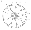
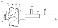
図1は、第一実施形態のタービン回転体1の側面図である。図2は、第一実施形態のタービン回転体1の正面図である。図2には、図1中に示す矢印II方向から見たタービン回転体1が示されている。タービン回転体1は、たとえば、図示しないターボチャージャの内部に配置され、内燃機関から排出された排気ガスの運動エネルギーを回転駆動力に変換して内燃機関に過給するために、用いられる。
[First embodiment]
FIG. 1 is a side view of the
図1に示されるように、タービン回転体1は、タービンホイール10と、回転シャフト30とを備えている。タービンホイール10は、回転シャフト30に固定されている。タービンホイール10は、たとえば溶接により、回転シャフト30の一端に一体的に連結されている。タービンホイール10と回転シャフト30とは、それぞれ耐熱性の金属材料により形成されている。タービンホイール10はたとえば、インコネルを形成材料としている。
As shown in FIG. 1 , the
図1,2に示されるように、タービンホイール10は、山形状のハブ12と、ハブ12の外周面に形成された複数のブレード14とを有している。図2に示される実施形態のタービンホイール10は、ハブ12に9枚のブレード14が取り付けられている。複数のブレード14は、タービンホイール10の周方向に並んで、互いに間隔をあけて配置されている。タービンホイール10はまた、ハブ12から突き出る頭部16を有している。頭部16は、略円柱状の形状を有している。タービンホイール10はまた、頭部16の頂面の一部が窪んだ基準穴20を有している。
As shown in FIGS. 1 and 2, the
回転シャフト30は、タービンホイール10に接合された根元部32を有している。回転シャフト30は、図1中に一点鎖線で示される軸心線CSを有している。回転シャフト30の軸心線CSは、根元部32の形状中心を通り、またタービンホイール10に形成された基準穴20を通って延びている。基準穴20は、回転シャフト30の軸心線CSが通る位置に形成されている。
The rotating
タービンホイール10は、図1中に一点鎖線で示される軸心線CTを有している。図2にも示される通り、タービンホイール10の軸心線CTは、タービンホイール10の形状中心を通って延びている。ハブ12は略円錐台状の形状を有しており、図2に示される正面視において、ハブ12は円形状の外周縁を有している。外周縁は、ハブ12における外形が最大の部位である。ハブ12の外周縁が形成する円の中心が、タービンホイール10の形状中心である。
The
図1に示されるように、タービンホイール10は、重心Gを有している。重心Gは、タービンホイール10の形状中心から偏心した位置にある場合がある。図1に示される重心Gは、タービンホイール10の形状中心から偏心した位置にあり、タービンホイール10の形状中心を示す軸心線CTと位置が一致していない。基準穴20は、タービンホイール10の重心Gの位置に形成されている。基準穴20は、軸心線CTからずれた位置に形成されている。
The
回転シャフト30の軸心線CSは、タービンホイール10の重心Gを通って延びている。回転シャフト30の軸心線CSは、タービンホイール10の軸心線CTからずれている場合がある。回転シャフト30の軸心線CSと、タービンホイール10の軸心線CTとは、ずれている場合互いに平行に延びている。
The axis CS of the
図1,2による図示では、わかりやすさを優先して、タービンホイール10の重心Gの形状中心に対するずれ量を誇張して示している。重心Gの位置に形成される基準穴20は、タービンホイール10の重心Gがタービンホイール10の形状中心に対してずれる量に対応して、タービンホイール10の頭部16に形成されている。
1 and 2, the amount of deviation of the center of gravity G of the
タービンホイール10の形状中心に対する回転シャフト30の軸心線CSのずれ量は、実際には、タービン回転体1の設計上の公差の範囲に収まる程度の微量である。そのため、回転シャフト30の軸心線CSがタービンホイール10の形状中心からずれていても、高速回転するタービン回転体1の性能への影響は無視できる程度に小さく、タービン回転体1の機能が損なわれることはない。
The deviation amount of the axis CS of the
以上の構成を備えているタービン回転体1の製造工程について、以下に説明する。まず、タービンホイール10の成形加工が行なわれる。この工程では、ハブ12、ブレード14および頭部16が、一体物として成形加工される。次に、別途設けられた重量バランス用の測定器により、タービンホイール10の径方向のアンバランス計測が行なわれ、タービンホイール10の重心Gの位置が計測される。
A manufacturing process of the
次に、タービンホイール10のアンバランス計測により計測された重心Gの位置に、基準穴20が形成される。図3は、第一実施形態のタービン回転体1の製造工程を示す第1の図である。この工程では、図3に示されるように、タービンホイール10が治具50によって保持される。この状態で、加工工具52、たとえばドリル工具をタービンホイール10に接近させて、頭部16の頂面に基準穴20を形成する。
Next, a
基準穴20は、タービンホイール10の重心Gを通り軸心線CTに平行な直線が頭部16の頂面と交差する位置に形成される。典型的には基準穴20は、当該直線を中心線とする有底円筒穴として、頭部16の頂面に形成される。タービンホイール10の重心Gがタービンホイール10の形状中心からずれている場合、基準穴20は、タービンホイール10の形状中心から外れた位置に形成される。
The
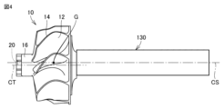
次に、シャフト素材130をタービンホイール10に接合する。図4は、第一実施形態のタービン回転体1の製造工程を示す第2の図である。シャフト素材130は、加工されることにより回転シャフト30が形成される素材であり、典型的には丸棒である。シャフト素材130は、軸心線CSを有している。
Next, the
シャフト素材130は、軸心線CSが基準穴20を通るようにタービンホイール10に対して位置決めされて、タービンホイール10に接合される。基準穴20はタービンホイール10の重心Gの位置に形成されているので、シャフト素材130は、軸心線CSがタービンホイール10の重心Gを通るようにして、タービンホイール10に接合される。基準穴20は、シャフト素材130をタービンホイール10に接合する際のシャフト素材130の軸心線CSの位置決めに用いられる、位置決め部として機能する。
The
シャフト素材130は、その軸心線CSがタービンホイール10の軸心線CTから外れた位置に位置決めされて、タービンホイール10に接合される。タービンホイール10に形成された基準穴20を使って機械的に芯出しが可能であるので、タービンホイール10に対してシャフト素材130を精度よく位置決めした上で、シャフト素材130がタービンホイール10に接合される。
The
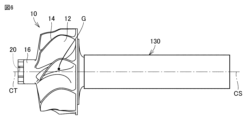
次に、シャフト素材130の加工が行なわれる。図5は、第一実施形態のタービン回転体1の製造工程を示す第3の図である。図4を参照して説明した前工程においてタービンホイール10に接合されたシャフト素材130を、加工工具60、典型的には切削工具または研磨工具などを用いて加工することで、回転シャフト30が所定の形状に成形加工される。
Next, the
このような製造工程を順に経ることで、一連の加工が終了し、図1,2に示される第一実施形態のタービン回転体1が完成する。
By going through such manufacturing steps in order, a series of machining is completed, and the
以上説明した本実施形態のタービン回転体1によると、図1,2に示されるように、タービンホイール10が形状中心から偏心した位置に重心Gを有し、回転シャフト30の軸心線CSが重心Gを通るように構成されている。そのため、タービンホイール10と回転シャフト30とを含むタービン回転体1全体としてのアンバランス量を低減することができる。タービンホイール10のアンバランスを修正するためにタービンホイール10を部分的に加工する加工量が小さくなるので、加工時間を短縮でき、刃具費の低減が可能となる。少ない加工量でアンバランス修正でき、タービン回転体1の製品形状が大きく変わることがないため、製品の強度、製品の信頼性などの製品機能に影響を与えることを抑制できる。
According to the
図4,5に示されるように、タービンホイール10の軸心線CTからずれた位置に軸心線CSが位置決めされてシャフト素材130がタービンホイール10に接合されて、その後シャフト素材130が加工されて回転シャフト30が形成される。このようにタービン回転体1を形成するので、図1に示されるように、回転シャフト30の軸心線CSが、回転シャフト30の根元部32の形状中心を通って延びるようになる。これにより、回転シャフト30の軸心線CSが、タービンホイール10の形状中心から偏心した重心Gを通る構成を、確実に実現することができる。
As shown in FIGS. 4 and 5, the axis CS is positioned at a position deviated from the axis CT of the
図1に示されるように、タービンホイール10は、軸心線CSが通る位置に形成された基準穴20を有している。タービンホイール10の重心Gの位置に基準穴20を形成し、この基準穴20を位置決め部として用いて、シャフト素材130をタービンホイール10に接合する際の、シャフト素材130の軸心線CSの位置決めがなされる。これにより、回転シャフト30の軸心線CSがタービンホイール10の重心Gを通る構成を、確実に実現することができる。
As shown in FIG. 1, the
[第二実施形態]
図6は、第二実施形態のタービン回転体1の製造工程を示す第1の図である。図6に示される工程では、図4と同様に、タービンホイール10にシャフト素材130が接合される。シャフト素材130は、軸心線CSを有している。図6においてはシャフト素材130は、その軸心線CSがタービンホイール10の軸心線CTと一致するように位置決めされて、タービンホイール10に接合される。シャフト素材130は、軸心線CSがタービンホイール10の形状中心に位置決めされて、タービンホイール10に接合される。
[Second embodiment]
FIG. 6 is a first diagram showing the manufacturing process of the
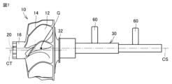
続いて、シャフト素材130の加工が行なわれる。図7は、第二実施形態のタービン回転体1の製造工程を示す第2の図である。図7に示される工程では、図5と同様に、タービンホイール10に接合されたシャフト素材130を、加工工具60で加工することで、回転シャフト30が成形加工される。
Subsequently, the
この成形加工によって、回転シャフト30の軸心線CSが、シャフト素材130の軸心線CSの位置から径方向にずれる。図7に示される回転シャフト30の軸心線CSは、タービンホイール10の軸心線CTから外れて、タービンホイール10の軸心線CTと平行に延びている。回転シャフト30の軸心線CSは、第一実施形態と同様に、タービンホイール10の重心Gを通って延び、タービンホイール10に形成された基準穴20を通って延びている。一方、回転シャフト30の軸心線CSは、根元部32の形状中心からずれている。
Due to this forming process, the axial center line CS of the
このように、タービンホイール10の形状中心にシャフト素材130を位置決めして接合し、シャフト素材130を加工してタービンホイール10の重心Gの位置に回転シャフト30の軸心線CSを合わせるような製造工程を経ることによっても、製品全体としてアンバランスが低減されたタービン回転体1を実現することができる。
In this way, the
[第三実施形態]
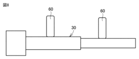
図8は、第三実施形態のタービン回転体1の製造工程を示す第1の図である。第一および第二実施形態では、シャフト素材130をタービンホイール10に接合した後にシャフト素材130を加工することで、回転シャフト30の成形加工が行なわれる。これに対し第三実施形態では、図8に示されるように、シャフト素材130がタービンホイール10に接合される前に加工工具60によって加工されて、回転シャフト30が成形加工される。
[Third embodiment]
FIG. 8 is a first diagram showing the manufacturing process of the
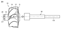
次に、成形された回転シャフト30を、タービンホイール10に接合する。図9は、第三実施形態のタービン回転体1の製造工程を示す第2の図である。回転シャフト30は、軸心線CSが基準穴20を通るようにタービンホイール10に対して位置決めされて、タービンホイール10に接合される。回転シャフト30は、軸心線CSがタービンホイール10の重心Gを通るようにして、タービンホイール10に接合される。回転シャフト30は、その軸心線CSがタービンホイール10の軸心線CTから外れた位置に位置決めされて、タービンホイール10に接合される。回転シャフト30をタービンホイール10に接合する際の軸心線CSの位置決めに、基準穴20が用いられる。
The molded
このような製造工程を経ることによっても、製品全体としてアンバランスが低減されたタービン回転体1を実現することができる。
Through such a manufacturing process, it is possible to realize the
[第四実施形態]
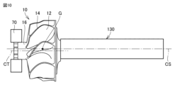
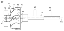
図10は、第四実施形態のタービン回転体1の製造工程を示す第1の図である。図11は、第四実施形態のタービン回転体1の製造工程を示す第2の図である。第一および第三実施形態では、タービンホイール10の重心Gの位置に基準穴20を形成して、シャフト素材130または回転シャフト30をタービンホイール10に接合する際の位置決めに基準穴20を用いる例を説明した。タービンホイール10に、必ずしも基準穴20を形成しなくてもよい。
[Fourth embodiment]
FIG. 10 is a first diagram showing the manufacturing process of the
図10,11に示される第四実施形態では、シャフト素材130をタービンホイール10に接合する前に、タービンホイール10の頭部16がチャック70により保持される。タービンホイール10の軸心線CTに対する重心Gの位置が、予め計測されている。チャック70でタービンホイール10を保持してタービンホイール10を精度よく位置決めし、位置決めされたタービンホイール10の重心Gの位置にシャフト素材130の軸心線CSが通るように、シャフト素材130がタービンホイール10に対して精度よく位置決めされる。この状態で、シャフト素材130がタービンホイール10に接合される。接合された後、シャフト素材130が加工工具60によって加工されて、回転シャフト30が形成される。
In a fourth embodiment shown in FIGS. 10 and 11, the
このような製造工程を経ることによっても、製品全体としてアンバランスが低減されたタービン回転体1を実現することができる。基準穴20を形成する加工が必要なくなることで、加工時間をさらに短縮でき、刃具費をさらに低減することができる。
Through such a manufacturing process, it is possible to realize the
[第五実施形態]
図12は、第五実施形態のタービン回転体の製造工程を示す図である。タービンホイール10にシャフト素材130または回転シャフト30を接合する際の位置決めに用いる位置決め部として、これまでの実施形態で説明した基準穴20に替えて、図12に示される基準突起120を設けてもよい。
[Fifth embodiment]
FIG. 12 is a diagram showing the manufacturing process of the turbine rotor according to the fifth embodiment. As a positioning portion used for positioning when joining the
基準突起120は、タービンホイール10の頭部16から、タービンホイール10の軸心線CT(図3など参照)の延びる方向に突き出るように、形成されている。基準突起120は、タービンホイール10の軸心線CTからずれた位置に形成されている。基準突起120は、タービンホイール10の重心Gの位置に形成されている。タービンホイール10に回転シャフト30が接合された状態において、基準突起120は、回転シャフト30の軸心線CSが通る位置に形成されている。回転シャフト30の軸心線CSは、基準穴20を通り、さらに基準突起120を通って延びている。
The
基準突起120を用いてタービンホイール10を機械的に芯出しすることで、シャフト素材130または回転シャフト30を、その軸心線CSが重心Gの位置を通るようにタービンホイール10に対して位置決めすることが容易になる。位置決めされたシャフト素材130または回転シャフト30を、その位置でタービンホイール10に接合することで、シャフト素材130または回転シャフト30の軸心線CSがタービンホイール10の重心Gを通るように、容易に配置することができる。
By mechanically centering the
したがって、このような製造工程を経ることによっても、タービン回転体1全体としてのアンバランスを低減することができる。タービンホイール10の重心Gの位置に仮設置した基準突起120を、製品形状の仕上げ後に除去することにより、基準突起120がアンバランスを発生することを防止することができる。
Therefore, the imbalance of the
以上のように実施形態について説明を行なったが、各実施形態において互いに組合せ可能な構成を適宜組み合わせてもよい。また、今回開示された実施形態はすべての点で例示であって制限的なものではないと考えられるべきである。本発明の範囲は上記した説明ではなくて特許請求の範囲によって示され、特許請求の範囲と均等の意味および範囲内でのすべての変更が含まれることが意図される。 Although the embodiments have been described as above, configurations that can be combined with each other in each embodiment may be combined as appropriate. Moreover, it should be considered that the embodiment disclosed this time is an illustration and is not restrictive in all respects. The scope of the present invention is indicated by the scope of the claims rather than the above description, and is intended to include all modifications within the meaning and range of equivalents of the scope of the claims.
1 タービン回転体、10 タービンホイール、12 ハブ、14 ブレード、16 頭部、20 基準穴、30 回転シャフト、32 根元部、50 冶具、52,60 加工工具、70 チャック、120 基準突部、130 シャフト素材、CT タービンホイールの軸心線、CS 回転シャフトの軸心線、G タービンホイールの重心。 1 turbine rotor, 10 turbine wheel, 12 hub, 14 blade, 16 head, 20 reference hole, 30 rotating shaft, 32 root, 50 jig, 52, 60 processing tool, 70 chuck, 120 reference protrusion, 130 shaft Material, CT Turbine Wheel Axis, CS Rotating Shaft Axis, G Turbine Wheel Center of Gravity.
Claims (4)
前記回転シャフトに固定されたタービンホイールとを備え、
前記タービンホイールは、形状中心から偏心した位置に重心を有し、
前記回転シャフトの軸心線が前記重心を通り、
前記回転シャフトは、前記タービンホイールに接合された根元部を有し、
前記軸心線が前記根元部の形状中心からずれている、タービン回転体。 a rotating shaft;
a turbine wheel fixed to the rotating shaft;
The turbine wheel has a center of gravity at a position eccentric from the shape center,
an axis of the rotating shaft passing through the center of gravity,
the rotating shaft having a root joined to the turbine wheel;
A turbine rotor , wherein the axial center line is offset from the shape center of the root portion .
前記タービンホイールの重心を計測することと、
加工されることにより前記回転シャフトが形成されるシャフト素材を、前記シャフト素材の軸心線が前記タービンホイールの形状中心を通るように前記タービンホイールに接合することと、
前記タービンホイールに接合された前記シャフト素材を加工して、前記回転シャフトの軸心線を前記シャフト素材の軸心線から径方向にずらした、前記回転シャフトを形成することとを備える、タービン回転体の製造方法。 A method for manufacturing a turbine rotor comprising a rotating shaft and a turbine wheel fixed to the rotating shaft,
measuring the center of gravity of the turbine wheel;
joining a shaft material, which is processed to form the rotating shaft, to the turbine wheel so that the axial center line of the shaft material passes through the shape center of the turbine wheel ;
machining the shaft blank that is joined to the turbine wheel to form the rotating shaft with the axis of the rotating shaft radially offset from the axis of the shaft blank. body manufacturing method.
Priority Applications (1)
| Application Number | Priority Date | Filing Date | Title |
|---|---|---|---|
| JP2019179415A JP7268564B2 (en) | 2019-09-30 | 2019-09-30 | Turbine rotor and manufacturing method thereof |
Applications Claiming Priority (1)
| Application Number | Priority Date | Filing Date | Title |
|---|---|---|---|
| JP2019179415A JP7268564B2 (en) | 2019-09-30 | 2019-09-30 | Turbine rotor and manufacturing method thereof |
Publications (2)
| Publication Number | Publication Date |
|---|---|
| JP2021055612A JP2021055612A (en) | 2021-04-08 |
| JP7268564B2 true JP7268564B2 (en) | 2023-05-08 |
Family
ID=75270218
Family Applications (1)
| Application Number | Title | Priority Date | Filing Date |
|---|---|---|---|
| JP2019179415A Active JP7268564B2 (en) | 2019-09-30 | 2019-09-30 | Turbine rotor and manufacturing method thereof |
Country Status (1)
| Country | Link |
|---|---|
| JP (1) | JP7268564B2 (en) |
Citations (1)
| Publication number | Priority date | Publication date | Assignee | Title |
|---|---|---|---|---|
| JP2012026875A (en) | 2010-07-23 | 2012-02-09 | Ihi Corp | Centroid position measuring method, centroid position measuring apparatus and method for manufacturing turbine rotor |
Family Cites Families (1)
| Publication number | Priority date | Publication date | Assignee | Title |
|---|---|---|---|---|
| JPS5850189A (en) * | 1981-09-22 | 1983-03-24 | Toyota Motor Corp | Method and device for joining turbine wheel and turbine shaft |
-
2019
- 2019-09-30 JP JP2019179415A patent/JP7268564B2/en active Active
Patent Citations (1)
| Publication number | Priority date | Publication date | Assignee | Title |
|---|---|---|---|---|
| JP2012026875A (en) | 2010-07-23 | 2012-02-09 | Ihi Corp | Centroid position measuring method, centroid position measuring apparatus and method for manufacturing turbine rotor |
Also Published As
| Publication number | Publication date |
|---|---|
| JP2021055612A (en) | 2021-04-08 |
Similar Documents
| Publication | Publication Date | Title |
|---|---|---|
| US5174715A (en) | Turbine nozzle | |
| US8850703B2 (en) | Method for the manufacture of the blade tips of rotor wheels made in BLISK design | |
| JP4837203B2 (en) | Blisk balanced by eccentricity | |
| US9638037B2 (en) | Method of balancing a gas turbine engine rotor | |
| DK202070704A1 (en) | Systems and methods for monitoring rotary equipment | |
| JP5588085B1 (en) | Compressor assembly and unbalance detection device for compressor assembly | |
| JP6189021B2 (en) | Impeller rotating body and rotating body | |
| EP2299239B1 (en) | Shaft curve calculation system of turbine rotor | |
| EP1862698B1 (en) | Rotor unbalance correction | |
| US9388697B2 (en) | First stage compressor disk configured for balancing the compressor rotor assembly | |
| US8631577B2 (en) | Method of fabricating integrally bladed rotor and stator vane assembly | |
| EP1452687A2 (en) | Rotor balancing | |
| CN114502825A (en) | Balance adjustment method for rotating body and turbocharger | |
| US20150046126A1 (en) | Gas turbine engine rotor assembly optimization | |
| US5182855A (en) | Turbine nozzle manufacturing method | |
| JP2017526846A (en) | Turbine blisk and method for manufacturing turbine blisk | |
| JP7268564B2 (en) | Turbine rotor and manufacturing method thereof | |
| US9498857B2 (en) | Method of fabricating integrally bladed rotor using surface positioning in relation to surface priority | |
| JP7169167B2 (en) | NOZZLE DIAPHRAGM MANUFACTURING METHOD AND NOZZLE DIAPHRAGM | |
| WO2018132629A1 (en) | Adaptive machining of cooled turbine airfoil | |
| WO2016147849A1 (en) | Rotational solid | |
| EP3117946A1 (en) | Linear friction welding method | |
| CN106103899B (en) | Rotor components with surfaces for checking concentricity | |
| US4017212A (en) | Bladed rotor | |
| JP2012013596A (en) | Rotor and balance correction method for the same |
Legal Events
| Date | Code | Title | Description |
|---|---|---|---|
| A621 | Written request for application examination |
Free format text: JAPANESE INTERMEDIATE CODE: A621 Effective date: 20211214 |
|
| A977 | Report on retrieval |
Free format text: JAPANESE INTERMEDIATE CODE: A971007 Effective date: 20221027 |
|
| A131 | Notification of reasons for refusal |
Free format text: JAPANESE INTERMEDIATE CODE: A131 Effective date: 20221101 |
|
| A521 | Request for written amendment filed |
Free format text: JAPANESE INTERMEDIATE CODE: A523 Effective date: 20221124 |
|
| TRDD | Decision of grant or rejection written | ||
| A01 | Written decision to grant a patent or to grant a registration (utility model) |
Free format text: JAPANESE INTERMEDIATE CODE: A01 Effective date: 20230322 |
|
| A61 | First payment of annual fees (during grant procedure) |
Free format text: JAPANESE INTERMEDIATE CODE: A61 Effective date: 20230404 |
|
| R151 | Written notification of patent or utility model registration |
Ref document number: 7268564 Country of ref document: JP Free format text: JAPANESE INTERMEDIATE CODE: R151 |

