JP7268308B2 - cup mounting device - Google Patents
cup mounting device Download PDFInfo
- Publication number
- JP7268308B2 JP7268308B2 JP2018164813A JP2018164813A JP7268308B2 JP 7268308 B2 JP7268308 B2 JP 7268308B2 JP 2018164813 A JP2018164813 A JP 2018164813A JP 2018164813 A JP2018164813 A JP 2018164813A JP 7268308 B2 JP7268308 B2 JP 7268308B2
- Authority
- JP
- Japan
- Prior art keywords
- lens
- cup
- support
- spectacle
- spectacle lens
- Prior art date
- Legal status (The legal status is an assumption and is not a legal conclusion. Google has not performed a legal analysis and makes no representation as to the accuracy of the status listed.)
- Active
Links
Images


Description
本開示は、眼鏡レンズにカップを取り付けるカップ取付装置に関する。 The present disclosure relates to a cup attaching device for attaching a cup to a spectacle lens.
眼鏡レンズの周縁を加工する際に用いる加工治具であるカップを、未加工の眼鏡レンズに対して取り付けるカップ取付装置が知られている。例えば、特許文献1では、眼鏡レンズを支持ピンで支持し、眼鏡レンズの適切な位置にカップを取り付けている。
2. Description of the Related Art A cup attachment device is known for attaching a cup, which is a processing jig used when processing the peripheral edge of a spectacle lens, to an unprocessed spectacle lens. For example, in
上記のカップ取付装置において、眼鏡レンズの前面と後面の曲率の差が大きな眼鏡レンズを支持ピンに載置するとき、眼鏡レンズの中心位置をずらして偏心させた状態で支持ピンに載置するとき、等には、眼鏡レンズの支持が不安定になり、精度よくカップを取り付けられない場合があった。これに対して、支持ピンを自在に回転させることで眼鏡レンズの支持を安定にし、カップを取り付けることも考えられるが、眼鏡レンズを支持ピンに容易に載置できなくなり、また、カップ取付装置が複雑な構成になる。 In the above cup mounting device, when a spectacle lens having a large difference in curvature between the front surface and the rear surface of the spectacle lens is placed on the support pins, and when the center position of the spectacle lens is shifted and placed on the support pins in an eccentric state. , etc., the support of the spectacle lens becomes unstable, and there are cases where the cup cannot be attached with high accuracy. On the other hand, it is conceivable to stabilize the support of the spectacle lens by freely rotating the support pin and attach the cup. It becomes a complicated configuration.
本開示は、上記従来技術に鑑み、眼鏡レンズにカップを適切に取り付けることができるカップ取付装置を提供することを技術課題とする。 A technical problem of the present disclosure is to provide a cup attachment device capable of appropriately attaching a cup to a spectacle lens in view of the above-described conventional technology.
上記課題を解決するために、本開示は、以下のような構成を備えることを特徴とする。 In order to solve the above problems, the present disclosure is characterized by having the following configuration.
(1) 本開示の第1態様に係るカップ取付装置は、眼鏡レンズに加工治具であるカップを取り付けるカップ取付装置において、前記眼鏡レンズの前面と、前記カップの取付面と、を平行に保つことで、前記カップを取り付ける基準面を前記眼鏡レンズの前面とし、前記眼鏡レンズを支持する第1レンズ支持手段と、前記眼鏡レンズの後面と、前記カップの取付面と、を平行に保つことで、前記カップを取り付ける基準面を前記眼鏡レンズの後面とし、前記眼鏡レンズを支持する第2レンズ支持手段と、前記カップ取付装置において、前記第1レンズ支持手段と前記第2レンズ支持手段とを切り換える切換手段と、前記眼鏡レンズに前記カップを取り付けるカップ取付手段と、を備えることを特徴とする。 (1) A cup mounting device according to a first aspect of the present disclosure is a cup mounting device for mounting a cup, which is a processing jig, on a spectacle lens, in which the front surface of the spectacle lens and the mounting surface of the cup are kept parallel. By using the front surface of the spectacle lens as the reference surface for attaching the cup, the first lens supporting means for supporting the spectacle lens, the rear surface of the spectacle lens, and the mounting surface of the cup are kept parallel. a second lens support means for supporting the spectacle lens with the reference surface for mounting the cup as the rear surface of the spectacle lens; and switching between the first lens support means and the second lens support means in the cup mounting device. The spectacle lens is characterized by comprising switching means and cup attachment means for attaching the cup to the spectacle lens.
<概要>
本開示の実施形態に係るカップ取付装置の概要について説明する。なお、以下の<>にて分類された項目は、独立または関連して利用されうる。
<Overview>
An outline of a cup attaching device according to an embodiment of the present disclosure will be described. In addition, the items classified by <> below can be used independently or in association with each other.
<レンズ支持手段>
例えば、本実施例におけるカップ取付装置(例えば、カップ取付装置1)は、レンズ支持手段(例えば、レンズ支持機構10)を備える。レンズ支持手段は、眼鏡レンズを載置して眼鏡レンズを支持する。レンズ支持手段は、第1レンズ支持手段(例えば、第1レンズ支持部15a)と、第2レンズ支持部15bと、を有していてもよい。本実施例では、第1レンズ支持手段によって眼鏡レンズの前面が基準面とされ、第2レンズ支持手段によって眼鏡レンズの後面が基準面とされる。基準面は、眼鏡レンズにカップを取り付ける際の基準となる面であり、カップの取付面と平行な面であってもよい。なお、この場合の平行とは、眼鏡レンズにカップを取り付ける際の基準軸(カップの取付面に直交する軸)と、眼鏡レンズのレンズ面(前面または後面)の交点における法線と、が一致する状態であってもよい。また、基準面は、眼鏡レンズの前面及び後面の形状(例えば、カーブ値、等)に応じて、前面または後面のいずれかに設けられてもよい。
<Lens support means>
For example, the cup mounting device (eg, cup mounting device 1) in this embodiment includes lens support means (eg, lens support mechanism 10). The lens support means supports the spectacle lens by placing the spectacle lens thereon. The lens support means may have a first lens support means (eg, first
<第1レンズ支持手段>
第1レンズ支持手段は、眼鏡レンズの前面(表面)とカップの取付面とを平行に保つことで、カップを取り付ける基準面を眼鏡レンズの前面とし、眼鏡レンズを支持してもよい。例えば、第1レンズ支持手段は、第1支持ピン(例えば、支持ピン21)を有していてもよい。第1支持ピンは、複数のピン(例えば、3本のピン、等)で構成されてもよい。第1支持ピンは、第1支持ピンと、第1支持ピンに載置される眼鏡レンズの後面と、の当接面を、カップの取付面に対して傾斜させるための支持ピンであってもよい。この場合、第1支持ピンと眼鏡レンズの後面との当接面は、カップの取付面に対していずれの経線方向(すなわち、0度~360度)に傾斜されてもよい。
<First Lens Support Means>
The first lens support means may support the spectacle lens by keeping the front surface (surface) of the spectacle lens and the mounting surface of the cup parallel to the front surface of the spectacle lens as a reference surface for mounting the cup. For example, the first lens support means may have a first support pin (eg, support pin 21). The first support pin may consist of a plurality of pins (eg, three pins, etc.). The first support pin may be a support pin for tilting a contact surface between the first support pin and the rear surface of the spectacle lens mounted on the first support pin with respect to the mounting surface of the cup. . In this case, the contact surface between the first support pin and the rear surface of the spectacle lens may be inclined in any meridional direction (ie, 0 to 360 degrees) with respect to the mounting surface of the cup.
例えば、本実施例において、第1レンズ支持手段は、カップの取付面に対して回転自在な第1支持ピンを有してもよい。第1支持ピンが回転自在であることによって、カップの取付面に対して任意の経線方向に傾斜され、その傾斜角度に応じて、カップ取付装置の接地面から各ピンまでの高さが変化する。 For example, in this embodiment, the first lens support means may have a first support pin that is rotatable with respect to the mounting surface of the cup. Since the first support pin is rotatable, it can be inclined in any meridional direction with respect to the mounting surface of the cup, and the height from the ground surface of the cup mounting device to each pin changes according to the inclination angle. .
例えば、第1レンズ支持手段は、このような回転自在な第1支持ピンを有し、第1支持ピンに載置された眼鏡レンズの前面と、カップの取付面とを平行に保つことで、眼鏡レンズの前面を基準面としてもよい。第1支持ピンが回転自在であることによって、眼鏡レンズの前面と後面の曲率の差が大きな眼鏡レンズ(例えば、ハイカーブレンズ、等)に対しても、その前面に基準面を設けることができるようになる。 For example, the first lens support means has such a rotatable first support pin, and by keeping the front surface of the spectacle lens placed on the first support pin parallel to the mounting surface of the cup, The front surface of the spectacle lens may be used as the reference plane. Since the first support pin is rotatable, it is possible to provide a reference plane on the front surface of the spectacle lens even for spectacle lenses having a large difference in curvature between the front surface and the rear surface of the spectacle lens (for example, high-curve lenses). become.
例えば、第1レンズ支持手段は、さらに、レンズ押さえ手段(例えば、レンズ押さえ機構40)を有していてもよい。レンズ押さえ手段は、眼鏡レンズの前面を押さえる。例えば、本実施例では、第1レンズ支持手段が備える第1支持ピンに対して、レンズ押さえ手段が垂直方向に移動することによって、第1支持ピンに載置された眼鏡レンズの前面をレンズ押さえ手段が垂直方向から押さえる。つまり、レンズ押さえ手段を用いて眼鏡レンズの前面が押さえられつつ、第1支持ピンを用いて眼鏡レンズの後面が押さえられる。これによって、第1支持ピンに載置されるとともにレンズ押さえ手段に押さえられた眼鏡レンズの前面と、レンズ押さえ手段と、の当接面は平行に保たれる。例えば、第1レンズ支持手段は、このように第1支持ピンに載置されるとともにレンズ押さえ手段に押さえられた眼鏡レンズの前面と、レンズ押さえ手段と、の当接面を平行に保つことで、眼鏡レンズの前面とカップの取付面とを平行に保ち、眼鏡レンズの前面を基準面としてもよい。第1レンズ支持手段がレンズ押さえ手段を備えることによって、眼鏡レンズの前面と後面の曲率の差が大きな眼鏡レンズ(例えば、ハイカーブレンズ、等)を挟持し、より安定に支持することができる。 For example, the first lens supporting means may further have lens pressing means (for example, lens pressing mechanism 40). The lens pressing means presses the front surface of the spectacle lens. For example, in this embodiment, the front surface of the spectacle lens mounted on the first support pin is moved vertically to the first support pin provided in the first lens support means, thereby causing the lens presser to move the front surface of the eyeglass lens. A means presses from a vertical direction. That is, while the front surface of the spectacle lens is pressed using the lens pressing means, the rear surface of the spectacle lens is pressed using the first support pin. As a result, the contact surface between the front surface of the spectacle lens placed on the first support pin and pressed by the lens pressing means and the lens pressing means is kept parallel. For example, the first lens support means can keep the contact surface of the front surface of the spectacle lens placed on the first support pin and pressed by the lens pressing means parallel to the contact surface of the lens pressing means. Alternatively, the front surface of the spectacle lens may be kept parallel to the mounting surface of the cup, and the front surface of the spectacle lens may be used as the reference plane. By providing the lens pressing means to the first lens supporting means, spectacle lenses having a large difference in curvature between the front surface and the rear surface of the spectacle lens (for example, a high curve lens, etc.) can be clamped and supported more stably.
なお、本実施例において、第1レンズ支持手段が備えるレンズ押さえ手段は、カップ取付装置から着脱可能であってもよい。この場合、レンズ押さえ手段を全体的にカップ取付装置から着脱可能とする構成であってもよい。また、この場合、レンズ押さえ手段を部分的にカップ取付装置から着脱可能とする構成であってもよい。一例としては、レンズ押さえ手段が備えるアームのみがカップ取付装置から着脱可能とされてもよい。 In addition, in this embodiment, the lens pressing means provided in the first lens supporting means may be detachable from the cup mounting device. In this case, the lens holding means may be configured to be detachable from the cup mounting device as a whole. In this case, the lens holding means may be partially detachable from the cup mounting device. As an example, only the arm of the lens holding means may be detachable from the cup mounting device.
また、本実施例において、第1レンズ支持手段が備えるレンズ押さえ手段は、眼鏡レンズを押さえる使用位置と、使用位置から退避させた退避位置と、に切り換え可能であってもよい。例えば、本実施例において、レンズ押さえ手段の使用位置は、レンズ押さえ手段が第1支持ピン上に配置される位置であってもよい。より詳細には、例えば、レンズ押さえ手段が備える押さえピン(例えば、レンズ押さえピン44)の水平方向における位置が、第1支持ピンの水平方向における位置と一致する位置であってもよい。レンズ支持手段として第1レンズ支持手段を用いる際には、レンズ押さえ手段を使用位置に切り換えて使用してもよい。レンズ支持手段として第2レンズ支持手段を用いる際には、レンズ押さえ手段を退避位置に切り換えて使用してもよい。眼鏡レンズの種類に応じて第1レンズ支持手段または第2レンズ支持手段のいずれかに変更した際には、レンズ押さえ手段の使用と不使用を容易に切り換えることができ、操作性が向上される。 Further, in this embodiment, the lens holding means provided in the first lens supporting means may be switchable between a use position holding the spectacle lens and a retracted position retracted from the use position. For example, in this embodiment, the use position of the lens pressing means may be a position where the lens pressing means is arranged on the first support pin. More specifically, for example, the horizontal position of the pressing pin (for example, the lens pressing pin 44) of the lens pressing means may coincide with the horizontal position of the first support pin. When using the first lens support means as the lens support means, the lens pressing means may be switched to the use position. When using the second lens support means as the lens support means, the lens pressing means may be switched to the retracted position. When changing to either the first lens support means or the second lens support means according to the type of the spectacle lens, the use and non-use of the lens pressing means can be easily switched to improve the operability. .
なお、第1レンズ支持手段は、眼鏡レンズの前面を基準面とすることが可能な構成を備えていればよく、カップの取付面に対して回転自在な第1支持ピンを有する構成に限定されない。例えば、各ピンの高さをそれぞれ調節することが可能な第1支持ピンを有することで、眼鏡レンズの前面とカップの取付面とを平行に保つようにしてもよい。この場合、第1レンズ支持手段は、さらにレンズ押さえ手段を有し、ピンに載置された眼鏡レンズとレンズ押さえ手段との当接面を平行に保つようにしてもよい。これによっても、眼鏡レンズの前面を基準面とすることができる。もちろん、第1支持ピンを用いることなく、眼鏡レンズの前面とカップの取付面とを平行に保つようにしてもよい。一例としては、円筒状のレンズ支持部を有し、眼鏡レンズの前面をレンズ支持部に載置することで、眼鏡レンズの前面とカップの取付面とを平行に保ち、眼鏡レンズの前面を基準面としてもよい。なお、この場合には、第1レンズ支持手段が眼鏡レンズの後面を押さえるレンズ押さえ手段を有し、眼鏡レンズを挟持するようにしてもよい。 In addition, the first lens support means may have a configuration that allows the front surface of the spectacle lens to be used as a reference plane, and is not limited to a configuration having a first support pin that is rotatable with respect to the mounting surface of the cup. . For example, the front surface of the spectacle lens and the mounting surface of the cup may be kept parallel by having first support pins whose heights are adjustable. In this case, the first lens support means may further have lens pressing means, and the abutment surfaces of the spectacle lens mounted on the pin and the lens pressing means may be kept parallel. This also makes it possible to use the front surface of the spectacle lens as the reference plane. Of course, the front surface of the spectacle lens and the mounting surface of the cup may be kept parallel without using the first support pin. As an example, by having a cylindrical lens supporting portion and placing the front surface of the spectacle lens on the lens supporting portion, the front surface of the spectacle lens and the mounting surface of the cup are kept parallel, and the front surface of the spectacle lens is used as a reference. It can be a face. In this case, the first lens supporting means may have lens holding means for holding the rear surface of the spectacle lens, and may hold the spectacle lens therebetween.
<第2レンズ支持手段>
第2レンズ支持手段は、眼鏡レンズの後面(裏面)とカップの取付面とを平行に保つことで、カップを取り付ける基準面を眼鏡レンズの後面とし、眼鏡レンズを支持してもよい。例えば、第2レンズ支持手段は、第2支持ピン(例えば、支持ピン26)を有していてもよい。第2支持ピンは、複数のピン(例えば、3本のピン、等)で構成されてもよい。第2支持ピンは、眼鏡レンズを載置する固定配置されたピンであってもよい。例えば、本実施例における第2支持ピンは、各ピンが同一の高さに固定配置されたピンであってもよい。
<Second Lens Support Means>
The second lens support means may support the spectacle lens by keeping the rear surface (rear surface) of the spectacle lens and the mounting surface of the cup parallel to the reference surface for mounting the cup on the rear surface of the spectacle lens. For example, the second lens support means may comprise a second support pin (eg, support pin 26). The second support pin may consist of multiple pins (eg, three pins, etc.). The second support pin may be a fixedly arranged pin on which the spectacle lens is placed. For example, the second support pins in this embodiment may be pins fixedly arranged at the same height.
例えば、第2レンズ支持手段は、このような固定配置された第2支持ピンを有し、第2支持ピンと、第2支持ピンに載置された眼鏡レンズの後面と、の当接面を平行に保つことで、眼鏡レンズの後面とカップの取付面とを平行に保ち、眼鏡レンズの後面を基準面としてもよい。第2支持ピンが固定配置されていることで、レンズ押さえ手段等を用いることなく眼鏡レンズの後面に基準面を設けることができ、操作が容易である。 For example, the second lens support means has such a fixedly arranged second support pin, and the abutting surfaces of the second support pin and the rear surface of the spectacle lens placed on the second support pin are parallel. , the rear surface of the spectacle lens and the mounting surface of the cup can be kept parallel, and the rear surface of the spectacle lens can be used as a reference plane. Since the second support pin is fixedly arranged, the reference surface can be provided on the rear surface of the spectacle lens without using lens pressing means or the like, and the operation is easy.
なお、本実施例において、第2レンズ支持手段は、さらに、レンズ押さえ手段を有していてもよい。この場合には、眼鏡レンズを第2支持ピンとレンズ押さえ手段とにより挟持し、眼鏡レンズをより安定に支持することができる。 In addition, in this embodiment, the second lens supporting means may further have a lens pressing means. In this case, the spectacle lens can be held between the second support pin and the lens pressing means, and the spectacle lens can be supported more stably.
なお、第2レンズ支持手段は、眼鏡レンズの後面を基準面とすることが可能な構成を備えていればよく、本実施例に限定されない。例えば、各ピン間の距離や間隔を調整できる高さが同一な可動ピンを有し、眼鏡レンズを支持する領域の大きさを変更できるようにしてもよい。また、例えば、第2支持ピンに加えて、着脱可能なピンを有する構成であってもよい。これらの場合であっても、各ピンと眼鏡レンズの後面との当接面を平行に保つとともに、眼鏡レンズの後面とカップの取付面とを平行に保ち、眼鏡レンズの後面を基準面とすることができる。 In addition, the second lens support means is not limited to this embodiment as long as it has a configuration that allows the rear surface of the spectacle lens to be used as a reference surface. For example, movable pins having the same height that can adjust the distance or interval between pins may be provided so that the size of the area for supporting the spectacle lens can be changed. Further, for example, in addition to the second support pin, it may be configured to have a detachable pin. Even in these cases, the abutment surfaces between the pins and the rear surface of the spectacle lens should be kept parallel, the rear surface of the spectacle lens and the mounting surface of the cup should be kept parallel, and the rear surface of the spectacle lens should be used as a reference plane. can be done.
<切換手段>
例えば、本実施例におけるカップ取付装置は、切換手段を備える。切換手段は、カップ取付装置において、第1レンズ支持手段と第2レンズ支持手段とを切り換える。例えば、切換手段は、第1レンズ支持手段と第2レンズ支持手段とのいずれか一方を、眼鏡レンズにカップを取り付けるための使用位置に配置し、他方を使用位置から退避させた退避位置に配置することで、第1レンズ支持手段と第2レンズ支持手段とを切り換えてもよい。切換手段を備えることで、眼鏡レンズの種類毎に基準面を容易に変更し、適切にカップを取り付けることができる。
<Switching Means>
For example, the cup attachment device in this embodiment comprises switching means. The switching means switches between the first lens supporting means and the second lens supporting means in the cup mounting device. For example, the switching means arranges one of the first lens support means and the second lens support means at the use position for attaching the cup to the spectacle lens, and the other at the retracted position where the other is retracted from the use position. By doing so, the first lens support means and the second lens support means may be switched. By providing the switching means, the reference surface can be easily changed for each type of spectacle lens, and the cup can be attached appropriately.
本実施例において、切換手段は、第1着脱手段(例えば、挿込ピン11)を有していてもよい。第1着脱手段は、第1レンズ支持手段及び第2レンズ支持手段をカップ取付装置に装着可能とする。なお、第1着脱手段は、第1レンズ支持手段及び第2レンズ支持手段をカップ取付装置に装着可能な構成であればよく、本実施例に限定されない。例えば、凸部と凹部を嵌合させる構成であってもよい。この場合には、カップ取付装置に第1レンズ支持手段及び第2レンズ支持手段を嵌合させるための嵌合部を設けるとともに、第1レンズ支持手段及び第2レンズ支持手段に嵌合部を嵌め込むための窪みを設けてもよい。また、例えば、磁石等を用いて第1レンズ支持手段及び第2レンズ支持手段を取り付ける構成であってもよい。これらのような場合、切換手段は、第1着脱手段を用いて第1レンズ支持手段または第2レンズ支持手段のいずれか一方を取り付けることによって、第1レンズ支持手段と第2レンズ支持手段とを切り換えるようにしてもよい。眼鏡レンズの種類に応じて適切なレンズ支持手段を取り付け、基準面を容易に変更することができるので、精度よくカップを取り付けることができる。 In this embodiment, the switching means may have a first attaching/detaching means (for example, insertion pin 11). The first attaching/detaching means enables the first lens supporting means and the second lens supporting means to be attached to the cup attaching device. Note that the first attachment/detachment means is not limited to this embodiment as long as the first lens support means and the second lens support means can be attached to the cup attachment device. For example, the configuration may be such that the convex portion and the concave portion are fitted to each other. In this case, the cup mounting device is provided with fitting portions for fitting the first lens supporting means and the second lens supporting means, and the fitting portions are fitted to the first lens supporting means and the second lens supporting means. A recess may be provided for insertion. Further, for example, a configuration may be adopted in which the first lens supporting means and the second lens supporting means are attached using magnets or the like. In such a case, the switching means can switch between the first lens supporting means and the second lens supporting means by attaching either the first lens supporting means or the second lens supporting means using the first attaching/detaching means. You may make it switch. A suitable lens supporting means can be attached according to the type of spectacle lens, and the reference surface can be easily changed, so that the cup can be attached with high accuracy.
また、本実施例において、切換手段は、第2着脱手段(例えば、凹部7)を有していてもよい。第2着脱手段は、レンズ押さえ手段をカップ取付装置に装着可能とする。なお、第2着脱手段は、第1レンズ支持手段及び第2レンズ支持手段をカップ取付装置に装着可能な構成であればよく、本実施例に限定されない。例えば、凸部と凹部を嵌合させる構成、磁石等を用いて取り付ける構成、等であってもよい。切換手段は、第2着脱手段を用いてレンズ押さえ手段を取り付けることによって、第1レンズ支持手段と第2レンズ支持手段とを切り換えるようにしてもよい。これによって、眼鏡レンズの種類に合わせてレンズ押さえ手段を着脱し、必要に応じて眼鏡レンズを挟持させ、眼鏡レンズを安定に支持することができる。 Also, in this embodiment, the switching means may have a second attaching/detaching means (for example, the recess 7). The second attaching/detaching means enables the lens holding means to be attached to the cup attaching device. In addition, the second attaching/detaching means is not limited to this embodiment as long as it has a structure capable of attaching the first lens supporting means and the second lens supporting means to the cup mounting device. For example, a configuration in which a convex portion and a concave portion are fitted to each other, a configuration in which a magnet or the like is used for attachment, or the like may be used. The switching means may switch between the first lens supporting means and the second lens supporting means by attaching the lens pressing means using the second attaching/detaching means. This makes it possible to attach and detach the lens holding means according to the type of the spectacle lens, clamp the spectacle lens as required, and stably support the spectacle lens.
なお、本実施例において、切換手段は、駆動部を有していてもよい。駆動部は、第1レンズ支持手段と第2レンズ支持手段とを移動させる。切換手段は、駆動部を駆動させることによって、第1レンズ支持手段と第2レンズ支持手段とを切り換えるようにしてもよい。この場合、駆動部はモータ等を備え、第1レンズ支持手段と第2レンズ支持手段とを自動的に切り換える構成としてもよい。また、この場合、駆動部はレバー等を備え、第1レンズ支持手段と第2レンズ支持手段とを手動的に切り換える構成としてもよい。このような駆動部によって、第1レンズ支持手段と第2レンズ支持手段とのいずれか一方が、眼鏡レンズにカップを取り付けるための使用位置に配置され、他方が使用位置から退避される退避位置に配置されるようにしてもよい。一例としては、駆動部が、第1レンズ支持手段と第2レンズ支持手段とをスライド移動させるスライド機構等を備え、スライド機構を用いて第1レンズ支持手段と第2レンズ支持手段とを移動させることで、その使用位置と退避位置が切り換えられてもよい。例えば、このような切換手段によって、眼鏡レンズの種類に応じて適切なレンズ支持手段に切り換え、基準面を容易に変更し、精度よくカップを取り付けることができる。 In addition, in the present embodiment, the switching means may have a drive section. The drive section moves the first lens support means and the second lens support means. The switching means may switch between the first lens supporting means and the second lens supporting means by driving the drive section. In this case, the driving section may have a motor or the like, and may be configured to automatically switch between the first lens supporting means and the second lens supporting means. Further, in this case, the drive section may have a lever or the like to manually switch between the first lens support means and the second lens support means. With such a drive unit, one of the first lens support means and the second lens support means is placed at the use position for attaching the cup to the spectacle lens, and the other is placed at the retracted position where the cup is retracted from the use position. You may make it arrange|position. As an example, the drive unit includes a slide mechanism or the like for sliding the first lens support means and the second lens support means, and uses the slide mechanism to move the first lens support means and the second lens support means. By doing so, the use position and the retracted position may be switched. For example, with such a switching means, it is possible to switch to an appropriate lens supporting means according to the type of spectacle lens, easily change the reference plane, and mount the cup with high accuracy.
また、本実施例において、切換手段は、ロック機構を有していてもよい。ロック機構は、カップの取付面に対する回転(傾斜)を抑制する。切換手段は、ロック機構によるロックとその解除によって、第1レンズ支持手段と第2レンズ支持手段とを切り換えるようにしてもよい。すなわち、切換手段によって、第1レンズ支持手段と第2レンズ支持手段とが兼用されてもよい。一例として、第1レンズ支持手段をロックすることで、第1レンズ支持手段の回転を抑制し、第1レンズ支持手段を第2レンズ支持手段として用いてもよい。例えば、このような切換手段によっても、眼鏡レンズの種類に応じて適切なレンズ支持手段に切り換え、基準面を容易に変更し、精度よくカップを取り付けることができる。 Also, in this embodiment, the switching means may have a lock mechanism. The lock mechanism suppresses rotation (inclination) of the cup with respect to the mounting surface. The switching means may switch between the first lens supporting means and the second lens supporting means by locking and releasing the lock mechanism. That is, the switching means may serve as both the first lens supporting means and the second lens supporting means. As an example, the rotation of the first lens supporting means may be suppressed by locking the first lens supporting means, and the first lens supporting means may be used as the second lens supporting means. For example, even with such a switching means, it is possible to switch to an appropriate lens supporting means according to the type of spectacle lens, easily change the reference surface, and attach the cup with high accuracy.
<カップ取付装置>
例えば、本実施例におけるカップ取付装置は、カップ取付手段(例えば、カップ取付機構50)を備える。カップ取付手段は、レンズにカップを取り付ける。カップ取付手段は、レンズの前面と後面の少なくともいずれかにカップを取り付ける構成であってもよい。例えば、カップ取付手段は、第1レンズ支持手段に支持された状態の眼鏡レンズ、または、第2レンズ支持手段に支持された状態の眼鏡レンズ、にカップを取り付ける。
<Cup mounting device>
For example, the cup attachment device in this embodiment includes cup attachment means (eg, cup attachment mechanism 50). A cup attachment means attaches the cup to the lens. The cup attachment means may be configured to attach a cup to at least one of the front surface and the rear surface of the lens. For example, the cup attachment means attaches the cup to the spectacle lens supported by the first lens support means or to the spectacle lens supported by the second lens support means.
例えば、レンズ支持手段として第1レンズ支持手段を用いる場合、カップ取付手段は、第1レンズ支持手段に支持された眼鏡レンズに対してカップを取り付ける。このとき、カップ取付手段は、第1レンズ支持手段に支持され、操作者に保持された状態のレンズに対して、カップを取り付けてもよい。また、この場合、カップ取付手段は、第1レンズ支持手段に支持され、さらに、レンズ押さえ手段に押さえられた状態の眼鏡レンズに対して、カップを取り付けてもよい。 For example, when the first lens supporting means is used as the lens supporting means, the cup attaching means attaches the cup to the spectacle lens supported by the first lens supporting means. At this time, the cup attaching means may attach the cup to the lens that is supported by the first lens supporting means and held by the operator. Further, in this case, the cup attaching means may attach the cup to the spectacle lens which is supported by the first lens supporting means and further pressed by the lens pressing means.
例えば、レンズ支持手段として第2レンズ支持手段を用いる場合、カップ取付手段は、第2レンズ支持手段に支持されたレンズに対してカップを取り付ける。この場合、カップ取付手段は、第2レンズ支持手段に支持され、操作者に保持された状態のレンズに対して、カップを取り付けてもよい。また、この場合、カップ取付手段は、第2レンズ支持手段に支持され、さらに、レンズ押さえ手段に押さえられた状態の眼鏡レンズに対して、カップを取り付けてもよい。例えば、本実施例では、第1レンズ支持手段または第2レンズ支持手段によって、眼鏡レンズの基準面が平行に維持されるため、このようなカップ取付手段を用いることで、カップを精度よく取り付けることができる。 For example, when the second lens supporting means is used as the lens supporting means, the cup attaching means attaches the cup to the lens supported by the second lens supporting means. In this case, the cup attachment means may attach the cup to the lens that is supported by the second lens support means and held by the operator. Further, in this case, the cup attaching means may attach the cup to the spectacle lens which is supported by the second lens supporting means and further pressed by the lens pressing means. For example, in the present embodiment, the reference plane of the spectacle lens is maintained parallel by the first lens supporting means or the second lens supporting means, so that the cup can be accurately attached by using such a cup attaching means. can be done.
なお、本実施例において、カップ取付手段は、眼鏡レンズを搬送するための搬送手段(例えば、眼鏡レンズを吸着して搬送するための搬送ユニット、等)を備えていてもよい。例えば、この場合には、レンズ支持手段により支持された眼鏡レンズが搬送手段によってカップ取付手段まで搬送され、カップ取付手段が搬送された眼鏡レンズに対してカップを取り付ける構成としてもよい。 In this embodiment, the cup attachment means may include transport means for transporting the spectacle lens (for example, a transport unit for adsorbing and transporting the spectacle lens, etc.). For example, in this case, the spectacle lens supported by the lens support means may be transported to the cup attachment means by the transport means, and the cup attachment means may attach the cup to the transported spectacle lens.
<実施例>
以下、本実施形態に係る一実施例を図面に基づいて説明する。図1はカップ取付装置1の外観図である。例えば、カップ取付装置1は、ディスプレイ3、収納部4、筺体5、テーブル8、レンズ支持機構10、レンズ測定機構30、レンズ押さえ機構40、カップ取付機構50、等を備える。
<Example>
An example according to the present embodiment will be described below with reference to the drawings. FIG. 1 is an external view of the
本実施例において、ディスプレイ3にはタッチパネル機能が付加され、ディスプレイ3が操作部(コントローラ)として機能する。なお、ディスプレイ3と操作部とは別に設ける構成であってもよく、この場合には、マウス、ジョイスティック、キーボード、携帯端末、等の少なくともいずれかを操作部として用いてもよい。また、本実施例において、ディスプレイ3にはLCD(Liquid Crystal Display)が用いられる。もちろん、LCDに限定されず、有機EL(Electro Luminescence)ディスプレイ、プラズマディスプレイ、等を用いる構成であってもよい。
In this embodiment, the
ディスプレイ3には、操作画面(加工条件の入力画面、レイアウトデータの入力画面、軸打ち画面、等)、レンズ測定機構30により撮像された眼鏡レンズ(以下、レンズ)LEのレンズ像、レンズ情報、等が表示される。レンズ情報は、例えば、レンズLEの外形、印点、隠しマーク、プリントマーク、等であってもよい。
The
収納部4は、テーブル8及び後述するレンズ支持部15を収納する。収納部4は、テーブル8の厚みやレンズ支持部15の厚み(本実施例では、プレート16の厚み)よりも大きな幅を有している。収納部4を用いることで、テーブル8やレンズ支持部15を立てた状態で収納することができる。本実施例において、収納部4は筐体5の側面に設けられる。この場合、収納部4は、筐体5の右側面及び左側面に設けられてもよいし、いずれかの側面に設けられてもよい。もちろん、筐体5の側面に限らず、上面や背面に設けられてもよい。
The
筺体5は略コの字状の側面形状である。筺体5の前面には、テーブル8を挿し込むための挿込口9(図3参照)が設けられる。筺体5の内部には、後述するレンズ測定機構30が備えられる。筺体5は、前側に突出する張出部5aと台座5bとを有する。張出部5aには、後述するカップ取付機構50が設けられる。台座5bには、後述するレンズ支持機構10とレンズ押さえ機構40が設けられる。レンズ押さえ機構40は、台座5bに設けられた凹部7に嵌め込まれている。
The
テーブル8は、デモレンズまたは型板を撮像する際に用いる。テーブル8は、カップ取付装置1からの着脱が可能である。操作者は、テーブル8を挿込口9に挿し込むことで、テーブル8にデモレンズまたは型板を載置し、デモレンズまたは型板の外形を撮像することができる。また、操作者は、テーブル8を挿込口9から取り外すことで、レンズ支持機構10を用いて、レンズLEに加工治具であるカップCu(図5参照)を取り付ける(軸打ちする)ことができる。
Table 8 is used when imaging a demo lens or template. The table 8 is detachable from the
<レンズ支持機構>
レンズ支持機構10はレンズLEを載置してレンズLEを支持する。例えば、レンズ支持機構10は、挿込ピン11、保護カバー12、レンズ支持部15、レンズ押さえ機構40、等を備える。挿込ピン11は、保護カバー12から突出するように固定される。レンズ支持部15は、保護カバー12上に載置される。
<Lens support mechanism>
A
<レンズ支持部>
レンズ支持部15は、カップCuを取り付ける基準面をレンズLEの前面とする第1レンズ支持部15aと、カップCuを取り付ける基準面をレンズLEの後面する第2レンズ支持部15bと、を有する。なお、基準面については後述する。
<Lens support>
The
図2はレンズ支持部15を示す図である。図2(a)は第1レンズ支持部15aを示し、図2(b)は第2レンズ支持部15bを示す。第1レンズ支持部15aと第2レンズ支持部15bは、ともにプレート16を有する。プレート16には穴17が設けられている。穴17は、挿込ピン11と嵌合するようになっている。穴17に挿込ピン11が刺さるようにプレート16を配置することで、第1レンズ支持部15aまたは第2レンズ支持部15bを一定の向きで保護カバー12上に載置することができる。これによって、本実施例では、第1レンズ支持部15aを保護カバー12上に載置した場合に、第1レンズ支持部15aが有する支持ピン21(後述)の中心点P1と、カップ取り付けの基準軸となるレンズ測定機構30の光軸L2と、が一致する。また、これによって、本実施例では、第2レンズ支持部15bを保護カバー12上に載置した場合に、第2レンズ支持部15bが有する支持ピン26(後述)の中心点P2と、光軸L2と、が一致する。なお、本実施例では、支持ピン21及び支持ピン26の中心点(つまり、中心点P1及び中心点P2)が、プレート16の中央に設けられてもよい。例えば、支持ピン21及び支持ピン26の中心点は、各支持ピンを通る外接円の外心であってもよい。
FIG. 2 is a diagram showing the
第1レンズ支持部15aは、プレート16の他、支持ピン21、三角板22、円筒部材23、固定部材24、等を備える。本実施例において、支持ピン21は3本で構成される。支持ピン21は、レンズの前面の形状に対する後面の形状の変化が大きなレンズ(例えば、レンズの前面の曲率と後面の曲率との差が大きなハイカーブレンズ、等)を載置する際に用いられてもよい。支持ピン21は、光軸L1に対して等距離かつ等角度(すなわち、120度)で、三角板22に固定配置される。支持ピン21は、レンズLEの後面に当接することで、レンズLEを支持する。三角板22は、回転自在なボール25(図4参照)を介して、円筒部材23に取り付けられる。三角板22の上面(つまり、支持ピン21が固定される面)には、再帰性反射部材が貼り付けられていてもよい。円筒部材23は、固定部材24に連結される。固定部材24は、プレート16に固定される。これによって、支持ピン21は回転自在となる。
In addition to the
第2レンズ支持部15bは、プレート16の他、支持ピン26、等を備える。本実施例において、支持ピン26は3本で構成される。支持ピン21は、レンズの前面の形状に対する後面の形状の変化が小さなレンズ(例えば、レンズの前面の曲率と後面の曲率との差が小さなレンズ、等)を載置する際に用いられてもよい。支持ピン26は、光軸L1に対して等距離かつ等角度(すなわち、120度)で、プレート16に固定配置される。支持ピン26は、レンズLEの後面に当接することで、レンズLEを支持する。
The second
<レンズ押さえ機構>
レンズ押さえ機構40は、レンズLEの前面を押さえる。レンズ押さえ機構40は、後述する円筒部材46が、台座5bに設けられた凹部7に嵌め込まれることで、カップ取付装置1に取り付けられている。なお、本実施例において、レンズ押さえ機構40は、カップ取付装置1からの着脱が可能である。また、本実施例において、レンズ押さえ機構40は、レンズ押さえ機構40が使用可能な使用位置と、レンズ押さえ機構40が使用位置から退避された退避位置と、に切り換え可能である。より詳細には、例えば、後述するアーム42が水平方向に回転されることで、使用位置と退避位置とに切り換え可能である。
<Lens holding mechanism>
A
図3はレンズ押さえ機構40を示す図である。図3(a)はレンズ押さえ機構40が使用可能な使用位置にある状態である。図3(b)はレンズ押さえ機構40が使用位置から退避位置に移動された状態である。例えば、レンズ押さえ機構40は、シャフト41、アーム42、レンズ押さえピン44、レバー45、円筒部材46、等を備える。
FIG. 3 is a diagram showing the
シャフト41は、その下端が円筒部材46に固定され、その上端が張出部5aに設けられた図示なき溝に嵌め込まれる。シャフト41には、アーム42が上下方向へ移動可能に取り付けられる。アーム42は、可視光を透過する透明な部材により形成されてもよい。アーム42の先端には、後述するカップ装着部55に取り付けられたカップCuを通過させるための空間43が形成される。アーム42は、図示なきバネにより下方向に付勢され、第1レンズ支持部15aにおける支持ピン21の上端と、レンズ押さえピン44の下端と、が同一(略同一)の高さとなるように配置される。レンズ押さえピン44は、空間43を囲むように設けられ、下方向に突出する。本実施例において、レンズ押さえピン44は3本で構成される。レバー45は、アーム42に固定され、アーム42を移動させるために用いる。なお、本実施例において、アーム42とレバー45とは一体的に形成されてもよい。
The
操作者は、レバー45を上方向に移動させて支持ピン21とレンズ押さえピン44との間を空けることで、支持ピン21とレンズ押さえピン44との間にレンズLEを挿入することができる。操作者がレバー45から手を離すと、アーム42が図示なきバネの付勢力により下方向に移動し、支持ピン21とレンズ押さえピン44にレンズLEが挟まれ、レンズLEが支持される。
The operator can move the
<レンズ測定機構>
図4はレンズ測定機構30を示す図である。レンズ測定機構30は、照明光学系310、撮像光学系320、等を備える。
<Lens measurement mechanism>
FIG. 4 is a diagram showing the
照明光学系310は、レンズLEの前面側から照明光を投光する。照明光学系310は、光源311、ハーフミラー312、凹面ミラー313、再帰性反射部材314、等を備える。光源311は、レンズLEに測定光束を照射する。光源311は、例えば、LED(Light Emitting Diode)であってもよい。光源311から出射した測定光束は、ハーフミラー312に反射されて、光軸L1に一致する。凹面ミラー313は、測定光束を光軸L1から光軸L2の方向へ反射させるとともに、測定光束を光軸L2上に配置されたレンズLEよりも大きな径の平行光束(略平行光束)に整形する。再帰性反射部材314は、測定光束を入射方向と略同一方向に反射する。再帰性反射部材314は、反射ムラを均一にするために、図示なきモータ等によって、光軸L2を中心とした軸回りに高速で回転されてもよい。
The illumination
再帰性反射部材314は、微細なガラス小球と、このガラス小球の下に配置された反射膜と、をもつ。再帰性反射部材314に入射した入射光束は、ガラス小球に屈折されて、ガラス小球の球面付近の1点で焦点を結び、反射膜に反射されて、反射光束となる。反射光束は、ガラス小球に再度屈折され、入射光束と略平行となって、元の方向に反射される。これによって、レンズ支持部15に支持されたレンズLEが後面側から照明される。
The
撮像光学系320は、レンズLEを前面側から撮像する。撮像光学系320は、凹面ミラー313、絞り321、撮像レンズ322、撮像素子323、等を備える。撮像光学系320の凹面ミラー313は、照明光学系310の凹面ミラー313と共用される。また、撮像光学系320の撮像倍率は、撮像素子323によってレンズLEの全体が撮像される倍率となっている。絞り321は、凹面ミラー313の焦点位置(略焦点位置)に配置される。絞り321は、光源311と共役(略共役)な位置関係である。撮像素子323は、光源311から出射され、再帰性反射部材314に反射された反射光束を撮像する。撮像素子323は、例えば、CCD(Charge Coupled Device)、CMOS(Complementary Metal Oxide Semiconductor)、等であってもよい。撮像素子323の焦点位置は、レンズLEの表面付近に合わされている。これによって、レンズLEの表面に付された印点、レンズに形成された隠しマーク、等をほぼ焦点の合った状態で撮像することができる。
The imaging
<カップ取付機構>
図5はカップ取付機構50を示す図である。カップ取付機構50は、レンズLEにカップを取り付ける。本実施例では、第1レンズ支持部15aあるいは第2レンズ支持部15bに支持されたレンズLEの前面にカップを取り付ける。カップ取付機構50は、移動支基51、支持アーム52、移動アーム53、シャフト54、カップ装着部55、等を備える。
<Cup attachment mechanism>
FIG. 5 is a diagram showing the
張出部5aの内部に設けられたブロック57には、支柱56が固定される。支柱56には、移動支基51が上下方向に移動可能に取り付けられる。移動支基51には、移動支基51を常時上方向に付勢するための図示なきバネが配置される。移動アーム53は、移動支基51に取り付けられる。なお、本実施例において、移動アーム53と移動支基51とは一体的に形成されてもよい。移動アーム53には、シャフト54が固定される。シャフト54には、カップ装着部55が下方向から前方向を向くように付勢力を与える図示なきコイルバネが設けられる。シャフト54の軸N1は、光軸L1に対して左右の直交方向に延びる。移動アーム53は、シャフト54(すなわち、軸N1)を中心として、カップ装着部55が前側(操作者側)を向く方向と、下側に向く方向と、に回転可能なように、支持アーム52を保持する。支持アーム52には、支持アーム52を回転させるためのレバー58が固定される。支持アーム52には、カップ装着部55が設けられる。カップ装着部55にはカップCuが装着される。
A
<レンズの基準面>
ここで、レンズLEの基準面について説明する。レンズLEの基準面は、レンズLEにカップCuを取り付ける際の基準となる面である。レンズLEの基準面は、レンズLEの前面及び後面の形状(例えば、カーブ値)に応じて、前面または後面のいずれかに設けてもよい。例えば、本実施例では、レンズ支持部15aを用いることで、レンズLEの前面を基準面として、カップCuを取り付けることができる。また、例えば、本実施例では、レンズ支持部15bを用いることで、レンズLEの後面を基準として、カップCuを取り付けることができる。
<Lens reference surface>
Here, the reference plane of the lens LE will be described. The reference surface of the lens LE is a surface that serves as a reference when the cup Cu is attached to the lens LE. The reference surface of the lens LE may be provided on either the front surface or the rear surface, depending on the shape (eg, curve value) of the front and rear surfaces of the lens LE. For example, in this embodiment, by using the
まず、レンズの前面の曲率と後面の曲率との差が大きなレンズ(以下、ハイカーブレンズLEh)へのカップCuの取り付けを例に挙げて、レンズLEの前面を基準面とする場合を説明する。例えば、ハイカーブフレーム(反り角の大きなフレーム)には、ハイカーブレンズLEhを枠入れすることがある。通常、レンズの前面の曲率と後面の曲率との差が小さなレンズ(以下、レンズLEl)に対しては、眼鏡装用者の瞳孔位置(アイポイント位置)と、レンズLElの中心位置(例えば、光学中心位置OC)と、玉型の幾何学中心と、を一致させ、レンズLElのレンズ径内に玉型がおさまるように、レンズLElに対する玉型の位置が設定される。このとき、カップCuは、レンズLElの中心位置に対して取り付けられる。しかし、ハイカーブフレームの形状に沿った玉型であると、上述のように玉型の位置を設定したときに、ハイカーブレンズLEhのレンズ径内に玉型がおさまらないことがある。このような場合は、ハイカーブレンズLEhの中心位置を予め偏心させることで玉型の位置を設定し、玉型をレンズ径内におさめることがある。このとき、カップCuは、ハイカーブレンズLEhの中心位置を偏心させた偏心位置Q(図6参照)に対して取り付けられる。 First, the case where the front surface of the lens LE is used as the reference plane will be described by taking as an example the attachment of the cup Cu to a lens having a large difference between the curvature of the front surface and the curvature of the rear surface of the lens (hereinafter referred to as a high-curve lens LEh). For example, a high curve lens LEh may be framed in a high curve frame (a frame with a large warp angle). Normally, for a lens with a small difference between the curvature of the front surface and the curvature of the back surface of the lens (hereinafter referred to as the lens LEl), the pupil position (eyepoint position) of the spectacle wearer and the center position of the lens LEl (for example, optical The position of the lens shape with respect to the lens LEl is set so that the center position OC) and the geometrical center of the lens shape are matched and the lens shape fits within the lens diameter of the lens LEl. At this time, the cup Cu is attached to the center position of the lens LEl. However, if the target lens shape conforms to the shape of the high-curve frame, the target lens shape may not fit within the lens diameter of the high-curve lens LEh when the position of the target lens shape is set as described above. In such a case, the center position of the high-curve lens LEh may be decentered in advance to set the position of the target lens shape and keep the target lens shape within the lens diameter. At this time, the cup Cu is attached to the eccentric position Q (see FIG. 6) obtained by decentering the center position of the high-curve lens LEh.
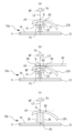
図6はハイカーブレンズLEhを各レンズ支持部に載置した状態を示す図である。図6(a)と図6(b)は、ハイカーブレンズLEhをレンズ支持部15aに載置した状態である。なお、図6(a)は支持ピン21をカップCuの取付面APに対して回転させていない場合であり、図6(b)は支持ピン21をカップCuの取付面APに対して回転させた場合である。図6(c)はハイカーブレンズLEhをレンズ支持部15bに載置した状態である。ハイカーブレンズLEhの中心位置を偏心させた状態では、カップ取り付けの基準軸となる光軸L2と、偏心位置Qと、が一致するようにハイカーブレンズLEhを支持し、カップCuを取り付ける。ハイカーブレンズLEhの前面とカップCuの取付面APがともに平行となるようにハイカーブレンズLEhを支持することで、カップCuを正確に取り付けることができる。
FIG. 6 is a diagram showing a state in which the high-curve lens LEh is placed on each lens supporting portion. 6(a) and 6(b) show a state in which the high-curve lens LEh is placed on the lens supporting portion 15a. 6(a) shows a case where the
例えば、図6(a)のようにレンズ支持部15aの支持ピン21を回転(傾斜)させない場合は、ハイカーブレンズLEhの前面(言い換えると、偏心位置Qに対する垂線)FPをカップの取付面APと平行にすると、ハイカーブレンズLEhの後面と支持ピン21が当接しないことがある。この状態では、ハイカーブレンズLEhが安定に支持されない。ハイカーブレンズLEhの後面と支持ピン21を当接させると、光軸L2と偏心位置Qとが一致していても、ハイカーブレンズLEhの前面FPがカップの取付面APと平行にならず、カップCuを正確に取り付けることができない。
For example, when the
しかし、例えば、図6(b)のようにレンズ支持部15aの支持ピン21を回転(傾斜)させる場合は、ハイカーブレンズLEhの前面FPをカップの取付面APと平行にするとともに、ハイカーブレンズLEhの後面と支持ピン21を当接させることが可能である。例えば、本実施例においては、ハイカーブレンズLEhを支持ピン21へ載置した後に三角板22を動かし、支持ピン21に載置したハイカーブレンズLEhを任意の方向へ傾けることで、レンズ支持部15aの接地面から各支持ピン21までの高さを変化させて、ハイカーブレンズLEhの後面と支持ピン21を当接させることができる。これによって、ハイカーブレンズLEhの前面FPをカップの取付面APに対して平行に維持し、光軸L2に偏心位置Qを一致させるとともに、ハイカーブレンズLEhを安定に支持することができる。例えば、このような状態においては、ハイカーブレンズLEhの前面FPが、カップCuを取り付ける際の基準となる基準面とされる。
However, for example, when the
なお、本実施例においては、さらに、レンズ押さえ機構40を用いて、ハイカーブレンズLEhをより安定に支持してもよい。レンズ押さえ機構40におけるアーム42は下方向に付勢されるため、ハイカーブレンズLEhの前面にレンズ押さえピン44が当接する。つまり、ハイカーブレンズLEhは、支持ピン21及びレンズ押さえピン44により挟持された状態となる。支持ピン21に載置されたハイカーブレンズLEhの前面とレンズ押さえピン44との当接面を平行に保つとともに、ハイカーブレンズLEhの前面とカップCuの取付面APとを平行に保つことで、ハイカーブレンズLEhの前面FPを基準面としてもよい。
In this embodiment, the
例えば、図6(c)のようにレンズ支持部15bの支持ピン26を用いた場合には、図6(a)のようにレンズ支持部15aの支持ピン21を回転(傾斜)させない場合と同様になる。支持ピン26の高さが固定されているので、ハイカーブレンズLEhの前面FPをカップの取付面APと平行にすると、ハイカーブレンズLEhの後面と支持ピン26が当接しないことがある。また、ハイカーブレンズLEhの後面と支持ピン26を当接させると、ハイカーブレンズLEhの前面FPがカップの取付面APと平行にならず、カップCuを正確に取り付けることができない。
For example, when the
例えば、このように、ハイカーブレンズLEhにカップCuを取り付けたい場合は、レンズ支持部15aを用いて、ハイカーブレンズLEhの前面FPに基準面を設けることが好ましい。なお、ハイカーブレンズLEhに限らず、レンズの中心位置を偏心させる場合等には同様の問題が生じるので、レンズ支持部15aを用いてレンズの前面を基準面とすることが好ましい。
For example, when it is desired to attach the cup Cu to the high-curve lens LEh in this way, it is preferable to use the
次に、レンズLElへのカップCuの取り付けを例に挙げて、レンズLEの後面を基準面とする場合を説明する。図7はレンズLElを各レンズ支持部に載置した状態を示す図である。図7(a)はレンズLElをレンズ支持部15aに載置した状態である。図7(b)はレンズLElをレンズ支持部15bに載置した状態である。例えば、レンズLElに対しては、レンズLElの中心位置を偏心させなくても、玉型がレンズ径内におさまることが多い。このため、カップ取り付けの基準軸となる光軸L2と、レンズLElの中心位置(光学中心位置OC)と、が一致するようにレンズLElを支持し、カップCuを取り付けてもよい。
Next, the case where the rear surface of the lens LE is used as the reference plane will be described, taking the attachment of the cup Cu to the lens LE1 as an example. FIG. 7 is a diagram showing a state in which the lens LEl is placed on each lens supporting portion. FIG. 7(a) shows a state in which the lens LEl is placed on the
例えば、図7(b)のようにレンズLElをレンズ支持部15bに載置した場合は、支持ピン26の中心点P2と、レンズLElの中心位置(本実施例では、光学中心位置OC)と、を一致させるようにレンズLElを支持ピン26へ載置することで、光軸L2とレンズLElの中心位置とを一致させ、レンズLElを安定に支持することができる。このとき、支持ピン26と、支持ピン26に載置されたレンズLElの後面と、の当接面は平行に保たれ、カップの取付面APと、レンズLElの後面(言い換えると、レンズLElの後面に対する垂線)BPと、が平行になる。例えば、このような状態においては、レンズLElの後面BPが、カップCuを取り付ける際の基準となる基準面とされる。なお、レンズLElの前面と後面における曲率の差は小さいため、カップの取付面APとレンズLElの後面BPが平行になるとともに、カップの取付面APとレンズLElの前面FPも平行になる。このため、レンズLElにカップCuを正確に取り付けることができる。レンズLElを支持ピン26に載置するだけでよく、操作は容易である。
For example, when the lens LEl is placed on the
例えば、図7(a)のようにレンズLElをレンズ支持部15aに載置した場合は、支持ピン21を回転(傾斜)させず、支持ピン21の中心点P1と、レンズLElの中心位置と、を一致させるようにレンズLElを支持ピン21へ載置することで、光軸L2とレンズLElの中心位置とを一致させ、レンズLElを安定に支持することができる。
For example, when the lens LEl is placed on the
なお、支持ピン21は回転自在であるため、レンズ押さえ機構40を用いることで、レンズLElをより安定に支持してもよい。すなわち、支持ピン21とレンズ押さえピン44とでレンズLElを挟持してもよい。これによっても、レンズLElの前面FP及び後面BPをカップの取付面APと平行に保ち、レンズLEにカップCuを正確に取り付けることができる。
Since the
例えば、レンズLElにカップCuを取り付けたい場合は、操作が容易であるため、レンズ支持部15bを用いて、レンズLElの後面BPに基準面を設けてもよい。なお、ハイカーブレンズLEhであっても、支持ピン26で安定に支持されるのであれば、レンズ支持部15bを用いて、レンズの後面を基準面としてもよい。
For example, when it is desired to attach the cup Cu to the lens LEl, the reference plane may be provided on the rear surface BP of the lens LEl using the
<制御系>
図8はカップ取付装置1の制御系を示す図である。例えば、制御部60は、一般的なCPU(プロセッサ)、RAM、ROM、等で実現される。CPUは、カップ取付装置1における各部の駆動を制御してもよい。RAMは、各種の情報を一時的に記憶してもよい。ROMには、CPUが実行する各種プログラムが記憶されてもよい。例えば、制御部60には、ディスプレイ3、光源311、撮像素子323、不揮発性メモリ(以下、メモリ65)、再帰性反射部材314を回転させるための図示なきモータ、等が電気的に接続される。
<Control system>
FIG. 8 is a diagram showing a control system of the
メモリ65は、電源の供給が遮断されても記憶内容を保持できる非一過性の記憶媒体であってもよい。例えば、メモリ65としては、ハードディスクドライブ、フラッシュROM、USBメモリ、SDカード、等を使用することができる。メモリ65は、レンズ測定機構30により測定されたレンズの外形、等を記憶してもよい。
The
<動作>
上記のような構成を備えるカップ取付装置1の動作を説明する。
<Action>
The operation of the
<玉型の取得>
まず、レンズLEの玉型が取得される。例えば、本実施例では、レンズ測定機構30及びテーブル8を用いて、フレームに枠入れされていたデモレンズまたは型板から玉型が取得される。例えば、本実施例においては、テーブル8が第3レンズ支持部としてレンズLEを支持してもよい。テーブル8は、第1レンズ支持部15a及び第2レンズ支持部15bを取り外した状態にて使用されてもよい。これにより、支持ピン21あるいは支持ピン26の像が写り込むことなく、テーブル8が支持したレンズLEを撮像することが可能である。
<Acquisition of lens shape>
First, the target lens shape of the lens LE is obtained. For example, in this embodiment, the
操作者は、テーブル8を挿込口9に挿し込み、テーブル8にデモレンズまたは型板を載置する。また、操作者は、玉型の取得を開始するための図示なきボタンを操作する。制御部60は、入力された操作信号に応じて、光源311を点灯させて光束を照射するとともに、再帰性反射部材314を回転させる。再帰性反射部材314に反射され、デモレンズまたは型板を後面側から照明する光束が、撮像素子323に撮像される。これにより、デモレンズの全体を撮像したデモレンズ像、または、型板の全体を撮像した型板像、が取得される。制御部60は、デモレンズ像または型板像を画像処理(例えば、エッジ検出、等)することで、デモレンズまたは型板の外形を検出し、これを玉型としてメモリ65に記憶させる。玉型を取得した後、操作者はテーブル8を挿込口9から取り外す。
The operator inserts the table 8 into the
なお、レンズLEの玉型は、デモレンズまたは型板の外形、フレームのリムの内形、等から取得されてもよい。本実施例では、カップ取付装置1を用いて玉型を取得したが、カップ取付装置1に別の装置を用いて測定した玉型を読み込ませることで玉型を取得してもよい。
Note that the target lens shape of the lens LE may be obtained from the outer shape of a demo lens or template, the inner shape of the rim of the frame, or the like. In this embodiment, the target lens shape is acquired using the
<加工条件とレイアウトの設定>
続いて、レンズLEの加工条件とレイアウトが設定される。レンズLEの加工条件は、レンズLEの種類(例えば、単焦点レンズ、二重焦点レンズ、累進レンズ、等)、レンズLEの材質、フレームの材質、加工モード(例えば、鏡面加工、面取り加工、溝掘り加工、等の有無)、レンズLEに対するカップCuの取り付け位置(例えば、レンズLEの光学中心位置、玉型の幾何学中心位置、等)、等の少なくともいずれかであってもよい。レンズLEのレイアウトは、眼鏡装用者の瞳孔間距離、フレーム中心間距離、等の少なくともいずれかであってもよい。操作者は、ディスプレイ3に表示される設定画面を操作することで、これらの条件とレイアウトを設定する。
<Processing conditions and layout settings>
Subsequently, processing conditions and layout of the lens LE are set. The processing conditions for the lens LE include the type of the lens LE (eg, single focus lens, bifocal lens, progressive lens, etc.), the material of the lens LE, the material of the frame, and the processing mode (eg, mirror surface processing, chamfering, groove processing, etc.). the presence or absence of engraving, etc.), the attachment position of the cup Cu to the lens LE (for example, the optical center position of the lens LE, the geometrical center position of the lens shape, etc.), and the like. The layout of the lenses LE may be the eyeglass wearer's interpupillary distance, frame center distance, and/or the like. The operator sets these conditions and layout by operating the setting screen displayed on the
<レンズ支持部の設置>
ここで、操作者は、レンズ支持機構10におけるレンズ支持部15を台座5bに載置する。本実施例では、レンズ支持部15aまたはレンズ支持部15bのいずれかが台座5bに配置される。レンズ支持部15aまたはレンズ支持部15bのいずれかは、レンズLEの前面及び後面の形状に合わせて選択されてもよい。
<Installation of the lens support>
Here, the operator places the
例えば、本実施例では、ハイカーブレンズLEhに対してカップCuを取り付けるためにレンズ支持部15aを選択した場合と、レンズLElに対してカップCuを取り付けるためにレンズ支持部15bを選択した場合と、について順に説明する。
For example, in this embodiment, when the
<レンズ支持部15aを設置する場合>
図10はカップ取付装置1からレンズ押さえ機構40が取り外された状態を示す図である。操作者は、レンズ支持機構10におけるレンズ支持部15aを台座5bに載置する。本実施例では、レンズ支持部15aが備える穴17に、保護カバー12から突出して固定された挿込ピン11が挿さるように、レンズ支持部15aが台座5bに載置される。また、操作者は、レンズ押さえ機構40を台座5bに取り付ける(すなわち、図10に示す状態から図3に示す状態になる)。本実施例では、レンズ押さえ機構40の円筒部材46が、台座5bの凹部7に嵌め込まれることで、レンズ押さえ機構40が台座5bに取り付けられる。また、操作者は、レンズ押さえ機構40のアーム42を使用位置に配置する(すなわち、図3(a)に示す状態から図3(b)に示す状態になる)。アーム42が使用位置に配置されることによって、支持ピン21の上部にレンズ押さえピン44が配置される。操作者は、レバー45を操作して、支持ピン21とレンズ押さえピン44の間にハイカーブレンズLEhを挟持させる。これによって、支持ピン21に載置されたハイカーブレンズLEhの前面と、レンズ押さえピン44と、の当接面が平行に保たれるとともに、ハイカーブレンズLEhの前面とカップCuの取付面APとが平行に保たれ、ハイカーブレンズLEhの前面がカップ取り付けの基準面とされる。
<When installing the
FIG. 10 is a diagram showing a state in which the
<レンズ支持部15bを設置する場合>
操作者は、レンズ支持機構10におけるレンズ支持部15bを台座5bに載置する。本実施例では、レンズ支持部15bが備える穴17に、保護カバー12から突出して固定された挿込ピン11が挿さるように、レンズ支持部15bが台座5bに載置される。なお、レンズ支持部15bを用いる際には、必ずしもレンズ押さえ機構40を台座5bに取り付けなくてもよい。このため、レンズ押さえ機構40は、図10に示すように台座5bの凹部7から取り外されてもよい。なお、レンズ押さえ機構40が予め取り付けられていた場合には、レンズ押さえ機構40のアーム42を退避位置に配置して、レンズLElを支持ピン26の上に載置してもよい。これによって、支持ピン26と、支持ピン26に載置されたレンズLElの後面と、の当接面が平行に保たれるとともに、レンズLElの後面とカップCuの取付面APとが平行に保たれ、レンズLElの後面がカップ取り付けの基準面とされる。
<When installing the
The operator places the
<レンズのアライメント>
操作者は、支持ピン21または支持ピン26にレンズLEを載置すると、カップ取り付けの基準軸である光軸L2と、レンズLEの中心位置(あるいは、偏心位置Q)と、を一致させるようにアライメントを行う。
<Lens Alignment>
When the operator places the lens LE on the
例えば、操作者は、アライメントを行うための図示なきボタンを操作する。制御部60は、入力された操作信号に応じて、光源311を点灯させて光束を照射するとともに、再帰性反射部材314を回転させる。再帰性反射部材314に反射され、レンズLEを後面側から照明する光束が、撮像素子323に撮像される。これにより、レンズLEの全体を撮像したレンズ像が取得される。ディスプレイ3には、レンズLEにカップCuを取り付けるための軸打ち画面70が表示される。
For example, the operator operates a button (not shown) for alignment. The
図9は軸打ち画面70の一例である。ここでは、支持ピン21にハイカーブレンズLEhを載置した状態での軸打ち画面を例に挙げる。軸打ち画面70には、アーム42の像であるアーム像42s、支持ピン21の像である支持ピン像21s、ハイカーブレンズLEhのレンズ像LEhs、アライメントの目標位置を表すマークM、等が表示される。レンズ像LEhsには、予め中心位置(あるいは、偏心位置)に付された印点の像である印点像Rsが現れる。操作者は、軸打ち画面70を確認しながら、印点像RsとマークMとが一致するように、支持ピン21上のハイカーブレンズLEhを移動させる。これによって、カップ取り付けの基準軸である光軸L2と、ハイカーブレンズLEhの中心位置(あるいは、偏心位置Q)と、が一致し、アライメントが完了する。
FIG. 9 is an example of an
なお、支持ピン26にレンズLElを載置した状態での軸打ち画面には、アーム像42sが表示されない。操作者は、ハイカーブレンズLEhのアライメントと同様に、軸打ち画面70を確認しながら、印点像RsとマークMとが一致するように、支持ピン26上のレンズLElを移動させ、アライメントを完了させる。
It should be noted that the
<カップの取り付け>
操作者は、アライメントが完了すると、レンズLEにカップCuを取り付ける。操作者は、カップ取付機構50のカップ装着部55にカップCuを装着する。また、操作者は、レバー58を操作して支持アーム52を回転させるとともに、支持アーム52を下方向に移動させる。これによって、レンズLEの前面にカップCuが取り付けられる。
<Installing the cup>
When the alignment is completed, the operator attaches the cup Cu to the lens LE. The operator mounts the cup Cu on the
以上説明したように、例えば、本実施例におけるカップ取付装置は、眼鏡レンズの前面とカップの取付面とを平行に保つことで、カップを取り付ける基準面を眼鏡レンズの前面とし、眼鏡レンズを支持する第1レンズ支持手段と、眼鏡レンズの後面とカップの取付面とを平行に保つことで、カップを取り付ける基準面を眼鏡レンズの後面とし、眼鏡レンズを支持する第2レンズ支持手段と、カップ取付装置において、第1レンズ支持手段と第2レンズ支持手段とを切り換える切換手段と、眼鏡レンズにカップを取り付けるカップ取付手段と、を備える。従来は、眼鏡レンズの前面を基準面とするか、または後面を基準面とするか、を選択することができず、眼鏡レンズの種類によっては、精度よくカップを取り付けることが難しい場合があった。しかし、カップ取付装置が本実施例のような構成を備えることで、眼鏡レンズの種類毎に基準面を容易に変更し、適切にカップを取り付けることができる。 As described above, for example, the cup mounting device of the present embodiment supports the spectacle lens by keeping the front surface of the spectacle lens and the mounting surface of the cup parallel, so that the reference surface for mounting the cup is the front surface of the spectacle lens. A second lens support means for supporting the spectacle lens, a second lens support means for supporting the spectacle lens, and a second lens support means for supporting the spectacle lens by keeping the rear surface of the spectacle lens and the mounting surface of the cup parallel to each other so that the reference surface for mounting the cup is the rear surface of the spectacle lens. The mounting device includes switching means for switching between the first lens supporting means and the second lens supporting means, and cup mounting means for mounting the cup on the spectacle lens. Conventionally, it was not possible to select whether to use the front surface of the spectacle lens as the reference surface or the rear surface of the spectacle lens as the reference surface. . However, by providing the cup mounting device with the configuration of this embodiment, the reference surface can be easily changed for each type of spectacle lens, and the cup can be mounted appropriately.
また、例えば、本実施例におけるカップ取付装置において、切換手段は、第1レンズ支持手段及び第2レンズ支持手段をカップ取付装置に装着可能とする第1着脱手段を有し、第1着脱手段を用いて第1レンズ支持手段または第2レンズ支持手段のいずれか一方を取り付けることによって、第1レンズ支持手段と第2レンズ支持手段とを切り換える。これによって、眼鏡レンズの種類に応じて適切なレンズ支持手段を取り付け、基準面を容易に変更することができるので、精度よくカップを取り付けることができる。 Further, for example, in the cup mounting device of the present embodiment, the switching means has a first attaching/detaching means that enables the first lens supporting means and the second lens supporting means to be attached to the cup attaching device. The first lens support means and the second lens support means are switched by attaching either one of the first lens support means and the second lens support means. As a result, it is possible to attach an appropriate lens supporting means according to the type of the spectacle lens and easily change the reference surface, so that the cup can be attached with high accuracy.
また、例えば、本実施例におけるカップ取付装置において、第1レンズ支持手段は、カップの取付面に対して回転自在な第1支持ピンを有し、第1支持ピンに載置された眼鏡レンズの前面と、カップの取付面とを平行に保つことで、眼鏡レンズの前面を基準面とする。第1支持ピンが回転自在であることによって、眼鏡レンズの前面と後面の曲率の差が大きな眼鏡レンズ(例えば、ハイカーブレンズ、等)に対しても、その前面に基準面を設けることができるようになる。 Further, for example, in the cup mounting device of the present embodiment, the first lens support means has a first support pin that is rotatable with respect to the mounting surface of the cup, and the spectacle lens mounted on the first support pin is mounted on the first support pin. By keeping the front surface parallel to the mounting surface of the cup, the front surface of the spectacle lens is used as a reference surface. Since the first support pin is rotatable, it is possible to provide a reference plane on the front surface of the spectacle lens even for spectacle lenses having a large difference in curvature between the front surface and the rear surface of the spectacle lens (for example, high-curve lenses). become.
また、例えば、本実施例におけるカップ取付装置において、第1レンズ支持手段は、さらに、眼鏡レンズの前面を押さえるレンズ押さえ手段を有し、第1支持ピンに載置されるとともにレンズ押さえ手段に押さえられた眼鏡レンズの前面と、レンズ押さえ手段と、の当接面を平行に保つことで、眼鏡レンズの前面と、カップの取付面とを平行に保ち、眼鏡レンズの前面を基準面とする。レンズ押さえ手段を備えることによって、眼鏡レンズの前面と後面の曲率の差が大きな眼鏡レンズ(例えば、ハイカーブレンズ、等)を挟持し、より安定に支持することができる。 Further, for example, in the cup mounting device of the present embodiment, the first lens supporting means further has lens pressing means for pressing the front surface of the spectacle lens, and is placed on the first supporting pins and pressed by the lens pressing means. By keeping the abutting surfaces of the front surface of the spectacle lens and the lens holding means parallel, the front surface of the spectacle lens and the mounting surface of the cup are kept parallel, and the front surface of the spectacle lens is used as a reference plane. By providing the lens holding means, spectacle lenses having a large difference in curvature between the front surface and the rear surface of the spectacle lens (for example, a high curve lens, etc.) can be clamped and supported more stably.
また、例えば、本実施例におけるカップ取付装置において、第1レンズ支持手段が備えるレンズ押さえ手段は着脱可能であって、切換手段は、レンズ押さえ手段を着脱する第2着脱手段を有し、第2着脱手段を用いてレンズ押さえ手段を取り付けることによって、第1レンズ支持手段と第2レンズ支持手段とを切り換える。これによって、眼鏡レンズの種類に合わせてレンズ押さえ手段を着脱し、必要に応じて眼鏡レンズを挟持させ、眼鏡レンズを安定に支持することができる。 Further, for example, in the cup mounting device of the present embodiment, the lens pressing means provided in the first lens supporting means is detachable, and the switching means has a second attachment/detachment means for attaching and detaching the lens pressing means. The first lens supporting means and the second lens supporting means are switched by attaching the lens pressing means using the attaching/detaching means. This makes it possible to attach and detach the lens holding means according to the type of the spectacle lens, clamp the spectacle lens as required, and stably support the spectacle lens.
また、例えば、本実施例におけるカップ取付装置において、第1レンズ支持手段が備えるレンズ押さえ手段は、眼鏡レンズを押さえる使用位置と、使用位置から退避させた退避位置と、に切り換え可能であって、第1レンズ支持手段を用いる際には、レンズ押さえ手段を使用位置に切り換えて使用し、第2レンズ支持手段を用いる際には、レンズ押さえ手段を退避位置に切り換えて使用する。例えば、本実施例においては、眼鏡レンズの前面を基準面とする場合にはレンズ押さえ手段を用いてもよく、眼鏡レンズの後面を基準面とする場合にはレンズ押さえ手段を用いなくてもよい。眼鏡レンズの種類に応じて第1レンズ支持手段または第2レンズ支持手段のいずれかに変更した際には、レンズ押さえ手段の使用と不使用を容易に切り換えることができ、操作性が向上される。 Further, for example, in the cup mounting device of the present embodiment, the lens holding means provided in the first lens supporting means can be switched between a use position for holding the spectacle lens and a retracted position for retracting from the use position, When using the first lens supporting means, the lens pressing means is switched to the use position, and when using the second lens supporting means, the lens pressing means is switched to the retracted position. For example, in this embodiment, when the front surface of the spectacle lens is used as the reference plane, the lens pressing means may be used, and when the rear surface of the spectacle lens is used as the reference plane, the lens pressing means may not be used. . When changing to either the first lens support means or the second lens support means according to the type of the spectacle lens, the use and non-use of the lens pressing means can be easily switched to improve the operability. .
また、例えば、本実施例におけるカップ取付装置は、眼鏡レンズを載置する固定配置された第2支持ピンを有し、第2支持ピンと、第2支持ピンに載置された眼鏡レンズの後面と、の当接面を平行に保つことで、眼鏡レンズの後面とカップの取付面とを平行に保ち、眼鏡レンズの後面を基準面とする。支持ピンが固定配置されていることで、レンズ押さえ手段等を用いることなく眼鏡レンズの後面に基準面を設けることができ、操作が容易である。 Also, for example, the cup mounting device in this embodiment has a fixedly arranged second support pin on which the spectacle lens is placed, and the second support pin and the rear surface of the spectacle lens placed on the second support pin. By keeping the abutment surfaces of (1) and (2) parallel, the rear surface of the spectacle lens and the mounting surface of the cup are kept parallel, and the rear surface of the spectacle lens is used as a reference plane. Since the support pin is fixedly arranged, the reference surface can be provided on the rear surface of the spectacle lens without using lens pressing means or the like, and the operation is easy.
また、例えば、本実施例におけるカップ取付装置は、眼鏡レンズにカップを取り付けるカップ取付手段を備え、第1レンズ支持手段に支持された状態の眼鏡レンズ、または、第2レンズ支持手段に支持された状態の眼鏡レンズ、にカップを取り付ける。本実施例では、第1レンズ支持手段または第2レンズ支持手段によって、眼鏡レンズの基準面が平行に維持される。このため、カップ取付手段を用いて、レンズ支持手段に支持されたレンズに対してカップを精度よく取り付けることができる。 Further, for example, the cup mounting device in the present embodiment includes cup mounting means for mounting the cup on the spectacle lens, and the spectacle lens supported by the first lens supporting means or the spectacle lens supported by the second lens supporting means. Attach the cup to the spectacle lens in the state. In this embodiment, the reference planes of the spectacle lenses are kept parallel by the first lens support means or the second lens support means. Therefore, the cup can be accurately attached to the lens supported by the lens support means by using the cup attachment means.
<変容例>
なお、本実施例では、レンズ測定機構30によって、光源311がレンズLEの前面を照明し、再帰性反射部材314に反射された光束が撮像素子323で撮像される構成を例に挙げて説明したがこれに限定されない。例えば、レンズ測定機構30は、光源によってレンズLEの後面を照明し、光束をスクリーンに投影する構成であってもよい。この場合、ディスプレイ3は必ずしも必要ではない。例えば、スクリーンに予めアライメントの目標位置を表すマークMを印しておき、スクリーンに投影されたレンズ像に現れる印点像Rsと、スクリーン上のマークMと、を一致させるようにアライメントを行ってもよい。例えば、このようなディスプレイ3を備えていないカップ取付装置に対しても、第1レンズ支持手段15aと第2レンズ支持手段15bとを切り換えて使用する構成としてもよい。
<transformation example>
In this embodiment, the
なお、本実施例では、レンズ支持部15のプレート16に穴17が設けられ、プレート16が挿込ピン11に刺さるように、レンズ支持部15を保護カバー12上に配置する構成を例に挙げて説明したがこれに限定されない。例えば、本実施例において、プレート16及び保護カバー12は正円形状であり、正円の中央に支持ピン21の中心点P1または支持ピン26の中心点P2が一致するように設計されている。このため、穴17や挿込ピン11を用いなくても、レンズ支持部15を保護カバー12上に載置すれば、各ピンの中心点と光軸L2とを一致させることができる。しかし、本実施例において、プレート16の中央からずれた位置に各ピンの中心点を配置するように設計されてもよい。この場合、レンズ支持部15を保護カバー12上に載置する向きによっては、各ピンの中心点と光軸L2とが一致しなくなる。このような構成とする際には、穴17や挿込ピン11等をより効果的に用いることができる。
In this embodiment, the
なお、本実施例では、レンズ支持機構10がレンズ支持部15a及びレンズ支持部15bを有し、これらを付け換えることによって、レンズLEの基準面を変更する構成を例に挙げて説明したがこれに限定されない。例えば、レンズ支持機構10が、レンズ支持部15a及びレンズ支持部15bを有し、これらを移動させることによって、レンズLEの基準面を変更する構成としてもよい。この場合には、レンズ支持部15a及びレンズ支持部15b移動させる駆動部を備えていてもよい。例えば、駆動部は、レンズ支持部15aとレンズ支持部15bをスライド移動させるためのスライド機構、等であってもよい。駆動部はモータ等を備え、レンズ支持部15aとレンズ支持部15bを自動的に切り換える構成としてもよい。この場合には、例えば、制御部60が駆動部の駆動を制御することによって、第1レンズ支持手段と第2レンズ支持手段とが自動的に切り換えられてもよい。また、駆動部はレバー等を備え、レンズ支持部15aとレンズ支持部15bを手動的に切り換える構成としてもよい。この場合には、例えば、操作者がレバーを操作することで、第1レンズ支持手段と第2レンズ支持手段とを手動的に切り換えてもよい。
In this embodiment, the
例えば、本実施例におけるカップ取付装置においては、このように、切換手段が、第1レンズ支持手段と第2レンズ支持手段とを移動させる駆動部を有し、駆動部を駆動させることによって、第1レンズ支持手段と第2レンズ支持手段とを切り換えてもよい。これによって、眼鏡レンズの種類に応じて適切なレンズ支持手段に切り換え、基準面を容易に変更することができるので、精度よくカップを取り付けることができる。 For example, in the cup mounting device of the present embodiment, the switching means has a driving section for moving the first lens supporting means and the second lens supporting means, and by driving the driving section, the second The first lens support means and the second lens support means may be switched. As a result, it is possible to switch to an appropriate lens supporting means according to the type of the spectacle lens, and to easily change the reference surface, so that the cup can be attached with high accuracy.
なお、本実施例では、レンズ支持機構10がレンズ支持部15aとレンズ支持部15bを有し、これらを付け換えることによって、レンズLEの基準面を変更する構成を例に挙げて説明したがこれに限定されない。レンズ支持機構10は、レンズ支持部15aとレンズ支持部15bとを兼用する構成としてもよい。例えば、この場合には、レンズ支持機構10にロック機構が設けられてもよい。ロック機構は、レンズ支持部15a(またはレンズ支持部15b)におけるカップCuの取付面に対する回転(傾斜)を抑制してもよい。一例として、レンズ支持部15aの回転をロック機構によりロックし、支持ピン21の高さが一律となるように固定することで、レンズLEの後面を基準面としてもよい。また、ロック機構を解除することで、支持ピン21を回転自在とし、レンズLEの前面を基準面としてもよい。例えば、本実施例においては、このように、レンズ支持機構10にロック機構を設け、ロック機構の使用と不使用を切り換えることによって、レンズLEの基準面を切り換えることが可能な構成としてもよい。
In the present embodiment, the
なお、本実施例では、レンズ支持部15aが回転自在な支持ピン21を備える構成を例に挙げて説明したがこれに限定されない。レンズ支持部15aは、レンズLEの前面を基準面とするための構成を有していればよい。例えば、レンズ支持部15aの支持ピン21は、各ピンの高さをそれぞれ調節することが可能な第1支持ピンを有することで、眼鏡レンズの前面とカップの取付面とを平行に保ち、レンズLEの前面を基準面としてもよい。ちろん、支持ピン21を用いることなく、眼鏡レンズの前面とカップの取付面とを平行に保つようにしてもよい。一例としては、円筒状のレンズ支持部を有し、眼鏡レンズの前面をレンズ支持部に載置することで、眼鏡レンズの前面とカップの取付面とを平行に保ち、眼鏡レンズの前面を基準面としてもよい。
In this embodiment, the configuration in which the
また、本実施例では、レンズ支持部15bが固定配置された支持ピン26を備える構成を例に挙げて説明したがこれに限定されない。レンズ支持部15bは、レンズLEの後面を基準面とするための構成を有していればよい。例えば、レンズ支持部15bの支持ピンは高さが同一な可動ピンであってもよく、中心点P2から各ピン間までの距離、及び、各ピン同士の間隔、等を調整して、レンズLEを支持する領域の大きさを変更するような構成を有していてもよい。
Further, in the present embodiment, the configuration in which the
なお、本実施例では、レンズ測定機構30が、レンズLEの外形、印点、隠しマーク、プリントマーク、等のレンズ情報を取得するための光学系を備える構成を例に挙げて説明したがこれに限定されない。例えば、レンズ測定機構30は、レンズLEの光学特性(例えば、球面度数、円柱度数、乱視軸角度、プリズム量、等)をレンズ情報として取得するための光学系を備えていてもよい。一例として、このような光学系は、多数の開口(光束の通過口)を所定のパターンにて形成した指標板、等を有し、レンズLEを介して撮像されたパターン像の変化量に基づいて、レンズLEの光学特性を演算するようにしてもよい。例えば、レンズLEのレンズLEの外形、印点、隠しマーク、プリントマーク、等を取得するための光学系と、レンズLEの光学特性を取得するための光学系と、はその少なくとも一部を兼用する構成としてもよいし、別に設ける構成としてもよい。
In this embodiment, the
1 カップ取付装置
10 レンズ支持機構
30 レンズ測定機構
40 レンズ押さえ機構
50 カップ取付機構
60 制御部
65 メモリ
1
Claims (5)
前記眼鏡レンズの前面と、前記カップの取付面と、を平行に保つことで、前記カップを取り付ける基準面を前記眼鏡レンズの前面とし、前記眼鏡レンズを支持する第1レンズ支持手段と、
前記眼鏡レンズの後面と、前記カップの取付面と、を平行に保つことで、前記カップを取り付ける基準面を前記眼鏡レンズの後面とし、前記眼鏡レンズを支持する第2レンズ支持手段と、
前記カップ取付装置において、前記第1レンズ支持手段と前記第2レンズ支持手段とを切り換える切換手段と、
前記眼鏡レンズに前記カップを取り付けるカップ取付手段と、
を備えることを特徴とするカップ取付装置。 In a cup attaching device for attaching a cup, which is a processing jig, to a spectacle lens,
a first lens support means for supporting the spectacle lens by keeping the front surface of the spectacle lens and the mounting surface of the cup parallel so that the reference surface for mounting the cup is the front surface of the spectacle lens;
a second lens support means for supporting the spectacle lens by keeping the rear surface of the spectacle lens and the mounting surface of the cup in parallel so that the reference surface for mounting the cup is the rear surface of the spectacle lens;
Switching means for switching between the first lens supporting means and the second lens supporting means in the cup mounting device;
cup attachment means for attaching the cup to the spectacle lens;
A cup attachment device comprising:
前記切換手段は、前記第1レンズ支持手段及び前記第2レンズ支持手段をカップ取付装置に装着可能とする第1着脱手段を有し、前記第1着脱手段を用いて前記第1レンズ支持手段または前記第2レンズ支持手段のいずれか一方を取り付けることによって、前記第1レンズ支持手段と前記第2レンズ支持手段とを切り換えることを特徴とするカップ取付装置。 The cup attachment device of claim 1, wherein
The switching means has a first attachment/detachment means for attaching the first lens support means and the second lens support means to the cup attaching device, and the first attachment/detachment means is used to attach the first lens support means or the second lens support means. A cup attaching device, wherein switching between the first lens supporting means and the second lens supporting means is performed by attaching either one of the second lens supporting means.
前記第1レンズ支持手段は、前記カップの取付面に対して傾斜自在な第1支持ピンを有し、
前記第1支持ピンに載置された前記眼鏡レンズの前面と、前記カップの取付面とを平行に保つことで、前記眼鏡レンズの前面を前記基準面とすることを特徴とするカップ取付装置。 3. The cup attachment device of claim 1 or 2,
The first lens support means has a first support pin tiltable with respect to the mounting surface of the cup,
A cup mounting device, wherein the front surface of the spectacle lens placed on the first support pin and the mounting surface of the cup are kept parallel to each other so that the front surface of the spectacle lens is used as the reference plane.
前記第1レンズ支持手段は、さらに、前記眼鏡レンズの前面を押さえるレンズ押さえ手段を有し、
前記第1支持ピンに載置されるとともに前記レンズ押さえ手段に押さえられた前記眼鏡レンズの前面と、前記レンズ押さえ手段と、の当接面を平行に保つことで、前記眼鏡レンズの前面と前記カップの取付面とを平行に保ち、前記眼鏡レンズの前面を前記基準面とすることを特徴とするカップ取付装置。 4. The cup attachment device of claim 3, wherein
The first lens support means further includes lens pressing means for pressing the front surface of the spectacle lens,
By keeping the contact surfaces of the front surface of the spectacle lens placed on the first support pins and pressed by the lens pressing means and the lens pressing means parallel to each other, the front surface of the spectacle lens and the lens pressing means are kept parallel. A cup mounting device, wherein the mounting surface of the cup is kept parallel, and the front surface of the spectacle lens is used as the reference surface.
前記第2レンズ支持手段は、前記眼鏡レンズを載置する固定配置された第2支持ピンを有し、
前記第2支持ピンと、前記第2支持ピンに載置された前記眼鏡レンズの後面と、の当接面を平行に保つことで、前記眼鏡レンズの後面と前記カップの取付面とを平行に保ち、前記眼鏡レンズの後面を前記基準面とすることを特徴とするカップ取付装置。 In the cup mounting device according to any one of claims 1 to 4,
The second lens support means has a fixedly arranged second support pin for mounting the spectacle lens,
By keeping the abutment surfaces of the second support pin and the rear surface of the spectacle lens placed on the second support pin parallel, the rear surface of the spectacle lens and the mounting surface of the cup are kept parallel. 2. A cup mounting device, wherein the rear surface of said spectacle lens is used as said reference surface.
Priority Applications (1)
| Application Number | Priority Date | Filing Date | Title |
|---|---|---|---|
| JP2018164813A JP7268308B2 (en) | 2018-09-03 | 2018-09-03 | cup mounting device |
Applications Claiming Priority (1)
| Application Number | Priority Date | Filing Date | Title |
|---|---|---|---|
| JP2018164813A JP7268308B2 (en) | 2018-09-03 | 2018-09-03 | cup mounting device |
Publications (3)
| Publication Number | Publication Date |
|---|---|
| JP2020038268A JP2020038268A (en) | 2020-03-12 |
| JP2020038268A5 JP2020038268A5 (en) | 2021-09-16 |
| JP7268308B2 true JP7268308B2 (en) | 2023-05-08 |
Family
ID=69737870
Family Applications (1)
| Application Number | Title | Priority Date | Filing Date |
|---|---|---|---|
| JP2018164813A Active JP7268308B2 (en) | 2018-09-03 | 2018-09-03 | cup mounting device |
Country Status (1)
| Country | Link |
|---|---|
| JP (1) | JP7268308B2 (en) |
Citations (4)
| Publication number | Priority date | Publication date | Assignee | Title |
|---|---|---|---|---|
| JP2007275998A (en) | 2006-04-03 | 2007-10-25 | Nidek Co Ltd | Cup mounting device |
| JP2013212573A (en) | 2012-03-09 | 2013-10-17 | Nidek Co Ltd | Apparatus having cup attaching unit and eyeglass lens processing apparatus having cup attaching unit |
| CN103492123A (en) | 2011-04-21 | 2014-01-01 | 埃西勒国际通用光学公司 | Ophthalmic-lens holder |
| US20140368813A1 (en) | 2011-11-29 | 2014-12-18 | Essilor International(Compagnie Generale D'optique | Ophthalmic lens holder for a centering device |
Family Cites Families (1)
| Publication number | Priority date | Publication date | Assignee | Title |
|---|---|---|---|---|
| JPS60172650U (en) * | 1984-04-20 | 1985-11-15 | ホーヤ株式会社 | Layout device for lens processing |
-
2018
- 2018-09-03 JP JP2018164813A patent/JP7268308B2/en active Active
Patent Citations (4)
| Publication number | Priority date | Publication date | Assignee | Title |
|---|---|---|---|---|
| JP2007275998A (en) | 2006-04-03 | 2007-10-25 | Nidek Co Ltd | Cup mounting device |
| CN103492123A (en) | 2011-04-21 | 2014-01-01 | 埃西勒国际通用光学公司 | Ophthalmic-lens holder |
| US20140368813A1 (en) | 2011-11-29 | 2014-12-18 | Essilor International(Compagnie Generale D'optique | Ophthalmic lens holder for a centering device |
| JP2013212573A (en) | 2012-03-09 | 2013-10-17 | Nidek Co Ltd | Apparatus having cup attaching unit and eyeglass lens processing apparatus having cup attaching unit |
Also Published As
| Publication number | Publication date |
|---|---|
| JP2020038268A (en) | 2020-03-12 |
Similar Documents
| Publication | Publication Date | Title |
|---|---|---|
| KR101442575B1 (en) | Cup attaching apparatus | |
| EP1997585B1 (en) | Cup attaching apparatus | |
| JP3462006B2 (en) | Auto focus device | |
| JP3929595B2 (en) | Eyeglass lens processing system | |
| KR101381121B1 (en) | Cup attaching apparatus | |
| JP6564545B1 (en) | Lens shape measuring device, lens shape measuring method, lens optical property measuring device, program, and recording medium | |
| JP2013212573A (en) | Apparatus having cup attaching unit and eyeglass lens processing apparatus having cup attaching unit | |
| CN103492123A (en) | Ophthalmic-lens holder | |
| JP7268308B2 (en) | cup mounting device | |
| KR101408122B1 (en) | Cup attaching apparatus | |
| KR20070049835A (en) | Focus adjusting device for camera module and adujusting method therefore | |
| JPH11216650A (en) | Centering device | |
| JP4104297B2 (en) | Cup mounting device | |
| JP5397889B2 (en) | Cup mounting device | |
| JP2009186728A (en) | Video microscope and adapter for observation | |
| JP6660508B1 (en) | Lens holding device and lens optical characteristic measuring device | |
| JP2019098484A (en) | Axial alignment device, device for lens processing, spectacle lens processing system, and spectacle lens processing method | |
| JP6759937B2 (en) | Lens measuring device | |
| JP7225644B2 (en) | lens measuring device | |
| JP6653048B1 (en) | Lens shape measuring device, lens shape measuring method, lens optical characteristic measuring device, program, and recording medium | |
| JP7225645B2 (en) | cup mounting device | |
| JP2008278124A (en) | Tilt adjustment method for imaging device and camera equipment with imaging device adjusted by the same method | |
| JP2020049632A (en) | Cup mounting device | |
| JP4138500B2 (en) | Lens meter | |
| JP2008008830A (en) | Lens meter |
Legal Events
| Date | Code | Title | Description |
|---|---|---|---|
| A521 | Request for written amendment filed |
Free format text: JAPANESE INTERMEDIATE CODE: A523 Effective date: 20210804 |
|
| A621 | Written request for application examination |
Free format text: JAPANESE INTERMEDIATE CODE: A621 Effective date: 20210804 |
|
| A977 | Report on retrieval |
Free format text: JAPANESE INTERMEDIATE CODE: A971007 Effective date: 20220831 |
|
| A131 | Notification of reasons for refusal |
Free format text: JAPANESE INTERMEDIATE CODE: A131 Effective date: 20221004 |
|
| A521 | Request for written amendment filed |
Free format text: JAPANESE INTERMEDIATE CODE: A523 Effective date: 20221205 |
|
| TRDD | Decision of grant or rejection written | ||
| A01 | Written decision to grant a patent or to grant a registration (utility model) |
Free format text: JAPANESE INTERMEDIATE CODE: A01 Effective date: 20230322 |
|
| A61 | First payment of annual fees (during grant procedure) |
Free format text: JAPANESE INTERMEDIATE CODE: A61 Effective date: 20230404 |
|
| R150 | Certificate of patent or registration of utility model |
Ref document number: 7268308 Country of ref document: JP Free format text: JAPANESE INTERMEDIATE CODE: R150 |