JP7266364B2 - fuel cell system - Google Patents
fuel cell system Download PDFInfo
- Publication number
- JP7266364B2 JP7266364B2 JP2017531816A JP2017531816A JP7266364B2 JP 7266364 B2 JP7266364 B2 JP 7266364B2 JP 2017531816 A JP2017531816 A JP 2017531816A JP 2017531816 A JP2017531816 A JP 2017531816A JP 7266364 B2 JP7266364 B2 JP 7266364B2
- Authority
- JP
- Japan
- Prior art keywords
- fuel cell
- surface area
- region
- fluid flow
- area
- Prior art date
- Legal status (The legal status is an assumption and is not a legal conclusion. Google has not performed a legal analysis and makes no representation as to the accuracy of the status listed.)
- Active
Links
Images


Classifications
-
- H—ELECTRICITY
- H01—ELECTRIC ELEMENTS
- H01M—PROCESSES OR MEANS, e.g. BATTERIES, FOR THE DIRECT CONVERSION OF CHEMICAL ENERGY INTO ELECTRICAL ENERGY
- H01M8/00—Fuel cells; Manufacture thereof
- H01M8/02—Details
- H01M8/0202—Collectors; Separators, e.g. bipolar separators; Interconnectors
- H01M8/0204—Non-porous and characterised by the material
-
- H—ELECTRICITY
- H01—ELECTRIC ELEMENTS
- H01M—PROCESSES OR MEANS, e.g. BATTERIES, FOR THE DIRECT CONVERSION OF CHEMICAL ENERGY INTO ELECTRICAL ENERGY
- H01M8/00—Fuel cells; Manufacture thereof
- H01M8/02—Details
- H01M8/0202—Collectors; Separators, e.g. bipolar separators; Interconnectors
-
- H—ELECTRICITY
- H01—ELECTRIC ELEMENTS
- H01M—PROCESSES OR MEANS, e.g. BATTERIES, FOR THE DIRECT CONVERSION OF CHEMICAL ENERGY INTO ELECTRICAL ENERGY
- H01M8/00—Fuel cells; Manufacture thereof
- H01M8/02—Details
- H01M8/0202—Collectors; Separators, e.g. bipolar separators; Interconnectors
- H01M8/0204—Non-porous and characterised by the material
- H01M8/0223—Composites
- H01M8/0228—Composites in the form of layered or coated products
-
- H—ELECTRICITY
- H01—ELECTRIC ELEMENTS
- H01M—PROCESSES OR MEANS, e.g. BATTERIES, FOR THE DIRECT CONVERSION OF CHEMICAL ENERGY INTO ELECTRICAL ENERGY
- H01M8/00—Fuel cells; Manufacture thereof
- H01M8/02—Details
- H01M8/0202—Collectors; Separators, e.g. bipolar separators; Interconnectors
- H01M8/023—Porous and characterised by the material
-
- H—ELECTRICITY
- H01—ELECTRIC ELEMENTS
- H01M—PROCESSES OR MEANS, e.g. BATTERIES, FOR THE DIRECT CONVERSION OF CHEMICAL ENERGY INTO ELECTRICAL ENERGY
- H01M8/00—Fuel cells; Manufacture thereof
- H01M8/02—Details
- H01M8/0202—Collectors; Separators, e.g. bipolar separators; Interconnectors
- H01M8/0258—Collectors; Separators, e.g. bipolar separators; Interconnectors characterised by the configuration of channels, e.g. by the flow field of the reactant or coolant
-
- Y—GENERAL TAGGING OF NEW TECHNOLOGICAL DEVELOPMENTS; GENERAL TAGGING OF CROSS-SECTIONAL TECHNOLOGIES SPANNING OVER SEVERAL SECTIONS OF THE IPC; TECHNICAL SUBJECTS COVERED BY FORMER USPC CROSS-REFERENCE ART COLLECTIONS [XRACs] AND DIGESTS
- Y02—TECHNOLOGIES OR APPLICATIONS FOR MITIGATION OR ADAPTATION AGAINST CLIMATE CHANGE
- Y02E—REDUCTION OF GREENHOUSE GAS [GHG] EMISSIONS, RELATED TO ENERGY GENERATION, TRANSMISSION OR DISTRIBUTION
- Y02E60/00—Enabling technologies; Technologies with a potential or indirect contribution to GHG emissions mitigation
- Y02E60/30—Hydrogen technology
- Y02E60/50—Fuel cells
-
- Y—GENERAL TAGGING OF NEW TECHNOLOGICAL DEVELOPMENTS; GENERAL TAGGING OF CROSS-SECTIONAL TECHNOLOGIES SPANNING OVER SEVERAL SECTIONS OF THE IPC; TECHNICAL SUBJECTS COVERED BY FORMER USPC CROSS-REFERENCE ART COLLECTIONS [XRACs] AND DIGESTS
- Y02—TECHNOLOGIES OR APPLICATIONS FOR MITIGATION OR ADAPTATION AGAINST CLIMATE CHANGE
- Y02P—CLIMATE CHANGE MITIGATION TECHNOLOGIES IN THE PRODUCTION OR PROCESSING OF GOODS
- Y02P70/00—Climate change mitigation technologies in the production process for final industrial or consumer products
- Y02P70/50—Manufacturing or production processes characterised by the final manufactured product
Description
この発明は燃料電池システムに関し、これに限定されないけれども、とくに、改善された流体流れ特性を有する燃料電池システムに関する。 This invention relates to fuel cell systems, and more particularly, but not exclusively, to fuel cell systems having improved fluid flow characteristics.
従来の電気化学燃料電池は、燃料および酸化剤を電気エネルギーおよび反応生成物に変換する。従来の燃料電池10のレイアウトの一例が図1に示されており、明確にするために様々な層を分解して示している。アノード12とカソード13との間には、固体高分子イオン交換膜11が挟まれている。アノード12とカソード13は、共に多孔質カーボンなどの導電性の多孔質材料から形成されており、または他の貴金属触媒が結合されている。アノード12およびカソード13は、多くの場合、膜11のそれぞれの隣接する表面に直接結合される。この組み合わせは、一般に、膜電極組立体またはMEAと呼ばれる。
Conventional electrochemical fuel cells convert fuel and oxidant into electrical energy and reaction products. An example layout of a
ポリマー膜および多孔質電極層を挟むのは、アノード流体流フィールドプレート14およびカソード流体流フィールドプレート15である。中間バッキング層12aおよび13aは、それぞれアノード流体流フィールドプレート14とアノード12との間で使用されてもよく、カソード流体流フィールドプレート15およびカソード13の間に使用されてもよい。バッキング層12a、13aは、多孔質であり、アノードおよびカソード表面への、また、そこからのガスの効果的な拡散を確実にするとともに、水蒸気および液体の水の管理を支援する。このため、バッキング層15aは、ガス拡散層(GDL)とも呼ばれることがある。
Sandwiching the polymer membrane and porous electrode layers are anode fluid
流体流フィールドプレート14、15は、それぞれのアノード電極12またはカソード電極13に電気的に接触することができる導電性の非多孔質材料から形成される。同時に、流体流フィールドプレートは、流体燃料、酸化剤及び/又は反応生成物の多孔質電極12、13への搬送、または多孔質電極12、13への排出を可能にする。これは、従来、流体流フィールドプレートの表面に流体流路を形成することによって、例えば、多孔質電極12、13の表面に溝またはチャネルを形成することによって、実現されている。
Fluid
図2aも参照すると、流体流路の1つの従来の構成は、図2aに示すように、入口マニホールド21および出口マニホールド22を有するアノード14(またはカソード15)の面に蛇行構造20を形成する。従来の設計によれば、蛇行構造20は、プレート14(または15)の表面にチャネル16を含み、マニホールド21および22はそれぞれプレートを貫通する開口部を含み、その結果、図2bに示すA-A断面の矢印で特に示されているように、プレートのスタックの深さ全体にわたって、プレートに直交する方向にチャネル20と連通することができる。
Referring also to Figure 2a, one conventional configuration of fluid flow paths forms a
図3を参照すると、従来の燃料電池組立体30の例では、プレートのスタックが構築されている。この構成では、隣接するアノードおよびカソードの流体流フィールドプレートは、従来の方法で組み合わされて、一方の面にアノードチャネル32を有し、対向する面にカソードチャネル33を有する単一のバイポーラプレート31を形成し、それぞれ対応する膜電極組立体(MEA)34に隣接する。入口マニホールド開口21および出口マニホールド開口22は、スタック全体に入口マニホールドおよび出口マニホールドを提供するために、すべて重ねられている。スタックの様々な要素は、明瞭にするためにわずかに分離して示されているが、本発明の目的のためには、それらがシールガスケットを用いて共に圧縮されることが理解されるであろう。あるいは、個々の燃料電池組立体30を別々に、例えば一列に設けることができる。
Referring to FIG. 3, in an example of a conventional
水管理は、そのような燃料電池の運転における重要な考慮事項である。燃料電池の運転中に、水素と酸素との反応による生成水がMEAの触媒部位に形成される。この水は、酸素がMEAのカソード面に輸送されると同時に、カソード拡散構造を介してMEAから排出されなければならない。しかしながら、MEAが適切に水和されたままであり、セルの内部電気抵抗が許容限界内にとどまることを確実にすることも重要である。MEAの加湿を制御できないと、ホットスポットおよび潜在的なセルの故障および/または不良なセルの性能につながる。 Water management is an important consideration in the operation of such fuel cells. During operation of the fuel cell, product water from the reaction of hydrogen and oxygen is formed at the catalytic sites of the MEA. This water must be expelled from the MEA through the cathode diffusion structure at the same time that oxygen is transported to the cathode surface of the MEA. However, it is also important to ensure that the MEA remains properly hydrated and that the internal electrical resistance of the cell remains within acceptable limits. Uncontrolled MEA humidification leads to hot spots and potential cell failure and/or poor cell performance.
本発明の第1の態様によれば、少なくとも第1表面領域および第2表面領域を有する燃料電池システムであって、前記第1表面領域は前記第2表面領域よりも親水性であり、前記第1および第2表面領域は燃料電池システム内の流体の流れを制御するために、燃料電池システムのパラメータ分布に従って配置される。第1および第2表面領域の配置とパラメータ分布との間の相関は、燃料電池スタックの疎水性特性を、使用中に遭遇する条件をより良く満たすように調整することを可能にする。このように、システムの性能は、例えば、出力効率、冷却効率及び局部的な故障の防止の点で改善することができる。 According to a first aspect of the invention, a fuel cell system having at least a first surface region and a second surface region, wherein the first surface region is more hydrophilic than the second surface region, and the The first and second surface areas are arranged according to the parameter distribution of the fuel cell system to control fluid flow within the fuel cell system. The correlation between the placement of the first and second surface regions and the parameter distribution allows tuning the hydrophobic properties of the fuel cell stack to better meet the conditions encountered during use. In this manner, system performance can be improved, for example, in terms of power efficiency, cooling efficiency, and prevention of localized failures.
第1表面領域および第2表面領域は、単一の構成要素上に提供されてもよい。構成要素の1つ以上の表面は、流体の流れを受けるように構成されてもよい。第1および第2の領域は、1つまたは複数の表面を横切る流体の流れを制御するように構成されてもよい。第1表面領域および第2表面領域は、単一成分の単一表面上に提供されてもよい。 The first surface region and the second surface region may be provided on a single component. One or more surfaces of the component may be configured to receive fluid flow. The first and second regions may be configured to control fluid flow across one or more surfaces. The first surface region and the second surface region may be provided on a single surface of a single component.
第1表面領域は、第2表面領域とは異なる構成要素上に設けられてもよい。この場合、第1表面領域が設けられる第1の構成要素は、第2表面領域が設けられる第2の構成要素と同じ種類の構成要素または異なる種類の構成要素であり得る。第1および/または第2表面領域は、連続領域であってもよい。第1および/または第2表面領域は、不連続領域であってもよい。 The first surface region may be provided on a different component than the second surface region. In this case, the first component provided with the first surface region can be of the same or a different type of component as the second component provided with the second surface region. The first and/or second surface regions may be continuous regions. The first and/or second surface regions may be discontinuous regions.
構成要素は、ガス拡散層、または燃料電池システムの燃料電池の活性領域にわたって反応物を誘導するように構成された燃料電池プレートまたは流体流プレートのうちの1つであってもよい。構成要素が流体流プレートである例では、第1表面領域は、流体流プレートのランド領域であってもよく、第2表面領域は、流体フロープレートのトラック領域であってもよい。流体流プレートは、折り畳まれた部分を含んでよい。第2表面領域は、折り畳まれた部分の上または中に提供されてもよい。流体流プレートは、活性領域を含んで良い。活性領域は、折り畳まれた部分に対して隣接する部分を有することができる。活性領域は、折り畳まれた部分に対して遠位の部分を有することができる。構成要素がカソード表面およびアノード表面を有するバイポーラフィールドフロープレートである例では、第2表面領域がカソード表面上に提供され、第1表面領域がアノード表面上に提供され得る。第1表面領域は、部品の表面の通電領域上に設けられてもよい。第1表面領域は、使用時に実質的な電流を流すように構成されていない構成要素の表面の領域上に設けられてもよい。電流を流すのに使用されない領域のみに疎水性コーティングを適用することは、電池の抵抗性が影響を受けず、依然として有利な疎水性を提供することを意味する。 The component may be a gas diffusion layer or one of a fuel cell plate or a fluid flow plate configured to direct reactants across the active area of the fuel cells of the fuel cell system. In examples where the component is a fluid flow plate, the first surface area may be the land area of the fluid flow plate and the second surface area may be the track area of the fluid flow plate. The fluid flow plate may include folded portions. A second surface area may be provided on or in the folded portion. A fluid flow plate may include an active area. The active region can have a portion adjacent to the folded portion. The active region can have a portion distal to the folded portion. In examples where the component is a bipolar field flow plate having a cathode surface and an anode surface, the second surface area may be provided on the cathode surface and the first surface area may be provided on the anode surface. The first surface area may be provided on the current-carrying area of the surface of the component. The first surface area may be provided over an area of the surface of the component that is not configured to carry a substantial current in use. Applying the hydrophobic coating only to areas not used to carry current means that the resistivity of the cell is not affected and still provides beneficial hydrophobicity.
構成要素は、水分離器;熱交換器;ポンプまたは燃料電池システムの流体ラインに接続される。 The components are water separators; heat exchangers; pumps or connected to the fluid lines of the fuel cell system.
パラメータ分布は、電流密度、電場または電位の分布、温度分布;pH分布;および表面を横切る反応物の流れの分布などの流体の流れの分布を含む。 Parameter distributions include fluid flow distributions such as current density, electric field or potential distributions, temperature distributions; pH distributions; and reactant flow distributions across a surface.
第1表面領域は、第2表面領域に対して異なるテクスチャまたは表面パターンを有することができる。第2表面領域の表面パターンは、増加した疎水性を提供するように構成することができる。第1表面領域は、化学的に不活性であってもよい。第1表面領域は、疎水性化学物質を有さなくてもよい。 The first surface region can have a different texture or surface pattern to the second surface region. The surface pattern of the second surface region can be configured to provide increased hydrophobicity. The first surface region may be chemically inert. The first surface region may be free of hydrophobic chemicals.
パターン化された表面は、微生物増殖を阻害するためのナノスケールまたはマイクロスケールの波形または隆起(連続または不連続)を含み得る。マイクロスケールの波形は、それぞれ1~100ミクロン、10~100ミクロン、場合によっては2~25ミクロンの幅を有することができる。マイクロスケールの波形は、その幅にわたって1~100ミクロン、10~100ミクロン、場合によっては2~25ミクロンの間隔で分離することができる。マイクロスケールの波形は、それぞれ1~100ミクロン、10~100ミクロン、場合によっては2~20ミクロンの深さを有することができる。パターン化された表面は、電池レリーフパターンを含むことができる。これは、パターン形成された表面の反復電池が効率的な製造を実現するので有利である。 The patterned surface can include nanoscale or microscale corrugations or ridges (continuous or discontinuous) to inhibit microbial growth. The microscale corrugations can each have a width of 1-100 microns, 10-100 microns, and sometimes 2-25 microns. The microscale corrugations can be separated by intervals of 1-100 microns, 10-100 microns, and sometimes 2-25 microns across their width. The microscale corrugations can each have a depth of 1-100 microns, 10-100 microns, and sometimes 2-20 microns. The patterned surface can include a battery relief pattern. This is advantageous because repeating cells of patterned surfaces allow for efficient manufacturing.
パターン化された表面は、2から30の間の平均粗さ係数を有し得、平均粗さ係数は、幾何学的表面積に対する実際の表面積の比として決定される(いくつかの例では、平均粗さ係数は30より大きくてもよい)。 The patterned surface can have an average roughness factor of between 2 and 30, where the average roughness factor is determined as the ratio of actual surface area to geometric surface area (in some examples, the average The roughness factor may be greater than 30).
パターン化表面は化学的に不活性であってもよい。有利なことに、表面は、特定の表面パターニングのために疎水性を有することができ、したがって、疎水性化学剤を含まない疎水性表面を提供する。これは、燃料電池システム内の燃料電池スタックへの純粋な冷却剤の供給を維持するために望ましいことがある。
The patterned surface may be chemically inert. Advantageously , the surface can be hydrophobic due to specific surface patterning, thus providing a hydrophobic surface free of hydrophobic chemicals. This may be desirable to maintain a pure coolant supply to the fuel cell stacks within the fuel cell system.
第1表面領域は、第2表面領域とは異なる化学的性質を有してもよい。 The first surface region may have a different chemical nature than the second surface region.
表面は、第1表面領域と第2表面領域との間に疎水性の勾配を提供する第3表面領域を含むことができる。 The surface can include a third surface region that provides a hydrophobicity gradient between the first surface region and the second surface region.
本発明のさらなる態様によれば、燃料電池システムを製造する方法が提供され、この方法は、燃料電池システムのパラメータ分布に従って少なくとも第1表面領域および第2表面領域を提供して、流体を制御する第1表面領域は第2表面領域よりも親水性である。 According to a further aspect of the invention, a method of manufacturing a fuel cell system is provided, the method providing at least a first surface area and a second surface area according to a parameter distribution of the fuel cell system to control the fluid. The first surface region is more hydrophilic than the second surface region.
この方法は、フィールドフロープレートの周辺領域に第1表面領域を設けるステップを含むことができる。この方法は、フィールドフロープレートの周辺領域に第2表面領域を設けるステップを含むことができる。本方法は、流体分配プレナムを形成するために、フィールドフロープレートの周辺領域を折り畳むステップを含むことができる。折り畳み工程は、フィールドフロープレート上に表面領域を設けた後に行うことができる。 The method may include providing a first surface region in a peripheral region of the field flow plate. The method may include providing a second surface region in a peripheral region of the field flow plate. The method may include folding a peripheral region of the field flow plate to form a fluid distribution plenum. The folding step can be performed after providing the surface regions on the field flow plate.
また、少なくとも第1表面領域と第2表面領域とを有する流体流プレートが開示され、第1表面領域は第2表面領域よりも親水性であり、第1表面領域と第2表面領域の一方または両方は、流体の流れを制御するために、流体の流れのプレートの折り畳まれた部分に配列されている。 Also disclosed is a fluid flow plate having at least a first surface area and a second surface area, the first surface area being more hydrophilic than the second surface area, and one of the first surface area and the second surface area or Both are arranged in the folded portion of the fluid flow plate to control fluid flow.
本発明の実施形態を、添付の図面を参照して、単なる例として以下に説明する。 Embodiments of the invention are described below, by way of example only, with reference to the accompanying drawings.
本発明の実施形態は、水と種々の燃料電池構成要素との間の相互作用、例えば表面の濡れ挙動を調節するための化学的コーティングまたはパターン化表面の使用に関する。燃料電池システムには、第1表面領域および第2表面領域が設けられている。第1表面領域は、第2表面領域よりも親水性である。換言すれば、第2表面領域は、第1表面領域よりも疎水性である。なぜなら、疎水性の特性は、親水性の引力の欠如であると考えることができるからである。いくつかの例では、第2の領域は、超疎水性材料を含むことができる。 Embodiments of the present invention relate to the use of chemical coatings or patterned surfaces to modulate interactions between water and various fuel cell components, such as the wetting behavior of surfaces. A fuel cell system is provided with a first surface area and a second surface area. The first surface region is more hydrophilic than the second surface region. In other words, the second surface area is more hydrophobic than the first surface area. This is because the hydrophobic character can be thought of as the lack of hydrophilic attraction. In some examples, the second region can include a superhydrophobic material.
燃料電池システムは、例えば、図1~図3に示す燃料電池組立体と同様の1つ以上の燃料電池組立体を備えてもよく、さらに、必要に応じて、アノードまたはカソード回路に追加のコンポーネントを備えてもよい。追加の構成要素は、当該技術分野で知られているように、水分離器、熱交換器、様々なポンプまたは流体ラインを含むことができる。第1表面領域および第2表面領域は、単一の構成要素上および/または単一の表面上に設けられてもよい。たとえば、コンポーネントの片面に表示されます。あるいは、第1表面領域は、第2表面領域に対して異なる構成要素および/または異なる表面上に設けられてもよい。 The fuel cell system may comprise, for example, one or more fuel cell assemblies similar to the fuel cell assemblies shown in FIGS. 1-3 , and optionally additional components in the anode or cathode circuits. may be provided. Additional components can include water separators, heat exchangers, various pumps or fluid lines as known in the art. The first surface region and the second surface region may be provided on a single component and/or on a single surface. For example, it appears on one side of the component. Alternatively, the first surface region may be provided on a different component and/or on a different surface relative to the second surface region.
第1および第2表面領域は、システム内の流体の流れを制御するために、燃料電池システムのパラメータ分布に従って配置される。パラメータ分布は、構成要素の表面にわたる特定の燃料電池システムパラメータの1次元または2次元分布、またはより一般的に燃料電池システム内のパラメータの1次元、2次元または3次元分布であり得る。このように、パラメータ分布は、表面全体またはシステム内の特定の特性のマップを提供するとみなすことができる。 The first and second surface areas are arranged according to a parameter distribution of the fuel cell system to control fluid flow within the system. A parameter distribution can be a one- or two-dimensional distribution of a particular fuel cell system parameter over the surface of a component, or more generally a one-, two- or three-dimensional distribution of a parameter within a fuel cell system. As such, the parameter distribution can be viewed as providing a map of specific properties within the entire surface or system.
パラメータ分布のタイプの例は:
電流密度、電場または電位の分布;
温度分布;
pH分布;そして
表面を横切る反応物質の流れのような流体の流れの分布
を含む。
Examples of types of parameter distributions are:
current density, electric field or potential distribution;
Temperature distribution;
pH distribution; and fluid flow distribution, such as reactant flow across a surface.
当業者は、いくつかの燃料電池構成要素について、上記のパラメータが相互に関連していることを理解するであろう。例えば、いくつかの構成要素の電流密度と温度分布との間には相関関係が存在し得る。パラメータ分布は、モデル/予測から導かれてもよく、またはシステムの実験的観察、または使用中の特定の構成要素から決定されてもよい。 Those skilled in the art will appreciate that the above parameters are interrelated for some fuel cell components. For example, a correlation may exist between the current density and temperature distribution of some components. Parameter distributions may be derived from models/predictions, or determined from experimental observations of the system, or specific components in use.
第1および第2表面領域の配置とパラメータ分布との間の相関は、燃料電池スタックの疎水性特性を、使用中に遭遇する条件をより良く満たすように調整することを可能にする。このように、システムの性能は、例えば、出力効率、冷却効率及び局部的な故障の防止の点で改善することができる。 The correlation between the placement of the first and second surface regions and the parameter distribution allows tuning the hydrophobic properties of the fuel cell stack to better meet the conditions encountered during use. In this manner, system performance can be improved, for example, in terms of power efficiency, cooling efficiency, and prevention of localized failures.
図4aおよび4bは、異なる親水性/疎水性表面特性が水/表面相互作用を調節するために使用される燃料電池システム内の表面配置の例を示す。 Figures 4a and 4b show examples of surface configurations within a fuel cell system where different hydrophilic/hydrophobic surface properties are used to modulate water/surface interactions.
図4aは、第1表面領域402aが第1の構成要素404a上に提供され、より高い疎水性の第2表面領域406が異なる第2の構成要素408上に提供される例を示す。この実施例では、2つの構成要素404a、408は同じ種類であり、両方とも燃料電池プレートである。あるいは、2つの構成要素404a、408は、例えば、ガス拡散層(GDL)であってもよい。
FIG. 4a shows an example where a
第1表面領域402aと第2表面領域406との間に疎水性レベルを有する第3表面領域410が、第1の構成要素404aと第2の構成要素408との間に位置する第3の構成要素412上に設けられる。第1表面領域402aと第2表面領域406との間に提供される。
Located between the first component 404a and the
バイポーラプレートまたはGDLに疎水性コーティングを施すことにより、セル内のフラッディングを低減することによって燃料電池性能を改善することができる。フラッディングの可能性は、セル配置に依存して、出口よりもスタックの入口に近いほど高い反応物レベルが存在する可能性があるため、燃料電池スタックの厚さ(およびいくつかの非積層配置)によって異なる。このようにして、領域402a、410、406の配置は、スタックを通る反応物流れを制御するために、スタックを通る反応物流れ分布に従う。反応物の流れ分布は、燃料電池プレートの平面に対して垂直な1次元分布として表すことができる。このような配置は、例えばスタックを通る温度またはセル電圧/電流分布に関連していてもよい。
Hydrophobic coatings on bipolar plates or GDLs can improve fuel cell performance by reducing flooding within the cell. The potential for flooding depends on the cell placement and the thickness of the fuel cell stack (and some non-stacked arrangements) as there may be higher reactant levels closer to the inlet of the stack than to the outlet. Varies depending on In this way, the placement of
図4aは、また、別の第1表面領域402bおよび第2表面領域406が、両方とも同じ構成要素408の異なる対向表面上に設けられている例を示している。疎水性層の形成は、セルの溢れを減らすために、例えばカソード面である。したがって、領域402a、410、406の配置は、プレートおよび流体流チャネルの配置に依存するより複雑な幾何形状ではあるが、スタックを通る反応物の流れ(または電圧)分布にも一致する。
FIG. 4a also shows an example in which another
図4bは、第1表面領域422および第2表面領域426の両方が、単一の構成要素428の単一の表面上に設けられている例を示す。この例では、構成要素428も流体流プレートである。構成要素428の表面は、流体の流れを受けるように構成され、第1および第2の領域は、表面を横切る流体の流れを制御するように構成される。
FIG. 4b shows an example in which both the
第1表面領域422は、流体流プレートの「ランド」領域に設けられる。第2表面領域426は、流体流プレートの「トラック」領域に設けられる。トラックは、入口と出口との間の燃料電池の活性領域上に反応物を導くように構成される。フラッディングし易い構成要素の領域にのみ疎水性コーティングを適用することは、構成要素のコストを低減し、潜在的に流体の流れ性能を改善することもできる。
A
いくつかの例では、第1表面領域422が設けられているランド領域は、MEAによって生成された電流を伝導するように構成することができる。トラック領域に設けられた第2表面領域426は、使用中に実質的な電流を流すように構成されていない。この例では、第1および第2表面領域は、プレートの表面にわたる反応物の流れを制御するために、プレートの表面上の電流密度の2次元分布に従って配置される。電流を流すのに使用されない領域にのみ疎水性コーティングを適用することは、セルの抵抗が影響を受けず、依然として有利な疎水性を提供することを意味する。
In some examples, the land area on which the
図4bに示す例の代替として、第3の表面領域が、入口の第2表面領域と出口の第1表面領域との間に提供されてもよい。このようにして、疎水性の勾配を、トラックに沿った第1表面領域と第2表面領域との間に提供することができる。勾配は、構成要素の疎水性が、図4aに関連して説明した反応物流分布と同様に、トラックを通る2次元反応物流分布に従うようなものであってもよい。 As an alternative to the example shown in Figure 4b, a third surface area may be provided between the second surface area of the inlet and the first surface area of the outlet. In this way a gradient of hydrophobicity can be provided between the first and second surface regions along the track. The gradient may be such that the hydrophobicity of the components follows a two-dimensional reactant flow distribution through the track, similar to the reactant flow distribution described in connection with Figure 4a.
第1および第2表面領域の1つまたは複数を含むことができる構成要素の他の例には、燃料電池システムの水分離器、熱交換器、凝縮器、ポンプまたは流体ラインなどの燃料電池システム構成要素が含まれる。 Other examples of components that can include one or more of the first and second surface regions include fuel cell systems such as water separators, heat exchangers, condensers, pumps or fluid lines of fuel cell systems. Contains components.
一例では、第1および第2表面領域は、氷形成を防止または管理するように構成することができる。親水性の第1表面領域を使用して、水を引き付けて、第1表面領域上の氷形成を促進することができる。凍結しないままにすることが有利である領域または材料内の氷の形成を防止するために、疎水性の第2の領域を使用することができる。これらの場合、第1および第2表面領域の配置は、例えば燃料電池システムの温度または化学分布に従うことができる。これらの原理は、燃料電池システムの空気、水、熱または水素モジュール内のどこにでも適用することができる。 In one example, the first and second surface regions can be configured to prevent or manage ice formation. A hydrophilic first surface region can be used to attract water and promote ice formation on the first surface region. A hydrophobic second region can be used to prevent ice formation in regions or materials that are beneficial to remain unfrozen. In these cases, the placement of the first and second surface regions can, for example, follow the temperature or chemical distribution of the fuel cell system. These principles can be applied anywhere within the air, water, heat or hydrogen modules of a fuel cell system.
第1および第2表面領域が熱交換器(凝縮器)の内部に設けられている例では、熱伝達を最大化するのに有利な領域および凝縮速度を疎水性の第2表面領域として提供することができる。水が排出されることが必要とされる領域は、親水性の第1表面領域として提供されてもよい。このような配置は、液膜の蓄積を防ぎ、コンデンサ内の凝縮を制限することがある。この例では、第1および第2表面領域の配置は、凝縮器の流体流、温度、圧力または熱伝達分布に従うことができる。第1および第2の領域の所望の配置は、凝縮器内で、凝縮器の意図された動作範囲に応じて変化して良い。なぜならば、例えば、加湿ガスの凝縮の変化率は、90-95℃と70-75℃とでは異なるからである。 In instances where the first and second surface areas are provided inside a heat exchanger (condenser), the hydrophobic second surface area provides an advantageous area for maximizing heat transfer and condensation rates. be able to. The area where water needs to be drained may be provided as a hydrophilic first surface area. Such an arrangement may prevent the build-up of a liquid film and limit condensation within the condenser. In this example, the placement of the first and second surface areas can follow the fluid flow, temperature, pressure or heat transfer distribution of the condenser. The desired placement of the first and second regions may vary within the condenser depending on the intended operating range of the condenser. This is because, for example, the rate of change of condensation of humidified gas is different between 90-95°C and 70-75 °C .
第1および第2表面領域が水分離器に設けられる例では、水分離を助けるために疎水性の第2表面領域が提供され、水抽出を補助する親水性の第1表面領域が提供され得る。この例では、第1および第2表面領域の配置は、水分離器の液体流、圧力または温度分布に従うことができる。 In examples where first and second surface regions are provided on the water separator, a hydrophobic second surface region may be provided to aid water separation and a hydrophilic first surface region may be provided to aid water extraction. . In this example, the placement of the first and second surface areas can follow the liquid flow, pressure or temperature distribution of the water separator.
表面パターニングおよび/または表面化学の変化を用いて、第1表面領域、第2表面領域、および第1表面領域と第2表面領域との間の疎水性の勾配を提供する任意の第3の表面領域を提供することができる。 Any third surface that uses surface patterning and/or changes in surface chemistry to provide a first surface region, a second surface region, and a gradient of hydrophobicity between the first and second surface regions area can be provided.
第1表面領域を提供するために使用され得る化学物質の例には、例えば、親水性カルボン酸塩、ピロディン誘導体およびポリ酢酸ビニル分子が含まれる。いくつかの例では、第1表面領域は化学的に不活性であってもよい。 Examples of chemicals that can be used to provide the first surface region include, for example, hydrophilic carboxylates, pyrodine derivatives and polyvinyl acetate molecules. In some examples, the first surface region may be chemically inert.
第2表面領域を提供するために使用され得る化学物質の例は、例えば、疎水性アルキル鎖、シラン、シロキサンおよびフルオロカーボン分子を含む。 Examples of chemicals that can be used to provide the second surface region include, for example, hydrophobic alkyl chains, silanes, siloxanes and fluorocarbon molecules.
図5aおよび図5bは、第2表面領域での使用に適した例示的な疎水性パターン化表面の概略図を示す。第1表面領域は、例えば、第2表面領域に対して滑らかな表面によって提供されてもよい。 Figures 5a and 5b show schematic diagrams of exemplary hydrophobic patterned surfaces suitable for use in the second surface region. The first surface region may for example be provided by a smooth surface with respect to the second surface region.
図5aには、例示的な表面50の上面図が示されている。図5bには、図5aの例示的な表面の3つの隆起部54を通る断面図が示されている。表面50は、細胞の反復パターンで表面の基底レベル56から持ち上げられた複数のナノスケールまたはマイクロスケールの波形54を含むと考えることができる。波形は、一連の不連続な隆起部、隆起部または突起部などの非連続的なものであってもよい。したがって、表面は、不連続な波形の行/領域を有する波形の外観を有することができる。
A top view of an
図5aは、六角形/菱形の単位セル52を有するセル状反復パターンを含むパターン形成された疎水性表面を示す。各単位セル52は、様々な長さの6つの平行な隆起部54を含み、当該隆起部54の間の空間56に対して隆起している。シャークスキンの構造を模倣すると考えられ、各単位セル52は、シャークスキンスケールを表し、各単位セル52は、シャークスキンスケールのものと同様の隆起部54を含む。
FIG. 5a shows a patterned hydrophobic surface comprising a cellular repeating pattern with hexagonal/
図5aに示す表面は、不連続な波形隆起部54の細胞性反復パターンを示しているが、疎水性を高めるための基準を満たす他の表面パターンを使用してもよい。例えば、表面は、表面のトップダウン図から、実質的に円形、楕円形、三角形、正方形、長方形、五角形、および/または六角形である構造を含むことができる。別の例として、疎水性パターン化表面は、表面を横切って延びるバンド内の構造を含むことができる。構造体は、表面の基底レベルから持ち上げられてもよく、および/または表面の基底レベルに沈む/押し込まれてもよい。パターン形成された疎水性表面は、1つ以上の異なる形状、構造の高さ、構造の分離、および/または構造の幅を含み得る。 Although the surface shown in Figure 5a shows a cellular repeating pattern of discontinuous corrugated ridges 54, other surface patterns that meet the criteria for increased hydrophobicity may be used. For example, a surface can include structures that are substantially circular, elliptical, triangular, square, rectangular, pentagonal, and/or hexagonal from a top-down view of the surface. As another example, a hydrophobic patterned surface can include structures within bands that extend across the surface. The structures may be lifted from the base level of the surface and/or may be sunk/pushed into the base level of the surface. The patterned hydrophobic surface can include one or more different shapes, feature heights, feature separations, and/or feature widths.
図5bは、そのようなパターン化された疎水性表面について定義され得る異なる寸法を示す。この例では、隆起部54および隆起部54の間の空間56は、ナノスケールまたはマイクロスケールの寸法を有する。例えば、隆起部54の各々は、2~25ミクロンの幅57を有することができる。マイクロスケールの隆起部は、2~25ミクロンの間隔58でそれらの幅を横切って分離することができる。マイクロスケール隆起部54は、それぞれ、2~20ミクロンの深さ59を有することができる。いくつかの例では、幅57は25ミクロンよりも大きく、間隔58は25ミクロンより大きくてもよく、および/または深さ59は20ミクロンより大きくてもよい。いくつかの例では、幅57は2ミクロン未満であり、間隔58は2ミクロン未満であり、および/または深さ59は2ミクロン未満であり得る。寸法57、58、59は、必要とされる疎水性のレベルに応じて調整することができる。寸法57、58、59は、疎水性の勾配を提供するために、第3表面領域にわたる距離の関数として変化させることができる。
Figure 5b shows different dimensions that can be defined for such a patterned hydrophobic surface. In this example, the ridges 54 and the spaces 56 between the ridges 54 have nanoscale or microscale dimensions. For example, each of the ridges 54 can have a
疎水性パターン化表面は、幾何学的表面積に対する実際の表面積の比として決定される2~30の平均粗さ係数を有することができる。例えば、完全に滑らかな1cm2領域は、1cm2の実際の幾何学的表面積を有し、したがって1の粗さ係数を有する。表面が例えば波形および表面パターニングにより粗くなるにつれて、粗さ因子が増加する。例えば、1cm2の表面がパターン化され、露出した全表面が2cm2の面積を有する場合、粗さ係数は2となる。 The hydrophobic patterned surface can have an average roughness factor of 2-30 , determined as the ratio of actual surface area to geometric surface area. For example, a perfectly smooth 1 cm 2 area has a net geometric surface area of 1 cm 2 and thus a roughness factor of 1. The roughness factor increases as the surface becomes rougher, for example due to corrugations and surface patterning. For example, if a 1 cm 2 surface is patterned and the total exposed surface has an area of 2 cm 2 , the roughness factor will be 2.
表面粗さは、他の測定基準を用いて定量化してもよい。例えば、算術平均粗さ係数Raは、表面に対して決定されてもよく、微生物増殖を阻害するのに役立つ特定の範囲にあってもよい。算術平均粗さ係数Raは、平均線からの断面粗さプロファイルの絶対逸脱の算術平均である。したがって、断面がパターン化された表面を通る場合、この断面の平均線からの差の算術平均が算術平均粗さ係数Raを与える。勿論、粗さを測定する他の方法を用いてもよく、これらの方法の1つ以上を用いて決定されたパターン化された疎水性表面の粗さは、特定のレベルの疎水性に寄与する特定の範囲にあってもよい。 Surface roughness may be quantified using other metrics. For example, an arithmetic mean roughness factor Ra may be determined for a surface and may be in a particular range to help inhibit microbial growth. The arithmetic mean roughness factor Ra is the arithmetic mean of the absolute deviations of the cross-sectional roughness profile from the mean line. Thus, if a cross-section passes through the patterned surface, the arithmetic mean of the differences from the mean line of this cross-section gives the arithmetic mean roughness factor Ra. Of course, other methods of measuring roughness may be used, and the roughness of a patterned hydrophobic surface determined using one or more of these methods contributes to a particular level of hydrophobicity. It may be in a certain range.
図5bは、隆起高さ59、幅57および分離58が表面50にわたって同一であることを示しているが、他の例では、これらの寸法の1つ以上が表面50にわたって変化してもよい。構造体がむしろ表面に押し込まれる構造体の高さは、表面の基底レベルから構造体によって形成されたくぼみ/溝の底部までの距離であると考えることができる。
Although FIG. 5b shows that ridge height 59,
疎水性パターン化表面は、Sharklet(登録商標)技術を有するTactivex(登録商標)表面であり得る。他の表面も使用できる。 The hydrophobic patterned surface can be a Tactivex® surface with Sharklet® technology. Other surfaces can also be used.
いくつかの例では、疎水性パターン化表面は化学的に不活性である。そのような非化学的系の使用は、その化学的活性が経時的に枯渇した場合に化学的活性構成要素が必要であり得るため、表面が「リフレッシュ」する必要がない場合があるため、有利であり得る。パターン化された表面は、化学的に活性な疎水性構成要素よりも長い時間疎水性を提供することができる。 In some examples, the hydrophobic patterned surface is chemically inert. The use of such non-chemical systems is advantageous as the surface may not need to be "refreshed" as chemically active components may be required if their chemical activity is exhausted over time. can be A patterned surface can provide hydrophobicity for a longer period of time than a chemically active hydrophobic component .
他の例では、疎水性パターン化表面は化学的に活性であり得る。これは、化学的活性および非化学的表面特性の両方を介して(すなわち、表面レリーフの物理的構造のために)疎水性領域を提供するのに有利であり得る。 In other examples, the hydrophobic patterned surface can be chemically active. This can be advantageous in providing hydrophobic regions through both chemical activity and non-chemical surface properties (ie, due to the physical structure of the surface relief).
図6aは、その第1表面67上に設けられた複数のチャネル63を有する流体流フィールドプレート61aを示す。流体流フィールドプレート61aの周縁の第1の面67には、第1折り曲げ面64aと第2折り曲げ面64bとが設けられている。折り畳み領域65aは、第1の折り畳み面64aと第2の折り畳み折り畳み面64bとの間の第1の面67に設けられている。第1の折り畳み面64a、第2の折り畳み面64bおよび折り畳み領域65aのうちの1つまたは複数は、疎水性表面領域を含むことができる。疎水性表面領域は、図5に関して先に説明したように、化学的に活性なまたは疎水性のパターン化表面として提供することができる。
Figure 6a shows a fluid
図6aの流体流プレート61aは、折り畳み領域65aに沿って折り畳み操作を受けると、図6bに示すように折り畳み部分62がプレート61bに形成された折り畳まれた流体流れフィールドプレート61bに変形する。折り畳まれた部分62の少なくとも一部は、流体流プレート61bのチャネル63に対して増大した疎水性の領域を提供する。プレートが折り畳まれる前に疎水性表面領域を適用することにより、囲まれた折り畳まれた領域内で均一な層または特定の幾何学的配置を有する層を提供することの困難性を低減することができる。
折り畳み部分62は、プレート61bの縁68に平行に延びる縦軸を有するプレナム65bと、互いに近接して対面している折り畳み面64a、64bによって形成された界面領域66とを有する。プレナム65b内に疎水性表面領域を設けることにより、燃料電池プレートへの流体注入に対する抵抗を低減することができる。界面領域66は、プレナムから第1表面67のチャネル63に向かって延びる流体接続を形成する。プレナム65bからチャネル63への流体の流れに対する抵抗は、折り畳まれた部分62の界面領域66に疎水性表面を付与して低減される。燃料または酸化剤流体は、折り畳まれた領域の反対側の流体流プレート61aの縁部に沿ったポートを介してチャネル63に供給されてもよい。
Folded
好ましくは、境界領域66は、境界領域66に沿って通過する流体が出口端66aから出て、それに近接して設けられたチャネル63に入るように、チャネル63に向かって延びる。出口縁部66aは、任意選択的に、流体が例えばチャネル63の上に部分的に重なる第1の折り畳み面64aまたは外縁部66aの適切な成形によって選択された数だけ、流路に直接的に流入するように設けられてもよい。出口エッジ66aは、チャネル63に対応する水の濃縮点を促進するために配置された、異なるレベルの疎水性を有する第1および第2表面領域を有してもよい。
Preferably,
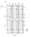
図7は、流体流フィールドプレート70の単純化した平面図を示す。流体流プレート70は、流体分配プレナムを形成する折り畳まれた部分72と、複数の流体流れチャネル78を含む活性領域74、76とを有する。複数の流体流路78および流体分配プレナムは、図6を参照して先に説明した構成を使用して達成することができる。活性領域は、折り畳まれた部分72に対して隣接する部分74および折り畳まれた部分に対して遠位の部分76である。
FIG. 7 shows a simplified plan view of a fluid
一例では、図6aおよび図6bに関して前述したように、活性領域74、76は、折り畳まれた部分72の少なくとも一部によって提供される第2表面領域よりも親水性である第1表面領域を有する。
In one example,
別の例では、折り畳まれた部分72の少なくとも一部は、活性領域74、76に形成された第2表面領域より親水性の高い第1表面領域を提供する。このような例は、燃料電池スタックにおいて、第2表面領域は、活性領域の遠位部分76のみによって、または活性領域の近位部分74および遠位部分76の両方によって、活性領域の近位部分74のみによって提供され得る。第2表面領域は、例えば、疎水性コーティングによって提供される。疎水性コーティングが活性領域の全てより少ない領域に適用される場合、マスクの使用は、活性領域の必要な部分へのコーティングの適用を導くために使用され得る。
In another example, at least a portion of the folded
流体流プレート70のカソード側およびアノード側は、疎水性表面領域の同じまたは異なる配置を有してもよい。例えば、流体流プレート70のアノード側の実質的に全てが第2表面領域で覆われ、流体流プレート70のカソード側の一部のみが第2表面領域で覆われてもよい。流体流プレート70のカソード側の残りの部分は、第1表面領域を提供することができる。
The cathode and anode sides of
この例では、第1および第2表面領域は、燃料電池の形状に合わせて配置することができる。蒸発冷却された燃料電池システムの場合、47℃から72℃の温度差は、背圧のような動作条件に応じて、活性領域と燃料分配プレナムのような非活性領域との間に存在し得る。受動的に冷却された平面燃料電池システムの場合、活性領域と非活性領域との間の温度差は約9℃であり得る。したがって、蒸発冷却されたシステムおよび受動的に冷却されたシステムでは、燃料電池の形状は、システム内の動作温度分布に関係する。液体冷却燃料電池システムの場合、活性領域と非活性領域との間の温度差は実質的に低くなり、いくつかの用途では約5℃となり得る。したがって、いくつかの液体冷却燃料電池システムの用途における温度勾配が比較的低いので、揮発性表面領域を温度の関数として配置することは、蒸発冷却燃料電池システムまたは受動冷却平面燃料電池システムにより適している。 In this example, the first and second surface regions can be arranged to conform to the shape of the fuel cell. For an evaporatively cooled fuel cell system, a temperature difference of 47°C to 72°C can exist between the active area and the non-active area such as the fuel distribution plenum, depending on operating conditions such as back pressure. . For a passively cooled planar fuel cell system, the temperature difference between active and non-active areas can be about 9°C. Therefore, in evaporatively cooled and passively cooled systems, the geometry of the fuel cell is related to the operating temperature distribution within the system. For liquid-cooled fuel cell systems, the temperature difference between active and non-active areas is substantially lower, and can be about 5° C. in some applications. Therefore, positioning the volatile surface area as a function of temperature is more suitable for evaporative cooling fuel cell systems or passively cooling planar fuel cell systems, as the temperature gradients in some liquid cooled fuel cell system applications are relatively low. there is
本発明はまた、少なくとも第2表面領域よりも親水性である第1表面領域を有する燃料電池システムを製造する方法に関する。この方法は、システム内の流体の流れを制御するために、燃料電池システムのパラメータ分布に従って第1表面領域および第2表面領域を提供することを含む。本方法はまた、フィールドフロープレートの周辺領域に第1および第2表面領域の一方または両方を設け、流体流プレナムを形成するためにフィールドフロープレートの周辺領域を折り畳むステップを含むことができる。このようにして、上記の例に関連して説明したような燃料電池システムを得ることができる。
The invention also relates to a method of manufacturing a fuel cell system having at least a first surface region that is more hydrophilic than a second surface region. The method includes providing a first surface area and a second surface area according to a parameter distribution of the fuel cell system to control fluid flow within the system. The method may also include providing one or both of the first and second surface regions in a peripheral region of the field-flow plate and folding the peripheral region of the field-flow plate to form a fluid flow plenum. In this way a fuel cell system such as that described in connection with the above example can be obtained.
Claims (3)
前記第1表面領域(422)は、前記第2表面領域(426)よりも親水性であり、前記第2表面領域(426)は、前記第1表面領域(422)より疎水性であり、前記第2表面領域(426)は、化学的に不活性であり、当該第2表面領域上のマイクロスケールの隆起部(54)のパターンによる2~30の間の平均粗さ係数を具備し、当該平均粗さ係数は実際の表面積の幾何学的表面積に対する比として定義され、前記第1表面領域(422)は前記流体流プレート(428)のランド領域であり、前記第2表面領域(426)は前記流体流プレート(428)のトラック領域であることを特徴とする燃料電池システム。 A fluid flow plate (428) having a plate surface having a first surface area (422) and a second surface area (422) both formed on a single cathode surface of the fluid flow plate (428). A fuel cell system having a surface area (426), comprising:
Said first surface region (422) is more hydrophilic than said second surface region (426), said second surface region (426) is more hydrophobic than said first surface region (422), said The second surface region (426) is chemically inert and has an average roughness factor of between 2 and 30 due to the pattern of microscale ridges (54) on the second surface region; The average roughness factor is defined as the ratio of actual surface area to geometric surface area , said first surface area (422) being the land area of said fluid flow plate (428) and said second surface area (426) being A fuel cell system characterized in that it is a track area of said fluid flow plate (428).
Applications Claiming Priority (3)
| Application Number | Priority Date | Filing Date | Title |
|---|---|---|---|
| GB1422458.8 | 2014-12-17 | ||
| GB201422458 | 2014-12-17 | ||
| PCT/GB2015/054020 WO2016097716A1 (en) | 2014-12-17 | 2015-12-15 | Fuel cell system |
Publications (3)
| Publication Number | Publication Date |
|---|---|
| JP2018503226A JP2018503226A (en) | 2018-02-01 |
| JP2018503226A5 JP2018503226A5 (en) | 2019-01-31 |
| JP7266364B2 true JP7266364B2 (en) | 2023-04-28 |
Family
ID=55135448
Family Applications (1)
| Application Number | Title | Priority Date | Filing Date |
|---|---|---|---|
| JP2017531816A Active JP7266364B2 (en) | 2014-12-17 | 2015-12-15 | fuel cell system |
Country Status (6)
| Country | Link |
|---|---|
| US (2) | US20170373327A1 (en) |
| EP (2) | EP3758118A1 (en) |
| JP (1) | JP7266364B2 (en) |
| KR (1) | KR102574336B1 (en) |
| CN (2) | CN112397738A (en) |
| WO (1) | WO2016097716A1 (en) |
Families Citing this family (2)
| Publication number | Priority date | Publication date | Assignee | Title |
|---|---|---|---|---|
| DK3396025T3 (en) * | 2017-04-26 | 2020-08-24 | Siemens Ag | Continuous manufacturing technique for the production of non-amplified electrochemical cell component |
| DE102021206839A1 (en) * | 2021-06-30 | 2023-01-05 | Robert Bosch Gesellschaft mit beschränkter Haftung | Hydrophobic bipolar plate |
Citations (4)
| Publication number | Priority date | Publication date | Assignee | Title |
|---|---|---|---|---|
| JP2004158237A (en) | 2002-11-05 | 2004-06-03 | Aisin Seiki Co Ltd | Fuel cell power generation system |
| JP2009536430A (en) | 2006-05-05 | 2009-10-08 | インテリジェント エナジー リミテッド | Fluid distribution plate for fuel cells |
| JP2011113740A (en) | 2009-11-25 | 2011-06-09 | Toshiba Corp | Direct methanol fuel cell |
| JP2014216100A (en) | 2013-04-23 | 2014-11-17 | パナソニック株式会社 | Polyelectrolyte fuel cell |
Family Cites Families (11)
| Publication number | Priority date | Publication date | Assignee | Title |
|---|---|---|---|---|
| US6024848A (en) * | 1998-04-15 | 2000-02-15 | International Fuel Cells, Corporation | Electrochemical cell with a porous support plate |
| JP4321039B2 (en) * | 2002-10-25 | 2009-08-26 | アイシン精機株式会社 | Polymer electrolyte fuel cell, oxidant gas separator for polymer electrolyte fuel cell |
| US7951510B2 (en) * | 2004-11-11 | 2011-05-31 | GM Global Technology Operations LLC | Electroconductive polymer coating on electroconductive elements in a fuel cell |
| US20070048590A1 (en) * | 2005-08-31 | 2007-03-01 | Suh Jun W | Fuel cell system, and unit cell and bipolar plate used therefor |
| JP2007095432A (en) * | 2005-09-28 | 2007-04-12 | Toshiba Corp | Fuel cell and fuel cell system |
| KR101240699B1 (en) * | 2005-10-19 | 2013-03-07 | 삼성에스디아이 주식회사 | Bipolar plate and fuel cell stack having the same |
| US20080107944A1 (en) * | 2006-11-03 | 2008-05-08 | Gm Global Technology Operations, Inc. | Folded edge seal for reduced cost fuel cell |
| US7732081B2 (en) * | 2007-05-23 | 2010-06-08 | Gm Global Technology Operations, Inc. | Hydrophilic/hydrophobic patterned surfaces and methods of making and using the same |
| US7901832B2 (en) * | 2008-05-13 | 2011-03-08 | GM Global Technology Operations LLC | Bipolar plate with inlet and outlet water management features |
| KR101084070B1 (en) * | 2009-03-04 | 2011-11-16 | 삼성에스디아이 주식회사 | Membrane-electrode assembly for fuel cell and fuel cell stack with the same |
| KR101395419B1 (en) * | 2012-06-05 | 2014-05-15 | 현대하이스코 주식회사 | Method of manufacturing bipolar plate for a fuel cell with excellent moisture removal in reactant surface |
-
2015
- 2015-12-15 US US15/537,379 patent/US20170373327A1/en not_active Abandoned
- 2015-12-15 CN CN202011285643.7A patent/CN112397738A/en active Pending
- 2015-12-15 KR KR1020177019717A patent/KR102574336B1/en active IP Right Grant
- 2015-12-15 CN CN201580076149.0A patent/CN107251293A/en active Pending
- 2015-12-15 JP JP2017531816A patent/JP7266364B2/en active Active
- 2015-12-15 EP EP20192000.6A patent/EP3758118A1/en active Pending
- 2015-12-15 EP EP15823735.4A patent/EP3235029A1/en not_active Withdrawn
- 2015-12-15 WO PCT/GB2015/054020 patent/WO2016097716A1/en active Application Filing
-
2020
- 2020-10-19 US US17/074,503 patent/US20210036337A1/en active Pending
Patent Citations (4)
| Publication number | Priority date | Publication date | Assignee | Title |
|---|---|---|---|---|
| JP2004158237A (en) | 2002-11-05 | 2004-06-03 | Aisin Seiki Co Ltd | Fuel cell power generation system |
| JP2009536430A (en) | 2006-05-05 | 2009-10-08 | インテリジェント エナジー リミテッド | Fluid distribution plate for fuel cells |
| JP2011113740A (en) | 2009-11-25 | 2011-06-09 | Toshiba Corp | Direct methanol fuel cell |
| JP2014216100A (en) | 2013-04-23 | 2014-11-17 | パナソニック株式会社 | Polyelectrolyte fuel cell |
Also Published As
| Publication number | Publication date |
|---|---|
| JP2018503226A (en) | 2018-02-01 |
| CN107251293A (en) | 2017-10-13 |
| US20170373327A1 (en) | 2017-12-28 |
| KR20170095357A (en) | 2017-08-22 |
| CN112397738A (en) | 2021-02-23 |
| KR102574336B1 (en) | 2023-09-01 |
| EP3235029A1 (en) | 2017-10-25 |
| US20210036337A1 (en) | 2021-02-04 |
| WO2016097716A1 (en) | 2016-06-23 |
| EP3758118A1 (en) | 2020-12-30 |
Similar Documents
| Publication | Publication Date | Title |
|---|---|---|
| US6555261B1 (en) | Microstructured flow fields | |
| KR101381851B1 (en) | Fuel cell fluid distribution plates | |
| US8039162B2 (en) | Unit cell for solid polymer electrolyte fuel cell | |
| RU2351041C2 (en) | Gas distribution in fuel cells | |
| CN102163723B (en) | High tortuosity diffusion medium | |
| KR101693993B1 (en) | Bipolar plate for fuel cell | |
| US20070105000A1 (en) | Flow field plate geometries | |
| JP4753599B2 (en) | Fuel cell | |
| JP5445592B2 (en) | Fuel cell separator and fuel cell | |
| JP2002260710A (en) | Solid polymer cell assembly, fuel cell stack and supply method of reactive gas for fuel cell | |
| JP4936663B2 (en) | Fuel cell direct water injection | |
| US20210036337A1 (en) | Fuel cell system | |
| JP4673110B2 (en) | Fuel cell | |
| US20120308913A1 (en) | Controlling fuel cell | |
| JP2006147466A (en) | Fuel cell and separator for fuel cell | |
| CN111788729B (en) | Fuel cell, cell unit thereof, and stack structure | |
| JP2021519506A (en) | Bipolar plate with wavy channels | |
| JP2006066172A (en) | Fuel cell | |
| US20230040108A1 (en) | Four-fluid bipolar plate for fuel cell | |
| US20240128480A1 (en) | Separator for fuel cell | |
| US8916313B2 (en) | Fuel cell | |
| GB2403061A (en) | Flow field plate geometries | |
| JP2008218201A (en) | Fuel cell | |
| JP2009009836A (en) | Fuel cell and separator for fuel cell |
Legal Events
| Date | Code | Title | Description |
|---|---|---|---|
| A521 | Request for written amendment filed |
Free format text: JAPANESE INTERMEDIATE CODE: A523 Effective date: 20181211 |
|
| A621 | Written request for application examination |
Free format text: JAPANESE INTERMEDIATE CODE: A621 Effective date: 20181211 |
|
| A977 | Report on retrieval |
Free format text: JAPANESE INTERMEDIATE CODE: A971007 Effective date: 20191111 |
|
| A131 | Notification of reasons for refusal |
Free format text: JAPANESE INTERMEDIATE CODE: A131 Effective date: 20200107 |
|
| A601 | Written request for extension of time |
Free format text: JAPANESE INTERMEDIATE CODE: A601 Effective date: 20200407 |
|
| A601 | Written request for extension of time |
Free format text: JAPANESE INTERMEDIATE CODE: A601 Effective date: 20200528 |
|
| A521 | Request for written amendment filed |
Free format text: JAPANESE INTERMEDIATE CODE: A523 Effective date: 20200702 |
|
| A02 | Decision of refusal |
Free format text: JAPANESE INTERMEDIATE CODE: A02 Effective date: 20210105 |
|
| A521 | Request for written amendment filed |
Free format text: JAPANESE INTERMEDIATE CODE: A523 Effective date: 20210506 |
|
| C60 | Trial request (containing other claim documents, opposition documents) |
Free format text: JAPANESE INTERMEDIATE CODE: C60 Effective date: 20210506 |
|
| A911 | Transfer to examiner for re-examination before appeal (zenchi) |
Free format text: JAPANESE INTERMEDIATE CODE: A911 Effective date: 20210517 |
|
| C21 | Notice of transfer of a case for reconsideration by examiners before appeal proceedings |
Free format text: JAPANESE INTERMEDIATE CODE: C21 Effective date: 20210518 |
|
| A912 | Re-examination (zenchi) completed and case transferred to appeal board |
Free format text: JAPANESE INTERMEDIATE CODE: A912 Effective date: 20210806 |
|
| C211 | Notice of termination of reconsideration by examiners before appeal proceedings |
Free format text: JAPANESE INTERMEDIATE CODE: C211 Effective date: 20210817 |
|
| C22 | Notice of designation (change) of administrative judge |
Free format text: JAPANESE INTERMEDIATE CODE: C22 Effective date: 20220222 |
|
| C22 | Notice of designation (change) of administrative judge |
Free format text: JAPANESE INTERMEDIATE CODE: C22 Effective date: 20220322 |
|
| C22 | Notice of designation (change) of administrative judge |
Free format text: JAPANESE INTERMEDIATE CODE: C22 Effective date: 20220412 |
|
| C13 | Notice of reasons for refusal |
Free format text: JAPANESE INTERMEDIATE CODE: C13 Effective date: 20220419 |
|
| C302 | Record of communication |
Free format text: JAPANESE INTERMEDIATE CODE: C302 Effective date: 20220422 |
|
| A521 | Request for written amendment filed |
Free format text: JAPANESE INTERMEDIATE CODE: A523 Effective date: 20220719 |
|
| C13 | Notice of reasons for refusal |
Free format text: JAPANESE INTERMEDIATE CODE: C13 Effective date: 20220920 |
|
| C22 | Notice of designation (change) of administrative judge |
Free format text: JAPANESE INTERMEDIATE CODE: C22 Effective date: 20221108 |
|
| A601 | Written request for extension of time |
Free format text: JAPANESE INTERMEDIATE CODE: A601 Effective date: 20221219 |
|
| A521 | Request for written amendment filed |
Free format text: JAPANESE INTERMEDIATE CODE: A523 Effective date: 20230116 |
|
| C23 | Notice of termination of proceedings |
Free format text: JAPANESE INTERMEDIATE CODE: C23 Effective date: 20230307 |
|
| C03 | Trial/appeal decision taken |
Free format text: JAPANESE INTERMEDIATE CODE: C03 Effective date: 20230404 |
|
| C30A | Notification sent |
Free format text: JAPANESE INTERMEDIATE CODE: C3012 Effective date: 20230404 |
|
| A61 | First payment of annual fees (during grant procedure) |
Free format text: JAPANESE INTERMEDIATE CODE: A61 Effective date: 20230418 |
|
| R150 | Certificate of patent or registration of utility model |
Ref document number: 7266364 Country of ref document: JP Free format text: JAPANESE INTERMEDIATE CODE: R150 |