JP7265150B2 - pachinko machine - Google Patents
pachinko machine Download PDFInfo
- Publication number
- JP7265150B2 JP7265150B2 JP2019101586A JP2019101586A JP7265150B2 JP 7265150 B2 JP7265150 B2 JP 7265150B2 JP 2019101586 A JP2019101586 A JP 2019101586A JP 2019101586 A JP2019101586 A JP 2019101586A JP 7265150 B2 JP7265150 B2 JP 7265150B2
- Authority
- JP
- Japan
- Prior art keywords
- game
- control board
- main control
- machine according
- main
- Prior art date
- Legal status (The legal status is an assumption and is not a legal conclusion. Google has not performed a legal analysis and makes no representation as to the accuracy of the status listed.)
- Active
Links
Images


Classifications
-
- Y—GENERAL TAGGING OF NEW TECHNOLOGICAL DEVELOPMENTS; GENERAL TAGGING OF CROSS-SECTIONAL TECHNOLOGIES SPANNING OVER SEVERAL SECTIONS OF THE IPC; TECHNICAL SUBJECTS COVERED BY FORMER USPC CROSS-REFERENCE ART COLLECTIONS [XRACs] AND DIGESTS
- Y02—TECHNOLOGIES OR APPLICATIONS FOR MITIGATION OR ADAPTATION AGAINST CLIMATE CHANGE
- Y02E—REDUCTION OF GREENHOUSE GAS [GHG] EMISSIONS, RELATED TO ENERGY GENERATION, TRANSMISSION OR DISTRIBUTION
- Y02E60/00—Enabling technologies; Technologies with a potential or indirect contribution to GHG emissions mitigation
- Y02E60/10—Energy storage using batteries
Description
ぱちんこ遊技機に関する。 It relates to a pachinko game machine.
近年のぱちんこ遊技機としては、遊技盤面(遊技領域)上の始動口に遊技球が入球したことを契機として所定確率の大当り抽選がなされ、当該大当り抽選に当選した場合には大当り(特別遊技)状態へと移行し、遊技盤面に備えられた大入賞口が開放して大量の賞球を獲得できるぱちんこ遊技機が主流である。このように構成されたぱちんこ遊技機の内には、当該大当り抽選における当選確率を上昇させる確率変動遊技状態や当該大当り抽選における抽選結果を報知するための図柄変動の効率を上昇させる時間短縮遊技状態等を備え、これら遊技状態によって遊技者にとって有利な遊技進行状態を創り出すことで遊技の興趣性を高める遊技機も存在している。また、遊技盤面の構成を工夫したり、演出内容を工夫することで遊技の興趣性を高める遊技機も存在している。 As a recent pachinko game machine, a jackpot lottery with a predetermined probability is triggered when a game ball enters the starting hole on the game board (game area), and if you win the jackpot lottery, you win a big hit (special game ) state, and a large winning opening provided on the game board can be opened to win a large number of prize balls. Among the pachinko gaming machines constructed in this way, there are a probability variable game state for increasing the probability of winning in the big win lottery and a time shortening game state for increasing the efficiency of pattern variation for notifying the lottery result in the big win lottery. There is also a gaming machine that enhances the interest of the game by creating a game progress state that is advantageous to the player by these game states. In addition, there are game machines that enhance the interest of the game by devising the structure of the game board surface or devising the content of the presentation.
興趣性の高いぱちんこ遊技機の提供が望まれている。 It is desired to provide pachinko game machines with high interest.
本態様に係るぱちんこ遊技機は、
遊技球が入球可能な始動口と、
識別情報を表示可能な識別情報表示部と
を備え、
始動口への入球に基づき、乱数を取得する乱数取得手段と、
乱数取得手段により乱数が取得された場合、当否判定許可条件を充足するまで当該取得された乱数を保留として一時記憶する乱数一時記憶手段と、
ある保留に関する当否判定許可条件を充足した場合、当該ある保留に係る乱数に基づき当否判定を実行する当否判定手段と、
当否判定手段による当否判定の結果に基づき、識別情報表示部にて識別情報を変動表示した後、識別情報を停止表示するよう制御する識別情報表示制御手段と、
当否判定手段による当否判定の結果が当選となった場合、識別情報が所定グループに属する停止表示態様にて停止表示された後、可変入賞口を遊技者にとって有利な状態とし得る特別遊技を実行可能である特別遊技制御手段と
を有し、
遊技状態として、通常遊技状態と、通常遊技状態よりも遊技者にとって有利な特定遊技状態とを少なくとも有し、
識別情報の変動表示時間を決定する際に参照されるテーブルとして第一変動パターンテーブルと、第一変動パターンテーブルとは識別情報の変動表示時間の選択傾向が異なる第二変動パターンテーブルと、を少なくとも有し、
第一変動パターンテーブルを参照する第一変動状態と、第二変動パターンテーブルを参照する第二変動状態と、を少なくとも有し、
通常遊技状態にて当否判定結果が当選となったことに基づいて実行された特別遊技を1回目として、N(但し、Nは1以上の整数)回目の特別遊技の終了後に特定遊技状態となった場合には、第一変動状態となり、
通常遊技状態にて当否判定結果が当選となったことに基づいて実行された特別遊技を1回目として、M(但し、Mは1以上の整数であり、M>N)回目の特別遊技の終了後に特定遊技状態となり且つ所定の条件を満たしていない場合には、第一変動状態となり、
通常遊技状態にて当否判定結果が当選となったことに基づいて実行された特別遊技を1回目として、M回目の特別遊技の終了後に特定遊技状態となり且つ所定の条件を満たしている場合には、第二変動状態となるよう構成されており、
第一変動パターンテーブルまたは第二変動パターンテーブルのうち、一方の変動パターンテーブルの方が他方の変動パターンテーブルよりも識別情報の変動表示時間の平均値が長時間となるよう構成され、
前記一方の変動パターンテーブルのうち所定の特別遊技とならない場合に最も選択され易い変動パターンの方が、前記他方の変動パターンテーブルのうち所定の特別遊技とならない場合に最も選択され易い変動パターンよりも、識別情報の変動表示時間が長時間となるよう構成される
ことを特徴とするぱちんこ遊技機である。
The pachinko game machine according to this aspect is
A starting port into which a game ball can enter;
and an identification information display unit capable of displaying identification information,
random number acquiring means for acquiring a random number based on the ball entering the starting port;
random number temporary storage means for temporarily storing the obtained random number as pending until a condition for permitting judgment is satisfied when a random number is obtained by the random number obtaining means;
a right or wrong determination means for executing a right or wrong determination based on a random number related to a certain hold when a right or wrong judgment permission condition for a certain hold is satisfied;
identification information display control means for controlling the identification information to be stopped and displayed after the identification information is variably displayed by the identification information display unit based on the result of the validity determination by the validity determination means;
When the result of the win/fail judgment by the win/fail judging means is winning, the identification information is stopped and displayed in a stop display mode belonging to a predetermined group, and then a special game can be executed in which the variable winning opening can be brought into an advantageous state for the player. and a special game control means,
As game states, it has at least a normal game state and a specific game state that is more advantageous to the player than the normal game state,
At least a first variation pattern table as a table to be referred to when determining the variation display time of the identification information, and a second variation pattern table in which the selection tendency of the variation display time of the identification information is different from that of the first variation pattern table. have
Having at least a first variation state that refers to the first variation pattern table and a second variation state that refers to the second variation pattern table,
The special game executed based on the winning judgment result in the normal game state is the first time, and after the N (where N is an integer equal to or greater than 1) special game , the specific game state If it becomes, it becomes the first change state,
M (where M is an integer equal to or greater than 1 and M>N) special game is completed, with the special game executed based on the success/failure determination result winning in the normal game state being the first one. When it becomes a specific game state later and does not meet the predetermined conditions, it becomes the first fluctuation state,
When the special game executed based on the success/failure determination result being won in the normal game state is the first time, the specific game state is entered after the M-th special game is completed, and a predetermined condition is satisfied . , is configured to be in the second fluctuation state,
Of the first variation pattern table or the second variation pattern table, one variation pattern table is configured so that the average value of the variation display time of the identification information is longer than the other variation pattern table,
A variation pattern that is most likely to be selected when a predetermined special game does not occur from the one variation pattern table is more likely to be selected than a variation pattern that is most likely to be selected when a predetermined special game does not occur from the other variation pattern table. , a pachinko game machine characterized in that it is configured such that the identification information is displayed for a long period of time.
本態様に係るぱちんこ遊技機によれば、興趣性の高い遊技機を提供することができる、という効果を奏する。 According to the pachinko game machine according to this aspect, it is possible to provide a highly entertaining game machine.
<<<ぱちんこ遊技機に関する実施形態>>>
はじめに、本明細書における各用語の意義について説明する。「入球」とは、賞球が払い出される入賞のみならず、賞球払い出しの無い「スルーチャッカー」への通過も含む。「識別情報」とは、五感(視覚、聴覚、触覚等)を通じて情報の種類を識別可能であればどのような形態でもよいが、好適には、視覚的なもの、例えば、数字、文字、図柄等の形状のあるものを挙げることができる。また、本明細書においては「識別情報」を、主遊技図柄・特別図柄(特図)や装飾図柄(装図)と呼ぶことがあるが、「特別図柄(特図)」は、主制御基板側にて表示制御される識別情報であり、「装飾図柄(装図)」は、副制御基板側にて表示される演出としての識別情報である。「識別情報を表示可能」とは、表示方法には何ら限定されず、例えば、発光手段(例えば液晶、LED、7セグ)の発光(発光の有無だけでなく、色の違いも含む)、物理的な表示(例えば、リール帯に描かれた図柄を所定位置に停止表示する)等、を挙げることができる。「演出」とは、遊技の興趣性を高める表示内容を指し、例えば、識別情報変動・停止や予告等をはじめ、アニメーションや実写等の動画像や絵、写真、文字等の静止画像又はこれらの組み合わせを挙げることができる。「開状態、開放状態」及び「閉状態、閉鎖状態」とは、例えば、一般的な大入賞口(いわゆる、アタッカー)の構成においては、開状態=入賞容易状態であり、閉状態=入賞非容易状態となる。また、例えば、遊技盤(遊技者側)から突き出した状態(以下、進出状態と呼ぶことがある)と遊技盤内(遊技者側と反対側)に引っ込んだ状態(以下、退避状態と呼ぶことがある)とを採り得る構成(いわゆる、ベロ型アタッカー)においては、進出状態=入賞容易状態であり、退避状態=入賞非容易状態となる。「乱数」とは、ぱちんこ遊技機において何らかの遊技内容を決定するための抽選(電子計算機によるくじ)に使用される乱数であり、狭義の乱数の他に擬似乱数も含む(例えば、乱数としてはハード乱数、擬似乱数としてはソフト乱数)。例えば、遊技の結果に影響を与えるいわゆる「基本乱数」、具体的には、特別遊技の移行と関連した「当選乱数(当否抽選用乱数)」、識別図柄の変動態様(又は変動時間)を決定するための「変動態様決定乱数」、停止図柄を決定する「図柄決定乱数」、特別遊技後に特定遊技(例えば確率変動遊技)に移行するか否かを決定する「当り図柄決定乱数」等を挙げることができる。尚、変動態様の内容や確定識別情報の内容等を決定する際、これらすべての乱数を使用する必要はなく、互いに同一又は相違する、少なくとも一つの乱数を使用すればよい。また、本明細書では、乱数の数とか複数個の乱数、といった形で乱数を個数表示していることがあるが、乱数取得の契機となる入球口(例えば始動入球口)の一回の入球により取得された乱数を一個と称している(即ち、前記の例だと、当選乱数+変動態様決定乱数+図柄決定乱数・・・という乱数の束を一個の乱数と称している)。また、例えば、一種の乱数(例えば当選乱数)が、別種の乱数(例えば図柄決定乱数)を兼ねていてもよい。「遊技状態」とは、ぱちんこ遊技機の場合、例えば、大入賞口が開放状態となり得る特別遊技状態、特別遊技状態への移行抽選確率が予め定められた値である非確率変動遊技状態よりも特別遊技状態への移行抽選確率が高い確率変動遊技状態、特別遊技への移行抽選契機となる始動口への入賞に対する補助が有る補助遊技状態(いわゆる、普通図柄時短状態、例えば、始動口に可変部材が取り付けられている場合では、可変部材の開放期間が長い、可変部材の開放当選確率が高い、可変部材の開放抽選の結果報知の時間が短い)、等の任意の一又は複数の組合せである。「遊技領域」とは、遊技球が転動可能な領域であり、遊技盤D35の手前(遊技者から見て)のみに限られず、例えば、遊技盤D35の奥側(遊技者から見て)と遊技盤D35の手前側(遊技者から見て)との双方を含む遊技球が転動可能な領域であってもよい。「左打ち」とは、後述する、遊技領域D30の左側(左打ちルートML10)を遊技球が流下するよう、遊技球の発射強度を調節して遊技球を打ち出すことである。「右打ち」とは、後述する、遊技領域D30の右側(右打ちルートMR10)を遊技球が流下するよう、遊技球の発射強度を調節して遊技球を打ち出すことである。また、「左打ち領域」とは、遊技領域中央を基準とした場合に遊技領域D30の左側の領域のことである。「右打ち領域」とは、遊技領域中央を基準とした場合に遊技領域D30の右側の領域のことである。「単位時間あたりにおける易入球遊技の期待平均実行時間」とは、補助遊技図柄の図柄変動が絶え間なく行われる状況(例えば、補助遊技図柄に係る保留が常に存在している状況)を仮定した場合において、始動口に取り付けられた可変部材の単位時間(例えば、5分間)あたりにおける開放期間が占める割合を意味しているが、内部処理的には、前述した遊技状態に基づき換言すると、例えば、始動口に可変部材が取り付けられている場合では、可変部材の開放期間の長短(いわゆる開放延長機能作動状態・非作動状態)、可変部材の開放契機となる普通図柄(補助遊技図柄)の当選確率の高低(いわゆる普図高確率抽選状態・低確率抽選状態)、可変部材の開放契機となる普通図柄(補助遊技図柄)の変動時間の長短(いわゆる普図変動短縮機能非作動状態・作動状態)、等の任意の一又は複数の組合せによって実現されるものである。「識別情報の変動表示期間の平均値」とは、識別情報の変動表示毎に変動表示期間を実測し、当該実測値に基づく平均値を採るという意味に限定されるものではない。より具体的には、識別情報の変動表示毎に、その変動表示期間を決定するよう構成されている場合であって、決定(選択)されるべき変動表示期間の候補が複数種類ある場合には、当該複数種類の変動表示期間に基づく期待値(「選択確率×変動表示期間」の総和)となるが、当該選択されるべき変動表示期間の候補が一種類である場合には、その一種類の変動表示期間そのものとなる(即ち、双方の概念を含むものである)。更には、ハズレ時における識別情報の変動表示期間の平均値のみに限定した概念又は当り時における識別情報の変動表示期間の平均値のみに限定した概念、或いは、最も選択確率の高い変動表示期間のみに限定した概念としてもよく、即ち、この文言の趣旨は、遊技者が体感できる遊技の進行スピードを指し示す指標として用いることにあることを補足しておく(よって、「識別情報の変動表示期間の平均値」を異ならせる実現方法としては、変動表示期間の候補及び/又は選択確率を異ならせる、或いは、変動表示期間の候補及び/又は選択確率が同一であっても更なる変動表示期間を付加する際の期間値を異ならせる、等の様々な手法はあるが、いずれかの手法に限定されるものではない)。「識別情報の変動表示期間の平均値が第一の期間となる第一変動期間状態と、識別情報の変動表示期間の平均値が当該第一の期間とは異なる第二の期間となる第二変動期間状態とを少なくとも有し、」とは、当該二つの状態のみならず、三つ以上の状態を有していてもよい(或いは、三つ以上の状態を有する場合におけるいずれか二つの状態を対象とする)という意味であり、例えば、識別情報の変動表示回数に応じて、「第一変動期間状態」→「第二変動期間状態」→「第三変動期間状態」との状態遷移を採り得るものも含む。この場合においては、夫々の状態における識別情報の変動表示期間の平均値が、「第一変動期間状態」<「第二変動期間状態」<「第三変動期間状態」となるよう構成した場合、高速な遊技進行状態→中速な遊技進行状態→低速な遊技進行状態、との状態遷移を構築することができる{勿論、この逆となる状態遷移(遊技進行状態)を構築してもよく、その場合、次回の大当りまで継続する確率変動遊技状態+電チュー特定遊技状態と併用する際において好適となる(次回の大当り発生が確定的である状況にも拘わらず、次回の大当りが得られない状況が続くほど、遊技の進行スピードが向上するため、いわゆるハマリ時における倦怠感を払拭できる)場合がある}。更には、各状態の特徴として、「第一変動期間状態」においては、ハズレ時における識別情報の変動表示期間の平均値と当り時における識別情報の変動表示期間の平均値との差が、「第二変動期間状態」におけるその差よりも小さい、「第三変動期間状態」においては、ハズレ時における識別情報の変動表示期間の平均値と当り時における識別情報の変動表示期間の平均値との差が、「第二変動期間状態」におけるその差よりも小さいことに加え、「第一変動期間状態」と比べて、特にハズレ時における識別情報の変動表示期間が相対的に長時間となり易い(即ち、当りやリーチを示唆する変動又はリーチ変動となり易い)、「第二変動期間状態」においては、他の状態と比べて、特に当り時における識別情報の変動表示期間が相対的に長時間となり易い{即ち、ハズレが確定的となる短変動ハズレの変動表示期間や当りを示唆する中変動ハズレの変動表示期間が選択されない(又は選択され難い)が、リーチ変動(長変動当り)の変動表示期間のみ選択される(又は選択され易い)}、といった特徴を有することを例示することができる。「特別遊技の実行終了後での高確率抽選状態における特定期間」とは、当該特別遊技の実行終了直後から所定回数分の図柄変動がなされるまでの期間であってもよいし、当該特別遊技の実行終了後における一又は複数回の図柄変動がなされた後から所定回数分の図柄変動がなされるまでの期間であってもよい(即ち、特別遊技の実行終了後にて高確率抽選状態が維持されている範囲内であれば、その範囲内における任意の期間であることを意味するが故、前述の「第一変動期間状態」→「第二変動期間状態」→「第三変動期間状態」との状態遷移を採り得る場合には、当該特定期間が「第一変動期間状態」及び/又は「第二変動期間状態」の滞在期間を意味するものとなり得る)。「保留に関する情報において所定条件を充足した際」とは、例えば、その保留消化時において特別遊技(いわゆる大当り遊技)が生起する可能性が高いことを意味するが、特別遊技が生起する可能性の判断基準には特に限定されない。より具体的には、「当選乱数(当否抽選用乱数)」、識別図柄の変動態様(又は変動時間)を決定するための「変動態様決定乱数」、停止図柄を決定する「図柄決定乱数」、特別遊技後に特定遊技(例えば確率変動遊技)に移行するか否かを決定する「当り図柄決定乱数」等の乱数値を判断基準としてもよいし、これら乱数値から導き出される事象内容(当否判定結果、変動時間の長さ、停止図柄の種類、特定遊技への移行可否等)を判断基準としてもよい。「保留の存在を示唆又は報知する」とは、示唆する場合には、例えば、当該保留に到るまでの保留消化時における演出(装飾図柄の図柄変動態様や、それと連動して行われている背景演出等)の実行態様を変化させる、等を挙げることができ、報知する場合には、例えば、当該保留生起時において保留表示灯(液晶表示装置上の画像であってもよい)の表示態様を変化させる(その場合には、表示色を変化させる、表示形状を変化させる、等)、当該保留生起時において保留発生音やBGM等の音響を変化させる、当該保留生起時において演出用のランプ(枠ランプ等)の点灯態様を変化させる、或いは、当該保留生起時において実行されている他の演出(装飾図柄の図柄変動態様や、それと連動して行われている背景演出等)の実行態様を変化させる、等を挙げることができる。
<<<Embodiment of pachinko machine>>>
First, the meaning of each term used in this specification will be explained. "Entering ball" includes not only prize winning in which a prize ball is paid out, but also passing through a "through chucker" in which prize balls are not paid out. "Identification information" may be in any form as long as the type of information can be identified through the five senses (visual, auditory, tactile, etc.), but is preferably visual, such as numbers, letters, and patterns. and the like. In addition, in this specification, "identification information" may be referred to as main game design/special design (special design) or decoration design (design), but "special design (special design)" is the main control board The "decorative design (design)" is identification information as an effect displayed on the sub-control board side. The term “identification information can be displayed” is not limited to any display method, and includes, for example, light emission from light emitting means (for example, liquid crystal, LED, 7-segment) (including not only the presence or absence of light emission but also the difference in color), physical typical display (for example, a pattern drawn on the reel band is stopped and displayed at a predetermined position). “Production” refers to display content that enhances the interest of the game, such as identification information change / stop, notice, etc., moving images such as animation and live action, still images such as pictures, photographs, characters, etc. Combinations can be mentioned. "Open state, open state" and "closed state, closed state" are, for example, in the configuration of a general large winning opening (so-called attacker), open state = easy winning state, closed state = non-winning state. Easy state. Also, for example, a state of protruding from the game board (player side) (hereinafter sometimes referred to as an advanced state) and a state of being retracted into the game board (on the side opposite to the player side) (hereinafter referred to as a retracted state) ) (so-called tongue-type attacker), advance state=easy-win state, retreat state=non-easy-win state. “Random numbers” are random numbers used in lotteries (computer-based lotteries) to determine game content in pachinko machines, and include pseudo-random numbers in addition to strictly-defined random numbers (for example, random numbers are hard soft random numbers as random numbers, pseudo-random numbers). For example, the so-called "basic random number" that affects the result of the game, specifically, the "random number (random number for lottery)" related to the transition to the special game, and the variation mode (or variation time) of the identification pattern are determined. ``variation mode determination random number'' for determining the stop pattern, ``symbol determination random number'' for determining the stop pattern, and ``hit pattern determination random number'' for determining whether to shift to a specific game (for example, probability variation game) after a special game. be able to. It is not necessary to use all these random numbers when determining the content of the variation mode, the content of the definite identification information, etc., but at least one random number that is the same or different from each other may be used. In this specification, the number of random numbers may be expressed in the form of the number of random numbers or a plurality of random numbers. The random number obtained by entering the ball is called one (that is, in the above example, a bunch of random numbers such as winning random number + variation mode determination random number + symbol determination random number ... is called one random number) . Also, for example, one type of random number (for example, winning random number) may serve as another type of random number (for example, symbol determination random number). "Game state" means, in the case of a pachinko game machine, for example, a special game state in which the large winning opening can be open, and a non-probability variable game state in which the lottery probability of transition to the special game state is a predetermined value. Transition to special game state Probability fluctuation game state with high lottery probability, transition to special game Auxiliary game state with assistance for winning a prize to the starting port that triggers the lottery (so-called normal pattern time saving state, for example, variable to the starting port In the case where the member is attached, any one or a combination of the following: long open period of the variable member, high probability of winning the open variable member, short time to announce the result of the open lottery of the variable member), etc. be. The "game area" is an area in which a game ball can roll, and is not limited to the area in front of the game board D35 (as viewed from the player), but may be, for example, the area behind the game board D35 (as seen from the player). and the front side of the game board D35 (as seen from the player), in which the game ball can roll. “Left-handed” refers to hitting a game ball by adjusting the shooting intensity of the game ball so that the game ball flows down the left side of the game area D30 (left-handed route ML10), which will be described later. "Right-handed" means to hit a game ball by adjusting the shooting intensity of the game ball so that the game ball flows down the right side of the game area D30 (right-handed route MR10), which will be described later. Also, the "left-handed area" is the area on the left side of the game area D30 when the center of the game area is used as a reference. "Right-handed area" is an area on the right side of the game area D30 when the center of the game area is used as a reference. "Expected average execution time of easy-to-enter game per unit time" is assumed to be a situation where auxiliary game patterns are constantly changing (for example, a situation where there is always a hold related to auxiliary game patterns) In the case, it means the ratio of the open period per unit time (for example, 5 minutes) of the variable member attached to the start port. , If the variable member is attached to the starting port, the length of the opening period of the variable member (so-called open extension function operating state / non-operating state), the normal pattern (auxiliary game pattern) that triggers the opening of the variable member Probability high and low (so-called normal pattern high probability lottery state / low probability lottery state), length of fluctuation time of normal pattern (auxiliary game pattern) that triggers the opening of variable members (so-called normal pattern fluctuation reduction function non-operating state / operating state ), etc., are realized by any one or multiple combinations. The "average value of the variable display period of the identification information" is not limited to the fact that the variable display period is actually measured for each variable display of the identification information and the average value based on the measured value is taken. More specifically, when the variable display period is determined for each variable display of the identification information, and there are multiple types of candidates for the variable display period to be determined (selected). , the expected value based on the multiple types of variable display periods (the sum of "selection probability x variable display period"), but if there is only one type of candidate for the variable display period to be selected, that one type (that is, it includes both concepts). Furthermore, a concept limited to only the average value of the variable display period of the identification information at the time of losing, a concept limited to only the average value of the variable display period of the identification information at the time of winning, or only the variable display period with the highest selection probability In other words, it should be added that the purpose of this phrase is to use it as an index that indicates the progress speed of the game that the player can experience (therefore, "the variable display period of the identification information As a method of making the "average value" different, the candidates and/or selection probabilities of the variable display period are made different, or even if the candidates and/or selection probabilities of the variable display period are the same, an additional variable display period is added. There are various methods such as differentiating the period value when performing the calculation, but the method is not limited to any of them). "a first variable period state in which the average value of the variable display period of identification information is the first period, and a second period in which the average value of the variable display period of identification information is a second period different from the first period "has at least a variable period state," may have not only the two states, but also three or more states (or any two states in the case of having three or more states For example, depending on the number of times the identification information is displayed, the state transition from "first fluctuation period state" → "second fluctuation period state" → "third fluctuation period state" Including what you can get. In this case, if the average value of the variable display period of the identification information in each state is configured to be "first variable period state"<"second variable period state"<"third variable period state", A state transition of high-speed game progress→medium-speed game progress→slow game progress can be constructed {of course, the opposite state transition (game progress) may be constructed, In that case, it is suitable when used together with the probability fluctuation game state that continues until the next big hit + the electric chew specific game state (despite the situation where the next big hit is certain, the next big hit As the situation continues, the progress speed of the game improves, so that it may be possible to dispel the feeling of fatigue during the so-called addiction)}. Furthermore, as a feature of each state, in the "first variable period state", the difference between the average value of the variable display period of identification information at the time of losing and the average value of the variable display period of identification information at the time of winning is " In the "third fluctuation period state", which is smaller than the difference in the "second fluctuation period state", the average value of the identification information fluctuation display period at the time of losing and the average value of the identification information fluctuation display period at the time of winning In addition to the fact that the difference is smaller than the difference in the "second fluctuation period state", compared to the "first fluctuation period state", the fluctuation display period of the identification information, especially at the time of losing, tends to be relatively long ( In other words, fluctuations or reach fluctuations that suggest hits and reach are likely to occur), in the "second fluctuation period state", the period of fluctuation display of identification information, especially at the time of winning, is relatively long compared to other states. {That is, the fluctuation display period of the short fluctuation loss that makes the loss deterministic and the fluctuation display period of the medium fluctuation loss that suggests a hit are not selected (or are difficult to select), but the reach fluctuation (per long fluctuation) fluctuation display only the period is selected (or is likely to be selected)}. "Specific period in the high probability lottery state after the execution of the special game" may be a period from immediately after the execution of the special game to a predetermined number of symbol changes, or the special game. It may be a period from after one or more symbol variations are made after the execution of the above to the symbol variations for a predetermined number of times (that is, after the execution of the special game, the high probability lottery state is maintained If it is within the range, it means that it is an arbitrary period within that range. If the state transition can be taken, the specific period can mean the stay period of "first fluctuation period state" and / or "second fluctuation period state"). "When a predetermined condition is satisfied in the information on hold" means, for example, that there is a high possibility that a special game (so-called jackpot game) will occur at the time of digestion of the hold, but the possibility that a special game will occur The judgment criteria are not particularly limited. More specifically, "winning random number (random number for success or failure lottery)", "variation mode determination random number" for determining the variation mode (or variation time) of the identification pattern, "symbol determination random number" for determining the stop design, A random number such as a "hit pattern determination random number" that determines whether or not to shift to a specific game (for example, a probability variation game) after a special game may be used as a judgment criterion, or event contents derived from these random numbers (whether judgment result , the length of the fluctuation time, the type of stop pattern, whether or not to shift to a specific game, etc.) may be used as the judgment criteria. "Suggesting or announcing the existence of a hold" means, in the case of suggesting, for example, the production at the time of digestion of the hold until the hold (the pattern variation of the decorative pattern, and the background effect, etc.) can be changed, and in the case of notification, for example, the display mode of the hold indicator lamp (which may be an image on the liquid crystal display device) at the time of the hold occurrence (In that case, change the display color, change the display shape, etc.), change the sound such as the on-hold sound and BGM at the time of the on-hold occurrence, and the production lamp at the time of the on-hold occurrence (frame lamp, etc.), or execution mode of other effects (decorative pattern pattern fluctuation mode, background effect performed in conjunction with it, etc.) being executed at the time of the suspension occurrence and the like.
尚、本実施形態は、あくまで一例であり、各手段が存在する場所や機能等、各種処理に関しての各ステップの順序、フラグのオン・オフのタイミング、各ステップの処理を担う手段名等に関し、以下の態様に限定されるものではない。また、上記した実施形態や変更例は、特定のものに対して適用されると限定的に解すべきでなく、どのような組み合わせであってもよい。例えば、ある実施形態についての変更例は、別の実施形態の変更例であると理解すべきであり、また、ある変更例と別の変更例が独立して記載されていたとしても、当該ある変更例と当該別の変更例を組み合わせたものも記載されていると理解すべきである。 Note that this embodiment is only an example, and regarding the location and function of each means, the order of each step regarding various processes, the timing of turning on and off the flag, the name of the means responsible for the processing of each step, etc. It is not limited to the following aspects. Moreover, the above-described embodiments and modifications should not be construed as being limited to being applied to a specific one, and may be combined in any way. For example, a modification of one embodiment should be understood as a modification of another embodiment, and even if one modification is described independently of another, the It should be understood that combinations of modifications and other such modifications are also described.
以下の実施形態は、従来の第1種ぱちんこ遊技機を二つ混在させたような機種(第1種第1種複合機)である。但し、これには何ら限定されず、他の遊技機(例えば、従来の第1種、第2種、第3種、一般電役等のぱちんこ遊技機)に応用された場合も範囲内である。尚、本実施形態は、あくまで一例であり、各手段が存在する場所や機能等、各種処理に関しての各ステップの順序、フラグのオン・オフのタイミング、各ステップの処理を担う手段名等に関し、以下の態様に限定されるものではない。また、上記した実施形態や変更例は、特定のものに対して適用されると限定的に解すべきでなく、どのような組み合わせであってもよい。例えば、ある実施形態についての変更例は、別の実施形態の変更例であると理解すべきであり、また、ある変更例と別の変更例が独立して記載されていたとしても、当該ある変更例と当該別の変更例を組み合わせたものも記載されていると理解すべきである。また、本実施形態では、各種テーブルに関し、抽選テーブルと参照テーブルとが存在するが、これらも限定的ではなく、抽選テーブルを参照テーブルとしたり或いはこの逆としてもよい。また、本例において「テーブル」という場合には、その形式に限定されるものではなく、一又は複数の情報に基づき、複数の選択候補の中から一又は複数の選択候補が選択されるように対応付けられている態様であると理解すべきである。更に、以下の実施形態や変更例において示す具体的一例としての数値{例えば、抽選実行時における当選確率、特別遊技時における最大ラウンド数、図柄変動時間、各遊技状態における継続回数、等}は、あくまで一例であり、特に、異なる条件下(例えば、第1主遊技側と第2主遊技側との条件別、確率変動遊技時と非確率変動遊技時との条件別、時間短縮遊技時と非時間短縮遊技時との条件別、等)において示した数値の大小関係や組み合わせは、以下の実施形態や変更例の趣旨を大きく逸脱しない限りにおいては、適宜変更してもよいものであると理解すべきである。例えば、第1主遊技側と第2主遊技側とで、抽選実行時における当選確率や特別遊技時における最大ラウンド数の期待値における大小関係が、第1主遊技側=第2主遊技側となるよう例示されていたとしても、当該大小関係を第1主遊技側<第2主遊技側とする、或いは、第1主遊技側>第2主遊技側とするといったように適宜変更してもよい(その他の数値、条件下についても同様)。また、例えば、確率変動遊技状態の継続回数として、次回大当りが発生するまで継続するとの趣旨に基づき構成するに際し、継続回数として「65535」をセットするのか(実質的に継続するよう構成する)、或いは、継続回数をセットせずに次回大当りが発生するまで確率変動遊技状態を維持する、といった同一趣旨に基づく実現方法の選択肢においても、以下の実施形態や変更例の趣旨を大きく逸脱しない限りにおいては、適宜変更してもよいものであると理解すべきである。
The following embodiment is a model (first class first class compound machine) in which two conventional first class pachinko game machines are mixed. However, it is not limited to this in any way, and it is within the scope even if it is applied to other game machines (for example,
(本実施形態)
ここで、各構成要素について説明する前に、本実施形態に係るぱちんこ遊技機の特徴(概略)を説明する。以下、図面を参照しながら、各要素について詳述する。
(this embodiment)
Here, before describing each component, the features (outline) of the pachinko gaming machine according to the present embodiment will be described. Each element will be described in detail below with reference to the drawings.
尚、以下の実施形態におけるステップ番号、符号、手段名等は、他の実施形態におけるステップ番号、符号、手段名等と同一である場合があるが、これらはそれぞれ単独の実施形態におけるステップ番号、符号、手段名等であることを示している(例えば、本実施形態におけるステップ2102と第2実施形態におけるステップ2102は、別の実施形態におけるステップ2102であるため、それぞれ単独で機能する処理である)。 Note that the step numbers, symbols, means names, etc. in the following embodiments may be the same as the step numbers, symbols, means names, etc. in other embodiments, but these are the step numbers, (For example, step 2102 in this embodiment and step 2102 in the second embodiment are step 2102 in another embodiment, so each is a process that functions independently. ).
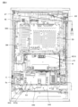
まず、図1を参照しながら、本実施形態に係るぱちんこ遊技機の前面側の基本構造を説明する。ぱちんこ遊技機は、主に遊技機枠と遊技盤D35で構成される。以下、これらを順に説明する。 First, referring to FIG. 1, the basic structure of the front side of the pachinko game machine according to the present embodiment will be described. The pachinko game machine is mainly composed of a game machine frame and a game board D35. These will be described in order below.
はじめに、ぱちんこ遊技機の遊技機枠は、外枠D12、前枠D14、透明板D16、扉D18、上球皿D20、下球皿D22及び発射ハンドルD44を含む。まず、外枠D12は、ぱちんこ遊技機を設置すべき位置に固定するための枠体である。前枠D14は、外枠D12の開口部分に整合する枠体であり、図示しないヒンジ機構を介して外枠D12に開閉可能に取り付けられる。前枠D14は、遊技球を発射する機構、遊技盤D35を着脱可能に収容させるための機構、遊技球を誘導又は回収するための機構等を含む。透明板D16は、ガラス等により形成され、扉D18により支持される。扉D18は、図示しないヒンジ機構を介して前枠D14に開閉可能に取り付けられる。上球皿D20は、遊技球の貯留、発射レ-ルへの遊技球の送り出し、下球皿D22への遊技球の抜き取り等の機構を有する。下球皿D22は、遊技球の貯留、抜き取り等の機構を有する。また、遊技盤D35の右上方と左上方とにはスピーカD24が設けられており、遊技状態等に応じた効果音が出力される。 First, the game machine frame of the pachinko game machine includes an outer frame D12, a front frame D14, a transparent plate D16, a door D18, an upper ball tray D20, a lower ball tray D22 and a firing handle D44. First, the outer frame D12 is a frame for fixing the pachinko game machine to a position to be installed. The front frame D14 is a frame that matches the opening of the outer frame D12, and is attached to the outer frame D12 via a hinge mechanism (not shown) so that it can be opened and closed. The front frame D14 includes a mechanism for shooting game balls, a mechanism for detachably housing the game board D35, a mechanism for guiding or collecting game balls, and the like. The transparent plate D16 is made of glass or the like and supported by the door D18. The door D18 is attached to the front frame D14 via a hinge mechanism (not shown) so that it can be opened and closed. The upper ball tray D20 has a mechanism for storing game balls, delivering game balls to the launch rail, extracting game balls to the lower ball tray D22, and the like. The lower ball tray D22 has a mechanism for storing and extracting game balls. Speakers D24 are provided on the upper right and upper left sides of the game board D35 to output sound effects according to the game state and the like.
遊技盤D35と遊技機の前面の透明板D16(例えば、ガラス板)とは、13mmを超え25mmを超えない距離(本例では、19mm)の距離を保ち並行になるように遊技機枠に取り付けられている。ここで、遊技盤D35は、容易に動揺しないように固定機構によってしっかりと固定されている。 The game board D35 and the transparent plate D16 (for example, a glass plate) on the front of the game machine are attached to the game machine frame so as to be parallel to each other while maintaining a distance of more than 13 mm and not more than 25 mm (19 mm in this example). It is Here, the game board D35 is firmly fixed by a fixing mechanism so as not to be easily shaken.
また、透明板D16(例えば、ガラス板)は、遊技盤の全体の構造の見通しを妨げず、遊技盤上の遊技球の位置を確認できるように遊技領域全体が無色透明で凹凸がないように形成されている。 In addition, the transparent plate D16 (for example, a glass plate) is designed so that the entire game area is colorless and transparent and has no unevenness so that the position of the game ball on the game board can be confirmed without obstructing the view of the entire structure of the game board. formed.
球皿(例えば、上球皿D20、下球皿D22)は、球皿上の遊技球が遊技者にとって可視的(遊技球の数を概ね確認可能)であり、遊技者が受け皿に受けた遊技球の取り出しを阻害しないような形状(遊技球を自由に取り出せるような形状)になっている。 The ball tray (for example, the upper ball tray D20, the lower ball tray D22) is such that the game balls on the ball tray are visible to the player (the number of game balls can be generally confirmed), and the player receives the game ball on the tray. It has a shape that does not hinder the taking out of the ball (a shape that allows the game ball to be taken out freely).
次に、遊技盤D35は、外レールD32と内レールD34とにより区画された遊技領域D30が形成されており、透明板D16を介して遊技盤D35上(遊技領域D30上)を流下する遊技球の位置を確認できるようになっている。遊技領域D30は、左打ち領域DL10と右打ち領域DR10とに大別される。そして、当該遊技領域D30には、図示しない複数の遊技釘及び風車等の機構や各種一般入賞口の他、左打ちルートML10、右打ちルートMR10、第1主遊技始動口A10、第2主遊技始動口B10、補助遊技始動口H10、第1大入賞口C10、第2大入賞口C20、第1主遊技図柄表示装置A20、第2主遊技図柄表示装置B20、演出表示装置SG、補助遊技図柄表示装置H20、センター飾りD38、可動体役物YK、右一般入賞口用ランプLP10、左一般入賞口P10、右一般入賞口P20、サブ入力ボタンSB、十字ボタンSB-2及びアウト口D36が設置されている。尚、本実施形態においては、左打ちルートML10を第1流下ルートと称することがあり、右打ちルートMR10を第2流下ルートと称することがある。以下、各要素を順番に詳述する。 Next, the game board D35 has a game area D30 defined by an outer rail D32 and an inner rail D34. position can be confirmed. The game area D30 is roughly divided into a left-handed area DL10 and a right-handed area DR10. In addition, in the game area D30, in addition to a plurality of mechanisms such as game nails and windmills (not shown) and various general winning openings, left-handed route ML10, right-handed route MR10, first main game start opening A10, second main game Starting port B10, auxiliary game starting port H10, first big winning port C10, second big winning port C20, first main game symbol display device A20, second main game symbol display device B20, effect display device SG, auxiliary game symbols Display device H20, center decoration D38, movable body accessory YK, right general prize winning lamp LP10, left general prize winning port P10, right general prize winning port P20, sub-input button SB, cross button SB-2 and out port D36 are installed. It is In this embodiment, the left-handed route ML10 may be referred to as the first downstream route, and the right-handed route MR10 may be referred to as the second downstream route. Each element will be described in detail below.
次に、第1主遊技始動口A10は、第1主遊技に対応する始動入賞口として設置されている。具体的構成としては、第1主遊技始動口A10は、第1主遊技始動口入球検出装置A11sを備える。ここで、第1主遊技始動口入球検出装置A11sは、第1主遊技始動口A10への遊技球の入球を検出するセンサであり、入球時にその入球を示す第1主遊技始動口入球情報を生成する。 Next, the first main game starting port A10 is installed as a starting prize winning port corresponding to the first main game. As a specific configuration, the first main game start opening A10 includes a first main game start opening ball detection device A11s. Here, the first main game start opening detection device A11s is a sensor that detects the entry of a game ball to the first main game start opening A10, and the first main game start that indicates the entry at the time of entry. Generate entry ball information.
次に、第2主遊技始動口B10は、第2主遊技に対応する始動入賞口として設置されている。具体的構成としては、第2主遊技始動口B10は、第2主遊技始動口入球検出装置B11sと、第2主遊技始動口電動役物B11dと、を備える。ここで、第2主遊技始動口入球検出装置B11sは、第2主遊技始動口B10への遊技球の入球を検出するセンサであり、入球時にその入球を示す第2主遊技始動口入球情報を生成する。次に、第2主遊技始動口電動役物B11dは、第2主遊技始動口B10に遊技球が入賞し難い閉鎖状態と当該閉鎖状態よりも遊技球が入賞し易い開放状態に可変する。 Next, the second main game starting port B10 is installed as a starting prize winning port corresponding to the second main game. Specifically, the second main game start opening B10 includes a second main game start opening ball detection device B11s and a second main game start electric accessory B11d. Here, the second main game start opening ball detection device B11s is a sensor that detects the entry of a game ball to the second main game start opening B10, and the second main game start indicating the entry at the time of entry. Generate entry ball information. Next, the second main game starter electric accessory B11d changes between a closed state in which game balls are less likely to enter the second main game starter B10 and an open state in which game balls are easier to enter than in the closed state.
ここで、本実施形態においては、第1主遊技始動口A10と第2主遊技始動口B10とが設けられており、遊技領域D30の左側(左打ち領域DL10)を流下する遊技球とが第1主遊技始動口A10に誘導され易い一方、遊技領域D30の右側(右打ち領域DR10)を流下する遊技球は第1主遊技始動口A10に誘導され難いよう構成されている。また、遊技領域D30の左側を流下する遊技球と遊技領域D30の右側を流下する遊技球とのいずれも第2主遊技始動口B10に誘導され得るよう構成されている。 Here, in the present embodiment, a first main game start port A10 and a second main game start port B10 are provided, and a game ball flowing down the left side of the game region D30 (left-handed region DL10) While easily guided to the first main game start port A10, the game ball flowing down the right side of the game region D30 (right hitting region DR10) is configured to be less likely to be guided to the first main game start port A10. In addition, both the game balls flowing down the left side of the game area D30 and the game balls flowing down the right side of the game area D30 are configured to be guided to the second main game start port B10.
尚、本実施形態では、第2主遊技始動口B10側に電動役物を設けるよう構成したが、これには限定されず、第1主遊技始動口A10側に電動役物を設けるよう構成してもよい。更には、本実施形態では、第1主遊技始動口A10と第2主遊技始動口B10とが重ねるように配置されているが、これにも限定されず、第1主遊技始動口A10と第2主遊技始動口B10とを離隔して配置してもよい。 In this embodiment, the electric accessory is provided on the side of the second main game start port B10, but it is not limited to this, and the electric accessory is provided on the side of the first main game start port A10. may Furthermore, in this embodiment, the first main game starter A10 and the second main game starter B10 are arranged so as to overlap, but this is not a limitation, and the first main game starter A10 and the second main game starter A10 are arranged to overlap. It may be arranged apart from the 2 main game start gate B10.
次に、補助遊技始動口H10は、補助遊技始動口入球検出装置H11sを備える。ここで、補助遊技始動口入球検出装置H11sは、補助遊技始動口H10への遊技球の入球を検出するセンサであり、入球時にその入球を示す補助遊技始動口入球情報を生成する。尚、補助遊技始動口H10への遊技球の入球は、第2主遊技始動口B10の第2主遊技始動口電動役物B11dを拡開させるための抽選の契機となる。 Next, the auxiliary game starting port H10 is provided with an auxiliary game starting port entering ball detection device H11s. Here, the auxiliary game start entrance ball detection device H11s is a sensor that detects the entrance of the game ball to the auxiliary game start hole H10, and generates auxiliary game start entrance ball information indicating the entrance ball at the time of entrance. do. The entry of the game ball into the auxiliary game starter H10 triggers a lottery for expanding the second main game starter electric accessory B11d of the second main game starter B10.
ここで、本実施形態においては、遊技領域D30の右側(遊技領域中央を基準)を流下する遊技球が補助遊技始動口H10に誘導され易く、遊技領域D30の左側(遊技領域中央を基準)を流下する遊技球が補助遊技始動口H10に誘導され難くなるよう構成されている。但し、これには限定されず、遊技領域D30の右側及び左側(遊技領域中央を基準)を流下する遊技球が、補助遊技始動口H10に誘導され得るよう構成されていてもよい。 Here, in the present embodiment, the game ball flowing down the right side of the game area D30 (based on the center of the game area) is likely to be guided to the auxiliary game start opening H10, the left side of the game area D30 (based on the center of the game area) It is configured to make it difficult for the flowing game balls to be guided to the auxiliary game starting port H10. However, it is not limited to this, and may be configured so that the game balls flowing down the right and left sides of the game area D30 (with respect to the center of the game area) can be guided to the auxiliary game start opening H10.
次に、左一般入賞口P10は、左一般入賞口入球検出装置P11sを備える。左一般入賞口入球検出装置P11sは、左一般入賞口P10への遊技球の入球を検出するセンサであり、入球時にその入球を示す左一般入賞口入球情報を生成する。尚、左一般入賞口P10への遊技球の入球によって、所定数(例えば、3球)の遊技球が賞球として払い出されることとなる。尚、遊技領域D30の左側(遊技領域中央を基準)を流下する遊技球は左一般入賞口P10に入球し易く、遊技領域D30の右側(遊技領域中央を基準)を流下する遊技球は左一般入賞口P10に入球し難いよう構成されている。即ち、左打ち(遊技領域D30の左側である左打ち領域DL10(左打ちルートML10)を遊技球が流下するよう、遊技球の発射強度を調節して遊技球を打ち出すこと)を実行した際に左一般入賞口P10に入球し易いよう構成されている。 Next, the left general winning opening P10 includes a left general winning opening ball detection device P11s. The left general winning opening ball detection device P11s is a sensor that detects the entry of a game ball into the left general winning opening P10, and generates left general winning opening ball information indicating the entry of the ball at the time of entry. A predetermined number (for example, 3) of game balls are paid out as prize balls by entering the game balls into the left general winning hole P10. In addition, a game ball flowing down the left side of the game area D30 (based on the center of the game area) easily enters the left general winning hole P10, and a game ball flowing down the right side of the game area D30 (based on the center of the game area) It is configured such that it is difficult for a ball to enter the general prize winning opening P10. That is, when hitting to the left (to adjust the shooting intensity of the game ball and hit the game ball so that the game ball flows down the left hitting area DL10 (left hitting route ML10) which is the left side of the game area D30). It is configured such that it is easy for a ball to enter the left general prize-winning hole P10.
次に、右一般入賞口P20は、右一般入賞口入球検出装置P21sを備える。右一般入賞口入球検出装置P21sは、右一般入賞口P20への遊技球の入球を検出するセンサであり、入球時にその入球を示す右一般入賞口入球情報を生成する。ここで、右一般入賞口P20は、右打ち領域DR10に配置され、補助遊技乱数を取得するという補助遊技始動口の役割と、賞球が払い出されるという一般入賞口の役割との双方を兼ね備えている。つまり、右一般入賞口P20への遊技球の入球は、第2主遊技始動口B10に取り付けられた第2主遊技始動口電動役物B11dを拡開させるための抽選の契機となる。また、右一般入賞口P20への遊技球の入球によって、所定数(例えば、2球)の遊技球が賞球として払い出されることとなる。尚、右一般入賞口P20への遊技球の入球によって、右一般入賞口P20から賞球として払い出される遊技球(例えば、2球)は、左一般入賞口P10への遊技球の入球によって、左一般入賞口P10から賞球として払い出される遊技球(例えば、3球)よりも少なくなるよう構成されている。尚、本実施形態においては、右打ちを実行した遊技球が右一般入賞口P20に入球し得るよう構成されている。即ち、右打ち(遊技領域D30の右側である右打ち領域DR10(右打ちルートMR10)を遊技球が流下するよう、遊技球の発射強度を調節して遊技球を打ち出すこと)を実行した際に右一般入賞口P20に入球し易いよう構成されている。 Next, the right general winning opening P20 includes a right general winning opening ball detection device P21s. The right general winning opening ball detection device P21s is a sensor that detects the entry of a game ball into the right general winning opening P20, and generates right general winning opening ball information indicating the entry of the ball at the time of entry. Here, the right general winning opening P20 is arranged in the right-handed area DR10, and has both the role of an auxiliary game starting opening for acquiring auxiliary game random numbers and the role of a general winning opening for paying out prize balls. there is In other words, the entry of a game ball into the right general winning opening P20 triggers a lottery for expanding the second main game start opening electric accessory B11d attached to the second main game start opening B10. Also, a predetermined number (for example, two) of game balls are paid out as prize balls by the game balls entering the right general winning hole P20. It should be noted that the game balls (for example, two balls) paid out as prize balls from the right general prize winning port P20 due to the game balls entering the right general prize winning port P20 will , the number of game balls paid out as prize balls (for example, 3 balls) from the left general winning hole P10. In addition, in this embodiment, it is configured so that a game ball hit to the right can enter the right general winning hole P20. That is, when hitting to the right (shooting the game ball by adjusting the shooting intensity of the game ball so that the game ball flows down the right hitting area DR10 (right hitting route MR10) which is the right side of the game area D30). It is configured so that the ball can easily enter the right general winning hole P20.
ここで、本実施形態においては、右打ちを実行した際に入球し得る入球口としては、上流から順に、「補助遊技始動口H10→右一般入賞口P20→第2大入賞口C20→第1大入賞口C10→第2主遊技始動口B10→アウト口D36」の順となっている。また、補助遊技始動口H10はゲートの形状をしているため、補助遊技始動口H10を通過した遊技球は遊技領域上を更に流下していくこととなり、下流にある入球口(上述した右一般入賞口P20等)に入球し得ることとなる。一方、右一般入賞口P20に入球した遊技球は遊技盤面奥側に流入することとなり、その後第1大入賞口C10や第2大入賞口C20に入球することはない(右打ちを実行して右一般入賞口P20に入球しなかった遊技球が第1大入賞口C10又は第2大入賞口C20に入球し得ることとなる)。 Here, in this embodiment, as a ball entrance that can be entered when hitting to the right, in order from upstream, "auxiliary game start opening H10 → right general winning opening P20 → second big winning opening C20 → 1st big prize winning opening C10→second main game starting opening B10→out opening D36". In addition, since the auxiliary game start opening H10 has a gate shape, the game ball that has passed through the auxiliary game start opening H10 will flow further down the game area, and the downstream ball entrance (the above-mentioned right The ball can be entered in the general winning hole P20, etc.). On the other hand, a game ball that enters the right general winning hole P20 will flow into the back side of the game board surface, and will not enter the first big winning hole C10 or the second big winning hole C20 after that (executing right-handed hitting) Then, the game ball that did not enter the right general winning hole P20 can enter the first big winning hole C10 or the second big winning hole C20).
尚、非時間短縮遊技状態における左打ちの実行時には(非時間短縮遊技状態においては左打ちにて遊技を進行する)、補助遊技始動口H10(及び右一般入賞口P20)に遊技球が入球し難いため第2主遊技始動口電動役物B11dが開放し難く、主遊技側の始動口として主に第1主遊技始動口A10への入球によって遊技を進行していくこととなり、一方、時間短縮遊技状態における右打ちの実行時には(時間短縮遊技状態においては右打ちにて遊技を進行する)、補助遊技始動口H10(及び右一般入賞口P20)に遊技球が入球し易いため第2主遊技始動口電動役物B11dが開放し易く、主遊技側の始動口として主に第2主遊技始動口B10への入球によって遊技を進行していくこととなる。また、非時間短縮遊技状態において左打ちにて遊技球を発射し続けた場合の第1主遊技始動口A10への入球容易性よりも、時間短縮遊技状態において右打ちにて遊技球を発射し続けた場合の第2主遊技始動口B10への入球容易性の方が高い、換言すると、非時間短縮遊技状態において左打ちにて遊技球を発射し続けた場合の第1主遊技始動口A10又は第2主遊技始動口B10への入球容易性よりも、時間短縮遊技状態において右打ちにて遊技球を発射し続けた場合の第1主遊技始動口A10又は第2主遊技始動口B10への入球容易性の方が高くなる。そこで、本例においては、左打ち実行時の方が右打ち実行時よりも入球し易い左一般入賞口P10に入球した際の賞球数(本例では、3球)を、右打ち実行時の方が左打ち実行時よりも入球し易い右一般入賞口P20に入球した際の賞球数(本例では、2球)よりも多く設計することにより、非時間短縮遊技状態にて左打ちで遊技を進行した場合と、時間短縮遊技状態にて右打ちで遊技を進行した場合との、入賞口へ入球することにより払い出される平均の賞球数の差分、即ち、ベース値(特別遊技に当選していない状況において、発射した遊技球100球に対する、払い出される賞球払出数の期待値)の差分が大きくなりすぎることを防止することができる。 In addition, when executing left-handed hitting in the non-time-reduced gaming state (the game proceeds with left-handed hitting in the non-time-reduced gaming state), the game ball enters the auxiliary game start port H10 (and the right general winning port P20). Since it is difficult to open the second main game starter electric accessory B11d, the game proceeds mainly by entering the first main game starter A10 as the starter on the main game side. When executing right-handed hitting in the time-reduced gaming state (the game proceeds with right-handed hitting in the time-reduced gaming state), the game ball is easy to enter the auxiliary game start opening H10 (and the right general winning opening P20). The 2 main game starter electric accessory B11d is easy to open, and the game progresses mainly by entering a ball into the 2nd main game starter B10 as the starter on the main game side. In addition, the ease of entering the first main game start opening A10 in the case of continuing to shoot left-handed game balls in a non-time-reduced gaming state is more pronounced than the ease with which a game ball can be shot right-handed in a time-reduced gaming state. The easiness of entering the ball into the second main game start port B10 is higher in the case of continuing to do so, in other words, the first main game start when the game ball continues to be shot left-handed in the non-shortening game state. 1st main game start A10 or 2nd main game start when game balls continue to be shot by hitting to the right in the time shortening game state rather than the ease of entering the ball into the hole A10 or 2nd main game start B10 The ease of entering the ball into the mouth B10 is higher. Therefore, in this example, the number of prize balls (three balls in this example) when entering the left general winning hole P10, which is easier to enter when hitting left than when hitting right, is By designing the number of winning balls (in this example, 2 balls) when entering the right general winning hole P20, which is easier to enter than the left-handed hitting, the non-time-reducing game state is realized. The difference in the average number of prize balls paid out by entering the winning hole between when the game is played with the left hand and when the game is played with the right hand in the time-reduced game state, that is, the base It is possible to prevent the difference between the values (the expected value of the number of prize balls to be paid out for 100 game balls that have been shot in a situation where the special game has not been won) from becoming too large.
また、右一般入賞口用ランプLP10は、例えば、液晶、LED等で構成されており、特別遊技の実行中に右一般入賞口に遊技球が入球することにより点灯し得るよう構成されている。また、詳細は後述することとなるが、右一般入賞口用ランプLP10の点灯色の違いにより特別遊技終了後に確率変動遊技状態に移行するか非確率変動遊技状態に移行するかを示唆し得るよう構成されている。尚、右一般入賞口用ランプLP10は、遊技領域D30上の、左打ち領域DL10に設けても良いし右打ち領域DR10に設けても良い。また、遊技領域D30以外の領域に設けてもよい。尚、本例においては、非確率変動遊技状態を、通常状態、通常遊技状態、通常時、低確率、低確率状態、低確率遊技状態、低確率時、非確変、低確率抽選状態等と称することがある。また、確率変動遊技状態を、高確率、高確率状態、高確率遊技状態、高確率時、確変、高確率抽選状態等と称することがある。また、時間短縮遊技状態を、時短状態、時短中、時短、等と称することがある。また、非時間短縮遊技状態を、非時短状態、非時短中、非時短等と称することがある。また、非確率変動遊技状態且つ非時間短縮遊技状態を、通常状態、通常遊技状態、通常時、等と称することがある。 Further, the right general winning hole lamp LP10 is composed of, for example, a liquid crystal, an LED, or the like, and is configured to be lit when a game ball enters the right general winning hole during execution of a special game. . In addition, although the details will be described later, the difference in the lighting color of the right general winning hole lamp LP10 can suggest whether to shift to the probability variable gaming state or the non-probability variable gaming state after the special game ends. It is configured. The right general winning hole lamp LP10 may be provided in the left-handed area DL10 or the right-handed area DR10 on the game area D30. Also, it may be provided in an area other than the game area D30. In this example, the non-probability variable gaming state is referred to as normal state, normal gaming state, normal time, low probability, low probability state, low probability gaming state, low probability time, non-probability variation, low probability lottery state, etc. Sometimes. Also, the probability variable gaming state may be referred to as high probability, high probability state, high probability gaming state, high probability time, probability variation, high probability lottery state, and the like. Also, the time reduction game state may be referred to as a time saving state, a time saving medium, a time saving, or the like. Also, the non-time-reduction gaming state may be referred to as non-time-saving state, non-time-saving, non-time-saving, and the like. Also, the non-probability variable gaming state and non-time reduction gaming state may be referred to as normal state, normal game state, normal time, and the like.
また、右打ちルートMR10を流下した遊技球は、右打ちルート流出口D50を通過して右一般入賞口P20、第1大入賞口C10、第2大入賞口C20等の近傍に流下していくこととなる。 In addition, the game ball flowing down the right-handed route MR10 passes through the right-handed route outflow port D50 and flows down to the vicinity of the right general winning port P20, the first big winning port C10, the second big winning port C20, and the like. It will happen.
次に、アウト口D36の右上方には、第1大入賞口C10と第2大入賞口C20とが設けられており、遊技領域D30の右側(遊技領域中央を基準)を流下する遊技球は、アウト口D36に到達する前に、第1大入賞口C10及び第2大入賞口C20が配置されている領域を通過し易いよう構成されている。 Next, on the upper right side of the out port D36, a first big prize winning port C10 and a second big prize winning port C20 are provided. , before reaching the out hole D36, it is configured to easily pass through the area where the first big winning hole C10 and the second big winning hole C20 are arranged.
次に、第1大入賞口C10は、第1主遊技図柄(特別図柄)又は第2主遊技図柄(特別図柄)が大当り図柄停止した場合に開状態となる、横長方形状を成しアウト口D36の右上方に位置した、主遊技に対応した入賞口である。具体的構成としては、第1大入賞口C10は、遊技球の入球を検出するための第1大入賞口入賞検出装置C11sと、第1大入賞口電動役物C11d{及び第1大入賞口電動役物ソレノイドC13}と、を備える。ここで、第1大入賞口入賞検出装置C11sは、第1大入賞口C10への遊技球の入球を検出するセンサであり、入球時にその入球を示す第1大入賞口入球情報を生成する。第1大入賞口電動役物C11dは、第1大入賞口C10に遊技球が入賞不能又は入賞困難な通常状態と遊技球が入賞し易い開放状態に第1大入賞口C10を可変させる(第1大入賞口電動役物ソレノイドC13を励磁して可変させる)。尚、本実施形態では、大入賞口の態様を、横長方形状を成し遊技球が入賞不能又は入賞困難な通常状態と遊技球が入賞し易い開放状態とに可変させる態様としているが、これには限定されない。その場合には、例えば、大入賞口内に設けられた棒状部材が遊技者側に突き出した状態である進出状態と遊技者側に対して引っ込んだ状態である退避状態とを採り得る態様(いわゆる、ベロ型アタッカ-)や、遊技球が転動可能な通路上の開口部を大入賞口とし、当該開口部を閉鎖する状態と開放する状態とを採り得る態様(いわゆる、スライド式アタッカー)としてもよく、大入賞口への入球数を所定数(例えば、10個)とすることを担保したい場合において好適である。 Next, the first big winning hole C10 is a horizontally rectangular out hole that opens when the first main game pattern (special pattern) or the second main game pattern (special pattern) stops as a jackpot pattern. This is a prize winning opening corresponding to the main game located on the upper right side of D36. As a specific configuration, the first large winning opening C10 includes a first large winning opening winning detection device C11s for detecting the entry of a game ball, a first large winning opening electric accessory C11d {and a first big winning Mouth electric accessory solenoid C13}. Here, the first big winning hole winning detection device C11s is a sensor that detects the entry of a game ball into the first big winning hole C10, and the first big winning hole entering ball information indicating the ball entering the first big winning hole C10. to generate The first big winning opening electric accessory C11d changes the first big winning opening C10 between a normal state in which the game ball cannot or is difficult to win in the first big winning opening C10 and an open state in which the game ball easily wins (the first 1 big prize opening electric accessory solenoid C13 is excited and varied). In the present embodiment, the mode of the big winning opening is changed between a normal state in which a game ball cannot or is difficult to win a horizontal rectangular shape and an open state in which a game ball can easily win a prize. is not limited to In that case, for example, a state in which the rod-shaped member provided in the big prize opening protrudes toward the player side and a retracted state in which the bar member is retracted toward the player side (so-called Tongue type attacker-), and an opening on the passage where the game ball can roll is used as a large winning opening, and the opening can be closed and opened (so-called slide attacker). This is suitable when it is desired to ensure that the number of balls entering the big winning hole is a predetermined number (eg, 10).
次に、第2大入賞口C20は、第1主遊技図柄(特別図柄)又は第2主遊技図柄(特別図柄)が大当り図柄で停止した場合に開状態となる、横長方形状を成しアウト口D36の右上方に位置した、主遊技に対応した入賞口である。具体的構成としては、第2大入賞口C20は、遊技球の入球を検出するための第2大入賞口入賞検出装置C21sと、第2大入賞口電動役物C21d{及び第2大入賞口電動役物ソレノイドC23}と、を備える。ここで、第2大入賞口入賞検出装置C21sは、第2大入賞口C20への遊技球の入球を検出するセンサであり、入球時にその入球を示す第2大入賞口入球情報を生成する。そして、第2大入賞口C20内に入球した遊技球は、第2大入賞口入賞検出装置C21sによって検出されるよう構成されている。次に、第2大入賞口電動役物C21dは、第2大入賞口C20に遊技球が入賞不能又は入賞困難な通常状態と遊技球が入賞し易い開放状態とに第2大入賞口C20を可変させる。尚、本実施形態では、大入賞口の態様を、横長方形状を成し遊技球が入賞不能又は入賞困難な通常状態と遊技球が入賞し易い開放状態とに可変させる態様としているが、これには限定されない。その場合には、例えば、大入賞口内に設けられた棒状部材が遊技者側に突き出した状態である進出状態と遊技者側に対して引っ込んだ状態である退避状態とを採り得る態様(いわゆる、ベロ型アタッカー)や、遊技球が転動可能な通路上の開口部を大入賞口とし、当該開口部を閉鎖する状態と開放する状態とを採り得る態様(いわゆる、スライド式アタッカー)としてもよく、大入賞口への入球数を所定数(例えば、10個)とすることを担保したい場合において好適である。 Next, the second big winning hole C20 is a horizontal rectangular shape that is opened when the first main game pattern (special pattern) or the second main game pattern (special pattern) stops with a big win pattern, and is out. This is a prize winning opening corresponding to the main game located on the upper right side of the opening D36. As a specific configuration, the second large winning opening C20 includes a second large winning opening winning detection device C21s for detecting the entry of a game ball, a second large winning opening electric accessory C21d {and a second large winning opening Mouth electric accessory solenoid C23}. Here, the second large winning opening detection device C21s is a sensor that detects the entry of a game ball into the second large winning opening C20, and the second large winning opening entry ball information indicating the entry of the ball at the time of entry. to generate A game ball entered into the second big winning hole C20 is configured to be detected by the second big winning hole winning detection device C21s. Next, the second big winning hole electric accessory C21d changes the second big winning hole C20 into a normal state in which the game ball cannot or is difficult to win in the second big winning hole C20 and an open state in which the game ball easily wins. variable. In the present embodiment, the mode of the big winning opening is changed between a normal state in which a game ball cannot or is difficult to win a horizontal rectangular shape and an open state in which a game ball can easily win a prize. is not limited to In that case, for example, a state in which the rod-shaped member provided in the big prize opening protrudes toward the player side and a retracted state in which the bar member is retracted toward the player side (so-called Tongue type attacker), or an opening on the passage where the game ball can roll is used as a large winning opening, and the opening can be closed and opened (so-called slide attacker). , is suitable when it is desired to ensure that the number of balls entering the big winning hole is a predetermined number (for example, 10).
次に、第1主遊技図柄表示装置A20(第2主遊技図柄表示装置B20)は、第1主遊技(第2主遊技)に対応する第1主遊技図柄(第2主遊技図柄)に関連した表示等を実行する装置である。具体的構成としては、第1主遊技図柄表示装置A20(第2主遊技図柄表示装置B20)は、第1主遊技図柄表示部A21g(第2主遊技図柄表示部B21g)と、第1主遊技図柄保留表示部A21h(第2主遊技図柄保留表示部B21h)とを備える。ここで、第1主遊技図柄保留表示部A21h(第2主遊技図柄保留表示部B21h)は、4個のランプから構成され、当該ランプの点灯個数が、第1主遊技(第2主遊技)に係る乱数の保留数(実行されていない主遊技図柄の変動数)に相当する。尚、第1主遊技図柄表示部A21g(第2主遊技図柄表示部B21g)は、例えば7セグメントLEDで構成され、第1主遊技図柄(第2主遊技図柄)は、「0」~「9」の10種類の数字及びハズレの「-」で表示される{但し、これには限定されず、いずれの主遊技図柄が表示されたのかを遊技者が認識困難となるよう、7セグメントLEDを用いて記号等によって表示することが好適である。また、保留数表示においても、4個のランプから構成されていることには限定されず、最大4個分の保留数を表示可能に構成(例えば、1個のランプから構成されており、保留数1:点灯、保留数2:低速点滅、保留数3:中速点滅、保留数4:高速点滅、するよう構成)されていればよい}。 Next, the first main game symbol display device A20 (second main game symbol display device B20) is associated with the first main game symbol (second main game symbol) corresponding to the first main game (second main game). It is a device that executes display, etc. As a specific configuration, the first main game symbol display device A20 (second main game symbol display device B20) includes a first main game symbol display portion A21g (second main game symbol display portion B21g) and a first main game symbol display portion A21g (second main game symbol display portion B21g). A symbol reservation display portion A21h (second main game symbol reservation display portion B21h) is provided. Here, the first main game symbol reservation display portion A21h (second main game symbol reservation display portion B21h) is composed of four lamps, and the number of lighting of the lamps is equal to the first main game (second main game). It corresponds to the number of pending random numbers (the number of fluctuations in the main game symbols that have not been executed). The first main game symbol display portion A21g (second main game symbol display portion B21g) is composed of, for example, a 7-segment LED, and the first main game symbol (second main game symbol) is "0" to "9". ” and ``-'' for failure {However, it is not limited to this, and the 7-segment LED is displayed so that it is difficult for the player to recognize which main game pattern is displayed. It is preferable to display by a symbol or the like using In addition, the display of the number of holds is not limited to being composed of four lamps, and is configured to be able to display the number of holds for up to four (for example, it is composed of one lamp, number 1: lighting, number of holds 2: flashing at low speed, number of holds 3: flashing at medium speed, number of holds 4: flashing at high speed}.
尚、主遊技図柄は必ずしも演出的な役割を持つ必要が無いため、本実施形態では、第1主遊技図柄表示装置A20の大きさは、目立たない程度に設定されている。しかしながら、主遊技図柄自体に演出的な役割を持たせて装飾図柄を表示させないような手法を採用する場合には、後述する演出表示装置SGのような液晶ディスプレーに、主遊技図柄を表示させるように構成してもよい。 It should be noted that the main game symbols do not necessarily have a role in performance, so in the present embodiment, the size of the first main game symbol display device A20 is set to an inconspicuous level. However, in the case of adopting a technique in which the main game symbols themselves have an effect role and the decorative symbols are not displayed, it is possible to display the main game symbols on a liquid crystal display such as the effect display device SG, which will be described later. can be configured to
次に、演出表示装置SGは、主遊技図柄と連動して変動・停止する装飾図柄を含む演出画像の表示等を実行する装置である。ここで、具体的構成としては、演出表示装置SGは、装飾図柄の変動表示等を含めて演出が実行される表示領域SG10を備える。ここで、表示領域SG10は、例えば、スロットマシンのゲームを模した複数列の装飾図柄変動の動画像を表示する装飾図柄表示領域SG11と、主遊技保留情報を表示する第1保留表示部SG12及び第2保留表示部SG13と、を有している。尚、演出表示装置SGは、本実施形態では液晶ディスプレーで構成されているが、機械式のドラムやLED等の他の表示手段で構成されていてもよい。次に、第1保留表示部SG12及び第2保留表示部SG13は夫々4個のランプから構成され、当該ランプは、主遊技図柄の保留ランプと連動している。 Next, the effect display device SG is a device for executing the display of effect images including decorative symbols that fluctuate and stop interlocking with the main game symbols. Here, as a specific configuration, the effect display device SG includes a display area SG10 in which effects including variable display of decorative symbols are executed. Here, the display area SG10 includes, for example, a decorative symbol display area SG11 that displays moving images of a plurality of rows of decorative symbol variations imitating a slot machine game, a first pending display area SG12 that displays main game pending information, and and a second pending display portion SG13. In this embodiment, the effect display device SG is composed of a liquid crystal display, but may be composed of other display means such as mechanical drums or LEDs. Next, the first suspension display portion SG12 and the second suspension display portion SG13 are each composed of four lamps, and the lamps are interlocked with the suspension lamps of the main game symbols.
次に、補助遊技図柄表示装置H20は、補助遊技図柄に関する表示等を実行する装置である。具体的構成としては、補助遊技図柄表示装置H20は、補助遊技図柄表示部H21gと、補助遊技図柄保留表示部H21hとを備える。ここで、補助遊技図柄保留表示部H21hは、4個のランプから構成され、当該ランプの点灯個数が、補助遊技図柄変動の保留数(実行されていない補助遊技図柄変動の数)に相当する。本実施形態においては、補助遊技乱数を取得し得る入球口として、補助遊技始動口H10と右一般入賞口P20との2つの入球口を有しており、当該2つの入球口のいずれに入球した場合にも、取得した補助遊技乱数に関する表示は補助遊技図柄表示装置H20に表示されることとなる。 Next, the auxiliary game symbol display device H20 is a device that executes display and the like regarding auxiliary game symbols. Specifically, the auxiliary game symbol display device H20 includes an auxiliary game symbol display portion H21g and an auxiliary game symbol reserve display portion H21h. Here, the auxiliary game symbol reservation display portion H21h is composed of four lamps, and the number of lights of the lamps corresponds to the number of auxiliary game symbol variations pending (the number of auxiliary game symbol variations that have not been executed). In this embodiment, there are two entrances, an auxiliary game start opening H10 and a right general winning opening P20, as entrances from which auxiliary game random numbers can be obtained. Also when the ball is entered, the display related to the acquired auxiliary game random number is displayed on the auxiliary game symbol display device H20.
次に、センター飾りD38は、演出表示装置SGの周囲に設置され、遊技球の流路、演出表示装置SGの保護、装飾等の機能を有する。また、遊技効果ランプD26は、遊技領域D30及び/又は遊技領域D30以外の領域に設けられ、点滅等することで演出の役割を果たす。 Next, the center decoration D38 is installed around the performance display device SG, and has functions such as the passage of game balls, the protection of the performance display device SG, decoration, and the like. In addition, the game effect lamp D26 is provided in the game area D30 and/or in an area other than the game area D30, and plays a role of effect by blinking or the like.
次に、可動体役物YKは、演出表示装置SGの近傍に設置され、図柄変動に伴う演出実行の際に駆動して遊技を盛り上げる役割を担っている。上下方向に移動したり、回転駆動したり、点灯したりして、駆動したことが目立つよう構成し、且つ、大当り期待度の高い図柄変動にて駆動し易い構成することが好適である。 Next, the movable accessory YK is installed in the vicinity of the effect display device SG, and is driven when the effect associated with the pattern variation is executed to make the game exciting. It is preferable to move vertically, rotationally drive, or light up so that the driving is conspicuous and easy to drive with pattern variations with high expectation for big hits.
次に、サブ入力ボタンSBは、副制御基板Sと電気的に接続された、操作(押下)することによって当該操作に基づく演出が実行されることとなる操作部材である。尚、サブ入力ボタンSBの操作態様として、単発押し(短時間の1回のみサブ入力ボタンSBを押下する操作態様)と、連打(複数回サブ入力ボタンSBを押下する操作態様)と、長押し(所定期間サブ入力ボタンSBを押し続ける操作態様)と、を有するよう構成してもよい。また、副制御基板Sと電気的に接続された、操作(押下)することによって当該操作に基づく演出が実行されることとなる操作部材はサブ入力ボタンSBのみには限定されず、上、下、左、右の4つの操作部を有しており、当該操作部を操作することにより、実行する演出(予告演出等)を選択可能に構成される十字キー、手前に引くことにより演出(可動体役物が作動する、等)が実行されるレバー、等を有するよう構成してもよい。 Next, the sub-input button SB is an operation member electrically connected to the sub-control board S, which is operated (depressed) to execute an effect based on the operation. The modes of operation of the sub-input button SB include a single press (an operation mode in which the sub-input button SB is pressed only once for a short period of time), a continuous press (an operation mode in which the sub-input button SB is pressed multiple times), and a long press. (an operation mode in which the sub-input button SB is kept pressed for a predetermined period of time). Further, the operation member that is electrically connected to the sub control board S and that is operated (depressed) to execute an effect based on the operation is not limited to the sub input button SB. , left, and right. By operating the operation part, the cross key is configured to be able to select the effect to be executed (notice effect, etc.). , etc.) may be configured to have a lever, etc., on which a physical object is actuated, etc.).
次に、アウト口D36は、遊技領域D30の下方に設けられた入球口であり、遊技領域D30に設けられたいずれの入賞口にも入球せずに流下した遊技球が入球する入球口であり、アウト口D36に遊技球が入球した場合には、乱数に基づく各種抽選や入球に基づく賞球等は実行されず、当該遊技球は遊技機外に排出されることとなる。なお、本実施例では、が遊技盤上の最下部にのみ、入賞口に入賞しなかった遊技球が入るアウト口D36が設けられているが、遊技盤の上部の所定箇所にアウト口を設けることも可能である。その場合には、当該入口が入賞口でないことを明らかにするため、シールを用いて、「OUT」を表示する等、入賞口と混同しないようにすることが望ましい。 Next, the out port D36 is a ball entry port provided below the game area D30. When a game ball enters the out hole D36, various lotteries based on random numbers and prize balls based on the entered ball are not executed, and the game ball is discharged out of the gaming machine. Become. In this embodiment, only the lowest part of the game board is provided with an out hole D36 for receiving game balls that did not win a prize. is also possible. In that case, in order to make it clear that the entrance is not a prize winning opening, it is desirable to use a sticker to display "OUT" or the like so as not to confuse it with a prize winning opening.
尚、不図示であるが、遊技盤D35(遊技領域D30)の大きさは、一辺が500mmである正方形の枠を超えず、かつ、直径が300mmである円を含む範囲が設定されている。 Although not shown, the size of the game board D35 (game area D30) is set to a range that does not exceed a square frame with a side of 500 mm and includes a circle with a diameter of 300 mm.
また、本実施形態においては、役物が作動しない場合(大入賞口C10等の可変入賞口が閉鎖状態となっている場合)における入賞口(遊技球を入賞させることが可能なもの、換言すると発射された遊技球について物理的に可能な軌跡をもってしても入賞が不可能でないものであり、例えば、第1主遊技始動口A10)の数(入賞口の入口の数)は、5個(第1主遊技始動口A10が1個、左一般入賞口P10が3個、右一般入賞口P20が1個)となっている。尚、入賞口の数は適宜設定可能であるが、入賞割合と遊技の複雑化抑止の観点から5個~15個の範囲が望ましい。ここで、入賞口の入口とは、入賞口及び当該入賞口に連なる遊技釘等(その間を遊技球が通過できない形で連続配置されている遊技釘等)で構成される遊技球の通過面のうち、入賞口から最も離れた位置にある部分を指す。尚、役物が作動しない場合における入賞口の入口の大きさ(入賞口の入口のうち、遊技盤D35と平行な距離の最大値であり、遊技釘により設定されている場合には釘と釘の内法)は、13mmを超えないように構成することが望ましく、大入賞口以外の可変入賞装置(電動役物や非電動役物)の入賞口の入口の大きさ(前述の通り)は、55mmを超えないことが望ましい。また、大入賞口の入口の大きさ(遊技盤と平行な距離の最大値)は、他の役物と区別するために、55mmを超え、135mmを超えないようにすることが望ましい。 In addition, in the present embodiment, when the accessory does not operate (when the variable winning opening such as the big winning opening C10 is in a closed state), the winning opening (that allows the game ball to win, in other words, Winning is not impossible even if the launched game ball has a physically possible trajectory. There is one first main game start opening A10, three left general winning openings P10, and one right general winning opening P20). Although the number of winning holes can be set as appropriate, a range of 5 to 15 is desirable from the viewpoint of the winning ratio and prevention of complication of the game. Here, the entrance of the prize winning opening means the passing surface of the game ball composed of the winning opening and the game nails etc. connected to the winning opening (game nails etc. continuously arranged in such a manner that the game ball cannot pass between them). Of these, it refers to the part that is farthest from the prize winning opening. In addition, the size of the entrance of the winning opening when the accessory does not operate (the maximum value of the distance parallel to the game board D35 among the entrances of the winning opening, and if it is set by the game nail, nail and nail It is desirable that the width of the inner diameter) does not exceed 13 mm. , should not exceed 55 mm. In addition, it is desirable that the size of the entrance of the big winning slot (maximum distance parallel to the game board) exceeds 55 mm and does not exceed 135 mm in order to distinguish it from other accessories.
更に、普通図柄表示装置が作動する契機となっているゲート(例えば、補助遊技始動口H10)の大きさ(ゲート及び当該ゲートに連なる遊技釘等(その間を遊技球が通過できない形で連続配置されている遊技釘等)で構成される遊技球の通過面のうち、ゲートから最も離れた位置で遊技盤D35と平行な距離の最大値、即ち実質的なゲートの入口)は、13mmを超えないようにすることが望ましい。 Furthermore, the size of the gate (for example, the auxiliary game starting port H10) that triggers the operation of the normal symbol display device (the game nail etc. connected to the gate and the gate (the game nails etc. are continuously arranged in such a way that the game ball cannot pass between them) Among the game ball passage surfaces composed of game nails, etc.), the maximum distance parallel to the game board D35 at the farthest position from the gate, that is, the actual gate entrance) does not exceed 13 mm. It is desirable to
尚、本実施形態においては、大入賞口を2つ(第1大入賞口C10と第2大入賞口C20との2つ)設けているが、射幸性の観点から2個を超えないように構成することが望ましい。また、本実施形態のように、2個の大入賞口が開放等している否かにかかわらず物理的に明確に分離されていることが明らかな構造が望ましい。更に、本実施形態のように、2個の大入賞口が水平方向に隣接することなく、2つの大入賞口の間に遊技球が通過可能となっていることが望ましい。また、本実施形態では始動口として、第1主遊技始動口A10と第2主遊技始動口B20との2つが設けているが、一般入賞口の数(本実施形態においては一般入賞口が4個設けられている)とのバランスを考慮し、3個を超えないように構成することが望ましい。 In the present embodiment, two big prize openings (the first big prize opening C10 and the second big prize opening C20) are provided. It is desirable to configure Also, as in this embodiment, it is desirable to have a structure in which it is clear that the two big winning holes are physically separated regardless of whether they are open or not. Furthermore, as in this embodiment, it is desirable that the game ball can pass between the two large winning openings without the two large winning openings being adjacent to each other in the horizontal direction. In addition, in this embodiment, two starting ports, the first main game starting port A10 and the second main game starting port B20, are provided. It is desirable that the number should not exceed three in consideration of the balance with the number of units provided.
なお、始動口内に可動物を設け、既に始動口に入賞した遊技球の動きを当該可動物で変化させてもよい。この場合には、可動物は、常時一定の動作を継続(一連の動作を繰り返すものを含む。)させ、動作の調整が不可能な構成とすることが望ましい。 It should be noted that a movable object may be provided in the starting hole, and the movement of the game ball that has already entered the starting hole may be changed by the movable object. In this case, it is desirable for the movable object to always continue a constant motion (including one that repeats a series of motions) and have a configuration in which the motion cannot be adjusted.
更に、前述の通り、遊技領域D30には、多数の遊技釘等が配置されているが、この配置は、遊技球の落下を一定の範囲で不規則にさせるものの、極端に不規則にしないことが望ましい。具体的には、電気的又はその他の動力(風車、その他の遊技球の落下の方向に変化を与えるための装置に遊技球が衝突したことにより、遊技球が落下の方向とは異なった方向に変化することを除く。)により遊技球を上昇させる装置(上昇させる程度がわずかであって、遊技球の落下の方向を著しく不規則にしないことが明らかなものを除く。)等は、発射した遊技球の順序と入賞口又はアウト口に入球する順序とが大きく相違する可能性があるため、このような装置は設けないことが望ましい。なお、遊技釘及び風車は、遊技板におおむね垂直(±5度程度)に打ち込まれている。また、いうまでもないが、遊技釘等その他遊技盤上に設ける構造物は遊技球の衝突により形状等が変化しない程度の耐久性(例えば、本例の遊技釘では、ビッカース硬度が150Hv~230Hvの真鍮製を用いている。)が確保されている。 Furthermore, as described above, a large number of game nails and the like are arranged in the game area D30. Although this arrangement makes the game balls fall irregularly within a certain range, it should not be extremely irregular. is desirable. Specifically, the game ball collides with an electrical or other power source (windmill, other device for changing the direction of the game ball falling, causing the game ball to move in a direction different from the falling direction. A device that elevates a game ball by means of a device that raises a game ball (except for those that raise the game ball only slightly and that clearly does not make the direction of the game ball fall significantly irregular), etc. Since there is a possibility that the order of the game balls and the order of entering the winning hole or the out hole are greatly different, it is desirable not to provide such a device. The game nail and the pinwheel are driven into the game board substantially perpendicularly (about ±5 degrees). Needless to say, game nails and other structures provided on the game board are durable enough not to change their shape due to collision of game balls (for example, the game nails of this example have a Vickers hardness of 150Hv to 230Hv). of brass.) is ensured.
次に、図2を参照しながら、ぱちんこ遊技機の背面側における基本構造を説明する。ぱちんこ遊技機は、ぱちんこ遊技機の全体動作を制御し、特に第1主遊技始動口A10(第2主遊技始動口B10)へ入球したときの抽選等、遊技動作全般の制御(即ち、遊技者の利益と直接関係する制御)を行う主制御基板Mと、遊技内容に興趣性を付与する演出表示装置SG上での各種演出に係る表示制御等を行うサブメイン制御部SMと、主に演出表示を実行するサブサブ制御部SSと、所定のエラー発生時に点灯してエラー発生を報知するエラーランプSS3と、賞球タンクKT、賞球レールKR及び各入賞口への入賞に応じて賞球タンクKTから供給される遊技球を上球皿D20へ払い出す払出ユニットKE10等を備える賞球払出装置(セット基盤)KEと、所定のエラーを解除するためのエラー解除スイッチKH3aと、賞球払出ユニットKE10による払出動作を制御する賞球払出制御基板KHと、払出に係るエラーの発生状況を表示(例えば、7セグ表示)するエラー表示器KH3と、払出ユニットKE10による払出動作を制御する賞球払出制御基板KHと、上球皿D20の遊技球(貯留球)を遊技領域D30へ1球ずつ発射する発射装置D42と、発射装置D42の発射動作を制御する発射制御基板D40と、ぱちんこ遊技機の各部へ電力を供給する電源供給ユニットEと、ぱちんこ遊技機の電源をオン・オフするスイッチである電源スイッチEa等が、前枠D14裏面(遊技側と反対側)に設けられている。 Next, the basic structure on the back side of the pachinko game machine will be described with reference to FIG. The pachinko game machine controls the overall operation of the pachinko game machine, and controls the overall game operation (i.e., the game A main control board M that performs control directly related to the interests of players), and a sub-main control unit SM that performs display control etc. related to various effects on the effect display device SG that adds interest to the game content. A sub-sub control unit SS that executes a performance display, an error lamp SS3 that lights up when a predetermined error occurs to notify the occurrence of an error, a prize ball tank KT, a prize ball rail KR, and a prize ball according to the winning in each prize opening. A prize ball payout device (set base) KE including a payout unit KE10 for paying out game balls supplied from the tank KT to the upper ball tray D20, an error release switch KH3a for canceling a predetermined error, and a prize ball payout. A prize ball payout control board KH that controls the payout operation of the unit KE10, an error indicator KH3 that displays the status of an error related to payout (for example, a 7-segment display), and a prize ball payout operation of the payout unit KE10. A payout control board KH, a launcher D42 for launching game balls (stored balls) in the upper ball tray D20 one by one into the game area D30, a launch control board D40 for controlling the launching operation of the launcher D42, and a pachinko game machine. A power supply unit E that supplies power to each part of the pachinko game machine, and a power switch Ea that is a switch for turning on/off the power of the pachinko game machine are provided on the rear surface of the front frame D14 (opposite side to the game side).
また、主制御基板M上には、第1主遊技始動口A10、第2主遊技始動口B10、左一般入賞口P10、右一般入賞口P20、第1大入賞口C10、第2大入賞口C20、等の入賞口への遊技球の入球状況を表示し得る入球状態表示装置J10が設けられており、4桁の8セグメント表示器が横一列に整列されて取り付けられている。尚、同図における入球状態表示装置J10は、主制御基板Mの遊技機の裏側方向の面に設けられており、遊技場側が所持している鍵で扉ユニットD18を解錠して扉ユニットD18を開放し、扉ユニットD18(遊技盤)の裏面に取り付けられた基板類を確認する必要があるので、遊技者は確認することができないよう構成されている。尚、入球状態表示装置J10に表示する前記入球状況の一例としては、総アウト個数による区間情報やベース比率(『(低確払出個数÷低確アウト個数)×100』で算出される値)等が挙げられる。尚、ステップ1550‐10の処理を実行するROM・RAM領域と、ステップ1000‐1~ステップ3500の処理を実行するROM・RAM領域とを異なる(互いにアドレスが重複していない)領域となるよう構成してもよい。 Also, on the main control board M, there are a first main game start port A10, a second main game start port B10, a left general winning port P10, a right general winning port P20, a first big winning port C10, and a second big winning port. A ball entry state display device J10 capable of displaying the state of entry of a game ball into a winning hole such as C20 is provided, and 4-digit 8-segment displays are arranged in a horizontal row and attached. The ball-entering state display device J10 in FIG. 1 is provided on the surface of the main control board M facing the back side of the game machine. Since it is necessary to open the D18 and check the boards attached to the rear surface of the door unit D18 (game board), the player cannot check it. In addition, as an example of the ball entry status displayed on the ball entry status display device J10, the interval information based on the total number of outs and the base ratio ((low probability payout number/low probability out number) x 100) ) and the like. Note that the ROM/RAM area for executing the process of step 1550-10 and the ROM/RAM area for executing the process of steps 1000-1 to 3500 are configured to be different areas (addresses do not overlap each other). You may
次に、図3及び図4を参照しながら、本実施形態に係るぱちんこ遊技機の賞球払出ユニットKE10の構造と遊技球の払出を行う動作原理を説明することとする。まず、図3上段に示されるように、賞球払出ユニットKE10は、払出の際に駆動される払出モータ(ステッピングモータと称することがある)KE10mを有している。そして、図3下段に示されるように、賞球払出ユニットKE10は、ステッピングモータKE10mと連結したスプロケットKE10pを有している。このような構造の賞球払出ユニットKE10は、下記の原理に従い動作する。まず、遊技領域内の入賞口に遊技球が入球すると、入賞信号が主制御基板Mに送られ主制御基板Mは払出個数を決定し、賞球払出制御基板KHへ賞球の信号を送信する。或いは、カードユニットR等の遊技球貸出装置から賞球払出制御基板KHへ球貸しの要求がなされる。これを受けて賞球払出制御基板KHは賞球払出ユニットKE10を作動させ、賞球払出ユニットKE10内のステッピングモータKE10mが遊技球の払出を実行する。図4に示されるように、ステッピングモータKE10mが回転することにより、スプロケットKE10p(第1スプロケットKE10p1、第2スプロケットKE10p2及び回転確認用部材KE10p3が一体となっている部材)が回転し、遊技球が1球ずつ払い出される。また、払い出された遊技球は、賞球払出ユニットKE10の下流に連続して設けられた払出カウントセンサKE10sにより検知される。尚、断面C‐Cについては、図示されるように、遊技球の流路に沿った(流路が見えやすい)断面を図示していることを補足しておく。 Next, referring to FIGS. 3 and 4, the structure of the prize ball payout unit KE10 of the pachinko game machine according to the present embodiment and the principle of operation for paying out game balls will be described. First, as shown in the upper part of FIG. 3, the prize ball payout unit KE10 has a payout motor (sometimes referred to as a stepping motor) KE10m driven at the time of payout. As shown in the lower part of FIG. 3, the prize ball payout unit KE10 has a sprocket KE10p connected to the stepping motor KE10m. The prize ball payout unit KE10 having such a structure operates according to the following principle. First, when a game ball enters a winning hole in the game area, a winning signal is sent to the main control board M, the main control board M determines the number of payouts, and a prize ball signal is sent to the prize ball payout control board KH. do. Alternatively, a request for ball lending is made from the game ball lending device such as the card unit R to the prize ball payout control board KH. In response to this, the prize ball payout control board KH operates the prize ball payout unit KE10, and the stepping motor KE10m in the prize ball payout unit KE10 executes game ball payout. As shown in FIG. 4, the rotation of the stepping motor KE10m rotates the sprocket KE10p (a member in which the first sprocket KE10p1, the second sprocket KE10p2, and the rotation confirmation member KE10p3 are integrated), and the game ball rotates. One ball is paid out. In addition, the paid out game balls are detected by a payout count sensor KE10s continuously provided downstream of the prize ball payout unit KE10. It should be noted that the cross section C-C is a cross section along the flow path of the game ball (the flow path is easy to see).
また、図3下段は、ロータ位置確認センサ(払出モータ位置センサ)KE10msと回転体(スプロケット)KE10pとを模式的に示した図である(一例)。ロータ位置確認センサKE10msは、一対の測定部を有しており、測定部間の物体を光の投受光により検出するフォトセンサである。ここで、一対の測定部は、光を投光する投光部と、投光部からの光を受光する受光部であり、回転確認用部材KE10p3を挟んで配置されている。ここで、回転確認用部材KE10p3は、円周に沿って6個の凹部が形成されており、回転確認用部材KE10p3がこれら投光部と受光部との間に介在しているときにはオフとなり、回転確認用部材KE10p3がこれら投光部と受光部との間に介在していないときにはオン(図3下段の状態)となる。 Further, the lower part of FIG. 3 is a diagram schematically showing a rotor position confirmation sensor (payout motor position sensor) KE10ms and a rotating body (sprocket) KE10p (an example). The rotor position confirmation sensor KE10ms is a photosensor that has a pair of measurement units and detects an object between the measurement units by light projection and reception. Here, the pair of measurement units are a light projecting unit that projects light and a light receiving unit that receives light from the light projecting unit, and are arranged with the rotation confirmation member KE10p3 interposed therebetween. Here, the rotation confirmation member KE10p3 has six concave portions formed along the circumference, and is turned off when the rotation confirmation member KE10p3 is interposed between the light projecting portion and the light receiving portion. When the rotation confirmation member KE10p3 is not interposed between the light projecting portion and the light receiving portion, it is turned on (state shown in the lower part of FIG. 3).
次に、図5のブロック図を参照しながら、本実施形態に係るぱちんこ遊技機の電気的な概略構成を説明する。はじめに、本実施形態に係るぱちんこ遊技機は、前述したように、遊技の進行を制御する主制御基板Mと、主制御基板Mからの情報(信号、コマンド等)に基づいて遊技球の払出を制御する賞球払出制御基板KHと、主制御基板Mからの情報(信号、コマンド等)に基づいて装飾図柄の変動・停止等の演出表示装置SG上での各種演出、スピーカD24からの音響、遊技効果ランプD26の点灯、エラー報知等の実行を制御する副制御基板S(本例では、サブメイン制御部SMとサブサブ制御部SSとが一つの基板上に配置されている)と、これらの制御基板を含む遊技機全体に電源を供給する電源供給ユニットEと、を主体として構成されている。ここで、副制御基板Sは、装飾図柄の変動・停止等の演出表示装置SG上での各種演出、スピーカD24からの音響、遊技効果ランプD26の点灯、エラー報知を制御するサブメイン制御部SMと、演出表示装置SG上での装飾図柄の変動表示・停止表示及び保留表示や予告表示等の表示処理を実行するサブサブ制御部SSの2つの制御部とを備えている。尚、主制御基板M、賞球払出制御基板KH、サブメイン制御部SM及びサブサブ制御部SSには、様々な演算処理を行うCPU、CPUの演算処理を規定したプログラムを予め記憶するROM、CPUが取り扱うデータ(遊技中に発生する各種データやROMから読み出されたコンピュータプログラム等)を一時的に記憶するRAM、電断時に情報を保持するためのバックアップ領域(及びバックアップ用電源)が搭載されている。 Next, a schematic electrical configuration of the pachinko game machine according to the present embodiment will be described with reference to the block diagram of FIG. First, the pachinko game machine according to the present embodiment, as described above, has a main control board M that controls the progress of the game, and pays out game balls based on information (signals, commands, etc.) from the main control board M. Based on information (signals, commands, etc.) from the prize ball payout control board KH to control and the main control board M, various effects on the effect display device SG such as fluctuation and stop of decorative patterns, sound from the speaker D24, A sub-control board S (in this example, a sub-main control section SM and a sub-sub-control section SS are arranged on one board) for controlling lighting of the game effect lamp D26, execution of error notification, etc.; A power supply unit E that supplies power to the entire game machine including the control board is the main component. Here, the sub-control board S is a sub-main control unit SM that controls various effects on the effect display device SG such as variation and stoppage of decorative patterns, sound from the speaker D24, lighting of the game effect lamp D26, and error notification. and a sub-sub control unit SS for executing display processing such as variable display/stop display of decorative symbols on the effect display device SG, pending display, advance notice display, and the like. In addition, the main control board M, prize ball payout control board KH, sub-main control unit SM and sub-sub control unit SS include a CPU for performing various arithmetic processing, a ROM for pre-storing a program defining the arithmetic processing of the CPU, and a CPU. Equipped with a RAM that temporarily stores data handled by (various data generated during games, computer programs read from ROM, etc.), and a backup area (and backup power supply) to retain information in the event of a power failure. ing.
以下、各基板の概略構成及び各基板・装置間の電気的な接続態様について概説する。まず、主制御基板Mは、入賞口センサNs{前述した第1主遊技始動口入球検出装置A11s、第2主遊技始動口入球検出装置B11s、補助遊技始動口入球検出装置H11s、第1大入賞口入賞検出装置C11s、第2大入賞口入賞検出装置C21s、一般入賞口入球検出装置P11s}、図示略する駆動ソレノイド(前述した、第1大入賞口ソレノイドC13、第2大入賞口ソレノイドC23等)、情報表示LED(不図示)等、遊技の進行に必須となる入出力装置である遊技周辺機器(図中の、第1主遊技周辺機器A、第2主遊技周辺機器B、第1・第2主遊技共用周辺機器C、補助遊技周辺機器H)と電気的に接続され、各入力装置からの入力信号に基づいて遊技の進行を制御している。更に、主制御基板Mは、賞球払出制御基板KHと、副制御基板S(サブメイン制御部SM・サブサブ制御部SS)とも電気的に接続されており、遊技進行に基づいて、賞球払出等に関する情報(コマンド)を賞球払出制御基板KHに、演出・遊技の進行状態等に関する情報(コマンド)を副制御基板Sにそれぞれ送信可能に構成されている。 Schematic configurations of the substrates and electrical connections between the substrates and devices will be described below. First, the main control board M has a winning opening sensor Ns {the first main game starting entrance entrance detection device A11s, the second main game start entrance entrance detection device B11s, the auxiliary game start entrance entrance detection device H11s, the second 1 large winning opening winning detection device C11s, 2nd large winning opening winning detection device C21s, general winning opening winning ball detection device P11s}, drive solenoids not shown (described above, first large winning opening solenoid C13, second big winning Solenoid C23, etc.), information display LEDs (not shown), etc. , first and second main game shared peripherals C, auxiliary game peripherals H), and controls the progress of the game based on input signals from each input device. Furthermore, the main control board M is electrically connected to the prize ball payout control board KH and the sub-control board S (sub-main control section SM, sub-sub control section SS), and prize ball payout is performed based on the game progress. etc. to the prize ball payout control board KH, and information (commands) to the sub control board S about the performance/game progress and the like.
また、本実施形態では、図5の矢印表記の通り、主制御基板Mと賞球払出制御基板KHとは、双方向通信が可能となるよう構成されている一方、主制御基板Mとサブメイン制御部SMとは、主制御基板Mからサブメイン制御部SMへの一方向通信が可能となるよう構成されている(通信方法は、シリアル通信、パラレル通信のいずれを用いてもよい)。尚、制御基板間(制御装置間)の通信については一方向通信でも双方向通信でもよい。また、主制御基板M及び賞球払出制御基板KHは、外部中継端子板Gを介して、遊技関連情報や払出関連情報を、外部出力情報としてホールコンピュータHCに出力(ホールコンピュータHC側に出力する一方向通信)可能に構成されている。 In addition, in this embodiment, as indicated by the arrows in FIG. The control section SM is configured to enable one-way communication from the main control board M to the sub-main control section SM (either serial communication or parallel communication may be used for the communication method). Communication between control boards (between control devices) may be one-way communication or two-way communication. In addition, the main control board M and the prize ball payout control board KH output game-related information and payout-related information to the hall computer HC via the external relay terminal board G as external output information (output to the hall computer HC side). one-way communication).
次に、賞球払出制御基板KHは、遊技球の払出を実行する賞球払出装置KEと、遊技者によって操作可能な装置であって遊技球の貸出要求を受付けて賞球払出制御基板KHに伝達する遊技球貸出装置R(カードユニットRと称することがある)とに接続されている。また、図示略するが、本実施形態では、賞球払出制御基板KH内に、発射装置の制御回路部(発射制御基板D40)が併設されており、賞球払出制御基板KHと発射装置D42(発射ハンドル・発射モータ・球送り装置等)とも接続されている。尚、本実施形態では、遊技球貸出装置Rを別体として遊技機に隣接する形態を採用しているが、遊技機と一体としてもよく、その場合には、賞球払出制御基板KHにより貸出制御及び電子マネー等貸出用の記録媒体の管理制御等を統括して行ってもよい。 Next, the prize ball payout control board KH includes a prize ball payout device KE for executing game ball payout, and a device operable by the player that accepts a game ball lending request and sends the prize ball payout control board KH. It is connected to a game ball lending device R (sometimes referred to as a card unit R) for transmission. Further, although not shown, in the present embodiment, a control circuit unit (firing control board D40) of the launching device is provided in the prize ball payout control board KH, and the prize ball payout control board KH and the launching device D42 ( It is also connected to the launch handle, launch motor, ball feeder, etc.). In this embodiment, the game ball lending device R is a separate unit adjacent to the gaming machine, but it may be integrated with the gaming machine. Control and management control of recording media for lending electronic money or the like may be performed in an integrated manner.
ここで、発射装置D42は、遊技者が発射ハンドルD44を直接操作したことが検出(タッチ検出)された場合に発射ハンドルの操作量に基づいて発射強度(発射位置)を決定し、遊技領域D30の任意の位置に向けて遊技球を1球ずつ発射できるように構成されており、連続して遊技球を発射する場合でも遊技球が1分間に100個を超えて発射できないようにカウンタやタイマ等により一定間隔(例えば599.9ms/1個)で遊技球が発射されるように構成されている。換言すると、確率変動遊技状態等の遊技状態や特別遊技の実行有無等の遊技の状態に関係することなく、常時一定間隔で遊技球の発射が行われる(発射速度が相違しない)ように構成されており、これにより、遊技の状態にかかわらず遊技者の発射技量が適切に反映されるようになっている。詳述すると、遊技者が右打ちを所望する場合には、右打ちを実行可能な発射強度に対応する位置に発射ハンドルD44を操作することにより右打ちを実行可能であり、遊技者が左打ちを所望する場合には、左打ちを実行可能な発射強度に対応する位置に発射ハンドルD44を操作することにより左打ちを実行可能となっており、特別遊技の実行中であるか否かなど遊技の状態に拘わらず、常時発射ハンドルD44の操作に基づく発射強度にて遊技球を発射可能に構成されているのである。 Here, when it is detected (touch detection) that the player has directly operated the firing handle D44, the firing device D42 determines the firing strength (firing position) based on the operation amount of the firing handle, and It is configured to shoot game balls one by one toward an arbitrary position, and even if game balls are shot continuously, counters and timers are used so that game balls cannot be shot in excess of 100 in one minute. It is configured such that game balls are shot at regular intervals (for example, 599.9 ms/1 ball). In other words, regardless of the game state such as the probability variable game state or the game state such as whether or not the special game is executed, the game balls are always shot at regular intervals (the shooting speed is the same). As a result, the player's shooting skill is appropriately reflected regardless of the game state. More specifically, when the player desires to shoot to the right, he or she can shoot to the right by operating the shooting handle D44 to a position corresponding to the shooting intensity at which the player can shoot to the left. is desired, the shooting handle D44 can be operated to a position corresponding to the firing intensity at which left-handed shooting can be performed, and the left-handed shooting can be performed. Regardless of the state of (1), the game ball can always be shot with the shooting intensity based on the operation of the shooting handle D44.
なお、発射ハンドルD44には、発射停止スイッチ(不図示)が設けられており、遊技者が任意のタイミングで遊技球の発射を停止することができる(1球単位で発射できる)ように構成されている。具体的には、遊技者が発射ハンドルD44を操作している(発射ハンドルD44を直接操作したことが検出(タッチ検出)されている)場合においても、発射停止スイッチを操作することにより遊技球の発射を停止することが可能となっている。ここで、「直接操作」とは、遊技者の身体の一部を使用し、遊技機に接触して遊技を行うことを意味する。また、本例においては射幸性の観点から、発射装置D42の性能が所定期間に亘って、或いは外来ノイズ等で変化しないよう、また耐久性が担保されるように発射モータ、発射ハンドル(強度調整機能)、発射装置の制御回路が夫々設計されている。また、発射ハンドルD44には、遊技者による発射位置の調整を阻害することがないように、発射ハンドルD44が振動する機能等を搭載しないことが望ましい。 The shooting handle D44 is provided with a shooting stop switch (not shown), and is configured so that the player can stop shooting game balls at an arbitrary timing (can shoot one ball at a time). ing. Specifically, even when the player is operating the shooting handle D44 (direct operation of the shooting handle D44 is detected (touch detection)), the game ball can be released by operating the shooting stop switch. It is possible to stop firing. Here, "direct operation" means using a part of the player's body to touch the gaming machine and play a game. In this example, from the viewpoint of gambling, the performance of the launching device D42 is not changed over a predetermined period of time or due to external noise, etc., and the launching motor and launching handle (strength adjustment) are arranged so that durability is ensured. function), the control circuit of the launcher is designed respectively. In addition, it is desirable that the shooting handle D44 does not have a function of vibrating the shooting handle D44 so as not to hinder the adjustment of the shooting position by the player.
また、遊技球の発射に係る装置総体である発射装置D42における遊技球に運動エネルギーを与える部分は、1の発射モータにより構成されている。また、発射ハンドルD44は、遊技者が直接操作していないときにその発射強度が0に戻るよう(ばね等により基準位置方向に付勢され発射ハンドルD44から手を離すと基準位置に戻るよう)になっており、遊技者の強度調整技能が遊技結果に反映可能となっている。 In addition, the part that gives kinetic energy to the game ball in the launching device D42, which is the entire device related to shooting the game ball, is composed of one shooting motor. Also, the shooting handle D44 is set so that the shooting intensity returns to 0 when the player does not directly operate it (it is urged by a spring or the like toward the reference position and returns to the reference position when the hand is released from the shooting handle D44). , and the strength adjustment skill of the player can be reflected in the game result.
尚、本例において、使用する遊技球は、直径11mm、質量が5.4g以上5.7g以下の玉が用いられる。 In this example, the game ball used is a ball with a diameter of 11 mm and a mass of 5.4 g or more and 5.7 g or less.
次に、副制御基板Sは、前述したように装飾図柄等を表示する演出表示装置SGと、スピーカD24と、遊技効果ランプD26と、その他演出用の駆動装置(不図示であるが、いわゆる演出用の可動体役物のモータ・ソレノイド等)と接続されている。また、所定の操作(長押しや押下)を実行することにより、ベース値の計測の開始又は終了、所定の演出の実行、又は、メンテナンスモードの表示開始、等が実行可能となるサブ入力ボタンSBも副制御基板Sを接続されている。また、サブ入力ボタン検出装置SBsが検出することにより、サブ入力ボタンSBが操作されたと判定し得る。本実施形態では、前述の通り、副制御基板S内にサブメイン制御部SMとサブサブ制御部SSとを有しており、サブメイン制御部SMによりスピーカD24から出力させる音声の制御、遊技効果(電飾)ランプD26の点灯制御並びに、演出表示装置SG上で表示する表示内容の決定制御が行われ、サブサブ制御部SSにより、演出表示装置SG上の表示制御(実体的な表示制御)が行われるように構成されている。尚、本実施形態では、サブメイン制御部SMとサブサブ制御部SSとを、副制御基板Sにて一体化されるよう構成されているが、これに限定されるわけではない(別基板として構成してもよいが、一体化するよう構成することでスペースメリットや配線等にノイズが混入してしまう事態を低減できるといったメリットが生ずる)。また、両制御部での作業分担についても、例えばサブサブ制御部SSにより音声制御を実行させる(VDPに音声制御回路が一体化されたものを採用する場合に好適)等、適宜変更できる。また、賞球として物理的な賞球を付与せずに電子的な価値を付与してもよい。 Next, the sub-control board S includes, as described above, the performance display device SG for displaying decorative patterns and the like, the speaker D24, the game effect lamp D26, and other driving devices for performance (not shown, but a so-called performance It is connected to a motor, solenoid, etc. of a movable body accessory for use. Also, by executing a predetermined operation (long press or press), the sub-input button SB can start or end the measurement of the base value, execute a predetermined effect, or start displaying the maintenance mode. is connected to the sub control board S. Further, it can be determined that the sub-input button SB has been operated based on detection by the sub-input button detection device SBs. In this embodiment, as described above, the sub-control board S has the sub-main control unit SM and the sub-sub-control unit SS. Lighting control of the illumination lamp D26 and determination control of display contents to be displayed on the effect display device SG are performed, and display control (substantial display control) on the effect display device SG is performed by the sub-sub control unit SS. It is configured to be In this embodiment, the sub-main control section SM and the sub-sub-control section SS are configured to be integrated on the sub-control board S, but the present invention is not limited to this (configured as separate boards). (Although it may be possible to do so, there are merits such as a space merit and a reduction in the situation where noise is mixed in the wiring etc.). Also, the division of work between the two controllers can be appropriately changed, for example, the sub-sub-controller SS executes voice control (preferable when adopting a VDP integrated with a voice control circuit). Also, instead of giving physical prize balls as prize balls, electronic values may be given.
次に、同図下段の、遊技球の流路イメージ図を参照し、遊技に供される遊技球の流路について説明する。本実施形態における遊技機においては、遊技領域D30内に発射された遊技球は、各入球口{第1主遊技始動口A10、第2主遊技始動口B10、第1大入賞口C10、第2大入賞口C20、一般入賞口P10、アウト口C80}のいずれかに入球し、各入球口に対応する入球センサを通過して遊技機内(遊技機枠D内)に誘導される。ここで、第1主遊技始動口A10に入球した遊技球については、不正検出の為に設けられた第1主遊技始動口確認センサA11s2を通過する。その後、遊技機内に誘導されたすべての遊技球は、総排出確認センサC90sを通過して遊技機外に排出されることとなるのである。尚、本例では特に図示していないが、入球確認用のスイッチ{各入球口(例えば、第1主遊技始動口A10、第2主遊技始動口B10、第1大入賞口C10、第2大入賞口C20、一般入賞口)に入球した遊技球が通過するスイッチであって、各入球口への入球を検出するためのスイッチとは異なる一又は複数のスイッチ}を有しているものとする。 Next, the flow path of the game ball to be played will be described with reference to the image diagram of the flow path of the game ball shown in the lower part of the figure. In the gaming machine according to the present embodiment, the game balls launched into the game area D30 enter the respective ball entrances {first main game start opening A10, second main game start opening B10, first big winning opening C10, first The ball enters one of the two major winning openings C20, general winning opening P10, and out opening C80}, passes through the ball entry sensor corresponding to each ball entry opening, and is guided into the game machine (inside the game machine frame D). . Here, the game ball entered into the first main game start opening A10 passes through the first main game start opening confirmation sensor A11s2 provided for fraud detection. After that, all game balls guided into the game machine pass through the total discharge confirmation sensor C90s and are discharged out of the game machine. It should be noted that, although not particularly shown in this example, a switch for confirming the entry of a ball {each entry opening (for example, the first main game start opening A10, the second main game start opening B10, the first big winning opening C10, the second (2 major winning openings C20, general winning openings) pass through a game ball, which is different from the switch for detecting the entry of a ball into each ball entry opening or a plurality of switches]. shall be
次に、図6は、主制御基板Mが行う一般的な処理の流れを示したメインフローチャートである。遊技機の電源投入後、同図(a)の処理が実行される。即ち、遊技機の電源投入後、初期設定を行った後(不図示)、ステップ1002で、主制御基板Mは、RAMクリアボタンの入力ポートを確認し、電源供給ユニットEのリセットボタン(RAMクリアボタン)が操作されたか否か、即ち、遊技場の管理者等によって意図的にRAMの内容をクリアさせる操作が行われたか否かを判定する。ステップ1002でYesの場合、ステップ1004で、主制御基板MのCPUMCは、主制御基板M側のRAM内容を全てクリアする。次に、ステップ1006で、主制御基板MのCPUMCは、主制御基板MのRAMをクリアしたことを示すRAMクリア情報(コマンド)をサブメイン制御部SM側に送信し(当該タイミングにて送信してもよいし、当該タイミングではコマンドをセットしておき後述する制御コマンド送信処理にて送信するよう構成してもよい)、ステップ1015の処理に移行する。他方、ステップ1002でNoの場合は、ステップ1007で、主制御基板MのCPUMCは、正常に電源断が行われたことを示す情報がRAMに保存されていないか否かを判定する。ステップ1007でYesの場合、ステップ1008で、主制御基板MのCPUMCは、主制御基板MにおけるRAM領域の内容をチェックする(例えば、電断時に記録されたチェックサムとRAM領域に保存されている情報量との比較を行う)。次に、ステップ1010で、主制御基板MのCPUMCは、当該チェック結果に基づきRAMの内容が正常でないか否か(正確に電断時の情報がRAMにバックアップされていないか否か)を判定する。ステップ1010でYes、即ちRAMにバックアップされていたデータが異常な場合には、ステップ1004の処理(前述したRAMクリア処理)に移行する。他方、ステップ1007でNo、即ちRAMに正常に電源断したことを示す情報が保存されていた場合、又は、ステップ1010でNo、即ちRAMにバックアップされていたデータが正常な場合、ステップ1012で、主制御基板MのCPUMCは、主制御基板MにおけるRAM内に記憶(バックアップ)されている電断時の各種情報コマンドを取得し、ステップ1014で、取得した各種情報コマンドをサブメイン制御部SM側に送信し(当該タイミングにて送信してもよいし、当該タイミングではコマンドをセットしておき後述する制御コマンド送信処理にて送信するよう構成してもよい)、ステップ1014‐1で、主制御基板MのCPUMCは、ソレノイドの復帰設定{第2主遊技始動口B10の第2主遊技始動口電動役物B11d、大入賞口(例えば、第1大入賞口C10、第2大入賞口C20)及び後述する可動片(例えば、図100の上遮蔽部材C24、下遮蔽部材C25等)の開放又は閉鎖状態を電源断前の状態に復帰させるため、第2主遊技始動口電動役物B11d、大入賞口、可動片の順に、ソレノイド作動ビットがオンか否かを判断し、オンの場合には、(電源断前に第2主遊技始動口/大入賞口/可動片が開放中と判断して、改めて開放させるために)ソレノイド作動フラグを対応するアドレスに格納する}を行い、ステップ1015の処理に移行する。ステップ1015で、主制御基板MのCPUMCは、正常に電源が投入されたことを示す情報をRAMに保存し、ステップ1016の処理に移行する。次に、ステップ1016で、主制御基板MのCPUMCは、同図(b)によって示される主制御基板M側のメイン処理に係る実行定時割り込み(例えば、約1.5ms毎のハードウエア割り込みを契機とするが、本例では、当該割り込み周期をTとする)を許可し{その結果、当該実行定時割り込みタイミング到達時には、同図(b)が実行されることとなる}、ステップ1018の処理に移行する。尚、ステップ1018後は、次の定時割り込みタイミングに到達するまで、主制御基板MのCPUMCは、各種乱数更新処理(例えば、乱数カウンタのインクリメント処理)を繰り返し実行することとなる。
Next, FIG. 6 is a main flow chart showing the flow of general processing performed by the main control board M. As shown in FIG. After the game machine is powered on, the process of FIG. 1(a) is executed. That is, after turning on the power of the game machine and performing initial settings (not shown), in
次に、図7は、主制御基板Mが行うタイマ割り込み処理の流れを示したフローチャートである。主制御基板MのCPUMCは、定時割り込みタイミングに到達した場合に発生する割り込み要求に基づいて、同図(b)の処理を実行する。即ち、定時割り込み周期Tの到達時(例えば、約1.5ms毎のハードウエア割り込み)を契機として、ステップ1000‐1で、主制御基板MのCPUMCは、後述の入力処理を実行する。次に、ステップ1000‐2で、主制御基板MのCPUMCは、後述の各種乱数更新処理を実行する。次に、ステップ1000‐3で、主制御基板MのCPUMCは、後述の初期値更新型乱数更新処理を実行する。次に、ステップ1000‐4で、主制御基板MのCPUMCは、後述の初期値乱数更新処理を実行する。次に、ステップ1000‐5で、主制御基板MのCPUMCは、後述のタイマ減算処理を実行する。次に、ステップ1000‐6で、主制御基板MのCPUMCは、後述の始動口2有効期間設定処理(第2主遊技始動口B10の有効期間を設定する処理)を実行する。次に、ステップ1000‐7で、主制御基板MのCPUMCは、後述の入賞監視処理を実行する。次に、ステップ3000で、主制御基板MのCPUMCは、後述の賞球払出コマンド送信制御処理を実行する。尚、各入賞口に遊技球が入賞した場合の賞球払出数は、第1主遊技始動口A10が4球、第2主遊技始動口B10が1球、第1大入賞口C10及び第2大入賞口C20が13球、左一般入賞口(一般入賞口とも称することがある)P10が3球、右一般入賞口P20が2球となっている。尚、これらの賞球払出数は一例であり、第1主遊技始動口A10に入球した場合と、第2主遊技始動口B10に入球した場合との賞球払出数が異なるように構成してもよいし、第1大入賞口C10に入球した場合と、第2大入賞口C20に入球した場合との賞球払出数を異なるようにしてもよい。尚、左一般入賞口P10に遊技球が入球した場合には、当否抽選等の抽選は実行されず、所定の賞球払出数(本例では、3球)が遊技者に付与されるよう構成されている。また、右一般入賞口P20に遊技球が入球した場合には、補助遊技側の乱数を取得すると共に、所定の賞球払出数(本例では、2球)が遊技者に付与されるよう構成されている。但し、本例に係るぱちんこ遊技機に設けられている全ての入賞口の賞球個数は、1の入賞(入球)に対して15個を超えず、且つ、遊技状態に関わらず一定(異常状況下やエラー発生中等により無効化されている場合を除く)となるように構成され、また、入賞以外で賞球払出が行われないように構成されており、様々な遊技状態を実現しつつ、直接的な遊技の結果が「発射した遊技球が所定の入賞口に入賞するか否か」に集約されるようになっている。
Next, FIG. 7 is a flow chart showing the flow of timer interrupt processing performed by the main control board M. As shown in FIG. The CPUMC of the main control board M executes the processing shown in FIG. That is, with the arrival of the scheduled interrupt cycle T (for example, hardware interrupt at approximately 1.5 ms intervals) as a trigger, the CPUMC of the main control board M executes the input processing described later in step 1000-1. Next, at step 1000-2, the CPUMC of the main control board M executes various random number updating processes, which will be described later. Next, at step 1000-3, the CPUMC of the main control board M executes an initial value update type random number update process, which will be described later. Next, at step 1000-4, the CPUMC of the main control board M executes an initial value random number updating process, which will be described later. Next, at step 1000-5, the CPUMC of the main control board M executes timer subtraction processing, which will be described later. Next, at step 1000-6, the CPUMC of the main control board M executes the starting
なお、本例では、具体的な賞球払出制御処理が主制御基板Mではなく賞球払出制御基板KHで行われるため、主制御基板Mでは、その払出制御の途中経過をリアルタイムで管理することが難しく、1個の遊技球の入賞に対する払出中に停電等の突発事項により障害があったときには、正確な個数の賞球が行えない場合がある。このため、本例では、改めて当該入賞に対する遊技球の払出しを行う異常時リトライ機能(例えば、第1主遊技始動口A10に遊技球が入賞して、1球の遊技球が払い出された時点で電源断が発生し、その後、電源復帰後に残りの3球の遊技球の払出を実行する機能)を有している。無論、賞球払出制御基板KHにバックアップ機能を付与することでこのような異常が発生した場合にも正確な個数の賞球払出を実現することも可能であり、この場合には、異常時リトライ機能を設けなくてもよい。 In this example, since the specific prize ball payout control process is performed by the prize ball payout control board KH instead of the main control board M, the main control board M manages the progress of the payout control in real time. However, if there is an accident such as a power failure during payout of one game ball, the correct number of prize balls may not be delivered. For this reason, in this example, a retry function in the event of an abnormality that again pays out game balls for the winning prize (for example, when a game ball enters the first main game start port A10 and one game ball is paid out , and after that, after the power is restored, the remaining 3 game balls are paid out). Of course, by providing a backup function to the prize ball payout control board KH, it is possible to realize the correct number of prize ball payouts even when such an abnormality occurs. No function is required.
次に、ステップ2000で、主制御基板MのCPUMCは、後述の入球検出処理を実行する。次に、ステップ1100で、主制御基板MのCPUMCは、後述の補助遊技内容決定乱数取得処理を実行する。次に、ステップ1200で、主制御基板MのCPUMCは、後述の電動役物駆動判定処理を実行する。次に、ステップ1300で、主制御基板MのCPUMCは、後述の主遊技内容決定乱数取得処理を実行する。次に、ステップ1400で、主制御基板MのCPUMCは、後述の主遊技図柄表示処理を実行する。次に、ステップ1600で、主制御基板MのCPUMCは、後述の特別遊技制御処理を実行する。次に、ステップ1601で、主制御基板MのCPUMCは、大入賞口有効期間設定処理を実行する。次に、ステップ1550で、主制御基板MのCPUMCは、後述の特別遊技作動条件判定処理を実行する。次に、ステップ1550‐1で、主制御基板MのCPUMCは、異常検知処理を実行する。次に、ステップ1550‐2で、主制御基板MのCPUMCは、入球通過時間異常検出処理を実行する。次に、ステップ1550‐3で、主制御基板MのCPUMCは、遊技状態表示処理を実行する。次に、ステップ1550‐4で、主制御基板MのCPUMCは、ハンドル状態信号検査処理を実行する。次に、ステップ1550‐5で、主制御基板MのCPUMCは、アウト口監視処理を実行する。次に、ステップ1550‐6で、主制御基板MのCPUMCは、LED出力処理を実行する。次に、ステップ1900で、主制御基板MのCPUMCは、後述の不正検知情報管理処理を実行する。次に、ステップ1950で、主制御基板MのCPUMCは、後述のエラー管理処理を実行する。次に、ステップ1550‐7で、主制御基板MのCPUMCは、後述の発射制御信号出力処理を実行する。次に、ステップ1550‐8で、主制御基板MのCPUMCは、試験信号出力処理を実行する。次に、ステップ1550‐9で、主制御基板MのCPUMCは、ソレノイド出力処理を実行する。次に、ステップ1999で、主制御基板MのCPUMCは、制御コマンド送信処理(前述の各処理でセットされたコマンドをサブメイン制御部側に送信する)を実行する。次に、ステップ3500で、主制御基板MのCPUMCは、後述の外部信号出力処理を実行する。次に、ステップ1550‐10で、主制御基板MのCPUMCは、入球状態制御処理を実行する。次に、ステップ1550‐11で、主制御基板MのCPUMCは、タイマ割り込みの発生を許可するよう設定し、本割り込み処理の実行直前に実行されていた処理に復帰する。
Next, at
尚、入力処理とは、センサ等の入力装置から主制御基板Mに入力される信号を判定し、当該信号に対応するフラグ等を設定する処理であり、本例においては、遊技盤面に取り付けられているスイッチ(例えば、第1主遊技始動口入球検出装置A11s、第2主遊技始動口入球検出装置B11s、補助遊技始動口入球検出装置H11s、第1大入賞口入賞検出装置C11s、第2大入賞口入賞検出装置C21s、一般入賞検出装置等)、アウト口D36への入球を検出するアウト球カウントスイッチ、断線短絡電源異常検知信号、開放信号(例えば、前枠D14、扉D18等)、磁気検知信号1(磁気検出センサ1による検出信号)、電波検知信号、衝撃検知信号、タッチ状態信号及び磁気検知信号2(磁気検出センサ2による検出信号)の入力を監視する処理である。尚、本例においては、RAMクリアスイッチ等の特殊な入力については、当該入力処理とは別の処理により入力判定等が行われている。 The input process is a process of determining a signal input to the main control board M from an input device such as a sensor and setting a flag or the like corresponding to the signal. switches (for example, the first main game start entrance detection device A11s, the second main game start entrance detection device B11s, the auxiliary game start entrance detection device H11s, the first big winning entrance winning detection device C11s, second big winning opening winning detection device C21s, general winning detection device, etc.), out ball count switch that detects the ball entering the out opening D36, disconnection short circuit power supply abnormality detection signal, open signal (for example, front frame D14, door D18 etc.), magnetic detection signal 1 (detection signal by magnetic detection sensor 1), radio wave detection signal, impact detection signal, touch state signal, and magnetic detection signal 2 (detection signal by magnetic detection sensor 2) are monitored. . In this example, for a special input such as a RAM clear switch, input determination and the like are performed by a process different from the input process.
尚、各種乱数更新処理とは、出玉への影響が極めて低い抽選に用いられる乱数を比較的単純に更新(例えば、定数を加算)する処理であり、本例においては、普通図柄変動パターン乱数(例えば、補助遊技図柄変動態様乱数)及び変動パターン乱数(例えば、変動態様抽選乱数)を更新する処理である。 In addition, various random number update processing is a process of relatively simply updating (for example, adding a constant) the random number used in the lottery that has a very low impact on the winning ball. (For example, auxiliary game symbol variation mode random number) and variation pattern random number (for example, variation mode lottery random number) is a process of updating.
尚、初期値更新型乱数更新処理とは、出玉への影響が一定程度生じる抽選に用いられる乱数を更新する処理(前述した、各種乱数更新処理とは異なる処理)であり、本例においては、普通図柄当り乱数(例えば、補助遊技図柄当選乱数)、普通図柄図柄乱数(例えば、補助遊技図柄停止図柄乱数)、特別図柄図柄乱数(例えば、図柄抽選乱数)、後述の特別図柄当りソフト乱数等を更新するための処理である。 Note that the initial value update type random number update process is a process of updating the random numbers used in the lottery that has a certain degree of influence on the ball output (a process different from the various random number update processes described above). , random number per normal design (for example, random number for winning auxiliary game design), random number for normal design design (for example, random number for stop design of auxiliary game design), random number for special design design (for example, random number for design lottery), soft random number per special design described later, etc. This is a process for updating the
尚、初期値乱数更新処理とは、前述した出玉への影響が一定程度生じる抽選に用いられる初期値更新型乱数更新処理で更新される乱数の初期値決定用の乱数を更新する処理であり、本例における、更新する乱数の一例としては、普通図柄当り初期値乱数、普通図柄図柄初期値乱数、特別図柄図柄初期値乱数及び特別図柄当りソフト初期値乱数等が例示できる。尚、普通図柄当り初期値乱数及び普通図柄図柄初期値乱数は、補助遊技内容決定乱数を複数有するよう構成した場合に初期値乱数更新処理にて更新される乱数となっている。 The initial value random number update process is a process of updating the random number for determining the initial value of the random number updated by the initial value update type random number update process used in the lottery that has a certain degree of influence on the ball output. , In this example, as an example of the random number to be updated, the initial value random number per normal design, the normal design design initial value random number, the special design design initial value random number, and the soft initial value random number per special design can be exemplified. Incidentally, the normal per symbol initial value random number and the normal symbol symbol initial value random number are random numbers that are updated by the initial value random number update process when a plurality of auxiliary game content determination random numbers are provided.
また、タイマ減算処理とは、2バイトタイマ(例えば、第1・第2主遊技図柄変動管理用タイマMP11t-C、第2主遊技始動口電動役物開放タイマMP22t-B、特別遊技用タイマMP34t、開放時間タイマ等)の更新を行う処理である。 In addition, the timer subtraction process is a 2-byte timer (for example, the first and second main game symbol variation management timer MP11t-C, the second main game start opening electric accessory opening timer MP22t-B, the special game timer MP34t , open time timer, etc.).
また、始動口2有効期間設定処理とは、普通電動役物(例えば、第2主遊技始動口電動役物B11d)の作動状態により、普通電動役物が作動することにより入賞容易となる入賞口(例えば、第2主遊技始動口B10)の有効期間を設定する処理である。 In addition, the start opening 2 effective period setting process is a winning opening that makes it easier to win by operating the normal electric accessory (for example, the second main game start opening electric accessory B11d) according to the operating state of the normal electric accessory. This is the process of setting the validity period of (for example, the second main game start port B10).
また、入賞監視処理とは、スイッチの通過カウンタの更新、外部端子板へ出力するセキュリティの出力要求の作成及び演出制御基板に送信するコマンドの送信要求を行う処理である。 Also, the winning monitoring process is a process of updating the passage counter of the switch, creating a security output request to be output to the external terminal board, and requesting transmission of a command to be transmitted to the effect control board.
また、大入賞口有効期間設定処理とは、大入賞口(例えば、第1大入賞口C10、第2大入賞口C20)の有効期間判定の結果を保存する処理である。尚、後述する第3実施形態のように、大入賞口内に特定領域C22を有するよう構成した場合には、大入賞口有効期間設定処理によって特定領域C22の有効期間判定の結果を保存するよう構成してもよい。 Also, the big winning opening effective period setting process is a process of saving the result of valid period determination of the big winning opening (for example, the first big winning opening C10, the second big winning opening C20). As in the third embodiment, which will be described later, when the special winning opening has a specific area C22, the special winning opening effective period setting process saves the result of valid period determination of the specific area C22. You may
また、異常検知処理とは、磁気の監視、断線・短絡の監視・電源の監視、電波の監視、ガラス枠セット・遊技盤D35の枠の開閉状態の監視及び衝撃の監視等を行う処理である。 The abnormality detection process is a process of monitoring magnetism, disconnection/short circuit, power source monitoring, radio wave monitoring, glass frame set/game board D35 frame opening/closing state monitoring, impact monitoring, and the like. .
また、入球通過時間異常検出処理とは、各種入球口(例えば、第1主遊技始動口A10)に遊技球が入球する際の入球通過時間異常の検出を行うため、各スイッチレベルの連続オン時間(入球センサの連続オン時間)の監視を行う処理である。 In addition, the entrance ball passage time abnormality detection process is to detect an entrance ball passage time abnormality when a game ball enters various ball entrances (for example, the first main game start opening A10). This is a process for monitoring the continuous ON time of the (entering ball sensor continuous ON time).
また、遊技状態表示処理とは、特別電動役物が連続して作動する回数(大当りにおける実行ラウンド数)、エラー状態、普通図柄表示装置の作動保留球数(補助遊技図柄表示装置H20に表示される現在の補助遊技保留球数)及び特別図柄表示装置の作動保留球数(第1主遊技図柄表示装置A20又は第2主遊技図柄表示装置B20に表示される現在の主遊技保留球数)の表示要求を行う処理である。 In addition, the game state display processing includes the number of times the special electric accessory operates continuously (the number of rounds executed in the big hit), the error state, the number of balls that are suspended in operation of the normal symbol display device (displayed on the auxiliary game symbol display device H20). current number of auxiliary game pending balls) and number of active pending balls of the special symbol display device (current number of main game pending balls displayed on the first main game symbol display device A20 or second main game symbol display device B20) This is processing for requesting display.
また、ハンドル状態信号検査処理とは、発射ハンドル(例えば、発射ハンドルD44)のタッチ状態の監視を行う処理である。 Further, the handle state signal inspection process is a process of monitoring the touch state of the firing handle (for example, the firing handle D44).
また、アウト口監視処理とは、セキュリティの出力要求の作成を行うため、アウト口(例えば、アウト口D36)の監視を行う処理である。 The out-port monitoring process is a process of monitoring the out-port (for example, the out-port D36) in order to create a security output request.
また、LED出力処理とは、特別図柄表示装置における表示(例えば、第1主遊技図柄表示装置A20における第1主遊技図柄の表示、第2主遊技図柄表示装置B20における第2主遊技図柄の表示、第1主遊技図柄表示装置A20における第1主遊技側の作動保留球数の表示、第2主遊技図柄表示装置B20における第2主遊技側の作動保留球数の表示)、普通図柄表示装置における表示(補助遊技図柄表示装置H20における補助図柄の表示、補助遊技図柄表示装置H20における補助遊技側の作動保留球数の表示)、エラー状態の表示、遊技状態の表示、打ち分けの表示(例えば、右打ちするべき状況、左打ちをするべき状況である旨を表示する)及び特別電動役物が連続して作動する回数の表示(大当りにおけるラウンド数の表示)を行うため、表示の初期化、表示データの出力等の主制御基板M側にて制御するLED出力の制御を順次行う処理である。 Also, the LED output process means display on the special symbol display device (for example, display of the first main game symbol on the first main game symbol display device A20, display of the second main game symbol on the second main game symbol display device B20, , display of the number of activated balls on the first main game side on the first main game symbol display device A20, display of the number of activated balls on the second main game side on the second main game symbol display device B20), normal symbol display device display (display of auxiliary symbols in the auxiliary game symbol display device H20, display of the number of balls withheld by the auxiliary game side in the auxiliary game symbol display device H20), display of error state, display of game state, display of hitting (for example , the situation to hit right, the situation to hit left) and the number of times the special electric accessory operates continuously (display the number of rounds in the big hit), initialization of the display , the output of LEDs controlled on the main control board M side, such as the output of display data, are sequentially controlled.
また、発射制御信号出力処理とは、遊技球の発射の禁止又は許可の信号を出力する処理であり、詳細については後述する。 Further, the shooting control signal output process is a process of outputting a signal for prohibiting or permitting shooting of game balls, and the details thereof will be described later.
また、試験信号出力処理とは、遊技機外部の試験装置に出力する信号を作成し、対応した出力ポートに出力する処理である。 The test signal output process is a process of creating a signal to be output to a test device outside the game machine and outputting it to the corresponding output port.
また、ソレノイド出力処理とは、普通電動役物(例えば、第2主遊技始動口電動役物B11d)ソレノイド及び大入賞口(例えば、第1大入賞口C10、第2大入賞口C20)ソレノイドの出力データの出力を行う処理である。尚、後述する第4実施形態のように大入賞口内に遮蔽部材(上遮蔽部材C24、下遮蔽部材C25)を有するよう構成した場合には、ソレノイド出力処理にて可動片ソレノイドの出力データの出力を実行する。 In addition, the solenoid output processing refers to the normal electric accessory (for example, the second main game starter electric accessory B11d) solenoid and the large winning opening (for example, the first large winning opening C10, the second large winning opening C20) solenoid This is a process of outputting output data. Incidentally, in the case where shielding members (upper shielding member C24, lower shielding member C25) are provided in the large winning opening as in the fourth embodiment described later, the output data of the movable piece solenoid is output in the solenoid output process. to run.
また、入球状態制御処理では、入球状態表示装置J10に表示するためのベース値の演算、当該演算結果の記憶、演算結果の表示制御等を実行する。このとき、後述する設定変更手段を設けた場合においては、設定値ごとに通常時賞球数カウンタ値、通常時アウト個数カウンタ値、総アウト個数カウンタ値、直前区間の最終ベース値等を記憶し、入球状態表示装置にて表示するよう構成することも可能である。より具体的には、電源投入時に、現在の設定に対応する遊技機の性能(例えば、大当り当選確率や各入賞口の賞球数)を読み出し、さらに、現在の設定に対応する記憶領域(例えば、通常時賞球数カウンタ値、通常時アウト個数カウンタ値、総アウト個数カウンタ値、直前区間の最終ベース値等を記憶する記憶領域)をセットする。そして、それぞれの記憶領域に記憶された値をもとに入状状態情報の生成及び表示を行う。このように構成することで、設定毎の入球状態情報(例えば、ベース値)を適切に生成及び表示することが可能となる。また、入球状態表示装置に表示する入球状態情報について、専用の入球状態表示切替ボタンを操作することにより、又は、設定変更ボタンを操作することにより表示内容が切り替わるよう構成する(例えば、現在の設定が1の場合、入球状態表示切替ボタンが1回操作されると、設定2の入球状態情報が表示され、さらにもう1回操作されると、設定3の入球状態情報が表示される)ことで、設定毎の最新情報を確認可能としてもよい。ここで、設定変更ボタンを用いる場合、設定変更ボタンを操作することで設定が変更されてしまうことがないように、上述した設定キーを用いる構成(例えば、電源オン且つ設定キースイッチを左に回している状態で、設定変更ボタンを操作することで、表示内容が切り替わる構成)が好ましい。尚、入球状態表示切替ボタンや設定変更ボタンにより、入球状態情報の表示を切り替えた場合、所定時間経過すると現在の設定の表示に戻すよう構成してもよい。 In addition, in the ball-entering state control process, calculation of a base value to be displayed on the ball-entering state display device J10, storage of the calculation result, display control of the calculation result, and the like are executed. At this time, if a setting change means to be described later is provided, the normal prize ball count counter value, normal out count counter value, total out count counter value, final base value of the immediately preceding section, etc. are stored for each set value. It is also possible to configure the display to be displayed on the ball entry state display device. More specifically, when the power is turned on, the performance of the gaming machine corresponding to the current settings (for example, the probability of winning a jackpot or the number of winning balls in each winning hole) is read, and a storage area corresponding to the current settings (for example, , a storage area for storing the normal prize ball count counter value, the normal out count counter value, the total out count counter value, the final base value of the immediately preceding section, etc.). Then, based on the values stored in the respective storage areas, the entry state information is generated and displayed. By configuring in this way, it is possible to appropriately generate and display ball entry state information (for example, base value) for each setting. In addition, regarding the ball-entering state information displayed on the ball-entering state display device, the display content is switched by operating a dedicated ball-entering state display switching button or by operating a setting change button (for example, When the current setting is 1, when the ball entry status display switching button is operated once, the ball entry status information of setting 2 is displayed, and when it is operated again, the ball entry status information of setting 3 is displayed. displayed), so that the latest information for each setting can be confirmed. Here, when using the setting change button, in order to prevent the setting from being changed by operating the setting change button, the above-described configuration using the setting key (for example, the power is turned on and the setting key switch is turned to the left) A configuration in which the display content is switched by operating the setting change button while the display is on) is preferable. Incidentally, when the display of the ball-entering state information is switched with the button for switching the display of the ball-entering state or the setting change button, the display may be returned to the current setting after a predetermined period of time has elapsed.
次に、図8は、主制御基板Mが行うNMI割り込み処理(電断時)の流れを示したメインフローチャートである。まず、NMI割り込み処理について説明する。前述の通り、主制御基板MのCPUMCは、リセットICからの電断信号がCPUのNMI端子に入力されるように構成されており、遊技機における電源断時において、同図(c)の処理が実行される。即ち、遊技機の電源断時(本例では、NMI割り込み時)において、ステップ1019‐1で、主制御基板MのCPUMCは、タイマ割り込み中ではないか否かを判定する。ステップ1019‐1でYesの場合、ステップ1019‐2で、主制御基板MのCPUMCは、正常に電源投入されたことを示す情報がRAMに保存されていないか否かを判定する。他方、ステップ1019‐1でNoの場合、再度ステップ1019‐1の処理を行う。ステップ1019‐2でYesの場合、ステップ1019‐3で、主制御基板MのCPUMCは、異常な電源断であることを示す情報をRAMに保存し、次のステップ1022に移行する。他方、ステップ1019‐2でNoの場合、ステップ1019‐4で、主制御基板MのCPUMCは、正常な電源断であることを示す情報をRAMに保存し、ステップ1020で、主制御基板MのCPUMCは、RAM領域の情報に基づき電断時情報(例えば、チェックサム)をセットする。次に、ステップ1022で、主制御基板MのCPUMCは、RAM領域への書き込みを禁止すると共に、タイマ割り込み処理を禁止し、電源断待ちループ処理に移行する。尚、電断信号がCPUのNMI端子に入力されることで電断処理(図8)を実行する例を説明したが、これに限らず、電断信号を特定の入力ポートに入力するように設定し、主制御基板側メイン処理(図6)やタイマ割り込み時処理(図7)にて特定の入力ポートを監視することで電断を判断して電断処理を行うようにしてもよい。
Next, FIG. 8 is a main flow chart showing the flow of NMI interrupt processing (at the time of power failure) performed by the main control board M. As shown in FIG. First, NMI interrupt processing will be described. As described above, the CPUMC of the main control board M is configured so that the power interruption signal from the reset IC is input to the NMI terminal of the CPU, and when the power supply to the gaming machine is interrupted, the process of FIG. is executed. That is, when the gaming machine is powered off (in this example, when an NMI interrupt occurs), at step 1019-1, the CPUMC of the main control board M determines whether or not a timer interrupt is occurring. If Yes at step 1019-1, at step 1019-2, the CPUMC of the main control board M determines whether or not information indicating that the power has been turned on normally is stored in the RAM. On the other hand, if No in step 1019-1, the process of step 1019-1 is performed again. If Yes at step 1019-2, at step 1019-3, the CPUMC of the main control board M saves information indicating an abnormal power failure in the RAM, and proceeds to the
次に、図9は、図7におけるステップ3000のサブルーチンに係る、賞球払出コマンド送信制御処理のフローチャートである。まず、ステップ3100で、主制御基板Mは、後述する対払出制御基板送信制御処理を実行する。次に、ステップ3200で、主制御基板Mは、後述する対払出制御基板受信制御処理を実行し、次の処理(ステップ3500の処理)に移行する。
Next, FIG. 9 is a flow chart of prize ball payout command transmission control processing according to the subroutine of
次に、図10は、図7のステップ3100のサブルーチンに係る、対払出制御基板送信制御処理のフローチャートを示したものである。まず、ステップ3105で、主制御基板MのCPUMCは、し、払出信号がOFFであるか否か、即ち、現在払出が実行されていないか否かを判定する。ステップ3105でYesの場合、ステップ3110で、主制御基板MのCPUMCは、未払出賞球(まだ賞球払出コマンドを賞球払出制御基板KH側に送信していない賞球)が存在するか否かを判定する。ステップ3110でYesの場合、ステップ3115で、主制御基板MのCPUMCは、賞球払出を行うことが不適なエラーである賞球払出関連エラー(例えば、払出モータの故障に関するエラー、上皿満タン、球切れエラー等)が発生していないか否かを判定する。ステップ3115でYesの場合、ステップ3120で、主制御基板MのCPUMCは、今回払出処理が実行される順番の未払出賞球情報に対応した賞球払出数分の賞球払出コマンド(図12参照)をセットする。そして、ステップ3125で、主制御基板MのCPUMCは、今回セットした賞球払出コマンドに対応する未払出賞球情報を消去し、以後の情報をシフトさせる処理を実行する。次に、ステップ3130で、主制御基板MのCPUMCは、セットした賞球払出コマンドを賞球払出制御基板KH側に送信し、次の処理(ステップ3200の対払出制御基板受信制御処理)に移行する。尚、ステップ3105、ステップ3110及びステップ3115でNoの場合にも、次の処理(ステップ3200の処理)に移行する。
Next, FIG. 10 shows a flowchart of the payout control board transmission control process according to the subroutine of
《主制御基板/払出制御基板間で送受信されるコマンド・情報の内容》
ここで、図11を参照しながら、主制御基板M及び賞球払出制御基板KH間で送受信されるコマンド及び情報の内容を説明する。ここで、本実施形態に係る主制御基板Mから賞球払出制御基板KHへのコマンドは、賞球払出コマンドであることの特定情報及び賞球個数の情報からなる。具体的には、ビット7~4は、1001固定である(当該コマンドが賞球払出コマンドであることの識別情報)。次に、ビット3~0は、賞球個数に関するものであり、例えば、0(0000B)は賞球0個であることを意味し、15(1111A)は賞球15個であることを意味する。
<<Details of commands and information sent and received between the main control board and the payout control board>>
Here, with reference to FIG. 11, the contents of commands and information transmitted and received between the main control board M and the prize ball payout control board KH will be described. Here, the command from the main control board M according to this embodiment to the prize ball payout control board KH consists of specific information indicating that it is a prize ball payout command and information on the number of prize balls. Specifically,
次に、賞球払出制御基板KHから主制御基板M側に送信される払出関連情報を説明することとする。ここで、一例として、払出関連情報(賞球払出関連情報又は払出異常関連情報)は、固定値(スタートビット)、払出モータ動作エラー情報、過剰払出エラー情報、球経路エラー情報、払出モータエラー情報、賞球装置エラー情報、受け皿満タンエラー及び賞球払出完了情報からなる。ここで、夫々のエラー内容の詳細については後述するが、夫々のエラーに対応したビットは、「0」であれば当該エラーが発生していないことを意味し、「1」であれば当該エラーが発生していることを意味する。尚、ビット0は、賞球払出完了に関するものであり、「0」は賞球払出完了であることを意味し、「1」は賞球払出未完了であることを意味する。
Next, the payout-related information transmitted from the prize ball payout control board KH to the main control board M side will be described. Here, as an example, the payout related information (prize ball payout related information or payout abnormality related information) includes a fixed value (start bit), payout motor operation error information, excessive payout error information, ball path error information, and payout motor error information. , prize ball device error information, tray full error, and prize ball payout completion information. Here, the details of each error will be described later. If the bit corresponding to each error is "0", it means that the error has not occurred. is occurring.
次に、図12は、図7のステップ3200のサブルーチンに係る、対払出制御基板受信制御処理のフローチャートを示したものである。まず、ステップ3205で、主制御基板MのCPUMCは、払出関連情報を受信したか否かを判定する。ここで、ステップ3205でYesの場合、ステップ3210で、主制御基板MのCPUMCは、受信した払出関連情報中にエラー情報(球切れエラー、上皿満タンエラー、他の払出関連エラー)が存在するか否かを判定する。ステップ3210でYesの場合、ステップ3215で、主制御基板MのCPUMCは、該当するエラーに係るエラーフラグをオンにすることで、賞球払出制御基板KH側でのエラー情報を主制御基板M側でも管理(一元管理)する。他方、ステップ3210でNoの場合、ステップ3220で、主制御基板MのCPUMCは、賞球払出制御基板KH側でのエラーに係るエラーフラグをオフにする。そして、ステップ3225で、主制御基板MのCPUMCは、受信した払出関連情報中に賞球払出完了情報が存在するか否かを判定する。ステップ3225でYesの場合、ステップ3230で、主制御基板MのCPUMCは、セットされている賞球払出コマンド(今回の払出完了に係る賞球払出コマンド)をクリアし、次の処理(ステップ3500の処理)に移行する。尚、ステップ3205及びステップ3225でNoの場合にも、次の処理(ステップ3500の処理)に移行する。 Next, FIG. 12 shows a flow chart of the payout control board reception control process according to the subroutine of step 3200 of FIG. First, at step 3205, the CPUMC of the main control board M determines whether or not the payout-related information has been received. Here, in the case of Yes in step 3205, in step 3210, the CPUMC of the main control board M detects that error information (out-of-ball error, upper tray full error, other payout-related error) exists in the received payout-related information. Determine whether or not In the case of Yes in step 3210, in step 3215, the CPUMC of the main control board M turns on the error flag related to the error, and the error information on the prize ball payout control board KH side is transmitted to the main control board M side. But manage (unified management). On the other hand, if No at step 3210, at step 3220, the CPUMC of the main control board M turns off the error flag associated with the error on the prize ball payout control board KH side. Then, in step 3225, the CPUMC of the main control board M determines whether or not the received payout-related information includes prize ball payout completion information. In the case of Yes at step 3225, at step 3230, the CPUMC of the main control board M clears the set prize ball payout command (prize ball payout command associated with the completion of this payout), and proceeds to the next process (step 3500). processing). Note that even if No in steps 3205 and 3225, the process proceeds to the next process (process of step 3500).
次に、図13は、図7におけるステップ1100のサブルーチンに係る、補助遊技内容決定乱数取得処理のフローチャートである。まず、ステップ1102で、主制御基板MのCPUMCは、補助遊技始動口H10に遊技球が入球(流入、ゲートの場合は通過)したか否かを判定する。ステップ1102でYesの場合、ステップ1103で、主制御基板MのCPUMCは、補助遊技始動口H10に入球した旨に関するコマンドである補助遊技始動口入球コマンドをサブメイン制御部SMへ送信するためのコマンド送信用バッファMT10にセット(ステップ1999の制御コマンド送信処理によってサブメイン制御部SM側に送信される)し、ステップ1110の処理に移行する。他方、ステップ1102でNoの場合、ステップ1104で、主制御基板MのCPUMCは、右一般入賞口P20に入球したか否かを判定する。ステップ1104でYesの場合、ステップ1106で、主制御基板MのCPUMCは、特別遊技実行フラグがオンであるか否かを判定する。ステップ1106でYesの場合、ステップ1108で、主制御基板MのCPUMCは、右一般入賞口P20に入球した旨に関するコマンドである右一般入賞口入球コマンドをサブメイン制御部SMへ送信するためのコマンド送信用バッファMT10にセット(ステップ1999の制御コマンド送信処理によってサブメイン制御部SM側に送信される)し、ステップ1110の処理に移行する。尚、ステップ1106でNoの場合にも、ステップ1110の処理に移行する。次に、ステップ1110で、主制御基板MのCPUMCは、保留球が上限(例えば、4個)でないか否かを判定する。ステップ1110でYesの場合、ステップ1112で、主制御基板MのCPUMCは、補助遊技内容決定乱数(例えば、補助遊技図柄当選乱数)を取得する。次に、ステップ1114で、主制御基板MのCPUMCは、何個目の保留であるかという情報と共に、主制御基板MのRAM領域にセットする形で保留球を1加算し、次の処理(ステップ1200の処理)に移行する。尚、ステップ1104及びステップ1110でNoの場合も、次の処理(ステップ1200の処理)に移行する。ここで、本実施形態においては、補助遊技始動口H10又は右一般入賞口P20に入球した場合に補助遊技側の乱数を取得し得るよう構成されている。また、補助遊技始動口H10はゲートの形状をしているため、補助遊技始動口H10に入球(補助遊技始動口H10を通過)した遊技球は、遊技盤面を引き続き流下することとなり補助遊技始動口H10よりも下流の入球口(右一般入賞口P20等)に入球し得る一方、右一般入賞口P20に入球した遊技球は、遊技盤面の奥に流下していき、以降他の入球口には入球しないよう構成されている。尚、詳細は後述することとなるが、補助遊技始動口H10に遊技球が入球(補助遊技始動口H10を遊技球が通過)しても賞球の払出はないが、右一般入賞口P20に遊技球が入球した場合には賞球の払出が発生するよう構成されている。
Next, FIG. 13 is a flow chart of the auxiliary game content determination random number acquisition process according to the subroutine of
次に、図14は、図7におけるステップ2000のサブルーチンに係る、入球検出処理のフローチャートである。まず、ステップ2150で、主制御基板MのCPUMCは、後述する補助遊技始動口入球検出処理を実行する。次に、ステップ2200で、主制御基板MのCPUMCは、後述する主遊技始動口入球検出処理を実行する。次に、ステップ2350で、入球判定手段は、後述する第1(第2)大入賞口入球検出処理を実行する。次に、ステップ2400で、主制御基板MのCPUMCは、後述する一般入賞口入球検出処理を実行する。次に、ステップ2500で、主制御基板MのCPUMCは、後述する排出球検出処理を実行する。次に、ステップ2600で、主制御基板MのCPUMCは、後述するアウト口入球検出処理を実行する。次に、ステップ2700で、主制御基板MのCPUMCは、後述する賞球決定処理を実行し、次の処理(ステップ1100の処理)に移行する。
Next, FIG. 14 is a flow chart of the entering ball detection process according to the subroutine of
次に、図15は、図14におけるステップ2100のサブルーチンに係る、補助遊技始動口入球検出処理のフローチャートである。まず、ステップ2102で、主制御基板MのCPUMCは、補助遊技始動口検出継続フラグがオフであるか否かを判定する。ステップ2102でYesの場合、ステップ2104で、主制御基板MのCPUMCは、補助遊技始動口入球検出装置H11sからの入力が入球検出時間(当該時間以上、補助遊技始動口入球検出装置H11sが入力を検知すると補助遊技始動口H10に入球があったとみなす時間)以上ONであるか否かを判定する。ステップ2104でYesの場合、ステップ2106で、主制御基板MのCPUMCは、補助遊技始動フラグをオンにする。次に、ステップ2108で、主制御基板MのCPUMCは、補助遊技始動口検出継続フラグをオンにし、次の処理(ステップ2200の処理)に移行する。 Next, FIG. 15 is a flow chart of auxiliary game starting entrance ball detection processing according to the subroutine of step 2100 in FIG. First, in step 2102, the CPUMC of the main control board M determines whether or not the auxiliary game start opening detection continuation flag is off. In the case of Yes in step 2102, in step 2104, the CPUMC of the main control board M determines that the input from the auxiliary game start entrance detection device H11s is the entrance detection time (this time or more, the auxiliary game start entrance detection device H11s When detects the input, it is determined whether or not it is ON for the time when it is considered that there is a ball entering the auxiliary game start port H10. In the case of Yes in step 2104, in step 2106, the CPUMC of the main control board M turns on the auxiliary game start flag. Next, in step 2108, the CPUMC of the main control board M turns on the auxiliary game start opening detection continuation flag, and proceeds to the next process (process of step 2200).
他方、ステップ2102でNoの場合、ステップ2110で、主制御基板MのCPUMCは、補助遊技始動口入球検出装置H11sからの入力が検出終了時間(当該時間以上、補助遊技始動口入球検出装置H11sが入力を検知していない場合、遊技球が補助遊技始動口入球検出装置H11sを通過完了したとみなす時間)以上OFFであるか否かを判定する。ステップ2110でYesの場合、ステップ2112で、主制御基板MのCPUMCは、補助遊技始動口検出継続フラグをオフにし、次の処理(ステップ2200の処理)に移行する。尚、ステップ2104又はステップ2110でNoの場合にも、次の処理(ステップ2200の処理)に移行する。 On the other hand, in the case of No in step 2102, in step 2110, the CPUMC of the main control board M detects that the input from the auxiliary game start entrance detection device H11s is detected over the detection end time (this time or more, the auxiliary game start entrance detection device If H11s does not detect the input, it is determined whether or not the game ball is OFF for the time considered to have passed through the auxiliary game start entrance entrance ball detection device H11s. In the case of Yes in step 2110, in step 2112, the CPUMC of the main control board M turns off the auxiliary game start opening detection continuation flag, and proceeds to the next process (process of step 2200). Note that even if No in step 2104 or step 2110, the process proceeds to the next process (process of step 2200).
次に、図16は、図14におけるステップ2200のサブルーチンに係る、主遊技始動口入球検出処理のフローチャートである。まず、ステップ2202で、主制御基板MのCPUMCは、第1主遊技始動口検出継続フラグがオフであるか否かを判定する。ステップ2202でYesの場合、ステップ2204で、主制御基板MのCPUMCは、第1主遊技始動口入球検出装置A11sからの入力は入球検出時間(当該時間以上、第1主遊技始動口入球検出装置A11sが入力を検知すると第1主遊技始動口A10に入球があったとみなす時間)以上ONであるか否かを判定する。ステップ2204でYesの場合、ステップ2206で、主制御基板MのCPUMCは、第1主遊技始動フラグをオンにする。次に、ステップ2208で、主制御基板MのCPUMCは、入球数カウンタ値に1を加算(インクリメント)する。次に、ステップ2210で、主制御基板MのCPUMCは、第1主遊技始動口検出継続フラグをオンにする。次に、ステップ2211で、主制御基板MのCPUMCは、始動口入球数カウンタのカウンタ値に1を加算(インクリメント)し、ステップ2216に移行する。 Next, FIG. 16 is a flow chart of the main game start entrance ball detection process according to the subroutine of step 2200 in FIG. First, at step 2202, the CPUMC of the main control board M determines whether or not the first main game start opening detection continuation flag is off. In the case of Yes in step 2202, in step 2204, the CPUMC of the main control board M determines that the input from the first main game start entrance detection device A11s is the entrance detection time (this time or more, the first main game start entrance When the ball detection device A11s detects an input, it is determined whether or not it is ON for the time considered to have entered the first main game start port A10. In the case of Yes in step 2204, in step 2206, the CPUMC of the main control board M turns on the first main game start flag. Next, at step 2208, the CPUMC of the main control board M adds (increments) 1 to the number-of-balls counter value. Next, at step 2210, the CPUMC of the main control board M turns on the first main game start opening detection continuation flag. Next, at step 2211, the CPUMC of the main control board M adds (increments) 1 to the counter value of the starting entrance ball number counter, and proceeds to step 2216.
他方、ステップ2202でNoの場合、ステップ2212で、主制御基板MのCPUMCは、入球数カウンタからの入力が検出時間(当該時間以上、第1主遊技始動口入球検出装置A11sが入力を検知していない場合、遊技球が第1主遊技始動口入球検出装置A11sを通過完了したとみなす時間)以上OFFであるか否かを判定する。ステップ2212でYesの場合、ステップ2214で、主制御基板MのCPUMCは、第1主遊技始動口検出継続フラグをオフにする。次に、ステップ2215で、主制御基板MのCPUMCは、第1主遊技始動口長時間検出フラグをオフにし、ステップ2216に移行する。尚、ステップ2204、ステップ2212でNoの場合にも、ステップ2216に移行する。 On the other hand, in the case of No in step 2202, in step 2212, the CPUMC of the main control board M detects that the input from the number-of-entered-balls counter has exceeded the detection time (this time or longer, the first main game start entrance-entered-ball detection device A11s has If it is not detected, it is determined whether or not the game ball is OFF for the time considered to have passed through the first main game start entrance ball detection device A11s. In the case of Yes in step 2212, in step 2214, the CPUMC of the main control board M turns off the first main game start opening detection continuation flag. Next, at step 2215, the CPUMC of the main control board M turns off the first main game start opening long time detection flag, and proceeds to step 2216. It should be noted that even if No in steps 2204 and 2212 , the process proceeds to step 2216 .
次に、ステップ2216で、主制御基板MのCPUMCは、第1主遊技始動口確認センサが遊技球を検出したか否かを判定する。ステップ2216でYesの場合、ステップ2218で主制御基板MのCPUMCは、第1主遊技始動口確認カウンタ値に1を加算(インクリメント)し、ステップ2222に移行する。尚、ステップ2216でNoの場合にも、ステップ2222に移行する。 Next, at step 2216, the CPUMC of the main control board M determines whether or not the first main game start opening confirmation sensor has detected a game ball. In the case of Yes in step 2216 , the CPUMC of the main control board M adds (increments) 1 to the first main game start opening confirmation counter value in step 2218 and proceeds to step 2222 . It should be noted that even if No in step 2216 , the process proceeds to step 2222 .
次に、ステップ2222で、主制御基板MのCPUMCは、第2主遊技始動口検出継続フラグがオフであるか否かを判定する。ステップ2222でYesの場合、ステップ2224で、第2主遊技始動口入球判定手段は、第2主遊技始動口入球検出装置B11sからの入力は入球検出時間(当該時間以上、第2主遊技始動口入球検出装置B11sが入力を検知すると第2主遊技始動口B10に入球があったとみなす時間)以上ONであるか否かを判定する。ステップ2224でYesの場合、ステップ2225で、主制御基板MのCPUMCは、第2主遊技始動口有効期間中フラグがオンであるか否かを判定する。ステップ2225でYesの場合、ステップ2226で、主制御基板MのCPUMCは、第2主遊技始動フラグをオンにする。次に、ステップ2228で、主制御基板MのCPUMCは、入球数カウンタ値に1を加算(インクリメント)する。次に、ステップ2230で、主制御基板MのCPUMCは、第2主遊技始動口検出継続フラグをオンにし、ステップ2240に移行する。 Next, at step 2222, the CPUMC of the main control board M determines whether or not the second main game start opening detection continuation flag is OFF. In the case of Yes in step 2222, in step 2224, the second main game start entrance ball determination means determines that the input from the second main game start entrance ball detection device B11s When the game start opening detection device B11s detects an input, it is determined whether or not it is ON for the time considered to have entered the second main game start opening B10. In the case of Yes in step 2224, in step 2225, the CPUMC of the main control board M determines whether or not the flag during the second main game start opening valid period is ON. In the case of Yes at step 2225, at step 2226, the CPUMC of the main control board M turns on the second main game start flag. Next, at step 2228, the CPUMC of the main control board M adds (increments) 1 to the number-of-balls counter value. Next, at step 2230, the CPUMC of the main control board M turns on the second main game start opening detection continuation flag, and proceeds to step 2240.
他方、ステップ2225でNoの場合(第2主遊技始動口B10への入球が有効でない期間中に遊技球の入球を検出した場合)、ステップ2231で、主制御基板MのCPUMCは、第2主遊技始動口B10に不正な入球があったと判定し、第2主遊技始動口不正入球コマンド(副制御基板S側へのコマンド)をセットし、ステップ2240に移行する。尚、ステップ2224でNoの場合にも、ステップ2240に移行する。 On the other hand, in the case of No in step 2225 (when the entry of the game ball into the second main game start port B10 is not valid), in step 2231, the CPUMC of the main control board M It is determined that there is an unauthorized ball entry to the second main game start opening B10, the second main game start opening unauthorized ball entry command (command to the sub control board S side) is set, and the process proceeds to step 2240. It should be noted that even if No in step 2224 , the process proceeds to step 2240 .
他方、ステップ2222でNoの場合、ステップ2232で、主制御基板MのCPUMCは、第2主遊技始動口入球検出装置B11sからの入力が検出時間(当該時間以上、第2主遊技始動口入球検出装置B11sが入力を検知していない場合、遊技球が第2主遊技始動口入球検出装置B11sを通過完了したとみなす時間)以上OFFであるか否かを判定する。ステップ2232でYesの場合、ステップ2234で、主制御基板MのCPUMCは、第2主遊技始動口検出継続フラグをオフにする。次に、ステップ2238で、主制御基板MのCPUMCは、第2主遊技始動口長時間検出フラグをオフにし、ステップ2240に移行する。尚、ステップ2232でNoの場合にも、ステップ2240に移行する。 On the other hand, if No in step 2222, in step 2232, the CPUMC of the main control board M detects that the input from the second main game start entrance detection If the ball detection device B11s does not detect an input, it is determined whether or not the game ball is OFF for the time considered to have passed through the second main game start entrance ball detection device B11s. In the case of Yes at step 2232, at step 2234, the CPUMC of the main control board M turns off the second main game start opening detection continuation flag. Next, at step 2238 , the CPUMC of the main control board M turns off the second main game start opening long time detection flag, and proceeds to step 2240 . It should be noted that even if No in step 2232 , the process proceeds to step 2240 .
次に、ステップ2240で、主制御基板MのCPUMCは、第1主遊技始動口入球検出装置A11s(第2主遊技始動口入球検出装置B11s)が不正検出時間(通常の入球として検出される時間を超えた時間であり、不正が行われていると判定する時間)以上ONとなっているか否かを判定する。ステップ2240でYesの場合、ステップ2242で、主制御基板MのCPUMCは、第1(第2)主遊技始動口長時間検出フラグをオンにし、次の処理(ステップ2300の処理)に移行する。他方、ステップ2240でNoの場合にも、次の処理(ステップ2300の処理)に移行する。 Next, in step 2240, the CPUMC of the main control board M detects that the first main game start entrance ball detection device A11s (second main game start entrance ball detection device B11s) is detected as a normal ball entry during the fraud detection time. It is determined whether or not it has been ON for a period of time exceeding the period of time for which fraudulent activity is determined to have occurred. In the case of Yes in step 2240, in step 2242, the CPUMC of the main control board M turns on the first (second) main game start opening long time detection flag, and proceeds to the next process (process of step 2300). On the other hand, also in the case of No in step 2240, the process proceeds to the next process (process of step 2300).
次に、図17は、図14におけるステップ2300のサブルーチンに係る、第1(第2)大入賞口入球検出処理のフローチャートである。まず、ステップ2302で、主制御基板MのCPUMCは、第1(第2)大入賞口検出継続フラグがオフであるか否かを判定する。ステップ2302でYesの場合、ステップ2304で、主制御基板MのCPUMCは、第1大入賞口入賞検出装置C11s(第2大入賞口入賞検出装置C21s)からの入力が入球検出時間(当該時間以上、入球検出装置が入力を検知すると、当該入球口に入球があったとみなす時間)以上ONであるか否かを判定する。ステップ2304でYesの場合、ステップ2305で、主制御基板MのCPUMCは、第1(第2)大入賞口有効期間中フラグがオンであるか否かを判定する。ステップ2305でYesの場合、ステップ2306で、主制御基板MのCPUMCは、第1(第2)大入賞口入球フラグをオンにする。次に、ステップ2308で、主制御基板MのCPUMCは、入球数カウンタ値に1を加算(インクリメント)する。次に、ステップ2310で、主制御基板MのCPUMCは、第1(第2)大入賞口検出継続フラグをオンにし、ステップ2320に移行する。
Next, FIG. 17 is a flow chart of the first (second) big winning hole entrance ball detection process according to the subroutine of
他方、ステップ2305でNoの場合(大入賞口への入球が有効でない期間中に遊技球の入球を検出した場合)、ステップ2311で、主制御基板MのCPUMCは、大入賞口に不正な入球があったと判定し、第1(第2)大入賞口不正入球コマンド(副制御基板S側へのコマンド)をセットし、ステップ2320に移行する。尚、ステップ2304でNoの場合にも、ステップ2320に移行する。 On the other hand, in the case of No in step 2305 (when the entry of a game ball into the large winning opening is detected during the period in which the entry of a ball into the large winning opening is not valid), in step 2311, the CPUMC of the main control board M detects that the large winning opening is illegal. Then, the first (second) big winning hole illegal ball entry command (command to the sub control board S side) is set, and the process proceeds to step 2320 . It should be noted that even if No in step 2304 , the process proceeds to step 2320 .
他方、ステップ2302でNoの場合、ステップ2312で、主制御基板MのCPUMCは、第1大入賞口入賞検出装置C11s(第2大入賞口入賞検出装置C21s)からの入力が検出時間{当該時間以上、第1大入賞口入賞検出装置C11s(第2大入賞口入賞検出装置C21s)が入力を検知していない場合、遊技球が第1大入賞口入賞検出装置C11s(第2大入賞口入賞検出装置C21s)を通過完了したとみなす時間}以上OFFであるか否かを判定する。ステップ2312でYesの場合、ステップ2314で、主制御基板MのCPUMCは、第1(第2)大入賞口検出継続フラグをオフにする。次に、ステップ2318で、主制御基板MのCPUMCは、第1(第2)大入賞口長時間検出フラグをオフにし、ステップ2320に移行する。
On the other hand, in the case of No in
次に、ステップ2320で、主制御基板MのCPUMCは、第1大入賞口入賞検出装置C11s(第2大入賞口入賞検出装置C21s)からの入力が不正検出時間{当該時間以上、第1大入賞口入賞検出装置C11s(第2大入賞口入賞検出装置C21s)が入力を検知した場合、第1大入賞口C10(第2大入賞口C20)への不正な入球が検知されたとみなす時間}以上ONであるか否かを判定する。ステップ2320でYesの場合、ステップ2322で、主制御基板MのCPUMCは、第1(第2)大入賞口長時間検出フラグをオンにし、次の処理(ステップ2400の処理)に移行する。他方、ステップ2320でNoの場合にも、次の処理(ステップ2400の処理)に移行する。 Next, in step 2320, the CPUMC of the main control board M determines that the input from the first large winning opening winning detection device C11s (the second large winning opening winning detection device C21s) When the winning opening detection device C11s (the second big winning opening detection device C21s) detects an input, the time when it is assumed that an illegal entry into the first big winning opening C10 (the second big winning opening C20) has been detected. } It is determined whether or not it is ON. In the case of Yes in step 2320, in step 2322, the CPUMC of the main control board M turns on the first (second) big winning opening long time detection flag, and proceeds to the next process (process of step 2400). On the other hand, also in the case of No in step 2320, the process proceeds to the next process (process of step 2400).
次に、図18は、図14におけるステップ2400のサブルーチンに係る、一般入賞口入球検出処理のフローチャートである。尚、一般入賞口(左一般入賞口P10と右一般入賞口P20とを総称して一般入賞口と称することがある)は、遊技球が入球することで、賞球を払い出すが、遊技の進行には影響しない(遊技の進行に影響する抽選を実行しない)入球口であり、遊技球の入球を検出するセンサである一般入賞口入球検出装置P11s(本実施形態においては、左一般入賞口P10への遊技球の入球を検出するセンサである一般入賞口入球検出装置P11sと右一般入賞口P20への遊技球の入球を検出するセンサである一般入賞口入球検出装置P11sとの2つの一般入賞口入球検出装置P11sを有している)を備えている。
Next, FIG. 18 is a flow chart of the general winning hole entrance ball detection process according to the subroutine of
まず、ステップ2402で、主制御基板MのCPUMCは、一般入賞口検出継続フラグがオフであるか否かを判定する。ステップ2402でYesの場合、ステップ2404で、主制御基板MのCPUMCは、一般入賞口入球検出装置からの入力が入球検出時間(当該時間以上、一般入賞口入球検出装置が入力を検知すると一般入賞口に入球があったとみなす時間)以上ONであるか否かを判定する。ステップ2404でYesの場合、ステップ2406で、主制御基板MのCPUMCは、一般入賞口入球フラグをオンにする。次に、ステップ2408で、主制御基板MのCPUMCは、入球数カウンタ値に1を加算(インクリメント)する。次に、ステップ2410で、主制御基板MのCPUMCは、一般入賞口検出継続フラグをオンにし、ステップ2420に移行する。他方、ステップ2402でNoの場合、ステップ2412で、主制御基板MのCPUMCは、一般入賞口入球検出装置からの入力が入球検出時間(当該時間以上、一般入賞口入球検出装置が入力を検知しなかった場合、遊技球が一般入賞口入球検出装置を通過完了したとみなす時間)以上OFFであるか否かを判定する。ステップ2412でYesの場合、ステップ2414で、主制御基板MのCPUMCは、一般入賞口検出継続フラグをオフにする。次に、ステップ2418で、主制御基板MのCPUMCは、一般入賞口長時間検出フラグをオフにし、ステップ2420に移行する。尚、ステップ2404、ステップ2412でNoの場合にも、ステップ2420に移行する。
First, at step 2402, the CPUMC of the main control board M determines whether or not the general winning opening detection continuation flag is off. In the case of Yes in step 2402, in step 2404, the CPUMC of the main control board M detects that the input from the general winning entrance ball detection device is within the ball entrance detection time (this time or more, the general winning entrance ball detection device detects the input). Then, it is determined whether or not the switch is ON for a period of time during which it is assumed that a ball has entered the general winning hole. In the case of Yes in step 2404, in step 2406, the CPUMC of the main control board M turns on the general winning hole entry ball flag. Next, at step 2408, the CPUMC of the main control board M adds (increments) 1 to the number-of-balls counter value. Next, at
次に、ステップ2420で、主制御基板MのCPUMCは、一般入賞口入球検出装置からの入力が不正検出時間{当該時間以上、一般入賞口入球検出装置が入力を検知した場合、一般入賞口への不正な入球が検知されたとみなす時間}以上ONであるか否かを判定する。ステップ2420でYesの場合、ステップ2422で、主制御基板MのCPUMCは、一般入賞口長時間検出フラグをオンにし、次の処理(ステップ2500の処理)に移行する。尚、ステップ2420でNoの場合にも、次の処理(ステップ2500の処理)に移行する。 Next, in step 2420, the CPUMC of the main control board M determines that the input from the general winning entrance ball detection device is the fraud detection time {if the general winning entrance ball detection device detects the input for this time or more, the general winning A determination is made as to whether or not the switch is ON for a period of time over which an illegal ball into the mouth is deemed to have been detected. In the case of Yes at step 2420, at step 2422, the CPUMC of the main control board M turns on the general winning opening long time detection flag, and proceeds to the next process (process at step 2500). Note that even if No in step 2420, the process proceeds to the next process (process of step 2500).
次に、図19は、図14におけるステップ2500のサブルーチンに係る、排出球検出処理のフローチャートである。まず、ステップ2502で、主制御基板MのCPUMCは、排出確認検出継続フラグがオフであるか否かを判定する。ステップ2502でYesの場合、ステップ2504で、主制御基板MのCPUMCは、総排出確認センサC90sからの入力が入球検出時間(当該時間以上、総排出確認センサC90sが入力を検知すると総排出確認センサC90sに入球があったとみなす時間)以上ONであるか否かを判定する。ステップ2504でYesの場合、ステップ2506で、主制御基板MのCPUMCは、排出確認検出継続フラグをオンにする。次に、ステップ2508で、主制御基板MのCPUMCは、総排出確認数カウンタに1を加算(インクリメント)し、次の処理(ステップ2520の処理)に移行する。
Next, FIG. 19 is a flow chart of the ejected ball detection process according to the subroutine of
他方、ステップ2502でNoの場合、ステップ2510で、主制御基板MのCPUMCは、総排出確認センサC90sからの入力が検出終了時間(当該時間以上、総排出確認センサC90sが入力を検知しなかった場合、遊技球が総排出確認センサC90sを通過完了したとみなす時間)以上OFFであるか否かを判定する。ステップ2510でYesの場合、ステップ2512で、主制御基板MのCPUMCは、排出確認検出継続フラグをオフにする。次に、ステップ2514で、主制御基板MのCPUMCは、排出確認長時間検出フラグをオフにし、次の処理(ステップ2520の処理)に移行する。尚、ステップ2504又はステップ2510でNoの場合にも、次の処理(ステップ2520の処理)に移行する。
On the other hand, in the case of No in step 2502, in step 2510, the CPUMC of the main control board M detects that the input from the total discharge confirmation sensor C90s has not detected the input for the detection end time (this time or more). In this case, it is determined whether or not the game ball is OFF for more than the time considered to have passed through the total discharge confirmation sensor C90s. If Yes at step 2510, at step 2512, the CPUMC of the main control board M turns off the discharge confirmation detection continuation flag. Next, in step 2514, the CPUMC of the main control board M turns off the discharge confirmation long time detection flag, and proceeds to the next process (process of step 2520). It should be noted that even in the case of No in
次に、ステップ2520で、主制御基板MのCPUMCは、総排出確認センサC90sからの入力が不正検出時間以上ONであるか否かを判定する。ステップ2520でYesの場合、ステップ2522で、主制御基板MのCPUMCは、排出確認長時間検出フラグをオンにし、次の処理(ステップ2600の処理)に移行する。他方、ステップ2520でNoの場合にも次の処理(ステップ2600の処理)に移行する。 Next, at step 2520, the CPUMC of the main control board M determines whether or not the input from the total discharge confirmation sensor C90s is ON for the fraud detection time or longer. If Yes at step 2520, at step 2522, the CPUMC of the main control board M turns on the discharge confirmation long time detection flag, and proceeds to the next process (process at step 2600). On the other hand, also in the case of No in step 2520, the process proceeds to the next process (process of step 2600).
次に、図20は、図14におけるステップ2600のサブルーチンに係る、アウト口入球検出処理のフローチャートである。まず、ステップ2602で、主制御基板MのCPUMCは、アウト口検出継続フラグがオフであるか否かを判定する。ステップ2602でYesの場合、ステップ2604で、主制御基板MのCPUMCは、アウト口入球検出装置C80sからの入力が入球検出時間(当該時間以上、アウト口入球検出装置C80sが入力を検知するとアウト口C80に入球があったとみなす時間)以上ONであるか否かを判定する。ステップ2604でYesの場合、ステップ2606で、主制御基板MのCPUMCは、アウト口検出継続フラグをオンにし、ステップ2620の処理に移行する。
Next, FIG. 20 is a flow chart of the out-going ball detection process according to the subroutine of
他方、ステップ2602でNoの場合、ステップ2610で、主制御基板MのCPUMCは、アウト口入球検出装置C80sからの入力が検出終了時間(当該時間以上、アウト口入球検出装置C80sが入力を検知していない場合、遊技球がアウト口入球検出装置C80sを通過完了したとみなす時間)以上OFFであるか否かを判定する。ステップ2610でYesの場合、ステップ2612で、主制御基板MのCPUMCは、アウト口検出継続フラグをオフにする。次に、ステップ2615で、主制御基板MのCPUMCは、アウト口長時間検出フラグをオフにし、ステップ2620に移行する。他方、ステップ2604又はステップ2610でNoの場合にも、ステップ2620に移行する。 On the other hand, in the case of No in step 2602, in step 2610, the CPUMC of the main control board M determines that the input from the out entrance ball detection device C80s is detected until the detection end time (this time or more, the out entrance entrance detection device C80s does If it is not detected, it is determined whether or not the game ball is OFF for the time considered to have passed through the out entrance ball detection device C80s. If Yes at step 2610, at step 2612, the CPUMC of the main control board M turns off the outlet detection continuation flag. Next, at step 2615, the CPUMC of the main control board M turns off the outlet long time detection flag, and proceeds to step 2620. FIG. On the other hand, if step 2604 or step 2610 is No, the process also proceeds to step 2620 .
次に、ステップ2620で、主制御基板MのCPUMCは、アウト口入球検出装置C80sからの入力が不正検出時間(当該時間以上、アウト口入球検出装置C80sが入力を検知している場合に、アウト口C80への不正な入球が行われているとみなす時間)以上ONであるか否かを判定する。ステップ2620でYesの場合、ステップ2622で、主制御基板MのCPUMCは、アウト口長時間検出フラグをオンにし、次の処理(ステップ2700の処理)に移行する。他方、ステップ2620でNoの場合にも、次の処理(ステップ2700の処理)に移行する。 Next, in step 2620, the CPUMC of the main control board M determines that the input from the out-door entrance ball detection device C80s is the fraud detection time (when the out-door entrance ball detection device C80s detects the input for the time or longer, , the time during which it is considered that an illegal ball is being entered into the out port C80). In the case of Yes at step 2620, at step 2622, the CPUMC of the main control board M turns on the outlet long time detection flag, and proceeds to the next process (process at step 2700). On the other hand, also in the case of No in step 2620, the process proceeds to the next process (process of step 2700).
次に、図21は、図14におけるステップ2700のサブルーチンに係る、賞球数決定処理のフローチャートである。まず、ステップ2702で、主制御基板MのCPUMCは、第1主遊技始動フラグがオンであるか否かを判定する。ステップ2702でYesの場合、ステップ2704で、主制御基板MのCPUMCは、賞球数カウンタMHcのカウンタ値に、第1主遊技始動口A10に係る賞球払出数(本例では、3)を加算する。次に、ステップ2708で、主制御基板MのCPUMCは、第1主遊技始動口A10に係る賞球を払い出す旨の情報(例えば、賞球払出数に係る情報)を一時記憶し、ステップ2712に移行する。他方、ステップ2702でNoの場合もステップ2712に移行する。
Next, FIG. 21 is a flow chart of the number of prize balls determination processing according to the subroutine of
次に、ステップ2712で、主制御基板MのCPUMCは、第2主遊技始動フラグがオンであるか否かを判定する。ステップ2712でYesの場合、ステップ2714で、主制御基板MのCPUMCは、賞球数カウンタMHcのカウンタ値に、第2主遊技始動口B10に係る賞球払出数(本例では、3)を加算する。次に、ステップ2718で、主制御基板MのCPUMCは、第2主遊技始動口B10に係る賞球を払い出す旨の情報(例えば、賞球払出数に係る情報)を一時記憶し、ステップ2722に移行する。他方、ステップ2712でNoの場合もステップ2722に移行する。 Next, at step 2712, the CPUMC of the main control board M determines whether or not the second main game start flag is ON. In the case of Yes at step 2712, at step 2714, the CPUMC of the main control board M sets the counter value of the prize ball counter MHc to the number of prize balls payout related to the second main game start port B10 (3 in this example). to add. Next, in step 2718, the CPUMC of the main control board M temporarily stores information (for example, information on the number of prize balls to be paid out) to the effect that prize balls are to be paid out from the second main game start port B10, and step 2722. transition to On the other hand, if No in step 2712, the process proceeds to step 2722 as well.
次に、ステップ2722で、主制御基板MのCPUMCは、第1(第2)大入賞口入球フラグがオンであるか否かを判定する。ステップ2722でYesの場合、ステップ2723で、主制御基板MのCPUMCは、第1(第2)大入賞口入球フラグをオフにする。次に、ステップ2724で、主制御基板MのCPUMCは、賞球数カウンタMHcのカウンタ値に第1大入賞口C10(第2大入賞口C20)に係る賞球払出数(本例では、13)を加算する。次に、ステップ2728で、主制御基板MのCPUMCは、第1大入賞口C10(第2大入賞口C20)に係る賞球を払い出す旨の情報(例えば、賞球払出数に係る情報)を一時記憶し、ステップ2732に移行する。他方、ステップ2722でNoの場合もステップ2732に移行する。 Next, at step 2722, the CPUMC of the main control board M determines whether or not the first (second) big winning hole entry flag is ON. In the case of Yes at step 2722, at step 2723, the CPUMC of the main control board M turns off the first (second) big winning hole entry flag. Next, at step 2724, the CPUMC of the main control board M sets the counter value of the prize ball counter MHc to the number of prize balls paid out (13 ) is added. Next, in step 2728, the CPUMC of the main control board M provides information to the effect that the prize balls related to the first big winning hole C10 (second big winning hole C20) will be paid out (for example, information related to the number of paid out prize balls). is temporarily stored, and the process proceeds to step 2732 . On the other hand, in the case of No in step 2722 as well, the process proceeds to step 2732 .
次に、ステップ2732で、主制御基板MのCPUMCは、一般入賞口入球フラグがオンであるか否かを判定する。ステップ2732でYesの場合、ステップ2733で、主制御基板MのCPUMCは、一般入賞口入球フラグをオフにする。次に、ステップ2734で、主制御基板MのCPUMCは、賞球数カウンタMHcのカウンタ値に、一般入賞口に係る賞球払出数(本例では、10)を加算する。次に、ステップ2738で、主制御基板MのCPUMCは、一般入賞口に係る賞球を払い出す旨の情報(例えば、賞球払出数に係る情報)を一時記憶し、次の処理(ステップ1100の処理)に移行する。他方、ステップ2732でNoの場合にも、次の処理(ステップ1100の処理)に移行する。 Next, at step 2732, the CPUMC of the main control board M determines whether or not the general winning hole entry flag is ON. In the case of Yes at step 2732, at step 2733, the CPUMC of the main control board M turns off the general winning hole entry ball flag. Next, at step 2734, the CPUMC of the main control board M adds the number of prize balls paid out (10 in this example) to the counter value of the prize ball number counter MHc. Next, at step 2738, the CPUMC of the main control board M temporarily stores information (for example, information on the number of prize balls to be paid out) to the effect that prize balls are to be paid out for the general winning hole, and the next process (step 1100) is performed. processing). On the other hand, also in the case of No in step 2732, the process proceeds to the next process (process of step 1100).
次に、図22は、図7におけるステップ1200のサブルーチンに係る、電動役物駆動判定処理のフローチャートである。まず、ステップ1202で、主制御基板MのCPUMCは、電動役物開放中フラグがオフであるか否かを判定する。ステップ1202でYesの場合、ステップ1204で、主制御基板MのCPUMCは、補助遊技図柄変動中フラグがオフであるか否かを判定する。ステップ1204でYesの場合、ステップ1206で、主制御基板MのCPUMCは、補助遊技図柄に関する保留球があるか否かを判定する。ステップ1206でYesの場合、ステップ1216で、主制御基板MのCPUMCは、補助遊技側の遊技状態(補助遊技時短フラグのフラグ状態)を取得すると共に、補助遊技図柄決定用抽選テーブルMN41ta-Hを参照し、当該取得した補助遊技側の遊技状態及び当該保留球に基づく補助遊技図柄当選乱数に基づき停止図柄を決定(例えば、補助遊技時短フラグがオンである場合には、オフである場合と比して高確率で当選図柄を選択)して主制御基板MのCPUMCのRAM領域に一時記憶する。
Next, FIG. 22 is a flow chart of the electric accessary product drive determination process according to the subroutine of
ここで、同図右は、補助遊技停止図柄決定用抽選テーブルの一例である。同テーブルに示されるように、本例においては、停止図柄は「D0、D1、D2」が存在し、当り図柄となる停止図柄は「D1、D2」であり、夫々が停止したことに起因して開放することとなる電動役物の開放態様は、非時間短縮遊技時においては、停止した図柄が「D1」である場合、開放態様は(0.2秒間開放→閉鎖)であり、停止した図柄が「D2」である場合、開放態様は(0.2秒間開放→0.8秒間閉鎖→2.0秒間開放、閉鎖)である(最長開放)。また、時間短縮遊技時においては、停止した図柄が「D1」である場合、開放態様は(1秒間開放→1秒間閉鎖→1秒間開放→1秒間閉鎖→1秒間開放→閉鎖)であり、停止した図柄が「D2」である場合、開放態様は(0.2秒間開放→0.8秒間閉鎖→4.0秒間開放→閉鎖)であるよう構成されている。尚、非時間短縮遊技時には停止図柄はハズレ図柄「D0」となり易く、時間短縮遊技時には停止図柄は当り図柄「D1」となり易いよう構成されている。 Here, the right side of the figure is an example of the lottery table for determining the auxiliary game stop symbol. As shown in the table, in this example, there are "D0, D1, D2" as the stop symbols, and "D1, D2" as the winning symbols. The opening mode of the electric accessary to be opened at the time of the non-time reduction game is (open for 0.2 seconds → closed) when the stopped symbol is "D1". When the pattern is "D2", the opening mode is (open for 0.2 seconds→close for 0.8 seconds→open, close for 2.0 seconds) (maximum open). Further, in the time shortening game, when the stopped symbol is "D1", the opening mode is (open for 1 second→close for 1 second→open for 1 second→close for 1 second→open for 1 second→close), and stop. When the drawn pattern is "D2", the opening mode is configured to be (open for 0.2 seconds→close for 0.8 seconds→open for 4.0 seconds→close). The stop pattern is likely to be a losing symbol "D0" during a non-time shortening game, and the stop symbol is likely to be a winning symbol "D1" during a time shortening game.
次に、ステップ1218で、主制御基板MのCPUMCは、補助遊技側の遊技状態(補助遊技時短フラグのフラグ状態)に基づき、補助遊技図柄変動管理用タイマMP11t-Hに補助遊技図柄の変動時間に係る所定時間(例えば、補助遊技時短フラグがオンの場合には1秒、補助遊技時短フラグがオフの場合には10秒)をセットする。そして、ステップ1220で、主制御基板MのCPUMCは、補助遊技図柄変動中フラグをオンにする。次に、ステップ1222で、主制御基板MのCPUMCは、補助遊技図柄に関する当該保留球を1減算した上で主制御基板MのCPUMCのRAM領域に記録されている保留情報を更新すると共に、補助遊技図柄変動管理用タイマMP11t-Hをスタートした後、補助遊技図柄表示部H21g上で補助遊技図柄の変動表示を開始する。
Next, in step 1218, the CPUMC of the main control board M sets the auxiliary game symbol variation management timer MP11t-H to the auxiliary game symbol variation time based on the auxiliary game side game state (flag state of the auxiliary game time reduction flag). (For example, 1 second when the auxiliary game time saving flag is on, 10 seconds when the auxiliary game time saving flag is off) is set. Then, at
次に、ステップ1224で、主制御基板MのCPUMCは、補助遊技図柄変動管理用タイマMP11t-Hを参照して、補助遊技図柄の変動時間に係る所定時間に到達したか否かを判定する。ステップ1224でYesの場合、ステップ1226で、主制御基板MのCPUMCは、補助遊技図柄の停止図柄を取得すると共に、当該取得した補助遊技図柄の停止図柄を補助遊技図柄表示部H21g上で確定表示する。そして、ステップ1228で、主制御基板MのCPUMCは、補助遊技図柄変動中フラグをオフにする。次に、ステップ1230で、主制御基板MのCPUMCは、当該補助遊技図柄の停止図柄が「当り」(本例では、D1・D2)であるか否かを判定する。ステップ1230でYesの場合、ステップ1232で、主制御基板MのCPUMCは、補助遊技側の当り図柄に基づき、開放態様(例えば、当り図柄「D1」の場合には、1秒間開放→1秒間閉鎖→1秒間開放→1秒間閉鎖→1秒間開放→閉鎖となる開放態様、当り図柄「D2」の場合には、0.2秒間開放、0.8秒間閉鎖、5秒間開放となる開放態様、)を決定し、第2主遊技始動口電動役物開放タイマMP22t-Bに電動役物の開放時間(開閉時間)に係る所定時間をセットする。次に、ステップ1234で、主制御基板MのCPUMCは、電動役物開放中フラグをオンにする。そして、ステップ1236で、主制御基板MのCPUMCは、第2主遊技始動口B10の第2主遊技始動口電動役物B11dを開放し、ステップ1242に移行する。尚、ステップ1202でNoの場合にも、ステップ1242に移行する。尚、本実施形態においては、主遊技時短フラグオフ且つ補助遊技停止図柄が所定の当り図柄(D2)である場合に第2主遊技始動口電動役物B11dを開放し続ける時間が最長となるよう構成されている。
Next, in step 1224, the CPUMC of the main control board M refers to the auxiliary game symbol variation management timer MP11t-H, and determines whether or not the predetermined time related to the auxiliary game symbol variation time has been reached. In the case of Yes in step 1224, in
次に、ステップ1242で、主制御基板MのCPUMCは、第2主遊技始動口電動役物開放タイマMP22t-Bを参照して、電動役物の開放時間に係る所定時間に到達したか否かを判定する。ステップ1242でYesの場合、ステップ1244及びステップ1246で、主制御基板MのCPUMCは、第2主遊技始動口電動役物B11dを閉鎖すると共に、電動役物開放中フラグをオフにし、次の処理(ステップ1300の処理)に移行する。
Next, in
尚、ステップ1204でNoの場合にはステップ1224に移行し、ステップ1206、ステップ1224、ステップ1230及びステップ1242でNoの場合には次の処理(ステップ1300の処理)に移行する。 If No at step 1204, the process proceeds to step 1224. If No at steps 1206, 1224, 1230, and 1242, the process proceeds to the next process (process of step 1300).
また、本フローチャートでは、便宜上、ステップ1226での停止図柄表示後、すぐに次のステップに移行しているが、これには限定されない。その場合には、500ms程度の停止表示固定時間を経てから次の処理に移行するよう構成してもよい(例えば、停止表示固定中フラグ及びタイマを利用して分岐処理を行うことによりこの処理を達成可能である)。また、補助遊技内容決定乱数は複数あってもよく、補助遊技の当否を決定するための補助遊技図柄当選乱数、補助遊技図柄の停止図柄を決定するための補助遊技図柄停止図柄乱数、補助遊技図柄の変動時間を決定するための補助遊技図柄変動態様乱数等を備えていてもよい。
Further, in this flowchart, for the sake of convenience, the process proceeds to the next step immediately after displaying the stop symbol in
尚、不図示であるが、第2主遊技始動口電動役物B11dの1回の開放動作(1回の補助遊技当り図柄の停止に基づく開放動作)において、第2主遊技始動口B10に遊技球が所定数(例えば、10球)入球した場合にも、第2主遊技始動口電動役物B11dの開放動作を終了するよう構成されている、即ち、時間短縮遊技状態(補助遊技時短フラグオン)の場合に補助遊技停止図柄「D2」に基づく第2主遊技始動口電動役物B11dの開放(最長開放)が実行された場合には、「0.2秒間開放→0.8秒間閉鎖→4秒間開放→閉鎖」の開放時間が終了する、或いは当該第2主遊技始動口電動役物B11dの開放期間中に前記所定数(例えば、10球)の遊技球が第2主遊技始動口B10に入球した場合のいずれか早い方の達成により、第2主遊技始動口電動役物B11dの開放(開放期間)が終了するよう構成されている。また、非時間短縮遊技状態(補助遊技時短フラグオフ)の場合に補助遊技停止図柄「D2」に基づく第2主遊技始動口電動役物B11dの開放(最長開放)が実行された場合には、「0.2秒間開放→0.8秒間閉鎖→2.0秒間開放→閉鎖」の開放時間が終了する、或いは当該第2主遊技始動口電動役物B11dの開放期間中に前記所定数(例えば、10球)の遊技球が第2主遊技始動口B10に入球した場合のいずれか早い方の達成により、第2主遊技始動口電動役物B11dの開放(開放期間)が終了するよう構成されている。また、時間短縮遊技状態(補助遊技時短フラグオン)における最長開放時(補助遊技停止図柄が「D2」の場合)の普通電動役物が開放している時間の合計は4.2秒であり、非時間短縮遊技状態(補助遊技時短フラグオフ)における最長開放時(補助遊技停止図柄が「D2」の場合)の普通電動役物が開放している時間の合計は2.2秒であり、いずれの遊技状態においても、一回の最大開放時間が通じて6秒を超えないよう構成されていると共に、作動中の最大入賞数が概ね10個を超えないように遊技状態毎(時間短縮遊技状態であるか非時間短縮遊技状態であるか)に予め定められている。 In addition, although not shown, in one opening operation of the second main game start opening electric accessory B11d (opening operation based on the stop of the symbol per auxiliary game once), the game is opened at the second main game start opening B10. Even when a predetermined number of balls (for example, 10 balls) are entered, the opening operation of the second main game starter electric accessory B11d is ended, that is, the time reduction game state (auxiliary game time reduction flag ON ), when the opening (longest opening) of the second main game starter electric accessory B11d based on the auxiliary game stop symbol “D2” is executed, “open for 0.2 seconds → close for 0.8 seconds → When the opening time of "open for 4 seconds → closed" ends, or the predetermined number of game balls (for example, 10 balls) are released from the second main game start opening B10 during the opening period of the second main game start opening electric accessory B11d. The opening (opening period) of the second main game starter electric accessory B11d is completed by the achievement of whichever is earlier when the ball is entered. Also, in the case of the non-time reduction game state (auxiliary game time reduction flag off), when the opening (longest opening) of the second main game start opening electric accessory B11d based on the auxiliary game stop symbol "D2" is executed, " Open for 0.2 seconds → Close for 0.8 seconds → Open for 2.0 seconds → Closed", or the predetermined number (for example, 10) game balls enter the second main game starter B10, whichever comes first, the opening (opening period) of the second main game starter electric accessory B11d ends. ing. In addition, the total time during which the normal electric accessories are open at the maximum opening time (when the auxiliary game stop symbol is "D2") in the time shortening game state (auxiliary game time reduction flag on) is 4.2 seconds, non- The total time that the normal electric accessories are open at the maximum open time (when the auxiliary game stop pattern is "D2") in the time shortening game state (auxiliary game time reduction flag off) is 2.2 seconds, any game Even in the state, it is configured not to exceed 6 seconds throughout the maximum opening time of one time, and in each game state (time shortening game state) so that the maximum number of winnings during operation does not exceed about 10 or non-time reduction game state).
また、本例では、普通電動役物(第2主遊技始動口電動役物B11d)の作動契機となっている普通図柄(補助遊技図柄)が当り態様で確定表示されると、ただちに(例えば、遊技機における最短の図柄変動時間より短い500ms以内)作動するように構成されており、普通電動役物がどの契機に基づいて作動しているのかが明確に対応づけられるようになっている。尚、普通電動役物(第2主遊技始動口電動役物B11d)の閉鎖動作中(開放→閉鎖となる動作の途中)に多数の遊技球が入賞することを抑止するために、普通電動役物(第2主遊技始動口電動役物B11d)が短時間で未作動中の状態に戻るように駆動源(ソレノイド)が選定されており、必要以上に遊技球が入賞してしまって出玉設計と大きく異なることがないようになっている。 In addition, in this example, when the normal symbol (auxiliary game symbol) which is the trigger for the operation of the normal electric accessory (second main game starter electric accessory B11d) is confirmed and displayed in the winning mode, immediately (for example, (within 500 ms, which is shorter than the shortest pattern variation time in the game machine), and it is clearly associated with which trigger the normal electric accessory is operating. In addition, in order to prevent a large number of game balls from winning during the closing operation (during the operation of opening → closing) of the normal electric role (second main game start opening electric role B11d), the normal electric role The drive source (solenoid) is selected so that the object (second main game starter electric accessory B11d) returns to the non-operating state in a short time, and more game balls than necessary are won and the ball is released. It is designed so that it does not differ greatly from the design.
次に、図23は、図7におけるステップ1300のサブルーチンに係る、主遊技内容決定乱数取得処理のフローチャートである。まず、ステップ1302で、主制御基板MのCPUMCは、第1主遊技始動口A10の第1主遊技始動口入球検出装置A11sから第1主遊技始動口入球情報を受信したか否かを判定する。ステップ1302でYesの場合、ステップ1303で、主制御基板MのCPUMCは、第1主遊技始動口A10に入球した旨に関するコマンドである第1主遊技始動口入球コマンドをサブメイン制御部SMへ送信するためのコマンド送信用バッファMT10にセット(ステップ1999の制御コマンド送信処理によってサブメイン制御部SM側に送信される)し、ステップ1304の処理に移行する。次に、ステップ1304で、主制御基板MのCPUMCは、主遊技(特に第1主遊技側)に関する保留球が上限(例えば4個)内であるか否かを判定する。ステップ1304でYesの場合、ステップ1306で、主制御基板MのCPUMCは、第1主遊技内容決定乱数を取得する。なお、本実施例では、第1主遊技内容決定乱数として、当否を決定するための当否抽選乱数、当り時の図柄を決定するための図柄抽選乱数、特別図柄の変動パターン(変動時間)を決定するための変動態様抽選乱数の3つの乱数を取得している。ちなみに、これら3つの乱数は夫々更新周期・乱数範囲の異なる乱数生成手段から生成され、本タイミングで一連的に取得するようになっている。次に、ステップ1308で、主制御基板MのCPUMCは、当該取得した乱数を主制御基板MのRAM領域に一時記憶(保留)する。次に、ステップ1310で、主制御基板MのCPUMCは、第1主遊技乱数が取得された旨の情報(保留発生コマンド)を、サブメイン制御部SMへ送信するためのコマンド送信用バッファMT10にセット(ステップ1999の制御コマンド送信処理によってサブメイン制御部SM側に送信される)する。
Next, FIG. 23 is a flow chart of main game content determination random number acquisition processing relating to the subroutine of
尚、当否抽選乱数は、1つの乱数により構成されるものでもよいし、2つ以上の乱数により生成される乱数でもよい。2つ以上の乱数により生成される乱数として、CPUのクロックや外部クロックに基づいて更新されるCPU内蔵乱数とタイマ割り込み処理により更新される特別図柄(主遊技図柄)当りソフト乱数とを備え、双方を演算(例えば加算)した結果を用いる等していてもよい。 The lottery random number may be composed of one random number, or may be a random number generated from two or more random numbers. As random numbers generated from two or more random numbers, a CPU built-in random number updated based on a CPU clock or an external clock and a soft random number per special symbol (main game symbol) updated by timer interrupt processing are provided. may be used.
次に、ステップ1312で、主制御基板MのCPUMCは、第2主遊技始動口B10の第2主遊技始動口入球検出装置B11sから第2主遊技始動口入球情報を受信したか否かを判定する。ステップ1312でYesの場合、ステップ1314で、主制御基板MのCPUMCは、主遊技(特に第2主遊技側)に関する保留球が上限(例えば4個)内であるか否かを判定する。ステップ1314でYesの場合、ステップ1316で、主制御基板MのCPUMCは、第2主遊技内容決定乱数を取得する。なお、本実施形態では、第2主遊技内容決定乱数として、第1主遊技側と同様に当否抽選乱数、図柄抽選乱数、変動態様抽選乱数の3つの乱数を取得している。ちなみに、第1主遊技側の各乱数の取得範囲と第2主遊技側の各乱数の取得範囲(例えば第1主遊技用の当否抽選乱数と第2主遊技用の当否抽選乱数の取得範囲)を同じに設定している。次に、ステップ1318で、主制御基板MのCPUMCは、当該取得した乱数をRAM領域に一時記憶(保留)する。次に、ステップ1320で、主制御基板MのCPUMCは、第2主遊技乱数が取得された旨の情報(保留発生コマンド)を、サブメイン制御部SMへ送信するためのコマンド送信用バッファMT10にセット(ステップ1999の制御コマンド送信処理によってサブメイン制御部SM側に送信される)し、次の処理(ステップ1400の処理)に移行する。尚、ステップ1302及びステップ1304でNoの場合にはステップ1312に移行し、ステップ1312及びステップ1314でNoの場合には次の処理(ステップ1400の処理)に移行する。 Next, in step 1312, the CPUMC of the main control board M has received the second main game start entrance ball information from the second main game start entrance ball detection device B11s of the second main game start entrance B10. judge. In the case of Yes in step 1312, in step 1314, the CPUMC of the main control board M determines whether or not the number of reserved balls related to the main game (especially the second main game side) is within the upper limit (eg 4). In the case of Yes at step 1314, at step 1316, the CPUMC of the main control board M acquires the second main game content determination random number. In this embodiment, three random numbers are acquired as the second main game content determination random numbers, the win/fail lottery random number, the symbol lottery random number, and the variation mode lottery random number, as in the case of the first main game side. Incidentally, the acquisition range of each random number on the first main game side and the acquisition range of each random number on the second main game side (for example, the acquisition range of the winning lottery random number for the first main game and the winning lottery random number for the second main game) are set to the same. Next, at step 1318, the CPUMC of the main control board M temporarily stores (holds) the acquired random number in the RAM area. Next, at step 1320, the CPUMC of the main control board M stores the information indicating that the second main game random number has been obtained (hold generation command) in the command transmission buffer MT10 for transmitting to the sub-main control unit SM. It is set (transmitted to the sub-main control unit SM side by the control command transmission process of step 1999), and the process proceeds to the next process (process of step 1400). If No in steps 1302 and 1304, the process proceeds to step 1312. If No in steps 1312 and 1314, the next process (process of step 1400) is performed.
次に、図24は、図7におけるステップ1400のサブルーチンに係る、主遊技図柄表示処理のフローチャートである。まず、ステップ1401で、主制御基板MのCPUMCは、主制御基板MのRAM領域を参照し、第2主遊技図柄の保留が存在していないか否かを確認する。ステップ1401でYesの場合、ステップ1400(1)で、主制御基板MのCPUMCは、後述の第1主遊技図柄表示処理を実行し、次の処理{ステップ1400(1)、(2)の処理}に移行する。他方、ステップ1401でNoの場合、ステップ1400(2)で、主制御基板MのCPUMCは、後述の第2主遊技図柄表示処理を実行し、次の処理{ステップ1400(1)、(2)の処理}に移行する。
Next, FIG. 24 is a flow chart of the main game symbol display process according to the subroutine of
このように、本実施形態においては、第2主遊技図柄の保留球が存在する場合には、第1主遊技図柄の保留球の存在に係らず(たとえ入賞順序が第1主遊技図柄の保留の方が先でも)、第2主遊技図柄の保留消化を優先して実行するよう構成されているが、これには限定されない(入賞順序に基づく保留消化や、双方の主遊技図柄を同時並行的に抽選する並列抽選を実行するよう構成してもよい)。 Thus, in the present embodiment, when there is a reserved ball of the second main game pattern, regardless of the presence of a reserved ball of the first main game pattern (even if the winning order is the reserved ball of the first main game pattern). Although it is configured to preferentially execute the pending digestion of the second main game symbol, it is not limited to this (pending digestion based on the winning order, and simultaneous parallel execution of both main game symbols It may be configured to execute a parallel lottery that randomly draws lots).
次に、図25は、図24におけるステップ1400(1){ステップ1400(2)}のサブルーチンに係る、第1主遊技図柄表示処理(第2主遊技図柄表示処理)のフローチャートである。尚、本処理は、第1主遊技図柄側と第2主遊技図柄側とで略同一の処理となるため、第1主遊技図柄側について主に説明し、第2主遊技図柄側の処理については括弧書きとする。まず、ステップ1403で、主制御基板MのCPUMCは、変動開始条件が充足しているか否かを判定する。ここで、当該変動開始条件は、特別遊技中(又は条件装置作動中)でない、且つ、主遊技図柄変動中でない、且つ、主遊技図柄の保留が存在することが条件となる。尚、本例では図示していないが、変動固定時間(主遊技図柄の確定表示後、当該確定表示図柄を停止表示する時間)を設ける場合、変動固定時間中には、次変動の変動開始条件を満たさないよう構成してもよい。 Next, FIG. 25 is a flow chart of the first main game symbol display process (second main game symbol display process) relating to the subroutine of step 1400 (1) {step 1400 (2)} in FIG. Since this process is substantially the same for the first main game symbol side and the second main game symbol side, the first main game symbol side will be mainly described, and the second main game symbol side will be described. should be written in parentheses. First, at step 1403, the CPUMC of the main control board M determines whether or not the fluctuation start condition is satisfied. Here, the fluctuation start condition is that the special game is not in progress (or the condition device is in operation), the main game symbols are not fluctuating, and the main game symbols are on hold. Although not shown in this example, if a variable fixed time (time to stop and display the finalized display pattern after the main game pattern is confirmed) is provided, during the variable fixed time, the next fluctuation start condition may be configured so as not to satisfy
ステップ1403でYesの場合、ステップ1405及びステップ1406で、主制御基板MのCPUMCは、主制御基板MのRAM領域に一時記憶されている、今回の図柄変動に係る第1主遊技内容決定乱数(第2主遊技内容決定乱数)を読み出すと共に、主制御基板MのRAM領域から削除し、当該一時記憶されている残りの保留情報をシフトする(保留消化処理)。次に、ステップ1410-1で、主制御基板MのCPUMCは、各遊技状態に対応する主遊技テーブル1を参照し、第1主遊技内容決定乱数(第2主遊技内容決定乱数)(特に、当選抽選乱数)に基づき、主遊技図柄当否抽選を実行する。
If Yes at step 1403, at
ここで、図26(主遊技テーブル1)は、第1主遊技用当否抽選テーブル(第2主遊技用当否抽選テーブル)の一例である。本例に示されるように、本実施形態においては、確率変動遊技状態時における大当り当選確率は、非確率変動遊技状態時における大当り当選確率よりも高確率となるよう構成されている。尚、当選確率はあくまでも一例であり、これには何ら限定されない。 Here, FIG. 26 (main game table 1) is an example of the first main game winning/failure lottery table (second main game winning/failure lottery table). As shown in this example, in the present embodiment, the probability of winning a jackpot in the probability variation gaming state is higher than the probability of winning a jackpot in the non-probability variation gaming state. It should be noted that the winning probability is merely an example, and is not limited to this at all.
次に、ステップ1410-2で、主制御基板MのCPUMCは、第1主遊技図柄決定用抽選テーブル(第2主遊技図柄決定用抽選テーブル)を参照し、主遊技図柄当否抽選結果及び第1主遊技内容決定乱数(第2主遊技内容決定乱数)(特に、図柄抽選乱数)に基づいて主遊技図柄に関する停止図柄を決定し、これらをRAM領域に一時記憶する。 Next, at step 1410-2, the CPUMC of the main control board M refers to the first main game symbol determination lottery table (the second main game symbol determination lottery table), the main game symbol win/fail lottery result and the first Based on the main game content determination random number (second main game content determination random number) (particularly, the symbol lottery random number), the stop symbols relating to the main game symbols are determined and temporarily stored in the RAM area.
ここで、図26(主遊技テーブル2)は、第1主遊技図柄決定用抽選テーブル(第2主遊技図柄決定用抽選テーブル)の一例である。本例に示されるように、本実施形態においては、大当りに当選した場合、複数の主遊技図柄候補(本例では、「4A・5A・7A」及び「4B・5B・7B」)の内から一つの主遊技図柄が大当り図柄として決定されるよう構成されている。尚、当該主遊技図柄を参照して決定される特別遊技のラウンド数は、4A、4B、5A、5Bが8R、7A、7Bが10Rとなっている。尚、乱数値や停止図柄の種類についても、あくまで一例であり、これには限定されない{例えば、ハズレ図柄は一種類の図柄であることには限定されず、複数種類の図柄を設けるよう構成してもよい}。 Here, FIG. 26 (main game table 2) is an example of a first main game symbol determination lottery table (second main game symbol determination lottery table). As shown in this example, in this embodiment, when a big hit is won, a plurality of main game symbol candidates ("4A, 5A, 7A" and "4B, 5B, 7B" in this example) are selected. It is configured such that one main game symbol is determined as a jackpot symbol. The number of rounds of the special game determined with reference to the main game symbols is 8R for 4A, 4B, 5A and 5B, and 10R for 7A and 7B. In addition, the types of random numbers and stop symbols are only examples and are not limited to these {for example, the lost symbols are not limited to one type of symbol, and may be configured to provide multiple types of symbols. may}.
次に、ステップ1412で、主制御基板MのCPUMCは、各遊技状態に対応する第1主遊技変動態様決定用抽選テーブル(第2主遊技変動態様決定用抽選テーブル)を参照し、主遊技図柄当否抽選結果及び第1主遊技内容決定乱数(第2主遊技内容決定乱数)(特に、変動態様抽選乱数)に基づいて主遊技図柄の変動態様を決定し、これらを主制御基板MのRAM領域に一時記憶して、ステップ1414に移行する。
Next, in
ここで、図26に示す主遊技テーブル3は、第1主遊技変動態様決定用抽選テーブル(第2主遊技変動態様決定用抽選テーブル)の一例である。本図に示されるように、本実施形態においては、主遊技図柄の当否抽選結果、主遊技時短フラグ状態に基づき、ある乱数値に対する主遊技図柄の変動態様(変動時間)が決定され得るよう構成されている。例えば、ある乱数値に関して、主遊技図柄の当否抽選結果が当りの場合には、相対的に変動時間が長時間となる変動態様が決定され易く、主遊技時短フラグがオンである場合(時間短縮遊技状態である場合)には、相対的に変動時間が短時間となる変動態様が決定され易いよう構成されている。尚、本例はあくまでも一例であり、変動態様(変動時間)の種類や選択率等には何ら限定されない。また、時間短縮遊技状態(主遊技時短フラグがオンの場合)における第1主遊技側の図柄変動時間が相対的に長時間となるよう構成してもよい{第2主遊技側での図柄変動が実行されることが遊技者にとって有利となるよう構成されていた際、第1主遊技側の図柄変動効率を低下させることで第2主遊技側の保留が生起し易い(遊技者にとって有利となる)状況を構築することを趣旨とするため、第1主遊技側の始動口と第2主遊技側の始動口とを打ち分けできない場合において特に効果を発揮する}。 Here, the main game table 3 shown in FIG. 26 is an example of the lottery table for determining the first main game variation mode (lottery table for determining the second main game variation mode). As shown in this figure, in the present embodiment, it is configured such that the variation mode (variation time) of the main game symbols with respect to a certain random value can be determined based on the result of the lottery of the main game symbols and the state of the main game time saving flag. It is For example, with respect to a certain random number, if the result of the lottery of the main game pattern is a win, it is easy to determine a variation mode in which the variation time is relatively long, and if the main game time reduction flag is on (time reduction In the case of a game state), it is configured such that a variation mode in which the variation time is relatively short is easily determined. This example is merely an example, and the type of variation mode (variation time), selectivity, and the like are not limited in any way. Also, it may be configured so that the symbol variation time on the first main game side in the time shortening game state (when the main game time shortening flag is ON) is relatively long {symbol variation on the second main game side is configured to be advantageous to the player, the pattern fluctuation efficiency of the first main game side is reduced, and the holding of the second main game side is likely to occur (which is advantageous to the player). Since it is intended to construct a situation, it is particularly effective when it is not possible to distinguish between the first main game side start opening and the second main game side start opening}.
次に、ステップ1414で、主制御基板MのCPUMCは、主制御基板MのRAM領域に一時記憶された主遊技図柄に係るコマンド(停止図柄情報、停止図柄の属性情報、変動態様情報等)及び現在の遊技状態に係るコマンド(図柄変動表示開始指示コマンド)を、サブメイン制御部SM側に送信するためのコマンド送信用バッファMT10にセット(ステップ1999の制御コマンド送信処理によってサブメイン制御部SM側に送信される)する。次に、ステップ1415で、主制御基板MのCPUMCが、主遊技図柄の変動時間に係る所定時間を第1・第2主遊技図柄変動管理用タイマMP11t-Cにセットする。次に、ステップ1416で、主制御基板MのCPUMCは、第1主遊技図柄表示装置A20(第2主遊技図柄表示装置B20)の第1主遊技図柄表示部A21g(第2主遊技図柄表示部B21g)上で、主制御基板MのRAM領域に記憶された変動態様に従い、主遊技図柄の変動表示を開始する。次に、ステップ1417で、主制御基板MのCPUMCは、変動中フラグをオンにし、ステップ1420に移行する。
Next, at step 1414, the CPUMC of the main control board M issues a command (stop symbol information, attribute information of the stop symbol, variation mode information, etc.) related to the main game symbol temporarily stored in the RAM area of the main control board M, and A command related to the current game state (symbol variation display start instruction command) is set in the command transmission buffer MT10 for transmitting to the sub-main control unit SM side (by the control command transmission processing in
他方、ステップ1403でNoの場合、ステップ1419で、主制御基板MのCPUMCは、変動中フラグがオンであるか否かを判定する。ステップ1419でYesの場合にはステップ1420に移行し、ステップ1419でNoの場合には次の処理(ステップ1601の処理)に移行する。 On the other hand, if No at step 1403, at step 1419, the CPUMC of the main control board M determines whether or not the fluctuating flag is on. If Yes in step 1419, the process proceeds to step 1420. If No in step 1419, the next process (process of step 1601) is performed.
次に、ステップ1420で、主制御基板MのCPUMCは、主遊技図柄の変動時間に係る所定時間に到達したか否かを判定する。ステップ1420でYesの場合、ステップ1422で、主制御基板MのCPUMCは、図柄変動が終了する旨の情報(図柄確定表示指示コマンド)を、サブメイン制御部SM側に送信するためのコマンド送信用バッファMT10にセット(ステップ1999の制御コマンド送信処理によってサブメイン制御部SM側に送信される)する。次に、ステップ1423で、主制御基板MのCPUMCは、第1主遊技図柄表示装置A20(第2主遊技図柄表示装置B20)の第1主遊技図柄表示部A21g(第2主遊技図柄表示部B21g)上での主遊技図柄の変動表示を停止し、主制御基板MのRAM領域に記憶されている停止図柄を確定停止図柄として表示制御する。次に、ステップ1424で、主制御基板MのCPUMCは、変動中フラグをオフにする。
Next, at step 1420, the CPUMC of the main control board M determines whether or not the predetermined time relating to the variation time of the main game symbols has been reached. In the case of Yes at step 1420, at
次に、ステップ1430で、主制御基板MのCPUMCは、主制御基板MのRAM領域を参照し、当該主遊技図柄の停止図柄が大当り図柄であるか否かを判定する。ステップ1430でYesの場合、ステップ1440で、主制御基板MのCPUMCは、条件装置作動フラグをオンにし、ステップ1500に移行する。他方、ステップ1430でNoの場合には、ステップ1500に移行する。
Next, at
次に、ステップ1500で、主制御基板MのCPUMCは、後述の特定遊技終了判定処理を実行し、次の処理(ステップ1601の処理)に移行する。尚、ステップ1420でNoの場合にも、次の処理(ステップ1601の処理)に移行する。
Next, at
次に、図27は、図25におけるステップ1500のサブルーチンに係る、特定遊技終了判定処理のフローチャートである。まず、ステップ1506で、主制御基板MのCPUMCは、主遊技確変フラグがオフであるか判定する。ステップ1506でYesの場合、ステップ1510で、主制御基板MのCPUMCは、時短回数カウンタMP52cを参照し、当該カウンタ値が0より大きいか否かを判定する。ステップ1510でYesの場合、ステップ1512で、主制御基板MのCPUMCは、時短回数カウンタMP52cのカウンタ値を1減算(デクリメント)する。次に、ステップ1514で、主制御基板MのCPUMCは、時短回数カウンタMP52cを参照し、当該カウンタ値が0であるか否かを判定する。ステップ1514でYesの場合、ステップ1516で、主制御基板MのCPUMCは、主遊技時短フラグをオフにする。次に、ステップ1518で、主制御基板MのCPUMCは、補助遊技時短フラグをオフにし、次の処理(ステップ1601の処理)に移行する。尚、ステップ1506、ステップ1510又はステップ1514でNoの場合にも次の処理(ステップ1601の処理)に移行する。このように、本例においては、残り時短回数(特別遊技終了後からの図柄変動終了回数によって時間短縮遊技状態が終了することとなる残りの図柄変動回数)を副制御基板Sに送信するよう構成されている。
Next, FIG. 27 is a flow chart of specific game end determination processing according to the subroutine of
次に、図28は、図7におけるステップ1600のサブルーチンに係る、特別遊技制御処理のフローチャートである。まず、ステップ1602で、主制御基板MのCPUMCは、特別遊技移行許可フラグがオンであるか否かを判定する。ステップ1602でYesの場合、ステップ1604及びステップ1606で、主制御基板MのCPUMCは、特別遊技移行許可フラグをオフにすると共に特別遊技実行フラグをオンにする。次に、ステップ1607で、主制御基板MのCPUMCは、ラウンド数カウンタ(不図示)に初期値(本例では、1)をセットする。次に、ステップ1608で、主制御基板MのCPUMCは、特別遊技を開始する旨の情報(特別遊技開始表示指示コマンド)を、サブメイン制御部側に送信するためのコマンド送信用バッファMT10にセット(ステップ1999の制御コマンド送信処理にて、サブメイン制御部SM側に送信される)し、ステップ1612に移行する。
Next, FIG. 28 is a flow chart of special game control processing according to the subroutine of
他方、ステップ1602でNoの場合、ステップ1610で、主制御基板MのCPUMCは、特別遊技実行フラグがオンであるか否かを判定する。そして、ステップ1610でYesの場合には、ステップ1612に移行する。尚、ステップ1610でNoの場合には、主制御基板MのCPUMCは、特別遊技の許可が下りていないと判定し、次の処理(ステップ1601の処理)に移行する。
On the other hand, if No at
次に、ステップ1612で、主制御基板MのCPUMCは、ラウンド継続フラグがオフであるか否か、換言すれば、各ラウンドの開始直前であるか否かを判定する。ステップ1612でYesの場合、即ち、各ラウンドの開始直前である場合、まず、ステップ1614で、セットした開放パターン(例えば、開放し続ける開放パターン、開放と閉鎖を複数回行うパターン)をセットする。次に、ステップ1616で、主制御基板MのCPUMCは、入賞球カウンタMP33cのカウンタ値をゼロクリアする。次に、ステップ1618で、主制御基板MのCPUMCは、ラウンド継続フラグをオンにする。次に、ステップ1620で、主制御基板MのCPUMCは、第1大入賞口C10の第1大入賞口電動役物C11d(又は第2大入賞口電動役物C21d)を駆動して第1大入賞口C10(又は第2大入賞口C20)を開放し、特別遊技用タイマMP34t(特に開放時間タイマ)に所定時間(例えば30秒)をセットしてスタートし、ステップ1622に移行する。他方、ステップ1612でNoの場合、即ち、大入賞口が開放中である場合、ステップ1614~1620の処理を行うことなく、ステップ1622に移行する。
Next, at step 1612, the CPUMC of the main control board M determines whether or not the round continuation flag is off, in other words, whether or not each round is about to start. If Yes in step 1612, that is, if it is just before the start of each round, first, in step 1614, the set opening pattern (for example, an opening pattern that keeps opening, a pattern that opens and closes multiple times) is set. Next, at step 1616, the CPUMC of the main control board M clears the counter value of the winning ball counter MP33c to zero. Next, at step 1618, the CPUMC of the main control board M turns on the round continuation flag. Next, in
次に、ステップ1622で、主制御基板MのCPUMCは、現在の特別遊技中に係る遊技状態コマンド(例えば、現在のラウンド数や遊技球の入賞個数等)を、サブメイン制御部SM側に送信するためのコマンド送信用バッファMT10にセット(ステップ1999の制御コマンド送信処理にて、サブメイン制御部SM側に送信される)する。次に、ステップ1624で、主制御基板MのCPUMCは、入賞球カウンタMP33cのカウンタ値を参照し、当該ラウンドで第1大入賞口C10(又は第2大入賞口C20)に所定個数(例えば、10球)の入賞球があったか否かを判定する。ステップ1624でYesの場合には、ステップ1628に移行する。他方、ステップ1624でNoの場合、ステップ1626で、主制御基板MのCPUMCは、特別遊技用タイマMP34t(特に開放時間タイマ)を参照して大入賞口の開放に係る所定時間(例えば、30秒)が経過したか否かを判定する。ステップ1626でYesの場合にも、ステップ1628に移行する。尚、ステップ1626でNoの場合には、次の処理(ステップ1601の処理)に移行する。
Next, at
次に、ステップ1628で、主制御基板MのCPUMCは、第1大入賞口C10の第1大入賞口電動役物C11d(又は第2大入賞口C20の第2大入賞口電動役物C21d)の駆動を停止して第1大入賞口C10(又は第2大入賞口C20)を閉鎖する。次に、ステップ1630で、主制御基板MのCPUMCは、特別遊技用タイマMP34t(特に開放時間タイマ)をリセットする。次に、ステップ1632で、主制御基板MのCPUMCは、ラウンド継続フラグをオフにする。次に、ステップ1633で、主制御基板MのCPUMCは、ラウンド数カウンタ(不図示)のカウンタ値に1を加算する。次に、ステップ1634で、最終ラウンドが終了したか否か(例えば、ラウンド数カウンタ(不図示)のカウンタ値が最大ラウンド数を超過したか否か)を判定する。ステップ1634でYesの場合、ステップ1636で、主制御基板MのCPUMCは、特別遊技実行フラグをオフにする。次に、ステップ1638で、主制御基板MのCPUMCは、特別遊技を終了する旨の情報(特別遊技終了表示指示コマンド)を、サブメイン制御部SM側に送信するためのコマンド送信用バッファMT10にセット(ステップ1999の制御コマンド送信処理にて、サブメイン制御部SM側に送信される)する。そして、ステップ1650で、後述の特別遊技終了後の遊技状態決定処理を実行し、次の処理(ステップ1997の処理)に移行する。尚、ステップ1634でNoの場合にも、次の処理(ステップ1997の処理)に移行する。
Next, in step 1628, the CPUMC of the main control board M displays the first big winning opening electric accessory C11d of the first big winning opening C10 (or the second big winning opening electric accessory C21d of the second big winning opening C20). is stopped to close the first big winning hole C10 (or the second big winning hole C20). Next, at
尚、本例では、1の単位遊技(1回のラウンドの実行)においてプログラム上として設定された遊技球の最大入賞数は、10個として設定されており、当該最大入賞数に達した場合には、大入賞口(例えば、第1大入賞口C10、第2大入賞口C20)を直ちに閉鎖するように制御し、最大入賞数を超える遊技球の入賞を阻止する一方、球がみ(大入賞口の閉鎖動作中に遊技球が扉と遊技盤との間で一時的に停留する)等の不測の事態によって最大入賞数を超えた場合でも、所定条件下(閉鎖後の所定期間内)に限り、当該最大入賞数を超えた入賞を有効な入賞として処理するようになっている。 In this example, the maximum winning number of game balls set as a program in one unit game (execution of one round) is set as 10, and when the maximum winning number is reached, controls to immediately close the big winning openings (for example, the first big winning opening C10, the second big winning opening C20), and prevents the winning of game balls exceeding the maximum winning number. Even if the maximum number of prizes is exceeded due to unforeseen circumstances such as game balls temporarily stopping between the door and the game board during the closing operation of the prize opening, the maximum number of prizes may be exceeded under predetermined conditions (within a predetermined period after closing). Only in this case, winnings exceeding the maximum number of winnings are treated as valid winnings.
より具体的には、大当りにおける第1ラウンドで第1大入賞口C10が開放する場合、第1ラウンドにおいて第1大入賞口C10に所定個数(例えば、10球)の入賞があった場合に第1ラウンドが終了することとなるが、第1ラウンドにおいて第1大入賞口C10に9球の遊技球が入球した状況にて、第1大入賞口C10への10球目の入球と11球目の入球とが略同時に発生することによって、第1ラウンドが終了することとなる所定個数(例えば、10球)を超過した遊技球が第1大入賞口C10に入球した場合でも、入賞を有効として賞球払出を行うように構成されている。一方、大入賞口の駆動機構(ソレノイドや駆動伝達機構)や開閉部(扉等)は、過剰入賞(最大入賞数を超える入賞)を抑止するように、閉鎖処理の実行とリアルタイムに大入賞口が閉鎖し、閉鎖動作直前に複数の遊技球が開閉部材やその近傍に滞留しないよう構造設計、電気設計がなされている。これにより、出玉設計値と乖離した遊技性能となることを抑止しつつ、遊技者に不利となるようなことがないように構成されている。 More specifically, when the first big winning hole C10 is opened in the first round of the jackpot, when a predetermined number (for example, 10 balls) of prizes are won in the first big winning hole C10 in the first round, the One round will end, but in the first round, in the situation where 9 game balls enter the first big prize hole C10, the tenth ball enters the first big prize hole C10 and the 11th ball enters the first big prize hole C10. Even if a predetermined number of game balls (for example, 10 balls) that will end the first round enter the first big prize hole C10 by entering the ball at the same time, It is configured to pay out prize balls with winning as effective. On the other hand, the drive mechanism (solenoid and drive transmission mechanism) and the opening/closing part (door, etc.) of the big prize opening execute closing processing and real-time is closed, and structural design and electrical design are made so that a plurality of game balls do not stay in the opening and closing member or its vicinity immediately before the closing operation. As a result, the game performance is prevented from deviating from the ball output design value, and the player is not disadvantaged.
また、1の単位遊技(1回のラウンドの実行)においてプログラム上として設定された最大開放時間は、1の単位遊技を通じて30秒以下となるように設定されており、最大開放時間経過前に大入賞口への遊技球の入賞数が最大入賞数に達した場合には、大入賞口を直ちに閉鎖するように制御し、最大開放時間経過後には、遊技球の入賞を阻止する一方、球がみ(大入賞口の閉鎖動作中に遊技球が扉と遊技盤との間で一時的に停留する)等の不測の事態によって最大開放時間経過後に入賞した場合でも、所定条件下(閉鎖後の所定期間内)に限り、当該入賞を有効な入賞として処理するようになっている。 In addition, the maximum open time set as a program in one unit game (execution of one round) is set to be 30 seconds or less throughout one unit game, When the number of winning game balls into the winning opening reaches the maximum winning number, control is performed so that the big winning opening is immediately closed, and after the maximum opening time elapses, the winning of game balls is prevented, while the balls are (The game ball temporarily stays between the door and the game board during the closing operation of the big winning opening.) Even if you win after the maximum opening time has passed, Only within a predetermined period), the winning is processed as a valid winning.
より具体的には、大当りにおける1回のラウンドを実行する際の大入賞口の開放態様として、大当りの種類や単位遊技の回数(実行ラウンド数)に応じて「15秒開放→2秒閉鎖→14.5秒開放→閉鎖」、「29.5秒開放→閉鎖」等、複数の作動パターンのいずれかが設定されるようになっているが、いずれの作動パターンであっても大入賞口が開放している時間の合計が30秒以下となるよう構成され、1回のラウンドにおいて大入賞口の最大開放時間(29.5秒)が経過して、大入賞口の閉鎖処理中に遊技球が入球した場合であっても、有効期間(大入賞口の閉鎖処理終了後から1000ms程度)内であれば入賞を有効として賞球払出を行うように構成されている。一方、大入賞口の駆動機構(ソレノイドや駆動伝達機構)や開閉部(扉等)は、最大開放時間の経過後の入賞を抑止するように、閉鎖処理の実行とリアルタイムに大入賞口が閉鎖し、閉鎖動作直前に複数の遊技球が開閉部材やその近傍に滞留しないよう構造設計、電気設計がなされている。これにより、出玉設計値と乖離した遊技性能となることを抑止しつつ、遊技者に不利となるようなことがないように構成されている。 More specifically, according to the type of jackpot and the number of unit games played (number of rounds executed), the opening mode of the jackpot when executing one round in the jackpot is "open for 15 seconds → closed for 2 seconds → 14.5 seconds open→closed", "29.5 seconds open→closed", etc., one of a plurality of operation patterns can be set, but the big prize opening will be opened in any operation pattern. The total opening time is set to 30 seconds or less, and when the maximum opening time (29.5 seconds) of the large winning opening elapses in one round, the game ball is closed during the closing process of the large winning opening. Even if a ball is entered, the prize ball is paid out as long as it is within the effective period (about 1000 ms after the end of closing processing of the big prize opening). On the other hand, the drive mechanism (solenoid and drive transmission mechanism) and the opening/closing part (door, etc.) of the big prize gate will close the big prize gate in real time with the execution of the closing process so as to prevent winning after the maximum opening time has passed. However, structural design and electrical design are made so that a plurality of game balls do not stay in the opening and closing member or its vicinity immediately before the closing operation. As a result, the game performance is prevented from deviating from the ball output design value, and the player is not disadvantaged.
次に、図29は、図28におけるステップ1650のサブルーチンに係る、特別遊技終了後の遊技状態決定処理のフローチャートである。まず、ステップ1652で、主制御基板MのCPUMCは、主遊技図柄の停止図柄は、確変大当り図柄(特別遊技終了後に確率変動遊技状態に移行することとなる大当り図柄であり、本例では、「5A・7A・5B・7B」)であるか否かを判定する。ステップ1652でYesの場合、ステップ1654で、主制御基板MのCPUMCは、主遊技確変フラグをオンにし、ステップ1656に移行する。他方、ステップ1652でNoの場合(本例では、特別遊技終了後に非確率変動遊技状態に移行することとなる大当り図柄である非確変大当り図柄が停止図柄の場合であり、本例では、「4A・4B」の場合)にも、ステップ1656に移行する。次に、ステップ1656で、主制御基板MのCPUMCは、時短回数カウンタMP52cに所定回数(本例では、100)をセットする。次に、ステップ1658で、主制御基板MのCPUMCは、主遊技時短フラグをオンにする。次に、ステップ1660で、主制御基板MのCPUMCは、補助遊技時短フラグをオンにし、次の処理(ステップ1601の処理)に移行する。
Next, FIG. 29 is a flowchart of the game state determination processing after the end of the special game, according to the subroutine of
また、本例においては、大当りの終了に基づいてのみ電サポ遊技状態(普通電動役物に係る入賞口の開放等の時間、開放等までの時間、開放等の回数及び普通電動役物が作動することとなる図柄の組合せが表示される確率を入賞が容易となるように変動させる状態であり、時間短縮遊技状態、補助遊技時間短縮遊技状態とも称することがある)に新たに移行し、当該状態は、特別図柄の確率変動中(確率変動遊技状態である場合)を除き、予め定められた所定回(例えば、100回)の主遊技図柄の変動が行われるまで(所定回目の主遊技図柄の変動が終了するまで)の間に限られている。更に、他の入賞口への入賞と合わせて獲得される遊技球数が、発射された遊技球数と略同じ(出玉率が1を超えない)か、それ以下となるように電サポ遊技状態中の出玉設計(各入賞口の配置や普通電動役物の作動内容、補助遊技図柄の当り確率等が設計)されており、電サポ遊技状態の出玉性能が、大当り遊技の出玉性能よりも高くならないようになっている。このように構成することで、主遊技図柄に関する遊技と補助遊技図柄に関する遊技とが遊技上の主従関係となり、遊技が必要以上に複雑化しない。 In addition, in this example, only based on the end of the big hit, the electric sapo game state (time for opening the winning opening related to normal electric accessories, time until opening, etc., number of openings, etc., and operation of normal electric accessories) It is a state in which the probability of displaying the combination of symbols to be played is changed so as to facilitate winning, and may be referred to as a time shortened game state or an auxiliary game time shortened game state). The state is, except during the probability fluctuation of the special symbols (in the case of the probability fluctuation gaming state), until the main game symbols are changed a predetermined number of times (for example, 100 times) (predetermined main game symbols until the end of the fluctuation). Furthermore, the electric support game is set so that the number of game balls acquired together with the winning of other winning holes is substantially the same as the number of game balls fired (the ball output rate does not exceed 1) or less. The ball is designed during the state (the placement of each winning port, the operation of normal electric accessories, the probability of hitting the auxiliary game pattern, etc.), and the ball output performance in the electric sapo game state is the same as the jackpot game. It is designed not to be higher than performance. By configuring in this way, the game related to the main game pattern and the game related to the auxiliary game pattern become master-slave relationship in the game, and the game does not become unnecessarily complicated.
次に、図30は、図7におけるステップ1550のサブルーチンに係る、特別遊技作動条件判定処理のフローチャートである。まず、ステップ1552で、主制御基板MのCPUMCは、条件装置作動フラグがオンであるか否かを判定する。ステップ1552でYesの場合、ステップ1554で、主制御基板MのCPUMCは、特定遊技フラグ(主遊技確変フラグ・主遊技時短フラグ・補助遊技時短フラグ)をオフにする。次に、ステップ1558で、主制御基板MのCPUMCは、時短回数カウンタMP52cの値をクリアする。次に、ステップ1560で、主制御基板MのCPUMCは、特別遊技移行許可フラグをオンにする。次に、ステップ1562で、主制御基板MのCPUMCは、条件装置作動フラグをオフにし、次の処理(ステップ1550-1の処理)に移行する。尚、ステップ1552でNoの場合も、次の処理(ステップ1550-1の処理)に移行する。
Next, FIG. 30 is a flowchart of the special game operation condition determination process according to the subroutine of
次に、図31は、図7におけるステップ1900のサブルーチンに係る、不正検知情報管理処理のフローチャートである。まず、ステップ1902で、主制御基板MのCPUMCは、不正電波センサを参照し、不正電波センサからの入力が所定回数連続でONであるか否かを判定する(例えば、当該処理はタイマ割り込み処理にて実行される処理であり、所定回数の割り込みにおいて連続でONとなっているか否かを判定することで、ノイズの影響を除去する趣旨である、尚、以下、同図における処理にて「所定回数連続で」という場合には、同様の趣旨である)。ステップ1902でYesの場合、ステップ1904で、主制御基板MのCPUMCは、不正電波が検出されたと判定し、不正電波検出フラグをオンにし、ステップ1912に移行する。他方、ステップ1902でNoの場合、ステップ1906で、主制御基板MのCPUMCは、不正電波センサを参照し、不正電波センサからの入力が所定回数連続でOFFであるか否かを判定する。ステップ1906でYesの場合、ステップ1908で、主制御基板MのCPUMCは、不正電波の検出が終了したと判定し、不正電波検出フラグをオフにし、ステップ1912に移行する。尚、ステップ1906でNoの場合にも、ステップ1912に移行する。
Next, FIG. 31 is a flow chart of fraud detection information management processing related to the subroutine of
次に、ステップ1912で、主制御基板MのCPUMCは、不正磁気センサを参照し、不正磁気センサからの入力が所定回数連続でONであるか否かを判定する。ステップ1912でYesの場合、ステップ1914で、主制御基板MのCPUMCは、不正磁気が検出されたと判定し、不正磁気検出フラグをオンにし、ステップ1922に移行する。他方、ステップ1912でNoの場合、ステップ1916で、主制御基板MのCPUMCは、不正磁気センサを参照し、不正磁気センサからの入力が所定回数連続でOFFであるか否かを判定する。ステップ1916でYesの場合、ステップ1918で、主制御基板MのCPUMCは、不正磁気の検出が終了したと判定し、不正磁気検出フラグをオフにし、ステップ1922に移行する。尚、ステップ1916でNoの場合にも、ステップ1922に移行する。
Next, in step 1912, the CPUMC of the main control board M refers to the fraudulent magnetic sensor and determines whether or not the input from the fraudulent magnetic sensor is ON for a predetermined number of times in succession. If Yes at step 1912 , at step 1914 , the CPUMC of the main control board M determines that fraudulent magnetism has been detected, turns on the fraudulent magnetism detection flag, and proceeds to step 1922 . On the other hand, if No at step 1912, at
次に、ステップ1922で、主制御基板MのCPUMCは、扉開放センサを参照し、扉開放センサからの入力が所定回数連続でONであるか否かを判定する。ステップ1922でYesの場合、ステップ1924で、主制御基板MのCPUMCは、扉ユニットD18が開放されたと判定し、扉開放中フラグをオンにし、ステップ1932に移行する。他方、ステップ1922でNoの場合、ステップ1926で、主制御基板MのCPUMCは、扉開放センサを参照し、扉開放センサからの入力が所定回数連続でOFFであるか否かを判定する。ステップ1926でYesの場合、ステップ1928で、主制御基板MのCPUMCは、扉ユニットD18が開放されたと判定し、扉開放中フラグをオフにし、ステップ1932に移行する。尚、ステップ1926でNoの場合にも、ステップ1932に移行する。
Next, at step 1922, the CPUMC of the main control board M refers to the door open sensor and determines whether or not the input from the door open sensor is ON for a predetermined number of times in succession. If Yes at step 1922 , at step 1924 , the CPUMC of the main control board M determines that the
次に、ステップ1932で、主制御基板MのCPUMCは、枠開放センサを参照し、枠開放センサからの入力が所定回数連続でONであるか否かを判定する。ステップ1932でYesの場合、ステップ1934で、主制御基板MのCPUMCは、遊技機枠Dが開放されたと判定し、枠開放中フラグをオンにし、ステップ1934に移行する。他方、ステップ1932でNoの場合、ステップ1936で、主制御基板MのCPUMCは、枠開放センサを参照し、枠開放センサからの入力が所定回数連続でOFFであるか否かを判定する。ステップ1936でYesの場合、ステップ1938で、主制御基板MのCPUMCは、遊技機枠Dが開放されたと判定し、枠開放中フラグをオフにし、次の処理(ステップ1950の処理)に移行する。尚、ステップ1936でNoの場合にも、次の処理(ステップ1950の処理)に移行する。 Next, at step 1932, the CPUMC of the main control board M refers to the frame open sensor and determines whether or not the input from the frame open sensor is ON for a predetermined number of times in succession. If Yes at step 1932 , at step 1934 , the CPUMC of the main control board M determines that the game machine frame D has been opened, turns on the frame open flag, and proceeds to step 1934 . On the other hand, if No at step 1932, at step 1936, the CPUMC of the main control board M refers to the frame open sensor and determines whether or not the input from the frame open sensor is OFF for a predetermined number of times in succession. If Yes at step 1936, at step 1938, the CPUMC of the main control board M determines that the game machine frame D has been opened, turns off the frame open flag, and proceeds to the next process (step 1950 process). . Note that even if No in step 1936, the process proceeds to the next process (process of step 1950).
次に、図32は、図7におけるステップ1950のサブルーチンに係る、エラー管理処理のフローチャートである。まず、ステップ1952で、主制御基板MのCPUMCは、エラー発生条件が充足されたか否かを判定する。ステップ1952でYesの場合、ステップ1954で、主制御基板MのCPUMCは、エラーが発生した旨及びエラー種別情報に係るコマンド(副制御基板S側へのコマンド)を送信する(ステップ1990の制御コマンド送信処理によってサブメイン制御部SM側に送信される)。次に、ステップ1956で、主制御基板MのCPUMCは、エラー解除条件が充足されたか否かを判定する。ステップ1956でYesの場合、ステップ1958で、主制御基板MのCPUMCは、エラーが解除された旨の情報に係るコマンド(副制御基板S側へのコマンド)を送信(ステップ1999の制御コマンド送信処理によってサブメイン制御部SM側に送信される)し、次の処理(ステップ1550-7の処理)に移行する。尚、ステップ1952又はステップ1956でNoの場合にも次の処理(ステップ1550-7の処理)に移行する。
Next, FIG. 32 is a flow chart of error management processing related to the subroutine of
次に、図33は、図7におけるステップ1550‐7のサブルーチンに係る、発射制御信号出力処理のフローチャートである。まず、ステップ1550‐7‐1で、主制御基板MのCPUMCは、払出制御基板(賞球払出制御基板KHと称することがある)と通信状態(BIT0)及び断線短絡電源異常(BIT1)を示すエラーフラグを取得する。通信状態を示すBIT0は、「00000000B」であれば正常を示し、「00000001B」であれば異常を示す。断線短絡電源異常を示すBIT1では、「00000000B」であれば正常を示し、「00000010B」であれば異常を示す。次に、ステップ1550‐7‐2で、主制御基板MのCPUMCは、ステップ1550‐7‐1で取得したエラーフラグと、判定データ(「00000011B」)の論理積を算出する。次に、ステップ1550‐7‐3で、主制御基板MのCPUMCは、発射許可信号ビットデータをセットする。例えば、出力ポートのBIT5が発射許可信号を示しており、「00000000B」であればエラー(異常)を示し、「00100000B」であれば正常を示す。次に、ステップ1550‐7‐4で、主制御基板MのCPUMCは、出力ポートへ出力し、次の処理(ステップ1550‐8の処理)に移行する。ここで出力ポートは、例えば、BIT0がデジット1ビットデータ、BIT1がデジット2ビットデータ、BIT2がデジット3ビットデータ、BIT3がデジット4ビットデータ、BIT4がデジット5ビットデータ、BIT5が発射許可信号ビットデータ、BIT6が演出ストローブビットデータ、BIT7がセキュリティビットのように構成されている。 Next, FIG. 33 is a flow chart of firing control signal output processing according to the subroutine of step 1550-7 in FIG. First, in step 1550-7-1, the CPUMC of the main control board M indicates the payout control board (sometimes referred to as the prize ball payout control board KH) and the communication state (BIT0) and disconnection short circuit power supply abnormality (BIT1). Get the error flag. BIT0, which indicates the communication state, indicates normal if "00000000B" and indicates abnormal if "00000001B". In BIT1 indicating disconnection and short-circuit power source abnormality, "00000000B" indicates normality, and "00000010B" indicates abnormality. Next, at step 1550-7-2, the CPUMC of the main control board M calculates the AND of the error flag acquired at step 1550-7-1 and the determination data ("00000011B"). Next, at step 1550-7-3, the CPUMC of the main control board M sets the firing enable signal bit data. For example, BIT5 of the output port indicates the emission enable signal, and "00000000B" indicates an error (abnormality), and "00100000B" indicates normality. Next, at step 1550-7-4, the CPUMC of the main control board M outputs to the output port and proceeds to the next process (process of step 1550-8). BIT0 is digit 1-bit data, BIT1 is digit 2-bit data, BIT2 is digit 3-bit data, BIT3 is digit 4-bit data, BIT4 is digit 5-bit data, and BIT5 is firing enable signal bit data. , BIT6 is effect strobe bit data, and BIT7 is a security bit.
次に、図34は、図7におけるステップ3500のサブルーチンに係る、外部信号出力処理のフローチャートである。まず、ステップ3502で、主制御基板MのCPUMCは、遊技状態一時記憶手段MBを参照し、遊技機の状態を確認する。次に、ステップ3504で、主制御基板MのCPUMCは、外部端子送信内容決定テーブル1を参照して、当該確認した遊技機の状態に基づき、外部中継端子板Gを介して、ホールコンピュータHCに遊技機の状態を示す信号を出力し、次の処理(ステップ1550-10の処理)に移行する。
Next, FIG. 34 is a flow chart of external signal output processing according to the subroutine of
(外部中継端子板)
ここで、同図下段(信号出力のイメージ図)を参照しながら、本実施形態に係る外部中継端子板Gを介しての信号出力について説明する。外部中継端子板Gには、各種ケーブルコネクタが接続される出力端子部としての複数の外部接続端子{例えば、賞球払出に関する情報、入賞や図柄停止に関する情報、現在の遊技状態(通常遊技状態、特定遊技状態、特別遊技状態等)に関する情報を出力するための遊技状態情報出力用の端子、扉が開放している際に開放検知センサ等によって検出される各種エラー情報を出力するためのエラー情報出力用の端子等}が設けられている。そして、後述するように、当該複数の出力端子は、ケーブルハーネスによってホールコンピュータHCと結線されることで、当該複数の出力端子からホールコンピュータHCへ情報出力可能に構成されている。ここで、本実施形態においては、賞球払出制御基板KHから出力される情報であって複数種類の情報である払出関連情報の出力用端子として、一の出力端子が割り当てられている。尚、当該一の出力端子以外の出力端子は主制御基板Mから出力される信号の出力用端子であり、例えば、大当り時に大当りの間信号を出力する大当り出力用端子(大当りの種類によって複数あり)、ガラス扉D18が開放している間信号を出力する扉開放出力用端子、始動口に入賞した際に信号を出力する始動口入賞時出力用端子、賞球タンクKTに球が不足している間信号を出力する球切れ時出力用端子、特別図柄確定停止時に信号を出力する特別図柄確定回数用出力用端子等のように、遊技場運営者側にとって重要な情報である遊技関連情報の出力用端子である。即ち、当該払出関連情報の出力用端子を一の出力端子とすることで、これら重要な遊技関連情報の出力用端子が枯渇してしまうことを回避できるよう構成されているのである。
(External relay terminal board)
Here, the signal output via the external relay terminal strip G according to this embodiment will be described with reference to the lower part of the figure (image diagram of signal output). The external relay terminal plate G has a plurality of external connection terminals as output terminals to which various cable connectors are connected {for example, information on prize ball payout, information on winning and symbol stop, current game state (normal game state, game state information output terminal for outputting information related to specific game state, special game state, etc.), error information for outputting various error information detected by an open detection sensor etc. when the door is open terminals for output, etc.} are provided. As will be described later, the plurality of output terminals are connected to the hall computer HC by cable harnesses so that information can be output from the plurality of output terminals to the hall computer HC. Here, in the present embodiment, one output terminal is assigned as a terminal for outputting payout-related information, which is information output from the prize ball payout control board KH and is a plurality of types of information. The output terminals other than the one output terminal are output terminals for signals output from the main control board M. For example, a jackpot output terminal for outputting a signal during a jackpot (there are a plurality of terminals depending on the type of jackpot). ), a door opening output terminal that outputs a signal while the glass door D18 is open, a start opening winning output terminal that outputs a signal when the start opening wins, and a ball shortage in the prize ball tank KT. Game-related information that is important for the game hall operator, such as output terminal for out-of-ball output that outputs a signal while it is in use, output terminal for the number of times of special design confirmation that outputs a signal when the special design is fixed, etc. This is an output terminal. That is, by using the output terminal for the payout-related information as one output terminal, it is possible to avoid exhaustion of the terminals for output of these important game-related information.
また、本実施形態においては、主制御基板M及び賞球払出制御基板KHは、外部中継端子板Gに対して遊技関連情報及び払出関連情報を一方向シリアル送信の形で送信するよう構成されている。即ち、外部中継端子板Gから主制御基板M及び賞球払出制御基板KHへは送信線が設けられていないのである(外部中継端子板GからホールコンピュータHCへの情報送信も同様)。 In this embodiment, the main control board M and the prize ball payout control board KH are configured to transmit the game-related information and payout-related information to the external relay terminal board G in the form of one-way serial transmission. there is That is, no transmission line is provided from the external relay terminal board G to the main control board M and the prize ball payout control board KH (the same applies to information transmission from the external relay terminal board G to the hall computer HC).
ここで、本実施形態に係るぱちんこ遊技機の情報伝達方式についての概略を説明すると、まず、主制御基板M及び賞球払出制御基板KHと外部中継端子板Gとの間、並びに外部中継端子板GとホールコンピュータHCとの間はケーブルハーネスによって結線されている。他方、本例に示すように、外部中継端子板Gは通信用継電器(所謂、リレー)によって構成されているため、主制御基板M及び賞球払出制御基板KHとホールコンピュータHCとは常時導通している訳ではない。即ち、主制御基板M及び賞球払出制御基板KHから外部中継端子板Gの入力端子に入力された電気的な信号(電圧がHiレベル/Lowレベルである2値論理の信号)が、当該リレー部によって一旦物理的な信号(スイッチ状態がオン/オフである2値論理の信号)に置き換えられた上で、外部中継端子板Gの出力端子からホールコンピュータHCへと出力されるのである。より具体的には、外部中継端子板Gは、夫々の入出力端子と対応した複数のリレーコイルG1及び接点部G2を有している。そして、入力端子に入力されたパルス信号に基づきリレーコイルG1を励磁すると磁力が発生し、当該発生した磁力によって接点部G2が閉状態となることで、出力端子とホールコンピュータHCが導通する。また、リレーコイルG1を消磁した場合には、接点部G2が開状態に復帰することで、出力端子とホールコンピュータHCが導通しなくなる。よって、ホールコンピュータHC側では、当該導通した期間を検出することで、外部中継端子板Gの入力端子に入力されたパルス信号と略同一のパルス信号を得ることができるのである。このような構成となっているため、主制御基板M及び賞球払出制御基板KHからホールコンピュータHCへの一方向通信を物理的に担保することができ、ホールコンピュータHC側から主制御基板M及び賞球払出制御基板KHを不正に操作するゴト行為(所謂、遠隔操作ゴト)を防止しているのである。尚、本例では、リレーコイルを用いた機構によって、ゴト行為を防止しつつ、ホールコンピュータHCへの一方向通信を可能に構成したが、これには限定されず、例えば、一対の発光部と受光部を持つフォトセンサによっても、一方向通信を可能に構成する(例えば、主制御基板M及び賞球払出制御基板KHに接続された発光部からの光を、ホールコンピュータHCに接続された受光部で読み取ることで、信号を受信する)ことができることを補足しておく。 Here, an outline of the information transmission system of the pachinko game machine according to the present embodiment will be described. A cable harness connects between G and the hall computer HC. On the other hand, as shown in this example, since the external relay terminal board G is composed of a communication relay (so-called relay), the main control board M, the prize ball payout control board KH and the hall computer HC are always connected. It doesn't mean that That is, an electrical signal (a signal of binary logic whose voltage is Hi level/Low level) input from the main control board M and the prize ball payout control board KH to the input terminal of the external relay terminal board G is After being replaced by a physical signal (a signal of binary logic whose switch state is ON/OFF) by the unit, it is output from the output terminal of the external relay terminal board G to the hall computer HC. More specifically, the external relay terminal board G has a plurality of relay coils G1 and contact portions G2 corresponding to respective input/output terminals. Then, when the relay coil G1 is excited based on the pulse signal input to the input terminal, a magnetic force is generated, and the generated magnetic force closes the contact portion G2, thereby connecting the output terminal and the hall computer HC. Further, when the relay coil G1 is demagnetized, the contact portion G2 returns to the open state, thereby disconnecting the output terminal from the hall computer HC. Therefore, on the hall computer HC side, a pulse signal substantially identical to the pulse signal input to the input terminal of the external relay terminal board G can be obtained by detecting the conduction period. With such a configuration, one-way communication from the main control board M and the prize ball payout control board KH to the hall computer HC can be physically secured, and the main control board M and This prevents illegal manipulation of the prize ball payout control board KH (so-called remote control goto). In this example, the mechanism using the relay coil is configured to prevent slanderous behavior and enable one-way communication to the hall computer HC. A photosensor having a light-receiving part is also configured to enable one-way communication (for example, light from a light-emitting part connected to the main control board M and prize ball payout control board KH is received by a light-receiving part connected to the hall computer HC). It should be supplemented that the signal can be received by reading it with the unit.
しかしながら、一旦物理的な信号(スイッチ状態がオン/オフ)に置き換えられる構成となるため、主制御基板M及び賞球払出制御基板KHからホールコンピュータHCに対して、外部中継端子板Gにおける一の入出力端子を用いて複雑な情報を送信することは困難であり、当該一の入出力端子を用いて一の種類の情報を送信する(例えば、特別図柄確定回数用出力用端子であれば、「特別図柄の1変動が終了」した旨の情報のみを送信可能とする)よう構成することが通例となっている。 However, since it is configured to be temporarily replaced with a physical signal (switch state is ON/OFF), the main control board M and the prize ball payout control board KH to the hall computer HC, one signal on the external relay terminal board G It is difficult to transmit complicated information using the input/output terminal, and one type of information is transmitted using the one input/output terminal (for example, if it is an output terminal for the number of times of special design determination, It is customary to configure so that only information indicating that "one variation of special symbols has ended" can be transmitted).
次に、図35を参照しながら、本実施形態における外部中継端子板への送信信号について説明する。尚、本例にて示す信号の具体的な内容(数値、報知態様、重複時の処置等)はあくまで一例であり、本例の概念を大きく逸脱しない限りは、変更可能であることを補足しておく。 Next, referring to FIG. 35, the transmission signal to the external relay terminal board in this embodiment will be described. It should be noted that the specific contents of the signal shown in this example (numerical value, notification mode, action at the time of duplication, etc.) are only examples, and can be changed as long as they do not deviate greatly from the concept of this example. Keep
まず、その他の信号である;常にオフであることを出力する予備的な信号は;電源投入{例えば、図6の(a)主制御基板側メイン処理の実行開始}後の任意のタイミングから;常時、オフ信号を出力する信号である。尚、当該信号は、開発機種(遊技性の複雑さ)毎に応じて使用有無が異なる信号である。 First, there are the other signals; the preliminary signals that output that they are always off; This is a signal that always outputs an OFF signal. It should be noted that this signal is a signal that is used or not depending on the developed model (complexity of game playability).
次に、IN/OUT係の信号である;遊技領域D30上に配置された全ての入球口(アウト口を含む)へ入球した遊技球個数(≒遊技領域D30に打ち込まれた遊技球個数)を出力する信号は;総排出確認センサC90sにて検出された遊技球数(例えば、総排出確認数カウンタMJ11c-C90の値であるが、入球数カウンタMJ10cの値であってもよい)が所定数(10)の倍数に達する毎に;0.2秒間に亘ってオン信号を出力した後、0.2秒間に亘ってオフ信号を出力する信号である。尚、出力期間が重複した場合には、今回出力している1信号の出力期間が満了するまで、次回の出力を待機するよう構成されている。 Next, there is a signal for the IN/OUT section; ) is the number of game balls detected by the total ejection confirmation sensor C90s (for example, the value of the total ejection confirmation number counter MJ11c-C90, but it may be the value of the entering ball number counter MJ10c). is a signal that outputs an ON signal for 0.2 seconds and then outputs an OFF signal for 0.2 seconds each time reaches a multiple of a predetermined number (10). In addition, when the output periods overlap, the next output is on standby until the output period of the one signal being output this time expires.
次に、IN/OUT係の信号である;遊技機が払い出した遊技球個数を出力する信号は;払出カウントセンサKE10sにて検出された遊技球数が所定数(10)の倍数に達する毎に;0.2秒間に亘ってオン信号を出力した後、0.2秒間に亘ってオフ信号を出力する信号である。尚、出力期間が重複した場合には、今回出力している1信号の出力期間が満了するまで、次回の出力を待機するよう構成されている。また、前記出力タイミングを初めて満たす場合には、所定期間の経過後(1割り込み分=0.004秒)から出力開始するよう構成してもよく、且つ、次回の出力を待機している場合には、今回の出力期間が満了した直後に(前記した所定期間が経過せずとも)出力開始するよう構成してもよい。 Next, there is an IN/OUT signal; a signal for outputting the number of game balls put out by the gaming machine; A signal that outputs an ON signal for 0.2 seconds and then outputs an OFF signal for 0.2 seconds. In addition, when the output periods overlap, the next output is on standby until the output period of the one signal being output this time expires. In addition, when the output timing is met for the first time, the output may be started after a predetermined period of time (1 interrupt = 0.004 seconds). may be configured to start output immediately after the current output period expires (even if the above-described predetermined period does not elapse).
次に、ユニット監視系の信号である;遊技機のガラス扉(透明板が着装された枠体であり、例えば、ガラス扉D18)が開放中であることを出力する信号は;扉ユニット開放検知センサD18sが、オフ→オンに変化した場合(例えば、ステップ1924で、扉開放中フラグをオンとした場合){※但し、オフ→オンに変化した後、所定期間(0.1秒間)オンが連続したことを出力タイミングとしてもよい};当該検知センサがオンである期間中(例えば、扉開放中フラグがオンである期間中)は、常時オン信号を出力する信号である{※但し、オン→オフに変化した後、所定期間(0.1秒間)が経過するまではオン信号を出力し続けてもよい}。 Next, the signal of the unit monitoring system; the signal outputting that the glass door of the game machine (a frame with a transparent plate attached, for example, the glass door D18) is being opened; door unit open detection When the sensor D18s changes from off to on (for example, when the door open flag is turned on in step 1924) {*However, after the change from off to on, it is turned on for a predetermined period (0.1 seconds). The output timing may be continuation}; During the period when the detection sensor is on (for example, during the period when the door open flag is on), it is a signal that always outputs an on signal. → After changing to OFF, the ON signal may continue to be output until a predetermined period (0.1 seconds) elapses}.
次に、ユニット監視系の信号である;遊技機の前枠(遊技盤が着装された枠体であり、例えば、前枠ユニットD14)が開放中であることを出力する信号は;前枠ユニット開放検知センサD14sが、オフ→オンに変化した場合(例えば、ステップ1934で枠開放中フラグをオンとした場合){※但し、オフ→オンに変化した後、所定期間(0.1秒間)オンが連続したことを出力タイミングとしてもよい};当該検知センサがオンである期間中(例えば、枠開放中フラグがオンである期間中)は、常時オン信号を出力する信号である{※但し、オン→オフに変化した後、所定期間(0.1秒間)が経過するまではオン信号を出力し続けてもよい}。 Next, the signal of the unit monitoring system; the signal outputting that the front frame of the game machine (the frame on which the game board is mounted, for example, the front frame unit D14) is being opened; the front frame unit When the open detection sensor D14s changes from off to on (for example, when the frame open flag is turned on at step 1934) {* However, after the change from off to on, it is turned on for a predetermined period (0.1 seconds). The output timing may be that the is continuous}; During the period when the detection sensor is on (for example, during the period when the frame open flag is on), it is a signal that always outputs an on signal {* However, After changing from on to off, the on signal may continue to be output until a predetermined period (0.1 seconds) elapses}.
次に、ユニット監視系の信号である;遊技機の受け皿枠(球受け皿が着装された枠体であり球皿ユニットD17)が開放中であることを出力する信号は;球皿ユニット開放検知センサD20sが、オフ→オンに変化した場合{※但し、オフ→オンに変化した後、所定期間(0.1秒間)オンが連続したことを出力タイミングとしてもよい};当該検知センサがオンである期間中は、常時オン信号を出力する信号である{※但し、オン→オフに変化した後、所定期間(0.1秒間)が経過するまではオン信号を出力し続けてもよい}。 Next, there is a signal from the unit monitoring system; a signal that outputs that the tray frame of the game machine (the frame on which the ball tray is attached, which is the ball tray unit D17) is being opened; the ball tray unit open detection sensor When D20s changes from off to on {*however, after the change from off to on, the output timing may be that the on continues for a predetermined period (0.1 seconds)}; the detection sensor is on. During the period, it is a signal that always outputs an ON signal {*however, after the ON→OFF change, the ON signal may continue to be output until a predetermined period (0.1 second) elapses}.
ここで、上記3種類のユニット監視系の信号は、各ユニット間の構成に応じて、同一の出力信号としてもよい。その場合には、いずれかの開放検知センサがオンである期間中は、オン信号を出力し続ければよい。また、各ユニットの開放検知センサは、主制御基板Mに接続していてもよいし、賞球払出制御基板KH側に接続されていてもよい(主制御基板Mと賞球払出制御基板KHとは、双方向通信可能であるため)。 Here, the above three types of unit monitoring system signals may be the same output signal depending on the configuration between the units. In that case, it is sufficient to keep outputting the ON signal while any of the open detection sensors is ON. In addition, the opening detection sensor of each unit may be connected to the main control board M, or may be connected to the prize ball payout control board KH side (the main control board M and the prize ball payout control board KH is bi-directional).
次に、図柄変動系の信号である;大入賞口(アタッカー)を開放させる契機となる図柄変動の全てを対象とし、その図柄変動回数を出力する信号は;第1主遊技図柄又は第2主遊技図柄の変動表示が終了した場合(例えば、ステップ1424で変動中フラグをオン→オフとした場合){※尚、変動表示が終了した後、図柄を固定表示している期間が終了した場合(又は開始した場合、期間中である場合)を出力タイミングとしてもよい};0.5秒間に亘ってオン信号を出力する信号である。尚、出力期間は、第1主遊技図柄及び第2主遊技図柄の変動表示期間が採り得る最短期間よりも短くなるよう構成しておくことが好適となる。また、主遊技図柄の変動固定時間中である期間、当該信号を出力するよう構成してもよい。 Next, the signal of the symbol variation system; targeting all symbol variations that trigger the opening of the big winning slot (attacker), and the signal for outputting the number of symbol variations is; the first main game symbol or the second main game symbol. When the variable display of the game pattern ends (for example, when the variable flag is turned from ON to OFF in step 1424) {*In addition, after the variable display ends, when the period of fixed display of the pattern ends ( or when it is started or during the period)}; This is a signal that outputs an ON signal for 0.5 seconds. It should be noted that the output period is preferably configured to be shorter than the shortest possible period of the variable display period of the first main game symbols and the second main game symbols. In addition, the signal may be output for a certain period during the fluctuation fixed time of the main game symbols.
次に、図柄変動系の信号である;大入賞口(アタッカー)を開放させる契機となる図柄変動の一部(例えば、第2主遊技側の図柄変動)を対象とし、その図柄変動回数を出力する信号は;第2主遊技図柄の変動表示が終了した場合(例えば、第2主遊技図柄表示処理における、ステップ1424にて、変動中フラグをオン→オフとした場合){※尚、変動表示が終了した後、図柄を固定表示している期間が終了した場合(又は開始した場合、期間中である場合)を出力タイミングとしてもよい};0.5秒間に亘ってオン信号を出力する信号である。尚、出力期間は、第2主遊技図柄の変動表示期間が採り得る最短期間よりも短くなるよう構成しておくことが好適となる。
Next, it is a signal of the symbol variation system; part of the symbol variation (for example, symbol variation on the second main game side) that triggers the opening of the big winning slot (attacker) is targeted, and the number of symbol variations is output. When the variable display of the second main game symbols is completed (for example, when the variable flag is turned from ON to OFF in
次に、大当り系の信号である;大入賞口(アタッカー)を開放させ得る期間中(役物連続作動装置作動中)であることを出力する信号は;特別遊技が開始された場合(例えば、ステップ1606で、役物連続作動装置作動フラグをオフ→オンとした場合であるが、ステップ1432で条件装置作動フラグをオフ→オンとした場合でもよい){※尚、開始デモ期間の開始前、期間中、終了後を出力タイミングとしてもよい};特別遊技が実行中である期間中(例えば、役物連続作動装置作動フラグ又は条件装置作動フラグがオンである期間中)は、常時オン信号を出力する信号である。
Next, it is a big hit system signal; a signal that outputs that it is during a period (a character continuous operation device is operating) that can open a big winning opening (attacker); When a special game is started (for example, In
次に、大当り系の信号である;大入賞口(アタッカー)を開放させ得る期間中(役物連続作動装置作動中)である、及び、大入賞口(アタッカー)を開放させる契機となる図柄変動の時間短縮遊技中(変動時間短縮機能作動中)であることを出力する信号は;特別遊技が開始された場合(例えば、ステップ1606で、役物連続作動装置作動フラグをオフ→オンとした場合、又はステップ1432で条件装置作動フラグをオフ→オンとした場合)、及び、時間短縮遊技が開始された場合(例えば、ステップ1708で主遊技時短フラグをオフ→オンとした場合、及び/又は、ステップ1710で、補助遊技時短フラグをオフ→オンとした場合);特別遊技が実行中である期間中(例えば、役物連続作動装置作動フラグ及び/又は条件装置作動フラグがオンである期間中)、及び、時間短縮遊技が実行されている期間中(例えば、主遊技時短フラグ及び/又は補助遊技時短フラグがオンである期間中)は、常時オン信号を出力する信号である。
Next, there is a signal of the jackpot system; it is during the period when the jackpot (attacker) can be opened (during the operation of the continuous actuating device), and the symbol variation that triggers the opening of the jackpot (attacker). The signal outputting that the time shortening game is in progress (the variable time shortening function is in operation) is: When a special game is started (for example, in
次に、その他の信号である;遊技機を一意に識別するための情報を出力する{※遊技機製造業者の識別コード(2バイト)、遊技機型式名識別コード(64バイト)、メイン基板CPUの固有情報(チップコードレジスタ値=4バイト)を順に出力する}信号は;電源投入{例えば、図6の(a)主制御基板側メイン処理の実行開始}後の任意のタイミング(例えば、電源投入後から約10秒後);当該固有情報を1フレーム(スタートビット1ビット+データビット8ビット+パリティビット1ビット+ストップビット1ビット)毎に分割したものを、シリアル伝送方式(調歩同期、200bps)にてすべて出力するまでの期間、出力する信号である。尚、他の信号種別とは、信号形式(定格電圧、定格電流)を異ならせておくことが好適である。 Next, there are other signals; information for uniquely identifying the gaming machine is output {* game machine manufacturer identification code (2 bytes), game machine model name identification code (64 bytes), main board CPU specific information (chip code register value = 4 bytes)} signal; arbitrary timing after power-on {for example, start of main processing on the main control board side in (a) of FIG. 6} (for example, power Approximately 10 seconds after input); The specific information is divided into each frame (1 bit of start bit + 8 bits of data bit + 1 bit of parity bit + 1 bit of stop bit) and serially transmitted (start-stop synchronization, 200 bps) until all signals are output. It is preferable to set the signal format (rated voltage, rated current) different from other signal types.
次に、IN/OUT系の信号である;遊技機からの払い出し予定である遊技球個数を出力する信号は;賞球払出し対象となる各入賞口の入球センサにて遊技球の入球を検出した際に、払出すべき賞球数を合計し、当該合計した賞球数(例えば、賞球数カウンタMHcの値)が所定数(10)の倍数に達する毎に;0.1秒間に亘ってオン信号を出力した後、0.1秒間に亘ってオフ信号を出力する信号である。尚、出力期間が重複した場合には、今回出力している1信号の出力期間が満了するまで、次回の出力を待機するよう構成されている。また、前記出力タイミングを初めて満たす場合には、所定期間の経過後(1割り込み分=0.004秒)から出力開始するよう構成してもよく、且つ、次回の出力を待機している場合には、今回の出力期間が満了した直後に(前記した所定期間が経過せずとも)出力開始するよう構成してもよい。 Next, the IN/OUT system signal; the signal for outputting the number of game balls to be paid out from the gaming machine; When it is detected, the number of prize balls to be paid out is totaled, and each time the total number of prize balls (for example, the value of the number of prize ball counter MHc) reaches a multiple of a predetermined number (10); After outputting an ON signal for a period of 0.1 seconds, an OFF signal is output. In addition, when the output periods overlap, the next output is on standby until the output period of the one signal being output this time expires. In addition, when the output timing is met for the first time, the output may be started after a predetermined period of time (1 interrupt = 0.004 seconds). may be configured to start output immediately after the current output period expires (even if the above-described predetermined period does not elapse).
次に、セキュリティ系の信号である;遊技機にてRAM初期化操作が行われたことを出力する信号は;RAM初期化操作を伴う、電源投入(例えば、ステップ1002でYesと判定した場合)後の任意のタイミング{電源投入後から所定期間(1割り込み分=0.004秒)の経過後}から;0.2秒間に亘ってオン信号を出力する信号である。尚、IN/OUT系や入賞検知系における出力期間と同一の出力期間となるよう構成してもよい。 Next, there is a security system signal; a signal outputting that a RAM initialization operation has been performed in a game machine; a power-on accompanied by a RAM initialization operation (for example, when it is determined as Yes in step 1002) It is a signal that outputs an ON signal for 0.2 seconds from an arbitrary later timing {after the elapse of a predetermined period (1 interrupt = 0.004 seconds) after the power is turned on}. The output period may be the same as the output period in the IN/OUT system or the winning detection system.
次に、セキュリティ系の信号である;大入賞口(アタッカー)を開放させ得る期間中(特別電動役物の作動から作動終了後における所定期間経過まで)以外の期間{例えば、第1(第2)大入賞口有効期間中フラグがオフである期間}において、大入賞口(アタッカーであり、例えば、第1大入賞口C10又は第2大入賞口C20)への入球を検出したことを出力する信号は;特別遊技中における各ラウンドの実行期間(排出待ち期間やラウンド間期間を含む)以外{例えば、第1(第2)大入賞口有効期間中フラグがオフである期間}において、大入賞口の入球センサにて遊技球の入球を検出した場合(例えば、ステップ2305でNoと判定した場合);0.2秒間に亘ってオン信号を出力した後、0.2秒間に亘ってオフ信号を出力する信号である。尚、出力期間が重複した場合には、今回出力している1信号の出力期間が満了するまで、次回の出力を待機するよう構成されている。 Next, there is a security system signal; a period other than the period during which the large winning opening (attacker) can be opened (from the operation of the special electric role until the elapse of a predetermined period after the operation ends) {for example, the first (second ) during the period in which the flag during the special winning opening valid period is off}, it is output that a ball entering the big winning opening (attacker, for example, the first big winning opening C10 or the second big winning opening C20) is detected. The signal to be played is; except for the execution period of each round during the special game (including the discharge waiting period and the inter-round period) {for example, the period during which the first (second) large winning opening valid period flag is off}, When the entry sensor of the winning opening detects the entry of the game ball (for example, when it is determined as No in step 2305); This is a signal for outputting an off signal. In addition, when the output periods overlap, the next output is on standby until the output period of the one signal being output this time expires.
次に、セキュリティ系の信号である;磁石センサエラー(磁石の接近を感知するセンサが異常な磁気を検出)があったことを出力する信号は;磁石センサからの信号がオンとなった場合(例えば、ステップ1914で不正磁気検出中フラグをオフ→オンとした場合){※但し、当該オンとなった後から所定期間(1秒)以内に、再度オンとなった場合には出力タイミングを満たさない};0.2秒間に亘ってオン信号を出力する信号である。尚、出力タイミングと、出力期間との関係性から、出力期間は重複し得ないよう構成されている。 Next is the security system signal; the signal outputting that there was a magnet sensor error (the sensor that detects the approach of a magnet detects abnormal magnetism); when the signal from the magnet sensor is turned on ( For example, in step 1914, if the fraudulent magnetism detection flag is turned from off to on) {*However, if it turns on again within a predetermined period (1 second) after turning on, the output timing is satisfied. None}; This is a signal that outputs an ON signal for 0.2 seconds. Note that the output periods are configured so as not to overlap due to the relationship between the output timing and the output period.
次に、セキュリティ系の信号である;電波センサエラー(電波を感受するセンサが異常な電波を検出)があったことを出力する信号は;電波センサからの信号がオンとなった場合(例えば、ステップ1904で不正電波検出中フラグをオフ→オンとした場合){※但し、当該オンとなった後から所定期間(1秒)以内に、再度オンとなった場合には出力タイミングを満たさない};0.2秒間に亘ってオン信号を出力する信号である。尚、出力タイミングと、出力期間との関係性から、出力期間は重複し得ないよう構成されている。 Next, it is a security system signal; a signal that outputs that there was a radio wave sensor error (a sensor that senses radio waves has detected an abnormal radio wave); If the illegal radio wave detection flag is changed from off to on in step 1904) {*However, if it turns on again within a predetermined period (1 second) after turning on, the output timing is not satisfied} A signal that outputs an ON signal for 0.2 seconds. Note that the output periods are configured so as not to overlap due to the relationship between the output timing and the output period.
次に、セキュリティ系の信号である;払出制御基板側(例えば、賞球払出制御基板KH)にて電波センサエラー(電波を感受するセンサが異常な電波を検出)があったことを出力する信号は;払出制御基板側に入力される電波センサからの信号がオンとなった場合(例えば、ステップ3215で、賞球払出制御基板KHからの電波検知エラーに係る情報を確認した場合){※但し、当該オンとなった後から所定期間(1秒)以内に、再度オンとなった場合には出力タイミングを満たさない};0.2秒間に亘ってオン信号を出力する信号である。尚、出力タイミングと、出力期間との関係性から、出力期間は重複し得ない。また、払出制御基板(例えば、賞球払出制御基板KH)側から主制御基板(例えば、主制御基板M)側に対して、電波センサからの信号がオンとなった旨のコマンドを送信し、当該コマンドを受信した主制御基板が信号を出力するよう構成してもよい。 Next, it is a security system signal; a signal that outputs that there was a radio wave sensor error (a sensor that senses radio waves detects an abnormal radio wave) on the payout control board side (for example, the prize ball payout control board KH) When the signal from the radio wave sensor input to the payout control board side is turned on (for example, in step 3215, when the information related to the radio wave detection error from the prize ball payout control board KH is confirmed) {*However, , If the switch turns on again within a predetermined period (1 second) after turning on, the output timing is not satisfied}; This is a signal that outputs an on signal for 0.2 seconds. Note that the output periods cannot overlap due to the relationship between the output timing and the output period. In addition, a command is sent from the payout control board (eg, prize ball payout control board KH) to the main control board (eg, main control board M) to indicate that the signal from the radio wave sensor has been turned on, The main control board that receives the command may be configured to output the signal.
次に、セキュリティ系の信号である;賞球払い出しの対象となる各入賞口への不正な入球(例えば、所定時間内における所定回数以上の入球、入球検出センサが所定時間以上ON継続、特別遊技中における大入賞口への入球数が、特別遊技の実行態様毎に定められた所定個数以上、ある入球有効期間中における設計値を超える数の入球、等)があったことを出力する信号は;1.各入賞口への入球を検出するためのスイッチで一の入球を検出した後、各入賞口毎に定められた期間内に再度、一の入球を検出した事象が、合計して所定回数以上発生した場合、及び2.各入賞口への入球を検出するためのスイッチで、所定期間に亘って入球を検出し続けた場合、及び3.ある特別遊技(例えば、10ラウンド大当り)の実行中において、大入賞口への入球センサにて検出された入球数が、当該期間中を通して規定数(例えば、160)を超えた場合、の1~3のいずれかを満たした場合;0.2秒間に亘ってオン信号を出力した後、0.2秒間に亘ってオフ信号を出力する信号である。尚、出力期間が重複した場合には、今回出力している1信号の出力期間が満了するまで、次回の出力を待機するよう構成されている。また、前記3の場合には、特別遊技の実行内容に応じて、規定数を異ならせておくことが好適である(例1:最大ラウンド数が10ラウンドの場合には、規定数=100。例2:大入賞口が短開放のみを行う場合には、前記3を適用しない)。 Next, there is a security system signal; an illegal entry into each winning hole to which prize balls are to be paid out (e.g., a prescribed number of entries or more in a prescribed period of time, or a ball entry detection sensor that continues to be ON for a prescribed period of time or longer). , the number of balls entered into the big winning slot during the special game is a predetermined number or more determined for each execution mode of the special game, the number of balls entered exceeds the design value during a certain valid period of ball entry, etc.) The signals that output:1. After one ball is detected by the switch for detecting the entry of a ball into each winning hole, the number of events in which one ball is detected again within the period specified for each winning hole is totaled and specified. 2. if it occurs more than the number of times; 3. When the switch for detecting the ball entering each winning hole continues to detect the ball entering for a predetermined period; During the execution of a certain special game (for example, a 10-round big win), if the number of balls entered into the big prize opening detected by the ball sensor exceeds a specified number (for example, 160) throughout the period. When any one of 1 to 3 is satisfied: A signal that outputs an ON signal for 0.2 seconds and then outputs an OFF signal for 0.2 seconds. In addition, when the output periods overlap, the next output is waited until the output period of the one signal being output this time expires. In the case of 3 above, it is preferable to change the specified number according to the execution contents of the special game (Example 1: If the maximum number of rounds is 10, the specified number=100. Example 2: When the big winning opening is only opened for a short time, the above 3 does not apply).
次に、セキュリティ系の信号である;遊技機にてRAM初期化操作が行われたこと、及び、遊技機にて検出可能な不正行為{例えば、不正入賞・・・大入賞口(アタッカー)を開放させ得る期間中(特別電動役物の作動時)以外の期間において、大入賞口(アタッカー)への入球を所定個数(5個)以上検出した、又は普通電動役物が開放し得ない期間中において、普通電動役物への入球を所定個数(5個)以上検出した。電波センサエラー・・・電波を感受するセンサが異常な電波を検出、又は、当該センサが未接続。盤面スイッチエラー・・・遊技盤面に設けられた、近接センサによって物体の接近を検出。磁石センサエラー・・・磁石の接近を感知するセンサが異常な磁気を検出、又は、当該センサが未接続、等}が行われていることを出力する信号は;1.RAM初期化操作が行われた(例えば、ステップ1002でYesと判定した場合)後の任意のタイミング、及び2.前記不正行為(不正入賞1、電波センサエラー)の検出時、及び3.前記不正行為(盤面スイッチエラー、磁石センサエラー)の検出時、の1~3のいずれかを満たした場合;前記1の場合には、第一期間(30秒間)に亘ってオン信号を出力し、前記2の場合には、第二期間(30秒間)に亘ってオン信号を出力し、前記3の場合には、第三期間(各不正行為の検出中)に亘ってオン信号を出力する信号である。尚、出力期間が重複した場合には、すべての出力期間を重複させ、すべての出力期間が満了するまで、オン信号の出力を維持するよう構成されている。また、前記1の場合と、前記2の場合とでは、出力期間を異ならせておいてもよい
Next is a security system signal; the RAM initialization operation has been performed in the game machine, and fraudulent acts that can be detected by the game machine {for example, fraudulent winning ... large winning opening (attacker) During the period other than the period during which the special electric accessory can be opened (at the time of operation of the special electric accessory), a predetermined number (5) or more of balls entering the big winning opening (attacker) are detected, or the normal electric accessory cannot be opened. During the period, a predetermined number (5) or more of balls entered into the normal electric accessories were detected. Radio wave sensor error: The sensor that senses radio waves has detected abnormal radio waves, or the sensor is not connected. Board switch error: The proximity sensor on the game board detects the approach of an object. Magnet sensor error: A signal outputting that a sensor that senses the approach of a magnet detects abnormal magnetism, or that the sensor is not connected, etc.; 2. Any time after a RAM initialization operation has taken place (eg, if
次に、セキュリティ系の信号である;遊技機にてRAM初期化操作が行われたこと、及び、遊技機にて検出可能な不正行為{例えば、異常入賞エラー・・・大入賞口(アタッカー)を開放させ得る期間中(特別電動役物の作動時)以外の期間において、大入賞口(アタッカー)への入球を検出した、普通電動役物が開放し得ない期間中(閉鎖直後の所定期間を除く)において、普通電動役物への入球を検出した、等。磁石センサエラー・・・磁石の接近を感知するセンサが異常な磁気を検出、等。排出エラー・・・賞球払い出し対象となる各入球口への入球を検出するためのスイッチで検出された入球数と、当該スイッチよりも下流にある入球確認用のスイッチ(特に図示していないが、各入球口に入球した遊技球が通過するスイッチであって、各入球口への入球を検出するためのスイッチとは異なる一又は複数のスイッチ)にて検出された入球数との差が所定数(100)を超えた、等}が行われていることを出力する信号は;1.RAM初期化操作が行われた(例えば、ステップ1002でYesと判定した場合)後の任意のタイミング、及び2.前記不正行為(異常入賞エラー、磁石センサエラー)の検出時、及び3.前記不正行為(排出エラー)の検出時;前記1、2の場合には、0.2秒間に亘ってオン信号を出力した後、0.2秒間に亘ってオフ信号を出力し、前記3の場合には、次回の前記1を満たすまでオン信号を出力する信号である。尚、出力期間が重複(前記3以外)した場合には、今回出力している1信号の出力期間が満了するまで、次回の出力を待機するよう構成されている。また、前記1、2に係る出力期間であっても、前記3に係る出力タイミングとなった時点でオン信号の出力を維持し、前記3に係る出力期間中において、前記1、2に係る出力タイミングとなった場合であっても、オン信号の出力を維持するよう構成されている。
Next is a security system signal; the RAM initialization operation has been performed in the game machine, and fraudulent behavior that can be detected by the game machine {for example, abnormal winning error ... large winning opening (attacker) During the period other than the period when the special electric role can be opened (when the special electric role is activated), the entry into the big winning opening (attacker) is detected, during the period when the normal electric role cannot be opened (predetermined immediately after closing except for the period), such as detecting a ball entering a normal electric accessory. Magnet sensor error: The sensor that senses the approach of magnets detects abnormal magnetism, etc. Ejection error: The number of balls detected by the switch for detecting the ball entering each ball entrance to be paid out, and the ball confirmation switch downstream of the switch (especially the figure Although not shown, it is a switch through which a game ball that has entered each ball entrance passes, and is detected by one or more switches that are different from the switch for detecting the ball entering each ball entrance. The difference between the number of hits and the number of hits exceeds a predetermined number (100), etc.} is performed. 2. Any time after a RAM initialization operation has taken place (eg, if
次に、入賞検知系の信号である;大入賞口(アタッカー)を開放させる契機となる図柄変動に係る始動口の全てを対象とし、各始動口への入球回数を出力する信号は;第1主遊技始動口への入球を検出するためのスイッチで一の入球を検出した場合、及び、第2主遊技始動口(電動役物が搭載されているものが1つ、電動役物が搭載されていないものが一つ)への入球を検出するためのスイッチで一の入球を検出した場合(例えば、ステップ2206で、第1主遊技始動フラグをオフ→オンとした場合、又はステップ2226で、第2主遊技始動フラグをオフ→オンとした場合);0.1秒間に亘ってオン信号を出力した後、0.1秒間に亘ってオフ信号を出力する信号である。尚、出力期間が重複した場合には、今回出力している1信号の出力期間が満了するまで、次回の出力を待機するよう構成されている。また、第2主遊技始動口(電動役物が搭載されているもの)への不正な入球を検出した場合には、当該入球を契機として出力タイミングを満たさないよう構成してもよい。 Next, it is a signal of the winning detection system; targeting all the starting openings related to the pattern change that triggers the opening of the big winning opening (attacker), and the signal that outputs the number of times a ball enters each starting opening is; When one ball is detected by the switch for detecting the ball entering the 1 main game start port, and the 2nd main game start port (one equipped with an electric accessory, an electric accessory If one ball is detected by the switch for detecting ball entry (one that is not equipped with ) (for example, in step 2206, if the first main game start flag is turned from off to on, Or in step 2226, when the second main game start flag is turned from OFF to ON); After outputting an ON signal for 0.1 seconds, it is a signal for outputting an OFF signal for 0.1 seconds. In addition, when the output periods overlap, the next output is on standby until the output period of the one signal being output this time expires. In addition, when an illegal ball entry into the second main game starter (equipped with an electric accessory) is detected, the output timing may not be satisfied with the ball entry as a trigger.
次に、図36~図47のフローチャートを参照しながら、賞球払出制御基板KH側での処理を詳述することとする。 Next, the processing on the prize ball payout control board KH will be described in detail with reference to the flow charts of FIGS. 36-47.
まず、図36は、賞球払出制御基板KH側で実行されるメインルーチン4000のフローチャートである。はじめに、ステップ4100で、払出制御基板(払出制御手段)KHは、後述する異常検出時エラー制御処理を実行する。次に、ステップ4200で、払出制御基板(払出制御手段)KHは、主制御基板Mとの間での、後述する賞球払出関連情報送受信処理を実行する。次に、ステップ4300で、払出制御基板(払出制御手段)KHは、後述する賞球払出制御処理(賞球払出開始・モータ駆動開始時)を実行する。次に、ステップ4400で、払出制御基板(払出制御手段)KHは、後述する賞球払出制御処理(モータ駆動終了時・賞球払出終了時)を実行する。次に、ステップ4500で、払出制御基板(払出制御手段)KHは、後述する賞球払出制御処理(モータ駆動実行時)を実行する。そして、ステップ4600で、払出制御基板(払出制御手段)KHは、後述するモータエラー時処理を実行し、ステップ4100に移行する。 First, FIG. 36 is a flow chart of a main routine 4000 executed on the prize ball payout control board KH side. First, at step 4100, the payout control board (payout control means) KH executes an error control process at the time of abnormality detection, which will be described later. Next, at step 4200, the payout control board (payout control means) KH executes prize ball payout related information transmission/reception processing with the main control board M, which will be described later. Next, at step 4300, the payout control board (payout control means) KH executes a prize ball payout control process (at the start of prize ball payout/motor drive start), which will be described later. Next, at step 4400, the payout control board (payout control means) KH executes prize ball payout control processing (at the end of motor driving/at the end of prize ball payout), which will be described later. Next, at step 4500, the payout control board (payout control means) KH executes prize ball payout control processing (during execution of motor drive), which will be described later. Then, at step 4600, the payout control board (payout control means) KH executes a motor error processing, which will be described later, and proceeds to step 4100.
ここで、同図右のブロック図を参照しながら、本実施形態における遊技機の、賞球払出制御基板KHは、主制御基板M側やカードユニットR側等とのコマンド・情報の送受信の制御を司る送受信制御手段3100と、賞球払出制御基板KH側での払出等に関連したエラーの制御を実行するエラー制御手段3200と、賞球払出コマンドや貸球コマンドを受けて所定数の遊技球の払出処理を実行する払出制御手段3300と、を有している。以下、各手段について詳述する。 Here, referring to the block diagram on the right side of FIG. , an error control means 3200 for controlling errors related to payout on the prize ball payout control board KH side, and a predetermined number of game balls in response to a prize ball payout command or a ball rental command. and a payout control means 3300 for executing payout processing. Each means will be described in detail below.
まず、送受信制御手段3100は、主制御基板MやカードユニットRからの情報(例えば、コマンドや信号)の受信制御を司る受信制御手段3110と、主制御基板MやカードユニットRへの情報の送信制御を司る送信制御手段3120と、を有している。 First, the transmission/reception control means 3100 includes reception control means 3110 for controlling reception of information (for example, commands and signals) from the main control board M and the card unit R, and transmission of information to the main control board M and the card unit R. and transmission control means 3120 for controlling.
ここで、受信制御手段3110は、主制御基板Mからの情報(例えば、コマンド)の受信制御を司るメイン側受信制御手段3111を更に有している。そして、メイン側受信制御手段3111は、主制御基板M側から送信されてきた情報が一時記憶されるメイン側受信情報一時記憶手段3111aを更に有している。また、送信制御手段3120は、主制御基板M側に送信するための払出動作に係るエラー情報が一時記憶される払出関連エラー情報一時記憶手段3121を更に有している。 Here, the reception control means 3110 further has main side reception control means 3111 for controlling reception of information (for example, commands) from the main control board M. FIG. The main side reception control means 3111 further has a main side reception information temporary storage means 3111a for temporarily storing information transmitted from the main control board M side. In addition, the transmission control means 3120 further has a payout-related error information temporary storage means 3121 for temporarily storing error information related to the payout operation for transmission to the main control board M side.
次に、エラー制御手段3200は、賞球払出制御基板KH側での払出等のエラーフラグのオン・オフ状態を一時記憶するためのエラーフラグ一時記憶手段3221と、払出モータ動作異常が検出された際のエラー制御を司る払出モータ動作異常検出時エラー制御手段3230と、払出異常が検出された際のエラー制御を司る払出異常検出時エラー制御手段3240と、球経路異常が検出された際のエラー制御を司る球経路異常検出時エラー制御手段3250と、払出モータ異常が検出された際のエラー制御を司る払出モータ異常検出時エラー制御手段3260と、賞球払出動作に係る致命的な異常が検出された際のエラー制御を司る要払出停止異常検出時エラー制御手段3270と、賞球払出ユニットKE10の玉噛みエラーが発生した場合に当該エラー報知の期間を管理する玉噛みエラー発生タイマ3200tと、払出カウントセンサKE10sの未通過エラーが発生した場合に当該エラー報知の期間を管理する未通過エラー発生タイマ3200t2と、を更に有している。ここで、払出モータ動作異常検出時エラー制御手段3230は、払出モータ動作異常が検出された回数を累積してカウントするための不正払出累積カウンタ3231を更に有している。また、払出異常検出時エラー制御手段3240は、過剰な賞球の払出個数を累積してカウントするための過剰払出累積カウンタ3241を更に有している。また、球経路異常検出時エラー制御手段3250は、賞球払出に係る払出間隔の時間延長処理を実行する払出間隔延長制御手段3251を更に有している。また、払出モータ異常検出時エラー制御手段3260は、払出モータKE10mの異常動作解消を図るための再試行動作(リトライ動作)を実行するリトライ動作制御手段3261を更に有している。
Next, the error control means 3200 includes an error flag temporary storage means 3221 for temporarily storing the on/off state of an error flag such as payout on the prize ball payout control board KH side, An error control means 3230 for error control when detecting an abnormality in the operation of the ball, an error control means 3240 for error control when an abnormality is detected when an abnormality is detected, and an error control means 3240 when an error is detected when an abnormality in the path of the ball is detected. Ball path abnormality detection error control means 3250 that governs control, payout motor abnormality detection error control means 3260 that governs error control when a payout motor abnormality is detected, and a fatal abnormality related to the prize ball payout operation is detected. a ball bite
次に、払出制御手段3300は、払出処理の際に必要な情報を一時記憶するための払出処理関連情報一時記憶手段3310を有している。ここで、払出処理関連情報一時記憶手段3310は、払出に関連した状態(例えば、払出中か否か・払出異常が発生しているか否か)を一時記憶するための払出状態フラグ一時記憶手段3311と、払出処理時に、払い出されるべき遊技球数がセットされる払出カウンタ3312と、払出モータKE10mの駆動されるべきステップ数を一時記憶するためのステップカウンタ一時記憶手段3313と、払出モータKE10mが駆動されている際、励磁されているステータの位置情報を一時記憶するための励磁ステータ位置特定カウンタ値一時記憶手段3314と、1回の連続払出動作(単位払出動作)後における所定時間(球通過待ち時間・モータ休止時間)を計時するための球通過待ちタイマ3315と、単位払出動作によって払出されるべき遊技球数がセットされる単位払出カウンタ3317と、を更に有している。ここで、本実施形態においては、球通過待ちタイマ3315はデクリメント方式のタイマであり、タイマ値が0となった時点で停止するよう構成されているが、これには限定されず、インクリメント方式のタイマを用いて構成することも可能である。以下、各サブルーチンを詳述することとする。 Next, the payout control means 3300 has a payout process related information temporary storage means 3310 for temporarily storing information necessary for the payout process. Here, the payout process related information temporary storage means 3310 is payout status flag temporary storage means 3311 for temporarily storing the status related to payout (for example, whether or not payout is in progress, whether or not payout abnormality has occurred). At the time of the payout process, a payout counter 3312 for setting the number of game balls to be paid out, a step counter temporary storage means 3313 for temporarily storing the number of steps to be driven by the payout motor KE10m, and the payout motor KE10m are driven. An excitation stator position identification counter value temporary storage means 3314 for temporarily storing the position information of the stator being excited when the excitation is being performed, and a predetermined time (ball passage waiting time) after one continuous payout operation (unit payout operation). It further has a ball passage waiting timer 3315 for timing time (motor pause time) and a unit payout counter 3317 in which the number of game balls to be paid out by the unit payout operation is set. Here, in the present embodiment, the ball passage waiting timer 3315 is a decrement type timer, and is configured to stop when the timer value reaches 0, but is not limited to this, and is an increment type timer. A configuration using a timer is also possible. Each subroutine will be described in detail below.
次に、図37は、図36のステップ4100のサブルーチンに係る、異常検出時エラー制御処理のフローチャートである。はじめに、ステップ4110で、エラー制御手段3200は、後述する払出モータ動作異常検出時エラー制御処理を実行する。次に、ステップ4120で、エラー制御手段3200は、後述する払出異常検出時エラー制御処理を実行する。次に、ステップ4140で、エラー制御手段3200は、後述する球経路異常検出時エラー制御処理を実行する。次に、ステップ4170で、エラー制御手段3200は、後述する払出モータ異常検出時エラー制御処理を実行する。次に、ステップ4190で、エラー制御手段3200は、後述する要払出停止異常検出時エラー制御処理を実行し、次の処理(ステップ4200の賞球払出関連情報送受信処理)へ移行する。 Next, FIG. 37 is a flow chart of error control processing at the time of abnormality detection according to the subroutine of step 4100 of FIG. First, at step 4110, the error control means 3200 executes an error control process at the time of abnormal operation of the payout motor, which will be described later. Next, at step 4120, the error control means 3200 executes an error control process at the time of abnormal payout detection, which will be described later. Next, at step 4140, the error control means 3200 executes an error control process at the time of ball path abnormality detection, which will be described later. Next, at step 4170, the error control means 3200 executes an error control process at the time of abnormal payout motor detection, which will be described later. Next, in step 4190, the error control means 3200 executes an error control process when a payout stop abnormality is detected, which will be described later, and proceeds to the next process (prize ball payout related information transmission/reception process in step 4200).
次に、図38は、図37のステップ4110のサブルーチンに係る、払出モータ動作異常検出時エラー制御処理のフローチャートである。はじめに、本処理の目的は、後述する払出モータ動作異常を検出した場合には、当該異常発生回数をカウントすることと、当該異常発生回数が閾値以上となった場合には、エラー発生を示すフラグをオンにすることである。まず、ステップ4111で、払出モータ動作異常検出時エラー制御手段3230は、払出状態フラグ一時記憶手段3311を参照し、払出モータ動作異常検出フラグがオンであるか否かを判定する。ここで、後述するように、払出モータ動作異常検出フラグは、賞球払出制御基板KH側での賞球払出処理を実行していない状況下で、払出カウントセンサKE10sにて遊技球の通過を検出した場合(払出モータ動作異常)にオンとなるフラグである。ステップ4111でYesの場合、ステップ4112で、払出モータ動作異常検出時エラー制御手段3230は、払出状態フラグ一時記憶手段3311にアクセスし、払出モータ動作異常検出フラグをオフにする。次に、ステップ4113で、払出モータ動作異常検出時エラー制御手段3230は、不正払出累積カウンタ3231のカウンタ値を1加算(インクリメント)する。次に、ステップ4114で、払出モータ動作異常検出時エラー制御手段3230は、不正払出累積カウンタ3231のカウンタ値を参照し、当該カウント値が所定数(例えば、25)以上であるか否かを判定する。ステップ4114でYesの場合、ステップ4115で、払出モータ動作異常検出時エラー制御手段3230は、エラーフラグ一時記憶手段3221内の払出モータ動作エラーフラグをオンにし、ステップ4116へ移行する。尚、ステップ4111又はステップ4114でNoの場合にも、ステップ4116へ移行する。 Next, FIG. 38 is a flow chart of error control processing at the time of detection of abnormal operation of the payout motor, according to the subroutine of step 4110 of FIG. First, the purpose of this process is to count the number of occurrences of the abnormality when a payout motor operation abnormality described later is detected, and to set a flag indicating the occurrence of an error when the number of occurrences of the abnormality exceeds a threshold value. is to turn on. First, in step 4111, the payout motor operation abnormality detection error control means 3230 refers to the payout state flag temporary storage means 3311 and determines whether or not the payout motor operation abnormality detection flag is on. Here, as will be described later, the payout motor operation abnormality detection flag detects the passing of the game ball by the payout count sensor KE10s under the condition that the prize ball payout process is not executed on the prize ball payout control board KH side. It is a flag that is turned on when (withdrawal motor operation abnormality). In the case of Yes in step 4111, in step 4112, the payout motor operation abnormality detection error control means 3230 accesses the payout state flag temporary storage means 3311 and turns off the payout motor operation abnormality detection flag. Next, in step 4113, the payout motor operation abnormality detection error control means 3230 adds 1 to the counter value of the fraudulent payout cumulative counter 3231 (increments). Next, in step 4114, the payout motor operation abnormality detection error control means 3230 refers to the counter value of the fraudulent payout cumulative counter 3231, and determines whether or not the count value is equal to or greater than a predetermined number (for example, 25). do. In the case of Yes in step 4114 , in step 4115 , the payout motor operation error detection error control means 3230 turns on the payout motor operation error flag in the error flag temporary storage means 3221 , and proceeds to step 4116 . It should be noted that even if No in step 4111 or step 4114 , the process proceeds to step 4116 .
次に、ステップ4116で、払出モータ動作異常検出時エラー制御手段3230は、エラーフラグ一時記憶手段3221を参照し、払出モータ動作エラーフラグがオンであるか否かを判定する。ステップ4116でYesの場合、ステップ4119で、払出モータ動作異常検出時エラー制御手段3230は、払出関連エラー情報として払出モータ動作エラーを、払出関連エラー情報一時記憶手段3121にセットし、次の処理(ステップ4120の払出異常検出時エラー制御処理)へ移行する。尚、ステップ4116でNoの場合にも、次の処理(ステップ4120の払出異常検出時エラー制御処理)へ移行する。 Next, in step 4116, the payout motor operation error detection error control means 3230 refers to the error flag temporary storage means 3221 and determines whether or not the payout motor operation error flag is on. In the case of Yes in step 4116, in step 4119, the payout motor operation error detection error control means 3230 sets the payout motor operation error as payout related error information in the payout related error information temporary storage means 3121, and the next process ( It shifts to step 4120 (error control processing when payout abnormality is detected). Also in the case of No in step 4116, the process proceeds to the next process (error control process at step 4120 when abnormal payout is detected).
次に、図39は、図37のステップ4120のサブルーチンに係る、払出異常検出時エラー制御処理のフローチャートである。はじめに、本処理の目的は、後述する払出異常を検出した場合には、当該異常に起因した過剰な遊技球の払出数をカウントすることと、当該カウント数が閾値以上となった場合には、エラー発生を示すフラグをオンにすることである。まず、ステップ4121で、払出異常検出時エラー制御手段3240は、払出状態フラグ一時記憶手段3311を参照し、払出異常検出フラグがオンであるか否かを判定する。ここで、後述するように、払出異常検出フラグは、主制御基板M側から送信されたコマンドに基づく所定の賞球払出数を超過して、過剰な遊技球の払出が検出された場合(払出異常)にオンとなるフラグである。ステップ4121でYesの場合、ステップ4122で、払出異常検出時エラー制御手段3240は、払出状態フラグ一時記憶手段3311にアクセスし、払出異常検出フラグをオフにする。次に、ステップ4123で、払出異常検出時エラー制御手段3240は、払出処理関連情報一時記憶手段3310に一時記憶されている過剰払出数を取得すると共に、当該過剰払出数を過剰払出累積カウンタ3241に加算する。次に、ステップ4124で、払出異常検出時エラー制御手段3240は、過剰払出累積カウンタ3241のカウンタ値を参照し、当該カウント値が所定数(例えば、25)以上であるか否かを判定する。ステップ4124でYesの場合、ステップ4125で、払出異常検出時エラー制御手段3240は、エラーフラグ一時記憶手段3221内の過剰払出エラーフラグをオンにし、ステップ4126へ移行する。尚、ステップ4121又はステップ4124でNoの場合にも、ステップ4126へ移行する。尚、当該過剰払出エラー(過剰払出エラーフラグがオンである状態)は、電源の再投入によってのみ、解消されるよう構成されているが、本例はあくまで一例であり、これには限定されず、例えば、エラー解除スイッチの押下や、所定時間経過、等によって当該エラーが解消されるよう構成してもよい。 Next, FIG. 39 is a flow chart of error control processing at the time of payout abnormality detection, relating to the subroutine of step 4120 of FIG. First, the purpose of this process is to count the number of excessive game ball payouts caused by the abnormality when a payout abnormality, which will be described later, is detected, and when the count number exceeds the threshold, It is to turn on a flag indicating the occurrence of an error. First, in step 4121, the payout abnormality detection error control means 3240 refers to the payout state flag temporary storage means 3311 and determines whether or not the payout abnormality detection flag is on. Here, as will be described later, the payout abnormality detection flag is set when a predetermined number of prize ball payouts based on a command transmitted from the main control board M side is exceeded and an excessive payout of game balls is detected (payout This is a flag that is turned on when there is an abnormality. In the case of Yes in step 4121, in step 4122, the payout abnormality detection error control means 3240 accesses the payout state flag temporary storage means 3311 and turns off the payout abnormality detection flag. Next, in step 4123, the payout abnormality detection error control means 3240 acquires the excess payout number temporarily stored in the payout process related information temporary storage means 3310, and sets the excess payout number to the excess payout accumulation counter 3241. to add. Next, in step 4124, the payout abnormality detection error control means 3240 refers to the counter value of the excessive payout accumulation counter 3241, and determines whether or not the count value is equal to or greater than a predetermined number (for example, 25). In the case of Yes at step 4124 , at step 4125 , the payout abnormality detection error control means 3240 turns on the overpayment error flag in the error flag temporary storage means 3221 , and proceeds to step 4126 . It should be noted that even if No in step 4121 or step 4124 , the process proceeds to step 4126 . In addition, the overpayment error (state in which the overpayment error flag is on) is configured to be resolved only by turning on the power again, but this example is only an example and is not limited to this. For example, the error may be canceled by pressing an error canceling switch or by elapse of a predetermined period of time.
次に、ステップ4126で、払出異常検出時エラー制御手段3240は、エラーフラグ一時記憶手段3221を参照し、過剰払出エラーフラグがオンであるか否かを判定する。ステップ4126でYesの場合、ステップ4129で、払出異常検出時エラー制御手段3240は、払出関連エラー情報として過剰払出エラーを、払出関連エラー情報一時記憶手段3121にセットし、次の処理(ステップ4140の球経路異常検出時エラー制御処理)へ移行する。尚、ステップ4126でNoの場合にも、次の処理(ステップ4140の球経路異常検出時エラー制御処理)へ移行する。 Next, in step 4126, the payout abnormality detection error control means 3240 refers to the error flag temporary storage means 3221 and determines whether or not the excessive payout error flag is on. In the case of Yes in step 4126, in step 4129, the payout abnormality detection error control means 3240 sets an excessive payout error as payout related error information in the payout related error information temporary storage means 3121, and the next process (step 4140 error control processing when ball path abnormality is detected). If No in step 4126, the process proceeds to the next process (error control process at step 4140 when ball path abnormality is detected).
次に、図40は、図37のステップ4140のサブルーチンに係る、球経路異常検出時エラー制御処理のフローチャートである。はじめに、本処理の目的は、後述する球経路異常を検出した場合には、(1)賞球タンクKT又は賞球払出ユニットKE10内に遊技球が存在していない(球切れ)異常が発生したか、又は賞球払出ユニットKE10内に存在する遊技球が少量である(球不足)異常が発生したかを調査すると共に、当該球切れ異常又は球不足異常に相当する異常を検出した場合には、エラー発生を示すフラグをオンにすることである。また、(2)球切れ異常又は球不足異常に相当する異常を検出した場合には、賞球払出の払出間隔を延長することで、球切れ異常又は球不足異常が解消されるまでの待ち時間を作り出すことである。まず、ステップ4141で、球経路異常検出時エラー制御手段3250は、払出状態フラグ一時記憶手段3311を参照し、球経路異常検出フラグがオンであるか否かを判定する。ここで、後述するように、球経路異常検出フラグは、賞球払出制御基板KH側で予定されている所定個数の払出動作(単位払出動作)実行終了時であって、モータ駆動が正常に動作していると判断されている状況下において、当該払出が予定されている所定個数に満たない状況が検出された場合にオンとなるフラグである。ステップ4141でYesの場合、ステップ4142で、球経路異常検出時エラー制御手段3250は、払出状態フラグ一時記憶手段3311にアクセスし、球経路異常検出フラグをオフにする。次に、ステップ4143で、球経路異常検出時エラー制御手段3250は、球切れ異常又は球不足異常の発生条件を充足しているか否かを判定する。ここで、球切れ異常又は球不足異常の発生条件には特に限定されないが、例えば、賞球タンクKT又は賞球払出ユニットKE10内の所定の位置に遊技球の検出センサを設け、当該検出センサで遊技球の存在を検出できない場合に球切れ異常が発生している条件とする例や、賞球払出ユニットKE10内のスプロケットKE10pの直上における球流路(本例では、2条の球流路が存在)の夫々に遊技球の検出センサを設け、当該検出センサの何れかで遊技球の存在を検出できない場合に球不足異常が発生している条件とする例を挙げることができる。ステップ4143でYesの場合、ステップ4144で、球経路異常検出時エラー制御手段3250は、エラーフラグ一時記憶手段3221内の球経路エラーフラグをオンにする。そして、ステップ4146で、球経路異常検出時エラー制御手段3250は、払出関連エラー情報として球経路エラーを、払出関連エラー情報一時記憶手段3121にセットし、ステップ4151へ移行する。尚、ステップ4141又はステップ4143でNoの場合にも、ステップ4151へ移行する。 Next, FIG. 40 is a flow chart of error control processing at the time of ball path abnormality detection according to the subroutine of step 4140 of FIG. First, the purpose of this process is to detect an abnormality in the ball path, which will be described later. Or, when an abnormality corresponding to the ball running out abnormality or the ball shortage abnormality is detected, along with investigating whether there is a small amount of game balls (ball shortage) abnormality in the prize ball payout unit KE10 , to turn on a flag indicating that an error has occurred. In addition, (2) when an abnormality equivalent to a ball running out abnormality or a ball shortage abnormality is detected, by extending the payout interval of the prize ball payout, the waiting time until the ball running out abnormality or ball shortage abnormality is resolved. is to create First, in step 4141, the ball path abnormality detection error control means 3250 refers to the payout state flag temporary storage means 3311 and determines whether or not the ball path abnormality detection flag is ON. Here, as will be described later, the ball path abnormality detection flag is set at the end of execution of a predetermined number of payout operations (unit payout operations) scheduled on the prize ball payout control board KH side, and the motor drive operates normally. This flag is turned on when it is detected that the predetermined number of coins to be paid out is not reached under the condition that it is determined that the number of coins to be paid out is not enough. In the case of Yes in step 4141, in step 4142, the ball path abnormality detection error control means 3250 accesses the payout state flag temporary storage means 3311 and turns off the ball path abnormality detection flag. Next, in step 4143, the ball path abnormality detection error control means 3250 determines whether or not the conditions for occurrence of the ball running out abnormality or the ball shortage abnormality are satisfied. Here, the conditions for occurrence of the ball-out abnormality or the ball-insufficient abnormality are not particularly limited. An example of the condition that the ball running out abnormality occurs when the presence of the game ball cannot be detected, and the ball flow path directly above the sprocket KE10p in the prize ball payout unit KE10 (in this example, two ball flow paths Existence) is provided with a game ball detection sensor, and when the existence of a game ball cannot be detected by any of the detection sensors, it is assumed that the ball shortage abnormality is occurring. In the case of Yes in step 4143 , in step 4144 , ball path abnormality detection error control means 3250 turns on the ball path error flag in error flag temporary storage means 3221 . Then, in step 4146 , the ball path abnormality detection error control means 3250 sets the ball path error as the payout-related error information in the payout-related error information temporary storage means 3121 , and proceeds to step 4151 . It should be noted that even if No in step 4141 or step 4143 , the process proceeds to step 4151 .
次に、ステップ4151で、球経路異常検出時エラー制御手段3250は、エラーフラグ一時記憶手段3221を参照し、球経路エラーフラグがオンであるか否かを判定する。ステップ4151でYesの場合、ステップ4152で、球経路異常検出時エラー制御手段3250は、球切れ異常又は球不足異常の解消条件を充足しているか否かを判定する。ここで、球切れ異常又は球不足異常の解消条件には特に限定されず、前述の球切れ異常又は球不足異常の発生条件が未充足となった場合に当該異常が解消された条件とする例を挙げることができる。ステップ4152でYesの場合、ステップ4153で、球経路異常検出時エラー制御手段3250は、エラーフラグ一時記憶手段3221内の球経路エラーフラグをオフにする。そして、ステップ4155で、払出間隔延長制御手段3251は、通常動作時における励磁タイミング(例えば、3ms×8ステップ=24msに1個の速度で所定個数の払出動作を行うよう連続して励磁)や球通過待ち時間(例えば、500ms)を設定し、次の処理(ステップ4170の払出モータ異常検出時エラー制御処理)へ移行する。他方、ステップ4152でNoの場合、ステップ4156で、払出間隔延長制御手段3251は、通常動作時と比較して相対的に球1個の払出速度が低速となるよう励磁タイミングや球通過待ち時間を変更し、次の処理(ステップ4170の払出モータ異常検出時エラー制御処理)へ移行する。尚、ステップ4151でNoの場合にも、次の処理(ステップ4170の払出モータ異常検出時エラー制御処理)へ移行する。ここで、当該変更する励磁タイミングには特に限定されないが、例えば、3ms×8ステップ=24msに1個の速度で球1個分の払出動作を実行した後、所定時間(例えば5秒)の待ち時間を設け、当該待ち時間経過後に、再度3ms×8ステップ=24msに1個の速度で払出動作を実行するよう励磁タイミングを変更する例を挙げることができる。また、当該変更する球通過待ち時間にも特に限定されない(例えば、500msから30秒へ変更)。 Next, in step 4151, the ball path abnormality detection error control means 3250 refers to the error flag temporary storage means 3221 and determines whether or not the ball path error flag is ON. In the case of Yes in step 4151, in step 4152, the ball path abnormality detection error control means 3250 determines whether or not the conditions for resolving the ball run-out abnormality or ball shortage abnormality are satisfied. Here, there is no particular limitation on the conditions for resolving the out-of-balls abnormality or insufficient balls-abnormality, and in the case where the above-mentioned conditions for occurrence of out-of-balls abnormality or insufficient balls-abnormality are unsatisfied, an example in which the abnormality is resolved can be mentioned. In the case of Yes in step 4152 , in step 4153 , ball path abnormality detection error control means 3250 turns off the ball path error flag in error flag temporary storage means 3221 . Then, in step 4155, the payout interval extension control means 3251 determines the excitation timing (for example, 3ms×8 steps=continuous excitation to perform a predetermined number of payout operations at a speed of 1 at 24ms) during normal operation, and the ball A passage waiting time (for example, 500 ms) is set, and the process proceeds to the next process (error control process at step 4170 when an abnormality in the payout motor is detected). On the other hand, if No at step 4152, at step 4156, the payout interval extension control means 3251 adjusts the excitation timing and the ball passage waiting time so that the payout speed of one ball is relatively lower than that during normal operation. Then, the process proceeds to the next process (error control process at step 4170 when abnormality of payout motor is detected). Incidentally, even in the case of No in step 4151, the process proceeds to the next process (error control process at step 4170 when abnormality of payout motor is detected). Here, the excitation timing to be changed is not particularly limited, but for example, after performing a payout operation for one ball at a speed of 3 ms×8 steps=24 ms, wait for a predetermined time (for example, 5 seconds). An example can be given of changing the excitation timing so that a time is provided, and after the waiting time has elapsed, the payout operation is performed again at a speed of 1 payout every 3 ms×8 steps=24 ms. Also, the changed ball passage waiting time is not particularly limited (for example, changed from 500 ms to 30 seconds).
次に、図41は、図37のステップ4170のサブルーチンに係る、払出モータ異常検出時エラー制御処理のフローチャートである。はじめに、本処理の目的は、後述する払出モータ異常を検出した場合には、エラー発生を示すフラグをオンにすると共に、払出モータ(賞球払出ユニットKE10内のステッピングモータKE10m)のリトライ動作への切替制御処理を実行することである。まず、ステップ4171で、払出モータ異常検出時エラー制御手段3260は、払出状態フラグ一時記憶手段3311を参照し、払出モータ異常検出フラグがオンであるか否かを判定する。ここで、後述するように、払出モータ異常検出フラグは、球がみ等の外的要因により、モータ駆動が正常に動作していないと判断された場合にオンとなるフラグである。ステップ4171でYesの場合、ステップ4172で、払出モータ異常検出時エラー制御手段3260は、払出状態フラグ一時記憶手段3311内の払出モータ異常検出フラグをオフにする。次に、ステップ4173で、払出モータ異常検出時エラー制御手段3260は、エラーフラグ一時記憶手段3221内の払出モータエラーフラグをオンにする。次に、ステップ4175で、払出モータ異常検出時エラー制御手段3260は、払出関連エラー情報として払出モータエラーを、払出関連エラー情報一時記憶手段3121にセットする。そして、ステップ4176で、払出モータ異常検出時エラー制御手段3260は、払出状態フラグ一時記憶手段3311内のリトライ動作実行待機フラグをオンにして、ステップ4177へ移行する。尚、ステップ4171でNoの場合にも、ステップ4177へ移行する。ここで、リトライ動作実行待機フラグとは、後述するモータエラーが発生した後の所定時間はリトライ動作を待機状態とし、当該所定時間内でのモータエラーの解消待ち時間を設けるためのフラグである。 Next, FIG. 41 is a flow chart of the error control process at the time of abnormal detection of the payout motor, according to the subroutine of step 4170 of FIG. First, the purpose of this process is to turn on a flag indicating the occurrence of an error when an abnormality in the payout motor, which will be described later, is detected, and to retry the payout motor (the stepping motor KE10m in the prize ball payout unit KE10). It is to execute a switching control process. First, in step 4171, the payout motor abnormality detection error control means 3260 refers to the payout state flag temporary storage means 3311 and determines whether or not the payout motor abnormality detection flag is on. Here, as will be described later, the payout motor abnormality detection flag is a flag that is turned on when it is determined that the motor drive is not operating normally due to external factors such as ball jam. In the case of Yes in step 4171 , in step 4172 , the payout motor abnormality detection error control means 3260 turns off the payout motor abnormality detection flag in the payout state flag temporary storage means 3311 . Next, at step 4173 , the payout motor abnormality detection error control means 3260 turns on the payout motor error flag in the error flag temporary storage means 3221 . Next, at step 4175, the payout motor abnormality detection error control means 3260 sets the payout motor error in the payout related error information temporary storage means 3121 as payout related error information. Then, at step 4176 , the payout motor abnormality detection error control means 3260 turns on the retry operation execution standby flag in the payout state flag temporary storage means 3311 , and proceeds to step 4177 . It should be noted that even if No in step 4171 , the process proceeds to step 4177 . Here, the retry operation execution standby flag is a flag for setting the retry operation to a standby state for a predetermined time after the occurrence of a motor error, which will be described later, and providing a wait time for the motor error to be eliminated within the predetermined time.
次に、ステップ4177で、払出モータ異常検出時エラー制御手段3260は、エラーフラグ一時記憶手段3221を参照し、払出モータエラーフラグがオンであるか否かを判定する。ステップ4177でYesの場合、ステップ4178で、リトライ動作制御手段3261は、払出状態フラグ一時記憶手段3311を参照し、リトライ動作実行許可フラグがオンであるか否かを判定する。ステップ4178でYesの場合、ステップ4179で、リトライ動作制御手段3261は、払出状態フラグ一時記憶手段3311内のリトライ動作実行許可フラグをオフにする。次に、ステップ4180で、リトライ動作制御手段3261は、リトライ動作時における所定のステップ数を、ステップカウンタ一時記憶手段3313内のステップカウンタ値(n)としてセットする。ここで、リトライ動作時における所定のステップ数には特に限定されないが、後述するリトライ動作時におけるロータ位置確認センサKE10msの確認タイミングと同数としておく例を挙げることができる。次に、ステップ4181で、リトライ動作制御手段3261は、励磁ステータ位置特定カウンタ値一時記憶手段3314内の励磁ステータ位置特定カウンタ値(j)として0をセットする。次に、ステップ4182で、リトライ動作制御手段3261は、ステッピングモータ動作に係るリトライ動作用の励磁方式(例えば、周知の1‐2相励磁方式)とリトライ動作用の1ステップの切替速度(例えば、6ms)を設定する。次に、ステップ4183で、リトライ動作制御手段3261は、ステッピングモータ動作に係る球通過待ち時間・モータ休止時間として所定値(例えば、500ms)を、球通過待ちタイマ3315にセットする。次に、ステップ4184で、リトライ動作制御手段3261は、払出状態フラグ一時記憶手段3311内のリトライ動作実行中フラグをオンにする。そして、ステップ4185で、リトライ動作制御手段3261は、払出状態フラグ一時記憶手段3311内のモータ駆動中フラグをオンにして、次の処理(ステップ4190の要払出停止異常検出時エラー制御処理)に移行する。尚、ステップ4177又はステップ4178でNoの場合にも、次の処理(ステップ4190の要払出停止異常検出時エラー制御処理)に移行する。
Next, in step 4177, the payout motor abnormality detection error control means 3260 refers to the error flag temporary storage means 3221 and determines whether or not the payout motor error flag is on. In the case of Yes at step 4177, at step 4178, the retry operation control means 3261 refers to the payout state flag temporary storage means 3311 and determines whether or not the retry operation execution permission flag is ON. In the case of Yes at step 4178 , at step 4179 , the retry operation control means 3261 turns off the retry operation execution permission flag in the payout state flag temporary storage means 3311 . Next, at step 4180 , the retry operation control means 3261 sets a predetermined number of steps during the retry operation as the step counter value (n) in the step counter temporary storage means 3313 . Here, the predetermined number of steps during the retry operation is not particularly limited, but an example of setting it to the same number as the confirmation timing of the rotor position confirmation sensor KE10ms during the retry operation, which will be described later, can be given. Next, at step 4181 , the retry operation control means 3261
次に、図42は、図37のステップ4190のサブルーチンに係る、要払出停止異常検出時エラー制御処理のフローチャートである。はじめに、本処理の目的は、賞球払出処理の続行に係る致命的な異常を検出した場合には、エラー発生を示すフラグをオンにすると共に、当該賞球払出処理の続行に係る致命的な異常が解消されるまで賞球払出処理の続行を不能とすることである。ここで、賞球払出処理の続行に係る致命的な異常とは、主制御基板Mと賞球払出制御基板KH間の通信異常、カードユニットRと賞球払出制御基板KH間の通信異常、払出カウントセンサKE10sのセンサ異常、受け皿(上皿)満タン異常等が挙げられる。まず、ステップ4191‐1で、要払出停止異常検出時エラー制御手段3270は、エラーフラグ一時記憶手段3221を参照し、払出モータエラーフラグがオフからオンに切り替わったか否かを判定する。ステップ4191‐1でYesの場合、ステップ4191‐2で、要払出停止異常検出時エラー制御手段3270は、玉噛みエラー発生タイマ3200tにエラー継続時間(例えば、120秒)をセットしてスタートさせ、ステップ4192‐1に移行する。他方、ステップ4191‐1でNoの場合、ステップ4191‐3で、要払出停止異常検出時エラー制御手段3270は、玉噛みエラー発生タイマ3200tを参照し、当該タイマ値が0であるか否かを判定する。ステップ4191‐3でYesの場合、ステップ4191‐4で、要払出停止異常検出時エラー制御手段3270は、エラーフラグ一時記憶手段3221内にある、払出モータエラーフラグをオフにし、ステップ4192‐1に移行する。他方、ステップ4191‐3でNoの場合にも、ステップ4192‐1に移行する。
Next, FIG. 42 is a flow chart of the error control process at the time of the payout stop abnormality detection, according to the subroutine of step 4190 of FIG. First, the purpose of this process is to turn on a flag indicating the occurrence of an error when a fatal abnormality related to the continuation of the prize ball payout process is detected, and to detect a fatal error related to the continuation of the prize ball payout process. To disable the continuation of prize ball payout processing until the abnormality is eliminated. Here, the fatal anomaly related to the continuation of the prize ball payout process includes a communication error between the main control board M and the prize ball payout control board KH, a communication error between the card unit R and the prize ball payout control board KH, and payout. The sensor abnormality of the count sensor KE10s, the tray (upper tray) full tank abnormality, and the like can be mentioned. First, in step 4191-1, the payout stop abnormality detection error control means 3270 refers to the error flag temporary storage means 3221 and determines whether or not the payout motor error flag has been switched from off to on. In the case of Yes in step 4191-1, in step 4191-2, the payout stop abnormality detection error control means 3270 sets and starts the error duration (for example, 120 seconds) in the ball biting
次に、ステップ4192‐1で、要払出停止異常検出時エラー制御手段3270は、エラーフラグ一時記憶手段3221を参照し、スイッチ未通過エラー検出フラグがオフからオンに切り替わったか否かを判定する。ステップ4192‐1でYesの場合、ステップ4192‐2で、要払出停止異常検出時エラー制御手段3270は、未通過エラー発生タイマ3200t2にエラー継続時間(例えば、120秒)をセットしてスタートさせ、ステップ4193‐1に移行する。他方、ステップ4192‐1でNoの場合、ステップ4192‐3で、要払出停止異常検出時エラー制御手段3270は、未通過エラー発生タイマ3200t2を参照し、当該タイマ値が0であるか否かを判定する。ステップ4192‐3でYesの場合、ステップ4192‐4で、要払出停止異常検出時エラー制御手段3270は、エラーフラグ一時記憶手段3221内にある、スイッチ未通過エラーフラグをオフにし、ステップ4193‐1に移行する。他方、ステップ4192‐3でNoの場合にも、ステップ4193‐1に移行する。 Next, in step 4192-1, the payout stop abnormality detection error control means 3270 refers to the error flag temporary storage means 3221 and determines whether or not the switch non-passage error detection flag has been switched from off to on. In the case of Yes in step 4192-1, in step 4192-2, the payout stop abnormality detection time error control means 3270 sets the error duration (for example, 120 seconds) to the non-passage error generation timer 3200t2 and starts it, Go to step 4193-1. On the other hand, in the case of No in step 4192-1, in step 4192-3, the payout stop abnormality detection error control means 3270 refers to the non-passage error generation timer 3200t2, and determines whether the timer value is 0. judge. In the case of Yes in step 4192-3, in step 4192-4, the payout stop abnormality detection error control means 3270 turns off the switch non-passing error flag in the error flag temporary storage means 3221, and step 4193-1. transition to On the other hand, also in the case of No in step 4192-3, the process proceeds to step 4193-1.
次に、ステップ4193‐1で、要払出停止異常検出時エラー制御手段3270は、エラー解除スイッチKH3aが押下されたか否かを判定する。ステップ4193‐1でYesの場合、ステップ4193‐2~ステップ4193‐5で、要払出停止異常検出時エラー制御手段3270は、当該エラー解除スイッチKH3aの押下をエラー解除条件に含むエラーに係るフラグ(例えば、払出モータ動作エラーフラグ、払出動作未完了時遊技球検出フラグ、払出モータエラーフラグ、スイッチ未通過エラー検出フラグ)をオフにし、ステップ4194‐1に移行する。他方、ステップ4193‐1でNoの場合にも、ステップ4194‐1に移行する。 Next, in step 4193-1, the payout stop abnormality detection error control means 3270 determines whether or not the error release switch KH3a has been pressed. If Yes in step 4193-1, in steps 4193-2 to 4193-5, the payout stop abnormality detection error control means 3270 generates a flag ( For example, the payout motor operation error flag, payout operation incomplete game ball detection flag, payout motor error flag, switch non-passing error detection flag) are turned off, and the process proceeds to step 4194-1. On the other hand, also in the case of No in step 4193-1, the process proceeds to step 4194-1.
次に、ステップ4194‐1で、要払出停止異常検出時エラー制御手段3270は、主制御基板Mと賞球払出制御基板KH間の通信異常が検出されたか否かを判定する。ステップ4194‐1でYesの場合、ステップ4194‐2で、要払出停止異常検出時エラー制御手段3270は、エラーフラグ一時記憶手段3221内の通信エラーフラグをオンにして、ステップ4195‐1へ移行する。他方、ステップ4194‐1でNoの場合、ステップ4194‐3で、要払出停止異常検出時エラー制御手段3270は、エラーフラグ一時記憶手段3221内の通信エラーフラグをオフにして、ステップ4195‐1へ移行する。 Next, in step 4194-1, the payout stop required error detection error control means 3270 determines whether or not a communication error between the main control board M and the ball payout control board KH is detected. In the case of Yes in step 4194-1, in step 4194-2, the payout stop abnormality detection error control means 3270 turns on the communication error flag in the error flag temporary storage means 3221, and proceeds to step 4195-1. . On the other hand, if No in step 4194-1, in step 4194-3, the payout stop abnormality detection error control means 3270 turns off the communication error flag in the error flag temporary storage means 3221, and proceeds to step 4195-1. Transition.
次に、ステップ4195‐1で、要払出停止異常検出時エラー制御手段3270は、払出カウントセンサKE10sのセンサ異常(例えば、カウントセンサからの入力が無い、又は、所定時間以上、入力値が一定である、等)が検出されたか否かを判定する。ステップ4195‐1でYesの場合、ステップ4195‐2で、要払出停止異常検出時エラー制御手段3270は、エラーフラグ一時記憶手段3221内の賞球装置エラーフラグをオンにして、ステップ4196‐1へ移行する。他方、ステップ4195‐1でNoの場合、ステップ4195‐3で、要払出停止異常検出時エラー制御手段3270は、エラーフラグ一時記憶手段3221内の賞球装置エラーフラグをオフにして、ステップ4196‐1へ移行する。 Next, in step 4195-1, the error control means 3270 when the payout stop abnormality is detected detects a sensor abnormality of the payout count sensor KE10s (for example, there is no input from the count sensor, or the input value is constant for a predetermined time or longer). etc.) is detected. In the case of Yes in step 4195-1, in step 4195-2, the payout stop abnormality detection time error control means 3270 turns on the prize ball device error flag in the error flag temporary storage means 3221, and proceeds to step 4196-1. Transition. On the other hand, in the case of No in step 4195-1, in step 4195-3, the payout stop abnormality detection time error control means 3270 turns off the prize ball device error flag in the error flag temporary storage means 3221, and step 4196- Go to 1.
次に、ステップ4196‐1で、要払出停止異常検出時エラー制御手段3270は、受け皿(上皿)満タン異常が検出されたか否かを判定する。ステップ4196‐1でYesの場合、ステップ4196‐2で、要払出停止異常検出時エラー制御手段3270は、エラーフラグ一時記憶手段3221内の受け皿満タンエラーフラグをオンにする。次に、ステップ4196‐3で、要払出停止異常検出時エラー制御手段3270は、副制御基板S側への、受け皿満タンコマンドを送信して、ステップ4197‐1へ移行する。他方、ステップ4196‐1でNoの場合、ステップ4196‐4で、要払出停止異常検出時エラー制御手段3270は、エラーフラグ一時記憶手段3221内の受け皿満タンエラーフラグをオフにする。次に、ステップ4196‐5で、要払出停止異常検出時エラー制御手段3270は、副制御基板S側への、受け皿満タン解除コマンドを送信して、ステップ4197‐1へ移行する。 Next, in step 4196-1, the error control means 3270 upon detection of abnormality requiring stoppage of dispensing determines whether or not the tray (upper tray) full tank abnormality has been detected. In the case of Yes in step 4196-1, the payout stop required abnormality detection error control means 3270 turns on the saucer full error flag in the error flag temporary storage means 3221 in step 4196-2. Next, in step 4196-3, the payout stop abnormality detection time error control means 3270 transmits a saucer full tank command to the sub-control board S side, and proceeds to step 4197-1. On the other hand, if No in step 4196-1, the payout stop required error detection error control means 3270 turns off the tray full error flag in the error flag temporary storage means 3221 in step 4196-4. Next, in step 4196-5, the payout stop abnormality detection time error control means 3270 transmits a tray full tank release command to the sub-control board S side, and proceeds to step 4197-1.
次に、ステップ4197‐1で、要払出停止異常検出時エラー制御手段3270は、カードユニットRの接続異常が検出されたか否かを判定する。ステップ4197‐1でYesの場合、ステップ4197‐2で、要払出停止異常検出時エラー制御手段3270は、エラーフラグ一時記憶手段3221内のCRユニット未接続エラーフラグをオンにして、ステップ4198‐1へ移行する。他方、ステップ4197‐1でNoの場合、ステップ4197‐3で、要払出停止異常検出時エラー制御手段3270は、エラーフラグ一時記憶手段3221内のCRユニット未接続エラーフラグをオフにして、ステップ4198‐1へ移行する。 Next, in step 4197-1, the payout stop required error detection error control means 3270 determines whether or not a connection error of the card unit R is detected. In the case of Yes in step 4197-1, in step 4197-2, the payout stop abnormality detection error control means 3270 turns on the CR unit disconnection error flag in the error flag temporary storage means 3221, and step 4198-1. to On the other hand, if No in step 4197-1, the payout stop abnormality detection error control means 3270 turns off the CR unit disconnection error flag in the error flag temporary storage means 3221 in step 4197-3. -1.
次に、ステップ4198‐1で、要払出停止異常検出時エラー制御手段3270は、エラーフラグ一時記憶手段3221を参照し、払出動作停止に係るエラーの一部(例えば、過剰払出エラー、賞球装置エラー、払出モータ動作エラー、払出動作未完了時遊技球検出、払出モータエラー、スイッチ未通過エラー)に関するすべてのフラグがオフであるか否かを判定する。 Next, in step 4198-1, the payout stop abnormality detection error control means 3270 refers to the error flag temporary storage means 3221, and part of the error related to the payout operation stop (for example, excessive payout error, prize ball device Error, payout motor operation error, game ball detection when payout operation is not completed, payout motor error, switch non-passing error) is determined whether or not all flags are off.
ステップ4198‐1でYesの場合、ステップ4198‐2で、要払出停止異常検出時エラー制御手段3270は、エラーフラグ一時記憶手段3221を参照し、通信エラーフラグ、賞球装置エラーフラグ、受け皿満タンエラーフラグ、CRユニット未接続エラーフラグの全てのエラーフラグがオフであるか否かを判定する。ステップ4198‐2でYesの場合、ステップ4198‐3で、要払出停止異常検出時エラー制御手段3270は、払出制御手段3300における通常の払出動作を実行(即ち、後述するステップ4198‐4で払出動作を一時停止している場合において、当該払出動作を再開)し、次の処理(ステップ4200の処理)に移行する。他方、ステップ4198‐1又はステップ4198‐2でNoの場合、ステップ4198‐4で、要払出停止異常検出時エラー制御手段3270は、払出制御手段3300における払出動作を強制的に一時停止し、次の処理(ステップ4200の処理)に移行する。 In the case of Yes in step 4198-1, in step 4198-2, the payout stop abnormality detection time error control means 3270 refers to the error flag temporary storage means 3221, the communication error flag, the prize ball device error flag, the tray full It is determined whether or not all the error flags of the error flag and the CR unit disconnection error flag are off. In the case of Yes in step 4198-2, in step 4198-3, the payout stop required abnormality detection error control means 3270 executes the normal payout operation in the payout control means 3300 (that is, payout operation in step 4198-4 described later). is paused, the payout operation is resumed), and the process proceeds to the next process (process of step 4200). On the other hand, if No in step 4198-1 or step 4198-2, in step 4198-4, the payout stop required error detection error control means 3270 forcibly suspends the payout operation in the payout control means 3300, and then (process of step 4200).
次に、図43は、図36のステップ4200のサブルーチンに係る、賞球払出関連情報受信処理(対主制御基板)のフローチャートである。ここで、当該フローの前半が主制御基板Mからの情報受信処理(及びこれに伴う賞球払出数のセット処理)であり、当該フローの後半が主制御基板Mへの情報送信処理である。そこで、前半の主制御基板Mからの情報受信処理(及びこれに伴う賞球払出数のセット処理)から説明すると、まず、ステップ4205で、メイン側受信制御手段3111は、払出状態フラグ一時記憶手段3311を参照し、賞球払出中フラグがオフであるか否かを判定する。ここで、「賞球払出中フラグ」とは、払出制御側での賞球払出処理が実行中の場合(払出装置の払出モータが駆動動作中である場合や、球通過待ち時間・モータ休止時間中である場合)にオンになるフラグである。ステップ4205でYesの場合、ステップ4210で、メイン側受信制御手段3111は、メイン側受信情報一時記憶手段3111aを参照し、賞球払出コマンドを受信したか否かを判定する。ステップ4210でYesの場合、ステップ4215で、払出制御手段3300は、払出状態フラグ一時記憶手段3311のフラグ領域にアクセスし、賞球払出開始許可フラグをオンにする。次に、ステップ4220で、払出制御手段3300は、メイン側受信情報一時記憶手段3111aに一時記憶されている賞球払出コマンド情報に基づき、今回払い出されるべき賞球払出数を導き、当該賞球払出数情報を払出カウンタ3312にセットし、次の処理(ステップ4225)に移行する。以上で、通常の賞球払出処理が実行される際の、賞球払出数のセット処理を終了する。尚、ステップ4205及びステップ4210でNoの場合にも次の処理(ステップ4225)に移行する。 Next, FIG. 43 is a flowchart of prize ball payout related information reception processing (for the main control board) according to the subroutine of step 4200 of FIG. Here, the first half of the flow is information reception processing from the main control board M (and accompanying processing of setting the number of prize balls to be paid out), and the second half of the flow is information transmission processing to the main control board M. Therefore, the first half of the process of receiving information from the main control board M (and the associated process of setting the number of prize balls to be paid out) will be described. With reference to 3311, it is determined whether or not the prize ball payout flag is off. Here, the "prize ball payout flag" is when the prize ball payout process is being executed on the payout control side (when the payout motor of the payout device is in driving operation, when the ball passage waiting time/motor pause time It is a flag that is turned on when the If Yes at step 4205, at step 4210, the main reception control means 3111 refers to the main reception information temporary storage means 3111a and determines whether or not a prize ball payout command has been received. If Yes at step 4210, at step 4215, the payout control means 3300 accesses the flag area of the payout state flag temporary storage means 3311 and turns on the prize ball payout start permission flag. Next, in step 4220, the payout control means 3300 derives the number of prize balls to be paid out based on the prize ball payout command information temporarily stored in the main-side reception information temporary storage means 3111a, and determines the prize ball payout. The number information is set in the payout counter 3312, and the process proceeds to the next process (step 4225). This completes the set processing of the number of prize balls to be paid out when the normal prize ball payout processing is executed. It should be noted that even if No in steps 4205 and 4210, the process proceeds to the next process (step 4225).
次に、主制御基板Mへの情報送信処理を説明すると、まず、ステップ4225で、送信制御手段3120は、エラーフラグ一時記憶手段3221を参照し、払出関連エラー送信フラグがオンであるか否かを判定する。ここで、「払出関連エラー送信フラグ」とは、前述のような払出関連エラー{払出モータ動作エラー、過剰払出エラー、球切れエラー、球不足エラー、払出モータエラー、払出停止エラー}が発生した際にオンとなり、当該エラー報知が主制御基板M側になされた後にオフとなるフラグである。ステップ4225でYesの場合、ステップ4230で、エラー制御手段3200は、エラーフラグ一時記憶手段3221内の払出関連エラー送信フラグをオフにする。そして、ステップ4235で、送信制御手段3120は、払出関連エラー情報一時記憶手段3121にセットされた払出関連エラー情報を主制御基板M側に送信し、次の処理(ステップ4240)に移行する。尚、ステップ4225でNoの場合にも次の処理(ステップ4240)に移行する。 Next, the information transmission processing to the main control board M will be described. First, in step 4225, the transmission control means 3120 refers to the error flag temporary storage means 3221 and determines whether or not the payout-related error transmission flag is on. judge. Here, the "payout-related error transmission flag" is when the payout-related error {payout motor operation error, excessive payout error, ball out error, ball shortage error, payout motor error, payout stop error} occurs. The flag is turned on immediately after the error is notified to the main control board M side and then turned off. If Yes at step 4225 , at step 4230 the error control means 3200 turns off the payout-related error transmission flag in the error flag temporary storage means 3221 . Then, at step 4235, the transmission control means 3120 transmits the payout-related error information set in the payout-related error information temporary storage means 3121 to the main control board M side, and proceeds to the next process (step 4240). Also in the case of No in step 4225, the process proceeds to the next process (step 4240).
次に、ステップ4240で、送信制御手段3120は、払出状態フラグ一時記憶手段3311を参照し、賞球払出完了フラグがオンであるか否かを判定する。ここで、「賞球払出完了フラグ」とは、払出制御手段3300により賞球払出が完了したと判定された場合にオンとなるフラグである。ステップ4240でYesの場合、ステップ4245で、送信制御手段3120は、払出状態フラグ一時記憶手段3311のフラグ領域にアクセスし、賞球払出完了フラグをオフにする。そして、ステップ4250で、送信制御手段3120は、主制御基板M側に対して賞球払出が完了した旨の情報を送信し、次の処理{ステップ4300の賞球払出制御処理(賞球払出開始・モータ駆動開始時)}に移行する。尚、ステップ4240でNoの場合にも、次の処理{ステップ4300の賞球払出制御処理(賞球払出開始・モータ駆動開始時)}に移行する。以上で、賞球払出完了情報送信処理を終了する。 Next, at step 4240, the transmission control means 3120 refers to the payout state flag temporary storage means 3311 and determines whether or not the prize ball payout completion flag is on. Here, the "prize ball payout completion flag" is a flag that is turned on when the payout control means 3300 determines that the prize ball payout is completed. If Yes at step 4240, at step 4245, the transmission control means 3120 accesses the flag area of the payout status flag temporary storage means 3311 and turns off the prize ball payout completion flag. Then, in step 4250, the transmission control means 3120 transmits information indicating that the prize ball payout has been completed to the main control board M side, and the next process {prize ball payout control process in step 4300 (prize ball payout start・Motor drive start)}. Incidentally, even in the case of No at step 4240, the next process {prize ball payout control process at step 4300 (at the start of prize ball payout/motor drive start)} is shifted to. With this, the prize ball payout completion information transmission process is terminated.
次に、図44は、図36のステップ4300のサブルーチンに係る、賞球払出制御処理(賞球払出開始・モータ駆動開始時)のフローチャートである。ここで、当該処理は、次のステップ4400のモータ駆動処理を実行する前段階の処理であり、主制御基板M側からの賞球払出コマンドを受信したことを受けてモータ駆動のステップ数等をセットする処理である。まず、ステップ4305で、払出制御手段3300は、払出状態フラグ一時記憶手段3311を参照し、賞球払出開始許可フラグ(図43のステップ4215参照)がオンであるか否かを判定する。ステップ4305でYesの場合、ステップ4310及びステップ4315で、払出制御手段3300は、払出状態フラグ一時記憶手段3311にアクセスし、賞球払出中フラグをオンにすると共に賞球払出開始許可フラグをオフにする。 Next, FIG. 44 is a flow chart of prize ball payout control processing (at the time of start of prize ball payout/motor drive start) relating to the subroutine of step 4300 of FIG. Here, this process is the process before executing the motor drive process of the next step 4400, and in response to receiving the prize ball payout command from the main control board M side, the number of motor drive steps, etc. This is the process of setting. First, at step 4305, the payout control means 3300 refers to the payout state flag temporary storage means 3311 and determines whether or not the prize ball payout start permission flag (see step 4215 in FIG. 43) is on. In the case of Yes in step 4305, in steps 4310 and 4315, the payout control means 3300 accesses the payout state flag temporary storage means 3311, turns on the prize ball payout flag, and turns off the prize ball payout start permission flag. do.
次に、ステップ4320で、払出制御手段3300は、払出カウンタ3312にセットされている賞球払出個数が所定個数(例えば3個)以上であるか否かを判定する。ステップ4320でYesの場合、ステップ4325で、払出制御手段3300は、所定個数分払い出されるよう、ステップカウンタ一時記憶手段3313にカウンタ値(n)を一時記憶し、ステップ4332に移行する。ここで一時記憶されるカウンタ値(n)は、ステッピングモータのステップ数である。他方、ステップ4320でNoの場合、払出制御手段3300は、払出カウンタ3312にセットされている賞球払出個数が払い出されるよう、ステップカウンタ一時記憶手段3313にカウンタ値(n)を一時記憶し、ステップ4332に移行する。 Next, at step 4320, the payout control means 3300 determines whether or not the number of paid out prize balls set in the payout counter 3312 is equal to or greater than a predetermined number (for example, 3). If Yes at step 4320 , at step 4325 , the payout control means 3300 temporarily stores the counter value (n) in the step counter temporary storage means 3313 so that the predetermined number of coins are paid out, and proceeds to step 4332 . The counter value (n) temporarily stored here is the number of steps of the stepping motor. On the other hand, in the case of No in step 4320, the payout control means 3300 temporarily stores the counter value (n) in the step counter temporary storage means 3313 so that the number of prize ball payouts set in the payout counter 3312 is paid out. 4332.
次に、ステップ4332で、払出制御手段3300は、今回の単位払出動作における払出予定個数(即ち、ステップ4325又はステップ4330で予定している払出個数)を、単位払出カウンタ3317にセットする。次に、ステップ4335で、払出制御手段3300は、励磁ステータ位置特定カウンタ値(j)として0をセットする。ここで、励磁ステータ位置特定カウンタは、ステータに対するロータの相対位置を示したものであり、「0」が払出待機(停止)時におけるデフォルト位置に相当する。次に、ステップ4337で、払出制御手段3300は、ステッピングモータ動作に係る通常動作用の励磁方式(例えば、周知の2‐2相励磁方式)と通常動作用の1ステップの切替速度(例えば、3ms)を設定する。次に、ステップ4338で、払出制御手段3300は、ステッピングモータ動作に係る球通過待ち時間・モータ休止時間として所定値(例えば、500ms)を、球通過待ちタイマ3315にセットする。次に、ステップ4339で、払出制御手段3300は、払出状態フラグ一時記憶手段3311にアクセスし、リトライ動作実行中フラグをオフにする。ここで、リトライ動作実行中フラグとは、前述のようにステッピングモータ動作に係るリトライ動作を実行中においてオンとなるフラグである。そして、ステップ4340で、払出制御手段3300は、払出状態フラグ一時記憶手段3311にアクセスし、モータ駆動中フラグをオンにし、次の処理{ステップ4400の賞球払出制御処理(モータ駆動終了時・賞球払出終了時)}に移行する。
Next, at step 4332 , the payout control means 3300 sets the planned payout number in the current unit payout operation (that is, the payout number scheduled at step 4325 or step 4330 ) to the unit payout counter 3317 . Next, at step 4335, the payout control means 3300
他方、ステップ4305でNoの場合、ステップ4345で、払出制御手段3300は、払出状態フラグ一時記憶手段3311を参照し、モータ駆動中フラグがオンであるか否かを判定する。ステップ4345でYesの場合には、既にモータが駆動されているので、次の処理{ステップ4400の賞球払出制御処理(モータ駆動終了時・賞球払出終了時)}に移行する。 On the other hand, if No at step 4305, at step 4345, the payout control means 3300 refers to the payout state flag temporary storage means 3311 and determines whether or not the motor driving flag is on. If Yes in step 4345, the motor has already been driven, so the next process {prize ball payout control process of step 4400 (at the end of motor driving/at the end of prize ball payout)} is shifted to.
他方、ステップ4345でNoの場合には、ステップ4350で、払出制御手段3300は、払出状態フラグ一時記憶手段3311にアクセスし、賞球払出継続フラグがオフであるか否かを判定する。ここで、賞球払出継続フラグとは、単位払出動作における所定ステップ数分のステッピングモータ動作後であって、球通過待ち時間・モータ休止時間経過時において、賞球払出動作を継続すべき場合(詳細な条件については後述する)にオンとなるフラグである。ステップ4350でYesの場合には、次の処理{ステップ4400の賞球払出制御処理(モータ駆動終了時・賞球払出終了時)}に移行する。 On the other hand, if No at step 4345, at step 4350, the payout control means 3300 accesses the payout state flag temporary storage means 3311 and determines whether or not the prize ball payout continuation flag is off. Here, the prize ball payout continuation flag refers to the case where the prize ball payout operation should be continued after the stepping motor has been operated for a predetermined number of steps in the unit payout operation and the ball passage waiting time/motor pause time has elapsed ( A detailed condition will be described later). In the case of Yes at step 4350, the next process {prize ball payout control process at step 4400 (at the end of motor driving/at the end of prize ball payout)} is shifted to.
他方、ステップ4350でNoの場合には、ステップ4352で、払出制御手段3300は、払出状態フラグ一時記憶手段3311にアクセスし、賞球払出継続フラグをオフにする。そして、ステップ4354で、払出制御手段3300は、単位払出カウンタ3317を参照し、当該カウンタ値が0超過であるか否か(即ち、今回の単位払出動作による払出予定個数分が全て払出されなかったか否か)を判定する。ステップ4354でYesの場合、ステップ4356で、払出制御手段3300は、払出状態フラグ一時記憶手段3311にアクセスし、球経路異常検出フラグをオンにして、ステップ4320へ移行する。他方、ステップ4354でNoの場合には、ステップ4356を実行することなくステップ4320へ移行する。即ち、賞球払出継続フラグがオンである場合には、主制御基板M側からの賞球払出コマンドの受信を契機とすることなく、再度モータ駆動のステップ数等をセットする処理を実行すると共に、今回の単位払出動作による払出予定個数分が全て払出されなかったと判定された場合には、球切れエラー又は球不足エラーの要因となる異常発生が検出されることとなる。 On the other hand, if No at step 4350, at step 4352, the payout control means 3300 accesses the payout state flag temporary storage means 3311 and turns off the prize ball payout continuation flag. Then, in step 4354, the payout control means 3300 refers to the unit payout counter 3317 to determine whether or not the counter value exceeds 0 (that is, whether or not all of the planned payout quantity by the current unit payout operation has been paid out). or not). If Yes at step 4354 , at step 4356 , the payout control means 3300 accesses the payout state flag temporary storage means 3311 , turns on the ball path abnormality detection flag, and proceeds to step 4320 . On the other hand, if step 4354 is No, the process proceeds to step 4320 without executing step 4356 . That is, when the prize ball payout continuation flag is ON, the process of setting the motor driving step number and the like is executed again without being triggered by the reception of the prize ball payout command from the main control board M side. If it is determined that the number of balls scheduled to be paid out by the unit payout operation this time has not been paid out, an abnormality that causes a ball-out error or a ball-shortage error is detected.
次に、図45は、図36のステップ4400のサブルーチンに係る、賞球払出制御処理(モータ駆動終了時・賞球払出終了時)のフローチャートである。ここで、当該処理は、前の処理(ステップ4300)で予定されているすべてのモータの駆動終了を実行し、或いは、予定されているすべての賞球払出が実行された際の終了処理である。ここで、ステップ4402~ステップ4419にかけてモータ駆動終了処理を実行し、ステップ4420~ステップ4425にかけて遊技球検知処理を実行し、ステップ4430~ステップ4462にかけて賞球払出終了処理を実行する。 Next, FIG. 45 is a flow chart of prize ball payout control processing (at the end of motor driving/at the end of prize ball payout) relating to the subroutine of step 4400 in FIG. Here, this process is the termination process when all the motors scheduled in the previous process (step 4300) are finished driving or when all the scheduled prize balls are paid out. . Here, step 4402 to step 4419 executes motor drive end processing, step 4420 to step 4425 execute game ball detection processing, and step 4430 to step 4462 execute prize ball payout end processing.
はじめに、モータ駆動終了処理から説明すると、まず、ステップ4402で、払出制御手段3300は、払出状態フラグ一時記憶手段3311のフラグ領域を参照し、賞球払出中フラグがオンであるか否かを判定する。ステップ4402でYesの場合、ステップ4405で、払出制御手段3300は、払出状態フラグ一時記憶手段3311のフラグ領域を参照し、モータ駆動中フラグがオンであるか否かを判定する。ステップ4405でYesの場合、ステップ4410で、払出制御手段3300は、ステップカウンタ一時記憶手段3313内のカウンタ値(n)を参照し、カウンタ値が0であるか否か、即ち、図44のステップ4325又はステップ4330でセットした今回の単位払出動作におけるステップ数がすべて実行されたか否かを判定する。ステップ4410でYesの場合、ステップ4415で、払出制御手段3300は、払出状態フラグ一時記憶手段3311のフラグ領域にアクセスし、モータ駆動中フラグをオフにする。次に、ステップ4416で、払出制御手段3300は、払出状態フラグ一時記憶手段3311のフラグ領域を参照し、リトライ動作実行中フラグがオンであるか否かを判定する。ステップ4416でYesの場合、ステップ4417で、払出制御手段3300は、払出状態フラグ一時記憶手段3311のフラグ領域にアクセスし、リトライ動作実行中フラグをオフにして、ステップ4418へ移行する。他方、ステップ4416でNoの場合には、ステップ4418へ移行する。次に、ステップ4418で、払出制御手段3300は、ステッピングモータの休止状態を維持(本例では、励磁出力を下げた上で、現在の励磁ステータ位置特定カウンタ値(j)に継続励磁)する。次に、ステップ4419で、払出制御手段3300は、球通過待ちタイマ3315をスタートさせ、ステップ4420に移行する。尚、ステップ4405又はステップ4410でNoの場合にもステップ4420に移行する。以上で、モータ駆動終了処理を終了する。
First, the motor drive end processing will be described. First, in step 4402, the payout control means 3300 refers to the flag area of the payout state flag temporary storage means 3311, and determines whether or not the prize ball payout flag is on. do. In the case of Yes at step 4402, at
次に、遊技球検出処理を説明すると、まず、ステップ4420で、払出制御手段3300は、払出カウントセンサKE10sから遊技球検出信号を受信したか否かを判定する。ステップ4420でYesの場合、ステップ4422で、払出制御手段3300は、単位払出カウンタ3317に一時記憶されているカウンタ値を1減算する。次に、ステップ4425で、払出制御手段3300は、払出カウンタ3312に一時記憶されているカウンタ値を1減算し、ステップ4430に移行する。尚、ステップ4420でNoの場合にもステップ4430に移行する。ここで、本例では、払出カウンタ3312の値を、入球を検知する毎に1減算(デクリメント)するよう構成しているが、これには限定されず、複数の遊技球の入球を検出している場合には、当該入球数分の値を減算し得るよう構成してもよい。以上で、遊技球検出時処理を終了する。 Next, the game ball detection process will be described. First, at step 4420, the payout control means 3300 determines whether or not a game ball detection signal has been received from the payout count sensor KE10s. In the case of Yes at step 4420 , at step 4422 , the payout control means 3300 subtracts 1 from the counter value temporarily stored in the unit payout counter 3317 . Next, at step 4425 , the payout control means 3300 subtracts 1 from the counter value temporarily stored in the payout counter 3312 and proceeds to step 4430 . It should be noted that the process proceeds to step 4430 also in the case of No in step 4420 . Here, in this example, the value of the payout counter 3312 is configured to be decremented by 1 each time an entering ball is detected, but the present invention is not limited to this, and the entering of a plurality of game balls is detected. If so, it may be configured so that the value corresponding to the number of hits can be subtracted. With this, the game ball detection processing is terminated.
次に、賞球払出終了処理を説明すると、まず、ステップ4430で、払出制御手段3300は、払出カウンタ3312を参照し、カウント値が0以下であるか否かを判定する。ステップ4430でYesの場合、ステップ4431で、払出制御手段3300は、払出状態フラグ一時記憶手段3311のフラグエリアを参照し、モータ駆動中フラグがオンであるか否かを判定する。ステップ4431でYesの場合(即ち、当該払出に係るモータの駆動が終了していないにも拘わらず、当該払出に係る遊技球数分の遊技球がセンサに検知された場合)、ステップ4432で、払出制御手段3300は、エラーフラグ一時記憶手段3221内にある、払出未完了時遊技球検出フラグをオンにし、ステップ4435に移行する。他方、ステップ4431でNoの場合にも、ステップ4435に移行する。 Next, the prize ball payout end processing will be described. First, at step 4430, the payout control means 3300 refers to the payout counter 3312 and determines whether or not the count value is 0 or less. In the case of Yes at step 4430, at step 4431, the payout control means 3300 refers to the flag area of the payout state flag temporary storage means 3311 and determines whether or not the motor driving flag is on. In the case of Yes in step 4431 (that is, when the number of game balls related to the payout is detected by the sensor even though the driving of the motor related to the payout has not ended), in step 4432, The payout control means 3300 turns on the game ball detection flag when payout is not completed in the error flag temporary storage means 3221 , and proceeds to step 4435 . On the other hand, if step 4431 is No, the process also proceeds to step 4435 .
次に、ステップ4435及びステップ4440で、払出制御手段3300は、払出状態フラグ一時記憶手段3311にアクセスし、賞球払出中フラグをオフにすると共に賞球払出完了フラグをオンにする。次に、ステップ4441で、払出制御手段3300は、払出カウンタ3312を参照し、カウント値が0未満であるか否かを判定する。ステップ4441でYesの場合、ステップ4442で、払出制御手段3300は、払出状態フラグ一時記憶手段3311内の払出異常検出フラグをオンにする。次に、ステップ4443で、払出制御手段3300は、払出カウンタ3312を参照し、当該カウント値に基づき過剰払出数(例えば、カウンタ値が「-3」であれば、過剰払出数は「3」)を払出処理関連情報一時記憶手段3310に一時記憶し、次の処理{ステップ4500の賞球払出制御処理(モータ駆動実行時)}に移行する。尚、ステップ4441でNoの場合(即ち、払出カウンタ3312のカウント値が0であり、所定の払出個数分が正常に払出された場合)にも、次の処理{ステップ4500の賞球払出制御処理(モータ駆動実行時)}に移行する。尚、本例では、払出カウンタ3312の値が0以下となった時点で、過剰払出の検出を行っているが、これには限定されず、例えば、払出に係るモータの駆動が終了してから所定時間(例えば、当該駆動によって払い出された遊技球が払出カウントセンサKE10sによって検出されるまでに十分な検出待機時間)が経過した時点で、過剰払出の検出(払出カウンタ3312の値が0未満であるか否かの判定)を実行し得るよう構成してもよい(即ち、過剰払出とは、払出予定である遊技球数を超過した個数分の遊技球が払出されたという不測の事態が発生したことを意味し、設計上は極めて発生し難いこの不測の事態が発生したということは、払出機構のいずれかにて不具合が生じているか、払出動作を行っている最中に不正行為が行われた可能性が高いことを意味している)。 Next, in steps 4435 and 4440, the payout control means 3300 accesses the payout state flag temporary storage means 3311, turns off the prize ball payout flag, and turns on the prize ball payout completion flag. Next, at step 4441, the payout control means 3300 refers to the payout counter 3312 and determines whether or not the count value is less than zero. In the case of Yes at step 4441 , at step 4442 , the payout control means 3300 turns on the payout abnormality detection flag in the payout state flag temporary storage means 3311 . Next, at step 4443, the payout control means 3300 refers to the payout counter 3312, and based on the count value, the number of excess payouts (for example, if the counter value is "-3", the number of excess payouts is "3"). is temporarily stored in the payout process related information temporary storage means 3310, and the process proceeds to the next process {prize ball payout control process at step 4500 (during motor drive execution)}. In addition, in the case of No in step 4441 (that is, when the count value of the payout counter 3312 is 0 and the predetermined number of payouts are normally paid out), the following processing {prize ball payout control processing of step 4500 (during execution of motor drive)}. In this example, when the value of the payout counter 3312 becomes 0 or less, overpayment is detected. When a predetermined time (for example, sufficient detection standby time until the game ball paid out by the drive is detected by the payout count sensor KE10s) has passed, detection of excessive payout (payout counter 3312 value less than 0 determination of whether or not) can be executed (that is, excessive payout is an unexpected situation in which the number of game balls that exceeds the number of game balls scheduled to be paid out has been paid out). The occurrence of this unforeseen event, which is extremely difficult to occur by design, means that there is a malfunction in one of the dispensing mechanisms, or that fraudulent acts have occurred during the dispensing operation. (meaning that it is likely that
他方、ステップ4430でNoの場合、ステップ4445で、払出制御手段3300は、球通過待ちタイマ3315のタイマ値を参照し、当該タイマ値が0であるか否かを判定する。ステップ4445でYesの場合、ステップ4446で、払出制御手段3300は、エラーフラグ一時記憶手段3221内にある、スイッチ未通過エラー検出フラグをオンにする(尚、本例では、払出動作終了後、所定時間の球通過待ち時間を経過しても、当該払出動作に係る遊技球数分の遊技球が検出されなかった場合、即座にスイッチ未通過エラーが発生したと判定しているが、これには限定されず、当該事象が複数回発生した場合に、スイッチ未通過エラーが発生したと判定するよう構成してもよい)。 On the other hand, if No at step 4430, at step 4445, the payout control means 3300 refers to the timer value of the ball passage waiting timer 3315 and determines whether or not the timer value is zero. In the case of Yes in step 4445, in step 4446, the payout control means 3300 turns on the switch non-passing error detection flag in the error flag temporary storage means 3221 (in this example, after the payout operation ends, a predetermined When the game balls for the number of game balls related to the payout operation are not detected even after the ball passing waiting time of time has passed, it is immediately determined that the switch non-passing error has occurred. It is not limited, and it may be configured to determine that a switch non-passing error has occurred when the event occurs multiple times.)
次に、ステップ4447で、払出制御手段3300は、払出状態フラグ一時記憶手段3311にアクセスし、リトライ動作実行待機フラグがオフであるか否かを判定する。ここで、リトライ動作実行待機フラグとは、前述のようにモータ駆動中においてモータエラーが発生した場合にオンとなるフラグである。ステップ4447でYesの場合、ステップ4450で、払出制御手段3300は、払出状態フラグ一時記憶手段3311にアクセスし、賞球払出継続フラグをオンにし、次の処理{ステップ4500の賞球払出制御処理(モータ駆動実行時)}へ移行する。他方、ステップ4447でNoの場合、ステップ4460及びステップ4462で、払出制御手段3300は、払出状態フラグ一時記憶手段3311にアクセスし、リトライ動作実行待機フラグをオフにすると共に、リトライ動作実行許可フラグをオンにし、次の処理{ステップ4500の賞球払出制御処理(モータ駆動実行時)}へ移行する。尚、ステップ4445でNoの場合にも、次の処理{ステップ2400の賞球払出制御処理(モータ駆動実行時)}へ移行する。
Next, at step 4447, the payout control means 3300 accesses the payout state flag temporary storage means 3311 and determines whether or not the retry action execution waiting flag is off. Here, the retry operation execution standby flag is a flag that is turned on when a motor error occurs during motor driving as described above. In the case of Yes at step 4447, at step 4450, the payout control means 3300 accesses the payout state flag temporary storage means 3311, turns on the prize ball payout continuation flag, and performs the following processing {prize ball payout control process at step 4500 ( (during execution of motor drive)}. On the other hand, in the case of No in step 4447, in
ここで、ステップ4402でNoの場合(即ち、賞球払出処理が実行中でない場合)には、ステップ4470で、払出制御手段3300は、払出カウントセンサKE10sから遊技球検出信号を受信したか否かを判定する。ステップ4470でYesの場合、ステップ4472で、払出制御手段3300は、払出状態フラグ一時記憶手段3311内の払出モータ動作異常検出フラグをオンにして、次の処理{ステップ4500の賞球払出制御処理(モータ駆動実行時)}へ移行する。尚、ステップ4470でNoの場合にも、次の処理{ステップ4500の賞球払出制御処理(モータ駆動実行時)}へ移行する。 Here, if No in step 4402 (that is, if the prize ball payout process is not being executed), in step 4470, the payout control means 3300 determines whether or not a game ball detection signal has been received from the payout count sensor KE10s. judge. In the case of Yes at step 4470, at step 4472, the payout control means 3300 turns on the payout motor operation abnormality detection flag in the payout state flag temporary storage means 3311, and performs the following processing {prize ball payout control process at step 4500 ( (during execution of motor drive)}. Incidentally, even in the case of No at step 4470, the next process {prize ball payout control process at step 4500 (during execution of motor drive)} is shifted to.
次に、図46は、図36のステップ4500のサブルーチンに係る、賞球払出制御処理(モータ駆動実行時)のフローチャートである。ここで、当該処理は、前の処理(ステップ4400)でセットされたステップ数に基づき、実際にモータ駆動を実行する処理である。まず、ステップ4505で、払出制御手段3300は、払出状態フラグ一時記憶手段3311のフラグ領域を参照し、モータ駆動中フラグがオンであるか否かを判定する。尚、モータ駆動中フラグは、ステップカウンタ一時記憶手段3313に所定のステップカウンタ数がセットされた際にオンとなるフラグであり(図44のステップ4340参照)、当該所定のステップカウンタ数と対応した励磁がすべて実行された際にオフとなるフラグである。ここで、ステップ4505でYesの場合、ステップ4510で、払出制御手段3300は、ステップカウンタ一時記憶手段3313のステップカウンタ値(n)を1減算する。次に、ステップ4520で、払出制御手段3300は、励磁ステータ位置特定カウンタ値一時記憶手段3314における励磁ステータ位置特定カウンタ値(j)を更新(1インクリメント)する。次に、ステップ4525で、払出制御手段3300は、所定の励磁方式と切替速度に基づき、励磁ステータ位置特定カウンタ値一時記憶手段3314における励磁ステータ位置特定カウンタ値(j)に対応したステータを励磁する。 Next, FIG. 46 is a flow chart of prize ball payout control processing (during execution of motor driving) relating to the subroutine of step 4500 of FIG. Here, this process is a process of actually driving the motor based on the number of steps set in the previous process (step 4400). First, at step 4505, the payout control means 3300 refers to the flag area of the payout state flag temporary storage means 3311 and determines whether or not the motor driving flag is ON. The motor driving flag is a flag that turns on when a predetermined step counter number is set in the step counter temporary storage means 3313 (see step 4340 in FIG. 44). This is a flag that turns off when all the excitation is executed. Here, if Yes in step 4505 , the payout control means 3300 subtracts 1 from the step counter value (n) of the step counter temporary storage means 3313 in step 4510 . Next, at step 4520 , the payout control means 3300 updates (increments by one) the exciting stator position identification counter value (j) in the excitation stator position identification counter value temporary storage means 3314 . Next, at step 4525, the payout control means 3300 excites the stator corresponding to the excitation stator position identification counter value (j) in the excitation stator position identification counter value temporary storage means 3314 based on the predetermined excitation method and switching speed. .
次に、ステップ4530で、払出制御手段3300は、励磁ステータ位置特定カウンタ値一時記憶手段3314内のカウンタ値(j)が、ロータ位置確認センサKE10msの確認タイミングであるか否かを判定する。ここで、ロータ位置確認センサKE10msの確認とは、モータ動作に係る異常動作(球がみ等による脱調現象)が発生しているか否かを確認する目的で行われるものである。ステップ4530でYesの場合、ステップ4550で、払出制御手段3300は、ロータ位置確認センサKE10msからの検知信号の有無を参照する。そして、ステップ4555で、エラー制御手段3200は、ステップ4550での検知信号の有無に基づき、ロータが正しく回転していないか否か、即ち、モータエラーが発生しているか否かを判定する。ステップ4555でYesの場合、ステップ4560で、エラー制御手段3200は、払出状態フラグ一時記憶手段3311におけるモータ位置異常フラグをオンにし、次の処理(ステップ4600のモータエラー時処理)に移行する。尚、ステップ4530でNoの場合にも、次の処理(ステップ4600のモータエラー時処理)に移行し、ステップ4555でNoの場合には、ステップ4565で、エラー制御手段3200は、エラーフラグ一時記憶手段3221におけるモータエラーフラグをオフにし、次の処理(ステップ4600のモータエラー時処理)に移行する。 Next, at step 4530, the payout control means 3300 determines whether or not the counter value (j) in the excitation stator position identification counter value temporary storage means 3314 is the confirmation timing of the rotor position confirmation sensor KE10ms. Here, the confirmation of the rotor position confirmation sensor KE10 ms is performed for the purpose of confirming whether or not an abnormal operation related to the motor operation (out-of-step phenomenon due to ball jamming, etc.) has occurred. In the case of Yes at step 4530, at step 4550, the payout control means 3300 refers to the presence or absence of the detection signal from the rotor position confirmation sensor KE10ms. Then, at step 4555, error control means 3200 determines whether or not the rotor is rotating correctly, that is, whether or not a motor error has occurred, based on the presence or absence of the detection signal at step 4550. If Yes at step 4555, at step 4560, the error control means 3200 turns on the motor position abnormality flag in the payout status flag temporary storage means 3311, and proceeds to the next process (motor error processing at step 4600). If No at step 4530, the process proceeds to the next process (motor error processing at step 4600). The motor error flag in means 3221 is turned off, and the process proceeds to the next process (step 4600 for motor error processing).
次に、図47は、図36のステップ4600のサブルーチンに係る、モータエラー時処理のフローチャートである。はじめに、本処理の目的は、モータエラーを検出した際には、モータ駆動を休止状態へと強制的に移行することである。まず、ステップ4605で、払出制御手段3300は、払出状態フラグ一時記憶手段3311を参照し、モータ位置異常フラグがオンであるか否かを判定する。ここで、図46のステップ4560に示すように、所定の検知タイミングにてモータが所定の回転位置に存在するか否かを検知した上、当該所定の回転位置に存在しない場合には脱調等をしたと判定し、このモータ位置異常フラグはオンとなる。ステップ4605でYesの場合、ステップ4610で、払出制御手段3300は、払出状態フラグ一時記憶手段3311にアクセスし、モータ位置異常フラグをオフにする。次に、ステップ4615で、払出制御手段3300は、払出状態フラグ一時記憶手段3311を内の払出モータ異常検出フラグをオンにする。そして、ステップ4620で、エラー制御手段3200は、ステップカウンタ一時記憶手段3313におけるステップカウンタ値(n)をクリアして、次の処理(ステップ4100の異常検出時エラー制御処理)に移行する。これは、モータエラー発生により、今回セットしたステップ数を実行しなくなったためであり、当該カウント値のクリア実行後は、モータ駆動が休止状態へと移行することとなる(図45のステップ4410及びステップ4415参照)。尚、ステップ4605でNoの場合にも、次の処理(ステップ4100の異常検出時エラー制御処理)に移行する。 Next, FIG. 47 is a flow chart of the motor error processing according to the subroutine of step 4600 of FIG. First, the purpose of this processing is to forcibly shift the motor drive to a rest state when a motor error is detected. First, at step 4605, the payout control means 3300 refers to the payout state flag temporary storage means 3311 and determines whether or not the motor position abnormality flag is on. Here, as shown in step 4560 in FIG. 46, it is detected at a predetermined detection timing whether or not the motor is at a predetermined rotational position. and the motor position abnormality flag is turned on. In the case of Yes at step 4605, at step 4610, the payout control means 3300 accesses the payout state flag temporary storage means 3311 and turns off the motor position abnormality flag. Next, at step 4615 , the payout control means 3300 turns on the payout motor abnormality detection flag in the payout state flag temporary storage means 3311 . Then, at step 4620, the error control means 3200 clears the step counter value (n) in the step counter temporary storage means 3313, and proceeds to the next process (error detection process at step 4100). This is because the number of steps set this time was not executed due to the occurrence of a motor error. 4415). Note that even if No in step 4605, the process proceeds to the next process (error control process at the time of abnormality detection in step 4100).
次に、図48~図54を参照して、サブメイン制御部SM側で実行される制御処理を説明する。まず、図48は、本実施形態に係るぱちんこ遊技機における、副制御基板S側(特に、サブメイン制御部SM側)のメインフローチャートである。ここで、同図(d)の処理は、遊技機への電源投入時等のリセット後に実行されるサブメイン制御部SM側での処理である。即ち、遊技機への電源投入時において、ステップ2002で、サブメイン制御部SMのCPUSCは、メイン側(主制御基板M側)から受信した情報に基づき、初期処理を実行する(例えば、RAMクリア情報を受信した場合→副制御基板S側のRAMを初期化、各種情報コマンドを受信した場合→電断時の演出関連情報を副制御基板S側のRAMに再セット)。その後、サブメイン制御部SMの繰り返し処理ルーチンである(f)を繰り返し実行するループ処理に移行する。ここで、(f)が実行された場合、同図(f)の処理に示されるように、まず、ステップ2100で、副制御基板SのCPUSCは、後述する指示画像表示制御処理を実行する。次に、ステップ2400で、副制御基板SのCPUSCは、後述する保留情報管理処理を実行する。次に、ステップ2700で、副制御基板SのCPUSCは、後述する装飾図柄表示内容決定処理を実行する。次に、ステップ2800で、副制御基板SのCPUSCは、後述する装飾図柄表示制御処理を実行する。次に、ステップ2900で、副制御基板SのCPUSCは、後述する特別遊技関連表示制御処理を実行する。次に、ステップ2999で、副制御基板SのCPUSCは、表示コマンド送信制御処理(これら一連のサブルーチンでセットされたコマンドをサブサブ制御部SS側に送信する)を実行し、本繰り返し処理ルーチンを終了する。
Next, referring to FIGS. 48 to 54, the control processing executed by the sub-main control section SM will be described. First, FIG. 48 is a main flowchart of the sub-control board S side (especially sub-main control unit SM side) in the pachinko game machine according to the present embodiment. Here, the process of FIG. 4(d) is a process on the side of the sub-main control unit SM that is executed after resetting such as when power is turned on to the gaming machine. That is, when the gaming machine is powered on, in step 2002, the CPUSC of the sub-main control unit SM executes initial processing (for example, RAM clearing) based on information received from the main side (main control board M side). When information is received → RAM on the sub control board S side is initialized, when various information commands are received → performance related information at the time of power failure is reset in the RAM on the sub control board S side). After that, the process shifts to loop processing for repeatedly executing (f), which is the repetitive processing routine of the sub-main control unit SM. Here, when (f) is executed, first, in step 2100, the CPUSC of the sub-control board S executes an instruction image display control process, which will be described later, as shown in the process of FIG. Next, at
以上のように、サブメイン制御部SMのCPUSCは、リセット後、サブメイン側ルーチン(S2100~S2999)をループ処理する形態を採用している。また、同図(e)の処理は、サブメイン制御部SMの割り込み時の処理であり、前述した主制御基板MにおけるSTB信号線からの信号がサブメイン制御部SMのCPUの一端子(本例では、NMI端子)に接続されていた場合における処理フロー(e)である。即ち、サブメイン制御部SMにおいてNMI割り込みが発生した場合(STB信号線がオンとなった場合)、ステップ2004で、副制御基板SのCPUSCは、主制御基板M側からのコマンド入力ポート(前述したデータ信号線の入力ポート)を確認する。そして、ステップ2006で、副制御基板SのCPUSCは、当該確認結果に基づき、サブメイン制御部SM側のRAM領域に、主制御基板M側から送信されたコマンドを一時記憶し、本割り込み処理直前に実行されていた処理へ復帰する。 As described above, the CPUSC of the sub-main control unit SM adopts a mode of looping the sub-main side routine (S2100 to S2999) after resetting. Further, the process of FIG. 4(e) is the process when the sub-main control unit SM is interrupted, and the signal from the STB signal line in the main control board M is transmitted to one terminal of the CPU of the sub-main control unit SM (main control board M). In the example, it is the processing flow (e) in the case of being connected to the NMI terminal). That is, when an NMI interrupt occurs in the sub-main control unit SM (when the STB signal line is turned on), in step 2004, the CPUSC of the sub-control board S receives the command input port from the main control board M side (described above). Check the input port of the data signal line that has been connected). Then, in step 2006, the CPUSC of the sub control board S temporarily stores the command transmitted from the main control board M side in the RAM area of the sub main control unit SM side based on the confirmation result, and immediately before this interrupt processing. return to the process that was being executed.
次に、図49は、図48におけるステップ2100のサブルーチンに係る、指示画像表示制御処理のフローチャートである。まず、ステップ2102で、副制御基板SのCPUSCは、特別遊技の実行中ではないか否かを判定する。ステップ2102でYesの場合、ステップ2104で、副制御基板SのCPUSCは、現在の遊技状態が非時間短縮遊技状態であるか否かを判定する。ステップ2104でYesの場合、ステップ2108の処理に移行する。他方、ステップ2102又はステップ2104でNoの場合、ステップ2106で、副制御基板SのCPUSCは、左打ち指示カウンタHSc(右打ちを実行した場合に入球し易い入球口への入球を計測するカウンタであり、カウンタ値が所定値に到達することにより、左打ちにて遊技を進行するべき状況にて左打ちが実行されていないと判定し、左打ち指示画像を表示することとなる)のカウンタ値をゼロクリアし、ステップ2116の処理に移行する。 Next, FIG. 49 is a flowchart of instruction image display control processing according to the subroutine of step 2100 in FIG. First, at step 2102, the CPUSC of the sub control board S determines whether or not a special game is being executed. In the case of Yes at step 2102, at step 2104, the CPUSC of the sub control board S determines whether or not the current game state is the non-time reduction game state. If Yes in step 2104 , the process proceeds to step 2108 . On the other hand, if No in step 2102 or step 2104, in step 2106, the CPUSC of the sub control board S sets the left-handed hitting instruction counter HSc (measures the number of balls entering the opening where the ball is likely to enter when executing right-handed hitting). When the counter value reaches a predetermined value, it is determined that the game should be played left-handed and left-handed is not executed, and a left-handed instruction image is displayed.) , is cleared to zero, and the process proceeds to step 2116 .
次に、ステップ2108で、副制御基板SのCPUSCは、主制御基板M側から補助遊技始動口入球コマンドを受信したか否かを判定する。ステップ2108でYesの場合、ステップ2110で、副制御基板SのCPUSCは、左打ち指示カウンタHScのカウンタ値に1を加算する。次に、ステップ2112で、副制御基板SのCPUSCは、左打ち指示カウンタ値は所定値(本例では、3)に到達したか否かを判定する。ステップ2112でYesの場合、ステップ2114で、副制御基板SのCPUSCは、左打ち指示画像を所定時間(例えば、5秒)表示するコマンドをセットする。次に、ステップ2115で、副制御基板SのCPUSCは、左打ち指示カウンタHScのカウンタ値をゼロクリアし、ステップ2116の処理に移行する。他方、ステップ2108又はステップ2112でNoの場合にもステップ2116の処理に移行する。ここで、同図右下は指示画像の表示イメージ図であり、最上段は、左打ち指示画像のイメージ図である。左打ち指示画像は演出表示装置SGにて表示される左打ちの実行を遊技者に促す画像であり、左打ちを実行するべき遊技の状況である、特別遊技が実行されていない且つ非時間短縮遊技状態にて、右打ちを実行していると判定した場合(補助遊技始動口H10に3球入球した場合)に所定時間(5秒)左打ち指示画像を表示するよう構成されている。尚、補助遊技始動口H10に入球した場合には左打ち指示カウンタHScのカウンタ値に1加算するが、右一般入賞口P20に入球した場合には左打ち指示カウンタHScのカウンタ値は増減しないよう構成されている。 Next, in step 2108, the CPUSC of the sub-control board S determines whether or not it has received the auxiliary game start entrance entry command from the main control board M side. In the case of Yes in step 2108, in step 2110, the CPUSC of the sub control board S adds 1 to the counter value of the left-handed instruction counter HSc. Next, in step 2112, the CPUSC of the sub-control board S determines whether or not the value of the left-handed instruction counter has reached a predetermined value (3 in this example). In the case of Yes in step 2112, in step 2114, the CPUSC of the sub control board S sets a command to display a left-handed instruction image for a predetermined time (for example, 5 seconds). Next, in step 2115, the CPUSC of the sub-control board S clears the counter value of the left-handed instruction counter HSc to zero, and proceeds to the processing of step 2116. On the other hand, if No in step 2108 or step 2112, the process proceeds to step 2116 as well. Here, the lower right of the figure is a display image diagram of the instruction image, and the uppermost stage is an image diagram of the left-handed instruction image. The left-handed instruction image is an image that prompts the player to execute left-handed throwing displayed on the performance display device SG, and is a game situation in which left-handed throwing should be executed, a special game is not executed, and no time reduction is performed. In the gaming state, when it is determined that hitting to the right is being executed (when three balls are entered into the auxiliary game start hole H10), a hitting to the left instruction image is displayed for a predetermined time (5 seconds). When the ball enters the auxiliary game start hole H10, the counter value of the left-handed instruction counter HSc is incremented by 1, but when the ball enters the right general winning hole P20, the counter value of the left-handed instruction counter HSc increases or decreases. configured not to.
次に、ステップ2116で、副制御基板SのCPUSCは、特別遊技の実行中であるか否かを判定する。ステップ2116でYesの場合、ステップ2122の処理に移行する。他方、ステップ2116でNoの場合、ステップ2118で、副制御基板SのCPUSCは、現在の遊技状態は非時間短縮遊技状態であるか否かを判定する。ステップ2118でYesの場合、ステップ2120で、副制御基板SのCPUSCは、右打ち指示カウンタMSc(左打ちを実行した場合に入球し易い入球口への入球を計測するカウンタであり、カウンタ値が所定値に到達することにより、右打ちにて遊技を進行するべき状況にて右打ちが実行されていないと判定し、右打ち指示画像を表示することとなる)のカウンタ値をゼロクリアにし、次の処理(ステップ2400の処理)に移行する。他方、ステップ2118でNoの場合、ステップ2122の処理に移行する。 Next, at step 2116, the CPUSC of the sub control board S determines whether or not a special game is being executed. If Yes in step 2116 , the process proceeds to step 2122 . On the other hand, if No at step 2116, at step 2118, the CPUSC of the sub control board S determines whether or not the current game state is the non-time reduction game state. In the case of Yes in step 2118, in step 2120, the CPUSC of the sub-control board S sets the right-handed instruction counter MSc (a counter that measures the number of balls entering a ball opening that is easy to enter when hitting left-handed). When the counter value reaches a predetermined value, it is determined that right-handed hitting is not executed in the situation where the game should be played right-handed, and a right-handed instruction image is displayed.) Clear the counter value to zero. , and proceeds to the next process (process of step 2400). On the other hand, if No in step 2118 , the process proceeds to step 2122 .
次に、ステップ2122で、副制御基板SのCPUSCは、主制御基板M側から第1主遊技始動口入球コマンドを受信したか否かを判定する。ステップ2122でYesの場合、ステップ2124で、副制御基板SのCPUSCは、右打ち指示カウンタMScのカウンタ値に1を加算する。次に、ステップ2126で、副制御基板SのCPUSCは、右打ち指示カウンタ値は所定値(本例では、3)に到達したか否かを判定する。ステップ2126でYesの場合、ステップ2128で、副制御基板SのCPUSCは、右打ち指示画像を所定時間(例えば、5秒)表示するコマンドをセットする。次に、ステップ2129で、副制御基板SのCPUSCは、右打ち指示カウンタMScのカウンタ値をゼロクリアし、次の処理(ステップ2400の処理)に移行する。尚、ステップ2122及びステップ2126でNoの場合にも、次の処理(ステップ2400の処理)に移行する。ここで、同図右下は指示画像の表示イメージ図であり、2段目は、右打ち指示画像のイメージ図である。右打ち指示画像は演出表示装置SGにて表示される右打ちの実行を遊技者に促す画像であり、右打ちを実行するべき遊技の状況である、特別遊技の実行中又は時間短縮遊技状態にて、左打ちを実行していると判定した場合(第1主遊技始動口A10に3球入球した場合)に所定時間(5秒)右打ち指示画像を表示するよう構成されている。尚、最下段は、時短中右打ち画像のイメージ図であり、時間短縮遊技状態においては右打ちにて遊技を進行するため、時間短縮遊技状態においては時短中右打ち画像が表示され続けることとなる(特別遊技の実行中も表示され続ける)。尚、時短中右打ち画像と右打ち指示画像との演出表示装置SG上の表示領域は、重複しないよう構成されており、表示領域の大きさは、時短中右打ち画像よりも右打ち指示画像の方が大きくなっている(左打ち指示や右打ち指示画像は、警告を目的としているため、相対的に大きい表示領域にて表示している)。 Next, at step 2122, the CPUSC of the sub control board S determines whether or not the first main game start port entry command is received from the main control board M side. In the case of Yes in step 2122, in step 2124, the CPUSC of the sub control board S adds 1 to the counter value of the right-handed instruction counter MSc. Next, at step 2126, the CPUSC of the sub-control board S determines whether or not the right-handed instruction counter value has reached a predetermined value (3 in this example). In the case of Yes in step 2126, in step 2128, the CPUSC of the sub control board S sets a command to display a right-handed instruction image for a predetermined time (for example, 5 seconds). Next, in step 2129, the CPUSC of the sub control board S clears the counter value of the right-handed instruction counter MSc to zero, and proceeds to the next process (process of step 2400). Note that even if No in steps 2122 and 2126, the process proceeds to the next process (process of step 2400). Here, the lower right of the figure is a display image diagram of the instruction image, and the second row is an image diagram of the right-handed instruction image. The right-handed instruction image is an image that is displayed on the effect display device SG and prompts the player to execute right-handed. Then, when it is determined that left-handed hitting is executed (when three balls are entered into the first main game start opening A10), the right-handed hitting instruction image is displayed for a predetermined time (5 seconds). In addition, the bottom row is an image diagram of the right hitting image during time saving, and since the game progresses with right hitting in the time shortening game state, the right hitting image during time saving will continue to be displayed in the time shortening game state. (Continues to be displayed even during execution of special games). In addition, the display areas on the effect display device SG for the right hitting image and the right hitting instruction image are configured so as not to overlap each other, and the size of the display area is larger than that of the right hitting instruction image during time saving. is larger (the left-handed instruction image and the right-handed instruction image are displayed in a relatively large display area because they are intended as warnings).
このように、本実施形態においては、例えば、特別遊技の実行中でない且つ非時間短縮遊技状態に右打ちをしている場合、遊技球が補助遊技始動口H10を通過すると、副制御基板SのCPUSCは、通過回数をカウントすると共に、通過回数が所定値(本例では、3球)に到達すると、左打ち指示画像(例えば、「左打ち」と表示)を表示するように構成されている。また、例えば、特別遊技の実行中でない且つ非時間短縮遊技状態に右打ちをしている場合、遊技球が右一般入賞口P20を通過すると、副制御基板SのCPUSCは、通過回数をカウントせず、右打ち指示画像(例えば、「右打ち」という画像)を表示しないように構成されている。また、例えば、特別遊技中又は時間短縮遊技状態に左打ちをしている場合、遊技球が第1主遊技始動口A10に入球すると、副制御基板SのCPUSCは、入球回数をカウントし、入球回数が所定値(本例では、3球)に到達すると、右打ち指示画像(例えば、「右打ち」という画像)を表示するように構成されている。尚、本実施形態においては、左打ち指示画像(例えば、「左打ち」という画像)又は右打ち指示画像(例えば、「右打ち」という画像)を、発射指示演出と称することがある。このように構成することにより、左打ちを実行するべき遊技の状況(特別遊技の実行中でない且つ非時間短縮遊技状態)において、遊技者が誤って右打ちを実行してしまった場合に、補助遊技始動口H10を通過した遊技球が右一般入賞口P20に入球することにより、遊技球1球の発射によって右打ち指示カウンタMScのカウンタ値が2増加してしまい、故意でない右打ちにも拘らず、左打ち指示画像が頻繁に表示されてしまうような本来意図していない頻度での注意喚起に関する表示を実行することを防止することができることとなる。尚、本例においては、左打ちカウンタ値が所定値(本例では、3)の倍数に到達する毎に左打ち指示画像を表示し得る{右打ちカウンタ値が所定値(本例では、3)の倍数に到達する毎に右打ち指示画像を表示し得る}よう構成したが、これには限定されず、左打ちカウンタ値が所定値(本例では、3)に到達した際に左打ち指示画像を表示し{右打ちカウンタ値が所定値(本例では、3)に到達した際に右打ち指示画像を表示し}、所定値(本例では、3)の2倍や3倍のカウンタ値となった場合には新たに左打ち指示画像(右打ち指示画像)を表示しないよう構成してもよい。また、左打ち指示画像(右打ち指示画像)は表示開始から所定時間(本例では、5秒)で消去するよう構成したが、これには限定されず、左打ち指示画像(右打ち指示画像)が表示された後、左打ち(右打ち)を実行したと判定した場合(例えば、左打ちを実行したと判定する場合は、第1主遊技始動口A10に遊技球が入球した場合、等であり、右打ちを実行したと判定する場合は、補助遊技始動口H10に遊技球が入球した場合、等である)又は遊技状態が移行した場合に、左打ち指示画像(右打ち指示画像)を消去するよう構成してもよい。 Thus, in the present embodiment, for example, when the special game is not being executed and the right hand is hit in the non-time reduction game state, when the game ball passes through the auxiliary game start opening H10, the sub control board S The CPUSC is configured to count the number of passes and, when the number of passes reaches a predetermined value (three balls in this example), display a left-handed instruction image (for example, display "left-handed"). . Further, for example, when the special game is not being executed and the game ball is hit to the right in a non-time-reduced game state, when the game ball passes through the right general winning hole P20, the CPUSC of the sub-control board S counts the number of passages. First, it is configured not to display a right-handed instruction image (for example, an image of "right-handed"). Further, for example, when a game ball enters the first main game start port A10 during a special game or in a time-reduced game state, the CPUSC of the sub-control board S counts the number of times the ball enters. , and when the number of hits reaches a predetermined value (three balls in this example), a right-handed instruction image (for example, an image "right-handed") is displayed. In the present embodiment, the left-handed instruction image (for example, "left-handed" image) or right-handed instruction image (for example, "right-handed" image) may be referred to as a shooting instruction effect. By configuring in this way, when the player erroneously executes a right stroke in a game situation in which a left stroke should be executed (a special game is not being executed and a non-time reduction game state), assistance is provided. When the game ball passing through the game start hole H10 enters the right general winning hole P20, the counter value of the right-handed instruction counter MSc is increased by 2 due to the shooting of one game ball, and even unintentional right-handed hitting. In spite of this, it is possible to prevent execution of a display related to calling attention at an unintended frequency such that the left-handed hitting instruction image is frequently displayed. In this example, a left-handed instruction image can be displayed each time the left-handed counter value reaches a multiple of a predetermined value (3 in this example). ), the right-handed instruction image can be displayed every time it reaches a multiple of )}, but it is not limited to this, and when the left-handed counter value reaches a predetermined value (in this example, 3) An instruction image is displayed {when the right-handed counter value reaches a predetermined value (3 in this example), the right-handed instruction image is displayed}, and the predetermined value (3 in this example) is doubled or tripled. When the counter value is reached, the left-hand hitting instruction image (right-hand hitting instruction image) may not be newly displayed. In addition, the left-handed instruction image (right-handed instruction image) is configured to be erased after a predetermined time (in this example, 5 seconds) from the start of display, but is not limited to this. ) is displayed, if it is determined that the left-handed (right-handed) is executed (for example, if it is determined that the left-handed is executed, if the game ball enters the first main game start port A10, Etc., when it is determined that a right-handed strike is executed, when a game ball enters the auxiliary game start opening H10, etc.) or when the game state shifts, a left-handed instruction image (right-handed instruction image) may be deleted.
ここで、「左打ち指示画像」を表示すべき状況においては、右側領域と左側領域の双方に打球が分散発射され、偶発的に遊技球が補助遊技始動口H10を通過している場合も考えられる。このため、所定期間内に遊技領域左側に配設された第1主遊技始動口A10や左一般入賞口P10に入賞した場合、換言すると、所定期間内に左打ちにて遊技を実行していると判定可能な場合には、前記所定値を変化させ(減算し)、或いは初期化して、左打ち指示画像を報知するまでの期間を延長させたり、報知方法(報知態様)を変化させる(例えば、音声報知は行わない、小さい表示による警告に変更する)等の処理を実行してもよい。尚、「右打ち指示画像」を表示する際についても同様の処理を実行してもよいが、「右打ち指示画像」を表示し得る遊技状態では、左打ちを行うことが著しく遊技者に不利益を与える仕様の場合もあり、このような仕様の場合には、「右打ち指示画像」を表示する場合には報知するまでの期間を延長させたり、報知方法(報知態様)を変化させる処理を行わないことが望ましい。 Here, in a situation in which the "left-handed instruction image" should be displayed, it is also possible that the batted balls are scattered and shot in both the right side area and the left side area, and the game ball accidentally passes through the auxiliary game start opening H10. be done. Therefore, when winning the first main game start opening A10 or the left general winning opening P10 arranged on the left side of the game area within a predetermined period, in other words, the game is executed with left-handed hitting within the predetermined period. If it can be determined, the predetermined value is changed (subtracted) or initialized to extend the period until the left-handed instruction image is notified, or the notification method (notification mode) is changed (for example , no voice notification, change to warning by small display), etc. may be executed. The same process may be executed when displaying the "right-handed instruction image", but in a game state in which the "right-handed instruction image" can be displayed, it is extremely uncomfortable for the player to hit left-handed. There may be specifications that give benefits, and in the case of such specifications, processing to extend the period until notification when displaying the "right-handed instruction image" or change the notification method (notification mode) It is desirable not to
次に、図50は、図48におけるステップ2400のサブルーチンに係る、保留情報管理処理のフローチャートである。まず、ステップ2402で、副制御基板SのCPUSCは、主制御基板M側から新たな保留発生に係るコマンド(第1主遊技図柄又は第2主遊技図柄に係る保留情報)を受信したか否かを判定する。ステップ2402でYesの場合、ステップ2404で、副制御基板SのCPUSCは、装図保留カウンタ値(本例では、第1主遊技用が最大4個、第2主遊技用が最大4個)に「1」を加算する。次に、ステップ2406で、副制御基板SのCPUSCは、主制御基板M側から送信された保留情報(乱数値等)を、副制御基板SのRAM領域に一時記憶し、ステップ2418に移行する。
Next, FIG. 50 is a flowchart of the pending information management process related to the subroutine of
他方、ステップ2402でNoの場合、ステップ2410で、副制御基板SのCPUSCは、主制御基板M側から図柄変動表示開始指示コマンドを受信したか否かを判定する。ステップ2410でYesの場合、ステップ2412で、副制御基板SのCPUSCは、装図保留カウンタ値から「1」を減算する。次に、ステップ2414で、副制御基板SのCPUSCは、当該図柄変動に関わる保留情報(乱数値等)を、副制御基板SのRAM領域から削除すると共に、残りの保留情報をシフトする。次に、ステップ2416で、副制御基板SのCPUSCは、図柄内容決定許可フラグをオンにし、ステップ2418に移行する。尚、ステップ2410でNoの場合にもステップ2418に移行する。
On the other hand, in the case of No in step 2402, in
次に、ステップ2418で、主制御基板MのCPUMCは、演出表示装置SG上にて、装図保留カウンタ値と同数の保留表示画像を点灯表示し、次の処理(ステップ2700の処理)に移行する。 Next, at step 2418, the CPUMC of the main control board M lights and displays the same number of suspension display images as the design suspension counter value on the effect display device SG, and shifts to the next process (process of step 2700). do.
次に、図51は、図48におけるステップ2700のサブルーチンに係る、装飾図柄表示内容決定処理のフローチャートである。まず、ステップ2702で、副制御基板SのCPUSCは、図柄内容決定許可フラグがオンであるか否かを判定する。ステップ2702でYesの場合、ステップ2704で、副制御基板SのCPUSCは、図柄内容決定許可フラグをオフにする。次に、ステップ2706で、副制御基板SのCPUSCは、一時記憶された図柄情報(主遊技図柄に係る停止図柄・変動態様)と、装図変動内容決定用抽選テーブルとを参照して、装飾図柄の停止図柄{例えば、主遊技図柄に係る停止図柄が大当り図柄である場合には、「7・7・7」等のゾロ目、ハズレ図柄である場合には、「1・3・5」等のバラケ目}及び変動態様を決定し副制御基板SのRAM領域に一時記憶する。
Next, FIG. 51 is a flow chart of the decorative symbol display content determination process according to the subroutine of
次に、ステップ2712で、副制御基板SのCPUSCは、図柄内容決定フラグをオンにし、次の処理(ステップ2800の処理)に移行する。尚、ステップ2702でNoの場合にも、次の処理(ステップ2800の処理)に移行する。 Next, at step 2712, the CPUSC of the sub control board S turns on the design content determination flag, and proceeds to the next process (process of step 2800). It should be noted that even if No in step 2702, the process proceeds to the next process (process of step 2800).
次に、図52は、図48におけるステップ2800のサブルーチンに係る、装飾図柄表示制御処理のフローチャートである。まず、ステップ2802で、副制御基板SのCPUSCは、図柄内容決定フラグがオンであるか否かを判定する。ステップ2802でYesの場合、ステップ2804で、副制御基板SのCPUSCは、図柄内容決定フラグをオフにする。次に、ステップ2806で、副制御基板SのCPUSCは、図柄変動中フラグをオンにする。次に、ステップ2809で、副制御基板SのCPUSCは、装図変動時間管理タイマSM21tをスタートし、ステップ2810に移行する。尚、ステップ2802でNoの場合にも、ステップ2810に移行する。
Next, FIG. 52 is a flow chart of the decorative design display control process related to the subroutine of step 2800 in FIG. First, at step 2802, the CPUSC of the sub control board S determines whether or not the design content determination flag is ON. In the case of Yes in step 2802, in step 2804, the CPUSC of the sub control board S turns off the design content determination flag. Next, at
次に、ステップ2810で、副制御基板SのCPUSCは、図柄変動中フラグがオンであるか否かを判定する。ステップ2810でYesの場合、ステップ2811で、副制御基板SのCPUSCは、装図変動時間管理タイマSM21tのタイマ値を確認する。次に、ステップ2812で、副制御基板SのCPUSCは、装図変動時間管理タイマSM21tと副制御基板SのRAM領域に一時記憶された変動態様とに基づき、装飾図柄の変動開始タイミングに到達したか否かを判定する。ステップ2812でYesの場合、ステップ2814で、副制御基板SのCPUSCは、演出表示装置SG上にて装飾図柄の変動を表示するコマンドをセット(ステップ2999の表示コマンド送信制御処理にて、サブサブ制御部SS側に送信される)し、ステップ2832に移行する。 Next, at step 2810, the CPUSC of the sub-control board S determines whether or not the symbol-fluctuation flag is ON. If Yes at step 2810, at step 2811, the CPUSC of the sub control board S confirms the timer value of the drawing variation time management timer SM21t. Next, in step 2812, the CPUSC of the sub-control board S reaches the variation start timing of the decorative design based on the design variation time management timer SM21t and the variation mode temporarily stored in the RAM area of the sub-control board S. Determine whether or not In the case of Yes in step 2812, in step 2814, the CPUSC of the sub-control board S sets a command to display the variation of the decorative pattern on the effect display device SG (in the display command transmission control process of step 2999, the sub-sub control (transmitted to the SS side), and the process proceeds to step 2832.
他方、ステップ2812でNoの場合、ステップ2816で、副制御基板SのCPUSCは、装図変動時間管理タイマSM21tと副制御基板SのRAM領域に一時記憶された変動態様とに基づき、装飾図柄の停止表示タイミング(仮停止表示タイミング)に到達したか否かを判定する。ステップ2816でYesの場合、ステップ2818で、副制御基板SのCPUSCは、演出表示装置SG上にて装飾図柄の停止表示(仮停止表示)を表示するコマンドをセット(ステップ2999の表示コマンド送信制御処理にて、サブサブ制御部SS側に送信される)し、ステップ2832に移行する。 On the other hand, in the case of No in step 2812, in step 2816, the CPUSC of the sub control board S changes the decoration pattern based on the design variation time management timer SM21t and the variation mode temporarily stored in the RAM area of the sub control board S. It is determined whether or not the stop display timing (temporary stop display timing) has been reached. In the case of Yes in step 2816, in step 2818, the CPUSC of the sub control board S sets a command to display the stop display (temporary stop display) of the decorative pattern on the effect display device SG (display command transmission control in step 2999). in processing, it is transmitted to the sub-sub control unit SS side), and the process proceeds to step 2832 .
他方、ステップ2816でNoの場合、ステップ2824で、副制御基板SのCPUSCは、装図変動時間管理タイマSM21tと副制御基板SのRAM領域に一時記憶された変動態様とに基づき、予告画像やリーチ画像の表示タイミングに到達したか否かを判定する。ステップ2824でYesの場合、ステップ2826で、副制御基板SのCPUSCは、当該予告画像やリーチ画像に係る画像表示を演出表示装置SGに表示するコマンドをセット(ステップ2999の表示コマンド送信制御処理にて、サブサブ制御部SS側に送信される)し、ステップ2832に移行する。尚、ステップ2824でNoの場合にも、ステップ2832に移行する。 On the other hand, if No in step 2816, in step 2824, the CPUSC of the sub control board S displays the preview image and the It is determined whether or not the display timing of the ready-to-win image has been reached. In the case of Yes in step 2824, in step 2826, the CPUSC of the sub control board S sets a command to display the image display related to the preview image and reach image on the effect display device SG (in the display command transmission control process of step 2999). and transmitted to the sub-sub-controller SS side), and the process proceeds to step 2832 . It should be noted that even if No in step 2824 , the process proceeds to step 2832 .
次に、ステップ2832で、副制御基板SのCPUSCは、主遊技図柄が停止表示されたか否かを判定する(例えば、主制御基板M側から主遊技図柄が停止表示される旨の情報を受信したか否かを判定する)。ステップ2832でYesの場合、ステップ2834で、副制御基板SのCPUSCは、演出表示装置SGにて装飾図柄の停止表示コマンド(確定表示コマンド)をセット(ステップ2999の表示コマンド送信制御処理にてサブサブ制御部SS側に送信される)する。次に、ステップ2836で、副制御基板SのCPUSCは、装図変動時間管理タイマSM21tを停止すると共にリセット(ゼロクリア)する。次に、ステップ2838で、副制御基板SのCPUSCは、図柄変動中フラグをオフにし、次の処理(ステップ2900の処理)に移行する。尚、ステップ2810又はステップ2832でNoの場合にも、次の処理(ステップ2900の処理)に移行する。 Next, at step 2832, the CPUSC of the sub control board S determines whether or not the main game symbols are stopped and displayed (for example, the information indicating that the main game symbols are stopped and displayed is received from the main control board M side). (determine whether or not the In the case of Yes in step 2832, in step 2834, the CPUSC of the sub control board S sets a decorative pattern stop display command (fixed display command) in the effect display device SG (sub sub in the display command transmission control process of step 2999). transmitted to the control unit SS side). Next, at step 2836, the CPUSC of the sub control board S stops and resets (clears to zero) the design variation time management timer SM21t. Next, at step 2838, the CPUSC of the sub-control board S turns off the symbol-changing flag, and proceeds to the next process (process of step 2900). Note that even if No in step 2810 or step 2832, the process proceeds to the next process (process of step 2900).
次に、図53は、図48におけるステップ2900のサブルーチンに係る、特別遊技関連表示制御処理のフローチャートである。まず、ステップ2902で、副制御基板SのCPUSCは、特別遊技中フラグがオフであるか否かを判定する。ステップ2902でYesの場合、ステップ2904で、副制御基板SのCPUSCは、主制御基板M側から特別遊技開始表示指示コマンドを受信したか否かを判定する。ステップ2904でYesの場合、ステップ2912で、副制御基板SのCPUSCは、特別遊技中フラグをオンにする。次に、ステップ2914で、副制御基板SのCPUSCは、演出表示装置SG上で大当り開始表示を行い(大当りの種類に基づき適宜表示を行う)、ステップ2920に移行する。尚、ステップ2902でNoの場合にも、ステップ2920に移行する。 Next, FIG. 53 is a flowchart of special game-related display control processing according to the subroutine of step 2900 in FIG. First, at step 2902, the CPUSC of the sub control board S determines whether or not the special game flag is off. In the case of Yes at step 2902, at step 2904, the CPUSC of the sub control board S determines whether or not a special game start display instruction command has been received from the main control board M side. In the case of Yes at step 2904, at step 2912, the CPUSC of the sub control board S turns on the special game flag. Next, at step 2914, the CPUSC of the sub-control board S displays the big win start display on the effect display device SG (appropriate display based on the type of big win), and proceeds to step 2920. It should be noted that even if No in step 2902 , the process proceeds to step 2920 .
次に、ステップ2920で、副制御基板SのCPUSCは、主制御基板M側から逐次送信されている遊技情報に基づき、演出表示装置SG上にてラウンド数と入賞個数と賞球数を逐次表示する(遊技性や大当りの種類等に基づき、必要に応じて適宜実行すればよい)コマンドをセットする。次に、ステップ3050で、副制御基板SのCPUSCは、後述する特別遊技中演出表示制御処理を実行する。次に、ステップ2926で、副制御基板SのCPUSCは、主制御基板M側から特別遊技終了表示指示コマンドを受信したか否かを判定する。ステップ2926でYesの場合、ステップ2928で、副制御基板SのCPUSCは、演出表示装置SG上で、大当り終了表示をするコマンドをセットする(大当りの種類に基づき適宜表示を行う)。次に、ステップ2929で、副制御基板SのCPUSCは、入球数カウンタNKc(特別遊技中における右一般入賞口P20への入球数を計測するカウンタ)をゼロクリアする。次に、ステップ2930で、副制御基板SのCPUSCは、特別遊技中フラグをオフにし、次の処理(ステップ2999の処理)に移行する。尚、ステップ2904又はステップ2926でNoの場合にも、次の処理(ステップ2999の処理)に移行する。 Next, at step 2920, the CPUSC of the sub control board S sequentially displays the number of rounds, the number of prizes won, and the number of prize balls on the effect display device SG based on the game information sequentially transmitted from the main control board M side. Set a command to execute (which may be appropriately executed as necessary based on game characteristics, types of jackpots, etc.). Next, at step 3050, the CPUSC of the sub control board S executes special game effect display control processing, which will be described later. Next, at step 2926, the CPUSC of the sub control board S determines whether or not a special game end display instruction command has been received from the main control board M side. In the case of Yes at step 2926, at step 2928, the CPUSC of the sub control board S sets a command to display the end of the big win on the performance display device SG (performs appropriate display based on the type of big win). Next, at step 2929, the CPUSC of the sub-control board S zeroes the number-of-balls-entering counter NKc (counter for measuring the number of entering-balls into the right general winning hole P20 during the special game). Next, at step 2930, the CPUSC of the sub control board S turns off the special game flag, and proceeds to the next process (step 2999 process). It should be noted that even if No in step 2904 or step 2926, the process proceeds to the next process (process of step 2999).
次に、図54は、図53におけるステップ3050のサブルーチンに係る、特別遊技中演出表示制御処理のフローチャートである。まず、ステップ3052で、副制御基板SのCPUSCは、主制御基板M側から右一般入賞口入球コマンドを受信したか否かを判定する。ステップ3052でYesの場合、ステップ3054で、副制御基板SのCPUSCは、右一般入賞口入球演出(特別遊技の実行中に右一般入賞口P20に遊技球が入球した際に演出表示装置SGにて表示される演出であり、例えば、「+2GET!」と表示)を表示し、且つ、賞球数に所定数(本例では、2球)を加算して表示するコマンドをセットする。ここで、本実施形態においては、右一般入賞口P20は第1大入賞口C10及び第2大入賞口C20よりも上流に配置されているため、特別遊技の実行中に第1大入賞口C10及び第2大入賞口C20に向けて発射した遊技球(右打ちにて発射した遊技球)は第1大入賞口C10又は第2大入賞口C20に入球する前に右一般入賞口P20に入球し得ることとなる。このように構成することにより、特別遊技の実行中に第1大入賞口C10又は第2大入賞口C20に入球することにより獲得できる賞球数に加えて右一般入賞口P20に入球することにより更に遊技球を獲得することができ、特別遊技の実行にて獲得可能な遊技球数を増加させることができる。
Next, FIG. 54 is a flow chart of special game effect display control processing relating to the subroutine of step 3050 in FIG. First, in step 3052, the CPUSC of the sub control board S determines whether or not the right general winning hole entry command is received from the main control board M side. In the case of Yes in step 3052, in
次に、ステップ3056で、副制御基板SのCPUSCは、入球数カウンタNKcのカウンタ値に1を加算し、ステップ3058の処理に移行する。尚、ステップ3052でNoの場合にも、ステップ3058の処理に移行する。次に、ステップ3058で、副制御基板SのCPUSCは、入球数カウンタNKcのカウンタ値は所定値(本例では、5球)に到達したか否かを判定する。ステップ3058でYesの場合、ステップ3060で、副制御基板SのCPUSCは、右一般入賞口用ランプ点灯態様決定テーブル(図55参照)を参照し、停止中の大当り図柄に基づいて点灯態様を決定し、決定した点灯態様にて右一般入賞口用ランプLP10を点灯し、次の処理(ステップ2926の処理)に移行する。尚、ステップ3058でNoの場合にも、次の処理(ステップ2926の処理)に移行する。このように、本実施形態においては、特別遊技中に、遊技球が右一般入賞口P20に入球した場合に、右一般入賞口入球演出を演出表示装置SG上に表示(例えば、「+2GET!」)し得るよう構成されており、遊技球が右一般入賞口P20に所定値(本例では、5球)入球すると、停止中の大当り図柄に基づいた点灯態様で右一般入賞口用ランプLP10を点灯させるように構成されている。尚、遊技球が右一般入賞口P20に入球した場合に実行する右一般入賞口入球演出は、演出表示装置SG上に表示するだけでなく、スピーカD24からの音声によって、「GET!」と出力するように構成してもよいし、画面上に「+2GET!」と表示すると同時に音声でも「GET!」と出力するように構成してもよい。また、スピーカD24からの音声の音量を複数段階設けて、音量の大きさにより特別遊技終了後の確率変動遊技状態への移行期待度を示唆し得るよう構成してもよい(音量が大の場合には音量が小の場合よりも確率変動遊技状態への移行期待度が高い、或いは本来出力されるべき音声である「GET!」が出力されない(出力自体を行わない/無音で出力する)と確率変動遊技状態への移行期待度が相対的に高い等)。
Next, at step 3056, the CPUSC of the sub-control board S adds 1 to the counter value of the number-of-entered-balls counter NKc, and proceeds to the process of step 3058. Note that even if the answer to step 3052 is No, the process proceeds to step 3058 . Next, at step 3058, the CPUSC of the sub control board S determines whether or not the counter value of the number-of-entered-balls counter NKc has reached a predetermined value (5 balls in this example). In the case of Yes at step 3058, at
次に、図55は、右一般入賞口用ランプ点灯態様決定テーブルの一例である。同図においては、停止中の大当り図柄が確率変動遊技状態に移行することとなる確変大当り図柄(本例では、5A、7A、5B、7B)である場合に参照される確変大当り図柄停止時テーブルと、停止中の大当り図柄が非確率変動遊技状態に移行することとなる非確変大当り図柄(本例では、4A、4B)である場合に参照される非確変大当り図柄停止時テーブルとから構成される。右一般入賞口用ランプLP10の点灯態様としては、「白色」、「青色」、「緑色」、「赤色」、「虹色」の5種類の表示態様を有しており、大当り終了後の確率変動遊技状態への移行期待度の低いものから順に「白色→青色→緑色→赤色→虹色」となっている。尚、「虹色」は大当り終了後に非確率変動遊技状態に移行する場合には点灯態様として選択されないため、右一般入賞口用ランプLP10が虹色にて点灯した場合には、大当り終了後には確率変動遊技状態に移行することが略確定的となる。尚、右一般入賞口用ランプLP10の点灯態様はあくまで一例であり種類数を増やしたり、置数の振分を変更しても問題ない。また、大当り中に所定数以上の遊技球が右一般入賞口P20に入球した場合に、大当りの終了タイミングにて右一般入賞口用ランプLP10が点灯するよう構成してもよいし、1回の大当り中に複数回右一般入賞口用ランプLP10が点灯し得るよう構成してもよい。更には、同じ点灯態様でも点灯態様の移行タイミングによって確率変動遊技状態への移行期待度を異ならせる、具体的には、同じ「赤」の態様でも後のタイミングで「赤」の態様に変化したほうが先のタイミングで「赤」の態様で変化している場合より確率変動遊技状態への移行期待度が高くなるよう設定(例えば、置数の振分をそのように設定)してもよく、このように構成することで、最初に態様が変化せず「白」のままだったとしても後から「赤」に変化すれば最初の変化態様が「赤」であった場合より期待度が高くなるため、継続して期待感を付与することができる。無論、逆に、早いタイミングで変化したほうが、信頼度が高いように設定することもでき、この場合には、早いタイミングでの変化をより大きく期待させることも可能である。 Next, FIG. 55 is an example of a right general prize winning opening lamp lighting mode determination table. In the same figure, when the stopped jackpot pattern is a probability variable jackpot pattern (5A, 7A, 5B, 7B in this example) that will shift to the probability variable gaming state, the table at the time of stoppage of the jackpot pattern is referred to. and a non-probability variable jackpot symbol stop time table referred to when the stopped jackpot symbols are non-probability variable jackpot symbols (4A and 4B in this example) that will shift to the non-probability variable gaming state. be. The lighting mode of the right general winning hole lamp LP10 has five types of display modes of "white", "blue", "green", "red", and "rainbow color", and the probability after the end of the big win. "White → blue → green → red → rainbow color" is arranged in descending order of expectation for transition to the variable gaming state. In addition, since "rainbow color" is not selected as a lighting mode when shifting to a non-probability variable game state after the end of the big win, when the right general winning entrance lamp LP10 is lit in rainbow color, after the end of the big win Shifting to the probability variation gaming state is almost certain. Incidentally, the lighting mode of the right general winning hole lamp LP10 is only an example, and there is no problem even if the number of types is increased or the distribution of the numbers is changed. Further, when a predetermined number or more of game balls enter the right general winning hole P20 during the big win, the right general winning hole lamp LP10 may be lit at the end timing of the big win, or once. The lamp LP10 for the right general prize winning opening may be lit a plurality of times during the jackpot. Furthermore, even in the same lighting mode, the degree of expectation for transition to the probability variable gaming state is varied depending on the transition timing of the lighting mode. It may be set so that the degree of expectation for the transition to the probability variable gaming state is higher than when it changes in the "red" mode at the earlier timing (for example, the allocation of numbers is set accordingly), By configuring in this way, even if the mode does not change initially and remains "white", if it changes to "red" later, the degree of expectation is higher than when the first mode of change is "red". Therefore, it is possible to continuously provide a sense of expectation. Of course, conversely, it is also possible to set the reliability so that the earlier the change, the higher the reliability.
次に、図56は、本実施形態に係るぱちんこ遊技機における、第1(第2)大入賞口及び右一般入賞口に係る作用図である。 Next, FIG. 56 is a working diagram relating to the first (second) big winning opening and the right general winning opening in the pachinko game machine according to the present embodiment.
同図に示すように、本実施形態においては、右一般入賞口P20は、第1大入賞口C10(又は第2大入賞口C20)よりも上流側に設置されている。ここで、第1大入賞口C10(又は第2大入賞口C20)が開放している場合においては、右打ちルート流出口D50から流出された遊技球は、第1大入賞口C10(又は第2大入賞口C20)に入球する場合の方が右一般入賞口P20に入球する場合よりも相対的に多くなるよう構成されている。 As shown in the figure, in this embodiment, the right general winning opening P20 is installed upstream of the first big winning opening C10 (or the second big winning opening C20). Here, when the first big winning hole C10 (or the second big winning hole C20) is open, the game ball flowing out from the right-handed route outflow hole D50 is the first big winning hole C10 (or the second big winning hole C10). It is configured such that the number of balls entering the second prize-winning hole C20) is relatively larger than the case of entering the right general prize-winning hole P20.
まず、同図左に示すように、特別遊技の実行中に右打ちを実行し、右打ちルート流出口D50から流出された遊技球が、遊技盤D35上に備えられた遊技釘の間を流下し、開放状態である第1大入賞口C10へ入球する。尚、第1大入賞口C10へ入球すると、賞球数(本例では、13球)が払出される。 First, as shown on the left side of the figure, a right-handed shot is executed during execution of a special game, and a game ball flowing out from a right-handed root outflow port D50 flows down between game nails provided on the game board D35. Then, the ball enters the first big winning hole C10 which is in the open state. When the ball enters the first big winning hole C10, the number of prize balls (13 balls in this example) is paid out.
また、同図右に示すように、例えば、特別遊技の実行中に、右打ちルート流出口D50から流出された遊技球が、遊技盤D35上に備えられた遊技釘にぶつかり、方向を変えて転動することによって右一般入賞口P20へ入球する。尚、右一般入賞口P20へ入球すると、賞球数(本例では、2球)が払出される。このように、右一般入賞口P20を第1大入賞口C10及び第2大入賞口C20よりも上流に配置することにより、特別遊技の実行中に第1大入賞口C10又は第2大入賞口C20への入球を狙って右打ちにて遊技を進行した場合に、当該右打ちにて発射した遊技球が右一般入賞口P20に入球し得ることによって特別遊技にて獲得可能な遊技球数を増加させることができることとなる。尚、右一般入賞口P20の近傍に備えられた遊技釘の代りに(樹脂などで成型された)成形物を設けることにより、右一般入賞口P20への入球容易性を調整するよう構成してもよい。 Also, as shown on the right side of FIG. The ball enters the right general winning hole P20 by rolling. When the ball enters the right general winning hole P20, the number of prize balls (two balls in this example) is paid out. In this way, by arranging the right general winning hole P20 upstream of the first big winning hole C10 and the second big winning hole C20, the first big winning hole C10 or the second big winning hole C10 or the second big winning hole C20 is arranged during the execution of the special game. A game ball that can be obtained in a special game by hitting the right-handed game ball and entering the right general prize-winning hole P20 when the game is played with the right-handed hitting aiming at entering the ball into C20. number can be increased. In addition, by providing a molding (made of resin or the like) instead of the game nail provided near the right general winning opening P20, it is configured to adjust the ease of entering the right general winning opening P20. may
以上のように構成することにより、本実施形態の係るぱちんこ遊技機においては、特別遊技の実行中に、右打ちにて発射した遊技球が、右打ちルート流出口D50から流出される際、第1大入賞口C10(又は第2大入賞口C20)への入球容易性を担保しつつ、遊技球の転動方向によっては、遊技球が右一般入賞口P20にも入球される。即ち、遊技球が第1大入賞口C10(又は第2大入賞口C20)へ入球する前に、右一般入賞口P20にも入球し得る構成としている。このため、特別遊技の実行期間における遊技者の獲得遊技球数が増加することとなる。よって、遊技者は、右一般入賞口P20への入球への関心が増すこととなり、結果、特別遊技の興趣性が高まることになる。更に、特別遊技中に右一般入賞口P20に所定数(本例では、5球)入球することにより、右一般入賞口用ランプLP10が点灯し、右一般入賞口用ランプLP10の点灯態様によって、特別遊技終了後の確率変動遊技状態への移行期待度を示唆し得るよう構成した。このように構成することによって、例えば、特別遊技の実行中に右一般入賞口P20に複数球遊技球が入球し、その後右一般入賞口用ランプLP10が「虹色」にて点灯した場合には、遊技者は特別遊技によって獲得した遊技球が多くなったことと、特別遊技終了後に確率変動遊技状態に移行することとの2つの高利益となる事象に歓喜することとなり、興趣性の高い遊技機を提供することができることとなる。 With the configuration as described above, in the pachinko gaming machine according to the present embodiment, when a game ball launched by hitting to the right flows out from the right hitting route outlet D50 during execution of a special game, the second While securing the ease of entering the first big winning hole C10 (or the second big winning hole C20), the game ball is also entered into the right general winning hole P20 depending on the rolling direction of the game ball. That is, before the game ball enters the first big winning hole C10 (or the second big winning hole C20), it can enter the right general winning hole P20. As a result, the number of game balls acquired by the player during the execution period of the special game increases. Therefore, the player's interest in entering the ball into the right general winning hole P20 increases, and as a result, the interest in the special game increases. Furthermore, by entering a predetermined number (in this example, 5 balls) in the right general winning opening P20 during the special game, the right general winning opening lamp LP10 lights up, and depending on the lighting mode of the right general winning opening lamp LP10 , is configured to suggest the degree of expectation for transition to the probability variable game state after the end of the special game. By configuring in this way, for example, when a multi-ball game ball enters the right general winning opening P20 during execution of a special game, and then the right general winning opening lamp LP10 lights up in "rainbow color". , the player will be delighted with the two high-profit events of increasing the number of game balls acquired by the special game and shifting to the probability variable game state after the special game is finished, which is highly interesting. It is possible to provide gaming machines.
尚、本実施形態においては、補助遊技始動口H10と右一般入賞口P20との配置関係を、図1に例示するように、右一般入賞口P20を補助遊技始動口H10の下流側に配置する構成とした。これにより、遊技球1球で、2つの補助遊技乱数を取得するように構成することが可能となる。尚、右一般入賞口P20を補助遊技始動口H10の上流側に配置する構成としてもよい。そのように構成することにより、遊技球1球で1つの補助遊技乱数を取得するように構成することが可能となる。 In the present embodiment, the arrangement relationship between the auxiliary game starting hole H10 and the right general winning hole P20 is such that the right general winning hole P20 is arranged downstream of the auxiliary game starting hole H10, as illustrated in FIG. It was configured. As a result, it is possible to obtain two auxiliary game random numbers with one game ball. It should be noted that the right general winning opening P20 may be arranged upstream of the auxiliary game starting opening H10. With such a configuration, it is possible to obtain one auxiliary game random number with one game ball.
また、本実施形態においては、右一般入賞口用ランプLP10は、右一般入賞口P20に遊技球が入球した場合、右一般入賞口用ランプ点灯態様決定テーブルを参照し、停止中の大当り図柄に基づいて点灯態様を決定するように構成したが、液晶やLED等の色の違いだけでなく、停止中の大当り図柄が確変大当り図柄であるか非確変大当り図柄であるかに基づいて演出表示装置SGに表示する表示態様を決定するように構成してもよい。例えば、特別遊技終了後の確率変動遊技状態への移行期待度の低いものから順に「チャンス→アツイ!→ゲキアツ!!」のように文字の種類によって期待度を示唆してもよいし、特別遊技終了後の確率変動遊技状態への移行期待度の低いものから順に「チャンス(小)→アツイ!(中)→ゲキアツ!!(大)」のように、文字の種類と文字の大きさ(表示領域の大きさ)によって期待度を示唆してもよい。また、停止中の大当り図柄が確変大当り図柄であるか非確変大当り図柄であるかに基づいてスピーカD24から出力する音声等の効果音を決定するように構成してもよい。例えば、特別遊技終了後の確率変動遊技状態への移行期待度の低いものから「チャンス→アツイ!→ゲキアツ!!」のように音声の種類によって期待度を示唆してもよいし、音声の出力に加えて、特別遊技終了後の確率変動遊技状態への移行期待度の低いものから音量を「チャンス(小さい音量)→アツイ!(中位の音量)→ゲキアツ!!(大音量)」のように音声の種類と音量とによって期待度を示唆してもよい。更に、上述した点灯、表示、表示の大きさ、音声、音量を組み合せてもよい。例えば、特別遊技終了後の確率変動遊技状態への移行期待度の低いものから点滅速度を「遅く→少し速く→速く」すると同時に、音声と音量についても期待度の低いものから「チャンス(小さい音量)→アツイ!(中位の音量)→ゲキアツ!!(大音量)」と出力するようにしてもよい。これにより、遊技者は、右一般入賞口P20への入球への関心が増すこととなり、結果、特別遊技の興趣性が更に高まることになる。尚、右一般入賞口用ランプLP10の点灯態様の項目で説明したように、最終態様が同じであっても変化タイミングによって期待度を異ならせることも可能である。 Further, in the present embodiment, when a game ball enters the right general winning hole P20, the right general winning hole lamp LP10 refers to the right general winning hole lamp lighting mode determination table, and determines the stopped jackpot pattern. However, the effect display is based not only on the difference in color of liquid crystals, LEDs, etc., but also on whether the jackpot pattern during stop is a probability variable jackpot pattern or a non-probability variable jackpot pattern. It may be configured to determine the display mode to be displayed on the device SG. For example, the degree of expectation may be suggested according to the type of characters such as "chance → hot! → gekiatsu!!" The type and size of characters (display region size) may indicate the degree of expectation. Also, it may be configured to determine the effect sound such as the voice output from the speaker D24 based on whether the stopped jackpot pattern is the probability variable jackpot pattern or the non-probability variable jackpot pattern. For example, the degree of expectation for transition to the probability variable gaming state after the end of the special game may be suggested according to the type of voice, such as "Chance → Hot! → Gekiatsu!!" In addition, the volume is changed from the lowest expected transition to the probability variable game state after the special game ends, like "Chance (low volume) → Atsui! (Medium volume) → Gekiatsu!! (Large volume)". It is also possible to suggest the degree of expectation based on the type and volume of voice. Furthermore, the lighting, display, display size, sound, and volume described above may be combined. For example, the blinking speed is set to "slow→slightly fast→fast" from those with low expectations for the transition to the probability variable game state after the end of the special game. )→Atsui! (medium volume)→Gekiatsu!! (loud volume)” may be output. As a result, the player's interest in entering the ball into the right general winning hole P20 increases, and as a result, the special game becomes more interesting. As described in the item of the lighting mode of the right general prize winning opening lamp LP10, even if the final mode is the same, it is possible to change the degree of expectation depending on the change timing.
また、本実施形態においては、左一般入賞口P10に遊技球が入賞した場合の賞球払出数を3球とし、右一般入賞口P20に遊技球が入賞した場合の賞球払出数を2球としているが、左一般入賞口P10に遊技球が入賞した場合の賞球払出数を3球以上(ここで、左一般入賞口P10の最低賞球払出数である3球を、「基準賞球払出数」と称する)とし、右一般入賞口P20に遊技球が入賞した場合の賞球払出数を、基準賞球払出数より少なくとも1球以上少なくするように構成してもよい。例えば、左一般入賞口P10の賞球払出数(基準賞球払出数)が3球であれば、右一般入賞口P20の賞球払出数は2球或いは1球であればよい。また、左一般入賞口P10の賞球払出数が5球であれば、右一般入賞口P20の賞球払出数は2球或いは1球であればよい。このように、左一般入賞口P10の賞球払出数に比して右一般入賞口P20の賞球払出数を減らすことが可能となる。このように、左一般入賞口P10と右一般入賞口P20との賞球払出数を変更可能にすることで、特別遊技中の賞球払出数を調整し易くなる。また、右一般入賞口P20のような賞球数が相対的に少ない入賞口を有するよう構成することにより、遊技機の出玉率を微調整することが容易となり、右一般入賞口P20の位置等を調整することにより遊技機を最適な出玉率に設計し易くなる。 Further, in the present embodiment, the number of prize balls to be paid out is three when the game balls enter the left general prize-winning port P10, and the number of prize balls to be paid out is two when the game balls enter the right general prize-winning port P20. However, when the game balls enter the left general winning hole P10, the number of paid out balls is 3 or more (here, 3 balls, which is the minimum number of paid out balls in the left general winning hole P10, is defined as the "standard prize ball ), and the number of prize balls to be paid out when a game ball enters the right general winning hole P20 may be set to be at least one less than the standard number of prize balls to be paid out. For example, if the number of paid out prize balls (reference number of paid out prize balls) of the left general winning opening P10 is three balls, the number of paying out prize balls of the right general winning opening P20 may be two balls or one ball. Also, if the number of prize balls to be paid out from the left general winning hole P10 is five, the number of prize balls to be paid out from the right general winning hole P20 may be two balls or one ball. In this way, it is possible to reduce the number of awarded balls to be paid out from the right general winning opening P20 as compared with the number of awarded balls to be paid out from the left general winning opening P10. In this way, by making it possible to change the number of prize balls to be paid out between the left general prize-winning opening P10 and the right general prize-winning opening P20, it becomes easy to adjust the number of prize balls to be dispensed during the special game. In addition, by constructing a winning hole such as the right general winning hole P20 that has a relatively small number of winning balls, it becomes easy to finely adjust the ball output rate of the gaming machine, and the position of the right general winning hole P20 can be easily adjusted. etc., it becomes easier to design the game machine to have an optimum ball output rate.
(本実施形態からの変更例1)
ここで、本実施形態においては、右一般入賞口P20が、第1大入賞口C10(又は第2大入賞口C20)より上流側に設置した構成とし、特別遊技中に右打ちした場合、遊技球が右打ちルートMR10を通過し右打ちルート流出口D50から流出すると、遊技球が第1大入賞口C10(又は第2大入賞口C20)近傍に到達する前に、右一般入賞口P20近傍に到達する構成としたが、右一般入賞口P20が、第1大入賞口C10(又は第2大入賞口C20)との配置関係についてはこれに限定されない。そこで、そのような別の態様について、本実施形態からの変更例1として以下、本実施形態からの変更点について主に説明する。
(
Here, in the present embodiment, the right general winning opening P20 is configured to be installed upstream from the first big winning opening C10 (or the second big winning opening C20), and when hitting right during a special game, the game When the ball passes through the right-handed route MR10 and flows out from the right-handed route outflow port D50, before the game ball reaches the vicinity of the first big prize-winning port C10 (or the second big prize-winning port C20), it reaches the vicinity of the right general prize-winning port P20. However, the arrangement relationship between the right general winning opening P20 and the first big winning opening C10 (or the second big winning opening C20) is not limited to this. Therefore, with respect to such another aspect, the points of change from the present embodiment will be mainly described below as
はじめに、図57は、本実施形態からの変更例1におけるぱちんこ遊技機の正面図である。本実施形態との相違点についてのみ詳述することとする。まず、本実施形態からの変更例1における右一般入賞口P20は、本実施形態とは異なり、右一般入賞口P20が、第1大入賞口C10(又は第2大入賞口C20)より下流側に設置された構成である。ここで、第1大入賞口C10(又は第2大入賞口C20)が開放している場合においては、右打ちルート流出口D50から流出された遊技球は、第1大入賞口C10(又は第2大入賞口C20)に入球する場合の方が右一般入賞口P20に入球する場合よりも相対的に多くなるよう構成されている。
First, FIG. 57 is a front view of a pachinko game machine in
次に、図58は、本実施形態からの変更例1における、第1(第2)大入賞口及び右一般入賞口に係る作用図である。
Next, FIG. 58 is a working diagram relating to the first (second) big winning opening and the right general winning opening in
同図に示すように、本実施形態においては、右一般入賞口P20は、第1大入賞口C10(又は第2大入賞口C20)よりも下流側に設置されている。 As shown in the figure, in this embodiment, the right general winning opening P20 is located downstream of the first big winning opening C10 (or the second big winning opening C20).
まず、同図左に示すように、例えば、特別遊技の実行中に、右打ちルート流出口D50から流出された遊技球が、遊技盤D35上に備えられた遊技釘の間を流下し、開放状態である第1大入賞口C10へ入球する。尚、第1大入賞口C10へ入球すると、賞球数(本例では、13球)が払出される。 First, as shown on the left side of FIG. A ball is entered into the first big winning hole C10 in the state. When the ball enters the first big winning hole C10, the number of prize balls (13 balls in this example) is paid out.
次に、同図右に示すように、例えば、特別遊技の実行中に、右打ちルート流出口D50から流出された遊技球が、閉鎖状態である第1大入賞口C10(又は第2大入賞口C20)を通過することによって下流に流下し、右一般入賞口P20へ入球する場合がある。尚、右一般入賞口P20へ入球すると、賞球数(本例では、2球)が払出される。また、遊技盤D35上に備えられた遊技釘の代りに成形物を設けることにより、右一般入賞口P20への入球容易性を調整することが可能となる。このように、右一般入賞口P20を第1大入賞口C10又は第2大入賞口C20よりも下流側に設けることにより、第1大入賞口C10又は第2大入賞口C20が閉鎖状態である場合等において第1大入賞口C10及び第2大入賞口C20に遊技球が入球しなかった場合にも、その後右一般入賞口P20に入球し得るよう構成されている。 Next, as shown on the right side of the figure, for example, during the execution of the special game, the game ball flowing out from the right-handed route outflow port D50 By passing through the opening C20), the ball may flow downstream and enter the right general winning opening P20. When the ball enters the right general winning hole P20, the number of prize balls (two balls in this example) is paid out. Further, by providing a molding in place of the game nail provided on the game board D35, it is possible to adjust the ease of entering the right general winning hole P20. Thus, by providing the right general winning opening P20 downstream of the first big winning opening C10 or the second big winning opening C20, the first big winning opening C10 or the second big winning opening C20 is closed. Even if the game ball does not enter the first big winning hole C10 and the second big winning hole C20 in some cases, it is configured to be able to enter the right general winning hole P20 thereafter.
以上のように構成することにより、本実施形態の係るぱちんこ遊技機においては、特別遊技の実行中に、右打ちにて発射した遊技球が、右打ちルート流出口D50から流出される際、第1大入賞口C10(又は第2大入賞口C20)が開放状態である場合には、遊技球が第1大入賞口C10(又は第2大入賞口C20)に入球し、第1大入賞口C10(又は第2大入賞口C20)が閉鎖状態である場合には、遊技球がそのまま通過して右一般入賞口P20にも入球し得ることとなる。このため、右一般入賞口P20が、第1大入賞口C10(又は第2大入賞口C20)より上流側に設置された場合に比して右一般入賞口P20に入球し難くなる{右一般入賞口P20が第1大入賞口C10(又は第2大入賞口C20)より上流側に設置されていた場合には、右打ちルート流出口D50から流出されたすべての遊技球が右一般入賞口P20の近傍を流下する一方、右一般入賞口P20が第1大入賞口C10(又は第2大入賞口C20)より下流側に設置されていた場合には、右打ちルート流出口D50から流出された遊技球のうち第1大入賞口C10(又は第2大入賞口C20)に入球しなかった遊技球のみが右一般入賞口P20の近傍を流下するため}。よって、遊技者にとっては、右一般入賞口P20への入球への関心を増しつつ(不利益を与えることなく)も、遊技としては第1大入賞口C10(又は第2大入賞口C20)が開放状態であり、右一般入賞口P20が第1大入賞口C10(又は第2大入賞口C20)より上流側に設置されている場合よりも特別遊技実行中において右一般入賞口P20に入球し難くなるため、特別遊技が実行された場合に獲得可能な賞球数に影響を与えることを抑えることができる。 With the configuration as described above, in the pachinko gaming machine according to the present embodiment, when a game ball launched by hitting to the right flows out from the right hitting route outlet D50 during execution of a special game, the second When the first big winning hole C10 (or the second big winning hole C20) is open, the game ball enters the first big winning hole C10 (or the second big winning hole C20), and the first big winning hole When the opening C10 (or the second big winning opening C20) is in a closed state, the game ball can pass through and enter the right general winning opening P20. Therefore, compared to the case where the right general winning opening P20 is installed on the upstream side of the first big winning opening C10 (or the second big winning opening C20), it becomes more difficult for a ball to enter the right general winning opening P20. When the general winning opening P20 is installed upstream from the first big winning opening C10 (or the second big winning opening C20), all the game balls flowed out from the right hitting route outflow opening D50 are right general winning. While flowing down near the opening P20, when the right general winning opening P20 is installed downstream from the first big winning opening C10 (or the second big winning opening C20), it flows out from the right-handed route outflow opening D50. Only the game balls that did not enter the first big winning hole C10 (or the second big winning hole C20) among the game balls made flow down in the vicinity of the right general winning hole P20}. Therefore, for the player, while increasing interest in entering the ball into the right general winning hole P20 (without giving a disadvantage), as a game, the first big winning hole C10 (or the second big winning hole C20) is in an open state, and the right general winning port P20 is placed upstream of the first big winning port C10 (or the second big winning port C20). Since it becomes difficult to hit the ball, it is possible to suppress the influence on the number of winning balls that can be obtained when the special game is executed.
尚、本例における遊技機のように、右打ちを実行した場合に入球し得る補助遊技側の乱数を取得可能な入球口として、補助遊技始動口H10と右一般入賞口P20とを設けた場合には、補助遊技始動口H10と右一般入賞口P20との設置する位置や入球容易性(例えば、成型物によって調整する)を調整することによって適切な遊技機に設計することができる。一例としては、補助遊技始動口H10への入球比率を相対的に高くすることにより、時間短縮遊技状態におけるベース(大当りが実行されていない状況における、発射した総遊技球数に対する賞球数の割合)を高くすることができる。また、右一般入賞口P20への入球比率を相対的に高くすることにより、時間短縮遊技状態に滞在している期間を長期間に設計することが容易となる。 It should be noted that, as in the gaming machine in this example, an auxiliary game start opening H10 and a right general winning opening P20 are provided as ball entrances capable of acquiring random numbers on the auxiliary game side that can be entered when hitting to the right. In such a case, it is possible to design an appropriate gaming machine by adjusting the positions where the auxiliary game start opening H10 and the right general winning opening P20 are installed and the easiness of ball entry (for example, adjusted by molding). . As an example, by relatively increasing the ball entry ratio to the auxiliary game start hole H10, the base in the time shortening game state percentage) can be increased. Also, by relatively increasing the percentage of balls entering the right general winning hole P20, it becomes easy to design a long period of time during which the time-reduced game state is maintained.
尚、本例では、大入賞口を2つ備える構成を例示したが、これに限定されることはなく大入賞口が1つの遊技機にも上述した構成を適用可能である。また、本例に係る遊技機に適用可能な構成として、大入賞口(2つ有する大入賞口のうちの1つの大入賞口でもよいし、大入賞口を1つのみ有していてもよい)内に遊技球が通過し得る特定領域を備え、特定領域を通過することにより、大当りの実行(小当り実行中に特定領域に入球することにより、小当り終了後に大当りが実行される)、大当り(又は小当り)終了後の確率変動遊技状態への移行有無、又は、大当り(又は小当り)終了後の時間短縮遊技状態への移行有無、等が決定されるように構成してもよい。 In this example, the configuration provided with two large winning slots was exemplified, but the configuration is not limited to this, and the above-described configuration can be applied to a gaming machine having one large winning slot. In addition, as a configuration applicable to the gaming machine according to the present example, a large winning opening (one of two large winning openings may be provided, or only one large winning opening may be provided). ) is provided with a specific area through which a game ball can pass, and by passing through the specific area, a big win is executed (by entering the specific area during execution of a small win, a big win is executed after the completion of the small win). , Whether or not to transition to the probability variable gaming state after the end of the big win (or minor win), or whether or not to transition to the time reduction gaming state after the end of the big win (or minor win), etc. may be determined. good.
<<本実施形態の出玉設計条件について>>
以上、本実施形態並びに、これらの変更例を記載したが、上述した実施形態に係るぱちんこ遊技機は過剰な出玉性能とならないように各種設計がなされており、以下ではこの点について補足的に説明する。尚、以下の構成が適用できるのは上述した実施形態のみに限定されず、後述するすべての実施形態に適用可能であることを補足しておく。
<<Regarding design conditions for putting out balls in this embodiment>>
The present embodiment and modifications thereof have been described above, but the pachinko gaming machines according to the above-described embodiments are designed in various ways so as not to have excessive ball payout performance. explain. It should be noted that the application of the following configuration is not limited to the above-described embodiments, and can be applied to all embodiments described later.
<短時間の出玉性能>
遊技球の発射を最も多数の遊技球の獲得が見込まれる発射速度及び発射強度により1時間継続して遊技球の発射を行った場合に獲得する遊技球の総数が、発射した遊技球の総数3分の1(約33%)を超え、2.2倍(220%)に満たないように出玉設計がなされている。本例においては、1分間に遊技球を100球発射可能(1時間で6000球の遊技球を発射可能)であるため、設計上、1時間で獲得する遊技球の総数が6000×1/3=2000球を超え、6000×2.2=13200球に満たないように出玉設計がなされている。具体的には、時間当たりの主遊技始動口(例えば、第1主遊技始動口A10、第2主遊技始動口B10)への入賞個数、主遊技図柄表示装置(例えば、第1主遊技図柄表示装置A20、第2主遊技図柄表示装置B20)の作動回数(主遊技図柄の変動回数)、主遊技図柄の当り確率(大当り確率)、特別遊技(大当り遊技、大当りとも称することがある)の内容、確率変動遊技状態や電サポ遊技状態(普通電動役物に係る入賞口の開放等の時間、開放等までの時間、開放等の回数及び普通電動役物が作動することとなる図柄の組合せが表示される確率を入賞が容易となるように変動させる状態)への移行確率と終了条件等が設定されている。
<Short-time ball output performance>
The total number of game balls to be obtained when game balls are continuously shot for one hour at the firing speed and firing intensity at which the maximum number of game balls are expected to be obtained is 3. Balls are designed to be over 1/10 (about 33%) and less than 2.2 times (220%). In this example, since 100 game balls can be shot per minute (6000 game balls can be shot in one hour), the total number of game balls acquired in one hour is 6000×1/3 by design. = 2,000 balls, but less than 6,000 x 2.2 = 13,200 balls. Specifically, the number of winnings to the main game start port (for example, the first main game start port A10, the second main game start port B10) per time, the main game symbol display device (for example, the first main game symbol display Device A20, second main game symbol display device B20) number of times of operation (variation number of main game symbols), probability of winning main game symbols (probability of big win), contents of special game (also called big win game or big win) , Probability fluctuation game state and electric sapo game state (time to open the winning mouth related to normal electric accessories, time until opening, etc., number of openings, etc., and combination of symbols that normal electric accessories will operate The transition probability to the state where the displayed probability is changed so as to facilitate winning), the end condition, etc. are set.
より詳細には、通常遊技状態(非確率変動遊技状態且つ非時間短縮遊技状態)において、主遊技始動口への入賞率が1分間に5.8個、主遊技図柄の変動回数が1分間に5.7回、大当り確率が1/319、特別遊技(大当り遊技)の平均獲得遊技数が1500個、確率変動割合が60%(例えば、特別遊技の6割で特別遊技の終了後に確率変動遊技に移行する)、電サポ遊技は確率変動遊技状態中と、特別遊技終了後の遊技状態が非確率変動遊技状態の場合であって、100回の主遊技図柄の変動が行われるまでに設定され、確率変動遊技状態(電サポ遊技と同時に実行される)において、主遊技始動口への入賞率が1分間に40個(賞球は1個)、主遊技図柄の変動回数が1分間に40.0回、大当り確率が1/159.8に設定され、電サポ遊技(非確率変動遊技状態の場合)において、主遊技始動口への入賞率が1分間に40個、主遊技図柄の変動回数が1分間に40回に設定されている。なお、本例では、特別遊技(大当り遊技)の平均獲得遊技球数と確率変動割合は遊技状態にかかわらず一定に設定されている。 More specifically, in the normal game state (non-probability variable game state and non-time reduction game state), the winning rate to the main game start port is 5.8 per minute, and the number of times the main game pattern changes per minute. 5.7 times, jackpot probability is 1/319, average winning number of special games (jackpot games) is 1500, probability variation rate is 60% (for example, probability variation game after special game at 60% of special game ), the electric sapo game is set during the probability fluctuation game state and when the game state after the special game is in the non-probability fluctuation game state, and the main game pattern is changed 100 times. , In the probability variable game state (executed at the same time as the electric sapo game), the winning rate to the main game start port is 40 per minute (one prize ball), and the number of times the main game pattern changes is 40 per minute. 0 times, the probability of a big hit is set to 1/159.8, the winning rate to the main game start port is 40 per minute in the electric sapo game (in the case of the non-variable probability game state), and the main game pattern changes. The number of times is set to 40 times per minute. It should be noted that, in this example, the average number of acquired game balls and the probability variation ratio of the special game (jackpot game) are set constant regardless of the game state.
また、本例に係るぱちんこ遊技機においては、1回の大当りにて実行され得る最大のラウンド数は10ラウンドとなっており、このように構成することにより、短時間の出玉性能が高くなりすぎることを抑制することができることとなる。尚、詳細は後述することとなるが、1回の大当りにて11ラウンド以上のラウンドを実行し得るよう構成してもよく、そのように構成する場合には、1回のラウンド又は1回の大当りにて獲得(払出)可能な遊技球数を調整することにより、短時間の出玉性能が高くなりすぎることを抑制することが好適である。また、1時間で獲得する遊技球の総数が6000×1/3=2000球を超える遊技機の構成の一例としては、
一般入賞口に遊技球が1球入球することにより払い出される遊技球数を設計上最大となる15球とし、1時間遊技球を発射し続けても1回も大当り及び小当りに当選しなかった場合においても、1時間で獲得する遊技球の総数が2000球を超えることが望ましく、そのような場合においては、
1時間遊技球を発射し続けた場合に、一般入賞口に少なくとも134球以上入球するような遊技盤面の構成とすることが好適である(遊技釘の配置や一般入賞口の設置位置を適宜調整することによって1時間あたりに少なくとも134球以上遊技球が入球するよう構成している)。そのように構成することによって、
15球×134=2010>2000
となり、1時間で獲得する遊技球の総数が2000球を超える遊技機を設計することができる。
In addition, in the pachinko gaming machine according to this example, the maximum number of rounds that can be executed in one jackpot is 10 rounds, and by configuring in this way, the short-time ball payout performance is enhanced. It will be possible to suppress too much. Although the details will be described later, it may be configured so that 11 or more rounds can be executed in one big win. By adjusting the number of game balls that can be acquired (paid out) in a big hit, it is preferable to prevent the short-time ball payout performance from becoming too high. Also, as an example of the configuration of a gaming machine in which the total number of game balls acquired in one hour exceeds 6000×1/3=2000 balls,
The number of game balls put out when one game ball enters a general winning hole is set to 15 balls, which is the maximum in design, and no big win or small win is won even if game balls are continuously shot for one hour. Even in such cases, it is desirable that the total number of game balls acquired in one hour exceeds 2000 balls, and in such a case,
It is preferable to configure the game board surface so that at least 134 balls enter the general winning hole when the game balls are continuously shot for one hour (the layout of the game nails and the installation position of the general winning hole are appropriately set). By adjusting, at least 134 or more game balls enter per hour). By configuring so
15 balls x 134 = 2010 > 2000
Therefore, it is possible to design a gaming machine in which the total number of game balls obtained in one hour exceeds 2000 balls.
<1時間で獲得する遊技球の総数が12000球に満たない遊技機の構成>
遊技球の発射を最も多数の遊技球の獲得が見込まれる発射速度及び発射強度により1時間継続して遊技球の発射を行った場合に、大当りに1回も当選しなくとも、獲得する遊技球の総数が発射する遊技球の総数の3分の1(約33%)を超えるよう設計し、且つ、遊技球の発射を最も多数の遊技球の獲得が見込まれる発射速度及び発射強度により1時間継続して遊技球の発射を行った場合に、獲得する遊技球の総数が発射する遊技球の総数の200%に満たないよう設計する場合の一例を以下に詳述する。
<Composition of a gaming machine where the total number of game balls acquired in one hour is less than 12,000>
When game balls are continuously shot for one hour at a shooting speed and shooting intensity that are expected to win the largest number of game balls, the game balls are obtained even if the game balls are not won even once. The total number of game balls is designed to exceed 1/3 (about 33%) of the total number of game balls fired, and the game ball is fired for 1 hour with the firing speed and firing intensity that are expected to acquire the largest number of game balls. An example of designing so that the total number of game balls to be obtained is less than 200% of the total number of game balls to be shot when the game balls are continuously shot will be described in detail below.
(1)まず、1時間の間大当りに1回も当選しなかった場合にも、発射する遊技球の総数の3分の1=6000×(1/3)=2000球が獲得できるよう設計されている。
(2)また、1時間遊技球を発射し続けて獲得可能な遊技球数は6000×2(200%)=12000球未満にしなければならない。
(3)上記(1)及び(2)から、1時間の期間にて、大当りによって獲得可能な最大の遊技球数は12000-2000=10000球未満でなければならない。
(4)1回の大当りで払出可能な最大の遊技球数を1500球とした場合(1500球払出可能な大当りを最大払出大当りと称することがある)、10000÷1500=6余り1000であるので、1時間で最大払出大当りを6回実行できることとなるが、大当りによる払出以外で前記余りである1000球以上の払出が生じることで、1時間遊技球を発射し続けて獲得可能な遊技球数が12000球以上となってしまう。時間短縮遊技状態である場合に第2主遊技始動口電動役物B11dが頻繁に開放することで第2主遊技始動口B10に遊技球が大量に入球すると、1時間遊技球を発射し続けて獲得可能な遊技球数が12000球以上となってしまう恐れがある。
(5)上記(4)の理由から、最大払出大当り1回分の払い出される遊技球数を担保し、1時間で最大払出大当りを6-1=5回実行され得るよう遊技機を設計することで、1時間遊技球を発射し続けて獲得可能な遊技球数が12000球以上となってしまうことがない遊技機を設計することができる。
(6)上記(5)のように設計する場合、1時間(60分)で5回の大当りが実行される場合において、ある大当りの実行終了後から次回の大当りの実行終了後までの平均の時間は、60分÷5回=12分となり、大当りの実行時間が3分であった場合、前記ある大当りの実行終了後から次回の大当りの実行開始までの時間は12分-3分=9分となる。
(7)確率変動遊技状態における大当り当選確率が1/40である場合において、前記ある大当りの実行終了後から次回の大当りの実行開始までの図柄変動が確率変動遊技状態における図柄変動であった場合の、大当りとなるまでに実行される平均の変動回数は40回であり、40回の図柄変動を実行して大当りとなる場合の図柄変動1回あたりの平均変動時間は、540秒(9分)÷40=12.5秒となる。
(1) First of all, it is designed so that one-third of the total number of game balls fired = 6000 x (1/3) = 2000 balls can be obtained even if the jackpot is not won even once for one hour. ing.
(2) In addition, the number of game balls that can be obtained by continuously shooting game balls for one hour must be less than 6000×2 (200%)=12000 balls.
(3) From (1) and (2) above, the maximum number of game balls that can be obtained by a jackpot in one hour must be less than 12000-2000=10000 balls.
(4) Assuming that the maximum number of game balls that can be paid out in one jackpot is 1,500 balls (a jackpot that can pay out 1,500 balls is sometimes referred to as the maximum payout jackpot), 10000÷1500=6 with
(5) For the reason of (4) above, the number of game balls to be paid out for one maximum payout jackpot is guaranteed, and the gaming machine is designed so that the maximum payout jackpot can be executed 6-1=5 times in one hour. , it is possible to design a gaming machine that prevents the number of game balls that can be obtained by continuously shooting game balls for one hour from reaching 12,000 or more.
(6) In the case of designing as in (5) above, when 5 jackpots are executed in 1 hour (60 minutes), the average from the end of execution of a certain jackpot to the end of execution of the next jackpot The time is 60 minutes ÷ 5 times = 12 minutes, and if the execution time of the big win is 3 minutes, the time from the end of execution of the above-mentioned big win to the start of execution of the next big win is 12 minutes - 3 minutes = 9. minute.
(7) When the jackpot winning probability in the probability variable gaming state is 1/40, and the pattern variation from the end of execution of the above-mentioned jackpot to the start of execution of the next big win is the pattern variation in the probability variable gaming state. , the average number of fluctuations executed until a big hit is 40 times, and the average fluctuation time per pattern fluctuation when a big hit is achieved by executing 40 times of pattern fluctuations is 540 seconds (9 minutes )÷40=12.5 seconds.
上記のように、1時間で獲得する遊技球の総数が12000球に満たないよう設計した遊技機においては、大当り(最大払出大当り)の実行時間が3分であることに対して、大当りに当選するまでの平均時間が9分であり、大当りに当選していない時間が遊技の3/4を占めてしまい、遊技者の遊技意欲が削がれ易くなってしまう。 As described above, in a gaming machine designed so that the total number of game balls to be acquired in one hour is less than 12,000, the execution time of the big win (maximum payout big win) is 3 minutes. The average time until winning is 9 minutes, and the time during which the jackpot is not won occupies 3/4 of the game, and the player's willingness to play is easily lost.
<1時間で獲得する遊技球の総数が13200球に満たない遊技機の構成>
遊技球の発射を最も多数の遊技球の獲得が見込まれる発射速度及び発射強度により1時間継続して遊技球の発射を行った場合に、大当りに1回も当選しなくとも、獲得する遊技球の総数が発射する遊技球の総数の3分の1(約33%)を超えるよう設計し、且つ、遊技球の発射を最も多数の遊技球の獲得が見込まれる発射速度及び発射強度により1時間継続して遊技球の発射を行った場合に、獲得する遊技球の総数が発射する遊技球の総数の220%に満たないよう設計する場合の一例を以下に詳述する。
<Composition of a gaming machine where the total number of game balls acquired in one hour is less than 13,200>
When game balls are continuously shot for one hour at a shooting speed and shooting intensity that are expected to win the largest number of game balls, the game balls are obtained even if the game balls are not won even once. The total number of game balls is designed to exceed 1/3 (about 33%) of the total number of game balls fired, and the game ball is fired for 1 hour with the firing speed and firing intensity that are expected to acquire the largest number of game balls. An example of designing so that the total number of game balls to be obtained is less than 220% of the total number of game balls to be shot when the game balls are continuously shot will be described in detail below.
(1)まず、1時間の間大当りに1回も当選しなかった場合にも、発射する遊技球の総数の3分の1=6000×(1/3)=2000球が獲得できるよう設計されている。
(2)また、1時間遊技球を発射し続けて獲得可能な遊技球数は6000×2.2(220%)=13200球未満にしなければならない。
(3)上記(1)及び(2)から、1時間の期間にて、大当りによって獲得可能な最大の遊技球数は13200-2000=11200球未満でなければならない。
(4)1回の大当りで払出可能な最大の遊技球数を1500球とした場合(1500球払出可能な大当りを最大払出大当りと称することがある)、11200÷1500=7余り700であるので、1時間で最大払出大当りを7回実行できることとなるが、大当りによる払出以外で前記余りである700球以上の払出が生じることで、1時間遊技球を発射し続けて獲得可能な遊技球数が13200球以上となってしまう。時間短縮遊技状態である場合に第2主遊技始動口電動役物B11dが頻繁に開放することで第2主遊技始動口B10に遊技球が大量に入球すると、1時間遊技球を発射し続けて獲得可能な遊技球数が13200球以上となってしまう恐れがある。
(5)上記(4)の理由から、最大払出大当り1回分の払い出される遊技球数を担保し、1時間で最大払出大当りを7-1=6回実行され得るよう遊技機を設計することで、1時間遊技球を発射し続けて獲得可能な遊技球数が13200球以上となってしまうことがない遊技機を設計することができる。
(6)上記(5)のように設計する場合、1時間(60分)で6回の大当りが実行される場合において、ある大当りの実行終了後から次回の大当りの実行終了後までの平均の時間は、60分÷6回=10分となり、大当りの実行時間が3分であった場合、前記ある大当りの実行終了後から次回の大当りの実行開始までの時間は10分-3分=7分となる。
(7)確率変動遊技状態における大当り当選確率が1/40である場合において、前記ある大当りの実行終了後から次回の大当りの実行開始までの図柄変動が確率変動遊技状態における図柄変動であった場合の、大当りとなるまでに実行される平均の変動回数は40回であり、40回の図柄変動を実行して大当りとなる場合の図柄変動1回あたりの平均変動時間は、420秒(7分)÷40=10.5秒となる。
(1) First of all, it is designed so that one-third of the total number of game balls fired = 6000 x (1/3) = 2000 balls can be obtained even if the jackpot is not won even once for one hour. ing.
(2) In addition, the number of game balls that can be obtained by continuously shooting game balls for one hour must be less than 6000×2.2 (220%)=13200 balls.
(3) From (1) and (2) above, the maximum number of game balls that can be obtained by a jackpot in a period of one hour must be less than 13200-2000=11200 balls.
(4) If the maximum number of game balls that can be paid out in one jackpot is 1500 (a jackpot that can be paid out with 1500 balls is sometimes referred to as the maximum payout jackpot), 11200÷1500=7 with
(5) For the reason of (4) above, the number of game balls to be paid out for one maximum payout jackpot is guaranteed, and the gaming machine is designed so that the maximum payout jackpot can be executed 7-1=6 times in one hour. , it is possible to design a gaming machine that prevents the number of game balls that can be obtained from continuously shooting game balls for one hour from reaching 13,200 or more.
(6) In the case of designing as in (5) above, when 6 jackpots are executed in 1 hour (60 minutes), the average of the time from the end of execution of a certain jackpot to the end of execution of the next jackpot The time is 60 minutes ÷ 6 times = 10 minutes, and if the execution time of the big win is 3 minutes, the time from the end of execution of the above-mentioned big win to the start of execution of the next big win is 10 minutes - 3 minutes = 7. minute.
(7) When the jackpot winning probability in the probability variable gaming state is 1/40, and the pattern variation from the end of execution of the above-mentioned jackpot to the start of execution of the next big win is the pattern variation in the probability variable gaming state. , the average number of fluctuations executed until a big hit is 40 times, and the average fluctuation time per symbol fluctuation in the case of executing 40 times of pattern fluctuations and achieving a big hit is 420 seconds (7 minutes )/40=10.5 seconds.
上記のように、1時間で獲得する遊技球の総数が13200球に満たないよう設計した遊技機においては、大当り(最大払出大当り)の実行時間が3分であることに対して、大当りに当選するまでの平均時間が7分であり、前述した1時間で獲得する遊技球の総数が12000球に満たない遊技機の構成と比較して、大当りに当選するまでの平均時間と大当りの実行時間とのバランスを改善することができ、遊技者の遊技意欲を高める興趣性の高い遊技機とすることができる。また、図柄変動1回あたりの平均変動時間についても、前述した1時間で獲得する遊技球の総数が12000球に満たない遊技機の構成と比較して、短時間にすることができ、テンポのよい遊技進行を実現可能な遊技機を創出することができることとなる。 As described above, in a gaming machine designed so that the total number of game balls acquired in one hour is less than 13,200, the execution time of the jackpot (maximum payout jackpot) is 3 minutes. The average time until winning is 7 minutes, and the total number of game balls acquired in one hour is less than 12,000, compared with the above-mentioned configuration of the gaming machine, the average time until winning the big win and the execution time of the big win. It is possible to improve the balance between the game and the game, and to provide a game machine with high interest that enhances the player's desire to play. In addition, the average fluctuation time per symbol fluctuation can be shortened compared to the above-mentioned configuration of the gaming machine in which the total number of game balls acquired in one hour is less than 12,000, and the tempo can be reduced. Thus, it is possible to create a game machine capable of realizing good game progress.
<中時間の出玉性能1>
遊技球の発射を4時間継続して、最も多数の遊技球の獲得が見込まれる発射速度及び発射強度により行った場合に獲得する遊技球の総数が発射させた遊技球の総数の5分の2(40%)を超え、かつ、2分の3(150%)に満たないように出玉設計がなされている。本例においては、1分間に遊技球を100球発射可能(4時間で24000球の遊技球を発射可能)であるため、設計上、4時間で獲得する遊技球の総数が24000×0.4=9600球を超え、かつ、24000×1.5=36000球に満たないように出玉設計がなされている。具体的には、時間当たりの主遊技始動口(第1主遊技始動口A10、第2主遊技始動口B10)への入賞個数、主遊技図柄表示装置(第1主遊技図柄表示装置A20、第2主遊技図柄表示装置B20)の作動回数(主遊技図柄の変動回数)、主遊技図柄の当り確率(大当り確率)、特別遊技(大当り遊技)の内容、確率変動遊技状態や電サポ遊技状態(普通電動役物に係る入賞口の開放等の時間、開放等までの時間、開放等の回数及び普通電動役物(例えば、第2主遊技始動口電動役物B11d)が作動することとなる図柄の組合せが表示される確率を入賞が容易となるように変動させる状態)への移行確率と終了条件等が設定されている。
<Medium time
Game balls are shot continuously for 4 hours, and the total number of game balls obtained when the shooting speed and shooting intensity are expected to obtain the largest number of game balls is two-fifths of the total number of game balls shot. (40%) and less than three-half (150%). In this example, since 100 game balls can be shot per minute (24000 game balls can be shot in 4 hours), the total number of game balls acquired in 4 hours is 24000×0.4. = 9,600 balls and is designed to be less than 24,000 x 1.5 = 36,000 balls. Specifically, the number of winnings to the main game starting port (first main game starting port A10, second main game starting port B10) per time, main game symbol display device (first main game symbol display device A20, second 2 Main game pattern display device B20) number of times of operation (variation number of main game patterns), probability of winning the main game pattern (jackpot probability), contents of special game (jackpot game), probability fluctuation game state and electric support game state ( The time to open the winning opening, etc., the time until opening, etc., the number of openings, etc., and the pattern that the normal electric accessory (for example, the second main game start opening electric accessory B11d) will operate The probability of displaying the combination of is changed to facilitate winning), the end condition, etc. are set.
<中時間の出玉性能2>
遊技球の発射を10時間継続して、最も多数の遊技球の獲得が見込まれる発射速度及び発射強度により行った場合に獲得する遊技球の総数が発射させた遊技球の総数の2分の1を超え、かつ、3分の4(約133%)に満たないように出玉設計がなされている。本例においては、1分間に遊技球を100球発射可能(10時間で60000球の遊技球を発射可能)であるため、設計上、10時間で獲得する遊技球の総数が60000÷2=30000球を超え、かつ、60000×1.34=80400球に満たないように出玉設計がなされている。具体的には、時間当たりの主遊技始動口(第1主遊技始動口A10、第2主遊技始動口B10)への入賞個数、主遊技図柄表示装置(第1主遊技図柄表示装置A20、第2主遊技図柄表示装置B20)の作動回数(主遊技図柄の変動回数)、主遊技図柄の当り確率(大当り確率)、特別遊技(大当り遊技)の内容、確率変動遊技状態や電サポ遊技状態(普通電動役物に係る入賞口の開放等の時間、開放等までの時間、開放等の回数及び普通電動役物(例えば、第2主遊技始動口電動役物B11d)が作動することとなる図柄の組合せが表示される確率を入賞が容易となるように変動させる状態)への移行確率と終了条件等が設定されている。
<Medium time
Game balls are continuously shot for 10 hours, and the total number of game balls obtained when the shooting speed and shooting intensity are expected to obtain the largest number of game balls is half of the total number of game balls shot. and less than four-thirds (approximately 133%). In this example, since 100 game balls can be shot per minute (60,000 game balls can be shot in 10 hours), the total number of game balls acquired in 10 hours is 60,000/2=30,000 by design. The number of balls released is designed to exceed 60000×1.34=80400 balls. Specifically, the number of winnings to the main game starting port (first main game starting port A10, second main game starting port B10) per time, main game symbol display device (first main game symbol display device A20, second 2 Main game pattern display device B20) number of times of operation (variation number of main game patterns), probability of winning the main game pattern (jackpot probability), contents of special game (jackpot game), probability fluctuation game state and electric support game state ( The time to open the winning opening, etc., the time until opening, etc., the number of openings, etc., and the pattern that the normal electric accessory (for example, the second main game start opening electric accessory B11d) will operate The probability of displaying the combination of is changed to facilitate winning), the end condition, etc. are set.
主遊技始動口への入賞率、主遊技図柄の変動回数、大当り確率、特別遊技(大当り遊技)の平均獲得遊技球数、確率変動割合や電サポ遊技の移行・終了割合は前述の通りであり、獲得する遊技球の総数が発射させた遊技球の総数の2分の1以下とならないように、遊技機の主遊技始動口や一般入賞口の賞球数は夫々2個、3個に設定されている。ここで、出玉性能の中核をなす特別遊技への移行可否を決定する際には、電子的な抽選を実行しているため、特定の10時間においては設計値よりも特別遊技に移行する頻度が低い場合も想定される。そこで、このような場合でも一定の賞球数が得られる(例えば、10時間あたり18000個)ように一般入賞口の賞球数や入賞割合が設計されており、一日当りの消費遊技球数を一定の範囲に収めていることが可能となり、ユーザーフレンドリーな遊技機とすることができる。 The winning rate to the main game start port, the number of changes in the main game pattern, the probability of a big hit, the average number of game balls acquired in a special game (jackpot game), the probability change ratio, and the transition / end ratio of the electric support game are as described above. , The number of prize balls in the main game start opening and the general winning opening of the game machine is set to 2 and 3 respectively so that the total number of game balls to be acquired does not become less than half of the total number of game balls fired. It is Here, when determining whether or not to shift to the special game, which is the core of ball payout performance, an electronic lottery is executed, so the frequency of shifting to the special game is higher than the design value in a specific 10 hours. is assumed to be low. Therefore, the number of prize balls and the winning ratio of the general prize gate are designed so that a certain number of prize balls can be obtained even in such a case (for example, 18000 balls per 10 hours), and the number of game balls consumed per day is designed. It is possible to keep it within a certain range, and the game machine can be made user-friendly.
<役物に係る出玉性能>
尚、本例においては、特別電動役物として機能する大入賞口(第1大入賞口C10、第2大入賞口C20など)開放時における大入賞口への入賞と、普通電動役物(本例では、第2主遊技始動口電動役物B11d)として機能し、普通電動役物開放時における普通電動役物が取り付けられた入賞口(本例では、第2主遊技始動口B10)への入賞とが、役物の作動によって入賞が容易になった入賞口への入賞に該当する。遊技機の射幸性を一定程度に収めるため、本例では、これらの役物により獲得できる遊技球数が獲得できるすべての遊技球数の7割となるように、また、大当りにより獲得できる遊技球数が獲得できるすべての遊技球数の6割となるように、出玉設計がなされている。
<Ball output performance related to accessories>
In addition, in this example, when the large winning opening (first large winning opening C10, second large winning opening C20, etc.) that functions as a special electric role is opened, the winning to the large winning opening and the normal electric role (this In the example, it functions as the second main game starter electric accessory B11d), and when the normal electric accessory is opened, the winning opening (in this example, the second main game starter B10) to which the normal electric accessory is attached Winning corresponds to winning a prize in a prize-winning opening that has become easier to win due to the operation of the accessory. In order to maintain the gambling nature of the game machine to a certain extent, in this example, the number of game balls that can be obtained by these accessories is 70% of the total number of game balls that can be obtained. The ball output is designed so that the number is 60% of all game balls that can be obtained.
尚、獲得する遊技球の数のうち役物の作動によるものの割合とは、役物比率と称することがあり、役物比率とは、すべての賞球払出数に対する大入賞口による賞球払出数及び普通電動役物が設けられている入賞口(本例では、第2主遊技始動口B10)による賞球払出数が占める割合であり、本例においては、第1主遊技始動口A10と第2主遊技始動口B10と第1大入賞口C10(第2大入賞口C20)と一般入賞口との合計の賞球払出数に対する、第2主遊技始動口B10と第1大入賞口C10(第2大入賞口C20)との合計の賞球払出数が占める割合となっている。 In addition, the ratio of the number of game balls to be acquired due to the operation of the accessory may be referred to as the role ratio, and the role ratio is the number of prize balls paid out by the big winning opening to the number of all prize balls paid out. And the ratio of the number of prize balls paid out by the winning opening (in this example, the second main game starting opening B10) provided with normal electric accessories, and in this example, the first main game starting opening A10 and the second 2 The second main game start opening B10 and the first big winning opening C10 ( It is the ratio of the total number of prize ball payouts with the second big prize opening C20).
また、役物が連続して作動する場合における当該役物の作動によるものの割合とは、連続役物比率と称することがあり、連続役物比率とは、すべての賞球払出数に対する大入賞口による賞球払出数が占める割合であり、本例においては、第1主遊技始動口A10と第2主遊技始動口B10と第1大入賞口C10(第2大入賞口C20)と一般入賞口との合計の賞球払出数に対する、第1大入賞口C10(第2大入賞口C20)の賞球払出数が占める割合となっている。また、より厳密には、連続役物比率とは、すべての賞球払出数に対する、条件装置作動フラグがオンとなっている場合の大入賞口による賞球払出数が占める割合であるため、そのように連続役物比率を算出する場合には、大入賞口の賞球払出数を記憶するためのリングバッファを2つ設けて、一方のリングバッファには、条件装置作動フラグがオンである場合の大入賞口による賞球払出数(大当りによる賞球払出数)を記憶し、他方のリングバッファには、条件装置作動フラグがオフである場合の大入賞口による賞球払出数(小当りによる賞球払出数)を記憶することによって連続役物比率を算出(記憶)するよう構成してもよい。 In addition, the ratio of the operation of the role in the case where the role is operated continuously may be referred to as the continuous role ratio, and the continuous role ratio is the large winning opening for the number of all prize balls paid out In this example, the first main game start opening A10, the second main game start opening B10, the first big winning opening C10 (second big winning opening C20) and the general winning opening The ratio of the number of prize balls paid out of the first big prize opening C10 (second big prize opening C20) to the total number of prize balls paid out. Also, more precisely, the continuous role ratio is the ratio of the number of prize balls paid out by the big winning opening when the conditional device operation flag is on to the number of all prize balls paid out. In the case of calculating the continuous role ratio like this, two ring buffers are provided for storing the number of prize balls paid out of the big winning opening, and one of the ring buffers has the condition device operation flag turned on. The number of prize balls paid out by the big winning opening (the number of prize balls paid out by the big win) is stored, and in the other ring buffer, the number of prize balls paid out by the big winning opening when the condition device operation flag is off (the number of prize balls paid out by the small winning It may be configured to calculate (store) the continuous role ratio by storing the number of prize balls paid out).
なお、上述のとおり、獲得する遊技球の数のうち役物の作動によるものの割合を抑止するため、特別電動役物が搭載されている本例においては、普通電動役物は1つのみの搭載に留めている。ちなみに、本例では、普通電動役物(本例では、第2主遊技始動口電動役物B11d)の作動契機をゲートの形状をしている補助遊技始動口H10への入球としているが、メカ式チューリップのような他の役物(大入賞口以外)の入賞により作動するように構成することもできる。なお、いうまでもないが、当該普通電動役物の作動により開放等する入賞口との関係は遊技状態によって変化することなく、一対一となるように設定されている。 In addition, as described above, in order to suppress the ratio of the number of game balls to be acquired due to the operation of the accessory, in this example where the special electric accessory is installed, only one normal electric accessory is installed. is kept in Incidentally, in this example, the activation trigger of the normal electric accessory (in this example, the second main game starter electric accessory B11d) is the entry into the auxiliary game starter H10 having the shape of a gate. It can also be configured to be activated by the winning of other accessories (other than the grand prize opening) such as a mechanical tulip. Needless to say, the relationship with the prize winning opening that is opened by the operation of the normal electric accessory is set to be one-to-one without changing depending on the game state.
(第2実施形態)
次に、各構成要素について説明する前に、第2実施形態に係るぱちんこ遊技機の特徴(概略)を説明する。以下、図面を参照しながら、各要素について詳述する。
(Second embodiment)
Next, before describing each component, the features (outline) of the pachinko gaming machine according to the second embodiment will be described. Each element will be described in detail below with reference to the drawings.
尚、以下の実施形態におけるステップ番号、符号、手段名等は、他の実施形態におけるステップ番号、符号、手段名等と同一である場合があるが、これらはそれぞれ単独の実施形態におけるステップ番号、符号、手段名等であることを示している(例えば、本実施形態におけるステップ2102と第2実施形態におけるステップ2102は、別の実施形態におけるステップ2102であるため、それぞれ単独で機能する処理である)。 Note that the step numbers, symbols, means names, etc. in the following embodiments may be the same as the step numbers, symbols, means names, etc. in other embodiments, but these are the step numbers, (For example, step 2102 in this embodiment and step 2102 in the second embodiment are step 2102 in another embodiment, so each is a process that functions independently. ).
尚、限定頻度とは、特定の図柄が停止表示された後の主遊技図柄の変動態様の種類及び/又は選択率が、当該特定の図柄が停止表示される前の主遊技図柄の変動態様の種類及び/又は選択率とは異なる状態(限定頻度状態)のことである。 The limited frequency means that the type and/or the selection rate of the main game symbols after the specific symbols are stopped and displayed is the variation of the main game symbols before the specific symbols are stopped and displayed. It is a state (limited frequency state) different from the type and/or selectivity.
ここで、第2実施形態に係るぱちんこ遊技機は、ゼロクリア可能な第1・第2主遊技図柄変動管理用タイマMP11t‐C(デクリメントカウンタ)を有している。更に、第2実施形態に係るぱちんこ遊技機は、時間を計測可能な補助遊技図柄変動管理用タイマMP11t‐Hを更に備えている。また、第2実施形態に係るぱちんこ遊技機は、第2主遊技始動口B10の電動役物B11dの駆動(開放)時間を計測する第2主遊技始動口電動役物開放タイマMP22t‐Bとを有している。また、第2実施形態に係るぱちんこ遊技機は、第1大入賞口C10と第2大入賞口C20への入賞球を計測する入賞球カウンタMP33cを有している。特別遊技時間管理手段MP34は、ラウンド時間を管理する特別遊技用タイマMP34tを更に有している。 Here, the pachinko gaming machine according to the second embodiment has first and second main game symbol variation management timers MP11t-C (decrement counters) that can be cleared to zero. Furthermore, the pachinko game machine according to the second embodiment further includes an auxiliary game symbol variation management timer MP11t-H capable of measuring time. In addition, the pachinko game machine according to the second embodiment includes a second main game starter electric accessory opening timer MP22t-B that measures the driving (opening) time of the electric accessory B11d of the second main game starter B10. have. Further, the pachinko gaming machine according to the second embodiment has a winning ball counter MP33c for counting winning balls to the first big winning hole C10 and the second big winning hole C20. The special game time management means MP34 further has a special game timer MP34t for managing the round time.
ここで、第2実施形態に係るぱちんこ遊技機は、確変回数をカウント可能な確変回数カウンタMP51c、時短回数をカウント可能な時短回数カウンタMP52c、を有している。ここで、「特定遊技」とは、例えば、特別遊技への抽選確率が通常遊技時よりも高い確率変動遊技や、主遊技図柄の変動時間が通常遊技時よりも相対的に短い時間短縮遊技を指す。 Here, the pachinko game machine according to the second embodiment has a probability variable number counter MP51c capable of counting the number of probability variable times, and a time saving number counter MP52c capable of counting the number of time saving times. Here, the "specific game" is, for example, a probability variable game in which the lottery probability to the special game is higher than in the normal game, or a time-reduced game in which the fluctuation time of the main game pattern is relatively shorter than in the normal game. Point.
ここで、第2実施形態においては、時間短縮遊技中には、非時間短縮遊技中と比較して、第1主遊技図柄及び第2主遊技図柄の変動時間が相対的に短縮される(時間短縮機能)。更に、補助遊技図柄の変動時間も相対的に短縮されると共に、第2主遊技始動口B10の電動役物B11dの開放延長時間が相対的に延長される(開放時間延長機能)。また、第2実施形態における時間短縮遊技は、第1主遊技図柄の変動回数と第2主遊技図柄の変動回数の合計値が所定回数を超えた場合に終了する。即ち、時短回数は、第1主遊技図柄及び第2主遊技図柄の変動(停止)毎に減算されるよう構成されている。尚、第2実施形態に係るぱちんこ遊技機は、例えば、図柄変動の度に所定確率で特定遊技(例えば確率変動遊技や時間短縮遊技)から通常遊技への移行抽選を行う機能を有していてもよい(いわゆる、転落抽選機能を有するぱちんこ遊技機の場合)。 Here, in the second embodiment, during the time reduction game, the fluctuation time of the first main game symbols and the second main game symbols is relatively shortened compared to the non-time reduction game (time shortening function). Furthermore, the variation time of the auxiliary game symbols is relatively shortened, and the opening extension time of the electric accessory B11d of the second main game start port B10 is relatively extended (opening time extension function). Also, the time reduction game in the second embodiment ends when the total value of the number of fluctuations of the first main game symbols and the number of fluctuations of the second main game symbols exceeds a predetermined number. That is, the number of times of time saving is configured to be subtracted each time the first main game pattern and the second main game pattern change (stop). In addition, the pachinko gaming machine according to the second embodiment, for example, has a function of performing a lottery for transition from a specific game (for example, a probability variation game or a time shortening game) to a normal game with a predetermined probability each time the pattern changes. (In the case of a so-called pachinko game machine with a falling lottery function).
次に、遊技周辺機器について説明する。尚、一部の周辺機器については既に詳細構成を述べたので、残る構成について簡潔に説明する。まず、遊技周辺機器は、第1主遊技側の周辺機器である第1主遊技周辺機器Aと、第2主遊技側の周辺機器である第2主遊技周辺機器Bと、第1主遊技側と第2主遊技側の共用周辺機器である第1・第2主遊技共用周辺機器Cと、補助遊技に関する補助遊技周辺機器Hと、副遊技制御手段(サブメイン制御部)SM、サブサブ制御部SS(及び演出表示装置SG)等、を有している。ここで、サブメイン制御部SMにより制御される演出は、第1主遊技図柄及び第2主遊技図柄の変動と時間的に同期の取れた形での装飾図柄の変動を含め、遊技の結果に影響を与えない情報のみの表示に係るものである。以下、これらの周辺機器を順番に説明する。 Next, game peripherals will be described. Since the detailed configuration of some peripheral devices has already been described, the remaining configuration will be briefly described. First, the game peripheral devices are the first main game peripheral device A, which is the peripheral device on the first main game side, the second main game peripheral device B, which is the peripheral device on the second main game side, and the first main game side. And the first and second main game shared peripheral device C which is a shared peripheral device on the second main game side, auxiliary game peripheral device H related to the auxiliary game, sub game control means (sub main control unit) SM, sub sub control unit SS (and effect display device SG) and the like. Here, the effects controlled by the sub-main control section SM are based on the results of the game, including the variation of the decorative symbols in time synchronization with the variation of the first main game symbols and the second main game symbols. It concerns the display of only non-influential information. These peripheral devices will be described in order below.
まず、第1主遊技周辺機器Aは、特別遊技移行の契機となる第1主遊技始動口A10と、第1主遊技図柄の停止表示及び変動表示が可能な第1主遊技図柄表示装置A20と、を有している。 First, the first main game peripheral device A consists of a first main game starting port A10 that triggers the shift to a special game, and a first main game symbol display device A20 that is capable of displaying the first main game symbols in a stationary and variable manner. ,have.
次に、第2主遊技周辺機器Bは、特別遊技移行の契機となる第2主遊技始動口B10と、第2主遊技図柄の停止表示及び変動表示が可能な第2主遊技図柄表示装置B20と、を有している。 Next, the second main game peripheral device B includes a second main game starting port B10 that triggers the transition to the special game, and a second main game symbol display device B20 that is capable of displaying the second main game symbols in a stationary and variable manner. and have
次に、第1・第2主遊技共用周辺機器Cは、通常遊技の際には閉状態にあり、特別遊技(大当り)の際には所定条件下で開状態となる第1大入賞口C10及び第2大入賞口C20を有している。 Next, the shared peripheral device C for the first and second main games is closed during the normal game, and is opened under predetermined conditions during the special game (big win). and a second big winning opening C20.
次に、補助遊技周辺機器Hは、第2主遊技始動口B10の第2主遊技始動口電動役物B11dの開放の契機となる補助遊技始動口H10と、補助遊技図柄の停止表示及び変動表示が可能な補助遊技図柄表示装置H20とを有している。 Next, the auxiliary game peripheral device H is the auxiliary game start opening H10 that triggers the opening of the second main game start electric accessory B11d of the second main game start opening B10, and the stop display and change display of the auxiliary game symbols. It has an auxiliary game symbol display device H20 capable of.
ここで、装図変動時間管理タイマSM21tは、装飾図柄の変動時間を計時するよう構成されている。 Here, the design variation time management timer SM21t is configured to measure the variation time of the decorative design.
次に、滞在ステージ管理カウンタSM23cは、演出ステージを切り替えるために特別遊技の終了から特定遊技状態において主遊技図柄が何回変動したかをカウントするよう構成されている。また、連荘回数カウンタSM23c2は、継続している特定遊技中に連続して大当りに当選した回数をカウントするよう構成されている。 Next, the stay stage management counter SM23c is configured to count how many times the main game symbols have changed in the specific game state from the end of the special game in order to switch the production stage. In addition, the number of times of consecutive games counter SM23c2 is configured to count the number of times a big win is won in succession during the continuing specific game.
次に、先読み演出実行カウンタSM26cは、保留先読み演出を主遊技図柄の複数変動に亘って実行する場合における当該保留先読み演出の進行状況を管理するよう構成されている。 Next, the look-ahead effect execution counter SM26c is configured to manage the progress of the pending look-ahead effect in the case where the look-ahead effect is executed over a plurality of variations of the main game symbols.
また、演出表示手段(サブサブ制御部)SSは、演出表示手段(サブサブ制御部)SSからの情報に基づいて演出に係る画像を表示する演出表示装置SGと電気的に接続されている。ここで、演出表示装置SGは、画像を表示する表示領域SG10を有している。 The performance display means (sub-sub control section) SS is electrically connected to a performance display device SG that displays an image related to the performance based on information from the performance display means (sub-sub control section) SS. Here, the effect display device SG has a display area SG10 for displaying an image.
ここで、表示領域SG10は、装飾図柄を変動表示するための装飾図柄表示領域SG11と、主遊技保留情報を表示する第1保留表示部SG12(及び第2保留表示部SG13)と、を有している。 Here, the display area SG10 has a decorative pattern display area SG11 for displaying decorative patterns in a variable manner, and a first pending display portion SG12 (and a second pending display portion SG13) for displaying main game pending information. ing.
尚、第1主遊技図柄表示装置A20、第2主遊技図柄表示装置B20及び補助遊技図柄表示装置H20が、主制御基板Mと情報伝達可能に接続されており、残る演出表示手段(サブサブ制御部)SSが、副遊技制御手段(サブメイン制御部)SMと情報伝達可能に接続されている。即ち、第1主遊技図柄表示装置A20、第2主遊技図柄表示装置B20及び補助遊技図柄表示装置H20は、主制御基板Mにより制御され、演出表示手段(サブサブ制御部)SSは、副遊技制御手段(サブメイン制御部)SMにより制御されることを意味する。尚、主制御基板Mと片方向通信(一方向通信)により制御される他の周辺機器を介して、別の周辺機器を制御するように構成してもよい。 In addition, the first main game symbol display device A20, the second main game symbol display device B20 and the auxiliary game symbol display device H20 are connected to the main control board M so as to be able to transmit information, and the remaining effect display means (sub-sub control unit ) SS is connected to the sub-game control means (sub-main control unit) SM so that information can be transmitted. That is, the first main game symbol display device A20, the second main game symbol display device B20 and the auxiliary game symbol display device H20 are controlled by the main control board M, and the effect display means (sub-sub control unit) SS is the sub-game control. means controlled by means (sub-main control unit) SM. It should be noted that another peripheral device may be controlled via another peripheral device controlled by the main control board M and one-way communication (one-way communication).
次に、図59は、図7におけるステップ1200のサブルーチンに係る、電動役物駆動判定処理のフローチャートである。まず、ステップ1202で、主制御基板MのCPUMCは、電動役物開放中フラグがオフであるか否かを判定する。ステップ1202でYesの場合、ステップ1204で、主制御基板MのCPUMCは、補助遊技図柄変動中フラグがオフであるか否かを判定する。ステップ1204でYesの場合、ステップ1206で、主制御基板MのCPUMCは、補助遊技図柄に関する保留球があるか否かを判定する。ステップ1206でYesの場合、ステップ1216で、主制御基板MのCPUMCは、補助遊技側の遊技状態(補助遊技時短フラグのフラグ状態)を取得すると共に、当該取得した補助遊技側の遊技状態及び当該保留球に基づく補助遊技図柄乱数に基づき停止図柄を決定(例えば、補助遊技時短フラグがオンである場合には、オフである場合と比して高確率で当選図柄を選択)して主制御基板MのRAM領域に一時記憶する。
Next, FIG. 59 is a flow chart of the electric accessary product drive determination process according to the subroutine of
ここで、同図右は、補助遊技停止図柄決定用抽選テーブルの一例である。同テーブルに示されるように、本例においては、停止図柄は「D0、D1、D2」が存在し、当り図柄となる停止図柄は「D1、D2」であり、夫々が停止したことに起因して開放することとなる電動役物の開放態様は、非時間短縮遊技時においては、停止した図柄が「D1」である場合、開放態様は(0.2秒間開放→閉鎖)であり、停止した図柄が「D2」である場合、開放態様は(0.2秒間開放→0.8秒間閉鎖→5.0秒間開放、閉鎖)である(最長開放)。また、時間短縮遊技時においては、停止した図柄が「D1」である場合、開放態様は(1秒間開放→1秒間閉鎖→1秒間開放→1秒間閉鎖→1秒間開放→閉鎖)であり、停止した図柄が「D2」である場合、開放態様は(0.2秒間開放→0.8秒間閉鎖→4.0秒間開放→閉鎖)であるよう構成されている。尚、非時間短縮遊技時には停止図柄はハズレ図柄「D0」となり易く、時間短縮遊技時には停止図柄は当り図柄「D1」となり易いよう構成されている。 Here, the right side of the same figure is an example of the lottery table for determining the auxiliary game stop symbol. As shown in the table, in this example, there are "D0, D1, D2" as the stop symbols, and "D1, D2" as the winning symbols. The opening mode of the electric accessary to be opened at the time of the non-time reduction game is (open for 0.2 seconds → closed) when the stopped symbol is "D1". When the pattern is "D2", the opening mode is (open for 0.2 seconds→close for 0.8 seconds→open, close for 5.0 seconds) (maximum open). Further, in the time shortening game, when the stopped symbol is "D1", the opening mode is (open for 1 second→close for 1 second→open for 1 second→close for 1 second→open for 1 second→close), and stop. When the drawn pattern is "D2", the opening mode is configured to be (open for 0.2 seconds→close for 0.8 seconds→open for 4.0 seconds→close). Incidentally, the stop pattern is likely to be a losing symbol "D0" during the non-time shortening game, and the stop symbol is likely to be a winning symbol "D1" during the time shortening game.
次に、ステップ1218で、主制御基板MのCPUMCは、補助遊技側の遊技状態(補助遊技時短フラグのフラグ状態)に基づき、補助遊技図柄変動管理用タイマMP11t‐Cに補助遊技図柄の変動時間に係る所定時間(例えば、補助遊技時短フラグがオンの場合には1秒、補助遊技時短フラグがオフの場合には10秒)をセットする。そして、ステップ1220で、主制御基板MのCPUMCは、補助遊技状態一時記憶手段MB10‐Hのフラグエリア内にある、補助遊技図柄変動中フラグをオンにする。次に、ステップ1222で、主制御基板MのCPUMCは、主制御基板MのRAM領域に一時記憶されている保留情報を更新すると共に、主制御基板MのCPUMCは、補助遊技図柄変動管理用タイマMP11t‐Hをスタートした後、補助遊技図柄表示部H21g上で補助遊技図柄の変動表示を開始する。
Next, in step 1218, the CPUMC of the main control board M sets the auxiliary game symbol variation management timer MP11t-C to the auxiliary game symbol variation time based on the auxiliary game side game state (flag state of the auxiliary game time reduction flag). (For example, 1 second when the auxiliary game time saving flag is on, 10 seconds when the auxiliary game time saving flag is off) is set. Then, at
次に、ステップ1224で、主制御基板MのCPUMCは、補助遊技図柄の変動時間に係る所定時間に到達したか否かを判定する。ステップ1224でYesの場合、ステップ1226で、主制御基板MのCPUMCは、補助遊技図柄の停止図柄を取得すると共に、当該取得した補助遊技図柄の停止図柄を補助遊技図柄表示部H21g上で確定表示する。そして、ステップ1228で、主制御基板MのCPUMCは、補助遊技状態一時記憶手段MB10‐Hのフラグエリア内にある、補助遊技図柄変動中フラグをオフにする。次に、ステップ1230で、主制御基板MのCPUMCは、当該補助遊技図柄の停止図柄が「当り」(本例では、D1・D2)であるか否かを判定する。ステップ1230でYesの場合、ステップ1232で、主制御基板MのCPUMCは、補助遊技側の当り図柄に基づき、開放態様(例えば、当り図柄「D1」の場合には、1秒間開放→1秒間閉鎖→1秒間開放→1秒間閉鎖→1秒間開放→閉鎖となる開放態様、当り図柄「D2」の場合には、0.2秒開放、0.8秒閉鎖、5秒開放となる開放態様)を決定し、電動役物の開放時間(開閉時間)に係る所定時間をセットする。次に、ステップ1234で、主制御基板MのCPUMCは、電動役物開放中フラグをオンにする。そして、ステップ1236で、主制御基板MのCPUMCは、第2主遊技始動口B10の第2主遊技電動役物B11dを開放する。次に、ステップ1238で、主制御基板MのCPUMCは、主遊技時短フラグがオフであるか否かを判定する。ステップ1238でYesの場合、ステップ1239で、主制御基板MのCPUMCは、当該停止図柄が所定の当り図柄(本例では、D2)であるか否かを判定する。ステップ1239でYesの場合、ステップ1240で、主制御基板MのCPUMCは、第2主遊技始動口電動役物B11dの最長開放が開始される旨の情報である、サブ側への電動役物最長開放開始コマンドをセットし、ステップ1242に移行する。尚、第2実施形態においては、主遊技時短フラグオフ且つ補助遊技停止図柄が所定の当り図柄(D2)である場合に第2主遊技始動口電動役物B11dを開放し続ける時間が最長となるよう構成されている。
Next, at step 1224, the CPUMC of the main control board M determines whether or not the predetermined time relating to the variation time of the auxiliary game symbols has been reached. In the case of Yes in step 1224, in
次に、ステップ1242で、主制御基板MのCPUMCは、電動役物の開放時間に係る所定時間に到達したか否かを判定する。ステップ1242でYesの場合、ステップ1244及びステップ1246で、主制御基板MのCPUMCは、第2主遊技始動口B10の第2主遊技電動役物B11dを閉鎖すると共に、電動役物開放中フラグをオフにする。次に、ステップ1248で、主制御基板MのCPUMCは、第2主遊技始動口電動役物B11dの最長開放が終了した旨の情報である、サブ側への電動役物最長開放終了コマンドをセットし、次の処理(ステップ1300の処理)に移行する。
Next, at
尚、ステップ1202でNoの場合にはステップ1242に移行し、ステップ1204でNoの場合にはステップ1224に移行し、ステップ1206、ステップ1224、ステップ1230、ステップ1238、ステップ1239及びステップ1242でNoの場合には次の処理(ステップ1300の処理)に移行する。 If No in step 1202, the process proceeds to step 1242; if No in step 1204, the process proceeds to step 1224; In that case, the process proceeds to the next process (process of step 1300).
また、本フローチャートでは、便宜上、ステップ1226での停止図柄表示後、すぐに次のステップに移行しているが、これには限定されない。その場合には、500ms程度の停止表示固定時間を経てから次の処理に移行するよう構成してもよい(例えば、停止表示固定中フラグ及びタイマを利用して分岐処理を行うことによりこの処理を達成可能である)。
Further, in this flowchart, for the sake of convenience, the process proceeds to the next step immediately after displaying the stop symbol in
次に、図60は、図24におけるステップ1400(1){ステップ1400(2)}のサブルーチンに係る、第1主遊技図柄表示処理(第2主遊技図柄表示処理)のフローチャートである。尚、本処理は、第1主遊技図柄側と第2主遊技図柄側とで略同一の処理となるため、第1主遊技図柄側について主に説明し、第2主遊技図柄側の処理については括弧書きとする。まず、ステップ1403で、主制御基板MのCPUMCは、変動開始条件が成立しているか否かを判定する。ここで、当該変動開始条件は、特別遊技中(又は条件装置作動中)でない、且つ、主遊技図柄変動中でない、且つ、主遊技図柄の保留が存在することが条件となる。尚、本例では図示していないが、変動固定時間(主遊技図柄の確定表示後、当該確定表示図柄を停止表示する時間)を設ける場合、変動固定時間中には、次変動の変動開始条件を満たさないよう構成してもよい。 Next, FIG. 60 is a flow chart of the first main game symbol display process (second main game symbol display process) relating to the subroutine of step 1400 (1) {step 1400 (2)} in FIG. Since this process is substantially the same for the first main game symbol side and the second main game symbol side, the first main game symbol side will be mainly described, and the second main game symbol side will be described. should be written in parentheses. First, at step 1403, the CPUMC of the main control board M determines whether or not the fluctuation start condition is satisfied. Here, the fluctuation start condition is that the special game is not in progress (or the condition device is in operation), the main game symbols are not fluctuating, and the main game symbols are on hold. Although not shown in this example, if a variable fixed time (time to stop and display the finalized display pattern after the main game pattern is confirmed) is provided, during the variable fixed time, the next fluctuation start condition may be configured so as not to satisfy
ステップ1403でYesの場合、ステップ1405及びステップ1406で、主制御基板MのCPUMCは、主制御基板MのRAM領域に一時記憶されている、今回の図柄変動に係る第1主遊技内容決定乱数(第2主遊技内容決定乱数)を読み出すと共に、当該第1主遊技内容決定乱数(第2主遊技内容決定乱数)を削除し、主制御基板MのRAM領域に一時記憶されている残りの情報をシフトする(保留消化処理)。次に、ステップ1410‐1で、主制御基板MのCPUMCは、第1主遊技内容決定乱数(第2主遊技内容決定乱数)(特に、当選抽選乱数)に基づき、主遊技図柄当否抽選を実行する。
If Yes at step 1403, at
次に、ステップ1410‐2で、主制御基板MのCPUMCは、主遊技図柄当否抽選結果及び第1主遊技内容決定乱数(第2主遊技内容決定乱数)(特に、図柄抽選乱数)に基づいて主遊技図柄に関する停止図柄を決定し、これらをRAM領域に一時記憶する。 Next, in step 1410-2, the CPUMC of the main control board M draws based on the main game symbol lottery result and the first main game content determination random number (second main game content determination random number) (particularly, the symbol lottery random number). Stop symbols relating to the main game symbols are determined and temporarily stored in the RAM area.
次に、ステップ1411で、主制御基板MのCPUMCは、当該カウンタ値が0であるか否かを判定する。ステップ1411でYesの場合、換言すれば、通常遊技状態(非確率変動・非時間短縮遊技状態)である場合、ステップ1412で、主制御基板MのCPUMCは、主遊技図柄当否抽選結果及び第1主遊技内容決定乱数(第2主遊技内容決定乱数)(特に、変動態様抽選乱数)に基づいて主遊技図柄の変動態様を決定し、これらを主制御基板MのRAM領域に一時記憶して、ステップ1414に移行する。
Next, at
他方、ステップ1411でNoの場合、換言すると、確率変動遊技状態である場合、ステップ1450で、主制御基板MのCPUMCは、後述する、限定頻度変動態様決定処理を実行する。次に、ステップ1413で、主制御基板MのCPUMCは、限定頻度カウンタMN52cのカウンタ値を1減算(デクリメント)し、ステップ1414に移行する。また、ステップ1413の処理は、ステップ1420でYesとなった直後(変動時間が終了したタイミング)にて実行するよう構成してもよい。
On the other hand, in the case of No in
次に、ステップ1414で、主制御基板MのCPUMCは、主制御基板MのRAM領域に一時記憶された主遊技図柄に係るコマンド(停止図柄情報、停止図柄の属性情報、変動態様情報等)及び現在の遊技状態に係るコマンド(図柄変動表示開始指示コマンド)を、サブメイン制御部SM側に送信するためのコマンド送信用バッファMT10にセット(ステップ1999の制御コマンド送信処理によってサブメイン制御部SM側に送信される)する。次に、ステップ1415で、主制御基板MのCPUMCは、主遊技図柄の変動時間に係る所定時間を第1・第2主遊技図柄変動管理用タイマMP11t‐Cにセットする。次に、ステップ1416で、主制御基板MのCPUMCは、第1主遊技図柄表示装置A20(第2主遊技図柄表示装置B20)の第1主遊技図柄表示部A21g(第2主遊技図柄表示部B21g)上で、主制御基板MのRAM領域に一時記憶された変動態様に従い、主遊技図柄の変動表示を開始する。次に、ステップ1417で、主制御基板MのCPUMCは、変動中フラグをオンにし、ステップ1420に移行する。
Next, in step 1414, the CPUMC of the main control board M issues a command (stop symbol information, attribute information of the stop symbol, variation mode information, etc.) related to the main game symbol temporarily stored in the RAM area of the main control board M, and A command related to the current game state (symbol variation display start instruction command) is set in the command transmission buffer MT10 for transmitting to the sub-main control unit SM side (by the control command transmission processing in
他方、ステップ1403でNoの場合、ステップ1419で、主制御基板MのCPUMCは、変動中フラグがオンであるか否かを判定する。ステップ1419でYesの場合にはステップ1420に移行し、ステップ1419でNoの場合には次の処理(ステップ1550の処理)に移行する。 On the other hand, if No at step 1403, at step 1419, the CPUMC of the main control board M determines whether or not the fluctuating flag is on. If Yes in step 1419, the process proceeds to step 1420. If No in step 1419, the process proceeds to the next process (process of step 1550).
次に、ステップ1420で、主制御基板MのCPUMCは、主遊技図柄の変動時間に係る所定時間に到達したか否かを判定する。ステップ1420でYesの場合、ステップ1422で、主制御基板MのCPUMCは、図柄変動が終了する旨の情報(図柄確定表示指示コマンド)を、サブメイン制御部SM側に送信するためのコマンド送信用バッファMT10にセット(ステップ1999の制御コマンド送信処理によってサブメイン制御部SM側に送信される)する。次に、ステップ1423で、主制御基板MのCPUMCは、第1主遊技図柄表示装置A20(第2主遊技図柄表示装置B20)の第1主遊技図柄表示部A21g(第2主遊技図柄表示部B21g)上での主遊技図柄の変動表示を停止し、主制御基板MのRAM領域に一時記憶されている停止図柄を確定停止図柄として表示制御する。次に、ステップ1424で、主制御基板MのCPUMCは、変動中フラグをオフにする。
Next, at step 1420, the CPUMC of the main control board M determines whether or not a predetermined time relating to the variation time of the main game symbols has been reached. In the case of Yes at step 1420, at
次に、ステップ1430で、主制御基板MのCPUMCは、当該主遊技図柄の停止図柄が大当り図柄であるか否かを判定する。ステップ1430でYesの場合、ステップ1431で、主制御基板MのCPUMCは、限定頻度カウンタに所定回数(本例では、80回)をセットする。尚、本例においては、全ての大当り図柄に係る特別遊技終了後に特定遊技状態(回数制限付き確率変動遊技状態且つ時間短縮遊技状態の処理)に移行するよう構成されている。次に、ステップ1440で、主制御基板MのCPUMCは、条件装置作動フラグをオンにし、ステップ1500に移行する。他方、ステップ1430でNoの場合には、ステップ1500に移行する。
Next, at
次に、ステップ1500で、主制御基板MのCPUMCは、後述の特定遊技終了判定処理を実行し、次の処理(ステップ1550の処理)に移行する。尚、ステップ1420でNoの場合にも、次の処理(ステップ1550の処理)に移行する。
Next, at
次に、図61は、図60におけるステップ1450のサブルーチンに係る、限定頻度変動態様決定処理のフローチャートである。まず、ステップ1452で、主制御基板MのCPUMCは、限定頻度カウンタMN52cを参照し、当該カウンタ値Gが第1段階範囲内の値(80≧G>50)であるか否かを判定する。ステップ1452でYesの場合、ステップ1454で、主制御基板MのCPUMCは、主遊技側乱数、当否抽選結果に基づき、主遊技図柄に係る変動態様(変動時間)を決定し、次の処理(ステップ1413の処理)に移行する。
Next, FIG. 61 is a flow chart of the limited frequency variation mode determination process according to the subroutine of
ここで、図62(限定頻度テーブル1)は、限定頻度変動態様決定用抽選テーブルMN52taの一例である。本例に示されるように、第2実施形態においては、限定頻度カウンタ値Gが所定の範囲内の値(80≧G>50)である場合に限定頻度テーブル1が参照される。尚、第1主遊技側と第2主遊技側とで参照するテーブルは同一の内容である。また、当り時の変動時間はハズレ時の変動時間と比較して相対的に長くなっている。尚、限定頻度テーブル2及び限定頻度テーブル3と比較すると、限定頻度テーブル1が最も平均の変動時間が短くなるよう構成されている。また、限定頻度テーブル1においては保留球数に拘らず同様のテーブルを参照するよう構成されている。 Here, FIG. 62 (limited frequency table 1) is an example of the lottery table MN52ta for determining the limited frequency variation mode. As shown in this example, in the second embodiment, the limited frequency table 1 is referred to when the limited frequency counter value G is within a predetermined range (80≧G>50). The tables referred to by the first main game side and the second main game side have the same contents. Also, the variation time at the time of winning is relatively longer than the variation time at the time of loss. When compared with the limited frequency table 2 and the limited frequency table 3, the limited frequency table 1 is configured to have the shortest average fluctuation time. Further, the limited frequency table 1 is configured to refer to a similar table regardless of the number of held balls.
他方、ステップ1452でNoの場合、ステップ1456で、主制御基板MのCPUMCは、限定頻度カウンタMN52cを参照し、当該カウンタ値Gが第2段階範囲内(50≧G>10)の値であるか否かを判定する。ステップ1456でYesの場合、ステップ1458で、主制御基板MのCPUMCは、主遊技側乱数、当否抽選結果、第2主遊技側の保留球数に基づき、主遊技図柄に係る変動態様(変動時間)を決定し、次の処理(ステップ1413の処理)に移行する。 On the other hand, if No in step 1452, in step 1456, the CPUMC of the main control board M refers to the limited frequency counter MN52c, and the counter value G is within the second stage range (50≧G>10). Determine whether or not In the case of Yes in step 1456, in step 1458, the CPUMC of the main control board M determines the variation mode (variation time ) is determined, and the process proceeds to the next process (process of step 1413).
ここで、図62(限定頻度テーブル2)は、限定頻度変動態様決定用抽選テーブルMN52taの一例である。本例に示されるように、第2実施形態においては、限定頻度カウンタ値Gが所定の範囲内(50≧G>10)の値である場合に限定頻度テーブル2が参照される。尚、第1主遊技側と第2主遊技側とで参照するテーブルは同一の内容となっている。また、当り時の変動時間はハズレ時の変動時間と比較して相対的に長くなっている。尚、限定頻度テーブル2及び限定頻度テーブル3と比較すると、限定頻度テーブル2が最も平均の変動時間が長くなるよう構成されている。また、限定頻度テーブル2においては保留球が0個または1個存在する場合に比べて2個又は3個存在する場合の方が平均の変動時間が短くなるよう構成されている。 Here, FIG. 62 (limited frequency table 2) is an example of the lottery table MN52ta for determining the limited frequency variation mode. As shown in this example, in the second embodiment, the limited frequency table 2 is referred to when the limited frequency counter value G is within a predetermined range (50≧G>10). The tables referred to by the first main game side and the second main game side have the same contents. Also, the variation time at the time of winning is relatively longer than the variation time at the time of loss. When compared with the limited frequency table 2 and the limited frequency table 3, the limited frequency table 2 is configured to have the longest average fluctuation time. In addition, the limited frequency table 2 is configured so that the average variation time is shorter when there are two or three pending balls than when there are zero or one.
他方、ステップ1456でNoの場合、換言すると、限定頻度カウンタ値Gが第3段階範囲内(10≧G)の値である場合、ステップ1460で、主制御基板MのCPUMCは、主遊技側乱数、当否抽選結果に基づき、主遊技図柄に係る変動態様(変動時間)を決定し、次の処理(ステップ1413の処理)に移行する。 On the other hand, if No at step 1456, in other words, if the limited frequency counter value G is within the range of the third stage (10≧G), at step 1460, the CPUMC of the main control board M generates a main game side random number. , Based on the lottery result, the variation mode (variation time) related to the main game symbol is determined, and the process proceeds to the next process (process of step 1413).
ここで、図62(限定頻度テーブル3)は、限定頻度変動態様決定用抽選テーブルMN52taの一例である。本例に示されるように、第2実施形態においては、限定頻度カウンタ値Gが所定の範囲(10≧G)である場合に限定頻度テーブル3が参照される。尚、第1主遊技側と第2主遊技側とで参照するテーブルは同一の内容となっている。また、限定頻度テーブル3にて選択され得る変動時間は1種類のみとなっており、当否抽選結果、保留球数に拘らず一定となっている。 Here, FIG. 62 (limited frequency table 3) is an example of the lottery table MN52ta for determining the limited frequency variation mode. As shown in this example, in the second embodiment, the limited frequency table 3 is referred to when the limited frequency counter value G is within a predetermined range (10≧G). The tables referred to by the first main game side and the second main game side have the same contents. In addition, only one type of variable time can be selected in the limited frequency table 3, and is constant regardless of the lottery results and the number of reserved balls.
尚、限定頻度テーブルの内容はこれには限定されず、所定の段階(例えば、第1段階)においてのみ、第1主遊技側と第2主遊技側とで、参照する限定頻度テーブルの内容が同一となるよう構成してもよい。また、所定の段階(例えば、第3段階)においては、(第1主遊技側、第2主遊技側の双方において)保留数に拘らず変動態様が決定されるように構成してもよい。そのように構成しない場合には、第1主遊技側では保留数に拘らず同一のテーブルから変動態様を選択し、第2主遊技側では、保留数が所定個数以上の場合には、保留数が所定個数以下の場合より相対的に短い変動時間となるよう構成することが望ましい。 The content of the limited frequency table is not limited to this, and only in a predetermined stage (for example, the first stage), the contents of the limited frequency table to be referred to by the first main game side and the second main game side are They may be configured to be identical. Also, at a predetermined stage (for example, the third stage), the variation mode may be determined (on both the first main game side and the second main game side) regardless of the number of reservations. If not configured as such, the first main game side selects a variation mode from the same table regardless of the number of reservations, and the second main game side selects the number of reservations when the number of reservations is equal to or greater than a predetermined number. is less than a predetermined number.
尚、第2実施形態においては、限定頻度テーブルは3種類とし、限定頻度テーブル1→限定頻度テーブル2→限定頻度テーブル3の順に3段階に切り替えるよう構成(いわゆる3段階ST)したがこれには限定されず、限定頻度テーブルの種類を何種類としても、参照するテーブルの順序を変更しても何ら問題ない。更には、限定頻度テーブル1と限定頻度テーブル2との2つのテーブルを有し、参照するテーブルを、限定頻度テーブル1→限定頻度テーブル2→限定頻度テーブル1の順に切り替えて3段階STの態様としてもよい。 In the second embodiment, there are three types of limited frequency tables, which are switched in three stages in the order of limited frequency table 1→limited frequency table 2→limited frequency table 3 (so-called 3-step ST). No matter how many types of limited frequency tables are used, there is no problem even if the order of the tables to be referred to is changed. Furthermore, there are two tables, a limited frequency table 1 and a limited frequency table 2, and the tables to be referred to are switched in the order of the limited frequency table 1→limited frequency table 2→limited frequency table 1 to form a three-step ST mode. good too.
次に、図63は、図60におけるステップ1500のサブルーチンに係る、特定遊技終了判定処理のフローチャートである。まず、ステップ1502で、主制御基板MのCPUMCは、確変回数カウンタMP51cのカウンタ値が0より大きいか否かを判定する。ステップ1502でYesの場合、ステップ1504で、主制御基板MのCPUMCは、確変回数カウンタMP51cのカウンタ値を1減算(デクリメント)する。ステップ1504でYesの場合、ステップ1506で、主制御基板MのCPUMCは、確変回数カウンタMP51cを参照し、当該カウンタ値が0であるか否かを判定する。ステップ1506でYesの場合、ステップ1508で、主制御基板MのCPUMCは、主遊技確変フラグをオフにし、ステップ1510に移行する。尚、ステップ1502又はステップ1506でNoの場合にも、ステップ1510に移行する。
Next, FIG. 63 is a flowchart of specific game end determination processing according to the subroutine of
次に、ステップ1510で、主制御基板MのCPUMCは、時短回数カウンタMP52cのカウンタ値が0より大きいか否かを判定する。ステップ1510でYesの場合、ステップ1512で、主制御基板MのCPUMCは、時短回数カウンタMP52cのカウンタ値を1減算(デクリメント)する。次に、ステップ1514で、主制御基板MのCPUMCは、時短回数カウンタMP52cを参照し、当該カウンタ値が0であるか否かを判定する。ステップ1514でYesの場合、ステップ1516で、主制御基板MのCPUMCは、主遊技時短フラグをオフにする。次に、ステップ1518で、主制御基板MのCPUMCは、補助遊技時短フラグをオフにし、次の処理(ステップ1550の処理)に移行する。尚、ステップ1510又はステップ1514でNoの場合にも次の処理(ステップ1550の処理)に移行する。
Next, at step 1510, the CPUMC of the main control board M determines whether or not the counter value of the time saving number counter MP52c is greater than zero. In the case of Yes in step 1510, in
次に、図64は、図7におけるステップ1550のサブルーチンに係る、特別遊技作動条件判定処理のフローチャートである。まず、ステップ1552で、主制御基板MのCPUMCは、条件装置作動フラグがオンであるか否かを判定する。ステップ1552でYesの場合、ステップ1554で、主制御基板MのCPUMCは、特定遊技フラグ(主遊技確変フラグ・主遊技時短フラグ・補助遊技時短フラグ)をオフにする。次に、ステップ1556で、主制御基板MのCPUMCは、確変回数カウンタMP51cの値をクリアする。次に、ステップ1558で、主制御基板MのCPUMCは、時短回数カウンタMP52cの値をクリアする。次に、ステップ1560で、主制御基板MのCPUMCは、特別遊技移行許可フラグをオンにする。次に、ステップ1562で、主制御基板MのCPUMCは、条件装置作動フラグをオフにし、次の処理(ステップ1600の処理)に移行する。尚、ステップ1552でNoの場合も、次の処理(ステップ1600の処理)に移行する。
Next, FIG. 64 is a flow chart of the special game operating condition determination process according to the subroutine of
このように、役物連続作動装置(特別遊技移行許可フラグ、大当りフラグとも称することがある)は、1つのみとなるように構成されており、ノイズ等の不測の事態が生じたとしても、特別遊技移行許可フラグが増加して、重複した役物連続作動装置の作動(大当り)が発生しないように構成されている。また、当該フラグは、大当り処理(大入賞口の作動条件)の作動条件となっているものの、大入賞口以外の可変入賞装置の作動を容易にする条件としては用いられていない。また、役物連続作動装置の作動契機が発生した場合(例えば、条件装置作動フラグがオンとなった場合)には、当該役物連続作動装置を直ちに作動させる(特別遊技移行許可フラグを直ちにオンにする)ように構成されている。尚、役物連続作動装置の作動とは、役物連続作動装置の作動契機が発生した時から(例えば、大当りが開始した時から、大当り図柄が停止した時から)、当該役物連続作動装置に係る特別電動役物に係る大入賞口が連続して開放等をしている状態を経て(例えば、大当りの実行中を経て)、当該状態が終了する時まで(例えば、大当りが終了する時まで)をいう。 In this way, the accessory continuous operation device (sometimes referred to as a special game transition permission flag or a big hit flag) is configured to be only one, and even if an unforeseen situation such as noise occurs, It is configured so that the special game shift permission flag is increased and the operation (jackpot) of the duplicate accessory continuous actuating device does not occur. Also, although the flag is an operating condition for the big win process (operating condition for the big winning opening), it is not used as a condition for facilitating the operation of the variable winning device other than the big winning opening. In addition, when the activation trigger of the accessory continuous operation device occurs (for example, when the conditional device operation flag is turned on), the accessory continuous operation device is immediately operated (the special game transition permission flag is immediately turned on to). In addition, the operation of the accessory continuous operation device is from the time when the trigger for the operation of the accessory continuous operation device occurs (for example, from the time when the jackpot starts, when the jackpot pattern stops). After the state in which the big prize mouth related to the special electric accessory is continuously opened (for example, after the jackpot is being executed), until the state ends (for example, when the jackpot ends) up to).
更に、前述したとおり、本例では、条件装置作動フラグがオンとなった場合(例えば、本実施形態における図30のステップ1550の処理を実行した場合)に限り役物連続作動装置が作動(特別遊技移行許可フラグをオンと)するようになっているが、遊技球が大入賞口以外の特定の入賞口に入賞し、又は特定のゲート(大入賞口内に設けられているゲートを除く。)若しくは大入賞口以外の特定の入賞口内の特定の領域を通過したときにフラグをセット(特別遊技移行許可フラグをオンに)するように構成することも可能である(例えば、補助遊技始動口H10と兼用となる「特定のゲート」(役物連続作動ゲートとも称する)を有しており、大当り図柄が停止したことにより、役物連続作動ゲートへの遊技球の入球が有効となり、その後役物連続作動ゲートに遊技球を入球させることにより、大当りが開始する)。ちなみに、上記の条件として記載された「特定」とは、一の遊技機の特性として決定されているものであり、遊技の都度により変動しないように設定し、予め定められていることが望ましい。また、特定の領域を複数、予め定めておくことも可能である。 Furthermore, as described above, in this example, the accessory continuous operating device operates (special The game transition permission flag is turned on), but the game ball wins in a specific winning opening other than the big winning opening, or a specific gate (excluding the gate set up in the big winning opening) Alternatively, it is also possible to set a flag (turn on the special game transition permission flag) when passing through a specific area in a specific winning opening other than the big winning opening (for example, auxiliary game start opening H10 It has a "specific gate" (also called a role continuous operation gate) that is also used as a role, and when the jackpot pattern stops, the game ball entering the role continuous operation gate becomes effective. A jackpot is started by entering a game ball into the object continuous operation gate). By the way, the "specific" described as the above condition is determined as a characteristic of one gaming machine, and is preferably set and predetermined so as not to change with each game. It is also possible to predetermine a plurality of specific areas.
次に、図65は、図7におけるステップ1650のサブルーチンに係る、特別遊技終了後の遊技状態決定処理のフローチャートである。まず、ステップ1652で、主制御基板MのCPUMCは、確変回数カウンタMP51cに所定回数(本例では、80回)をセットする。次に、ステップ1654で、主制御基板MのCPUMCは、主遊技確変フラグをオンにする。次に、ステップ1656で、主制御基板MのCPUMCは、時短回数カウンタMP52cに所定回数(本例では、80回)をセットする。次に、ステップ1658で、主制御基板MのCPUMCは、主遊技時短フラグをオンにする。次に、ステップ1658で、主制御基板MのCPUMCは、補助遊技時短フラグをオンにし、次の処理(ステップ1997の処理)に移行する。
Next, FIG. 65 is a flow chart of the game state determination processing after the special game ends, according to the subroutine of
次に、図66~図73を参照して、サブメイン制御部SM側で実行される制御処理を説明する。まず、図66は、第2実施形態に係るぱちんこ遊技機における、副制御基板S側(特に、サブメイン制御部SM側)のメインフローチャートである。ここで、同図(d)の処理は、遊技機への電源投入時等のリセット後に実行されるサブメイン制御部SM側での処理である。即ち、遊技機への電源投入時において、ステップ2002で、サブメイン制御部SMのCPUSCは、メイン側(主制御基板M側)から受信した情報に基づき、初期処理を実行する(例えば、RAMクリア情報を受信した場合→サブ側のRAMを初期化、各種情報コマンドを受信した場合→電断時の演出関連情報をサブ側のRAMに再セット)。その後、サブメイン制御部SMの繰り返し処理ルーチンである(f)を繰り返し実行するループ処理に移行する。ここで、(f)が実行された場合、同図(f)の処理に示されるように、まず、ステップ2050で、副遊技制御手段(サブメイン制御部)SMのCPUSCは、後述する滞在ステージ決定処理を実行する。次に、ステップ2100で、副制御基板SのCPUSCは、後述する保留情報管理処理を実行する。次に、ステップ2200で、副制御基板SのCPUSCは、後述する装飾図柄表示内容決定処理を実行する。次に、ステップ2300で、副制御基板SのCPUSCは、後述する装飾図柄表示制御処理を実行する。次に、ステップ2400で、副制御基板SのCPUSCは、後述する特別遊技関連表示制御処理を実行する。次に、ステップ2900で、副制御基板SのCPUSCは、表示コマンド送信制御処理(これら一連のサブルーチンでセットされたコマンドをサブサブ制御部SS側に送信する)を実行し、本繰り返し処理ルーチンを終了する。
Next, referring to FIGS. 66 to 73, the control processing executed by the sub-main control section SM will be described. First, FIG. 66 is a main flowchart on the side of the sub-control board S (especially on the side of the sub-main control unit SM) in the pachinko game machine according to the second embodiment. Here, the process of FIG. 4(d) is a process on the side of the sub-main control unit SM that is executed after resetting such as when power is turned on to the gaming machine. That is, when the gaming machine is powered on, in step 2002, the CPUSC of the sub-main control unit SM executes initial processing (for example, RAM clearing) based on information received from the main side (main control board M side). When information is received → RAM on the sub side is initialized, when various information commands are received → performance related information at the time of power failure is reset to RAM on the sub side). After that, the process shifts to loop processing for repeatedly executing (f), which is the repetitive processing routine of the sub-main control unit SM. Here, when (f) is executed, as shown in the process of FIG. Execute decision processing. Next, at step 2100, the CPUSC of the sub control board S executes a hold information management process, which will be described later. Next, at step 2200, the CPUSC of the sub-control board S executes a decorative symbol display content determination process, which will be described later. Next, at
以上のように、サブメイン制御部SMは、リセット後、サブメイン側ルーチン(S2050~S2900)をループ処理する形態を採用している。また、同図(e)の処理は、サブメイン制御部SMの割り込み処理であり、前述した主制御基板MにおけるSTB信号線からの信号がサブメイン制御部SMのCPUの一端子(本例では、NMI端子)に接続されていた場合における処理フロー(e)である。即ち、サブメイン制御部SMにおいてNMI割り込みが発生した場合(STB信号線がオンとなった場合)、ステップ2004で、副制御基板SのCPUSCは、主制御基板M側からのコマンド入力ポート(前述したデータ信号線の入力ポート)を確認する。そして、ステップ2006で、副制御基板SのCPUSCは、当該確認結果に基づき、サブメイン制御部SM側のRAM領域に、主制御基板M側から送信されたコマンドを一時記憶し、本割り込み処理直前に実行されていた処理へ復帰する。 As described above, the sub-main control unit SM adopts a mode of performing loop processing of the sub-main side routine (S2050 to S2900) after resetting. Further, the processing of FIG. 4(e) is the interrupt processing of the sub-main control unit SM, and the signal from the STB signal line in the main control board M is transmitted to one terminal of the CPU of the sub-main control unit SM (in this example, , NMI terminal). That is, when an NMI interrupt occurs in the sub-main control unit SM (when the STB signal line is turned on), at step 2004, the CPUSC of the sub-control board S receives the command input port from the main control board M side (described above). Check the input port of the data signal line that has been connected). In step 2006, the CPUSC of the sub-control board S temporarily stores the command sent from the main control board M in the RAM area of the sub-main control unit SM based on the confirmation result, and immediately before this interrupt processing. return to the process that was being executed.
次に、図67は、図66におけるステップ2050のサブルーチンに係る、滞在ステージ決定処理のフローチャートである。まず、ステップ2052で、副制御基板SのCPUSCは、メイン側で特定遊技が開始(本例では、確率変動遊技状態且つ時間短縮遊技状態に移行)したか否かを判定する。ステップ2052でYesの場合、ステップ2054で、副制御基板SのCPUSCは、滞在ステージ管理カウンタSM23cの値に初期値(例えば、1)をセットする。次に、ステップ2056で、副制御基板SのCPUSCは、特定遊技実行中フラグをオンにし、ステップ2066に移行する。
Next, FIG. 67 is a flow chart of stay stage determination processing according to the subroutine of
ここで、特定遊技実行中フラグとは、特定遊技(例えば、確率変動遊技状態且つ時間短縮遊技状態であり、いわゆるST)状態であることを示すフラグであり、特定遊技の開始を契機としてオンとなり、大当り又は滞在ステージ管理カウンタSM23cの値が上限値(例えば、STの上限回数である80)を超えたことを契機としてオフとなるよう構成されている。 Here, the specific game running flag is a flag indicating that it is in a specific game (for example, probability variation game state and time shortening game state, so-called ST) state, and is turned on with the start of the specific game as a trigger. , the value of the jackpot or stay stage management counter SM23c exceeds the upper limit value (for example, 80, which is the upper limit number of times of ST).
他方、ステップ2052でNoの場合、ステップ2058で、副制御基板SのCPUSCは、特定遊技が終了したか否かを判定する{例えば、メイン側情報一時記憶手段SM11bを参照して判定、又は滞在ステージ管理カウンタSM23cの値が上限値(例えば、STの上限回数である80)を超えたかを判定}。ステップ2058でYesの場合、ステップ2060で、副制御基板SのCPUSCは、滞在ステージ管理カウンタSM23cの値をリセット(ゼロクリア)する。次に、ステップ2062で、副制御基板SのCPUSCは、特定遊技実行中フラグをオフにする。次に、ステップ2064で、副制御基板SのCPUSCは、連荘回数カウンタSM23c2(特定遊技中の大当りが連続した回数を計数するカウンタであり、後述のステップ2410の処理にて値が加算される)の値をリセット(ゼロクリア)し、ステップ2066に移行する。尚、ステップ2058でNoの場合にも、ステップ2066に移行する。
On the other hand, in the case of No in step 2052, in step 2058, the CPUSC of the sub control board S determines whether or not the specific game has ended {for example, refer to the main side information temporary storage means SM11b to determine or stay Determining whether the value of the stage management counter SM23c has exceeded an upper limit value (for example, 80, which is the upper limit number of times of ST). If Yes at step 2058, at step 2060, the CPUSC of the sub control board S resets (clears to zero) the value of the stay stage management counter SM23c. Next, at step 2062, the CPUSC of the sub control board S turns off the specific game running flag. Next, in step 2064, the CPUSC of the sub-control board S displays the number of consecutive game counter SM23c2 (a counter that counts the number of consecutive big hits during the specific game, and the value is added in the process of
次に、ステップ2066で、副制御基板SのCPUSCは、特定遊技実行中フラグがオンであるか否かを判定する。ステップ2066でYesの場合、ステップ2068で、副制御基板SのCPUSCは、新たに主遊技図柄が停止したか否かを判定する。ステップ2068でYesの場合、ステップ2070で、副制御基板SのCPUSCは、滞在ステージ管理カウンタSM23cの値に1加算(インクリメント)し、ステップ2072に移行する。他方、ステップ2068でNoの場合、ステップ2070の処理を実行せずに、ステップ2072に移行する。
Next, at step 2066, the CPUSC of the sub control board S determines whether or not the specific game running flag is ON. In the case of Yes at step 2066, at step 2068, the CPUSC of the sub control board S determines whether or not the main game symbols have newly stopped. If Yes at step 2068 , at
次に、ステップ2072で、副制御基板SのCPUSCは、当該カウンタ値が第1の範囲内の値(1~30)であるか否かを判定する。ステップ2072でYesの場合、ステップ2074で、副制御基板SのCPUSCは、滞在ステージとして「短演出ステージ」をセット(副制御基板SのRAM領域に一時記憶)し、次の処理(ステップ2100の処理)に移行する。 Next, at step 2072, the CPUSC of the sub control board S determines whether or not the counter value is within the first range (1 to 30). In the case of Yes in step 2072, in step 2074, the CPUSC of the sub control board S sets the "short effect stage" as the stay stage (temporarily stores it in the RAM area of the sub control board S), and performs the next process (step 2100). processing).
他方、ステップ2072でNoの場合、ステップ2076で、副制御基板SのCPUSCは、滞在ステージ管理カウンタSM23cを参照し、当該カウンタ値が第2の範囲内の値(31~70)であるか否かを判定する。ステップ2076でYesの場合、ステップ2078で、副制御基板SのCPUSCは、滞在ステージとして「長演出ステージ」をセット(RAM領域に一時記憶)し、次の処理(ステップ2100の処理)に移行する。 On the other hand, if No at step 2072, at step 2076, the CPUSC of the sub control board S refers to the stay stage management counter SM23c to determine whether the counter value is within the second range (31 to 70). determine whether In the case of Yes in step 2076, in step 2078, the CPUSC of the sub control board S sets (temporarily stores in the RAM area) the "long effect stage" as the stay stage, and proceeds to the next process (process of step 2100). .
他方、ステップ2076でNoの場合、ステップ2080で、副制御基板SのCPUSCは、滞在ステージ管理カウンタSM23cを参照し、当該カウンタ値が第3の範囲内の値(71~80)であるか否かを判定する。ステップ2080でYesの場合、ステップ2082で、副制御基板SのCPUSCは、滞在ステージとして「固定演出ステージ」をセット(RAM領域に一時記憶)し、次の処理(ステップ2100の処理)に移行する。尚、ステップ2066、ステップ2080でNoの場合(例えば、特定遊技中でない場合)にも、次の処理(ステップ2100の処理)に移行する。 On the other hand, if No at step 2076, at step 2080, the CPUSC of the sub control board S refers to the stay stage management counter SM23c to determine whether the counter value is within the third range (71 to 80). determine whether In the case of Yes in step 2080, in step 2082, the CPUSC of the sub control board S sets (temporarily stores in the RAM area) the "fixed effect stage" as the stay stage, and proceeds to the next process (process of step 2100). . Incidentally, even in the case of No in steps 2066 and 2080 (for example, when the specific game is not in progress), the process proceeds to the next process (process of step 2100).
尚、第2実施形態では、3段階目(固定演出ステージ)は当否抽選結果に係わらず、態様が1種類(本例では、5秒)のみ、演出内容も1種類(本例では、先読み時と非先読み時で表示内容が異なるが、系統としては固定時間演出のみ)であるが、複数の変動態様、演出内容を設けてもよい。そのように構成した場合、3段階目の演出内容の種類は2段階目(長演出ステージ)と比べて少ないことが望ましい。傾向としては、変動パターン・演出内容共に、その種類数が「第2段階>第1段階>第3段階」であることが望ましい。 In the second embodiment, the third stage (fixed effect stage) has only one mode (5 seconds in this example) and one type of effect Although the display content is different between and non-prefetching, as a system, it is only a fixed time effect), but a plurality of variation modes and effect contents may be provided. In such a configuration, it is desirable that the number of types of presentation contents in the third stage is smaller than that in the second stage (long presentation stage). As for the tendency, it is desirable that the number of types of both the variation pattern and the content of the effect be "second stage>first stage>third stage".
このように構成することで、特定遊技中の図柄変動回数を計数する滞在ステージ管理カウンタSM23cの値に基づき、演出内容を決定するための滞在ステージを切り替えることが可能となる。 By configuring in this way, it is possible to switch the stay stage for determining the effect content based on the value of the stay stage management counter SM23c that counts the number of symbol changes during the specific game.
次に、図68は、図66におけるステップ2100のサブルーチンに係る、保留情報管理処理のフローチャートである。まず、ステップ2102で、副制御基板SのCPUSCは、主制御基板M側から新たな電動役物最長開放開始コマンドを受信したか否かを判定する。ステップ2102でYesの場合、換言すれば、第2主遊技始動口電動役物B11dの最長開放が開始された場合、ステップ2104で、副制御基板SのCPUSCは、電動役物最長開放中フラグをオンにし、ステップ2110に移行する。他方、ステップ2102でNoの場合、ステップ2106で、副制御基板SのCPUSCは、主制御基板M側から新たな電動役物最長開放終了コマンドを受信したか否かを判定する。ステップ2106でYesの場合、換言すれば、第2主遊技始動口電動役物B11dの最長開放が終了した場合、ステップ2108で、副制御基板SのCPUSCは、電動役物最長開放中フラグをオフにし、ステップ2110に移行する。他方、ステップ2106でNoの場合にも、ステップ2110に移行する。 Next, FIG. 68 is a flowchart of the pending information management process related to the subroutine of step 2100 in FIG. First, in step 2102, the CPUSC of the sub control board S determines whether or not a new electric accessory longest opening start command has been received from the main control board M side. In the case of Yes in step 2102, in other words, when the longest opening of the second main game starter electric accessory B11d is started, in step 2104, the CPUSC of the sub control board S sets the electric accessory longest open flag. Turn on and go to step 2110 . On the other hand, in the case of No in step 2102, in step 2106, the CPUSC of the sub control board S determines whether or not a new electric accessary product longest open end command has been received from the main control board M side. In the case of Yes in step 2106, in other words, when the longest opening of the second main game starter electric accessory B11d is completed, in step 2108, the CPUSC of the sub control board S turns off the electric accessory longest opening flag. and go to step 2110 . On the other hand, if No in step 2106, the process proceeds to step 2110 as well.
ここで、電動役物最長開放中フラグとは、第2主遊技始動口電動役物B11dが、1度に開放し続ける時間が最長となる開放態様にて開放(最長開放)されている期間中にオンとなるフラグであり、当該電動役物最長開放中フラグがオンである際に発生した保留は、当該最長開放中の遊技球の入球に基づく保留であると判断するために使用しているフラグである。尚、第2実施形態においては、当該電動役物最長開放中フラグがオンとなるのは非時間短縮遊技時のみである。 Here, the electric accessory longest open flag means that the second main game start opening electric accessory B11d is open (longest open) in an open mode in which the time to keep open at one time is the longest. It is a flag that is turned on, and the suspension that occurs when the electric accessory longest open flag is on is used to determine that it is a suspension based on the entry of the game ball during the longest opening. flag. Incidentally, in the second embodiment, the electric accessary product longest open flag is turned on only during the non-time reduction game.
次に、ステップ2110で、副制御基板SのCPUSCは、主制御基板M側から新たな保留発生コマンド(第1主遊技図柄又は第2主遊技図柄に係る保留情報)を受信したか否かを判定する。ステップ2110でYesの場合、ステップ2112で、副制御基板SのCPUSCは、装図保留カウンタ(本例では、第1主遊技用が最大4個、第2主遊技用が最大4個)に「1」を加算(インクリメント)する。次に、ステップ2114で、副制御基板SのCPUSCは、主制御基板M側から送信された保留発生コマンドに基づき、保留情報(特に、主遊技図柄抽選に係る乱数値であり、例えば、当否抽選乱数・図柄抽選乱数・変動態様抽選乱数)を、副制御基板SのRAM領域に一時記憶する。 Next, at step 2110, the CPUSC of the sub-control board S determines whether or not a new hold generation command (holding information relating to the first main game symbol or the second main game symbol) has been received from the main control board M side. judge. In the case of Yes at step 2110, at step 2112, the CPUSC of the sub-control board S sets the binding reservation counter (in this example, up to 4 for the first main game and up to 4 for the second main game) to " 1” is added (incremented). Next, in step 2114, the CPUSC of the sub-control board S, based on the hold generation command transmitted from the main control board M side, reserve information (in particular, a random number value related to the main game symbol lottery, for example, a winning lottery Random number/symbol lottery random number/fluctuation mode lottery random number) is temporarily stored in the RAM area of the sub-control board S.
次に、ステップ2116で、副制御基板SのCPUSCは、電動役物最長開放中フラグがオンであるか否かを判定する。ステップ2116でYesの場合、ステップ2118で、副制御基板SのCPUSCは、当該新たに副制御基板SのRAM領域に一時記憶した保留が第2主遊技側の保留であるか否かを判定する。ステップ2118でYesの場合、ステップ2120で、副制御基板SのCPUSCは、当該新たに副制御基板SのRAM領域に一時記憶した保留情報に、電動役物最長開放時に発生した保留である旨の情報を付加し、ステップ2122に移行する。他方、ステップ2116又はステップ2118でNoの場合、ステップ2120の処理を実行せずにステップ2122に移行する。 Next, at step 2116, the CPUSC of the sub-control board S determines whether or not the electric accessory longest open flag is ON. In the case of Yes in step 2116, in step 2118, the CPUSC of the sub control board S determines whether or not the hold newly temporarily stored in the RAM area of the sub control board S is the hold of the second main game side. . In the case of Yes in step 2118, in step 2120, the CPUSC of the sub-control board S stores in the hold information newly temporarily stored in the RAM area of the sub-control board S a hold that occurred when the electric accessory was opened for the longest time. Add information and move to step 2122 . On the other hand, if step 2116 or step 2118 is No, the process proceeds to step 2122 without executing the process of step 2120 .
次に、ステップ2122で、副制御基板SのCPUSCは、副制御基板SのRAM領域に一時記憶された保留情報(特に、当否抽選乱数)に基づき、各保留の当否結果を事前判定する。次に、ステップ2124で、副制御基板SのCPUSCは、前記事前判定結果に基づき、当該新たな保留以前に消化される保留の内、当選(大当り)となる保留が存在しないか否かを判定する。ステップ2124でYesの場合、ステップ2150で、副制御基板SのCPUSCは、後述する先読み演出実行判定処理を実行し、ステップ2142に移行する。他方、ステップ2124でNoの場合、ステップ2150の処理を実行せずに、ステップ2142に移行する。次に、ステップ2142で、副制御基板SのCPUSCは、演出表示手段SSを駆使して演出表示装置SG上(特に、第1保留表示部SG12、第2保留表示部SG13)に、装図保留カウンタ値と同数の保留表示ランプを点灯表示し、次の処理(ステップ2200の処理)に移行する。 Next, in step 2122, the CPUSC of the sub-control board S prejudges the result of each hold based on the hold information (particularly, the lottery random number) temporarily stored in the RAM area of the sub-control board S. Next, at step 2124, the CPUSC of the sub-control board S determines whether or not there is a hold that will result in a winning (big hit) among the holds digested before the new hold, based on the result of the prior determination. judge. In the case of Yes at step 2124 , at step 2150 , the CPUSC of the sub control board S executes prefetch effect execution determination processing, which will be described later, and proceeds to step 2142 . On the other hand, if No in step 2124 , the process proceeds to step 2142 without executing the process of step 2150 . Next, at step 2142, the CPUSC of the sub-control board S makes full use of the effect display means SS to display the design reservation on the effect display device SG (in particular, the first reservation display section SG12 and the second reservation display section SG13). The same number of pending display lamps as the counter value are turned on, and the next process (process of step 2200) is performed.
他方、ステップ2110でNoの場合、ステップ2130で、副制御基板SのCPUSCは、主制御基板M側から図柄変動表示開始指示コマンドを受信したか否かを判定する。ステップ2130でYesの場合、ステップ2132で、副制御基板SのCPUSCは、装図保留カウンタから「1」を減算(デクリメント)する。次に、ステップ2134で、副制御基板SのCPUSCは、当該図柄変動に係る保留情報を、残りの保留情報をシフトする。 On the other hand, if No at step 2110, at step 2130, the CPUSC of the sub-control board S determines whether or not it has received a symbol variation display start instruction command from the main control board M side. If Yes at step 2130, at step 2132, the CPUSC of the sub control board S decrements the drawing reservation counter by "1". Next, at step 2134, the CPUSC of the sub-control board S shifts the pending information related to the symbol variation and the remaining pending information.
次に、ステップ2136で、副制御基板SのCPUSCは、当該消化した保留が、電動役物最長開放時に発生した保留であるか否かを判定する。ステップ2136でYesの場合、ステップ2138で、副制御基板SのCPUSCは、最長開放時保留用演出許可フラグをオンにし、ステップ2140に移行する。他方、ステップ2136でNoの場合、ステップ2138の処理を実行せずに、ステップ2140に移行する。尚、最長開放時保留用演出とは、電動役物最長開放時において第2主遊技始動口電動役物B11dへ入球した場合の、当該入球に係る図柄変動時においてのみ発生する(又は発生し易い)演出であり、例えば、保留表示態様の変化、選択される演出内容の変化(背景や予告内容の変化)が挙げられる。 Next, at step 2136, the CPUSC of the sub-control board S determines whether or not the canceled suspension is the suspension that occurred when the electric accessory was opened for the longest time. In the case of Yes at step 2136 , at step 2138 , the CPUSC of the sub control board S turns on the effect permission flag for holding the longest opening, and proceeds to step 2140 . On the other hand, if No in step 2136 , the process proceeds to step 2140 without executing the process of step 2138 . It should be noted that the maximum open holding effect is generated only when the pattern changes related to the entry when the ball is entered into the second main game start opening electric accessory B11d at the time of the longest open of the electric accessory (or occurs For example, a change in the pending display mode, a change in the content of the selected presentation (a change in the background or the content of the notice) can be mentioned.
次に、ステップ2140で、副制御基板SのCPUSCは、図柄内容決定許可フラグをオンにし、ステップ2142に移行する。尚、ステップ2130でNoの場合には、ステップ2132~ステップ2140の処理を実行せずに、ステップ2142に移行し、保留表示処理を実行してから、次の処理(ステップ2200の処理)に移行する。 Next, at step 2140, the CPUSC of the sub control board S turns on the design content determination permission flag, and proceeds to step 2142. In the case of No in step 2130, the processing of steps 2132 to 2140 is not executed, and the processing proceeds to step 2142. After execution of the pending display processing, the processing proceeds to the next processing (processing of step 2200). do.
次に、図69は、図68におけるステップ2150のサブルーチンに係る、先読み演出実行判定処理のフローチャートである。まず、ステップ2152で、副制御基板SのCPUSCは、当該カウンタ値が0であるか否かを判定する。ステップ2152でYesの場合、ステップ2154で、副制御基板SのCPUSCは、当該新たに発生した保留が第2主遊技側の保留であるか否かを判定する。ステップ2154でYesの場合、ステップ2156で、副制御基板SのCPUSCは、現在セット(一時記憶)されている滞在ステージが「長演出ステージ」であるか否かを判定する。
Next, FIG. 69 is a flow chart of the look-ahead effect execution determination process relating to the subroutine of step 2150 in FIG. First, at
ステップ2156でYesの場合、ステップ2158で、副制御基板SのCPUSCは、副制御基板SのRAM領域に一時記憶されている保留情報(特に、変動態様決定乱数等)に基づき、当該新たな保留の変動時間を事前判定する。次に、ステップ2160で、副制御基板SのCPUSCは、当該新たな保留の変動時間が所定時間(例えば、10秒)以上となることが確定しているか否かを判定する。ここで、変動時間を事前判定するに際して、例えば、当該新たな保留の変動態様乱数値が900~1023である場合、当該新たな保留消化時の保留数に関係なく、変動時間は10秒以上となることが判定できる(図26参照)。
In the case of Yes in step 2156, in step 2158, the CPUSC of the sub control board S creates the new hold based on the hold information (particularly, the fluctuation mode determination random number, etc.) temporarily stored in the RAM area of the sub control board S. Predetermine the fluctuation time of . Next, at
ステップ2160でYesの場合、ステップ2162で、副制御基板SのCPUSCは、当該新たな保留が大当りとなる保留であるか否かを判定する(例えば、当否抽選乱数に基づいて判定する)。ステップ2162でYesの場合、ステップ2164で、副制御基板SのCPUSCは、所定確率(例えば、1/3)で当選となる先読み演出抽選を実行し、ステップ2176に移行する。他方、ステップ2162でNoの場合、ステップ2166で、副制御基板SのCPUSCは、所定確率(例えば、1/5であるが、ステップ2164での当選確率より低確率であればよい)で当選となる先読み演出抽選を実行し、ステップ2176に移行する。
In the case of Yes at
他方、ステップ2156でNoの場合、ステップ2168で、副制御基板SのCPUSCは、現在セット(RAM領域に一時記憶)されている滞在ステージが「固定演出ステージ」であるか否かを判定する。ステップ2168でYesの場合、ステップ2170で、副制御基板SのCPUSCは、当該新たな保留が大当りとなる保留であるか否かを判定する(例えば、当否抽選乱数に基づいて判定する)。ステップ2170でYesの場合、ステップ2172で、副制御基板SのCPUSCは、所定確率(例えば、1/4)で当選となる先読み演出抽選を実行し、ステップ2176に移行する。他方、ステップ2170でNoの場合、ステップ2174で、副制御基板SのCPUSCは、所定確率(例えば、1/6であるが、ステップ2172での当選確率より低確率であればよい)で当選となる先読み演出抽選を実行し、ステップ2176に移行する。
On the other hand, if No at step 2156, at
次に、ステップ2176で、副制御基板SのCPUSCは、先読み演出抽選(ステップ2164、ステップ2166、ステップ2172、ステップ2174いずれかの抽選)に当選したか否かを判定する。ステップ2176でYesの場合、ステップ2178で、副制御基板SのCPUSCは、副制御基板SのRAM領域に一時記憶された保留数を参照し、前記抽選に当選した保留(トリガ保留)が消化されるまでの主遊技図柄の変動停止回数Ha(0~4回)を導出する。次に、ステップ2180で、副制御基板SのCPUSCは、滞在ステージ管理カウンタSM23cを参照し、当該カウンタ値に基づき、現在の滞在ステージが終了するまでの主遊技図柄の変動停止回数Hbを導出する。
Next, at step 2176, the CPUSC of the sub-control board S determines whether or not the prefetch effect lottery (lottery of
ここで、変動停止回数Hbは、現時点で変動表示中の図柄の変動停止回数をも含む。また、先読み演出の実行可否は、後述するように、変動開始時に決定するため、図柄変動中である場合には、当該変動中の図柄が停止した次の変動から、先読み演出が実行され得るのである。 Here, the fluctuation stop count Hb also includes the fluctuation stop count of the symbols that are currently being variably displayed. In addition, as will be described later, whether or not the look-ahead effect can be executed is determined at the start of the fluctuation, so if the pattern is in the process of changing, the look-ahead effect can be executed from the next change after the design during the change stops. be.
次に、ステップ2182で、副制御基板SのCPUSCは、先読み演出を実行する回数(本例では、Ha)が、最低先読み演出回数(有効な先読み演出を実行するための最低回数であり、例えば、2回)以上であるか否かを判定する。ステップ2182でYesの場合、ステップ2184で、副制御基板SのCPUSCは、当該導出したHa及びHbが、Ha≦Hbの関係を充足している(先読み演出が現在の滞在ステージ中に終了する)か否かを判定する。ステップ2184でYesの場合、ステップ2186で、副制御基板SのCPUSCは、先読み演出実行カウンタSM26cにHaをセットし、次の処理(ステップ2142の処理)に移行する。尚、ステップ2152、ステップ2154、ステップ2160、ステップ2168、ステップ2176、ステップ2182、ステップ2184のいずれかでNoの場合にも、次の処理(ステップ2142の処理)に移行する。
Next, in step 2182, the CPUSC of the sub control board S determines that the number of times of executing the look-ahead effect (Ha in this example) is the minimum number of times of look-ahead effect (the minimum number of times for executing an effective look-ahead effect, for example , twice). In the case of Yes in step 2182, in step 2184, the CPUSC of the sub control board S determines that the derived Ha and Hb satisfy the relationship Ha≦Hb (the look-ahead effect ends during the current stay stage). Determine whether or not In the case of Yes in step 2184, in
このように、複数変動に亘る先読み演出が、現在の滞在ステージ中に終了しない場合には先読み演出を実行しないよう構成することで(特に、ステップ2184)、テーブルの切り替わりと先読み演出とが同時に実行されないこととなり、遊技者を混乱させてしまう事態を回避することが可能となるのである。尚、第2実施形態においては、先読み演出抽選を実行した後、滞在ステージを跨ぐかの判断に応じて先読み演出の実行可否判断を行っているが、これには限定されず、先読み演出に係る処理の順序は適宜変更してもよく、例えば滞在ステージを跨ぐことが判定された後に先読み演出抽選を実行するよう構成してもよい(即ち、滞在ステージを跨ぐことが予定されている場合には、そもそも先読み演出抽選自体を実行しない構成をも含むとの意)。 In this way, if the look-ahead effect over multiple variations does not end during the current stay stage, the look-ahead effect is not executed (especially step 2184), so that the table switching and the look-ahead effect are executed at the same time. Therefore, it is possible to avoid a situation in which the player is confused. In the second embodiment, after the prefetch effect lottery is executed, it is determined whether or not the prefetch effect can be executed according to the determination whether to step over the stay stage. The order of processing may be changed as appropriate. For example, it may be configured such that the prefetch effect lottery is executed after it is determined that the stay stage is to be crossed (that is, if it is planned to cross the stay stage, , meaning that it also includes a configuration that does not execute the look-ahead effect lottery itself in the first place).
尚、本例における先読み演出はトリガ保留に係る変動でも発生する演出、つまり、複数変動に亘る先読み演出における当該複数変動には当該トリガ保留に係る変動を含んでもよい。例えば、同一の態様の演出もしくは同系統の演出が、トリガ保留に係る変動より以前の変動から当該トリガ保留に係る変動まで発生する演出でもよい。 Note that the look-ahead effect in this example may also include a change related to the trigger hold, that is, the multiple changes in the look-ahead effect over multiple changes may include the change related to the trigger hold. For example, an effect of the same mode or an effect of the same system may occur from a change before a change related to trigger suspension to a change related to the trigger suspension.
尚、本例はあくまで一例であり、これには限定されず、例えば、複数変動に亘る先読み演出の終了が現在の滞在ステージ終了(又は切り替わり)後となる場合にも先読み演出を実行可能とし、複数変動に亘る先読み演出が滞在ステージ終了(又は切り替わり)を跨いだ場合には、当該先読み演出に係るいずれかの変動において大当りとなる期待度が、滞在ステージ終了(又は切り替わり)を跨がない先読み演出を実行している場合よりも相対的に高いよう構成してもよい。そのように構成した場合には、滞在ステージ(及び演出)の終了(又は切り替わり)を跨いで先読み演出が発生するか否か、という点に遊技者の注目を集めることが可能となり、遊技の興趣性を高めることができることとなる。 Note that this example is only an example, and is not limited to this. For example, even if the end of the look-ahead effect over multiple fluctuations is after the current stay stage ends (or switches), the look-ahead effect can be executed, When the look-ahead effect that spans multiple fluctuations straddles the end (or switching) of the stay stage, the expectation of a big hit in any of the fluctuations related to the look-ahead effect is a look-ahead that does not straddle the end (or switching) of the stay stage It may be configured to be relatively higher than when the production is being performed. In such a configuration, it is possible to attract the player's attention to whether or not the look-ahead effect will occur across the end (or switching) of the stay stage (and effect), and the interest of the game. It is possible to improve the quality.
また、複数変動に亘る先読み演出が、現在の滞在ステージの終了(又は切り替わり)後となる場合にも先読み演出を実行可能とした場合、当該先読み演出は、現在の滞在ステージが終了する最終変動までで終了(中断)するよう構成してもよい。また、先読み演出を中断した場合、当該中断した先読み演出とは異なる先読み演出(例えば、切り替わった後の滞在ステージでの演出に即した先読み演出又はその他の演出)を代わりに実行し得るよう構成してもよい。更には、複数変動に亘る先読み演出が終了するまで、現在の滞在ステージを少なくとも見た目上、終了(又は切り替わり)させないように構成することも可能である。 In addition, if the pre-reading effect over multiple fluctuations can be executed even after the current stay stage ends (or switches), the pre-reading effect will continue until the final change when the current stay stage ends. It may be configured to end (interrupt) with In addition, when the look-ahead effect is interrupted, a look-ahead effect different from the interrupted look-ahead effect (for example, a look-ahead effect that is in line with the effect at the stay stage after switching or other effects) can be executed instead. may Furthermore, it is also possible to configure so that the current stay stage is not finished (or switched), at least visually, until the look-ahead effect over multiple variations is finished.
また、或る滞在ステージにおいて、以後の変動において高期待度演出もしくは変動時間が長い変動態様が選択される旨を報知する先読み演出が発生し、且つ当該或る滞在ステージで当該高期待度演出もしくは変動時間が長い変動態様が選択されなかった場合には、次の滞在ステージにて当該高期待度演出もしくは変動時間が長い変動態様が選択されるよう構成してもよい。また、そのように構成した場合には、次の滞在ステージにおける先読み演出は当該次の滞在ステージに即した演出にすることが望ましい。 In addition, in a certain stay stage, a foreseeing effect that notifies that a high-expectation-level effect or a variation mode with a long variation time is selected in subsequent fluctuations occurs, and at the certain stay stage, the high-expectation-level effect or If a variation mode with a long variation time is not selected, the high-expectation performance or a variation mode with a long variation time may be selected in the next stay stage. In addition, in such a configuration, it is desirable that the look-ahead effect in the next stay stage should be the effect in line with the next stay stage.
次に、図70は、図66におけるステップ2200のサブルーチンに係る、装飾図柄表示内容決定処理のフローチャートである。まず、ステップ2202で、副制御基板SのCPUSCは、図柄内容決定許可フラグがオンであるか否かを判定する。ステップ2202でYesの場合、ステップ2204で、副制御基板SのCPUSCは、図柄内容決定許可フラグをオフにする。次に、ステップ2206で、副制御基板SのCPUSCは、装飾図柄の停止図柄{例えば、主遊技図柄に係る停止図柄が大当り図柄である場合には、「7・7・7」等のゾロ目、ハズレ図柄である場合には、「1・3・5」等のバラケ目}及び変動態様を決定し副制御基板SのRAM領域に一時記憶する。 Next, FIG. 70 is a flow chart of the decorative symbol display content determination process according to the subroutine of step 2200 in FIG. First, at step 2202, the CPUSC of the sub-control board S determines whether or not the design content determination permission flag is ON. In the case of Yes in step 2202, in step 2204, the CPUSC of the sub control board S turns off the design content determination permission flag. Next, in step 2206, the CPUSC of the sub-control board S selects the stop symbols of the decorative symbols {for example, when the stop symbols related to the main game symbols are the jackpot symbols, double numbers such as "7, 7, 7", etc. , and if the pattern is a losing pattern, a separate pattern such as "1, 3, 5"} and a variation mode are determined and temporarily stored in the RAM area of the sub-control board S. FIG.
次に、ステップ2250で、副制御基板SのCPUSCは、後述する演出内容決定処理を実行する。次に、ステップ2208で、副制御基板SのCPUSCは、図柄内容決定フラグをオンにし、次の処理(ステップ2300の処理)に移行する。尚、ステップ2202でNoの場合にも、次の処理(ステップ2300の処理)に移行する。 Next, at step 2250, the CPUSC of the sub-control board S executes the effect content determination process, which will be described later. Next, at step 2208, the CPUSC of the sub-control board S turns on the design content determination flag, and proceeds to the next process (process of step 2300). Note that even if No in step 2202, the process proceeds to the next process (process of step 2300).
次に、図71は、図70におけるステップ2250のサブルーチンに係る、演出内容決定処理のフローチャートである。まず、ステップ2252で、副制御基板SのCPUSCは、特定遊技実行中フラグがオフであるか否かを判定する。ステップ2252でYesの場合、ステップ2254で、副制御基板SのCPUSCは、最長開放時保留用演出許可フラグがオフであるか否かを判定する。ステップ2254でYesの場合、ステップ2256で、副制御基板SのCPUSCは、主遊技図柄の変動態様に基づき、演出内容決定テーブルSM25ta{特に、通常時用テーブル(最長開放時保留用演出許可フラグオフ}}を参照して演出内容を決定し、次の処理(ステップ2208の処理)に移行する。 Next, FIG. 71 is a flow chart of effect content determination processing relating to the subroutine of step 2250 in FIG. First, at step 2252, the CPUSC of the sub control board S determines whether or not the specific game running flag is off. In the case of Yes in step 2252, in step 2254, the CPUSC of the sub-control board S determines whether or not the effect permission flag for longest open suspension is OFF. In the case of Yes in step 2254, in step 2256, the CPUSC of the sub control board S, based on the variation mode of the main game symbols, the effect content determination table SM25ta {especially, the normal table (longest open time suspension effect permission flag off} } to determine the content of the effect, and the process proceeds to the next process (step 2208).
他方、ステップ2254でNoの場合、ステップ2258で、副制御基板SのCPUSCは、最長開放時保留用演出許可フラグをオフにする。次に、ステップ2260で、副制御基板SのCPUSCは、最長開放時保留用演出実行フラグをオンにする。次に、ステップ2262で、副制御基板SのCPUSCは、主遊技図柄の変動態様に基づき、演出内容決定テーブルSM25ta{特に、通常時用テーブル(最長開放時保留用演出許可フラグオン}}を参照して演出内容を決定し、次の処理(ステップ2208の処理)に移行する。 On the other hand, in the case of No in step 2254, in step 2258, the CPUSC of the sub control board S turns off the effect permission flag for the longest open suspension. Next, at step 2260, the CPUSC of the sub-control board S turns on the effect execution flag for holding the maximum open time. Next, at step 2262, the CPUSC of the sub-control board S refers to the effect content determination table SM25ta {especially, the table for normal time (the effect permission flag for holding the longest open time is turned on}} based on the variation mode of the main game symbols. to determine the contents of the effect, and the process proceeds to the next process (process of step 2208).
ここで、図72は、演出内容決定テーブルSM25taの一例である。特に、通常時演出内容決定テーブルは、非確率変動遊技状態且つ非時間短縮遊技状態時において演出を決定する際に参照されるテーブルであり、図示されるように、主遊技図柄の変動態様に基づき、複数の演出内容候補の中から一の演出内容が決定されるよう構成されている。また、最長開放時保留用演出許可フラグがオンである場合には、「長演出ステージ」滞在中における演出と同様の演出が決定されるよう構成されている(最長開放時保留用演出許可フラグが「オフ」である場合は、「長演出ステージ」滞在中における演出が非時間短縮遊技中に発生することはないため、最長開放時に発生した保留に係る変動である旨を遊技者が容易に認識できる)。尚、本例はあくまで一例であり、演出内容、変動態様、テーブルの構成等、これには限定されず、例えば、主遊技図柄の変動態様(及び当否抽選結果)と乱数とを参照して演出内容を決定するよう構成してもよい(主遊技側の変動態様が同一である場合に、異なる演出を実行し得るよう構成してもよい)。 Here, FIG. 72 is an example of the effect content determination table SM25ta. In particular, the normal effect content determination table is a table that is referred to when determining the effect in the non-probability variable game state and the non-time reduction game state, and as illustrated, based on the variation mode of the main game symbols. , one presentation content is determined from a plurality of presentation content candidates. In addition, if the longest open pending effect permission flag is on, the same effect as during the stay in the "long effect stage" is determined (the longest open pending effect permission flag is If it is "off", the effect during the stay of the "long effect stage" will not occur during the non-time-reduced game, so the player can easily recognize that it is a change related to the hold that occurred during the longest open time. can). In addition, this example is only an example, and the content of the effect, the variation mode, the configuration of the table, etc. are not limited to this. It may be configured to determine the content (if the variation mode on the main game side is the same, it may be configured so that different effects can be executed).
フローチャートの説明に戻ると、他方、ステップ2252でNoの場合、即ち、現在の遊技状態が確率変動遊技状態且つ時間短縮遊技状態である場合、ステップ2264で、副制御基板SのCPUSCは、当該カウンタ値が0より大きい(先読み演出を実行する状況)か否かを判定する。ステップ2264でYesの場合、ステップ2266で、副制御基板SのCPUSCは、先読み演出実行カウンタSM26cの値を1減算(デクリメント)する。次に、ステップ2268で、副制御基板SのCPUSCは、現在セットされている滞在ステージが「長演出ステージ」であるか否かを判定する。ステップ2268でYesの場合、ステップ2270で、副制御基板SのCPUSCは、「長演出ステージ」専用の先読み演出(例えば、変動開始時に「あと○○回で…!」と先読み演出実行カウンタSM26cの値をカウントダウンする演出)を表示するコマンドをセットし、ステップ2274に移行する。 Returning to the explanation of the flowchart, on the other hand, if No in step 2252, that is, if the current game state is the probability variable game state and the time reduction game state, in step 2264, the CPUSC of the sub control board S It is determined whether or not the value is greater than 0 (situation to execute look-ahead effect). In the case of Yes at step 2264, at step 2266, the CPUSC of the sub-control board S decrements the value of the look-ahead effect execution counter SM26c by 1 (decrement). Next, at step 2268, the CPUSC of the sub control board S determines whether or not the currently set stay stage is the "long effect stage". In the case of Yes in step 2268, in step 2270, the CPUSC of the sub-control board S generates a pre-reading effect dedicated to the "long effect stage" (for example, at the start of the fluctuation, the pre-reading effect execution counter SM26c A command is set to display an effect of counting down the value, and the process proceeds to step 2274 .
他方、ステップ2268でNoの場合、換言すれば、「固定演出ステージ」で先読み演出を実行する場合、ステップ2272で、副制御基板SのCPUSCは、「固定演出ステージ」の変動時における当否煽り段階での演出内容を、当該ステージ専用の先読み演出(例えば、大当り期待度に基づき、背景表示色が変化する演出、等)に決定し、ステップ2274に移行する。尚、ステップ2264でNoの場合にも、ステップ2274に移行する。 On the other hand, in the case of No in step 2268, in other words, when executing the look-ahead effect in the "fixed effect stage", in step 2272, the CPUSC of the sub-control board S determines whether the "fixed effect stage" is fluctuating. is determined to be a look-ahead effect dedicated to the stage (for example, an effect in which the background display color changes based on the degree of expectation for a big hit, etc.), and the process proceeds to step 2274 . It should be noted that even if No in step 2264 , the process proceeds to step 2274 .
次に、ステップ2274で、副制御基板SのCPUSCは、主遊技図柄の変動態様及び現在セットされている滞在ステージに基づき、演出内容決定テーブルSM25ta(特に、特定遊技時用のテーブル)を参照して演出内容を決定し、次の処理(ステップ2208の処理)に移行する。 Next, at step 2274, the CPUSC of the sub-control board S refers to the effect content determination table SM25ta (particularly, the table for the specific game) based on the variation mode of the main game symbols and the currently set stay stage. to determine the content of the effect, and the process proceeds to the next process (process of step 2208).
ここで、図72の特定遊技時演出内容決定テーブルは、確率変動遊技状態且つ時間短縮遊技状態(本例では、80回のST)時において演出を決定する際に参照されるテーブルであり、図示されるように、セットされている滞在ステージ(ST中の変動回数)によって演出内容が切り替わるよう構成されている(主遊技図柄の変動態様・変動時間が切り替わることに対応して、演出内容も切り替わるよう構成されている)。演出内容の一例を挙げて説明すると、「固定演出ステージ」に選択される演出である固定時間演出は、同図下段のイメージ図に図示されるように、まず、装飾図柄の変動が開始し、図柄変動に係る画像が1秒間表示された時点で、当否煽り段階における演出を1秒間表示する。ここで、当否煽り段階における演出は、先読み演出非実行時であれば、サブ入力ボタンSBの操作を促す画像であり、当該演出表示後、サブ入力ボタンSBの操作があるか、又は更に1秒が経過することによって、当否報知段階の演出表示に移行する。他方、先読み演出実行時であれば、当否煽り段階における演出は、ステップ2268の処理にて決定した、背景画像の表示色が変化する演出(即ち、サブ入力ボタンSBの操作を促す演出は発生しない)であり、当該演出表示後、更に1秒が経過することによって、当否報知段階の演出表示に移行する。次に、当否報知段階では、遊技者に対して、当該変動が当りであるか、ハズレであるかを報知する演出を実行する。尚、先読み演出が継続する場合には、先読み演出の実行状態(本例では、背景画像の表示色)を先読み演出の終了まで引き継ぐよう構成してもよい。例えば、所定時間が経過したことを契機として、当該変動の当否結果を報知する画像を表示する。尚、本例はあくまで一例であり、演出内容、変動態様、テーブルの構成等、これには限定されず、例えば、主遊技図柄の変動態様(及び当否抽選結果)と乱数とを参照して演出内容を決定するよう構成してもよい(主遊技側の変動態様が同一である場合に、異なる演出を実行し得るよう構成してもよい)。また、本例では特に図示していないが、第1主遊技側の保留消化時にも、特定遊技中のいずれかの滞在ステージにおける専用演出(例えば、スーパーバトルリーチ・スペシャルバトルリーチ等)が実行され得るよう構成してもよい。また、サブ入力ボタンSBの操作を促す演出は、その演出実行尺が担保困難となる状況下(例えば、本例における「短演出ステージ」滞在時)においては、実行しないよう構成しておくことが好適である。 Here, the specific game effect content determination table in FIG. 72 is a table referred to when determining the effect in the probability variable game state and the time reduction game state (in this example, ST of 80 times). so that the set stay stage (number of fluctuations in ST) will switch the production contents (in response to the switching of the main game pattern fluctuation mode / fluctuation time, the production contents will also switch configured as follows). An example of the content of the production will be explained. In the fixed time production, which is the production selected for the "fixed production stage", as shown in the image diagram at the bottom of the figure, first, the decorative pattern starts to change, and the pattern is changed. At the time when the image related to the variation is displayed for one second, the effect in the winning/failure stage is displayed for one second. Here, the effect in the success/fail stage is an image prompting the operation of the sub-input button SB if the look-ahead effect is not executed, and after the effect is displayed, there is an operation of the sub-input button SB or one second. After elapses, the process shifts to the performance display of the win/fail notification stage. On the other hand, if the look-ahead effect is to be executed, the effect in the success/fail stage is the effect of changing the display color of the background image determined in the process of step 2268 (that is, the effect of prompting the user to operate the sub-input button SB does not occur). ), and when one second elapses after the effect display, the process shifts to the effect display of the winning/failure notification stage. Next, in the success/failure notification stage, an effect is executed to notify the player whether the variation is a win or a loss. Incidentally, when the look-ahead effect continues, the execution state of the look-ahead effect (in this example, the display color of the background image) may be inherited until the look-ahead effect ends. For example, when a predetermined period of time has passed, an image is displayed to inform the propriety result of the variation. In addition, this example is only an example, and the content of the effect, the variation mode, the configuration of the table, etc. are not limited to this. It may be configured to determine the content (if the variation mode on the main game side is the same, it may be configured so that different effects can be executed). In addition, although not shown in this example, even when the first main game side completes the hold, a special effect (for example, Super Battle Reach, Special Battle Reach, etc.) is executed in one of the staying stages during the specific game. may be configured to obtain In addition, the effect that prompts the user to operate the sub-input button SB may be configured not to be executed under a situation where it is difficult to guarantee the effect execution scale (for example, when staying in the "short effect stage" in this example). preferred.
次に、図73は、図66におけるステップ2400のサブルーチンに係る、特別遊技関連表示制御処理のフローチャートである。まず、ステップ2402で、副制御基板SのCPUSCは、特別遊技中フラグがオフであるか否かを判定する。ステップ2402でYesの場合、ステップ2404で、副制御基板SのCPUSCは、メイン側から特別遊技開始表示指示コマンドを受信したか否かを判定する。ステップ2404でYesの場合、ステップ2406で、副制御基板SのCPUSCは、当該大当りが初当り(非確率変動・非時間短縮遊技状態中における大当り)でないか否かを判定する。ステップ2406でYesの場合、ステップ2410に移行する。他方、ステップ2406でNoの場合(初当りである場合)、ステップ2408で、副制御基板SのCPUSCは、最長開放時保留用演出実行フラグがオンであるか否かを判定する。ステップ2408でYesの場合、換言すれば、N=初当りとした場合、ステップ2409で、副制御基板SのCPUSCは、最長開放時保留用演出実行フラグをオフにし、ステップ2410に移行する。
Next, FIG. 73 is a flowchart of special game-related display control processing according to the subroutine of
次に、ステップ2410で、副制御基板SのCPUSCは、連荘回数カウンタSM23c2の値に1加算(インクリメント)し、ステップ2412に移行する。尚、ステップ2408でNoの場合にも、ステップ2412に移行する。
Next, at
次に、ステップ2412及びステップ2414で、副制御基板SのCPUSCは、特別遊技中フラグをオンにすると共に、演出表示装置SG上で大当り開始表示を行い(大当りの種類に基づき適宜表示を行う)、ステップ2416に移行する。尚、ステップ2402でNoの場合にも、ステップ2416に移行する。
Next, in
次に、ステップ2416で、副制御基板SのCPUSCは、メイン側から逐次送信されている遊技情報に基づき、演出表示装置SG上にてラウンド数と入賞個数を逐次表示する(遊技性や大当りの種類等に基づき、必要に応じて適宜実行すればよい)。次に、ステップ2418で、副制御基板SのCPUSCは、当該カウンタ値が所定値(例えば、10)以上であるか否かを判定する。ステップ2418でYesの場合、ステップ2420で、副制御基板SのCPUSCは、当該実行中の大当りが最大ラウンド大当り(例えば、10R大当りであり、7A・7B図柄に係る大当り)であるか否かを判定する。ステップ2420でYesの場合、ステップ2422で、副制御基板SのCPUSCは、エンディング演出{所定条件(例えば、特定遊技中における、連荘回数、連荘時における総獲得出玉数、複数種類の特定演出がすべて発生、等の一又は複数の組み合わせとなる条件)を満たした場合にのみ表示される特別遊技中又は特定遊技中の演出}の表示に係るコマンドをセットし、ステップ2426に移行する。他方、ステップ2418、ステップ2420のいずれかでNoの場合、ステップ2424で、副制御基板SのCPUSCは、大当り進行中表示に係るコマンドをセットし、ステップ2426に移行する。 Next, at step 2416, the CPUSC of the sub control board S sequentially displays the number of rounds and the number of prizes won on the effect display device SG based on the game information sequentially transmitted from the main side. It may be executed appropriately as necessary based on the type, etc.). Next, at step 2418, the CPUSC of the sub control board S determines whether or not the counter value is equal to or greater than a predetermined value (eg, 10). In the case of Yes at step 2418, at step 2420, the CPUSC of the sub control board S determines whether the jackpot in execution is a maximum round jackpot (for example, a 10R jackpot and a jackpot related to 7A/7B symbols). judge. In the case of Yes in step 2420, in step 2422, the CPUSC of the sub control board S executes the ending effect {predetermined conditions (for example, the number of consecutive games during a specific game, the total number of balls obtained during consecutive games, a plurality of types of specific Effect during special game or specific game, which is displayed only when fulfilling one or a combination of conditions such as all effects are generated) is set, and the process proceeds to step 2426. On the other hand, in the case of No in either step 2418 or step 2420, in step 2424, the CPUSC of the sub-control board S sets a command for displaying the progress of the big hit, and proceeds to step 2426.
このように構成することで、大当りの連荘回数(初当りはカウントしない)に基づいて、大当り実行中に表示する演出を特殊な演出にすることが可能であると共に、第2主遊技始動口電動役物B11dの最長開放中における入球によって発生した保留で大当りとなった場合には、当該大当りが初当りであっても、連荘回数としてカウントするため、第2主遊技始動口電動役物B11dの最長開放中に発生した保留に係る変動時に、遊技者の興味を惹きつけることができるのである。尚、本例はあくまで一例であり、これには限定されず、例えば、エンディング演出の発生条件として複数の条件が存在する場合、当該複数の条件の内少なくとも一の条件(例えば、特定演出で大当り、等)を満たしたものとみなすよう構成してもよい。 By constructing in this manner, it is possible to make special effects displayed during the execution of the big win based on the number of consecutive games of the big win (the first win is not counted), and the second main game start port. In the case of a big hit due to the holding caused by the ball entering during the longest opening of the electric role object B11d, even if the big hit is the first hit, it is counted as the number of consecutive games, so the second main game start gate electric role The interest of the player can be attracted at the time of change related to the holding that occurs while the object B11d is open for the longest time. It should be noted that this example is merely an example, and is not limited to this. , etc.) may be considered to be satisfied.
次に、ステップ2426で、副制御基板SのCPUSCは、メイン側から特別遊技終了表示指示コマンドを受信したか否かを判定する。ステップ2426でYesの場合、ステップ2428で、副制御基板SのCPUSCは、演出表示装置SG上で、大当り終了表示を行う(大当りの種類に基づき適宜表示を行う)。次に、ステップ2430で、副制御基板SのCPUSCは、特別遊技中フラグをオフにし、次の処理(ステップ2900の処理)に移行する。尚、ステップ2404又はステップ2426でNoの場合にも、次の処理(ステップ2900の処理)に移行する。 Next, at step 2426, the CPUSC of the sub-control board S determines whether or not a special game end display instruction command has been received from the main side. In the case of Yes at step 2426, at step 2428, the CPUSC of the sub-control board S displays the end of the big win on the performance display device SG (performs appropriate display based on the type of big win). Next, at step 2430, the CPUSC of the sub control board S turns off the special game flag, and proceeds to the next process (step 2900). Incidentally, even if No in step 2404 or step 2426, the process proceeds to the next process (process of step 2900).
(作用)
次に、図74を参照しながら、第2実施形態における作用について説明する。はじめに、同図は、特別遊技の終了後から、特定遊技中の先読み演出について示した作用図である。尚、本例においては大当りに当選せずに特定遊技が終了した場合を例示している。
(action)
Next, the operation of the second embodiment will be described with reference to FIG. First, the figure is an operation diagram showing the look-ahead effect during the specific game after the special game is finished. In this example, the specific game ends without winning the jackpot.
まず、確率変動遊技状態且つ時間短縮遊技状態である状況下、第1主遊技側の保留球が消化され、第2主遊技側の保留球が4個になった後、図中1のタイミングにおいて、第2主遊技図柄の変動が開始することとなる。次に、図中2のタイミングにおいて、特別遊技後に主遊技図柄が30回変動したことを契機として、短演出ステージが終了し、長演出ステージに移行することとなる。 First, under the situation of the probability variable game state and the time reduction game state, after the reserved balls on the first main game side are digested and the number of reserved balls on the second main game side becomes four, at the timing of 1 in the figure , the variation of the second main game symbols will start. Next, at the timing of 2 in the drawing, when the main game pattern has changed 30 times after the special game, the short production stage ends and the long production stage is started.
次に、図中3のタイミングにおいて、先読み演出の実行契機となり得るトリガ保留が発生したことにより先読み演出実行可否の判断が行われる。本タイミングにおいては、トリガ保留消化までの変動停止回数Haが3回であり、長演出ステージが終了するまでの変動停止回数Hbが40回であり(Ha≦Hb)であるため、先読み演出が実行されることとなる。次に、図中4のタイミングにおいて、先読み演出の実行が決定してから最初の第2主遊技図柄の変動が開始したため、当該変動から先読み演出が実行される。 Next, at the timing of 3 in the drawing, a determination as to whether or not to execute the look-ahead effect is made due to occurrence of a trigger suspension that can be a trigger for the execution of the look-ahead effect. At this timing, the variable stop count Ha until the trigger hold is completed is 3, and the variable stop count Hb until the end of the long effect stage is 40 (Ha≦Hb), so the look-ahead effect is executed. It will be done. Next, at the timing of 4 in the figure, since the first variation of the second main game symbols has started since execution of the look-ahead effect was decided, the look-ahead effect is executed from the variation.
次に、図中5のタイミングにおいて、トリガ保留の消化に係る第2主遊技図柄の変動が開始される。当該トリガ保留に係る変動はハズレであり、また、長演出ステージにおけるトリガ保留に係る変動は10秒以上の変動時間であるため、60秒の変動時間となっている。次に、図中6のタイミングにおいて、トリガ保留に係る主遊技図柄の変動が終了したことを契機として、先読み演出が終了することとなる。 Next, at the timing of 5 in the figure, the variation of the second main game symbols related to the digestion of the pending trigger is started. The variation related to the trigger suspension is a loss, and the variation related to the trigger suspension in the long effect stage is a variation time of 10 seconds or more, so the variation time is 60 seconds. Next, at the timing of 6 in the figure, the look-ahead effect ends when the variation of the main game symbols related to the trigger hold ends.
次に、図中7のタイミングにおいて、先読み演出の実行契機となり得るトリガ保留が発生したことにより先読み演出実行可否の判断が行われる。本タイミングにおいては、トリガ保留消化までの変動停止回数Haが3回であり、長演出ステージが終了するまでの変動停止回数Hbが1回であり(Ha>Hb)であるため、先読み演出が実行されないこととなる。次に、図中8のタイミングにおいて、特別遊技後に主遊技図柄が70回変動したことを契機として、長演出ステージが終了し、固定演出ステージに移行することとなる。 Next, at the timing of 7 in the drawing, a determination is made as to whether or not to execute the look-ahead effect due to occurrence of a trigger hold that can be a trigger for the execution of the look-ahead effect. At this timing, the number of variable stop times Ha until the completion of the trigger hold is 3, and the variable stop number Hb until the end of the long effect stage is 1 time (Ha>Hb), so the look-ahead effect is executed. It will not be done. Next, at the timing of 8 in the drawing, when the main game pattern changes 70 times after the special game, the long production stage ends and the fixed production stage is entered.
次に、図中9のタイミングにおいて、先読み演出の実行契機となり得るトリガ保留が発生したことにより先読み演出実行可否の判断が行われる。本タイミングにおいては、トリガ保留消化までの変動停止回数Haが2回であり、固定演出ステージが終了するまでの変動停止回数Hbが10回であり(Ha≦Hb)であるため、先読み演出が実行されることとなる。次に、図中10のタイミングにおいて、先読み演出の実行が決定してから最初の第2主遊技図柄の変動が開始したため、当該変動から先読み演出が実行される。次に、図中11のタイミングにおいて、トリガ保留に係る主遊技図柄の変動が終了したことに契機として、先読み演出が終了することとなる。尚、当該先読み演出は固定演出ステージにおける先読み演出であるため、トリガ保留に係る変動時間も5秒となっている。次に、図中12のタイミングにおいて、特別遊技後に主遊技図柄が80回変動したことを契機として、固定演出ステージが終了し、特定遊技も終了することとなる。 Next, at the timing of 9 in the drawing, a determination is made as to whether or not to execute the look-ahead effect due to occurrence of a trigger hold that can be a trigger for the execution of the look-ahead effect. At this timing, the number of variable stop times Ha until the completion of the trigger hold is 2, and the variable stop number Hb until the end of the fixed effect stage is 10 times (Ha≤Hb), so the prefetch effect is executed. It will be done. Next, at the timing of 10 in the drawing, since the first variation of the second main game symbols has started since execution of the look-ahead effect was decided, the look-ahead effect is executed from the variation. Next, at the timing of 11 in the figure, the look-ahead effect ends when the variation of the main game symbols related to the trigger hold ends. Since the look-ahead effect is a look-ahead effect in the fixed effect stage, the variable time related to the trigger suspension is also 5 seconds. Next, at the timing of 12 in the figure, when the main game pattern has changed 80 times after the special game, the fixed effect stage is finished and the specific game is also finished.
次に、図75を参照しながら、第2実施形態における作用について説明する。はじめに、同図は、特別遊技の終了後から、特定遊技中の主遊技図柄の変動態様について示した作用図である。尚、本例においては大当りに当選せずに長演出ステージが終了した場合を例示している。 Next, the operation of the second embodiment will be described with reference to FIG. First, the same figure is a function diagram showing the fluctuation mode of the main game symbols during the specific game after the end of the special game. In this example, the case where the long effect stage ends without winning the jackpot is exemplified.
まず、確率変動遊技状態且つ時間短縮遊技状態である状況下、図中1のタイミングにおいて、特定遊技における1変動目となる第1主遊技図柄の変動が開始される。同図下段に示されるようにハズレ時においては第1主遊技側の限定頻度テーブル1と第2主遊技側の限定頻度テーブル1とは同一のテーブル内容となっており、保留数にも依存しない。この場合(限定頻度テーブル1において点線で囲まれたテーブル内容)をXとする。本タイミングの変動の際参照するテーブル内容はXである。また、当該変動によって第1主遊技側の保留球は2個から1個になる。
First, under the condition of the probability variable game state and the time reduction game state, at the
次に、図中2のタイミングにおいて、特定遊技における2変動目となる第1主遊技図柄の変動が開始される。本タイミングの変動の際参照するテーブル内容はXである。また、当該変動によって第1主遊技側の保留球は1個から0個になる。本タイミングに係る第1主遊技図柄の変動開始時には第1主遊技側の保留は1個であり、図中1のタイミングに係る第1主遊技図柄の変動開始時には第1主遊技側の保留は1個であるが、保留数に拘らず参照するテーブル内容はXとなっている。
Next, at
次に、図中3のタイミングにおいて、特定遊技における3変動目となる第2主遊技図柄の変動が開始される。本タイミングの変動の際参照するテーブル内容はXである。また、当該変動によって第2主遊技側の保留球は1個から0個になる。次に、図中4のタイミングにおいて、特定遊技における5変動目となる第2主遊技図柄の変動が開始される。本タイミングの変動の際参照するテーブル内容はXである。また、当該変動によって第2主遊技側の保留球は3個から2個になる。本タイミングに係る第2主遊技図柄の変動開始時には第2主遊技側の保留は3個であり、図中3のタイミングに係る第2主遊技図柄の変動開始時には第2主遊技側の保留は1個であるが、保留数に拘らず参照するテーブル内容はXとなっている。 Next, at the timing of 3 in the figure, the variation of the second main game symbol, which is the third variation in the specific game, is started. The contents of the table to be referred to when changing this timing are X. Also, the number of held balls on the second main game side changes from 1 to 0 due to the change. Next, at the timing of 4 in the figure, the variation of the second main game symbol, which is the fifth variation in the specific game, is started. The contents of the table to be referred to when changing this timing are X. Also, the number of held balls on the second main game side changes from 3 to 2 due to the change. When the second main game symbols start to fluctuate according to this timing, the second main game has 3 reserves. Although there is one, the table contents to be referred to are X regardless of the number of reservations.
このように、本例においては、短演出ステージ時には第1主遊技側の変動であるか第2主遊技側の変動であるかに拘らず、また、保留数にも拘らず、変動態様決定時に参照するテーブルの内容は同一となっている。 Thus, in this example, during the short production stage, regardless of whether the fluctuation is on the first main game side or the second main game side, and regardless of the number of reservations, at the time of determining the fluctuation mode The contents of the referenced tables are the same.
次に、図中5のタイミングにおいて、特定遊技における30変動目となる主遊技図柄の変動が終了したため短演出ステージが終了し、長演出ステージに切り替わることとなる。次に、図中6のタイミングにおいて、特定遊技における31変動目となる第2主遊技図柄の変動が開始される。本タイミングの変動の際参照するテーブル内容はZである。また、当該変動によって第2主遊技側の保留球は2個から1個になる。次に、図中7のタイミングにおいて、特定遊技における32変動目となる第2主遊技図柄の変動が開始される。本タイミングの変動の際参照するテーブル内容はYである。また、当該変動によって第2主遊技側の保留球は1個から0個になる。本タイミングに係る第2主遊技図柄の変動開始時には第2主遊技側の保留は1個であり、図中6のタイミングに係る第2主遊技図柄の変動開始時には第2主遊技側の保留は2個であるため、保留数の相違によって参照するテーブル内容が異なっている(YとZ)。 Next, at the timing of 5 in the figure, since the variation of the main game pattern, which is the 30th variation in the specific game, is completed, the short performance stage ends, and the stage is switched to the long performance stage. Next, at the timing of 6 in the figure, the variation of the second main game symbol, which is the 31st variation in the specific game, is started. Z is the content of the table referred to when this timing is varied. In addition, the number of held balls on the second main game side changes from 2 to 1 due to the change. Next, at the timing of 7 in the drawing, the variation of the second main game symbol, which is the 32nd variation in the specific game, is started. Y is the content of the table to be referred to when this timing is varied. Also, the number of held balls on the second main game side changes from 1 to 0 due to the change. When the variation of the second main game symbols related to this timing starts, there is one hold on the second main game side. Since there are two, the contents of the table to be referenced are different (Y and Z) due to the difference in the number of reservations.
次に、図中8のタイミングにおいて、特定遊技における33変動目となる第1主遊技図柄の変動が開始される。本タイミングの変動の際参照するテーブル内容はZである。また、当該変動によって第2主遊技側の保留球は2個から1個になる。次に、図中9のタイミングにおいて、特定遊技における34変動目となる第1主遊技図柄の変動が開始される。本タイミングの変動の際参照するテーブル内容はYである。また、当該変動によって第1主遊技側の保留球は1個から0個になる。本タイミングに係る第1主遊技図柄の変動開始時には第1主遊技側の保留は1個であり、図中8のタイミングに係る第1主遊技図柄の変動開始時には第1主遊技側の保留は2個であるため、保留数の相違によって参照するテーブル内容が異なっている(YとZ)。 Next, at the timing of 8 in the figure, the variation of the first main game symbol, which is the 33rd variation in the specific game, is started. Z is the content of the table referred to when this timing is varied. In addition, the number of held balls on the second main game side changes from 2 to 1 due to the change. Next, at the timing of 9 in the figure, the variation of the first main game symbol, which is the 34th variation in the specific game, is started. Y is the content of the table to be referred to when this timing is varied. In addition, the number of held balls on the first main game side changes from 1 to 0 due to the change. When the fluctuation of the first main game symbols related to this timing starts, the number of reserves on the first main game side is one. Since there are two, the contents of the table to be referenced are different (Y and Z) due to the difference in the number of reservations.
このように、本例においては、長演出ステージ時には第1主遊技側の変動であるか第2主遊技側の変動であるかに拘らず、変動態様決定時に参照するテーブルの内容は同一となっているが、保留数が相違する場合には変動態様決定時に参照するテーブルの内容が異なり得るよう構成されている。 Thus, in this example, during the long effect stage, regardless of whether the fluctuation is on the first main game side or on the second main game side, the contents of the table to be referred to when determining the fluctuation mode are the same. However, if the number of reservations is different, the content of the table referred to when determining the variation mode may be different.
尚、特定遊技中の主遊技図柄の変動態様決定の際のテーブル内容はこれには限定されない、図76を参照しながらその一例の作用を示す。はじめに、同図は、特別遊技の終了後から、特定遊技中の主遊技図柄の変動態様について示した作用図である。尚、本例においては大当りに当選せずに長演出ステージが終了した場合を例示している。 Incidentally, the contents of the table for determining the variation mode of the main game symbols during the specific game are not limited to this. First, the same figure is a function diagram showing the fluctuation mode of the main game symbols during the specific game after the end of the special game. In this example, the case where the long effect stage ends without winning the jackpot is exemplified.
はじめに、図中1のタイミングにおいて、特定遊技における2変動目となる第2主遊技図柄の変動が開始される。また、同図下段に示されるように、第2主遊技図柄の変動態様はハズレ時においては第1主遊技側の保留の有無によって異なるテーブル内容となっている。第1主遊技側の保留が存在する場合をX’とする。第1主遊技側の保留が存在しない場合をY’とする。本タイミングの変動の際参照するテーブル内容は第1主遊技側の保留が存在するためX’である。また、当該変動によって第2主遊技側の保留球は2個から1個になる。次に、図中2のタイミングにおいて、特定遊技における4変動目となる第1主遊技図柄の変動が開始される。当該変動によって第1主遊技側の保留球は1個から0個になる。次に、図中3のタイミングにおいて、特定遊技における5変動目となる第2主遊技図柄の変動が開始される。本タイミングの変動の際参照するテーブル内容は第1主遊技側の保留が存在しないためY’である。また、当該変動によって第2主遊技側の保留球は2個から1個になる。
First, at
このように、本例においては、短演出ステージ時には第2主遊技側の変動態様決定時に参照するテーブルの内容は第1主遊技側の保留の有無によって異なるよう構成されている。 Thus, in this example, during the short effect stage, the contents of the table referred to when determining the variation mode on the second main game side are configured to differ depending on whether or not the first main game side is on hold.
次に、図中4のタイミングにおいて、特定遊技における30変動目となる主遊技図柄の変動が終了したため短演出ステージが終了し、長演出ステージに切り替わることとなる。次に、図中5のタイミングにおいて、特定遊技における32変動目となる第2主遊技図柄の変動が開始され、また、図中6のタイミングにおいて、特定遊技における35変動目となる第2主遊技図柄の変動が開始される。図中5のタイミングでの第2主遊技図柄の変動開始時においては、第1主遊技側の保留が1個であるのに対し、図中6のタイミングでの第2主遊技図柄の変動開始時においては、第1主遊技側の保留が0個であるが、第2主遊技図柄の変動態様の決定の際に参照するテーブル内容は同一となっており、変動時間は共に10秒となっている。 Next, at the timing of 4 in the figure, since the variation of the main game symbol, which is the 30th variation in the specific game, is completed, the short performance stage ends, and the stage is switched to the long performance stage. Next, at the timing of 5 in the figure, the variation of the second main game pattern, which is the 32nd variation in the specific game, starts, and at the timing of 6 in the figure, the second main game, which is the 35th variation in the specific game. Variation of the design is started. At the timing of 5 in the figure when the second main game symbol starts to fluctuate, the first main game side holds only one symbol, while the second main game symbol starts to fluctuate at the timing of 6 in the figure. In some cases, the number of reserves on the first main game side is 0, but the contents of the table referred to when determining the fluctuation mode of the second main game symbols are the same, and the fluctuation time is 10 seconds for both. ing.
以上のように構成することで、第2実施形態に係るぱちんこ遊技機によれば、回数制限付きの確率変動遊技状態(且つ、時間短縮遊技状態)中の遊技において、主遊技図柄の変動回数が所定回数となったことを契機として、選択される変動態様(変動時間)の候補が相違することとなる(切り替わる)よう構成されている。また、変動態様の切り替わりに応じて、演出内容も切り替えることにより、特定遊技{回数制限付きの確率変動遊技状態(且つ、時間短縮遊技状態)}中の遊技の進行に合わせて演出の態様を異ならせることができ、遊技の興趣性を向上させることが可能となるのである。 By configuring as described above, according to the pachinko gaming machine according to the second embodiment, in the game during the probability fluctuation game state with the number of times limit (and the time shortened game state), the number of times the main game pattern changes Triggered by reaching the predetermined number of times, the candidate for the variation mode (variation time) to be selected is changed (switched). In addition, by switching the effect content according to the switching of the variation mode, the effect mode can be changed according to the progress of the game during the specific game {probability variable game state with number limit (and time reduction game state)}. Therefore, it is possible to improve the interest of the game.
(第2実施形態からの変更例1)
また、本例では特に図示していないが、特別遊技の終了時に、大当りとなる保留(特に、第2主遊技側の保留)が存在する場合、特殊な演出を実行することによって、当該大当りを、斬新な方法で演出することが可能である。そこで、そのような構成を第2実施形態からの変更例1とし、以下、第2実施形態からの変更点についてのみ詳述する。
(
In addition, although not shown in this example, when there is a big hit pending (particularly, a big hit pending on the side of the second main game) at the end of the special game, the big win can be won by executing a special effect. can be produced in novel ways. Therefore, such a configuration is defined as
尚、以下の実施形態におけるステップ番号、符号、手段名等は、他の実施形態におけるステップ番号、符号、手段名等と同一である場合があるが、これらはそれぞれ単独の実施形態におけるステップ番号、符号、手段名等であることを示している(例えば、本実施形態におけるステップ2102と第2実施形態におけるステップ2102は、別の実施形態におけるステップ2102であるため、それぞれ単独で機能する処理である)。 Note that the step numbers, symbols, means names, etc. in the following embodiments may be the same as the step numbers, symbols, means names, etc. in other embodiments, but these are the step numbers, (For example, step 2102 in the present embodiment and step 2102 in the second embodiment are step 2102 in another embodiment, so each is a process that functions independently. ).
はじめに、図77は、第2実施形態からの変更例1における、図7のステップ1600のサブルーチンに係る、特別遊技制御処理のフローチャートである。第2実施形態からの変更点は、ステップ1636(変1)~ステップ1800(変1)であり、その目的は、終了デモを実行することである。即ち、特別遊技の最終ラウンドが終了した場合、ステップ1636(変1)で、主制御基板MのCPUMCは、終了デモ実行許可フラグをオンにし、ステップ1638(変1)に移行する。次に、ステップ1638(変1)で、主制御基板MのCPUMCは、終了デモ実行許可フラグがオンであるか否かを判定する。ステップ1638(変1)でYesの場合、ステップ1800(変1)で、主制御基板MのCPUMCは、後述する終了デモ時間制御処理を実行し、次の処理(ステップ1997の処理)に移行する。尚、ステップ1638(変1)でNoの場合にも次の処理(ステップ1997の処理)に移行する。
First, FIG. 77 is a flowchart of special game control processing according to the subroutine of
次に、図78は、第2実施形態からの変更例1における、図77のステップ1800(変1)のサブルーチンに係る、終了デモ時間制御処理のフローチャートである。まず、ステップ1802で、主制御基板MのCPUMCは、終了デモ実行中フラグがオフであるか否かを判定する。ステップ1802でYesの場合、ステップ1804で、主制御基板MのCPUMCは、停止図柄は長デモ時間大当り図柄(本例では、7A・7B)であるか否かを判定する。ステップ1804でYesの場合、ステップ1806で、主制御基板MのCPUMCは、終了デモ時間タイマ(特別遊技の終了デモ時間を計測するためのメイン側のタイマ)に長時間(例えば、10秒)をセットしてスタートし、ステップ1810に移行する。他方、ステップ1804でNoの場合、換言すると、停止図柄が短デモ時間大当り図柄(3A・3B・5A・5B)である場合、ステップ1808で、主制御基板MのCPUMCは、終了デモ時間タイマに短時間(例えば、3秒)をセットしてスタートし、ステップ1810に移行する。次に、ステップ1810で、主制御基板MのCPUMCは、サブ側への特別遊技終了表示指示コマンド及び決定した終了デモ時間情報に係るコマンドをセット(ステップ1999制御コマンド送信処理によってサブメイン制御部SM側に送信される)する。次に、ステップ1812で、主制御基板MのCPUMCは、終了デモ実行中フラグをオンにし、ステップ1814に移行する。尚、ステップ1802でNoの場合にも、ステップ1814に移行する。
Next, FIG. 78 is a flowchart of end demonstration time control processing according to the subroutine of step 1800 (variation 1) of FIG. 77 in
次に、ステップ1814で、主制御基板MのCPUMCは、当該タイマ値が0であるか否かを判定する。ステップ1814でYesの場合、ステップ1816で、主制御基板MのCPUMCは、終了デモ実行中フラグをオフにする。次に、ステップ1818で、主制御基板MのCPUMCは、終了デモ実行許可フラグをオフにする。次に、ステップ1820で、主制御基板MのCPUMCは、特別遊技実行フラグをオフにする。次に、ステップ1650で、主制御基板MのCPUMCは、前述した特別遊技終了後の遊技状態決定処理を実行し、次の処理(ステップ1997の処理)に移行する。尚、ステップ1814でNoの場合にも、次の処理(ステップ1997の処理)に移行する。
Next, at step 1814, the CPUMC of the main control board M determines whether or not the timer value is zero. If Yes at step 1814, at step 1816, the CPUMC of the main control board M turns off the end demonstration running flag. Next, at step 1818, the CPUMC of the main control board M turns off the end demonstration execution permission flag. Next, at step 1820, the CPUMC of the main control board M turns off the special game execution flag. Next, at
次に、図79は、第2実施形態からの変更例1における、図66のステップ2400のサブルーチンに係る、特別遊技関連表示制御処理のフローチャートである。第2実施形態からの変更点は、ステップ2480(変1)~ステップ2600(変1)であり、その目的は、終了デモ演出及び終了デモ延長演出を実行することである。即ち、特別遊技中をオフにした後、ステップ2480(変1)で、副制御基板SのCPUSCは、終了デモ時間が長時間(10秒)であるか否かを判定する。ステップ2480(変1)でYesの場合、ステップ2482(変1)で、副制御基板SのCPUSCは、デモ時間表示タイマに長時間(例えば、10秒)をセットしてスタートし、ステップ2486(変1)に移行する。他方、ステップ2480(変1)でNoの場合、ステップ2484(変1)で、副制御基板SのCPUSCは、デモ時間表示タイマに短時間(例えば、3秒)をセットしてスタートし、ステップ2486(変1)に移行する。
Next, FIG. 79 is a flowchart of special game-related display control processing according to the subroutine of
次に、ステップ2486(変1)で、副制御基板SのCPUSCは、終了デモ画像(例えば、遊技球の獲得数、連荘回数等を報知する画像)を表示するコマンドをセット(ステップ2900の表示コマンド送信制御処理にて、サブサブ制御部SS側に送信される)する。次に、ステップ2488(変1)で、副制御基板SのCPUSCは、終了デモ表示中フラグをオンにし、ステップ2490(変1)に移行する。尚、ステップ2404又はステップ2426でNoの場合にも、ステップ2490(変1)に移行する。 Next, at step 2486 (variant 1), the CPUSC of the sub-control board S sets a command to display an end demonstration image (for example, an image notifying the number of game balls acquired, the number of consecutive games, etc.) (step 2900). (transmitted to the sub-sub control unit SS side in the display command transmission control process). Next, at step 2488 (variant 1), the CPUSC of the sub-control board S turns on the end demonstration displaying flag, and proceeds to step 2490 (variant 1). Note that even if No in step 2404 or step 2426, the process proceeds to step 2490 (variant 1).
次に、ステップ2490(変1)で、副制御基板SのCPUSCは、終了デモ表示中フラグがオンであるか否かを判定する。ステップ2490(変1)でYesの場合、ステップ2492(変1)で、副制御基板SのCPUSCは、デモ時間表示タイマ(特別遊技の終了デモ時間を計測するためのサブ側のタイマ)値が0であるか否かを判定する。ステップ2492(変1)でYesの場合、ステップ2600(変1)で、副制御基板SのCPUSCは、後述する終了デモ延長演出実行処理を実行し、次の処理(ステップ2900の処理)に移行する。尚、ステップ2490(変1)又はステップ2492(変1)でNoの場合にも次の処理(ステップ2900の処理)に移行する。 Next, at step 2490 (Variation 1), the CPUSC of the sub control board S determines whether or not the end demonstration displaying flag is ON. If Yes in step 2490 (variant 1), in step 2492 (variant 1), the CPUSC of the sub control board S determines that the demo time display timer (sub-side timer for measuring the end demo time of the special game) value is It is determined whether or not it is 0. In the case of Yes in step 2492 (variant 1), in step 2600 (variant 1), the CPUSC of the sub control board S executes end demonstration extension effect execution processing, which will be described later, and proceeds to the next processing (processing of step 2900). do. Note that even if No in step 2490 (variant 1) or step 2492 (variant 1), the process proceeds to the next process (process of step 2900).
以上のように変更することにより、第2実施形態からの変更例1においては、特別遊技終了時に、特別遊技の結果等を報知する終了デモ演出を実行可能に構成すると共に、当該デモ演出の終了後(特別遊技終了後)、主遊技図柄の変動(特定遊技)開始後の所定期間(大当り保留が存在する場合、当該大当り変動終了直前まで、大当り保留が存在しない場合、現時点で存在する保留に係る変動終了まで)、当該デモ演出と略同一の演出を表示(例えば、主遊技図柄変動中にも、特別遊技の結果などを報知する画像を継続して表示)することで、特別遊技終了時の保留内に大当りとなる保留が存在する場合には、当該大当り保留に係る図柄停止(=大当り)直前まで当該デモ演出と略同一の画像が表示されるよう構成されているため、遊技者にとっては、特別遊技の終了後、特定遊技中の変動を経ずに突然、次の大当りとなり、特別遊技が再度開始されたように認識するといった、斬新な演出となり、遊技の興趣性を向上させることが可能となる。また、大当りに当選した主遊技図柄によって終了デモ演出の実行時間を相違させることにより、遊技者には終了デモ演出と当該終了デモ演出と同様の演出を実行する主遊技図柄の変動中の演出とで区別がつかず、遊技の興趣性が高まることとなる。
By making the above changes, in the
<のめり込み>
尚、本例に係る遊技機においては、終了デモ演出として、遊技に対するのめり込みの防止を促すための注意喚起画像(例えば、演出表示装置に「ぱちんこは適度に楽しむ遊びです」と表示)を表示し得るよう構成してもよい。尚、注意喚起画像の表示タイミング(表示する期間)としては、特別遊技終了デモ時間中には限定されず、遊技に対するのめり込みの防止を促すための注意喚起画像を表示可能なタイミングとして、大当りが終了した後や、大当り終了デモだけでなく、遊技時間が所定の時間経過する毎や、払い出した遊技球数(付与した遊技価値)が所定球数(所定の遊技価値付与数)を超える毎、発射した遊技球数が所定球数(所定の賭け遊技価値数)を超える毎などに、注意喚起画像を表示することができる。遊技者にメッセージを頻繁に視認させることで、のめり込みを的確に防止することができる。
<Immersion>
In addition, in the gaming machine according to this example, a warning image (for example, displaying "Pachinko is a game to be enjoyed moderately" on the effect display device) is displayed as a final demonstration effect to prevent the player from becoming addicted to the game. may be configured to obtain In addition, the display timing (display period) of the warning image is not limited to the special game end demo time, and the timing at which the warning image can be displayed to prevent the addiction to the game is the end of the big win. not only after the jackpot end demonstration, but also every time the game time elapses for a predetermined period of time, or every time the number of game balls paid out (game value imparted) exceeds a predetermined number of balls (predetermined number of game values imparted). A warning image can be displayed every time the number of game balls played exceeds a predetermined number of balls (predetermined number of betting game values). Engagement can be accurately prevented by having the player visually recognize the message frequently.
注意喚起画像は、所定時間経過したことを契機に消去するようにしても、遊技者が注意喚起画像を消去するための操作をすることで消去するようにしてもよい。遊技者に操作させることによって、のめり込みを認識させることができる。 The attention calling image may be erased when a predetermined period of time has elapsed, or may be erased when the player performs an operation for erasing the attention calling image. By making the player operate, it is possible to make the player recognize the immersion.
(第3実施形態)
尚、第2実施形態においては、特別遊技終了後には必ず回数制限付きの確率変動遊技状態に移行すると共に、当該確率変動遊技状態である期間の演出を段階的に切り替えることによって、遊技の興趣性を向上するよう構成した。しかし、第2実施形態の構成では、大当り図柄によって確率変動遊技状態に移行するか否か、という点では遊技者の期待感を煽ることができない。そこで、そのような課題を解決するための構成を、第3実施形態とし、以下、第2実施形態との相違点についてのみ詳述する。
(Third Embodiment)
In addition, in the second embodiment, after the end of the special game, the state is always shifted to the probability variable game state with the number of times limited, and by switching step by step the effect of the period in which the probability variable game state is, the interest of the game is improved. configured to improve However, in the configuration of the second embodiment, it is not possible to arouse the player's expectations in terms of whether or not the jackpot pattern will shift to the probability varying game state. Therefore, a configuration for solving such problems is defined as a third embodiment, and only the differences from the second embodiment will be described in detail below.
尚、以下の実施形態におけるステップ番号、符号、手段名等は、他の実施形態におけるステップ番号、符号、手段名等と同一である場合があるが、これらはそれぞれ単独の実施形態におけるステップ番号、符号、手段名等であることを示している(例えば、本実施形態におけるステップ2102と第2実施形態におけるステップ2102は、別の実施形態におけるステップ2102であるため、それぞれ単独で機能する処理である)。 Note that the step numbers, symbols, means names, etc. in the following embodiments may be the same as the step numbers, symbols, means names, etc. in other embodiments, but these are the step numbers, (For example, step 2102 in this embodiment and step 2102 in the second embodiment are step 2102 in another embodiment, so each is a process that functions independently. ).
はじめに、第3実施形態に係る遊技機は、第2大入賞口C20の内部に、遊技球が入球可能な特定領域C22を有している。また、第3実施形態に係る遊技機は特別遊技実行中に特定領域C22に遊技球が入球することにより、当該特別遊技終了後に確率変動遊技所状態に移行するような構成(いわゆる、玉確機)となっている。 First, the gaming machine according to the third embodiment has a specific area C22 in which a game ball can enter inside the second big winning hole C20. In addition, the gaming machine according to the third embodiment is configured such that the game ball enters the specific area C22 during execution of the special game, so that the state of the probability changing amusement center is shifted after the special game is completed (so-called ball probability). machine).
まず、図80は、第3実施形態における、図7のステップ1400(1){ステップ1400(2)}のサブルーチンに係る、第1(第2)主遊技図柄表示処理のフローチャートである。はじめに、第2実施形態との相違点は、ステップ1408(第2)、ステップ1412‐1(第2)及びステップ1412‐2(第2)であり、その目的は、非確率変動遊技状態且つ時間短縮遊技状態である場合の変動態様を第2実施形態にて示したものと異ならせることである。即ち、ステップ1410‐2で主遊技図柄の停止図柄を決定した後、ステップ1408(第2)で、主制御基板MのCPUMCは、主遊技時短フラグがオフであるか否かを判定する。ステップ1408(第2)でYesの場合、ステップ1412‐1(第2)で、主制御基板MのCPUMCは、主遊技側乱数・当否抽選結果に基づき、主遊技図柄の変動態様を決定する。他方、ステップ1408(第2)でNoの場合、ステップ1411に移行し、主制御基板MのCPUMCは、限定頻度カウンタ値が0であるか否かを判定する。ステップ1411でYesの場合、即ち、限定頻度カウンタ値が0である場合、ステップ1412‐2(第2)で、主制御基板MのCPUMCは、主遊技側乱数・当否抽選結果に基づき、主遊技図柄の変動態様を決定する。他方、ステップ1411でNoの場合、ステップ1450及び1413の処理にて、第2実施形態と同様の処理を実行する。
First, FIG. 80 is a flow chart of the first (second) main game symbol display process according to the subroutine of step 1400 (1) {step 1400 (2)} of FIG. 7 in the third embodiment. First, the difference from the second embodiment is step 1408 (second), step 1412-1 (second) and step 1412-2 (second), the purpose of which is to change the non-probability variable game state and time It is to make the variation mode in the case of the shortened game state different from that shown in the second embodiment. That is, after determining the stop symbol of the main game symbol in step 1410-2, in step 1408 (second), the CPUMC of the main control board M determines whether or not the main game time saving flag is off. In the case of Yes in step 1408 (second), in step 1412-1 (second), the CPUMC of the main control board M determines the variation mode of the main game symbols based on the main game side random numbers and winning/losing lottery results. On the other hand, if No in step 1408 (second), the process proceeds to step 1411, and the CPUMC of the main control board M determines whether or not the limited frequency counter value is zero. If Yes in
ここで、図81は、第3実施形態における、主制御基板側での第1(第2)主遊技図柄表示処理にて用いられる主遊技テーブル構成図である。第2実施形態との相違点は、大当りとなる主遊技図柄の組み合わせが異なる点と、非確率変動遊技状態且つ時間短縮遊技状態時に参照するテーブルを設けた点である。尚、大当りとなる主遊技図柄のうち、特定領域に遊技球が入球容易となる特別遊技が実行されることとなる主遊技図柄は「5A・7A・3B・5B・7B」であり、特定領域に遊技球が入球困難となる特別遊技が実行されることとなる主遊技図柄は「2A」となっている。 Here, FIG. 81 is a configuration diagram of the main game table used in the first (second) main game symbol display process on the main control board side in the third embodiment. The difference from the second embodiment is that the combination of the main game symbols that result in a big hit is different, and that a table to be referred to during the non-variable probability game state and the time reduction game state is provided. In addition, among the main game symbols that result in a big hit, the main game symbols for executing a special game that makes it easier for the game ball to enter the specific area are ``5A, 7A, 3B, 5B, and 7B''. The main game symbol for executing a special game in which it is difficult for a game ball to enter the area is "2A".
次に、図82は、第3実施形態における、図77のステップ1600のサブルーチンに係る、特別遊技制御処理のフローチャートである。はじめに、第2実施形態との相違点は、ステップ1611(第2)及びステップ1850(第2)であり、その目的は、振分遊技(特定領域を有する第2大入賞口C20を開放する単位遊技)を実行し得るよう構成することである。即ち、ステップ1608でサブ側への特別遊技開始表示指示コマンドをセットした後、又は、特別遊技実行フラグがオンであった場合、ステップ1611(第2)で、主制御基板MのCPUMCは、現在実行するラウンドが振分遊技実行ラウンド(本例では第2R、4R)であるか否かを判定する。ステップ1611(第2)でYesの場合、ステップ1850(第2)で、主制御基板MのCPUMCは、後述する振分遊技実行処理を実行し、ステップ1634に移行する。他方、ステップ1611(第2)でNoの場合には、ステップ1612に移行し、第2実施形態と同様の処理を実行する。
Next, FIG. 82 is a flow chart of special game control processing according to the subroutine of
次に、図83は、第3実施形態における、図82のステップ1850(第2)のサブルーチンに係る、振分遊技実行処理のフローチャートである。まず、ステップ1852で、主制御基板MのCPUMCは、振分遊技実行中フラグがオンであるか否かを判定する。ステップ1852でYesの場合、ステップ1866に移行する。他方、ステップ1852でNoの場合、ステップ1854で、主制御基板MのCPUMCは、停止している主遊技図柄は長開放図柄(振分遊技実行ラウンドにおいて第2大入賞口C20が相対的に長時間開放する大当り図柄であり、本例では、3B・5A・5B・7A・7B)であるか否かを判定する。ステップ1854でYesの場合、ステップ1856で、主制御基板MのCPUMCは、特定領域C22を有する第2大入賞口C20の開放パターンとして、長開放パターン(例えば、15秒間の開放であって、特定領域C22への入球が確定的となるよう設計された開放パターン)をセットし、ステップ1860に移行する。ステップ1854でNoの場合、換言すると、停止図柄が2Aの場合、ステップ1858で、主制御基板MのCPUMCは、特定領域C22を有する第2大入賞口C20の開放パタ‐ンとして、短開放パタ‐ン(例えば、0.1秒間の開放であって、特定領域C22への非入球が確定的となるよう設計された開放パターン)をセットし、ステップ1860に移行する。尚、第3実施形態においては、第1主遊技側の長開放図柄は「5A・7A」となっており、大当り時に選択される割合は「524/1024」となっており、第2主遊技側の長開放図柄は「3B・5B・7B」となっており、大当り時に選択される割合は「1024/1024」となっているため、第1主遊技側の大当りよりも第2主遊技側の大当りの方が振分遊技実行ラウンドにおいて第2大入賞口C20が長開放となる割合が高い、即ち、大当り時に特定領域C22に遊技球が入球し易いよう構成されている。
Next, FIG. 83 is a flow chart of distribution game execution processing according to the subroutine of step 1850 (second) of FIG. 82 in the third embodiment. First, at step 1852, the CPUMC of the main control board M determines whether or not the distribution game execution flag is ON. If Yes in step 1852 , go to
次に、ステップ1860で、主制御基板MのCPUMCは、入賞球カウンタMP33cのカウンタ値をクリアする。次に、ステップ1862で、主制御基板MのCPUMCは、振分遊技継続フラグをオンにする。次に、ステップ1864で、主制御基板MのCPUMCは、セットされた開放パターンにて第2大入賞口C20を開放し、ステップ1866に移行する。 Next, at step 1860, the CPUMC of the main control board M clears the counter value of the winning ball counter MP33c. Next, at step 1862, the CPUMC of the main control board M turns on the distribution game continuation flag. Next, at step 1864, the CPUMC of the main control board M opens the second big winning hole C20 according to the set opening pattern, and proceeds to step 1866.
次に、ステップ1866で、主制御基板MのCPUMCは、入賞球カウンタMP33cのカウンタ値を確認し、第2大入賞口C20に遊技球が所定個数(10個)入賞したか否かを判定する。ステップ1866でYesの場合、ステップ1870に移行する。他方、ステップ1866でNoの場合には、ステップ1868で、主制御基板MのCPUMCは、第2大入賞口C20の開放期間(セットされた開放パターン)が終了したか否かを判定する。ステップ1868でYesの場合、ステップ1870に移行する。次に、ステップ1870で、主制御基板MのCPUMCは、第2大入賞口C20を閉鎖する。次に、ステップ1872で、主制御基板MのCPUMCは、振分遊技実行中フラグをオフにする。次に、ステップ1874で、主制御基板MのCPUMCは、当該振分遊技の実行ラウンドにおいて特定領域C22への遊技球の入球があったか否かを判定する。ステップ1874でYesの場合、ステップ1876で、主制御基板MのCPUMCは、主遊技確変移行予約フラグをオンにし、ステップ1878に移行する。尚、ステップ1874でNoの場合も、ステップ1878に移行する。次に、ステップ1878で、主制御基板MのCPUMCは、ラウンド数カウンタに1を加算し(振分遊技の実行ラウンドを終了し)、次の処理(ステップ1634の処理)に移行する。尚、ステップ1868でNoの場合にも、次の処理(ステップ1634の処理)に移行する。
Next, at
次に、図84は、第3実施形態における、図82のステップ1650のサブルーチンに係る特別遊技終了後の遊技状態決定処理のフローチャートである。はじめに、第2実施形態との相違点は、ステップ1680(第2)、ステップ1682(第2)、ステップ1684(第2)及びステップ1686(第2)についてであり、その目的は、第3実施形態にて実行する振分遊技において、特定領域C22への入球があったか否かによって、確率変動遊技状態への移行可否及び時間短縮遊技状態における変動回数の上限値を異ならせることである。即ち、本サブルーチンの実行時、ステップ1680(第2)で、主制御基板MのCPUMCは、主遊技確変移行予約フラグがオンであるか否かを判定する。ステップ1680(第2)でYesの場合、ステップ1682(第2)で、主制御基板MのCPUMCは、主遊技確変移行予約フラグをオフにする。次に、ステップ1652及びステップ1654で、主制御基板MのCPUMCは、確変回数カウンタMP51cに所定回数(本例では、80回)をセットすると共に、主遊技確変フラグをオンにする。次に、ステップ1684(第2)で、主制御基板MのCPUMCは、限定頻度カウンタMN52cに所定回数(本例では、80回)をセットする。次に、ステップ1656で、主制御基板MのCPUMCは、時短回数カウンタMP52cに所定回数A(本例では、80回)をセットしてステップ1658に移行し、以降、ステップ1658及びステップ1660にて、第2実施形態と同様の処理を実行する。
Next, FIG. 84 is a flowchart of the game state determination processing after the end of the special game according to the subroutine of
他方、ステップ1680(第2)でNoの場合、ステップ1686(第2)で、主制御基板MのCPUMCは、時短回数カウンタMP52cに所定回数B(本例では、50回であるが、これには限定されない。尚、所定回数A以下の値が好適である。)をセットし、ステップ1658に移行する。 On the other hand, if No in step 1680 (second), in step 1686 (second), the CPUMC of the main control board M sets the time-saving counter MP52c to a predetermined number of times B (in this example, 50 times, but this is not limited, and a value equal to or less than the predetermined number of times A is preferable.
ここで、第3実施形態においては、特別遊技中における特定領域C22への入球有無に拘らず、特別遊技終了後には時間短縮遊技状態に移行するよう構成されている。また、特別遊技中に特定領域C22への遊技球の入球があった場合には当該特別遊技後にて時間短縮遊技状態となる変動回数が、確率変動遊技状態となる変動回数と同じ所定回数A(本例では80回)となり、特別遊技中に特定領域への遊技球の入球がなかった場合には当該特別遊技後にて時間短縮遊技状態となる変動回数が所定回数Aとは異なる(少ない)回数である所定回数B(本例では50回)となるように構成されている。これにより、万一、特定領域C22への入球が容易となる特別遊技中に特定領域C22を通過しなかった場合でも、一定程度の有利期間を提供でき、特定領域C22を通過しなかった場合の興趣低下の抑止が期待できる。また、時間短縮遊技状態時の主遊技図柄の変動態様は、所定回数Aの時間短縮遊技状態時においては3段階の限定頻度テーブル(限定頻度テーブル1、限定頻度テーブル2及び限定頻度テーブル3)が参照され、所定回数Bの時間短縮遊技状態時においては主遊技テーブル3‐2が参照され、また、演出内容も異なるテーブルを参照するよう構成されている。尚、当該構成は特別遊技の実行契機となった大当り図柄が同一の場合にも相違する場合にも適用される(例えば、同一の大当り図柄を契機とした特別遊技であっても、特別遊技実行中に特定領域C22に入球するか否かによって時短回数が相違する、等)。尚、本例はあくまで一例であり、これには限定されず、例えば、時間短縮遊技の変動上限回数が、大当り時の図柄に基づいて決定されるよう構成してもよい(例えば、特別遊技中に特定領域C22への入球がなされなかった場合、大当り図柄によって時間短縮遊技の変動上限回数が決定される、等)。 Here, in the third embodiment, regardless of whether or not a ball is entered into the specific area C22 during the special game, the state is shifted to the time shortening game state after the special game is finished. Further, when there is a game ball entering the specific area C22 during the special game, the number of fluctuations in the time shortening game state after the special game is the same predetermined number of times A as the number of fluctuations in the probability fluctuation game state. (80 times in this example), and if the game ball does not enter the specific area during the special game, the number of fluctuations in the time-reduced game state after the special game is different from the predetermined number A (smaller ), which is a predetermined number of times B (50 times in this example). As a result, even in the unlikely event that the specific area C22 is not passed during the special game in which it is easy for the ball to enter the specific area C22, a certain advantageous period can be provided, and the case where the specific area C22 is not passed can be provided. It can be expected to prevent the decline in interest in In addition, the variation mode of the main game symbols in the time-reduced game state is that, in the time-reduced game state of the predetermined number of times A, there are three stages of limited frequency tables (limited frequency table 1, limited frequency table 2, and limited frequency table 3). The main game table 3-2 is referred to during the time-reduced game state for a predetermined number of times B, and a table with different effect contents is referred to. In addition, the configuration is applied to both cases in which the jackpot symbols that triggered the execution of the special game are the same or different (for example, even if the special game is triggered by the same jackpot pattern, the special game execution The number of times of time saving differs depending on whether or not the ball enters the specific area C22, etc.). It should be noted that this example is merely an example, and is not limited to this. If the ball is not entered into the specific area C22 at the beginning of the game, the upper limit number of fluctuations in the time reduction game is determined by the jackpot pattern, etc.).
次に、図85は、第3実施形態における、演出内容決定テーブルの一例である。第2実施形態との相違点は、同図右側下段に図示する、非確率変動遊技状態且つ時間短縮遊技状態時に参照される演出内容決定テーブルを有している点である。第3実施形態では、特別遊技中に特定領域C22に遊技球が入球しなかった場合、特別遊技後の遊技状態は確率変動遊技状態とならず、非確率変動・時間短縮遊技状態(50変動)となる。そうなった場合、当該テーブルを参照し、演出内容を決定することとなる。尚、本例はあくまで一例であり、変動回数、演出内容、変動態様、テーブルの構成等、これには限定されない。 Next, FIG. 85 is an example of an effect content determination table in the third embodiment. The difference from the second embodiment is that it has an effect content determination table that is referred to during the non-probability variation game state and the time reduction game state, shown in the lower right part of the figure. In the third embodiment, when the game ball does not enter the specific area C22 during the special game, the game state after the special game does not become the probability fluctuation game state, but the non-probability fluctuation / time reduction game state (50 fluctuation ). In that case, the table is referenced to determine the contents of the effect. It should be noted that this example is merely an example, and the number of times of variation, the content of presentation, the mode of variation, the structure of the table, etc., are not limited to these.
以上のように、第3実施形態に係る、特別遊技中の特定領域への遊技球の入球有無によって、当該特別遊技実行後に確率変動遊技状態へと移行するか否かを決定する(特定領域に入球ありで確率変動遊技状態に移行し、入球なしで確率変動遊技状態に移行しない)遊技機(いわゆる、玉確タイプの遊技機)において、確率変動遊技状態とならなかった場合の非確率変動遊技状態且つ時間短縮遊技状態中の変動態様(及び演出)を確率変動遊技状態中の変動態様(及び演出)と異ならせることで、遊技者の利益態様に応じた、適切な演出を実行することができるのである。尚、本例では特に図示していないが、振分遊技を実行する際には、専用の演出(第2大入賞口C20が長開放となるか否かを煽る演出、特定領域C22への入球がなされるか否かを煽る演出、特定領域C22への入球がなされた旨を報知する演出、等)が実行されるよう構成してもよい{実行態様には特に限定されないが、例えば、特定領域C22への入球がなされた旨を報知する演出である場合には、当該入球がなされたタイミング(直後であることが望ましい)にて、演出表示装置SGや演出表示装置SGの前面に設けられた演出装置(例えば、いわゆる演出用の可動体役物や導光板等)にて、当該報知を実行するよう構成することを例示することができる(例えば、演出表示装置SG上に「V」と描かれた画像を表示する、或いは、演出用の可動体役物を初期位置から演出可能な位置へ変位させる、或いは、導光板に光を照射することで導光板上に像を浮かび上がらせる、等)}。尚、特定領域C22への入球がなされた旨を報知する演出を実行するに際しては、特定の遊技状態(例えば、確率変動遊技状態)で特別遊技に当選したときや特定の特別図柄(大当り図柄)が当選したとき等の、特定領域C22への入球が略確定的となるよう設計された開放パターンが実行される特別遊技においては、「V」と描かれた画像を控えめに表示(例えば、小さく表示)するなど、特定領域C22への入球が略確定的となるよう設計された開放パターンが実行されない特別遊技が行われる可能性がある状況において(特別遊技における特定領域C22への入球容易性が不明である状況において)、その後、特定領域C22への入球が略確定的となるよう設計された開放パターンが実行された場合には、特定領域C22への入球がなされた旨を報知する演出と異なる演出を実行することも好適であり、これにより、必要に応じた優先度で演出を実行することができる。 As described above, according to the third embodiment, depending on whether or not the game ball enters the specific area during the special game, it is determined whether or not to shift to the probability fluctuation game state after executing the special game (specific area In a gaming machine (so-called ball certainty type gaming machine) that shifts to the probability variable gaming state with a ball in and does not shift to the probability variable gaming state without a ball in, if the non-probability variable gaming state does not occur By making the variation mode (and performance) during the probability variable game state and the time reduction game state different from the variation mode (and performance) during the probability variable game state, an appropriate performance is executed according to the profit mode of the player. It is possible. Although not particularly shown in this example, when executing a sorting game, special effects (effects to incite whether the second big winning opening C20 will be long open, entry to the specific area C22 Effect of inciting whether or not the ball will be played, effect of notifying that the ball has been entered into the specific area C22, etc.) may be configured to be executed (the execution mode is not particularly limited, but for example , In the case of an effect to notify that the ball has entered the specific area C22, the effect display device SG or the effect display device SG is displayed at the timing (preferably immediately after) when the ball is entered. It can be exemplified that the effect device (for example, a so-called movable body accessory for performance, a light guide plate, etc.) provided on the front side is configured to execute the notification (for example, on the effect display device SG An image is displayed on the light guide plate by displaying an image drawn with "V", by displacing the movable body accessory for production from the initial position to a position where production is possible, or by irradiating the light guide plate with light. float, etc.)}. It should be noted that when executing the effect to notify that the ball has been entered into the specific area C22, when a special game is won in a specific game state (for example, probability variable game state) or a specific special pattern (jackpot pattern) ) is won, in a special game in which an open pattern designed to make it almost certain that the ball enters the specific area C22 is executed, an image drawn with "V" is displayed sparingly (for example, , small display), etc., in a situation where there is a possibility that a special game will not be performed that is designed to make the ball entering the specific area C22 almost certain (e.g., entering the specific area C22 in the special game In a situation where the ball easiness is unknown), after that, when an open pattern designed to make the ball entering the specific area C22 almost certain is executed, the ball was entered into the specific area C22 It is also preferable to execute an effect different from the effect of notifying that effect, and thereby the effect can be executed with a priority according to need.
また、第3実施形態においては、第2大入賞口C20が開状態となる単位遊技(ラウンド)における開放態様が、複数存在する(例えば、2種類)。具体的には、特に図示していないが、第一の時間(好適には、遊技球の1発射間隔未満又は以下)開放し得る第一単位遊技と、前記第一の時間開放した後、所定時間の閉鎖を経て、前記第一の時間よりも長い第二の時間再び開放(又は開閉)し得る第二単位遊技と、を有する。このように、第一の単位遊技及び第二の単位遊技を実行可能と構成することにより、確率変動移行への期待度が低い第一の時間の開放動作が終了した後であっても、確率変動移行への期待度が高い第二の時間の開放動作が実行される可能性を持たせることができる。その結果、特別遊技中における遊技の興趣性を高めることが可能となる。尚、前記第二の時間は、特定領域への入球を担保すべく、遊技球の1発射間隔以上又は超であることが好適であり、(当該ラウンドの上限入賞個数の半分)×(遊技球の1発射間隔)以上又は超であることがより好適であり、(当該ラウンドの上限入賞個数)×(遊技球の1発射間隔)以上又は超であることが特に好適である。 Further, in the third embodiment, there are a plurality of opening modes (for example, two types) in the unit game (round) in which the second big winning hole C20 is open. Specifically, although not shown, a first unit game that can be opened for a first time (preferably less than or less than one shooting interval of the game ball), and a predetermined time after opening the first time and a second unit game that can be closed (or opened and closed) again for a second period longer than the first period after being closed for a period of time. Thus, by configuring the first unit game and the second unit game to be executable, the probability It is possible to have the possibility of executing the opening operation at the second time when the expectation for the fluctuation transition is high. As a result, it is possible to enhance the interest of the game during the special game. In addition, the second time is preferably more than or equal to one firing interval of the game ball in order to ensure that the ball enters the specific area. It is more preferable to be at least or more than (1 firing interval of the ball), and it is particularly preferable to be at least (upper limit winning number of the round) x (1 firing interval of the game ball) or more.
以上のように、第3実施形態に係る、特別遊技中の特定領域への遊技球の入球有無によって、当該特別遊技実行後に確率変動遊技状態へと移行するか否かを決定する(特定領域に入球ありで確率変動遊技状態に移行し、入球なしで確率変動遊技状態に移行しない)遊技機(いわゆる、玉確タイプの遊技機)において、確率変動遊技状態とならなかった場合の非確率変動遊技状態且つ時間短縮遊技状態中の変動態様(及び演出)を確率変動遊技状態中の変動態様(及び演出)と異ならせることで、遊技者の利益態様に応じた、適切な演出を実行することができるのである。尚、本例では特に図示していないが、振分遊技を実行する際には、専用の演出(第2大入賞口C20が長開放となるか否かを煽る演出、特定領域C22への入球がなされるか否かを煽る演出、特定領域C22への入球がなされた旨を報知する演出、等)が実行されるよう構成してもよい{実行態様には特に限定されないが、例えば、特定領域C22への入球がなされた旨を報知する演出である場合には、当該入球がなされたタイミング(直後であることが望ましい)にて、演出表示装置SGや演出表示装置SGの前面に設けられた演出装置(例えば、いわゆる演出用の可動体役物や導光板等)にて、当該報知を実行するよう構成することを例示することができる(例えば、演出表示装置SG上に「V」と描かれた画像を表示する、或いは、演出用の可動体役物を初期位置から演出可能な位置へ変位させる、或いは、導光板に光を照射することで導光板上に像を浮かび上がらせる、等)}。 As described above, according to the third embodiment, depending on whether or not the game ball enters the specific area during the special game, it is determined whether or not to shift to the probability fluctuation game state after executing the special game (specific area In a gaming machine (so-called ball certainty type gaming machine) that shifts to the probability variable gaming state with a ball in and does not shift to the probability variable gaming state without a ball in, if the non-probability variable gaming state does not occur By making the variation mode (and performance) during the probability variable game state and the time reduction game state different from the variation mode (and performance) during the probability variable game state, an appropriate performance is executed according to the profit mode of the player. It is possible. Although not particularly shown in this example, when executing a sorting game, special effects (effects to incite whether the second big winning opening C20 will be long open, entry to the specific area C22 Effect of inciting whether or not the ball will be played, effect of notifying that the ball has been entered into the specific area C22, etc.) may be configured to be executed (the execution mode is not particularly limited, but for example , In the case of an effect to notify that the ball has entered the specific area C22, the effect display device SG or the effect display device SG is displayed at the timing (preferably immediately after) when the ball is entered. It can be exemplified that the effect device (for example, a so-called movable body accessory for performance, a light guide plate, etc.) provided on the front side is configured to execute the notification (for example, on the effect display device SG An image is displayed on the light guide plate by displaying an image drawn with "V", by displacing the movable body accessory for production from the initial position to a position where production is possible, or by irradiating the light guide plate with light. float, etc.)}.
また、第3実施形態においては、第2大入賞口C20が開状態となる単位遊技(ラウンド)における開放態様が、複数存在する(例えば、2種類)。具体的には、特に図示していないが、第一の時間(好適には、遊技球が1球以上は入球可能であるが相対的に短時間となる開放時間)開放し得る第一単位遊技と、前記第一の時間開放した後、所定時間の閉鎖を経て、前記第一の時間よりも長い第二の時間再び開放(又は開閉)し得る第二単位遊技と、を有する。このように、第一の単位遊技及び第二の単位遊技を実行可能と構成することにより、確率変動遊技状態への移行期待度が低い第一の時間の開放動作が終了した後であっても、確率変動遊技状態への移行期待度が高い第二の時間の開放動作が実行される可能性を持たせることができる。その結果、特別遊技中における遊技の興趣性を高めることが可能となる。尚、前記第二の時間は、特定領域C22への入球を担保すべく、複数球の遊技球が第2大入賞口C20に入球容易となるよう構成することが好適であり、(当該ラウンドの上限入賞個数の半分)×(遊技球の1発射間隔)以上又は超であることがより好適であり、(当該ラウンドの上限入賞個数)×(遊技球の1発射間隔)以上又は超であることが特に好適である。 Further, in the third embodiment, there are a plurality of opening modes (for example, two types) in the unit game (round) in which the second big winning hole C20 is open. Specifically, although not shown, a first unit that can be opened for a first time (preferably, a relatively short opening time in which one or more game balls can be entered) and a second unit game that can be opened (or opened and closed) for a second time longer than the first time after being opened for the first time and then closed for a predetermined time. Thus, by configuring the first unit game and the second unit game to be executable, even after the opening operation of the first time when the expectation for transition to the probability variation gaming state is low is completed , it is possible to have the possibility of executing the opening operation at the second time when the degree of expectation for transition to the probability variation gaming state is high. As a result, it is possible to enhance the interest of the game during the special game. In addition, the second time is preferably configured so that a plurality of game balls can easily enter the second big winning hole C20 in order to ensure that the ball enters the specific area C22. Half of the upper limit winning number of the round) x (1 firing interval of the game ball) or more is more preferable, and (upper limit winning number of the round) x (1 firing interval of the game ball) or more or more It is particularly preferred to have
尚、第3実施形態のような特別遊技の実行中に特定領域C22に入球することにより、特別遊技終了後に確率変動遊技状態に移行し得る遊技機(いわゆる、玉確機)においては、(1)大入賞口を1つのみ設けて、当該1つの大入賞口にて通常ラウンド(特定領域C22への入球が無効となるラウンド)と振分遊技実行ラウンド(特定領域C22への入球が有効となるラウンド)とを実行する、(2)大入賞口Aと、特定領域C22を有する大入賞口Bとを設けて、大入賞口Aにて通常ラウンドを実行し、大入賞口Bにて振分遊技実行ラウンドを実行する、(3)大入賞口Aと、特定領域C22を有する大入賞口Bと上下に重なるような配置(大入賞口Bが上となっている)にて設け、大入賞口Aにて通常ラウンドを実行し、大入賞口Bにて振分遊技実行ラウンドを実行し、振分遊技実行ラウンドの実行中のみ特定領域C22がへの入球が有効となり得る、(4)大入賞口Aと、特定領域C22を有する大入賞口Bと上下に重なるような配置(大入賞口Bが上となっている)にて設け、大入賞口Aにて通常ラウンドを実行し、大入賞口Bにて振分遊技実行ラウンドを実行し、振分遊技実行ラウンドの実行中のみ特定領域C22に遊技球が入球し得る(遮蔽部材が設けられており、当該遮蔽部材が開放状態であると特定領域C22への入球が容易となり、当該遮蔽部材が閉鎖状態であると特定領域C22への入球が困難となる)、のように構成してもよい。 In addition, in a gaming machine (so-called ball-provisioning machine) that can shift to the probability variable gaming state after the special game by entering the specific area C22 during execution of the special game as in the third embodiment, ( 1) Only one big winning hole is provided, and a normal round (a round in which the ball entering the specific area C22 is invalid) and a distribution game execution round (a ball entering the specific area C22) (2) providing a large winning opening A and a large winning opening B having a specific area C22, executing a normal round in the large winning opening A, and executing a large winning opening B; (3) In an arrangement that overlaps the large winning opening A and the large winning opening B having the specific area C22 (large winning opening B is on top) A normal round is executed at the big winning opening A, a distribution game execution round is executed at the big winning opening B, and only during the execution of the distribution game execution round, entering the specific area C22 can be effective. , (4) Provided in an arrangement such that the large winning opening A and the large winning opening B having the specific area C22 overlap vertically (large winning opening B is on top), and a normal round at the large winning opening A , the distribution game execution round is executed at the big winning opening B, and the game ball can enter the specific area C22 only during the execution of the distribution game execution round (a shielding member is provided, and the shielding When the member is in the open state, it becomes easy to enter the specific area C22, and when the shielding member is in the closed state, it becomes difficult to enter the specific area C22).
(第3実施形態からの変更例1)
尚、第3実施形態においては、特別遊技実行中に特定領域C22に入球することによって当該特別遊技終了後に確率変動遊技状態に移行する遊技機の構成を例示したが、このような構成は第3実施形態に構成には限定されない。そこで、第3実施形態とは異なる特定領域C22を有する構成を第3実施形態からの変更例1とし、以下、第3実施形態からの変更点についてのみ詳述する。
(
In addition, in the third embodiment, the configuration of the gaming machine that shifts to the probability variable gaming state after the special game is completed by entering the specific area C22 during execution of the special game was illustrated. The configuration is not limited to the three embodiments. Therefore, the configuration having the specific region C22 different from that of the third embodiment is defined as
尚、以下の実施形態におけるステップ番号、符号、手段名等は、他の実施形態におけるステップ番号、符号、手段名等と同一である場合があるが、これらはそれぞれ単独の実施形態におけるステップ番号、符号、手段名等であることを示している(例えば、本実施形態におけるステップ2102と第2実施形態におけるステップ2102は、別の実施形態におけるステップ2102であるため、それぞれ単独で機能する処理である)。 Note that the step numbers, symbols, means names, etc. in the following embodiments may be the same as the step numbers, symbols, means names, etc. in other embodiments, but these are the step numbers, (For example, step 2102 in this embodiment and step 2102 in the second embodiment are step 2102 in another embodiment, so each is a process that functions independently. ).
はじめに、図86は、第3実施形態からの変更例1における、主制御基板MのCPUMCが行う一般的な処理の流れを示したメインフローチャートである。第2実施形態との相違点は、入賞口に対応する賞球数を図示したことであり、即ち、第1主遊技始動口A10の賞球数は3球であり、第2主遊技始動口B10の賞球数は1球であり、第1大入賞口C10の賞球数は15球であり、第2大入賞口C20の賞球数は13球であり、一般入賞口の賞球数は10球である。このように、第3実施形態からの変更例1においては、第1大入賞口C10の賞球数よりも、第2大入賞口C20の賞球数の方が少なくなっている。
First, FIG. 86 is a main flow chart showing the flow of general processing performed by the CPUMC of the main control board M in
次に、図87は、第3実施形態からの変更例1における、図24のステップ1400(1){ステップ1400(2)}のサブルーチンに係る、第1(第2)主遊技図柄表示処理のフローチャートである。はじめに、第3実施形態からの変更点は、ステップ1450(第2変1)、ステップ1431‐1(第2変1)及びステップ1431‐2(第2変1)であり、即ち、ステップ1411で限定頻度カウンタ値が0ではない場合、ステップ1450(第2変1)で、主制御基板MのCPUMCは、後述する限定頻度変動態様決定処理を実行し、ステップ1413に移行する。
Next, FIG. 87 shows the first (second) main game symbol display process according to the subroutine of step 1400 (1) {step 1400 (2)} of FIG. 24 in
また、ステップ1440で、条件装置作動フラグをオンにした後、ステップ1431‐1(第2変1)で、主制御基板MのCPUMCは、停止図柄が限度頻度大当り図柄(大当り終了後の時間短縮遊技状態が終了した後に限定頻度状態となる大当り図柄であり、本例では、7B)であるか否かを判定する。ステップ1431‐1(第2変1)でYesの場合、ステップ1431‐2(第2変1)で、主制御基板MのCPUMCは、限度頻度カウンタに所定回数(本例では、100回)をセットし、ステップ1500に移行する。
In step 1440, after the condition device operation flag is turned on, in step 1431-1 (second variation 1), the CPUMC of the main control board M determines that the stop pattern is a limit frequency jackpot pattern (shortening the time after the jackpot ends). It is determined whether or not it is a jackpot pattern that becomes a limited frequency state after the game state is finished, and in this example, 7B). If Yes in step 1431-1 (second variation 1), in step 1431-2 (second variation 1), the CPUMC of the main control board M stores a predetermined number of times (100 times in this example) in the limit frequency counter. set and go to
次に、図88は、第3実施形態からの変更例1における、図87のステップ1450(第2変1)のサブルーチンに係る、限定頻度変動態様決定処理のフローチャートである。まず、ステップ1451‐1で、主制御基板MのCPUMCは、限定頻度カウンタ値Gが第1段階範囲内の値(100≧G>21)であるか否かを判定する。ステップ1451‐1でYesの場合、ステップ1451‐2で、主制御基板MのCPUMCは、主遊技テーブル3を参照して主遊技側乱数、当否抽選結果に基づき、主遊技図柄に係る変動態様(変動時間)を決定し、次の処理(ステップ1413の処理)に移行する。他方、ステップ1451‐1でNoの場合、ステップ1451‐3で、主制御基板MのCPUMCは、限定頻度カウンタ値Gが第2段階範囲内の値(G=21)であるか否かを判定する。尚、限定頻度カウンタ値が21の場合には、時間短縮遊技状態における最終変動となっている。ステップ1451‐3でYesの場合、ステップ1451‐4で、主制御基板MのCPUMCは、現在の遊技状態が確率変動遊技状態であるか否かを判定する。ステップ1451‐4でYesの場合、ステップ1451‐5で、主制御基板MのCPUMCは、限定頻度テーブル1を参照して、主遊技側乱数、当否抽選結果に基づき、主遊技図柄に係る変動態様(変動時間)を決定し、次の処理(ステップ1413の処理)に移行する。尚、ステップ1451‐4でNoの場合にはステップ1451‐2に移行し、主遊技テーブル3を参照して主遊技図柄に係る変動態様(変動時間)を決定する。このように、第3実施形態からの変更例1においては、時間短縮遊技状態の最終変動において、確率変動遊技状態である場合と非確率変動遊技状態である場合とで、変動態様を決定する際に参照するテーブルが相違する。換言すると、限度頻度大当り図柄である「7B」に係る大当りの実行中に特定領域C22に遊技球した場合と入球しなかった場合とで、当該大当り終了後の時間短縮遊技状態の最終図柄変動にて変動態様を決定する際に参照するテーブルが相違するよう構成されている。尚、ステップ1451‐3でNoの場合、ステップ1451‐6で、主制御基板MのCPUMCは、限定頻度テーブル2を参照して、主遊技側乱数、当否抽選結果に基づき、主遊技図柄に係る変動態様(変動時間)を決定し、次の処理(ステップ1413の処理)に移行する。また、第3実施形態からの変更例1においては、前述した、限度頻度大当り図柄である「7B」に係る大当りが終了した場合には、限定頻度カウンタに100回がセットされ、時短回数カウンタMP52cに80回がセットされる。このように構成しているため、限定頻度カウンタ値が第1段階範囲内でない、即ち、限定頻度カウンタ値が20以下の値である場合には、非時間短縮遊技状態且つ限定頻度カウンタ値が0より大きい状況となる。このような状態の場合に限定頻度テーブルを参照して主遊技図柄の変動態様を決定するよう構成することにより、限度頻度大当り図柄である「7B」に係る大当りが終了した場合には、「図柄変動80回分の時間短縮遊技状態→図柄変動20回分の限定頻度状態(非時間短縮遊技状態)」のように遷移していくこととなる。尚、このような構成には限定されず、時間短縮遊技状態においては80回の図柄変動の期間にて限定頻度状態A(参照する限定頻度テーブルが「限定頻度テーブルA1→限定頻度テーブルA2→限定頻度テーブルA3」と遷移する)となり、時間短縮遊技状態が終了し非時間短縮遊技状態に移行してから20回の図柄変動の期間にて限定頻度状態B(参照する限定頻度テーブルは「限定頻度テーブルB1」のみとなる)となる、即ち、限定頻度状態は、異なる遊技状態を跨がないよう構成してもよい。尚、限度頻度大当り図柄である「7B」が当選した場合には当該「7B」に係る特別遊技実行中に特定領域C22に入球するか否かに拘らず時短回数カウンタMP52cに80回がセットされ、限定頻度カウンタに100回がセットされる、即ち、時間短縮遊技状態の終了後に限定頻度状態に移行するよう構成されている。尚、限定頻度カウンタ値が0ではない状態にて大当りした場合には連荘中の大当りと見做し、前述した連荘回数カウンタ値を加算するよう構成してもよい(時間短縮遊技状態が終了していても、限定頻度状態にて大当りに当選したならば連荘の大当りと見做してよい)。尚、これには限定されず、限度頻度大当り図柄である「7B」が当選した場合において、当該「7B」に係る特別遊技実行中に特定領域C22に入球した場合には時短回数カウンタMP52cに80回がセットされ、限定頻度カウンタに100回がセットされる一方、特定領域C22に入球しなかった場合には時短回数カウンタMP52cに50回がセットされ、限定頻度カウンタに70回がセットされるように構成してもよい。また、限度頻度大当り図柄である「7B」が当選した場合において、当該「7B」に係る特別遊技実行中に特定領域C22に入球しなかった場合の、特別遊技終了後の時間短縮遊技状態における最終変動においては、当該最終変動のみにて参照される限定頻度テーブル(例えば、限定頻度テーブル3)を参照して主遊技図柄の変動態様を決定するよう構成してもよい。尚、限定頻度テーブル3の内容は、保留数に依存せず、当りの場合もハズレの場合も7秒の均一の変動時間が決定されるよう構成してもよい。また、限度頻度大当り図柄である「7B」が当選した場合において、当該「7B」に係る特別遊技実行中に特定領域C22に入球しなかった場合の、特別遊技終了後の時間短縮遊技状態における最終変動にて参照する限定頻度テーブルを、当該「7B」に係る特別遊技実行中に特定領域C22に入球した場合の、特別遊技終了後の時間短縮遊技状態における最終変動にて参照する限定頻度テーブルを同一とするよう構成してもよく、そのように構成した場合には、時間短縮遊技状態における最終変動における演出内容及び演出傾向を同一としてもよい。
Next, FIG. 88 is a flow chart of the limited frequency variation mode determination process according to the subroutine of step 1450 (second variation 1) of FIG. 87 in
ここで、図89は、第3実施形態からの変更例1における、主制御基板側での第1(第2)主遊技図柄表示処理にて用いられる主遊技テーブル構成図である。第3実施形態からの変更点は、大当りとなる主遊技図柄の組み合わせが異なる点と、限定頻度テーブルを設けた点である。尚、大当りとなる主遊技図柄のうち、特定領域に遊技球が入球容易となる特別遊技が実行されることとなる主遊技図柄は「5A・7A・3B・5B・7B」であり、特定領域に遊技球が入球困難となる特別遊技が実行されることとなる主遊技図柄は「4A」となっている。また、前述した、限度頻度大当り図柄である「7B」に係る大当りが終了した場合には、80回の図柄変動の時間短縮遊技状態に移行し(主遊技テーブル3を参照して変動時間が決定される)、当該80回の図柄変動が終了すると、その後20回の図柄変動の限定頻度状態に移行する(限定頻度テーブル2を参照して変動時間が決定される)よう構成されている。尚、限定頻度テーブル2を参照する限定頻度状態の場合には、主遊技図柄の変動時間は、当否抽選結果に拘らず10秒を超過するような長時間が選択されないよう構成されている。また、限度頻度大当り図柄である「7B」に係る大当りが終了した場合に移行する時間短縮遊技状態の最終変動(大当り終了後から80変動目)においては、当該「7B」の実行中にて特定領域C22への入球があった場合には限定頻度テーブル1を参照して変動態様を決定する一方、当該「7B」の実行中にて特定領域C22への入球がなかった場合には主遊技テーブル3を参照して変動態様を決定するよう構成されている(主遊技テーブル3のハズレにおける最短変動時間よりも限定頻度テーブル1のハズレにおける最短変動時間の方が長時間となっている)。尚、時間短縮遊技状態における最終変動では限定頻度テーブル1又は主遊技テーブル3が参照され得るよう構成されているが、時間短縮遊技状態における最終変動が確率変動遊技状態である場合と非確率変動遊技状態である場合とで当該最終変動における演出内容を相違させる、即ち、特別遊技中に特定領域C22に遊技球が入球するか否かで当該最終変動における演出内容を相違させるよう構成してもよい。例えば、相対的に長時間の図柄変動となる限定頻度テーブル1を参照した場合には、当該図柄変動にて確率変動遊技状態且つ時間短縮遊技状態が終了するかもしくは大当りとなるかを煽るような演出を実行してもよい。
Here, FIG. 89 is a configuration diagram of the main game table used in the first (second) main game symbol display process on the main control board side in
次に、図90は、第3実施形態からの変更例1における、図7のステップ1600のサブルーチンに係る、特別遊技制御処理のフローチャートである。はじめに、第3実施形態からの変更点は、ステップ1611(第2変1)、ステップ1635‐1(第2変1)及び1635‐2(第2変1)であり、即ち、ステップ1608でサブ側への特別遊技開始表示指示コマンドをセットした後、又は、ステップ1610で特別遊技実行フラグがオンであった場合、ステップ1611(第2変1)で、主制御基板MのCPUMCは、現在実行するラウンドが振分遊技実行ラウンド(特定領域C22を有する第2大入賞口C20が開放することとなるラウンドであり、本例では、第2R及び第4R)であるか否かを判定する。ステップ1611(第2変1)でYesの場合、ステップ1850(第2)に移行し、Noの場合にはステップ1612に移行する。
Next, FIG. 90 is a flow chart of special game control processing according to the subroutine of
また、ステップ1634で特別遊技における最終ラウンドであった場合、ステップ1635‐1(第2変1)で、主制御基板MのCPUMCは、終了デモ実行許可フラグ(オンとなることにより特別遊技終了デモ時間が開始されることとなるフラグ)をオンにし、ステップ1635‐2(第2変1)に移行する。尚、ステップ1634でNoの場合にもステップ1635‐2(第2変1)に移行する。次に、ステップ1635‐2(第2変1)で、主制御基板MのCPUMCは、終了デモ実行許可フラグがオンであるか否かを判定する。ステップ1635‐2(第2変1)でYesの場合、ステップ1800(変1)に移行し、Noの場合には次の処理(ステップ1997の処理)に移行する。 Also, if it is the final round in the special game at step 1634, at step 1635-1 (second variation 1), the CPUMC of the main control board M sets the end demonstration execution permission flag (special game end demo flag that the time is to start) is turned on, and the process proceeds to step 1635-2 (second variation 1). Note that even if No in step 1634, the process proceeds to step 1635-2 (second variation 1). Next, at step 1635-2 (second variation 1), the CPUMC of the main control board M determines whether or not the end demonstration execution permission flag is ON. If Yes in step 1635-2 (second variation 1), the process proceeds to step 1800 (variation 1), and if No, the next process (process of step 1997) is performed.
次に、図91は、第3実施形態からの変更例1における、図90のステップ1800(変1)のサブルーチンに係る、終了デモ時間制御処理のフローチャートである。はじめに、第3実施形態からの変更点は、ステップ1803(第2変1)であり、即ち、ステップ1802で終了デモ実行中フラグがオフであった場合、ステップ1803(第2変1)で、主制御基板MのCPUMCは、当該特別遊技にて特定領域C22への入球があったか否かを判定する。ステップ1803(第2変1)でYesの場合にはステップ1806に移行し、Noの場合にはステップ1808に移行する。このように、第3実施形態からの変更例1においては、特別遊技の最終ラウンド終了後の期間である特別遊技終了デモ時間は、当該特別遊技の実行中に特定領域C22への遊技球の入球があったか否かによって時間値が相違するよう構成されている。尚、特別遊技終了デモ時間が相違する条件はこれには限定されず、例えば、大当りとなった時点での遊技状態によって相違させてもよい。具体的には、(1)確率変動遊技状態であるか非確率変動遊技状態であるかによって相違する、(2)時間短縮遊技状態であるか非時間短縮遊技状態であるかによって相違する、(3)確率変動遊技状態且つ時間短縮遊技状態と、確率変動遊技状態且つ非時間短縮遊技状態と、非確率変動遊技状態且つ時間短縮遊技状態と、非確率変動遊技状態且つ非時間短縮遊技状態と、の夫々が相違する、(4)確率変動遊技状態且つ時間短縮遊技状態と、確率変動遊技状態且つ非時間短縮遊技状態と、非確率変動遊技状態且つ時間短縮遊技状態と、非確率変動遊技状態且つ非時間短縮遊技状態と、の一部の組み合わせで相違する、よう構成してもよい。
Next, FIG. 91 is a flowchart of end demonstration time control processing according to the subroutine of step 1800 (variation 1) of FIG. 90 in
また、本例においては、或る大当り図柄に係る特別遊技について、(1)非時間短縮遊技状態にて特別遊技に当選し、特別遊技中に特定領域C22への入球があった場合の特別遊技終了デモ時間は第一期間(10秒)、(2)非時間短縮遊技状態にて特別遊技に当選し、特別遊技中に特定領域C22への入球がなかった場合の特別遊技終了デモ時間は第二期間(3秒)、(3)時間短縮遊技状態にて特別遊技に当選し、特別遊技中に特定領域C22への入球があった場合の特別遊技終了デモ時間は第二期間(1秒)、(4)時間短縮遊技状態にて特別遊技に当選し、特別遊技中に特定領域C22への入球がなかった場合の特別遊技終了デモ時間は第三期間(3秒)、のように、「第二期間<第三期間<第一期間」となるよう構成してもよい。尚、このような構成は、非確率変動遊技状態且つ非時間短縮遊技状態又は確率変動遊技状態且つ時間短縮遊技状態にて当選した特別遊技に適用することが好適である。尚、特別遊技終了デモ時間にて実行される演出の具体例としては、第一期間においては、確率変動遊技状態に移行する旨を報知する演出、遊技球の貸出に使用するICカードの取り忘れの注意喚起に関する演出、のめりこみ防止を図る標語の表示演出、遊技機メーカーのロゴを表示する演出を実行し、第三期間においては、非確率変動遊技状態且つ時間短縮遊技状態に移行する旨を報知する演出、ICカードの取り忘れの注意喚起に関する演出を実行し、第二期間においては、確率変動遊技状態(連荘状態)が継続する旨を報知する演出を実行する。このように、特別遊技終了デモ時間の長さによって実行される演出が相違するよう構成してもよい。また、状況別の特別遊技終了デモ時間の長短を比較すると、特別遊技開始前が非確率変動遊技状態であり特別遊技終了後が確率変動遊技状態となる場合(初当り)の特別遊技終了デモ時間が10秒、特別遊技終了後が非確率変動遊技状態且つ時間短縮遊技状態となる場合の特別遊技終了デモ時間が3秒、特別遊技開始前が確率変動遊技状態であり特別遊技終了後が確率変動遊技状態となる場合(連荘継続)の特別遊技終了デモ時間が1秒、といった時間値の関係となるよう構成してもよい。 In addition, in this example, regarding a special game related to a certain jackpot pattern, (1) special game is won in a non-time-reduced game state, and there is a ball entering the specific area C22 during the special game. The game end demo time is the first period (10 seconds), (2) the special game end demo time when the special game is won in the non-time-reduced game state and no ball is entered into the specific area C22 during the special game. is the second period (3 seconds), (3) If the special game is won in the time-reduced game state and there is a ball entering the specific area C22 during the special game, the special game end demonstration time is the second period ( 1 second), (4) If the special game is won in the time-reduced game state and no ball is entered into the specific area C22 during the special game, the special game end demonstration time is the third period (3 seconds). Thus, it may be configured such that "second period<third period<first period". It should be noted that such a configuration is preferably applied to a special game won in the non-probability varying gaming state and non-time shortening gaming state or the probability varying gaming state and time shortening gaming state. In addition, as a specific example of the effect executed during the special game end demo time, in the first period, the effect of notifying the transition to the probability variable game state, forgetting to take out the IC card used for lending the game ball , a slogan display effect to prevent addiction, and an effect to display the logo of the game machine manufacturer. An effect for notifying, an effect for calling attention to forgetting to take the IC card is executed, and an effect for notifying that the probability variable game state (continuous game state) will continue is executed in the second period. In this way, it may be configured such that the effect to be executed differs depending on the length of the special game end demonstration time. In addition, comparing the length of the special game end demo time by situation, the special game end demo time when the non-probability variable game state is before the special game starts and the probability variable game state is after the special game (first hit) is 10 seconds, the special game end demo time is 3 seconds when the special game is in a non-probability variable game state and a time shortened game state, the probability variable game state is before the special game starts, and the probability variable state is after the special game ends. It may be configured such that the special game ending demonstration time in the case of entering the game state (continuous game continuation) is 1 second.
次に、図92は、第3実施形態からの変更例1における、図66のステップ2400のサブルーチンに係る、特別遊技関連表示制御処理のフローチャートである。第2実施形態との相違点は、ステップ2480(第2変1)~ステップ2484(第2変1)である。即ち、ステップ2430で特別遊技中をオフにした後、ステップ2480(第2変1)で、副制御基板SのCPUSCは、特別遊技終了コマンドは長開放コマンド(ステップ1810にてセットされる終了デモ時間情報に係るコマンドであり、終了デモ時間が長時間である10秒である旨に係るコマンド)であるか否かを判定する。ステップ2480(第2変1)でYesの場合、ステップ2482(第2変1)で、副制御基板SのCPUSCは、連荘継続画像(特別遊技終了後に確率変動遊技状態に移行する旨を報知する演出であり、例えば、「おめでとう!まだまだ継続!」と表示する)を長時間(本例では、10秒)表示するコマンドをセットし、次の処理(ステップ2900の処理)に移行する。他方、ステップ2480(第2変1)でNoの場合、即ち、特別遊技終了コマンドが短開放コマンドであった場合、ステップ2484(第2変1)で、連荘終了画像(特別遊技終了後に確率変動遊技状態に移行しない旨を報知する演出であり、例えば、「またね!」と表示する)を短時間(本例では、3秒)表示するコマンドをセットし、次の処理(ステップ2900の処理)に移行する。尚、特別遊技終了デモ時間が長時間(10秒)である場合と短時間(3秒)である場合とで、特別遊技終了デモ時間にて実行する演出態様が相違するよう構成したが、特別遊技終了デモ時間が長時間(10秒)である場合の特別遊技終了後の時間短縮遊技状態における演出態様(演出傾向)と、特別遊技終了デモ時間が短時間(3秒)である場合の特別遊技終了後の時間短縮遊技状態における演出態様(演出傾向)とは同一となるよう構成されている。
Next, FIG. 92 is a flowchart of special game-related display control processing according to the subroutine of
以上のように構成することにより、第3実施形態からの変更例1に係る遊技機においては、特別遊技における最終ラウンドが終了した後に特別遊技終了デモ時間を設け、実行中の特別遊技にて特定領域C22へ遊技球が入球したか否かによって、特別遊技終了デモ時間の期間が相違するよう構成することにより、特定領域C22に入球した場合には遊技者にとって高利益であることから長時間の遊技者を祝福するような演出を実行する一方、特定領域C22に入球しなかった場合には遊技者にとって高利益でないことから短時間の演出を実行した後通常遊技に戻るような、より抑揚のある遊技機とすることができる。 By configuring as described above, in the gaming machine according to Modification Example 1 from the third embodiment, a special game end demonstration time is set after the final round of the special game ends, and a special game end demonstration time is specified in the special game being executed. By configuring the period of the special game end demonstration time to be different depending on whether or not the game ball enters the area C22, it is possible to increase the profit for the player when the game ball enters the specific area C22. On the other hand, if the player does not enter the specified area C22, it is not profitable for the player. A game machine with more intonation can be provided.
尚、第3実施形態からの変更例1においては、特別遊技開始デモ時間を設けてもよい。尚、特別遊技開始デモ時間においては、当該特別遊技にて特定領域C22に遊技球が入球するか否かが決定していないため、特定領域C22への入球有無によっては特別遊技開始デモ時間の期間は相違しないこととなる。但し、特別遊技に当選した際の遊技状態に応じて特別遊技開始デモ時間を相違させてもよく、例えば、非時間短縮遊技状態にて特別遊技に当選した場合には10秒(遊技者に右打ちの実行を促す演出を実行するため相対的に長時間)、非時間短縮遊技状態にて特別遊技に当選した場合には3秒(遊技者に右打ちの実行を促す演出を実行しないため相対的に短時間)となるよう構成してもよい。また、特定領域C22への入球が略確定的となるよう設計された開放パターンが実行される特別遊技が行われる際には、特別遊技開始デモ時間において「SUPERラッキー!」のように、実質的に特別遊技終了後に確率変動遊技状態となることを示唆するような演出を実行して抑揚を高めてもよい。
Incidentally, in
(第3実施形態からの変更例2)
尚、第3実施形態及び第3実施形態からの変更例1においては、特別遊技実行中に特定領域C22に入球することによって当該特別遊技終了後に確率変動遊技状態に移行する遊技機の構成を例示したが、このような構成としては第3実施形態及び第3実施形態からの変更例1の構成のみには限定されない。そこで、第3実施形態及び第3実施形態からの変更例1とは異なる特定領域C22を有する構成を第3実施形態からの変更例2とし、以下、第3実施形態からの変更点についてのみ詳述する。
(
In addition, in the third embodiment and the
尚、以下の実施形態におけるステップ番号、符号、手段名等は、他の実施形態におけるステップ番号、符号、手段名等と同一である場合があるが、これらはそれぞれ単独の実施形態におけるステップ番号、符号、手段名等であることを示している(例えば、本実施形態におけるステップ2102と第2実施形態におけるステップ2102は、別の実施形態におけるステップ2102であるため、それぞれ単独で機能する処理である)。 Note that the step numbers, symbols, means names, etc. in the following embodiments may be the same as the step numbers, symbols, means names, etc. in other embodiments, but these are the step numbers, (For example, step 2102 in this embodiment and step 2102 in the second embodiment are step 2102 in another embodiment, so each is a process that functions independently. ).
はじめに、図93は、第3実施形態からの変更例2における、図7のステップ1600のサブルーチンに係る、特別遊技制御処理のフローチャートである。まず、第3実施形態との相違点は、ステップ1609‐1(第2変2)及びステップ3100(第2変2)であり、即ち、ステップ1608でサブ側への特別遊技開始表示指示コマンドをセットした後、ステップ1609‐1(第2変2)で、主制御基板MのCPUMCは、開始デモ実行許可フラグをオンにし、ステップ3100(第2変2)に移行する。他方、ステップ1610でYesの場合にも、ステップ3100(第2変2)に移行する。次に、ステップ3100(第2変2)で、主制御基板MのCPUMCは、後述する開始デモ時間制御処理を実行し、ステップ1610に移行する。
First, FIG. 93 is a flow chart of special game control processing according to the subroutine of
次に、図94は、第3実施形態からの変更例2における、図93のステップ1850(第2)のサブルーチンに係る、振分遊技実行処理のフローチャートである。はじめに、第3実施形態との相違点は、ステップ1851‐1(第2変2)、ステップ1899‐1(第2変2)~ステップ1899‐7(第2変2)であり、即ち、ステップ1851‐1(第2変2)で、主制御基板MのCPUMCは、振分デモ時間中フラグがオフであるか否かを判定する。ステップ1851‐1(第2変2)でYesの場合、ステップ1852に移行し、Noの場合にはステップ1854に移行する。また、ステップ1856で長開放パターンをセットした後、又は、ステップ1858で、短開放パターンをセットした後、ステップ1899‐1(第2変2)で、主制御基板MのCPUMCは、停止図柄は第1主遊技図柄(第1主遊技大当り図柄)であるか否かを判定する。ステップ1899‐1(第2変2)でYesの場合、ステップ1899‐2(第2変2)で、主制御基板MのCPUMCは、振分開始デモタイマに長時間{ステップ1899‐3(第2変2)でセットする時間値よりも長時間となる時間値であり、本例では、10秒}をセットしてスタートし、ステップ1899‐4(第2変2)に移行する。他方、ステップ1899‐1(第2変2)でNoの場合、換言すると、停止図柄が第2主遊技図柄(第2主遊技大当り図柄)であった場合、ステップ1899‐3(第2変2)で、主制御基板MのCPUMCは、振分開始デモタイマに短時間{ステップ1899‐2(第2変2)でセットする時間値よりも短時間となる時間値であり、本例では、3秒}をセットしてスタートし、ステップ1899‐4(第2変2)に移行する。次に、ステップ1899‐4(第2変2)で、主制御基板MのCPUMCは、決定した振分開始デモ時間情報に係るコマンド(サブ側へのコマンドであり、実行中の特別遊技の振分デモ時間の時間値に係るコマンド)をセットする。次に、ステップ1899‐5(第2変2)で、主制御基板MのCPUMCは、振分デモ時間中フラグ(オンとなることにより振分デモ時間が開始されるフラグ)をオンにし、ステップ1899‐6(第2変2)に移行する。尚、ステップ1851‐1(第2変2)でNoの場合にも、ステップ1899‐6(第2変2)に移行する。次に、ステップ1899‐6(第2変2)で、主制御基板MのCPUMCは、振分開始デモタイマの値が0であるか否かを判定する。ステップ1899‐6(第2変2)でYesの場合、ステップ1899‐7(第2変2)で、主制御基板MのCPUMCは、振分デモ時間中フラグをオフにし、ステップ1860に移行する。尚、ステップ1899‐6(第2変2)でNoの場合には、次の処理(ステップ1634の処理)に移行する。このように、第3実施形態からの変更例2においては、振分遊技実行ラウンドの開始デモ時間である、振分開始デモ時間は、第1主遊技側の大当りである場合の方が第2主遊技側の大当りである場合よりも長時間となっている。
Next, FIG. 94 is a flow chart of distribution game execution processing according to the subroutine of step 1850 (second) of FIG. 93 in
次に、図95は、大入賞口の開放パターンの一例の構成図である。第3実施形態における大当り図柄は、第1主遊技大当り図柄が「4A・5A・7A」の3種類、第2主遊技大当り図柄が「4B・5B・7B」の3種類の合計6種類の大当り図柄を有しており、1回のラウンドにおける開放パターンは、「短開放=500ms開放→閉鎖」、「長開放=30000ms開放→閉鎖」の2種類のみとなっている。尚、大入賞口(第1大入賞口C10又は第2大入賞口C20)の開放パターンはこれには限定されず、種類を増やしてもよいし、1回のラウンドにおいて複数回開放するような開放パターン(例えば、「10000ms開放→10000ms閉鎖→10000ms開放→閉鎖」)としてもよい。ここで、第3実施形態からの変更例2においては、第2主遊技長開放大当りである「5B・7B」のみすべてのラウンド(10R)において大入賞口の開放パターンが長開放となっている。また、第2大入賞口C20が開放することとなる振分遊技実行ラウンドは第4ラウンドとなっており、その他のラウンドは第1大入賞口が開放することとなる。また、すべての大当りにおいて、実行されるラウンド数は4ラウンド以上となっており、振分遊技実行ラウンドが必ず実行されるよう構成されている。このように、第1主遊技長開放大当りである「5A・7A」には短開放となるラウンドが存在する(第2R)一方、第2主遊技長開放大当りである「5B・7B」には短開放となるラウンドが存在しない、即ち、短開放となるラウンド数は、第2主遊技長開放大当りよりも第1主遊技長開放大当りの方が多いよう構成されている。 Next, FIG. 95 is a configuration diagram of an example of the opening pattern of the big winning opening. The jackpot patterns in the third embodiment are three types of first main game jackpot patterns "4A, 5A, and 7A" and three types of second main game jackpot patterns "4B, 5B, and 7B," for a total of six jackpot patterns. There are only two types of opening patterns in one round: "Short opening = 500 ms open -> close" and "Long opening = 30000 ms open -> close". In addition, the opening pattern of the big winning opening (the first big winning opening C10 or the second big winning opening C20) is not limited to this. An open pattern (for example, "open for 10000 ms→close for 10000 ms→open for 10000 ms→close") may be used. Here, in the modification example 2 from the third embodiment, the opening pattern of the big winning opening is long opening in all rounds (10R) only for the second main game length opening jackpot "5B/7B". . Also, the distribution game execution round to be opened by the second big winning hole C20 is the fourth round, and the other rounds are to be opened by the first big winning hole. In addition, in all big hits, the number of rounds to be executed is 4 rounds or more, and a distribution game execution round is always executed. In this way, the first main game length opening jackpot "5A/7A" has a short opening round (second R), while the second main game length opening jackpot "5B/7B" has a short opening round. There is no short open round, that is, the number of short open rounds is configured so that the first main game length open jackpot is larger than the second main game length open jackpot.
次に、図96は、第3実施形態からの変更例2における、図93のステップ3100(第2変2)のサブルーチンに係る開始デモ時間制御処理のフローチャートである。まず、ステップ3102で、主制御基板MのCPUMCは、開始デモ実行中フラグがオフであるか否かを判定する。ステップ3102でYesの場合、ステップ3104で、主制御基板MのCPUMCは、開始デモ時間タイマに開始デモ時間(本例では、3秒)をセットしてスタートする。次に、ステップ3016で、主制御基板MのCPUMCは、停止中の大当り図柄が第2主遊技大当り図柄(本例では、3B、5B及び7B)か否かを判定する。ステップ3106でYesの場合、ステップ3108で、主制御基板MのCPUMCは、サブ側への特別遊技開始表示指示コマンドとして、第2長開放コマンド(第2主遊技大当り図柄に係る特別遊技が開始された旨に係るコマンド)をセットし、ステップ3116に移行する。他方、ステップ3106でNoの場合、ステップ3110で、主制御基板MのCPUMCは、停止中の大当り図柄が第1主遊技長開放大当り図柄(本例では、5A及び7A)である否かを判定する。ステップ3110でYesの場合、ステップ3112で、主制御基板MのCPUMCは、サブ側への特別遊技開始表示指示コマンドとして、第1長開放コマンド(第1主遊技大当り図柄のうち第2大入賞口C20が長開放となる特別遊技が開始された旨に係るコマンド)をセットし、ステップ3116に移行する。他方、ステップ3110でNoの場合、換言すると、停止中の大当り図柄が第1主遊技長開放大当り図柄ではないの場合、即ち、第1主遊技短開放図柄(本例では、2A)である場合、ステップ3114で、主制御基板MのCPUMCは、サブ側への特別遊技開始表示指示コマンドとして、第1短開放コマンド(第1主遊技大当り図柄のうち第2大入賞口C20が短開放となる特別遊技が開始された旨に係るコマンド)をセットし、ステップ3116に移行する。
Next, FIG. 96 is a flow chart of start demonstration time control processing according to the subroutine of step 3100 (second modification 2) of FIG. 93 in
次に、ステップ3116で、主制御基板MのCPUMCは、サブ側への決定した開始デモ時間情報に係るコマンドをセットする。次に、ステップ3118で、主制御基板MのCPUMCは、開始デモ実行中フラグをオンにし、ステップ3120に移行する。尚、ステップ3102でNoの場合にも、ステップ3120に移行する。次に、ステップ3120で、主制御基板MのCPUMCは、開始デモ時間タイマのタイマ値が0であるか否かを判定する。ステップ3120でYesの場合、ステップ3122で、主制御基板MのCPUMCは、開始デモ実行中フラグをオフにする。次に、ステップ3124で、主制御基板MのCPUMCは、開始デモ実行許可フラグをオフにする。次に、ステップ3124で、主制御基板MのCPUMCは、特別遊技実行フラグをオンにし、次の処理(ステップ1610の処理)に移行する。他方、ステップ3120でNoの場合にも、次の処理(ステップ1610の処理)に移行する。 Next, at step 3116, the CPUMC of the main control board M sets a command related to the decided start demonstration time information to the sub side. Next, at step 3118, the CPUMC of the main control board M turns on the start demonstration running flag, and proceeds to step 3120. FIG. It should be noted that even if No in step 3102 , the process proceeds to step 3120 . Next, at step 3120, the CPUMC of the main control board M determines whether or not the timer value of the start demonstration time timer is zero. If Yes at step 3120, at step 3122, the CPUMC of the main control board M turns off the start demonstration running flag. Next, at step 3124, the CPUMC of the main control board M turns off the start demonstration execution permission flag. Next, at step 3124, the CPUMC of the main control board M turns on the special game execution flag, and proceeds to the next process (process of step 1610). On the other hand, also in the case of No in step 3120, the process proceeds to the next process (process of step 1610).
次に、図97は、第3実施形態からの変更例2における、図66のステップ2400のサブルーチンに係る、特別遊技関連表示制御処理のフローチャートである。第3実施形態からの変更点は、ステップ2403‐1(第2変2)~ステップ2403‐11(第2変2)及びステップ2350(第2変2)であり、即ち、ステップ2402で特別遊技中フラグをオフにした後、ステップ2403‐1(第2変2)で、副制御基板SのCPUSCは、開始デモ中フラグ(オンとなることにより特別遊技開始デモ時間が開始されることとなるフラグ)がオフである否かを判定する。ステップ2403‐1(第2変2)でYesの場合、ステップ2404に移行する。次に、ステップ2404でYesの場合、ステップ2403‐2(第2変2)で、副制御基板SのCPUSCは、開始デモ表示タイマに所定時間(例えば、3秒)をセットして当該タイマをスタートする。次に、ステップ2403‐3(第2変2)で、副制御基板SのCPUSCは、開始デモ中フラグをオンにする。次に、ステップ2350(第2変2)で、副制御基板SのCPUSCは、後述する開始デモ演出実行処理を実行し、ステップ2403‐4(第2変2)に移行する。尚、ステップ2403‐1(第2変2)でNoの場合にもステップ2403‐4(第2変2)に移行する。
Next, FIG. 97 is a flowchart of special game-related display control processing according to the subroutine of
次に、ステップ2403‐4(第2変2)で、副制御基板SのCPUSCは、開始デモ時間タイマのタイマ値が0であるか否かを判定する。ステップ2403‐4(第2変2)でYesの場合、ステップ2403‐5(第2変2)で、副制御基板SのCPUSCは、開始デモ中フラグをオフにし、ステップ2412に移行する。他方、ステップ2403‐4(第2変2)でNoの場合、次の処理(ステップ2900の処理)に移行する。 Next, in step 2403-4 (second variant 2), the CPUSC of the sub control board S determines whether or not the timer value of the start demonstration time timer is zero. If Yes in step 2403-4 (second variation 2), in step 2403-5 (second variation 2), the CPUSC of the sub control board S turns off the start demonstration flag and proceeds to step 2412. On the other hand, if No in step 2403-4 (second variation 2), the next process (process of step 2900) is performed.
また、ステップ2414で大当り開始表示に係るコマンドをセットした後、ステップ2403‐6(第2変2)で、副制御基板SのCPUSCは、メイン側から振分開始デモ時間情報に係るコマンドを受信したか否かを判定する。ステップ2403‐6(第2変2)でYesの場合、ステップ2403‐7(第2変2)で、副制御基板SのCPUSCは、振分開始デモ時間は長時間(本例では、10秒)であるかを判定する。尚、第3実施形態からの変更例2においては、振分開始デモ時間、即ち、振分遊技実行ラウンドの開始デモ時間の時間値は、長時間と短時間の2種類存在している。ステップ2403‐7(第2変2)でYesの場合、ステップ2403‐8(第2変2)で、副制御基板SのCPUSCは、長時間となる振分開始デモ時間にて入球容易未報知演出(振分遊技実行ラウンドにて第2大入賞口C20が長開放となるか否かを遊技者に確定的に報知しない演出)を実行し、ステップ2403‐10(第2変2)に移行する。他方、ステップ2403‐7(第2変2)でNoの場合、ステップ2403‐9(第2変2)で、副制御基板SのCPUSCは、短時間となる振分開始デモ時間にて入球容易報知演出(振分遊技実行ラウンドにて第2大入賞口C20が長開放となることを遊技者に確定的に報知する演出)を実行し、ステップ2403‐10(第2変2)に移行する。尚、ステップ2403‐6(第2変2)でNoの場合にも、ステップ2403‐10(第2変2)に移行する。このように、第3実施形態からの変更例2においては、第1主遊技図柄に係る振分遊技実行ラウンドにおいては入球容易未報知演出を実行し、第2主遊技図柄に係る振分遊技実行ラウンドにおいては入球容易報知演出を実行するよう構成されている。尚、これには限定されず、遊技状態によっても入球容易未報知演出と入球容易報知演出とのいずれの演出を実行するかを相違させてもよい。例えば、非時間短縮遊技状態且つ非確率変動遊技状態にて当選した第1主遊技側の長開放大当り(5A・7A)に係る振分遊技実行ラウンドにおいては入球容易未報知演出を実行し、時間短縮遊技状態且つ確率変動遊技状態にて当選した第2主遊技側の長開放大当り(3B・5B・7B)に係る振分遊技実行ラウンドにおいては入球容易報知演出を実行するよう構成してもよい。また、第2実施形態にて前述したようなエンディング演出を実行し得るよう構成してもよく、そのように構成した場合には、エンディング演出を実行する特別遊技実行中においては、入球容易未報知演出及び入球容易報知演出は遊技者にとって目立たないよう表示するよう構成することが好適である。そのように構成することによって、達成難易度が高いエンディング演出に対してより注目させることができることとなる。同様に、特別遊技に実行中において存在する保留の中に大当りとなる保留が存在している旨を遊技者に報知する保留内連荘演出を実行可能に構成し、当該保留内連荘演出が実行された場合においても入球容易未報知演出及び入球容易報知演出を遊技者にとって目立たないよう表示するよう構成してもよい。
Also, after setting the command for displaying the start of the big win at
次に、ステップ2403‐10(第2変2)で、副制御基板SのCPUSCは、実行中の特別遊技は第2主遊技長開放大当り図柄に係る特別遊技であるか否かを判定する(第2主遊技長開放大当り図柄は、3B、5B及び7Bとなっている)。ステップ2403‐10(第2変2)でYesの場合にはステップ2416に移行する。他方、ステップ2403‐10(第2変2)でNoの場合、ステップ2403‐11(第2変2)で、副制御基板SのCPUSCは、入賞個数を遂次表示するコマンドをセット(短開放となるラウンドが存在する大当りでは、ラウンド数を報知しない)し、ステップ2426に移行する。このように、第3実施形態からの変更例2においては、すべてのラウンドにおいて第1大入賞口C10又は第2大入賞口C20が長開放となる大当り図柄である第2主遊技長開放大当り図柄に係る大当りにおいては、各ラウンドの実行時に実行中のラウンドを報知する(現在第何ラウンドを実行しているかを報知する)一方、いずれかのラウンドにおいて第1大入賞口C10又は第2大入賞口C20が短開放となる大当りにおいては(もしくは、第1大入賞口C10が短開放となるラウンドを有する大当りにおいては)、各ラウンドの実行時に実行中のラウンドを報知しないよう構成されている。また、実行中のラウンドを報知しない場合には、ラウンドを報知する表示の代わりにラウンド数(実質ラウンド数)に対応するオブジェクト画像(例えば、宝箱、等)を第1大入賞口C10又は第2大入賞口C20が長開放となるラウンドが実行される毎に追加して表示していくよう構成してもよい。また、特別遊技開始時(又は、特別遊技開始直後)にてオブジェクト画像を複数個表示しておき、当該オブジェクト画像の個数分のラウンド数が長開放となることを保障する演出を実行するよう構成してもよい。尚、すべてのラウンドが長開放となる特別遊技実行時には当該演出を実行しなくてもよいし、実行してもよいが、実行しない場合には現在実行しているラウンド数を表示するよう構成することが望ましい。尚、いずれかのラウンドにおいて第1大入賞口C10又は第2大入賞口C20が短開放となる大当りにおいては(もしくは、第1大入賞口C10が短開放となるラウンドを有する大当りにおいては)、第1大入賞口C10又は第2大入賞口C20が長開放となるラウンド数のみを報知するよう構成してもよい(例えば、「第1R=長開放、第2R=短開放、第3R=長開放」となる場合には、第3Rにて2ラウンド目であることを報知する、等)。尚、特別遊技の実行中に実行する演出はこれには限定されず、例えば、特別遊技実行中の振分遊技実行ラウンド以降の所定のラウンド(もしくは振分遊技実行ラウンド)にて保留内に大当りとなる保留が存在する場合には、大当りとなることが確定的である旨を報知する保留内連荘演出を実行し得るよう構成してもよい。尚、このように構成した場合には、振分遊技実行ラウンド以前のラウンドにて保留内連荘演出を実行した場合には、特別遊技終了後の遊技状態が決定していない(特定領域C22への入球有無が決定していない)ため、大当りとなることを報知したにも拘らず、当該報知対象となった保留に係る図柄変動がハズレとなってしまう可能性が生じるため、保留内連荘演出の実行タイミングは、振分遊技実行ラウンドにて特定領域C22に入球した後、もしくは、振分遊技実行ラウンドが終了した後とすることが好適である。また、振分遊技実行ラウンドはどのラウンドとしてもよく、例えば、第1ラウンドを振分遊技実行ラウンドとするよう構成してもよい(大入賞口が1つである場合にも適用可能である)が、打球すべき遊技球が存在しない場合(例えば、当りとなる図柄変動中に全ての遊技球を打ち切ってしまった場合)でも追加の遊技球の貸出が行える時間を十分とれるように第2ラウンド以降とすることが望ましい。 Next, at step 2403-10 (second variation 2), the CPUSC of the sub control board S determines whether or not the special game being executed is a special game related to the second main game length open big hit symbol ( The second main game length open jackpot symbols are 3B, 5B and 7B). If Yes in step 2403-10 (second variation 2), step 2416 is entered. On the other hand, if No in step 2403-10 (second variation 2), in step 2403-11 (second variation 2), the CPUSC of the sub control board S sets a command to sequentially display the number of winning prizes (short open In the case of a big hit with such a round, the number of rounds is not notified), and the process proceeds to step 2426 . As described above, in the modification example 2 from the third embodiment, the second main game long open jackpot pattern is a jackpot pattern in which the first big prize hole C10 or the second big prize hole C20 is long open in all rounds. In the jackpot related to , the round being executed is notified when each round is executed (notifying which round is currently being executed), and the first big prize opening C10 or the second big prize in any round In a big win with a short opening of the opening C20 (or in a big winning having rounds with a short opening of the first big winning opening C10), the round being executed is not notified when each round is executed. In addition, if the round being executed is not notified, instead of the display notifying the round, an object image (for example, a treasure box, etc.) corresponding to the number of rounds (actually the number of rounds) is displayed in the first big prize opening C10 or the second It may be configured to additionally display each time a round in which the big winning opening C20 is open for a long time is executed. In addition, at the start of the special game (or immediately after the start of the special game), a plurality of object images are displayed, and an effect is executed to ensure that the number of rounds corresponding to the number of the object images is long open. You may When the special game is executed in which all rounds are long open, the effect may or may not be executed, but if not executed, the number of rounds currently being executed is displayed. is desirable. In addition, in a big win in which the first big winning hole C10 or the second big winning hole C20 is short-opened in any round (or in a big win having a round in which the first big winning hole C10 is short-opened), It may be configured to notify only the number of rounds in which the first big prize opening C10 or the second big prize opening C20 is long open (for example, "1st R = long open, 2nd R = short open, 3rd R = long open In the case of "open", notify that it is the second round in the 3rd round, etc.). It should be noted that the effect executed during execution of the special game is not limited to this, for example, a jackpot is held in a predetermined round (or distribution game execution round) after the distribution game execution round during execution of the special game. In the case where there is a reservation to become a big hit, it may be constructed so as to be able to execute a reservation-in-reservation effect for informing that it is certain that the game will be a big hit. In addition, in the case of such a configuration, when the holding inner rendezvous effect is executed in the round before the distribution game execution round, the game state after the special game is not determined (to the specific area C22 (The presence or absence of the ball has not been determined), so even though it was announced that it would be a big hit, there is a possibility that the pattern change related to the suspension that was the target of the notification will be lost. The execution timing of the manor effect is preferably after the ball enters the specific area C22 in the distribution game execution round, or after the distribution game execution round ends. In addition, the distribution game execution round may be any round, for example, the first round may be configured to be the distribution game execution round (applicable even when there is one big winning hole) However, even if there are no game balls to hit (for example, if all the game balls are cut off during the pattern change that will be a hit), the second round is designed so that there is enough time to lend out additional game balls. It is desirable to do so later.
次に、図98は、第3実施形態からの変更例2における、図97のステップ2350(第2変2)のサブルーチンに係る、開始デモ演出実行処理のフローチャートである。まず、ステップ2352で、副制御基板SのCPUSCは、メイン側から第2長開放コマンドを受信するか否かを判定する。ステップ2352でYesの場合、ステップ2360に移行する。他方、ステップ2352でNoの場合、ステップ2354で、副制御基板SのCPUSCは、メイン側から第1長開放コマンドを受信するか否かを判定する。ステップ2354でYesの場合、ステップ2356で、副制御基板SのCPUSCは、1/5で当選する確定演出実行抽選(実行中の特別遊技において第2大入賞口C20が長開放する旨を報知するか否かの抽選)を実行する。次に、ステップ2358で、副制御基板SのCPUSCは、当該確定演出実行抽選に当選したか否かを判定する。ステップ2358でYesの場合、ステップ2360に移行する。次に、ステップ2360で、副制御基板SのCPUSCは、開始デモ演出として、長開放確定報知演出(実行中の特別遊技において第2大入賞口C20が長開放する旨を報知する演出)を実行し、次の処理{ステップ2403‐4(第2変2)の処理}に移行する。尚、ステップ2354でNoの場合(メイン側から第1短開放コマンドを受信した場合)又はステップ2358でNoの場合、ステップ2362で、副制御基板SのCPUSCは、開始デモ演出として長開放有無非報知演出(実行中の特別遊技において第2大入賞口C20が長開放するのか短開放するのかを報知しない演出)を実行し、次の処理{ステップ2403‐4(第2変2)の処理}に移行する。尚、開始デモ演出が実行されることとなる特別遊技開始デモ時間においても、振分開始デモ時間と同様に、第1主遊技側の大当り(のうち高い割合)では10秒、第2主遊技側の大当り(のうち高い割合)では3秒となるように構成してもよい。
Next, FIG. 98 is a flow chart of start demonstration effect execution processing according to the subroutine of step 2350 (second modification 2) of FIG. 97 in
以上のように構成することにより、第3実施形態からの変更例2においては、第2主遊技側に係る特別遊技においては、すべての特別遊技で振分遊技実行ラウンドにて第2大入賞口C20が長開放し、第1主遊技側に係る特別遊技においては、振分遊技実行ラウンドにて第2大入賞口C20が長開放する特別遊技と短開放する特別遊技とを設けるよう構成し、第2主遊技側の特別遊技においては、特別遊技の開始デモ時間にて第2大入賞口C20が長開放する旨を報知する一方、第1主遊技側の特別遊技においては、第2大入賞口C20が長開放する特別遊技であっても特別遊技の開始デモ時間にて第2大入賞口C20が長開放する旨を報知する場合と報知しない場合とを有するよう構成し、特別遊技中に特定領域C22に入球することが確定的な第2主遊技側の特別遊技では遊技者に第2大入賞口C20が長開放する旨を報知する一方、特別遊技中に特定領域C22に入球することが確定的ではない第1主遊技側の特別遊技では遊技者に第2大入賞口C20が長開放するか否かを煽る演出を基本的には実行するが確定的に報知する場合もあるよう構成することにより、特定領域C22への入球容易性に対応した演出を実行可能な興趣性の高い遊技機とすることができる。 By configuring as above, in the second modification example from the third embodiment, in the special game related to the second main game side, the second big winning opening in the distribution game execution round in all special games C20 is long open, and in the special game related to the first main game side, a special game in which the second big winning opening C20 is long open and a special game in which the second big winning opening C20 is short open are provided in the distribution game execution round, In the special game on the side of the second main game, while notifying that the second big winning port C20 will be open for a long time at the start demonstration time of the special game, in the special game on the side of the first main game, the second big winning. Even if it is a special game in which the opening C20 is long open, it is configured to have a case where it is notified that the second big winning opening C20 is long open at the start demonstration time of the special game and a case where it is not notified, and during the special game. In the special game on the side of the second main game in which it is certain that the ball will enter the specific area C22, the player is notified that the second big winning hole C20 will be opened for a long time, while the player enters the specific area C22 during the special game. In the special game on the side of the first main game where it is not definite to open the second big prize opening C20, an effect is basically executed to prompt the player whether or not the second big prize opening C20 will be opened for a long time. With such a configuration, it is possible to provide a highly entertaining gaming machine capable of executing an effect corresponding to the ease with which a ball can be entered into the specific area C22.
尚、第3実施形態からの変更例2においては、入球容易報知演出及び入球容易未報知演出を振分開始デモ時間にて実行するよう構成したが、振分遊技実行ラウンドよりも前に実行されるラウンドの実行中(複数ラウンドに亘って実行してもよい)にて実行してもよいし、振分遊技実行ラウンドの実行中にて実行してもよい。
In the
(第4実施形態)
尚、第3実施形態においては、特別遊技中に特定領域C22に遊技球が入球することによって、当該特別遊技の終了後に確率変動遊技状態に移行するよう構成したが、大入賞口内部の領域に入球することによって遊技者にとって高利益となる遊技性はこれには限定されない。そこでそのような遊技性となる構成を第4実施形態とし、以下、第2実施形態との相違点についてのみ詳述する。
(Fourth embodiment)
In addition, in the third embodiment, by entering the game ball into the specific area C22 during the special game, it is configured to shift to the probability variable game state after the special game ends, but the area inside the big winning opening The playability that allows the player to make a high profit by entering the ball is not limited to this. Therefore, a configuration that provides such playability is defined as a fourth embodiment, and only the differences from the second embodiment will be described in detail below.
尚、以下の実施形態におけるステップ番号、符号、手段名等は、他の実施形態におけるステップ番号、符号、手段名等と同一である場合があるが、これらはそれぞれ単独の実施形態におけるステップ番号、符号、手段名等であることを示している(例えば、本実施形態におけるステップ2102と第2実施形態におけるステップ2102は、別の実施形態におけるステップ2102であるため、それぞれ単独で機能する処理である)。 Note that the step numbers, symbols, means names, etc. in the following embodiments may be the same as the step numbers, symbols, means names, etc. in other embodiments, but these are the step numbers, (For example, step 2102 in this embodiment and step 2102 in the second embodiment are step 2102 in another embodiment, so each is a process that functions independently. ).
はじめに、図99は、第4実施形態における、遊技機の前面側の基本構造を示す図面である。以下、第2実施形態からの相違点についてのみ詳述する。 First, FIG. 99 is a drawing showing the basic structure of the front side of the gaming machine in the fourth embodiment. Only differences from the second embodiment will be described in detail below.
まず、第4実施形態においては、第1主遊技始動口A10と第2主遊技始動口B10とが重ねるように配置されており、且つ、第1主遊技始動口A10の存在により、第2主遊技始動口B10の上部が塞がれている。また、遊技領域D30の左側(遊技領域中央を基準)を流下する遊技球と、遊技領域D30の右側(遊技領域中央を基準)を流下する遊技球のどちらもが、第2主遊技始動口B10に誘導され、遊技領域D30の左側(遊技領域中央を基準)を流下する遊技球が第1主遊技始動口A10に誘導され易く、遊技領域D30の右側(遊技領域中央を基準)を流下する遊技球が第1主遊技始動口A10に誘導され難いよう構成されている。尚、遊技領域D30の左側(遊技領域中央を基準)を流下する遊技球と、遊技領域D30の右側(遊技領域中央を基準)を流下する遊技球のどちらもが、第1主遊技始動口A10に誘導されるよう構成してもよい。 First, in the fourth embodiment, the first main game starter A10 and the second main game starter B10 are arranged so as to overlap each other, and due to the presence of the first main game starter A10, the second main game starter The upper part of the game start port B10 is blocked. In addition, both the game ball flowing down the left side of the game area D30 (based on the center of the game area) and the game ball flowing down the right side of the game area D30 (based on the center of the game area) are the second main game start opening B10 A game ball flowing down the left side of the game area D30 (based on the center of the game area) is easily guided to the first main game start port A10, and flows down the right side of the game area D30 (based on the center of the game area) It is configured so that the ball is difficult to be guided to the first main game start port A10. Both the game ball flowing down the left side of the game area D30 (based on the center of the game area) and the game ball flowing down the right side of the game area D30 (based on the center of the game area) are the first main game start opening A10. may be configured to be guided to
また、遊技領域D30の左側(遊技領域中央を基準)を流下する遊技球が、第1主遊技始動口A10に誘導され易い一方、第2主遊技始動口B10に誘導され難く、遊技領域D30の右側(遊技領域中央を基準)を流下する遊技球が、第1主遊技始動口A10に誘導され難い一方、第2主遊技始動口B10に誘導され易いように夫々の始動口を配置してもよい。尚、「誘導され易い」及び「誘導され難い」は、例えば、遊技球を右側及び左側にそれぞれ10000球発射した際の、入球数の大小で決定するものとする。 In addition, while the game ball flowing down the left side of the game area D30 (based on the center of the game area) is easily guided to the first main game start port A10, it is difficult to be guided to the second main game start port B10. Even if the respective start ports are arranged so that the game ball flowing down on the right side (based on the center of the game area) is less likely to be guided to the first main game start port A10, but more likely to be guided to the second main game start port B10. good. It should be noted that "easily guided" and "difficult to be guided" are determined, for example, by the number of incoming balls when 10,000 game balls are shot to the right and left respectively.
ここで、第4実施形態においては、補助遊技始動口H10は、遊技領域D30の右側(遊技領域中央を基準)を流下する遊技球が、誘導され易く、遊技領域D30の左側を流下する遊技球が誘導され難いよう構成されている{但し、これには限定されず、遊技領域D30の左側(遊技領域中央を基準)を流下する遊技球が、補助遊技始動口H10に誘導され易いよう構成してもよい(例えば、遊技領域D30左側と右側に夫々、補助遊技始動口H10を設けてもよい)}。 Here, in the fourth embodiment, the auxiliary game start opening H10 is such that a game ball flowing down the right side of the game area D30 (based on the center of the game area) is easily guided, and a game ball flowing down the left side of the game area D30 is easily guided. {However, it is not limited to this, and the game ball flowing down the left side of the game area D30 (based on the center of the game area) is configured to be easily guided to the auxiliary game start opening H10. (For example, an auxiliary game starting port H10 may be provided on the left side and right side of the game area D30)}.
次に、アウト口D36の右上方には、第1大入賞口C10と第2大入賞口C20とが配置されており、遊技領域D30の右側(遊技領域中央を基準)を流下する遊技球は、アウト口D36に到達する前に、第1大入賞口C10及び第2大入賞口C20が配置されている領域を通過し易いよう構成されている。 Next, on the upper right side of the out hole D36, a first big winning hole C10 and a second big winning hole C20 are arranged. , before reaching the out port D36, it is configured to easily pass through the area where the first big prize winning port C10 and the second big prize winning port C20 are arranged.
次に、第2大入賞口C20は、第1主遊技図柄(特別図柄)又は第2主遊技図柄(特別図柄)が大当り図柄で停止した場合に開状態となる、横長方形状を成しアウト口D36の右上方、且つ、第1大入賞口C10の右上方に位置した、主遊技に対応した入賞口である。具体的構成としては、第2大入賞口C20は、遊技球の入球を検出するための第2大入賞口入賞検出装置C21sと、第2大入賞口電動役物C21d(及び第2大入賞口ソレノイドC26)と、小当り遊技開始時に駆動を開始し、遊技球の下遮蔽部材C25への流下を阻害し得る上遮蔽部材C24と、遊技機の電源投入時に駆動を開始し、遊技球のV入賞口C22への流下を阻害し得る下遮蔽部材C25と、小当り遊技時に入球することにより特別遊技に移行する契機となる入賞口であるV入賞口C22と、V入賞口C22への遊技球の入球を検出するためのV入賞口入球検出装置C27sと、第2大入賞口C20に入球した遊技球を排出するための第2大入賞口排出口C23と、第2大入賞口排出口C23への遊技球の入球を検出するための第2大入賞口排出検出装置C23sと、を備える。ここで、第2大入賞口入賞検出装置C21sは、第2大入賞口C20への遊技球の入球を検出するセンサであり、入球時にその入球を示す第2大入賞口入球情報を生成する。そして、第2大入賞口C20内に入球した遊技球は、第2大入賞口入賞検出装置C21sよって検出されるよう構成されている。次に、第2大入賞口電動役物C21dは、第2大入賞口C20に遊技球が入賞不能又は入賞困難な通常状態と遊技球が入賞し易い開放状態とに第2大入賞口C20を可変させる。尚、第2実施形態では、大入賞口の態様を、横長方形状を成し遊技球が入賞不能又は入賞困難な通常状態と遊技球が入賞し易い開放状態とに可変させる態様としているが、これには限定されない。その場合には、例えば、大入賞口内に設けられた棒状部材が遊技者側に突き出した状態である進出状態と遊技者側に対して引っ込んだ状態である退避状態とを採り得る態様(いわゆる、ベロ型アタッカー)としてもよく、大入賞口への入球数を所定数(例えば、10個)とすることを担保したい場合において好適である。尚、第2大入賞口C20の内部の構造については、後述することとする。 Next, the second big winning hole C20 is a horizontal rectangular shape that is opened when the first main game pattern (special pattern) or the second main game pattern (special pattern) stops with a big win pattern, and is out. This is a winning opening corresponding to the main game, located above the opening D36 and above the first big winning opening C10. As a specific configuration, the second large winning opening C20 includes a second large winning opening winning detection device C21s for detecting the entry of a game ball, a second large winning opening electric accessory C21d (and a second large winning opening an upper solenoid C26), an upper shielding member C24 that starts to drive when a small winning game starts and can block the flow of the game ball to the lower shielding member C25, and a drive that starts when the game machine is powered on to release the game ball. A lower shielding member C25 that can hinder the flow down to the V winning opening C22, a V winning opening C22 that is a winning opening that triggers a shift to a special game by entering a ball during a small winning game, and a V winning opening C22 A V winning opening ball detection device C27s for detecting the entry of a game ball, a second big winning opening discharge opening C23 for discharging a gaming ball that has entered the second big winning opening C20, and a second large winning opening discharge opening C23. A second big winning opening discharge detection device C23s for detecting the entry of a game ball into the winning opening discharge opening C23 is provided. Here, the second large winning opening detection device C21s is a sensor that detects the entry of a game ball into the second large winning opening C20, and the second large winning opening entry ball information indicating the entry of the ball at the time of entry. to generate A game ball entered into the second large winning opening C20 is configured to be detected by the second large winning opening winning detection device C21s. Next, the second big winning hole electric accessory C21d changes the second big winning hole C20 into a normal state in which the game ball cannot or is difficult to win in the second big winning hole C20 and an open state in which the game ball easily wins. variable. In the second embodiment, the mode of the big winning opening is changed between a normal state in which the game ball is in the shape of a horizontal rectangle and it is impossible or difficult for the game ball to win, and an open state in which the game ball is easy to win. It is not limited to this. In that case, for example, a state in which the rod-shaped member provided in the big prize opening protrudes toward the player side and a retracted state in which the bar member is retracted toward the player side (so-called It may be a tongue type attacker), which is suitable when it is desired to ensure that the number of balls entering the big winning hole is a predetermined number (for example, 10). The internal structure of the second big winning hole C20 will be described later.
次に、図100は、第4実施形態における、第2大入賞口C20に係る作用図であり、より具体的には、第2大入賞口内C20内に設けられた上遮蔽部材C24及び下遮蔽部材C25の開放態様及び閉鎖態様に基づくV入賞口C22への遊技球の入球可否に係る作用図である。尚、第4実施形態においては、小当り遊技実行中に遊技球を第2大入賞口C20に向けて発射し続けていれば(右打ちし続けていれば)、第2大入賞口C20に遊技球が複数球入球するよう構成されている{例えば、第2大入賞口C20(第2大入賞口電動役物C21d)の開放態様は「0.2秒開放→0.8秒閉鎖→1秒開放→1秒閉鎖→1秒開放→閉鎖」である}ため、V入賞口C22への遊技球の入球可否は、第2大入賞口C20内の遊技球が、上遮蔽部材C24と下遮蔽部材C25との開放タイミングとうまく合致するか否かによって決定される。以下、小当り遊技中にて、第2大入賞口C20に入球した遊技球の作用について詳述する。 Next, FIG. 100 is a working diagram relating to the second big prize winning port C20 in the fourth embodiment. It is an operation diagram relating to whether or not a game ball can enter the V winning opening C22 based on the open mode and the closed mode of the member C25. In addition, in the fourth embodiment, if the game ball continues to be shot toward the second big winning hole C20 during execution of the small winning game (if it continues to hit to the right), it will enter the second big winning hole C20. A game ball is configured to enter a plurality of balls {for example, the opening mode of the second big winning mouth C20 (second big winning mouth electric accessory C21d) is "open for 0.2 seconds → close for 0.8 seconds → open for 1 second→closed for 1 second→open for 1 second→closed.} Therefore, whether or not a game ball can enter the V winning opening C22 is determined if the game ball inside the second big winning opening C20 is the upper shielding member C24. It is determined by whether or not the opening timing of the lower shielding member C25 matches well. Hereinafter, the action of the game ball entering the second big winning hole C20 during the small winning game will be described in detail.
まず、図100(a)に示されるように、第2大入賞口C20は、その内部に(第2大入賞口C20内部における遊技球の流路として)、第2大入賞口C20への入球を検出する第2大入賞口入賞検出装置C21sと、V入賞口C22と、V入賞口C22への入球を検出するV入賞口入賞検出装置C22sと、V入賞口C22へ入球されなかった遊技球の排出流路である第2大入賞口排出口C23と、第2大入賞口排出口C23への入球を検出する第2大入賞口排出検出装置C23sと、を備え、更に、V入賞口C22の上方に設けられた下遮蔽部材C25と、下遮蔽部材C25の上方に設けられた上遮蔽部材C24と、を備え、上遮蔽部材C24及び下遮蔽部材C25は、遊技盤から(遊技者から見て手前側に)突き出した状態(進出状態)となることで遊技球の落下を阻害可能又は阻害容易となる閉鎖状態と、遊技盤内(遊技者から見て奥側)に引っ込んだ状態(退避状態)となることで遊技球の落下を阻害不可能又は阻害困難(遊技球が落下可能)となる開放状態と、を採り得るよう構成されている(いわゆる、ベロ型アタッカーのような構成である)。より詳細には、第2実施形態においては、上遮蔽部材C24が閉鎖状態の場合には、遊技球は下遮蔽部材C25まで到達不可能又は到達困難であり、上遮蔽部材C24が開放状態の場合には、遊技球は下遮蔽部材C25まで到達可能又は到達容易であり、下遮蔽部材C25が閉鎖状態の場合には、遊技球はV入賞口C22まで到達不可能又は到達困難であり、下遮蔽部材C25が開放状態の場合には、遊技球はV入賞口C22まで到達可能又は到達容易となるように構成されている。次に、小当り遊技実行中に第2大入賞口C20に入球した遊技球の具体的な流路に関して説明する。 First, as shown in FIG. 100(a), the second big winning hole C20 has an inside thereof (as a flow path of the game ball inside the second big winning hole C20), and the entry into the second big winning hole C20. A second big winning opening winning detection device C21s for detecting a ball, a V winning opening C22, a V winning opening winning detection device C22s for detecting a ball entering the V winning opening C22, and a ball not entering the V winning opening C22. a second big winning hole outlet C23 which is a discharge channel for the game ball, and a second big winning hole discharge detection device C23s for detecting the ball entering the second big winning hole outlet C23; A lower shielding member C25 provided above the V winning opening C22 and an upper shielding member C24 provided above the lower shielding member C25 are provided. A closed state in which the game ball can or easily be prevented from falling by protruding (advanced state), and a closed state in which the game ball is retracted into the game board (back side as viewed from the player). It is configured to be able to take an open state (a so-called tongue type attacker) in which it is impossible or difficult to prevent the game ball from falling (a game ball can fall) by being in a state (retracted state). configuration). More specifically, in the second embodiment, when the upper shielding member C24 is in the closed state, the game ball cannot or hardly reaches the lower shielding member C25, and when the upper shielding member C24 is in the open state. , the game ball can or easily reach the lower shielding member C25, and when the lower shielding member C25 is closed, the game ball cannot or cannot reach the V winning opening C22, and the lower shielding When the member C25 is in the open state, the game ball is configured to reach or easily reach the V winning opening C22. Next, a specific flow path of a game ball entering the second big winning hole C20 during execution of a small winning game will be described.
図100(a)に示すように、小当り遊技実行中に第2大入賞口C20に入球した遊技球は、第2大入賞口入賞検出装置C21sを通過した後、閉鎖状態である上遮蔽部材C24まで誘導され、上遮蔽部材C24及び第2大入賞口C20の内壁面等で形成される領域(停留領域とする。)にて停留する(上遮蔽部材C24上に載置される)。第2実施形態では、当該停留領域は遊技球が一つのみ載置可能なように構成されているため、図100(a)に示されるように、或る遊技球が当該停留領域に載置されている場合には、当該或る遊技球の載置タイミング以降に第2大入賞口C20内部に誘導された遊技球は、上遮蔽部材C24上に載置された当該或る遊技球と衝突して、上遮蔽部材C24を通過せずに第2大入賞口排出検出装置C23s及び第2大入賞口排出口C23へ到達する流路(V入賞口C22への入球が不可能又は困難となる流路)へと誘導されるよう構成されている(尚、当該停留領域は、当該別の遊技球が衝突した際の衝撃によっては、当該或る遊技球が当該停留領域から抜出されないよう構成されている)。ここで、図100(a)右部は、図100(a)におけるX-X断面を模式的に示した断面図である。当該断面図に示されるように、図100(a)では、上遮蔽部材C24及び下遮蔽部材C25が共に閉鎖状態{遊技盤から(遊技者から見て手前側に)突き出した状態(当該断面図において左側に突出している状態)}となっており、この場合、上遮蔽部材C24上に遊技球が載置可能となっていることが理解される。 As shown in FIG. 100(a), the game ball entered into the second large winning opening C20 during execution of the small winning game passes through the second large winning opening winning detection device C21s, and then the upper shielding which is in the closed state. It is guided to the member C24, and stops (is placed on the upper shielding member C24) in an area (a staying area) formed by the upper shielding member C24 and the inner wall surface of the second big prize winning opening C20. In the second embodiment, the stationary area is configured so that only one game ball can be placed, so as shown in FIG. If so, the game ball guided into the second big winning hole C20 after the timing of placing the certain game ball collides with the certain game ball placed on the upper shielding member C24. Then, without passing through the upper shielding member C24, the flow path reaching the second large winning opening discharge detection device C23s and the second large winning opening discharging opening C23 (V It is impossible or difficult to enter the ball into the winning opening C22 (In addition, the stationary area is configured to prevent the certain game ball from being extracted from the stationary area by the impact when the other game ball collides. It is configured). Here, the right part of FIG. 100(a) is a cross-sectional view schematically showing the XX cross section in FIG. 100(a). As shown in the cross-sectional view, in FIG. 100(a), both the upper shielding member C24 and the lower shielding member C25 are in a closed state {protruding from the game board (toward the player as viewed from the player) (this cross-sectional view )}, and in this case, it is understood that the game ball can be placed on the upper shielding member C24.
尚、第4実施形態においては、上遮蔽部材C24は小当り遊技開始から一定時間後(本例では、小当り遊技開始から5秒後)に開放されるように設定されており、下遮蔽部材C25は電源投入時から一定周期(本例では、4秒周期)で閉鎖状態と開放状態との遷移を繰り返すよう構成されている(下遮蔽部材C25の開放タイミングは周期的なものとなる)状況下、V入賞口C22への入球の可否は、上遮蔽部材C24が開放状態となるタイミング(換言すれば、小当り遊技開始のタイミング)によって主に決定されるのである(下遮蔽部材C25が開放状態となるタイミングと上遮蔽部材C24が開放状態となるタイミングとが略一致する予定である小当り遊技が開始される場合に、V入賞口C22へ遊技球が入球し得る)。 In addition, in the fourth embodiment, the upper shielding member C24 is set to be opened after a certain period of time from the start of the small winning game (in this example, 5 seconds after the start of the small winning game). C25 is configured to repeat transitions between the closed state and the open state at a constant cycle (4-second cycle in this example) from the time the power is turned on (the opening timing of the lower shielding member C25 is periodic). Whether or not a ball can enter the lower V winning opening C22 is mainly determined by the timing when the upper shielding member C24 opens (in other words, the timing when the small winning game starts). A game ball can enter the V winning opening C22 when a small hit game is started in which the timing of opening and the timing of opening the upper shielding member C24 are scheduled to substantially match).
尚、第4実施形態はあくまで一例であり、上遮蔽部材C24及び下遮蔽部材C25は、遊技球の落下を阻害不能又は阻害困難な状態と、遊技球の落下を阻害可能又は阻害容易な状態と、を遷移可能であればどのような構造であってもよいし、その他の構成に関しても何ら限定されるものではない。 The fourth embodiment is merely an example, and the upper shielding member C24 and the lower shielding member C25 can be in a state in which it is impossible or difficult to impede the falling of the game ball, and a state in which it is possible or easy to impede the fall of the game ball. , and the other configurations are not limited at all.
また、第4実施形態においては、V入賞口C22への遊技球の入球を阻害する遮蔽部材を上遮蔽部材C24と下遮蔽部材C25の2つ設けたがこれには限定されず、1つの遮蔽部材にてV入賞口C22への遊技球の入球を阻害するよう構成してもよい。更に、第3実施形態に示した、特別遊技中にて特定領域C22に遊技球が入球することにより、当該特別遊技終了後に確率変動遊技状態に移行することとなる遊技機においても、特定領域C22への遊技球の入球を阻害する遮蔽部材を設けるよう構成してもよい。そのように構成した場合には、遮蔽部材の開放態様は大当りの契機となった大当り図柄によって相違するよう構成してもよく、そのように構成した場合、(1)振分遊技実行ラウンドにおける遮蔽部材の開放態様として、大当り図柄に拘らず振分遊技実行ラウンド開始タイミングから50ms後又は振分遊技実行ラウンド開始タイミングにて遮蔽部材が閉状態から開状態となる、(2)振分遊技実行ラウンドの終了タイミングから200ms後のタイミングで遮蔽部材が開状態から閉状態となる(大当り図柄によって、200ms後の場合や3000ms後の場合がある)、よう構成してもよく、そのように構成することにより、大当り図柄に拘らず遮蔽部材が開放するタイミングが存在する、振分遊技実行ラウンドが開始されてから遮蔽部材が最初に開放を開始するまでの期間よりも、振分遊技実行ラウンドが終了してから遮蔽部材が最後に閉鎖するまでの期間の方が長時間となるよう構成することができる。
In addition, in the fourth embodiment, two shielding members, the upper shielding member C24 and the lower shielding member C25, are provided to prevent the game ball from entering the V winning hole C22. A shielding member may be configured to block entry of game balls into the V winning opening C22. Furthermore, as shown in the third embodiment, by entering the game ball into the specific area C22 during the special game, even in the gaming machine that will shift to the probability variable game state after the special game is completed, the specific area It may be configured to provide a shielding member that inhibits the entry of game balls into C22. In such a configuration, the opening mode of the shielding member may be configured to differ depending on the jackpot symbol that triggered the jackpot. As the opening mode of the member, regardless of the jackpot pattern, the shielding member changes from the closed state to the open state after 50 ms from the distribution game execution round start timing or at the distribution game execution round start timing, (2) Distribution
次に、図101は、第4実施形態における、主制御基板MのCPUMCが行うタイマ割り込み時処理である。第2実施形態との相違点は、ステップ1700(第3)、ステップ1750(第3)、ステップ3450(第3)及びステップ1950(第3)である。即ち、ステップ1600で、特別遊技制御処理を実行した後ステップ1700(第3)で、主制御基板MのCPUMCは、後述の小当り遊技制御処理を実行する。次に、ステップ1750(第3)で、主制御基板MのCPUMCは、後述の上遮蔽部材駆動制御処理を実行する。次に、ステップ3450(第3)で、主制御基板MのCPUMCは、後述の下遮蔽部材駆動制御処理を実行する。次に、ステップ1950(第3)で、主制御基板MのCPUMCは、後述のV入賞口入球判定処理を実行し、ステップ1601に移行する。
Next, FIG. 101 shows timer interrupt processing performed by the CPUMC of the main control board M in the fourth embodiment. Differences from the second embodiment are step 1700 (third), step 1750 (third), step 3450 (third) and step 1950 (third). That is, at
次に、図102は、第4実施形態における、図101におけるステップ1400(1){ステップ1400(2)}のサブルーチンに係る、第1主遊技図柄表示処理(第2主遊技図柄表示処理)のフローチャートである。第2実施形態との相違点は、ステップ1403(第3)、1410‐3(第3)、ステップ1434(第3)及びステップ1436(第3)であり、即ち、ステップ1403(第3)で、主制御基板MのCPUMCは、変動開始条件が充足したか否かを判定する(第4実施形態においては、小当り遊技実行中でないことが変動開始条件として追加されている)。ステップ1403(第3)でYesの場合にはステップ1405に移行し、Noの場合にはステップ1419に移行する。また、ステップ1410‐2で主遊技図柄に関する停止図柄を決定した後、ステップ1410‐3(第3)で、主制御基板MのCPUMCは、主遊技側乱数、当否抽選結果、遊技状態に基づき、主遊技図柄に関する変動態様(又は変動時間)を決定し、ステップ1414に移行する。 Next, FIG. 102 shows the first main game symbol display process (second main game symbol display process) according to the subroutine of step 1400 (1) {step 1400 (2)} in FIG. 101 in the fourth embodiment. It is a flow chart. Differences from the second embodiment are steps 1403 (third), 1410-3 (third), step 1434 (third) and step 1436 (third), that is, in step 1403 (third) , CPUMC of the main control board M determines whether or not the fluctuation start condition is satisfied (in the fourth embodiment, it is added as a fluctuation start condition that the small winning game is not being executed). If Yes in step 1403 (third), the process proceeds to step 1405 , and if No, the process proceeds to step 1419 . Also, after determining the stop symbols related to the main game symbols in step 1410-2, in step 1410-3 (third), the CPUMC of the main control board M, based on the main game side random numbers, the win/loss lottery result, and the game state, A variation mode (or variation time) regarding the main game symbols is determined, and the process proceeds to step 1414 .
また、ステップ1430で停止図柄が大当り図柄でなかった場合、ステップ1434(第3)で、主制御基板MのCPUMCは、停止図柄が小当り図柄であるか否かを判定する。ステップ1434(第3)でYesの場合、ステップ1436(第3)で、主制御基板MのCPUMCは、小当りフラグをオンにし、ステップ1500に移行する。他方、ステップ1434(第3)でNoの場合にも、ステップ1500に移行する。
Further, when the stopped symbol is not a big hit symbol at
次に、図103(主遊技テーブル1及び主遊技テーブル2)は、第4実施形態における、第1主遊技用当否抽選テーブルMN11ta‐A(第2主遊技用当否抽選テーブルMN11ta‐B)の一例である。第4実施形態においては、遊技状態に拘らず、第1主遊技側に係る図柄変動であるか第2主遊技側に係る図柄変動であるかによってのみ参照するテーブル内容が相違するよう構成されている。また、第1主遊技側と第2主遊技側と共に小当りに当選し得るよう構成されており、第2主遊技側における当否抽選結果はほぼ(1020/1024の確率で)小当りとなる。尚、当選確率はあくまでも一例であり、これには何ら限定されない。また、小当りに当選した場合、第1主遊技側は1種類、第2主遊技側は2種類の主遊技図柄候補のうちから一つの主遊技図柄が小当り図柄として決定されるよう構成されている。尚、乱数値や停止図柄の種類についても、あくまで一例であり、これには限定されない{例えば、ハズレ図柄は一種類の図柄であることには限定されず、複数種類の図柄を設けるよう構成してもよく、特定の図柄が停止表示された場合には当該特定の図柄が停止表示される前とは、主遊技図柄の変動態様の種類及び/又は選択率が異なる状態(限定頻度状態)へ移行するよう構成してもよい}。 Next, FIG. 103 (main game table 1 and main game table 2) is an example of the first main game success/failure lottery table MN11ta-A (second main game success/failure lottery table MN11ta-B) in the fourth embodiment. is. In the fourth embodiment, regardless of the game state, the contents of the table to be referred to differ only depending on whether the symbol variation is related to the first main game side or the symbol variation related to the second main game side. there is In addition, it is configured so that a small win can be won on both the first main game side and the second main game side, and the win/loss lottery result on the second main game side is almost a small win (at a probability of 1020/1024). It should be noted that the winning probability is merely an example, and is not limited to this at all. Further, when a small win is won, one main game symbol is determined as a small winning symbol from among one type of main game symbol candidates for the first main game side and two types of main game symbol candidates for the second main game side. ing. In addition, the types of random numbers and stop symbols are only examples and are not limited to these {for example, the lost symbols are not limited to one type of symbol, and may be configured to provide multiple types of symbols. Alternatively, when a specific symbol is stopped and displayed, the type of variation and/or selection rate of the main game pattern is different from before the specific symbol is stopped and displayed (limited frequency state). may be configured to migrate}.
次に、図104は、第4実施形態における、図28におけるステップ1650のサブルーチンに係る、特別遊技終了後の遊技状態決定処理のフローチャートである。まず、ステップ1681‐1で、主制御基板MのCPUMCは、V入賞口C22への入球を契機とした特別遊技終了後ではないか否かを判定する(第4実施形態においては、小当り遊技中にV入賞口C22へ遊技球が入球することを契機として、特別遊技が実行されるよう構成されている)。ステップ1681‐1でYesの場合、ステップ1681‐2で、主制御基板MのCPUMCは、停止図柄が時短大当り図柄(特別遊技の実行終了後に時間短縮遊技状態に移行する大当り図柄であり、本例では、4B・5A・5B・7A・7B)であるか否かを判定する。ステップ1681‐2でYesの場合、ステップ1681‐5に移行する。他方、ステップ1681‐1でNoの場合、ステップ1681‐4で、主制御基板MのCPUMCは、時短小当り図柄(特別遊技の実行終了後に時間短縮遊技状態に移行することとなる、当該特別遊技への移行契機となる小当り図柄であり、本例では、7AK・7BK)を契機とした特別遊技終了後であるか否かを判定する。ステップ1681‐4でYesの場合にはステップ1681‐5に移行する。
Next, FIG. 104 is a flowchart of the game state determination process after the end of the special game, according to the subroutine of
次に、ステップ1681‐5で、主制御基板MのCPUMCは、時短回数カウンタMP52cのカウンタ値に所定回数(本例では、100回)をセットする。次に、ステップ1681‐6及びステップ1681‐7で、主制御基板MのCPUMCは、主遊技時短フラグ及び補助遊技時短フラグをオンにし、次の処理{ステップ1700(第3)の処理}に移行する。尚、ステップ1681‐2でNoの場合、換言すると、停止図柄が時短大当り図柄である4Aの場合、又は、ステップ1681‐4でNoの場合、換言すると、時短小当り図柄である2BKを契機とした特別遊技終了後である場合にも、にも次の処理{ステップ1700(第3)の処理}に移行する。尚、限定頻度に係る処理(ステップ1411、ステップ1450のサブルーチン、ステップ1413、ステップ1431)は削除されている。
Next, in step 1681-5, the CPUMC of the main control board M sets a predetermined number of times (100 times in this example) to the counter value of the time saving number counter MP52c. Next, in steps 1681-6 and 1681-7, the CPUMC of the main control board M turns on the main game time saving flag and the auxiliary game time saving flag, and proceeds to the next process {step 1700 (third) process}. do. In the case of No in step 1681-2, in other words, when the stop pattern is 4A, which is a time-saving jackpot pattern, or in the case of No in step 1681-4, in other words, 2BK, which is a time-saving small hit pattern, is triggered. Even if it is after the end of the special game, the next process {step 1700 (third) process} is also performed. Note that the processing related to the limited frequency (
次に、図105は、第4実施形態における、図101におけるステップ1700(第3)のサブルーチンに係る、小当り遊技制御処理のフローチャートである。まず、ステップ1701で、主制御基板MのCPUMCは、排出待機中フラグ{後述するステップ1722でオンとなるフラグであり、即ち、予定されていた小当り遊技(特に、予定されていた第2大入賞口C20の開放パターン)の実行終了後において、第2大入賞口C20内に残存している遊技球の排出待ち期間(排出待機時間)中においてオンとなるフラグ}がオフであるか否かを判定する。ステップ1701でYesの場合、ステップ1702で、主制御基板MのCPUMCは、小当りフラグがオンであるか否かを判定する。ステップ1702でYesの場合、ステップ1704で、主制御基板MのCPUMCは、小当りフラグをオフにする。次に、ステップ1705で、主制御基板MのCPUMCは、当該ラウンドの第2大入賞口C20の開放パターン(本例では、例えば、すべての小当り図柄において、「0.2秒開放→0.8秒閉鎖→1秒開放→1秒閉鎖→1秒開放→閉鎖」であり、遊技球を第2大入賞口C20に向けて発射し続けていれば、第2大入賞口C20に遊技球が複数球入球するよう構成されている)をセットする。尚、小当り実行時における大入賞口(第2大入賞口C20)の開放態様は任意に設定可能であり、例えば、小当り1回の実行時における第2大入賞口C20の合計の開放時間を所定時間以下(例えば、1.8秒以下)となるよう構成してもよい(例えば、「0.2秒開放→0.8秒閉鎖→1秒開放→閉鎖」(合計の開放時間=1.2秒))。次に、ステップ1706で、主制御基板MのCPUMCは、小当り実行フラグをオンにする。次に、ステップ1707で、主制御基板MのCPUMCは、小当り実行開始コマンド(小当り遊技が開始された旨のコマンドであり、遊技者に第2大入賞口C20へ向けた遊技球の発射を促すためのコマンドである)を、サブメイン制御部SMへ送信するためのコマンド送信用バッファMT10にセット(ステップ1999の制御コマンド送信処理によってサブメイン制御部SM側に送信される)する。次に、ステップ1708で、主制御基板MのCPUMCは、第2大入賞口C20を開放すると共に、小当り遊技用タイマMP41tをスタートする(タイマ値がカウントダウンされる)。次に、ステップ1709で、主制御基板MのCPUMCは、排出待機タイマMP41t‐2(インクリメントタイマ)をスタートし、ステップ1712に移行する。尚、第4実施形態においては、当該排出待機タイマMP41t‐2が小当り遊技開始時からの経過時間を計測することにより、当該小当り開始から所定時間(本例では、10秒)経過後に排出待機時間が終了するよう構成されている{勿論、排出待機時間の計測方法はこれには限定されず、例えば、予定されていた小当り遊技(特に、予定されていた第2大入賞口C20の開放パターン)の実行終了後から計測開始してもよい}。 Next, FIG. 105 is a flow chart of small-hit game control processing according to the subroutine of step 1700 (third) in FIG. 101 in the fourth embodiment. First, in step 1701, the CPUMC of the main control board M is a discharge standby flag {a flag that is turned on in step 1722 to be described later, that is, a scheduled small winning game (especially, a scheduled second After the execution of the opening pattern of the winning opening C20) is completed, the flag that is turned on during the discharge waiting period (discharge waiting time) of the game balls remaining in the second big winning opening C20 is turned off. judge. In the case of Yes in step 1701, in step 1702, the CPUMC of the main control board M determines whether or not the small hit flag is ON. In the case of Yes in step 1702, in step 1704, the CPUMC of the main control board M turns off the small hit flag. Next, at step 1705, the CPUMC of the main control board M determines the opening pattern of the second big winning opening C20 of the round (in this example, for example, in all small winning symbols, "0.2 seconds open→0. Closed for 8 seconds → Open for 1 second → Closed for 1 second → Open for 1 second → Closed", and if the game ball continues to be shot toward the second big winning hole C20, the game ball enters the second big winning hole C20. configured to enter multiple balls). The opening mode of the big winning hole (second big winning hole C20) during execution of the small win can be arbitrarily set. may be configured to be a predetermined time or less (for example, 1.8 seconds or less) (for example, "open for 0.2 seconds → close for 0.8 seconds → open for 1 second → close" (total open time = 1 .2 seconds)). Next, at step 1706, the CPUMC of the main control board M turns on the small hit execution flag. Next, in step 1707, the CPUMC of the main control board M issues a small winning execution start command (a command to the effect that a small winning game has started), and directs the player to shoot a game ball toward the second big winning opening C20. ) is set in the command transmission buffer MT10 for transmission to the sub-main control unit SM (transmitted to the sub-main control unit SM by the control command transmission processing in step 1999). Next, at step 1708, the CPUMC of the main control board M opens the second big winning hole C20 and starts the small winning game timer MP41t (the timer value is counted down). Next, at step 1709, the CPUMC of the main control board M starts a discharge standby timer MP41t-2 (increment timer), and proceeds to step 1712. In addition, in the fourth embodiment, the discharge standby timer MP41t-2 measures the elapsed time from the start of the small winning game, and discharges after a predetermined time (10 seconds in this example) from the start of the small winning {Of course, the method of measuring the discharge waiting time is not limited to this, for example, the scheduled small winning game (especially, the scheduled second big winning opening C20 The measurement may be started after the execution of the open pattern) is completed}.
他方、ステップ1702でNoの場合、ステップ1710で、主制御基板MのCPUMCは、小当り実行フラグがオンであるか否かを判定する。ステップ1710でYesの場合、ステップ1712に移行する。 On the other hand, in the case of No in step 1702, in step 1710, the CPUMC of the main control board M determines whether or not the small hit execution flag is ON. If Yes in step 1710 , go to step 1712 .
次に、ステップ1712で、主制御基板MのCPUMCは、第2大入賞口C20に遊技球の入賞(入球)があったか否かを判定する。ステップ1712でYesの場合、ステップ1714で、主制御基板MのCPUMCは、第2大入賞口C20に所定個数(例えば、10個)の入賞球があったか否かを判定する。ステップ1714でYesの場合には、ステップ1718に移行する。他方、ステップ1712又はステップ1714でNoの場合、ステップ1716で、主制御基板MのCPUMCは、小当り遊技用タイマMP41tを参照して大入賞口開放に係る所定時間(例えば、4秒)が経過したか否かを判定する。ステップ1716でYesの場合、ステップ1718に移行する。 Next, at step 1712, the CPUMC of the main control board M determines whether or not a game ball has won a prize (entered a ball) in the second big prize winning opening C20. In the case of Yes at step 1712, at step 1714, the CPUMC of the main control board M determines whether or not there are a predetermined number (for example, 10) of winning balls in the second big winning hole C20. If Yes in step 1714 , go to step 1718 . On the other hand, in the case of No in step 1712 or step 1714, in step 1716, the CPUMC of the main control board M refers to the small winning game timer MP41t, and a predetermined time (for example, 4 seconds) relating to the opening of the big winning opening has passed. determine whether or not If Yes at step 1716 , go to step 1718 .
次に、ステップ1718で、主制御基板MのCPUMCは、第2大入賞口電動役物C21dの駆動を停止して第2大入賞口C20を閉鎖する。次に、ステップ1722で、主制御基板MのCPUMCは、排出待機中フラグをオンにし(本処理実行タイミングから排出待機時間が開始されることとなる)、ステップ1724に移行する。尚、ステップ1701でNoの場合にも、ステップ1724に移行する。 Next, at step 1718, the CPUMC of the main control board M stops the driving of the second big winning opening electric accessory C21d to close the second big winning opening C20. Next, at step 1722, the CPUMC of the main control board M turns on the discharge standby flag (the discharge standby time starts from the execution timing of this process), and the process proceeds to step 1724. It should be noted that even if No in step 1701 , the process proceeds to step 1724 .
次に、ステップ1724で、主制御基板MのCPUMCは、当該タイマ値が排出待機時間終了値(本例では、10秒)となったか否かを判定する。ステップ1724でYesの場合、ステップ1725で、主制御基板MのCPUMCは、排出待機タイマMP41t‐2をゼロクリアする。次に、ステップ1726で、主制御基板MのCPUMCは、排出待機中フラグをオフにする。次に、ステップ1728で、主制御基板MのCPUMCは、小当り遊技用タイマMP41tを停止してリセットする。次に、ステップ1730で、主制御基板MのCPUMCは、小当り実行フラグをオフにし、次の処理{ステップ1750(第3)の処理}に移行する。尚、ステップ1710、ステップ1716又はステップ1724でNoの場合にも次の処理{ステップ1750(第3)の処理}に移行する。
Next, at step 1724, the CPUMC of the main control board M determines whether or not the timer value has reached the discharge waiting time end value (10 seconds in this example). If Yes at step 1724, at
ここで、本例においては、1の小当りにおいてプログラム上として設定された最大入賞数は10個、1回の小当りにおける大入賞口の最大開放時間は通じて1.8秒以下である1.2秒(より具体的には、小当りを1回実行する際の大入賞口の開放態様として、「0.2秒開放→0.8秒閉鎖→1秒開放→閉鎖」する一連の開閉動作)に設定されており、いずれかの閉鎖条件が達成した場合に大入賞口を閉鎖するように制御される。ここで、過剰入賞を抑止して出玉設計値との乖離を最小化するために、閉鎖条件の達成後は直ちに閉鎖するように制御することが望ましい。一方、そのように処理した場合でも閉鎖条件達成直後に大入賞口に入球したり、カウントセンサの手前に入賞済み球が滞留している(閉鎖条件の達成後に入賞済み球をカウントセンサが検出する)ことも考えられる。そこで、最大開放時間の経過後、最大入賞数を超えた後のいずれの場合であっても、所定条件下(閉鎖後の所定期間内)に限り、当該入賞を有効な入賞として処理するよう構成することが望ましい。 Here, in this example, the maximum number of winning prizes set as a program for one small win is 10, and the maximum opening time of the big winning hole for one small win is 1.8 seconds or less. .2 seconds (more specifically, a series of opening and closing of "0.2 seconds open → 0.8 seconds closed → 1 second open → closed" as the opening mode of the big winning opening when executing one small win operation), and is controlled to close the big winning opening when any of the closing conditions is achieved. Here, in order to suppress excessive prize winning and minimize the divergence from the design value of paid balls, it is desirable to perform control so as to close immediately after the closing conditions are met. On the other hand, even if such processing is performed, the ball enters the big prize hole immediately after the closing condition is met, or the winning ball stays in front of the count sensor (the winning ball is detected by the count sensor after the closing condition is met). to do) is also considered. Therefore, in either case after the maximum opening time has passed or after the maximum number of winnings has been exceeded, the winning is processed as a valid winning only under predetermined conditions (within a predetermined period after closing). It is desirable to
次に、図106は、第4実施形態における、図101におけるステップ1750(第3)のサブルーチンに係る、上遮蔽部材駆動制御処理のフローチャートである。まず、ステップ1752で、主制御基板MのCPUMCは、小当り実行フラグがオンであるか否かを判定する。ステップ1752でYesの場合、ステップ1754で、主制御基板MのCPUMCは、所定の駆動パターン(本例では、「5秒閉鎖→1秒開放→24秒閉鎖」を繰り返すパターン)にて上遮蔽部材C24の駆動を開始し、次の処理(ステップの1800の処理)に移行する。尚、上遮蔽部材C24の駆動パターンは変更しても問題ないが、本例では、上遮蔽部材C24の開放タイミングと下遮蔽部材C25の開放タイミングとが一致した場合にのみ、遊技球がV入賞口C22に入球可能となるよう構成されているため、開放時間を3秒等の長時間としたり、駆動開始から10秒以上開放しなかったりとして、V入賞口C22に入球不可能には構成しないことが望ましい。他方、ステップ1752でNoの場合、ステップ1756で、主制御基板MのCPUMCは、上遮蔽部材C24を閉鎖状態(初期位置)にして駆動を終了し、次の処理{ステップの3450(第3)の処理}に移行する。このように、第2実施形態においては、上遮蔽部材C24は小当り遊技の開始(小当りに係る第2大入賞口C20の開放開始)を契機として駆動を開始し、小当り遊技の終了を契機として駆動を終了するよう構成されており、前記上遮蔽部材C24の開放パターンにて1回駆動するよりも前に小当り遊技が終了し、上遮蔽部材C24の駆動は終了するよう構成されている。尚、小当り遊技には排出待機時間が設けられているため、小当り遊技に係る第2大入賞口C20の開放が終了した以降も、当該排出待機時間が終了するまで小当り遊技は終了しないこととなる。 Next, FIG. 106 is a flow chart of the upper shielding member drive control process according to the subroutine of step 1750 (third) in FIG. 101 in the fourth embodiment. First, at step 1752, the CPUMC of the main control board M determines whether or not the small hit execution flag is ON. In the case of Yes in step 1752, in step 1754, the CPUMC of the main control board M controls the upper shielding member in a predetermined driving pattern (in this example, a pattern that repeats "closed for 5 seconds→opened for 1 second→closed for 24 seconds"). C24 is started to be driven, and the next process (process of step 1800) is performed. There is no problem even if the driving pattern of the upper shielding member C24 is changed. Since it is configured so that a ball can be entered into the opening C22, it is not possible to enter the V winning opening C22 by setting the opening time to a long time such as 3 seconds or not opening for more than 10 seconds from the start of driving. It is recommended not to configure. On the other hand, if No in step 1752, in step 1756, the CPUMC of the main control board M closes the upper shielding member C24 (initial position) to end the driving, and performs the next processing {step 3450 (third) processing}. Thus, in the second embodiment, the upper shielding member C24 starts driving with the start of the small winning game (the opening of the second big winning opening C20 related to the small winning) as a trigger, and ends the small winning game. It is configured to end the driving as a trigger, and the small winning game is completed before the upper shielding member C24 is driven once in the open pattern, and the driving of the upper shielding member C24 is completed. there is In addition, since the small winning game is provided with a discharge waiting time, the small winning game does not end until the discharge waiting time ends even after the opening of the second big winning opening C20 related to the small winning game is completed. It will happen.
次に、図107は、第4実施形態における、図101におけるステップ3450(第3)のサブルーチンに係る、下遮蔽部材駆動制御処理のフローチャートである。まず、ステップ3452で、主制御基板MのCPUMCは、電源投入後から常時一定の駆動パターン(本例では、「3秒閉鎖→1秒開放」を繰り返すパターン)にて下遮蔽部材C25を駆動し、次の処理{ステップ1950(第3)の処理}に移行する。このように、上遮蔽部材C24が小当り遊技の開始を契機として駆動を開始することに対して、下遮蔽部材C25は遊技機の電源投入を契機として駆動を開始するよう構成されている。 Next, FIG. 107 is a flow chart of the lower shielding member drive control process according to the subroutine of step 3450 (third) in FIG. 101 in the fourth embodiment. First, in step 3452, the CPUMC of the main control board M drives the lower shielding member C25 in a constant driving pattern (in this example, a pattern that repeats "closed for 3 seconds → open for 1 second") after the power is turned on. , the process proceeds to the next process {step 1950 (third) process}. Thus, the upper shielding member C24 is configured to start driving when the small winning game is started, while the lower shielding member C25 is configured to start driving when the gaming machine is turned on.
次に、図108は、第4実施形態における、図101におけるステップ1950(第3)のサブルーチンに係る、V入賞口入球判定処理のフローチャートである。まず、ステップ1952で、主制御基板MのCPUMCは、条件装置作動予約フラグ(後述するステップ1960でオンとなるフラグであり、即ち、排出待機時間中においてV入賞口C22に遊技球が入球した場合にオンとなるフラグ)がオフであるか否かを判定する。ステップ1952でYesの場合、ステップ1954で、主制御基板MのCPUMCは、V入賞口C22への遊技球の入球があったか否かを判定する。ステップ1954でYesの場合、ステップ1956で、主制御基板MのCPUMCは、V入賞口有効期間(小当り遊技の開始タイミングから、当該小当り遊技に係る排出待機時間終了タイミングまでの期間)内であるか否かを判定する。ステップ1956でYesの場合、ステップ1958で、主制御基板MのCPUMCは、V入賞検出コマンド(後述する、V入賞検出演出を実行するためのコマンド)を、サブメイン制御部SM側に送信するためのコマンド送信用バッファMT10にセット(ステップ1999の制御コマンド送信処理によってサブメイン制御部SM側に送信される)する。次に、ステップ1960で、主制御基板MのCPUMCは、条件装置作動予約フラグをオンにし、次の処理(ステップ1997の処理)に移行する。 Next, FIG. 108 is a flow chart of the V winning hole entry ball determination process according to the subroutine of step 1950 (third) in FIG. 101 in the fourth embodiment. First, at step 1952, the CPUMC of the main control board M sets a conditional device operation reservation flag (a flag that is turned on at step 1960, which will be described later). flag) is turned off. In the case of Yes at step 1952, at step 1954, the CPUMC of the main control board M determines whether or not a game ball has entered the V winning hole C22. In the case of Yes in step 1954, in step 1956, the CPUMC of the main control board M is within the V winning opening effective period (period from the start timing of the small winning game to the end timing of the discharge standby time related to the small winning game) Determine whether or not there is In the case of Yes at step 1956, at step 1958, the CPUMC of the main control board M transmits a V winning detection command (a command for executing a V winning detection effect, which will be described later) to the sub-main control unit SM side. command transmission buffer MT10 (transmitted to the sub-main control unit SM side by the control command transmission processing in step 1999). Next, at step 1960, the CPUMC of the main control board M turns on the condition device operation reservation flag, and proceeds to the next process (process of step 1997).
他方、ステップ1952でNoの場合、ステップ1962で、主制御基板MのCPUMCは、V入賞口有効期間(小当り遊技の開始タイミングから、当該小当り遊技に係る排出待機時間終了タイミングまでの期間)が終了したか否かを判定する。ステップ1962でYesの場合、ステップ1964で、主制御基板MのCPUMCは、条件装置作動フラグをオンにし、次の処理(ステップ1997の処理)に移行する。尚、ステップ1954、ステップ1956又はステップ1962でNoの場合にも、次の処理(ステップ1997の処理)に移行する。また、ステップ1956でNoの場合、換言すれば、小当り遊技が実行されていないにも拘わらずV入賞口C22に遊技球が入球する等の不正入球の危険性が高まる場合においては、適宜エラー処理を実行するよう構成しておくことが好適である。尚、V入賞口C22への入球に係る特別遊技のラウンド数は「9R」となっており、「小当り遊技→V入賞口C22への入球に係る特別遊技」の一連の流れを合計すると、小当り遊技に係るラウンド数の「1R」と特別遊技に係るラウンド数の「9R」とで、「10R」となっている。なお、本例では、V入賞口C22(特定領域)へ入球させるラウンドを1Rとして設定していた(つまり、出玉が獲得できるラウンドは、2~10ラウンドの9ラウンド分である)が、V入賞口C22へ入球した後から1Rとして設計してもよい(つまり、1~10ラウンドの10ラウンド分の出玉が獲得できる)。
On the other hand, in the case of No in step 1952, in step 1962, the CPUMC of the main control board M determines the V winning opening valid period (from the start timing of the small winning game to the end timing of the discharge waiting time related to the small winning game) is finished. In the case of Yes at step 1962, at
次に、図109~図111を参照して、第4実施形態に係るサブメイン制御部SM側で実行される制御処理を説明する。まず、図109は、第4実施形態に係るぱちんこ遊技機における、副制御基板S側(特に、サブメイン制御部SM側)のメインフローチャートである。ここで、同図(a)の処理は、遊技機への電源投入時等のリセット後に実行されるサブメイン制御部SM側での処理である。第2実施形態からの変更点は、ステップ2001(第3)及びステップ2003(第3)である。即ち、遊技機への電源投入時において、ステップ2001(第3)で、副制御基板SのCPUSCは、電源投入タイマSM24tをリセットしてスタートする。尚、電源投入タイマSM24tは、下遮蔽部材C25の開放タイミングを把握するために設けられている。次に、ステップ2002で、副制御基板SのCPUSCは、メイン側(主制御基板M側)から受信した情報に基づき、初期処理を実行する(例えば、RAMクリア情報を受信した場合→サブ側のRAMを初期化、各種情報コマンドを受信した場合→電断時の演出関連情報をサブ側のRAMに再セット)。次に、ステップ2003(第3)で、副制御基板SのCPUSCは、メイン側(主制御基板M側)から受信した情報に基づき、保留数(例えば、装図保留カウンタ値)を復元する。尚、実行中の演出、特殊図柄に係る情報等は復元されず、次変動の開始時までは「準備中」画面を表示する。その後、副制御基板SのCPUSCの繰り返し処理ルーチンである(b)を繰り返し実行するループ処理に移行する。第2実施形態からの変更点は、ステップ2500(第3)及びステップ2550(第3)である。即ち、ステップ2300で、副制御基板SのCPUSCは、前述した装飾図柄表示制御処理を実行する。次に、ステップ2500(第3)で、副制御基板SのCPUSCは、後述するV入賞検出演出表示制御処理を実行し、ステップ2400に移行する。また、ステップ2400で特別遊技関連表示制御処理を実行した後、ステップ2550(第3)で、副制御基板SのCPUSCは、後述する小当り遊技関連表示制御処理を実行し、ステップ2900に移行する。尚、ステップ2050の滞在ステージ決定処理は削除されている。
Next, with reference to FIGS. 109 to 111, control processing executed by the sub-main control unit SM according to the fourth embodiment will be described. First, FIG. 109 is a main flowchart of the sub-control board S side (especially sub-main control unit SM side) in the pachinko game machine according to the fourth embodiment. Here, the process of FIG. 1(a) is the process on the side of the sub-main control unit SM that is executed after reset such as when power is turned on to the gaming machine. The changes from the second embodiment are step 2001 (third) and step 2003 (third). That is, when the game machine is powered on, the CPUSC of the sub-control board S resets and starts the power-on timer SM24t in step 2001 (third). The power-on timer SM24t is provided for grasping the opening timing of the lower shielding member C25. Next, in step 2002, the CPUSC of the sub-control board S executes initial processing based on the information received from the main side (main control board M side) (for example, when RAM clear information is received → sub-side When the RAM is initialized and various information commands are received → the performance-related information at the time of power failure is reset in the sub-side RAM). Next, in step 2003 (third), the CPUSC of the sub-control board S restores the pending number (for example, the drawing pending counter value) based on the information received from the main side (main control board M side). In addition, the performance being executed, the information related to the special pattern, etc. are not restored, and the "preparing" screen is displayed until the start of the next variation. After that, the CPUSC of the sub-control board S shifts to loop processing for repeatedly executing (b), which is a repetitive processing routine. The changes from the second embodiment are step 2500 (third) and step 2550 (third). That is, at
次に、図110は、第4実施形態における、図109におけるステップ2500(第3)のサブルーチンに係る、V入賞検出演出表示制御処理のフローチャートである。まず、ステップ2502で、副制御基板SのCPUSCは、メイン側から小当り実行開始コマンド(小当り遊技が開始された旨に係るコマンド)を受信したか否かを判定する。ステップ2502でYesの場合、ステップ2504で、副制御基板SのCPUSCは、右打ち指示演出{小当り遊技中に第2大入賞口C20に向けた遊技球の発射(右打ちの実行)を促す演出}に係るコマンドをセット(ステップ2900の表示コマンド送信制御処理にてサブサブ制御部SS側に送信される)し、ステップ2506に移行する。他方、ステップ2502でNoの場合にも、ステップ2506に移行する。次に、ステップ2506で、副制御基板SのCPUSCは、副制御基板SのCPUSCは、メイン側からV入賞検出コマンド(V入賞口C22に遊技球が入球した旨を遊技者に報知するための演出である、V入賞検出演出を実行するためのコマンド)を受信したか否かを判定する。ステップ2506でYesの場合、ステップ2508で、副制御基板SのCPUSCは、V入賞検出演出に係るコマンドをセット(ステップ2900の表示コマンド送信制御処理にてサブサブ制御部SS側に送信される)し、次の処理(ステップ2400の処理)に移行する。他方、ステップ2506でNoの場合にも、次の処理(ステップ2400の処理)に移行する。尚、V入賞検出演出は、V入賞口C22に遊技球が入球し、その後特別遊技が実行されることを遊技者に報知する演出であるため、演出内容としては、遊技者を祝福する演出内容や遊技者にとって高利益である旨を報知する演出内容等が望ましく、例えば、演出表示装置SG上に「V」を表示領域SG10一杯に表示する演出となる。
Next, FIG. 110 is a flow chart of the V winning detection effect display control process according to the subroutine of step 2500 (third) in FIG. 109 in the fourth embodiment. First, in step 2502, the CPUSC of the sub-control board S determines whether or not it has received a small-hit execution start command (a command indicating that a small-hit game has started) from the main side. In the case of Yes in step 2502, in
次に、図111は、第4実施形態における、図109におけるステップ2550(第3)のサブルーチンに係る、小当り遊技関連表示制御処理のフローチャートである。まず、ステップ2552で、副制御基板SのCPUSCは、小当り中フラグがオフであるか否かを判定する。ステップ2552でYesの場合、ステップ2554で、副制御基板SのCPUSCは、メイン側から小当り開始コマンドを受信したか否かを判定する。ステップ2554でYesの場合、ステップ2558で、副制御基板SのCPUSCは、小当り開始表示に係るコマンドをセット(ステップ2900の表示コマンド送信制御処理にてサブサブ制御部SS側に送信される)する。 Next, FIG. 111 is a flow chart of small-hit game-related display control processing according to the subroutine of step 2550 (third) in FIG. 109 in the fourth embodiment. First, in step 2552, the CPUSC of the sub-control board S determines whether or not the flag during the small hit is off. In the case of Yes in step 2552, in step 2554, the CPUSC of the sub control board S determines whether or not it has received a small hit start command from the main side. In the case of Yes in step 2554, in step 2558, the CPUSC of the sub-control board S sets a command related to the small hit start display (transmitted to the sub-sub control unit SS side in the display command transmission control process of step 2900). .
次に、ステップ2562で、副制御基板SのCPUSCは、小当り中フラグをオンにし、ステップ2564に移行する。尚、ステップ2552でNoの場合にも、ステップ2564に移行する。次に、ステップ2564で、副制御基板SのCPUSCは、メイン側から小当り終了コマンドを受信したか否かを判定する。ステップ2564でYesの場合、ステップ2566で、副制御基板SのCPUSCは、小当り終了表示に係るコマンドをセット(ステップ2900の表示コマンド送信制御処理にてサブサブ制御部SS側に送信される)する。次に、ステップ2568で、副制御基板SのCPUSCは、小当り中フラグをオフにし、次の処理(ステップ2900の処理)に移行する。尚、ステップ2554又はステップ2564でNoの場合にも、次の処理(ステップ2900の処理)に移行する。 Next, at step 2562, the CPUSC of the sub-control board S turns on the small hit medium flag, and proceeds to step 2564. It should be noted that even if No in step 2552 , the process proceeds to step 2564 . Next, at step 2564, the CPUSC of the sub control board S determines whether or not it has received a small hit end command from the main side. In the case of Yes in step 2564, in step 2566, the CPUSC of the sub-control board S sets a command related to the small hit end display (transmitted to the sub-sub control unit SS side in the display command transmission control process of step 2900). . Next, in step 2568, the CPUSC of the sub-control board S turns off the flag during a small hit, and proceeds to the next process (process of step 2900). Note that even if No in step 2554 or step 2564, the process proceeds to the next process (process of step 2900).
(作用)
次に、図112を参照しながら、第4実施形態における、V入賞口C22への入賞に係る作用について説明する。はじめに、同図は、小当りに係る保留が生起した場合に、変動時間決定時の保留数に基づき算出されることとなる、小当りに係る保留が生起してから上遮蔽部材C24の開放が開始されるまでの時間(以降、単に「上遮蔽部材開放到達時間」と表記する場合がある。)と、V入賞口C22への入球容易性と、の関係性を例示した作用図である。尚、本例においては、ハズレに係る保留が2個存在している或る図柄変動中に小当りに係る保留が生起した場合を例示している。尚、本例においては、保留の消化順は、「第1保留→第2保留→第3保留」の順とする(第3保留が小当りに係る保留である)。尚、以下においては、第3保留(=小当りに係る保留)が生起してから変動中の図柄変動が終了するまでの時間は同一(2秒)であり、第1保留の図柄変動開始のタイミング及び第1保留~第3保留の変動態様決定乱数の乱数値が同一(例えば、第1保留及び第2保留の変動態様決定乱数の乱数値が799であり、第3保留の変動態様決定乱数の乱数値が1023)であるとする。
(Action)
Next, with reference to FIG. 112, the operation related to winning to the V winning opening C22 in the fourth embodiment will be described. First, in the figure, when a hold related to a small hit occurs, the opening of the upper shielding member C24 is calculated based on the number of holds at the time of determining the fluctuation time. FIG. 10 is an action diagram illustrating the relationship between the time until the game starts (hereinafter sometimes simply referred to as "upper shielding member opening arrival time") and the ease with which a ball can enter the V winning hole C22. . In addition, in this example, a case is illustrated in which a hold related to a small hit occurs during a certain symbol variation in which there are two holds related to a loss. In this example, the order of consuming the reserves is "first reserve->second reserve->third reserve" (the third reserve is a reserve related to a small prize). In the following, the time from the occurrence of the third suspension (=reservation related to the small hit) to the end of the pattern variation during variation is the same (2 seconds), and the start of the pattern variation of the first suspension The random values of the timing and the first to third suspension fluctuation mode determination random numbers are the same (for example, the random number values of the first and second suspension fluctuation mode determination random numbers are 799, and the third suspension variation mode determination random number is 1023).
まず、ハズレに係る保留が2個存在している図柄変動中に小当りに係る保留が生起した場合、上遮蔽部材開放到達時間は、第3保留(=小当りに係る保留)が生起してから変動中の図柄変動が終了するまでの時間と;第1保留の変動時間と;第2保留の変動時間と;第3保留(=小当りに係る保留)の変動時間と;小当り遊技開始から上遮蔽部材C24の開放が開始されるまでの時間と;の合計の時間として算出される。 First, when a hold related to a small hit occurs during a pattern variation in which there are two holds related to a loss, the third hold (= hold related to a small win) occurs in the upper shielding member opening arrival time. The time from to the end of the pattern fluctuation during fluctuation; the fluctuation time of the first reservation; the fluctuation time of the second reservation; the fluctuation time of the third reservation (=holding related to the small hit); to the time when the upper shielding member C24 starts to open, and ;
次に、同図上部の表を参照しながら、ハズレに係る保留が2個存在(第1保留及び第2保留)している図柄変動中に、第3保留(=小当りに係る保留)が生起した状況下、パターンAとして、第3保留(=小当りに係る保留)生起以降に遊技球の発射を停止した場合{特には、第3保留(=小当りに係る保留)が生起した以降は新たな保留が生起しない場合}の上遮蔽部材開放到達時間と、パターンBとして、第3保留(=小当りに係る保留)生起以降に遊技球の発射を継続した場合{特には、第3保留(=小当りに係る保留)が生起した以降に新たな保留が生起する場合}の上遮蔽部材開放到達時間と、を例示する。 Next, while referring to the table in the upper part of the same figure, during the pattern variation in which there are two retentions related to losing (first retention and second retention), the third retention (=retention related to the small hit) is Under the situation that occurred, as pattern A, when the shooting of the game ball is stopped after the occurrence of the third suspension (= suspension related to the small hit) {especially after the third suspension (= suspension related to the small hit) is when a new hold does not occur} and the shielding member opening arrival time, and as pattern B, when the game ball is continued to be launched after the occurrence of the third hold (= hold related to the small hit) {especially, the third When a new hold occurs after a hold (=hold related to a small hit) occurs} and the upper shielding member opening arrival time are exemplified.
パターンAにおいては、第3保留(=小当りに係る保留)が生起した以降は新たな保留が生起せず、第1保留に係る変動時間決定時には、保留数が2個{第2保留及び第3保留(=小当りに係る保留)}であり、第2保留に係る変動時間決定時には、保留数が1個{第3保留(=小当りに係る保留)}であり、第3保留(=小当りに係る保留)に係る変動時間決定時には、保留数が0個となる。この場合、図26の第1主遊技変動態様決定用抽選テーブルを参照し、第3保留(=小当りに係る保留)が生起してから変動中の図柄変動が終了するまでの時間が2秒であり;第1保留の変動時間が5秒であり;第2保留の変動時間が10秒であり;第3保留(=小当りに係る保留)の変動時間が60秒であり;小当り遊技開始から上遮蔽部材C24の開放が開始されるまでの時間が5秒である;ことから、上遮蔽部材開放到達時間は82秒となる。
In pattern A, a new hold does not occur after the occurrence of the third hold (= hold related to the small hit), and when the fluctuation time related to the first hold is determined, the number of holds is 2 {second hold and
次に、パターンBは、第3保留(=小当りに係る保留)が生起した以降、第1保留の図柄変動開始後から第2保留の図柄変動開始前に新たに2個の保留が生起する場合であり、第1保留に係る変動時間決定時には、保留数が2個{第2保留及び第3保留(=小当りに係る保留)}であり、第2保留に係る変動時間決定時には保留数が3個{第3保留(=小当りに係る保留)及び新たに生起した2個の保留}であり、第3保留(=小当りに係る保留)に係る変動時間決定時には、保留数が2個(前記新たに生起した保留2個)となる。この場合、図26の第1主遊技変動態様決定用抽選テーブルを参照し、パターンBにおいては、第3保留(=小当りに係る保留)が生起してから変動中の図柄変動が終了するまでの時間が2秒であり;第1保留の変動時間が5秒であり;第2保留の変動時間が5秒であり;第3保留(=小当りに係る保留)の変動時間が60秒であり;小当り遊技開始から上遮蔽部材C24の開放が開始されるまでの時間が5秒である;ことから、上遮蔽部材開放到達時間は77秒となる。 Next, in pattern B, after the occurrence of the third suspension (=reservation related to the small win), two new suspensions occur after the start of the symbol variation of the first suspension and before the start of the symbol variation of the second suspension. In the case, when the variable time related to the first hold is determined, the number of holds is 2 {second hold and third hold (= hold related to the small hit)}, and the number of holds when the variable time is determined for the second hold There are 3 {third hold (= hold related to small hit) and two new holds}, and when the variable time related to the 3rd hold (= hold related to small win) is determined, the number of holds is 2 (the newly occurring two pending). In this case, referring to the lottery table for determining the first main game variation mode in FIG. 26, in pattern B, from the occurrence of the third suspension (=retention related to the small win) to the end of the symbol variation during variation. The time of the first suspension is 2 seconds; The variation time of the first suspension is 5 seconds; The variation time of the second suspension is 5 seconds; The variation time of the third suspension (= suspension related to the small hit) is 60 seconds Yes; the time from the start of the small winning game to the start of opening the upper shielding member C24 is 5 seconds;
ここで、前述のように、V入賞口C22への入球容易性(V入賞口C22への遊技球の入球可否)は、上遮蔽部材C24の開放タイミングと下遮蔽部材C25の開放タイミングとがうまく合致するか否かによって決定される。即ち、上遮蔽部材開放到達時間と下遮蔽部材C25の開放タイミングを参照することにより、上記パターンA及びパターンBに係る小当り遊技時において、V入賞口C22への入球が容易であるか否かを事前に判定することが可能となる。 Here, as described above, the ease with which a ball can enter the V winning opening C22 (whether or not a game ball can enter the V winning opening C22) depends on the opening timing of the upper shielding member C24 and the opening timing of the lower shielding member C25. is a good match or not. That is, by referring to the opening arrival time of the upper shielding member and the opening timing of the lower shielding member C25, it is possible to determine whether or not it is easy to enter the ball into the V winning opening C22 during the small winning game according to the patterns A and B. It is possible to determine in advance whether
次に、同図下部は、上記パターンA及び上記パターンBの各々における上遮蔽部材C24の開放態様(閉鎖態様)と、下遮蔽部材C25の開放態様(閉鎖態様)(下遮蔽部材C25は、電源投入時から周期的に開放と閉鎖とを繰り返している。)と、を示すタイミングチャートである。本タイミングチャートにおいては、第3保留(=小当りに係る保留)生起タイミングを基準として、第3保留(=小当りに係る保留)生起タイミングからの経過時間を図示している。また、下遮蔽部材C25の開放態様(閉鎖態様)としては、第3保留(=小当りに係る保留)生起タイミングからの経過時間が、「4n+1(秒)」~「4n+2(秒)」(nは整数)となる期間において開放状態となるものとしている。 Next, the lower part of the figure shows the open mode (closed mode) of the upper shielding member C24 and the open mode (closed mode) of the lower shielding member C25 in each of the pattern A and the pattern B (the lower shielding member C25 is a power source). It repeats opening and closing periodically from the time of turning on.) is a timing chart showing . In this timing chart, the elapsed time from the third suspension (=retention associated with the small hit) occurrence timing is illustrated with reference to the third suspension (=retention associated with the small hit) occurrence timing. In addition, as the opening mode (closing mode) of the lower shielding member C25, the elapsed time from the timing of occurrence of the third suspension (= suspension related to the small hit) is "4n+1 (seconds)" to "4n+2 (seconds)" (n is an integer).
本タイミングチャートに示されるように、パターンAにおいては、上遮蔽部材C24の開放が開始されるタイミングが、第3保留(=小当りに係る保留)生起タイミングから82秒が経過したタイミングであり、遊技球が上遮蔽部材C24の位置から下遮蔽部材C25に到達するまでの時間(本例では0.2秒)を加味すると82.2秒となり、当該82.2秒は、「4n+1(秒)」~「4n+2(秒)」(nは整数)の範囲外である。従って、上遮蔽部材C24の開放タイミングと、下遮蔽部材C25の開放タイミングとが合致せず、上遮蔽部材C24が開放されることで上遮蔽部材C24上に載置されていた遊技球が落下し、下遮蔽部材C25まで到達した時点において、下遮蔽部材C25が開放されていないため、下遮蔽部材C25の下流に位置するV入賞口C22への入球が困難となる(下遮蔽部材C25によってV入賞口C22への入球が阻害され易い)。他方、パターンBにおいては、上遮蔽部材C24の開放が開始されるタイミングが、第3保留(=小当りに係る保留)生起タイミングから77秒が経過したタイミングであり、遊技球が上遮蔽部材C24の位置から下遮蔽部材C25に到達するまでの時間(本例では0.2秒)を加味すると77.2秒となり、当該77.2秒は、「4n+1(秒)」~「4n+2(秒)」(nは整数)の範囲内である(n=19)。従って、上遮蔽部材C24の開放タイミングと、下遮蔽部材C25の開放タイミングとが合致し、上遮蔽部材C24が開放されることで上遮蔽部材C24上に載置されていた遊技球が落下し下遮蔽部材C25まで到達した時点で、下遮蔽部材C25が開放されているため、下遮蔽部材C25の下流に位置するV入賞口C22への入球が容易となる(下遮蔽部材C25によっては遊技球のV入賞口C22への入球が阻害され難い)。尚、当該パターンA及び当該パターンBの場合には、前述した、発射継続指示演出が実行されることとなる。 As shown in this timing chart, in pattern A, the timing at which the opening of the upper shielding member C24 is started is the timing when 82 seconds have elapsed from the timing of the occurrence of the third suspension (= suspension related to the small hit), Taking into account the time (0.2 seconds in this example) required for the game ball to reach the lower shielding member C25 from the position of the upper shielding member C24, the result is 82.2 seconds. " to "4n+2 (seconds)" (n is an integer). Therefore, the opening timing of the upper shielding member C24 and the opening timing of the lower shielding member C25 do not match, and the game ball placed on the upper shielding member C24 falls due to the opening of the upper shielding member C24. , When reaching the lower shielding member C25, the lower shielding member C25 is not opened, so it becomes difficult for the ball to enter the V winning opening C22 located downstream of the lower shielding member C25 (V Entry of the ball into the prize winning opening C22 is likely to be hindered). On the other hand, in pattern B, the timing at which the opening of the upper shielding member C24 is started is the timing when 77 seconds have passed since the timing of occurrence of the third hold (=holding related to the small hit), and the game ball is placed on the upper shielding member C24. When the time (0.2 seconds in this example) to reach the lower shielding member C25 from the position of is added, it becomes 77.2 seconds. " (n is an integer) (n=19). Therefore, the opening timing of the upper shielding member C24 and the opening timing of the lower shielding member C25 match, and the game balls placed on the upper shielding member C24 fall down when the upper shielding member C24 is opened. Since the lower shielding member C25 is opened when the lower shielding member C25 is reached, it becomes easier for the ball to enter the V winning opening C22 located downstream of the lower shielding member C25 (the game ball may Entry of the ball into the V winning opening C22 is difficult to be inhibited). Incidentally, in the case of the pattern A and the pattern B, the above-described shooting continuation instruction effect is executed.
以上のように、第4実施形態においては、パターンAとして、小当りに係る保留が生起してから小当りに係る図柄変動が開始されるまでに新たな保留が生起しない(保留数が2個以上である状態にて図柄変動が開始され難い=小当りに係る保留が生起してから上遮蔽部材C24の開放が開始されるまでの時間が長くなり易い)場合と、パターンBとして、小当りに係る保留が生起してから小当りに係る図柄変動が開始されるまでに新たな保留が生起する(保留数が2個以上である状態が常に維持されたまま図柄変動が開始され易い=小当りに係る保留が生起してから上遮蔽部材C24の開放が開始されるまでの時間が短くなり易い)場合と、において、上遮蔽部材C24の開放タイミングが変化し得る。更には、このような上遮蔽部材C24の開放タイミングの変化により、上遮蔽部材C24の開放タイミングと下遮蔽部材C25の開放タイミングとがうまく合致するか否かが変化し得る構成となっているため、小当りに当選した場合に、V入賞口C22に入球するか否かに注目するような興趣性の高い遊技機とすることができる。 As described above, in the fourth embodiment, as the pattern A, a new hold does not occur from the occurrence of the hold related to the small hit to the start of the symbol variation related to the small win (the number of holds is 2 Pattern variation is difficult to start in the above state (the time from the occurrence of a hold related to a small hit to the start of opening of the upper shielding member C24 tends to be long); A new hold occurs after the hold related to the occurrence of the small hit before the start of the pattern change related to the small hit (the number of holds is always maintained at 2 or more, and the pattern change is easily started = small The opening timing of the upper shielding member C24 may change in the case where the time from the occurrence of a hold relating to a win to the start of opening the upper shielding member C24 tends to be short. Furthermore, it is possible to change whether or not the opening timing of the upper shielding member C24 matches the opening timing of the lower shielding member C25 according to such a change in the opening timing of the upper shielding member C24. It is possible to provide a highly entertaining game machine in which, when winning a small prize, the player pays attention to whether or not the ball enters the V winning hole C22.
尚、第4実施形態においては、小当りに係る保留が生起した時点で存在している保留の変動態様決定乱数に基づいて、保留消化時の保留数に対応した実行され得る変動時間をすべて確認し、その結果に基づいて予め小当りに係る保留が生起してから上遮蔽部材C24の開放が開始されるまでの時間を算出し、当該算出された結果と、下遮蔽部材C25の開放タイミングと、を参照する(更には、遊技球が上遮蔽部材C24の位置から下遮蔽部材C25に到達するまでの時間を加味する)ことにより、小当り遊技において、V入賞口C22への入球を容易とする(上遮蔽部材C24の開放タイミングと下遮蔽部材C25の開放タイミングとを合致させる)ための望ましい保留数の変化(どのタイミングでどの程度の保留が存在することが望ましいか)を予想することが可能となる。このように構成し、且つ、小当りとなる保留の生起時に当該保留に係る小当り遊技実行中におけるV入賞口C22への入球が可能である場合、当該入球可能となる変動時間の組み合わせとなり易い遊技球の発射態様(又は、望ましい保留数の変化)を演出として遊技者に報知し得るよう構成してもよく、そのように構成することにより、小当り遊技においてV入賞口C22へ遊技球が入球するか否かが遊技者の技術介入により決定し得るという斬新な遊技性を創出することができることとなる。 In addition, in the fourth embodiment, based on the pending variation mode determination random number that exists at the time of occurrence of the pending related to the small hit, all the variable times that can be executed corresponding to the pending number at the time of the pending digestion are confirmed. Then, based on the result, the time from the occurrence of the hold related to the small win to the start of the opening of the upper shielding member C24 is calculated in advance, and the calculated result and the opening timing of the lower shielding member C25 are calculated. , (Furthermore, the time required for the game ball to reach the lower shielding member C25 from the position of the upper shielding member C24 is taken into consideration), in the small winning game, the ball can be easily entered into the V winning opening C22. (matching the opening timing of the upper shielding member C24 with the opening timing of the lower shielding member C25). becomes possible. In this way, when a ball can be entered into the V winning opening C22 during execution of the small winning game related to the reservation at the time of occurrence of the reservation to become a small win, the combination of the variation time that enables the ball to enter. It may be configured so that the player can be notified of the shooting mode of the game ball that is likely to become (or the change in the desired number of reservations) as an effect. It is possible to create novel playability that whether or not the ball will enter the ball can be determined by the player's technical intervention.
尚、第4実施形態においては、主遊技図柄の変動時間を決定する際の保留数によって、当該決定される変動時間が相違し得るよう構成することによって、小当りとなる保留が生起してから下遮蔽部材C25が開放するまでの時間を変化し得るよう構成し、遊技者の技術介入を可能としたが、小当りとなる保留が生起してから下遮蔽部材C25が開放するまでの時間を、遊技者の技術介入によって相違し得るようにする構成はこれには限定されず、例えば、(1)遊技者が押下することにより主遊技図柄の変動が強制停止して、停止図柄が表示されることとなる変動短縮ボタンを設けて、当該ボタンを押下するタイミングにより、前記時間を相違させる、(2)第1主遊技図柄と第2主遊技図柄との双方の主遊技図柄を同時並行的に抽選可能(及び変動可能)である並列抽選を実行し得るよう構成し、且つ、第2主遊技図柄に係る停止図柄が小当り図柄となった場合には、当該小当り図柄に係る小当り遊技実行中の期間は第1主遊技図柄の変動時間(変動時間の経過)を一時停止するよう構成して、前記時間を相違させる、よう構成してもよい。 In addition, in the fourth embodiment, depending on the number of reservations when determining the fluctuation time of the main game pattern, the determined fluctuation time can be different, so that after the reservation to become a small win occurs. The time until the opening of the lower shielding member C25 can be changed, and the player's technical intervention is made possible, but the time until the opening of the lower shielding member C25 after the holding of the small win occurs. However, the configuration that can be changed by the player's technical intervention is not limited to this. (2) Both the first main game symbols and the second main game symbols are executed simultaneously in parallel. A parallel lottery that can be drawn (and can be changed) can be executed at any time, and when the stop pattern related to the second main game pattern becomes a small winning pattern, a small winning related to the small winning pattern During the period during which the game is being executed, the variation time (elapse of variation time) of the first main game symbols may be temporarily stopped, and the time may be varied.
尚、第4実施形態においては、所定の条件(例えば、特定の小当り図柄が停止中、等)を充足した場合に、当該小当り遊技実行中にV入賞口C22に遊技球が入球し得るような遊技球の発射タイミングを遊技者に報知する演出(例えば、演出表示装置SG上にて、「今特定入球口に入球すればV入賞口に入球する大チャンス!!」等と表示する)を実行し得るよう構成してもよい。 In the fourth embodiment, when a predetermined condition (for example, a specific small winning symbol is stopped, etc.) is satisfied, the game ball enters the V winning opening C22 during the execution of the small winning game. An effect that notifies the player of the timing of launching a game ball that can be obtained (for example, on the effect display device SG, "If you enter a specific ball hole now, you have a great chance to enter the V winning hole!", etc.) ) can be executed.
また、第4実施形態において、特定遊技状態として、非確率変動遊技状態と比較して当否抽選結果が遊技者にとって有利となる確率変動遊技状態を有し、且つ、特別遊技中における第2大入賞口C20が開放するラウンドである振分遊技実行ラウンドを有するよう構成し、当該振分遊技実行ラウンド中にV入賞口C22に入球することによって、当該特別遊技終了後に確率変動遊技状態に移行するよう構成してもよい(第3実施形態にて例示したような、いわゆる玉確遊技)。また、そのように構成した場合には、振分遊技実行ラウンド以前のラウンドにて、振分遊技実行ラウンドにてV入賞口C22に遊技球が入球し得るような遊技球の発射タイミングを遊技者に報知する演出(例えば、演出表示装置SG上にて、「今第2大入賞口に入球すれば確変の大チャンス!!」等と表示する)を実行し得るよう構成することが望ましい。 In addition, in the fourth embodiment, as the specific game state, there is a probability variable game state in which the win/loss lottery result is more advantageous to the player than in the non-probability variable game state, and the second big prize during the special game. It is configured to have a distribution game execution round, which is a round in which the mouth C20 is opened, and by entering a ball in the V prize winning opening C22 during the distribution game execution round, the state is shifted to the probability variation game state after the special game is finished. (So-called ball confirmation game, such as illustrated in the third embodiment). In addition, in the case of such a configuration, in the round before the distribution game execution round, the game ball launch timing is set so that the game ball can enter the V winning opening C22 in the distribution game execution round. It is desirable to be configured so as to be able to execute an effect to notify the player (for example, display on the effect display device SG, "If you enter the second big prize hole now, you will have a big chance to change the probability!" etc.). .
<大入賞口の構造>
尚、第4実施形態では、条件装置の作動に係る大入賞口内の特定の領域(例えば、第2大入賞口C20内に設けられたV入賞口C22)を通過する遊技球の数が、当該大入賞口に入賞する遊技球の数のおおむね10分の1を超えないように構成されている。なお、第4実施形態では、1の特定の領域(例えば、V入賞口C22)を設け、この上方に特定の領域を通過する容易度を変化させる可動物(例えば、下遮蔽部材C25)を搭載しているものの、特定の領域自体は、遊技の都度により変動させることなく、事前に定められているが、特定の領域を複数設けてもよい。また、可動物は、役物連続作動装置の未作動時における特別電動役物が作動を開始した時から、大入賞口に入賞した遊技球が遊技の結果に影響を及ぼすか否かが確定するときまでの間、常時一定の動作を継続(一連の動作を繰り返す)ように構成されており、特定の領域を通過する遊技球の数の割合が設計値に合致するように構成されている。
<Structure of the Grand Prize Entrance>
In addition, in the fourth embodiment, the number of game balls passing through a specific area (for example, the V winning opening C22 provided in the second large winning opening C20) in the big winning opening related to the operation of the condition device is It is constructed so as not to exceed approximately 1/10 of the number of game balls that enter the big winning hole. In the fourth embodiment, one specific area (for example, the V winning opening C22) is provided, and a movable object (for example, the lower shielding member C25) that changes the ease of passing through the specific area is mounted above this. However, although the specific area itself is determined in advance without being varied each time a game is played, a plurality of specific areas may be provided. Also, regarding the movable object, it is determined whether or not the game ball that has entered the big prize opening affects the result of the game from the time when the special electric accessory starts to operate when the accessory continuous actuating device is not operated. It is configured to always continue a constant motion (repeating a series of motions) until the time, and is configured so that the ratio of the number of game balls passing through a specific area matches the design value.
より具体的には、第4実施形態の構成として、第2大入賞口C20内に可動物として、上遮蔽部材C24と下遮蔽部材C25との2つの可動物が設けられており、上遮蔽部材C24は小当り遊技の開始を契機として駆動を開始し、小当り遊技の終了を契機として駆動を終了するよう構成されており、下遮蔽部材C25は電源投入後から常時一定の駆動パターンにて駆動するよう構成されている。また、不図示であるが、小当りの実行中に第2大入賞口C20に向けて遊技球を発射し続けた場合において、第2大入賞口C20に入球した遊技球は上遮蔽部材C24と下遮蔽部材C25との2つの可動物によってV入賞口C22に入球し難く第2大入賞口排出口C23に入球し易くなっており、第2大入賞口C20に入球した遊技球の10分の1以下の遊技球がV入賞口C22に入球し、その他の第2大入賞口C20に入球した遊技球は第2大入賞口排出口C23に入球するよう構成されている。
More specifically, as the configuration of the fourth embodiment, two movable objects, an upper shielding member C24 and a lower shielding member C25, are provided as movable objects in the second prize winning opening C20. C24 is configured to start driving at the start of a small winning game and end driving at the end of the small winning game, and the lower shielding member C25 is always driven in a constant driving pattern after the power is turned on. is configured to Further, although not shown, in the case where the game ball is continuously shot toward the second big winning hole C20 during execution of the small win, the game ball entering the second big winning hole C20 and the lower shielding member C25 make it difficult for the ball to enter the V winning opening C22 and easy to enter the second large winning opening discharge opening C23, and the game ball enters the second large winning
ここで、常時一定の動作とは、可動物が電源投入後に動作し続けること場合を含み、可動物を一定の周期で停止させたり、役物連続作動装置の作動中(特別電動役物の作動中)に入賞した遊技球の数のうち、一の数を契機として、可動物が一定の動作を行うように構成する場合も含む。 Here, the constant operation includes the case where the movable object continues to operate after the power is turned on, such as stopping the movable object at a certain cycle or during the operation of the accessory continuous operation device (operation of the special electric accessory Middle) Including the case where the movable object performs a certain action triggered by one of the number of winning game balls.
更に、第4実施形態では、特定の領域を持つ大入賞口が、役物連続作動装置未作動時における一の契機で入賞した遊技球が他の契機で入賞した遊技球の落下の方向に何らかの変化を与えることがないように大入賞口内における遊技球の滞留時間を短くすべく、遊技球の転動面が形成されている(センター飾りのステージにおける前後方向の傾斜より急傾斜となるように排出口に向けて傾いている)。また、役物連続作動装置未作動時における一の契機で大入賞口に入賞した遊技球が特定の領域を通過するか否かが決定される前に、別の遊技球の始動口への入賞により再び開放等しないように、排出球検出センサを設け、この排出球検出センサの検出又は、閉鎖後の所定時間の経過を契機に図柄の変動開始条件を満足するように構成されている。 Furthermore, in the fourth embodiment, the big winning opening having a specific area is arranged such that a game ball that has won a prize at one time when the accessory continuous actuating device is not operated is in some direction in which a game ball that has won a prize at another time falls. In order to shorten the residence time of the game ball in the big prize opening so as not to give a change, the rolling surface of the game ball is formed (so that it is steeper than the inclination in the front and back direction on the stage of the center decoration angled toward the outlet). In addition, before it is determined whether or not the game ball that has entered the big prize opening at one opportunity when the accessory continuous actuating device is not operated passes through a specific area, another game ball enters the start opening A discharge ball detection sensor is provided to prevent the game from opening again due to the opening, etc., and the design fluctuation start condition is satisfied upon detection of the discharge ball detection sensor or the lapse of a predetermined time after closing.
<<<本例に係る遊技機の構成>>>
ここで、本例に係る遊技機の構成又は本例に係る遊技機に適用可能な構成について以下に詳述する。
<<普通電動役物の性能>>
以下、本例における普通電動役物(本例では、第2主遊技始動口電動役物B11d)の性能について詳述する。
<<<Configuration of gaming machine according to this example>>>
Here, the configuration of the gaming machine according to this example or the configuration applicable to the gaming machine according to this example will be described in detail below.
<<Performance of ordinary electric accessories>>
Hereinafter, the performance of the normal electric accessory in this example (in this example, the second main game start opening electric accessory B11d) will be described in detail.
<基本性能>
本例では、補助遊技始動口H10の通過を契機として普通図柄(補助遊技図柄)を変動させ、普通図柄(補助遊技図柄)の停止態様により、可変部材(例えば、第2主遊技始動口電動役物B11d)を開放させる普通電動役物を1のみ備えている。このように、本例においては、大入賞口(例えば、第1大入賞口C10、第2大入賞口C20)への入賞を契機としては、普通電動役物(例えば、第2主遊技始動口電動役物B11d)が開放しないよう構成され、また、普通図柄表示装置(例えば、補助遊技図柄表示装置H20)と当該普通図柄表示装置の作動により作動する普通電動役物との関係が予め定められ、遊技状態等(確率変動遊技状態であるか否か、時間短縮遊技状態であるか否か、特別遊技の実行中であるか否か、等)で変化しないように構成されており、遊技状態により普通電動役物の作動割合等を変化させつつ、遊技の複雑化を一定の範囲内に収まるようになっている。なお、いうまでもないが、普通図柄表示装置(補助遊技図柄表示装置H20)は、特定のゲート(例えば、補助遊技始動口H10)を通過した場合にのみ作動するよう構成されており、他の条件により普通図柄表示装置が作動することはない。
<Basic performance>
In this example, the normal pattern (auxiliary game pattern) is changed with the passage of the auxiliary game start port H10 as a trigger, and the normal pattern (auxiliary game pattern) stops, depending on the variable member (for example, the second main game start port electric role It has only one ordinary electric accessory that opens the object B11d). Thus, in this example, as a result of winning a prize in a large winning port (for example, a first large winning port C10, a second large winning port C20), a normal electric accessory (for example, a second main game start port The electric accessory B11d) is configured not to open, and the relationship between the normal symbol display device (for example, the auxiliary game symbol display device H20) and the normal electric accessory operated by the operation of the normal symbol display device is predetermined. , game state, etc. (whether it is a probability variable game state, whether it is a time reduction game state, whether it is a special game, etc.) The complication of the game can be kept within a certain range while changing the operating ratio etc. of the normal electric accessories. Needless to say, the normal symbol display device (auxiliary game symbol display device H20) is configured to operate only when passing through a specific gate (eg, auxiliary game start port H10), and other Depending on the conditions, the normal design display device will not operate.
また、本例では、普通図柄表示装置(例えば、補助遊技図柄表示装置H20)は、普通電動役物(例えば、第2主遊技始動口電動役物B11d)が作動している間に作動しないように構成されている。ここで、「普通電動役物が作動している間」とは、遊技球が、補助遊技始動口H10を通過して、普通図柄(補助遊技図柄)が変動表示され、その後、普通図柄表示装置上に当該普通電動役物が作動することとなる図柄の組合せが表示された後(表示された時は含まない)、当該普通電動役物に係る入賞口が開放等を開始した時から、当該普通電動役物に係る入賞口が開放等している状態を経て、当該状態が終了する時までをいう。また、普通電動役物の1の作動を明瞭に把握できるように、普通電動役物が作動している間の後に当該作動が終了したことを確認できるように、当該作動の終了後、次の普通図柄の変動開始までに所定のブランクタイムを設けたり、電飾装置(例えば、遊技効果ランプD26)やスピーカ(例えば、スピーカD24)等の出力により、当該作動が終了したことを報知することが望ましい。
Also, in this example, the normal symbol display device (for example, the auxiliary game symbol display device H20) is not operated while the normal electric accessory (for example, the second main game start opening electric accessory B11d) is operating. is configured to Here, "while the normal electric accessory is operating" means that the game ball passes through the auxiliary game starting port H10, the normal symbol (auxiliary game symbol) is variably displayed, and then the normal symbol display device. After the combination of symbols that will activate the normal electric accessory is displayed above (not including when it is displayed), from the time the winning opening related to the normal electric accessory starts opening, etc. It refers to the state until the state ends after the state where the winning opening related to the normal electric accessory is open. In addition, in order to clearly grasp the operation of the normal
<保留記憶性能>
本例では、遊技球が補助遊技始動口H10を通過した時(普通図柄表示装置が作動することとなる場合)から当該普通図柄表示装置(例えば、補助遊技図柄表示装置H20)の作動が終了する時までの間又は普通図柄表示装置において普通電動役物(例えば、第2主遊技始動口電動役物B11d)が作動することとなる図柄の組合せが表示された時から当該普通電動役物の作動が終了するまでの間に、4個を超える数の遊技球が補助遊技始動口H10を通過した場合、当該普通図柄表示装置又は普通電動役物の作動が終了した後、最初の4個の遊技球以外のゲートの通過により引き続き当該普通図柄表示装置を作動させることができないように、当該4個を超える分の通過情報を記憶しないように構成されている(補助遊技保留球の上限数が4個に構成されている)。ここで、「普通図柄表示装置の作動が終了する時」とは、普通図柄表示装置上の図柄の組合せの変動が継続している状態を経て、当該変動が終了する時のことをいい、「普通電動役物の作動が終了した後」とは、普通電動役物に係る入賞口が開放等している状態を経て、当該状態が終了する時の後のことをいう。また、「普通図柄表示装置の作動」とは、遊技球が、普通図柄表示装置が作動することとなるゲートを通過し、最初の四個の遊技球の効果による当該普通図柄表示装置への作用の後、当該普通図柄表示装置上の図柄の組合せが変動を開始した時から、当該変動が継続している状態を経て、当該変動が終了する時までをいう。
<Reserved memory performance>
In this example, when the game ball passes through the auxiliary game starting port H10 (when the normal symbol display device operates), the operation of the normal symbol display device (for example, the auxiliary game symbol display device H20) ends. until the time or from the time when the combination of symbols that will activate the normal electric accessory (for example, the second main game starter electric accessory B11d) is displayed on the normal symbol display device, the normal electric accessory is activated. If more than 4 game balls pass through the auxiliary game starting port H10 before the end of the first 4 games after the operation of the normal symbol display device or normal electric accessory ends It is configured not to store the passing information exceeding the four so that the normal symbol display device cannot be operated continuously by passing the gate other than the ball (the upper limit number of auxiliary game holding balls is 4 configured individually). Here, "when the operation of the normal design display device ends" refers to the time when the variation ends after the state in which the combination of symbols on the normal design display device continues to fluctuate. "After the operation of the normal electric accessory ends" refers to the state after the state ends after the winning opening related to the normal electric accessory is opened. In addition, "activation of the normal symbol display device" means that the game ball passes through the gate that activates the normal symbol display device, and the effect of the first four game balls on the normal symbol display device. After that, it refers to the time from when the combination of symbols on the normal symbol display device starts to change, through the state in which the change continues, to the time when the change ends.
具体的には、本例においては、図7のステップ1110にて例示されるように、すべての実施形態において補助遊技保留上限数は4個となっており、補助遊技保留球が上限数である状況にて補助遊技始動口H10を遊技球が通過しても、当該通過に基づく新たな補助遊技保留球は生起しないよう構成されている。尚、補助遊技保留上限数は4個のみには限定されず、変更しても問題ない。
Specifically, in this example, as exemplified in
<普通図柄の性能>
本例では、遊技球がゲート(例えば、補助遊技始動口H10であり、入賞口であってもよい)を通過した時(普通図柄表示装置が作動することとなる場合に限る)から当該普通図柄表示装置(例えば、補助遊技図柄表示装置H20)に図柄の組合せが表示される時までの時間は、あらかじめ定められている。ここで、「普通図柄表示装置に図柄の組合せが表示される時」は、「普通図柄表示装置の作動が終了する時」であり、「あらかじめ定められ」とは、一の遊技機の特性として決定されていることを意味する。具体的には、当該遊技球によって普通図柄表示装置が作動を開始した時から作動を終了する時までの時間が予め定められるように構成されている。
<Performance of normal pattern>
In this example, when the game ball passes through the gate (for example, the auxiliary game start opening H10, which may be a winning opening) (limited to the case where the normal design display device operates), the normal design The time until the combination of symbols is displayed on the display device (for example, the auxiliary game symbol display device H20) is predetermined. Here, "when a combination of symbols is displayed on the normal symbol display device" is "when the operation of the normal symbol display device is completed", and "predetermined" is a characteristic of one gaming machine. It means that it has been decided. Specifically, it is configured such that the time from when the normal symbol display device starts to operate by the game ball to when the operation ends is predetermined.
詳述すると、遊技球が補助遊技に対応する入賞口に入賞し、又はゲート(例えば、補助遊技始動口H10)を通過した時から当該普通図柄表示装置(例えば、補助遊技図柄表示装置H20)に図柄の組合せが表示される時までの時間(補助遊技図柄の変動時間)は、本実施形態の場合を例示すると、時間短縮遊技状態(補助遊技時短フラグオン)の場合には1秒、非時間短縮遊技状態(補助遊技時短フラグオフ)の場合には10秒となっており、あらかじめ定められた時間値となっている。なお、短縮ボタン(不図示であるが、操作することにより、主遊技図柄の変動時間を短縮する、又は補助遊技図柄の変動時間を短縮することが可能となる主制御基板M側に接続されるボタン)の操作に基づく変動短縮機能等、普通図柄表示装置が作動した後に当該作動における図柄の組合せが表示されるまでの時間を変動させる機能は搭載しないことが望ましく、これにより出玉性能の設計が容易になることが期待できる。 In detail, from the time the game ball enters the winning opening corresponding to the auxiliary game, or passes through the gate (for example, the auxiliary game starting opening H10), the normal symbol display device (for example, the auxiliary game symbol display device H20) In the case of this embodiment, the time until the combination of symbols is displayed (fluctuation time of the auxiliary game symbols) is 1 second in the case of the time-reduced game state (auxiliary game time-reduction flag on), and non-time-reduced In the case of the game state (auxiliary game time reduction flag off), it is 10 seconds, which is a predetermined time value. In addition, a shortening button (not shown, but operated to shorten the variation time of the main game pattern, or shorten the variation time of the auxiliary game pattern) Connected to the main control board M side It is desirable not to install a function that changes the time until the combination of symbols is displayed after the normal symbol display device is activated, such as a variation shortening function based on the operation of the button). can be expected to become easier.
<確率変動機能>
本例では、普通電動役物(例えば、第2主遊技始動口電動役物B11d)が作動することとなる図柄の組合せが表示される確率の値として、通常遊技状態(非時間短縮遊技状態、補助遊技時短フラグオフの状態等と称することがある)の確率と、電サポ遊技状態(時間短縮遊技状態、補助遊技時短フラグオンの状態等と称することがある)の確率の2つが定められており、電サポ遊技状態への移行は、役物連続作動装置の作動が終了したとき(大当が終了したとき)にのみなされるように設定されている。具体的には、非時間短縮遊技状態(補助遊技時短フラグオフ)における、普通電動役物(第2主遊技始動口電動役物B11d)が作動することとなる図柄の組み合わせが表示される確率である「14/1024」と、時間短縮遊技状態(補助遊技時短フラグオン)における、普通電動役物(第2主遊技始動口電動役物B11d)が作動することとなる図柄の組み合わせが表示される確率である「1023/1024」との2種類を有している。なお、一方の確率を「0/n」、または「1/1」となるよう(必ずはずれとなる/必ず当りとなるよう)に構成してもよい。
<Probability variation function>
In this example, the normal game state (non-time reduction game state, There are two probabilities: the probability of the auxiliary game time saving flag off state, etc.) and the electric support game state (time reduction game state, auxiliary game time saving flag on state, etc.). The transition to the electric sapo gaming state is set so as to be made only when the operation of the accessory continuous operating device is completed (when the jackpot is completed). Specifically, it is the probability that a combination of symbols that will activate the normal electric accessory (second main game start opening electric accessory B11d) in the non-time shortening game state (auxiliary game time saving flag off) is displayed. "14/1024" and the probability that a combination of symbols that will activate the normal electric accessory (second main game start electric accessory B11d) in the time shortening game state (auxiliary game time saving flag on) will be displayed. There are two types of "1023/1024". One of the probabilities may be set to be "0/n" or "1/1" (always lose/always win).
<普通電動役物を複数設けた変更例>
本例では、特別電動役物を搭載している関係から、普通電動役物を1のみ搭載した(第2主遊技始動口電動役物B11dの1つのみ搭載した)ものを例示したが、特別電動役物を搭載する代わりに、複数の普通電動役物を搭載することも可能である。この場合には、複数の普通電動役物の作動により同時に可変入賞装置が開放することがないように構成することが望ましい。具体的には、一の普通図柄表示装置に一の普通電動役物を作動させることとなる図柄の組合せが表示された時から当該普通電動役物の作動が終了する時までの間、別の普通図柄表示装置に対して、普通電動役物を作動させることとならない図柄で停止し、かつ、そのままの状態で表示を継続するような制御処理を行ったり、あらかじめ定められた変動時間(補助遊技図柄に係る変動時間)の計測を中断した上で、図柄を停止させないような制御処理を行うことで、同時に可変入賞装置が開放することがないように制御することが可能となる。なお、設定値を設けた場合には、普通電動役物の作動確率(普通図柄の当り確率)を設定値毎に設けることも可能である。また、複数の普通電動役物を設けた場合においては、全ての作動確率について設定値毎に変化させてもよいし、一部のみの作動確率(例えば、複数の普通電動役物が連続的に作動するように形成された所謂一般電役機(必要があれば、特許第5213219号を参照)の場合には、起点となる普通電動役物の作動確率)を変化させてもよい。
<Example of modification with multiple normal electric accessories>
In this example, since the special electric accessory is installed, only one normal electric accessory is installed (only one second main game starter electric accessory B11d is installed). Instead of mounting an electric accessory, it is also possible to mount a plurality of ordinary electric accessories. In this case, it is desirable to configure so that the variable winning device is not opened simultaneously due to the actuation of a plurality of ordinary electric accessories. Specifically, from the time a combination of symbols that causes one normal electric accessory to operate is displayed on one normal symbol display device to the time when the operation of the normal electric accessory ends, another For the normal pattern display device, stop with a pattern that does not operate the normal electric accessory, and perform control processing such as continuing the display as it is, or perform a predetermined fluctuation time (auxiliary game It is possible to control the variable winning device so as not to open at the same time by performing control processing not to stop the pattern after interrupting the measurement of the variation time related to the pattern. In addition, when setting values are provided, it is also possible to set the operation probability of normal electric accessories (probability of winning a normal symbol) for each setting value. In addition, when a plurality of ordinary electric accessories are provided, all the operation probabilities may be changed for each set value, or only a part of the operation probabilities (for example, a plurality of ordinary electric accessories are continuously In the case of a so-called general electric machine configured to operate (see Japanese Patent No. 5213219 if necessary), the operating probability of a normal electric machine that serves as a starting point) may be changed.
<<特別電動役物の性能>>
以下、本例における特別電動役物(例えば、第1大入賞口C10、第2大入賞口C20)の性能について詳述する。
<<Performance of special electric accessories>>
Hereinafter, the performance of the special electric accessory (for example, the first big prize opening C10 and the second big prize opening C20) in this example will be described in detail.
<<特別電動役物の性能>>
<特別電動役物・条件装置の数>
本例における特別電動役物(大入賞口)の数の一例として、本実施形態では、特別電動役物(大入賞口)の数は、第1大入賞口C10と第2大入賞口C20との2つであり、特別図柄表示装置(主遊技図柄表示装置)の数は、第1主遊技図柄表示装置A20と第2主遊技図柄表示装置B20との2つであり、条件装置の数は、条件装置フラグが1つのみ設けられており、大当りは条件装置フラグがオンとなった場合にのみ開始するよう構成されている。
<<Performance of special electric accessories>>
<Number of special electric accessories/conditioning devices>
As an example of the number of special electric accessories (large winning openings) in this example, in the present embodiment, the number of special electric accessories (large winning openings) is a first large winning opening C10 and a second large winning opening C20. There are two special symbol display devices (main game symbol display devices), the first main game symbol display device A20 and the second main game symbol display device B20, and the number of condition devices is , and only one conditional device flag is provided, and the jackpot is configured to start only when the conditional device flag is turned on.
<特別電動役物の作動性能>
本例(例えば、第4実施形態)では、2の特別電動役物が搭載されている(大入賞口が2つ設けられている)が、いずれの特別電動役物においても、役物連続作動装置が作動していない場合には、あらかじめ定められた小当り図柄の組合せ(条件装置の作動に係るものを除く)が表示された場合にのみ作動するように構成されている。ここで、役物連続作動装置が作動している場合とは、作動契機が発生した後(発生した時は含まない)、当該役物連続作動装置に係る特別電動役物に係る大入賞口が開放等を開始した時から(大当りが開始した時から)、当該役物連続作動装置に係る特別電動役物に係る大入賞口が連続して開放等している状態(大当りの実行中)を経て、当該状態が終了する(大当りが終了する)時までをいう。また、「条件装置の作動」とは、特別図柄表示装置上に当該条件装置が作動することとなる図柄の組合せが表示され(例えば、図25のステップ1423の処理の実行時に大当り図柄が停止表示され)、又は遊技球が、役物連続作動装置が作動していないときに開放等する大入賞口内の特定の領域を通過した時(例えば、図108のステップ1956でYesと判定されたとき)から、当該役物連続作動装置に係る特別電動役物に係る大入賞口が連続して開放等している状態(例えば、大当りの実行中)を経て、当該状態が終了する(例えば、大当りが終了する)時までをいう。
<Operating performance of special electric accessories>
In this example (e.g., the fourth embodiment), two special electric accessories are installed (two large winning openings are provided), but in any special electric accessory, continuous operation of the accessory is possible. When the device is not operating, it is configured to operate only when a predetermined combination of small winning symbols (excluding those related to the operation of the condition device) is displayed. Here, when the accessory continuous actuating device is operating, after the activation opportunity occurs (not including when it occurs), the special electric accessory related to the accessory continuous actuating device is opened. From the time the opening, etc. started (from the time the big win started), the state in which the big prize opening related to the special electric role product related to the relevant role product continuous operation device is continuously open (during the execution of the big win) After that, it means the time until the relevant state ends (the big win ends). In addition, "activation of the condition device" means that a combination of symbols that cause the condition device to operate is displayed on the special symbol display device (for example, the jackpot symbol is stopped and displayed when the process of step 1423 in FIG. 25 is executed). ), or when the game ball passes through a specific area in the big winning opening that is opened when the accessory continuous actuating device is not operating (for example, when it is determined as Yes at step 1956 in FIG. 108) From there, the state is terminated (for example, a big win is end).
また、特別電動役物の作動とは、役物連続作動装置が作動している場合にあっては、役物連続作動装置による作動契機が発生した後、当該特別電動役物に係る大入賞口が開放等を開始した(例えば、大当りが開始した)時から、当該特別電動役物に係る大入賞口が開放等している状態(例えば、大当りの実行中)を経て、当該状態が終了する(例えば、大当りが終了する)時までをいい、役物連続作動装置が作動している場合以外にあっては、特別電動役物の作動契機が発生した後、当該特別電動役物に係る大入賞口が開放等を開始した(例えば、小当りが開始した)時から、当該特別電動役物に係る大入賞口が開放等している状態(例えば、小当りの実行中)を経て、当該状態が終了する(例えば、小当りが終了する)時までをいう。尚、本実施例のうち第4実施形態では、小当り図柄の停止表示を契機として、小当りが開始し、当該小当りに基づいて第2大入賞口C20(特別電動役物)が開放するように構成されている。 In addition, the operation of the special electric accessory means that, in the case where the accessory continuous operation device is in operation, after the trigger for the operation by the accessory continuous operation device occurs, the special winning opening related to the special electric accessory starts opening (for example, the start of a big win), the state ends after the state where the big prize opening related to the special electric role is open (for example, during the execution of the big win) (For example, until the end of the jackpot), except when the accessory continuous operation device is operating, after the special electric accessory triggers the operation From the time when the winning opening starts to open (for example, the small winning starts), through the state in which the big winning opening related to the special electric role is open (for example, the small winning is being executed), Until the state ends (for example, the small win ends). In addition, in the fourth embodiment of the present embodiment, the small winning starts when the small winning symbol is stopped and displayed, and the second big winning opening C20 (special electric accessory) opens based on the small winning. is configured as
また、本例では、特別電動役物が、その作動契機が発生した時にその作動と作動契機との関係が把握できるように作動させており、また、役物連続作動装置による作動契機が発生した時に当該契機による特別電動役物の2回目以降の作動について連続しているものと認識できる程度に間断なく作動するようにラウンド間のブランク時間(ラウンド間時間とも称することがある)が設定されている。具体的には、大当りの実行中においては、ラウンド間時間(あるラウンドの終了からあるラウンドの次回のラウンドの開始までの時間)の時間値を大当りにおける複数のラウンドが連続していることを認識できる程度の時間値に設計することが好適であり(ラウンド間時間を長時間としすぎると、複数のラウンドが連続していることを認識し難くなる)、本例では、出玉性能(役物比率等)を考慮しつつラウンド間時間を60ms~3000ms程度の間で適宜設定されている。 In addition, in this example, the special electric accessory is operated so that the relationship between the operation and the operation opportunity can be grasped when the operation opportunity occurs, and the operation opportunity by the accessory continuous operation device has occurred. Sometimes, the blank time between rounds (sometimes referred to as the time between rounds) is set so that the second and subsequent operations of the special electric accessory due to the trigger will operate without interruption to the extent that it can be recognized as continuous. there is Specifically, during the execution of the jackpot, the time value of the inter-round time (the time from the end of one round to the start of the next round of a given round) is used to recognize that multiple rounds in the jackpot are continuous. It is preferable to design the time value as much as possible (if the time between rounds is set too long, it becomes difficult to recognize that multiple rounds are continuing). ratio, etc.), the time between rounds is appropriately set between 60 ms and 3000 ms.
更に、本例では、特別電動役物を1回のみ作動させる図柄(例えば、小当り図柄)と条件装置を作動させる図柄(例えば、大当り図柄)とを明確に区別し、これらを同時に作動させる(図柄が表示されたときに小当りと大当りとが同時に発生するような)特定の図柄の組合せを設けていない。一方、役物連続作動装置がその作動時に2個の特別電動役物を合計10回を超えない範囲で任意に作動させている。具体的には、大入賞口として第1大入賞口C10と第2大入賞口C20との2つを有するよう構成した場合において、10ラウンドの大当りを実行する場合、「1ラウンド~5ラウンド:第1大入賞口C10が開放、6ラウンド~10ラウンド:第2大入賞口C10が開放」のように、第1大入賞口C10と第2大入賞口C20とが同時に作動しないよう構成し、且つ、2個の特別電動役物の作動回数を合計10回を超えない範囲で設定している。また、役物連続作動装置(大当り)の1回の作動に対しては必ず2回以上の特別電動役物の作動が伴うように設定されており、小当り遊技と大当り遊技とを明確に差別化している(小当り遊技においては、特別電動役物が1回のみ作動する)。 Furthermore, in this example, the pattern that activates the special electric accessory only once (for example, a small winning pattern) and the pattern that activates the condition device (for example, a big winning pattern) are clearly distinguished, and these are operated at the same time ( There is no combination of specific symbols such that a small win and a big win occur at the same time when the symbols are displayed. On the other hand, the accessory continuous actuating device arbitrarily operates two special electric accessories within a range not exceeding 10 times in total during its operation. Specifically, in the case where there are two big winning holes, a first big winning hole C10 and a second big winning hole C20, when executing a 10-round big win, "1 round to 5 rounds: 1st big prize hole C10 is open, 6th to 10th round: 2nd big prize hole C10 is open", so that the first big prize hole C10 and the second big prize hole C20 are not operated at the same time, In addition, the number of operations of the two special electric accessories is set within a range not exceeding 10 times in total. In addition, it is set so that one operation of the accessory continuous operation device (big win) is always accompanied by two or more special electric accessories, and a clear distinction is made between the small winning game and the big winning game. (In the small winning game, the special electric accessory operates only once).
尚、本例においては、大入賞口への入球を契機として主遊技図柄が変動しないよう構成し、また、1の特別電動役物の作動により、あらかじめ定められた1の大入賞口以外の入賞口について開放等が生じないように構成されている。これにより、特別遊技がループ的に発生すること及び、1の特別遊技の遊技形態の複雑化を抑止することができる。
また、特別電動役物の作動により開放する大入賞口は、遊技の都度により変動することがないようにあらかじめ定められており、また、特別電動役物と当該特別電動役物の作動により開放等する大入賞口との関係が一対一となるように設定されている。
In addition, in this example, it is configured so that the main game pattern does not change when the ball enters the big winning hole, and by the operation of one special electric accessory, the game pattern other than the predetermined one big winning hole is set. The winning opening is configured so as not to be opened. As a result, it is possible to prevent the special game from occurring in a loop and the complication of the game form of one special game.
In addition, the large winning opening opened by the operation of the special electric role is predetermined so that it does not change depending on the game, and it is opened by the operation of the special electric role and the special electric role. It is set to have a one-to-one relationship with the big winning opening.
<特別電動役物(大当り)の出玉性能/作動確率等>
本例では、射幸性を一定範囲内で収めるため、大当りの出玉性能及び、作動確率(大当り確率)について、物連続作動装置(大当り)の1回の作動により特別電動役物が連続して作動する回数の合計(例えば、大当りにおける実行ラウンド数の期待値)をN回、特別電動役物に係る最大入賞数の最大値(例えば、大当りにおける1回のラウンドが終了することとなる大入賞口への入球数)がR、1個の遊技球が大入賞口に入賞した場合に獲得する遊技球の数の最大値(例えば、大入賞口に1球入球した際の賞球払出数)がSとしたときに、作動確率M(例えば、大当り当選確率の期待値)が「M×N×R×S≦7.5」を超えないように設定されている。なお、遊技球が始動口(例えば、第1主遊技始動口A10)へ入賞するまでの過程に遊技性を持たせる場合等においては、作動確率Mを高く設定することも好適となるため、「M×N×R×S≦12」程度を超えないように構成してもよい。
<Special electric accessory (jackpot) performance/operation probability, etc.>
In this example, in order to keep the gambling property within a certain range, regarding the jackpot ball output performance and the operation probability (jackpot probability), the special electric accessory is continuously activated by one operation of the object continuous operation device (jackpot). The total number of times of operation (for example, the expected value of the number of rounds executed in the jackpot) is N times, and the maximum number of prizes related to the special electric accessory (for example, the big prize that ends one round in the jackpot) The number of balls entering the opening) is R, and the maximum number of game balls to be obtained when one game ball enters the big winning opening (for example, prize ball payout when one ball enters the big winning opening) number) is set to S, the operation probability M (for example, the expected value of the probability of winning a jackpot) is set so as not to exceed "M×N×R×S≦7.5". It should be noted that, in the case where the process until the game ball enters the starting hole (for example, the first main game starting hole A10) is given a game effect, etc., it is also preferable to set the activation probability M high. M×N×R×S≦12” may be not exceeded.
また、遊技機を設計する際に「M×N×R×S≦7.5」とは異なる条件を充足するよう設計してもよく、以下のように構成してもよい。
「N×R×S≦1500」を充足する、換言すると、Mを考慮せずに設計する。尚、「N×R×S」は適宜定めた所定数以下となるよう構成することが好適であり、所定数は1500には限定されない。また、1回の大当りにて払い出す遊技球数が1500球以下となるよう設計していれば、大当りにて実行され得る最大のラウンド数が10回を超過する回数(例えば、16回)となるよう構成してもよい。
Also, when designing a game machine, it may be designed to satisfy a condition different from "M×N×R×S≦7.5", or may be configured as follows.
It satisfies “N×R×S≦1500”, in other words, it is designed without considering M. It should be noted that "N×R×S" is preferably configured to be a predetermined number or less, and the predetermined number is not limited to 1,500. Also, if the number of game balls paid out in one big win is designed to be 1500 or less, the maximum number of rounds that can be executed in the big win exceeds 10 times (for example, 16 times). It may be configured to
本実施形態を用いてより具体的に例示すると、高い方の大当り確率(確率変動遊技状態における大当り確率)をMH、低い方の大当り確率(非確率変動遊技状態における大当り確率)をML、大当り確率が高い方(確率変動遊技状態)である場合における大当りの開始が連続して生じる回数の期待値をPとした場合、
MH=410/65536≒0.0063、ML=205/65536≒0.003、
P≒1.357、
S=15、R=10、N=10
M=(P+1)÷{(P÷MH)+(1÷ML)}=0.0044(1/227.663)
よって、
M×N×R×S=0.0044×10×10×15≒6.5886≦7.5
となっており、「M×N×R×S≦7.5」を充足している。
なお、詳細の計算は省略するが、他の実施形態においても「M×N×R×S≦7.5」を充足するように各値が設定されている。
As a more specific example using this embodiment, MH is the higher jackpot probability (jackpot probability in the probability variation gaming state), ML is the lower jackpot probability (jackpot probability in the non-probability variation gaming state), and ML is the jackpot probability. When P is the expected value of the number of times the start of the jackpot occurs in succession when the is higher (probability fluctuation gaming state),
MH=410/65536≈0.0063, ML=205/65536≈0.003,
P≈1.357,
S=15, R=10, N=10
M=(P+1)÷{(P÷MH)+(1÷ML)}=0.0044(1/227.663)
Therefore,
M×N×R×S=0.0044×10×10×15≈6.5886≦7.5
and satisfies “M×N×R×S≦7.5”.
Although detailed calculations are omitted, each value is set so as to satisfy "M×N×R×S≦7.5" in other embodiments as well.
本例では、本実施形態にて例示されるように役物連続作動装置の作動の終了時(大当りの終了時)ごとに作動確率Mの値を低い値から高い値へ変動させたり(非確率変動遊技状態にて大当りに当選し、当該大当り終了後に確率変動遊技状態に移行する場合当該抽選に当選したこととする)、或いは高い値のまま変動させない抽選(高確率変動抽選と称することがある)を行っている(確率変動遊技状態にて大当りに当選し、当該大当り終了後に再度確率変動遊技状態に移行する場合当該抽選に当選したこととする)が、いずれの場合も、その当選確率は、あらかじめ定められた一の値(以下この項でα(0<α≦1)とする。)となっている。
また、本実施形態では採用していないが、作動確率Mの値が高い値のとき、1回の条件装置の作動に係る抽選ごとに作動確率Mの値を高い値から低い値へ変動させる抽選(転落抽選と称することがある)を行う場合は、その当選確率は、あらかじめ定められた一の値(以下この項でβ(0≦β<1)とする。)とすることが望ましい。
なお、確率を変動させる場合のP・α・βの値の関係は、


In addition, although not adopted in this embodiment, when the value of the activation probability M is a high value, a lottery that changes the value of the activation probability M from a high value to a low value for each lottery related to the operation of one condition device. When conducting a drop lottery (sometimes referred to as a drop lottery), the probability of winning is preferably set to a predetermined value (hereinafter referred to as β (0≦β<1) in this section).
The relationship between the values of P, α, and β when the probability is varied is
尚、上記のα、β及びγを2以上持つことも可能ではあるが、遊技機の確率設定を考慮し、本例では、α、β及びγは夫々1種類以下となるように構成されている。また、本実施形態のように高確率変動抽選を構造物により行う場合のαは、物理的に可能である最大値「1」として上記の関係を満足することが望ましい。更に、転落抽選を構造物により行う場合のβは、物理的に可能である最小値である「0」として上記の関係を満足することが望ましい。なお、高確率時の条件装置の作動回数に制限を設けている場合のPは、当該制限値と上記の計算値の小さい方として上記の関係を満足させることが望ましい。 Although it is possible to have two or more of α, β, and γ, in this example, α, β, and γ are each configured to be one or less in consideration of the probability setting of the gaming machine. there is Also, when the high-probability variation lottery is performed using a structure as in the present embodiment, it is preferable that α is set to the physically possible maximum value of "1" to satisfy the above relationship. Furthermore, it is desirable that β in the case of performing a falling lottery using a structure satisfies the above relationship with the physically possible minimum value of "0". It should be noted that when a limit is set for the number of operations of the conditional device at the time of high probability, P is preferably the smaller one of the limit value and the above calculated value to satisfy the above relationship.
より具体的には、本例においては、大当り確率を2種類有しており、一例として、本実施形態においては、作動確率の値のうち低いものに該当する非確率変動遊技状態における大当り確率は「205/65536」であり、作動確率の値のうち高いものに該当する確率変動遊技状態における大当り確率は「410/65536」となっている。このように、作動確率の高いものが低いものの10倍を超えない(例えば、2倍)ように設定することが望ましく、これにより、短時間の出玉率が著しく高くなることを抑止している。 More specifically, in this example, there are two types of jackpot probabilities, and as an example, in this embodiment, the jackpot probability in the non-probability variable gaming state corresponding to the lower value of the operating probability is It is "205/65536", and the jackpot probability is "410/65536" in the probability variation gaming state corresponding to the higher value of the operation probability. In this way, it is desirable to set the high probability of activation not to exceed 10 times that of the low probability (for example, double), thereby preventing the short-term payout rate from becoming significantly high. .
ここで、例えば、単位遊技中(大当りにおけるラウンド実行中)において大入賞口内の継続領域を遊技球が通過したことを条件とするなど、プログラム上の数値等が存在しない場合、上述したNは、継続する可能性のある最大値(例えば、最大ラウンド数である16)として設定することが望ましい。
Here, for example, when there is no numerical value in the program, such as the condition that the game ball has passed through the continuation area in the big winning opening during the unit game (during the round execution in the big hit), the above-mentioned N is It is desirable to set it as the maximum value that may continue (
また、役物連続作動装置が作動している場合(大当り中である場合)において、大入賞口の1回の開放等の時間が1.8秒未満となる単位遊技を設けることは、「大当り」としての機能上の観点から望ましくはないが、遊技興趣を高めるために採用する場合には、当該大当たりに関するパラメータ(大当り確率、ラウンド数等)を含まずに作動確率を設定することが望ましい。尚、複数の特別図柄表示装置(例えば、第1主遊技図柄表示装置A20、第2主遊技図柄表示装置B20)を有する遊技機におけるNは、最大値となる方の特別図柄表示装置の値とすることが望ましく、値が複数存在する場合のN、R、Sは、それぞれの最大値を設定することが望ましい。 In addition, when the accessory continuous actuating device is operating (when the jackpot is in progress), providing a unit game in which the time to open the jackpot once is less than 1.8 seconds is considered a "jackpot." Although it is not desirable from the functional point of view as ", it is desirable to set the operation probability without including the parameters (jackpot probability, number of rounds, etc.) related to the big win when adopting it to enhance the game interest. In addition, in a game machine having a plurality of special symbol display devices (for example, the first main game symbol display device A20 and the second main game symbol display device B20), N is the value of the special symbol display device with the maximum value. When there are multiple values, it is desirable to set the respective maximum values for N, R, and S.
更に、本例では、役物連続作動装置の1回の作動により特別電動役物が連続して作動する回数の合計(大当りの実行ラウンド数)は、すべての大当り(役物連続作動装置の作動)で10回を超えないように設定され、1回の大当り(役物連続作動装置の作動)において、単位遊技毎に2つの大入賞口の一方のみが開放するように構成されている(各単位遊技でいずれの大入賞口が開放するかは大当り毎に予め定められている)。ここで、「作動する回数の合計」とは、各々の特別電動役物が作動する回数の合計をいい、役物連続作動装置が作動していないとき(例えば、小当りの実行中)、特定の領域(例えば、V入賞口C22)を大入賞口内に持つ大入賞口に係る特別電動役物が作動し、大入賞口内の特定の領域を通過することで条件装置が作動し、当該装置に係る役物連続作動装置が作動する場合(例えば、第4実施形態の構成が該当しており、このような構成を小当りVと称することがある)には、当該特別電動役物の作動も作動回数に含めて設定されている。 Furthermore, in this example, the total number of times the special electric role product is continuously operated by one operation of the accessory continuous actuating device (the number of execution rounds of the jackpot) is equal to all the jackpots (the ) is set not to exceed 10 times, and in one big hit (operation of the accessory continuous actuating device), only one of the two big winning holes is opened for each unit game (each It is predetermined for each jackpot which jackpot is opened in the unit game). Here, "total number of times of operation" refers to the total number of times each special electric role product operates, and when the role product continuous operation device is not operating (for example, during execution of a small win), a specific area (for example, V winning opening C22) in the big winning opening operates a special electric accessory related to the big winning opening, and by passing through a specific area in the big winning opening, the condition device is activated, and the device When such an accessory continuous operation device operates (for example, the configuration of the fourth embodiment corresponds, and such a configuration may be referred to as a small win V), the special electric accessory is also operated. It is set to be included in the number of operations.
尚、役物連続作動装置に係る一の特別電動役物が作動している状況にて、所定の始動口への入賞等により別の特別電動役物が作動したり当該別の特別電動役物に係る大入賞口が開放等する時に作動したりすることがないよう、役物連続作動装置が作動した場合には、他の特別電動役物に係る機能が作動しないように、作動条件が定められている。 In addition, in a situation where one special electric accessory related to the accessory continuous operation device is operating, another special electric accessory is operated by winning a prize at a predetermined start port, etc. The operating conditions are set so that the functions related to other special electric accessories will not operate when the accessory continuous operation device is activated so that it will not operate when the big prize opening related to is opened. It is
また、本例では、大当りの発生契機となった図柄(大当り図柄)の種類により特別電動役物の連続作動回数(実行ラウンド数)を決定しているが、他の抽選装置を設けることもできる。その際は、抽選確率として、あらかじめ定められた一の確率を設け、遊技の都度に確率が変動しないように構成することが望ましい。なお、特別電動役物の連続作動回数を決定する場合には、役物連続作動装置の作動時に直ちに行われ、当該決定の結果を明示し、結果を明示した後は、明示された回数を表す情報を変動させないようにすることが望ましい。 In addition, in this example, the number of consecutive operations (number of rounds) of the special electric accessory is determined according to the type of pattern (jackpot pattern) that triggered the occurrence of the big win, but other lottery devices can be provided. . In that case, it is desirable to set a predetermined probability of one as the lottery probability so that the probability does not change each time a game is played. In addition, when determining the number of times of continuous operation of the special electric accessory, it will be done immediately when the accessory continuous operation device is activated, and the result of the determination will be specified. After the result is specified, the specified number of times will be displayed. It is desirable to keep information from fluctuating.
更に、本例とは異なり、例えば大入賞口内の特定の領域への通過を継続条件(大当りの継続条件、次回のラウンドの実行条件)としている場合等、単位遊技の継続条件を設定している場合には、特別電動役物が継続して作動することが物理的に可能である最大の回数を表示する(例えば、最大の回数のラウンドを実行する前に継続条件を充足せずに4回の単位遊技の実行にて大当りが終了する場合にも、当該大当りの開始時には最大の単位遊技の回数である10回に係る表示を表示する)ことが望ましい。 Furthermore, unlike this example, conditions for continuation of the unit game are set, for example, when passage to a specific area in the big winning opening is set as a condition for continuation (condition for continuation of the jackpot, condition for execution of the next round). , displays the maximum number of times that the special electric accessory can continue to operate physically (for example, 4 times without satisfying the continuation condition before executing the maximum number of rounds) Even when the big win ends with the execution of the unit game, it is desirable to display the display of 10 times, which is the maximum number of unit games, at the start of the big win.
尚、当該通過領域は、遊技の状態によって変動したり、無効又は有効(大入賞口内への入賞自体が有効な期間に限る)とならないように設定されることが望ましく、通過領域への通過率を可変させるために構造物を設ける場合には、役物連続作動装置の作動中において、常時一定の動作を継続させ、外部から調整できないように構成することが望ましい。ちなみに、上述した「M×N×R×S≦7.5」のNは、特別電動役物が継続して作動することが物理的に可能である最大の回数として算出すればよい。ここで、常時一定の動作とは、可動物が電源投入後に動作し続ける場合や、可動物が一定の周期で停まること、役物連続作動装置の作動中(特別電動役物の作動中)に入賞した遊技球の数のうち、一の数を契機として、可動物が一定の動作を行うことを含む。 In addition, it is desirable that the passage area is set so as not to fluctuate depending on the state of the game, or to be invalid or valid (limited to the period during which the winning itself into the big winning opening is valid). When a structure is provided to vary the , it is desirable that a constant operation is always continued during operation of the accessory continuous actuating device and that it cannot be adjusted from the outside. Incidentally, N in the above-mentioned "M×N×R×S≦7.5" may be calculated as the maximum number of times that the special electric accessory can continue to operate physically. Here, the constant operation means that the movable object continues to operate after the power is turned on, that the movable object stops at a certain cycle, and that the accessory continuous operation device is operating (during the operation of the special electric accessory) Triggered by one of the number of winning game balls, the movable object performs a certain action.
遊技機が、特定の領域を複数設け、当該領域ごとの特別電動役物の連続作動回数を決定する構造を持つことは、差し支えない。また、この場合のNは、特別電動役物が継続して作動することが物理的に可能である最大の回数である。 It is permissible for the game machine to have a structure in which a plurality of specific areas are provided and the number of times of continuous operation of the special electric accessory is determined for each area. Also, N in this case is the maximum number of times that the special electric accessory can continue to operate physically.
<特別電動役物(大当り)の終了処理等>
本例においては、役物連続作動装置(大当り)の作動終了処理として、役物連続作動装置(大当り)の作動が終了したときに、特別電動役物及び条件装置の作動を終了させるようになっており、特別電動役物及び条件装置が、役物連続作動装置の作動終了後に当該役物連続作動装置の作動によって生じたあらゆる動作を原因として、再び作動しないような処理が設けられている。一例としては、役物連続作動装置の作動(大当り開始時、大当り実行中等)によってオンとなったすべてのフラグのクリア処理(すべてのフラグをオフにする)を実行する、役物連続作動装置の作動(大当り開始時、大当り実行中等)にて使用したRAM領域のクリア処理を実行することが好適である。
<End processing of special electric accessories (jackpot), etc.>
In this example, when the operation of the accessory continuous actuating device (jackpot) ends, the operation of the special electric accessory and the condition device is terminated as the operation end processing of the accessory continuous actuating device (jackpot). A process is provided to prevent the special electric accessory and condition device from operating again due to any motion caused by the operation of the continuous accessory actuating device after the continuous activating device has finished operating. As an example, a role continuous actuating device that executes clear processing (turns off all flags) of all flags that have been turned on by the operation of the continuous activating device (at the start of the jackpot, during the execution of the jackpot, etc.) It is preferable to execute the clearing process of the RAM area used in the operation (at the start of the jackpot, during the execution of the jackpot, etc.).
<特別図柄表示装置の作動処理等>
本例では、遊技球が始動口(例えば、第1主遊技始動口A10、第2主遊技始動口B10)に入賞した場合にのみ特別図柄表示装置(例えば、第1主遊技図柄表示装置A20、第2主遊技図柄表示装置B20)の図柄が変動するように構成されており、他の条件を契機に図柄の変動が行われないように構成されている。また、特別図柄表示装置は、特別電動役物が作動している間に作動しないよう、図柄の変動を禁止(特別電動役物の非作動を変動開始条件として設定)している。ここで、「特別電動役物が作動している間」とは、役物連続作動装置の作動時及び未作動時における作動契機が発生した後、当該特別電動役物に係る大入賞口が開放等を開始した時から(開放等した時は含まない。)、当該特別電動役物に係る大入賞口が開放等している状態を経て、当該状態が終了する時までをいい、本例における大当りに当選し、大当りに係る大入賞口の開放が開始してから大当りが終了するまで、又は、小当りに当選し、小当りに係る大入賞口の開放が開始してから小当りが終了するまで、となっている。
<Operation processing of special symbol display device, etc.>
In this example, a special symbol display device (eg, first main game symbol display device A20, The symbols on the second main game symbol display device B20) are configured to be changed, and are configured not to be changed by other conditions as a trigger. In addition, the special symbol display device prohibits the variation of the symbol (sets the non-operation of the special electric accessory as a variation start condition) so as not to operate while the special electric accessory is operating. Here, "while the special electric accessory is in operation" means that the special prize opening related to the special electric accessory is opened after an activation opportunity occurs when the accessory continuous actuating device is activated or not. etc. (not including the time when it is opened, etc.), through the state where the big prize mouth related to the special electric accessory is open, etc., until the state ends, and in this example From the start of the opening of the big winning opening associated with the big win to the end of the big winning, or from the opening of the big winning opening associated with the winning of the small winning to the end of the small winning. Until then.
また、本例においては、「特別電動役物の作動が終了したこと」が明確になるように、その作動の終了を示唆する演出表示を実行するようになっている。具体的には、特別電動役物が作動終了したことを示すコマンドを副制御基板S側に送信し、当該コマンドに基づいて終了演出(例えば、特別遊技終了デモ時間演出)を所定時間(例えば、1s~10s程度)実行するように構成されている。 In addition, in this example, in order to make it clear that "the operation of the special electric accessory has ended", an effect display suggesting the end of the operation is executed. Specifically, a command indicating that the special electric accessory has finished operating is transmitted to the sub control board S side, and based on the command, the end effect (for example, special game end demonstration time effect) is performed for a predetermined time (for example, 1s to 10s).
本例では、特別図柄表示装置を2個設け(第1主遊技図柄表示装置A20と第2主遊技図柄表示装置B20との2個)、かつ、一の特別図柄表示装置に一の条件装置又は特別電動役物を作動させることとなる図柄の組合せが表示された時から当該条件装置又は特別電動役物の作動が終了する時までの間、別の特別図柄表示装置に対しては、その変動を実行しないように構成されているが、一の特別図柄表示装置と別の特別図柄表示装置とを並行して表示(例えば、第1主遊技図柄と第2主遊技図柄とが同時に変動表示可能な構成であり、1種+1種並列タイプと称することがある)を採用した場合には、重複した際に複雑化する大当り等の処理を行わないようにするため、或いは、必要以上に大当りの性能を高めることがないように、一の図柄が条件装置及び特別電動役物を作動させることとなる図柄で停止した場合には、別の図柄を条件装置及び特別電動役物を作動させることとならない図柄で強制停止させ、そのままの状態で表示を継続するように構成したり、あらかじめ定められた変動時間の計測を中断した上で、図柄を停止させないような制御を行う。即ち、第1主遊技図柄と第2主遊技図柄とが同時に変動表示可能となる並列抽選を実行可能に構成した場合において、一方の図柄が変動表示中に他方の図柄(別の図柄)が大当り図柄又は小当り図柄にて停止表示した場合には、一方の図柄をハズレ図柄にて強制停止させる制御や、一方の図柄の変動を一時停止させる制御を行うこと、が好適である。 In this example, two special symbol display devices are provided (two of the first main game symbol display device A20 and the second main game symbol display device B20), and one special symbol display device has one condition device or From the time the combination of symbols that will activate the special electric accessory is displayed until the operation of the conditional device or special electric accessory ends, for another special symbol display device, the fluctuation However, one special symbol display device and another special symbol display device are displayed in parallel (for example, the first main game symbol and the second main game symbol can be variably displayed at the same time structure, sometimes referred to as 1 type + 1 type parallel type), in order to avoid processing such as a big hit that becomes complicated when overlapping, or to make a big hit more than necessary In order not to increase the performance of, if one pattern stops with a pattern that will activate the condition device and the special electric accessory, another symbol will activate the condition device and the special electric accessory It is configured to forcibly stop the pattern that does not become the pattern and continue the display as it is, or control so as not to stop the pattern after interrupting the measurement of the predetermined fluctuation time. That is, in the case where a parallel lottery can be executed in which the first main game symbols and the second main game symbols can be variably displayed at the same time, while one of the symbols is variably displayed, the other symbol (another symbol) is a big hit. When a symbol or a small winning symbol is stopped and displayed, it is preferable to perform control to forcibly stop one symbol in a losing symbol or control to temporarily stop the fluctuation of one symbol.
<特別図柄表示装置の保留数>
本例では、遊技球が始動口に入賞した時から当該特別図柄表示装置の作動が終了する時までの間、特別図柄表示装置において特別電動役物が作動することとなる図柄の組合せが表示された時から当該特別電動役物の作動が終了する時までの間又は条件装置が作動することとなる図柄の組合せが表示された時から当該条件装置の作動により作動した役物連続作動装置の作動が終了する時までの間に、4個を超える数の遊技球が始動口に入賞した場合において、当該特別図柄表示装置、特別電動役物又は役物連続作動装置の作動が終了した後、当該4個を超える数の遊技球のうち最初の4個の遊技球以外の遊技球の入賞により引き続き当該特別図柄表示装置を作動させることができないようになっている。
<Number of reserved special symbol display devices>
In this example, from the time the game ball enters the starting hole until the operation of the special symbol display device ends, the special symbol display device displays a combination of symbols that will activate the special electric accessory. Activation of the accessory continuous operation device that is activated by the operation of the conditional device from the time the special electric accessory is activated to the time the operation of the special electric accessory is completed, or from the time the combination of symbols that causes the conditional device to be activated is displayed If more than 4 game balls have entered the starting slot before the end of the game, after the operation of the special symbol display device, the special electric accessory or the accessory continuous operation device is completed, the When game balls other than the first four game balls out of the number of game balls exceeding four win a prize, the special symbol display device cannot be operated continuously.
具体的には、第1主遊技側の保留上限数が4個、第2主遊技側の保留上限数が4個となっており、第1主遊技側の保留数が上限数である4個である状況にて第1主遊技始動口A10に遊技球が入球した場合には、第1主遊技側の保留球は新たに生起しないよう構成(例えば、図23のステップ1304の処理でNoと判定する場合)されており、第2主遊技側の保留数が上限数である4個である状況にて第2主遊技始動口B10に遊技球が入球した場合には、第2主遊技側の保留球は新たに生起しないよう構成(例えば、図23のステップ1314の処理でNoと判定する場合)されている。 Specifically, the upper limit number of reservations on the first main game side is 4, the upper limit number of reservations on the second main game side is 4, and the number of reservations on the first main game side is the upper limit number of 4. In a certain situation, when a game ball enters the first main game start port A10, the configuration is such that the ball on hold on the first main game side does not newly occur (for example, No in the processing of step 1304 in FIG. 23 is determined), and when the game ball enters the second main game start port B10 in a situation where the number of reservations on the second main game side is 4, which is the upper limit number, the second main game It is configured so that the ball on hold on the game side does not newly occur (for example, when it is determined as No in the process of step 1314 in FIG. 23).
<特別図柄の変動時間設定処理等>
本例では、遊技球が始動口に入賞した時から特別図柄表示装置に図柄の組合せが表示される時までの時間をあらかじめ定められたものにするため、遊技球の始動口への入球によって特別図柄表示装置が作動を開始した時から終了する時までの時間を設定している。ここで、特別図柄表示装置に図柄の組合せが表示される時とは特別図柄表示装置の作動が終了する時をいい、あらかじめ定められとは、一の遊技機の特性として決定されているものをいう。具体的には、第1主遊技図柄と第2主遊技図柄の変動開始前に、遊技状態・保留個数に応じて予め定められた変動時間決定テーブルを用いて変動時間を決定し、変動時間を決定した後は、当該決定した変動時間を変化させないように構成されている。尚、本例では、遊技者が、図柄の組合せが表示されていることを明確に確認できるように、図柄停止時において、可動役物や他の表示画像(例えば、演出表示装置SGに表示された画像)により図柄の視認を妨げないように制御される。また、出玉設計上の観点から、変動時間短縮ボタンの操作等により、特別図柄表示装置が作動した後に当該作動における図柄の組合せが表示されるまでの時間を変動させる機能は搭載していないが、変動時間を変化させる機能を搭載してもよく、その場合には、出玉設計上の影響が少なくなるよう、一定の範囲で短縮機能を制限する(時間の範囲を定める、操作可能な遊技状態を定める(例えば電サポ中等、元々の変動時間が短く設定された遊技期間に限って有効とする)ことが望ましい。
<Special symbol fluctuation time setting processing, etc.>
In this example, in order to predetermine the time from when the game ball enters the start hole to when the combination of symbols is displayed on the special pattern display device, the entry of the game ball into the start hole The time from when the special pattern display device starts operating to when it ends is set. Here, the time when the combination of symbols is displayed on the special symbol display device means the time when the operation of the special symbol display device is finished, and the term “predetermined” means the one determined as the characteristic of one gaming machine. say. Specifically, before the start of the variation of the first main game symbol and the second main game symbol, the variation time is determined using a predetermined variation time determination table according to the game state and the number of pending, and the variation time is determined. After the determination, the determined variation time is configured not to be changed. In this example, in order that the player can clearly confirm that the combination of symbols is displayed, when the symbols are stopped, the movable accessories and other display images (for example, the images displayed on the effect display device SG) are displayed. The image is controlled so as not to interfere with the visual recognition of the pattern. Also, from the viewpoint of ball output design, it is not equipped with a function to change the time until the combination of symbols in the operation is displayed after the special symbol display device operates by operating the variation time reduction button etc. , A function that changes the variable time may be installed. It is desirable to determine the state (valid only during the game period in which the original fluctuation time is set to be short, such as during power supply).
<遊技機の材質>
以下、本例の遊技機に適用可能な、遊技機の構成に係る材質を例示することとする。
<Material of game machine>
Examples of materials related to the configuration of the gaming machine applicable to the gaming machine of this example are given below.
本例における遊技機に使用可能な遊技球の材質は、鋼製であり、且つ均一の材質となっている。 The material of the game balls that can be used in the gaming machine in this example is steel and is of uniform material.
また、本例においては、入賞口の材質は、硬質プラスチックその他の材料となっており、遊技球の落下その他の衝撃により破損し、又はその形状が変形し難いように構成されている。 Further, in this example, the material of the prize winning opening is hard plastic or other materials, and is structured so as to be difficult to be damaged or deformed by impact such as dropping of a game ball.
また、本例においては、遊技くぎ及び風車の軸の材質は、ビッカース硬度が150Hv以上230Hv以下である硬度を有する真ちゅう又はこれと同等の硬度を有する金属で容易にさびず、かつ、折れない性質となっている。また、遊技釘等(遊技くぎ及び風車の軸を除く)の材質は、硬質プラスチックその他の材料で遊技球の落下その他の衝撃により破損し、又はその形状が変形し難いように構成されている。 Further, in this example, the material of the shaft of the game nail and the windmill is brass having a Vickers hardness of 150 Hv or more and 230 Hv or less, or a metal having a hardness equivalent to brass, and has the property of not easily rusting and not breaking. It has become. In addition, the game nails and the like (excluding the game nails and the shaft of the pinwheel) are made of hard plastic or other materials so that they are not easily damaged or deformed by the impact of dropping the game ball or the like.
また、本例においては、遊技盤の材質は、合板材その他の材料で入賞口及び遊技釘等を固定することができ、かつ、容易に曲がらない程度の硬度と強度を有するものであり、遊技盤の表面は、滑らかで、均一の材質のものとなっている。尚、遊技盤の枠の材質は、遊技盤と同等以上の硬度と強度を有するよう構成されている。 Further, in this example, the material of the game board is plywood or other materials that can fix the winning openings and game nails, etc., and has hardness and strength to the extent that it does not bend easily. The surface of the disc is smooth and of uniform material. The material of the frame of the game board is constructed to have hardness and strength equal to or greater than those of the game board.
また、本例においては、ガラス板等(例えば、透明板D16)の材質は、ガラスその他の材料で透明(無色透明であることを透明と称している)であり、かつ、遊技球の落下その他の衝撃により破損し、又はその形状が変形するものでないよう構成されている。 Further, in this example, the material of the glass plate or the like (for example, the transparent plate D16) is glass or other materials and is transparent (colorless and transparent is referred to as transparent), and the drop of the game ball, etc. It is constructed so that it will not be damaged or its shape will be deformed by the impact of the
また、遊技機のすべての部品の材質は、温度又は湿度の通常の変化により変質しない、又はその形状が変形しないよう構成することが好適である。 In addition, it is preferable that the materials of all the parts of the gaming machine are constructed so that they do not change in quality or change in shape due to normal changes in temperature or humidity.
<その他の補足事項>
本例に係る遊技機では、既説した遊技機の機能の変化条件以外で遊技機の性能を変動させることがないように設計されている。具体的には、時刻若しくは電源投入又は特別図柄表示装置(例えば、主遊技図柄表示装置)上の図柄の表示回数(例えば、主遊技図柄の変動回数)等の遊技の結果を契機として普通電動役物(例えば、第2主遊技始動口電動役物B11d)の作動確率又は大入賞口内の内部構造等、遊技の状態を変動させる機能や、遊技の結果に影響を与えることとなる遊技機の性能を調整又は変動することを可能とする機能等は搭載していない。無論、これらを搭載することも可能ではあるが、出玉設計が複雑となり、必要以上に射幸性を高める可能性も考慮して搭載することが望ましい。
<Other supplementary matters>
The gaming machine according to this example is designed so that the performance of the gaming machine is not changed except under the conditions for changing the functions of the gaming machine described above. Specifically, the normal electric role is triggered by the result of the game such as the time or the power on or the number of times the pattern is displayed on the special pattern display device (for example, the main game pattern display device) (for example, the number of times the main game pattern fluctuates) Functions that change the state of the game, such as the probability of operation of objects (for example, the second main game starter electric accessory B11d) or the internal structure of the big winning opening, and the performance of the gaming machine that affects the result of the game It is not equipped with a function that enables adjustment or variation of Of course, it is possible to install these, but it is desirable to install them in consideration of the possibility of complicating the ball delivery design and increasing the gambling property more than necessary.
また、普通電動役物(例えば、第2主遊技始動口電動役物B11d)は、開放等が生じた場合でも、発射した遊技球のうち、一定程度は当該入賞口(例えば、第2主遊技始動口B10)に入賞しないように構成されていることが望ましく、任意の発射速度及び発射強度で発射された遊技球が遊技釘等に触れることなく、開放等している入賞口に入賞することができないように、遊技部品が配置されていることが望ましい。 In addition, even if the normal electric accessory (for example, the second main game start opening electric accessory B11d) is opened, etc., a certain amount of the game balls that are fired will be the winning opening (for example, the second main game It is desirable that the starting port B10) is configured so as not to win a prize, and a game ball fired at an arbitrary firing speed and firing intensity can enter an open winning port without touching a game nail or the like. It is desirable that the game parts are arranged so that
更にまた、役物(特別電動役物、普通電動役物、等)が作動した場合に当該役物の作動により開放等が生じた入賞口以外の入賞口への遊技球の入賞が容易にならないように構成されることが望ましく、開放等が生じた入賞口が開放等が生じていない場合と異なった遊技球の落下の流れを形成し、この結果、任意の入賞口への入賞が容易とならないように、他の入賞口や電チュー(例えば、第2主遊技始動口電動役物B11d)の開閉装置の構造が設計されていることが望ましい。更に、本例のように、特別電動役物の作動によらずに大入賞口の入口の開放等が行われる機能や、役物の作動を容易にするための特別の装置(役物又は役物連続作動装置であるものを除く)を搭載しないことが望ましい。 Furthermore, when the accessory (special electric accessory, normal electric accessory, etc.) is activated, it is not easy for the game ball to enter the winning opening other than the winning opening that has been opened due to the operation of the accessory. It is desirable to be configured as follows, and form a flow of falling game balls different from the case where the opening etc. has not occurred, and as a result, it is easy to win a prize in any winning opening. In order to prevent this, it is desirable to design the structure of the opening/closing device of other winning openings and electric chews (for example, the second main game start opening electric accessory B11d). Furthermore, as in this example, a function that opens the entrance of the big prize mouth without depending on the operation of the special electric role, and a special device (accessory or role) for facilitating the operation of the role (except those that are continuous actuators) should not be installed.
その他、入賞口及びゲートが、遊技の状態によって無効又は有効となったり、調整することを可能となるような性能、役物に係る入賞口の動作が遊技の状態によって変動したり調整することを可能となるような性能等は搭載しないことが望ましい。 In addition, performance that enables the winning gates and gates to be disabled or enabled depending on the state of the game, and that the operation of the winning gates related to the accessories fluctuates or is adjusted depending on the state of the game It is desirable not to install such performance as possible.
また、本例においては、始動口への遊技球の入賞が特別電動役物以外の役物の作動契機となり得るよう構成されていない(例えば、第1主遊技始動口A10への入賞によって大当りや小当りが実行され得るが、第2主遊技始動口電動役物B11dが開放されることはない)が、他の役物の作動契機とすることも可能である。この場合には、射幸性や役物に係る出玉率の割合等を十分考慮した設計を要する。 In addition, in this example, it is not configured so that the winning of the game ball to the starting port can be the trigger for the operation of the role other than the special electric role (for example, winning the first main game starting port A10 can result in a big hit or A small win can be executed, but the second main game starter electric accessory B11d is not opened), but it is also possible to use it as a trigger for activating other accessories. In this case, a design that fully considers gambling characteristics and the rate of ball payout related to accessories is required.
本例では、1回の主遊技側の当否抽選によって大当りに複数回当選することがないように構成されており、公平な抽選が提供されるようになっている。また、作動確率及び普通電動役物が作動することとなる図柄の組合せが表示される確率を変動させるための装置を除き、役物の作動に係る図柄の組合せを表示する確率{例えば、大当り確率、小当り確率、補助遊技当選確率(第2主遊技始動口電動役物B11dが開放することとなる補助遊技図柄が停止表示される確率)等}を変動させることがないように構成されている。 In this example, it is constructed so that a single win-or-fail lottery on the main game side will not result in winning a big win multiple times, so that a fair lottery can be provided. In addition, the probability of displaying a combination of symbols related to the operation of the role (for example, the probability of a big hit , small hit probability, auxiliary game winning probability (probability that the auxiliary game symbol to be opened by the second main game starter electric accessory B11d is stopped and displayed), etc.} are configured so as not to be changed. .
≪その他の構成≫
本例に係る遊技機には以下の構成を適用しても問題ない。なお、以下の構成は上述したすべての実施形態に適用可能である。また、以下の構成を1つのみ適用してもよいし、複数の構成を組み合わせて適用してもよい。
≪Other configurations≫
There is no problem even if the following configuration is applied to the gaming machine according to this example. Note that the following configuration is applicable to all the embodiments described above. Also, only one of the following configurations may be applied, or a plurality of configurations may be combined and applied.
<メカ式チューリップの搭載>
本例においては、所定の入賞口に入賞した場合に、自身の入賞口の入口を拡大させるメカ式チューリップ(非電動役物ともいう)を設けていなかったが、遊技領域の適宜位置にメカ式チューリップを1又は2個程度搭載してもよい。この場合、メカ式チューリップは、入賞口の入口を拡大させた後、当該入賞口へのあらかじめ定めた1又は2個の入賞により閉鎖するように構成することが望ましい。また、当該メカ式チューリップの閉鎖時(閉鎖直前)に遊技球が入賞して拡大させる条件を達成した際には直ちに入口が拡大し、あらかじめ定めた数の遊技球が入賞して閉鎖させる条件を達成した際には直ちに閉鎖するように、開閉機構がメカ式チューリップと一体に設けられていることが望ましい。
<Equipped with a mechanical tulip>
In this example, a mechanical tulip (also referred to as a non-electric accessory) that expands the entrance of its own winning slot when winning a predetermined winning slot was not provided, but a mechanical type About one or two tulips may be mounted. In this case, it is desirable that the mechanical tulip expands the opening of the prize-winning opening and then closes when one or two predetermined prizes enter the prize-winning opening. In addition, when the mechanical tulip is closed (immediately before closing), when the conditions for winning and expanding the game ball are achieved, the entrance will immediately expand, and the condition for closing after the predetermined number of game balls will win. Preferably, an opening and closing mechanism is integrated with the mechanical tulip so that it closes immediately when achieved.
なお、重複入賞したときの処理等の負担が大きくなることから、開閉機構の一部にソレノイド等の電気的動力を使用せず、機械的な開閉機構のみで構成されることが望ましい。また、最大入賞数目の遊技球と当該遊技球とは別の遊技球が略同時に入賞した時に、当該役物が1回作動を終了し、再び作動するように構成されていてもよく、このように構成すれば、稀なケースではあるが、連続して入賞させたことによる遊技者の利益を確保することができる。ちなみに、本例においては、電動役物として主遊技始動口電動役物(第2主遊技始動口電動役物B11d)が設けられているため、役物全体の出玉量を抑止する観点から、遊技盤D35に設けられたメカ(第1種非電動役物)に係る最大入賞数の合計を4個以下(1回開きのメカ式チューリップであれば4個、2回開きのメカ式チューリップであれば2個)とすることが望ましい。また、所定の入賞口に入賞した場合に、当該所定の入賞口とは異なる入賞口の入口を拡大させるメカ式チューリップ(非電動役物ともいう)を設けてもよい。また、そのような場合にも、上述したような、所定の入賞口に入賞した場合に、自身の入賞口の入口を拡大させるメカ式チューリップと同様に構成してもよい。 It should be noted that it is desirable to configure only a mechanical opening and closing mechanism without using electric power such as a solenoid for a part of the opening and closing mechanism, because the burden of processing and the like when winning multiple prizes increases. In addition, when the game ball of the maximum winning number and the game ball different from the game ball win substantially at the same time, the accessory may end the operation once and operate again. , it is possible to ensure the profit of the player by winning consecutively, although it is a rare case. Incidentally, in this example, since the main game starter electric accessory (second main game starter electric accessory B11d) is provided as the electric accessory, from the viewpoint of suppressing the amount of balls released from the entire accessory, The total number of maximum winnings related to the mechanism (first type non-electric accessory) provided on the game board D35 is 4 or less (4 for a mechanical tulip that opens once, 4 for a mechanical tulip that opens twice) It is desirable to set it to 2 if possible. In addition, a mechanical tulip (also referred to as a non-electric accessory) may be provided that expands the entrance of a prize-winning opening different from the predetermined prize-winning opening when a predetermined prize-winning opening is won. Also in such a case, it may be constructed in the same manner as the mechanical tulip that enlarges the entrance of its own winning slot when winning a predetermined winning slot as described above.
本例では、搭載していないが、遊技領域D30に遊技球を停留する(遊技球を停止させた後、遊技球を入賞口に向けて落下させる)保留装置を2個程度設けてもよい。ここで、「入賞口に向けて落下させる」とは、当該装置が遊技球を入賞口に入賞する可能性があるように落下させることをいう。また、保留装置を設ける際には、当該装置から落下した遊技球が大入賞口に入賞する可能性がない位置に配置することが望ましい。なお、磁石等で遊技球を吸着し、遊技球を入賞口に向けて落下させるような構造の保留装置を採用することもできる。この場合、磁石等の数を2個程度にすることが望ましい。 Although not mounted in this example, about two holding devices for stopping the game balls (stopping the game balls and dropping the game balls toward the winning opening) may be provided in the game area D30. Here, "to drop toward the winning hole" means that the device drops the game ball so that it may enter the winning hole. Also, when providing a holding device, it is desirable to place it in a position where there is no possibility that the game ball that has fallen from the device will enter the big winning slot. It is also possible to employ a retaining device having a structure in which a game ball is attracted by a magnet or the like and the game ball is dropped toward the winning opening. In this case, it is desirable to set the number of magnets or the like to about two.
尚、保留装置から遊技球が落下する契機の調整を遊技者が行うようにすることが可能であり、例えば保留解除操作部を設けることも可能である。また、保留記憶装置の数との関係から、保留装置には、5個を超える遊技球を保留することができないようにすることが望ましい。なお、遊技の公平性等の観点から、保留装置の保留を容易にする装置は搭載しないことが望ましい。 In addition, it is possible for the player to adjust the trigger for the game ball to fall from the holding device. In addition, it is desirable that the holding device cannot hold more than five game balls in view of the number of holding storage devices. From the viewpoint of game fairness, etc., it is desirable not to install a device that facilitates the holding of the holding device.
尚、遊技球が入賞口に入賞し、若しくはゲートを通過し、又は図柄の組合せが表示された時(役物が作動することとなる場合に限る)から当該役物の作動が終了する時までの間に遊技球が入賞口に入賞し、若しくはゲートを通過し、又は図柄の組合せが表示されたこと(当該役物が作動することとなる場合に限る)を記憶する装置を設けることも可能であるが、保留装置、保留記憶装置との関係から、複雑化を抑止するためにこれらは搭載しないよう構成してもよい。 In addition, from the time the game ball enters the winning slot, passes through the gate, or the combination of symbols is displayed (limited to the case where the role is activated) until the end of the operation of the said role It is also possible to provide a device that memorizes that a game ball has entered a prize-winning slot, passed through a gate, or that a combination of symbols has been displayed (limited to when the relevant role is activated). However, considering the relationship between the reserved device and the reserved storage device, it may be configured so that they are not mounted in order to suppress complication.
ここで、役物の作動が終了するときとは、役物に係る入賞口が開放等している状態を経て、当該状態が終了するときをいう。尚、本例では、役物の作動契機が発生した時には直ちに作動するように構成されている。また、役物あるいは役物連続作動装置の作動契機を電磁的記録等により貯留し、任意の契機で当該貯留情報等により役物あるいは役物連続作動装置を連続して作動させることを可能とする構造の搭載も可能ではあるが、遊技の公正の担保の観点から望ましくない。具体的には、大当り図柄が停止表示した(大当りに当選した)にも拘わらず大当りを実行せずに、その後、主遊技図柄の変動が所定回数実行された場合などの所定の条件を充足した場合に、当該大当り図柄に係る大当りを実行するように構成しないことが好適である。 Here, the time when the operation of the accessory ends means the time when the state ends after the state where the prize-winning port related to the accessory is opened or the like. In addition, in this example, it is configured to be activated immediately when an activation trigger of the accessory is generated. In addition, it is possible to store the activation trigger of the accessory or the continuous activation device by electromagnetic recording, etc., and to continuously operate the accessory or the continuous activation device according to the stored information etc. at any trigger. Although it is possible to install a structure, it is not desirable from the viewpoint of guaranteeing game fairness. Specifically, a predetermined condition is satisfied, such as when a big win is not executed despite the stop display of the jackpot symbols (the jackpot is won), and then the main game patterns are changed a predetermined number of times. In such a case, it is preferable not to execute a big win related to the big win symbol.
(第5実施形態)
まず、図113を参照しながら、第5実施形態に係るぱちんこ遊技機の前面側の基本構造を説明する。第5実施形態においては、ECOぱちんこ遊技機の実現に際し、ぱちんこ遊技機とぱちんこ遊技機の外部に設置されたECOユニットEUとに大別され(遊技場設備に対して、夫々を別体として着脱可能に構成され)、ぱちんこ遊技機においては遊技盤側と遊技枠側とに大別される(遊技枠側は遊技場設備に対して着脱可能に構成され、遊技盤側は遊技枠側に対して着脱可能に構成されている)。以下、まず主にぱちんこ遊技機に係る構成について順に説明する。
(Fifth embodiment)
First, referring to FIG. 113, the basic structure of the front side of the pachinko game machine according to the fifth embodiment will be described. In the fifth embodiment, when realizing an ECO pachinko game machine, the pachinko game machine is roughly divided into an ECO unit EU installed outside the pachinko game machine. The pachinko machine is roughly divided into a game board side and a game frame side (the game frame side is configured to be detachable from the game hall equipment, and the game board side is attached to the game frame side. are configured to be detachable through the Hereinafter, first, the configuration mainly related to the pachinko game machine will be described in order.
はじめに、ぱちんこ遊技機の遊技枠は、外枠12、前枠14、透明板16、扉18、操作部装置50、入賞情報表示装置60及び発射ハンドル44を含む。まず、外枠12は、ぱちんこ遊技機を設置すべき位置に固定するための枠体である。前枠14は、外枠12の開口部分に整合する枠体であり、図示しないヒンジ機構を介して外枠12に開閉可能に取り付けられる。前枠14は、遊技球を発射する機構、遊技盤を着脱可能に収容させるための機構、遊技球を誘導又は回収するための機構等を含む。透明板16は、ガラス等により形成され、扉18により支持される。扉18は、図示しないヒンジ機構を介して前枠14に開閉可能に取り付けられる。また、遊技枠の前面にはスピーカ24が設けられており、遊技状態等に応じた効果音が出力される。
First, the game frame of the pachinko game machine includes an
ここで、操作部装置50は、タッチパネル式インターフェース52、持ち球数表示部54、サブ入力ボタンSB、等から構成されており、タッチパネル式インターフェース52は、遊技者のタッチ操作(接触型・非接触型のいずれかのタッチ操作)によって、遊技機の遊技状態情報や後述するECOユニットEUに挿入されたICカード(遊技媒体記録メディア)に記録された遊技媒体情報を表示及び利用することができるよう構成されている。また、タッチパネル式インターフェース52は、演出表示機能も備えており、サブメイン制御部2000からのコマンドによって、遊技に係る演出を実行し得るよう構成されている。また、持ち球数表示部54は、持ち球数{遊技に使用(遊技領域30内に発射)することのできる遊技球数}を表示する。また、サブ入力ボタンSBは、遊技者の操作によってサブメイン制御基板2000側による演出を操作するための装置である。
Here, the
次に、入賞情報表示装置60(賞球数表示部60a及び入賞口種別ランプ60b)は、遊技盤面上に設けられた入賞口(又は始動口等)に遊技球が入球した際に、当該遊技球が入球した入賞口(又は始動口)の位置や、遊技者に付与される賞球数を表示するための装置である。また、遊技盤前面には、遊技者に付与された賞球数を表示するための賞球数表示部28が設けられている。尚、入賞情報表示装置60や賞球数表示部28への情報出力を行う制御態様の詳細については後述する。
Next, the winning information display device 60 (the number of winning
次に、遊技盤は、外レール32と内レール34とにより区画された遊技領域30が形成されている。そして、当該遊技領域30には、図示しない複数の遊技釘及び風車等の機構や各種一般入賞口の他、第1主遊技始動口110、第2主遊技始動口210、補助遊技始動口410、第1大入賞口310、第2大入賞口320、第1主遊技図柄表示装置120、第2主遊技図柄表示装置220、演出表示装置2550、補助遊技図柄表示装置420、センター飾り38及びアウト口36が設置されている。以下、各要素を順番に詳述する。
Next, the game board has a
次に、第1主遊技始動口110は、第1主遊技に対応する始動入賞口として設置されている。具体的構成としては、第1主遊技始動口110は、第1主遊技始動口入球検出装置111を備える。ここで、第1主遊技始動口入球検出装置111は、第1主遊技始動口110への遊技球の入球を検出するセンサであり、入球時にその入球を示す第1主遊技始動口入球情報を生成する。
Next, the first main
次に、第2主遊技始動口210は、第2主遊技に対応する始動入賞口として設置されている。具体的構成としては、第2主遊技始動口210は、第2主遊技始動口入球検出装置211と、第2主遊技始動口電動役物212と、を備える。ここで、第2主遊技始動口入球検出装置211は、第2主遊技始動口210への遊技球の入球を検出するセンサであり、入球時にその入球を示す第2主遊技始動口入球情報を生成する。次に、第2主遊技始動口電動役物212は、第2主遊技始動口210に遊技球が入賞し難い閉鎖状態と当該通常状態よりも遊技球が入賞し易い開放状態に可変する。尚、第5実施形態では、第2主遊技始動口210側に電動役物を設けるよう構成したが、これには限定されず、第1主遊技始動口110側に電動役物を設けるよう構成してもよい。更には、第5実施形態では、第1主遊技始動口110と第2主遊技始動口210とが上下に隣接して配置されているが、これにも限定されず、第1主遊技始動口110と第2主遊技始動口210とを離隔して設けても良い。
Next, the second main
次に、補助遊技始動口410は、補助遊技始動口入球検出装置411を備える。ここで、補助遊技始動口入球検出装置411は、補助遊技始動口410への遊技球の入球を検出するセンサであり、入球時にその入球を示す補助遊技始動口入球情報を生成する。尚、補助遊技始動口410への遊技球の入球は、第2主遊技始動口210の第2主遊技始動口電動役物212を拡開させるための抽選の契機となる。尚、補助遊技始動口410の位置はあくまで一例である。
Next, the auxiliary
次に、アウト口36の上方には、第1大入賞口310と第2大入賞口320とが設けられており、遊技領域30の右側又は左側(遊技領域中央を基準)を流下する遊技球は、アウト口36に到達する前に、第1大入賞口310及び第2大入賞口320が配置されている領域を通過し易いよう構成されている。
Next, above the
次に、第1大入賞口310は、第1主遊技図柄(特別図柄)又は第2主遊技図柄(特別図柄)が大当り図柄停止した場合に開状態となる、横長方形状を成しアウト口36の上方に位置した、主遊技に対応した入賞口である。具体的構成としては、第1大入賞口310は、遊技球の入球を検出するための第1大入賞口入賞検出装置311と、第1大入賞口電動役物312(及び第1大入賞口ソレノイド312a)と、を備える。ここで、第1大入賞口入賞検出装置311は、第1大入賞口310への遊技球の入球を検出するセンサであり、入球時にその入球を示す第1大入賞口入球情報を生成する。第1大入賞口電動役物312は、第1大入賞口310に遊技球が入賞不能又は入賞困難な通常状態と遊技球が入賞し易い開放状態に第1大入賞口310を可変させる(第1大入賞口ソレノイド312aを励磁して可変させる)。尚、第5実施形態では、大入賞口の態様を、横長方形状を成し遊技球が入賞不能又は入賞困難な通常状態と遊技球が入賞し易い開放状態とに可変させる態様としているが、これには限定されない。その場合には、例えば、大入賞口内に設けられた棒状部材が遊技者側に突き出した状態である進出状態と遊技者側に対して引っ込んだ状態である退避状態とを採り得る態様(所謂、ベロ型アタッカー)としてもよく、大入賞口への入球数を所定数(例えば、10個)とすることを担保したい場合において好適である。
Next, the first big winning
次に、第2大入賞口320は、第1主遊技図柄(特別図柄)又は第2主遊技図柄(特別図柄)が大当り図柄で停止した場合に開状態となる、横長方形状を成しアウト口36の上方に位置した、主遊技に対応した入賞口である。具体的構成としては、第2大入賞口320は、遊技球の入球を検出するための第2大入賞口入賞検出装置321と、第2大入賞口電動役物322(及び第2大入賞口ソレノイド322a)と、を備える。ここで、第2大入賞口入賞検出装置322は、第2大入賞口320への遊技球の入球を検出するセンサであり、入球時にその入球を示す第2大入賞口入球情報を生成する。そして、第2大入賞口320内に入球した遊技球は、第2大入賞口入賞検出装置321によって検出されるよう構成されている。次に、第2大入賞口電動役物322は、第2大入賞口320に遊技球が入賞不能又は入賞困難な通常状態と遊技球が入賞し易い開放状態とに第2大入賞口320を可変させる(振分入賞口ソレノイド322aを励磁して可変させる)。尚、第5実施形態では、大入賞口の態様を、横長方形状を成し遊技球が入賞不能又は入賞困難な通常状態と遊技球が入賞し易い開放状態とに可変させる態様としているが、これには限定されない。その場合には、例えば、大入賞口内に設けられた棒状部材が遊技者側に突き出した状態である進出状態と遊技者側に対して引っ込んだ状態である退避状態とを採り得る態様(所謂、ベロ型アタッカー)としてもよく、大入賞口への入球数を所定数(例えば、10個)とすることを担保したい場合において好適である。
Next, the second big winning
次に、第1主遊技図柄表示装置120(第2主遊技図柄表示装置220)は、第1主遊技(第2主遊技)に対応する第1主遊技図柄(第2主遊技図柄)に関連した表示等を実行する装置である。具体的構成としては、第1主遊技図柄表示装置120(第2主遊技図柄表示装置220)は、第1主遊技図柄表示部121(第2主遊技図柄表示部221)と、第1主遊技図柄保留表示部122(第2主遊技図柄保留表示部222)とを備える。ここで、第1主遊技図柄保留表示部122(第2主遊技図柄保留表示部222)は、4個のランプから構成され、当該ランプの点灯個数が、第1主遊技(第2主遊技)に係る乱数の保留数(実行されていない主遊技図柄の変動数)に相当する。尚、第1主遊技図柄表示部121(第2主遊技図柄表示部221)は、例えば7セグメントLEDで構成され、第1主遊技図柄(第2主遊技図柄)は、「0」~「9」の10種類の数字及びハズレの「-」で表示される{但し、これには限定されず、いずれの主遊技図柄が表示されたのかを遊技者が認識困難となるよう、7セグメントLEDを用いて記号等によって表示することが好適である。また、保留数表示においても、4個のランプから構成されていることには限定されず、最大4個分の保留数を表示可能に構成(例えば、1個のランプから構成されており、保留数1:点灯、保留数2:低速点滅、保留数3:中速点滅、保留数4:高速点滅、するよう構成)されていればよい}。 Next, the first main game symbol display device 120 (second main game symbol display device 220) is associated with the first main game symbol (second main game symbol) corresponding to the first main game (second main game). It is a device that executes display, etc. As a specific configuration, the first main game symbol display device 120 (second main game symbol display device 220) includes a first main game symbol display unit 121 (second main game symbol display unit 221) and a first main game symbol display unit 121 (second main game symbol display unit 221). A symbol reservation display unit 122 (second main game symbol reservation display unit 222) is provided. Here, the first main game symbol reservation display portion 122 (second main game symbol reservation display portion 222) is composed of four lamps, and the number of lighting of the lamps is the same as the first main game (second main game). It corresponds to the number of pending random numbers (the number of fluctuations in the main game symbols that have not been executed). In addition, the first main game symbol display unit 121 (second main game symbol display unit 221) is composed of, for example, a 7-segment LED, and the first main game symbol (second main game symbol) is "0" to "9". ” and ``-'' for failure {However, it is not limited to this, and the 7-segment LED is displayed so that it is difficult for the player to recognize which main game pattern is displayed. It is preferable to display by a symbol or the like using In addition, the display of the number of holds is not limited to being composed of four lamps, and can be configured to display the number of holds for up to four (for example, it is composed of one lamp, number 1: lighting, number of holds 2: flashing at low speed, number of holds 3: flashing at medium speed, number of holds 4: flashing at high speed}.
尚、第1主遊技図柄(第2主遊技図柄)は必ずしも演出的な役割を持つ必要が無いため、第5実施形態では、第1主遊技図柄表示装置120(第2主遊技図柄表示装置220)の大きさは、目立たない程度に設定されている。しかしながら、第1主遊技図柄(第2主遊技図柄)自体に演出的な役割を持たせて第1主遊技側の装飾図柄及び/又は第2主遊技側の装飾図柄を表示させないような手法を採用する場合には、演出表示装置2550のような液晶ディスプレーに、第1主遊技図柄(第2主遊技図柄)を表示させるように構成してもよい。
It should be noted that the first main game symbol (second main game symbol) does not necessarily have to play a role in production, so in the fifth embodiment, the first main game symbol display device 120 (second main game symbol display ) is set to be inconspicuous. However, there is a method of making the first main game symbol (second main game symbol) play a role in directing itself and not displaying the decorative symbols of the first main game side and/or the decorative symbols of the second main game side. When employed, a liquid crystal display such as the
次に、演出表示装置2550は、第1主遊技図柄・第2主遊技図柄と連動して変動・停止する装飾図柄を含む演出画像の表示等を実行する装置である。尚、演出表示装置2550は、第5実施形態では液晶ディスプレーで構成されているが、機械式のドラムやLED等の他の表示手段で構成されていてもよい。
Next, the
次に、補助遊技図柄表示装置420は、補助遊技図柄に関する表示等を実行する装置である。具体的構成としては、補助遊技図柄表示装置420は、補助遊技図柄表示部421と、補助遊技図柄保留表示部422とを備える。ここで、補助遊技図柄保留表示部422は、4個のランプから構成され、当該ランプの点灯個数が、補助遊技図柄変動の保留数(実行されていない補助遊技図柄変動の数)に相当する。
Next, the auxiliary game
次に、センター飾り38は、演出表示装置2550の周囲に設置され、遊技球の流路、演出表示装置2550の保護、装飾等の機能を有する。また、遊技効果ランプ26は、遊技領域30又は遊技領域30以外の領域に設けられ、点滅等することで演出の役割を果たす。
Next, the
次に、図114のブロック図を参照しながら、第5実施形態に係るぱちんこ遊技機の電気的な概略構成を説明する。はじめに、第5実施形態は、前述したように、ぱちんこ遊技機とぱちんこ遊技機の外部に設置されたECOユニットEUとに大別され(遊技場設備に対して、夫々を別体として着脱可能に構成され)、ぱちんこ遊技機においては遊技盤側と遊技枠側とに大別される(遊技枠側は遊技場設備に対して着脱可能に構成され、遊技盤側は遊技枠側に対して着脱可能に構成されている)。以下、大別された夫々の概略構成及び各基板・装置間の電気的な接続態様について概説する。 Next, the schematic electrical configuration of the pachinko game machine according to the fifth embodiment will be described with reference to the block diagram of FIG. First, as described above, the fifth embodiment is roughly divided into a pachinko game machine and an ECO unit EU installed outside the pachinko game machine (each of which can be detachably attached to the game hall equipment as a separate unit). The pachinko game machine is roughly divided into a game board side and a game frame side (the game frame side is configured to be detachable from the game hall equipment, and the game board side is detachable from the game frame side. configured as possible). In the following, the schematic configuration of each of the roughly classified components and the electrical connection between the substrates and devices will be outlined.
<ぱちんこ遊技機/遊技盤側>
第5実施形態に係るぱちんこ遊技機(遊技盤側)は、遊技の進行を制御する主制御基板Aと、主制御基板Aからの情報(信号、コマンド等)に基づいて装飾図柄の変動・停止等の演出表示装置2550上での各種演出、スピーカ24からの音響、遊技効果ランプ26の点灯、エラー報知等の実行を制御する副制御基板B(本例では、サブメイン制御部2000とサブサブ制御部2500とが一つの基板上に配置されている)と、遊技周辺機器(第1主遊技周辺機器100、第2主遊技周辺機器200、第1・第2主遊技共用周辺機器300、補助遊技周辺機器400)と、賞球数表示装置28、等を主体として構成されている。尚、スピーカ24や遊技効果ランプ26については、ぱちんこ遊技機(遊技機枠側)にて設けるよう構成してもよい。ここで、副制御基板Bは、装飾図柄の変動・停止等の演出表示装置2550上での各種演出、スピーカ24からの音響、遊技効果ランプ26の点灯、エラー報知を制御するサブメイン制御部2000と、演出表示装置2550上での装飾図柄の変動表示・停止表示及び保留表示や予告表示等の表示処理を実行するサブサブ制御部2500の2つの制御部とを備えている。尚、主制御基板A、サブメイン制御部2000及びサブサブ制御部2500には、様々な演算処理を行うCPU、CPUの演算処理を規定したプログラムを予め記憶するROM、CPUが取り扱うデータ(遊技中に発生する各種データやROMから読み出されたコンピュータプログラム等)を一時的に記憶するRAMが搭載されている。
<Pachinko machine / game board side>
The pachinko game machine (game board side) according to the fifth embodiment includes a main control board A that controls the progress of the game, and variations and stops of decorative symbols based on information (signals, commands, etc.) from the main control board A. Sub-control board B (in this example,
まず、主制御基板Aは、遊技周辺機器(第1主遊技周辺機器100、第2主遊技周辺機器200、第1・第2主遊技共用周辺機器300、補助遊技周辺機器400)、賞球数表示装置28、情報表示LED(不図示)等、遊技の進行に必須となる入出力装置と電気的に接続され、各入出力装置からの入力信号に基づいて遊技の進行を制御すると共に、当該遊技の進行に係る情報を必要に応じて各入出力装置へ出力するよう構成されている。更に、主制御基板Aは、賞球払出制御基板3000と、副制御基板B(サブメイン制御部2000・サブサブ制御部2500)とも電気的に接続されており、遊技進行に基づいて、賞球払出等に関する情報(コマンド)を賞球払出制御基板3000に、演出・遊技の進行状態等に関する情報(コマンド)を副制御基板Bにそれぞれ送信可能に構成されている。
First, the main control board A includes game peripheral devices (first main game
次に、副制御基板Bは、前述したように装飾図柄等を表示する演出表示装置2550と、スピーカ24と、遊技効果ランプ26と、その他演出用の駆動装置(不図示)と接続されている。第5実施形態では、副制御基板B内にサブメイン制御部2000とサブサブ制御部2500とを有しており、サブメイン制御部2000によりスピーカ24から出力させる音声の制御、遊技効果(電飾)ランプ26の点灯制御並びに、演出表示装置2550上で表示する表示内容の決定制御が行われ、サブサブ制御部2500により、演出表示装置上の表示制御(実体的な表示制御)が行われるように構成されている。また、タッチパネル式インターフェース52とも接続した場合には、当該タッチパネル式インターフェース52上にて、副制御基板Bによって制御される各種演出の表示が可能となる。尚、第5実施形態では、サブメイン制御部2000とサブサブ制御部2500とを、副制御基板Bにて一体化されるよう構成されているが、これに限定されるわけではない(別基板として構成してもよいが、一体化するよう構成することでスペースメリットや配線等にノイズが混入してしまう事態を低減できるといったメリットが生ずる)。また、両制御部での作業分担についても、例えばサブサブ制御部2500により音声制御を実行させる(VDPに音声制御回路が一体化されたものを採用する場合に好適)等、適宜変更できる。
Next, the sub-control board B is connected to the
<ぱちんこ遊技機/遊技枠側>
第5実施形態に係るぱちんこ遊技機(遊技枠側)は、遊技球の発射制御や遊技者に対しての賞球付与(第5実施形態においては、持ち球データの加減算)制御を司る払出制御基板3000と、遊技機全体に電源を供給することとなる電源供給ユニットEと、前述した操作部装置50と、遊技球の発射機構である発射制御基板40(及び発射装置42や発射検出センサ43)と、賞球許可センサ類KS(詳細については後述するが、賞球払出しの対象となる入球口への入球を検出可能となるセンサ)と、前述した入賞情報表示装置60、等を主体として構成されている。尚、払出制御基板3000や操作部装置50には、様々な演算処理を行うCPU、CPUの演算処理を規定したプログラムを予め記憶するROM、CPUが取り扱うデータ(遊技中に発生する各種データやROMから読み出されたコンピュータプログラム等)を一時的に記憶するRAMが搭載されている。尚、本例では、電源供給ユニットEから払出制御基板3000及び副制御基板Bに対して電力供給がなされると共に、払出制御基板3000を介して主制御基板Aにも電力供給がなされるよう構成されている。
<Pachinko machine / game frame side>
The pachinko game machine (game frame side) according to the fifth embodiment is a payout control that governs the control of shooting game balls and awarding prize balls to players (addition and subtraction of ball data in the fifth embodiment). A
ここで、賞球払出制御基板3000は、発射装置42の制御回路である発射制御基板40と、賞球許可センサ類KS(詳細については後述するが、賞球払出しの対象となる入球口への入球を検出可能となるセンサ)と、入賞情報表示装置60と、操作部装置50とに接続されており、加えて、第5実施形態に係るぱちんこ遊技機(遊技盤側)における主制御基板A及び後述するECOユニットEUとも接続されている。そして、後述するように、主制御基板A及びECOユニットEUからの情報(主に遊技者の持ち球の加算対象となる情報)、発射検出センサ43(主に遊技者の持ち球の減算対象となる情報)等に基づいて遊技に係る持ち球の操作(加算・減算等)を制御すると共に、当該持ち球情報の表示や、発射制御基板40を介して発射装置42(発射ハンドル・発射モータ・球送り装置等)の動作を制御し得るよう構成されている。
Here, the prize ball
ここで、本例においては、サブメイン制御部2000(副遊技制御手段2000)は、画像演出を実行するサブサブ制御部2500(演出表示手段2500)、操作部装置50、各種遊技効果ランプ26(例えばサイドランプ)やスピーカ24等とも電気的に接続されている。更に、賞球払出制御基板3000は、遊技球の発射を司る発射制御基板40(及び遊技球を発射する発射装置42)、賞球を許可する賞球許可センサ類KS、遊技球の貸出要求等を受付けて賞球払出制御基板3000に伝達するECOユニットEU、持ち球数の表示やICカード情報の操作等を実行する操作部装置50と電気的に接続されている。
Here, in this example, the sub-main control unit 2000 (sub-game control means 2000) includes a sub-sub-control unit 2500 (effect display means 2500) that executes an image effect, an
また、賞球払出制御基板3000は、賞球に係る情報を送受信するための送受信制御手段3100と、賞球払出しに係る処理を司る払出制御手段3300と、遊技球の発射に係る処理を司る発射制御手段3400と、賞球払出制御基板3000側での電断時の処理を司る電断時・電断復帰時初期処理制御手段3500と、を有している。
In addition, the prize ball
ここで、送受信制御手段3100は、情報の受信を制御する受信制御手段3110と、情報の送信を制御する送信制御手段3120と、を有している。また、受信制御手段3110は、主制御基板Aから受信した情報を一時記憶するためのメイン側受信情報一時記憶手段3111と、ECOユニットEUから受信した情報を一時記憶するためのECOユニット側受信情報一時記憶手段3112と、を更に有している。 Here, the transmission/reception control means 3100 has a reception control means 3110 for controlling reception of information and a transmission control means 3120 for controlling transmission of information. The reception control means 3110 also includes a main side reception information temporary storage means 3111 for temporarily storing information received from the main control board A, and an ECO unit side reception information temporary storage means 3111 for temporarily storing information received from the ECO unit EU. It further has temporary storage means 3112 .
次に、払出制御手段3300は、賞球に係る情報を一時記憶するための払出処理関連情報一時記憶手段3310を有しており、当該払出処理関連情報一時記憶手段3310は、主制御基板Aから受信した各入賞口への入賞数を計数するための各入賞カウンタ(第1主遊技始動口入賞カウンタ3311a、第2主遊技始動口入賞カウンタ3311b、第1大入賞口入賞カウンタ3311c、第2大入賞口入賞カウンタ3311d、一般入賞口入賞カウンタ3311e)と、遊技者の現在の持ち球数(遊技に供することのできる遊技媒体数)を計数するための持ち球数カウンタ3312と、現時点で遊技枠内に存在している遊技球(封入遊技球)数を計数するための封入遊技球数カウンタ3313と、を更に有している。 Next, the payout control means 3300 has a payout process related information temporary storage means 3310 for temporarily storing information related to prize balls. Each winning counter for counting the number of winnings to each winning opening received (first main game starting opening winning counter 3311a, second main game starting opening winning counter 3311b, first big winning opening winning counter 3311c, second big winning opening winning counter 3311c A winning opening winning counter 3311d, a general winning opening winning counter 3311e), a ball number counter 3312 for counting the current number of balls owned by the player (the number of game media that can be used in games), and a game slot at the present time. It further has an enclosed game ball number counter 3313 for counting the number of game balls (enclosed game balls) existing inside.
次に、発射制御手段3400は、遊技球の発射制御に係る情報を一時記憶するための発射制御関連情報一時記憶手段3410を有している。 Next, the launch control means 3400 has a launch control related information temporary storage means 3410 for temporarily storing information relating to the launch control of game balls.
次に、電断時・電断復帰時初期処理制御手段3500は、電断時の情報を一時記憶(バクアップ)するための電断時情報一時記憶手段3510を有している。 Next, the power failure/recovery initial processing control means 3500 has a power failure information temporary storage means 3510 for temporarily storing (backing up) information at the time of power failure.
<ECOユニット>
次に、ECOユニットEUは、賞球払出制御基板3000や操作部装置50と接続され、遊技者の個人遊技状態情報(特に、所持している遊技媒体数情報)が記録されたICカード(会員カード、一般カード)を挿入することで、当該ICカードに記録された遊技状態情報を操作部装置50上にて表示可能であると共に、操作部装置50上での操作によって当該遊技状態情報を利用したり、貸出制御及び電子マネー等貸出用の管理制御等を行うことができるよう構成されている。また、ECOユニットEUは、ネットワークを介してホールコンピュータHと接続されており、遊技関連情報を出力できるよう構成され、遊技枠及び遊技盤の認証処理も、当該ECOユニットEUを介して行われる。尚、ECOユニットEUは、遊技機とは異なる電源(電源装置E2)から電力を供給されていると共に、操作部装置50とも接続されており、操作部装置50に対しては、ECOユニットEUから電力が供給されるよう構成されている。
<ECO unit>
Next, the ECO unit EU is connected to the prize ball
尚、第5実施形態では、図115の矢印表記の通り、主制御基板Aと賞球払出制御基板3000とは、双方向通信が可能となるよう構成されている一方、主制御基板Aとサブメイン制御部2000とは、主制御基板Aからサブメイン制御部2000への一方向通信が可能となるよう構成されている(通信方法は、シリアル通信、パラレル通信のいずれを用いてもよい)。また、賞球払出制御基板3000及び操作部装置50とECOユニットEUとは、双方向通信が可能となるよう構成されている一方、賞球払出制御基板3000から操作部装置50への一方向通信が可能となるよう構成されている{あくまでも、制御基板間(制御装置間)の通信方法については一例である}。
In addition, in the fifth embodiment, as indicated by the arrows in FIG. The
次に、図115を参照しながら、第5実施形態に係る遊技機における、ECOユニット-賞球払出制御基板間の処理イメージ(特に、持ち球数の加算・減算・移送処理について)を説明する。尚、同図においては常に、賞球払出制御基板3000は、持ち球数情報{遊技に使用(遊技領域30内に発射)することのできる遊技球数に係る情報}を持ち球数表示部54に対して送信し、持ち球数表示部54は、持ち球数表示の更新を繰り返しているものとする。また、各処理において、エラー等は発生しない場合について例示している。
Next, with reference to FIG. 115, an image of processing between the ECO unit and the prize ball payout control board (particularly regarding addition, subtraction, and transfer processing of the number of possessed balls) in the gaming machine according to the fifth embodiment will be described. . In the same figure, the prize ball
<持ち球数加算処理>
はじめに、持ち球数加算処理の一例として、同図上段の、球貸処理について説明する。まず、(1)で、タッチパネル式インターフェース52上での球貸操作が行われた場合、タッチパネル式インターフェース52から、(2)の「球貸操作情報」が、ECOユニットEUに対して送信される。次に、当該「球貸操作情報」を受信したECOユニットEUは、(3)の球貸制御処理にて、ICカードの残高消費を実行し、(4)の「持ち球数加算要求」を賞球払出制御基板3000に送信する。次に、当該「持ち球数加算要求」を受信した賞球払出制御基板3000は、(5)の持ち球数加算処理にて、現在の持ち球数に、消費した残高分の遊技媒体数を加算する。(5)の処理が終了すると、賞球払出制御基板3000は、(6)の「加算完了情報」を、ECOユニットEUに対して送信する。次に、当該「加算完了情報」を受信したECOユニットEUは、(7)の「球貸完了表示指示」をタッチパネル式インターフェース52に対して送信する。次に、当該「球貸完了表示指示」を受信したタッチパネル式インターフェース52は、(8)の球貸完了表示を実行し、球貸処理が終了する。
<Possession number addition processing>
First, as an example of the number-of-handed-balls addition process, the ball rental process shown in the upper part of the figure will be described. First, in (1), when a ball lending operation is performed on the
<持ち球数減算処理>
次に、持ち球数減算処理の一例として、同図中段の、球消費処理(特に、ワゴンサービスに係る処理)について説明する。まず、(1)で、タッチパネル式インターフェース52上でのワゴンサービス利用操作が行われた場合、タッチパネル式インターフェース52から、(2)の「球消費操作情報」が、ECOユニットEUに対して送信される。次に、当該「球消費操作情報」を受信したECOユニットEUは、(3)の「持ち球数減算要求」を賞球払出制御基板3000に送信する。次に、当該「持ち球数減算要求」を受信した賞球払出制御基板3000は、(4)の持ち球数減算処理にて、現在の持ち球数から、ワゴンサービスにて消費する分の遊技媒体数を減算する。(4)の処理が終了すると、賞球払出制御基板3000は、(5)の「減算完了情報」を、ECOユニットEUに対して送信する。次に、当該「減算完了情報」を受信したECOユニットEUは、(6)の「球消費完了表示指示」をタッチパネル式インターフェース52に対して送信する。次に、当該「球消費完了表示指示」を受信したタッチパネル式インターフェース52は、(7)のワゴンサービス利用完了表示を実行し、球消費処理が終了する。
<Decrease processing for the number of possession balls>
Next, as an example of the number-of-balls subtraction process, the ball consumption process (particularly, the process related to the wagon service) in the middle of the figure will be described. First, in (1), when a wagon service utilization operation is performed on the touch
<持ち球数移送処理>
次に、持ち球数移送処理の一例として、同図下段の、ICカード返却処理について説明する。まず、(1)で、タッチパネル式インターフェース52上での返却操作(ICカード返却操作)が行われた場合、タッチパネル式インターフェース52から、(2)の「返却操作情報」が、ECOユニットEUに対して送信される。次に、当該「返却操作情報」を受信したECOユニットEUは、(3)の「持ち球数返却要求」を賞球払出制御基板3000に送信する。次に、当該「持ち球数返却要求」を受信した賞球払出制御基板3000は、(4)の持ち球移送処理にて、遊技を停止(例えば、遊技球の発射を停止)すると共に、(5)の持ち球数移送処理にて、遊技盤面上を流下している遊技球(浮遊球)が存在しないことを確認し(例えば、封入遊技球数カウンタ3313のカウンタ値が初期値となるまで待機する)、(6)の「持ち球数情報」を、ECOユニットEUに対して送信する。次に、当該「持ち球数情報」を受信したECOユニットEUは、(7)の返却制御処理にて、当該受信した情報に基づき、持ち球数を一時記憶し、(8)の「持ち球数クリア要求」を賞球払出制御基板3000に送信する。次に、当該「持ち球数クリア要求」を受信した賞球払出制御基板3000は、(9)の持ち球数移送処理にて、現在の持ち球数をクリア(ゼロクリア)し、(10)の「持ち球数クリア完了情報」をECOユニットEUに対して送信する。次に、当該「持ち球数クリア完了情報」を受信したECOユニットEUは、(11)の返却制御処理にて、前述の(7)の処理にて一時記憶した持ち球数を、当該ECOユニットに挿入されているICカードに記憶されている貯玉数に加算する。次に、(12)の返却制御処理にて、ECOユニットEUは、当該ICカードをICカード返却口より排出(返却)し、(13)の「返却完了表示指示」をタッチパネル式インターフェース52に対して送信する。次に、次に、当該「返却完了表示指示」を受信したタッチパネル式インターフェース52は、(14)の返却完了表示を実行し、タッチパネル式インターフェース52-ECOユニットEU間のICカード返却処理が終了する。また、(12)の処理の完了時、ECOユニットEUは、(15)の「返却完了情報」を、賞球払出制御基板3000に対して送信する。次に、当該「返却完了情報」を受信した賞球払出制御基板3000は、(4)の処理にて実行した遊技停止を解除して(16)の遊技可能な状態へと復帰し、ECOユニットEU-賞球払出制御基板3000間のICカード返却処理が終了する。
<Handball number transfer processing>
Next, as an example of the number-of-balls transfer process, the IC card return process shown in the lower part of the figure will be described. First, in (1), when a return operation (IC card return operation) is performed on the
<認証処理>
次に、図116を参照しながら、第5実施形態に係る遊技機における、遊技機の認証処理について説明する。ここで、遊技機の認証処理とは、遊技機の電源投入時に、当該遊技機が正規な遊技機であるか否かを判定する処理である。尚、同図では、正規な遊技機であると認証された場合について例示している。
<Authentication process>
Next, with reference to FIG. 116, the gaming machine authentication process in the gaming machine according to the fifth embodiment will be described. Here, the gaming machine authentication process is a process of determining whether or not the gaming machine is a legitimate gaming machine when the power of the gaming machine is turned on. In addition, in the same figure, the case where it is authenticated as a regular gaming machine is exemplified.
まず、遊技機の電源投入時、主制御基板Aは、(1)の認証制御処理にて、主制御基板AのCPUに記憶された固有の主制御基板IDを暗号化し、(2)の「主制御基板ID」として、賞球払出制御基板3000に対して送信する。また、電源投入時、賞球払出制御基板3000は、(3)の認証制御処理にて、賞球払出制御基板3000のCPUに記憶された固有の払出制御基板IDを暗号化し、受信した(2)の「主制御基板ID」と共に(4)の「主制御基板ID・払出制御基板ID」としてECOユニットEUに対して送信する。次に、当該「主制御基板ID・払出制御基板ID」を受信したECOユニットEUは、当該受信した情報に基づき、(5)の「主制御基板ID・払出制御基板ID」を、下記管理センターに対して送信する。次に、鍵管理センターは、(6)の処理にて、当該受信した、暗号化されたID(主制御基板ID・払出制御基板ID)を復号化すると共に、(7)の「納品情報要求」を、遊技機管理センターに対して送信する。次に、当該「納品情報要求」を受信した遊技機管理センターは、(8)の処理にて、当該遊技機管理センターに登録されている、正規な主制御基板及び払出制御基板の納品情報を確認し、暗号化して(9)の「納品情報」として、鍵管理センターに対して送信する。次に、当該「納品情報」を受信した鍵管理センターは、(10)の処理にて、当該受信した納品情報を復号化する。次に、鍵管理センターは、(11)の処理にて、遊技機から受信した主制御基板ID及び払出制御基板IDと、遊技機管理センターから受信した納品情報と、を照合(認証)する。次に、鍵管理センターは、(12)の処理にて、当該認証結果を暗号化し、(13)の「認証結果」としてECOユニットEUに対して送信する。次に、当該「認証結果」を受信したECOユニットEUは、(14)の処理にて、当該受信した、暗号化された認証結果を復号化する。次に、当該復号化した認証結果が認証成功である場合、ECOユニットEUは、(15)の「遊技開始許可」を、賞球払出制御基板3000に対して送信する。次に、当該「遊技開始許可」を受信した賞球払出制御基板3000は、(16)の「遊技開始許可」を、主制御基板Aに対して送信する。ここで、「遊技開始許可」を受信した主制御基板A及び賞球払出制御基板3000は、正規な遊技機であると認証され、遊技開始可能となる。また、認証結果が認証失敗である場合には、ECOユニットEUから「遊技開始許可」が送信されず、主制御基板A及び賞球払出制御基板3000は、遊技開始可能とならないこととなる。尚、本例あくまで一例であり、これには限定されず、例えば、(4)や(5)の主制御基板ID・払出制御基板IDは、別々に送信してもよいし、鍵管理センターと遊技機管理センターとは、常に納品情報の送受信を行っていてもよい。また、遊技機に設定値を設ける場合(詳細は第6実施形態を参照)には、(4)の「主制御基板ID・払出制御基板ID」の送信に合わせて当該設定値情報を送信するようにしてもよい。なお、設定値は、主制御基板からの情報に基づいて認識してもよいし、設定値を設定する機能を有する装置の情報に基づいて賞球払出制御基板3000が認識して送信してもよい。
First, when the game machine is powered on, the main control board A encrypts the unique main control board ID stored in the CPU of the main control board A in the authentication control process of (1), Main control board ID" is transmitted to the prize ball
<遊技球の循環機構について>
次に、図117を参照しながら、遊技球の循環について説明する。第5実施形態に係るぱちんこ遊技機においては、ぱちんこ遊技機内で一定数(例えば、100球)の遊技球を循環させることで遊技が可能となっており(以下、循環させる遊技球を封入遊技球と呼ぶことがある)、遊技機外からの遊技球の供給及び遊技機外への遊技球の排出(払出し)を行うことなく遊技進行が可能に構成されている。
<Regarding the game ball circulation mechanism>
Next, the circulation of game balls will be described with reference to FIG. In the pachinko game machine according to the fifth embodiment, a game can be played by circulating a certain number of game balls (for example, 100 balls) in the pachinko game machine (hereafter, game balls to be circulated are enclosed game balls ), the game can be progressed without supplying game balls from outside the game machine and discharging (payout) game balls outside the game machine.
まず、封入遊技球数管理手段内の、封入遊技球タンクには、封入遊技球が貯留されており、封入遊技球タンク内の封入遊技球は、球送りソレノイド機構によって発射装置42へと送り出され、発射制御装置42によって、遊技球が遊技盤側の遊技領域30に向けて発射される。次に、遊技領域30に発射された遊技球は、遊技周辺機器であるいずれかの入球口(例えば、第1主遊技始動口110、第2主遊技始動口210、第1大入賞口310、第2大入賞口320、一般入賞口、アウト口36、等)に入球し(第1主遊技始動口入球検出装置111、第2主遊技始動口入球検出装置211、第1大入賞口入賞検出装置311、第2大入賞口入賞検出装置321、一般入賞口検出装置にて入球検出され)、遊技盤側から遊技枠側に流入する。当該流入した封入遊技球は、遊技領域30に設けられた入球口に対応した賞球許可センサ類KS(例えば、第1主遊技始動口賞球許可センサ110KS、第2主遊技始動口賞球許可センサ210KS、第1大入賞口賞球許可センサ310KS、第2大入賞口賞球許可センサ320KS、一般入賞口賞球許可センサ、等)及びアウト球検出センサによって検出され、封入遊技球タンクに再び貯留される。そして、このように封入遊技球がぱちんこ遊技機内を循環している状況下、遊技球が遊技盤側の遊技領域30に向けて発射される、或いは、賞球払出しの対象となる入球口(例えば、第1主遊技始動口110、第2主遊技始動口210、第1大入賞口310、第2大入賞口320、一般入賞口、等)に入球した場合には、賞球払出制御基板3000によって、遊技者に対しての賞球付与(第5実施形態においては、持ち球データの加減算)が行われることとなる。
First, enclosed game balls are stored in the enclosed game ball tank in the enclosed game ball number management means, and the enclosed game balls in the enclosed game ball tank are delivered to the
次に、図118~図123を参照して、賞球払出制御基板3000側で実行される制御処理を説明する。まず、図118は、第5実施形態に係るぱちんこ遊技機における、賞球払出制御基板3000のメインフローチャートである。ここで、同図(g)の賞球払出制御基板側メイン処理は、遊技機への電源投入時等のリセット後に実行される賞球払出制御基板3000での処理である。即ち、遊技機への電源投入時において、ステップ3100で、賞球払出制御基板3000は、後述する電断復帰時初期処理を実行する。その後、賞球払出制御基板3000の繰り返し処理ルーチンである(h)を繰り返し実行するループ処理に移行する。ここで、(h)が実行された場合、同図(h)の処理に示されるように、まず、ステップ3200で、賞球払出制御基板3000は、後述する封入遊技球数管理処理を実行する。次に、ステップ3300で、賞球払出制御基板3000は、後述する持ち球数管理処理を実行する。次に、ステップ3400で、賞球払出制御基板3000は、後述する遊技球発射制御処理を実行する。次に、ステップ3500で、賞球払出制御基板3000は、賞球関連情報送受信制御処理(主制御基板A、発射制御基板40、ECOユニットEU、等との間で、賞球に係る情報を送受信する)を実行し、本繰り返し処理ルーチンを終了する。
Next, with reference to FIGS. 118 to 123, control processing executed on the prize ball
以上のように、賞球払出制御基板3000は、リセット後、賞球払出制御基板側ルーチン(S3200~S3500)をループ処理する形態を採用している。また、同図(i)の処理は、賞球払出制御基板3000のNMI割り込み処理であり、電源供給ユニットEからの電力が所定レベルまで低下した際に強制的に実行される処理フローである。即ち、賞球払出制御基板3000のCPUにおいてNMI割り込みが発生した場合、ステップ3600で、賞球払出制御基板3000は、後述する電断時処理を実行し、電断待ちループに移行する。
As described above, the prize ball
次に、図119は、図118におけるステップ3100のサブルーチンに係る、電断復帰時初期処理のフローチャートである。まず、ステップ3102で、電断時・電断復帰時初期処理制御手段3500は、電断時情報一時記憶手段3510のフラグエリアを参照し、払出制御側電断フラグがオンであるか否かを判定する。ステップ3102でYesの場合、ステップ3104で、電断時・電断復帰時初期処理制御手段3500は、電断時情報一時記憶手段3510のフラグエリア内にある、払出制御側電断フラグをオフにする。次に、ステップ3106で、電断時・電断復帰時初期処理制御手段3500は、電断時にバックアップした情報に基づき、各入賞カウンタ(例えば、第1主遊技始動口入賞カウンタ3311a、第2主遊技始動口入賞カウンタ3311b、第1大入賞口入賞カウンタ3311c、第2大入賞口入賞カウンタ3311d、一般入賞口入賞カウンタ3311e)のカウンタ値を復元する。次に、ステップ3108で、電断時・電断復帰時初期処理制御手段3500は、電断時にバックアップした情報に基づき、持ち球数カウンタ3312のカウンタ値を復元する。次に、ステップ3110で、電断時・電断復帰時初期処理制御手段3500は、封入遊技球数カウンタ3313に初期値(例えば、100であるが、封入遊技球タンク内の遊技球数を計数可能に構成されている場合には、当該計数結果を初期値としてもよい)を再セットする。次に、ステップ3112で、電断時・電断復帰時初期処理制御手段3500は、電断時にバックアップした情報に基づき、その他の遊技に必要な情報(例えば、各種フラグ情報、受信コマンド、未送信コマンド、等)を復元する。次に、ステップ3114で、電断時・電断復帰時初期処理制御手段3500は、発射制御関連情報一時記憶手段3410のフラグエリア内にある、遊技停止フラグ(封入遊技球数異常フラグ・不正賞球情報フラグ)をオフにし、ステップ3116に移行する。他方、ステップ3102でNoの場合、ステップ3104~ステップ3114の処理を実行せずに、ステップ3116に移行する。尚、本例では図示していないが、封入遊技球数カウンタ3313に初期値を再セットする際に、浮遊球(遊技領域30に存在する遊技球)が遊技枠側に戻るまでの待機時間を設けてもよい。
Next, FIG. 119 is a flow chart of initial processing at the time of recovery from power failure, relating to the subroutine of
次に、ステップ3116で、電断時・電断復帰時初期処理制御手段3500は、メイン側受信情報一時記憶手段3111を参照し、主制御基板A側から基本賞球数情報コマンドを受信したか否かを判定する。ステップ3116でYesの場合、ステップ3118で、電断時・電断復帰時初期処理制御手段3500は、当該受信した基本賞球数情報コマンドに基づき、各入賞口の基本賞球数情報を払出処理関連情報一時記憶手段3310に一時記憶し、本サブルーチンの呼び出し元に復帰する。他方、ステップ3116でNoの場合、換言すれば、基本賞球数情報コマンドの受信に失敗した場合、ステップ3120で、電断時・電断復帰時初期処理制御手段3500は、主制御基板Aに対して、設定コマンドの送信を要求(当該設定コマンド送信要求によって、主制御基板Aから基本賞球数情報コマンドの送信があった場合は、ステップ3500の賞球関連情報送受信制御処理によって受信及び記憶を行う)し、本サブルーチンの呼び出し元に復帰すると共に、(h)の賞球払出制御基板側ルーチンに移行する。 Next, in step 3116, the initial processing control means 3500 at the time of power failure/recovery from power failure refers to the main side received information temporary storage means 3111, and whether or not the basic prize number information command is received from the main control board A side. determine whether or not In the case of Yes in step 3116, in step 3118, the initial processing control means 3500 at power failure/recovery from power failure performs payout processing of the basic prize ball number information of each winning hole based on the received basic prize ball number information command. The related information is temporarily stored in the related information temporary storage means 3310 and returned to the caller of this subroutine. On the other hand, in the case of No in step 3116, in other words, if the reception of the basic number-of-balls information command fails, in step 3120, the initial processing control means 3500 at the time of power failure/recovery from power failure sends the main control board A On the other hand, request transmission of setting command (if the basic prize number information command is transmitted from main control board A by the setting command transmission request, it is received and stored by the prize ball related information transmission/reception control process of step 3500 ), return to the calling source of this subroutine, and shift to the prize ball payout control board side routine of (h).
次に、図120は、図118におけるステップ3200のサブルーチンに係る、封入遊技球数管理処理のフローチャートである。まず、ステップ3202で、払出制御手段3300は、発射制御関連情報一時記憶手段3400を参照し(或いは、発射検出センサ43からの発射信号に基づき)、遊技球の発射が行われたか否かを判定する。ステップ3202でYesの場合、ステップ3204で、払出制御手段3300は、封入遊技球数カウンタ3313のカウンタ値から1減算(デクリメント)し、ステップ3206に移行する。他方、ステップ3202でNoの場合、ステップ3204の処理を実行せずに、ステップ3206に移行する。
Next, FIG. 120 is a flow chart of the enclosed game ball number management process according to the subroutine of step 3200 in FIG. First, in step 3202, the payout control means 3300 refers to the launch control related information temporary storage means 3400 (or based on the launch signal from the launch detection sensor 43) and determines whether or not the game ball has been launched. do. In the case of Yes at step 3202 , at
次に、ステップ3206で、払出制御手段3300は、賞球許可センサ類KS及びアウト球検出センサからの情報を参照し、排出球が検出されたか否かを判定する。ステップ3206でYesの場合、ステップ3208で、払出制御手段3300は、封入遊技球数カウンタ3313のカウンタ値に1加算(インクリメント)し、ステップ3210に移行する。他方、ステップ3206でNoの場合、ステップ3208の処理を実行せずに、ステップ3210に移行する。 Next, at step 3206, the payout control means 3300 refers to the information from the prize ball permission sensors KS and the out ball detection sensor, and determines whether or not the discharged ball has been detected. In the case of Yes at step 3206 , at step 3208 , the payout control means 3300 adds 1 (increments) to the counter value of the enclosed game ball number counter 3313 and proceeds to step 3210 . On the other hand, if No in step 3206 , the process proceeds to step 3210 without executing the process of step 3208 .
次に、ステップ3210で、払出制御手段3300は、封入遊技球数カウンタ3313のカウンタ値が適正範囲内の値(例えば、51~100)であるか否かを判定する。ここで、封入遊技球数カウンタ3313とは、遊技機枠側に存在している封入遊技球数を計数するカウンタであり、初期値として100(本遊技機に封入されている遊技球数)がセットされている。本遊技機においては、遊技機外からの遊技球の供給、遊技機外への遊技球の排出がなされないため、遊技機内に存在する遊技球数を計数することで、不正や球詰まり等のエラーを検出することができるのである。 Next, at step 3210, the payout control means 3300 determines whether or not the counter value of the enclosed game ball number counter 3313 is within a proper range (for example, 51 to 100). Here, the enclosed game ball number counter 3313 is a counter for counting the number of enclosed game balls existing in the gaming machine frame side, and the initial value is 100 (the number of game balls enclosed in the gaming machine). is set. In this gaming machine, game balls are not supplied from outside the gaming machine, nor are game balls discharged outside the gaming machine. Errors can be detected.
フローチャートの説明に戻ると、ステップ3210でYesの場合、本サブルーチンの呼び出し元に復帰する。他方、ステップ3210でNoの場合、ステップ3212及びステップ3214で、払出制御手段3300は、遊技機内の遊技球数が異常であると判断し、発射制御関連情報一時記憶手段3410のフラグエリア内にある、封入遊技球数異常フラグをオンにする(遊技が停止することとなる)と共に、エラー報知を実行し、本サブルーチンの呼び出し元に復帰する。 Returning to the description of the flowchart, if Yes in step 3210, the process returns to the caller of this subroutine. On the other hand, in the case of No in step 3210, in steps 3212 and 3214, the payout control means 3300 determines that the number of game balls in the gaming machine is abnormal, and is within the flag area of the launch control related information temporary storage means 3410. , turns on the enclosed game ball number abnormality flag (the game is stopped), executes error notification, and returns to the caller of this subroutine.
次に、図121は、図118におけるステップ3300のサブルーチンに係る、持ち球数管理処理のフローチャートである。まず、ステップ3302で、払出制御手段3300は、ECOユニット側受信情報一時記憶手段3112を参照し、ECOユニットEUからの持ち球操作情報(タッチパネル式インターフェース52上での球貸操作、貯玉再プレイ操作、球共有操作、ワゴンサービス利用操作、ICカード返却操作、等によって送信される持ち球加算・減算・クリア等の要求情報)を受信したか否かを判定する。ステップ3302でYesの場合、ステップ3304で、払出制御手段3300は、当該受信した持ち球操作情報に基づき、持ち球数カウンタ3312のカウンタ値を加算(又は減算、クリア)し、ステップ3306に移行する。他方、ステップ3302でNoの場合、ステップ3304の処理を実行せずに、ステップ3306に移行する。
Next, FIG. 121 is a flow chart of the number-of-balls-in-hand management process related to the subroutine of step 3300 in FIG. First, in
次に、ステップ3306で、払出制御手段3300は、発射制御関連情報一時記憶手段3400を参照し(或いは、発射検出センサ43からの発射信号に基づき)、遊技球の発射が行われたか否かを判定する。ステップ3306でYesの場合、ステップ3308で、払出制御手段3300は、持ち球数カウンタ3312のカウンタ値から1減算(デクリメント)し、ステップ3310に移行する。他方、ステップ3306でNoの場合、ステップ3308の処理を実行せずに、ステップ3310に移行する。 Next, at step 3306, the payout control means 3300 refers to the launch control related information temporary storage means 3400 (or based on the launch signal from the launch detection sensor 43) and determines whether or not the game ball has been launched. judge. In the case of Yes at step 3306 , at step 3308 , the payout control means 3300 decrements the counter value of the number-of-balls counter 3312 by 1, and proceeds to step 3310 . On the other hand, if No in step 3306 , the process proceeds to step 3310 without executing the process of step 3308 .
次に、ステップ3310で、払出制御手段3300は、メイン側受信情報一時記憶手段3111を参照し、主制御基板A側から入賞情報コマンドを受信したか否かを判定する。ステップ3310でYesの場合、ステップ3312で、払出制御手段3300は、当該受信した入賞情報コマンドに基づき、入賞口種別及び賞球数に係る情報を取得する。次に、ステップ3314で、払出制御手段3300は、当該取得した入賞口種別及び賞球数が、払出処理関連情報一時記憶手段3310に一時記憶された基本賞球数情報と一致するか否かを判定する。ステップ3314でYesの場合、ステップ3316で、払出制御手段3300は、当該判定結果が一致した入賞口の入賞カウンタのカウンタ値に1加算(インクリメント)し、ステップ3330に移行する。他方、ステップ3314でNoの場合、ステップ3318及びステップ3320で、払出制御手段3300は、当該入賞情報コマンドが不正なものであると判断し、発射制御関連情報一時記憶手段3410のフラグエリア内にある、不正入賞情報フラグをオンにする(遊技が停止することとなる)と共に、エラー報知を実行し、ステップ3330に移行する。尚、ステップ3310でNoの場合、ステップ3312~3320の処理を実行せずに、ステップ3330に移行する。
Next, at
次に、ステップ3330で、払出制御手段3300は、賞球許可センサ類KSからの情報を確認し、いずれかの賞球許可センサにて入球を検出したか否かを判定する。ステップ3330でYesの場合、ステップ3332で、払出制御手段3300は、払出処理関連情報一時記憶手段3310を参照し、当該入球を検出した賞球許可センサに対応した入賞カウンタ値が1以上であるか否かを判定する。ステップ3332でYesの場合、ステップ3334で、払出制御手段3300は、当該対応する入賞カウンタのカウンタ値から1減算(デクリメント)する。次に、ステップ3336で、払出制御手段3300は、払出処理関連情報一時記憶手段3310に一時記憶された基本賞球数情報に基づき、当該入球を検出したセンサに対応する賞球数を、持ち球数カウンタ3312のカウンタ値に加算する。次に、ステップ3338で、払出制御手段3300は、主制御基板A側への賞球払出完了コマンドをセット(ステップ3500の賞球関連情報送受信制御処理によって、主制御基板A側に送信される)する。次に、ステップ3340で、払出制御手段3300は、入賞情報表示装置60上にて、当該賞球に係る入賞口種別及び賞球数を表示し、ステップ3342に移行する。尚、ステップ3330又はステップ3332でNoの場合にも、ステップ3342に移行する。
Next, at step 3330, the payout control means 3300 confirms the information from the prize ball permission sensors KS, and determines whether or not any prize ball permission sensor has detected the entry of a ball. If Yes at step 3330, at step 3332, the payout control means 3300 refers to the payout process related information temporary storage means 3310, and the winning counter value corresponding to the winning ball permission sensor that detected the entering ball is 1 or more. Determine whether or not In the case of Yes at step 3332, at step 3334, the payout control means 3300 decrements the counter value of the corresponding winning counter by 1. Next, in step 3336, the payout control means 3300, based on the basic number of prize balls information temporarily stored in the payout process related information temporary storage means 3310, the number of prize balls corresponding to the sensor that detected the entering ball, It is added to the counter value of the ball number counter 3312 . Next, in step 3338, the payout control means 3300 sets a prize ball payout completion command to the main control board A side (transmitted to the main control board A side by the prize ball related information transmission/reception control process of step 3500). do. Next, at step 3340 , the payout control means 3300 displays the winning hole type and the number of winning balls related to the winning ball on the winning
次に、ステップ3342で、払出制御手段3300は、持ち球数カウンタ3312のカウンタ値を参照し、持ち球数表示部54上にて、現在の持ち球数を表示し、本サブルーチンの呼び出し元に復帰する。
Next, in
ここで、同図(入賞カウンタのイメージ図)は、主制御基板A側から入賞情報コマンドを受信してから賞球が付与されるまでの処理イメージを示した図である(特に、第1主遊技始動口110への入球があった場合について例示している)。まず、主制御基板A側から、第1主遊技始動口110への入球に係る入賞情報コマンドを受信すると、第1主遊技始動口入賞カウンタ3311aのカウンタ値に1が加算されるが、この段階では、賞球払出し(加算処理)は発生しない。次に、賞球払出制御基板3000側の第1主遊技始動口賞球許可センサ110KSにて入球を検出することで、第1主遊技始動口入賞カウンタ3111aのカウンタ値から1減算し、第1主遊技始動口110の賞球数である「3」が、賞球として持ち球数カウンタ3312のカウンタ値に加算されることとなる。
Here, the figure (image diagram of the winning counter) is a diagram showing a processing image from receiving a winning information command from the main control board A side to awarding a prize ball (particularly, the first main game A case where a ball enters the starting
また、同図(入賞情報表示例)は、第5実施形態に係る遊技機における、入賞情報表示装置60での表示態様の一例を示した図である。初期状態(入賞が検出されていない状態)においては、賞球数表示部60a及び入賞口種別ランプ60bでの表示は行われず、賞球の付与が完了すると、入賞情報に応じて、賞球数及び入賞口種別が表示されることとなる。例えば、第1主遊技始動口110への入球に係る賞球が付与されると、第1主遊技始動口110への入賞に対応した入賞口種別ランプ60b(本例では、一番左に位置するランプ)が点灯し、賞球数表示部60aでは、賞球数表示として「+3」との表示がなされることとなる。尚、短い時間内に複数の入賞が検出された場合には、入賞を検出した順に、入賞口種別及び賞球数を、遊技者が表示内容を確認可能な時間(例えば、0.5秒間)表示し続けることが望ましい。また、本例はあくまで一例であり、表示手段・表示方法や賞球数など、これには限定されず、例えば、ランプの点灯態様の組合せや、サウンドによって入賞口種別や賞球数を遊技者に対して報知し得るよう構成してもよい。また、同時に複数の入賞情報を表示可能に構成することで、短い時間内に複数の入賞があった場合にも、より正確な表示をすることが可能となる。
In addition, FIG. 10 (example of winning information display) is a diagram showing an example of a display mode of the winning
次に、図122は、図118におけるステップ3500のサブルーチンに係る、遊技球発射制御処理のフローチャートである。まず、ステップ3502で、発射制御手段3400は、発射制御関連情報一時記憶手段3410のフラグエリアを参照し、遊技停止フラグ{封入遊技球数異常フラグ(遊技機内の遊技球数が多い又は少ないと判定した場合にオンとなるフラグ)・不正賞球情報フラグ(異常な賞球が発生したと判定した場合にオンとなるフラグ)}がオフであるか否かを判定する。ステップ3502でYesの場合、ステップ3504で、発射制御手段3400は、持ち球数カウンタ3312を参照し、当該カウンタ値が0より大きいか否かを判定する。ステップ3504でYesの場合、ステップ3506で、発射制御手段3400は、発射制御基板40からの情報を参照し、ハンドル44の入力(遊技者による回転操作)があるか否かを判定する。ステップ3506でYesの場合、ステップ3508で、発射制御手段3400は、当該ハンドル入力に基づき、遊技球の発射強度を決定する(例えば、遊技者の操作によるハンドル44の変位が大きいほど、強い発射強度とする)。次に、ステップ3510で、発射制御手段3400は、遊技球発射ソレノイドを駆動し、遊技球を遊技領域30に発射し、本サブルーチンの呼び出し元に復帰する。尚、ステップ3502~ステップ3506でNoの場合にも、本サブルーチンの呼び出し元に復帰する。
Next, FIG. 122 is a flowchart of the game ball launch control process according to the subroutine of
次に、図123は、図118におけるステップ3600のサブルーチンに係る、電断時処理のフローチャートである。まず、ステップ3602で、電断時・電断復帰時初期処理制御手段3500は、各入賞カウンタ(例えば、第1主遊技始動口入賞カウンタ3311a、第2主遊技始動口入賞カウンタ3311b、第1大入賞口入賞カウンタ3311c、第2大入賞口入賞カウンタ3311d、一般入賞口入賞カウンタ3311e)のカウンタ値を、電断時情報一時記憶手段3510に一時記憶(バックアップ)する。次に、ステップ3604で、電断時・電断復帰時初期処理制御手段3500は、持ち球数カウンタ3312のカウンタ値を、電断時情報一時記憶手段3510に一時記憶(バックアップ)する。次に、ステップ3606で、電断時・電断復帰時初期処理制御手段3500は、電断時情報一時記憶手段3510のフラグエリア内にある、払出制御側電断フラグをオンにする。次に、ステップ3608で、電断時・電断復帰時初期処理制御手段3500は、その他の遊技に必要な情報(例えば、各種フラグ情報、受信コマンド、未送信コマンド、等)を電断時情報一時記憶手段3510に一時記憶(バックアップ)する。次に、ステップ3610で、電断時・電断復帰時初期処理制御手段3500は、バックアップ領域に電源を供給し、本サブルーチンの呼び出し元に復帰して電断待ちループに移行する。
Next, FIG. 123 is a flow chart of power failure processing according to the subroutine of step 3600 in FIG. First, in step 3602, the initial processing control means 3500 for power failure/recovery from power failure controls each winning counter (eg, first main game starting opening winning counter 3311a, second main game starting opening winning counter 3311b, first main game starting opening winning counter 3311b). The counter values of the winning opening winning counter 3311c, the second big winning opening winning counter 3311d, and the general winning opening winning counter 3311e) are temporarily stored (backed up) in the power failure information temporary storage means 3510. Next, in
以上のように構成することで、第5実施形態に係る遊技機によれば、遊技盤側に設けられた入球検出装置(例えば、第1入球検出装置111、第2入球検出装置211、第1入賞検出装置311、第2入賞検出装置321、等)と、遊技枠側に設けられた賞球許可センサ類KS(例えば、第1主遊技始動口賞球許可センサ110KS、第2主遊技始動口賞球許可センサ210KS、第1大入賞口賞球許可センサ310KS、第2大入賞口賞球許可センサ320KS、一般入賞口賞球許可センサ、等)と、の双方で入球が検出され、且つ、主制御基板A側から送信された入賞情報(例えば、入賞口種別・賞球数に係る情報)が、賞球払出制御基板3000側に記憶された基本賞球数情報と一致した場合にのみ、遊技者に対して賞球が付与されるよう構成されているため、不正行為による賞球の獲得を防止することができる。また、遊技枠側に賞球許可センサ類KSを設けることで、遊技盤のコストを削減できることとなる(ぱちんこ遊技機の機種入れ換えは、主に遊技盤のみの入れ替えにて行われ、遊技枠は繰り返し使用されることが多いため)。また、遊技者に対して賞球を付与した入賞については、所定の表示部(例えば、入賞情報表示装置60)にて、入賞口種別及び賞球数を表示し得るよう構成されているため、遊技者にとって、いずれの入賞口に入賞し、何球の賞球が得られたか、という情報が分かり易い、ユーザーフレンドリーな遊技機を提供することができることとなる。
With the configuration as described above, according to the gaming machine according to the fifth embodiment, the entering ball detection device (for example, the first entering
尚、本例はあくまで一例であり、これには限定されない。例えば、第5実施形態における入賞情報表示装置60は、遊技枠に設けたが、これには限定されず、第1主遊技図柄表示装置120(又は第2主遊技図柄表示装置)等の他の表示装置と同一基板上に設けてもよい(そのように構成した場合、コスト削減・視認性向上等の効果がある)。また、第5実施形態においては、主制御装置Aから賞球払出制御基板3000に対して入賞情報(及び基本賞球数情報)を送信し、入賞情報が正常であるか否かを、賞球払出制御基板3000側で判定するよう構成したが、これには限定されず、例えば、第5実施形態とは逆の構成にて入賞情報の異常を判定するよう構成してもよい{賞球払出制御基板3000から主制御装置Aに対して入賞情報(及び基本賞球数情報)を送信し、入賞情報が正常であるか否かを、主制御基板A側で判定するよう構成してもよい}。また、例えば、賞球数の表示をフルカラー7セグで行い、賞球数を表示した色によって、入賞口種別や入賞口の位置を報知し得るよう構成してもよい。また、入賞口の入球容易性に応じて、入賞情報の表示を異ならせる(例えば、入球が容易な入賞口への入賞の場合には白色での表示、入球が困難な一般入賞口への入賞の場合には、効果音と共に赤色での表示を行う)よう構成してもよい。そのように構成した場合、通常とは異なる表示の頻度によって、遊技機の、遊技者に対する利益の期待度を推測することが可能となる。
Note that this example is merely an example, and is not limited to this. For example, the winning
<<第5実施形態に適用可能なその他の構成>>
ここで、第5実施形態に係るぱちんこ遊技機に適用可能なその他の構成を以下に詳述する。尚、以下の構成は第5実施形態のみには限定されず、本例に係るすべての実施形態の構成にて適用可能となっている。
<<Other configurations applicable to the fifth embodiment>>
Here, other configurations applicable to the pachinko gaming machine according to the fifth embodiment will be described in detail below. Note that the following configuration is not limited to only the fifth embodiment, and can be applied to the configurations of all embodiments according to this example.
<総得点表示装置D190>
本例に係る遊技機では、貸出された遊技球や、所定の入賞口への入球によって得られた遊技球を、演算処理可能な擬似的な遊技媒体とし、発射する遊技球は、実体的な遊技球としてもよい。そのように構成した場合、発射可能な遊技球の総数等を表示可能な総得点表示装置D190を設けてもよい。総得点表示装置D190は、7セグメントLEDで形成された9個の表示部を有しており、遊技者から視認容易な位置(例えば、図1におけるサブ入力ボタンSBの近傍)に設けられている。また、9個(9桁)の表示部は、総得点情報を表示するための5個(5桁)の表示部と、獲得得点情報を表示するための2個(2桁)の表示部と、エラー情報を表示するための2個(2桁)の表示部と、から構成されている。尚、総得点表示装置D190に表示される発射可能な遊技球の総数は、遊技球が貸出された場合や、所定の入賞口への入球によって賞球が得られた場合に増加し得るよう構成されている。また、総得点表示装置D190に表示される発射可能な遊技球の総数は、RAMなどの記憶装置に記憶されている。記憶装置は、例えば、主制御基板MのCPUに内蔵されているRAMなどにすることができる。なお、これに加え、総得点表示装置D190にも、別途RAMなどの記憶装置を有するよう構成し、主制御基板Mと総得点表示装置D190との双方で発射可能な遊技球の総数に係る情報を記憶できるよう構成してもよい。また、このようにすることで、本例に係る遊技機の総得点表示装置D190は、遊技球の総数を表示するだけでなく記憶することもできる。
<Total score display device D190>
In the gaming machine according to the present example, a game ball that is rented or a game ball that is obtained by entering a predetermined winning hole is used as a pseudo game medium that can be arithmetically processed, and the game ball that is shot is a physical game medium. It is good also as a game ball. In such a configuration, a total score display device D190 capable of displaying the total number of game balls that can be shot may be provided. The total score display device D190 has 9 display units formed of 7-segment LEDs, and is provided at a position easily visible to the player (for example, near the sub-input button SB in FIG. 1). . The 9 (9-digit) display sections consist of 5 (5-digit) display sections for displaying total score information and 2 (2-digit) display sections for displaying acquired score information. , and two (two-digit) display sections for displaying error information. The total number of game balls that can be shot displayed on the total score display device D190 can be increased when game balls are rented or when prize balls are obtained by entering a predetermined winning hole. It is configured. Also, the total number of game balls that can be shot displayed on the total score display device D190 is stored in a storage device such as a RAM. The storage device can be, for example, a RAM built in the CPU of the main control board M, or the like. In addition to this, the total score display device D190 is also configured to have a separate storage device such as a RAM, so that both the main control board M and the total score display device D190 provide information related to the total number of game balls that can be shot. may be configured to be stored. Further, by doing so, the total score display device D190 of the gaming machine according to this example can not only display the total number of game balls but also store the total number.
また、総得点表示装置D190には、以下の情報を表示可能とすることができる。
(1)総得点情報
総得点情報とは、発射することが可能な得点の総数を示す情報である。尚、発射可能な遊技球を得点と称することがあり(1球=1点)、発射可能な遊技球数の合計を総得点と称することがある。
(2)獲得得点情報
獲得得点情報とは、所定の入賞口への1回の遊技球の入球によって得られた得点(他の実施形態では賞球と称することがある)を示す情報である。
(3)エラー情報
主制御基板及び/又は払出制御基板に異常が発生したことを示す情報である。ここで、前述したように、総得点表示装置D190には、総得点情報を表示するために5つ(5桁)の表示部を有し、獲得得点情報を表示するために2つ(2桁)の表示部を有し、エラー情報を表示するために2つ(2桁)の表示部を有し、合計で9個の表示部を有している。尚、獲得得点情報を表示するための表示部とエラー情報を表示するための表示部は兼用しても良い。このとき、獲得得点情報を表示している場合にエラーが発生した場合には、表示している獲得得点情報からエラー情報に切り替える。一例として、エラー発生時にはエラーの種別毎に「E1」、「E2」、「E3」・・のようにエラーの種別によって異なる表示態様にて表示し、電源断復帰が正常に実行できない場合のエラーとして「E1」を表示するよう構成した場合において、例えば、8球の払い出しが行われる際に「*8」を表示(「*」は消灯を示す)しているときに電源断が起こり、電源断復帰が正常に実行できない場合のエラーは、「E1」表示、電源断復帰が正常に実行できた場合には、「*8」表示のよう構成してもよい。尚、表示部の数は適宜変更可能であり、例えば、総得点情報を表示するための表示部を4つにし、4桁までの情報を表示可能としたり、総得点情報を表示するための表示部を6つにし、6桁までの情報を表示可能としても良い。
In addition, the following information can be displayed on the total score display device D190.
(1) Total Score Information Total score information is information indicating the total number of points that can be fired. The number of game balls that can be shot is sometimes called a score (1 ball = 1 point), and the total number of game balls that can be shot is sometimes called a total score.
(2) Acquisition score information Acquisition score information is information indicating the score obtained by entering a game ball once into a predetermined winning hole (in other embodiments, it may be referred to as a prize ball). .
(3) Error information Information indicating that an abnormality has occurred in the main control board and/or the payout control board. Here, as described above, the total score display device D190 has five (five-digit) display units for displaying total score information, and two (two-digit) display units for displaying acquired score information. ), and two (two-digit) display sections for displaying error information, for a total of nine display sections. The display unit for displaying the acquired score information and the display unit for displaying the error information may be used together. At this time, if an error occurs while the obtained score information is being displayed, the displayed obtained score information is switched to error information. As an example, when an error occurs, it is displayed in different display modes depending on the type of error, such as "E1", "E2", "E3", etc. , for example, when 8 balls are paid out, the power is cut off when “*8” is displayed (“*” indicates that it is turned off). An error may be displayed with "E1" if the recovery from power interruption cannot be performed normally, and an error "*8" may be displayed if the recovery from power failure can be performed normally. Note that the number of display units can be changed as appropriate. For example, the number of display units for displaying the total score information can be changed to four, and information up to four digits can be displayed. It is also possible to have six sections and display up to six digits of information.
尚、1分間に100球の遊技球を発射可能な遊技機において、1時間遊技球を発射し続けたときに出玉率が2であった場合には、「イン:100×60=6000、アウト:12000」となる。遊技場の営業時間が14時間だった場合には、「イン:84000、アウト:168000」となり、このような場合において、遊技場の営業終了時の総得点表示装置D190に表示される総得点は、おおよそ「168000-84000=84000」となるため、このように構成した場合には、総得点表示装置D190における総得点情報を表示するための表示部は5つとし、5桁までの情報を表示可能とすることが好適である。 In addition, in a gaming machine capable of shooting 100 game balls per minute, if the ball output rate is 2 when the game balls are continuously shot for 1 hour, "in: 100 x 60 = 6000, Out: 12000". If the business hours of the game arcade are 14 hours, it will be "in: 84000, out: 168000". , approximately "168000-84000=84000", in the case of this configuration, the number of display units for displaying the total score information in the total score display device D190 is five, and information up to five digits is displayed. It is preferable to allow
複数種類存在するエラーのうち、設定変更時のRAMクリア処理を実行しないと復帰できない復帰不可能エラー(当該エラーが発生する直前の状況には復帰不可能なエラー)が発生した場合、復帰する際には、主制御基板及び/又は払出制御基板のRAMをクリアするが、上述したように総得点に関する情報はクリアしないようにすることによって、遊技者に不利益を与えないようにすることができる(例えば、総得点として「2000」得点有しているときに復帰不可能エラーが発生し、復帰不可能エラーから復帰した際に「0」となることを防止することができる)。また、総得点に関する情報を含むRAMの領域(アドレス)もクリア対象とした場合であっても、総得点に関する情報をCRユニットにも記憶しておき、復帰不可能エラーから復帰した場合には、接続端子板から総得点に関する情報を主制御基板及び/又は払出制御基板に送信するように構成することによって、遊技者に不利益を与えないようにすることが可能である。また、総得点表示装置D190にRAMを備えている場合には、当該RAMに総得点に関する情報を記憶することによって復帰不可能エラーが発生し、復帰不可能エラーから復帰した場合であっても、遊技者に不利益を与えないようにすることが可能である。換言すると、電源断が発生した場合や主制御基板及び/又は払出制御基板のRAMをクリアした場合にも総得点情報をバックアップするための手段(総得点情報をバックアップするための記憶領域)を有していれば、復帰不可能エラーが発生した場合であっても、遊技者に不利益を与えないようにすることが可能である(総得点情報を主制御基板及び/又は払出制御基板のRAM内の記憶領域とバックアップするための記憶領域とに記憶するよう構成してもよいし、主制御基板及び/又は払出制御基板のRAMをクリアしても消去されない記憶領域(バックアップするための記憶領域)のみに記憶するよう構成してもよい。 Of the multiple types of errors, if an unrecoverable error (an unrecoverable error in the situation immediately before the error occurred) that cannot be recovered without executing RAM clear processing when changing settings occurs, when recovering , the RAM of the main control board and/or the payout control board is cleared, but as described above, by not clearing the information on the total score, it is possible to prevent the player from being disadvantaged. (For example, it is possible to prevent the occurrence of an unrecoverable error when the total score is "2000" and the return from the unrecoverable error to "0"). Even if the area (address) of the RAM containing the information about the total score is also cleared, the information about the total score is also stored in the CR unit, and when the recovery from an unrecoverable error occurs, By configuring the connection terminal board to transmit information on the total score to the main control board and/or the payout control board, it is possible to prevent the player from being disadvantaged. Further, when the total score display device D190 is provided with a RAM, even if an unrecoverable error occurs due to storing information on the total score in the RAM and recovery from the unrecoverable error occurs, It is possible to prevent the player from being disadvantaged. In other words, it has means (storage area for backing up the total score information) for backing up the total score information even when the power is cut off or when the RAM of the main control board and/or the payout control board is cleared. If so, even if an unrecoverable error occurs, it is possible to prevent the player from being disadvantaged. It may be configured to store in a storage area inside and a storage area for backup, or a storage area that is not erased even if the RAM of the main control board and / or the payout control board is cleared (memory area for backup ) only.
<差玉数に関する情報>
本例に係る遊技機においては、所定の期間(例えば、遊技者が遊技を開始してからの所定の期間)における遊技球数(得点)の差玉数{払い出されたすべての遊技球数から発射したすべての遊技球数を減算した球数}を確認可能に構成してもよい。例えば、遊技者から常時確認(視認)可能な位置に差玉数を表示する表示部を設けてもよいし、演出表示装置に表示し得るよう構成してもよい。尚、演出表示装置に差玉数に関する表示を表示し得るよう構成した場合には、演出表示装置の一部の表示領域に差玉数に関する表示を常時表示するよう構成してもよいし、ボタン有効期間にてサブ入力ボタンSBを操作することにより表示されるメニュー画面にて(又は、メニュー画面にて再度サブ入力ボタンSBを操作することによって)、演出表示装置に差玉数に関する表示を表示するよう構成してもよい(遊技者が差玉数の確認を所望した場合にはサブ入力ボタンSBを操作することによっていつでも差玉数を確認可能に構成してもよい)。尚、遊技を開始した時点等の所定のタイミングからの総得点の増減値を差玉数としてもよく、例えば、遊技開始時の総得点が2000点(球)であり、現在の総得点が2500点(球)である場合には、差玉数は+500点(球)となり、遊技開始時の総得点が2000点(球)であり、現在の総得点が1500点(球)である場合には、差玉数は-500点(球)となるよう構成してもよい。また、差玉数を所定の表示部(例えば、演出表示装置)に表示する場合、差玉数が正の値及び0の場合には黒色にて表示し、差玉数が負の値である場合には赤色にて表示する等、差玉数の値によって表示色(表示態様)を異ならせてもよい。
<Information on the number of difference balls>
In the gaming machine according to this example, the number of difference balls in the number of game balls (score) in a predetermined period (for example, a predetermined period after the player starts playing) {the number of all game balls paid out The number of balls obtained by subtracting the number of all game balls fired from } may be configured to be able to be confirmed. For example, a display section for displaying the number of difference balls may be provided at a position where the player can always confirm (visually recognize), or it may be configured so as to be displayed on the performance display device. In addition, when the effect display device is configured to be able to display the display regarding the number of difference balls, it may be configured to always display the display regarding the number of difference balls in a part of the display area of the effect display device. On the menu screen displayed by operating the sub-input button SB during the valid period (or by operating the sub-input button SB again on the menu screen), display regarding the number of difference balls is displayed on the effect display device. (If the player desires to check the number of difference balls, the number of difference balls may be confirmed at any time by operating the sub-input button SB). In addition, the increase or decrease value of the total score from a predetermined timing such as the start of the game may be the number of difference balls. For example, the total score at the start of the game is 2000 points (ball), If it is a point (ball), the number of difference balls is +500 points (ball), and if the total score at the start of the game is 2000 points (ball) and the current total score is 1500 points (ball) , the number of difference balls may be configured to be -500 points (ball). Also, when the number of difference balls is displayed on a predetermined display unit (for example, effect display device), when the number of difference balls is a positive value or 0, it is displayed in black, and the number of difference balls is a negative value. In some cases, the display color (display mode) may be changed according to the value of the number of difference balls, such as displaying in red.
尚、前記差玉数に関する情報として、現在の差玉数の情報や、所定数から現在の差玉数を減算した遊技球数に関する情報を、主制御基板Mが計測及び演算し、主制御基板M側にて記憶し得るよう構成してもよい。また、前記差玉数に関する情報として、現在の差玉数の情報や、所定数から現在の差玉数を減算した遊技球数に関する情報を、主制御基板M以外の基板(例えば、賞球払出制御基板KH)が計測及び演算し、主制御基板M側にて記憶し得るよう構成してもよい。また、当該主制御基板Mが記憶した情報を副制御基板S側に送信し得るよう構成してもよい。また、他の装置から差玉数に関する情報を受信し、主制御基板M側が把握できるようにしても良い。 As the information on the number of difference balls, the main control board M measures and calculates information on the current number of difference balls and information on the number of game balls obtained by subtracting the current number of difference balls from a predetermined number. It may be configured so that it can be stored on the M side. In addition, as the information on the number of difference balls, information on the current number of difference balls and information on the number of game balls obtained by subtracting the current number of difference balls from a predetermined number are sent to a board other than the main control board M (for example, prize ball payout). It may be configured so that the control board KH) can measure and calculate, and the main control board M side can store them. Also, the information stored in the main control board M may be configured to be transmitted to the sub control board S side. Further, it is also possible to receive information about the number of difference balls from another device so that the main control board M side can grasp it.
また、差玉数に関する構成として、以下のように構成してもよい。
(1)差玉数が所定数に到達した場合に、遊技の進行を停止する。一例としては、遊技者が発射ハンドルD44を操作しても遊技球が発射されない(発射装置D42の制御が実行されない)、入賞口への入球が無効になる(例えば、第1主遊技始動口入球検出装置A11s等の入賞口への遊技球を検出するためのセンサが遊技球を検出しない、図14にて例示した入球検出処理を実行しない)、主制御基板M側の各種抽選を実行しない(例えば、図25で詳述した当否抽選、図柄決定抽選、変動態様決定抽選、等を実行しない)、ように構成してもよい。
(2)差玉数に関する情報を所定の記録媒体に電磁的に記録可能に構成してもよく、さらに、遊技者が遊技を開始する際に当該記録媒体に記憶している情報を読み込んで、差玉数に関する情報を引き継いで遊技を進行可能に構成してもよい。そのように構成した場合には、遊技者が1日に複数台の遊技機にて遊技を実行した場合にも、差玉数を引き継いで計測することができ、当該遊技者の1日における差玉数を把握することができる。また、遊技者の1日における差玉数が所定数に到達した際には、前述したように遊技を停止すると共に、前記記録媒体に遊技を停止する所定数に差玉数が到達した旨の情報を記録し、所定期間(例えば、次の営業日になるまで)遊技ができない(遊技球の貸し出しができない)よう構成してもよい。尚、遊技者が1日に複数台の遊技機にて遊技を実行した場合においては、いずれの遊技者が遊技を実行したのかを把握可能に構成することが好適であり、例えば、前記記録媒体にどの遊技者が遊技を実行しているか識別可能な識別情報を記録しておき、遊技を開始する際に当該識別情報を参照して、前記1日における差玉数の情報を読み出し可能に構成することが好適である。
Further, as a configuration related to the difference number of balls, it may be configured as follows.
(1) When the difference ball number reaches a predetermined number, the progress of the game is stopped. As an example, even if the player operates the shooting handle D44, the game ball is not shot (control of the shooting device D42 is not executed), and the entry of the ball into the winning opening is invalidated (for example, the first main game start opening The sensor for detecting the game ball to the winning hole such as the ball entry detection device A11s does not detect the game ball, the ball entry detection process illustrated in FIG. 14 is not executed), various lotteries on the main control board M It may be configured so as not to be executed (for example, the winning lottery, the symbol determination lottery, the variation mode determination lottery, etc. detailed in FIG. 25 are not executed).
(2) Information regarding the number of difference balls may be electromagnetically recorded on a predetermined recording medium, and when the player starts playing, the information stored in the recording medium is read, It may be configured so that the game can be progressed by taking over the information on the number of difference balls. With such a configuration, even if a player plays a game on a plurality of gaming machines in one day, the number of difference balls can be taken over and measured, and the difference in the player's difference in one day can be measured. It is possible to grasp the number of balls. Further, when the number of difference balls in one day of the player reaches a predetermined number, the game is stopped as described above, and a message to the effect that the number of difference balls has reached the predetermined number for stopping the game is displayed on the recording medium. Information may be recorded so that a game cannot be played (gaming balls cannot be rented) for a predetermined period of time (for example, until the next business day). In addition, when a player executes a game on a plurality of gaming machines in one day, it is preferable to be configured so that it is possible to grasp which player has executed the game. identification information that can identify which player is playing a game is recorded in the game, and the identification information is referred to when the game is started, and the information on the number of difference balls in the day can be read out. It is preferable to
また、遊技の進行を停止した際には、遊技の進行を停止した旨の情報を副制御基板S等、他の制御基板に送信し得るよう構成してもよく、例えば副制御基板Sに情報を送信する場合には、送信された情報に基づいて、以下のように、所定の表示を行う制御や、実行中の演出等の表示の表示態様を変化させる制御を行うことが可能となる。
(1)遊技の進行を停止した際には、演出表示装置にて、遊技の進行を停止した旨の表示として、(1-1)現在表示中の演出よりも前面のレイヤーに遊技を停止した旨の表示を演出表示装置の表示領域の半分以上の面積を要して表示する、(1-2)現在表示中の演出よりも前面のレイヤーに前述した注意喚起画像(例えば、「ぱちんこは適度に楽しむ遊びです」との表示)を表示する、(1-3)現在表示中の演出の表示を消去して演出表示装置の表示領域全体に遊技の進行を停止した旨の表示を表示する、よう構成してもよい。また、遊技の進行を停止した旨の表示を表示する際には、当該表示専用の音声を出力(例えば、「遊技を終了します。のめりこみに注意してください」)してもよいし、当該表示専用の点灯態様にて遊技効果ランプを点灯させてもよい。
(2)差玉数が前記所定数に到達した際に大当り中、特別遊技開始デモ時間、又は大当り図柄に係る図柄変動中であった場合には、(2-1)遊技の進行を停止する処理を実行せず、その後大当りにて増加した遊技球数以上差玉数が減少した際に遊技の進行を停止する、(2-2)遊技の進行を停止し、且つ、その後遊技者では不可能な操作(例えば、遊技場管理者のみが実行可能な操作)によってのみ遊技の進行を再開可能、又は、設定変更時のRAMクリアを実行しない限り遊技を再開不可能(後述する第6実施形態の構成に適用した場合)、のように構成してもよい。
Further, when the progress of the game is stopped, the information indicating that the progress of the game has been stopped may be transmitted to another control board such as the sub control board S. For example, the information is sent to the sub control board S. When transmitting, based on the transmitted information, it is possible to perform control to perform a predetermined display and control to change the display mode of the display such as the effect being executed as follows.
(1) When the progress of the game is stopped, the effect display device indicates that the progress of the game has been stopped, and (1-1) the game is stopped in a layer in front of the currently displayed effect. (1-2) The above-mentioned alert image (for example, "Pachinko is moderate (1-3) erasing the display of the currently displayed effect and displaying a display indicating that the progress of the game has stopped over the entire display area of the effect display device; may be configured as follows. In addition, when displaying a display indicating that the progress of the game has been stopped, it is possible to output a voice dedicated to the display (for example, "The game will end. Please be careful not to get addicted"), The game effect lamp may be lit in a lighting mode dedicated to the display.
(2) When the difference ball number reaches the above-mentioned predetermined number, if it is during a big win, during a special game start demo time, or during a pattern change related to a big win pattern, (2-1) Stop the progress of the game. Stop the progress of the game when the number of difference balls is reduced by more than the number of game balls increased by the big win without executing the process. The progress of the game can be resumed only by a possible operation (for example, an operation that can be performed only by the game hall manager), or the game cannot be resumed unless the RAM is cleared when the settings are changed (a sixth embodiment described later). (when applied to the configuration of ), it may be configured as follows.
また、遊技の進行が停止することとなる所定数に到達していない場合に、主制御基板M側から副制御基板S側に差玉数に関する情報を送信し得るよう構成してもよく、そのように構成した場合には、副制御基板S側にて実行する表示として、遊技の進行が停止することとなる差玉数である所定数まで、あと一定数差玉数が減少すると到達する状況となった場合(例えば、あと100球の発射によって所定数に到達する場合)には、遊技の進行の停止が迫っている旨を演出表示装置にて表示または音声にて出力するよう構成してもよい。また、例えば、前記所定数が-2500点(球)である場合において、差玉数が前記所定数に対して相対的に近い値である場合(例えば、-2000球)よりも、差玉数が前記所定数に対して相対的に遠い値である場合(例えば、+1000球)の方が、副制御基板S側にて実行する演出として、図柄変動中に予告演出(例えば、会話演出等)を実行する頻度が高くなるよう構成してもよい。 In addition, when the predetermined number at which the progress of the game is stopped is not reached, the main control board M side may be configured to transmit information regarding the number of difference balls to the sub control board S side. In such a configuration, as a display executed on the sub control board S side, a situation is reached when the number of difference balls is reduced by a certain number to the predetermined number, which is the number of difference balls at which the progress of the game is stopped. When it becomes (for example, when the predetermined number is reached by firing 100 more balls), the fact that the progress of the game is about to stop is displayed or output by sound on the effect display device. good too. Also, for example, when the predetermined number is -2500 points (ball), the number of difference balls is more is a value relatively far from the predetermined number (for example, +1000 balls), as the effect executed on the sub control board S side, the notice effect (for example, conversation effect, etc.) during the pattern fluctuation may be configured to be executed more frequently.
<総得点が上限値となった場合の作用>
また、遊技球の払出が発生した場合に総得点が増加し得ることとなるが、総得点に上限値を設けて、総得点が当該所定値に到達した場合には、総得点が増加しないよう構成してもよい。一例としては、総得点に関する記憶領域の大きさを2バイトとした場合、記憶可能な総得点は0~65535までとなり、総得点の上限値は65535となる。そのように構成した場合、総得点が65510である状況下、大入賞口(例えば、第1大入賞口C10)に遊技球が入球し、15球の払出が発生した場合には、15点(球)の得点が総得点に加算され、総得点は65525となる。一方、総得点が65530である状況下、大入賞口(例えば、第1大入賞口C10)に遊技球が入球し、15球の払出が発生した場合には、15点(球)の得点が総得点に加算されると総得点の上限値である65535を超過してしまうため、5点(球)の得点が総得点に加算され、総得点は上限値である65535となる。尚、総得点が上限値である場合に、CRユニットCRU(ECOユニットと称することがある)から総得点を増加する旨の情報を受信した場合にも、総得点が増加しないよう構成してもよい(例えば、CRユニットCRUへの紙幣の投入が無効になる、CRユニットCRUに設けられた得点を貸し出すためのボタンの操作が無効になる)。尚、入賞により総得点が上限値に到達する(超過する)状況となった場合には、エラーが発生して遊技の進行が停止するよう構成してもよい。また、入賞により総得点が上限値に到達する(超過する)状況となった場合に、上位桁を16進表示にする、スクロール表示・切替表示させる等、表示形態を変えることにより全体の得点を表示してもよい。
<Action when the total score reaches the upper limit>
In addition, although the total score can increase when game balls are paid out, an upper limit is set for the total score so that when the total score reaches the predetermined value, the total score does not increase. may be configured. As an example, if the size of the storage area for the total score is 2 bytes, the total score that can be stored is from 0 to 65,535, and the upper limit of the total score is 65,535. In such a configuration, under the situation where the total score is 65510, if a game ball enters the big winning hole (for example, the first big winning hole C10) and 15 balls are paid out, 15 points. The (ball) score is added to the total score, making the total score 65,525. On the other hand, under the situation where the total score is 65530, when a game ball enters the big winning hole (for example, the first big winning hole C10) and 15 balls are paid out, 15 points (balls) are scored. If is added to the total score, the total score exceeds the upper limit of 65,535. It should be noted that even if information indicating that the total score is to be increased is received from the CR unit CRU (sometimes referred to as an ECO unit) when the total score is at the upper limit, the total score may not be increased. Good (for example, the insertion of banknotes into the CR unit CRU becomes invalid, and the operation of the button for lending points provided in the CR unit CRU becomes invalid). In addition, when the total score reaches (exceeds) the upper limit due to winning, an error may occur and the progress of the game may be stopped. In addition, when the total score reaches (exceeds) the upper limit due to winning a prize, the overall score can be increased by changing the display format, such as displaying the upper digits in hexadecimal, scrolling display, switching display, etc. may be displayed.
<遊技価値情報に関する構成>
1球の遊技球又は1点の得点の価値が第1の価値(例えば、4円)である旨の情報と、1球の遊技球又は1点の得点の価値が前記第1の価値よりも低い第2の価値(例えば、1円)である旨の情報とを、遊技機内に設けられた端子板である接続端子板から主制御基板M(以降の主制御基板Mを払出制御基板Hとしてもよい)に送信可能に構成してもよい。尚、第1の価値である情報と第2の価値である情報とを遊技価値情報と称することがある。また、そのように構成した場合に、第1の価値である情報と第2の価値である情報とのいずれの情報を受信したのかを主制御基板Mが記憶可能に構成してもよい。また、主制御基板Mが記憶している遊技価値情報と、接続端子板から受信した遊技価値情報とが一致しているかを確認可能に構成してもよく、当該確認の実行タイミングとしては、(1)常時一致しているかを確認する、(2)所定の遊技球数を発射する毎(例えば、排出球を計測することによって発射球数を計測する)、(3)所定の期間毎(例えば、1時間)、(4)電源断が発生した後の電源復帰後、(5)設定変更に関するRAMクリア処理の実行後、のようにしてもよい。また、主制御基板Mが記憶している遊技価値情報と、接続端子板から受信した遊技価値情報とが一致しているかを確認した結果、一致していないと判定した場合、例えば、主制御基板Mにて記憶している遊技価値情報が第1の価値であり、接続端子板から受信した遊技価値情報が第2の価値である場合には、遊技価値情報が一致するまで遊技の進行を停止し、遊技球の発射を不可能にしたり、入賞口への入球を無効にしたり、得点(総得点)の精算処理を実行不可能とするよう構成してもよい。
<Configuration related to game value information>
Information to the effect that the value of one game ball or one score is the first value (for example, 4 yen), and the value of one game ball or one score is higher than the first value Information to the effect that it is a low second value (for example, 1 yen) is sent from the connection terminal board, which is a terminal board provided in the game machine, to the main control board M (hereinafter the main control board M is used as the payout control board H). may be configured to be able to transmit to Information that is the first value and information that is the second value may be referred to as game value information. Further, in such a configuration, the main control board M may be configured to be able to store which information has been received, the information as the first value or the information as the second value. Further, it may be possible to check whether the game value information stored in the main control board M and the game value information received from the connection terminal board match. (2) every time a predetermined number of game balls are shot (for example, the number of shot balls is counted by counting discharged balls); (3) every predetermined period (for example, , 1 hour), (4) after power is restored after a power failure, and (5) after execution of RAM clear processing related to setting change. Further, when it is determined that the game value information stored in the main control board M and the game value information received from the connection terminal board are not matched as a result of checking whether they match, for example, the main control board If the game value information stored in M is the first value and the game value information received from the connecting terminal board is the second value, the progress of the game is stopped until the game value information matches. However, it may be configured to disable the shooting of game balls, disable the entry of balls into the winning openings, or disable the execution of the score (total score) settlement process.
また、前述したように、遊技の進行を停止した際に、主制御基板M側から副制御基板S側に遊技の進行を停止した旨の情報を送信し得るよう構成した場合において、(1)主制御基板Mが第1の価値である遊技価値情報を記憶している状況下、差玉数が所定値に到達した場合には遊技の進行を停止且つ遊技の進行を停止した旨の演出を実行する一方、主制御基板Mが第2の価値である遊技価値情報を記憶している状況下、差玉数が所定値に到達した場合には遊技の進行を停止しない且つ遊技の進行を停止した旨の演出を実行しない(2)主制御基板Mが第1の価値である遊技価値情報を記憶している状況下、差玉数が所定値に到達した場合には遊技の進行を停止且つ遊技の進行を停止した旨の演出を実行する一方、主制御基板Mが第2の価値である遊技価値情報を記憶している場合には差玉数に拘わらず遊技の進行を停止しない且つ遊技の進行を停止した旨の演出を実行しない、(3)主制御基板Mが第1の価値である遊技価値情報を記憶している状況下、差玉数が所定値(例えば、-2500球)に到達した場合には遊技の進行を停止且つ遊技の進行を停止した旨の演出を実行し、主制御基板Mが第2の価値である遊技価値情報を記憶している状況下、差玉数が前記所定値よりも少ない値である特定値(例えば、-10000球)に到達した場合には遊技の進行を停止且つ遊技の進行を停止した旨の演出を実行する、よう構成してもよい。尚、差玉数に基づいて遊技の進行を停止する旨の演出を実行し得るよう構成したが、これには限定されず、差玉数と遊技価値情報とに基づいて算出可能である得点(遊技価値、遊技球、持ち点)の貸出金額に関する情報に基づいて、遊技の進行の停止に関する演出を実行するよう構成してもよい。また、主制御基板Mが第1の価値である遊技価値情報を記憶している状況にて差玉数に関する演出を実行する場合の演出態様と、主制御基板Mが第2の価値である遊技価値情報を記憶している状況にて差玉数に関する演出を実行する場合の演出態様とを相違させてもよい。このように構成することによって、遊技者の使用している金額に基づいた演出の実行態様とすることができ、適切に遊技に対するのめりこみを防止することができる。 Further, as described above, in the case where information indicating that the progress of the game is stopped can be transmitted from the main control board M side to the sub-control board S side when the progress of the game is stopped, (1) Under the condition that the main control board M stores the game value information which is the first value, when the difference ball number reaches a predetermined value, the progress of the game is stopped and an effect to the effect that the progress of the game is stopped is provided. On the other hand, under the condition that the main control board M stores the game value information which is the second value, when the difference ball number reaches a predetermined value, the progress of the game is not stopped and the progress of the game is stopped. (2) Under the condition that the main control board M stores the game value information, which is the first value, when the difference number of balls reaches a predetermined value, the progress of the game is stopped and While performing an effect to the effect that the progress of the game has been stopped, when the main control board M stores the game value information as the second value, the progress of the game is not stopped regardless of the number of difference balls and the game is played. (3) Under the condition that the main control board M stores the game value information as the first value, the difference number of balls is a predetermined value (eg, -2500 balls). When reaching , the progress of the game is stopped and an effect to the effect that the progress of the game has been stopped is executed, and under the condition that the main control board M stores the game value information which is the second value, the difference number of balls is smaller than the predetermined value (for example, -10000 balls), the progress of the game is stopped and an effect indicating that the progress of the game has been stopped is executed. . In addition, although it is configured to be able to execute the effect of stopping the progress of the game based on the number of difference balls, it is not limited to this, and the score ( Based on the information on the amount of money lent (game value, game balls, points), an effect for stopping the progress of the game may be executed. In addition, the effect mode in the case of executing the effect related to the number of difference balls in a situation where the main control board M stores the game value information as the first value, and the game in which the main control board M is the second value. The effect mode may be different from that in the case where the effect regarding the number of difference balls is executed in the situation where the value information is stored. By constructing in this way, it is possible to set the execution mode of the effect based on the amount of money used by the player, and appropriately prevent the player from becoming absorbed in the game.
<遊技の終了操作の構成>
また、第5実施形態に関する遊技機においては、精算ボタンD60を有するよう構成し、遊技者が精算ボタンD60を操作することによって、主制御基板Mから接続端子板に得点に関する情報を送信し得るよう構成してもよい(当該操作によって遊技を終了することができる)。尚、当該得点に関する情報を送信している途中にて電源断が発生した場合においては、電源断復帰後に、(1)主制御基板Mから接続端子板へ再度得点に関する情報を送信する(2)接続端子板から主制御基板Mへ再度超過した分の得点に関する情報を送信することを要求する要求信号を送信し、その後、主制御基板Mから接続端子板に再度得点に関する情報を送信する、よう構成してもよい。
<Structure of game end operation>
In addition, the gaming machine according to the fifth embodiment is configured to have a checkout button D60, and the player can operate the checkout button D60 to transmit information about the score from the main control board M to the connection terminal board. You may configure (this operation can end the game). If the power is cut off while the information on the score is being sent, (1) the information on the score is sent again from the main control board M to the connection terminal board after the power is restored (2). A request signal is transmitted from the connection terminal board to the main control board M again requesting transmission of the information regarding the score for the excess, and then the main control board M transmits the information regarding the score again to the connection terminal board. may be configured.
また、扉ユニット開放中に精算ボタンD60を操作した場合には、(1)得点の精算に関する処理を実行する、(2)得点の精算に関する処理を実行しないよう構成してもよい。また、精算ボタンD60を操作した直後に扉ユニットが開放した場合には、得点の精算に関する処理を中断せずに継続して実行可能に構成してもよい。 In addition, when the settlement button D60 is operated while the door unit is open, (1) processing related to settlement of points is executed, and (2) processing related to settlement of points is not executed. In addition, when the door unit is opened immediately after the settlement button D60 is operated, the score settlement processing may be continuously executed without interruption.
設定確認状態にて精算ボタンD60を操作した場合において、(1)設定値が確認可能な状況にて得点の精算に関する処理を実行する、(2)設定値が確認できなくなり、得点の精算に関する処理を実行する、(3)設定値が確認可能な状況にて得点の精算に関する処理を実行しない、(4)設定値が確認できなくなり、得点の精算に関する処理を実行しないよう構成してもよい。 When the settlement button D60 is operated in the setting confirmation state, (1) the score settlement processing is executed when the setting value can be confirmed, and (2) the setting value cannot be confirmed and the score settlement processing is performed. (3) Do not execute the process for settling the score when the set value can be confirmed; (4) Do not execute the process for settling the score when the set value cannot be confirmed.
設定変更モードにて精算ボタンD60を操作した場合において、(1)設定変更モードのまま得点の精算に関する処理を実行する、(2)設定変更モードが終了し、得点の精算に関する処理を実行する、(3)設定変更モードのまま得点の精算に関する処理を実行しない、(4)設定変更モードが終了し、得点の精算に関する処理を実行しないよう構成してもよい。 When the settlement button D60 is operated in the setting change mode, (1) the score settlement processing is executed while in the setting change mode, (2) the setting change mode is terminated and the score settlement processing is executed. (3) The setting change mode may be maintained so that the score adjustment processing is not executed, and (4) the setting change mode is terminated and the score adjustment processing is not executed.
主遊技図柄の変動中にて精算ボタンD60を操作した場合において、(1)主遊技図柄が変動したまま得点の精算に関する処理を実行する、(2)主遊技図柄が変動したまま得点の精算に関する処理を実行しないように構成してもよい。 When the settlement button D60 is operated while the main game symbols are fluctuating, (1) the score settlement processing is executed while the main game symbols are fluctuating, and (2) the score settlement is executed while the main game symbols are fluctuating. It may be configured not to execute processing.
大当りの実行中(又は小当りの実行中)にて精算ボタンD60を操作した場合において、(1)大当り(又は小当り)が実行されたまま得点の精算に関する処理を実行する、(2)大当り(又は小当り)が実行されたまま得点の精算に関する処理を実行しないよう構成してもよい。 When the settlement button D60 is operated during the execution of the big win (or during the execution of the minor win), (1) the processing relating to settlement of the score is executed while the big win (or minor win) is being executed, (2) the big win. It may be configured not to execute processing related to settlement of points while (or a small win) is being executed.
以上の通り、主制御基板Mと接続端子板との間で得点に関する情報を送信又は受信している最中に、意図していない事象(電源断、エラー)が発生した場合であっても、正確に得点に関する情報を送信又は受信が可能となる。なお、上述の構成に際し、又は上述の構成に加え、送信側は、(1)得点に関する情報の中に、送信が終了したことを示すデータを含める(例えば、シリアル通信の場合に終了ビット情報を有する)、(2)得点に関する情報を送信した後に、終了を示す情報を送信する、ように構成されていても良い。また、受信側は、送信された得点に関する情報を受信した後に、送信側に対して情報を受信したことを示す受信完了情報を送信するように構成されていても良い。 As described above, even if an unintended event (power failure, error) occurs during transmission or reception of score information between the main control board M and the connection terminal board, It is possible to transmit or receive information about scores accurately. In the above configuration, or in addition to the above configuration, the transmitting side must (1) include data indicating that transmission has ended in the score information (for example, end bit information in the case of serial communication). (2) information indicating the end is transmitted after transmitting the information regarding the score. Further, the receiving side may be configured to transmit reception completion information indicating that the information has been received to the transmitting side after receiving the transmitted information regarding the score.
(第6実施形態)
尚、本実施形態においては、遊技機の主遊技図柄の当否当選確率等に対応する設定値を1種類のみ設ける構成としているが、このような設定値を複数設ける構成としてもよい。そこでこのような設定を複数設ける構成を第6実施形態とし、以下、本実施形態との相違点について詳述する。
(Sixth embodiment)
In this embodiment, only one type of setting value corresponding to the winning probability of the main game symbols of the gaming machine is provided, but a plurality of such setting values may be provided. Therefore, a configuration in which a plurality of such settings are provided will be referred to as a sixth embodiment, and the differences from this embodiment will be described in detail below.
尚、以下の実施形態におけるステップ番号、符号、手段名等は、他の実施形態におけるステップ番号、符号、手段名等と同一である場合があるが、これらはそれぞれ単独の実施形態におけるステップ番号、符号、手段名等であることを示している(例えば、本実施形態におけるステップ2102と第2実施形態におけるステップ2102は、別の実施形態におけるステップ2102であるため、それぞれ単独で機能する処理である)。 Note that the step numbers, symbols, means names, etc. in the following embodiments may be the same as the step numbers, symbols, means names, etc. in other embodiments, but these are the step numbers, (For example, step 2102 in this embodiment and step 2102 in the second embodiment are step 2102 in another embodiment, so each is a process that functions independently. ).
はじめに、第6実施形態に係るぱちんこ遊技機は、主遊技図柄の当否当選確率等を異ならせるための設定値を複数備えるために、設定変更手段として、設定変更用のキースイッチ及び設定変更ボタンを設けている。以下、本例における設定変更用の装置として、設定変更用のキースイッチと設定変更ボタンを用いて説明するが、これに限らず、ディップスイッチ等の一般的な入力装置を採用してもよい。また、特定の管理者のみが設定変更を行うことを可能にする観点より、設定変更用のキーを用いるのが好適だが、その他にも、パスワードの入力、生体認証、等のセキュリティ性能の高い認証システムを利用して設定変更を可能とするように構成してもよい。 First, the pachinko gaming machine according to the sixth embodiment has a plurality of setting values for differentiating the winning probability of the main game pattern, etc., so that the key switch and the setting change button for changing the setting are provided as the setting change means. are provided. Hereinafter, as the device for changing settings in this example, a key switch for changing settings and a setting change button will be used for explanation, but the present invention is not limited to this, and a general input device such as a DIP switch may be employed. Also, from the viewpoint of enabling only a specific administrator to change settings, it is preferable to use a key for changing settings. The configuration may be such that the setting can be changed using the system.
ここで、本例においては、設定変更用のキースイッチは、設定キー差込口に設定キーを挿入し、所定の方向に回動させることにより、ON状態と、OFF状態とに変移可能となっている。尚、本例においては、電源投入時に(所定条件のもと)、設定変更用のキースイッチがON状態である場合には、設定変更モードとなり、設定変更ボタンによる操作(例えば、押下)が有効となり得る一方、設定変更用のキースイッチがOFF状態である場合には、設定変更モードにはならず、設定変更ボタンによる操作(例えば、押下)が無効となる。また、設定変更ボタンを有効とするための所定条件として、主制御基板Mに入力される扉D18の開放信号を挙げることができる。このように構成することで、設定変更が実行可能な状況として、「設定変更用のキースイッチがON状態であること」に加え、「扉D18が開放状態になっていること」の2つが必要条件になるため、扉D18が閉塞された状態で設定変更用のキースイッチがONになるという通常では考えられない状態(すなわち、不正な設定変更)を抑制することができる。 Here, in this example, the key switch for changing the setting can be changed between the ON state and the OFF state by inserting the setting key into the setting key insertion port and turning it in a predetermined direction. ing. In this example, when the power is turned on (under predetermined conditions), if the setting change key switch is in the ON state, the setting change mode is entered, and operation (for example, pressing) by the setting change button is valid. On the other hand, when the setting change key switch is in the OFF state, the setting change mode is not entered, and the operation (for example, pressing) of the setting change button is disabled. Further, the opening signal of the door D18 input to the main control board M can be given as a predetermined condition for enabling the setting change button. By configuring in this way, two conditions are required as conditions in which setting change can be executed: "the key switch for setting change is in the ON state" and "the door D18 is in the open state". Since this is a condition, it is possible to prevent a situation in which the setting change key switch is turned on while the door D18 is closed (that is, an illegal setting change).
以下では、電源投入時における、設定変更に係る処理について、図124aを用いて説明する。 In the following, processing related to setting change at power-on will be described with reference to FIG. 124a.
まず、図124aは、第6実施形態に係る、主制御基板Mが行う一般的な処理の流れを示したメインフローチャートである。遊技機の電源投入後、ステップ1001(第6)で、主制御基板Mは、設定キースイッチがオフであるか否かを判定する。ステップ1001(第6)でYESの場合、ステップ1002の処理に移行する。ステップ1001(第6)でNOの場合(設定キースイッチの操作が有った場合)、主制御基板Mは、ステップ1003(第6)の処理(後述する、設定変更処理)を実行し、ステップ1004の処理に移行する。 First, FIG. 124a is a main flow chart showing the flow of general processing performed by the main control board M according to the sixth embodiment. After the game machine is powered on, at step 1001 (sixth), the main control board M determines whether or not the setting key switch is off. If YES in step 1001 (sixth), the process proceeds to step 1002 . If NO in step 1001 (sixth) (if the setting key switch has been operated), the main control board M executes the process of step 1003 (sixth) (setting change process, which will be described later), and The processing of 1004 is performed.
尚、本例においては、遊技機は複数の設定値を備えるが、設定変更ボタンの操作態様と、遊技機の設定値の変移との対応は、適宜自由に設計可能である。例えば、本例における設定値の数が6(設定値が「1」~「6」のいずれかとなる)であり、且つ、電源投入時の設定値が「6」の場合、設定変更ボタンを1回操作すると、設定値が「5」となり、設定変更ボタンを3回操作すると、設定値が「3」となる、といったように、設定変更ボタンの操作回数に応じて、設定値を「6」→「1」に繰り下げていく構成であってもよい(同様に、設定変更ボタンの操作回数に応じて、設定値を「1」→「6」に順次繰り上げていく構成であってもよい)。また、この場合、設定値が「1」の状態で、設定変更ボタンを1回操作すると、設定値が「6」となる、といったように、設定値が下限値である状態にて、設定変更ボタンが操作された場合には、設定値が上限値に変移するように構成してもよい。同様に、設定変更ボタンの操作回数に応じて、設定値を繰り上げていく構成とし、設定値が上限値(本例では、「6」)の状態にて設定変更ボタンが操作された場合には、設定値が下限値(本例では、「1」)に変移するように構成してもよい。また、操作ボタンを長押しすることで、設定値が順次変更されるように構成してもよい。 In this example, the game machine has a plurality of setting values, but the correspondence between the operation mode of the setting change button and the change of the setting value of the game machine can be freely designed. For example, if the number of setting values in this example is 6 (the setting value is one of "1" to "6") and the setting value is "6" when the power is turned on, the setting change button is pressed once. If the button is operated three times, the set value becomes "5", and if the button is operated three times, the set value becomes "3". → "1" may be moved down (similarly, according to the number of times the setting change button is operated, the setting value may be moved up sequentially from "1" to "6"). . Also, in this case, when the setting value is "1" and the setting change button is operated once, the setting value becomes "6". The setting value may be changed to the upper limit value when the button is operated. Similarly, according to the number of times the setting change button is operated, the setting value is incremented. , the set value may be changed to the lower limit value (“1” in this example). Alternatively, the setting values may be changed sequentially by pressing the operation button for a long time.
なお、設定値の数は、例えば、2、3、4、5、6等、適宜自由に設計可能である。設定値の数が少ないほど(例えば、設定値の数が2や3の場合)、複数の設定値を有することに基づく遊技の興趣性を向上させつつも遊技機の構成を簡易なものとすることが可能となり、設定値の数が多いほど(例えば、設定値の数が5や6の場合)、より遊技の興趣性を高めることが可能となる。 The number of set values can be freely designed as appropriate, for example, 2, 3, 4, 5, 6, and the like. The smaller the number of set values (for example, when the number of set values is 2 or 3), the more interesting the game based on having a plurality of set values is and the simpler the configuration of the game machine is. As the number of setting values increases (for example, when the number of setting values is 5 or 6), it is possible to increase the interest of the game.
ここで、図124bは主制御基板Mがケースに収容された状態及び、設定操作部周辺の断面を示したものである。図124bに示すように主制御基板Mには、CPUMCが主制御基板Mの右上に設けられ、中央上部には出玉試験等を実施する際にのみ取り付けられる試験端子TSの搭載領域が形成され、主制御基板Mの右下部には既述した入球状態表示装置J10が設けられている。また、主制御基板Mの左上部には設定変更用の操作部並びに設定値表示装置が設けられている。本実施例においては上述のようにCPU、試験端子、入球状態表示装置J10、設定変更用の操作部並びに設定値表示装置が平面視(遊技機の背面視)においてラップしないよう(重ならないよう)に配置され、また、入球状態表示装置J10と設定値表示装置との誤認を抑止できるように所定以上(例えば30mm以上)の間隔が設けられている。なお、本実施例においては図124bにおける左側が遊技機枠を開放する際の自由端となっており、設定変更用の操作部並びに設定値表示装置を自由端側近傍に配置することにより、設定値の変更作業等を容易にできるように配慮する一方で、入球状態表示装置J10については遊技機枠を開放する際の回転軸側に配置することで遊技機枠を開放した際に、表示情報を意図せず遊技者に視認されることを抑止するように配慮している。尚、設定値の変更等に際して不正防止を優先する場合には、設定変更用の操作部並びに設定値表示装置を主制御基板の正面視右側(遊技枠の回転軸側)に形成してもよい。ここで、本実施例においては、上述した点を考慮し、安易に設定変更用の操作部にアクセスできないように設定変更用の操作部に対応する部分に開閉蓋SKCを設け、設定値の変更作業や設定情報の確認作業等の場合を除き、設定変更用の操作部が露出しないように構成されている。以下では、設定変更用の操作部並びに設定値表示装置に関して図124bの下図(関連部分の部分断面図)も参照しつつ説明する。 Here, FIG. 124b shows a state in which the main control board M is housed in a case and a section around the setting operation section. As shown in FIG. 124b, on the main control board M, a CPUMC is provided on the upper right side of the main control board M, and a mounting area for a test terminal TS, which is attached only when a ball payout test or the like is performed, is formed in the upper central part of the main control board M. At the lower right portion of the main control board M, the ball entering state display device J10 is provided. An operation unit for changing settings and a set value display device are provided on the upper left portion of the main control board M. FIG. In this embodiment, as described above, the CPU, the test terminal, the entering state display device J10, the operation unit for changing the settings, and the set value display device are arranged so that they do not overlap in plan view (rear view of the game machine). ), and a predetermined or more (for example, 30 mm or more) interval is provided so as to prevent misidentification between the entering state display device J10 and the set value display device. In this embodiment, the left side in FIG. 124b is the free end for opening the game machine frame. While consideration is given to making it easier to change the value, etc., the ball entry state display device J10 is placed on the side of the rotation axis when the game machine frame is opened, so that when the game machine frame is opened, the display is displayed. Consideration is given to prevent information from being unintentionally viewed by a player. In addition, if priority is given to prevention of tampering when changing setting values, etc., the operation unit for changing settings and the setting value display device may be formed on the right side of the main control board when viewed from the front (on the side of the rotation axis of the game frame). . Here, in the present embodiment, in consideration of the above-mentioned points, an opening/closing cover SKC is provided at a portion corresponding to the operation unit for changing the setting so that the operation unit for changing the setting cannot be easily accessed, and the setting value can be changed. The operation unit for changing settings is configured so as not to be exposed except when performing work or confirming setting information. In the following, an operation unit for changing settings and a set value display device will be described with reference to the lower diagram of FIG. 124b (partial sectional view of related parts).
まず、設定変更用の操作部に対応する基板ケースの上面は設定キースイッチSK1の設定キー差込口に設定キー(鍵)が挿入可能となるように、また、設定変更ボタンSK2の操作が可能となるように所定の大きさの開口が形成されている。但し、当該開口から基板の上面に向かって側壁等の区画壁か形成されることにより、開口を介して主制御基板Mの他の電子部品(例えばCPU)にアクセスできないようになっている。また、この開口に対応して設定キー差込口が形成された設定キーSK1と、プッシュ式の設定変更ボタンSK2とが上下に配設され、更に、開口部の大きさに対応した開閉蓋SKCが開口を常に閉鎖する方向に付勢された状態で開閉可能に基板ケースに取り付けられている。 First, the upper surface of the substrate case corresponding to the operation unit for changing settings is designed so that a setting key can be inserted into the setting key insertion port of the setting key switch SK1, and the setting change button SK2 can be operated. An opening of a predetermined size is formed so that However, a partition wall such as a side wall is formed from the opening toward the upper surface of the substrate, so that access to other electronic components (for example, CPU) of the main control substrate M cannot be made through the opening. A setting key SK1 having a setting key insertion opening corresponding to the opening and a push-type setting change button SK2 are arranged above and below. is attached to the substrate case so as to be openable and closable while being biased in a direction to always close the opening.
次に、設定変更等の操作方法と設定変更・設定表示の作用の概要について簡単に説明する。設定値の確認を行う際には、まず、開閉蓋SKCを付勢力に抗して所定角度開放し、設定キースイッチSK1の設定キー差込口に設定キー(鍵)を挿入してキーを右方向に回転させる。この操作により、7セグメントLEDで形成された設定値表示装置に、現在の設定値(例えば設定値の範囲が1~6であれば該当する数値)が表示され、設定表示モードであることを示すためにセグメントDP(ドット)が表示される。なお、本実施例においては、遊技機が起動している(電源がオンになっている)状況では、設定値の表示(設定確認状態への移行)は可能であるものの、設定値の変更処理はできない(新たに設定変更モードには移行できない)ように構成されている。なお設定表示モードを設定確認モードと称することがある。 Next, a brief description will be given of an operation method for changing settings, etc., and an overview of the actions of changing settings and displaying settings. When confirming the set value, first, the opening/closing cover SKC is opened at a predetermined angle against the urging force, the setting key (key) is inserted into the setting key insertion port of the setting key switch SK1, and the key is turned to the right. rotate in the direction By this operation, the current setting value (for example, if the setting value range is 1 to 6, the corresponding numerical value) is displayed on the setting value display device formed by the 7-segment LED, indicating that it is in the setting display mode. A segment DP (dot) is displayed for this purpose. In this embodiment, when the gaming machine is running (power is on), it is possible to display the setting values (transition to the setting confirmation state), but the setting value change processing is performed. is not possible (cannot move to the setting change mode anew). Note that the setting display mode may be referred to as a setting confirmation mode.
一方、設定値の変更を行う際には、まず、電源スイッチEa(図2参照)を操作して電源をオフにし、その後、開閉蓋SKCを付勢力に抗して所定角度開放し、設定キースイッチSK1の設定キー差込口に設定キー(鍵)を挿入してキーを右方向に回転させる。そして、再度電源スイッチEa(図2参照)を操作して電源をオンにする。この操作により、7セグメントLEDで形成された設定値表示装置に、現在の設定値(例えば設定値の範囲が1~6であれば該当する数値)が点滅表示され、設定変更モードであることを示すためにセグメントDP(ドット)が消灯する。この状態で、設定変更ボタンSK2を押圧操作すると、現在の設定値に+1ずつされた新たな設定値が一時記憶され、記憶された設定値が設定値表示装置に表示される。管理者は、任意の設定値となるように設定変更ボタンSK2を操作する。なお、本実施例では、電源投入時の設定値が「1」であれば、設定変更ボタンSK2を1回押圧操作する毎に「1」「2」・・・「5」「6」「1」のように設定変更後の設定値の候補が変更される。そして、設定変更ボタンの操作により、任意の設定値に変更(設定値表示装置に任意の設定値を表示)した状態で設定キースイッチSK1に挿入されているキーを左方向に回転させると、設定変更処理が完了し、所定時間(例えば1000ms)設定値表示装置に、現在の設定値が点灯表示されるとともにセグメントDP(ドット)が点灯表示された後、双方の表示が消灯する。尚、本例においては、設定変更後の設定値の候補を選択した後、設定キースイッチSK1に挿入されているキーを左方向に回転させることで設定変更処理が完了(設定値が確定)するよう構成したが、これには限定されず、(1)所定の入球口に遊技球が入球したことを検出、(2)設定確定用のスイッチを新たに設け、当該スイッチを操作する、(3)設定変更ボタンを長押し(1秒以上オンを維持)する、等で設定変更処理が完了(設定値が確定)するよう構成してもよい。 On the other hand, when changing the set value, first, the power switch Ea (see FIG. 2) is operated to turn off the power, and then the opening/closing cover SKC is opened at a predetermined angle against the urging force, and the setting key is pressed. A setting key (key) is inserted into the setting key insertion port of the switch SK1 and rotated clockwise. Then, the power switch Ea (see FIG. 2) is operated again to turn on the power. By this operation, the current setting value (for example, if the range of the setting value is 1 to 6, the corresponding numerical value) blinks on the setting value display device formed by the 7-segment LED, indicating that it is in the setting change mode. segment DP (dot) is extinguished to indicate When the setting change button SK2 is pressed in this state, a new setting value obtained by adding 1 to the current setting value is temporarily stored, and the stored setting value is displayed on the setting value display device. The administrator operates the setting change button SK2 to set any setting value. In the present embodiment, if the set value at the time of power-on is "1", "1", "2", ..., "5", "6", "1" is changed each time the setting change button SK2 is pressed once. , the setting value candidate after the setting change is changed. Then, by operating the setting change button, when the key inserted in the setting key switch SK1 is rotated counterclockwise in a state in which the setting value is changed to an arbitrary setting value (an arbitrary setting value is displayed on the setting value display device), the setting value is changed. After the change processing is completed, the current set value is lit and displayed on the set value display device for a predetermined time (for example, 1000 ms) and the segment DP (dot) is lit and displayed, and then both displays are extinguished. In this example, after selecting a setting value candidate after the setting change, the key inserted in the setting key switch SK1 is rotated counterclockwise to complete the setting change process (the setting value is confirmed). (1) detecting that a game ball has entered a predetermined ball entrance; (2) newly providing a switch for confirming the setting; operating the switch; (3) The configuration may be such that the setting change process is completed (the set value is confirmed) by long-pressing the setting change button (maintaining it on for one second or longer).
また、設定値を変更する際に、遊技機前面側に設定値を表示させるよう構成すると設定変更(設定値の変更)をスムーズに行うことができるが、遊技場の営業時間中(遊技者の遊技中)に設定変更を行った場合には、設定値が確認できてしまい、遊技の公平性が阻害されてしまう。しかしながら、本例の遊技機においては、設定値を変更する際に設定キーを利用するため、設定値を変更できるのは設定キーを保持する特定の管理者のみとなっており、遊技場の営業時間中(遊技者の遊技中)に設定変更が行われることがないよう構成されている。この場合、遊技機に設けられている既存の発光手段(例えば、図1の特別図柄表示装置(第1主遊技図柄表示装置A20や第2主遊技図柄表示装置B20))を兼用し、設定変更中、または、設定確認中のみ設定値を表示させるようにすることで、設定値の確認を容易にすることができる。 Also, when setting values are changed, if the setting values are displayed on the front side of the game machine, setting changes (change of setting values) can be performed smoothly. If the setting is changed during the game, the set value can be confirmed, and the fairness of the game is hindered. However, in the gaming machine of this example, since the setting key is used to change the setting value, only a specific manager holding the setting key can change the setting value. It is configured so that the settings are not changed during time (while the player is playing). In this case, the existing light-emitting means (for example, the special symbol display device in FIG. 1 (the first main game symbol display device A20 and the second main game symbol display device B20)) provided in the gaming machine is also used, and the setting is changed. By displaying the setting value only during confirmation of the setting, the confirmation of the setting value can be facilitated.
図125は、第6実施形態に係る、設定変更処理の流れを示したフローチャートである。設定変更処理が開始されると、ステップ1003-1で、設定変更処理が開始したことを示すコマンドをセットし、副制御基板Sに対して送信する。これにより、副制御基板Sは、演出表示装置において「設定変更モード中」等の表示を行うことができる(図140)。また、同時に、外端信号(セキュリティ信号)として外部端子板への出力を行う。ステップ1003-2で、設定値(設定値データ)が正常な範囲(「1」~「6」)にあるか否かを確認し、YESの場合、ステップ1003-4の処理に移行する。ステップ1003-2でNOの場合、すなわち、設定値(設定値データ)が「1」~「6」以外の異常な値と判断された場合には、ステップ1003-3で最低出玉率の設定値(設定値データ)である「1」をセットし、ステップ1003-4の処理に移行する。ステップ1003-4では、設定変更中であることを示す表示態様(例えば、全点灯)で特別図柄表示装置(第1主遊技図柄表示装置A20又は第2主遊技図柄表示装置B20と称することがある)のLEDを点灯させ、同時に、設定表示装置に現在の設定値を表示する。次に、ステップ1003-5で、設定変更ボタンの入力があるか否かを確認し、NOの場合、ステップ1003-11の処理に移行する。ステップ1003-5でYESの場合、ステップ1003-6で設定変更ボタンによって切り替えられた設定値データを取得し、ステップ1003-7の処理に移行する。ステップ1003-7では、現在の設定値(設定値データ)が最大値でないか否かを確認し、YESの場合、ステップ1003-9の処理に移行し、設定値(設定値データ)に1を加算する。ステップ1003-7でNOの場合、すなわち、設定値(設定値データ)が最大の「6」であると判断された場合には、ステップ1003-8で最低出玉率である「1」をセットするとともに、ステップ1003-9の処理に移行し、設定値(設定値データ)に1を加算する。続いて、ステップ1003-10で設定値データの更新を行い、ステップ1003-11で設定キー信号の立下りがあるかどうかを確認する。ステップ1003-11では、設定キー信号の立下りがない場合、ステップ1003-5の処理に移行し、設定キー信号の立下りが確認されるまでステップ1003-5の処理からステップ1003-11の処理を繰り返す。ステップ1003-11でYESの場合、すなわち設定キースイッチが設定変更を行う前の状態に戻ったと判断された場合、ステップ1003-12で特別図柄表示装置のLEDを全消灯することで、設定変更中であることを示す表示態様をクリアした後、ステップ1003-13で、設定変更処理が終了したことを示すコマンドをセットし、副制御基板Sに対して送信する。これにより、副制御基板Sは、演出表示装置において表示中の「設定変更モード中」を非表示にするとともに、外部端子板への出力を停止する。ステップ1003-13の処理が終了した後は、本処理のステップ1004の処理に移行し、RAMクリアを実行する。また、第6実施形態の処理フローにおいては、設定変更ボタンによって切り替えられた設定値が設定キー信号の立下りによって確定される処理となっているが(ステップ1003-11)、これに限らず、いずれかのメイン操作(図示しない、玉貸しボタンや、ハンドルのセンサ、等)を行うことで設定値を確定させるようにしてもよい。さらにいうと、遊技盤面に設けられた各種スイッチの入力情報(各種ゲート、始動口、アタッカー、等)によって設定値を確定させるようにしてもよく、この場合には、遊技者が各種スイッチに触れることができないことにより、不正な設定変更を防止することができるとともに、このように設定変更において複雑な手順を採用することで、不正な設定変更を予防する役目もある。また、全体の処理を通して、RAMで管理する設定値データとして「1」~「6」を用いて説明したが、それぞれ、設定値データ「0」~「5」に置き換えて処理を行ってもよい。このようにすることで、RAM異常によりRAMクリアが発生した際、設定値データを管理するRAMの値に「0」がセットされることによる異常判定(ステップ1003-2でNO)を回避することができる。設定値データを「0」~「5」で管理すると、「0」は設定値データとして扱われているため、異常と判断されることがない。さらに、設定値データを利用して何らかの抽選を行う場合(例えば、先読みテーブル等において設定値毎に異なるデータを選択する場合)、テーブル選択におけるオフセット処理が行いやすい利点もある。具体的に、設定値データを「1」~「6」で管理する場合、テーブル選択のオフセットデータとしてそのまま使用する際には、開始アドレスを-1する等の処理を行う必要があるが、設定値データを「0」~「5」で管理する場合、そのままの値をオフセットデータとして使用することができる。実際に、設定値データを設定表示装置に表示する際には、設定値データに1加算することで「1」~「6」として表示する。 FIG. 125 is a flowchart showing the flow of setting change processing according to the sixth embodiment. When the setting change process is started, a command indicating the start of the setting change process is set and transmitted to the sub control board S in step 1003-1. As a result, the sub-control board S can display "in setting change mode" or the like on the effect display device (FIG. 140). At the same time, it is output to the external terminal board as an outer end signal (security signal). At step 1003-2, it is checked whether the set value (set value data) is within the normal range ("1" to "6"), and if YES, the process proceeds to step 1003-4. If NO in step 1003-2, that is, if the set value (set value data) is determined to be an abnormal value other than "1" to "6", the minimum payout rate is set in step 1003-3. A value (set value data) of "1" is set, and the process proceeds to step 1003-4. In step 1003-4, a special symbol display device (first main game symbol display device A20 or second main game symbol display device B20 may be called in a display mode (for example, full lighting) indicating that the setting is being changed. ) is turned on, and at the same time, the current set value is displayed on the setting display device. Next, in step 1003-5, it is confirmed whether or not there is an input from the setting change button, and if NO, the process proceeds to step 1003-11. If YES in step 1003-5, the setting value data switched by the setting change button is obtained in step 1003-6, and the process proceeds to step 1003-7. At step 1003-7, it is checked whether the current set value (set value data) is not the maximum value. to add. If NO at step 1003-7, that is, if it is determined that the set value (set value data) is the maximum "6", the lowest ball payout rate "1" is set at step 1003-8. At the same time, the process proceeds to step 1003-9, and 1 is added to the set value (set value data). Subsequently, in step 1003-10, the set value data is updated, and in step 1003-11, it is checked whether or not there is a fall of the set key signal. At step 1003-11, if there is no fall of the setting key signal, the processing proceeds to step 1003-5, and the processing from step 1003-5 to step 1003-11 continues until the fall of the setting key signal is confirmed. repeat. In the case of YES in step 1003-11, that is, when it is determined that the setting key switch has returned to the state before the setting change, all the LEDs of the special symbol display device are turned off in step 1003-12, and the setting is being changed. After clearing the display mode indicating that the setting change process is completed, a command is set and transmitted to the sub-control board S in step 1003-13. As a result, the sub-control board S hides the message "setting change mode in progress" being displayed on the effect display device, and stops the output to the external terminal board. After the processing of step 1003-13 is completed, the processing shifts to step 1004 of this processing, and RAM clear is executed. In addition, in the processing flow of the sixth embodiment, the setting value switched by the setting change button is confirmed by the fall of the setting key signal (step 1003-11). The set value may be determined by performing any one of the main operations (ball lending button, steering wheel sensor, etc., not shown). Furthermore, the input information of various switches (various gates, starting ports, attackers, etc.) provided on the game board may determine the set values. In this case, the player touches the various switches. Unauthorized change of settings can be prevented by not being able to change settings, and adopting such a complicated procedure for changing settings also serves to prevent unauthorized change of settings. Also, throughout the entire process, the setting value data managed by the RAM has been described using "1" to "6", but the setting value data "0" to "5" may be substituted for the processing. . By doing so, when the RAM is cleared due to a RAM abnormality, the abnormality determination (NO in step 1003-2) due to setting "0" to the value of the RAM that manages the set value data can be avoided. can be done. If the set value data is managed as "0" to "5", "0" is treated as set value data and is not judged to be abnormal. Furthermore, when some kind of lottery is performed using set value data (for example, when different data is selected for each set value in a look-ahead table or the like), there is an advantage that offset processing in table selection is easy to perform. Specifically, when setting value data is managed with "1" to "6", when using it as it is as offset data for table selection, it is necessary to perform processing such as subtracting 1 from the start address. When the value data is managed with "0" to "5", the value can be used as it is as the offset data. When actually displaying the setting value data on the setting display device, the setting value data is displayed as "1" to "6" by adding 1 to the setting value data.
本例においては、ステップ1003-2にて設定値(設定値データ)が正常な範囲にあるか否かを判定する、換言すると、設定値(設定値データ)の確認処理を実行するよう構成したが、当該確認処理の実行タイミングとしては、
(1)電源投入直後のタイミング
(2)所定の入球口への入球タイミング
(3)主遊技始動口への入球タイミング
(4)補助遊技始動口への入球タイミング
(5)大入賞口への入球タイミング
(6)主遊技図柄変動開始タイミング
(7)遊技状態が切り替わった直後のタイミング
(8)大当り開始直後のタイミング
(9)大当り終了直後のタイミング
上記のタイミングにて実行してもよい。尚、上記9つのタイミングのいずれか1つのタイミングのみで設定値(設定値データ)の確認処理を実行してもよいし、上記9つのタイミングの複数のタイミングにて設定値(設定値データ)の確認処理を実行してもよい。例えば、電源投入時にはチェックサム処理を実行するよう構成されているため、わざわざ設定値(設定値データ)のみを確認する処理を設ける必要がないという観点から、電源投入直後のタイミングにて設定値(設定値データ)の確認処理を実行しないよう構成してもよい。
In this example, in step 1003-2, it is determined whether or not the set value (set value data) is within a normal range, in other words, the set value (set value data) is confirmed. However, as the execution timing of the confirmation process,
(1) Timing immediately after turning on the power (2) Timing of entering a ball into a predetermined opening (3) Timing of entering a ball into a main game starting opening (4) Timing of entering a ball into an auxiliary game starting opening (5) Big win Timing of entering the ball into the mouth (6) Main game pattern fluctuation start timing (7) Timing immediately after the game state is switched (8) Timing immediately after the start of the big win (9) Timing immediately after the end of the big win Execute at the above timing. good too. Note that the setting value (setting value data) confirmation process may be executed only at one of the above nine timings, or the setting value (setting value data) confirmation process may be executed at a plurality of the above nine timings. A confirmation process may be performed. For example, since it is configured to execute checksum processing when the power is turned on, it is not necessary to provide a process to check only the set values (set value data). The setting value data) may be configured not to execute confirmation processing.
次に、電源投入時(所定条件)以外の状況で設定変更用のキースイッチ(設定キースイッチと称することがある)がON状態になった場合における処理について説明する。 Next, a description will be given of processing when a setting change key switch (sometimes referred to as a setting key switch) is turned on in a situation other than when power is turned on (predetermined conditions).
図126は、第6実施形態に係る、主制御基板Mが行うタイマ割り込み時処理の流れを示したフローチャートである。主制御基板MのCPUMCは、定時割り込みタイミングに到達した場合に発生する割り込み要求に基づいて、同図(b)の処理を実行する。即ち、定時割り込み周期Tの到達時(例えば、約1.5ms毎のハードウエア割り込み)を契機として、ステップ1000‐S(第6)で、主制御基板MのCPUMCは、後述の設定キー操作判定処理を実行し、ステップ1000‐1の処理に移行する。 FIG. 126 is a flow chart showing the flow of timer interrupt processing performed by the main control board M according to the sixth embodiment. The CPUMC of the main control board M executes the processing shown in FIG. That is, with the arrival of the scheduled interrupt period T (for example, a hardware interrupt at approximately 1.5 ms intervals) as a trigger, in step 1000-S (6th), the CPUMC of the main control board M judges the setting key operation described later. Execute the process and move to the process of step 1000-1.
尚、設定キー操作判定処理とは、設定キースイッチの操作の有無を判定する(設定キーが設定キー差込口に入力されているか否か、及び、設定変更用のキースイッチがON状態となっているか否か、等を判定する)処理である。タイマ割り込み時処理における設定キー操作判定処理において、設定キースイッチの操作が有りと判定された場合(即ち、設定キー差込口に設定キーが挿入され、設定キーが所定の方向に回動されることで設定変更用のキースイッチがON状態となっている場合)、所定の表示装置(本例では、設定値表示装置)に、現在の遊技機の設定値を表示する。 The setting key operation determination process determines whether or not the setting key switch has been operated (whether or not the setting key is input to the setting key insertion port, and whether or not the key switch for changing the setting is in the ON state). It is a process of judging whether or not When it is determined that the setting key switch has been operated in the setting key operation determination processing in the timer interrupt processing (i.e., the setting key is inserted into the setting key insertion port and the setting key is rotated in a predetermined direction). When the key switch for changing the setting is in the ON state, the current setting value of the game machine is displayed on a predetermined display device (in this example, the setting value display device).
ここで、前述のように、電源投入時に(所定条件のもとで)行われる設定変更処理においては、設定キースイッチの操作が有った場合、設定キースイッチの操作が終了するまでは次の処理に移行しない一方、設定キー操作判定処理においては、設定キースイッチの操作が有った場合でも、設定キースイッチの操作の終了を待たずに次の処理に移行可能なように構成されている。従って、設定変更処理が実行されている状況(具体的には、設定変更中)と、設定キー操作判定処理において設定キースイッチの操作が有りと判定されている状況(具体的には、設定値表示中)とで実行可能な処理が相違する構成を採り得る。ここで、設定変更中の場合と、設定値表示中の場合とにおいて、各々実行可能な処理の一例を以下の表に示す。尚、表中において、「○」は該当する処理を実行可能であることを示し、「×」は該当する処理を実行不可能であることを示し、「△」は該当する処理が一時停止されることを示す。尚、表中において、「遊技関連入力」とは、例えば、入賞口からのセンサ入力である。また、「異常報知A」とは、例えば、ガラス枠セット・遊技盤D35の枠の開放エラー、衝撃によるエラー等の異常報知である。また、「異常報知B」とは、例えば、磁気、断線・短絡・電源、電波に係る異常報知である。また、「演出制御コマンド」とは、例えば、副制御基板S側へのコマンド送信である。また、「払出制御コマンド」とは、例えば、賞球払出制御基板KHへのコマンド送信である。また、「乱数更新」とは、例えば、普通図柄当り乱数(例えば、補助遊技図柄当選乱数)、普通図柄図柄乱数(例えば、補助遊技図柄停止図柄乱数)、特別図柄図柄乱数(例えば、図柄抽選乱数)、及び特別図柄当りソフト乱数等を更新する処理である。また、「外部出力」とは、例えば、外部端子板へ出力するセキュリティ信号(設定変更中又は設定値表示中である旨の信号)の出力である。また、「メンテナンスモード」とは、副制御基板S側での情報出力に関する各種設定モードである。また、「報知」とは、副制御基板S側での設定変更中又は設定値表示中である旨の報知である。また、「払出」とは、賞球払出制御基板KH側での遊技機の払出し処理である。また、「発射」とは、発射制御基板D40側での遊技球の発射可能又は不可能を意味する。

次に、各装置の配置について説明する。 Next, the arrangement of each device will be described.
≪設定変更手段の配置≫
まず、設定キー差込口の配置について説明する。設定キー差込口は、主制御基板Mに搭載されており、入球状態表示装置J10、RAMクリアボタン等とは別個に備えられている。
≪Arrangement of setting change means≫
First, the layout of the setting key slot will be described. The setting key slot is mounted on the main control board M, and is provided separately from the ball entry state display device J10, the RAM clear button, and the like.
≪設定値表示装置≫
次に、設定値表示装置について説明する。本例に係る遊技機は設定変更する際に、設定しようとする設定値を表示するための設定値表示装置を主制御基板Mに備えている。設定値表示装置は、7セグメント表示器であり、「1」~「6」の表示により、設定1~6の6段階を判別可能となっている。尚、第6実施形態では、設定値表示装置を、入球状態表示装置J10、RAMクリアボタン等とは別個に備える例を説明したが、これに限らず、入球状態表示装置J10を利用して設定値の表示を行うようにしてもよい。この場合、入球状態表示装置J10には、設定値とベース値との両方が表示されることになるが、設定変更モードや設定確認状態では設定値を表示するようにし、それ以外の場合には、ベース値を表示するよう構成してもよい。また、設定変更モードの間もベース値を表示し続けるようにすることも可能であり、その際は、設定値とベース値の表示を、時間、または、いずれかの入力装置の操作によって切り替えることが考えられる。さらに、入球状態表示装置J10の表示態様を変更することで、4桁の7セグにて、設定値とベース値の両方を同時に表示してもよい。例えば、4桁の7セグのうち、最上位桁に現在の設定値を表示し、残りの3桁にベース値を表示するよう構成してもよい。
≪Set value display device≫
Next, the set value display device will be described. The gaming machine according to this example includes a set value display device on the main control board M for displaying set values to be set when changing settings. The setting value display device is a 7-segment display device, and the display of "1" to "6" makes it possible to determine six levels of setting 1 to 6. In the sixth embodiment, an example in which the set value display device is provided separately from the ball entry state display device J10, the RAM clear button, etc. has been described. The setting value may be displayed by pressing the In this case, both the setting value and the base value are displayed on the ball entry state display device J10. may be configured to display the base value. It is also possible to keep the base value displayed during the setting change mode. can be considered. Further, by changing the display mode of the entering state display device J10, both the set value and the base value may be displayed simultaneously in 4-digit 7-segment. For example, of the 4-digit 7-segment, the most significant digit may display the current set value, and the remaining 3 digits may display the base value.
≪変更対象≫
第6実施形態においては、1の遊技状態における主遊技図柄の当否抽選の当選確率を変更可能に構成されている。例えば、設定1~6の6段階が設けられており、設定1から設定6の順で確率変動遊技状態及び非確率変動遊技状態夫々の大当りの当選確率が徐々に高くなるように(遊技者に有利となるように)構成されており、また、設定毎の確率変動遊技状態の当選確率は非確率変動遊技状態の当選確率の2倍となっている。具体的には、非確率変動遊技状態の当選確率は、設定1:1/320(205/65536)、設定2:1/318(206/65536)、設定3:1/317(207/65536)、設定4:1/315(208/65536)、設定5:1/314(209/65536)、設定6:1/312(210/65536)のように設けられ、確率変動遊技状態の当選確率は、設定1:1/160(410/65536)、設定2:1/159(412/65536)、設定3:1/158(414/65536)、設定4:1/58(416/65536)、設定5:1/157(418/65536)、設定6:1/156(420/65536)となるように設けられている。尚、主遊技図柄の当否抽選の当選確率には、小当りの当選確率も含まれ、小当りの当選確率は、設定値及び遊技状態(確率変動遊技状態、非確率変動遊技状態)に関わらず一定(例えば、1/99)に設定されている。なお、確率変動遊技状態の当選確率は、非確率変動遊技状態の10倍以内になるように、即ち、設定1:1/30.7、設定2:1/30.3、設定3:1/29.9、設定4:1/29.5、設定5:1/28.0、設定6:1/27.0となるように設けていてもよい。
≪Change target≫
In the sixth embodiment, it is possible to change the winning probability of the winning lottery of the main game symbols in one game state. For example, 6 stages of setting 1 to 6 are provided, and the probability of winning the jackpot in each of the probability fluctuation gaming state and the non-probability fluctuation gaming state gradually increases in the order of setting 1 to setting 6 (for the player Also, the winning probability of the probability variable gaming state for each setting is double the winning probability of the non-probability variable gaming state. Specifically, the winning probability of the non-probability variation gaming state is set 1: 1/320 (205/65536), set 2: 1/318 (206/65536), set 3: 1/317 (207/65536) , Setting 4: 1/315 (208/65536), Setting 5: 1/314 (209/65536), Setting 6: 1/312 (210/65536). , setting 1: 1/160 (410/65536), setting 2: 1/159 (412/65536), setting 3: 1/158 (414/65536), setting 4: 1/58 (416/65536), setting 5:1/157 (418/65536), setting 6:1/156 (420/65536). In addition, the winning probability of the winning lottery of the main game pattern includes the winning probability of the small win, and the winning probability of the small win is regardless of the set value and the game state (variable probability game state, non-variable probability game state). It is set constant (eg, 1/99). It should be noted that the winning probability of the probability variable gaming state is within 10 times the non-probability variable gaming state, that is, setting 1: 1/30.7, setting 2: 1/30.3, setting 3: 1/ 29.9, setting 4: 1/29.5, setting 5: 1/28.0, and setting 6: 1/27.0.
次に、設定値の記憶領域について説明する。
≪設定値の記憶領域≫
第6実施形態におけるRAM領域は、設定値の記憶領域(特定の領域)とその他の遊技データ記憶領域(例えば、主遊技側乱数、ラウンド数等)とを有しており、設定値の記憶領域は、RAM領域の上位アドレスに記憶するよう構成されている。尚、設定キースイッチによる設定変更を実行し、且つRAM領域に異常があった場合には、設定値の記憶領域を含め、全てのRAM領域がクリア(初期化)されるが、RAMクリアボタンの操作によるRAMクリアでは、設定値の記憶領域はクリアされず、その他の遊技データ記憶領域のデータのみがクリア(初期化)される。また、RAMクリア時のクリア範囲を指定し易くすることを目的として設定値をRAM領域の先頭アドレスに記憶する例を説明したが、RAM領域のいずれのアドレスに記憶しても問題ない。また、設定変更を実行し、且つRAM領域に異常があった場合にも、クリアされない記憶領域を設けてもよく、例えば、設定変更を実行し、且つRAM領域に異常があった場合にも、入球状態表示装置J10への表示に関する情報はクリアしないよう構成してもよい。
Next, storage areas for setting values will be described.
<<Storage area for set values>>
The RAM area in the sixth embodiment has a setting value storage area (specific area) and other game data storage areas (for example, main game side random numbers, round numbers, etc.). are configured to be stored at high-order addresses in the RAM area. If a setting is changed by the setting key switch and there is an error in the RAM area, the entire RAM area, including the setting value storage area, is cleared (initialized). When the RAM is cleared by operation, the memory area for setting values is not cleared, and only the data in other game data memory areas are cleared (initialized). Also, an example has been described in which the set value is stored at the start address of the RAM area for the purpose of facilitating designation of the clear range when clearing the RAM, but there is no problem in storing the setting value at any address in the RAM area. Also, a storage area may be provided that is not cleared even when a setting change is executed and there is an abnormality in the RAM area. The information related to the display on the entering state display device J10 may be configured not to be cleared.
≪設定値データの確認タイミング≫
次に、当否抽選時における設定値の確認処理について説明する。当否抽選時における設定値の確認処理は、タイマ割り込み時処理におけるステップ1400の主遊技図柄表示処理中のステップ1410-1の前に行われ、現在設定されている設定値を確認し、設定されている設定値に対応する主遊技テーブル1(つまり、上述した設定に対応する大当りの当選確率)を設定する処理である。当否抽選時において設定値の確認処理を行った後、ステップ1410-1で、主制御基板MのCPUMCは、各遊技状態に対応する主遊技テーブル1を参照し、第1主遊技内容決定乱数(第2主遊技内容決定乱数)(特に、当選抽選乱数)に基づき、主遊技図柄当否抽選を実行する。尚、現在設定されている設定値を確認したときに、設定値が範囲外(例えば、設定1~設定6の6段階設定を使用する場合には、設定値が0以下の場合と7以上の場合に範囲外となる)であると判定した場合には、(1)設定変更時のRAMクリア処理を実行しないと復帰できない復帰不可能エラー(当該エラーが発生する直前の状況には復帰不可能なエラー)として遊技の進行を停止する、(2)設定値を最も遊技者にとって不利な設定1として判定する、のように構成してもよい。
≪Timing of confirmation of set value data≫
Next, confirmation processing of set values at the time of lottery will be described. Confirmation processing of the set value at the time of the lottery is performed before step 1410-1 during the main game symbol display processing of
≪設定変更中の処理≫
次に、設定変更中の処理について説明する。
<<Processing while changing settings>>
Next, processing during setting change will be described.
<主制御側の処理>
まず、主制御基板MのCPUMCは、設定変更中であることを特別図柄表示装置(第1主遊技図柄表示装置A20、第2主遊技図柄表示装置B20)にて表示可能に構成されている。具体的には、設定変更中は、特別図柄表示装置のLEDが全点灯するよう構成されている。なお、特別図柄表示装置のLEDの全点灯は、遊技者の遊技中に表示されることがない態様であることが望ましい。また、設定変更中であることを示すことが可能であれば、必ずしも、特別図柄表示装置を使用する必要はなく、例えば、遊技盤面に設けられた各種LEDを利用してもよい。ただし、この際、通常の電断復帰時に行われる各種機能に関する報知(電断復帰報知やRAMクリア報知、等)と同一の点灯パターンで報知を行ってしまうと、報知態様が混同して設定変更中であることを明確に判断できない懸念が生じるため、設定変更中でのみ実行される点灯パターンにて報知を行うのが望ましい。この場合、設定変更が終了した後に各種機能に関する報知に切り替えて報知することで、設定変更中から通常の電断復帰状態に移行したことを視覚的に分かりやすくすることができる。また、専用のLEDを設け、設定変更中にのみ表示するように処理することで、その他の遊技情報を表示する各種LED{特別図柄表示装置や普通図柄表示装置(補助遊技図柄表示装置H20)}を兼用するよりも、処理負担を軽くすることができる。
<Processing on the main control side>
First, the CPUMC of the main control board M is configured to be able to display that the setting is being changed on the special symbol display device (first main game symbol display device A20, second main game symbol display device B20). Specifically, during the setting change, all the LEDs of the special symbol display device are configured to light up. It should be noted that it is desirable that all the LEDs of the special symbol display device are lit up in such a manner that they are not displayed during the game of the player. Also, if it is possible to indicate that the setting is being changed, it is not always necessary to use a special symbol display device, and for example, various LEDs provided on the game board surface may be used. However, at this time, if the same lighting pattern as the notification related to various functions normally performed at the time of power failure recovery (power failure recovery notification, RAM clear notification, etc.) is performed, the notification mode will be confused and the setting will be changed. Since there is a concern that it may not be possible to clearly determine that the setting is being changed, it is desirable to notify the user with a lighting pattern that is executed only during the setting change. In this case, by switching to the notification regarding various functions after the setting change is completed, it is possible to make it visually easy to understand that the setting change has been changed to the normal power failure recovery state. Also, by providing a dedicated LED and processing it to display only during setting change, various LEDs {special symbol display device and normal symbol display device (auxiliary game symbol display device H20)} that display other game information , the processing load can be reduced compared to using .
<副制御側の処理>
次に、副制御基板SのCPUSCは、設定変更中であることを演出表示装置SG、スピーカD24等にて示唆可能に構成されている。具体的には、演出表示装置SGにて、「設定変更中」の画像を表示するよう構成され、スピーカD24にて「設定変更中です」の音声を出力するよう構成されている。また、設定変更中には、主遊技に関係しない(主制御基板MのCPUMCにて制御されない)遊技データを変更可能に構成されている。例えば、音量変更の設定(可能又は不可能)、RTC(リアルタイムクロック)の設定、省エネモードの設定{遊技待機中(所定期間遊技が実行されていないと判定した場合に遊技待機中となり、例えば、発射ハンドルが5分間操作されていない場合に遊技待機中になるよう構成されており、遊技待機中においては、演出表示装置にて待機デモ画面が表示される)には通常遊技中と比べて光量が低くなる}等の変更が可能となっており、サブ入力ボタンSBや十字キーを操作することでこれらの変更が可能に構成されている。また、これに限らず、タッチパネル等の入力装置を代用してもよい。この場合、演出表示装置としてメインの遊技に使用する液晶ディスプレーの他に、サブ入力のみを行う別の液晶ディスプレーを設け、タッチパネルとして利用するのが望ましい。尚、RTC(リアルタイムクロック)とは、サブメイン制御部の基板上に設けられた、計時を行う機構である。RTC(リアルタイムクロック)は、基板から独立した内蔵電源(バッテリー)を有しており、遊技機に対する電力の供給が行われていない間も計時を継続するため、工場出荷時等に設定された日付・時刻に基づき、現在の日付・時刻を供給することが可能である。
<Processing on the sub-control side>
Next, the CPUSC of the sub-control board S is configured to be able to suggest that the settings are being changed by means of the effect display device SG, the speaker D24, and the like. Specifically, the effect display device SG is configured to display an image of "Settings are being changed", and the speaker D24 is configured to output a voice of "Settings are being changed". Also, during the setting change, the game data unrelated to the main game (not controlled by the CPUMC of the main control board M) can be changed. For example, setting of volume change (possible or impossible), setting of RTC (real time clock), setting of energy saving mode {playing standby (playing standby when it is determined that the game has not been executed for a predetermined period of time, for example, When the shooting handle is not operated for 5 minutes, it is in game standby, and during game standby, the standby demonstration screen is displayed on the effect display device). is lowered}, and these changes can be made by operating the sub-input button SB or the cross key. Moreover, you may substitute input devices, such as not only this but a touch panel. In this case, in addition to the liquid crystal display used for the main game as the effect display device, it is desirable to provide another liquid crystal display for performing only sub-inputs and use it as a touch panel. The RTC (real time clock) is a mechanism for measuring time provided on the board of the sub-main control section. The RTC (real-time clock) has a built-in power source (battery) that is independent of the board, and keeps time even when power is not supplied to the game machine. - Based on the time, it is possible to supply the current date and time.
<入力制限>
次に、設定変更中の入力制限について説明する。具体的には、ステップ1003(第6)の処理(後述する、設定変更処理)では、始動口(第1主遊技始動口A10、第2主遊技始動口B10)への入球を検出しないよう構成されている。例えば、第1主遊技始動口入球検出装置(A11s)又は第2主遊技始動口入球検出装置(B11s)が入力を検出したことにより、入力信号が入力ポートに入力されていたとしても、主制御基板MのCPUMCは、タイマ割り込み時処理を許可していないため、入力ポートを確認することがない。しかし、扉開放検出や磁石検出等のエラー検出を可能に構成されている。本実施形態では、これらの異常検出をタイマ割り込み時処理においてのみ検出する構成としたが、第6実施形態においては、主制御基板側メイン処理(設定変更処理)にて扉開放検出や磁石検出等のエラー検出を可能とすることで、設定変更中状態にてゴト行為が行われることを防止することが可能である。
<Input restrictions>
Next, input restrictions during setting change will be described. Specifically, in the process of step 1003 (sixth) (setting change process, which will be described later), the entry to the start port (first main game start port A10, second main game start port B10) is not detected. It is configured. For example, even if the input signal is input to the input port by detecting the input by the first main game start entrance detection device (A11s) or the second main game start entrance detection device (B11s), Since the CPUMC of the main control board M does not permit timer interrupt processing, it does not check the input port. However, it is configured to enable error detection such as door open detection and magnet detection. In the present embodiment, these abnormalities are detected only in timer interrupt processing. error detection, it is possible to prevent cheating from being performed in the setting changing state.
<外部出力>
次に、主制御基板MのCPUMCが外部へ出力する情報について説明する。主制御基板MのCPUMCが外部へ出力する情報として、1.設定値、2.設定変更中を示す信号、を出力することが可能である。本実施例においては、1.設定値の外部出力、2.設定変更中を示す情報、の双方とも主制御基板Mからホールコンピュータに出力するよう構成している。なお、設定変更中を示す信号は、設定変更中は継続して出力されており、設定変更終了時から所定時間(例えば、1000ms)が経過するまで継続して出力されるよう構成されている。さらに、主制御基板MのCPUMCは、副制御基板SのCPUSC及び賞球払出制御基板のCPUに、設定値コマンド、設定変更開始コマンド、設定変更終了コマンドを送信するよう構成されている。
<External output>
Next, the information that the CPUMC of the main control board M outputs to the outside will be described. As the information that the CPUMC of the main control board M outputs to the outside, 1. setting value;2. It is possible to output a signal indicating that the setting is being changed. In this embodiment, 1. external output of set values;2. Information indicating that the setting is being changed is configured to be output from the main control board M to the hall computer. The signal indicating that the setting is being changed is continuously output during the setting change, and is configured to continue to be output until a predetermined time (for example, 1000 ms) elapses after the setting change is completed. Further, the CPUMC of the main control board M is configured to transmit a setting value command, a setting change start command, and a setting change end command to the CPUSC of the sub control board S and the CPU of the prize ball payout control board.
<払出処理>
次に、払出処理中に電源断が発生し、その後、設定変更となった際の処理について説明する。具体的には、賞球払出ユニットKE10にて賞球の払い出しが行われている状況において電源断が発生した場合には、残賞球数がRAM領域にバックアップされた状態で電源がオフになる。そして、電源復帰時に、通常の電源復帰(つまり、RAMクリアではない)では、残賞球数が記憶されたままであるため、電源復帰後に残賞球数が払い出されるが、設定キースイッチが操作されている(オンとなっている)状況にて電源復帰した場合には、設定値の記憶領域を含む全てのRAM領域がクリアされるため、バックアップされていた残賞球数もクリアされ、賞球払い出し中に電源断となったとしても電源復帰時に残賞球数が払い出されることがないよう構成されている。なお、不図示であるが、設定変更モードに移行した際には、主遊技基板MのCPUMCは、賞球払出制御基板KH(賞球払出制御基板のCPU)に設定変更モードに移行した旨のコマンド(設定変更開始コマンドと称することがある)を送信し、設定変更モード終了時には、設定変更モードが終了した旨のコマンド(設定変更終了コマンドと称することがある)を送信するよう構成されている。なお、設定変更が有効に行われた後に、残賞球数をクリアするように構成してもよい。
<Payment processing>
Next, a description will be given of the process when the power is cut off during the payout process and then the setting is changed. Specifically, when power is cut off while prize balls are being paid out in the prize ball payout unit KE10, the power is turned off while the number of remaining prize balls is backed up in the RAM area. . When the power is restored, the number of remaining prize balls is still stored in normal power restoration (that is, RAM is not cleared). If the power is restored when the power is turned on, the entire RAM area, including the storage area for the set values, will be cleared, so the number of remaining prize balls that was backed up will also be cleared. Even if the power is cut off during the putting out, the number of remaining prize balls will not be put out when the power is restored. Although not shown, when the setting change mode is entered, the CPUMC of the main game board M notifies the prize ball payout control board KH (the CPU of the prize ball payout control board) that the setting change mode has been entered. A command (sometimes referred to as a setting change start command) is transmitted, and when the setting change mode ends, a command indicating that the setting change mode has ended (sometimes referred to as a setting change end command) is transmitted. . It should be noted that the number of remaining prize balls may be cleared after the setting change is effective.
<乱数更新処理>
第6実施形態において、設定変更中に乱数更新処理が行われないよう構成されている。つまり、乱数の更新は、主制御基板側メイン処理のステップ1018の乱数更新又はタイマ割り込み時処理のステップ1000‐2(各種乱数更新処理)、ステップ1000‐3(初期値更新型乱数更新処理)、ステップ1000‐4(初期値乱数更新処理)において行われるのみであり、設定変更処理内では、乱数の更新を行う処理が設けられていない。
<Random number update process>
The sixth embodiment is configured so that random number update processing is not performed during setting changes. In other words, the random number is updated by updating the random number in
≪設定確認中の表示≫
次に、設定確認中(設定確認状態、設定表示中と称することがある)の表示について説明する。
<<Display during setting confirmation>>
Next, display during setting confirmation (sometimes referred to as setting confirmation state or setting display) will be described.
<主制御側の表示>
まず、主制御側では、上述した通り、特別図柄表示装置(第1主遊技図柄表示装置A20、第2主遊技図柄表示装置B20)のLEDにて設定変更中であることを表示可能に構成されているが、設定確認中においても特別図柄表示装置(第1主遊技図柄表示装置A20、第2主遊技図柄表示装置B20)のLEDにて設定確認中であることを表示可能に構成されており、設定確認中には特別図柄表示装置の全てのLEDが点滅表示するよう構成されている。尚、特別図柄表示装置の全てのLEDが点滅表示する態様は、遊技者の遊技中に表示されることがない態様であることが望ましい(遊技者の遊技中に表示される態様は、例えば、あるLEDと別のLEDとが交互に点滅表示される態様である)。また、特別図柄の変動中に設定確認中となった際には、特別図柄表示装置(第1主遊技図柄表示装置A20、第2主遊技図柄表示装置B20)における主遊技図柄の変動表示は、設定値の表示より優先して表示されるよう構成されている。
<Display on the main control side>
First, on the main control side, as described above, the LEDs of the special symbol display devices (first main game symbol display device A20, second main game symbol display device B20) are configured to be able to display that the settings are being changed. However, even during setting confirmation, the LEDs of the special symbol display devices (first main game symbol display device A20, second main game symbol display device B20) are configured to be able to display that the setting is being confirmed. , All the LEDs of the special symbol display device are configured to blink during setting confirmation. It should be noted that it is desirable that the mode in which all the LEDs of the special symbol display device flash and display is a mode that is not displayed during the player's game (the mode that is displayed during the player's game is, for example, A certain LED and another LED blink alternately). Also, when the setting is being confirmed during the fluctuation of the special symbols, the fluctuation display of the main game symbols on the special symbol display device (first main game symbol display device A20, second main game symbol display device B20) is It is configured to be displayed with priority over the display of setting values.
<副制御側の表示>
次に、設定確認中において、副制御基板S側では、演出表示装置SGにて「設定確認中」の画像表示、スピーカD24にて「設定確認中です」の音声出力が行われる。なお、設定変更中(設定変更モード、設定変更モード中と称することがある)には、主遊技に関係しない(主制御基板MのCPUMCにて制御されない、遊技の結果に影響しない)遊技データを変更可能に構成されている(メンテナンスモード)が、設定確認中には、主遊技に関係しない(主制御基板MのCPUMCにて制御されない、遊技の結果に影響しない)遊技データであっても変更不可能なように構成されており、設定可能な状態とならないよう構成されている。なお、出力時間を延長する他のエラーとの重要度に合わせて出力時間を設定することが望ましい(例えば、設定変更の報知の重要度が初期化時の報知より重要度が高く、初期化時の出力延長時間が5000msであれば、設定変更時にはそれより長い6000msにする等が挙げられる)。
<Display on the sub-control side>
Next, during the confirmation of the setting, on the side of the sub-control board S, the effect display device SG displays the image "Confirming the setting", and the speaker D24 outputs the voice "Confirming the setting". It should be noted that during the setting change (sometimes referred to as a setting change mode or setting change mode), game data unrelated to the main game (not controlled by the CPUMC of the main control board M and not affecting the game result) is changed. Although it is configured to be changeable (maintenance mode), even game data that is not related to the main game (not controlled by the CPUMC of the main control board M and does not affect the game result) can be changed during the setting confirmation. It is configured so that it is not possible and is configured not to be in a configurable state. In addition, it is desirable to set the output time according to the importance of other errors that extend the output time (for example, the importance of setting change notification is higher than that of initialization notification, and the is 5000 ms, the setting may be changed to a longer time of 6000 ms).
<入力情報の制限>
次に、入力情報の制限について説明する。設定変更中には、上述のように、入力情報の制限が設けられていたが、設定確認中には、入力情報の制限が設けられていないよう構成されている。具体的には、設定変更中には入力が制限されていた始動口(第1主遊技始動口A10、第2主遊技始動口B10)への入球検出が行われる等、主制御側(主制御基板MのCPUMCによる制御)、副制御側(副制御基板SのCPUSCによる制御)に関わらず、遊技に関する全ての情報を検出し、処理するように構成されている。
<Restrictions on input information>
Next, restrictions on input information will be described. As described above, input information is restricted during setting change, but input information is not restricted during setting confirmation. Specifically, the main control side (main Regardless of the control by the CPUMC of the control board M) or the sub-control side (control by the CPUSC of the sub-control board S), all information related to the game is detected and processed.
<外部出力>
次に、設定確認中の外部出力について説明する。まず、設定変更中に外部出力を行う設定値について、設定確認中では、外部出力を行わないよう構成されている。次に、設定確認中は、設定確認中であることを示す信号を継続して出力するよう構成されている。また、設定確認終了後、特定時間(例えば、500ms)まで継続して出力するよう構成されており、設定変更中の所定時間(例えば、1000ms)よりも短い時間出力されるよう構成されている。
<External output>
Next, external output during setting confirmation will be described. First, for setting values that are to be externally output during setting change, they are configured not to be externally output during setting confirmation. Next, while the settings are being checked, a signal indicating that the settings are being checked is continuously output. Further, it is configured to continuously output until a specific time (for example, 500 ms) after the completion of setting confirmation, and is configured to output for a time shorter than the predetermined time (for example, 1000 ms) during setting change.
<払出処理>
次に、設定確認中の賞球払出制御について説明する。まず、賞球払出装置KEにて賞球の払い出しが行われている際に、設定確認中となった場合には、賞球の払い出し制御を一旦中断するよう構成されている。設定の確認は、遊技店員等が遊技機枠を開放し、遊技機背面側から設定キースイッチにより確認可能となる。つまり、遊技機枠を開放することにより、店側の球供給装置から遊技機への球供給が正常に行われないようになる可能性がある。したがって、賞球の払い出しを一旦中断する構成が好ましい。なお、不図示であるが、賞球の払い出しを一旦中断する際には、主遊技基板MのCPUMCは、賞球払出制御基板KH(賞球払出制御基板のCPU)に設定確認状態に移行した旨のコマンド(設定確認開始コマンドと称することがある)を送信し、設定確認状態の終了時には、設定確認状態が終了した旨のコマンド(設定確認終了コマンドと称することがある)を送信するよう構成されている。
<Payment processing>
Next, prize ball payout control during setting confirmation will be described. First, when the prize balls are being paid out by the prize ball payout device KE, the prize ball payout control is temporarily interrupted when the setting is being checked. The setting can be confirmed by a game clerk or the like by opening the game machine frame and using the setting key switch from the back side of the game machine. In other words, by opening the game machine frame, there is a possibility that the ball supply device on the parlor side will not normally supply the balls to the game machine. Therefore, it is preferable to temporarily suspend the payout of prize balls. Although not shown, when the payout of prize balls is temporarily interrupted, the CPUMC of the main game board M shifts to the setting confirmation state of the prize ball payout control board KH (the CPU of the prize ball payout control board). A command indicating that the setting confirmation state has ended (sometimes referred to as a setting confirmation start command) is transmitted, and when the setting confirmation state ends, a command indicating that the setting confirmation state has ended (sometimes referred to as a setting confirmation end command) is transmitted. It is
<乱数更新処理等の内部処理>
次に、設定確認中の乱数更新処理等の内部処理について説明する。設定変更中には、乱数の更新処理が行われないよう構成されているが、設定確認中では、遊技中と同様に乱数更新処理等が行われるよう構成されている。
<Internal processing such as random number update processing>
Next, internal processing such as random number update processing during setting confirmation will be described. The random number update process is not performed during the setting change, but the random number update process and the like are performed during the setting confirmation process in the same manner as during the game.
≪電源復帰時における処理≫
次に、電源断復帰時の処理について説明する。
<<Processing when the power is restored>>
Next, the processing at the time of power failure recovery will be described.
<通常電源断復帰>
まず、電源復帰時に設定変更及びRAMクリアが行われなかった場合には、設定値を含め、電源断前の遊技状態に復帰させ、遊技が開始されるよう構成されている。
<Normal power failure recovery>
First, if the settings are not changed and the RAM is not cleared when the power is restored, the game state including the set values is restored to the state before the power was turned off, and the game is started.
<設定変更時の処理>
次に、設定変更時の処理について説明する。設定変更時は、設定値を含め全てのRAM領域のデータがクリアされ、その後、設定された設定値が記憶される。なお、設定値以外のRAM領域のデータのクリアを行う際に、例えば主遊技図柄又は補助遊技図柄の状態等、電断時の遊技状態に応じてRAMクリアを行う範囲を異ならせるように構成することも可能である。具体的には、主遊技図柄が確率変動状態でRAMクリアを行う場合、設定値データと主遊技図柄の状態データ(確率変動、非確率変動等)の双方がクリアされ、主遊技図柄が非確率変動状態でRAMクリアを行う場合、設定値データがクリアされ、主遊技図柄の状態データはクリアされないようにすることが挙げられる。また、補助遊技図柄についても主遊技図柄と同様に構成してもよく、さらに、主遊技図柄の状態と補助遊技図柄の状態との組み合わせにより、RAMクリアを行う範囲を異ならせるよう構成してもよい。このように構成することにより、RAMクリア時の処理負担を軽減させることが可能である。
<Processing when changing settings>
Next, processing when changing settings will be described. When the setting is changed, all data in the RAM area including the set value are cleared, and then the set set value is stored. In addition, when clearing the data in the RAM area other than the set values, the range for clearing the RAM is changed according to the game state at the time of power failure, such as the state of the main game pattern or the auxiliary game pattern. is also possible. Specifically, when the RAM is cleared while the main game symbols are in the probability variation state, both the set value data and the state data of the main game symbols (probability variation, non-probability variation, etc.) are cleared, and the main game symbols are non-probability. When the RAM is cleared in the variable state, the set value data is cleared and the state data of the main game symbols are not cleared. Further, the auxiliary game symbols may be configured in the same manner as the main game symbols, and furthermore, it may be configured so that the RAM clearing range is varied depending on the combination of the state of the main game symbols and the state of the auxiliary game symbols. good. By configuring in this way, it is possible to reduce the processing load when clearing the RAM.
<RAMクリア時の処理>
次に、RAMクリア時の処理について説明する。RAMクリアボタン操作時のRAMクリアでは、設定値を除き、その他の遊技データがクリアされる。また、RAM領域内に異常があった場合のRAMクリアでは、設定値を含め、全てのRAM領域のデータがクリアされるよう構成されている。
<Processing when clearing RAM>
Next, the processing when clearing the RAM will be described. When the RAM clear button is operated, game data other than the set values are cleared. In addition, in RAM clearing when there is an abnormality in the RAM area, all the data in the RAM area including the set values are cleared.
≪コマンド送信タイミング≫
次に、本実施形態では、タイマ割り込み時処理におけるステップ1999における制御コマンド送信処理においてコマンドが送信されるよう構成されているが、第6実施形態における設定変更モードが開始された際又は設定変更モードが終了した際には、主遊技基板MのCPUMCは、賞球払出制御基板KH(賞球払出制御基板のCPU)に、設定変更モードの開始後、即座に、設定変更モード開始に係るコマンド(設定変更開始コマンド)を送信し、設定変更の終了後、即座に、設定変更終了に係るコマンド(設定変更終了コマンド)を送信するよう構成するのが好適である。また、遊技の開始時(例えば、変動開始コマンドの送信タイミング)、遊技の終了時(例えば、変動停止コマンドの停止タイミング)、保留生起時(例えば、後述する、先読み用当否コマンドや先読み用変動態様コマンドの停止タイミング)等のタイミングにて、主制御基板Mから副制御基板Sに対して設定値に関するコマンドを送信するようにしてもよい。このとき、副制御基板Sは、受信した設定値を記憶するとともに、次遊技で受信した設定値との比較を行い、相違する場合には報知を行うようにすることで、遊技途中における不正な設定変更の発見を助長することもできる。
<<Command transmission timing>>
Next, in the present embodiment, the command is transmitted in the control command transmission process in
≪第6実施形態のまとめ≫
以上のように、設定変更に係る処理を説明したが、概要をまとめると以下の通りとなる。まず、設定変更中の状況にあっては、主制御手段(例えば、主制御基板MのCPUMC)は、演出制御手段(例えば、副制御基板SのCPUSC)と払出制御手段(例えば、賞球払出制御基板KHのCPU)に対して主制御手段において設定変更中の処理が実行される旨を示すコマンド(設定変更開始コマンド)を送信するとともに、当否に関連する乱数の更新処理、始動口センサ等の遊技関連入力、例えば球皿満タン(上球皿D20に過剰に遊技球が貯留されることにより、満タンを検知するセンサが遊技球を検知するエラー)等の優先度の低い異常報知が行われないようにする。また、主制御手段は、外部端子から設定変更中である旨の信号を出力する。なお、優先度の高い異常報知{例えば、不正に直結する異常(磁気検知、電波検知等)}については設定変更中においても報知が行われる。一方、演出制御手段においては、設定変更中である旨の報知を行うとともに、メンテナンスモードに移行し、演出制御手段におけるテスト出力や、各種の演出設定、遊技者操作の有効範囲の設定等が実行できるように構成される。また、払出制御手段にあっては、払出処理及び発射処理のいずれも禁止されるように構成される。
<<Summary of the sixth embodiment>>
As described above, the processing related to the setting change has been described, and the summary is as follows. First, in a situation where the settings are being changed, the main control means (for example, the CPUMC of the main control board M), the effect control means (for example, the CPUSC of the sub control board S) and the payout control means (for example, the prize ball payout CPU of the control board KH), a command (setting change start command) indicating that the process during setting change is to be executed in the main control means is transmitted, and a random number update process related to success or failure, a start opening sensor, etc. game-related input, for example, low-priority anomaly notification such as ball tray full (an error in which the sensor that detects the full tank detects game balls due to excessive game balls being stored in the upper ball tray D20) prevent it from happening. Further, the main control means outputs a signal indicating that the setting is being changed from the external terminal. It should be noted that high-priority anomaly notifications {for example, anomalies directly linked to fraud (magnetic detection, radio wave detection, etc.)} are also notified during setting changes. On the other hand, the effect control means notifies that the settings are being changed, shifts to maintenance mode, and executes test output in the effect control means, various effect settings, setting of the effective range of player operation, etc. configured to allow Also, the payout control means is configured to prohibit both the payout process and the shooting process.
尚、上記優先度の低いエラーまたは優先度の高いエラーの発生中(検出中)に電源をオフにし、電源がオフの状況にて設定キースイッチをオンにして電源を投入した場合には、設定変更モードになり、当該設定変更モードにて設定値を変更した場合(設定値を確定した場合)、発生していた優先度の低いエラーまたは優先度の高いエラーの検出及びエラー報知を終了するよう構成してもよい。また、そのように構成した場合にも、設定値の変更後に再度異常を検出した場合には、エラーの検出及びエラー報知を実行するよう構成してもよい。また、設定変更モード中に優先度の低い異常を検出した場合には、エラーであると判定せずにエラー報知を実行しないよう構成してもよいし、設定確認状態中に優先度の低い異常を検出した場合には、エラーであると判定せずにエラー報知を実行しないよう構成してもよい。 If the power is turned off while an error with a low priority or an error with a high priority is occurring (during detection), and the power is turned off, the setting key switch is turned on to turn on the power. When the change mode is entered and the setting value is changed in the setting change mode (when the setting value is confirmed), the detection and error notification of the low-priority error or high-priority error that has occurred will be terminated. may be configured. Further, even in such a configuration, if an abnormality is detected again after changing the setting value, the error detection and error notification may be performed. In addition, when an abnormality with a low priority is detected during the setting change mode, it may not be judged as an error and error notification may not be executed. is detected, the error notification may not be executed without judging that there is an error.
設定値表示装置にて設定値を表示中の状況にあっては、主制御手段は、演出制御手段と払出制御手段に対して主制御手段において設定値表示中の処理が実行される旨を示すコマンド(設定表示中コマンド)を送信する一方で、当否に関連する乱数の更新処理、始動口センサ等の遊技関連入力、異常報知等、通常と同様の処理が行われるようになっている。但し、外部端子からは設定値表示中である旨の信号を出力する。同様に、演出制御手段においても、設定値を表示中である旨の報知を行うものの、メンテナンスモードに移行することはない。そして、払出制御手段にあっては、払出処理を一旦中断するものの、発射処理の動作は禁止しないように構成される。 In a situation where the set value is being displayed on the set value display device, the main control means indicates to the performance control means and the payout control means that the main control means will execute the process during which the set value is being displayed. While sending a command (setting display command), the same processing as usual, such as update processing of random numbers related to win/fail, game-related input such as a start opening sensor, and abnormality notification, is performed. However, a signal indicating that the set value is being displayed is output from the external terminal. Similarly, the effect control means also notifies that the setting value is being displayed, but does not shift to the maintenance mode. In the payout control means, the payout process is temporarily interrupted, but the operation of the shooting process is not prohibited.
以上の通り構成されているため、第6実施形態においては、設定変更という管理者のみが行う操作に基づく点を考慮して、演出制御手段(例えば、副制御基板SのCPUSC)においても管理者が行う操作モードに移行させ、また、主制御手段(例えば、主制御基板MのCPUMC)や払出制御手段(例えば、賞球払出制御基板KHのCPU)においては、遊技機能を停止する。すなわち、他の制御手段においても設定変更の処理に合わせて管理者のみが実行可能な操作が実行された場合専用の処理が実行され、通常の遊技進行にて実行する処理が実行されない。このため、設定変更という1の操作を起点として、複数の制御手段が夫々に対応した管理処理を実行することができる。一方、設定表示という確認作業の際(設定確認状態)においては、通常の遊技処理を極力維持するように構成することで、必要以上に制御の制約を与えることがなく、適正な処理を実現することができる。 Since it is configured as described above, in the sixth embodiment, in consideration of the point based on the operation of changing settings, which is performed only by the administrator, the effect control means (for example, the CPUSC of the sub control board S) Also, the main control means (for example, the CPUMC of the main control board M) and the payout control means (for example, the CPU of the prize ball payout control board KH) stop the game function. That is, when an operation that can be executed only by the administrator is executed in the other control means as well, a dedicated process is executed, and the process executed in normal game progress is not executed. Therefore, starting from one operation of changing the settings, a plurality of control means can execute corresponding management processes. On the other hand, during the confirmation work of setting display (setting confirmation state), by configuring so as to maintain the normal game processing as much as possible, it is possible to realize appropriate processing without imposing unnecessary restrictions on control. be able to.
<<第6実施形態の変形例>>
なお、第6実施形態(設定変更)に関する変形例について以下に列挙する。
≪変更対象≫
第6実施形態においては、主遊技図柄の当否確率について設定値毎に異ならせるようになっているが、出玉率に影響を与える他のパラメータについても変更することが可能である。具体的には、出玉率に影響がある、大当り終了後の確率変動遊技状態への移行割合や大当り種別の選択割合(当り時の図柄選択割合)、補助遊技図柄の当否確率や電サポ移行割合、特別図柄、補助遊技図柄の変動時間(時間当たりの相対的な変動回数の差異)、入賞率に影響がある可動物の動作速度等のパラメータの1又は複数を複合させることが可能である。また、設定値毎の部分的なパラメータが相違するものの、同一の出玉率となるように構成することも可能である。無論、出玉率の向上に応じて各パラメータを向上させるようにすることも可能である。また、例えば特別図柄の当否確率と補助遊技図柄の当否確率等、複数のパラメータを個別に設定できるようにしてもよく、この場合には2段階以上に可変できるような設定キースイッチを用い、設定キースイッチの位置に対応したパラメータの変更モードに移行させるように構成すればよい。なお、出玉率に影響を与えるパラメータに加え、影響を与えない演出頻度等も変更できるように構成してもよい。
≪設定値データの確認タイミング≫
第6実施形態においては、特別図柄の抽選処理毎で設定値を確認する処理を行っていたが、所定のタイミングでのみ実行することも可能である。具体的には、設定変更時及び電源投入時に情報を一度だけ確認してもよいし、大当り等の遊技状態の変更タイミング毎に確認してもよい。また、入球状態表示装置J10を搭載した遊技機の場合には、その表示タイミングや演算タイミングに合わせて確認してもよい。これにより、設定値を確認するタイミングを少なくでき、他の処理への負担を低減することができる。
≪設定キースイッチ等の配置≫
第6実施形態においては、主制御基板に設定キースイッチ及び設定変更ボタン、設定値表示装置を搭載したが、払出制御装置(例えば、賞球払出制御基板KH等)や電源ユニット(例えば、電源供給ユニットE)に設けたり、独立した1の装置として構成することもできる。また、例えば設定キースイッチを主制御基板に設け、設定変更ボタンを払出制御基板に設けるなど、各種ボタンや表示器を複数の装置に分散して設けることも可能である。なお、設定値の変更は、不正操作の対象となる恐れがあるため、入力機能(設定キースイッチ及び設定変更ボタン)は、主制御基板や払出制御基板等、封止構造を有する制御装置内に設けることが望ましい。また、第6実施形態では、設定キースイッチと設定変更ボタンを使用して設定変更を行う例を説明したが、ディップスイッチ等の一般的な入力装置を利用することで、適宜、設計変更することができる。
<<Modified Example of Sixth Embodiment>>
In addition, the modification regarding 6th Embodiment (setting change) is enumerated below.
≪Change target≫
In the sixth embodiment, the win/loss probability of the main game symbols is changed for each set value, but it is also possible to change other parameters that affect the payout rate. Specifically, the ratio of transition to the probability variable game state after the end of the jackpot, the selection ratio of the jackpot type (symbol selection ratio at the time of winning), the probability of success or failure of the auxiliary game pattern, and the shift to the electric support It is possible to combine one or more of parameters such as ratio, special symbols, variation time of auxiliary game symbols (difference in relative number of variations per time), operating speed of movable objects that affect the winning rate. . Also, it is possible to configure the same ball payout rate even though the partial parameters for each set value are different. Of course, it is also possible to improve each parameter according to the improvement of the payout rate. Also, for example, a plurality of parameters such as the probability of success of special symbols and the probability of success of auxiliary game symbols may be set individually. The configuration may be such that the mode is shifted to a parameter change mode corresponding to the position of the key switch. It should be noted that, in addition to the parameters that affect the payout rate, it may also be possible to change the performance frequency that does not affect the payout rate.
≪Timing of confirmation of set value data≫
In the sixth embodiment, the process of confirming the setting value is performed for each special symbol lottery process, but it is also possible to perform it only at a predetermined timing. Specifically, the information may be checked only once when the settings are changed and when the power is turned on, or may be checked at each change timing of the game state such as a big win. Also, in the case of a game machine equipped with the ball entry state display device J10, confirmation may be made in accordance with the display timing or calculation timing. As a result, the timing of checking the setting value can be reduced, and the load on other processes can be reduced.
≪Arrangement of setting key switches, etc.≫
In the sixth embodiment, the main control board is equipped with a setting key switch, a setting change button, and a set value display device. It can be provided in the unit E) or can be configured as an independent device. Also, for example, setting key switches are provided on the main control board, and setting change buttons are provided on the payout control board. In addition, since changing the setting value may be subject to unauthorized operation, the input function (setting key switch and setting change button) should be placed inside the control device with a sealed structure, such as the main control board and payout control board. It is desirable to have In addition, in the sixth embodiment, an example of changing settings using setting key switches and setting change buttons has been described. can be done.
次に、図140は、設定変更中、及び設定確認中における、演出表示装置SGでの表示態様の例を示した図である。 Next, FIG. 140 is a diagram showing an example of a display mode on the effect display device SG during setting change and setting confirmation.
次に、同図上段は、図124aの設定変更処理において、副制御基板Sで実行されるメンテナンスモード中に設定可能な項目の一覧を示すイメージ図である。本例においては、主制御基板M側から設定変更モードに移行したことを示すコマンドを送信することにより、主制御基板M側で設定変更中において、その旨を示すとともに、副制御基板S側でメンテナンスモード(店舗での設定や製造確認用のモード)を実行可能なように構成されている。また、本例においては、メンテナンスモード中、演出表示装置SGに、現在の設定値を案内する設定表示画像SGSHG(本例においては、現在の設定値である「4」を示す画像)の表示を行うよう構成されている。また、同図に示されるように、設定変更モードである場合には、演出表示装置SGにて、設定変更モード情報表示画像SGHMH(現在設定変更中である旨の報知を行う画像であり、本例においては、「設定変更モード中」との表示を行う画像)を表示可能なように構成されている。 Next, the upper part of the figure is an image diagram showing a list of items that can be set during the maintenance mode executed by the sub control board S in the setting change process of FIG. 124a. In this example, by transmitting a command indicating that the setting change mode has been entered from the main control board M side, it is indicated that the setting is being changed on the main control board M side, and the sub control board S side It is configured so that a maintenance mode (a mode for store settings and manufacturing confirmation) can be executed. In this example, during the maintenance mode, the effect display device SG displays a setting display image SGSHG (in this example, an image showing the current setting value "4") for guiding the current setting value. configured to do so. Further, as shown in the figure, in the case of the setting change mode, the effect display device SG displays a setting change mode information display image SGHMH (an image for notifying that the setting is currently being changed). In the example, it is configured to be able to display an image displaying "in setting change mode").
尚、同図に示されるように、本例においては、メンテナンスモード中、情報出力に関する各種設定として、複数の項目を選択可能に構成されている。より具体的には、本例においては、メンテナンスモード中、出荷時テストモード(例えば、ランプ・音声・液晶表示装置・入力確認等のテストを実行するモード)の実行(尚、出荷時テストモードは、一連の動作が終了する、又は、例えばサブ入力ボタンを長押しすることにより本画面に戻る、等としてもよい)、広告内容の設定{即ち、デモ画面を始めとした特定のタイミングにて広告を表示するか否かの設定であり、また広告を表示する場合の具体的な広告内容(例えば、店名等)の設定である}、節電モードの有効又は無効(即ち、遊技待機中等に、省エネモードに自動で移行するか否かの設定である)、RTC演出(所定の時刻に到達すると実行される演出)の有効又は無効の選択(RTC演出を行うか否かの設定であり、全てのRTC演出を一律に設定可能としてもよいし、複数のRTC演出を個別に設定可能としてもよい)、設定確認状態において設定値表示を行うか否かの選択{即ち、遊技機の現在の設定値を演出表示装置SGに表示可能とするモードである設定表示モード(表示設定)と、遊技機の現在の設定値を演出表示装置SGには表示しないモードである設定表示モード(非表示設定)とのいずれを選択するかの設定である}、遊技者音量設定の有効又は無効の選択及び遊技者光量設定の有効又は無効の選択(メンテナンスモード以外での通常状態において、遊技者がサブ入力ボタンや十字キー等を用いて音量設定や光量設定を行うことを可能とするか否かの設定である)、を行うことが可能な構成としている。また、メンテナンスモードの終了が選択された場合、または、設定変更終了時に(例えば、主制御基板M側から設定変更モードからの復帰(設定変更モードの終了)を示すコマンドを受信したことに基づいて)メンテナンスモードを終了し、デモ画面、通常画面、専用画面等の所定の画面が表示される。 As shown in the figure, in this example, a plurality of items can be selected as various settings related to information output during the maintenance mode. More specifically, in this example, during the maintenance mode, a shipping test mode (for example, a mode for testing lamps, sounds, liquid crystal display devices, input confirmation, etc.) is executed (the shipping test mode is , a series of operations may be completed, or, for example, by pressing and holding the sub-input button to return to the main screen, etc.), advertisement content setting {that is, advertisement at a specific timing such as a demo screen and whether or not to display the advertisement, and the specific advertisement content (for example, store name, etc.) when displaying the advertisement}, enabling or disabling the power saving mode (that is, when waiting for a game, etc., mode), selection of whether to enable or disable RTC effects (effects that are executed when a predetermined time is reached) (settings for whether or not to perform RTC effects, all The RTC effect may be uniformly set, or a plurality of RTC effects may be individually set), and the selection of whether or not to display the setting value in the setting confirmation state {that is, the current setting value of the gaming machine can be displayed on the effect display device SG, and a setting display mode (non-display setting) is a mode in which the current set value of the gaming machine is not displayed on the effect display device SG. }, selection of enabling or disabling the player's volume setting and selection of enabling or disabling the player's light intensity setting (in a normal state other than the maintenance mode, the player can press the sub-input button or It is a setting of whether or not it is possible to perform volume setting and light amount setting using a cross key or the like). Also, when the end of the maintenance mode is selected, or when the setting change is finished (for example, based on the reception of a command indicating return from the setting change mode (end of the setting change mode) from the main control board M side) ) The maintenance mode is ended, and a predetermined screen such as a demo screen, normal screen, or dedicated screen is displayed.
本例においては、十字キーの操作によって項目を選択し、サブ入力ボタンを押下することで変更内容を決定するよう構成されている。また、演出表示装置SGにて、ボタン操作情報画像SGHMB(メンテナンスモードにおけるボタン操作の説明を行う画像)を表示可能なように構成されている。また、設定変更表示領域(例えば、演出表示装置SG)の下部には、メンテナンスモードの終了条件を示唆・案内する字幕SGHMJ(本例では、「メンテナンスモードは設定変更終了時に強制終了します。…」という字幕)がスクロール表示される。尚、字幕SGHMJは、十字キーで「メンテナンスモードの終了」を選択した場合に表示されてもよいし、メンテナンスモード中において常に表示されてもよい。また、このような字幕SGHMJに限らず、所定の文字情報や音声情報等によりメンテナンスモードの終了条件等を示唆・案内してもよいし、このような案内・示唆を行わなくともよい。また、サブ入力ボタン又は十字キーが所定時間操作されていないことに基づいて自動でメンテナンスモードを終了するよう構成してもよく、この場合、字幕SGHMJとして、サブ入力ボタン又は十字キーの操作が特定時間(所定時間未満の時間)されていない旨と共に、自動でメンテナンスモードを終了するまでの残り時間等を告知するよう構成してもよい。 In this example, an item is selected by operating the cross key, and the content to be changed is determined by pressing the sub-input button. Further, the effect display device SG is configured to be able to display a button operation information image SGHMB (an image for explaining button operation in the maintenance mode). In addition, at the bottom of the setting change display area (for example, the effect display device SG), there is a caption SGHMJ that suggests and guides the end condition of the maintenance mode (in this example, "Maintenance mode will be forcibly terminated when the setting change is completed. ” subtitle) is scrolled. The caption SGHMJ may be displayed when "end of maintenance mode" is selected with the cross key, or may be displayed all the time during the maintenance mode. In addition, not only subtitles SGHMJ, but also predetermined text information, voice information, etc. may be used to suggest/guidance of conditions for ending the maintenance mode, etc., or such guidance/suggestion may not be performed. Alternatively, the maintenance mode may be automatically terminated based on the fact that the sub-input button or cross key has not been operated for a predetermined period of time. It may be configured to notify that the time (less than the predetermined time) has not been reached and the remaining time until the maintenance mode is automatically terminated.
次に、設定確認中の表示画面例について説明する。同図中段は、副制御基板S側が遊技待機状態(図柄変動が実行されておらず、また、保留も存在しない状態)であり、前述したメンテナンスモードにおいて設定表示モードが、設定表示モード(表示設定)となっており、且つ、主制御基板M側が設定確認中において表示されるイメージ図である。本例においては、主制御基板M側から設定確認中モード(設定確認モードと称することがあり、副制御基板S側と主制御基板M側とを総称して設定表示モードと称することがある)に移行したことを示すコマンドを送信することにより、主制御基板M側が設定確認中の状態において、副制御基板S側でその旨を示す表示を実行可能なように構成されている。 Next, an example of a display screen during setting confirmation will be described. In the middle part of the figure, the sub-control board S side is in a game standby state (a state in which no pattern variation is being executed and there is no hold), and the setting display mode in the above-described maintenance mode is changed to the setting display mode (display setting). ), and is an image diagram displayed when the main control board M side is confirming the settings. In this example, the setting confirmation mode is set from the main control board M side (sometimes referred to as the setting confirmation mode, and the sub control board S side and the main control board M side are sometimes collectively referred to as the setting display mode). By transmitting a command indicating that the main control board M side is confirming the settings, the sub control board S side can display a message to that effect.
また、本例では、設定表示画像SGSHGは、遊技待機状態に表示されるデモ画面に係る画像の手前に存在する(即ち、設定表示画像SGSHGの方が、デモ画面に係る画像よりも表示の優先度が高く、デモ画面の画像によっては、設定表示画像SGSHGの表示の視認性が妨げられない)よう構成されている。また、本例においては、デモ画面表示領域(例えば、演出表示装置SG)の下部には、設定表示モード(表示設定)の終了条件を示唆・案内する字幕SGSMJ(本例では、「設定表示モード(表示設定)中です。設定キーを抜くと通常モードに戻ります」という字幕)がスクロール表示される。 Further, in this example, the setting display image SGSHG exists in front of the image related to the demo screen displayed in the game standby state (that is, the setting display image SGSHG has priority over the image related to the demo screen). The visibility of the display of the setting display image SGSHG is not hindered depending on the image of the demonstration screen). Further, in this example, at the bottom of the demonstration screen display area (for example, effect display device SG), subtitles SGSMJ (in this example, "set display mode (Display setting is in progress. Remove the setting key to return to normal mode.") is scrolled.
次に、同図下段は、副制御基板S側が図柄変動状態(図柄変動が実行されている状態)であり、且つ、主制御基板M側が設定確認中において表示されるイメージ図である。尚、同図においては、装飾図柄として第1装飾図柄(演出表示装置SGの中央部に主に表示される装飾図柄であり、第2装飾図柄よりも表示領域が相対的に大きい)と第2装飾図柄(演出表示装置SGの右下部に主に表示される装飾図柄であり、第1装飾図柄よりも表示領域が相対的に小さい)との2つの装飾図柄が演出表示装置SGに表示されているが、第1装飾図柄と第2装飾図柄とのいずれも同一の主遊技図柄の図柄変動に対応した装飾図柄(例えば、第1主遊技図柄の変動中であれば、第1装飾図柄と第2装飾図柄とのいずれもが当該第1主遊技図柄に対応している)となっており、スーパーリーチ演出等の実行中に第1装飾図柄が非表示となった場合等にも、遊技者が第2装飾図柄を視認することで装飾図柄を確認できるように構成されている。また、本例では、前述したメンテナンスモードにおいて設定表示モードが非表示設定となっている。より具体的には、左右図柄に「7」が仮停止してリーチ状態を構成し、第1保留表示部SG12において2つの保留が表示され且つ、2つ目の保留について先読み演出として「赤色」が表示され、第2保留表示部SG13においては保留が表示されておらず、当該変動に対応する信頼度示唆予告として擬似的な保留表示の表示態様が「緑色」となっている状況で主制御基板M側が設定確認中に移行した場合の表示例である。
Next, the lower part of the figure is an image diagram displayed when the sub-control board S side is in the symbol variation state (the symbol variation is being executed) and the main control board M side is confirming the settings. In the figure, as the decorative patterns, a first decorative pattern (a decorative pattern that is mainly displayed in the central portion of the effect display device SG and has a relatively larger display area than the second decorative pattern) and a second decorative pattern. Two decorative designs are displayed on the performance display device SG: a decorative design (a decorative design that is mainly displayed in the lower right portion of the performance display device SG, and has a relatively smaller display area than the first decorative design). However, both the first decorative symbols and the second decorative symbols are the same decorative symbols corresponding to the symbol fluctuations of the main game symbols (for example, if the first main game symbols are fluctuating, the first decorative symbols and the second
本例では、前述したとおり、設定表示モードが非表示設定となっているため、設定表示画像にて「☆」が示されており、設定表示画像SGSHGからは具体的な設定値が判別不可能又は困難となっている。なお、設定表示モードが非表示設定となっている場合には、設定表示に関する画像(例えば、設定表示画像SGSHG)を表示させなくてもよい。また、本例においては、第1装飾図柄よりも手前に設定表示画像SGSHGが表示されている(設定表示画像SGSHGにより、画面中央に存在する第1装飾図柄が隠れている)一方で、第2装飾図柄(画面右下に配された、装飾図柄)により、装飾図柄の視認性が担保されている。また、本例においては、演出表示装置SGの上部には、設定表示モード(非表示設定)の終了条件を示唆・案内する字幕SGSMJ(本例では、「設定表示モード(非表示設定)中です。設定キーを抜くと通常モードに戻ります」という字幕)が表示される。尚、主遊技図柄変動中においては、字幕SGSMJが、主遊技図柄や保留表示等と重複しないよう構成され、保留先読み演出や、当該図柄変動に係る保留情報の視認性を妨げないようになっている)。 In this example, as described above, since the setting display mode is set to be non-display, "☆" is shown in the setting display image, and the specific setting value cannot be determined from the setting display image SGSHG. or difficult. Note that when the setting display mode is set to non-display, an image related to setting display (for example, setting display image SGSHG) may not be displayed. In this example, the setting display image SGSHG is displayed in front of the first decorative pattern (the first decorative pattern existing in the center of the screen is hidden by the setting display image SGSHG), while the second decorative pattern The visibility of the decorative pattern is ensured by the decorative pattern (decorative pattern arranged at the bottom right of the screen). Also, in this example, the caption SGSMJ (in this example, "In setting display mode (non-display setting) If you pull out the setting key, it will return to normal mode") is displayed. In addition, during the main game pattern change, the subtitle SGSMJ is configured so as not to overlap with the main game pattern, reserved display, etc., so as not to interfere with the visibility of the reserved look-ahead effect and the reserved information related to the pattern change. are).
なお、第6実施形態(設定変更)に関する第2変形例について以下に列挙する。
≪設定変更を必要としない遊技機≫
第6実施形態では、特別図柄の当否確率について設定値毎に異ならせる例を説明したが、普通機など、電気的に出玉率の設定を行いにくい遊技機においては、実質的に設定変更を行う機能(設定変更手段)を設けることにあまり意味をなさない場合がある。しかし、遊技機開発を行ううえで、設定変更手段を設けた遊技機と設定変更手段を設けない遊技機とを別々に設計するのは、ハード的・ソフト的な観点からも好ましいものではなく、可能な限り、同じソフト構成・ハード構成を利用して多種多様なスペックの遊技機を開発することが、開発コストを抑制するためにも必要である。そこで、以下は、設定変更を必要としない遊技機における、設定変更手段の取り扱いについての一例を列挙する。このように構成することで、設定変更手段を必要としない遊技機においても、設定変更手段を行う遊技機と同様のソフト構成・ハード構成で遊技機開発を行うことが可能となる。また、設定変更手段を必要としない遊技機と、設定変更手段を行う遊技機とで、必ずしもハード構成・ソフト構成が同一である必要はなく、同様の効果を発揮するものであれば、多少の設計変更があっても問題ない。
<1段階設定>
設定変更手段によって変更し得る設定値を1種類に設定する。これにより、設定値を切り替える処理は同じまま(例えば、設定変更モードには移行するが、設定変更スイッチを操作しても設定値は「1」から変更されないように処理を行うことで)、従来と同様に、設定変更を必要としない遊技機と同様の仕様を実現することができる。この場合、設定値として採り得る数値は1種類のため、設定値データとしての「1」を設定値表示装置に表示することで、設定を表示する処理が行われていることを認識させるようにしてもよいし、表示しなくても、どちらでもよい。また、副制御基板に設定値に関する情報を表示する処理が搭載されている場合には、デフォルトの値(例えば「設定1」)を送信するようにしてもよいし、事実上の設定値が存在しない旨のコマンドを送信してもよい。なお、設定値が存在しない旨のコマンドを送信する場合、副制御基板には、当該コマンドの受信により設定値が存在しないことを表示する処理が行われるようにしておくことが望ましい。
<共通設定値>
設定変更手段によって変更し得る設定値を全て同一の設定値として設定する。具体的に、6段階設定(設定1~設定6)を使用する場合、例えば、全ての設定値を「1」として取り扱うことで、いずれの設定値を選択した場合でも同じ設定値として機能させることができる。これにより、設定値を切り替える処理は変更することなく、1段階設定と同様の仕様を実現可能にする。また、設定値データの読み出しに際しては、設定1~設定6のそれぞれに対応するROMのアドレスに設定値「1」のデータを記憶し、選択された設定値に応じたアドレスから設定値「1」のデータを読み出してもよいし、設定1~設定6に共通するアドレスに設定値「1」のデータを記憶するようにしてもよい。このとき、設定値表示装置には、設定変更ボタンを操作に応じて、設定値「1」~「6」を表示することも考えられるが、いずれの操作が行われた場合でも設定値「1」を表示するのが設定変更を必要としない機械においては好適であり、これにより、設定値を確認する際の誤認を避けることができる。
<設定値を参照しないソフト処理>
RAMに保存した設定値(設定変更手段によって選択された設定値)を処理的に参照しないようにする。具体的には、設定値を採用する遊技機の場合、特別図柄の当否を抽選する際、当否確率テーブルを参照するにあたっては、選択された設定値としてRAMに保存された設定値を参照して設定値に対応する当否確率テーブルを選択する(後述の第8実施形態に記載)。このとき、設定値をRAMから参照する処理を省略し、予め定めた1つの当否確率テーブルを決定することで、設定変更を必要としない遊技機と同様の仕様を実現することができる。
<設定値を参照するソフト処理>
設定変更を必要としない遊技機として、上記にて設定値を参照しないソフト処理について説明したが、選択可能な設定値の数に係わらず遊技状態に応じて1つの当否確率テーブルのみを備える場合、この限りでない。選択された設定値がいずれの設定値データであったとしても、同一の当否確率テーブルを決定することになるため、結果として、設定値による設定差が生じることがなくなる。
<識別フラグ>
設定変更を行う遊技機と、設定変更を必要としない遊技機とを識別するフラグを設け、遊技開始タイミング等の所定契機にてフラグを判断することで、設定変更を行う遊技機における処理と、設定変更を必要としない遊技機における処理とを変更する。具体的には、図124aの電源投入時の処理において、S1001の処理を行う前に主制御基板MのROMに格納されたフラグ参照し、設定変更を必要としない遊技機であることを示す値のときは、S1001の処理を行わずにS1002の処理に移行することが考えられる。この場合、ソフト的な変更は生じ得るが、少なくとも、ハード的な変更は生じ得ない。
<設定数の設定>
設定変更に使用する設定数を選択する。例えば、1段階設定、3段階設定、6段階設定の3種類を、遊技スペックに応じて適宜選択可能に設計する。具体的には、設定変更を行う際に使用する設定キースイッチの回動位置に応じて設定する方法や、ディップスイッチ等の入力スイッチを使用して選択する方法が考えられる。また、別の手段として、上記の識別フラグを利用した例と同様に、主制御基板MのROMに格納された選択可能な設定数(1段階設定、3段階設定、6段階設定)を示すフラグを、図124aのステップ1001(第6)の処理の前や、図125のステップ1003-1の処理の前に参照することで設定数を選択可能にしてもよい。このような方法を用いることにより、現在の遊技機の仕様として、1段階設定に対応する遊技機、3段階設定に対応する遊技機、6段階設定に対応する遊技機、の3種類に区分けすることが可能となるため、設定数に応じた処理を容易に選択することができる。また、これにより、1段階設定を選択使用する場合には設定変更を必要としない遊技機として機能させることができるとともに、3段階設定、6段階設定を選択使用する場合には選択した設定段階による設定変更が可能な遊技機として機能させることができる。また、上記の1段階設定を利用した例と同様に、副制御基板に設定情報を表示する処理が搭載されている場合には、選択された設定数を示す値(例えば「3段階設定」)を送信するようにしてもよい。これにより、副制御基板Sは、主制御基板Mから受信した値に応じて、「現在、選択されている設定は、3段階設定です」等の報知を、演出表示装置SGやスピーカD24にて行うことができる。
<その他>
設定変更に関する機能(設定変更ボタン、等)を、主制御基板ではなく、副基板(電源基板、等)に設け、設定変更を必要としない遊技機の場合には、主制御基板への信号入力を行わないようにしてもよい。具体的には、設定変更に関する機能を設けた副基板と、主制御基板との間のハーネス接続を行わない方法や、副基板から主制御基板に対して設定変更に係るコマンドを送信しないようにする方法、等が考えられる。
In addition, the second modification regarding the sixth embodiment (setting change) will be enumerated below.
≪Amusement machines that do not require setting changes≫
In the sixth embodiment, an example in which the probability of success or failure of special symbols is changed for each set value has been described. In some cases, it does not make much sense to provide a function (setting changing means) to perform the setting. However, when developing a game machine, it is not desirable from both a hardware and software standpoint to separately design a game machine equipped with a setting change means and a game machine without a setting change means. In order to reduce development costs, it is necessary to develop game machines with a wide variety of specifications using the same software and hardware configurations as much as possible. Therefore, an example of how to handle the setting change means in a gaming machine that does not require setting changes will be listed below. By configuring in this way, it is possible to develop a game machine with the same software and hardware configuration as a game machine that does not require the setting change means, even if the game machine does not require the setting change means. In addition, it is not necessary that the hardware and software configurations be the same between the game machine that does not require the setting change means and the game machine that does use the setting change means. There is no problem even if there is a design change.
<1 step setting>
A set value that can be changed by the setting change means is set to one type. As a result, the process of switching the setting value remains the same (for example, even though the setting change mode is entered, the setting value is not changed from "1" even if the setting change switch is operated). Similarly, it is possible to realize specifications similar to those of gaming machines that do not require setting changes. In this case, since there is only one type of numerical value that can be used as the setting value, by displaying "1" as the setting value data on the setting value display device, it is made to recognize that the processing for displaying the setting is being performed. It does not matter if it is displayed or not. Also, if the sub-control board is equipped with a process for displaying information about the set values, the default value (for example, "setting 1") may be sent, or the actual set values exist. You can send a command not to. When a command indicating that the setting value does not exist is transmitted, it is desirable that the sub-control board receives the command and displays that the setting value does not exist.
<Common setting value>
All setting values that can be changed by the setting changing means are set as the same setting value. Specifically, when using 6-level settings (
<Software processing that does not refer to set values>
The setting values stored in the RAM (the setting values selected by the setting changing means) are not referred to in processing. Specifically, in the case of a gaming machine that adopts set values, when referring to the win-or-fail probability table when drawing lots for special symbols, the set values stored in the RAM as the selected set values are referred to. A success/failure probability table corresponding to the set value is selected (described in an eighth embodiment to be described later). At this time, by omitting the process of referring to the set values from the RAM and determining one predetermined win-or-fail probability table, it is possible to realize specifications similar to those of gaming machines that do not require setting changes.
<Software processing that refers to set values>
The software processing that does not refer to set values has been described above as a game machine that does not require setting changes. This is not the case. Regardless of which set value data the selected set value is, the same right/wrong probability table is determined. As a result, there is no setting difference due to the set value.
<Identification flag>
A flag is provided to distinguish between a gaming machine that requires a setting change and a gaming machine that does not require a setting change, and the flag is determined at a predetermined trigger such as a game start timing to perform processing in the gaming machine that changes the setting; To change processing in a game machine that does not require setting change. Specifically, in the power-on process of FIG. 124a, the flag stored in the ROM of the main control board M is referred to before the process of S1001, and the value indicating that the gaming machine does not require a setting change. When , it is conceivable to shift to the process of S1002 without performing the process of S1001. In this case, software changes may occur, but at least hardware changes may not occur.
<Set number of settings>
Select the number of settings to use for setting changes. For example, three types of setting, 1-step setting, 3-step setting, and 6-step setting, are designed so that they can be appropriately selected according to game specifications. Specifically, a method of setting according to the rotational position of a setting key switch used when changing settings, and a method of selecting using an input switch such as a DIP switch are conceivable. As another means, as in the example using the identification flag, a flag indicating the number of selectable settings (1-step setting, 3-step setting, 6-step setting) stored in the ROM of the main control board M may be referred to before the processing of step 1001 (sixth) in FIG. 124a or before the processing of step 1003-1 in FIG. 125 to enable selection of the set number. By using such a method, the specifications of current gaming machines can be divided into three types: gaming machines corresponding to 1-level setting, gaming machines corresponding to 3-level setting, and gaming machines corresponding to 6-level setting. Therefore, it is possible to easily select a process according to the set number. Further, as a result, it is possible to function as a game machine that does not require a setting change when one-step setting is selected and used, and when three-step setting and six-step setting are selected and used, the selected setting step is used. It can function as a game machine whose settings can be changed. Also, as in the example using the one-step setting above, if the sub-control board is equipped with a process for displaying setting information, a value indicating the number of settings selected (for example, "three-step setting") may be sent. As a result, the sub control board S notifies, according to the value received from the main control board M, "the currently selected setting is a three-step setting", etc., through the effect display device SG or the speaker D24. It can be carried out.
<Others>
Functions related to setting changes (setting change buttons, etc.) are provided on the sub-board (power supply board, etc.) instead of the main control board, and in the case of game machines that do not require setting changes, signal input to the main control board may not be performed. Specifically, there is a method of not connecting the harness between the main control board and the sub-board that has functions related to setting changes, and a method of not sending commands related to setting changes from the sub-board to the main control board. method, etc. can be considered.
<<設定確認中の構成>>
本例に係る遊技機に適用可能な設定確認中の構成について以下に列挙する。尚、以下に列挙する構成については、上述したすべての実施形態に適用可能であり、1又は複数を適宜組み合わせて問題ないことを補足しておく(設定値を複数設けた場合に限る)。
<<Configuration being checked>>
Configurations during setting confirmation applicable to the gaming machine according to this example are listed below. It should be noted that the configurations enumerated below are applicable to all the above-described embodiments, and it should be supplemented that there is no problem by appropriately combining one or a plurality of configurations (only when a plurality of setting values are provided).
<設定確認中の作用>
設定確認中(設定確認状態)においては、以下のように構成してもよい。
(1)第1主遊技始動口A10、第2主遊技始動口B10、補助遊技始動口H10、一般入賞口P10、第1大入賞口C10、第2大入賞口C20、への入球が無効となる(一部の入球口のみ入球が無効となり、その他の入球口への入球は有効としてもよい
(2)第1主遊技始動口A10、第2主遊技始動口B10、補助遊技始動口H10、一般入賞口P10、第1大入賞口C10、第2大入賞口C20、への入球が有効のままとなる
(3)発射ハンドルD44の操作が無効となる(遊技球が発射不能となる)
(4)発射ハンドルD44の操作が有効のままとなる(遊技球が発射不能とならない)
(5)エラーの検出は実行可能であるがエラー報知を演出表示装置SGにて表示しない
(6)エラーの検出は実行可能であり、演出表示装置SGにおける設定確認中に係る表示よりも前面レイヤーにてエラー報知を表示する
(7)デモ画面を表示しない(遊技待機状態に移行しない)
(8)主遊技図柄(第1主遊技図柄、第2主遊技図柄)が変動開始しない
(9)補助遊技図柄が変動開始しない
<Action during setting confirmation>
During setting confirmation (setting confirmation state), the configuration may be as follows.
(1) Entry into the first main game starter A10, second main game starter B10, auxiliary game starter H10, general winnings P10, first big winnings C10 and second big winnings C20 is invalid. (It is possible that only some entrances are invalid, and other entrances are valid. (2) 1st main game start gate A10, 2nd main game start gate B10, auxiliary (3) Operation of the launch handle D44 is disabled (the game ball is unfireable)
(4) The operation of the shooting handle D44 remains valid (the game ball is not disabled to be shot).
(5) Error detection is executable, but error notification is not displayed on effect display device SG. Display an error notification at (7) Do not display the demo screen (do not shift to game standby state)
(8) Main game symbols (first main game symbol, second main game symbol) do not start changing (9) Auxiliary game symbols do not start changing
<設定確認不可能な期間>
本例においては、遊技機の起動中に設定キースイッチをオンにすることで設定確認状態に移行し得るよう構成したが、以下の期間においては設定キースイッチをオンにしても設定確認できない(設定確認状態に移行しない)よう構成してもよい。
(1)特別遊技開始デモ時間
(2)特別遊技終了デモ時間
(3)特別遊技実行中
(4)主遊技図柄(第1主遊技図柄、第2主遊技図柄)の変動中
(5)補助遊技図柄の変動中
(6)普通電動役物(例えば、第2主遊技始動口電動役物)の作動中
(7)特定演出中(RTCに係る演出の実行中等)
(8)時間短縮遊技状態中
(9)確率変動遊技状態中
(10)特定のエラー(扉開放検出や磁石検出等)発生中
<Period during which settings cannot be confirmed>
In this example, it is configured so that turning on the setting key switch while the game machine is running allows the transition to the setting confirmation state. It may be configured so as not to shift to the confirmation state).
(1) Special game start demo time (2) Special game end demo time (3) Special game in progress (4) Main game symbols (first main game symbol, second main game symbol) fluctuating (5) Auxiliary game While the pattern is changing (6) During the operation of the normal electric accessory (for example, the second main game starter electric accessory) (7) During the specific effect (executing the effect related to RTC, etc.)
(8) During time reduction game state (9) During probability variation game state (10) During specific error (door open detection, magnet detection, etc.)
<設定確認中から復帰した場合>
本例においては、設定確認状態にて設定キースイッチをオンからオフにすることで設定確認状態から復帰し得るよう構成したが、設定確認中(設定確認状態)から復帰した場合(設定キーをオフにした場合)の作用について以下のように構成してもよい。
(1)音量設定が初期設定に設定される
(2)光量設定が初期設定に設定される
(3)デモ画面が表示される(遊技待機状態に移行する)
<When returning from checking settings>
In this example, it is configured to be able to return from the setting confirmation state by turning the setting key switch from ON to OFF in the setting confirmation state. ) may be configured as follows.
(1) The volume setting is set to the initial setting (2) The light intensity setting is set to the initial setting (3) The demo screen is displayed (shifts to the game standby state)
<<設定変更モードの構成>>
本例に係る遊技機に適用可能な設定変更モードの構成について以下に列挙する。尚、以下に列挙する構成については、上述したすべての実施形態に適用可能であり、1又は複数を適宜組み合わせて問題ないことを補足しておく(設定値を複数設けた場合に限る)。
<<Configuration of setting change mode>>
Configurations of setting change modes applicable to the gaming machine according to this example are listed below. It should be noted that the configurations listed below are applicable to all of the above-described embodiments, and it is supplemented that there is no problem in appropriately combining one or a plurality of configurations (only when a plurality of setting values are provided).
<設定変更モード中に電源断が発生した場合>
設定変更モード中に電源断が発生し、その後電源断から復帰した場合(設定キースイッチはオンのままである場合)、
(1)設定変更モードが再開される
(2)設定変更モードが終了する(その後設定キースイッチをオフ→オンとした場合には設定確認中となる)
(3)設定確認中に移行する
尚、上記(1)のように構成することにより、電源復帰時に設定キースイッチのオン・オフ状況を確認することで、設定変更モードに移行するか否かを判断することができ、簡便な処理にて設定変更モードへの移行有無を判定することができる。
<When power failure occurs during setting change mode>
If the power is interrupted while in the setting change mode and then recovered from the power interruption (if the setting key switch remains on),
(1) The setting change mode is restarted. (2) The setting change mode ends.
(3) Transition during setting confirmation By configuring as in (1) above, whether or not to transition to the setting change mode can be determined by checking the ON/OFF status of the setting key switch when the power is restored. It is possible to determine whether or not to switch to the setting change mode by a simple process.
<設定変更モード中の作用>
(1)第1主遊技始動口A10、第2主遊技始動口B10、補助遊技始動口H10、一般入賞口P10、第1大入賞口C10、第2大入賞口C20、への入球が無効となる(一部の入球口のみ入球が無効となり、その他の入球口への入球は有効としてもよい
(2)第1主遊技始動口A10、第2主遊技始動口B10、補助遊技始動口H10、一般入賞口P10、第1大入賞口C10、第2大入賞口C20、への入球が有効のままとなる
(3)発射ハンドルD44の操作が無効となる(遊技球が発射不能となる)
(4)発射ハンドルD44の操作が有効のままとなる(遊技球が発射不能とならない)
(5)エラーの検出は実行可能であるがエラー報知を演出表示装置SGにて表示しない
(6)エラーの検出は実行可能であり、演出表示装置SGにおける設定確認中に係る表示よりも前面レイヤーにてエラー報知を表示する
(7)デモ画面を表示しない(遊技待機状態に移行しない)
(8)主遊技図柄(第1主遊技図柄、第2主遊技図柄)が変動開始しない
(9)補助遊技図柄が変動開始しない
<Action during setting change mode>
(1) Entry into the first main game starter A10, second main game starter B10, auxiliary game starter H10, general winnings P10, first big winnings C10 and second big winnings C20 is invalid. (It is possible that only some entrances are invalid, and other entrances are valid. (2) 1st main game start gate A10, 2nd main game start gate B10, auxiliary (3) Operation of the launch handle D44 is disabled (the game ball is unfireable)
(4) The operation of the shooting handle D44 remains valid (the game ball is not disabled to be shot).
(5) Error detection is executable, but error notification is not displayed on effect display device SG. Display an error notification at (7) Do not display the demo screen (do not shift to game standby state)
(8) Main game symbols (first main game symbol, second main game symbol) do not start changing (9) Auxiliary game symbols do not start changing
<設定変更モード中から復帰した場合>
設定変更モード中から復帰した場合の作用について以下のように構成してもよい。
(1)音量設定が初期設定に設定される
(2)光量設定が初期設定に設定される
(3)デモ画面が表示される(遊技待機状態に移行する)
<When returning from the setting change mode>
The action when returning from the setting change mode may be configured as follows.
(1) The volume setting is set to the initial setting (2) The light intensity setting is set to the initial setting (3) The demo screen is displayed (shifts to the game standby state)
<設定確認状態に関する作用1>
「保留が0個の状況にて遊技球を発射した→遊技領域を遊技球が流下している状況にて扉ユニットD18を開放→設定キースイッチを操作して設定確認状態にする→遊技球が第1主遊技始動口A10に入球→第1主遊技図柄が変動開始→第1主遊技図柄が大当り図柄にて停止表示」となった場合において、
(1)設定値が表示されたまま大当りが開始される
(2)設定値が表示されたままであり、大当りが開始しない。その後、設定キースイッチを操作して設定確認状態が終了すると、設定値の表示が非表示になると共に大当りが開始される
(3)エラーとなり遊技の進行が停止される
のように構成してもよいし、設定確認状態にて遊技球が第1主遊技始動口A10(または、第2主遊技始動口B10)に入球しても、当該入球は無効となるよう構成してもよいし、当該入球に基づく保留が生起するが、設定確認状態が終了するまで保留が消化されず、図柄変動が開始されないように構成してもよい。尚、設定確認状態に移行しても、遊技の結果には影響がないため、上記(1)のように構成することにより、スムーズに遊技進行が行えることとなる。
<
"A game ball was launched when the number of pending balls was 0 → The door unit D18 was opened while the game ball was flowing down the game area → The setting key switch was operated to enter the setting confirmation state → A game ball was released. 1st main game starting gate A10 -> 1st main game symbols start to fluctuate -> 1st main game symbols are jackpot symbols and stop display.
(1) The big win starts while the set value is displayed. (2) The set value remains displayed and the big win does not start. After that, when the setting key switch is operated and the setting confirmation state ends, the display of the set value disappears and the jackpot starts (3) An error occurs and the progress of the game is stopped. Alternatively, even if a game ball enters the first main game start port A10 (or the second main game start port B10) in the setting confirmation state, the entry may be invalidated. , A suspension based on the ball entry occurs, but the suspension may not be digested until the setting confirmation state is completed, and the symbol variation may not be started. It should be noted that even if the state is shifted to the setting confirmation state, the result of the game is not affected.
<設定確認状態に関する作用2>
「保留が0個の状況にて遊技球を発射した→遊技領域を遊技球が流下している状況にて扉ユニットD18を開放→設定キースイッチを操作して設定確認状態にする→遊技球が第1主遊技始動口A10に入球→第1主遊技図柄が変動開始→第1主遊技図柄が小当り図柄にて停止表示」となった場合において、
(1)設定値が表示されたまま小当りが開始される
(2)設定値が表示されたままであり、小当りが開始しない。その後、設定キースイッチを操作して設定確認状態が終了すると、設定値の表示が非表示になると共に小当りが開始される
(3)エラーとなり遊技の進行が停止される
のように構成してもよい。尚、設定確認状態に移行しても、遊技の結果には影響がないため、上記(1)のように構成することにより、スムーズに遊技進行が行えることとなる。
<
"A game ball was launched when the number of pending balls was 0 → The door unit D18 was opened while the game ball was flowing down the game area → The setting key switch was operated to enter the setting confirmation state → A game ball was released. 1st main game starting gate A10 ball entry → 1st main game symbols start to fluctuate → 1st main game symbols are small winning symbols and are stopped and displayed.
(1) A small win is started while the set value is displayed. (2) A small win is not started while the set value is displayed. After that, when the setting key switch is operated and the setting confirmation state is completed, the display of the set value is hidden and a small win is started (3) An error occurs and the progress of the game is stopped. good too. It should be noted that even if the state is shifted to the setting confirmation state, the result of the game is not affected.
<設定確認状態に関する作用3>
「遊技球を発射した→遊技領域を遊技球が流下している状況にて扉ユニットD18を開放→設定キースイッチを操作して設定確認状態にする→遊技球が補助遊技始動口H10に入球→補助遊技図柄が変動開始→補助遊技図柄が当り図柄にて停止表示」となった場合において、
(1)設定値が表示されたまま第2主遊技始動口電動役物B11d(普通電動役物)が開放開始する
(2)設定値が表示されたままであり、第2主遊技始動口電動役物B11d(普通電動役物)が開放開始しない。その後、設定キースイッチを操作して設定確認状態が終了すると、設定値の表示が非表示になると共に第2主遊技始動口電動役物B11d(普通電動役物)の開放が開始される
尚、設定確認状態に移行しても、遊技の結果には影響がないため、上記(1)のように構成することにより、スムーズに遊技進行が行えることとなる。
<
"A game ball is launched → The door unit D18 is opened while the game ball is flowing down the game area → The setting key switch is operated to confirm the setting → The game ball enters the auxiliary game start opening H10. → Auxiliary game symbols start to fluctuate → Auxiliary game symbols win and stop displaying at the symbols”,
(1) The second main game starter electric accessory B11d (normal electric accessory) starts to open while the set value is displayed (2) The set value remains displayed and the second main game starter electric role is displayed Object B11d (normal electric accessories) does not start opening. After that, when the setting key switch is operated to end the setting confirmation state, the display of the setting value disappears and the opening of the second main game start opening electric accessory B11d (normal electric accessory) is started. Since the game result is not affected even if the state is changed to the setting confirmation state, the game can be smoothly progressed by configuring as in (1) above.
<設定確認状態に関する作用4>
「設定キースイッチを操作して設定確認状態にする→電源断が発生する→設定キースイッチがオンである状況を維持したまま電源復帰する」となった場合において、
(1)電源断時のバックアップ情報に基づき設定確認状態に復帰する
(2)設定変更モードに移行する
(3)設定確認状態にも設定変更モードにも移行しない(その後設定キースイッチをオフ→オンとした場合には設定確認中となる)
尚、電源復帰時に設定値キースイッチがオンであるかを判定し、オンであった場合には設定変更モードに移行するよう構成することで、簡便な処理にて設定変更モードへの移行有無を判定することができるため、上記(2)の構成が最も好適である。
<
In the case of "operating the setting key switch to confirm the settings → power failure occurs → power is restored while the setting key switch is on",
(1) Returns to the setting confirmation state based on the backup information when the power is turned off. (2) Shifts to the setting change mode. If it is, the setting is being confirmed)
When the power is restored, it is determined whether the set value key switch is on, and if it is on, it is configured to shift to the setting change mode. The configuration of (2) above is the most suitable because it can be determined.
<設定確認状態に関する作用5>
「設定キースイッチを操作して設定確認状態にする→電源断が発生する→設定キースイッチをオフにする→設定キースイッチを再度オンにした状況にて電源復帰する」となった場合において、
(1)電源断時のバックアップ情報に基づき設定確認状態に復帰する
(2)設定変更モードに移行する
(3)設定確認状態にも設定変更モードにも移行しない(その後設定キースイッチをオフ→オンとした場合には設定確認中となる)
尚、電源復帰時に設定値キースイッチがオンであるかを判定し、オンであった場合には設定変更モードに移行するよう構成することで、簡便な処理にて設定変更モードへの移行有無を判定することができるため、上記(2)の構成が最も好適である。
<
In the case of "operate the setting key switch to confirm the settings → power failure occurs → turn off the setting key switch → turn on the setting key switch again to restore power",
(1) Returns to the setting confirmation state based on the backup information when the power is turned off. (2) Shifts to the setting change mode. If it is, the setting is being confirmed)
When the power is restored, it is determined whether the set value key switch is on, and if it is on, it is configured to shift to the setting change mode. The above configuration (2) is the most suitable because it can be determined.
<設定確認状態に関する作用6>
「設定キースイッチを操作して設定確認状態にする→電源断が発生する→設定キースイッチをオフにする→設定キースイッチがオフである状況を維持したまま電源復帰する」となった場合において、
(1)設定確認状態にも設定変更モードにも移行しない
<
In the case of "operate the setting key switch to check the settings → power failure occurs → turn off the setting key switch → restore the power while maintaining the state where the setting key switch is off",
(1) Neither transition to setting confirmation state nor setting change mode
(第7実施形態)
本実施形態において、入球に係る情報を入球状態表示装置に表示し得るよう構成されている。入球に係る情報の生成・表示等の処理を主制御基板(主制御基板MのCPUMC)にて実行するよう構成した実施形態を第7実施形態として詳述する。
(Seventh embodiment)
In the present embodiment, it is configured so that the information regarding the ball entry can be displayed on the ball entry state display device. An embodiment in which processing such as generation and display of information relating to ball entry is executed by the main control board (CPUMC of the main control board M) will be described in detail as the seventh embodiment.
<第1ROM・RAM領域における処理>
まず、図127は、第7実施形態における、主制御基板M側のメインフローチャートである。図127における特徴的な処理は、ステップ1001(第7)、ステップ1003(第7)、ステップ1000(第7)、ステップ1005(第7)、ステップ1001‐1(第7)、ステップ1001‐2(第7)、ステップ1018‐1(第7)、ステップ1018‐2(第7)、ステップ1019(第7)、ステップ1992(第7)、ステップ7000(第7)である。はじめに、電源が投入された後、ステップ1001(第7)で、主制御基板MのCPUMCは、設定キースイッチがオフであるか否かを判定する。ステップ1001(第7)でYesの場合、ステップ1000(第7)の処理に移行する。なお、ステップ1001(第7)でYesの場合には、電断時に第1RAM領域にバックアップされている設定値が復元される。他方、ステップ1001(第7)でNoの場合、ステップ1003(第7)で、主制御基板MのCPUMCは、設定変更処理を実行し、ステップ1004の処理に移行する。次に、ステップ1000(第7)で、主制御基板MのCPUMCは、第1ROM・RAM領域における処理として、第2ROM・RAM領域の電源投入時の第2RAM領域確認処理を呼び出す。次に、ステップ1005(第7)で、主制御基板MのCPUMCは、第2ROMのプログラムにより、第1RAM領域に記憶されている設定値を参照し、設定値に対応する第2RAM領域をセットする。したがって、以降の処理は、設定値に対応する第2RAM領域を用いて行われることとなる(例えば、設定値として「1」が設定されている場合、第2RAM領域の設定「1」に対応する記憶領域を用いる)。次に、ステップ1001‐1(第7)で、主制御基板MのCPUMCは、第2ROM・RAM領域における処理として、第2RAM領域に異常があるか否かを判定する(例えば、設定値として「1」が設定されている場合、第2RAM領域の設定「1」に対応する記憶領域に異常があるか否かを判定する)。ステップ1001‐1(第7)でYesの場合、ステップ1001‐2(第7)で、主制御基板MのCPUMCは、第1RAM領域及び第2RAM領域のデータを全てクリアする(例えば、第1RAM領域のデータと、設定値として「1」が設定されている場合、第2RAM領域の設定「1」に対応する記憶領域のデータをクリアする)。尚、第1RAM領域の更新は第1ROM・RAM制御によってのみに行われ、第2RAM領域の更新は第2ROM・RAM制御によってのみに行われるよう構成されているため、第1RAM領域のクリアは、第1ROM・RAM制御における処理で行われ、第2RAM領域のクリアは、第2ROM・RAM制御における処理で行われる。ここで、第2RAM領域についてイメージ図を用いて説明する。第2RAM領域は、設定値に対応するように設けられており、設定1に対応する第2RAM領域、設定2に対応する第2RAM領域、設定3に対応する第2RAM領域、等が設けられている。つまり、設定1に対応する第2RAM領域には、初期フラグ、表示データ切替フラグ1、表示データ切替フラグ2、通常時賞球数カウンタ値、通常時アウト個数カウンタ値、総アウト個数カウンタ値等が記憶され、設定2、設定3に対応する第2領域にも同様に、初期フラグ、表示データ切替フラグ1、表示データ切替フラグ2、通常時賞球数カウンタ値、通常時アウト個数カウンタ値、総アウト個数カウンタ値等が記憶されるよう構成されている。第1ROM・RAM領域における処理として、ステップ1018の処理を実行した後、ステップ1018‐1(第7)で、主制御基板MのCPUMCは、電源断信号の入力ポートの値をロードする。次に、ステップ1018‐2(第7)で、主制御基板MのCPUMCは、入力ポートの値が電源断の発生を示す値ではないか否かを判定する。例えば、入力ポートの値が0であれば、電源断が発生していないことを示し、入力ポートの値が1であれば、電源断が発生していることを示すよう構成されている。ステップ1018‐2(第7)でYesの場合、ステップ1019(第7)で、主制御基板MのCPUMCは、第2ROM・RAM領域の入球状態表示装置演算処理を呼び出す{つまり、第1ROM・RAM領域におけるメインループ処理(ステップ1018~ステップ1019の処理を繰り返し行う)で入球状態表示装置演算処理を呼び出して(例えば、call命令)、第2ROM・RAM領域で入球状態表示装置演算処理を実行する}。他方、ステップ1018‐2(第7)でNoの場合、主制御基板MのCPUMCは、ステップ1020、ステップ1022の処理を行い、電源が落ちるまで待機する。タイマ割り込み時処理では、ステップ2000~ステップ1990の処理を実行した後、ステップ1992(第7)で、主制御基板MのCPUMCは、第2ROM・RAM領域の入球状態表示装置表示制御処理を呼び出す。尚、ステップ1008のRAMチェック(例えば、電断時に記録されたチェックサムとRAM領域に保存されている情報量との比較を行う)は、第1RAM領域のチェックを行う処理であり、第2RAM領域のチェックを行う処理{詳細は後述するが、第2RAM領域内の特定のデータに異常があるか否かを判定する処理(即ち、ステップ1008における第1RAM領域のチェックとはチェック処理が異なる)}ではない。また、第1ROM・RAM制御における処理である主制御基板側メイン処理及びタイマ割り込み処理において第2ROM・RAM制御における処理が呼び出された後は、第1ROM・RAM領域ではなく、第2ROM・RAM領域を使用して処理が実行される。尚、主制制御基板M側の処理に使用するカウンタ類や制御用データ(レジスタの値等)はバックアップされる構成のため、第1RAM領域に記憶されているデータと同様に、当該実施形態における第2RAM領域に記憶されている全データもバックアップされるように構成されている。また、当該第7実施形態において「クリア」との用語は、ゼロクリアするだけに限られず、初期化することも含む(つまり、遊技開始状態である初期状態に戻すことについて「クリア」の用語を使用する)。
<Processing in the first ROM/RAM area>
First, FIG. 127 is a main flowchart of the main control board M side in the seventh embodiment. Characteristic processing in FIG. 127 is step 1001 (seventh), step 1003 (seventh), step 1000 (seventh), step 1005 (seventh), step 1001-1 (seventh), step 1001-2. (seventh), step 1018-1 (seventh), step 1018-2 (seventh), step 1019 (seventh), step 1992 (seventh), and step 7000 (seventh). First, after the power is turned on, at step 1001 (seventh), the CPUMC of the main control board M determines whether or not the setting key switch is off. If Yes in step 1001 (seventh), the process proceeds to step 1000 (seventh). If Yes in step 1001 (seventh), the set values backed up in the first RAM area at the time of power failure are restored. On the other hand, if No at step 1001 (seventh), at step 1003 (seventh), the CPUMC of the main control board M executes the setting change process, and proceeds to the process of
<第2ROM・RAM領域における処理>
次に、図128は、第7実施形態における、図127のステップ1019において呼び出される第2ROM・RAM領域による制御である入球状態表示装置演算処理に係るフローチャートである。まず、ステップ8100で、主制御基板MのCPUMCは、スタックポインタ(アドレスをAとする)を第2RAM領域に退避する。次に、ステップ8200で、主制御基板MのCPUMCは、第2スタックエリアにスタックポインタ(アドレスをBとする)を設定する。尚、スタックエリアの切り替えについては、図138(第7)にて詳述するが、これらの処理により、入球状態表示装置演算処理で使用するスタックエリアが第1スタックエリアから第2スタックエリアに変更されることとなる。次に、ステップ8300で、主制御基板MのCPUMCは、全レジスタのデータを第2スタックエリアに退避させる。次に、ステップ8400で、主制御基板MのCPUMCは、後述する第2RAM領域クリアチェック処理を実行する。次に、ステップ8500で、主制御基板MのCPUMCは、後述する区間判定を実行する。次に、ステップ8800で、主制御基板MのCPUMCは、後述する演算処理を実行する。次に、ステップ8900で、主制御基板MのCPUMCは、第2スタックエリアに退避した全レジスタのデータを復帰させる。次に、ステップ8950で、主制御基板MのCPUMCは、スタックポインタ(A)を第2RAM領域から復帰させる。
<Processing in the second ROM/RAM area>
Next, FIG. 128 is a flow chart relating to the ball entry state display device arithmetic processing which is the control by the second ROM/RAM area called in step 1019 of FIG. 127 in the seventh embodiment. First, at step 8100, the CPUMC of the main control board M saves the stack pointer (address is A) to the second RAM area. Next, at
次に、図129は、第7実施形態における、図128のステップ8400のサブルーチンに係る、第2ROM・RAM領域による制御である第2RAM領域クリアチェック処理のフローチャートである。例えば、設定値として「1」が設定されている場合、第2RAM領域の設定「1」に対応する記憶領域のクリアチェック処理を行うよう構成されている。まず、ステップ8401で、主制御基板MのCPUMCは、第2RAM領域に記憶されている初期フラグがAA55Hではないか否かを判定する。初期フラグとは、第2RAM領域をクリアするか否かを示すデータであり、0000Hであれば第2RAM領域をクリアすることを示し、AA55Hであれば第2RAM領域をクリアしないことを示す。尚、第2RAM領域をクリアすることを示す0000Hは、別の処理で記憶されるよう構成されており、例えば、通常時アウト個数カウンタ値と総アウト個数カウンタ値とを比較して、通常時アウト個数カウンタ値の方が大きい場合に記憶されるよう構成されている。また、当該判定(ステップ8401の処理)では、AA55Hではないか否かを判定しているため、0000H以外であってもAA55Hでなければ「AA55Hではない」との判定条件に該当する。ステップ8401でYesの場合、ステップ8404で、主制御基板MのCPUMCは、第2RAM領域をクリアし、ステップ8402に移行する。尚、ステップ8404でクリアするデータは、スタックエリア以外の第2RAM領域のデータであり、当該処理により、1.後述する区間は、現在区間B以降に滞在中でも区間Aに戻る、2.カウンタ類がすべて初期化される、3.ステップ8402以降の処理が続行される、よう構成されている。他方、ステップ8401でNoの場合、ステップ8404をスキップし、ステップ8402の処理に移行する。次に、ステップ8402で、主制御基板MのCPUMCは、第2RAM領域に異常があるか否かを判定する。例えば、後述する表示データ切替フラグ1、表示データ切替フラグ2の値が範囲外(0、1、2以外)の場合には異常ありと判定することが挙げられる。ステップ8402でYesの場合、ステップ8405で、主制御基板MのCPUMCは、第2RAM領域をクリアし、次の処理(ステップ8500の処理)に移行する。他方、ステップ8402でNoの場合、ステップ8405をスキップし、次の処理(ステップ8500の処理)に移行する。尚、ステップ8405でクリアするデータは、スタックエリア以外の第2RAM領域のデータであり、当該処理により、1.後述する区間は、現在区間B以降に滞在中でも区間Aに戻る、2.カウンタ類がすべて初期化される、3.ステップ8500以降の処理が続行される、よう構成されている。
Next, FIG. 129 is a flowchart of second RAM area clear check processing, which is control by the second ROM/RAM area, according to the subroutine of step 8400 of FIG. 128 in the seventh embodiment. For example, when "1" is set as the set value, the clear check process of the storage area corresponding to the setting "1" of the second RAM area is performed. First, at step 8401, the CPUMC of the main control board M determines whether or not the initial flag stored in the second RAM area is AA55H. The initial flag is data indicating whether or not to clear the second RAM area. 0000H indicates to clear the second RAM area, and AA55H indicates not to clear the second RAM area. 0000H, which indicates that the second RAM area is to be cleared, is configured to be stored in a separate process. It is configured to be stored when the number counter value is greater. Further, in the determination (process of step 8401), since it is determined whether or not it is not AA55H, even if it is other than 0000H, it corresponds to the determination condition "not AA55H" if it is not AA55H. If Yes at step 8401 , at step 8404 the CPUMC of the main control board M clears the second RAM area and proceeds to step 8402 . The data cleared in step 8404 is the data in the second RAM area other than the stack area. Sections to be described later return to section A even if the user is currently staying in section B or later;2. 3. all counters are initialized; It is configured so that the processing after step 8402 is continued. On the other hand, if step 8401 is No, step 8404 is skipped and step 8402 is processed. Next, at step 8402, the CPUMC of the main control board M determines whether or not there is an abnormality in the second RAM area. For example, when the values of display
次に、図130は、第7実施形態における、図128のステップ8500のサブルーチンに係る、第2ROM・RAM領域による制御である区間判定のフローチャートである。まず、ステップ8502で、主制御基板MのCPUMCは、表示データ切替フラグ1が0であるか否かを判定する。尚、表示データ切替フラグ1とは、入球状態表示装置演算処理における区間を示すフラグであり、表示データ切替フラグ1が0であれば区間A{例えば、初回の電源投入から総アウト個数が所定個数(例えば、300個)未満}であり、表示データ切替フラグ1が1であれば区間B{例えば、初回の電源投入からの総アウト個数が所定個数(例えば、300個)以上かつ特定個数(例えば、60000個)未満}であり、表示データ切替フラグ1が2であれば区間N{例えば、区間B以降に総アウト個数カウンタの値が特定個数(例えば、60000個)に達する毎に切り替えられる区間}であることを示すフラグである。また、表示データ切替フラグ1は、電源断が発生してもクリアされないようにバックアップされる構成となっている。次に、ステップ8502でYesの場合、ステップ8600で、主制御基板MのCPUMCは、後述する区間A時判定を実行し、次の処理(ステップ8800の処理)に移行する。他方、ステップ8502でNoの場合、ステップ8700で、主制御基板MのCPUMCは、後述する区間B以降時判定を実行し、次の処理(ステップ8800の処理)に移行する。
Next, FIG. 130 is a flow chart of section determination, which is control by the second ROM/RAM area, according to the subroutine of step 8500 of FIG. 128 in the seventh embodiment. First, at step 8502, the CPUMC of the main control board M determines whether the display
次に、図131は、第7実施形態における、図130のステップ8600のサブルーチンに係る、第2ROM・RAM領域による制御である区間A時判定のフローチャートである。まず、ステップ8602で、主制御基板MのCPUMCは、総アウト個数カウンタ値が300以上であるか否かを判定する(ここで使用した「300」の数値は例示であり、遊技機の製造時における検査工程にてカウントされる想定値よりも大きな値であればよい)。次に、ステップ8602でYesの場合、ステップ8608で、主制御基板MのCPUMCは、表示データ切替フラグ1に1を設定する(0から1に変更する)。次に、ステップ8610で、主制御基板MのCPUMCは、カウンタクリアを実行し、次の処理(ステップ8800の処理)に移行する。ここでクリアされるカウンタは、通常時賞球数カウンタ、通常時アウト個数カウンタ、総アウト個数カウンタである。他方、ステップ8602でNoの場合、ステップ8650(第7)で、主制御基板MのCPUMCは、後述するSW集計処理(スイッチ集計処理)を実行し、次の処理(ステップ8800の処理)に移行する。補足としてSW集計処理について簡易的に説明すると、後述するステップ7500の処理にて読み出した各入賞口の検出情報に基づき、通常時賞球数カウンタ、通常時アウト個数カウンタ、総アウト個数カウンタの更新を行う処理である。
Next, FIG. 131 is a flowchart of section A time determination, which is control by the second ROM/RAM area, according to the subroutine of step 8600 of FIG. 130 in the seventh embodiment. First, in step 8602, the CPUMC of the main control board M determines whether or not the total out number counter value is 300 or more (the numerical value of "300" used here is an example, and A value larger than the assumed value counted in the inspection process in ). Next, if Yes at step 8602, at
次に、図132は、第7実施形態における、図130のステップ8700のサブルーチンに係る、第2ROM・RAM領域による制御である区間B以降時判定のフローチャートである。まず、ステップ8702で、主制御基板MのCPUMCは、総アウト個数カウンタ値が60000以上であるか否かを判定する(ここで使用した60000の数値は例示であり、遊技球の発射間隔を100個/分とした場合において、遊技球の発射時間が10時間に到達したことの想定値である)。次に、ステップ8702でYesの場合、ステップ8706で、主制御基板MのCPUMCは、表示データ切替フラグ1に2を設定する(表示データ切替フラグ1に2を再設定することも含む)。次に、ステップ8707で、主制御基板MのCPUMCは、当該区間の最終ベース値を記憶する。次に、ステップ8708で、主制御基板MのCPUMCは、カウンタクリアを実行し、次の処理(ステップ8800の処理)に移行する。ここでクリアされるカウンタは、通常時賞球数カウンタ、通常時アウト個数カウンタ、総アウト個数カウンタである。他方、ステップ8702でNoの場合、ステップ8650(第7)で、主制御基板MのCPUMCは、後述するSW集計処理を実行し、次の処理(ステップ8800の処理)に移行する。
Next, FIG. 132 is a flow chart of determination after section B, which is control by the second ROM/RAM area, according to the subroutine of
次に、図133は、第7実施形態における、図131及び図132のステップ8650のサブルーチンに係る、第2ROM・RAM領域による制御であるSW集計処理のフローチャートである。まず、ステップ8651で、主制御基板MのCPUMCは、いずれかの入球センサの入球フラグがオンであるか否かを判定する。ステップ8651でYesの場合、ステップ8651‐1で、主制御基板MのCPUMCは、いずれの入球センサの入球フラグを確認するかを判定する(いずれの入球センサの入球フラグを確認するかをαの値に基づいて決定する)。他方、ステップ8651でNoの場合、次の処理(ステップ8800の処理)に移行する。まず、α=0のとき、ステップ8652で、主制御基板MのCPUMCは、第2大入賞口入球フラグがオンであるか否かを判定する。ステップ8652でYesの場合、ステップ8653で、主制御基板MのCPUMCは、第2大入賞口入球フラグをオフにし、ステップ8654で、主制御基板MのCPUMCは、第2大入賞口賞球フラグをオンにし、ステップ8679でαに1を加算し、次の処理(ステップ8680の処理)に移行する。他方、ステップ8652でNoの場合、ステップ8679でαに1を加算し、次の処理(ステップ8680の処理)に移行する。次に、α=1のとき、ステップ8655で、主制御基板MのCPUMCは、第1大入賞口入球フラグがオンであるか否かを判定する。ステップ8655でYesの場合、ステップ8656で、主制御基板MのCPUMCは、第1大入賞口入球フラグをオフにし、ステップ8657で、主制御基板MのCPUMCは、第1大入賞口賞球フラグをオンにし、ステップ8679でαに1を加算し、次の処理(ステップ8680の処理)に移行する。他方、ステップ8655でNoの場合、ステップ8679でαに1を加算し、次の処理(ステップ8680の処理)に移行する。次に、α=2のとき、ステップ8658で、主制御基板MのCPUMCは、第2主遊技始動口入球フラグがオンであるか否かを判定する。ステップ8658でYesの場合、ステップ8659で、主制御基板MのCPUMCは、第2主遊技始動口入球フラグをオフにし、ステップ8660で、主制御基板MのCPUMCは、第2主遊技始動口賞球フラグをオンにし、ステップ8679でαに1を加算し、次の処理(ステップ8680の処理)に移行する。他方、ステップ8658でNoの場合、ステップ8679でαに1を加算し、次の処理(ステップ8680の処理)に移行する。次に、α=3のとき、ステップ8661で、主制御基板MのCPUMCは、第1主遊技始動口入球フラグがオンであるか否かを判定する。ステップ8661でYesの場合、ステップ8662で、主制御基板MのCPUMCは、第1主遊技始動口入球フラグをオフにし、ステップ8663で、主制御基板MのCPUMCは、第1主遊技始動口賞球フラグをオンにし、ステップ8679でαに1を加算し、次の処理(ステップ8680の処理)に移行する。他方、ステップ8661でNoの場合、ステップ8679でαに1を加算し、次の処理(ステップ8680の処理)に移行する。次に、α=4のとき、ステップ8664で、主制御基板MのCPUMCは、一般入賞口1入球フラグがオンであるか否かを判定する。ステップ8664でYesの場合、ステップ8665で、主制御基板MのCPUMCは、一般入賞口1入球フラグをオフにし、ステップ8666で、主制御基板MのCPUMCは、一般入賞口1賞球フラグをオンにし、ステップ8679でαに1を加算し、次の処理(ステップ8680の処理)に移行する。他方、ステップ8664でNoの場合、ステップ8679でαに1を加算し、次の処理(ステップ8680の処理)に移行する。次に、α=5のとき、ステップ8667で、主制御基板MのCPUMCは、一般入賞口2入球フラグがオンであるか否かを判定する。ステップ8667でYesの場合、ステップ8668で、主制御基板MのCPUMCは、一般入賞口2入球フラグをオフにし、ステップ8669で、主制御基板MのCPUMCは、一般入賞口2賞球フラグをオンにし、ステップ8679でαに1を加算し、次の処理(ステップ8680の処理)に移行する。他方、ステップ8667でNoの場合、ステップ8679でαに1を加算し、次の処理(ステップ8680の処理)に移行する。次に、α=6のとき、ステップ8670で、主制御基板MのCPUMCは、一般入賞口3入球フラグがオンであるか否かを判定する。ステップ8670でYesの場合、ステップ8671で、主制御基板MのCPUMCは、一般入賞口3入球フラグをオフにし、ステップ8672で、主制御基板MのCPUMCは、一般入賞口3賞球フラグをオンにし、ステップ8679でαに1を加算し、次の処理(ステップ8680の処理)に移行する。他方、ステップ8670でNoの場合、ステップ8679でαに1を加算し、次の処理(ステップ8680の処理)に移行する。次に、α=7のとき、ステップ8673で、主制御基板MのCPUMCは、一般入賞口4入球フラグがオンであるか否かを判定する。ステップ8673でYesの場合、ステップ8674で、主制御基板MのCPUMCは、一般入賞口4入球フラグをオフにし、ステップ8675で、主制御基板MのCPUMCは、一般入賞口4賞球フラグをオンにし、ステップ8679でαに1を加算し、次の処理(ステップ8680の処理)に移行する。他方、ステップ8673でNoの場合、ステップ8679でαに1を加算し、次の処理(ステップ8680の処理)に移行する。次に、α=8のとき、ステップ8676で、主制御基板MのCPUMCは、総排出確認センサフラグがオンであるか否かを判定する。ステップ8676でYesの場合、ステップ8677で、主制御基板MのCPUMCは、総排出確認センサフラグをオフにし、ステップ8678で、主制御基板MのCPUMCは、アウト個数カウンタ加算フラグをオンにし、ステップ8679‐1でαをクリアし、次の処理(ステップ8680の処理)に移行する。他方、ステップ8676でNoの場合、ステップ8679‐1でαをクリアし、次の処理(ステップ8680の処理)に移行する。次に、ステップ8680(第7)で、主制御基板MのCPUMCは、カウンタ加算処理を実行し、次の処理(ステップ8800の処理)に移行する。尚、複数の一般入賞口の入球センサを1つにまとめてもよく、例えば、補助遊技状態(高ベース状態)中に右打ちを行う構成の場合、左打ちの際に入球可能な一般入賞口1~3への入球を検出する第1一般入賞口入球センサを備え、右打ちの際に入球可能な一般入賞口4への入球を検出する第2一般入賞口入球センサを備える構成としてもよい。
Next, FIG. 133 is a flow chart of SW aggregation processing, which is control by the second ROM/RAM area, according to the subroutine of step 8650 in FIGS. 131 and 132 in the seventh embodiment. First, at
次に、図134は、第7実施形態における、図133のステップ8680のサブルーチンに係る、第2ROM・RAM領域による制御であるカウンタ加算処理のフローチャートである。まず、ステップ8682で、主制御基板MのCPUMCは、通常時賞球数カウンタの加算を実行する。尚、通常時賞球数カウンタの加算を実行する条件が設けられており、遊技状態が非確率変動遊技状態且つ非時間短縮遊技状態、且つ、大当りではないときに、賞球フラグ(第2大入賞口賞球フラグ、第1大入賞口賞球フラグ、第2主遊技始動口賞球フラグ、第1主遊技始動口賞球フラグ、一般入賞口1賞球フラグ、一般入賞口2賞球フラグ、一般入賞口3賞球フラグ、一般入賞口4賞球フラグ)がオンである場合に通常時賞球数カウンタの加算が実行されるように構成されている。また、確率変動遊技状態且つ非時間短縮遊技状態において通常時賞球数カウンタの加算を実行するように構成しても良いが、1.非確率変動状態且つ非時間短縮遊技状態のときと発射すべき位置が変化しない(例えば、左打ちのまま)場合は、確率変動遊技状態且つ非時間短縮遊技状態において通常時賞球数カウンタの加算を実行するように構成しても良い、2.非確率変動状態且つ非時間短縮遊技状態のときと発射すべき位置が変化する(例えば、左打ちから右打ちに変わる)場合は、確率変動遊技状態且つ非時間短縮遊技状態において通常時賞球数カウンタの加算を実行しない、ように構成するのが好ましい。「1.非確率変動状態且つ非時間短縮遊技状態のときと発射すべき位置が変化しない」ように構成した場合には、大当り中以外の非補助遊技状態(低ベース状態)における賞球数をカウントすることになる。尚、通常時賞球数カウンタの加算が終了すると、賞球フラグをオフにする。補足であるが、通常時賞球数カウンタは2バイトで構成されており、賞球数を加算した値が上限値を超えているか否か(キャリーフラグが発生しているか否か)を確認し、超えている場合には加算しない(2バイトの上限値で維持する)よう構成されている。次に、ステップ8684で、主制御基板MのCPUMCは、通常時アウト個数カウンタの加算を実行する。尚、通常時アウト個数カウンタの加算にも実行する条件が設けられており、遊技状態が非確率変動遊技状態且つ非時間短縮遊技状態、且つ、大当り中ではないときに、アウト個数カウンタ加算フラグがオンである場合に通常時アウト個数カウンタの加算が実行されるように構成されている。また、通常時アウト個数カウンタも通常時賞球数カウンタと同様に、確率変動遊技状態且つ非時間短縮遊技状態において加算を実行するように構成してもよく、1.非確率変動状態且つ非時間短縮遊技状態のときと発射すべき位置が変化しない(例えば、左打ちのまま)場合は、確率変動遊技状態且つ非時間短縮遊技状態において通常時アウト個数カウンタの加算を実行するように構成しても良い、2.非確率変動状態且つ非時間短縮遊技状態のときと発射すべき位置が変化する(例えば、左打ちから右打ちに変わる)場合は、確率変動遊技状態且つ非時間短縮遊技状態において通常時アウト個数カウンタの加算を実行しない、ように構成するのが好ましい。「1.非確率変動状態且つ非時間短縮遊技状態のときと発射すべき位置が変化しない」ように構成した場合には、大当り中以外の非補助遊技状態(低ベース状態)におけるアウト個数をカウントすることになる。補足であるが、通常時アウト個数カウンタは2バイトで構成されており、加算した値が上限値を超えているか否か(キャリーフラグが発生しているか否か)を確認し、超えている場合には加算しない(2バイトの上限値で維持する)よう構成されている。尚、アウト個数カウンタ加算フラグは次のステップ8686の総アウト個数カウンタの加算でも使用するため、通常時アウト個数カウンタの加算が終了してもオフにせず、オンのまま維持する。次に、ステップ8686で、主制御基板MのCPUMCは、総アウト個数カウンタの加算を実行する。アウト個数カウンタ加算フラグがオンであれば通常時賞球数カウンタを加算するよう構成されており、加算が終了すると、アウト個数カウンタ加算フラグをオフにし、次の処理(ステップ8800の処理)に移行する。補足であるが、総アウト個数カウンタは2バイトで構成されており、加算した値が上限値を超えているか否か(キャリーフラグが発生しているか否か)を確認し、超えている場合には加算しない(2バイトの上限値で維持する)よう構成されている。
Next, FIG. 134 is a flowchart of counter addition processing, which is control by the second ROM/RAM area, according to the subroutine of step 8680 of FIG. 133 in the seventh embodiment. First, at step 8682, the CPUMC of the main control board M adds the number of prize balls to the normal time counter. In addition, there is a condition for executing the addition of the number of prize balls counter at normal time. Winning opening prize ball flag, 1st big winning opening prize ball flag, 2nd main game start opening prize ball flag, 1st main game start opening prize ball flag, general winning
次に、図135は、第7実施形態における、図128のステップ8800のサブルーチンに係る、第2ROM・RAM領域による制御である演算処理のフローチャートである。まず、ステップ8802で、主制御基板MのCPUMCは、区間変更がないか否かを判定する。ステップ8802でYesの場合、ステップ8804で、主制御基板MのCPUMCは、ベース計算を実行する。ここで、ベース値は、{(通常時賞球数カウンタ値÷通常時アウト個数カウンタ値)×100}の式で算出される。次に、ステップ8806で、主制御基板MのCPUMCは、ステップ8804で算出したベース値(入球状態情報)を、現在のベース値(入球状態情報)として入球状態表示装置J10に表示するための表示用に記憶し、次の処理(ステップ8900の処理)に移行する。ここで記憶するベース値(入球状態情報)は、小数点第一位を四捨五入された値を記憶する。他方、ステップ8802でNoの場合も次の処理(ステップ8900の処理)に移行する。 Next, FIG. 135 is a flowchart of arithmetic processing, which is control by the second ROM/RAM area, according to the subroutine of step 8800 of FIG. 128 in the seventh embodiment. First, at step 8802, the CPUMC of the main control board M determines whether or not there is a section change. If Yes at step 8802, at step 8804 the CPUMC of the main control board M performs base calculations. Here, the base value is calculated by the formula {(normal prize ball count counter value/normal out count counter value)×100}. Next, in step 8806, the CPUMC of the main control board M displays the base value (ball entry state information) calculated in step 8804 as the current base value (ball entry state information) on the ball entry state display device J10. store for display, and proceed to the next process (process of step 8900). The base value (entering state information) stored here is a value rounded off to the first decimal place. On the other hand, also in the case of No in step 8802, the process proceeds to the next process (process of step 8900).
<第2ROM・RAM領域における処理>
次に、図136は、第7実施形態における、図127のステップ1992において呼び出される第2ROM・RAM領域による制御である入球状態表示装置表示制御処理に係るフローチャートである。まず、ステップ7100で、主制御基板MのCPUMCは、スタックポインタ(アドレスをAとする)を第2RAM領域に退避する。次に、ステップ7200で、主制御基板MのCPUMCは、第2スタックエリアにスタックポインタ(アドレスをBとする)を設定する。尚、スタックエリアの切り替えについては、図138(第7)にて詳述するが、これらの処理により、入球状態表示装置表示制御処理で使用するスタックエリアが第1スタックエリアから第2スタックエリアに変更されることとなる。次に、ステップ7300で、主制御基板MのCPUMCは、全レジスタのデータを第2スタックエリアに退避させる。次に、ステップ8400で、主制御基板MのCPUMCは、第2RAM領域クリアチェック処理を実行する。尚、入球状態表示装置制御で実行する第2RAM領域クリアチェック処理と入球状態表示装置演算処理で実行する第2RAM領域クリアチェック処理とは同一の処理である。次に、ステップ7500で、主制御基板MのCPUMCは、第1RAMの各入賞口の検出情報を読み出す。具体的には、第2ROMのプログラムでは、第1RAMの検出情報がオンであることを、1回のエッジ検出(オフ→オン)で入球ありと判定し、入球ありと判定した場合、第2RAM領域内の入球情報の記憶領域(2バイト)のうち、対応する入賞口の記憶領域のフラグをオン(1を設定する)にする。例えば、第1RAM領域の第2主遊技始動口の検出情報がオンであった場合、第2ROMのプログラムで第1RAM領域の第2主遊技始動口の検出情報がオンであることを判定した際に、オンであることを1回判定すると、第2RAM領域内の入球情報の記憶領域であるD1に1を設定する。そして、ここで設定した入球情報に基づいてステップ8650のSW集計処理が実行される。なお、第2RAM領域内の入球情報の記憶領域は2バイトに限定されず、入球センサの数に応じて1バイト等に変更され得る。次に、ステップ7600(第7)で、主制御基板MのCPUMCは、表示内容更新処理を実行する。次に、ステップ7700で、主制御基板MのCPUMCは、第2スタックエリアに退避した全レジスタのデータを復帰させる。次に、ステップ7800で、主制御基板MのCPUMCは、スタックポインタ(A)を第2RAM領域から復帰させる。
<Processing in the second ROM/RAM area>
Next, FIG. 136 is a flow chart relating to the ball entry state display device display control process, which is control by the second ROM/RAM area called in step 1992 of FIG. 127 in the seventh embodiment. First, at step 7100, the CPUMC of the main control board M saves the stack pointer (address is A) to the second RAM area. Next, at step 7200, the CPUMC of the main control board M sets a stack pointer (with an address of B) in the second stack area. The switching of the stack area will be described in detail in FIG. 138 (7th), but by these processes, the stack area used in the display control processing for the entering state display device is changed from the first stack area to the second stack area. will be changed to Next, at step 7300, the CPUMC of the main control board M saves the data of all registers to the second stack area. Next, at step 8400, the CPUMC of the main control board M executes the second RAM area clear check process. The second RAM area clear check process executed in the ball entry state display device control and the second RAM area clear check process executed in the ball entry state display device arithmetic processing are the same processing. Next, at step 7500, the CPUMC of the main control board M reads the detection information of each prize winning opening from the first RAM. Specifically, the program in the second ROM determines that the detection information in the first RAM is ON, and that there is a ball hit with one edge detection (OFF→ON). Of the storage areas (2 bytes) for ball entry information in the 2RAM area, the flag in the storage area for the corresponding winning opening is turned on (set to 1). For example, when the detection information of the second main game start opening of the first RAM area is ON, when it is determined that the detection information of the second main game start opening of the first RAM area is ON by the program of the second ROM, , once it is determined to be ON, 1 is set in D1, which is a storage area for ball entry information in the second RAM area. Then, based on the entering ball information set here, the SW counting process of step 8650 is executed. It should be noted that the storage area for ball entry information in the second RAM area is not limited to 2 bytes, and may be changed to 1 byte or the like according to the number of ball entry sensors. Next, at step 7600 (seventh), the CPUMC of the main control board M executes display content update processing. Next, at step 7700, the CPUMC of the main control board M restores the data of all the registers saved in the second stack area. Next, at step 7800, the CPUMC of the main control board M restores the stack pointer (A) from the second RAM area.
次に、図137は、第7実施形態における、図136のステップ7600のサブルーチンに係る、第2ROM・RAM領域による制御である表示内容更新処理のフローチャートである。はじめに、第1セグ情報及び第2セグ情報の機能について説明する。まず、第1セグ情報とは、現在の区間においてリアルタイムに更新されるベース値に関する情報であり、第2セグ情報とは、現在の区間の直前の区間における最終値(最終ベース値)に関する情報である。 Next, FIG. 137 is a flow chart of the display content updating process, which is controlled by the second ROM/RAM area, according to the subroutine of step 7600 of FIG. 136 in the seventh embodiment. First, functions of the first segment information and the second segment information will be described. First, the first segment information is information about the base value updated in real time in the current section, and the second segment information is information about the final value (final base value) in the section immediately before the current section. be.
次に、表示内容更新処理のフローチャートについて説明する。まず、ステップ7610で、主制御基板MのCPUMCは、点滅状態の更新を実行する。ここでは、後述するステップ7630にて、第1セグ情報が「点滅」に設定されている場合、第1セグ情報にかかる表示中に点灯と消灯を0.3秒毎に切り替える点滅表示の制御を実行し、後述するステップ7640にて、第2セグ情報が「点滅」に設定されている場合、第2セグ情報にかかる表示中に点灯と消灯を0.3秒毎に切り替える点滅表示の制御を実行する。次に、ステップ7620で、主制御基板MのCPUMCは、第1セグ情報と第2セグ情報の表示切替処理を実行する。例えば、第1セグ情報と第2セグ情報とを5秒毎に切り替える。尚、第1セグ情報及び第2セグ情報は、識別セグと比率セグで構成されており、入球状態表示装置J10の左2つの8セグメント表示器が識別セグ(現在の区間のベース値を表示していることを示す「bL.」又は直前の区間の最終ベース値を表示していることを示す「b6.」が表示される)であり、右2つの8セグメント表示器が比率セグ(「--」又はベース値が表示される)である。
Next, a flowchart of display content update processing will be described. First, at step 7610, the CPUMC of the main control board M updates the flashing state. Here, in
次に、ステップ7630で、主制御基板MのCPUMCは、第1セグ情報の設定(更新)を実行する。第1セグ情報の表示内容は、区間A(後述する表示データ切替フラグ2が0の場合)では、識別セグに「bL.」を点滅表示、比率セグに「--」を表示するよう設定される。区間B(表示データ切替フラグ2が1の場合)では、識別セグに、通常時アウト個数カウンタ値が0~5999のときには「bL.」を点滅表示、通常時アウト個数カウンタ値が6000以上のときには「bL.」を点灯表示、比率セグにステップ8806で記憶したベース値を表示するよう設定される。区間C(表示データ切替フラグ2が2の場合)では、識別セグに、通常時アウト個数カウンタ値が0~5999のときには「bL.」を点滅表示、通常時アウト個数カウンタ値が6000以上のときには「bL.」を点灯表示、比率セグにステップ8806で記憶したベース値を表示するよう設定される。区間N(表示データ切替フラグ2が2の場合)では、識別セグに、通常時アウト個数カウンタ値が0~5999のときには「bL.」を点滅表示、通常時アウト個数カウンタ値が6000以上のときには「bL.」を点灯表示、比率セグにステップ8806で記憶したベース値を表示するよう設定される。尚、すでに前述した通り、区間C及び区間Nは、区間B以降に総アウト個数カウンタの値が60000個に達する毎に切り替えられる区間である。
Next, at
次に、ステップ7640で、主制御基板MのCPUMCは、第2セグ情報の設定(更新)を実行する。第2セグ情報の表示内容は、区間A(表示データ切替フラグ2が0の場合)では、識別セグに「b6.」を点滅表示、比率セグに「--」を表示するよう設定される。区間B(表示データ切替フラグ2が1の場合)では、識別セグに「b6.」を点滅表示、比率セグに「--」を表示するよう設定される。区間C(表示データ切替フラグ2が2の場合)では、識別セグに「b6.」を点灯表示、比率セグにステップ8707で記憶した区間Bの最終値(最終ベース値)を表示するよう設定される。区間N(表示データ切替フラグ2が1の場合)では、識別セグに「b6.」を点灯表示、比率セグに区間N-1における最終値(最終ベース値)を表示するよう設定される。
Next, at step 7640, the CPUMC of the main control board M sets (updates) the second segment information. The display contents of the second segment information are set so that, in the interval A (when the display
次に、ステップ7650で、主制御基板MのCPUMCは、表示データ切替フラグ2の更新を実行する。表示データ切替フラグ2は、表示データ切替フラグ1に合わせて更新されるフラグであり、入球状態表示装置J10にベース値を表示するための表示用のフラグである。
Next, at
次に、図138は、第7実施形態における、スタックエリア切り替えのイメージ図である。本図では、スタックエリアにデータが積まれる様子、及び、第1スタックエリアと第2スタックエリアが切り替えられる様子を示しており、丸で囲まれたアドレスはセットされているスタックポインタを示している。まず、第1ROM・RAM領域にて処理を実行しており、第1スタックエリアを使用するためのスタックポインタA(アドレスはA)がセットされている。次に、第1ROM・RAM領域にて処理を実行し、その後第2ROM領域の処理を呼び出す。次に、第2ROM領域の処理において、スタックポインタAを第2RAM領域に退避させ、第2スタックエリアを使用するためのスタックポインタB(アドレスはB)を設定する。次に、全レジスタを第2スタックエリアに退避した後、スタックポインタBのアドレスを変更する。次に、第2ROM・RAM領域による処理を実行し、全レジスタを復帰させる。次に、第1スタックエリアのスタックポインタAを復帰させ、第1ROM領域の呼び出し元に復帰し、その後は第1ROM・RAM領域の処理を実行する。 Next, FIG. 138 is an image diagram of stack area switching in the seventh embodiment. This figure shows how data is stacked in the stack area and how the first stack area and the second stack area are switched, and the circled addresses indicate the set stack pointers. . First, processing is being executed in the first ROM/RAM area, and a stack pointer A (address is A) for using the first stack area is set. Next, the process is executed in the first ROM/RAM area, and then the process in the second ROM area is called. Next, in the processing of the second ROM area, the stack pointer A is saved in the second RAM area, and the stack pointer B (address is B) for using the second stack area is set. Next, after saving all the registers to the second stack area, the address of the stack pointer B is changed. Next, processing is executed by the second ROM/RAM area, and all registers are restored. Next, the stack pointer A of the first stack area is restored, the calling source of the first ROM area is restored, and then the processing of the first ROM/RAM area is executed.
次に、図139は、第7実施形態の変形例1における、電気的全体構成図である。第7実施形態の変形例1における特徴は、遊技球の流路イメージ図である。第7実施形態の変形例1では、遊技球のアウト個数を検出するためのセンサが、総排出確認センサC90sの1つだけではなく、第1排出確認センサと第2排出確認センサの2つとなっている。第1排出確認センサは主に、左打ち時に入球する入賞口(第1主遊技始動口A10、一般入賞口)及びアウト口に入球した遊技球を検出するように構成されており、第2排出確認センサは主に、右打ち時に入球する入賞口(第2主遊技始動口B10、第1大入賞口C10、第2大入賞口C20)に入球した遊技球を検出するように構成されている。このように構成された上で、さらに、ステップ8650のSW集計処理において各入賞口を直列で検出するよう構成した場合(つまり、第2大入賞口→第1大入賞口→第2主遊技始動口→第1主遊技始動口→一般入賞口1~4→排出確認センサの順に毎回確認する)、1回のカウンタ加算処理により2球分の加算を行うケースが発生し得る。このときに、区間が変更されることとなる総アウト個数カウンタの値が60000個を超えることがあり得る。この場合、2球分の加算を行った結果を当該区間の最終ベース値として記憶するように構成してもよい。このように、同時に発生した入球及び賞球を同じ区間内のベース値として算出するために、通常時賞球数カウンタ、通常アウト個数カウンタの値を2球分加算することで、当該区間における正確なベース値を算出することが可能となる。
Next, FIG. 139 is an electrical overall configuration diagram in
第7実施形態及び第7実施形態の変形例1では、メインループ処理内で入球状態表示装置演算処理を呼び出して実行し、タイマ割り込み処理内で入球状態表示装置表示制御処理を呼び出して実行するよう構成することにより、処理を分散させることで効率良く処理できるようにしたが、この構成に限られず、例えば、タイマ割り込み処理内で、入球状態表示装置演算処理と入球状態表示装置表示制御処理を呼び出して実行するよう構成することも可能である。このように構成することで、処理の簡素化及び容量削減を図ることが可能である。例えば、表示データ切替フラグを1つのみ備える構成とすることができ、入球状態表示装置演算処理で更新された表示データ切替フラグ入球状態表示装置表示制御処理において参照するよう構成することが挙げられる。 In the seventh embodiment and modified example 1 of the seventh embodiment, the ball entry state display device arithmetic processing is called and executed within the main loop processing, and the ball entry state display device display control processing is called and executed within the timer interrupt processing. However, it is not limited to this configuration. It can also be configured to invoke and execute control processing. By configuring in this way, it is possible to simplify the processing and reduce the capacity. For example, it can be configured to have only one display data switching flag, and the display data switching flag updated in the ball entry state display device calculation processing can be referred to in the ball entry state display device display control processing. be done.
また、第7実施形態において、入球状態表示装置演算処理及び入球状態表示装置表示制御処理が実行される度に、第2RAM領域クリアチェック処理を実行することで、ノイズ等による突発的な異常が発生した場合に早急に対応可能なよう構成した実施形態を説明したが、これに限られず、第2RAM領域のチェックを、所定条件を充足した場合(例えば、カウンタ加算処理において通常時賞球数カウンタ値、通常時アウト個数カウンタ値、総アウト個数カウンタ値が所定個数に到達したことなど)を契機として実行するよう構成することも可能である。このように構成することによっても、第2RAM領域のチェックを過度に実行することなく、処理の効率化を図ることが可能である。 Further, in the seventh embodiment, the second RAM area clear check process is executed each time the ball entry status display device calculation process and the ball entry status display device display control process are executed, thereby preventing sudden abnormalities due to noise or the like. However, this is not restrictive, and the second RAM area is checked when a predetermined condition is satisfied (for example, in the counter addition process, the normal number of prize balls It is also possible to configure such that execution is triggered by a counter value, a normal out number counter value, or a total out number counter value reaching a predetermined number. With this configuration as well, it is possible to improve the efficiency of processing without excessively checking the second RAM area.
また、上記の遊技機において、賞球払出動作中にRAMクリア処理(第1RAM領域のクリア処理)が発生する場合(例えば、電源断時にRAMクリアボタンが操作される、ノイズや瞬電による異常な電源断の発生後に電断復帰する)が想定される。例えば、特定数(例えば10個)の賞球払出動作中に、所定数(例えば6個)の払出完了時にRAMクリア処理が発生した場合、残りの賞球数(例えば4個)の記憶情報はクリアされ、残りの賞球数に対する払出が実行されず払出動作が終了することとなるが、入球状態表示装置J10では、特定数分の賞球が加算された値で算出されたベース値が表示される。このように構成することで、ベース値等の入球情報を意図的に調整できないよう構成することができ、入賞口への入球数に基づいて構成な入球情報を生成可能である。 In addition, in the above game machine, if RAM clear processing (clear processing of the first RAM area) occurs during the prize ball payout operation (for example, when the RAM clear button is operated at the time of power failure, abnormal noise or electric shock occurs) after the occurrence of power failure) is assumed. For example, when RAM clear processing occurs when a predetermined number (for example, 6) of prize balls is paid out during a specific number (for example, 10) of prize balls, the remaining number of prize balls (for example, 4) is stored. is cleared, and the payout operation for the remaining number of prize balls is not executed, and the payout operation ends. Is displayed. By configuring in this way, it is possible to configure such that the ball entry information such as the base value cannot be intentionally adjusted, and it is possible to generate structured ball entry information based on the number of balls entered into the prize winning opening.
なお、設定値毎の入球状態情報を入球状態表示装置J10にて表示するよう構成してもよく、例えば、第7実施形態において入球状態表示装置J10にて「bL.」「b6.」と表示するよう構成したが、「b」の表示を「設定値」に変更することで、設定毎の入球状態情報(ベース値)を確認できるよう構成してもよい。具体的には、設定1であれば、入球状態表示装置J10の左2つの7セグメント表示器に「1L.」「16.」と表示され、設定2であれば、入球状態表示装置J10の左2つの7セグメント表示器に「2L.」「26.」と表示される。また、設定変更ボタンを操作すると、設定値における入球状態情報が切り替えられることで設定毎の入球状態情報を確認できるよう構成することも可能であり、さらに、所定時間毎(例えば、2秒毎)に設定毎の入球状態情報を確認できるよう構成することも可能である。特に、設定値を変更することで相違し得る対象が主遊技図柄に係る当否抽選の当選確率のみである場合、設定値毎のベース値に差が生じないため、いずれの設定値においても常に同一のベース値になるが、設定変更の対象が、補助遊技図柄の当否確率や小当りの当選確率、等に及ぶ場合(一例を後述する)、設定値毎のベース値に差が生じるため、設定値毎の入球状態情報を個別に管理・表示することで、設定値に応じたベース値を確認することが可能となる。 Note that the ball entry state information for each set value may be displayed on the ball entry state display device J10. For example, in the seventh embodiment, the ball entry state display device J10 displays "bL." However, by changing the display of "b" to "setting value", it is possible to check the entering state information (base value) for each setting. Specifically, if the setting is 1, "1L." "2L." and "26." are displayed on the left two 7-segment displays of In addition, it is possible to configure such that when the setting change button is operated, the ball entry state information in the set value is switched so that the ball entry state information for each setting can be confirmed. It is also possible to configure so that the entering ball state information for each setting can be checked every time. In particular, if the target that can be changed by changing the setting value is only the winning probability of the winning lottery related to the main game pattern, there is no difference in the base value for each setting value, so it is always the same for any setting value However, if the target of the setting change is the probability of success or failure of auxiliary game symbols, the probability of winning a small hit, etc. (an example will be described later), there will be a difference in the base value for each setting value. By individually managing and displaying the ball entry status information for each value, it is possible to check the base value corresponding to the set value.
≪入球状態表示装置に関する変更例≫
次に、本例に係る遊技機に適用可能な入球状態表示装置J10の構成の変更例を例示する。
≪Example of change regarding ball entry status display device≫
Next, a modified example of the configuration of the ball entry state display device J10 applicable to the gaming machine according to this example will be illustrated.
ここで、設定毎にベース値を算出する場合には、設定毎の遊技球の総発射球数=総排出球数を計測する必要があり、当該総排出球数の計測結果を記憶するRAM領域を3バイトとした場合、3バイトの記憶領域にて記憶可能な最大の総排出球数は、「2563-1=16777215球」となっており、設定毎の総排出球数が16777215球となり、当該設定毎の総排出球数がRAM領域に記憶された場合(3バイトにて記憶可能な上限に達した場合)には、設定毎の総排出球数が上限に達した旨の情報をRAM内の所定の領域に記憶し、当該所定の領域に設定毎の総排出球数が上限に達した旨の情報が記憶されている場合には、入球状態表示装置J10に表示するための計測(ベース値を算出するために必要な計測)を実行しないように構成してもよい。 Here, when calculating the base value for each setting, it is necessary to measure the total number of game balls fired = the total number of discharged balls for each setting. is 3 bytes, the maximum total number of discharged balls that can be stored in the 3-byte storage area is "256 3 -1 = 16777215 balls", and the total number of discharged balls for each setting is 16777215 balls. , When the total number of discharged balls for each setting is stored in the RAM area (when the maximum number of balls that can be stored in 3 bytes is reached), the information to the effect that the total number of discharged balls for each setting has reached the upper limit is displayed. It is stored in a predetermined area in the RAM, and when information indicating that the total number of ejected balls for each setting has reached the upper limit is stored in the predetermined area, the information is displayed on the ball entry state display device J10. It may be configured not to perform measurement (measurement necessary to calculate the base value).
また、RAM内の或る1バイトに前記総排出球数が上限に達した旨の情報を記憶し得るよう構成し、そのような1バイトの記憶領域を設定毎に有するよう構成してもよい。即ち、設定値として設定1~設定6までの6種類の設定値を有する場合には、前記設定毎の総排出球数が上限に達した旨の情報が記憶されている記憶領域(1バイトの記憶領域)を6種類有するよう構成してもよい。 In addition, the RAM may be configured to store information indicating that the total number of discharged balls has reached the upper limit in a certain 1 byte, and such a 1-byte storage area may be provided for each setting. . That is, when there are six types of setting values from setting 1 to setting 6 as setting values, a storage area (1 byte It may be configured to have six types of storage areas).
尚、入球状態表示装置J10における表示態様として、設定1~設定6におけるベース値を5秒毎に切り替えて繰り返し表示するよう構成してもよく(設定6におけるベース値を5秒表示した後は再度設定1におけるベース値を表示する)、そのように構成した場合に、設定変更ボタンを操作すると、設定値の識別表示を所定時間(例えば、2秒)表示した後、当該設定値におけるベース値を表示するよう構成してもよい。そのように構成した場合、前記所定時間の経過前に再度設定変更ボタンを操作することにより、次の設定値の識別表示が表示されるよう構成してもよい。具体的には、
(1)設定変更ボタンを操作→設定1の識別表示が2秒間表示される→設定1におけるベース値が5秒間表示される→設定2におけるベース値が5秒間表示される
(2)設定変更ボタンを操作→設定1の識別表示が表示される→1秒後に設定変更ボタンを再度操作→設定2の識別表示が2秒間表示される→設定2におけるベース値が5秒間表示される→設定3におけるベース値が5秒間表示される
のように構成してもよい。
In addition, as a display mode of the entering state display device J10, the base values in setting 1 to setting 6 may be configured to be repeatedly displayed by switching every 5 seconds (after displaying the base value in setting 6 for 5 seconds, display the base value in setting 1 again), and in such a configuration, when the setting change button is operated, the identification display of the setting value is displayed for a predetermined time (for example, 2 seconds), and then the base value in the setting value is displayed. may be configured to display In such a configuration, the identification display of the next set value may be displayed by operating the setting change button again before the predetermined time elapses. in particular,
(1) Operation of the setting change button -> the identification display of setting 1 is displayed for 2 seconds -> the base value of setting 1 is displayed for 5 seconds -> the base value of setting 2 is displayed for 5 seconds (2) Setting change button → The identification display of setting 1 is displayed → After 1 second, the setting change button is operated again → The identification display of setting 2 is displayed for 2 seconds → The base value in setting 2 is displayed for 5 seconds → In setting 3 The base value may be configured to be displayed for 5 seconds.
尚、入球状態表示装置J10の表示態様(表示を切り替える時間値や表示する項目の順序等)は適宜変更しても問題ないが、所定のエラー発生時等、エラー解除のために扉ユニットを開放する必要が生じる場合には、扉ユニットを開放していても遊技者からは設定値が確認できないよう構成することが好適である。即ち、設定値に係る識別表示(例えば、設定1に係る識別表示)を入球状態表示装置J10に表示する際には、扉ユニットを開放していても視認し難い位置に入球状態表示装置J10を設置したり、管理者による所定の操作(所定の操作は遊技者には実行不可能)を実行しない限り設定値に係る識別表示が入球状態表示装置J10に表示されないよう構成することが好適である。 It should be noted that the display mode of the entering state display device J10 (time value for switching display, order of items to be displayed, etc.) may be changed as appropriate, but when a predetermined error occurs, the door unit is turned off to cancel the error. When it is necessary to open the door unit, it is preferable to configure so that the set value cannot be confirmed by the player even if the door unit is opened. That is, when the identification display related to the set value (for example, the identification display related to setting 1) is displayed on the ball entry state display device J10, the ball entry state display device J10 is placed in a position that is difficult to see even when the door unit is open. Unless J10 is installed or a predetermined operation (predetermined operation cannot be performed by the player) is performed by the administrator, the identification display related to the setting value may not be displayed on the ball entry state display device J10. preferred.
(第8実施形態)
次に、図141は、第8実施形態における、設定値に応じて主遊技図柄の当選確率を変更する場合の第1主遊技用当否抽選テーブル(第2主遊技用当否抽選テーブル)の一例である。本例では、設定1、設定2、設定3の順に遊技者に付与される利益率が高くなるよう構成されている。より具体的には、非確率変動遊技時の設定1の当り(大当り)当選確率が、約1/320に設定されており、非確率変動遊技時の設定2の当り(大当り)当選確率が、約1/318に設定されており、非確率変動遊技時の設定3の当り(大当り)当選確率が、約1/317に設定されている。また、確率変動遊技時の設定1の当り(大当り)当選確率が、約1/160に設定されており、確率変動遊技時の設定2の当り(大当り)当選確率が、約1/159に設定されており、確率変動遊技時の設定3の当り(大当り)当選確率が、約1/158に設定されている。よって、確率変動遊技時の当り(大当り)当選確率が、非確率変動遊技時の当り(大当り)当選確率の約2倍になっており、その比率が全設定で共通になるよう構成されている。この点は、第1主遊技側、第2主遊技側も同様となっている。
(Eighth embodiment)
Next, FIG. 141 shows an example of the first main game win/loss lottery table (second main game win/loss lottery table) in the case of changing the winning probability of the main game symbols according to the set value in the eighth embodiment. be. In this example, the setting 1, the setting 2, and the setting 3 are configured so that the profit rate given to the player increases in that order. More specifically, the setting 1 win (jackpot) winning probability during the non-probability variation game is set to approximately 1/320, and the
また、同図に示されるように、非確率変動遊技時の設定1において当り(大当り)と判定される乱数値範囲にも、非確率変動遊技時の設定2において当り(大当り)と判定される乱数値範囲にも、非確率変動遊技時の設定3において当り(大当り)と判定される乱数値範囲にも、「0~204」が共通の範囲として含まれている。よって、例えば、「0~204」のいずれかを乱数値とする保留が非確率変動遊技時において生起した場合において、当該保留が消化され当否抽選が行われるよりも前に、当該保留が当り(大当り)となる予定である旨を事前報知した場合(且つ、「0~204」の範囲外となる当り(大当り)と判定される乱数値の場合には、事前報知しないこととすると)、その事前報知(先読み演出)が実行されることなく当該保留が消化され当否抽選が行われる(結果、大当りが発生する)ことの頻度が高まるほど、設定3である可能性が高くなる(設定値の示唆が可能となる)よう構成することもできる(設定1、設定2、設定3の順で、「0~204」の範囲外となる当り(大当り)と判定される乱数値が多くなるためである)。尚、この点については、確率変動遊技時にも同様に適用可能であり、第1主遊技側でも第2主遊技側でも同様に適用可能である。また、ある設定値において当り(小当り)と判定される乱数値範囲は、他の設定値において当り(大当り)と判定される乱数値範囲と重複していないため、設定値がいずれであるかに拘わらず、当り(小当り)と判定される乱数値範囲に属する乱数値とする保留が生起した場合において、当該保留が消化され当否抽選が行われるよりも前に、当該保留が当り(小当り)となる予定である旨を事前報知すると、設定値がいずれであっても当り(小当り)の事前報知とできる(先読み演出に係る事前判定処理を共通化できる)。 In addition, as shown in the figure, it is determined to be a hit (big hit) in the setting 2 of the non-probability variation game even in the random value range determined to be a hit (big hit) in the setting 1 at the time of the non-probability variation game. Both the random number range and the random number range determined as winning (jackpot) in the setting 3 at the time of non-probability variation game include "0 to 204" as a common range. Therefore, for example, when a hold with a random value of one of "0 to 204" occurs during a non-probability variation game, the hold is won ( (and if the random number determined to be a hit (jackpot) outside the range of "0 to 204" is not notified in advance), that The higher the frequency that the hold is digested and the winning lottery is performed (resulting in a big hit) without the advance notification (prefetching effect) being executed, the higher the possibility of setting 3 (the set value It can also be configured so that suggestions can be made) (In the order of setting 1, setting 2, and setting 3, the number of random numbers determined as hits (big hits) outside the range of “0 to 204” increases. be). This point can be similarly applied to the probability variation game, and can be applied to both the first main game side and the second main game side. Also, since the random number range determined to be a hit (small hit) for a certain set value does not overlap with the random number range determined to be a hit (big hit) for other set values, which set value is Regardless of whether or not a hit (minor hit) is determined to be a random number that belongs to the range of random values, if a hold occurs, the hold will be a hit (small hit) before the hold is digested and the lottery If you pre-notify that you are going to be a hit), you can pre-notify a win (minor win) regardless of the set value (pre-determination processing related to the look-ahead effect can be shared).
他方、先読み演出によって設定値の示唆が行われないよう構成することも可能であり、以下、その一例を示す。下表の先読み判定テーブルは、主制御基板Mが有している事前判定用のテーブルである。主制御基板Mは、保留が生起すると当該保留に係る乱数値に基づき先読み判定テーブルを参照して先読みコードを導出し、副制御基板Sへ送信する。副制御基板Sは、予め主制御基板Mから送信された設定値に係る情報に基づき、例えば、主制御基板M側が設定3であれば、先読みコードA、B、Cのいずれかの場合に当り(大当り)である旨の事前報知を行い、主制御基板M側が設定2であれば、先読みコードA、Bのいずれかの場合のみに当り(大当り)である旨の事前報知を行い、主制御基板M側が設定1であれば、先読みコードAの場合のみに当り(大当り)である旨の事前報知を行う。このように構成することで、先読み演出の実行傾向からは主制御基板M側の設定を推測することが困難となるのである。

(第9実施形態)
上述したように、先読み演出を行うためには、遊技状態(例えば、非確率変動遊技時)と設定値(例えば、設定1)とを踏まえて、保留として保持されている乱数値が、当り(大当り)と判定される乱数値範囲(例えば、「0~204」)に属するか否かを事前判定しなければ不正確なものとなり得る。その際、第2実施形態において例示したように、先読み演出の実行可否を副制御基板S側で決定するよう構成する場合、例えば、図69のステップ2162で示されるように、保留として保持されている乱数値が、当り(大当り)と判定される乱数値範囲に属するか否かを副制御基板S側で事前判定する必要性があり、その際には副制御基板S側にて設定値に関する情報が必要となる。ところが、主制御基板Mが保持している設定値に関する情報を副制御基板Sへ送信してしまうことはセキュリティ上或いは遊技の公正性を担保する上では好ましくない{副制御基板S側へ送信する際に設定値に関する情報が傍受され悪用される恐れもあるし、副制御基板S側にて設定値に関する情報を外部へ明確に報知した(例えば、遊技場運営者がメンテナンスの用途で表示した)ものが遊技行為者に盗み見られる恐れもある}。そこで、主制御基板Mが保持している設定値に関する情報を副制御基板Sへ送信せずとも先読み演出を正確に行うための手法を、以下、第9実施形態として詳述する。
(Ninth embodiment)
As described above, in order to perform the look-ahead effect, based on the game state (for example, non-probability variation game) and the setting value (for example, setting 1), the random number held as pending is the hit ( It can be inaccurate unless it is determined in advance whether it belongs to the random value range (eg, "0 to 204") that is determined to be a big hit. At that time, as illustrated in the second embodiment, when configured to determine whether or not to execute the look-ahead effect on the sub-control board S side, for example, as shown in
まず、第9実施形態においては、新たな保留が生起した際に、当該新たな保留が大当りとなる保留であるか否かによって、先読み演出抽選の実行又は非実行となる確率が相違するように(即ち、先読み演出抽選の際には、当該新たな保留に係る「当否抽選乱数」に関する情報を参照するように)構成されている。 First, in the ninth embodiment, when a new hold occurs, depending on whether or not the new hold is a hold for a big hit, the probability of execution or non-execution of the look-ahead effect lottery is different. (That is, in the case of the look-ahead effect lottery, it is configured to refer to the information on the "win-win lottery random number" related to the new reservation).
この場合、新たな保留に係る当否抽選乱数が同じであっても、設定毎にその当否抽選結果(大当りであるか否か)が異なり得る、という状況が生じ、更には、当否抽選結果が相違する結果、同じ変動態様抽選乱数が取得されたとしても、選択される変動態様(例えば、変動時間)が異なる、という状況が生じ得る。一例として、『「当否抽選乱数」が「206」であり、変動態様抽選乱数が「900」』という保留が生起した場合に、設定値3においては「大当り」となり且つ「変動時間が60秒」であることが決定され、設定値1においては「ハズレ」となり且つ「変動時間が30秒」であることが決定される、といった状況が生じ得る。この場合、設定3においては、(当該新たな保留に係る大当り期待度が高いことを報知するために)先読み演出抽選が実行され易いように(先読み演出抽選確率が高くなるように)構成することが望ましい一方で、設定1においては、先読み演出抽選が実行され難いように(先読み演出抽選確率が低くなるように)構成することが望ましい、といった場合がある。しかしながら、副制御基板S側が現在の設定値に係る情報を有していない(副制御基板S側が現在の設定値を保持していない)場合、副制御基板Sは、当否抽選乱数「206」が、「大当り」と判定されるのか「ハズレ」と判定されるのかが判断できない結果、正確な先読み演出が実行困難となる事態が想定される。
In this case, even if the winning/failing lottery random number related to the new reservation is the same, the winning/failing lottery result (whether it is a big hit or not) may differ for each setting. As a result, even if the same variation mode lottery random number is obtained, a situation may arise in which the selected variation mode (for example, variation time) is different. As an example, if a hold occurs where "the ``win-fail random number'' is ``206'' and the variation mode random number is ``900'', the setting
そこで、設定値を有する第6実施形態のような遊技機においては、先読み演出抽選の実行又は非実行を決定する(抽選する)際に、「当否抽選乱数」に関する情報を参照することなく、「変動態様抽選乱数」及び/又は「図柄抽選乱数」に関する情報のみを参照する構成としてもよい。一例として、新たに生起した保留に係る変動時間が長時間(例えば、60秒)であることが確定している{そのような乱数値範囲に属する「変動態様抽選乱数」であった場合であり、例えば、図26の主遊技テーブル3においては、「1000~1023」の何れかであった場合には、大当りであるか否かに拘わらず長時間(例えば、60秒)の変動態様が選択される}場合には、特定確率(例えば、1/3)で当選となる先読み演出抽選を実行する一方で、変動時間が短時間(例えば、10秒)であることが確定している{そのような乱数値範囲に属する「変動態様抽選乱数」であった場合であり、例えば、図26の主遊技テーブル3においては、「0~2」の何れかであった場合には、大当りであるか否かに拘わらず短時間(例えば、10秒)の変動態様が選択される}場合には、上記特定確率よりも低い確率である所定確率(例えば、1/50)で当選となる先読み演出抽選を実行する、等である。このように構成することで、先読み演出として「新たに生起した保留に係る変動時間が長時間となる予定であることを示唆する」ことに関して、先読み演出を正確に行うことは可能となる。 Therefore, in a gaming machine such as the sixth embodiment having a set value, when determining whether to execute a look-ahead effect lottery or not (lottery), without referring to the information on the "win or fail lottery random number", " It is also possible to refer only to information related to "fluctuation mode lottery random number" and/or "symbol lottery random number". As an example, it is confirmed that the fluctuation time related to the newly occurring hold is long (for example, 60 seconds) {If it was a "fluctuation mode lottery random number" belonging to such a random number range For example, in the main game table 3 of FIG. 26, when the value is any of "1000 to 1023", a long-time (for example, 60 seconds) variation mode is selected regardless of whether it is a big hit or not. If the For example, in the case of the main game table 3 of FIG. 26, if the number is any one of "0 to 2", it is a big hit. A short-time (for example, 10 seconds) variation mode is selected regardless of whether or not}, a pre-reading effect that wins with a predetermined probability (for example, 1/50) that is lower than the specific probability perform a lottery, and so on. By configuring in this way, it is possible to accurately carry out the look-ahead effect with respect to "suggesting that the variable time related to the newly occurring suspension is scheduled to be long" as the look-ahead effect.
同様に、「図柄抽選乱数」のみを参照して先読み演出抽選を実行する場合、「新たな保留が生起した際に、図柄抽選乱数のみに基づき先読み演出抽選を行い、当該新たに生起した保留に係る停止図柄がいずれであるかを示唆する演出」(当該新たな保留が仮に大当りであった場合の図柄種別(確率変動大当り図柄であるか否か)を示唆する演出)、と読み替えることもできる。 Similarly, when executing a pre-reading effect lottery by referring only to the "symbol lottery random number", "when a new hold occurs, perform a pre-reading effect lottery based only on the symbol lottery random number, It can also be read as "a production that suggests which of the relevant stopped symbols" .
次に、主制御基板Mが保持している設定値に関する情報を副制御基板Sへ送信せずとも先読み演出を正確に行うための別の手法(主制御側で設定値に応じて当否判定を行う手法)について詳述する。 Next, another method for accurately performing the look-ahead effect without transmitting information about the setting values held by the main control board M to the sub-control board S method) will be described in detail.
次に、図142は、第9実施形態における、主遊技内容決定乱数取得処理のフローチャートである。本実施形態である図23との相違点は、ステップ1316‐1(第9)にて、主制御基板MのCPUMCは、先読み用判定処理を行うことである。 Next, FIG. 142 is a flowchart of main game content determination random number acquisition processing in the ninth embodiment. The difference from FIG. 23, which is the present embodiment, is that in step 1316-1 (9th), the CPUMC of the main control board M performs pre-reading determination processing.
次に、図143は、第9実施形態における、先読み用判定処理のサブルーチンに係るフローチャートである。まず、ステップ1316‐1-2で、主制御基板MのCPUMCは、現在の設定値が3(=設定3)であるか否かを判定する。ステップ1316‐1-2でYesの場合、ステップ1316‐1-3で、主制御基板MのCPUMCは、設定3における当否判定テーブル(当該当否判定テーブルは、当否抽選テーブルと同様の内容であるが、参照タイミングが異なるため、別のテーブルとして備えられている)を参照し、取得した第2主遊技内容決定乱数が当り(大当り)であるか否かを判定する。ステップ1316‐1-3でYesの場合、ステップ1316‐1-4で、主制御基板MのCPUMCは、限定頻度カウンタ値、保留情報(当該取得した乱数値を含める保留数、変動態様乱数)に基づき、対応する当り時の判定用限定頻度テーブル(当該判定用限定テーブルは、限定頻度テーブルと同様の内容であるが、参照タイミングが異なるため、別のテーブルとして備えられている)を参照して、変動態様を判定する。他方、ステップ1316‐1-3でNoの場合、主制御基板MのCPUMCは、限定頻度カウンタ値、保留情報(当該取得した乱数値を含める保留数、変動態様乱数)に基づき、対応するはずれ時の限定頻度テーブルを参照して、変動態様を判定する。次に、ステップ1316‐1-2でNoの場合、ステップ1316‐1-6で、主制御基板MのCPUMCは、現在の設定値が2(=設定2)であるか否かを判定する。ステップ1316‐1-6でYesの場合、ステップ1316‐1-7で、主制御基板MのCPUMCは、設定2における当否判定テーブル(当該判定テーブルは、当否抽選テーブルと同様の内容であるが、参照タイミングが異なるため、別のテーブルとして備えられている)を参照し、取得した第2主遊技内容決定乱数が当り(大当り)であるか否かを判定する。ステップ1316‐1-7でYesの場合、ステップ1316‐1-8で、主制御基板MのCPUMCは、限定頻度カウンタ値、保留情報(当該取得した乱数値を含める保留数、変動態様乱数)に基づき、対応する当り時の判定用限定頻度テーブル(当該判定用限定テーブルは、限定頻度テーブルと同様の内容であるが、参照タイミングが異なるため、別のテーブルとして備えられている)を参照して、変動態様を判定する。他方、ステップ1316‐1-7でNoの場合、主制御基板MのCPUMCは、限定頻度カウンタ値、保留情報(当該取得した乱数値を含める保留数、変動態様乱数)に基づき、対応するハズレ時の限定頻度テーブルを参照して、変動態様を判定する。次に、ステップ1316‐1-6でNoの場合、ステップ1316‐1-10で、主制御基板MのCPUMCは、現在の設定値が1(=設定1)であるか否かを判定する。ステップ1316‐1-10でYesの場合、ステップ1316‐1-11で、主制御基板MのCPUMCは、設定1における当否判定テーブル(当該判定テーブルは、当否抽選テーブルと同様の内容であるが、参照タイミングが異なるため、別のテーブルとして備えられている)を参照し、取得した第2主遊技内容決定乱数が当り(大当り)であるか否かを判定する。ステップ1316‐1-11でYesの場合、ステップ1316‐1-12で、主制御基板MのCPUMCは、限定頻度カウンタ値、保留情報(当該取得した乱数値を含める保留数、変動態様乱数)に基づき、対応する当り時の判定用限定頻度テーブル(当該判定用限定テーブルは、限定頻度テーブルと同様の内容であるが、参照タイミングが異なるため、別のテーブルとして備えられている)を参照して、変動態様を判定する。他方、ステップ1316‐1-11でNoの場合、主制御基板MのCPUMCは、限定頻度カウンタ値、保留情報(当該取得した乱数値を含める保留数、変動態様乱数)に基づき、対応するハズレ時の限定頻度テーブルを参照して、変動態様を判定する。ステップ1316‐1-4、ステップ1316‐1-5、ステップ1316‐1-8、ステップ1316‐1-9、ステップ1316‐1-12、ステップ1316‐1-13の処理が終了すると、ステップ1316‐1-14で、主制御基板MのCPUMCは、当否判定結果及び変動態様の判定結果に基づいて、先読み用当否コマンド及び先読み用変動態様コマンドをセットし、次の処理(ステップ1318)の処理に移行する。なお、ステップ1316‐1‐10でNoの場合も次の処理(ステップ1318)の処理に移行する。 Next, FIG. 143 is a flow chart relating to a subroutine of prefetch determination processing in the ninth embodiment. First, at step 1316-1-2, the CPUMC of the main control board M determines whether or not the current setting value is 3 (=setting 3). In the case of Yes in step 1316-1-2, in step 1316-1-3, the CPUMC of the main control board M displays the success/failure determination table in setting 3 (although the success/failure determination table has the same content as the success/failure lottery table). , which is provided as a separate table because the reference timing is different), and determines whether or not the acquired second main game content determination random number is a win (jackpot). In the case of Yes in step 1316-1-3, in step 1316-1-4, the CPUMC of the main control board M sets the limited frequency counter value, pending information (holding number including the acquired random value, variable mode random number) Based on this, refer to the corresponding limited frequency table for judgment at the time of winning (this limited table for judgment has the same contents as the limited frequency table, but is provided as a separate table because the reference timing is different). , determine the variation mode. On the other hand, in the case of No in step 1316-1-3, the CPUMC of the main control board M, based on the limited frequency counter value and the hold information (the number of holds including the obtained random number, the variation mode random number), The variation mode is determined by referring to the limited frequency table of . Next, if No at step 1316-1-2, at step 1316-1-6, the CPUMC of the main control board M determines whether or not the current setting value is 2 (=setting 2). In the case of Yes in step 1316-1-6, in step 1316-1-7, the CPUMC of the main control board M displays the success/failure determination table in setting 2 (this determination table has the same contents as the success/failure lottery table, Since the reference timing is different, it is provided as a separate table), and it is determined whether or not the acquired second main game content determination random number is a win (jackpot). In the case of Yes in step 1316-1-7, in step 1316-1-8, the CPUMC of the main control board M changes the limited frequency counter value, pending information (holding number including the acquired random value, variable mode random number) Based on this, refer to the corresponding limited frequency table for judgment at the time of winning (this limited table for judgment has the same contents as the limited frequency table, but is provided as a separate table because the reference timing is different). , determine the variation mode. On the other hand, in the case of No in step 1316-1-7, the CPUMC of the main control board M, based on the limited frequency counter value and the hold information (the hold number including the obtained random number, the fluctuation mode random number), the corresponding loss time The variation mode is determined by referring to the limited frequency table of . Next, if No at step 1316-1-6, at step 1316-1-10, the CPUMC of the main control board M determines whether or not the current setting value is 1 (=setting 1). In the case of Yes in step 1316-1-10, in step 1316-1-11, the CPUMC of the main control board M displays the success/failure determination table in setting 1 (this determination table has the same content as the success/failure lottery table, Since the reference timing is different, it is provided as a separate table), and it is determined whether or not the acquired second main game content determination random number is a win (jackpot). In the case of Yes in step 1316-1-11, in step 1316-1-12, the CPUMC of the main control board M changes the limited frequency counter value, pending information (holding number including the obtained random value, variable mode random number) Based on this, refer to the corresponding limited frequency table for judgment at the time of winning (this limited table for judgment has the same contents as the limited frequency table, but is provided as a separate table because the reference timing is different). , determine the variation mode. On the other hand, in the case of No in step 1316-1-11, the CPUMC of the main control board M, based on the limited frequency counter value and the hold information (the hold number including the obtained random number, the fluctuation mode random number), The variation mode is determined by referring to the limited frequency table of . After the processing of steps 1316-1-4, 1316-1-5, 1316-1-8, 1316-1-9, 1316-1-12, and 1316-1-13, step 1316- At 1-14, the CPUMC of the main control board M sets a look-ahead pass/fail command and a look-ahead variation mode command based on the pass/fail determination result and the variation mode determination result, and proceeds to the next process (step 1318). Transition. Note that even if No in step 1316-1-10, the process proceeds to the next process (step 1318).
このように、主制御基板MのCPUMCは、乱数値(例えば、主遊技用乱数値、変動態様乱数値)を取得した際に、設定値に応じた当否判定を行ったうえで、変動態様判定を行い、当否判定結果(先読み用当否コマンド)及び変動態様結果(先読み用変動態様コマンド)を副制御基板SのCPUSCに送信することで、副制御基板SのCPUSCは、主制御側の設定値による影響を受けることなく、当否結果と変動態様に応じた先読み演出の実行判定を行うことが可能となる。 In this way, when the CPUMC of the main control board M acquires a random number value (for example, a random number value for the main game, a variation mode random number value), it performs a win-or-fail decision according to the set value, and then determines a variation mode. , and by transmitting the pass/fail determination result (read-ahead pass/fail command) and the variation mode result (pre-read variation mode command) to the CPUSC of the sub-control board S, the CPUSC of the sub-control board S changes the set value on the main control side It is possible to determine the execution of the prefetch effect according to the success or failure result and the variation mode without being affected by the result.
なお、本例では、取得した乱数値を保留する前に先読み用判定処理を行う(つまり、取得したレジスタにおいて取得している乱数値を直接判定する)よう構成したが、これに限られず、取得した乱数値をRAMに一度記憶した後、記憶した乱数値を読み出して先読み判定処理を行うよう構成することも可能である。 In this example, the configuration is such that the read-ahead judgment processing is performed before the acquired random number is reserved (that is, the random number acquired in the acquired register is directly judged). It is also possible to configure such that after once storing the random number value in the RAM, the stored random number value is read out and pre-reading determination processing is performed.
次に、図144は、第9実施形態における、先読み演出実行判定処理のフローチャートである。図69(第2)との相違点は、ステップ2155(第9)、ステップ2158(第9)である。ステップ2154でYesの場合、ステップ2155で、副制御基板SのCPUSCが、保留内に当り保留がないか否か判定しYesの場合、ステップ2156の処理に移行する。他方、ステップ2155でNoの場合、次の処理(ステップ2142の処理)に移行する。ステップ2158(第9)では、副制御基板SのCPUSCは、主制御基板MのCPUMCから送信された先読み用変動態様コマンドに基づいて、変動時間を事前判定する。なお、ステップ2162では、副制御基板SのCPUSCは、主制御基板MのCPUMCから送信された先読み用当否コマンドに基づいて、当該新たな保留は大当りとなる保留であるか否かを判定する。
Next, FIG. 144 is a flow chart of prefetch effect execution determination processing in the ninth embodiment. Differences from FIG. 69 (second) are step 2155 (ninth) and step 2158 (ninth). If Yes at step 2154 , at step 2155 , the CPUSC of the sub control board S determines whether or not there is a hit hold in the hold. On the other hand, if No in step 2155, the process proceeds to the next process (process of step 2142). In step 2158 (9th), the CPUSC of the sub-control board S pre-determines the variation time based on the look-ahead variation mode command transmitted from the CPUMC of the main control board M. FIG. In
また、主制御基板Mにて保留として保持されている乱数値に関する情報は、副制御基板Sへ送信可能であり{例えば、図23のステップ1310のタイミングで、前述した第1主遊技内容決定乱数(当否を決定するための当否抽選乱数、当り時の図柄を決定するための図柄抽選乱数、特別図柄の変動パターンを決定するための変動態様抽選乱数の3つの乱数)を送信可能であり}、当該保留の消化時において当り(大当り)と判定されたか否かは、主制御基板Mから特別遊技の発生有無に関する情報を副制御基板Sへ送信する(例えば、図25のステップ1414にて、主遊技図柄に関する当否抽選結果を送信する、或いは、大当りであった場合には図28のステップ1608で特別遊技開始表示指示コマンドが送信される)ことで副制御基板S側にて把握可能である。このような前提構成に着目すると、副制御基板S側にて設定値に関する情報を保持せずとも先読み演出を正確に行うための別の手法を挙げることができる。
In addition, the information about the random number held as pending in the main control board M can be transmitted to the sub-control board S {for example, at the timing of
より具体的には、非確率変動遊技状態である状況下、主制御基板Mにて或る保留として保持されている乱数値に関する情報が「204」として副制御基板Sへ送信され、当該或る保留の消化時において主制御基板Mから特別遊技発生有りの旨の情報が副制御基板Sへ送信された場合、その特別遊技の実行後であって非確率変動遊技状態である状況下、主制御基板Mにて別の保留として保持されている乱数値に関する情報が「204」として副制御基板Sへ送信された際には、副制御基板S側は、当該別の保留が消化されるよりも前に、特別遊技が発生予定であることを推測できるため、この推測に基づき副制御基板Sは、当該別の保留が消化されるよりも前に当り(大当り)に関する先読み演出(事前報知)が実行可能となる。 More specifically, under the non-probability variation gaming state, the information about the random number held as a certain reservation in the main control board M is transmitted to the sub control board S as "204", and the certain When information to the effect that there is a special game occurrence is transmitted from the main control board M to the sub control board S at the end of the hold, the main control is performed after the special game is executed and in a non-probability variable game state. When the information about the random value held as another hold in the board M is transmitted to the sub-control board S as "204", the sub-control board S side will Since it can be presumed that a special game is scheduled to occur in advance, the sub-control board S, based on this presumption, performs a pre-reading effect (advance notification) regarding a hit (jackpot) before the other hold is completed. become executable.
即ち、副制御基板S側において、保留として保持されている乱数値に関する情報と、その保留が消化された際に発生した事象とを遊技履歴として蓄積していく(副制御基板S側が学習していく)ことで、当該遊技履歴に基づく先読み演出は、当り(大当り)に関する事前報知として正確なものとなり得る。 That is, on the sub control board S side, the information about the retained random number value and the event that occurred when the retention was completed are accumulated as a game history (the sub control board S side learns and By doing so, the look-ahead effect based on the game history can be accurate as advance notification of a hit (big hit).
但し、このように、保留として保持されている乱数値に関する情報と、その保留が消化された際に発生した事象とを遊技履歴として蓄積していく(副制御基板S側が学習していく)ことで、当該遊技履歴に基づく先読み演出の精度を向上させる手法は、主制御基板M側の設定が或る設定値にて維持(固定)されていることが前提条件として必要であるため、主制御基板M側の設定値が変更されたことが副制御基板S側で推測・把握された場合(例えば、電源断があった場合、主制御基板M側から設定値が変更された旨のコマンドが送信された場合)には、それまでに蓄積された情報はクリアして再蓄積していくことが望ましい。 However, in this way, the information about the random number held as a hold and the event that occurred when the hold was completed are accumulated as a game history (the sub control board S side learns). In the method of improving the accuracy of the look-ahead effect based on the game history, it is necessary as a precondition that the setting on the main control board M side is maintained (fixed) at a certain set value, so the main control When the sub-control board S side guesses and grasps that the setting value on the board M side has been changed (for example, when there is a power failure, a command to the effect that the setting value has been changed is issued from the main control board M side. is sent), it is desirable to clear the information accumulated up to that point and re-accumulate it.
加えて、主制御基板Mが有する第1主遊技用当否抽選テーブル(第2主遊技用当否抽選テーブル)が図141に示されるような乱数値範囲で設定されていた場合、非確率変動遊技状態である状況下、主制御基板Mにて或る保留として保持されている乱数値に関する情報が「206」として副制御基板Sへ送信され、当該或る保留の消化時において主制御基板Mから特別遊技発生有りの旨の情報が副制御基板Sへ送信された場合、{乱数値「206」が当り(大当り)と判定されるのは設定3のみであるが故}、主制御基板Mが保持している設定値に関する情報を副制御基板Sへ送信せずとも(換言すれば、副制御基板S側にて設定値に関する情報を保持せずとも)、副制御基板S側は主制御基板M側が設定3であることを把握可能となる(その場合、副制御基板S側は、乱数値「206」が当り(大当り)と判定されること=設定3であることの対応関係は予め保持しておく必要性がある)。 In addition, when the first main game success/failure lottery table (second main game success/failure lottery table) possessed by the main control board M is set in a random number range as shown in FIG. In this situation, the information about the random value held as a certain hold in the main control board M is sent to the sub control board S as "206", and when the certain hold is completed, the main control board M sends a special When the information indicating that a game has occurred is transmitted to the sub control board S, {because only the setting 3 is determined to be a hit (jackpot) with the random value "206"}, the main control board M holds it. Even if the information about the set values that are currently set is not transmitted to the sub control board S (in other words, even if the information about the set values is not held on the sub control board S side), the sub control board S side (In that case, the sub-control board S side holds in advance the correspondence relationship that the random number value "206" is determined to be a hit (jackpot) = setting 3. must be kept).
更には、主制御基板Mが有する第1主遊技用当否抽選テーブル(第2主遊技用当否抽選テーブル)が図145に示されるような乱数値範囲で設定されており、副制御基板S側でも同様のテーブルを有していた場合、即ち、ある設定値において当り(大当り)と判定される乱数値範囲が、他の設定値において当り(大当り)と判定される乱数値範囲と重複しない場合(本例では、非確率変動遊技状態且つ設定1:0~204、非確率変動遊技状態且つ設定2:205~410、非確率変動遊技状態且つ設定3:411~617)、非確率変動遊技状態である状況下、主制御基板Mにて或る保留として保持されている乱数値に関する情報が「411~617」の何れかとして副制御基板Sへ送信され、当該或る保留の消化時において主制御基板Mから特別遊技発生有りの旨の情報が副制御基板Sへ送信された場合、主制御基板Mが保持している設定値に関する情報を副制御基板Sへ送信せずとも(換言すれば、副制御基板S側にて設定値に関する情報を保持せずとも)、副制御基板S側は主制御基板M側が設定3であることを把握可能となる。よって、このように構成した場合には、副制御基板S側は主制御基板M側の設定値が何れであるかを迅速に把握可能となる。 Furthermore, the first main game win-fail lottery table (second main game win-fail lottery table) of the main control board M is set in a random number range as shown in FIG. If you have a similar table, that is, if the random number range determined to be a hit (jackpot) for a certain set value does not overlap with the random number range determined to be a hit (jackpot) for another set value ( In this example, non-probability fluctuation gaming state and setting 1: 0-204, non-probability fluctuation gaming state and setting 2: 205-410, non-probability fluctuation gaming state and setting 3: 411-617), non-probability fluctuation gaming state Under certain circumstances, the information about the random value held as a certain hold in the main control board M is sent to the sub-control board S as one of "411 to 617", and when the certain hold is completed, the main control When information indicating that a special game has occurred is transmitted from the board M to the sub-control board S, even if the information about the setting value held by the main control board M is not transmitted to the sub-control board S (in other words, (Even if the sub control board S side does not hold information about the setting value), the sub control board S side can grasp that the main control board M side is setting 3. Therefore, when configured in this way, the sub control board S side can quickly grasp which setting value is set on the main control board M side.
尚、同様に、非確率変動遊技状態である状況下、主制御基板Mにて或る保留として保持されている乱数値に関する情報が「0~204」の何れかとして副制御基板Sへ送信され、当該或る保留の消化時において主制御基板Mから特別遊技発生有りの旨の情報が副制御基板Sへ送信されなかった場合(「ハズレ」であった場合)、副制御基板S側は主制御基板M側が設定2又は3であることを把握可能となるので、このような観点からも副制御基板S側は主制御基板M側の設定値が何れであるか(何れである可能性があるか)を迅速に把握可能となるといえる。 Similarly, under the non-probability variation gaming state, the information about the random number held as a certain hold in the main control board M is transmitted to the sub control board S as any one of "0 to 204". , when the main control board M does not send the information indicating that there is a special game to the sub control board S at the end of the certain hold (in the case of "lost"), the sub control board S side is the main control board. Since it is possible to grasp that the control board M side is set to 2 or 3, from this point of view, the sub control board S side can determine which setting value is set on the main control board M side. It can be said that it is possible to quickly grasp whether there is
以上、説明した各実施例(特に、設定値を複数有する実施形態)においては、主制御基板Mが設定値情報を把握し、把握された設定値情報に基づいて主遊技図柄の当否抽選テーブルを選択する等の処理をおこなっていたが、副制御基板Sのみならず、主制御基板Mの制御プログラムにおいても設定情報を把握できないように構成することで、不正等に対する強化を図ることが期待できる。そこで、変更例として、主制御基板M(CPU)の制御プログラムと独立して設定に応じた当選値等のパラメータを設定可能な形態を例示する。 In each embodiment described above (particularly, an embodiment having a plurality of set values), the main control board M grasps the set value information, and based on the grasped set value information, draws a lottery table for the main game symbols. Although processing such as selection has been performed, by configuring not only the sub control board S but also the control program of the main control board M so that the setting information cannot be grasped, it can be expected to strengthen against fraud etc. . Therefore, as a modified example, a form in which parameters such as winning values can be set independently of the control program of the main control board M (CPU) will be exemplified.
具体的には、本変更例においては、設定値(本変更例においては設定1~3の3段階)に応じた当選確率テーブルを通常の記憶領域と別の領域である当選値データ記憶装置Q20に設け、当選値データ記憶装置Q20に記憶された当選値等のデータのうち、設定変更手段Q10により設定された設定値に応じた当選値等のデータを主制御基板MのCPUMCが読み出すことができるように構成されている。図146の本変更例におけるハードウエアの概略ブロック図を用いて詳述すると、主制御基板MのCPUMCと当選値データ記憶装置Q20との間が8ビットのデータバスで接続されるとともに、当選値データ記憶装置(ROM)Q20の下位アドレス(例えば、下位2ビットである「A0・A1」アドレス信号線)及び読取要求信号(例えばリード信号)を送信可能に電気的に接続されている。また、当選値データ記憶装置(ROM)Q20の上位アドレス(例えば「A14・A15」のアドレス)に対応した端子が設定変更手段Q10と接続されており、設定変更手段Q10から出力される設定値に対応した信号が当選値データ記憶装置Q20の上位アドレス(例えば「A14・A15」のアドレス)の指定データとなるようになっている。
Specifically, in this modified example, a winning probability table corresponding to set values (three levels of
次に、当該概略ブロック図における設定変更手段Q10の構成について詳述する。本変更例における設定変更手段Q10は、ロータリースイッチに近似した設定キースイッチと、設定キースイッチにより操作した1~3の設定値を報知する3つの設定値表示LEDとを備えている。本変更例における設定キースイッチは、設定キーを挿入してから右方向に2段階回転するように構成され、且つ、1段階目~2段階目の間は1段階目の位置に付勢されている。このような設定キースイッチに、設定キーを挿入し、右方向に1段階回転させると現在選択されている設定値に対応した設定値表示LEDが点灯するように構成され、この状態から2段階目の回転可能な位置まで右方向に回転させると1回毎に設定値が1ずつインクリメントするように構成されている。なお、設定値の最大値である3が設定されている状態で更に1回、回転させると設定値が最小値である1に戻るように構成されている。そして、設定キースイッチにより設定された設定値は設定変更手段Q10により保持され、2ビットの信号(設定1であれば「01」、設定2であれば「10」、設定3であれば「11」)として出力され、出力されたデータは、前述の通り当選値データ記憶装置(ROM)Q20の上位ビット端子に入力されるように電気的に接続されている。
Next, the configuration of the setting change means Q10 in the schematic block diagram will be described in detail. The setting change means Q10 in this modified example includes a setting key switch similar to a rotary switch, and three setting value display LEDs for informing
次に、当該概略ブロック図における当選値データ記憶装置(ROM)Q20の構成について詳述する。本変更例における当選値データ記憶装置(ROM)Q20は、0000h~FFFFhまでの16ビットのアドレスに対応した8ビットのデータ格納領域を備えた記憶装置を例示しており、図146のテーブルに示すように上位アドレス「01」「10」「11」(即ち、「40h」「80h」「C0h」)に対応させて設定値毎の当り値が非確率変動遊技状態(低確率)・確率変動遊技状態(高確率)毎に記憶されている。また、当選値データ記憶装置(ROM)Q20のリード端子(読出を要求する端子)及び、下位2ビットのアドレス並びに、データバスは主制御基板MのCPUMCと接続されている。なお、概要ブロック図では図示を省略しているが、「A3」~「A13」までのアドレスバスについてはGNDと接続されており、図146のテーブルに示すアドレスに対応した記憶領域以外へのアクセスが不可能となっている。 Next, the configuration of the winning value data storage device (ROM) Q20 in the schematic block diagram will be described in detail. The winning value data storage device (ROM) Q20 in this modified example exemplifies a storage device having 8-bit data storage areas corresponding to 16-bit addresses from 0000h to FFFFh, and is shown in the table of FIG. As shown, the hit value for each set value is a non-probability fluctuation game state (low probability)/probability fluctuation game It is stored for each state (high probability). The read terminal (terminal requesting readout) of the winning value data storage device (ROM) Q20, the address of the lower 2 bits, and the data bus are connected to the CPUMC of the main control board M. FIG. Although not shown in the schematic block diagram, the address buses from "A3" to "A13" are connected to GND, and access to areas other than the storage areas corresponding to the addresses shown in the table of FIG. has become impossible.
(作用)
次に、本変更例においての各設定値に対応する当選値の読み込みの流れについて、設定変更手段Q10により設定値「1」が設定され、遊技状態が通常遊技状態(非確率変動遊技状態)である場合を例示して説明する。主制御基板MのCPUMCは、当選値を参照すべき所定の処理を実行する際(例えば、当否抽選を行う際)に、通常遊技状態(非確率変動遊技状態)に対応したアドレスのうち、当選値の下位の値に該当するデータアドレス(00h)を指定して当該指定アドレスのデータをリードする。すると、当選値データ記憶装置(ROM)Q20の上位アドレスは、設定変更手段Q10からの出力データにより設定値「1」に対応した「4000h」に固定されているため、「4000h」のデータである「11001100」がデータバスから出力される。そして、主制御基板MのCPUMCは、データバスに出力された「11001100」の値を一旦レジスタ等に取り込み、続けて、通常遊技状態(非確率変動遊技状態)に対応したアドレスのうち、当選値の上位の値に該当するデータ(01h)を指定して当該指定アドレスのデータをリードする。すると、当選値データ記憶装置(ROM)Q20の上位アドレスは設定変更手段Q10からの出力データにより設定値「1」に対応した「4000h」に固定されているため、「4001h」のデータである「00000000」がデータバスから出力される。そして、主制御基板MのCPUMCは、データバスに出力された「00000000」の値を一旦レジスタ等に取り込み、先に取り込んだ下位アドレスのデータ「11001100」と合わせて16ビットの値である「0000000011001100(10進数で205)」を得る。そして、主制御基板MのCPUMCは、当否判定用の乱数値「N」と、前述のように取得した当選値とを比較し、乱数値が「N」が当選値以下(N≦当選値)かを判定し、当選値以下であれば当りと判定する。
(Action)
Next, regarding the flow of reading the winning value corresponding to each set value in this modified example, the set value "1" is set by the setting change means Q10, and the game state is the normal game state (non-probability variable game state). A certain case will be exemplified and explained. When the CPUMC of the main control board M executes a predetermined process to refer to the winning value (for example, when performing a winning lottery), among the addresses corresponding to the normal gaming state (non-probability variable gaming state), A data address (00h) corresponding to the lower value of the value is specified, and the data of the specified address is read. Then, since the upper address of the winning value data storage device (ROM) Q20 is fixed to "4000h" corresponding to the set value "1" by the output data from the setting change means Q10, it is the data of "4000h". "11001100" is output from the data bus. Then, the CPUMC of the main control board M takes in the value "11001100" output to the data bus once into a register or the like, and then selects the winning value from the addresses corresponding to the normal game state (non-probability variation game state). The data (01h) corresponding to the upper value of is specified, and the data of the specified address is read. Then, since the upper address of the winning value data storage device (ROM) Q20 is fixed to "4000h" corresponding to the set value "1" by the output data from the setting change means Q10, the data of "4001h" is changed to " 00000000” is output from the data bus. Then, the CPUMC of the main control board M takes the value of "00000000" output to the data bus into a register or the like, and combines it with the lower address data "11001100" taken in earlier to obtain a 16-bit value of "0000000011001100". (205 in decimal)” is obtained. Then, the CPUMC of the main control board M compares the random number "N" for winning/failure judgment with the winning value obtained as described above, and the random number "N" is equal to or less than the winning value (N≦winning value). If the winning value is less than or equal to the winning value, it is determined as winning.
以上のように構成することにより、主制御基板MのCPUMCは、そもそも設定値が何れであるかを把握していないものの、設定値に応じた抽選を実現することができ、不正対策に適した遊技機を提供することができる。 With the above configuration, although the CPUMC of the main control board M does not know what the set value is, it is possible to draw a lottery according to the set value, which is suitable for fraud countermeasures. Amusement machines can be provided.
なお、本変更例においては、通常のプログラムを記憶した記憶装置(ROM)と別の記憶装置(ROM)を用いたが、共通の記憶装置(ROM)を用いて一部のエリアを当選値データ記憶領域に割当て、該当する領域について、上述のように読み込み対象のアドレスを外部から操作するように構成することも可能である。また、本変更例ではハードウエアにより設定値に対応した記憶領域をリードするように構成したが、ソフトウエアにより一定の制限を行って不正防止を担保することも可能である。 In this modified example, a storage device (ROM) that stores a normal program and another storage device (ROM) are used, but a common storage device (ROM) is used to store part of the winning value data. It is also possible to allocate the data to a storage area and operate the read target address from the outside as described above for the corresponding area. Further, in this modified example, the hardware is configured to read the storage area corresponding to the set value, but it is also possible to secure fraud prevention by imposing a certain restriction on the software.
具体的には、各実施例における主制御基板Mにおけるメインルーチンに移行する前の処理(電源投入後の初期化処理)において、設定変更手段Q10からの出力情報(設定値)を読み取り、読み取った出力情報に応じた当選値の格納領域を特定させる(当否抽選時にリードすべき記憶領域を特定させる)。そして、初期化処理以外、即ち、初期化処理完了後に移行するメインルーチン処理や割り込み処理においては、設定変更手段Q10からの出力情報(設定値)を読み込む処理を設けることなく、特定された格納領域の当選値を使用するように構成する。このように構成することにより、電源投入後等の特定の時期以外(初期化処理以外)においては設定値情報を読み取ることができないプログラムを構成することができ、不正防止に寄与することが期待できる。 Specifically, in the process (initialization process after power-on) before shifting to the main routine in the main control board M in each embodiment, the output information (set value) from the setting change means Q10 is read and read. To specify a storage area for a winning value according to output information (to specify a storage area to be read at the time of winning/failure lottery). In other than the initialization process, that is, in the main routine process and the interrupt process that shift after the completion of the initialization process, there is no need to provide the process of reading the output information (set value) from the setting change means Q10. configured to use the winning value of By configuring in this way, it is possible to configure a program that cannot read the set value information except at a specific time (other than the initialization process) such as after power-on, which can be expected to contribute to fraud prevention. .
以上のように、各実施形態においては、ハードウエア及びソフトウエアにより所定条件下(所定の制限のもと)で設定値に応じた当選値テーブルの格納エリアを指定することにより、設定値に応じた確率で抽選等を行いつつ、主制御基板Mでの通常の処理ルーチンにおいて設定値情報を確認できないように構成されているため、主制御基板Mのみならず副制御基板Sにおいても設定値情報を認識することができず、設定値情報を盗み取るような不正を効果的に抑止することが期待できる。 As described above, in each embodiment, by specifying the storage area of the winning value table according to the set value under predetermined conditions (under predetermined restrictions) by hardware and software, While performing a lottery or the like with a high probability, the setting value information cannot be confirmed in the normal processing routine in the main control board M. can be expected to effectively deter fraud such as stealing setting value information.
前述した先読み用判定処理において、設定されている設定値を参照して先読み演出の実行有無を判定し得るよう構成したが、これには限定されず、設定値を参照せずに先読み演出を実行するよう構成してもよい。具体的には、前述した先読み判定テーブルにおける先読みコードA(設定値に関わらず大当りとなる乱数範囲)と先読みコードD(設定値に関わらず小当りとなる乱数範囲)、先読みコードE(設定値に関わらずはずれとなる乱数範囲)に決定された場合には、先読み抽選を実行し得る一方、先読みコードB及びC(設定値によって大当りとなる場合とはずれとなる場合がある乱数)に決定された場合には、先読み抽選を実行しないよう構成してもよい。 In the pre-reading determination process described above, it is configured to determine whether or not to execute the pre-reading effect by referring to the set value, but the present invention is not limited to this, and the pre-reading effect is executed without referring to the set value. may be configured to Specifically, the look-ahead code A (random number range that will be a big hit regardless of the set value) and look-ahead code D (random number range that will be a small hit regardless of the set value), look-ahead code E (set value If it is determined to be a random number range that will be lost regardless of), a prefetch lottery can be executed, while prefetch codes B and C (random numbers that may result in a big hit or a loss depending on the set value) are determined. In this case, the prefetch lottery may be configured not to be executed.
以上のように構成することで、設定値に関わらず共通の処理を用いて副制御基板が先読み演出を実行可能に構成することができる。 By configuring as described above, the sub-control board can be configured to be able to execute the look-ahead effect using common processing regardless of the set value.
尚、主制御基板M側から副制御基板S側に設定値に関する情報を送信し得るよう構成することによって、副制御基板S側が現在設定されている設定値を把握可能に構成してもよく、そのように構成した場合には、特定の予告演出を実行可能に構成し、設定値によって当該特定の予告演出の発生確率が相違するよう構成してもよいし、特定の設定値(例えば、設定6)の場合にのみ特定の予告演出が実行され得るよう構成してもよい。また、設定値毎に所定の演出に対する選択上限回数(例えば、RAMクリアによって選択上限回数はリセットされる)を設けて、設定1~設定5では選択上限回数が特定回数未満となっており、設定6では選択上限回数が特定回数以上となるよう構成することで、所定の演出が特定回数以実行された場合に設定値が設定6であることを遊技者が認識できるよう構成してもよい。そのように構成することによって、遊技者は前記特定の演出の実行有無又は実行頻度に注目することによって、現在設定されている設定値を推測しながら遊技を実行していくことができ、興趣性の高い遊技機を提供することができる。
It should be noted that the setting values may be grasped by the sub-control board S side by configuring so that information about the setting values can be transmitted from the main control board M side to the sub-control board S side. In such a configuration, a specific advance notice effect may be configured to be executable, and the probability of occurrence of the specific notice effect may differ depending on the setting value, or a specific setting value (for example, setting It may be configured so that a specific advance notice effect can be executed only in the case of 6). In addition, an upper limit number of selections for a predetermined effect is provided for each setting value (for example, the upper limit number of selections is reset by clearing the RAM), and in
(第10実施形態)
はじめに、図147は、第10実施形態における、主制御基板側でのメイン処理のフローチャートである。本実施形態である図6との相違点は、図147では、遊技機の電源投入後に行われるステップ999(第10)の初期設定処理を図示した点である。尚、第10実施形態においては、設定値を複数有しており、設定値が相違することにより、当否抽選に用いる乱数値の分母が相違し得るよう構成している(詳細は後述する)。
(Tenth embodiment)
First, FIG. 147 is a flowchart of main processing on the main control board side in the tenth embodiment. The difference from FIG. 6, which is the present embodiment, is that FIG. 147 illustrates the initial setting process of step 999 (10th) performed after power-on of the gaming machine. In the tenth embodiment, a plurality of set values are provided, and the denominator of the random number used in the winning lottery may be different depending on the set value (details will be described later).
次に、図148は、第10実施形態における、主制御基板側での初期設定処理のフローチャートである。まず、ステップ999‐1で、主制御基板Mは、各ポート・レジスタ設定処理を実行する。次に、ステップ999‐2で、主制御基板Mは、設定キー(設定キースイッチ)の操作がなかったか否かを判定する。ステップ999‐2でYesの場合、ステップ999‐4の処理に移行する。他方、ステップ999‐2でNoの場合、ステップ999‐3で主制御基板Mは、設定変更処理(設定変更処理は、図125の通りである)を実行し、ステップ999‐3‐1で、主制御基板Mは、RAMクリアを実行した後、ステップ999‐4の処理に移行する。次に、ステップ999‐4で、主制御基板Mは、設定値情報をリードする。次に、ステップ999‐5で、主制御基板Mは、設定値が1であるか否かを判定する。ステップ999‐5でYesの場合、ステップ999‐6で、主制御基板Mは、設定1に対応したデータアドレスをリードし、ステップ999‐7で、主制御基板Mは、リードしたデータ値(65535)を乱数上限値(当選抽選乱数の上限値)にセットし、次の処理(ステップ1002の処理)に移行する。他方、ステップ999‐5でNoの場合、ステップ999‐8で、主制御基板Mは、設定値が2であるか否かを判定する。ステップ999‐8でYesの場合、ステップ999‐9で、主制御基板Mは、設定2に対応したデータアドレスをリードし、ステップ999‐10で、主制御基板Mは、リードしたデータ値(65501)を乱数上限値(当選抽選乱数の上限値)にセットし、次の処理(ステップ1002の処理)に移行する。ステップ999‐8でNoの場合、ステップ999‐11で、主制御基板Mは、設定3に対応したデータアドレスをリードし、ステップ999‐12で、主制御基板Mは、リードしたデータ値(65301)を乱数上限値(当選抽選乱数の上限値)にセットし、次の処理(ステップ1002の処理)に移行する。 Next, FIG. 148 is a flowchart of initial setting processing on the main control board side in the tenth embodiment. First, at step 999-1, the main control board M executes each port register setting process. Next, at step 999-2, the main control board M determines whether or not the setting key (setting key switch) has been operated. If Yes in step 999-2, the process proceeds to step 999-4. On the other hand, if No in step 999-2, the main control board M executes setting change processing (the setting change processing is as shown in FIG. 125) in step 999-3, and in step 999-3-1, After executing the RAM clear, the main control board M shifts to the process of step 999-4. Next, at step 999-4, the main control board M reads the set value information. Next, at step 999-5, the main control board M determines whether the set value is 1 or not. If Yes in step 999-5, in step 999-6, main control board M reads the data address corresponding to setting 1, and in step 999-7, main control board M reads the read data value (65535 ) is set as the upper limit of the random number (the upper limit of the winning lottery random number), and the process proceeds to the next process (step 1002). On the other hand, if No in step 999-5, the main control board M determines whether or not the set value is 2 in step 999-8. If Yes in step 999-8, in step 999-9 main control board M reads the data address corresponding to setting 2, and in step 999-10 main control board M reads the read data value (65501 ) is set as the upper limit of the random number (the upper limit of the winning lottery random number), and the process proceeds to the next process (step 1002). If No in step 999-8, in step 999-11 main control board M reads the data address corresponding to setting 3, and in step 999-12 main control board M reads the read data value (65301 ) is set as the upper limit of the random number (the upper limit of the winning lottery random number), and the process proceeds to the next process (step 1002).
次に、図149は、初期設定処理で設定される当選抽選乱数の乱数上限値を示すテーブルである。まず、非確率変動遊技時について説明する。設定1では、非確率変動遊技時において、当選抽選乱数の乱数上限値が65535となっている。乱数値は、乱数値0~204(置数205)が大当り、乱数値205~65535がハズレに設定されている。次に、設定2では、非確率変動遊技時において、当選抽選乱数の乱数上限値が65501となっている。乱数値は、乱数値0~204(置数205)が大当り、乱数値205~65501がハズレに設定されている。次に、設定3では、非確率変動遊技時において、当選抽選乱数の乱数上限値が65301となっている。乱数値は、乱数値0~204(置数205)が大当り、乱数値205~65301がハズレに設定されている。
Next, FIG. 149 is a table showing random number upper limit values of winning lottery random numbers set in the initial setting process. First, the non-probability variation game time will be described. In
次に、確率変動遊技状態時について説明する。設定1では、確率変動遊技時において、当選抽選乱数の乱数上限値は、非確率変動遊技時の設定1と同様に65535となっている。乱数値は、乱数値0~409(置数410)が大当り、乱数値410~65535がハズレに設定されている。次に、設定2では、確率変動遊技時において、当選抽選乱数の乱数上限値は、非確率変動遊技時の設定2と同様に65501となっている。乱数値は、乱数値0~409(置数410)が大当り、乱数値410~65501がハズレに設定されている。次に設定3では、確率変動遊技時において、当選抽選乱数の乱数上限値は、非確率変動遊技状態時の設定3と同様に65301となっている。乱数値は、乱数値0~409(置数410)が大当り、乱数値410~65301がハズレに設定されている。
Next, the probability variation game state will be described. In
このように構成することにより、設定値を変更することによる当選確率の違いは、同一遊技状態下(例えば、非確率変動遊技時、確率変動時)においては、乱数上限値の違いにより生じることとなる。このため、当選確率を設定毎に変更しつつ、当否抽選用の判定テーブルを共通にすることができ、先読み処理や当否抽選において設定値毎に個別の処理を実行する必要を低減することができる。 By configuring in this way, the difference in the winning probability due to the change in the set value is caused by the difference in the random number upper limit value under the same game state (for example, during non-probability fluctuation game, during probability fluctuation). Become. Therefore, while changing the winning probability for each setting, it is possible to share the determination table for the winning/failing lottery, and reduce the necessity of executing individual processing for each set value in the look-ahead process and the winning/failure lottery. .
なお、本実施例においては、初期設定処理(ステップ999)において、設定スイッチの操作状況を判断した後にRAMの情報を確認する処理(ステップ1007)、必要に応じてRAMクリア(初期化)する処理(ステップ1004)を行っているが、各ポート・レジスタ設定処理(ステップ999-1)において、RAMチェック処理(ステップ1008)を行ってもよい。この場合、例えばRAMチェック処理(ステップ1008)において、RAMのチェックサムデータを用いてRAMに電断時のデータが正常に記憶されていないと判断された場合には、設定値の記憶情報が正常か否か(6段階設定であれば、1~6であるか否か)に関わらず(判断することなく)、必要な記憶領域をクリアした後に、デフォルトの設定値(例えば設定1)を設定し、その後に、各ポートの設定処理等を行うこととなる。なお、プログラム処理の開始に先立って実行すべきCPUの内蔵レジスタの設定処理については、RAMチェック処理の前に行われる。また、その後のRAMクリアボタンの操作状況判定(ステップ1002)において、未操作と判断された後のRAMの情報を確認処理(ステップ1007)、並びに、必要に応じたRAMクリア(初期化)処理(ステップ1004)については重複した処理になるため、省略される。 In this embodiment, in the initial setting process (step 999), after judging the operation status of the setting switch, the process of confirming the information in the RAM (step 1007) and the process of clearing (initializing) the RAM as necessary. Although (step 1004) is performed, the RAM check process (step 1008) may be performed in each port register setting process (step 999-1). In this case, for example, in the RAM check process (step 1008), if it is determined by using the checksum data of the RAM that the data at the time of power failure is not normally stored in the RAM, the stored information of the set value is normally stored. Regardless of whether or not (if it is a 6-step setting, whether it is 1 to 6 or not) (without judging), after clearing the necessary storage area, set the default setting value (for example, setting 1) After that, the setting processing of each port and the like are performed. It should be noted that the processing for setting the internal register of the CPU, which should be executed prior to the start of the program processing, is performed before the RAM check processing. In addition, in the judgment of the operation status of the RAM clear button (step 1002) after that, the information of the RAM after it is judged that the operation has not been performed is confirmed (step 1007), and if necessary, the RAM clear (initialization) processing ( Step 1004) is omitted because it is redundant processing.
以上のように、設定値の変更前にRAMチェックを行うことにより、RAMのデータが異常であるにもかかわらず、設定値データ自体が正常であった場合であっても、異常であると判断してデフォルトの設定値をセットすることができ、想定外の設定に基づく遊技機の動作を制限することができる。なお、デフォルトの設定値が設定されたことを示唆できるように、電源立ち上げ時に、通常と異なる電源立ち上げの報知(例えば、枠ランプの点灯パターンを変化させたり、報知時間を異ならせる等)を実行することも好適である。 As described above, by performing the RAM check before changing the setting value, even if the data in the RAM is abnormal, even if the setting value data itself is normal, it is judged to be abnormal. A default setting value can be set by using the setting value, and the operation of the game machine based on the unexpected setting can be restricted. In order to suggest that the default settings have been set, when the power is turned on, an unusual power-on notification (for example, by changing the lighting pattern of the frame lamp, or by changing the notification time, etc.) It is also preferred to perform
また、上記設定値の記憶情報が正常か否かの判定は、以下のタイミングで実行してもよい。また、以下の複数のタイミングで実行してもよいし、1つのタイミングのみで実行してもよく、即ち、設定値の記憶情報が正常か否かの判定の実行タイミングをどのように組み合わせてもよい。
(1)電源投入直後
(2)主遊技図柄の変動開始前
(3)主遊技図柄の変動終了後
(4)大当り図柄の停止時から大当りが開始するまでの期間
(5)大当りの終了後
(6)当否抽選の実行直前
(7)小当り図柄の停止時から小当りが開始するまでの期間
(8)小当りの終了後
(9)遊技状態が移行した直後
(10)保留が生起した直後
尚、上記(1)のタイミングで設定値の記憶情報が正常か否かの判定を実行しないように構成した場合にも、前述したRAMチェック処理を実行しているため設定値の記憶情報のみを確認しなくともよく、使用する容量を削減できることとなる。
Further, the determination as to whether or not the stored information of the set values is normal may be performed at the following timing. Further, it may be executed at a plurality of timings described below, or may be executed at only one timing. good.
(1) Immediately after turning on the power (2) Before the main game pattern starts to change (3) After the main game pattern changes (4) Period from the stop of the jackpot pattern to the start of the jackpot 6) Immediately before the execution of the winning lottery (7) Period from when the small winning pattern stops until the small winning starts (8) After the small winning ends (9) Immediately after the game state shifts (10) Immediately after the suspension occurs It should be noted that even if the configuration is such that it is not determined whether or not the stored information of the set values is normal at the timing of (1) above, only the stored information of the set values is executed because the above-described RAM check processing is executed. There is no need to confirm this, and the capacity to be used can be reduced.
(第11実施形態)
次に、第8実施形態における、設定値に応じて主遊技図柄の当選確率を変更する場合の変更例を説明する。本変更例においては、高確率状態(確率変動遊技状態)における当選確率をベースとして2段階抽選を実施する点で第8実施形態と大きく異なる。以下では、図面を参照しつつ、本変更例について説明する。
(Eleventh embodiment)
Next, a modification example in which the winning probability of the main game symbol is changed according to the setting value in the eighth embodiment will be described. In this modified example, it is greatly different from the eighth embodiment in that a two-stage lottery is carried out based on the winning probability in the high probability state (probability variable gaming state). This modification will be described below with reference to the drawings.
図150は、本変更例に係る乱数取得処理のフローチャート、図150(a)は、本抽選処理における第1抽選処理用に設けられた判定テーブル、図150(b)は、本抽選処理における第2抽選処理用に設けられた判定テーブルである。なお、図150(a)においては設定値毎に抽選用の判定値が設定されているが、図150(b)においては全設定値共通の抽選用の判定値を設けている点に特徴がある。 FIG. 150 is a flowchart of random number acquisition processing according to this modification, FIG. 150(a) is a determination table provided for the first lottery processing in this lottery processing, and FIG. 2 is a determination table provided for lottery processing. In FIG. 150(a), a determination value for lottery is set for each set value, but FIG. 150(b) is characterized in that a determination value for lottery common to all set values is provided. be.
まず、図150を用いて、本変更例に係る乱数取得処理のフローチャートを説明する。本変形例においても本実施形態の図7におけるフローチャートと同様の流れで処理が進むため、主要な相違点である、本実施形態の図7におけるステップ1300のサブルーチンに係る、主遊技内容決定乱数取得処理のうち、第1主遊技始動口に関するフローチャート部分を説明する。 First, with reference to FIG. 150, a flowchart of random number acquisition processing according to this modification will be described. Also in this modification, the processing proceeds in the same flow as in the flowchart in FIG. Of the processes, a flowchart portion relating to the first main game starting port will be explained.
本変形例においては、ステップ1302で、主制御基板MのCPUMCは、第1主遊技始動口A10の第1主遊技始動口入球検出装置A11sから第1主遊技始動口入球情報を受信したか否かを判定する。ステップ1302でYesの場合、ステップ1303で、主制御基板MのCPUMCは、第1主遊技始動口A10に入球した旨に関するコマンドである第1主遊技始動口入球コマンドをサブメイン制御部SMへ送信するためのコマンド送信用バッファMT10にセット(ステップ1999の制御コマンド送信処理によってサブメイン制御部SM側に送信される)し、ステップ1304の処理に移行する。次に、ステップ1304で、主制御基板MのCPUMCは、主遊技(特に第1主遊技側)に関する保留球が上限(例えば4個)内であるか否かを判定する。ステップ1304でYesの場合、ステップ1306で、主制御基板MのCPUMCは、第1主遊技内容決定乱数として、第1当否抽選乱数、第2当否抽選乱数、図柄抽選乱数、及び変動態様抽選を取得する。すなわち、本変形例においては、第1主遊技内容決定乱数として、当否を決定するための当否抽選乱数は、第1当否抽選乱数及び第2当否抽選乱数の2つの乱数を取得する。なお、本実施形態と同様にこれら4つの乱数(特に第1当否決定乱数及び第2当否決定乱数)は夫々更新周期・乱数範囲の異なる乱数生成手段から生成され、本タイミングで一連的に順次取得するようになっている。 In this modification, at step 1302, the CPUMC of the main control board M receives the first main game start entrance ball information from the first main game start entrance ball detection device A11s of the first main game start entrance A10. Determine whether or not In the case of Yes in step 1302, in step 1303, the CPUMC of the main control board M sends the first main game starting port entry command, which is a command related to entering the first main game starting port A10, to the sub-main control unit SM. (transmitted to the sub-main control section SM side by the control command transmission processing in step 1999), and the process proceeds to step 1304. Next, in step 1304, the CPUMC of the main control board M determines whether or not the number of reserved balls related to the main game (especially the first main game side) is within the upper limit (for example, 4). In the case of Yes in step 1304, in step 1306, the CPUMC of the main control board M acquires the first lottery random number, the second lottery random number, the pattern lottery random number, and the variation mode lottery as the first main game content determination random number. do. That is, in this modification, two random numbers, the first win/fail lottery random number and the second win/fail lottery random number, are obtained as the first main game content determination random number for determining win/loss. As in the present embodiment, these four random numbers (particularly the first success/failure determination random number and the second success/failure determination random number) are generated by random number generation means with different update cycles and random number ranges, and are sequentially obtained at this timing. It is designed to
次に、ステップ1307で、主制御基板MのCPUMCは、当該取得した乱数に基づいて先読み演出を実行するために取得した各乱数に応じた先読み処理を行う。具体的には、取得した第1当否抽選乱数、第2当否抽選乱数の夫々を別個の比較手段により比較することで、夫々の当否抽選乱数が当たりとなり得る値であるかを判定し、その結果に基づく情報を後述するステップ1310でコマンドとしてセット可能なように、また、図柄抽選乱数、及び変動態様抽選について、どのような図柄が選択されるか、或いはどのような変動態様が選択されるかを判定し、予測できる情報をステップ1310でコマンドとしてセット可能なように夫々処理している。
Next, in step 1307, the CPUMC of the main control board M performs prefetching processing corresponding to each random number acquired in order to execute the prefetching effect based on the acquired random number. Specifically, by comparing the obtained first win/fail lottery random number and second win/fail lottery random number by separate comparing means, it is determined whether each win/fail lottery random number is a value that can be a win, and the result is obtained. In order to be able to set as a command in
次に、ステップ1308で、主制御基板MのCPUMCは、当該取得した乱数を主制御基板MのRAM領域に一時記憶(保留)する。次に、ステップ1310で、主制御基板MのCPUMCは、第1主遊技乱数が取得された旨の情報(保留発生コマンド)を、サブメイン制御部SMへ送信するためのコマンド送信用バッファMT10にセット(ステップ1999の制御コマンド送信処理によってサブメイン制御部SM側に送信される)する。なお、図150においては、第1主遊技始動口に関する処理ルーチンと同様であるため、第2主遊技始動口に関する処理ルーチンの説明を省略している点を付言しておく。
Next, at
次に、変動開始条件が成立した際の処理について、図150のテーブルを参照しつつ説明する。ここで、全体の処理の流れについてはステップ1410-1に関する点を除き、本実施形態(図25参照)におけるステップ1403~ステップ1500と同様であるため説明を省略する。 Next, referring to the table in FIG. 150, the processing when the fluctuation start condition is satisfied will be described. Here, since the overall processing flow is the same as steps 1403 to 1500 in this embodiment (see FIG. 25) except for the point related to step 1410-1, the description will be omitted.
本変更例においても、本実施形態と同様にステップ1403で、変動開始条件が充足すると、ステップ1405及びステップ1406で、主制御基板MのRAM領域に一時記憶されている、今回の図柄変動に係る第1主遊技内容決定乱数を読み出すと共に、当該RAM領域から削除し、当該一時記憶されている残りの保留情報をシフトする(保留消化処理)。
In this modified example, as in the case of the present embodiment, at step 1403, when the condition for starting the variation is satisfied, at
その後、ステップ1410-1で、主制御基板MのCPUMCは、まず、図150に示す第1当否抽選乱数判定テーブルを参照して、第1当否抽選乱数が当りとなるか否かを判定する。次に、現在の遊技状態が通常遊技状態(低確率状態)か、高確率遊技状態かを確認し、高確率状態である場合には、第2当否抽選乱数を判定することなく当りであると判定する。一方、現在の遊技状態が手通常遊技状態(低確率状態)である場合で、且つ、第1当否抽選乱数が当りとなっている場合には、更に、図150に示す第2当否抽選乱数判定テーブルを参照して、第2当否抽選乱数が当りとなっているか否かを判定する。 Thereafter, at step 1410-1, the CPUMC of the main control board M first refers to the first win/fail random number determination table shown in FIG. Next, it is confirmed whether the current game state is a normal game state (low probability state) or a high probability game state, and if it is a high probability state, it is judged as a win without judging the second win/fail lottery random number. judge. On the other hand, when the current game state is the hand normal game state (low probability state), and when the first win/fail lottery random number is a hit, the second win/fail lottery random number judgment shown in FIG. By referring to the table, it is determined whether or not the second lottery random number is a win.
ここで、本変更例においては、第1当否抽選乱数のテーブルは、設定1では2050/65536(1/31.969)、設定2では2100/65536(1/31.208)、設定3では2150/65536(1/30.482)となっており、第1当否抽選乱数のテーブルは、全設定共通で1/2.5となっている。つまり、本変形例において、通常遊技状態(非確率変動遊技状態)における当り(大当り)確率は、設定1で1/79.92、設定2で1/78.02、設定3で1/76.20となり、高確率遊技状態(確率変動遊技状態)における当り(大当り)確率は、設定1で1/31.969、設定2で1/31.208、設定3で1/30.482となる。したがって、本変形例においては、通常遊技状態と高確率遊技状態との確率変更比率は、全設定値において、共通の2.5倍となる。尚、同一の設定値における、非確率変動遊技状態における大当り確率と確率変動遊技状態における大当り確率との大当り確率の倍率を設定変更比率と称している。 Here, in this modified example, the first lottery random number table is 2050/65536 (1/31.969) for setting 1, 2100/65536 (1/31.208) for setting 2, and 2150 for setting 3. /65536 (1/30.482), and the first lottery random number table is 1/2.5 in common for all settings. That is, in this modified example, the hit (jackpot) probability in the normal game state (non-variable probability game state) is 1/79.92 at setting 1, 1/78.02 at setting 2, and 1/76.02 at setting 3. 20, and the hit (jackpot) probability in the high probability game state (variable probability game state) is 1/31.969 with setting 1, 1/31.208 with setting 2, and 1/30.482 with setting 3. Therefore, in this modification, the probability change ratio between the normal game state and the high probability game state is 2.5 times in common for all set values. In the same set value, the multiplier of the jackpot probability in the non-probability variable gaming state and the jackpot probability in the probability variable gaming state is called the setting change ratio.
以上のように、本変更例のように2つの当否抽選乱数を採用することにより、所定範囲の乱数値を用いて当否の決定を行う前提で通常時(非確率変動遊技状態時)の当り確率を細かく設定した場合であっても、高確率時(確率変動遊技状態時)との当選比率を各設定で完全に同一とすることができるという効果を得ることができる。 As described above, by adopting two winning lottery random numbers as in this modified example, the winning probability during normal time (during non-probability variable gaming state) is determined on the premise that winning or losing is determined using random numbers within a predetermined range. is finely set, it is possible to obtain the effect that the winning ratio at the time of high probability (at the time of probability variable gaming state) can be completely the same for each setting.
なお、本変更例においては、現在の遊技状態が高確率遊技状態である場合には、第2当否抽選乱数を判定することなく第1主遊技で「当り」となる旨の決定を行っているが、高確率遊技状態であっても第2当否抽選乱数を1/1とし、第2当否抽選が必ず「当り」となるように設定した上で、第2当否抽選を実行することも可能である。このように構成することで、遊技状態によって置数が異なる条件のもとで双方の抽選処理を共通して実行することになるため、遊技状態に関わらず、処理速度の均一化を図ることができる。 In this modified example, when the current game state is the high-probability game state, it is determined that the first main game is a "win" without judging the second win/fail lottery random number. However, it is also possible to set the second success/failure lottery random number to 1/1 even in the high probability game state so that the second success/failure lottery always results in a "win", and then execute the second success/failure lottery. be. By configuring in this way, both lottery processes are executed in common under the condition that the number set differs depending on the game state, so that the processing speed can be made uniform regardless of the game state. can.
(第11実施形態からの変形例)
また、第11実施形態においては、高確率状態(確率変動遊技状態)における当選確率をベースとして2段階抽選を実施していたが、2段階目の抽選(第2当否抽選乱数の判定処理)については、本実施形態のように遊技状態毎に1つずつの判定テーブル(1の低確率用の当否抽選テーブルと1の高確率用の当否抽選テーブル)を備えておき、1段目の抽選(第1当否抽選乱数の判定処理)について、設定値毎に異なる判定テーブルを用いて抽選を行うことも可能である。
(Modified example from the eleventh embodiment)
In addition, in the eleventh embodiment, a two-stage lottery was carried out based on the winning probability in the high probability state (probability variable gaming state), but the second stage lottery (second winning lottery random number determination process) is provided with one determination table for each game state (1 low-probability lottery table and 1 high-probability lottery table) as in the present embodiment, and the first stage lottery ( With regard to the process of determining the first winning lottery random number), it is also possible to perform a lottery using a different determination table for each set value.
具体的には、第11実施形態における、主遊技内容決定乱数の取得処理にて、当否を決定するための当否抽選乱数のうち第1当否抽選乱数を図151のように設定値毎に異なる抽選確率テーブルとの比較用の乱数とし、第2当否抽選乱数は図151のように遊技状態別に設けられ、各設定値共通の抽選確率テーブル(非確率変動遊技状態用と確率変動遊技状態用の1つずつ)との比較用の乱数としてそれぞれ取得する。なお、取得した乱数に関する先読み判定等については、第11実施形態と同様である。 Specifically, in the main game content determination random number acquisition processing in the eleventh embodiment, the first win/fail lottery random number among the win/fail lottery random numbers for determining win/fail is set to a different lottery for each set value as shown in FIG. A random number for comparison with the probability table is provided for each game state as shown in FIG. each) as random numbers for comparison. Note that the read-ahead determination and the like regarding the acquired random numbers are the same as in the eleventh embodiment.
次に、変動開始条件が成立した際の処理{第11実施形態(必要であれば本実施形態も参照)におけるステップ1403で、変動開始条件が充足した後の処理}について説明する。ステップ1405及びステップ1406で、主制御基板MのRAM領域に一時記憶されている、今回の図柄変動に係る第1主遊技内容決定乱数を読み出すと共に、当該RAM領域から削除し、当該一時記憶されている残りの保留情報をシフトする(保留消化処理)。
Next, the processing when the fluctuation start condition is satisfied {the process after the fluctuation start condition is satisfied in step 1403 in the eleventh embodiment (see also this embodiment if necessary)} will be described. In
その後、ステップ1410-1で、主制御基板MのCPUMCは、まず、図151に示す設定値に応じた第1当否抽選乱数判定テーブルを参照して、第1当否抽選乱数が当りであるか否かを判定する。次に、現在の遊技状態が通常遊技状態(非確率変動遊技状態)か、高確率遊技状態かを確認し、高確率状態である場合には、高確率状態用の第2当否抽選乱数判定テーブルを用いて第2当否抽選乱数を判定し、通常遊技状態(低確率状態)である場合には低確率状態用の第2当否抽選乱数判定テーブルを参照して、第2当否抽選乱数が当りとなっているか否かを判定する。そしていずれの乱数も当りである場合に、今回の図柄変動で大当たりが発生するようにフラグ等の設定を行う。なお、一方の当否抽選で外れとなった場合には第11実施例と同様に、他方の処理を省略することも可能である。 Thereafter, in step 1410-1, the CPUMC of the main control board M first refers to the first win/fail lottery random number determination table corresponding to the set values shown in FIG. determine whether Next, it is confirmed whether the current game state is a normal game state (non-probability variable game state) or a high probability game state, and if it is a high probability state, a second winning lottery random number determination table for the high probability state. is used to determine the second success or failure lottery random number, and in the case of the normal game state (low probability state), the second success or failure lottery random number determination table for the low probability state is referred to, and the second success or failure lottery random number is a hit. Determine whether or not Then, if any of the random numbers is a win, a flag or the like is set so that a big win will occur in this symbol variation. It should be noted that if one lottery results in a loss, it is possible to omit the other process, as in the eleventh embodiment.
ここで、本変更例においては、第1当否抽選乱数のテーブルは、設定1では98/100、設定2では99/100、設定3では100/100となっており、第2当否抽選乱数の当否抽選乱数判定テーブルのうち、低確率状態用のテーブルは全設定共通で210/65536(1/318.4)、高確率状態用のテーブルは全設定共通で1001/65536(1/65.5)、となっている。つまり、本変形例において、通常遊技状態(非確率変動遊技状態)における当り(大当り)確率は、設定1では1/318.4、設定2で1/315.2、設定3で1/312.0となり、高確率遊技状態における当り(大当り)確率は、設定1で1/66.8、設定2で1/66.1、設定3で1/65.5となる。したがって、本変形例においては、通常遊技状態(低確率状態)と高確率遊技状態との確率変更比率は、全設定値において、共通の1001/210倍(4.766・・・倍)となる。すなわち、本実施例においては、通常遊技状態(低確率状態)と高確率状態との当選確率の比率は低確率用の第2当否抽選乱数判定テーブルと高確率用の第2当否抽選乱数判定テーブルの比となる。このため、その比率を一様に設定することが極めて容易であり、特に本実施例のように、高確率時の当否抽選テーブルの当り乱数の個数を素(本実施例においては、1001個)とした場合でも、設定毎の確率比率を同一とすることができる。(この点は、第11実施形態と同様である)。 Here, in this modified example, the table of the first lottery random number is 98/100 for setting 1, 99/100 for setting 2, and 100/100 for setting 3. Of the lottery random number determination tables, the low probability state table is common to all settings, 210/65536 (1/318.4), and the high probability state table is common to all settings, 1001/65536 (1/65.5). , has become. That is, in this modified example, the hit (jackpot) probability in the normal game state (non-variable probability game state) is 1/318.4 at setting 1, 1/315.2 at setting 2, 1/312.2 at setting 3, and so on. 0, and the winning (jackpot) probability in the high-probability gaming state is 1/66.8 with setting 1, 1/66.1 with setting 2, and 1/65.5 with setting 3. Therefore, in this modification, the probability change ratio between the normal gaming state (low probability state) and the high probability gaming state is a common 1001/210 times (4.766... times) for all set values. . That is, in this embodiment, the ratio of winning probabilities between the normal game state (low probability state) and the high probability state is determined by the second win/loss lottery random number determination table for low probability and the second win/fail lottery random number determination table for high probability. is the ratio of Therefore, it is extremely easy to set the ratio uniformly. Especially, as in this embodiment, the number of winning random numbers in the success/fail lottery table at high probability is prime (1001 in this embodiment). , the probability ratio for each setting can be the same. (This point is the same as in the eleventh embodiment).
なお、本変更例においては、最終的に大当りとなるか否かは第2当否抽選乱数のパラメータに大きく依存するため、本パラメータに関する情報のみに基づいて先読み演出の実行を判定することも好適である。詳述すると、本実施例における実当選確率(最終的に大当りとなる確率)は、第1当否抽選乱数の当選確率と、第2当否抽選乱数の当選確率との合算により算出されるものの、第1当否抽選乱数の当選確率が非常に高く(設定1でも98/100)設定されているため、第2当否抽選乱数の当否結果に大きく依存することになる。したがって、大当りの期待度を示すための情報を生成する先読み判定処理においては、第2当否抽選乱数のパラメータが重要となる。 In this modified example, whether or not a big hit is finally achieved depends greatly on the parameter of the second lottery random number, so it is also preferable to determine the execution of the look-ahead effect based only on the information on this parameter. be. More specifically, the actual winning probability (probability of winning the final jackpot) in this embodiment is calculated by adding the winning probability of the first lottery random number and the winning probability of the second lottery random number. Since the winning probability of the first winning lottery random number is set to be very high (98/100 even with the setting 1), it greatly depends on the winning result of the second winning lottery random number. Therefore, in the look-ahead determination process for generating information indicating the degree of expectation of a big hit, the parameter of the second lottery random number is important.
このようなことから、実際の先読み演出の実行判定(例えば本実施形態における副制御基板の先読み処理等)では、その演出の実行可否や内容決定のプロセスにおいて、第2当否抽選乱数の当否結果に基づいて生成される情報の依存度を高く設定することが好ましい。(無論、本変更例のように第1当否抽選乱数の当選確率が極めて高い場合には、第2当否抽選乱数の当否結果に基づく情報のみに基づいて先読み判定時の当否予測を行ってもよい。) For this reason, in the execution determination of the actual prefetching effect (for example, the prefetching process of the sub control board in the present embodiment), in the process of determining whether the effect can be executed or not, the result of the second success or failure lottery random number It is preferable to set a high degree of dependence of the information generated based on. (Of course, if the winning probability of the first winning lottery random number is extremely high as in this modified example, the winning prediction at the time of prefetching judgment may be performed based only on the information based on the winning result of the second winning lottery random number. .)
具体的には、本変更例並びに第11実施形態のように複数の乱数を用いて段階的に当否判定を行う場合には、先読み演出の決定(先読み演出の実行可否や先読み判定処理等を含む)に際して当選確率の低い方(第11実施形態であれば第1当否抽選乱数の判定結果、本変更例であれば第2当否抽選乱数の判定結果)の情報の依存度を高くすることが好ましく、これにより適切に先読演出による当り示唆の機能を果たせることとなる。 Specifically, in the case of stepwise determination using a plurality of random numbers as in this modified example and the eleventh embodiment, determination of prefetching effect (including execution possibility of prefetching effect and prefetching determination processing etc. ), it is preferable to increase the degree of dependence on the information of the one with the lower probability of winning (the determination result of the first lottery random number in the eleventh embodiment, the determination result of the second lottery random number in this modified example). , By this, it is possible to properly fulfill the function of suggesting a hit by the look-ahead effect.
<第12実施形態>
前述した第2実施形態においては、特別遊技の終了後に確率変動遊技状態に移行した場合に主遊技図柄の変動回数によって確率変動遊技状態が終了する(ST機とも称することがある)よう構成した。ここで、第2実施形態のように確率変動遊技状態が主遊技図柄の変動回数によって終了し得る構成に、第8実施形態にて詳述したような設定値を複数有する構成を適用した場合、確率変動遊技状態が終了するまでに大当りに当選する確率(連荘する確率とも称することがある)が設定値によって相違してしまい、遊技者にとって有利な状態が遊技機毎に平等ではなくなってしまうおそれが生じる。ここで、そのような問題を解決可能な構成を第12実施形態として、以下第2実施形態との相違点についてのみ詳述する。
<Twelfth Embodiment>
In the above-described second embodiment, when the state is shifted to the probability variable game state after the end of the special game, the probability variable game state is ended by the number of times the main game pattern changes (sometimes referred to as ST machine). Here, when a configuration having a plurality of set values as described in detail in the eighth embodiment is applied to the configuration in which the probability variation gaming state can be terminated depending on the number of times the main game pattern changes as in the second embodiment, The probability of winning a big win (sometimes called the probability of winning consecutive games) before the end of the variable-probability game state differs depending on the set value, and the state advantageous to the player is not equal for each game machine. Fear arises. Here, a configuration capable of solving such a problem will be described as a twelfth embodiment, and only the differences from the second embodiment will be described in detail below.
はじめに、図152は、第12実施形態における、第1主遊技用当否抽選テーブル(第2主遊技用当否抽選テーブル)の一例である。尚、第1主遊技用図柄決定用抽選テーブル(第2主遊技用図柄決定用抽選テーブル)、第1主遊技変動態様決定用抽選テーブル(第2主遊技変動態様決定用抽選テーブル)については、図141と同様となっているため説明は割愛する。 First, FIG. 152 is an example of a first main game win/fail lottery table (second main game win/fail lottery table) in the twelfth embodiment. In addition, regarding the first main game symbol determination lottery table (second main game symbol determination lottery table) and the first main game variation mode determination lottery table (second main game variation mode determination lottery table), Since it is similar to FIG. 141, the description is omitted.
第1主遊技用当否抽選テーブル(第2主遊技用当否抽選テーブル)における非確率変動遊技状態にて参照するテーブルでは、遊技者に付与される利益率が低いものから順に、設定1、設定2、設定3の順番となっている。より具体的には、非確率変動遊技状態での設定1の当り(大当り)当選確率が、約1/320に設定されており、非確率変動遊技状態での設定2の当り(大当り)当選確率が、約1/318に設定されており、非確率変動遊技状態での設定3の当り(大当り)当選確率が、約1/317に設定されている。一方、第1主遊技用当否抽選テーブル(第2主遊技用当否抽選テーブル)における非確率変動遊技状態にて参照するテーブルでは、いずれの設定値においても当り(大当り)当選確率が同一となるよう構成されている。より具体的には、設定1、設定2及び設定3のすべての設定値において、当り(大当り)当選確率が、約1/159に設定されている。 In the table referred to in the non-variable-probability game state in the first main game win-fail lottery table (second main game win-fail lottery table), setting 1 and setting 2 are given in descending order of the profit rate given to the player. , in the order of setting 3. More specifically, the setting 1 winning (jackpot) winning probability in the non-probability variable gaming state is set to approximately 1/320, and the setting 2 winning (jackpot) winning probability in the non-probability variable gaming state. is set to approximately 1/318, and the winning probability of setting 3 in the non-probability variable gaming state is set to approximately 1/317. On the other hand, in the table referred to in the non-probability variable game state in the first main game winning lottery table (second main game winning lottery table), the winning (jackpot) winning probability is the same for any set value. It is configured. More specifically, in all setting values of setting 1, setting 2 and setting 3, the probability of winning a hit (jackpot) is set to approximately 1/159.
尚、図65にて示すように、第12実施形態形態においては、大当り終了後には、当該大当りに係る大当り図柄に拘わらず確率変動遊技状態に移行するよう構成されており、確変回数カウンタMP51cに80回がセットされる、換言すると、確変回数は80回となっている。また、確率変動遊技状態における大当り確率は412/65536であるため、確変回数である80回の主遊技図柄の変動のいずれかで大当りに当選できる確率(連荘確率とも称することがある)は、
{1-(1-412/65536)80}×100≒39.62(%)
であり、設定値が相違しても同一の連荘確率となっている。
In addition, as shown in FIG. 65, in the twelfth embodiment, after the big win is completed, it is configured to shift to the probability variable gaming state regardless of the big win pattern related to the big win, and the probability variable
{1−(1−412/65536) 80 }×100≈39.62(%)
, and even if the set values are different, the probability of consecutive residences is the same.
また、非確率変動遊技状態における大当り確率と確率変動遊技状態における大当り確率との大当り確率の倍率は、
<設定1>
(412/65536)÷(205/65536)≒2.01
<設定2>
(412/65536)÷(206/65536)≒2.00
<設定3>
(412/65536)÷(2077/65536)≒1.99
となっており、
倍率が最も大きい設定値である設定1と倍率が最も小さい設定値である設定3とを比較した場合、
2.01÷1.99×100≒101(%)となっている(当該101%の値を大当り比率の設定差と称することがある)。
尚、大当り比率の設定差を変更してもよく、還元すると、非確率変動遊技状態における大当り確率を設定値毎に変更してもよく、そのような場合には、著しい射幸性を有する遊技機としないために前記大当り比率の設定差が110(%)以内となるよう構成することが好適である。
In addition, the ratio of the jackpot probability between the jackpot probability in the non-probability fluctuation gaming state and the jackpot probability in the probability fluctuation gaming state is
<
(412/65536)÷(205/65536)≈2.01
<
(412/65536)÷(206/65536)≈2.00
<
(412/65536)÷(2077/65536)≈1.99
and
When comparing setting 1, which is the setting value with the largest magnification, and setting 3, which is the setting value with the smallest magnification,
2.01÷1.99×100≈101(%) (the value of 101% may be referred to as the setting difference of the jackpot ratio).
In addition, the set difference of the jackpot ratio may be changed, and when the return is made, the jackpot probability in the non-probability variable game state may be changed for each set value, and in such a case, a game machine having a remarkable gambling property In order to prevent this, it is preferable to configure the setting difference of the jackpot ratio to be within 110 (%).
以上のように構成することにより、第12実施形態形態のぱちんこ遊技機においては、設定値として設定1、設定2、設定3の3つの設定値を有しており、非確率変動遊技状態においては、設定値が相違することにより大当り確率が相違し得るよう構成することにより、遊技者に現在の設定値はどの程度有利な設定値であるかを推測しながら遊技を進行するという斬新な興趣性を教授できると共に、確率変動遊技状態における大当り確率を設定値が相違しても同一の大当り確率となるよう設定することにより、特別遊技の終了後に確率変動遊技状態に移行した場合に主遊技図柄の変動回数によって確率変動遊技状態が終了する(ST機とも称することがある)よう構成された遊技機において、確率変動遊技状態における連荘確率が設定値によって相違してしまう事態を防止することができ、遊技者にとって有利な状態である確率変動遊技状態にて提供する利益率が遊技する遊技機によって相違することがない、ユーザーフレンドリーな遊技機を創出することができる。 By configuring as described above, in the pachinko game machine of the twelfth embodiment, there are three set values, setting 1, setting 2, and setting 3, as setting values, and in the non-probability variation gaming state By constructing the game machine in such a way that the odds of big wins can be varied by different set values, the game is novel and interesting in that the player progresses the game while guessing how advantageous the current set values are to the player. can be taught, and by setting the jackpot probability in the probability variable game state so that it will be the same jackpot probability even if the set value is different, when it shifts to the probability variable game state after the end of the special game, the main game pattern In a gaming machine configured such that the probability variable gaming state is terminated by the number of fluctuations (sometimes referred to as a ST machine), it is possible to prevent a situation in which the consecutive game probability in the probability variable gaming state differs depending on the set value. Therefore, it is possible to create a user-friendly gaming machine in which the profit rate provided in the probability variable gaming state, which is an advantageous state for the player, does not differ depending on the gaming machine used.
尚、第12実施形態形態においては、確率変動遊技状態における大当り確率が設定値によって相違しないよう構成したが、これには限定されず、確率変動遊技状態における大当り確率が設定値によって相違し得るよう構成してもよい。そのように構成する場合には、遊技者にとって有利な確率変動遊技状態の利益率を設定値によって乖離させすぎないよう(確率変動遊技状態=有利な状態であると遊技者が認識できるよう)に、確率変動遊技状態の大当り確率が最も高くなる設定値における大当り確率(例えば、設定3)÷確率変動遊技状態の大当り確率が最も低くなる設定値における大当り確率(例えば、設定1)×100≦105(%)となるよう構成することが好適である。 In the twelfth embodiment, the jackpot probability in the probability variable gaming state is configured so as not to differ depending on the set value. may be configured. In the case of such a configuration, it is necessary to prevent the set value from deviating too much from the profit rate of the variable probability gaming state that is advantageous to the player (so that the player can recognize that the variable probability gaming state is an advantageous state). , jackpot probability at the set value at which the jackpot probability in the probability variable gaming state is the highest (for example, setting 3) / jackpot probability at the set value at which the jackpot probability in the probability variable gaming state is lowest (for example, setting 1) x 100 ≤ 105 (%).
(第12実施形態の変更例)
尚、第12実施形態と同様に、確率変動遊技状態における大当り当選確率が設定値毎に相違しないような構成を、以下の構成に適用してもよい。
(1)第2主遊技側に小当りを有している
(2)第2主遊技側の変動時間の平均値は、確率変動遊技状態且つ非時間短縮遊技状態である場合には相対的に短時間(例えば、1秒)となり、確率変動遊技状態且つ非時間短縮遊技状態以外である場合には相対的に長時間(例えば、300秒)となる
(3)第2主遊技側の小当り当選確率はほぼ1/1
(4)確率変動遊技状態且つ非時間短縮遊技状態にて大当りに当選すると、大当り終了後に確率変動遊技状態且つ非時間短縮遊技状態以外の遊技状態に移行し得る
(5)確率変動遊技状態且つ非時間短縮遊技状態が遊技者にとって最も有利な遊技状態である
上記のように構成した場合に、設定値が高い程(例えば、設定1よりも設定3の方が)確率変動遊技状態における大当り確率が高くなるよう構成した場合には、確率変動遊技状態且つ非時間短縮遊技状態が終了するのが早い(終了するまでに実行できる図柄変動回数の平均値が少ない)ようになってしまう。このような理由から、上記のような構成とした場合に、確率変動遊技状態における大当り当選確率が設定値毎に相違しないよう構成することで、遊技者にとって有利な確率変動遊技状態の期待値が設定毎に相違し難い公正な遊技機を構成することができる。
(Modified example of the 12th embodiment)
Incidentally, as in the twelfth embodiment, a configuration in which the jackpot winning probability in the probability variable gaming state does not differ for each set value may be applied to the following configuration.
(1) The second main game side has a small hit (2) The average value of the fluctuation time on the second main game side is relatively high when it is in the probability fluctuation game state and the non-time reduction game state It will be a short time (eg, 1 second), and will be relatively long (eg, 300 seconds) in a state other than the probability variable gaming state and the non-time reduction gaming state. (3) Minor win on the second main game side The odds of winning are about 1/1.
(4) If a jackpot is won in a probability variable gaming state and a non-time-reduced gaming state, the game state can be shifted to a game state other than the probability variable gaming state and a non-time-reduced gaming state after the jackpot is completed. In the above configuration in which the time reduction gaming state is the most advantageous gaming state for the player, the higher the set value (for example, the setting 3 is higher than the setting 1), the higher the jackpot probability in the probability variable gaming state. If it is configured to be higher, the probability variation game state and the non-time reduction game state end sooner (the average value of the number of symbol variations that can be executed until the end is small). For this reason, in the case of the above configuration, the expected value of the probability variable gaming state that is advantageous to the player is increased by configuring the jackpot winning probability in the probability variable gaming state so that it does not differ for each set value. It is possible to construct a fair gaming machine that is unlikely to differ from one setting to another.
(第13実施形態)
<試験端子の概要>
ここで、本実施例に係る試験端子および、試験端子から出力する情報について、補足的に説明する。本実施例においては、市場(遊技店)に供給する遊技機には搭載しないものの、様々な出玉試験等を容易に行うために、試験時に限り、コネクタ及び、試験端子の出力専用のバッファICやラッチIC等を搭載する(専用ICがない場合には、コネクタのみを搭載する)ことで、遊技機の各種情報を出力可能に構成されている。具体的には、図124(b)に示したように主制御基板の中央上部に試験端子TSの搭載領域が形成され、試験時に、当該領域の対応したランド(制御回路と電気的に接続されている回路パターン)に対応するように、1又は複数のバッファICやラッチIC(例えば74HC244や74HC541)及び接続コネクタを搭載(半田付)することにより、試験端子TSから所定の遊技情報が出力可能となる。
(13th embodiment)
<Overview of test terminals>
Here, the test terminals according to the present embodiment and the information output from the test terminals will be supplementarily described. In this embodiment, although it is not installed in the game machine to be supplied to the market (game hall), in order to easily perform various ball payout tests, etc., the connector and the buffer IC dedicated to the output of the test terminal are used only at the time of the test. , a latch IC, etc. (if there is no dedicated IC, only a connector is mounted), various information of the gaming machine can be output. Specifically, as shown in FIG. 124(b), a mounting area for the test terminals TS is formed in the upper central portion of the main control board, and during testing, corresponding lands (electrically connected to the control circuit) in this area are used. Predetermined game information can be output from the test terminal TS by mounting (soldering) one or more buffer ICs, latch ICs (e.g. 74HC244 or 74HC541), and connectors so as to correspond to the circuit pattern). becomes.
<試験端子出力情報>
次に、上述した試験端子から出力される情報について簡単に説明する。前述したとおり試験端子は出玉試験等を容易に行うことを目的としているため、出玉の獲得状況や遊技の進行状況を把握するための情報をなるべくリアルタイムに出力できるように構成されている。本実施例においては、遊技に関して主制御基板Mに入力される信号である「アウト球カウント」「タッチ状態」「普通図柄作動ゲート」「第1主遊技始動口」「第2主遊技始動口」「普通入賞口」「第1大入賞口入賞」「第2大入賞口入賞」が出力され、異常に関する信号として「断線短絡電源異常検知信号」「扉開放信号」「磁気検知信号」「電波検知信号」「衝撃検知信号」が出力され、また、遊技機の状態に関する信号として「条件装置作動中」「役物連続作動装置作動中」「第1主遊技図柄当り」「第1主遊技図柄変動中」「第2主遊技図柄当り」「第2主遊技図柄変動中」「第1主遊技高確率状態」「第1主遊技変動時間短縮状態」「第2主遊技高確率状態」「第2主遊技変動時間短縮状態」「補助遊技図柄高確率状態」「補助遊技図柄変動時間短縮状態」「補助遊技開放延長状態」「特別電動役物作動中」「第1大入賞口ソレノイド駆動中」「第2大入賞口ソレノイド駆動中」「補助遊技図柄当り」「補助遊技図柄変動中」「普通電動役物作動中」「遊技機エラー状態」が出力され、その他図柄に関する情報して「主遊技図柄の図柄データ」「補助遊技図柄の図柄データ」が出力される。また、設定装置(設定変更ボタン、設定キースイッチ等が設けられた設定値の表示及び設定変更に関する装置)を搭載している場合には、設定装置の作動状態(例えば、設定変更モード中であるか、設定表示モード中であるか)及び、設定値の情報も出力され、入球状態表示装置J10を搭載している場合には、当該表示装置に表示される情報についても出力されている。
<Test terminal output information>
Next, the information output from the test terminals described above will be briefly described. As described above, the test terminal is intended to facilitate ball-out tests, etc., and is configured so as to be able to output information in real time as much as possible for grasping the status of winning balls and the progress of the game. In this embodiment, "out ball count", "touch state", "normal symbol operation gate", "first main game start port", and "second main game start port", which are signals input to the main control board M regarding games. "Normal winning mouth", "1st big winning mouth winning", "2nd big winning mouth winning" are output, and as signals related to abnormalities, "disconnection short circuit power supply abnormality detection signal", "door open signal", "magnetism detection signal", "radio wave detection"Signal" and "Impact detection signal" are output, and as signals related to the state of the gaming machine, "Condition device is in operation", "Accessory continuous operation device is in operation", "First main game symbol hit", "First main game symbol variation" is output. Medium""2nd main game symbol hit""2nd main game symbol fluctuating""1st main game high probability state""1st main game fluctuation time reduction state""2nd main game high probability state""2nd Main game fluctuation time shortened state "Auxiliary game symbol high probability state""Auxiliary game symbol fluctuation time shortened state""Auxiliary game open extended state""Special electric accessory in operation""1st large winning opening solenoid driven"" The 2nd big prize opening solenoid is being driven,” “assisting game symbol hit”, “auxiliary game symbol is changing”, “ordinary electric accessories are in operation”, “game machine error state” is output, and information about other symbols is “main game symbol”. 'symbol data' and 'symbol data of auxiliary game patterns' are output. Also, if a setting device (a device related to setting value display and setting change provided with setting change buttons, setting key switches, etc.) is installed, the operating state of the setting device (for example, setting change mode) or whether it is in the setting display mode) and set value information are also output, and when the ball entry state display device J10 is installed, information to be displayed on the display device is also output.
<試験端子出力情報の出力処理>
本実施例においては、試験用の情報という観点から、多岐に亘る情報を出力しているのであるが、以下ではこれらの情報の出力タイミングについて、図153を用いて簡単に説明する。なお、図153は説明を簡素化するために部分的な入出力についてのみ記載している。
<Output processing of test terminal output information>
In the present embodiment, a wide variety of information is output from the viewpoint of test information, and the output timing of this information will be briefly described below with reference to FIG. It should be noted that FIG. 153 shows only partial input/output for the sake of simplification of explanation.
<遊技に関して主制御基板Mに入力される信号及び異常に関する信号>
これらの入力信号については、CPUMCの処理と別に主制御基板Mに入力される信号を直接分配して試験端子用のバッファICを介して出力している。第1主遊技始動口のセンサ入力を例示すると、図153に示すように、主制御基板Mに入力された始動口センサの信号は、入力回路によりロジック回路のレベルの信号に変換され、入力バッファに入力される。CPUMCにおける入力のタイミング(割り込み処理における入賞判定処理)となるとCPUMCは、該当する入力ポートを指定することにより入力バッファを開放して、入力回路とデータバスとが接続されることで信号レベルを所定の記憶領域に記憶する。ここで、入力回路と入力バッファとを接続する信号線は、試験端子用バッファを介して試験端子TSにも接続されている。これにより、遊技に関して主制御基板Mに入力される信号は、CPUMCの処理状況に関わらず、リアルタイムに試験端子TSから出力されることになる。換言すると、例えば、主制御基板MのCPUMCが設定変更処理や入球状態表示装置に係る処理を行っているか否かに関わらず、遊技に関して主制御基板Mに入力される信号は試験端子TSから出力されるようになっている。
<Signals input to the main control board M regarding games and signals regarding abnormalities>
As for these input signals, the signals input to the main control board M are directly distributed separately from the processing of the CPUMC and output via the buffer IC for the test terminal. As an example of the sensor input of the first main game starting port, as shown in FIG. 153, the signal of the starting port sensor input to the main control board M is converted by the input circuit into a logic circuit level signal, and the input buffer is entered in When it comes to the timing of the input in the CPUMC (winning judgment processing in the interrupt processing), the CPUMC opens the input buffer by designating the corresponding input port, and connects the input circuit and the data bus to the predetermined signal level. stored in the storage area of Here, the signal line connecting the input circuit and the input buffer is also connected to the test terminal TS via the test terminal buffer. As a result, the signal input to the main control board M regarding the game is output from the test terminal TS in real time regardless of the processing status of the CPUMC. In other words, for example, regardless of whether or not the CPUMC of the main control board M is performing setting change processing or processing related to the entering state display device, the signal input to the main control board M regarding the game is from the test terminal TS. It is designed to be output.
<遊技機の状態に関する信号1>
CPUMCの処理により、遊技機の各種出力装置に対して出力する信号として出力IC(一般的にはラッチIC)を介して出力ドライバに出力している遊技機の状態に関する信号(便宜上遊技機の状態に関する信号1と称する。)に対応する試験端子用の信号は、出力ICと出力ドライバとを接続する信号線から分配して試験端子用のバッファICを介して出力するようになっている。第1大入賞口ソレノイドを例示すると、図153に示すように、主制御基板Mから出力される第1大入賞口ソレノイドの駆動信号は、CPUMCにおける出力のタイミング(割り込み処理におけるソレノイド出力処理)となるとCPUMCは、該当する出力ポート(図153では第1出力IC)に対応するアドレスを指定することにより駆動用のデータとして出力されているデータバス信号を出力ICにラッチさせ、出力ICから信号を出力ドライバに向けて出力させることにより、第1大入賞口ソレノイドに駆動信号を供給する。ここで、出力ICと出力ドライバとを接続する信号線は、試験端子用バッファを介して試験端子TSにも接続されている。これにより、遊技に関して主制御基板Mから出力される信号は、CPUMCの出力処理に応じて、リアルタイムに試験端子TSから出力されることになる。換言すると、例えば、主制御基板MのCPUMCが設定変更処理を行っている場合には、大当り等の処理が実行されることがないため、遊技関連の出力(第1大入賞口ソレノイド)は駆動を示す信号が出力されることがない。一方、入球状態表示装置に係る処理を行っている場合であっても、遊技機の作動は継続しているため、遊技機の状態に応じてこれらの信号が出力されることになる。
<
Through the processing of the CPUMC, a signal related to the state of the gaming machine (for convenience, the state of the gaming machine ) is distributed from the signal line connecting the output IC and the output driver and output via the test terminal buffer IC. As an example of the first large winning opening solenoid, as shown in FIG. 153, the drive signal for the first large winning opening solenoid output from the main control board M is the output timing of the CPUMC (solenoid output processing in interrupt processing) and Then, the CPUMC designates an address corresponding to the corresponding output port (the first output IC in FIG. 153) to cause the output IC to latch the data bus signal output as driving data, and the signal is output from the output IC. A driving signal is supplied to the first big winning opening solenoid by outputting it toward the output driver. Here, the signal line connecting the output IC and the output driver is also connected to the test terminal TS via the test terminal buffer. As a result, the signal output from the main control board M regarding the game is output from the test terminal TS in real time according to the output processing of the CPUMC. In other words, for example, when the CPUMC of the main control board M is performing the setting change processing, since processing such as a big hit is not executed, the game-related output (first big winning opening solenoid) is not driven. is not output. On the other hand, since the operation of the gaming machine continues even when the process related to the ball entry state display device is being performed, these signals are output according to the state of the gaming machine.
<遊技機の状態に関する信号2及びその他図柄に関する情報>
また、遊技機の状態に関する信号のうち、「第1主遊技図柄当り」「第1主遊技図柄変動中」等、出力装置を直接作動させるものと異なる信号(便宜上、遊技機の状態に関する信号2と称する。)及び、その他図柄に関する情報については、CPUMCが試験端子に出力するための専用プログラムを用い、専用の出力IC及び試験端子用バッファを介して試験端子に出力するように構成されている。第1主遊技図柄変動中の信号を例示すると、第1主遊技図柄の変動中である場合には、CPUMCは、所定の試験信号出力処理において、図153に示す第2出力ICに対応するアドレスを指定することにより試験信号用のデータとして出力されているデータバス信号を第2出力ICにラッチさせ、第2出力ICから信号を試験端子用バッファに向けて出力させることにより、試験端子TSから第1主遊技図柄変動中を示す信号が出力されることになる。換言すると、例えば、主制御基板MのCPUMCが設定変更処理を行っている場合に、所定の試験信号出力処理が行われない仕様であれば、第1主遊技図柄変動中を示す信号が出力されることがない。(そもそも、本実施例においては設定変更中に第1主遊技図柄変動中となることがないため、当該処理を実行するか否かで影響はない)、一方、入球状態表示装置に係る処理を行っている場合であっても、遊技機の作動は継続しているため、遊技機の状態に応じてこれらの信号が出力されることになる。
<
In addition, among the signals related to the state of the gaming machine, signals different from those that directly operate the output device, such as "1st main game symbol hit", "1st main game symbol fluctuating" (for convenience, signal 2 ) and other pattern information is configured to be output to the test terminal via a dedicated output IC and a test terminal buffer using a dedicated program for the CPUMC to output to the test terminal. . As an example of the signal during the first main game symbol fluctuation, when the first main game symbol is fluctuating, the CPUMC, in a predetermined test signal output process, outputs the address corresponding to the second output IC shown in FIG. By designating , the data bus signal output as test signal data is latched in the second output IC, and the signal is output from the second output IC to the test terminal buffer. A signal indicating that the first main game symbols are fluctuating is output. In other words, for example, when the CPUMC of the main control board M is performing the setting change process, if the specification does not perform the predetermined test signal output process, a signal indicating that the first main game pattern is changing is output. never (In the first place, in the present embodiment, the first main game symbols are not changed during the setting change, so there is no influence whether or not to execute the processing). Since the operation of the game machine continues even when the game machine is in operation, these signals are output according to the state of the game machine.
<設定装置の作動状態を示す情報>
設定装置の作動状態のうち、設定変更モード中であるか、設定表示モード中であるかについては、CPUMCが試験端子に出力するための専用プログラムを用い、専用の出力IC及び試験端子用バッファを介して試験端子に出力するように構成されている。設定変更モード中の信号を例示すると、設定変更モード中である場合には、CPUMCは、設定変更モード中の出力処理又は、所定の試験信号出力処理において、図153に示す第2出力ICに対応するアドレスを指定することにより試験信号用のデータとして出力されているデータバス信号を第2出力ICにラッチさせ、第2出力ICから信号を試験端子用バッファに向けて出力させることにより、試験端子TSから設定変更モード中を示す信号が出力されることになる。なお、本実施例のうち、LEDで設定値情報表示装置を構成している場合には、定値がどの値かを明示するために端子数を増加させる等の処理を試験端子の入力先で行うことで「遊技機の状態に関する信号1」と同様に、当該情報を出力している信号をそのまま試験端子TSに分割供給することも可能である。
<Information indicating the operating state of the setting device>
Of the operating states of the setting device, whether it is in the setting change mode or in the setting display mode is determined by the CPUMC using a dedicated program for outputting to the test terminal, using a dedicated output IC and a buffer for the test terminal. It is configured to output to the test terminal via. As an example of the signal in the setting change mode, when the setting change mode is in progress, the CPUMC corresponds to the second output IC shown in FIG. 153 in the output process during the setting change mode or the predetermined test signal output process By designating the address to be tested, the data bus signal output as test signal data is latched in the second output IC, and the signal is output from the second output IC to the test terminal buffer. A signal indicating that the setting change mode is in progress is output from the TS. In this embodiment, when the set value information display device is configured with LEDs, processing such as increasing the number of terminals is performed at the input destination of the test terminal in order to clearly indicate which value is the fixed value. By doing so, it is possible to divide and supply the signal outputting the information as it is to the test terminal TS in the same manner as the "
<入球状態表示装置の表示内容を示す情報>
入球状態表示装置の表示内容を示す情報については、設定装置の作動状態を示す情報と同様にCPUMCが試験端子に出力するための専用プログラムを用い、専用の出力IC及び試験端子用バッファを介して試験端子に出力するように構成されている。CPUMCは、所定の試験信号出力処理において、図153に示す第2出力ICに対応するアドレスを指定することにより試験信号用のデータとして出力されているデータバス信号を第2出力ICにラッチさせ、第2出力ICから信号を試験端子用バッファに向けて出力させることにより、試験端子TSから入球状態表示装置の表示内容を示す信号が出力されることになる。したがって、例えば、主制御基板MのCPUMCが設定変更処理を行っている場合に、所定の試験信号出力処理が行われない仕様であれば入球状態表示装置の表示内容を示す信号が出力されることがない。(そもそも、本実施例においては設定変更中に入球状態表示装置の表示を行うことがないため、当該処理を実行するか否かで影響はない)。
<Information indicating the display content of the entry status display device>
As for the information indicating the display contents of the entry status display device, similar to the information indicating the operation status of the setting device, the CPUMC uses a dedicated program for output to the test terminal, and the information is sent via the dedicated output IC and the test terminal buffer. are configured to be output to the test terminals. The CPUMC designates an address corresponding to the second output IC shown in FIG. By outputting a signal from the second output IC to the test terminal buffer, a signal indicating the display contents of the ball-entering state display device is output from the test terminal TS. Therefore, for example, when the CPUMC of the main control board M is performing the setting change process, if the specification does not perform the predetermined test signal output process, a signal indicating the display contents of the ball entry state display device is output. never (In the first place, in this embodiment, there is no display on the ball entry state display device during the setting change, so there is no influence whether or not this process is executed).
(第14実施形態)
<<メモリマップの構成>>
次に、図154を参照して、本例に係るぱちんこ遊技機(特に第5実施形態)に適用可能な主制御基板MのRAMにおけるメモリマップの一部の構成について、第14実施形態として詳述する。同図に示す領域には、上位アドレスから、(1)「設定値データ」:設定値に関する情報(設定値を管理するための番号のデータ等)を格納するための領域、(2)「外部信号系データ」:外部信号出力に関係する情報を格納するための領域、(3)「RAMチェックサムデータ」:電源投入時に実行するチェックサム算出処理にて使用するデータであって、電源断時にRAMに記憶されているデータから算出されたデータを記憶し、電源投入時に実行するチェックサム算出処理にて特定の値(例えば「0」)を算出させる為の情報を格納するための領域、(4)「制御コマンドバッファ」:副制御基板側に送信するためのコマンド情報を格納するための領域、(5)「スタックポインタ一時保存バッファ」:電源断復帰時に使用する情報であって、電源断時に現在のスタックポインタに記憶されているデータを記憶し、電源断復帰時にスタックポインタに記憶する情報を格納するための領域、(6)「未使用領域」:遊技に使用されない領域を格納するための領域、(7)「退避データ1~退避データ8」:CALL命令、PUSH命令などにより、退避されるデータが設計上最大に書き込まれる可能性があるRAM、の順に領域が使用されている。このように構成した場合において、設計上スタックポインタが示す最上位アドレスは「7FF8H」となっているが、想定しない不具合(予期しない電断など)が発生した場合には、「7FF8H」よりも上位のアドレスをスタックポインタが示してしまう事態が生じる可能性がある。その場合、予め退避されるデータの領域として確保していた「退避データ1~退避データ8」の領域を超えて、退避データが記憶されてしまう可能性がある。そのような事態を考慮して、前記想定しない不具合が発生した場合にスタックポインタが示してしまう恐れのあるアドレス(「7FF8H」に近いアドレス)には遊技の進行に影響がないデータ(影響が少ないデータ)を格納するよう構成することが好適である。具体的には、予め退避されるデータの領域として確保していた「退避データ1~退避データ8」から少なくとも1アドレス空けたアドレスに、「設定値データ」を記憶するアドレスを設けることにより、遊技者だけでなく遊技場に対しても不利益を与えない遊技機を提供することができる。尚、同図においては、(5)「スタックポインタ一時保存バッファ」は、電源断復帰後に遊技が進行している状況においては使用することのないデータであり、(4)「制御コマンドバッファ」においては、副制御基板S側にコマンドを送信できなくなっても遊技の進行には影響が生じにくく、(3)「RAMチェックサムデータ」は、電源断復帰後に遊技が進行している状況においては使用することのないデータであり、(2)「外部信号系データ」は、ホールコンピュータに送信するためのデータであるため、遊技の進行には影響の少ないデータである。一方、(1)「設定値データ」は遊技の結果に影響のある設定値に関する情報であり、例えば、ゼロクリアされてしまった場合には当否抽選が正常に実行されない等の遊技者に著しい不利益が生じてしまう。以上の通り、(1)「設定値データ」は、遊技の正常な進行にとって重要なデータとなっている。このような理由から、同図における(1)~(7)では、(1)「設定値データ」が最も上位のデータ(上位アドレスに記憶されるデータ)となっている。換言すると、(1)「設定値データ」と(7)「退避データ1~退避データ8」との間のアドレスには、(2)「外部信号系データ」、(3)「RAMチェックサムデータ」、(4)「制御コマンドバッファ」、(5)「スタックポインタ一時保存バッファ」、(6)「未使用領域」、が格納されている。尚、(2)「外部信号系データ」、(3)「RAMチェックサムデータ」、(4)「制御コマンドバッファ」、(5)「スタックポインタ一時保存バッファ」、(6)「未使用領域」の5つのデータを格納するアドレスの順序は変更しても問題なく、例えば、上位アドレスから「(3)→(2)→(4)→(5)→(6)」の順に格納してもよいし、上位アドレスから「(6)→(5)→(3)→(2)→(4)」の順に格納してもよい。また、(6)「未使用領域」を設けないよう構成してもよい。
(14th embodiment)
<<Configuration of memory map>>
Next, referring to FIG. 154, a partial configuration of the memory map in the RAM of the main control board M applicable to the pachinko game machine according to this example (especially the fifth embodiment) will be described in detail as a fourteenth embodiment. describe. The area shown in FIG. (3) "RAM checksum data": data used in the checksum calculation process executed when the power is turned on, and is stored when the power is turned off. An area for storing data calculated from the data stored in the RAM and for storing information for calculating a specific value (for example, "0") in the checksum calculation process executed when the power is turned on, ( 4) "Control command buffer": area for storing command information to be sent to the sub-control board side; (6) "unused area": for storing the area not used for games and (7) "
尚、図154に示す「設定値データ」を格納するための領域、換言すると、図154における(1)の領域には、以下のデータを格納し得るよう構成してもよい。
(A)総得点データ:総得点を示すデータ
(B)ラウンド実行中における大入賞口への入球数カウンタ:ラウンドが終了することとなる条件(入球数)を充足したか否かを判定するためのカウンタ
(C)遊技状態に関するデータ:現在の遊技状態を示すデータ
尚、上記(A)~(C)と「設定値データ」とを複数格納し得る(異なるアドレスに格納する)よう構成してもよいし、いずれか1つのみ格納し得るよう構成してもよい。また、複数格納し得るよう構成する場合には、当該複数のデータのいずれもが、図154における(2)~(7)の領域よりも上位のアドレスに格納(格納するための領域を設ける)するよう構成することが好適である。そのように構成することにより、遊技者や遊技場に対して不利益を与えない遊技機を提供することができる。さらにまた、少なくとも(6)の領域よりも上位のアドレスであれば、設計上スタックポインタが示す最上位アドレスは「7FF8H」となっているが、想定しない不具合(予期しない電断など)が発生した場合に「7FF8H」よりも上位のアドレスをスタックポインタが示してしまう事態が生じる可能性があるが、遊技者や遊技場に対して不利益を与えない遊技機を提供することができる。
The area for storing the "set value data" shown in FIG. 154, in other words, the area (1) in FIG. 154 may be configured to store the following data.
(A) Total score data: Data indicating the total score (B) Counter for the number of balls entered into the big winning slot during round execution: Determines whether or not the condition (number of balls entered) for ending the round is satisfied (C) Data related to the game state: Data indicating the current game state It is configured so that a plurality of the above (A) to (C) and "set value data" can be stored (stored at different addresses) or only one of them may be stored. In addition, when a plurality of data can be stored, each of the plurality of data is stored at an address higher than the areas (2) to (7) in FIG. 154 (an area for storing is provided). It is preferable to configure so as to With such a configuration, it is possible to provide a gaming machine that does not disadvantage the players or the gaming facility. Furthermore, if the address is at least higher than the area (6), the highest address indicated by the stack pointer is "7FF8H" by design, but an unexpected problem (such as an unexpected power failure) occurred. Although there is a possibility that the stack pointer indicates an address higher than "7FF8H" in some cases, it is possible to provide a gaming machine that does not disadvantage players and gaming facilities.
(第15実施形態)
尚、上述した実施形態においては、確率変動遊技状態の終了条件として、大当りの当選によって終了する場合と、大当り終了後の主遊技図柄の変動回数によって終了する場合とを例示したが、本例に係る遊技機に適用可能な確率変動遊技状態の終了条件は、上述した構成には限定されない。そこで、上述した構成とは異なる確率変動遊技状態の終了条件を有する構成を、第15実施形態として、以下、本実施形態との相違点についてのみ詳述する。
(15th embodiment)
In the above-described embodiment, the conditions for ending the probability variable gaming state include the case of ending with the winning of a big win and the case of ending with the number of fluctuations of the main game symbols after the end of the big win, but in this example. The condition for ending the probability varying gaming state applicable to the gaming machine is not limited to the configuration described above. Therefore, a configuration having conditions for ending the probability varying gaming state, which is different from the configuration described above, will be described in detail below as a fifteenth embodiment, only with respect to the differences from the present embodiment.
はじめに、図155は、第15実施形態における、図24のステップ1400(1)、(2)のサブルーチンに係る、第1(第2)主遊技図柄表示処理のフローチャートである。本実施形態との相違点は、ステップ1448‐1(第15)~ステップ1448‐4(第15)であり、即ち、ステップ1406で保留消化を実行した後、ステップ1448‐1(第15)で、主制御基板MのCPUMCは、主遊技確変フラグがオンであるか否かを判定する。ステップ1448‐1(第15)でYesの場合、ステップ1448‐2(第15)で、主制御基板MのCPUMCは、所定確率(例えば、1/50)で当選する確変転落抽選(確率変動遊技状態が終了するか否かの抽選)を実行する。次に、ステップ1448‐3(第15)で、主制御基板MのCPUMCは、確変転落抽選に当選したか否かを判定する。ステップ1448‐3(第15)でYesの場合、ステップ1448‐4(第15)で、主制御基板MのCPUMCは、主遊技確変フラグをオフにし、ステップ1410‐1に移行する。尚、ステップ1448‐1(第15)又はステップ1448‐3(第15)でNoの場合にも、ステップ1410‐1に移行する。 First, FIG. 155 is a flow chart of the first (second) main game symbol display process according to the subroutines of steps 1400 (1) and (2) of FIG. 24 in the fifteenth embodiment. The differences from this embodiment are steps 1448-1 (15th) to 1448-4 (15th), that is, after execution of pending digestion in step 1406, in step 1448-1 (15th) , CPUMC of the main control board M determines whether or not the main game probability variation flag is on. In the case of Yes in step 1448-1 (15th), in step 1448-2 (15th), the CPUMC of the main control board M draws a probability variable drop lottery (probability variable game A lottery to determine whether the state ends or not) is executed. Next, at step 1448-3 (fifteenth), the CPUMC of the main control board M determines whether or not the variable probability fall lottery has been won. In the case of Yes at step 1448-3 (15th), at step 1448-4 (15th), CPUMC of the main control board M turns off the main game probability variation flag, and proceeds to step 1410-1. Note that if step 1448-1 (15th) or step 1448-3 (15th) is No, the process also proceeds to step 1410-1.
以上のように構成することにより、第15実施形態に係る遊技機においては、本実施形態と同様に大当り終了後に確率変動遊技状態に移行した場合には、主遊技図柄の変動回数によって当該確率変動遊技状態が終了しないよう構成されている状況下、確率変動遊技状態にて実行される主遊技図柄の変動毎(当否抽選実行直前のタイミング)に確変転落抽選を実行し、当該確変転落抽選に当選した場合には、確率変動遊技状態が終了する(確率変動遊技状態から非確率変動遊技状態に移行する)よう構成することによって、遊技者はいつ確率変動遊技状態が終了するのかに注目し、確率変動遊技状態における主遊技図柄の図柄変動の興趣性を向上させることができる。 With the configuration as described above, in the gaming machine according to the fifteenth embodiment, when the game state shifts to the probability variation game state after the end of the big hit, as in the present embodiment, the probability variation depends on the number of variations of the main game symbols. Under the situation where the game state is configured not to end, the probability variable drop lottery is executed at each change of the main game pattern executed in the probability variable game state (timing just before the winning lottery execution), and the variable probability drop lottery is won. In this case, by configuring the probability variable gaming state to end (transition from the probability variable gaming state to the non-probability variable gaming state), the player can pay attention to when the probability variable gaming state ends and the probability It is possible to improve the interest of the symbol variation of the main game symbols in the variable game state.
(第15実施形態からの変更例1)
尚、第15実施形態においては、確率変動遊技状態の終了条件として、確変転落抽選を実行可能に構成した遊技機を例示したが、確変転落抽選の態様は第15実施形態のものには限定されない。そこで、第15実施形態とは異なる確変転落抽選を実行可能な遊技機の構成を、第15実施形態からの変更例1として、以下、第15実施形態との変更点についてのみ詳述する。
(
In the fifteenth embodiment, as the end condition of the probability variable gaming state, a game machine configured to be able to execute the variable probability drop lottery was exemplified, but the aspect of the variable probability drop lottery is not limited to that of the fifteenth embodiment. . Therefore, the configuration of a gaming machine capable of executing a variable probability drop lottery different from the fifteenth embodiment will be described in detail below as modification example 1 from the fifteenth embodiment, only with respect to the differences from the fifteenth embodiment.
はじめに、図156は、第15実施形態からの変更例1における、図24のステップ1400(1)、(2)のサブルーチンに係る、第1(第2)主遊技図柄表示処理のフローチャートである。第15実施形態との変更点は、ステップ1448‐5(第15変1)及びステップ1448‐6(第15変1)であり、即ち、ステップ1448‐1(第15)で主遊技確変フラグがオンであると判定した場合、ステップ1448‐5(第15変1)で、主制御基板MのCPUMCは、現在の設定値を確認する(第15実施形態においては、第6実施形態等で前述した設定値を有しており、設定1~設定3の3種類の設定値のいずれかが設定されている)。次に、ステップ1448‐6(第15変1)で、主制御基板MのCPUMCは、設定値に基づいた確率にて確変転落抽選を実行し、ステップ1448‐3(第15)に移行する。尚、第15実施形態からの変更例1においては、確変転落抽選の当選確率が設定値によって相違するよう構成されており、確変転落抽選の当選確率は、設定1:1/109、設定2:1/104、設定3:1/99となっている。
First, FIG. 156 is a flow chart of the first (second) main game symbol display process according to the subroutines of steps 1400 (1) and (2) of FIG. 24 in
次に、図157は、主遊技側のテーブル構成図(主遊技テーブル1~主遊技テーブル3)である。第15実施形態からの変更点は、主遊技テーブル1である当否抽選用テーブルであり、第1主遊技側と第2主遊技側とのいずれにおいても、設定されている設定値によって大当り当選確率が相違し得るよう構成されている。具体的には、非確率変動遊技状態の当選確率は、設定1:200/65536、設定2:210/65536、設定3:220/65536のように設けられ、確率変動遊技状態の当選確率は、設定1:600/65536、設定2:630/65536、設定3:660/65536となるように設けられている。 Next, FIG. 157 is a table configuration diagram (main game table 1 to main game table 3) on the main game side. The difference from the fifteenth embodiment is the winning lottery table which is the main game table 1, and both the first main game side and the second main game side have a jackpot winning probability according to the set value. are configured to be different. Specifically, the winning probability of the non-probability variable gaming state is provided as setting 1: 200/65536, setting 2: 210/65536, setting 3: 220/65536, and the winning probability of the probability variable gaming state is Setting 1: 600/65536, setting 2: 630/65536, and setting 3: 660/65536 are provided.
以上のように構成することにより、第15実施形態からの変更例1に係るぱちんこ遊技機においては、確率変動遊技状態における大当り確率が設定値毎に相違し得るよう構成され、設定値が高い程(例えば、設定1よりも設定3の方が)確率変動遊技状態における大当り確率が高くなるよう構成されている。一方、確変転落抽選の当選率は設定値が高い程(例えば、設定1よりも設定3の方が)高くなっており、確変転落抽選の当選率が高い方が確率変動遊技状態が早く終了し易いため、設定値が高い程、確率変動遊技状態が早く終了し易く構成されている。このように構成することにより、設定3等の相対的に高い設定値に設定された遊技機において、確率変動遊技状態にて大当りに当選し易い分、確率変動遊技状態が早く終了し易くなり、遊技者にとって有利な確率変動遊技状態の期待値が設定毎に相違し難い公正な遊技機を構成することができる。
By configuring as described above, in the pachinko game machine according to
尚、確率変動遊技状態において大当りに当選できる期待値、換言すると、確率変動遊技状態が終了するまでに大当りに当選できる確率をすべての設定値で同一に構成してもよく、そのように構成する場合には、
設定1の確率変動遊技状態における大当り確率:1/A
設定2の確率変動遊技状態における大当り確率:1/B
設定3の確率変動遊技状態における大当り確率:1/C
設定1の確変転落抽選の当選確率:1/X
設定2の確変転落抽選の当選確率:1/Y
設定3の確変転落抽選の当選確率:1/Z
とした場合、
1-{1-(1/X-1)}A=1-{1-(1/Y-1)}B=1-{1-(1/Z-1)}C
上記のように構成することにより、確率変動遊技状態が終了するまでに大当りに当選できる確率がすべての設定値で同一となる。
The expected value of winning the big win in the probability variable gaming state, in other words, the probability of winning the big win before the probability variable gaming state ends may be configured to be the same for all set values. in case of,
Jackpot probability in setting 1 probability variation gaming state: 1/A
Jackpot probability in setting 2 probability variation gaming state: 1/B
Jackpot probability in setting 3 probability variation gaming state: 1/C
Winning probability of variable fall lottery with setting 1: 1/X
Winning probability of setting 2 variable fall lottery: 1/Y
Winning probability of setting 3 variable fall lottery: 1/Z
and
1-{1-(1/X-1)} A = 1-{1-(1/Y-1)} B = 1-{1-(1/Z-1)} C
By constructing as described above, the probability of winning the jackpot before the probability variable gaming state ends is the same for all set values.
(第15実施形態からの変更例2)
尚、第15実施形態からの変更例1においては、確変転落抽選の当選確率を設定値毎に相違し得るよう構成することにより、遊技者にとって有利な確率変動遊技状態の期待値が設定毎に相違し難い遊技機を構成したが、確変転落抽選を有していない遊技機においてもこのような構成を適用可能である。そこで、そのような構成を、第15実施形態からの変更例2として、以下、第15実施形態からの変更例1との変更点についてのみ詳述する。
(
In addition, in the
はじめに、図158は、第15実施形態からの変更例2における、図28のステップ1650のサブルーチンに係る特別遊技終了後の遊技状態決定処理のフローチャートである。まず、ステップ1698‐1(第15変2)で、主制御基板MのCPUMCは、現在の設定値を確認する。次に、ステップ1698‐2(第15変2)で、主制御基板MのCPUMCは、現在の設定値が設定1であるか否かを判定する。ステップ1698‐2(第15変2)でYesの場合、ステップ1698‐3(第15変2)で、主制御基板MのCPUMCは、確変回数カウンタMP51cに所定回数として109回をセットする。次に、ステップ1698‐4(第15変2)で、主制御基板MのCPUMCは、主遊技確変フラグをオンにする。次に、ステップ1698‐5(第15変2)で、主制御基板MのCPUMCは、時短回数カウンタMP52cに所定回数として確変回数カウンタMP51cにセットした回数と同一の109回をセットし、ステップ1698‐13(第15変2)に移行する。
First, FIG. 158 is a flowchart of the game state determination processing after the end of the special game according to the subroutine of
また、ステップ1698‐2(第15変2)でNoの場合、ステップ1698‐6(第15変2)で、主制御基板MのCPUMCは、現在の設定値が設定2であるか否かを判定する。ステップ1698‐6(第15変2)でYesの場合、ステップ1698‐7(第15変2)で、主制御基板MのCPUMCは、確変回数カウンタMP51cに所定回数として104回をセットする。次に、ステップ1698‐8(第15変2)で、主制御基板MのCPUMCは、主遊技確変フラグをオンにする。次に、ステップ1698‐9(第15変2)で、主制御基板MのCPUMCは、時短回数カウンタMP52cに所定回数として確変回数カウンタMP51cにセットした回数と同一の104回をセットし、ステップ1698‐13(第15変2)に移行する。 Further, if No in step 1698-2 (15th variation 2), in step 1698-6 (15th variation 2), the CPUMC of the main control board M checks whether the current setting value is setting 2. judge. In the case of Yes in step 1698-6 (15th variation 2), in step 1698-7 (15th variation 2), the CPUMC of the main control board M sets 104 times as the predetermined number of times in the probability variation number counter MP51c. Next, at step 1698-8 (15th variation 2), the CPUMC of the main control board M turns on the main game probability variation flag. Next, in step 1698-9 (15th variation 2), the CPUMC of the main control board M sets the time saving number counter MP52c to 104 times, which is the same as the number set to the probability variable number counter MP51c as the predetermined number of times, and step 1698 - Go to 13 (15th Variation 2).
また、ステップ1698‐6(第15変2)でNoの場合、換言すると、現在の設定値が設定3である場合、ステップ1698‐10(第15変2)で、主制御基板MのCPUMCは、確変回数カウンタMP51cに所定回数として99回をセットする。次に、ステップ1698‐11(第15変2)で、主制御基板MのCPUMCは、主遊技確変フラグをオンにする。次に、ステップ1698‐12(第15変2)で、主制御基板MのCPUMCは、時短回数カウンタMP52cに所定回数として確変回数カウンタMP51cにセットした回数と同一の99回をセットし、ステップ1698‐13(第15変2)に移行する。 Also, if No in step 1698-6 (15th transformation 2), in other words, if the current setting value is setting 3, in step 1698-10 (15th transformation 2), the CPUMC of the main control board M , 99 times is set as a predetermined number of times in the probability variable number counter MP51c. Next, at step 1698-11 (15th variation 2), the CPUMC of the main control board M turns on the main game probability variation flag. Next, in step 1698-12 (15th variation 2), the CPUMC of the main control board M sets the time saving number counter MP52c to 99 times, which is the same as the number set to the probability variable number counter MP51c as the predetermined number of times, and step 1698 - Go to 13 (15th Variation 2).
次に、ステップ1698‐13(第15変2)で、主制御基板MのCPUMCは、主遊技時短フラグをオンにする。次に、ステップ1698‐14(第15変2)で、主制御基板MのCPUMCは、補助遊技時短フラグをオンにして次の処理(ステップ1601の処理)に移行する。このように、第15実施形態からの変更例2においては、確変回数及び時短回数が設定値毎に相違するよう構成されており、設定3が最も少ない回数であり設定1が最も多い回数となっている。即ち、設定値が高くなる程確変回数及び時短回数が少なくなるよう構成されている。
Next, at step 1698-13 (15th variation 2), the CPUMC of the main control board M turns on the main game time saving flag. Next, at step 1698-14 (15th variation 2), the CPUMC of the main control board M turns on the auxiliary game time saving flag and proceeds to the next process (step 1601 process). Thus, in
以上のように構成することにより、第15実施形態からの変更例2に係るぱちんこ遊技機においては、確率変動遊技状態における大当り確率が設定値毎に相違し得るよう構成され、設定値が高い程(例えば、設定1よりも設定3の方が)確率変動遊技状態における大当り確率が高くなるよう構成されている。一方、大当り終了後に付与される確変回数は設定値が高い程(例えば、設定1よりも設定3の方が)少なくなっており、設定値が高い程、確率変動遊技状態が早く終了し易く構成されている。このように構成することにより、設定3等の相対的に高い設定値に設定された場合には、確率変動遊技状態にて大当りに当選し易く確変回数が少なくなる一方、設定1等の相対的に低い設定値に設定された場合には、確率変動遊技状態にて大当りに当選し難く確変回数が多くなり、遊技者にとって有利な確率変動遊技状態の期待値が設定毎に相違し難い公正な遊技機を構成することができる。
By configuring as described above, in the pachinko game machine according to the
尚、確率変動遊技状態において大当りに当選できる期待値、換言すると、確率変動遊技状態が終了するまでに大当りに当選できる確率をすべての設定値で同一に構成してもよく、そのように構成する場合には、
設定1の確率変動遊技状態における大当り確率:1/A
設定2の確率変動遊技状態における大当り確率:1/B
設定3の確率変動遊技状態における大当り確率:1/C
設定1の確変回数:X
設定2の確変回数:/Y
設定3の確変回数:/Z
とした場合、
1-{1-(1/X)}A=1-{1-(1/Y)}B=1-{1-(1/Z)}C
上記のように構成することにより、確率変動遊技状態が終了するまでに大当りに当選できる確率がすべての設定値で同一となる。
The expected value of winning the big win in the probability variable gaming state, in other words, the probability of winning the big win before the probability variable gaming state ends may be configured to be the same for all set values. in case of,
Jackpot probability in setting 1 probability variation gaming state: 1/A
Jackpot probability in setting 2 probability variation gaming state: 1/B
Jackpot probability in setting 3 probability variation gaming state: 1/C
Setting 1 Probable number of times: X
Setting 2 probability variable number of times: /Y
Setting 3 probability variable number of times: /Z
and
1-{1-(1/X)} A = 1-{1-(1/Y)} B = 1-{1-(1/Z)} C
By constructing as described above, the probability of winning the jackpot before the probability variable gaming state ends is the same for all set values.
(第15実施形態からの変更例3)
尚、第15実施形態からの変更例2においては、大当り終了後に付与される確変回数が設定値毎に相違し得るよう構成することにより、遊技者にとって有利な確率変動遊技状態の期待値が設定毎に相違し難い遊技機を構成したが、このような構成は第15実施形態からの変更例2の構成のみには限定されない。そこで、そのような構成を、第15実施形態からの変更例3として、以下、第15実施形態からの変更例2との変更点についてのみ詳述する。
(
In addition, in the modification example 2 from the fifteenth embodiment, the expected value of the probability variable gaming state that is advantageous to the player is set by configuring the variable probability number given after the end of the big hit to be different for each set value. However, such a configuration is not limited only to the configuration of
はじめに、図159は、第15実施形態からの変更例3における、図28のステップ1650のサブルーチンに係る特別遊技終了後の遊技状態決定処理のフローチャートである。第15実施形態からの変更例2からの変更点は、ステップ1699‐1(第15変3)、ステップ1699‐2(第15変3)及びステップ1699‐3(第15)であり、即ち、ステップ1698‐1(第15変2)で現在の設定値を確認した後、ステップ1699‐1(第15変3)で、主制御基板MのCPUMCは、確変時短回数決定テーブル(設定値に基づいて大当り終了後に付与する確変回数及び時短回数を決定するためのテーブル)を参照し、現在の設定値に基づいて確変回数及び時短回数を決定する。次に、ステップ1699‐2(第15変3)で、主制御基板MのCPUMCは、確変回数カウンタMP51cに決定した確変回数をセットして、ステップ1698‐4(第15変2)に移行する。次に、ステップ1698‐4(第15変2)で主遊技確変フラグをオンにした後、ステップ1699‐3(第15変3)で、主制御基板MのCPUMCは、時短回数カウンタMP52cに決定した時短回数をセットして、ステップ1698‐13(第15変2)に移行する。
First, FIG. 159 is a flowchart of the game state determination processing after the end of the special game according to the subroutine of
ここで、同図右上段は確変時短回数決定テーブルである。本テーブルに示すように、第15実施形態からの変更例3においては、大当り終了後に付与される確変回数及び時短回数を設定値に基づいて決定するよう構成されており、確変回数及び時短回数は、100回、80回、60回の3種類の回数から抽選によって決定されるよう構成されている。また、設定値が高い程(例えば、設定1よりも設定3の方が設定値が高い)確変回数及び時短回数として少ない回数が決定され易いよう構成されている(例えば、設定1は確変回数及び時短回数として100回が400/1000で決定されることに対して、設定3は確変回数及び時短回数として100回が300/1000で決定される)。即ち、設定値が高い程、平均の確変回数及び平均の時短回数が少なくなるよう構成されている。尚、確変回数及び時短回数の選択候補の数や回数は変更しても問題ない。
Here, the upper right part of the figure is a probability variable time reduction frequency determination table. As shown in this table, in the
以上のように構成することにより、第15実施形態からの変更例3に係るぱちんこ遊技機においては、確率変動遊技状態における大当り確率が設定値毎に相違し得るよう構成され、大当り終了後に付与される確変回数及び時短回数を複数種類の選択候補から決定するよう構成した。更に、設定値が高い程、大当り終了後に付与される確変回数及び時短回数として相対的に少ない回数となる選択候補が選択(決定)され易いよう構成することにより、設定3等の相対的に高い設定値に設定された場合には、確率変動遊技状態にて大当りに当選し易く確変回数が少なくなる一方、設定1等の相対的に低い設定値に設定された場合には、確率変動遊技状態にて大当りに当選し難く確変回数が多くなり、遊技者にとって有利な確率変動遊技状態の期待値が設定毎に相違し難い公正な遊技機を構成することができる。
By configuring as described above, in the pachinko game machine according to the
(第15実施形態からの変更例4)
尚、第15実施形態からの変更例2及び第15実施形態からの変更例3においては、大当り終了後に付与される確変回数が設定値毎に相違し得るよう構成することにより、遊技者にとって有利な確率変動遊技状態の期待値が設定毎に相違し難い遊技機を構成したが、このような構成は第15実施形態からの変更例2及び第15実施形態からの変更例3の構成のみには限定されない。そこで、そのような構成を、第15実施形態からの変更例4として、以下、第15実施形態からの変更例3との変更点についてのみ詳述する。
(
Incidentally, in
はじめに、図160は、第15実施形態からの変更例4における、図28のステップ1650のサブルーチンに係る特別遊技終了後の遊技状態決定処理のフローチャートである。第15実施形態からの変更例3からの変更点は、ステップ1699‐4(第15変4)であり、即ち、ステップ1698‐4(第15変2)で主遊技確変フラグをオンにした後、ステップ1699‐4(第15変4)で、主制御基板MのCPUMCは、時短回数カウンタMP52cに所定回数(本例では、100回)をセットし、ステップ1698‐13(第15変2)に移行する。また、第15実施形態では、確変時短回数決定テーブルを参照して、大当り終了後に付与される確変回数と時短回数とを決定するよう構成していたが、第15実施形態からの変更例4においては、確変回数決定テーブルを参照して、大当り終了後に付与される確変回数のみを決定するよう構成している。尚、確変回数決定テーブルの内容は、前述した確変時短回数決定テーブルにおける確変回数に対応した内容と同一であるため説明は割愛する。
First, FIG. 160 is a flowchart of the game state determination processing after the end of the special game according to the subroutine of
以上のように構成することにより、第15実施形態からの変更例4に係るぱちんこ遊技機においては、確率変動遊技状態における大当り確率が設定値毎に相違し得るよう構成され、大当り終了後に付与される時短回数を所定回数(100回)に固定し、大当り終了後に付与される確変回数を複数種類の選択候補から決定するよう構成した。また、大当り終了後に付与される時短回数である所定回数(100回)は決定され得る確変回数の最大値以上となる、換言すると、確率変動遊技状態の終了後においても時間短縮遊技状態が継続し得るよう構成した。このように構成することにより、設定3等の相対的に高い設定値に設定された場合には、確率変動遊技状態にて大当りに当選し易く確変回数が少なくなる一方、設定1等の相対的に低い設定値に設定された場合には、確率変動遊技状態にて大当りに当選し難く確変回数が多くなり、遊技者にとって有利な確率変動遊技状態の期待値が設定毎に相違し難い公正な遊技機を構成することができる。
By configuring as described above, in the pachinko game machine according to the
尚、第15実施形態からの変更例4においては、大当り終了後に移行することとなる確率変動遊技状態且つ時間短縮遊技状態と、確変回数分の図柄変動が終了した後に移行し得る非確率変動遊技状態且つ時間短縮遊技状態とで、背景演出等の演出態様が同様となるよう構成し、遊技者から見て、現在の遊技状態が確率変動遊技状態且つ時間短縮遊技状態であるか非確率変動遊技状態且つ時間短縮遊技状態であるかが判別し難くなるよう構成してもよい。そのように構成することにより、大当り終了後に付与された確変回数が遊技者には認識し難いため、現在の設定値がいずれであるかが判別困難となり、遊技者にとって低利益な設定値に設定されていることを認識されて遊技を終了してしまう事態を防止することができる。また、時間短縮遊技状態が終了するまで(本例においては大当り終了後100回の図柄変動終了まで)、確率変動遊技状態がいつまで継続しているかに期待感を抱きながら遊技を進行することができ、より興趣性の高い遊技機を提供することができる。 In addition, in the modification example 4 from the 15th embodiment, the probability fluctuation game state and time shortening game state that will be shifted after the end of the big hit, and the non-probability fluctuation game that can be shifted after the pattern fluctuation for the number of probability fluctuations is completed The state and the time shortened game state are configured so that the performance modes such as the background performance are the same, and from the player's point of view, the current game state is the probability variable game state and the time shortened game state or the non-probability variable game state. It may be configured such that it is difficult to determine whether the state is the state and the time-reduced game state. With such a configuration, it is difficult for the player to recognize the probability variable number given after the end of the big win, so that it becomes difficult to determine which of the current set values is, and the set value is set to a low profit for the player. It is possible to prevent a situation in which the game is finished by being recognized that the game is being played. In addition, until the time-reduced game state ends (in this example, until the symbols change ends 100 times after the end of the big win), the player can proceed with the game with a sense of anticipation as to how long the probability variable game state will continue. , it is possible to provide a more interesting game machine.
尚、第15実施形態からの変更例4においては、非確率変動遊技状態での大当り確率と確率変動遊技状態での大当り確率とを設定値が相違した場合にも同一となるよう構成してもよく、そのように構成した場合に、設定値が高い程、確変回数が相対的に多い選択候補が決定され易い、換言すると、設定値が高い程、大当り終了後に付与される確変回数の平均値が多くなるよう構成することによって、高い設定値程遊技者にとって有利な遊技機を設計してもよい。
In addition, in the
また、第15実施形態からの変更例3や第15実施形態からの変更例4にて詳述した、確変回数や時短回数を複数の選択候補から設定値に基づいて決定するよう構成された遊技機において、特定の設定値(例えば、設定3)に設定されている場合にのみ選択され得る確変回数又は時短回数を設けてもよい。一例としては、第15実施形態からの変更例4において、設定1及び設定2である場合には、大当り終了後に付与される時短回数は100回のみとなる一方、設定値3である場合には、大当り終了後に付与される時短回数として、100回と99回の2種類から選択される(例えば、「100回:99回=99:1」で選択される)よう構成してもよい。このように構成することで、大当り終了後99回の図柄変動実行後に時間短縮遊技状態が終了した場合に、遊技者は現在の設定値が相対的に高い設定値である設定3であることを認識することができ、遊技意欲を向上させることができる。
In addition, the game configured to determine the probability variable number of times and the time saving number of times from a plurality of selection candidates based on the set value In the machine, it is possible to provide a probability variable number of times or a time saving number of times that can be selected only when it is set to a specific setting value (for example, setting 3). As an example, in the
また、確変転落抽選の当選確率、確変回数、等を設定値毎に調整することによって、遊技者にとって有利な確率変動遊技状態の期待値が設定毎に相違し難い遊技機の構成を例示したが、上述した要素を組み合わせて調整することによって、遊技者にとって有利な確率変動遊技状態の期待値が設定毎に相違し難い遊技機を構成してもよい。具体的には、確率変動遊技状態における大当り当選確率と確変転落抽選の当選確率と大当り終了後に付与される確変回数とを適宜調整することによって、遊技者にとって有利な確率変動遊技状態の期待値が設定毎に相違し難い遊技機を構成してもよい。 In addition, by adjusting the winning probability of the probability variable fall lottery, the probability variable number of times, etc. for each set value, the configuration of the gaming machine in which the expected value of the probability variable gaming state that is advantageous to the player is unlikely to differ for each setting is illustrated. By combining and adjusting the above-described elements, a gaming machine may be constructed in which the expected value of the probability variable gaming state that is advantageous to the player is unlikely to differ from one setting to another. Specifically, by appropriately adjusting the probability of winning a jackpot in the variable probability gaming state, the probability of winning a variable drop lottery, and the variable number of times given after the end of the jackpot, the expected value of the probability variable gaming state that is advantageous to the player is increased. A gaming machine may be configured in which the settings are unlikely to differ for each setting.
(第16実施形態)
尚、第4実施形態においては、小当り実行中に大入賞口内の特定の領域(V入賞口)に遊技球が入球することによって、小当り終了後に大当りが実行される構成を例示したが、このような構成は第4実施形態のみには限定されない。そこで、第4実施形態とは異なる小当り実行中に大入賞口内の特定の領域(V入賞口)に遊技球が入球することによって、小当り終了後に大当りが実行される構成を、第16実施形態として、以下、第4実施形態から相違点についてのみ詳述する。
(16th embodiment)
In the fourth embodiment, the game ball enters a specific area (V winning opening) in the big winning opening during execution of the small winning, thereby executing the big winning after the small winning is finished. , such a configuration is not limited only to the fourth embodiment. Therefore, a configuration in which a game ball enters a specific area (V winning opening) in the big winning opening during execution of the small winning, which is different from the fourth embodiment, so that the big winning is executed after the small winning is completed is implemented in the 16th embodiment. As an embodiment, only differences from the fourth embodiment will be described in detail below.
はじめに、図161は、第16実施形態における当否抽選用決定テーブル(主遊技テーブル1)及び図柄抽選用決定テーブル(主遊技テーブル2)である。第4実施形態との相違点は、主遊技テーブル1においては、第1主遊技側に小当りを設けていない点と、第2主遊技側の当否抽選を実行する際に設定値を参照することである。また、主遊技テーブル2における相違点は、第2主遊技側の小当り図柄が「7BK」のみとなった点である。同図に示すように、小当り当選確率は、設定1が「8200/65536」で最も低くなっており、設定3が「9200/65536」で最も高くなっている。 First, FIG. 161 shows a win/fail lottery determination table (main game table 1) and a symbol lottery determination table (main game table 2) in the sixteenth embodiment. The difference from the fourth embodiment is that the main game table 1 does not have a small win on the first main game side, and the set value is referred to when executing the winning lottery on the second main game side. That is. Also, the difference in the main game table 2 is that the small winning symbol on the second main game side is only "7BK". As shown in the figure, setting 1 is the lowest at "8200/65536", and setting 3 is the highest at "9200/65536".
次に、図162は、第16実施形態における、図28におけるステップ1650(第16)のサブルーチンに係る、特別遊技終了後の遊技状態決定処理のフローチャートである。まず、ステップ1682‐1で、主制御基板MのCPUMCは、V入賞口C22への入球を契機とした特別遊技終了後ではないか否かを判定する(第16実施形態においては、小当り遊技中にV入賞口C22へ遊技球が入球することを契機として、特別遊技が実行されるよう構成されている)。ステップ1682‐1でYesの場合、ステップ1682‐2で、主制御基板MのCPUMCは、停止図柄が時短大当り図柄(特別遊技の実行終了後に時間短縮遊技状態に移行する大当り図柄であり、本例では、4B・5A・5B・7A・7B)であるか否かを判定する。ステップ1682‐2でYesの場合、ステップ1682‐5に移行する。尚、ステップ1682‐1でNoの場合にも、ステップ1682‐5に移行する。 Next, FIG. 162 is a flowchart of the game state determination process after the end of the special game, according to the subroutine of step 1650 (sixteenth) in FIG. 28 in the sixteenth embodiment. First, in step 1682-1, the CPUMC of the main control board M determines whether or not the special game triggered by the entry of the ball into the V winning opening C22 has ended (in the 16th embodiment, the small winning A special game is executed when a game ball enters the V winning hole C22 during a game. In the case of Yes in step 1682-1, in step 1682-2, the CPUMC of the main control board M determines that the stop symbol is a time-saving jackpot symbol (a jackpot symbol that transitions to a time-reducing game state after the execution of the special game is finished, and in this example 4B, 5A, 5B, 7A, 7B) is determined. If Yes in step 1682-2, go to step 1682-5. Note that even if No in step 1682-1, the process proceeds to step 1682-5.
次に、ステップ1682‐5で、主制御基板MのCPUMCは、時短回数カウンタMP52cのカウンタ値に所定回数(本例では、2回)をセットする。次に、ステップ1682‐6及びステップ1682‐7で、主制御基板MのCPUMCは、主遊技時短フラグ及び補助遊技時短フラグをオンにし、次の処理{ステップ1700(第3)の処理}に移行する。尚、ステップ1682‐2でNoの場合、換言すると、停止図柄が時短大当り図柄である4Aの場合にも、次の処理{ステップ1700(第3)の処理}に移行する。尚、第16実施形態においては、第2主遊技側の保留上限数は4個となっており、大当り終了後に時間短縮遊技状態にて第2主遊技図柄の変動を実行できる回数は、時短回数である2回+第2主遊技側の保留上限数である4回=6回となっている。また、第2主遊技側の小当り当選確率は、8200/65536(設定1)~9200/65536(設定3)となっており、6回の図柄変動にて小当りに当選できるか否かという遊技性となっている。尚、第2主遊技側の小当り図柄は「7BK」のみとなっており、「7BK」に係る小当りは小当り実行中に第2大入賞口C20に遊技球を発射し続けることにより、V入賞口C22への入球が略確定的となり、且つ、「7BK」を契機とした大当り終了後には時間短縮遊技状態に移行するため、「大当り終了後の時間短縮遊技状態にて第2主遊技側の小当りに当選≒連荘」となるよう構成されている。 Next, in step 1682-5, the CPUMC of the main control board M sets a predetermined number of times (two times in this example) to the counter value of the time saving number counter MP52c. Next, in steps 1682-6 and 1682-7, the CPUMC of the main control board M turns on the main game time saving flag and the auxiliary game time saving flag, and proceeds to the next process {step 1700 (third) process}. do. Incidentally, in the case of No in step 1682-2, in other words, in the case of 4A, which is the time-saving jackpot symbol, the stop symbol also moves to the next process {step 1700 (third) process}. In the 16th embodiment, the upper limit number of reservations on the second main game side is 4, and the number of times the second main game symbol can be changed in the time shortening game state after the big hit is completed is the number of time saving times. 2 times + 4 times, which is the second main game's upper limit number of reservations, = 6 times. In addition, the probability of winning a small hit on the second main game side is 8200/65536 (setting 1) to 9200/65536 (setting 3). It is playful. In addition, the small winning symbol on the second main game side is only "7BK", and the small winning related to "7BK" is achieved by continuously shooting game balls into the second big winning opening C20 during execution of the small winning. The entry of the ball into the V winning opening C22 is almost certain, and after the big hit triggered by "7BK", the state shifts to the time-reduced game state. It is configured so that winning a small hit on the game side ≈ Renso.
以上のように構成することにより、第16実施形態に係る遊技機においては、大当り終了後の時間短縮遊技状態にて第2主遊技側の小当りに当選することで連荘が継続する遊技機に構成し、設定値が高い程、第2主遊技側の小当りの当選率が高くなるよう構成することにより、設定値が高い程、遊技者に有利となる遊技機を設計することができる。 With the configuration as described above, in the gaming machine according to the sixteenth embodiment, a game machine in which consecutive games are continued by winning a small win on the second main game side in the time-reduced game state after the end of the big win. , and the higher the set value, the higher the odds of winning a small win on the second main game side, so that the higher the set value, the more advantageous the player can be designed. .
<<設定値によって相違させることができる要素>>
第16実施形態においては、設定値によって小当り当選確率が相違し得るよう構成したが、本例に係る遊技機は、以下の要素が設定値によって相違し得るよう構成してもよい。尚、以下に挙げる要素を1つのみ適用してもよいし、複数の要素を組み合わせて適用してもよい。
(1)大当り確率(大当り当選確率)
(2)小当り確率(小当り当選確率)
(3)補助遊技図柄の当選確率(普通電動役物が作動することとなる補助遊技停止図柄の選択確率)
(4)普通電動役物(例えば、第2主遊技始動口電動役物B11d)の開放時間(1回の開放→閉鎖までの時間でもよいし、普通電動役物が作動することとなる補助遊技図柄が1回した場合の普通電動役物の開放時間の合計でもよい)
(5)大当り図柄の選択態様(大当り図柄を決定するテーブルの内容、乱数振分)
(6)小当り図柄の選択態様(小当り図柄を決定するテーブルの内容、乱数振分)
(7)大当り実行時のラウンド数(1の大当りにおけるラウンド数でもよいし、すべての大当りに対するラウンド数の平均値でもよい)
(8)所定の入賞口の賞球数
(9)確変回数
(10)時短回数
(11)確変転落抽選の当選確率
<<Elements that can be changed depending on the setting value>>
In the 16th embodiment, it is configured so that the small winning winning probability can be different depending on the set value, but the gaming machine according to this example may be configured so that the following elements can be different depending on the set value. Note that only one of the elements listed below may be applied, or a combination of a plurality of elements may be applied.
(1) Jackpot probability (jackpot winning probability)
(2) Small hit probability (small hit winning probability)
(3) Winning probability of auxiliary game pattern (selection probability of auxiliary game stop pattern that normal electric accessory will operate)
(4) The opening time of the normal electric accessory (for example, the second main game starter electric accessory B11d) (the time from one opening to closing may be used, or the auxiliary game in which the normal electric accessory operates It may be the total opening time of the normal electric accessory when the pattern turns once)
(5) Selection mode of jackpot patterns (contents of table for determining jackpot patterns, random number distribution)
(6) Selection mode of small-hit designs (contents of table for determining small-hit designs, random number allocation)
(7) Number of rounds at the time of execution of the jackpot (the number of rounds for one jackpot or the average number of rounds for all jackpots)
(8) Number of prize balls in the predetermined winning mouth (9) Number of times of variable probability (10) Number of times of time reduction (11) Probability of winning variable falling lottery
また、前述したように、設定値を複数有する遊技機として構成した場合においては、遊技機前面に設定値表示装置を設ける、主制御基板Mにて制御する表示装置に設定値を表示可能に構成する等として、現在の設定値を遊技者が確認できるよう構成してもよい。そのように構成し、遊技場の管理者が設定値を告知することにより、遊技場毎に異なるスペックを遊技者が選択して遊技することができると共に、遊技場の運営に幅を持たせることができる。尚、遊技者が設定値を確認できる構成として、副制御基板Sにて制御する表示装置(例えば、演出表示装置SG)にて設定値を表示可能に構成してもよい。 Further, as described above, when the game machine is configured to have a plurality of set values, a set value display device is provided in front of the game machine, and the set values can be displayed on the display device controlled by the main control board M. For example, it may be configured so that the player can check the current set value. To enable a player to select specs different for each game hall and play a game by notifying the setting value by the manager of the game hall and to provide a range in the operation of the game hall. can be done. It should be noted that the setting values may be displayed on a display device (for example, effect display device SG) controlled by the sub-control board S so that the player can check the setting values.
尚、本例に係る遊技機に設定値によって相違し得る要素を設けた場合において、例えば、設定値として設定1、設定2、設定3の3つの設定値を有しており、設定値によって大当り確率が相違し得るよう構成した場合において、設定値によって相違しない要素においても、設定値毎に夫々同一の内容となるテーブルを有するよう構成してもよい。具体例としては、
(1)大当り図柄の抽選テーブル(例えば、主遊技テーブル2における大当り時に参照するテーブル)として同一の内容の設定1用のテーブルと設定2用のテーブルと設定3用のテーブルとの3つを有するよう構成する。
(2)小当り図柄の抽選テーブル(例えば、主遊技テーブル2における小当り時に参照するテーブル)として同一の内容の設定1用のテーブルと設定2用のテーブルと設定3用のテーブルとの3つを有するよう構成する。
(3)同一の遊技状態且つ同一の当否抽選結果である変動時間決定用の抽選テーブル(例えば、時間短縮遊技状態且つ大当り時に参照する変動態様決定用抽選テーブル)として同一の内容の設定1用のテーブルと設定2用のテーブルと設定3用のテーブルとの3つを有するよう構成する。
上記のように構成してもよい。また、遊技機におけるいずれかの要素が設定値によって相違し得る構成として、一部の設定値同士では同一であり他の一部の設定値同士では相違するように構成した場合にも、すべての設定値にて夫々テーブルを有するよう構成してもよい。一例としては、非確率変動遊技状態における大当り確率が、「設定1:1/300、設定2:1/300、設定3:1/290」であるよう設計した遊技機においても、設定1用の非確率変動遊技状態における当否抽選テーブルと、設定2用の非確率変動遊技状態における当否抽選テーブルと、設定3用の非確率変動遊技状態における当否抽選テーブルと、の3つのテーブルを有するよう構成してもよい。そのように構成することにより、遊技機の設計値を調整する際等において、設定値が相違してもテーブルの内容が同一である設計から、設定値が相違するとテーブルの内容が相違し得る設計に変更する際にも、複雑な処理を構成し直す必要がなく簡便に設計することができることとなる。
In addition, in the case where the game machine according to this embodiment is provided with an element that can differ depending on the setting value, for example, there are three setting values of setting 1, setting 2, and setting 3 as the setting value, and the big hit is achieved depending on the setting value. In the case where the probabilities are configured to be different, even elements that do not differ depending on the set values may be configured to have tables with the same contents for each set value. As a specific example,
(1) There are three tables for setting 1, setting 2, and setting 3 with the same content as lottery tables for jackpot symbols (for example, a table to be referred to at the time of a jackpot on the main game table 2). configured as follows.
(2) Three tables for setting 1, setting 2, and setting 3 with the same content as lottery tables for small winning symbols (for example, a table to be referred to at the time of a small winning on the main game table 2). configured to have
(3) A lottery table for determining variable time (for example, a lottery table for determining variation mode to be referred to when a time-reduced game state and a big hit) is the same game state and the same win-or-fail lottery result. It is configured to have three tables, a table for setting 2 and a table for setting 3.
It may be configured as described above. In addition, as a configuration in which any element in the game machine can differ depending on the setting value, even if it is configured so that some setting values are the same and other setting values are different, all It may be configured to have a table for each set value. As an example, even in a gaming machine designed so that the jackpot probability in the non-probability variable gaming state is "setting 1: 1/300, setting 2: 1/300, setting 3: 1/290", setting 1 It is constituted so as to have three tables, a win-fail lottery table in the non-probability variable game state, a win-fail lottery table in the non-probability variable game state for setting 2, and a win-fail lottery table in the non-probability variable game state for setting 3. may With such a configuration, when adjusting the design values of the gaming machine, etc., a design in which the contents of the table are the same even if the set values are different is changed to a design in which the contents of the table are different when the set values are different. , the design can be simplified without the need to reconfigure complicated processing.
(第17実施形態)
第8実施形態に記載した設定を備える構成を変更して、以下の遊技性を有する遊技機を提供することができる。
(17th embodiment)
By changing the configuration having the settings described in the eighth embodiment, it is possible to provide a gaming machine having the following game characteristics.
はじめに、図163は、第17実施形態に係るぱちんこ遊技機の正面図である。本図では、第1主遊技始動口A10と第2主遊技始動口B30とを備えた振分始動口ユニットC50が設けられている。振分始動口ユニットC50の詳細については後述するが、図示するように、振分始動口ユニットC50には、第1主遊技始動口A10と第2主遊技始動口B30とが配設されており、流下する遊技球が、第1主遊技始動口A10及び第2主遊技始動口B30のいずれか一方に誘導され易いよう構成されている(詳細については図164にて後述する)。また、遊技領域の右側を流下する遊技球は、右第2主遊技始動口B10、大入賞口C10に入球し易いように構成されている。具体的な構成としては、右第2主遊技始動口B10は、右第2主遊技始動口入球検出装置B11sと、右第2主遊技始動口電動役物B11dと、を備える。右第2主遊技始動口入球検出装置B11sは、右第2主遊技始動口B10への遊技球の入球を検出するセンサであり、入球時にその入球を示す第2主遊技始動口入球情報を生成する。尚、右第2主遊技始動口B10が、左右に羽根を備える電動式チューリップ(所謂電チュー)と称する入球装置となっている構成を例示したが、これに限られず、ベロ型電チュー(所謂ベロ電)と称する遊技球を入球させるための板が前後に可変するタイプ、片羽根のみが備えられているタイプ、などの電チューを採用しても良い。 First, FIG. 163 is a front view of a pachinko game machine according to the seventeenth embodiment. In this figure, a distribution starter unit C50 having a first main game starter A10 and a second main game starter B30 is provided. Details of the distribution starter unit C50 will be described later, but as shown, the distribution starter unit C50 is provided with a first main game starter A10 and a second main game starter B30. , The game ball flowing down is configured to be easily guided to either the first main game start port A10 or the second main game start port B30 (details will be described later with reference to FIG. 164). In addition, the game ball flowing down the right side of the game area is configured to easily enter the right second main game start opening B10 and the big winning opening C10. As a specific configuration, the right second main game start opening B10 includes a right second main game start opening entrance ball detection device B11s and a right second main game start opening electric accessory B11d. The right second main game start opening ball detection device B11s is a sensor that detects the entry of a game ball to the right second main game start opening B10, and the second main game start opening that indicates the entry at the time of entry. Generate ball entry information. In addition, the right second main game start opening B10 is an example of a configuration in which a ball entry device called an electric tulip (so-called electric chew) equipped with wings on the left and right is illustrated, but it is not limited to this, and a tongue type electric chew ( It is also possible to adopt an electric chew such as a type in which a plate for entering a game ball is variable back and forth, a type in which only one blade is provided, and the like.
次に、図164は、第17実施形態に係る振分始動口ユニットC50の全体図及び作用図である。まず、振分始動口ユニットC50は、遊技領域D30を流下する遊技球が入球可能な共通入球口C51と、共通入球口C51よりも下方に設けられ共通入球口C51から流下した遊技球を左右方向へ規則的に振り分ける始動口振分部材C50y(本例では、支軸を中心に左右方向へ傾倒する三本足の部材)と、始動口振分部材C50yよりも下方に設けられた第1主遊技始動口A10と、始動口振分部材C50yよりも下方に設けられた第2主遊技始動口B30と、を備える。このように構成された振分始動口ユニットC50は、同図点線囲みにて示されるように、共通入球口C51へ流入した遊技球を、始動口振分部材C50yの左右方向への傾倒動作によって、第1主遊技始動口A10及び第2主遊技始動口B30のいずれか一方に誘導するよう構成されている。例えば、始動口振分部材C50yが左方向への傾倒動作を行っている場合を「第1位置」とし、始動口振分部材C50yが右方向への傾倒動作を行っている場合を「第2位置」とした場合、始動口振分部材C50yが「第2位置」である状況下、共通入球口C51へ流入した遊技球は、第1主遊技始動口A10側へと誘導されると共に、始動口振分部材C50yが「第1位置」へと変位する一方、始動口振分部材C50yが「第1位置」である状況下、共通入球口C51へ流入した遊技球は、第2主遊技始動口B30側へと誘導されると共に、始動口振分部材C50yが「第2位置」へと変位することとなる。そして、本例では、始動口振分部材C50yの左右方向への傾倒動作は、遊技球の自重によって行われるよう構成されている結果、機構上は、共通入球口C51へ流入した遊技球が、第1主遊技始動口A10及び第2主遊技始動口B30のいずれか一方に遊技球が交互に振り分けられる(いずれか一方へ向けて1個の遊技球を振り分けた後に、他方へ向けて1個の遊技球を振り分ける動作を繰り返す)ことを意図して設計されているのである。 Next, FIG. 164 is an overall view and operation diagram of the sorting start port unit C50 according to the seventeenth embodiment. First, the distribution start port unit C50 includes a common ball entrance C51 into which game balls flowing down the game area D30 can enter, and a game that is provided below the common ball entrance C51 and flows down from the common ball entrance C51. A starting point distribution member C50y (in this example, a three-legged member that tilts in the left and right direction around a support shaft) that distributes balls regularly in the left and right direction, and a starting point distribution member C50y provided below the starting point distribution member C50y. A first main game start port A10 and a second main game start port B30 provided below the start port distribution member C50y. The sorting starting port unit C50 configured in this way causes the game balls that have flowed into the common ball inlet C51 to tilt in the left-right direction of the starting port sorting member C50y, as indicated by the dotted line in the figure. It is configured to lead to either one of the first main game start port A10 and the second main game start port B30. For example, the case where the starting point distributing member C50y is tilting leftward is defined as the "first position", and the case where the starting point distributing member C50y is tilting rightward is defined as the "second position". position", the game ball flowing into the common ball entrance C51 is guided toward the first main game start opening A10 under the condition that the start opening distribution member C50y is at the "second position", While the starting opening distribution member C50y is displaced to the "first position", the game ball flowing into the common ball entrance C51 under the condition that the starting opening distribution member C50y is at the "first position" Along with being guided to the game start opening B30 side, the start opening distribution member C50y is displaced to the "second position". In this example, the tilting motion of the starting port distribution member C50y in the left-right direction is performed by the weight of the game ball. , A game ball is alternately distributed to either the first main game start port A10 or the second main game start port B30. It is designed with the intention of repeating the action of distributing individual game balls.
次に、図165は、第17実施形態における、図7のステップ1400のサブルーチンに係る主遊技図柄表示処理のフローチャートである。まず、ステップ1400(1)(第17)で、主制御基板MのCPUMCは、後述する、第1主遊技図柄表示処理を実行する。次に、ステップ1400(2)(第17)で、主制御基板MのCPUMCは、後述する、第2主遊技図柄表示処理を実行し、次の処理(ステップ1500の処理)に移行する。このように構成することによって、第1主遊技側の変動時にも第2主遊技側の変動が開始し得ることになり、また、第2主遊技側の変動時にも第1主遊技側の変動が開始し得ることとなる(いわゆる、並列抽選)。
Next, FIG. 165 is a flow chart of the main game symbol display process according to the subroutine of
次に、図166は、第17実施形態における、図165のステップ1400(1){ステップ1400(2)}のサブルーチンに係る、第1(第2)主遊技図柄表示処理のフローチャートである。尚、本処理は、第1主遊技図柄側と第2主遊技図柄側とで略同一の処理となるため、第1主遊技図柄側について主に説明し、第2主遊技図柄側の処理については括弧書きとする。まず、ステップ1407‐1で、主制御基板MのCPUMCは、第1(第2)変動開始条件が充足したか否かを判定する。当該変動開始条件は、特別遊技中(又は条件装置作動中)でない、且つ、第1主遊技図柄変動中でない(第2主遊技図柄側の処理の場合には、第2主遊技図柄変動中でない)、且つ、主遊技図柄の保留が存在する、且つ、小当り遊技中でないことが条件となる。即ち、並列抽選を実行可能であるため、第1主遊技図柄に係る処理を実行する場合には、第2主遊技図柄は変動していても問題ないが、第1主遊技図柄が変動中であった場合には、第1主遊技側に係る変動開始条件は充足しない。 Next, FIG. 166 is a flow chart of the first (second) main game symbol display process according to the subroutine of step 1400 (1) {step 1400 (2)} of FIG. 165 in the seventeenth embodiment. Since this process is substantially the same for the first main game symbol side and the second main game symbol side, the first main game symbol side will be mainly described, and the second main game symbol side will be described. should be written in parentheses. First, at step 1407-1, the CPUMC of the main control board M determines whether or not the first (second) fluctuation start condition is satisfied. The fluctuation start condition is that the special game is not in progress (or the condition device is in operation) and the first main game symbols are not in fluctuation (in the case of processing on the second main game symbol side, the second main game symbols are not in fluctuation). ), and the main game symbols are held, and the small winning game is not in progress. That is, since the parallel lottery can be executed, when executing the processing related to the first main game symbols, there is no problem even if the second main game symbols are fluctuating, but the first main game symbols are fluctuating. If there is, the fluctuation start condition related to the first main game side is not satisfied.
次に、ステップ1407‐2で、主制御基板MのCPUMCは、主遊技側乱数を読出する。次に、ステップ1407‐3で、主制御基板MのCPUMCは、当該読出した主遊技側乱数を保留情報から削除して残りの保留情報をシフト(保留消化)する。次に、ステップ1407‐4で、主制御基板MのCPUMCは、主遊技側乱数及び遊技状態に基づき、主遊技図柄当否抽選を実行する。次に、ステップ1407‐5で、主制御基板MのCPUMCは、主遊技側乱数、当否抽選結果に基づき、主遊技図柄に関する停止図柄を決定し、これらをRAM領域に一時記憶する。次に、ステップ1407‐6で、主制御基板MのCPUMCは、主遊技図柄当否抽選結果及び第1主遊技内容決定乱数(第2主遊技内容決定乱数)(特に、変動態様抽選乱数)に基づいて主遊技図柄の変動態様を決定し、これらRAM領域に一時記憶する。次に、ステップ1407‐7で、主制御基板MのCPUMCは、決定した主遊技図柄に関する情報及び遊技状態情報に係るコマンド(副制御基板S側へのコマンドであり、図柄変動表示開始指示コマンド等)をセットする。次に、ステップ1407-8で、主制御基板MのCPUMCは、当該変動態様に基づき、主遊技図柄の変動時間に係る所定時間を第1主遊技図柄変動管理用タイマ(第2主遊技図柄変動管理用タイマ)にセットし、当該タイマをスタートさせる。次に、ステップ1407‐9で、主制御基板MのCPUMCは、第1主遊技図柄表示装置A20(第2主遊技図柄表示装置B20)の第1主遊技図柄表示部A21g(第2主遊技図柄表示部B21g)上で、第1主遊技図柄(第2主遊技図柄)の変動表示を開始する。次に、ステップ1407‐10で、主制御基板MのCPUMCは、第1(第2)変動中フラグをオンにし、ステップ1407‐12に移行する。他方、ステップ1407‐1でNoの場合、ステップ1407‐11で、主制御基板MのCPUMCは、第1(第2)変動中フラグがオンになっているか否かを判定する。ステップ1407‐11でYesの場合には、ステップ1407‐12に移行する。 Next, at step 1407-2, the CPUMC of the main control board M reads the main game side random number. Next, at step 1407-3, the CPUMC of the main control board M deletes the read main game side random number from the hold information and shifts (holds) the remaining hold information. Next, at step 1407-4, the CPUMC of the main control board M executes a main game symbol success/fail lottery based on the main game side random number and the game state. Next, at step 1407-5, the CPUMC of the main control board M determines stop symbols for the main game symbols based on the main game side random numbers and the lottery results, and temporarily stores them in the RAM area. Next, in step 1407-6, the CPUMC of the main control board M is based on the main game symbol lottery result and the first main game content determination random number (second main game content determination random number) (especially, variation mode lottery random number). to determine the variation mode of the main game pattern and temporarily store it in these RAM areas. Next, at step 1407-7, the CPUMC of the main control board M issues a command (a command to the sub-control board S side, such as a symbol variation display start command, etc.) relating to the determined main game symbol information and game state information. ). Next, at step 1407-8, the CPUMC of the main control board M sets the first main game symbol variation management timer (second main game symbol variation) for a predetermined time related to the variation time of the main game symbols based on the variation mode. management timer) and start the timer. Next, at step 1407-9, the CPUMC of the main control board M displays the first main game symbol display unit A21g (second main game symbol display unit) of the first main game symbol display device A20 (second main game symbol display device B20). The variable display of the first main game symbols (second main game symbols) is started on the display portion B21g). Next, at step 1407-10, the CPUMC of the main control board M turns on the first (second) fluctuating flag, and proceeds to step 1407-12. On the other hand, if No in step 1407-1, the CPUMC of the main control board M determines whether or not the first (second) fluctuating flag is turned on in step 1407-11. If yes in step 1407-11, go to step 1407-12.
次に、ステップ1407‐12で、主制御基板MのCPUMCは、第1主遊技図柄(第2主遊技図柄)の変動時間に係る所定時間に到達したか否かを判定する。ステップ1407‐12でYesの場合、ステップ1407‐13で、主制御基板MのCPUMCは、第1主遊技図柄表示装置A20(第2主遊技図柄表示装置B20)の第1主遊技図柄表示部A21g(第2主遊技図柄表示部B21g)上での主遊技図柄の変動表示を停止し、確定停止図柄として表示制御し、ステップ1407‐17に移行する。他方、ステップ1407‐12でNoの場合、ステップ1407‐14で、主制御基板MのCPUMCは、特別遊技実行フラグがオンであるか否か又は小当り実行フラグがオンであるか否かを判定する。ステップ1407‐14でYesの場合、ステップ1407‐15で、主制御基板MのCPUMCは、第1(第2)強制停止実行コマンド(サブ側へのコマンドであり、第1主遊技側が大当り又は小当りとなった場合には第2主遊技図柄がハズレで強制停止する情報を送信し、第2主遊技側が大当り又は小当りとなった場合には第1主遊技図柄がハズレで強制停止する情報を送信するコマンド)をセット(ステップ1999の制御コマンド送信処理によってサブメイン制御部SM側に送信される)する。次に、ステップ1407‐16で、主制御基板MのCPUMCは、第1主遊技図柄表示装置A20(第2主遊技図柄表示装置B20)の第1主遊技図柄表示部A21g(第2主遊技図柄表示部B21g)上での主遊技図柄の変動表示を、停止図柄をハズレ図柄にして停止し、当該ハズレ図柄を確定停止図柄として表示制御し、ステップ1407‐17に移行する。このように、第17実施形態においては、第1主遊技図柄が大当り図柄又は小当りにて停止した場合には、変動中の第2主遊技図柄はハズレにて強制停止し、第2主遊技図柄が大当り図柄又は小当りにて停止した場合には、変動中の第1主遊技図柄はハズレにて強制停止するよう構成されている。また、第1主遊技図柄又は第2主遊技図柄がハズレにて強制停止する際には、強制停止する直前に、副制御基板S側への強制停止する旨のコマンドがセットされるよう構成されている。尚、第1主遊技図柄が大当り図柄又は小当りにて停止した場合には、変動中の第2主遊技図柄を一時停止させ、特別遊技又は小当り遊技の終了後に第2主遊技図柄の変動を再開させ、第2主遊技図柄が大当り図柄又は小当りにて停止した場合には、変動中の第1主遊技図柄を一時停止させ、特別遊技又は小当り遊技の終了後に第1主遊技図柄の変動を再開させるよう構成することも可能である。 Next, at step 1407-12, the CPUMC of the main control board M determines whether or not the predetermined time relating to the variation time of the first main game symbol (second main game symbol) has been reached. In the case of Yes at step 1407-12, at step 1407-13, the CPUMC of the main control board M displays the first main game symbol display portion A21g of the first main game symbol display device A20 (second main game symbol display device B20). (Second main game symbol display portion B21g) Stops the variable display of the main game symbols, controls the display as fixed stop symbols, and proceeds to step 1407-17. On the other hand, in the case of No in step 1407-12, in step 1407-14, the CPUMC of the main control board M determines whether the special game execution flag is on or whether the small hit execution flag is on. do. In the case of Yes in step 1407-14, in step 1407-15, the CPUMC of the main control board M issues the first (second) forced stop execution command (a command to the sub side, and the first main game side wins or In the case of a hit, information is transmitted to forcibly stop the second main game pattern due to a loss, and when the second main game side results in a big win or a small win, information to forcibly stop the first main game pattern due to a loss. command) is set (transmitted to the sub-main control unit SM by the control command transmission process in step 1999). Next, at step 1407-16, the CPUMC of the main control board M displays the first main game symbol display section A21g (second main game symbol display device A20) of the first main game symbol display device A20 (second main game symbol display device B20). The variable display of the main game symbols on the display portion B21g) is stopped by changing the stop symbols to the lost symbols, the lost symbols are controlled to be displayed as fixed stop symbols, and the process proceeds to step 1407-17. As described above, in the seventeenth embodiment, when the first main game symbols stop due to a big hit or a small win, the second main game symbols in the process of being changed are forcibly stopped due to a loss, and the second main game is stopped. When the symbols are stopped by a big winning symbol or a small winning symbol, the first main game symbol during fluctuation is forcibly stopped by losing. In addition, when the first main game symbol or the second main game symbol is forcibly stopped due to a loss, a command to the effect that the forcible stop is made to the sub-control board S side is set immediately before the forcible stop. ing. In addition, when the first main game symbols are stopped by the big winning symbols or the small winning symbols, the second main game symbols during variation are temporarily stopped, and the second main game symbols are changed after the special game or the small winning game is finished. is resumed, and when the second main game symbols stop at the big win or small win, the changing first main game symbols are temporarily stopped, and after the special game or the small win game ends, the first main game symbols. It is also possible to configure to resume the variation of .
次に、ステップ1407‐17で、主制御基板MのCPUMCは、図柄変動が終了する旨の情報(図柄確定表示指示コマンド)を、サブメイン制御部SM側に送信するためのコマンド送信用バッファMT10にセット(ステップ1999の制御コマンド送信処理によってサブメイン制御部SM側に送信される)する。次に、ステップ1407‐18で、主制御基板MのCPUMCは、第1(第2)変動中フラグをオフし、ステップ1407‐19に移行する。次に、ステップ1407‐19で、主制御基板MのCPUMCは、当該主遊技図柄の停止図柄が大当り図柄であるか否かを判定する。ステップ1407‐19でYesの場合、ステップ1407‐20で、主制御基板MのCPUMCは、条件装置作動フラグをオンにし、ステップ1450に移行する。他方、ステップ1407‐19でNoの場合には、ステップ1407‐21で、主制御基板MのCPUMCは、停止図柄が小当り図柄であるか否かを判定する。次に、ステップ1407‐21でYesの場合、ステップ1407‐22で、主制御基板MのCPUMCは、小当りフラグをオンにする。 Next, at step 1407-17, the CPUMC of the main control board M sends the command transmission buffer MT10 for transmitting information indicating that the pattern variation is finished (symbol determination display instruction command) to the sub-main control section SM side. (transmitted to the sub-main control unit SM side by the control command transmission processing in step 1999). Next, at step 1407-18, the CPUMC of the main control board M turns off the first (second) fluctuating flag, and proceeds to step 1407-19. Next, at step 1407-19, the CPUMC of the main control board M determines whether or not the stop symbol of the main game symbol is a jackpot symbol. If Yes at step 1407-19, at step 1407-20 the CPUMC of the main control board M turns on the condition device operation flag and proceeds to step 1450. On the other hand, if No at step 1407-19, at step 1407-21, the CPUMC of the main control board M determines whether or not the stop symbol is a small winning symbol. Next, if Yes at step 1407-21, at step 1407-22, the CPUMC of the main control board M turns on the small hit flag.
次に、ステップ1450で、主制御基板MのCPUMCは、前述した特定遊技終了判定処理を実行し、次の処理(ステップ1500の処理)に移行する。尚、ステップ1407‐22の処理の終了後、ステップ1407‐11、ステップ1407‐14、ステップ1407‐21でNoの場合にも、次の処理(ステップ1500の処理)に移行する。
Next, at
次に、図167は、第17実施形態における第1主遊技用当否抽選テーブル(第2主遊技用当否抽選テーブル)、第1主遊技停止図柄決定用抽選テーブル(第2主遊技停止図柄決定用抽選テーブル)、第1主遊技変動態様決定用抽選テーブル(第2主遊技変動態様決定用抽選テーブル)の一例である。本例では、第1主遊技用当否抽選テーブル(第2主遊技用当否抽選テーブル)は、設定1、設定2、設定3の順に遊技者に付与される利益率(大当り当選確率)が高くなるよう構成されている。より具体的には、非確率変動遊技時(非確率変動遊技状態とも称する)の設定1の当り(大当り)当選確率が、約1/319に設定されており、非確率変動遊技時の設定2の当り(大当り)当選確率が、約1/303に設定されており、非確率変動遊技時の設定3の当り(大当り)当選確率が、約1/285に設定されている。また、確率変動遊技時(確率変動遊技状態とも称する)の設定1の当り(大当り)当選確率が、約1/31.9に設定されており、確率変動遊技時の設定2の当り(大当り)当選確率が、約1/30.3に設定されており、確率変動遊技時の設定3の当り(大当り)当選確率が、約1/28.5に設定されている。このように、確率変動遊技時の当り(大当り)当選確率が、非確率変動遊技時の当り(大当り)当選確率の約10倍(10倍以下)になっており、その比率が全設定で共通となるよう構成されている。この点は、第1主遊技側及び第2主遊技側とのいずれにおいても同様となっている。小当りの当選確率は、第1主遊技側の方が第2主遊技側より当選し易くなっており、第1主遊技側では約1/99に設定されており、第2主遊技側では約1/65536に設定されているが、第2主遊技側で小当りに当選しないよう設定してもよい。尚、小当りの当選確率は、確率変動の有無(確率変動遊技状態であるか非確率変動遊技状態であるか)によって変化しない。 Next, FIG. 167 shows the first main game win/loss lottery table (second main game win/loss lottery table) and the first main game stop symbol determination lottery table (second main game stop symbol determination) in the seventeenth embodiment. lottery table), and an example of a lottery table for determining the first main game variation mode (lottery table for determining the second main game variation mode). In this example, in the first main game win-loss lottery table (second main game win-loss lottery table), the profit rate (jackpot winning probability) given to the player increases in the order of setting 1, setting 2, and setting 3. is configured as follows. More specifically, the winning (jackpot) winning probability of setting 1 during non-probability variation gaming (also referred to as non-probability variation gaming state) is set to about 1/319, and setting 2 during non-probability variation gaming A winning (big win) probability of winning is set to about 1/303, and a winning (big win) winning probability of setting 3 in the non-probability variation game is set to about 1/285. In addition, the setting 1 hit (jackpot) winning probability during the probability fluctuation game (also referred to as the probability fluctuation game state) is set to about 1/31.9, and the setting 2 hit (jackpot) during the probability fluctuation game The probability of winning is set to about 1/30.3, and the winning probability of setting 3 in the probability variation game is set to about 1/28.5. In this way, the winning (jackpot) winning probability during the probability variation game is approximately ten times (10 times or less) the winning (jackpot) winning probability during the non-probability variation game, and the ratio is common to all settings. is configured to be This point is the same for both the first main game side and the second main game side. The odds of winning a small hit are easier to win on the first main game side than on the second main game side, and are set to approximately 1/99 on the first main game side and on the second main game side. Although it is set to about 1/65536, it may be set so that the second main game side does not win a small hit. It should be noted that the winning probability of the small hit does not change depending on the presence or absence of probability variation (whether it is a probability variation gaming state or a non-probability variation gaming state).
次に、第1主遊技停止図柄決定用抽選テーブル(第2主遊技停止図柄決定用抽選テーブル)について説明する。ハズレ時については、本実施形態と同様であるため、説明を省略する。本実施形態との相違点は、大当り時の停止図柄及び乱数範囲が異なる点、大当りラウンド数(1回の大当りにおいて実行されるラウンド数)が異なる点、小当り図柄を備えている点である。第17実施形態では、第1主遊技停止図柄決定用抽選テーブルにおいて大当り時の図柄抽選乱数が、「0~349」の場合には停止図柄として「4A」が選択され、「350~949」の場合には停止図柄として「5A」が選択され、「950~1023」の場合には停止図柄として「7A」が選択される。第2主遊技停止図柄決定用抽選テーブルにおいて大当り時の図柄抽選乱数が、「0~349」の場合には停止図柄として「4B」が選択され、「350~1023」の場合には停止図柄として「7B」が選択される。尚、「4A」に係る大当りは4R非確変大当り(大当りラウンド数が4Rであり、大当り終了後に非確率変動遊技状態に移行する大当り)、「5A」に係る大当りは4R確変大当り(大当りラウンド数が4Rであり、大当り終了後に確率変動遊技状態に移行する大当り)、「7A」に係る大当りは10R確変大当り(大当りラウンド数が10Rであり、大当り終了後に確率変動遊技状態に移行する大当り)、「4B」に係る大当りは4R非確変大当り(大当りラウンド数が4Rであり、大当り終了後に非確率変動遊技状態に移行する大当り)、「7B」に係る大当りは10R確変大当り(大当りラウンド数が10Rであり、大当り終了後に確率変動遊技状態に移行する大当り)となっている。小当り時の第1主遊技停止図柄決定用抽選テーブルでは、図柄抽選乱数が「0~599」であった場合には停止図柄として「1AK」が選択され、図柄抽選乱数が「600~899」であった場合には停止図柄として「2AK」が選択され、図柄抽選乱数が「900~1023」であった場合には停止図柄として「3AK」が選択される。小当り時の第2主遊技停止図柄決定用抽選テーブルでは、「0~1023」であった場合には停止図柄として「BK」が選択される。 Next, the first main game stop symbol determination lottery table (second main game stop symbol determination lottery table) will be described. Since it is the same as that of this embodiment about the time of a miss, description is abbreviate|omitted. The difference from the present embodiment is that the stop pattern and random number range at the time of the big win are different, the number of big win rounds (the number of rounds executed in one big win) is different, and the small winning symbols are provided. . In the seventeenth embodiment, when the symbol lottery random number at the time of the big hit is "0 to 349" in the first main game stop symbol determination lottery table, "4A" is selected as the stop symbol, and "350 to 949" is selected. In this case, "5A" is selected as the stop symbol, and in the case of "950 to 1023", "7A" is selected as the stop symbol. In the lottery table for determining the second main game stop symbol, when the symbol lottery random number at the time of the big win is "0 to 349", "4B" is selected as the stop symbol, and when it is "350 to 1023", it is selected as the stop symbol. "7B" is selected. In addition, the jackpot related to "4A" is a 4R non-variable jackpot (the number of jackpot rounds is 4R, and the jackpot shifts to a non-probability variable gaming state after the jackpot ends), and the jackpot related to "5A" is a 4R is 4R, a jackpot that shifts to a probability variable gaming state after the jackpot ends), a jackpot related to “7A” is a 10R probability variable jackpot (a jackpot round number is 10R, and a jackpot that shifts to a probability variable gaming state after the jackpot ends), The jackpot related to "4B" is a 4R non-variable jackpot (the number of jackpot rounds is 4R, and the jackpot shifts to a non-probability variable gaming state after the jackpot ends), and the jackpot related to "7B" is a 10R variable jackpot (the number of jackpot rounds is 10R). , and it is a jackpot that shifts to the probability variation game state after the jackpot ends. In the lottery table for determining the first main game stop symbol at the time of the small win, when the symbol lottery random number is "0 to 599", "1AK" is selected as the stop symbol and the symbol lottery random number is "600 to 899". , "2AK" is selected as the stop symbol, and when the symbol lottery random number is "900 to 1023", "3AK" is selected as the stop symbol. In the lottery table for determining the second main game stop symbol at the time of a small hit, "BK" is selected as the stop symbol when "0 to 1023".
次に、図168を用いて、第1主遊技変動態様決定用抽選テーブル(第2主遊技変動態様決定用抽選テーブル)について説明する。尚、図165の当り時(且つ、非時間短縮遊技時/時間短縮遊技時)については、本実施形態と同様であるため、説明を省略する。まず、第1主遊技変動態様決定用抽選テーブルA(第2主遊技変動態様決定用抽選テーブルA)について説明する。第1主遊技変動態様決定用抽選テーブルAと第2主遊技変動態様決定用抽選テーブルAの特徴として、非時間短縮遊技時且つハズレ時において、第1主遊技変動態様決定用抽選テーブルAは、相対的に変動時間が短い変動態様(第2主遊技変動態様決定用抽選テーブルAよりも変動時間が短い変動態様)が選択されるよう構成されており、第2主遊技変動態様決定用抽選テーブルAは、相対的に変動時間が長い変動態様(第1主遊技変動態様決定用抽選テーブルAよりも変動時間が長い変動態様)が選択されるよう構成されている。つまり、第1主遊技変動態様決定用抽選テーブルA(第2主遊技変動態様決定用抽選テーブルA)が選択されている場合は、第1主遊技側のハズレ変動の変動時間が短く、第2主遊技側のハズレ変動の変動時間が長くなっている。第1主遊技変動態様決定用抽選テーブルA(ハズレ時、非時間短縮遊技時)では、変動態様抽選乱数が「0~1023」であった場合には、変動時間が14秒の変動態様a1が選択される。第2主遊技変動態様決定用抽選テーブルA(ハズレ時、非時間短縮遊技時)では、変動態様抽選乱数が「0~1023」であった場合には、変動時間が60秒の変動態様b1が選択される。第1主遊技変動態様決定用抽選テーブルA(ハズレ時、時間短縮遊技時)では、変動態様抽選乱数が「0~1023」であった場合には、変動時間が3秒の変動態様a0が選択される。第2主遊技変動態様決定用抽選テーブルA(ハズレ時、時間短縮遊技時)では、変動態様抽選乱数が「0~1023」であった場合には、変動時間が3秒の変動態様b0が選択される。 Next, with reference to FIG. 168, the lottery table for determining the first main game variation mode (lottery table for determining the second main game variation mode) will be described. 165 (and during non-time shortening game/time shortening game) is the same as in the present embodiment, so the description is omitted. First, the lottery table A for determining the first main game variation mode (the lottery table A for determining the second main game variation mode) will be described. As a feature of the lottery table A for determining the first main game variation mode and the lottery table A for determining the second main game variation mode, the lottery table A for determining the first main game variation mode is A variation mode with a relatively short variation time (a variation mode with a shorter variation time than the second main game variation mode determination lottery table A) is configured to be selected, and the second main game variation mode determination lottery table is configured. A is configured to select a variation mode with a relatively long variation time (a variation mode with a longer variation time than the lottery table A for determining the first main game variation mode). That is, when the lottery table A for determining the first main game variation mode (lottery table A for determining the second main game variation mode) is selected, the variation time of the loss variation on the first main game side is short, and the second The fluctuation time of the loss fluctuation on the main game side is long. In the lottery table A for determining the first main game variation mode (at the time of loss, at the time of non-time reduction game), when the variation mode lottery random number is "0 to 1023", the variation mode a1 with a variation time of 14 seconds is selected. selected. In the lottery table A for determining the second main game variation mode (at the time of loss, at the time of the non-time reduction game), when the variation mode lottery random number is "0 to 1023", the variation mode b1 with a variation time of 60 seconds is selected. selected. In the lottery table A for determining the first main game variation mode (at the time of loss, at the time of the time shortening game), when the variation mode lottery random number is "0 to 1023", the variation mode a0 with a variation time of 3 seconds is selected. be done. In the lottery table A for determining the second main game variation mode (at the time of loss, at the time of the time shortening game), when the variation mode lottery random number is "0 to 1023", the variation mode b0 with a variation time of 3 seconds is selected. be done.
次に、第1主遊技変動態様決定用抽選テーブルB(第2主遊技変動態様決定用抽選テーブルB)について説明する。第1主遊技変動態様決定用抽選テーブルBと第2主遊技変動態様決定用抽選テーブルBの特徴として、非時間短縮遊技時且つハズレ時において、第1主遊技変動態様決定用抽選テーブルBは、相対的に変動時間が長い変動態様(第2主遊技変動態様決定用抽選テーブルBよりも変動時間が長い変動態様)が選択されるよう構成されており、第2主遊技変動態様決定用抽選テーブルBは、相対的に変動時間が短い変動態様(第1主遊技変動態様決定用抽選テーブルBよりも変動時間が長い変動態様)が選択されるよう構成されている。つまり、第1主遊技変動態様決定用抽選テーブルB(第2主遊技変動態様決定用抽選テーブルB)が選択されている場合は、第1主遊技側のハズレ変動の変動時間が長く、第2主遊技側のハズレ変動の変動時間が短くなっており、第1主遊技変動態様決定用抽選テーブルA(第2主遊技変動態様決定用抽選テーブルA)が選択されている場合と第1主遊技変動態様決定用抽選テーブルB(第2主遊技変動態様決定用抽選テーブルB)が選択されている場合とでは、第1主遊技側と第2主遊技側のハズレ変動の変動時間の長短が逆転している。第1主遊技変動態様決定用抽選テーブルB(ハズレ時、非時間短縮遊技時)では、変動態様抽選乱数が「0~1023」であった場合には、変動時間が60秒の変動態様a2が選択される。第2主遊技変動態様決定用抽選テーブルB(ハズレ時、非時間短縮遊技時)では、変動態様抽選乱数が「0~1023」であった場合には、変動時間が14秒の変動態様b2が選択される。第1主遊技変動態様決定用抽選テーブルB(ハズレ時、時間短縮遊技時)では、変動態様抽選乱数が「0~1023」であった場合には、変動時間が3秒の変動態様a0が選択される。第2主遊技変動態様決定用抽選テーブルB(ハズレ時、時間短縮遊技時)では、変動態様抽選乱数が「0~1023」であった場合には、変動時間が3秒の変動態様b0が選択される。 Next, the lottery table B for determining the first main game variation mode (the lottery table B for determining the second main game variation mode) will be described. As a feature of the lottery table B for determining the first main game variation mode and the lottery table B for determining the second main game variation mode, the lottery table B for determining the first main game variation mode is A variation mode with a relatively long variation time (a variation mode with a longer variation time than the second main game variation mode determination lottery table B) is configured to be selected, and the second main game variation mode determination lottery table is configured. B is configured to select a variation mode with a relatively short variation time (a variation mode with a longer variation time than the first main game variation mode determination lottery table B). That is, when the lottery table B for determining the first main game variation mode (lottery table B for determining the second main game variation mode) is selected, the variation time of the loss variation on the first main game side is long, and the second The case where the fluctuation time of the losing fluctuation on the main game side is short and the first main game fluctuation mode determination lottery table A (the second main game fluctuation mode determination lottery table A) is selected and the first main game When the lottery table B for determining the variation mode (the lottery table B for determining the second main game variation mode) is selected, the length of the variation time of the loss variation on the first main game side and the second main game side is reversed. are doing. In the lottery table B for determining the first main game variation mode (at the time of loss, at the time of non-time reduction game), when the variation mode lottery random number is "0 to 1023", the variation mode a2 with a variation time of 60 seconds is selected. selected. In the lottery table B for determining the second main game variation mode (at the time of loss, at the time of non-time reduction game), when the variation mode lottery random number is "0 to 1023", the variation mode b2 with a variation time of 14 seconds is selected. selected. In the lottery table B for determining the first main game variation mode (at the time of loss, at the time of the time shortening game), when the variation mode lottery random number is "0 to 1023", the variation mode a0 with the variation time of 3 seconds is selected. be done. In the lottery table B for determining the second main game variation mode (at the time of losing, at the time of the time shortening game), when the variation mode lottery random number is "0 to 1023", the variation mode b0 with a variation time of 3 seconds is selected. be done.
次に、第1主遊技変動態様決定用抽選テーブルC(第2主遊技変動態様決定用抽選テーブルC)について説明する。第1主遊技変動態様決定用抽選テーブルCと第2主遊技変動態様決定用抽選テーブルCの特徴として、非時間短縮遊技時且つハズレ時において、第1主遊技変動態様決定用抽選テーブルCと第2主遊技変動態様決定用抽選テーブルCとで、同一の変動時間の変動態様が選択されるよう構成されており、相対的に短い変動時間の変動態様が選択されるよう構成されている。つまり、第1主遊技変動態様決定用抽選テーブルC(第2主遊技変動態様決定用抽選テーブルC)が選択されている場合は、第1主遊技側と第2主遊技側のいずれの変動においても、ハズレ変動の変動時間が短くなっている。第1主遊技変動態様決定用抽選テーブルC(ハズレ時、非時間短縮遊技時)では、変動態様抽選乱数が「0~1023」であった場合には、変動時間が14秒の変動態様a1が選択される。第2主遊技変動態様決定用抽選テーブルC(ハズレ時、非時間短縮遊技時)では、変動態様抽選乱数が「0~1023」であった場合には、変動時間が14秒の変動態様b2が選択される。第1主遊技変動態様決定用抽選テーブルC(ハズレ時、時間短縮遊技時)では、変動態様抽選乱数が「0~1023」であった場合には、変動時間が3秒の変動態様a0が選択される。第2主遊技変動態様決定用抽選テーブルC(ハズレ時、時間短縮遊技時)では、変動態様抽選乱数が「0~1023」であった場合には、変動時間が3秒の変動態様b0が選択される。 Next, the lottery table C for determining the first main game variation mode (the lottery table C for determining the second main game variation mode) will be described. As a feature of the lottery table C for determining the first main game variation mode and the lottery table C for determining the second main game variation mode, the lottery table C for determining the first main game variation mode and the lottery table C for determining the second main game variation mode The lottery table C for determining the second main game variation mode is configured to select the variation mode with the same variation time, and is configured to select the variation mode with a relatively short variation time. That is, when the lottery table C for determining the first main game variation mode (the lottery table C for determining the second main game variation mode) is selected, in either variation of the first main game side or the second main game side Also, the change time of the loss change is shortened. In the lottery table C for determining the first main game variation mode (at the time of loss, at the time of non-time reduction game), when the variation mode lottery random number is "0 to 1023", the variation mode a1 with a variation time of 14 seconds is selected. selected. In the lottery table C for determining the second main game variation mode (at the time of losing, at the time of the non-time reduction game), when the variation mode lottery random number is "0 to 1023", the variation mode b2 with a variation time of 14 seconds is selected. selected. In the lottery table C for determining the first main game variation mode (at the time of loss, at the time of the time shortening game), when the variation mode lottery random number is "0 to 1023", the variation mode a0 with the variation time of 3 seconds is selected. be done. In the lottery table C for determining the second main game variation mode (at the time of loss, at the time of the time shortening game), when the variation mode lottery random number is "0 to 1023", the variation mode b0 with a variation time of 3 seconds is selected. be done.
次に、図169を用いて、小当りによる変動態様決定用抽選テーブルの遷移について説明する。尚、ここでは、ハズレ時且つ非時間短縮遊技時に参照する第1主遊技変動態様決定用抽選テーブルA(第2主遊技変動態様決定用抽選テーブルA)、第1主遊技変動態様決定用抽選テーブルB(第2主遊技変動態様決定用抽選テーブルB)、第1主遊技変動態様決定用抽選テーブルC(第2主遊技変動態様決定用抽選テーブルC)の遷移を説明するが、当り時には当り時用の第1主遊技変動態様決定用抽選テーブル(当り時用の第2主遊技変動態様決定用抽選テーブル)を参照することを補足しておく。図169が示す通り、第1主遊技側において小当りに当選した場合、停止した小当り図柄に応じて変動態様決定用抽選テーブルが選択されるよう構成されている。具体的には、小当り図柄が1AKであった場合、第1主遊技変動態様決定用抽選テーブルA(第2主遊技変動態様決定用抽選テーブルA)が選択され、小当り図柄が2AKであった場合、第1主遊技変動態様決定用抽選テーブルB(第2主遊技変動態様決定用抽選テーブルB)が選択され、小当り図柄が3AKであった場合、第1主遊技変動態様決定用抽選テーブルC(第2主遊技変動態様決定用抽選テーブルC)が選択されるよう構成されている。 Next, with reference to FIG. 169, the transition of the lottery table for determination of variation mode due to small hits will be described. In addition, here, the first main game variation mode determination lottery table A (second main game variation mode determination lottery table A) and the first main game variation mode determination lottery table are referred to at the time of losing and non-time shortening games. B (second main game variation mode determining lottery table B) and first main game variation mode determining lottery table C (second main game variation mode determining lottery table C) will be explained. It is supplemented to refer to the lottery table for determining the first main game variation mode for (the lottery table for determining the second main game variation mode for winning). As shown in FIG. 169, when a small win is won on the first main game side, the variation mode determination lottery table is selected according to the stopped small win symbol. Specifically, when the small winning symbol is 1AK, the first main game variation mode determining lottery table A (second main game variation mode determining lottery table A) is selected, and the small winning symbol is 2AK. In this case, the lottery table B for determining the first main game variation mode (the lottery table B for determining the second main game variation mode) is selected, and if the small winning symbol is 3AK, the lottery for determining the first main game variation mode Table C (lottery table C for determining second main game variation mode) is configured to be selected.
このように、第17実施形態では、小当り図柄に応じて第1主遊技変動態様決定用抽選テーブル(第2主遊技変動態様決定用抽選テーブル)が移行するよう構成されている。この構成を用いることで、次のゲーム性を実現することが可能となる。 Thus, in the seventeenth embodiment, the lottery table for determining the first main game variation mode (lottery table for determining the second main game variation mode) is configured to shift according to the small winning symbol. By using this configuration, it is possible to realize the following game properties.
まず、第17実施形態における前提の構成を説明する。
(1)並列抽せん(第1主遊技図柄と第2主遊技図柄が同時に変動可能)である
(2)第1主遊技側に小当りを備える
(3)小当りによって第1主遊技変動態様決定用抽選テーブル及び第2主遊技変動態様決定用抽選テーブルが変更され得る
First, the configuration premised in the seventeenth embodiment will be described.
(1) Parallel lottery (first main game symbols and second main game symbols can fluctuate at the same time) (2) Equipped with a small win on the first main game side (3) First main game variation mode determined by small win The lottery table for and the lottery table for determining the second main game variation mode can be changed
次に、具体的な遊技の流れを、第17実施形態の特徴点を含め説明する。まず、電源投入後(RAMクリア後)には、非時間短縮遊技状態であり、且つ、第1主遊技変動態様決定用抽選テーブルA(第2主遊技変動態様決定用抽選テーブルA)が選択される状態となっている。電源投入後(RAMクリア後)は、非時間短縮遊技状態であるため、左打ちを行い、振分始動口ユニットC50へ遊技球が入球し、第1主遊技始動口A10と第2主遊技始動口B30とへ遊技球が交互に入球する。また、第17実施形態では、第1主遊技図柄と第2主遊技図柄とが並列して変動可能であり、第1主遊技変動態様決定用抽選テーブルAにおいては、ハズレ時の変動時間が14秒であり、第2主遊技変動態様決定用抽選テーブルAにおいては、ハズレ時の変動時間が60秒であるため(第1主遊技図柄の変動時間の方が第2主遊技図柄の変動時間よりも相対的に短時間であるため)、第1主遊技側の図柄変動の方が比較的多く行われる。第1主遊技始動口A10に入球し、小当りに当選すると、小当り図柄の種類に応じて次回の遊技以降の変動態様決定用抽選テーブルが選択される。例えば、第1主遊技側にて小当り図柄2AKが停止したとすると、2AKに係る小当りが実行され、次回の遊技以降は、第1主遊技変動態様決定用抽選テーブルB(第2主遊技変動態様決定用抽選テーブルB)が選択される。 Next, a specific game flow will be described including features of the seventeenth embodiment. First, after turning on the power (after clearing the RAM), the game is in a non-reduced time game state, and the first main game variation mode determination lottery table A (second main game variation mode determination lottery table A) is selected. It is in a state of After turning on the power (after clearing the RAM), since it is in a non-time-reduced gaming state, left-handed hitting is performed, and the game ball enters the distribution starter unit C50, the first main game starter A10, and the second main game. Game balls are alternately entered into the starting port B30. Further, in the seventeenth embodiment, the first main game symbols and the second main game symbols can be varied in parallel. Seconds, and in the lottery table A for determining the second main game variation mode, the variation time at the time of losing is 60 seconds (the variation time of the first main game symbols is longer than the variation time of the second main game symbols). (because the time is also relatively short), the symbol changes on the first main game side are relatively frequent. When the player enters the first main game start port A10 and wins a small win, a lottery table for determining the variation mode for the next and subsequent games is selected according to the type of the small win symbol. For example, if the small winning symbol 2AK stops on the first main game side, the small winning related to 2AK is executed, and after the next game, the lottery table B for determining the first main game variation mode (second main game A lottery table B) for determination of variation mode is selected.
第1主遊技変動態様決定用抽選テーブルBでは、ハズレ時の変動時間が60秒であり、第2主遊技変動態様決定用抽選テーブルBでは、ハズレ時の変動時間が14秒であり、第1主遊技変動態様決定用抽選テーブルA及び第2主遊技変動態様決定用抽選テーブルAとはハズレ時の変動時間の長さが逆転しているため、第2主遊技側の図柄変動の方が比較的多く行われるようになる。第1主遊技側では、10R確変大当りが約5%で選択され、第2主遊技側では、10R確変大当りが約65%で選択されるため、第1主遊技側よりも第2主遊技側の図柄変動の方が遊技者にとって有利になっており、前述したように第1主遊技変動態様決定用抽選テーブルB(第2主遊技変動態様決定用抽選テーブルB)が選択されている場合には第2主遊技側の抽選回数(変動回数)が多くなるため、第1主遊技側で抽選(及び変動)を行う回数が多い第1主遊技変動態様決定用抽選テーブルA(第2主遊技変動態様決定用抽選テーブルA)が選択されている場合よりも第1主遊技変動態様決定用抽選テーブルB(第2主遊技変動態様決定用抽選テーブルB)が選択されている場合の方が有利な状態であると言える。また、第1主遊技変動態様決定用抽選テーブルB(第2主遊技変動態様決定用抽選テーブルB)が選択されている場合には、演出表示装置SGでは、特殊モード(例えば、夜背景画面)に突入させ、10R確変大当り{約1500発(賞球15個×10カウント×10ラウンド)}を獲得し易いモードであることを示唆し、第1主遊技変動態様決定用抽選テーブルA(第2主遊技変動態様決定用抽選テーブルA)が選択されている場合には、演出表示装置SGでは、通常モード(例えば、昼背景画面)に突入させることで、遊技者に有利な状態であることを視覚的に認識させることができるよう構成されている。 In the lottery table B for determining the first main game variation mode, the variation time at the time of losing is 60 seconds, in the lottery table B for determining the second main game variation mode, the variation time at the time of losing is 14 seconds, The drawing table A for determining the main game variation mode and the drawing table A for determining the second main game variation mode reverse the length of the variation time at the time of losing, so the pattern variation on the second main game side is compared. It will be done more often. On the first main game side, the 10R probability variable jackpot is selected at about 5%, and on the second main game side, the 10R probability variable jackpot is selected at about 65%, so the second main game side is higher than the first main game side. pattern variation is more advantageous for the player, and as described above, when the first main game variation mode determination lottery table B (second main game variation mode determination lottery table B) is selected, Since the number of lotteries (number of fluctuations) on the second main game side increases, the lottery table A for determining the first main game variation mode (second main game The case where the first main game variation mode determination lottery table B (the second main game variation mode determination lottery table B) is selected is more advantageous than the case where the variation mode determination lottery table A) is selected. It can be said that it is in a good state. Further, when the lottery table B for determining the first main game variation mode (the lottery table B for determining the second main game variation mode) is selected, the effect display device SG displays a special mode (for example, night background screen). , suggesting that it is a mode in which it is easy to win a 10R variable jackpot {about 1500 shots (15 prize balls x 10 counts x 10 rounds)}, and the first main game variation mode determination lottery table A (second When the lottery table A) for determining the main game variation mode is selected, the effect display device SG displays that the player is in an advantageous state by entering the normal mode (for example, daytime background screen). It is configured so that it can be visually recognized.
さらに第1主遊技側で小当りに当選し、小当り図柄3AKが停止したとすると、次回の遊技以降は、第1主遊技変動態様決定用抽選テーブルC(第2主遊技変動態様決定用抽選テーブルC)が選択される。第1主遊技変動態様決定用抽選テーブルC(第2主遊技変動態様決定用抽選テーブルC)では、第1主遊技側、第2主遊技側ともにハズレ時に14秒の変動時間が選択されるため、第1主遊技変動態様決定用抽選テーブルA(第2主遊技変動態様決定用抽選テーブルA)、第1主遊技変動態様決定用抽選テーブルB(第2主遊技変動態様決定用抽選テーブルB)よりも、大当りまでに要する時間が短くなる(大当り確率は変わらないため、平均の変動時間が短時間であるほど大当りまでに要する時間が短くなる)。ここで、第1主遊技変動態様決定用抽選テーブルC(第2主遊技変動態様決定用抽選テーブルC)が選択されている場合には、演出表示装置SGでは、特殊モード(例えば、夕方背景画面)に突入させ、短い変動時間となっていて大当りまでに要する時間が短いモードであることを示唆する。また、第1主遊技変動態様決定用抽選テーブルC(第2主遊技変動態様決定用抽選テーブルC)選択時の特殊モードの背景は、第1主遊技変動態様決定用抽選テーブルB(第2主遊技変動態様決定用抽選テーブルB)選択時の特殊モードの背景とは異なっているため、遊技者はどのモードに滞在しているか(どのテーブルが選択されているか)を認識可能に構成されている。なお、背景に関する構成は本例の構成には限定されず、第1主遊技変動態様決定用抽選テーブルB(第2主遊技変動態様決定用抽選テーブルB)選択時においても、昼背景画面や夕方背景画面が選択されることがあり、第1主遊技変動態様決定用抽選テーブルC(第2主遊技変動態様決定用抽選テーブルC)選択時においても、昼背景画面や夕方背景画面が選択されることがあるよう構成してもよく、そのように構成することで、遊技者はどのテーブルが選択されているかに注目しながら遊技を進行することができる。また、各テーブル選択時の変動時間の選択傾向についても、変動時間の種類を増加させてもよいし、変動時間の選択率を変更してもよく、例えば、選択され得る変動時間の種類をすべてのテーブルで同一とし、選択確率を異ならせることで、現在どのテーブルが選択されているかを遊技者に判別され難くすることができる。 Furthermore, if a small win is won on the first main game side and the small win symbol 3AK stops, the first main game variation mode determination lottery table C (second main game variation mode determination lottery) will be displayed after the next game. Table C) is selected. In the lottery table C for determining the first main game variation mode (the lottery table C for determining the second main game variation mode), a variation time of 14 seconds is selected when both the first main game side and the second main game side lose. , lottery table A for determining the first main game variation mode (lottery table A for determining the second main game variation mode), lottery table B for determining the first main game variation mode (lottery table B for determining the second main game variation mode) than (since the probability of a big hit does not change, the shorter the average fluctuation time, the shorter the time required to reach a big hit). Here, when the lottery table C for determining the first main game variation mode (the lottery table C for determining the second main game variation mode) is selected, the effect display device SG displays a special mode (for example, an evening background screen). ), suggesting that it is a mode with a short fluctuation time and a short time required for a big hit. In addition, the background of the special mode when selecting the first main game variation mode determination lottery table C (second main game variation mode determination lottery table C) is the first main game variation mode determination lottery table B (second main game variation mode determination lottery table C). Since the background of the special mode at the time of selecting the lottery table B) for determining the game variation mode is different, it is configured so that the player can recognize which mode the player is staying in (which table is selected). . In addition, the configuration regarding the background is not limited to the configuration of this example, and even when the first main game variation mode determination lottery table B (second main game variation mode determination lottery table B) is selected, the The background screen may be selected, and even when the first main game variation mode determination lottery table C (second main game variation mode determination lottery table C) is selected, the daytime background screen and the evening background screen are selected. It may be constructed so that there may be one, and with such a construction, the player can proceed with the game while paying attention to which table is selected. Also, regarding the selection tendency of the variable time when selecting each table, the types of variable time may be increased, or the selection rate of the variable time may be changed. By making the tables the same and making the selection probabilities different, it is possible to make it difficult for the player to determine which table is currently selected.
尚、演出表示装置SGでは、第1主遊技側の変動と第2主遊技側の変動の双方を表示するよう構成しても良く、例えば、第1主遊技側の変動と第2主遊技側の変動をそれぞれ演出表示装置SGの表示領域の半分を使用して表示(例えば、左右に表示、上下に表示)したり、変動時間が短い変動態様決定用抽選テーブルが選択されている主遊技側(第1主遊技側と第2主遊技側とで、現在選択されているテーブルにおける変動時間の平均値が短時間である方)の表示領域を大きく表示する等とすることができる。また、変動時間が短い変動態様決定用抽選テーブルが選択されている主遊技側の表示領域のみを表示しておき、変動時間が長い変動態様決定用抽選テーブルが選択されている主遊技側にて大当り期待度が高い変動となった場合や大当りとなる変動となった場合には、大当り期待度の高い変動や大当りとなる変動の表示に切り替える(表示領域を切り替える)構成等とすることもできる。 The effect display device SG may be configured to display both the fluctuations on the first main game side and the fluctuations on the second main game side. are displayed using half of the display area of the effect display device SG (for example, display on the left and right, display on the top and bottom), or the main game side where the lottery table for determining the variation mode with a short variation time is selected. (Among the first main game side and the second main game side, the average value of the fluctuation time in the currently selected table is short) can be displayed in a larger display area. Further, only the display area of the main game side in which the lottery table for determining the variation mode with the short variation time is selected is displayed, and on the main game side in which the lottery table for determining the variation mode with the long variation time is selected. In the case of a change with a high degree of expectation for a big hit or a change that will result in a big hit, it is possible to switch to the display of the variation with a high degree of expectation for a big hit or the variation that will result in a big hit (switch the display area). .
このように、小当りにより第1主遊技変動態様決定用抽選テーブル(第2主遊技変動態様決定用抽選テーブル)を変更することで第1主遊技側と第2主遊技側との変動時間の傾向が相違することと、第1主遊技側と第2主遊技側とで大当りラウンド数の選択割合が異なることにより、多様な遊技性を提供することが可能であるが、第17実施形態ではさらに「設定」が設けられており、設定による大当り確率の違いも大きくゲーム性に影響する。具体的には、設定1の場合、約1/320で大当りとなり、設定3の場合、約1/285で大当りになるため、設定3である場合に第1主遊技変動態様決定用抽選テーブルB(第2主遊技変動態様決定用抽選テーブルB)が選択されていると、第2主遊技側での抽選(及び変動)回数が多くなり、10R確変大当りを獲得し易い状態となっている。 In this way, by changing the lottery table for determining the first main game variation mode (lottery table for determining the second main game variation mode) according to the small hit, the variation time between the first main game side and the second main game side is changed. Since the tendencies are different and the selection ratio of the number of big hit rounds is different between the first main game side and the second main game side, it is possible to provide various game characteristics, but in the seventeenth embodiment. In addition, "settings" are provided, and the difference in jackpot probability depending on the setting greatly affects the game. Specifically, in the case of setting 1, the big win is about 1/320, and in the case of setting 3, the big win is about 1/285. When (the lottery table B for determining the second main game variation mode) is selected, the number of lotteries (and variations) on the second main game side increases, making it easier to win the 10R probability variable jackpot.
尚、設定と第1主遊技変動態様決定用抽選テーブル(第2主遊技変動態様決定用抽選テーブル)とにより、移行する演出モードの選択割合を予め定めていても良く、例えば、設定1且つ第1主遊技変動態様決定用抽選テーブルA(第2主遊技変動態様決定用抽選テーブルA)では、通常背景(昼背景画面)になり易く、特殊モード(夕方背景画面、夜背景画面)になり難く、設定3且つ第2主遊技変動態様決定用抽選テーブルB(第2主遊技変動態様決定用抽選テーブルB)や設定3且つ第2主遊技変動態様決定用抽選テーブルC(第2主遊技変動態様決定用抽選テーブルC)では、特殊モードになり易く、通常背景になり難いよう構成しても良い。さらに、設定3且つ第1主遊技変動態様決定用抽選テーブルB(第2主遊技変動態様決定用抽選テーブルB)の場合は、極稀に他の状態(設定3且つ第1主遊技(第2主遊技)変動態様決定用抽選テーブルB以外)では出現しない宇宙背景画面になり、設定3(高設定)であることを示唆するよう構成してもよい。そのように構成することにより、遊技者は設定を推測しながら遊技を進行することができる。 In addition, the selection ratio of the production mode to be shifted may be predetermined by the setting and the lottery table for determining the first main game variation mode (lottery table for determining the second main game variation mode). In the lottery table A for determining the 1 main game variation mode (the lottery table A for determining the second main game variation mode), it is easy to become a normal background (daytime background screen), and it is difficult to become a special mode (evening background screen, night background screen). , setting 3 and second main game variation mode determination lottery table B (second main game variation mode determination lottery table B) and setting 3 and second main game variation mode determination lottery table C (second main game variation mode The determination lottery table C) may be configured so that the special mode is likely to occur and the normal background is unlikely to occur. Furthermore, in the case of setting 3 and the lottery table B for determining the first main game variation mode (lottery table B for determining the second main game variation mode), very rarely other states (setting 3 and the first main game (second The space background screen that does not appear in the main game (other than the variation mode determination lottery table B) may be displayed to suggest setting 3 (high setting). With such a configuration, the player can proceed with the game while guessing the settings.
第17実施形態では、小当り図柄によって第1主遊技変動態様決定用抽選テーブル(第2主遊技変動態様決定用抽選テーブル)を変更するよう構成したが、小当り図柄によって第1主遊技変動態様決定用抽選テーブル(第2主遊技変動態様決定用抽選テーブル)の遷移パターンを予め定めることも可能である。具体的には、小当り図柄1AKの場合、第1主遊技変動態様決定用抽選テーブルB(第2主遊技変動態様決定用抽選テーブルB)を10回→第1主遊技変動態様決定用抽選テーブルC(第2主遊技変動態様決定用抽選テーブルC)を10回、小当り図柄2AKの場合、第1主遊技変動態様決定用抽選テーブルB(第2主遊技変動態様決定用抽選テーブルB)を20回→第1主遊技変動態様決定用抽選テーブルC(第2主遊技変動態様決定用抽選テーブルC)を10回、小当り図柄3AKの場合、第1主遊技変動態様決定用抽選テーブルB(第2主遊技変動態様決定用抽選テーブルB)を30回→第1主遊技変動態様決定用抽選テーブルC(第2主遊技変動態様決定用抽選テーブルC)を20回、のように、選択された第1主遊技変動態様決定用抽選テーブル(第2主遊技変動態様決定用抽選テーブル)が予め定められた変動回数分だけ選択されるように構成することができる。また、第1主遊技変動態様決定用抽選テーブルA(第2主遊技変動態様決定用抽選テーブルA)を経由せずに第1主遊技変動態様決定用抽選テーブルB(第2主遊技変動態様決定用抽選テーブルB)の選択が開始されるよう構成したり、第1主遊技変動態様決定用抽選テーブルA(第2主遊技変動態様決定用抽選テーブルA)→第1主遊技変動態様決定用抽選テーブルC(第2主遊技変動態様決定用抽選テーブルC)→第1主遊技変動態様決定用抽選テーブルB(第2主遊技変動態様決定用抽選テーブルB)、等のように、第1主遊技変動態様決定用抽選テーブル(第2主遊技変動態様決定用抽選テーブル)が2回以上変更される構成としたり、第1主遊技変動態様決定用抽選テーブルB(第2主遊技変動態様決定用抽選テーブルB)→第1主遊技変動態様決定用抽選テーブルA(第2主遊技変動態様決定用抽選テーブルA)→第1主遊技変動態様決定用抽選テーブルB(第2主遊技変動態様決定用抽選テーブルB)、のように、一度有利な状態が終了したとみせかけて、再度有利な状態とするように変更すること等も可能である。 In the seventeenth embodiment, the lottery table for determining the first main game variation mode (lottery table for determining the second main game variation mode) is changed according to the small winning symbol, but the first main game variation mode is determined according to the small winning symbol. It is also possible to predetermine the transition pattern of the determination lottery table (second main game variation mode determination lottery table). Specifically, in the case of the small winning symbol 1AK, the lottery table B for determining the first main game variation mode (lottery table B for determining the second main game variation mode) 10 times → the lottery table for determining the first main game variation mode C (lottery table C for determining the second main game variation mode) 10 times, in the case of a small winning pattern 2AK, the lottery table B for determining the first main game variation mode (lottery table B for determining the second main game variation mode) 20 times → lottery table C for determining the first main game variation mode (lottery table C for determining the second main game variation mode) 10 times, in the case of a small winning symbol 3AK, the lottery table B for determining the first main game variation mode The lottery table for determining the second main game variation mode B) is selected 30 times → the lottery table for determining the first main game variation mode C (the lottery table for determining the second main game variation mode C) is selected 20 times. The first main game variation mode determination lottery table (second main game variation mode determination lottery table) can be configured to be selected for a predetermined number of variations. Also, without going through the lottery table A for determining the first main game variation mode (lottery table A for determining the second main game variation mode), the lottery table B for determining the first main game variation mode (determining the second main game variation mode) Lottery table B) for selection is started, or lottery table A for determining the first main game variation mode (lottery table A for determining the second main game variation mode) → lottery for determining the first main game variation mode Table C (lottery table C for determining the second main game variation mode) → lottery table B for determining the first main game variation mode (lottery table B for determining the second main game variation mode), etc., the first main game The lottery table for determining the variation mode (the lottery table for determining the second main game variation mode) is changed twice or more, or the lottery table for determining the first main game variation mode B (the lottery for determining the second main game variation mode) Table B) → lottery table A for determining the first main game variation mode (lottery table A for determining the second main game variation mode) → lottery table B for determining the first main game variation mode (lottery for determining the second main game variation mode) As shown in Table B), it is also possible to pretend that the favorable state has ended once, and then change it so that it becomes favorable again.
上述した通り、一方の主遊技側で小当り図柄が停止した場合、他方の主遊技側の変動を強制的にハズレで終了させるよう構成することができ(大当り図柄が停止した場合も同様に構成してもよい)、このように構成することで、変動時間が長い変動態様決定用抽選テーブルから変動時間が短い変動態様決定用抽選テーブルに変更された場合でも、即座に変動時間が短い変動態様決定用抽選テーブルによる変動を開始することが可能となる。 As described above, when the small winning symbols stop on one main game side, the fluctuation on the other main game side can be forced to end with a loss (the same configuration can be applied when the big winning symbols stop). With this configuration, even when the lottery table for determining the variation mode with a long variation time is changed to the lottery table for determining a variation mode with a short variation time, the variation mode with a short variation time is immediately changed. It becomes possible to start the variation by the determination lottery table.
尚、第17実施形態の遊技機において、時間短縮遊技状態の終了条件、確率変動遊技状態(STの場合)の終了条件、第1主遊技変動態様決定用抽選テーブルA(第2主遊技変動態様決定用抽選テーブルA)の終了条件、第1主遊技変動態様決定用抽選テーブルB(第2主遊技変動態様決定用抽選テーブルB)の終了条件、第1主遊技変動態様決定用抽選テーブルC(第2主遊技変動態様決定用抽選テーブルC)の終了条件は、第1主遊技図柄の変動が所定回数に達した場合、第2主遊技図柄の変動が所定回数に達した場合、第1主遊技図柄の変動及び第2主遊技図柄の変動の合計変動回数が所定回数に達した場合、であってよい。また、時間短縮遊技状態の終了条件、第1主遊技変動態様決定用抽選テーブルA(第2主遊技変動態様決定用抽選テーブルA)の終了条件、第1主遊技変動態様決定用抽選テーブルB(第2主遊技変動態様決定用抽選テーブルB)の終了条件、第1主遊技変動態様決定用抽選テーブルC(第2主遊技変動態様決定用抽選テーブルC)の終了条件は、第1主遊技図柄の変動が規定回数に達した場合、第2主遊技図柄の変動回数が特定の回数に達した場合、第1主遊技図柄の変動及び第2主遊技図柄の変動の合計変動回数が所定回数に達した場合、のうち一又は複数の条件を備えていてもよい。 In addition, in the gaming machine of the 17th embodiment, the end condition of the time reduction game state, the end condition of the probability variation game state (in the case of ST), the lottery table A for determining the first main game variation mode (second main game variation mode) Lottery table for determination A) ending condition, lottery table for determining the first main game variation mode B (lottery table for determining the second main game variation mode B) ending condition, lottery table for determining the first main game variation mode C ( The end condition of the lottery table C) for determining the second main game variation mode is that when the variation of the first main game symbols reaches a predetermined number of times, when the variation of the second main game symbols reaches a predetermined number of times, the first main game symbol This may be the case where the total number of variations of the variation of the game symbols and the variation of the second main game symbols reaches a predetermined number of times. In addition, the end condition of the time shortening game state, the end condition of the first main game variation mode determination lottery table A (second main game variation mode determination lottery table A), the first main game variation mode determination lottery table B ( The end condition of the second main game variation mode determination lottery table B) and the end condition of the first main game variation mode determination lottery table C (second main game variation mode determination lottery table C) are the first main game symbols. When the number of fluctuations reaches a specified number of times, when the number of fluctuations of the second main game symbols reaches a specific number of times, the total number of fluctuations of the first main game symbol fluctuations and the second main game symbol fluctuations reaches a predetermined number of times. It may have one or more of the conditions of when it is reached.
(第17実施形態の変更例)
図170は、第17実施形態の変更例におけるぱちんこ遊技機の正面図である。本図では、左打ち時には、第1主遊技始動口A10に入球し易いように構成されており、右打ち時には、第2主遊技始動口B10、上第2主遊技始動口B30、大入賞口C10、に入球し易いように構成されている。上第2主遊技始動口B30は、第2主遊技に対応する始動入賞口として設置されている。具体的な構成としては、上第2主遊技始動口B30は、上第2主遊技始動口入球検出装置B31sと、上第2主遊技始動口電動役物B31dと、を備える。上第2主遊技始動口入球検出装置B31sは、上第2主遊技始動口B30への遊技球の入球を検出するセンサであり、入球時にその入球を示す第2主遊技始動口入球情報を生成する。次に、上第2主遊技始動口電動役物B31dは、上第2主遊技始動口B30に遊技球が入賞し難い閉鎖状態と当該通常状態よりも遊技球が入賞し易い開放状態に可変する。このように、第17実施形態の変更例においては、第2主遊技側に対応する始動口として、第2主遊技始動口B10と上第2主遊技始動口B30との2つの始動口を有している。尚、上第2主遊技始動口B30が、左右に羽根を備える電動式チューリップ(所謂電チュー)と称する入球装置となっている構成を例示したが、これに限られず、ベロ型電チュー(所謂ベロ電)と称する遊技球を入球させるための板が前後に可変するタイプ、片羽根のみが備えられているタイプ、などの電チューを採用しても良い。
(Modified example of the 17th embodiment)
FIG. 170 is a front view of a pachinko game machine in a modified example of the seventeenth embodiment. In this figure, when hitting left, it is configured so that it is easy to enter the first main game start A10, and when hitting right, the second main game start B10, the upper second main game start B30, and the big prize. It is configured so that the ball can be easily entered into the mouth C10. The upper second main game starting port B30 is installed as a starting prize winning port corresponding to the second main game. As a specific configuration, the upper second main game start opening B30 includes an upper second main game start opening entrance ball detection device B31s and an upper second main game start opening electric accessory B31d. The upper second main game start opening ball detection device B31s is a sensor that detects the entry of a game ball to the upper second main game start opening B30, and the second main game start opening that indicates the entry at the time of entry. Generate ball entry information. Next, the upper second main game starter electric accessory B31d is changed between a closed state in which game balls are less likely to enter the upper second main game starter B30 and an open state in which game balls are easier to enter than in the normal state. . Thus, in the modification of the seventeenth embodiment, there are two starting ports, the second main game starting port B10 and the upper second main game starting port B30, as the starting ports corresponding to the second main game side. are doing. In addition, the upper second main game start opening B30 is an example of a configuration in which a ball entry device called an electric tulip (so-called electric chew) equipped with wings on the left and right is illustrated, but it is not limited to this, and a tongue type electric chew ( It is also possible to adopt an electric chew such as a type in which a plate for entering a game ball is variable back and forth, a type in which only one blade is provided, and the like.
この構成では、主に第1主遊技側(第1主遊技始動口A10)で遊技を行い、第1主遊技側で小当りに当選すると、第2主遊技側の変動時間が短くなるため、右打ちして、第2主遊技側(第2主遊技始動口B10)で遊技を行うことが可能となる。第17実施形態で説明したように、このときには、特殊モード(例えば、夕方背景画面、夜背景画面)へ移行させて10R確変大当り(約1500発)を獲得し易いモードであることを示唆する。さらにこのときは、遊技者が発射すべき位置を認識し易くするために、演出表示装置SGにて「→→右打ち→→」の文字等を表示したり、「右打ちして下さい」等の音声による報知をするのが好ましい。 In this configuration, the game is played mainly on the first main game side (first main game start port A10), and if a small win is won on the first main game side, the fluctuation time on the second main game side becomes shorter. It is possible to play the game on the second main game side (second main game start port B10) by hitting right. As explained in the seventeenth embodiment, at this time, the mode is shifted to a special mode (for example, evening background screen, night background screen) to suggest that the 10R probability variable jackpot (approximately 1500 shots) can easily be obtained. Furthermore, at this time, in order to make it easier for the player to recognize the position where the shot should be fired, the effect display device SG displays characters such as "→→Right shot→→" or "Please hit right." It is preferable to notify by voice.
第17実施形態の変更例においても、第17実施形態に記載した一部の構成を適用可能であることは言うまでもなく、例えば、小当り図柄によって第1主遊技変動態様決定用抽選テーブル(第2主遊技変動態様決定用抽選テーブル)の遷移パターンを予め定める構成等を適用可能である。 It goes without saying that a part of the configuration described in the seventeenth embodiment can also be applied to the modified example of the seventeenth embodiment. A configuration or the like that predetermines the transition pattern of the main game variation mode determination lottery table) can be applied.
また、別の変更例として、確率変動遊技状態への突入率及び確率変動遊技状態の継続率を、第1主遊技側と第2主遊技側とで異ならせる構成(所謂VST機)としてもよい。この構成(VST機)について補足すると、大入賞口内に設けられた特定領域(V領域)を遊技球が通過することで大当り終了後に確率変動遊技状態を付与する構成であり、大当りとなった停止図柄によって、遊技球が特定領域を通過可能となるか否かが予め定められている。具体的には、例えば、第1主遊技側では50%で特定領域を通過可能(確率変動遊技状態が付与される)とし(第1主遊技側の大当りの50%で、特定領域に入球容易となる大当り図柄が決定されるようにする)、第2主遊技側では約100%で特定領域を通過可能(確率変動遊技状態が付与される)とする(第2主遊技側の大当りの100%で、特定領域に入球容易となる大当り図柄が決定されるようにする)よう構成される。尚、確率変動遊技状態はSTと呼ばれる、確率変動機能が所定の変動回数に到達すると終了する構成となっている。 In addition, as another modification, the rate of entry into the variable probability game state and the rate of continuation of the variable probability game state may be different between the first main game side and the second main game side (a so-called VST machine). . Supplementing this configuration (VST machine), it is a configuration in which the game ball passes through a specific area (V area) provided in the big winning opening to give a probability variable game state after the end of the big hit. Depending on the pattern, it is predetermined whether or not the game ball can pass through the specific area. Specifically, for example, on the first main game side, it is possible to pass through the specific area at 50% (probability fluctuation game state is given) (50% of the jackpot on the first main game side, enter the specific area The second main game side can pass through the specific area at about 100% (provided with a probability variable game state) (the second main game side's big hit At 100%, a big hit pattern that makes it easy to enter a specific area is determined). In addition, the probability variation game state is called ST, and is configured to end when the probability variation function reaches a predetermined number of variations.
(第18実施形態)
第12実施形態の変更例をさらに変更して、以下の遊技性を有する遊技機を提供することができる。
(18th embodiment)
By further modifying the modified example of the twelfth embodiment, it is possible to provide a gaming machine having the following game characteristics.
はじめに、図171は、第18実施形態に係るぱちんこ遊技機の正面図である。本図では、遊技領域の左側を流下する遊技球は、第1主遊技始動口A10に入球可能に構成されており、遊技領域の右側を流下する遊技球は、右第1主遊技始動口A30、第2主遊技始動口B10、大入賞口C10に入球可能に構成されている。具体的な構成としては、右第1主遊技始動口A30は、右第1主遊技始動口入球検出装置A31sと、右第1主遊技始動口電動役物A31dと、を備える。右第1主遊技始動口入球検出装置A31sは、右第1主遊技始動口A30への遊技球の入球を検出するセンサであり、入球時にその入球を示す第1主遊技始動口入球情報を生成する。次に、右第1主遊技始動口電動役物A31dは、右第1主遊技始動口A30に遊技球が入賞し難い閉鎖状態と当該通常状態よりも遊技球が入賞し易い開放状態に可変する。尚、右第1主遊技始動口A30が、左右に羽根を備える電動式チューリップ(所謂電チュー)と称する入球装置となっている構成を例示したが、これに限られず、ベロ型電チュー(所謂ベロ電)と称する遊技球を入球させるための板が前後に可変するタイプ、片羽根のみが備えられているタイプ、などの電チューを採用しても良い。 First, FIG. 171 is a front view of a pachinko game machine according to the eighteenth embodiment. In this figure, the game ball flowing down the left side of the game area is configured to be able to enter the first main game start opening A10, and the game ball flowing down the right side of the game area is the right first main game start opening A30, the second main game start opening B10, and the big winning opening C10 are configured so that a ball can be entered. As a specific configuration, the right first main game start opening A30 includes a right first main game start opening entrance detection device A31s and a right first main game start opening electric accessory A31d. The right first main game start opening detection device A31s is a sensor that detects the entry of a game ball to the right first main game start opening A30, and the first main game start opening that indicates the entry at the time of entry. Generate entry information. Next, the right first main game starter electric accessory A31d is changed between a closed state in which game balls are less likely to enter the right first main game starter A30 and an open state in which game balls are easier to enter than in the normal state. . In addition, although the right first main game starter A30 has been exemplified as a ball entry device called an electric tulip (so-called electric chew) equipped with wings on the left and right sides, it is not limited to this, and the tongue type electric chew ( It is also possible to adopt an electric chew such as a type in which a plate for entering a game ball is variable back and forth, a type in which only one blade is provided, and the like.
次に、図172は、第18実施形態における第1主遊技用当否抽選テーブル(第2主遊技用当否抽選テーブル)、第1主遊技停止図柄決定用抽選テーブル(第2主遊技停止図柄決定用抽選テーブル)、第1主遊技変動態様決定用抽選テーブル(第2主遊技変動態様決定用抽選テーブル)の一例である。本例では、第1主遊技用当否抽選テーブル(第2主遊技用当否抽選テーブル)は、設定1、設定2、設定3の順に遊技者に付与される利益率(大当り当選確率)が高くなるよう構成されている。より具体的には、非確率変動遊技時の設定1の当り(大当り)当選確率が、約1/319に設定されており、非確率変動遊技時の設定2の当り(大当り)当選確率が、約1/303に設定されており、非確率変動遊技時の設定3の当り(大当り)当選確率が、約1/285に設定されている。また、確率変動遊技時の設定1の当り(大当り)当選確率が、約1/31.9に設定されており、確率変動遊技時の設定2の当り(大当り)当選確率が、約1/30.3に設定されており、確率変動遊技時の設定3の当り(大当り)当選確率が、約1/28.5に設定されている。このように、確率変動遊技時の当り(大当り)当選確率が、非確率変動遊技時の当り(大当り)当選確率の約10倍(10倍以下)になっており、その比率が全設定で共通になるよう構成されている。この点は、第1主遊技側、第2主遊技側も同様となっている。第2主遊技側では、小当りの当選確率が当否抽選の約99%(約1/1.03)に設定されている。
Next, FIG. 172 shows the first main game winning lottery table (second main game winning lottery table) and the first main game stop symbol determination lottery table (second main game stop symbol determination) in the eighteenth embodiment. lottery table), and an example of a lottery table for determining the first main game variation mode (lottery table for determining the second main game variation mode). In this example, in the first main game win-loss lottery table (second main game win-loss lottery table), the profit rate (jackpot winning probability) given to the player increases in the order of setting 1, setting 2, and setting 3. is configured as follows. More specifically, the setting 1 win (jackpot) winning probability during the non-probability fluctuation game is set to about 1/319, and the
次に、第1主遊技停止図柄決定用抽選テーブル(第2主遊技停止図柄決定用抽選テーブル)について説明する。第18実施形態では、第1主遊技停止図柄決定用抽選テーブルにおいて大当り時の図柄抽選乱数が、「0~349」の場合には停止図柄として「4A」が選択され、「350~949」の場合には停止図柄として「5A」が選択され、「950~1023」の場合には停止図柄として「7A」が選択される。第2主遊技停止図柄決定用抽選テーブルにおいて大当り時の図柄抽選乱数が、「0~349」の場合には停止図柄として「4B」が選択され、「350~1023」の場合には停止図柄として「7B」が選択される。尚、「4A」に係る大当りは4R非確変大当り(大当りラウンド数が4Rであり、大当り終了後に非確率変動遊技状態に移行する大当り)、「5A」に係る大当りは4R確変大当り(大当りラウンド数が4Rであり、大当り終了後に確率変動遊技状態に移行する大当り)、「7A」に係る大当りは10R確変大当り(大当りラウンド数が10Rであり、大当り終了後に確率変動遊技状態に移行する大当り)、「4B」に係る大当りは4R非確変大当り(大当りラウンド数が4Rであり、大当り終了後に非確率変動遊技状態に移行する大当り)、「7B」に係る大当りは10R確変大当り(大当りラウンド数が10Rであり、大当り終了後に確率変動遊技状態に移行する大当り)となっており、「4A」、「4B」は大当り終了後に時間短縮遊技状態が30回(主遊技図柄が30回変動するまで)、「5A」は大当り終了後に時間短縮遊技状態が100回(主遊技図柄が100回変動するまで)、「7A」、「7B」は大当り終了後に時間短縮遊技状態が0回付与される(言い換えると、時間短縮遊技状態が付与されず非時間短縮遊技状態となる)大当り図柄である。小当り時の第2主遊技停止図柄決定用抽選テーブルでは、図柄抽選乱数が「0~1023」であった場合には停止図柄として「BK」が選択される。
Next, the first main game stop symbol determination lottery table (second main game stop symbol determination lottery table) will be described. In the eighteenth embodiment, when the symbol lottery random number at the time of the big win is "0-349" in the first main game stop symbol determination lottery table, "4A" is selected as the stop symbol, and "350-949" is selected. In this case, "5A" is selected as the stop symbol, and in the case of "950 to 1023", "7A" is selected as the stop symbol. In the lottery table for determining the second main game stop symbol, when the symbol lottery random number at the time of the big win is "0 to 349", "4B" is selected as the stop symbol, and when it is "350 to 1023", it is selected as the stop symbol. "7B" is selected. In addition, the jackpot related to "4A" is a 4R non-variable jackpot (the number of jackpot rounds is 4R, and the jackpot shifts to a non-probability variable gaming state after the jackpot ends), and the jackpot related to "5A" is a 4R is 4R, a jackpot that shifts to a probability variable gaming state after the jackpot ends), a jackpot related to “7A” is a 10R probability variable jackpot (a jackpot round number is 10R, and a jackpot that shifts to a probability variable gaming state after the jackpot ends), The jackpot related to "4B" is a 4R non-variable jackpot (the number of jackpot rounds is 4R, and the jackpot shifts to a non-probability variable gaming state after the jackpot ends), and the jackpot related to "7B" is a 10R variable jackpot (the number of jackpot rounds is 10R). , and "4A" and "4B" enter the time-reduced
次に、第1主遊技変動態様決定用抽選テーブル(第2主遊技変動態様決定用抽選テーブル)について、第12実施形態からの変更点を説明する。当り時(且つ、非時間短縮遊技時/時間短縮遊技時)については、本実施形態及び第12実施形態と同様であるため、説明を省略し、ハズレ時の第1主遊技変動態様決定用抽選テーブル(第2主遊技変動態様決定用抽選テーブル)、小当り時の第2主遊技変動態様決定用抽選テーブルについて説明する。まず、ハズレ時且つ時間短縮遊技時における第1主遊技変動態様決定用抽選テーブルでは、変動態様抽選乱数が「0~899」であった場合には、変動時間が3秒の変動態様a0が選択され、変動態様抽選乱数が「900~999」であった場合には、変動時間が10秒の変動態様a1が選択され、変動態様抽選乱数が「1000~1023」であった場合には、変動時間が60秒の変動態様a3が選択される。次に、ハズレ時且つ非確率変動遊技時且つ非時間短縮遊技時における第2主遊技変動態様決定用抽選テーブルでは、変動態様抽選乱数が「0~1023」であった場合には、変動時間が300秒の変動態様b10が選択される。次に、ハズレ時且つ確率変動遊技時且つ非時間短縮遊技時における第2主遊技変動態様決定用抽選テーブルでは、変動態様抽選乱数が「0~1023」であった場合には、変動時間が10秒の変動態様b11が選択される。次に、小当り時且つ非確率変動遊技時且つ非時間短縮遊技時における第2主遊技変動態様決定用抽選テーブルでは、変動態様抽選乱数が「0~1023」であった場合には、変動時間が300秒の変動態様BK0が選択される。次に、小当り時且つ確率変動遊技時且つ非時間短縮遊技時における第2主遊技変動態様決定用抽選テーブルでは、変動態様抽選乱数が「0~1023」であった場合には、変動時間が2秒の変動態様BK1が選択される。このように、非確率変動遊技時且つ非時間短縮遊技時には、第2主遊技始動口B10に入球させても変動時間が長いため、効率良く遊技することができないように構成されている(遊技者は非確率変動遊技状態且つ非時間短縮遊技状態では第2主遊技始動口B10に向けて遊技球を発射しない遊技性となっている)。 Next, regarding the lottery table for determining the first main game variation mode (lottery table for determining the second main game variation mode), changes from the twelfth embodiment will be described. Since it is the same as in the present embodiment and the twelfth embodiment, the winning time (and non-time shortening game time / time shortening game time) is omitted, and the lottery for determining the first main game variation mode at the time of loss A table (lottery table for determining the second main game variation mode) and a lottery table for determining the second main game variation mode at the time of a small hit will be described. First, in the lottery table for determining the first main game variation mode at the time of losing and the time shortening game, when the variation mode lottery random number is "0 to 899", the variation mode a0 with the variation time of 3 seconds is selected. Then, when the variation mode lottery random number is "900 to 999", the variation mode a1 with a variation time of 10 seconds is selected, and when the variation mode lottery random number is "1000 to 1023", the variation Variation mode a3 with a time of 60 seconds is selected. Next, in the lottery table for determining the second main game variation mode at the time of loss, the non-probability variation game, and the non-time shortening game, when the variation mode lottery random number is "0 to 1023", the variation time A variation mode b10 of 300 seconds is selected. Next, in the lottery table for determining the second main game variation mode at the time of losing, at the time of the probability variation game, and at the time of the non-time reduction game, when the variation mode lottery random number is "0 to 1023", the variation time is 10 Second variation mode b11 is selected. Next, in the lottery table for determining the second main game variation mode at the time of the small hit, the non-probability variation game, and the non-time reduction game, when the variation mode lottery random number is "0 to 1023", the variation time is 300 seconds, the variation mode BK0 is selected. Next, in the lottery table for determining the second main game variation mode at the time of the small hit, the probability variation game, and the non-time shortening game, when the variation mode lottery random number is "0 to 1023", the variation time A variation mode BK1 of 2 seconds is selected. In this way, during the non-probability variation game and the non-time reduction game, the variation time is long even if the ball is entered in the second main game start port B10, so that the game cannot be played efficiently (game The player does not shoot the game ball toward the second main game start port B10 in the non-variable probability game state and the non-time reduction game state).
このように、第18実施形態では、第2主遊技側では高確率で小当りに当選するよう構成されている。この構成を用いることで、次のゲーム性を実現することが可能となる。 Thus, in the eighteenth embodiment, the second main game side is configured to win a small hit with a high probability. By using this configuration, it is possible to realize the following game properties.
まず、第18実施形態における前提の構成を説明する。
(1)並列抽せん
(2)確率変動遊技状態は、次回大当りまで継続する
(3)大当り図柄に応じて時間短縮遊技状態(時短)回数が異なる
(4)第2主遊技側では、高確率で小当りに当選する
(5)非確率変動遊技状態で第2主遊技始動口に入球した場合の変動時間は相対的に長く(例えば、ハズレや小当りで300秒、350秒等)、確率変動遊技状態で第2主遊技始動口に入球した場合の変動時間は相対的に短い(例えば、2秒、3秒が選択され易い等)
(6)第1主遊技始動口(後述する右第1主遊技始動口A30)に電チューが備えられている
First, the configuration premised in the eighteenth embodiment will be described.
(1) Parallel lottery (2) The variable probability game state continues until the next big hit (3) The number of time reduction game states (time reduction) varies depending on the jackpot pattern (4) High probability on the second main game side Winning a small hit (5) When the ball enters the second main game start port in a non-probability variable gaming state, the fluctuation time is relatively long (for example, 300 seconds, 350 seconds, etc. for a loss or a small hit), and the probability The variation time when the ball enters the second main game start port in the variation game state is relatively short (for example, 2 seconds, 3 seconds are likely to be selected, etc.)
(6) An electric chew is provided at the first main game starter (right first main game starter A30, which will be described later).
次に、図173を用いて、具体的な遊技の流れを、第18実施形態の特徴点を含め説明する。まず、電源投入後(RAMクリア後)には、非確率変動遊技状態且つ非時間短縮遊技状態となっており、前述した通り、第2主遊技側のハズレ時や小当り時の変動時間は常に長くなる(例えば、300秒)よう構成されているため、主に第1主遊技始動口A10に遊技球を入球させて遊技を行う。次に、第1主遊技側にて大当りに当選した場合、大当り遊技を行う。次に、第1主遊技側にて大当りとなった停止図柄が、大当り終了後に非確率変動遊技状態且つ時間短縮遊技状態となる図柄であった場合には、大当り遊技終了後に非確率変動遊技状態且つ時間短縮遊技状態へ移行し、主に右第1主遊技始動口A30に遊技球を入球させて遊技を行う。非確率変動遊技状態且つ時間短縮遊技状態にて、主遊技図柄の変動回数が、大当りとなった停止図柄に応じて付与された時間短縮遊技状態の回数(例えば、30回、100回等)に達すると、時間短縮遊技状態が終了し、非確率変動遊技状態且つ非時間短縮遊技状態へと移行する。 Next, with reference to FIG. 173, a specific game flow including features of the eighteenth embodiment will be described. First, after turning on the power (after clearing the RAM), it is in a non-probability variable game state and a non-time reduction game state. Since it is configured to be longer (for example, 300 seconds), the game is played mainly by entering the game ball into the first main game start opening A10. Next, when a big win is won on the first main game side, a big win game is played. Next, when the stop pattern that has resulted in a big win on the first main game side is a pattern that will be in the non-probability variable game state and the time reduction game state after the big win is completed, the non-probability variable game state will be established after the big win game is completed. Then, the game is shifted to the time shortening game state, and the game is played mainly by entering the game ball into the right first main game start opening A30. In the non-probability variation game state and the time reduction game state, the number of times of variation of the main game pattern is equal to the number of times of the time reduction game state (for example, 30 times, 100 times, etc.) given according to the stop pattern that resulted in a big hit. When it reaches, the time shortening game state is terminated, and the state shifts to a non-probability variation game state and a non-time shortening game state.
他方、第1主遊技側にて大当りとなった停止図柄が、大当り終了後に確率変動遊技状態且つ時間短縮遊技状態となる図柄であった場合には、大当り遊技終了後に確率変動遊技状態且つ時間短縮遊技状態へ移行し、主に右第1主遊技始動口A30に遊技球を入球させて遊技を行う。確率変動遊技状態且つ時間短縮遊技状態にて、主遊技図柄の変動回数が、大当りとなった停止図柄に応じて付与された時間短縮遊技状態の回数(例えば、30回、100回等)に達すると、時間短縮遊技状態が終了し、確率変動遊技状態且つ非時間短縮遊技状態へと移行する。確率変動遊技状態且つ非時間短縮遊技状態では、主に第2主遊技始動口B10に遊技球を入球させて遊技を行う。第2主遊技始動口への入球によって高確率で小当りに当選するため、小当りによって大入賞口が開放し、大入賞口に遊技球が入球することで、出玉を獲得可能である。確率変動遊技状態且つ非時間短縮遊技状態にて第2主遊技側で大当りに当選した場合、第1主遊技側にて大当りに当選した場合と同様に、第2主遊技側にて大当りとなった停止図柄に応じて移行する遊技状態が定められている。尚、第2主遊技側の大当りでは、第1主遊技側の大当りとは異なる割合で遊技状態が移行する、第1主遊技側の大当りとは時間短縮遊技状態の回数が異なる、等のように構成しても良く、本例では、第2主遊技側の大当りでは、大当り終了後に確率変動遊技状態且つ時間短縮遊技状態へ移行しないよう構成されている。 On the other hand, when the stop symbol that has resulted in a big win on the first main game side is a symbol that will be in the probability variable game state and the time shortening game state after the big win is finished, the probability variable game state and the time shortened game will be entered after the big win game is finished. The game state is shifted to the game state, and the game is played mainly by entering the game ball into the right first main game start opening A30. In the probability variation game state and the time reduction game state, the number of fluctuations of the main game pattern reaches the number of times of the time reduction game state (for example, 30 times, 100 times, etc.) given according to the stop pattern that resulted in a big win. Then, the time shortening game state is terminated, and the game state shifts to the probability variation game state and the non-time shortening game state. In the probability variable game state and the non-time reduction game state, the game is played mainly by entering the game ball into the second main game start port B10. Since the ball entering the second main game start gate has a high probability of winning a small prize, the small prize opens the big prize gate, and when the game ball enters the big prize gate, it is possible to win a ball. be. When a big win is won on the second main game side in a probability variable game state and a non-time reduction game state, a big win is made on the second main game side in the same way as when a big win is won on the first main game side. A game state to be shifted according to the stopped symbol is determined. In the second main game side, the game state shifts at a different rate from the first main game side jackpot, the number of times of the time reduction game state is different from the first main game side jackpot, and so on. In this example, in the second main game side jackpot, it is configured not to shift to the probability variable game state and time reduction game state after the jackpot ends.
他方、第1主遊技側にて大当りとなった停止図柄が、確率変動遊技状態且つ非時間短縮遊技状態となる図柄であった場合には、大当り遊技終了後に(確率変動遊技状態且つ)時間短縮遊技状態を経由せず、直接、確率変動遊技状態且つ非時間短縮遊技状態へ移行し、主に第2主遊技始動口B10に遊技球を入球させて遊技を行う。 On the other hand, if the stop symbol that resulted in a big hit on the first main game side is a pattern that would result in a probability variable game state and a non-time shortening game state, after the big win game ends (probability variable game state and) time shortening. Without going through the game state, the player directly shifts to the probability variable game state and the non-time reduction game state, and plays the game mainly by entering the game ball into the second main game start port B10.
ここで、設定を備えることによる各遊技状態の特徴を説明する。
(1)非確率変動遊技状態且つ非時間短縮遊技状態
非確率変動遊技状態且つ非時間短縮遊技状態では、第1主遊技始動口A10へ遊技球を入球させて大当りを目指す遊技性であり、設定による大当り確率(本例では、設定1:約1/319、設定2:約1/303、設定3:約1/285)の差が当該遊技状態における設定を備えることによる特徴である。
(2)非確率変動遊技状態且つ時間短縮遊技状態
非確率変動遊技状態且つ時間短縮遊技状態では、右第1主遊技始動口A30へ遊技球を入球させて大当りを目指す遊技性であり、設定による大当り確率の差により、当該遊技状態を抜ける(時間短縮遊技状態が終了する)割合が異なることが特徴である。高設定(本例では、設定3:約1/285)の方が低設定(本例では、設定1:約1/319)である場合よりも、当該遊技状態を抜ける割合が低く、持ち球を減らすことなく連荘させることが可能である。
(3)確率変動遊技状態且つ時間短縮遊技状態
確率変動遊技状態且つ時間短縮遊技状態では、非確率変動遊技状態且つ時間短縮遊技状態と同様に、右第1主遊技始動口A30へ遊技球を入球させて大当りを目指す遊技性であり、設定による大当り確率の差により、当該遊技状態を抜ける(時間短縮遊技状態が終了する)割合が異なることが特徴である(時間短縮遊技状態が終了するまでに大当りに当選できる確率が設定によって異なるため)。高設定(本例では、設定3:約1/28.5)である場合の方が低設定(本例では、設定1:約1/31.9)である場合よりも、当該遊技状態を抜ける割合が低く、持ち球を減らすことなく連荘させることが可能である。一方、当該遊技状態を抜ける(時間短縮遊技状態が終了する)と、確率変動遊技状態且つ非時間短縮遊技状態となり、第2主遊技始動口B10へ遊技球を入球させて大当りを目指す遊技性となる。第2主遊技始動口B10では、小当りが高確率で発生するため、出玉を増やしながら遊技することができ、さらに、停止し得る大当りの停止図柄が高ラウンド大当り(実行されるラウンド数が相対的に多い大当り)等である場合が多く、本例では、10R大当りが発生し易くなっている。従って、確率変動遊技状態且つ時間短縮遊技状態では、低設定である場合の方が高設定である場合よりも、確率変動遊技状態且つ時間短縮遊技状態を抜けて確率変動遊技状態且つ非時間短縮遊技状態へ移行する可能性が高いため、有利であるとも言える。
(4)確率変動遊技状態且つ非時間短縮遊技状態
確率変動遊技状態且つ非時間短縮遊技状態では、第2主遊技始動口B10で大当りを目指す遊技であり、設定による大当り確率の差により、当該遊技状態を抜ける(確率変動遊技状態且つ非時間短縮遊技状態が終了する)割合が異なること、小当りにより出玉を獲得可能であること、が特徴である。高設定(本例では、設定3:約1/28.5)である場合の方が低設定(本例では、設定1:約1/31.9)である場合よりも、大当りによる出玉を獲得し易いが、大当りにより、非確率変動遊技状態且つ非時間短縮遊技状態へ移行する可能性が高くなってしまう。反対に、低設定である場合の方が高設定である場合よりも、大当りに当選して非確率変動遊技状態且つ非時間短縮遊技状態へ移行する可能性が低く、小当りによって出玉を増加させやすいが、大当りに当選し難いため短時間で出玉を増加させ難くなっている。
Here, the characteristics of each game state by providing settings will be described.
(1) Non-probability variable gaming state and non-time shortened gaming state In the non-probability variable gaming state and non-time shortened gaming state, the game property is to aim for a big hit by entering the game ball into the first main game start port A10, The difference in the jackpot probability due to setting (in this example, setting 1: about 1/319, setting 2: about 1/303, setting 3: about 1/285) is a feature of the setting in the game state.
(2) Non-probability variable gaming state and time-reduced gaming state In the non-probability-variable gaming state and time-reduced gaming state, it is a game property that aims at a big hit by entering the game ball into the right first main game start port A30, and is set. Depending on the difference in the jackpot probability, the ratio of exiting the game state (time shortening game state ends) is characterized. High setting (in this example, setting 3: about 1/285) is lower than low setting (in this example, setting 1: about 1/319), the rate of exiting the game state is lower, can be extended without reducing
(3) Probability fluctuation gaming state and time reduction gaming state In the probability fluctuation gaming state and time reduction gaming state, as in the non-probability fluctuation gaming state and time reduction gaming state, a game ball is entered into the right first main game start port A30. It is a game property aiming for a big hit by making a ball, and it is characterized by the ratio of exiting the game state (ending the time shortening game state) depending on the difference in the hit probability depending on the setting (until the time shortening game state ends) (Because the probability of winning the jackpot differs depending on the setting). High setting (in this example, setting 3: about 1/28.5) is higher than low setting (in this example, setting 1: about 1/31.9). The rate of dropping out is low, and it is possible to make consecutive houses without reducing the number of balls you have. On the other hand, when the game state is exited (the time-reduced game state ends), the probability-variable game state and the non-time-reduced game state are entered, and a game ball is entered into the second main game start port B10 to aim for a big hit. becomes. At the second main game start port B10, small wins occur with a high probability, so you can play while increasing the number of balls that come out. In many cases, it is a relatively large jackpot), and in this example, a 10R jackpot is likely to occur. Therefore, in the probability varying gaming state and time shortening gaming state, the probability varying gaming state and non-time shortening gaming state exits the probability varying gaming state and time shortening gaming state more than the case of high setting in the case of low setting. It can also be said to be advantageous because the probability of transitioning to a state is high.
(4) Probability fluctuation gaming state and non-time reduction gaming state In the probability fluctuation gaming state and non-time reduction gaming state, it is a game aiming for a big hit at the second main game start port B10, and due to the difference in the jackpot probability due to the setting, the game It is characterized by the fact that the ratio of exiting the state (the probability fluctuation game state and the non-time shortening game state are ended) is different, and that it is possible to acquire a ball by a small hit. High setting (in this example, setting 3: about 1/28.5) is higher than low setting (in this example, setting 1: about 1/31.9). is easy to acquire, but the possibility of shifting to a non-probability variable game state and a non-time reduction game state increases due to a big hit. On the contrary, when the setting is low, the possibility of winning the big win and shifting to the non-probability variable game state and the non-time reduction game state is lower than when the setting is high, and the ball output is increased by the small win. However, since it is difficult to win a big hit, it is difficult to increase the number of paid balls in a short time.
尚、電チューが備えられた右第1主遊技始動口A30に入球し易いよう、右第1主遊技始動口A30の直上において、遊技球の落下速度が低速になるよう構成しても良く、例えば、釘等により遊技球が左右に移動するように落下させることで落下速度を低速にすることができる。 In addition, in order to make it easier to enter the right first main game start opening A30 equipped with an electric chew, the falling speed of the game ball may be reduced immediately above the right first main game start opening A30. For example, the falling speed can be reduced by dropping the game ball so as to move left and right using a nail or the like.
次に、演出表示装置SGにおける演出について説明する。(非確率変動遊技状態/確率変動遊技状態且つ)時間短縮遊技状態では、時間短縮遊技状態が終了することにより、非確率変動遊技状態且つ非時間短縮遊技状態に移行して連荘状態(遊技者にとって有利な遊技状態)が終了する又は確率変動遊技状態且つ非時間短縮遊技状態に移行して連荘状態が継続するため、どちらに移行する可能性が高いのかを煽る演出を行う。例えば、味方キャラが敵キャラを攻撃して倒すと確率変動遊技状態且つ非時間短縮遊技状態に移行することを報知し、倒せなければ非確率変動遊技状態且つ非時間短縮遊技状態に移行することを報知する。このとき、時間短縮遊技状態中は、敵キャラへ与えたダメージを累積してインジケータで表示し、インジケータが増加してMAXになると敵キャラを倒す、反対に、インジケータが減少して残りゲージがなしになると敵キャラを倒す、という構成としても良い。尚、敵キャラへ与えるダメージを副制御基板Sでの抽選により決定するが、現在の遊技状態が確率変動遊技状態且つ時間短縮遊技状態であれば大ダメージが選択され易く、現在の遊技状態が非確率変動遊技状態且つ時間短縮遊技状態であれば小ダメージが選択され易く構成するのが好適である。また、演出方法は、これに限定されず、例えば、味方キャラが、敵が制圧している拠点や関門を突破し、突破した段階により移行する遊技状態を示唆又は報知するよう構成しても良い。また、時間短縮遊技状態を抜ける可能性を示唆する(言い換えると、設定を示唆する又は設定による大当り確率を示唆する)ように、時間短縮遊技状態を抜ける可能性が低いことを示すインジケータ又は時間短縮遊技状態を抜ける可能性が高いことを示すインジケータを増加させる、増減させる、等の構成としても良い。なお、当該演出の実行期間としては、時間短縮遊技状態における最終変動にて実行するよう構成してもよいし、時間短縮遊技状態が終了直前の5回の図柄変動に亘って実行するよう構成してもよい。 Next, an effect in the effect display device SG will be described. (Non-probability variable game state/probability variable game state and) In the time-reduced game state, when the time-reduced game state ends, it shifts to the non-probability-variable game state and non-time-reduced game state A game state advantageous to the player ends or shifts to a probability variable game state and a non-time shortening game state to continue the consecutive game state, so an effect is performed to incite which direction the game is most likely to shift to. For example, if an ally character attacks and defeats an enemy character, it informs that it will shift to the probability variable game state and non-time reduction game state, and if it cannot be defeated, it will shift to the non-probability variable game state and non-time reduction game state. inform. At this time, during the time reduction game state, the accumulated damage to the enemy character is displayed with an indicator, and when the indicator increases and reaches MAX, the enemy character is defeated. Conversely, the indicator decreases and the remaining gauge disappears. If it becomes, it may be configured to defeat the enemy character. The damage dealt to the enemy character is determined by lottery on the sub control board S, but if the current game state is the probability variable game state and the time reduction game state, large damage is likely to be selected, and the current game state is non-existent. It is preferable to configure so that small damage is easily selected in the probability variable game state and the time reduction game state. Also, the production method is not limited to this, and for example, it may be configured such that a friendly character breaks through a base or barrier controlled by an enemy, and suggests or notifies the game state to be changed depending on the breakthrough stage. . Also, an indicator or time reduction indicating that the possibility of exiting the time-reduced gaming state is low so as to suggest the possibility of exiting the time-reduced gaming state (in other words, suggesting setting or suggesting a jackpot probability by setting) It is also possible to increase, increase, or decrease the number of indicators indicating that there is a high possibility of exiting the game state. In addition, as the execution period of the effect, it may be configured to be executed at the final variation in the time shortened game state, or it may be configured to be executed over five symbol variations immediately before the time shortened game state ends. may
次に、変更例として、第1主遊技側と第2主遊技側が備える大当り時に付与する時間短縮遊技状態の回数の一例を説明する。第1主遊技側では、時間短縮遊技状態を50回又は100回のうちいずれかを付与可能であり、第2主遊技側では、時間短縮遊技状態が付与されないように構成することにより、確率変動遊技状態且つ非時間短縮遊技状態に移行しづらいが、一度移行すると抜けづらく、小当りと大当りにより短時間で多くの出玉を獲得させることが可能な遊技性を提供することができる。 Next, as a modified example, an example of the number of times of the time shortening game state given at the time of the big hit provided by the first main game side and the second main game side will be described. On the first main game side, either 50 times or 100 times of the time reduction game state can be given, and on the second main game side, the probability fluctuation is achieved by configuring so that the time reduction game state is not given. It is difficult to shift to a game state and a non-time-reduction game state, but once shifted, it is difficult to escape, and a game property can be provided in which a large number of balls can be obtained in a short time by small wins and big wins.
また、別の変更例として、確率変動遊技状態への突入率及び継続率を第1主遊技側と第2主遊技側とで異ならせる構成(所謂VST機)としてもよい。具体的には、第1主遊技側では50%で特定領域を通過可能(確率変動遊技状態が付与される)とし、第2主遊技側では100%で特定領域を通過可能(確率変動遊技状態が付与される)とするよう構成される。尚、確率変動遊技状態はSTと呼ばれる、確率変動機能が所定の変動回数に到達すると終了する構成となっている。この構成とした場合には、確率変動遊技状態且つ非時間短縮遊技状態となった場合であっても、確率変動機能が所定の変動回数に到達すると終了する可能性がある遊技性となる。 In addition, as another example of modification, a configuration (so-called VST machine) may be adopted in which the entry rate and the continuation rate of the probability variable game state are different between the first main game side and the second main game side. Specifically, on the first main game side, the specific area can be passed at 50% (probability variable game state is given), and on the second main game side, the specific area can be passed at 100% (probability variable game state is given). In addition, the probability variation game state is called ST, and is configured to end when the probability variation function reaches a predetermined number of variations. In the case of this configuration, even if the probability variation game state and the non-time shortening game state are set, the game characteristic may end when the probability variation function reaches the predetermined number of times of variation.
(第19実施形態)
次に、図174は、第19実施形態に係るぱちんこ遊技機における、第1主遊技用当否抽選テーブル(第2主遊技用当否抽選テーブル)、第1主遊技停止図柄決定用抽選テーブル(第2主遊技停止図柄決定用抽選テーブル)、第1主遊技変動態様決定用抽選テーブル(第2主遊技変動態様決定用抽選テーブル)の一例である。主に確率変動遊技状態において設定を推測可能な第2主遊技用当否抽選テーブルとなっている。第2主遊技用当否抽選テーブルでは、非確率変動遊技時において、設定1は、第2当否抽選乱数が「0~204」の場合に当り(大当り)となり、第2当否抽選乱数が「205~2299」の場合にハズレとなり、第2当否抽選乱数が「2300~65535」の場合に当り(小当り)となる。設定2は、第2当否抽選乱数が「0~215」の場合に当り(大当り)となり、第2当否抽選乱数が「216~2299」の場合にハズレとなり、第2当否抽選乱数が「2300~65535」の場合に当り(小当り)となる。設定3は、第2当否抽選乱数が「0~229」の場合に当り(大当り)となり、第2当否抽選乱数が「230~2299」の場合にハズレとなり、第2当否抽選乱数が「2300~65535」の場合に当り(小当り)となる。次に、第2主遊技用当否抽選テーブルでは、確率変動遊技時において、設定1は、第2当否抽選乱数が「0~2049」の場合に当り(大当り)となり、第2当否抽選乱数が「2050~2299」の場合にハズレとなり、第2当否抽選乱数が「2300~65535」の場合に当り(小当り)となる。設定2は、第2当否抽選乱数が「0~2159」の場合に当り(大当り)となり、第2当否抽選乱数が「2160~2299」の場合にハズレとなり、第2当否抽選乱数が「2300~65535」の場合に当り(小当り)となる。設定3は、第2当否抽選乱数が「0~2299」の場合に当り(大当り)となり、第2当否抽選乱数が「2300~65535」の場合に当り(小当り)となる。
(Nineteenth embodiment)
Next, FIG. 174 shows the first main game success/failure lottery table (second main game success/failure lottery table), the first main game stop symbol determination lottery table (second Main game stop symbol determination lottery table), first main game variation mode determination lottery table (second main game variation mode determination lottery table). It is a lottery table for the second main game whose setting can be guessed mainly in the probability variable game state. In the second main game winning lottery table, in the non-probability variation game, setting 1 is a hit (big hit) when the second winning lottery random number is "0 to 204", and the second winning lottery random number is "205 to 205". 2299", it becomes a loss, and when the second lottery random number is "2300 to 65535", it becomes a hit (minor win).
このように、確率変動遊技時に第2主遊技側でハズレが発生しなければ設定3であることが確定し、設定1と設定2は、ハズレの発生頻度からどちらの設定であるかを推測することが可能となっており、遊技者に確率変動遊技時に移行させて設定を推測したいと思わせることができ、非確率変動遊技時における稼働を促進させることができる。 In this way, if no loss occurs on the second main game side during the probability variation game, setting 3 is determined, and setting 1 or setting 2 is guessed from the occurrence frequency of losses. It is possible to make the player want to guess the setting by shifting to the probability variation game, and to promote the operation in the non-probability variation game.
次に、変更例として、図175を用いて、第2主遊技側にハズレ時の停止図柄を複数備え、設定によりハズレ時の停止図柄の選択割合が異なるよう構成した一例を説明する。ハズレ時の第2主遊技停止図柄決定用抽選テーブルでは、設定1は、図柄抽選乱数が「0~799」の場合に停止図柄として「1F」が選択され、図柄抽選乱数が「800~1023」の場合に停止図柄として「2F」が選択される。設定2は、図柄抽選乱数が「0~699」の場合に停止図柄として「1F」が選択され、図柄抽選乱数が「700~1023」の場合に停止図柄として「2F」が選択される。設定3は、図柄抽選乱数が「0~599」の場合に停止図柄として「1F」が選択され、図柄抽選乱数が「600~1023」の場合に停止図柄として「2F」が選択される。 Next, as a modified example, with reference to FIG. 175, an example will be described in which a plurality of stop symbols at the time of loss are provided on the second main game side, and the selection ratio of the stop symbols at the time of loss is set differently. In the lottery table for determining the second main game stop symbol at the time of loss, setting 1 selects "1F" as the stop symbol when the symbol lottery random number is "0 to 799", and the symbol lottery random number is "800 to 1023". In the case of , "2F" is selected as the stop symbol. In setting 2, "1F" is selected as a stop symbol when the symbol lottery random number is "0-699", and "2F" is selected as a stop symbol when the symbol lottery random number is "700-1023". In setting 3, "1F" is selected as a stop symbol when the symbol lottery random number is "0-599", and "2F" is selected as a stop symbol when the symbol lottery random number is "600-1023".
非確率変動遊技時且つ非時間短縮遊技時におけるハズレ時には、停止図柄が「1F」と「2F」のいずれであっても、第2主遊技変動態様決定用抽選テーブルにおいて、変動態様抽選乱数が「0~1023」であった場合に、変動時間が300秒の変動態様b10が選択されるよう構成されており、また、(非確率変動遊技状時/確率変動遊技時且つ)時間短縮遊技時におけるハズレ時には、停止図柄が「1F」と「2F」のいずれであっても、第2主遊技変動態様決定用抽選テーブルにおいて、変動態様抽選乱数が「0~899」であった場合に、変動時間が3秒の変動態様b0が選択され、変動態様抽選乱数が「900~923」であった場合に、変動時間が10秒の変動態様b1が選択され、変動態様抽選乱数が「924~1023」であった場合に、変動時間が60秒の変動態様b3が選択されるよう構成されている。 When you lose during a non-probability variation game and a non-time reduction game, regardless of whether the stop symbol is "1F" or "2F", the variation mode lottery random number is " 0 to 1023", the variation mode b10 with a variation time of 300 seconds is selected. At the time of losing, regardless of whether the stop symbol is "1F" or "2F", in the second main game variation mode determination lottery table, when the variation mode lottery random number is "0 to 899", the variation time When the variation mode b0 of 3 seconds is selected and the variation mode lottery random number is "900 to 923", the variation mode b1 with a variation time of 10 seconds is selected, and the variation mode lottery random number is "924 to 1023" , the variation mode b3 with a variation time of 60 seconds is selected.
確率変動遊技時且つ非時間短縮遊技時におけるハズレ時には、停止図柄が「1F」であるか「2F」であるかに応じて、第2主遊技変動態様決定用抽選テーブルが異なっており、停止図柄が「1F」の場合には非リーチとなる変動態様b20、b21、b22のいずれかが選択され、停止図柄が「2F」の場合には、リーチとなる変動態様b30、b31のいずれかが選択されるよう構成されている。 When the probability variation game and the non-time reduction game are lost, the lottery table for determining the second main game variation mode differs depending on whether the stop symbol is "1F" or "2F", and the stop symbol is determined. is "1F", one of the non-reach variation modes b20, b21, b22 is selected, and when the stop symbol is "2F", one of the reach variation modes b30, b31 is selected. configured to be
このように、非確率変動遊技時且つ非時間短縮遊技時、又は、(非確率変動遊技状時/確率変動遊技時且つ)時間短縮遊技時には、ハズレ時の第2主遊技変動態様決定用抽選テーブルが、選択された停止図柄によって異なることなく同一であるため、遊技者は変動態様から設定を推測することができず、停止図柄が表示された際に停止図柄を確認し、自らカウントすることで設定を推測することができる。尚、非確率変動遊技時且つ非時間短縮遊技時は第2主遊技側の変動時間として、ハズレ時又は小当り時は、300秒の長変動が選択されるよう構成されており、さらに、ほぼ小当りとなるため、設定を推測することは極めて困難であり、(非確率変動遊技状時/確率変動遊技時且つ)時間短縮遊技時は、右第1主遊技始動口A30に遊技球が入球する頻度が高いため、第2主遊技始動口B10に遊技球が入球する頻度が低くなっているため、設定を推測することが困難である。 In this way, at the time of non-probability fluctuation game and non-time reduction game, or (non-probability fluctuation game state/probability fluctuation game and) time reduction game, lottery table for determining the second main game variation mode at the time of loss However, since it does not differ depending on the selected stop symbol and is the same, the player cannot guess the setting from the variation mode, and when the stop symbol is displayed, the player confirms the stop symbol and counts it himself. You can guess the settings. In addition, during the non-probability variation game and the non-time reduction game, the variation time on the second main game side is configured to be selected as a long variation of 300 seconds at the time of loss or at the time of a small hit. Since it will be a small hit, it is extremely difficult to guess the setting, and (at the time of non-probability variation game / probability variation game and) at the time of time reduction game, the game ball enters the right first main game start port A30. Since the frequency of hitting the ball is high, the frequency of the game ball entering the second main game start port B10 is low, so it is difficult to guess the setting.
このように構成することにより、確率変動遊技時且つ非時間短縮遊技時におけるハズレ時に、リーチとなった変動態様の発生回数をカウントすること(=リーチの発生頻度)により、設定を推測することが可能な遊技機となっており、遊技状態が確率変動遊技時且つ非時間短縮遊技時のときにのみリーチの発生回数をカウントして設定を推測することが可能な構成とすることで、遊技者に確率変動遊技時且つ非時間短縮遊技時に移行させて設定を推測したいと思わせることができ、非確率変動遊技時且つ非時間短縮遊技時における稼働を促進させることができる。尚、リーチとなった変動態様の発生回数をカウント可能な構成でなくともよく、例えば、特定の予告や演出が発生する変動態様であったり、特定の変動時間の変動態様であってもよく、また、確率変動遊技時且つ非時間短縮遊技時で設定を推測することが可能な構成としたが、他の遊技状態において設定を推測することが可能な構成としてもよい。 By configuring in this way, it is possible to guess the setting by counting the number of occurrences of the fluctuation mode that becomes reach (= reach occurrence frequency) when losing in the probability fluctuation game and the non-time shortening game. The game machine is capable of counting the number of reach occurrences only when the game state is a probability variation game and a non-time shortening game, and the setting can be estimated by counting the number of reach occurrences. It is possible to make the player want to guess the setting by shifting to the time of the probability variation game and the non-time shortening game, and promote the operation in the non-probability variation game and the non-time shortening game. In addition, it may not be a configuration that can count the number of occurrences of the variation mode that becomes reach, for example, it may be a variation mode in which a specific notice or effect occurs, or a variation mode in a specific variation time In addition, although the configuration is such that the setting can be guessed during the probability variation game and the non-time reduction game, the configuration may be such that the setting can be guessed in other game states.
尚、第1主遊技用当否テーブル及び第2主遊技用当否テーブルに当り(大当り)がなく、ほぼ当り(小当り)となる遊技性の場合には、設定により小当り確率が異なることはなく、小当り遊技中に特定領域(V領域)を通過することで大当りとなり、小当り図柄に基づいて付与される時間短縮遊技状態の回数が決定される。設定により小当り図柄の選択割合が異なるよう構成することで、設定により連荘し易さが異なる遊技性を提供することができる。さらに、上述した、ハズレ図柄を複数備え、設定によりハズレ図柄の選択割合が異なる構成を採用することで、設定を推測可能とすることもできる。尚、設定により小当り確率が異なる構成としても良い。 In addition, in the case of game characteristics in which there is no hit (big win) in the first main game win/loss table and the second main game win/fail table and there is almost a win (minor win), the small win probability does not change depending on the setting. A big hit is achieved by passing through a specific area (V area) during a small winning game, and the number of times of the time shortening game state to be provided based on the small winning pattern is determined. By configuring so that the selection ratio of the small winning pattern differs depending on the setting, it is possible to provide a game property in which the easiness of consecutive games varies depending on the setting. Furthermore, by adopting the above-described configuration in which a plurality of failing symbols are provided and the selection ratio of the failing symbols differs depending on the setting, it is possible to make it possible to guess the setting. In addition, it is good also as a structure with which a small-hit probability differs by setting.
(第20実施形態)
第20実施形態では、設定を備えた遊技機における副制御基板Sにより設定を示唆するタイミング(条件)及び演出の一例を示す。
(Twentieth embodiment)
In the twentieth embodiment, an example of timing (conditions) and effects for suggesting settings by the sub-control board S in a game machine with settings is shown.
(1)設定を示唆するタイミング
設定を示唆するタイミングの一例として、保留数が所定数となった場合が挙げられる。例えば、非確率変動遊技状態且つ非時間短縮遊技状態において主に第1主遊技始動口のみで遊技が行われる機種である場合には、保留数が最大数である4個になった場合、非確率変動遊技状態且つ非時間短縮遊技状態において第1主遊技始動口と第2主遊技始動口とで交互に遊技が行われる機種である場合(例えば、第17実施形態)には、保留数が最大数である8個になった場合である。尚、保留数が所定数となった場合に必ず設定を示唆する演出(設定示唆演出)を実行する構成でなくても良く、保留数が所定数となった場合に設定示唆演出を実行するか否かを抽選(実行可否抽選)により決定する構成、第1主遊技始動口への入球数により設定示唆演出を実行可能(設定示唆演出を実行する又実行可否抽選を実行する)とする構成、第2主遊技始動口への入球数により設定示唆演出を実行可能とする構成、第1主遊技始動口と第2主遊技始動口への合計入球数により設定示唆演出を実行可能とする構成、保留ありの状態(=保留が途切れない状態)で始動口へ入球した場合にカウントアップするカウンタのカウンタ値が一定値(例えば、10)になると設定示唆演出を実行可能(一定値に達すると設定示唆演出を実行する又実行可否抽選を実行する)とする構成、保留数が最大数の状態でさらに所定数(例えば、2個)の入球があった場合に設定示唆演出を実行可能とする構成、等であっても良い。入球数によって設定示唆演出を実行可能とする構成又は保留数が最大数の状態でさらに所定数(例えば、2個)の入球があった場合に設定示唆演出を実行可能とする構成の場合には、保留数が最大数になった場合に発射を停止させる、所謂止め打ちを防止することができる。具体的には、遊技者にとっては、保留数が最大数になったとしてもさらに入球させることで設定示唆の恩恵を得ることができ、遊技場の営業者(管理者)にとっては、遊技者が、保留数が最大数の状態でさらに遊技球を発射すると、遊技球が始動口へ入球したとしても当否抽選の対象とならないため、全ての入球が当否抽選の対象となる場合よりも大当りとなる可能性を下げることができ、また、発射した遊技球の全てが始動口等の入賞口へ入球することはなく、賞球を伴わない無駄玉が増えるため、売り上げを増加させることができる。つまり、遊技者と遊技場の営業者(管理者)の双方にメリットをもたらすことができる。また、設定を示唆するタイミングは、保留数が所定数になった場合に限られず、所定の予告(例えば、会話予告)時、装飾図柄が複数回変動しているように見せる擬似連時、先読み演出時、大当り時、大当り開始デモ時、大当り終了デモ時、小当り時、小当り開始デモ時、小当り終了デモ時、所定のモード時、確率変動遊技状態時、確率変動遊技状態(ST)の最終変動、時間短縮遊技状態時、時間短縮遊技状態(時短)の最終変動、後述する特殊図柄が停止した際、のように様々なタイミングであっても良い。
(1) Timing for Suggesting Setting An example of a timing for suggesting setting is when the pending number reaches a predetermined number. For example, in the non-probability variable gaming state and non-time shortening gaming state, if the model is a model in which the game is mainly played only at the first main game start port, when the number of reservations reaches the maximum number of four, In the case of a model in which the game is alternately played at the first main game start port and the second main game start port in the probability variable game state and the non-time reduction game state (for example, the 17th embodiment), the number of reservations is This is the case when the maximum number is eight. It should be noted that it is not always necessary to execute the setting suggesting effect (setting suggesting effect) when the pending number reaches a predetermined number, and whether the setting suggesting effect is executed when the pending number reaches a predetermined number. A configuration in which whether or not is determined by lottery (executability lottery), a configuration in which the setting suggestion effect can be executed (executing the setting suggestion effect or executing the execution possibility lottery) depending on the number of balls entering the first main game start port. , A configuration in which a setting suggestion effect can be executed by the number of balls entering the second main game start port, and a setting suggestion effect can be executed by the total number of balls entering the first main game start port and the second main game start port. configuration, setting suggestion effect can be executed when the counter value of the counter that counts up when the ball enters the starting port in a state with a hold (= a state where the hold is not interrupted) reaches a certain value (for example, 10) (a certain value When reaching , the setting suggestion effect is executed or the execution possibility lottery is executed), and when there is a predetermined number (for example, 2) of balls in the state where the number of reservations is the maximum, the setting suggestion effect is performed It may be configured to be executable, or the like. In the case of a configuration in which the setting suggestion effect can be executed depending on the number of hits, or in the case of a configuration in which the setting suggestion effect can be executed when there is a predetermined number (for example, two) of hits in a state where the number of pending balls is the maximum. In this case, it is possible to prevent the so-called stopping shot, in which the firing is stopped when the number of reserves reaches the maximum number. Specifically, even if the number of pending balls reaches the maximum number, the player can benefit from setting suggestions by allowing more balls to enter. However, if more game balls are fired with the maximum number of pending balls, even if the game ball enters the start port, it will not be subject to the lottery. To increase sales by reducing the possibility of winning a big hit, preventing all shot game balls from entering a winning opening such as a starting opening, and increasing waste balls without prize balls. can be done. In other words, it is possible to bring advantages to both the player and the operator (administrator) of the game arcade. In addition, the timing to suggest the setting is not limited to when the number of reservations reaches a predetermined number, but at the time of a predetermined notice (for example, a conversation notice), a pseudo-continuous time that makes the decorative pattern appear to change multiple times, a look-ahead At the time of performance, at the time of jackpot, at the time of jackpot start demonstration, at the time of jackpot end demonstration, at the time of small win, at the time of small win start demonstration, at the time of small win end demonstration, predetermined mode, probability variable game state, probability variable game state (ST) It may be various timings such as the final variation of the time reduction game state, the final variation of the time reduction game state (time reduction), and when the special symbol described later stops.
(2)設定を示唆する演出(設定示唆演出)
(2‐1)演出による示唆
設定を示唆する演出(設定示唆演出)の一例として、ルーレット演出が挙げられる。具体的には、設定を示唆するタイミング(例えば、非確率変動遊技状態且つ非時間短縮遊技状態において主に第1主遊技始動口のみで遊技が行われる機種である場合には、保留数が最大数である4個になった場合)になると、変動中の演出とは異なる演出であるルーレット演出を表示させる。ルーレット演出は、設定に基づいてルーレットに、「設定1:0%」、「設定1:10%」、「設定1:20%」、「設定1:30%」、「設定1:40%」、「設定1:50%」、「設定1:60%」、「設定1:70%」、「設定1:80%」、「設定1:90%」、「設定1:100%」、「設定2:0%」、「設定2:10%」、「設定2:20%」、「設定2:30%」、「設定2:40%」、「設定2:50%」、「設定2:60%」、「設定2:70%」、「設定2:80%」、「設定2:90%」、「設定2:100%」、「設定3:0%」、「設定3:10%」、「設定3:20%」、「設定3:30%」、「設定3:40%」、「設定3:50%」、「設定3:60%」、「設定3:70%」、「設定3:80%」、「設定3:90%」、「設定3:100%」の中から決定された所定数(例えば、1~6個)分が表示され、いずれかの表示内容にて停止するよう構成されており、設定3である場合には、設定3である可能性を示す表示内容にて停止し易く、設定1である場合には、設定1である可能性を示唆する表示内容にて停止し易く構成されている。尚、ルーレットの回転が開始され、所定時間(例えば、5秒)以内にサブ入力ボタンSBが操作された場合にルーレットを停止表示する(サブ入力ボタンSBが操作されなかった場合にはルーレットが停止表示されない)構成としても良く、このように構成することにより、サブ入力ボタンSBの操作を積極的に促すことが可能となる。また、設定示唆演出はルーレット演出に限られず、例えば、3枚のカードが裏返し(設定示唆内容が見えない状態)で表示され、いずれかのカードを遊技者が選択するなどの構成としても良いし、サブ入力ボタンSBの操作回数により、設定を示唆する表示内容が変更されるよう構成してもよい。また、設定2又は設定3が確定する高設定確定表示等を備える構成としてもよい。また、設定示唆演出は、予告時の表示態様等であってもよく、例えば、サブ入力ボタンSBが押下されるとキャラクタのセリフが表示される会話予告において、金色文字や金色枠が表示されると高設定であることを示唆するよう構成しても良い(金色文字や金色枠は、大当り期待度を示唆する表示態様として表示され得る表示態様であっても、大当り期待度を示唆する表示態様としては表示され得ない表示態様であってもよい)。
(2) Effect suggesting setting (setting suggesting effect)
(2-1) Suggestion by Effect A roulette effect is given as an example of the effect suggesting the setting (setting suggesting effect). Specifically, the timing that suggests the setting (for example, in the case of a model in which the game is mainly played only at the first main game start port in the non-probability variable gaming state and the non-time shortening gaming state, the number of reservations is the maximum When the number becomes 4), a roulette effect, which is a different effect from the changing effect, is displayed. The roulette effect is based on the settings of the roulette, "setting 1: 0%", "setting 1: 10%", "setting 1: 20%", "setting 1: 30%", "setting 1: 40%". , "Setting 1: 50%", "Setting 1: 60%", "Setting 1: 70%", "Setting 1: 80%", "Setting 1: 90%", "Setting 1: 100%", " Setting 2: 0%", "Setting 2: 10%", "Setting 2: 20%", "Setting 2: 30%", "Setting 2: 40%", "Setting 2: 50%", "Setting 2 : 60%", "Setting 2: 70%", "Setting 2: 80%", "Setting 2: 90%", "Setting 2: 100%", "Setting 3: 0%", "Setting 3: 10%"%","Setting 3: 20%", "Setting 3: 30%", "Setting 3: 40%", "Setting 3: 50%", "Setting 3: 60%", "Setting 3: 70%" , "setting 3: 80%", "setting 3: 90%", and "setting 3: 100%" are displayed for a predetermined number (for example, 1 to 6), and any display content If it is setting 3, it is easy to stop with the display content indicating the possibility that it is setting 3, and if it is setting 1, it suggests the possibility that it is setting 1 It is configured to be easy to stop with the displayed content. When the sub-input button SB is operated within a predetermined time (for example, 5 seconds) after the rotation of the roulette is started, the roulette is stopped and displayed (when the sub-input button SB is not operated, the roulette is stopped). (not displayed), and with this configuration, it is possible to positively prompt the user to operate the sub-input button SB. In addition, the setting suggesting effect is not limited to the roulette effect. For example, three cards may be displayed face down (in a state in which the setting suggesting contents cannot be seen), and the player may select one of the cards. , and the number of times the sub-input button SB is operated may be configured to change the display content suggesting the setting. Further, a configuration including a high setting confirmation display or the like in which setting 2 or setting 3 is confirmed may be provided. In addition, the setting suggestion effect may be a display mode at the time of notice, etc. For example, when the sub-input button SB is pressed, gold characters and a gold frame are displayed in a conversation notice in which the character's lines are displayed. It may be configured to suggest that the setting is high (gold letters and gold frames may be displayed as a display mode that suggests the degree of expectation of a big hit, even if it is a display mode that suggests the degree of expectation of a big win. It may be a display mode that cannot be displayed as a display).
このように、設定示唆演出を変動中に実行可能とすることで、設定又は設定示唆演出を備えていない場合よりも、設定示唆演出の時間を確保するために、遊技時間を長くすることができる。つまり、規定の時間内で出玉が多くなり過ぎる(出率が高すぎる)ことは適正な遊技機ではないとする遊技機試験がある中、1変動の変動時間を長くすることで規定の時間内における出率を下げることは、開発者が適正な出玉を設計する際に極めて効果的な手法である。また、1変動の変動時間が長くなることは、遊技者からすると煩わしいことであるが、設定示唆という付加価値を設けることで遊技者にとってのデメリットを軽減することが可能となっている。 In this way, by making the setting suggesting effect executable during fluctuation, it is possible to lengthen the game time in order to secure the time for the setting suggesting effect compared to the case where the setting or the setting suggesting effect is not provided. . In other words, while there is a game machine test that states that a game machine with too many balls (too high a payout rate) within a specified time is not a proper game machine, increasing the variation time of one variation Reducing the payout rate within the game is an extremely effective method for developers to design proper payout balls. In addition, it is troublesome for the player to have a long fluctuation time for one fluctuation.
(2‐2)装飾図柄による示唆
設定を示唆する一例として、装飾図柄による示唆が挙げられる。具体的には、ハズレ(例えば、リーチなしハズレ)のときに設定を示唆するための特殊図柄(例えば、通常の装飾図柄列にはない図柄、7図柄等)を停止可能に構成し、例えば、ハズレのときに、設定1では1/200、設定2では1/150、設定3では1/100、で抽選を行い、当選した場合には特殊図柄が停止するよう構成する。このように構成することで、特殊図柄が停止した回数を遊技者自らカウントすることや特殊図柄の停止位置(特殊図柄の停止位置も抽選する場合)により、設定を推測することが可能である。尚、特殊図柄が停止した回数を副制御基板S側でカウントしておき、携帯端末等によって特殊図柄が停止した回数を確認可能としても良い。具体的には、変動が停止しているときにサブ入力ボタンSBが押下されると、副制御基板Sは、カウントしていた特殊図柄の停止回数等の情報を含む二次元コードを生成して演出表示装置SGに表示する。遊技者は二次元コードを携帯端末等で読み取ることにより、遊技機側でカウントされた特殊図柄の停止回数等の情報を得ることができる。また、特殊図柄が停止可能な構成ではなく、装飾図柄の停止形状(例えば、通常は、横一直線上に装飾図柄が停止するが、ハズレのときに、設定1では1/200、設定2では1/150、設定3では1/100、で抽選を行い、当選した場合には山型、逆山型等の通常とは異なる停止形状となる)、装飾図柄の変動開始順序(例えば、通常は、左中右の順に変動が開始するが、ハズレのときに、設定1では1/200、設定2では1/150、設定3では1/100、で抽選を行い、当選した場合には、左右中や中右左等の順に変動を開始させる)、装飾図柄の停止順序又は仮停止順序(通常は、左右中の順に変動が停止又は仮停止するが、ハズレのときに、設定1では1/200、設定2では1/150、設定3では1/100、で抽選を行い、当選した場合には、左中右や中右左の順に停止又は仮停止させる)、奇数図柄揃い(ハズレのときに、設定1では1/200、設定2では1/150、設定3では1/100、で抽選を行い、当選した場合には奇数図柄揃いで停止する)の回数、偶数図柄揃い(ハズレのときに、設定1では1/200、設定2では1/150、設定3では1/100、で抽選を行い、当選した場合には偶数図柄揃いで停止する)の回数、ハズレ停止時に表示される色(例えば、赤色の発生回数が多いほど高設定の可能性が高く、青色の発生回数が多い又は色が表示されないほど低設定である可能性が高い等)、リーチ図柄(例えば、高設定ほど7リーチになり易い等)、一部又は全ての装飾図柄が遅れて変動開始する(例えば、通常は、主遊技図柄の変動が開始すると略同時に装飾図柄の変動も開始するが、高設定ほど、主遊技図柄の変動が開始してから所定時間(例えば、3秒)経過後に装飾図柄の変動を開始する割合が高くなり易い)、等によって設定を示唆する構成とすることも可能である。
(2-2) Suggestion by Decorative Design An example of suggesting setting is suggestion by decorative design. Specifically, a special pattern (for example, a pattern that is not in the normal decorative pattern row, 7 patterns, etc.) for suggesting a setting at the time of a loss (for example, a loss without reach) can be stopped. A lottery is performed at 1/200 for setting 1, 1/150 for setting 2, and 1/100 for setting 3 when the game is lost, and the special pattern is stopped when the lottery is won. By configuring in this way, it is possible for the player to guess the setting by counting the number of times the special symbols are stopped or by the stop positions of the special symbols (when the stop positions of the special symbols are also selected by lottery). It should be noted that the number of times the special symbols have stopped may be counted on the side of the sub-control board S, and the number of times the special symbols have stopped may be confirmed by a portable terminal or the like. Specifically, when the sub-input button SB is pressed while the variation is stopped, the sub-control board S generates a two-dimensional code including information such as the number of stops of the special symbol that has been counted. It is displayed on the performance display device SG. By reading the two-dimensional code with a portable terminal or the like, the player can obtain information such as the number of stops of the special symbols counted on the gaming machine side. Also, instead of a configuration in which special symbols can be stopped, the stop shape of the decorative pattern (for example, normally, the decorative pattern stops on a horizontal straight line, but when it is lost, 1/200 at setting 1, 1 at setting 2) / 150, 1/100 at setting 3, lottery, and if you win, it will be a stop shape different from usual such as mountain shape, reverse mountain shape), the order of starting variation of decorative patterns (for example, usually The change starts in the order of left, middle, right, but when you lose, a lottery will be held with 1/200 for setting 1, 1/150 for setting 2, and 1/100 for setting 3. If you win, the left, right, middle , center, right, left, etc.), decorative pattern stop order or temporary stop order (usually, the change is stopped or temporarily stopped in the order of left, right, middle, etc., but when it is lost, setting 1 is 1/200, Setting 2 is 1/150, setting 3 is 1/100, and if you win, stop or temporarily stop in the order of left, middle, right, middle, right, left), odd number patterns (if you lose, set 1 at 1/200, setting 2 at 1/150, setting 3 at 1/100, lottery, and if you win, stop with odd pattern matching), even pattern matching (when you lose, set 1 at 1/200, setting 2 at 1/150, setting 3 at 1/100, lottery, and if you win, stop with even numbered patterns) Number of times, color displayed when losing stops (for example, The higher the number of occurrences of red, the higher the possibility of high setting, and the higher the number of occurrences of blue, the higher the possibility that the setting is low so that the color is not displayed, etc.), the reach pattern (for example, the higher the setting, the 7 reach. easy, etc.), some or all of the decorative symbols start to fluctuate with a delay (for example, usually, when the main game patterns start to fluctuate, the decorative patterns also start to fluctuate, but the higher the setting, the more the main game patterns It is also possible to suggest a setting by, for example, increasing the rate at which the decorative pattern starts to change after a predetermined time (for example, 3 seconds) has elapsed since the start of the change.
(第21実施形態)
第15実施形態などで前述したような、複数の設定値を有している遊技機に適応可能な構成を第21実施形態として以下に詳述する。
(21st embodiment)
A configuration applicable to a gaming machine having a plurality of set values as described in the fifteenth embodiment and the like will be described in detail below as a twenty-first embodiment.
(設定変更方法)
次に、図176及び図177は、設定キースイッチ及びRAMクリアボタンを用いた設定変更方法を示す遷移図である。当該設定変更方法は以下の手順により行われる。
(1)遊技店員等が前枠D14を外枠D12から開放する。
(2)遊技店員等が前枠D14を開放した際、遊技機の電源スイッチEaがオフ且つ設定キースイッチがオフ且つRAMクリアボタンがオフであれば、次の手順に進む。尚、遊技機の電源スイッチEaがオン又は設定キースイッチがオンであれば、オフにして次の手順に進む。
(3)遊技店員等が設定キースイッチを右方向に回転させてオンにする、RAMクリアボタンをオンにする。
(4)遊技店員等が電源スイッチEaをオンにすると、遊技機は設定変更モードに移行し、設定値表示装置に設定値が表示される。このとき、設定値表示装置にはデフォルト設定値(例えば、大当り確率が最も低い設定1)が表示されるよう構成してもよいし、現在設定されている設定値が表示されるよう構成してもよい。また、設定変更モードであることを把握可能にするため、「設定変更中です」の音声が出力されるよう構成してもよい。なお、設定値表示装置は主制御基板Mにて制御される。
(5)RAMクリアボタンを一旦オフにする
(6)遊技店員等がRAMクリアボタンを押下する毎(オフからオンになる毎)に、設定値(設定値データ、設定値候補と称することがある)が次の設定値(設定値データ)に変更されると共に、設定値表示装置に設定値(設定値データ)が表示される。同図においては、設定値1に+1され、設定値2に変更されているが、設定が飛び番(例えば、設定1→設定3→設定5、設定2→設定4→設定6、等)で構成されている場合であっても、次の設定値(例えば、設定値1から設定値3に変更される)となるよう構成することが好適である。また、遊技店員等が設定変更ボタンを1回押下すると、設定が-1される構成であってもよい。この場合、設定6は大当り確率が最も低い設定であることが望ましく、デフォルト設定値を6としておくことが望ましい。さらに、設定として、7セグメント表示機の設定値表示装置で表示可能である文字や記号が用いられてもよく、例えば、L(LOW)やH(HIGH)とすることも可能である。尚、ここでは設定値の表示や設定値の選択候補が変更可能であって、設定が確定するのは確定条件を満たした際となるよう構成されている。即ち、設定値表示装置の表示は、設定変更モードに移行した時点で「1」が表示され、設定変更ボタンを操作する毎に、「1→2→3→1→2」と表示が切り替わっていき、設定値表示装置の表示が「2」であるときに確定条件を満たすと、設定値が2に設定(確定)されるよう構成されている。
(7)遊技店員等が設定キースイッチを左方向に回転させてオフにすることで設定が確定され(確定条件を満たして設定変更モード終了)、遊技機の設定値表示装置に表示されていた設定値の表示が消去される。尚、設定確定後、所定時間(例えば、5秒)が経過するまでは設定値が表示されるよう構成してもよい。
(8)前枠D14を閉鎖する。尚、設定が確定されたことにより、遊技が実行可能となるよう構成してもよいし、前枠D14が閉鎖されたことにより、遊技が実行可能となるよう構成してもよい。なお、本例に係る遊技機は、前枠D14が閉鎖しているか開放しているかを検出可能なセンサを有している。
(How to change settings)
Next, FIGS. 176 and 177 are transition diagrams showing a setting change method using the setting key switch and the RAM clear button. The setting change method is performed according to the following procedure.
(1) A game clerk or the like releases the front frame D14 from the outer frame D12.
(2) When the game clerk opens the front frame D14, if the power switch Ea of the gaming machine is off, the setting key switch is off, and the RAM clear button is off, the next procedure is performed. If the power switch Ea of the gaming machine is on or the setting key switch is on, it is turned off to proceed to the next procedure.
(3) A game clerk or the like turns the setting key switch to the right to turn it on, turning on the RAM clear button.
(4) When the game clerk or the like turns on the power switch Ea, the game machine shifts to the setting change mode, and the set value is displayed on the set value display device. At this time, the setting value display device may be configured to display a default setting value (for example, setting 1 with the lowest jackpot probability), or may be configured to display the currently set setting value. good too. Also, in order to make it possible to grasp that the mode is the setting change mode, a configuration may be adopted in which a voice saying "setting is being changed" is output. The set value display device is controlled by the main control board M.
(5) Once the RAM clear button is turned off (6) Each time the game clerk presses the RAM clear button (every time it is turned on from off), the set value (set value data, sometimes referred to as set value candidate) ) is changed to the next set value (set value data), and the set value (set value data) is displayed on the set value display device. In the same figure, the setting
(7) The setting is confirmed when the game clerk turns the setting key switch to the left to turn it off (the confirmation condition is satisfied and the setting change mode ends), and is displayed on the setting value display device of the game machine. The setting value display is cleared. It should be noted that the setting value may be displayed until a predetermined time (for example, 5 seconds) has elapsed after the setting is confirmed.
(8) Close the front frame D14. It should be noted that the configuration may be such that the game can be executed when the setting is confirmed, or the game can be executed when the front frame D14 is closed. The gaming machine according to this example has a sensor capable of detecting whether the front frame D14 is closed or open.
(設定確認方法)
次に、図178は、設定キースイッチ及びRAMクリアボタンを用いた設定確認方法を示す遷移図である。当該設定確認方法は以下の手順により行われる。
(1)遊技店員等が前枠D14を外枠D12から開放する。
(2)遊技機の電源スイッチEaがオフ且つ設定キースイッチがオフ且つRAMクリアボタンがオフとなっている。
(3)(4)遊技店員等が設定キースイッチを右方向に回転させてオンにし、電源スイッチEaをオンにすると、遊技機は設定確認モード(設定表示モードと称することもある)へ移行し、設定値表示装置に現在の設定値が表示される。このとき、設定確認モードであることを把握可能にするため、「設定確認中です」の音声が出力されるよう構成してもよく、遊技進行中であるが、遊技音(BGM、SE等)は出力されず(遊技音の出力が停止して)、「設定確認中です」の音声のみが出力されるよう構成してもよく、また、遊技音と「設定確認中です」が同時に出力される構成としてもよい。
(5)遊技店員等が設定キースイッチをオフにすると、遊技機は設定確認モードを終了し、設定値表示装置に表示されていた設定値の表示が消去される。この際、「設定確認を終了します」の音声が出力されるよう構成してもよい。
(6)遊技店員等が前枠D14を閉鎖する。設定確認モードでは、遊技の進行(特別図柄の変動等)が一時停止することなく継続されているため、特別図柄の変動中に前枠が閉鎖された場合であっても、演出表示装置SGでは装飾図柄の変動や演出表示が継続されたままである。尚、設定確認モードにおいて、遊技の進行を一時停止する構成としてもよく、この場合には、設定キースイッチがオンになると設定確認モードに移行して遊技の進行が一時停止され、設定キースイッチがオフになると設定確認モードが終了して一時停止が解除され、引き続き遊技が進行することとなる。ここで、設定確認モードに移行した場合には、設定変更モードに移行した場合とは異なり、確率状態は設定確認モードに移行する直前の状態に維持されている。
(Setting confirmation method)
Next, FIG. 178 is a transition diagram showing a setting confirmation method using the setting key switch and the RAM clear button. The setting confirmation method is performed according to the following procedure.
(1) A game clerk or the like releases the front frame D14 from the outer frame D12.
(2) The power switch Ea of the gaming machine is off, the setting key switch is off, and the RAM clear button is off.
(3) (4) When a game clerk turns the setting key switch to the right to turn it on and turns on the power switch Ea, the gaming machine shifts to a setting confirmation mode (also referred to as a setting display mode). , the current set value is displayed on the set value display device. At this time, in order to make it possible to grasp that it is in the setting confirmation mode, it may be configured to output a sound "Confirming settings". is not output (the output of the game sound is stopped), and only the sound "Checking settings" is output, or the game sound and "Checking settings" are output at the same time. It is good also as a structure.
(5) When the game clerk or the like turns off the setting key switch, the game machine terminates the setting confirmation mode, and the display of the setting value displayed on the setting value display device is erased. At this time, the configuration may be such that a voice saying "The setting confirmation is finished" is output.
(6) The game clerk or the like closes the front frame D14. In the setting confirmation mode, since the progress of the game (variation of special symbols, etc.) is continued without being paused, even if the front frame is closed during the variation of the special symbols, the effect display device SG Variation of decorative patterns and effect display are continued. In the setting confirmation mode, the progress of the game may be temporarily stopped. In this case, when the setting key switch is turned on, the setting confirmation mode is entered, the progress of the game is temporarily stopped, and the setting key switch is turned on. When turned off, the setting confirmation mode is terminated, the temporary stop is released, and the game continues to progress. Here, when shifting to the setting confirmation mode, unlike the case of shifting to the setting change mode, the probability state is maintained in the state immediately before shifting to the setting confirmation mode.
次に、図179は、第21実施形態における、主制御基板Mが行う一般的な処理の流れを示したメインフローチャートである。遊技機の電源投入後、同図(a)の処理が実行される。即ち、遊技機の電源投入後、初期設定を行った後(不図示)、ステップ1010-1で、主制御基板MのCPUMCは、設定キースイッチがオンであるか否かを判定する。ステップ1010-1でYesの場合、ステップ1010-2で、主制御基板MのCPUMCは、前枠D14が開放しているか否かを判定する(前述したように、前枠D14が閉鎖しているか開放しているかはセンサのオン・オフで判定している)。 Next, FIG. 179 is a main flow chart showing the flow of general processing performed by the main control board M in the twenty-first embodiment. After the game machine is powered on, the process of FIG. 1(a) is executed. That is, after power-on of the gaming machine and initial setting (not shown), at step 1010-1, the CPUMC of the main control board M determines whether or not the setting key switch is turned on. In the case of Yes in step 1010-1, in step 1010-2, the CPUMC of the main control board M determines whether or not the front frame D14 is open (as described above, whether or not the front frame D14 is closed). Whether it is open or not is determined by turning on/off the sensor).
ステップ1010-2でYesの場合、ステップ1010-3で、主制御基板MのCPUMCは、RAMクリアボタンがオンであるか否かを判定する。ステップ1010-3でYesの場合、ステップ1010-4で、主制御基板MのCPUMCは、RAMクリアを実行する。次に、ステップ1010-5で、主制御基板MのCPUMCは、設定変更処理の実行に係る情報をサブメイン制御部SMへ送信するためのコマンド送信用バッファMT10にセット(ステップ1999の制御コマンド送信処理によってサブメイン制御部SM側に送信される)する。次に、ステップ1010-6で、主制御基板MのCPUMCは、遊技の進行を停止する。次に、ステップ1003(第21)で、主制御基板MのCPUMCは、設定変更処理を実行し、ステップ1010-23に移行する。なお、遊技の進行が停止すると、各種入賞口へ遊技球が入球しても賞球が払い出されない、各種入球口(始動口)へ遊技球が入球しても乱数を取得しない、主遊技図柄が新たに変動表示を開始しない、大当り及び小当りが新たに開始しない、などのように作用することとなる。 If Yes at step 1010-2, at step 1010-3, the CPUMC of the main control board M determines whether or not the RAM clear button is on. If Yes at step 1010-3, at step 1010-4, the CPUMC of the main control board M executes RAM clear. Next, at step 1010-5, the CPUMC of the main control board M sets the information related to the execution of the setting change process in the command transmission buffer MT10 for transmitting to the sub-main control unit SM (control command transmission at step 1999). (transmitted to the sub-main control unit SM side by processing). Next, at step 1010-6, the CPUMC of the main control board M stops the progress of the game. Next, in step 1003 (21st), the CPUMC of the main control board M executes setting change processing, and proceeds to step 1010-23. In addition, when the progress of the game is stopped, no prize balls are paid out even if the game balls enter the various winning holes, no random numbers are acquired even if the game balls enter the various ball entering holes (starting holes), The main game symbols do not newly start the variable display, and the big wins and small wins do not start anew.
他方、ステップ1010-1でNoの場合、又は、ステップ1010-3でNoの場合には、ステップ1010-8に移行する。また、ステップ1010-2でNoの場合には、ステップ1010-7で、主制御基板MのCPUMCは、設定キースイッチのオン情報をクリアし、ステップ1010-8に移行する。なお、ステップ1010-7の処理を実行して設定キースイッチのオン情報がクリアされた場合に、その後再度設定キースイッチがオンであると判定する構成として、(1)設定キースイッチのオフ→オン(立ち上がり)を検出した場合にオンであると判定する、(2)電源をオフにし、その後電源を再投入した場合に設定キースイッチがオンであった場合に判定する、のように構成してもよい。 On the other hand, if No in step 1010-1 or No in step 1010-3, the process proceeds to step 1010-8. If No in step 1010-2, the CPUMC of the main control board M clears the ON information of the setting key switch in step 1010-7, and proceeds to step 1010-8. When the ON information of the setting key switch is cleared by executing the processing of step 1010-7, it is determined that the setting key switch is ON again after that. (2) When the power is turned off and then turned on again, it is determined if the setting key switch is on. good too.
このように、本例においては、電源を投入した際に、設定キースイッチがオン、且つ、前枠D14が開放、且つ、RAMクリアボタンがオンであった場合に、設定変更処理を実行(設定変更モードに移行)するよう構成されている。また、前枠D14の開放を検出していない(前枠D14の閉鎖を検出している)場合には、設定キースイッチがオン、且つ、RAMクリアボタンがオンであっても、設定キースイッチのオン情報がクリアされ、設定変更モードには移行しないよう構成されている。なお、これには限定されず、前枠D14の開放を検出していない(前枠D14の閉鎖を検出している)場合においても、設定キースイッチのオン情報をクリアしない、即ち、前枠D14の開放を検出している場合と同様の処理を実行するよう構成してもよい。そのように構成した場合には、以下のように作用することとなる。
<作用1>
前枠D14が開放している状態にて、設定キースイッチがオン、且つ、RAMクリアボタンがオンで電源を投入→設定変更モードに移行する
前枠D14が閉鎖している状態にて、設定キースイッチがオン、且つ、RAMクリアボタンがオンで電源を投入→設定変更モードに移行する
<作用2>
前枠D14が開放している状態にて、設定キースイッチがオン、且つ、RAMクリアボタンがオフで電源を投入→設定確認モードに移行する
前枠D14が閉鎖している状態にて、設定キースイッチがオン、且つ、RAMクリアボタンがオフで電源を投入→設定確認モードに移行する
Thus, in this example, when the power is turned on, if the setting key switch is on, the front frame D14 is open, and the RAM clear button is on, the setting change process is executed (set change mode). Further, when the opening of the front frame D14 is not detected (the closing of the front frame D14 is detected), even if the setting key switch is on and the RAM clear button is on, the setting key switch is turned on. The ON information is cleared, and it is configured not to shift to the setting change mode. Note that the present invention is not limited to this, and even when the opening of the front frame D14 is not detected (the closing of the front frame D14 is detected), the ON information of the setting key switch is not cleared. It may be configured to execute the same processing as when the opening of is detected. When configured in such a manner, it will act as follows.
<
With the front frame D14 open, the setting key switch is ON and the RAM clear button is ON, and the power is turned on → the setting change mode is entered. With the front frame D14 closed, the setting key When the switch is on and the RAM clear button is on, the power is turned on→the setting change mode is entered <
With the front frame D14 open, turn on the power with the setting key switch on and the RAM clear button off → shift to setting confirmation mode With the front frame D14 closed, set key When the switch is on and the RAM clear button is off, turn on the power → shift to setting confirmation mode
次に、ステップ1010-8で、主制御基板MのCPUMCは、正常に電源断が行われたことを示す情報がRAMに保存されているか否かを判定する。ステップ1010-8でYesの場合、ステップ1010-9で、主制御基板MのCPUMCは、主制御基板MにおけるRAM領域の内容をチェックする(例えば、電断時に記録されたチェックサムとRAM領域に保存されている情報量との比較を行う)。次に、ステップ1010-10で、主制御基板MのCPUMCは、当該チェック結果に基づきRAMの内容が正常であるか否か(正確に電断時の情報がRAMにバックアップされているか否か)を判定する。ステップ1010-10でYesの場合、即ちRAMにバックアップされていたデータが正常な場合には、ステップ1010-10-1で、主制御基板MのCPUMCは、電源断前の異常が継続している状況ではないか否か(遊技を停止する異常が発生している状況で電源断となった後電源復帰していないか否か)を判定する。ステップ1010-10-1でYesの場合、ステップ1010-11で、主制御基板MのCPUMCは、当該電源投入の前においては設定変更処理中(設定変更モード中)に電源断しているか否かを判定する。ステップ1010-11でYesの場合には、ステップ1010-12で、主制御基板MのCPUMCは、設定変更異常に係る情報をサブメイン制御部SMへ送信するためのコマンド送信用バッファMT10にセット(ステップ1999の制御コマンド送信処理によってサブメイン制御部SM側に送信される)する。次に、ステップ1010-12で、主制御基板MのCPUMCは、設定変更異常を報知(例えば、主制御基板Mにて制御される所定の表示装置にて報知)して遊技の進行を停止する。このように、第21実施形態においては、設定変更モード中に電源断となった場合には、その後の電源投入後に設定変更異常となる場合があるよう構成されている。また、ステップ1010-11でNoの場合、ステップ1010-11-1で、主制御基板MのCPUMCは、RAMクリアボタンがオフであるか否かを判定する。ステップ1010-11-1でYesの場合、ステップ1010-19に移行し、ステップ1010-11-1でNoの場合、換言すると、RAMクリアボタンオン且つ設定キースイッチオフで電源投入した場合、ステップ1010-16に移行し、RAMクリアを実行する。 Next, at step 1010-8, the CPUMC of the main control board M determines whether or not information indicating that the power has been turned off normally is stored in the RAM. If Yes at step 1010-8, at step 1010-9, the CPUMC of the main control board M checks the contents of the RAM area in the main control board M (for example, the checksum recorded at the time of power failure and the RAM area comparison with the amount of information stored). Next, in step 1010-10, the CPUMC of the main control board M determines whether or not the contents of the RAM are normal based on the check result (whether or not the information at the time of power failure is correctly backed up in the RAM). judge. If Yes in step 1010-10, that is, if the data backed up in the RAM is normal, in step 1010-10-1, the CPUMC of the main control board M continues to be abnormal before the power was turned off. It is determined whether or not the situation is not the same (whether or not the power is restored after the power is turned off in a situation where an abnormality that stops the game has occurred). If Yes in step 1010-10-1, in step 1010-11, CPUMC of the main control board M determines whether the power is turned off during setting change processing (during setting change mode) before the power is turned on. judge. If Yes at step 1010-11, at step 1010-12, the CPUMC of the main control board M sets ( (transmitted to the sub-main control unit SM side by the control command transmission processing in step 1999). Next, in step 1010-12, the CPUMC of the main control board M notifies the setting change abnormality (for example, notifies it by a predetermined display device controlled by the main control board M) and stops the progress of the game. . As described above, in the twenty-first embodiment, if the power is turned off during the setting change mode, a setting change abnormality may occur after the power is turned on. If No in step 1010-11, the CPUMC of the main control board M determines whether or not the RAM clear button is off in step 1010-11-1. If Yes at step 1010-11-1, the process proceeds to step 1010-19. Go to -16 and execute RAM clear.
また、ステップ1010-10-1でNoの場合、ステップ1010-10-2で、主制御基板MのCPUMCは、継続している異常(電源断前に検出していた異常)に係る情報をサブメイン制御部SMへ送信するためのコマンド送信用バッファMT10にセット(ステップ1999の制御コマンド送信処理によってサブメイン制御部SM側に送信される)する。次に、ステップ1010-10-3で、主制御基板MのCPUMCは、継続している異常を報知(例えば、主制御基板Mにて制御される所定の表示装置にて報知)して遊技の進行を停止する。 Further, if No at step 1010-10-1, at step 1010-10-2, the CPUMC of the main control board M sub-submits information about the continuing abnormality (abnormality detected before the power was cut off). It is set in the command transmission buffer MT10 for transmission to the main control section SM (transmitted to the sub-main control section SM side by the control command transmission processing in step 1999). Next, in step 1010-10-3, the CPUMC of the main control board M notifies the continuing abnormality (for example, notifies it by a predetermined display device controlled by the main control board M), and starts the game. Stop progress.
ステップ1010-8又はステップ1010-10でNoの場合、ステップ1010-14で、主制御基板MのCPUMCは、設定値データが正常な範囲内(本例では、「1」~「3」)であるか否かを判定する。ステップ1010-14でYesの場合、ステップ1010-15で、主制御基板MのCPUMCは、RAM検査フラグの内容が正常であるか否かを判定する。なお、本例では、所定のRAM領域に記憶されるRAM検査フラグの内容が「AA55H」である場合に正常であると判定する。なお、ステップ1010-15で正常であると判定するRAM検査フラグの内容は、「AA55H」には限定されず、任意の内容を設定してもよく、通常遊技で使用される値でもよいし、0でもよい。また、RAM検査フラグの内容を通常遊技で使用されない値とする場合には、どのような値を用いてもよい(すべての値を使用可能である)。ステップ1010-15でYesの場合、ステップ1010-16で、主制御基板MのCPUMCは、RAMクリアを実行し、ステップ1010-23に移行する。他方、ステップ1010-14又はステップ1010-15でNoの場合、ステップ1010-17で、主制御基板MのCPUMCは、RAM異常に係る情報をサブメイン制御部SMへ送信するためのコマンド送信用バッファMT10にセット(ステップ1999の制御コマンド送信処理によってサブメイン制御部SM側に送信される)する。次に、ステップ1010-18で、主制御基板MのCPUMCは、RAM異常を報知(例えば、主制御基板Mにて制御される所定の表示装置にて報知)して遊技の進行を停止する。なお、前述した所定のRAM領域は、RAM検査フラグが記憶されているRAM領域のみとしてもよいし、RAM検査フラグが記憶されているRAM領域と設定値データが記憶されているRAM領域とを合わせて所定のRAM領域としてもよく、そのように構成した場合には、設定値データが正常であり且つRAM検査フラグの内容が正常であることを「所定のRAM領域の値が特定条件を満たしている」と称することがある。 In the case of No in step 1010-8 or step 1010-10, in step 1010-14, the CPUMC of the main control board M determines that the set value data is within the normal range ("1" to "3" in this example). Determine whether or not there is If Yes at step 1010-14, at step 1010-15, the CPUMC of the main control board M determines whether or not the content of the RAM check flag is normal. In this example, it is determined that the operation is normal when the content of the RAM check flag stored in the predetermined RAM area is "AA55H". The content of the RAM inspection flag determined to be normal in step 1010-15 is not limited to "AA55H", and may be set to any content, or may be a value used in a normal game, 0 is acceptable. Also, if the content of the RAM inspection flag is set to a value that is not used in normal games, any value may be used (all values can be used). If Yes at step 1010-15, at step 1010-16, the CPUMC of the main control board M clears the RAM and proceeds to step 1010-23. On the other hand, if No at step 1010-14 or step 1010-15, at step 1010-17, the CPUMC of the main control board M creates a command transmission buffer for transmitting information related to the RAM abnormality to the sub-main control unit SM. It is set in MT10 (transmitted to the sub-main control section SM side by the control command transmission processing in step 1999). Next, at step 1010-18, the CPUMC of the main control board M notifies the RAM abnormality (for example, notifies it by a predetermined display device controlled by the main control board M) and stops the progress of the game. The predetermined RAM area described above may be only the RAM area in which the RAM inspection flag is stored, or the RAM area in which the RAM inspection flag is stored and the RAM area in which the set value data are stored. In such a configuration, it is possible to confirm that the set value data is normal and the content of the RAM inspection flag is normal, "the value in the predetermined RAM area satisfies a specific condition." It is sometimes called "there is".
このように、第21実施形態においては、RAM内の電源断復帰データが正常ではないと判定された場合にも、直ちにRAM異常であると判定しないよう構成されている。より具体的には、RAM内の電源断復帰データが正常ではないと判定された場合、(1)設定値データが正常な範囲内であり、且つ、RAM検査フラグの内容が正常であると判定した場合にはRAM異常ではないと判定し、(2)設定値データが正常な範囲内でない、又は、RAM検査フラグの内容が正常でない、のいずれかであると判定した場合にはRAM異常であると判定して遊技を停止するよう構成されている。 As described above, in the twenty-first embodiment, even when it is determined that the power-off recovery data in the RAM is not normal, it is not immediately determined that the RAM is abnormal. More specifically, when it is determined that the power-off recovery data in the RAM is not normal, (1) it is determined that the set value data is within the normal range and the content of the RAM inspection flag is normal. If it is determined that (2) the set value data is not within the normal range or the content of the RAM inspection flag is not normal, it is determined that the RAM is abnormal. It is configured to determine that there is, and stop the game.
このように構成することにより、コネクタの接触不良などのハードに関する要因によって瞬断(ごく短い時間で「電源オン→電源オフ→電源オン」を検出する)が発生した場合においても、バックアップがとれないことによるRAM異常が発生し難くすることができ、遊技機を適切に稼働させることができる。 With this configuration, backup cannot be obtained even if an instantaneous interruption ("power on -> power off -> power on" is detected in a very short time) due to a hardware-related factor such as poor connector contact. Therefore, it is possible to make it difficult for a RAM abnormality to occur due to such an event, and it is possible to properly operate the game machine.
なお、RAM検査フラグが記憶される前記所定のRAM領域の容量は、ステップ1010-9に係る前記チェックサムの値を記憶するRAM領域の容量よりも小さくなっている。 Note that the capacity of the predetermined RAM area in which the RAM inspection flag is stored is smaller than the capacity of the RAM area in which the checksum value in step 1010-9 is stored.
また、RAM検査フラグが記憶される前記所定のRAM領域の容量を1バイトで構成した場合には、使用できる情報の種類が256種類(0~255のいずれか)となってしまい、RAM異常が発生した際には、現実的に起こり得る確率(例えば、256種類の値からランダムに決定される場合には、1/256)でRAM検査フラグと同等の値が入ってしまうため、そのような場合には、RAM異常が発生しているにも拘わらず、RAM検査フラグが正常と判断され、且つ、設定値データも正常の範囲であると判断された結果、RAM異常ではないと判断されてしまう可能性がある。そこで、RAM検査フラグが記憶される前記所定のRAM領域の容量を2バイト以上にすることによって、使用できる情報の種類が65536種類以上とすることができ、RAM異常が発生したと誤って判断してしまう事態が生じ難くすることができるため、RAM検査フラグが記憶される前記所定のRAM領域の容量は2バイト以上とすることが好適である。 Further, if the capacity of the predetermined RAM area in which the RAM inspection flag is stored is configured with 1 byte, the types of information that can be used are 256 types (any one of 0 to 255), and the RAM abnormality will occur. When it occurs, a value equivalent to the RAM check flag will be entered with a realistic probability (for example, 1/256 if randomly determined from 256 types of values). In this case, the RAM inspection flag is determined to be normal and the set value data is determined to be within the normal range even though the RAM is abnormal, and as a result, it is determined that the RAM is not abnormal. It may get lost. Therefore, by setting the capacity of the predetermined RAM area in which the RAM check flag is stored to 2 bytes or more, the types of information that can be used can be increased to 65536 types or more, and it is possible to erroneously determine that a RAM abnormality has occurred. Therefore, it is preferable to set the capacity of the predetermined RAM area in which the RAM check flag is stored to 2 bytes or more.
フローチャートの説明に戻ると、ステップ1010-19で、主制御基板MのCPUMCは、設定値データは正常な範囲内であるか否かを判定する。ステップ1010-19でYesの場合、ステップ1010-20で、主制御基板MのCPUMCは、設定キースイッチのオン情報があるか否かを判定する。なお、ステップ1010-7の処理で設定キースイッチのオン情報がクリアされていた場合には、ステップ1010-20ではNoと判定される。例えば、前枠D14が閉鎖している状況にて設定キースイッチをオンにする操作を実行し、電源投入した場合において、設定キースイッチをオンにする操作を実行したまま新たに操作しなかった場合にも(見た目上設定キースイッチがオンになっていても)、設定キースイッチのオン情報がクリアされていることとなる。ステップ1010-19でNoの場合、ステップ1010-24で、主制御基板MのCPUMCは、設定値異常に係る情報をサブメイン制御部SMへ送信するためのコマンド送信用バッファMT10にセット(ステップ1999の制御コマンド送信処理によってサブメイン制御部SM側に送信される)する。次に、ステップ1010-25で、主制御基板MのCPUMCは、設定値異常を報知(例えば、主制御基板Mにて制御される所定の表示装置にて報知)して遊技の進行を停止する。 Returning to the description of the flowchart, at step 1010-19, the CPUMC of the main control board M determines whether or not the set value data is within the normal range. If Yes at step 1010-19, at step 1010-20, the CPUMC of the main control board M determines whether or not there is ON information for the setting key switch. If the ON information of the setting key switch has been cleared in the process of step 1010-7, the determination in step 1010-20 is NO. For example, when an operation to turn on the setting key switch is performed while the front frame D14 is closed, and the power is turned on, the operation to turn on the setting key switch is not performed and a new operation is not performed. Also (even if the setting key switch is apparently turned on), the ON information of the setting key switch is cleared. In the case of No in step 1010-19, in step 1010-24, the CPUMC of the main control board M sets the information related to the setting value abnormality in the command transmission buffer MT10 for transmitting to the sub-main control unit SM (step 1999 (transmitted to the sub-main control unit SM side by the control command transmission process of ). Next, in step 1010-25, the CPUMC of the main control board M notifies the set value abnormality (for example, notifies it by a predetermined display device controlled by the main control board M) and stops the progress of the game. .
また、ステップ1010-20でYesの場合、ステップ1010-21で、主制御基板MのCPUMCは、設定確認処理の実行に係る情報をサブメイン制御部SMへ送信するためのコマンド送信用バッファMT10にセット(ステップ1999の制御コマンド送信処理によってサブメイン制御部SM側に送信される)する。次に、ステップ1010-22で、主制御基板MのCPUMCは、遊技の進行を停止する。次に、ステップ3850で、主制御基板MのCPUMCは、設定確認処理を実行し、ステップ1012に移行する。なお、ステップ1010-20でNoの場合にも、ステップ1012に移行する。 If Yes at step 1010-20, at step 1010-21, the CPUMC of the main control board M stores the command transmission buffer MT10 for transmitting information related to the execution of the setting confirmation process to the sub-main control unit SM. It is set (transmitted to the sub-main control unit SM side by the control command transmission processing in step 1999). Next, at step 1010-22, the CPUMC of the main control board M stops the progress of the game. Next, at step 3850 , the CPUMC of the main control board M executes setting confirmation processing, and proceeds to step 1012 . It should be noted that even if No in step 1010-20, the process proceeds to step 1012 as well.
次に、ステップ1012で、主制御基板MのCPUMCは、主制御基板MにおけるRAM内に記憶(バックアップ)されている電断時の各種情報コマンドを取得し、ステップ1014で、取得した各種情報コマンドをサブメイン制御部SM側に送信し(当該タイミングにて送信してもよいし、当該タイミングではコマンドをセットしておき制御コマンド送信処理にて送信するよう構成してもよい)、ステップ1014‐1で、主制御基板MのCPUMCは、ソレノイドの復帰設定{第2主遊技始動口B10の第2主遊技始動口電動役物B11d、大入賞口(例えば、第1大入賞口C10、第2大入賞口C20)及び可動片(例えば、図100の上遮蔽部材C24、下遮蔽部材C25等)の開放又は閉鎖状態を電源断前の状態に復帰させるため、第2主遊技始動口電動役物B11d、大入賞口、可動片の順に、ソレノイド作動ビットがオンか否かを判断し、オンの場合には、(電源断前に第2主遊技始動口/大入賞口/可動片が開放中と判断して、改めて開放させるために)ソレノイド作動フラグを対応するアドレスに格納する}を行い、ステップ1010-23の処理に移行する。
Next, at
次に、ステップ1010-23で、主制御基板MのCPUMCは、電源復帰に係る情報をサブメイン制御部SMへ送信するためのコマンド送信用バッファMT10にセット(ステップ1999の制御コマンド送信処理によってサブメイン制御部SM側に送信される)する。次に、ステップ1016で、主制御基板MのCPUMCは、主制御基板M側のメイン処理に係る実行定時割り込み(例えば、約1.5ms毎のハードウエア割り込みを契機とするが、本例では、当該割り込み周期をTとする)を許可し、ステップ1018の処理に移行する。尚、ステップ1018後は、次の定時割り込みタイミングに到達するまで、主制御基板MのCPUMCは、各種乱数更新処理(例えば、乱数カウンタのインクリメント処理)を繰り返し実行することとなる。
Next, at step 1010-23, the CPUMC of the main control board M sets the information related to power restoration to the command transmission buffer MT10 for transmitting to the sub-main control unit SM (by the control command transmission processing of
ここで、図179にて遊技機の電源投入時に副制御基板S側に送信する遊技停止に関するコマンドについて詳述したが、第21実施形態においては、これら電源投入時の遊技停止に関するコマンドは、電源を投入した際にいずれか1つを副制御基板S側に(必ず)送信するよう構成されている。また、これら遊技停止に関するコマンドには優先度が設定されており、複数のコマンドが出力条件を満たしている場合には、そのうちの最も優先度が高いコマンドのみを副制御基板S側に送信するよう構成されている。 Here, in FIG. 179, the command regarding the game stop transmitted to the sub control board S side when the game machine is powered on has been described in detail. , one of them is (always) transmitted to the sub-control board S side. In addition, priority is set for these game stop commands, and when a plurality of commands satisfy the output conditions, only the command with the highest priority among them is transmitted to the sub control board S side. It is configured.
具体的には、図180に示すように、電源投入時に主制御基板M側から副制御基板S側に送信することとなる遊技停止に係るコマンド(遊技状態に関するコマンド、状態情報などと称することがある)として、(1)設定変更処理の実行に係る情報、(2)RAM異常に係る情報、(3)継続している異常に係る情報、(4)設定変更異常に係る情報、(5)設定値異常に係る情報、(6)設定確認処理の実行に係る情報、(7)電源復帰に係る情報の7つを有している。なお、「(7)電源復帰に係る情報」については、遊技停止とならず電源復帰して遊技可能な状態となる旨のコマンドとなっている(他のコマンドは遊技停止となる場合に出力条件を満たすため、当該コマンドと同時に出力条件を満たすことがない)。 Specifically, as shown in FIG. 180, when the power is turned on, a command related to game stop (which may be referred to as a command related to the game state, state information, etc.) to be transmitted from the main control board M side to the sub control board S side. (1) information related to execution of setting change processing, (2) information related to RAM abnormality, (3) information related to continuing abnormality, (4) information related to setting change abnormality, (5) It has seven pieces of information related to setting value abnormality, (6) information related to execution of setting confirmation processing, and (7) information related to power restoration. It should be noted that "(7) Information relating to power restoration" is a command to the effect that the game is not stopped but the power is restored and the game can be played (other commands are output conditions when the game is stopped) is satisfied, the output condition is not satisfied at the same time as the command).
また、電源投入時に副制御基板S側に送信される遊技停止に関するコマンドの送信タイミング(出力条件)としては、
(1)設定変更処理の実行に係る情報:設定変更操作(前枠D14開放、且つ、設定キースイッチオン、且つ、RAMクリアボタンオン)での電源投入時
(2)RAM異常に係る情報:RAMのバックアップが正常でない状態での電源投入時
(3)継続している異常に係る情報:電源断前に検出したエラーが電源復帰後にも継続している
(4)設定変更異常に係る情報:設定変更処理中に電源オフ→設定変更操作以外での電源投入時
(5)設定値異常に係る情報:設定値が範囲外での電源投入時、又は設定値が範囲外での主遊技図柄変動開始時
(6)設定確認処理の実行に係る情報:設定確認操作(前枠D14開放、且つ、設定キースイッチオン、且つ、RAMクリアボタンオフ)での電源投入時
(7)電源復帰に係る情報:電源断復帰での(通常の)電源投入時、RAMクリア操作での電源投入時、設定変更処理または設定確認処理が終了したとき
となっており、上記(1)~(6)の優先度は、高いものから「(1)→(2)→(3)→(4)→(5)→(6)」となっている。
In addition, as the transmission timing (output condition) of the command regarding the game stop transmitted to the sub control board S side when the power is turned on,
(1) Information related to execution of setting change processing: When power is turned on during setting change operation (front frame D14 open, setting key switch ON, and RAM clear button ON) (2) Information related to RAM abnormality: RAM When the power is turned on when the backup is not normal (3) Information related to continuing abnormality: The error detected before power failure continues even after power is restored (4) Information related to setting change abnormality: Setting Power off during change processing→When power is turned on other than setting change operation (5) Information related to setting value abnormality: When power is turned on when the setting value is out of range, or when the setting value is out of range Main game pattern fluctuation starts Time (6) Information related to execution of setting confirmation process: When power is turned on in setting confirmation operation (open front frame D14, setting key switch on, and RAM clear button off) (7) Information related to power recovery: When the power is turned on (normally) after power failure recovery, when the power is turned on by clearing the RAM, and when the setting change process or setting confirmation process is completed. , "(1)→(2)→(3)→(4)→(5)→(6)" from the highest.
また、前述したように、上記(1)~(6)の複数のコマンドの出力条件を満たした場合には、優先度が最も高い1つのコマンドのみが電源投入時に副制御基板S側に送信されるよう構成されている。また、そのような場合には、副制御基板S側で受信する遊技停止に関するコマンドは1種類のみであるため、当該受信した最も優先度の高いコマンドに関する報知を副制御基板S側(例えば、演出表示装置SG)で行うこととなるが、主制御基板M側における異常の報知(エラー報知)については、最も優先度の高い異常のみを所定の表示装置にて報知してもよいし、所定の表示装置にて所定時間毎(例えば、2秒毎)に切り替えて複数の異常を報知するよう構成してもよい。 Further, as described above, when the above multiple command output conditions (1) to (6) are satisfied, only one command with the highest priority is transmitted to the sub control board S side when the power is turned on. It is configured as follows. Also, in such a case, since there is only one type of command related to game stop received by the sub-control board S side, the sub-control board S side (for example, effect SG), but with regard to the notification of an abnormality (error notification) on the main control board M side, only the abnormality with the highest priority may be notified by a predetermined display device, or by a predetermined display device. The display device may be configured to notify a plurality of abnormalities by switching at predetermined time intervals (for example, every two seconds).
また、第21実施形態においては、設定変更モードへの移行条件と設定確認モードへの移行条件とに、前枠D14の開放が含まれているが、扉D18の開放を条件に変更してもよい。 In the twenty-first embodiment, the conditions for shifting to the setting change mode and the conditions for shifting to the setting confirmation mode include the opening of the front frame D14. good.
図179及び図180にて詳述した電源投入時のコマンドの構成を有しているため、第21実施形態に係る遊技機は以下のような作用を有することとなる。 Since the gaming machine according to the 21st embodiment has the configuration of the command at the time of turning on the power as described in detail in FIGS. 179 and 180, it has the following effects.
<作用1-1>
遊技を停止することとなる所定のエラーを検出している状況にて電源断が発生し、その後、設定変更モードに移行させるための操作(設定キースイッチオン、且つ前枠D14開放、且つRAMクリアボタンオン)を行い電源投入した場合には、設定変更モードに移行し、電源投入時に副制御基板S側に送信される遊技停止に関するコマンドとして、設定変更処理の実行に係る情報が送信される。
<Action 1-1>
A power outage occurs in a situation where a predetermined error that will stop the game is detected, and then an operation for shifting to the setting change mode (setting key switch ON, front frame D14 open, and RAM clear button on) and the power is turned on, the game shifts to the setting change mode, and information on the execution of the setting change process is transmitted as a command regarding the game stop transmitted to the sub control board S side when the power is turned on.
<作用1-2>
遊技を停止することとなる所定のエラーを検出している状況にて電源断が発生し、その後、設定確認モードに移行させるための操作(設定キースイッチオン、且つ前枠D14開放、且つRAMクリアボタンオフ)を行い電源投入した場合には、継続している異常を報知して遊技を停止し、電源投入時に副制御基板S側に送信される遊技停止に関するコマンドとして、継続している異常に係る情報が送信される。
<Action 1-2>
A power outage occurs in a situation where a predetermined error that will stop the game is detected, and then an operation for shifting to the setting confirmation mode (setting key switch ON, front frame D14 open, and RAM clear button off) and the power is turned on, the game is stopped by announcing the continuing abnormality, and as a command regarding the game stop transmitted to the sub control board S side when the power is turned on, the continuing abnormality is detected. Such information is transmitted.
このように構成することによって、電源投入時において、設定変更モードに移行することにより、電源断前に検出していた異常が解消したにも拘らず、異常が継続していると管理者が認識してしまうことや、電源投入時において、電源断前に検出していた異常が解消していないにも拘らず、設定確認モードであると管理者が認識してしまうことを防止することができる。 With this configuration, when the power is turned on, by shifting to the setting change mode, the administrator can recognize that the abnormality continues even though the abnormality detected before the power is turned off has been resolved. When the power is turned on, it is possible to prevent the administrator from recognizing that it is in the setting confirmation mode even though the abnormality detected before the power was turned off has not been resolved. .
<作用2-1>
設定変更モード中にて(設定値が確定する前に)電源断が発生し、その後、通常電源復帰した(設定変更モードに移行させるための操作を行わずに電源復帰した)場合、設定変更異常を報知して遊技を停止し、電源投入時に副制御基板S側に送信される遊技停止に関するコマンドとして、設定変更異常に係る情報が送信される。
<Action 2-1>
If the power is interrupted while in the setting change mode (before the setting value is fixed) and then the normal power is restored (the power is restored without performing the operation to shift to the setting change mode), the setting change error occurs. is notified to stop the game, and information about the setting change abnormality is transmitted as a command related to the game stop transmitted to the sub control board S side when the power is turned on.
<作用2-2>
設定変更モード中にて(設定値が確定する前に)電源断が発生し、その後、設定変更モードに移行させるための操作(設定キースイッチオン、且つ前枠D14開放、且つRAMクリアボタンオン)を行い電源投入した場合には、設定変更モードに移行し、電源投入時に副制御基板S側に送信される遊技停止に関するコマンドとして、設定変更処理の実行に係る情報が送信される。
<Action 2-2>
A power failure occurs in the setting change mode (before the setting value is fixed), and then an operation for shifting to the setting change mode (set key switch on, front frame D14 open, and RAM clear button on) When the power is turned on, the setting change mode is entered, and information regarding execution of the setting change process is transmitted as a command regarding game stop transmitted to the sub control board S side when the power is turned on.
<作用2-3>
設定変更モード中にて(設定値が確定する前に)電源断が発生し、その後、前枠D14が閉鎖している状況にて、設定キースイッチオン、且つRAMクリアボタンオンを行い電源投入した場合には、設定変更異常を報知して遊技を停止し、電源投入時に副制御基板S側に送信される遊技停止に関するコマンドとして、設定変更異常に係る情報が送信される。より具体的には、前枠D14が閉鎖している状況では、設定キースイッチがオンであっても、図179のステップ1010-7の処理によって設定キースイッチの入力情報はクリアされる(または、設定キースイッチの入力情報を検出しないよう構成してもよい)ため、設定キースイッチオフ且つRAMクリアボタンオンで電源投入した、換言すると、通常のRAMクリア操作にて電源投入された場合と同様の作用となるため、上記<作用2-1>と同様に設定変更異常に係る情報が送信されることとなる。
<Action 2-3>
A power failure occurred in the setting change mode (before the setting value was determined), and then the power was turned on by turning on the setting key switch and the RAM clear button while the front frame D14 was closed. In this case, the setting change abnormality is notified and the game is stopped, and information regarding the setting change abnormality is transmitted as a command regarding the game stop transmitted to the sub control board S side when the power is turned on. More specifically, when the front frame D14 is closed, even if the setting key switch is on, the input information of the setting key switch is cleared by the processing of step 1010-7 in FIG. (The setting key switch input information may be configured not to be detected.) Therefore, the power is turned on by turning off the setting key switch and turning on the RAM clear button. Therefore, the information related to the setting change abnormality is transmitted in the same manner as <Action 2-1>.
このように構成することによって、例えば、遊技場で設定変更を実行する際、管理者が設定変更モード中に設定値を確定しないまま(設定キースイッチをオフにする前に)電源をオフにし、設定変更が終わったと勘違いしたまま再度電源投入した場合においても(設定キースイッチがオンのまま電源投入した場合と、設定キースイッチをオフにした後電源投入した場合とのいずれにおいても)、設定変更異常を報知することによって、設定変更が正常に終了していないことを報知することができる。 With this configuration, for example, when changing settings in a game arcade, the administrator turns off the power without finalizing the setting values during the setting change mode (before turning off the setting key switch). Even if the power is turned on again with the misunderstanding that the setting has been changed (either when the power is turned on with the setting key switch turned on or when the power is turned on after the setting key switch is turned off), the setting will not be changed. By reporting the abnormality, it is possible to report that the setting change has not been completed normally.
<作用2-4>
設定変更モード中にて(設定値が確定する前に)電源断が発生し、その後、設定確認モードに移行させるための操作(設定キースイッチオン、且つ前枠D14開放、且つRAMクリアボタンオフ)を行い電源投入した場合には、設定変更異常を報知して遊技を停止し、電源投入時に副制御基板S側に送信される遊技停止に関するコマンドとして、設定変更異常に係る情報が送信される。
<Action 2-4>
A power failure occurs in the setting change mode (before the setting value is fixed), and then an operation to shift to the setting confirmation mode (setting key switch on, front frame D14 open, and RAM clear button off) When the power is turned on, the setting change abnormality is reported and the game is stopped, and information regarding the setting change abnormality is transmitted as a command regarding the game stop transmitted to the sub control board S side when the power is turned on.
このように構成することによって、例えば、遊技場で設定変更を実行する際、管理者が設定変更モード中に設定値を確定しないまま(設定キースイッチをオフにする前に)電源をオフにし、設定変更モードに移行させようとしたものの、RAMクリアボタンを押し忘れたまま電源投入した場合(前枠D14開放、且つ設定キースイッチオン、且つRAMクリアボタンオフで電源投入した場合)においても、設定変更異常を報知することによって、設定変更が正常に終了していないことを報知することができ、設定確認モードに移行してしまって設定値が確定したと誤認する事態を防止することができる。 With this configuration, for example, when changing settings in a game arcade, the administrator turns off the power without finalizing the setting values during the setting change mode (before turning off the setting key switch). Even if you tried to shift to the setting change mode, but you forgot to press the RAM clear button when you turned on the power (when you turned on the power with the front frame D14 open, the setting key switch on, and the RAM clear button off), the setting By notifying the change abnormality, it is possible to notify that the setting change is not normally completed, and to prevent a situation in which the setting confirmation mode is shifted and the set value is erroneously recognized as fixed.
また、第21実施形態においては、以下の作用となるよう構成してもよい。 Further, the twenty-first embodiment may be configured to have the following effects.
<作用3>
設定変更モード中に電源断が発生し、その後、前枠D14が開放しており、且つ所定の状態(例えば、設定キースイッチオン且つRAMクリアボタンオン以外の状態)で電源を投入すると、設定変更異常を検出する(設定変更異常を報知する)
設定変更異常を検出している状況で電源断が発生し、その後、前枠D14が開放しており、且つ設定キースイッチオン且つRAMクリアボタンオンの状態で電源を投入すると、設定変更異常が解消し、設定変更モードに移行する
設定変更異常を検出している状況で電源断が発生し、その後、前枠D14が閉鎖しており、且つ設定キースイッチオン且つRAMクリアボタンオンの状態で電源を投入すると、設定変更異常が解消し、設定変更モードに移行する
<
When the power is turned off in the setting change mode, the front frame D14 is open, and the power is turned on in a predetermined state (for example, a state other than the setting key switch ON and the RAM clear button ON), the setting is changed. Detect anomalies (Notify of setting change anomalies)
If the power is turned off while a setting change error is being detected, then the front frame D14 is open, the setting key switch is on, and the RAM clear button is on. If the power is turned on, the setting change error is resolved. and shift to the setting change mode. A power failure occurs while a setting change abnormality is being detected, and then the power is turned off with the front frame D14 closed, the setting key switch on, and the RAM clear button on. When the power is turned on, the setting change error is resolved and the system shifts to the setting change mode.
第21実施形態においても、前述した入球状態表示装置J10を有するよう構成してもよく、そのように構成した場合には以下の作用となるよう構成してもよい。
<作用4-1>
所定の状態にて、設定キースイッチオン且つRAMクリアボタンオンの状態で電源を投入すると、設定変更モードに移行し、入球状態表示装置J10には設定値(設定可能な設定値のいずれかであり、例えば、初期値として1)を表示する
所定の状態にて、設定キースイッチオン且つRAMクリアボタンオフの状態で電源を投入すると、設定確認モードに移行し、入球状態表示装置J10には設定値(現在設定されている設定値であり、例えば、1)+「.」(ドットポイント)を表示する(ドットポイントを特定情報と称することがある)
所定の状態にて、設定キースイッチオフ且つRAMクリアボタンオフの状態で電源を投入すると、入球状態表示装置J10にはベース値を表示する
所定のエラーが発生している(所定のエラーを検出している)状態にて、設定キースイッチオン且つRAMクリアボタンオンの状態で電源を投入すると、入球状態表示装置J10にはエラーコードを表示する
<作用4-2>
所定の状態にて、設定キースイッチオン且つRAMクリアボタンオンの状態で電源を投入すると、設定変更モードに移行し、入球状態表示装置J10には設定値としてあらかじめ定められた所定値(本例では、1)を表示する
所定の状態にて、設定キースイッチオン且つRAMクリアボタンオフの状態で電源を投入すると、設定確認モードに移行し、入球状態表示装置J10には現在設定されている設定値を表示する
設定変更モード中に電源断が発生し、その後、設定キースイッチオン且つRAMクリアボタンオンの状態で電源を投入すると、設定変更モードに移行し、入球状態表示装置J10には設定値としてあらかじめ定められた所定値(本例では、1)を表示する
設定変更モード中に電源断が発生し、その後、設定キースイッチオン且つRAMクリアボタンオフの状態で電源を投入すると、設定変更異常を検出し、入球状態表示装置J10にはエラーコードを表示する
The twenty-first embodiment may also be configured to have the above-described ball-entered state display device J10, and in the case of such a configuration, it may be configured to have the following effects.
<Action 4-1>
In a predetermined state, when the power is turned on with the setting key switch ON and the RAM clear button ON, the mode shifts to the setting change mode, and the setting value (any set value that can be set) is displayed on the ball entry state display device J10. For example, 1) is displayed as an initial value. In a predetermined state, when the power is turned on with the setting key switch on and the RAM clear button off, the setting confirmation mode is entered. Displays the set value (currently set set value, for example, 1) + "." (dot point) (the dot point is sometimes referred to as specific information)
In a predetermined state, when the power is turned on with the setting key switch off and the RAM clear button off, the base value is displayed on the ball entry state display device J10. ), when the power is turned on with the setting key switch ON and the RAM clear button ON, an error code is displayed on the ball entry state display device J10 <Operation 4-2>
In a predetermined state, when the power is turned on with the setting key switch ON and the RAM clear button ON, the mode shifts to the setting change mode, and a predetermined value (this example Then, 1) is displayed. In a predetermined state, when the power is turned on with the setting key switch on and the RAM clear button off, the mode shifts to the setting confirmation mode, and the ball entry state display device J10 is currently set. If the power is turned off in the setting change mode, and then the power is turned on with the setting key switch on and the RAM clear button on, the setting change mode is entered. A predetermined value (in this example, 1) is displayed as a set value. If the power is turned off during the setting change mode, and then the power is turned on with the setting key switch on and the RAM clear button off, the setting Detects change abnormality and displays error code on ball entry status display device J10
<作用5>
前枠D14が開放している状態にて、設定キースイッチがオン、且つ、RAMクリアボタンがオンで電源を投入→設定変更モードに移行する
前枠D14が閉鎖している状態にて、設定キースイッチがオン、且つ、RAMクリアボタンがオンで電源を投入→設定変更モードに移行しない(RAMクリアを実行してもよいし、エラーを検出するよう構成してもよい)
設定変更モード中において、前枠D14が開放している状態にて、設定キースイッチをオンからオフにする→設定値を確定し、設定変更モードを終了する
設定変更モード中において、前枠D14が閉鎖している状態にて、設定キースイッチをオンからオフにする→設定値を確定し、設定変更モードを終了する
<
With the front frame D14 open, the setting key switch is ON and the RAM clear button is ON, and the power is turned on → the setting change mode is entered. With the front frame D14 closed, the setting key When the switch is on and the RAM clear button is on, the power is turned on → does not shift to the setting change mode (RAM clearing may be executed, or an error may be detected).
In the setting change mode, while the front frame D14 is open, turn the setting key switch from ON to OFF→Determine the set value and exit the setting change mode In the setting change mode, the front frame D14 is In the closed state, turn the setting key switch from ON to OFF → Confirm the setting value and exit the setting change mode
<作用6>
前枠D14が開放している状態にて、設定キースイッチがオン、且つ、RAMクリアボタンがオフで電源を投入→設定確認モードに移行する
前枠D14が閉鎖している状態にて、設定キースイッチがオン、且つ、RAMクリアボタンがオフで電源を投入→設定確認モードに移行しない(通常の電源復帰としてもよいし、エラーを検出するよう構成してもよい)
設定確認モード中において、前枠D14が開放している状態にて、設定キースイッチをオンからオフにする→設定確認モードを終了する
設定確認モード中において、前枠D14が閉鎖している状態にて、設定キースイッチをオンからオフにする→設定確認モードを終了する
<
With the front frame D14 open, turn on the power with the setting key switch on and the RAM clear button off → shift to setting confirmation mode With the front frame D14 closed, set key When the switch is on and the RAM clear button is off, the power is turned on → does not shift to the setting confirmation mode (normal power may be restored, or an error may be detected).
In the setting confirmation mode, turn the setting key switch from ON to OFF while the front frame D14 is open → End the setting confirmation mode. to turn the setting key switch from on to off → exit the setting confirmation mode.
<作用7>
主制御基板Mは、RAMクリアボタンのオンオフ情報(第1入力情報と称することがある)と設定キースイッチのオンオフ情報(第2入力情報と称することがある)とを検出可能
電源投入時に前枠D14の開放を検出した場合(前枠D14が開放している場合)においては、第1入力情報に基づいた処理を実行可能であり、第2入力情報に基づいた処理を実行可能である
電源投入時に前枠D14の閉鎖を検出した場合(前枠D14が閉鎖している場合)においては、第1入力情報に基づいた処理を実行可能である一方、第2入力情報に基づいた処理を実行しない(例えば、図179に図示するように、設定キースイッチのオン情報をクリアする、または、設定キースイッチのオン情報を検出しない)
電源が投入されている状態である所定状態(例えば、設定変更モード、設定確認モード)においては、前枠D14の閉鎖を検出している場合(前枠D14が閉鎖している場合)においても、第2入力情報に基づいた処理を実行可能である(例えば、設定変更モードにて設定キースイッチをオンからオフにすると設定変更モードが終了する、設定確認モードにて設定キースイッチをオンからオフにすると設定確認モードが終了する)
<
The main control board M can detect ON/OFF information of the RAM clear button (sometimes referred to as first input information) and ON/OFF information of the setting key switch (sometimes referred to as second input information) Front frame when power is turned on When the opening of D14 is detected (when the front frame D14 is open), the processing based on the first input information can be executed, and the processing based on the second input information can be executed. When it is detected that the front frame D14 is closed (when the front frame D14 is closed), the process based on the first input information can be executed, but the process based on the second input information is not executed. (For example, as shown in FIG. 179, the ON information of the setting key switch is cleared, or the ON information of the setting key switch is not detected)
In a predetermined state in which the power is turned on (for example, setting change mode, setting confirmation mode), even when the closure of the front frame D14 is detected (when the front frame D14 is closed), It is possible to execute processing based on the second input information (for example, turning the setting key switch from ON to OFF in the setting change mode ends the setting change mode, turning the setting key switch from ON to OFF in the setting confirmation mode). Then the setting confirmation mode ends.)
<作用8>
設定変更モード中に電源断が発生し、その後、設定キースイッチをオンからオフにした後に、新たに電源が投入されると、設定変更異常エラー(所定のエラーと称することがある)を報知し得る。
設定確認モード中に電源断が発生し、その後、設定キースイッチをオンからオフにした後に、新たに電源が投入されると、設定変更異常エラー(所定のエラーと称することがある)を報知しない。
<
If the power is turned off during the setting change mode, and then the power is turned on again after turning the setting key switch from ON to OFF, a setting change abnormal error (sometimes referred to as a predetermined error) will be notified. obtain.
If the power is turned off during the setting confirmation mode, and then the power is turned on again after turning the setting key switch from ON to OFF, a setting change abnormal error (sometimes referred to as a predetermined error) will not be notified. .
なお、上述した作用の複数を組み合わせてもよいし、上述した作用のうちの一部のみを有するよう構成してもよい。 It should be noted that a plurality of the above-described actions may be combined, or only some of the above-described actions may be provided.
図181は、第21実施形態における、図179のステップ1003(第21)のサブルーチンに係る設定変更処理のフローチャートである。設定変更処理が開始されると、ステップ1003-1で、主制御基板MのCPUMCは、設定変更処理が開始したことを示すコマンドをセットし、副制御基板Sに対して送信する。これにより、副制御基板Sは、演出表示装置SGにおいて「設定変更モード中」等の表示を行うことができる。また、同時に、外端信号(セキュリティ信号)として外部端子板への出力を行う。次に、ステップ1003-2で、主制御基板MのCPUMCは、設定値(設定値データ)が正常な範囲(「1」~「3」)にあるか否かを判定する。ステップ1003-2でYesの場合、ステップ1003-4の処理に移行する。ステップ1003-2でNoの場合、すなわち、設定値(設定値データ)が「1」~「3」以外の異常な値と判断された場合には、ステップ1003-3で、主制御基板MのCPUMCは、最低出玉率の設定値(設定値データ)である「1」をセットし、ステップ1003-4の処理に移行する。 FIG. 181 is a flow chart of setting change processing related to the subroutine of step 1003 (21st) in FIG. 179 in the twenty-first embodiment. When the setting change process is started, the CPUMC of the main control board M sets a command indicating that the setting change process has started and transmits it to the sub control board S in step 1003-1. As a result, the sub-control board S can display, for example, "in setting change mode" on the effect display device SG. At the same time, it is output to the external terminal board as an outer end signal (security signal). Next, at step 1003-2, the CPUMC of the main control board M determines whether or not the set value (set value data) is within the normal range ("1" to "3"). If Yes in step 1003-2, the process proceeds to step 1003-4. If No in step 1003-2, that is, if the set value (set value data) is determined to be an abnormal value other than "1" to "3", in step 1003-3, the main control board M The CPUMC sets "1" as the set value (set value data) of the minimum payout rate, and shifts to the process of step 1003-4.
次に、ステップ1003-4で、主制御基板MのCPUMCは、設定変更中であることを示す表示態様(例えば、全点灯)で特別図柄表示装置(第1主遊技図柄表示装置A20又は第2主遊技図柄表示装置B20と称することがある)のLEDを点灯させ、同時に、設定表示装置に現在の設定値を表示する。次に、ステップ1003-5で、主制御基板MのCPUMCは、RAMクリアボタンの入力(オフ→オンとなる立ち上がり)があるか否かを判定し、Noの場合、ステップ1003-11の処理に移行する。ステップ1003-5でYesの場合、主制御基板MのCPUMCは、ステップ1003-6でRAMクリアボタンによって切り替えられた設定値データを取得し、ステップ1003-7の処理に移行する。次に、ステップ1003-7で、主制御基板MのCPUMCは、現在の設定値(設定値データ)が最大値(本例では、「3」)でないか否かを確認し、Yesの場合、ステップ1003-9の処理に移行し、設定値(設定値データ)に1を加算する。ステップ1003-7でNoの場合、すなわち、設定値(設定値データ)が最大の「3」であると判断された場合には、ステップ1003-8で、主制御基板MのCPUMCは、最低出玉率となる設定値である「1」をセットするとともに、ステップ1003-9の処理に移行し、設定値(設定値データ)に1を加算する。次に、ステップ1003-10で、主制御基板MのCPUMCは、設定値データの更新を行う。次に、ステップ1003-11で、主制御基板MのCPUMCは、設定キースイッチ信号の立下りがあるか否かを判定する。なお、本例では、ステップ1003-11で、設定キースイッチ信号の立下りがあるか否かを判定しているが、これには限定されず、設定キースイッチがオフであるか否かを判定する(設定キースイッチのレベルを判定する)よう構成してもよい。ステップ1003-11でNoの場合、ステップ1003-5の処理に移行し、設定キースイッチ信号の立下りが確認されるまでステップ1003-5の処理からステップ1003-11の処理を繰り返す。ステップ1003-11でYesの場合、すなわち設定キースイッチが設定変更を行う前の状態に戻ったと判断された場合、ステップ1003-12で、主制御基板MのCPUMCは、特別図柄表示装置のLEDを全消灯することで、設定変更中であることを示す表示態様をクリアする。次に、ステップ1003-13で、主制御基板MのCPUMCは、設定変更処理が終了したことを示すコマンドをセットし、副制御基板Sに対して送信する。これにより、副制御基板Sは、演出表示装置SGにおいて表示中の「設定変更モード中」を非表示にするとともに、外部端子板への出力を停止することとなる。次に、ステップ1003-14で、主制御基板MのCPUMCは、設定変更モードの移行に伴う遊技停止を解除し、次の処理(ステップ1010-23の処理)に移行する。 Next, at step 1003-4, the CPUMC of the main control board M displays the special symbol display device (first main game symbol display device A20 or second The LED of the main game symbol display device B20) is turned on, and at the same time, the current set value is displayed on the setting display device. Next, in step 1003-5, the CPUMC of the main control board M determines whether or not there is an input from the RAM clear button (rising from off to on). Transition. If Yes in step 1003-5, the CPUMC of the main control board M acquires the set value data switched by the RAM clear button in step 1003-6, and shifts to the process of step 1003-7. Next, in step 1003-7, the CPUMC of the main control board M checks whether the current set value (set value data) is not the maximum value ("3" in this example). The process proceeds to step 1003-9, and 1 is added to the set value (set value data). If No in step 1003-7, that is, if it is determined that the set value (set value data) is the maximum "3", in step 1003-8, the CPUMC of the main control board M "1", which is the set value for the ball rate, is set, and the process proceeds to step 1003-9 to add 1 to the set value (set value data). Next, at step 1003-10, the CPUMC of the main control board M updates the set value data. Next, at step 1003-11, the CPUMC of the main control board M determines whether or not the setting key switch signal has fallen. In this example, it is determined in step 1003-11 whether or not the setting key switch signal has fallen. However, the present invention is not limited to this. (the level of the setting key switch is determined). If No in step 1003-11, the process proceeds to step 1003-5, and the processes from step 1003-5 to step 1003-11 are repeated until the fall of the setting key switch signal is confirmed. If Yes in step 1003-11, that is, if it is determined that the setting key switch has returned to the state before the setting change, in step 1003-12, the CPUMC of the main control board M turns on the LED of the special symbol display device. By turning off all lights, the display mode indicating that the setting is being changed is cleared. Next, at step 1003-13, the CPUMC of the main control board M sets a command indicating that the setting change process has ended, and transmits the command to the sub control board S. As a result, the sub-control board S hides the message "in setting change mode" being displayed on the effect display device SG, and stops the output to the external terminal board. Next, at step 1003-14, the CPUMC of the main control board M cancels the game stop accompanying the shift to the setting change mode, and shifts to the next process (process of step 1010-23).
なお、設定変更処理の実行タイミングとして、ステップ1016の処理以降に実行されるタイマ割り込み処理にて実行するよう構成してもよい。また、全体の処理を通して、RAMで管理する設定値データとして「1」~「3」を用いて説明したが、それぞれ、設定値データ「0」~「2」に置き換えて(1減算した数値を用いて)処理を行ってもよい。このようにすることで、RAM異常によりRAMクリアが発生した際、設定値データを管理するRAMの値に「0」がセットされることによる異常判定(ステップ1003-2でNo)を回避することができる。設定値データを「0」~「2」で管理すると、「0」は設定値データとして扱われているため、異常と判断されることがない。さらに、設定値データを利用して何らかの抽選を行う場合(例えば、先読みテーブル等において設定値毎に異なるデータを選択する場合)、テーブル選択におけるオフセット処理が行いやすい利点もある。具体的に、設定値データを「1」~「3」で管理する場合、テーブル選択のオフセットデータとしてそのまま使用する際には、開始アドレスを-1する等の処理を行う必要があるが、設定値データを「0」~「2」で管理する場合、そのままの値をオフセットデータとして使用することができる。実際に、設定値データを設定表示装置に表示する際には、設定値データに1加算することで「1」~「3」として表示する。
It should be noted that the setting change process may be executed at a timer interrupt process that is executed after the process of
次に、図182は、第21実施形態における、図179のステップ3850(第21)のサブルーチンに係る設定確認処理のフローチャートである。まず、ステップ3852で、主制御基板MのCPUMCは、現在の設定値情報に応じた設定値を設定値表示装置に表示する。次に、ステップ3854で、主制御基板MのCPUMCは、主制御基板MのCPUMCは、設定確認が完了した(設定キースイッチ信号が立下り)か否かを判定する。なお、本例では、ステップ1003-11で、設定キースイッチ信号の立下りがあるか否かを判定しているが、これには限定されず、設定キースイッチがオフであるか否かを判定する(設定キースイッチのレベルを判定する)よう構成してもよい。ステップ3854でNoの場合には、ステップ3852に移行し、ステップ3852及びステップ3854の処理を繰り返し実行することとなる。他方、ステップ3854でYesの場合、ステップ3856で、主制御基板MのCPUMCは、設定値表示装置に表示している設定値の表示を消去する。次に、ステップ3856-1で、主制御基板MのCPUMCは、設定確認モードの移行に伴う遊技停止を解除し、次の処理(ステップ1012の処理)に移行する。 Next, FIG. 182 is a flow chart of setting confirmation processing related to the subroutine of step 3850 (21st) in FIG. 179 in the twenty-first embodiment. First, in step 3852, the CPUMC of the main control board M displays the set values corresponding to the current set value information on the set value display device. Next, in step 3854, the CPUMC of the main control board M determines whether or not the setting confirmation has been completed (the setting key switch signal has fallen). In this example, it is determined in step 1003-11 whether or not the setting key switch signal has fallen. However, the present invention is not limited to this. (the level of the setting key switch is determined). In the case of No in step 3854, the process proceeds to step 3852, and the processes of steps 3852 and 3854 are repeatedly executed. On the other hand, in the case of Yes in step 3854, in step 3856, the CPUMC of the main control board M erases the display of the set values displayed on the set value display device. Next, at step 3856-1, the CPUMC of the main control board M cancels the game stop accompanying the shift to the setting confirmation mode, and shifts to the next process (process of step 1012).
次に、図183は、第21実施形態における、タイマ割り込み処理のフローチャートである。本実施形態との相違点は、ステップ1551(第21)であり、即ち、ステップ1550で、主制御基板MのCPUMCは、特別遊技開始時制御処理を実行した後、ステップ1551(第21)で、主制御基板MのCPUMCは、後述する、特別遊技開始時制御処理を実行し、ステップ1550-1に移行する。 Next, FIG. 183 is a flowchart of timer interrupt processing in the twenty-first embodiment. The difference from this embodiment is step 1551 (21st). , the CPUMC of the main control board M executes a special game start time control process, which will be described later, and proceeds to step 1550-1.
次に、図184は、第21実施形態における、図24のステップ1400(1)、(2)のサブルーチンに係る第1(第2)主遊技図側表示処理のフローチャートである。本実施形態との相違点は、ステップ1430(第21)であり、即ち、ステップ1424で、主制御基板MのCPUMCは、変動中フラグをオフにした後、ステップ1430(第21)で、主制御基板MのCPUMCは、停止図柄が当り図柄(大当り図柄又は小当り図柄)であるか否かを判定する。ステップ1430(第21)でYesの場合、ステップ1440で、主制御基板MのCPUMCは、条件装置作動フラグをオンにし、ステップ1430(第21)でNoの場合には、ステップ1500に移行する。このように、第21実施形態においては、大当り図柄が停止した場合(大当りに当選した場合)と小当り図柄が停止した場合(小当りに当選した場合)とで、同一のフラグである条件装置作動フラグをオンにするよう構成されている。なお、ステップ1403の変動開始条件として、小当り遊技中でないことを追加している。 Next, FIG. 184 is a flow chart of the first (second) main game diagram side display processing related to the subroutines of steps 1400 (1) and (2) of FIG. 24 in the twenty-first embodiment. The difference from this embodiment is step 1430 (21st). The CPUMC of the control board M determines whether or not the stop symbol is a winning symbol (a big winning symbol or a small winning symbol). If Yes at step 1430 (21st), the CPUMC of the main control board M turns on the condition device operation flag at step 1440, and if No at step 1430 (21st), the process proceeds to step 1500. Thus, in the twenty-first embodiment, when the big hit pattern stops (when the big hit is won) and when the small hit pattern stops (when the small hit is won), the condition device that is the same flag It is configured to turn on the activation flag. It should be noted that, as a variation start condition of step 1403, it is added that the small winning game is not in progress.
次に、図185は、第21実施形態における、図183のステップ1551(第21)のサブルーチンに係る特別遊技開始時制御処理のフローチャートである。まず、ステップ1551-1で、主制御基板MのCPUMCは、特別遊技移行許可フラグがオンであるか否かを判定する。ステップ1551-1でYesの場合、ステップ1551-2で、主制御基板MのCPUMCは、特別遊技移行許可フラグをオフにする。次に、ステップ1551-3で、主制御基板MのCPUMCは、特別遊技開始フラグをオンにする。次に、ステップ1551-4で、主制御基板MのCPUMCは、基底アドレスとして、開放回数テーブルのアドレスをセットする。 Next, FIG. 185 is a flowchart of special game start time control processing according to the subroutine of step 1551 (21st) of FIG. 183 in the 21st embodiment. First, at step 1551-1, the CPUMC of the main control board M determines whether or not the special game transition permission flag is ON. If Yes at step 1551-1, at step 1551-2, the CPUMC of the main control board M turns off the special game shift permission flag. Next, at step 1551-3, the CPUMC of the main control board M turns on the special game start flag. Next, at step 1551-4, the CPUMC of the main control board M sets the address of the open count table as the base address.
ここで、同図右の表は第21実施形態における開放回数テーブルである。開放回数テーブルとは、大当り実行時又は小当り実行時における、大入賞口の作動パターンと開放回数データとが記憶されているテーブルである。作動パターンとは、大入賞口の開放態様であり、詳細は後述することとなるが、実際に実行するラウンド数よりも多いラウンド数分の開放態様に対応した作動パターンが決定される場合があるよう構成されている。また、開放回数データとは、実際に実行するラウンド数のデータであり、小当りの場合には開放回数データは1Rのデータとなる。また、開放回数テーブルには、大当りに関する情報と小当りに関する情報とが記憶されており、大当り図柄又は小当り図柄の種類によってアドレスが割り当てられている。 Here, the table on the right side of the figure is the number-of-opens table in the 21st embodiment. The number-of-opens table is a table that stores operation patterns and number-of-opens data of the big winning openings when executing a big win or a small win. The operation pattern is the opening mode of the big prize opening, and details will be described later, but there is a case where the operation pattern corresponding to the opening mode for the number of rounds larger than the number of rounds actually executed is determined. is configured as follows. Further, the open count data is the data of the number of rounds actually executed, and in the case of a small hit, the open count data is 1R data. In addition, the number-of-opens table stores information on big wins and information on small wins, and addresses are assigned according to the types of big win symbols or small win symbols.
フローチャートの説明に戻ると、ステップ1551-5で、主制御基板MのCPUMCは、基底アドレスに図柄番号の値を加算する。ここでの図柄番号とは、同図右の開放回数テーブルにて図示している図柄番号であり、大当り図柄又は小当り図柄に対応する番号となっている。次に、ステップ1551-6で、主制御基板MのCPUMCは、開放回数データとして、基底アドレスの内容の下位4ビットを読み出し、作動パターンデータとして、基底アドレスの内容の上位4ビットを読み出す。次に、ステップ1551-8で、主制御基板MのCPUMCは、RAMアドレスとして、大当り用バッファのアドレスをセットする(小当りを実行する場合にも、本処理で大当り用バッファのアドレスを一旦セットすることとなる)。 Returning to the description of the flowchart, at step 1551-5, the CPUMC of the main control board M adds the symbol number value to the base address. Here, the symbol number is the symbol number shown in the number-of-opens table on the right side of FIG. Next, in step 1551-6, the CPUMC of the main control board M reads the lower 4 bits of the content of the base address as the number of opening data, and reads the upper 4 bits of the content of the base address as the operation pattern data. Next, in step 1551-8, the CPUMC of the main control board M sets the address of the big win buffer as the RAM address (even if a small win is executed, the address of the big win buffer is once set in this process). will be done).
次に、ステップ1551-8で、主制御基板MのCPUMCは、開放回数データが1Rのデータではないか否かを判定する。ステップ1551-8でYesの場合にはステップ1551-10に移行する。他方、ステップ1551-8でNoの場合、換言すると、開放回数データが1Rのデータである場合には、小当りに当選したと判断され、ステップ1551-9で、主制御基板MのCPUMCは、RAMアドレスとして、小当り用バッファのアドレスをセットし、ステップ1551-10に移行する。次に、ステップ1551-10で、主制御基板MのCPUMCは、開放回数データをRAMアドレスに一時記憶し、作動パターンデータをRAMアドレス+1(のアドレス)に一時記憶し、次の処理(ステップ1550-1の処理)に移行する。 Next, at step 1551-8, the CPUMC of the main control board M determines whether or not the open count data is not 1R data. If Yes in step 1551-8, the process proceeds to step 1551-10. On the other hand, in the case of No in step 1551-8, in other words, when the opening number data is 1R data, it is determined that a small hit has been won, and in step 1551-9, the CPUMC of the main control board M As the RAM address, the address of the small win buffer is set, and the process proceeds to step 1551-10. Next, in step 1551-10, the CPUMC of the main control board M temporarily stores the open count data in the RAM address, temporarily stores the operation pattern data in the RAM address +1 (address of), and performs the next process (step 1550 -1).
このように、第21実施形態においては、大当りに当選した場合と小当りに当選した場合とのいずれにおいても、同一の処理として、特別遊技開始時制御処理を実行し、更に、同一のテーブルとして開放回数テーブルを参照して、作動パターンと開放回数データを読み出すよう構成されている。なお、後述することとなるが、大当り実行中及び小当り実行中に実行する処理である特別遊技制御処理についても、大当り実行時と小当り実行時とのいずれにおいても実行する共通の処理となっている。また、大当りに対応する開放回数データは、2Rデータ、4Rデータ、10Rデータの3種類であり、小当りに対応する開放回数データは、1Rデータの1種類のみとなっている。このように構成されていることにより、開放回数データが1Rデータであるか否かを判定することで、大当りに係る処理の実行中であるのか小当りに係る処理の実行中であるのかを判断することができる。 As described above, in the twenty-first embodiment, the control process at the start of the special game is executed as the same process in both the case of winning the big win and the case of winning the small win, and further, the same table is used. It is configured to read the operation pattern and the number of times of opening data by referring to the number of times of opening table. In addition, although it will be described later, the special game control process, which is the process executed during the execution of the big win and the execution of the small win, is a common process executed during both the execution of the big win and the execution of the small win. ing. In addition, there are three kinds of open number data corresponding to the big hit, 2R data, 4R data and 10R data, and the open number data corresponding to the small hit is only one type of 1R data. With such a configuration, it is determined whether the process related to the big win or the process related to the small win is being performed by determining whether or not the number-of-opens data is 1R data. can do.
なお、第21実施形態においては、大入賞口を1つのみ有する遊技機について詳述したが、これには限定されず、大入賞口を2つ有する遊技機にも上述した構成は適用可能である。より具体的には、大入賞口として第1大入賞口と第2大入賞口との2つを有している場合においては、(1)第1大入賞口用の開放回数テーブル、開放回数データ、作動パターンと、第2大入賞口用の開放回数テーブル、開放回数データ、作動パターンと、を有するよう構成してもよいし、(2)第1大入賞口と第2大入賞口とを合算した1つの開放回数テーブルを有し、図柄番号毎に開放回数データと作動パターンを設定するよう構成してもよい。 In the 21st embodiment, the game machine having only one big winning hole was described in detail, but the configuration is not limited to this, and the configuration described above can also be applied to a gaming machine having two big winning holes. be. More specifically, in the case where there are two big winning holes, that is, a first big winning hole and a second big winning hole, (1) the number of openings table for the first big winning hole, and the number of openings; Data, an operation pattern, an opening number table for the second big prize opening, an opening number data, and an operation pattern, and (2) the first big winning opening and the second big winning opening may be provided, and the number of times of opening data and the operation pattern may be set for each pattern number.
なお、図185に図示するような、大当りと小当りとで同一の処理を実行する構成は様々な構成の遊技機に適用可能であり、例えば、前述する並列抽選を実行可能な遊技機に適用してもよい。 It should be noted that the configuration for executing the same process for the big win and the small win, as shown in FIG. You may
次に、図186は、第21実施形態における、大当りと小当りについて詳述した図である。まず、同図上段は、図柄毎の大入賞口の実際の開放態様などについて図示している。大入賞口の開放態様である作動パターンとして、作動パターン1~作動パターン4の4種類を有している。ここで、同図下段に図示するように、作動パターン2は、「28秒開放→閉鎖」で終了するラウンドを10回繰り返す開放態様となっている。なお、同図における大入賞口の開放態様とは、1回のラウンド実行中に所定個数の遊技球が入球することによってラウンドの終了条件を充足せずに、ラウンド実行中に所定時間が経過することによってラウンドの終了条件を充足する場合の開放態様となっている(大入賞口への遊技球の入球状況によっては、図示している開放態様よりも早いタイミングでラウンドが終了し得る)。
Next, FIG. 186 is a diagram detailing the big win and the small win in the twenty-first embodiment. First, the upper part of the figure illustrates the actual opening state of the big winning opening for each symbol. There are four types of
ここで、作動パターン2がセットされる場合には、10ラウンド分の大入賞口の開放態様がセットされることとなるが、第21実施形態においては、ラウンド実行回数(開放回数データ)が4ラウンドである、図柄番号6番の第2主遊技4R確変有時短有図柄に係る大当りの場合にも、作動パターン2がセットされることとなる。これは、ラウンド実行回数(開放回数データ)が10ラウンドであり、作動パターン2がセットされることとなる、図柄番号3番の第1主遊技10R確変有時短無図柄と図柄番号5番の第2主遊技10R確変有時短無図柄に係る大当り実行時における、第1ラウンド開始から第4ラウンド終了までの大入賞口の開放態様と、図柄番号6番の第2主遊技4R確変有時短有図柄に係る大当り実行時における、第1ラウンド開始から第4ラウンド終了まで(大当りにおけるすべてのラウンド)の大入賞口の開放態様とが同一であるためである。即ち、実際に実行するラウンド実行回数が異なっている場合においても、大当りの途中までの大入賞口の開放態様が同一である場合には、同一の作動パターンをセットするよう構成されている。
Here, when the
このように構成することによって、第21実施形態においては、大当り図柄又は小当り図柄の種類数の作動パターンを有する必要がなくなり、使用するデータ容量を削減することができる。 By configuring in this way, in the twenty-first embodiment, it is not necessary to have operation patterns for the number of types of big winning symbols or small winning symbols, and the data capacity to be used can be reduced.
なお、本例においては、「28秒開放→閉鎖」×10Rである作動パターン2を、ラウンド実行回数(開放回数データ)が4ラウンドである、図柄番号6番の第2主遊技4R確変有時短有図柄に係る大当りの場合にセットするよう構成したが、このような場合においては、図柄番号6番に係る大当りでは使用されない5R目以降の開放態様については、4ラウンド目までとは異なる開放態様であっても問題ない。具体的には、1ラウンド目から4ラウンド目までの開放態様が、「28秒開放→閉鎖」であり、5ラウンド目から10ラウンド目までの開放態様が、「10秒開放→2秒閉鎖→16秒開放」などであってもよい。
In this example, the
図186のような実際に実行するラウンド実行回数が異なる大当りに対して同一の作動パターンがセットされ得る構成を採用する具体例として、以下のように構成してもよい。
(1)第1主遊技側(又は第2主遊技側)の大当りのラウンド実行回数として、2R、4R、6R、8R、10Rを有しており、大当りが終了する可能性のある2R、4R、6R、8Rの実行中には大当りが継続するか否かの継続可否演出を実行可能(例えば、演出表示装置SGにて表示する)に構成する。このように構成した場合には、遊技者は大当りがいつまで継続するかに注目する遊技性となるため、大当り中の大入賞口の開放態様は、ラウンド実行回数が2R、4R、6R、8R、10Rの大当りのすべてにおいて同一であることが好適である(大入賞口の開放態様を視認することでラウンド実行回数を判別されないようにするため)。そこで、ラウンド実行回数が10Rの大当りにてセットされる作動パターンと同一の作動パターンを、ラウンド実行回数が2R、4R、6R、8Rの大当りにおいてもセットするよう構成して、例えば、2Rの大当りの場合には開放回数データが2Rのデータであるため、第2ラウンドが終了することで大当りが終了するよう構成することができ、このように構成することにより、大当りの実行に要するデータ容量を削減することができる(作動パターンの種類を少なくすることができるため)。また、同様の構成で、10Rの大当りのみ大当り終了後には確率変動遊技状態に移行し、2R、4R、6R、8Rの大当りにおける大当り終了後には非確率変動遊技状態に移行するよう構成してもよい。
As a specific example of adopting a configuration in which the same operation pattern can be set for jackpots with different numbers of rounds to be actually performed, as shown in FIG. 186, the following configuration may be used.
(1) There are 2R, 4R, 6R, 8R, and 10R as the number of times the first main game side (or the second main game side) executes the big hit rounds, and there is a possibility that the big win will end at 2R and 4R. , 6R, and 8R, a continuation permission/prohibition effect indicating whether or not the big win will continue can be executed (for example, displayed by the effect display device SG). In the case of such a configuration, the player pays attention to how long the big win continues. It is preferable that all of the 10R jackpots are the same (to prevent the number of rounds being performed from being determined by visually recognizing the opening mode of the big prize winning opening). Therefore, the same operation pattern as the operation pattern set for the 10R jackpot with the number of rounds executed is set for the jackpots with the number of rounds executed 2R, 4R, 6R and 8R. In the case of , since the opening number data is 2R data, it is possible to configure so that the big win ends when the second round ends. can be reduced (because the number of types of actuation patterns can be reduced). Further, in a similar configuration, only the 10R jackpot can be configured to shift to the probability variable game state after the jackpot ends, and to shift to the non-probability variable game state after the jackpot ends in the 2R, 4R, 6R, and 8R jackpots. good.
次に、図187は、第21実施形態における、図183のステップ1600のサブルーチンに係る特別遊技制御処理のフローチャートである。なお、前述したように、第21実施形態においては、本サブルーチンの処理は大当り実行時のみでなく小当り実行時にも実行するよう構成されている。
Next, FIG. 187 is a flowchart of special game control processing according to the subroutine of
本実施形態との相違点は、ステップ1602(第21)、ステップ1604(第21)であり、即ち、まずステップ1602(第21)で、主制御基板MのCPUMCは、特別遊技開始フラグ(図185のステップ1551-3でオンとなるフラグ)がオンであるか否かを判定する。ステップ1602(第21)でYesの場合、ステップ1604(第21)で、主制御基板MのCPUMCは、特別遊技開始フラグをオフにして、ステップ1606に移行する。他方、ステップ1602(第21)でNoの場合には、ステップ1610に移行する。 The difference from this embodiment is step 1602 (21st) and step 1604 (21st). First, at step 1602 (21st), the CPUMC of the main control board M sets a special game start flag (Fig. 185, step 1551-3) is turned on. In the case of Yes at step 1602 (21st), at step 1604 (21st), the CPUMC of the main control board M turns off the special game start flag and proceeds to step 1606 . On the other hand, if No in step 1602 (21st), the process proceeds to step 1610 .
また、第21実施形態においては、ステップ1634の処理を実行する場合には、セットされている開放回数データに基づいて最終ラウンドが終了したか否かを判定するよう構成されており、例えば、前述した図柄番号6番の第2主遊技4R確変有時短有図柄に係る大当りの実行時には、10ラウンドに対応した作動パターン2がセットされ、開放回数データとして4ラウンドのデータがセットされており、ステップ1634の処理にて4ラウンド目が終了したと判定された場合には、セットされた作動パターンに拘らず、大当りの終了に係る処理を実行するよう構成されている。なお、不図示であるが、最終ラウンドが終了したか否かを判断する構成としては、例えば、ラウンド終了時に1加算されるカウンタを有し、当該カウンタ値が開放回数データの値に到達した場合に最終ラウンドが終了したと判定するよう構成してもよい。
Further, in the twenty-first embodiment, when executing the processing of step 1634, it is configured to determine whether or not the final round has ended based on the set number of opening data. At the time of execution of the jackpot related to the 2nd
また、本処理が大当りの実行中に実行された場合には、ステップ1650の処理は、大当り図柄が停止した際の遊技状態や大当り図柄などに基づいて大当り終了後の遊技状態を決定し、本処理が小当りの実行中に実行された場合には、ステップ1650の処理を実行しない(もしくは、実行しても小当り終了時(及び小当り開始前)と小当り終了後の遊技状態を変更しない)よう構成してもよい。
Further, when this process is executed during execution of the big win, the process of
次に、図188は、第21実施形態などの本例に係る実施形態に適用可能なラウンド表示灯テーブルの一例である。ラウンド表示灯(単位遊技表示灯と称することがある)とは、図183のステップ1550-6のLED出力処理にて制御される(主制御基板M側の処理によって制御される)表示灯(ランプ)であり、大当り又は小当りにて実行されるラウンド数(特別電動役物が連続して作動する回数)を報知するランプである。ラウンド表示灯にてラウンド数を報知するタイミングは任意であるが、例えば、大当り図柄または小当り図柄が停止した直後や、大当り開始デモ時間又は小当り開始デモ時間にて報知するよう構成してもよい。 Next, FIG. 188 is an example of a round indicator lamp table that can be applied to embodiments according to this example such as the twenty-first embodiment. A round indicator light (sometimes referred to as a unit game indicator light) is an indicator light (lamp ), which is a lamp that informs the number of rounds (the number of times the special electric accessory operates continuously) to be executed in the big hit or the small hit. The timing of notifying the number of rounds by the round indicator lamp is arbitrary, but for example, it may be configured to notify immediately after the stop of the big winning pattern or the small winning pattern, or at the big winning start demonstration time or the small winning start demonstration time. good.
同図においては、製番A、製番B、製番Cとの、有している大当りの種類や小当りの有無などが異なる製番における、ラウンド表示灯テーブルの一例を図示している。なお、本例における製番とは遊技機の種類を示しており、大当り確率などのスペックが相違する遊技機や、実行される演出の傾向が異なる遊技機(登場キャラクタが異なる、ストーリーが異なる等)は、異なる製番であることとなる。ラウンド表示テーブルとは、ラウンド表示灯を点灯させる際に参照するテーブルであり、ハズレ、小当り、大当りの種類に対応したラウンド表示灯データが記憶されている。なお、ラウンド表示灯テーブル表示灯データテーブルと称することがあり、ラウンド表示灯データを単位遊技表示灯の報知に関する情報と称することがある。 In the same figure, an example of a round indicator light table is shown for the product numbers A, B, and C, which have different types of big wins and whether or not they have small wins. In this example, the manufacturing number indicates the type of gaming machine, and gaming machines with different specs such as jackpot probability, and gaming machines with different tendencies in the execution of effects (different characters, different stories, etc.) ) is a different product number. The round display table is a table that is referred to when lighting the round indicator lamp, and stores round indicator lamp data corresponding to the types of loss, small win, and big win. In addition, it may be called a round indicator light table indicator light data table, and the round indicator light data may be called information related to the notification of the unit game indicator light.
まず、製番Aに係るラウンド表示灯テーブルについて詳述すると、製番Aは大当りとして、2R大当り(ラウンド実行回数が2ラウンドの大当り)、4R大当り、10R大当りの3種類のラウンド実行回数の大当りを有している。また、小当りを有している。ここで、本例に係るぱちんこ遊技機における設計上の最大ラウンド数(ラウンド実行回数)を10ラウンドとしており、2ラウンド~10ラウンドまでのうち、製番Aでは実行されないラウンド実行回数が存在することとなる。そのような、実行されないラウンド実行回数の大当り又は小当りについては、ラウンド表示灯データとして「00H」(0データと称することがある)が規定されるよう構成されている。また、実行され得るラウンド実行回数の大当り又は実行され得る小当りについては、ラウンド実行回数に対応したラウンド表示灯データが記憶され、小当りに対応したラウンド表示灯データが記憶され、ハズレに対応したラウンド表示灯データが記憶されている。 First, a detailed description of the round indicator lamp table related to the serial number A will be given. have. It also has a small hit. Here, the design maximum number of rounds (the number of rounds executed) in the pachinko game machine according to this example is set to 10 rounds, and among the 2nd to 10th rounds, there are the number of rounds executed that are not executed in the product number A. becomes. For such a big win or small win of the number of rounds that are not executed, "00H" (sometimes referred to as 0 data) is defined as the round indicator light data. In addition, as for the big win of the number of rounds that can be executed or the small win that can be executed, the round indicator light data corresponding to the number of rounds executed is stored, the round indicator light data corresponding to the small win is stored, and the loss is dealt with. Round indicator light data is stored.
より具体的には、
ハズレに対応するラウンド表示灯データ:「00000000B」
小当りに対応するラウンド表示灯データ:「00000000B」
2R大当りに対応するラウンド表示灯データ:「00000110B」
4R大当りに対応するラウンド表示灯データ:「00000111B」
10R大当りに対応するラウンド表示灯データ:「00001111B」
のようにラウンド表示灯データが記憶されている。
More specifically,
Round indicator light data corresponding to loss: "00000000B"
Round indicator light data corresponding to small hit: "00000000B"
Round indicator light data corresponding to 2R jackpot: "00000110B"
Round indicator light data corresponding to 4R jackpot: "00000111B"
Round indicator light data corresponding to 10R jackpot: "00001111B"
Round indicator light data is stored as follows.
次に、製番Bにおいては、小当りを有しておらず、大当りとして10R大当りのみを有している。よって、製番Bにおけるラウンド表示灯テーブルでは、小当りと2ラウンド~9ラウンドの大当りに対応するラウンド表示灯データは「00H」が記憶されている。また、具体的なラウンド表示灯データとしては、
ハズレに対応するラウンド表示灯データ:「00000000B」
10R大当りに対応するラウンド表示灯データ:「00001111B」
となっており、製番Aと製番Bとで異なる製番であるが、10R大当りに対応するラウンド表示灯データは「00001111B」といったように、実行され得るラウンド実行回数の大当りに対応するラウンド表示灯データと、小当りに対応するラウンド表示灯データと、ハズレに対応するラウンド表示灯データとは、製番がいずれであるかに拘らず予め定められた所定のデータが記憶されるよう構成されている。
Next, the product number B does not have a small hit, and has only a 10R big hit as a big hit. Therefore, in the round indicator light table for product number B, "00H" is stored as the round indicator light data corresponding to the small wins and the big wins of the 2nd to 9th rounds. In addition, as specific round indicator data,
Round indicator light data corresponding to loss: "00000000B"
Round indicator light data corresponding to 10R jackpot: "00001111B"
Although the product number A and product number B are different, the round indicator light data corresponding to the 10R jackpot is "00001111B", and the round corresponding to the number of rounds that can be executed is "00001111B". The indicator light data, the round indicator light data corresponding to the small win, and the round indicator light data corresponding to the loss are configured to store predetermined data regardless of the manufacturing number. It is
なお、製番Cにおいては、小当りを有しており、大当りとして5Rと10Rとの2種類の大当りを有している。よって、2ラウンド~4ラウンドと、6ラウンド~9ラウンドの大当りに対応するラウンド表示灯データは「00H」が記憶されている。また、具体的なラウンド表示灯データとしては、
ハズレに対応するラウンド表示灯データ:「00000000B」
小当りに対応するラウンド表示灯データ:「00000000B」
5R大当りに対応するラウンド表示灯データ:「00001100B」
10R大当りに対応するラウンド表示灯データ:「00001111B」
となっており、ハズレ及び10Rに対応するラウンド表示灯データは製番A及び製番Bと同一であり、小当りに対応するラウンド表示灯データは製番Aと同一となっている。
Incidentally, the product No. C has a small hit and two types of big hits, 5R and 10R. Therefore, "00H" is stored as the round indicator light data corresponding to the 2nd to 4th rounds and the 6th to 9th rounds. In addition, as specific round indicator data,
Round indicator light data corresponding to loss: "00000000B"
Round indicator light data corresponding to small hit: "00000000B"
Round indicator light data corresponding to the 5R jackpot: "00001100B"
Round indicator light data corresponding to 10R jackpot: "00001111B"
The round indicator light data corresponding to the loss and 10R are the same as the product number A and the product number B, and the round indicator light data corresponding to the small hit is the same as the product number A.
このように構成することにより、様々な製番を製造していく場合にも、製番毎にラウンド表示に対する異なるオフセットを作成する必要がなく、汎用性の高い遊技機とすることができる。また、大当りに対応するラウンド表示灯データと小当りに対応するラウンド表示灯データとを同じラウンド表示灯テーブルに記憶しており、前述した第21実施形態における、特別遊技開始時制御処理と特別遊技制御処理の構成である、大当りと小当りとで同一の制御処理を実行する構成と組み合わせることで、使用データ容量の削減と汎用性の高い処理を実現することができる。 By configuring in this way, even when various manufacturing numbers are manufactured, it is not necessary to create a different offset for the round display for each manufacturing number, and the game machine can be made highly versatile. In addition, the round indicator light data corresponding to the big win and the round indicator light data corresponding to the small win are stored in the same round indicator light table, and the special game start time control process and the special game in the 21st embodiment described above are stored. By combining with the configuration of executing the same control processing for the big win and the small win, which is the configuration of the control processing, it is possible to reduce the amount of data used and achieve highly versatile processing.
なお、本例とは異なり、使用しないラウンド表示灯データとして「00H」を設けない、即ち、有していないラウンド数の大当りや有していない小当りが存在していた場合には、データを詰めてラウンド表示灯テーブルを作成した場合には、使用するデータ容量が少なくなることがメリットであるが、製番毎にオフセットを作成する必要が生じることがデメリットとなる。例えば、同図における<製番A>の場合、大当りのラウンド数とテーブルデータとの対応関係がないため、以下のように構成し、オフセット(オフセットテーブル)を利用して変換する必要がある。
<オフセットテーブル>
ハズレ:1、小当り:2、2R大当り:3、4R大当り:4、10R大当り:5
<ラウンド表示灯テーブル>
(1)ハズレ:00000000B
(2)小当り:00000000B
(3)2R大当り:00000110B
(4)4R大当り:00000111B
(5)10R大当り:00001111B
In addition, unlike this example, "00H" is not provided as round indicator light data that is not used. When the round indicator table is created with a tight fit, the advantage is that the amount of data to be used is reduced, but the disadvantage is that it is necessary to create an offset for each production number. For example, in the case of <manufacturing number A> in the same figure, since there is no correspondence between the number of rounds of the jackpot and the table data, it is necessary to configure as follows and convert using an offset (offset table).
<Offset table>
Lose: 1, small hit: 2, 2R big hit: 3, 4R big hit: 4, 10R big hit: 5
<Round indicator table>
(1) Missing: 00000000B
(2) Small hit: 00000000B
(3) 2R jackpot: 00000110B
(4) 4R jackpot: 00000111B
(5) 10R jackpot: 00001111B
<製番A>にて10R大当りに当選した場合、オフセットテーブルを参照して10R大当りに対応した「5」を読み出す。その後、当該「5」に対応したデータである10R大当り:「00001111B」がラウンド表示灯テーブルから読みだされる。一方、本例においては、<製番A>にて10R大当りに当選した場合、ラウンド数の「10」を用いて、「10」に対応したデータである10R大当り:「00001111B」がラウンド表示灯テーブルから読み出されることとなる。このように、本例に係るラウンド表示テーブルの構成は、テーブルに使用するデータ容量は従来よりも大きくなるが、製番が異なった場合にも汎用性の高い構成とすることができる。 When the 10R jackpot is won with <product number A>, the offset table is referred to and "5" corresponding to the 10R jackpot is read. After that, the 10R jackpot: "00001111B", which is the data corresponding to the "5", is read from the round indicator table. On the other hand, in this example, when the 10R jackpot is won in <Product number A>, the round number "10" is used, and the data corresponding to "10" 10R jackpot: "00001111B" is the round indicator light. It will be read from the table. As described above, the configuration of the round display table according to this example has a larger data capacity than that of the conventional table, but can be configured to have high versatility even when the manufacturing numbers are different.
なお、同図におけるラウンド表示灯データ「00H」は、遊技機として使用しないデータを示しており、換言すると、出力されることのないデータとなっている。他方、同図におけるラウンド表示灯データ「00000000B」は、使用され得るデータを示しており、より具体的には、ハズレに対応するラウンド表示灯データ「00000000B」は、他の点灯制御の場合と同様に出力ポートに出力される。ただし、0であるクリアデータのため、結果としてラウンド表示灯は点灯しない。なお、ハズレや小当りの場合にもラウンド表示灯をいずれかの態様で点灯させたい場合には、ハズレに対応するラウンド表示灯データ又は小当りに対応するラウンド表示灯データに、点灯データを設定することで、ラウンド表示灯データに関するプログラムを変更せずに構成することができる。 The round indicator data "00H" in the figure indicates data that is not used in the game machine, in other words, data that is never output. On the other hand, the round indicator light data "00000000B" in the figure indicates data that can be used. output to the output port. However, since the clear data is 0, the round indicator lamp does not turn on as a result. In addition, if you want to light the round indicator light in any mode even in the case of a loss or a small hit, set the lighting data to the round indicator light data corresponding to the loss or the round indicator light data corresponding to the small hit. By doing so, it is possible to configure without changing the program related to the round indicator light data.
なお、同図における製番Aと製番Cとにおいては、
ハズレに対応するラウンド表示灯データ:「00000000B」
小当りに対応するラウンド表示灯データ:「00000000B」
のように、ハズレと小当りとでラウンド表示灯データが同一となっているが、作動パターンや開放回数データを参照することにより、ハズレの場合にはラウンド表示灯を点灯させずに小当りの場合にはラウンド表示灯を点灯させるよう構成することができる。なお、これには限定されず、ハズレに対応するラウンド表示灯データと小当りに対応するラウンド表示灯データとを異なるデータ(値)にしてもよいし、ハズレに対応するラウンド表示灯データと小当りに対応するラウンド表示灯データとをいずれも0以外のデータとしてもよい。
In addition, in the manufacturing number A and the manufacturing number C in the same figure,
Round indicator light data corresponding to loss: "00000000B"
Round indicator light data corresponding to small hit: "00000000B"
As in, the round indicator light data is the same for the loss and the small hit, but by referring to the operation pattern and the number of times of opening data, in the case of a loss, the round indicator light is not lit and the small win is performed. It can be configured to illuminate the round indicator light in some cases. In addition, it is not limited to this, and the round indicator light data corresponding to the losing and the round indicator light data corresponding to the small hit may be different data (value), or the round indicator light data corresponding to the losing and the small Both the round indicator light data corresponding to the hit and the data other than 0 may be used.
(第22実施形態)
第15実施形態などで前述したような、複数の設定値を有している遊技機に適応可能な先読みに関する構成を第22実施形態として、第21実施形態との相違点について以下に詳述する。
(22nd embodiment)
A configuration related to prefetching that can be applied to a game machine having a plurality of set values as described in the fifteenth embodiment etc. is referred to as a twenty-second embodiment, and the differences from the twenty-first embodiment will be described in detail below. .
まず、図189は、第22実施形態における、図183のステップ1300のサブルーチンに係る主遊技内容決定乱数取得処理のフローチャートである。第21実施形態との相違点は、ステップ1309-1(第22)及びステップ1319-1(第22)であり、即ち、ステップ1308で、主制御基板MのCPUMCは、第1主遊技内容決定乱数を記憶(保留)した後、ステップ1309-1(第22)で、主制御基板MのCPUMCは、当否抽選乱数に基づき、先読みコマンド(副制御基板S側へのコマンド)を決定してセットし、ステップ1310に移行する。
First, FIG. 189 is a flow chart of main game content determination random number acquisition processing related to the subroutine of
また、ステップ1318で、主制御基板MのCPUMCは、第2主遊技内容決定乱数を記憶(保留)した後、ステップ1319-1(第22)で、主制御基板MのCPUMCは、当否抽選乱数に基づき、先読みコマンド(副制御基板S側へのコマンド)を決定してセットし、ステップ1320に移行する。 In addition, at step 1318, the CPUMC of the main control board M stores (holds) the second main game content determination random number, and then at step 1319-1 (22nd), the CPUMC of the main control board M stores the win/fail lottery random number. Based on , a prefetch command (a command to the sub control board S side) is determined and set, and the process proceeds to step 1320 .
なお、第22実施形態は、第9実施形態(特に図145等)にて前述した、主制御基板Mが有する第1主遊技用当否抽選テーブル(第2主遊技用当否抽選テーブル)の乱数値範囲を設定することで、主制御基板Mが保持している設定値に関する情報を副制御基板Sへ送信せずとも、副制御基板S側で定められている設定値を把握することができる構成と同様の趣旨となっており、即ち、第9実施形態の構成や効果は第22実施形態にも適用可能であるし、第9実施形態の構成と第22実施形態の構成とを組み合わせることも可能であることを補足しておく。また、第22実施形態の構成は、第9実施形態のみには限定されず、本例のすべての実施形態に適用可能(組み合わせ可能)である。 In addition, the 22nd embodiment is a random number value of the first main game win/loss lottery table (second main game win/loss lottery table) possessed by the main control board M described above in the ninth embodiment (especially FIG. 145, etc.). By setting the range, it is possible to grasp the set values determined on the side of the sub-control board S without transmitting information about the set values held by the main control board M to the sub-control board S. That is, the configuration and effects of the ninth embodiment can be applied to the twenty-second embodiment, and the configuration of the ninth embodiment and the configuration of the twenty-second embodiment can be combined. Note that it is possible. Also, the configuration of the twenty-second embodiment is not limited to only the ninth embodiment, but is applicable (combinable) to all the embodiments of this example.
次に、図190は、第22実施形態に係る先読みコマンド一覧である。第22実施形態においては、設定値は設定1~設定6までの6段階となっており、非確率変動遊技状態においては、大当り確率が低いものから「設定1→設定2→設定3→設定4→設定5→設定6」となっており、確率変動遊技状態においても、大当り確率が低いものから「設定1→設定2→設定3→設定4→設定5→設定6」となっている。また、第1主遊技側と第2主遊技側とに小当りを有しており、第1主遊技側よりも第2主遊技側の方が小当り当選確率が高くなっている。 Next, FIG. 190 is a prefetch command list according to the twenty-second embodiment. In the 22nd embodiment, the set values are set in six stages from setting 1 to setting 6, and in the non-probability variable gaming state, from the one with the lowest jackpot probability, "setting 1 → setting 2 → setting 3 → setting 4 → setting 5 → setting 6", and even in the probability variable game state, the order is "setting 1 → setting 2 → setting 3 → setting 4 → setting 5 → setting 6" from the lowest jackpot probability. In addition, the first main game side and the second main game side have small wins, and the probability of winning a small win is higher on the second main game side than on the first main game side.
同図に示すように、当否抽選乱数は、0~65535であり、設定及び遊技状態毎に、ハズレ、大当り、小当りとなる乱数範囲が設定されており、乱数範囲の区切り毎に先読みコマンドが設定されている。ここで、先読みコマンド毎に設定された乱数範囲の役割について詳述すると、
先読みコマンド「00H」:ハズレ1
先読みコマンド「01H」:ハズレ2
先読みコマンド「02H」:設定6以上且つ確率変動遊技状態の場合に大当り
先読みコマンド「03H」:設定5以上且つ確率変動遊技状態の場合に大当り
先読みコマンド「04H」:設定4以上且つ確率変動遊技状態の場合に大当り
先読みコマンド「05H」:設定3以上且つ確率変動遊技状態の場合に大当り
先読みコマンド「06H」:設定2以上且つ確率変動遊技状態の場合に大当り
先読みコマンド「07H」:確率変動遊技状態の場合(設定値に拘らず)に大当り
先読みコマンド「08H」:設定6以上の場合に大当り
先読みコマンド「09H」:設定5以上の場合に大当り
先読みコマンド「0AH」:設定4以上の場合に大当り
先読みコマンド「0BH」:設定3以上の場合に大当り
先読みコマンド「0CH」:設定2以上の場合に大当り
先読みコマンド「0DH」:設定1以上の場合(設定値及び遊技状態に拘らず)に大当り
先読みコマンド「0EH」:第1主遊技側であった場合には小当り、第2主遊技側であった場合にはハズレ
先読みコマンド「0FH」:第1主遊技側であった場合にはハズレ、第2主遊技側であった場合には小当り
先読みコマンド「10H」:第1主遊技側であった場合には小当り、第2主遊技側であった場合には小当り
のように先読みコマンドが設定されている。なお、これらの区切りについては、図188にて前述したラウンド表示灯データのように、予めすべての区切りについて先読みコマンドが設定されており、製番によって存在しない先読みコマンドに関しては、乱数範囲を設定しない(0とする)よう構成されている。第22実施形態においては、第1主遊技側よりも第2主遊技側の方が小当り当選確率が高くなっており、第1主遊技側で小当りとなる乱数であり且つ第2主遊技側では小当りとならない乱数範囲が存在していないため、先読みコマンド「0EH」:第1主遊技側であった場合には小当り、第2主遊技側であった場合にはハズレ、については乱数範囲なしとなっている。
As shown in the figure, the lottery random numbers are from 0 to 65535, and random number ranges for losing, big wins, and small wins are set for each setting and game state. is set. Here, the role of the random number range set for each look-ahead command will be described in detail.
Look-ahead command "00H":
Prefetch command "01H":
Look-ahead command "02H": Big hit look-ahead command "03H" in the case of setting 6 or more and probability variation gaming state: Big hit look-ahead command "04H" in the case of setting 5 or more and probability variation gaming state: Setting 4 or more and probability variation gaming state In the case of the jackpot look-ahead command "05H": set 3 or more and the probability variation game state jackpot look-ahead command "06H": set 2 or more and the probability variation game state jackpot look-ahead command "07H": probability variation game state In the case of (regardless of the setting value), the jackpot lookahead command "08H": If the setting is 6 or more, the jackpot lookahead command "09H": If the setting is 5 or more, the jackpot lookahead command "0AH": If the setting is 4 or more, the jackpot Look-ahead command "0BH": Jackpot look-ahead command "0CH" when setting is 3 or more: Jackpot look-ahead command "0DH" when setting is 2 or more: Jackpot look-ahead when setting is 1 or more (regardless of set value and game state) Command "0EH": Small win if on the first main game side, loss if on the second main game side Prefetch command "0FH": Lost if on the first main game side, Minor hit lookahead command "10H" when on the second main game side: Minor hit when on the first main game side, Minor hit when on the second main game side. command is set. Note that for these delimiters, prefetch commands are set in advance for all delimiters, like the round indicator light data described above with reference to FIG. (set to 0). In the twenty-second embodiment, the odds of winning a small win are higher on the second main game side than on the first main game side. Since there is no random number range that does not result in a small hit on the side, the look-ahead command "0EH": If it is the first main game side, it will be a small hit, and if it is the second main game side, it will be a loss. There is no random number range.
また、図示するように、乱数値の小さいものから、「ハズレ→確率変動遊技状態における最も大当り確率の高い設定値のみ大当りとなる乱数範囲→・・→確率変動遊技状態におけるすべての設定値で大当りとなる乱数範囲→非確率変動遊技状態における最も大当り確率の高い設定値のみ大当りとなる乱数範囲→・・→非確率変動遊技状態におけるすべての設定値で大当りとなる乱数範囲→小当りに関する乱数範囲」の順に先読みコマンドに関する乱数範囲の区切りを設定することによって、先読みコマンドの種類が増えすぎないようにすることができ、使用するデータ容量を削減することができると共に、主制御基板M側から副制御基板S側に先読みコマンドを送信した際に、副制御基板S側で設定値に関する演出(前述した設定示唆演出など)を実行することができる。 Also, as shown in the figure, from the smallest random value, "Loss → Random number range in which only the set value with the highest jackpot probability in the probability variation gaming state wins the jackpot → ... → Big hit at all set values in the probability variation gaming state Random number range → Random number range in which only the setting value with the highest jackpot probability in the non-probability fluctuation game state is a big hit → Random number range in which all setting values in the non-probability fluctuation game state are big hits → Random number range related to small wins ”, it is possible to prevent the number of types of prefetch commands from increasing too much, reduce the amount of data to be used, and When the read-ahead command is transmitted to the control board S side, the sub-control board S side can perform an effect related to the set value (such as the above-described setting suggesting effect).
また、先読みコマンドは、確率変動遊技状態における複数の設定値毎の大当りとなる乱数範囲の差分毎と、非確率変動遊技状態における複数の設定値毎の大当りとなる乱数範囲の差分毎と、に設定されている(差分が判断できるように先読みコマンドが設定されている)。また、同図における先読みコマンドと設定値に関する情報とを任意のタイミングで主制御基板M側から副制御基板S側に送信することにより、設定1ではハズレであるが、設定6では大当りとなる乱数値である保留に対しても、設定6に定められている場合には、大当りとなる保留として先読み演出を実行することができると共に、ハズレとなる保留に対して誤って大当りとなる保留に対する演出を実行してしまうことがないように構成することができる。 In addition, the look-ahead command is for each difference in the random number range that will be a big hit for each of the plurality of set values in the probability variation gaming state, and for each difference in the random number range that will be a big hit for each of the plurality of set values in the non-probability variation gaming state. It is set (the prefetch command is set so that the difference can be determined). In addition, by transmitting the look-ahead command and information about the setting value in the same figure from the main control board M side to the sub control board S side at an arbitrary timing, setting 1 is a loss, but setting 6 is a big hit. For suspension which is a numerical value, when it is set in setting 6, it is possible to execute a read-ahead presentation as a big win suspension, and a performance for a suspension which is a big win by mistake for a suspension which is a loss. can be configured so that
ハズレに対応する先読みコマンドとして、「00H:ハズレ1」、「01H:ハズレ2」とを有しており、「00H:ハズレ1」については設定値や遊技状態に拘らず同一の乱数範囲となっており、他方、「01H:ハズレ2」については設定値や遊技状態によって相違し得る乱数範囲となっている。なお、同図の構成には限定されず、ハズレに対応する先読みコマンドを1つのみ有するよう構成してもよい。
"00H:
また、小当りに対応する先読みコマンドとして、
先読みコマンド「0EH」:第1主遊技側であった場合には小当り、第2主遊技側であった場合にはハズレ
先読みコマンド「0FH」:第1主遊技側であった場合にはハズレ、第2主遊技側であった場合には小当り
先読みコマンド「10H」:第1主遊技側であった場合には小当り、第2主遊技側であった場合には小当り
の3種類の先読みコマンドを有しており、前述したように、遊技機のスペックで有していない場合には乱数範囲が設定されないよう構成されている。このように構成することによって、第1主遊技側と第2主遊技側とにおける小当りの有無や小当り当選確率に拘らず、小当りの当選状況に対応した先読みコマンドを主制御基板M側から副制御基板S側に送信することができ、汎用性の高い先読みコマンドを構築することができる。また、第1主遊技側の小当りの当否に関する情報と第2主遊技側の小当りの当否に関する情報とを1つの先読みコマンドとして主制御基板M側から副制御基板S側へ送信可能に構成することにより、以下の6つの状況に対応した遊技機を創出することができる。
(1)第1主遊技側のみ小当りを有する遊技機:「0EH→○」、「0FH→×」、「10H→×」
(2)第1主遊技側のみ小当りを有する遊技機:「0EH→×」、「0FH→○」、「10H→×」
(3)第1主遊技側と第2主遊技側とで小当りを有しており、小当り当選となる乱数範囲が重なっていない遊技機:「0EH→○」、「0FH→○」、「10H→×」
(4)第1主遊技側と第2主遊技側とで小当りを有しており、小当り当選となる乱数範囲が重なっており、第1主遊技側の小当り当選となる乱数範囲の方が第2主遊技側の小当り当選となる乱数範囲よりも大きい遊技機:「0EH→○」、「0FH→×」、「10H→○」
(5)第1主遊技側と第2主遊技側とで小当りを有しており、小当り当選となる乱数範囲が重なっており、第1主遊技側の小当り当選となる乱数範囲と第2主遊技側の小当り当選となる乱数範囲とが同一である遊技機:「0EH→×」、「0FH→×」、「10H→○」
(6)第1主遊技側と第2主遊技側とで小当りを有しており、小当り当選となる乱数範囲が重なっており、第2主遊技側の小当り当選となる乱数範囲の方が第1主遊技側の小当り当選となる乱数範囲よりも大きい遊技機:「0EH→×」、「0FH→○」、「10H→○」
上記の6つの状況に対応した遊技機を3つの先読みコマンドで構成(区別)することができる。なお、上記における「○」は乱数範囲を(1以上)有していることを示しており、上記における「×」は乱数範囲を有していない(0である)ことを示している。
Also, as a prefetch command corresponding to the small hit,
Look-ahead command "0EH": Small win if on the first main game side, loss if on the second main game side Look-ahead command "0FH": Lost if on the first main game side , Small hit look-ahead command "10H" when on the second main game side: Small hit when on the first main game side, small hit when on the second main game side. , and as described above, the random number range is not set if the specifications of the gaming machine do not allow it. By configuring in this way, regardless of the presence or absence of a small win and the probability of winning a small win on the first main game side and the second main game side, the main control board M side can send the look-ahead command corresponding to the winning situation of the small win. can be transmitted to the sub control board S side, and a highly versatile prefetch command can be constructed. In addition, information on the success or failure of a small win on the first main game side and information on the success or failure of a small win on the second main game side can be transmitted from the main control board M side to the sub control board S side as one look-ahead command. By doing so, it is possible to create gaming machines corresponding to the following six situations.
(1) Gaming machines with small hits only on the first main game side: “0EH→○”, “0FH→X”, “10H→X”
(2) Gaming machines with small hits only on the first main game side: “0EH→X”, “0FH→○”, “10H→X”
(3) A game machine that has small wins on the first main game side and the second main game side and does not overlap the random number ranges for winning small wins: “0EH→○”, “0FH→○”, "10H→X"
(4) The 1st main game side and the 2nd main game side have a small hit, the random number range for the small win win overlaps, and the random number range for the small win on the 1st main game side A game machine with a larger random number range than the second main game side's small hit winning range: "0EH→○", "0FH→X", "10H→○"
(5) The first main game side and the second main game side have small wins, the random number range for winning a small win overlaps, and the random number range for winning a small win on the first main game side. A gaming machine with the same random number range as the second main game side winning small hit: “0EH→X”, “0FH→X”, “10H→○”
(6) The first main game side and the second main game side have small wins, the random number ranges for winning small wins overlap, and the range of random numbers for winning small wins on the second main game side overlaps. A gaming machine with a larger random number range than the small hit winning range on the first main game side: “0EH→X”, “0FH→○”, “10H→○”
A game machine corresponding to the above six situations can be configured (distinguished) by three prefetch commands. In addition, "O" in the above indicates that the random number range is (1 or more), and "X" in the above indicates that the random number range is not provided (0).
また、従来の設計では、製番Aにおいては、第1主遊技側のみ小当りとなる先読みコマンドを「0EH」に設定し、製番Bにおいては、第2主遊技側のみ小当りとなる先読みコマンドを「0EH」に設定する等、先読みコマンドとしての「0EH」の役割が製番毎に異なってしまう場合があった。そのため、副制御基板S側の設計として、製番毎に先読みコマンドとしての「0EH」の役割を設定する必要があり、主制御基板M側の構成が決定しないと、先読みコマンドに関する構成を決定することができないという問題点があった。これに対し、第22実施形態における先読みコマンドでは、製番に拘わらず、第1主遊技側のみ小当りとなる先読みコマンドを「0EH」に設定している、即ち、すべての製番で一義的に先読みコマンドの役割がデータ毎に割り当てられているため、副制御基板S側の設計として、製番毎に先読みコマンドとしての「0EH」の役割を設定する必要がなく、主制御基板M側の構成に影響することなく先読みコマンドに関する構成を決定することができる。 In addition, in the conventional design, in the production number A, the prefetch command that gives a small hit only on the first main game side is set to "0EH", and in the production number B, a prefetch command that gives a small hit only on the second main game side. The role of "0EH" as a look-ahead command, such as setting the command to "0EH", sometimes changed for each serial number. Therefore, it is necessary to set the role of "0EH" as a prefetch command for each manufacturing number in the design of the sub control board S side. I had a problem that I couldn't. On the other hand, in the look-ahead command in the 22nd embodiment, regardless of the product number, the look-ahead command that gives a small hit only on the first main game side is set to "0EH", that is, all product numbers are unique. Since the role of the prefetch command is assigned to each data, there is no need to set the role of "0EH" as the prefetch command for each manufacturing number as a design on the sub control board S side, and the main control board M side Configuration can be determined for lookahead commands without affecting configuration.
なお、本例に係る遊技機を、主制御基板MのROM領域及びRAM領域を、通常の遊技に使用する第1ROM領域、第1RAM領域と、通常の遊技には使用せずエラーの検出などに使用する第2ROM領域、第2RAM領域と、に分けるよう構成した場合において、設定変更処理や設定確認処理を第2ROM領域及び第2RAM領域を使用して実行するよう構成してもよい。 In the game machine according to this example, the ROM area and the RAM area of the main control board M are divided into the first ROM area and the first RAM area that are used for normal games, and the first ROM area and first RAM area that are not used for normal games and are used for error detection. In the case where the configuration is divided into the second ROM area and the second RAM area to be used, the configuration may be such that the setting change process and the setting confirmation process are executed using the second ROM area and the second RAM area.
(第23実施形態)
第21実施形態においては、遊技機の電源投入時に副制御基板S側に送信する遊技停止に関するコマンドについて詳述したが、電源投入時の作用や設定変更モード及び設定確認モードにおける処理は、第21実施形態の構成のみには限定されない。そこで、本例に適用可能な、電源投入時の作用や設定変更モード及び設定確認モードにおける処理の構成を第23実施形態として以下に詳述する。
(23rd embodiment)
In the twenty-first embodiment, the command related to the game stop transmitted to the sub-control board S side when the power of the gaming machine is turned on has been described in detail. It is not limited only to the configuration of the embodiment. Accordingly, the operation at the time of power-on and the configuration of processing in the setting change mode and the setting confirmation mode, which are applicable to this example, will be described in detail below as a twenty-third embodiment.
まず、図191は、第23実施形態における、主制御基板Mが行う一般的な処理の流れを示したメインフローチャートである。遊技機の電源投入後、同図(a)の処理が実行される。即ち、遊技機の電源投入後、初期設定を行った後(不図示)、ステップ1010-1で、主制御基板MのCPUMCは、設定キースイッチがオンであるか否かを判定する。ステップ1010-1でYesの場合、ステップ1010-2で、主制御基板MのCPUMCは、前枠D14が開放しているか否かを判定する(前述したように、前枠D14が閉鎖しているか開放しているかはセンサのオン・オフで判定している)。 First, FIG. 191 is a main flow chart showing the flow of general processing performed by the main control board M in the twenty-third embodiment. After the game machine is powered on, the process of FIG. 1(a) is executed. That is, after power-on of the game machine and initialization (not shown), at step 1010-1, the CPUMC of the main control board M determines whether or not the setting key switch is turned on. In the case of Yes in step 1010-1, in step 1010-2, the CPUMC of the main control board M determines whether or not the front frame D14 is open (as described above, whether or not the front frame D14 is closed). Whether it is open or not is determined by turning on/off the sensor).
ステップ1010-2でYesの場合、ステップ1010-3で、主制御基板MのCPUMCは、RAMクリアボタンがオンであるか否かを判定する。ステップ1010-3でYesの場合、ステップ1010-4で、主制御基板MのCPUMCは、RAMクリアを実行する。次に、ステップ1010-5で、主制御基板MのCPUMCは、設定変更処理の実行に係る情報をサブメイン制御部SMへ送信するためのコマンド送信用バッファMT10にセット(ステップ1999の制御コマンド送信処理によってサブメイン制御部SM側に送信される)する。次に、ステップ1010-5-1で、主制御基板MのCPUMCは、設定変更フラグ(後述する設定制御処理にて用いるフラグ)をオンにし、ステップ1010-23に移行する。 If Yes at step 1010-2, at step 1010-3, the CPUMC of the main control board M determines whether or not the RAM clear button is on. If Yes at step 1010-3, at step 1010-4, the CPUMC of the main control board M executes RAM clear. Next, at step 1010-5, the CPUMC of the main control board M sets the information related to the execution of the setting change process in the command transmission buffer MT10 for transmitting to the sub-main control unit SM (control command transmission at step 1999). (transmitted to the sub-main control unit SM side by processing). Next, at step 1010-5-1, the CPUMC of the main control board M turns on a setting change flag (a flag used in setting control processing, which will be described later), and proceeds to step 1010-23.
他方、ステップ1010-1でNoの場合、又は、ステップ1010-3でNoの場合には、ステップ1010-8に移行する。また、ステップ1010-2でNoの場合には、ステップ1010-7で、主制御基板MのCPUMCは、設定キースイッチのオン情報をクリアし、ステップ1010-8に移行する。なお、ステップ1010-7の処理を実行して設定キースイッチのオン情報がクリアされた場合に、その後再度設定キースイッチがオンであると判定する構成として、(1)設定キースイッチのオフ→オン(立ち上がり)を検出した場合にオンであると判定する、(2)電源をオフにし、その後電源を再投入した場合に設定キースイッチがオンであった場合に判定する、のように構成してもよい。 On the other hand, if No in step 1010-1 or No in step 1010-3, the process proceeds to step 1010-8. If No in step 1010-2, the CPUMC of the main control board M clears the ON information of the setting key switch in step 1010-7, and proceeds to step 1010-8. When the ON information of the setting key switch is cleared by executing the processing of step 1010-7, it is determined that the setting key switch is ON again after that. (2) When the power is turned off and then turned on again, the setting key switch is judged to be on. good too.
次に、ステップ1010-8で、主制御基板MのCPUMCは、正常に電源断が行われたことを示す情報がRAMに保存されているか否かを判定する。ステップ1010-8でYesの場合、ステップ1010-9で、主制御基板MのCPUMCは、主制御基板MにおけるRAM領域の内容をチェックする(例えば、電断時に記録されたチェックサムとRAM領域に保存されている情報量との比較を行う)。次に、ステップ1010-10で、主制御基板MのCPUMCは、当該チェック結果に基づきRAMの内容が正常であるか否か(正確に電断時の情報がRAMにバックアップされているか否か)を判定する。ステップ1010-10でYesの場合、即ちRAMにバックアップされていたデータが正常な場合には、ステップ1010-10-1で、主制御基板MのCPUMCは、電源断前の異常が継続している状況ではないか否か(遊技を停止する異常が発生している状況で電源断となった後電源復帰していないか否か)を判定する。ステップ1010-10-1でYesの場合、ステップ1010-11で、主制御基板MのCPUMCは、当該電源投入の前においては設定変更処理中(設定変更モード中)に電源断しているか否かを判定する。ステップ1010-11でYesの場合には、ステップ1010-12で、主制御基板MのCPUMCは、設定変更異常に係る情報をサブメイン制御部SMへ送信するためのコマンド送信用バッファMT10にセット(ステップ1999の制御コマンド送信処理によってサブメイン制御部SM側に送信される)する。次に、ステップ1010-12で、主制御基板MのCPUMCは、設定変更異常を報知(例えば、主制御基板Mにて制御される所定の表示装置にて報知)する。次に、ステップ1010-13で、主制御基板MのCPUMCは、設定変更異常フラグ(後述する、ステップ1000-5-1にて用いるフラグ)をオンにし、ステップ1010-23に移行する。このように、第23実施形態においては、設定変更モード中に電源断となった場合には、その後の電源投入後に設定変更異常となる場合があるよう構成されている。また、ステップ1010-11でNoの場合、ステップ1010-11-1で、主制御基板MのCPUMCは、RAMクリアボタンがオフであるか否かを判定する。ステップ1010-11-1でYesの場合、ステップ1010-19に移行し、ステップ1010-11-1でNoの場合、換言すると、RAMクリアボタンオン且つ設定キースイッチオフで電源投入した場合、ステップ1010-16に移行し、RAMクリアを実行する。 Next, at step 1010-8, the CPUMC of the main control board M determines whether or not information indicating that the power has been turned off normally is stored in the RAM. If Yes at step 1010-8, at step 1010-9, the CPUMC of the main control board M checks the contents of the RAM area in the main control board M (for example, the checksum recorded at the time of power failure and the RAM area comparison with the amount of information stored). Next, in step 1010-10, the CPUMC of the main control board M determines whether or not the contents of the RAM are normal based on the check result (whether or not the information at the time of power failure is correctly backed up in the RAM). judge. If Yes in step 1010-10, that is, if the data backed up in the RAM is normal, in step 1010-10-1, the CPUMC of the main control board M continues to be abnormal before the power was turned off. It is determined whether or not the situation is not the same (whether or not the power is restored after the power is turned off in a situation where an abnormality that stops the game has occurred). If Yes in step 1010-10-1, in step 1010-11, CPUMC of the main control board M determines whether the power is turned off during setting change processing (during setting change mode) before the power is turned on. judge. If Yes at step 1010-11, at step 1010-12, the CPUMC of the main control board M sets ( (transmitted to the sub-main control unit SM side by the control command transmission processing in step 1999). Next, at step 1010-12, the CPUMC of the main control board M notifies the setting change abnormality (for example, notifies by a predetermined display device controlled by the main control board M). Next, at step 1010-13, the CPUMC of the main control board M turns on a setting change abnormality flag (a flag used at step 1000-5-1, which will be described later), and proceeds to step 1010-23. As described above, in the twenty-third embodiment, if the power is turned off during the setting change mode, a setting change abnormality may occur after the power is turned on. If No in step 1010-11, the CPUMC of the main control board M determines whether or not the RAM clear button is off in step 1010-11-1. If Yes at step 1010-11-1, the process proceeds to step 1010-19. Go to -16 and execute RAM clear.
また、ステップ1010-10-1でNoの場合、ステップ1010-10-2で、主制御基板MのCPUMCは、継続している異常(電源断前に検出していた異常)に係る情報をサブメイン制御部SMへ送信するためのコマンド送信用バッファMT10にセット(ステップ1999の制御コマンド送信処理によってサブメイン制御部SM側に送信される)し、ステップ1010-23に移行する。 Further, if No at step 1010-10-1, at step 1010-10-2, the CPUMC of the main control board M sub-submits the information on the continuing abnormality (abnormality detected before power-off). It is set in the command transmission buffer MT10 for transmission to the main control section SM (transmitted to the sub-main control section SM side by the control command transmission processing in step 1999), and the process proceeds to step 1010-23.
ステップ1010-8又はステップ1010-10でNoの場合、ステップ1010-14で、主制御基板MのCPUMCは、設定値データが正常な範囲内(本例では、「1」~「3」)であるか否かを判定する。ステップ1010-14でYesの場合、ステップ1010-15で、主制御基板MのCPUMCは、RAM検査フラグの内容が正常であるか否かを判定する。なお、本例では、所定のRAM領域に記憶されるRAM検査フラグの内容が「AA55H」である場合に正常であると判定する。なお、ステップ1010-15で正常であると判定するRAM検査フラグの内容は、「AA55H」には限定されず、任意の内容を設定してもよく、通常遊技で使用される値でもよいし、0でもよい。ステップ1010-15でYesの場合、ステップ1010-16で、主制御基板MのCPUMCは、RAMクリアを実行し、ステップ1010-23に移行する。他方、ステップ1010-14又はステップ1010-15でNoの場合、ステップ1010-17で、主制御基板MのCPUMCは、RAM異常に係る情報をサブメイン制御部SMへ送信するためのコマンド送信用バッファMT10にセット(ステップ1999の制御コマンド送信処理によってサブメイン制御部SM側に送信される)する。次に、ステップ1010-18で、主制御基板MのCPUMCは、RAM異常フラグ(後述する、ステップ1000-5-1で用いるフラグ)をオンにし、ステップ1010-23に移行する。なお、前述した所定のRAM領域は、RAM検査フラグが記憶されているRAM領域のみとしてもよいし、RAM検査フラグが記憶されているRAM領域と設定値データが記憶されているRAM領域とを合わせて所定のRAM領域としてもよく、そのように構成した場合には、設定値データが正常であり且つRAM検査フラグの内容が正常であることを「所定のRAM領域の値が特定条件を満たしている」と称することがある。 In the case of No in step 1010-8 or step 1010-10, in step 1010-14, the CPUMC of the main control board M determines that the set value data is within the normal range ("1" to "3" in this example). Determine whether or not there is If Yes at step 1010-14, at step 1010-15, the CPUMC of the main control board M determines whether or not the content of the RAM check flag is normal. In this example, it is determined that the operation is normal when the content of the RAM check flag stored in the predetermined RAM area is "AA55H". The content of the RAM inspection flag determined to be normal in step 1010-15 is not limited to "AA55H", and may be set to any content, or may be a value used in a normal game, 0 is acceptable. If Yes at step 1010-15, at step 1010-16, the CPUMC of the main control board M clears the RAM and proceeds to step 1010-23. On the other hand, if No at step 1010-14 or step 1010-15, at step 1010-17, the CPUMC of the main control board M creates a command transmission buffer for transmitting information related to the RAM abnormality to the sub-main control unit SM. It is set in MT10 (transmitted to the sub-main control section SM side by the control command transmission processing in step 1999). Next, at step 1010-18, the CPUMC of the main control board M turns on a RAM abnormality flag (a flag used at step 1000-5-1, which will be described later), and proceeds to step 1010-23. The predetermined RAM area described above may be only the RAM area in which the RAM inspection flag is stored, or the RAM area in which the RAM inspection flag is stored and the RAM area in which the set value data are stored. In such a configuration, it is possible to confirm that the set value data is normal and the content of the RAM inspection flag is normal, "the value in the predetermined RAM area satisfies a specific condition." It is sometimes called "there is".
フローチャートの説明に戻ると、ステップ1010-19で、主制御基板MのCPUMCは、設定値データは正常な範囲内であるか否かを判定する。ステップ1010-19でYesの場合、ステップ1010-20で、主制御基板MのCPUMCは、設定キースイッチのオン情報があるか否かを判定する。なお、ステップ1010-7の処理で設定キースイッチのオン情報がクリアされていた場合には、ステップ1010-20ではNoと判定される。例えば、前枠D14が閉鎖している状況にて設定キースイッチをオンにする操作を実行し、電源投入した場合において、設定キースイッチをオンにする操作を実行したまま新たに操作しなかった場合にも(見た目上設定キースイッチがオンになっていても)、設定キースイッチのオン情報がクリアされていることとなる。ステップ1010-19でNoの場合、ステップ1010-24で、主制御基板MのCPUMCは、設定値異常に係る情報をサブメイン制御部SMへ送信するためのコマンド送信用バッファMT10にセット(ステップ1999の制御コマンド送信処理によってサブメイン制御部SM側に送信される)する。次に、ステップ1010-25で、主制御基板MのCPUMCは、設定値異常フラグ(後述する、ステップ1000-5-1で用いるフラグ)をオンにし、ステップ1010-23に移行する。 Returning to the description of the flowchart, at step 1010-19, the CPUMC of the main control board M determines whether or not the set value data is within the normal range. If Yes at step 1010-19, at step 1010-20, the CPUMC of the main control board M determines whether or not there is ON information for the setting key switch. It should be noted that if the ON information of the setting key switch has been cleared in the process of step 1010-7, it is judged No in step 1010-20. For example, when an operation to turn on the setting key switch is performed while the front frame D14 is closed and the power is turned on, the operation to turn on the setting key switch is not performed and a new operation is not performed. Also (even if the setting key switch is apparently turned on), the ON information of the setting key switch is cleared. In the case of No in step 1010-19, in step 1010-24, the CPUMC of the main control board M sets the information related to the setting value abnormality in the command transmission buffer MT10 for transmitting to the sub-main control unit SM (step 1999 (transmitted to the sub-main control unit SM side by the control command transmission process of ). Next, at step 1010-25, the CPUMC of the main control board M turns on a set value abnormality flag (a flag used at step 1000-5-1, which will be described later), and proceeds to step 1010-23.
また、ステップ1010-20でYesの場合、ステップ1010-21で、主制御基板MのCPUMCは、設定確認処理の実行に係る情報をサブメイン制御部SMへ送信するためのコマンド送信用バッファMT10にセット(ステップ1999の制御コマンド送信処理によってサブメイン制御部SM側に送信される)する。次に、ステップ1010-22-1で、主制御基板MのCPUMCは、設定確認フラグ(後述する、設定制御処理にて用いるフラグ)をオンにし、ステップ1012に移行する。なお、ステップ1010-20でNoの場合にも、ステップ1012に移行する。 If Yes at step 1010-20, at step 1010-21, the CPUMC of the main control board M stores the command transmission buffer MT10 for transmitting information related to the execution of the setting confirmation process to the sub-main control unit SM. Set (transmitted to the sub-main control unit SM side by the control command transmission processing in step 1999). Next, in step 1010-22-1, the CPUMC of the main control board M turns on a setting confirmation flag (a flag used in setting control processing, which will be described later), and proceeds to step 1012. It should be noted that even if No in step 1010-20, the process proceeds to step 1012 as well.
次に、ステップ1012で、主制御基板MのCPUMCは、主制御基板MにおけるRAM内に記憶(バックアップ)されている電断時の各種情報コマンドを取得し、ステップ1014で、取得した各種情報コマンドをサブメイン制御部SM側に送信し(当該タイミングにて送信してもよいし、当該タイミングではコマンドをセットしておき制御コマンド送信処理にて送信するよう構成してもよい)、ステップ1014‐1で、主制御基板MのCPUMCは、ソレノイドの復帰設定{第2主遊技始動口B10の第2主遊技始動口電動役物B11d、大入賞口(例えば、第1大入賞口C10、第2大入賞口C20)及び可動片(例えば、図100の上遮蔽部材C24、下遮蔽部材C25等)の開放又は閉鎖状態を電源断前の状態に復帰させるため、第2主遊技始動口電動役物B11d、大入賞口、可動片の順に、ソレノイド作動ビットがオンか否かを判断し、オンの場合には、(電源断前に第2主遊技始動口/大入賞口/可動片が開放中と判断して、改めて開放させるために)ソレノイド作動フラグを対応するアドレスに格納する}を行い、ステップ1010-23の処理に移行する。
Next, at
次に、ステップ1010-23で、主制御基板MのCPUMCは、電源復帰に係る情報をサブメイン制御部SMへ送信するためのコマンド送信用バッファMT10にセット(ステップ1999の制御コマンド送信処理によってサブメイン制御部SM側に送信される)する。次に、ステップ1016で、主制御基板MのCPUMCは、主制御基板M側のメイン処理に係る実行定時割り込み(例えば、約1.5ms毎のハードウエア割り込みを契機とするが、本例では、当該割り込み周期をTとする)を許可し、ステップ1018の処理に移行する。尚、ステップ1018後は、次の定時割り込みタイミングに到達するまで、主制御基板MのCPUMCは、各種乱数更新処理(例えば、乱数カウンタのインクリメント処理)を繰り返し実行することとなる。
Next, at step 1010-23, the CPUMC of the main control board M sets information relating to power restoration to the command transmission buffer MT10 for transmitting to the sub-main control unit SM (by the control command transmission processing at
次に、図192は、第23実施形態における、主制御基板Mが行うタイマ割り込み処理の流れを示したフローチャートである。第21実施形態との相違点は、ステップ1009、ステップ1000-5-1の処理である。即ち、ステップ1000-5で、主制御基板MのCPUMCは、タイマ減算処理を実行した後、ステップ1009で、主制御基板MのCPUMCは後述する設定制御処理を実行する。次に、ステップ1000-5-1で、主制御基板MのCPUMCは遊技停止となるフラグがオフであるか否かを判定する。ここで、第23実施形態における遊技停止となるフラグとは、RAM異常フラグ、設定値異常フラグ、設定変更異常フラグ、設定変更フラグ、設定確認フラグとなっており、これら遊技停止となるフラグのいずれかがオンとなっている場合には、ステップ1000-5-1でNoと判定されることとなる。ステップ1000-5-1でYesの場合には、ステップ1000-6に移行し、ステップ1000-5-1でNoの場合には、ステップ1000-6~ステップ1551(第21)の処理を実行せずに、ステップ1550-1に移行する。即ち、遊技停止時には、ステップ1000-6~ステップ1551(第21)の処理を実行しないよう構成されている。なお、第23実施形態においては、設定変更モード中と設定確認モード中にはステップ1009の設定制御処理を実行するよう構成されており、換言すると、設定変更モード中と設定確認モード中はタイマ割り込み処理を実行可能に構成されている。また、遊技停止中においてもタイマ割り込み処理を実行可能に構成されている。
Next, FIG. 192 is a flow chart showing the flow of timer interrupt processing performed by the main control board M in the twenty-third embodiment. The difference from the 21st embodiment is the processing of
なお、図191にてセットしたサブ側へのコマンド(ステップ1010-5などでセットしたコマンド)は、ステップ1999の制御コマンド送信処理にて送信するよう構成されている。また、RAM異常、設定値異常、設定変更異常に関する報知や、設定変更モード中、設定確認モード中に関する報知は、ステップ1550-6のLED出力処理にて表示制御を実行するよう構成されている。
The commands to the sub side set in FIG. 191 (commands set in step 1010-5, etc.) are configured to be transmitted in the control command transmission processing of
図193は、第23実施形態における、図192のステップ1009のサブルーチンに係る設定制御処理のフローチャートである。まず、ステップ1009-1で、主制御基板MのCPUMCは、設定変更フラグがオンであるか否かを判定する。ステップ1009-1でYesの場合、ステップ1009-2で、主制御基板MのCPUMCは、RAMクリアスイッチ(RAMクリアボタンと称することがある)の立ち上がりがあるか否かを判定する。ステップ1009-2でYesの場合、1009-3で、主制御基板MのCPUMCは、設定値番号のアドレスをセットする。次に、ステップ1009-4で、主制御基板MのCPUMCは、設定値番号の内容が「最大設定値(本例では、6)-1」未満の場合には設定値番号の内容を+1し、設定値番号の内容が「最大設定値-1」以上の場合には0を設定値番号とする。なお、第23実施形態においては、設定値は1、2、3、4、5、6の6段階であるが、設定値番号は0、1、2、3、4、5の6段階となっている。即ち、設定値から1を減算した値が設定値番号となっている。また、ステップ1550-6のLED出力処理にて、セットされている設定値番号に対応した設定値を設定値表示装置に表示する。次に、ステップ1009-5で、主制御基板MのCPUMCは、設定値検査処理(設定値番号を確認するための処理)を実行する。次に、ステップ1009-6で、主制御基板MのCPUMCは、設定(設定値番号)は設定できる値であるか否かを判定する。ここで、設定できる値とは、第23実施形態においては、設定値が1、2、3、4、5、6の6段階であるので、当該6つの値に対応した設定値番号である0、1、2、3、4、5のいずれかであるか否かを判定することとなる。なお、設定値が、1、2、5、6の4段階であった場合には、当該4つの値に対応した設定値番号である0、1、4、5のいずれかであるか否かを判定することとなり、設定値番号が2や3である場合には設定できない値であるため、ステップ1009-6でNoと判定されることとなる。
FIG. 193 is a flowchart of setting control processing related to the subroutine of
ここで、ステップ1009-5の設定値検査処理について詳述すると、設定値検査処理では、遊技機に用いられる設定値が適切な設定値(設定可能な設定値)であるか否かを、設定値検査データと整合することで判断するよう構成されている。より具体的には、
(1)設定可能な設定値が1、2、3、4、5、6の6段階であった場合
設定値検査データ:「00111111B」
(2)設定可能な設定値が1、2、3、4、6の5段階であった場合
設定値検査データ:「00101111B」
(3)設定可能な設定値が1のみの1段階であった場合
設定値検査データ:「00000001B」
(4)設定可能な設定値が6のみの1段階であった場合
設定値検査データ:「00100000B」
のように設定値検査データが設定される。即ち、設定値検査データの最下位ビットが設定1に対応したビットであり、最下位ビットから6ビット分がそれぞれ、設定1、2、3、4、5、6に対応しており、設定可能な設定値に対応したビットには「1」が格納され、設定不可能な設定値に対応したビットには「0」が格納される。設定値検査データを用いた設定値検査処理の実行態様としては、設定値データに1加算した回数(設定値の回数)をローテート回数として、設定値検査データを右に1ビットローテートし、キャリーフラグが1である場合には設定可能な設定値であると判定し、キャリーフラグが0である場合には設定不可能な設定値であると判定するよう構成されている。なお、設定値が1~6であり設定値データも1~6のように、設定値と設定値データとが同一の値であるよう構成してもよく、そのように構成した場合には、設定値データ(設定値)の回数をローテート回数として設定値検査処理を実行するよう構成してもよい。
Here, the setting value inspection processing of step 1009-5 will be described in detail. It is configured to determine by matching with value check data. More specifically,
(1) When the possible set values are 1, 2, 3, 4, 5, and 6, set value inspection data: "00111111B"
(2) When the settable setting values are 1, 2, 3, 4, and 6, setting value inspection data: "00101111B"
(3) When the settable setting value is only 1, set value inspection data: "00000001B"
(4) When the settable setting value is only 6 in one step Setting value inspection data: "00100000B"
Setting value inspection data is set as follows. That is, the least significant bit of the setting value inspection data is the bit corresponding to setting 1, and the 6 bits from the least significant bit correspond to setting 1, 2, 3, 4, 5, and 6, respectively, and can be set. "1" is stored in the bit corresponding to the set value, and "0" is stored in the bit corresponding to the set value that cannot be set. As an execution mode of the setting value inspection process using the setting value inspection data, the number of times the setting value data is incremented by 1 (the number of setting values) is set as the number of times of rotation, and the setting value inspection data is rotated 1 bit to the right, and a carry flag is set. is 1, it is determined that the setting value can be set, and if the carry flag is 0, it is determined that the setting value cannot be set. It should be noted that the setting value and the setting value data may be the same value such that the setting value is 1 to 6 and the setting value data is 1 to 6. In such a configuration, The set value inspection process may be executed using the number of set value data (set value) as the number of rotations.
上記のように設定値検査データを用いることで、設定可能な設定値が1、2、3、4、6の5段階であった場合の設定5などの、間に設定不可能な設定値を有する遊技機においても、設定値(または、設定番号データ)が設定可能な設定値であるか否かを判断することができる。なお、設定可能な設定値が1、2、3、4、6の5段階であった場合、前述したステップ1010-19の処理において、1~6の範囲外である8などが設定値(設定値データが7)であると判断した場合には、設定値異常であると判定され、間に設けられた設定不可能な5が設定値(設定値データが4)であると判断した場合にも、設定値異常であると判定されるよう構成されている。
By using the setting value inspection data as described above, setting values that cannot be set in between, such as setting 5 when the settable setting values are 1, 2, 3, 4, and 6, can be changed. It is possible to determine whether or not the setting value (or setting number data) is a setting value that can be set even in a game machine having such a setting value. Note that if there are five levels of
フローチャートの説明に戻ると、ステップ1009-6でYesの場合には、ステップ1009-9に移行し、ステップ1009-6でNoの場合には、ステップ1009-6でYesと判定されるまで、ステップ1009-3~ステップ1009-6の処理を繰り返し実行する。なお、ステップ1009-2でNoの場合にも、ステップ1009-9に移行する。 Returning to the description of the flowchart, if Yes in step 1009-6, the process proceeds to step 1009-9; 1009-3 to step 1009-6 are repeatedly executed. It should be noted that even if No in step 1009-2, the process proceeds to step 1009-9.
このように、第23実施形態においては、RAMクリアスイッチ(RAMクリアボタン)を操作する毎に(オフ→オンとなる毎に)、設定値番号が「0→1→2→3→4→5→0→1→・・・」と遷移するよう構成されている。また、同図のように構成することにより、設定値が、1、2、5、6の4段階などの間に設定できない設定値(3、4)が存在するような遊技機においても、同一の処理にて対応することができ、汎用性の高い設定制御処理とすることができる。なお、設定値番号を遷移させるための操作部材RAMクリアスイッチ(RAMクリアボタン)には限定されず、RAMクリアスイッチ(RAMクリアボタン)とは異なる操作部材である、設定値番号を遷移させるための設定変更ボタンを設けてもよい。 As described above, in the twenty-third embodiment, each time the RAM clear switch (RAM clear button) is operated (every time OFF→ON), the set value number changes from 0→1→2→3→4→5. →0→1→...". In addition, by configuring as shown in the figure, even in a game machine in which there are set values (3, 4) that cannot be set in four stages such as 1, 2, 5, and 6, the same operation can be performed. , and the setting control process can be highly versatile. The operation member RAM clear switch (RAM clear button) for transitioning the set value number is not limited to the operation member. A setting change button may be provided.
また、ステップ1009-1でNoの場合、ステップ1009-7で、主制御基板MのCPUMCは、設定確認フラグがオンであるか否かを判定する。ステップ1009-7でYesの場合、ステップ1009-8で、主制御基板MのCPUMCは、設定値番号のアドレスをセットし、ステップ1009-9に移行する。他方、ステップ1009-7でNoの場合には、次の処理(ステップ1000-5-1の処理)に移行する。なお、ステップ1550-6のLED出力処理にて、セットされている設定値番号に対応した設定値を設定値表示装置に表示する。 If No in step 1009-1, the CPUMC of the main control board M determines whether or not the setting confirmation flag is on in step 1009-7. If Yes at step 1009-7, at step 1009-8, the CPUMC of the main control board M sets the address of the set value number, and proceeds to step 1009-9. On the other hand, if No in step 1009-7, the process proceeds to the next process (step 1000-5-1). Incidentally, in the LED output process of step 1550-6, the set value corresponding to the set set value number is displayed on the set value display device.
次に、ステップ1009-9で、主制御基板MのCPUMCは、設定キースイッチがオフであるか否かを判定する。ステップ1009-9でYesの場合、ステップ1009-10で、主制御基板MのCPUMCは、設定変更フラグ及び設定確認フラグをオフにして、次の処理(ステップ1000-5-1の処理)に移行する。なお、ステップ1009-9でNoの場合にも、次の処理(ステップ1000-5-1の処理)に移行する。 Next, at step 1009-9, the CPUMC of the main control board M determines whether or not the setting key switch is off. If Yes at step 1009-9, at step 1009-10, the CPUMC of the main control board M turns off the setting change flag and the setting confirmation flag, and proceeds to the next process (step 1000-5-1 process). do. It should be noted that even if No in step 1009-9, the next process (process of step 1000-5-1) is performed.
なお、第23実施形態にて上述した、電源投入時の処理、設定変更モード中の処理、設定確認モード中の処理の1又は複数を、上述したすべての実施形態(特に第21実施形態)に適用してもよいことを補足しておく。具体例としては、第23実施形態の電源投入時の処理、設定変更モード中の処理、設定確認モード中の処理を採用し、且つ、第21実施形態における遊技停止に係るコマンドを送信する構成を採用してもよい。 One or more of the power-on process, the process during the setting change mode, and the process during the setting confirmation mode described in the twenty-third embodiment may be applied to all the above-described embodiments (especially the twenty-first embodiment). Note that it may apply. As a specific example, the power-on process, the process during the setting change mode, and the process during the setting confirmation mode of the twenty-third embodiment are employed, and a configuration for transmitting a command related to game stop in the twenty-first embodiment is adopted. may be adopted.
≪各実施形態の概要のまとめ≫
ここで、上述した各実施形態の概要を説明する。
<<Summary of outline of each embodiment>>
Here, an outline of each embodiment described above will be described.
<本実施形態>
本実施形態におけるぱちんこ遊技機では、主制御基板の制御として、電源投入時に実行される一般的な処理である主制御基板メイン処理と、主制御基板側メイン処理で電源投入時の処理を実行した後に処理の発生が許可され、遊技中の処理を行うタイマ割り込み処理を備えている。さらに、遊技性に関する構成として、2つの主遊技図柄を備え(第1主遊技図柄、第2主遊技図柄)、第2主遊技図柄の保留消化を優先して実行し、大当りを消化するための大入賞口を2つ備え(第1大入賞口、第2大入賞口、大当り中には遊技球を遊技盤面右側に発射する右打ちにて消化するようになっており、大当り終了後に約70%(主遊技図柄の停止図柄による)で次回の大当りが発生するまで主遊技図柄(特別図柄)の当否抽選における当選確率が高確率となる確率変動遊技状態が付与され、大当り終了後に100%で100回の高ベース状態(補助遊技時短状態、補助遊技時短フラグオン)が付与されるようになっており、大入賞口の近辺に一般入賞口を備えている。また、大当り中や補助遊技中には、副制御基板側で右打ちを示唆する打ち分け指示を行うようになっている。
<This embodiment>
In the pachinko game machine in this embodiment, as the control of the main control board, the main control board main process, which is a general process executed when the power is turned on, and the main control board side main process. Processing is allowed to occur later, and timer interrupt processing is provided to perform processing during the game. Furthermore, as a configuration related to game performance, two main game symbols (first main game symbol, second main game symbol) are provided, and priority is given to holding and digesting the second main game symbol. Equipped with two big winning openings (1st big winning opening, 2nd big winning opening, and during the big hit, the game ball is fired to the right side of the game board to be extinguished, and after the big hit ends, about 70 % (depending on the stop pattern of the main game pattern) until the next big hit occurs, a probability variable game state is provided in which the probability of winning in the winning lottery of the main game pattern (special pattern) is high, and after the big hit ends, it is 100%. 100 times high base state (short auxiliary game time state, auxiliary game short flag on) is provided, and a general winning opening is provided near the big winning opening.In addition, during the big hit and auxiliary game , the sub-control board side is designed to give a separate instruction to suggest hitting to the right.
<第2実施形態>
第2実施形態におけるぱちんこ遊技機では、遊技性に関する構成として、大当り終了後に確率変動遊技状態が100%付与され、確率変動状態で80回変動すると確率変動遊技状態が終了する(ST)よう変更されている。また、確率変動遊技状態における変動態様決定用抽選テーブルは、3段階に分かれている。また、低ベース状態(非補助遊技時短状態、補助遊技時短フラグオフ)における補助遊技図柄の当否抽選で当りとなった場合に普通電動役物の開放時間が最長となる開放態様が備えられている。さらに、保留された乱数値(当否抽選乱数、図柄抽選乱数、変動態様抽選乱数)に基づいて先読み演出が実行されるよう構成されており、ST中には変動態様決定用抽選テーブルに対応するよう演出ステージが変更されるようになっており、先読み演出は、演出ステージの変更を跨いで実行されないようになっている。さらに、確率変動遊技状態や補助遊技時短状態により大当りが所定回数連続して発生した場合には特別な演出(エンディング演出)を実行するようになっている。また、変形例にて特別遊技終了デモ時間にて終了デモ画像(遊技球の獲得数等)を表示するよう構成されている。
<Second embodiment>
In the pachinko gaming machine according to the second embodiment, as a configuration relating to game performance, a probability variation gaming state is provided 100% after the end of the jackpot, and the probability variation gaming state is terminated (ST) when the probability variation state fluctuates 80 times. ing. Further, the lottery table for determining the variation mode in the probability variation gaming state is divided into three stages. In addition, there is provided an opening mode in which the opening time of the ordinary electric accessory becomes the longest when the auxiliary game pattern wins in the winning lottery in the low base state (non-auxiliary game time saving state, auxiliary game time saving flag off). Furthermore, it is configured to execute a prefetch effect based on the retained random number (win/fail lottery random number, pattern lottery random number, variation mode lottery random number), and during the ST it corresponds to the lottery table for determining the variation mode. The effect stage is changed, and the look-ahead effect is not executed across the change of the effect stage. Furthermore, when a predetermined number of consecutive big wins occur due to the variable probability game state or the auxiliary game time saving state, a special effect (ending effect) is executed. Further, in a modified example, an end demonstration image (the number of winning game balls, etc.) is displayed during the special game end demonstration time.
<第3実施形態>
第3実施形態におけるぱちんこ遊技機では、第2実施形態から確率変動状態の付与条件が変更されており、第2大入賞口の内部に、遊技球が入球可能な特定領域を備え、大当り中に特定領域に遊技球が入球することにより、大当り終了後に確率変動遊技が付与される(玉確機)よう構成されている。
<第4実施形態>
第4実施形態におけるぱちんこ遊技機では、主遊技図柄の抽選(当否抽選、図柄抽選)により小当りが発生した場合に、大入賞口内の特定領域を遊技球が通過する(小当りにより大入賞口が1.8秒未満で開放する)と、大当りとなり多くの出玉が獲得できる遊技性となっている。また、主遊技図柄における確率変動を備えておらず、大当り終了後には普通図柄の確率変動による補助遊技状態(時間短縮遊技状態、補助遊技時短フラグオン)となる。なお、普通電動役物(第2主遊技始動口電動役物)が設けられている主遊技始動口(第2主遊技始動口)に対応する第2主遊技図柄における小当り確率(1021/1024)は、第1主遊技図柄における小当り確率(4/1024)よりも高くなっており、第2主遊技図柄では小当りが頻繁に発生するようになっている。また、大入賞口内の特定領域の上部に2つの遮蔽部材が設けられており、遊技球の大入賞口への入球タイミングによって特定領域に入球する場合としない場合とが起こり得るよう構成されている。
<Third Embodiment>
In the pachinko gaming machine according to the third embodiment, the condition for giving the probability variation state is changed from the second embodiment, and a specific area in which a game ball can enter is provided inside the second big winning hole, By entering the game ball into the specific area at the time, the probability variation game is given after the big hit is completed (ball winning machine).
<Fourth Embodiment>
In the pachinko gaming machine according to the fourth embodiment, when a small win is generated by lottery of main game patterns (win/fail lottery, pattern lottery), the game ball passes through a specific area in the big prize hole is released in less than 1.8 seconds), it becomes a big hit and has a game property in which a large number of balls can be obtained. In addition, it does not have a probability variation in the main game pattern, and after the big hit ends, it becomes an auxiliary game state (time shortening game state, auxiliary game time shortening flag on) due to probability variation of normal symbols. In addition, the small winning probability (1021/1024 ) is higher than the small win probability (4/1024) in the first main game symbols, and small wins occur frequently in the second main game symbols. In addition, two shielding members are provided on the upper part of the specific area in the big winning hole, and it is configured so that the ball may or may not enter the specific area depending on the timing of the game ball entering the big winning hole. ing.
<第5実施形態>
第5実施形態におけるぱちんこ遊技機では、遊技球が遊技機内で循環するよう構成されている。また、ぱちんこ遊技機とぱちんこ遊技機の外部に設置されたECOユニットとに大別され(遊技場設備に対して、夫々を別体として着脱可能に構成され)ている。ぱちんこ遊技機においては遊技盤側と遊技枠側とに大別され、遊技枠側に備えられる払出制御基板において、遊技球の発射制御や遊技者に対しての賞球付与(第5実施形態においては、持ち球データの加減算)制御を司るよう構成されている。さらに、操作部装置を備え、タッチパネル式インターフェース、持ち球数表示部、サブ入力ボタン等から構成されており、タッチパネル式インターフェースは、遊技者のタッチ操作(接触型・非接触型のいずれかのタッチ操作)によって、遊技機の遊技状態情報やECOユニットに挿入されたICカード(遊技媒体記録メディア)に記録された遊技媒体情報を表示及び利用することができるよう構成されている。賞球払出制御基板は、持ち球数表示部に持ち球数{遊技に使用(遊技領域内に発射)することのできる遊技球数}を表示するよう制御する。さらに、遊技枠と遊技盤の認証処理(遊技機の電源投入時に、当該遊技機が正規な遊技機であるか否かを判定する処理)が、ECOユニットを介して行われるよう構成されている。
<Fifth Embodiment>
The pachinko game machine in the fifth embodiment is configured so that game balls circulate within the game machine. In addition, they are roughly divided into a pachinko game machine and an ECO unit installed outside the pachinko game machine (each of which is configured to be attachable and detachable as a separate body to the game hall equipment). A pachinko game machine is roughly divided into a game board side and a game frame side, and a payout control board provided on the game frame side controls the shooting of game balls and gives prize balls to players (in the fifth embodiment, is configured to control addition/subtraction of possession ball data. In addition, it is equipped with an operation unit device, and is composed of a touch panel interface, a display of the number of balls held, a sub input button, etc. operation), the game state information of the game machine and the game medium information recorded in the IC card (game medium recording medium) inserted in the ECO unit can be displayed and used. The prize ball payout control board controls to display the number of possessed balls {the number of game balls that can be used in the game (shot into the game area)} on the possessed ball number display section. Furthermore, the authentication processing of the game frame and the game board (the processing of determining whether or not the gaming machine is a legitimate gaming machine when the power of the gaming machine is turned on) is configured to be performed via the ECO unit. .
<第6実施形態>
第6実施形態におけるぱちんこ遊技機では、当否抽選の当選確率等を変更する設定値が設けられている。設定値の変更は、設定キー差込口に設定キーを挿入して操作した後電源を投入することにより可能となる構成となっている。また、電源投入後に設定キー差込口に設定キーを挿入して操作することにより、設定値の確認が可能となっている。なお、設定キー差込口は、主制御基板に設けられている。設定値の変更中(又は確認中)は、設定値が、主制御側では主制御基板に設けられた設定値表示装置にて表示され、副制御側では演出表示装置にて設定変更中(又は確認中)である旨を示す表示がされる。
<Sixth embodiment>
In the pachinko game machine according to the sixth embodiment, setting values are provided for changing the winning probability of the lottery. The setting value can be changed by inserting the setting key into the setting key slot and turning on the power after operating the setting key. Also, by inserting the setting key into the setting key slot after turning on the power and operating it, it is possible to confirm the setting value. The setting key insertion port is provided on the main control board. While the set value is being changed (or confirmed), the set value is displayed on the set value display device provided on the main control board on the main control side, and is being changed on the effect display device on the sub control side (or confirmation) is displayed.
<第7実施形態>
第7実施形態におけるぱちんこ遊技機では、低ベース状態(非補助遊技時短状態、補助遊技時短フラグオフ)における入球状態情報(ベース値)を主制御基板に設けられた入球状態表示装置にて表示するよう構成されている。また、主制御基板の制御である主制御基板メイン処理に入球状態表示装置演算処理(ベース値の算出処理)を設け、タイマ割り込み処理に入球状態表示装置表示制御処理(ベース値の表示処理)を設けている。なお、第1ROM・RAM領域における処理として、主制御基板メイン処理及びタイマ割り込み処理が設けられ、第2ROM・RAM領域における処理として、入球状態表示装置演算処理及び入球状態表示装置表示制御処理が設けられており、主制御基板メイン処理において第2ROM・RAM領域における処理である入球状態表示装置演算処理が呼び出され、タイマ割り込み処理において第2ROM・RAM領域における処理である入球状態表示装置表示制御処理が呼び出されるよう構成されている。入球状態情報は、所定期間(例えば、アウト個数が60000個等)毎に記憶されるよう構成されており、入球状態表示装置には、リアルタイムに更新されるベース情報(「bL.」)と直前区間におけるベース情報(「b6.」)を表示可能となっている。
<Seventh embodiment>
In the pachinko game machine according to the seventh embodiment, the entry state information (base value) in the low base state (non-assisted game time reduction state, auxiliary game time reduction flag off) is displayed on the entry state display device provided on the main control board. is configured to In addition, the main control board main processing, which is the control of the main control board, is provided with the ball entering state display device calculation processing (base value calculation processing), and the timer interrupt processing is provided with the ball entering state display device display control processing (base value display processing). ) is provided. Main control board main processing and timer interrupt processing are provided as processing in the first ROM/RAM area, and ball entry state display device calculation processing and entry state display device display control processing are provided as processing in the second ROM/RAM region. In the main processing of the main control board, the ball entry state display device arithmetic processing, which is the processing in the second ROM/RAM area, is called, and in the timer interrupt processing, the ball entry state display device display, which is the processing in the second ROM/RAM region, is called. A control process is configured to be called. The ball entry status information is configured to be stored for each predetermined period (for example, the number of outs is 60,000, etc.). and the base information ("b6.") in the immediately preceding section can be displayed.
<第8実施形態>
第8実施形態におけるぱちんこ遊技機では、設定値に応じた当否抽選テーブルを備え、先読み演出の実行傾向から設定値を推測することが可能な態様と困難な態様との双方を説明した。当否抽選テーブルは、確率変動遊技時の当り(大当り)当選確率が、非確率変動遊技時の当り(大当り)当選確率の約2倍になっており、その比率が全設定で共通になるよう構成されている。先読み演出の実行傾向から設定値を推測することが可能な態様として、設定値共通の当り乱数範囲(0~204)を設け、高設定ほど共通の乱数範囲外での当り乱数が多く構成され、共通の当り乱数範囲内で当り(大当り)の際に先読み演出を発生可能することで、先読み演出が発生せずに当り(大当り)が多くなるほど高設定である可能性が高いことが予測できる。先読み演出の実行傾向から設定値を推測することが困難な態様として、当り時には必ず先読み演出が実行されるような構成であるとするならば、設定値の違いによって当りとなる演出態様が異なることがないため、設定の判別が不可能となるよう構成されている。
<Eighth embodiment>
In the pachinko game machine in the eighth embodiment, both the aspect in which the winning/failure lottery table corresponding to the setting value is provided and the setting value can be estimated from the execution tendency of the look-ahead effect and the aspect in which it is difficult have been described. The success/failure lottery table is configured so that the winning (jackpot) winning probability during the probability variation game is about twice the winning (jackpot) winning probability during the non-probability variation game, and the ratio is common to all settings. It is As a mode in which the setting value can be estimated from the execution tendency of the look-ahead effect, a winning random number range (0 to 204) common to the setting value is provided, and the higher the setting, the more winning random numbers outside the common random number range. By making it possible to generate a read-ahead performance in the case of a win (big win) within a common hit random number range, it is possible to predict that the higher the number of wins (big wins) without the occurrence of the read-ahead performance, the higher the possibility of the setting. As a mode in which it is difficult to guess the setting value from the execution tendency of the look-ahead performance, if the configuration is such that the look-ahead performance is always executed at the time of winning, the performance mode of winning will be different depending on the difference in the set value. Since there is no
<第9実施形態>
第9実施形態におけるぱちんこ遊技機は、設定値に関する情報を副制御基板へ送信せずとも先読み演出を正確に行うための手法である。まず、第1の手法では、当否抽選乱数に関する情報を参照することなく、変動態様抽選乱数及び/又は図柄抽選乱数に関する情報のみを参照する構成となっている。第2の手法では、主制御基板で設定値に対応する当否判定を行い、判定結果を副制御基板に送信する構成となっている。第3の手法では、副制御基板側において、保留として保持されている乱数値に関する情報と、その保留が消化された際に発生した事象とを遊技履歴として蓄積していく(副制御基板側が学習していく)構成となっている。第4の手法では、主制御基板の制御プログラムにおいて設定情報を把握できないように構成することにより、主制御基板及び副制御基板の双方において設定値を把握できない構成となっている。
<Ninth Embodiment>
The pachinko game machine in the ninth embodiment is a technique for accurately performing a look-ahead effect without transmitting information on setting values to the sub-control board. First, in the first method, it is configured to refer only to the information regarding the variation mode lottery random number and/or the pattern lottery random number without referring to the information regarding the success or failure lottery random number. In the second method, the main control board determines whether or not the set value is appropriate, and the determination result is transmitted to the sub-control board. In the third method, on the sub-control board side, the information about the retained random value and the events that occurred when the retention was completed are accumulated as a game history (the sub-control board side learns (continued). In the fourth method, setting information cannot be grasped in the control program of the main control board, so that setting values cannot be grasped in both the main control board and the sub-control board.
<第10実施形態>
第10実施形態におけるぱちんこ遊技機では、設定値に応じて、取得し得る当否抽選乱数の範囲が異なるよう構成されている。なお、当り(大当り)となる置数は設定値に関わらず共通であるため、設定値に応じた当否抽選乱数の範囲の違いにより、当否抽選における当選確率が異なる構成となっている。
<Tenth Embodiment>
The pachinko gaming machine according to the tenth embodiment is configured so that the range of win/fail lottery random numbers that can be obtained varies depending on the set value. In addition, since the winning (big hit) number is common regardless of the setting value, the probability of winning in the winning lottery differs depending on the range of the winning lottery random number according to the setting value.
<第11実施形態>
第11実施形態におけるぱちんこ遊技機では、複数の当否抽選判定テーブルを用いて当否抽選を行うよう構成されている。第1当否抽選判定テーブルでは、設定値により当選確率が異なり、第2当否抽選判定テーブルでは、設定値に関わらず当選確率が共通に構成されており、第1当否抽選判定テーブルと第2当否抽選判定テーブルの双方で当選となった場合に、当否抽選に当選することとなる。
<Eleventh Embodiment>
The pachinko game machine according to the eleventh embodiment is configured to perform a win/fail lottery using a plurality of win/fail lottery determination tables. In the first lottery determination table, winning probabilities differ depending on the set values, and in the second lottery determination table, the winning probabilities are configured in common regardless of the set values, the first lottery determination table and the second lottery determination table. If the player wins on both sides of the determination table, the player wins the lottery.
<第12実施形態>
第12実施形態におけるぱちんこ遊技機では、設定値として設定1、設定2、設定3の3つの設定値を有しており、非確率変動遊技状態においては、設定値が相違することにより大当り確率が相違し得るよう構成し、確率変動遊技状態における大当り確率を設定値が相違しても同一の大当り確率となるよう構成されている。
<Twelfth Embodiment>
The pachinko game machine in the twelfth embodiment has three set values, setting 1, setting 2, and setting 3, as set values. It is constructed so as to be different, and it is constructed so that the big win probability in the probability variable game state is the same even if the set value is different.
<第13実施形態>
第13実施形態におけるぱちんこ遊技機では、遊技機外に出力する試験端子信号として、設定装置の作動状態(例えば、設定変更モード中であるか、設定表示モード中であるか)及び、設定値の情報が出力されるよう構成されている。
<Thirteenth Embodiment>
In the pachinko game machine according to the thirteenth embodiment, the operating state of the setting device (for example, whether it is in the setting change mode or in the setting display mode) and the setting value as the test terminal signal output to the outside of the game machine It is configured to output information.
<第14実施形態>
第14実施形態におけるぱちんこ遊技機では、主制御基板のRAM領域に格納する情報として、異常が発生したり消去されてしまった場合に遊技の結果に甚大な被害を及ぼす情報(例えば、設定値データ)を、上位アドレスに格納するよう構成されている。
<14th Embodiment>
In the pachinko game machine according to the fourteenth embodiment, as information stored in the RAM area of the main control board, information (for example, set value data ) is stored at a higher address.
<第15実施形態>
第15実施形態におけるぱちんこ遊技機では、確率変動遊技状態において確変転落抽選を実行可能に構成されている。
<Fifteenth embodiment>
The pachinko gaming machine in the fifteenth embodiment is configured so as to be able to execute a variable probability drop lottery in a variable probability gaming state.
<第15実施形態からの変更例1>
第15実施形態からの変更例1におけるぱちんこ遊技機では、確率変動遊技状態における大当り確率が設定値毎に相違し得るよう構成され、設定値が高い程(例えば、設定1よりも設定3の方が)確率変動遊技状態における大当り確率が高くなるよう構成され、且つ確変転落抽選を実行可能であり、設定値が高い程確変転落抽選の当選確率が高くなるよう構成されている。
<
In the pachinko game machine in
<第15実施形態からの変更例2>
第15実施形態からの変更例2におけるぱちんこ遊技機では、確率変動遊技状態における大当り確率が設定値毎に相違し得るよう構成され、設定値が高い程(例えば、設定1よりも設定3の方が)確率変動遊技状態における大当り確率が高くなるよう構成され、且つ主遊技図柄の変動回数によって確率変動遊技状態が終了し、当該変動回数(確変回数)及び時短回数は設定値が高い程少なくなるよう構成されている。
<
In the pachinko game machine in
<第15実施形態からの変更例3>
第15実施形態からの変更例3におけるぱちんこ遊技機では、確率変動遊技状態における大当り確率が設定値毎に相違し得るよう構成され、設定値が高い程(例えば、設定1よりも設定3の方が)確率変動遊技状態における大当り確率が高くなるよう構成されている。また、主遊技図柄の変動回数によって確率変動遊技状態が終了し、当該変動回数(確変回数)及び時短回数は複数種類の選択候補から決定し、設定値が高い程、大当り終了後に付与される確変回数及び時短回数として相対的に少ない回数となる選択候補が選択(決定)され易いよう構成されている。
<
In the pachinko game machine in
<第15実施形態からの変更例4>
第15実施形態からの変更例4におけるぱちんこ遊技機では、第15実施形態からの変更例3におけるぱちんこ遊技機では、確率変動遊技状態における大当り確率が設定値毎に相違し得るよう構成され、設定値が高い程(例えば、設定1よりも設定3の方が)確率変動遊技状態における大当り確率が高くなるよう構成されている。また、主遊技図柄の変動回数によって確率変動遊技状態が終了し、当該変動回数(確変回数)は複数種類の選択候補から決定し、設定値が高い程、大当り終了後に付与される確変回数として相対的に少ない回数となる選択候補が選択(決定)され易いよう構成し、時短回数は設定値に拘らず同一の回数となるよう構成されている。
<
In the pachinko game machine in
<第16実施形態>
第16実施形態におけるぱちんこ遊技機では、設定値を複数設け、設定値が高い程、第2主遊技側の小当りの当選率が高くなるよう構成されている。
<Sixteenth Embodiment>
In the pachinko game machine in the sixteenth embodiment, a plurality of setting values are provided, and the higher the setting value is, the higher the odds of winning a small hit on the second main game side are configured.
<第17実施形態>
第17実施形態におけるぱちんこ遊技機では、設定を備えており、並列抽せん機であり、小当り図柄に応じて第1主遊技変動態様決定用抽選テーブル(第2主遊技変動態様決定用抽選テーブル)が変更されるよう構成されている。
<Seventeenth Embodiment>
The pachinko game machine in the seventeenth embodiment has settings, is a parallel lottery machine, and has a lottery table for determining the first main game variation mode (lottery table for determining the second main game variation mode) according to the small winning symbols. is configured to change.
<第18実施形態>
第18実施形態におけるぱちんこ遊技機では、設定を複数設けており、第1主遊技始動口で遊技を行う時間短縮遊技状態が、低設定であると終了し易く且つ第2主遊技始動口による遊技へ移行し易くなっており、高設定であると時間短縮遊技状態が終了し難く且つ第2主遊技始動口による遊技へ移行し難く構成されている。
<Eighteenth Embodiment>
In the pachinko gaming machine in the eighteenth embodiment, a plurality of settings are provided, and if the time-reducing game state in which the game is played at the first main game start port is set to a low value, the game ends easily and the game is played at the second main game start port. If the setting is high, it is difficult to end the time-reduced game state and to make it difficult to shift to the game by the second main game start port.
<第19実施形態>
第19実施形態におけるぱちんこ遊技機では、ハズレの出現回数をカウントすることにり設定を推測可能に構成されている。
<Nineteenth Embodiment>
The pachinko game machine in the nineteenth embodiment is configured so that the settings can be guessed by counting the number of appearances of failures.
<第20実施形態>
第20実施形態におけるぱちんこ遊技機では、所定のタイミングで設定示唆演出が発生する又は装飾図柄により設定を示唆するよう構成されている。
<Twentieth Embodiment>
The pachinko game machine according to the twentieth embodiment is configured to generate a setting suggesting effect at a predetermined timing or to suggest a setting by a decorative pattern.
<<本例における課題・効果のまとめ>>
ここで、上述した各実施形態における課題及び効果を以下に詳述する。
<<Summary of problems and effects in this example>>
Here, the problems and effects of each embodiment described above will be described in detail below.
<本実施形態における課題>
興趣性の高い遊技盤面構成を有する遊技機が求められていた。
<Problem in this embodiment>
There has been a demand for a game machine having a highly entertaining game board configuration.
<本実施形態の効果>
特別遊技の実行中に、右打ちにて発射した遊技球が、右打ちルート流出口D50から流出される際、第1大入賞口C10(又は第2大入賞口C20)が開放状態である場合には、遊技球が第1大入賞口C10(又は第2大入賞口C20)に入球し、第1大入賞口C10(又は第2大入賞口C20)が閉鎖状態である場合には、遊技球がそのまま通過して右一般入賞口P20にも入球し得ることとなる。このため、右一般入賞口P20が、第1大入賞口C10(又は第2大入賞口C20)より上流側に設置された場合に比して右一般入賞口P20に入球し難くなる{右一般入賞口P20が第1大入賞口C10(又は第2大入賞口C20)より上流側に設置されていた場合には、右打ちルート流出口D50から流出されたすべての遊技球が右一般入賞口P20の近傍を流下する一方、右一般入賞口P20が第1大入賞口C10(又は第2大入賞口C20)より下流側に設置されていた場合には、右打ちルート流出口D50から流出された遊技球のうち第1大入賞口C10(又は第2大入賞口C20)に入球しなかった遊技球のみが右一般入賞口P20の近傍を流下するため}。よって、遊技者にとっては、右一般入賞口P20への入球への関心を増しつつ(不利益を与えることなく)も、遊技としては第1大入賞口C10(又は第2大入賞口C20)が開放状態であり、右一般入賞口P20が第1大入賞口C10(又は第2大入賞口C20)より上流側に設置されている場合よりも特別遊技実行中において右一般入賞口P20に入球し難くなるため、特別遊技が実行された場合に獲得可能な賞球数に影響を与えることを抑えることができる。
<Effects of this embodiment>
During execution of the special game, when the game ball launched by hitting to the right flows out from the right hitting route outlet D50, the first big winning hole C10 (or the second big winning hole C20) is in an open state. When the game ball enters the first big winning hole C10 (or the second big winning hole C20) and the first big winning hole C10 (or the second big winning hole C20) is closed, The game ball passes through as it is and can enter the right general winning hole P20. Therefore, compared to the case where the right general winning opening P20 is installed on the upstream side of the first big winning opening C10 (or the second big winning opening C20), it becomes more difficult for a ball to enter the right general winning opening P20. When the general winning opening P20 is installed upstream from the first big winning opening C10 (or the second big winning opening C20), all the game balls flowed out from the right hitting route outflow opening D50 are right general winning. While flowing down near the opening P20, when the right general winning opening P20 is installed downstream from the first big winning opening C10 (or the second big winning opening C20), it flows out from the right-handed route outflow opening D50. Only the game balls that did not enter the first big winning hole C10 (or the second big winning hole C20) among the game balls made flow down in the vicinity of the right general winning hole P20}. Therefore, for the player, while increasing interest in entering the ball into the right general winning hole P20 (without giving a disadvantage), as a game, the first big winning hole C10 (or the second big winning hole C20) is in an open state, and the right general winning port P20 is placed upstream of the first big winning port C10 (or the second big winning port C20). Since it becomes difficult to hit the ball, it is possible to suppress the influence on the number of winning balls that can be obtained when the special game is executed.
<第2実施形態における課題>
回数制限付きの確率変動遊技状態(且つ、時間短縮遊技状態)中の遊技において、主遊技図柄の変動回数が所定回数となったことを契機として、選択される変動態様(変動時間)の候補が相違することとなる(切り替わる)遊技機において、興趣性の向上が求められていた。
<Problem in Second Embodiment>
In a game in a probability variable game state with a number of times limit (and a time shortened game state), when the number of times the main game pattern changes reaches a predetermined number, candidates for the selected variation mode (variation time) are selected. There has been a demand for improved entertainment in gaming machines that are different (switched).
<第2実施形態の効果>
回数制限付きの確率変動遊技状態(且つ、時間短縮遊技状態)中の遊技において、主遊技図柄の変動回数が所定回数となったことを契機として、選択される変動態様(変動時間)の候補が相違することとなる(切り替わる)よう構成されている。また、変動態様の切り替わりに応じて、演出内容も切り替えることにより、特定遊技{回数制限付きの確率変動遊技状態(且つ、時間短縮遊技状態)}中の遊技の進行に合わせて演出の態様を異ならせることができ、遊技の興趣性を向上させることが可能となる。
<Effects of Second Embodiment>
In a game in a probability variable game state with a number of times limit (and a time shortened game state), when the number of times the main game pattern changes reaches a predetermined number, candidates for the selected variation mode (variation time) are selected. It is configured to be different (switch). In addition, by switching the effect content according to the switching of the variation mode, the effect mode can be changed according to the progress of the game during the specific game {probability variable game state with number limit (and time reduction game state)}. It is possible to improve the interest of the game.
<第3実施形態における課題>
大当り図柄によって確率変動遊技状態に移行するか否か、という点で遊技者の期待感を煽ることができる遊技機が求められていた。
<Problem in the third embodiment>
There has been a demand for a gaming machine capable of arousing a player's sense of expectation in terms of whether or not a transition to a probability variable gaming state is made according to the jackpot symbols.
<第3実施形態の効果>
特別遊技中の特定領域への遊技球の入球有無によって、当該特別遊技実行後に確率変動遊技状態へと移行するか否かを決定する(特定領域に入球ありで確率変動遊技状態に移行し、入球なしで確率変動遊技状態に移行しない)遊技機(いわゆる、玉確タイプの遊技機)において、確率変動遊技状態とならなかった場合の非確率変動遊技状態且つ時間短縮遊技状態中の変動態様(及び演出)を確率変動遊技状態中の変動態様(及び演出)と異ならせることで、遊技者の利益態様に応じた、適切な演出を実行することができるのである。尚、本例では特に図示していないが、振分遊技を実行する際には、専用の演出(第2大入賞口C20が長開放となるか否かを煽る演出、特定領域C22への入球がなされるか否かを煽る演出、特定領域C22への入球がなされた旨を報知する演出、等)が実行されるよう構成してもよい{実行態様には特に限定されないが、例えば、特定領域C22への入球がなされた旨を報知する演出である場合には、当該入球がなされたタイミング(直後であることが望ましい)にて、演出表示装置SGや演出表示装置SGの前面に設けられた演出装置(例えば、いわゆる演出用の可動体役物や導光板等)にて、当該報知を実行するよう構成することを例示することができる(例えば、演出表示装置SG上に「V」と描かれた画像を表示する、或いは、演出用の可動体役物を初期位置から演出可能な位置へ変位させる、或いは、導光板に光を照射することで導光板上に像を浮かび上がらせる、等)}。尚、特定領域C22への入球がなされた旨を報知する演出を実行するに際しては、特定の遊技状態(例えば、確率変動遊技状態)で特別遊技に当選したときや特定の特別図柄(大当り図柄)が当選したとき等の、特定領域C22への入球が略確定的となるよう設計された開放パターンが実行される特別遊技においては、「V」と描かれた画像を控えめに表示(例えば、小さく表示)するなど、特定領域C22への入球が略確定的となるよう設計された開放パターンが実行されない特別遊技が行われる可能性がある状況において(特別遊技における特定領域C22への入球容易性が不明である状況において)、その後、特定領域C22への入球が略確定的となるよう設計された開放パターンが実行された場合には、特定領域C22への入球がなされた旨を報知する演出と異なる演出を実行することも好適であり、これにより、必要に応じた優先度で演出を実行することができる。
<Effects of the third embodiment>
Depending on whether or not the game ball enters the specific area during the special game, it is determined whether or not to shift to the probability fluctuation game state after executing the special game (If there is a ball entered in the specific area, the probability fluctuation game state , does not shift to the probability variable gaming state without entering a ball) game machine (so-called ball probability type gaming machine), fluctuation during the non-probability variable gaming state and time reduction gaming state when the probability variable gaming state does not occur By making the mode (and effect) different from the variation mode (and effect) during the probability variable game state, it is possible to execute an appropriate effect according to the profit mode of the player. Although not particularly shown in this example, when executing a sorting game, special effects (effects to incite whether the second big winning opening C20 will be long open, entry to the specific area C22 Effect of inciting whether or not the ball will be played, effect of notifying that the ball has been entered into the specific area C22, etc.) may be configured to be executed (the execution mode is not particularly limited, but for example , In the case of an effect to notify that the ball has entered the specific area C22, the effect display device SG or the effect display device SG is displayed at the timing (preferably immediately after) when the ball is entered. It can be exemplified that the effect device (for example, a so-called movable body accessory for performance, a light guide plate, etc.) provided on the front side is configured to execute the notification (for example, on the effect display device SG An image is displayed on the light guide plate by displaying an image drawn with "V", by displacing the movable body accessory for production from the initial position to a position where production is possible, or by irradiating the light guide plate with light. float, etc.)}. It should be noted that when executing the effect to notify that the ball has been entered into the specific area C22, when a special game is won in a specific game state (for example, probability variable game state) or a specific special pattern (jackpot pattern) ) is won, in a special game in which an open pattern designed to make it almost certain that the ball enters the specific area C22 is executed, an image drawn with a "V" is displayed sparingly (for example, , small display), etc., in a situation where there is a possibility that a special game will not be performed that is designed so that the ball entering the specific area C22 is almost certain (entering the specific area C22 in the special game In a situation where the ball easiness is unknown), after that, when an open pattern designed to make the ball entering the specific area C22 almost certain is executed, the ball was entered into the specific area C22 It is also preferable to execute an effect different from the effect for notifying that effect, and thereby the effect can be executed with a priority according to need.
<第4実施形態における課題>
小当りを有する遊技機において、より興趣性の高い遊技性の創出が求められていた。
<Problem in the fourth embodiment>
In a game machine having a small hit, there is a demand for creation of a game with a higher level of interest.
<第4実施形態の効果>
パターンAとして、小当りに係る保留が生起してから小当りに係る図柄変動が開始されるまでに新たな保留が生起しない(保留数が2個以上である状態にて図柄変動が開始され難い=小当りに係る保留が生起してから上遮蔽部材C24の開放が開始されるまでの時間が長くなり易い)場合と、パターンBとして、小当りに係る保留が生起してから小当りに係る図柄変動が開始されるまでに新たな保留が生起する(保留数が2個以上である状態が常に維持されたまま図柄変動が開始され易い=小当りに係る保留が生起してから上遮蔽部材C24の開放が開始されるまでの時間が短くなり易い)場合と、において、上遮蔽部材C24の開放タイミングが変化し得る。更には、このような上遮蔽部材C24の開放タイミングの変化により、上遮蔽部材C24の開放タイミングと下遮蔽部材C25の開放タイミングとがうまく合致するか否かが変化し得る構成となっているため、小当りに当選した場合に、V入賞口C22に入球するか否かに注目するような興趣性の高い遊技機とすることができる。
<Effects of the Fourth Embodiment>
As pattern A, a new hold does not occur from the time when the hold related to the small win occurs until the pattern change related to the small win starts (The pattern change is difficult to start in a state where the number of holds is 2 or more. = The time from when the suspension related to the small win occurs until the opening of the upper shielding member C24 is started tends to be long), and as Pattern B, the suspension related to the small win occurs after the suspension related to the small win A new hold occurs before the pattern change starts (the pattern change is likely to start while the number of holds is always maintained at 2 or more = the upper shielding member after the hold related to the small hit occurs The opening timing of the upper shielding member C24 may change in the case where the time until the opening of C24 is started tends to be shortened. Furthermore, it is possible to change whether or not the opening timing of the upper shielding member C24 matches the opening timing of the lower shielding member C25 according to such a change in the opening timing of the upper shielding member C24. It is possible to provide a highly entertaining game machine in which, when winning a small prize, the player pays attention to whether or not the ball enters the V winning hole C22.
<第5実施形態における課題>
遊技者が遊技球に触れることができるため、遊技球に対する様々な不正が行われてしまう恐れが生じてしまうという懸念があった。
<Problems in the Fifth Embodiment>
Since the player can touch the game ball, there is a concern that various fraudulent actions may be taken against the game ball.
<第5実施形態の効果>
遊技盤側に設けられた入球検出装置(例えば、第1入球検出装置111、第2入球検出装置211、第1入賞検出装置311、第2入賞検出装置321、等)と、遊技枠側に設けられた賞球許可センサ類KS(例えば、第1主遊技始動口賞球許可センサ110KS、第2主遊技始動口賞球許可センサ210KS、第1大入賞口賞球許可センサ310KS、第2大入賞口賞球許可センサ320KS、一般入賞口賞球許可センサ、等)と、の双方で入球が検出され、且つ、主制御基板A側から送信された入賞情報(例えば、入賞口種別・賞球数に係る情報)が、賞球払出制御基板3000側に記憶された基本賞球数情報と一致した場合にのみ、遊技者に対して賞球が付与されるよう構成されているため、不正行為による賞球の獲得を防止することができる。また、遊技枠側に賞球許可センサ類KSを設けることで、遊技盤のコストを削減できることとなる(ぱちんこ遊技機の機種入れ換えは、主に遊技盤のみの入れ替えにて行われ、遊技枠は繰り返し使用されることが多いため)。また、遊技者に対して賞球を付与した入賞については、所定の表示部(例えば、入賞情報表示装置60)にて、入賞口種別及び賞球数を表示し得るよう構成されているため、遊技者にとって、いずれの入賞口に入賞し、何球の賞球が得られたか、という情報が分かり易い、ユーザーフレンドリーな遊技機を提供することができることとなる。
<Effects of the Fifth Embodiment>
A ball-entering detection device (for example, a first ball-entering
<第6実施形態における課題>
1つの遊技状態(例えば、非確率変動遊技状態、確率変動遊技状態)に対する大当り確率が1種類のみとなるよう構成したぱちんこ遊技機がありふれているため、稼働率が向上するような、従来よりも興趣性の高いぱちんこ遊技機が求められていた。また、遊技場の営業者(管理者)の営業自由度を高められるような遊技機を創出することが求められていた。
<Problems in the sixth embodiment>
Pachinko game machines configured so that there is only one type of jackpot probability for one game state (for example, non-probability variable game state, probability variable game state) are common, so that the operating rate is improved. There was a demand for a highly entertaining pachinko machine. In addition, there is a need to create a game machine that can increase the degree of operational freedom of game arcade operators (administrators).
<第6実施形態の効果>
設定変更という管理者のみが行う操作に基づく点を考慮して、演出制御手段(例えば、副制御基板SのCPUSC)においても管理者が行う操作モードに移行させ、また、主制御手段(例えば、主制御基板MのCPUMC)や払出制御手段(例えば、賞球払出制御基板KHのCPU)においては、遊技機能を停止する。すなわち、他の制御手段においても設定変更の処理に合わせて管理者用の処理が実行され、遊技機能に関する処理が実行されない。このため、設定変更という1の操作を起点として、複数の制御手段が夫々に対応した管理処理を実行することができる。一方、設定表示という確認作業の際においては、通常の遊技処理を極力維持するように構成することで、必要以上に制御の制約を与えることがなく、適正な処理を実現することができる。
<Effects of the sixth embodiment>
Considering the point based on the operation that only the administrator performs such as setting change, the production control means (for example, CPUSC of the sub control board S) is also shifted to the operation mode performed by the administrator, and the main control means (for example, The CPUMC of the main control board M) and the payout control means (for example, the CPU of the prize ball payout control board KH) stop the game function. In other words, in the other control means, the processing for the administrator is executed in accordance with the setting change processing, and the processing related to the game function is not executed. Therefore, starting from one operation of changing the setting, a plurality of control means can execute corresponding management processes. On the other hand, at the time of confirming the setting display, it is possible to realize appropriate processing without restricting control more than necessary by maintaining normal game processing as much as possible.
<第7実施形態及び第7実施形態からの変更例1における課題>
入球状態表示装置J10に表示する入球に係る情報の生成・表示等の処理を主制御基板Mにて実行する場合、当該生成・表示等の処理を実行するための容量が膨大になってしまう。
<Problems in the seventh embodiment and
When the main control board M executes processing such as generation and display of information related to ball entry to be displayed on the ball entry state display device J10, the capacity for executing the processing such as generation and display becomes enormous. put away.
<第7実施形態及び第7実施形態からの変更例1の効果>
第7実施形態及び第7実施形態の変形例1では、メインループ処理内で入球状態表示装置演算処理を呼び出して実行し、タイマ割り込み処理内で入球状態表示装置表示制御処理を呼び出して実行するよう構成することにより、処理を分散させることで効率良く処理できるようにしたが、この構成に限られず、例えば、タイマ割り込み処理内で、入球状態表示装置演算処理と入球状態表示装置表示制御処理を呼び出して実行するよう構成することも可能である。このように構成することで、処理の簡素化及び容量削減を図ることが可能である。例えば、表示データ切替フラグを1つのみ備える構成とすることができ、入球状態表示装置演算処理で更新された表示データ切替フラグ入球状態表示装置表示制御処理において参照するよう構成することが挙げられる。
<Effects of
In the seventh embodiment and modified example 1 of the seventh embodiment, the ball entry state display device arithmetic processing is called and executed within the main loop processing, and the ball entry state display device display control processing is called and executed within the timer interrupt processing. However, it is not limited to this configuration. It can also be configured to invoke and execute control processing. By configuring in this way, it is possible to simplify the processing and reduce the capacity. For example, it can be configured to have only one display data switching flag, and the display data switching flag updated in the ball entry state display device calculation processing can be referred to in the ball entry state display device display control processing. be done.
また、第7実施形態において、入球状態表示装置演算処理及び入球状態表示装置表示制御処理が実行される度に、第2RAM領域クリアチェック処理を実行することで、ノイズ等による突発的な異常が発生した場合に早急に対応可能なよう構成した実施形態を説明したが、これに限られず、第2RAM領域のチェックを、所定条件を充足した場合(例えば、カウンタ加算処理において通常時賞球数カウンタ値、通常時アウト個数カウンタ値、総アウト個数カウンタ値が所定個数に到達したことなど)を契機として実行するよう構成することも可能である。このように構成することによっても、第2RAM領域のチェックを過度に実行することなく、処理の効率化を図ることが可能である。 In addition, in the seventh embodiment, the second RAM area clear check process is executed each time the ball entry status display device calculation process and the ball entry status display device display control process are executed, thereby preventing sudden abnormalities due to noise or the like. However, the present invention is not limited to this, and the second RAM area is checked when a predetermined condition is satisfied (for example, when the normal number of prize balls in the counter addition process It is also possible to configure such that execution is triggered by a counter value, a normal out number counter value, or a total out number counter value reaching a predetermined number. With this configuration as well, it is possible to improve the efficiency of processing without excessively checking the second RAM area.
また、上記の遊技機において、賞球払出動作中にRAMクリア処理(第1RAM領域のクリア処理)が発生する場合(例えば、電源断時にRAMクリアボタンが操作される、ノイズや瞬電による異常な電源断の発生後に電断復帰する)が想定される。例えば、特定数(例えば10個)の賞球払出動作中に、所定数(例えば6個)の払出完了時にRAMクリア処理が発生した場合、残りの賞球数(例えば4個)の記憶情報はクリアされ、残りの賞球数に対する払出が実行されず払出動作が終了することとなるが、入球状態表示装置J10では、特定数分の賞球が加算された値で算出されたベース値が表示される。このように構成することで、ベース値等の入球情報を意図的に調整できないよう構成することができ、入賞口への入球数に基づいて構成な入球情報を生成可能である。 In addition, in the above game machine, if RAM clear processing (clear processing of the first RAM area) occurs during the prize ball payout operation (for example, when the RAM clear button is operated at the time of power failure, abnormal noise due to noise or instantaneous electricity) after the occurrence of power failure) is assumed. For example, when RAM clear processing occurs when a predetermined number (for example, 6) of prize balls is paid out while a specific number (for example, 10) of prize balls is being paid out, the remaining number of prize balls (for example, 4) is stored. is cleared, and the payout operation for the remaining number of prize balls is not executed, and the payout operation ends. Is displayed. By configuring in this way, it is possible to prevent intentional adjustment of the ball entry information such as the base value, and it is possible to generate structured ball entry information based on the number of balls entered into the prize winning opening.
<第8実施形態における課題>
1つの遊技状態(例えば、非確率変動遊技状態、確率変動遊技状態)に対する大当り確率が1種類のみとなるよう構成したぱちんこ遊技機がありふれているため、稼働率が向上するような、従来よりも興趣性の高いぱちんこ遊技機が求められていた。また、遊技場の営業者(管理者)の営業自由度を高められるような遊技機を創出することが求められていた。
<Problems in the eighth embodiment>
Pachinko game machines configured so that there is only one type of jackpot probability for one game state (for example, non-probability variable game state, probability variable game state) are common, so that the operating rate is improved. There was a demand for a highly entertaining pachinko machine. In addition, there is a need to create a game machine that can increase the degree of operational freedom of game arcade operators (administrators).
<第8実施形態の効果>
設定値を複数設け、非確率変動遊技状態及び確率変動遊技状態の大当り確率が設定値によって相違し得るよう構成することにより、遊技者は、遊技している遊技機の設定値が遊技者にとって高利益となる設定値であることに期待感を抱きながら遊技を進行することができるため、大当りに当選することにより、遊技球を獲得できる喜びと遊技者に有利な設定値に設定されている期待感とを得ることができる。
<Effects of the eighth embodiment>
By providing a plurality of set values and configuring the jackpot probabilities in the non-probability variable gaming state and in the probability variable gaming state to differ depending on the set values, the player can easily understand that the set values of the gaming machine in which the player is playing are high for the player. Since it is possible to proceed with the game while having a sense of anticipation that the set value will be profitable, the expectation that the set value is set to be advantageous to the player and the joy of winning the game ball by winning the jackpot. You can get the feeling.
<第9実施形態における課題>
先読み演出を行うためには、遊技状態(例えば、非確率変動遊技時)と設定値(例えば、設定1)とを踏まえて、保留として保持されている乱数値が、当り(大当り)と判定される乱数値範囲(例えば、「0~204」)に属するか否かを事前判定しなければ不正確なものとなり得る。その際、第2実施形態において例示したように、先読み演出の実行可否を副制御基板S側で決定するよう構成する場合、例えば、図69のステップ2162で示されるように、保留として保持されている乱数値が、当り(大当り)と判定される乱数値範囲に属するか否かを副制御基板S側で事前判定する必要性があり、その際には副制御基板S側にて設定値に関する情報が必要となる。ところが、主制御基板Mが保持している設定値に関する情報を副制御基板Sへ送信してしまうことはセキュリティ上或いは遊技の公正性を担保する上では好ましくない{副制御基板S側へ送信する際に設定値に関する情報が傍受され悪用される恐れもあるし、副制御基板S側にて設定値に関する情報を外部へ明確に報知した(例えば、遊技場運営者がメンテナンスの用途で表示した)ものが遊技行為者に盗み見られる恐れもある}。
<Problems in the ninth embodiment>
In order to perform the look-ahead effect, the random number held as pending is determined as a hit (jackpot) based on the game state (for example, non-variable probability game) and the set value (for example, setting 1). It can be inaccurate unless it is pre-determined whether it belongs to a certain random value range (eg, "0 to 204"). At that time, as illustrated in the second embodiment, when configured to determine whether or not to execute the look-ahead effect on the sub-control board S side, for example, as shown in
<第9実施形態の効果>
第9実施形態に係る遊技機においては、設定値を変更可能であり、設定値に関する情報を主制御基板M側から副制御基板S側には送信しないよう構成されており、そのように構成した場合においても、齟齬が生じない適切な先読み演出を実行することができる。
<Effects of the ninth embodiment>
In the game machine according to the ninth embodiment, the setting values can be changed, and the information about the setting values is configured not to be transmitted from the main control board M side to the sub control board S side. Even in this case, it is possible to execute an appropriate look-ahead effect that does not cause any discrepancies.
<第10実施形態における課題>
設定値を複数有する遊技機において、設定した設定値によって大当りとなる当否抽選の乱数範囲が相違してしまう。
<Problems in the tenth embodiment>
To solve the problem that, in a game machine having a plurality of set values, the random number range of a winning lottery for a big win differs depending on the set set values.
<第10実施形態の効果>
当否抽選乱数の合計(大当りとなる乱数、ハズレとなる乱数、小当りとなる乱数)を設定値毎に相違させるよう構成することで、設定値によって大当り確率が相違し得る遊技機においても大当りとなる乱数範囲をすべての設定値にて同一とすることができる。
<Effects of the tenth embodiment>
By configuring the sum of winning/failing lottery random numbers (random numbers for big wins, random numbers for losing random numbers, random numbers for small wins) to be different for each set value, even in a game machine where the probability of big wins may differ depending on the set values, a big win can be achieved. can be the same for all settings.
<第11実施形態における課題>
設定値を複数有する遊技機においては、設定した設定値や遊技状態によって当否抽選テーブルの内容が複雑になってしまい、非確率変動遊技状態における大当り確率と確率変動遊技状態における大当り確率との比率をすべての設定値で同一となる遊技機を設計することが困難である。
<Problems in the Eleventh Embodiment>
In a gaming machine having a plurality of set values, the content of the winning/failure lottery table becomes complicated depending on the set set values and the game state, and the ratio of the jackpot probability in the non-probability variable game state and the jackpot probability in the probability variable game state is changed. It is difficult to design a gaming machine that is the same for all set values.
<第11実施形態の効果>
当否抽選用テーブルとして第1当否抽選乱数判定テーブルと第2当否抽選乱数判定テーブルとを有し、第1当否抽選乱数判定テーブルでは、設定している設定値によってテーブルの内容(当りとなる乱数範囲)が相違するが、遊技状態によってはテーブルの内容(当りとなる乱数範囲)が相違しないよう構成し、第1当否抽選乱数判定テーブルを参照した当否抽選の結果が当りとなった場合において、確率変動遊技状態である場合には第2当否抽選乱数判定テーブルを参照せずに大当りと判定し、非確率変動遊技状態である場合には第2当否抽選乱数判定テーブルを参照して抽選を実行することにより、非確率変動遊技状態における大当り確率と確率変動遊技状態における大当り確率との比率をすべての設定値で同一となる遊技機を容易に創出できることとなる。
<Effects of the Eleventh Embodiment>
A first success/failure lottery random number determination table and a second success/failure lottery random number determination table are provided as tables for success/failure lottery. ) are different, but the content of the table (random number range for winning) is configured so that it does not differ depending on the game state, and when the result of the winning lottery referring to the first winning lottery random number determination table is a win, the probability In the variable game state, a big win is determined without referring to the second success/failure lottery random number determination table, and in the non-probability variation game state, the second success/failure lottery random number determination table is referred to and the lottery is executed. As a result, it is possible to easily create a gaming machine in which the ratio of the jackpot probability in the non-variable probability gaming state and the jackpot probability in the probability varying gaming state is the same for all set values.
<第12実施形態における課題>
特別遊技の終了後に確率変動遊技状態に移行した場合に主遊技図柄の変動回数によって確率変動遊技状態が終了する(ST機とも称することがある)よう構成した。ここで、第2実施形態のように確率変動遊技状態が主遊技図柄の変動回数によって終了し得る構成に、第8実施形態にて詳述したような設定値を複数有する構成を適用した場合、確率変動遊技状態が終了するまでに大当りに当選する確率(連荘する確率とも称することがある)が設定値によって相違してしまい、遊技者にとって有利な状態が遊技機毎に平等ではなくなってしまうおそれが生じる。
<Problems in the twelfth embodiment>
When shifting to the probability variable game state after the end of the special game, the probability variable game state is terminated by the number of times the main game pattern changes (sometimes called ST machine). Here, when a configuration having a plurality of set values as described in detail in the eighth embodiment is applied to the configuration in which the probability variation gaming state can be terminated depending on the number of times the main game pattern changes as in the second embodiment, The probability of winning a jackpot (sometimes called the probability of winning consecutive games) before the end of the variable-probability game state differs depending on the set value, and the state advantageous to the player is not equal for each game machine. Fear arises.
<第12実施形態の効果>
設定値として設定1、設定2、設定3の3つの設定値を有しており、非確率変動遊技状態においては、設定値が相違することにより大当り確率が相違し得るよう構成することにより、遊技者に現在の設定値はどの程度有利な設定値であるかを推測しながら遊技を進行するという斬新な興趣性を教授できると共に、確率変動遊技状態における大当り確率を設定値が相違しても同一の大当り確率となるよう設定することにより、特別遊技の終了後に確率変動遊技状態に移行した場合に主遊技図柄の変動回数によって確率変動遊技状態が終了する(ST機とも称することがある)よう構成された遊技機において、確率変動遊技状態における連荘確率が設定値によって相違してしまう事態を防止することができ、遊技者にとって有利な状態である確率変動遊技状態にて提供する利益率が遊技する遊技機によって相違することがない、ユーザーフレンドリーな遊技機を創出することができる。
<Effects of the twelfth embodiment>
It has three setting values, setting 1, setting 2, and setting 3, as setting values, and in a non-probability variable game state, by configuring so that the set values are different, the probability of big wins can be different. It is possible to teach a player a novel interest in progressing the game while guessing how advantageous the current set value is, and the same big hit probability in the probability variable game state even if the set value is different. By setting the probability of a big hit, when the state is shifted to the probability variable game state after the end of the special game, the probability variable game state is ended by the number of times the main game pattern is changed (also referred to as ST machine). In a game machine with a variable probability, it is possible to prevent a situation in which the consecutive game probability in the probability variable game state differs depending on the set value, and the profit rate provided in the probability variable game state, which is an advantageous state for the player, is improved. It is possible to create a user-friendly gaming machine that does not differ depending on the gaming machine used.
<第13実施形態における課題>
設定値を複数有する遊技機において、試験信号を適切に出力する必要があった。
<Problems in the thirteenth embodiment>
A gaming machine having multiple set values needs to output a test signal appropriately.
<第13実施形態の効果>
試験端子から試験信号として、設定装置の作動状態(例えば、設定変更モード中であるか、設定表示モード中であるか)及び、設定値の情報が出力されるよう構成することにより、設定値に基づいた適切な情報を遊技機外に出力することができる。
<Effects of the thirteenth embodiment>
The operating state of the setting device (for example, whether it is in the setting change mode or the setting display mode) and information on the setting value are output from the test terminal as a test signal. Appropriate information based on this can be output outside the gaming machine.
<第14実施形態における課題>
設計上スタックポインタが示す最上位アドレスは「7FF8H」となっているが、想定しない不具合(予期しない電断など)が発生した場合に「7FF8H」よりも上位のアドレスをスタックポインタが示してしまう事態が生じる可能性がある。
<Problems in the 14th embodiment>
By design, the highest address indicated by the stack pointer is "7FF8H", but if an unexpected problem (such as an unexpected power failure) occurs, the stack pointer indicates an address higher than "7FF8H". may occur.
<第14実施形態の効果>
設計上スタックポインタが示す最上位アドレスは「7FF8H」となっており、想定しない不具合(予期しない電断など)が発生し、「7FF8H」よりも上位のアドレスをスタックポインタが示してしまう事態が生じた場合においても、異常が発生したり消去されてしまった場合に遊技の結果に甚大な被害を及ぼす情報(例えば、設定値データ)を、上位アドレスに格納するよう構成することで構成な遊技機を創出することができる。
<Effect of Fourteenth Embodiment>
By design, the highest address indicated by the stack pointer is "7FF8H", and an unexpected problem (such as an unexpected power failure) occurs, causing the stack pointer to indicate an address higher than "7FF8H". Even in such a case, the information (e.g., set value data) that would cause serious damage to the game results if an abnormality occurs or is erased is stored in a high-order address. can be created.
<第15実施形態における課題>
より斬新な確率変動遊技状態の終了条件を有する遊技機が求められていた。
<Problems in the fifteenth embodiment>
There has been a demand for a game machine having a more innovative ending condition of the probability variable game state.
<第15実施形態の効果>
確率変動遊技状態において確変転落抽選を実行可能に構成することにより、斬新な遊技性を創出することができる。
<Effects of the fifteenth embodiment>
A novel game property can be created by configuring the variable probability drop lottery to be executable in the variable probability game state.
<第15実施形態からの変更例1における課題>
確変転落抽選を有する遊技機において、より斬新な遊技性が求められていた。
<Problem in
In a game machine having a probability variable drop lottery, a more novel game property has been demanded.
<第15実施形態からの変更例1の効果>
確率変動遊技状態における大当り確率が設定値毎に相違し得るよう構成され、設定値が高い程(例えば、設定1よりも設定3の方が)確率変動遊技状態における大当り確率が高くなるよう構成されている。一方、確変転落抽選の当選率は設定値が高い程(例えば、設定1よりも設定3の方が)高くなっており、確変転落抽選の当選率が高い方が確率変動遊技状態が早く終了し易いため、設定値が高い程、確率変動遊技状態が早く終了し易く構成されている。このように構成することにより、設定3等の相対的に高い設定値に設定された遊技機において、確率変動遊技状態にて大当りに当選し易い分、確率変動遊技状態が早く終了し易くなり、遊技者にとって有利な確率変動遊技状態の期待値が設定毎に相違し難い公正な遊技機を構成することができる。
<Effect of
The jackpot probability in the probability variable gaming state is configured to be different for each set value, and the higher the set value (for example, setting 3 is higher than the setting 1), the higher the jackpot probability in the probability variable gaming state is. ing. On the other hand, the higher the set value is, the higher the winning rate of the variable drop lottery is (for example, setting 3 is higher than the setting 1). Therefore, the higher the set value, the earlier the probability variation game state is likely to end. With this configuration, in a gaming machine set to a relatively high set value such as setting 3, it is easy to win a big win in the probability variable game state, and the probability variable game state is easily ended early. It is possible to configure a fair game machine in which the expected value of the probability variable game state that is advantageous to the player is unlikely to differ for each setting.
<第15実施形態からの変更例2における課題>
遊技者にとって有利な確率変動遊技状態の期待値が設定毎に相違し難く、且つ確変転落抽選を有していない遊技機が求められていた。
<Problems in
There is a demand for a game machine in which the expected value of a probability variable game state advantageous to a player is unlikely to differ for each setting and which does not have a probability variable drop lottery.
<第15実施形態からの変更例2の効果>
確率変動遊技状態における大当り確率が設定値毎に相違し得るよう構成され、設定値が高い程(例えば、設定1よりも設定3の方が)確率変動遊技状態における大当り確率が高くなるよう構成されている。一方、大当り終了後に付与される確変回数は設定値が高い程(例えば、設定1よりも設定3の方が)少なくなっており、設定値が高い程、確率変動遊技状態が早く終了し易く構成されている。このように構成することにより、設定3等の相対的に高い設定値に設定された場合には、確率変動遊技状態にて大当りに当選し易く確変回数が少なくなる一方、設定1等の相対的に低い設定値に設定された場合には、確率変動遊技状態にて大当りに当選し難く確変回数が多くなり、遊技者にとって有利な確率変動遊技状態の期待値が設定毎に相違し難い公正な遊技機を構成することができる。
<Effect of
The jackpot probability in the probability variable game state is configured to differ for each set value, and the higher the set value (for example, setting 3 is higher than the setting 1), the higher the jackpot probability in the probability variable game state is. ing. On the other hand, the higher the set value is, the lower the probability variable number of times given after the end of the big hit (for example, setting 3 is lower than the setting 1), and the higher the set value is, the faster the probability variable game state ends easily. It is By configuring in this way, when a relatively high set value such as setting 3 is set, it is easy to win a big hit in the probability variable game state, and the probability variable number of times is reduced. When the set value is set to a low value, it is difficult to win a big win in the probability variable gaming state, and the probability variable number of times increases, and the expected value of the probability variable gaming state that is advantageous to the player is unlikely to differ for each setting. A game machine can be configured.
<第15実施形態からの変更例3における課題>
遊技者にとって有利な確率変動遊技状態の期待値が設定毎に相違し難い遊技機の構成として新たな構成を有する遊技機が求められていた。
<Problem in
There has been a demand for a game machine having a new configuration as a configuration of a game machine in which the expected value of the probability variable game state that is advantageous to the player is unlikely to differ for each setting.
<第15実施形態からの変更例3の効果>
確率変動遊技状態における大当り確率が設定値毎に相違し得るよう構成され、大当り終了後に付与される確変回数及び時短回数を複数種類の選択候補から決定するよう構成した。更に、設定値が高い程、大当り終了後に付与される確変回数及び時短回数として相対的に少ない回数となる選択候補が選択(決定)され易いよう構成することにより、設定3等の相対的に高い設定値に設定された場合には、確率変動遊技状態にて大当りに当選し易く確変回数が少なくなる一方、設定1等の相対的に低い設定値に設定された場合には、確率変動遊技状態にて大当りに当選し難く確変回数が多くなり、遊技者にとって有利な確率変動遊技状態の期待値が設定毎に相違し難い公正な遊技機を構成することができる。
<Effect of
The jackpot probability in the probability variable game state is configured to be different for each set value, and the probability variable number of times and the time saving number of times given after the jackpot is completed are determined from a plurality of selection candidates. Furthermore, the higher the set value, the more likely it is to select (determine) a selection candidate that has a relatively small number of times as the number of probability variations and the number of time reductions given after the end of the big hit. When it is set to the set value, it is easy to win a jackpot in the probability variable gaming state and the number of times of probability variable is reduced, while when it is set to a relatively low set value such as setting 1, the probability variable gaming state A fair game machine can be constructed in which it is difficult to win a jackpot, the probability variation frequency is increased, and the expected value of the probability variation game state advantageous to the player is unlikely to differ for each setting.
<第15実施形態からの変更例4における課題>
遊技者にとって有利な確率変動遊技状態の期待値が設定毎に相違し難い遊技機の構成として新たな構成を有する遊技機が求められていた。
<Problem in
There has been a demand for a game machine having a new configuration as a configuration of a game machine in which the expected value of the probability variable game state that is advantageous to the player is unlikely to differ for each setting.
<第15実施形態からの変更例4の効果>
確率変動遊技状態における大当り確率が設定値毎に相違し得るよう構成され、大当り終了後に付与される時短回数を所定回数(100回)に固定し、大当り終了後に付与される確変回数を複数種類の選択候補から決定するよう構成した。また、大当り終了後に付与される時短回数である所定回数(100回)は決定され得る確変回数の最大値以上となる、換言すると、確率変動遊技状態の終了後においても時間短縮遊技状態が継続し得るよう構成した。このように構成することにより、設定3等の相対的に高い設定値に設定された場合には、確率変動遊技状態にて大当りに当選し易く確変回数が少なくなる一方、設定1等の相対的に低い設定値に設定された場合には、確率変動遊技状態にて大当りに当選し難く確変回数が多くなり、遊技者にとって有利な確率変動遊技状態の期待値が設定毎に相違し難い公正な遊技機を構成することができる。
<Effect of
The jackpot probability in the probability variable game state is configured to be different for each set value, the number of times of shortening time given after the jackpot is fixed to a predetermined number (100 times), and the number of probability variable times given after the jackpot is set to a plurality of types. It was configured to be determined from the selection candidates. In addition, the predetermined number of times (100 times), which is the number of times of time reduction given after the end of the big hit, is equal to or greater than the maximum value of the number of probability variations that can be determined, in other words, the time reduction gaming state continues even after the probability variation gaming state ends. configured to obtain By configuring in this way, when a relatively high set value such as setting 3 is set, it is easy to win a big hit in the probability variable game state, and the number of probability variable times is reduced. If the set value is set to a low value, it is difficult to win a big win in the probability variable gaming state, and the number of probability variable times increases, and the expected value of the probability variable gaming state that is advantageous to the player is unlikely to differ for each setting. A gaming machine can be configured.
<第16実施形態における課題>
小当り実行中に大入賞口内の特定の領域(V入賞口)に遊技球が入球することによって、小当り終了後に大当りが実行される構成として新たな構成を有する遊技機が求められていた。
<Problems in the 16th embodiment>
There has been a demand for a game machine having a new configuration in which a game ball enters a specific area (V winning opening) in a big winning opening during execution of a small winning, and a big winning is executed after the small winning. .
<第16実施形態の効果>
大当り終了後の時間短縮遊技状態にて第2主遊技側の小当りに当選することで連荘が継続する遊技機に構成し、設定値が高い程、第2主遊技側の小当りの当選率が高くなるよう構成することにより、設定値が高い程、遊技者に有利となる遊技機を設計することができる。
<Effects of the 16th Embodiment>
The game machine is constructed such that continuous play continues by winning a small win on the second main game side in a time-reduced game state after the end of the big win, and the higher the set value is, the smaller win on the second main game side wins. By constructing the rate to be high, it is possible to design a gaming machine that is more advantageous to the player as the set value is higher.
<第17実施形態における課題>
設定を用いた遊技機の新たなゲーム性が求められていた。
<Problem in 17th embodiment>
There has been a demand for new game features for gaming machines that use settings.
<第17実施形態における効果>
並列抽せん機であり、小当り図柄に応じて有利な第2主遊技側の変動態様決定用抽選テーブルに変更することで、変動時間が相対的に短くなり、複数の要素(高設定且つ変動時間が相対的に短い変動態様決定用抽選テーブルが選択された状態)により大当りになり易い状態を備えた遊技機を提供することができる。
<第18実施形態における課題>
設定を用いた遊技機の新たなゲーム性が求められていた。
<第18実施形態における効果>
第1主遊技始動口で遊技を行う時間短縮遊技状態が、低設定であると終了し易く且つ第2主遊技始動口による遊技へ移行し易くなっており、高設定であると時間短縮遊技状態が終了し難く且つ第2主遊技始動口による遊技へ移行し難い遊技機を提供することができる。
<Effects of the seventeenth embodiment>
It is a parallel lottery machine, and by changing to the lottery table for determining the variation mode on the second main game side that is advantageous according to the small winning pattern, the variation time is relatively shortened, and multiple elements (high setting and variation time It is possible to provide a game machine in which a big win is likely to occur due to a state in which a lottery table for determining a variation mode with a relatively short value is selected.
<Problems in the eighteenth embodiment>
There has been a demand for new game features for gaming machines that use settings.
<Effects of the eighteenth embodiment>
When the time shortening game state in which the game is played at the first main game start port is set to a low setting, it is easily terminated and the game is easily shifted to the game by the second main game start port, and when the setting is high, the time shortening game state. It is possible to provide a game machine which is difficult to end and is difficult to shift to the game by the second main game start port.
<第19実施形態における課題>
設定を示唆可能な遊技機が求められていた。
<Problems in the 19th embodiment>
There is a demand for a gaming machine that can suggest settings.
<第19実施形態における効果>
ハズレの出現回数をカウントすることにより設定を推測可能な遊技機を提供することができる。
<Effects of the 19th embodiment>
It is possible to provide a game machine capable of inferring settings by counting the number of appearances of failures.
<第20実施形態における課題>
設定を示唆可能な遊技機が求められていた。
<Problems in the twentieth embodiment>
There is a demand for a gaming machine that can suggest settings.
<第20実施形態における効果>
所定のタイミングで設定示唆演出が発生する又は装飾図柄により設定を示唆することにより設定を推測可能な遊技機を提供することができる。
<Effects of the twentieth embodiment>
It is possible to provide a game machine in which a setting can be guessed by generating a setting suggesting effect at a predetermined timing or by suggesting a setting with a decorative pattern.
<第21実施形態における課題>
複数の設定値を有しており大当り又は小当りに関する処理において汎用性の高い遊技機が求められていた。
<Problem in the 21st embodiment>
There has been a demand for a gaming machine that has a plurality of set values and is highly versatile in processing relating to big wins or small wins.
<第21実施形態における効果>
開放回数データが1Rデータであるか否かを判定することにより、大当りに係る処理の実行中であるのか小当りに係る処理の実行中であるのかを判断することができる。
大当り図柄又は小当り図柄の種類数の作動パターンを有する必要がなくなり、使用するデータ容量を削減することができる。
様々な製番を製造していく場合にも、製番毎にラウンド表示に対する異なるオフセットを作成する必要がなく、汎用性の高い遊技機とすることができる。また、大当りに対応するラウンド表示灯データと小当りに対応するラウンド表示灯データとを同じラウンド表示灯テーブルに記憶しており、前述した第21実施形態における、特別遊技開始時制御処理と特別遊技制御処理の構成である、大当りと小当りとで同一の制御処理を実行する構成と組み合わせることで、使用データ容量の削減と汎用性の高い処理を実現することができる。
<Effects of the twenty-first embodiment>
By determining whether or not the number-of-opening data is 1R data, it is possible to determine whether the process relating to the big win or the process relating to the small win is being carried out.
It is no longer necessary to have operation patterns for the number of types of big winning symbols or small winning symbols, and the data capacity to be used can be reduced.
Even when various manufacturing numbers are manufactured, it is not necessary to create a different offset for the round display for each manufacturing number, and the game machine can be highly versatile. In addition, the round indicator light data corresponding to the big win and the round indicator light data corresponding to the small win are stored in the same round indicator light table, and the special game start time control process and the special game in the 21st embodiment described above are stored. By combining with the configuration of the control processing, in which the same control processing is executed for the big win and the small win, it is possible to reduce the amount of data used and achieve highly versatile processing.
<第22実施形態における課題>
複数の設定値を有しており汎用性の高い先読みコマンドを有する遊技機が求められていた。
<Problem in the 22nd embodiment>
There has been a demand for a game machine having multiple set values and a highly versatile look-ahead command.
<第22実施形態における効果>
先読みコマンドの種類が増えすぎないようにすることができ、使用するデータ容量を削減することができると共に、主制御基板M側から副制御基板S側に先読みコマンドを送信した際に、副制御基板S側で設定値に関する演出(前述した設定示唆演出など)を実行することができる。
設定1ではハズレであるが、設定6では大当りとなる乱数値である保留に対しても、設定6に定められている場合には、大当りとなる保留として先読み演出を実行することができると共に、ハズレとなる保留に対して誤って大当りとなる保留に対する演出を実行してしまうことがないように構成することができる。
6つの状況に対応した遊技機を3つの先読みコマンドで構成(区別)することができる。
<Effects of the twenty-second embodiment>
It is possible to prevent the number of types of prefetch commands from increasing too much, and to reduce the amount of data to be used. On the S side, it is possible to execute an effect related to the set value (such as the above-described setting suggesting effect).
In setting 1, it is a loss, but in setting 6, even with respect to suspension of a random number that becomes a big hit, when it is determined in setting 6, it is possible to execute a look-ahead performance as a big hit suspension, It is possible to configure so as not to erroneously execute the performance for the suspension that becomes a big hit for the suspension that will result in a loss.
Gaming machines corresponding to six situations can be configured (distinguished) by three prefetch commands.
<第23実施形態における課題>
電源投入時に適切なコマンドをメイン側からサブ側に送信可能な遊技機が求められていた。
<Problems in the twenty-third embodiment>
There is a demand for a game machine that can transmit appropriate commands from the main side to the sub side when the power is turned on.
<第23実施形態における効果>
電源投入時にメイン側からサブ側に送信するコマンドに優先度を設けることにより、適切なコマンド送信態様とすることができる。
<Effects of the twenty-third embodiment>
By giving priority to commands to be transmitted from the main side to the sub side when the power is turned on, an appropriate command transmission mode can be achieved.
≪実施形態の組み合わせ≫
本明細書において、各実施形態や変形例を適宜組み合わせることが可能であるが、特に優位となる実施形態の組み合わせについて、以下に列挙する。
<本実施形態+第6実施形態>
本実施形態と第6実施形態とを組み合わせることで、主制御基板側の設定値を副制御基板側において示唆可能に構成することができ、例えば、大当り中に、第1実施形態において設けられた大入賞口の近辺の一般入賞口に遊技機球が入球することで、設定値の示唆演出を行うよう構成することが可能となる。
<第2実施形態+第6実施形態>
第2実施形態と第6実施形態とを組み合わせることで、第2実施形態における副制御基板側の演出内容決定処理においても設定値に応じた演出抽選を行うよう構成することが可能となる。例えば、低確率状態且つ低ベースである通常時において設定値に応じて異なる演出抽選を行ってもよく(先読み演出の当選割合や先読み演出の演出内容を異ならせる等)、また、高確率状態かつ高ベースであるST時において設定値に応じて異なる演出抽選を行ってもよい。ここで、大当り変動において予告等により大当りの示唆だけでなく、設定値の示唆も実行するよう構成した場合、低確率状態よりも高確率状態の方が大当りになり易いため、連荘するほど設定値の示唆演出が多く発生し、設定の把握が容易になる。例えば、先読み演出(画像)に設定を示唆する内容を含めるように構成する、又は、先読み演出の発生頻度により、設定把握が可能に構成してもよい。また、大当り終了後の限定頻度テーブルにおける変動態様を設定に応じて異ならせるよう構成することも可能であり、あわせて、演出ステージ等を異ならせることも可能となる。
<第3実施形態(第4実施形態)+第5実施形態>
第3実施形態(又は第4実施形態)と第5実施決定とを組み合わせることで、始動口等の入賞口や大入賞口の内部に特定領域(V入賞口)を備えるぱちんこ機において、球皿内部の遊技球に触れることができない構成となり、この構成であれば、元々遊技機が保持している遊技球以外のモノ(糸付き球等)を球皿から遊技領域内に発射することが不可能又は困難になるため、入賞口や特定領域に不正に遊技球等を通過させるゴト行為の防止となる。
<第4実施形態+第6実施形態>
第4実施形態と第6実施形態とを組み合わせることで、設定値に応じてV入賞口の遮蔽部材の開放態様を異ならせることや、設定値に応じて当否抽選における当り(大当り)の当選確率のみ変更して当り(小当り)の当選確率は変更しない(設定値に関わらず共通)構成や、設定値に応じて当否抽選における当り(小当り)の当選確率のみ変更して当り(大当り)の当選確率は変更しない(設定値に関わらず共通)構成、設定値に応じて当り(大当り)と当り(小当り)の双方の当選確率を変更する構成とすることも可能である。
<第4実施形態+第11実施形態>
第4実施形態と第11実施形態とを組み合わせることで、大当りについては複数の抽選確率テーブル(第11実施形態では2つ)により当否抽選を実行し、小当りについては小当り用の1つの抽選確率テーブルにより当否抽選を行う構成となる。つまり、大当りについては、2段階抽選にて当否を決定し、小当りについては、1段階抽選にて当否を決定する抽選方法となり、合計3回の抽選を行うことで1回の当否抽選に関する処理が完了する。
<第5実施形態+第6実施形態>
第5実施形態と第6実施形態とを組み合わせることで、設定値を操作部装置にて確認するよう構成することが可能である。具体的には、主制御基板から賞球払出制御基板に設定値情報が送信され、賞球払出制御基板は操作部装置のタッチパネル式インターフェースに設定値を表示する制御を行うよう構成することができる。
<<Combination of embodiments>>
In this specification, it is possible to appropriately combine each embodiment and modifications, and combinations of embodiments that are particularly advantageous are listed below.
<Present Embodiment + Sixth Embodiment>
By combining this embodiment and the sixth embodiment, the set value on the main control board side can be configured to be suggestible on the sub control board side. By entering a game machine ball into a general prize winning hole near the big winning hole, it is possible to perform a setting value suggestive effect.
<Second Embodiment + Sixth Embodiment>
By combining the second embodiment and the sixth embodiment, it is possible to perform a drawing lottery for the effect corresponding to the set value even in the effect content determination process on the side of the sub control board in the second embodiment. For example, in the normal state of low probability state and low base, different production lotteries may be performed according to the set value (such as changing the winning percentage of the prefetching production and the content of the prefetching production). A different effect lottery may be performed according to the set value at the time of ST, which is a high base. Here, when it is configured to execute not only the suggestion of the big hit but also the suggestion of the setting value by advance notice etc. in the big hit variation, since the high probability state is more likely to be a big hit than the low probability state, the setting is set as the number of consecutive houses increases. A lot of suggested effects of values occur, and it becomes easy to grasp the settings. For example, the look-ahead effect (image) may be configured to include content suggesting the setting, or the setting may be comprehended based on the occurrence frequency of the look-ahead effect. Also, it is possible to configure the variation mode in the limited frequency table after the end of the big hit to differ according to the setting, and at the same time, it is possible to vary the performance stage and the like.
<Third Embodiment (Fourth Embodiment) + Fifth Embodiment>
By combining the third embodiment (or the fourth embodiment) and the fifth implementation determination, in a pachinko machine having a specific area (V winning opening) inside the winning opening such as the starting opening and the large winning opening, the ball plate The game balls inside cannot be touched, and with this structure, it is impossible to shoot objects other than the game balls originally held by the game machine (balls with strings, etc.) from the ball tray into the game area. Since it becomes possible or difficult, it is possible to prevent fraudulent acts such as illegally passing a game ball or the like through a prize winning opening or a specific area.
<Fourth Embodiment + Sixth Embodiment>
By combining the fourth embodiment and the sixth embodiment, it is possible to change the opening mode of the shielding member of the V winning opening according to the set value, and the probability of winning (big hit) in the lottery according to the set value. Only change the win (minor win) winning probability without changing (common regardless of the set value) configuration, or change only the win (minor win) winning probability in the winning lottery according to the set value and win (big win) The probability of winning is not changed (common regardless of the set value), and the probability of winning of both winning (big win) and winning (minor win) can be changed according to the set value.
<Fourth Embodiment + Eleventh Embodiment>
By combining the fourth embodiment and the eleventh embodiment, a lottery for a big win is executed using a plurality of lottery probability tables (two tables in the eleventh embodiment), and one lottery for a small win is executed for a small win. A winning lottery is performed using a probability table. In other words, a lottery method is used in which the success or failure of a big win is determined by a two-stage lottery, and the success or failure of a small win is determined by a one-stage lottery, and by performing a total of three lotteries, one lottery process is performed. is completed.
<Fifth Embodiment + Sixth Embodiment>
By combining the fifth embodiment and the sixth embodiment, it is possible to configure so that the set value can be confirmed by the operation unit device. Specifically, set value information is transmitted from the main control board to the prize ball payout control board, and the prize ball payout control board can be configured to perform control to display the set values on the touch panel type interface of the operation unit device. .
<<<回胴式遊技機に関する実施形態>>>
本例に係る構成は、回胴式遊技機にも適用可能である。そこで、本例に適用可能な回胴式遊技機に関する構成を以下に詳述することとする。なお、ぱちんこ遊技機における実施形態と回胴式遊技機における実施形態とは異なる実施形態であり、例えば、ぱちんこ遊技機における本実施形態と回胴式遊技機における本実施形態とは、異なる実施形態となっていることを補足しておく。また、本例に係るぱちんこ遊技機に適用可能な構成は、いすれも回胴式遊技機に適用しても問題ないことを補足しておく。
<<<Embodiments relating to reel-type gaming machines>>>
The configuration according to this example can also be applied to a reel-type gaming machine. Therefore, the configuration of the reel-type game machine applicable to this example will be described in detail below. The embodiment of the pachinko game machine and the embodiment of the reel-type game machine are different embodiments. For example, the embodiment of the pachinko game machine and the embodiment of the reel-type game machine are different embodiments. Supplement that it is. Further, it should be supplemented that any configuration applicable to the pachinko game machine according to this example may be applied to the reel-type game machine without any problem.
まず、本明細書に記載された各用語の意義について説明する。「乱数」とは、回胴式遊技機において何らかの遊技内容を決定するための抽選(電子計算機によるくじであり、抽せんとも称することがある)に使用される乱数であり、狭義の乱数の他に擬似乱数も含む(例えば、乱数としてはハード乱数、CPUを含む主制御チップによって生成された内蔵乱数、擬似乱数としてはソフト乱数)。例えば、遊技の結果に影響を与えるいわゆる「基本乱数」、具体的には、特別遊技に移行するための特別役や入賞役(小役、再遊技役)と関連した「当選乱数」、等を挙げることができる。「CPU」とは、当業界において周知であるものと同義であり、使用されているアーキテクチャ(CISC、RISC、ビット数等)や処理性能等には何ら限定されない。「電断(電源断)」とは、遊技機に設けられた電源スイッチの操作実行有無に係らず、遊技機に供給される電源電圧が一定レベル以下となったことを指し、例えば、電源供給ユニットの破損や停電等による不測の事態による電源供給の遮断をも包含する。「ROM」とは、当業界において周知であるものと同義であり、情報を物理的に保持する(例えば、データ読み出し用の電流を与えた場合、導通する素子構成であれば「1」、導通しない素子構成であれば「0」となる)。RAMとは、当業界において周知であるものと同義であり、情報を電気的に保持する(例えば、データ読み出し用の電流を与えた場合、蓄電されていれば「1」、蓄電されていなければ「0」となる。尚、RAM内で保持されているデータの一部又はすべてに対して、電断時にはバックアップ電源が供給されるよう構成されていることが一般的である)。「遊技状態」とは、例えば、遊技メダルが獲得容易であり遊技者にとって有利な特別遊技状態(いわゆる大当り遊技であり、ボーナス遊技や第1種BB・第2種BB等と呼ばれるものが該当する)、再遊技役の当選率があらかじめ定められた値である通常遊技状態よりも再遊技役の当選率が高い(又は低い)状態である再遊技確率変動遊技状態(RT状態)、当選した役を入賞させるためのリールの停止順、停止位置を報知し得るAT(アシストタイム)中状態、前記RT状態とAT中状態とが複合したART(アシストリプレイタイム)状態、等が挙げられる。また、通常遊技状態においても、RT状態、AT中状態、ART中状態への移行抽選確率が異なる、高確率通常遊技状態、低確率通常遊技状態、等(本例では、抽選状態と称している)が挙げられる。また、遊技状態は複合しても問題ない{更に、これらの遊技状態や機能(例えば、AT中状態への移行抽選や、リールの停止順に係る報知指示の出力等)は、遊技進行を制御する主制御基板側ですべて実装してしまっても問題ない}。また、本例においては、ATに関する状態とRT状態とを個別に記載し、RT状態が「RT1」且つATに関する状態が「通常遊技状態」等と称しているが、RT状態とATに関する状態とを纏めてARTに関する状態としてARTに関する状態が「通常遊技状態」等と称してもよい。「当選役」とは、内部抽選(内部注抽せんと称することがある)により当選した条件装置の種類(又は、条件装置番号)である。「報知状態」とは、後述する押し順ナビを実行可能なATに関する状態であり、リール停止順によって入賞する役が相違しないために押し順ナビが実行されない条件装置が当選したゲームであっても、ATに関する状態が押し順ナビを実行可能な状態であれば「報知状態」とするよう構成している。「カウンタ値」とは「報知遊技実行可能数」とも称し、後述する、AT残りゲーム数もしくはATカウンタM60のカウンタ値である。例えば、「報知遊技実行可能数」が1以上(「0」となった当該遊技も含めても良い)である場合には後述する押し順ナビが実行され得る。また、「報知遊技実行可能数」として、小役(主に、押し順ベル役)が当選したことに基づいて得られる遊技媒体の差枚数(払出し枚数から投入枚数を引いた枚数)や、押し順ベル役の当選回数、を採用しても良い。また、「特殊報知状態」とは、ATに関する状態のうち遊技者に最も有利となる状態であり、本例では、「上乗せ特化状態」と称している。また、「特定条件」とは、ATカウンタ値を減算し得る条件であり、例えば、1ゲームが終了した、所定役(例えば、押し順ベル役)が当選した、等が特定条件となる。「第1種特別役物」とは、規定数ごとの入賞に係る図柄の組合せの数を増加させ、又は規定数ごとの入賞に係る条件装置が作動する確率を上昇させる役物で、あらかじめ定められた場合に作動し12回を超えない回数の遊技の結果が得られるまで作動を継続することができるものであり、RB(レギュラーボーナス)と称することがある。「第1種特別役物連続作動装置」とは、第1種特別役物を連続して作動させることができる装置で、特定の図柄の組合せが表示された場合に作動しあらかじめ定められた場合に作動を終了するものであり、BB(ビッグボーナス)や第1種BBと称することがある。「第2種特別役物」とは、役抽選の結果に拘らず入賞に係る条件装置を作動させることとなる役物で、あらかじめ定められた場合に作動し1回の遊技の結果が得られた場合に作動を終了するものであり、CB(チャレンジボーナス)と称することがある。「第2種特別役物連続作動装置」とは、第2種特別役物を連続して作動させることができる装置で、特定の図柄の組合せが表示された場合に作動しあらかじめ定められた場合に作動を終了するものであり、MB(ミドルボーナス)や第2種BBと称することがある。「普通役物」とは、規定数毎の入賞に係る図柄の組合せの数を増加させ、又は、規定数毎の入賞に係る条件装置が作動する確率を上昇させる役物で、特定の図柄の組合せが表示された場合に作動し1回の遊技の結果が得られた場合に作動を終了することとされているものであり、SB(シングルボーナス)と称することがある。「オールJACINタイプ」とは、第1種BB役が入賞した場合にJACINしたものとみなし、第1種BBの実行中においては常にRB中とする構成である。また、「JACIN抽選タイプ」とは、第1種BBの実行時にて非RB中とRB中とを繰り返し実行する構成である。また、「無制御リール」とは、停止操作を行った後に実行され得る引込み制御が実行されない状態のリールであり、停止操作を受け付けたリール位置から停止し得る最も近いリール位置にて停止する状態のリールである。「オールCBタイプ」とは、第2種BBの実行時にて常にCB中となる構成である。「CB移行抽選タイプ」とは、第2種BBの実行時にて非CB中とCB中とを繰り返し実行する構成である。
First, the meaning of each term described in this specification will be explained. "Random numbers" are random numbers used in lotteries (computer-based lotteries, sometimes referred to as lotteries) to determine certain game content in reel-type gaming machines, and are used in addition to narrowly defined random numbers. It also includes pseudo-random numbers (for example, hard random numbers as random numbers, built-in random numbers generated by a main control chip including a CPU, soft random numbers as pseudo-random numbers). For example, the so-called "basic random number" that affects the result of the game, specifically, the "winning random number" related to the special role for transitioning to the special game and the winning role (small role, replay role), etc. can be mentioned. "CPU" has the same meaning as that well known in the industry, and is not limited to the architecture (CISC, RISC, number of bits, etc.), processing performance, etc. used. “Electrical interruption (power supply interruption)” refers to the fact that the power supply voltage supplied to the gaming machine has fallen below a certain level, regardless of whether or not the power switch provided on the gaming machine is operated. It also includes interruption of power supply due to unforeseen circumstances such as unit damage or power failure. "ROM" is synonymous with what is well known in the industry, and physically retains information (for example, when a current for reading data is applied, it is "1" if the element configuration is conductive, "0" if the element configuration does not RAM is synonymous with what is well known in the industry, and holds information electrically (for example, when a current for reading data is applied, it is "1" if it is charged, and "1" if it is not charged). It becomes "0."It is generally configured so that backup power is supplied to part or all of the data held in the RAM when power is cut off.). The "game state" is, for example, a special game state in which game medals can be easily acquired and is advantageous to the player (so-called jackpot game, bonus game,
尚、本実施形態は、あくまで一例であり、各手段が存在する場所や機能等、各種処理に関しての各ステップの順序、フラグのオン・オフのタイミング、各ステップの処理を担う手段名等に関し、以下の態様に限定されるものではない。また、上記した実施形態や変更例は、特定のものに対して適用されると限定的に解すべきでなく、どのような組み合わせであってもよい。例えば、ある実施形態についての変更例は、別の実施形態の変更例であると理解すべきであり、また、ある変更例と別の変更例が独立して記載されていたとしても、当該ある変更例と当該別の変更例を組み合わせたものも記載されていると理解すべきである。 Note that this embodiment is only an example, and regarding the location and function of each means, the order of each step related to various processes, the timing of turning on and off the flag, the name of the means responsible for the processing of each step, etc. It is not limited to the following aspects. Also, the above-described embodiments and modifications should not be construed as being limited to being applied to a specific one, and may be combined in any way. For example, a modification of one embodiment should be understood as a modification of another embodiment, and even if one modification is described independently of another, the It should be understood that combinations of modifications and other such modifications are also described.
(本実施形態)
ここで、各構成要素について説明する前に、本実施形態に係る回胴式遊技機Pの特徴(概略)を説明する。以下、図面を参照しながら、各要素について詳述する。
(this embodiment)
Here, before describing each component, the features (outline) of the reel-type game machine P according to the present embodiment will be described. Each element will be described in detail below with reference to the drawings.
まず、図194(一部の構成については図195)を参照しながら、本実施形態に係る回胴式遊技機Pの前面側の基本構造を説明する。回胴式遊技機Pは、主に前扉(フロントドアとも称す)と、裏箱(キャビネット、基体とも称す)と裏箱内に設置されたリールユニット、ホッパ装置、電源供給ユニットE、主制御基板M(CPUMCを含む主制御チップCが搭載されている基板)、副制御基板S(CPUSCを含む副制御チップSCが搭載されている基板)で構成される。以下、これらを順に説明する。 First, referring to FIG. 194 (FIG. 195 for part of the configuration), the basic structure of the front side of the reel-type game machine P according to this embodiment will be described. The reel-type gaming machine P mainly includes a front door (also referred to as a front door), a back box (also referred to as a cabinet or base), reel units installed in the back box, a hopper device, a power supply unit E, and a main control unit. It consists of a substrate M (a substrate on which a main control chip C including a CPUMC is mounted) and a sub-control substrate S (a substrate on which a sub-control chip SC including a CPUSC is mounted). These will be described in order below.
<前扉DU>
前扉DUは、遊技状態を視認可能にするための機構、遊技媒体の入力を可能にするための機構、リールユニットを操作するための機構、その他の機構等を含む。具体的には、遊技状態を視認可能にするための機構として、リール窓D160、投入数表示灯D210、スタートランプD180、再遊技ランプD290、投入可能ランプD300、特別遊技状態表示装置D250、クレジット数表示装置D200、払出数表示装置(押し順表示装置)D270(押し順表示装置D270と称することもある)、ATカウンタ値表示装置D280、有利区間表示器YH等が取り付けられている。また、遊技媒体の投入や賭け数(ベット数)の入力を可能にするための機構として、メダル投入口D170、ベットボタンD220、投入された遊技媒体の払い出しを可能にするための機構として、精算ボタンD60が取り付けられている。そして、リールを操作するための機構として、スタートレバーD50、停止ボタンD40が取り付けられている。なお、本実施形態における回胴式遊技機は、スタートレバーD50、停止ボタンD40、メダル投入口D170、ベットボタンD220、精算ボタンD60、サブ入力ボタンSB、十字キーSB2等が取り付けられている遊技者側にせり出した形状の操作卓を備えている。以下、各要素について詳述する。
<Front door DU>
The front door DU includes a mechanism for making the game state visible, a mechanism for allowing input of game media, a mechanism for operating the reel units, other mechanisms, and the like. Specifically, as a mechanism for visually recognizing the game state, reel window D160, insertion number display lamp D210, start lamp D180, replay lamp D290, insertion possible lamp D300, special game state display device D250, credit number A display device D200, a payout number display device (push order display device) D270 (also referred to as a push order display device D270), an AT counter value display device D280, an advantageous interval display device YH, and the like are attached. In addition, as a mechanism for enabling the insertion of game media and inputting the number of bets (number of bets), a medal insertion slot D170, a bet button D220, and a mechanism for enabling the payment of the inserted game media are settling. A button D60 is attached. A start lever D50 and a stop button D40 are attached as mechanisms for operating the reels. It should be noted that the reel-type gaming machine in this embodiment is equipped with a start lever D50, a stop button D40, a medal slot D170, a bet button D220, a checkout button D60, a sub-input button SB, a cross key SB2, and the like. It is equipped with an operation console that protrudes to the side. Each element will be described in detail below.
<遊技状態を視認可能にするための機構>
次に、遊技状態を視認可能にするための機構の要部について説明する。リール窓D160は、前扉DUの一部を構成する合成樹脂等によって形成された透明な部材であり、リール窓D160を通して遊技機枠内に設置されたリールユニットを視認可能に構成されている。また、投入数表示灯D210は、3つのLEDによって構成されており、現在ベット(一の遊技を開始するために必要な遊技メダルを投入すること)されているメダル数と同数のLEDが点灯するよう構成されている。具体的には、投入数表示灯D210は、1ベットランプD211、2ベットランプD212、3ベットランプD213の3つのLED(ランプ)によって構成されており、ベットされている遊技メダルが1枚である場合には1ベットランプD211:点灯、2ベットランプD212:消灯、3ベットランプD213:消灯となり、ベットされている遊技メダルが2枚である場合には1ベットランプD211:点灯、2ベットランプD212:点灯、3ベットランプD213:消灯となり、ベットされている遊技メダルが3枚である場合には1ベットランプD211:点灯、2ベットランプD212:点灯、3ベットランプD213:点灯となる(再遊技が停止表示した次ゲームにおいてはその限りではなく、詳細は後述する)。また、スタートランプD180は、LEDによって構成されており、スタートレバーD50の操作が有効(操作を受け付けている)である場合に点灯し、スタートレバーD50の操作が無効(操作を受け付けていない)である場合に消灯するよう構成されている。また、再遊技ランプD290は、LEDによって構成されており、再遊技が停止表示したことを契機として点灯し、再遊技が停止表示した次回の遊技が終了したことによって消灯するよう構成されている。また、投入可能ランプD300は、メダル投入口D170への遊技メダルの投入が有効である、又は、ベットボタンD220の操作が有効である場合に点灯(点滅としてもよい)し、遊技メダルの投入が無効である、又は、ベットボタンD220の操作が無効である場合に消灯するよう構成されている。また、特別遊技状態表示装置D250は、7セグメントディスプレイによって構成されており、特別遊技中に払い出された払出数の総数が表示されるよう構成されている。尚、特別遊技状態表示装置D250を設けない構成としてもよく、そのように構成した場合には、後述する演出表示装置S40(第二情報表示部とも称することがある)にて当該払出数の総数を表示するよう構成することで遊技者は特別遊技中に払い出された払出数の総数を認識することができユーザーフレンドリーな遊技機とすることができる。また、クレジット数表示装置D200は、7セグメントディスプレイによって構成されており、遊技者の持ちメダルとして遊技機内に貯留されているメダル数の総数(クレジット数)が表示されるよう構成されている。また、払出数表示装置(押し順表示装置)D270は、7セグメントディスプレイによって構成されており、現在払出されている遊技メダル数及びリール停止順(左停止ボタンD41、中停止ボタンD42、右停止ボタンD43の停止順)によって入賞する役が相違し得る条件装置{いわゆる押し順役(押し順あり役とも称することがある)であるが、入賞する役や停止表示される図柄組合せが相違した場合には、遊技者に付される利益率(払出枚数、その後のRT状態等)が異なり得るよう構成されているものが一般的である}が成立したゲームにて、遊技者に最も有利となるリール停止順を報知し得るよう構成されている(当該報知を押し順ナビと称することがある)。このように、払出数表示装置(押し順表示装置)D270は、現在払出されている遊技メダル数と遊技者に最も高利益となるリール停止順との2つの表示を実行し得るよう構成されており、実行されている表示が2つの表示のうちいずれであるかを遊技者が誤認しないような表示態様となっており、当該表示態様の詳細は後述することとする。また、ATカウンタ値表示装置D280は、ATに関する状態(詳細は後述する)のうち、押し順表示装置D270(第一情報表示部とも称することがある)に表示された押し順ナビ表示に従って遊技を進行した場合に保障されることとなる遊技者にとって有利なATに関する状態(本例では、押し順ナビ状態、報知遊技とも称することがあり詳細は後述する)に滞在し得るゲーム数を表示し得るよう構成されている。尚、ATカウンタ値表示装置D280を設けない構成としてもよく、そのように構成した場合には、AT中状態に滞在し得るゲーム数を演出表示装置S40にて表示するよう構成することで遊技者は当該有利なATに関する状態が保障されているゲーム数を認識することができユーザーフレンドリーな遊技機とすることができる。尚、払出数表示装置(押し順表示装置)D270は、払出数表示装置と押し順表示装置との2つの装置に分けるよう構成してもよい。
<Mechanism for making game state visible>
Next, the main part of the mechanism for making the game state visible will be described. The reel window D160 is a transparent member made of synthetic resin or the like that constitutes a part of the front door DU, and is configured so that the reel unit installed within the gaming machine frame can be visually recognized through the reel window D160. In addition, the input number display lamp D210 is composed of three LEDs, and the same number of LEDs as the number of medals currently bet (insert game medals required to start one game) are lit. is configured as follows. Specifically, the inserted number display lamp D210 is composed of three LEDs (lamps) of a 1-bet lamp D211, a 2-bet lamp D212, and a 3-bet lamp D213, and one game medal is bet. In this case, the 1-bet lamp D211: lights up, the 2-bet lamp D212: goes out, and the 3-bet lamp D213: goes out. : lights up, 3 bet lamp D213: lights off, and when the number of bets is 3, 1 bet lamp D211: lights up, 2 bet lamp D212: lights up, 3 bet lamp D213: lights up (replay This is not the case in the next game in which is displayed stopped, details will be described later). The start lamp D180 is composed of an LED, and lights up when the operation of the start lever D50 is valid (operation is accepted), and is turned on when the operation of the start lever D50 is invalid (operation is not accepted). It is configured to turn off in certain cases. Further, the replay lamp D290 is composed of an LED, and is configured to be lit when the replay stop display is triggered and turn off when the next game after the replay stop display is completed. In addition, the insertable lamp D300 lights up (may blink) when the inserting of game medals into the medal inserting slot D170 is effective, or when the operation of the bet button D220 is effective, and the inserting of game medals is enabled. It is configured to be turned off when the bet button D220 is invalid or the operation of the bet button D220 is invalid. Also, the special game state display device D250 is composed of a 7-segment display, and is configured to display the total number of payouts paid out during the special game. In addition, the special game state display device D250 may not be provided. is displayed, the player can recognize the total number of payouts paid out during the special game, and a user-friendly gaming machine can be provided. The credit amount display device D200 is composed of a 7-segment display, and is configured to display the total number of medals (credit amount) stored in the gaming machine as the player's own medals. In addition, the payout number display device (press order display device) D270 is composed of a 7-segment display, and displays the number of game medals currently paid out and the reel stop order (left stop button D41, middle stop button D42, right stop button). D43 (stopping order of D43) can make a difference in the winning hand. is generally configured so that the profit rate (the number of payouts, the RT state after that, etc.) given to the player can be different} is established, the reel that is most advantageous to the player The stop order is configured to be notified (this notification is sometimes referred to as push order navigation). In this way, the number-of-payouts display device (push-order display device) D270 is configured to be able to display two types of display: the number of game medals currently being paid out and the order in which the reels are stopped in order to maximize the profit for the player. The display mode is such that the player does not misunderstand which of the two displays is being executed, and the details of the display mode will be described later. In addition, the AT counter value display device D280 performs the game according to the pressing order navigation display displayed on the pressing order display device D270 (also referred to as the first information display unit) among the AT related states (details will be described later). It is possible to display the number of games in which the player can stay in an AT-related state (in this example, also referred to as push-order navigation state or information game, details of which will be described later) that is guaranteed to the player when progressing. is configured as follows. It should be noted that the AT counter value display device D280 may not be provided. In such a configuration, the effect display device S40 displays the number of games in which the AT counter value display device D280 can be maintained. can recognize the number of games in which the state regarding the advantageous AT is guaranteed, and can be a user-friendly gaming machine. The payout number display device (pressing order display device) D270 may be configured to be divided into two devices, a payout number display device and a push order display device.
また、有利区間表示器YHは、LEDによって構成されており、「有利区間」である場合には点灯し、「有利区間」でない場合には消灯するよう構成されている(点灯及び消灯タイミングについては後述する)。ここで、本例に係る回胴式遊技機においては、従来の回胴式遊技機と同様に、遊技メダルが獲得容易であり遊技者にとって有利な特別遊技状態(いわゆる大当り遊技であり、ボーナス遊技や第1種BB・第2種BB等と呼ばれるものが該当する)、再遊技役の当選率があらかじめ定められた値である通常遊技状態よりも再遊技役の当選率が高い(又は低い)状態である再遊技確率変動遊技状態(RT状態)、当選した役を入賞させるためのリールの停止順、停止位置を報知し得るAT(アシストタイム)中状態、前記RT状態とAT中状態とが複合したART(アシストリプレイタイム)状態、等を採り得るが、これらの「遊技状態」とは別に、「通常区間」、「待機区間」及び「有利区間」という3つの「遊技区間」のいずれかを設定可能となっている。尚、本例においては「待機区間」は設定しておらず、「通常区間」と「有利区間」とのいずれかの遊技区間を設定している。このうち、「有利区間」が他の「遊技区間」よりも、遊技者にとって相対的に有利となるものとして位置付けられており、例えば、「遊技状態」がAT中状態やART状態であることと「有利区間」とが対応付けされている。即ち、「遊技状態」がAT中状態やART状態であると、有利区間表示器YHが点灯するのであるが、後述するように、「遊技区間」の設定制御も「遊技状態」の設定制御と同様に、遊技進行を制御する主制御基板側で行われるため、有利区間表示器YHの点灯/消灯状況によって、遊技進行状況が遊技者にとって相対的に有利なものとなっているか否かが、嘘偽りなく遊技者に対して伝達可能となっている。尚、後述するように、「有利区間」が所定の上限ゲーム数(例えば、1500ゲーム)に達するまで継続すると「通常区間」が強制的に設定されるのであるが、その際には、残存するATに関する状態も強制的に終了させられる(AT中状態を維持するための情報がクリア・初期化される)ため、設定される「遊技区間」の変更が「遊技状態」の移行にも影響を与え得るものとなっており、それにより比較的設計自由度の高いAT中状態やART状態等の「遊技状態」によって、著しく射幸性が高まってしまうことを自動的に抑制できるものとなっているのである。尚、上述したように、「有利区間」が所定の上限ゲーム数(例えば、1500ゲーム)に達するまで継続すると「通常区間」が強制的に設定される、即ち、「有利区間」が終了することとなるが、「有利区間」の終了条件はこれには限定されない。本例に係る回胴式遊技機における「有利区間」の終了条件は、「押し順役(押し順あり役)を構成する小役の中で、払出し枚数が最も多い小役を獲得可能な押し順ナビ1回の実行(例えば、押し順役を構成する小役として、7枚、3枚、1枚の小役がある場合、払出し枚数が最も多い7枚が獲得可能な押し順ナビであって、押し順により7枚、又は1枚が獲得可能な押し順役と、押し順により3枚が獲得可能な押し順役があれば、3枚が獲得可能な押し順ナビは、ここでいう押し順ナビには該当しない)」、又は、「BB、RB、MB、のいずれかに当選」を満たし、且つ、「任意の終了条件(40G1セットのループ抽選に非当選(AT)、固定32G経過(ガセ前兆)等)」、又は、「有利区間1500G」を満たすことが終了条件となっている。尚、押し順ベル役が存在しないような仕様(例:RT状態を移行するためのリプレイの押し順は存在するが、押し順によって払出し枚数が異なる小役が存在しない仕様)の場合には、「払出し枚数が最も多い小役を獲得可能な押し順ナビ1回」という有利区間を終了するための条件は除外される。また、本実施形態では、押し順役を構成する小役として11枚役に対応する小役と1枚役に対応する小役を含む小役により構成されているため、「払出し枚数が最も多い小役を獲得可能な押し順ナビ1回の実行」とは、11枚のメダルが獲得可能(11枚役が入賞可能)な押し順を報知することを指す。 In addition, the advantageous section indicator YH is composed of an LED, and is configured to be lit in the case of the "advantageous section" and to be extinguished in the case of not being the "advantageous section" (the lighting and extinguishing timings are described later). Here, in the reel-type gaming machine according to the present example, as in the conventional reel-type gaming machine, game medals can be easily acquired, and a special game state (so-called jackpot game, bonus game, etc.) is advantageous for the player. , 1st type BB, 2nd type BB, etc.), the winning rate of the replay role is higher (or lower) than the normal game state where the winning rate of the replay role is a predetermined value The replay probability variable gaming state (RT state), the stopping order of the reels for winning the winning combination, the AT (assist time) state that can notify the stopping position, and the RT state and the AT state. Composite ART (assist replay time) state, etc. can be taken, but apart from these "game states", one of three "game sections", "normal section", "waiting section" and "advantage section" can be set. In this example, the "waiting section" is not set, and either the "normal section" or the "advantageous section" is set. Among these, the "advantageous section" is positioned as being relatively more advantageous for the player than other "game sections". "advantageous section" is associated. That is, when the "game state" is the AT state or the ART state, the advantageous interval indicator YH lights up. Similarly, since this is done on the side of the main control board that controls the progress of the game, whether or not the progress of the game is relatively advantageous to the player can be determined by the lighting/light-out status of the advantageous zone indicator YH. It is possible to truthfully transmit to the player. As will be described later, if the "advantageous section" continues until it reaches a predetermined upper limit number of games (for example, 1500 games), the "normal section" is forcibly set. The state related to AT is also forcibly terminated (information to maintain the state during AT is cleared and initialized), so changing the set "game section" does not affect the transition of "game state". As a result, it is possible to automatically suppress the remarkably increased gambling nature due to the "game state" such as the AT state and the ART state, which have a relatively high degree of design freedom. of. As described above, if the "advantageous section" continues until it reaches a predetermined upper limit number of games (for example, 1500 games), the "normal section" is forcibly set, that is, the "advantageous section" ends. However, the end condition of the "advantageous section" is not limited to this. The end condition of the "advantageous section" in the reel-type gaming machine according to the present example is "a push that can win a small win with the largest number of payouts among the small wins that constitute the push order (play with push order). Execution of forward navigation once (for example, if there are small wins of 7, 3, and 1 as small wins that make up the push order navigator, the 7 wins with the highest number of payouts can be acquired. Then, if there is a pushing order combination in which 7 cards or 1 card can be obtained depending on the pushing order and a pushing order combination in which 3 cards can be obtained depending on the pushing order, the pushing order navigation that can obtain 3 cards is referred to here. (does not apply to push order navigation)" or "won any of BB, RB, or MB", and "arbitrary termination conditions (not won in 40G1 set loop lottery (AT), fixed 32G The end condition is that the progress (fake omen, etc.)” or the “advantageous section 1500G” is satisfied. In addition, in the case of specifications where there is no push order bell combination (eg, there is a replay push order for transitioning to the RT state, but there is no small combination with a different payout number depending on the push order), The condition for ending the advantageous section, ie, “one press-order navigator capable of acquiring the small winning combination with the largest number of payouts”, is excluded. In addition, in the present embodiment, the small winning combination that constitutes the winning combination is composed of a small combination corresponding to an 11-card combination and a small combination corresponding to a 1-card combination. Execution of push order navigator that can win a small win once" means notification of a push order in which 11 medals can be won (11 wins can be won).
<遊技媒体の入力を可能にするための機構>
次に、遊技媒体の入力を可能にするための機構の要部について説明する。メダル投入口D170は、遊技メダルの投入口であり、メダル受付可能状態である状況下において当該投入口に投入された遊技メダルは遊技機内部へと誘導される。また、遊技機内部にはメダルの投入を検出するセンサとして、投入受付センサD10sと、第1投入センサD20sと、第2投入センサD30sと、が設けられており、遊技機内部へと誘導された遊技メダルが正常に投入されたと判断した場合に、投入されたメダルをベットされたメダルとして検出し得るよう構成されている。また、ベットボタンD220は、遊技者によって操作可能に構成されており、操作によって、貯留されているメダル(クレジットのメダル)をベットすることができるよう構成されている。また、精算ボタンD60は、遊技者によって操作可能に構成されており、操作によって、貯留されているメダル(クレジットのメダル)及び/又はベットされているメダルを遊技者に払い戻すことが可能となっている。尚、精算ボタンD60の操作によって払い戻された遊技メダルは、放出口D240に払い出されるよう構成されている。
<Mechanism for enabling input of game media>
Next, the main part of the mechanism for enabling the input of game media will be described. The medal slot D170 is a slot for inserting game medals, and the game medals inserted into the slot are guided into the gaming machine in a state where medals can be accepted. In addition, an insertion receiving sensor D10s, a first insertion sensor D20s, and a second insertion sensor D30s are provided as sensors for detecting the insertion of medals inside the gaming machine, and the medals are guided into the gaming machine. When it is determined that game medals have been inserted normally, the inserted medals can be detected as bet medals. Also, the bet button D220 is configured to be operable by the player, and configured to bet accumulated medals (credit medals) by operation. The settlement button D60 is configured to be operable by the player, and can be operated to refund the accumulated medals (credit medals) and/or bet medals to the player. there is The game medals paid out by operating the settlement button D60 are arranged to be paid out to the ejection port D240.
<リールユニットを操作するための機構>
次に、スタートレバーD50は、遊技者によって操作可能に構成されており、操作によってリールの動作を開始可能に構成されている。また、停止ボタンD40は、遊技者によって操作可能な左停止ボタンD41、中停止ボタンD42、右停止ボタンD43を備えており、夫々の停止ボタンを操作することによってリールの動作を順次停止可能に構成されている。
<Mechanism for operating the reel unit>
Next, the start lever D50 is configured so as to be operable by the player, and is configured to be capable of starting the movement of the reels by operation. In addition, the stop button D40 includes a left stop button D41, a middle stop button D42, and a right stop button D43 that can be operated by the player. By operating each stop button, the operation of the reels can be sequentially stopped. It is
<前扉DUに設けられたその他の機構>
次に前扉DUに設けられたその他の機構の要部について図195の前扉DUを開いて回胴式遊技機Pの内部の構成を示した斜視図も参照しつつ説明する。前扉DUには、遊技の興趣性を高めるための機構として、予告演出や背景演出等の演出を表示するための演出表示装置S40、様々な点灯態様にて点灯し得る遊技効果ランプD26(不図示)、信号中継用の扉基板D、投入されたメダルの検出等を行なうメダルセレクタDS、サウンドを出力し得るスピーカS20、合成樹脂等によって形成された部材である、中パネル(中装飾パネル)、上パネルD130及び下パネルD140、等が設けられている。演出表示装置S40は、上パネルに形成された透視領域を介して演出等を表示する表示部が視認可能となるように前扉DUの裏面側上部に取り付けられている。また、装飾ランプユニットD150及びLEDランプユニットS10は、回胴式遊技機Pの遊技の進行に応じて発光する発光源を有しており、下パネルD140を挟んで右側及び左側の各々に装飾ランプユニットD150が設けられ、上パネルD130を挟んで右側及び左側の各々にLEDランプユニットS10が設けられている(装飾ランプユニットD150とLEDランプユニットS10とを総称して、ランプユニットと称することがある)。また、前扉DUの背面におけるリール窓D160の下方には、扉基板Dが取り付けられており、この扉基板Dには、前述した停止ボタンD40や、スタートレバーD50、精算ボタンD60等の入力信号が入力され、入力された信号を直接或いは加工して後述する主制御基板Mに出力する中継基板の機能を有している。また、メダル投入口D170に対応し、前扉DUの背面における扉基板Dの付近には、詳細後述するメダルセレクタDSが設けられており、メダル投入口D170から投入されたメダルの検出並びに簡易的な真贋を行ない、適正なメダルを後述するホッパH40に案内し、不適正なメダルを後述するメダル受け皿D230に返却する機能を有している。更に、扉基板Dの下方の左右にスピーカS20が夫々1つずつ設けられている。中パネルは、操作卓の上側、上パネルD130の下側の部分であり、前述したリール窓を含むパネル部分である。また、前述した操作卓D190に取り付けられているサブ入力ボタンSB及び十字キーSB2とは、後述するメニュー画面における操作や副制御基板S側でのボタン連打演出(サブ入力ボタンSBを連打操作することによって、ボーナスに当選しているか否かに関する演出を実行する)やミニゲーム(例えば、「AT中状態」への突入の成否の演出)等の進行等に用いる部材である。なお、回胴式遊技機Pの前扉DUには、放出口D240から放出された遊技メダル(或いは単にメダルと呼ぶことがある)を受けるメダル受け皿D230、前扉DUの開閉状態を検出可能な扉スイッチD80が設けられている。また、前扉DUには鍵穴D260が設けられており、鍵穴D260の形状と整合するキー(ドアキー)を鍵穴D260に差し込む{加えて、所定の方向(例えば、時計回り)に捻る}ことで、前扉DUを開放し得るよう構成されている。更に、本実施形態においては、ドアキーを鍵穴D260に差し込む{加えて、所定の方向(例えば、反時計回り)に捻る}ことで、エラー状態(ドア開放エラー等)を解除し得るよう構成されている。また、ベットボタンD220の内部にはベットボタンランプS50が設けられており、ベットボタンランプS50は、副制御基板Sにて制御されるLEDで構成されており、ベットボタンランプS50が点灯(又は点滅)することにより、ベットボタンD220の操作が有効であることを遊技者に知覚させることができる。また、停止ボタンD40の内部には停止ボタンランプS60が設けられており(左停止ボタンD41、中停止ボタンD42、右停止ボタンD43の3つの停止ボタンに夫々設けられている)、停止ボタンランプS60は、副制御基板Sにて制御されるLEDで構成されており、停止ボタンランプS60の点灯(又は点滅)の有無及び/又は点灯色により、停止ボタンD40の操作が有効であることを遊技者に知覚させることができる。尚、有効である停止ボタンD40に対応した点灯色にて点灯するのは有効である停止ボタンD40に対応した停止ボタンランプS60のみとなるよう構成されているため、例えば、左停止ボタンD41が無効、中停止ボタンD42が有効、右停止ボタンD43が有効である場合には、左停止ボタンD41に対応した停止ボタンランプS60が消灯、中停止ボタンD42に対応した停止ボタンランプS60が点灯、右停止ボタンD43に対応した停止ボタンランプS60が点灯のように、3つの停止ボタンランプS60の点灯態様が夫々相違し得るよう構成されている。また、停止ボタンランプS60の点灯色や点灯態様を相違させることにより(点灯・点滅のように相違させたり、低速点滅・高速点滅のように相違させてもよい)、押し順ナビが実行されるゲームにて、現在停止操作するべき停止ボタンを遊技者が判別し易くなるよう構成してもよく、例えば、すべてのリールが回転中であり、「左→中→右」の押し順が正解(最大の払出枚数)となる押し順ベルに当選している場合に、左停止ボタンに対応する停止ボタンランプを白色で点滅させ、中停止ボタンに対応する停止ボタンランプと右停止ボタンに対応する停止ボタンランプとを青色に点灯させ、その後、遊技者が左停止ボタンを操作して左リールを停止させた場合には、左停止ボタンに対応する停止ボタンランプを消灯させ、中停止ボタンに対応する停止ボタンランプを白色で点滅させ、右停止ボタンに対応する停止ボタンランプとを青色に点灯させるよう構成してもよい。
<Other mechanisms provided in the front door DU>
Next, the essential parts of other mechanisms provided on the front door DU will be described with reference to the perspective view of FIG. On the front door DU, as a mechanism for increasing the interest of the game, there is an effect display device S40 for displaying effects such as an advance notice effect and a background effect, and a game effect lamp D26 that can be lit in various lighting modes (not shown), a door substrate D for relaying signals, a medal selector DS for detecting inserted medals, a speaker S20 capable of outputting sound, and a middle panel (middle decorative panel) made of synthetic resin or the like. , an upper panel D130 and a lower panel D140, and the like. The effect display device S40 is attached to the upper part of the back side of the front door DU so that the display section for displaying effects and the like can be visually recognized through the see-through area formed on the upper panel. Also, the decorative lamp unit D150 and the LED lamp unit S10 have light emitting sources that emit light according to the progress of the game of the reel-type game machine P, and decorative lamps are provided on the right and left sides of the lower panel D140, respectively. A unit D150 is provided, and an LED lamp unit S10 is provided on each of the right and left sides of the upper panel D130 (the decorative lamp unit D150 and the LED lamp unit S10 may be collectively referred to as lamp units). ). Further, a door substrate D is attached below the reel window D160 on the back surface of the front door DU, and this door substrate D receives input signals from the aforementioned stop button D40, start lever D50, checkout button D60, and the like. is input, and has the function of a relay board that directly or processes the input signal and outputs it to the main control board M, which will be described later. Corresponding to the medal insertion slot D170, a medal selector DS, which will be described later in detail, is provided near the door substrate D on the back of the front door DU, and detects medals inserted from the medal insertion slot D170. It has a function of carrying out an authenticity check, guiding proper medals to a hopper H40, which will be described later, and returning improper medals to a medal receiving tray D230, which will be described later. Furthermore, one speaker S20 is provided on each of the right and left sides below the door substrate D. As shown in FIG. The middle panel is the upper side of the operator console and the lower side of the upper panel D130, and is the panel part including the aforementioned reel window. Further, the sub-input button SB and the cross key SB2 attached to the console D190 described above are used for operations on the menu screen, which will be described later, and button repeated hitting effects on the sub-control board S side. This is a member used for the progress of mini-games (for example, the success or failure of entering the "AT state") and the like. The front door DU of the reel-type game machine P has a medal receiving tray D230 for receiving game medals (or simply called medals) discharged from the discharge port D240, and the opening/closing state of the front door DU can be detected. A door switch D80 is provided. In addition, a keyhole D260 is provided in the front door DU, and a key (door key) that matches the shape of the keyhole D260 is inserted into the keyhole D260 {and twisted in a predetermined direction (for example, clockwise)}. It is configured so that the front door DU can be opened. Furthermore, in this embodiment, an error state (door open error, etc.) can be canceled by inserting the door key into the keyhole D260 {in addition, twisting it in a predetermined direction (for example, counterclockwise)}. there is A bet button lamp S50 is provided inside the bet button D220. The bet button lamp S50 is composed of an LED controlled by the sub-control board S. The bet button lamp S50 lights up (or blinks). ), the player can perceive that the operation of the bet button D220 is valid. A stop button lamp S60 is provided inside the stop button D40 (provided for each of the three stop buttons: the left stop button D41, the middle stop button D42, and the right stop button D43). is composed of LEDs controlled by the sub-control board S, and the presence or absence and/or lighting color of the stop button lamp S60 indicates to the player that the operation of the stop button D40 is valid. can be perceived by It should be noted that only the stop button lamp S60 corresponding to the active stop button D40 is lit in the lighting color corresponding to the active stop button D40. For example, the left stop button D41 is disabled. , when the middle stop button D42 is effective and the right stop button D43 is effective, the stop button lamp S60 corresponding to the left stop button D41 is turned off, the stop button lamp S60 corresponding to the middle stop button D42 is turned on, and the right stop button is turned on. Like the lighting of the stop button lamp S60 corresponding to the button D43, the lighting modes of the three stop button lamps S60 are configured to be different from each other. Further, by changing the lighting color and lighting mode of the stop button lamp S60 (they may be different such as lighting/blinking or low speed/high speed flashing), push order navigation is executed. In the game, it may be configured so that the player can easily identify the stop button that should be stopped at present. When winning the push order bell that will be the maximum payout number), the stop button lamp corresponding to the left stop button flashes in white, the stop button lamp corresponding to the middle stop button and the stop corresponding to the right stop button After that, when the player operates the left stop button to stop the left reel, the stop button lamp corresponding to the left stop button is turned off, and the stop button lamp corresponding to the middle stop button is turned off. The stop button lamp may be flashed in white, and the stop button lamp corresponding to the right stop button may be illuminated in blue.
次に裏箱(キャビネット、基体とも称す)並びに、裏箱内に設置される各装置について説明する。裏箱の略中央には、リール窓D160を介してその一部が視認可能となるようにリールユニットが取付られている。リールユニットは、リールM50とリールM50の駆動源(ステッピングモータ等)とを備えている。また、リールM50は、左リールM51、中リールM52、右リールM53を備えている。ここで、夫々のリール部は合成樹脂等により形成され、リール部の外周上(リール帯MO上)には複数の図柄が描かれている。そして、スタートレバーD50及び停止ボタンD40における各停止ボタンの操作に基づき、夫々のリール部の回転動作及び停止動作を可能とするよう構成されている。また、図示しないが、左リールM51、中リールM52及び右リールM53の内部にはLED(以下、リールバックライトと呼ぶことがある)が設けられており、LEDが点灯した際にはリール部外周を透過した光によって、リール部外周が点灯したように視認できるよう構成されている。また、リールM50の上方には、各リール(左リールM51、中リールM52、右リールM53)を駆動するための後述する回胴基板Kが格納されている。 Next, the back box (also called cabinet or base) and each device installed in the back box will be described. A reel unit is attached to substantially the center of the back box so that a part thereof can be visually recognized through the reel window D160. The reel unit includes a reel M50 and a drive source (stepping motor, etc.) for the reel M50. The reel M50 also includes a left reel M51, a middle reel M52, and a right reel M53. Here, each reel portion is formed of synthetic resin or the like, and a plurality of patterns are drawn on the outer circumference of the reel portion (on the reel band MO). Further, it is configured to allow the respective reel portions to be rotated and stopped based on the operation of each stop button in the start lever D50 and the stop button D40. Although not shown, LEDs (hereinafter sometimes referred to as reel backlights) are provided inside the left reel M51, the middle reel M52, and the right reel M53. The outer circumference of the reel can be visually recognized as if it were illuminated by the light transmitted through. Above the reel M50, a reel board K, which will be described later, for driving each reel (left reel M51, middle reel M52, and right reel M53) is stored.
また、リールM50の上方には、遊技全体の制御を司る後述する主制御基板Mが格納され、リールM50の左方には、図194に示した演出表示装置S40、LEDランプユニットS10、スピーカS20等を用いて行われる各種演出の制御を司る後述する副制御基板Sが格納されている。なお、主制御基板Mには、後述する設定変更装置制御処理を実行するため(設定変更を行うため)に使用する設定キースイッチM20、設定値の変更やエラー解除等を実行し得る設定/リセットボタンM30が接続されている。図195において、設定キースイッチM20、設定/リセットボタンM30については何れも不図示としているが、主制御基板Mの基板上等の適宜位置に設けられていればよい(即ち、前扉DUを開かなければ人為的なアクセスが困難な位置に設けられていればよい)。 In addition, above the reel M50, a main control board M to control the entire game is stored, and to the left of the reel M50, the effect display device S40, the LED lamp unit S10, and the speaker S20 shown in FIG. A sub-control board S, which will be described later, is stored for controlling various effects performed using the . The main control board M includes a setting key switch M20 used to execute a setting change device control process (to change settings), and a setting/reset key switch M20 for changing setting values and canceling errors. A button M30 is connected. Although neither the setting key switch M20 nor the setting/reset button M30 are shown in FIG. If not, it may be provided in a position where human access is difficult).
リールM50の下方には、投入された遊技メダルが集められるホッパH40や、遊技メダルを払い出すメダル払出装置Hが設けられており、回胴式遊技機P全体に電源を供給するための電源基板Eが格納されている。メダル払出装置Hから払い出された遊技メダルは、コインシュータD90を通って、放出口D240から払い出されるようになっている。また、電源基板E(電源供給ユニットEとも称することがある)の前面には、回胴式遊技機Pの電源を投入するための電源スイッチE10も設けられている。なお、メダル払出装置Hの詳細については後述する。 A hopper H40 for collecting inserted game medals and a medal payout device H for paying out game medals are provided below the reel M50, and a power supply board for supplying power to the entire reel-type game machine P. E is stored. The game medals paid out from the medal payout device H pass through the coin shooter D90 and are paid out from the outlet D240. A power switch E10 for turning on the power of the reel-type game machine P is also provided on the front surface of the power board E (sometimes referred to as a power supply unit E). Details of the medal payout device H will be described later.
<メダルセレクタDS>
次に、メダルセレクタDSについて、図196を交えつつ詳細に説明する。図196は、回胴式遊技機P内部における、メダル投入口D170に投入された遊技メダルの経路(セレクタ)を示した斜視図である。メダルセレクタDSは、扉基板Dの付近にメダル投入口D170から投入された遊技メダルの通路となる投入受付センサD10sが設けられており、投入受付センサD10sの下方には、遊技メダルを放出口D240に導くためのコインシュータD90などが設けられている。投入受付センサD10sは、メダル投入口D170から投入された遊技メダルを主に寸法に基づいて選別し、規格寸法に適合した遊技メダルだけを受け入れる機能を有しており、この機能により適合しないと判断されたメダル(又は、その他の異物)は、ブロッカD100により放出口D240に払い戻されるよう構成されている。遊技者がスタートレバーD50を操作する前に(遊技メダルの投入が有効である状態にて)遊技メダルを投入すると、遊技メダルは投入受付センサD10sによって選別され、規格を満足しているものだけがホッパH40内に投入され、規格を満たしていないメダルは、コインシュータD90を通って、放出口D240に返却されるようになっている。これに対して、スタートレバーD50が操作された後に(遊技メダルの投入が有効でない状態にて)遊技メダルが投入された場合は、規格を満たしているか否かに拘らず、投入された遊技メダルはコインシュータD90を通って、放出口D240に返却される。また、投入受付センサD10sの内部(流路の奥)には、詳細後述するメダル投入に係るセンサが設けられており、寸法規格を満たして受け入れられた遊技メダルが通過すると、第1投入センサD20s及び第2投入センサD30sによって検出されて、その信号が後述する主制御基板Mに供給されるようになっている。
<Medal Selector DS>
Next, the medal selector DS will be described in detail with reference to FIG. FIG. 196 is a perspective view showing a path (selector) of game medals inserted into the medal slot D170 inside the reel-type game machine P. FIG. The medal selector DS is provided with an insertion reception sensor D10s serving as a path for game medals inserted from the medal insertion opening D170 near the door substrate D, and below the insertion reception sensor D10s is an ejection opening D240 for game medals. A coin shooter D90 or the like is provided for leading to. The insertion reception sensor D10s has a function of selecting game medals inserted from the medal insertion slot D170 mainly based on the size and accepting only the game medals conforming to the standard dimensions. The medals (or other foreign objects) that have been dropped are configured to be paid back to the ejection port D240 by the blocker D100. When the player inserts game medals before operating the start lever D50 (in a state in which the insertion of game medals is valid), the game medals are sorted by the insertion reception sensor D10s, and only those satisfying the standards are selected. Tokens that are thrown into the hopper H40 and do not meet the standards are returned to the outlet D240 through the coin shooter D90. On the other hand, when game medals are inserted after the start lever D50 is operated (in a state in which the insertion of game medals is not valid), regardless of whether the standard is met, the inserted game medals is returned to the outlet D240 through the coin shooter D90. Further, inside the insertion receiving sensor D10s (at the back of the flow path), there is provided a sensor related to medal insertion, which will be described later in detail. and the second insertion sensor D30s, and the signal thereof is supplied to the main control board M, which will be described later.
次に、メダル投入に係るセンサについて詳述する。メダル投入口D170に投入された遊技メダルは、まず投入受付センサD10sを通過する。投入受付センサD10sは機械式のダブルセンサになっており、遊技メダルが通過することによって、2つの突起した機構が押下されることによりオンとなり遊技メダルが正常に通路を通過することができることとなる。また、このような構成により、遊技メダルではない異物(規格を満足していない異物であり、例えば、遊技メダルよりも径が小さいもの)が投入された場合には、2つの突起した機構が押下されない。このようなメダルは、起立した状態をメダルが維持できないため、通路を通過できず(メダルが倒れこむ)、前述したようにコインシュータD90を通って放出口D240に払い戻されることとなる。そのほかにも、投入受付センサD10sは、オンとなっている時間が所定時間以上連続した場合等にも、エラーであると判定し得る(その結果、ブロッカD100がオフとなり得る)よう構成されている。 Next, the sensor for inserting medals will be described in detail. Game medals inserted into the medal slot D170 first pass through the insertion acceptance sensor D10s. The insertion acceptance sensor D10s is a mechanical double sensor, and when the game medals pass, the two protruding mechanisms are pushed down to turn on and allow the game medals to pass normally through the path. . Also, with such a configuration, when a foreign object that is not a game medal (a foreign object that does not satisfy the standard, for example, a diameter smaller than that of a game medal) is thrown in, the two protruding mechanisms are pushed down. not. Since such medals cannot be maintained in an upright state, they cannot pass through the path (the medals fall down) and are returned to the ejection port D240 through the coin shooter D90 as described above. In addition, the input reception sensor D10s is configured to be able to determine that an error has occurred (as a result, the blocker D100 can be turned off) even when the ON time continues for a predetermined time or longer. .
遊技メダルがブロッカD100を正常に通過した場合に、通過直後に第1投入センサD20s及び第2投入センサD30sを通過することとなる。この投入センサ(第1投入センサD20s及び第2投入センサD30s)は2つのセンサで構成されており(遊技メダルの規格上の直径よりも小さい間隔で隣接配置されており)、夫々のセンサのオン・オフ状況(第1投入センサD20s及び第2投入センサD30sのオン・オフの組み合わせの遷移していく順序、等)及びオン・オフとなっている時間を監視することにより様々なエラーを検出可能に構成されている。 When the game medal normally passes through the blocker D100, it passes through the first insertion sensor D20s and the second insertion sensor D30s immediately after passing. This insertion sensor (first insertion sensor D20s and second insertion sensor D30s) is composed of two sensors (arranged adjacent to each other with an interval smaller than the standard diameter of game medals), and each sensor is turned on.・Various errors can be detected by monitoring the off state (the order of transition of the combination of on/off of the first insertion sensor D20s and the second insertion sensor D30s, etc.) and the ON/OFF time. is configured to
<メダル払出装置H>
次に、図197のメダル払出装置Hの正面図及び上面図を用いてメダル払出装置Hを詳細に説明する。メダル払出装置Hは、クレジット(遊技機内部に電子的に貯留されている遊技メダル)又はベットされているメダル(遊技を開始するために投入されたメダル)が存在する状態で、精算ボタンが操作された、又は、入賞により遊技メダルが払い出される場合に作動することとなる。作動する場合には、まず、ホッパモータH80が駆動することにより、ディスク回転軸H50aを中心にディスクH50が回転する。回転によりメダル払出装置H内の遊技メダルは放出付勢手段H70を変位させて遊技メダル出口H60から放出口D240に向かって流下していくこととなる。尚、払出センサ(第1払出センサH10s及び第2払出センサH20s)は2つのセンサで構成されており、夫々のセンサのオン・オフ状況(第1払出センサH10s及び第2払出センサH20sのオン・オフの組み合わせの遷移していく順序、等)及びオン・オフとなっている時間を監視することにより様々なエラーを検出可能に構成されている。より具体的には、例えば、遊技メダル出口H60を正常に通過する際には、放出付勢手段H70の変位により、第1払出センサH10s=オフ・第2払出センサH20s=オフの状態から、第1払出センサH10s=オフ・第2払出センサH20s=オフ→第1払出センサH10s=オン・第2払出センサH20s=オフ→第1払出センサH10s=オン・第2払出センサH20s=オン→第1払出センサH10s=オフ・第2払出センサH20s=オン→第1払出センサH10s=オフ・第2払出センサH20s=オフ、というセンサ状態遷移となるため、このセンサ状態遷移と反する動きを検出した場合には、エラーとするよう構成することを例示することができる。
<Medal Dispensing Device H>
Next, the medal payout device H will be described in detail with reference to the front view and top view of the medal payout device H in FIG. The medal payout device H operates the checkout button in a state where credits (game medals electronically stored inside the game machine) or bet medals (medals inserted to start a game) are present. or when game medals are paid out as a result of winning a prize. When operating, the hopper motor H80 is first driven to rotate the disk H50 around the disk rotation axis H50a. The rotation causes the game medals in the medal payout device H to displace the release urging means H70 and flow down from the game medal outlet H60 toward the release port D240. The payout sensor (the first payout sensor H10s and the second payout sensor H20s) is composed of two sensors. Various errors can be detected by monitoring the transition order of off combinations, etc.) and the time of on/off. More specifically, for example, when passing through the game medal exit H60 normally, due to the displacement of the release urging means H70, the first payout sensor H10s = off and the second payout sensor H20s = off to the second payout sensor H20s. 1st payout sensor H10s = off · 2nd payout sensor H20s = off → 1st payout sensor H10s = on · 2nd payout sensor H20s = off → 1st payout sensor H10s = on · 2nd payout sensor H20s = on → 1st payout Sensor H10s = off, second payout sensor H20s = on → first payout sensor H10s = off, second payout sensor H20s = off. , to be an error.
次に、図198は、本実施形態における、回胴式遊技機の基本仕様一覧である。本実施形態に係る回胴式遊技機は、規定数(1ゲームにてベットできる遊技メダルの最大枚数)が3枚、左リールM51、中リールM52及び右リールM53のコマ数はいずれも20コマ、入賞判定される有効ラインは「左リールM51上段、中リールM52中段、右リールM53下段」の1ラインとなっている。尚、最大払出枚数は11枚、最小払出枚数は1枚(入賞役と払出枚数との対応付けは後述)である。また、優先入賞順(引き込み優先順)は、「再遊技役→小役(ベル、スイカ、等)→ボーナス」となっており、例えば、再遊技役とボーナスが同時に成立している場合には、再遊技役となる図柄組み合わせが停止表示し且つボーナスは入賞不能である。また、ベルとスイカが成立している場合には、どちらも引き込める位置(入賞する停止位置まで4コマ以内の位置)で停止ボタンを押した場合には払出枚数が多い小役を優先して引きこむよう構成されている。尚、同図に示した構成はあくまで一例であり、各リールのコマ数を変更(例えば、21コマに変更)したり、有効ラインの構成を変更(例えば、横3ライン、斜め2ラインの5ラインに変更、左リールM51下段、中リールM52中段、右リールM53上段の1ラインに変更)しても何ら問題ない。また、特に押し順によって遊技者にとって異なる利益が付与される押し順小役が当選したときの引き込み制御としては、予め定められた正解の押し順で操作された場合には払出し枚数の多い小役を優先して引き込むように制御(枚数優先制御)しており、正解の押し順とは異なる不正解の押し順で操作された場合には停止表示可能な(停止操作から4コマ以内の位置に配置されている)図柄のうち入賞可能性を高める(入賞可能な複数図柄組合せのうち入賞する可能性が最も多くなる)図柄を引き込む制御(個数優先制御)を行っている。 Next, FIG. 198 is a list of basic specifications of the reel-type game machine in this embodiment. In the reel-type gaming machine according to the present embodiment, the specified number (the maximum number of game medals that can be bet in one game) is 3, and the number of frames on the left reel M51, middle reel M52, and right reel M53 is 20 frames. , the effective line for which a prize is determined is one line of "left reel M51 upper stage, middle reel M52 middle stage, right reel M53 lower stage". The maximum number of payouts is 11, and the minimum number of payouts is 1 (association between the winning combination and the number of payouts will be described later). In addition, the priority winning order (pull-in priority order) is "replay role → small win (bell, watermelon, etc.) → bonus", for example, when the replay role and bonus are established at the same time , the symbol combination to be the replay combination is stopped and displayed, and the bonus cannot be won. Also, if the bell and watermelon are established, if you press the stop button at a position where you can draw both (a position within 4 frames to the stop position where you win a prize), give priority to a small combination with a large number of payouts. It is designed to pull. The configuration shown in the figure is only an example, and the number of frames on each reel can be changed (for example, changed to 21 frames), or the configuration of effective lines can be changed (for example, 3 horizontal lines, 2 diagonal lines, 5 lines). There is no problem even if the line is changed to 1 line of the left reel M51 lower stage, the middle reel M52 middle stage, and the right reel M53 upper stage). In addition, as a pull-in control when a small winning combination in which different benefits are given to the player depending on the pressing order is won, a small combination with a large number of payouts is provided when the operation is performed in a predetermined correct pressing order. (number of sheets priority control), and if the incorrect pressing order is different from the correct pressing order, it is possible to stop display (in a position within 4 frames from the stop operation A control (quantity priority control) is performed to draw in the symbols that increase the possibility of winning (among the combination of multiple symbols that can be won, the possibility of winning is the highest) among the symbols that are arranged.
次に、図199は、本実施形態における、回胴式遊技機のリール配列一覧である。同図に示されるように、左リールM51、中リールM52及び右リールM53のコマ数はいずれも20コマ(0番~19番)であり、図柄は「黒セブン」、「白セブン」、「羊」、「ブランク」、「ベル」、「リプレイA」、「リプレイB」、「スイカA」、「スイカB」、「チェリー」の10種類となっている。ここで、「ブランク」は、その他の図柄と同様に当選役を構成する図柄組み合わせに含まれる図柄であり、当選役を構成しない図柄という意味ではなく、「ブランク」を含む当選役を構成する図柄組み合わせとしては、例えば、「スイカB・リプレイA・ブランク」で再遊技02となっている。尚、同図に示した構成はあくまで一例であり、図柄の種類を増減・変更しても何ら問題ない。 Next, FIG. 199 is a reel arrangement list of the reel-type game machine in this embodiment. As shown in the figure, the left reel M51, the middle reel M52, and the right reel M53 each have 20 frames (No. Sheep", "Blank", "Bell", "Replay A", "Replay B", "Watermelon A", "Watermelon B", and "Cherry". Here, "blank" is a symbol included in a symbol combination that constitutes a winning combination, like other symbols. As a combination, for example, "watermelon B, replay A, blank" is replay 02. The configuration shown in the figure is merely an example, and there is no problem even if the types of symbols are increased, decreased, or changed.
次に、図200~図202は、本実施形態における図柄組み合わせ一覧1~3である。本実施形態においては、夫々の条件装置に対して複数の図柄組み合わせが存在しており、後述するように、左リールM51、中リールM52及び右リールM53の停止順番や停止位置に応じて、いずれか一の図柄組み合わせが有効ライン(前述した1ライン)上に停止表示されるよう構成されている。尚、有効ライン上に同一種類の図柄が揃っていない場合にも遊技者から見ると有効ライン以外のライン上にて一列に同一の図柄が揃いやすく構成されている(スイカの場合には中段に横一直線に揃う等、リール上のいずれかに一直線にスイカ図柄が3つ揃うよう構成されている)。また、本実施形態においては、第1種BB役(いわゆる第1種特別役物に係る役物連続作動装置であるが、以下、単にBB役と呼ぶことがある)となる図柄組み合わせして、1種BB‐A(RB-Aを連続作動させ、264枚を超える払出で終了)となる「羊・羊・羊」と、1種BB‐B(RB-Bを連続作動させ、132枚を超える払出で終了)となる「黒セブン・黒セブン・黒セブン」と、1種BB‐C(RB-Bを連続作動させ、132枚を超える払出で終了)となる「白セブン・白セブン・白セブン」との3つの図柄組み合わせを有している。尚、本実施形態においては、第1種BB役が入賞し、BBが実行された(役物が作動した)場合には、当該BB実行中においては、BB中のすべてのゲームにおいて、1つの抽選テーブルを参照して、役物以外の当選役(小役、再遊技役)を抽選するよう構成されている(1回のBBの実行中において役抽選の際に参照するテーブルを切り替えない方式であり、以下、オールJACINタイプと呼ぶことがある)。尚、第1種BB役の形式に関しては、これには限定されず、1回のBBの実行中において役抽選の際に参照するテーブルを切り替え得るよう構成してもよい。また、RT状態が「RT1」である場合に14番~16番に対応する再遊技04となる図柄組み合わせが停止表示されると、RT0に移行するよう構成されている(RT状態の詳細については後述する)。尚、「RT1」よりも「RT0」の方が遊技者に不利なRT状態であるため、「RT1」から「RT0」に移行することを転落すると称することがある。また、17番に対応する再遊技05となる図柄組み合わせが停止表示されると、左リールM51、中リールM52及び右リールM53の下段に「黒セブン」が停止表示され得ることとなり、18番に対応する再遊技05となる図柄組み合わせが停止表示されると、左リールM51、中リールM52及び右リールM53の下段に「白セブン」が停止表示され得ることとなる(詳細は後述することとする)。また、後述する「入賞‐A1」~「入賞‐A6」の条件装置である押し順ベルが当選した場合には、遊技者にとって最も有利な押し順にてリールを停止させると、21番~27番に対応する「入賞01」~「入賞03」となる図柄組み合わせが停止表示され、11枚の遊技メダルが払い出される一方、遊技者にとって最も有利な押し順とは異なる押し順にてリールを停止させると、39番~56番に対応する「入賞08」~「入賞11」となる図柄組み合わせが停止表示され、1枚の遊技メダルが払い出されることとなる。尚、同図における「‐」はいずれの図柄が停止表示されてもよい旨を示しており、例えば、23番に対応する「ベル・‐・ベル」は左リールM51及び右リールM53の有効ライン上にベルが停止表示されれば中リールM52の有効ライン上にはどの図柄が停止表示されても11枚の遊技メダルが獲得できる。
200 to 202 are symbol combination lists 1 to 3 in this embodiment. In this embodiment, there are a plurality of symbol combinations for each conditional device, and as will be described later, any Either one of the symbol combinations is configured to be stopped and displayed on the effective line (one line described above). Even if the symbols of the same kind are not aligned on the activated lines, the same symbols are arranged in a row on lines other than the activated lines from the player's point of view (in the case of watermelon, the symbols are arranged in the middle row). It is configured so that three watermelon patterns are aligned in a straight line on any one of the reels, such as horizontally aligned. In addition, in the present embodiment, the combination of symbols for a
次に、図203は、本実施形態における条件装置一覧である。尚、同図においては、条件装置番号を当選番号と称しており、以降においても条件装置番号を当選番号と称することがある。本実施形態においては、再遊技役は再遊技‐A~再遊技‐D3(当選番号1~6)まで設けられており、左リールM51、中リールM52及び右リールM53の停止順番や停止位置に応じて、停止表示する再遊技役が相違し得るよう構成されている。ここで、本実施形態においては、最も右の列である「条件装置」の項目に図示されているように、左リールM51、中リールM52及び右リールM53の停止順番や停止位置に応じて複数種類の条件装置が停止表示され得るよう構成されており、当該複数種類の条件装置のうち同一の当選番号となる条件装置を纏めて、右から3番目の列である「条件装置(名称)」の項目にて図示している。具体的には、例えば、当選番号1に対応する条件装置である「再遊技‐A」においては、左リールM51、中リールM52及び右リールM53の停止順番や停止位置に応じて、「再遊技01」、「再遊技02」、「再遊技03」の3種類の条件装置が停止表示され得るよう構成されている。尚、「条件装置(名称)」を単に条件装置と称することがある。また、「再遊技01」等の再遊技に関する条件装置を再遊技役と称することがあり、「入賞01」等の入賞することで遊技メダルが払い出される条件装置を小役と称することがあり、「1種BB‐A」等の停止表示されることによりBBが開始することとなる条件装置をBB役と称することがある。また、当選番号21~23及び25~27に当選した場合には、BB役と小役とが重複して当選することとなり、そのような場合には、当選した小役に対応する図柄が停止表示し得る位置にて左停止ボタンD41、中停止ボタンD42及び右停止ボタンD43を操作するとBB役に対応する図柄が停止表示せずに小役に対応する図柄が停止表示する一方、小役に対応する図柄が停止表示しない(引き込めない)位置にて左停止ボタンD41、中停止ボタンD42及び右停止ボタンD43を操作すると小役に対応する図柄が停止表示せずにBB役に対応する図柄が停止表示するよう構成されている。具体的には、例えば、当選番号21の条件装置である「1種BB‐B+入賞‐C」に当選した場合には、「入賞12」又は「入賞13」であるチェリーと、「1種BB‐B」である黒セブンとのいずれかが停止表示し得ることとなる。より具体的には、左リールM51→中リールM52→右リールM53の順番にリールを停止させる場合において、(1)第1停止にて左リールM51の上段に図柄番号0~4番(図199のリール配列を参照)が位置している操作タイミングにて左停止ボタンD41を操作した場合には、左リールM51の上段に「入賞12」に対応する図柄番号4番が停止し、中リールM52及び右リールM53の停止位置に拘らず、「入賞12」が停止表示される。(2)第1停止にて左リールM51の上段に図柄番号5~12番が位置している操作タイミングにて左停止ボタンD41を操作した場合には、左リールM51の上段に「入賞13」に対応する図柄番号6番、11番、又は16番が停止し、中リールM52及び右リールM53の停止位置に拘らず、「入賞13」が停止表示される。(3‐1)第1停止にて左リールM51の上段に図柄番号13~19番が位置している操作タイミングにて左停止ボタンD41を操作した場合には、左リールM51の上段に「1種BB‐B」に対応する図柄番号17番又は19番が停止する。(3‐2)第2停止にて中リールM52の中段に図柄番号14~18番が位置している操作タイミングにて中停止ボタンD42を操作した場合には、中リールM52の中段に「1種BB‐B」に対応する図柄番号18番が停止し、その後、第3停止にて右リールM53の下段に図柄番号13~17番が位置している操作タイミングにて右停止ボタンD43を操作した場合には、右リールM53の下段に「1種BB‐B」に対応する図柄番号17番が停止し、BB役が停止表示されることとなる。(3‐3)第2停止にて中リールM52の中段に図柄番号19~13番が位置している操作タイミングにて中停止ボタンD42を操作した場合には、中リールM52の中段に「1種BB‐B」に対応する図柄番号18番が停止できず、いずれの条件装置も停止表示されないこととなる。
Next, FIG. 203 is a condition device list in this embodiment. In addition, in the same figure, the condition device number is called the winning number, and the condition device number may be called the winning number hereinafter. In this embodiment, the replay combination is provided from replay-A to replay-D3 (winning
次に、「役割」の項目には、「条件装置(名称)」がどのような役割となっているかを図示しており、当選番号1に対応する「通常リプレイ」は、停止ボタンの押し順に拘らず、RT状態が移行しない再遊技役が停止表示される再遊技に係る条件装置であり、当選番号2に対応する「逆押し白7揃いリプレイ」は、停止ボタンの押し順に拘らず、RT状態が移行しない再遊技役が停止表示される再遊技に係る条件装置であるが、逆押し(右リールM53→中リールM52→左リールM51の順にリールを停止させること)にて、右リールM53の図柄番号18~2番の範囲、中リールM52の図柄番号9~13番の範囲、左リールM51の図柄番号5~10番の範囲が各リールの下段に位置している操作タイミングにて停止ボタンを操作することにより、右リールM53、中リールM52及び左リールM51の下段に「白セブン」が停止表示され、遊技者から見ると白セブンが下段に揃っているように見えるよう構成されている。尚、再遊技‐Bに当選し、AT上乗せ抽選に当選したゲームにおいて、逆押しで「白セブン」を狙うよう指示する演出(詳細は後述する)を実行することにより、AT上乗せ抽選に当選した旨を遊技者に報知し得るよう構成されている。当選番号3に対応する「順押し黒7揃いリプレイ」は、停止ボタンの押し順に拘らず、RT状態が移行しない再遊技役が停止表示される再遊技に係る条件装置であるが、順押し(左リールM51→中リールM52→右リールM53の順にリールを停止させること)にて、左リールM51の図柄番号13~19番の範囲、中リールM52の図柄番号14~18番の範囲、右リールM53の図柄番号13~17番の範囲が各リールの下段に位置している操作タイミングにて停止ボタンを操作することにより、左リールM51、中リールM52及び右リールM53の下段に「黒セブン」が停止表示され、遊技者から見ると黒セブンが下段に揃っているように見えるよう構成されている。尚、再遊技‐Cに当選し、AT上乗せ抽選に当選したゲームにおいて、順押しで「黒セブン」を狙うよう指示する演出(詳細は後述する)を実行することにより、AT上乗せ抽選に当選した旨を遊技者に報知し得るよう構成されている。
Next, the "role" item shows what kind of role the "condition device (name)" has, and the "normal replay" corresponding to the winning
また、当選番号4に対応する「RT維持RP1**(3択)」は第1停止リールを左リールM51と中リールM52と右リールM53とのいずれにするか(いずれの停止ボタンを操作するか)によって、停止表示される再遊技役が相違し得る条件装置であり、第1停止リールを左リールM51とした場合には、RT状態が移行しない再遊技01、再遊技02又は再遊技03が停止表示され、第1停止リールを中リールM52又は右リールM53とした場合には、RT状態が「RT1」から「RT0」に移行し得る再遊技04が停止表示される。また、当選番号5に対応する「RT維持RP*1*(3択)」は第1停止リールを左リールM51と中リールM52と右リールM53とのいずれにするか(いずれの停止ボタンを操作するか)によって、停止表示される再遊技役が相違し得る条件装置であり、第1停止リールを中リールM52とした場合には、RT状態が移行しない再遊技03が停止表示され、第1停止リールを左リールM51又は右リールM53とした場合には、RT状態が「RT1」から「RT0」に移行し得る再遊技04が停止表示される。また、当選番号6に対応する「RT維持RP**1(3択)」は第1停止リールを左リールM51と中リールM52と右リールM53とのいずれにするか(いずれの停止ボタンを操作するか)によって、停止表示される再遊技役が相違し得る条件装置であり、第1停止リールを右リールM53とした場合には、RT状態が移行しない再遊技01又は再遊技03が停止表示され、第1停止リールを左リールM51又は中リールM52とした場合には、RT状態が「RT1」から「RT0」に移行し得る再遊技04が停止表示される。
In addition, "RT maintenance RP1** (three options)" corresponding to the winning
また、当選番号7~12に対応する、「押し順ベル123」~「押し順ベル321」は、リール停止順を6択のいずれとするかによって入賞する小役が相違し得る条件装置であり、例えば、「左リールM51:1、中リールM52:2、右リールM53:3」となっており「123」の場合「左リールM51→中リールM52→右リールM53」の押し順で停止させるという意味であり、例えば、「入賞A‐1」(当選番号7)の場合には、「123」=「左→中→右」の順に停止させる(押し順に正解する)と最大獲得枚数である11枚の遊技メダルが獲得できる「入賞01」となる図柄組み合わせが停止表示することとなる。尚、「押し順ベル123」の「123」等はその当選番号における最大獲得枚数を獲得可能な押し順(リール停止順)を示している。尚、最大獲得枚数を獲得可能な押し順以外の押し順にてリールを停止させた場合には、即ち、押し順に正解できないと1枚の払出となるよう構成されており、このように構成することで、「AT中状態」等のATに関する状態にて再遊技役の押し順やベルの押し順をナビ(押し順表示装置D270にて最高利益となる押し順を表示)し、「通常遊技状態」等のATに関する状態には押し順をナビしないという遊技者の利益率が異なる複数の遊技状態を創出することができる。尚、ATに関する状態については後述する。
In addition, "push order bell 123" to "push
また、当選番号13に対応する、「共通ベル」は、入賞04~入賞07のいずれが停止しても最大獲得枚数である11枚の遊技メダルが獲得できる、即ち、押し順に拘らず最大利益が獲得できる条件装置であり、押し順不問ベルと称することがある。また、当選番号15に対応する、「スイカA」は、平行ラインにスイカ(スイカAとスイカBのいずれか)が3つ揃いし易いよう構成されており、例えば、図202における60番の入賞14は各リール中段にスイカAが3つ揃いすることとなる。また、当選番号16に対応する、「スイカB」は、斜めラインにスイカ(スイカAとスイカBのいずれか)が3つ揃いし易いよう構成されており、例えば、図202における66番の入賞16は左リールM51上段にスイカB、中リールM52中段にスイカB、右リールM53下段にスイカAのように、斜め右下がりにスイカが3つ揃いすることとなる。また、当選番号17に対応する、「BB中弱レア小役(斜めベル揃い)」は、有効ライン上にベルが3つ揃いし得る条件装置であり、詳細は後述するが、BB中に当選することによってAT上乗せ抽選が実行される条件装置である。また、当選番号18に対応する、「BB中強レア小役(V字ベル揃い)」は、左リールM51上段、中リールM52中段、右リールM53上段にベルが停止表示され得る条件装置であり、詳細は後述するが、BB中に当選することによってAT上乗せ抽選が実行される条件装置である。
In addition, the "common bell" corresponding to winning
次に、「ボーナス当選情報」の項目には、0~3までの数値が当選番号毎に振り分けられている。本実施形態においては、ボーナス(BB役)が含まれない当選番号はボーナス当選情報を0とし、ボーナス(BB役)が含まれる当選番号として、1種BB‐Aが含まれる当選番号(19)のボーナス当選情報を1、1種BB‐Bが含まれる当選番号(20~23)のボーナス当選情報を2、1種BB‐Cが含まれる当選番号(24~27)のボーナス当選情報を3としている。ボーナス当選情報を主制御基板Mが記憶することによっていずれのBB成立の有無やいずれのBB役に当選したかに係る情報を記憶することができる。尚、ボーナス当選情報の詳細については後述する。 Next, in the item of "bonus winning information", numerical values from 0 to 3 are assigned to each winning number. In this embodiment, the bonus winning information is set to 0 for winning numbers that do not include a bonus (BB role), and a winning number that includes one type of BB-A as a winning number that includes a bonus (BB role) (19). 1 for bonus winning information, 2 for bonus winning information for winning numbers (20 to 23) including one type BB-B, 3 for bonus winning information for winning numbers (24 to 27) including one type BB-C and By storing the bonus winning information in the main control board M, it is possible to store information relating to the presence or absence of which BB has been established and which BB combination has been won. The details of the bonus winning information will be described later.
次に、「入賞・再遊技当選情報」の項目には、0~18までの数値が当選番号毎に振り分けられている。本実施形態においては、再遊技役と小役とが含まれない当選番号(ハズレに対応する当選番号0とボーナスに対応する当選番号19・20・24)は入賞・再遊技当選情報を0とし、再遊技役又は小役が含まれる当選番号に対して1~18入賞・再遊技当選情報を条件装置毎に振り分けている。入賞・再遊技当選情報を主制御基板Mが記憶することによっていずれの再遊技役又は小役に当選したかに係る情報を記憶することができる。尚、入賞・再遊技当選情報の詳細については後述する。
Next, in the item of "winning/replay winning information", numerical values from 0 to 18 are distributed for each winning number. In this embodiment, the winning/replay winning information is set to 0 for the winning numbers (winning
次に、「演出グループ番号」の項目には、0~11までの数値が当選番号毎に振り分けられている。演出グループ番号を主制御基板M側から副制御基板S側に送信することによって、副制御基板S側が実行する演出を決定することができるよう構成されている。尚、演出グループ番号の詳細については後述する。 Next, in the item of "effect group number", numerical values from 0 to 11 are distributed for each winning number. By transmitting the effect group number from the main control board M side to the sub control board S side, the effect to be executed by the sub control board S side can be determined. Details of the effect group number will be described later.
次に、「出玉グループ番号」の項目には、0~13までの数値が当選番号毎に振り分けられている。出玉グループ番号を主制御基板Mが記憶し、当該記憶した出玉グループ番号をATに関する抽選(例えば、AT抽選、AT上乗せ抽選)を実行する際に使用することにより、ATに関する抽選処理を実行するためのプログラム、データ容量を削減することができる。尚、出玉グループ番号が0となる条件装置が当選してもAT抽選及びAT上乗せ抽選は実行されない。一方、出玉グループ番号が0でない条件装置が当選した場合には、AT抽選又はAT上乗せ抽選が実行され得ることとなる。尚、出玉グループ番号の詳細については後述する。また、出玉グループ番号が0となる条件装置が当選した場合にも、AT抽選又はAT上乗せ抽選が実行され得るよう構成してもよく、そのように構成した場合には、出玉グループ番号が0となる条件装置が当選してAT抽選又はAT上乗せ抽選が実行された場合には、当該抽選結果がかならずハズレ(非当選)となるよう構成することが好適である。 Next, in the item of "ball-out group number", numerical values from 0 to 13 are assigned for each winning number. A main control board M stores a payout ball group number, and the stored payout ball group number is used when executing a lottery (for example, an AT lottery, an AT additional lottery) for an AT, thereby executing a lottery process for an AT. It is possible to reduce the amount of programs and data to be used. In addition, even if the condition device with the payout ball group number of 0 is won, the AT lottery and the AT additional lottery are not executed. On the other hand, when a conditional device whose payout ball group number is not 0 is won, an AT lottery or an AT additional lottery can be executed. Details of the payout ball group number will be described later. In addition, even when a conditional device with a payout group number of 0 is won, an AT lottery or an AT additional lottery may be executed. It is preferable to configure the lottery result to always be a loss (non-win) when the AT lottery or the AT extra lottery is executed with the conditional device set to 0 being won.
次に、図204は、本実施形態における小役、再遊技役に関する当選番号(条件装置番号、当選役とも称す)及びボーナス(BB、BB役とも称す)が役抽選手段により決定される抽選確率(当選率とも称する)を示す一覧である。同図においては、当選番号の当選率を図示している。 Next, FIG. 204 shows the lottery probability that winning numbers (conditional device numbers, also called winning hands) and bonuses (also called BB and BB hands) relating to small winnings and replaying hands in this embodiment are determined by the winning lottery means. (also referred to as winning rate). In the figure, the winning rate of winning numbers is illustrated.
まず、BB未作動時である「RT0」、「RT1」及び「RT2」における抽選確率について詳述する。本実施形態においては、RT状態によって当選役(特に、再遊技役)の出現率(抽選確率)が相違し得るよう構成されており、「再遊技役」(すべての再遊技役を合計した出現率)は「RT1」の場合においてその他のRT状態よりも出現率が高くなっている。また、当選番号4~6にて停止表示し得る「再遊技04」(いわゆる転落再遊技役であり、「RT1」であり且つボーナスが当選していない状況下において当該再遊技役に対応する図柄組合せが停止表示されると、以降「RT0」に移行することとなる)は「RT1」にて主に当選し、「RT0」においてはほぼ出現しないようになっている。尚、「RT2」においては、当選番号4~6にて停止表示し得る「再遊技04」が出現し得ることとなるが、「再遊技04」が停止表示されてもRT状態は移行しない。尚、「RT1」において「再遊技04」が停止表示された場合には、「RT0」に移行した、即ち、RT状態が転落した旨を報知する演出である転落演出(例えば、演出表示装置S40に「残念」と表示)を実行し、「RT0」において「再遊技04」が停止表示された場合には、転落演出を実行しないよう構成してもよい。そのように構成することにより、「再遊技04」が停止表示されたにも拘らず、転落演出が実行されなかったことにより、BBに当選していることを認識することができ、遊技の興趣性を高めることができる。尚、そのように構成した場合には、「再遊技04」が停止表示されたことにより出力される効果音と「再遊技04」以外の再遊技役(例えば、RT状態が移行しない「再遊技01」)が停止表示されたことにより出力される効果音とが相違するよう構成してもよく、そのように構成することにより、「再遊技04」が停止表示されたことを遊技者が認識し易く構成することができる。また、押し順ナビが発生しないATに関する状態(例えば、「通常遊技状態」であり、非AT遊技状態と称することがある)である場合と押し順ナビが発生し得るATに関する状態(例えば、「AT中状態」であり、AT遊技状態と称することがある)である場合との両方の場合において「RT1」に滞在することがある。このとき、「RT1」から「RT0」へ移行(転落)する可能性がある当選番号が当選したとき、非AT遊技状態のときにはRT状態が転落する可能性があることを示す特殊な効果音をスタートレバーD50の操作に基づいて出力しないように構成されていても良い。これにより、非AT遊技状態においては「RT0」に転落する可能性があることを遊技者に悟らせることなく、遊技状態を移行させることが可能となる。一方、AT遊技状態のときにはRT状態が転落する可能性があることを示す特殊な効果音をスタートレバーの操作に基づいて出力する(且つ、RT状態が転落しない再遊技役が停止表示される押し順ナビを報知する)ように構成されていても良い。これにより、RT状態が転落しないよう遊技者は気を付けて、特殊な効果音が報知された以降の停止ボタンD40の操作を行なうことが可能となる。また、当選番号2又は3にて停止表示し得る「再遊技05」(AT状態にて停止表示された場合にAT上乗せ抽選に当選した旨を報知し得る再遊技役)は主に「RT1」で出現し、その他のRT状態ではほぼ出現しないようになっている。尚、これら再遊技役となる図柄組み合わせの停止表示に伴うRT状態に関する状態の遷移については後述する。また、後述するように、本実施形態においては、遊技者に最も有利となるリール停止順を報知する押し順ナビを押し順表示装置D270及び演出表示装置S40にて実行し得るよう構成されている。尚、当該抽選確率を適宜変更しても何ら問題ない。また、本実施形態においては、ボーナスは小役と重複し得るよう構成されており、スイカA、スイカB、チェリーの一部と重複している。具体的には、当選番号21~23及び当選番号25~27がボーナスと小役とが重複している条件装置となっている。
First, the lottery probabilities at "RT0", "RT1" and "RT2" when the BB is not activated will be described in detail. In this embodiment, the appearance rate (lottery probability) of the winning combination (particularly, the replay combination) may differ depending on the RT state. rate) is higher in the case of "RT1" than in other RT states. In addition, "replay 04" (so-called fall replay role) that can be stopped and displayed at winning
また、「RT2」である状況においては、BBに当選しており、且つ、BBが未作動である状況であるため、当選番号20及び24のBB役(小役とは重複していない単独のBB役であり、単独BB役、単独BBと称することがある)に当選した場合には、BB役の新たな当選は無効となり、小役の当選のみが有効となる。具体的には、例えば、「RT2」であり、且つ、1種BB‐Aに当選している(持ち越している)状況下、当選番号24の「1種BB‐C」に当選した場合には、当該当選番号24に係る1種BB‐Cは無効となる。即ち、当選番号0の「ハズレ」に当選した場合と同様の状況となる。尚、持ち越している1種BB‐Aは当選している状態が継続される。また、「RT2」である状況においては、BBに当選しており、且つ、BBが未作動である状況であるため、当選番号21~23及び当選番号25~27の小役とBB役とが重複している条件装置に当選した場合には、BB役の新たな当選は無効となり、小役の当選のみが有効となる。具体的には、例えば、「RT2」であり、且つ、1種BB‐Aに当選している(持ち越している)状況下、当選番号21の「1種BB‐B+入賞‐C」に当選した場合には、当該当選番号21に係る1種BB‐Bは無効となり、入賞‐Cのみが有効となる。即ち、当選番号14の「入賞‐C」に当選した場合と同様の状況となる。尚、持ち越している1種BB‐Aは当選している状態が継続される。尚、ボーナスとの重複は小役に限られるものでなく、再遊技役の一部とで重複していても良い。例えば、当選番号4~6の再遊技役の一部でボーナス役と重複しても良い。このように、ボーナスがRT移行リプレイ(RT状態が移行し得る再遊技役)を含む条件装置とも重複するようにすることで、RT移行リプレイを含む条件装置が当選したときにもボーナスが当選する可能性があり、RT移行リプレイが停止表示されても、ボーナスの否定をしないこととなるため、遊技者に期待を持たせることが可能となる。なお、このように構成した場合には、RT移行リプレイが停止表示されてもRT状態は移行しないように制御する。これにより、遊技者はRT状態が移行(リプレイ確率が相対的に低いRT状態に移行)しているはずであるのにリプレイ確率が低確率になっていない(頻繁にリプレイに当選する)こと等から、ボーナスに当選している可能性が高いかもしれないといった遊技に関する興趣を高めることが可能となる。
In addition, in the situation of "RT2", since the BB is won and the BB is not activated, the BB wins of the winning
次に、BB作動時である「1種BB‐A,B,C」における抽選確率について詳述する。本実施形態においては、BB作動中においては、当選番号13の「共通ベル」と当選番号17の「BB中弱レア小役(斜めベル揃い)」と当選番号18の「BB中強レア小役(V字ベル揃い)」との3つの小役が当選し得るよう構成されており、「AT中状態」にて当選したBBの作動中において「BB中弱レア小役(斜めベル揃い)」又は「BB中強レア小役(V字ベル揃い)」に当選した場合にはAT上乗せ抽選が実行されるよう構成されている(詳細は後述することとする)。
Next, the lottery probability in "one kind of BB-A, B, and C" when the BB is activated will be described in detail. In this embodiment, during the BB operation, the winning
また、同図上段においては、設定値が1である場合の小役出現率を例示しており、共通ベル(当選番号13)においては、RT状態に拘らず出現率が一律となっているが、同図下段に示すように、共通ベルの出現率は設定値(本例では、6段階)によって相違するよう構成されている。具体的には、設定1における置数が3204、設定2における置数が3404、設定3における置数が3604、設定4における置数が3904、設定5における置数が4204、設定6における置数が4504、となっており、設定値が高くなる程出現率が高くなるよう構成されている。このように構成することにより、例えば、遊技者が共通ベルの出現回数(当選回数)を計測しながら遊技を進行した場合、共通ベルに頻繁に当選することにより、遊技している遊技機に係る設定値が相対的に高い設定値であることに期待を抱きながら遊技を進行することができる。また、設定値が高くなるほど1遊技当たりにおける期待値が高くなり、設定値が高くなるほど出玉率が高くなるように構成されている。なお、共通ベルの出現率は設定値によって相違するよう構成されているが、当該共通ベルの当選によっては、後述するAT抽選、AT上乗せ抽選、及び、高確率状態移行抽選は実行されないので、ATに関する状態の移行抽選(ATに関する抽選とも称する。)には影響を及ぼさないよう構成されている。 In addition, the upper part of the figure shows an example of the appearance rate of a small combination when the set value is 1, and in the common bell (winning number 13), the appearance rate is uniform regardless of the RT state. , and as shown in the lower part of the figure, the appearance rate of the common bell is configured to differ depending on the set value (6 levels in this example). Specifically, the number of entries in setting 1 is 3204, the number of entries in setting 2 is 3404, the number of entries in setting 3 is 3604, the number of entries in setting 4 is 3904, the number of entries in setting 5 is 4204, the number of entries in setting 6 is 4504, and the higher the set value, the higher the appearance rate. With this configuration, for example, when a player progresses a game while counting the number of appearances of common bells (the number of wins), the common bells are frequently won, thereby increasing The game can be played while expecting that the set value is a relatively high set value. Also, the higher the set value, the higher the expected value per game, and the higher the set value, the higher the payout rate. In addition, although the appearance rate of the common bell is configured to differ depending on the setting value, the AT lottery, the AT additional lottery, and the high-probability state transition lottery, which will be described later, are not executed depending on the winning of the common bell. It is configured so as not to affect the status transition lottery (also referred to as AT lottery).
また、同図中段は、押し順ナビあり時における期待値一覧である。同図においては、「AT中状態」等の押し順表示装置D270及び演出表示装置S40にて押し順ナビが実行され得る状態において押し順ナビが実行された場合に、当該ナビに従ってリールを停止させた場合の1遊技あたりの平均払出数(入賞した小役によって払い出される平均のメダルの枚数であり、1ゲームで得られる遊技媒体の期待数とも称する)と、1遊技あたりのメダル増減期待値(3枚ベットにて遊技した場合のメダル投入枚数に対するメダル払出枚数の比率であり、1より大きい場合には期待値がプラスとなりメダルが増加していくこととなる一方、1より小さい場合には期待値がマイナスとなりメダルが減少していくこととなる)とを図示している。尚、1遊技あたりの平均払出数は、「再遊技役の置数の総和(当選番号1~6についての置数の総和)×再遊技役における払出枚数(3枚)+小役(11枚役)の置数(小役出現率)の総和(当選番号7~16についての置数の総和)×小役(11枚役)における払出枚数(11枚)/すべての置数の総和(65536)」のようにして算出することができる。また、1遊技あたりのメダル増減期待値は、「1遊技あたりの平均払出数/1遊技あたりのメダル投入枚数(3枚)」のようにして算出することができる。尚、1ゲームあたりのメダル投入数(1ゲームを行う際の遊技媒体の投入数)は3枚となっており、1遊技あたりの平均払出数が3より大きい場合に1遊技あたりのメダル増減期待値が1より大きくなるよう構成されている。同図に示されるように、本実施形態においては、「RT1」が1遊技あたりのメダル増減期待値が相対的に最も大きくなっている。尚、同図における数値はボーナスによるメダルの増減は考慮していない。即ち、押し順ナビが発生する状況において遊技を進行した場合(最適操作態様で操作された場合、有利操作態様で操作された場合とも称す)、「RT1」ではメダルが増えていくこととなる。尚、「RT0」及び「RT2」においては、不図示であるが、押し順ナビが発生していない状況下においては、1遊技あたりのメダル増減期待値は1より小さい値となっており、メダルが減少していくこととなる。尚、本実施形態においては、「RT0」又は「RT2」においても押し順ナビあり時においては1遊技あたりのメダル増減期待値が1より大きくなっているが、これには限定されず、「RT0」又は「RT2」における押し順ナビあり時の1遊技あたりのメダル増減期待値が1より小さくなるよう構成してもよい。尚、再遊技役となる図柄組み合わせが停止表示した場合には実際には前回遊技における賭け枚数(3枚)が自動ベットされるが、本実施形態におけるメダル増減期待値を算出するにあたっては、メダル3枚の払出しと仮定して算出している。尚、1遊技を1ゲームと称することがある。
In addition, the middle part of the figure is a list of expected values when there is push order navigation. In the figure, when the push order navigation is executed in a state where the push order navigation can be executed by the push order display device D270 and the effect display device S40 such as "AT state", the reels are stopped according to the navigation. The average number of payouts per game in the case of It is the ratio of the number of paid out medals to the number of inserted medals when the game is played with three bets. The value becomes negative and the number of medals decreases). In addition, the average number of payouts per game is "the sum of the number of re-playing positions (the sum of the number of positions for the winning
また、各RT状態における、1遊技あたりの平均払出数は、RT状態が「RT0」の場合には3.511291504であり、RT状態が「RT1」の場合には4.737915039であり、RT状態が「RT2」の場合には3.67137146となっている。また、各RT状態における、1遊技あたりのメダル増減期待値は、RT状態が「RT0」の場合には1.170430501であり、RT状態が「RT1」の場合には1.579305013でありRT状態が「RT2」の場合には1.223790487となっており、押し順ナビあり時においては、RT状態が「RT1」の場合が遊技者にとって最も有利なRT状態となっている。尚、当該数値は設定1である場合の値となっている。尚、上記小役、再遊技役に関する当選番号及びボーナスの抽選確率はあくまで一例であり、例えば、BBが内部成立中となる「RT2」における1遊技あたりのメダル増減期待値(押し順ナビあり時のメダル増減期待値)が1未満となるよう構成してもよい。そのように構成することにより、押し順ナビが発生する状況且つ「RT2」である場合(BBが内部成立中である場合)に、ボーナスを揃えることができるゲームにてボーナスを揃えなかった場合にも、徐々に持ちメダルが減少していくこととなり、押し順ナビが発生する状況且つ「RT2」である場合(BBが内部成立中である場合)に、ボーナスを揃えることができるゲームにて故意にボーナスを揃えないことにより持ちメダルを増加させていくような攻略を防止することができる。具体的には、「RT2」においてハズレとなる確率を、「RT2」において当選する全ての小役(入賞-A1~入賞-I)の当選確率よりも高くなるように設計することが好ましく、そのように設計されるように再遊技役の当選確率を定めることが好ましい(再遊技役の当選確率を高く設計するとその分ハズレとなる確率が低くなってしまうため、再遊技役の当選確率が高くなり過ぎないように設計することが好ましい)。尚、本例の「RT2」においては、すべての小役を合算した当選確率は18784/65536であり、すべての再遊技の合算した当選確率は、12501/65536であり、ハズレとなる確率は、34251/65536となっており(図204参照)、ハズレとなる確率の方がすべての小役を合算した当選確率よりも高くなるように設計されている。 In addition, the average number of payouts per game in each RT state is 3.511291504 when the RT state is "RT0", and is 4.737915039 when the RT state is "RT1". is "RT2", it is 3.67137146. In addition, the expected medal increase/decrease value per game in each RT state is 1.170430501 when the RT state is "RT0", and is 1.579305013 when the RT state is "RT1". is 1.223790487 when is "RT2", and when there is push order navigation, the RT state of "RT1" is the most advantageous RT state for the player. Note that the numerical value is a value when the setting is 1. It should be noted that the winning number and bonus lottery probability for the above-mentioned small winning combination and replaying combination are only examples, and for example, the expected medal increase/decrease value per game in "RT2" where BB is internally established (when there is push order navigation (expected medal increase/decrease value) may be configured to be less than one. With such a configuration, in the case where the push order navigation occurs and when it is "RT2" (when the BB is internally established), when the bonus is not arranged in the game in which the bonus can be arranged However, the number of medals you have will gradually decrease, and if you are in a situation where push order navigation occurs and it is "RT2" (when BB is internally established), you can intentionally It is possible to prevent a strategy that increases the number of medals possessed by not arranging the bonuses in the game. Specifically, it is preferable to design the probability of losing in “RT2” to be higher than the winning probability of all small winnings (winning-A1 to winning-I) that win in “RT2”. It is preferable to set the winning probability of the replay role so that it is designed to It is preferable to design so that it does not become too much). In addition, in "RT2" of this example, the total winning probability of all small winnings is 18784/65536, the total winning probability of all replays is 12501/65536, and the probability of losing is It is 34251/65536 (see FIG. 204), and is designed so that the probability of losing is higher than the winning probability of summing up all the small wins.
また、図204に示すように、本実施形態においては、1種BB‐Aの出現率は、設定1~設定6の全てについて同一の置数である40が割り当てられている。また、1種BB‐Cの出現率は、設定1~設定6の全てについて同一の置数である160が割り当てられている。これに対して、1種BB‐Bの出現率は、設定1に対して160が割り当てられ、設定2に対して180が割り当てられ、設定3に対して200が割り当てられ、設定4に対して220が割り当てられ、設定5に対して240が割り当てられ、設定6に対して270が割り当てられている。即ち、1種BB‐Bの出現率は、設定値によって割り当てられている置数が異なっている。このように、1種BB‐A及び1種BB‐Cは、設定差のないBB(1種BB‐A、1種BB‐Cを設定差なしBB、設定差なしボーナスと称することがある)として機能し、1種BB‐Bは、設定差のあるBB(1種BB‐Bを設定差ありBB、設定差ありボーナスと称することがある)として機能する。また、1種BB‐A、1種BB‐Bと1種BB‐CのいずれもRT状態に拘らず(「RT0」と「RT1」とで)出現率は一律である。尚、1種BB‐A及び1種BB‐C(合算)の出現率は設定値に拘らず同一であるが、1種BB‐B(合算)の出現率は設定値によって相違する。尚、1種BB‐Bの出現率として合算した出現率は設定値が相違しても同一であるが、当選番号毎の出現率が設定値によって相違するよう構成してもよく、そのように構成した場合にも1種BB‐Bを設定差ありBBと称してもよい。
Also, as shown in FIG. 204, in this embodiment, the appearance rate of
次に、図205のブロック図を参照しながら、本実施形態に係る回胴式遊技機Pの電気的な概略構成を説明する。はじめに、本実施形態に係る回胴式遊技機は、遊技の進行を制御する主制御基板Mを中心として、副制御基板S、扉基板D、回胴基板K、電源基板E、中継基板IN、設定キースイッチM20、設定/リセットボタンM30等がデータをやり取り可能に接続されて構成されている。尚、図中の実線部がデータのやり取りに関する動きを示したものであり、図中の破線部が電源供給ルートを示したものである。尚、電源供給ルートはこれに限られたものではなく、例えば電源基板Eから主制御基板を介さずに中継基板INや扉基板Dに電源を供給しても良い。 Next, with reference to the block diagram of FIG. 205, a schematic electrical configuration of the reel-type game machine P according to this embodiment will be described. First, the reel-type game machine according to the present embodiment has a main control board M for controlling the progress of the game, a sub-control board S, a door board D, a reel board K, a power supply board E, a relay board IN, A setting key switch M20, a setting/reset button M30, etc. are connected so as to be able to exchange data. The solid line portion in the figure indicates the movement related to data exchange, and the dashed line portion in the figure indicates the power supply route. The power supply route is not limited to this. For example, power may be supplied from the power supply board E to the relay board IN or the door board D without passing through the main control board.
主制御基板(主制御手段、主基板、メイン制御手段、メイン基板、主遊技部と称することがある)Mは、回胴式遊技機Pで行われる遊技全体の進行を司る基板である。主制御基板Mには、主制御チップCが搭載されており、主制御チップCには、CPUC100(CPUMCとも称することがある)、内蔵ROMC110、内蔵RAMC120等がバスによって互いにデータをやり取り可能に接続されて搭載されている。そして、主制御基板Mは、前扉DUに搭載された扉基板Dから、スタートレバーD50等が操作されたことを示す信号等を受け取って、副制御基板Sや、扉基板D、回胴基板K等に向かって制御コマンド(あるいは制御信号)を出力することにより、これら各種基板の動作を制御している{例えば、副制御基板Sに向かって指示番号(押し順番号、指示情報、操作情報とも称する)を出力することにより、副制御基板Sは演出表示装置S40上で押し順ナビを実行することが可能となっている}。
A main control board (also referred to as main control means, main board, main control means, main board, or main game section) M is a board that governs the progress of the entire game performed in the reel-type game machine P. A main control chip C is mounted on the main control board M, and a CPUC 100 (also referred to as CPUMC), a built-in
また、副制御基板(副制御手段、副基板、サブ制御手段、サブ基板、副遊技部と称することがある)Sにも、前述した主制御基板Mと同様に、副制御チップSCが搭載されており、副制御チップSCには、CPUSC100や、ROM、RAM等が設けられていて、バスによって互いにデータをやり取り可能に接続されて構成されている。また、副制御基板Sには、各種LEDランプS10(ベットボタンランプS50や停止ボタンランプS60が含まれている)、スピーカS20、演出表示装置S40、回胴バックライト(バックランプとも称する)S30等が接続されている。ここで回胴バックライトS30とは、左リールM51、中リールM52、右リールM53夫々の内部に設けられ、リールの表面に描かれた図柄を裏側から照らすライトである。副制御基板Sは、主制御基板Mから受け取った制御コマンドを解析して、各種LEDランプS10、スピーカS20、演出表示装置S40、回胴バックライトS30等にそれぞれ駆動信号を出力することにより、各種の演出を行っている。尚、本例に係る回胴式遊技機においては、左リールの上段、中段、下段、中リールの上段、中段、下段、右リールの上段、中段、下段、の9個の範囲を遊技者が個別に識別できるよう、回胴バックライトS30として複数のLEDが設けられている。一例としては、左リールの上段に対応するLEDが点灯し、その他のLEDがすべて消灯することによって、遊技者は左リール上段が点灯していると識別することができる。また、本例に係る回胴式遊技機は、所定の図柄組み合わせが停止表示した際に、回胴バックライトS30の点灯態様を変化させることによって当該所定の図柄組み合わせが停止表示した旨を遊技者に示唆するバックランプ演出(バックライト演出と称することがある)を実行可能に構成されている。
Also, the sub-control board (sometimes referred to as sub-control means, sub-board, sub-control means, sub-board, sub-game part) S also has a sub-control chip SC mounted thereon, like the main control board M described above. The sub control chip SC is provided with a
扉基板Dには、前述した投入受付センサD10s、第1投入センサD20s、第2投入センサD30s、回転しているリールM50を停止するための停止ボタンD40、リールM50の回転を開始するためのスタートレバーD50、貯留されている遊技メダル(クレジット)や投入された遊技メダルを払い出して遊技を終了するための精算ボタンD60、遊技の状態を表示する各種の表示パネルD70{不図示であるが、前述した、投入数表示灯D210、スタートランプD180、再遊技ランプD290、投入可能ランプD300、特別遊技状態表示装置D250、払出数表示装置(押し順表示装置)D270は、クレジット数表示装置D200、有利区間表示器YH、等の表示装置の集合体}、前扉の開閉判定やエラーの解除や設定値の変更を実行するための扉スイッチD80、投入された後に適合しないと判断された遊技メダル(又は、その他の異物)を放出口D240に払い戻すためのブロッカD100等が接続されている。また、この扉基板Dは、前述した主制御基板Mとデータをやり取り可能に接続されている。このため、前扉DUに設けられたスタートレバーD50や、停止ボタンD40、精算ボタンD60等を操作すると、扉基板Dを介して、操作に係る信号が主制御基板Mに供給されるようになっている。また、投入受付センサD10sが遊技メダルの通過を検出した信号も、扉基板Dを介して主制御基板Mに供給される。 On the door substrate D, there are the aforementioned insertion reception sensor D10s, the first insertion sensor D20s, the second insertion sensor D30s, the stop button D40 for stopping the rotating reel M50, and the start button for starting the rotation of the reel M50. A lever D50, a checkout button D60 for paying out stored game medals (credits) or inserted game medals to end the game, various display panels D70 for displaying the game status {not shown, but the above-mentioned The input number display lamp D210, the start lamp D180, the replay lamp D290, the input possible lamp D300, the special game state display device D250, the payout number display device (push order display device) D270, the credit amount display device D200, the advantageous section display unit YH, etc.}, door switch D80 for judging whether the front door is open or closed, canceling errors, and changing set values, game medals judged to be unsuitable after being inserted (or , and other foreign matter) to the outlet D240. Further, the door board D is connected to the main control board M described above so that data can be exchanged. Therefore, when the start lever D50, the stop button D40, the checkout button D60, etc., provided on the front door DU are operated, a signal relating to the operation is supplied to the main control board M via the door board D. ing. In addition, a signal that the insertion reception sensor D10s detects the passage of game medals is also supplied to the main control board M through the door board D.
また、回胴基板Kには、リールM50を回転させるための回胴モータK10と、リールM50の回転位置を検出するための回胴センサK20等が接続されている。回胴基板Kは、当該回胴センサK20によって、リールM50の回転位置を検出しながら回胴モータK10を駆動することにより、リールM50を、決定された停止位置で停止させることが可能となっている。また、本実施形態の回胴式遊技機においては、回胴モータK10には、所謂ステップモータ(ステッピングモータと称することがある)が使用されている。尚、ステップモータは、リールM50が1回転するステップ数として、480ステップが設定されている。また、各リール(左リールM51、中リールM52、右リールM53)には略均一の大きさで所定数(例えば、20個)の図柄が設定されており、1図柄分に相当するステップ数としては、24ステップ(=480/20)が設定されている。尚、ステップ数、リール1周あたりの図柄の数は変更しても何ら問題ない。 Also connected to the reel board K are a reel motor K10 for rotating the reel M50, a reel sensor K20 for detecting the rotational position of the reel M50, and the like. The spinning drum substrate K can stop the reel M50 at the determined stop position by driving the spinning drum motor K10 while detecting the rotational position of the reel M50 by the spinning drum sensor K20. there is Further, in the reel-type game machine of the present embodiment, a so-called step motor (sometimes referred to as a stepping motor) is used as the reel motor K10. The step motor is set to 480 steps as the number of steps for one rotation of the reel M50. In addition, a predetermined number (for example, 20) of symbols of approximately uniform size are set on each reel (left reel M51, middle reel M52, right reel M53), and the number of steps corresponding to one symbol is is set to 24 steps (=480/20). There is no problem even if the number of steps and the number of symbols per reel are changed.
また、メダル払出装置Hは、中継基板INを介して、主制御基板Mに接続されており、主制御基板Mからの制御信号に基づいて、所定枚数(例えば、10枚)の遊技メダルを払い出す動作を行う。尚、メダル払出装置Hにはメダルが正常に払い出されたか否かの判定や払い出された遊技メダルの数の計測を実行する第1払出センサH10s及び第2払出センサH20sと、ディスクH50を回転させるためのホッパモータH80と、が接続されている。 Also, the medal payout device H is connected to the main control board M via the relay board IN, and based on the control signal from the main control board M, pays out a predetermined number of game medals (for example, 10). perform the action to release. The medal payout device H includes a first payout sensor H10s and a second payout sensor H20s for judging whether or not medals have been paid out normally and for measuring the number of game medals paid out, and a disc H50. A hopper motor H80 for rotating is connected.
これら各種制御基板、及び基板で消費される電力は、電源基板E(電源スイッチE10により電源供給の有無を制御する基板)から供給されている。図205では、電源基板Eから電力が供給される様子を破線の矢印で表している。図示されているように、主制御基板Mおよび副制御基板Sには、電源基板Eから電力が直接供給されており、各種基板(扉基板D、回胴基板K、中継基板IN)には、主制御基板Mを介して電力が供給されている。電源基板Eには所定量(例えば、100V)の交流電圧が供給されており、この電力を規定電圧の直流電圧に変換した後、夫々の制御基板及び基板に供給している。 These various control boards and the power consumed by the boards are supplied from a power supply board E (a board that controls the presence or absence of power supply by means of a power switch E10). In FIG. 205, the dashed arrow indicates how power is supplied from the power supply substrate E. As shown in FIG. As shown in the figure, the main control board M and the sub control board S are directly supplied with power from the power supply board E, and the various boards (door board D, reel board K, relay board IN) are Power is supplied through the main control board M. A predetermined amount of AC voltage (for example, 100 V) is supplied to the power supply board E, and after this power is converted into a specified DC voltage, it is supplied to each control board and board.
また、主制御基板Mには、後述する設定変更装置制御処理を実行するため(設定変更を行うため)に使用する設定キースイッチM20、設定値の変更やエラー解除等を実行し得る設定/リセットボタンM30、が接続されている。また、主制御基板Mは、リールM50(左リールM51、中リールM52、右リールM53)の回転や停止を制御するリール制御手段と、遊技者にとって有利なATに関する状態である「AT中状態」に移行するためのAT移行抽選を実行するAT抽選手段と、「AT中状態」に滞在可能なゲーム数であるAT残りゲーム数(又は、ATカウンタM60のカウンタ値)を増加させるAT上乗せ抽選を実行するAT上乗せ抽選手段と、を有している。 The main control board M also includes a setting key switch M20 used to execute a setting change device control process (to change settings), and a setting/reset key switch M20 for changing setting values and canceling errors. Button M30, is connected. The main control board M also includes reel control means for controlling rotation and stopping of the reels M50 (left reel M51, middle reel M52, and right reel M53), and an "AT in progress state" which is a state related to AT advantageous to the player. AT lottery means for executing an AT transition lottery for shifting to , and an AT add-on lottery for increasing the number of AT remaining games (or the counter value of the AT counter M60), which is the number of games that can be stayed in the "AT state". and an AT addition lottery means to be executed.
次に、図206~229は、本実施形態における、主制御基板Mが行う一般的な処理の流れを示したフローチャートである。 Next, FIGS. 206 to 229 are flow charts showing the flow of general processing performed by the main control board M in this embodiment.
尚、フローチャートは主に、処理ステップ(長方形にて図示)、判断(ひし形にて図示)、流れ線(矢印)、開始・終了・復帰等を示す端子(角丸長方形にて図示)によって構成されている。また、処理ステップの内、別のフローチャートにて詳細を図示している場合、当該別のフローチャートを参照するものをサブルーチン(左右の線が二重線である長方形にて図示)として図示している。ここで、遊技機の開発段階においては、スペック違いの遊技機を同時に開発することも行われているが、本例においては、メイン側の処理内に、スペック違いの遊技機で実行するサブルーチン(通常は使用しないサブルーチン)を残さないよう構成しており、ノイズや不正行為によって、通常時には実行されない未使用サブルーチンに係る処理が実行されることを防止している。 The flowchart mainly consists of processing steps (indicated by rectangles), judgments (indicated by diamonds), flow lines (arrows), and terminals (indicated by rounded rectangles) indicating start, end, return, etc. ing. Further, when the details of the processing steps are shown in a separate flowchart, those referring to the separate flowchart are shown as subroutines (indicated by rectangles with double lines on the left and right sides). . Here, in the development stage of a game machine, game machines with different specifications are sometimes developed at the same time, but in this example, a subroutine ( (subroutines that are not normally used) are configured not to be left behind, thereby preventing execution of processing related to unused subroutines that are not normally executed due to noise or fraud.
まず、図206は、回胴式遊技機Pの電源を投入した後(或いはシステムリセットやユーザリセット時において)、主制御基板MのCPUC100にて初めて実行される処理の流れを示したフローチャートである。まず、ステップ1000で、回胴式遊技機Pの電源を投入した後、ステップ1002で、主制御基板MのCPUC100は、タイマ割り込みの初期設定を実行する(ここでは、タイマ割り込みが開始されるのではなくタイマ割り込みの種類をセットするのみであり、以降の処理において、タイマ割り込みが開始されると定期的に後述するタイマ割り込み時処理に係るフローチャートが実行される)。次に、ステップ1004で、主制御基板MのCPUC100は、主制御チップCの機能設定としてシリアル通信の設定(速度、データの長さ、データ送信方法の設定)等を実行する。次に、ステップ1006で、主制御基板MのCPUC100は、RAM領域の先頭アドレスからチェックサム領域直前のアドレスまでのチェックサムを算出する。次に、ステップ1008で、主制御基板MのCPUC100は、RAM領域をチェックし(例えば、当該算出したチェックサムとチェックサム領域に保持されているチェックサムデータとに基づき、電源断・電源断復帰により内蔵RAMC120に格納されているデータが正しく保持されているか否かをチェックし)、電源断復帰データを生成する。次に、ステップ1010で、主制御基板MのCPUC100は、設定キースイッチM20のスイッチ状態を確認する。次に、ステップ1014で、主制御基板MのCPUC100は、設定キースイッチM20がオフであるか否かを判定する。
First, FIG. 206 is a flow chart showing the flow of processing executed for the first time by the
ステップ1014でYesの場合、ステップ1016で、主制御基板MのCPUC100は、RAM内の電源断処理済みフラグのオン・オフ(ステップ1904でオンとなる)及び全RAMのチェックサム状態(ステップ1006でのチェック結果)を参照し、RAM内の電源断復帰データは正常であるか否かを判定する。ステップ1016でYesの場合、ステップ1020で、主制御基板MのCPUC100は、決定された初期化範囲で、RAM領域の初期化を実行する。次に、ステップ1022で、主制御基板MのCPUC100は、電源断時の処理(ステップ1902)にて保存したスタックポインタに係るデータに基づき、スタックポインタを復帰する。次に、ステップ1036で、主制御基板MのCPUC100は、RAM領域内を参照し、RAM領域内の設定値に係るデータは正常範囲内(本例では、0~5)であるか否かを判定する。ステップ1036でYesの場合、ステップ1038で、主制御基板MのCPUC100は、入力ポートの読み込みを実行する。次に、ステップ1040で、主制御基板MのCPUC100は、ステップ1002にてセットしたタイマ割り込みを開始する。次に、ステップ1042で、主制御基板MのCPUC100は、電源断処理済みフラグをオフにし、復帰したスタックポインタに従い電源断時の処理に復帰する。
If Yes at
また、ステップ1016でNoの場合、ステップ1024で、主制御基板MのCPUC100は、バックアップエラー表示をセットする(例えば、レジスタ領域内にエラー番号をセットする)。次に、ステップ1300で、主制御基板MのCPUC100は、後述する、復帰不可能エラー処理を実行する。
If No at
また、ステップ1036でNoの場合、ステップ1046で、主制御基板MのCPUC100は、設定値エラー表示(例えば、払出数表示装置D270に表示されることとなる)をセットする(例えば、レジスタ領域内にセットする)。次に、ステップ1300で、主制御基板MのCPUC100は、後述する復帰不可能エラー処理を実行する。
Further, if No in step 1036, in step 1046, the
また、ステップ1014でNoの場合、ステップ1028で、主制御基板MのCPUC100は、RAM内の電源断処理済みフラグのオン・オフ(ステップ1904でオンとなる)及び全RAMのチェックサム状態(ステップ1006でのチェック結果)を参照し、RAM内の電源断復帰データは正常であるか否かを判定する。ステップ1028でYesの場合、ステップ1030で、主制御基板MのCPUC100は、RAMの初期化範囲をRAM内の設定値(設定値データ)を記憶する記憶領域を除く所定範囲に決定してセット(例えば、レジスタ領域内にセット)し、ステップ1034に移行する。RAMの初期化範囲に含まれない範囲は、設定値(設定値データ)を記憶する記憶領域のみには限定されず、「有利区間」の総累計ゲーム数、遊技区間の総累計(有利区間+通常区間)ゲーム数、「有利区間」の滞在割合を算出した結果、等もRAMの初期化範囲に含まれない範囲となっている。このように構成することにより、遊技における「有利区間」に滞在している比率(有利区間比率)を算出及び表示することができることとなる。また、有利区間比率の算出処理は、単位遊技が終了するタイミングで算出するよう構成されている。また、有利区間比率は、遊技機の電源が投入されると表示される(例えば、4桁の7セグメントディスプレイに表示される)。具体的な表示態様としては、「有利区間比率→6000ゲームあたりの連続役物比率→6000ゲームあたりの役物比率→累積の連続役物比率→累積の役物比率」の順に5秒間隔で繰り返し表示される。尚、連続役物比率とは「RBが作動している状態での払出し数/総払出し数」であり、役物比率とは「RB、CB、又はSBが作動している状態での払出し数/総払出し数」である。他方、ステップ1028でNoの場合、ステップ1032で、主制御基板MのCPUC100は、RAMの初期化範囲をRAM内の設定値(設定値データ)を記憶する記憶領域を含む特定範囲に決定してセット(例えば、レジスタ領域内にセット)し、ステップ1034に移行する。次に、ステップ1034で、主制御基板MのCPUC100は、ステップ1030又はステップ1032にて決定された初期化範囲で、RAM領域の初期化を実行する。次に、ステップ1100で、主制御基板MのCPUC100は、後述する、設定変更装置制御処理を実行する。
If No at
尚、不図示ではあるが、主制御基板Mが搭載する一時記憶領域(RAM領域等)の初期値(処理開始時の値)は、特別遊技が実行される値とならないよう構成することが好適である(プログラムの処理開始直後に、ノイズや不正行為により、特別遊技の実行判定を行う処理を実行してしまった場合に特別遊技が誤って実行されることを防止するため)。また、不図示ではあるが、主制御基板MのRAM領域内に当選乱数等の乱数を記憶する場合には、専用の記憶領域を確保し、乱数に係る情報を記憶しているバイト内には当該乱数に係る情報のみを記憶する(各種タイマ値等、その他の情報を記憶しない)よう構成することが好適である(同じ1バイト内に記憶した別のデータを操作する際に、ノイズ等によって乱数に係る情報が書き換わってしまうことを防止するため)。 Although not shown, the initial value (value at the start of processing) of the temporary storage area (RAM area, etc.) mounted on the main control board M is preferably configured so as not to be the value at which the special game is executed. (In order to prevent the special game from being erroneously executed when the special game execution determination process is executed due to noise or fraud immediately after the start of the program processing). Also, although not shown, when storing random numbers such as winning random numbers in the RAM area of the main control board M, a dedicated storage area is secured, and the bytes storing the information related to the random numbers have It is preferable to store only information related to the random number (other information such as various timer values is not stored) (when operating other data stored in the same byte, noise etc. (to prevent information related to random numbers from being rewritten).
次に、図207は、図206におけるステップ1100のサブルーチンに係る、設定変更装置制御処理のフローチャートであり、設定変更モードとも称する。まず、ステップ1102で、主制御基板MのCPUC100は、スタックポインタをセットする(当該処理の先頭アドレスで初期化する)。次に、ステップ1104で、主制御基板MのCPUC100は、タイマ割り込みを起動する。次に、ステップ1106で、主制御基板MのCPUC100は、RAM領域内の設定値(設定値データ)は正常範囲内(本例では、0~5)ではないか否かを判定する。尚、設定値(設定値データ)を1~6で管理していた場合、RAMの初期化を実行し設定値が「0」となったときに「1」に戻す処理が必要となる。そこで、本例においては、設定値(設定値データ)の正常範囲を0~5として管理することにより、RAMの初期化を実行した後の設定値(設定値データ)の補正処理(ステップ1106及びステップ1108の処理)を不要とすることができ、処理時間を短縮することや処理の容量を削減することが可能となる。ステップ1106でYesの場合、ステップ1108で、主制御基板MのCPUC100は、設定値(設定値データ)に所定値(例えば、0=遊技者にとって最も不利となる値)をセットし、ステップ1110に移行する。他方、ステップ1106でNoの場合にもステップ1110に移行する。次に、ステップ1110で、主制御基板MのCPUC100は、エラー表示LED(例えば、払出数表示装置D270)に設定変更装置作動中である旨(例えば、全セグメントを点灯させる「88」)を表示し、設定表示LED(不図示)に設定値を表示(設定値に係る表示はRAM内で保持している設定値(設定値データ)に1を加算した数値となっている)し、ステップ1112に移行する。尚、前述したように、払出数表示装置D270は押し順を報知する際にも使用される。そのように構成されているため、例えば、7セグLEDの一部に故障が発生している(点灯できないセグがある)ような場合において押し順を報知する際、誤った情報を報知することがあり得る。このような事態を防止するため、設定変更装置作動中において払出数表示装置D270に7セグメントを全点灯「88」させることにより、7セグメントが故障しているか否かが確認でき、遊技者に不利益等を与えることを防止できる。また、設定値(設定値データ)の表示に係る構成として、設定値を記憶する記憶領域における設定値(設定値データ)に1を加算したデータを記憶しておく設定値表示用のRAMの記憶領域を有し、当該記憶領域を参照して設定値を表示するよう構成しても良い。尚、不図示であるが、ステップ1110の処理を実行した後、副制御基板S側に設定変更モードに移行していることを示すコマンドを送信するための処理を実行している。
Next, FIG. 207 is a flow chart of the setting change device control process related to the subroutine of
次に、ステップ1112で、主制御基板MのCPUC100は、設定/リセットボタンM30がオフからオンに切り替わったか否かを判定する。ステップ1112でYesの場合、ステップ1114で、主制御基板MのCPUC100は、現在の設定値(設定値データ)に1を加算し(加算した結果設定値(設定値データ)が5を超過した場合には、設定値(設定値データ)は0となる)、ステップ1116に移行する。尚、ステップ1112でNoの場合にも、ステップ1116に移行する。次に、ステップ1116で、主制御基板MのCPUC100は、スタートレバーD50がオフからオンに切り替わったか否かを判定する。ステップ1116でNoの場合には、ステップ1112に移行し、ステップ1112~ステップ1116の処理をループする。ステップ1116でYesの場合、ステップ1118で、主制御基板MのCPUC100は、設定キースイッチM20がオンからオフに切り替わったか否かを判定する。ステップ1118でNoの場合には、ステップ1118の処理をループする。他方、ステップ1118でYesの場合、ステップ1120で、主制御基板MのCPUC100は、エラー表示LED(不図示)に設定変更装置の作動が終了した旨を表示し、設定表示LED(不図示)の設定値(設定値データ)の表示を消去し、ステップ1200の遊技進行制御処理に移行する。尚、不図示であるが、ステップ1120の処理を実行した後、副制御基板S側に設定変更モードを終了することを示すコマンドを送信するための処理を実行している。
Next, at step 1112, the
次に、図208は、図206におけるステップ1300の(及び他のフローチャートにおいて呼び出された)サブルーチンに係る、復帰不可能エラー処理のフローチャートである。まず、ステップ1302で、主制御基板MのCPUC100は、割り込みを禁止する(以降は、後述するタイマ割り込み時処理に係るフローチャートが実行されない)。次に、ステップ1304で、主制御基板MのCPUC100は、出力ポートアドレス及び出力ポート数をセットする。次に、ステップ1306で、主制御基板MのCPUC100は、出力ポート(本例では、0~6であり、各種LEDへの表示出力や各種モータへの駆動出力)をオフにする。次に、ステップ1308で、主制御基板MのCPUC100は、次のポート出力アドレスをセットする(この繰り返しにより、各種LEDへの表示出力や各種モータへの駆動出力が順次停止される)。次に、ステップ1310で、主制御基板MのCPUC100は、各出力ポートへの出力が終了したか否かを判定する。ステップ1310でYesの場合には、ステップ1312で、主制御基板MのCPUC100は、セットされているエラー表示を実行し(本処理を実行する際には何らかのエラーが発生している)、当該処理の実行を繰り返し、電源電圧が低下することでリセット信号が入力されて終了する。(即ち、無限ループに突入するので、復帰を促す一切の操作を受け付けない)。尚、ステップ1310でNoの場合には、ステップ1306に移行する。尚、ステップ1306~ステップ1310の処理は、LED・モータへの出力をクリアする処理である(但し、外部出力信号はクリアしないので、エラーに関する情報やエラー発生時における遊技進行状況等をホールコンピュータ側へ出力することは可能である)。
Next, FIG. 208 is a flowchart of unrecoverable error handling according to the subroutine of
次に、図209は、図207におけるステップ1200のサブルーチンに係る、遊技進行制御処理(1枚目)のフローチャートである。まず、ステップ1202で、主制御基板MのCPUC100は、スタックポインタをセットする(当該処理の先頭アドレスで初期化する)。次に、ステップ1203で、主制御基板MのCPUC100は、当該ゲームに必要なRAM領域内のデータ(例えば、ベット上限数、入賞の有効ライン、等)をセットする。尚、ステップ1203は、前回の遊技で使用したデータ{例えば、条件装置番号(当選番号)、演出グループ番号、指示情報}をクリアするためのデータ(RAMのアドレスをクリアするための「0」のデータ)をRAMにセットする処理も含まれる。尚、条件装置番号、演出グループ番号、指示情報等はクリアせずに、次遊技が実行された際に選択された番号を上書きするように構成するようにしても良い。次に、ステップ1204で、主制御基板MのCPUC100は、当該ゲームにおけるRT状態(例えば、「RT0」等)をセットする(図220のステップ1704で決定したRT状態をセットする)。次に、ステップ1205で、主制御基板MのCPUC100は、ステップ1204でセットしたRT状態に関するコマンド(サブ側へのコマンド)をセットする。尚、RT状態をセットする処理は、図220のステップ1704にて実行してもよい。また、ステップ1704にてRT状態に関するコマンド(サブ側へのコマンド)をセットしても良い。また、RT状態をサブ側に送信する場合には常時送信する必要はなく、遊技区間が「有利区間」である場合にのみRT状態をサブ側に送信するよう構成してもよい。次に、ステップ1206で、主制御基板MのCPUC100は、当該ゲームにおけるATに関する状態(例えば、「AT中状態」等)をセットする(図214のステップ1420、ステップ1429、図215のステップ1435、ステップ1439、ステップ1443、図216のステップ1444‐3、ステップ1444‐4で決定したATに関する状態をセットする)。次に、ステップ1207で、主制御基板MのCPUC100は、ステップ1206でセットしたATに関する状態に関するコマンド(サブ側へのコマンド)をセットする。また、ATに関する状態をセットする処理は、図214のステップ1416、ステップ1428、図215のステップ1438、図216のステップ1444‐1にて実行してもよい。また、ATに関する状態をサブ側に送信する場合には常時送信する必要はなく、遊技区間が「有利区間」である場合にのみATに関する状態をサブ側に送信するよう構成してもよい。次に、ステップ1208で、主制御基板MのCPUC100は、当該ゲームにおける遊技区間(例えば、「有利区間」等)をセットする(図224のステップ3510、ステップ3516、ステップ3520で決定した遊技区間をセットする)。次に、ステップ1208‐1で、主制御基板MのCPUC100は、ステップ1208でセットした遊技区間に関するコマンド(サブ側へのコマンド)をセットする。次に、ステップ1209で、主制御基板MのCPUC100は、メダル払出装置Hが遊技メダルで満杯ではないか否かを判定する。具体的には、メダル払出装置Hから溢れ出たメダルを格納するメダル補助タンクHS(詳細は後述する)を備え、メダル補助タンクHSの内部に侵入可能な2つの満杯検知電極DE(詳細は後述する)による電流の導通/非導通にて判定する(メダルを介して電流が導通した場合には、満杯と判定する)。ステップ1209でYesの場合、ステップ1218に移行する。
Next, FIG. 209 is a flow chart of the game progress control process (first game) according to the subroutine of
他方、ステップ1209でNoの場合、ステップ1210で、主制御基板MのCPUC100は、メダル満杯エラーフラグをオンにする(例えば、RAM領域のメダル満杯エラーフラグ領域内をオンに相当する値で更新する)。次に、ステップ1212で、主制御基板MのCPUC100は、メダル満杯エラーに対応したエラー番号の表示を7セグLED(例えば、貯留表示LED又は獲得枚数LED)で実行する。次に、ステップ1214で、主制御基板MのCPUC100は、メダル満杯エラーが解除されたか否か(例えば、メダル補助タンクHSに設けられた2つの満杯検知電極による電流が非導通、且つ、設定/リセットボタンM30が押下されたか否か)を判定する。ステップ1214でYesの場合、ステップ1216で、主制御基板MのCPUC100は、メダル満杯エラーフラグをオフにし(例えば、RAM領域のメダル満杯エラーフラグ領域内をオフに相当する値で更新し)、ステップ1218に移行する。他方、ステップ1214でNoの場合には、ステップ1212に移行する。次に、ステップ1218で、主制御基板MのCPUC100は、メダル投入受付を許可し(再遊技役の次ゲームにおいては自動にて投入動作が実行されることとなる)、次の処理(ステップ1220の処理)に移行する。ここで、ステップ1218では、ブロッカD100のオン処理(メダル流路が形成する処理)を行う。具体的には、前回遊技で再遊技役が成立した場合には、現在の貯留数(クレジット)が所定値(本例では、50枚)未満であることを条件として、ブロッカD100のオン処理を実行する。換言すると、現在の貯留数(クレジット)が所定値である場合には、ブロッカD100のオン処理を実行しない。一方、前回遊技で再遊技役が成立しなかった場合には、一律にブロッカD100のオン処理を実行するようにしている。このように構成することにより、再遊技役が成立した場合であっても貯留数(クレジット)が所定値に達していない場合には、遊技メダルが投入できるように構成され、「RT1」等のRT状態よりも再遊技役の当選確率の高いRT状態(例えば、「RT1」)に滞在しているときや、見た目では再遊技役とは分かり辛い再遊技役(小役に見せかけた再遊技:無効ライン上にベル-ベル-ベルや、左リールにチェリーが停止した図柄組合せ)が停止した場合であっても、遊技者はリズム良く(違和感なく)遊技を行うことができる。
On the other hand, if No in step 1209, in step 1210, the
次に、図210は、図209におけるステップ1200のサブルーチンに係る、遊技進行制御処理(2枚目)のフローチャートである。まず、ステップ1220で、主制御基板MのCPUC100は、遊技メダルがベットされていない、又は貯蓄されていない(クレジットが存在していない)か否かを判定する。ステップ1220でYesの場合、ステップ1221で、主制御基板MのCPUC100は、設定値表示条件を充足している(例えば、扉スイッチD80、設定キースイッチM20がすべてオンとなると当該条件を充足する)か否かを判定する。ステップ1221でYesの場合、ステップ1222で、主制御基板MのCPUC100は、設定表示LED(不図示だが、払出数表示装置D270、クレジット数表示装置D200、投入数表示灯D210としてもよい)に設定値を表示し(設定確認モードに移行し)、設定キースイッチM20がオフとなったことを条件にステップ1221に移行する。尚、設定変更モードの移行条件を満たしたときには、副制御基板S側に設定変更モードを開始することを示すコマンドを送信するための処理、設定変更モードの終了条件を満たしたときに設定変更モードを終了することを示すコマンドを送信するための処理を実行している。ステップ1220又はステップ1221でNoの場合、ステップ1224で、主制御基板MのCPUC100は、遊技メダルの投入及び精算に係る管理を実行する。次に、ステップ1225で、主制御基板MのCPUC100は、遊技メダルの受付可能枚数を確認する。次に、ステップ1226で、主制御基板MのCPUC100は、ブロッカD100がオンか否かを判定する。ステップ1226でYesの場合、ステップ1227で、主制御基板MのCPUC100は、第1投入センサD20s又は第2投入センサD30sがオンであるか否かを判定する(本実施形態においてはメダルの投入を検出するための投入センサを2つ有しており、第1投入センサD20s又は第2投入センサD30sがオンとなると、遊技メダルを1枚受け付けたと判定する)。ステップ1227でYesの場合、ステップ1230で、主制御基板MのCPUC100は、第1投入センサD20s及び第2投入センサD30sがオフであるか否かを判定する(第1投入センサD20s又は第2投入センサD30sがオンとなった後、第1投入センサD20s及び第2投入センサD30sがオフとなると、受け付けた1枚の遊技メダルが第1投入センサD20s及び第2投入センサD30sを通過したと判定する)。ステップ1230でYesの場合、ステップ1231で、主制御基板MのCPUC100は、1枚の正常な遊技メダルの投入を受け付けたと判定する。不図示であるが、ステップ1231の後、主制御基板MのCPUC100は、クレジットが上限数(本例では、50)、且つ、ベット数が最大数(本例では、3)であるか否かを判定し、Yesと判定した場合にはブロッカD100をオフ(メダル流路を形成しない状態)に制御する。尚、ステップ1230でNoの場合には、ステップ1230の処理を繰り返し、ステップ1226またはステップ1227でNoの場合には、ステップ1232に移行する。
Next, FIG. 210 is a flowchart of the game progress control process (second sheet) relating to the subroutine of
次に、ステップ1232で、主制御基板MのCPUC100は、精算ボタンD60の操作があったか否かを判定する。ステップ1232でYesの場合、ステップ1233で、主制御基板MのCPUC100は、クレジットの残り枚数又はベットされている遊技メダルが存在するか否かを判定する。ステップ1233でYesの場合、ステップ1234で、主制御基板MのCPUC100は、ホッパ駆動フラグ(RAM領域内のフラグであり、ホッパモータH80を駆動している際にオンとするフラグ)をオンにし、遊技メダル1枚の払出を実行する。次に、ステップ1236で、主制御基板MのCPUC100は、第1払出センサH10s又は第2払出センサH20sがオンであるか否かを判定する(本実施形態においてはメダルの払出を検出するための払出センサを2つ有しており、第1払出センサH10s又は第2払出センサH20sがオンとなると、遊技メダル1枚の払出動作が行われていると判定する)。ステップ1236でYesの場合、ステップ1247に移行する。ここで、フローチャート上には明記してはいないが、前回遊技が再遊技役であった場合にはクレジットの残り枚数のみが精算の対象となる。
Next, at step 1232, the
他方、ステップ1236でNoの場合、ステップ1241で、主制御基板MのCPUC100は、ホッパ駆動後(ステップ1234の処理のタイミング後)から所定時間(例えば、5秒)経過したか否かを判定する。具体的には、ホッパ駆動信号をホッパモータH80に送信している(ホッパモータH80が回転している)のにもかかわらず、メダルが払い出されていないと判定している状況が所定時間継続したか否かを判定する。ステップ1241でYesの場合、ステップ1242で、主制御基板MのCPUC100は、メダル空エラーフラグをオンにする(例えば、メダル空エラーフラグ領域内をオンに相当する値で更新する)。次に、ステップ1244で、主制御基板MのCPUC100は、メダル空エラー表示を実行する。次に、ステップ1245で、主制御基板MのCPUC100は、メダル空エラーが解除されたか否か(例えば、設定/リセットボタンM30が押下されたか否か)を判定する。ステップ1245でYesの場合、ステップ1246で、主制御基板MのCPUC100は、メダル空エラーフラグをオフにし(例えば、RAM領域のメダル空エラーフラグ領域内をオフに相当する値で更新し)、ステップ1247に移行する。他方、ステップ1245でNoの場合、ステップ1244に移行する。
On the other hand, if No at
次に、ステップ1247で、主制御基板MのCPUC100は、第1払出センサH10s及び第2払出センサH20sがオフであるか否かを判定する(第1払出センサH10s又は第2払出センサH20sがオンとなった後、第1払出センサH10s及び第2払出センサH20sがオフとなると、払出動作が行われていた1枚の遊技メダルの払出動作が完了したと判定する)。ステップ1247でYesの場合、ステップ1248で、主制御基板MのCPUC100は、ホッパ駆動フラグをオフにし、ステップ1233に移行する。尚、ステップ1241又はステップ1247でNoの場合には、ステップ1236に移行する。
Next, at step 1247, the
他方、ステップ1232又はステップ1233でNoの場合、ステップ1251で、主制御基板MのCPUC100は、スタートレバーD50が有効であり(例えば、ゲームを開始するための規定枚数の遊技メダルが投入された等)、且つ、当該スタートレバーD50の操作があったか否かを判定する。ステップ1251でYesの場合、ステップ1253で、主制御基板MのCPUC100は、RAM領域内の設定値は正常範囲内(本例では、0~5)であるか否かを判定する。ステップ1253でYesの場合、ステップ1254で、主制御基板MのCPUC100は、乱数の取得、ブロッカD100をオフにする処理を実行した後に、次の処理(ステップ3600の処理)に移行する。他方、ステップ1253でNoの場合、ステップ1256で、主制御基板MのCPUC100は、設定値エラー表示をセットする(例えば、レジスタ領域内にエラー番号をセットする)。次に、ステップ1300で、主制御基板MのCPUC100は、復帰不可能エラー処理を実行する。尚、ステップ1251でNoの場合には、ステップ1220に移行する。
On the other hand, if No at step 1232 or step 1233, at
次に、図211は、図209におけるステップ1200のサブルーチンに係る、遊技進行制御処理(3枚目)のフローチャートである。まず、ステップ3600で、主制御基板MのCPUC100は、後述する、内部抽選実行処理を実行する。次に、ステップ1259で、主制御基板MのCPUC100は、現在のATに関する状態はAT上乗せ抽選可能な状態であるか否かを判定する。ここで、本例においては、AT上乗せ抽選を実行可能なATに関する状態は、「AT中状態」、「上乗せ特化状態」、「特化前兆状態」、「有利BB状態」となっており、「有利BB内部中遊技」においては、ATカウンタ値が0より大きい状態となり得るがAT上乗せ抽選は実行しないよう構成されている。これは、「有利BB内部中遊技」において、遊技者が敢えてBBの図柄組合せを揃えさせないことの方が、遊技者にとって有利となってしまうことを防止するためである。尚、「有利BB内部中遊技」にてAT上乗せ抽選を実行し得るよう構成してもよく、そのように構成した場合には、「有利BB内部中遊技」にてAT上乗せ抽選に当選してもすぐには報知せずに、その後BBが終了したタイミングでAT上乗せ抽選に当選した旨、又は、ATゲーム数が上乗せされた後のAT残りゲーム数を報知するよう構成してもよい。
Next, FIG. 211 is a flowchart of the game progress control process (third sheet) according to the subroutine of
ステップ1259でYesの場合、ステップ1500で、主制御基板MのCPUC100は、後述する、ゲーム数上乗せ実行処理を実行し、ステップ1400に移行する。他方、ステップ1259でNoの場合にもステップ1400に移行する。このゲーム数上乗せ実行処理は、ATに関する状態に応じて異なる抽選テーブルを用いて抽選を実行することも可能であるが、設定値に応じては抽選確率が異ならない(同一の抽選テーブルを用いて抽選を実行する)ことが好適である。次に、ステップ1400で、主制御基板MのCPUC100は、後述する、AT状態移行制御処理を実行する。次に、ステップ1450で、主制御基板MのCPUC100は、後述する、条件装置番号管理処理を実行する。
If Yes at
ここで、本例におけるATに関する状態を列挙し詳述する(図223のAT状態遷移図でも示されている)。(1)「低確率状態」とは、ATに当選していない(「AT中状態」に移行する権利を獲得していない)状態であり、且つ、ボーナス役に当選していない状態である。尚、「低確率状態」とは、所謂「通常状態」であるため、「通常状態」と称することもある。(2)「通常BB内部中遊技」とは、「低確率状態」においてBB役に当選した、且つ、BB役が入賞していない、且つ、AT抽選に当選していない状態である。(3)「通常BB状態」とは、「低確率状態」においてBB役に当選し、且つ、AT抽選に当選していない状況にて、BB役に対応する図柄組合せが停止表示されたとき、又は、「通常BB内部中遊技」においてBB役に対応する図柄組合せが停止表示されたときに実行される状態である。(4)「高確率状態」とは、AT抽選に当選していない(「AT中状態」に移行する権利を獲得していない)状態であり、且つ、ボーナス役に当選していない状態であり、前述した「低確率状態」よりもATに当選し易い状態である。尚、後述するように、新たに「高確率状態」に移行した場合には高確保障ゲーム数が経過するまでは「低確率状態」に移行しないよう構成されている(5)「AT中状態」とは、AT(押し順ナビ)を行い、且つ、AT残りゲーム数(ATカウンタ値)の減算を行う状態である。尚、ATカウンタ値が0となっても、後述する継続抽選に当選した場合には、ATカウンタに所定値がセットされ、「AT中状態」が継続する(6)「特化前兆状態」とは、「AT中状態」よりもATゲーム数が相対的に上乗せされ易い状態である「上乗せ特化状態」に移行する権利を獲得している状態である。(7)「上乗せ特化状態」とは、「AT中状態」よりもATゲーム数が相対的に上乗せされ易い状態である。(8)「有利BB内部中遊技」とは、「高確率状態」、「AT中状態」、「特化前兆状態」又は「上乗せ特化状態」においてBB役に当選し、且つ、BB役が入賞していない状態である。(9)「待機BB内部中遊技」とは、「低確率状態」においてBB役に当選し、且つ、BB役によってAT抽選に当選しており、且つ、BB役が入賞していない状態である。(10)「有利BB状態」とは、「高確率状態」、「AT中状態」、「特化前兆状態」又は「上乗せ特化状態」においてBB役に当選しBB役に対応する図柄組合せが停止表示されたとき、又は、「有利BB内部中遊技」においてBB役に対応する図柄組合せが停止表示されたときに実行される状態、又は、「低確率状態」においてBB役に当選し、且つ、BB役によってAT抽選に当選しており、且つ、BB役に対応する図柄組合せが停止表示されたとき、又は、「待機BB内部中遊技」においてBB役に対応する図柄組み合わせが停止表示された時に実行される状態である。(12)「復活可否演出用状態」とは、ATカウンタ値が0となり、かつ、後述する継続抽選に非当選となった場合に移行するATに関する状態であり。「復活可否演出用状態」においては、後述する復活抽選が実行され、復活抽選に当選した場合には「AT中状態」に移行(ATカウンタに所定値がセットされる)し、復活抽選に非当選となった場合には「低確率状態」に移行することとなる。 Here, the states related to the AT in this example are listed and detailed (also shown in the AT state transition diagram of FIG. 223). (1) A "low probability state" is a state in which an AT has not been won (the right to shift to an "AT state" has not been acquired) and a bonus combination has not been won. Note that the "low-probability state" is a so-called "normal state", so it may also be referred to as a "normal state." (2) “Normal BB internal game” is a state in which a BB role is won in a “low-probability state”, the BB role is not won, and the AT lottery is not won. (3) "Normal BB state" means that when the symbol combination corresponding to the BB role is stopped and displayed in a situation where the BB role is won in the "low probability state" and the AT lottery is not won, Alternatively, it is a state executed when the symbol combination corresponding to the BB combination is stop-displayed in the "normal BB internal game". (4) "High probability state" is a state in which the AT lottery has not been won (the right to shift to "AT state" has not been acquired) and a bonus combination has not been won. , is a state in which it is easier to win an AT than in the above-described “low probability state”. In addition, as will be described later, in the case of a new transition to the "high probability state", it is configured not to transition to the "low probability state" until the number of high securing obstacle games has passed (5) "AT state ' is a state in which AT (push order navigation) is performed and the number of remaining AT games (AT counter value) is subtracted. Even if the AT counter value becomes 0, if a continuation lottery (to be described later) is won, a predetermined value is set in the AT counter, and the "AT state" continues. is a state in which the player has acquired the right to shift to the "additional specialized state", which is a state in which the number of AT games is relatively more likely to be added than in the "AT in progress state". (7) "Additional specialization state" is a state in which the number of AT games is relatively more likely to be added than in the "AT in progress state". (8) “advantageous BB internal game” means winning the BB role in the “high probability state”, “AT state”, “specialization precursor state” or “additional specialization state”, and the BB role is It is in a state of not winning a prize. (9) "Standby BB internal game" is a state in which the BB role is won in the "low probability state", the AT lottery is won with the BB role, and the BB role is not won. . (10) "advantageous BB state" means that a symbol combination corresponding to the BB role is won in the "high probability state", "AT state", "specialization precursor state" or "additional specialization state". A state executed when the symbol combination corresponding to the BB role is stopped and displayed in the ``advantageous BB internal game'', or winning the BB role in the ``low probability state'', and , when the AT lottery is won with the BB role and the symbol combination corresponding to the BB role is stop-displayed, or the symbol combination corresponding to the BB role is stop-displayed in the ``waiting BB internal game''. It is a state that is executed when (12) "Restoration possibility effect state" is a state related to AT that is shifted when the AT counter value becomes 0 and a continuous lottery, which will be described later, is not won. In the "state for effecting whether or not resurrection is possible", a resurrection lottery, which will be described later, is executed, and when the resurrection lottery is won, the state shifts to "AT state" (a predetermined value is set in the AT counter), and the resurrection lottery is not performed. If you win, you will be moved to the "low probability state".
次に、ステップ1550で、主制御基板MのCPUC100は、後述する、全リールの回転を開始し、ステップ1261‐1に移行する。次に、ステップ1261‐1で、主制御基板MのCPUC100は、引き込みポイント作成要求(回転している左リールM51、中リールM52、右リールM53の停止位置を決定するために要求され、停止順番や他のリールの停止位置に応じて適宜要求される)があったか否かを判定する。ステップ1261‐1でYesの場合、ステップ1262で、主制御基板MのCPUC100は、引き込みポイントを作成し、ステップ1263に移行する。他方、ステップ1261‐1でNoの場合にも、ステップ1263に移行する。このように、「BB内部中遊技」においては、押し順ベルに当選したゲームにおいて、停止ボタンを11枚の払出となる正解の押し順にて停止させなかった(例えば、入賞‐A1の場合には停止ボタンを「左→中→右」の順で停止させなかった)場合(不正解の押し順にてリールを停止させた場合)にも、リールの停止制御によって11枚の払出となる図柄組み合わせが入賞するよう構成されている。次に、ステップ1263で、主制御基板MのCPUC100は、リール停止受付可否チェックを実行する。次に、ステップ1264で、主制御基板MのCPUC100は、いずれかの停止ボタン(左停止ボタンD41、中停止ボタンD42、右停止ボタンD43)の操作があったか否かを判定する。ステップ1264でYesの場合、ステップ1265で、主制御基板MのCPUC100は、操作があった停止ボタンに対応したリール(例えば、左停止ボタンD41には左リールM51が対応)の停止位置を決定する。他方、ステップ1264でNoの場合にも、ステップ1266に移行する。次に、ステップ1266で、主制御基板MのCPUC100は、全リール停止チェック処理を実行する。次に、ステップ1267で、主制御基板MのCPUC100は、すべてのリール(左リールM51、中リールM52、右リールM53)が停止したか否かを判定する。ステップ1267でYesの場合、ステップ1268で、主制御基板MのCPUC100は、RAM内の図柄停止位置データと、内部当選役停止可能位置データとを比較する。次に、ステップ1269で、主制御基板MのCPUC100は、表示された図柄の組み合わせが正常であるか否かを判定する(内部抽選によって決定された入賞可能となる役と一致していなければ異常であると判定される)。尚、ステップ1269における表示された図柄の組み合わせが正常であるか否かの判定は、停止ボタンの操作に基づくリールの停止制御が正常に完了したか否かを判定しており、入賞役に当選しているゲームにて、当該入賞役が入賞可能な操作態様で停止ボタンの操作が実行された場合において、実際に停止したリール位置が正常でなかった(内部抽選によって決定された入賞可能となる役が遊技者からの見た目上では停止表示なかった)場合であっても、遊技機内部の処理によってリールの停止制御が正常に実行完了した場合には、当該入賞役の入賞に基づく遊技メダルの払い出しが実行されるよう構成されている。ステップ1269でYesの場合にはステップ1274に移行する。他方、ステップ1269でNoの場合、ステップ1270で、主制御基板MのCPUC100は、表示判定エラー表示をセットする(例えば、レジスタ領域内にセットする)。次に、ステップ1300で、主制御基板MのCPUC100は、復帰不可能エラー処理を実行する。他方、ステップ1267でNoの場合、ステップ1261‐1に移行する。
Next, at
次に、ステップ1274で、主制御基板MのCPUC100は、入賞による遊技メダルの払出処理を実行する。次に、ステップ1275で、主制御基板MのCPUC100は、遊技メダルを払い出す入賞があったか否かを判定する{入賞によって獲得した遊技メダルが、クレジットの最大数(本例では、50)を超過した場合に、遊技メダルの払出が実行される}。ステップ1275でYesの場合、ステップ1276で、主制御基板MのCPUC100は、ホッパ駆動フラグ(ホッパモータH80を駆動している際にオンとするフラグ)をオンにし、遊技メダル1枚の払出を実行する。次に、ステップ1277で、主制御基板MのCPUC100は、第1払出センサH10s又は第2払出センサH20sがオンであるか否かを判定する(第1払出センサH10s又は第2払出センサH20sがオンとなると、遊技メダル1枚の払出動作が行われていると判定する)。ステップ1277でYesの場合にはステップ1286に移行する。
Next, at step 1274, the
他方、ステップ1277でNoの場合、ステップ1279で、主制御基板MのCPUC100は、ホッパ駆動後(ステップ1276の処理のタイミング後)から所定時間(例えば、5秒)経過したか否かを判定する。ステップ1279でYesの場合、ステップ1280で、主制御基板MのCPUC100は、メダル空エラーフラグをオンにする(例えば、RAM領域のメダル空エラーフラグ領域内をオンに相当する値で更新する)。次に、ステップ1281で、主制御基板MのCPUC100は、メダル空エラー表示を7セグLEDで実行する。次に、ステップ1282で、主制御基板MのCPUC100は、メダル空エラーが解除されたか否か(例えば、設定/リセットボタンM30が押下されたか否か)を判定する。ステップ1282でYesの場合、ステップ1283で、主制御基板MのCPUC100は、メダル空エラーフラグをオフにし(例えば、RAM領域のメダル空エラーフラグ領域内をオフに相当する値で更新し)、ステップ1286に移行する。他方、ステップ1282でNoの場合、ステップ1281に移行する。
On the other hand, if No at step 1277, at
次に、ステップ1286で、主制御基板MのCPUC100は、第1払出センサH10s及び第2払出センサH20sがオフであるか否かを判定する(第1払出センサH10s又は第2払出センサH20sがオンとなった後、第1払出センサH10s及び第2払出センサH20sがオフとなると、払出動作が行われていた1枚の遊技メダルの払出動作が完了したと判定する)。ステップ1286でYesの場合、ステップ1288で、主制御基板MのCPUC100は、ホッパ駆動フラグをオフにし、ステップ1290に移行する。尚、ステップ1279又はステップ1286でNoの場合には、ステップ1277に移行する。次に、ステップ1290で、主制御基板MのCPUC100は、当該入賞(ステップ1275でYesとなった入賞)に対応した払出が完了したか否かを判定する。ステップ1290でYesの場合にはステップ3400に移行する。尚、ステップ1286でNoの場合には、ステップ1277に移行し、ステップ1275でNoの場合には、ステップ3400に移行し、ステップ1290でNoの場合には、ステップ1276に移行する。
Next, at
次に、ステップ3400で、主制御基板MのCPUC100は、後述する、残りゲーム数管理処理を実行する。次に、ステップ1700で、主制御基板MのCPUC100は、後述する、RT状態移行制御処理を実行する。次に、ステップ1750で、主制御基板MのCPUC100は、後述する、AT状態開始制御処理を実行する。次に、ステップ3500で、主制御基板MのCPUC100は、後述する、遊技区間移行制御処理を実行する。次に、ステップ1293で、主制御基板MのCPUC100は、遊技終了処理(例えば、ベット数のクリア、遊技状態の移行処理等)を実行し、次の処理(ステップ1202の処理)に移行する。
Next, at step 3400, the
次に、図212は、本実施形態における、図211のステップ3600のサブルーチンに係る、内部抽選実行処理のフローチャートである。まず、ステップ3602で、主制御基板MのCPUC100は、内部抽選テーブル(当選番号や取得した乱数と比較するための置数等が記憶されている、内部抽選を実行する際に用いるテーブル)をセットし、ステップ3604に移行する。次に、ステップ3604で、主制御基板MのCPUC100は、セットされている内部抽選テーブルアドレスに係る当選番号を取得する。尚、当選番号から入賞・再遊技当選情報を生成することができる。また、ボーナスと小役とが重複して当選したり、ボーナスと再遊技役とが重複して当選したりした場合には、当選番号から入賞・再遊技当選情報とボーナス当選情報との双方の当選情報を生成することができる。具体的な生成の処理については、後述する。次に、ステップ3606で、主制御基板MのCPUC100は、セットされている内部抽選テーブルアドレスに係る繰り返し回数を取得する。ここで、繰り返し回数とは、出玉グループ番号が同一であり、且つ、取得した乱数と比較するための置数が同一である連続した当選番号の数であり、主制御基板MのROMに予め記憶されている。例えば、出玉グループ番号2は、当選番号4~12の9個の当選番号が含まれており、押し順再遊技役である当選番号4~6の連続する3個については前記置数が同一となっており、押し順ベル役である当選番号7~12の連続する6個については前記置数が同一となっているため、押し順再遊技役に係る繰り返し回数は3となり、押し順ベル役に係る繰り返し回数は6となる。尚、押し順再遊技役である当選番号4~6を取得した際に用いる抽選テーブルと押し順ベル役である当選番号7~12を取得した際に用いる抽選テーブルとは単一の抽選テーブルとして構成されている。次に、ステップ3608で、主制御基板MのCPUC100は、セットされている内部抽選テーブルアドレスに係る出玉グループ番号を取得し、ステップ3610に移行する。
Next, FIG. 212 is a flow chart of internal lottery execution processing according to the subroutine of step 3600 of FIG. 211 in this embodiment. First, in step 3602, the
次に、ステップ3610で、主制御基板MのCPUC100は、設定値データを取得する。次に、ステップ3612で、主制御基板MのCPUC100は、指定アドレスデータを取得する。次に、ステップ3614で、主制御基板MのCPUC100は、内部抽選に当選したか否か(取得した乱数が今回検索した内部抽選テーブル内に存在したか否か)を判定する。ステップ3614でYesの場合には、内部抽選に当選したと判定したため、その後の内部抽選テーブルアドレスに関しては判定(抽選)を実行せずに、次の処理(ステップ1259の処理)に移行する。他方、ステップ3614でNoの場合、ステップ3616で、主制御基板MのCPUC100は、繰り返し回数を更新する。次に、ステップ3618で、主制御基板MのCPUC100は、残っている繰り返し回数があるか否かを判定する。ステップ3618でYesの場合、ステップ3610に移行し、残っている繰り返し回数がなくなる又は内部抽選に当選するまで、ステップ3610~ステップ3618の処理を繰り返し実行する。尚、ステップ3618でNoの場合、ステップ3620で、主制御基板MのCPUC100は、内部抽選テーブルアドレスを更新(次の出玉グループ番号に係るアドレスに更新)し、ステップ3604に移行してステップ3604以降の処理を実行する。尚、内部抽選の具体的な処理については後述することとなる。
Next, at step 3610, the
次に、図213は、本実施形態における、図211のステップ1500のサブルーチンに係る、ゲーム数上乗せ実行処理のフローチャートである。まず、ステップ1502で、主制御基板MのCPUC100は、ATに関する状態は「AT中状態」、「特化前兆状態」又は「上乗せ特化状態」であるか否かを判定する。ステップ1502でYesの場合、ステップ1504で、主制御基板MのCPUC100は、当該ゲームに係る出玉グループ番号はAT中上乗せ役(「AT中状態」において、残りATゲーム数を上乗せし得る当選番号であり、本例では、再遊技‐B、再遊技‐C、入賞‐Dとなっている)に関する出玉グループ番号(本例では、1、3)であるか否かを判定する。ステップ1504でYesの場合にはステップ1514に移行する。また、ステップ1502でNoの場合、換言すると、ATに関する状態が有利BB状態であった場合、ステップ1512で、主制御基板MのCPUC100は、当該ゲームに関する出玉グループ番号はBB中上乗せ役(「有利BB状態」において、残りATゲーム数を上乗せし得る当選番号であり、本例では、入賞‐H、入賞‐I)に関する出玉グループ番号(本例では、5、6)であるか否かを判定する。ステップ1512でYesの場合には、ステップ1514に移行し、ステップ1512でNoの場合には、ステップ1518に移行する。また、ステップ1504でNoの場合、ステップ1506で、主制御基板MのCPUC100は、ATに関する状態は「上乗せ特化状態」であるか否かを判定する。ステップ1506でYesの場合、ステップ1508で、主制御基板MのCPUC100は、当該ゲームに関する出玉グループ番号は特化中上乗せ役(「上乗せ特化状態」において、残りATゲーム数を上乗せし得る且つ「AT中状態」においては残りATゲーム数を上乗せしない当選番号であり、本例では、再遊技‐A、再遊技‐D1~D3、入賞‐A1~A6となっている)に関する出玉グループ番号(本例では、2、13)であるか否かを判定する。ステップ1508でYesの場合、ステップ1514に移行する。尚、ステップ1506又はステップ1508でNoの場合にはステップ1518に移行する。
Next, FIG. 213 is a flow chart of the number-of-games addition execution process according to the subroutine of
次に、ステップ1514で、主制御基板MのCPUC100は、当選時上乗せゲーム数抽選テーブルを参照し、当該ゲームに係る出玉グループ番号に基づいてAT上乗せゲーム数を決定する(例えば、欄外にて示す抽選テーブルにおいて、ラッチした乱数値がいずれの範囲内に収まっているか否かで判定する)。尚、AT上乗せゲーム数を決定することを、AT上乗せ抽選を実行するとも称する。次に、ステップ1516で、主制御基板MのCPUC100は、当該決定したAT上乗せゲーム数をATカウンタM60のカウンタ値に加算し、当該加算後のATカウンタ値をATカウンタM60にセットする。次に、ステップ1517で、主制御基板MのCPUC100は、当該決定したAT上乗せゲーム数に係るコマンド(副制御基板S側へのコマンドであり、副制御基板Sは当該コマンドを受信することにより、ATゲーム数上乗せが実行されたか否かと上乗せゲーム数が何ゲームであるかを認識することができる)をセットし、ステップ1518に移行する。尚、ボーナスが含まれる当選番号(当選番号19~27)に係る出玉グループ番号である、出玉グループ番号7~11の場合にもATに関する抽選(AT抽選、AT上乗せ抽選)が実行され得る。
Next, at step 1514, the CPUC 100 of the main control board M refers to the lottery table for the number of additional games when winning, and determines the number of AT additional games based on the ball-out group number related to the game (for example, in the margin). In the lottery table shown, it is determined by which range the latched random number falls within). Determining the number of AT-added games is also referred to as executing an AT-added lottery. Next, in
ここで、同図欄外にて示す抽選テーブルは、当選時上乗せゲーム数抽選テーブルの一例であり、本実施形態においては、押し順ナビが実行されるATに関する状態の一部(本例では、「AT中状態」、「特化前兆状態」、「上乗せ特化状態」、「有利BB状態」)にて当選時上乗せ役が当選した場合には、当該ゲームに係る出玉グループ番号に基づいて、AT上乗せゲーム数は「0」~「300」が抽選によって決定され、当該決定された値がATカウンタM60のカウンタ値に加算されることとなる。尚、「0」が決定された場合にはAT残りゲーム数は増加しないこととなる(「0」が決定された場合には、AT上乗せ抽選に非当選と称することがある)。 Here, the lottery table shown in the margin of the figure is an example of the lottery table for the number of additional games when winning. AT state", "specialization precursor state", "additional specialization state", and "advantageous BB state"). The number of AT additional games is determined by lottery from "0" to "300", and the determined value is added to the counter value of the AT counter M60. Incidentally, when "0" is determined, the number of remaining AT games does not increase (when "0" is determined, this may be referred to as non-winning in the AT additional lottery).
また、当選時上乗せ役に当選した場合のAT上乗せゲーム数の平均値(期待値)は、図示されるような値となっており、具体的な算出方法としては、当選役がスイカAである場合には、{置数(600)×AT上乗せゲーム数(0)+置数(100)×AT上乗せゲーム数(10)+置数(300)×AT上乗せゲーム数(30)+置数(24)×AT上乗せゲーム数(100)}/置数の総数(1024)=12.1(ゲーム)、のようにして算出することができる。 In addition, the average value (expected value) of the number of AT-additional games in the case of winning an additional role at the time of winning is a value as shown in the figure. In the case, {number (600) x number of AT extra games (0) + number (100) x number of AT extra games (10) + number (300) x number of AT extra games (30) + number ( 24)×Number of AT-added games (100)}/Total number of entries (1024)=12.1 (games).
次に、当選役が再遊技‐B又は再遊技‐Cである場合には、{置数(500)×AT上乗せゲーム数(0)+置数(200)×AT上乗せゲーム数(50)+置数(300)×AT上乗せゲーム数(100)+置数(24)×AT上乗せゲーム数(300)}/置数の総数(1024)=46.1(ゲーム)、のようにして算出することができる。 Next, when the winning combination is Replay-B or Replay-C, {Set number (500)*AT additional game number (0)+Set number (200)*AT additional game number (50)+ Number of entries (300) x Number of AT games added (100) + Number of entries (24) x Number of AT games added (300)}/Total number of entries (1024) = 46.1 (games) be able to.
次に、当選役が再遊技‐A又は再遊技‐D1~D3、入賞‐A1~A6である場合には、{置数(300)×AT上乗せゲーム数(10)+置数(600)×AT上乗せゲーム数(30)+置数(124)×AT上乗せゲーム数(50)}/置数の総数(1024)=26.61(ゲーム)、のようにして算出することができる。尚、当選役が再遊技‐A又は再遊技‐D1~D3、入賞‐A1~A6である場合にATゲーム数が上乗せされるのはATに関する状態が「上乗せ特化状態」である場合のみとなっている。 Next, when the winning combination is Replay-A or Replay-D1 to D3, and Winning-A1 to A6, {number of games (300) x number of AT-added games (10) + number of games (600) x AT additional game number (30) + set number (124) x AT additional game number (50)}/total number of set numbers (1024) = 26.61 (games). In addition, when the winning combination is Replay-A or Replay-D1~D3, Winning-A1~A6, the number of AT games will be added only when the state regarding AT is "Additional specialized state". It's becoming
次に、当選役がBB中弱レア役である場合には、{置数(800)×AT上乗せゲーム数(0)+置数(100)×AT上乗せゲーム数(10)+置数(100)×AT上乗せゲーム数(30)+置数(24)×AT上乗せゲーム数(100)}/置数の総数(1024)=6.3(ゲーム)、のようにして算出することができる。 Next, when the winning combination is a BB medium-low rare combination, {set number (800) x AT additional game number (0) + set number (100) x AT additional game number (10) + set number (100 )*number of AT-added games (30)+number of entries (24)*number of AT-added games (100)}/total number of entries (1024)=6.3 (games).
次に、当選役がBB中強レア役である場合には、{置数(300)×AT上乗せゲーム数(0)+置数(300)×AT上乗せゲーム数(30)+置数(400)×AT上乗せゲーム数(50)+置数(24)×AT上乗せゲーム数(300)}/置数の総数(1024)=35.4(ゲーム)、のようにして算出することができる。 Next, when the winning combination is a BB medium-strong rare combination, {set number (300)*AT additional game number (0)+set number (300)*AT additional game number (30)+set number (400 )*number of AT-added games (50)+number of entries (24)*number of AT-added games (300)}/total number of entries (1024)=35.4 (games).
尚、本実施形態においては、AT上乗せ抽選を実行した場合には、当選役の種類によってAT上乗せゲーム数の平均値が相違し得るよう構成されているが、設定値によってはAT上乗せゲーム数の平均値は相違しないよう構成されている。ここで、当選番号に基づいてAT上乗せ抽選を実行するよう構成する場合には、例えば、当選番号7と当選番号8とでAT上乗せ抽選として同一の処理を実行する場合、当選番号が7であるか8であるかを判断する処理を実行しなければならないが、本実施形態のように、出玉グループ番号に基づいてAT上乗せ抽選を実行するよう構成することにより、当選番号7と当選番号8とでAT上乗せ抽選として同一の処理を実行する場合には、出玉グループ番号が2であるかを判断するのみで当選番号7と当選番号8とのいずれのAT上乗せ抽選に関する処理も実行することができることとなる。
In the present embodiment, when the AT extra lottery is executed, the average value of the AT extra game count may differ depending on the type of winning combination. Mean values are configured not to differ. Here, in the case of executing the AT additional lottery based on the winning number, for example, if the winning
フローチャートの説明に戻ると、次に、ステップ1518で、主制御基板MのCPUC100は、当該ゲームに係る当選番号(又は入賞・再遊技当選情報、又は出玉グループ番号、等で判断してもよい)は再遊技‐B(逆押しで停止させることによって無効ラインに白セブンが一直線になり得る再遊技である逆押し白7リプレイ)に関する当選番号であるか否かを判定する。ステップ1518でYesの場合、ステップ1520で、主制御基板MのCPUC100は、再遊技‐BによるATゲーム数上乗せがあったか否か、換言すると、再遊技‐Bに当選したことによるAT上乗せゲーム数は0ではなかったか否かを判定する。ステップ1520でYesの場合、ステップ1522で、主制御基板MのCPUC100は、逆押し指示コマンド(副制御基板S側へのコマンドであり、逆押し(「右→中→左」)にて無効ラインに白セブンを揃えるよう指示する演出を実行することとなる)をセットし、ステップ1526に移行する。他方、ステップ1520でNoの場合、ステップ1524で、主制御基板MのCPUC100は、逆押し回避コマンド(副制御基板S側へのコマンドであり、逆押し(「右→中→左」)以外の押し順を指示し、無効ラインに白セブンを揃えないようにする演出を実行することとなる)をセットし、ステップ1526に移行する。尚、ステップ1518でNoの場合にも、ステップ1526に移行する。次に、ステップ1526で、主制御基板MのCPUC100は、当該ゲームに係る当選番号(又は入賞・再遊技当選情報、又は出玉グループ番号、等で判断してもよい)は再遊技‐C(順押しで停止させることによって無効ラインに黒セブンが一直線になり得る再遊技である順押し黒7リプレイ)であるか否かを判定する。ステップ1526でYesの場合、ステップ1528で、主制御基板MのCPUC100は、再遊技‐CによるATゲーム数上乗せがあったか否か、換言すると、再遊技‐Cに当選したことによるAT上乗せゲーム数は0ではなかったか否かを判定する。ステップ1528でYesの場合、ステップ1530で、主制御基板MのCPUC100は、順押し指示コマンド(副制御基板S側へのコマンドであり、順押し(「左→中→右」)にて無効ラインに黒セブンを揃えるよう指示する演出を実行することとなる)をセットし、次の処理(ステップ1400の処理)に移行する。他方、ステップ1528でNoの場合、ステップ1532で、主制御基板MのCPUC100は、順押し回避コマンド(副制御基板S側へのコマンドであり、順押し(「左→中→右」)以外の押し順を指示し、無効ラインに黒セブンを揃えないようにする演出を実行することとなる)をセットし、次の処理(ステップ1400の処理)に移行する。尚、ステップ1526でNoの場合にも、次の処理(ステップ1400の処理)に移行する。尚、本実施形態においては、逆押し指示コマンド、逆押し回避コマンド、順押し指示コマンド、順押し回避コマンドを副制御基板Sに送信し、副制御基板Sがこれらコマンドを受信することによって、副制御基板S側にて押し順ナビに関する演出を実行し得るよう構成したが、これには限定されず、AT上乗せ抽選に当選した場合に、AT上乗せ抽選に当選した旨及びAT上乗せゲーム数に係るコマンド(例えば、ステップ1517の処理に係るAT上乗せゲーム数に係るコマンド)を副制御基板S側に送信し、副制御基板S側が当該コマンドを受信した場合に、副制御基板S側で押し順ナビに関する演出の実行タイミングや演出態様を決定するよう構成してもよい。一例としては、再遊技‐Bが当選した遊技であって、副制御基板S側で前記コマンドを受信したゲーム(ATゲーム数上乗せがあるゲーム)にて逆押しを指示する演出態様を選択して実行するよう構成してもよいし、副制御基板S側で前記コマンドを受信したゲームでは逆押しを指示する演出を実行せず、その後の所定条件(例えば、特定の再遊技役(例えば、再遊技‐B又はC)に当選した)を充足したゲームにて無効ラインにて7揃いが可能な押し順を指示する演出を実行するよう構成してもよい。又は、再遊技‐Bが当選した遊技であって、副制御基板S側で前記コマンドを受信したゲーム(ATゲーム数の上乗せがあるゲーム)では、逆押しを指示する演出を実行せず、その後の所定条件(例えば、所定ゲーム数後(同時に連続演出を実行しても良く、その場合には連続演出の最終ゲーム)を充足したゲームにてATゲーム数上乗せ演出(演出表示装置S40にて表示されるAT残りゲーム数に係る表示が増加する演出であり、例えば、「+30G」と表示)を実行しても良い。尚、本例においては、演出表示装置S40においても、AT残りゲーム数に係る表示を表示し得るよう構成されており、当該表示と主制御基板側で記憶しているAT残りゲーム数とは同一であってもよいし、相違していてもよい。尚、再遊技‐Bが当選した遊技であって、副制御基板S側で前記コマンドを受信したゲーム(ATゲーム数の上乗せがあるゲーム)で、逆押しを指示する演出を実行せず、その後の所定条件を充足したゲームにてATゲーム数上乗せ演出を実行する場合の例としては、副制御基板S側でボーナスの当選を煽る特別な演出(例えば、所定の連続演出)を実行しているとき(ボーナス内部中では再遊技‐Bの当選確率が低い(0%も含む)ため、7揃いが可能な押し順を報知してしまうとボーナス当選していないことが遊技者に認識されてしまう)等、副制御基板S側が特別な演出を実行しているときが挙げられる。尚、主制御基板M側にてAT上乗せ抽選に当選し、AT残りゲーム数の上乗せがあったことを副制御基板S側が判断する情報としては、(1)AT残りゲーム数に関する情報をAT上乗せ抽選後に主制御基板M側から副制御基板S側に送信する。その後、副制御基板S側で、前回送信されたAT残りゲーム数に関する情報と今回送信されたAT残りゲーム数に関する情報との差分を算出し、AT上乗せ抽選で当選したAT上乗せゲーム数を把握する、(2)主制御基板M側のAT上乗せ抽選の結果として得られたAT上乗せゲーム数に関するコマンドを副制御基板S側に送信する。また、AT上乗せ抽選に当選しなかった場合には、AT上乗せ抽選に当選しなかった旨に係るコマンドを副制御基板S側に送信し、副制御基板S側が当該コマンドを受信した場合に、副制御基板S側で押し順ナビに関する演出の演出態様を決定するよう構成してもよい。一例としては、再遊技‐Bが当選した遊技であって、副制御基板S側で前記コマンドを受信したゲーム(ATゲーム数上乗せがなかったゲーム)にて中押し(第1停止として中停止ボタンを操作することであり、7揃いを回避する押し順)を指示する演出態様を選択して実行するよう構成してもよい。尚、主制御基板M側にてAT上乗せ抽選が実行されたが、AT残りゲーム数の上乗せがなかったことを副制御基板S側が判断する情報としては、(1)AT残りゲーム数に関する情報をAT上乗せ抽選後に主制御基板M側から副制御基板S側に送信する。その後、副制御基板S側で、前回送信されたAT残りゲーム数に関する情報と今回送信されたAT残りゲーム数に関する情報との差分を算出し、AT上乗せ抽選で当選したAT上乗せゲーム数を把握する(前回送信されたAT残りゲーム数に関する情報から今回送信されたAT残りゲーム数に関する情報を減算した値が1である場合にAT上乗せ抽選に当選しなかったと判断する)、(2)主制御基板M側のAT上乗せ抽選の結果としてAT上乗せゲーム数が0ゲームである旨に関するコマンドを副制御基板S側に送信する。
Returning to the explanation of the flow chart, next, in
次に、図214は、本実施形態における、図211のステップ1400のサブルーチンに係る、AT状態移行制御処理のフローチャート(1枚目)である。まず、ステップ1402で、主制御基板MのCPUC100は、現在のATに関する状態は、AT抽選を実行可能なATに関する状態であるか否かを判定する。尚、本実施形態においては、AT抽選を実行可能なATに関する状態は、「高確率状態」のみとなっており、「高確率状態」にてBBに当選することにより「有利BB内部中遊技」に移行し、その後BB役が入賞することにより、「有利BB状態」に移行し、実行されたBBが終了することにより、「AT中状態」に移行すると共に、ATカウンタにATゲーム数の初期値である50回がセットされることとなる。尚、「低確率状態」にてBBに当選しても、「通常BB内部中遊技」に移行して、その後「AT中状態」には移行しない。尚、これには限定されず、「通常遊技状態」にてBBに当選した場合にBB役を契機としてAT抽選に当選し得るよう構成してもよい。そのように構成した場合には、「通常遊技状態」にてBBに当選した場合にBB役を契機としてAT抽選に当選した場合には、「有利BB内部中遊技」に移行し、その後BBを揃えることで「有利BB状態」に移行することとなる。尚、「通常遊技状態」にてBBに当選し、且つ、BBを揃えていない内部中の状態においては、遊技区間を「有利区間」としてもよいし、「待機区間」としてもよい。ステップ1402でYesの場合、ステップ1404で、主制御基板MのCPUC100は、当該ゲームに係る条件装置はAT抽選役(本例では、設定差なしBB役である第1種BB‐A又は第1種BB‐C)であるか否かを判定する。尚、本実施形態においては、設定差なしBB単独の当選番号(当選番号19、24)と設定差なしBBと小役が重複している当選番号(当選番号、25、26、27)とのいずれもがAT抽選役となっている。ステップ1404でYesの場合、ステップ1406で、主制御基板MのCPUC100は、次ゲーム以降のATに関する状態を「有利BB内部中遊技」に決定し、ステップ1410に移行する。また、ステップ1402又はステップ1404でNoの場合にも、ステップ1410に移行する。尚、本実施形態においてはATに関する状態が相違した場合にAT抽選に係るAT当選率(当選し得るか当選しないか)が相違するよう構成されているが、ATに関する状態が同一である場合には、設定値が相違してもAT抽選に係るAT当選率は同一となっている(「高確率状態」にてBBに当選した場合には設定値に拘らず必ずATに当選する=その後「AT中状態」に移行する)。
Next, FIG. 214 is a flowchart (first sheet) of the AT state transition control process according to the subroutine of
次に、ステップ1410で、主制御基板MのCPUC100は、次ゲーム以降のATに関する状態が決定されていないか否かを判定する。ステップ1410でYesの場合、ステップ1412で、主制御基板MのCPUC100は、現在のATに関する状態は「低確率状態」であるか否かを判定する。ステップ1412でYesの場合、ステップ1414で、主制御基板MのCPUC100は、当該ゲームに係る条件装置は状態昇格役(当選することによって「低確率状態」から「高確率状態」に移行し得る小役であり、本例では、チェリー)であるか否かを判定する。ステップ1414でYesの場合、ステップ1416で、主制御基板MのCPUC100は、所定確率(本例では、1/2であり、設定値によって相違していなければ変更しても問題ない)にて当選する高確率状態移行抽選を実行する。次に、ステップ1418で、主制御基板MのCPUC100は、当該実行した高確率状態移行抽選に当選したか否かを判定する。ステップ1418でYesの場合、ステップ1420で、主制御基板MのCPUC100は、次ゲーム以降のATに関する状態を「高確率状態」に決定し、ステップ1430に移行する。
Next, at
また、ステップ1412でNoの場合、ステップ1424で、主制御基板MのCPUC100は、現在のATに関する状態は「高確率状態」であるか否かを判定する。ステップ1424でYesの場合、ステップ1426で、主制御基板MのCPUC100は、高確保障カウンタKHcのカウンタ値が1(高確保障最終ゲームであり、「高確率状態」となってから10ゲーム目)であるか否かを判定する。ステップ1426でYesの場合、ステップ1428で、主制御基板MのCPUC100は、低確率移行条件を充足しているか否かを判定する。ここで、本実施形態においては、ATに関する状態が「高確率状態」である場合には遊技区間が「有利区間」となっており、遊技区間が「有利区間」である場合には、押し順ナビが1回以上実行される、又は、所定ゲーム数(本例では、1500ゲーム)「有利区間」が継続することを充足しなければ「有利区間」が終了しないよう構成されている(即ち、低確率状態移行抽選に当選したとしても、押し順ナビが1回以上実行されていない等により低確率移行条件を充足していない場合には、「高確率状態」が終了しないよう構成されている)。尚、「有利区間」中にBB役が当選し、BBを実行した場合には、「有利区間」にて押し順ナビを1回も実行していなくても「有利区間」を任意のタイミングで終了し得るように構成されていてもよい。ステップ1428でYesの場合、ステップ1429で、主制御基板MのCPUC100は、次ゲーム以降のATに関する状態を「低確率状態」に決定し、ステップ1430に移行する。ここで、低確率移行条件は、押し順ナビが1回実行されたことで充足する。尚、押し順役(リール停止順によって入賞する役が相違し、遊技者の利益率が相違する当選番号)として、最大払出枚数が8枚の役と最大払出枚数が11枚の役とを設けた場合には、最大払出枚数が多い最大払出枚数が11枚の役の押し順ナビが1回実行されたことを低確率移行条件としてもよい。尚、ステップ1410、ステップ1414、ステップ1418、ステップ1424、ステップ1426又はステップ1428でNoの場合にもステップ1430に移行する。このように、本実施形態においては、新たに「高確率状態」に移行した場合には、高確保障カウンタKHcに高確保障ゲームである10ゲームをセットし、当該カウンタ値が0となるまでは「低確率状態」に移行しないよう構成されている。尚、このような抽選方式はあくまで一例であり、例えば、「高確率状態」に移行してから10ゲーム間は低確率状態移行抽選を実行せず(「高確率状態」の滞在が保障される)、当該10ゲーム経過後から毎ゲームで所定の確率(例えば、1/20)で「高確率状態」から「低確率状態」に移行する抽選を実行するよう構成してもよい。尚、AT抽選役(低確AT抽選役、高確AT抽選役)、状態昇格役は、全設定値において同一の当選確率となっている。
If No at
次に、図215は、本実施形態における、図211のステップ1400のサブルーチンに係る、AT状態移行制御処理のフローチャート(2枚目)である。まず、ステップ1430で、主制御基板MのCPUC100は、現在のATに関する状態は「AT中状態」であるか否かを判定する。ステップ1430でYesの場合、ステップ1431で、主制御基板MのCPUC100は、ATカウンタM60のカウンタ値は所定値(本例では、4)以上であるか否か判定する。ここで、本実施形態においては、ATに関する状態が「AT中状態」である場合において、ATカウンタ値が4以上である、換言するとAT残りゲーム数が4ゲーム以上である場合においては、スイカBに当選した際の1/2の確率で「上乗せ特化状態」への移行権利を獲得し、「特化前兆状態」に移行し得る一方、ATに関する状態が「AT中状態」である場合において、ATカウンタ値が3以下である、換言するとAT残りゲーム数が3ゲーム以下である場合においては、スイカBに当選しても「上乗せ特化状態」への移行権利を獲得する抽選(特化状態移行抽選とも称することがある)を実行せず、「特化前兆状態」及び「上乗せ特化状態」に移行しないよう構成されている。尚、これには限定されず、ATカウンタ値が3以下である場合であっても、スイカBに当選して「上乗せ特化状態」への移行権利を獲得する抽選(特化状態移行抽選とも称することがある)を実行し得るよう構成してもよく、そのように構成し、ATカウンタ値が3以下である状況にてスイカBに当選して「上乗せ特化状態」への移行権利を獲得する抽選に当選した場合には、当該抽選に当選した次ゲームから「特化前兆状態」又は「上乗せ特化状態」となり得る(に移行し得る)よう構成してもよいし、ATカウンタ値が所定値(例えば、1又は0)となったときに「特化前兆状態」又は「上乗せ特化状態」となり得る(に移行し得る)よう構成してもよいし、当該抽選に当選した遊技から所定数の遊技の実行後に「特化前兆状態」又は「上乗せ特化状態」となり得る(に移行し得る)よう構成してもよい。また、「上乗せ特化状態」に移行する場合には、必ずしも「特化前兆状態」を経由する必要はなく、例えば、「AT中状態」から「上乗せ特化状態」に直接移行し得るよう構成してもよい。ステップ1431でYesの場合、ステップ1432で、主制御基板MのCPUC100は、当該ゲームに係る条件装置は特化移行役(「上乗せ特化状態」への移行権利を獲得する抽選を実行し得る小役であり、本例では、スイカB)であるか否かを判定する。ステップ1432でYesの場合、ステップ1433で、主制御基板MのCPUC100は、所定確率(本例では、1/2)で当選する特化状態移行抽選を実行する。次に、ステップ1434で、主制御基板MのCPUC100は、当該実行した特化状態移行抽選に当選したか否かを判定する。ステップ1434でYesの場合、ステップ1435で、主制御基板MのCPUC100は、次ゲーム以降のATに関する状態を「特化前兆状態」に決定し、ステップ1444‐1に移行する。他方、ステップ1431でNoの場合、ステップ1436で、主制御基板MのCPUC100は、ATカウンタM60のカウンタ値が1(ATカウンタ値が1の場合はAT最終ゲームとなる)であるか否かを判定する。ステップ1436でYesの場合、ステップ1437で、主制御基板MのCPUC100は、所定確率(本例では、2/3)で当選する継続抽選を実行する。次に、ステップ1438で、主制御基板MのCPUC100は、当該実行した継続抽選に当選したか否かを判定する。ステップ1438でYesの場合、ステップ1439で、主制御基板MのCPUC100は、次ゲーム以降のATに関する状態を「AT中状態」に決定し、ステップ1444‐1に移行する(AT状態移行可能条件を充足するためATカウンタにAT初期ゲーム数(本例では、50)がセットされることになる)。他方、ステップ1438でNoの場合、ステップ1443で、主制御基板MのCPUC100は、次ゲーム以降のATに関する状態を「復活可否演出用状態」に決定し、ステップ1444‐1に移行する。尚、ステップ1430、ステップ1432、ステップ1434又はステップ1436でNoの場合にも、ステップ1444‐1に移行する。このように、本実施形態においては、AT最終ゲームにて継続抽選を実行し、継続抽選に当選した場合には、再度ATカウンタM60に初期値である50ゲームがセットされる。即ち、ATゲーム数上乗せを考慮しない場合、1セットあたり50ゲームのATが2/3でループし続ける遊技性となっている。尚、継続抽選の実行タイミングはAT最終ゲームには限定されず、例えば、ATの最初のゲーム(新たに「AT中状態」となった最初のゲームやATカウンタM60に初期値がセットされてから最初のゲーム)に継続抽選を実行するよう構成してもよい。そのように構成することにより、「AT中状態」にてすでに次回のセット(継続抽選の当選に係るAT)が実行されるか否か(ATが継続するか否か)が決定されているため、継続抽選に当選している場合と継続抽選に当選しなかった場合とでAT中の演出を相違させることができ、例えば、継続抽選に当選している場合には、ATカウンタM60のカウンタ値が1以上の状況(ATの実行途中)にてBGMを変更(歌が流れる、等)したり、継続抽選に当選していることが確定的となる演出を実行することができる。
Next, FIG. 215 is a flowchart (second sheet) of the AT state transition control process according to the subroutine of
次に、図216は、本実施形態における、図211のステップ1400のサブルーチンに係る、AT状態移行制御処理のフローチャート(3枚目)である。まず、ステップ1444‐1で、主制御基板MのCPUC100は、現在のATに関する状態は復活可否演出用状態であるか否かを判定する。ステップ1444‐1でYesの場合、ステップ1444‐2で、主制御基板MのCPUC100は、当該ゲームに関する条件装置は復活役(「復活可否演出用状態」にて当選することにより次回のゲームにて「AT中状態」に移行可能となる役、換言すると、ATを引き戻せる役)であるか否かを判定する。ここで、本実施形態においては復活役は、スイカA、スイカB、チェリー、ボーナス役(設定差なしBB役のみであり、設定差ありBB役は含まない)のいずれかが含まれている役となっており、当該ゲームに関する条件装置が復活役となった場合を、復活抽選に当選すると称している。ステップ1444‐2でYesの場合、ステップ1444‐3で、主制御基板MのCPUC100は、次ゲーム以降のATに関する状態を「AT中状態」に決定し、ステップ1445に移行する。ここで、AT状態移行可能条件を充足するためATカウンタにAT初期ゲーム数(本例では、50)がセットされることとなる。他方、ステップ1444‐2でNoの場合、ステップ1444‐4で、主制御基板MのCPUC100は、次ゲーム以降のATに関する状態を「低確率状態」に決定し、ステップ1445に移行する。尚、ステップ1441‐1でNoの場合にも、ステップ1445に移行する。このように、本実施形態においては、AT最終ゲームとなり、かつ、継続抽選に非当選となった場合においても「復活可否演出用状態」に移行し、当該「復活可否演出用状態」にて復活抽選に当選することができれば、次回のゲームから「AT中状態」に移行するよう構成されている。尚、「復活可否演出用状態」は「有利区間」となっているが、「AT中状態」におけるATに関する抽選(AT上乗せ抽選、継続抽選、等)は実行されず、復活抽選を実行可能に構成されており、「AT中状態」と「復活可否演出用状態」とではATに関する抽選の実行態様が相違している。
Next, FIG. 216 is a flowchart (third sheet) of the AT state transition control process according to the subroutine of
次に、ステップ1445で、主制御基板MのCPUC100は、次ゲーム以降のATに関する状態が決定されていないか否かを判定する。ステップ1445でYesの場合、ステップ1446で、主制御基板MのCPUC100は、ATに関する状態の移行条件を充足したか否かを判定する(例えば、図223にて示されるように、「特化前兆状態」にて前兆ゲーム数である10ゲームを消化した場合に充足する)。ステップ1446でYesの場合、ステップ1447で、主制御基板MのCPUC100は、次ゲーム以降のATに関する状態を決定し、ステップ1448に移行する(例えば、図223にて示されるように、「特化前兆状態」にて前兆ゲーム数を消化した場合には「上乗せ特化状態」に決定)。尚、ステップ1445又はステップ1446でNoの場合にも、ステップ1448に移行する。次に、ステップ1448で、主制御基板MのCPUC100は、高確保障カウンタ値コマンド(本例では、サブ側へのコマンドであり、現在の高確保障カウンタ値、換言すると、高確率状態が保障されている残りのゲーム数に係るコマンド)をセットし、ステップ1449‐1に移行する。次に、ステップ1449‐1で、主制御基板MのCPUC100は、次ゲーム以降のATに関する状態は「有利BB内部中遊技」に決定するか否かを判定する。ステップ1449‐1でYesの場合、ステップ1449‐2で、主制御基板MのCPUC100は、高確保障カウンタKHcのカウンタ値をゼロクリアし、次の処理(ステップ1450の処理)に移行する。尚、ステップ1499‐1でNoの場合にも、次の処理(ステップ1450の処理)に移行する。
Next, at step 1445, the
尚、本実施形態においては、抽選状態によってAT当選率が相違するよう構成されており、「低確率状態」にてBB役(設定差なしBB役)に当選した場合にはAT移行抽選に当選しない(その後「AT中状態」に移行しない)一方、「高確率状態」にてBB役(設定差なしBB役)に当選した場合にはAT移行抽選に当選する(その後「AT中状態」に移行する)よう構成したが、これには限定されず、所定の条件装置である条件装置AをAT抽選役とし、「有利区間」であるATに関する状態として「高確率状態A」と「高確率状態B」とを有するよう構成した場合に、「高確率状態A」にて条件装置Aに当選した場合には1/10でAT移行抽選に当選し、「高確率状態B」にて条件装置Aに当選した場合には1/2でAT移行抽選に当選するよう構成してもよい。尚、AT移行抽選に当選した場合には、ATに関する状態として「AT中状態」へ移行するまでの準備状態である「AT準備状態」に移行し、その後所定の終了条件(例えば、「AT準備状態」に移行してから10ゲーム経過)を充足した場合に「AT中状態」に移行するよう構成してもよい。 In addition, in this embodiment, the AT winning rate is configured to differ depending on the lottery state, and if the BB role (BB role with no set difference) is won in the "low probability state", the AT transition lottery is won. On the other hand, if you win the BB role (no set difference BB role) in the "high probability state", you will win the AT transition lottery (then you will be in the "AT state" However, it is not limited to this, and the condition device A, which is a predetermined condition device, is used as an AT lottery role, and the states related to the AT that are the “advantageous section” are “high probability state A” and “high probability state B", if you win the condition device A in the "high probability state A", you will win the AT transition lottery at 1/10, and the condition device in the "high probability state B" It may be configured such that when A is won, the AT shift lottery is won at 1/2. In addition, when the AT transition lottery is won, the state related to AT is shifted to "AT ready state" which is a preparation state until shifting to "AT in progress state". 10 games have passed since the transition to the "state"), the transition to the "AT state" may be made.
次に、図217は、本実施形態における、図211のステップ1450のサブルーチンに係る、条件装置番号管理処理のフローチャートである。まず、ステップ1451で、主制御基板MのCPUC100は、現在の遊技区間は「有利区間」であるか否かを判定する。ステップ1451でYesの場合、ステップ1452で、主制御基板MのCPUC100は、入賞・再遊技当選情報に係るコマンド(副制御基板S側のコマンドであり、例えば、当該ゲームに係る入賞・再遊技当選情報に係るコマンド)をセットする。次に、ステップ1454で、主制御基板MのCPUC100は、当該ゲームに係る条件装置は押し順あり役(押し順によって入賞する役が相違する条件装置であり、例えば、入賞‐A1等)であるか否かを判定する。ステップ1454でYesの場合、ステップ1458で、主制御基板MのCPUC100は、当該ゲームに係る入賞・再遊技当選情報に基づき、当該ゲーム中における指示番号(押し順番号とも称す)を決定し、指示番号を記憶するためのRAMアドレス(押し順ナビを表示するためRAMアドレスとは異なるアドレス)に記憶する。尚、指示番号とは押し順に係る情報であり、本例においては、主制御基板Mが決定し、副制御基板Sに送信されることとなる(詳細は後述する)。また、副制御基板Sは当該指示番号を受信することにより演出表示装置S40上で押し順ナビを表示することができることとなる。尚、押し順ナビを実行しない場合にも指示番号が決定(不図示であるが指示番号をクリアすることに基づいて指示番号が初期値となる)されるよう構成されている。尚、押し順当てゲームを実行する場合には、押し順当てゲーム専用の所定の指示番号(例えば、AX)を決定するよう構成してもよい。次に、ステップ1460で、主制御基板MのCPUC100は、当該ゲームに係る指示番号に基づいて押し順表示装置D270にて押し順ナビ表示を実行する(主制御基板側の押し順ナビ表示の表示イメージは図227を参照)。次に、ステップ1466で、主制御基板MのCPUC100は、ステップ1458で決定した指示番号に係るコマンド(サブ側へのコマンド)をセット(例えば、レジスタ領域内にセット)し、ステップ1472に移行する(副制御基板側の押し順ナビ表示の表示イメージは図227を参照)。尚、本例では、押し順表示装置D270及び演出表示装置S40にて遊技者に最も高利益となるリールの停止順を表示することを押し順ナビ、押し順ナビ表示を表示する、等と称している。尚、本実施形態においては指示番号に基づいて押し順ナビを表示しており、例えば、「左→中→右」の押し順は押し順表示装置D270にて「=1」で表示するよう構成されており、押し順ベルの場合も押し順再遊技の場合もいずれも「=1」で表示するよう構成している。尚、これには限定されず、押し順ベルに係るゲームにて「左→中→右」の押し順ナビを押し順表示装置D270に表示する場合と、押し順再遊技に係るゲームにて「左→中→右」の押し順ナビを押し順表示装置D270に表示する場合とで異なる表示態様となるよう構成してもよい。即ち、押し順表示装置D270に表示される押し順ナビの表示態様の種類数は入賞・再遊技当選情報の種類数と同数となるよう構成してもよい。
Next, FIG. 217 is a flow chart of conditional device number management processing according to the subroutine of
また、ステップ1451又はステップ1454でNoの場合、ステップ1468で、主制御基板MのCPUC100は、当該ゲームの入賞・再遊技当選情報にマスク処理を実行し、マスク処理をした情報をRAMの所定アドレスに記憶する。ここで、当該ゲームに係る入賞・再遊技当選情報を副制御基板S側に送信した場合に、不正な行為により当該入賞・再遊技当選情報が認識されてしまうと、当該ゲームに係る高利益となる押し順(リール停止順)が認識されてしまうこととなる。そこで、本例においては、当該ゲームに係る入賞・再遊技当選情報にマスク処理{入賞・再遊技当選情報(特に押し順に係る情報)を秘匿的にする処理}を実行してから副制御基板Sに送信するよう構成することにより、高利益な押し順が認識できないよう構成している。尚、本実施形態における、マスク処理の方法としては、複数の入賞・再遊技当選情報(同様の役割を持った入賞・再遊技当選情報が好適であり、例えば、押し順によってRT状態が移行する再遊技役となる図柄組み合わせが停止表示し得る複数の入賞・再遊技当選情報)を1つの演出グループ番号(例えば、入賞・再遊技当選情報4~6を演出グループ4とする等)として、演出グループ番号を副制御基板S側に送信するよう構成している。尚、マスク処理の方法としては、これには限定されず、例えば、設けられている入賞・再遊技当選情報(本例では、0~18)の後に、新たにマスク処理後の入賞・再遊技当選情報を設けるよう構成してもよい。また、そのような場合にも、演出グループ番号のように既存の入賞・再遊技当選情報のうち複数の入賞・再遊技当選情報を1つの入賞・再遊技当選情報としてマスク処理後の入賞・再遊技当選情報を設けるよう構成することが望ましい(例えば、入賞・再遊技当選情報4~6を、マスク処理後の入賞・再遊技当選情報である入賞・再遊技当選情報19(新たに設けた入賞・再遊技当選情報)とする等)。尚、主制御基板MにおけるATに関する状態等に基づき、操作情報(押し順ナビ)を報知する遊技であると判断した場合には、副制御基板S側に入賞・再遊技当選情報を送信し、操作情報を報知しない遊技では副制御基板S側に演出グループ番号を送信するようにしても良い。このように構成した場合、指示番号に係るコマンドを副制御基板S側に送信しても良いし、送信しないように構成しても良い。
If No at step 1451 or
次に、ステップ1470で、主制御基板MのCPUC100は、当該マスク処理を実行した後の演出グループ番号に係るコマンド(サブ側へのコマンド)をセット(例えば、レジスタ領域内にセット)し、ステップ1472に移行する。次に、ステップ1472で、主制御基板MのCPUC100は、ボーナス当選情報(ボーナスに当選したか否かがサブ側で認識できることとなる)に係るコマンド(サブ側へのコマンド)をセット(例えば、レジスタ領域内にセット)し、次の処理(ステップ1550の処理)に移行する。尚、本実施形態においては、当選番号から入賞・再遊技当選情報とボーナス当選情報とを導出するよう構成されているが、当該導出方法については後述することとする。また、同図下段に示すように、押し順ナビの表示例としては、「AT中状態」の場合には、(1)転落再遊技役が含まれる場合→転落再遊技役が停止表示されない押し順をナビ、(2)ベル(1枚役・11枚役)の場合→最も払出枚数が多くなる押し順をナビ、等のように構成されている。このように、本実施形態においては、遊技区間が「有利区間」である場合には、副制御基板S側に入賞・再遊技当選情報(当選役の種類と遊技者にとって最も有利な押し順とを特定できる番号)や指示番号(遊技者にとって最も有利な押し順を特定できる番号)を送信し得るよう構成されている一方、遊技区間が「通常区間」である場合には、副制御基板S側に演出グループ番号(当選役の概要のみ特定できる番号)を送信し得るよう構成されている。即ち、「有利区間」においては、押し順によって遊技の結果及び遊技者の利益が相違する入賞・再遊技当選情報を含めた、当該ゲームに係る入賞・再遊技当選情報をそのまま副制御基板S側に送信し得る一方、「有利区間」でない遊技区間においては、当該ゲームに係る入賞・再遊技当選情報は送信せずに、押し順によって遊技の結果及び遊技者の利益が相違する入賞・再遊技当選情報の場合には押し順に係る情報を秘匿した演出グループ番号を副制御基板S側に送信するよう構成されている。
Next, in step 1470, the
尚、遊技区間が「有利区間」でない場合等においては、主制御基板Mで決定された入賞・再遊技当選情報を副制御基板Sに送信する際にマスク処理を実行して演出グループ番号を決定し、当該演出グループ番号を副制御基板Sに送信するよう構成している。尚、演出グループ番号とは入賞・再遊技当選情報を、同様の役割となる当選役(例えば、転落再遊技役が含まれる再遊技役、押し順ベル、等)に係る入賞・再遊技当選情報をグループ化して、番号を振り分けたものである。当該ゲームに係る入賞・再遊技当選情報にマスク処理{入賞・再遊技当選情報(特に押し順に係る情報)を秘匿的にする処理}を実行してから副制御基板Sに送信するよう構成することにより、不正な行為により当該入賞・再遊技当選情報に係る情報が認識され、当該ゲームに係る高利益となる押し順(リール停止順)が認識されてしまう事態を防止している。 In addition, when the game section is not the "advantageous section", etc., when transmitting the winning/re-game winning information determined by the main control board M to the sub control board S, mask processing is executed to determine the effect group number. , and the effect group number is transmitted to the sub-control board S. Note that the performance group number is the winning/replay winning information, and the winning/replay winning information related to a winning combination that has a similar role (for example, a replay combination including a falling replay combination, a bell in order of pushing, etc.). are grouped and numbered. The prize winning/replay winning information related to the game is masked {processing to make the winning/replay winning information (especially information related to the order of pushing) confidential} before being transmitted to the sub-control board S. Therefore, it is possible to prevent the information related to the winning/replay winning information from being recognized by an illegal act, and to prevent the recognition of the pressing order (reel stop order) that is highly profitable for the game.
次に、図218は、本実施形態における、図211のステップ1550のサブルーチンに係る、リール回転開始準備処理のフローチャートである。まず、ステップ1552で、主制御基板MのCPUC100は、遊技間隔最小時間タイマM70(減算タイマ)のタイマ値が0であるか否かを判定する。ここで、遊技間隔最小時間タイマM70は、あるゲーム開始タイミング(リール回転開始タイミング)から次のゲーム開始タイミング(リール回転開始タイミング)までに担保されるべき時間(本例では、4.1秒)を計測するタイマである。ステップ1552でYesの場合、ステップ1554で、主制御基板MのCPUC100は、遊技間隔最小時間タイマM70のタイマ値に新たに最小時間(本例では、4.1秒)をセットしてスタートする。他方、ステップ1552でNoの場合、主制御基板MのCPUC100は、無限ループ処理を実行する。次に、ステップ1556で、主制御基板MのCPUC100は、終了したゲームに係るリール停止順に係る情報及び押し順に係る情報をクリアする。次に、ステップ1558で、主制御基板MのCPUC100は、終了したゲームに係るリール停止中に係る情報及び引き込みポイント作成要求をクリアする。次に、ステップ1560で、主制御基板MのCPUC100は、終了したゲームに係る図柄停止位置データを初期化する。次に、ステップ1562で、主制御基板MのCPUC100は、当該ゲームに係るリール回転開始待機時の出力要求をセットする。次に、ステップ1564で、主制御基板MのCPUC100は、当該ゲームに係るリール制御コマンドをセットし、次の処理(ステップ1260の処理)に移行する。換言すると、ステップ1562及びステップ1564の処理によって、副制御基板Sにリールが回転開始することを示すためのコマンドが送信可能となる。
Next, FIG. 218 is a flow chart of reel rotation start preparation processing according to the subroutine of
次に、図219は、本実施形態における、図211のステップ3400のサブルーチンに係る、残りゲーム数管理処理のフローチャートである。まず、ステップ3402で、主制御基板MのCPUC100は、現在の遊技区間は「有利区間」であるか否かを判定する。尚、詳細は後述することとなるが、「有利区間」とは遊技区間のうちの1つであり、ATに関する状態が「AT中状態」である場合などの遊技者にとって有利である遊技の状況にてセットされ易い遊技区間となっている。ステップ3402でYesの場合、ステップ3404で、主制御基板MのCPUC100は、有利区間残りゲーム数カウンタYKc‐1(デクリメントカウンタであり、「有利区間」に滞在し得る最大ゲーム数である1500が初期値としてセットされ、「有利区間」である期間にて毎ゲーム減算され得るカウンタ)のカウンタ値を1減算する。
Next, FIG. 219 is a flow chart of the number-of-remaining-games management process according to the subroutine of step 3400 of FIG. 211 in this embodiment. First, at step 3402, the
次に、ステップ3408で、主制御基板MのCPUC100は、現在のATに関する状態は「AT中状態」であるか否かを判定する。ステップ3408でYesの場合、ステップ3410で、主制御基板MのCPUC100は、ATカウンタ値を1減算する。次に、ステップ3412で、主制御基板MのCPUC100は、ATに関する状態が高確率状態であるか否かを判定する。ステップ3412でYesの場合、ステップ3414で、主制御基板MのCPUC100は、高確保障カウンタKHcのカウンタ値を1減算し、次の処理(ステップ1700の処理)に移行する。尚、ステップ3402、ステップ3408又はステップ3412でNoの場合にも、次の処理(ステップ1700の処理)に移行する。このように、本実施形態においては、押し順ナビが表示し得るATに関する状態として「AT中状態」である場合には、毎ゲームATカウンタ値が減算されるが、「有利BB状態」、「有利BB内部中遊技」、「特化前兆状態」又は「上乗せ特化状態」である場合には、ゲームが実行されてもATカウンタ値は減算されないよう構成されている。即ち、ATカウンタ値が残存している(1以上残っている)状況にて「AT中状態」から「特化前兆状態」に移行した場合には、ATカウンタ値を維持したまま、「AT中状態」→「特化前兆状態」→「上乗せ特化状態」と遷移(移行)することができるよう構成されている。尚、ATに関する状態が「AT中状態」であっても、その遊技でボーナス役を含む当選番号が決定された場合に、ATカウンタ値を1減算しないようにすることができる。このとき、例えば、主制御基板MのRAMに記憶されるATカウンタ値は減算しないが、副制御基板Sによって制御される演出表示装置S40に表示される残りATゲーム数は減算するように表示を制御しても良い。例えば、ATカウンタ値が「30」で、演出表示装置S40に表示されている残りAT残りゲーム数が「30」のときに遊技が実行され且つボーナスが当選した場合、ATカウンタ値は「30」を維持、又は当該遊技に係るAT上乗せ抽選により得られた値「α」を加算した値である「30+α」を記憶するが、スタートレバーD50の操作を契機に、演出表示装置S40に表示されているAT残りゲーム数として「29」、又はAT上乗せ抽選により得られた値「α」を加算した値である「29+α」を表示しても良い(尚、上乗せ抽選により得られた「α」は、当該遊技で報知せずに、当該遊技以降の特定の遊技(ボーナス遊技開始時、ボーナス遊技中、ボーナス遊技終了時、又はボーナス遊技終了後から所定の条件を満たした遊技)において「α」を報知しても良い)。そして、演出表示装置S40に表示されているAT残りゲーム数は、「有利BB内部中遊技」においても遊技毎に1ずつ減算し、ボーナス確定を示唆する演出(例えば、ボーナス確定画面)を出力するまでAT残りゲーム数が遊技毎に減算されるように構成することができる。このように構成することによって、「AT中状態」等の押し順ナビが実行され得る状態にてボーナスに当選した場合において、ボーナス当選を遊技者に直ぐに把握されないようにすることができる。つまり、ボーナス役を含む当選番号が決定された後に、ボーナスに当選したか否かを煽る複数遊技に亘る連続演出を演出表示装置S40等を用いて実行し、遊技の興趣を高めることができる。尚、ボーナス遊技が終了した後に演出表示装置S40に表示されるATの残りゲーム数は「30」又はAT上乗せ抽選の結果上乗せに当選し上乗せした結果を報知する場合は、「30」以上の値を表示するように制御するようにすることができる。尚、ATカウンタ値が「1」で、且つ演出表示装置S40に表示されている残りATゲーム数が「1」のときに遊技が実行されボーナスが当選した場合、演出表示装置S40に表示されているAT残りゲーム数に係る表示は「0」となるが、この状態を維持したまま、ボーナスに当選したか否かを煽る複数遊技に亘る連続演出を実行し、ATカウンタ値が「1」で、演出表示装置S40に表示されているAT残りゲーム数が「1」のときに遊技が実行され且つAT上乗せ抽選が実行され得る当選番号(又は入賞・再遊技当選情報、又は出玉グループ番号)が当選し、且つ、AT上乗せ抽選に当選しなかった場合には、ATゲーム数が「0」となるとともに演出表示装置S40に表示されているATゲーム数は「0」となる。また、AT残りゲーム数が少ない場合には、AT残りゲーム数が多い場合よりも連続演出を実行する確率を低く(0%も含む)設定するように構成しても良い。
Next, in step 3408, the
次に、図220は、本実施形態における、図211のステップ1700のサブルーチンに係る、RT状態移行制御処理のフローチャートである。まず、ステップ1702で、主制御基板MのCPUC100は、当該ゲームにてRT状態移行可能条件が充足したか否かを判定する。ここで、本実施形態においては、RT状態移行可能条件は、RAMクリアの実行(RAMの初期化)、再遊技の停止表示(本例では、再遊技04の停止表示)、BBの当選・開始・終了にて充足し得るよう構成されている。ステップ1702でYesの場合、ステップ1704で、主制御基板MのCPUC100は、当該充足したRT状態移行可能条件に基づきRT状態移行可否及び次ゲーム以降のRT状態を決定し(図221のRT状態遷移図を参照)、次の処理(ステップ1750の処理)に移行する。尚、ステップ1702でNoの場合にも次の処理(ステップ1750の処理)に移行する。尚、本実施形態においては、全リールの停止後にRT状態移行制御処理を実行しているが、「RT1」に移行する場合には当該移行タイミングはレバーオン時に移行しても良い。RT状態を移行する(RT番号をRAMに記憶する)タイミングは、適宜定めることができる。
Next, FIG. 220 is a flow chart of RT state transition control processing according to the subroutine of step 1700 of FIG. 211 in this embodiment. First, at step 1702, the
次に、図221は、本実施形態における、RT状態遷移図である。本実施形態においては、「RT0」~「RT2」及び「1種BB‐A,B,C」の4つのRT状態が存在しており、図中の矢印に示される条件を満たすことによってRT状態が移行することとなる。RT状態の具体的な移行例としては、RT状態が「RT1」である場合に、RAM初期化が実行される、又は、再遊技04が停止表示された場合に「RT0」に移行する。再遊技04が停止表示とは、具体的には、RT状態が「RT1」である状況にて「再遊技‐D1」に当選した場合に、第一停止として左停止ボタンを操作した場合には、再遊技01~03が停止表示し、RT状態として「RT1」が維持される。一方、RT状態が「RT1」である状況にて「再遊技‐D1」に当選した場合に、第一停止として中停止ボタン又は右停止ボタンを操作した場合には、再遊技04が停止表示し、RT状態は「RT1」から「RT0」に移行する。 Next, FIG. 221 is an RT state transition diagram in this embodiment. In this embodiment, there are four RT states, "RT0" to "RT2" and "1 type BB-A, B, C", and the RT states are fulfilled by satisfying the conditions indicated by the arrows in the figure. will be transferred. As a specific example of transition to the RT state, when the RT state is "RT1", RAM initialization is executed, or when replay 04 is stopped and displayed, the state shifts to "RT0". Replay 04 is displayed as being stopped, specifically, when "Replay-D1" is won in a situation where the RT state is "RT1", and the left stop button is operated as the first stop. , replays 01 to 03 are stopped and displayed, and "RT1" is maintained as the RT state. On the other hand, when "replay-D1" is won in a situation where the RT state is "RT1", if the middle stop button or right stop button is operated as the first stop, replay 04 is stopped and displayed. , the RT state transitions from "RT1" to "RT0".
また、RT状態が「RT0」又は「RT1」の場合に、BB役に当選し、当該当選したゲームにてBB役を入賞させない(1種BB‐A,B,Cに係る条件装置が作動する)とRT状態が「RT2」に移行する。また、「RT2」にてBB役を入賞させる(1種BB‐A,B,Cが作動する)と「1種BB‐A,B,C」に移行する。また、「1種BB‐A,B,C」にてBBが終了(1種BB‐A,B,Cの作動が終了)すると「RT1」に移行する。尚、ATに関する状態が「低確率状態」である場合にBBに当選し、BBが終了した場合には、RT状態は遊技者にとって高利益な「RT1」に移行することとなるが、ATに関する状態は押し順ナビが発生しない状態であるため、「再遊技‐D1~D3」に当選した際に不正解の押し順(第1停止が左ボタン、中ボタン、右ボタンの3択であり、3択のうち1つが正解の押し順であり再遊技04以外の再遊技が停止表示され、3択のうち2つが不正解の押し順であり再遊技04が停止表示される)にてリールを停止させることにより再遊技04が停止表示してしまい、「RT1」から「RT0」に移行することとなる。また、ATに関する状態が「高確率状態」、「AT中状態」、「特化前兆状態」又は「上乗せ特化状態」である場合にBBに当選し、BBが終了した場合には、RT状態は遊技者にとって高利益な「RT1」に移行することとなると共に、ATに関する状態は押し順ナビが発生する状態であり、「再遊技‐D1~D3」に当選した際にも、再遊技04が停止表示しない正解の押し順をナビしてくれるため、「RT1」を維持することができることとなる。 Also, when the RT state is "RT0" or "RT1", the BB role is won, and the BB role is not won in the winning game (the conditional device related to 1 type BB-A, B, C is activated ) and the RT state shifts to "RT2". Also, when the BB role is won in "RT2" (1 types BB-A, B, C are activated), the game shifts to "1 types BB-A, B, C". Also, when BB ends in "1 type BB-A, B, C" (operation of 1 type BB-A, B, C ends), it shifts to "RT1". It should be noted that when the state regarding AT is "low probability state", the BB is won, and when the BB ends, the RT state will shift to "RT1", which is highly profitable for the player. Since the state is a state where the push order navigation does not occur, when winning "Replay-D1 to D3", the wrong push order (the first stop is the left button, the middle button, and the right button, One of the three options is the correct pressing order and the replays other than the replay 04 are stopped and displayed, and two of the three options are the incorrect pressing order and the replay 04 is stopped and displayed). By stopping the replay 04, the replay 04 is stopped and displayed, and the game shifts from "RT1" to "RT0". Also, if the state related to AT is "high probability state", "AT state", "specialization precursor state" or "additional specialization state", BB is elected, and when BB ends, RT state will shift to "RT1", which is highly profitable for the player, and the state related to AT is a state where push order navigation occurs, and even when "replay-D1 to D3" is won, replay 04 can navigate the order of pressing correct answers that are not displayed stop, so that "RT1" can be maintained.
次に、図222は、本実施形態における、図211のステップ1750のサブルーチンに係る、AT状態開始制御処理のフローチャートである。まず、ステップ1752で、主制御基板MのCPUC100は、当該ゲームにてAT状態移行可能条件が充足したか否かを判定する。尚、AT状態移行可能条件とは、例えば、(1)「高確率状態」にて当選した設定差なしBBが終了した場合、(2)継続抽選に当選した場合、(3)復活抽選に当選した場合に充足する。ステップ1752でYesの場合、ステップ1754で、主制御基板MのCPUC100は、新たに「AT前兆状態」に移行したことを契機として、AT初期ゲーム数(本例では、50であり、「AT中状態」に移行した後から減算が開始されるゲーム数)をATカウンタM60にセットし、ステップ1756に移行する。尚、ステップ1752でNoの場合にも、ステップ1756に移行する。次にステップ1756で、主制御基板MのCPUC100は、現在のATに関する状態は高確率状態ではないか否かを判定する。ステップ1756でYesの場合、ステップ1758で、主制御基板MのCPUC100は、次のゲームのATに関する状態は高確率状態であるか否かを判定する。ステップ1758でYesの場合、ステップ1760で、主制御基板MのCPUC100は、高確保障ゲーム数(本例では、10)を高確保障カウンタにセットし、次の処理(ステップ3500の処理)に移行する。尚、ステップ1756又はステップ1758でNoの場合にも、次の処理(ステップ3500の処理)に移行する。尚、「高確率状態」にてBBに当選し「有利BB内部中遊技」に移行した後、BBを入賞させることにより「有利BB状態」に移行し、当該「有利BB状態」にてATゲーム数が上乗せされた場合には、BBが終了し「有利BB状態」から「AT中状態」に移行した時点で、ATカウンタにセットされる初期値は50を超過していることとなる。具体的には、「有利BB状態」でATゲーム数が30ゲーム上乗せされた後、「AT中状態」に移行した場合には、ATカウンタに80(初期値50+上乗せ30)がセットされることになる。このとき、「有利BB状態」において30ゲーム上乗せされたことを遊技者に報知する演出を行った場合、「AT中状態」の開始時に、AT初期ゲーム数として80ゲームである旨を遊技者に報知するのが望ましいが、別の報知方法として、あえて、「有利BB状態」において30ゲーム上乗せされたことを遊技者に報知する演出を行わずに、「AT中状態」の開始時に初期値である50ゲームを遊技者に提示した後、AT中(例えば、「AT中状態」の開始直後や、演出表示装置S40におけるAT残りゲーム数が少ない状態)に30ゲーム上乗せされたことを遊技者に報知する演出を行う報知方法も考えられる。このようにすることで、遊技者は「有利BB状態」でATゲーム数上乗せが行われたのか、または、何ゲームのゲーム数上乗せが行われたのか、を明確に把握することができないため、AT中(押し順ナビが発生し得る状態)にて原因不明で突如発生する上乗せ演出に対する興趣を高めることができる。尚、本例においては、ステップ1754にてAT初期ゲーム数をATカウンタM60にセットするよう構成しているが、AT初期ゲーム数をセットする処理の実行タイミングは本例のものには限定されず、前述したステップ1400のAT状態移行制御処理を実行するタイミングにAT初期ゲーム数をATカウンタM60にセットするよう構成してもよい。また、ATカウンタM60にセットされたゲーム数(AT初期ゲーム数)は、BBが終了した後の遊技(ATに関する状態が「AT中状態」)になったときから減算されるよう構成されている(BB中には減算開始しない)。また、ATカウンタM60のカウンタ値は主制御基板MのRAMの記憶領域に記憶されるよう構成されている。
Next, FIG. 222 is a flowchart of the AT state start control process according to the subroutine of step 1750 of FIG. 211 in this embodiment. First, at step 1752, the
次に、図223は、本実施形態における、AT状態遷移図である。本実施形態においては、「低確率状態」、「通常BB内部中遊技」、「通常BB状態」、「高確率状態」、「AT中状態」、「特化前兆状態」、「上乗せ特化状態」、「有利BB内部中遊技」、「有利BB状態」、「復活可否演出用状態」の10個のATに関する状態が存在しており、図中の矢印に示される条件を満たすことによってATに関する状態が移行することとなる。例えば、「AT中状態」にてスイカBに当選し、1/2で当選する特化状態移行抽選に当選した場合には「特化前兆状態」に移行する。また、「特化前兆状態」に移行してから10ゲームが経過(消化)した場合には「上乗せ特化状態」に移行するよう構成されている。尚、遊技区間としては、「低確率状態」、「通常BB内部中遊技」、「通常BB状態」の3つのATに関する状態が「通常区間」に設定され、「高確率状態」、「AT中状態」、「特化前兆状態」、「上乗せ特化状態」、「有利BB内部中遊技」、「有利BB状態」、「復活可否演出用状態」の7つのATに関する状態が「有利区間」に設定される。即ち、「有利区間」となる7つのATに関する状態を遷移(移行)していても、「通常区間」に設定せずに1500ゲーム経過した場合には「有利区間」は強制的に終了して「通常区間」に設定される。また、押し順ナビが表示される報知遊技状態である「AT中状態」、「特化前兆状態」又は「上乗せ特化状態」である場合に、再遊技04が停止表示された場合であっても、遊技状態は維持される。 Next, FIG. 223 is an AT state transition diagram in this embodiment. In the present embodiment, "low probability state", "normal BB internal game", "normal BB state", "high probability state", "AT state", "specialization precursor state", "additional specialization state" , ``advantageous BB internal game'', ``advantageous BB state'', and ``restoration possibility state''. The state will change. For example, if the watermelon B is won in the "AT state" and the special state transition lottery that wins in 1/2 is won, the state shifts to the "special precursor state". Further, when 10 games have passed (completed) after shifting to the "predictive state of specialization", the state is shifted to the "additional specialization state". In addition, as the game section, three AT-related states of "low probability state", "normal BB internal game", and "normal BB state" are set in the "normal section", and "high probability state", "AT during State", "specialization precursor state", "additional specialization state", "advantageous BB internal game", "advantageous BB state", "recovery possibility state" 7 AT related states are in "advantageous section" set. That is, even if the state of the 7 ATs that are the "advantageous section" is transitioned (transitioned), if 1500 games have passed without setting the "normal section", the "advantageous section" is forcibly terminated. It is set to "Normal section". Further, in the case of the information game state in which the push order navigation is displayed, that is, the "AT state", the "predictive state of specialization", or the state of "additional specialization", even if the replay 04 is stopped and displayed. Also, the game state is maintained.
尚、前述したように、「AT中状態」である場合に、ATカウンタM60のカウンタ値が0であり且つ継続抽選非当選の場合には、「復活可否演出用状態」となる。「復活可否演出用状態」で復活抽選に当選した場合には、再び「AT中状態」に戻ることができる。一方、「復活可否演出用状態」で復活抽選に当選しなかった場合には、「低確率状態」に移行し、「有利区間」から「通常区間」になる。 As described above, if the AT counter M60 has a counter value of 0 in the "AT in progress state" and the continuous lottery is not won, the "restoration possible/impossible effect state" is entered. When winning the resurrection lottery in the "resurrection possible/impossible effect state", the player can return to the "AT in progress state" again. On the other hand, if the revival lottery is not won in the ``restoration availability effect state'', the state shifts to the ``low probability state'', and the ``advantageous section'' becomes the ``normal section''.
「高確率状態」にて設定差なしBB(1種BB‐A又は1種BB‐C)に当選し、設定差なしBBが作動し、「有利BB状態」が終了したときには、「AT中状態」に移行する。また、「AT中状態」に設定差なしBB(1種BB‐A又は1種BB‐C)に当選し、設定差なしBBが作動し、「有利BB状態」が終了したときにも、「AT中状態」に移行する。尚、「復活可否演出用状態」にて設定差なしBB(1種BB‐A又は1種BB‐C)に当選し、設定差なしBBが作動し、「有利BB状態」が終了したときにも「AT中状態」に移行する(復活抽選に当選するため)。尚、「復活可否演出用状態」にて設定差ありBB(1種BB‐B)に当選し、設定差ありBBが作動し、「有利BB状態」が終了したときには、設定差ありBBが単独のBB役に係る当選番号(当選番号20)であった場合にはBB終了後に「低確率状態」となり(設定差ありBB役を契機として復活抽選に当選しないため)、設定差ありBBがレア役と重複している当選番号(当選番号21~23)であった場合にはBB終了後に「AT中状態」となる(レア役を契機として復活抽選に当選するため)。
In the "high probability state", when the BB without set difference (1 type BB-A or 1 type BB-C) is elected, the BB without set difference is activated, and when the "advantageous BB state" ends, "AT state ”. Also, when you win BB without set difference (1 type BB-A or 1 type BB-C) in "AT state", BB without set difference is activated, and "advantageous BB state" ends, " "In AT state". In addition, when winning BB with no set difference (1 type BB-A or 1 type BB-C) in the "recovery possibility state", BB with no set difference is activated, and "advantageous BB state" ends also shifts to "state during AT" (to win the revival lottery). In addition, when the BB with a set difference (1 type BB-B) is elected in the ``state for revival possibility/refusal effect'', the BB with a set difference is activated, and when the ``advantageous BB state'' ends, the BB with a set difference is alone. If it is a winning number (winning number 20) related to the BB role of , it will be in a "low probability state" after the BB is over (because the BB role with the setting difference will not win the revival lottery), and the BB with the setting difference is rare. If the winning number (winning
また、「有利区間」で且つ「高確率状態」である場合に設定差ありBB(1種BB‐B)に当選し、設定差ありBBが作動し、「有利BB状態」が終了したときには、「高確率状態」に移行する。 Also, in the case of "advantageous section" and "high probability state", BB with set difference (1 type BB-B) is elected, BB with set difference is activated, and when "advantageous BB state" ends, Move to "high probability state".
また、「有利BB状態」の終了後に移行するATに関する状態は、AT中(「AT中状態」、「特化前兆状態」、「上乗せ特化状態」)にて当選したBB終了後(設定差ありBBと設定差なしBBとのいずれも)には「AT中状態」、「特化前兆状態」又は「上乗せ特化状態」のうちBB当選時のATに関する状態に移行し、非AT中(「高確率状態」)にて当選した設定差なしBB終了後には、「AT中状態」に移行する。また、非AT中(「高確率状態」)にて当選した設定差ありBB終了後には、「高確率状態」に移行する。 In addition, the state related to AT that transitions after the end of the “advantageous BB state” is after the BB that was elected during AT (“AT state”, “specialization precursor state”, “additional specialization state”) (setting difference In both BB with BB and BB with no set difference), transition to the state related to AT at the time of BB winning among "AT state", "specialization precursor state" or "additional specialization state", and during non-AT ( After finishing the BB with no set difference won in the "high probability state"), the state shifts to the "AT state". In addition, after the BB with a setting difference that is won during non-AT (“high probability state”), the game shifts to the “high probability state”.
尚、ATに関する状態は本実施形態のものには限定されず、例えば、「低確率状態」又は「高確率状態」にて所定の当選番号に当選することによってAT抽選が実行され、当該AT抽選に当選することにより「前兆状態」に移行し、16~32ゲーム経過後に「AT中状態」に移行するよう構成してもよいし、そのように構成した場合には、前記所定の条件装置に当選することによってAT抽選が実行され、当該AT抽選に当選しなかった場合には、「ガセ前兆状態」に移行し、16~32ゲーム経過後に「低確率状態」又は「高確率状態」に移行するよう構成してもよい。また、遊技区間として「有利区間」とも「通常区間」とも異なる「待機区間」を設けてもよく、例えば、「チェリー」に当選することによってAT抽選が実行される遊技性とした場合に、BBとチェリーが重複した「BB+チェリー」に当選し、AT抽選に当選した場合には、「BB+チェリー」の「BB」が入賞するまでのBB内部中の状態を「待機区間」とするよう構成してもよい。このように、「待機区間」を設けることにより、「低確率状態」にてBBに当選、且つ、AT抽選に非当選である場合と、「低確率状態」にてBBに当選、且つ、AT抽選に当選している場合とで、BBの図柄組合せが揃うまで(有利区間表示器が点灯するまで)の期間においては、有利区間表示器YHが消灯しているため、AT抽選に当選しているか否かを遊技者に対して煽ることができる。また、「上乗せ特化状態」においてBBが当選した場合には、当該BB終了後に「上乗せ特化状態」が再開するよう構成してもよく、そのように構成した場合には、当該BB中は「上乗せ特化状態」において当選したBBとして「AT中状態」にて当選したBBとは異なるAT上乗せ抽選を実行する(例えば、「AT中状態」にて当選したBBよりもAT上乗せ抽選に当選し易い、ATゲーム数上乗せ1回あたりのゲーム数が相対的に多い)よう構成してもよい。また、「特化前兆状態」においてBBが当選した場合には、当該BB終了後に「上乗せ特化状態」に移行するよう構成してもよく、そのように構成した場合には、当該BB中は「上乗せ特化状態」において当選したBBと同様にAT上乗せ抽選が実行されるよう構成してもよい。 In addition, the state regarding AT is not limited to that of this embodiment, for example, AT lottery is executed by winning a predetermined winning number in "low probability state" or "high probability state". It may be configured to shift to the "precursive state" by winning , and shift to the "AT state" after 16 to 32 games have elapsed. An AT lottery is executed by winning the lottery, and if the AT lottery is not won, the game shifts to a "fake omen state", and after 16 to 32 games, shifts to a "low probability state" or "high probability state". may be configured to Also, as the game section, a "waiting section" different from the "advantageous section" and the "normal section" may be provided. If you win "BB + Cherry" overlapping with Cherry and win the AT lottery, the state inside BB until "BB" of "BB + Cherry" wins is configured to be a "waiting interval". may In this way, by providing a "waiting interval", if the BB is won in the "low probability state" and the AT lottery is not won, and if the BB is won in the "low probability state" and the AT During the period until the BB symbol combination is complete (until the advantageous section indicator lights up), the advantageous section indicator YH is off, so you won't win the AT lottery. It is possible to incite the player whether or not there is. Also, if BB wins in the "additional specialization state", it may be configured so that the "additional specialization state" is restarted after the BB ends. Execute an AT add-on lottery that is different from the BB that won in the "AT state" as a BB that won in the "add-on specialized state" The number of AT games is added, and the number of games per game is relatively large). In addition, when BB is elected in the "specialized precursor state", it may be configured to shift to the "additional specialized state" after the end of the BB. It may be configured such that the AT addition lottery is executed in the same manner as the winning BB in the "addition specialization state".
次に、図224は、本実施形態における、図211のステップ3500のサブルーチンに係る、遊技区間移行制御処理のフローチャートである。はじめに、本実施形態においては、遊技の状態に係る区間として遊技区間を有しており、遊技区間としては、相対的に遊技者にとって低利益な「通常区間」と、相対的に遊技者にとって高利益な区間である「有利区間」と、の2つの遊技区間を有している。フローチャートの説明としては、まず、ステップ3508で、主制御基板MのCPUC100は、当該ゲームに係る遊技区間は「通常区間」であるか否かを判定する。ステップ3508でYesの場合、ステップ3510で、主制御基板MのCPUC100は、次ゲーム以降の遊技区間を現在のATに関する状態及び現在の遊技の状況に対応する遊技区間に決定し、ステップ3528に移行する。他方、ステップ3508でNoの場合、換言すると遊技区間が「有利区間」である場合、ステップ3514で、主制御基板MのCPUC100は、有利区間残りゲーム数カウンタYKc‐1のカウンタ値が0であるか否か、換言すると、「有利区間」が継続可能な最大ゲーム数に到達したか否かを判定する。ステップ3514でYesの場合、ステップ3515で、主制御基板MのCPUC100は、ATに関連する情報をすべてクリアする(それにより、ATカウンタ値が0となり、「特化前兆状態」の滞在ゲーム数といったものも0となる)。他方、ステップ3514でNoの場合、ステップ3518で、主制御基板MのCPUC100は、任意の有利区間終了条件を充足していないか否かを判定する。ここで、任意の有利区間終了条件とは、有利区間残りゲーム数カウンタYKc‐1のカウンタ値が0となった場合以外の「有利区間」の終了条件であり、例えば、ATカウンタ値が0となった場合や、押し順ナビが所定回数実行された場合等となっている。ステップ3518でNoの場合、即ち、任意の有利区間終了条件を充足した場合にはステップ3515に移行する。このように、本実施形態においては、「有利区間」が終了して次ゲーム以降に「通常区間」に設定する場合には、ATに関連する情報(AT継続ゲーム数、AT残りゲーム数、等に係る情報)をすべてクリアするので、以降の「通常区間」において再度「有利区間」となる際の条件が緩和されることがなくなる。尚、ステップ3515の処理(有利区間終了時の処理)によりクリアするATに関連する情報としては、有利区間残りゲーム数カウンタYKc‐1のカウンタ値、遊技状態を示すフラグ等がある。また、これらの情報は設定変更時のRAMクリアによってもクリアされることとなるが、設定変更時のRAMクリアによっては、「役物連続作動装置(BB)に係る条件装置」や「RT状態」、「貯留枚数」等に係る情報もクリアするのに対し、ステップ3515の処理(有利区間終了時の処理)によっては、「役物連続作動装置(BB)に係る条件装置」や「RT状態」、「貯留枚数」等に係る情報はクリアされない。このように、設定変更時のRAMクリア範囲と「有利区間」終了時(例えば、ステップ3515の処理実行時)のクリア範囲は相違している。尚、設定変更時のRAMクリアによって、「役物連続作動装置(BB)に係る条件装置」や「RT状態」を保持するように構成していても良い。また、「有利区間」終了時にクリアする範囲のアドレスは連続している。このように「有利区間」終了時にクリアする範囲のアドレスを連続させることにより、クリア処理時にクリアする先頭アドレスと、クリアするアドレスの範囲を指定するという簡易的な処理でクリアすることができる。また、「有利区間」が終了した場合には、「有利区間」が終了した旨に係るコマンドを主制御基板Mから副制御基板Sに送信する。但し、副制御基板S側は当該コマンドを受信しても、「有利区間」であった旨や、「AT中状態」を何ゲーム実行したかに係る情報等の遊技履歴は消去しないよう構成されている。但し、設定変更時のRAMクリアを実行した場合には、副制御基板S側における、「有利区間」であった旨や、「AT中状態」を何ゲーム実行したかに係る情報等の遊技履歴も消去されることとなる。
Next, FIG. 224 is a flow chart of the game interval transition control process according to the subroutine of
尚、有利区間残りゲーム数カウンタYKc‐1のカウンタ値が0となったために「有利区間」が終了した場合には、(1)現在のATに関する状態が「高確率状態」であった場合には、次ゲームにてATに関する状態が「低確率状態」となる、(2)現在のATに関する状態が「有利BB内部中遊技」であった場合には、次ゲームにてATに関する状態が「通常BB内部中遊技」となる、(3)現在のATに関する状態が「有利BB状態」であった場合には、次ゲームにてATに関する状態が「通常BB状態」となる、(4)現在のATに関する状態が「AT中状態」、「特化前兆状態」、「上乗せ特化状態」又は「復活可否演出用状態」であった場合には、次ゲームにてATに関する状態が「低確率状態」となるよう構成されている(ATに関連する情報がクリアされるため)。 In addition, when the "advantageous section" ends because the counter value of the advantageous section remaining game number counter YKc-1 becomes 0, (1) when the state regarding the current AT is "high probability state" (2) If the current AT state is "advantageous BB internal game" in the next game, the AT state will be "low probability state" in the next game. (3) If the current state of AT is "advantageous BB state", the state of AT in the next game will be "normal BB state" (4) Currently If the state related to the AT is "AT state", "specialization precursor state", "additional specialization state" or "state for resurrection possibility state", the state related to AT in the next game will be "low probability state” (because the AT related information is cleared).
次に、ステップ3516で、主制御基板MのCPUC100は、次ゲーム以降の遊技区間を「通常区間」に設定する。次に、ステップ3517で、主制御基板MのCPUC100は、「有利区間」が終了したため有利区間表示器YHを消灯し、ステップ3528に移行する。尚、「有利区間」が終了して「通常区間」に設定する際に有利区間表示器YHを消灯するよう構成されているが、詳細な消灯のタイミングは本実施形態のタイミングには限定されず、例えば、「有利区間」が終了して「通常区間」となるゲームに係る遊技メダル投入時に有利区間表示器YHを消灯するよう構成してもよい。換言すると、次遊技が開始可能となるスタートレバーD50が操作される前に有利区間表示器YHを消灯するように構成していれば良い。他方、ステップ3518でYesの場合、ステップ3520で、主制御基板MのCPUC100は、次ゲーム以降の遊技区間を「有利区間」に決定し、ステップ3528に移行する。
Next, at step 3516, the
次に、ステップ3528で、主制御基板MのCPUC100は、次ゲームにて新たに「有利区間」に設定することが決定した(「通常区間」から「有利区間」に設定することが決定した)か否かを判定する。ステップ3528でYesの場合、ステップ3530で、主制御基板MのCPUC100は、有利区間残りゲーム数カウンタYKc‐1に所定値をセットする。尚、当該有利区間残りゲーム数カウンタYKc‐1にセットする所定値は、すべての設定値において共通する固定の数値(本例では、1500)となっている。次に、ステップ3534で、主制御基板MのCPUC100は、有利区間表示器YHを点灯し、次の処理(ステップ1293の処理)に移行する。尚、ステップ3528でNoの場合にも、次の処理(ステップ1293の処理)に移行する。尚、本実施形態においては、ステップ3534のタイミングにて有利区間表示器YHの点灯処理を実行したが、有利区間表示器YHの点灯タイミングはこれには限定されず、有利区間表示器YHの点灯タイミングは新たに「有利区間」となる前のゲーム(「通常区間」のゲーム)におけるスタートレバーの操作タイミングから新たに「有利区間」となるゲームにおける遊技メダル投入可能となるタイミングまで(新たに「有利区間」となる前のゲームが再遊技に係るゲームであった場合には、新たに「有利区間」となるゲームにおけるスタートレバーの操作が有効となるタイミングまで)の期間にて適宜設定してもよい。
Next, at step 3528, the
次に、図225は、本実施形態におけるステップ1600のサブルーチンに係る、タイマ割り込み時処理のフローチャートである。当該サブルーチンの処理は、ステップ1040又はステップ1104の処理にて、タイマ割り込みが開始された場合に実行開始され、以降、所定時間(本例では、Tとしているが、例えば、2ms程度の時間が設定される)を周期として定期的に実行されるよう構成されている。
Next, FIG. 225 is a flow chart of timer interrupt processing according to the subroutine of
まず、ステップ1602で、主制御基板MのCPUC100は、割り込み開始時の処理(例えば、CPUC100内のレジスタで保持されているデータの退避、電源断検知信号の入力ポートチェック等)を実行する。次に、ステップ1604で、主制御基板MのCPUC100は、現在(今回の割り込み処理にて)電源断を検知していないか否かを判定する。ステップ1604でNoの場合、ステップ1900で、主制御基板MのCPUC100は、後述する、電源断時処理を実行する。他方、ステップ1604でYesの場合、ステップ1606で、主制御基板MのCPUC100は、タイマ計測(ソフトウエアで管理する各種タイマの更新処理)を開始する。次に、ステップ1608で、主制御基板MのCPUC100は、入力ポートデータを生成して、当該データを記憶する(RAM領域内の各入力ポートデータの格納領域を更新する)。ここで、入力ポートデータとは、精算ボタンD60、スタートレバーD50、停止ボタンD40、扉スイッチD80、設定キースイッチM20、設定/リセットボタンM30、電源断検知信号、投入受付センサD10s、第1投入センサD20s、第2投入センサD30s、第1払出センサH10s、第2払出センサH20s、等の検出に係る情報である(即ち、これらの操作部材での操作有無やセンサ検知状態が、割り込み間隔Tでサンプリングされる)。
First, in
次に、ステップ1610で、主制御基板MのCPUC100は、RAM領域内の入力ポートデータを参照し、各入力ポートデータのサンプリング結果に応じて、扉スイッチフラグ、設定キースイッチフラグのオン・オフを切り替える(例えば、扉スイッチD80のスイッチ状態が複数回のサンプリングに亘って連続してオンである場合に、扉スイッチフラグをオンとすることで、ノイズの影響を受けることなく前扉DUが開状態であることを検出することもできる)。次に、ステップ6100で、主制御基板MのCPUC100は、全リール(左リールM51、中リールM52、右リールM53)の回胴駆動制御処理(リールM50の駆動の制御に係る処理であり、詳細は後述する)を実行する。次に、ステップ1612で、主制御基板MのCPUC100は、ATカウンタM60を参照し、当該カウンタ値が0より大きいか否かを判定する。ステップ1612でYesの場合、ステップ1613で、主制御基板MのCPUC100は、ATカウンタ値表示装置D280にてAT残りゲーム数(ATゲーム数)を表示し、ステップ1614に移行する。尚、ステップ1612でNoの場合にもステップ1614に移行する。尚、主制御基板Mで制御されるATカウンタ値表示装置D280を備えていない場合には、ステップ1612及びステップ1613の処理は不要である。次に、ステップ1614で、主制御基板MのCPUC100は、出力データを出力ポートに出力する。ここで、出力データとは、リールM50、ブロッカD100、等を駆動するためのデータである。次に、ステップ1616で、主制御基板MのCPUC100は、すべてのエラーフラグがオフ(不図示であるが、投入メダル逆流エラーフラグ、投入枚数エラーフラグ、投入メダル滞留エラーフラグ、投入異常エラーフラグ、払出異常エラーフラグ、払出メダル滞留エラーフラグ、扉スイッチフラグ、等のエラーに係るフラグが全てオフ)であるか否かを判定する。ステップ1616でYesの場合、ステップ1618で、主制御基板MのCPUC100は、エラー未検出コマンド(サブ側へのコマンドであり、エラーが検出されていない旨に係るコマンド)をセットし(例えば、レジスタ領域内にセットし)、ステップ1622に移行する。他方、ステップ1616でNoの場合、ステップ1620で、主制御基板MのCPUC100は、エラー検出コマンド(サブ側へのコマンドであり、エラーが検出されている旨に係るコマンド)をセットし(例えば、レジスタ領域内にセットし)、ステップ1622に移行する。尚、ステップ1620においては、オンとなっているエラーフラグに対応したエラー(現在発生しているエラー)に係る情報がサブ側に送信されるよう構成されている。また、エラー未検出コマンドはエラーが発生していた状態からエラーが解除された場合にのみ(フラグがオフになったと判定された場合にのみ)セットしても良いし、エラー未検出のときには当該情報のセット処理を実行しなくても良い(ステップ1618が無くても良い)。更に、エラー検出コマンドはエラーが発生していない状態からエラーが発生した場合にのみセット処理を実行しても良いし、第1のエラー(例えば、投入メダル滞留エラー)が発生している状態から第2のエラー(例えば、払出メダル滞留エラー)のようにエラーの種類が変わった場合にセット処理を実行してもよい。
Next, at step 1610, the
次に、ステップ1622で、主制御基板MのCPUC100は、制御コマンド(サブ側のコマンド)を送信する(例えば、ステップ1618やステップ1620でレジスタ領域内にセットされている場合には、そのセットされた制御コマンドを送信することとなる)。ここで、副制御基板Sに送信するコマンドとして、スタートレバー操作タイミングに係るコマンド(スタートレバー操作直後に送信される)、第1リール停止受付タイミングに係るコマンド(第1停止として停止ボタンを操作した直後に送信される)、第2リール停止受付タイミングに係るコマンド(第2停止として停止ボタンを操作した直後に送信される)、第3リール停止受付タイミングに係るコマンド(第3停止として停止ボタンを操作した直後に送信される)、全リールが停止した直後に送信される)、停止表示図柄の停止タイミングに係るコマンド(表示図柄停止として停止ボタンを操作した直後に送信される)、入賞・再遊技当選情報に係るコマンド(スタートレバー操作直後に送信される(有利区間中に限る))、ボーナス当選情報に係るコマンド(スタートレバー操作直後に送信される)、RT状態に係るコマンド(全リールが停止してから次のゲームが開始されるまでの間に送信される)、ATに関する状態に係るコマンド(全リールが停止してから次のゲームが開始されるまでの間に送信される)、高確保障カウンタ値コマンド(スタートレバー操作直後に送信される)、AT残りゲーム数に係るコマンド(全リールが停止してから次のゲームが開始されるまでの間、又は、スタートレバー操作直後に送信される)、遊技区間に関するコマンド(全リールが停止してから次のゲームが開始されるまでの間に送信される)、等がある。次に、ステップ1624で、主制御基板MのCPUC100は、外部端子信号(回胴式遊技機Pから外部のホールコンピュータ等へ情報伝達するための信号)を出力する。尚、当該外部信号にて出力されるエラーに係る情報としては、不図示であるが、ドア開放エラー、投入異常エラー、払出異常エラー、投入受付センサ滞留エラー、等が出力される。尚、ドア開放エラーは、前扉DUが開放されドアスイッチフラグがオンとなった場合にエラーとなるよう構成されており、投入受付センサ滞留エラーは投入受付センサが遊技メダルの滞留を検出した場合にエラーとなるよう構成されている。次に、ステップ1626で、主制御基板MのCPUC100は、LED(7セグLEDランプ、等)の出力データ(例えば、複数の7セグLEDユニットのうち、所定の7セグLEDユニットを点灯させ、7セグの所定のセグメントを点灯させる)を出力する(所謂、ダイナミック点灯)。次に、ステップ1628で、主制御基板MのCPUC100は、LEDの点灯態様(例えば、LEDの点灯色を変更)を実行する。尚、ステップ1628は実行されなくてもよい。次に、ステップ1630で、主制御基板MのCPUC100は、ソフト乱数管理処理(ソフトウエアで管理する乱数値の更新処理等)を実行する。次に、ステップ1632で、主制御基板MのCPUC100は、内部情報レジスタデータを取得する(内部情報レジスタには、乱数発生回路に異常が出ると異常フラグ用ビットが立つ領域が存在している)。次に、ステップ1634で、主制御基板MのCPUC100は、乱数更新用クロックの周波数は正常であるか否か(当該周波数異常を示す異常フラグ用ビットが立っていないか否か)を判定する。具体的には、乱数更新用クロックの周波数が所定値を下回った場合に異常用フラグビットが立つ。ステップ1634でYesの場合、ステップ1636で、主制御基板MのCPUC100は、内蔵乱数の更新状態は正常であるか否か(当該更新状態異常を示す異常フラグ用ビットが立っていないか否か)を判定する。ステップ1636でYesの場合、ステップ1638で、主制御基板MのCPUC100は、割り込み終了処理を実行し、次の処理(ステップ1602の処理)に移行する。他方、ステップ1634又はステップ1636でNoの場合には、ステップ1640で、主制御基板MのCPUC100は、内蔵乱数エラー表示をセットする(例えば、レジスタ領域内にエラー番号をセットする)。次に、ステップ1300で、主制御基板MのCPUC100は、前述した、復帰不可能エラー処理を実行する。
Next, at
次に、図226は、本実施形態における、図225のステップ6100のサブルーチンに係る、回胴駆動制御処理のフローチャートである。尚、本処理においては、1つのリールについての処理を例示しているが、左リールM51、中リールM52、右リールM53のそれぞれに対応する処理を実行することを補足しておく。まず、ステップ6102で、主制御基板MのCPUMCは、リール回転開始待機状態開始タイミング(例えば、図218のステップ1564の処理の実行後のタイミング)に到達したか否かを判定する。ステップ6102でYesの場合、ステップ6104で、主制御基板MのCPUMCは、リール駆動状態を、リール回転開始待機状態に更新し、ステップ6106に移行する。他方、ステップ6102でNoの場合にもステップ6106に移行する。 Next, FIG. 226 is a flow chart of the reel driving control process according to the subroutine of step 6100 of FIG. 225 in this embodiment. In this processing, the processing for one reel is exemplified, but it should be supplemented that the processing corresponding to each of the left reel M51, the middle reel M52, and the right reel M53 is executed. First, at step 6102, the CPUMC of the main control board M determines whether or not the reel rotation start standby state start timing (for example, the timing after execution of the process of step 1564 in FIG. 218) has been reached. If Yes at step 6102 , at step 6104 , the CPUMC of the main control board M updates the reel drive state to the reel rotation start standby state, and proceeds to step 6106 . On the other hand, if No in step 6102, the process proceeds to step 6106 as well.
次に、ステップ6106で、主制御基板MのCPUMCは、リール加速状態開始タイミング(リール回転開始待機状態が終了し、リールの加速処理を実行開始するタイミングであり、例えば、図211のステップ1260の処理の実行タイミング)に到達したか否かを判定する。ステップ6106でYesの場合、ステップ6108で、主制御基板MのCPUMCは、リール駆動状態を、リール加速状態に更新する。次に、ステップ6110で、主制御基板MのCPUMCは、リール加速処理を実行し、ステップ6112に移行する。尚、リールが停止している場合には、本処理によってリールの回転が開始することとなる。他方、ステップ6106でNoの場合にも、ステップ6112に移行する。
Next, at step 6106, the CPUMC of the main control board M determines the reel acceleration state start timing (the timing at which the reel rotation start waiting state ends and the reel acceleration processing starts. It is determined whether or not the processing execution timing) has been reached. If Yes at step 6106, at
次に、ステップ6112で、主制御基板MのCPUMCは、現在のリール駆動状態はリール加速状態であるか否かを判定する。ステップ6112でYesの場合、ステップ6114で、主制御基板MのCPUMCは、リール加速状態の終了タイミング(例えば、後述する図228におけるリール加速状態における「割り込み実行回数」分の割り込み処理をすべて実行したタイミング)に到達したか否かを判定する。ステップ6114でYesの場合、ステップ6116で、主制御基板MのCPUMCは、リール駆動状態を、リール定速状態に更新する。次に、ステップ6118で、主制御基板MのCPUMCは、リール定速維持処理を実行し、ステップ6120に移行する。尚、ステップ6112又はステップ6114でNoの場合にも、ステップ6120に移行する。
Next, at step 6112, the CPUMC of the main control board M determines whether or not the current reel drive state is the reel acceleration state. In the case of Yes in step 6112, in step 6114, the CPUMC of the main control board M executes all the interrupt processes corresponding to the end timing of the reel acceleration state (for example, the "interruption execution count" in the reel acceleration state in FIG. 228 described later). timing) is reached. In the case of Yes at step 6114, at
次に、ステップ6120で、主制御基板MのCPUMCは、現在のリール駆動状態はリール定速状態であるか否かを判定する。ステップ6120でYesの場合、ステップ6122で、主制御基板MのCPUMCは、リール定速状態となってから(ステップ6116の処理を実行してから)、リールセンサがリール(本サブルーチンの処理に対応するリール)に設けられたインデックスを検出したか否かを判定する。ここで、不図示であるが、各リールには、1個(2個以上であってもよい)のインデックスが設けられている。インデックスは、リールの例えば周側面に凸状に設けられており、リールが所定位置を通過したか否かや、1回転したか否か等を検出するときに用いられる。そして、各インデックスは、リールセンサにより検知される。リールセンサの信号は、主制御基板Mに電気的に接続されている。そして、リールセンサがインデックスを検出する(切る)と、その入力信号が主制御基板Mに入力され、そのリールが所定位置を通過したことが検知されるよう構成されている。ステップ6122でYesの場合、リールの回転速度が定速になったと判定し、ステップ6130の処理に移行する。他方、ステップ6122でNoの場合、ステップ6124で、主制御基板MのCPUMCは、リール駆動状態がリール定速状態となってから所定時間(例えば、割り込み処理を400回実行する時間値)が経過したか否かを判定する。ステップ6124でNoの場合には、リールの回転速度が定速になったと判定し、ステップ6130の処理に移行する。このように、本例においては、リール駆動状態がリール定速状態になってから所定時間以内にリールセンサがインデックスを検出することでリール回転速度が正常に定速になっているかを判定可能に構成されている。尚、前記所定時間は、本例では割り込み処理400回を実行する時間値となっており(割り込み処理400回で400ステップ回転できるよう構成されている)、リール回転速度が定速である場合にリールが1回転(1周)する時間(例えば、リール1回転分は336ステップであり、割り込み処理を336回実行する時間値)よりも長時間となっている。このように構成することにより、リール駆動状態が定速状態となったタイミングにおけるインデックスとリールセンサとの距離(リールが回転してインデックスがリールセンサに検出されるまでの距離)がどれだけ離れていても、リール回転速度が定速であった場合には、リール駆動状態がリール定速状態となってから前記所定時間以内(割り込み処理を400回実行する時間値)にインデックスをリールセンサが検出することができるよう構成されている。 Next, at step 6120, the CPUMC of the main control board M determines whether or not the current reel drive state is the reel constant speed state. In the case of Yes in step 6120, in step 6122, after the CPUMC of the main control board M reaches the reel constant speed state (after executing the processing of step 6116), the reel sensor detects the reel (corresponding to the processing of this subroutine). It is determined whether or not the index provided on the reel to be played has been detected. Here, although not shown, each reel is provided with one (or two or more) index. The index is provided, for example, in a convex shape on the peripheral side surface of the reel, and is used when detecting whether or not the reel has passed a predetermined position, whether or not it has made one revolution, and the like. Each index is detected by a reel sensor. Signals from the reel sensors are electrically connected to the main control board M. When the reel sensor detects (turns off) the index, the input signal is input to the main control board M to detect that the reel has passed a predetermined position. If Yes at step 6122 , it is determined that the rotation speed of the reel has become constant, and the process proceeds to step 6130 . On the other hand, in the case of No in step 6122, in step 6124, the CPUMC of the main control board M detects that a predetermined time (for example, a time value for executing interrupt processing 400 times) has elapsed since the reel drive state changed to the reel constant speed state. determine whether or not If No in step 6124 , it is determined that the rotation speed of the reel has become constant, and the process proceeds to step 6130 . Thus, in this example, it is possible to determine whether the reel rotational speed is normally constant by detecting the index within a predetermined time after the reel driving state becomes the reel constant speed state. It is configured. In this example, the predetermined time is a time value for executing interrupt processing 400 times (configured so that 400 steps of rotation can be performed by interrupt processing 400 times), and when the reel rotation speed is constant, It is longer than the time required for one rotation (one round) of the reel (for example, one rotation of the reel is 336 steps and the time value for executing the interrupt process 336 times). With this configuration, it is possible to determine how far the distance between the index and the reel sensor (the distance until the reel is rotated and the index is detected by the reel sensor) at the timing when the reel driving state becomes the constant speed state. However, if the reel rotation speed is constant, the reel sensor detects the index within the predetermined time (time value for executing interrupt processing 400 times) after the reel driving state becomes the reel constant speed state. It is configured so that it can
フローチャートの説明に戻ると、ステップ6124でYesの場合、ステップ6126で、主制御基板MのCPUMCは、リール駆動状態を、リール加速状態に更新する。次に、ステップ6128で、主制御基板MのCPUMCは、リール再加速処理を実行し、ステップ6130の処理に移行する。このように、本例においては、リール駆動状態がリール定速状態になってから所定時間(例えば、割り込み処理を400回実行する時間値)以内にリールセンサがインデックスを検出しなかった場合には、リール駆動状態をリール加速状態に再度更新し、リール再加速処理(ステッピングモータの励磁態様はリール加速処理と同様となっている)を実行するよう構成されている。尚、ステップ6120でNoの場合にも、ステップ6130の処理に移行することとなる。尚、リール再加速処理は前述したリール加速処理と同一の処理としなくともよく、リール再加速処理とリール加速処理とで、ステッピングモータの励磁する相の組み合わせや励磁する相の組み合わせ毎の割り込み処理の実行回数を相違させてもよい。 Returning to the description of the flowchart, if Yes at step 6124, at step 6126, the CPUMC of the main control board M updates the reel drive state to the reel acceleration state. Next, at step 6128, the CPUMC of the main control board M executes the reel re-acceleration process, and proceeds to the process of step 6130. Thus, in this example, if the reel sensor does not detect the index within a predetermined time (for example, a time value for executing interrupt processing 400 times) after the reel driving state becomes the reel constant speed state, , the reel drive state is renewed to the reel acceleration state, and reel re-acceleration processing (the stepping motor excitation mode is the same as the reel acceleration processing) is executed. It should be noted that even if the result in step 6120 is No, the process proceeds to step 6130 . Note that the reel re-acceleration process does not have to be the same process as the reel acceleration process described above. may be executed differently.
次に、図227は、本実施形態における、図225のステップ6200のサブルーチンに係る、リール回転停止処理のフローチャートである。まず、ステップ6106で、主制御基板MのCPUMCは、リール減速待機状態開始タイミング(リール定速状態が終了するタイミングであり、例えば、停止ボタンが操作されることによってリール減速待機状態開始タイミングとなったと判定する)に到達したか否かを判定する。ステップ6130でYesの場合、ステップ6132で、主制御基板MのCPUMCは、リール駆動状態を、リール減速待機状態に更新し、ステップ6134に移行する。他方、ステップ6130でNoの場合にも、ステップ6134に移行する。 Next, FIG. 227 is a flow chart of reel rotation stop processing according to the subroutine of step 6200 in FIG. 225 in this embodiment. First, at step 6106, the CPUMC of the main control board M determines the start timing of the reel deceleration standby state (the timing at which the reel constant speed state ends). It is determined whether or not it has reached If Yes at step 6130 , at step 6132 , the CPUMC of the main control board M updates the reel driving state to the reel deceleration standby state, and proceeds to step 6134 . On the other hand, if the result of step 6130 is No, the process proceeds to step 6134 as well.
次に、ステップ6134で、主制御基板MのCPUMCは、現在のリール駆動状態は、リール減速待機状態であるか否かを判定する。ステップ6136でYesの場合、主制御基板MのCPUMCは、リール減速待機状態終了タイミング(リール減速処理を実行開始するタイミング)に到達したか否かを判定する。ステップ6136でYesの場合、ステップ6138で、主制御基板MのCPUMCは、リールの減速(リール減速処理)を開始する。次に、ステップ6140で、主制御基板MのCPUMCは、リール駆動状態を、リール減速状態に更新し、ステップ6142の処理に移行する。尚、ステップ6134又はステップ6136でNoの場合にも、ステップ6142の処理に移行する。 Next, at step 6134, the CPUMC of the main control board M determines whether or not the current reel drive state is the reel deceleration standby state. In the case of Yes in step 6136, the CPUMC of the main control board M determines whether or not the reel deceleration standby state end timing (timing to start executing reel deceleration processing) has been reached. If Yes at step 6136, at step 6138, the CPUMC of the main control board M starts decelerating the reel (reel deceleration processing). Next, at step 6140, the CPUMC of the main control board M updates the reel drive state to the reel deceleration state, and proceeds to the process of step 6142. It should be noted that even if No in step 6134 or step 6136 , the process proceeds to step 6142 .
次に、ステップ6142で、主制御基板MのCPUMCは、現在のリール駆動状態はリール減速状態であるか否かを判定する。ステップ6142でYesの場合、ステップ6144で、主制御基板MのCPUMCは、リール減速状態終了タイミング(リール減速処理を実行終了するタイミング)に到達したか否かを判定する。ステップ6144でYesの場合、ステップ6146で、主制御基板MのCPUMCは、リール駆動状態を、リール停止状態に更新し、次の処理(ステップ1612の処理)に移行する。尚、ステップ6142又はステップ6144でNoの場合にも、次の処理(ステップ1612の処理)に移行する。 Next, at step 6142, the CPUMC of the main control board M determines whether or not the current reel drive state is the reel deceleration state. In the case of Yes in step 6142, in step 6144, the CPUMC of the main control board M determines whether or not the reel deceleration state end timing (timing to end execution of reel deceleration processing) has been reached. In the case of Yes at step 6144, at step 6146, the CPUMC of the main control board M updates the reel drive state to the reel stop state, and proceeds to the next process (process of step 1612). Note that even if No in step 6142 or step 6144, the process proceeds to the next process (process of step 1612).
次に、図228を用いて、本例に係る回胴式遊技機のリールM50の回転動作について詳述する。本例に係る回胴式遊技機は、スタートレバーD50が操作されたことに基づいてステッピングモータの回転を開始し、リールの回転速度が定速に達すると、以下、定速を維持する(リール駆動状態がリール定速状態となるとリール定速維持処理を実行するが、実際に回転速度が定速に達していない場合もある)。そして、いずれかの停止ボタンが操作されると、操作された停止ボタンに対応するリール(ステッピングモータ)について停止制御を行う。ここで、ステッピングモータは、Φ0,Φ1,Φ2,Φ3という4つの相を有する4相ステッピングモータ(4相ステッピングモータでなくとも問題ない)であり、励磁する相を切り替え、ステッピングモータを1-2相励磁することで回転制御を行う。すなわち、駆動パルスデータ(励磁する相の組み合わせ)を循環的に変化させていくことで、ステッピングモータを正方向に回転させることができる。同図においては、Φ0~Φ3のうち、どの相を励磁するのかを指定している様を表すものを「励磁する相」の列に示している(詳細は後述する)。 Next, with reference to FIG. 228, the rotation operation of the reel M50 of the reel-type gaming machine according to this example will be described in detail. In the reel-type gaming machine according to this example, the rotation of the stepping motor is started based on the operation of the start lever D50, and when the rotation speed of the reel reaches a constant speed, the constant speed is maintained thereafter (reel When the drive state becomes the reel constant speed state, the reel constant speed maintenance process is executed, but the rotational speed may not actually reach the constant speed). When one of the stop buttons is operated, stop control is performed on the reel (stepping motor) corresponding to the operated stop button. Here, the stepping motor is a four-phase stepping motor having four phases Φ0, Φ1, Φ2, and Φ3 (there is no problem if it is not a four-phase stepping motor). Rotation is controlled by phase excitation. That is, by cyclically changing the drive pulse data (combination of phases to be excited), the stepping motor can be rotated in the forward direction. In the same figure, the column of "Phase to be excited" shows how to designate which phase among Φ0 to Φ3 is to be excited (details will be described later).
また、同図上段の「リール回転速度イメージ」に示すように、ステッピングモータが回転開始してから停止するまでの駆動状態を6つに分け、各駆動状態に応じた駆動パターンに従って、ステッピングモータを駆動制御している。ここで駆動状態には、「リール停止状態」、「リール回転開始待機状態」、「リール加速状態」、「リール定速状態」、「リール減速待機状態」、「リール減速状態」がある。尚、「リール回転速度イメージ」においては、縦軸はリール回転速度であり上方向に速度が速くなってゆき、横軸は時間であり時間が右方向に時間が経過してゆくよう図示している。また、同図に示す一例は、リールの回転不良が発生しなかった場合を例示しており、リールを手で押さえる、脱調が発生する等の要因でリール回転不良が発生した場合はこの限りではない(リール回転不良が発生した場合については後述することとする)。 In addition, as shown in the "reel rotation speed image" in the upper part of the same figure, the driving state from the start of rotation of the stepping motor until it stops is divided into six, and the stepping motor is rotated according to the driving pattern corresponding to each driving state. Drive controlled. Here, the driving states include "reel stop state", "reel rotation start standby state", "reel acceleration state", "reel constant speed state", "reel deceleration standby state", and "reel deceleration state". In the "reel rotation speed image", the vertical axis is the reel rotation speed, which increases upward, and the horizontal axis is time, which is illustrated so that time elapses in the right direction. there is In addition, the example shown in the same figure illustrates the case where the reel rotation failure does not occur. Not (cases where reel rotation failure occurs will be described later).
「リール停止状態」は、リールが停止している状態を示すものであり、「リール停止状態」になっているときは、リールは静止した状態になっており、ステッピングモータの4相すべての相が励磁されていない状態になっている。 The "reel stop state" indicates a state in which the reel is stopped. In the "reel stop state", the reel is in a stationary state, and all four phases of the stepping motor are is not energized.
次に、「リール停止状態」である状況にて、図中(1)のタイミングで、スタートレバーD50が操作されたことに基づいて、リール駆動状態が「リール回転開始待機状態」に更新される。ここで、「リール回転開始待機状態」は、スタートレバーD50が操作されてからステッピングモータの加速処理(リール加速処理)を開始するまで待機している状態を示すものである。この待機期間は、リール駆動状態が「リール停止状態」から「リール加速状態」へ移行するまでの期間になっている。例えば、前回の遊技でリールの駆動状態が「リール加速状態」になった時点からの時間を計時し、最小遊技時間(約4.1秒)経過前に今回の遊技に係るスタートレバーD50が操作された場合は、「リール回転開始待機状態」となる。 Next, when the start lever D50 is operated in the "reel stop state", the reel drive state is updated to the "reel rotation start waiting state" at the timing (1) in the figure. . Here, the "reel rotation start standby state" indicates a state of waiting from the operation of the start lever D50 to the start of acceleration processing of the stepping motor (reel acceleration processing). This waiting period is a period until the reel driving state shifts from the "reel stop state" to the "reel acceleration state". For example, the time is counted from the time when the reel drive state changed to the "reel acceleration state" in the previous game, and the start lever D50 related to the current game is operated before the minimum game time (about 4.1 seconds) elapses. If it is done, it will be "reel rotation start waiting state".
次に、図中(2)のタイミングで、リール駆動状態が「リール回転開始待機状態」から「リール加速状態」に更新される。ここで、「リール加速状態」は、リールが静止している状態から定速に到達するためにリールを加速している状態である。本例では、タイマ割り込み処理を220回(「100+60+30+15+8+4+2+1=220」であり、同図左下段のリール加速状態における割り込み実行回数を参照)実行すると加速状態が終了する(リール駆動状態を「リール定速状態」に更新する)よう構成されている。次に、図中(3)のタイミング、換言すると、「リール加速状態」があと1回のタイマ割り込み処理の実行により終了するタイミングで、リール回転速度が定速に到達する。尚、本タイミングでは、リール駆動状態は「リール加速状態」のままとなっている。次に、図中(4)のタイミングにて、リール駆動状態が「リール回転開始待機状態」から「リール加速状態」に更新されてから、タイマ割り込み処理が220回実行されたことにより、リール駆動状態が「リール定速状態」に更新される。このように、本例においては、リール回転速度が定速に到達した後に、タイマ割り込み処理1回分はリール駆動状態が「リール加速状態」のままになる、換言すると、「リール加速状態」における最終の励磁する相の組み合わせである「φ3、φ0」では割り込み処理を1回のみ実行するよう構成されており、励磁する相の組み合わせ毎に割り込み処理を1回実行する「リール定速状態」と同様の励磁態様となっている(リールの回転異常が発生しなかった場合)。このように構成することによって、リール回転速度が定速に到達するまでの加速処理を安定して実行することができる。 Next, at the timing (2) in the figure, the reel drive state is updated from the "reel rotation start waiting state" to the "reel acceleration state". Here, the "reel acceleration state" is a state in which the reel is accelerated from a stationary state to reach a constant speed. In this example, when the timer interrupt processing is executed 220 times ("100+60+30+15+8+4+2+1=220", refer to the number of interrupt executions in the reel acceleration state in the lower left of the figure), the acceleration state ends (reel driving state is changed to "reel constant speed status”). Next, at the timing (3) in the figure, in other words, at the timing when the "reel acceleration state" is terminated by the execution of the timer interrupt process one more time, the reel rotational speed reaches a constant speed. At this timing, the reel drive state remains in the "reel acceleration state". Next, at the timing of (4) in the figure, after the reel drive state is updated from the "reel rotation start waiting state" to the "reel acceleration state", the timer interrupt process is executed 220 times, whereby the reel is driven. The state is updated to "reel constant speed state". Thus, in this example, after the reel rotation speed reaches a constant speed, the reel drive state remains in the "reel acceleration state" for one timer interrupt process. In the combination of phases to be excited "φ3, φ0", the interrupt processing is configured to be executed only once. is in the excitation mode (when reel rotation abnormality does not occur). With this configuration, it is possible to stably execute the acceleration process until the reel rotational speed reaches a constant speed.
ここで、同図下段は「ステップモータ励磁イメージ」である。同図においては、リール駆動状態が「リール加速状態」である場合におけるステップモータ励磁イメージと、リール駆動状態が「リール定速状態」である場合におけるステップモータ励磁イメージとを例示する。まず、リール駆動状態が「リール加速状態」である場合におけるステップモータ励磁イメージを、同図左下段を参照して詳述する。尚、「励磁する相」は励磁する相の組み合わせであり、「割り込み実行回数」は、その励磁する相の組み合わせで励磁することとなる割り込み処理を実行する回数を示している。本例においては、リール加速処理を実行する際には、ステップモータ(ステッピングモータ)をタイマ割り込み処理220回分励磁するよう構成されており、(KA)「φ0」にて割り込み処理を100回→(KB)「φ0、φ1」にて割り込み処理を60回→(KC)「φ1」にて割り込み処理を30回→(KD)「φ1、φ2」にて割り込み処理を15回→(KE)「φ2」にて割り込み処理を8回→(KF)「φ2、φ3」にて割り込み処理を4回→(KG)「φ3」にて割り込み処理を2回→(KH)「φ3、φ0」にて割り込み処理を1回、のように割り込み処理を実行してステップモータ(ステッピングモータ)を励磁するよう構成されている(割り込み処理の実行回数はあくまで一例であり変更しても問題ない)。このように、本例においては、リール加速処理の実行時においては、1の励磁する相の組み合わせにて割り込み処理を実行する回数を徐々に減少させていくよう構成されている。 Here, the lower part of the figure is the "step motor excitation image". In the figure, an image of step motor excitation when the reel driving state is the "reel acceleration state" and an image of the step motor excitation when the reel driving state is the "reel constant speed state" are illustrated. First, the step motor excitation image when the reel drive state is the "reel acceleration state" will be described in detail with reference to the lower left part of the figure. The "phase to be excited" is the combination of the phases to be excited, and the "interrupt execution count" indicates the number of times the interrupt process is executed to excite the combination of the phases to be excited. In this example, when the reel acceleration process is executed, the stepping motor is excited for 220 times of timer interrupt processing. KB) 60 interrupt processes at "φ0, φ1" → (KC) 30 interrupt processes at "φ1" → (KD) 15 interrupt processes at "φ1, φ2" → (KE) "φ2 → (KF) 4 interrupts at "φ2, φ3" → (KG) 2 interrupts at "φ3" → (KH) Interrupt at "φ3, φ0" It is configured to excite the step motor (stepping motor) by executing interrupt processing such as processing once (the number of times interrupt processing is executed is just an example, and there is no problem if it is changed). In this way, in this example, when the reel acceleration process is executed, the number of interrupt processes executed in one combination of phases to be excited is gradually reduced.
次に、リール駆動状態が「リール定速状態」である場合におけるステップモータ励磁イメージを、同図右下段を参照して詳述する。本例においては、リール定速状態である場合(リール定速維持処理を実行する際)には、(TA)「φ0」にて割り込み処理を1回→(TB)「φ0、φ1」にて割り込み処理を1回→(TC)「φ1」にて割り込み処理を1回→(TD)「φ1、φ2」にて割り込み処理を1回→(TE)「φ2」にて割り込み処理を1回→(TF)「φ2、φ3」にて割り込み処理を1回→(TG)「φ3」にて割り込み処理を1回→(TH)「φ3、φ0」にて割り込み処理を1回→(TA)「φ0」にて割り込み処理を1回→(TB)「φ0、φ1」にて割り込み処理を1回→・・・、のように(TA)~(TG)を割り込み処理1回ずつ繰り返して実行してステップモータ(ステッピングモータ)を励磁するよう構成されている。このように、本例においては、リール定速維持処理の実行時においては、1の励磁する相の組み合わせにて割り込み処理を実行する回数がすべて1回となるよう構成されている。 Next, the step motor excitation image when the reel drive state is the "reel constant speed state" will be described in detail with reference to the lower right part of the figure. In this example, when the reel is in the constant speed state (when the reel constant speed maintenance process is executed), the interrupt processing is performed once at (TA) ``φ0'' → (TB) at ``φ0, φ1'' 1 interrupt processing → (TC) 1 interrupt processing at “φ1” → (TD) 1 interrupt processing at “φ1, φ2” → (TE) 1 interrupt processing at “φ2” → (TF) 1 interrupt process at "φ2, φ3" → (TG) 1 interrupt process at "φ3" → (TH) 1 interrupt process at "φ3, φ0" → (TA) " φ0” interrupt processing once → (TB) ”φ0, φ1” interrupt processing once → . . . is configured to excite a step motor (stepping motor). In this way, in this example, when the reel constant speed maintenance process is executed, the number of times the interrupt process is executed for each combination of phases to be excited is one.
次に、リール駆動状態が「リール定速状態」である状況にて、図中(5)のタイミングで、いずれかのリールに対応した停止ボタンが操作され、リール駆動状態が「リール減速待機状態」に更新される。ここで、「リール定速状態」は、リールの回転速度が定速になっている状態(励磁する相の組み合わせを1回の割り込み処理毎に切り替えている状態)であり、「リール減速待機状態」は、遊技者によって停止ボタンが操作されてから、停止制御を開始するまでの状態(リール減速待機状態においては、すべりコマ数に対応したリールのすべりが発生している)を示すものである。この駆動状態の期間は、停止ボタンの操作タイミングに基づいて定まる。 Next, in the situation where the reel drive state is the "reel constant speed state", at the timing of (5) in the figure, the stop button corresponding to one of the reels is operated, and the reel drive state is changed to the "reel deceleration standby state". ” is updated. Here, the "reel constant speed state" is a state in which the rotational speed of the reel is constant (a state in which the combination of phases to be excited is switched for each interrupt processing), and the "reel deceleration standby state ” indicates the state from when the stop button is operated by the player to when the stop control is started (in the reel deceleration waiting state, the reels are slipping corresponding to the number of slipping frames). . The period of this driving state is determined based on the operation timing of the stop button.
次に、図中(6)のタイミングで、リール駆動状態が「リール減速待機状態」から「リール減速状態」に更新され、リールの減速が開始される。リール駆動状態が「リール減速待機状態」から「リール減速状態」に更新されると、リールの回転を停止すべくステッピングモータの特定の相を所定時間励磁し続けることとなり、一例としては、4相全てを励磁する4相励磁を行う。そして、所定時間励磁を行うと、図中(7)のタイミングにて、リール駆動状態が「リール減速状態」から「リール停止状態」に更新され、リールが停止することとなる。 Next, at timing (6) in the figure, the reel drive state is updated from the "reel deceleration standby state" to the "reel deceleration state", and deceleration of the reels is started. When the reel driving state is updated from the "reel deceleration standby state" to the "reel deceleration state", a specific phase of the stepping motor is continuously excited for a predetermined period of time to stop the rotation of the reel. A four-phase excitation that excites all is performed. Then, when excitation is performed for a predetermined time, the reel drive state is updated from the "reel deceleration state" to the "reel stop state" at the timing (7) in the figure, and the reel stops.
上述したように、本例に係る回胴遊技機は、リール駆動状態がリール定速状態になってから所定時間(例えば、割り込み処理を400回実行する時間値)以内にリールセンサがインデックスを検出しなかった場合には、リール駆動状態をリール加速状態に再度更新し、リール再加速処理(ステッピングモータの励磁態様はリール加速処理と同様となっている)を実行するよう構成されているため、リール駆動状態がリール加速状態である場合、換言すると、リール加速処理の実行中にはリールの加速が正常に実行されたか否かを判定していない。また、リールの加速が正常に行われたか、換言すると、リールが定速になっているか(リール回転不良が発生していないか)は、ステップ6124の処理(リール駆動状態がリール定速状態に更新されてから所定時間経過後に判定される)で判定することとなるが、ステップ6124の処理で、リールセンサがインデックスを検出しなかったことからリールが定速になっていない(リール回転不良が発生している)と判定した場合には、リール再加速処理を実行する、即ち、再度リール加速処理を初めから実行するよう構成されている。このように、リール加速処理の実行中にはリールの加速が正常に実行されたか否かを判定しないよう構成することにより、リール加速処理の実行中にリール回転不良が発生した場合においても、その後、リール回転不良が解消し、リール加速処理を実行終了するまでの残りのリール加速処理によって、リールの回転速度を定速に到達させることができた場合には、リール駆動状態がリール定速状態に更新されてから所定時間経過するまでにリールセンサがインデックスを検出することにより、再加速処理を実行せずにリール定速維持処理を実行することとなり、リール再加速処理の実行によって、遊技者が遊技を進行できない(停止ボタンを操作できない)事態を発生し難くすることができる。また、リール加速処理の実行中において、リールの加速が正常に実行されたか否かを判定する処理を実行しないよう構成することにより、リールの回転に関する処理に要するデータ量を少なくすることができる。尚、このように構成されていることから、本例に係る回胴式遊技機がリール加速処理を実行している途中にてリール回転不良が発生した場合には、以下のように作用することとなる。 As described above, in the reel game machine according to the present example, the reel sensor detects the index within a predetermined time (for example, a time value for executing interrupt processing 400 times) after the reel driving state becomes the reel constant speed state. If not, the reel drive state is updated to the reel acceleration state again, and the reel re-acceleration process (the excitation mode of the stepping motor is the same as the reel acceleration process) is executed. If the reel drive state is the reel acceleration state, in other words, it is not determined whether or not the reels have been normally accelerated during the reel acceleration process. In addition, whether the reels are normally accelerated, in other words, whether the reels are at a constant speed (whether reel rotation failure has occurred) is determined by the processing of step 6124 (reel drive state changes to reel constant speed state). However, in the process of step 6124, since the reel sensor did not detect the index, the reel has not reached a constant speed (reel rotation failure has occurred). has occurred), the reel re-acceleration process is executed, that is, the reel acceleration process is executed again from the beginning. In this way, by not determining whether or not the reel acceleration has been normally performed during the execution of the reel acceleration process, even if the reel rotation failure occurs during the execution of the reel acceleration process, the , when the reel rotation failure is resolved and the reel rotation speed can be brought to a constant speed by the remaining reel acceleration processing until the reel acceleration processing is completed, the reel driving state is the reel constant speed state. When the reel sensor detects the index within a predetermined period of time after being updated to , the reel constant speed maintenance process is executed without executing the re-acceleration process, and by executing the reel re-acceleration process, It is possible to make it difficult to cause a situation in which the player cannot proceed with the game (the stop button cannot be operated). Further, by not executing the process of determining whether or not the acceleration of the reels has been normally executed during the execution of the reel acceleration process, it is possible to reduce the amount of data required for the process relating to the rotation of the reels. In addition, since it is configured in this way, when reel rotation failure occurs while the reel acceleration processing is being executed by the reel-type gaming machine according to the present embodiment, the following actions are taken. becomes.
<作用1>
リールの回転が開始→リール駆動状態をリール加速状態に更新→リール加速処理を実行→リール加速処理の実行終了→リール駆動状態をリール定速状態に更新→リール定速維持処理を実行→リール定速維持処理の実行中にリール回転不良が発生→リール回転不良を検知→リール再加速処理を実行
上記のように作用し得るよう構成されている。
尚、リール回転不良とは、リール窓D160等のリール近傍に設けられた部材によってリールの回転が阻害される(リール窓D160にリールが擦れる等)、脱調が発生する等によって、リールの加速が正常に実行されなかった場合を称している。このように、リール定速維持処理の実行中にリール回転不良が発生した場合にもリール再加速処理を実行するよう構成することにより、円滑に遊技を進行することができることとなる。
<
Reel rotation starts → Reel driving state is updated to reel acceleration state → Reel acceleration processing is executed → Reel acceleration processing is completed → Reel driving state is updated to reel constant speed state → Reel constant speed maintenance processing is executed → Reel constant speed Reel rotation failure occurs during execution of the speed maintenance process→Detection of reel rotation failure→Execution of reel re-acceleration process.
It should be noted that the reel rotation failure means that the rotation of the reel is hindered by a member provided near the reel such as the reel window D160 (the reel rubs against the reel window D160, etc.), or the reel is accelerated due to the occurrence of step-out. is not executed normally. In this manner, the game can be smoothly progressed by executing the reel re-acceleration process even when the reel rotation failure occurs during execution of the reel constant speed maintenance process.
<作用2>
リールの回転が開始→リール駆動状態をリール加速状態に更新→リール加速処理を実行→リール加速処理の実行途中にリール回転不良が発生→リール加速処理を継続して実行→リール加速処理の実行終了→リール駆動状態をリール定速状態に更新→リール定速維持処理を実行→リール回転不良を検知→リール再加速処理を実行
上記のように作用し得るよう構成されている。このように、リール加速処理の実行中にリール回転不良が発生した場合にも、その後リール回転不良を検知した場合にリール再加速処理を実行するよう構成することにより、円滑に遊技を進行することができることとなる。また、上記のように、リール加速処理の実行途中にて回胴回転不良が発生した場合にも、リール加速処理を継続して実行し、回胴回転不良が発生していない場合と同様の割り込み回数分リール加速処理を実行した場合にリール加速処理の実行を終了することとなる。このように構成することにより、リール加速処理の実行開始直後にリール回転不良が発生した場合等にリール再加速処理を実行せずにリールの回転速度が定速に到達し易いよう構成することができる。
<
Reel rotation starts → Reel driving status is updated to reel acceleration → Reel acceleration processing is executed → Reel rotation failure occurs during reel acceleration processing → Reel acceleration processing is continued → Reel acceleration processing is completed →Renewal of reel drive state to reel constant speed state→Execution of reel constant speed maintenance processing→Detection of reel rotation failure→Execution of reel re-acceleration processing. In this way, even if reel rotation failure occurs during execution of the reel acceleration processing, the reel re-acceleration processing is executed when the reel rotation failure is detected after that, so that the game can be smoothly progressed. can be done. In addition, as described above, even if a reel rotation failure occurs during the execution of the reel acceleration processing, the reel acceleration processing is continued to be executed, and the same interrupt as in the case where the reel rotation failure does not occur When the reel acceleration process has been executed for the number of times, the execution of the reel acceleration process is terminated. By configuring in this way, it is possible to configure so that the rotation speed of the reel can easily reach a constant speed without executing the reel re-acceleration processing when reel rotation failure occurs immediately after the start of execution of the reel acceleration processing. can.
<作用3>
リールの回転が開始→リール駆動状態をリール加速状態に更新→リール加速処理を実行→リール加速処理の実行途中に電源断が発生→電源断から復帰→リール加速処理を継続して実行(未処理のリール加速処理を実行)→リール加速処理の実行途中にリール回転不良が発生→リール加速処理を継続して実行(未処理のリール加速処理を実行)→リール加速処理の実行終了→リール駆動状態をリール定速状態に更新→リール定速維持処理を実行→リール回転不良を検知→リール再加速処理を実行
上記のように作用し得るよう構成されている。このように、リール加速処理の実行中に電源断が発生した場合にも、電源復帰後に継続してリール加速処理を実行し、その後リール駆動状態をリール定速状態に更新した後から所定時間以内にリールセンサがインデックスを検出しなかった場合にリール再加速処理を実行することにより、円滑に遊技を進行することができることとなる。また、リール加速処理の実行中に電源断が発生した場合に、電源復帰後に継続してリール加速処理を実行し、その後リール駆動状態をリール定速状態に更新した後から所定時間以内にリールセンサがインデックスを検出した場合にはリール再加速処理を実行しないよう構成されており、そのように構成することにより、リール再加速処理によって遊技者が遊技を進行できない(停止ボタンを操作できない)事態を発生し難くすることができる。
<
Reel rotation starts → Reel driving status is updated to reel acceleration → Reel acceleration processing is executed → Power interruption occurs during execution of reel acceleration processing → Recovery from power interruption → Reel acceleration processing continues (unprocessed) Execution of reel acceleration processing)→Reel rotation failure occurs during execution of reel acceleration processing→Continues execution of reel acceleration processing (execution of unprocessed reel acceleration processing)→Finished execution of reel acceleration processing→Reel drive state to the reel constant speed state→execution of reel constant speed maintenance processing→detection of reel rotation failure→execution of reel re-acceleration processing. In this way, even if the power is cut off during execution of the reel acceleration process, the reel acceleration process is continuously executed after the power is restored, and within a predetermined time after the reel drive state is updated to the reel constant speed state. By executing the reel re-acceleration process when the reel sensor does not detect the index at the beginning, the game can be smoothly progressed. In addition, if a power failure occurs during execution of the reel acceleration process, the reel acceleration process is continuously executed after the power is restored, and then the reel sensor is detected within a predetermined time after the reel drive state is updated to the reel constant speed state. is configured not to execute the reel re-acceleration process when the index is detected. can be made less likely to occur.
<<最終停止ボタン操作後の作用>>
本例に係る回胴式遊技機は、最終停止ボタン(第3停止ボタン)の操作後に最終のリール(最後まで回転しているリールであり、第3リールとも称する)が停止し、入賞役となる図柄組み合わせが停止表示した場合には遊技メダルの払出が実行され得るよう構成されているが、遊技メダルの払出に関する作用として、以下のように構成してもよい。
<<Action after final stop button operation>>
In the reel-type gaming machine according to this example, after the final stop button (third stop button) is operated, the final reel (the reel that rotates to the end, also referred to as the third reel) stops, and a winning combination is achieved. Although the system is configured such that game medals can be paid out when a symbol combination is stopped and displayed, the action related to the game medals payout may be configured as follows.
<作用1>
入賞役に当選したゲームとしてリールの回転が開始→リール駆動状態を定速状態に更新→定速状態維持処理を実行→停止ボタンの受付が有効になる→第1リールの停止操作として第1停止ボタンを操作→第1リールが停止表示→第2リールの停止操作として第2停止ボタンを操作→第2リールが停止表示→第3リールの停止操作として第3停止ボタンを操作(第3停止ボタンの操作を受け付ける)→リール駆動状態をリール減速状態に更新→電源断が発生→第3リールが停止表示位置まで移動(回転)→電源断を検出→電源断時処理を実行→電源復帰→リールに入賞役に対応する図柄組み合わせが停止表示→遊技メダルの払出に関する処理を実行
上記のように作用するよう構成してもよい。このように構成することで、前述した共通ベル等の、当選した場合には停止ボタンの操作タイミングに拘わらず入賞させることができる小役に当選したゲームにおいて、第3停止ボタンの停止操作を受け付けた直後に遊技場の停電などにより電源断が発生した場合にも、第3リールの停止予定位置に拘らず(すべりコマ数が最大であった場合にも)、電源断を検出する前に当該停止予定位置までの移動(回転)が完了するよう構成することができる。また、電源復帰後に入賞役を構成する図柄組み合わせ(例えば、共通ベル)が停止表示されている場合には、正常に遊技メダルの払出を実行することができ、遊技者に不利益が生じ難いよう構成することができる。
<
Reel rotation starts as a game in which a winning combination is won → Reel drive state is updated to constant speed state → Constant speed state maintenance processing is executed → Acceptance of stop button becomes effective → 1st stop as stop operation of 1st reel Operate the button → 1st reel is stop display → Operate the 2nd stop button to stop the 2nd reel → 2nd reel is stop display → Operate the 3rd stop button to stop the 3rd reel (3rd stop button) operation is received) → Renew reel drive status to reel deceleration → Power failure occurs → 3rd reel moves (rotates) to the stop display position → Power failure is detected → Power failure processing is executed → Power is restored → Reel The symbol combination corresponding to the winning combination may be stopped and displayed, and then the processing relating to the payout of the game medals may be executed as described above. By configuring in this way, in a game in which a small winning combination such as the above-described common bell is won regardless of the operation timing of the stop button, the stop operation of the third stop button is accepted. Even if a power outage occurs immediately after the power outage due to a power outage in the amusement center, regardless of the planned stop position of the third reel (even if the number of sliding frames is the maximum), the relevant power outage is detected before the power outage is detected. It can be configured so that the movement (rotation) to the planned stop position is completed. Further, when the symbol combination (for example, a common bell) that constitutes the winning combination is stopped and displayed after the power is restored, the payout of the game medals can be executed normally, so that the player is unlikely to be disadvantaged. Can be configured.
<作用2>
入賞役に当選したゲームとしてリールの回転が開始→リール駆動状態を定速状態に更新→定速状態維持処理を実行→停止ボタンの受付が有効になる→第1リールの停止操作として第1停止ボタンを操作→第1リールが停止表示→第2リールの停止操作として第2停止ボタンを操作→第2リールが停止表示→第3リールの停止操作として第3停止ボタンを操作(第3停止ボタンの操作を受け付ける)→リール駆動状態をリール減速状態に更新→リール回転不良が発生→第3リールが遊技者から見て停止予定位置まで移動(回転)できない→遊技者から見てリールに入賞役に対応する図柄組み合わせが停止表示していないが、ステップ1269の判定処理では図柄組み合わせは正常であると判定(停止ボタンの操作に基づくリールの停止制御が正常に完了したと判定した場合であり、例えば、ベル役が当選しているゲームにおいて、遊技者から見てリールに入賞役であるベル役に対応する図柄組み合わせが停止表示しなかったが、遊技者の停止ボタンの操作に対応した遊技機内部の処理によってベル役に対応する図柄組み合わせを停止表示させるための停止制御を正常に実行した場合)→遊技メダルの払出に関する処理を実行
上記のように作用するよう構成してもよい。このように構成することで、第3停止ボタンの停止操作を受け付けた直後にリール回転不良が発生し、遊技者から見てリールに入賞役に対応する図柄組み合わせが停止表示していない場合にも、遊技機の内部処理にて入賞役に当選し、且つ当該入賞役に対応する図柄組み合わせを停止表示できるタイミングで各リール(左リール、中リール、右リール)に対応する停止ボタンの操作を受け付けており、当該入賞役に対応する図柄組み合わせを停止表示させるための停止制御が正常に実行された場合には、遊技メダルの払出を実行することができ、遊技者に不利益が生じ難いよう構成することができる。尚、リール回転不良が発生するタイミングは上記の例には限定されず、第2リールが停止表示してから遊技メダルの払出に関する処理を実行までの期間にリール回転不良が発生し、結果として第3停止に対応するリールが停止予定位置に停止できなかった場合にはすべて適用可能である(以下に例示するリール回転不良に関する作用にも適用可能である)。尚、上記作用2においては、入賞役に当選したゲームにおける作用を例示している。即ち、リール回転不良が発生しなかった場合には、以下のような作用となる(他の作用においても回転不良及び電源断が発生しなかった場合には、同様の作用となるよう構成してもよい)。
入賞役に当選したゲームとしてリールの回転が開始→リール駆動状態を定速状態に更新→定速状態維持処理を実行→停止ボタンの受付が有効になる→第1リールの停止操作として第1停止ボタンを操作→第1リールが停止表示→第2リールの停止操作として第2停止ボタンを操作→第2リールが停止表示→第3リールの停止操作として第3停止ボタンを操作(第3停止ボタンの操作を受け付ける)→リール駆動状態をリール減速状態に更新→第3リールが遊技者から見て停止予定位置まで移動する→遊技者から見てリールに入賞役に対応する図柄組み合わせが停止表示しており、ステップ1269の判定処理で図柄組み合わせは正常であると判定→遊技メダルの払出に関する処理を実行
尚、前述又は後述する作用における入賞役としては、当選したゲームにて停止ボタンの操作タイミングに拘わらず入賞可能な入賞役(例えば、共通ベル)としてもよいし、当選したゲームにて停止ボタンの操作タイミングによって入賞する場合と入賞しない場合とがある入賞役(例えば、スイカA、スイカB、チェリー)としてもよい。また、所定の遊技状態にて所定の入賞役に当選したゲームにおいて、リール回転不良や電源断が発生せず、当該所定の入賞役に対応する図柄組み合わせが停止表示した場合に、リールバックライト(バックランプと称することがある)が点滅する演出(バックランプ演出と称することがある)として当該所定の入賞役に対応するバックランプ演出を実行するよう構成した場合には、前記所定の遊技状態にて前記所定の入賞役に当選したゲームにて、リール回転不良が発生して、前記所定の入賞役に対応する図柄組み合わせが停止表示しなかった場合にも、前記所定の入賞役に対応するバックランプ演出を実行するよう構成してもよい。また、本作用においては、第3停止に対応するリールが停止予定位置に停止できなかった場合について例示したが、これには限定されず、第1停止に対応するリールがリール回転不良によって停止予定位置に停止できなかった場合に適用してもよいし、第2停止に対応するリールがリール回転不良によって停止予定位置に停止できなかった場合に適用してもよい(他の作用についても同様に適用可能である)。
<
Reel rotation starts as a game in which a winning combination is won → Reel drive state is updated to constant speed state → Constant speed state maintenance processing is executed → Acceptance of stop button becomes effective → 1st stop as stop operation of 1st reel Operate the button → 1st reel is stop display → Operate the 2nd stop button to stop the 2nd reel → 2nd reel is stop display → Operate the 3rd stop button to stop the 3rd reel (3rd stop button) operation is accepted)→The reel drive state is updated to the reel deceleration state→Reel rotation failure occurs→The third reel cannot move (rotate) to the expected stop position from the player's point of view→The reel winning combination from the player's point of view Although the symbol combination corresponding to is not stopped and displayed, it is determined that the symbol combination is normal in the determination process of step 1269 (this is the case where it is determined that the reel stop control based on the operation of the stop button has been completed normally, For example, in a game in which the bell role is won, the symbol combination corresponding to the bell role, which is the winning role on the reels from the player's point of view, did not stop and display, but the gaming machine responded to the player's operation of the stop button. When the stop control for stop-displaying the symbol combination corresponding to the bell combination is normally executed by the internal processing → Execution of the processing related to the payout of the game medals. With this configuration, even if the reel rotation failure occurs immediately after receiving the stop operation of the third stop button and the symbol combination corresponding to the winning combination of the reels is not stopped and displayed from the player's point of view. Receives the operation of the stop button corresponding to each reel (left reel, middle reel, right reel) at the timing when the winning combination is won by the internal processing of the gaming machine and the symbol combination corresponding to the winning combination can be stopped and displayed. When the stop control for stop-displaying the symbol combination corresponding to the winning combination is normally executed, the game medals can be paid out, and the player is unlikely to be disadvantaged. can do. The timing at which the reel rotation failure occurs is not limited to the above example. This is applicable to all the cases where the reel corresponding to the 3 stops could not be stopped at the expected stop position (also applicable to the actions related to the reel rotation failures exemplified below). Note that, in the
Reel rotation starts as a game in which a winning combination is won → Reel drive state is updated to constant speed state → Constant speed state maintenance processing is executed → Acceptance of stop button becomes effective → 1st stop as stop operation of 1st reel Operate the button → 1st reel is stop display → Operate the 2nd stop button to stop the 2nd reel → 2nd reel is stop display → Operate the 3rd stop button to stop the 3rd reel (3rd stop button) operation is accepted)→The reel drive state is updated to the reel deceleration state→The 3rd reel moves to the expected stop position as seen from the player→The symbol combination corresponding to the winning combination is stopped and displayed on the reels as seen from the player In step 1269, it is determined that the symbol combination is normal.→Processing related to payout of game medals is executed. It may be a winning combination that can win regardless (for example, a common bell), or a winning combination that may or may not win depending on the operation timing of the stop button in the winning game (for example, watermelon A, watermelon B, etc.). cherry). In addition, in a game in which a predetermined winning combination is won in a predetermined gaming state, reel backlight ( When configured to execute a back lamp effect corresponding to the predetermined winning combination as a flashing effect (sometimes referred to as a back lamp effect), the predetermined game state is entered. In the game in which the predetermined winning combination is won by the player, even if the reel rotation failure occurs and the symbol combination corresponding to the predetermined winning combination is not stopped and displayed, the back corresponding to the predetermined winning combination is not displayed. It may be configured to execute a lamp effect. Further, in this action, the case where the reel corresponding to the third stop could not be stopped at the planned stop position was illustrated, but the reel corresponding to the first stop is not limited to this, and the reel corresponding to the first stop is scheduled to stop due to reel rotation failure. It may be applied when it could not be stopped at the position, or it may be applied when the reel corresponding to the second stop could not be stopped at the planned stop position due to reel rotation failure (similarly for other actions applicable).
<作用3>
入賞役に当選したゲームとしてリールの回転が開始→リール駆動状態を定速状態に更新→定速状態維持処理を実行→停止ボタンの受付が有効になる→第1リールの停止操作として第1停止ボタンを操作→第1リールが停止表示→第2リールの停止操作として第2停止ボタンを操作→第2リールが停止表示→電源断が発生して遊技機への電力の供給が停止→第3リールの停止操作として第3停止ボタンを操作(第3停止ボタンの操作を受け付ける)→リール駆動状態をリール減速状態に更新→電源断を検出→電源断時処理を実行→第3リールが遊技者から見て停止予定位置まで移動(回転)できない→遊技者から見てリールに入賞役に対応する図柄組み合わせが停止表示していないが、ステップ1269の判定処理では図柄組み合わせは正常であると判定(停止ボタンの操作に基づくリールの停止制御が正常に完了したと判定した場合であり、例えば、ベル役が当選しているゲームにおいて、遊技者から見てリールに入賞役であるベル役に対応する図柄組み合わせが停止表示しなかったが、遊技者の停止ボタンの操作に対応した遊技機内部の処理によってベル役に対応する図柄組み合わせを停止表示させるための停止制御を正常に実行した場合)→遊技メダルの払出に関する処理を実行
上記のように作用するよう構成してもよい。尚、電源断を検出するタイミング、電源断が発生して遊技機への電力の供給が停止するタイミング、ステップ1269の判定処理で図柄組み合わせは正常であると判定するタイミング、及び電源復帰するタイミングは、上記のタイミングには限定されず、第2リールが停止表示してから遊技メダルの払出に関する処理を実行までの期間に、電源断を検出するタイミング、電源断が発生して遊技機への電力の供給が停止するタイミング、ステップ1269の判定処理で図柄組み合わせは正常であると判定するタイミング、及び電源復帰するタイミングが存在していればよく、電源断の発生によって第3停止ボタンに対応するリールが停止予定位置に停止できなかった場合にはすべて適用可能である(以下に例示する電源断を含む作用についても同様である)。このように構成することで、第3停止ボタンの停止操作を受け付けた直前(又は直後)に電源断が発生し、遊技者から見てリールに入賞役に対応する図柄組み合わせが停止表示できなかった場合にも、遊技機の内部処理にて入賞役に当選し、且つ当該入賞役に対応する図柄組み合わせを停止表示できるタイミングで各リール(左リール、中リール、右リール)に対応する停止ボタンの操作を受け付けており、当該入賞役に対応する図柄組み合わせを停止表示させるための停止制御が正常に実行された場合には、電源復帰後に遊技メダルの払出(遊技メダルの払出には、ホッパの駆動による放出口からの払出のみではなく、クレジット数表示装置の表示(クレジット数)が増加することも含まれることとする)を実行することができ、遊技者に不利益が生じ難いよう構成することができる。尚、電源断が発生して遊技機への電力の供給が停止するタイミングを電源断が発生するタイミングと称することがある。また、所定の遊技状態にて所定の入賞役に当選したゲームにおいて、リール回転不良や電源断が発生せず、当該所定の入賞役に対応する図柄組み合わせが停止表示した場合に、リールバックライト(バックランプと称することがある)が点滅する演出(バックランプ演出と称することがある)として当該所定の入賞役に対応するバックランプ演出を実行するよう構成した場合には、前記所定の遊技状態にて前記所定の入賞役に当選したゲームにて、電源断が発生して、前記所定の入賞役に対応する図柄組み合わせが停止表示しなかった場合にも、前記所定の入賞役に対応するバックランプ演出を実行するよう構成してもよい。また、本作用においては、第3停止に対応するリールが停止予定位置に停止できなかった場合について例示したが、これには限定されず、第1停止に対応するリールが電源断によって停止予定位置に停止できなかった場合に適用してもよいし、第2停止に対応するリールが電源断によって停止予定位置に停止できなかった場合に適用してもよい(他の作用についても同様に適用可能である)。
<
Reel rotation starts as a game in which a winning combination is won → Reel drive state is updated to constant speed state → Constant speed state maintenance processing is executed → Acceptance of stop button becomes effective → 1st stop as stop operation of 1st reel Operation of the button → 1st reel is stopped display → 2nd stop button is operated to stop the 2nd reel → 2nd reel is stopped display → Power interruption occurs and power supply to the game machine is stopped → 3rd Operate the third stop button as a reel stop operation (accept the operation of the third stop button) → Update the reel drive state to the reel deceleration state → Detect power interruption → Execute power interruption processing → 3rd reel is the player cannot move (rotate) to the expected stop position as seen from the player's point of view → Although the symbol combination corresponding to the winning combination is not stopped and displayed on the reels from the player's point of view, the symbol combination is determined to be normal in the determination process of step 1269 ( This is the case where it is determined that the stop control of the reels based on the operation of the stop button has been completed normally. The symbol combination was not stopped and displayed, but the stop control for stopping and displaying the symbol combination corresponding to the bell combination was normally executed by the processing inside the gaming machine corresponding to the operation of the stop button by the player) → game Execution of processing relating to payout of medals It may be configured to operate as described above. The timing for detecting power interruption, the timing for stopping power supply to the game machine due to power interruption, the timing for judging that the symbol combination is normal in the judgment processing of step 1269, and the timing for power restoration are , The timing is not limited to the above timing, and during the period from the stop display of the second reel to the execution of the processing related to the payout of game medals, the timing of detecting the power interruption, the power interruption occurs, and the power to the gaming machine , the timing of determining that the symbol combination is normal in the determination process of step 1269, and the timing of power restoration. is not able to stop at the expected stop position (the same applies to actions including power-off illustrated below). With this configuration, the power supply was interrupted immediately before (or immediately after) receiving the stop operation of the third stop button, and the symbol combination corresponding to the winning combination on the reels could not be stopped and displayed from the player's point of view. In this case, the stop button corresponding to each reel (left reel, middle reel, right reel) is pressed at the timing when the winning combination is won by the internal processing of the gaming machine and the symbol combination corresponding to the winning combination can be stopped and displayed. If the operation is accepted and the stop control for stop-displaying the symbol combination corresponding to the winning combination is normally executed, the game medals are paid out after the power is restored (the hopper is driven to pay out the game medals). not only the payout from the ejection port by , but also the display (the number of credits) of the credit number display device is increased), and it is configured so that the player is unlikely to be disadvantaged can be done. It should be noted that the timing at which the supply of power to the game machine is stopped due to the occurrence of a power failure is sometimes referred to as the timing at which the power failure occurs. In addition, in a game in which a predetermined winning combination is won in a predetermined gaming state, reel backlight ( When configured to execute a back lamp effect corresponding to the predetermined winning combination as a flashing effect (sometimes referred to as a back lamp effect), the predetermined game state is entered. In the game in which the predetermined winning combination is won by the game, even if the power supply is cut off and the symbol combination corresponding to the predetermined winning combination is not stopped and displayed, the back lamp corresponding to the predetermined winning combination is not displayed. It may be configured to perform a production. Further, in this action, the case where the reel corresponding to the third stop could not be stopped at the expected stop position was illustrated, but the present invention is not limited to this. It may be applied when the reel corresponding to the second stop could not be stopped at the planned stop position due to power failure (other actions can be applied in the same way). is).
<作用4>
ハズレとなったゲームとしてリールの回転が開始→リール駆動状態を定速状態に更新→定速状態維持処理を実行→停止ボタンの受付が有効になる→第1リールの停止操作として第1停止ボタンを操作→第1リールが停止表示→第2リールの停止操作として第2停止ボタンを操作→第2リールが停止表示→第3リールの停止操作として第3停止ボタンを操作(第3停止ボタンの操作を受け付ける)→リール駆動状態をリール減速状態に更新→リール回転不良が発生→第3リールが遊技者から見て停止予定位置まで移動(回転)できない→遊技者から見てリールに入賞役に対応する図柄組み合わせが停止表示しているが、ステップ1269の判定処理では図柄組み合わせは正常であると判定(停止ボタンの操作に基づくリールの停止制御が正常に完了したと判定した場合であり、例えば、ハズレとなったゲームにおいて、遊技者から見てリールにハズレに対応する図柄組み合わせが停止表示しなかったが、遊技者の停止ボタンの操作に対応した遊技機内部の処理によってハズレに対応する図柄組み合わせを停止表示させるための停止制御を正常に実行した場合)→遊技メダルの払出が実行されない
上記のように作用するよう構成してもよい。このように構成することで、役抽選の結果がハズレとなったゲームにおいて、第3停止ボタンの停止操作を受け付けた直後にリール回転不良が発生し、遊技者から見てリールに入賞役に対応する図柄組み合わせが停止表示している場合にも、遊技機の内部処理にてハズレとなり、且つハズレに対応する図柄組み合わせを停止表示できるタイミングで各リール(左リール、中リール、右リール)に対応する停止ボタンの操作を受け付けており、ハズレに対応する図柄組み合わせを停止表示させるための停止制御が正常に実行された場合には、入賞役に対応する図柄組み合わせが停止表示されていても遊技メダルの払出を実行しないよう構成することができ、公正な遊技機とすることができると共に、遊技場に意図しない不利益を生じさせない遊技機とすることができる。尚、上記作用4はハズレのみには限定されず、例えば、ベルに当選していないゲーム(再遊技役に当選しているゲーム、スイカに当選しているゲーム、等)において、リール回転不良が発生してベルに対応する図柄組み合わせが停止表示した場合にも適用することができることを補足しておく。また、このような場合においては、遊技者から見た停止表示されている図柄組み合わせは、回転不良により内部抽選結果と整合性のとれていない図柄組み合わせとなっているが、ステップ1269の判定処理では図柄組み合わせは正常であると判定しているため、表示判定エラー(復帰不可能エラー)は発生しない(表示判定エラーが発生したと判定しない)よう構成されている。
<
Reel rotation starts as a lost game→Reel driving state is updated to constant speed state→Constant speed state maintenance processing is executed→Stop button reception becomes effective→1st stop button as stop operation of the 1st reel → 1st reel is stop display → 2nd stop button is operated to stop the 2nd reel → 2nd reel is stop display → 3rd stop button is operated to stop the 3rd reel (3rd stop button operation is accepted)→Release driving state is updated to reel deceleration state→Reel rotation failure occurs→The third reel cannot move (rotate) to the expected stop position from the player's point of view→The reel becomes a winning combination from the player's point of view Although the corresponding symbol combination is stopped and displayed, it is determined in the determination process of step 1269 that the symbol combination is normal (when it is determined that the stop control of the reels based on the operation of the stop button has been completed normally, for example In the game in which the game was lost, the symbol combination corresponding to the loss was not stopped and displayed on the reels as seen from the player, but the symbol corresponding to the loss was not displayed by processing inside the gaming machine corresponding to the operation of the stop button by the player. If the stop control for stop-displaying the combination is normally executed)→The payout of the game medals is not executed. With this configuration, in a game in which the result of the winning combination lottery is a loss, the reel rotation failure occurs immediately after receiving the stop operation of the third stop button, and the reel corresponds to the winning combination from the player's point of view. Even if the corresponding symbol combination is stopped and displayed, it will be lost in the internal processing of the gaming machine, and each reel (left reel, middle reel, right reel) will be dealt with at the timing when the symbol combination corresponding to the loss can be stopped and displayed. and the stop control for stopping and displaying the symbol combination corresponding to the winning combination is normally executed, game medals are awarded even if the symbol combination corresponding to the winning combination is stopped and displayed. can be constructed so as not to execute the payout of the coin, the game machine can be a fair game machine, and the game machine can be a game machine that does not cause unintended disadvantages to the game parlor. It should be noted that the
<作用5>
ハズレとなったゲームとしてリールの回転が開始→リール駆動状態を定速状態に更新→定速状態維持処理を実行→停止ボタンの受付が有効になる→第1リールの停止操作として第1停止ボタンを操作→第1リールが停止表示→第2リールの停止操作として第2停止ボタンを操作→第2リールが停止表示→電源断が発生して遊技機への電力の供給が停止→第3リールの停止操作として第3停止ボタンを操作(第3停止ボタンの操作を受け付ける)→リール駆動状態をリール減速状態に更新→電源断を検出→電源断時処理を実行→第3リールが遊技者から見て停止予定位置まで移動(回転)できない→遊技者から見てリールに入賞役に対応する図柄組み合わせが停止表示しているが、ステップ1269の判定処理では図柄組み合わせは正常であると判定(停止ボタンの操作に基づくリールの停止制御が正常に完了したと判定した場合であり、例えば、ハズレとなったゲームにおいて、遊技者から見てリールにハズレに対応する図柄組み合わせが停止表示しなかったが、遊技者の停止ボタンの操作に対応した遊技機内部の処理によってハズレに対応する図柄組み合わせを停止表示させるための停止制御を正常に実行した場合)→電源復帰→遊技メダルの払出が実行されない
上記のように作用するよう構成してもよい。このように構成することで、役抽選の結果ハズレとなったゲームにおいて、第3停止ボタンの停止操作を受け付けた直後に電源断時処理を実行し、遊技者から見てリールに入賞役に対応する図柄組み合わせが停止表示している場合にも、遊技機の内部処理にてハズレとなり、且つハズレに対応する図柄組み合わせを停止表示できるタイミングで各リール(左リール、中リール、右リール)に対応する停止ボタンの操作を受け付けており、ハズレに対応する図柄組み合わせを停止表示させるための停止制御が正常に実行された場合には、入賞役に対応する図柄組み合わせが停止表示されていても遊技メダルの払出を実行しないよう構成することができ、公正な遊技機とすることができると共に、遊技場に意図しない不利益を生じさせない遊技機とすることができる。尚、上記作用5はハズレのみには限定されず、例えば、ベルに当選していないゲーム(再遊技役に当選しているゲーム、スイカに当選しているゲーム、等)において、リール回転不良が発生してベルに対応する図柄組み合わせが停止表示した場合にも適用することができることを補足しておく。また、このような場合においては、遊技者から見た停止表示されている図柄組み合わせは、回転不良により内部抽選結果と整合性のとれていない図柄組み合わせとなっているが、ステップ1269の判定処理では図柄組み合わせは正常であると判定しているため、表示判定エラー(復帰不可能エラー)は発生しない(表示判定エラーが発生したと判定しない)よう構成されている。
<
Reel rotation starts as a lost game→Reel driving state is updated to constant speed state→Constant speed state maintenance processing is executed→Stop button reception becomes effective→1st stop button as stop operation of the 1st reel → The 1st reel is displayed as a stop → The 2nd stop button is operated to stop the 2nd reel → The 2nd reel is displayed as a stop → The power supply to the gaming machine is stopped due to a power failure → The 3rd reel Operation of the third stop button as a stop operation (accepts the operation of the third stop button)→renewal of the reel driving state to the reel deceleration state→detection of power failure→execution of power failure processing→
<作用6>
ハズレとなったゲームとしてリールの回転が開始→リール駆動状態を定速状態に更新→定速状態維持処理を実行→停止ボタンの受付が有効になる→第1リールの停止操作として第1停止ボタンを操作→第1リールが停止表示→第2リールの停止操作として第2停止ボタンを操作→第2リールが停止表示→第3リールの停止操作として第3停止ボタンを操作(第3停止ボタンの操作を受け付ける)→リール駆動状態をリール減速状態に更新→リール回転不良が発生→第3リールが遊技者から見て停止予定位置まで移動(回転)できない→遊技者から見てリールにボーナス役(例えば、BB役)に対応する図柄組み合わせが停止表示しているが、ステップ1269の判定処理では図柄組み合わせは正常であると判定(停止ボタンの操作に基づくリールの停止制御が正常に完了したと判定した場合であり、例えば、ボーナス役に当選しておらず、且つ、ハズレとなったゲームにおいて、遊技者から見てリールにボーナス役に対応する図柄組み合わせが停止表示したが、遊技者の停止ボタンの操作に対応した遊技機内部の処理によってハズレに対応する図柄組み合わせを停止表示させるための停止制御を正常に実行した場合)→ボーナスが開始せず、且つ、ボーナス開始時のフリーズが実行されない
上記のように作用するよう構成してもよい。このように構成することで、役抽選の結果がハズレとなったゲームにおいて、第3停止ボタンの停止操作を受け付けた直後にリール回転不良が発生し、遊技者から見てリールにボーナス役に対応する図柄組み合わせが停止表示している場合にも、遊技機の内部処理にてハズレとなり、且つハズレに対応する図柄組み合わせを停止表示できるタイミングで各リール(左リール、中リール、右リール)に対応する停止ボタンの操作を受け付けており、ハズレに対応する図柄組み合わせを停止表示させるための停止制御が正常に実行された場合には、ボーナス役に対応する図柄組み合わせが停止表示されていてもボーナスが開始しないよう構成することができ、公正な遊技機とすることができると共に、遊技場に意図しない不利益を生じさせない遊技機とすることができる。尚、上記作用6はハズレのみには限定されず、例えば、ボーナス役に当選しておらず(ボーナス内部中でなく)、且つボーナス役に当選しなかったゲーム(再遊技役に当選しているゲーム、スイカに当選しているゲーム、等)において、リール回転不良が発生してボーナス役に対応する図柄組み合わせが停止表示した場合にも適用することができることを補足しておく。尚、上記作用6においては、ボーナス役に当選しなかったゲームにおける作用を例示している。即ち、リール回転不良が発生しなかった場合には、以下のような作用となる(他の作用においても回転不良及び電源断が発生しなかった場合には、適用可能である)。
リールの回転が開始→リール駆動状態を定速状態に更新→定速状態維持処理を実行→停止ボタンの受付が有効になる→第1リールの停止操作として第1停止ボタンを操作→第1リールが停止表示→第2リールの停止操作として第2停止ボタンを操作→第2リールが停止表示→第3リールの停止操作として第3停止ボタンを操作(第3停止ボタンの操作を受け付ける)→リール駆動状態をリール減速状態に更新→第3リールが遊技者から見て停止予定位置まで移動する→遊技者から見てリールにボーナス役に対応する図柄組み合わせが停止表示しておらず、ステップ1269の判定処理で図柄組み合わせは正常であると判定→ボーナスが実行開始されない、且つボーナス開始時のフリーズが実行されない
のような作用となる。一方、ボーナス役に当選したゲーム又はボーナス内部中にて、リール回転不良が発生していなかった場合としては以下の作用となる。
リールの回転が開始→リール駆動状態を定速状態に更新→定速状態維持処理を実行→停止ボタンの受付が有効になる→第1リールの停止操作として第1停止ボタンを操作→第1リールが停止表示→第2リールの停止操作として第2停止ボタンを操作→第2リールが停止表示→第3リールの停止操作として第3停止ボタンを操作(第3停止ボタンの操作を受け付ける)→リール駆動状態をリール減速状態に更新→第3リールが遊技者から見て停止予定位置まで移動する→遊技者から見てリールにボーナス役に対応する図柄組み合わせが停止表示し、ステップ1269の判定処理で図柄組み合わせは正常であると判定→ボーナスが実行開始される、且つボーナス開始時のフリーズが実行される
のような作用を例示することができる。尚、上記では、ボーナスの開始時にフリーズを実行する場合を例示したが、ボーナスの種類(ボーナス役の種類)によって、フリーズが実行されるボーナスとフリーズが実行されないボーナスを有していてもよいし、ボーナス役に当選する遊技状態によってもフリーズの実行有無を相違させてもよい。
<
Reel rotation starts as a lost game→Reel driving state is updated to constant speed state→Constant speed state maintenance processing is executed→Stop button reception becomes effective→1st stop button as stop operation of the 1st reel → 1st reel is stop display → 2nd stop button is operated to stop the 2nd reel → 2nd reel is stop display → 3rd stop button is operated to stop the 3rd reel (3rd stop button operation is accepted)→renewal of the reel drive state to reel deceleration state→reel rotation failure occurs→the third reel cannot move (rotate) to the expected stop position from the player's point of view→reel bonus role from the player's point of view ( For example, the symbol combination corresponding to the BB hand) is stopped and displayed, but in the determination process of step 1269, it is determined that the symbol combination is normal (it is determined that the reel stop control based on the operation of the stop button has been completed normally). For example, in a game in which the bonus combination was not won and the player lost, the symbol combination corresponding to the bonus combination was stopped and displayed on the reels from the player's point of view, but the player's stop button When the stop control for stopping and displaying the symbol combination corresponding to the loss is normally executed by the processing inside the gaming machine corresponding to the operation of → The bonus does not start and the freeze at the start of the bonus is not executed. It may be configured to act as With this configuration, in a game in which the result of the winning combination lottery is a loss, the reel rotation failure occurs immediately after receiving the stop operation of the third stop button, and the reel corresponds to the bonus combination from the player's point of view. Even if the corresponding symbol combination is stopped and displayed, it will be lost in the internal processing of the gaming machine, and each reel (left reel, middle reel, right reel) will be dealt with at the timing when the symbol combination corresponding to the loss can be stopped and displayed. If the operation of the stop button is accepted, and the stop control for stopping and displaying the symbol combination corresponding to the losing combination is normally executed, the bonus is not displayed even if the symbol combination corresponding to the bonus combination is stopped and displayed. It is possible to configure the game machine so that it does not start, so that the game machine can be a fair game machine and the game machine can be a game machine that does not cause unintended disadvantages to the game arcade. Note that the
Reel rotation starts→Reel driving state is updated to constant speed state→Constant speed state maintenance processing is executed→Stop button acceptance becomes effective→First stop button is operated to stop the first reel→First reel is displayed as stopped → the second stop button is operated to stop the second reel → the second reel is displayed as stopped → the third stop button is operated as the stop operation for the third reel (accepts the operation of the third stop button) → reel The drive state is updated to the reel deceleration state→the third reel moves to the expected stop position as seen from the player→the symbol combination corresponding to the bonus combination is not stopped and displayed on the reels as seen from the player, and step 1269 is executed. It is determined that the symbol combination is normal in the determination process.→The bonus does not start to be executed, and the freeze at the start of the bonus is not executed. On the other hand, in the game in which the bonus combination is won or in the inside of the bonus, if the reel rotation failure does not occur, the following operations are performed.
Reel rotation starts→Reel driving state is updated to constant speed state→Constant speed state maintenance processing is executed→Stop button acceptance becomes effective→First stop button is operated to stop the first reel→First reel is displayed as stopped → the second stop button is operated to stop the second reel → the second reel is displayed as stopped → the third stop button is operated as the stop operation for the third reel (accepts the operation of the third stop button) → reel The drive state is updated to the reel deceleration state→The third reel moves to the expected stop position as seen from the player→The symbol combination corresponding to the bonus combination is stopped and displayed on the reels as seen from the player. It is determined that the symbol combination is normal→execution of the bonus is started, and a freeze at the start of the bonus is executed. In the above, the case where the freeze is executed at the start of the bonus has been exemplified, but depending on the type of bonus (type of bonus combination), there may be bonuses where freeze is executed and bonuses where freeze is not executed. Whether or not the freeze is executed may be varied depending on the game state in which the bonus combination is won.
<作用7>
ハズレとなったゲームとしてリールの回転が開始→リール駆動状態を定速状態に更新→定速状態維持処理を実行→停止ボタンの受付が有効になる→第1リールの停止操作として第1停止ボタンを操作→第1リールが停止表示→第2リールの停止操作として第2停止ボタンを操作→第2リールが停止表示→電源断が発生して遊技機への電力の供給が停止→第3リールの停止操作として第3停止ボタンを操作(第3停止ボタンの操作を受け付ける)→リール駆動状態をリール減速状態に更新→電源断を検出→電源断時処理を実行→第3リールが遊技者から見て停止予定位置まで移動(回転)できない→遊技者から見てリールにボーナス役(例えば、BB役)に対応する図柄組み合わせが停止表示しているが、ステップ1269の判定処理では図柄組み合わせは正常であると判定(停止ボタンの操作に基づくリールの停止制御が正常に完了したと判定した場合であり、例えば、ボーナス役に当選しておらず、且つ、ハズレとなったゲームにおいて、遊技者から見てリールにボーナス役に対応する図柄組み合わせが停止表示したが、遊技者の停止ボタンの操作に対応した遊技機内部の処理によってハズレに対応する図柄組み合わせを停止表示させるための停止制御を正常に実行した場合)→電源復帰→ボーナスが開始せず、且つ、ボーナス開始時のフリーズが実行されない
上記のように作用するよう構成してもよい。このように構成することで、役抽選の結果がハズレとなったゲームにおいて、第3停止ボタンの停止操作を受け付けた直後に電源断時処理を実行し、遊技者から見てリールにボーナス役に対応する図柄組み合わせが停止表示している場合にも、遊技機の内部処理にてハズレとなり、且つハズレに対応する図柄組み合わせを停止表示できるタイミングで各リール(左リール、中リール、右リール)に対応する停止ボタンの操作を受け付けており、ハズレに対応する図柄組み合わせを停止表示させるための停止制御が正常に実行された場合には、ボーナス役に対応する図柄組み合わせが停止表示されていても遊技メダルのボーナスを開始しないよう構成することができ、公正な遊技機とすることができると共に、遊技場に意図しない不利益を生じさせない遊技機とすることができる。尚、上記作用6はハズレのみには限定されず、例えば、ボーナス役に当選しておらず(ボーナス内部中でなく)、且つボーナス役に当選しなかったゲーム(再遊技役に当選しているゲーム、スイカに当選しているゲーム、等)において、リール回転不良が発生してボーナス役に対応する図柄組み合わせが停止表示した場合にも適用することができることを補足しておく。尚、上記作用6においては、ボーナス役に当選しなかったゲームにおける作用を例示している。即ち、電源断が発生しなかった場合には、以下のような作用となる(他の作用においても回転不良及び電源断が発生しなかった場合には、適用可能である)。
リールの回転が開始→リール駆動状態を定速状態に更新→定速状態維持処理を実行→停止ボタンの受付が有効になる→第1リールの停止操作として第1停止ボタンを操作→第1リールが停止表示→第2リールの停止操作として第2停止ボタンを操作→第2リールが停止表示→第3リールの停止操作として第3停止ボタンを操作(第3停止ボタンの操作を受け付ける)→リール駆動状態をリール減速状態に更新→第3リールが遊技者から見て停止予定位置まで移動する→遊技者から見てリールにボーナス役に対応する図柄組み合わせが停止表示しておらず、ステップ1269の判定処理で図柄組み合わせは正常であると判定→ボーナスが実行開始されない、且つボーナス開始時のフリーズが実行されない
のような作用となる。一方、ボーナス役に当選したゲーム又はボーナス内部中にて、リール電源断が発生していなかった場合としては以下の作用となる。
リールの回転が開始→リール駆動状態を定速状態に更新→定速状態維持処理を実行→停止ボタンの受付が有効になる→第1リールの停止操作として第1停止ボタンを操作→第1リールが停止表示→第2リールの停止操作として第2停止ボタンを操作→第2リールが停止表示→第3リールの停止操作として第3停止ボタンを操作(第3停止ボタンの操作を受け付ける)→リール駆動状態をリール減速状態に更新→第3リールが遊技者から見て停止予定位置まで移動する→遊技者から見てリールにボーナス役に対応する図柄組み合わせが停止表示し、ステップ1269の判定処理で図柄組み合わせは正常であると判定→ボーナスが実行開始される、且つボーナス開始時のフリーズが実行される
のような作用を例示することができる。尚、上記では、ボーナスの開始時にフリーズを実行する場合を例示したが、ボーナスの種類(ボーナス役の種類)によって、フリーズが実行されるボーナスとフリーズが実行されないボーナスを有していてもよいし、ボーナス役に当選する遊技状態によってもフリーズの実行有無を相違させてもよい。
<
Reel rotation starts as a lost game→Reel driving state is updated to constant speed state→Constant speed state maintenance processing is executed→Stop button reception becomes effective→1st stop button as stop operation of the 1st reel → The 1st reel is displayed as a stop → The 2nd stop button is operated to stop the 2nd reel → The 2nd reel is displayed as a stop → The power supply to the gaming machine is stopped due to a power failure → The 3rd reel Operation of the third stop button as a stop operation (accepts the operation of the third stop button)→renewal of the reel driving state to the reel deceleration state→detection of power failure→execution of power failure processing→
Reel rotation starts→Reel driving state is updated to constant speed state→Constant speed state maintenance processing is executed→Stop button acceptance becomes effective→First stop button is operated to stop the first reel→First reel is displayed as stopped → the second stop button is operated to stop the second reel → the second reel is displayed as stopped → the third stop button is operated as the stop operation for the third reel (accepts the operation of the third stop button) → reel The drive state is updated to the reel deceleration state→the third reel moves to the expected stop position as seen from the player→the symbol combination corresponding to the bonus combination is not stopped and displayed on the reels as seen from the player, and step 1269 is executed. In the determination process, the symbol combination is determined to be normal→the bonus does not start to be executed, and the freeze at the start of the bonus is not executed. On the other hand, in the game in which the bonus combination is won or during the bonus, if the power supply to the reels has not been cut off, the operation will be as follows.
Reel rotation starts→Reel driving state is updated to constant speed state→Constant speed state maintenance processing is executed→Stop button acceptance becomes effective→First stop button is operated to stop the first reel→First reel is displayed as stopped → the second stop button is operated to stop the second reel → the second reel is displayed as stopped → the third stop button is operated as the stop operation for the third reel (accepts the operation of the third stop button) → reel The drive state is updated to the reel deceleration state→The third reel moves to the expected stop position as seen from the player→The symbol combination corresponding to the bonus combination is stopped and displayed on the reels as seen from the player. It is determined that the symbol combination is normal→execution of the bonus is started, and a freeze at the start of the bonus is executed. In the above, the case where the freeze is executed at the start of the bonus is exemplified, but depending on the type of bonus (type of bonus combination), there may be bonuses where freeze is executed and bonuses where freeze is not executed. Whether or not the freeze is executed may be varied depending on the game state in which the bonus combination is won.
<作用8>
ボーナス内部中に実行されたゲームとして、又はボーナス役に当選したゲームとしてリールの回転が開始→リール駆動状態を定速状態に更新→定速状態維持処理を実行→停止ボタンの受付が有効になる→第1リールの停止操作として第1停止ボタンを操作→第1リールが停止表示→第2リールの停止操作として第2停止ボタンを操作→第2リールが停止表示→第3リールの停止操作として第3停止ボタンを操作(第3停止ボタンの操作を受け付ける)→リール駆動状態をリール減速状態に更新→リール回転不良が発生→第3リールが遊技者から見て停止予定位置まで移動(回転)できない→遊技者から見てリールにボーナス役(例えば、BB役)に対応する図柄組み合わせが停止表示していないが、ステップ1269の判定処理では図柄組み合わせは正常であると判定→ボーナスが開始し、且つ、ボーナス開始時のフリーズが実行される
上記のように作用するよう構成してもよい。このように構成することで、ボーナスに当選している状況にて実行されたゲーム、又はボーナス役に当選したゲームにおいて、第3停止ボタンの停止操作を受け付けた直後にリール回転不良が発生し、遊技者から見てリールにボーナス役に対応する図柄組み合わせが停止表示していない場合にも、ボーナス役に対応する図柄組み合わせを停止表示できるタイミングで各リール(左リール、中リール、右リール)に対応する停止ボタンの操作を受け付けており、ボーナス役に対応する図柄組み合わせを停止表示させるための停止制御が正常に実行された場合には、ボーナス役に対応する図柄組み合わせが停止表示されていなくても、ボーナスを開始し且つボーナス開始時に実行されるフリーズを実行するよう構成することができ、ボーナスが開始されるべき状況でリール回転不良によってボーナスが開始されなくなってしまうような遊技者にとっての著しい不利益を生じさせないよう構成することができると共に、リール回転不良が発生しなかった場合と同様に、ボーナス開始時のフリーズを実行することによって、遊技者は違和感なく遊技を進行することができることとなる。
<
As a game executed during the bonus or as a game in which a bonus combination is won, the reels start rotating → update the reel drive state to the constant speed state → execute the constant speed state maintenance process → enable reception of the stop button. → Operate the 1st stop button as the stop operation of the 1st reel → Stop display of the 1st reel → Operate the 2nd stop button as the stop operation of the 2nd reel → Stop display of the 2nd reel → Stop operation of the 3rd reel Operate the third stop button (accept the operation of the third stop button) → update the reel drive state to the reel deceleration state → cause reel rotation failure → move (rotate) the third reel to the expected stop position as seen from the player Impossible→The symbol combination corresponding to the bonus combination (for example, the BB combination) is not stopped and displayed on the reels from the player's point of view, but the symbol combination is determined to be normal in the determination processing of step 1269→Bonus starts, In addition, it may be configured to operate as described above in which the freeze at the start of the bonus is executed. With this configuration, in a game executed in a situation where a bonus has been won or a game in which a bonus combination has been won, reel rotation failure occurs immediately after accepting the stop operation of the third stop button, Even when the symbol combination corresponding to the bonus combination is not stop-displayed on the reels as seen from the player, each reel (left reel, middle reel, right reel) is displayed at the timing when the symbol combination corresponding to the bonus combination can be stop-displayed. When the operation of the corresponding stop button is accepted and the stop control for stop-displaying the symbol combination corresponding to the bonus combination is normally executed, the symbol combination corresponding to the bonus combination is not stopped-displayed. can also be configured to start the bonus and execute a freeze that is executed at the start of the bonus, which is significant for a player who does not start the bonus due to reel rotation failure when the bonus should be started. To enable a player to proceed with a game without a sense of incongruity by performing a freeze at the start of a bonus in the same manner as in the case where reel rotation failure does not occur. Become.
<作用9>
ボーナス内部中に実行されたゲームとして、又はボーナス役に当選したゲームとしてリールの回転が開始→リール駆動状態を定速状態に更新→定速状態維持処理を実行→停止ボタンの受付が有効になる→第1リールの停止操作として第1停止ボタンを操作→第1リールが停止表示→第2リールの停止操作として第2停止ボタンを操作→第2リールが停止表示→電源断が発生して遊技機への電力の供給が停止→第3リールの停止操作として第3停止ボタンを操作(第3停止ボタンの操作を受け付ける)→リール駆動状態をリール減速状態に更新→電源断を検出→電源断時処理を実行→第3リールが遊技者から見て停止予定位置まで移動(回転)できない→遊技者から見てリールにボーナス役(例えば、BB役)に対応する図柄組み合わせが停止表示していないが、ステップ1269の判定処理では図柄組み合わせは正常であると判定→電源復帰→ボーナスが開始し、且つ、ボーナス開始時のフリーズが実行される
上記のように作用するよう構成してもよい。このように構成することで、ボーナスに当選している状況にて実行されたゲーム、又はボーナス役に当選したゲームにおいて、第3停止ボタンの停止操作を受け付けた直後に電源断時処理を実行し、遊技者から見てリールにボーナス役に対応する図柄組み合わせが停止表示していない場合にも、ボーナス役に対応する図柄組み合わせを停止表示できるタイミングで各リール(左リール、中リール、右リール)に対応する停止ボタンの操作を受け付けており、ボーナス役に対応する図柄組み合わせを停止表示させるための停止制御が正常に実行された場合には、ボーナス役に対応する図柄組み合わせが停止表示されていなくても、ボーナスを開始し且つボーナス開始時に実行されるフリーズを実行するよう構成することができ、ボーナスが開始されるべき状況で電源断によってボーナスが開始されなくなってしまうような遊技者にとっての著しい不利益を生じさせないよう構成することができると共に、リール回転不良が発生しなかった場合と同様に、ボーナス開始時のフリーズを実行することによって、遊技者は違和感なく遊技を進行することができることとなる。
<
As a game executed during the bonus or as a game in which a bonus combination is won, the reels start rotating → update the reel drive state to the constant speed state → execute the constant speed state maintenance process → enable reception of the stop button. → Operate the first stop button to stop the first reel → Stop display on the first reel → Operate the second stop button to stop the second reel → Stop display on the second reel → Power off occurs and the game is played Power supply to the machine is stopped → 3rd stop button is operated to stop the 3rd reel (accepts operation of the 3rd stop button) → Reel driving state is updated to reel deceleration state → Power interruption is detected → Power interruption Time processing is executed→The third reel cannot be moved (rotated) to the expected stop position from the player's point of view→The symbol combination corresponding to the bonus combination (for example, BB combination) is not stopped and displayed on the reels from the player's point of view However, in the determination process of step 1269, the symbol combination is determined to be normal→the power is restored→the bonus starts, and the freeze at the start of the bonus may be executed as described above. With this configuration, in a game executed in a state where a bonus has been won or a game in which a bonus combination has been won, the power-off process is executed immediately after receiving the stop operation of the third stop button. , even when the symbol combination corresponding to the bonus combination is not stopped and displayed on the reels from the player's point of view, each reel (left reel, middle reel, right reel) is displayed at the timing when the symbol combination corresponding to the bonus combination can be stopped and displayed. If the operation of the stop button corresponding to is received and the stop control for stop-displaying the symbol combination corresponding to the bonus combination is normally executed, the symbol combination corresponding to the bonus combination is not stopped-displayed. However, it can be configured to start the bonus and execute a freeze that is executed at the start of the bonus, and it is remarkable for the player that the bonus will not start due to a power failure in the situation where the bonus should be started. To enable a player to proceed with a game without a sense of incongruity by performing a freeze at the start of a bonus in the same manner as in the case where reel rotation failure does not occur. Become.
<作用10>
ハズレとなったゲームとしてリールの回転が開始→リール駆動状態を定速状態に更新→定速状態維持処理を実行→停止ボタンの受付が有効になる→第1リールの停止操作として第1停止ボタンを操作→第1リールが停止表示→第2リールの停止操作として第2停止ボタンを操作→第2リールが停止表示→第3リールの停止操作として第3停止ボタンを操作(第3停止ボタンの操作を受け付ける)→リール駆動状態をリール減速状態に更新→リール回転不良が発生→第3リールが遊技者から見て停止予定位置まで移動(回転)できない→遊技者から見てリールに再遊技役に対応する図柄組み合わせが停止表示しているが、ステップ1269の判定処理では図柄組み合わせは正常であると判定(停止ボタンの操作に基づくリールの停止制御が正常に完了したと判定した場合であり、例えば、ハズレとなったゲームにおいて、遊技者から見てリールに再遊技役に対応する図柄組み合わせが停止表示したが、遊技者の停止ボタンの操作に対応した遊技機内部の処理によってハズレに対応する図柄組み合わせを停止表示させるための停止制御を正常に実行した場合)→再遊技役の停止表示に対応する自動ベットが行われず、且つ再遊技ランプD290が新たに点灯しない
上記のように作用するよう構成してもよい。このように構成することで、役抽選の結果がハズレとなったゲームにおいて、第3停止ボタンの停止操作を受け付けた直後にリール回転不良が発生し、遊技者から見てリールに再遊技役に対応する図柄組み合わせが停止表示している場合にも、遊技機の内部処理にてハズレとなり、且つハズレに対応する図柄組み合わせを停止表示できるタイミングで各リール(左リール、中リール、右リール)に対応する停止ボタンの操作を受け付けており、ハズレに対応する図柄組み合わせを停止表示させるための停止制御が正常に実行された場合には、再遊技役に対応する図柄組み合わせが停止表示されていても自動ベットが行われず、且つ再遊技ランプD290が新たに点灯しないこととなる。また、作用10において、現在のRT状態にて停止表示した場合にRT状態が移行することとなる再遊技役に対応する図柄組み合わせが遊技者から見て停止表示していたとしても、遊技機の内部処理にてハズレとなり、且つハズレに対応する図柄組み合わせを停止表示できるタイミングで各リール(左リール、中リール、右リール)に対応する停止ボタンの操作を受け付けており、ハズレに対応する図柄組み合わせを停止表示させるための停止制御が正常に実行された場合には、RT状態は移行しないこととなる(再遊技役以外のRT状態が移行することとなる役に対応する図柄組み合わせが停止表示した場合にも同様に適用可能である)。このように構成することにより、遊技場に意図しない不利益を生じさせない遊技機とすることができる。尚、上記作用10はハズレのみには限定されず、例えば、再遊技役に当選していないゲームにおいて、リール回転不良が発生して再遊技役に対応する図柄組み合わせが停止表示した場合に適用することができることを補足しておく。即ち、リール回転不良が発生しなかった場合には、以下のような作用となる(他の作用においても回転不良及び電源断が発生しなかった場合には、適用可能である)。
リールの回転が開始→リール駆動状態を定速状態に更新→定速状態維持処理を実行→停止ボタンの受付が有効になる→第1リールの停止操作として第1停止ボタンを操作→第1リールが停止表示→第2リールの停止操作として第2停止ボタンを操作→第2リールが停止表示→第3リールの停止操作として第3停止ボタンを操作(第3停止ボタンの操作を受け付ける)→リール駆動状態をリール減速状態に更新→第3リールが遊技者から見て停止予定位置まで移動する→遊技者から見てリールにハズレに対応する図柄組み合わせが停止表示し、ステップ1269の判定処理で図柄組み合わせは正常であると判定→自動ベットが行われず、且つ再遊技ランプD290が新たに点灯しない
のような作用となる。
尚、自動ベットとは、再遊技役に当選したゲームにてベットしていた規定数(例えば、3枚)の遊技メダルが、再遊技役が停止表示したことにより、ベットボタン(マックスベットボタン)の操作やメダル投入口からの遊技メダルの投入がなくとも自動でベットされることとなっている。
一方、再遊技役に当選したゲームにてリール回転不良が発生しなかった場合としては以下の作用となる。
リールの回転が開始→リール駆動状態を定速状態に更新→定速状態維持処理を実行→停止ボタンの受付が有効になる→第1リールの停止操作として第1停止ボタンを操作→第1リールが停止表示→第2リールの停止操作として第2停止ボタンを操作→第2リールが停止表示→第3リールの停止操作として第3停止ボタンを操作(第3停止ボタンの操作を受け付ける)→リール駆動状態をリール減速状態に更新→第3リールが遊技者から見て停止予定位置まで移動する→遊技者から見てリールに再遊技役に対応する図柄組み合わせが停止表示し、ステップ1269の判定処理で図柄組み合わせは正常であると判定→自動ベットが実行される、且つ再遊技ランプD290が新たに点灯する(前回のゲームにて再遊技役に当選していた場合には再遊技ランプD290は点灯を継続する)
のような作用を例示することができる。
<
Reel rotation starts as a lost game→Reel driving state is updated to constant speed state→Constant speed state maintenance processing is executed→Stop button reception becomes effective→1st stop button as stop operation of the 1st reel → 1st reel is stop display → 2nd stop button is operated to stop the 2nd reel → 2nd reel is stop display → 3rd stop button is operated to stop the 3rd reel (3rd stop button operation is accepted)→renewal of the reel drive state to reel deceleration state→reel rotation failure occurs→the third reel cannot move (rotate) to the expected stop position from the player's point of view→replay role on the reel from the player's point of view The symbol combination corresponding to is stopped and displayed, but in the determination process of step 1269, it is determined that the symbol combination is normal (when it is determined that the stop control of the reels based on the operation of the stop button has been completed normally, For example, in a game in which the player loses, the combination of symbols corresponding to the replay combination is stopped and displayed on the reels as seen from the player, but the loss is dealt with by processing inside the gaming machine corresponding to the player's operation of the stop button. When the stop control for stop-displaying the symbol combination is normally executed)→Automatic betting corresponding to the stop display of the replay combination is not performed, and the re-game lamp D290 is not newly lit. may be configured. With this configuration, in a game in which the result of the winning combination lottery is a loss, the reel rotation failure occurs immediately after receiving the stop operation of the third stop button, and the reel becomes a replaying combination from the player's point of view. Even if the corresponding symbol combination is stopped and displayed, it will be lost in the internal processing of the gaming machine, and each reel (left reel, middle reel, right reel) will be displayed at the timing when the symbol combination corresponding to the loss can be stopped and displayed. When the operation of the corresponding stop button is accepted and the stop control for stop-displaying the symbol combination corresponding to the losing combination is normally executed, even if the symbol combination corresponding to the replay combination is stop-displayed. Automatic betting is not performed, and the replay lamp D290 is not illuminated again. Further, in the
Reel rotation starts→Reel driving state is updated to constant speed state→Constant speed state maintenance processing is executed→Stop button acceptance becomes effective→First stop button is operated to stop the first reel→First reel is displayed as stopped → the second stop button is operated to stop the second reel → the second reel is displayed as stopped → the third stop button is operated as the stop operation for the third reel (accepts the operation of the third stop button) → reel The drive state is updated to the reel deceleration state→the third reel moves to the expected stop position as seen from the player→the symbol combination corresponding to the losing reel is stopped and displayed as seen from the player, and the symbols are displayed in the determination process of step 1269. It is determined that the combination is normal→automatic betting is not performed, and the replay lamp D290 is not lit again.
In addition, the automatic bet means that the specified number (for example, 3) of game medals betted in the game in which the replay role is won is displayed by the bet button (max bet button) when the replay role is stopped and displayed. The bet is automatically placed without the operation of or insertion of game medals from the medal slot.
On the other hand, when the reel rotation failure does not occur in the game in which the replay role is won, the following operations are performed.
Reel rotation starts→Reel driving state is updated to constant speed state→Constant speed state maintenance processing is executed→Stop button acceptance becomes effective→First stop button is operated to stop the first reel→First reel is displayed as stopped → the second stop button is operated to stop the second reel → the second reel is displayed as stopped → the third stop button is operated as the stop operation for the third reel (accepts the operation of the third stop button) → reel The drive state is updated to the reel deceleration state→The third reel moves to the expected stop position as seen from the player→The symbol combination corresponding to the replay combination is displayed stopped on the reels as seen from the player, and the determination process of step 1269 is performed. , the symbol combination is determined to be normal → an automatic bet is executed, and the replay lamp D290 lights up again (if the replay role was won in the previous game, the replay lamp D290 lights up). continue)
Such action can be exemplified.
<作用11>
ハズレとなったゲームとしてリールの回転が開始→リール駆動状態を定速状態に更新→定速状態維持処理を実行→停止ボタンの受付が有効になる→第1リールの停止操作として第1停止ボタンを操作→第1リールが停止表示→第2リールの停止操作として第2停止ボタンを操作→第2リールが停止表示→電源断が発生して遊技機への電力の供給が停止→第3リールの停止操作として第3停止ボタンを操作(第3停止ボタンの操作を受け付ける)→リール駆動状態をリール減速状態に更新→電源断を検出→電源断時処理を実行→第3リールが遊技者から見て停止予定位置まで移動(回転)できない→遊技者から見てリールに再遊技役に対応する図柄組み合わせが停止表示しているが、ステップ1269の判定処理では図柄組み合わせは正常であると判定(停止ボタンの操作に基づくリールの停止制御が正常に完了したと判定した場合であり、例えば、ハズレとなったゲームにおいて、遊技者から見てリールに再遊技役に対応する図柄組み合わせが停止表示したが、遊技者の停止ボタンの操作に対応した遊技機内部の処理によってハズレに対応する図柄組み合わせを停止表示させるための停止制御を正常に実行した場合)→電源復帰→再遊技役の停止表示に対応する自動ベットが行われず、且つ再遊技ランプD290が新たに点灯しない
上記のように作用するよう構成してもよい。このように構成することで、役抽選の結果がハズレとなったゲームにおいて、第3停止ボタンの停止操作を受け付けた直後に電源断時処理を実行し、遊技者から見てリールに再遊技役に対応する図柄組み合わせが停止表示している場合にも、遊技機の内部処理にてハズレとなり、且つハズレに対応する図柄組み合わせを停止表示できるタイミングで各リール(左リール、中リール、右リール)に対応する停止ボタンの操作を受け付けており、ハズレに対応する図柄組み合わせを停止表示させるための停止制御が正常に実行された場合には、再遊技役に対応する図柄組み合わせが停止表示されていても自動ベットが行われず、且つ再遊技ランプD290が新たに点灯しないこととなる。また、作用10において、現在のRT状態にて停止表示した場合にRT状態が移行することとなる再遊技役に対応する図柄組み合わせが遊技者から見て停止表示していたとしても、遊技機の内部処理にてハズレとなり、且つハズレに対応する図柄組み合わせを停止表示できるタイミングで各リール(左リール、中リール、右リール)に対応する停止ボタンの操作を受け付けており、ハズレに対応する図柄組み合わせを停止表示させるための停止制御が正常に実行された場合には、RT状態は移行しないこととなる(再遊技役以外のRT状態が移行することとなる役に対応する図柄組み合わせが停止表示した場合にも同様に適用可能である)。このように構成することにより、遊技場に意図しない不利益を生じさせない遊技機とすることができる。尚、上記作用11はハズレのみには限定されず、例えば、再遊技役に当選していないゲームにおいて、電源断が発生して再遊技役に対応する図柄組み合わせが停止表示した場合に適用することができることを補足しておく。即ち、電源断が発生しなかった場合には、以下のような作用となる(他の作用においても回転不良及び電源断が発生しなかった場合には、適用可能である)。
リールの回転が開始→リール駆動状態を定速状態に更新→定速状態維持処理を実行→停止ボタンの受付が有効になる→第1リールの停止操作として第1停止ボタンを操作→第1リールが停止表示→第2リールの停止操作として第2停止ボタンを操作→第2リールが停止表示→第3リールの停止操作として第3停止ボタンを操作(第3停止ボタンの操作を受け付ける)→リール駆動状態をリール減速状態に更新→第3リールが遊技者から見て停止予定位置まで移動する→遊技者から見てリールにハズレに対応する図柄組み合わせが停止表示し、ステップ1269の判定処理で図柄組み合わせは正常であると判定→自動ベットが行われず、且つ再遊技ランプD290が新たに点灯しない
のような作用となる。一方、再遊技役に当選したゲームにて電源断が発生しなかった場合としては以下の作用となる。
リールの回転が開始→リール駆動状態を定速状態に更新→定速状態維持処理を実行→停止ボタンの受付が有効になる→第1リールの停止操作として第1停止ボタンを操作→第1リールが停止表示→第2リールの停止操作として第2停止ボタンを操作→第2リールが停止表示→第3リールの停止操作として第3停止ボタンを操作(第3停止ボタンの操作を受け付ける)→リール駆動状態をリール減速状態に更新→第3リールが遊技者から見て停止予定位置まで移動する→遊技者から見てリールに再遊技役に対応する図柄組み合わせが停止表示し、ステップ1269の判定処理で図柄組み合わせは正常であると判定→自動ベットが実行される、且つ再遊技ランプD290が新たに点灯する(前回のゲームにて再遊技役に当選していた場合には再遊技ランプD290は点灯を継続する)
のような作用を例示することができる。
<
Reel rotation starts as a lost game→Reel driving state is updated to constant speed state→Constant speed state maintenance processing is executed→Stop button reception becomes effective→1st stop button as stop operation of the 1st reel → The 1st reel is displayed as a stop → The 2nd stop button is operated to stop the 2nd reel → The 2nd reel is displayed as a stop → The power supply to the gaming machine is stopped due to a power failure → The 3rd reel Operation of the third stop button as a stop operation (accepts the operation of the third stop button)→renewal of the reel driving state to the reel deceleration state→detection of power failure→execution of power failure processing→
Reel rotation starts→Reel driving state is updated to constant speed state→Constant speed state maintenance processing is executed→Stop button acceptance becomes effective→First stop button is operated to stop the first reel→First reel is displayed as stopped → the second stop button is operated to stop the second reel → the second reel is displayed as stopped → the third stop button is operated as the stop operation for the third reel (accepts the operation of the third stop button) → reel The drive state is updated to the reel deceleration state→the third reel moves to the expected stop position as seen from the player→the symbol combination corresponding to the losing reel is stopped and displayed as seen from the player, and the symbols are displayed in the determination process of step 1269. It is determined that the combination is normal→automatic betting is not performed, and the replay lamp D290 is not lit again. On the other hand, in the case where the power failure does not occur in the game in which the replay role is won, the following operations are performed.
Reel rotation starts→Reel driving state is updated to constant speed state→Constant speed state maintenance processing is executed→Stop button acceptance becomes effective→First stop button is operated to stop the first reel→First reel is displayed as stopped → the second stop button is operated to stop the second reel → the second reel is displayed as stopped → the third stop button is operated as the stop operation for the third reel (accepts the operation of the third stop button) → reel The drive state is updated to the reel deceleration state→The third reel moves to the expected stop position as seen from the player→The symbol combination corresponding to the replay combination is displayed stopped on the reels as seen from the player, and the determination process of step 1269 is performed. , the symbol combination is determined to be normal → an automatic bet is executed, and the replay lamp D290 lights up again (if the replay role was won in the previous game, the replay lamp D290 lights up). continue)
Such action can be exemplified.
<作用12>
再遊技に当選したゲームとしてリールの回転が開始→リール駆動状態を定速状態に更新→定速状態維持処理を実行→停止ボタンの受付が有効になる→第1リールの停止操作として第1停止ボタンを操作→第1リールが停止表示→第2リールの停止操作として第2停止ボタンを操作→第2リールが停止表示→第3リールの停止操作として第3停止ボタンを操作(第3停止ボタンの操作を受け付ける)→リール駆動状態をリール減速状態に更新→リール回転不良が発生→第3リールが遊技者から見て停止予定位置まで移動(回転)できない→遊技者から見てリールに再遊技役に対応する図柄組み合わせが停止表示していないが、ステップ1269の判定処理では図柄組み合わせは正常であると判定→再遊技役の停止表示に対応する自動ベットが行われ、且つ再遊技ランプD290が新たに点灯する
上記のように作用するよう構成してもよい。このように構成することで、役抽選の結果が再遊技となったゲームにおいて、第3停止ボタンの停止操作を受け付けた直後にリール回転不良が発生し、遊技者から見てリールに再遊技役に対応する図柄組み合わせが停止表示していない場合にも、遊技機の内部処理にて再遊技に当選しており、且つ再遊技役に対応する図柄組み合わせを停止表示できるタイミングで各リール(左リール、中リール、右リール)に対応する停止ボタンの操作を受け付けており、再遊技役に対応する図柄組み合わせを停止表示させるための停止制御が正常に実行された場合には、再遊技役に対応する図柄組み合わせが停止表示されていなくても自動ベットが行われ、且つ再遊技ランプD290が新たに点灯することとなる。このように構成することにより、遊技者に意図しない不利益を生じさせない遊技機とすることができると共に、再遊技役に対応する図柄組み合わせが停止表示しないことにより、リールを視認しても再遊技役に当選したのか否かが判断できなくても、自動ベットの実行有無や再遊技ランプD290の点灯を視認することにより、遊技の状況を誤認し難くすることができる。また、作用12において、現在のRT状態にて停止表示した場合にRT状態が移行することとなる再遊技役に当選していた場合には、当該再遊技役に対応する図柄組み合わせが停止表示していなくとも、RT状態は移行することとなる。このように構成することにより、遊技の進行に不具合が生じ難い遊技機とすることができ、ユーザーフレンドリーな遊技機を構成することができる。
<
Reel rotation starts as a game won for replay → Reel drive state is updated to constant speed state → Constant speed state maintenance processing is executed → Acceptance of stop button becomes effective → 1st stop as stop operation of 1st reel Operate the button → 1st reel is stop display → Operate the 2nd stop button to stop the 2nd reel → 2nd reel is stop display → Operate the 3rd stop button to stop the 3rd reel (3rd stop button) operation is received)→renewal of reel drive state to reel deceleration state→reel rotation failure occurs→3rd reel cannot move (rotate) to the expected stop position from the player's point of view→replay on the reel from the player's point of view Although the symbol combination corresponding to the winning combination is not stopped and displayed, the symbol combination is determined to be normal in the determination processing of step 1269.→Automatic betting corresponding to the stopped display of the replaying combination is made, and the replaying lamp D290 is turned on. It may be configured to act as described above for newly lighting. With this configuration, in a game in which the result of the winning combination lottery is a replay, the reel rotation failure occurs immediately after receiving the stop operation of the third stop button, and the replaying combination of the reels appears from the player's point of view. Even if the symbol combination corresponding to is not stopped and displayed, the replay has been won by the internal processing of the gaming machine, and each reel (left reel , middle reel, and right reel), and when the stop control for stopping and displaying the symbol combination corresponding to the replay role is normally executed, it corresponds to the replay role. An automatic bet is made even if the symbol combination to be played is not stopped and displayed, and the replay lamp D290 is newly lit. By constructing in this way, it is possible to provide a gaming machine that does not cause an unintended disadvantage to the player, and since the symbol combination corresponding to the replay combination is not stopped and displayed, the replay can be performed even if the reels are visually recognized. Even if it is not possible to determine whether or not the winning combination has been won, it is possible to make it difficult to misunderstand the game situation by visually confirming whether or not the automatic bet is executed and the lighting of the re-game lamp D290. Further, in the
<作用13>
再遊技に当選したゲームとしてリールの回転が開始→リール駆動状態を定速状態に更新→定速状態維持処理を実行→停止ボタンの受付が有効になる→第1リールの停止操作として第1停止ボタンを操作→第1リールが停止表示→第2リールの停止操作として第2停止ボタンを操作→第2リールが停止表示→電源断が発生して遊技機への電力の供給が停止→第3リールの停止操作として第3停止ボタンを操作(第3停止ボタンの操作を受け付ける)→リール駆動状態をリール減速状態に更新→電源断を検出→電源断時処理を実行→第3リールが遊技者から見て停止予定位置まで移動(回転)できない→遊技者から見てリールに再遊技役に対応する図柄組み合わせが停止表示していないが、ステップ1269の判定処理では図柄組み合わせは正常であると判定→電源復帰→再遊技役の停止表示に対応する自動ベットが行われ、且つ再遊技ランプD290が新たに点灯する
上記のように作用するよう構成してもよい。このように構成することで、役抽選の結果が再遊技となったゲームにおいて、第3停止ボタンの停止操作を受け付けた直後に電源断時処理を実行し、遊技者から見てリールに再遊技役に対応する図柄組み合わせが停止表示していない場合にも、遊技機の内部処理にて再遊技に当選しており、且つ再遊技役に対応する図柄組み合わせを停止表示できるタイミングで各リール(左リール、中リール、右リール)に対応する停止ボタンの操作を受け付けており、再遊技役に対応する図柄組み合わせを停止表示させるための停止制御が正常に実行された場合には、再遊技役に対応する図柄組み合わせが停止表示されていなくても自動ベットが行われ、且つ再遊技ランプD290が新たに点灯することとなる。このように構成することにより、遊技者に意図しない不利益を生じさせない遊技機とすることができると共に、再遊技役に対応する図柄組み合わせが停止表示しないことにより、リールを視認しても再遊技役に当選したのか否かが判断できなくても、自動ベットの実行有無や再遊技ランプD290の点灯を視認することにより、遊技の状況を誤認し難くすることができる。また、作用13において、現在のRT状態にて停止表示した場合にRT状態が移行することとなる再遊技役に当選していた場合には、当該再遊技役に対応する図柄組み合わせが停止表示していなくとも、RT状態は移行することとなる。このように構成することにより、遊技の進行に不具合が生じ難い遊技機とすることができ、ユーザーフレンドリーな遊技機を構成することができる。
<
Reel rotation starts as a game won for replay → Reel drive state is updated to constant speed state → Constant speed state maintenance processing is executed → Acceptance of stop button becomes effective → 1st stop as stop operation of 1st reel Operation of the button → 1st reel is stopped display → 2nd stop button is operated to stop the 2nd reel → 2nd reel is stopped display → Power interruption occurs and power supply to the game machine is stopped → 3rd Operate the third stop button as a reel stop operation (accept the operation of the third stop button) → Update the reel drive state to the reel deceleration state → Detect power interruption → Execute power interruption processing → 3rd reel is the player Not able to move (rotate) to the expected stop position as seen from the player's point of view → Although the symbol combination corresponding to the replaying combination is not stopped and displayed on the reels from the player's point of view, it is determined that the symbol combination is normal in the determination process of step 1269. →Return of the power supply→Automatic betting corresponding to the stop display of the replay combination is performed, and the replay lamp D290 is newly lit. With this configuration, in a game in which the result of the lottery is replay, the power-off processing is executed immediately after receiving the stop operation of the third stop button, and the reel is replayed from the player's point of view. Even if the symbol combination corresponding to the role is not stopped and displayed, the replay is won by the internal processing of the gaming machine, and each reel (left (reel, middle reel, right reel) is received, and when the stop control for stopping and displaying the symbol combination corresponding to the replay role is normally executed, the replay role is performed. Even if the corresponding symbol combination is not stopped and displayed, an automatic bet is made and the replay lamp D290 is newly lit. By constructing in this way, it is possible to provide a gaming machine that does not cause an unintended disadvantage to the player, and since the symbol combination corresponding to the replay combination is not stopped and displayed, the replay can be performed even if the reels are visually recognized. Even if it is not possible to determine whether or not the winning combination has been won, it is possible to make it difficult to misunderstand the game situation by visually confirming whether or not the automatic bet is executed and the lighting of the re-game lamp D290. In addition, in the
<作用14>
RT状態が移行する役(RT移行役と称することがある)に当選したゲームとしてリールの回転が開始→リール駆動状態を定速状態に更新→定速状態維持処理を実行→停止ボタンの受付が有効になる→第1リールの停止操作として第1停止ボタンを操作→第1リールが停止表示→第2リールの停止操作として第2停止ボタンを操作→第2リールが停止表示→第3リールの停止操作として第3停止ボタンを操作(第3停止ボタンの操作を受け付ける)→リール駆動状態をリール減速状態に更新→リール回転不良が発生→第3リールが遊技者から見て停止予定位置まで移動(回転)できない→遊技者から見てRT移行役に対応する図柄組み合わせが停止表示していないが、ステップ1269の判定処理では図柄組み合わせは正常であると判定→RT状態が移行する
上記のように作用するよう構成してもよい。このように構成することで、RT移行役に当選したゲームにおいて、第3停止ボタンの停止操作を受け付けた直後にリール回転不良が発生し、遊技者から見てリールにRT移行役に対応する図柄組み合わせが停止表示していない場合にも、遊技機の内部処理にてRT移行役に当選しており、且つRT移行役に対応する図柄組み合わせを停止表示できるタイミングで各リール(左リール、中リール、右リール)に対応する停止ボタンの操作を受け付けており、RT移行役に対応する図柄組み合わせを停止表示させるための停止制御が正常に実行された場合には、RT移行役に対応する図柄組み合わせが停止表示されていなくてもRT状態が移行することとなる。このように構成することにより、遊技者に意図しない不利益を生じさせない遊技機とすることができると共に、遊技機が本来有する遊技状態の遷移に沿って遊技を進行させることができ、遊技場の管理者も安心して遊技機を稼働させることができる。尚、RT移行役とは、所定のRT状態にて図柄組み合わせが停止表示することにより、当該所定のRT状態とは異なるRT状態に移行する役であり、滞在しているRT状態によってRT移行役となるか否かが相違し得ることとなる。即ち、RT状態Aでは所定役AはRT移行役であるが、RT状態Bでは所定役AはRT移行役とならない場合があってもよいし、RT状態Aでは所定役AはRT移行役であるが、RT状態Bでは所定役Aに当選しない場合があってもよい。
<
Reel rotation starts as a game in which the RT state transition (sometimes referred to as RT transition) is won → Reel driving state is updated to constant speed state → Constant speed state maintenance processing is executed → Stop button is accepted Enabled → Operate the 1st stop button to stop the 1st reel → Stop display on the 1st reel → Operate the 2nd stop button to stop the 2nd reel → Stop display on the 2nd reel → 3rd reel Operation of the third stop button as a stop operation (accepts the operation of the third stop button)→renewal of the reel drive state to reel deceleration state→reel rotation failure→the third reel moves to the expected stop position as seen from the player. (Rotation) is not possible→From the player's point of view, the symbol combination corresponding to the RT transition combination is not stopped and displayed, but the determination processing in step 1269 determines that the symbol combination is normal→RT state transitions As described above. may be configured to work. With this configuration, in the game in which the RT transition combination is won, the reel rotation failure occurs immediately after receiving the stop operation of the third stop button, and the symbols corresponding to the RT transition combination are displayed on the reels from the player's point of view. Even if the combination is not stopped and displayed, the RT transition combination is won by the internal processing of the gaming machine, and each reel (left reel, middle reel) is displayed at the timing when the symbol combination corresponding to the RT transition combination can be stopped and displayed. , right reel) is received, and when the stop control for stopping and displaying the symbol combination corresponding to the RT transition role is normally executed, the symbol combination corresponding to the RT transition role is executed. Even if is not stopped and displayed, the RT state is shifted. By constructing in this way, it is possible to provide a gaming machine that does not cause unintended disadvantages to the player, and it is possible to progress the game along the transition of the game state inherent in the gaming machine, thereby improving the performance of the gaming facility. The administrator can also operate the game machine with peace of mind. It should be noted that the RT transition hand is a hand that transitions to an RT state different from the predetermined RT state by stopping display of the symbol combination in a predetermined RT state. It can be different whether it becomes or not. That is, in RT state A, the predetermined combination A is an RT transition combination, but in RT state B, the predetermined combination A may not be an RT transition combination, and in RT state A, the predetermined combination A is an RT transition combination. However, there may be a case where the prescribed combination A is not won in the RT state B.
<作用15>
RT状態が移行する役(RT移行役と称することがある)に当選したゲームとしてリールの回転が開始→リール駆動状態を定速状態に更新→定速状態維持処理を実行→停止ボタンの受付が有効になる→第1リールの停止操作として第1停止ボタンを操作→第1リールが停止表示→第2リールの停止操作として第2停止ボタンを操作→第2リールが停止表示→電源断が発生して遊技機への電力の供給が停止→第3リールの停止操作として第3停止ボタンを操作(第3停止ボタンの操作を受け付ける)→リール駆動状態をリール減速状態に更新→電源断を検出→電源断時処理を実行→第3リールが遊技者から見て停止予定位置まで移動(回転)できない→遊技者から見てRT移行役に対応する図柄組み合わせが停止表示していないが、ステップ1269の判定処理では図柄組み合わせは正常であると判定→RT状態が移行する(電源復帰後にRT状態が移行してもよいし、電源復帰前にRT状態が移行してもよい)
上記のように作用するよう構成してもよい。このように構成することで、RT移行役に当選したゲームにおいて、第3停止ボタンの停止操作を受け付けた直後に電源断時処理を実行し、遊技者から見てリールにRT移行役に対応する図柄組み合わせが停止表示していない場合にも、遊技機の内部処理にてRT移行役に当選しており、且つRT移行役に対応する図柄組み合わせを停止表示できるタイミングで各リール(左リール、中リール、右リール)に対応する停止ボタンの操作を受け付けており、RT移行役に対応する図柄組み合わせを停止表示させるための停止制御が正常に実行された場合には、RT移行役に対応する図柄組み合わせが停止表示されていなくてもRT状態が移行することとなる。このように構成することにより、遊技者に意図しない不利益を生じさせない遊技機とすることができると共に、遊技機が本来有する遊技状態の遷移に沿って遊技を進行させることができ、遊技場の管理者も安心して遊技機を稼働させることができる。
<
Reel rotation starts as a game in which the RT state transition (sometimes referred to as RT transition) is won → Reel driving state is updated to constant speed state → Constant speed state maintenance processing is executed → Stop button is accepted Becomes effective → Operate the 1st stop button to stop the 1st reel → Display stop on the 1st reel → Operate the 2nd stop button to stop the 2nd reel → Display stop on the 2nd reel → Power off occurs Then the power supply to the game machine is stopped → The third stop button is operated to stop the third reel (accepts the operation of the third stop button) → The reel drive state is updated to the reel deceleration state → Power interruption is detected →execution of power-off processing →cannot move (rotate) the third reel to the expected stop position from the player's point of view→step 1269, although the symbol combination corresponding to the RT transition combination is not stopped and displayed from the player's point of view. In the determination process of , it is determined that the symbol combination is normal → the RT state shifts (the RT state may shift after the power is restored, or the RT state may shift before the power is restored).
It may be configured to operate as described above. With this configuration, in the game in which the RT transition combination is won, the power-off process is executed immediately after receiving the stop operation of the third stop button, and the RT transition combination is matched to the reels from the player's point of view. Even if the symbol combination is not stopped and displayed, each reel (left reel, middle If the operation of the stop button corresponding to the reel, right reel) is received, and the stop control for stopping and displaying the symbol combination corresponding to the RT transition combination is normally executed, the symbol corresponding to the RT transition combination is executed. Even if the combination is not stopped and displayed, the RT state will be changed. By constructing in this way, it is possible to provide a gaming machine that does not cause unintended disadvantages to the player, and it is possible to progress the game along the transition of the game state inherent in the gaming machine, thereby improving the performance of the gaming facility. The administrator can also operate the game machine with peace of mind.
<作用16>
RT状態が移行する役(RT移行役と称することがある)に当選していないゲームとしてリールの回転が開始→リール駆動状態を定速状態に更新→定速状態維持処理を実行→停止ボタンの受付が有効になる→第1リールの停止操作として第1停止ボタンを操作→第1リールが停止表示→第2リールの停止操作として第2停止ボタンを操作→第2リールが停止表示→第3リールの停止操作として第3停止ボタンを操作(第3停止ボタンの操作を受け付ける)→リール駆動状態をリール減速状態に更新→リール回転不良が発生→第3リールが遊技者から見て停止予定位置まで移動(回転)できない→遊技者から見てRT移行役に対応する図柄組み合わせが停止表示しているが、ステップ1269の判定処理では図柄組み合わせは正常であると判定→RT状態が移行しない
上記のように作用するよう構成してもよい。このように構成することで、RT移行役に当選していないゲームにおいて、第3停止ボタンの停止操作を受け付けた直後にリール回転不良が発生し、遊技者から見てリールにRT移行役に対応する図柄組み合わせが停止表示してしまった場合にも、RT状態が移行しないこととなる。このように構成することにより、例えば、AT中状態にて遊技者にとって不利なRT状態に移行させないための押し順ナビが実行された場合に、遊技者が押し順ナビに従って停止ボタンを操作下にも拘わらず、リール回転不良によりRT状態が移行してしまう(転落してしまう)図柄組み合わせが見た目上停止表示してしまった場合にも、RT状態が移行しないこととなり、遊技者に意図しない不利益を生じさせない遊技機とすることができると共に、遊技機が本来有する遊技状態の遷移に沿って遊技を進行させることができ、遊技場の管理者も安心して遊技機を稼働させることができる。
<
The rotation of the reels starts as a game in which the RT state transition role (sometimes referred to as an RT transition role) has not been won → the reel drive state is updated to the constant speed state → the constant speed state maintenance process is executed → the stop button is pressed. Acceptance becomes valid → 1st stop button is operated to stop the 1st reel → 1st reel is displayed to stop → 2nd stop button is operated to stop the 2nd reel → 2nd reel is displayed to be stopped → 3rd Operation of the third stop button as a reel stop operation (accepting the operation of the third stop button)→Renewal of the reel driving state to reel deceleration state→Occurrence of reel rotation failure→The third reel is at the expected stop position as seen from the player. →The symbol combination corresponding to the RT transition combination is stopped and displayed from the player's point of view. It may be configured to act as With this configuration, in a game in which the RT transition combination is not won, the reel rotation failure occurs immediately after receiving the stop operation of the third stop button, and the reel corresponds to the RT transition combination from the player's point of view. Even if the symbol combination to be played is stopped and displayed, the RT state does not shift. With this configuration, for example, when push-order navigation is executed to prevent the player from transitioning to the RT state, which is disadvantageous to the player, in the AT state, the player can press the stop button according to the push-order navigation. In spite of this, even if the RT state shifts (falls down) due to reel rotation failure and the symbol combination is visually stopped and displayed, the RT state does not shift, and unintended consequences for the player. To provide a game machine which does not generate profit, to progress a game along the transition of a game state originally possessed by the game machine, and to enable a manager of a game parlor to operate the game machine without anxiety.
<作用17>
RT状態が移行する役(RT移行役と称することがある)に当選していないゲームとしてリールの回転が開始→リール駆動状態を定速状態に更新→定速状態維持処理を実行→停止ボタンの受付が有効になる→第1リールの停止操作として第1停止ボタンを操作→第1リールが停止表示→第2リールの停止操作として第2停止ボタンを操作→第2リールが停止表示→電源断が発生して遊技機への電力の供給が停止→第3リールの停止操作として第3停止ボタンを操作(第3停止ボタンの操作を受け付ける)→リール駆動状態をリール減速状態に更新→電源断を検出→電源断時処理を実行→第3リールが遊技者から見て停止予定位置まで移動(回転)できない→遊技者から見てRT移行役に対応する図柄組み合わせが停止表示しているが、ステップ1269の判定処理では図柄組み合わせは正常であると判定→RT状態が移行しない
上記のように作用するよう構成してもよい。このように構成することで、RT移行役に当選していないゲームにおいて、第3停止ボタンの停止操作を受け付けた直後に電源断時処理を実行し、遊技者から見てリールにRT移行役に対応する図柄組み合わせが停止表示してしまった場合にも、RT状態が移行しないこととなる。このように構成することにより、例えば、AT中状態にて遊技者にとって不利なRT状態に移行させないための押し順ナビが実行された場合に、遊技者が押し順ナビに従って停止ボタンを操作下にも拘わらず、リール回転不良によりRT状態が移行してしまう(転落してしまう)図柄組み合わせが見た目上停止表示してしまった場合にも、RT状態が移行しないこととなり、遊技者に意図しない不利益を生じさせない遊技機とすることができると共に、遊技機が本来有する遊技状態の遷移に沿って遊技を進行させることができ、遊技場の管理者も安心して遊技機を稼働させることができる。
<
The rotation of the reels starts as a game in which the RT state transition role (sometimes referred to as an RT transition role) has not been won → the reel drive state is updated to the constant speed state → the constant speed state maintenance process is executed → the stop button is pressed. Reception becomes effective → 1st stop button is operated to stop the 1st reel → 1st reel is displayed to stop → 2nd stop button is operated to stop the 2nd reel → 2nd reel is displayed to stop → power is turned off occurs and the power supply to the game machine is stopped → The third stop button is operated to stop the third reel (accepts the operation of the third stop button) → The reel drive state is updated to the reel deceleration state → Power is cut off is detected→execution of power failure processing→the third reel cannot move (rotate) to the expected stop position from the player's point of view→the symbol combination corresponding to the RT transition combination is stopped and displayed from the player's point of view, In the determination process of step 1269, the pattern combination is determined to be normal, and the RT state does not shift. With this configuration, in a game in which the RT transition role is not won, the power failure processing is executed immediately after receiving the stop operation of the third stop button, and the RT transition role is displayed on the reel as seen from the player. Even when the corresponding symbol combination is stopped and displayed, the RT state does not shift. With this configuration, for example, when push-order navigation is executed to prevent the player from transitioning to the RT state, which is disadvantageous to the player, in the AT state, the player can press the stop button according to the push-order navigation. In spite of this, even if the RT state shifts (falls down) due to reel rotation failure and the symbol combination is visually stopped and displayed, the RT state does not shift, and unintended consequences for the player. To provide a game machine which does not generate profit, to progress a game along the transition of a game state originally possessed by the game machine, and to enable a manager of a game parlor to operate the game machine without anxiety.
<作用18>
ハズレとなったゲームとしてリールの回転が開始→リール駆動状態を定速状態に更新→定速状態維持処理を実行→停止ボタンの受付が有効になる→第1リールの停止操作として第1停止ボタンを操作→第1リールが停止表示→第2リールの停止操作として第2停止ボタンを操作→リール回転不良が発生→第2リールが遊技者から見て停止予定位置まで移動(回転)できない→遊技者から見て第1リール及び第2リールにおける有効ライン上にボーナス役に対応する図柄組み合わせが停止表示→スピーカからテンパイ音が出力されない
また、
ハズレとなったゲームとしてリールの回転が開始→リール駆動状態を定速状態に更新→定速状態維持処理を実行→停止ボタンの受付が有効になる→第1リールの停止操作として第1停止ボタンを操作→第1リールが停止表示→第2リールの停止操作として第2停止ボタンを操作→リール回転不良が発生→第2リールが遊技者から見て停止予定位置まで移動(回転)できない→遊技者から見て第1リール及び第2リールにおける有効ライン上にボーナス役に対応する図柄組み合わせが停止表示しない(第2リールが停止予定位置まで移動した場合には、第1リール及び第2リールにおける有効ライン上にボーナス役に対応する図柄組み合わせが停止表示する)→スピーカからテンパイ音が出力される
上記のように作用するよう構成してもよい。また、リール回転不良が発生しなかった場合の作用としては、
ハズレとなったゲームとしてリールの回転が開始→リール駆動状態を定速状態に更新→定速状態維持処理を実行→停止ボタンの受付が有効になる→第1リールの停止操作として第1停止ボタンを操作→第1リールが停止表示→第2リールの停止操作として第2停止ボタンを操作→第2リールが遊技者から見て停止予定位置まで移動(回転)→遊技者から見て第1リール及び第2リールにおける有効ライン上にボーナス役に対応する図柄組み合わせが停止表示→スピーカからテンパイ音が出力される
また、
ハズレとなったゲームとしてリールの回転が開始→リール駆動状態を定速状態に更新→定速状態維持処理を実行→停止ボタンの受付が有効になる→第1リールの停止操作として第1停止ボタンを操作→第1リールが停止表示→第2リールの停止操作として第2停止ボタンを操作→第2リールが遊技者から見て停止予定位置まで移動(回転)→遊技者から見て第1リール及び第2リールにおける有効ライン上にボーナス役に対応する図柄組み合わせが停止表示しない→スピーカからテンパイ音が出力されない
上記のように作用するよう構成してもよい。
このように構成することで、役抽選の結果がハズレとなったゲームにおいて、第2停止ボタンの停止操作を受け付けた直後にリール回転不良が発生し、ボーナス図柄を構成する図柄組み合わせが第1停止及び第2停止に停止した、換言すると、ボーナス図柄がテンパイした場合にも、本例の停止予定位置にて停止した場合にはボーナス図柄がテンパイしない予定であった場合にはテンパイ音を出力しないこととなり、リール回転不良の発生によりリールにおける見た目上の停止位置が正常でない場合にも、スピーカからの出力によって遊技者はリール回転不良が発生していることをいち早く察知することができる。また、同様に、役抽選の結果がハズレとなったゲームにおいて、第2停止ボタンの停止操作を受け付けた直後にリール回転不良が発生し、ボーナス図柄を構成する図柄組み合わせが第1停止及び第2停止に停止しなかった、換言すると、ボーナス図柄がテンパイしなかった場合にも、本例の停止予定位置にて停止した場合にはボーナス図柄がテンパイする予定であった場合にはテンパイ音を出力することとなり、リール回転不良の発生によりリールにおける見た目上の停止位置が正常でない場合にも、スピーカからの出力によって遊技者はリール回転不良が発生していることをいち早く察知することができる。
<
Reel rotation starts as a lost game→Reel driving state is updated to constant speed state→Constant speed state maintenance processing is executed→Stop button reception becomes effective→1st stop button as stop operation of the 1st reel → The 1st reel is displayed to be stopped → The 2nd stop button is operated to stop the 2nd reel → Malrotation of the reel occurs → The 2nd reel cannot move (rotate) to the expected stop position as seen from the player → Play Symbol combinations corresponding to the bonus combination are displayed stationary on the effective lines of the first reel and the second reel from the perspective of the player → no tenpai sound is output from the speaker.
Reel rotation starts as a lost game→Reel driving state is updated to constant speed state→Constant speed state maintenance processing is executed→Stop button reception becomes effective→1st stop button as stop operation of the 1st reel → The 1st reel is displayed to be stopped → The 2nd stop button is operated to stop the 2nd reel → Malrotation of the reel occurs → The 2nd reel cannot move (rotate) to the expected stop position as seen from the player → Play The symbol combination corresponding to the bonus combination is not stopped and displayed on the effective lines of the first reel and the second reel from the perspective of the person (when the second reel moves to the planned stop position, the A combination of symbols corresponding to the bonus combination is stopped and displayed on the activated line.) → A tenpai sound is output from the speaker. Also, as an action when reel rotation failure does not occur,
Reel rotation starts as a lost game→Reel driving state is updated to constant speed state→Constant speed state maintenance processing is executed→Stop button reception becomes effective→1st stop button as stop operation of the 1st reel → 1st reel is stopped and displayed → 2nd stop button is operated to stop the 2nd reel → 2nd reel moves (rotates) to the expected stop position as seen from the player → 1st reel as seen from the player And the symbol combination corresponding to the bonus combination is displayed stopped on the activated line on the second reel → A tenpai sound is output from the speaker.
Reel rotation starts as a lost game→Reel driving state is updated to constant speed state→Constant speed state maintenance processing is executed→Stop button reception becomes effective→1st stop button as stop operation of the 1st reel → 1st reel is stopped and displayed → 2nd stop button is operated to stop the 2nd reel → 2nd reel moves (rotates) to the expected stop position as seen from the player → 1st reel as seen from the player Also, the symbol combination corresponding to the bonus combination is not stopped and displayed on the activated line of the second reel→the tenpai sound is not output from the speaker.
With this configuration, in a game in which the result of the winning combination lottery is a loss, the reel rotation failure occurs immediately after receiving the stop operation of the second stop button, and the symbol combination constituting the bonus symbols is the first stop. And when the bonus symbols are stopped at the second stop, in other words, even if the bonus symbols are ten-up, if the bonus symbols are scheduled not to be ten-up when stopped at the planned stop position in this example, the ten-pai sound is not output. As a result, even when the apparent stop positions of the reels are not normal due to the occurrence of reel rotation failure, the player can quickly perceive that the reel rotation failure has occurred by the output from the speaker. Similarly, in a game in which the result of the winning combination lottery is a loss, the reel rotation failure occurs immediately after receiving the stop operation of the second stop button, and the symbol combination constituting the bonus symbols is the first stop and the second stop button. Even when the bonus symbols did not stop, in other words, when the bonus symbols did not become tenpai, when the bonus symbols were scheduled to become tenpai when stopped at the planned stop position in this example, a tenpai sound is output. As a result, even when the apparent stop position of the reel is not normal due to the occurrence of the reel rotation failure, the player can quickly perceive the occurrence of the reel rotation failure by the output from the speaker.
<作用19>
ハズレとなったゲームとしてリールの回転が開始→リール駆動状態を定速状態に更新→定速状態維持処理を実行→停止ボタンの受付が有効になる→第1リールの停止操作として第1停止ボタンを操作→第1リールが停止表示→電源断が発生して遊技機への電力の供給が停止→第2リールの停止操作として第2停止ボタンを操作→電源断を検出→電源断時処理を実行→第2リールが遊技者から見て停止予定位置まで移動(回転)できない→遊技者から見て第1リール及び第2リールにおける有効ライン上にボーナス役に対応する図柄組み合わせが停止表示→電源復帰→スピーカからテンパイ音が出力されない
また、
ハズレとなったゲームとしてリールの回転が開始→リール駆動状態を定速状態に更新→定速状態維持処理を実行→停止ボタンの受付が有効になる→第1リールの停止操作として第1停止ボタンを操作→第1リールが停止表示→電源断が発生して遊技機への電力の供給が停止→第2リールの停止操作として第2停止ボタンを操作→電源断を検出→電源断時処理を実行→第2リールが遊技者から見て停止予定位置まで移動(回転)できない→遊技者から見て第1リール及び第2リールにおける有効ライン上にボーナス役に対応する図柄組み合わせが停止表示しない(第2リールが停止予定位置まで移動した場合には、第1リール及び第2リールにおける有効ライン上にボーナス役に対応する図柄組み合わせが停止表示する)→電源復帰→スピーカからテンパイ音が出力される
上記のように作用するよう構成してもよい。また、電源断が発生しなかった場合の作用としては、
ハズレとなったゲームとしてリールの回転が開始→リール駆動状態を定速状態に更新→定速状態維持処理を実行→停止ボタンの受付が有効になる→第1リールの停止操作として第1停止ボタンを操作→第1リールが停止表示→第2リールの停止操作として第2停止ボタンを操作→第2リールが遊技者から見て停止予定位置まで移動(回転)→遊技者から見て第1リール及び第2リールにおける有効ライン上にボーナス役に対応する図柄組み合わせが停止表示→スピーカからテンパイ音が出力される
また、
ハズレとなったゲームとしてリールの回転が開始→リール駆動状態を定速状態に更新→定速状態維持処理を実行→停止ボタンの受付が有効になる→第1リールの停止操作として第1停止ボタンを操作→第1リールが停止表示→第2リールの停止操作として第2停止ボタンを操作→第2リールが遊技者から見て停止予定位置まで移動(回転)→遊技者から見て第1リール及び第2リールにおける有効ライン上にボーナス役に対応する図柄組み合わせが停止表示しない→スピーカからテンパイ音が出力されない
上記のように作用するよう構成してもよい。尚、スピーカからテンパイ音を出力するタイミングは、電源断時処理の実行終了前であってもよいし、電源断発生後の電源復帰後としてもよい。
このように構成することで、役抽選の結果がハズレとなったゲームにおいて、第2停止ボタンの停止操作を受け付けた直後に電源断時処理を実行し、ボーナス図柄を構成する図柄組み合わせが第1停止及び第2停止として停止した、換言すると、ボーナス図柄がテンパイした場合にも、本例の停止予定位置にて停止した場合にはボーナス図柄がテンパイしない予定であった場合にはテンパイ音を出力しないこととなり、リール回転不良の発生によりリールにおける見た目上の停止位置が正常でない場合にも、スピーカからの出力によって遊技者はリール回転不良が発生していることをいち早く察知することができる。また、同様に、役抽選の結果がハズレとなったゲームにおいて、第2停止ボタンの停止操作を受け付けた直後にリール回転不良が発生し、ボーナス図柄を構成する図柄組み合わせが第1停止及び第2停止として停止しなかった、換言すると、ボーナス図柄がテンパイしなかった場合にも、本例の停止予定位置にて停止した場合にはボーナス図柄がテンパイする予定であった場合にはテンパイ音を出力することとなり、リール回転不良の発生によりリールにおける見た目上の停止位置が正常でない場合にも、スピーカからの出力によって遊技者はリール回転不良が発生していることをいち早く察知することができる。尚、本作用では第2停止に対応するリールが停止予定位置に停止しなかった場合を例示したが、第1停止に対応するリールが停止予定位置に停止しなかった(第1停止操作を実行した直後にリール回転不良が発生した)場合としてもよい。
<
Reel rotation starts as a lost game→Reel driving state is updated to constant speed state→Constant speed state maintenance processing is executed→Stop button reception becomes effective→1st stop button as stop operation of the 1st reel → The 1st reel is stopped and displayed → A power cut occurs and power supply to the gaming machine is stopped → The 2nd stop button is operated to stop the 2nd reel → Power cut is detected → Power cut processing is executed. Execution → The second reel cannot be moved (rotated) to the expected stop position as seen from the player → Symbol combinations corresponding to the bonus combinations are stopped and displayed on the effective lines of the first and second reels as seen from the player → Power supply Return → Tenpai sound is not output from the speaker.
Reel rotation starts as a lost game→Reel driving state is updated to constant speed state→Constant speed state maintenance processing is executed→Stop button reception becomes effective→1st stop button as stop operation of the 1st reel → The 1st reel is stopped and displayed → A power cut occurs and power supply to the gaming machine is stopped → The 2nd stop button is operated to stop the 2nd reel → Power cut is detected → Power cut processing is executed. Execution → The second reel cannot be moved (rotated) to the expected stop position as viewed from the player → The symbol combination corresponding to the bonus combination is not stopped and displayed on the activated lines of the first and second reels as viewed from the player ( When the second reel moves to the expected stop position, the symbol combination corresponding to the bonus combination is stopped and displayed on the effective lines of the first and second reels.)→Power is restored→A tenpai sound is output from the speaker. It may be configured to operate as described above. In addition, as an action when power failure does not occur,
Reel rotation starts as a lost game→Reel driving state is updated to constant speed state→Constant speed state maintenance processing is executed→Stop button reception becomes effective→1st stop button as stop operation of the 1st reel → 1st reel is stopped and displayed → 2nd stop button is operated to stop the 2nd reel → 2nd reel moves (rotates) to the expected stop position as seen from the player → 1st reel as seen from the player And the symbol combination corresponding to the bonus combination is displayed stopped on the activated line on the second reel → A tenpai sound is output from the speaker.
Reel rotation starts as a lost game→Reel driving state is updated to constant speed state→Constant speed state maintenance processing is executed→Stop button reception becomes effective→1st stop button as stop operation of the 1st reel → 1st reel is stopped and displayed → 2nd stop button is operated to stop the 2nd reel → 2nd reel moves (rotates) to the expected stop position as seen from the player → 1st reel as seen from the player Also, the symbol combination corresponding to the bonus combination is not stopped and displayed on the activated line of the second reel→the tenpai sound is not output from the speaker. The timing for outputting the tenpai sound from the speaker may be before the execution of the power-off processing is completed, or after the power is restored after the occurrence of the power-off.
With this configuration, in a game in which the result of the winning combination lottery is a loss, the power failure processing is executed immediately after receiving the stop operation of the second stop button, and the symbol combination constituting the bonus symbols is the first symbol combination. In other words, even if the bonus symbols are stopped as the stop and the second stop, the tenpai sound is output when the bonus symbols are scheduled not to be tenup if the bonus symbols are stopped at the planned stop position of this example. Therefore, even when the apparent stop position of the reel is not normal due to the occurrence of the reel rotation failure, the player can quickly perceive the occurrence of the reel rotation failure by the output from the speaker. Similarly, in a game in which the result of the winning combination lottery is a loss, the reel rotation failure occurs immediately after receiving the stop operation of the second stop button, and the symbol combination constituting the bonus symbols is the first stop and the second stop button. Even if the game does not stop as a stop, in other words, if the bonus symbols do not tense, if the bonus symbols are scheduled to tense when stopped at the planned stop position in this example, the tenpai sound is output. As a result, even when the apparent stop position of the reel is not normal due to the occurrence of the reel rotation failure, the player can quickly perceive the occurrence of the reel rotation failure by the output from the speaker. In this operation, the case where the reel corresponding to the second stop did not stop at the planned stop position was illustrated, but the reel corresponding to the first stop did not stop at the planned stop position (when the first stop operation was executed). It may be the case that the reel rotation failure occurred immediately after the start.
<作用20>
ボーナス内部中でなく、且つハズレとなったゲームとしてリールの回転が開始→リール駆動状態を定速状態に更新→定速状態維持処理を実行→停止ボタンの受付が有効になる→第1リールの停止操作として第1停止ボタンを操作→第1リールが停止表示→第2リールの停止操作として第2停止ボタンを操作→リール回転不良が発生→第2リールが遊技者から見て停止予定位置まで移動(回転)できない→遊技者から見て第1リール及び第2リールにおける有効ライン上にボーナス役に対応する図柄組み合わせが停止表示→スピーカからボーナス確定テンパイ音が出力されない
また、
ボーナス内部中である、又はボーナスに当選したゲームとしてリールの回転が開始→リール駆動状態を定速状態に更新→定速状態維持処理を実行→停止ボタンの受付が有効になる→第1リールの停止操作として第1停止ボタンを操作→第1リールが停止表示→第2リールの停止操作として第2停止ボタンを操作→リール回転不良が発生→第2リールが遊技者から見て停止予定位置まで移動(回転)できない→遊技者から見て第1リール及び第2リールにおける有効ライン上にボーナス役に対応する図柄組み合わせが停止表示しない(第2リールが停止予定位置まで移動した場合には、第1リール及び第2リールにおける有効ライン上にボーナス役に対応する図柄組み合わせが停止表示する)→スピーカからボーナス確定テンパイ音が出力される
上記のように作用するよう構成してもよい。また、リール回転不良が発生しなかった場合の作用としては、
ボーナス内部中である、又はボーナスに当選したゲームとしてリールの回転が開始→リール駆動状態を定速状態に更新→定速状態維持処理を実行→停止ボタンの受付が有効になる→第1リールの停止操作として第1停止ボタンを操作→第1リールが停止表示→第2リールの停止操作として第2停止ボタンを操作→第2リールが遊技者から見て停止予定位置まで移動(回転)→遊技者から見て第1リール及び第2リールにおける有効ライン上にボーナス役に対応する図柄組み合わせが停止表示→スピーカからボーナス確定テンパイ音が出力される
また、
ボーナス内部中でなく、且つハズレとなったゲームとしてリールの回転が開始→リール駆動状態を定速状態に更新→定速状態維持処理を実行→停止ボタンの受付が有効になる→第1リールの停止操作として第1停止ボタンを操作→第1リールが停止表示→第2リールの停止操作として第2停止ボタンを操作→第2リールが遊技者から見て停止予定位置まで移動(回転)→遊技者から見て第1リール及び第2リールにおける有効ライン上にボーナス役に対応する図柄組み合わせが停止表示しない→スピーカからボーナス確定テンパイ音が出力されない
上記のように作用するよう構成してもよい。尚、ボーナス確定テンパイ音とは、所定のボーナス図柄を構成する図柄が有効ラインに停止表示(テンパイ)し、且つ当該所定のボーナス図柄が停止表示可能な状況である場合にスピーカから出力され得るテンパイ音である。
このように構成することで、役抽選の結果がハズレであり、且つボーナス内部中でないゲームにおいて、第2停止ボタンの停止操作を受け付けた直後にリール回転不良が発生し、ボーナス図柄を構成する図柄組み合わせが第1停止及び第2停止として停止した、換言すると、ボーナス図柄がテンパイした場合にも、本例の停止予定位置にて停止した場合にはボーナス図柄がテンパイしない予定であった場合にはボーナス確定テンパイ音を出力しないこととなり、リール回転不良の発生によりリールにおける見た目上の停止位置が正常でない場合にも、スピーカからの出力によって遊技者はリール回転不良が発生していることをいち早く察知することができる。
また、同様に、役抽選の結果がボーナス役となったゲーム又はボーナス内部中に実行されたゲームにおいて、第2停止ボタンの停止操作を受け付けた直後にリール回転不良が発生し、ボーナス図柄を構成する図柄組み合わせが第1停止及び第2停止として停止しなかった、換言すると、ボーナス図柄がテンパイしなかった場合にも、本例の停止予定位置にて停止した場合にはボーナス図柄がテンパイする予定であった場合にはボーナス確定テンパイ音を出力することとなり、リール回転不良の発生によりリールにおける見た目上の停止位置が正常でない場合にも、スピーカからの出力によって遊技者はリール回転不良が発生していることをいち早く察知することができる。尚、本作用では第2停止に対応するリールが停止予定位置に停止しなかった場合を例示したが、第1停止に対応するリールが停止予定位置に停止しなかった(第1停止操作を実行した直後にリール回転不良が発生した)場合としてもよい。
<
Reel rotation starts as a game that is not in the bonus and has been lost → Reel driving state is updated to constant speed → Constant speed state maintenance processing is executed → Acceptance of the stop button becomes effective → First reel starts Operation of the first stop button as a stop operation → Stop display of the first reel → Operation of the second stop button as a stop operation of the second reel → Occurrence of reel rotation failure → The second reel reaches the expected stop position as seen from the player. Unable to move (rotate)→A symbol combination corresponding to a bonus combination is statically displayed on the activated lines of the first and second reels from the player's point of view→No bonus confirmation tenpai sound is output from the speaker.
Reel rotation starts as a game in which the bonus is in progress or the bonus is won → Reel drive state is updated to constant speed → Constant speed state maintenance processing is executed → Acceptance of the stop button becomes effective → First reel starts. Operation of the first stop button as a stop operation → Stop display of the first reel → Operation of the second stop button as a stop operation of the second reel → Occurrence of reel rotation failure → The second reel reaches the expected stop position as seen from the player. Unable to move (rotate) → From the player's point of view, the symbol combination corresponding to the bonus combination does not stop and display on the activated lines of the first and second reels (when the second reel moves to the expected stop position, the symbol combination does not stop). The symbol combination corresponding to the bonus combination is stopped and displayed on the activated lines of the 1st and 2nd reels.)→The sound of the tenpai confirming the bonus is output from the speaker. Also, as an action when reel rotation failure does not occur,
Reel rotation starts as a game in which the bonus is in progress or the bonus is won → Reel drive state is updated to constant speed → Constant speed state maintenance processing is executed → Acceptance of the stop button becomes effective → First reel starts. The first stop button is operated as a stop operation → the first reel is stopped and displayed → the second stop button is operated as a stop operation for the second reel → the second reel moves (rotates) to the expected stop position as seen from the player → the game A combination of symbols corresponding to the bonus combination is displayed stationary on the effective lines of the first reel and the second reel as viewed from the player.
Reel rotation starts as a game that is not in the bonus and has been lost → Reel driving state is updated to constant speed → Constant speed state maintenance processing is executed → Acceptance of the stop button becomes effective → First reel starts The first stop button is operated as a stop operation → the first reel is stopped and displayed → the second stop button is operated as a stop operation for the second reel → the second reel moves (rotates) to the expected stop position as seen from the player → the game From the player's point of view, the symbol combination corresponding to the bonus combination is not stopped and displayed on the effective lines of the first reel and the second reel.→Bonus confirmation tenpai sound is not output from the speaker. Note that the bonus confirmation tenpai sound is the tenpai sound that can be output from the speaker when the symbols that make up the predetermined bonus symbols are stopped and displayed (tenpai) on the active line and the predetermined bonus symbols can be stopped and displayed. is the sound.
With this configuration, in a game in which the result of the winning combination lottery is a loss and the bonus is not in progress, the reel rotation failure occurs immediately after receiving the stop operation of the second stop button, and the symbols forming the bonus symbols. In other words, even if the combination is stopped as the first stop and the second stop, even if the bonus symbols are tense, if the bonus symbols are scheduled not to be tense if the combination is stopped at the planned stop position of this example. Even if the sound of the bonus confirmation tenpai is not output and the apparent stop position of the reel is not normal due to the occurrence of the reel rotation failure, the player can quickly perceive that the reel rotation failure has occurred by the output from the speaker. can do.
Similarly, in a game in which the result of the lottery is a bonus or a game executed during the bonus, the reel rotation failure occurs immediately after receiving the stop operation of the second stop button, forming a bonus symbol. Even if the combination of symbols to be played did not stop at the first stop and the second stop, in other words, even if the bonus symbols did not tense, if the bonus symbols stopped at the planned stop position in this example, the bonus symbols will be tense. If it is, the sound of bonus determination tenpai is output, and even if the apparent stop position of the reel is not normal due to the occurrence of reel rotation failure, the player will not be able to detect the reel rotation failure due to the output from the speaker. You can quickly detect that In this action, the case where the reel corresponding to the second stop did not stop at the planned stop position was exemplified, but the reel corresponding to the first stop did not stop at the planned stop position (when the first stop operation was executed). It may be the case that the reel rotation failure occurred immediately after the start.
<作用21>
ハズレとなったゲームとしてリールの回転が開始→リール駆動状態を定速状態に更新→定速状態維持処理を実行→停止ボタンの受付が有効になる→第1リールの停止操作として第1停止ボタンを操作→第1リールが停止表示→電源断が発生して遊技機への電力の供給が停止→第2リールの停止操作として第2停止ボタンを操作→電源断を検出→電源断時処理を実行→第2リールが遊技者から見て停止予定位置まで移動(回転)できない→遊技者から見て第1リール及び第2リールにおける有効ライン上にボーナス役に対応する図柄組み合わせが停止表示→電源復帰→スピーカからテンパイ音が出力されない
また、
ハズレとなったゲームとしてリールの回転が開始→リール駆動状態を定速状態に更新→定速状態維持処理を実行→停止ボタンの受付が有効になる→第1リールの停止操作として第1停止ボタンを操作→第1リールが停止表示→電源断が発生して遊技機への電力の供給が停止→第2リールの停止操作として第2停止ボタンを操作→電源断を検出→電源断時処理を実行→第2リールが遊技者から見て停止予定位置まで移動(回転)できない→遊技者から見て第1リール及び第2リールにおける有効ライン上にボーナス役に対応する図柄組み合わせが停止表示しない(第2リールが停止予定位置まで移動した場合には、第1リール及び第2リールにおける有効ライン上にボーナス役に対応する図柄組み合わせが停止表示する)→電源復帰→スピーカからテンパイ音が出力される
上記のように作用するよう構成してもよい。また、電源断が発生しなかった場合の作用としては、
ハズレとなったゲームとしてリールの回転が開始→リール駆動状態を定速状態に更新→定速状態維持処理を実行→停止ボタンの受付が有効になる→第1リールの停止操作として第1停止ボタンを操作→第1リールが停止表示→第2リールの停止操作として第2停止ボタンを操作→第2リールが遊技者から見て停止予定位置まで移動(回転)→遊技者から見て第1リール及び第2リールにおける有効ライン上にボーナス役に対応する図柄組み合わせが停止表示→スピーカからテンパイ音が出力される
また、
ハズレとなったゲームとしてリールの回転が開始→リール駆動状態を定速状態に更新→定速状態維持処理を実行→停止ボタンの受付が有効になる→第1リールの停止操作として第1停止ボタンを操作→第1リールが停止表示→第2リールの停止操作として第2停止ボタンを操作→第2リールが遊技者から見て停止予定位置まで移動(回転)→遊技者から見て第1リール及び第2リールにおける有効ライン上にボーナス役に対応する図柄組み合わせが停止表示しない→スピーカからテンパイ音が出力されない
上記のように作用するよう構成してもよい。尚、スピーカからテンパイ音を出力するタイミングは、電源断時処理の実行終了前であってもよいし、電源断発生後の電源復帰後としてもよい。
このように構成することで、役抽選の結果がハズレとなったゲームにおいて、第2停止ボタンの停止操作を受け付けた直後に電源断時処理を実行し、ボーナス図柄を構成する図柄組み合わせが第1停止及び第2停止として停止した、換言すると、ボーナス図柄がテンパイした場合にも、本例の停止予定位置にて停止した場合にはボーナス図柄がテンパイしない予定であった場合にはテンパイ音を出力しないこととなり、電源断の発生によりリールにおける見た目上の停止位置が正常でない場合にも、スピーカからの出力によって遊技者は電源断の発生によってリールに異常が発生していることをいち早く察知することができる。また、同様に、役抽選の結果がハズレとなったゲームにおいて、第2停止ボタンの停止操作を受け付けた直後に電源断が発生し、ボーナス図柄を構成する図柄組み合わせが第1停止及び第2停止として停止しなかった、換言すると、ボーナス図柄がテンパイしなかった場合にも、本例の停止予定位置にて停止した場合にはボーナス図柄がテンパイする予定であった場合にはテンパイ音を出力することとなり、電源断の発生によりリールにおける見た目上の停止位置が正常でない場合にも、スピーカからの出力によって遊技者は電源断の発生によってリールに異常が発生していることをいち早く察知することができる。尚、本作用では第2停止に対応するリールが停止予定位置に停止しなかった場合を例示したが、第1停止に対応するリールが停止予定位置に停止しなかった(第1停止操作を実行した直後に電源断時処理を実行した)場合としてもよい。
<
Reel rotation starts as a lost game→Reel driving state is updated to constant speed state→Constant speed state maintenance processing is executed→Stop button reception becomes effective→1st stop button as stop operation of the 1st reel → The 1st reel is stopped and displayed → A power cut occurs and power supply to the gaming machine is stopped → The 2nd stop button is operated to stop the 2nd reel → Power cut is detected → Power cut processing is executed. Execution → The second reel cannot be moved (rotated) to the expected stop position as seen from the player → Symbol combinations corresponding to the bonus combinations are stopped and displayed on the effective lines of the first and second reels as seen from the player → Power supply Return → Tenpai sound is not output from the speaker.
Reel rotation starts as a lost game→Reel driving state is updated to constant speed state→Constant speed state maintenance processing is executed→Stop button reception becomes effective→1st stop button as stop operation of the 1st reel → The 1st reel is stopped and displayed → A power cut occurs and power supply to the gaming machine is stopped → The 2nd stop button is operated to stop the 2nd reel → Power cut is detected → Power cut processing is executed. Execution → The second reel cannot be moved (rotated) to the expected stop position as viewed from the player → The symbol combination corresponding to the bonus combination is not stopped and displayed on the activated lines of the first and second reels as viewed from the player ( When the second reel moves to the expected stop position, the symbol combination corresponding to the bonus combination is stopped and displayed on the effective lines of the first and second reels.)→Power is restored→A tenpai sound is output from the speaker. It may be configured to operate as described above. In addition, as an action when power failure does not occur,
Reel rotation starts as a lost game→Reel driving state is updated to constant speed state→Constant speed state maintenance processing is executed→Stop button reception becomes effective→1st stop button as stop operation of the 1st reel → 1st reel is stopped and displayed → 2nd stop button is operated to stop the 2nd reel → 2nd reel moves (rotates) to the expected stop position as seen from the player → 1st reel as seen from the player And the symbol combination corresponding to the bonus combination is displayed stopped on the activated line on the second reel → A tenpai sound is output from the speaker.
Reel rotation starts as a lost game→Reel driving state is updated to constant speed state→Constant speed state maintenance processing is executed→Stop button reception becomes effective→1st stop button as stop operation of the 1st reel → 1st reel is stopped and displayed → 2nd stop button is operated to stop the 2nd reel → 2nd reel moves (rotates) to the expected stop position as seen from the player → 1st reel as seen from the player Also, the symbol combination corresponding to the bonus combination is not stopped and displayed on the activated line of the second reel→the tenpai sound is not output from the speaker. The timing for outputting the tenpai sound from the speaker may be before the execution of the power-off processing is completed, or after the power is restored after the occurrence of the power-off.
With this configuration, in a game in which the result of the winning combination lottery is a loss, the power failure processing is executed immediately after receiving the stop operation of the second stop button, and the symbol combination constituting the bonus symbols is the first symbol combination. In other words, even if the bonus symbols are stopped as the stop and the second stop, the tenpai sound is output when the bonus symbols are scheduled not to be tenup if the bonus symbols are stopped at the planned stop position of this example. Therefore, even if the apparent stop position of the reel is not normal due to the occurrence of power failure, the player can quickly perceive that the reel is abnormal due to the power failure due to the output from the speaker. can be done. Similarly, in a game in which the result of the winning lottery is a loss, the power supply is cut off immediately after receiving the stop operation of the second stop button, and the combination of symbols constituting the bonus symbols is the first stop and the second stop. In other words, even if the bonus symbols do not tense, if the bonus symbols are scheduled to tenup if the bonus symbols stop at the planned stop position in this example, a tenpai sound is output. As a result, even if the apparent stop position of the reel is not normal due to the occurrence of power failure, the player can quickly perceive that the reel is abnormal due to the power failure due to the output from the speaker. can. In this operation, the case where the reel corresponding to the second stop did not stop at the planned stop position was illustrated, but the reel corresponding to the first stop did not stop at the planned stop position (when the first stop operation was executed). The power-off process may be executed immediately after the power-off).
<作用22>
ボーナス内部中でなく、且つハズレとなったゲームとしてリールの回転が開始→リール駆動状態を定速状態に更新→定速状態維持処理を実行→停止ボタンの受付が有効になる→第1リールの停止操作として第1停止ボタンを操作→第1リールが停止表示→電源断が発生して遊技機への電力の供給が停止→第2リールの停止操作として第2停止ボタンを操作→電源断を検出→電源断時処理を実行→第2リールが遊技者から見て停止予定位置まで移動(回転)できない→遊技者から見て第1リール及び第2リールにおける有効ライン上にボーナス役に対応する図柄組み合わせが停止表示→スピーカからボーナス確定テンパイ音が出力されない
また、
ボーナス内部中である、又はボーナスに当選したゲームとしてリールの回転が開始→リール駆動状態を定速状態に更新→定速状態維持処理を実行→停止ボタンの受付が有効になる→第1リールの停止操作として第1停止ボタンを操作→第1リールが停止表示→電源断が発生して遊技機への電力の供給が停止→第2リールの停止操作として第2停止ボタンを操作→電源断を検出→電源断時処理を実行→第2リールが遊技者から見て停止予定位置まで移動(回転)できない→遊技者から見て第1リール及び第2リールにおける有効ライン上にボーナス役に対応する図柄組み合わせが停止表示しない(第2リールが停止予定位置まで移動した場合には、第1リール及び第2リールにおける有効ライン上にボーナス役に対応する図柄組み合わせが停止表示する)→スピーカからボーナス確定テンパイ音が出力される
上記のように作用するよう構成してもよい。また、電源断が発生しなかった場合の作用としては、
ボーナス内部中である、又はボーナスに当選したゲームとしてリールの回転が開始→リール駆動状態を定速状態に更新→定速状態維持処理を実行→停止ボタンの受付が有効になる→第1リールの停止操作として第1停止ボタンを操作→第1リールが停止表示→第2リールの停止操作として第2停止ボタンを操作→第2リールが遊技者から見て停止予定位置まで移動(回転)→遊技者から見て第1リール及び第2リールにおける有効ライン上にボーナス役に対応する図柄組み合わせが停止表示→スピーカからボーナス確定テンパイ音が出力される
また、
ボーナス内部中でなく、且つハズレとなったゲームとしてリールの回転が開始→リール駆動状態を定速状態に更新→定速状態維持処理を実行→停止ボタンの受付が有効になる→第1リールの停止操作として第1停止ボタンを操作→第1リールが停止表示→第2リールの停止操作として第2停止ボタンを操作→第2リールが遊技者から見て停止予定位置まで移動(回転)→遊技者から見て第1リール及び第2リールにおける有効ライン上にボーナス役に対応する図柄組み合わせが停止表示しない→スピーカからボーナス確定テンパイ音が出力されない
上記のように作用するよう構成してもよい。尚、ボーナス確定テンパイ音とは、所定のボーナス図柄を構成する図柄が有効ラインに停止表示(テンパイ)し、且つ当該所定のボーナス図柄が停止表示可能な状況である場合にスピーカから出力され得るテンパイ音である。
このように構成することで、役抽選の結果がハズレであり、且つボーナス内部中でないゲームにおいて、第2停止ボタンの停止操作を受け付けた直後に電源断時処理を実行し、ボーナス図柄を構成する図柄組み合わせが第1停止及び第2停止として停止した、換言すると、ボーナス図柄がテンパイした場合にも、本例の停止予定位置にて停止した場合にはボーナス図柄がテンパイしない予定であった場合にはボーナス確定テンパイ音を出力しないこととなり、電源断の発生によりリールにおける見た目上の停止位置が正常でない場合にも、スピーカからの出力によって遊技者は電源断によってリールに異常が発生していることをいち早く察知することができる。
また、同様に、役抽選の結果がボーナス役となったゲーム又はボーナス内部中に実行されたゲームにおいて、第2停止ボタンの停止操作を受け付けた直後に電源断時処理が発生し、ボーナス図柄を構成する図柄組み合わせが第1停止及び第2停止として停止しなかった、換言すると、ボーナス図柄がテンパイしなかった場合にも、本例の停止予定位置にて停止した場合にはボーナス図柄がテンパイする予定であった場合にはボーナス確定テンパイ音を出力することとなり、電源断の発生によりリールにおける見た目上の停止位置が正常でない場合にも、スピーカからの出力によって遊技者は電源断によってリールに異常が発生していることをいち早く察知することができる。尚、本作用では第2停止に対応するリールが停止予定位置に停止しなかった場合を例示したが、第1停止に対応するリールが停止予定位置に停止しなかった(第1停止操作を実行した直後に電源断時処理を実行した)場合としてもよい。
<
Reel rotation starts as a game that is not in the bonus and has been lost → Reel driving state is updated to constant speed → Constant speed state maintenance processing is executed → Acceptance of the stop button becomes effective → First reel starts Operate the 1st stop button as a stop operation → Stop display on the 1st reel → A power failure occurs and power supply to the gaming machine is stopped → Operate the 2nd stop button as a stop operation for the 2nd reel → Power off Detection→execution of power failure processing→cannot move (rotate) the second reel to the expected stop position from the player's point of view→corresponds to the bonus combination on the activated lines of the first and second reels from the player's point of view The pattern combination is displayed stopped → The sound of the bonus confirmed tenpai is not output from the speaker.
Reel rotation starts as a game in which the bonus is in progress or the bonus is won → Reel drive state is updated to constant speed → Constant speed state maintenance processing is executed → Acceptance of the stop button becomes effective → First reel starts. Operate the 1st stop button as a stop operation → Stop display on the 1st reel → A power failure occurs and power supply to the gaming machine is stopped → Operate the 2nd stop button as a stop operation for the 2nd reel → Power off Detection→execution of power failure processing→cannot move (rotate) the second reel to the expected stop position from the player's point of view→corresponds to the bonus combination on the activated lines of the first and second reels from the player's point of view The symbol combination is not stopped and displayed (when the second reel moves to the expected stop position, the symbol combination corresponding to the bonus combination is stopped and displayed on the activated lines of the first reel and the second reel)→Bonus is confirmed from the speaker. It may be configured to operate as described above in which a tenpai sound is output. In addition, as an action when power failure does not occur,
Reel rotation starts as a game in which the bonus is in progress or the bonus is won → Reel drive state is updated to constant speed → Constant speed state maintenance processing is executed → Acceptance of the stop button becomes effective → First reel starts. The first stop button is operated as a stop operation → the first reel is stopped and displayed → the second stop button is operated as a stop operation for the second reel → the second reel moves (rotates) to the expected stop position as seen from the player → the game A combination of symbols corresponding to the bonus combination is displayed stationary on the effective lines of the first reel and the second reel as viewed from the player.
Reel rotation starts as a game that is not in the bonus and has been lost → Reel driving state is updated to constant speed → Constant speed state maintenance processing is executed → Acceptance of the stop button becomes effective → First reel starts The first stop button is operated as a stop operation → the first reel is stopped and displayed → the second stop button is operated as a stop operation for the second reel → the second reel moves (rotates) to the expected stop position as seen from the player → the game From the player's point of view, the symbol combination corresponding to the bonus combination is not stopped and displayed on the effective lines of the first reel and the second reel.→Bonus confirmation tenpai sound is not output from the speaker. Note that the bonus confirmation tenpai sound is the tenpai sound that can be output from the speaker when the symbols that make up the predetermined bonus symbols are stopped and displayed (tenpai) on the active line and the predetermined bonus symbols can be stopped and displayed. is the sound.
With this configuration, in a game where the result of the lottery is a loss and the bonus is not in progress, the power-off processing is executed immediately after receiving the stop operation of the second stop button, and the bonus pattern is formed. When the symbol combination is stopped as the first stop and the second stop, in other words, even if the bonus symbols are tense, if the bonus symbols are stopped at the planned stop position in this example, the bonus symbols are scheduled not to be tense. will not output the bonus confirmation tenpai sound, and even if the apparent stop position of the reel is not normal due to the power failure, the output from the speaker will inform the player that there is an abnormality in the reel due to the power failure. can be detected quickly.
Similarly, in a game in which the result of the winning lottery is a bonus winning combination or a game executed during the bonus, power-off processing occurs immediately after the stop operation of the second stop button is received, and the bonus symbols are displayed. Even if the constituting symbol combination did not stop at the first stop and the second stop, in other words, even if the bonus symbols did not reappear, the bonus symbols would reappear if they stopped at the expected stop position of this example. If it was planned, a bonus confirmation tenpai sound is output, and even if the apparent stop position of the reel is not normal due to the power failure, the output from the speaker will notify the player that the reel is abnormal due to the power failure. It is possible to quickly perceive that is occurring. In this action, the case where the reel corresponding to the second stop did not stop at the planned stop position was exemplified, but the reel corresponding to the first stop did not stop at the planned stop position (when the first stop operation was executed). It is also possible to execute the power-off process immediately after the power-off).
<作用23>
クレジット数が1以上であり、所定の再遊技役に当選したゲームとしてリールの回転が開始→リール駆動状態を定速状態に更新→定速状態維持処理を実行→停止ボタンの受付が有効になる→第1リールの停止操作として第1停止ボタンを操作→第1リールが停止表示→第2リールの停止操作として第2停止ボタンを操作→第2リールが停止表示→第3リールの停止操作として第3停止ボタンを操作(第3停止ボタンの操作を受け付ける)→リール駆動状態をリール減速状態に更新→リール回転不良が発生→第3リールが遊技者から見て停止予定位置まで移動(回転)できない→前記所定の再遊技役に対応する図柄組み合わせが停止表示しない→マックスベットランプが点灯しない
また、
クレジット数が1以上であり、再遊技役に当選していないゲームとしてリールの回転が開始→リール駆動状態を定速状態に更新→定速状態維持処理を実行→停止ボタンの受付が有効になる→第1リールの停止操作として第1停止ボタンを操作→第1リールが停止表示→第2リールの停止操作として第2停止ボタンを操作→第2リールが停止表示→第3リールの停止操作として第3停止ボタンを操作(第3停止ボタンの操作を受け付ける)→リール駆動状態をリール減速状態に更新→リール回転不良が発生→第3リールが遊技者から見て停止予定位置まで移動(回転)できない→前記所定の再遊技役に対応する図柄組み合わせが停止表示→マックスベットランプが点灯する
上記のように作用するよう構成してもよい。また、リール回転不良が発生しなかった場合の作用としては、
クレジット数が1以上であり、所定の再遊技役に当選したゲームとしてリールの回転が開始→リール駆動状態を定速状態に更新→定速状態維持処理を実行→停止ボタンの受付が有効になる→第1リールの停止操作として第1停止ボタンを操作→第1リールが停止表示→第2リールの停止操作として第2停止ボタンを操作→第2リールが停止表示→第3リールの停止操作として第3停止ボタンを操作(第3停止ボタンの操作を受け付ける)→リール駆動状態をリール減速状態に更新→第3リールが遊技者から見て停止予定位置まで移動(回転)→前記所定の再遊技役に対応する図柄組み合わせが停止表示→マックスベットランプが点灯しない
また、
クレジット数が1以上であり、再遊技役に当選していないゲームとしてリールの回転が開始→リール駆動状態を定速状態に更新→定速状態維持処理を実行→停止ボタンの受付が有効になる→第1リールの停止操作として第1停止ボタンを操作→第1リールが停止表示→第2リールの停止操作として第2停止ボタンを操作→第2リールが停止表示→第3リールの停止操作として第3停止ボタンを操作(第3停止ボタンの操作を受け付ける)→リール駆動状態をリール減速状態に更新→第3リールが遊技者から見て停止予定位置まで移動(回転)→前記所定の再遊技役に対応する図柄組み合わせが停止表示しない→マックスベットランプが点灯する
上記のように作用するよう構成してもよい。
このように構成することで、再遊技に当選したゲームにおいて、第3停止ボタンの停止操作を受け付けた直後にリール回転不良が発生し、再遊技に対応する図柄組み合わせが停止表示しなかった場合にも、再遊技に対応する図柄組み合わせが停止表示した場合と同様に、マックスベットランプが点灯しないことにより、遊技者はマックスベットボタンの操作が有効でないことをいち早く察知することができる。また、再遊技に当選していないゲームにおいて、第3停止ボタンの停止操作を受け付けた直後にリール回転不良が発生し、再遊技に対応する図柄組み合わせが停止表示してしまった場合にも、再遊技に対応する図柄組み合わせが停止表示していない場合と同様に、マックスベットランプが点灯することにより、遊技者はマックスベットボタンの操作が有効であることをいち早く察知することができる。
<
The number of credits is 1 or more, and the rotation of the reels is started as a game in which a predetermined replay combination is won.→The reel driving state is updated to the constant speed state.→The constant speed state maintenance process is executed.→The acceptance of the stop button becomes effective. → Operate the 1st stop button as the stop operation of the 1st reel → Stop display of the 1st reel → Operate the 2nd stop button as the stop operation of the 2nd reel → Stop display of the 2nd reel → Stop operation of the 3rd reel Operate the third stop button (accept the operation of the third stop button) → update the reel drive state to the reel deceleration state → cause reel rotation failure → move (rotate) the third reel to the expected stop position as seen from the player Impossible → the symbol combination corresponding to the predetermined replay combination does not stop and display → the max bet lamp does not light up.
The number of credits is 1 or more, and the reel rotation is started as a game in which the replay role is not won → Reel drive state is updated to constant speed state → Constant speed state maintenance processing is executed → Acceptance of stop button becomes effective → Operate the 1st stop button as the stop operation of the 1st reel → Stop display of the 1st reel → Operate the 2nd stop button as the stop operation of the 2nd reel → Stop display of the 2nd reel → Stop operation of the 3rd reel Operate the third stop button (accept the operation of the third stop button) → update the reel drive state to the reel deceleration state → cause reel rotation failure → move (rotate) the third reel to the expected stop position as seen from the player Impossible→symbol combination corresponding to the predetermined replay combination is stopped and displayed→maximum bet lamp lights up. Also, as an action when reel rotation failure does not occur,
The number of credits is 1 or more, and the rotation of the reels is started as a game in which a predetermined replay combination is won.→The reel driving state is updated to the constant speed state.→The constant speed state maintenance process is executed.→The acceptance of the stop button becomes valid. → Operate the 1st stop button as the stop operation of the 1st reel → Stop display of the 1st reel → Operate the 2nd stop button as the stop operation of the 2nd reel → Stop display of the 2nd reel → Stop operation of the 3rd reel Operate the third stop button (accept the operation of the third stop button) → update the reel drive state to the reel deceleration state → move (rotate) the third reel to the expected stop position as seen from the player → the predetermined replay The symbol combination corresponding to the role is displayed stopped → Max bet lamp does not light up Also,
The number of credits is 1 or more, and the reel rotation is started as a game in which the replay role is not won → Reel drive state is updated to constant speed state → Constant speed state maintenance processing is executed → Acceptance of stop button becomes effective → Operate the 1st stop button as the stop operation of the 1st reel → Stop display of the 1st reel → Operate the 2nd stop button as the stop operation of the 2nd reel → Stop display of the 2nd reel → Stop operation of the 3rd reel Operate the third stop button (accept the operation of the third stop button) → update the reel drive state to the reel deceleration state → move (rotate) the third reel to the expected stop position as seen from the player → the predetermined replay The combination of symbols corresponding to the winning combination is not stopped and displayed →the max bet lamp lights up.
With this configuration, in a game in which a replay is won, a reel rotation failure occurs immediately after accepting the stop operation of the third stop button, and the symbol combination corresponding to the replay is not stop-displayed. Similarly to the case where the symbol combination corresponding to the replay is stopped and displayed, the player can quickly perceive that the operation of the max bet button is not effective because the max bet lamp does not light up. In addition, in a game in which the replay is not won, if the reel rotation failure occurs immediately after receiving the stop operation of the third stop button, and the symbol combination corresponding to the replay is stopped and displayed, the replay is not possible. As in the case where the symbol combination corresponding to the game is not stopped and displayed, the lighting of the max bet lamp allows the player to quickly perceive that the operation of the max bet button is effective.
<作用24>
クレジット数が1以上であり、所定の再遊技役に当選したゲームとしてリールの回転が開始→リール駆動状態を定速状態に更新→定速状態維持処理を実行→停止ボタンの受付が有効になる→第1リールの停止操作として第1停止ボタンを操作→第1リールが停止表示→第2リールの停止操作として第2停止ボタンを操作→第2リールが停止表示→電源断が発生して遊技機への電力の供給が停止→第3リールの停止操作として第3停止ボタンを操作(第3停止ボタンの操作を受け付ける)→リール駆動状態をリール減速状態に更新→電源断を検出→電源断時処理を実行→第3リールが遊技者から見て停止予定位置まで移動(回転)できない→前記所定の再遊技役に対応する図柄組み合わせが停止表示しない→マックスベットランプが点灯しない
また、
クレジット数が1以上であり、再遊技役に当選していないゲームとしてリールの回転が開始→リール駆動状態を定速状態に更新→定速状態維持処理を実行→停止ボタンの受付が有効になる→第1リールの停止操作として第1停止ボタンを操作→第1リールが停止表示→第2リールの停止操作として第2停止ボタンを操作→第2リールが停止表示→電源断が発生して遊技機への電力の供給が停止→第3リールの停止操作として第3停止ボタンを操作(第3停止ボタンの操作を受け付ける)→リール駆動状態をリール減速状態に更新→電源断を検出→電源断時処理を実行→第3リールが遊技者から見て停止予定位置まで移動(回転)できない→前記所定の再遊技役に対応する図柄組み合わせが停止表示→マックスベットランプが点灯する
上記のように作用するよう構成してもよい。また、電源断が発生しなかった場合の作用としては、
クレジット数が1以上であり、所定の再遊技役に当選したゲームとしてリールの回転が開始→リール駆動状態を定速状態に更新→定速状態維持処理を実行→停止ボタンの受付が有効になる→第1リールの停止操作として第1停止ボタンを操作→第1リールが停止表示→第2リールの停止操作として第2停止ボタンを操作→第2リールが停止表示→第3リールの停止操作として第3停止ボタンを操作(第3停止ボタンの操作を受け付ける)→リール駆動状態をリール減速状態に更新→第3リールが遊技者から見て停止予定位置まで移動(回転)→前記所定の再遊技役に対応する図柄組み合わせが停止表示→マックスベットランプが点灯しない
また、
クレジット数が1以上であり、再遊技役に当選していないゲームとしてリールの回転が開始→リール駆動状態を定速状態に更新→定速状態維持処理を実行→停止ボタンの受付が有効になる→第1リールの停止操作として第1停止ボタンを操作→第1リールが停止表示→第2リールの停止操作として第2停止ボタンを操作→第2リールが停止表示→第3リールの停止操作として第3停止ボタンを操作(第3停止ボタンの操作を受け付ける)→リール駆動状態をリール減速状態に更新→第3リールが遊技者から見て停止予定位置まで移動(回転)→前記所定の再遊技役に対応する図柄組み合わせが停止表示しない→マックスベットランプが点灯する
上記のように作用するよう構成してもよい。
このように構成することで、再遊技に当選したゲームにおいて、第3停止ボタンの停止操作を受け付けた直後に電源断時処理を実行し、再遊技に対応する図柄組み合わせが停止表示しなかった場合にも、再遊技に対応する図柄組み合わせが停止表示した場合と同様に、マックスベットランプが点灯しないことにより、遊技者はマックスベットボタンの操作が有効でないことをいち早く察知することができる。また、再遊技に当選していないゲームにおいて、第3停止ボタンの停止操作を受け付けた直後に電源断時処理を実行し、再遊技に対応する図柄組み合わせが停止表示してしまった場合にも、再遊技に対応する図柄組み合わせが停止表示していない場合と同様に、マックスベットランプが点灯することにより、遊技者はマックスベットボタンの操作が有効であることをいち早く察知することができる。
<
The number of credits is 1 or more, and the rotation of the reels is started as a game in which a predetermined replay combination is won.→The reel driving state is updated to the constant speed state.→The constant speed state maintenance process is executed.→The acceptance of the stop button becomes effective. → Operate the first stop button to stop the first reel → Stop display on the first reel → Operate the second stop button to stop the second reel → Stop display on the second reel → Power off occurs and the game is played Power supply to the machine is stopped → 3rd stop button is operated to stop the 3rd reel (accepts operation of the 3rd stop button) → Reel driving state is updated to reel deceleration state → Power interruption is detected → Power interruption Time processing is executed→The third reel cannot be moved (rotated) to the expected stop position from the player's point of view→The symbol combination corresponding to the predetermined replay combination is not stopped and displayed→The max bet lamp is not lit.
The number of credits is 1 or more, and the reel rotation is started as a game in which the replay role is not won → Reel drive state is updated to constant speed state → Constant speed state maintenance processing is executed → Acceptance of stop button becomes effective → Operate the first stop button to stop the first reel → Stop display on the first reel → Operate the second stop button to stop the second reel → Stop display on the second reel → Power off occurs and the game is played Power supply to the machine is stopped → 3rd stop button is operated to stop the 3rd reel (accepts operation of the 3rd stop button) → Reel driving state is updated to reel deceleration state → Power interruption is detected → Power interruption Time processing is executed→The third reel cannot be moved (rotated) to the expected stop position from the player's point of view→The symbol combination corresponding to the predetermined replay combination is displayed in a stopped state→The max bet lamp lights up. may be configured to In addition, as an action when power failure does not occur,
The number of credits is 1 or more, and the rotation of the reels is started as a game in which a predetermined replay combination is won.→The reel driving state is updated to the constant speed state.→The constant speed state maintenance process is executed.→The acceptance of the stop button becomes valid. → Operate the 1st stop button as the stop operation of the 1st reel → Stop display of the 1st reel → Operate the 2nd stop button as the stop operation of the 2nd reel → Stop display of the 2nd reel → Stop operation of the 3rd reel Operate the third stop button (accept the operation of the third stop button) → update the reel drive state to the reel deceleration state → move (rotate) the third reel to the expected stop position as seen from the player → the predetermined replay The symbol combination corresponding to the role is displayed stopped → Max bet lamp does not light up Also,
The number of credits is 1 or more, and the reel rotation is started as a game in which the replay role is not won → The reel drive state is updated to the constant speed state → The constant speed state maintenance process is executed → Acceptance of the stop button becomes effective → Operate the 1st stop button as the stop operation of the 1st reel → Stop display of the 1st reel → Operate the 2nd stop button as the stop operation of the 2nd reel → Stop display of the 2nd reel → Stop operation of the 3rd reel Operate the third stop button (accept the operation of the third stop button) → update the reel drive state to the reel deceleration state → move (rotate) the third reel to the expected stop position as seen from the player → the predetermined replay The combination of symbols corresponding to the winning combination is not stopped and displayed →the max bet lamp lights up.
With this configuration, in a game in which a replay is won, when the power-off process is executed immediately after accepting the stop operation of the third stop button, and the symbol combination corresponding to the replay is not stopped and displayed. In addition, the player can quickly perceive that the operation of the max bet button is not effective because the max bet lamp does not light up, similarly to the case where the symbol combination corresponding to the replay is stopped and displayed. Also, in a game in which the replay is not won, even if the power-off processing is executed immediately after accepting the stop operation of the third stop button, and the symbol combination corresponding to the replay is stopped and displayed. As in the case where the symbol combination corresponding to the replay is not stopped and displayed, the lighting of the max bet lamp allows the player to quickly perceive that the operation of the max bet button is effective.
<作用25>
ボーナス実行中におけるゲームであり、且つ入賞役に当選しており、当該入賞役の入賞に対応する遊技メダルが遊技者に付与されることでボーナスの終了条件を充足することとなるゲームとしてリールの回転が開始→リール駆動状態を定速状態に更新→定速状態維持処理を実行→停止ボタンの受付が有効になる→第1リールの停止操作として第1停止ボタンを操作→第1リールが停止表示→第2リールの停止操作として第2停止ボタンを操作→第2リールが停止表示→第3リールの停止操作として第3停止ボタンを操作(第3停止ボタンの操作を受け付ける)→リール駆動状態をリール減速状態に更新→リール回転不良が発生→第3リールが遊技者から見て停止予定位置まで移動(回転)できない→前記入賞役に対応する図柄組み合わせが停止表示しない→ボーナスが終了し、ボーナス終了時フリーズが実行される
上記のように作用するよう構成してもよい。また、リール回転不良が発生しなかった場合の作用としては、
ボーナス実行中におけるゲームであり、且つ入賞役に当選しており、当該入賞役の入賞に対応する遊技メダルが遊技者に付与されることでボーナスの終了条件を充足することとなるゲームとしてリールの回転が開始→リール駆動状態を定速状態に更新→定速状態維持処理を実行→停止ボタンの受付が有効になる→第1リールの停止操作として第1停止ボタンを操作→第1リールが停止表示→第2リールの停止操作として第2停止ボタンを操作→第2リールが停止表示→第3リールの停止操作として第3停止ボタンを操作(第3停止ボタンの操作を受け付ける)→リール駆動状態をリール減速状態に更新→第3リールが遊技者から見て停止予定位置まで移動(回転)→前記入賞役に対応する図柄組み合わせが停止表示→ボーナスが終了し、ボーナス終了時フリーズが実行される
上記のように作用するよう構成してもよい。
このように構成することで、ボーナス最終ゲームにて入賞役に当選し、第3停止ボタンの停止操作を受け付けた直後にリール回転不良が発生し、入賞役に対応する図柄組み合わせが停止表示しなかった場合にも、入賞役に対応する図柄組み合わせが停止表示した場合と同様に、ボーナスが終了すると共に、ボーナス終了時フリーズが実行されることにより、遊技者はボーナスが正常に終了したことをいち早く察知することができ、遊技の進行に対する違和感を抱かせることのない遊技機を提供することができる。
<
A game in which a bonus is being executed, a winning combination has been won, and game medals corresponding to the winning of the winning combination are awarded to the player to satisfy the conditions for ending the bonus. Rotation starts→reel drive state updated to constant speed state→execution of constant speed state maintenance processing→acceptance of stop button becomes effective→operate first stop button to stop
A game in which a bonus is being executed, a winning combination has been won, and game medals corresponding to the winning of the winning combination are awarded to the player to satisfy the conditions for ending the bonus. Rotation starts→reel drive state updated to constant speed state→execution of constant speed state maintenance processing→acceptance of stop button becomes effective→operate first stop button to stop
With this configuration, the winning combination is won in the final bonus game, and the reel rotation failure occurs immediately after receiving the stop operation of the third stop button, and the symbol combination corresponding to the winning combination is not displayed. Also in this case, as in the case where the symbol combination corresponding to the winning combination is stopped and displayed, the bonus is ended and the freeze at the end of the bonus is executed, so that the player can immediately know that the bonus has ended normally. To provide a game machine which can be perceived and which does not cause a sense of incongruity in the progress of a game.
<作用26>
ボーナス実行中におけるゲームであり、且つ入賞役に当選しており、当該入賞役の入賞に対応する遊技メダルが遊技者に付与されることでボーナスの終了条件を充足することとなるゲームとしてリールの回転が開始→リール駆動状態を定速状態に更新→定速状態維持処理を実行→停止ボタンの受付が有効になる→第1リールの停止操作として第1停止ボタンを操作→第1リールが停止表示→第2リールの停止操作として第2停止ボタンを操作→第2リールが停止表示→電源断が発生して遊技機への電力の供給が停止→第3リールの停止操作として第3停止ボタンを操作(第3停止ボタンの操作を受け付ける)→リール駆動状態をリール減速状態に更新→電源断を検出→電源断時処理を実行→第3リールが遊技者から見て停止予定位置まで移動(回転)できない→前記入賞役に対応する図柄組み合わせが停止表示しない→ボーナスが終了し、ボーナス終了時フリーズが実行される
上記のように作用するよう構成してもよい。また、電源断が発生しなかった場合の作用としては、
ボーナス実行中におけるゲームであり、且つ入賞役に当選しており、当該入賞役の入賞に対応する遊技メダルが遊技者に付与されることでボーナスの終了条件を充足することとなるゲームとしてリールの回転が開始→リール駆動状態を定速状態に更新→定速状態維持処理を実行→停止ボタンの受付が有効になる→第1リールの停止操作として第1停止ボタンを操作→第1リールが停止表示→第2リールの停止操作として第2停止ボタンを操作→第2リールが停止表示→第3リールの停止操作として第3停止ボタンを操作(第3停止ボタンの操作を受け付ける)→リール駆動状態をリール減速状態に更新→第3リールが遊技者から見て停止予定位置まで移動(回転)→前記入賞役に対応する図柄組み合わせが停止表示→ボーナスが終了し、ボーナス終了時フリーズが実行される
上記のように作用するよう構成してもよい。
このように構成することで、ボーナス最終ゲームにて入賞役に当選し、第3停止ボタンの停止操作を受け付けた直後に電源断時処理を実行し、入賞役に対応する図柄組み合わせが停止表示しなかった場合にも、入賞役に対応する図柄組み合わせが停止表示した場合と同様に、ボーナスが終了すると共に、ボーナス終了時フリーズが実行されることにより、遊技者はボーナスが正常に終了したことをいち早く察知することができ、遊技の進行に対する違和感を抱かせることのない遊技機を提供することができる。
<
A game in which a bonus is being executed, a winning combination has been won, and game medals corresponding to the winning of the winning combination are awarded to the player to satisfy the conditions for ending the bonus. Rotation starts→reel drive state updated to constant speed state→execution of constant speed state maintenance processing→acceptance of stop button becomes effective→operate first stop button to stop
A game in which a bonus is being executed, a winning combination has been won, and game medals corresponding to the winning of the winning combination are awarded to the player to satisfy the conditions for ending the bonus. Rotation starts→reel drive state updated to constant speed state→execution of constant speed state maintenance processing→acceptance of stop button becomes effective→operate first stop button to stop
With this configuration, the winning combination is won in the final bonus game, and immediately after the stop operation of the third stop button is accepted, the power-off process is executed, and the symbol combination corresponding to the winning combination is stopped and displayed. Even if the symbol combination corresponding to the winning combination is not displayed, the bonus is terminated and the freeze at the end of the bonus is executed, so that the player can recognize that the bonus has been normally terminated. To provide a game machine which can be detected quickly and which does not cause a sense of incongruity in the progress of a game.
尚、上述した本例に係る回胴式遊技機におけるリール加速処理に関する構成から、
リール加速処理の実行中に回胴回転不良が発生しなかった場合のリール加速処理の実行期間=A
リール加速処理の実行中に回胴回転不良が発生した場合の、回胴回転不良が発生するまでのリール加速処理の実行期間=B
リール加速処理の実行中に回胴回転不良が発生した場合の、回胴回転不良が発生した後のリール加速処理の実行期間=C
とした場合、
A=B+C
となるよう構成されている。
また、
リール加速処理の実行中に回胴回転不良が発生しなかった場合のリール加速処理の割り込み処理実行回数=D
リール加速処理の実行中に回胴回転不良が発生した場合の、回胴回転不良が発生するまでのリール加速処理の割り込み処理実行回数=E
リール加速処理の実行中に回胴回転不良が発生した場合の、回胴回転不良が発生した後のリール加速処理の割り込み処理実行回数=F
とした場合、
D=E+F
となるよう構成されている。
In addition, from the configuration related to the reel acceleration process in the reel-type gaming machine according to the present example described above,
Execution period of reel acceleration processing when reel rotation failure does not occur during execution of reel acceleration processing = A
Execution period of the reel acceleration process until the reel rotation failure occurs when the reel rotation failure occurs during execution of the reel acceleration processing = B
Execution period of the reel acceleration process after the reel rotation failure occurs when the reel rotation failure occurs during execution of the reel acceleration process = C
and
A = B + C
is configured to be
again,
The number of interrupt processing execution times for reel acceleration processing when reel rotation failure does not occur during execution of reel acceleration processing = D
When reel rotation failure occurs during execution of reel acceleration processing, the number of reel acceleration processing interrupt processing execution times until reel rotation failure occurs = E
Number of interrupt processing executions of reel acceleration processing after occurrence of reel rotation failure when reel rotation failure occurs during execution of reel acceleration processing = F
and
D=E+F
is configured to be
次に、図229は、図228におけるステップ1900のサブルーチンに係る、電源断時処理のフローチャートである。まず、ステップ1902で、主制御基板MのCPUC100は、スタックポインタを保存する。次に、ステップ1904で、主制御基板MのCPUC100は、電源断処理済みフラグをオンにする(例えば、RAM領域の電源断処理済みフラグ領域内をオンに相当する値で更新する)。次に、ステップ1906で、主制御基板MのCPUC100は、RAM領域の先頭アドレスからチェックサム領域直前アドレスまでのチェックサムを算出し、当該算出したチェックサムに基づく誤り検出用情報(例えば、当該算出したチェックサムにおける下位1バイト、或いは、その補数となるもの)をチェックサム領域にてセットする。次に、ステップ1912で、主制御基板MのCPUC100は、RAMの書き込みを禁止し、ステップ1914に移行する。次に、ステップ1914で、主制御基板MのCPUC100は、リセットを待機するための無限ループ処理を実行する。
Next, FIG. 229 is a flow chart of power-off processing according to the subroutine of
次に、図230は、本例に係る回胴式遊技機の押し順表示のイメージ図の一例を示したものである。図上の表は、実行される押し順ナビが示すリール停止順と指示番号(押し順に係る情報であり、本例においては、主制御基板Mが決定し、副制御基板Sに送信される)との対応を示す表である。例えば、押し順として、「中→右→左」を報知する場合の指示番号は、「A5」であることを示している。次に、図中左側は、押し順が「左→中→右」である場合(対応する指示番号は、「A1」)の押し順表示装置D270、有利区間表示器YH、及び演出表示装置S40に表示されるイメージを図示している。ここで、本例の押し順表示装置D270は、7セグメントの表示方式であり、払出数表示装置を兼ねている。また、メダルの払出が実行された場合に、当該払い出されたメダルの枚数は押し順表示装置D270にて2桁の数字で表示される。ここで、押し順ナビを実行する際にも、押し順表示装置D270の表示を2桁の数値で表示してしまうと、押し順表示装置D270における表示が、メダルの払出枚数であるか押し順ナビ表示であるかが判別困難になってしまう。そのため、メダルの払出枚数であるか押し順ナビ表示であるかの区別がつくように、押し順表示装置D270には、「=1」のように左側の桁には「=」を表示するよう構成することにより、押し順表示装置D270の表示が2桁の数値であった場合にはメダルの払出枚数の表示であり、押し順表示装置D270の表示として左側が「=」、右側が数字であった場合には押し順ナビの表示であると判別可能に構成し、遊技者の誤認を防ぐことができるように構成している。更に、押し順表示装置D270の右下部に備えられた、有利区間表示器YHにおいて、現在の遊技区間が、「有利区間」であることを示すランプが点灯している。同時に当該「有利区間」(又は、「AT中状態」)の残りゲーム数を示す「残り40ゲーム」の表示が演出表示装置S40上にて表示されている。また、図中右側が、押し順が「中→左→右」である場合(対応する指示番号は「A3」)の押し順表示装置D270及び演出表示装置S40に表示されるイメージを図示している。加えて、現在の遊技区間が「有利区間」であるため、有利区間表示器YHが点灯し、当該「有利区間」の残りゲーム数を示す「残り25ゲーム」の表示が演出表示装置S40上にて表示されている。尚、押し順あり役(リール停止順によって停止表示される役が相違する条件装置のうち、メダルの払出を伴う条件装置であり、例えば、ベル)と押し順あり再遊技役(リール停止順によって停止表示される役が相違する条件装置のうち、再遊技役に係る条件装置)の指示番号のセグメント表示を異なるものとしてもよいし、押し順表示装置D270の表示方式は7セグメントに限定されるものではなく、例えば、LED表示器を用いて、指示番号に対応する点灯パターンに従い、複数のLEDを点灯させることで、指示を行うように構成してもよい。尚、クレジット数表示装置D200の右下部に、有利区間表示器YHを備える構成としてもよい。この場合の有利区間表示器YHを点灯させるタイミングは、精算ボタンD60の操作が有効となるまで、であることが好ましい。遊技者が遊技をやめる際は、クレジット数表示装置D200を視認してメダルが残っていないかを確認することになる。そして、メダルが残っていれば、精算ボタンD60が操作される。即ち、精算ボタンD60が有効となるまでに点灯させることで、次遊技から「有利区間」であるのに、誤って遊技をやめてしまうことを防止することができる、というユーザフレンドリーな遊技機とすることができる。 Next, FIG. 230 shows an example of an image diagram of the pushing order display of the reel-type game machine according to this example. The table on the figure shows the reel stop order and the instruction number indicated by the push order navigation to be executed (information related to the push order, in this example, determined by the main control board M and transmitted to the sub control board S). It is a table showing correspondence with. For example, it indicates that the instruction number is "A5" when "middle→right→left" is notified as the pressing order. Next, the left side of the drawing shows the pressing order display device D270, the advantageous interval display YH, and the effect display device S40 when the pressing order is "left→middle→right" (the corresponding instruction number is "A1"). The image displayed in the Here, the pressing order display device D270 of this example is of a 7-segment display type, and also serves as a payout number display device. Also, when medals are paid out, the number of medals paid out is displayed in a two-digit number on the push order display device D270. Here, when the push order navigation is executed, if the display of the push order display device D270 is displayed with a two-digit numerical value, the display on the push order display device D270 will not be the number of medals to be paid out or the push order. It becomes difficult to distinguish whether it is a navigation display. Therefore, in order to distinguish between the number of medals to be paid out and the push order navigation display, the push order display device D270 should display "=" in the left digit like "=1". By configuring, when the display of the push order display device D270 is a two-digit numerical value, it is the display of the number of payout medals, and as the display of the push order display device D270, the left side is "=" and the right side is a number. If there is, it is configured to be able to determine that it is the display of the push order navigation, so as to prevent misrecognition by the player. Furthermore, in the advantageous section indicator YH provided in the lower right portion of the push order display device D270, a lamp is lit to indicate that the current game section is the "advantageous section". At the same time, a display of "40 remaining games" indicating the number of remaining games in the "advantageous section" (or "AT state") is displayed on the effect display device S40. Also, the right side of the drawing shows an image displayed on the pressing order display device D270 and the effect display device S40 when the pressing order is "middle → left → right" (the corresponding instruction number is "A3"). there is In addition, since the current game section is the "advantageous section", the advantageous section indicator YH lights up, and the display of "remaining 25 games" indicating the number of remaining games in the "advantageous section" is displayed on the effect display device S40. are displayed. In addition, a combination with a pressing order (among the conditional devices that differ in the combination that is stopped and displayed depending on the order of reel stop, a conditional device that accompanies the payout of medals, for example, a bell) and a replay combination with a pressing order (depending on the order of reel stop) Of the conditional devices with different stop-displayed hands, the segment display of the instruction number of the conditional device related to the replayed hand may be different, and the display method of the push order display device D270 is limited to 7 segments. Instead, for example, an LED indicator may be used to light a plurality of LEDs according to a lighting pattern corresponding to the instruction number, thereby giving an instruction. It should be noted that an advantageous section display YH may be provided in the lower right portion of the credit amount display device D200. In this case, it is preferable that the advantageous interval indicator YH is turned on until the operation of the settlement button D60 becomes valid. When the player quits the game, he/she will check the credit number display device D200 to see if there are any remaining medals. Then, if medals remain, the settlement button D60 is operated. That is, by turning on the light before the settlement button D60 becomes effective, it is possible to prevent the game from being erroneously stopped even though it is in the "advantageous section" from the next game, thereby providing a user-friendly game machine. be able to.
また、有利区間表示器YHにおける遊技区間の報知態様は、本例には限定されず、2つの7セグメント両方の右下に有利区間表示器YHと同様の区間表示器を備える(区間表示器を2つ備える)構成としてもよく、そのように構成した場合には、左側の区間表示器が点灯した場合には、現在の遊技区間が「通常区間」である旨を報知し、他方、右側の区間表示器が点灯した場合には、現在の遊技区間が「有利区間」である旨を報知するよう構成してもよい。更に、区間表示器の点灯時における色彩や点灯態様によって、「通常区間」と「有利区間」を区別する(例えば、「通常区間」においては「緑」、「有利区間」においては「赤」としたり、「通常区間」においては点灯、「有利区間」においては「点滅」とする)よう構成してもよい。更には、「有利区間」における「AT中BB内部中遊技」、「AT中BB状態」、「AT前兆状態」、「AT中状態」等によって、区間表示器の表示態様を変更するよう構成してもよい。更に、現在の遊技区間が「待機区間」であることを、「通常区間」及び、「有利区間」と区別して認識できるよう構成してもよい。但し、「通常区間」と「有利区間」の区別については使用する区間表示器を異ならせる等、区別し易い態様とし、遊技者が現在の遊技区間が「有利区間」であるか否かを認識し易くすることが好ましい。 In addition, the notification mode of the game section in the advantageous section display YH is not limited to this example, and a section display similar to the advantageous section display YH is provided at the lower right of both of the two seven segments (the section display is In such a configuration, when the section indicator on the left lights up, it notifies that the current game section is the "normal section", and on the other hand, the section on the right It may be configured to notify that the current game section is the "advantageous section" when the section indicator lights up. In addition, the “normal section” and the “advantageous section” are distinguished by the color and lighting mode of the section display (for example, “normal section” is indicated by “green” and “advantageous section” is indicated by “red”). Alternatively, it may be configured such that it lights up in the "normal section" and "blinks" in the "advantageous section"). Furthermore, it is configured to change the display mode of the section indicator according to the ``BB internal game during AT'', ``BB state during AT'', ``AT precursor state'', ``state during AT'', etc. in the ``advantageous section''. may Furthermore, it may be configured such that the current game section being the "waiting section" can be recognized separately from the "normal section" and the "advantageous section". However, regarding the distinction between the "normal section" and the "advantageous section", it is made easy to distinguish by using different section indicators, etc., so that the player can recognize whether the current game section is the "advantageous section". It is preferable to make it easy to
また、「有利区間」の残りゲーム数を示す演出表示装置S40上の表示については、例えば、「AT前兆状態」や「AT準備中」においては、当該「有利区間」の残りゲーム数を表示しない構成(遊技者にとって相対的に低利益な状態において、「有利区間」の残りゲーム数が減算されていくという、遊技者にとっての不利益を報知しない)としてもよい。但し、このように構成した場合であっても、区間表示器は点灯させ、遊技者に「有利区間」中である旨を報知することが好適である。同時に、区間表示器は、主制御基板M側が制御するよう構成すると共に、当該表示が、遊技者にとって視認容易な位置に区間表示器を設置するよう構成することが好ましい。 In addition, regarding the display on the effect display device S40 indicating the number of remaining games in the "advantageous section", for example, the number of remaining games in the "advantageous section" is not displayed in the "AT precursor state" or "AT preparation". A configuration (not informing the player of the disadvantage that the number of remaining games in the "advantageous section" is reduced when the profit is relatively low for the player) may be adopted. However, even in the case of such a configuration, it is preferable to turn on the section indicator to inform the player that the "advantageous section" is in progress. At the same time, it is preferable that the section display is configured to be controlled by the main control board M side, and that the section display is installed at a position where the display can be easily viewed by the player.
次に、図231~図250を参照して、副制御基板S側で実行される制御処理を説明する。 Next, referring to FIGS. 231 to 250, the control processing executed on the sub control board S side will be described.
<サブ側プログラム開始処理>
はじめに、図231は、サブ側プログラム開始処理を示すサブルーチンである。このサブ側プログラム開始処理は、電源が投入されたことにより呼び出されて実行される。
<Sub-side program start processing>
First, FIG. 231 is a subroutine showing sub-side program start processing. This sub-side program start processing is called and executed when the power is turned on.
まず、ステップ2002で、副制御基板SのCPUSCは、割り込みを禁止する。次に、ステップ2004で、副制御基板SのCPUSCは、CPUやRAMの初期化、チェックサムの算出等の各種の初期化処理を実行する。 First, in step 2002, the CPUSC of the sub control board S prohibits interrupts. Next, in step 2004, the CPUSC of the sub-control board S executes various initialization processes such as initialization of the CPU and RAM and calculation of checksum.
次に、ステップ2008で、副制御基板SのCPUSCは、電源投入時に算出したチェックサム値と、電源断時に算出して記憶しているチェックサム値とが一致するか否かを判断する。ステップ2008でYesの場合、換言すると、ステップ2008の判断処理で、双方のチェックサム値が一致すると判別した場合には、ステップ2010で、副制御基板SのCPUSCは、後述する1コマンド処理の実行中に電源断が発生した状態から復帰した状態であるか否か、すなわち、完全復帰した状態であるか否かを判断する。 Next, in step 2008, the CPUSC of the sub-control board S determines whether or not the checksum value calculated when the power is turned on matches the checksum value calculated and stored when the power is turned off. If Yes in step 2008, in other words, if it is determined in step 2008 that both checksum values match, in step 2010, the CPUSC of the sub-control board S executes 1-command processing, which will be described later. It is determined whether or not the state has been restored from the state in which the power was interrupted during the operation, that is, whether or not the state has been completely restored.
ステップ2010でYesの場合、換言すると、完全復帰であると判別した場合には、ステップ2012で、副制御基板SのCPUSCは、割り込みを許可し、電源断が発生したときに実行をしていた1コマンド処理に処理を戻す。 In the case of Yes in step 2010, in other words, when it is determined that the recovery is complete, in step 2012, the CPUSC of the sub-control board S permits the interrupt, and was executed when the power was cut off. Return to 1 command processing.
一方、ステップ2008でNoの場合、換言すると、前述したステップ2008の判断処理で、双方のチェックサム値が一致しないと判別した場合には、ステップ2014で、副制御基板SのCPUSCは、RAMクリアを実行する。尚、ステップ2014の処理を実行した後、又は、ステップ2010でNoの場合には、処理をサブメインループ処理に移行させる。 On the other hand, if No in step 2008, in other words, if it is determined in the determination process of step 2008 that both checksum values do not match, in step 2014, the CPUSC of the sub control board S clears the RAM. to run. After executing the process of step 2014, or in the case of No in step 2010, the process is shifted to the sub-main loop process.
<サブメインループ処理>
次に、図232は、サブメインループ処理を示すサブルーチンである。サブメインループ処理は、図231に示すサブ側プログラム開始処理が実行された後に、呼び出されて実行される。
<Sub-main loop processing>
Next, FIG. 232 is a subroutine showing sub-main loop processing. The sub-main loop process is called and executed after the sub-side program start process shown in FIG. 231 is executed.
まず、ステップ2102で、副制御基板SのCPUSCは、ウォッチドッグタイマをクリアする。次に、ステップ2104で、副制御基板SのCPUSCは、ウォッチドッグタイマの作動を開始する。次に、ステップ2106で、副制御基板SのCPUSCは、割り込みを許可する。次に、ステップ2108で、副制御基板SのCPUSCは、コマンド受信処理を実行する。このコマンド受信処理は、主制御基板Mから送信された各種のコマンドを受信する処理である。 First, at step 2102, the CPUSC of the sub control board S clears the watchdog timer. Next, at step 2104, the CPUSC of the sub-control board S starts operating the watchdog timer. Next, at step 2106, the CPUSC of the sub control board S permits interrupts. Next, at step 2108, the CPUSC of the sub control board S executes command reception processing. This command reception process is a process of receiving various commands transmitted from the main control board M. FIG.
次に、ステップ2250で、副制御基板SのCPUSCは、後述する、1コマンド処理を実行する。この1コマンド処理は、主制御手段100からの制御コマンドに基づいて実行される処理である。具体的な処理は後述する。ステップ2110で、副制御基板SのCPUSCは、所定時間、例えば16msが経過したか否かを判断し、経過していないと判別したときには、ステップ2108に処理を戻す。一方、所定時間が経過していると判別したときには、ステップ2102に処理を戻す。なお、所定時間は、16msに限られず、処理に応じて適宜に変更することができる。 Next, at step 2250, the CPUSC of the sub control board S executes 1-command processing, which will be described later. This one-command process is a process executed based on a control command from the main control means 100 . Specific processing will be described later. At step 2110, the CPUSC of the sub control board S determines whether or not a predetermined period of time, for example 16 ms, has elapsed. On the other hand, when it is determined that the predetermined time has passed, the process returns to step 2102 . Note that the predetermined time is not limited to 16 ms, and can be appropriately changed according to the processing.
<サブ側電源断処理>
次に、図233は、副制御基板S側で実行されるサブ側電源断処理を示すサブルーチンである。サブ側電源断処理は、副制御基板Sが電源断を検知したことにより開始される処理である。
<Sub-side power-off processing>
Next, FIG. 233 is a subroutine showing sub-side power-off processing executed on the sub-control board S side. The sub-side power-off process is a process started when the sub-control board S detects power-off.
まず、ステップ2202で、副制御基板SのCPUSCは、ウォッチドッグタイマを停止する。ステップ2204で、副制御基板SのCPUSCは、サブ側プログラム開始処理の実行中であるか否かを判定する。ステップ2204でYesの場合にはステップ2210に移行する。他方、ステップ2204でNoの場合、ステップ2206で、副制御基板SのCPUSCは、チェックサムを算出する。次に、ステップ2208で、副制御基板SのCPUSCは、各種データ(チェックサムの算出結果や、実行していたプログラムの番地等)を退避させ、ステップ2210に移行する。 First, at step 2202, the CPUSC of the sub control board S stops the watchdog timer. At step 2204, the CPUSC of the sub-control board S determines whether or not the sub-side program start processing is being executed. If Yes in step 2204 , the process proceeds to step 2210 . On the other hand, if No at step 2204, at step 2206, the CPUSC of the sub control board S calculates the checksum. Next, in step 2208, the CPUSC of the sub-control board S saves various data (checksum calculation result, address of the program being executed, etc.), and proceeds to step 2210. FIG.
次に、ステップ2210で、副制御基板SのCPUSCは、500msが経過したか否かを判定する。ここで、500msが経過していると判別したときには、電源断処理を終了する。他方、ステップ2210でNoの場合、ステップ2212で、副制御基板SのCPUSCは、電源が復帰したか否かを判定する。ステップ2212でYesの場合、ステップ2214で、副制御基板SのCPUSCは、瞬断発生回数を更新する。次に、ステップ2216で、副制御基板SのCPUSCは、ウォッチドッグタイマの作動を開始し、電源断時に実行していた処理に戻す。尚、ステップ2212の判断処理で、電源が復帰していないと判別した場合には、前述したステップ2210に処理を戻す。 Next, at step 2210, the CPUSC of the sub control board S determines whether 500 ms has passed. Here, when it is determined that 500 ms has passed, the power-off process is terminated. On the other hand, if No at step 2210, at step 2212, the CPUSC of the sub control board S determines whether or not the power has been restored. In the case of Yes in step 2212, in step 2214, the CPUSC of the sub control board S updates the number of occurrences of momentary interruption. Next, in step 2216, the CPUSC of the sub-control board S starts the watchdog timer operation and returns to the process that was being executed when the power was turned off. If it is determined in step 2212 that the power has not been restored, the process returns to step 2210 described above.
<1コマンド処理>
次に、図234は、図232のステップ2250の処理で呼び出されて実行される1コマンド処理を示すサブルーチンである。
<1 command processing>
Next, FIG. 234 is a subroutine showing 1-command processing called and executed in the processing of step 2250 in FIG.
次に、ステップ2252で、副制御基板SのCPUSCは、スタートレバーの操作タイミングではないか否かを判定する。ステップ2252でNoの場合、換言すると、スタートレバーの操作タイミングであると判別したときには、ステップ3000で、副制御基板SのCPUSCは、後述するスタートレバー操作時演出関連決定処理のサブルーチンを呼び出して実行する。次に、ステップ2300で、副制御基板SのCPUSCは、後述するスタートレバー操作時処理を実行し、ステップ7100に移行する。
Next, at step 2252, the CPUSC of the sub control board S determines whether or not it is time to operate the start lever. In the case of No in step 2252, in other words, when it is determined that it is time to operate the start lever, in
次に、ステップ2252でYesの場合、換言すると、スタートレバーの操作タイミングでない場合には、副制御基板SのCPUSCは、ステップ2254で、第1リール停止受付タイミングではないか否かを判定する。ステップ2254でNoの場合、換言すると、第1リール停止受付タイミングである場合には、ステップ2500で、副制御基板SのCPUSCは、後述する第1回胴停止受付時処理のサブルーチンを呼び出して実行し、ステップ7100に移行する。
Next, if Yes in step 2252, in other words, if it is not the start lever operation timing, the CPUSC of the sub control board S determines in step 2254 whether it is not the first reel stop acceptance timing. If No in step 2254, in other words, if it is time to accept the first reel stoppage, then in
次に、ステップ2254でYesの場合、換言すると、第1リール停止受付タイミングでない場合には、ステップ2258で、副制御基板SのCPUSCは、第2リール停止受付タイミングではないか否かを判定する。ステップ2258でNoの場合、換言すると、第2リール停止受付タイミングである場合には、ステップ2550で、副制御基板SのCPUSCは、後述する第2回胴停止受付時処理のサブルーチンを呼び出して実行し、ステップ7100に移行する。
Next, if Yes in step 2254, in other words, if it is not the first reel stop reception timing, in step 2258, the CPUSC of the sub control board S determines whether or not it is not the second reel stop reception timing. . If No at step 2258, in other words, if it is time to accept the second reel stop, at
次に、ステップ2258でYesの場合、換言すると、第2リール停止受付タイミングでない場合には、ステップ2262で、副制御基板SのCPUSCは、第3リール停止受付タイミングではないか否かを判定する。ステップ2262でNoの場合、換言すると、第3リール停止受付タイミングである場合には、ステップ3200で、副制御基板SのCPUSCは、後述する第3回胴停止時演出関連決定処理のサブルーチンを呼び出して実行する。次に、ステップ2600で、副制御基板SのCPUSCは、後述する第3回胴停止受付時処理を実行し、ステップ7100に移行する。
Next, if Yes in step 2258, in other words, if it is not the second reel stop reception timing, in step 2262, the CPUSC of the sub control board S determines whether or not it is not the third reel stop reception timing. . In the case of No in step 2262, in other words, when it is the third reel stop acceptance timing, in step 3200, the CPUSC of the sub control board S calls the subroutine of the effect related determination processing at the time of the third reel stop, which will be described later. to run. Next, at
次に、ステップ2262でYesの場合、換言すると、第3リール停止受付タイミングでない場合には、ステップ2266で、副制御基板SのCPUSCは、停止表示図柄の停止タイミングであるか否かを判定する。ステップ2266でYesの場合、換言すると、停止表示図柄の停止タイミングである場合には、ステップ2268で、副制御基板SのCPUSCは、停止表示図柄時処理(図示せず)を実行し、ステップ7100に移行する。他方、ステップ2266でNoの場合、換言すると、停止表示図柄の停止タイミングでない場合には、副制御基板SのCPUSCは、直ちに、ステップ7100に移行する。 Next, if Yes in step 2262, in other words, if it is not the third reel stop acceptance timing, in step 2266, the CPUSC of the sub control board S determines whether or not it is the stop timing of the stop display pattern. . In the case of Yes in step 2266, in other words, when it is the stop timing of the stop display pattern, in step 2268, the CPUSC of the sub control board S executes stop display pattern time processing (not shown), and step 7100 is executed. transition to On the other hand, if No in step 2266 , in other words, if it is not the stop timing of the stop display pattern, the CPUSC of the sub control board S immediately proceeds to step 7100 .
次に、ステップ7100で、副制御基板SのCPUSCは、後述するメニュー画面表示制御処理を実行する。次にステップ7200で、副制御基板SのCPUSCは、後述する待機画面表示制御処理を実行し、次の処理(ステップ2110の処理)に移行する。 Next, at step 7100, the CPUSC of the sub-control board S executes menu screen display control processing, which will be described later. Next, at step 7200, the CPUSC of the sub-control board S executes standby screen display control processing, which will be described later, and proceeds to the next processing (processing of step 2110).
次に、図235は、図234のステップ3000の処理で呼び出されて実行されるスタートレバー操作時演出関連決定処理を示すサブルーチンである。まず、ステップ3002で、副制御基板SのCPUSCは、当該ゲームのATに関する状態は「高確率状態」であるか否かを判定する。ステップ3002でYesの場合、ステップ3004で、副制御基板SのCPUSCは、主制御基板M側から受信した高確保障カウンタ値コマンドに基づき、現時点で残っている高確保障ゲーム数(高確率状態があと何ゲーム保障されているか)を確認する。次に、ステップ3050で、副制御基板SのCPUSCは、後述するバトル演出実行可否決定処理のサブルーチンを呼び出して実行し、ステップ3006に移行する。次に、ステップ3006で、副制御基板SのCPUSCは、当該ゲームにおいてはバトル演出が実行されことが決定されているか否かを判定する。ステップ3006でYesの場合、ステップ3008で、副制御基板SのCPUSCは、現在の滞在ステージと、当該ゲームのATに関する状態と、次ゲームのATに関する状態と、現在の高確保障ゲーム数とに基づき、滞在ステージ決定テーブル(図237参照)を参照して、滞在ステージ移行抽選(滞在ステージを変更するか否かの抽選)を実行し、次の処理(ステップ2300の処理)に移行する。尚、ステップ3006でNoの場合にも、次の処理(ステップ2300の処理)に移行する。他方、ステップ3002でNoの場合、ステップ3010で、副制御基板SのCPUSCは、当該ゲームのATに関する状態は「低確率状態」であるか否かを判定する。ステップ3010でYesの場合、ステップ3012で、副制御基板SのCPUSCは、現在の滞在ステージと、当該ゲームのATに関する状態と、次ゲームのATに関する状態とに基づき、滞在ステージ決定テーブル(図237参照)を参照して、滞在ステージ移行抽選を実行し、次の処理(ステップ2300の処理)に移行する。他方、ステップ3010でNoの場合、ステップ3014で、副制御基板SのCPUSCは、当該ゲームのATに関する状態は「AT中状態」であるか否かを判定する。ステップ3014でYesの場合、ステップ3100で、副制御基板SのCPUSCは、後述するAT中演出決定処理のサブルーチンを呼び出して実行し、次の処理(ステップ2300の処理)に移行する。他方、ステップ3014でNoの場合、ステップ3016で、副制御基板SのCPUSCは、当該ゲームのATに関する状態は「復活可否演出用状態」であるか否かを判定する。ステップ3016でYesの場合、ステップ3150で、副制御基板SのCPUSCは、後述する復活可否演出決定処理のサブルーチンを呼び出して実行し、次の処理(ステップ2300の処理)に移行する。他方、ステップ3016でNoの場合、ステップ3018で、副制御基板SのCPUSCは、現在の滞在ステージと当該ゲームのATに関する状態と、次ゲームのATに関する状態とに基づき、予告演出及び滞在ステージを決定し、次の処理(ステップ2300の処理)に移行する。尚、滞在ステージとは演出表示装置S40にて表示される背景演出を主とした演出のことであり、常にいずれかの滞在ステージが設定されるよう構成されている。尚、滞在ステージが異なると、背景演出、予告演出、等の各種演出の傾向が相違することとなる。
Next, FIG. 235 is a subroutine showing the effect related determination process at the time of start lever operation called and executed in the process of
次に、図236は、図235のステップ3050の処理で呼び出されて実行されるバトル演出実行可否決定処理を示すサブルーチンである。まず、ステップ3052で、副制御基板SのCPUSCは、高確保障ゲーム数は4以上であるか否かを判定する。ステップ3052でYesの場合、ステップ3054で、副制御基板SのCPUSCは、当該ゲームに係る条件装置はBB役であるか否かを判定する。ステップ3054でYesの場合、ステップ3056で、副制御基板SのCPUSCは、所定確率(本例では、1/2)で当選するバトル演出実行可否抽選(バトル演出(勝利)を実行するか否かの抽選)を実行する。次に、ステップ3058で、副制御基板SのCPUSCは、ステップ3056で実行したバトル演出実行可否抽選に当選したか否かを判定する。ステップ3058でYesの場合、ステップ3060で、副制御基板SのCPUSCは、当該ゲームに係る演出をバトル演出(勝利)に決定し、次の処理(ステップ3006の処理)に移行する。他方、ステップ3058でNoの場合、ステップ3062で、副制御基板SのCPUSCは、当該ゲームに係る演出をバトル演出以外の演出に決定し、次の処理(ステップ3006の処理)に移行する。ここで、バトル演出とは、複数ゲームに亘って実行される連続演出であり、バトル演出に勝利する、即ち、バトル演出(勝利)が実行されることにより、BB役に当選した且つAT抽選に当選したことが確定的となるよう構成されている。尚、バトル演出に関する構成はこれには限定されず、AT抽選には当選していなくともBB役に当選している場合(BB終了後には「低確率状態」又は「高確率状態」に移行する)にバトル演出(勝利)を実行し得るよう構成してもよい。
Next, FIG. 236 is a subroutine showing the battle effect execution enable/disable determination process called and executed in the process of step 3050 in FIG. First, at step 3052, the CPUSC of the sub control board S determines whether or not the number of high-retention obstacle games is 4 or more. In the case of Yes at step 3052, at
また、ステップ3054でNoの場合、副制御基板SのCPUSCは、当該ゲームに係る条件装置はレア役であるか否かを判定する。ここで、本例においては、レア役は、入賞-C(チェリー)、入賞-D(スイカA)及び入賞-E(スイカB)となっており、BB役と重複して当選し得る役となっている。即ち、遊技者はレア役が停止表示されることにより、BB役と同時当選していることに期待感を抱くこととなるステップ3064でYesの場合、ステップ3066で、副制御基板SのCPUSCは、所定確率(本例では、1/3であり、ステップ3056における所定確率よりも低い確率となっている)で当選するガセバトル演出実行可否抽選(バトル演出(敗北)を実行するか否かの抽選)を実行する。次に、ステップ3068で、副制御基板SのCPUSCは、ステップ3066で実行したガセバトル演出実行可否抽選に当選したか否かを判定する。ステップ3068でYesの場合、ステップ3070で、副制御基板SのCPUSCは、当該ゲームに係る演出をバトル演出(敗北)に決定し、次の処理(ステップ3006の処理)に移行する。また、ステップ3052、ステップ3064又はステップ3068でNoの場合、ステップ3072で、副制御基板SのCPUSCは、当該ゲームに係る演出をバトル演出以外の演出に決定し、次の処理(ステップ3006の処理)に移行する。ここで、バトル演出(敗北)は「通常区間」であっても実行し得るよう構成してもよい。
If No in
このように、高確保障ゲーム数が所定数以上である場合、例えば4以上である場合に、複数ゲームに亘ってバトル演出のような連続演出を実行し得る一方、高確保障ゲーム数が所定数未満である場合、例えば、4未満である場合に、バトル演出のような連続演出を実行しないよう構成されているため、連続演出の実行途中であるにもかかわらず、「低確率状態」への移行(「通常区間」が設定されること)によって有利区間表示器YHが消灯することを防止でき、バトル演出が終了するまでの有利区間表示器YHの点灯を確保できる場合にのみバトル演出を実行することにより、遊技者のBB当選への期待感を損なうことがなく、ユーザーフレンドリーな遊技機とすることができる。 Thus, when the number of high-retention obstacle games is a predetermined number or more, for example, 4 or more, a continuous effect such as a battle effect can be executed over a plurality of games, while the number of high-retention obstacle games is a predetermined number. If it is less than the number, for example, if it is less than 4, it is configured not to execute a continuous effect such as a battle effect, so even though the continuous effect is being executed, the "low probability state" is entered. The transition (setting of the "normal section") prevents the advantageous section indicator YH from turning off, and the battle production is performed only when the advantageous section indicator YH can be kept lit until the battle production ends. By executing this, a user-friendly gaming machine can be provided without impairing the player's expectation for BB winning.
また、レア役に当選しているときには、バトル演出(敗北)などの連続演出を実行し得るよう構成されているので、バトル演出の実行頻度を担保でき常に期待感を持って遊技を進行することができる。 Further, when a rare role is won, a continuous effect such as a battle effect (defeat) can be executed, so that the execution frequency of the battle effect can be ensured and the game can be progressed with a sense of anticipation at all times. can be done.
次に、図237は、滞在ステージ決定テーブルの一例である。尚、図237に示す滞在ステージ決定テーブルは、一部のみを抜粋したものである。図237に示す滞在ステージ決定テーブルは、当該ゲームが「低確率状態」であるときに使用するテーブルと、当該ゲームが「高確率状態」且つ高確保障ゲーム数が4以上であるときに使用するテーブルと、当該ゲームが「高確率状態」且つ高確保障ゲーム数が3以下であるときに使用するテーブルとの3種類からなる。 Next, FIG. 237 is an example of a stay stage determination table. It should be noted that the stay stage determination table shown in FIG. 237 is only an excerpt. The stay stage determination table shown in FIG. 237 is used when the game is in a "low probability state" and when the game is in a "high probability state" and the number of high securing obstacle games is 4 or more. There are three types of tables: a table and a table used when the game is in a "high probability state" and the number of high securing obstacle games is 3 or less.
当該ゲームが「低確率状態」であるときに使用する滞在ステージ決定テーブルでは、現在の滞在ステージと、次ゲームのATに関する状態と、当骸ゲームの滞在ステージと、対応する置数との関係が規定されている。「低確率状態」である場合には、現在の滞在ステージとして、砂漠ステージと街ステージとの2種類の演出ステージからなり、移行するステージとしては、砂漠ステージと街ステージと会議室ステージと洞窟ステージとの4種類の演出ステージからなる。次ゲームのATに関する状態として、「低確率状態」、「通常BB内部中遊技」と、「高確率状態」との3つの状態がある。 In the stay stage determination table used when the game is in the "low probability state", the relationship between the current stay stage, the AT-related state of the next game, the stay stage of the corpse game, and the corresponding set number is stipulated. In the case of the "low probability state", the current stay stage consists of two types of production stages, the desert stage and the city stage, and the transition stages are the desert stage, the city stage, the conference room stage, and the cave stage. It consists of four types of production stages. There are three states regarding the AT of the next game: "low probability state", "normal BB inside game", and "high probability state".
現在の滞在ステージが砂漠ステージであり次ゲームで「低確率状態」又は「通常BB内部中遊技」に移行する場合に当該ゲームで砂漠ステージが維持される場合の置数として0~979が割り当てられている。また、現在の滞在ステージが砂漠ステージであり次ゲームで「低確率状態」又は「通常BB内部中遊技」に移行する場合に当該ゲームで砂漠ステージから街ステージに移行する場合の置数として980~999が割り当てられている。
If the current stay stage is the desert stage and the next game shifts to the "low probability state" or "normal BB internal game", 0 to 979 are assigned as the setting number when the desert stage is maintained in the game. ing. Also, if the current stay stage is the desert stage and the next game shifts to the "low probability state" or "normal BB internal game", the
さらに、現在の滞在ステージが街ステージであり次ゲームで「低確率状態」又は「通常BB内部中遊技」に移行する場合に当該ゲームで街ステージから砂漠ステージに移行する場合の置数として0~19が割り当てられている。現在の滞在ステージが街ステージであり次ゲームで「低確率状態」又は「通常BB内部中遊技」に移行する場合に当該ゲームで街ステージが維持される場合の置数として20~999が割り当てられている。 Furthermore, if the current stay stage is the town stage and the next game shifts to the "low probability state" or "normal BB inside game", the setting number in the case of shifting from the town stage to the desert stage in the game is from 0 to 19 are assigned. If the current stay stage is the town stage and the next game shifts to the "low probability state" or "normal BB inside game", 20 to 999 are assigned as the number when the town stage is maintained in the game. ing.
また、現在の滞在ステージが砂漠ステージであり次ゲームで「高確率状態」に移行する場合に当該ゲームで砂漠ステージが維持される場合の置数として0~249が割り当てられている。現在の滞在ステージが砂漠ステージであり次ゲームで「高確率状態」に移行する場合に当該ゲームで砂漠ステージから街ステージに移行する場合の置数として250~499が割り当てられている。現在の滞在ステージが砂漠ステージであり次ゲームで「高確率状態」に移行する場合に当該ゲームで砂漠ステージから会議室ステージに移行する場合の置数として500~749が割り当てられている。現在の滞在ステージが砂漠ステージであり次ゲームで「高確率状態」に移行する場合に当該ゲームで砂漠ステージから洞窟ステージに移行する場合の置数として750~999が割り当てられている。 In addition, 0 to 249 are assigned as input numbers when the desert stage is maintained in the current game when the current stay stage is the desert stage and the transition to the "high-probability state" occurs in the next game. 250 to 499 are assigned as input numbers in the case of transition from the desert stage to the city stage in the current game when the current stay stage is the desert stage and the transition to the "high probability state" occurs in the next game. If the current stay stage is the desert stage and the next game is to transition to the "high probability state", 500 to 749 are assigned as the set numbers when transitioning from the desert stage to the conference room stage in the game. 750 to 999 are assigned as input numbers in the case of transition from the desert stage to the cave stage in the game when the current stay stage is the desert stage and the transition to the "high probability state" occurs in the next game.
現在の滞在ステージが街ステージであり次ゲームで「高確率状態」に移行する場合に当該ゲームで街ステージから砂漠ステージに移行する場合の置数として0~249が割り当てられている。現在の滞在ステージが街ステージであり次ゲームで「高確率状態」に移行する場合に当該ゲームで街ステージが維持される場合の置数として250~499が割り当てられている。現在の滞在ステージが街ステージであり次ゲームで「高確率状態」に移行する場合に当該ゲームで街ステージから会議室ステージに移行する場合の置数として500~749が割り当てられている。現在の滞在ステージが街ステージであり次ゲームで「高確率状態」に移行する場合に当該ゲームで街ステージから洞窟ステージに移行する場合の置数として750~999が割り当てられている。 If the current stay stage is the town stage and the player moves to the "high probability state" in the next game, 0 to 249 are assigned as input numbers in the case of the transition from the town stage to the desert stage in the current game. 250 to 499 are assigned as input numbers when the town stage is maintained in the game when the current stay stage is the town stage and the transition to the "high probability state" occurs in the next game. 500 to 749 are assigned as a set number when the current stay stage is the town stage and the transition to the "high probability state" is made in the next game, and the transition from the town stage to the conference room stage is made in the game. 750 to 999 are assigned as a set number when the current stay stage is the town stage and the transition to the "high probability state" is made in the next game, and the transition from the town stage to the cave stage is made in the game.
当該ゲームが「高確率状態」且つ高確保障ゲーム数が4以上であるときに使用する滞在ステージ決定テーブルでは、現在の滞在ステージと、当骸ゲームの滞在ステージと、置数との関係が規定されている。現在の滞在ステージ及び移行するステージとして、砂漠ステージと街ステージと会議室ステージと洞窟ステージとの4種類の演出ステージからなる。 The stay stage determination table used when the game is in a "high probability state" and the number of high secured obstacle games is 4 or more defines the relationship between the current stay stage, the stay stage of the corpse game, and the set number. It is As the current stay stage and transition stage, there are four types of production stages: a desert stage, a town stage, a conference room stage, and a cave stage.
現在の滞在ステージが砂漠ステージであり当該ゲームで砂漠ステージが維持される場合の置数として0~879が割り当てられている。現在の滞在ステージが砂漠ステージであり当該ゲームで砂漠ステージから街ステージに移行する場合の置数として880~929が割り当てられている。現在の滞在ステージが砂漠ステージであり当該ゲームで砂漠ステージから会議室ステージに移行する場合の置数として930~959が割り当てられている。現在の滞在ステージが砂漠ステージであり当該ゲームで砂漠ステージから洞窟ステージに移行する場合の置数として960~999が割り当てられている。 0 to 879 are assigned as input numbers when the current stay stage is the desert stage and the desert stage is maintained in the game. 880 to 929 are assigned as input numbers when the current stay stage is the desert stage and the game transitions from the desert stage to the city stage. 930 to 959 are assigned as input numbers when the current stay stage is the desert stage and the game transitions from the desert stage to the meeting room stage. 960 to 999 are assigned as input numbers when the current stay stage is the desert stage and the game transitions from the desert stage to the cave stage.
現在の滞在ステージが街ステージであり当該ゲームで街ステージから砂漠ステージに移行する場合の置数として0~879が割り当てられている。現在の滞在ステージが街ステージであり当該ゲームで街ステージが維持される場合の置数として880~929が割り当てられている。現在の滞在ステージが街ステージであり当該ゲームで街ステージから会議室ステージに移行する場合の置数として930~959が割り当てられている。現在の滞在ステージが街ステージであり当該ゲームで街ステージから洞窟ステージに移行する場合の置数として960~999が割り当てられている。 0 to 879 are assigned as input numbers when the current stay stage is the town stage and the game shifts from the town stage to the desert stage. 880 to 929 are assigned as the set numbers when the current stay stage is the town stage and the town stage is maintained in the game. 930 to 959 are assigned as the set numbers when the current stay stage is the city stage and the transition from the city stage to the conference room stage in the game. 960 to 999 are assigned as the set numbers when the current stay stage is the town stage and the game shifts from the town stage to the cave stage.
現在の滞在ステージが会議室ステージであり当該ゲームで会議室ステージから砂漠ステージに移行する場合の置数として0~49が割り当てられている。現在の滞在ステージが会議室ステージであり当該ゲームで会議室ステージから街ステージに移行する場合の置数として50~99が割り当てられている。現在の滞在ステージが会議室ステージであり当該ゲームで会議室ステージが維持される場合の置数として100~949が割り当てられている。現在の滞在ステージが会議室ステージであり当該ゲームで会議室ステージから洞窟ステージに移行する場合の置数として950~999が割り当てられている。 0 to 49 are assigned as set numbers when the current stay stage is the conference room stage and the game transitions from the conference room stage to the desert stage. If the current stay stage is the meeting room stage and the game moves from the meeting room stage to the city stage, 50 to 99 are assigned as the set numbers. 100 to 949 are assigned as set numbers when the current stay stage is the meeting room stage and the meeting room stage is maintained in the game. 950 to 999 are assigned as set numbers when the current stay stage is the meeting room stage and the game transitions from the meeting room stage to the cave stage.
現在の滞在ステージが洞窟ステージであり当該ゲームで洞窟ステージから砂漠ステージに移行する場合の置数として0~49が割り当てられている。現在の滞在ステージが洞窟ステージであり当該ゲームで洞窟ステージから街ステージに移行する場合の置数として50~99が割り当てられている。現在の滞在ステージが洞窟ステージであり当該ゲームで洞窟ステージから会議室ステージに移行する場合の置数として100~199が割り当てられている。現在の滞在ステージが洞窟ステージであり当該ゲームで洞窟ステージが維持される場合の置数として200~999が割り当てられている。 0 to 49 are assigned as input numbers when the current stay stage is the cave stage and the game shifts from the cave stage to the desert stage. If the current stay stage is the cave stage and the game shifts from the cave stage to the city stage, 50 to 99 are assigned as input numbers. 100 to 199 are assigned as the set numbers when the current stay stage is the cave stage and the game shifts from the cave stage to the conference room stage. 200 to 999 are assigned as the set numbers when the current stay stage is the cave stage and the cave stage is maintained in the game.
当該ゲームが「高確率状態」且つ高確保障ゲーム数が3以下であるときに使用する滞在ステージ決定テーブルでは、現在の滞在ステージと、次ゲームのATに関する状態と、当骸ゲームの滞在ステージと、置数との関係が規定されている。現在の滞在ステージ及び移行するステージとして、砂漠ステージと街ステージと会議室ステージと洞窟ステージとの4種類の演出ステージからなる。次ゲームのATに関する状態として、「高確率状態」、「有利BB内部中遊技」と、「低確率状態」との3つの状態がある。 The stay stage determination table used when the game is a "high probability state" and the number of high secured obstacle games is 3 or less includes the current stay stage, the state related to AT in the next game, and the stay stage of the corpse game. , and the relationship with the set number is specified. As the current stay stage and transition stage, there are four types of production stages: a desert stage, a town stage, a conference room stage, and a cave stage. There are three states, "high probability state", "advantageous BB internal game", and "low probability state", as the state regarding the AT of the next game.
現在の滞在ステージが砂漠ステージであり次ゲームで「高確率状態」又は「有利BB内部中遊技」に移行する場合に当該ゲームで砂漠ステージが維持される場合の置数として0~979が割り当てられている。現在の滞在ステージが砂漠ステージであり次ゲームで「高確率状態」又は「有利BB内部中遊技」に移行する場合に当該ゲームで砂漠ステージから街ステージに移行する場合の置数として980~999が割り当てられている。 If the current stay stage is the desert stage and the next game shifts to "high probability state" or "advantageous BB internal game", 0 to 979 are assigned as a setting number when the desert stage is maintained in the game. ing. If the current stay stage is the desert stage and the next game shifts to a "high probability state" or "advantageous BB internal game", 980 to 999 will be set as the setting number when shifting from the desert stage to the town stage in the game. assigned.
現在の滞在ステージが街ステージであり次ゲームで「高確率状態」又は「有利BB内部中遊技」に移行する場合に当該ゲームで街ステージから砂漠ステージに移行する場合の置数として0~19が割り当てられている。現在の滞在ステージが街ステージであり次ゲームで「高確率状態」又は「有利BB内部中遊技」に移行する場合に当該ゲームで街ステージが維持される場合の置数として20~999が割り当てられている。 If the current stay stage is the city stage and the next game shifts to a "high probability state" or "advantageous BB internal game", 0 to 19 are set as the number to shift from the city stage to the desert stage in that game. assigned. If the current stay stage is the town stage and the next game shifts to a "high probability state" or "advantageous BB internal game", 20 to 999 are assigned as a setting number when the town stage is maintained in the game. ing.
現在の滞在ステージが会議室ステージであり次ゲームで「高確率状態」又は「有利BB内部中遊技」に移行する場合に当該ゲームで会議室ステージから砂漠ステージに移行する場合の置数として0~29が割り当てられている。現在の滞在ステージが会議室ステージであり次ゲームで「高確率状態」又は「有利BB内部中遊技」に移行する場合に当該ゲームで会議室ステージから街ステージに移行する場合の置数として30~59が割り当てられている。現在の滞在ステージが会議室ステージであり次ゲームで「高確率状態」又は「有利BB内部中遊技」に移行する場合に当該ゲームで会議室ステージが維持される場合の置数として60~999が割り当てられている。 If the current stay stage is the conference room stage and the next game shifts to "high probability state" or "advantageous BB inside game", the setting number in the case of shifting from the conference room stage to the desert stage in the game is 0 ~ 29 have been assigned. If the current stay stage is the conference room stage and the next game shifts to a "high probability state" or "advantageous BB internal game", the set number when shifting from the conference room stage to the town stage in the game is 30 or more. 59 have been assigned. If the current stay stage is the conference room stage and the next game shifts to the "high probability state" or "advantageous BB inside game", the setting number when the conference room stage is maintained in the game is 60 to 999. assigned.
現在の滞在ステージが洞窟ステージであり次ゲームで「高確率状態」又は「有利BB内部中遊技」に移行する場合に当該ゲームで洞窟ステージから砂漠ステージに移行する場合の置数として0~29が割り当てられている。現在の滞在ステージが洞窟ステージであり次ゲームで「高確率状態」又は「有利BB内部中遊技」に移行する場合に当該ゲームで洞窟ステージから街ステージに移行する場合の置数として30~59が割り当てられている。現在の滞在ステージが洞窟ステージであり次ゲームで「高確率状態」又は「有利BB内部中遊技」に移行する場合に当該ゲームで洞窟ステージから会議室ステージに移行する場合の置数として60~99が割り当てられている。現在の滞在ステージが洞窟ステージであり次ゲームで「高確率状態」又は「有利BB内部中遊技」に移行する場合に当該ゲームで洞窟ステージが維持される場合の置数として100~999が割り当てられている。 If the current stay stage is the cave stage and the next game shifts to "high probability state" or "advantageous BB internal game", 0 to 29 are set as the number to shift from the cave stage to the desert stage in the game. assigned. If the current stay stage is the cave stage and the next game shifts to "high probability state" or "advantageous BB inside game", 30 to 59 are set as the number when shifting from the cave stage to the town stage in the game. assigned. If the current stay stage is the cave stage and the next game shifts to "high probability state" or "advantageous BB inside game", the setting number when shifting from the cave stage to the conference room stage in the game is 60 to 99. is assigned. If the current stay stage is a cave stage and the next game shifts to a "high probability state" or "advantageous BB inside game", 100 to 999 are assigned as a setting number when the cave stage is maintained in the game. ing.
現在の滞在ステージが砂漠ステージであり次ゲームで「低確率状態」に移行する場合に当該ゲームで砂漠ステージが維持される場合の置数として0~499が割り当てられている。現在の滞在ステージが砂漠ステージであり次ゲームで「低確率状態」に移行する場合に当該ゲームで砂漠ステージから街ステージに移行する場合の置数として500~999が割り当てられている。 If the current stay stage is the desert stage and the transition to the "low probability state" is made in the next game, 0 to 499 are assigned as the input numbers when the desert stage is maintained in the game. 500 to 999 are assigned as input numbers in the case of transition from the desert stage to the city stage in the game when the current stay stage is the desert stage and the transition to the "low probability state" is made in the next game.
現在の滞在ステージが街ステージであり次ゲームで「低確率状態」に移行する場合に当該ゲームで街ステージから砂漠ステージに移行する場合の置数として0~499が割り当てられている。現在の滞在ステージが街ステージであり次ゲームで「低確率状態」に移行する場合に当該ゲームで街ステージが維持される場合の置数として500~999が割り当てられている。 If the current stay stage is the town stage and the player moves to the "low probability state" in the next game, 0 to 499 are assigned as an input number in the case of the transition from the town stage to the desert stage in the current game. 500 to 999 are assigned as a set number when the town stage is maintained in the game when the current stay stage is the town stage and the transition to the "low probability state" is made in the next game.
現在の滞在ステージが会議室ステージであり次ゲームで「低確率状態」に移行する場合に当該ゲームで会議室ステージから砂漠ステージに移行する場合の置数として0~499が割り当てられている。現在の滞在ステージが会議室ステージであり次ゲームで「低確率状態」に移行する場合に当該ゲームで会議室ステージから街ステージに移行する場合の置数として500~999が割り当てられている。 If the current stay stage is the conference room stage and the next game shifts to the "low probability state", 0 to 499 are assigned as a set number in the case of transition from the conference room stage to the desert stage in the game. If the current stay stage is the conference room stage and the next game shifts to the "low probability state", 500 to 999 are assigned as a set number in the case of transition from the conference room stage to the town stage in the game.
現在の滞在ステージが洞窟ステージであり次ゲームで「低確率状態」に移行する場合に当該ゲームで洞窟ステージから砂漠ステージに移行する場合の置数として0~499が割り当てられている。現在の滞在ステージが洞窟ステージであり次ゲームで低確率状態に移行する場合に当該ゲームで洞窟ステージから街ステージに移行する場合の置数として500~999が割り当てられている。 If the current stay stage is the cave stage and the player moves to the "low probability state" in the next game, 0 to 499 are assigned as the input numbers in the case of transition from the cave stage to the desert stage in the game. 500 to 999 are assigned as a set number in the case of transition from the cave stage to the city stage in the current game when the current stay stage is the cave stage and the transition to the low probability state is made in the next game.
このように、「低確率状態」であるときには、砂漠ステージ又は街ステージの2つのステージが選択され得る(図235のステップ3012)。一方、「高確率状態」であるときには、砂漠ステージ、街ステージ、会議室ステージ、洞窟ステージの4つのステージが選択され得る(図235のステップ3008)。換言すると、「有利区間」である場合には4つの滞在ステージが選択され得る一方、「通常区間」においては2つの滞在ステージが選択され得るよう構成されており、「通常区間」において選択され得る2の滞在ステージは、「有利区間」においても選択され得る。このように構成することで、AT抽選の当選に期待が持てない「通常区間」においても、「有利区間」における滞在ステージとなり得る滞在ステージを選択することにより、「通常区間」においても飽きることなく遊技機を進行することができる。また、「高確率状態」から「低確率状態」に移行する場合、即ち、「有利区間」から「通常区間」となる場合に、「有利区間」の段階で、「通常区間」で選択される演出ステージを選択しておくことで、「有利区間」から「通常区間」に移行することを遊技者に判別しにくくし、期待感を保って遊技を継続させることができる。
Thus, when it is in the "low probability state", two stages, the desert stage or the city stage, can be selected (step 3012 in FIG. 235). On the other hand, when it is in the "high probability state", four stages of desert stage, town stage, conference room stage, and cave stage can be selected (
尚、「通常区間」で選択される演出ステージの一部が、「有利区間」で選択される演出ステージと重複する(「通常区間」において選択され得るが「有利区間」では選択されない演出ステージを有する)ようにしてもよい。 In addition, some of the production stages selected in the "normal section" overlap with the production stages selected in the "advantageous section" (a production stage that can be selected in the "normal section" but not have).
また、高確保障ゲーム数が4以上であるときに使用する滞在ステージ決定テーブルと、高確保障ゲーム数が3以下であるときに使用する滞在ステージ決定テーブルとを相違させ、高確保障ゲーム数が少なくなった(3ゲーム以下になった)場合には、現在の滞在ステージよりも「有利区間」である期待度の高い滞在ステージへの移行(例えば、砂漠ステージ→会議室ステージ)をしないよう構成することにより、より期待度の高い滞在ステージに移行したにもかかわらず、少ないゲーム数にて「通常区間」なってしまい遊技者を落胆させることを防止することができる。尚、滞在ステージは「有利区間」である期待度が低い(「有利区間」にて選択され難い)ものから「砂漠ステージ、街ステージ、洞窟ステージ、会議室ステージ」の順になっている。 Further, the stay stage determination table used when the number of high-security obstacle games is 4 or more and the stay stage determination table used when the number of high-security obstacle games is 3 or less are differentiated, and the number of high-security obstacle games If there are fewer (below 3 games), do not move to a stay stage with a high degree of expectation (for example, desert stage → conference room stage), which is an "advantageous section" than the current stay stage. By constructing the stage, it is possible to prevent the player from being disappointed with the "normal section" after a small number of games even though the stage has shifted to a stay stage with a higher degree of expectation. The stay stages are arranged in the order of "desert stage, town stage, cave stage, conference room stage" from the lowest expected "advantageous section" (difficult to select in the "advantageous section").
尚、滞在ステージの構成は本例のものには限定されず、滞在ステージによって示唆され得るものを、「有利区間」である期待度とAT抽選に当選している期待度とBBに当選している期待度を示唆し得るよう構成してもよい。一例としては、BB役やレア役に当選したゲームにて滞在ステージが移行し得るよう構成し(BB役によってAT抽選に当選した場合と単独レア役に当選してAT抽選が実行されていない場合とを含む)、移行した滞在ステージによってAT抽選に当選している期待度が相違するよう構成し、期待度が低い順に「砂漠ステージ、街ステージ、洞窟ステージ、会議室ステージ」の順に構成してもよいし、移行した滞在ステージによってBB役に当選している期待度が相違するよう構成し、期待度が低い順に「砂漠ステージ、街ステージ、洞窟ステージ、会議室ステージ」の順に構成してもよい(例えば、会議室ステージに移行した場合には、BB内部当選中又はAT抽選に当選していることが確定的となる、等)。 In addition, the configuration of the stay stage is not limited to this example. It may be configured so as to suggest the degree of expectation. As an example, it is configured so that the stay stage can be shifted in the game in which the BB role or rare role is won (when the BB role wins the AT lottery and when the single rare role is won and the AT lottery is not executed ), configured so that the level of expectation for winning the AT lottery differs depending on the stage of stay, and in order of low level of expectation, "desert stage, town stage, cave stage, conference room stage". Alternatively, it may be configured so that the degree of expectation for winning the role of BB is different depending on the transitioned stay stage, and configured in the order of "desert stage, town stage, cave stage, conference room stage" in descending order of expectation. Good (for example, when moving to the conference room stage, it becomes certain that the BB internal lottery or the AT lottery has been won, etc.).
次に、図238は、図235のステップ3100の処理で呼び出されて実行されるAT中演出決定処理を示すサブルーチンである。まず、ステップ3102で、副制御基板SのCPUSCは、AT残りゲーム数は3ゲーム以下であるか否かを判定する。ステップ3102でYesの場合、ステップ3104で、副制御基板SのCPUSCは、AT最終ゲームであるか否かを判定する。ステップ3104でYesの場合、ステップ3106で、副制御基板SのCPUSCは、継続抽選に当選しているか否かを判定する。ステップ3106でYesの場合、ステップ3108で、副制御基板SのCPUSCは、当該ゲームに係る演出をAT継続煽り演出(成功)(ATが継続してATカウンタM60に初期値がセットされる、換言すると、次ゲームのATに関する状態が「AT中状態」となることを報知する演出)又はAT継続煽り演出(失敗)(ATが継続してATカウンタM60に初期値がセットされることが確定的とならず、次ゲームのATに関する状態が「AT中状態」又は「復活可否演出用状態」となることを報知する演出)に決定し、ステップ3126に移行する。ここで、継続抽選に当選している場合には、AT継続煽り演出(成功)対AT継続煽り演出(失敗)は、4対1の割合で決定する。即ち、本実施形態においては、継続抽選に当選している場合においても、AT継続煽り演出(失敗)が実行される場合があり、そのような場合には、次回のセットの最初のゲームに該当する次ゲームにおいて、復活演出(成功)が実行されることとなり、遊技者は恰も復活抽選に当選したかのように感じるよう構成されている(実際は継続抽選に当選しており、主制御基板M側の制御としてはAT継続煽り演出(成功)が実行された場合と同様)。このように構成することにより、「復活可否演出用状態」において復活抽選に当選することは稀であるが{1ゲームで2320/65536(設定1の場合)の抽選に当選}、継続演出に当選した場合にも復活演出(成功)を実行し得るよう構成することにより、復活演出が実行された場合に復活演出(成功)が実行される割合を高めることができ、遊技者は復活演出に期待感を高めることができる。
Next, FIG. 238 is a subroutine showing the effect determination process during AT called and executed in the process of
また、ステップ3106でNoの場合、ステップ3110で、副制御基板SのCPUSCは、当該ゲームに係る演出をAT継続煽り演出(失敗)に決定し、ステップ3126に移行する。また、ステップ3104でNoの場合、ステップ3112で、副制御基板SのCPUSCは、当該ゲームに係る演出をAT終盤演出に決定し、ステップ3126に移行する。また、ステップ3102でNoの場合、ステップ3114で、副制御基板SのCPUSCは、AT継続煽り演出(失敗)が実行された次ゲームであるか否かを判定する。ステップ3114でYesの場合、ステップ3116で、副制御基板SのCPUSCは、当該ゲームに係る演出を復活演出(成功)(「復活可否演出用状態」にて実行される復活演出(成功)と同様の演出態様であり、本処理では「AT中状態」が継続していた旨に係る演出)に決定し、ステップ3126に移行する。他方、ステップ3114でNoの場合にも、ステップ3126に移行する。 Further, if No in step 3106 , in step 3110 , the CPUSC of the sub-control board S determines the effect related to the game to be an AT continuation fan effect (failure), and proceeds to step 3126 . Further, if No in step 3104 , in step 3112 , the CPUSC of the sub control board S determines the AT final stage effect as the effect for the game, and proceeds to step 3126 . Further, if No in step 3102, in step 3114, the CPUSC of the sub control board S determines whether or not it is the next game in which the AT continuation fan effect (failure) has been executed. In the case of Yes in step 3114, in step 3116, the CPUSC of the sub-control board S sets the effect related to the game to the resurrection effect (success) (similar to the resurrection effect (success) executed in the “resurrection possible/impossible effect state”). , and in this process, it is determined to be an effect related to the continuation of the “AT state”), and the process proceeds to step 3126 . On the other hand, if step 3114 is No, the process proceeds to step 3126 as well.
次に、ステップ3126で、副制御基板SのCPUSCは、当該ゲームにてATゲーム数上乗せがあったか否かを判定する。ステップ3126でYesの場合、ステップ3028で、副制御基板SのCPUSCは、当該ゲームに係る演出を上乗せ演出(AT残りゲーム数が上乗せされた旨を報知する演出であり、例えば、「+50GET」等)に決定し、次の処理(ステップ2300の処理)に移行する。他方、ステップ3126でNoの場合、副制御基板SのCPUSCは、当該ゲームに係る演出をAT中演出(「AT中状態」等のAT中に実行される演出)に決定し、次の処理(ステップ2300の処理)に移行する。
Next, at step 3126, the CPUSC of the sub-control board S determines whether or not the number of AT games has been increased in the game. In the case of Yes in step 3126, in
次に、図239は、図235のステップ3150の処理で呼び出されて実行される復活可否演出決定処理を示すサブルーチンである。まず、ステップ3152で、副制御基板SのCPUSCは、復活抽選に当選したか否かを判定する。ステップ3152でYesの場合、ステップ3154で、副制御基板SのCPUSCは、当該ゲームに係る演出を復活演出(成功)(前述した、ステップ3116にて実行される演出と同様の演出態様であり、「復活可否演出用状態」にて復活抽選に当選した旨を報知する演出であり、次ゲームにて「AT中状態」に移行し、ATカウンタM60に初期値がセットされることとなる)に決定し、次の処理(ステップ2300の処理)に移行する。他方、ステップ3152でNoの場合、ステップ3156で、副制御基板SのCPUSCは、当該ゲームに係る演出を復活演出(失敗)(「復活可否演出用状態」にて復活抽選に非当選であった旨を報知する演出であり、次ゲームにて「低確率状態」に移行することとなる)に決定し、次の処理(ステップ2300の処理)に移行する。 Next, FIG. 239 is a subroutine showing the resurrection permission/inhibition determination process called and executed in the process of step 3150 in FIG. First, at step 3152, the CPUSC of the sub control board S determines whether or not the revival lottery has been won. In the case of Yes in step 3152, in step 3154, the CPUSC of the sub control board S changes the effect related to the game to a revival effect (success) (a effect mode similar to the effect executed in step 3116 described above, It is an effect that informs that you have won the revival lottery in the "resurrection possibility state", and in the next game, it will shift to the "AT state" and the initial value will be set in the AT counter M60). It decides and moves to the next process (process of step 2300). On the other hand, in the case of No in step 3152, in step 3156, the CPUSC of the sub-control board S changes the effect related to the game to the revival effect (failure) It is an effect to notify that effect, and the state will be shifted to the "low probability state" in the next game), and the process shifts to the next process (process of step 2300).
尚、前述したように、「復活可否演出用状態」も有利区間となっている、即ち、「有利区間」であるAT最終ゲーム(「AT中状態」の最終ゲーム)にて継続抽選に当選しなかった場合にも、次ゲームである「復活可否演出用状態」においても「有利区間」を延長するよう構成されているため、遊技者は有利区間表示器YHが点灯しているか否かを確認しただけでは、復活演出が成功するか否かを判別することが困難となり、復活演出の結果に注目することとなる。また、前述したように「AT中状態」と「復活可否演出用状態」とではATに関する抽選の実行態様が相違している。即ち、復活演出(成功)が実行される継続抽選に当選した次ゲームと、復活演出(成功)が実行される復活抽選に当選したゲームと、ではATに関する抽選の実行態様が相違することとなる。 In addition, as described above, the "resurrection possible or not effect state" is also an advantageous section, that is, if you win the continuous lottery in the AT final game (the final game of "AT state") which is the "advantageous section" Even if there is not, the ``advantageous interval'' is extended in the next game, ie, the ``resurrection permission/inhibition effect state'', so the player confirms whether or not the advantageous interval indicator YH is illuminated. It becomes difficult to determine whether or not the resurrection effect will be successful only by doing so, and attention is paid to the result of the resurrection effect. In addition, as described above, the execution mode of lottery relating to AT is different between the "AT in progress state" and the "restoration possible/impossible effect state". That is, the next game in which the continuation lottery in which the resurrection effect (successful) is executed is won and the game in which the resurrection lottery in which the resurrection effect (success) is executed are different in the execution mode of the lottery relating to AT. .
尚、本実施形態においては、AT中状態が終了した次のゲームにて1ゲームの「復活可否演出用状態」に移行し、当該「復活可否演出用状態」にて復活抽選を実行するよう構成することで、復活演出(成功)の実行ゲームと復活演出(失敗)の実行ゲームとのいずれも「有利区間」とする、即ち、有利区間表示器YHを点灯するよう構成することで、演出の結果を確認せずともATが終了するか否かを判別できてしまうことを防止したが、このような構成としては、以下のように構成してもよい。
(1)復活抽選を実行する1ゲームにおいてもATに関する状態を「AT中状態」とし、復活抽選を実行する1ゲームにおいては復活フラグをオンにし、復活抽選を実行するゲーム以前のゲームにおいては復活フラグをオフにすることにより、ATに関する異なる抽選態様とする。
(2)復活抽選を実行しないよう構成し、主制御基板M側の制御ではあくまで継続抽選に当選するか否かで「AT中状態」が終了するか否かが決定するよう構成し、かつ、継続抽選の実行タイミングをAT最終ゲームよりも前のゲーム(AT最終ゲームの1ゲーム前、実行中のセットの最初のゲーム、等)とする。そのように構成し、AT最終ゲームにて副制御基板S側の演出として復活演出(成功)と復活演出(失敗)とが実行され得る。演出の一例としては、「AT最終ゲームの前ゲーム:AT継続煽り演出(成功)→AT最終ゲーム:次セットのATが開始される旨の演出」、「AT最終ゲームの前ゲーム:AT継続煽り演出(次ゲームに継続)→AT最終ゲーム:AT継続煽り演出(成功)」、「AT最終ゲームの前ゲーム:AT継続煽り演出(失敗)→AT最終ゲーム:復活演出(成功)」、「AT最終ゲームの前ゲーム:AT継続煽り演出(失敗)→AT最終ゲーム:復活演出(失敗)」、等が実行するよう構成してもよい。即ち、主制御基板M側では継続抽選に当選するか否かによって「AT中状態」が継続する(次セットが実行される)か否かを決定しており、副制御基板S側の演出にてAT継続煽り演出や復活演出を実行するよう構成してもよい。
(3)復活演出(成功)が実行されるゲームにて、所定のタイミングまで復活演出(失敗)と同様の演出態様にて演出を実行し、当該所定のタイミングから復活演出(成功)である旨を報知する、即ち、当該所定のタイミングにて遊技者にATが継続する旨を報知するよう構成してもよい。そのように構成した場合における、前記所定のタイミングとしては、
(1)復活演出(成功)が実行されるゲームに係るベットボタン操作タイミング(遊技メダル投入タイミング)であり、継続抽選に当選している場合に実行可能となる、
(2)復活演出(成功)が実行されるゲームに係るスタートレバー操作タイミングであり、スタートレバー操作タイミングとなった場合には復活演出(敗北)と同様の演出態様となる演出は実行されない、
(3)復活演出(成功)が実行されるゲームに係る第1停止となる停止ボタンを押下したタイミング(第1停止オンとなったタイミング)、
(4)復活演出(成功)が実行されるゲームに係る第1停止となる停止ボタンを押下した後停止ボタンを離したタイミング(第1停止オン→オフとなったタイミング)、
(5)復活演出(成功)が実行されるゲームに係る第2停止となる停止ボタンを押下したタイミング(第2停止オンとなったタイミング)、
(6)復活演出(成功)が実行されるゲームに係る第2停止となる停止ボタンを押下した後停止ボタンを離したタイミング(第2停止オン→オフとなったタイミング)、
(7)復活演出(成功)が実行されるゲームに係る第3停止となる停止ボタンを押下したタイミング(第3停止オンとなったタイミング)、
(8)復活演出(成功)が実行されるゲームに係る第3停止となる停止ボタンを押下した後停止ボタンを離したタイミング(第3停止オン→オフとなったタイミング)、
等としてもよいし、
(9)復活演出(成功)が実行されるゲームの次ゲームに係るベットボタン操作タイミング(遊技メダル投入タイミング)、
(10)復活演出(成功)が実行されるゲームの次ゲームに係るスタートレバー操作タイミング、
等としてもよい。また、上記の(1)~(10)のような様々なタイミングのうちいずれのタイミングとするかを抽選によって決定するよう構成した場合には、第1停止となる停止ボタンを押下したタイミング以降において、継続抽選と復活抽選とのいずれにも当選していない場合にも有利区間表示器YHが継続して点灯しているため、遊技者は、第3停止となる停止ボタンを押下した後停止ボタンを離したタイミング、又は、復活演出が実行されるゲームの次ゲームに係るスタートレバー操作タイミングまで、ATが継続することに期待感を抱きながら遊技をすることができる。
In addition, in this embodiment, in the next game after the AT state is finished, the game is shifted to the ``resurrection possibility state'' of one game, and the revival lottery is executed in the ``resurrection possibility state''. By doing so, both the execution game of the resurrection effect (success) and the execution game of the resurrection effect (failure) are set as the "advantageous section", that is, the advantageous section indicator YH is lit. Although it is possible to prevent the determination of whether or not the AT is to end without checking the result, such a configuration may be configured as follows.
(1) In one game in which the resurrection lottery is executed, the AT-related state is set to "AT state", in one game in which the resurrection lottery is executed, the resurrection flag is turned on, and in the game before the resurrection lottery is executed, the resurrection is performed. By turning off the flag, a different lottery mode for AT is provided.
(2) It is configured not to execute the resurrection lottery, and the control on the main control board M side is configured to determine whether or not the "AT state" ends depending on whether or not the continuation lottery is won, and The execution timing of the continuation lottery is set to a game before the AT final game (one game before the AT final game, the first game of the set being executed, etc.). With such a configuration, a resurrection effect (success) and a resurrection effect (failure) can be executed as effects on the sub-control board S side in the AT final game. As an example of production, "previous game of AT final game: AT continuation agitation production (success) → AT final game: production to the effect that AT of the next set is started", "previous game of AT final game: AT continuation agitation Production (continue to the next game) → AT final game: AT continuation agitation production (success)”, “AT previous game: AT continuation agitation production (failure) → AT final game: resurrection production (success)”, “AT The game before the final game: AT continuation provocation effect (failure)→AT final game: resurrection effect (failure)”, etc. may be executed. That is, the main control board M side determines whether or not the "AT state" continues (the next set is executed) depending on whether or not the continuation lottery is won. It may be configured to execute an AT continuation agitation effect or a resurrection effect.
(3) In a game in which a resurrection effect (success) is executed, the resurrection effect (success) is executed until a predetermined timing in the same effect mode as the resurrection effect (failure), and the resurrection effect (success) is executed from the predetermined timing. , that is, to inform the player that the AT will continue at the predetermined timing. In the case of such a configuration, the predetermined timing is
(1) It is the bet button operation timing (game medal insertion timing) related to the game in which the resurrection effect (success) is executed, and can be executed when the continuation lottery is won.
(2) It is the start lever operation timing related to the game in which the resurrection effect (success) is executed, and when the start lever operation timing comes, the effect in the same effect mode as the resurrection effect (defeat) is not executed.
(3) Timing of pressing the stop button that is the first stop related to the game in which the resurrection effect (success) is executed (timing of turning on the first stop),
(4) Timing of releasing the stop button after pressing the stop button that is the first stop related to the game in which the resurrection effect (success) is executed (timing of turning the first stop ON→OFF),
(5) Timing of pressing the stop button that is the second stop related to the game in which the resurrection effect (success) is executed (timing of turning on the second stop),
(6) Timing of releasing the stop button after pressing the stop button, which is the second stop related to the game in which the resurrection effect (success) is executed (second stop on→off timing),
(7) Timing of pressing the stop button that is the third stop related to the game in which the resurrection effect (success) is executed (timing of turning on the third stop),
(8) Timing of releasing the stop button after pressing the stop button that is the third stop related to the game in which the resurrection effect (success) is executed (timing of turning the third stop ON→OFF),
etc.,
(9) bet button operation timing (game medal insertion timing) relating to the next game after the game in which the resurrection effect (success) is executed;
(10) start lever operation timing for the next game after the game in which the resurrection effect (success) is executed;
etc. In addition, in the case where it is configured to determine which timing among various timings such as the above (1) to (10) by lottery, after the timing when the stop button that is the first stop is pressed. Since the advantageous section indicator YH is continuously illuminated even when neither the continuation lottery nor the revival lottery is won, the player presses the stop button, which is the third stop, and then the stop button. It is possible to play the game with a sense of anticipation that the AT will continue until the timing when is released or the start lever operation timing for the next game after the game in which the resurrection effect is executed.
<スタートレバー操作時処理>
次に、図240は、図234のステップ2300の処理で呼び出されて実行されるスタートレバー操作時処理を示すサブルーチンである。
<Processing when operating the start lever>
Next, FIG. 240 is a subroutine showing the start lever operation processing that is called and executed in the processing of
次に、ステップ2302で、副制御基板SのCPUSCは、ATに関する状態がAT中状態であるか否かを判定する。ステップ2302でYesの場合、換言すれば、ATに関する状態がAT中状態である場合には、ステップ2350で、副制御基板SのCPUSCは、後述するスタートレバー操作時AT中処理を読み出して実行し、次の処理(ステップ2110の処理)に移行させる。
Next, in
次に、ステップ2302でNoの場合、換言すれば、ATに関する状態がAT中状態でない場合には、ステップ2304で、副制御基板SのCPUSCは、ATに関する状態が特化前兆状態であるか否かを判定する。ステップ2304でYesの場合、換言すれば、ATに関する状態が特化前兆状態である場合には、ステップ2400で、副制御基板SのCPUSCは、後述するスタートレバー操作時特化前兆処理を読み出して実行し、次の処理(ステップ2110の処理)に移行させる。
Next, if No in
次に、ステップ2304でNoの場合、換言すれば、ATに関する状態が「特化前兆状態」でない場合には、ステップ2306で、副制御基板SのCPUSCは、ATに関する状態が「上乗せ特化状態」であるか否かを判定する。ステップ2306でYesの場合、換言すれば、ATに関する状態が「上乗せ特化状態」である場合には、ステップ2450で、副制御基板SのCPUSCは、後述するスタートレバー操作時上乗せ特化処理を読み出して実行し、次の処理(ステップ2110の処理)に移行させる。
Next, if No in step 2304, in other words, if the state regarding the AT is not the "predictive state of specialization", in
次に、ステップ2306でNoの場合、換言すれば、ATに関する状態が「上乗せ特化状態」でない場合には、ステップ2307で、副制御基板SのCPUSCは、ATに関する状態は「有利BB内部中遊技」であるか否かを判定する。ステップ2307でYesの場合、換言すると、ATに関する状態は「有利BB内部中遊技」である場合には、ステップ2700で、副制御基板SのCPUSCは、スタートレバー操作時有利BB内部中処理のサブルーチンを呼び出して実行し、次の処理(ステップ2110の処理)に移行させる。
Next, if No in
ステップ2307でNoの場合、換言すると、ATに関する状態は「有利BB内部中遊技」でない場合には、ステップ2308で、副制御基板SのCPUSCは、RT状態は、「RT1」であるか否かを判定する。ステップ2308でYesの場合、換言すれば、RT状態は、「RT1」である場合には、ステップ2310で、副制御基板SのCPUSCは、ATに関する状態は、押し順ナビなし(押し順ナビが発生しないATに関する状態であり、「低確率状態」、「通常BB内部中遊技」、「通常BB状態」等となっている)であるか否かを判定する。ステップ2310でYesの場合、換言すれば、ATに関する状態が押し順ナビなしである場合には、ステップ2312で、副制御基板SのCPUSCは、回避コマンドを受信したか否かを判定する。尚、前述したように、逆押し指示コマンド、逆押し回避コマンド、順押し指示コマンド、順押し回避コマンドを副制御基板S側が受信したことにより、押し順ナビに関する演出を実行し得る構成ではなく、AT上乗せ抽選に当選した場合に、主制御基板M側がAT上乗せ抽選に当選した旨及びAT上乗せゲーム数に係るコマンドを副制御基板S側に送信し、副制御基板S側が当該コマンドを受信した場合に、副制御基板S側で押し順ナビに関する演出の実行タイミングや演出態様を決定するよう構成してもよい。
If No in
ステップ2312でYesの場合、換言すれば、回避コマンドを受信した場合には、ステップ2314で、副制御基板SのCPUSCは、押し順ナビ表示として成立を回避する画像を第1の数字表示態様グループで演出表示装置S40に表示し、次の処理(ステップ2110の処理)に移行させる。このように、本実施形態においては、「RT1」且つ「AT中状態」である状況からゲーム数が経過してATカウンタ値が0となることにより「RT1」且つ「低確率状態」に移行した場合に(再遊技04が停止表示される前に)、逆押し白7揃いリプレイ又は順押し黒7揃いリプレイに当選した場合には、ATゲーム数上乗せが発生しないため、白セブン又は黒セブンが一直線とならない押し順がナビされるよう構成されている。また、「RT1」且つ「AT中状態」である状況からゲーム数が経過してATカウンタ値が0となることにより「RT1」且つ「低確率状態」に移行した場合には、まだ「有利区間」とし、押し順ベルに当選したゲームにおいては押し順ナビが発生可能であるが、押し順再遊技に当選したゲームにおいては押し順ナビが発生しないよう構成してもよい。 If Yes in step 2312, in other words, if an avoidance command is received, in step 2314, the CPUSC of the sub control board S displays an image for avoiding establishment as a push order navigation display in the first number display mode group. is displayed on the effect display device S40, and the process proceeds to the next process (process of step 2110). Thus, in the present embodiment, when the number of games has passed from the state of "RT1" and "AT state" and the AT counter value becomes 0, the state is shifted to "RT1" and "low probability state". In the case (before the replay 04 is stopped and displayed), if you win the reverse push white 7 replay or the forward push black 7 replay, the number of AT games will not be added, so white seven or black seven It is configured so that the pressing order that does not form a straight line can be navigated. Also, when the number of games has passed from the state of "RT1" and "AT state" and the AT counter value becomes 0, and the state shifts to "RT1" and "low probability state", the "advantageous section , the push order navigation can occur in the game in which the push order bell is won, but the push order navigation may not occur in the game in which the push order replay is won.
副制御基板SのCPUSCは、ステップ2308でNoの場合、ステップ2310でNoの場合、ステップ2312でNoの場合には、ステップ2316で、ATに関する状態に基づき演出画像及び背景画像を表示し、次の処理(ステップ2110の処理)に移行させる。 If No in step 2308, No in step 2310, or No in step 2312, the CPUSC of the sub control board S displays the effect image and the background image in step 2316 based on the state of the AT, and then (processing of step 2110).
<スタートレバー操作時AT中処理>
次に、図241は、図240のステップ2350の処理で呼び出されて実行されるスタートレバー操作時AT中処理を示すサブルーチンである。
<Processing during AT when the start lever is operated>
Next, FIG. 241 is a subroutine showing the process during AT at the time of start lever operation called and executed in the process of step 2350 in FIG.
次に、副制御基板SのCPUSCは、ステップ2352で、当該ゲームに係る条件装置に関する情報を読出し、ステップ2354で、当該ゲームに係る入賞・再遊技当選情報を確認し、ステップ2356で、指示番号に係るコマンドを確認する。このように、「AT中状態」等の押し順ナビが実行され得るATに関する状態においては、主制御基板Mが入賞・再遊技当選情報に係るコマンドを副制御基板S側に送信し、「低確率状態」等の押し順ナビが実行されないATに関する状態(遊技区間が「通常区間」の場合も該当する)において演出グループ番号を送信する場合には、指示番号に係るコマンドを送信しなくても良い。さらにまた、主制御基板Mは、押し順ナビが実行され得るATに関する状態であっても押し順ナビが実行されないATに関する状態と同様に演出グループ番号を送信し、演出グループ番号と、指示番号に係るコマンドとに基づいて、押し順ベル(又は、押し順再遊技)が当選したこと、及び正解の押し順が把握できるように構成されていても良い。例えば、押し順ベル実行時の押し順ナビ表示と押し順再遊技の押し順ナビ表示とを同一の表示態様グループ(例えば、数字にて押し順を報知し、且つ、数字に係る表示色が同一)にて表示するように構成した場合に適用することができる。また、そのように構成した場合には、演出表示装置S40にて押し順ナビ実行時に、押し順ナビ表示とは異なる演出用画像(例えば、キャラクタ画像)を表示するよう構成し、押し順ベルに係る押し順ナビ実行時と押し順再遊技に係る押し順ナビ実行時とで異なる演出用画像を表示するよう構成してもよい。 Next, at step 2352, the CPUSC of the sub-control board S reads out the information regarding the condition device related to the game, at step 2354, confirms the winning/replay winning information related to the game, and at step 2356, the instruction number Check the commands related to In this way, in a state related to AT in which push order navigation can be executed, such as the "AT in progress state", the main control board M transmits a command related to the winning/replay winning information to the sub control board S side, When sending the effect group number in a state related to AT where the push order navigation is not executed such as "probability state" (this also applies when the game section is a "normal section"), even if you do not send a command related to the instruction number good. Furthermore, the main control board M transmits the effect group number in the same manner as the state related to the AT in which the push order navigation is not executed even in the state related to the AT in which the push order navigation can be executed, and the effect group number and the instruction number are transmitted. Based on such a command, it may be possible to comprehend that the pressing order bell (or pressing order replay) has been won and the correct pressing order. For example, the same display mode group is used for the push order navigation display when the push order bell is executed and the push order navigation display for the push order replay (for example, the push order is indicated by numbers and the display colors related to the numbers are the same). ) can be applied when configured to be displayed. Further, in the case of such a configuration, when the effect display device S40 executes the push order navigation, an effect image (for example, a character image) different from the push order navigation display is displayed. A configuration may be adopted in which a different performance image is displayed when the push order navigation is executed and when the push order navigation is executed according to the push order replay.
次に、ステップ2358で、副制御基板SのCPUSCは、当該ゲームの条件装置は押し順ベルであるか否かを判定する。ここで、押し順ベルは、前述した入賞‐A1~入賞‐A6のいずれかとなっている。
Next, at
ステップ2358でYesの場合、換言すれば、当該ゲームの条件装置は押し順ベルである場合には、ステップ2360で、副制御基板SのCPUSCは、押し順ナビ表示として、押し順ベルの6択の押し順のうちの正解の押し順を示唆する画像を第1の数字表示態様グループで演出表示装置S40に表示する。押し順は、第一停止ボタン、第二停止ボタン及び第三停止ボタンの各々を、左停止ボタンD41、中停止ボタンD42及び右停止ボタンD43に対応させた情報である。例えば、押し順ベルである入賞‐A1に当選した場合には、最大払出枚数を獲得可能な押し順である「左→中→右」に対応する押し順を示唆する数字を、円で囲った表示態様で表示する。
If Yes at
次に、ステップ2358でNoの場合、換言すれば、当該ゲームの条件装置は押し順ベルでない場合には、ステップ2362で、副制御基板SのCPUSCは、当該ゲームの条件装置は押し順再遊技であるか否かを判定する。ここで、押し順再遊技は、再遊技‐D1~D3のいずれかとなっている。
Next, if No in
ステップ2362でYesの場合、換言すれば、当該ゲームの条件装置は押し順再遊技である場合には、ステップ2364で、副制御基板SのCPUSCは、押し順ナビ表示として、押し順再遊技の3択の押し順のうちの正解の押し順を示唆する画像を演出表示装置S40に表示する。ここで、押し順は、3択であるので、第一停止ボタンを、左停止ボタンD41、中停止ボタンD42又は右停止ボタンD43のいずれかに対応させる情報である。例えば、第一停止ボタンが左停止ボタンD41である場合には、数字の1のみが、押し順ナビ表示として表示される。
If Yes at step 2362, in other words, if the condition device of the game is push order replay, at step 2364, the CPUSC of the sub control board S displays push order replay as push order navigation display. An image suggesting the correct pressing order of the three alternative pressing orders is displayed on the effect display device S40. Here, since there are three options for the pressing order, the information is such that the first stop button corresponds to either the left stop button D41, the middle stop button D42, or the right stop button D43. For example, when the first stop button is the left stop button D41, only the
ステップ2362でNoの場合、換言すれば、当該ゲームの条件装置は押し順再遊技である場合には、ステップ2366で、副制御基板SのCPUSCは、回避コマンドを受信したか否かを判定する。ここで、順押し回避コマンドと逆押し回避コマンドとを総称して回避コマンドと称している。ステップ2366でYesの場合、換言すれば、回避コマンドを受信した場合には、ステップ2368で、副制御基板SのCPUSCは、押し順ナビ表示として、成立を回避する画像を第1の数字表示態様グループで演出表示装置S40に表示する。 If No at step 2362, in other words, if the condition device of the game is push order replay, at step 2366, the CPUSC of the sub-control board S determines whether or not an avoidance command has been received. . Here, the forward-press avoidance command and the reverse-press avoidance command are collectively referred to as avoidance commands. If Yes in step 2366, in other words, if an avoidance command is received, in step 2368, the CPUSC of the sub control board S displays an image for avoiding establishment in the first numerical display mode as a push order navigation display. The group is displayed on the effect display device S40.
次に、副制御基板SのCPUSCは、ステップ2366でNoの場合、前述したステップ2360、2364又は2368の処理を実行した後、ステップ2370で、AT中背景画像を演出表示装置S40に表示する。 Next, in the case of No in step 2366, the CPUSC of the sub control board S executes the processing of steps 2360, 2364 or 2368 described above, and then, in step 2370, displays the background image during AT on the effect display device S40.
次に、ステップ2372で、副制御基板SのCPUSCは、AT残りゲーム数が3ゲーム以下であるか否かを判定する。ステップ2372でYesの場合、換言すれば、AT残りゲーム数が3ゲーム以下である場合には、ステップS2374で、副制御基板SのCPUSCは、AT残りゲーム数を表示態様B(後述する表示態様Aよりも目立たない表示態様)で演出表示装置S40に表示する。 Next, at step 2372, the CPUSC of the sub control board S determines whether or not the number of AT remaining games is 3 games or less. If Yes in step 2372, in other words, if the AT remaining game number is 3 games or less, in step S2374, the CPUSC of the sub control board S displays the AT remaining game number in the display mode B (display mode described later). A) is displayed on the effect display device S40 in a less conspicuous display mode than A).
次に、ステップ2376で、副制御基板SのCPUSCは、順押し指示コマンドを受信したか否かを判定する。ステップ2376で、Yesの場合、換言すれば、順押し指示コマンドを受信した場合には、ステップ2378で、副制御基板SのCPUSCは、押し順ナビ表示として、成立を回避する画像を第1の数字表示態様グループで演出表示装置S40に表示する。 Next, at step 2376, the CPUSC of the sub control board S determines whether or not a forward push instruction command has been received. In the case of Yes in step 2376, in other words, when the forward pressing instruction command is received, in step 2378, the CPUSC of the sub control board S displays the image for avoiding establishment as the pressing order navigation display in step 2378. Displayed on the effect display device S40 in the number display mode group.
ステップ2376で、Noの場合、又はステップ2378の処理を実行した場合には、ステップ2380で、副制御基板SのCPUSCは、逆押し指示コマンドを受信したか否かを判定する。ステップ2380で、Yesの場合、換言すれば、逆押し指示コマンドを受信した場合には、ステップ2382で、副制御基板SのCPUSCは、押し順ナビ表示として、成立を回避する画像を第1の数字表示態様グループで演出表示装置S40に表示する。 If No in step 2376 or if the process of step 2378 has been executed, in step 2380 the CPUSC of the sub control board S determines whether or not a reverse push instruction command has been received. In the case of Yes in step 2380, in other words, when the reverse push instruction command is received, in step 2382, the CPUSC of the sub control board S displays the image for avoiding establishment as the push order navigation display in step 2382. Displayed on the effect display device S40 in the number display mode group.
副制御基板SのCPUSCは、ステップ2380で、Noの場合、又はステップ2382の処理実行した場合には、次の処理(ステップ2110の処理)に移行させる。 In step 2380, the CPUSC of the sub-control board S shifts to the next process (process of step 2110) if No or if the process of step 2382 is executed.
ステップ2372でNoの場合、換言すれば、AT残りゲーム数が4ゲーム以上である場合には、ステップS2384で、副制御基板SのCPUSCは、AT残りゲーム数を表示態様A(前述した表示態様Bよりも目立つ表示態様)で演出表示装置S40に表示する。ここで、4ゲーム以上である場合には、表示態様Aで表示し、3ゲーム以下である場合には、表示態様Bで表示する。 If No in step 2372, in other words, if the number of AT remaining games is four or more, in step S2384, the CPUSC of the sub control board S displays the number of AT remaining games in the display mode A (the display mode described above). B) is displayed on the effect display device S40 in a more conspicuous display mode than B). Here, when the number of games is 4 or more, display mode A is used, and when the number of games is 3 or less, display mode B is used.
次に、ステップ2386で、副制御基板SのCPUSCは、順押し指示コマンドを受信したか否かを判定する。ステップ2386で、Yesの場合、換言すれば、順押し指示コマンドを受信した場合には、ステップ2388で、副制御基板SのCPUSCは、押し順ナビ表示として、「左→中→右」に対応する押し順を示唆する画像を矢印の画像で演出表示装置S40に表示する。 Next, at step 2386, the CPUSC of the sub control board S determines whether or not a forward push instruction command has been received. In the case of Yes in step 2386, in other words, when the forward pressing instruction command is received, in step 2388, the CPUSC of the sub control board S corresponds to "left→middle→right" as the pressing order navigation display. An image suggesting the pressing order to be performed is displayed as an arrow image on the effect display device S40.
ステップ2386で、Noの場合、又はステップ2388の処理実行した場合には、ステップ2390で、副制御基板SのCPUSCは、逆押し指示コマンドを受信したか否かを判定する。ステップ2390で、Yesの場合、換言すれば、逆押し指示コマンドを受信した場合には、ステップ2392で、副制御基板SのCPUSCは、押し順ナビ表示として、「右→中→左」に対応する押し順を示唆する画像を矢印の画像で演出表示装置S40に表示する。 If No in step 2386, or if the process of step 2388 is executed, in step 2390, the CPUSC of the sub control board S determines whether or not a reverse push instruction command has been received. In the case of Yes in step 2390, in other words, when the reverse push instruction command is received, in step 2392, the CPUSC of the sub control board S corresponds to "right→middle→left" as the push order navigation display. An image suggesting the pressing order to be performed is displayed as an arrow image on the effect display device S40.
副制御基板SのCPUSCは、ステップ2390で、Noの場合、又はステップ2392の処理実行した場合には、次の処理(ステップ2110の処理)に移行させる。このように、AT残りゲーム数が少ない場合、換言するとAT残りゲーム数の表示を表示態様Aよりも目立つ表示態様である表示態様Bにて表示している場合には、順押し指示コマンド又は逆押し指示コマンドを受信しても矢印の画像と共に「7を狙え!」と表示する演出を実行せず、白セブン及び黒セブンが無効ラインに停止表示しない押し順である中リールを第1停止リールとする押し順ナビを実行するよう構成した。このように構成することにより、AT残りゲーム数が少ない状況において、AT残りゲーム数が少ないことを遊技者に対して煽る表示態様である表示態様BにてAT残りゲーム数を表示している場合には、矢印の画像や「7を狙え!」の表示によって当該表示態様BのAT残りゲーム数の表示の視認性を妨げないよう構成することができる。同様に、演出表示装置S40に表示されているAT残りゲーム数が少ない状況にて「AT中状態」(押し順ナビが実行され得るATに関する状態)が継続するか否かを煽る連続演出(例えば、バトル演出)を実行するよう構成した場合にも、バトル演出の実行中は矢印の画像や「7を狙え!」が表示されないよう構成することで、バトル演出の視認性を妨げないよう構成することができる。また、このように構成することにより、演出表示装置S40におけるAT残りゲーム数が0となり且つバトル演出に敗北して「AT中状態」が終了する旨が表示された場合にも、当該バトル演出中に順押し指示コマンド又は逆押し指示コマンドを受信していた場合には、「AT中状態」が終了する旨が表示された以降のベットボタンD220の操作タイミング等にて順押し指示コマンド又は逆押し指示コマンドに基づく(順押し黒7リプレイ又は逆押し白7リプレイの当選に基づく)AT上乗せゲーム数を報知する、即ち、AT上乗せ抽選に当選したゲームではATゲーム数が上乗せされたことを報知せず、以降のタイミングにて当該ATゲーム数が上乗せされたことを報知するよう構成することができ、遊技の興趣性が高まることとなる。 In step 2390, the CPUSC of the sub control board S shifts to the next process (process of step 2110) if No or if the process of step 2392 is executed. Thus, when the AT remaining game number is small, in other words, when the AT remaining game number is displayed in the display mode B that is more conspicuous than the display mode A, the forward press instruction command or the reverse Even if the push instruction command is received, the effect of displaying "Aim for 7!" along with the image of the arrow is not executed, and white 7 and black 7 are not stopped and displayed on the invalid line. It was configured to execute the push order navigation. With this configuration, when the number of AT remaining games is small, the number of AT remaining games is displayed in the display mode B, which is a display mode that encourages the player that the number of AT remaining games is small. In this case, the visibility of the display of the number of AT remaining games in the display mode B can be configured so as not to hinder the visibility of the display of the number of remaining AT games by the display of the arrow image or "Aim for 7!". Similarly, a continuous effect (for example, , battle production), the visibility of the battle production is not hindered by configuring so that the image of the arrow and "Aim for 7!" are not displayed during the execution of the battle production. be able to. Further, with such a configuration, even when the number of remaining AT games on the effect display device S40 becomes 0 and the effect of losing the battle effect and ending the "AT state" is displayed, the battle effect is still in progress. If a forward press instruction command or a reverse press instruction command is received in , the forward press instruction command or reverse press instruction command will be issued at the operation timing of the bet button D220 after the end of the "AT state" is displayed. Inform the number of AT games added based on the instruction command (based on winning of forward push black 7 replay or reverse push white 7 replay). Instead, it can be configured to notify that the number of AT games has been added at a later timing, thereby enhancing the interest of the game.
<スタートレバー操作時特化前兆処理>
次に、図242は、図240のステップ2400の処理で呼び出されて実行されるスタートレバー操作時特化前兆処理を示すサブルーチンである。
<Specialized precursor processing when operating the start lever>
Next, FIG. 242 is a subroutine showing the start lever operation special precursor process that is called and executed in the process of
次に、副制御基板SのCPUSCは、ステップ2402で、当該ゲームに係る条件装置に関する情報を読出し、ステップ2404で、当該ゲームに係る入賞・再遊技当選情報を確認し、ステップ2406で、指示番号に係るコマンドを確認する。このように、「AT中状態」等の押し順ナビが実行され得るATに関する状態においては、主制御基板Mが入賞・再遊技当選情報に係るコマンドを副制御基板S側に送信し、「低確率状態」等の押し順ナビが実行されないATに関する状態(遊技区間が「通常区間」の場合も該当する)において演出グループ番号を送信する場合には、指示番号に係るコマンドを送信しなくても良い。さらにまた、主制御基板Mは、押し順ナビが実行され得るATに関する状態であっても押し順ナビが実行されないATに関する状態と同様に演出グループ番号を送信し、演出グループ番号と、指示番号に係るコマンドとに基づいて、押し順ベル(又は、押し順再遊技)が当選したこと、及び正解の押し順が把握できるように構成されていても良い。 Next, at step 2402, the CPUSC of the sub-control board S reads out the information about the condition device related to the game, at step 2404, confirms the winning/replay winning information related to the game, and at step 2406, the instruction number Check the commands related to In this way, in a state related to AT such as the "AT state" in which push order navigation can be executed, the main control board M transmits a command related to the winning/replay winning information to the sub control board S side, When sending the effect group number in a state related to AT where the push order navigation is not executed such as "probability state" (this also applies when the game section is a "normal section"), even if you do not send a command related to the instruction number good. Furthermore, the main control board M transmits the effect group number in the same manner as in the state related to the AT in which the push order navigation is not executed even in the state related to the AT in which the push order navigation can be executed, and the effect group number and the instruction number are transmitted. Based on such a command, it may be possible to comprehend that the pressing order bell (or pressing order replay) has been won and the correct pressing order.
次に、ステップ2408で、副制御基板SのCPUSCは、当該ゲームの条件装置は押し順ベルであるか否かを判定する。ここで、押し順ベルは、前述した入賞‐A1~入賞‐A6のいずれかとなっている。 Next, at step 2408, the CPUSC of the sub-control board S determines whether or not the condition device of the game is the pushing order bell. Here, the pushing order bell is one of the above-mentioned win-A1 to win-A6.
ステップ2408でYesの場合、換言すれば、当該ゲームの条件装置は押し順ベルである場合には、ステップ2410で、副制御基板SのCPUSCは、押し順ナビ表示として、押し順ベルの6択の押し順のうちの正解の押し順を示唆する画像を第2の数字表示態様グループで演出表示装置S40に表示する。押し順は、第一停止ボタン、第二停止ボタン及び第三停止ボタンの各々を、左停止ボタンD41、中停止ボタンD42及び右停止ボタンD43に対応させた情報である。例えば、押し順ベルである入賞‐A2に当選した場合には、最大払出枚数を獲得可能な押し順である「左→右→中」に対応する押し順を示唆する数字を星印で囲った表示態様で表示する。前述した第1の数字表示態様グループ及び第2の数字表示態様グループは、押し順を示唆する数値を、互いに異なる表示態様グループで表示すればよく、例えば、第1の数字表示態様グループは、数字を青色で表示し、第2の数字表示態様グループは、数字を赤色で表示するなどにすることができる。
If Yes in step 2408, in other words, if the conditional device of the game is the push order bell, in
次に、ステップ2408でNoの場合、換言すれば、当該ゲームの条件装置は押し順ベルでない場合には、副制御基板SのCPUSCは、ステップ2412で、当該ゲームの条件装置は押し順再遊技であるか否かを判定する。ここで、押し順再遊技は、再遊技‐D1~D3のいずれかとなっている。 Next, if No in step 2408, in other words, if the condition device of the game is not the push order bell, the CPUSC of the sub control board S determines in step 2412 that the condition device of the game is the push order replay. It is determined whether or not. Here, the push order replay is any one of replay-D1 to D3.
ステップ2412でYesの場合、換言すれば、当該ゲームの条件装置は押し順再遊技である場合には、ステップ2414で、副制御基板SのCPUSCは、押し順ナビ表示として、押し順再遊技の3択の押し順のうちの正解の押し順を示唆する画像を第2の数字表示態様グループで演出表示装置S40に表示する。ここで、押し順は、3択であるので、第一停止ボタンを、左停止ボタンD41、中停止ボタンD42又は右停止ボタンD43のいずれかに対応させる情報である。例えば、正解の押し順として第一停止ボタンが左停止ボタンD41である場合には、演出表示装置S40の中央より左下側に数字の「1」が表示され、第一停止ボタンが中停止ボタンD42である場合には、演出表示装置S40の中央下側に数字の「1」が表示され、第一停止ボタンが右停止ボタンD43である場合には、演出表示装置S40の中央より右下側に数字の「1」が、押し順ナビ表示として表示される。換言すると、演出表示装置S40における停止すべきリールに対応する停止ボタンD40に近い位置に押し順の情報が表示される。
If Yes at step 2412, in other words, if the game condition device is push order replay, at
次に、ステップ2412でNoの場合、換言すれば、当該ゲームの条件装置は押し順再遊技でない場合には、ステップ2416で、副制御基板SのCPUSCは、順押し指示コマンドを受信したか否かを判断する。ステップ2416でYesの場合、換言すれば、順押し指示コマンドを受信した場合には、ステップ2418で、副制御基板SのCPUSCは、押し順ナビ表示として、「左→中→右」に対応する押し順を示唆する画像を矢印の画像で演出表示装置S40に表示する。 Next, if No in step 2412, in other words, if the condition device of the game is not the push order replay, in step 2416, the CPUSC of the sub control board S determines whether or not the order push instruction command has been received. to judge whether In the case of Yes in step 2416, in other words, when the forward pressing instruction command is received, in step 2418, the CPUSC of the sub control board S corresponds to "left→middle→right" as the pressing order navigation display. An image suggesting the pressing order is displayed on the effect display device S40 in the form of an arrow image.
次に、ステップ2416でNoの場合、換言すれば、順押し指示コマンドを受信していない場合には、ステップ2420で、副制御基板SのCPUSCは、逆押し指示コマンドを受信したか否かを判断する。ステップ2420でYesの場合、換言すれば、逆押し指示コマンドを受信した場合には、ステップ2422で、副制御基板SのCPUSCは、押し順ナビ表示として、「右→中→左」に対応する押し順を示唆する画像を矢印の画像で演出表示装置S40に表示する。 Next, if No in step 2416, in other words, if the forward push instruction command has not been received, in step 2420, the CPUSC of the sub control board S determines whether or not the reverse push instruction command has been received. to decide. In the case of Yes in step 2420, in other words, when the reverse push instruction command is received, in step 2422, the CPUSC of the sub control board S corresponds to "right→middle→left" as the push order navigation display. An image suggesting the pressing order is displayed on the effect display device S40 in the form of an arrow image.
次に、ステップ2420でNoの場合、換言すれば、逆押し指示コマンドを受信していない場合には、ステップ2424で、副制御基板SのCPUSCは、回避コマンドを受信したか否かを判断する。ここで、順押し回避コマンドと、逆押し回避コマンドとを総称して回避コマンドを称している。ステップ2424でYesの場合、換言すれば、回避コマンドを受信した場合には、ステップ2426で、副制御基板SのCPUSCは、押し順ナビ表示として、成立を回避する画像を第2の数字表示態様グループで演出表示装置S40に表示する。 Next, if No in step 2420, in other words, if the reverse push instruction command has not been received, in step 2424, the CPUSC of the sub control board S determines whether or not the avoidance command has been received. . Here, the forward-press avoidance command and the reverse-press avoidance command are collectively referred to as avoidance commands. If Yes in step 2424, in other words, if an avoidance command is received, in step 2426, the CPUSC of the sub control board S displays an image for avoiding establishment in the second numerical display mode as a push order navigation display. The group is displayed on the effect display device S40.
次に、副制御基板SのCPUSCは、ステップ2410、2414、2418、2422、2426の処理を実行した場合、又は、ステップ2424でNoの場合には、ステップ2428で、AT中背景画像を演出表示装置S40に表示し、ステップS2430で、AT残りゲーム数を表示態様Aで演出表示装置S40に表示し、次の処理(ステップ2110の処理)に移行させる。
Next, when the CPUSC of the sub control board S executes the processing of
<スタートレバー操作時上乗せ特化処理>
次に、図243は、図240のステップ2450の処理で呼び出されて実行されるスタートレバー操作時上乗せ特化処理を示すサブルーチンである。
<Additional special processing when operating the start lever>
Next, FIG. 243 is a subroutine showing the special processing for adding when the start lever is operated which is called and executed in the processing of step 2450 in FIG.
次に、副制御基板SのCPUSCは、ステップ2452で、当該ゲームに係る条件装置に関する情報を読出し、ステップ2454で、当該ゲームに係る入賞・再遊技当選情報を確認し、ステップ2456で、指示番号に係るコマンドを確認する。このように、「AT中状態」等の押し順ナビが実行され得るATに関する状態においては、主制御基板Mが入賞・再遊技当選情報に係るコマンドを副制御基板S側に送信し、「低確率状態」等の押し順ナビが実行されないATに関する状態(遊技区間が「通常区間」の場合も該当する)において演出グループ番号を送信する場合には、指示番号に係るコマンドを送信しなくても良い。さらにまた、主制御基板Mは、押し順ナビが実行され得るATに関する状態であっても押し順ナビが実行されないATに関する状態と同様に演出グループ番号を送信し、演出グループ番号と、指示番号に係るコマンドとに基づいて、押し順ベル(又は、押し順再遊技)が当選したこと、及び正解の押し順が把握できるように構成されていても良い。 Next, at step 2452, the CPUSC of the sub-control board S reads out the information regarding the condition device related to the game, at step 2454, confirms the winning/replay winning information related to the game, and at step 2456, the instruction number Check the commands related to In this way, in a state related to AT in which push order navigation can be executed, such as the "AT in progress state", the main control board M transmits a command related to the winning/replay winning information to the sub control board S side, When sending the effect group number in a state related to AT where the push order navigation is not executed such as "probability state" (this also applies when the game section is a "normal section"), even if you do not send a command related to the instruction number good. Furthermore, the main control board M transmits the effect group number in the same manner as the state related to the AT in which the push order navigation is not executed even in the state related to the AT in which the push order navigation can be executed, and the effect group number and the instruction number are transmitted. Based on such a command, it may be possible to comprehend that the pressing order bell (or pressing order replay) has been won and the correct pressing order.
次に、ステップ2458で、副制御基板SのCPUSCは、当該ゲームの条件装置は押し順ベル又は共通ベルであるか否かを判定する。ここで、押し順ベルは、前述した入賞‐A1~入賞‐A6、入賞‐Bのいずれかとなっている。
Next, at
ステップ2458でYesの場合、換言すれば、当該ゲームの条件装置は押し順ベル又は共通ベルである場合には、ステップ2460で、副制御基板SのCPUSCは、押し順ナビ表示として、押し順ベルの6択の押し順のうちの正解の押し順を示唆する画像を第1の数字表示態様グループで演出表示装置S40に表示する。押し順は、第一停止ボタン、第二停止ボタン及び第三停止ボタンの各々を、左停止ボタンD41、中停止ボタンD42及び右停止ボタンD43に対応させた情報である。例えば、押し順ベルである入賞‐A4に当選した場合には、最大払出枚数を獲得可能な押し順である「右→左→中」に対応する押し順を示唆する数字を、星印で囲った表示態様で表示する。前述した第1の数字表示態様グループ及び第2の数字表示態様グループは、押し順を示唆する数値を、互いに異なる表示態様グループで表示すればよく、例えば、第1の数字表示態様グループは、数字を青色で表示し、第2の数字表示態様グループは、数字を赤色で表示するなどにすることができる。
If Yes at
次に、前述したステップ2458でNoの場合、換言すれば、当該ゲームの条件装置は押し順ベルでも共通ベルでもない場合には、ステップ2462で、副制御基板SのCPUSCは、当該ゲームの条件装置は押し順再遊技であるか否かを判定する。ここで、押し順再遊技は、再遊技‐D1~D3のいずれかとなっている。
Next, if No in
ステップ2462でYesの場合、換言すれば、当該ゲームの条件装置は押し順再遊技である場合には、ステップ2464で、副制御基板SのCPUSCは、押し順ナビ表示として、押し順再遊技の3択の押し順のうちの正解の押し順を示唆する画像を第1の数字表示態様グループで演出表示装置S40に表示する。ここで、押し順は、3択であるので、第一停止ボタンを、左停止ボタンD41、中停止ボタンD42又は右停止ボタンD43のいずれかに対応させた情報である。例えば、正解の押し順として第一停止ボタンが左停止ボタンD41である場合には、演出表示装置S40の中央より左下側に数字の「1」が表示され、第一停止ボタンが中停止ボタンD42である場合には、演出表示装置S40の中央下側に数字の「1」が表示され、第一停止ボタンが右停止ボタンD43である場合には、演出表示装置S40の中央より右下側に数字の「1」が、押し順ナビ表示として表示される。換言すると、停止すべきリールに対応するストップスイッチに近い位置に押し順の情報が表示される。
If Yes at
次に、前述したステップ2462でNoの場合、換言すれば、当該ゲームの条件装置は押し順再遊技でない場合には、ステップ2466で、副制御基板SのCPUSCは、順押し指示コマンドを受信したか否かを判定する。ステップ2466でYesの場合、換言すれば、順押し指示コマンドを受信した場合には、ステップ2468で、副制御基板SのCPUSCは、押し順ナビ表示として、「左→中→右」に対応する押し順を示唆する画像を矢印の画像で演出表示装置S40に表示する。すなわち、押し順は、順押しであるので、第一停止ボタン、第二停止ボタン及び第三停止ボタンは、順に、左停止ボタンD41、中停止ボタンD42及び右停止ボタンD43であり、左から右に向く矢印の画像によって押し順を示唆することができる。
Next, in the case of No at
次に、前述したステップ2466でNoの場合、換言すれば、順押し指示コマンドを受信していない場合には、ステップ2470で、副制御基板SのCPUSCは、逆押し指示コマンドを受信したか否かを判定する。ステップ2470でYesの場合、換言すれば、逆押し指示コマンドを受信した場合には、ステップ2472で、副制御基板SのCPUSCは、押し順ナビ表示として、「右→中→左」に対応する押し順を示唆する画像を矢印の画像で演出表示装置S40に表示する。すなわち、押し順は、逆押しであるので、第一停止ボタン、第二停止ボタン及び第三停止ボタンは、順に、右停止ボタンD43、中停止ボタンD42及び左停止ボタンD41であり、右から左に向く矢印の画像によって押し順を示唆することができる。 Next, if No in step 2466 described above, in other words, if the forward push instruction command has not been received, in step 2470, the CPUSC of the sub control board S determines whether or not the reverse push instruction command has been received. determine whether In the case of Yes in step 2470, in other words, when the reverse push instruction command is received, in step 2472, the CPUSC of the sub control board S corresponds to "right→middle→left" as the push order navigation display. An image suggesting the pressing order is displayed on the effect display device S40 in the form of an arrow image. That is, since the pressing order is reverse pressing, the first stop button, the second stop button and the third stop button are the right stop button D43, the middle stop button D42 and the left stop button D41 in order, from right to left. The pressing order can be suggested by an image of an arrow pointing to.
次に、前述したステップ2470でNoの場合、換言すれば、逆押し指示コマンドを受信していない場合には、ステップ2474で、副制御基板SのCPUSCは、回避コマンドを受信したか否かを判定する。ステップ2474でYesの場合、換言すれば、回避コマンドを受信した場合には、ステップ2476で、副制御基板SのCPUSCは、押し順ナビ表示として、成立を回避する画像を第1の数字表示態様グループで演出表示装置S40に表示する。ここで、回避コマンドは、順押し回避コマンドと逆押し回避コマンドとの双方のコマンドを総称する。したがって、順押し回避コマンドを受信した場合でも、逆押し回避コマンドを受信した場合でも、ステップ2476の処理が実行される。例えば、順押し回避コマンドを受信した場合には、順押し「左→中→右」を回避するために、演出表示装置S40の中央より右下側に数字の「1」を表示して、第一停止ボタンが右停止ボタンD43であるかのような情報を、押し順ナビ表示として表示する。 Next, if No in step 2470 described above, in other words, if the reverse push instruction command has not been received, in step 2474 the CPUSC of the sub control board S determines whether or not the avoidance command has been received. judge. In the case of Yes in step 2474, in other words, when the avoidance command is received, in step 2476, the CPUSC of the sub control board S displays the image for avoiding establishment in the first numerical display mode as the push order navigation display. The group is displayed on the effect display device S40. Here, the avoidance command collectively refers to both the forward push avoidance command and the reverse push avoidance command. Therefore, the process of step 2476 is executed regardless of whether the forward press avoidance command is received or the reverse press avoidance command is received. For example, when a forward pressing avoidance command is received, the number "1" is displayed on the lower right side of the center of the effect display device S40 in order to avoid the forward pressing "left→middle→right". Information as if the pause button is the right stop button D43 is displayed as the push order navigation display.
次に、副制御基板SのCPUSCは、前述したステップ2460、2464、2468、2472、2476の処理を実行した場合、又は2474でNoの場合には、ステップ2480で、AT中背景画像を演出表示装置S40に表示し、ステップ2482で、AT残りゲーム数を表示態様Aで演出表示装置S40に表示し、次の処理(ステップ2110の処理)に移行させる。
Next, the CPUSC of the sub control board S executes the processing of
<スタートレバー操作時有利BB内部中処理>
次に、図244は、図240のステップ2700の処理で呼び出されて実行されるスタートレバー操作時有利BB内部中処理を示すサブルーチンである。
<Advantageous BB internal processing when operating the start lever>
Next, FIG. 244 is a subroutine showing the advantageous BB internal processing when the start lever is operated which is called and executed in the processing of
次に、副制御基板SのCPUSCは、ステップ2702で、当該ゲームに係る条件装置に関する情報を読出し、ステップ2704で、当該ゲームに係る入賞・再遊技当選情報を確認し、ステップ2706で、指示番号に係るコマンドを確認する。このように、「AT中状態」等の押し順ナビが実行され得るATに関する状態においては、主制御基板Mが入賞・再遊技当選情報に係るコマンドを副制御基板S側に送信し、「低確率状態」等の押し順ナビが実行されないATに関する状態(遊技区間が「通常区間」の場合も該当する)において演出グループ番号を送信する場合には、指示番号に係るコマンドを送信しなくても良い。さらにまた、主制御基板Mは、押し順ナビが実行され得るATに関する状態であっても押し順ナビが実行されないATに関する状態と同様に演出グループ番号を送信し、演出グループ番号と、指示番号に係るコマンドとに基づいて、押し順ベル(又は、押し順再遊技)が当選したこと、及び正解の押し順が把握できるように構成されていても良い。 Next, at step 2702, the CPUSC of the sub-control board S reads out the information regarding the condition device related to the game, at step 2704, confirms the winning/replay winning information related to the game, and at step 2706, the instruction number Check the commands related to In this way, in a state related to AT such as the "AT state" in which push order navigation can be executed, the main control board M transmits a command related to the winning/replay winning information to the sub control board S side, When sending the effect group number in a state related to AT where the push order navigation is not executed such as "probability state" (this also applies when the game section is a "normal section"), even if you do not send a command related to the instruction number good. Furthermore, the main control board M transmits the effect group number in the same manner as in the state related to the AT in which the push order navigation is not executed even in the state related to the AT in which the push order navigation can be executed, and the effect group number and the instruction number are transmitted. Based on such a command, it may be possible to comprehend that the pressing order bell (or pressing order replay) has been won and the correct pressing order.
次に、ステップ2708で、副制御基板SのCPUSCは、有利BB内部中遊技に移行してから所定ゲーム(5ゲーム)が経過していないか否かを判定する。ステップ2708でYesの場合、換言すれば、有利BB内部中遊技に移行してから所定ゲーム(5ゲーム)が経過していない場合には、ステップ2710で、副制御基板SのCPUSCは、当該ゲームの条件装置は押し順ベル又は共通ベルであるか否かを判定する。ここで、押し順ベルは、前述した入賞‐A1~入賞‐A6、入賞‐Bのいずれかとなっている。
Next, at
ステップ2710でYesの場合、換言すれば、当該ゲームの条件装置は押し順ベル又は共通ベルである場合には、ステップ2712で、副制御基板SのCPUSCは、押し順ナビ表示として、押し順ベルの6択の押し順のうちの正解の押し順を示唆する画像を第1の数字表示態様グループで演出表示装置S40に表示する。押し順は、第一停止ボタン、第二停止ボタン及び第三停止ボタンの各々を、左停止ボタンD41、中停止ボタンD42及び右停止ボタンD43に対応させた情報である。例えば、押し順ベルである入賞‐A4に当選した場合には、最大払出枚数を獲得可能な押し順である「右→左→中」に対応する押し順を示唆する数字を、星印で囲った表示態様で表示する。前述した第1の数字表示態様グループ及び第2の数字表示態様グループは、押し順を示唆する数値を、互いに異なる表示態様グループで表示すればよく、例えば、第1の数字表示態様グループは、数字を青色で表示し、第2の数字表示態様グループは、数字を赤色で表示するなどにすることができる。 If Yes in step 2710, in other words, if the game condition device is the push order bell or common bell, in step 2712 the CPUSC of the sub control board S displays the push order bell as the push order navigation display. An image suggesting the correct pressing order among the six alternative pressing orders is displayed on the effect display device S40 in the first number display mode group. The pressing order is information in which the first stop button, the second stop button and the third stop button correspond to the left stop button D41, the middle stop button D42 and the right stop button D43. For example, if you win the prize-A4, which is the pressing order bell, the numbers suggesting the pressing order corresponding to "right → left → middle", which is the pressing order in which the maximum number of payouts can be obtained, are enclosed in asterisks. display mode. The first number display mode group and the second number display mode group described above may display numerical values suggesting the pressing order in different display mode groups. may be displayed in blue, a second group of numerical representations may display the numbers in red, and so on.
次に、前述したステップ2710でNoの場合、換言すれば、当該ゲームの条件装置は押し順ベルでも共通ベルでもない場合には、ステップ2714で、副制御基板SのCPUSCは、当該ゲームの条件装置は押し順再遊技であるか否かを判定する。ここで、押し順再遊技は、再遊技‐D1~D3のいずれかとなっている。 Next, if No in step 2710 described above, in other words, if the condition device for the game is neither the pressing order bell nor the common bell, then in step 2714, the CPUSC of the sub control board S determines the conditions for the game. The device determines whether or not it is a push order replay. Here, the push order replay is any one of replay-D1 to D3.
ステップ2714でYesの場合、換言すれば、当該ゲームの条件装置は押し順再遊技である場合には、ステップ2716で、副制御基板SのCPUSCは、押し順ナビ表示として、押し順再遊技の3択の押し順のうちの正解の押し順を示唆する画像を第1の数字表示態様グループで演出表示装置S40に表示する。ここで、押し順は、3択であるので、第一停止ボタンを、左停止ボタンD41、中停止ボタンD42又は右停止ボタンD43のいずれかに対応させた情報である。例えば、正解の押し順として第一停止ボタンが左停止ボタンD41である場合には、演出表示装置S40の中央より左下側に数字の「1」が表示され、第一停止ボタンが中停止ボタンD42である場合には、演出表示装置S40の中央下側に数字の「1」が表示され、第一停止ボタンが右停止ボタンD43である場合には、演出表示装置S40の中央より右下側に数字の「1」が、押し順ナビ表示として表示される。換言すると、停止すべきリールに対応するストップスイッチに近い位置に押し順の情報が表示される。 If Yes at step 2714, in other words, if the condition device of the game is push order replay, at step 2716, the CPUSC of the sub control board S displays push order replay as push order navigation display. An image suggesting the correct pressing order among the three alternative pressing orders is displayed on the effect display device S40 in the first number display mode group. Here, since there are three options for the pressing order, the information is such that the first stop button corresponds to either the left stop button D41, the middle stop button D42, or the right stop button D43. For example, when the first stop button is the left stop button D41 as the pressing order of the correct answer, the number "1" is displayed on the lower left side of the center of the effect display device S40, and the first stop button is the middle stop button D42. , the number "1" is displayed at the bottom center of the effect display device S40, and when the first stop button is the right stop button D43, it is displayed at the lower right side from the center of the effect display device S40. The number "1" is displayed as a push order navigation display. In other words, the push order information is displayed at a position near the stop switch corresponding to the reel to be stopped.
次に、前述したステップ2714でNoの場合、換言すれば、当該ゲームの条件装置は押し順再遊技でない場合には、ステップ2718で、副制御基板SのCPUSCは、7リプレイに関するコマンドを受信したか否かを判定する。ここで、順押し指示コマンドと逆押し指示コマンドと順押し回避コマンドと逆押し回避コマンドとを総称して7リプレイコマンドと称する。ステップ2718でYesの場合、換言すれば、7リプレイに関するコマンドを受信した場合には、ステップ2720で、副制御基板SのCPUSCは、押し順ナビ表示として、成立を回避する画像を第1の数字表示態様グループで演出表示装置S40に表示する。 Next, if No in step 2714 described above, in other words, if the condition device of the game is not push-order replay, in step 2718, the CPUSC of the sub-control board S receives a command regarding 7 replays. Determine whether or not Here, the forward-press instruction command, the reverse-press instruction command, the forward-press avoidance command, and the reverse-press avoidance command are collectively referred to as 7 replay commands. In the case of Yes in step 2718, in other words, when the command regarding 7 replays is received, in step 2720, the CPUSC of the sub control board S displays the image for avoiding establishment as the push order navigation display by the first number. Displayed on the effect display device S40 in the display mode group.
次に、副制御基板SのCPUSCは、前述したステップ2712、2716、2720の処理を実行した場合、又はステップ2718でNoの場合には、ステップ2722で、AT中背景画像を演出表示装置S40に表示し、ステップS2724で、AT残りゲーム数を表示態様Aで演出表示装置S40に表示し、次の処理(ステップ2110の処理)に移行させる。 Next, when the CPUSC of the sub control board S executes the processes of steps 2712, 2716, and 2720 described above, or when No in step 2718, in step 2722, the background image during AT is displayed on the effect display device S40. In step S2724, the number of AT remaining games is displayed in the display mode A on the effect display device S40, and the process proceeds to the next process (process of step 2110).
ステップ2708でNoの場合、換言すれば、有利BB内部中遊技に移行してから所定ゲーム(5ゲーム)が経過した場合には、ステップ2726で、副制御基板SのCPUSCは、演出表示装置S40にて、BBに当選していることを報知し(この処理では、押し順ナビは表示しない)、次の処理(ステップ2110の処理)に移行させる。
In the case of No in
<第1回胴停止受付時処理>
次に、図245は、図234のステップ2500の処理で呼び出されて実行される第1回胴停止受付時処理を示すサブルーチンである。
<Processing when accepting the first stoppage of the cylinder>
Next, FIG. 245 is a subroutine showing the first reel stop accepting process called and executed in the process of
次に、ステップ2502で、副制御基板SのCPUSCは、当該ゲームにおいて押し順ナビが表示中であるか否かを判定する。ステップ2502でYesの場合、換言すれば、押し順ナビが表示中である場合には、ステップ2504で、副制御基板SのCPUSCは、第1停止として正解の押し順に基づく停止ボタンの操作があるか否かを判定する。
Next, at step 2502, the CPUSC of the sub control board S determines whether or not the push order navigation is being displayed in the game. In the case of Yes in step 2502, in other words, when the push order navigation is being displayed, in
次に、ステップ2504でYesの場合、換言すれば、第1停止として正解の押し順に基づく停止ボタンの操作がある場合には、ステップ2506で、副制御基板SのCPUSCは、押し順ナビ表示における第1停止に係る表示を消去し、次の処理(ステップ2110の処理)に移行させる。
Next, if Yes in
次に、ステップ2504でNoの場合、換言すれば、第1停止として正解の押し順に基づく停止ボタンの操作がない場合には、ステップ2508で、副制御基板SのCPUSCは、順押しナビ又は逆押しナビに係る押し順ナビの表示中であるか否かを判定する。ここで、7リプレイとは、順押し黒7揃いリプレイと逆押し白7揃いリプレイとの総称である。ステップ2508で、Yesの場合には、ステップ2510で、副制御基板SのCPUSCは、押し順ナビを暗転表示し(当該ゲーム中では暗転表示され続ける)、次の処理(ステップ2110の処理)に移行させる。
Next, if No in
ステップ2508でNoの場合、換言すれば、7リプレイに係る押し順ナビの表示中でない場合には、ステップ2512で、副制御基板SのCPUSCは、押し順ナビ表示を全て消去し、押し順失敗演出を実行し、次の処理(ステップ2110の処理)に移行させる。
In the case of No in
<第2回胴停止受付時処理>
次に、図246は、図234のステップ2550の処理で呼び出されて実行される第2回胴停止受付時処理を示すサブルーチンである。
<Processing when accepting second reel stop>
Next, FIG. 246 is a subroutine showing the second reel stop accepting process called and executed in the process of
次に、ステップ2552で、副制御基板SのCPUSCは、当該ゲームにおいて押し順ナビが表示中であるか否かを判定する。ステップ2552でYesの場合、換言すると、押し順ナビが表示中である場合には、ステップ2554で、副制御基板SのCPUSCは、当該ゲームに係る条件装置は押し順ベルであるか否かを判定する。ステップ2554でYesの場合、換言すると、当該ゲームに係る条件装置は押し順ベルである場合には、ステップ2556で、副制御基板SのCPUSCは、第2停止として正解の押し順に基づく停止ボタンの操作があるか否かを判定する。 Next, at step 2552, the CPUSC of the sub control board S determines whether or not the push order navigation is being displayed in the game. If Yes in step 2552, in other words, if push order navigation is being displayed, in step 2554, the CPUSC of the sub control board S determines whether the conditional device for the game is the push order bell. judge. If Yes in step 2554, in other words, if the conditional device related to the game is the pressing order bell, in step 2556, the CPUSC of the sub control board S selects the stop button based on the correct pressing order as the second stop. Determine whether or not there is an operation.
次に、ステップ2556でYesの場合、換言すると、第2停止として正解の押し順に基づく停止ボタンの操作がある場合には、ステップ2558で、副制御基板SのCPUSCは、押し順ナビ表示における第2停止に係る表示を消去し、次の処理(ステップ2110の処理)に移行させる。 Next, if Yes in step 2556, in other words, if there is an operation of the stop button based on the correct pressing order as the second stop, in step 2558, the CPUSC of the sub control board S displays the first button in the pressing order navigation display. 2 Deletes the display related to the stop, and shifts to the next process (process of step 2110).
次に、ステップ2556でNoの場合、換言すると、第2停止として正解の押し順に基づく停止ボタンの操作がない場合には、ステップ2560で、副制御基板SのCPUSCは、押し順ナビ表示をすべて消去し、押し順失敗演出を実行し、次の処理(ステップ2110の処理)に移行させる。 Next, if No in step 2556, in other words, if there is no stop button operation based on the correct pressing order as the second stop, in step 2560, the CPUSC of the sub control board S displays all the pressing order navigation displays. It is erased, the pressing order failure effect is executed, and the next process (process of step 2110) is performed.
次に、ステップ2552でNoの場合、換言すると、押し順ナビが表示中でない場合、又は、ステップ2554でNoの場合、換言すると、当該ゲームに係る条件装置は押し順ベルでない場合には、直ちに、次の処理(ステップ2110の処理)に移行させる。 Next, if No in step 2552, in other words, if the push order navigation is not being displayed, or if No in step 2554, in other words, if the condition device related to the game is not the push order bell, immediately , to the next process (process of step 2110).
<第3回胴停止時演出関連決定処理>
次に、図247は、図234のステップ3200の処理で呼び出されて実行される第3回胴停止時演出関連決定処理を示すサブルーチンである。
<Decision processing related to effect at the time of third drum stop>
Next, FIG. 247 is a subroutine showing the third drum stopping effect related determination process that is called and executed in the process of step 3200 in FIG.
次に、ステップ3202で、副制御基板SのCPUSCは、BB役が入賞したか否かを判定する。ステップ3202でYesの場合、換言すると、BB役が入賞した場合には、ステップ3204で、副制御基板SのCPUSCは、非AT中(「低確率状態」又は「高確率状態」)に当選したBB役であるか否かを判定する。ステップ3204でYesの場合、換言すると、非AT中に当選したBB役である場合、ステップ3206で、副制御基板SのCPUSCは、非AT中BB開始演出決定テーブルを参照し、当該ゲームのATに関する状態及びBB役に基づき、BB開始演出(BB役を入賞させると実行される演出)を決定して実行し、次の処理(ステップ2600の処理)に移行する。
Next, at step 3202, the CPUSC of the sub control board S determines whether or not the BB combination has been won. In the case of Yes in step 3202, in other words, when the BB combination is won, in
次に、ステップ3204でNoの場合、換言すると、AT中(「AT中状態」、「上乗せ特化状態」、「特化準備状態」又は「復活可否演出用状態」)に当選したBB役である場合、ステップ3208で、副制御基板SのCPUSCは、AT中BB開始演出決定テーブルを参照し、当該ゲームのATに関する状態及びBB役に基づき、BB開始演出を決定して実行し、次の処理(ステップ2600の処理)に移行させる。
Next, in the case of No in
次に、ステップ3202でNoの場合、換言すると、BB役が入賞しない場合、ステップ3210で、副制御基板SのCPUSCは、当該ゲームにて実行された演出に基づき演出を決定して実行し、次の処理(ステップ2600の処理)に移行させる。 Next, if No in step 3202, in other words, if the BB combination does not win, in step 3210, the CPUSC of the sub control board S determines and executes an effect based on the effect executed in the game, The processing is shifted to the next processing (processing of step 2600).
図247の下左に示す非AT中BB開始演出決定テーブルは、非AT状態におけるBBの開始時点の演出を決定するためのテーブルである。非AT中BB開始演出決定テーブルは、BB役の種類とATに関する状態とBB開始演出の種類と確率(振分)との関係を規定するためのテーブルである。BB役の種類は、設定差ありBB(1種BB‐B)と、設定差なしBB(1種BB‐A及び1種BB‐C)との2種類である。ATに関する状態は、「通常BB内部中遊技」と、「有利BB内部中遊技」との2種類である。BB開始演出は、通常演出と高期待度演出とプレミア演出との3種類である。尚、非AT中にて当選したBBにおける、BB開始演出の種類によって、BB終了後に「AT中状態」に移行する期待度が相違するよう構成されており、期待度の低いものから「通常演出→高期待度演出→プレミア演出」の順になっている。 The non-AT BB start effect determination table shown in the lower left of FIG. 247 is a table for determining the effect at the start time of the BB in the non-AT state. The non-AT BB start effect determination table is a table for defining the relationship between the type of BB combination, the state regarding AT, the type of BB start effect, and the probability (distribution). There are two types of BB wins: BB with setting difference (1 type BB-B) and BB without setting difference (1 type BB-A and 1 type BB-C). There are two types of AT-related states: "ordinary BB inside game" and "advantageous BB inside game". There are three types of BB start effects: normal effects, high expectation effects, and premium effects. In addition, depending on the type of BB start effect in the BB won during non-AT, it is configured so that the degree of expectation to shift to the "AT state" after the BB ends is different. → High expectations production → Premier production”.
BB役が設定差ありBB(1種BB-B)であり、当該ゲームのATに関する状態が通常BB内部中遊技である場合に、BB開始演出が通常演出となる確率は、179/256である。BB役が設定差ありBB(1種BB-B)であり、当該ゲームのATに関する状態が「通常BB内部中遊技」である場合に、BB開始演出が高期待度演出となる確率は、77/256である。BB役が設定差ありBB(1種BB-B)であり、当該ゲームのATに関する状態が「通常BB内部中遊技」である場合に、BB開始演出がプレミア演出となる確率は、0/256である。 When the BB role is BB with setting difference (1 type BB-B) and the state regarding AT of the game is normal BB inside game, the probability that BB start effect is normal effect is 179/256. . When the BB role is BB with setting difference (1 type BB-B), and the state regarding AT of the game is "normal BB internal game", the probability that the BB start effect is a high expectation effect is 77. /256. When the BB role is BB with setting difference (1 type BB-B) and the state regarding AT of the game is "normal BB internal game", the probability that the BB start effect is a premium effect is 0/256. is.
BB役が設定差ありBB(1種BB‐B)であり、当該ゲームのATに関する状態が「有利BB内部中遊技」である場合に、BB開始演出が通常演出となる確率は、179/256である。BB役が設定差ありBB(1種BB‐B)であり、当該ゲームのATに関する状態が「有利BB内部中遊技」である場合に、BB開始演出が高期待度演出となる確率は、77/256である。BB役が設定差ありBB(1種BB‐B)であり、当該ゲームのATに関する状態が「有利BB内部中遊技」である場合に、BB開始演出がプレミア演出となる確率は、0/256である。 When the BB role is a BB with setting difference (1 type BB-B) and the state regarding the AT of the game is "advantageous BB internal game", the probability that the BB start effect will be the normal effect is 179/256. is. When the BB role is a BB with setting difference (1 type BB-B) and the state regarding AT of the game is "advantageous BB inside medium game", the probability that the BB start effect is a high expectation effect is 77. /256. When the BB role is BB with setting difference (1 type BB-B), and the state regarding AT of the game is "advantageous BB internal game", the probability that the BB start effect is a premium effect is 0/256. is.
BB役が設定差なしBB(1種BB‐A及び1種BB‐C)であり、当該ゲームのATに関する状態が「通常BB内部中遊技」である場合に、BB開始演出が通常演出となる確率は、179/256である。BB役が設定差なしBB(1種BB‐A及び1種BB‐C)であり、当該ゲームのATに関する状態が「通常BB内部中遊技」である場合に、BB開始演出が高期待度演出となる確率は、77/256である。BB役が設定差なしBB(1種BB‐A及び1種BB‐C)であり、当該ゲームのATに関する状態が「通常BB内部中遊技」である場合に、BB開始演出がプレミア演出となる確率は、0/256である。 When the BB role is BB with no setting difference (1 type BB-A and 1 type BB-C) and the state regarding AT of the game is "normal BB internal game", the BB start effect is normal effect. The probability is 179/256. When the BB role is BB with no setting difference (1 type BB-A and 1 type BB-C) and the state regarding AT of the game is "normal BB internal medium game", BB start production is high expectation production is 77/256. When the BB role is BB with no setting difference (1 type BB-A and 1 type BB-C) and the state regarding AT of the game is ``normal BB internal medium game'', the BB start presentation is a premium presentation. The probability is 0/256.
BB役が設定差なしBB(1種BB-A及び1種BB‐C)であり、当該ゲームのATに関する状態が「有利BB内部中遊技」である場合に、BB開始演出が通常演出となる確率は、67/256である。BB役が設定差なしBB(1種BB‐A及び1種BB‐C)であり、当該ゲームのATに関する状態が「有利BB内部中遊技」である場合に、BB開始演出が高期待度演出となる確率は、157/256である。BB役が設定差なしBB(1種BB‐A及び1種BB‐C)であり、当該ゲームのATに関する状態が「有利BB内部中遊技」である場合に、BB開始演出がプレミア演出となる確率は、32/256である。 When the BB role is BB with no setting difference (1 type BB-A and 1 type BB-C) and the state regarding AT of the game is "advantageous BB inside medium game", the BB start effect is normal effect. The probability is 67/256. When the BB role is a BB with no set difference (1 type BB-A and 1 type BB-C) and the AT state of the game is "advantageous BB internal medium game", the BB start effect is a high expectation effect. is 157/256. When the BB role is BB with no setting difference (1 type BB-A and 1 type BB-C) and the state regarding AT of the game is "advantageous BB internal medium game", the BB start presentation is a premium presentation. The probability is 32/256.
「通常区間」であるときには、設定差なしBB(1種BB‐A及び1種BB‐C)に当選した場合でも、設定差ありBB(1種BB‐B)に当選した場合でも、プレミア演出が選択されることはなく、高期待度演出よりも通常演出が選択される可能性が高くなるように定められている。 When it is a "normal section", even if you win BB without set difference (1 type BB-A and 1 type BB-C), even if you win BB with set difference (1 type BB-B), premium performance is not selected, and the possibility of selecting the normal effect rather than the high-expectation effect is determined to be higher.
有利区間であっても、設定差ありBB(1種BB‐B)に当選した場合には、プレミア演出が選択されることはなく、高期待度演出よりも通常演出が選択される可能性が高くなるように定められている。 Even if it is an advantageous section, if you win BB with a setting difference (1 type BB-B), the premium effect will not be selected, and there is a possibility that the normal effect will be selected rather than the high expectation effect. determined to be higher.
「有利区間」であり、設定差なしBB(1種BB‐A及び1種BB‐C)に当選した場合には、プレミア演出が選択される可能性がある。このように構成したことにより、プレミア演出が選択されることで、設定差なしBBに当選したことで、設定差なしBBが終了した後に「AT中状態」に移行することが確定していることを遊技者に示すことができる。また、「有利区間」であり、設定差なしBB(1種BB‐A及び1種BB‐C)に当選した場合には、通常演出よりも高期待度演出が選択される可能性が高くなる(通常演出が選択される可能性が低くなる)ように定められている。このようにすることで、遊技者は、BB開始演出を確認することによって、BB終了後にATが開始されるのか否かを推測することができ、ATの当選に期待感を抱くことができる。尚、「通常BB内部中遊技」にて入賞した設定差ありBB(1種BB‐B)に係るBB開始演出の振分と、「通常BB内部中遊技」にて入賞した設定差なしBB(1種BB‐A及び1種BB‐C)に係るBB開始演出の振分とは同一の振分となっている。尚、これには限定されず、「通常BB内部中遊技」にて入賞した設定差ありBB(1種BB‐B)に係るBB開始演出の振分と、「通常BB内部中遊技」にて入賞した設定差なしBB(1種BB‐A及び1種BB‐C)に係るBB開始演出の振分とを相違させてもよく、そのように構成することにより、設定差ありBBに関するBB開始演出であるか設定差なしBBに関するBB開始演出であるかによって振分が相違するよう構成することができる。 In the case of the "advantageous section" and winning the BB with no setting difference (1 type BB-A and 1 type BB-C), there is a possibility that the premium effect will be selected. With such a configuration, it is confirmed that the player wins the BB with no set difference by selecting the premium performance, and shifts to the 'state during AT' after the BB with no set difference ends. can be shown to the player. In addition, if it is an "advantageous section" and you win a BB with no set difference (1st type BB-A and 1st type BB-C), the possibility that the high-expectation effect will be selected over the normal effect will be higher. (The possibility that the normal effect will be selected becomes low). By doing so, the player can guess whether or not the AT will be started after the BB ends by confirming the BB start performance, and can have expectations for winning the AT. In addition, the distribution of the BB start effect related to the BB with a setting difference (1 type BB-B) won in the "normal BB internal game" and the BB without the setting difference won in the "normal BB internal game" ( The distribution is the same as the distribution of the BB start effect related to 1 type BB-A and 1 type BB-C). In addition, it is not limited to this, and the distribution of the BB start effect related to the BB with a setting difference (1 type BB-B) won in the "normal BB internal game", and the "normal BB internal game" The allocation of the BB start effect for the winning BBs without setting difference (1 type BB-A and 1 type BB-C) may be different, and by configuring in such a way, the BB start for BBs with setting difference It is possible to configure such that distribution differs depending on whether it is an effect or a BB start effect for a BB with no setting difference.
図247の下右に示すAT中BB開始演出決定テーブルは、AT中におけるBBの開始時点の演出を決定するためのテーブルである。AT中BB開始演出決定テーブルも、BB役の種類とATに関する状態とBB開始演出の種類と確率(振分)との関係を規定するためのテーブルである。BB役の種類は、設定差ありBB(1種BB‐B)と、設定差なしBB(1種BB‐A及び1種BB‐C)との2種類である。ATに関する状態は、「有利BB内部中遊技」との1種類である。BB開始演出は、上乗せ可能演出と上乗せ不可演出との2種類である。上乗せ可能演出はBBの実行中にAT上乗せ抽選が実行され得ることを示唆する演出であり、上乗せ不可演出はBBの実行中にAT上乗せ抽選が実行されないことを示唆する演出である。AT中に当選したBBについては、AT抽選に当選するか否かという要素がなく、BBの種類によってはAT上乗せ抽選が実行されるか否かが相違し得ることとなる。また、AT中においては、AT上乗せ抽選が実行されない設定差ありBBにおいても、遊技メダルが獲得できることとBB終了後には遊技者に有利なAT中となることにより、実行されるBBがAT上乗せ抽選が実行されるか否かを明確に報知するよう構成されている。以下、具体例を詳述する。 The BB start effect determination table during AT shown in the lower right of FIG. 247 is a table for determining the effect at the start time of BB during AT. The BB start effect determination table during AT is also a table for defining the relationship between the type of BB win, the state regarding AT, the type of BB start effect, and the probability (distribution). There are two types of BB wins: BB with setting difference (1 type BB-B) and BB without setting difference (1 type BB-A and 1 type BB-C). The state related to AT is one type of "advantageous BB internal game". There are two types of BB start effects, ie, an addable effect and an unaddable effect. The add-on possible performance is a performance suggesting that the AT add-on lottery can be executed during the execution of the BB, and the add-on impossible performance is a performance suggesting that the AT add-on lottery is not executed during the execution of the BB. As for the BB that wins during the AT, there is no factor as to whether or not it wins the AT lottery, and whether or not the AT extra lottery is executed depends on the type of BB. In addition, during AT, even in BB with a setting difference in which AT addition lottery is not executed, game medals can be obtained and after BB ends, AT is advantageous to the player, so that BB to be executed is AT addition lottery. is configured to clearly notify whether or not is executed. A specific example will be described in detail below.
BB役が設定差ありBB(1種BB‐B)であり、当該ゲームのATに関する状態が「有利BB内部中遊技」である場合に、BB開始演出が上乗せ可能演出となる確率は、0/256であり、上乗せ可能演出が実行されることはない。BB役が設定差ありBB(1種BB‐B)であり、当該ゲームのATに関する状態が「有利BB内部中遊技」である場合に、BB開始演出が上乗せ不可演出となる確率は、256/256であり、必ず上乗せ不可演出が実行される。BB役が設定差なしBB(1種BB‐A及び1種BB‐C)であり、当該ゲームのATに関する状態が「有利BB内部中遊技」である場合に、BB開始演出が上乗せ可能演出となる確率は、256/256であり、必ず上乗せ可能演出が実行される。BB役が設定差なしBB(1種BB‐A及び1種BB‐C)であり、当該ゲームのATに関する状態が「有利BB内部中遊技」である場合に、BB開始演出が上乗せ不可演出となる確率は、0/256であり、上乗せ不可演出が実行されることはない。 When the BB role is a BB with a setting difference (1 type BB-B) and the AT state of the game is "advantageous BB internal game", the probability that the BB start effect will be an additional effect is 0/ 256, and the add-on effect is never executed. When the BB role is a BB with setting difference (1 type BB-B) and the state regarding AT of the game is "advantageous BB internal game", the probability that the BB start effect will not be added is 256/ 256, and the non-additional effect is always executed. When the BB role is a BB with no set difference (1 type BB-A and 1 type BB-C) and the AT state of the game is "advantageous BB inside medium game", the BB start effect is an effect that can be added. The probability of becoming is 256/256, and the extra possible effect is always executed. When the BB role is a BB with no setting difference (1 type BB-A and 1 type BB-C) and the AT state of the game is "advantageous BB internal game", the BB start effect is a non-addable effect. The probability is 0/256, and the non-additional effect is never executed.
<第3回胴停止受付時処理>
次に、図248は、図234のステップ2600の処理で呼び出されて実行される第3回胴停止受付時処理を示すサブルーチンである。
<Processing at the time of reception of the 3rd cylinder stop>
Next, FIG. 248 is a subroutine showing the processing at reception of the third reel stop which is called and executed in the processing of
次に、ステップ2602で、副制御基板SのCPUSCは、当該ゲームにおいて押し順ナビが表示中であるか否かを判定する。ステップ2602でYesの場合、換言すると、押し順ナビが表示中である場合には、ステップ2604で、副制御基板SのCPUSCは、当該ゲームに係る条件装置は押し順ベルであるか否かを判定する。ステップ2604でYesの場合、換言すると、当該ゲームに係る条件装置は押し順ベルである場合には、ステップ2606で、副制御基板SのCPUSCは、第3停止として正解の押し順に基づく停止ボタンの操作があるか否かを判定する。 Next, at step 2602, the CPUSC of the sub control board S determines whether or not the push order navigation is being displayed in the game. If Yes in step 2602, in other words, if push order navigation is being displayed, in step 2604, the CPUSC of the sub-control board S checks whether the conditional device for the game is the push order bell. judge. If Yes in step 2604, in other words, if the conditional device for the game is the pressing order bell, in step 2606, the CPUSC of the sub control board S selects the stop button based on the correct pressing order as the third stop. Determine whether or not there is an operation.
次に、ステップ2606でYesの場合、換言すると、第3停止として正解の押し順に基づく停止ボタンの操作がある場合には、ステップ2608で、副制御基板SのCPUSCは、押し順成功演出として演出表示装置S40にて「GET!」を表示する。他方、ステップ2606でNoの場合、換言すると、第3停止として正解の押し順に基づく停止ボタンの操作がない場合には、ステップ2610で、副制御基板SのCPUSCは、押し順成功演出の「GET!」を表示しない。 Next, if Yes in step 2606, in other words, if there is a stop button operation based on the correct pressing order as the third stop, in step 2608, the CPUSC of the sub-control board S produces a pressing order successful presentation. "GET!" is displayed on the display device S40. On the other hand, if No in step 2606, in other words, if there is no operation of the stop button based on the correct pressing order as the third stop, in step 2610, the CPUSC of the sub control board S outputs "GET" of the pressing order successful presentation. !" is not displayed.
前述したステップ2602でNoの場合、換言すると、押し順ナビが表示中でない場合、ステップ2604でNoの場合、換言すると、当該ゲームに係る条件装置は押し順ベルでない場合、又は、ステップ2608若しくは2610の処理を実行した場合には、ステップ2612で、副制御基板SのCPUSCは、メイン側からAT上乗せゲーム数に係るコマンド(ステップ1517にてセットしたコマンド)を受信したか否かを判定する。尚、前述したように、主制御基板MがAT残りゲーム数を示すコマンドを副制御基板Sに送信し、副制御基板Sは前回受信したAT残りゲーム数を示すコマンドとの差分を算出することによりATゲーム数の上乗せが実行されたか否か及びAT上乗せゲーム数を判断し、AT上乗せゲーム数を表示可能に構成してもよい。 If No at step 2602 described above, in other words, if the push order navigation is not being displayed, if No at step 2604, in other words, if the conditional device related to the game is not the push order bell, or step 2608 or 2610 is executed, at step 2612, the CPUSC of the sub control board S determines whether or not a command (command set at step 1517) relating to the number of AT-added games has been received from the main side. As described above, the main control board M transmits a command indicating the number of remaining AT games to the sub-control board S, and the sub-control board S calculates the difference from the previously received command indicating the number of remaining AT games. It is also possible to determine whether or not the number of AT games has been added and the number of games to be added to the AT, and display the number of games to be added to the AT.
次に、ステップ2612でYesの場合、換言すると、メイン側からATゲーム数に係るコマンドを受信した場合には、ステップ2614で、副制御基板SのCPUSCは、演出表示装置S40にてAT上乗せゲーム数を表示し、次の処理(ステップ2110の処理)に移行させる。他方、ステップ2612でNoの場合、換言すると、メイン側からATゲーム数に係るコマンドを受信していない場合には、ステップ2616で、副制御基板SのCPUSCは、演出表示装置S40にてAT上乗せゲーム数を表示せずに、次の処理(ステップ2110の処理)に移行させる。また、AT上乗せゲーム数の報知方法として、(1)上乗せゲーム数の全てを当該遊技で報知する、(2)上乗せゲーム数の一部を当該遊技で報知し、残りの遊技数を当該遊技以降の遊技で報知する、(3)当該遊技では上乗せゲーム数を報知せず、当該遊技以降の遊技(例えば、7リプレイ当選時や、共通ベル当選時(本来上乗せされない役の当選時)や、複数遊技(連続演出)を実行した後や、演出表示装置S40の残り遊技数が「0」となった遊技、又は「0」となった遊技の次遊技のベットボタンD220操作、スタートレバーD50の操作)で報知したりすることができる。 Next, in the case of Yes in step 2612, in other words, when a command relating to the number of AT games is received from the main side, in step 2614, the CPUSC of the sub control board S causes the effect display device S40 to display an AT additional game. The number is displayed, and the process proceeds to the next process (process of step 2110). On the other hand, in the case of No in step 2612, in other words, when the command related to the number of AT games has not been received from the main side, in step 2616, the CPUSC of the sub control board S causes the effect display device S40 to add AT. Without displaying the number of games, the process proceeds to the next process (process of step 2110). In addition, as a method of reporting the number of AT-added games, (1) all the number of added games is notified in the relevant game, (2) part of the number of added games is notified in the relevant game, and the remaining number of games is notified after the relevant game. (3) The game does not notify the number of additional games, and the game after the game (for example, when winning 7 replays, when winning a common bell (when winning a role that is not originally added), or when multiple After the game (continuous effect) is executed, the game in which the number of remaining games in the effect display device S40 becomes "0", or the next game after the game becomes "0", operation of the bet button D220 and operation of the start lever D50. ) can be notified.
なお、「上乗せ特化状態」にて共通ベルに当選した場合には、押し順ナビに従って停止させた場合であっても、AT上乗せゲーム数に関する表示をしない(共通ベルではAT上乗せ抽選をしていない)。 In addition, if you win a common bell in the "additional specialization state", even if you stop according to the push order navigation, the number of AT addition games will not be displayed (common bells do not have an AT addition lottery. do not have).
以上のように構成することにより、本実施形態に係る回胴式遊技機によれば、「有利区間」において有利区間表示器YHが点灯するよう構成した遊技機において、遊技者にとって有利である期間を適切に報知可能に構成することができる。また、「復活可否演出用状態」を設けることにより、継続演出に当選し、その後復活演出(成功)が実行される場合においては、当該復活演出(成功)が実行されるゲームのATに関する状態は「AT中状態」であるため有利区間表示器YHが点灯しており、一方、継続演出に非当選となり、その後復活演出(失敗)が実行される場合においても、当該復活演出(失敗)が実行されるゲームのATに関する状態を「復活可否演出用状態」とし、当該ATに関する状態を「有利区間」とすることにより、有利区間表示器YHは点灯することとなる。このように構成することにより、復活演出を実行するゲームにて有利区間表示器YHを視認することにより、復活演出が成功するのか失敗するのかを認識し難いよう構成することができることとなり、遊技者にとって有利である期間を適切に報知可能に構成された遊技機において、興趣性の高い遊技機を担保することができる。 With the configuration as described above, according to the reel-type gaming machine according to the present embodiment, in the gaming machine configured so that the advantageous interval indicator YH lights up in the "advantageous interval", the period that is advantageous to the player can be configured to be appropriately notified. In addition, by providing the "resurrection possible/impossible effect state", in the case where the continuous effect is won and the resurrection effect (success) is executed after that, the state related to the AT of the game in which the resurrection effect (success) is executed is Even if the advantage section indicator YH is lit because of the "AT state" and the continuation effect is not won and the resurrection effect (failure) is executed after that, the resurrection effect (failure) is executed. By setting the state regarding the AT of the game to be played as the "recovery permission/prohibition effect state" and the state regarding the AT as the "advantageous section", the advantageous section indicator YH lights up. With this configuration, it is possible to make it difficult for the player to recognize whether the resurrection effect succeeds or fails by visually recognizing the advantageous interval indicator YH in the game in which the resurrection effect is executed. A gaming machine configured to be able to appropriately notify a period that is advantageous to the player can ensure a highly entertaining gaming machine.
尚、本例においては「高確率状態」にてBB役に当選した場合にAT抽選に当選し得るよう構成し、当該BB終了後には「AT中状態」に移行し得るよう構成したが、ATに関する構成は本例のものには限定されず、例えば、チェリー等のレア役にてAT抽選に当選し得る(BB役でなくとも当選し得る)よう構成し、AT抽選に当選した場合にはATに関する状態として「AT前兆状態」に移行し、「AT前兆状態」にて所定ゲーム数(例えば、10ゲーム)遊技をすることで「AT中状態」に移行するよう構成してもよい。 In addition, in this example, when the BB role is won in the "high probability state", it is configured to be able to win the AT lottery, and after the end of the BB, it is configured to be able to shift to the "AT state", but the AT The configuration regarding is not limited to this example, for example, it is configured so that a rare role such as cherry can win the AT lottery (can be won even if it is not a BB role), and if the AT lottery is won It may be configured such that the state related to AT is shifted to "AT precursory state", and a predetermined number of games (for example, 10 games) are played in "AT precursory state" to shift to "AT in progress state".
次に、図249は、本実施形態における、図234のステップ7100のサブルーチンに係る、メニュー画面表示制御処理のフローチャートである。まず、ステップ7102で、副制御基板SのCPUSCは、演出表示装置S40上にてメニュー画面が非表示であるか否かを判定する。ここで、メニュー画面とは、サブ入力ボタンSBを押下する等して演出表示装置SGに表示され得る画面であり、複数の項目から遊技者が選択して各種設定や遊技機に関する情報を確認することができる画面となっている。尚、項目の選択及び決定方法の一例としては、十字キーSB2(上ボタン、下ボタン、左ボタン、右ボタンの4つのボタンを有している)を操作して所望する項目にカーソルを合わせ、サブ入力ボタンSBを操作することにより、現在選択されている(カーソルがあっている)項目を決定し、当該項目に対応した画面が表示されることとなる。尚、本例では、項目を選択する画面と選択した項目を決定して表示される項目に対応する画面とのいずれもメニュー画面であるとしている。また、メニュー画面の表示態様は複数有していてもよく、例えば、遊技状態によってメニュー画面にて選択できる項目を相違させたり、背景画像のデザインを相違させたりしてもよく、換言すると、それらの相違点があったとしてもすべてメニュー画面と称することとしている。
Next, FIG. 249 is a flowchart of the menu screen display control process according to the subroutine of step 7100 of FIG. 234 in this embodiment. First, at
<メニュー画面で選択できる項目>
メニュー画面にて選択可能な項目の一例を以下に列挙する。
(1)音量調整:遊技機から出力する音量を遊技者が調整できるように構成してもよく、例えば、音量調整に対応する画面を表示させてから、十字キーSB2の右ボタンを操作すると出力音量が大きくなり、十字キーSB2の左ボタンを操作すると出力音量が小さくなるよう構成してもよい。
(2)光量調整:LEDランプS10(停止ボタンランプS60、ベットボタンランプS50)等の副制御基板Sにて制御する各種ランプの光量(輝度)を遊技者が調整できるように構成してもよく、例えば、光量調整に対応する画面を表示させてから、十字キーSB2の上ボタンを操作すると光量(輝度)が強く(明るく)なり、十字キーSB2の下ボタンを操作すると光量(輝度)が弱く(暗く)なるよう構成してもよい。
(3)キャラクタカスタマイズ:遊技中に登場するキャラクタ(主人公キャラ、押し順ナビの声、対戦キャラ、演出表示装置S40に常時表示される遊技進行をサポートするキャラ、等)を選択・変更できるように構成してもよく、キャラクタカスタマイズに対応する画面を表示させた後、十字キーSB2で選択したいキャラクタにカーソルを合わせ、サブ入力ボタンSBを操作することで決定する。
(4)リール配列表:リール配列表に対応する画面にリール配列を表示可能に構成してもよい。
(5)配当表:配当表に対応する画面に配当表(停止表示することで再遊技や入賞役を構成する図柄組み合わせの一覧表)を表示可能に構成してもよい。尚、配当表を複数画面に分割して表示する場合には、例えば、十字キーSB2の左ボタンと右ボタンとで配当表の画面を切り替えられるよう構成してもよい。
<Items that can be selected on the menu screen>
Examples of selectable items on the menu screen are listed below.
(1) Volume adjustment: It may be configured so that the player can adjust the volume output from the gaming machine. For example, after displaying a screen corresponding to volume adjustment, the right button of the cross key SB2 is operated to output It may be configured such that the volume increases and the output volume decreases when the left button of the cross key SB2 is operated.
(2) Light amount adjustment: The light amount (brightness) of various lamps controlled by the sub-control board S such as the LED lamp S10 (stop button lamp S60, bet button lamp S50) may be adjusted by the player. For example, after displaying a screen corresponding to light amount adjustment, operating the upper button of the cross key SB2 increases the light amount (brightness), and operating the lower button of the cross key SB2 decreases the light amount (brightness). It may be configured to be (dark).
(3) Character customization: Characters that appear during the game (main character, push-order navigation voice, opponent character, character that supports the progress of the game that is always displayed on the effect display device S40, etc.) can be selected and changed. After displaying a screen corresponding to character customization, move the cursor to the character to be selected with the cross key SB2, and select by operating the sub-input button SB.
(4) Reel array table: The reel array may be displayed on a screen corresponding to the reel array table.
(5) Payout table: A payout table (a list of symbol combinations that constitute a replay or a winning combination by stopping display) may be displayed on a screen corresponding to the payout table. When the payout table is divided and displayed on a plurality of screens, for example, the screen of the payout table may be switched with the left button and the right button of the cross key SB2.
フローチャートの説明に戻ると、ステップ7102でYesの場合、ステップ7104で、副制御基板SのCPUSCは、メニュー画面表示可能状態であるか否かを判定する。ここで、メニュー画面表示可能状態とは、サブ入力ボタンSBの操作等、メニュー画面を表示し得る操作(時間経過で表示し得るよう構成してもよい)を実行した場合にメニュー画面が表示される状態であり、具体例としては、以下のように構成してもよい。
(1)遊技終了タイミング(第3停止ボタンをオン→オフとしたタイミング、表示判定タイミング、入賞に基づく払出完了タイミング、遊技終了処理として副制御基板S側に遊技終了に係るコマンドをセット又は送信したタイミング、遊技終了に係るコマンドを副制御基板S側が受信したタイミング等)から、遊技を進行しない(新たにベット操作がない、新たに再遊技の停止表示に基づく自動ベット動作がない、新たにスタートレバーの操作がない、新たにリールの回転開始がない、等)まま、所定時間(例えば、5秒)が経過した場合にメニュー画面表示可能状態としてもよい(それまではサブ入力ボタンSBを操作してもメニュー画面が表示されない)。尚、ベット操作とは、ベットボタンD220を操作してベットした場合と、メダル投入口D170に遊技メダルを投入してベットした場合のいずれをも含んでいる(再遊技の停止表示に基づく自動ベットもベット操作に含めてもよい)。
(2-1)遊技の実行中(遊技メダルがベットされている、リール回転開始までのウエイト期間中、リール回転中)にメニュー画面表示可能状態としないよう構成してもよい。
(2-2)遊技の実行中(遊技メダルがベットされている等)にメニュー画面表示可能状態とするよう構成してもよい。
(3)所定の演出実行中(ボーナスに当選しているか否かを報知する演出実行中、複数ゲームに亘って実行する連続演出実行中、ATゲーム数上乗せ抽選に当選しているかを報知する演出、等)は、メニュー画面表示可能状態としないよう構成してもよい。
(4)再遊技役の停止表示中にてメニュー画面表示可能状態としないよう構成してもよい。
尚、メニュー画面表示可能状態であることを遊技者に認識し易くするために、メニュー画面表示可能状態である場合には、サブ入力ボタンSB(サブ入力ボタンSBの内部に設けられたLED)を点滅表示するよう構成してもよい。
Returning to the description of the flowchart, if Yes at
(1) Game end timing (timing to turn the third stop button from ON to OFF, display judgment timing, payout completion timing based on winning, set or transmit a command related to game end to the sub control board S side as game end processing timing, the timing at which the sub control board S side receives a command related to the end of the game, etc.), the game does not progress (no new betting operation, no new automatic betting operation based on the replay stop display, new start When a predetermined period of time (for example, 5 seconds) elapses while the lever is not operated, the reels are not newly rotated, etc., the menu screen may be displayed (until then, the sub-input button SB is operated. menu screen does not appear). Note that the betting operation includes both betting by operating the bet button D220 and betting by inserting game medals into the medal slot D170 (automatic betting based on replay stop display). may also be included in betting operations).
(2-1) It may be configured such that the menu screen display is not enabled during execution of the game (during the wait period until the start of reel rotation, during which game medals are betted, and during reel rotation).
(2-2) The menu screen may be displayed while the game is being played (game medals are bet, etc.).
(3) During the execution of a predetermined effect (during the execution of the effect to notify whether or not a bonus has been won, during the execution of a continuous effect that is executed over multiple games, and to notify whether the AT game number addition lottery has been won) , etc.) may be configured not to be in the menu screen displayable state.
(4) It may be configured such that the menu screen display is not enabled during the stop display of the replay combination.
In order to make it easier for the player to recognize that the menu screen can be displayed, the sub-input button SB (the LED provided inside the sub-input button SB) is turned on when the menu screen can be displayed. It may be configured to display blinking.
フローチャートの説明に戻ると、ステップ7104でYesの場合、ステップ7106で、副制御基板SのCPUSCは、サブ入力ボタンSBの操作があったか否かを判定する。尚、本例においてはメニュー画面を表示する操作をサブ入力ボタンSBの操作としているが、メニュー画面を表示する操作を変更しても、メニュー画面を表示する操作を複数有するよう構成してもよい。ステップ7106でYesの場合、ステップ7108で、副制御基板SのCPUSCは、演出表示装置S40にメニュー画面を表示する。次に、ステップ7109で、副制御基板SのCPUSCは、待機タイマ(遊技終了タイミングから後述する待機画面に移行する時間を計測するためのタイマ)を停止して当該タイマ値をゼロクリアする。次に、ステップ7110で、副制御基板SのCPUSCは、待機タイマ計時中フラグ(待機タイマが計時しているときにオンとなるフラグ)をオフにする。次に、ステップ7111で、副制御基板SのCPUSCは、メニュー待機タイマ(メニュー画面から後述する待機画面に移行する時間を計測するためのタイマであり、メニュー画面が表示開始されたタイミングで初期値がセットされる)に所定時間B(本例では、300秒であり、後述する所定時間Aよりも長時間となっている)をセットして、当該タイマをスタートする。次に、ステップ7112で、副制御基板SのCPUSCは、メニュー待機タイマ計時中フラグ(メニュー待機タイマが計時しているときにオンとなるフラグ)をオンにし、次の処理(ステップ7200の処理)に移行する。
Returning to the description of the flowchart, if Yes at step 7104, at step 7106, the CPUSC of the sub-control board S determines whether or not the sub-input button SB has been operated. In this example, the operation of displaying the menu screen is the operation of the sub-input button SB, but the operation of displaying the menu screen may be changed, or a plurality of operations of displaying the menu screen may be provided. . In the case of Yes at step 7106, at
また、ステップ7114で、副制御基板SのCPUSCは、メニュー画面終了条件を充足した否かを判定する。メニュー画面終了条件とは、メニュー画面の表示を終了する、換言すると、演出表示装置S40にて表示する画面(画像)をメニュー画面から他の画面(画像)に切り替える条件であり、充足する具体例としては、以下のように構成してもよい。
(1)新たにベット操作があった、新たにスタートレバーの操作があった、新たにリールの回転開始した場合に充足するよう構成してもよい。
(2)メニュー画面が表示され続けている状況下、メニュー画面の表示開始から所定時間(本例では、所定時間Bである300秒)が経過した場合に充足するよう構成してもよい。
(3)メニュー画面の所定の項目を選択及び決定し、当該所定の項目に対応する画面にて所定の操作を実行することで充足するよう構成してもよく、例えば、音量調整の項目にカーソルを合わせ、サブ入力ボタンSBを操作することによって、音量調整に対応した画面が表示され、十字キーSB2を操作して所望の音量に調整した後に、再度サブ入力ボタンSBを操作することで、選択中の大きさに音量が設定されると共に、メニュー画面の表示が終了し、メニュー画面が表示される前の画面(通常画面と称することがある)が表示される。
Also, in step 7114, the CPUSC of the sub control board S determines whether or not the menu screen termination condition is satisfied. The menu screen end condition is a condition for ending display of the menu screen, in other words, a condition for switching the screen (image) displayed by the effect display device S40 from the menu screen to another screen (image). may be configured as follows.
(1) It may be configured to be satisfied when there is a new bet operation, a new start lever operation, or a new start of rotation of the reels.
(2) In a situation where the menu screen continues to be displayed, the condition may be satisfied when a predetermined time (in this example, 300 seconds, which is the predetermined time B) has passed since the menu screen started to be displayed.
(3) Selecting and determining a predetermined item on the menu screen and executing a predetermined operation on the screen corresponding to the predetermined item may be sufficient. and operating the sub-input button SB, a screen corresponding to volume adjustment is displayed. The volume is set to medium volume, the display of the menu screen ends, and the screen before the menu screen is displayed (sometimes referred to as a normal screen) is displayed.
フローチャートの説明に戻ると、ステップ7114でYesの場合、ステップ7116で、副制御基板SのCPUSCは、演出表示装置S40にメニュー画面表示前に表示されていた画像を表示する。一例としては、主人公が森を歩いている画面が表示されている状況にて、サブ入力ボタンSBが操作されたことによりメニュー画面が表示された場合には、メニュー画面の表示が終了すると、再度主人公が森を歩いている画面が表示されることとなる。次に、ステップ7118で、副制御基板SのCPUSCは、メニュー待機タイマを停止してゼロクリアする。次に、ステップ7120で、副制御基板SのCPUSCは、メニュー待機タイマ計時中フラグをオフにし、次の処理(ステップ7200の処理)に移行する。 Returning to the description of the flowchart, if Yes at step 7114, at step 7116, the CPUSC of the sub control board S displays the image displayed before the menu screen display on the effect display device S40. As an example, if the menu screen is displayed by operating the sub-input button SB while the main character is walking in the forest, the menu screen is displayed again. A screen in which the hero is walking in the forest is displayed. Next, at step 7118, the CPUSC of the sub control board S stops the menu standby timer and clears it to zero. Next, at step 7120, the CPUSC of the sub control board S turns off the menu standby timer clocking flag, and proceeds to the next process (process of step 7200).
また、ステップ7114でNoの場合、ステップ7122で、副制御基板SのCPUSCは、サブ入力ボタンSB又は十字キーSB2の操作があったか否かを判定する。ステップ7122でYesの場合、ステップ7124で、副制御基板SのCPUSCは、メニュー待機タイマに所定時間B(本例では、300秒)を再セットし、次の処理(ステップ7200の処理)に移行する。尚、ステップ7104、ステップ7106又はステップ7122でNoの場合にも、次の処理(ステップ7200の処理)に移行する。このように、本実施形態においては、メニュー画面が表示されている状況にてサブ入力ボタンSB又は十字キーSB2の操作があった場合には、メニュー待機タイマに所定時間B(本例では、300秒)を再セットする、換言すると、待機画面が表示されるまでの時間の計測を初めからやり直すよう構成されている。尚、本例では、待機画面の表示に関するタイマとして、待機タイマとメニュー待機タイマとの2つのタイマを使用するよう構成したが、これには限定されず、待機画面の表示に関するタイマを1つのみ使用するよう構成してもよい。具体的には、待機画面の表示に関するタイマとして待機タイマのみを使用し、上述した待機タイマにセットする所定時間A(180秒)とメニュー待機タイマにセットする所定時間B(300秒)とを待機タイマにセットするよう構成してもよい。具体例としては、第3停止ボタンがオン→オフとなって待機タイマに所定時間A(180秒)がセットされ、その後、待機タイマのタイマ値が100秒の状況下、サブ入力ボタンSBが操作されてメニュー画面が表示開始されると、待機タイマに所定時間B(300秒が)セットされるよう構成してもよい。 If No at step 7114, at step 7122, the CPUSC of the sub-control board S determines whether or not the sub-input button SB or cross key SB2 has been operated. If Yes at step 7122, at step 7124, the CPUSC of the sub control board S resets the menu standby timer to the predetermined time B (300 seconds in this example), and proceeds to the next process (process of step 7200). do. Note that even if No in step 7104, step 7106, or step 7122, the process proceeds to the next process (process of step 7200). As described above, in this embodiment, when the sub-input button SB or the cross key SB2 is operated while the menu screen is displayed, the menu standby timer is set to the predetermined time B (300 in this example). seconds), in other words, the measurement of the time until the standby screen is displayed is restarted from the beginning. In this example, two timers, a standby timer and a menu standby timer, are used as timers for displaying the standby screen. may be configured to use Specifically, only the standby timer is used as a timer for displaying the standby screen, and the predetermined time A (180 seconds) set in the standby timer and the predetermined time B (300 seconds) set in the menu standby timer are waited. It may be configured to set a timer. As a specific example, the third stop button is switched from ON to OFF, and a predetermined time A (180 seconds) is set in the standby timer. When the menu screen is started to be displayed, a predetermined time B (300 seconds) is set in the standby timer.
次に、図250は、本実施形態における、図234のステップ7200のサブルーチンに係る、待機画面表示制御処理のフローチャートである。まず、ステップ7202で、副制御基板SのCPUSCは、待機画面は非表示であるか否かを判定する。ここで、待機画面とは、所定時間遊技が実行されていない(遊技が進行していない)と判定した場合に演出表示装置SGに表示され得る画面であり、遊技機にて実行される演出のストーリーに関する動画像が繰り返し再生されたり、「節電中」との表示が表示されたり、遊技機製造メーカーに関するロゴマークが表示されたりする。尚、本例においては、前述したメニュー画面を表示させる条件として遊技者による操作を必要としている一方、待機画面を表示させる条件としては遊技者による操作を必要としないよう構成されている。 Next, FIG. 250 is a flow chart of standby screen display control processing according to the subroutine of step 7200 of FIG. 234 in this embodiment. First, in step 7202, the CPUSC of the sub control board S determines whether or not the standby screen is hidden. Here, the standby screen is a screen that can be displayed on the effect display device SG when it is determined that the game has not been executed for a predetermined time (the game is not progressing), and is a screen that can be displayed on the effect display device SG. A moving image related to the story is repeatedly reproduced, a message "power saving" is displayed, and a logo mark of the game machine manufacturer is displayed. In this example, the player's operation is required as a condition for displaying the above-described menu screen, while the player's operation is not required as a condition for displaying the standby screen.
ステップ7202でYesの場合、ステップ7204で、副制御基板SのCPUSCは、待機タイマ計時中フラグ(後述する待機タイマが計時しているときにオンとなるフラグ)がオフであるか否かを判定する。ステップ7204でYesの場合、ステップ7206で、副制御基板SのCPUSCは、遊技終了タイミングに到達したか否かを判定する。尚、本処理においては、第3停止ボタンがオン→オフとなったタイミングを遊技終了タイミングとしている。ステップ7206でYesの場合、ステップ7208で、副制御基板SのCPUSCは、待機タイマ(遊技終了時から待機画面に移行する時間を計測するためのタイマであり、遊技終了したタイミングで初期値がセットされる)に所定時間A(本例では、180秒であり、前述した所定時間Bよりも短時間となっている)をセットして、当該タイマをスタートする。次に、ステップ7210で、副制御基板SのCPUSCは、待機タイマ計時中フラグをオンにし、ステップ7212に移行する。尚、本実施形態においては、ステップ7208及びステップ7210の処理を実行する条件として、遊技終了タイミングに到達したことを条件としたが、これに加え、メニュー画面にてサブ入力ボタンSBを操作することにより、メニュー画面の表示前に表示されていた画像を表示した(メニュー画面の表示が終了した)ことを条件としてもよい。
If Yes at step 7202, at
次に、ステップ7212で、副制御基板SのCPUSCは、待機タイマのタイマ値が0となったか否かを判定する。ステップ7212でYesの場合、ステップ7214で、副制御基板SのCPUSCは、演出表示装置S40に待機画面を表示し、ステップ7216に移行する。次に、ステップ7216で、副制御基板SのCPUSCは、メニュー待機タイマを停止してゼロクリアする。次に、ステップ7218で、副制御基板SのCPUSCは、メニュー待機タイマ計時中フラグをオフにする。次に、ステップ7220で、副制御基板SのCPUSCは、待機タイマを停止してゼロクリアする。次に、ステップ7222で、副制御基板SのCPUSCは、待機タイマ計時中フラグをオフにし、ステップ7224に移行する。尚、ステップ7206でNoの場合にもステップ7224に移行する。
Next, at step 7212, the CPUSC of the sub control board S determines whether or not the timer value of the standby timer has reached zero. In the case of Yes at step 7212 , at step 7214 , the CPUSC of the sub control board S displays a standby screen on the effect
次に、ステップ7224で、副制御基板SのCPUSCは、メニュー待機タイマ計時中フラグがオンであるか否かを判定する。ステップ7224でYesの場合、ステップ7226で、副制御基板SのCPUSCは、メニュー待機タイマのタイマ値が0となったか否かを判定する。ステップ7226でYesの場合、ステップ7228で、副制御基板SのCPUSCは、演出表示装置S40に待機画面を表示する。次に、ステップ7230で、副制御基板SのCPUSCは、メニュー待機タイマを停止してゼロクリアする。次に、ステップ7232で、副制御基板SのCPUSCは、メニュー待機タイマ計時中フラグをオフにする。次に、ステップ7234で、副制御基板SのCPUSCは、待機タイマを停止してゼロクリアする。次に、ステップ7236で、副制御基板SのCPUSCは、待機タイマ計時中フラグをオフにし、次の処理(ステップ2110の処理)に移行する。尚、ステップ7224又はステップ7226でNoの場合にも、次の処理(ステップ2110の処理)に移行する。 Next, at step 7224, the CPUSC of the sub control board S determines whether or not the menu standby timer timing flag is ON. If Yes at step 7224, at step 7226, the CPUSC of the sub control board S determines whether or not the timer value of the menu standby timer has reached zero. In the case of Yes at step 7226, at step 7228, the CPUSC of the sub control board S displays a standby screen on the effect display device S40. Next, at step 7230, the CPUSC of the sub control board S stops the menu standby timer and clears it to zero. Next, at step 7232, the CPUSC of the sub control board S turns off the menu standby timer clocking flag. Next, at step 7234, the CPUSC of the sub control board S stops the standby timer and clears it to zero. Next, at step 7236, the CPUSC of the sub control board S turns off the standby timer clocking flag, and proceeds to the next process (process of step 2110). Note that even if No in step 7224 or step 7226, the process proceeds to the next process (process of step 2110).
また、ステップ7204でNoの場合、換言すると、待機タイマ計時中フラグがオンである場合、ステップ7238で、副制御基板SのCPUSCは、待機タイマ計時終了条件を充足していないか否かを判定する。ここで、待機タイマ計時終了条件とは、待機タイマの計時を終了し、待機タイマのタイマ値をゼロクリアすることとなる条件であり、新たにベット操作があった、新たにスタートレバーの操作があった、新たにリールの回転が開始した、等が待機タイマ計時終了条件となっている。ステップ7238でYesの場合には、ステップ7212に移行し、他方、ステップ7238でNoの場合には、ステップ7216に移行する。
If No in
また、ステップ7202でNoの場合、ステップ7240で、副制御基板SのCPUSCは、待機画面終了条件を充足したか否かを判定する。ここで、待機画面終了条件とは、待機画面の表示を終了する条件であり、本例においては、新たにベット操作があった、新たにスタートレバーの操作があった、新たにリールの回転が開始した、等が待機画面終了条件となっている。尚、待機画面からメニュー画面に移行(メニュー画面を表示)可能に構成してもよく、例えば、待機画面が表示されている状況にてサブ入力ボタンSBを操作することによってメニュー画面が表示され得るよう構成してもよい。次に、ステップ7242で、副制御基板SのCPUSCは、演出表示装置S40に待機画面の表示前に表示されていた画像を表示し、次の処理(ステップ2110の処理)に移行する。一例としては、主人公が森を歩いている画面が表示されている状況にて、所定時間A遊技を進行しなかったことにより待機画面が表示された場合に、ベット操作を実行することによって再度主人公が森を歩いている画面が表示されることとなる。 In the case of No at step 7202, at step 7240, the CPUSC of the sub control board S determines whether or not the standby screen end condition is satisfied. Here, the standby screen termination condition is a condition for terminating the display of the standby screen. In this example, a new bet operation, a new start lever operation, and a new reel rotation are "Started" and the like are conditions for ending the standby screen. It should be noted that the standby screen may be changed to the menu screen (the menu screen may be displayed). For example, the menu screen may be displayed by operating the sub-input button SB while the standby screen is being displayed. may be configured as follows. Next, at step 7242, the CPUSC of the sub control board S displays the image displayed before the standby screen is displayed on the effect display device S40, and proceeds to the next process (process of step 2110). As an example, in a situation where a screen in which the hero is walking in the forest is displayed, if the standby screen is displayed because the A game has not progressed for a predetermined time, the player can re-play the game by executing the bet operation. is walking in the forest.
次に、図251は、本実施形態に係る待機画面移行イメージ図である。まず(a)の場合、メニュー画面表示可能状態にてサブ入力ボタンSBの操作があったことによりメニュー画面が表示される。その後、メニュー画面が表示されている状況下、サブ入力ボタンSBやベットボタンD220の操作がないまま5分(所定時間Bであり300秒)経過し、待機画面が表示される。次に、(b)の場合、ゲームが実行され、遊技者がリールを停止させてゆき、第3停止ボタンの停止操作をすることですべてのリールが停止し、遊技者が第3停止ボタンを離したタイミングから3分(所定時間Aであり180秒)経過し、その間サブ入力ボタンSBやベットボタンD220の操作がなかったため、待機画面が表示される。このように、本例では、メニュー画面が表示されてから所定時間B経過した場合と、遊技を終了してから(第3停止ボタンがオン→オフとなってから)所定時間A経過した場合とで待機画面を表示し得るよう構成されており、所定時間Aよりも所定時間Bの方が長時間となっている。 Next, FIG. 251 is an image diagram of switching to the standby screen according to this embodiment. First, in the case of (a), the menu screen is displayed when the sub-input button SB is operated in the menu screen displayable state. Thereafter, while the menu screen is being displayed, 5 minutes (predetermined time B, 300 seconds) pass without any operation of the sub-input button SB or bet button D220, and the standby screen is displayed. Next, in the case of (b), the game is executed, the player stops the reels, all the reels are stopped by pressing the third stop button, and the player presses the third stop button. Three minutes (predetermined time A: 180 seconds) have passed since the release timing, and since the sub-input button SB and bet button D220 were not operated during that time, the standby screen is displayed. As described above, in this example, when the predetermined time B has passed since the menu screen was displayed, and when the predetermined time A has passed since the game was finished (after the third stop button was switched from ON to OFF). , and the predetermined time B is longer than the predetermined time A.
<<本例に適用可能なメニュー画面と待機画面の構成>>
ここで、本例に係る回胴式遊技機に適用可能なメニュー画面と待機画面に関する構成を、本実施形態の構成も含めて以下に詳述する。尚、以下に列挙する構成については、上述したすべての実施形態に適用可能であり、1又は複数を適宜組み合わせて問題ないことを補足しておく。
<<Structure of menu screen and standby screen applicable to this example>>
Here, the configuration of the menu screen and standby screen applicable to the reel-type gaming machine according to this example will be described in detail below, including the configuration of this embodiment. It should be noted that the configurations enumerated below are applicable to all the embodiments described above, and it is supplemented that there is no problem in combining one or a plurality of them as appropriate.
<待機タイマの計時開始タイミング>
待機画面を表示するまでの時間を計測する待機タイマに初期値をセットして計時を開始するタイミングとして、(1)最終停止操作として第3停止ボタン(最後まで回転しているリールに対応した停止ボタン)をオンにした後オフにしたタイミングから計時を開始する、(2)表示判定の実行タイミングから計時を開始する、(3)入賞に基づく払出完了タイミングから計時を開始する、(4)遊技終了処理として副制御基板S側に遊技終了に係るコマンドをセット又は送信したタイミングから計時を開始する、(5)遊技終了に係るコマンドを副制御基板S側が受信したタイミングから計時を開始するよう構成してもよい。また、初期値として所定時間A(待機タイマにセットするタイマ値であり、例えば、180秒)をセットしてもよい。
<Time measurement start timing of standby timer>
As the timing to set the initial value to the standby timer that measures the time until the standby screen is displayed and start timing, (1) the third stop button (stop corresponding to the reel that is spinning to the end) as the final stop operation button) is turned on and then turned off, (2) time is started from the execution timing of the display judgment, (3) time is started from the payout completion timing based on the winning, (4) game As end processing, timing is started at the timing when a command relating to the end of the game is set or transmitted to the sub control board S side. You may Also, a predetermined time A (a timer value to be set in the standby timer, for example, 180 seconds) may be set as the initial value.
<メニュー待機タイマの計時開始タイミング>
メニュー画面を表示するまでの時間を計測するメニュー待機タイマに初期値をセットして計時を開始するタイミングとして、サブ入力ボタンSBを操作してメニュー画面を表示させたタイミングから計時を開始するよう構成してもよい。また、初期値として所定時間B(メニュー待機タイマにセットするタイマ値であり、例えば、300秒)をセットしてもよい。尚、メニュー待機タイマにセットする所定時間Bは、前述した待機タイマにセットする所定時間A(待機タイマにセットするタイマ値であり、例えば、180秒)よりも長時間となっている。
<Menu standby timer start timing>
As the timing for setting the initial value to the menu waiting timer for measuring the time until the menu screen is displayed and starting time measurement, the time measurement is started from the timing when the menu screen is displayed by operating the sub-input button SB. You may Also, a predetermined time B (a timer value set in the menu standby timer, eg, 300 seconds) may be set as an initial value. The predetermined time B set in the menu standby timer is longer than the predetermined time A set in the standby timer (a timer value set in the standby timer, eg, 180 seconds).
<サブ入力ボタンに関する構成>
メニュー待機タイマが計時している状況にて、メニュー待機タイマに初期値を再セットし得るよう構成してもよく、例えば、メニュー画面の表示中にサブ入力ボタンSB又は十字キーSB2を操作することによりメニュー待機タイマに初期値である所定時間B(メニュー待機タイマにセットするタイマ値であり、例えば、300秒)をセットするよう構成してもよい。一例としては、メニュー画面が表示開始されたことにより、メニュー待機タイマに300秒をセットして計時を開始し、100秒後にメニュー待機タイマのタイマ値が200秒である状況下、十字キーSB2を操作したことにより、メニュー待機タイマに300秒が再セットされるよう構成してもよい。また、サブ入力ボタンSBを操作することによりメニュー画面を表示開始し得るよう構成し、メニュー画面の表示中(メニュー画面を表示開始してからサブ入力ボタンSBや十字キーSB2を操作することにより画面が遷移した遷移先の画面もメニュー画面としてもよい)に十字キーSBを操作することにより、メニュー待機タイマに初期値を再セットし得るよう構成してもよいし、メニュー画面の表示中(メニュー画面を表示開始してからサブ入力ボタンSBや十字キーSB2を操作することにより画面が遷移した遷移先の画面もメニュー画面としてもよい)にサブ入力ボタンSB又は十字キーSBを操作することにより、メニュー待機タイマに初期値を再セットし得るよう構成してもよい。
<Configuration related to sub-input button>
The initial value of the menu standby timer may be reset while the menu standby timer is counting. For example, operating the sub-input button SB or cross key SB2 while the menu screen is displayed may may be configured to set a predetermined time B (a timer value to be set in the menu standby timer, for example, 300 seconds) as an initial value to the menu standby timer. As an example, when the menu screen starts to be displayed, the menu standby timer is set to 300 seconds to start timing. After 100 seconds, the timer value of the menu standby timer is 200 seconds. The operation may be configured to reset the menu waiting timer to 300 seconds. Also, the menu screen can be displayed by operating the sub-input button SB. The transition destination screen may also be the menu screen), by operating the cross key SB, the menu standby timer may be reset to the initial value, or while the menu screen is being displayed (menu By operating the sub-input button SB or the cross key SB, the screen to which the screen transitions by operating the sub-input button SB or the cross key SB2 after the start of displaying the screen may also be the menu screen. The menu waiting timer may be configured to reset the initial value.
<停止ボタンに関する構成>
待機タイマが計時している状況にて、最終停止操作として第3停止ボタン(最後まで回転しているリールに対応した停止ボタン)をオンにした後オフにし、その後、ベット操作を実行していない状況にて停止ボタン(左停止ボタン、中停止ボタン及び右停止ボタン)を操作しても、待機タイマに初期値を再セットしないよう構成してもよい。一例としては、最終停止操作として第3停止ボタン(最後まで回転しているリールに対応した停止ボタン)をオンにした後オフにし、待機タイマに180秒がセットされてタイマの計時を開始し、その後、ベット操作を実行していない、且つ待機タイマのタイマ値が100秒である状況にて、停止ボタンを操作しても待機タイマのタイマ値を新たに再セットせず、タイマ値は100秒のままとなっているよう構成してもよい。
<Configuration related to the stop button>
While the standby timer is counting, as the final stop operation, the third stop button (the stop button corresponding to the reel that is spinning to the end) is turned on and then turned off, and no betting operation is performed after that. The initial value of the standby timer may not be reset even if the stop buttons (left stop button, middle stop button, and right stop button) are operated under certain circumstances. As an example, as the final stop operation, the third stop button (the stop button corresponding to the reel that is spinning to the end) is turned on and then turned off, 180 seconds are set in the standby timer, and the timer starts counting, After that, in a situation where no betting operation is executed and the timer value of the standby timer is 100 seconds, even if the stop button is operated, the timer value of the standby timer is not reset and the timer value is 100 seconds. It may be configured so that it remains as it is.
<ベット操作に関する構成>
待機タイマが計時している状況にて、最終停止操作として第3停止ボタン(最後まで回転しているリールに対応した停止ボタン)をオンにした後オフにし、その後、ベット操作を実行した場合(ベットボタンD220を操作してベットした場合、又はメダル投入口D170に遊技メダルを投入してベットした場合)には、待機タイマの計時を停止し、タイマ値をゼロクリアする。即ち、待機タイマが計時している状況にて、最終停止操作として第3停止ボタン(最後まで回転しているリールに対応した停止ボタン)をオンにした後オフにし、その後、ベット操作を実行し、その他の操作を実行しないままであった場合には、時間経過によって待機画面が表示されることがないよう構成してもよい。尚、そのように構成した場合に、ベット操作からの時間経過によって待機画面が表示されることはないが、当該ベット操作から特定時間(例えば、100秒)経過した場合に出力中のサウンドの音量を0にする又は小さくするよう構成してもよい。このように構成することにより、残りの遊技メダルが規定数(例えば、3枚)未満となり(例えば、1枚)、残りの1枚の遊技メダルをベット(例えば、ベットボタンを操作)した状態で遊技を終了した場合や、遊技者がクレジットに規定数未満の遊技メダルを残存させて遊技を終了した(ベットはされていない)状態で、遊技場の店員が遊技機を清掃する際にベットボタンを操作してしまいベットされた場合等においても、意図しない音量でサウンドが出力されなくなる。
<Configuration related to bet operation>
When the standby timer is counting, the third stop button (the stop button corresponding to the reel spinning to the end) is turned on and then turned off as the final stop operation, and then the betting operation is executed ( When a bet is placed by operating the bet button D220, or when a game medal is placed by inserting game medals into the medal slot D170), the standby timer is stopped and the timer value is cleared to zero. That is, while the standby timer is counting, the third stop button (stop button corresponding to the reel spinning to the end) is turned on and then turned off as the final stop operation, and then the betting operation is executed. , and other operations are not performed, the standby screen may not be displayed due to the passage of time. In such a configuration, the standby screen will not be displayed due to the passage of time from the bet operation, but the volume of the sound being output when a specific time (for example, 100 seconds) has passed since the bet operation. may be configured to be 0 or smaller. By configuring in this way, the number of remaining game medals is less than the specified number (for example, 3) (for example, 1), and the remaining 1 game medal is bet (for example, the bet button is operated). When the game is finished, or when the player has finished the game with less than the specified number of game medals left in the credit (no bet is placed), the bet button is pressed when the game hall clerk cleans the game machine. Even if a bet is made by operating the , the sound will not be output at an unintended volume.
<待機画面の表示条件>
待機画面の表示に関するデクリメントタイマ(本例では、待機タイマ、メニュー待機タイマ)のタイマ値が「1→0」になったことを条件にして待機画面を表示するよう構成してもよい。このように構成することにより、ベット操作が実行された場合やタイマ計測になんらかの異常が発生した場合に、タイマ値が「20→0」のように「1」を経由しないで「0」に到達した場合(ゼロクリアされた場合)にも、待機画面が表示されることはなく、意図しない待機画面の表示を防止することができる(その後、タイマ値が再セットされ、「1→0」になった場合に待機画面を表示するよう構成してもよい)。待機画面を表示するためのフラグを設けて、当該フラグがオンになった場合に待機画面を表示するよう構成してもよい。
<Display conditions for the standby screen>
The standby screen may be displayed on condition that the timer value of the decrement timer (standby timer, menu standby timer in this example) regarding the display of the standby screen has changed from "1 to 0". With this configuration, when a bet operation is executed or when some abnormality occurs in timer measurement, the timer value reaches "0" without going through "1" like "20→0". (When zero is cleared), the standby screen will not be displayed, and it is possible to prevent the unintended display of the standby screen. (It may be configured to display the standby screen when A flag for displaying the standby screen may be provided, and the standby screen may be displayed when the flag is turned on.
<精算ボタンに関する構成>
待機タイマが計時している状況にて、最終停止操作として第3停止ボタン(最後まで回転しているリールに対応した停止ボタン)をオンにした後オフにし、その後クレジットが1以上存在している状況にて、精算ボタンを操作してクレジットの精算を実行した場合、当該精算ボタンの操作タイミングから所定時間A(例えば、180秒)経過後又はクレジットの精算が終了したタイミング(最後の遊技メダルが放出口D240に返却されるタイミング)にて待機画面を表示するよう構成してもよい。
<Configuration related to payment button>
While the standby timer is counting, the third stop button (stop button corresponding to the reel spinning to the end) is turned on and then turned off as the final stop operation, and then 1 or more credits exist. In this situation, if the credits are settled by operating the settlement button, a predetermined time A (for example, 180 seconds) has passed since the timing of operating the settlement button, or the timing at which the credits have been settled (the last game medal is The standby screen may be displayed at the timing of returning to the ejection port D240.
<設定キースイッチに関する構成>
最終停止操作として第3停止ボタン(最後まで回転しているリールに対応した停止ボタン)をオンにした後オフにし、その後、電源が投入されている状況にて設定キースイッチをオフ→オンとしたタイミングから所定時間A(例えば、180秒)経過した場合に待機画面を表示するよう構成してもよい。また、最終停止操作として第3停止ボタン(最後まで回転しているリールに対応した停止ボタン)をオンにした後オフにし、その後、電源が投入されている状況にて、前扉を開放して設定キースイッチをオフ→オンとし、その後前扉を閉鎖したタイミングから所定時間A(例えば、180秒)経過した場合に待機画面を表示するよう構成してもよい。
<Configuration related to setting key switch>
As the final stop operation, the third stop button (the stop button corresponding to the reel that is spinning to the end) is turned on and then turned off, and then the setting key switch is turned off → on while the power is on. The standby screen may be displayed when a predetermined time A (for example, 180 seconds) has elapsed from the timing. Also, as a final stop operation, turn on and turn off the third stop button (stop button corresponding to the reel that is spinning to the end), and then open the front door while the power is on. The setting key switch may be turned from off to on, and the standby screen may be displayed when a predetermined time A (for example, 180 seconds) elapses after the front door is closed.
<所定のエラー発生時に関する構成>
最終停止操作として第3停止ボタン(最後まで回転しているリールに対応した停止ボタン)をオンにした後オフにし、その後、主制御基板M側に関する所定のエラー(例えば、遊技メダルがメダルセレクタDS内に滞留した場合に発生するエラー)が発生し、当該所定のエラーを解除したタイミングから所定時間A(例えば、180秒)経過した場合に待機画面を表示するよう構成してもよい。
<Structure for When a Predetermined Error Occurs>
As a final stop operation, the third stop button (the stop button corresponding to the reel that is spinning to the end) is turned on and then turned off, and then a predetermined error on the main control board M side (for example, the game medal is the medal selector DS The standby screen may be displayed when a predetermined time A (for example, 180 seconds) elapses from the timing at which the predetermined error is canceled.
<前扉に関する構成>
最終停止操作として第3停止ボタン(最後まで回転しているリールに対応した停止ボタン)をオンにした後オフにすることで待機タイマが計時を開始し、その後、前扉を開放し、開放状態を維持している場合にも待機タイマの計時を継続するよう構成してもよい。また、最終停止操作として第3停止ボタン(最後まで回転しているリールに対応した停止ボタン)をオンにした後オフにすることで待機タイマが計時を開始し、その後、前扉を開放し、その後、前扉を閉鎖した場合にも待機タイマの計時を継続するよう構成してもよい。
<Configuration related to the front door>
As the final stop operation, the third stop button (the stop button corresponding to the reel that has been rotated to the end) is turned on and then turned off, so that the standby timer starts timing, and then the front door is opened to open it. may be configured to continue the time measurement of the standby timer even when the is maintained. In addition, as the final stop operation, the third stop button (stop button corresponding to the reel that is rotating to the end) is turned on and then turned off, so that the standby timer starts timing, and then the front door is opened, After that, even when the front door is closed, the standby timer may continue to count.
<AT中に関する構成1>
非AT中(例えば、ATに関する状態が「通常遊技状態」)である状況にて、最終停止操作として第3停止ボタン(最後まで回転しているリールに対応した停止ボタン)をオンにした後オフにしたタイミングから所定時間A(例えば、180秒)経過した場合には待機画面を表示し得る一方、AT中(例えば、ATに関する状態が「AT中状態」)である状況にて、最終停止操作として第3停止ボタン(最後まで回転しているリールに対応した停止ボタン)をオンにした後オフにしたタイミングから所定時間A(例えば、180秒)経過した場合には待機画面を表示しないよう構成してもよい。また、同様に、連続演出の実行中、ボーナスの実行中、ART中においても、最終停止操作の終了後から所定時間A経過しても待機画面を表示しないよう構成してもよい。また、AT中(例えば、ATに関する状態が「AT中状態」)である状況にて、押し順ナビが実行されたゲームにおける最終停止操作として第3停止ボタン(最後まで回転しているリールに対応した停止ボタン)をオンにした後オフにしたタイミングから所定時間A(例えば、180秒)経過した場合には待機画面を表示しない一方、AT中(例えば、ATに関する状態が「AT中状態」)である状況にて、押し順ナビが実行されなかったゲームにおける最終停止操作として第3停止ボタン(最後まで回転しているリールに対応した停止ボタン)をオンにした後オフにしたタイミングから所定時間A(例えば、180秒)経過した場合には待機画面を表示し得るよう構成してもよい。
<
In a non-AT state (for example, the state related to AT is "normal game state"), as the final stop operation, the third stop button (stop button corresponding to the reel spinning to the end) is turned on and then turned off. When a predetermined time A (e.g., 180 seconds) has passed since the timing was set, the standby screen can be displayed, and in a situation where AT is in progress (e.g., the state related to AT is "AT state"), the final stop operation , when a predetermined time A (for example, 180 seconds) has passed from the timing when the third stop button (stop button corresponding to the reel that is spinning to the end) is turned on and then turned off, the standby screen is not displayed. You may Similarly, during execution of the continuous effect, during execution of the bonus, and during ART, the standby screen may not be displayed even after the predetermined time A has elapsed after the end of the final stop operation. In addition, in a situation where AT is in progress (for example, the state related to AT is "AT state"), the third stop button (corresponding to the reel that is spinning to the end) is used as the final stop operation in the game in which push order navigation is executed. If a predetermined time A (e.g., 180 seconds) elapses from the timing when the stop button) is turned on and then turned off, the standby screen is not displayed, while the AT is in progress (e.g., the state related to AT is "AT state") In this situation, the third stop button (the stop button corresponding to the reel spinning to the end) as the final stop operation in the game where the push order navigation was not executed is turned on and then turned off for a predetermined time. The standby screen may be displayed when A (for example, 180 seconds) has elapsed.
<AT中に関する構成2>
AT中(例えば、ATに関する状態が「AT中状態」)である状況にて、サブ入力ボタン操作等によりメニュー画面を表示させた場合、(1)所定時間B(例えば、300秒)経過することにより待機画面を表示可能、(2)所定時間B(例えば、300秒)経過することによりAT中の通常画面(メニュー画面の表示前に表示されていた画面)に復帰する、となるよう構成してもよい。
<
When the menu screen is displayed by operating the sub-input button or the like in a situation in which AT is in progress (for example, the state regarding AT is "AT state"), (1) a predetermined time B (for example, 300 seconds) has elapsed. (2) After a predetermined time B (for example, 300 seconds) elapses, the normal screen during AT (the screen that was displayed before the menu screen was displayed) is restored. may
<AT中に関する構成3>
非AT中(例えば、ATに関する状態が「通常遊技状態」)である状況にて、最終停止操作として第3停止ボタン(最後まで回転しているリールに対応した停止ボタン)をオンにした後オフにしたタイミングから所定時間A(例えば、60秒)経過した場合には待機画面を表示し得るよう構成し、非AT中(例えば、ATに関する状態が「通常遊技状態」)である状況にて、メニュー画面が表示され、メニュー画面の表示開始から所定時間B(例えば、60秒)経過した場合には待機画面を表示し得るよう構成し、AT中(例えば、ATに関する状態が「AT中状態」)である状況にて、メニュー画面が表示され、メニュー画面の表示開始から所定時間C(例えば、180秒)経過した場合にはAT中の通常画面(メニュー画面の表示前に表示されていた画面)に復帰するよう構成してもよい。即ち、時間値を比較した場合、「所定時間A=所定時間B<所定時間C」となるように構成してもよい。尚、所定時間Aと所定時間Bとの時間値を同一としなくてもよく、所定時間Cが最も長時間となっていればよい。
<
In a non-AT state (for example, the state related to AT is "normal game state"), as the final stop operation, the third stop button (stop button corresponding to the reel spinning to the end) is turned on and then turned off. When a predetermined time A (e.g., 60 seconds) has passed from the timing set, the standby screen is configured to be displayed, and in a situation where the AT is not in progress (e.g., the state related to AT is "normal game state"), A menu screen is displayed, and when a predetermined time B (for example, 60 seconds) has elapsed from the start of the display of the menu screen, the standby screen is configured to be displayed during AT (for example, the state related to AT is "AT state"). ), the menu screen is displayed, and when a predetermined time C (for example, 180 seconds) has passed since the start of the menu screen display, the normal screen during AT (the screen that was displayed before the menu screen was displayed) ) may be configured to return to That is, when the time values are compared, it may be configured such that "predetermined time A=predetermined time B<predetermined time C". Note that the time values of the predetermined time A and the predetermined time B may not be the same, and the predetermined time C may be the longest.
<その他の構成1>
待機画面の表示中にメダル投入口D170から遊技メダルを投入することによってメニュー画面を表示し得るよう構成してもよい。尚、待機画面の表示中にメダル投入口D170から遊技メダルを投入することによって表示されるメニュー画面は、(1)サブ入力ボタンを操作することによって表示されるメニュー画面と同一の画面、(2)サブ入力ボタンを操作することによって表示されるメニュー画面から所定の操作を実行する(所定の項目を選択して決定する)ことで表示される画面、(3)サブ入力ボタンを操作することによって表示されるメニュー画面と異なる画面、のように構成してもよい。また、待機画面の表示中にメダル投入口D170から遊技メダルを投入することによって表示されるメニュー画面の表示中にメダル投入口D170から遊技メダルを投入してもメニュー画面が表示され続ける一方、サブ入力ボタンを操作することによって表示されるメニュー画面の表示中にメダル投入口D170から遊技メダルを投入すると、メニュー画面の表示前に表示されていた画面に復帰するよう構成してもよい。また、待機画面の表示中にメダル投入口D170から遊技メダルを投入してベットするとメニュー画面が表示され、待機画面の表示中にベットボタンを操作してベットするとメニュー画面の表示前に表示されていた画面(電源投入直後に待機画面が表示された場合には、遊技中に表示される通常画面)が表示されるよう構成してもよい。また、待機画面の表示中にメダル投入口D170から遊技メダルを投入してベットするとメニュー画面が表示され、待機画面の表示中であり、クレジットに貯留されている遊技メダルが規定数である3枚以上の状況にてベットボタン(例えば、1回の操作によって3枚ベット可能なマックスベットボタン)を操作してベットするとメニュー画面の表示前に表示されていた画面(電源投入直後に待機画面が表示された場合には、遊技中に表示される通常画面)が表示され、待機画面の表示中であり、クレジットに貯留されている遊技メダルが規定数である3枚未満である状況にてベットボタン(例えば、1回の操作によって3枚ベット可能なマックスベットボタン)を操作してベットするとメニュー画面が表示されるよう構成してもよい。
<
The menu screen may be displayed by inserting game medals from the medal insertion slot D170 while the standby screen is displayed. The menu screen displayed by inserting game medals from the medal insertion slot D170 while the standby screen is displayed is (1) the same screen as the menu screen displayed by operating the sub-input button; ) A screen displayed by executing a predetermined operation (selecting and determining a predetermined item) from the menu screen displayed by operating the sub-input button, (3) By operating the sub-input button A screen different from the displayed menu screen may be configured. Further, even if game medals are inserted from the medal slot D170 while the menu screen is displayed by inserting game medals from the medal slot D170 while the standby screen is displayed, the menu screen continues to be displayed, while the sub screen is displayed. When game medals are inserted from the medal slot D170 while the menu screen displayed by operating the input button is displayed, the screen displayed before the menu screen is displayed may be returned. If game medals are inserted from the medal insertion slot D170 and bet while the standby screen is displayed, a menu screen will be displayed. It may also be configured such that a normal screen displayed during a game is displayed when the standby screen is displayed immediately after the power is turned on. Further, when game medals are inserted from the medal slot D170 and bet while the standby screen is displayed, the menu screen is displayed, the standby screen is being displayed, and the number of game medals accumulated in the credit is three, which is the prescribed number. In the above situation, if you operate the bet button (for example, the max bet button that allows you to bet 3 cards with one operation) and make a bet, the screen that was displayed before the menu screen was displayed (the standby screen is displayed immediately after the power is turned on). If it is, the normal screen that is displayed during the game) is displayed, the standby screen is being displayed, and the bet button is pressed when the number of game medals accumulated in the credit is less than 3, which is the prescribed number. (For example, a maximum bet button that allows three bets to be made by one operation) may be operated to display a menu screen when a bet is made.
<その他の構成2>
待機画面の表示態様を複数有しており、所定条件(例えば、メニュー画面にてパスワードを入力することにより、前回までの遊技履歴を引き継いで遊技していることを所定条件としてもよい)を充足していない場合にはストーリー紹介を行う動画像が待機画面として表示されるが、所定条件を充足している場合にはキャラクタ紹介を行う動画像が待機画面として表示されるよう構成してもよい。また、前記所定条件を充足していない場合と前記所定条件を充足している場合とのいずれにおいても、ストーリー紹介とキャラクタ紹介とが待機画面として表示され得るが、前記所定条件を充足しているか否かによって、ストーリー紹介とキャラクタ紹介とのいずれを表示するかの頻度が相違するよう構成してもよい。
<
It has a plurality of display modes of the standby screen, and satisfies a predetermined condition (for example, the predetermined condition may be that the game history is inherited up to the previous time by entering a password on the menu screen and the game is played). If not, a moving image introducing a story is displayed as a standby screen, but if a predetermined condition is satisfied, a moving image introducing a character may be displayed as a standby screen. . In addition, both when the predetermined condition is not satisfied and when the predetermined condition is satisfied, the story introduction and the character introduction can be displayed as a standby screen. Depending on whether or not, the frequency of displaying either the story introduction or the character introduction may be configured to differ.
<その他の変更例>
尚、本例においては、入賞することによって第1BBが実行される第1BB役と、入賞することによって遊技者にとって第1BBよりも低利益な第2BBが実行される第2BB役と、を有するよう構成してもよく、さらに、第1BB役と第2BB役とが重複当選し得るよう構成してもよい(「第1BB+第2BB」の役を設ける)。そのように構成し、「第1BB+第2BB」に当選した場合、高利益な第1BBの実行に対応する図柄組合せ(第1BB役)を停止表示可能とし、第1BBの実行が終了した後に、第2BBに対応する図柄組合せ(第2BB役)を停止表示可能としてもよい(第1BBの実行中においても第2BBに当選していることを持ち越す)。尚、「第1BB+第2BB」に当選した場合に、高利益な第1BBを先に実行することによって、例えば、遊技場の閉店時間が迫っている状況にて、「第1BB+第2BB」に当選した場合に、低利益な第2BBが先に実行され、当該第2BBの実行中に遊技場の閉店時間となってしまい、高利益な第1BBを実行できずに遊技を終了しなければならない事態を防止することができる。
<Other modification examples>
In this example, there are a first BB combination in which the first BB is executed by winning a prize and a second BB combination in which the second BB, which is lower in profit for the player than the first BB, is executed by winning a prize. Further, it may be constructed so that the 1st BB hand and the 2nd BB hand can be won simultaneously (providing the hand of "1st BB + 2nd BB"). In such a configuration, when "1st BB + 2nd BB" is won, the symbol combination (1st BB combination) corresponding to the execution of the high-profit 1BB can be stopped and displayed, and after the execution of the 1st BB is completed, the 1st The symbol combination (second BB combination) corresponding to 2BB may be stop-displayed (even during the execution of 1BB, the winning of 2BB is carried over). In addition, when the "1st BB + 2nd BB" is won, by executing the highly profitable 1st BB first, for example, in a situation where the closing time of the game hall is approaching, the "1st BB + 2nd BB" is won. In this case, the low-profit 2nd BB is executed first, and the game hall closes during the execution of the 2nd BB, and the game must be finished without being able to execute the high-profit 1st BB. can be prevented.
第1BBの作動が終了した後は、即時、第2BBの当選を報知してもよいし、潜伏させてから(報知しないまま所定ゲーム経過した後に)報知してもよい、当該潜伏させる構成を採用した場合には、第1BBの作動が終了した後の潜伏期間においては、再遊技の当選確率を高くするよう構成してもよい。また、潜伏させている時は、第2BBの当選可能性を示唆する演出を実行するよう構成してもよい(例えば、演出表示装置S40にて「BB連荘チャンスタイム!!」と表示する)。そのように構成した場合には、第1BBの終了後に第2BBが当選しない場合も設けなければ、演出発生=第2BBが当選していることが確定的となってしまうため、第1BBのみに当選し、その第1BBの作動が終了した後も、第2BBの当選可能性を示唆する演出を実行するよう構成することが好適である(第1BB終了後の演出態様は、上述したものと同様に、例えば、演出表示装置S40にて「BB連荘チャンスタイム!!」と表示する)。また、第1BBのみに当選し、その第1BBの作動が終了した後に、再度第1BBに当選した時であっても、第2BBの当選可能性を示唆する演出の実行を中止しないように構成してもよい。また、一旦、第2BBの当選をガセ報知した後、第1BBの当選を報知するよう構成してもよい(例えば、「BB連荘チャンスタイム!!」の表示→「残念」の表示→「第1BB当選中!!」等のように表示)。更に、AT中に重複当選し、第1BBの作動が終了した後に、第2BBを潜伏させている時は、演出表示装置S40では、AT準備中等を経てATに復帰させる(復帰後は演出上の残り遊技数の減少等を行う)が、内部的な残り遊技数の減少等は引き続き、中断しておくよう構成してもよい。尚、第1BBと第2BBとが重複当選した場合、第1BBの作動開始から第2BBの作動終了するまでの払出枚数を累計して演出表示装置S40等にて表示するよう構成してもよい。 After the operation of the 1st BB is completed, the winning of the 2nd BB may be notified immediately, or may be notified after hiding (after a predetermined game has passed without notification). In this case, the probability of winning the replay may be increased during the latent period after the operation of the first BB is finished. Also, when hidden, it may be configured to execute an effect suggesting the possibility of winning the second BB (for example, display "BB Renso Chance Time!!" on the effect display device S40). . In the case of such a configuration, if the 2nd BB is not won after the 1st BB ends, it will be definite that the effect occurs = the 2nd BB is won, so only the 1st BB is won. However, even after the operation of the first BB is completed, it is preferable to construct an effect suggesting the possibility of winning the second BB (the effect mode after the end of the first BB is the same as that described above) , for example, "BB Renso Chance Time!!" is displayed on the effect display device S40). Also, even if only the 1st BB is won and the 1st BB is won again after the operation of the 1st BB is completed, the execution of the performance suggesting the possibility of winning the 2nd BB is not stopped. may Alternatively, once the winning of the second BB is falsely announced, the winning of the first BB may be notified (for example, display of "BB Renso chance time!!" → display of "sorry" → display of "first 1BB winning!!”, etc.). Furthermore, when the second BB is hidden after the second BB is hidden after the operation of the first BB is completed, the effect display device S40 returns to the AT after preparing for the AT (after returning, the effect However, the internal reduction of the remaining number of games may be continued and interrupted. When the 1st BB and the 2nd BB are repeatedly won, the number of payouts from the start of the operation of the 1st BB to the end of the operation of the 2nd BB may be accumulated and displayed on the performance display device S40 or the like.
尚、本例においては、
(1)第1BBと小役Aが重複当選した場合には、第1BBを優先して停止制御する。
(2)第1BBと小役Bが重複当選した場合には、小役Bを優先して停止制御する。
即ち、BB役よりも優先して停止制御する小役と、BB役の方が優先して停止制御する小役とを設けてもよい。
(3)第1BBと小役Aが重複当選した場合には、小役Aが入賞したとき、又は、小役Aに対応する図柄組合せのうち一部の図柄(例えば、第1停止時、第2停止時)が停止した場合には小役Aに対応する報知(小役Aが入賞できるような報知)を行う。
即ち、本来であれば小役Aよりも優先して停止制御する第1BB役を報知するものを、第1停止や第2停止の結果(第1停止や第2停止の実行後の停止態様)によって、第3停止をどの位置で停止させるかに拘らず第1BB役が入賞不可能である場合(小役Aは入賞可能である)には、小役Aに対応する報知を行う。また、遊技の結果として小役Aが入賞した場合には小役Aに対応する報知を行う。このように構成することによって、ゲームの途中で変化する様々な遊技の状況に応じて遊技者に最も有利な報知を実行することができると共に、演出表示装置S40等によって報知された内容と実際に入賞する役が矛盾してしまうことを防止することができる。
(4)第1BBと小役Bが重複当選した場合には、全リール回転中に小役Bに対応する報知を行う。
In addition, in this example,
(1) When the 1st BB and the minor combination A are won in duplicate, the 1st BB is preferentially controlled to be stopped.
(2) When the 1st BB and the small winning combination B are won in duplicate, the small winning combination B is preferentially controlled to be stopped.
That is, there may be provided a small winning combination that is controlled to be stopped with priority over the BB combination and a small combination that is controlled to be stopped with priority given to the BB combination.
(3) In the event that the 1st BB and the minor winning combination A are duplicated, when the minor winning combination A wins, or some of the symbol combinations corresponding to the minor winning combination A (for example, during the first stop, the 2 stop) is stopped, the notification corresponding to the minor winning combination A (notifying that the minor winning combination A can be won) is performed.
That is, the result of the first stop or the second stop (the stop mode after the execution of the first stop or the second stop) is to be notified of the first BB win, which is originally controlled to be stopped with priority over the minor win A. Therefore, if the first BB win cannot be won regardless of the position where the third stop is stopped (small win A can win), notification corresponding to minor win A is made. Further, when the minor winning combination A is won as a result of the game, the notification corresponding to the minor winning combination A is made. By constructing in this way, it is possible to execute notification that is most advantageous to the player in accordance with various game situations that change during the game, and to match the content notified by the effect display device S40 and the like to the actual result. It is possible to prevent a contradiction in winning roles.
(4) When the 1st BB and the minor combination B are won in duplicate, a notification corresponding to the minor combination B is made during rotation of all the reels.
また、主制御基板Mにて制御する、停止表示された図柄(又は図柄組合せ)の番号を表示する表示器(7セグ等)を有するよう構成してもよい。そのように構成した場合に、演出表示装置S40では、停止表示された図柄(又は図柄組合せ)とは対応していない矛盾演出を行う。例えば、有効ライン上にリプレイ-リプレイ-リプレイの図柄組合せが停止しているときに、スイカが当選したときに出力される可能性が高い演出(例えば、ランプを緑色に光らせる)を実行する。 In addition, it may be configured to have a display device (such as 7 segments) for displaying the numbers of symbols (or combination of symbols) stopped and displayed, which is controlled by the main control board M. FIG. In such a configuration, the effect display device S40 performs a contradictory effect that does not correspond to the symbols (or combination of symbols) stopped and displayed. For example, when the replay-replay-replay symbol combination is stopped on the active line, an effect (for example, lighting a lamp in green) that is highly likely to be output when a watermelon is won is executed.
尚、本例においては、副制御基板S側から出力が可能な(入力はできない)イヤホンジャックを設け、以下のような特徴を有する構成としてもよい。
(1)遊技機のサブ入力ボタンによって、イヤホンジャックから出力される音量を複数段階から選択できる。
(2)イヤホンジャックを使用して遊技をしている場合においても、エラー発生時には、遊技機から予め定めた音量でエラー報知音が出力される(例えば、遊技機に設けたスピーカから出力される)。
(3)イヤホンジャックを使用して遊技をしている場合において、最大音量を選択しているときにおいても、イヤホンジャックから最大音量ではない所定の音量でエラー報知音が出力される。
In this example, an earphone jack capable of outputting (not inputting) from the sub-control board S side may be provided to have the following features.
(1) The volume output from the earphone jack can be selected from a plurality of levels by using the sub-input button of the gaming machine.
(2) Even when playing a game using an earphone jack, when an error occurs, an error notification sound is output from the game machine at a predetermined volume (for example, output from a speaker provided in the game machine). ).
(3) When playing a game using the earphone jack, even when the maximum volume is selected, the error notification sound is output from the earphone jack at a predetermined volume other than the maximum volume.
また、AT中状態やBB実行中は、イヤホンジャックを使用して遊技をしている場合においても、遊技機から演出音が出力されるよう構成してもよい。また、イヤホンジャックを使用していない時用の音量と、イヤホンジャックを使用していない時用の音量を個別に記憶しておくよう構成してもよい。イヤホンが抜かれた場合であっても、すぐにはイヤホンジャックを使用している時用の音量はクリア(初期値に)しない構成としてもよい。例えば、10分間無操作であった時は、いずれの音量もクリア(初期値に)することとしてもよい。但し、イヤホンが挿されたままである時は、イヤホンジャックを使用している時用の音量はクリア(初期値に)しなくても良い。イヤホンジャックは、遊技の邪魔にならない箇所に設けられることが好ましい(例えば、イヤホンジャックにイヤホンを挿入している場合に、スタートレバーを操作しようとしてイヤホンコードが遊技者の腕に絡まないような箇所)。 Also, during the AT state or during the BB execution, the gaming machine may be configured to output a performance sound even when playing a game using an earphone jack. Alternatively, the volume for when the earphone jack is not used and the volume for when the earphone jack is not used may be stored separately. Even if the earphone is pulled out, the volume for using the earphone jack may not be cleared (to the initial value) immediately. For example, when there is no operation for 10 minutes, all volumes may be cleared (to the initial value). However, when the earphone is still inserted, the volume for using the earphone jack does not need to be cleared (to the initial value). It is preferable that the earphone jack be provided in a place that does not interfere with the game (for example, if an earphone is inserted into the earphone jack, the earphone cord will not get entangled in the player's arm when trying to operate the start lever). ).
尚、本例においては、
(1)BB実行時において特定の枚数以上の獲得であった場合のBB終了後と、特定の枚数以下の獲得であった場合のBB終了後とで、再遊技役の当選確率が変動できるよう構成してもよい。
(2)再遊技役の当選確率が相対的に高いRT状態(例えば、RT1)が終了した場合に移行するRT状態を複数有していてもよい。例えば、「RT1」終了後に「RT0」に移行するよう構成してもよいし「RT3」(新たに設けたRT状態)に移行するよう構成してもよい。
(3)所定の役が入賞した場合にRT状態を移行する。即ちRT状態の移行を入賞との1対1対応とせずに、条件装置や入賞に拘らず一定確率で移行する(例えば、毎ゲーム一定確率でRT移行抽選を実行する)。
(4)0枚のRT移行目の搭載、0枚役の重複当選、0枚役の重複入賞を可能にする。即ち、どの押し順にて停止したとしても、どの位置で停止操作をおこなったとしても1枚以上の役が入賞しない役である0枚役を設け、当該0枚役の入賞によりRT状態が移行し得る、0枚役と7枚役との重複当選や0枚役Aと0枚役Bとの重複当選を可能に構成してもよい。尚、0枚役の重複当選時は、押し順により、RT移行する0枚役とRT移行しない0枚役のいずれかを入賞させるように構成してもよい。0枚役とBB役とを重複当選させ、0枚役を優先させて入賞させることも可能である。
In addition, in this example,
(1) The winning probability of the replay role can be changed after the BB ends when the number of wins equals or exceeds a specific number during the BB execution, and after the BB ends when the wins of a specific number or less. may be configured.
(2) There may be a plurality of RT states to which a transition is made when the RT state (for example, RT1) in which the winning probability of the replay combination is relatively high ends. For example, it may be configured to shift to "RT0" after "RT1" ends, or to shift to "RT3" (a newly provided RT state).
(3) When a predetermined winning combination is won, the RT state is shifted. That is, without making the transition of the RT state a one-to-one correspondence with the prize, it transitions with a certain probability regardless of the condition device or the prize (for example, the RT transition lottery is executed with a certain probability every game).
(4) It is possible to install 0-coin RT transition, duplicate wins with 0-coin, and duplicate wins with 0-coin. That is, a 0-coin combination is provided, which is a combination in which no more than 1 combination is won no matter what position the player stops in any pressing order, and when the 0-coin combination is won, the RT state shifts. It is also possible to make possible the double winning of the 0-card hand and the 7-card hand and the double winning of the 0-card hand A and the 0-card hand B. It should be noted that, when the 0-piece winning combination is won, either the 0-card combination that moves to RT or the 0-card combination that does not move to RT may be awarded depending on the pressing order. It is also possible to win the 0-card hand and the BB hand more than once and give priority to the 0-card hand.
尚、本例のように、押し順ベルの押し順が6択(「左→中→右」、「左→右→中」、「中→左→右」、「中→右→左」、「右→左→中」、「右→中→左」の6択)であり、押し順再遊技の押し順が3択(第1停止が左、中、右の3択)であるよう構成した場合には、押し順表示装置D270における押し順表示として、押し順ベルに係る押し順ナビ表示と押し順再遊技に係る押し順ナビ表示とが相違する、換言すると、6択の押し順ナビ表示と3択の押し順ナビ表示とが相違するよう構成してもよい。一例としては、6択に係る押し順表示として、「左→中→右」の場合には「=1」、「左→右→中」の場合には「=2」、「中→左→右」の場合には「=3」、「中→右→左」の場合には「=4」、「右→左→中」の場合には「=5」、「右→中→左」の場合には「=6」のように表示し、3択に係る押し順表示として、第1停止が左の場合には「=7」、第1停止が中の場合には「=8」、第1停止が右の場合には「=9」、のように表示するよう構成してもよい。 In addition, as in this example, the pressing order of the bell is 6 options ("left → middle → right", "left → right → middle", "middle → left → right", "middle → right → left", 6 choices of ``Right→Left→Center'' and ``Right→Center→Left''), and the push order of the push order replay is configured to have 3 choices (first stop is 3 choices of Left, Center, and Right). In this case, as the push order display on the push order display device D270, the push order navigation display related to the push order bell and the push order navigation display related to the push order replay are different. The display may be configured to be different from the three-option pressing order navigation display. As an example, as the pressing order display for the six options, "=1" in the case of "left→middle→right", "=2" in the case of "left→right→middle", and "middle→left→ "=3" for "right", "=4" for "middle→right→left", "=5" for "right→left→middle", "right→middle→left" In the case of , it is displayed as "=6", and as a push order display related to the three options, "=7" when the first stop is left, and "=8" when the first stop is middle. , and "=9" if the first stop is right.
尚、本例においては以下のように構成してもよい。
(1)「AT中状態」、「特化前兆状態」又は「上乗せ特化状態」にて連続して消化したゲーム数であるAT消化ゲーム数を演出表示装置にて表示可能に構成し、AT残りゲーム数が0となったことにより「AT中状態」から「通常遊技状態」に移行した後特定ゲーム以内に再度AT抽選に当選し「AT中状態」に移行した場合には、前回のAT消化ゲーム数を引き継いで加算していく一方、「有利区間」が所定ゲーム数(例えば、1500ゲーム)連続したことにより「AT中状態」から「通常遊技状態」に移行した後特定ゲーム以内に再度AT抽選に当選し「AT中状態」に移行した場合には、前回のAT消化ゲーム数を引き継がず、あらたに0ゲームからAT消化ゲーム数をカウントする。
(2)リールが回転を開始してから所定時間(例えば、30秒)停止ボタンを操作しなかった場合には、演出表示装置S40にてリールを停止することを促す表示(例えば、「リールを止めてください」と表示)するよう構成し、押し順ナビが発生しているゲームにてリールが回転を開始してから所定時間停止ボタンを操作しなかった場合には、(2‐1)演出表示装置S40における押し順ナビ表示とリールを停止することを促す表示との表示領域が重ならない、(2‐2)リールを停止することを促す表示が表示されない。
(3)押し順ナビが発生しているゲームにて電源を「オン→オフ→オン」とした場合には、リールの回転速度が定速となって停止ボタンの操作が有効となるよりも前のタイミングにて押し順ナビ(押し順表示装置D270における表示及び/又は演出表示装置S40における表示)が再表示される。
(4)或るATに関する状態と別のATに関する状態とでは、共通ベルが当選したゲームにて押し順ナビが発生する頻度が相違する、又は、押し順ナビが発生し得るATに関する状態である或るATに関する状態と、押し順ナビが発生し得るATに関する状態である別のATに関する状態とでは、共通ベルが当選したゲームにて押し順ナビが発生する頻度が相違する。
(5)最も再遊技の当選確率が高いRT状態(本例では「RT1」)である場合には、押し順ナビが発生するゲームの割合の方が押し順ナビが発生しないゲームの割合よりも高い。例えば、ベル役と再遊技役との合算当選率が1/2以上となっている。このように構成することにより、AT中に遊技者が飽きることなく遊技を進行することができる。
以上のように構成してもよい。
Note that the present example may be configured as follows.
(1) The number of AT completed games, which is the number of games played consecutively in the "AT in progress state", "specialization precursor state" or "additional specialization state", can be displayed on the effect display device, and the AT When the AT lottery is won again within a specific game after the transition from the "AT state" to the "normal game state" due to the number of remaining games becoming 0, and the state shifts to the "AT state", the previous AT While the number of games played is taken over and added, the "advantageous section" continues for a predetermined number of games (for example, 1500 games), and after the transition from the "AT state" to the "normal game state" occurs again within a specific game. When the AT lottery is won and the state shifts to the "state during AT", the number of AT games played in the previous time is not taken over, and the number of AT games played is newly counted from 0 game.
(2) If the stop button is not operated for a predetermined time (for example, 30 seconds) after the reel starts spinning, a display urging to stop the reel is displayed on the effect display device S40 (for example, "Stop the reel." Please stop."), and if the stop button is not operated for a predetermined time after the reels start spinning in a game in which push-order navigation is occurring, (2-1) effect (2-2) The display prompting to stop the reels is not displayed.
(3) If the power supply is turned "ON→OFF→ON" in a game in which push order navigation occurs, the rotation speed of the reel becomes constant and the operation of the stop button becomes effective. The push order navigation (the display on the push order display device D270 and/or the display on the effect display device S40) is redisplayed at the timing of .
(4) A state related to a certain AT and a state related to another AT differ in frequency of occurrence of push order navigation in a game in which a common bell is won, or a state related to an AT in which push order navigation may occur. The frequency of occurrence of push-order navigation in a game in which a common bell is won differs between the state of a certain AT and the state of another AT in which push-order navigation can occur.
(5) In the case of the RT state (“RT1” in this example) where the winning probability of replay is the highest, the ratio of games in which push order navigation occurs is higher than the ratio of games in which push order navigation does not occur. expensive. For example, the combined winning rate of the bell combination and the replay combination is 1/2 or more. With such a configuration, the player can progress the game without getting bored during the AT.
It may be configured as described above.
ここで、上述した遊技区間についての特徴点を以下に詳述することとする。 Here, the characteristic points of the above-described game section will be described in detail below.
≪通常区間≫
(1)押し順ナビが押し順表示装置D270にて表示されない。
(2)押し順ナビが演出表示装置S40にて表示されない。
(3)押し順によって遊技者の利益率に差異が生じる条件装置に係るコマンド(信号)を主制御基板M側から副制御基板S側に送信しない。
(4)BBの内部当選中とBBの実行中を除いて「有利区間」への移行抽選を実行可能である。
≪Normal section≫
(1) Push order navigation is not displayed on the push order display device D270.
(2) The push order navigation is not displayed on the effect display device S40.
(3) Do not transmit commands (signals) from the main control board M side to the sub control board S side for conditional devices that cause a difference in the player's profit rate depending on the pressing order.
(4) It is possible to execute a lottery for transition to the "advantageous section" except during the internal winning of the BB and during the execution of the BB.
≪待機区間≫
(1)押し順ナビが押し順表示装置D270にて表示されない。
(2)押し順ナビが演出表示装置S40にて表示されない。
(3)押し順によって遊技者の利益率に差異が生じる条件装置に係るコマンド(信号)を主制御基板M側から副制御基板S側に送信しない。
(4)「有利区間」への移行抽選が実行されない。
(5)「待機状態」にてBBが入賞した後は、次ゲームから「有利区間」となる。
≪Waiting section≫
(1) Push order navigation is not displayed on the push order display device D270.
(2) The push order navigation is not displayed on the effect display device S40.
(3) Do not transmit commands (signals) from the main control board M side to the sub control board S side for conditional devices that cause a difference in the player's profit rate depending on the pressing order.
(4) A lottery for transition to the "advantageous section" is not executed.
(5) After the BB wins in the "waiting state", the next game is the "advantageous section".
≪有利区間≫
(1)押し順ナビが押し順表示装置D270にて表示され得る。
(2)押し順ナビが演出表示装置S40にて表示され得る。
(3)押し順によって遊技者の利益率に差異が生じる条件装置に係るコマンド(信号)を主制御基板M側から副制御基板S側に送信され得る。
(4)「有利区間」の性能を変更する(例えば、ATに関する状態として「高確率状態」から「AT中状態」に移行する)抽選や、ATゲーム数上乗せ抽選等が実行され得る。
(5)「有利区間」中においては、有利区間表示器YHが常時点灯している。
(6)有利区間残りゲーム数カウンタYKc‐1のカウンタ値が0となった場合には、「有利区間」にてBB又は押し順ナビが1回以上実行されないと当該「有利区間」が基本的に終了しないよう構成されているが、例外として、「有利区間」が連続して所定ゲーム数(本例では、1500)継続した場合には「有利区間」にてBB及び押し順ナビが1回も実行されていなくとも当該「有利区間」が終了し得るよう構成されている。
(7)有利区間残りゲーム数カウンタYKc‐1の計測は「有利区間」におけるすべてのゲームにて実行される(例えば、BB実行中においても毎ゲームカウンタ値が加算されてゆく)。
≪Advantageous section≫
(1) Push order navigation can be displayed on the push order display device D270.
(2) Push order navigation can be displayed on the effect display device S40.
(3) A command (signal) relating to a conditional device that causes a difference in the player's profit rate depending on the pressing order can be transmitted from the main control board M side to the sub control board S side.
(4) A lottery that changes the performance of the "advantageous section" (for example, shifts from a "high probability state" to an "AT in progress state" as a state related to AT), a lottery that adds the number of AT games, etc. can be executed.
(5) During the "advantageous section", the advantageous section indicator YH is always lit.
(6) If the counter value of the advantageous section remaining game number counter YKc-1 becomes 0, the "advantageous section" is basically executed unless BB or push order navigation is executed one or more times in the "advantageous section". However, as an exception, if the "advantageous section" continues for a predetermined number of games (1500 in this example), BB and push order navigation are performed once in the "advantageous section". The "advantageous interval" is configured to end even if neither is executed.
(7) The counting of the advantageous interval remaining game number counter YKc-1 is executed in all games in the "advantageous interval" (for example, the counter value of each game is incremented even during BB execution).
ここで、「有利区間」への設定抽選に係る特徴点を以下に詳述する。
(1)役抽選の結果に基づいて「有利区間」への設定の有無が決定され、ゲーム数の経過等では「有利区間」への設定の有無は決定されない。
(2)設定値によって抽選確率の異なる条件装置が成立した場合には、当該条件装置の成立では「有利区間」への設定抽選が実行されない。
(3)ある条件装置が成立して「有利区間」への設定抽選が実行される場合においては、設定値が相違しても当該抽選確率は同一となっている。
(4)設定値によって「有利区間」の性能が相違しない(例えば、強チェリーが成立した場合において、設定1では「高確率状態」に移行し、設定6では「AT中状態」に移行する、等、設定値によって相違することはない)。
(5)「有利区間」への設定抽選に当選した場合には、基本的に次ゲームから「有利区間」となる(「通常区間」にて成立したBB役にて「有利区間」への設定抽選に当選した場合には、次ゲームでは「待機区間」とすることができる)。
Here, the characteristic points related to the setting lottery for the "advantageous section" will be described in detail below.
(1) Whether or not the "advantageous section" is set is determined based on the result of the combination lottery, and whether or not the "advantageous section" is set is not determined by the number of games played.
(2) If a conditional device with different lottery probabilities is established depending on the set value, the setting lottery for the "advantageous section" is not executed when the conditional device is established.
(3) When a certain conditional device is established and a setting lottery for the "advantageous section" is executed, the lottery probability is the same even if the set values are different.
(4) The performance of the "advantageous section" does not differ depending on the setting value (for example, when a strong cherry is established, setting 1 shifts to "high probability state", setting 6 shifts to "AT state", etc., which does not differ depending on the set value).
(5) Setting to "advantageous section" If you win the lottery, basically it will be "advantageous section" from the next game If you win the lottery, it can be used as a "waiting section" in the next game).
ここで、「有利区間」の性能の変更に係る特徴点を以下に詳述する。
(1)設定値を参照して「有利区間」の性能を変更する抽選が実行されない(全設定値共通の条件として、所定ゲーム数が経過、所定の条件装置が成立、を条件としてもよい)。
(2)設定値によって抽選確率の異なる条件装置が成立した場合には、当該条件装置の成立では「有利区間」の性能を変更する抽選が実行されない。ATゲーム数上乗せ抽選等も実行されない。
(3)BBが内部当選している場合には「有利区間」の性能を変更する抽選が実行されない。ATゲーム数上乗せ抽選等も実行されない。
(4)BB実行中において、当該実行されているBBの契機となったBB役の抽選確率が設定値によって相違する場合には、当該BB実行中においては「有利区間」の性能を変更する抽選が実行されない。ATゲーム数上乗せ抽選等も実行されない。
(5)BB実行中において、当該実行されているBBの契機となったBB役の抽選確率が設定値によって相違しない場合には、当該BB実行中においては「有利区間」の性能を変更する抽選が実行され得る。ATゲーム数上乗せ抽選等も実行され得る。
Here, the characteristic points related to the change of the performance of the "advantageous section" will be described in detail below.
(1) A lottery to change the performance of the "advantageous section" by referring to the setting value is not executed (as a condition common to all setting values, a predetermined number of games has elapsed and a predetermined condition device is established). .
(2) If a conditional device with different lottery probabilities is established depending on the set value, the lottery for changing the performance of the "advantageous section" is not executed when the conditional device is met. The AT game number addition lottery and the like are not executed.
(3) If the BB is internally elected, the lottery for changing the performance of the "advantageous section" is not executed. The AT game number addition lottery and the like are not executed.
(4) During execution of BB, if the lottery probability of the BB role that triggered the BB that is being executed differs depending on the set value, a lottery that changes the performance of the "advantageous section" during the execution of BB is not executed. The AT game number addition lottery and the like are not executed.
(5) During execution of BB, if the lottery probability of the BB role that triggered the BB being executed does not differ depending on the set value, a lottery that changes the performance of the "advantageous section" during execution of the BB can be performed. A lottery for adding the number of AT games and the like can also be executed.
また、本例に係る回胴式遊技機は以下の構成を適用してもよい。また、以下の構成を単独で適用してもよいし、複数の構成を組み合わせてもよい。 Further, the following configuration may be applied to the reel-type game machine according to this example. Moreover, the following configurations may be applied singly, or a plurality of configurations may be combined.
<<ポイント1>>
(1)「有利区間」であるが「高確率状態」よりもAT抽選に当選し難いATに関する状態として「ガセ高確率状態」を有するよう構成する。
(2)連続演出は、少なくとも、所定G数以上の連続した遊技回数で構成する。
(3)AT抽選に100%で当選しない通常役とAT抽選に100%で当選する特殊役とを有しており、通常役を契機に連続演出を実行した場合且つAT抽選に当選していない場合に、当該連続演出中に特殊役に当選すると、連続演出途中であってもAT抽選に当選している旨を報知する演出を実行する(連続演出を差し替える)。
(4)高確保障ゲーム数の残りゲームが多い程、期待度(ボーナス当選の期待度、AT抽選当選の期待度)が高い連続演出を選択する確率が高く、高確保障ゲーム数の残りゲームが少ない程、期待度が低い連続演出を選択する確率が高い。
(5)高確保障ゲーム数の残りゲーム数が少ない程期待度(ボーナス当選の期待度、AT抽選当選の期待度)が高い1ゲーム完結の演出を選択する確率が高い。
(6)高確保障ゲーム数の残りゲーム数が所定値(例えば、4ゲーム)以下である場合、ハズレとなる連続演出は実行されないが、当りとなる連続演出(ボーナス当選、AT抽選当選)は実行され得る。換言すると、高確保障ゲーム数の残りゲーム数が所定値(例えば、4ゲーム)以下である場合、1ゲーム完結の演出はハズレの場合も当りの場合も実行され得るが、連続演出は当りの場合のみ実行され得る。
(7)有利区間の天井G数(1500ゲーム)まで所定値(4ゲーム)以下である場合、連続演出は実行されない。
(8)有利区間の天井G数まで所定値以下である場合と所定値より多い場合とで演出の選択傾向が相違する(連続演出の発生頻度、所定の演出の大当り期待度等)。
(9)「通常区間」におけるハズレの連続演出(例えば、敗北する演出)の途中で「有利区間」に新たに移行した場合、
(9‐1)連続演出を書き換える(「有利区間」移行ゲームにてステージチェンジ演出「振り向くとキャラがいてステチェン示唆セリフ」等)。連続演出(敗北)の途中にて演出が書き換えられる割合は、連続演出(勝利)の途中にて演出が書き換えられる割合よりも高い。
(9‐2)連続演出を最後まで実行した後に滞在ステージを変更する。連続演出の実行中に「有利区間」に移行した場合における、当該ゲームにて副制御基板S側で移行した旨を報知する割合と、連続演出を実行していない場合における、当該ゲームにて副制御基板S側で移行した旨を報知する割合とが相違する。
<<
(1) It is configured to have a "fake high probability state" as a state related to an AT that is in the "advantageous section" but is less likely to win the AT lottery than the "high probability state".
(2) The continuous effect is composed of at least the number of consecutive games equal to or greater than a predetermined number of Gs.
(3) It has a normal role that does not win the AT lottery with 100% and a special role that wins the AT lottery with 100%, and when the continuous performance is executed with the normal role as a trigger and the AT lottery is not won. In this case, if a special role is won during the continuous performance, a performance for informing that the AT lottery is won is executed even during the continuous performance (replaces the continuous performance).
(4) The higher the number of remaining high-securing obstacle games, the higher the probability of selecting a continuous effect with a high degree of expectation (expectation for bonus winning, expectation for AT lottery winning), and the remaining number of high-security obstacle games. The smaller the number, the higher the probability of selecting the continuous performance with the lower expectation.
(5) The probability of selecting the one-game complete effect with high expectations (expectations for winning a bonus, expectations for winning an AT lottery) is high as the number of remaining games is small.
(6) If the number of high-security obstacle games remaining is less than a predetermined value (for example, 4 games), the continuous performance that will be a loss is not executed, but the continuous performance that will be a hit (bonus winning, AT lottery winning) can be performed. In other words, when the number of remaining games in the number of high-retention obstacle games is equal to or less than a predetermined value (for example, 4 games), the effect of completing one game can be executed both in the case of a loss and in the case of a hit, but in the continuous effect, the effect is a win. can only be executed if
(7) When the ceiling G number (1500 games) in the advantageous section is equal to or less than a predetermined value (4 games), the continuous effect is not executed.
(8) The selection tendency of effects differs depending on whether the ceiling G number in the advantageous section is equal to or less than a predetermined value and when it is greater than the predetermined value (occurrence frequency of continuous effects, degree of expectation for a big hit in a predetermined effect, etc.).
(9) In the case of a new shift to the “advantageous section” in the middle of the continuous production of losing (for example, the production of defeat) in the “normal section”,
(9-1) Rewrite the continuous effect (such as a stage change effect in the "advantageous section" transition game, such as "when you turn around, there is a character and you have a line that suggests Sutechen"). The rate of rewriting the presentation during the continuous presentation (defeat) is higher than the rate of rewriting the presentation during the continuous presentation (winning).
(9-2) Change the stay stage after executing the continuous effect to the end. In the case of shifting to the "advantageous section" during the execution of continuous production, the ratio of notifying the fact that it has shifted on the sub control board S side in the game, and when the continuous production is not being executed, the secondary in the game It differs from the rate at which the control board S side notifies that the shift has occurred.
<<ポイント2>>
(1)「通常区間」にて設定され得る滞在ステージ(ステージA群とする)を遊技者が選択可能に構成する。例えば、サブ入力ボタンの操作によって選択可能とする。
(2)滞在ステージA群の1:「有利区間」となるか否かの抽選結果を、当該ゲームでのスタートレバーON時に先告知、
滞在ステージA群の2:「有利区間」となるか否かの抽選結果を、当該ゲームの終了時(又は次ゲームベット時(再遊技停止表示時はスタートレバー操作時))に後告知。
(3)「有利区間」且つ滞在ステージA群以外に滞在ステージである状態から、「通常区間」となった場合には、滞在ステージA群から滞在ステージを選択する。「有利区間」且つ演出A群以外に滞在ステージである状態から、「通常区間」となった場合には、滞在ステージを維持する。
(4)有利区間表示器が消灯且つ滞在ステージA群のときのAT期待度と、有利区間表示器が消灯且つ滞在ステージA群以外のときのAT期待度とが相違する。例えば、AT期待度の低いものから「有利区間表示器が消灯且つ滞在ステージA群→有利区間表示器が点灯且つ滞在ステージA群→有利区間表示器が点灯且つ滞在ステージA群以外」
(5)「通常区間」から「有利区間」となったゲームでの演出(1G完結の演出と連続演出とを含む)を契機として滞在ステージの移行(滞在ステージA群→滞在ステージB群)が発生する割合と、「有利区間」から「通常区間」となったゲームでの演出を契機として滞在ステージの移行が発生する割合とが相違する。
<<
(1) Configure so that the player can select a stay stage (stage A group) that can be set in the "normal section". For example, it can be selected by operating a sub-input button.
(2) Stay stage group A 1: The lottery result of whether or not it will be an “advantageous section” will be announced in advance when the start lever is turned on in the game,
Stay stage A group 2: The lottery result of whether or not it will be an “advantageous section” is notified after the end of the game (or when betting the next game (when the replay stop is displayed, when the start lever is operated)).
(3) When the state of "advantageous section" and stay stage other than stay stage group A becomes "normal section", a stay stage is selected from stay stage group A. When the state of the "advantageous section" and the staying stage other than the production group A changes to the "normal section", the staying stage is maintained.
(4) The AT expectation level when the advantageous interval display is unlit and stay stage group A is different from the AT expectation level when the advantageous interval indicator is unlit and stay stage other than stay stage A group. For example, from low AT expectations, "advantageous interval indicator is off and stay stage A group → advantageous interval indicator is on and stay stage A group → advantageous interval indicator is on and stay stage other than A group"
(5) A change in stay stage (stay stage group A → stay stage group B) triggered by the production in the game that changed from the “normal section” to the “advantageous section” (including the production of 1G completion and continuous production) There is a difference between the rate of occurrence and the rate of transition to the stay stage triggered by the production in the game from the "advantageous section" to the "normal section".
<<ポイント3>>
(1)「有利区間」の保障ゲーム数(高確保障ゲーム数の残りゲーム数)が多い程、期待度(AT抽選に当選している期待度、ボーナスに当選している期待度)が高い滞在ステージを選択する確率が高く、「有利区間」の保障ゲーム数(高確保障ゲーム数の残りゲーム数)が少ない程、期待度(AT抽選に当選している期待度、ボーナスに当選している期待度)が高い滞在ステージを選択する確率が高い。
(2)「有利区間」の残り保障ゲームが所定値以下(4ゲーム以下)である場合、残り保障ゲーム数が少ない程、滞在ステージが移行する演出を選択する確率が低い。
(3)期待度(AT抽選に当選している期待度、ボーナスに当選している期待度)の高い滞在ステージに滞在していない状況で期待度の高い演出が選択された場合は、期待度(AT抽選に当選している期待度、ボーナスに当選している期待度)の高い滞在ステージに滞在している状況で期待度の高い演出が選択された場合よりも期待度(AT抽選に当選している期待度、ボーナスに当選している期待度)が高い。
<<
(1) The higher the number of guaranteed games in the “advantageous section” (the remaining number of games with high secured obstacles), the higher the degree of expectation (expectation of winning the AT lottery, expectation of winning the bonus). The higher the probability of choosing the stay stage, the lower the number of guaranteed games in the "advantageous section" (remaining number of games with high secured obstacles), the higher the level of expectation (expectation of winning the AT lottery, winning the bonus probability of choosing a stay stage with a high degree of expectation).
(2) When the number of guaranteed remaining games in the “advantageous section” is equal to or less than a predetermined value (four games or less), the smaller the number of guaranteed remaining games, the lower the probability of selecting an effect that transitions to the stay stage.
(3) Stay with high expectations (expectation for winning AT lottery, expectation for winning bonus) (expectation for winning the AT lottery, expectation for winning the bonus) (expectation of winning a bonus) is high.
<<ポイント4>>
(1)「復活可否演出用状態」にてBBに当選した場合には、
(1‐1)BB中にAT上乗せ抽選を実行してもよいし、実行しないようにしてもよい。
(1‐2)BB終了後に「AT中状態」に移行してもよいし、移行しないようにしてもよい。
(1‐3)BB中にAT上乗せ抽選を実行してもよいし、実行しないようにしてもよい。
(1‐4)BB終了後に「AT中状態」に移行した場合には、AT残りゲーム数を「復活可否演出用状態」における1ゲーム分減算してもよいし、減算しなくともよい。
(2)「復活可否演出用状態」にてAT上乗せ抽選を実行してもよいし、実行しないようにしてもよい。AT上乗せ抽選を実行した場合、
(3)「復活可否演出用状態」にて逆押し白7揃いリプレイ又は順押し黒7揃いリプレイに当選した場合には回避ナビが発生し、復活演出(成功)を実行した後のタイミングにて上乗せゲーム数を報知する。
(4)「復活可否演出用状態」にて「有利区間」に移行し得る役に当選した場合には、次ゲームの開始タイミングで有利区間表示器が消灯する一方、「復活可否演出用状態」にて復活抽選に当選しなかった場合の次ゲームで「有利区間」に移行し得る役に当選した場合には、次ゲームの開始タイミングで有利区間表示器が点灯し得る。
(5)「復活可否演出用状態」では有利区間ではあるがAT上乗せ抽選が行われない仕様の場合、
(5‐1)「復活可否演出用状態」にてAT上乗せ抽選を実行し得る役(例えば、スイカA)に当選してもATゲーム数は上乗せされないが、復活演出(成功)を実行する1G(「AT中状態」)で上乗せし得る役(例えば、スイカA)に当選した場合ATゲーム数は上乗せされ得る。
(6)AT終盤の演出として「バトル演出3G+復活演出(失敗)1G」を実行する予定の場合において、復活演出実行ゲームにてボーナスに当選して復活演出(成功)が実行された場合のボーナス中においてはATゲーム数上乗せが発生しないが、バトル演出実行ゲーム(3Gのいずれか)にてボーナスに当選して復活演出(成功)が実行された場合のボーナス中においてはATゲーム数上乗せが発生し得る。また、ボーナス中の演出傾向が相違していてもよい。
<<
(1) If you win BB in the "resurrection state",
(1-1) AT addition lottery may be executed during BB, or may not be executed.
(1-2) After completing the BB, the state may be changed to the "AT state", or may not be changed.
(1-3) AT addition lottery may be executed during BB, or may not be executed.
(1-4) When the state shifts to the "AT state" after the BB ends, the number of remaining AT games may or may not be subtracted by one game in the "resurrection possible/impossible effect state".
(2) The AT addition lottery may be executed in the "resurrection possible/impossible effect state", or may not be executed. If you run an AT extra lottery,
(3) If you win a reverse push white 7 matching replay or a forward push black 7 matching replay in the "state for resurrection possibility production", avoidance navigation will occur, and at the timing after the revival production (success) is executed. The number of additional games is reported.
(4) In the case of winning a combination that can move to the "advantageous zone" in the "state for revival possibility", the advantageous zone indicator will be extinguished at the start of the next game, while the "state for revival possibility" will be displayed. In the case where the revival lottery is not won in the next game, the advantageous zone indicator can be lit at the start timing of the next game when winning a role that can shift to the "advantageous zone" in the next game.
(5) In the case of the "state for revival possibility production state", although it is an advantageous section, if the AT addition lottery is not performed,
(5-1) Even if you win a role (for example, watermelon A) that can execute an AT extra lottery in the "state for revival possibility/impossibility effect", the number of AT games will not be added, but the revival effect (success) will be executed 1G ("AT in state") When winning a role that can be added (for example, watermelon A), the number of AT games can be added.
(6) A bonus in the event that a bonus is won in the resurrection effect execution game and the resurrection effect (success) is executed in the case where "battle effect 3G + resurrection effect (failure) 1G" is scheduled to be executed as the effect at the end of the AT. During the bonus, the number of AT games is not added, but when the bonus is won in the battle effect execution game (any of 3G) and the revival effect (success) is executed, the number of AT games is added during the bonus. can. Also, the production tendencies during the bonus may be different.
<<ポイント5>>
(1)「有利区間」であるATに関する状態として遊技状態Aと遊技状態Bとを有する場合、
(1‐1)AT上乗せ抽選の当選期待度は「遊技状態A>有利状態B」となる(遊技状態Aの方が遊技状態Bよりも相対的にATゲーム数が上乗せされ易い又はAT上乗せゲーム数が多い)。
(1‐2)遊技状態Aで役Xに当選したときに上乗せ可能な上乗せ数と、遊技状態Aで役Yに当選したときの上乗せ可能な上乗せ数は異なる。
(1‐3)遊技状態Bで役Xに当選したときに上乗せ可能な上乗せ数と、遊技状態Bで役Yに当選したときに上乗せ可能な上乗せ数は同じ。
<<
(1) If there is a game state A and a game state B as the state related to the AT that is the "advantageous section",
(1-1) The degree of expectation for winning the AT extra lottery is "game state A>advantageous state B" a lot).
(1-2) The number of additions that can be added when winning the role X in the gaming state A and the number of additions that can be added when winning the combination Y in the gaming state A are different.
(1-3) The number of additions that can be added when winning the combination X in the gaming state B and the number of additions that can be added when winning the combination Y in the gaming state B are the same.
<<ポイント6>>
(1)転落回避示唆表示の表示態様を、スタートレバー操作時(A)と、第1停止後~第2停止する前(B)と、第2停止後~第3停止する前(C)とで相違させる。
(1‐1)転落回避示唆表示の表示態様は遊技者にとって目立たないものから「A<B<C」の順になっている。
(2)「AT中状態」且つ「RT1」の状態からATが終了した「低確率状態」且つ「RT1」となった場合において、押し順役に当選した場合に、押し順表示装置にて押し順ナビを表示するが、演出表示装置においては押し順ナビを表示しない(「???」と表示する)。
(3)転落回避示唆表示が表示されるゲームにて第3停止にて入賞18(転落役)が入賞した場合には、第2停止後の表示態様と同一の表示態様にて表示を維持する。
(4)電源断から復帰した場合であり演出表示装置の表示に係る初期処理が完了していない状況にてスタートレバーを操作した場合には、演出表示装置の表示に係る初期処理の完了よりも前のタイミングにてスピーカからの音声(例えば、「左だっ!」)にて押し順ナビを実行する。
(5)「上乗せ特化状態」等の遊技者にとって高利益なATに関する状態であっても、転落役に当選した場合には、転落回避示唆演出が優先して表示される。
(6)「有利区間」にて転落役が入賞しても「有利区間」は維持される。
(7)転落役が押し順役(押し順によって停止表示するか否かが決定する)であるよう構成した場合において、転落役ではない押し順役(押し順ベル等)に当選し、押し順ナビが実行され、押し順ナビとは異なる押し順にて停止させた場合には、演出表示装置の表示が暗転し得る一方、転落役に当選した場合に押し順ナビとは異なる押し順にて停止させた場合には、演出表示装置の表示は暗転しない(もしくは、転落回避示唆演出の表示には暗転しない)。
<<
(1) The display mode of the fall avoidance display is changed to when the start lever is operated (A), after the first stop to before the second stop (B), and after the second stop to before the third stop (C). to differ.
(1-1) The display mode of the fall avoidance suggestive display is arranged in the order of "A<B<C" from the least conspicuous to the player.
(2) When the state of "AT in progress" and "RT1" changes to "low probability state" and "RT1" where the AT is finished, when winning the push order, press on the push order display device. The order navigation is displayed, but the push order navigation is not displayed on the effect display device (displayed as "???").
(3) In a game in which a fall avoidance suggestion display is displayed, if winning 18 (falling combination) wins at the 3rd stop, the display is maintained in the same display mode as after the 2nd stop. .
(4) If the start lever is operated in a situation where the power is restored from a power failure and the initial processing related to the display of the effect display device has not been completed, the initial processing related to the display of the effect display device is completed. At the previous timing, the push order navigation is executed by the voice from the speaker (for example, "It's left!").
(5) Even in a state related to an AT that is highly profitable for the player, such as an "additional specialized state", if the fall combination is won, the fall avoidance suggestive effect is preferentially displayed.
(6) The "advantageous section" is maintained even if the fallen combination wins in the "advantageous section".
(7) In the case where the falling hand is configured to be a pushing hand (whether or not to display a stop display is determined by the pushing order), a pushing hand that is not a falling hand (push order bell, etc.) is won, and the pushing order is selected. When navigation is executed and stopped in a pressing order different from the pressing order navigation, the display of the effect display device may be darkened, while when the falling role is won, the pressing order different from the pressing order navigation is stopped. In this case, the display of the effect display device does not darken (or the display of the fall avoidance suggesting effect does not darken).
<<ポイント7>>
(1)設定差ありBBに係るBB終了後に「RT3」且つ「AT準備状態」に移行するよう構成した場合(本実施形態からの変更例1と同様)。
(1‐1)「RT3」にて高確率で当選する役をに当選することによりAT上乗せ抽選に当選する(100%当選してもよいし、所定確率で当選してもよい)。
(1‐2)BB役の種類によってBB終了後に移行するRT状態を相違させ、いずれかのRT状態にて出現し易い役に応じてAT上乗せ抽選の実行態様(上乗せ抽選を実行する役、上乗せ抽選当選確率、AT上乗せゲーム数)を相違させる。
(1‐3)ボーナスA→RT1→昇格リプレイA→RT3(リプレイ確率高)、ボーナスB→RT2→昇格リプレイB→RT3、となるように構成し、昇格リプレイAと昇格リプレイBとで上乗せの当選率もしくは平均上乗せゲーム数が相違する。
(1‐4)ボーナスA→RT1、ボーナスB→RT2とし、且つ、昇格リプレイAと昇格リプレイBとを有している場合、RT1とRT2とで昇格リプレイAと昇格リプレイBとの当選確率が相違する。
(1‐5)ボーナスA→RT1、ボーナスB→RT2とし、夫々昇格リプレイと転落リプレイが当選し得るよう構成し、RT1とRT2で昇格リプレイと転落リプレイの当選確率が相違する。
(1‐6)設定差ありBB終了後に専用のRT状態に移行し(「RT3」且つ「AT準備状態」)、その後昇格リプレイを契機として「上乗せ特化状態」に移行する。
<<
(1) When the BB associated with the BB with setting difference is configured to shift to "RT3" and "AT ready state" after the end of BB (similar to
(1-1) By winning a role that has a high probability of winning in "RT3", the player wins the AT additional lottery (100% winning or predetermined probability winning).
(1-2) Depending on the type of BB combination, the RT state to be shifted after the BB is completed is changed, and the execution mode of the AT addition lottery (the combination that executes the addition lottery, the addition The lottery winning probability, the number of AT-added games) are made different.
(1-3) Bonus A → RT1 → promotion replay A → RT3 (high replay probability), bonus B → RT2 → promotion replay B → RT3, and promotion replay A and promotion replay B are added. The winning rate or the average number of additional games is different.
(1-4) When bonus A → RT1, bonus B → RT2, and promotion replay A and promotion replay B are provided, the winning probability of promotion replay A and promotion replay B in RT1 and RT2 is differ.
(1-5) Bonus A→RT1 and bonus B→RT2 are configured so that promotion replays and drop replays can be won, respectively, and RT1 and RT2 have different winning probabilities for promotion replays and drop replays.
(1-6) After BB with setting difference is completed, it shifts to a dedicated RT state (“RT3” and “AT preparation state”), and then shifts to “additional specialization state” with promotion replay as a trigger.
<<ポイント8>>
(1)1種BB‐B1と1種BB‐B2とを有しており、1種BB‐B1終了後には「RT3」に移行し、1種BB‐B2終了後には「RT4」に移行するよう構成した場合。
(1‐1)「RT3」と「RT4」とではAT上乗せ抽選の実行態様(上乗せ抽選を実行する役、上乗せ抽選当選確率、AT上乗せゲーム数)が相違する。
(1‐2)1種BB‐B1に係るBB開始演出と1種BB‐B2に係るBB開始演出とでは、演出傾向が異なる(期待度の高いBB開始演出の選択率が異なる)。
(2)「AT準備状態」且つ「RT3」にて再遊技06よりも先に再遊技04が停止表示した場合に「RT4」に移行し、宝箱紛失演出を実行しない。「RT4」においては「RT3」に昇格する再遊技役が当選する。また、「RT4」から「RT3」となった場合には、その後再遊技‐E1~E3に当選しても宝箱開放上乗せ演出を実行しない。
(3)BB役を複数種類有しており、BB役を入賞させても遊技者からはどのBB役が入賞したかを見た目上判別し難いよう構成し、且つ、BBの種類によってBB終了後のRT状態を相違させ、昇格再遊技役に当選した際のAT上乗せ抽選の実行態様がRT状態によって相違する。そのように構成した場合には、BB中に実行される宝箱獲得演出の選択傾向をBBの種類によって相違させる(金の宝箱を獲得、銀の宝箱を獲得、銅の宝箱を獲得、等の置数振分が相違する)。
<<
(1) It has 1 type BB-B1 and 1 type BB-B2, and after finishing 1 type BB-B1, it shifts to "RT3", and after finishing 1 type BB-B2, it shifts to "RT4". If configured as
(1-1) "RT3" and "RT4" are different in the execution mode of the AT additional lottery (the combination for executing the additional lottery, the probability of winning the additional lottery, the number of AT additional games).
(1-2) The BB start effect associated with
(2) When the replay 04 is stop-displayed before the replay 06 in the "AT ready state" and "RT3", the process shifts to "RT4", and the treasure box loss presentation is not executed. In "RT4", a replaying role promoted to "RT3" is won. Further, when "RT4" becomes "RT3", even if re-game-E1 to E3 are won after that, the treasure box opening additional effect is not executed.
(3) There are a plurality of types of BB roles, and even if a player wins a BB role, it is difficult for the player to visually determine which BB role has been won, and after the BB has ended, depending on the type of BB. are made different, and the execution mode of the AT extra lottery when winning the promotion replay role is different depending on the RT state. In such a configuration, the selection tendency of the treasure chest acquisition effect to be executed during the BB is differentiated according to the type of BB (such as acquisition of a gold treasure box, acquisition of a silver treasure box, acquisition of a copper treasure box, etc.). different numbers).
<<ポイント9>>
(1)AT中に当選した設定差ありBBに係るBB開始演出とAT中に当選した設定差なしBBに係る開始演出で同一の演出態様となる割合と、非AT中に当選した設定差ありBBに係るBB開始演出と非AT中に当選した設定差なしBBに係る開始演出で同一の演出態様となる割合とが相違する。
<<
(1) There is a setting difference between the BB start effect for the BB that is won during AT and the setting difference that is not set for the BB that is won during AT, and the ratio of the same effect mode for the start effect for BB that is won during AT, and there is a setting difference for winning during non-AT. The ratio of the BB start effect related to BB and the start effect related to BB with no setting difference won during non-AT is different.
<<ポイント10>>
(1)「有利区間」で設定差ありBBに当選したときに設定値を示唆する演出が選択される確率よりも、「通常区間」で設定差なしBBに当選したときに設定値を示唆する演出が選択される確率の方が高い。
(2)非AT中に当選したBBでは、設定差に応じて異なるBB開始演出を選択するが、AT中に当選したBBでは、設定差に拘らず同じBB開始演出を選択する。
(3)AT中に当選した設定差ありBBとAT中に当選した設定差なしBBとでBB開始演出が同一の演出態様となる割合と、非AT中に当選した設定差ありBBと非AT中に当選した設定差なしBBとでBB開始演出が同一の演出態様となる割合が相違する。
<<Point 10>>
(1) Suggest a set value when winning a BB without a set difference in a “normal section” rather than the probability of selecting an effect that suggests a set value when winning a BB with a set difference in an “advantageous section” The probability that the production will be selected is higher.
(2) A BB won during non-AT selects a different BB start performance according to the set difference, but a BB won during AT selects the same BB start performance regardless of the set difference.
(3) The ratio of the BB start effects in the same effect mode between BBs with set differences won during AT and BBs without set differences won during AT, and BBs with set differences won during non-AT and BBs with set differences and non-AT The ratio of the BB start performance to be the same performance mode is different between the BB with no setting difference won in the middle.
<<ポイント11>>
(1)「設定差なし役(設定値によって当選率が相違しない役)+BB」当選時は、「設定差なし役」の当選時に実行可能な、「有利区間表示器点灯+演出B」を選択する確率よりも、「設定差あり役(設定値によって当選率が相違する役)」の当選時に実行可能な、「有利区間表示器消灯+演出A」を選択する確率の方が高い{「レア役+BB時」は、高確率状態への移行を煽る演出(例えば、高確率状態にて滞在し得る滞在ステージに移行する演出)よりも、BBの当選を煽う演出(例えば、バトル演出)の方が実行されやすい}。
(2)所定役(例えば、チェリー)に当選した場合に100%で高確率状態に移行するよう構成し、高確保障ゲーム数の振分を「50%→3G、40%→20G、10%→50G」のように振り分けて、3Gが選択された場合にはバトル敗北、その他の場合にはバトル勝利とする。また、バトル勝利した相手によって高確ゲーム数の長さ(20ゲームであるか50ゲームであるか)の期待度が異なる。また、上記の例の場合、高確20G目で継続可否を煽る演出(20ゲームであるか50ゲームであるかを煽る演出であり成功すると50ゲームであることが確定的となる)を実行する。
<<Point 11>>
(1) When winning the "no set difference (the win rate does not differ depending on the set value) + BB", select "advantage zone indicator lighting + effect B" that can be executed when the "no set difference" is won. The probability of selecting "advantage zone display extinguished + effect A" that can be executed when winning the "set difference hand (the winning rate is different depending on the set value)" is higher than the probability of choosing {"rare Role + BB time” is a production that arouses the winning of BB (for example, a battle production) rather than a production that agitates the transition to a high probability state (for example, a production that shifts to a stay stage where you can stay in a high probability state). easier to execute}.
(2) When a predetermined combination (for example, cherry) is won, it is configured to shift to a high probability state at 100%, and the number of high security obstacle games is distributed as follows: 50% → 3G, 40% → 20G, 10% → 50G", and if 3G is selected, the battle is defeated, and in other cases, the battle is won. Also, the degree of expectation for the number of high-probability games (20 games or 50 games) differs depending on the opponent who won the battle. Also, in the case of the above example, at the 20th game, a highly accurate 20th game is executed to agitate whether or not the game can be continued (a production to agitate whether the game is 20 or 50, and if successful, it will be definite that it will be the 50th game). .
<<ポイント12>>
(1)「通常区間」において実行され得る所定のフリーズ演出を有しており、当該フリーズ演出は設定値によって発生確率が相違する。
(1‐1)「有利区間」においては、所定のフリーズ演出が実行されない。
(1‐2)「有利区間」よりも「通常区間」の方が所定のフリーズ演出が実行され易い。
(1‐3)所定のフリーズ演出は設定差ありBB当選ゲームにて実行され得る。
(1‐4)所定のフリーズ演出は設定差ありBB入賞ゲームにて実行され得る。
(1‐5)所定のフリーズ演出はハズレ時に実行され得る。
<<Point 12>>
(1) It has a predetermined freeze effect that can be executed in the "normal section", and the probability of occurrence of the freeze effect differs depending on the set value.
(1-1) In the "advantageous section", the predetermined freeze effect is not executed.
(1-2) A predetermined freeze effect is more likely to be executed in the "normal section" than in the "advantageous section".
(1-3) A predetermined freeze effect can be executed in a BB winning game with a setting difference.
(1-4) A predetermined freeze effect can be executed in a BB winning game with a setting difference.
(1-5) A predetermined freeze effect can be executed at the time of failure.
<<<本例に適用可能な構成>>>
本例に係る回胴式遊技機に適用可能な構成を以下に詳述する。尚、以下に詳述するいずれの構成も、前述したすべての実施形態に適用可能であり、以下に詳述する1の構成を適用してもよいし、以下に詳述する複数の構成を適用してもよいことを補足しておく。
<<<Configuration applicable to this example>>>
A configuration applicable to the reel-type game machine according to this example will be described in detail below. Any of the configurations described in detail below can be applied to all the embodiments described above, and one configuration described in detail below may be applied, or a plurality of configurations described in detail below can be applied. Add what you can do.
<<メモリマップの構成>>
まず、図252を参照して、本例に係る回胴式遊技機に適用可能な主制御基板MのRAM(第1RAMと称することがある)におけるメモリマップの一部の構成について詳述する。同図に示す領域には、上位アドレスから、(1)「設定値データ」:設定の段階を管理する番号に係るデータのための領域、(2)「外部信号系データ」:外部信号出力に関係する情報を格納するための領域、(3)「RAMチェックサムデータ」:電源投入時に実行するチェックサム算出処理にて使用するデータであって、電源断時にRAMに記憶されているデータから算出されたデータを記憶し、電源投入時に実行するチェックサム算出処理にて特定の値(例えば「0」)を算出させる為の情報を格納するための領域、(4)「制御コマンドバッファ」:副制御基板側に送信するためのコマンド情報を格納するための領域、(5)「スタックポインタ一時保存バッファ」:電源断復帰時に使用する情報であって、電源断時に現在のスタックポインタに記憶されているデータを記憶し、電源断復帰時にスタックポインタに記憶する情報を格納するための領域、(6)「未使用領域」:遊技に使用されない領域を格納するための領域、(7)「退避データ1~退避データ8」:CALL命令、PUSH命令などにより、退避されるデータが設計上最大に書き込まれる可能性があるRAM、の順に領域が使用されている。このように構成した場合において、設計上スタックポインタが示す最上位アドレスは「7FF8H」となっているが、想定しない不具合(予期しない電断など)が発生した場合には、「7FF8H」よりも上位のアドレスをスタックポインタが示してしまう事態が生じる可能性がある。その場合、予め退避されるデータの領域として確保していた「退避データ1~退避データ8」の領域を超えて、退避データが記憶されてしまう可能性がある。そのような事態を考慮して、前記想定しない不具合が発生した場合にスタックポインタが示してしまう恐れのあるアドレス(「7FF8H」に近いアドレス)には遊技の進行に影響がないデータ(影響が少ないデータ)を格納するよう構成することが好適である。具体的には、予め退避されるデータの領域として確保していた「退避データ1~退避データ8」から少なくとも1アドレス空けたアドレスに、「設定値データ」を記憶するアドレスを設けることにより、遊技者だけでなく遊技場に対しても不利益を与えない遊技機を提供することができる。尚、同図においては、(5)「スタックポインタ一時保存バッファ」は、電源断復帰後に遊技が進行している状況においては使用することのないデータであり、(4)「制御コマンドバッファ」においては、副制御基板S側にコマンドを送信できなくなっても遊技の進行には影響が生じにくく、(3)「RAMチェックサムデータ」は、電源断復帰後に遊技が進行している状況においては使用することのないデータであり、(2)「外部信号系データ」は、ホールコンピュータに送信するためのデータであるため、遊技の進行には影響の少ないデータである。一方、(1)「設定値データ」は遊技の結果に影響を及ぼす設定値に関するデータであるため、例えば、低い設定値に変更されてしまった場合には遊技者に著しい不利益が生じてしまう可能性がある。さらにまた、例えば、高い設定値に変更されてしまった場合には遊技場に著しい不利益が生じてしまう可能性がある。以上の通り、(1)「設定値データ」は、遊技の正常な進行にとって重要なデータとなっている。このような理由から、同図における(1)~(7)では、(1)「設定値データ」が最も上位のデータ(上位アドレスに記憶されるデータ)となっている。換言すると、(1)「設定値データ」と(7)「退避データ1~退避データ8」との間のアドレスには、(2)「外部信号系データ」、(3)「RAMチェックサムデータ」、(4)「制御コマンドバッファ」、(5)「スタックポインタ一時保存バッファ」、(6)「未使用領域」、が格納されている。このように構成することにより、遊技機に不具合が発生して、スタックポインタからRAMに退避されるデータ数が設計を超えてしまった場合においても、遊技に使用していないRAMを備えていることにより遊技機に異常状態が発生し難いよう構成することができる。尚、(2)「外部信号系データ」、(3)「RAMチェックサムデータ」、(4)「制御コマンドバッファ」、(5)「スタックポインタ一時保存バッファ」、(6)「未使用領域」の5つのデータを格納するアドレスの順序は変更しても問題なく、例えば、上位アドレスから「(3)→(2)→(4)→(5)→(6)」の順に格納してもよいし、上位アドレスから「(6)→(5)→(3)→(2)→(4)」の順に格納してもよい。また、(6)「未使用領域」を設けないよう構成してもよい。尚、上記(2)~(5)のRAM領域に格納されているデータは、RAM領域に格納されているデータが変更されてしまった場合においても、遊技メダルを投入不可能とならない(遊技メダルを投入不可能となるエラーが発生しない)データとなっている。
<<Configuration of memory map>>
First, with reference to FIG. 252, the configuration of part of the memory map in the RAM (sometimes referred to as first RAM) of the main control board M applicable to the reel-type game machine according to this example will be described in detail. The areas shown in FIG. Area for storing related information, (3) "RAM checksum data": Data used in checksum calculation processing executed when power is turned on, calculated from data stored in RAM when power is turned off. (4) "control command buffer": sub Area for storing command information to be sent to the control board side, (5) "stack pointer temporary storage buffer": Information used when power is restored, and is stored in the current stack pointer when power is turned off. (6) "unused area": an area for storing an area that is not used for games; (7) "saving
尚、図252に示す「設定値データ」を格納するための領域、換言すると、図252における(1)の領域には、以下のデータを格納し得るよう構成してもよい。
(A)総得点データ:実態的な遊技メダルを使用しない封入式の回胴式遊技機において投入可能な遊技メダルの総数と同様の役割を担う遊技価値数に関するデータを格納するための領域(総得点データを図252における(1)の領域に記憶する場合には、図252における(1)の領域として2バイトを有するよう構成してもよい)
(B)最小遊技時間:1回の最小遊技時間をカウントする(割り込み処理ごとにカウンタ値を減算していく)ためのデータ(1回の最小遊技時間は4.1秒)
(C)BB作動時の獲得枚数カウンタ:BBが終了することとなる条件(払出枚数)を充足したか否かを判定するためのカウンタ(遊技者に遊技価値を付与した値に対応してカウンタ値を減算していく)
(D)MB作動時の獲得枚数カウンタ:MBが終了することとなる条件(払出枚数)を充足したか否かを判定するためのカウンタ(遊技者に遊技価値を付与した値に対応してカウンタ値を減算していく)
尚、上記(A)~(D)と「設定値データ」とを複数格納し得る(異なるアドレスに格納する)よう構成してもよいし、いずれか1つのみ格納し得るよう構成してもよい。また、複数格納し得るよう構成する場合には、当該複数のデータのいずれもが、図252における(2)~(7)の領域よりも上位のアドレスに格納(格納するための領域を設ける)するよう構成することが好適である。そのように構成することにより、遊技者や遊技場に対して不利益を与えない遊技機を提供することができる。さらにまた、少なくとも(6)の領域よりも上位のアドレスであれば、設計上スタックポインタが示す最上位アドレスは「7FF8H」となっているが、想定しない不具合(予期しない電断など)が発生した場合に「7FF8H」よりも上位のアドレスをスタックポインタが示してしまう事態が生じる可能性があるが、遊技者や遊技場に対して不利益を与えない遊技機を提供することができる。
The area for storing the "set value data" shown in FIG. 252, in other words, the area (1) in FIG. 252 may be configured to store the following data.
(A) Total score data: An area for storing data related to the number of game values, which plays the same role as the total number of game medals that can be inserted in an enclosed reel-type gaming machine that does not use actual game medals (total When the score data is stored in area (1) in FIG. 252, the area (1) in FIG. 252 may be configured to have 2 bytes.)
(B) Minimum game time: Data for counting the minimum game time for one game (decrementing the counter value for each interrupt processing) (minimum game time for one game is 4.1 seconds)
(C) Acquired number counter at the time of BB operation: A counter for determining whether or not the condition for ending BB (number of payouts) is satisfied (counter corresponding to the value given to the player) value is subtracted)
(D) Acquisition number counter at the time of MB operation: A counter for determining whether or not the condition (number of payouts) for ending MB is satisfied (counter corresponding to the value given to the player) value is subtracted)
A plurality of (A) to (D) and "set value data" may be stored (stored at different addresses), or only one of them may be stored. good. In addition, when a plurality of data can be stored, each of the plurality of data is stored at an address higher than the areas (2) to (7) in FIG. 252 (an area for storing is provided). It is preferable to configure so as to With such a configuration, it is possible to provide a gaming machine that does not disadvantage the players or the gaming facility. Furthermore, if the address is at least higher than the area (6), the highest address indicated by the stack pointer is "7FF8H" by design, but an unexpected problem (such as an unexpected power failure) occurred. Although there is a possibility that the stack pointer indicates an address higher than "7FF8H" in some cases, it is possible to provide a gaming machine that does not disadvantage players and gaming facilities.
<<再遊技停止表示時に関する作用>>
次に、図253を参照して、本例に係る回胴式遊技機に適用可能な再遊技の当選したゲームにおける作用を詳述する。尚、以下に例示する構成は、再遊技の停止表示中においても遊技メダルを投入可能である構成を例示している。
<<Action related to replay stop display>>
Next, with reference to FIG. 253, the operation of a replay winning game applicable to the reel-type gaming machine according to this example will be described in detail. The configuration illustrated below illustrates a configuration in which game medals can be inserted even during the replay stop display.
まず、再遊技に当選したゲームにおいて(前回のゲームはハズレとする)、2つのリールが停止、1つのリール(最終リールとも称する)が回転しており、1ベットランプD211、2ベットランプD212、3ベットランプD213が点灯している状況下、最終リールに対応する停止ボタンが操作され(停止ボタンはオンのままとなる)、図中(1)のタイミングにて、再遊技図柄が停止表示する。その後、図中(2)のタイミングにて、停止ボタンを離し(オン→オフ)、その後、図中(3)のタイミングにて、再遊技ランプD290が点灯する。その後、図中(4)のタイミングにて、2ベットランプD212と3ベットランプD213とが略同時に消灯する。その後、図中(5)のタイミングにて、停止表示した再遊技に係る自動ベット動作(再遊技が停止表示すると遊技メダルの投入やベットボタンの操作がなくともベットされる)として、2ベットランプD212が点灯する。その後、図中(6)のタイミングにて、スタートレバーD50の操作が有効になり、停止表示した再遊技に係る自動ベット動作として、3ベットランプD213が点灯すると共に、3ベットランプD213の点灯タイミングと略同時に、スタートランプD180及び投入可能ランプD300が点灯する(投入可能ランプD300は点滅するよう構成してもよい)。 First, in a game in which a replay was won (previous game is assumed to be a loss), two reels are stopped, one reel (also called the final reel) is spinning, 1-bet lamp D211, 2-bet lamp D212, While the 3-bet lamp D213 is lit, the stop button corresponding to the final reel is operated (the stop button remains ON), and the replay symbols are stopped and displayed at the timing of (1) in the figure. . After that, at the timing (2) in the figure, the stop button is released (on→off), and after that, at the timing (3) in the figure, the replay lamp D290 lights up. After that, at the timing of (4) in the drawing, the 2 bed lamp D212 and the 3 bed lamp D213 are turned off substantially simultaneously. After that, at the timing of (5) in the figure, a 2 bet ramp is performed as an automatic betting operation related to the replay that has been stopped (when the replay is displayed to be stopped, a bet is made without inserting game medals or operating the bet button). D212 lights up. After that, at the timing of (6) in the figure, the operation of the start lever D50 becomes effective, and the 3-bet lamp D213 lights up as an automatic bet operation related to the replay that is stopped and displayed, and the lighting timing of the 3-bet lamp D213. Substantially at the same time, the start lamp D180 and the ready-to-start lamp D300 are turned on (the ready-to-start lamp D300 may be configured to blink).
ここで、同図における作用の特徴点について、以下に詳述する。 Here, the feature points of the action in the figure will be described in detail below.
<構成1>
再遊技が停止表示した次ゲームに係るスタートランプD180と3ベットランプD213とは略同時タイミングで点灯するよう構成されている。投入可能ランプD300をスタートランプD180よりも後に点灯させると、遊技者が遊技メダルを投入したい場合において、スタートランプD180が先に点灯したことを視認することで遊技メダルの投入ができないと認識してしまう場合があり、他方、スタートランプD180を投入可能ランプD300よりも後に点灯させると、遊技をスタートできないと認識してしまう場合がある。そこで、上記のように投入可能ランプD300とスタートランプD180とを略同時に点灯させることにより、遊技者の遊技メダル投入やスタートレバーD50の操作に関する判断を円滑にすることができ、誤った遊技メダルの投入やスタートレバーD50の操作を防ぐことができる。
<
The start lamp D180 and the 3-bet lamp D213 relating to the next game for which the replay is stopped and displayed are configured to light up at substantially the same timing. When the insertable lamp D300 is turned on after the start lamp D180, when the player wants to insert the game medals, he/she recognizes that the game medals cannot be inserted by visually confirming that the start lamp D180 has been turned on first. On the other hand, if the start lamp D180 is turned on after the start lamp D300 is turned on, the player may recognize that the game cannot be started. Therefore, by turning on the insertable lamp D300 and the start lamp D180 substantially simultaneously as described above, it is possible to facilitate the player's judgment regarding the insertion of game medals and the operation of the start lever D50, and thus the wrong game medals. It is possible to prevent the injection and the operation of the start lever D50.
<構成2>
再遊技が停止表示するゲームに係るベット操作タイミングから、再遊技が停止表示した次ゲームの遊技終了まで、1ベットランプD211は常に点灯している。このように構成することにより、遊技者にとって再遊技当選による自動ベット動作が行われたということが認識し易くなると共に、いち早く再遊技が当選したことを告知することができるため、遊技の進行を円滑にすることができる。
<
The 1-bet lamp D211 is always lit from the bet operation timing of the game in which the replay is stopped and displayed to the end of the next game in which the replay is stopped and displayed. With this configuration, it becomes easier for the player to recognize that the automatic betting operation has been performed due to the winning of the replay, and the fact that the winning of the replay has been won can be quickly notified, so that the progress of the game can be accelerated. can be smoothed out.
<構成3>
再遊技が停止表示したことに基づく再遊技ランプD290の点灯は、スタートランプD180の点灯よりも前のタイミングとなっている。このように、再遊技ランプD290を先に点灯することで、再遊技が当選したことを先に告知し、その後、スタートランプD180を点灯させて再遊技当選によるスタートレバーD50の操作が可能になったことを遊技者に告知することで、遊技者は遊技状況の把握を円滑にすることができる。
<
Lighting of the replay lamp D290 based on the stop display of the replay is before lighting of the start lamp D180. Thus, by lighting the re-game lamp D290 first, it is notified that the re-game has been won first, and then the start lamp D180 is lit to enable the operation of the start lever D50 due to the re-game winning. By informing the player of the fact, the player can smoothly grasp the game situation.
<構成4>
再遊技が停止表示したことに基づく再遊技ランプD290の点灯は、投入可能ランプD300の点灯よりも前のタイミングとなっている。このように、再遊技ランプD290を先に点灯することで、再遊技が当選したことを先に告知し、その後、投入可能ランプD300を点灯させて遊技メダルの投入が可能であることを告知することで遊技状況の把握を円滑にすることができる。
<
The lighting of the replay lamp D290 based on the stop display of the replay is at a timing before the lighting of the input possible lamp D300. In this way, by first lighting the re-game lamp D290, it is first notified that the re-game has been won, and after that, the insertable lamp D300 is lit to notify that the game medals can be inserted. This makes it possible to smoothly grasp the game situation.
<構成5>
再遊技が停止表示したことに基づく再遊技ランプD290の点灯は、3ベットランプD213の点灯よりも前のタイミングとなっている。このように、再遊技ランプD290を先に点灯することで、再遊技が当選したことを先に告知し、遊技者にとって再遊技当選による自動ベット動作が行われたということが認識し易くなると共に、いち早く再遊技が当選したことを告知することができるため、遊技の進行を円滑にすることができる。
<
The lighting of the replay lamp D290 based on the stop display of the replay is before the lighting of the 3-bet lamp D213. In this way, by lighting the replay lamp D290 first, the fact that the replay win is announced first, making it easier for the player to recognize that the automatic betting operation has been performed due to the replay win. , since it is possible to quickly notify that the replay has been won, the progress of the game can be made smooth.
<構成6>
再遊技が停止表示したことに基づく再遊技ランプD290の点灯は、2ベットランプD212の点灯よりも前のタイミングとなっている。このように、再遊技ランプD290を先に点灯することで、再遊技が当選したことを先に告知し、遊技者にとって再遊技当選による自動ベット動作が行われたということが認識し易くなると共に、いち早く再遊技が当選したことを告知することができるため、遊技の進行を円滑にすることができる。
<
Lighting of the replay lamp D290 based on the stop display of the replay is before lighting of the 2 bet lamp D212. In this way, by lighting the replay lamp D290 first, the fact that the replay win is announced first, and the player can easily recognize that the automatic betting operation has been performed due to the replay win. , since it is possible to quickly notify that the replay has been won, the progress of the game can be made smooth.
<構成7>
再遊技が停止表示した次ゲームに係る2ベットランプD212と3ベットランプD213の点灯は、2ベットランプD212が点灯した後に3ベットランプD213が点灯する(2ベットランプD212と3ベットランプD213とは略同時に点灯しない)。このように構成することにより、遊技者にとって再遊技当選による自動ベット動作が行われたということが認識し易くなり、遊技の進行を円滑にすることができる。
<
The lighting of the 2-bed lamp D212 and the 3-bed lamp D213 pertaining to the next game in which the replay is stopped and displayed is such that the 3-bed lamp D213 is lit after the 2-bed lamp D212 is lit (the 2-bed lamp D212 and the 3-bed lamp D213 are do not light up at approximately the same time). With this configuration, it becomes easier for the player to recognize that the automatic betting operation has been performed by winning a replay game, and the game progresses smoothly.
<構成8>
再遊技が停止表示した後の2ベットランプD212と3ベットランプD213の消灯タイミングは略同時となっている。複数のランプ(2ベットランプD212と3ベットランプD213)が点灯していると遊技状態の把握が困難になるため、2ベットランプD212と3ベットランプD213を略同時に消灯させることで、遊技者が遊技状態を素早く把握できるようになる。
<
The 2-bet lamp D212 and the 3-bet lamp D213 are turned off at substantially the same time after the stop display of the replay. When a plurality of lamps (2-bed lamp D212 and 3-bed lamp D213) are lit, it becomes difficult to grasp the game state. You can quickly grasp the game state.
<構成9>
再遊技が停止表示したことに基づく再遊技ランプD290の点灯タイミングは、再遊技が停止表示した後の2ベットランプD212の消灯タイミングよりも前になっている。このように、再遊技ランプD290を先に点灯することで、再遊技が当選したことを先に告知し、遊技者にとって再遊技当選による自動ベット動作が行われたということが認識し易くなると共に、いち早く再遊技が当選したことを告知することができるため、遊技の進行を円滑にすることができる。
<
The turn-on timing of the re-game lamp D290 based on the stop display of the re-game is earlier than the turn-off timing of the 2-bet lamp D212 after the stop display of the re-game. In this way, by lighting the replay lamp D290 first, the fact that the replay win is announced first, making it easier for the player to recognize that the automatic betting operation has been performed due to the replay win. , since it is possible to quickly notify that the replay has been won, the progress of the game can be made smooth.
<構成10>
再遊技が停止表示したことに基づく再遊技ランプD290の点灯タイミングは、再遊技が停止表示した後の3ベットランプD213の消灯タイミングよりも前になっている。このように、再遊技ランプD290を先に点灯することで、再遊技が当選したことを先に告知し、遊技者にとって再遊技当選による自動ベット動作が行われたということが認識し易くなると共に、いち早く再遊技が当選したことを告知することができるため、遊技の進行を円滑にすることができる。
<
The turn-on timing of the re-game lamp D290 based on the stop display of the re-game is earlier than the turn-off timing of the 3-bet lamp D213 after the stop display of the re-game. In this way, by lighting the replay lamp D290 first, the fact that the replay win is announced first, making it easier for the player to recognize that the automatic betting operation has been performed due to the replay win. , since it is possible to quickly notify that the replay has been won, the progress of the game can be made smooth.
<構成11>
再遊技が停止表示した次ゲームに係るスタートランプD180と3ベットランプD213との点灯タイミングは略同時となっている。このように構成することにより、遊技者にスタートレバーD50の操作が有効であることをいち早く告知することができるため、遊技の進行を円滑にすることができる。
<
The lighting timings of the start lamp D180 and the 3-bet lamp D213 relating to the next game for which the replay is stopped and displayed are substantially the same. With this configuration, it is possible to quickly notify the player that the operation of the start lever D50 is effective, so that the game progresses smoothly.
<<その他の作用1>>
ここで、本例に係る回胴式遊技機に適用可能な再遊技の当選したゲームにおける図253の構成とは異なる作用を、その他の作用1として以下に詳述する。
<<
Here, the effect different from the configuration of FIG. 253 in the replay winning game applicable to the reel-type gaming machine according to this example will be described in detail as
<構成12>
再遊技が停止表示するゲームに係るベット操作タイミングから、再遊技が停止表示した次ゲームの遊技終了まで、2ベットランプD212及び3ベットランプD213は常に点灯しているよう構成してもよい。このように構成することにより、遊技者にとって、再遊技当選による自動ベット動作が行われたということが認識し易くなると共に、いち早く再遊技が当選したことを告知することができるため、遊技の進行を円滑にすることができる。
<
The 2-bet lamp D212 and the 3-bet lamp D213 may be configured to always light up from the timing of the bet operation related to the game in which the replay is stopped and displayed until the end of the next game in which the replay is stopped and displayed. With this configuration, it becomes easier for the player to recognize that the automatic betting operation has been performed by winning the replay, and the fact that the replay has been won can be notified as soon as possible, thereby progressing the game. can be facilitated.
<構成13>
再遊技が停止表示したことに基づく再遊技ランプD290の点灯タイミングと、再遊技が停止表示した後の2ベットランプD212の消灯タイミングとを略同時に構成してもよい。遊技者に自動ベット動作が行われていることを報知したいが、ベットランプ(2ベットランプD212)を点灯し続けていると遊技状態の把握が困難になることから、一旦2ベットランプD212を消灯することで遊技状態の把握を円滑にすることができ、さらに再遊技ランプD290を再遊技が停止表示した次ゲームに係る2ベットランプD212の点灯タイミング(投入可能ランプD300の点灯タイミングとしてもよい)よりも先に点灯することで遊技メダルを投入しなくてもよいことを予め告知しておくことができる。
<
The turn-on timing of the replay lamp D290 based on the stop display of the replay and the turn-off timing of the 2-bet lamp D212 after the stop display of the replay may be configured substantially simultaneously. It is desired to notify the player that an automatic bet operation is being performed, but if the bet lamp (2 bet lamp D212) is kept lit, it becomes difficult to grasp the gaming state, so the 2 bet lamp D212 is turned off once. By doing so, it is possible to smoothly grasp the gaming state, and furthermore, the lighting timing of the 2-bet lamp D212 related to the next game after the replay lamp D290 has been stopped and displayed (it may be the lighting timing of the input possible lamp D300). It is possible to notify in advance that game medals do not need to be inserted by turning on the light earlier.
<構成14>
再遊技が停止表示したことに基づく再遊技ランプD290の点灯タイミングと、再遊技が停止表示した後の3ベットランプD213の消灯タイミングとを略同時に構成してもよい。遊技者に自動ベット動作が行われていることを報知したいが、ベットランプ(3ベットランプD213)を点灯し続けていると遊技状態の把握が困難になることから、一旦2ベットランプD212を消灯することで遊技状態の把握を円滑にすることができ、さらに再遊技ランプD290を再遊技が停止表示した次ゲームに係る3ベットランプD213の点灯タイミング(投入可能ランプD300の点灯タイミングとしてもよい)よりも先に点灯することで遊技メダルを投入しなくてもよいことを予め告知しておくことができる。
<
The turn-on timing of the replay lamp D290 based on the stop display of the replay and the turn-off timing of the 3-bet lamp D213 after the stop display of the replay may be configured substantially simultaneously. It is desired to inform the player that an automatic betting operation is being performed, but if the bet lamp (3-bet lamp D213) continues to be lit, it becomes difficult to grasp the gaming state, so the 2-bet lamp D212 is turned off once. By doing so, it is possible to smoothly grasp the gaming state, and furthermore, the lighting timing of the 3-bet lamp D213 related to the next game after the replay lamp D290 is displayed as being stopped (it may also be the lighting timing of the input possible lamp D300). It is possible to notify in advance that game medals do not have to be inserted by lighting the indicator before the indicator.
<構成15>
あるゲームにて再遊技に当選し、当該あるゲームの次ゲームにおいても再遊技に当選した場合には、当該あるゲームに係る再遊技が停止表示したことに基づいて再遊技ランプD290が点灯してから、当該あるゲームの次々ゲームの遊技終了まで再遊技ランプD290が点灯し続けるよう構成してもよい。このように、再遊技ランプD290を継続して点灯させることで、遊技者にいち早く再遊技の当選を告知でき、遊技の進行を円滑にすることができる。
<
When a player wins a replay in a certain game and wins a replay in the next game of the certain game, the replay lamp D290 lights up based on the stop display of the replay of the certain game. The replay lamp D290 may be configured to continue to light up until the end of the next game of the certain game. In this way, by continuously lighting the replay lamp D290, the player can be promptly notified of the winning of the replay, and the progress of the game can be facilitated.
<構成16>
第3停止操作(又は、再遊技図柄停止表示)を契機として、再遊技ランプD290、3ベットランプD213、2ベットランプD212、1ベットランプD211、スタートランプD180、投入可能ランプD300、等の各種ランプの制御を実行してもよい。このように構成することで、遊技の進行タイミングに応じたランプによる告知を実行することができ、遊技者が遊技の進行状況を把握することが容易となる。
<
Triggered by the third stop operation (or replay pattern stop display), various lamps such as a replay lamp D290, a 3-bet lamp D213, a 2-bet lamp D212, a 1-bet lamp D211, a start lamp D180, and an input possible lamp D300. control may be performed. By configuring in this way, it is possible to execute the notification by the lamp according to the progress timing of the game, and it becomes easy for the player to grasp the progress of the game.
<構成17>
再遊技ランプD290とスタートランプD180と投入可能ランプD300との点灯タイミングが略同時となるよう構成してもよい。このように構成することで、再遊技の停止表示に基づくランプの点灯であることを明確に報知することができる。
<
The lighting timings of the replay lamp D290, the start lamp D180, and the input possible lamp D300 may be substantially the same. By configuring in this way, it is possible to clearly notify that the lamp is turned on based on the replay stop display.
<構成18>
再遊技が停止表示したことに基づいて、3ベットランプD213と2ベットランプD212と1ベットランプD211とが略同時に消灯し、その後、3ベットランプD213と2ベットランプD212と1ベットランプD211とが略同時に点灯するよう構成してもよい。このように構成することで、再遊技に当選した場合の自動ベットされる遊技メダル数が3枚であることを明確に報知できる。
<
Based on the stop display of the replay, the 3-bet lamp D213, the 2-bet lamp D212 and the 1-bet lamp D211 are turned off substantially at the same time. It may be configured to turn on substantially simultaneously. With this configuration, it is possible to clearly inform that the number of game medals to be automatically bet when winning the replay is three.
<構成19>
再遊技が停止表示したことに基づいて、3ベットランプD213と2ベットランプD212と1ベットランプD211とが略同時に消灯し、その後、3ベットランプD213と2ベットランプD212と1ベットランプD211と再遊技ランプD290とスタートランプD180と投入可能ランプD300とが略同時に点灯するよう構成してもよい。このように構成することで、再遊技に当選した場合の自動ベットされる遊技メダル数が3枚であることを明確に報知できると共に、再遊技の停止表示に基づくランプの点灯であることを明確に報知することができる。
<
Based on the stop display of the replay, the 3-bet lamp D213, the 2-bet lamp D212, and the 1-bet lamp D211 are turned off substantially simultaneously, and then the 3-bet lamp D213, the 2-bet lamp D212, and the 1-bet lamp D211 are restarted. The game lamp D290, the start lamp D180, and the input possible lamp D300 may be configured to light substantially simultaneously. With this configuration, it is possible to clearly notify that the number of game medals to be automatically bet when winning the replay is 3, and to clearly indicate that the lamp is turned on based on the stop display of the replay. can be notified to
<<その他の作用2>>
ここで更に、本例に係る回胴式遊技機に適用可能な再遊技の当選したゲームにおける図253の構成とは異なる作用を、図254~図256を用いてその他の作用2として以下に詳述する。
<<
254 to 256, the action different from the configuration of FIG. 253 in the replay winning game applicable to the reel-type gaming machine according to this embodiment will be described in detail below as
<再遊技停止表示時に関する作用図2>
次に、図254を参照して、本例の回胴式遊技機に適用可能な作用を詳述する。
<Action Diagram 2 Regarding Replay Stop Display>
Next, with reference to FIG. 254, the action applicable to the reel-type game machine of this example will be described in detail.
まず、再遊技に当選したゲームにおいて(前回のゲームはハズレとする)、2つのリールが停止、1つのリール(最終リールとも称する)が回転しており、1ベットランプD211、2ベットランプD212、3ベットランプD213が点灯している状況下、最終リールに対応する停止ボタンが操作され(停止ボタンはオンのままとなる)、図中(1)のタイミングにて、再遊技図柄が停止表示するのと略同時に、再遊技ランプD290が点灯し、略同時のタイミングにて2ベットランプD212と3ベットランプD213とが消灯する。その後、図中(2)のタイミングにて、2ベットランプD212が点灯する。その後、図中(3)のタイミングにて、3ベットランプD213が点灯する。その後、図中(4)のタイミングにて、停止ボタンが離され(オン→オフ)、その後、図中(5)のタイミングにて、スタートレバーD50の操作が有効になり、スタートランプD180及び投入可能ランプD300が略同時に点灯する。尚、1ベットランプD211は点灯したままとなっている。 First, in a game in which a replay was won (previous game is assumed to be a loss), two reels are stopped, one reel (also referred to as the final reel) is spinning, 1-bet lamp D211, 2-bet lamp D212, While the 3-bet lamp D213 is on, the stop button corresponding to the final reel is operated (the stop button remains on), and the replay symbols are stopped and displayed at the timing of (1) in the figure. Substantially at the same time, the regame lamp D290 is turned on, and at substantially the same timing, the 2-bet lamp D212 and the 3-bet lamp D213 are turned off. After that, at the timing (2) in the figure, the 2 bed lamp D212 lights up. After that, at the timing (3) in the figure, the 3 bed lamp D213 lights up. After that, at the timing of (4) in the figure, the stop button is released (ON→OFF), and then at the timing of (5) in the figure, the operation of the start lever D50 becomes effective, and the start lamp D180 is turned on. The possible lamp D300 lights almost simultaneously. Incidentally, the 1-bed lamp D211 remains on.
<再遊技停止表示時に関する作用図3>
まず、再遊技に当選したゲームにおいて(前回のゲームはハズレとする)、2つのリールが停止、1つのリール(最終リールとも称する)が回転しており、1ベットランプD211、2ベットランプD212、3ベットランプD213が点灯している状況下、最終リールに対応する停止ボタンが操作され(停止ボタンはオンのままとなる)、図中(1)のタイミングにて、再遊技図柄が停止表示する。その後、図中(2)のタイミングにて、停止ボタンが離され(オン→オフ)、その後、図中(3)のタイミングにて、再遊技ランプD290が点灯する。その後、図中(4)のタイミングにて、スタートレバーD50の操作が有効になり、スタートランプD180及び投入可能ランプD300が略同時に点灯する。尚、1ベットランプD211と2ベットランプD212と3ベットランプD213とは点灯したままとなっている。
<Action Diagram 3 Regarding Replay Stop Display>
First, in a game in which a replay was won (previous game is assumed to be a loss), two reels are stopped, one reel (also called the final reel) is spinning, 1-bet lamp D211, 2-bet lamp D212, While the 3-bet lamp D213 is lit, the stop button corresponding to the final reel is operated (the stop button remains ON), and the replay symbols are stopped and displayed at the timing of (1) in the figure. . After that, at the timing (2) in the figure, the stop button is released (on→off), and after that, at the timing (3) in the figure, the replay lamp D290 lights up. After that, at the timing of (4) in the figure, the operation of the start lever D50 becomes valid, and the start lamp D180 and the ready-to-start lamp D300 are turned on substantially simultaneously. The 1-bed lamp D211, the 2-bed lamp D212, and the 3-bed lamp D213 remain lit.
<再遊技停止表示時に関する作用図4>
まず、再遊技に当選したゲームにおいて(前回のゲームはハズレとする)、2つのリールが停止、1つのリール(最終リールとも称する)が回転しており、1ベットランプD211、2ベットランプD212、3ベットランプD213が点灯している状況下、最終リールに対応する停止ボタンが操作され(停止ボタンはオンのままとなる)、図中(1)のタイミングにて、再遊技図柄が停止表示する。その後、図中(2)のタイミングにて、停止ボタンが離され(オン→オフ)、その後、図中(3)のタイミングにて、再遊技ランプD290が点灯するのと略同時にスタートランプD180及び投入可能ランプD300が点灯する。その後、図中(4)のタイミングにて、スタートレバーD50の操作が有効になる。尚、1ベットランプD211と2ベットランプD212と3ベットランプD213とは点灯したままとなっている。
<Action Diagram 4 Regarding Replay Stop Display>
First, in a game in which a replay was won (previous game is assumed to be a loss), two reels are stopped, one reel (also called the final reel) is spinning, 1-bet lamp D211, 2-bet lamp D212, While the 3-bet lamp D213 is lit, the stop button corresponding to the final reel is operated (the stop button remains ON), and the replay symbols are stopped and displayed at the timing of (1) in the figure. . After that, at the timing of (2) in the figure, the stop button is released (on→off). The input ready lamp D300 lights up. After that, at the timing of (4) in the figure, the operation of the start lever D50 becomes valid. The 1-bed lamp D211, the 2-bed lamp D212, and the 3-bed lamp D213 remain lit.
<再遊技停止表示時に関する作用図5>
まず、再遊技に当選したゲームにおいて(前回のゲームはハズレとする)、2つのリールが停止、1つのリール(最終リールとも称する)が回転しており、1ベットランプD211、2ベットランプD212、3ベットランプD213が点灯している状況下、最終リールに対応する停止ボタンが操作され(停止ボタンはオンのままとなる)、図中(1)のタイミングにて、再遊技図柄が停止表示する。その後、図中(2)のタイミングにて、停止ボタンが離され(オン→オフ)、その後、図中(3)のタイミングにて、1ベットランプD211と2ベットランプD212と3ベットランプD213とが略同時に消灯する。その後、図中(4)のタイミングにて、1ベットランプD211と2ベットランプD212と再遊技ランプD290とが略同時に点灯する。その後、図中(5)のタイミングにて、スタートレバーD50の操作が有効になり、3ベットランプD213とスタートランプD180と投入可能ランプD300とが略同時に点灯する。
<Action Diagram 5 Regarding Replay Stop Display>
First, in a game in which a replay was won (previous game is assumed to be a loss), two reels are stopped, one reel (also called the final reel) is spinning, 1-bet lamp D211, 2-bet lamp D212, While the 3-bet lamp D213 is lit, the stop button corresponding to the final reel is operated (the stop button remains ON), and the replay symbols are stopped and displayed at the timing of (1) in the figure. . After that, at the timing of (2) in the figure, the stop button is released (on→off), and then at the timing of (3) in the figure, the 1-bed ramp D211, the 2-bed ramp D212, and the 3-bed ramp D213. turn off at about the same time. After that, at the timing of (4) in the figure, the 1-bet lamp D211, the 2-bet lamp D212 and the replay lamp D290 are lit substantially simultaneously. After that, at the timing (5) in the figure, the operation of the start lever D50 becomes valid, and the 3 bed lamp D213, the start lamp D180, and the turn-on lamp D300 light almost simultaneously.
<再遊技停止表示時に関する作用図6>
まず、再遊技に当選したゲームにおいて(前回のゲームはハズレとする)、2つのリールが停止、1つのリール(最終リールとも称する)が回転しており、1ベットランプD211、2ベットランプD212、3ベットランプD213が点灯している状況下、最終リールに対応する停止ボタンが操作され(停止ボタンはオンのままとなる)、図中(1)のタイミングにて、再遊技図柄が停止表示する。その後、図中(2)のタイミングにて、停止ボタンが離され(オン→オフ)、その後、図中(3)のタイミングにて、再遊技ランプD290が点灯するのと略同時に、2ベットランプD212と3ベットランプD213とが消灯する。その後、図中(4)のタイミングにて、2ベットランプD212が点灯する。その後、図中(5)のタイミングにて、3ベットランプD213が点灯する。その後、図中(6)のタイミングにて、スタートレバーD50の操作が有効になり、スタートランプD180と投入可能ランプD300とが略同時に点灯する。尚、1ベットランプD211は点灯したままとなっている。
<Action Diagram 6 Regarding Replay Stop Display>
First, in a game in which a replay was won (previous game is assumed to be a loss), two reels are stopped, one reel (also called the final reel) is spinning, 1-bet lamp D211, 2-bet lamp D212, While the 3-bet lamp D213 is lit, the stop button corresponding to the final reel is operated (the stop button remains ON), and the replay symbols are stopped and displayed at the timing of (1) in the figure. . After that, at the timing of (2) in the figure, the stop button is released (on→off), and after that, at the timing of (3) in the figure, the 2 bet lamp lights up substantially simultaneously with the replay lamp D290. D212 and 3 bed lamp D213 are turned off. After that, at the timing of (4) in the figure, the 2 bed lamp D212 lights up. After that, at the timing (5) in the figure, the 3 bed lamp D213 lights up. After that, at the timing (6) in the figure, the operation of the start lever D50 becomes effective, and the start lamp D180 and the turn-on lamp D300 are turned on substantially at the same time. Incidentally, the 1-bed lamp D211 remains on.
<再遊技停止表示時に関する作用図7>
まず、再遊技に当選したゲームにおいて(前回のゲームはハズレとする)、2つのリールが停止、1つのリール(最終リールとも称する)が回転しており、1ベットランプD211、2ベットランプD212、3ベットランプD213が点灯している状況下、最終リールに対応する停止ボタンが操作され(停止ボタンはオンのままとなる)、図中(1)のタイミングにて、再遊技図柄が停止表示する。その後、図中(2)のタイミングにて、停止ボタンが離され(オン→オフ)、その後、図中(3)のタイミングにて、スタートレバーD50の操作が有効になり、再遊技ランプD290とスタートランプD180と投入可能ランプD300とが略同時に点灯する。尚、1ベットランプD211と2ベットランプD212と3ベットランプD213とは点灯したままとなっている。
<Action Diagram 7 Regarding Replay Stop Display>
First, in a game in which a replay was won (previous game is assumed to be a loss), two reels are stopped, one reel (also called the final reel) is spinning, 1-bet lamp D211, 2-bet lamp D212, While the 3-bet lamp D213 is lit, the stop button corresponding to the final reel is operated (the stop button remains ON), and the replay symbols are stopped and displayed at the timing of (1) in the figure. . After that, at the timing of (2) in the figure, the stop button is released (ON→OFF), and then at the timing of (3) in the figure, the operation of the start lever D50 becomes effective, and the replay lamp D290 is activated. The start lamp D180 and the ready-to-start lamp D300 are turned on substantially at the same time. The 1-bed lamp D211, the 2-bed lamp D212, and the 3-bed lamp D213 remain lit.
<再遊技停止表示時に関する作用図8>
まず、再遊技に当選したゲームにおいて(前回のゲームはハズレとする)、2つのリールが停止、1つのリール(最終リールとも称する)が回転しており、1ベットランプD211、2ベットランプD212、3ベットランプD213が点灯している状況下、最終リールに対応する停止ボタンが操作され(停止ボタンはオンのままとなる)、図中(1)のタイミングにて、再遊技図柄が停止表示する。その後、図中(2)のタイミングにて、停止ボタンが離され(オン→オフ)、その後、図中(3)のタイミングにて、1ベットランプD211と2ベットランプD212と3ベットランプD213とが略同時に消灯する。その後、図中(4)のタイミングにて、スタートレバーD50の操作が有効になり、再遊技ランプD290と1ベットランプD211と2ベットランプD212と3ベットランプD213とスタートランプD180と投入可能ランプD300とが略同時に点灯する。
<Action Diagram 8 Regarding Replay Stop Display>
First, in a game in which a replay was won (previous game is assumed to be a loss), two reels are stopped, one reel (also referred to as the final reel) is spinning, 1-bet lamp D211, 2-bet lamp D212, While the 3-bet lamp D213 is on, the stop button corresponding to the final reel is operated (the stop button remains on), and the replay symbols are stopped and displayed at the timing of (1) in the figure. . After that, at the timing of (2) in the figure, the stop button is released (on→off), and then at the timing of (3) in the figure, the 1-bed ramp D211, the 2-bed ramp D212, and the 3-bed ramp D213. turn off at about the same time. After that, at the timing of (4) in the figure, the operation of the start lever D50 becomes valid, and the replay lamp D290, the 1-bet lamp D211, the 2-bet lamp D212, the 3-bet lamp D213, the start lamp D180, and the entry possible lamp D300. and light up at approximately the same time.
<再遊技停止表示時に関する作用図9>
まず、再遊技に当選したゲームにおいて(前回のゲームはハズレとする)、2つのリールが停止、1つのリール(最終リールとも称する)が回転しており、1ベットランプD211、2ベットランプD212、3ベットランプD213が点灯している状況下、最終リールに対応する停止ボタンが操作され(停止ボタンはオンのままとなる)、図中(1)のタイミングにて、再遊技図柄が停止表示する。その後、図中(2)のタイミングにて、停止ボタンが離され(オン→オフ)、その後、図中(3)のタイミングにて、再遊技ランプD290が点灯する。その後、図中(4)のタイミングにて、2ベットランプD212と3ベットランプD213とが略同時に消灯する。その後、図中(5)のタイミングにて、2ベットランプD212が点灯する。その後、図中(6)のタイミングにて、3ベットランプD213が点灯する。その後、図中(7)のタイミングにて、スタートレバーD50の操作が有効になり、スタートランプD180と投入可能ランプD300とが略同時に点灯する。尚、1ベットランプD211は点灯したままとなっている。
<Action Diagram 9 Regarding Replay Stop Display>
First, in a game in which a replay was won (previous game is assumed to be a loss), two reels are stopped, one reel (also referred to as the final reel) is spinning, 1-bet lamp D211, 2-bet lamp D212, While the 3-bet lamp D213 is on, the stop button corresponding to the final reel is operated (the stop button remains on), and the replay symbols are stopped and displayed at the timing of (1) in the figure. . After that, at the timing (2) in the figure, the stop button is released (on→off), and after that, at the timing (3) in the figure, the replay lamp D290 lights up. After that, at the timing of (4) in the drawing, the 2-bed lamp D212 and the 3-bed lamp D213 are turned off substantially simultaneously. After that, at the timing of (5) in the figure, the 2 bed lamp D212 lights up. After that, at the timing (6) in the figure, the 3 bed lamp D213 lights up. After that, at the timing (7) in the figure, the operation of the start lever D50 becomes valid, and the start lamp D180 and the turn-on lamp D300 are turned on substantially at the same time. Incidentally, the 1-bed lamp D211 remains on.
<再遊技停止表示時に関する作用図10>
まず、再遊技に当選したゲームにおいて(前回のゲームはハズレとする)、2つのリールが停止、1つのリール(最終リールとも称する)が回転しており、1ベットランプD211、2ベットランプD212、3ベットランプD213が点灯している状況下、最終リールに対応する停止ボタンが操作され(停止ボタンはオンのままとなる)、図中(1)のタイミングにて、再遊技図柄が停止表示する。その後、図中(2)のタイミングにて、停止ボタンが離され(オン→オフ)、その後、図中(3)のタイミングにて、再遊技ランプD290が点灯する。その後、図中(4)のタイミングにて、スタートレバーD50の操作が有効になり、スタートランプD180と投入可能ランプD300とが略同時に点灯する。尚、1ベットランプD211と2ベットランプD212と3ベットランプD213とは点灯したままとなっている。
<Action Diagram 10 Regarding Replay Stop Display>
First, in a game in which a replay was won (previous game is assumed to be a loss), two reels are stopped, one reel (also called the final reel) is spinning, 1-bet lamp D211, 2-bet lamp D212, While the 3-bet lamp D213 is lit, the stop button corresponding to the final reel is operated (the stop button remains ON), and the replay symbols are stopped and displayed at the timing of (1) in the figure. . After that, at the timing (2) in the figure, the stop button is released (on→off), and after that, at the timing (3) in the figure, the replay lamp D290 lights up. After that, at the timing of (4) in the figure, the operation of the start lever D50 becomes valid, and the start lamp D180 and the ready-to-start lamp D300 are turned on substantially at the same time. The 1-bed lamp D211, the 2-bed lamp D212, and the 3-bed lamp D213 remain lit.
尚、図254~図256に例示した構成のうち、上述した構成1~構成19と同様の構成となっているものに関しては、上述した構成1~構成19同様の効果を創出することができる。
Among the configurations illustrated in FIGS. 254 to 256, configurations similar to
尚、上述した、再遊技図柄の停止表示タイミング、停止ボタンの操作タイミング、再遊技ランプD290の点灯・消灯タイミング、3ベットランプD213の点灯・消灯タイミング、2ベットランプD212の点灯・消灯タイミング、1ベットランプD211の点灯・消灯タイミング、スタートランプD180の点灯タイミング、投入可能ランプD300の点灯タイミングに関する構成は、いずれの構成(タイミング)を組み合わせても問題ないことを補足しておく。 In addition, the above-mentioned stop display timing of the re-game pattern, operation timing of the stop button, lighting/extinguishing timing of the re-game lamp D290, lighting/extinguishing timing of the 3-bet lamp D213, lighting/extinguishing timing of the 2-bet lamp D212, 1 It should be supplemented that any configuration (timing) can be combined with respect to the timing of turning on/off the bed lamp D211, the timing of turning on the start lamp D180, and the timing of turning on the turn-on lamp D300.
尚、上記においては、再遊技の停止表示中においても遊技メダルを投入可能である構成を例示したが、これには限定されず、再遊技の停止表示中においては、遊技メダルを投入不可能に構成してもよい(上述したすべての構成に適用可能である)。そのように構成した場合には、再遊技が停止表示している期間は投入可能ランプD300が消灯したままとなる。 In the above description, the game medals can be inserted even during the stop display of the replay, but the configuration is not limited to this. configuration (applicable to all configurations described above). In such a configuration, the input possible lamp D300 remains extinguished while the replay is stopped and displayed.
また、上述した略同時とは、遊技者が視認した際に見た目上同時であると認識できればよく、例えば、割り込み処理を10回実行する期間以内に実行される処理(点灯・消灯タイミング)であれば、略同時であるとしても問題ない。 In addition, the above-mentioned "substantially at the same time" means that when the player visually recognizes it as being at the same time, for example, it may be a process (lighting/lighting-out timing) that is executed within a period in which the interrupt process is executed 10 times. For example, there is no problem even if it is almost simultaneous.
<<ベットボタンランプに関する構成>>
本例に係る回胴式遊技機におけるベットボタンランプS50に関する構成として、以下のように構成してもよい。
<<Configuration related to bed button lamp>>
The bet button lamp S50 in the reel-type gaming machine according to this example may be configured as follows.
主制御基板Mの処理によってベットボタンD220を無効から有効にする処理が実行され、その後、主制御基板Mは副制御基板S側にベットボタンランプS50を点灯させるためのコマンドを送信し(主制御基板Mは副制御基板S側にベットボタンD220が有効になった旨のコマンドを送信するよう構成してもよい)、その後、副制御基板Sは、主制御基板Mから送信したベットボタンランプS50を点灯させるためのコマンドを受信したことにより、ベットボタンランプS50を点灯させるための処理を実行するよう構成してもよい。このように構成することにより、ベットボタンランプS50は副制御基板S側で点灯・消灯を管理しているが、主制御基板M側の遊技の状況に応じてベットボタンD220が有効である状況にて確実にベットボタンランプS50を点灯させることができ、遊技者がベットボタンランプS50の点灯を視認してベット(ベットボタンD220)が有効であるかを判断しても、主制御基板M側の遊技の状況との齟齬が生じないよう構成することができる。 The processing of the main control board M executes the processing to enable the bet button D220 from invalidity, and then the main control board M transmits a command to turn on the bet button lamp S50 to the sub control board S side (main control board M The board M may be configured to transmit a command indicating that the bet button D220 is activated to the sub-control board S side), after which the sub-control board S transmits the bet button lamp S50 transmitted from the main control board M. may be configured to execute processing for lighting the bet button lamp S50 upon receiving a command for lighting the bet button lamp S50. With this configuration, the bet button lamp S50 is controlled to be turned on/off on the sub-control board S side, but the bet button D220 is activated according to the game status on the main control board M side. can reliably light up the bet button lamp S50, and even if the player visually recognizes the lighting of the bet button lamp S50 and determines whether the bet (bet button D220) is valid, the main control board M side It can be configured so as not to cause inconsistency with the game situation.
<<停止ボタンランプに関する構成>>
本例に係る回胴式遊技機における停止ボタンランプS60に関する構成として、以下のように構成してもよい。
<<Configuration regarding the stop button lamp>>
The configuration regarding the stop button lamp S60 in the reel-type game machine according to this example may be configured as follows.
主制御基板Mの処理によって停止ボタンD40(左停止ボタンD41、中停止ボタンD42、右停止ボタンD43のいずれか)を無効から有効にする処理が実行され、その後、主制御基板Mは副制御基板S側に停止ボタンランプS60(前記有効にする処理が実行された停止ボタンに対応する停止ボタンランプS60)を点灯させるためのコマンドを送信し{主制御基板Mは副制御基板S側に停止ボタンD40(左停止ボタンD41、中停止ボタンD42、右停止ボタンD43のいずれか)が有効になった旨のコマンドを送信するよう構成してもよい}、その後、副制御基板Sは、主制御基板Mから送信した停止ボタンランプS60を点灯させるためのコマンドを受信したことにより、停止ボタンランプS60を点灯させるための処理を実行するよう構成してもよい。このように構成することにより、停止ボタンランプS60は副制御基板S側で点灯・消灯を管理しているが、主制御基板M側の遊技の状況に応じて停止ボタンランプS60が有効である状況にて確実に停止ボタンランプS60を点灯させることができ、遊技者が停止ボタンランプS60の点灯を視認して停止ボタンD40(左停止ボタンD41、中停止ボタンD42、右停止ボタンD43のいずれか)が有効であるかを判断しても、主制御基板M側の遊技の状況と齟齬が生じないよう構成することができる。 A process of enabling the stop button D40 (one of the left stop button D41, the middle stop button D42, and the right stop button D43) is executed by the processing of the main control board M. A command for turning on the stop button lamp S60 (the stop button lamp S60 corresponding to the stop button on which the above-mentioned enabling process has been executed) is sent to the S side {the main control board M transmits the stop button to the sub control board S side D40 (either left stop button D41, middle stop button D42, or right stop button D43) may be configured to transmit a command to the effect that it is activated}. It may be configured such that upon receiving the command for lighting the stop button lamp S60 transmitted from M, the processing for lighting the stop button lamp S60 is executed. With this configuration, the stop button lamp S60 is controlled to be turned on and off on the sub-control board S side, but the stop button lamp S60 is activated according to the game situation on the main control board M side. can reliably light the stop button lamp S60, and when the player visually recognizes the lighting of the stop button lamp S60, the stop button D40 (either the left stop button D41, the middle stop button D42, or the right stop button D43) is valid, it can be configured so as not to cause any discrepancies with the game situation on the main control board M side.
<<本例に適用可能なリールユニットRUに関する構成>>
図257及び図258に示すように、本例に係る回胴式遊技機は、リールM50(M51、M52及びM53)の各々を、リールユニットRUを介して回転可能に備える。尚、図257は、リールユニットRU及びホッパH40の配置を示す正面図である。図258は、リールユニットRU及びホッパH40の配置を示す断面図である。本例に係る回胴式遊技機のリールユニットRUは、3つのリールM51、M52及びM53の全てを回転可能に収納する一体型ユニットとなっている。リールユニットRUは、略半円筒状の形状を有し、開口部RU10が形成されている。3つのリールM51、M52及びM53の図柄が開口部RU10を介して視認できるように、3つのリールM51、M52及びM53は、リールユニットRUに設けられている。尚、詳細は後述することとなるが、3つのリールは夫々、リール枠MWにリール帯MOが取り付けられることにより形成されている。
<<Structure Regarding Reel Unit RU Applicable to this Example>>
As shown in FIGS. 257 and 258, the reel-type gaming machine according to this example includes reels M50 (M51, M52 and M53) rotatably via reel units RU. Incidentally, FIG. 257 is a front view showing the arrangement of the reel unit RU and the hopper H40. FIG. 258 is a sectional view showing the arrangement of the reel unit RU and the hopper H40. The reel unit RU of the reel-type gaming machine according to this example is an integrated unit that rotatably accommodates all three reels M51, M52 and M53. The reel unit RU has a substantially semi-cylindrical shape, and is provided with an opening RU10. The three reels M51, M52 and M53 are provided in the reel unit RU so that the patterns of the three reels M51, M52 and M53 can be visually recognized through the opening RU10. Although details will be described later, each of the three reels is formed by attaching a reel band MO to a reel frame MW.
図258に示すように、リールユニットRUは、開口部RU10を挟んで天部RU20及び底部RU30を有する。リールユニットRUの底部RU30を、後述する台座部BUの上面に載せることで、リールユニットRUを台座部BUに設けることができる。 As shown in FIG. 258, the reel unit RU has a top portion RU20 and a bottom portion RU30 with an opening RU10 interposed therebetween. By placing the bottom portion RU30 of the reel unit RU on the upper surface of the base portion BU, which will be described later, the reel unit RU can be provided on the base portion BU.
<貫通孔RU40>
図257及び図258に示すように、リールユニットRUの底部RU30の前側端部には、複数の、例えば、3つの貫通孔RU40が前側端部の長手方向(水平方向)に沿って形成されている。3つの貫通孔RU40は、例えば、左リールM51、中リールM52、右リールM53に対応するように形成されている。
<Through hole RU40>
As shown in FIGS. 257 and 258, a plurality of, for example, three through holes RU40 are formed along the longitudinal direction (horizontal direction) of the front end of the bottom RU30 of the reel unit RU. there is The three through holes RU40 are formed to correspond to, for example, the left reel M51, the middle reel M52, and the right reel M53.
<<台座部BU>>
台座部BUは、金属板などで構成され、略板状の形状を有する。台座部BUの端部は、裏箱の左側側面、右側側面、背面などにビスなど(図示せず)で取り付けられ、台座部BUは、裏箱に固定されている。台座部BUは、水平方向に延在するように裏箱に取り付けられる。前述したように、台座部BUには、リールユニットRUが載置される。
<<Pedestal BU>>
The base portion BU is made of a metal plate or the like and has a substantially plate-like shape. The ends of the pedestal BU are attached to the left side, the right side, and the back of the back box with screws (not shown), and the pedestal BU is fixed to the back box. The pedestal BU is attached to the back box so as to extend horizontally. As described above, the reel unit RU is mounted on the base portion BU.
<ネジ穴BU10>
台座部BUの前面端部には、複数の、例えば、3つのネジ穴BU10が前面端部の長手方向(水平方向)に沿って形成されている。前述したリールユニットRUの底部RU30に形成されている複数の貫通孔RU40は、台座部BUの複数のネジ穴BU10の各々に対応するように形成されている。3つのネジ穴BU10は、例えば、左リールM51、中リールM52、右リールM53に対応するように形成されている。
<Screw hole BU10>
A plurality of, for example, three screw holes BU10 are formed along the longitudinal direction (horizontal direction) of the front end portion of the base portion BU. A plurality of through holes RU40 formed in the bottom portion RU30 of the reel unit RU described above are formed to correspond to the plurality of screw holes BU10 of the base portion BU. The three screw holes BU10 are formed to correspond to, for example, the left reel M51, the middle reel M52, and the right reel M53.
なお、貫通孔RU40及びネジ穴BU10の数や位置は、互いに対応し水平方向に沿って配置されていればよく、安定してリールユニットRUを台座部BUに載置できればよい。また、台座部BUのネジ穴BU10(及びビスBS)によって、リールユニットRUのみを台座部BUに取り付けるよう構成してもよいし、台座部BUのネジ穴BU10(及びビスBS)によって、リールユニットRUと1つのリール(左リールM51、中リールM52、又は右リールM53)との双方を台座部BUに取り付けるよう構成してもよい。 The numbers and positions of the through-holes RU40 and the screw holes BU10 need only correspond to each other and be arranged along the horizontal direction so that the reel unit RU can be stably mounted on the base portion BU. Further, the screw hole BU10 (and the screw BS) of the base portion BU may be used to attach only the reel unit RU to the base portion BU, or the screw hole BU10 (and the screw BS) of the base portion BU may be used to attach the reel unit RU to the base portion BU. Both the RU and one reel (the left reel M51, the middle reel M52, or the right reel M53) may be attached to the base portion BU.
<<リールユニットRUの固定方法>>
図257及び図258に示すように、リールユニットRUを台座部BUに載置するとともに、リールユニットRUの貫通孔RU40の各々が、対応する台座部BUのネジ穴BU10と連通するように、リールユニットRUを位置づけ、リールユニットRUの貫通孔RU40を介して、ビスBSをネジ穴BU10に螺合することで、リールユニットRUを台座部BUの一定の位置に取り付けて保持することができる。このようにすることで、リールユニットRUを、台座部BUに着脱可能に取り付けることができる。
<<How to fix the reel unit RU>>
As shown in FIGS. 257 and 258, the reel unit RU is placed on the pedestal portion BU, and the reel unit RU is mounted so that each of the through holes RU40 of the reel unit RU communicates with the screw hole BU10 of the corresponding pedestal portion BU. By positioning the unit RU and screwing the screw BS into the threaded hole BU10 via the through hole RU40 of the reel unit RU, the reel unit RU can be attached and held at a fixed position on the base portion BU. By doing so, the reel unit RU can be detachably attached to the base portion BU.
ビスBSの他にネジやボルトなどの螺合部材によって取り付ける場合のほか、着脱可能なリベット、例えば、プッシュリベットなどの部材を用いてリールユニットRUを着脱可能に取り付けてもよい。係合部材や係止部材などによってリールユニットRUを着脱可能に台座部BUに取り付けることができればよい。 The reel unit RU may be detachably attached using a member such as a detachable rivet, for example, a push rivet, in addition to the screw BS. It is sufficient that the reel unit RU can be detachably attached to the base portion BU by means of an engaging member, a locking member, or the like.
なお、本例においては、リールユニットRUを台座部BUに載置する構成を例示したが、これには限定されず、リールユニットRUの上部に貫通孔RU40を設けてビスBSによって筐体内部に固定する(ぶらさげるように固定する)よう構成してもよいし、リールユニットRUの両側側面部に貫通孔RU40を設けてビスBSによって筐体内部に固定するよう構成してもよい。また、そのように構成した場合にも、以下に詳述するビスBSの位置やビスBSの落下位置に関する構成(例えば、前扉DUが開閉する箇所に最も近い位置に配置されたビスBSに関する構成)を適用可能であることを補足しておく。 In this example, the configuration in which the reel unit RU is placed on the pedestal portion BU was exemplified, but the configuration is not limited to this. It may be configured to be fixed (fixed so as to hang), or through holes RU40 may be provided in both side surfaces of the reel unit RU and fixed to the inside of the housing by screws BS. In addition, even if such a configuration is used, the configuration regarding the position of the screw BS and the drop position of the screw BS, which will be described in detail below (for example, the configuration regarding the screw BS located at the position closest to the opening/closing position of the front door DU) ) can be applied.
<<ホッパH40及びメダル補助タンクHS>>
図259(a)は、ホッパH40の背面右側からの斜視図であり、図259(b)は、ホッパH40の背面左側からの斜視図である。尚、図259(a)及び(b)には、後述するビスBSの移動を示す矢印も記載している。このビスBSの移動を示す矢印は、ビスBSとホッパH40の位置(1)及び(2)の双方について、図259(a)及び(b)に記載している。
<<Hopper H40 and medal auxiliary tank HS>>
FIG. 259(a) is a perspective view of the hopper H40 from the right side of the back surface, and FIG. 259(b) is a perspective view of the hopper H40 from the left side of the back surface. 259(a) and (b) also show arrows indicating movement of the screw BS, which will be described later. The arrows indicating the movement of the screw BS are shown in FIGS. 259(a) and (b) for both the positions (1) and (2) of the screw BS and the hopper H40.
ホッパH40(主タンク部材と称することがある)は、ABS(アクリロニトリルブタジエンスチレン)樹脂などにより成型された漏斗型のタンクである。図259に示すように、ホッパH40は、前側側壁H42と、左側側壁H44と、後側側壁H46と、右側側壁H48とを有する。前側側壁H42と左側側壁H44と後側側壁H46と右側側壁H48とは、周回するように配置され、前側側壁H42と左側側壁H44と後側側壁H46と右側側壁H48とによって開口部H30が形成される。開口部H30は、上方に向かって開口するように形成されている。前述したメダル投入口D170から投入されたメダルは、開口部H30を介してホッパH40の内部に導入される。なお、ホッパH40は、複数の部材から構成されていてもよく、当該複数の部材を総称して、ホッパH40、主タンク部材、主タンクユニット、等と称してもよい。 The hopper H40 (sometimes referred to as a main tank member) is a funnel-shaped tank made of ABS (acrylonitrile-butadiene-styrene) resin or the like. As shown in FIG. 259, the hopper H40 has a front sidewall H42, a left sidewall H44, a rear sidewall H46 and a right sidewall H48. The front side wall H42, the left side wall H44, the rear side wall H46, and the right side wall H48 are arranged so as to circle, and the front side wall H42, the left side wall H44, the rear side wall H46, and the right side wall H48 form an opening H30. be. The opening H30 is formed to open upward. The medals inserted from the medal insertion slot D170 are introduced into the hopper H40 through the opening H30. The hopper H40 may be composed of a plurality of members, and the plurality of members may be collectively referred to as the hopper H40, the main tank member, the main tank unit, or the like.
さらに、ホッパH40は、ホッパ底部H52と右側傾斜部H54及び左側傾斜部H56とを有する。右側傾斜部H54は、ホッパH40の右側に配置され、ホッパH40の右側に導入された遊技メダルは、自重で、後述するホッパ底部H52に向かって案内される。左側傾斜部H56は、ホッパH40の左側に配置され、ホッパH40の左側に導入されたメダルを自重でホッパ底部H52に向かって案内する。さらに、左側傾斜部H56は、被覆部H57を有する。被覆部H57は、左側傾斜部H56から延出し、後述するディスクH50の略左半分の上方を覆うように配置される。被覆部H57を設けたことにより、ホッパ底部H52で複数の遊技メダルが連架して落下できない状態となることを防止し、遊技メダルを円滑にホッパ底部H52に向かって案内することができる。 Further, the hopper H40 has a hopper bottom portion H52, a right slope portion H54 and a left slope portion H56. The right inclined portion H54 is arranged on the right side of the hopper H40, and the game medals introduced to the right side of the hopper H40 are guided by their own weight toward the hopper bottom portion H52, which will be described later. The left inclined portion H56 is arranged on the left side of the hopper H40, and guides medals introduced to the left side of the hopper H40 toward the hopper bottom portion H52 by its own weight. Further, the left inclined portion H56 has a covering portion H57. The covering portion H57 extends from the left inclined portion H56 and is arranged so as to cover an upper portion of substantially the left half of the disk H50, which will be described later. By providing the covering portion H57, it is possible to prevent a plurality of game medals from being continuously suspended in the hopper bottom portion H52 and unable to drop, and smoothly guide the game medals toward the hopper bottom portion H52.
右側傾斜部H54、左側傾斜部H56及び被覆部H57を設けたことにより、開口部H30を介してホッパH40の内部に導入された遊技メダルはいずれもホッパ底部H52に案内することができる。右側傾斜部H54、左側傾斜部H56及び被覆部H57によって案内されたメダルは、ホッパ底部H52に貯留されていく。このように、右側傾斜部H54、左側傾斜部H56及び被覆部H57は、遊技メダルをホッパH40の内部に収納する収納用傾斜部として機能する。 By providing the right inclined portion H54, the left inclined portion H56 and the covering portion H57, all game medals introduced into the hopper H40 through the opening portion H30 can be guided to the hopper bottom portion H52. The tokens guided by the right inclined portion H54, the left inclined portion H56 and the covering portion H57 are stored in the hopper bottom portion H52. In this manner, the right inclined portion H54, the left inclined portion H56 and the covering portion H57 function as a storage inclined portion for storing game medals inside the hopper H40.
ホッパ底部H52には、回転体としてのディスクH50が配置されている。ディスクH50は、前述したホッパモータH80によって回転駆動され、ディスクH50の回転動作により、遊技メダルは、遊技メダル出口H60から排出される。このようにして、ホッパH40に貯留されているメダルを、1枚ずつ遊技メダル出口H60から排出することができる。 A disk H50 as a rotating body is arranged in the hopper bottom H52. The disk H50 is rotationally driven by the hopper motor H80 described above, and game medals are ejected from the game medal outlet H60 by the rotational movement of the disk H50. In this manner, the medals stored in the hopper H40 can be discharged from the game medal outlet H60 one by one.
<排出案内部H62>
前側側壁H42の内側には、前側側壁H42に沿って排出案内部H62が形成されている。排出案内部H62は、長尺な形状を有し、かつ、傾斜して形成された傾斜面H64を有する。ホッパH40が裏箱に配置されたときには、傾斜面H64の左側よりも傾斜面H64の右側が下方に位置する。傾斜面H64の幅は、略一定に形成されているが、下方に向かうに(左側から右側に向かう)従って若干広がるように形成されている。
<Ejection guide part H62>
A discharge guide portion H62 is formed inside the front side wall H42 along the front side wall H42. The discharge guide portion H62 has an elongated shape and an inclined surface H64 formed to be inclined. When the hopper H40 is arranged in the back box, the right side of the inclined surface H64 is positioned lower than the left side of the inclined surface H64. The width of the inclined surface H64 is formed substantially constant, but is formed so as to widen slightly as it goes downward (going from left to right).
排出案内部H62は、遊技メダルがホッパH40に貯留されていき、遊技メダルがホッパH40から溢れるよりも前に、ホッパH40の上部にある遊技メダルをメダル補助タンクHSに案内し、ホッパH40に貯留されているメダルを減らすための部材である。傾斜面H64の右側には、排出口H66が形成されており、傾斜面H64によって案内された遊技メダルは、排出口H66を介して、メダル補助タンクHSに排出される。このように、排出案内部H62は、遊技メダルをホッパH40の外部に排出する排出用傾斜部として機能する。前述したように、右側傾斜部H54、左側傾斜部H56及び被覆部H57は、遊技メダルをホッパH40の内部に収納する収納用傾斜部として機能するのに対し、排出案内部H62は、遊技メダルをホッパH40の外部に排出する排出用傾斜部として機能し、右側傾斜部H54及び左側傾斜部H56とは逆の機能を有する。 The ejection guide part H62 guides the game medals above the hopper H40 to the medal auxiliary tank HS and stores them in the hopper H40 before the game medals are accumulated in the hopper H40 and overflow from the hopper H40. It is a member for reducing the number of medals. A discharge port H66 is formed on the right side of the inclined surface H64, and the game medals guided by the inclined surface H64 are discharged to the medal auxiliary tank HS through the discharge port H66. In this manner, the discharge guide portion H62 functions as a discharge inclined portion for discharging the game medals to the outside of the hopper H40. As described above, the right inclined portion H54, the left inclined portion H56, and the cover portion H57 function as a storage inclined portion for storing the game medals inside the hopper H40, while the ejection guide portion H62 serves to remove the game medals. It functions as a discharging inclined portion for discharging to the outside of the hopper H40, and has a function opposite to that of the right inclined portion H54 and the left inclined portion H56.
また、左側傾斜部H56及び被覆部H57並びに排出案内部H62は、いずれも左側から右側に向かって遊技メダルを移動させる。すなわち、左側傾斜部H56及び被覆部H57並びに排出案内部H62は、いずれも右下がりの傾斜を有している。左側傾斜部H56及び被覆部H57の最終目標は、ホッパ底部H52であり、排出案内部H62の最終目標は、メダル補助タンクHSであるが、傾きを同じにすることで、ホッパH40の全体的な遊技メダルの移動を左側から右側に揃えることができる。 In addition, the left inclined portion H56, the covering portion H57, and the ejection guide portion H62 all move the game medals from the left side to the right side. In other words, the left inclined portion H56, the covering portion H57, and the discharge guide portion H62 all slope downward to the right. The final target of the left inclined portion H56 and the covering portion H57 is the hopper bottom portion H52, and the final target of the discharge guide portion H62 is the medal auxiliary tank HS. Movement of the game medals can be aligned from the left side to the right side.
排出案内部H62の傾斜面H64の奥行き側の排出口H66の近傍には、傾斜面H64の長手方向に沿って、上方向に向かって突出する突出壁H58が立設されている。突出壁H58によって傾斜面H64に載ったメダルがホッパ底部H52に落下することを防止することができる。 A projecting wall H58 projecting upward along the longitudinal direction of the inclined surface H64 is erected in the vicinity of the discharge port H66 on the depth side of the inclined surface H64 of the discharge guide portion H62. The projecting wall H58 can prevent the medals placed on the inclined surface H64 from falling to the hopper bottom H52.
<メダル補助タンクHS>
メダル補助タンクHSは、略四角柱状の形状を有し、底面と4つの側面とを有する。メダル補助タンクHSは、上部に開口部HS10を有し、ホッパH40から排出されたメダルは、開口部HS10を介して導入されメダル補助タンクHSの内部に貯留される。なお、メダル補助タンクHSの詳細な構造及び機能については、後述する。
<Medal auxiliary tank HS>
The medal auxiliary tank HS has a substantially quadrangular prism shape and has a bottom surface and four side surfaces. The medal auxiliary tank HS has an opening HS10 at the top, and the medals discharged from the hopper H40 are introduced through the opening HS10 and stored inside the medal auxiliary tank HS. The detailed structure and function of the medal auxiliary tank HS will be described later.
<<リールユニットRUのビスBSの脱落>>
回胴式遊技機には、前扉DUが、裏箱に対して開閉可能に取り付けられている(前扉DUと裏箱とを合わせて筐体と称することがある)。前扉DUは、前扉DUの左側(遊技者から見て左側)を回転中心にして裏箱に回転可能に取り付けられている。このため、前扉DUの右側(遊技者から見て右側)が最も移動距離が大きく、前扉DUが閉じられるときには、裏箱との接触や衝突による衝撃が発生し裏箱に伝播する。回胴式遊技機の右側で衝撃は発生するために、回胴式遊技機の右側の衝撃が最も大きく、回胴式遊技機の左側では、徐々に衝撃が弱くなりやすい。
<<Failure of screw BS of reel unit RU>>
A front door DU is attached to the back box of the reel-type game machine so that it can be opened and closed (the front door DU and the back box are sometimes collectively referred to as a housing). The front door DU is rotatably attached to the back box with the left side of the front door DU (the left side as seen from the player) as the center of rotation. Therefore, the right side of the front door DU (the right side from the player's point of view) has the longest moving distance, and when the front door DU is closed, impact due to contact or collision with the back box is generated and propagated to the back box. Since the impact occurs on the right side of the reel-type game machine, the impact on the right side of the reel-type game machine is the greatest, and the impact tends to gradually weaken on the left side of the reel-type game machine.
前述したように、リールユニットRUは、ビスBSによって台座部BUに着脱可能に取り付けられている。ビスBSは、左側、中央、右側の3箇所で台座部BUのネジ穴BU10に螺合されており、右側のネジ穴BU10に螺合されている右側ビスBSは、最も大きい衝撃が加えられる。このため、右側のネジ穴BU10に螺合されている右側ビスBSは衝撃によって最も緩み易く、螺合が解除されたときには、右側ビスBSは脱落して落下することになる。また、中央のネジ穴BU10に螺合されている中央ビスBSも、衝撃が加えられ、衝撃によって緩んで脱落する可能性がある。なお、左側のネジ穴BU10に螺合されている左ビスBSは、ある程度、衝撃が小さくなると想定されるが、衝撃の伝播の程度や使用時間などによって緩んで脱落する可能性は当然にある。 As described above, the reel unit RU is detachably attached to the base portion BU with screws BS. The screw BS is screwed into the screw hole BU10 of the pedestal BU at three locations, left, center and right, and the right screw BS screwed into the right screw hole BU10 receives the greatest impact. For this reason, the right screw BS screwed into the right screw hole BU10 is most likely to be loosened by an impact, and when the screwing is released, the right screw BS will come off and fall. Also, the central screw BS screwed into the central screw hole BU10 may be loosened by the impact and dropped. It is assumed that the left screw BS screwed into the left screw hole BU10 will receive less impact to some extent, but it is of course possible that the left screw BS may loosen and fall off depending on the degree of impact propagation and usage time.
<<ビスBSとホッパH40の位置(1)>>
図257及び図258に示すように、ホッパH40(メダル払出装置H)及びメダル補助タンクHSは、リールユニットRUの下部に配置されている。図257に示す例では、前述した3つのビスBSのうち、少なくとも右側ビスBSの下方に、ホッパH40の傾斜面H64が位置する。
<<Position of screw BS and hopper H40 (1)>>
As shown in FIGS. 257 and 258, the hopper H40 (the medal payout device H) and the medal auxiliary tank HS are arranged below the reel unit RU. In the example shown in FIG. 257, the inclined surface H64 of the hopper H40 is positioned below at least the right screw BS among the three screws BS described above.
右側ビスBSが衝撃によって脱落した場合には、まず、下方に向かって自由落下する(矢印1A)。落下した右側ビスBSは、傾斜面H64に達し、右側ビスBSの自重によって、傾斜面H64に案内されながら傾斜面H64を転動し傾斜面H64に沿って移動する(矢印1B)。右側ビスBSが、排出口H66に達すると、メダル補助タンクHSに向かって自由落下し(矢印1C)、メダル補助タンクHSに収納される。
When the right screw BS falls off due to impact, it first freely falls downward (
このように、右側ビスBSが衝撃によって脱落した場合であっても、ホッパH40から排出することができ、脱落したビスBSが、ホッパH40に進入することを未然に防止し、脱落したビスBSによってディスクH50の回転動作を妨げたりディスクH50を破損させたりすることを防ぎ、ホッパH40を安定的に動作させることができる。 In this way, even if the right screw BS falls off due to an impact, it can be discharged from the hopper H40, and the dropped screw BS is prevented from entering the hopper H40. It is possible to stably operate the hopper H40 by preventing the rotation of the disk H50 from being hindered and the disk H50 from being damaged.
なお、前述した例では、右側ビスBSのみを対象にしたが、3つの左側ビスBS、中央ビスBS、右側ビスBSの全てが、ホッパH40の傾斜面H64の上方に位置するように、ホッパH40及びリールユニットRUを位置づけるようにしてもよい。いずれのビスBSが脱落した場合でも、脱落したビスBSをメダル補助タンクHSに案内することができる。また、本例においては、リールユニットRUを台座部BUに載置するためのビスBSを例示したが、これには限定されず、裏箱との接触や衝突による衝撃が発生し易い前扉DUの右側(遊技者から見て右側)に取り付けられたビスなどの部材に関しても、脱落した際にメダル補助タンクHSに収納されるよう構成してもよい。 In the above example, only the right screw BS was targeted. and the reel unit RU may be positioned. Even if any screw BS is dropped, the dropped screw BS can be guided to the medal auxiliary tank HS. In this example, the screw BS for mounting the reel unit RU on the pedestal portion BU was exemplified, but the present invention is not limited to this. A member such as a screw attached to the right side (right side as viewed from the player) may also be configured to be stored in the medal auxiliary tank HS when dropped.
<<ビスBSとホッパH40の位置(2)>>
図260は、リールユニットRU及びホッパH40の配置を示す正面図である。図260に示す例では、前述した3つのビスBSのうち、中央ビスBSの下方に、ホッパH40の傾斜面H64が位置し、右側ビスBSの下方には、メダル補助タンクHSが位置する。なお、図260において、図257と同様の構成については、同一の符号を付して示した。
<<Position of screw BS and hopper H40 (2)>>
FIG. 260 is a front view showing the arrangement of reel units RU and hoppers H40. In the example shown in FIG. 260, the inclined surface H64 of the hopper H40 is positioned below the center screw BS among the three screws BS described above, and the medal auxiliary tank HS is positioned below the right screw BS. In FIG. 260, the same components as in FIG. 257 are denoted by the same reference numerals.
右側ビスBSが衝撃によって脱落した場合には、そのまま下方に向かって自由落下し(矢印2A)、そのまま(傾斜面H64に接触せずに)、メダル補助タンクHSに収納される。
When the right screw BS falls off due to the impact, it freely falls downward (
中央ビスBSが衝撃によって脱落した場合には、まず、下方に向かって自由落下する(矢印3A)。落下した中央ビスBSは、傾斜面H64に達し、中央ビスBSの自重によって、傾斜面H64に案内されながら傾斜面H64を転動し傾斜面H64に沿って移動する(矢印3B)。中央ビスBSが、排出口H66に達すると、メダル補助タンクHSに向かって自由落下し(矢印3C)、メダル補助タンクHSに収納される。
When the central screw BS falls off due to impact, it first freely falls downward (
脱落した右側ビスBSや中央ビスBSが、ホッパH40に進入することを未然に防止し、脱落したビスBSによってディスクH50の回転動作を妨げたりディスクH50を破損させたりすることを防ぎ、ホッパH40を安定的に動作させることができる。 The dropped right side screw BS and the central screw BS are prevented from entering the hopper H40, and the dropped screw BS prevents the disc H50 from interfering with the rotating operation or damaging the disc H50, thereby preventing the hopper H40 from being damaged. It can operate stably.
なお、前述した例では、右側ビスBS及び中央ビスBSを対象にしたが、左側ビスBSも、ホッパH40の傾斜面H64の上方に位置するように、ホッパH40及びリールユニットRUを位置づけるようにしてもよい。いずれのビスBSが脱落した場合でも、脱落したビスBSをメダル補助タンクHSに案内することができる。 In the example described above, the right screw BS and the central screw BS were targeted. good too. Even if any screw BS is dropped, the dropped screw BS can be guided to the medal auxiliary tank HS.
前述したように、排出案内部H62の傾斜面H64の奥行き側に、傾斜面H64の長手方向に沿って、上方向に向かって突出する突出壁H58を形成するのが好ましい。突出壁H58を設けたことにより、脱落して傾斜面H64に載ったビスBSもホッパ底部H52に落下することを防止することができる。突出壁H58の高さは、ビスBSが傾斜面H64に落下したときに跳ね返る高さ以上である。ビスBSが、ホッパ底部H52に落下しないようにし、ビスBSがディスクH50の動作を妨げたり故障させたりすることを防止することができる。 As described above, it is preferable to form the projecting wall H58 projecting upward along the longitudinal direction of the inclined surface H64 on the depth side of the inclined surface H64 of the discharge guide portion H62. By providing the protruding wall H58, it is possible to prevent the screw BS that has dropped and rested on the inclined surface H64 from falling to the hopper bottom portion H52. The height of the projecting wall H58 is greater than or equal to the height at which the screw BS rebounds when dropped onto the inclined surface H64. The screws BS are prevented from falling into the hopper bottom portion H52, and the screws BS can be prevented from interfering with the operation of the disk H50 or causing failure.
このように、前扉DUの開閉による振動等により、リールユニットRUを取り付けるためのビスBSが脱着してしまった場合にも、当該脱着したビスBSがホッパH40内に侵入せずに、メダル補助タンクHSに落下するよう構成することによって、遊技場の管理者は脱着したビスBSを容易に回収することができる。 In this way, even if the screw BS for attaching the reel unit RU is detached due to vibration or the like due to the opening and closing of the front door DU, the detached screw BS does not enter the hopper H40 and medal assistance is provided. By configuring the screw BS to drop into the tank HS, the manager of the game arcade can easily collect the detached screw BS.
<<ホッパH400>>
図260に示す例では、右側ビスBSが落下したときには、ホッパH40の外側(遊技者から見て右側側壁H48の右側)を通過して(矢印2A)メダル補助タンクHSに収納される。落下した右側ビスBSを、ホッパH40の内側を通過させずに、メダル補助タンクHSに収納させる構成とすることで、図257に示したホッパH40と共用することができる。
<<Hopper H400>>
In the example shown in FIG. 260, when the right screw BS falls, it passes outside the hopper H40 (on the right side of the right side wall H48 as seen from the player) (
一方、図260の破線で示すように、右側側壁H48を右側に延伸させた構造(右側側壁H480)のホッパH400を用いてもよい。ホッパH400には、右側側壁H480の近くの底部に、底部開口H410が形成されており、右側ビスBSが落下したときには、ホッパH400の内部を通過し、さらに底部開口H410を介して、メダル補助タンクHSに収納される。このように、底部開口H410を介することで、落下した右側ビスBSをホッパH40内に侵入させずに、的確にメダル補助タンクHSに案内することができる。 On the other hand, as indicated by the dashed line in FIG. 260, a hopper H400 having a structure (right side wall H480) in which the right side wall H48 is extended to the right side may be used. The hopper H400 has a bottom opening H410 formed at the bottom near the right side wall H480. When the right screw BS falls, it passes through the inside of the hopper H400 and further through the bottom opening H410 into the medal auxiliary tank. Stored in HS. In this manner, by passing through the bottom opening H410, the dropped right screw BS can be accurately guided to the medal auxiliary tank HS without entering the hopper H40.
<<延出部RU50>>
前述した例では、ビスBSが、脱落した場合には、そのまま下方のメダル補助タンクHSに向かって自由落下するものであった。これに対して、図258の破線で示すように、リールユニットRUや台座部BUの下部に延出部ENを設けてもよい。延出部ENを設けることで、ビスBSが、脱落した場合でも、直ちに落下せず、一旦、延出部ENによって案内した後に、メダル補助タンクHSに落下させることができる。このように、延出部ENによって、ビスBSが取り付けられる位置と、メダル補助タンクHSの位置との整合を図ることができ、メダル補助タンクHSを配置する位置の自由度を高めることができる。
<<Extension RU50>>
In the above example, when the screw BS falls off, it freely falls toward the medal auxiliary tank HS below. On the other hand, as indicated by the dashed line in FIG. 258, the extending portion EN may be provided below the reel unit RU and the base portion BU. By providing the extending portion EN, even if the screw BS falls off, it does not fall immediately, but can be dropped into the medal auxiliary tank HS after being guided by the extending portion EN. In this way, the extending portion EN can match the position where the screw BS is attached and the position of the medal auxiliary tank HS, thereby increasing the flexibility of the position of the medal auxiliary tank HS.
<<メダル補助タンクHSの構成>>
<満杯検知電極用貫通孔HS20>
図261に示すように、メダル補助タンクHSには、奥側の面に少なくとも2つの満杯検知電極用貫通孔HS20が形成されている。また、裏箱の背面の下部には、2本の満杯検知電極DEと、導通検出基板CC(図258参照)とが設けられている。2本の満杯検知電極DEは、長尺な形状を有し、互いに平行にかつ水平に延在し、前方に向かって突出するように配置されている。メダル補助タンクHSの2つの満杯検知電極用貫通孔HS20は、2本の満杯検知電極DEに対応して形成されている。メダル補助タンクHSを裏箱の底部に配置すると、2本の満杯検知電極DBは、対応する満杯検知電極用貫通孔HS20を通過して、メダル補助タンクHSの内側に向かって突出する。
<<Structure of Medal Auxiliary Tank HS>>
<Through hole HS20 for full detection electrode>
As shown in FIG. 261, the medal auxiliary tank HS is formed with at least two full detection electrode through holes HS20 on the back surface. In addition, two fullness detection electrodes DE and a continuity detection substrate CC (see FIG. 258) are provided at the lower part of the rear surface of the back box. The two fullness detection electrodes DE have an elongated shape, extend horizontally and parallel to each other, and are arranged to protrude forward. The two fullness detection electrode through holes HS20 of the medal auxiliary tank HS are formed corresponding to the two fullness detection electrodes DE. When the medal auxiliary tank HS is arranged at the bottom of the back box, the two fullness detection electrodes DB pass through the corresponding fullness detection electrode through-holes HS20 and protrude toward the inside of the medal auxiliary tank HS.
メダル補助タンクHSにメダルが貯留されていくに従って、貯留されている遊技メダルの最上部分UL(図262(c)参照)は、徐々に上昇して2本の満杯検知電極DEに近づいていく。なお、図262(c)は、メダル補助タンクHSに遊技メダルが貯留されている状態を示す断面図である。図262(c)に示した最上部分ULの線は、メダル補助タンクHSに貯留された遊技メダルのうち最上部分ULに位置する遊技メダルの輪郭を結んだ線(例えば、包絡線など)である(簡便のため、最上部分ULを滑らかな曲線にて図示している)。メダル補助タンクHSに貯留されている遊技メダルが2本の満杯検知電極DEに接触し、複数のメダルを介して2本の満杯検知電極DEが導通すると、2本の満杯検知電極DEの間に電気回路が形成される。電気回路の形成により、導通検出基板CCは、2本の満杯検知電極DEの間で導通したことを示す信号を出力する。このようにすることで、2本の満杯検知電極DEの位置まで遊技メダルが貯留された場合に、メダル満杯エラーを検出することができるよう構成されている。 As medals are stored in the medal auxiliary tank HS, the uppermost portion UL (see FIG. 262(c)) of the stored game medals gradually rises and approaches the two full detection electrodes DE. Incidentally, FIG. 262(c) is a sectional view showing a state in which game medals are stored in the medal auxiliary tank HS. The line of the uppermost portion UL shown in FIG. 262(c) is a line (for example, an envelope line) connecting the contours of the game medals positioned in the uppermost portion UL among the game medals stored in the medal auxiliary tank HS. (For convenience, the uppermost portion UL is shown as a smooth curve). When the game medals stored in the medal auxiliary tank HS come into contact with the two fullness detection electrodes DE and the two fullness detection electrodes DE become conductive through the plurality of medals, the contact between the two fullness detection electrodes DE is detected. An electrical circuit is formed. By forming an electric circuit, the continuity detection board CC outputs a signal indicating that there is continuity between the two fullness detection electrodes DE. By doing so, when the game medals are stored up to the position of the two full detection electrodes DE, the medal full error can be detected.
なお、満杯検知電極DEの数は、2本だけでなく、3本以上設けてもよい。例えば、3本設ける場合には、前述した2本の満杯検知電極に加えて、当該2本の満杯検知電極の下方に1本の満杯検知電極を新たに設け、当該新たに設けた1本の満杯検知電極と、前述した2本の満杯検知電極のいずれか1本とが導通することによりメダル満杯エラーを検出することができるよう構成することができ、そのように構成することにより、メダル補助タンクHSに遊技メダルが均等に貯留されていない場合(例えば、メダル補助タンクHSの右側に偏って遊技メダルが貯留されている場合)においても、メダル満杯エラーを検出することができることとなる。 The number of fullness detection electrodes DE is not limited to two, and may be three or more. For example, when three are provided, in addition to the two fullness detection electrodes described above, one fullness detection electrode is newly provided below the two fullness detection electrodes, and the newly provided one It is possible to configure such that a medal full error can be detected by conducting between the full detection electrode and any one of the two full detection electrodes described above. Even when the game medals are not evenly stored in the tank HS (for example, when the game medals are stored on the right side of the medal auxiliary tank HS), the full medal error can be detected.
<<ビスBSの素材及びメダルの素材>>
ビスBSの素材は、磁着可能で、かつ、導通可能なものである。例えば、鉄鋼材によって形成されている。また、メダルの素材は、磁着不可で、かつ、導通可能なものである。例えば、真鍮にメッキをしたものや、ステンレスによって形成されている。このように構成することにより、メダル補助タンクHSにビスBSが落下した場合においても、磁石等を用いることにより、簡便にメダル補助タンクHSからビスBSを取り出せることとなる。
<<Material of screw BS and medal>>
The material of the screw BS is magnetizable and electrically conductive. For example, it is made of steel. Also, the material of the medal is non-magnetizable and conductive. For example, it is made of plated brass or stainless steel. With this configuration, even if the screw BS falls into the medal auxiliary tank HS, the screw BS can be easily removed from the medal auxiliary tank HS by using a magnet or the like.
<<ビスBSの全長BLと2本の満杯検知電極DEの間の距離ELとの関係>>
前述した左側ビスBS、中央ビスBS及び右側ビスBSは、リールユニットRUを台座部BUに取り付けるために用いられる。図262(b)は、ビスBSの全体を示す正面図である。このビスBSは、長手方向の全長BL(図262(b)参照)が、2本の満杯検知電極DEの間の距離EL(図262(a)参照)よりも短いものを用いる(ビスBSの全長BL<2本の満杯検知電極DEの間の距離EL)。このようにすることで、ビスBS(例えば、右側ビスBS)が脱落して、メダル補助タンクHSに入り込んだ場合であっても満杯検知電極DEの間よりも短いため、ビスBS単独で2本の満杯検知電極DEと導通することはない(ビスBSが2本の満杯検知電極DEに引っかかることがない)。なお、ビスBSの全長BLは、頭部の厚み(長さ)と呼び長さとの和である。また、図262(a)は、メダル補助タンクHSの内部に満杯検知電極DEが突出した状態を示すメダル補助タンクHSの奥側部分の平面図である。
<<Relationship Between Overall Length BL of Screw BS and Distance EL Between Two Full Detection Electrodes DE>>
The left screw BS, center screw BS, and right screw BS described above are used to attach the reel unit RU to the base BU. FIG. 262(b) is a front view showing the entire screw BS. This screw BS has a total longitudinal length BL (see FIG. 262(b)) shorter than the distance EL (see FIG. 262(a)) between the two full detection electrodes DE (see FIG. 262(a)). Overall length BL<distance EL between two full detection electrodes DE). By doing so, even if the screw BS (for example, the right screw BS) falls off and enters the medal auxiliary tank HS, it is shorter than the space between the full detection electrodes DE, so there are two screws BS alone. (The screw BS is not caught by two fullness detection electrodes DE). The total length BL of the screw BS is the sum of the head thickness (length) and the nominal length. Also, FIG. 262(a) is a plan view of the back side portion of the medal auxiliary tank HS showing a state in which the full detection electrode DE protrudes inside the medal auxiliary tank HS.
<<ビスBSの座面の長さHRと満杯検知電極DEの直径EDとの関係>>
ビスBSの座面の径方向の長さHR(図262(b)参照)は、満杯検知電極DEの直径ED(図262(a)参照)よりも短い(ビスBSの座面の径方向の長さHR<満杯検知電極DEの直径ED)。このようにすることで、ビスBSが脱落して、メダル補助タンクHSに入り込んだ場合であっても、ビスBSの頭部が、一方の満杯検知電極DEに掛止されることがなく、ビスBSが満杯検知電極DEと接触した場合であっても直ちに離脱することができ、ビスBS単独で偶然に導通することはない。
<<Relationship Between Length HR of Bearing Surface of Screw BS and Diameter ED of Full Detection Electrode DE>>
The radial length HR (see FIG. 262(b)) of the bearing surface of the screw BS is shorter than the diameter ED (see FIG. 262(a)) of the full detection electrode DE (see FIG. 262(a)). length HR<diameter ED of full sensing electrode DE). By doing so, even if the screw BS falls off and enters the medal auxiliary tank HS, the head of the screw BS will not be hooked on one of the full detection electrodes DE. Even if the BS comes into contact with the full detection electrode DE, it can be immediately detached and the screw BS alone will not accidentally conduct.
特に、図262(c)に示すように、2本の満杯検知電極DEのうちの一方の満杯検知電極DE(例えば、図262(c)の右側の満杯検知電極DE)が既に貯留されているメダルと接触している状態(最上部分UL)となっているときに、他方の満杯検知電極DE(例えば、図262(c)の左側の満杯検知電極DE)とビスBSが一時的に接触するような場合が生じたとしても、ビスBSが満杯検知電極DEに掛止されることはなく、直ちにビスBSは満杯検知電極DEから離脱することができ(図262(c)の矢印F参照)、ビスBSを介して導通回路が形成されることはなく、メダル補助タンクHSの満杯状態を誤判断されることはない。 In particular, as shown in FIG. 262(c), one of the two fullness detection electrodes DE (for example, the fullness detection electrode DE on the right side in FIG. 262(c)) is already stored. When in contact with the medal (uppermost portion UL), the other full detection electrode DE (for example, the left full detection electrode DE in FIG. 262(c)) and the screw BS temporarily contact. Even if such a case occurs, the screw BS will not be hooked to the fullness detection electrode DE, and the screw BS can be immediately detached from the fullness detection electrode DE (see arrow F in FIG. 262(c)). , a conductive circuit is not formed via the screws BS, and the full state of the medal auxiliary tank HS is not erroneously determined.
なお、本例として、リールユニットRUとして、3つのリールの全てを収納する一体型ユニットである場合について説明したが、3つのリールの各々を別個に収納する別体型ユニットである場合でも、ビスBSによって台座部BUに着脱可能に取り付けられ、ビスBSが外れる可能性は同様に生ずる。このため、メダル補助タンクHSやビスBSなどの構成を同様に採用することができる。 In this example, the case where the reel unit RU is an integrated unit that houses all three reels has been described. is detachably attached to the pedestal portion BU by the screw BS. Therefore, the configuration of the medal auxiliary tank HS, screws BS, etc. can be similarly adopted.
<<リール帯の構成>>
図263(a)は、リール帯MOの全体を示す正面図である。図263(b)は、リール帯MOを湾曲させた状態を示す斜視図である。図263(c)は、リール帯MOの切れ目M59の近くを拡大して示した拡大正面図である。図263(d)は、「白セブン」図柄の近くを拡大して示した拡大正面図である。なお、「白セブン」図柄はボーナス図柄であり、有効ライン上に「白セブン・白セブン・白セブン」が停止表示することによりBBが開始されることとなる。リール帯MOは、薄い板状の長尺な形状(帯状)を有する。前述したように、リール帯MOには、長手方向に沿って、複数の図柄が描かれている。リール帯MOは、可撓性を有し、湾曲させることができる。また、透光性を有し、回胴バックライトから発せられた光によって背面から図柄を照明することができる。
<<Configuration of Reel Band>>
FIG. 263(a) is a front view showing the entire reel band MO. FIG. 263(b) is a perspective view showing a state in which the reel band MO is curved. FIG. 263(c) is an enlarged front view showing the vicinity of the break M59 of the reel band MO. FIG. 263(d) is an enlarged front view showing the vicinity of the "white seven" pattern. The "white seven" symbol is a bonus symbol, and the BB is started by stop-displaying "white seven, white seven, white seven" on the active line. The reel strip MO has a thin plate-like elongated shape (strip shape). As described above, a plurality of patterns are drawn along the longitudinal direction on the reel band MO. The reel band MO is flexible and can be curved. In addition, it has translucency, and the pattern can be illuminated from the back by the light emitted from the spinning cylinder backlight.
リール帯MOの長手方向において第1の端部M55と第2の端部M57とを有する。第1の端部M55と第2の端部M57とが互いに向かい合うように湾曲させて、リール枠MWに取り付けることで環状(円筒状)のリールM50を形成する。リール枠MWは、主に、2本の同じ大きさの環状のフレームからなり、2本のフレームは、プラスチックなどの樹脂によって形成されて軽量化が図られている。2本のフレームは、互いに平行に、かつ双方の中心が同一の回転軸に位置するように配置されている。また、2本のフレームの間隔は、リール帯MOの幅と略同じになるように配置されている。2本のフレームの外周に沿って、2本のフレームの間にリール帯MOを貼付することで、リールM50を形成することができる。 It has a first end M55 and a second end M57 in the longitudinal direction of the reel band MO. A ring-shaped (cylindrical) reel M50 is formed by bending the first end M55 and the second end M57 so as to face each other and attaching it to the reel frame MW. The reel frame MW is mainly composed of two annular frames of the same size, and the two frames are made of resin such as plastic to reduce weight. The two frames are arranged parallel to each other and centered on the same axis of rotation. Also, the interval between the two frames is arranged so as to be substantially the same as the width of the reel band MO. The reel M50 can be formed by attaching the reel band MO between the two frames along the outer periphery of the two frames.
<重畳部分M58及び切れ目M59>
リール帯MOは、リール帯MOの長手方向の長さがリール枠MWの全周の長さよりも若干長く形成されている。このため、リール帯MOをリール枠MWに取り付けたときには、第1の端部M55及び第2の端部M57の近くでリール帯MOの一部が重なる部分(重畳部分M58)が生ずる。このようにすることで、周方向(リール帯MOの長手方向)に沿って間隙が生ずることなく、リール枠MWの全周に亘ってリール帯MOを取り付けることができる。また、リール帯MOをリール枠MWに取り付けたときには、リール帯MOの一部が重なり、第1の端部M55によって切れ目M59が形成される。
<Overlapping portion M58 and cut M59>
The length of the reel band MO in the longitudinal direction is slightly longer than the length of the entire circumference of the reel frame MW. Therefore, when the reel band MO is attached to the reel frame MW, a portion (overlapping portion M58) where the reel band MO partially overlaps occurs near the first end M55 and the second end M57. By doing so, the reel strip MO can be mounted over the entire circumference of the reel frame MW without creating a gap along the circumferential direction (longitudinal direction of the reel strip MO). Further, when the reel band MO is attached to the reel frame MW, the reel band MO partially overlaps, and the first end portion M55 forms a cut M59.
図263(c)に示すように、第2の端部M57の上側にリール帯MOが貼り付けられて、第1の端部M55によって切れ目M59が形成される。尚、このようにリール帯MOをリール枠MWに取り付ける場合には、まず、リール帯MOを貼り始める際に、第2の端部M57からリール枠MWに貼り始め、その後、リール枠MWをリールM50の回転方向と同じ向きに徐々に回転させながら、リール帯MOを第2の端部M57から第1の端部M55に向かってリール枠MWの一周に沿って貼っていき、最後に、第2の端部M57の上側にリール帯MOを貼って、第1の端部M55まで貼り終わる。このような順序でリール帯MOを貼った場合には、第1の端部M55は、リールM50の回転方向とは逆向きに向かって貼り終わることとなり、リール帯MOの上に第1の端部M55が重なった状態となる。 As shown in FIG. 263(c), the reel strip MO is attached to the upper side of the second end M57, and a cut M59 is formed by the first end M55. When attaching the reel strip MO to the reel frame MW in this way, first, when starting to stick the reel strip MO, sticking to the reel frame MW is started from the second end M57, and then the reel frame MW is attached to the reel. While gradually rotating in the same direction as the rotation direction of M50, the reel band MO is attached along the circumference of the reel frame MW from the second end M57 toward the first end M55, and finally, the first end M55. The reel band MO is pasted on the upper side of the end M57 of No. 2, and the pasting ends up to the first end M55. When the reel strip MO is stuck in this order, the first end M55 ends in the direction opposite to the rotation direction of the reel M50, and the first end is placed on the reel strip MO. A state in which the portions M55 are overlapped is obtained.
一方、リール帯MOを第1の端部M55からリール枠MWに貼り始め、その後、リール枠MWをリールM50の回転方向と逆向きに徐々に回転させながら、リール帯MOを第1の端部M55から第2の端部M57に向かってリール枠MWの一周に沿って貼っていき、最後に、第1の端部M55の上側にリール帯MOを貼って、第2の端部M57まで貼り終わる。このような順序でリール帯MOを貼った場合には、第2の端部M57は、リールM50の回転方向と同じ向きに向かって貼り終わることとなり、リール帯MOの上に第2の端部M57が重なった状態となる。 On the other hand, the reel strip MO is started to be attached to the reel frame MW from the first end M55, and then the reel frame MW is gradually rotated in the direction opposite to the rotation direction of the reel M50 while the reel strip MO is attached to the first end. Stick along one circumference of the reel frame MW from M55 toward the second end M57, and finally stick the reel band MO on the upper side of the first end M55 and stick it up to the second end M57. end. When the reel strip MO is pasted in this order, the second end M57 ends in the same direction as the rotation direction of the reel M50, and the second end is placed on the reel strip MO. M57 will overlap.
ここで、リール帯MOを第1の端部M55からリール枠MWに貼り始め、その後第2の端部M57をリールM50の回転方向と同じ向きに向かって貼り終わり、リール帯MOの上に第2の端部M57が重なった状態となった場合においては、遊技を実行してリールM50が回転したときに、第2の端部M57の断面に空気が接触することで(空気抵抗が大きく)、第2の端部M57とその下側のリール帯MOとの間に空気が入り込みやすくなり、第2の端部M57近傍のリール帯MOが徐々に剥がれやすい状態となる。 Here, the reel band MO is started to be attached to the reel frame MW from the first end M55, and then the second end M57 is attached in the same direction as the rotation direction of the reel M50. 2 ends M57 overlap each other, when the reel M50 is rotated by executing a game, air contacts the cross section of the second end M57 (air resistance is large). , air tends to enter between the second end M57 and the reel strip MO below it, and the reel strip MO in the vicinity of the second end M57 is gradually peeled off.
これに対して、リール帯MOを第2の端部M57からリール枠MWに貼り始め、その後第1の端部M55をリールM50の回転方向とは逆向きに向かって貼り終わり、リール帯MOの上に第1の端部M55が重なった状態となった場合においては、遊技を実行してリールM50が回転したときに、前述したリール帯MOの上に第2の端部M57が重なった状態と比較して、第1の端部M55の断面に空気が接触しにくく(空気抵抗が小さく)、第1の端部M55とその下側のリール帯MOとの間には空気が入り込みにくく、第1の端部M55近傍のリール帯MOが剥がれにくい状態となる。 On the other hand, the reel strip MO starts to stick to the reel frame MW from the second end M57, and then sticks the first end M55 in the direction opposite to the rotation direction of the reel M50. In the case where the first end M55 is superimposed on the reel M50, the second end M57 is superimposed on the reel band MO. , air is less likely to contact the cross section of the first end M55 (air resistance is smaller), and air is less likely to enter between the first end M55 and the reel strip MO below it, The reel band MO in the vicinity of the first end M55 becomes difficult to peel off.
以上から、リール帯MOをリール枠MWに貼る際には、リール帯MOを第2の端部M57からリール枠MWに貼り始め、その後第1の端部M55をリールM50の回転方向とは逆向きに向かって貼り終わり、リール帯MOの上に第1の端部M55が重なった状態とすることが好適である。 As described above, when attaching the reel strip MO to the reel frame MW, the reel strip MO is attached to the reel frame MW from the second end M57, and then the first end M55 is rotated in the direction opposite to the rotation direction of the reel M50. It is preferable that the first end portion M55 overlaps the reel strip MO after the tape is stuck in the direction.
<各種の誤差>
このように、リール帯MOをリール枠MWに取り付けたときには、第1の端部M55と第2の端部M57との間に重畳部分M58が形成され、第1の端部M55又は第2の端部M57のいずれかの端部によって切れ目M59が形成される。前述したリール枠MWは、プラスチックなどの樹脂で形成されているため、成形の際に誤差が生ずる場合がある。また、リール枠MWを組み立てる際に変形して誤差が生ずる場合もある。さらに、リール帯MOは、可撓性を有するため、リール帯MOをリール枠MWに取り付ける際に、リール帯MOに歪みなどが生じたままの状態で取り付けられたり、リール枠MWの大きさ(外周)が設計値とは若干異なる状態で取り付けられる場合もある。重畳部分M58の下側のリール帯MOに大きい図柄(例えば、「白セブン」)が位置するよう構成した場合には、これらの各種の誤差のために、リール帯MOの取り付け位置が、所望している位置からずれた場合に、当該大きい図柄に、重畳部分M58の上側のリール帯MOが重なることで、上側のリール帯MOによって、当該大きい図柄が覆われてしまうことも想定される。
<Various errors>
Thus, when the reel band MO is attached to the reel frame MW, the overlapped portion M58 is formed between the first end M55 and the second end M57, and the first end M55 or the second end M57 A cut M59 is formed by one of the ends M57. Since the aforementioned reel frame MW is made of resin such as plastic, errors may occur during molding. In addition, when assembling the reel frame MW, deformation may occur and an error may occur. Furthermore, since the reel strip MO is flexible, when the reel strip MO is attached to the reel frame MW, the reel strip MO may be attached while being distorted or the like, or the size of the reel frame MW ( outer circumference) may be installed in a state slightly different from the design value. If a large pattern (for example, "white seven") is positioned on the reel strip MO below the overlapping portion M58, the mounting position of the reel strip MO may not be as desired due to these various errors. If the reel strip MO on the upper side of the superimposed portion M58 overlaps the large symbol, it is assumed that the large symbol is covered by the reel strip MO on the upper side.
また、遊技者は、遊技状態に応じて、ボーナス図柄を狙って目押しをすることがあり、ボーナス図柄を切れ目M59の近くに配置した場合には、ボーナス図柄を狙って目押しをするときや、ボーナス図柄を停止させたときなどには、ボーナス図柄を視認する際に切れ目M59も視認させてしまう可能がある。前述したような各種の誤差が生じていた場合には、図柄だけでなく、切れ目M59のずれや図柄の位置のずれなども遊技者に視認させてしまうことも想定される。ボーナス図柄が図柄組み合わせとして停止表示した場合には、遊技者にとって高利益となる図柄組み合わせであるため、遊技者は喜びと共にボーナス図柄に注目することとなるが、その場合に切れ目M59のずれや図柄の位置のずれなどを視認してしまうと、ボーナス図柄となる図柄組み合わせが停止表示された喜びが減少してしまう可能性がある。 In addition, depending on the game state, the player may aim at the bonus symbols when aiming at the bonus symbols. , when the bonus symbols are stopped, etc., there is a possibility that the break M59 is also visually recognized when visually recognizing the bonus symbols. In the event that various errors as described above have occurred, it is conceivable that the player may visually recognize not only the pattern, but also the misalignment of the cut line M59 and the positional misalignment of the symbol. When the bonus symbols are stop-displayed as a symbol combination, the symbol combination is highly profitable for the player, and the player pays attention to the bonus symbols with pleasure. Visually recognizing the shift of the position of , there is a possibility that the joy of stopping and displaying the bonus symbol combination may decrease.
<ボーナス図柄の場合>
このようなことを防止するために、切れ目M59に最も近い位置には、ボーナス図柄などの最も大きい図柄よりも小さい図柄が配置される。具体的には、図柄の長手方向(リール帯MOの長手方向)の長さが最も長い図柄(ボーナス図柄など)の長手方向の長さをLLとした場合に、長手方向の長さがLLよりも短い図柄(長手方向の長さSL)を、第1の端部M55と第2の端部M57との双方に最も近い位置に配置する。
<For bonus designs>
In order to prevent such a situation, a symbol smaller than the largest symbol, such as a bonus symbol, is arranged at the position closest to the break M59. Specifically, when the length in the longitudinal direction of the symbol (bonus symbol, etc.) having the longest length in the longitudinal direction (longitudinal direction of the reel band MO) is LL, the length in the longitudinal direction is greater than LL. The shortest pattern (longitudinal length SL) is positioned closest to both the first end M55 and the second end M57.
このように、長手方向の長さが短い図柄を第1の端部M55及び第2の端部M57に最も近い位置に配置することで、各種の誤差が生じた場合であっても、これらの図柄は、重畳部分M58(切れ目M59)から離隔した位置に配置することができ、リール帯MOによって図柄が覆われることを防止することができる。さらに、前述した各種の誤差が生じていた場合であっても、切れ目M59のずれや図柄の位置のずれなどを遊技者に視認させることも防止することができる。尚、同図においては、ベル図柄(ベルに対応する図柄組み合わせを構成し得る図柄)の長手方向の長さとチェリー図柄(チェリーに対応する図柄組み合わせを構成し得る図柄)の長手方向の長さとを同一のSLとして図示しているが、ボーナス図柄(白セブン)の長手方向の長さであるLLよりも短ければ、ベル図柄の長手方向の長さとチェリー図柄の長手方向の長さとを相違させても問題ない。また、切れ目M59の近傍に配置する図柄は、ベル図柄とチェリー図柄のみには限定されず、ボーナス図柄でなければよく、例えば、再遊技図柄(再遊技に対応する図柄組み合わせを構成し得る図柄)やスイカ図柄(スイカに対応する図柄組み合わせを構成し得る図柄)を切れ目M59の近傍に配置するよう構成してもよい。また、本例においては、ボーナス図柄(白セブン)の長手方向の長さと、切れ目M59近傍に位置する図柄(例えば、ベル図柄)の長手方向の長さとを比較したが、これには限定されず、ボーナス図柄(白セブン)の短手方向の長さが、切れ目M59近傍に位置する図柄(例えば、ベル図柄)の短手方向の長さよりも長くなるよう構成してもよい。 In this way, by arranging the pattern having the shortest length in the longitudinal direction at the position closest to the first end M55 and the second end M57, even if various errors occur, these The symbols can be arranged at a position separated from the superimposed portion M58 (cut M59), and the symbols can be prevented from being covered by the reel band MO. Furthermore, even if the various errors described above have occurred, it is possible to prevent the player from visually recognizing the misalignment of the cut line M59 and the misalignment of the symbol position. In the figure, the longitudinal length of the bell pattern (symbols that can form a pattern combination corresponding to the bell) and the longitudinal direction of the cherry pattern (symbols that can form a pattern combination corresponding to the cherry) are shown. Although shown as the same SL, if it is shorter than LL, which is the longitudinal length of the bonus symbol (white seven), the longitudinal length of the bell symbol and the longitudinal length of the cherry symbol are made different. is no problem. Also, the symbols to be arranged in the vicinity of the break M59 are not limited to only the bell symbol and the cherry symbol, and may be any non-bonus symbol. or a watermelon pattern (a pattern that can form a pattern combination corresponding to a watermelon) may be arranged near the break M59. Also, in this example, the longitudinal length of the bonus symbol (white seven) and the longitudinal length of the symbol (for example, the bell symbol) located near the break M59 were compared, but the present invention is not limited to this. , The length of the bonus symbol (white seven) in the short direction may be longer than the length of the short direction of the symbol (for example, the bell symbol) located near the break M59.
前述した例では、図柄の長手方向の長さが最も長い図柄(ボーナス図柄など)の長手方向の長さをLLと、長手方向の長さがLLよりも短い図柄の長手方向の長さSLとの比較で図柄の配置を決定したが、短手方向(リール帯MOの長手方向に対して垂直な方向)の長さをLTと、短手方向の長さがLTよりも短い図柄の短手方向の長さSTとの比較で図柄の配置を決定してもよい。 In the above example, the longitudinal length of the symbol with the longest longitudinal length (bonus symbol, etc.) is LL, and the longitudinal length of the symbol whose longitudinal length is shorter than LL is SL. The layout of the symbols was determined by comparing the length of the short direction (the direction perpendicular to the longitudinal direction of the reel band MO) to LT, and the length of the short direction of the symbol to be shorter than LT. The placement of the symbols may be determined by comparison with the direction length ST.
前述した長手方向の長さLL及びSLは、長手方向に沿って上側に最も突出した図柄の部分と下側に最も突出した図柄の部分との差の長さである。同様に、短手方向の長さLT及びSTは、短手方向に沿って上側に最も突出した図柄の部分と下側に最も突出した図柄の部分との差の長さである。 The lengths LL and SL in the longitudinal direction described above are the lengths of the difference between the portion of the pattern that protrudes most upward and the portion of the pattern that protrudes most downward along the longitudinal direction. Similarly, the lengths LT and ST in the short direction are the lengths of the difference between the part of the pattern that protrudes most upward and the part of the pattern that protrudes most downward along the short direction.
<小役図柄の場合>
さらに、ボーナス図柄のほかに、スイカ図柄やチェリー図柄等、当選していても停止ボタンの操作タイミングによっては有効ラインに停止表示しない図柄、換言すると、最大すべりコマ数以上に離れて配置されている箇所が少なくとも1か所以上存在する図柄(レア役に対応する図柄、取りこぼしが発生し得る図柄、等と称することがある)も目押しの対象になる図柄となり、遊技者が視認しようとする図柄である。また、レア役に当選したゲームにて、停止ボタンを操作する前に当該レア役への当選を報知しない場合があり、そのような場合においても遊技者はレア役を入賞させたいため、最もレア役を取得しやすい(最も遊技者にとって高利益となる)停止ボタンの操作タイミング(操作態様)にて停止ボタンを操作することが多い。尚、入賞した場合に1枚等少ない払出枚数となる入賞役を多数有している遊技機も存在し、そのような場合には、最も遊技者にとって高利益となる停止ボタンの操作タイミング(操作態様)にて停止ボタンを操作することが多い。尚、最も遊技者にとって高利益となる停止ボタンの操作タイミング(操作態様)にて停止ボタンを操作することを、最適遊技方法と称することがある。
<In the case of a small role pattern>
Furthermore, in addition to bonus symbols, symbols such as watermelon symbols and cherry symbols, which are not stopped and displayed on the active line depending on the operation timing of the stop button even if they are won, in other words, are arranged apart from the maximum number of sliding frames or more. A symbol that has at least one position (sometimes referred to as a symbol corresponding to a rare role, a symbol that can be missed, etc.) is also a symbol that is the target of the spotting, and is a symbol that the player tries to see. is. In addition, in a game in which a rare role is won, there are cases where the winning of the rare role is not notified before the stop button is operated. The stop button is often operated at the operation timing (operation mode) of the stop button at which it is easy to acquire a winning combination (which is the most profitable for the player). There are also gaming machines that have a large number of winning combinations in which the number of payouts is small, such as one coin, when a prize is won. mode), the stop button is often operated. It should be noted that operating the stop button at the operating timing (operating mode) of the stop button that is most profitable for the player may be referred to as an optimal game method.
ここで、図264を参照して、最適遊技方法にて遊技を実行する際の切れ目M59との関係の一例を以下に詳述する。尚、図264に例示する遊技機においては、有効ラインは、左リール上段・中リール上段・右リール上段(上段一直線)と、左リール中段・中リール中段・右リール中段(中段一直線)と、左リール下段・中リール下段・右リール下段(下段一直線)と、左リール上段・中リール中段・右リール下段(右下がり一直線)と、左リール下段・中リール中段・右リール上段(右上がり一直線)と、の5ラインであり、規定数を3枚として構成している。また、レア役として、スイカ役とチェリー役とを有しており、スイカ役が入賞する場合には有効ライン上に「スイカ・スイカ・スイカ」が一直線に停止表示し、チェリー役が入賞する場合には有効ライン上に「チェリー・any・any」(anyはいずれの図柄でもよい旨を示している)が一直線に停止表示するよう構成されている。また、スイカ図柄とチェリー図柄とはいずれもレア役であるので、最大すべりコマ数以上に離れて配置されている箇所が少なくとも1か所以上存在する図柄となっている。 Here, with reference to FIG. 264, an example of the relationship with the break M59 when executing the game in the optimum game method will be described in detail below. In the gaming machine illustrated in FIG. 264, the effective lines are the upper left reel, the upper middle reel, and the upper right reel (straight upper line), the middle left reel, the middle middle reel, and the middle right reel (straight middle line), Lower left reel, lower middle reel, lower right reel (straight line at the bottom), upper left reel, middle middle reel, lower right reel (straight downward to the right), lower left reel, middle middle reel, upper right reel (straight upward to the right) ) and , and the prescribed number is three. In addition, as rare roles, there are a watermelon role and a cherry role, and when the watermelon role wins a prize, "watermelon, watermelon, watermelon" is linearly stopped and displayed on the activated line, and when the cherry role wins a prize. , "cherry, any, any" ("any" indicates that any pattern is acceptable) is stopped and displayed in a straight line on the effective line. Further, since both the watermelon symbol and the cherry symbol are rare combinations, the symbols have at least one or more places that are arranged apart from each other by the maximum number of sliding frames or more.
図264は、リール帯MOの一部を拡大して示した拡大正面図である。尚、同図においては、左リールについてのみ例示している。図264に示す例では、リール帯MOに、スイカ、ベル、リプレイ、BAR、チェリーの順に配置され、かつ、これらの図柄は、第1の端部M55や第2の端部M57から離れた位置に配置されている。遊技者は、レア役が当選した場合に、当該レア役の当選を察知し易く、且つ、当該レア役を入賞させ易いリール上の位置を狙って停止ボタンを操作する場合が多く、レア役であるスイカ役又はチェリー役に当選した場合に、前述した最適遊技方法にて遊技することで当該レア役を入賞させることができることとなる。具体的には、当該レア役を入賞させることができる停止ボタンの操作タイミングとして、チェリー図柄が上段に位置しているタイミングからチェリー図柄が下段に位置しているタイミングまでの3コマの間に停止ボタンを操作することによって、スイカ役とチェリー役のいずれに当選した場合も入賞させることができる。このような操作タイミング(最適遊技方法)で停止ボタンを操作した場合には、チェリー図柄が上段~スイカ図柄が下段までの9コマの範囲が停止表示され得る範囲となっており、同図に示すように、当該9コマのいずれの範囲が停止表示された場合においても(9通りの停止表示態様のいずれとなっても)、第1の端部M55や第2の端部M57から離れた位置に配置されており(スイカの2コマ上に配置されている図柄の近傍に切れ目M59はなく、チェリーの2コマ下に配置されている図柄の近傍にも切れ目M59はない)、切れ目M59のずれや図柄の位置のずれなどを遊技者に視認させることを防止することができる。 FIG. 264 is an enlarged front view showing an enlarged part of the reel band MO. In addition, only the left reel is illustrated in FIG. In the example shown in FIG. 264, a watermelon, a bell, a replay, a BAR, and a cherry are arranged in this order on the reel band MO, and these symbols are positioned away from the first end M55 and the second end M57. are placed in When a player wins a rare role, the player often operates the stop button aiming at a position on the reels where it is easy to sense that the rare role has been won and where it is easy for the player to win the rare role. When a certain watermelon combination or cherry combination is won, the rare combination can be won by playing the game with the above-described optimum game method. Specifically, as the operation timing of the stop button that can win the rare combination, the player stops during three frames from the timing when the cherry symbol is positioned on the upper row to the timing when the cherry symbol is positioned on the lower row. By operating the button, it is possible to win a prize regardless of whether the watermelon role or the cherry role is won. When the stop button is operated at such an operation timing (optimal game method), the range of 9 frames from the upper row of cherry symbols to the lower row of watermelon symbols can be stop-displayed, as shown in FIG. , regardless of which range of the nine frames is statically displayed (in any of the nine modes of static display), the position distant from the first end M55 or the second end M57 (there is no cut M59 near the pattern placed two frames above the watermelon, and there is no cut M59 near the pattern placed two frames below the cherry), and the gap of the cut M59 It is possible to prevent the player from visually recognizing the deviation of the position of the symbol or the position of the symbol.
同図に示すように、前記レア役を入賞させ易いリール上の位置を狙って停止ボタンを操作した場合に停止表示し得る図柄を、第1の端部M55や第2の端部M57の近傍に設けないよう構成することにより、リールにおける頻繁に停止表示される位置に第1の端部M55や第2の端部M57が位置しないよう構成することができ、切れ目M59のずれや図柄の位置のずれなどが生じている場合にも、切れ目M59のずれや図柄の位置のずれが遊技者に視認され難くなるよう構成することができる。 As shown in the figure, symbols that can be stopped and displayed when the stop button is operated aiming at a position on the reel where the rare combination is easily won are placed near the first end M55 and the second end M57. It is possible to configure so that the first end M55 and the second end M57 are not positioned at the position where the reel is frequently stopped and displayed, and the deviation of the break M59 and the position of the pattern Even if there is a deviation of the cut line M59 or a positional deviation of the symbol, it is difficult for the player to visually recognize the deviation of the cut line M59.
尚、本例におけるリールの1周分のステップ数は336ステップとなっており、1つのリールに配置されている図柄数は20図柄(20コマ)となっている。ここで、336÷20=16余り16となっているため、20コマ(図柄)の振り分けとして、17ステップのコマ(図柄)が16個と16ステップのコマ(図柄)が4個とで1つのリールは構成されている。また、切れ目M59はできるだけ遊技者に視認されないよう構成した方が、見栄えが良く好適であるため、切れ目M59と隣接しているコマ(図柄)は、相対的にステップ数の少ない16ステップとすることが好適である。 In this example, the number of steps for one round of the reel is 336 steps, and the number of symbols arranged on one reel is 20 symbols (20 frames). Here, since 336/20 = 16 with a remainder of 16, the 20 frames (symbols) are divided into 16 frames (symbols) of 17 steps and 4 frames (symbols) of 16 steps. The reel is configured. In addition, since it is preferable to make the break M59 invisible to the player as much as possible because it looks good, the pieces (symbols) adjacent to the break M59 are set to 16 steps, which is a relatively small number of steps. is preferred.
尚、本例における回胴式遊技機の構成として、一般的な回胴式遊技機で用いられる実体的な遊技メダルを投入・払出する必要がなく、データ化された擬似的な遊技媒体を用いて遊技進行が可能とするよう構成してもよい。また、そのように構成した場合、実体的な遊技メダルを投入・払出する必要がない分だけ、回胴式遊技機内部への不正アクセスの防止効果を上げたり(例えば、遊技メダルの投入開口部や払出開口部を有さない、前面扉と裏箱とが一体化されている等により、異物が挿入される間隙を封鎖する)、不正な遊技メダルが使用される危険性を低下させたり、といった不正行為(いわゆるゴト行為)に対するセキュリティ性も向上させるよう構成することができる(封入式の回胴式遊技機と称することがある)。尚、封入式の回胴式遊技機の構成は、前述したいずれの実施形態(又は構成)にも適用可能であることを補足しておく。尚、前記クレジット及びクレジット数表示装置D200を有していないよう構成してもよく、例えば、前記クレジット及び総得点(合計の得点)を1つの総得点として纏めて、主制御基板M、払出制御基板H(遊技価値制御基板、遊技価値制御手段とも称することがある)、又はその他の基板にて、当該総得点の増減処理や表示処理を実行してもよい。 It should be noted that, as the configuration of the reel-type gaming machine in this example, it is not necessary to insert and pay out actual game medals used in general reel-type gaming machines. It may be configured to allow the game to progress by pressing the button. In addition, in the case of such a configuration, the effect of preventing unauthorized access to the inside of the reel-type gaming machine is increased by the amount of no need to insert and pay out actual game medals (for example, the opening for inserting game medals or a payout opening, and the front door and the back box are integrated, etc., to block the gap where foreign objects are inserted), reduce the risk of illegal game tokens being used, (Sometimes referred to as an enclosed reel-type game machine). It should be noted that the configuration of the enclosed reel-type game machine is applicable to any of the above-described embodiments (or configurations). It should be noted that the credits and the number of credits display device D200 may not be provided. The increase/decrease processing and display processing of the total score may be executed on the board H (which may also be referred to as a game value control board or game value control means) or another board.
また、一般的な回胴式遊技機で用いられる実体的な遊技メダルに相当し、封入式の回胴式遊技機で遊技を行うために用いられる擬似的な遊技媒体として「得点」を有するよう構成してもよい。なお、「得点」を「得点情報」、「持ち点」、「持ち点情報」、「遊技価値」、「遊技価値情報」と称することもある。物理的に実在する実体的な遊技メダルは、遊技者が直接に手にして取り扱うことができる。これに対して、封入式の回胴式遊技機では、遊技者が実体的な遊技メダルを直接に扱うことなく遊技を進めることができる。得点は、実体的な遊技メダルではなく、主制御基板等のCPUが演算処理できるようにデータ化された擬似的な遊技媒体である。また、「クレジット」とは、得点のうち、ベット可能な状態又は精算可能な状態に一時的に貯留するための得点であり、主に主制御基板Mで管理されるデータである。また、「総得点」とは、封入式の回胴式遊技機に投入し得るすべての得点であり、主制御基板や払出制御基板にて管理されるデータとしてもよい。「総得点」は、実体的な遊技メダルを用いる一般的な回胴式遊技機のメダル受け皿に載せられている遊技メダルの数に相当する。尚、封入式の回胴式遊技機の構成を前述した実施形態に適用する場合には、本明細書内において「遊技メダル」と称しているものを、「得点」、「得点情報」、「持ち点」、「持ち点情報」、「遊技価値」、「遊技価値情報」等として扱うことは何等問題なく、適宜、「得点」、「得点情報」、「持ち点」、「持ち点情報」、「遊技価値」、「遊技価値情報」として称することに何ら問題無い。尚、「クレジット」を有していなくてもよい。また、クレジット数表示装置を、総得点表示装置として置き換えることも問題ない。 In addition, it corresponds to a physical game medal used in a general reel-type game machine, and has a "score" as a pseudo game medium used for playing a game in an enclosed reel-type game machine. may be configured. The "score" may also be referred to as "score information", "score", "score information", "game value", or "game value information". The game medals that are physically present can be directly handled by the player. On the other hand, in an enclosed reel type game machine, the player can proceed with the game without directly handling actual game medals. The score is not an actual game medal, but a pseudo-game medium converted into data so that a CPU such as a main control board can perform arithmetic processing. "Credits" are points that are temporarily stored in a bet-enabled state or a settlement-enabled state, and are mainly data managed by the main control board M. FIG. Further, the "total score" is all the scores that can be put into the enclosed reel-type game machine, and may be data managed by the main control board or payout control board. The "total score" corresponds to the number of game medals placed on the medal tray of a general reel-type gaming machine that uses physical game medals. In addition, when the configuration of the enclosed reel-type game machine is applied to the above-described embodiment, what is called "game medal" in this specification is replaced with "score", "score information", " There is no problem in handling it as "score", "score information", "game value", "game value information", etc., as appropriate, "score", "score information", "score", "score information" , “game value”, and “game value information”. In addition, it is not necessary to have "credit". Also, there is no problem in replacing the credit number display device with a total score display device.
(第2実施形態)
尚、本実施形態においては、遊技者に有利なATに関する状態としてAT中状態等を有するよう構成し、AT中状態(いわゆるAT)では押し順ナビを実行することにより、遊技者に有利な状態を設けると共に、遊技の興趣性を向上したが、ATを実行可能な遊技機の構成としては、本実施形態の構成には限定されない。そこで、本実施形態の構成とは異なるATを実行可能な回胴式遊技機の構成を第2実施形態として、以下、本実施形態との相違点についてのみ詳述する。
(Second embodiment)
In this embodiment, it is configured to have an AT-in-progress state or the like as an AT-related state that is advantageous to the player, and in the AT-in-progress state (so-called AT), push-order navigation is executed, resulting in a state that is advantageous to the player. is provided to improve the interest of the game, but the configuration of the gaming machine capable of executing AT is not limited to the configuration of the present embodiment. Therefore, the configuration of a reel-type game machine capable of executing AT, which is different from the configuration of the present embodiment, will be described as a second embodiment, and only the differences from the present embodiment will be described in detail below.
はじめに、図265は、第2実施形態における、図209のステップ1200のサブルーチンに係る、遊技進行制御処理(3枚目)のフローチャートである。同図における本実施形態との相違点は、ステップ4100(第2)及びステップ4200(第2)であり、即ち、ステップ1450で、前述した条件装置番号管理処理を実行した後、ステップ4100(第2)で、主制御基板MのCPUMCは、後述する、回転開始時フリーズ実行判定処理を実行し、ステップ1550に移行する。
First, FIG. 265 is a flow chart of the game progress control process (third card) according to the subroutine of
また、ステップ1750で、前述したAT中状態開始制御処理を実行した後、ステップ4200(第2)で、主制御基板MのCPUMCは、後述する停止時フリーズ実行判定処理を実行し、ステップ3500に移行する。詳細は後述することとなるが、第2実施形態においては、リールの回転開始時(スタートレバーD50操作時)と、リールの停止時(最終リールの停止時、第3リールの停止時)にフリーズ(所定時間リールが回転開始しない、所定時間次回の遊技に係るベット操作が実行できない)が発生し得るよう構成されている。 In step 1750, after executing the above-described AT state start control processing, in step 4200 (second), the CPUMC of the main control board M executes freeze execution determination processing at stop time, which will be described later, and the process proceeds to step 3500. Transition. Details will be described later, but in the second embodiment, when the reel starts rotating (when the start lever D50 is operated) and when the reel stops (when the last reel stops, when the third reel stops) (the reel does not start rotating for a predetermined time, and the betting operation for the next game cannot be executed for a predetermined time) can occur.
次に、図266は、第2実施形態における、図265のステップ4100(第2)のサブルーチンに係る、回転開始時フリーズ実行判定処理のフローチャートである。まず、ステップ4102で、主制御基板MのCPUMCは、当該ゲームからATに関する状態が新たに「AT中状態」となったか否かを判定する。ここで、「新たにAT中状態となった」とは、AT抽選に当選した後、初めてATに関する状態が「AT中状態」となった場合(AT初当りとも称することがある)であり、一例としては、(1)「高確率状態」にてBBに当選する→「有利BB内部中状態」に移行→BB図柄(ボーナス図柄)が停止表示し、「有利BB状態」に移行→BBが終了し、新たに「AT中状態」に移行、(2)「高確率状態」にてチェリーに当選した場合に1/2でAT抽選に当選する、且つAT抽選に当選した後は前兆状態{AT抽選に当選しているか否かに係る期待感を遊技者に抱かせるためのATに関する状態であり、チェリーの当選に係るAT抽選に当選しなかった場合においても、「前兆状態」と同様の演出態様(背景演出等)である「ガセ前兆状態」を有するよう構成してもよい}に移行するよう構成した場合においては、「高確率状態」にてチェリーに当選し、チェリーの当選に基づくAT抽選に当選したため、「前兆状態」に移行する→「前兆状態」の終了条件となる所定ゲーム数が実行されたため、新たに「AT中状態」に移行する、等の遊技状態遷移が「新たにAT中状態となった」に該当することとなる。一方、「新たにAT中状態となった」に該当しない場合の一例としては、(1)「AT中状態」に滞在している→ATカウンタ値が0となったため「AT継続バトル状態」{「AT中状態」に再度移行する(連荘する)可能性がある状態}に移行する→再度「AT中状態」に移行する、(2)「AT中状態」にてBBに当選する→「有利BB内部中状態」に移行→BB図柄(ボーナス図柄)が停止表示し、「有利BB状態」に移行→BBが終了し、再度「AT中状態」に移行、等の遊技状態遷移は「新たにAT中状態となった」に該当しないこととなる。 Next, FIG. 266 is a flow chart of freeze execution determination processing at rotation start according to the subroutine of step 4100 (second) in FIG. 265 in the second embodiment. First, in step 4102, the CPUMC of the main control board M determines whether or not the state regarding AT from the game has newly changed to "state during AT". Here, "newly in AT state" means that the state regarding AT becomes "AT in state" for the first time after winning the AT lottery (sometimes referred to as AT first hit), As an example, (1) BB is won in "high probability state" → transition to "advantageous BB internal medium state" → BB symbol (bonus symbol) is stopped and displayed, transition to "advantageous BB state" → BB is Finished, newly moved to "AT state", (2) If cherry is won in "high probability state", AT lottery will be won at 1/2, and after winning AT lottery, precursor state { This is an AT-related state for making the player feel a sense of anticipation as to whether or not the AT lottery has been won. may be configured to have a "fake omen state" which is a production mode (background production, etc.)}, the cherry is won in the "high probability state", and based on the winning of the cherry. Since the AT lottery was won, the game state transition is "new It will be in the state of AT during". On the other hand, as an example of a case that does not correspond to "newly in AT state", (1) staying in "AT in state" → "AT continuous battle state" because the AT counter value has become 0 { Move to state where there is a possibility of moving to "AT state" again (continue)} → Move to "AT state" again, (2) Win BB in "AT state" → " Advantageous BB internal state” → BB symbols (bonus symbols) are stopped and displayed, transition to “advantageous BB state” → BB ends, and transition to “AT state” again. It does not correspond to "became in an AT state during".
フローチャートの説明に戻ると、ステップ4102でYesの場合、ステップ4104で、主制御基板MのCPUMCは、AT開始フリーズ実行フラグ(オンとなることでリール回転開始時にフリーズが実行されることとなるフラグ)をオンにする。次に、ステップ4106で、主制御基板MのCPUMCは、AT開始フリーズ実行コマンド(副制御基板S側へのコマンドであり、当該コマンドを副制御基板S側が受信することにより、副制御基板S側にて、AT開始演出が実行されることとなる)をセットし、次の処理(ステップ1550の処理)に移行する。尚、ステップ4102でNoの場合にも、次の処理(ステップ1550の処理)に移行する。尚、同図にて例示しているフリーズはあくまで一例であり、様々な種類(実行条件や実行時間)のフリーズを有するよう構成しても問題ない。 Returning to the description of the flowchart, if Yes in step 4102, in step 4104, the CPUMC of the main control board M sets the AT start freeze execution flag (a flag that freezes are executed at the start of reel rotation when turned on). ). Next, in step 4106, the CPUMC of the main control board M issues an AT start freeze execution command (a command to the sub control board S side). , the AT start effect will be executed), and the process proceeds to the next process (step 1550). Note that even if No in step 4102, the process proceeds to the next process (process of step 1550). It should be noted that the freeze illustrated in the figure is merely an example, and there is no problem even if it is configured to have various types of freezes (execution conditions and execution times).
次に、図267は、第2実施形態における、図265のステップ1550のサブルーチンに係る、リール回転開始準備処理のフローチャートである。本実施形態との相違点は、ステップ1568(第2)~ステップ1574(第2)であり、即ち、ステップ1568(第2)で、主制御基板MのCPUMCは、AT開始フリーズ実行フラグがオンであるか否かを判定する。ステップ1568(第2)でYesの場合、ステップ1570(第2)で、主制御基板MのCPUMCは、AT開始フリーズ実行フラグをオフにする。次に、ステップ1572(第2)で、主制御基板MのCPUMCは、フリーズ実行タイマ(デクリメントタイマであり、新たに「AT中状態」となった場合に実行されるフリーズの実行時間と「AT中状態」が終了する際に実行されるフリーズの実行時間とを計測するためのタイマ)に、開始時フリーズ実行時間(本例では、5秒であり、新たに「AT中状態」となった場合に実行されるフリーズの実行時間)をセットして当該タイマをスタートし、ステップ1574(第2)に移行する。次に、ステップ1574(第2)で、主制御基板MのCPUMCは、フリーズ実行タイマのタイマ値が0となったか否かを判定する。ステップ1574(第2)でYesの場合には、ステップ1552に移行する。他方、ステップ1574(第2)でNoの場合、「AT中状態」開始時のフリーズの実行時間が経過するまで、ステップ1574(第2)の処理を繰り返し実行する。尚、ステップ1568(第2)でNoの場合にも、ステップ1552に移行する。
Next, FIG. 267 is a flow chart of reel rotation start preparation processing according to the subroutine of
このように、第2実施形態においては、新たに「AT中状態」が開始された場合にフリーズ(AT開始時のフリーズと称することがある)が実行されるよう構成されており、詳細は後述することとなるが、フリーズ実行中においては、副制御基板S側にてAT開始演出が実行されることとなる。本例においては、AT開始時のフリーズの実行時間を5秒としたが、当該実行時間は変更しても問題なく、AT開始演出の実行時間に合わせて設定することが好適である。尚、本例においては、後述宇するAT終了時のフリーズ実行時間は3秒となっており、AT終了時のフリーズ実行時間よりもAT開始時のフリーズ実行時間の方が長時間となるよう構成されている。このように、今後遊技者に有利な状況となるAT開始時のフリーズ実行時間をAT終了時のフリーズ実行時間よりも相対的に長時間とすることにより、遊技者の遊技意欲を高める興趣性の高い遊技機とすることができる。 As described above, in the second embodiment, the freeze (sometimes referred to as the freeze at the start of AT) is executed when the "state during AT" is newly started, and the details will be described later. However, during execution of the freeze, the AT start effect is executed on the sub-control board S side. In this example, the execution time of the freeze at the start of the AT is set to 5 seconds, but there is no problem even if the execution time is changed, and it is preferable to set it in accordance with the execution time of the AT start effect. In this example, the freeze execution time at the end of AT, which will be described later, is 3 seconds, and the freeze execution time at the start of AT is longer than the freeze execution time at the end of AT. It is In this way, by setting the freeze execution time at the start of AT, which will be advantageous to the player in the future, to be relatively longer than the freeze execution time at the end of AT, the player's desire to play the game is enhanced. It can be an expensive gaming machine.
次に、図268は、第2実施形態における、図268のステップ4200(第2)のサブルーチンに係る、停止時フリーズ実行判定処理のフローチャートである。まず、ステップ4202で、主制御基板MのCPUMCは、当該ゲームにてATカウンタ値が新たに0となったか否かを判定する。「ATカウンタ値が新たに0となった」とは、「AT中状態」などのATカウンタ値が減算していく状況にて、ATカウンタ値が「1→0」となった場合であり、ATに関する状態が「通常遊技状態」である状況等の、ATカウンタ値が常に0である場合は含んでいない。 Next, FIG. 268 is a flow chart of freeze execution determination processing at stop according to the subroutine of step 4200 (second) in FIG. 268 in the second embodiment. First, at step 4202, the CPUMC of the main control board M determines whether or not the AT counter value has newly become 0 in the game. "The AT counter value has become 0" means that the AT counter value has changed from "1 to 0" in a situation where the AT counter value is decrementing, such as in an "AT in-progress state." It does not include the case where the AT counter value is always 0, such as when the AT-related state is "normal game state".
フローチャートの説明に戻ると、ステップ4202でYesの場合、ステップ4206に移行する。他方、ステップ4202でNoの場合、ステップ4204で、主制御基板MのCPUMCは、当該ゲームにて、有利区間残りゲーム数カウンタ値が新たに0となったか否かを判定する。「有利区間残りゲーム数カウンタ値が新たに0となった」とは、「AT中状態」などの有利区間残りゲーム数カウンタ値が減算していく状況にて、有利区間残りゲーム数カウンタ値が「1→0」となった場合であり、ATに関する状態が「通常遊技状態」である状況等の、有利区間残りゲーム数カウンタ値が常に0である場合は含んでいない。ステップ4204でYesの場合、ステップ4206に移行することとなる。次に、ステップ4206で、主制御基板MのCPUMCは、フリーズ実行タイマ(デクリメントタイマであり、新たに「AT中状態」となった場合に実行されるフリーズの実行時間と「AT中状態」が終了する際に実行されるフリーズの実行時間とを計測するためのタイマ)に、終了時フリーズ実行時間(本例では、3秒であり、「AT中状態」が終了する場合に実行されるフリーズの実行時間)をセットして当該タイマをスタートする。次に、ステップ4208で、主制御基板MのCPUMCは、AT終了フリーズ実行コマンド(副制御基板S側へのコマンドであり、当該コマンドを副制御基板S側が受信することにより、副制御基板S側にて、AT終了演出が実行されることとなる)をセットし、ステップ4210に移行する。次に、ステップ4210で、主制御基板MのCPUMCは、フリーズ実行タイマのタイマ値が0であるか否かを判定する。ステップ4210でYesの場合には、次の処理(ステップ3500の処理)に移行する。他方、ステップ4210でNoの場合、「AT中状態」終了時のフリーズの実行時間が経過するまで、ステップ4210の処理を繰り返し実行する。尚、ステップ4204でNoの場合には、次の処理(ステップ3500の処理)に移行する。
Returning to the description of the flowchart, if Yes in step 4202 , the process proceeds to step 4206 . On the other hand, if No at step 4202, at
次に、図269は、第2実施形態における、AT開始演出実行イメージ図である。同図においては、AT開始演出を実行途中で電源断が発生しなかった場合と電源断が発生した場合との一例を詳述することとする。 Next, FIG. 269 is an AT start effect execution image diagram in the second embodiment. In the figure, an example of a case where the power failure does not occur and a case where the power failure occurs during execution of the AT start effect will be described in detail.
まず、同図における(a)にて、AT開始演出の実行途中で電源断が発生しなかった場合について詳述する。まず、ATに関する状態が新たに「AT中状態」となるゲームに係るスタートレバーD50が操作された(ゲームの開始条件を充足した)ことにより、AT開始演出が実行開始されると共に、フリーズが実行される。また、AT開始演出の演出態様として、演出表示装置S40に「ワープ実行!」と1秒間表示される(AT開始演出の実行中は、常時AT開始演出実行時専用の背景演出が実行される)。尚、本例においては、AT開始演出及びフリーズの実行時間は5秒となっている。その後、フリーズ開始から1秒が経過し、演出表示装置S40にて「ワープ実行!」との表示が消去される。尚、AT開始演出実行時専用の背景演出のみが演出表示装置S40に表示されている状態は3秒間維持することとなる。その後、フリーズの実行開始から4秒経過すると、AT開始演出の演出態様として、演出表示装置S40に「AT50G START!!」と1秒間表示される。その後、フリーズの実行開始から5秒が経過すると、フリーズの実行が終了すると共に、AT開始演出の実行が終了し、リールの回転が開始されることとなる。尚、AT開始演出の実行が終了した場合には、演出表示装置S40の「AT50G START!!」の表示が消去されると共に、AT開始演出実行時専用の背景演出から、AT中状態にて表示可能な背景演出に切り替わることとなる。また、AT中状態の1ゲーム目にて、前述した押し順ナビが実行される場合には、(1)フリーズが実行開始→5秒経過したことによりフリーズが終了→リールが回転開始すると共に演出表示装置S40にて押し順ナビを表示、(2)フリーズが実行開始→5秒経過したことによりフリーズが終了→リールが回転開始→リール駆動状態がリール定速状態になると共に演出表示装置S40にて押し順ナビを表示、のように構成してもよい。このように構成することにより、フリーズの実行によってリールの回転開始タイミングが従来よりも遅いタイミングとなった場合においても、遊技者が誤って正解の押し順と異なる押し順に対応した停止ボタンを操作してしまう事態を防止することができる。 First, in (a) of the figure, a detailed description will be given of a case where the power is not cut off during execution of the AT start effect. First, when the start lever D50 related to the game in which the AT-related state is newly set to "AT-in-progress state" is operated (the game start condition is satisfied), the AT start effect is started to be executed, and the freeze is executed. be done. Also, as an effect mode of the AT start effect, the effect display device S40 displays "Warp execution!" . In this example, the execution time of AT start effect and freeze is 5 seconds. After that, one second has passed since the start of freezing, and the display of "warp execution!" is erased from the effect display device S40. The state in which only the background effect dedicated to the execution of the AT start effect is displayed on the effect display device S40 is maintained for 3 seconds. After that, when 4 seconds have passed since the start of execution of the freeze, "AT50G START!!" After that, when 5 seconds have passed since the execution of the freeze is started, the execution of the freeze is finished, the execution of the AT start effect is finished, and the rotation of the reels is started. When the execution of the AT start effect is completed, the display of "AT50G START!!" It will switch to a possible background effect. In addition, when the above-described push order navigation is executed in the first game in the AT state, (1) Freeze starts execution → Freeze ends after 5 seconds have passed → Reel starts spinning and production The display device S40 displays the pressing order navigation. (2) Freeze starts → Freeze ends after 5 seconds have passed → Reel starts rotating → Reel drive state becomes reel constant speed state, and effect display device S40 is displayed. may be configured to display the pressing order navigation. With this configuration, even when the reel rotation start timing is later than before due to the execution of freezing, the player may mistakenly operate the stop button corresponding to the pressing order different from the correct pressing order. It is possible to prevent a situation where
次に、同図における(b)にて、AT開始演出の実行途中で電源断が発生した場合について詳述する。まず、ATに関する状態が新たに「AT中状態」となるゲームに係るスタートレバーD50が操作された(ゲームの開始条件を充足した)ことにより、AT開始演出が実行開始されると共に、フリーズが実行される。また、AT開始演出の演出態様として、演出表示装置S40に「ワープ実行!」と1秒間表示される(AT開始演出の実行中は、常時AT開始演出実行時専用の背景演出が実行される)。尚、本例においては、AT開始演出及びフリーズの実行時間は5秒となっている(電源断中の時間は除く)。その後、フリーズ開始から1秒が経過し、演出表示装置S40にて「ワープ実行!」との表示が消去される。尚、AT開始演出実行時専用の背景演出のみが演出表示装置S40に表示されている状態は3秒間維持することとなる。その後、フリーズの実行開始から2秒経過した時点で、電源断が発生する(例えば、遊技場が停電する)。その後、電源が復帰すると、演出表示装置S40に「AT50G START!!」と3秒間表示されると共に、フリーズが実行されたままとなる。その後、電源断中をのぞいたフリーズの実行開始からの合計の時間が5秒となった場合に、フリーズの実行が終了すると共に、AT開始演出の実行が終了し、リールの回転が開始されることとなる。このように、本例においては、フリーズの実行中(AT開始演出の実行中)に電源断が発生し、その後電源断から復帰した場合においては、フリーズの実行時間は電源断発生前の状態から継続して実行することとなる。一例としては、フリーズの実行時間が5秒である場合において、フリーズの実行開始から1秒後に電源断が発生した場合には、電源復帰後から4秒間フリーズが実行されることとなり、フリーズの実行開始から3秒後に電源断が発生した場合には、電源復帰後から2秒間フリーズが実行されることとなる。 Next, in (b) of the same figure, a case in which a power failure occurs during execution of the AT start effect will be described in detail. First, when the start lever D50 related to the game in which the AT-related state is newly set to "AT-in-progress state" is operated (the game start condition is satisfied), the AT start effect is started to be executed, and the freeze is executed. be done. Also, as an effect mode of the AT start effect, the effect display device S40 displays "Warp execution!" . In this example, the execution time of the AT start effect and freeze is 5 seconds (excluding the time during power off). After that, one second has passed since the start of freezing, and the display of "warp execution!" is erased from the effect display device S40. The state in which only the background effect dedicated to the execution of the AT start effect is displayed on the effect display device S40 is maintained for 3 seconds. After that, when 2 seconds have passed from the start of the freeze, a power failure occurs (for example, a power outage occurs in the game arcade). After that, when the power is restored, the effect display device S40 displays "AT50G START!!" After that, when the total time from the start of the freeze execution, excluding the time when the power is off, reaches 5 seconds, the execution of the freeze ends, the execution of the AT start effect ends, and the rotation of the reels starts. It will happen. Thus, in this example, when the power failure occurs during execution of the freeze (during the execution of the AT start effect), and then the power is restored, the execution time of the freeze is changed from the state before the power failure. It will continue to run. As an example, when the freeze execution time is 5 seconds, if the power is cut off 1 second after the start of the freeze, the freeze will be executed for 4 seconds after the power is restored, and the freeze will be executed. If a power failure occurs 3 seconds after the start, the freeze will be executed for 2 seconds after the power is restored.
また、AT開始演出の実行時間もフリーズの実行時間と同様に、AT開始演出の実行中に電源断が発生し、その後、電源断から復帰した場合においては、AT開始演出の実行時間は電源断発生前の状態から継続して実行することとなる。一方、AT開始演出の演出態様はAT開始演出の実行中に電源断が発生した場合と電源断が発生しなかった場合とで相違することとなり、具体的には、AT開始演出の実行中に電源断が発生しなかった場合においては、AT開始演出の実行開始から4秒が経過したタイミングにて、「AT50G START!!」と演出表示装置S40に表示される一方、AT開始演出の実行中に電源断が発生した場合においては、電源断の発生タイミングに拘わらず、電源断からの復帰後に、「AT50G START!!」と演出表示装置S40に表示されることとなる。尚、「AT50G START!!」との表示を、AT開始時ゲーム数表示と称することがある。また、同図においては、AT開始時ゲーム数表示として、AT開始時の(AT中状態開始時の)AT残りゲーム数が50ゲームである旨を報知するよう図示しているが、表示態様はこれには限定されず、例えば、AT中状態に移行する直前に実行された「有利BB状態」にてATゲーム数上乗せ抽選を実行可能に構成した場合においては、当該「有利BB状態」におけるATゲーム数上乗せ抽選の当選にて獲得したAT残りゲーム数をAT初期ゲーム数である50ゲームに上乗せしたAT残りゲーム数を、AT開始時ゲーム数表示として演出表示装置S40に表示するよう構成してもよい。一例としては、「有利BB状態」におけるATゲーム数上乗せ抽選によって30ゲームのAT残りゲーム数を獲得した場合には、AT開始時ゲーム数表示として、「AT80G START!!」と表示するよう構成してもよい。尚、同図においては、AT開始演出についてのみ例示したが、AT終了演出についても同様に、AT終了演出の演出態様はAT終了演出の実行中に電源断が発生した場合と電源断が発生しなかった場合とで相違するよう構成されている(例えば、AT終了演出の実行中に電源断が発生しなかった場合においては、AT終了演出の開始から2秒後に「AT終了 GET〇〇」と表示される一方、AT終了演出の実行中に電源断が発生した場合においては、電源断の発生タイミングに拘わらず、電源断からの復帰後に「AT終了 GET〇〇」と表示される)。また、AT開始演出又はAT終了演出の実行中に表示される演出であり、且つAT開始演出又はAT終了演出の実行中に電源断が発生した場合に、電源断復帰後には即時表示される演出であれば、AT開始時ゲーム数表示には限定されず、遊技者が視認できることで遊技をスムーズに進行できる表示であれば問題ない。 Also, the execution time of the AT start effect is the same as the execution time of the freeze, and in the case where the power is cut off during the execution of the AT start effect and then the power is restored from the power cut, the execution time of the AT start effect is the same as the execution time of the freeze. Execution continues from the state before the occurrence. On the other hand, the effect mode of the AT start effect is different between the case where the power failure occurs during execution of the AT start effect and the case where the power failure does not occur. Specifically, during the execution of the AT start effect, When the power failure does not occur, at the timing when 4 seconds have passed since the start of the AT start effect, "AT50G START!!" is displayed on the effect display device S40, while the AT start effect is being executed. , "AT50G START!" The display of "AT50G START!!" may be referred to as the number of games displayed at the start of AT. In addition, in the figure, as the display of the number of games at the start of AT, it is shown that the number of remaining AT games at the start of AT (at the start of the AT state) is 50 games, but the display mode is It is not limited to this, for example, in the case where the AT game number addition lottery is configured to be executable in the "advantageous BB state" executed immediately before shifting to the AT state, the AT in the "advantageous BB state" The number of remaining AT games obtained by winning the lottery for adding the number of games is added to the initial number of AT games of 50 games, and the number of remaining AT games is displayed on the performance display device S40 as the number of games displayed at the start of AT. good too. As an example, when the number of remaining AT games is 30 games in the AT game number addition lottery in the "advantageous BB state", it is configured to display "AT80G START !!" as the game number display at the start of AT. may In the same figure, only the AT start effect is illustrated, but the AT end effect is similarly performed. (For example, if there is no power failure during the execution of the AT end effect, "AT end GET 〇〇" will be displayed 2 seconds after the start of the AT end effect. On the other hand, when the power is cut off during execution of the AT end effect, ``AT end GET OO'' is displayed after the power is restored regardless of the timing of the power cut. Further, the effect is displayed during the execution of the AT start effect or the AT end effect, and if the power is cut off during the execution of the AT start effect or the AT end effect, the effect is displayed immediately after the power is restored. If so, the display is not limited to the display of the number of games at the start of the AT, and any display that allows the player to visually recognize and smoothly progress the game is acceptable.
以上のように構成することにより、第2実施形態に係る遊技機によれば、新たにAT中状態に移行した場合と、AT中状態が終了する場合とで、フリーズを実行可能に構成すると共に、新たにAT中状態に移行した場合におけるフリーズ実行中にはAT開始演出を実行し、AT中状態が終了する場合におけるフリーズ実行中にはAT終了演出を実行するよう構成した。このように構成した場合において、AT開始演出又はAT終了演出の実行中に電源断が発生した場合、電源断の復帰後には、AT開始演出又はAT終了演出における所定のタイミングから表示される予定の表示を、電源断復帰後に即時に表示するよう構成することによって、フリーズの実行中に意図しない電源断(例えば、遊技場の停電等)が発生した場合においても、AT残りゲーム数等の、遊技者が遊技の状況を把握するために必要な情報を即座に表示するよう構成することにより、遊技者が遊技の状況を把握できなくなる事態を防止することができる。 By configuring as described above, according to the gaming machine according to the second embodiment, when the state is newly shifted to the state during AT and when the state during AT ends, freeze can be executed. It is configured to execute an AT start performance during freeze execution when newly shifting to an AT state, and to execute an AT end performance during freeze execution when the AT state ends. In the case of such a configuration, when a power failure occurs during the execution of the AT start effect or the AT end effect, after the power is restored, the AT start effect or the AT end effect is scheduled to be displayed at a predetermined timing. By configuring the display to be displayed immediately after power failure recovery, even if an unintended power failure (for example, a power failure in a game hall, etc.) occurs during execution of a freeze, the number of AT remaining games, etc. It is possible to prevent the player from being unable to grasp the game situation by immediately displaying the information necessary for the player to grasp the game situation.
尚、第2実施形態においては、新たにAT中状態に移行した場合と、AT中状態が終了する場合とで、フリーズを実行可能に構成したが、フリーズの実行態様はこれには限定されず、BB開始時やBB終了時等に実行し得るよう構成してもよいし、当選した条件装置や滞在している遊技状態に基づいて実行し得るよう構成してもよい。 In the second embodiment, the freeze can be executed when the AT state is newly entered and when the AT state ends, but the execution mode of the freeze is not limited to this. , at the start of the BB, or at the end of the BB, etc., or may be constructed so as to be executed based on the winning condition device or the staying game state.
尚、上述した本例に係る回胴式遊技機におけるフリーズに関する構成から、
フリーズの実行中に電源断が発生しなかった場合のフリーズの実行期間=A
フリーズの実行中に電源断が発生した場合の、電源断が発生するまでのフリーズの実行期間=B
フリーズの実行中に電源断が発生した場合の、電源断が発生した後のフリーズの実行期間=C
とした場合、
A=B+C
となるよう構成されている。
In addition, from the configuration related to freezing in the reel-type gaming machine according to the above-described example,
Freeze execution period when power failure does not occur during freeze execution = A
If the power is interrupted during execution of the freeze, the freeze execution period until the power interruption occurs = B
If power failure occurs during freeze execution, freeze execution period after power failure = C
and
A = B + C
is configured to be
尚、AT開始演出に係るフリーズが実行終了すると、前述したリール加速処理が実行されることとなる。 Incidentally, when the execution of the freeze related to the AT start effect is completed, the aforementioned reel acceleration processing is executed.
<<<<本例に適用可能な構成2>>>>
本例に係る回胴式遊技機に適用可能な構成を以下に詳述する。尚、以下に詳述するいずれの構成も、前述したすべての実施形態に適用可能であり、以下に詳述する1の構成を適用してもよいし、以下に詳述する複数の構成を適用してもよいことを補足しておく。
<<<<
A configuration applicable to the reel-type game machine according to this example will be described in detail below. Any of the configurations described in detail below can be applied to all the embodiments described above, and one configuration described in detail below may be applied, or a plurality of configurations described in detail below can be applied. Add what you can do.
<<<ランプユニットの構成>>>
まず、図270及び図271を用いて、本例に係る遊技機に適用可能なランプユニット(装飾ランプユニットD150とLEDランプユニットS10との総称)の点灯に関する構成を詳述する。
<<<Lamp unit configuration>>>
First, with reference to FIGS. 270 and 271, a detailed description will be given of the lighting configuration of the lamp unit (generic term for the decorative lamp unit D150 and the LED lamp unit S10) applicable to the gaming machine according to this example.
図270は、ランプユニット点灯構成イメージである。同図においては、本例に係る遊技機に適用可能なランプユニットの点灯に関する構成を詳述する。尚、同図に図示する各項目はあくまで一部の抜粋であり、例えば、要素1の欄に図示されている項目は、「赤色」~「色なし」の8個のみには限定されない。まず、図270に示すように、ランプユニットの点灯に関する要素として、要素1~要素6の6種類の要素を有している。
FIG. 270 is an image of the lighting configuration of the lamp unit. In the same figure, the configuration regarding the lighting of the lamp unit applicable to the game machine according to this example will be described in detail. It should be noted that each item illustrated in the figure is only a partial excerpt, and for example, the items illustrated in the column of
<要素1>
要素1は点灯色となっており、「赤色」、「青色」、「緑色」、「白色」、「赤色+緑色」、「青色+緑色」、「青色+白色」、「色なし」の8種類の点灯色を要素1として有している。尚、本例に係るランプユニットは複数のLEDから構成されており、点灯色が「赤色」の場合は、すべてのLEDが赤色にて点灯することを示しており、点灯色が「赤色+青色」の場合は、合計のLEDの個数であるN個のLEDのうち、M個のLEDが赤色にて点灯し、L個のLEDが青色にて点灯することを示している(N=M+L)。尚、赤色にて点灯するLEDと青色にて点灯するLEDの順序の組み合わせは1通りのみであってもよいし、複数通りであってもよい(複数通り設ける場合には、点灯色として、「赤色+青色1」、「赤色+青色2」のように点灯色を複数設けてもよい)。また、「色なし」は消灯(非点灯)を示しており、常時消灯となる場合に選択される点灯色となっている。尚、前述したように、同図における要素1~要素6を構成する項目の数はあくまで一部の抜粋であり、要素1においては、「赤色+青色+緑色」等、3つ以上の色を組み合わせた点灯色を有するよう構成しても問題ない。
<
<要素2>
要素2は点灯時間となっており、「0.1秒」、「0.2秒」、「0.3秒」、「1秒」、「3秒」、「常時」、「点灯なし」の7種類の点灯時間を要素2として有している。尚、「常時」は、常時点灯となる場合に選択される点灯時間となっており、「点灯なし」は、常時消灯となる場合に選択される点灯時間となっている。
<
<要素3>
要素3は消灯時間となっており、「0.1秒」、「0.2秒」、「0.3秒」、「1秒」、「3秒」、「常時」、「消灯なし」の7種類の消灯時間を要素3として有している。尚、「常時」は、常時消灯となる場合に選択される点灯時間となっており、「消灯なし」は、常時点灯となる場合に選択される消灯時間となっている。
<
<要素4>
要素4は、点灯時間パターンとなっており、点灯時間パターンは、要素2である点灯時間と要素3である消灯時間とを組み合わせて構成されており、「0.1秒点灯→0.1秒消灯」、「0.1秒点灯→0.3秒消灯」、「0.2秒点灯→0.3秒消灯」、「1秒点灯→0.1秒消灯」、「3秒点灯→0.3秒消灯」、「常時点灯」、「常時消灯」の7種類の点灯時間パターンを要素4として有している。点灯時間パターンの一例としては、「0.1秒点灯→0.1秒消灯」の場合、要素2である「0.1秒」の点灯時間と要素3である「0.1秒」の消灯時間とを組み合わせて構成されている。尚、「常時点灯」は、常時点灯となる場合に選択される点灯時間パターンであり、要素2である「常時」の点灯時間と要素3である「消灯なし」の消灯時間とを組み合わせて構成されている。また、「常時消灯」は、常時消灯となる場合に選択される点灯時間パターンであり、要素2である「点灯なし」の点灯時間と要素3である「常時」の消灯時間とを組み合わせて構成されている。
<
The
<要素5>
要素5は、点灯要素となっており、点灯要素は、要素1である点灯色と要素4である点灯時間パターンとを組み合わせて構成されている。換言すると、点灯要素は、要素1である点灯色と要素2である点灯時間と要素3である消灯時間とを組み合わせて構成されている。尚、同図においては、説明の都合上、点灯要素の具体的な内容を点灯要素内容とし、点灯要素内容毎に振り分けた識別要素を点灯要素種別として図示している。点灯要素としては、
点灯要素種別a:「0.1秒赤色点灯→0.1秒消灯」
点灯要素種別b:「0.1秒青色点灯→0.1秒消灯」
点灯要素種別c:「0.1秒赤色点灯→0.3秒消灯」
点灯要素種別d:「0.1秒赤色+青色点灯→0.3秒消灯」
点灯要素種別e:「0.2秒赤色+青色点灯→0.3秒消灯」
点灯要素種別f:「0.2秒青色+緑色点灯→0.3秒消灯」
点灯要素種別g:「1秒白色点灯→0.1秒消灯」
点灯要素種別h:「1秒青色+白色点灯→0.1秒消灯」
点灯要素種別i:「3秒緑色点灯→0.3秒消灯」
点灯要素種別j:「3秒青色+緑色点灯→0.3秒消灯」
点灯要素種別k:「常時赤色点灯」
点灯要素種別l:「常時青色点灯」
点灯要素種別m:「常時緑色点灯」
点灯要素種別n:「常時白色点灯」
点灯要素種別o:「常時赤色+緑色点灯」
点灯要素種別p:「常時青色+緑色点灯」
点灯要素種別q:「常時青色+白色点灯」
点灯要素種別r:「常時消灯(色なし)」
の18種類の点灯要素を要素5として有している。点灯要素の一例としては、「0.1秒赤色点灯→0.1秒消灯」の場合、要素1である「赤色」と要素4である「0.1秒点灯→0.1秒消灯」の点灯時間パターン(上述したように点灯時間パターンは点灯時間と消灯時間との組み合わせである)とを組み合わせて構成されている。また、「常時赤色+緑色点灯」は、要素1である「赤色+緑色」と要素4である「常時点灯」とを組み合わせて構成されている。また、「常時消灯(色なし)」は、要素1である「色なし」と要素4である「常時消灯」とを組み合わせて構成されている。
<
The
Lighting element type a: "Lights red for 0.1 seconds → turns off for 0.1 seconds"
Lighting element type b: “0.1 second blue light → 0.1 second light off”
Lighting element type c: "Lights red for 0.1 seconds → turns off for 0.3 seconds"
Lighting element type d: "0.1 seconds red + blue lighting → 0.3 seconds off"
Lighting element type e: "0.2 seconds red + blue lighting → 0.3 seconds off"
Lighting element type f: “0.2 seconds blue + green light → 0.3 seconds light off”
Lighting element type g: "1 second white lighting → 0.1 second off"
Lighting element type h: "1 second blue + white lighting → 0.1 second off"
Lighting element type i: "Lights green for 3 seconds → turns off for 0.3 seconds"
Lighting element type j: "Lights blue + green for 3 seconds → turns off for 0.3 seconds"
Lighting element type k: "always red light"
Lighting element type l: "always blue lighting"
Lighting element type m: "always green lighting"
Lighting element type n: "Always white lighting"
Lighting element type o: "always red + green lighting"
Lighting element type p: "always blue + green lighting"
Lighting element type q: "always blue + white lighting"
Lighting element type r: "always off (no color)"
has 18 types of lighting elements as
<要素6>
要素6は、点灯パターンとなっており、要素5である点灯要素を1又は複数組み合わせて構成されている。尚、同図においては、説明の都合上、点灯パターンの具体的な内容を点灯パターン内容とし、点灯パターン内容毎に振り分けた識別要素を点灯パターン種別として図示している。点灯パターンとしては、
パターン1:「a→a→a→a」
パターン2:「b→b→b→b」
パターン3:「a→b→a→b」
パターン4:「a→a→g→g」
パターン5:「g→f→j」
パターン6:「i→h→b」
パターン7:「g→f→b」
パターン8:「i→j→g」
パターン9:「g→g→g」
パターン10:「k」
パターン11:「l」
パターン12:「m」
パターン13:「n」
パターン14:「o」
パターン15:「p」
パターン16:「q」
パターン17:「r」
の17種類の点灯パターンを要素6として有している。点灯パターンの一例としては、パターン1:「a→a→a→a」の場合、要素5である「0.1秒赤色点灯→0.1秒消灯」を4回繰り返すよう構成されている。また、パターン8「i→j→g」の場合、点灯要素種別i:「3秒緑色点灯→0.3秒消灯」と実行した後、点灯要素種別j:「3秒青色+緑色点灯→0.3秒消灯」を実行し、点灯要素種別g:「1秒白色点灯→0.1秒消灯」を実行するよう構成されている。尚、点灯パターンをさらに組み合わせて、パターン1→パターン4のようにランプユニットを点灯させてもよいし、パターン1→パターン4→パターン1→パターン4→パターン1→・・・のように、「パターン1→パターン4」を、点灯終了条件を充足するまで繰り返し点灯させてもよい。尚、点灯終了条件は、所定のエラー解除等の遊技の状況が変化した場合に充足するよう構成してもよいし、所定時間が経過した場合に充足するよう構成してもよい。
<
The
Pattern 1: "a→a→a→a"
Pattern 2: "b→b→b→b"
Pattern 3: "a→b→a→b"
Pattern 4: "a→a→g→g"
Pattern 5: "g→f→j"
Pattern 6: "i→h→b"
Pattern 7: "g→f→b"
Pattern 8: "i→j→g"
Pattern 9: "g→g→g"
Pattern 10: "k"
Pattern 11: "l"
Pattern 12: "m"
Pattern 13: "n"
Pattern 14: "o"
Pattern 15: "p"
Pattern 16: "q"
Pattern 17: "r"
has 17 types of lighting patterns as
上記のように、本例に係る遊技機におけるランプユニットは点灯パターンの組み合わせによって点灯するよう構成されており、要素6の点灯パターンは、要素5の点灯要素の組み合わせによって構成されており、要素5の点灯要素は、要素1の点灯色と要素4の点灯時間パターンとの組み合わせによって構成されており、要素4の点灯時間パターンは、要素2の点灯時間と要素3の消灯時間との組み合わせによって構成されている。
As described above, the lamp unit in the gaming machine according to this example is configured to be lit by a combination of lighting patterns, and the lighting pattern of
尚、ランプユニットの点灯に係る構成として、要素1~要素6から構成されているよう詳述したが、これには限定されず、要素の数を増減してもよいし、要素1~要素6の内容を変更してもよい(例えば、要素1を点灯輝度にする等)。
It should be noted that although the configuration related to the lighting of the lamp unit is described in detail as being composed of
次に、図271は、状況別報知態様の一例である。同図においては、本例に係る遊技機に適用可能な、ランプユニットの点灯パターン(ランプユニット点灯パターンとも称することがある)、回胴バックランプS30の点灯態様(バックランプ点灯態様とも称することがある)、及びスピーカS20から出力されるサウンド(スピーカのサウンドとも称することがある)に関する遊技の状況毎の構成の一例を詳述する。尚、同図に図示する各項目はあくまで一部の抜粋であり、例えば、BB実行中に実行される点灯パターンはパターン7の1種類のみには限定されず、BBの種類(BBに係る条件装置の種類)やBBに当選した遊技状態によって点灯パターンを相違させてもよいし、1回のBBにおいて、複数の点灯パターンを組み合わせた点灯態様(点灯の周期)をBBが終了するまで繰り返し実行するよう構成してもよいことを補足しておく。また、エラーについても、一例として、メダル空エラーを例示しているが、エラーの種類によってランプユニットの点灯パターンを相違させてもよい。尚、構成1~構成6のすべてにおいて、通常遊技中(エラー発生中でない、且つ、電源投入直後でない、且つ、待機画面の表示中でない、且つ、設定確認モードでない、且つ、設定変更モードでない、且つボーナス実行中でない状況)において選択させ得るランプユニットの点灯パターンは、パターン2、パターン5、パターン6、パターン7、パターン8、パターン9、パターン11、パターン15、パターン16、パターン17、のいずれか1つ又は複数の組み合わせとなるよう構成されている。尚、通常遊技中として、低確率状態やAT中状態などさまざまな遊技状態を有するよう構成しているため、遊技状態によって選択され得るランプユニットの点灯パターンを相違させてもよい。換言すると、特定の遊技状態では選択されない点灯パターンや特定の遊技状態でのみ選択され得る点灯パターンを有するよう構成してもよい。尚、電源投入時とは、電源投入から所定時間(例えば、1秒)経過まで(電源投入直後)の状況となっている。
Next, FIG. 271 is an example of a state-based notification mode. In the same figure, the lighting pattern of the lamp unit (also referred to as the lamp unit lighting pattern) and the lighting mode of the reel back lamp S30 (also referred to as the back lamp lighting mode) that are applicable to the gaming machine according to the present embodiment are shown. There is), and an example of the configuration for each game situation regarding the sound output from the speaker S20 (sometimes referred to as the sound of the speaker) will be described in detail. It should be noted that each item shown in the figure is only a partial excerpt. The lighting pattern may be changed according to the type of device) or the game state in which the BB was won, or in one BB, the lighting mode (lighting cycle) combining a plurality of lighting patterns is repeatedly executed until the BB is completed. Note that it may be configured to As for the error, an empty medal error is exemplified as an example, but the lighting pattern of the lamp unit may be changed according to the type of error. In addition, in all of
<<構成1>>
<メダル空エラー発生中>
ランプユニット点灯パターン:パターン10(常時赤色点灯)
バックランプ点灯態様:相対的に小さい光量(通常の光量よりも小さい光量)で点灯
スピーカのサウンド:エラー解除までメダル空エラー発生中専用のサウンドをループ(繰り返し再生)
<電源投入時>
ランプユニット点灯パターン:パターン13(常時白色点灯)
バックランプ点灯態様:消灯
スピーカのサウンド:電源投入時専用のサウンドを所定時間出力
<待機画面表示中>
ランプユニット点灯パターン:パターン11(常時青色点灯)
バックランプ点灯態様:通常の光量で点灯
スピーカのサウンド:出力なし
<設定確認モード中>
ランプユニット点灯パターン:パターン12(常時緑色点灯)
バックランプ点灯態様:消灯
スピーカのサウンド:設定確認モード中専用のサウンド
<設定変更モード中>
ランプユニット点灯パターン:パターン9(「1秒白色点灯→0.1秒消灯」を3回繰り返す)
バックランプ点灯態様:消灯
スピーカのサウンド:設定変更モード中専用のサウンド
<BB実行中>
ランプユニット点灯パターン:パターン7(「1秒白色点灯→0.1秒消灯」→「0.2秒青色+緑色点灯→0.3秒消灯」→「0.1秒青色点灯→0.1秒消灯」)
バックランプ点灯態様:通常の光量で点灯
スピーカのサウンド:BB実行中専用のサウンドをループ(繰り返し再生)
上記のように構成されている。尚、電源投入時に実行される演出は、電源断が発生する前に実行されていた演出や電源断発生前の遊技状態によって相違し得るよう構成してもよい。
<<
<Empty Medal Error Occurred>
Lamp unit lighting pattern: Pattern 10 (constant red lighting)
Back lamp lighting mode: Lights with a relatively small amount of light (smaller than normal light amount) Speaker sound: Loops (repeatedly plays) a special sound for when a medal empty error occurs until the error is cleared
<When power is turned on>
Lamp unit lighting pattern: Pattern 13 (always white lighting)
Back lamp lighting mode: Off Speaker sound: Outputs a sound dedicated to powering on for a predetermined time <during standby screen display>
Lamp unit lighting pattern: Pattern 11 (always blue lighting)
Back lamp lighting mode: Lights with normal light intensity Speaker sound: No output <During setting confirmation mode>
Lamp unit lighting pattern: Pattern 12 (always green lighting)
Back lamp lighting mode: Off Speaker sound: Dedicated sound during setting confirmation mode <During setting change mode>
Lamp unit lighting pattern: Pattern 9 (“White lighting for 1 second → Turning off for 0.1 second” is repeated three times)
Back lamp lighting mode: Off Speaker sound: Special sound during setting change mode <BB execution>
Lamp unit lighting pattern: Pattern 7 (“1 second white lighting → 0.1 seconds off” → “0.2 seconds blue + green lighting → 0.3 seconds off” → “0.1 seconds blue lighting → 0.1 seconds lights out")
Back lamp lighting mode: Lights up with normal amount of light Speaker sound: Loops (repeatedly plays) a special sound during BB execution
It is configured as described above. It should be noted that the effect executed when the power is turned on may be configured so as to be different depending on the effect executed before the power failure occurred and the game state before the power failure occurred.
構成1のように、メダル空エラー発生時等のエラー発生中と通常遊技中とで、ランプユニットの点灯パターンとして異なる点灯パターンのみを選択するよう構成し、且つ、点灯パターンを構成する点灯色として、メダル空エラー発生時には赤色が使用される一方、通常遊技中には赤色が使用されないよう構成する(所定の点灯色がエラー発生時にしか選択されないよう構成する)ことにより、遊技者や管理者が、エラーが発生している場合とエラーが発生していない場合とを容易に判別することができ、遊技場の営業や遊技の進行をスムーズにすることができる。また、電源投入直後と通常遊技中とで、ランプユニットの点灯パターンとして異なる点灯パターンを選択するよう構成することにより、遊技者や管理者が、電源投入直後と通常遊技中とを容易に判別することができ、遊技場の営業や遊技の進行をスムーズにすることができる。また、通常遊技中にも拘わらずエラーが発生したと誤認することがなく、遊技者はストレスなく遊技を進行できると共に、管理者はエラーが発生している遊技機を明確に判別することができることとなる。また、待機画面表示中と通常遊技中とで、ランプユニットの点灯パターンとして異なる点灯パターンを選択するよう構成することにより、遊技者や管理者が、待機画面表示中と通常遊技中とを容易に判別することができ、遊技場の営業や遊技の進行をスムーズにすることができる。また、待機画面の表示中において、遊技者が遊技を進行していないにも拘わらず、派手な点灯パターンを使用することによる消費電力を抑制することができる。また、設定確認モード中と通常遊技中とで、ランプユニットの点灯パターンとして異なる点灯パターンを選択するよう構成することにより、遊技者や管理者が、設定確認モード中と通常遊技中とを容易に判別することができ、遊技場の営業や遊技の進行をスムーズにすることができる。また、管理者が意図しない設定確認モードを即座に判別することができ、意図しない設定確認モードを迅速に判別することができると共に、設定キースイッチをオフにすることを失念してしまっても察知することができる。また、設定変更モード中と通常遊技中とで、ランプユニットの点灯パターンとして異なる点灯パターンを選択するよう構成することにより、遊技者や管理者が、設定変更モード中と通常遊技中とを容易に判別することができ、遊技場の営業や遊技の進行をスムーズにすることができる。また、管理者が意図しない設定変更モードを即座に判別することができ、意図しない設定変更モードを迅速に判別することができる。また、BB実行中と通常遊技中(BB実行中でない状態)とで、ランプユニットの点灯パターンとして異なる点灯パターンを選択するよう構成することにより、遊技者や管理者が、BB実行中と通常遊技中(BB実行中でない状態)とを容易に判別することができ、遊技者や管理者が遊技の状況を明確に判別することができる。
As in
尚、上述したような、ランプユニットに係るエラー発生時と通常遊技中との相違点、電源投入直後と通常遊技中との相違点、待機画面の表示中と通常遊技中との相違点、設定確認モード中と通常遊技中との相違点、設定変更モード中と通常遊技中との相違点、BB実行中と通常遊技中との相違点、としては、通常遊技中において使用されない点灯色(要素1)を有するよう構成してもよいし、通常遊技中において使用されない点灯時間(要素2)を有するよう構成してもよいし、通常遊技中において使用されない消灯時間(要素3)を有するよう構成してもよいし、通常遊技中において使用されない点灯時間パターン(要素4)を有するよう構成してもよいし、通常遊技中において使用されない点灯要素(要素5)を有するよう構成してもよいし、通常遊技中において使用されない点灯パターン(要素6)を有するよう構成してもよい。 In addition, as described above, the differences between when an error related to the lamp unit occurs and during the normal game, the differences between immediately after the power is turned on and during the normal game, the differences between when the standby screen is displayed and during the normal game, and the settings Differences between confirmation mode and normal game, difference between setting change mode and normal game, difference between BB execution and normal game are the lighting colors that are not used during normal game (element 1), may be configured to have a lighting time (element 2) that is not used during the normal game, or configured to have a lighting time (element 3) that is not used during the normal game It may be configured to have a lighting time pattern (element 4) that is not used during the normal game, or it may be configured to have a lighting element (element 5) that is not used during the normal game. , It may be configured to have a lighting pattern (element 6) that is not used during the normal game.
<<構成2>>
<メダル空エラー発生中>
ランプユニット点灯パターン:パターン10(常時赤色点灯)
バックランプ点灯態様:通常の光量で点灯
スピーカのサウンド:エラー解除までメダル空エラー発生中専用のサウンドをループ(繰り返し再生)
<電源投入時>
ランプユニット点灯パターン:パターン17(常時消灯(色なし))
バックランプ点灯態様:消灯
スピーカのサウンド:出力なし
<待機画面表示中>
ランプユニット点灯パターン:パターン11(常時青色点灯)
バックランプ点灯態様:待機画面表示中専用のパターンで点灯(点滅)
スピーカのサウンド:出力なし
<設定確認モード中>
ランプユニット点灯パターン:パターン10(常時赤色点灯)
バックランプ点灯態様:通常の光量で点灯
スピーカのサウンド:出力なし
<設定変更モード中>
ランプユニット点灯パターン:パターン10(常時赤色点灯)
バックランプ点灯態様:通常の光量で点灯
スピーカのサウンド:出力なし
<BB実行中>
ランプユニット点灯パターン:パターン7(「1秒白色点灯→0.1秒消灯」→「0.2秒青色+緑色点灯→0.3秒消灯」→「0.1秒青色点灯→0.1秒消灯」)
バックランプ点灯態様:通常の光量で点灯
スピーカのサウンド:BB実行中専用のサウンドをループ(繰り返し再生)
上記のように構成されている。
<<
<Empty Medal Error Occurred>
Lamp unit lighting pattern: Pattern 10 (constant red lighting)
Back lamp lighting mode: Lights up with normal amount of light Speaker sound: Loops (repeatedly plays) special sound during medal empty error occurrence until the error is cleared
<When power is turned on>
Lamp unit lighting pattern: Pattern 17 (always off (no color))
Back lamp lighting mode: Off Speaker sound: No output <During standby screen display>
Lamp unit lighting pattern: Pattern 11 (always blue lighting)
Back lamp lighting mode: Lights (blinks) in a dedicated pattern while the standby screen is displayed
Speaker sound: No output <during setting confirmation mode>
Lamp unit lighting pattern: Pattern 10 (constant red lighting)
Back lamp lighting mode: Lights with normal light intensity Speaker sound: No output <During setting change mode>
Lamp unit lighting pattern: Pattern 10 (constant red lighting)
Back lamp lighting mode: Lights with normal light intensity Speaker sound: No output <BB in progress>
Lamp unit lighting pattern: Pattern 7 (“1 second white lighting → 0.1 seconds off” → “0.2 seconds blue + green lighting → 0.3 seconds off” → “0.1 seconds blue lighting → 0.1 seconds lights out”)
Back lamp lighting mode: Lights up with normal amount of light Speaker sound: Loops (repeatedly plays) a special sound during BB execution
It is configured as described above.
<<構成3>>
<メダル空エラー発生中>
ランプユニット点灯パターン:パターン1(「0.1秒赤色点灯→0.1秒消灯」を4回繰り返す)
バックランプ点灯態様:通常の光量で点灯
スピーカのサウンド:エラー解除までメダル空エラー発生中専用のサウンドをループ(繰り返し再生)
<電源投入時>
ランプユニット点灯パターン:パターン13(常時白色点灯)
バックランプ点灯態様:通常の光量で点灯
スピーカのサウンド:出力なし
<待機画面表示中>
ランプユニット点灯パターン:パターン5(「1秒白色点灯→0.1秒消灯」→「0.2秒青色+緑色点灯→0.3秒消灯」→「3秒緑色点灯→0.3秒消灯」)
バックランプ点灯態様:通常の光量で点灯
スピーカのサウンド:出力なし
<設定確認モード中>
ランプユニット点灯パターン:パターン10(常時赤色点灯)
バックランプ点灯態様:通常の光量で点灯
スピーカのサウンド:出力なし
<設定変更モード中>
ランプユニット点灯パターン:パターン10(常時赤色点灯)
バックランプ点灯態様:通常の光量で点灯
スピーカのサウンド:出力なし
<BB実行中>
ランプユニット点灯パターン:パターン6(「3秒緑色点灯→0.3秒消灯」→「1秒青色+白色点灯→0.1秒消灯」→「0.1秒青色点灯→0.1秒消灯」)
バックランプ点灯態様:通常の光量で点灯
スピーカのサウンド:BB実行中専用のサウンドをループ(繰り返し再生)
上記のように構成されている。
<<
<Medal Empty Error Occurred>
Lamp unit lighting pattern: Pattern 1 (“0.1 seconds red lighting → 0.1 seconds lighting off” is repeated 4 times)
Back lamp lighting mode: Lights up with normal amount of light Speaker sound: Loops (repeatedly plays) special sound during medal empty error occurrence until the error is cleared
<When power is turned on>
Lamp unit lighting pattern: Pattern 13 (always white lighting)
Back lamp lighting mode: Lights with normal light intensity Speaker sound: No output <during standby screen display>
Lamp unit lighting pattern: Pattern 5 (“1 second white lighting → 0.1 seconds off” → “0.2 seconds blue + green lighting → 0.3 seconds off” → “3 seconds green lighting → 0.3 seconds off”) )
Back lamp lighting mode: Lights with normal light intensity Speaker sound: No output <During setting confirmation mode>
Lamp unit lighting pattern: Pattern 10 (constant red lighting)
Back lamp lighting mode: Lights with normal light intensity Speaker sound: No output <During setting change mode>
Lamp unit lighting pattern: Pattern 10 (constant red lighting)
Back lamp lighting mode: Lights with normal light intensity Speaker sound: No output <BB in progress>
Lamp unit lighting pattern: Pattern 6 (“3 seconds green lighting → 0.3 seconds off” → “1 second blue + white lighting → 0.1 seconds off” → “0.1 seconds blue lighting → 0.1 seconds off” )
Back lamp lighting mode: Lights up with normal amount of light Speaker sound: Loops (repeatedly plays) a special sound during BB execution
It is configured as described above.
<<構成4>>
<メダル空エラー発生中>
ランプユニット点灯パターン:パターン14(常時赤色+緑色点灯)
バックランプ点灯態様:通常の光量で点灯
スピーカのサウンド:エラー解除までメダル空エラー発生中専用のサウンドをループ(繰り返し再生)
<電源投入時>
ランプユニット点灯パターン:パターン13(常時白色点灯)
バックランプ点灯態様:消灯
スピーカのサウンド:出力なし
<待機画面表示中>
ランプユニット点灯パターン:パターン11(常時青色点灯)
バックランプ点灯態様:消灯
スピーカのサウンド:出力なし
<設定確認モード中>
ランプユニット点灯パターン:パターン3(「0.1秒赤色点灯→0.1秒消灯」→「0.1秒青色点灯→0.1秒消灯」→「0.1秒赤色点灯→0.1秒消灯」→「0.1秒青色点灯→0.1秒消灯」)
バックランプ点灯態様:消灯
スピーカのサウンド:出力なし
<設定変更モード中>
ランプユニット点灯パターン:パターン3(「0.1秒赤色点灯→0.1秒消灯」→「0.1秒青色点灯→0.1秒消灯」→「0.1秒赤色点灯→0.1秒消灯」→「0.1秒青色点灯→0.1秒消灯」)
バックランプ点灯態様:消灯
スピーカのサウンド:出力なし
<BB実行中>
ランプユニット点灯パターン:パターン6(「3秒緑色点灯→0.3秒消灯」→「1秒青色+白色点灯→0.1秒消灯」→「0.1秒青色点灯→0.1秒消灯」)
バックランプ点灯態様:通常の光量で点灯
スピーカのサウンド:BB実行中専用のサウンドをループ(繰り返し再生)
上記のように構成されている。尚、メダル空エラー発生中にスピーカから出力する警告音と、設定確認モード中及び設定変更モード中にスピーカから出力する警告音とを同一の警告音とし、警告音とは別に、メダル空エラー発生中には「メダル空エラー発生中です」との音声をスピーカから出力し、設定確認モード中には「設定確認モード中です」とスピーカから出力し、設定変更モード中には「設定変更モード中です」とスピーカから出力するよう構成してもよい。尚、メダル空エラーとは異なるエラーに関しても同様に、警告音と「〇〇エラー中です」の音声とをスピーカから出力するよう構成してもよい。
<<
<Empty Medal Error Occurred>
Lamp unit lighting pattern: Pattern 14 (always red + green lighting)
Back lamp lighting mode: Lights up with normal light volume Speaker sound: Loop (repeatedly played) special sound during medal empty error occurrence until the error is cleared
<When power is turned on>
Lamp unit lighting pattern: Pattern 13 (always white lighting)
Back lamp lighting mode: Off Speaker sound: No output <During standby screen display>
Lamp unit lighting pattern: Pattern 11 (always blue lighting)
Back lamp lighting mode: Off Speaker sound: No output <During setting confirmation mode>
Lamp unit lighting pattern: Pattern 3 (“0.1 seconds red lighting → 0.1 seconds off” → “0.1 seconds blue lighting → 0.1 seconds off” → “0.1 seconds red lighting → 0.1 seconds off" → "lights in blue for 0.1 seconds → lights out for 0.1 seconds")
Back lamp lighting mode: Off Speaker sound: No output <During setting change mode>
Lamp unit lighting pattern: Pattern 3 (“0.1 seconds red lighting → 0.1 seconds off” → “0.1 seconds blue lighting → 0.1 seconds off” → “0.1 seconds red lighting → 0.1 seconds off" → "lights in blue for 0.1 seconds → lights out for 0.1 seconds")
Back lamp lighting mode: Off Speaker sound: No output <BB in progress>
Lamp unit lighting pattern: Pattern 6 (“3 seconds green lighting → 0.3 seconds off” → “1 second blue + white lighting → 0.1 seconds off” → “0.1 seconds blue lighting → 0.1 seconds off”) )
Back lamp lighting mode: Lights up with normal amount of light Speaker sound: Loops (repeatedly plays) a special sound during BB execution
It is configured as described above. In addition, the warning sound output from the speaker when the medal empty error occurs and the warning sound output from the speaker during the setting confirmation mode and the setting change mode are set to the same warning sound, and the medal empty error is generated separately from the warning sound. While in the setting change mode, the speaker will output the voice "Medal empty error is occurring", "Setting confirmation mode in progress" will be output from the speaker during the setting confirmation mode, and "Setting change mode in progress" will be output during the setting change mode. It may be configured to output from the speaker. It should be noted that errors other than the empty medal error may also be configured to output a warning sound and a voice saying "There is a XX error" from the speaker.
<<構成5>>
<メダル空エラー発生中>
ランプユニット点灯パターン:パターン13(常時白色点灯)
バックランプ点灯態様:通常の光量で点灯
スピーカのサウンド:エラー解除までメダル空エラー発生中専用のサウンドをループ(繰り返し再生)
<電源投入時>
ランプユニット点灯パターン:パターン17(常時消灯(点灯なし))
バックランプ点灯態様:点灯→消灯(通常遊技中となった場合に点灯)
スピーカのサウンド:出力なし
<待機画面表示中>
ランプユニット点灯パターン:パターン17(常時消灯(点灯なし))
バックランプ点灯態様:消灯
スピーカのサウンド:出力なし
<設定確認モード中>
ランプユニット点灯パターン:パターン13(常時白色点灯)
バックランプ点灯態様:通常の光量で点灯
スピーカのサウンド:設定確認モード中専用のサウンド
<設定変更モード中>
ランプユニット点灯パターン:パターン13(常時白色点灯)
バックランプ点灯態様:通常の光量で点灯
スピーカのサウンド:設定変更モード中専用のサウンド
<BB実行中>
ランプユニット点灯パターン:パターン5(「1秒白色点灯→0.1秒消灯」→「0.2秒青色+緑色点灯→0.3秒消灯」→「3秒青色+緑色点灯→0.3秒消灯」)
バックランプ点灯態様:通常の光量で点灯
スピーカのサウンド:BB実行中専用のサウンドをループ(繰り返し再生)
上記のように構成されている。
<<
<Empty Medal Error Occurred>
Lamp unit lighting pattern: Pattern 13 (always white lighting)
Back lamp lighting mode: Lights up with normal light volume Speaker sound: Loop (repeatedly played) special sound during medal empty error occurrence until the error is cleared
<When power is turned on>
Lamp unit lighting pattern: pattern 17 (always off (no lighting))
Back lamp lighting mode: lit → extinguished (lit when normal game is in progress)
Speaker sound: No output <Standby screen displayed>
Lamp unit lighting pattern: pattern 17 (always off (no lighting))
Back lamp lighting mode: Off Speaker sound: No output <During setting confirmation mode>
Lamp unit lighting pattern: Pattern 13 (always white lighting)
Back lamp lighting mode: Lights up with normal light intensity Speaker sound: Dedicated sound during setting confirmation mode <During setting change mode>
Lamp unit lighting pattern: Pattern 13 (always white lighting)
Back lamp lighting mode: Lights up with normal light volume Speaker sound: Special sound during setting change mode <during BB execution>
Lamp unit lighting pattern: Pattern 5 (“1 second white lighting → 0.1 seconds off” → “0.2 seconds blue + green lighting → 0.3 seconds off” → “3 seconds blue + green lighting → 0.3 seconds lights out”)
Back lamp lighting mode: Lights up with normal amount of light Speaker sound: Loops (repeatedly plays) a special sound during BB execution
It is configured as described above.
<<構成6>>
<メダル空エラー発生中>
ランプユニット点灯パターン:パターン1(「0.1秒赤色点灯→0.1秒消灯」を4回繰り返す)
バックランプ点灯態様:通常の光量で点灯
スピーカのサウンド:エラー解除までメダル空エラー発生中専用のサウンドをループ(繰り返し再生)
<電源投入時>
ランプユニット点灯パターン:パターン17(常時消灯(点灯なし))
バックランプ点灯態様:消灯
スピーカのサウンド:出力なし
<待機画面表示中>
ランプユニット点灯パターン:パターン11(常時青色点灯)
バックランプ点灯態様:消灯
スピーカのサウンド:出力なし
<設定確認モード中>
ランプユニット点灯パターン:パターン4(「0.1秒赤色点灯→0.1秒消灯」→「0.1秒赤色点灯→0.1秒消灯」→「1秒白色点灯→0.1秒消灯」→「1秒白色点灯→0.1秒消灯」)
バックランプ点灯態様:通常の光量で点灯
スピーカのサウンド:設定確認モード中専用のサウンド
<設定変更モード中>
ランプユニット点灯パターン:パターン4(「0.1秒赤色点灯→0.1秒消灯」→「0.1秒赤色点灯→0.1秒消灯」→「1秒白色点灯→0.1秒消灯」→「1秒白色点灯→0.1秒消灯」)
バックランプ点灯態様:通常の光量で点灯
スピーカのサウンド:設定変更モード中専用のサウンド
<BB実行中>
ランプユニット点灯パターン:パターン5(「1秒白色点灯→0.1秒消灯」→「0.2秒青色+緑色点灯→0.3秒消灯」→「3秒青色+緑色点灯→0.3秒消灯」)
バックランプ点灯態様:通常の光量で点灯
スピーカのサウンド:BB実行中専用のサウンドをループ(繰り返し再生)
上記のように構成されている。
<<
<Medal Empty Error Occurred>
Lamp unit lighting pattern: Pattern 1 (“0.1 seconds red lighting → 0.1 seconds lighting off” is repeated 4 times)
Back lamp lighting mode: Lights up with normal light volume Speaker sound: Loop (repeatedly played) special sound during medal empty error occurrence until the error is cleared
<When power is turned on>
Lamp unit lighting pattern: pattern 17 (always off (no lighting))
Back lamp lighting mode: Off Speaker sound: No output <During standby screen display>
Lamp unit lighting pattern: Pattern 11 (always blue lighting)
Back lamp lighting mode: Off Speaker sound: No output <During setting confirmation mode>
Lamp unit lighting pattern: Pattern 4 (“0.1 second red lighting → 0.1 second off” → “0.1 second red lighting → 0.1 second off” → “1 second white lighting → 0.1 second off” → ``Lights white for 1 second → Turns off for 0.1 seconds'')
Back lamp lighting mode: Lights up with normal light intensity Speaker sound: Dedicated sound during setting confirmation mode <During setting change mode>
Lamp unit lighting pattern: Pattern 4 (“0.1 second red lighting → 0.1 second off” → “0.1 second red lighting → 0.1 second off” → “1 second white lighting → 0.1 second off” → ``Lights white for 1 second → Turns off for 0.1 seconds'')
Back lamp lighting mode: Lights up with normal light volume Speaker sound: Special sound during setting change mode <during BB execution>
Lamp unit lighting pattern: Pattern 5 (“1 second white lighting → 0.1 seconds off” → “0.2 seconds blue + green lighting → 0.3 seconds off” → “3 seconds blue + green lighting → 0.3 seconds lights out”)
Back lamp lighting mode: Lights up with normal amount of light Speaker sound: Loops (repeatedly plays) a special sound during BB execution
It is configured as described above.
尚、同図においては、構成1~構成6の6種類の構成を例示したが、当該構成はあくまで一例であり、遊技の状況毎のランプユニット点灯パターンやバックランプ点灯態様やスピーカから出力するサウンドを各構成から組み合わせてもよいし、どのように変更してもよい。また、ランプユニットの点灯パターンについては、ランプユニットに係る、エラー発生時と通常遊技中との相違点、電源投入直後と通常遊技中との相違点、待機画面の表示中と通常遊技中との相違点、設定確認モード中と通常遊技中との相違点、設定変更モード中と通常遊技中との相違点、BB実行中と通常遊技中との相違点、として、前述した要素1~要素6(図270参照)のいずれかを、通常遊技中には選択されないものが選択されるよう構成することが好適である。
In the figure, six types of
また、同図においては、エラーとしてメダル空エラーのみを例示しているが、これには限定されず、表示判定エラーやドア開放エラーについても、ランプユニットに係る、エラー発生時と通常遊技中との相違点、電源投入直後と通常遊技中との相違点、待機画面の表示中と通常遊技中との相違点、設定確認モード中と通常遊技中との相違点、設定変更モード中と通常遊技中との相違点、BB実行中と通常遊技中との相違点、として、前述した要素1~要素6(図270参照)のいずれかを、通常遊技中には選択されないものが選択されるよう構成してもよいし、メダル空エラーと表示判定エラーとで、ランプユニットに係る前述した要素1~要素6(図270参照)のいずれかを相違させる等、発生しているエラーの種類によって、ランプユニットに係る前述した要素1~要素6(図270参照)のいずれかを相違させてもよい。
In addition, in the figure, only an empty medal error is illustrated as an error, but it is not limited to this, and a display determination error and a door open error also occur when an error occurs and during a normal game related to the lamp unit. Differences between immediately after turning on the power and during normal game Differences between displaying the standby screen and normal game Differences between setting confirmation mode and normal game Differences between setting change mode and normal game As the difference between during BB execution and during normal game, any of the above-mentioned
また、再遊技役が停止表示した際には、ランプユニットの点灯態様によって遊技者に再遊技役に係る図柄組み合わせが停止表示したことを報知するよう構成してもよく、具体的には、所定の遊技状態にて実行されたゲームにおいて、再遊技役に当選して再遊技役に係る図柄組み合わせが停止表示した場合にランプユニットが点灯するよう構成し、且つ、要素1~要素6のいずれかを当該ランプユニットの点灯態様には含まれており、再遊技役に当選せずに再遊技役に係る図柄組み合わせとは異なる図柄組み合わせが停止表示した場合におけるランプユニットの点灯態様には含まれないよう構成してもよい。このように構成することにより、遊技者は再遊技役に当選したことを明確に認識することができる。
Further, when the replay combination is stopped and displayed, it may be configured to inform the player that the symbol combination related to the replay combination has been stopped and displayed by the lighting mode of the lamp unit. In the game executed in the game state of , the lamp unit is configured to light up when the replay role is won and the symbol combination related to the replay role is stopped and displayed, and any one of the
<<<前扉開放と払出に関する構成>>>
次に、図272を用いて、本例に係る遊技機に適用可能な遊技メダルの払出に関する構成を詳述する。尚、同図に示す、「通常」とは、例えば、「低確率状態」にて入賞‐B(共通ベル)に当選し、共通ベルに対応する図柄組み合わせ(例えば、入賞04)が停止表示して11枚の遊技メダルを払い出すような場合を示している。また、「扉開放前に払出発生」や「扉開放後に払出発生」についても、入賞‐B(共通ベル)に当選し、共通ベルに対応する図柄組み合わせ(例えば、入賞04)が停止表示する場合を例示している。尚、同図においては、クレジット(クレジット数表示装置D200に表示されているクレジット数)が上限値(本例では、50)である場合について詳述している。
<<<Configuration related to front door opening and dispensing>>>
Next, with reference to FIG. 272, the configuration regarding the payout of game medals applicable to the gaming machine according to this example will be described in detail. In addition, "normal" shown in FIG. This shows a case where 11 game medals are paid out. Also, regarding "payout occurs before door is opened" and "payout occurs after door is opened", if Winning-B (common bell) is won and the symbol combination corresponding to the common bell (for example, winning 04) is stopped and displayed. is exemplified. In addition, in the figure, the case where the credit (the number of credits displayed on the credit number display device D200) is the upper limit (50 in this example) is described in detail.
<<構成1>>
<通常の払出の場合>
構成1における通常の払出が実行される場合について詳述する。まず、3つのリールのうち2つのリールが停止し、他の1つのリールが回転している状況下、第3停止ボタンが押下され(第3停止ボタンが押下されることを第3停止ボタンがオンになると称することがある)、入賞04が停止表示する。その後、第3停止ボタンが非押下中となり(遊技者が第3停止ボタンから指を離すこと等によって第3停止ボタンが押下中から非押下中となる。尚、第3停止ボタンが押下中から非押下中となることを、第3停止ボタンがオンからオフとなると称することがある)、入賞04に対応する遊技メダルが払い出されると共に、スピーカS20から遊技メダルの払出に対応した払出音(同図における音B)が所定時間出力される。
<<
<In case of normal payment>
A case where a normal payout is executed in
<扉開放前に払出が実行される場合>
次に、構成1における扉開放前に払出が実行される場合について詳述する。まず、3つのリールのうち2つのリールが停止し、他の1つのリールが回転している状況下、第3停止ボタンがオンとなり、入賞04が停止表示する。その後、第3停止ボタンがオンからオフとなり、入賞04に対応する遊技メダルが払い出されると共に、スピーカS20から遊技メダルの払出に対応した払出音が出力開始される。その後、遊技メダルの払出に対応した払出音が出力されている状況下、前扉DUが開放され、スピーカS20から前扉DUが開放していることを報知する前扉開放報知音(同図における音A)が出力される。即ち、払出音と前扉開放報知音とが同時に出力される。その後、払出音の出力開始から所定時間が経過して払出音の出力が終了すると共に、前扉開放報知音の出力が終了する。尚、前扉DUは開放されたままとなっており、即ち、前扉開放報知音は、前扉DUが開放された場合に出力開始され、その後前扉DUが開放されたままであっても出力開放から特定時間経過することによって出力が終了するよう構成されている。このように構成することによって、管理者が設定確認や設定変更を行うために前扉DUを開放した場合等において、設定確認又は設定変更が終了するまで前扉開放報知音が出力され続けることを防止することがなく、ストレスなく設定確認及び設定変更を行うことができることとなる。尚、同図においては、払出音の出力終了と同時に前扉開放音の出力が終了するよう図示しているが、これには限定されず、払出音の出力終了タイミングと前扉開放音の出力終了タイミングとが異なるタイミングとなっていても何ら問題ない。
<When payment is executed before the door is opened>
Next, the case where the payout is executed before the door is opened in
<扉開放後に払出が実行される場合>
次に、構成1における扉開放後に払出が実行される場合について詳述する。まず、3つのリールのうち2つのリールが停止し、他の1つのリールが回転している状況下、第3停止ボタンがオンとなり、入賞04が停止表示する。その後、第3停止ボタンがオンである状況下、前扉DUが開放され、スピーカS20から前扉DUが開放していることを報知する前扉開放報知音(同図における音A)が出力される。即ち、第3停止ボタンのオン・オフに拘らず、前扉DUが開放されることによって前扉開放報知音が出力されるよう構成されている。その後、前扉DUが開放されており、且つ前扉開放報知音が出力されている状況下、第3停止ボタンがオンからオフとなり、入賞04に対応する遊技メダルが払い出されると共に、スピーカS20から遊技メダルの払出に対応した払出音が出力開始される。即ち、払出音と前扉開放報知音とが同時に出力される。その後、前扉DUの開放から特定時間が経過し、前扉開放報知音の出力が終了する。その後、払出音の出力開始から所定時間が経過して払出音の出力が終了する。
<When payout is executed after the door is opened>
Next, the case where the payout is executed after the door is opened in
構成1のように、前扉DUの開放に拘らず遊技メダルの払出を実行可能に構成することにより、遊技場の管理者が遊技機に遊技メダルを補給する場合などに前扉DUを閉め忘れてしまった(しっかりと閉まってしない)場合等においても、遊技メダルを正常に払い出すことができ、遊技者に不利益が生じないよう構成することができる。また、前扉開放報知音と払出音とを同時に出力可能に構成することにより、遊技機の状況がリアルタイムで把握できることとなる。尚、上記構成1のように構成する場合には、前扉開放報知音と払出音とを区別し易いような出力態様(音色、音程、テンポ、等)にすることが好適である。
As in
<<構成2>>
<通常の払出の場合>
構成2における通常の払出が実行される場合について詳述する。まず、3つのリールのうち2つのリールが停止し、他の1つのリールが回転している状況下、第3停止ボタンが押下され(第3停止ボタンが押下されることを第3停止ボタンがオンになると称することがある)、入賞04が停止表示する。その後、第3停止ボタンが非押下中となり(遊技者が第3停止ボタンから指を離すこと等によって第3停止ボタンが押下中から非押下中となる。尚、第3停止ボタンが押下中から非押下中となることを、第3停止ボタンがオンからオフとなると称することがある)、入賞04に対応する遊技メダルが払い出されると共に、スピーカS20から遊技メダルの払出に対応した払出音(同図における音B)が所定時間出力される。
<<
<In case of normal payment>
A case where a normal payout is executed in
<扉開放前に払出が実行される場合>
次に、構成2における扉開放前に払出が実行される場合について詳述する。まず、3つのリールのうち2つのリールが停止し、他の1つのリールが回転している状況下、第3停止ボタンがオンとなり、入賞04が停止表示する。その後、第3停止ボタンがオンからオフとなり、入賞04に対応する遊技メダルが払い出されると共に、スピーカS20から遊技メダルの払出に対応した払出音が出力開始される。その後、遊技メダルの払出に対応した払出音が出力されている状況下、前扉DUが開放され、スピーカS20から前扉DUが開放していることを報知する前扉開放報知音(同図における音A)が出力されると共に、払出音の出力が終了する。その後、前扉DUの開放から特定時間経過し、前扉開放報知音の出力が終了する。尚、払出音の出力期間である所定時間は、前扉開放報知音の出力中に終了することとなる。
<When payment is executed before the door is opened>
Next, the case where the payout is executed before the door is opened in
<扉開放後に払出が実行される場合>
次に、構成2における扉開放後に払出が実行される場合について詳述する。まず、3つのリールのうち2つのリールが停止し、他の1つのリールが回転している状況下、第3停止ボタンがオンとなり、入賞04が停止表示する。その後、第3停止ボタンがオンである状況下、前扉DUが開放され、スピーカS20から前扉DUが開放していることを報知する前扉開放報知音(同図における音A)が出力される。即ち、第3停止ボタンのオン・オフに拘らず、前扉DUが開放されることによって前扉開放報知音が出力されるよう構成されている。その後、前扉DUが開放されており、且つ前扉開放報知音が出力されている状況下、第3停止ボタンがオンからオフとなり、入賞04に対応する遊技メダルが払い出されるが、当該払出に対応した払出音は出力されない。その後、遊技メダルの払出が実行されている状況下、前扉DUの開放から特定時間経過し、前扉開放報知音の出力が終了すると共に、入賞04に対応する払出音が出力される。その後、入賞04に対応する遊技メダルの払出開始から所定時間経過し、払出音の出力が終了する。
<When payout is executed after the door is opened>
Next, the case where the payout is executed after the door is opened in
構成2のように、前扉DUの開放に拘らず遊技メダルの払出を実行可能に構成することにより、遊技場の管理者が遊技機に遊技メダルを補給する場合などに前扉DUを閉め忘れてしまった(しっかりと閉まってしない)場合等においても、遊技メダルを正常に払い出すことができ、遊技者に不利益が生じないよう構成することができる。また、前扉開放報知音と払出音とを同時に出力しないよう構成することにより、前扉開放報知音と払出音との音色が混在することにより、遊技機の状況が判断し難くなる事態を防止することができる。尚、構成2において、前扉開放報知音の出力中においても、払出音を出力するよう構成し、払出音の音量を前扉開放報知音の音量と比較して相対的に小さく(音量0も含む)するよう構成してもよい。
As in
<<その他の構成>>
図272に例示した構成を適用した場合、前扉DUの開放中においても、遊技メダルの投入、マックスベットボタン(本例では、ベットボタンD220)の操作、及びベットボタンランプS50(マックスベットランプとも称することがある)や投入可能ランプやベットランプ(1ベットランプ、2ベットランプ、3ベットランプ)の点灯が有効となるよう構成してもよい。即ち、前扉DUの開放中に遊技メダルを投入した場合には、遊技メダルの投入を検出可能であり(ブロッカがオンであり)、且つ当該投入が有効(クレジットが増加する、又は遊技メダルがベットされる)となるよう構成してもよい。そのように構成した場合には、遊技メダルの投入又はベットボタン(マックスベットボタン)の操作に対応したベット音(又はメダル投入音)をスピーカS20から出力するよう構成してもよい(前扉DUが開放していない場合においても、遊技メダルの投入又はベットボタン(マックスベットボタン)の操作に対応したベット音は出力可能)し、遊技メダルの投入又はベットボタン(マックスベットボタン)の操作に対応したベット音を出力しないよう構成してもよい。
<<Other configurations>>
When the configuration illustrated in FIG. 272 is applied, even while the front door DU is open, the insertion of game medals, the operation of the max bet button (in this example, the bet button D220), and the bet button lamp S50 (also called the max bet lamp) It may be configured so that lighting of lamps that can be turned on and bed lamps (1-bed lamp, 2-bed lamp, 3-bed lamp) are enabled. That is, when game medals are inserted while the front door DU is open, the insertion of game medals can be detected (the blocker is on) and the insertion is effective (credits increase or game medals are bet). In such a configuration, the bet sound (or medal insertion sound) corresponding to the insertion of game medals or the operation of the bet button (max bet button) may be output from the speaker S20 (front door DU Even when is not open, the bet sound corresponding to the insertion of game medals or the operation of the bet button (max bet button) can be output), corresponding to the insertion of game medals or the operation of the bet button (max bet button) The betting sound may be configured not to be output.
<<<電源断と払出に関する構成>>>
本例に係る遊技機に適用可能な、小役入賞時に第3停止を押下したまま電源断した場合の作用を以下に例示する。尚、以下に例示するいずれの構成も、本例に係るすべての実施形態に適用可能であることを補足しておく。尚、以下に詳述する構成は、クレジットが上限値(例えば、50)である場合、換言すると、小役の入賞により遊技メダルがメダル受け皿D230に払い出される場合を例示している。また、回胴バックライトS30の点滅による演出をバックランプ演出と称することがある。
<<<Configuration related to power off and payout>>>
An example of the action when the power is turned off while the third stop button is pressed when winning a minor winning combination, which is applicable to the gaming machine according to the present example, will be exemplified below. It should be added that any of the configurations illustrated below are applicable to all embodiments according to this example. The configuration described in detail below exemplifies the case where the credit is the upper limit value (for example, 50), in other words, the case where game medals are paid out to the medal receiving tray D230 by winning a small winning combination. Also, the performance by blinking the reel backlight S30 may be referred to as a back lamp performance.
<構成1>
小役(例えば、入賞04の共通ベル)に当選したゲームにて、第3停止ボタンを押下して(オンにして)小役を入賞させる→第3停止ボタンを押下したまま電源断が発生する(遊技場に停電が発生する等)→第3停止ボタンを押下したまま電源復帰する→電源復帰すると共に前記小役に対応する遊技メダルの払出が実行される
上記の作用となるように構成してもよい。
<
In a game in which a small winning combination (for example, the common bell of winning 04) is won, the third stop button is pressed (turned on) to win a small winning combination → Power failure occurs while the third stop button is pressed. (A power outage occurs in the game arcade, etc.)→The power supply is restored while the third stop button is pressed.→The power supply is restored and the game medals corresponding to the small combination are paid out. may
また、電源断が発生していない状況にて遊技が進行し、小役の入賞に基づく遊技メダルの払出が実行された場合には、小役の入賞に基づくバックランプ演出が実行可能であり、且つ小役の入賞に基づく払出音が出力可能となる一方、上述した構成1のように、第3停止ボタンを押下したまま電源復帰して、小役の入賞に基づく遊技メダルの払出が実行された場合には、小役の入賞に基づくバックランプ演出が実行されない、且つ小役の入賞に基づく払出音が出力されないよう構成してもよい。このように構成することにより、電源断復帰後にバックランプ演出と払出音の出力とが突然実行されることにより、遊技者を驚かすことがないよう構成することができる。
In addition, when the game progresses in a state where the power is not cut off and game medals are paid out based on the winning of the minor winning combination, it is possible to execute the back lamp effect based on the winning of the minor winning combination. In addition, while the payout sound based on the winning of the minor winning combination can be output, the power is restored while the third stop button is held down as in the
このように構成することにより、遊技者が第3停止を押下している場合に電源断が発生し、即座に電源復帰した場合等においても、小役の入賞に基づく遊技メダルの払出を実行することができ、遊技者に不利益を生じないようにすることができる。尚、主制御基板M側が制御する所定の操作部材(例えば、スタートレバー、すべての停止ボタン、ベットボタン(マックスベットボタン)、精算ボタン、等)のいずれかが操作されていても、他の所定の操作部材が操作されていなければ、入賞に基づく遊技メダルの払出を実行可能に構成してもよい。例えば、電源断から復帰する場合に、第3停止ボタンとスタートレバーとの双方が操作されている(オンとなっている)場合には、入賞に基づく遊技メダルの払出を実行しないよう構成してもよい。また、そのように構成した場合には、(1)その後、第3停止ボタンを離すかスタートレバーを離すことによって(主制御基板M側が制御する操作部材のうちオンとなっている操作部材が1つのみとなることによって)、入賞に基づく遊技メダルの払出が実行されるよう構成してもよいし、(2)その後、第3停止ボタンとスタートレバーとを離すことによって(主制御基板M側が制御する操作部材がすべてオフとなることによって)、入賞に基づく遊技メダルの払出が実行されるよう構成してもよい。 By constructing in this manner, game medals are paid out based on the winning of a small winning combination even when the power is cut off while the player is pressing the third stop button and the power is immediately restored. It is possible to prevent the player from being disadvantaged. In addition, even if any of the predetermined operation members controlled by the main control board M side (for example, the start lever, all the stop buttons, the bet button (max bet button), the checkout button, etc.) is operated, other predetermined If the operation member is not operated, the payout of game medals based on winning may be executed. For example, if both the third stop button and the start lever are operated (turned on) when the power is restored from a power failure, the payout of game medals based on winnings is not executed. good too. In the case of such a configuration, (1) after that, by releasing the third stop button or releasing the start lever (one of the operating members controlled by the main control board M side is turned on) (2) After that, by releasing the third stop button and the start lever (main control board M side (By turning off all of the controlling operation members), game medals may be paid out based on the winning.
尚、上記電源断が発生する状況を例示すると、電源スイッチがオンからオフになる、電源を供給するケーブルが断線する、遊技場に停電が発生する、電源を供給するケーブルが差し込み口から抜ける、等が考えられ、いずれの場合にも、上述した構成に適用可能である。 Examples of situations in which the above-mentioned power interruption occurs include: the power switch turning from on to off; the cable supplying power being disconnected; the power outage occurring in the game arcade; etc. are conceivable, and in any case, it is applicable to the configuration described above.
<構成2>
小役(例えば、入賞04の共通ベル)に当選したゲームにて、第3停止ボタンを押下して(オンにして)小役を入賞させる→第3停止ボタンを押下したまま前扉DUを開放(前扉DUを開放することでドア開放エラーが発生する)し、電源断が発生する(電源スイッチをオフにする等)→第3停止ボタンを押下したまま電源復帰する(電源スイッチをオンにする等)→第3停止ボタンを押下したまま前扉DUを閉鎖してドア開放エラーを解除する(例えば、ドアキーを鍵穴D260に差し込んで所定の方向に捻る)→ドア開放エラーが解除されると共に、前記小役に対応する遊技メダルの払出が実行される
上記の作用となるように構成してもよい。
<
In a game in which a small win (for example, the common bell of prize 04) is won, the third stop button is pressed (turned on) to win a small win → Open the front door DU while pressing the third stop button (A door open error occurs when the front door DU is opened), and a power failure occurs (power switch is turned off, etc.) → Power is restored while the third stop button is pressed (power switch is turned on). etc.) → Close the front door DU while pressing the third stop button to release the door open error (for example, insert the door key into the keyhole D260 and twist it in a predetermined direction) → Release the door open error and , the game medals corresponding to the small winning combination may be paid out as described above.
また、電源断が発生していない状況にて遊技が進行し、小役の入賞に基づく遊技メダルの払出が実行された場合には、小役の入賞に基づくバックランプ演出が実行可能であり、且つ小役の入賞に基づく払出音が出力可能となる一方、上述した構成2のように、第3停止ボタンを押下したままドア開放エラーが解除されて、小役の入賞に基づく遊技メダルの払出が実行された場合には、小役の入賞に基づくバックランプ演出が実行されない、且つ小役の入賞に基づく払出音が出力されないよう構成してもよい。このように構成することにより、ドア開放エラー解除後にバックランプ演出と払出音の出力とが突然実行されることにより、遊技者を驚かすことがないよう構成することができる。
In addition, when the game progresses in a state where the power is not cut off and game medals are paid out based on the winning of the minor winning combination, it is possible to execute the back lamp effect based on the winning of the minor winning combination. In addition, while the payout sound based on the winning of the minor combination can be output, the door opening error is canceled while the third stop button is pressed as in the
<構成3>
小役(例えば、入賞04の共通ベル)に当選したゲームにて、第3停止ボタンを押下して(オンにして)小役を入賞させる→第3停止ボタンを押下したまま電源断が発生する(遊技場に停電が発生する等)→第3停止ボタンから指を離す(第3停止ボタンをオンからオフにする)→電源復帰する→電源復帰すると共に前記小役に対応する遊技メダルの払出が実行される
上記のように構成してもよい。
<
In a game in which a small winning combination (for example, the common bell of winning 04) is won, the third stop button is pressed (turned on) to win a small winning combination → Power failure occurs while the third stop button is pressed. (For example, a power outage occurs in the game arcade) → Release the finger from the third stop button (Turn the third stop button from ON to OFF) → Restore the power → Restore the power and pay out the game medals corresponding to the minor winning combination may be configured as described above.
また、電源断が発生していない状況にて遊技が進行し、小役の入賞に基づく遊技メダルの払出が実行された場合には、小役の入賞に基づくバックランプ演出が実行可能であり、且つ小役の入賞に基づく払出音が出力可能となる一方、上述した構成3のように、第3停止ボタンを押下したまま電源断が発生して、第3停止ボタンを離した後に電源復帰して、小役の入賞に基づく遊技メダルの払出が実行された場合には、小役の入賞に基づくバックランプ演出が実行されない、且つ小役の入賞に基づく払出音が出力されないよう構成してもよい。このように構成することにより、電源断復帰後にバックランプ演出と払出音の出力とが突然実行されることにより、遊技者を驚かせてしまうことがないよう構成することができる。
In addition, when the game progresses in a state where the power is not cut off and game medals are paid out based on the winning of the minor winning combination, it is possible to execute the back lamp effect based on the winning of the minor winning combination. In addition, while it is possible to output a payout sound based on the winning of a small winning combination, as in the above-described
尚、上記構成1、構成2又は構成3のように構成した場合には、電源断復帰後の処理として、第3停止ボタンが押下されているか否か(オンであるか否か)を判定する処理(遊技進行制御処理にて実行される処理)を実行する前に、入賞に基づく遊技メダルの払出処理(遊技進行制御処理にて実行される処理)を実行するよう構成してもよい。また、前述したように、小役が入賞となる図柄組み合わせが停止表示した状況にて第3停止ボタンを押したまま電源断が発生し、その後第3停止ボタンを押下したまま電源断から復帰し、その後第3停止ボタンを離すことにより入賞に基づく遊技メダルの払出が実行されるよう構成してもよく、そのように構成した場合においては、当該払出に対応する払出音の出力とバックランプ演出は実行されないよう構成してもよい(電源断を介せずに入賞に基づく遊技メダルの払出が実行された場合には、払出音の出力とバックランプ演出とを実行する)。
In addition, when configured as in the
<<<設定確認モードと払出に関する構成>>>
本例に係る遊技機に適用可能な、小役入賞時に第3停止を押下したまま設定キースイッチをオンにした場合の作用を以下に例示する。尚、以下に例示するいずれの構成も、本例に係るすべての実施形態に適用可能であることを補足しておく。尚、以下に詳述する構成は、クレジットが上限値(例えば、50)である場合、換言すると、小役の入賞により遊技メダルがメダル受け皿D230に払い出される場合を例示している。また、以下に詳述する構成は、リール停止中であり、且つ電源投入されており、且つ、スタートレバー、すべての停止ボタン、ベットボタン(マックスベットボタン)、精算ボタン、等の主制御基板側にて制御される各種操作部材が操作されていない(オンではない)状況にて、前扉DUを開放して設定キースイッチをオフからオンにした場合には、設定確認モードに移行可能に構成されている場合を例示している。尚、設定確認モード中においては、演出表示装置S40にて設定確認モード中である旨を報知するよう構成してもよいし、報知しないよう構成してもよい。
<<<Setting confirmation mode and configuration related to payout>>>
An example of the action when the setting key switch is turned on while the third stop button is pressed when winning a minor winning combination, which is applicable to the gaming machine according to this example, will be described below. It should be added that any of the configurations illustrated below are applicable to all the embodiments according to this example. The configuration described in detail below exemplifies the case where the credit is the upper limit value (for example, 50), in other words, the case where game medals are paid out to the medal receiving tray D230 by winning a small winning combination. In addition, the configuration described in detail below is that the reel is stopped, the power is turned on, and the main control board side of the start lever, all stop buttons, bet button (max bet button), settlement button, etc. When the front door DU is opened and the setting key switch is turned on from off when the various operation members controlled by are not operated (not on), the setting confirmation mode can be entered. This is an example of a case where It should be noted that during the setting confirmation mode, the effect display device S40 may be configured to notify that the setting confirmation mode is in progress, or may be configured not to notify.
<構成1>
小役(例えば、入賞04の共通ベル)に当選したゲームにて、第3停止ボタンを押下して(オンにして)小役を入賞させる→第3停止ボタンを押下したまま前扉DUを開放(前扉DUを開放することでドア開放エラーが発生する)して設定キースイッチをオンにする(設定確認モードには移行しない)→第3停止ボタンを押下したまま前扉DUを閉鎖してドア開放エラーを解除する(例えば、ドアキーを鍵穴D260に差し込んで所定の方向に捻る)→第3停止ボタンを離しても設定確認モードに移行しない
上記のように構成してもよい。
<
In a game in which a small win (for example, the common bell of prize 04) is won, the third stop button is pressed (turned on) to win a small win → Open the front door DU while pressing the third stop button (A door open error occurs by opening the front door DU) and turn on the setting key switch (does not shift to setting confirmation mode) → Close the front door DU while pressing the 3rd stop button. Canceling the door open error (for example, inserting the door key into the keyhole D260 and twisting it in a predetermined direction)→Do not shift to the setting confirmation mode even when the third stop button is released may be configured as described above.
また、そのように構成した場合には、その後設定キースイッチがオンのまま、ベットが可能であり、ベットされている状況にてスタートレバーを操作することでリールが回転開始可能であり、停止ボタンを操作することによりリールを停止することが可能であるよう(遊技を進行可能に)構成してもよい。また、その後設定キースイッチがオンのままでは、ベットが不可能(遊技メダルの投入も不可能)としてもよいし、ベットは可能であるがスタートレバーを操作してもリールが回転開始しないよう構成してもよい。換言すると、設定キースイッチがオンのままでは、遊技の実行ができないよう構成してもよい。そのように構成した場合には、演出表示装置S40には設定確認モード中である旨の表示は表示されないことを補足しておく。また、設定キースイッチがオンのまま(上記構成1のような作用となった後)、再遊技図柄が停止表示していない状況にて前扉DUを開放した場合に、設定確認モードに移行し得るよう構成してもよいし、再遊技図柄が停止表示している状況にて前扉DUを開放した場合に、設定確認モードに移行しないよう構成してもよい。また、前記前扉DUを開放して設定確認モードに移行した場合においては、設定確認モードである旨を演出表示装置S40にて表示するよう構成してもよい。
Further, in the case of such a configuration, it is possible to place a bet while the setting key switch is on, and the reels can be started to rotate by operating the start lever while the bet is being placed, and the stop button can be used. It may be configured such that the reels can be stopped (the game can be progressed) by operating . Further, after that, if the setting key switch remains on, betting may be disabled (game medals cannot be inserted), or betting may be enabled, but the reels will not start rotating even if the start lever is operated. You may In other words, the game may not be executed while the setting key switch is on. It is supplemented that, in such a configuration, the effect display device S40 does not display a display indicating that the setting confirmation mode is in progress. In addition, when the front door DU is opened while the setting key switch is on (after the operation as in the
<<<マックスベットランプの点灯に関する構成>>>
次に、図273~図276を参照して、本例に係る回胴式遊技機に適用可能なマックスベットランプ(ベットボタンランプS50とも称することがある)の点灯に関する作用を詳述する。尚、以下に例示する構成は、再遊技の停止表示中においても遊技メダルを投入可能である構成を例示している。尚、マックスベットランプとは、マックスベットボタン内部又は近傍に設けられている、マックスベットボタンの操作が有効である旨を報知する、副制御基板S側又は主制御基板M側にて制御されるランプである。尚、同図においては、マックスベットランプが点灯(又は点滅)していることをON、マックスベットランプが消灯していることをOFF、1ベットランプD211が点灯していることをON、1ベットランプD211が消灯していることをOFF、2ベットランプD212が点灯していることをON、2ベットランプD212が消灯していることをOFF、3ベットランプD213が点灯していることをON、3ベットランプD213が消灯していることをOFF、スタートランプD180が点灯(又は点滅)していることをON、スタートランプD180が消灯していることをOFF、と図示している。また、図中では遊技メダルを1枚ずつメダル投入口D170から投入する場合(投入受付センサD10s、第1投入センサD20s、第2投入センサD30s等のメダル投入口D170に投入された遊技メダルを検出するセンサが遊技メダルを1枚ずつ検出する場合)を例示しているが、ベットボタンとして、マックスベットボタンとは異なる、1回の操作(オフ→オン)によって1枚の遊技メダルをベット可能な1ベットボタンや、1回の操作(オフ→オン)によって2枚の遊技メダルをベット可能な2ベットボタンを設けてもよく、そのように構成した場合に、メダル投入口D170への1枚の遊技メダル投入(投入受付センサD10s、第1投入センサD20s、又は第2投入センサD30sによる1枚の遊技メダルの検出)と同様の作用を、1ベットボタンの1回の押下に適用しても問題ない。
<<<Configuration related to lighting of max bed lamp>>>
Next, with reference to FIGS. 273 to 276, the operation of lighting the max bet lamp (also referred to as bet button lamp S50) applicable to the reel-type gaming machine according to this example will be described in detail. The configuration illustrated below illustrates a configuration in which game medals can be inserted even during the replay stop display. The max bet lamp is provided inside or near the max bet button, and is controlled by the sub control board S side or the main control board M side to notify that the operation of the max bet button is effective. is a lamp. In the figure, ON means that the max bed lamp is lit (or blinking), OFF means that the max bed lamp is turned off, ON means that the 1 bed lamp D211 is lit, and 1 bed is turned on. OFF when the lamp D211 is off, ON when the 2 bed lamp D212 is on, OFF when the 2 bed lamp D212 is off, ON when the 3 bed lamp D213 is on, OFF indicates that the 3 bed lamp D213 is off, ON indicates that the start lamp D180 is on (or blinks), and OFF indicates that the start lamp D180 is off. In addition, in the figure, when game medals are inserted one by one from the medal insertion slot D170 (the game medals inserted into the medal insertion slot D170 are detected by the insertion reception sensor D10s, the first insertion sensor D20s, the second insertion sensor D30s, etc.) The sensor detects game medals one by one) as an example, but unlike the max bet button, the bet button can bet one game medal with one operation (off → on). A 1-bet button or a 2-bet button that enables betting of two game medals by one operation (off→on) may be provided. Applying the same action as game medal insertion (detection of one game medal by insertion reception sensor D10s, first insertion sensor D20s, or second insertion sensor D30s) to pressing the 1-bet button once is problematic. do not have.
<<構成1>>
まず、図273における構成1について詳述する。回胴式遊技機に遊技メダルがベットされておらず、且つベットが有効である状況下において、マックスベットランプが点灯しており、1ベットランプD211が消灯しており、2ベットランプD212が消灯しており、3ベットランプD213が消灯しており、スタートランプD180が消灯している。その後、1枚目の遊技メダルが投入され、マックスベットランプが消灯する。その後、マックスベットランプが点灯すると共に、1ベットランプD211が点灯する。その後、2枚目の遊技メダルが投入され、マックスベットランプが消灯する。その後、マックスベットランプが点灯すると共に、2ベットランプD212が点灯する。その後、3枚目の遊技メダルが投入され、マックスベットランプが消灯、3ベットランプD213が点灯すると共に、スタートランプD180が点灯する。
<<
First,
構成1のように、マックスベットランプが遊技メダル1枚投入する毎に「消灯→点灯」するよう構成することにより、遊技メダルがメダル投入口D170から遊技機内部に誘導されている期間は、マックスベットボタンの操作が無効となっているため、当該誘導されている期間にてマックスベットランプを消灯させることにより、マックスベットボタンが有効となっている期間を正確に報知することができる。また、マックスベットボタンが有効となっている期間を正確に報知することにより、遊技者は、マックスベットボタンが無効、換言すると、遊技メダルの投入が無効である期間を把握することができるため、当該無効の期間にて遊技メダルを投入してしまい、遊技メダルが正常に投入されない事態を防止することができ、テンポのよい遊技進行が実現可能となる。
As in
また、構成1のように、3枚目の遊技メダルが投入されて、マックスベットランプが消灯した後に、3ベットランプD213が点灯するよう構成することにより、3ベットランプD213が点灯しているときにはマックスベットランプが消灯しているため、遊技者は規定数である3枚の遊技メダルがベットされたことを明確に認識することができる。
Further, as in
<<構成2>>
次に、図273における構成2について詳述する。回胴式遊技機に遊技メダルがベットされておらず、且つベットが有効である状況下において、マックスベットランプが点灯しており、1ベットランプD211が消灯しており、2ベットランプD212が消灯しており、3ベットランプD213が消灯しており、スタートランプD180が消灯している。その後、1枚目の遊技メダルが投入され、マックスベットランプが点灯したままであると共に、1ベットランプD211が点灯する。その後、2枚目の遊技メダルが投入され、マックスベットランプが点灯したままであると共に、2ベットランプD212が点灯する。その後、3枚目の遊技メダルが投入され、3ベットランプD213が点灯すると共に、スタートランプD180が点灯する。その後、マックスベットランプが消灯する。
<<
Next,
構成2のように、3枚目の遊技メダルが投入されて、3ベットランプD213が点灯した後にマックスベットランプが消灯するよう構成する、換言すると、3ベットランプD213を遊技者がマックスベットボタンを操作してからできるだけ早く点灯するよう構成することにより、遊技者の操作に合わせてシームレスに3ベットランプD213を点灯させることができ、遊技の進行をスムーズにすることができると共に、遊技者が余分に遊技メダルを投入したり、動作の遅さによる遊技機の性能や挙動に不信感を抱く事態を防止することができる。
Like
<<構成3>>
次に、図274における構成3について詳述する。回胴式遊技機に遊技メダルがベットされておらず、且つベットが有効である状況下において、マックスベットランプが点灯しており、1ベットランプD211が消灯しており、2ベットランプD212が消灯しており、3ベットランプD213が消灯しており、スタートランプD180が消灯している。その後、1枚目の遊技メダルが投入され、マックスベットランプが点灯したままであると共に、1ベットランプD211が点灯する。その後、2枚目の遊技メダルが投入され、マックスベットランプが点灯したままであると共に、2ベットランプD212が点灯する。その後、3枚目の遊技メダルが投入され、マックスベットランプが消灯すると共に、スタートランプD180が点灯する。その後、3ベットランプD213が点灯する。
<<
Next,
構成3のように、3枚目の遊技メダルが投入されて、3ベットランプD213が点灯する前のマックスベットランプが消灯すると略同時にスタートランプD180が点灯するよう構成することにより、次回の遊技が開始可能である旨を遊技者にいち早く報知することができ、遊技の進行をスムーズにすることができると共に、遊技者が余分に遊技メダルを投入したり、動作の遅さによる遊技機の性能や挙動に不信感を抱く事態を防止することができる。
As in
<<構成4>>
次に、図274における構成4について詳述する。回胴式遊技機に遊技メダルがベットされておらず、且つベットが有効である状況下において、マックスベットランプが点灯しており、1ベットランプD211が消灯しており、2ベットランプD212が消灯しており、3ベットランプD213が消灯しており、スタートランプD180が消灯している。その後、1枚目の遊技メダルが投入され、マックスベットランプが消灯する。その後、マックスベットランプが点灯すると共に、1ベットランプD211が点灯する。その後、2枚目の遊技メダルが投入され、マックスベットランプが消灯する。その後、マックスベットランプが点灯すると共に、2ベットランプD212が点灯する。その後、3枚目の遊技メダルが投入され、マックスベットランプが消灯する。その後、3ベットランプD213が点灯すると共に、スタートランプD180が点灯する。
<<
Next,
<<構成5>>
次に、図275における構成5について詳述する。回胴式遊技機に遊技メダルがベットされておらず、且つベットが有効である状況下において、マックスベットランプが点滅しており、1ベットランプD211が点灯しており、2ベットランプD212が点灯しており、3ベットランプD213が点灯しており、スタートランプD180が消灯している。その後、1枚目の遊技メダルが投入され、2ベットランプD212及び3ベットランプD213が消灯する。その後、2枚目の遊技メダルが投入され、2ベットランプD212が点灯する。その後、3枚目の遊技メダルが投入され、3ベットランプD213が点灯すると共に、スタートランプD180が点灯する。その後、マックスベットランプが点滅する際の、点灯→消灯となるタイミングよりも前に(点灯の途中で)、マックスベットランプが消灯する。尚、同図においては、マックスベットランプが点灯→消灯を繰り返すこととなる点滅における、点灯している状況にて、3枚目の遊技メダルが投入された場合を例示しているため、3枚目の遊技メダルが投入されたタイミングにてマックスベットランプが点灯→消灯となっているが、マックスベットランプの点滅における、消灯している状況にて、3枚目の遊技メダルが投入された場合には、3枚目の遊技メダルが投入されたタイミング以降はマックスベットランプが消灯したままとなる。
<<
Next,
構成5のように、ベットしていない状況にて、1ベットランプD211、2ベットランプD212、及び3ベットランプD213をすべて点灯させるよう構成した場合においても、遊技メダルの投入枚数(1枚目、2枚目、3枚目)によって、スタートランプD180、2ベットランプD212、及び3ベットランプD213の点灯・消灯の組み合わせを相違させることによって、遊技者は現在の遊技の状況(何枚の遊技メダルがベットされているか)を把握できることとなる。
As in
<<構成6>>
次に、図275における構成6について詳述する。回胴式遊技機に遊技メダルがベットされておらず、且つベットが有効である状況下において、マックスベットランプが点灯しており、1ベットランプD211が消灯しており、2ベットランプD212が消灯しており、3ベットランプD213が消灯しており、スタートランプD180が消灯している。その後、1枚目の遊技メダルが投入され、マックスベットランプが点灯したままであると共に、1ベットランプD211が点灯する。その後、2枚目の遊技メダルが投入され、マックスベットランプが点灯したままであると共に、2ベットランプD212が点灯する。その後、3枚目の遊技メダルが投入され、当該遊技メダルの投入を検知したタイミング(構成2におけるスタートランプD180及び3ベットランプD213の点灯タイミングよりも早いタイミング)でスタートランプD180が点灯すると共に、3ベットランプD213が点灯する。その後、マックスベットランプが消灯する。
<<
Next,
構成6のように、3枚目の遊技メダルが投入されて、3ベットランプD213が点灯した後にマックスベットランプが消灯するよう構成する、換言すると、3ベットランプD213を遊技者がマックスベットボタンを操作してからできるだけ早く点灯するよう構成することにより、遊技者の操作に合わせてシームレスに3ベットランプD213を点灯させることができ、遊技の進行をスムーズにすることができると共に、遊技者が余分に遊技メダルを投入したり、動作の遅さによる遊技機の性能や挙動に不信感を抱く事態を防止することができる。
As in
<<構成7>>
次に、図276における構成7について詳述する。回胴式遊技機に遊技メダルがベットされておらず、且つベットが有効である状況下において、マックスベットランプが点灯しており、1ベットランプD211が消灯しており、2ベットランプD212が消灯しており、3ベットランプD213が消灯しており、スタートランプD180が消灯している。その後、1枚目の遊技メダルが投入され、マックスベットランプが点灯したままであると共に、1ベットランプD211が点灯する。その後、スタートランプD180が点灯する(点滅を開始する)。その後、2枚目の遊技メダルが投入され、マックスベットランプが点灯したままであると共に、2ベットランプD212が点灯する。その後、3枚目の遊技メダルが投入され、マックスベットランプが消灯すると共に、3ベットランプD213が点灯する。
<<
Next,
構成6のように、3枚目の遊技メダルを投入した後に、マックスベットランプの消灯と3ベットランプD213の点灯が略同時となるよう構成する、換言すると、3ベットランプD213を遊技者がマックスベットボタンを操作してからできるだけ早く点灯するよう構成することにより、遊技者の操作に合わせてシームレスに3ベットランプD213を点灯させることができ、遊技の進行をスムーズにすることができると共に、遊技者が余分に遊技メダルを投入したり、動作の遅さによる遊技機の性能や挙動に不信感を抱く事態を防止することができる。
As in
尚、上述した構成1~構成4、構成6及び構成7において、マックスベットランプがオン=マックスベットランプが点灯としたが、マックスベットボタンが有効であることを遊技者が認識できる点灯態様であればよく、構成5と同様に、マックスベットランプがオン=マックスベットランプが点滅となるよう構成してもよい。また、構成5においても、マックスベットランプがオン=マックスベットランプが点灯となるように構成してもよい。また、同様に、構成1~構成6については、スタートランプD180がオン=スタートランプD180が点灯としたが、スタートレバーD50の操作が有効であることを遊技者が認識できる点灯態様であればよく、構成7と同様に、スタートランプD180がオン=スタートランプD180が点滅となるよう構成してもよい。また、構成7においても、スタートランプD180がオン=スタートランプD180が点灯となるように構成してもよい。また、マックスベットランプは、副制御基板S側で制御するよう構成してもよいし、主制御基板M側で制御するよう構成してもよい。
In the
<<<精算ボタン操作時に関する構成>>>
次に、図277~図280を参照して、本例に係る回胴式遊技機に適用可能な精算ボタンD60操作時の作用を詳述する。尚、以下の構成は、遊技機に3枚の遊技メダルがベットされており、クレジット数表示装置D200に表示されているクレジット数が4である場合を例示している。尚、同図においては、マックスベットランプが点灯(又は点滅)していることをON、マックスベットランプが消灯していることをOFF、精算ボタンの操作を新たに検出したことをON、精算ボタンの操作を検出していない、又は精算ボタンの操作を新たに検出していないことをOFF、1ベットランプD211が点灯していることをON、1ベットランプD211が消灯していることをOFF、2ベットランプD212が点灯していることをON、2ベットランプD212が消灯していることをOFF、3ベットランプD213が点灯していることをON、3ベットランプD213が消灯していることをOFF、スタートランプD180が点灯(又は点滅)していることをON、スタートランプD180が消灯していることをOFF、投入可能ランプD300が点灯(又は点滅)していることをON、投入可能ランプD300が消灯していることをOFF、クレジット数表示装置D200が1減算されることを、OFF→ON→OFFで1減算、と図示している。また、図中では遊技メダルを1枚ずつメダル投入口D170から投入する場合を例示しているが、ベットボタンとして、マックスベットボタンとは異なる、1回の操作(オフ→オン)によって1枚の遊技メダルをベット可能な1ベットボタンや、1回の操作(オフ→オン)によって2枚の遊技メダルをベット可能な2ベットボタンを設けてもよく、そのように構成した場合に、メダル投入口D170への1枚の遊技メダル投入と同様の作用を、1ベットボタンの1回の押下に適用しても問題ない。尚、以下に例示する構成は、再遊技の停止表示中においても遊技機に貯留されている遊技メダルを精算可能に構成してもよいし、再遊技の停止表示中においては遊技機に貯留されている遊技メダルを精算できないように構成してもよい。また、精算ボタンD60を操作して、ベットされている遊技メダルが放出口D40から払い出される条件として(精算ボタンが操作されたと判定する条件として)、精算ボタンが「オン→オフ」となったこととしてもよいし、「オン」となったこととしてもよいし、「0・5秒以上オン」となったこととしてもよい。
<<<Configuration when operating the payment button>>>
Next, with reference to FIGS. 277 to 280, the operation of operating the settlement button D60 applicable to the reel-type game machine according to this example will be described in detail. In the following configuration, three game medals have been bet on the gaming machine and the number of credits displayed on the credit number display device D200 is four. In the same figure, it is ON when the max bed lamp is lit (or blinking), OFF when the max bed lamp is off, ON when a new operation of the checkout button is detected, and the checkout button. or no new operation of the checkout button is detected, ON when the 1 bed lamp D211 is lit, OFF when the 1 bed lamp D211 is off, ON when the 2 bed lamp D212 is on, OFF when the 2 bed lamp D212 is off, ON when the 3 bed lamp D213 is on, and when the 3 bed lamp D213 is off OFF, ON when the start lamp D180 is lit (or blinking), OFF when the start lamp D180 is extinguished, ON when the ready-to-start lamp D300 is lit (or blinking), Ready-to-start lamp When the D300 is turned off, it is indicated as OFF, and when the credit amount display device D200 is decremented by 1, it is illustrated as decremented by 1 in the order of OFF→ON→OFF. Also, in the figure, the case of inserting game medals one by one from the medal slot D170 is exemplified. A 1-bet button for betting game medals and a 2-bet button for betting two game medals with one operation (off→on) may be provided. There is no problem in applying the same effect as inserting one game medal to D170 to pressing the 1-bet button once. The configuration illustrated below may be configured so that the game medals accumulated in the gaming machine can be settled even during the stop display of the replay, or the game medals accumulated in the gaming machine during the stop display of the replay can be set. It may be configured such that the game medals that are stored cannot be settled. In addition, as a condition for operating the settlement button D60 to pay out the bet game medals from the ejection port D40 (as a condition for determining that the settlement button has been operated), the settlement button has changed from "on to off". It may be "on", or "on for 0.5 seconds or more".
<<構成1>>
まず、図277における構成1について詳述する。回胴式遊技機に遊技メダルが3枚ベットされており、且つベットが有効でない状況下において、マックスベットランプが消灯しており、1ベットランプD211が点灯しており、2ベットランプD212が点灯しており、3ベットランプD213が点灯しており、スタートランプD180が点灯しており、投入可能ランプD300が点灯している。その後、精算ボタンD60が1回操作され(オフ→オンとなり)、1ベットランプD211、2ベットランプD212、3ベットランプD213、スタートランプD180、及び投入可能ランプD300が消灯すると共に、ベットされている3枚の遊技メダルが放出口D40から払い出され(払出が開始される)、その後、クレジット数表示装置D200に表示されている遊技機に貯留されているクレジットである4枚の遊技メダルが放出口D40から払い出される。また、最後に払い出される遊技メダル(クレジット数表示装置D200の表示が1→0となる遊技メダル)が払い出されたタイミングで、投入可能ランプD300が点灯する。
<<
First,
構成1のように、ベットされている遊技メダルをクレジットよりも先に精算する(払い出す)よう構成することによって、遊技者が遊技を終了する際に、クレジットが0になったことを確認してすぐに離席したとしても、ベットされている遊技メダルの精算を忘れてしまうことが起こらないようにすることができる。特に、クレジット数が1~2枚等の少量である状況にて遊技を終了する場合は、遊技者が十分な遊技メダルを獲得できずに遊技を終了する可能性が相対的に高いため、遊技者の注意力も散漫になっている可能性がある。そのような場合にも、遊技者に意図しない不利益を生じないようにするために、ベットされている遊技メダルをクレジットよりも先に精算する(払い出す)よう構成しており、そのように構成されていることから、構成1においては、クレジット数表示装置D200に表示されているクレジット数が減算するよりも前に、1ベットランプD211、2ベットランプD212、3ベットランプD213、スタートランプD180、及び投入可能ランプD300が消灯するよう構成されている。
As in
<<構成2>>
次に、図277における構成2について詳述する。回胴式遊技機に遊技メダルが3枚ベットされており、且つベットが有効でない状況下において、マックスベットランプが消灯しており、1ベットランプD211が点灯しており、2ベットランプD212が点灯しており、3ベットランプD213が点灯しており、スタートランプD180が点灯しており、投入可能ランプD300が点灯している。その後、精算ボタンD60が1回操作され(オフ→オンとなり)、マックスベットランプが点灯すると共に、ベットされている3枚の遊技メダルが放出口D40から払い出される(払出が開始される)。その後、スタートランプD180が消灯すると共に、投入可能ランプD300が消灯する。その後、3ベットランプD213が消灯する。その後、2ベットランプD212が消灯する。その後、1ベットランプD211が消灯すると共に投入可能ランプD300が点灯する。尚、構成2においては、精算ボタンD60が1回操作されたと判定した場合、ベットされている遊技メダルを払い出すが、クレジットは払い出さないよう構成されており、ベットされている遊技メダルが0である状況にて精算ボタンD60が1回操作されたと判定した場合にクレジットを払い出すよう構成されている。
<<
Next,
構成2のように、精算ボタンD60が1回操作されたと判定した場合、ベットされている遊技メダルを払い出すが、クレジットは払い出さないよう構成し、且つ、精算ボタンD60が操作された場合において、1ベットランプD211、2ベットランプD212、3ベットランプD213、スタートランプD180及び投入可能ランプD300の消灯よりも前のタイミングでマックスベットランプを点灯するよう構成することにより、遊技者が誤って精算ボタンを操作してしまった場合に、ベットされている遊技メダルのみが払い出されることとなり、遊技者はマックスベットボタンを再度操作してクレジットをベットしたいため、マックスベットボタンが操作可能である旨をいち早く報知するよう構成することにより、遊技の進行をスムーズにすることができる。
As in
<<構成3>>
次に、図278における構成3について詳述する。回胴式遊技機に遊技メダルが3枚ベットされており、且つベットが有効でない状況下において、マックスベットランプが消灯しており、1ベットランプD211が点灯しており、2ベットランプD212が点灯しており、3ベットランプD213が点灯しており、スタートランプD180が点灯しており、投入可能ランプD300が点灯している。その後、精算ボタンD60が1回操作され(オフ→オンとなり)、スタートランプD180及び投入可能ランプD300が消灯する。ベットされている3枚の遊技メダルが放出口D40から払い出され(払出が開始される)、その後、クレジット数表示装置D200に表示されている遊技機に貯留されているクレジットである4枚の遊技メダルが放出口D40から払い出されることとなる。また、精算ボタンD60から指を離したタイミングの後、3ベットランプD213→2ベットランプD212→1ベットランプD211の順に消灯していく。また、最後に払い出される遊技メダル(クレジット数表示装置D200の表示が1→0となる遊技メダル)が払い出されたタイミングで、投入可能ランプD300が点灯する。
<<
Next,
<<構成4>>
次に、図278における構成4について詳述する。回胴式遊技機に遊技メダルが3枚ベットされており、且つベットが有効でない状況下において、マックスベットランプが消灯しており、1ベットランプD211が点灯しており、2ベットランプD212が点灯しており、3ベットランプD213が点灯しており、スタートランプD180が点灯しており、投入可能ランプD300が点灯している。その後、精算ボタンD60が1回操作され(オフ→オンとなり)、スタートランプD180及び投入可能ランプD300が消灯すると共に、ベットされている3枚の遊技メダルが放出口D40から払い出される(払出が開始される)。その後、3ベットランプD213が消灯する。その後、2ベットランプD212が消灯する。その後、1ベットランプD211が消灯すると共に投入可能ランプD300が点灯する。その後、マックスベットランプが点灯する。尚、構成4においては、精算ボタンD60が1回操作されたと判定した場合、ベットされている遊技メダルを払い出すが、クレジットは払い出さないよう構成されており、ベットされている遊技メダルが0である状況にて精算ボタンD60が1回操作されたと判定した場合にクレジットを払い出すよう構成されている。
<<
Next,
構成4のように、ベットされている遊技メダルを払い出すが、クレジットは払い出さないよう構成し、且つ、投入可能ランプD300の点灯よりも後のタイミングでマックスベットランプを点灯するよう構成することにより、遊技者が3枚ベットした後に1枚ベットへの変更を所望した場合においては、精算ボタンD60を1回操作してベットされている3枚の遊技メダルを精算した後に、遊技メダルを1枚投入する又は1ベットボタンを操作することとなるため、そのような場合において、マックスベットランプよりも投入可能ランプD300を先に点灯させることで、遊技の進行をスムーズにすることができる。
As in the
<<構成5>>
次に、図279における構成5について詳述する。回胴式遊技機に遊技メダルが3枚ベットされており、且つベットが有効でない状況下において、マックスベットランプが消灯しており、1ベットランプD211が点灯しており、2ベットランプD212が点灯しており、3ベットランプD213が点灯しており、スタートランプD180が点灯しており、投入可能ランプD300が点灯している。その後、精算ボタンD60が1回操作され(オフ→オンとなり)、1ベットランプD211、2ベットランプD212、3ベットランプD213、スタートランプD180、及び投入可能ランプD300が消灯すると共に、ベットされている3枚の遊技メダルが放出口D40から払い出される(払出が開始される)。その後、投入可能ランプD300が点灯する。その後、マックスベットランプが点灯する。尚、構成5においては、精算ボタンD60が1回操作されたと判定した場合、ベットされている遊技メダルを払い出すが、クレジットは払い出さないよう構成されており、ベットされている遊技メダルが0である状況にて精算ボタンD60が1回操作されたと判定した場合にクレジットを払い出すよう構成されている。
<<
Next,
<<構成6>>
次に、図279における構成6について詳述する。回胴式遊技機に遊技メダルが3枚ベットされており、且つベットが有効でない状況下において、マックスベットランプが消灯しており、1ベットランプD211が点灯しており、2ベットランプD212が点灯しており、3ベットランプD213が点灯しており、スタートランプD180が点灯しており、投入可能ランプD300が点灯している。その後、精算ボタンD60が押下されたタイミング(オフ→オンとなったタイミング)で、投入可能ランプD300が消灯する。その後、スタートランプD180が消灯する。ベットされている3枚の遊技メダルが放出口D40から払い出され(払出が開始される)、その後、クレジット数表示装置D200に表示されている遊技機に貯留されているクレジットである4枚の遊技メダルが放出口D40から払い出されることとなる。また、精算ボタンD60が操作されたタイミングの後、3ベットランプD213→2ベットランプD212→1ベットランプD211の順に消灯していく。また、最後に払い出される遊技メダル(クレジット数表示装置D200の表示が1→0となる遊技メダル)が払い出された後、投入可能ランプD300が点灯する。尚、マックスベットランプは消灯したままとなっている。
<<
Next,
<<構成7>>
次に、図280における構成7について詳述する。回胴式遊技機に遊技メダルが3枚ベットされており、且つベットが有効でない状況下において、マックスベットランプが消灯しており、1ベットランプD211が点灯しており、2ベットランプD212が点灯しており、3ベットランプD213が点灯しており、スタートランプD180が点灯しており、投入可能ランプD300が点灯している。その後、精算ボタンD60が押下されたタイミング(オフ→オンとなったタイミング)で、マックスベットランプの点滅が開始し、スタートランプD180が消灯する。その後、投入可能ランプD180が消灯すると共に、ベットされている3枚の遊技メダルが放出口D40から払い出される(払出が開始される)。その後、3ベットランプD213が消灯する。その後、2ベットランプD212が消灯する。その後、1ベットランプD211が消灯する。その後、投入可能ランプD300が点灯する。尚、マックスベットランプは消灯したままとなっている。尚、構成7においては、精算ボタンD60が1回操作されたと判定した場合、ベットされている遊技メダルを払い出すが、クレジットは払い出さないよう構成されており、ベットされている遊技メダルが0である状況にて精算ボタンD60が1回操作されたと判定した場合にクレジットを払い出すよう構成されている。
<<
Next,
<<<<電源断のタイミングによる動作の相違>>>>
図281は、遊技機への給電と電源断とのタイミングによる主制御基板M及び副制御基板Sの動作を説明するタイミングチャートである。図281(a)は、遊技機への給電と電源断とのタイミングの第1の態様を示すタイミングチャートであり、図281(b)は、遊技機への給電と電源断とのタイミングの第2の態様を示すタイミングチャートである。
<<<<Differences in operation due to power off timing>>>>>
FIG. 281 is a timing chart for explaining the operation of the main control board M and the sub control board S according to the timing of power supply to the gaming machine and power off. FIG. 281(a) is a timing chart showing a first aspect of the timing of supplying power to the game machine and turning off the power, and FIG. 2 is a timing
第1の態様は、主制御基板Mのメインプログラムや、副制御基板Sのサブプログラムの実行が開始された後に、電源断が発生する態様である。一方、第2の態様は、主制御基板のメインプログラムや、副制御基板のサブプログラムの実行が開始されるよりも前に、電源断が発生する態様である。 The first mode is a mode in which the power is turned off after the main program of the main control board M or the subprogram of the sub control board S has been started. On the other hand, the second mode is a mode in which the power is turned off before the main program of the main control board or the subprogram of the sub-control board starts to be executed.
本例では、電源断は、遊技機への給電が停止した状態であり、遊技機の電源スイッチがオフになった状態や、電源ケーブルが抜けた状態や、電源ケーブルが断線した状態や、停電でもよい。遊技場において意図せずに給電が停止した場合なども含む。尚、電源断が発生したタイミングとは、遊技機への給電が停止したタイミングであり、遊技機の電源スイッチがオフになったタイミングであり、電源ケーブルが抜けたタイミングであり、電源ケーブルが断線したタイミングであり、停電が発生したタイミングである。 In this example, "power off" refers to the state in which power supply to the game machine is stopped. It's okay. This also includes unintentional power outages at playgrounds. The timing at which the power supply is interrupted means the timing at which the power supply to the game machine is stopped, the timing at which the power switch of the game machine is turned off, the timing at which the power cable is disconnected, and the power cable is disconnected. It is the timing when the power failure occurred.
図281(a)及び図281(b)において、ΔT1は、給電の開始から電源断が発生した後に主制御基板Mへの供給電圧がローレベル(オフレベルと称することがある)に到達するまでの時間であり、ΔT2は、給電の開始から主制御基板Mへの供給電圧が供給レベルに達するまでの時間であり、ΔT3は、電源断が発生したタイミングから主制御基板Mへの供給電圧がローレベルになるまでの時間であり、ΔT4は、主制御基板Mへの供給電圧が供給レベルに達してから副制御基板Sのサブプログラムが起動するまでの時間であり、ΔT5は、主制御基板Mへの供給電圧が供給レベルに達してから主制御基板Mのメインプログラムが起動するまでの時間である。ここで、ΔT5<ΔT1、ΔT2<ΔT3、ΔT5>ΔT3、ΔT4<ΔT5という関係が成立する。 In FIGS. 281(a) and 281(b), ΔT1 is from the start of power supply until the voltage supplied to the main control board M reaches a low level (sometimes referred to as off-level) after a power failure. ΔT2 is the time from the start of power supply until the supply voltage to the main control board M reaches the supply level, and ΔT3 is the time when the supply voltage to the main control board M rises from the timing when the power supply is cut off. ΔT4 is the time from when the supply voltage to the main control board M reaches the supply level to when the sub-program of the sub-control board S starts up, and ΔT5 is the main control board It is the time from when the supply voltage to M reaches the supply level to when the main program of the main control board M starts up. Here, the relationships ΔT5<ΔT1, ΔT2<ΔT3, ΔT5>ΔT3, and ΔT4<ΔT5 are established.
<<<第1の態様>>>
<<電源の状態の変化>>
時刻t1で遊技機の給電が開始され、時刻t3で電源断が発生し遊技機への給電が停止する。
<<<first aspect>>>
<<change in power status>>
At time t1, power supply to the game machine is started, and at time t3, the power supply is interrupted and the power supply to the game machine is stopped.
<<主制御基板の動作>>
<電源供給ユニットEから主制御基板に供給される電源電圧>
前述したように、時刻t1から遊技機への給電が開始される。遊技機への給電により、電源供給ユニットEは、時刻t1から主制御基板に給電を開始する。電源供給ユニットEから主制御基板Mに供給される電源電圧は、オフレベル(時刻t1)から供給レベル(時刻t2)まで増加し、時刻t2から供給レベルで一定となる。尚、同図においては、主制御基板に給電を開始してから電源電圧が供給レベルに到達するまでの時間が一定である場合を例示しているが、これには限定されず、主制御基板に給電を開始してから電源電圧が供給レベルに到達するまでの時間にばらつきが生じ得るよう(ランダムとなるよう)構成してもよい。また、副制御基板に給電を開始してから電源電圧が供給レベルに到達するまでの時間が一定である場合を例示しているが、これには限定されず、副制御基板に給電を開始してから電源電圧が供給レベルに到達するまでの時間にはばらつきが生じるよう(ランダムとなるよう)構成してもよい。尚、そのように構成した場合においても、主制御基板に給電を開始してから電源電圧が供給レベルに到達するまでの時間の最小値(最小時間)は、副制御基板に給電を開始してから電源電圧が供給レベルに到達するまでの時間の最大値(最大時間)よりも長時間となるよう構成することが好適である。
<<Operation of main control board>>
<Power supply voltage supplied from power supply unit E to main control board>
As described above, power supply to the game machine starts at time t1. By supplying power to the game machine, the power supply unit E starts supplying power to the main control board from time t1. The power supply voltage supplied from the power supply unit E to the main control board M increases from the off level (time t1) to the supply level (time t2), and becomes constant at the supply level from time t2. In addition, in the same figure, the case where the time from the start of power supply to the main control board until the power supply voltage reaches the supply level is exemplified, but it is not limited to this, and the main control board It may be configured so that the time from when the power supply is started to when the power supply voltage reaches the supply level may vary (randomly). In addition, although the case where the time from the start of power supply to the sub-control board until the power supply voltage reaches the supply level is constant, this is not a limitation, and the power supply is started to the sub-control board. The time from when the power supply voltage reaches the supply level may vary (randomly). Even in such a configuration, the minimum value (minimum time) from the start of power supply to the main control board until the power supply voltage reaches the supply level is It is preferable to configure the power supply voltage to reach the supply level longer than the maximum value (maximum time).
その後、時刻t3で電源断が発生する。この電源断の発生により、電源供給ユニットEから主制御基板Mに供給される電源電圧は、供給レベル(時刻t3)から維持レベル(時刻t4)まで徐々に低下し、時刻t4から維持レベルで略一定となる。電源供給ユニットEには、コンデンサから構成されるバックアップ電源を有し、電源断が生じた場合でも、電源供給ユニットEは、一定の時間(時刻t4~時刻t5)に亘って略一定の電源電圧(維持レベル)を出力することができる(維持レベルの電圧が供給されている状況にて電源断時処理が実行されることとなる)。本例では、電源断時処理の実行開始(電源断を検出して)から維持レベルを保つ時間(時刻t3から時刻t5までの時間)は、最低でもタイマ割り込み処理を20回実行できる分の時間(タイマ割り込み時処理(図225)を20回呼び出して実行できる時間)担保できるよう構成されている。
After that, a power failure occurs at time t3. Due to the occurrence of this power failure, the power supply voltage supplied from the power supply unit E to the main control board M gradually decreases from the supply level (time t3) to the maintenance level (time t4), and from time t4, it is almost at the maintenance level. constant. The power supply unit E has a backup power supply composed of a capacitor, and even if the power supply is cut off, the power supply unit E maintains a substantially constant power supply voltage for a certain period of time (time t4 to time t5). (maintenance level) can be output (power-off processing is executed in a state where the voltage of the maintenance level is supplied). In this example, the time period (from time t3 to time t5) during which the maintenance level is maintained from the start of execution of the power-off processing (power-off is detected) is at least the time required to execute the timer interrupt
その後、電源供給ユニットEから主制御基板Mに供給される電源電圧は、時刻t5から徐々に低下し、時刻t6でオフレベルとなる。 After that, the power supply voltage supplied from the power supply unit E to the main control board M gradually decreases from time t5, and becomes off level at time t6.
<メインプログラムの起動>
主制御基板で実行されるメインプログラムは、電源電圧が一定になった時刻t2からΔT5まで経過した時刻taから起動する。このメインプログラムの実行により、前述した図206に示した主制御基板START(電源投入)の処理が実行される。
<Starting the main program>
The main program executed by the main control board starts at time ta when ΔT5 has elapsed from time t2 when the power supply voltage becomes constant. By executing this main program, the main control board START (power-on) process shown in FIG. 206 is executed.
前述したように、図206のステップ1014の判断処理で、設定キースイッチがオフである場合には、ステップ1016~1022、1036~1046及び1300の処理が実行され、ステップ1040の処理によって、タイマ割り込みが起動される。
As described above, when the setting key switch is turned off in the judgment process of
また、図206のステップ1014の判断処理で、設定キースイッチがオンである場合には、ステップ1028~1034及び1100の処理が実行される。
Also, if the setting key switch is on in the determination process of
<タイマ割り込みの起動>
設定キースイッチがオフである場合には、図206のステップ1040の処理によってタイマ割り込みが起動され、設定キースイッチがオンである場合には、図207のステップ1104の処理によってタイマ割り込みが起動される。タイマ割り込みが起動された後には、所定の周期T毎に、図225に示すタイマ割り込み処理が呼び出されて実行される。タイマ割り込みが実行される周期Tは、1.8msecである。
<Activation of timer interrupt>
If the setting key switch is off, the timer interrupt is activated by the processing of step 1040 in FIG. 206, and if the setting key switch is on, the timer interrupt is activated by the processing of step 1104 in FIG. . After the timer interrupt is activated, the timer interrupt process shown in FIG. 225 is called and executed every predetermined cycle T. FIG. A cycle T for executing the timer interrupt is 1.8 msec.
<電源断の発生の検知>
電源断の発生が発生した場合には、電源供給ユニットEから電源断検知信号が出力される。主制御基板Mは、電源断検知信号が入力される入力ポートを有する。電源断検知信号は、電源断が発生していない場合には、ハイレベルの信号であり、電源断が発生している場合には、ローレベルの信号である。主制御基板Mは、入力ポートから読み出したデータが、ハイレベルの信号であるか又はローレベルの信号であるかによって、電源断の発生の有無を判断することができる。
<Detection of occurrence of power failure>
When a power failure occurs, the power supply unit E outputs a power failure detection signal. The main control board M has an input port to which a power-off detection signal is input. The power-off detection signal is a high-level signal when power-off has not occurred, and is a low-level signal when power-off has occurred. The main control board M can determine whether or not power failure has occurred depending on whether the data read from the input port is a high-level signal or a low-level signal.
本例では、主制御基板Mは、図225のステップ1604の判断処理で電源断を検知する。具体的には、主制御基板Mは、連続する2回のタイマ割り込み処理において、2回とも入力ポートから読み出したデータがローレベルの信号である場合に電源断が発生したと判断する。 In this example, the main control board M detects the power-off in the judgment process of step 1604 in FIG. Specifically, the main control board M determines that the power failure has occurred when the data read from the input port is a low-level signal in two consecutive timer interrupt processes.
このように、本例では、連続する2回のタイマ割り込み処理によって電源断の発生を検知する。したがって、図206のステップ1040の処理や、図207のステップ1104の処理によってタイマ割り込みが起動された後に電源断の発生が発生した場合には、電源断の発生を検知することができる。一方、タイマ割り込みが起動されるよりも前に電源断が発生した場合には、電源断の発生を検知することはできない。 Thus, in this example, the occurrence of power failure is detected by two consecutive timer interrupt processes. Therefore, when a power failure occurs after the timer interrupt is activated by the process of step 1040 in FIG. 206 or the process of step 1104 in FIG. 207, the power failure can be detected. On the other hand, if the power failure occurs before the timer interrupt is activated, the occurrence of the power failure cannot be detected.
このように、メインプログラムの実行が開始された後に電源断が発生し、図206のステップ1040の処理や図207のステップ1104の処理によってタイマ割り込みが起動された後に電源断が発生した場合には、割り込み処理によって電源断が発生したことを検出することができる。電源断が発生したことを検出したときには、図229に示す電源断時処理を実行することができる。 In this way, when the power is turned off after the main program starts running, and after the timer interrupt is activated by the processing of step 1040 in FIG. 206 or the processing of step 1104 in FIG. , it is possible to detect that the power supply has been interrupted by interrupt processing. When it is detected that a power failure has occurred, the power failure processing shown in FIG. 229 can be executed.
<<副制御基板の動作>>
<サブプログラムの起動>
副制御基板Sで実行されるサブプログラムは、電源電圧が一定になった時刻t2からΔT4が経過した時刻tbから起動する。このサブプログラムの実行により、前述した図231に示したサブ側プログラム開始処理が実行される。なお、ΔT4は、前述したΔT5よりも短く、副制御基板Sを主制御基板Mよりも先に起動させることで、副制御基板Sは、主制御基板Mから送信されるコマンドを取りこぼすことなく受信することができる。尚、同図においては、主制御基板Mに給電を開始してから電源電圧が供給レベルに到達するタイミングと、副制御基板Sに給電を開始してから電源電圧が供給レベルに到達するタイミングとを、同一の時刻tbとして図示しているが、主制御基板Mに給電を開始してから電源電圧が供給レベルに到達するまでの時間と副制御基板Sに給電を開始してから電源電圧が供給レベルに到達するまでの時間とが相違するよう構成してもよく、そのように構成した場合にも、主制御基板Mに給電を開始してから主制御基板Mのメインプログラムが起動するまでの時間を、副制御基板Sに給電を開始してから副制御基板Sのサブプログラムが起動するまでの時間よりも長時間に構成することが好適であり、主制御基板M側の電源電圧が供給レベルに到達してから主制御基板Mのメインプログラムが起動するまでの時間を、副制御基板S側の電源電圧が供給レベルに到達してから副制御基板Sのサブプログラムが起動するまでの時間よりも長時間に構成することが好適である。
<<Operation of sub control board>>
<Start subprogram>
The sub-program executed by the sub-control board S starts at time tb when ΔT4 has passed from time t2 when the power supply voltage becomes constant. By executing this subprogram, the sub-side program start processing shown in FIG. 231 is executed. ΔT4 is shorter than ΔT5 described above, and by activating the sub-control board S before the main control board M, the sub-control board S does not miss commands transmitted from the main control board M. can receive. In the figure, the timing at which the power supply voltage reaches the supply level after starting power supply to the main control board M and the timing at which the power supply voltage reaches the supply level after starting power supply to the sub-control board S are shown. are shown as the same time tb. It may be configured so that the time until reaching the supply level is different, and even in such a configuration, from the start of power supply to the main control board M to the start of the main program of the main control board M is longer than the time from the start of power supply to the sub-control board S to the activation of the sub-program of the sub-control board S, and the power supply voltage on the main control board M side is The time from reaching the supply level to starting the main program of the main control board M is defined as the time from reaching the supply level of the power supply voltage on the sub-control board S side to starting the sub-program on the sub-control board S. It is preferred to configure it to be longer than hours.
<<<第2の態様>>>
図281(b)は、遊技機への給電と電源断とのタイミングの第2の態様を示すタイミングチャートである。第2の態様は、主制御基板Mで実行されるメインプログラムの実行が開始される前に電源断が発生する態様である。すなわち、電源供給ユニットEから副制御基板Sに供給される電源電圧が供給レベルになった時刻t2からΔT5まで経過するよりも前の時点で電源断が発生する態様である。
<<<Second Aspect>>>
FIG. 281(b) is a timing chart showing a second aspect of the timing of power supply to the gaming machine and power shutdown. A second mode is a mode in which the power is turned off before the main program executed by the main control board M is started. In other words, the power supply is interrupted before ΔT5 elapses from time t2 when the power supply voltage supplied from the power supply unit E to the sub-control board S reaches the supply level.
このように、第2の態様では、メインプログラムの実行が開始されるよりも前の時点で(タイマ割り込みが起動する前の時点で)電源断が発生するため、メインプログラムによって電源断が発生したことを検出することができず、図229に示す電源断時処理が実行されることなく、電源断により遊技機は停止する(供給電圧がローレベルに到達する)。 As described above, in the second mode, since the power failure occurs before the execution of the main program is started (before the timer interrupt is activated), the power failure is caused by the main program. 229 is not executed, and the game machine stops due to power failure (supply voltage reaches low level).
<<主制御基板の動作>>
<電源供給ユニットEから主制御基板に供給される電源電圧>
時刻t1から遊技機への給電が開始される。遊技機への給電により、電源供給ユニットEは、時刻t1から主制御基板Mに給電を開始する。電源供給ユニットEから主制御基板Mに供給される電源電圧は、オフレベル(時刻t1)から供給レベル(時刻t2)まで増加し、時刻t2から供給レベルで一定となる。
<<Operation of main control board>>
<Power supply voltage supplied from power supply unit E to main control board>
Power supply to the gaming machine starts at time t1. By supplying power to the gaming machine, the power supply unit E starts supplying power to the main control board M from time t1. The power supply voltage supplied from the power supply unit E to the main control board M increases from the off level (time t1) to the supply level (time t2), and becomes constant at the supply level from time t2.
その後、時刻t13で電源断が発生する。この電源断の発生により、電源供給ユニットEから主制御基板Mに供給される電源電圧は、供給レベル(時刻t13)から維持レベル(時刻t14)まで徐々に低下し、時刻t14から維持レベルで略一定となる。その後、電源供給ユニットEから主制御基板Mに供給される電源電圧は、時刻t15から徐々に低下し時刻t16でオフレベルとなる。 After that, a power failure occurs at time t13. Due to the occurrence of this power failure, the power supply voltage supplied from the power supply unit E to the main control board M gradually decreases from the supply level (time t13) to the maintenance level (time t14), and from time t14, it is almost at the maintenance level. becomes constant. Thereafter, the power supply voltage supplied from the power supply unit E to the main control board M gradually decreases from time t15 and becomes off level at time t16.
このように、第2の態様では、電源断が発生した後にメインプログラムの実行が開始されることとなるが、図206のステップ1040の処理や図207のステップ1104の処理によってタイマ割り込みが起動されるよりも前に、電源供給ユニットEから主制御基板Mに供給される電源電圧がオフレベルとなるよう構成されている。 As described above, in the second mode, the execution of the main program is started after the power is turned off. The power supply voltage supplied from the power supply unit E to the main control board M is set to the off level before the power supply unit E is turned on.
尚、同図においては、第1の態様と第2の態様とを例示したが、本例に係る遊技機に適用可能な構成としては、
(1)主制御基板Mに給電を開始した直後(例えば、主制御基板Mに給電を開始してからタイマ割り込み処理を1回実行する時間経過後)に電源断が発生
→メインプログラムの実行が開始される前に電源供給ユニットEから主制御基板Mに供給される電源電圧がオフレベルとなる(メインプログラムの実行が開始されないこととなる)
(2)主制御基板Mに給電を開始
→電源供給ユニットEから主制御基板Mに供給される電源電圧が供給レベルに到達した直後(例えば、主制御基板Mに供給される電源電圧が供給レベルに到達してからタイマ割り込み処理を1回実行する時間経過後)に電源断が発生
→メインプログラムの実行が開始される前に電源供給ユニットEから主制御基板Mに供給される電源電圧がオフレベルとなる(メインプログラムの実行が開始されないこととなる)
上記のように構成してもよい。
In addition, although the first mode and the second mode are illustrated in FIG.
(1) Immediately after power supply to the main control board M is started (for example, after a period of time from the start of power supply to the main control board M to execution of timer interrupt processing once), a power failure occurs → the execution of the main program is interrupted. Before starting, the power supply voltage supplied from the power supply unit E to the main control board M becomes off level (the execution of the main program does not start).
(2) Starting power supply to the main control board M → Immediately after the power supply voltage supplied from the power supply unit E to the main control board M reaches the supply level (for example, the power supply voltage supplied to the main control board M reaches the supply level After the timer interrupt processing is executed once after reaching , a power failure occurs → The power supply voltage supplied from the power supply unit E to the main control board M is turned off before the execution of the main program is started. level (main program execution will not start)
It may be configured as described above.
<<<設定キースイッチの状態と給電状態との関係>>>
図282(a)は、第1の態様での設定キースイッチの状態と給電状態と状況との関係を示す表であり、図282(b)は、第2の態様での設定キースイッチの状態と給電状態と状況との関係を示す表である。
<<<Relationship between setting key switch status and power supply status>>>
FIG. 282(a) is a table showing the relationship between the state of the setting key switch, the power supply state, and the situation in the first mode, and FIG. 282(b) is the state of the setting key switch in the second mode. 4 is a table showing the relationship between , power supply state, and situation.
<<第1の態様での設定キースイッチの状態と給電状態との関係>>
<状態1>
まず、図282(a)の状態1では、遊技機は、通常状態、すなわち、遊技が実行されている状態、又は遊技が実行可能な状態になっており、設定キースイッチは「オフ」となっており、「給電状態」は「オン」になっている。
<<Relationship between the state of the setting key switch and the power supply state in the first mode>>
<
First, in
<状態2>
状態2では、設定キースイッチが「オフ」となったままで電源断が生じ、「給電状態」は「オフ」となる。このとき、図229の電源断時処理が実行されて、通常状態で次に実行すべき処理の番地が、戻り番地として記憶領域に保存される。
<
In
<状態3>
状態3では、「給電状態」が「オフ」のままの状態で、設定キースイッチが操作されて「オン」に切り替えられる。
<
In
<状態4>
次に、状態4では、設定キースイッチが「オン」となった状態で、電源が供給されることで、「給電状態」は「オン」に切り替わる。「給電状態」が「オン」となることで、図206の主制御基板START(電源投入)処理が実行される。前述したように、第1の態様では、メインプログラムの実行が開始された後に、電源断が発生する態様であり、電源断が発生する(次の状態5)よりも前に、図206の主制御基板START(電源投入)処理を実行することができる。
<
Next, in
前述した図206のステップ1014の判断処理では、設定キースイッチは、オンであると判断されて、ステップ1028~1034の処理が実行されて、ステップ1100で設定変更装置制御処理が呼び出されて実行され、通常状態から設定変更モードに移行する。なお、この設定変更装置制御処理で、図207に示すステップ1102の処理によって、記憶領域が初期化される。このように、設定キースイッチが「オン」である状態で、「給電状態」が「オン」となった場合には、設定変更モードに移行することとなり、その後設定変更スイッチやスタートレバーを操作することにより設定値の変更が可能となっている。また、図225のステップ1622の処理によって、設定変更開始コマンドが副制御基板Sに送信されることにより、副制御基板S側にて設定変更モード中である旨の報知が可能となっている。
In the judgment process of
<状態5>
次に、設定変更モードであるときであり、設定変更装置制御処理が実行されている状態で、電源断が生じると、「給電状態」は「オフ」に変化する。電源断が生じたことで、図229の電源断時処理が呼び出され実行され、ステップ1902の処理によって、設定変更装置制御処理(設定変更モード)で次に実行すべき処理の番地が、戻り番地として記憶領域に保存される。
<
Next, when the device is in the setting change mode and the setting change device control process is being executed, if the power is turned off, the 'power supply state' changes to 'off'. 229 is called and executed when the power is turned off, and the process of step 1902 changes the address of the process to be executed next in the setting change device control process (setting change mode) to the return address. stored in the storage area as
<状態6>
状態6では、「給電状態」が「オフ」のままの状態で、設定キースイッチが操作されて、設定キースイッチが「オフ」に切り替えられる。
<
In
<状態7>
状態7では、設定キースイッチが「オフ」となった状態で、電源が供給されて、「給電状態」は「オン」に切り替わる。「給電状態」が「オン」となることで、図206の主制御基板START(電源投入)処理が実行される。図206のステップ1014の判断処理では、設定キースイッチは、「オフ」であると判断されて、ステップ1022の処理が実行される。このステップ1022の処理によって、状態5で記憶領域に保存された戻り番地に復帰し、戻り番地の処理から実行が開始される。前述したように、状態5で記憶領域に保存された戻り番地は、設定変更装置制御処理における次に実行すべき処理の番地であり、復帰することによって、設定変更装置制御処理の処理が直ちに実行される。このように、第1の態様では、通常状態にて電源供給がオフとなり、電源供給がオフである状況にて設定キースイッチをオンにして電源供給をオンにすることで設定変更モードに移行することが設定変更モードに移行する場合の基本的な作用となっているが、設定変更モード中にて電源供給をオフにし、設定キースイッチをオフにしてから電源供給をオンにした場合にも、戻り番地として設定変更モードが記憶されているため設定変更モード中となるよう構成されている。このように構成することにより、設定変更モード中に電源断が発生した(例えば、遊技場が停電になった等)場合にも、電源断発生前の状態に戻ることができ、遊技機の異常な動作を発生し難くすることができる。
<
In
<<第2の態様での設定キースイッチの状態と給電状態との関係>>
<状態1>
図282(b)の状態1は、第1の態様と同様に、遊技機は、通常状態、すなわち、遊技が実行されている状態や、遊技が実行可能な状態であり、設定キースイッチは「オフ」となっており、「給電状態」は「オン」になっている。
<<Relationship between the state of the setting key switch and the power supply state in the second mode>>
<
<状態2>
状態2も、第1の態様と同様に、設定キースイッチが「オフ」となったままで電源断が生じ、「給電状態」は「オフ」となる。このとき、図229の電源断時処理が実行されて、通常状態で次に実行すべき処理の番地が、戻り番地として記憶領域に保存される。
<
In
<状態3>
状態3では、「給電状態」が「オフ」のままの状態で、設定キースイッチが操作されて「オン」に切り替えられる。
<
In
<状態4>
状態4では、設定キースイッチが「オン」となった状態で、電源が供給されて、「給電状態」は「オン」に切り替わる。
<
In
<状態5>
状態5では、設定キースイッチが「オン」となった状態で、電源断が発生して、「給電状態」は「オフ」に切り替わる。前述したように、第2の態様では、主制御基板Mで実行されるメインプログラムの実行が開始される前に電源断が発生する。したがって、第2の態様では、「給電状態」は、一旦、「オン」になるが(状態4)、状態4に係る「給電状態」が「オン」となった直後(例えば、タイマ割り込み処理を1回実行する時間の経過後)に「給電状態」は「オフ」に切り替わる。換言すると、図206の主制御基板START(電源投入)処理が実行される前(又は、タイマ割り込みを起動する前)に、電源供給ユニットEから主制御基板Mに供給される電源電圧がオフレベルとなる(状態5)。このため、設定変更装置制御処理が実行されることはなく、記憶領域に記憶されている戻り番地は変更されず、状態2で保存された戻り番地がそのまま記憶領域に保存されている。
<
In
<状態6>
次に、状態6では、「給電状態」が「オフ」のままの状態で、設定キースイッチが操作されて、設定キースイッチが「オフ」に切り替えられる。
<
Next, in
<状態7>
状態7では、設定キースイッチが「オフ」となった状態で、電源が供給されて、「給電状態」は「オン」に切り替わる。「給電状態」が「オン」となることで、図206の主制御基板START(電源投入)処理が実行される。図206のステップ1014の判断処理では、設定キースイッチは、オフであると判断されて、ステップ1022の処理が実行される。このステップ1022の処理によって、状態2で記憶領域に保存された戻り番地に復帰し、戻り番地から実行が開始される。前述したように、状態2で記憶領域に保存された戻り番地は、通常状態で次に実行すべき処理の番地であり、通常状態で次に実行すべき処理が実行される。このように、第2の態様では、設定キースイッチが「オン」となった状態で、「給電状態」が「オン」となった場合においても、主制御基板Mのメインプログラムが実行される前に電源供給が「オフ」となった場合には、その後、設定キースイッチが「オフ」となってから電源供給が「オン」となっても、設定変更モードには移行しないよう構成されている。第2の態様のように構成することにより、遊技機の電源投入直後に電源断が発生した場合に、設定変更モードに移行させてしまうと遊技機に意図しない不具合が発生しまう可能性があるため、設定キースイッチがオンであっても設定変更モードに移行しないよう構成することができ、より不具合が生じ難い遊技機を構成することができる。
<
In
<<<メダルの付与の制御及び払出音の出力制御>>
前述したように、小役に入賞した場合(小役に対応する図柄組み合わせが停止表示した場合)には、入賞した小役に対応する払出し枚数のメダルが遊技者に付与される。
<<<Medal grant control and payout sound output control>>
As described above, when a minor winning combination is won (when the symbol combination corresponding to the minor winning combination is stopped and displayed), the player is provided with the number of medals to be paid out corresponding to the winning minor winning combination.
<<メダル付与の処理>>
メダルを付与する処理には、クレジット数として加算して付与する処理と、実際に遊技メダルを遊技機外に払い出して付与する処理とがある。
<<Medal granting process>>
The process of awarding medals includes the process of awarding the medals by adding them as the number of credits and the process of awarding the game medals by actually paying them out of the gaming machine.
<クレジット数の加算処理>
主制御基板MのCPUC100は、現在のクレジット数が最大貯留数未満(例えば、50未満)であるときには、クレジット数が最大貯留数に達するまで払出し枚数に応じてクレジット数を加算する。このクレジット数の加算処理は、主制御基板MのCPUC100の演算処理により実行される。
<Credit addition processing>
The
<遊技メダルの払い出し処理>
主制御基板MのCPUC100は、現在のクレジット数が最大貯留数を超えたときには、ホッパH40を駆動してメダル払出装置Hからメダルを払い出することでメダルを付与する。メダル払出装置Hからの払出し処理は、主制御基板MからホッパH40に駆動信号を出力することで実行される。
<Payout processing of game medals>
The
<<メダル付与の態様>>
現在のクレジット数と付与するメダルの数とに応じて、クレジット数の加算処理のみの態様と、遊技メダルの払い出し処理のみの態様と、クレジット数の加算処理から遊技メダルの払い出し処理に移行する(クレジット数の加算処理とメダルの払い出し処理とのいずれも実行する)態様との3種類の態様がある。
<<Aspect of awarding medals>>
Depending on the current number of credits and the number of medals to be given, the mode of only adding credits, the mode of only paying out game medals, or shifting from the adding of credits to the paying out of game medals ( There are three modes, namely, a mode in which both the credit amount addition process and the medal payout process are executed.
<クレジット数の加算処理のみの態様>
現在のクレジット数が最大貯留数以下である場合には、主制御基板MのCPUC100は、クレジット数が最大貯留数に達するまで払出し枚数に応じてクレジット数を加算する。払出し枚数を加算しても最大貯留数に達しない場合には、クレジット数の加算処理のみで、メダル付与の処理は終了する。
<Aspect of credit amount addition processing only>
If the current number of credits is equal to or less than the maximum accumulated number, the
<クレジット数の加算処理から遊技メダルの払い出し処理に移行する態様>
現在のクレジット数が最大貯留数以下である場合に、主制御基板MのCPUC100は、クレジット数が最大貯留数に達するまで払い出し枚数に応じてクレジット数を加算する。主制御基板MのCPUC100は、クレジット数が最大貯留数に達した場合には、クレジット数の加算処理から遊技メダルの払い出し処理に切り替える。主制御基板MのCPUC100は、払い出し枚数からクレジットの加算分を減じた残りの枚数の遊技メダルを、ホッパH40を駆動してメダル払出装置Hから払い出す。クレジットの加算分と、メダル払出装置Hから払い出した遊技メダルの数との総和が、入賞した小役に対応する払出枚数である。
<Aspect of Shifting from Credit Addition Processing to Game Medal Payout Processing>
When the current number of credits is equal to or less than the maximum accumulated number, the
このように、クレジット数の加算処理から遊技メダルの払い出し処理に移行する場合には、主制御基板MのCPUC100は、クレジットの加算処理から遊技メダルの払い出し処理に切り替える。
In this way, when shifting from the credit addition process to the game medal payout process, the
<遊技メダルの払い出し処理のみの態様>
現在のクレジット数が既に最大貯留数となっている場合には、主制御基板MのCPUC100は、ホッパH40に駆動信号を出力してメダル払出装置Hから払出枚数分の遊技メダルを払い出す。
<Aspect of Payout Processing Only for Game Medals>
When the current number of credits has already reached the maximum number, the
<<具体例>>
例えば、図283に示すように、現在のクレジット数が47であるときに、払出枚数5枚のメダルを遊技者に付与する場合には、まず、主制御基板MのCPUC100は、クレジット数を1つずつ加算する。具体的には、主制御基板MのCPUC100は、クレジット数を48、49、50と増やす。図283に示す例では、クレジット表示装置に表示されているクレジット数が、47→48(1枚目(時刻t1))→49(2枚目(時刻t2))→50(3枚目(時刻t3))と変化する。クレジット数が50となることで、最大貯留数(50枚)に達し、これ以上は、クレジットを増やすことができない。
<<Specific example>>
For example, as shown in FIG. 283, when the current number of credits is 47 and five medals are to be paid out to the player, first, the
次に、主制御基板MのCPUC100は、クレジットの加算処理から遊技メダルの払い出し処理に切り替え、ホッパH40に駆動信号を出力し、払出し枚数5枚から、クレジットの加算分の3枚を減じた残りの2枚をメダル払出装置Hから払い出す。
Next, the
図283に示す例では、主制御基板MのCPUC100は、時刻t4でホッパH40に駆動信号を出力して払出処理を開始する。時刻t4~時刻t5で4枚目の遊技メダルが払い出され、時刻t6~時刻t7で5枚目の遊技メダルが払い出される。主制御基板MのCPUC100は、メダル払出装置Hから払い出されたメダルの数を計数しており、時刻t7で5枚目の遊技メダルが払い出されたことを検出して払い出し処理を終了する。
In the example shown in FIG. 283, the
<<各種時間>>
<クレジット数の加算処理の単位処理時間及び遊技メダルの払い出し処理の単位処理時間>
主制御基板MのCPUC100によるクレジットの加算処理では、クレジット数mからクレジット数m+1に増やすのに単位処理時間aを要する。例えば、図283に示すように、クレジット数48(1枚目)からクレジット数49(2枚目)に増やすのに、時刻t2-時刻t1=aを要し、クレジット数49(2枚目)からクレジット数50(3枚目)に増やすのに、時刻t3-時刻t2=aを要する。クレジットの加算処理において、単位処理時間aは略一定である。
<<Various times>>
<Unit processing time for credit addition processing and unit processing time for game medal payout processing>
In the credit addition process by the
また、メダル払出装置Hから遊技メダルを払い出す処理では、n枚目の遊技メダルの払い出しからn+1枚目の遊技メダルの払い出しまでに単位処理時間cを要する。例えば、図283に示すように、4枚目の遊技メダルの払い出しから5枚目の遊技メダルの払い出しまでに、時刻t6-時刻t4=cを要する。遊技メダルの払い出し処理において、単位処理時間cは略一定である。 In addition, in the process of paying out game medals from the medal payout device H, unit processing time c is required from the nth game medal payout to the (n+1)th game medal payout. For example, as shown in FIG. 283, time t6−time t4=c is required from the payout of the fourth game medal to the payout of the fifth game medal. In the game medal payout process, the unit processing time c is substantially constant.
1つの単位処理時間aは、連続する2つの加算処理のタイミングの差で規定できる。例えば、単位処理時間aは、47から48への(1枚目の)加算処理のタイミング(時刻t1)と48から49への(2枚目の)加算処理のタイミング(時刻t2)との差や、48から49への(2枚目の)加算処理のタイミング(時刻t2)と49から50への(3枚目の)加算処理のタイミング(時刻t3)との差である。 One unit processing time a can be defined by the timing difference between two successive addition processes. For example, the unit processing time a is the difference between the timing (time t1) of addition processing from 47 to 48 (first sheet) and the timing (time t2) of addition processing from 48 to 49 (second sheet). and the difference between the timing (time t2) of addition processing from 48 to 49 (second sheet) and the timing (time t3) of addition processing from 49 to 50 (third sheet).
また、1つの単位処理時間cは、連続する2つの払出処理の開始のタイミングの差で規定できる。例えば、単位処理時間cは、5枚目の処理の開始のタイミング(時刻t6)と4枚目の加算処理の開始のタイミング(時刻t4)との差である。このように、単位処理時間a及びcは一定の周期となるように規定すればよい。 Also, one unit processing time c can be defined by the difference between the start timings of two consecutive payout processes. For example, the unit processing time c is the difference between the start timing (time t6) of processing for the fifth image and the start timing (time t4) of addition processing for the fourth image. In this way, the unit processing times a and c may be defined so as to have a constant cycle.
<クレジット数の加算処理から遊技メダルの払い出し処理への切り替え時間e>
前述したように、クレジット数が最大貯留数に達するまでクレジット数を加算し、払出枚数の全てを付与していない場合には、遊技メダルの払い出し処理に切り替える。主制御基板MのCPUC100が、クレジット数の加算処理から遊技メダルの払い出し処理に切り替えるのに切り替え時間eを要する。
<Switching time e from credit amount addition processing to game medal payout processing>
As described above, the number of credits is added until the number of credits reaches the maximum accumulated number, and if the total number of payouts has not been given, the process is switched to payout processing of game medals. It takes a switching time e for the
<<時間の比較>> <<Comparison of time>>
<単位処理時間aと単位処理時間c>
前述した単位処理時間aは、単位処理時間cと相違する。単位処理時間aは、主制御基板MのCPUC100の演算処理によって定まる時間であり、単位処理時間cは、主制御基板MのCPUC100の演算処理に要する時間と、メダル払出装置Hの駆動に要する時間との双方からなる。単位処理時間cを単位処理時間aよりも長くすることができる。このようにすることで、メダル払出装置Hの駆動時間も含めて的確に払出の制御をすることができる。
<Unit processing time a and unit processing time c>
The unit processing time a described above is different from the unit processing time c. The unit processing time a is the time determined by the arithmetic processing of the
尚、前述したように、メダル払出装置Hの駆動に要する時間を調整することで、単位処理時間cを単位処理時間aと等しくすることもできる。このようにすることで、払出処理を迅速にすることができる。 Incidentally, as described above, by adjusting the time required for driving the token payout device H, the unit processing time c can be made equal to the unit processing time a. By doing so, the payout process can be expedited.
<切り替え時間e>
切り替え時間eは、単位処理時間aと相違する。切り替え時間eを単位処理時間aよりも長くすることができる。切り替え時間eを長くすることで、クレジット数の加算処理から遊技メダルの払い出し処理に安定して切り替えることができ、主制御基板MのCPUC100の演算処理からホッパH40の駆動に円滑に切り替えることができる。
<Switching time e>
The switching time e is different from the unit processing time a. The switching time e can be made longer than the unit processing time a. By lengthening the switching time e, it is possible to stably switch from the credit addition process to the game medal payout process, and to smoothly switch from the arithmetic processing of the
また、切り替え時間eを単位処理時間aよりも短くすることもできる。切り替え時間eを短くすることで、クレジット数の加算処理から遊技メダルの払い出し処理に迅速に切り替えることができ、遊技メダルの払い出し処理を早めに終了することで、次の遊技を直ちに開始することで、遊技メダルの消費を増し、遊技場の利益を高めることができると共に、遊技機の稼働効率を高めることができる。 Also, the switching time e can be made shorter than the unit processing time a. By shortening the switching time e, it is possible to quickly switch from the credit addition process to the game medal payout process, and by ending the game medal payout process early, the next game can be immediately started. , the consumption of game medals can be increased, the profit of the game hall can be increased, and the operating efficiency of the game machine can be improved.
このように、切り替え時間eを単位処理時間aと相違させることで、遊技メダルの払い出し処理に切り替えるときに、払出しが一定の周期とは異なり、遊技メダルのメダル受け皿への払い出しが始まる高揚感や期待感を遊技に与えることができる。 Thus, by making the switching time e different from the unit processing time a, when switching to the payout process of the game medals, the payout process is different from the fixed period, and the payout of the game medals to the medal receiving tray starts to give an exhilarating feeling. It is possible to give a sense of expectation to the game.
切り替え時間eを単位処理時間aと一致させることもできる。切り替え時間eを単位処理時間aと一致させた場合には、一定の周期でメダルを遊技者に付与することができ、クレジット数の加算処理も遊技メダルの払い出し処理も同等のメダルの付与であることを遊技者に示すことで安心感を与えることができる。 It is also possible to match the switching time e with the unit processing time a. When the switching time e is matched with the unit processing time a, medals can be given to the player at a constant cycle, and the process of adding the credit amount and the process of paying out the game medals are equivalent to the giving of medals. A sense of security can be given to the player by showing this fact to the player.
<<遊技媒体付与音の出力>>
主制御基板MのCPUC100は、クレジットの加算処理を開始するときに(時刻t1)、払い出し開始コマンドを副制御基板Sに出力する。副制御基板Sは、この払い出し開始コマンドを受信したことを契機にして、スピーカS20からの遊技媒体付与音の出力を開始する。
<< Output of sound given to game media >>
The
また、主制御基板MのCPUC100は、遊技メダルの払い出しが終了するときに(時刻t7)、払い出し終了コマンドを副制御基板Sに出力する。副制御基板Sは、この払い出し終了コマンドを受信したことを契機にして、スピーカS20からの遊技媒体付与音の出力を終了する。前述したように、主制御基板MのCPUC100は、メダル払出装置Hから払い出された遊技メダルの数を計数しており、入賞した小役に対応する払い出し枚数の遊技メダルの全てを遊技者に付与したか否かを判断する。主制御基板MのCPUC100は、入賞した小役に対応する払い出し枚数の遊技メダルの全てを付与したと判断したときには、払い出し終了コマンドの副制御基板Sへの出力を終了して、スピーカS20からの遊技媒体付与音の出力を終了する。尚、遊技媒体付与音を一定の周期のサウンドを繰り返し再生する(出力する)ような態様とした場合には、払い出し終了コマンドを副制御基板S側が受信したタイミングにて即座に遊技媒体付与音の出力を終了するよう構成してもよいし、払い出し終了コマンドを副制御基板S側が受信したタイミングにて出力している遊技媒体付与音の周期が終了したタイミングにて遊技媒体付与音の出力を終了するよう構成してもよい。
Further, the
遊技媒体付与音は、単位付与音データを少なくとも1回再生することでスピーカS20から出力される音である。単位付与音データは、副制御基板SのRAMに予め記憶されている。図283に示すように、単位付与音データの1回分の再生時間はdであり、副制御基板SのCPUSCは、単位付与音データをRAMから読み出し、払い出し開始コマンドを受信したときから払い出し終了コマンドを受信するまでの間に亘って、単位付与音データを複数回繰り返し再生することで、遊技媒体付与音をスピーカS20から出力する。 The game medium imparted sound is a sound output from the speaker S20 by reproducing the unit imparted sound data at least once. The unit-applied sound data is stored in the RAM of the sub-control board S in advance. As shown in FIG. 283, the playback time for one unit given sound data is d, and the CPUSC of the sub control board S reads out the unit given sound data from the RAM, and receives the payout start command and the payout end command. is received, the unit imparted sound data is repeatedly reproduced a plurality of times, thereby outputting the game medium imparted sound from the speaker S20.
<第1の態様>
図283に示す遊技媒体付与音の第1の態様は、払い出し開始コマンドを受信したときから単位付与音データを再生時間d毎に繰り返し再生する態様である。このように再生することで、一定の周期で遊技媒体付与音が出力される。前述したように、クレジット数の加算処理から遊技メダルの払い出し処理に切り替える場合であっても、遊技媒体付与音が一定の周期で出力されるため、払出について遊技者に違和感を感じさせず、クレジット数の加算処理も遊技メダルの払い出し処理も同等の価値を付与していることを遊技者に示すことで安心感を与えることができる。
<First Aspect>
A first mode of the game medium imparted sound shown in FIG. 283 is a mode in which the unit imparted sound data is repeatedly reproduced for each reproduction time d from the time when the payout start command is received. By reproducing in this way, the game medium applied sound is output at a constant cycle. As described above, even when the processing for adding the credits is switched to the processing for paying out the game medals, the game medium imparting sound is output at a constant cycle. It is possible to give the player a sense of security by showing the player that the process of adding the number and the process of paying out the game medals give the same value.
<第2の態様>
また、図283に示す遊技媒体付与音の第2の態様は、払い出し開始コマンドを受信したときから単位付与音データを再生時間d毎に再生し、クレジット数の加算処理が終了した後に時間fだけ単位付与音データを再生し、その後、時刻t4で遊技メダルの払い出し処理の開始とともに、改めて単位付与音データの再生を開始する態様である。遊技メダルの払い出し処理に切り替えるときに、遊技媒体付与音が一定の周期とは異なるタイミングで出力されるため、遊技メダルのメダル受け皿への払出しが始まる高揚感や期待感を遊技に与えることができる。
<Second Aspect>
In addition, in the second mode of the game medium imparted sound shown in FIG. 283, the unit imparted sound data is reproduced every playback time d from the time the payout start command is received, and after the addition processing of the credit amount is completed, the unit imparted sound data is reproduced for the time f. In this mode, the unit-applied sound data is reproduced, and then, at time t4, the game medal payout process is started, and the reproduction of the unit-applied sound data is started again. When switching to the game medal payout process, the game medium imparting sound is output at a timing different from the fixed period, so that the game can be given a sense of excitement and anticipation when the game medals start to be paid out to the medal receiving tray. .
なお、メダル払出装置Hから遊技メダルを払い出している最中に、ホッパH40の遊技メダルがなくなり、ホッパエラーが発生した場合(例えば、ステップ1279の処理にてYesと判定した場合)には、副制御基板Sは、遊技媒体付与音の出力を停止し、ホッパエラーが発生したことを示す音声を出力する。ホッパH40に遊技メダルが供給され、払出可能な状態になると、主制御基板Mは、改めて払い出し開始コマンドを副制御基板Sに送信し、副制御基板Sは、遊技媒体付与音の出力を開始する。尚、これには限定されず、ホッパエラーが発生した場合にも遊技媒体付与音は継続して出力されることとなるが、遊技媒体付与音の音量をホッパエラーが発生したことを示す音声の音量と比較して小さい音量にて出力(音量=0としてもよい)し、ホッパエラーが解除されることにより、ホッパエラーが発生したことを示す音声の出力を終了すると共に、遊技媒体付与音の音量を元に戻すよう構成してもよい。 It should be noted that, while the game medals are being paid out from the medal payout device H, if the hopper H40 runs out of game medals and a hopper error occurs (for example, if it is determined as Yes in the processing of step 1279), the secondary The control board S stops outputting the game medium imparted sound and outputs a sound indicating that a hopper error has occurred. When game medals are supplied to the hopper H40 and ready to be paid out, the main control board M again transmits a payout start command to the sub control board S, and the sub control board S starts outputting a game medium imparting sound. . It should be noted that the present invention is not limited to this, and even if a hopper error occurs, the sound given to the game medium is continuously output. By outputting at a volume smaller than the volume (volume may be set to 0) and canceling the hopper error, the output of the sound indicating that the hopper error has occurred is terminated, and the sound given to the game medium is output. It may be configured to restore the volume.
<<<基板における集積回路の配置>>
図284は、主制御基板Mに実装されている各種の電子部品の配置を示す正面図である。図285は、主制御基板Mに実装されている電子部品の配置を示す側面図である。
<<<Arrangement of Integrated Circuit on Substrate>>
284 is a front view showing the arrangement of various electronic components mounted on the main control board M. FIG. 285 is a side view showing the arrangement of electronic components mounted on the main control board M. FIG.
主制御基板Mは、略板状で長方形状のプリント基板MPを有する。プリント基板MPの表側には、主に、CPUC100、IC、抵抗、コネクタなどが実装され、プリント基板MPの裏側には、主に、導体による回路パターンが形成されている。主制御基板M(プリント基板MP)は、互いに平行で長手方向に沿った2つの長手端部ML1及びML2と、互いに平行で短手方向に沿った2つの短手端部MS1及びMS2とからなる長方形状を有する。
The main control board M has a substantially plate-shaped rectangular printed board MP. A
本例では、主制御基板Mは、遊技機の筐体内で立設するように取り付けられる。主制御基板Mが、立設して取り付けられたときには、長手端部ML1及びML2が水平方向に沿って配置され、短手端部MS1及びMS2が鉛直方向に沿って配置される。長手端部ML1は上側に位置し、長手端部ML2は下側に位置する。また、プリント基板MPの表側から見て、短手端部MS1は、短手端部MS2よりも左側に位置し、短手端部MS2は、短手端部MS1よりも右側に位置する。 In this example, the main control board M is attached so as to stand upright within the housing of the gaming machine. When the main control board M is installed in an upright position, the long ends ML1 and ML2 are arranged in the horizontal direction, and the short ends MS1 and MS2 are arranged in the vertical direction. Longitudinal end ML1 is positioned on the upper side, and longitudinal end ML2 is positioned on the lower side. In addition, when viewed from the front side of the printed circuit board MP, the short end MS1 is positioned to the left of the short end MS2, and the short end MS2 is positioned to the right of the short end MS1.
以下では、長手端部ML1側を上側と称し、長手端部ML2側を下側と称し、短手端部MS1側を左側と称し、短手端部MS2側を右側と称する。 Hereinafter, the side of the longitudinal end ML1 is called the upper side, the side of the longitudinal end ML2 is called the lower side, the side of the short end MS1 is called the left side, and the side of the short end MS2 is called the right side.
<CPUC100>
CPUC100は、長尺な形状を有し、長手方向の長さはCLLであり、短手方向の長さはCSLである。CPUC100は複数のピンを有し(図示せず)、複数のピンは、本体部から突出して形成されている。CPUC100がプリント基板MPに取り付けられたときには、複数のピンによって電気的接続が形成され、複数のピンには互いに異なる電気信号が流れる。このため、CPUC100をプリント基板MPに取り付ける作業では、CPUC100に所望の動作をさせるべく、CPUC100を適正な向きに取り付ける必要がある。CPUC100の第1番目のピン(図284に示す1P)をCPUC100を配置するための基準ピンとしている。CPUC100の本体部には、第1番目のピン(1P)を視認するためのマークが形成されたり、CPUC100の向きを視認するための切り欠き(図示せず)が形成されたりしている。
<CPUC100>
The
本例では、CPUC100の長手方向が、主制御基板Mの長手方向と一致するように(平行となるように)、CPUC100はプリント基板MPに取り付けられる。本例では、図284に示すように、CPUC100の第1番目のピンが左下側に位置するようにCPUC100を配置することで、CPUC100を、後述するICの向きと揃えて配置することになり、CPUC100をプリント基板MPに取り付ける作業の際に、CPUC100の向きを間違えて取り付けるミスを低減することができる。
In this example, the
さらに、一般的に、CPUC100の本体部には、型番やメーカ名などの各種の文字情報(図示せず)が、印字されている。文字情報は、CPUC100の長手方向に沿って第1番目のピン側から離隔するように印字されている。CPUC100がプリント基板MPに取り付けられた状態で、型番やメーカ名などの文字情報を容易に視認できるようにするのが好ましい。上述したように、CPUC100の第1番目のピンが左下側に位置するようにCPUC100を配置することで、印字されている型番やメーカ名などを視認しやすい向きでCPUC100を配置することができる。
Furthermore, generally, on the body of the
なお、CPUC100がプリント基板MPに取り付けられたときには、CPUC100のピンの番号は、プリント基板MPの表側から見て、第1番目のピン(1P)を始点にして反時計回りに沿って順に大きくなる。
When the
<IC>
プリント基板MPの表側には、各種のIC(集積回路)も取り付けられている。ICは、長尺な形状を有し、長手方向の長さはILLであり、短手方向の長さはISLである。CPUC100と同様に、ICも複数のピンを有し(図示せず)、複数のピンは、本体部から突出して形成されている。ICがプリント基板MPに取り付けられたときには、複数のピンによって電気的接続が形成され、複数のピンには互いに異なる電気信号が流れる。このため、ICをプリント基板MPに取り付ける作業においても、ICに所望する動作をさせるべく、ICを適正な向きに取り付ける必要がある。このため、ICの第1番目のピン(図284に示す1P)もICを配置するための基準ピンとしている。ICの本体部には、第1番目のピン(1P)を視認するためのマークが形成されたり、ICの向きを視認するための切り欠き(図示せず)が形成されたりしている。
<IC>
Various ICs (integrated circuits) are also attached to the front side of the printed circuit board MP. The IC has an elongated shape with a longitudinal length of ILL and a lateral length of ISL. Similar to the
本例では、ICの長手方向が、CPUC100の長手方向や主制御基板Mの長手方向と一致するように(平行となるように)、ICはプリント基板MPに取り付けられる。さらに、ICの第1番目のピンが左下側に位置するようにICをプリント基板MPに配置している。このように、ICの第1番目のピンが、常に左下側に位置するようにICを配置することで、全てのICの向きを揃えて配置することになり、ICをプリント基板MPに取り付ける作業の際に、ICの向きを間違えて取り付けるようなミスを低減することができる。
In this example, the IC is attached to the printed circuit board MP such that the longitudinal direction of the IC matches (is parallel to) the longitudinal direction of the
さらに、一般的に、ICの本体部には、型番やメーカ名などの各種の文字情報(図示せず)が、印字されている。文字情報は、第1番目のピン側からICの長手方向に沿って離隔するように印字されている。ICがプリント基板MPに取り付けられている状態で、ICの型番やメーカ名などの文字情報を容易に視認できるようにするのが好ましい。上述したように、ICの第1番目のピンが左下側に位置するようにICを配置することで、印字されている型番やメーカ名などを視認しやすい向きになるようにICを配置することもできる。 Furthermore, generally, various character information (not shown) such as a model number and a manufacturer's name is printed on the main body of the IC. Character information is printed so as to be separated from the first pin side along the longitudinal direction of the IC. It is preferable to make the character information such as the IC model number and the manufacturer's name easily visible while the IC is attached to the printed circuit board MP. As described above, by arranging the IC so that the first pin of the IC is located on the lower left side, the IC is arranged so that the printed model number, manufacturer name, etc. are easily visible. can also
なお、ICがプリント基板MPに取り付けられたときには、ICのピンの番号は、プリント基板MPの表側から見て、第1番目のピン(1P)を始点にして反時計回りに沿って順に大きくなる。 When the IC is attached to the printed circuit board MP, the pin numbers of the IC increase in order counterclockwise from the first pin (1P) as viewed from the front side of the printed circuit board MP. .
<抵抗>
プリント基板MPの表側には、各種の抵抗も取り付けられており、他の電子部品と電気的接続が形成されている。ICは、長尺な形状を有し、長手方向の長さはRLLであり、短手方向の長さはRSLである。
<Resistance>
Various resistors are also attached to the front side of the printed circuit board MP, and are electrically connected to other electronic components. The IC has an elongated shape with a longitudinal length RLL and a lateral length RSL.
<コネクタ>
プリント基板MPの表側には、コネクタも取り付けられており、他の電子部品と電気的接続が形成されている。主制御基板Mは、コネクタを介して副制御基板Sなどに接続され、各種の信号を送受信することができる。
<Connector>
A connector is also attached to the front side of the printed circuit board MP to form an electrical connection with other electronic components. The main control board M is connected to the sub-control board S or the like via a connector, and can transmit and receive various signals.
<CPUC100とICとの間隔>
図284の破線で示すように、CPUC100の周囲の所定の範囲CSR1の内側には、抵抗のみが配置され、ICは配置されていない。所定の範囲CSR1は、CPUC100の外周CORからの長さが所定の長さ以下となる範囲である。ここで、所定の長さは、例えば、少なくともCPUC100の短手方向の長さCSLにすることができる。ICには、各種の電流(時間的に変化する電流などであり、例えば、高周波信号)が流れ、ICがノイズの発生源となり得るため、CPUC100の動作に影響を与える可能性がある。このように、CPUC100の周囲の所定の範囲CSR1の内側にICを配置しないことで、ICをCPUC100からある程度の距離(例えば、長さCSL)だけ離隔した位置に配置し、ICから発せられるノイズを、CPUC100の動作に影響させないようにできる。
<Space between
As indicated by the dashed line in FIG. 284, only resistors and no ICs are arranged inside a predetermined range CSR1 around CPUC100. The predetermined range CSR1 is a range in which the length from the outer circumference COR of the
また、CPUC100の外周CORからの所定の長さを、少なくとも抵抗の長手方向の長さRLLにしてもよい。抵抗には電流が流れるため、抵抗が熱源となり得るため、CPUC100の動作に影響を与える可能性がある。このため、CPUC100の周囲の所定の範囲CSR1の内側に、抵抗を配置しないようにすることで、抵抗をCPUC100からある程度の距離(例えば、長さRLL)だけ離隔した位置に配置し、抵抗から発せられる熱を、CPUC100の動作に影響させないようにできる。
Also, the predetermined length from the outer circumference COR of the
<CPUC100の高さとICの高さと他の部品の高さとの関係>
図285は、図284に示した各種の電子部品の高さを示す側面図である。この図285に示すように、CPUC100の高さCHTが最も高く、次に、ICの高さIHTが高く、抵抗の高さRHTが最も低い。図284に示すように、CPUC100の周囲の所定の範囲CSR2の内側には、CPUC100の高さCHT未満の部品のみが配置される。所定の範囲CSR2は、CPUC100の外周CORからの長さが所定の長さ以下となる範囲である。ここで、所定の長さは、例えば、抵抗の長手方向の長さRLLにすることができる。
<Relationship between height of
285 is a side view showing the height of various electronic components shown in FIG. 284. FIG. As shown in FIG. 285, the height CHT of the
CPUC100をプリント基板MPに取り付ける作業では、取り付け用具(図示せず)が用いられる。取り付け用具は、取り付け用具の先端部でCPUC100を挟持してプリント基板MPに近づけて取り付ける用具である。取り付け用具の先端部でCPUC100を挟持する構造であるため、CPUC100が挟持されているときには、CPUC100の周囲に取り付け用具の先端部が配置される。このため、CPUC100を取り付けるときには、取り付け用具の先端部もプリント基板MPに近づけざるを得ず、取り付け用具の先端部が他の電子部品と干渉しないように、取り付け用具の先端部のための空間を確保する必要がある。
An attachment tool (not shown) is used in the work of attaching the
このため、CPUC100がプリント基板MPに取り付けられる位置の周辺の領域CSR2には、CPUC100の高さCHT未満の部品のみを配置する。このようにすることで、取り付け用具の先端部がプリント基板MPに最も近づいた状態であっても、取り付け用具の先端部が他の部品と干渉することはない。領域CSR2は、CPUC100の外周CORからの長さが所定の長さ以下となる範囲である。ここで、所定の長さは、例えば、少なくとも抵抗の長手方向の長さRLLにすることができる。
Therefore, in the region CSR2 around the position where the
尚、CPUC100の高さCHT未満の部品のみを配置するのは、CPUC100がプリント基板MPに取り付けられる位置の周辺の領域のみとし、プリント基板MPにおけるCPUC100がプリント基板MPに取り付けられる位置の周辺の領域外には、CPUC100の高さCHT以上の部品が取り付けられるよう構成してもよいし、プリント基板MPに取り付けられるすべての部品がCPUC100の高さCHT未満の部品となるよう構成してもよい。
It should be noted that only the parts below the height CHT of the
このように、CPUC100の周囲の所定の範囲CSR2の内側には、CPUC100の高さCHTよりも低い電子部品のみを配置することで、取り付け用具の先端部を近づけられる空間を確保することができ、取り付け用具を用いても、他の電子部品に損傷を与えることなく、CPUC100をプリント基板MPに取り付けることができる。
In this way, by arranging only the electronic components that are lower than the height CHT of the
なお、前述した例では主制御基板Mを一例として説明したが、副制御基板Sや扉基板Dや回胴基板Kや電源基板Eなど、CPUやICなどの電子部品が搭載される基板の全てに適用することができる。 In the above example, the main control board M was explained as an example, but all boards on which electronic parts such as CPUs and ICs are mounted, such as the sub control board S, the door board D, the reel board K, and the power supply board E can be applied to
<<<AT抽選に関する構成>>>
次に、図286を参照して、本例に係る回胴式遊技機に適用可能なAT状態移行制御処理の構成について詳述する。尚、同図に例示する構成は、ATを有するよう構成した場合においては、上述したすべての構成に適用可能であることを補足しておく。
<<<Configuration related to AT lottery>>>
Next, with reference to FIG. 286, the configuration of AT state transition control processing applicable to the reel-type gaming machine according to this example will be described in detail. It should be noted that the configuration illustrated in the figure can be applied to all of the configurations described above when it is configured to have an AT.
はじめに、図286は、本実施形態における、図211のステップ1400のサブルーチンに係る、AT状態移行制御処理のフローチャートである。まず、ステップ1401‐1で、主制御基板MのCPUMCは、現在のATに関する状態はAT抽選可能な状態であるか否かを判定する。尚、同図においては、低確率状態や高確率状態等のAT抽選に当選する確率の異なる複数の遊技状態は有しておらず、例えば、本実施形態における高確率状態等の1の遊技状態においてのみAT抽選を実行し得るよう構成されている。また、本実施形態との相違点として、BBの当選に基づいてAT抽選は実行しないよう構成されている。
First, FIG. 286 is a flow chart of AT state transition control processing according to the subroutine of
ステップ1401‐1でYesの場合、ステップ1401‐2で、主制御基板MのCPUMCは、AT抽選種別として「2」をセットし、所定のRAM領域に一時記憶する。ここで、AT抽選種別とは、AT抽選を実行するために要するデータ容量を削減するために設けている、AT抽選を実行する際に当選確率を識別するための種別である。次に、ステップ1401‐3で、主制御基板MのCPUMCは、当該ゲームに係る条件装置は設定差なし(抽選確率に設定差がない条件装置)であるか否かを判定する。同図に示す変更例においては、設定差なしとなる条件装置は、スイカB、チェリー、スイカA、再遊技(すべての再遊技役としてもよいし、一部の再遊技役としてもよい)、押し順ベルとなっており、本処理においては、設定差なしとなる条件装置に当選しているかどうかを判定している。尚、ハズレと共通ベルの抽選確率には設定差が設けられている(設定差ありとなっている)が、本処理においては、ハズレ又は共通ベルに当選したか否かを判定しないよう構成されている。尚、AT抽選種別を記憶する前記所定のRAM領域と、前述した当選番号や演出グループ番号を記憶するRAM領域とは異なる領域とすることが好適である。そのように構成することにより、当選確率に設定差のある条件装置に関する情報と当選確率に設定差のない条件装置に関する情報とが区別して記憶される領域である当選番号を記憶する領域と演出グループ番号を記憶する領域と、当選確率に設定差のある条件装置に関する情報と当選確率に設定差のない条件装置に関する情報とが区別せずに記憶される領域であるAT抽選種別を記憶する領域とを、混同しないよう構成することができる。 If Yes at step 1401-1, at step 1401-2, the CPUMC of the main control board M sets "2" as the AT lottery type and temporarily stores it in a predetermined RAM area. Here, the AT lottery type is a type for identifying the winning probability when executing the AT lottery, which is provided to reduce the data capacity required for executing the AT lottery. Next, in step 1401-3, the CPUMC of the main control board M determines whether or not the condition device related to the game has no set difference (condition device with no set difference in lottery probability). In the modified example shown in the figure, the conditional devices for no setting difference are watermelon B, cherry, watermelon A, replay (all replay hands or part of replay hands may be used), The pressing order is the bell, and in this process, it is determined whether or not the conditional device with no setting difference is won. There is a set difference between the lottery probabilities of the lost and common bells (there is a set difference), but in this processing, it is configured not to determine whether or not the lost or common bell is won. ing. It should be noted that it is preferable that the predetermined RAM area for storing the AT lottery type and the RAM area for storing the winning number and effect group number described above are different areas. With such a configuration, an area for storing winning numbers, which is an area in which information on a condition device with a setting difference in winning probability and information on a condition device with no setting difference in winning probability are stored separately, and a performance group. A region for storing numbers, and a region for storing AT lottery types, which is a region in which information on conditional devices with set differences in winning probabilities and information on conditional devices with no set differences in winning probabilities are stored without distinction. can be constructed so as not to confuse
ステップ1401‐3でYesの場合、ステップ1401‐4で、主制御基板MのCPUMCは、AT抽選種別テーブルを参照して、AT抽選種別をセットして前記所定のRAM領域(ステップ1401‐2に係る所定のRAM領域と同一のRAM領域)に一時記憶し(上書きされることとなる)、ステップ1401‐5に移行する。尚、ステップ1401‐3でNoの場合にも、ステップ1401‐5に移行する。ここで、同図右中段のAT抽選テーブルについて詳述する。本変更例においては、AT抽選を実行可能な状況にて設定差なしとなる条件装置に当選した場合には、スイカBに当選した場合はAT抽選種別として「0」を、チェリーに当選した場合はAT抽選種別として「0」を、スイカAに当選した場合はAT抽選種別として「1」を、再遊技に当選した場合はAT抽選種別として「2」を、押し順ベルに当選した場合はAT抽選種別として「2」を、セットするよう構成されている。 If Yes at step 1401-3, at step 1401-4, the CPUMC of the main control board M refers to the AT lottery type table, sets the AT lottery type, and stores the AT lottery type in the predetermined RAM area (step 1401-2). (the same RAM area as the predetermined RAM area) is temporarily stored (overwritten), and the process proceeds to step 1401-5. Note that even if No in step 1401-3, the process proceeds to step 1401-5. Here, the AT lottery table in the middle right part of the figure will be described in detail. In this modified example, if the AT lottery is executable and the conditional device with no set difference is won, if the watermelon B is won, the AT lottery type is set to "0", and if the cherry is won. If you win the AT lottery type "0", if you win the watermelon A, "1" as the AT lottery type, if you win the replay, "2" as the AT lottery type, if you win the push order bell It is configured to set "2" as the AT lottery type.
次に、ステップ1401‐5で、主制御基板MのCPUMCは、セットされているAT抽選種別に基づき、AT抽選を実行する。ここで、同図右下段に示すように、AT抽選に当選する確率は、AT抽選種別が「0」の場合には56/256であり、AT抽選種別が「1」の場合には18/256であり、AT抽選種別が「2」の場合には1/256であり、AT抽選に当選し易いものから順に、「0→1→2」となっている。次に、ステップ1401‐6で、主制御基板MのCPUMCは、ステップ1401‐5で実行したAT抽選に当選したか否かを判定する。ステップ1401‐6でYesの場合、ステップ1401‐7で、主制御基板MのCPUMCは、ATカウンタにAT初期ゲーム数として所定値(例えば、50)をセットする。尚、本変更例においては、本実施形態とは異なり、AT状態移行制御処理にてATカウンタにAT初期ゲーム数をセットするよう構成しており、AT状態開始制御処理ではAT初期ゲーム数はセットしないよう構成されている(ATゲーム数上乗せに当選した場合には、ATゲーム数が加算される場合がある)。次に、ステップ1401‐8で、主制御基板MのCPUMCは、次ゲーム以降のATに関する状態を「AT中状態」に決定し、次の処理(ステップ1430の処理)に移行する。尚、ステップ1401‐1又はステップ1401‐6でNoの場合にも、次の処理(ステップ1430の処理)に移行する。 Next, at step 1401-5, the CPUMC of the main control board M executes an AT lottery based on the set AT lottery type. Here, as shown in the lower right part of the figure, the probability of winning the AT lottery is 56/256 when the AT lottery type is "0" and 18/256 when the AT lottery type is "1". It is 256, and when the AT lottery type is "2", it is 1/256, and the AT lottery type is "0→1→2" in descending order. Next, at step 1401-6, the CPUMC of the main control board M determines whether or not the AT lottery executed at step 1401-5 has been won. If Yes at step 1401-6, at step 1401-7, the CPUMC of the main control board M sets the AT counter to a predetermined value (eg, 50) as the number of AT initial games. In this modified example, unlike the present embodiment, the AT state transition control process sets the AT initial game number in the AT counter, and the AT state start control process sets the AT initial game number. It is configured so that it does not (the number of AT games may be added when winning the addition of the number of AT games). Next, in step 1401-8, the CPUMC of the main control board M determines the state regarding AT after the next game to be "AT state", and proceeds to the next process (process of step 1430). Note that even if No in step 1401-1 or step 1401-6, the process proceeds to the next process (process of step 1430).
従来の遊技機においては、AT抽選として、当選役を参照しない共通の抽選処理と、設定差なしとなる条件装置に当選した場合に実行される抽選処理(当選役を参照する抽選処理)とを有するよう構成した場合には、AT抽選を少なくとも2回実行する必要があったが、同図のようにAT抽選種別を設けることにより、当選役を参照しない共通の抽選処理(同図においては、ステップ1401‐2の処理が対応している)と、設定差なしとなる条件装置に当選した場合に実行される抽選処理(同図においては、ステップ1401‐4の処理が対応している)とを1回の抽選処理(同図においては、ステップ1401‐6の処理が対応している)にて実行することができることとなる。 In a conventional game machine, as an AT lottery, a common lottery process that does not refer to a winning combination, and a lottery process that is executed when a conditional device with no set difference is won (a lottery process that refers to a winning combination) is performed. However, by providing the AT lottery type as shown in the figure, a common lottery process (in the figure, The process of step 1401-2 corresponds), and the lottery process executed when the conditional device with no set difference is won (in the figure, the process of step 1401-4 corresponds). can be executed in one lottery process (corresponding to the process of step 1401-6 in the figure).
以上、遊技機として、回胴式遊技機の構成を例示したが、上述した構成は、ぱちんこ遊技機やじゃん球遊技機やアレンジボールやゲーム機やカジノマシン等の様々な遊技用の機種に適用できる。 As described above, the configuration of a reel-type gaming machine has been exemplified as a gaming machine, but the above-described configuration can be applied to various gaming machines such as pachinko gaming machines, rock-paper-scissors gaming machines, arrange-ball gaming machines, gaming machines, and casino machines. can.
尚、上述した構成のうち、設定変更モード、設定確認モード、設定キースイッチ、設定/リセットボタン等の設定に関する構成(例えば、図252に例示した構成)は、設定値を有するぱちんこ遊技機にも適用可能である。 Among the above-described configurations, the configuration related to settings such as the setting change mode, the setting confirmation mode, the setting key switch, and the setting/reset button (for example, the configuration illustrated in FIG. 252) can also be Applicable.
<<<本例に係る遊技機に適用可能な押し順ナビに係る構成>>>
本例に係る遊技機においては、押し順ナビを実行可能に構成されている。ここで、本例に適用可能な押し順ナビの実行態様を以下に詳述する。なお、以下に詳述する構成は、すべての実施形態に適用可能であることを補足しておく。
<<<Configuration Related to Push Order Navigation Applicable to Gaming Machine According to this Example>>>
The gaming machine according to this example is configured to be able to execute push order navigation. Here, the manner in which the push order navigation that can be applied to this example is executed will be described in detail below. It should be noted that the configuration described in detail below is applicable to all embodiments.
また、本例における押し順ナビに関しては、以下の構成を押し順ナビと称している。
(1)主制御基板Mにて制御される押し順表示装置D270に遊技者に有利な停止ボタンの操作態様が表示されることを押し順ナビと称する。具体例としては、「=3」と表示することで、「中→左→右」の押し順を指示可能である。また、押し順表示装置D270に表示される押し順ナビを指示、指示表示と称することがあり、押し順表示装置D270にて押し順ナビを実行する遊技を指示遊技と称することがある。
(2)副制御基板Sにて制御される演出表示装置S40に遊技者に有利な停止ボタンの操作態様(を示唆する画像)が表示されることを押し順ナビと称する。具体例としては、「123」と表示することで、「左→中→右」の押し順を指示(示唆)可能である。
(3)副制御基板Sにて制御されるスピーカS20から遊技者に有利な停止ボタンの操作態様を示唆する音声を出力することを押し順ナビと称する。具体例としては、スタートレバーを操作した際に「左です」と出力することで、第1停止ボタンとして左停止ボタンを操作すべき旨を指示(示唆)可能である。
(4)副制御基板Sにて制御されるリール窓枠ランプD310が遊技者に有利な停止ボタンの操作態様を示唆するよう点灯(点滅)することを押し順ナビと称する。具体例としては、スタートレバーを操作した際に左リール及び左停止ボタンに対応したリール窓枠ランプD310が点灯することで、第1停止ボタンとして左停止ボタンを操作すべき旨を指示(示唆)可能である。
(5)主制御基板M、又は副制御基板Sにて制御される停止ボタンD40(左停止ボタンD41、中停止ボタンD42、右停止ボタンD43)の内部に設けられた停止ボタンランプS60が遊技者に有利な停止ボタンの操作態様を示唆するよう点灯(点滅)することを押し順ナビと称する。具体例としては、スタートレバーを操作した際に左リールに対応した左停止ボタンD41が点灯することで、第1停止ボタンとして左停止ボタンを操作すべき旨を指示(示唆)可能である。
Further, regarding the push order navigation in this example, the following configuration is called push order navigation.
(1) Displaying a stop button operation mode advantageous to the player on the push order display device D270 controlled by the main control board M is called push order navigation. As a specific example, by displaying "=3", it is possible to indicate the pressing order of "middle→left→right". Also, the push order navigation displayed on the push order display device D270 may be referred to as an instruction or instruction display, and a game in which the push order navigation is executed on the push order display device D270 may be referred to as an instruction game.
(2) Displaying (an image suggesting an operation mode of) the stop button advantageous to the player on the effect display device S40 controlled by the sub-control board S is referred to as push-order navigation. As a specific example, by displaying "123", it is possible to instruct (suggest) the pressing order of "left→middle→right".
(3) Outputting a sound from the speaker S20 controlled by the sub-control board S to suggest an operation mode of the stop button that is advantageous to the player is called push-order navigation. As a specific example, it is possible to instruct (suggest) that the left stop button should be operated as the first stop button by outputting "left" when the start lever is operated.
(4) Lighting (blinking) of the reel window frame lamp D310 controlled by the sub-control board S to suggest the operation mode of the stop button advantageous to the player is called push-order navigation. As a specific example, when the start lever is operated, the reel window frame lamp D310 corresponding to the left reel and the left stop button lights up, thereby instructing (suggesting) that the left stop button should be operated as the first stop button. It is possible.
(5) The stop button lamp S60 provided inside the stop button D40 (left stop button D41, middle stop button D42, right stop button D43) controlled by the main control board M or the sub control board S Lighting (blinking) so as to suggest an operation mode of the stop button that is advantageous to the user is called push-order navigation. As a specific example, it is possible to instruct (suggest) that the left stop button D41 should be operated as the first stop button by lighting the left stop button D41 corresponding to the left reel when the start lever is operated.
以下では、押し順役(押し順ベル、押し順再遊技役などの押し順によって払出枚数やRT状態の移行態様が相違し得る役)が当選役として決定された遊技に、押し順ナビの表示が開始されるタイミング、及び押し順ナビが終了するタイミングについて説明する。AT中状態において押し順役が当選役として決定されることで、遊技者に最も有利となる停止ボタンの操作態様(リール停止順や停止ボタンの操作タイミング)を報知する押し順ナビを実行し得るよう構成されている。 In the following, push order navigation is displayed in a game in which a push order role (a role that can change the payout number and RT state transition mode depending on the push order, such as a push order bell, a push order replay role, etc.) is determined as a winning role. The timing at which is started and the timing at which the push order navigation ends will be described. By determining the winning combination as the winning combination in the AT state, it is possible to execute the pressing order navigation for notifying the player of the operation mode of the stop button (reel stop order and stop button operation timing) that is most advantageous to the player. is configured as follows.
<<押し順ナビの表示開始に係る構成>>
<ウエイトがない場合における押し順ナビの実行態様>
はじめに、ウエイトがない場合、換言すると、最小遊技時間が経過している(遊技間隔最小時間タイマM70のタイマ値が0である)場合にスタートレバーを操作して遊技が実行される場合の押し順ナビの実行態様について以下に説明する。
<<Configuration related to display start of push order navigation>>
<Mode of execution of push order navigation when there is no wait>
First, when there is no wait, in other words, when the minimum game time has passed (the timer value of the game interval minimum time timer M70 is 0), the pressing order when the game is executed by operating the start lever. The manner in which navigation is performed will be described below.
<構成1>
まず、図287の構成について説明する。ATに関する状態がAT中状態(押し順役に当選した場合に押し順ナビを実行する遊技状態)であり、最小遊技時間が経過している状況にて、スタートレバーが操作され、回胴回転開始処理を実行してリールが回転開始する(図211のステップ1260にて実行する)。なお、当該遊技においては、所定の押し順ベルに当選しており、「中→左→右」の順で停止操作することで遊技者に最も有利となる(払出枚数が多い)場合(例えば、「入賞‐A3」に当選した場合)について例示している。
<
First, the configuration of FIG. 287 will be described. The AT-related state is the AT-in-progress state (game state in which push-order navigation is executed when winning the push order role), and in a situation where the minimum game time has elapsed, the start lever is operated to start spinning the drum. Processing is executed and the reels start rotating (executed at step 1260 in FIG. 211). It should be noted that, in the game, if the predetermined pressing order of the bell is won, and the stop operation in the order of "middle → left → right" is most advantageous to the player (the number of payouts is large) (for example, The case of winning the "won-award-A3") is exemplified.
その後、回胴回転処理を実行した直後に、押し順表示装置D270にて押し順ナビとして「=3」が表示される。ここで、押し順表示装置D270における押し順ナビの一例として、
「=1」:「左→中→右」の押し順を指示
「=2」:「左→右→中」の押し順を指示
「=3」:「中→左→右」の押し順を指示
「=4」:「中→右→左」の押し順を指示
「=5」:「右→左→中」の押し順を指示
「=6」:「右→中→左」の押し順を指示
のように構成されている。
Then, immediately after the drum rotation process is executed, "=3" is displayed as the push order navigation on the push order display device D270. Here, as an example of the push order navigation in the push order display device D270,
"=1": Indicate the pressing order of "left → middle → right""=2": Indicate the pressing order of "left → right → middle""=3": Indicate the pressing order of "middle → left → right" Instruction "=4": Indicate the order of pressing "middle → right → left""=5": Indicate the order of pressing "right → left → middle""=6": Indicate the order of pressing "right → middle → left" The instructions are configured as follows.
なお、押し順表示装置D270にて押し順ナビを実行する場合の表示態様としては、上述した表示態様には限定されず、例えば、「=」を表示せずに、右側の桁(下位桁)のみに数字を表示してもよいし、右側の桁(下位桁)のみに停止ボタン(又はリール)に対応した数字ではない表示態様を表示するよう構成してもよい。また、右側の桁(下位桁)は次回停止操作すべき停止ボタン(又はリール)に対応した表示とし、左側の桁(上位桁)は当該遊技全体の押し順を示す表示とするよう構成してもよい。そのように構成した場合には、右側の桁(下位桁)は停止ボタンの停止操作毎に表示態様が変化し得る一方、左側の桁(上位桁)は停止ボタンの停止操作に拘らず同一の表示態様となる。 It should be noted that the display mode when executing the push order navigation on the push order display device D270 is not limited to the display mode described above. Only the numbers may be displayed, or only the right digits (lower digits) may be configured to display a display mode other than the numbers corresponding to the stop button (or reel). In addition, the right digit (lower digit) is configured to display corresponding to the stop button (or reel) to be stopped next time, and the left digit (upper digit) is configured to display the push order of the entire game. good too. In such a configuration, the display mode of the right digit (lower digit) can change for each stop operation of the stop button, while the left digit (higher digit) remains the same regardless of the stop operation of the stop button. display mode.
押し順表示装置D270にて押し順ナビとして「=3」が表示された後、演出表示装置S40にて押し順ナビとして「123」が表示されることとなる。ここで、演出表示装置S40における押し順ナビの一例として、
「123」:「左→中→右」の押し順を指示
「132」:「左→右→中」の押し順を指示
「213」:「中→左→右」の押し順を指示
「312」:「中→右→左」の押し順を指示
「231」:「右→左→中」の押し順を指示
「321」:「右→中→左」の押し順を指示
のように構成されている。
After "=3" is displayed as the push order navigation on the push order display device D270, "123" is displayed as the push order navigation on the effect display device S40. Here, as an example of the push order navigation in the effect display device S40,
"123": Indicate the pressing order of "left → middle → right""132": Instruct the pressing order of "left → right → middle""213": Indicate the pressing order of "middle → left → right""312" ”: Indicate the pressing order of “middle → right → left” “231”: Instruct the pressing order of “right → left → middle” “321”: Configure as instructing the pressing order of “right → middle → left” It is
なお、演出表示装置S40にて押し順ナビを実行する場合の表示態様としては、上述した表示態様には限定されず、算用数字以外の表示態様としてもよく、例えば、漢数字としてもよいし、数字ではないキャラクタの画像やシンボルの画像等としてもよい。また、すべての停止ボタンに対応した表示態様以外にも、例えば、第1停止のみを指示する「1- -」(第1停止として左停止ボタンを操作すべき旨を報知する押し順ナビ)のような押し順ナビを実行してもよい。 It should be noted that the display mode for executing the push order navigation on the effect display device S40 is not limited to the display mode described above, and may be a display mode other than Arabic numerals, for example, Chinese numerals. , an image of characters other than numbers, an image of a symbol, or the like may be used. In addition to the display mode corresponding to all the stop buttons, for example, "1--" (push sequence navigation for notifying that the left stop button should be operated as the first stop) to instruct only the first stop. Such push order navigation may be executed.
なお、「表示」とは、表示するべき要素がすべて表示完了することとしてもよいし、表示するべき要素が表示を開始したこととしてもよい。例えば、演出表示装置S40に「123」を表示するとは、演出表示装置S40に「123」がすべて表示完了することとしてもよいし、演出表示装置S40にて「123」の表示が開始された(表示開始時のエフェクトが発生したなど)こととしてもよい。同様に、「表示終了」とは、表示を終了するべき要素がすべて表示されなくなることとしてもよいし、表示を終了するべき要素を表示されなくするための表示遷移を開始したこととしてもよい。例えば、演出表示装置S40にて「123」の表示を終了するとは、演出表示装置S40に「123」がすべて表示されなくなることとしてもよいし、演出表示装置S40にて「123」の表示の一部が消去され始めた(表示終了時のエフェクトが発生したなど)こととしてもよい。同様に、「表示を消去」とは、表示を消去するべき要素がすべて表示されなくなることとしてもよいし、表示を消去するべき要素を表示されなくするための表示遷移を開始したこととしてもよい。例えば、演出表示装置S40にて「123」の表示を消去するとは、演出表示装置S40に「123」がすべて表示されなくなることとしてもよいし、演出表示装置S40にて「123」の表示の一部が消去され始めた(表示消去時のエフェクトが発生したなど)こととしてもよい。また、同様に、演出表示装置S40にて「1」の表示を消去するとは、演出表示装置S40に「123」がすべて表示されている状況にて左停止ボタンが操作された後、演出表示装置S40に「1」が表示されなくなることとしてもよいし、演出表示装置S40にて「1」の表示の一部が消去され始めた(表示消去時のエフェクトが発生したなど)こととしてもよい。 Note that "display" may be the completion of displaying all the elements to be displayed, or the start of display of the elements to be displayed. For example, displaying "123" on the effect display device S40 may mean that all "123" is displayed on the effect display device S40, or display of "123" has started on the effect display device S40 ( It may be assumed that an effect occurs at the time of display start, etc.). Similarly, "end of display" may mean that all the elements whose display should end are not displayed, or that a display transition has started so that the elements whose display should end should not be displayed. For example, ending the display of "123" on the effect display device S40 may mean that all "123" is not displayed on the effect display device S40, or one of "123" is displayed on the effect display device S40. It may be that the part has started to be erased (eg, an effect at the end of display has occurred). Similarly, "clear display" may mean that all elements whose display should be cleared are no longer displayed, or that a display transition has been started so that the elements whose display should be cleared are no longer displayed. . For example, erasing the display of "123" on the effect display device S40 may mean that all "123" is not displayed on the effect display device S40, or one of the displays of "123" on the effect display device S40. It may be that the part has started to be erased (eg, an effect has occurred when the display is erased). Likewise, erasing the display of "1" on the effect display device S40 means that after the left stop button is operated in a situation where all "123" are displayed on the effect display device S40, the effect display device It may be that "1" is no longer displayed in S40, or part of the display of "1" has started to be erased in the effect display device S40 (such as an effect occurring when the display is erased).
演出表示装置S40にて押し順ナビが表示された後、停止ボタンの操作が有効になる。なお、リールの回転が開始した後、リール駆動状態がリール加速状態からリール定速状態となることで、停止ボタンの操作が有効となる。指示遊技においては、遊技者は押し順表示装置D270又は演出表示装置S40に表示される押し順ナビを確認して停止ボタンを操作するため、同図のように、停止ボタンが有効になるよりも前に押し順ナビを表示可能とすることで、遊技者が押し順を確認する前に停止ボタンを操作してしまう事態(押し順を間違えてしまう事態)を防止することができる。 After the push order navigation is displayed on the effect display device S40, the operation of the stop button becomes effective. After the reel starts to rotate, the operation of the stop button becomes effective when the reel drive state changes from the reel acceleration state to the reel constant speed state. In the instruction game, the player confirms the push order navigation displayed on the push order display device D270 or the effect display device S40 and operates the stop button. By enabling the push order navigation to be displayed in front, it is possible to prevent a situation in which the player operates the stop button before confirming the push order (a situation in which the push order is mistaken).
また、図287においては、押し順表示装置D270における押し順ナビの方が、演出表示装置S40における押し順ナビよりも先に表示される(表示開始される)こととなる。ここで、押し順表示装置D270の押し順ナビの表示について説明する。「入賞‐A3」が当選役として決定された場合に、主制御基板MのCPUC100は、タイマ割り込み時処理として、ステップ1622にて、制御コマンドとして入賞・再遊技当選情報に係るコマンドを副制御基板S側へ送信する。副制御基板SのCPUSCは、主制御基板MのCPUC100より受信した入賞・再遊技当選情報に係るコマンドに基づいて、ステップ2250のコマンド処理を実行する(コマンド処理としてステップ2360等の押し順ナビを表示するための押し順ナビ表示処理を実行する)。
Also, in FIG. 287, the push order navigation on the push order display device D270 is displayed (started to be displayed) before the push order navigation on the effect display device S40. Here, the display of the push order navigation of the push order display device D270 will be described. When "Winning-A3" is determined as a winning combination, the
ここで、副制御基板S側で制御する演出表示装置S40にて押し順ナビを表示する場合の処理について詳述する。まず、副制御基板SのCPUSCが主制御基板MのCPUC100からの入賞・再遊技当選情報に係るコマンドを受信した後、コマンドデータの保存、コマンド解析処理、サブメイン基板(副制御基板S内の基板)から演出制御基板(副制御基板S内の基板)に押し順ナビの表示態様に係るコマンドを送信する処理を順次行い、入賞・再遊技当選情報に係るコマンドの受信から押し順ナビの表示態様に係るコマンドの送信までは約16msを要する。また、演出制御基板は押し順ナビの表示態様に係るコマンドを受信し、コマンドの内容に問題がない場合には描画処理を実行し、当該描画処理には約32msを要する。なお、一例として、主制御基板Mが副制御基板S側に送信するコマンドを入賞・再遊技当選情報に係るコマンドとしたが、あくまで一例であり、演出グループ番号に係るコマンドなど他のコマンドとしてもよく、所望する演出の実行タイミングによって適宜設計すればよい。
Here, a detailed description will be given of the process of displaying the push order navigation on the effect display device S40 controlled by the sub-control board S side. First, after the CPUSC of the sub-control board S receives a command related to the winning/re-game winning information from the
また、主制御基板M側で制御する押し順表示装置D270にて押し順ナビを表示する場合については、押し順表示装置D270はダイナミック点灯にて点灯するよう構成されているため、タイマ割り込み処理の周期を2msとすると、5つの7セグLEDユニットをタイマ割り込み処理毎に順次点灯させるため、点灯が完了するまでは最大で10ms程度の時間を要する。このように構成されているため、主制御基板M側で制御する押し順表示装置D270にて押し順ナビを表示する契機(例えば、スタートレバーの操作)が発生してから押し順ナビの表示が完了するまでの時間よりも、副制御基板S側で制御する演出表示装置S40にて押し順ナビを表示する契機(例えば、主制御基板M側からの入賞・再遊技当選情報に係るコマンドの受信)が発生してから押し順ナビの表示が完了するまでの時間の方が長時間となるよう構成されている。 Further, in the case where the push order display device D270 controlled by the main control board M side displays the push order navigation, the push order display device D270 is configured to be illuminated dynamically. If the period is 2 ms, the five 7-segment LED units are sequentially lit for each timer interrupt process, so it takes about 10 ms at maximum until the lighting is completed. Because of this configuration, the push order navigation is displayed after an opportunity (for example, operation of the start lever) for displaying the push order navigation in the push order display device D270 controlled by the main control board M side occurs. Rather than the time until completion, the opportunity to display the push order navigation on the effect display device S40 controlled by the sub control board S side (for example, reception of a command related to winning/replay winning information from the main control board M side ) is generated and the display of the push order navigation is completed is longer.
ここで、本例における押し順ナビの表示を開始可能な期間として、主制御基板MのCPUC100が実行する処理を用いて詳しく説明することにする。遊技機は、主制御基板MのCPUC100が周辺機器等の制御を行うことで遊技を進行させていくよう設計されている。尚、本例における主制御基板MのCPUC100が実行する処理については、説明を簡素化するために特定のステップに限って説明するが、この限りではないことを補足しておく。例えば、ステップ1251の判断処理で主制御基板MのCPUC100が、スタートレバーD50の操作が行われたと判定すると、ステップ1550でリール回転開始準備処理を実行する。そして、ステップ6102のリール回転開始待機状態開始タイミングに到達したと判定することで、ステップ6106のリール加速状態開始タイミングに到達しているかを判定する。そして、ステップ6108、およびステップ6110によりリール駆動状態をリール加速状態に更新し、リールの回転が開始する。ここで、ステップ6102からステップ6108までの期間は、リール回転開始までのウエイト期間に相当する期間であり、例えば所定の条件としての遊技間隔最小時間タイマM70によるゲーム開始タイミング(リール回転開始タイミング)から次のゲーム開始タイミング(リール回転開始タイミング)までに担保されるべき時間(本例では、4.1秒)を満たしていないために発生する期間であり、最小遊技時間とも称することがある。次にステップ6114で主制御基板MのCPUC100は、ステップ6114のリール加速状態終了タイミングに到達したかを判定する。そして、主制御基板MのCPUC100は、ステップ6116、およびステップ6118でリール駆動状態をリール定速状態に更新し、リールの定速状態を維持するよう処理を行った後、停止ボタンの操作を有効にする処理が実行される。本例では、主制御基板MのCPUC100が上記の処理を実行する期間内のいずれかのタイミング、換言すると、スタートレバーの操作が実行されたときから停止ボタンの操作が有効になるまでのいずれかのタイミングにて、押し順ナビが表示(表示開始)されるよう構成されていればよい。
Here, the processing executed by the
このように、スタートレバーD50の操作を行ったタイミングから停止ボタンの操作が有効になるまでの期間を、主制御基板MのCPUC100が実行する処理に従って説明したが、本例では、主制御基板MのCPUC100が実行する処理に従って、スタートレバー操作→最小遊技時間が経過→リール回転開始→リール加速状態→リール定速状態→停止ボタンの操作が有効(リール停止ボタンの操作が有効とも称する)、と期間を分けて規定することにする。例えば、図287では、押し順表示装置D270による押し順ナビは回胴回転開始処理を実行した直後のタイミング、演出表示装置S40による押し順ナビはリール加速状態中に実行される場合を例示している。
In this way, the period from the timing when the start lever D50 is operated until the operation of the stop button becomes effective has been described according to the processing executed by the
なお、図287においては、演出表示装置S40による押し順ナビがリール加速状態にて実行される場合を例示したが、主制御基板Mが副制御基板S側にコマンドを送信し、その後副制御基板Sが描画処理を実行して押し順ナビがリール加速状態の期間中に表示されるということであり、副制御基板S側の押し順ナビの表示に関する構成としては、以下のように構成してもよい。
(1)スタートレバー操作→最小遊技時間が経過→主制御基板Mが回胴回転開始処理を実行してリール回転開始→リール駆動状態を加速状態に更新→主制御基板Mが押し順表示装置D270にて押し順ナビをダイナミック点灯で表示→主制御基板Mが副制御基板S側に入賞・再遊技当選情報に係るコマンドを送信→副制御基板S側が入賞・再遊技当選情報に係るコマンドを受信→当該コマンドを契機として副制御基板S側が描画処理を実行し演出表示装置S40にて押し順ナビを表示→リール駆動状態を定速状態に更新
(2)スタートレバー操作→最小遊技時間が経過→主制御基板Mが回胴回転開始処理を実行してリール回転開始→リール駆動状態を加速状態に更新→主制御基板Mが押し順表示装置D270にて押し順ナビをダイナミック点灯で表示→主制御基板Mが副制御基板S側に入賞・再遊技当選情報に係るコマンドを送信→副制御基板S側が入賞・再遊技当選情報に係るコマンドを受信→主制御基板Mが副制御基板S側に所定のコマンドを送信→副制御基板S側が当該所定のコマンドを受信→当該所定のコマンドを契機として副制御基板S側が描画処理を実行し演出表示装置S40にて押し順ナビを表示→リール駆動状態を定速状態に更新
(3)スタートレバー操作→最小遊技時間が経過→主制御基板Mが回胴回転開始処理を実行してリール回転開始→リール駆動状態を加速状態に更新→主制御基板Mが押し順表示装置D270にて押し順ナビをダイナミック点灯で表示→主制御基板Mが副制御基板S側に入賞・再遊技当選情報に係るコマンドを送信→副制御基板S側が入賞・再遊技当選情報に係るコマンドを受信→リール駆動状態を定速状態に更新→当該コマンドを契機として副制御基板S側が描画処理を実行し演出表示装置S40にて押し順ナビを表示
(4)スタートレバー操作→最小遊技時間が経過→主制御基板Mが回胴回転開始処理を実行してリール回転開始→リール駆動状態を加速状態に更新→主制御基板Mが押し順表示装置D270にて押し順ナビをダイナミック点灯で表示→主制御基板Mが副制御基板S側に入賞・再遊技当選情報に係るコマンドを送信→副制御基板S側が入賞・再遊技当選情報に係るコマンドを受信→主制御基板Mが副制御基板S側に所定のコマンドを送信→副制御基板S側が当該所定のコマンドを受信→リール駆動状態を定速状態に更新→当該所定のコマンドを契機として副制御基板S側が描画処理を実行し演出表示装置S40にて押し順ナビを表示
上記のように構成してもよい。即ち、副制御基板S側が主制御基板M側から所定のコマンドを受信してから描画処理を実行するまでの時間値を設計して副制御基板S側の押し順ナビの表示タイミングを決定してもよいし、主制御基板M側が副制御基板S側に所定のコマンドを送信するタイミングを設計して副制御基板S側の押し順ナビの表示タイミングを決定してもよい。
Note that FIG. 287 illustrates the case where the pushing order navigation by the effect display device S40 is executed in the reel acceleration state, but the main control board M transmits the command to the sub control board S side, and then the sub control board. S executes the drawing process and the push order navigation is displayed during the period when the reel is in the accelerated state. good too.
(1) Start lever operation→Minimum game time elapsed→Main control board M executes reel rotation start processing to start reel rotation→Renew reel drive state to acceleration state→Main control board M push order display device D270 The push order navigation is displayed by dynamic lighting → The main control board M transmits a command related to the winning/replay winning information to the sub control board S side → The sub control board S receives the command related to winning/replay winning information →The sub-control board S side executes the drawing process with the command as a trigger, and the push order navigation is displayed on the effect display device S40 →The reel driving state is updated to the constant speed state (2) Start lever operation →The minimum game time has passed → The main control board M executes reel rotation start processing to start reel rotation → updates the reel drive state to the acceleration state → the main control board M displays the push order navigation by dynamic lighting on the push order display device D270 → main control The board M transmits a command related to the winning/re-game winning information to the sub-control board S side → The sub-control board S side receives the command related to the winning/re-game winning information → The main control board M sends a predetermined command to the sub-control board S side → The sub-control board S side receives the predetermined command → The sub-control board S side executes drawing processing with the given command as a trigger, and displays the push order navigation on the effect display device S40 → The reel drive state is displayed. Update to constant speed state (3) Start lever operation → Minimum game time elapses → Main control board M executes reel rotation start processing to start reel rotation → Renew reel drive state to acceleration state → Main control board M The push order navigation is displayed by dynamic lighting on the push order display device D270→The main control board M transmits a command related to the winning/replay winning information to the sub control board S side→The sub control board S side receives the winning/replay winning information Receipt of command related to → Update reel drive state to constant speed state → Triggered by the command, the sub control board S side executes drawing processing and displays push order navigation on effect display device S40 (4) Start lever operation → Minimum Playing time elapses→Main control board M executes reel rotation start processing to start reel rotation→Renews reel drive state to acceleration state→Main control board M dynamically lights push order navigation on push order display device D270 → The main control board M transmits a command related to the winning/re-game winning information to the sub-control board S side → The sub-control board S receives the command related to the winning/re-game winning information → The main control board M sub-controls A predetermined command is sent to the board S → the sub-control board S receives the specified command → the reel driving state is updated to the constant speed state → the sub-control board S executes the drawing process with the specified command as a trigger. The push order navigation may be displayed on the display device S40 as described above. That is, the time value from when the sub control board S side receives a predetermined command from the main control board M side to when the drawing process is executed is designed, and the display timing of the push order navigation on the sub control board S side is determined. Alternatively, the timing at which the main control board M side transmits a predetermined command to the sub control board S side may be designed to determine the display timing of the push order navigation on the sub control board S side.
<構成2>
次に、図288の構成について説明する。ATに関する状態がAT中状態(押し順役に当選した場合に押し順ナビを実行する遊技状態)であり、最小遊技時間が経過している状況にて、スタートレバーが操作され、回胴回転開始処理を実行してリールが回転開始する。なお、当該遊技においては、所定の押し順ベルに当選しており、「中→左→右」の順で停止操作することで遊技者に最も有利となる(払出枚数が多い)場合(例えば、「入賞‐A3」に当選した場合)について例示している。
<
Next, the configuration of FIG. 288 will be described. The AT-related state is the AT-in-progress state (game state in which push-order navigation is executed when winning the push order role), and in a situation where the minimum game time has elapsed, the start lever is operated to start spinning the drum. Processing is executed and the reels start rotating. It should be noted that, in the game, if the predetermined pressing order of the bell is won, and the stop operation in the order of "middle → left → right" is most advantageous to the player (the number of payouts is large) (for example, The case of winning "winning - A3") is exemplified.
その後、停止ボタンの操作が有効になり、主制御基板Mから副制御基板S側にコマンドが送信されて、演出表示装置S40にて押し順ナビとして「213」が表示される。演出表示装置S40にて押し順ナビとして「213」が表示された後、押し順表示装置D270にて押し順ナビとして「=3」がダイナミック点灯にて表示される。図288では、演出表示装置S40の押し順ナビの方が、押し順表示装置D270の押し順ナビよりも先に表示される。例えば、図288では、演出表示装置S40による押し順ナビは回胴回転開始処理を実行した後のタイミング、押し順表示装置D270による押し順ナビはリール停止ボタンの操作が有効になる直前のタイミングで実行される。 Thereafter, the operation of the stop button becomes effective, a command is transmitted from the main control board M to the sub-control board S side, and "213" is displayed as push order navigation on the effect display device S40. After "213" is displayed as the push order navigation on the effect display device S40, "=3" is dynamically lit and displayed as the push order navigation on the push order display device D270. In FIG. 288, the push order navigation of the effect display device S40 is displayed before the push order navigation of the push order display device D270. For example, in FIG. 288, the pressing order navigation by the effect display device S40 is performed at the timing after the reel rotation start process is executed, and the pressing order navigation by the pressing order display device D270 is performed at the timing immediately before the operation of the reel stop button becomes effective. executed.
<効果1>
図287又は図288のように構成することにより、押し順表示装置D270、及び演出表示装置S40に表示される押し順ナビの開始タイミングを所定の期間(スタートレバー操作→最小遊技時間が経過→リール回転開始→リール加速状態→リール定速状態→停止ボタンの操作が有効、となるまでの期間)で定めることにより、例えば押し順表示装置D270、及び演出表示装置S40の双方で押し順ナビを開始するタイミングが遅れて遊技者がどちらの表示装置を見ても押し順ナビが認識できないという事態を確実に防止でき、遊技者に不利益等を与えることのないユーザーフレンドリーな遊技機を提供することができる。
<
By configuring as shown in FIG. 287 or FIG. 288, the start timing of the push order navigation displayed on the push order display device D270 and the effect display device S40 can be set for a predetermined period (start lever operation → minimum game time elapsed → reel Start of rotation → reel acceleration state → reel constant speed state → operation of the stop button is valid), for example, the push order navigation is started on both the push order display device D270 and the effect display device S40. To provide a user-friendly game machine capable of surely preventing a situation in which a player cannot recognize push-order navigation regardless of which display device he/she sees due to a delay in the timing to play the game, and which does not give disadvantage to the player. can be done.
<効果2>
また、図287又は図288のように構成することにより、押し順表示装置D270に表示される押し順ナビの開始タイミングと、演出表示装置S40上に表示される押し順ナビの開始タイミングを異ならせることで、2つの表示装置を同時に視認しなければならないという状態を回避でき、遊技者は押し順ナビが発生したタイミングで個々の表示装置にて押し順ナビを視認できるという遊技者の遊技負担を軽減できるユーザーフレンドリーな遊技機を提供することができる。
<
287 or 288, the start timing of the push order navigation displayed on the push order display device D270 and the start timing of the push order navigation displayed on the effect display device S40 are made different. By doing so, it is possible to avoid the situation in which two display devices must be viewed at the same time, and the player is relieved of the game burden of being able to visually recognize the push order navigation on each display device at the timing when the push order navigation occurs. It is possible to provide a user-friendly gaming machine that can be reduced.
<構成3>
AT中状態において、押し順役(押し順ベル、押し順再遊技役など)が当選役として決定された場合に、押し順を報知する演出手段として、演出表示装置S40だけでなく、例えば図290、図291に記載されているように中パネル(中装飾パネル)に備えられたランプ(以下、リール窓枠ランプD310と称する)、もしくはスピーカS20から出力される音声などによって押し順を報知するような構成も可能である。構成3においては、指示遊技が実行された場合、リール窓枠ランプD310にて押し順ナビを実行可能に構成されている。リール窓枠ランプD310は、左リールM51、中リールM52、右リールM53のそれぞれに対応する位置(リール近傍)に備えられており、例えば、スタートランプD180と同様にLEDなどによって構成されている。リール窓枠ランプD310の点灯、及びスピーカS20から出力される音声などは、演出表示装置S40と同様に副制御基板Sにて制御管理されているものである。つまり、これらの演出手段によって押し順ナビを実行する場合には、演出表示装置S40の時と同様に、副制御基板SのCPUSCが、主制御基板MのCPUC100より受信したコマンドに基づいて、ステップ2108、ステップ2250によりコマンド処理(ここではリール窓枠ランプ点灯処理、音声出力処理と称する)を実行することで押し順ナビを実行することが可能となる。尚、リール窓枠ランプD310は、遊技者ができるだけ視認しやすい位置に備えられていることが好ましいため、例えばリール窓D160の上側、もしくは下側など(遊技者から見ると、リールが視認できるリール窓D160の上側、もしくは下側のスペース)に各リールに対応させるよう備えておくことが好ましい。
<
In the AT state, when a winning combination (push order bell, push order replay combination, etc.) is determined as a winning combination, not only the production display device S40 but also the production display device S40, for example, FIG. 291, a lamp (hereinafter referred to as a reel window frame lamp D310) provided on the middle panel (middle decorative panel) as shown in FIG. configuration is also possible. In the
図290を用いて構成3について説明する。ATに関する状態がAT中状態(押し順役に当選した場合に押し順ナビを実行する遊技状態)であり、最小遊技時間が経過している状況にて、スタートレバーが操作され、回胴回転開始処理を実行してリールが回転開始する。なお、当該遊技においては、所定の押し順ベルに当選しており、「中→左→右」の順で停止操作することで遊技者に最も有利となる(払出枚数が多い)場合(例えば、「入賞‐A3」に当選した場合)について例示している。
その後、回胴回転開始処理を実行した直後に、押し順表示装置D270にて押し順ナビとして「=3」がダイナミック点灯にて表示(表示開始)される。押し順表示装置D270にて押し順ナビとして「=3」が表示された後、リール窓枠ランプD310による押し順ナビとして、中リール(中停止ボタン)に対応するランプが点灯(点灯開始)する。その後、演出表示装置S40にて押し順ナビとして「213」が表示(表示開始)される。図290では、押し順ナビが表示される順番としては、「押し順表示装置→リール窓枠ランプ→演出表示装置」となっており、リール窓枠ランプD310の点灯による押し順ナビの表示が開始されるタイミングは、押し順表示装置D270よりも遅く、演出表示装置S40よりも早いタイミングとなっている。 After that, immediately after the drum rotation start process is executed, the pressing order display device D270 displays (starts to display) "=3" as the pressing order navigation by dynamic lighting. After "=3" is displayed as push order navigation on the push order display device D270, the lamp corresponding to the middle reel (middle stop button) lights (starts lighting) as push order navigation by the reel window frame lamp D310. . After that, "213" is displayed (started to be displayed) as push order navigation on the effect display device S40. In FIG. 290, the order in which the pressing order navigation is displayed is "pressing order display device→reel window frame lamp→effect display device", and the pressing order navigation display starts when the reel window frame lamp D310 lights up. The timing is later than the pressing order display device D270 and earlier than the effect display device S40.
ここで、副制御基板S側で制御する演出表示装置S40にて押し順ナビを表示する場合には、副制御基板SのCPUSCが主制御基板MのCPUC100からの入賞・再遊技当選情報に係るコマンドを受信した後、コマンドデータの保存、コマンド解析処理を順次行った後、サブメイン基板(副制御基板S内の基板)から演出制御基板(副制御基板S内の基板)に押し順ナビの表示態様に係るコマンドを送信する処理及びサブメイン基板(副制御基板S内の基板)からランプ制御基板(副制御基板S内の基板)に押し順ナビの点灯態様に係るコマンドを送信する処理を行い、入賞・再遊技当選情報に係るコマンドの受信から押し順ナビの表示態様に係るコマンドの送信及び押し順ナビの点灯態様に係るコマンドの送信までは約16msを要する。また、演出制御基板は押し順ナビの表示態様に係るコマンドを受信し、コマンドの内容に問題がない場合には描画処理を実行し、当該描画処理には約32msを要する。一方、ランプ制御基板は押し順ナビの点灯態様に係るコマンドを受信し、コマンドの内容に問題がない場合にはすぐに点灯処理を実行する(点灯処理は描画処理よりも短時間で実行可能)ため、主制御基板Mから副制御基板S側に入賞・再遊技当選情報に係るコマンドを送信し、副制御基板S側が当該コマンドの受信を契機として、演出表示装置S40とリール窓枠ランプD310とによる押し順ナビを実行する場合には、演出表示装置S40による押し順ナビの表示よりも前にリール窓枠ランプD310による押し順ナビの表示(点灯表示)が実行されるよう構成されている。なお、主制御基板Mから送信されるコマンドは入賞・再遊技当選情報に係るコマンドには限定されず、演出グループ番号に係るコマンドなどとしてもよい。 Here, when the effect display device S40 controlled by the sub-control board S side displays the push order navigation, the CPUSC of the sub-control board S relates to the winning/re-game winning information from the CPUC100 of the main control board M. After receiving the command, the command data is saved and the command analysis process is sequentially performed, and then the push order navigation from the sub-main board (board in the sub-control board S) to the production control board (board in the sub-control board S). A process of transmitting a command related to the display mode and a process of transmitting a command related to the lighting mode of the push order navigation from the sub-main board (board in the sub-control board S) to the lamp control board (board in the sub-control board S). Approximately 16 ms is required from the reception of the command related to the winning/replay winning information to the transmission of the command related to the display mode of the push-order navigation and the transmission of the command related to the lighting mode of the push-order navigation. Also, the effect control board receives a command related to the display mode of the push order navigation, and if there is no problem with the content of the command, executes drawing processing, which takes about 32 ms. On the other hand, the lamp control board receives a command related to the lighting mode of the push order navigation, and if there is no problem with the contents of the command, immediately executes the lighting process (the lighting process can be executed in a shorter time than the drawing process). Therefore, the main control board M transmits a command related to winning/replay winning information to the sub control board S side, and the sub control board S side receives the command as a trigger, and the effect display device S40 and the reel window frame lamp D310 When the pressing order navigation is executed by the effect display device S40, the pressing order navigation is displayed (lighted display) by the reel window frame lamp D310 before the pressing order navigation is displayed by the effect display device S40. The command transmitted from the main control board M is not limited to the command relating to the winning/replay winning information, and may be a command relating to the effect group number.
このように、演出表示装置S40による押し順ナビの表示よりも前にリール窓枠ランプD310による押し順ナビの表示(点灯表示)が実行されるよう構成することにより、遊技者に簡素な報知をより早く実行することができ、遊技者が押し順を確認する前に停止ボタンを操作してしまう事態(押し順を間違えてしまう事態)を防止することができる。 In this manner, the display (lighting display) of the push order navigation by the reel window frame lamp D310 is executed before the display of the push order navigation by the effect display device S40, thereby providing a simple notification to the player. It can be executed more quickly, and it is possible to prevent a situation in which the player operates the stop button before confirming the order of pushing (a situation in which the order of pushing is wrong).
なお、押し順ナビが表示される順番としては、「押し順表示装置→演出表示装置→リール窓枠ランプ」とするよう構成してもよい。そのように構成する場合には、サブメイン基板が演出制御基板に押し順ナビに係るコマンドを送信した後に、サブメイン基板がランプ基板に押し順ナビに係るコマンドを送信するよう構成してもよいし、演出表示装置S40における押し順ナビが表示される契機となる主制御基板M側からのコマンドとリール窓枠ランプD310における押し順ナビが表示される契機となる主制御基板M側からのコマンドとを異なるコマンドとしてもよい。 The order in which the push order navigation is displayed may be configured to be "the push order display device → the effect display device → the reel window frame lamp". In such a configuration, the sub-main board may transmit a command related to push order navigation to the lamp board after the sub main board transmits a command related to push order navigation to the effect control board. A command from the main control board M that triggers the display of the push order navigation on the effect display device S40 and a command from the main control board M that triggers the display of the push order navigation on the reel window frame lamp D310. and may be different commands.
上記のように、押し順ナビが表示(表示開始)される順番として、「押し順表示装置→リール窓枠ランプ→演出表示装置」である場合の説明を行ったが、押し順ナビが表示(表示開始)される順番はこの限りではない。例えば押し順ナビが表示(表示開始)される順番の変形例として、「リール窓枠ランプ→押し順表示装置→演出表示装置」、「演出表示装置→押し順表示装置→リール窓枠ランプ」、「リール窓枠ランプ→演出表示装置→押し順表示装置」、「演出表示装置→リール窓枠ランプ→押し順表示装置」とするよう構成してもよい。そのように構成する場合には、サブメイン基板がランプ基板、及び演出制御基板に押し順ナビに係るコマンドを送信した後、主制御基板Mが、押し順表示装置D270にて押し順ナビをダイナミック点灯にて表示(表示開始)するよう構成してもよいし、演出表示装置S40における押し順ナビが表示される契機となる主制御基板M側からのコマンドとリール窓枠ランプD310における押し順ナビが表示される契機となる主制御基板M側からのコマンドとを異なるコマンドとしてもよい。このようにしてサブメイン基板からコマンドを送るタイミング、主制御基板Mが押し順ナビをダイナミック点灯にて表示(表示開始)するタイミングに応じて、
(1)押し順表示装置D270でのダイナミック点灯による押し順ナビを最先で実行する
(2)リール窓枠ランプD310による押し順ナビを最先で実行する
(3)演出表示装置S40による押し順ナビを最先で実行する
など、押し順ナビが表示(表示開始)される順番を変更可能となる。
As described above, the order in which the push order navigation is displayed (starts to be displayed) was described as "press order display device → reel window frame lamp → effect display device", but the push order navigation is displayed ( The order of display start) is not limited to this. For example, as modifications of the order in which the push order navigation is displayed (started to be displayed), "reel window frame lamp → push order display device → effect display device", "effect display device → push order display device → reel window frame lamp", It may be configured such that "reel window frame lamp→effect display device→press order display device" or "effect display device→reel window frame lamp→press order display device". In such a configuration, after the sub-main board transmits a command related to push order navigation to the lamp board and effect control board, the main control board M dynamically displays push order navigation on the push order display device D270. It may be configured to display (start display) by lighting, or a command from the main control board M side and the push order navigation on the reel window frame lamp D310 that triggers the display of the push order navigation on the effect display device S40. may be a different command from the command from the main control board M side that triggers the display of . In this way, depending on the timing of sending a command from the sub-main board and the timing of displaying (starting to display) the push order navigation by dynamic lighting on the main control board M,
(1) Push order navigation by dynamic lighting on the push order display device D270 is executed first (2) Push order navigation by the reel window frame lamp D310 is executed first (3) Push order by the effect display device S40 It is possible to change the order in which the push order navigation is displayed (display start), such as executing navigation first.
<効果>
このように、最小遊技時間が経過している状況にて、リール窓枠ランプD310での押し順ナビの開始タイミングを所定の期間(スタートレバー操作→リール回転開始→リール加速状態→リール定速状態→停止ボタンの操作が有効、となるまでの期間)で定めることにより、例えば、演出表示装置S40のような液晶ユニットを搭載していない遊技機であっても、押し順ナビをランプの点灯(本例ではリール窓枠ランプD310の点灯)などを用いて実行することができ、遊技者が押し順ナビ(停止ボタンの有利な操作態様)を認識できないといったことが起こり難いユーザーフレンドリーな遊技機を提供することができる。
<effect>
In this way, in a situation where the minimum playing time has passed, the start timing of the push order navigation on the reel window frame lamp D310 is set for a predetermined period (start lever operation→reel rotation start→reel acceleration state→reel constant speed state). → period until the operation of the stop button becomes valid), for example, even in a game machine that does not have a liquid crystal unit such as the effect display device S40, the pressing order navigation can be performed by turning on the lamp ( In this example, the lighting of the reel window frame lamp D310), etc., and it is difficult for the player to recognize the push order navigation (advantageous operation mode of the stop button). can provide.
<構成4>
次に、構成4として、スピーカS20から出力される音声による押し順ナビの報知を実行する構成について説明する。構成4は、指示遊技において、音声によって押し順を報知するよう構成されており、例えば、「左です」、「中です」、「右です」などの台詞をスピーカから音声として出力し、当該停止操作を行うべきリール(操作するべき停止ボタン)に対応した押し順ナビを実行する。
<
Next, as
図291を用いて構成4について説明する。ATに関する状態がAT中状態(押し順役に当選した場合に押し順ナビを実行する遊技状態)であり、最小遊技時間が経過している状況にて、スタートレバーが操作され、回胴回転開始処理を実行してリールが回転開始する。なお、当該遊技においては、所定の押し順ベルに当選しており、「中→左→右」の順で停止操作することで遊技者に最も有利となる(払出枚数が多い)場合(例えば、「入賞‐A3」に当選した場合)について例示している。
その後、回胴回転開始処理を実行した直後に、押し順表示装置D270にて押し順ナビとして「=3」がダイナミック点灯にて表示(表示開始)される。押し順表示装置D270にて押し順ナビとして「=3」が表示された後、スピーカS20による音声を出力する押し順ナビとして、「中です」(第1停止操作としては中停止ボタンを操作することを示唆する音声)との音声が出力される。その後、演出表示装置S40にて押し順ナビとして「213」が表示(表示開始)される。図291では、押し順ナビが表示される順番としては、「押し順表示装置→音声→演出表示装置」となっており、音声出力による押し順ナビの報知が開始されるタイミングは、リール窓枠ランプD310と同様に、押し順表示装置D270よりも遅く、演出表示装置S40よりも早いタイミングとなっている。 After that, immediately after the drum rotation start process is executed, "=3" is displayed (started to be displayed) by dynamic lighting as the push order navigation on the push order display device D270. After "=3" is displayed as the push order navigation on the push order display device D270, the push order navigation for outputting the voice from the speaker S20 is "middle" (the middle stop button is operated as the first stop operation). A voice suggesting that the After that, "213" is displayed (started to be displayed) as push order navigation on the effect display device S40. In FIG. 291, the order in which the push order navigation is displayed is "the push order display device → the sound → the effect display device", and the timing at which the notification of the push order navigation by voice output is started is the reel window frame. As with the lamp D310, the timing is later than the push order display device D270 and earlier than the effect display device S40.
ここで、副制御基板S側で制御する演出表示装置S40にて押し順ナビを表示する場合には、副制御基板SのCPUSCが主制御基板MのCPUC100からの入賞・再遊技当選情報に係るコマンドを受信した後、コマンドデータの保存、コマンド解析処理を順次行った後、サブメイン基板(副制御基板S内の基板)から演出制御基板(副制御基板S内の基板)に押し順ナビの表示態様に係るコマンドを送信する処理及びサブメイン基板(副制御基板S内の基板)から音声制御基板(副制御基板S内の基板)に押し順ナビの出力態様に係るコマンドを送信する処理を行い、入賞・再遊技当選情報に係るコマンドの受信から押し順ナビの表示態様に係るコマンドの送信及び押し順ナビの出力態様に係るコマンドの送信までは約16msを要する。また、演出制御基板は押し順ナビの表示態様に係るコマンドを受信し、コマンドの内容に問題がない場合には描画処理を実行し、当該描画処理には約32msを要する。一方、音声制御基板は押し順ナビの出力態様に係るコマンドを受信し、コマンドの内容に問題がない場合にはすぐに音声出力処理を実行する(音声出力処理は描画処理よりも短時間で実行可能)ため、主制御基板Mから副制御基板S側に入賞・再遊技当選情報に係るコマンドを送信し、副制御基板S側が当該コマンドの受信を契機として、演出表示装置S40とスピーカS20とによる押し順ナビを実行する場合には、演出表示装置S40による押し順ナビの表示よりも前にスピーカS20による押し順ナビの出力(音声出力)が実行されるよう構成されている。なお、主制御基板Mから送信されるコマンドは入賞・再遊技当選情報に係るコマンドには限定されず、演出グループ番号に係るコマンドなどとしてもよい。 Here, when the effect display device S40 controlled by the sub-control board S side displays the push order navigation, the CPUSC of the sub-control board S relates to the winning/re-game winning information from the CPUC100 of the main control board M. After receiving the command, the command data is saved and the command analysis process is sequentially performed, and then the push order navigation from the sub-main board (board in the sub-control board S) to the production control board (board in the sub-control board S). A process of transmitting a command related to the display mode and a process of transmitting a command related to the output mode of push-order navigation from the sub-main board (board in the sub-control board S) to the voice control board (board in the sub-control board S). Approximately 16 ms is required from the reception of the command related to the winning/replay winning information to the transmission of the command related to the push-order navigation display mode and the transmission of the command related to the push-order navigation output mode. Also, the effect control board receives a command related to the display mode of the push order navigation, and if there is no problem with the content of the command, executes drawing processing, which takes about 32 ms. On the other hand, the voice control board receives a command related to the output mode of push-order navigation, and if there is no problem with the contents of the command, immediately executes voice output processing (voice output processing is executed in a shorter time than drawing processing). possible), the main control board M transmits a command related to the winning/replay winning information to the sub control board S side, and when the sub control board S receives the command, the effect display device S40 and the speaker S20 When the push order navigation is executed, the output (audio output) of the push order navigation by the speaker S20 is executed before the push order navigation is displayed by the effect display device S40. The command transmitted from the main control board M is not limited to the command relating to the winning/replay winning information, and may be a command relating to the effect group number.
このように、演出表示装置S40による押し順ナビの表示よりも前にスピーカS20による押し順ナビの出力(音声出力)が実行されるよう構成することにより、遊技者に簡素な報知をより早く実行することができると共に、遊技者は演出表示装置S40を見ていなくても音声によって押し順を認識することができ、押し順を確認する前に停止ボタンを操作してしまう事態(押し順を間違えてしまう事態)を防止することができる。 In this way, by constructing the output (audio output) of the push-order navigation by the speaker S20 before the display of the push-order navigation by the effect display device S40, simple notification to the player can be executed more quickly. In addition, the player can recognize the pressing order by voice without looking at the effect display device S40, and the situation where the stop button is operated before confirming the pressing order (the pressing order is wrong). situation) can be prevented.
上記のように、押し順ナビが表示(表示開始)される順番として、「押し順表示装置→音声→演出表示装置」である場合の説明を行ったが、押し順ナビが表示(表示開始)される順番はこの限りではない。例えば押し順ナビが表示(表示開始)される順番の変形例として、「押し順表示装置→演出表示装置→音声」とするよう構成してもよい。そのように構成する場合には、サブメイン基板が演出制御基板に押し順ナビに係るコマンドを送信した後に、サブメイン基板が音声制御基板に押し順ナビに係るコマンドを送信するよう構成してもよいし、演出表示装置S40における押し順ナビが表示される契機となる主制御基板M側からのコマンドとスピーカS20からの音声における押し順ナビが表示される契機となる主制御基板M側からのコマンドとを異なるコマンドとしてもよい。 As described above, the order in which the push order navigation is displayed (starts to be displayed) was described as "press order display device → sound → effect display device", but the push order navigation is displayed (started). The order in which they are performed is not limited to this. For example, as a modified example of the order in which the push order navigation is displayed (started to be displayed), it may be configured such that "the push order display device → the effect display device → the voice". In such a configuration, the sub-main board may be configured to transmit a command related to push-order navigation to the voice control board after the sub-main board transmits a command related to push-order navigation to the effect control board. A command from the main control board M that triggers the display of the push order navigation on the effect display device S40 and a command from the main control board M that triggers the display of the push order navigation in the voice from the speaker S20. command may be a different command.
更に、押し順ナビが表示(表示開始)される順番として、「音声→押し順表示装置→演出表示装置」、「音声→演出表示装置→押し順表示装置」、「演出表示装置→音声→押し順表示装置」、「演出表示装置→押し順表示装置→音声」などと構成することも可能である。そのように構成する場合には、サブメイン基板が音声制御基板、及び演出制御基板に押し順ナビに係るコマンドを送信した後、主制御基板Mが、押し順表示装置D270にて押し順ナビをダイナミック点灯にて表示(表示開始)するよう構成してもよいし、演出表示装置S40における押し順ナビが表示される契機となる主制御基板M側からのコマンドとスピーカS20からの音声における押し順ナビが表示される契機となる主制御基板M側からのコマンドとを異なるコマンドとしてもよい。このようにしてサブメイン基板からコマンドを送るタイミング、主制御基板Mが押し順ナビをダイナミック点灯にて表示(表示開始)するタイミングに応じて、
(1)押し順表示装置D270でのダイナミック点灯による押し順ナビを最先で実行する
(2)スピーカS20からの音声による押し順ナビを最先で実行する
(3)演出表示装置S40による押し順ナビを最先で実行する
など、押し順ナビが表示(表示開始)される順番を変更可能となる。
Furthermore, the order in which the push order navigation is displayed (starts to be displayed) is as follows: "voice → push order display device → effect display device", "voice → effect display device → push order display device", "effect display device → sound → press It is also possible to configure such as "order display device", "effect display device -> push order display device ->sound", and the like. In such a configuration, after the sub-main board transmits a command related to push order navigation to the voice control board and effect control board, the main control board M causes the push order display device D270 to carry out push order navigation. It may be configured to display (start display) by dynamic lighting, or the command from the main control board M side and the pressing order in the voice from the speaker S20 that triggers the display of the pressing order navigation in the effect display device S40. A command different from the command from the main control board M side that triggers the navigation display may be used. In this way, depending on the timing of sending a command from the sub-main board and the timing of displaying (starting to display) the push order navigation by dynamic lighting on the main control board M,
(1) First to execute push order navigation by dynamic lighting on the push order display device D270 (2) First to execute push order navigation by voice from the speaker S20 (3) Push order by the effect display device S40 It is possible to change the order in which the push order navigation is displayed (display start), such as executing navigation first.
<効果>
このように、最小遊技時間が経過している状況にて、音声での押し順ナビの開始タイミングを所定の期間(スタートレバー操作→リール回転開始→リール加速状態→リール定速状態→停止ボタンの操作が有効、となるまでの期間)で定めることにより、例えば、演出表示装置S40のような液晶ユニットを搭載していない遊技機であっても、押し順ナビを音声(本例ではスピーカS20から出力される音声)などを用いて実行することができ、遊技者が押し順ナビを認識できないといったことが起こり難いユーザーフレンドリーな遊技機を提供することができる。
<effect>
In this way, in a situation where the minimum playing time has passed, the start timing of the push order navigation by voice is set for a predetermined period (start lever operation → reel rotation start → reel acceleration state → reel constant speed state → stop button For example, even in a game machine that does not have a liquid crystal unit such as the effect display device S40, the push order navigation can be performed by voice (in this example, from the speaker S20). It is possible to provide a user-friendly game machine in which it is difficult for the player to fail to recognize the push order navigation.
<<ウエイトがある場合における押し順ナビの実行態様>>
はじめに、ウエイトがある場合、換言すると、最小遊技時間が経過していない(遊技間隔最小時間タイマM70のタイマ値が0より大きい値である)状況にてスタートレバーを操作し、その後、遊技が実行される場合の押し順ナビの実行態様について以下に説明する。
<<Mode of execution of push order navigation when there is a wait>>
First, when there is a wait, in other words, the start lever is operated in a state where the minimum game time has not elapsed (the timer value of the game interval minimum time timer M70 is a value greater than 0), and then the game is executed. The manner in which the push order navigation is executed in the case where the buttons are pressed will be described below.
<構成1>
まず、図292の構成1について説明する。ATに関する状態がAT中状態(押し順役に当選した場合に押し順ナビを実行する遊技状態)であり、最小遊技時間が経過していない状況にて、スタートレバーが操作される。なお、当該遊技においては、所定の押し順ベルに当選しており、「中→左→右」の順で停止操作することで遊技者に最も有利となる(払出枚数が多い)場合(例えば、「入賞‐A3」に当選した場合)について例示している。
<
First,
まず、最小遊技時間が経過していない状況にて、スタートレバーD50が操作され、主制御基板Mがタイマ割り込み処理にてスタートレバーD50の操作を検知することで、押し順表示装置D270に「=3」の押し順ナビをダイナミック点灯で表示(表示開始)する処理を実行する。その後、最小遊技時間が経過する前の期間中にて、演出表示装置S40にて押し順ナビとして「213」が表示(表示開始)される。図292では、押し順表示装置D270の押し順ナビの方が、演出表示装置S40の押し順ナビよりも先に表示される。 First, when the start lever D50 is operated in a situation where the minimum game time has not elapsed, the main control board M detects the operation of the start lever D50 in timer interrupt processing, and the push order display device D270 displays "= 3” to display (start displaying) the push order navigation with dynamic lighting. After that, during the period before the minimum game time elapses, "213" is displayed (started to be displayed) as push order navigation on the effect display device S40. In FIG. 292, the push order navigation of the push order display device D270 is displayed before the push order navigation of the effect display device S40.
<構成2>
次に、図293の構成2について説明する。ATに関する状態がAT中状態(押し順役に当選した場合に押し順ナビを実行する遊技状態)であり、最小遊技時間が経過していない状況にて、スタートレバーが操作される。なお、当該遊技においては、所定の押し順ベルに当選しており、「中→左→右」の順で停止操作することで遊技者に最も有利となる(払出枚数が多い)場合(例えば、「入賞‐A3」に当選した場合)について例示している。
<
Next,
スタートレバーD50が操作されることで、主制御基板Mは、タイマ割り込み処理にて副制御基板S側に演出グループ番号に係るコマンドを送信する。副制御基板Sは、主制御基板Mから演出グループ番号に係るコマンドを受信した後に、演出表示装置S40にて押し順ナビとして「213」を表示(表示開始)する処理を実行する(前述した描画処理を実行する)。その後、最小遊技時間が経過し、回胴回転開始処理を実行してリールが回転開始し、主制御基板Mは、リール駆動状態が定速状態となって停止ボタンの操作が有効となるよりも前に(停止ボタンの操作が有効となる直前に)押し順表示装置D270にて押し順ナビとして「=3」をダイナミック点灯で表示(表示開始)する処理を実行する。図293では、演出表示装置S40の押し順ナビの方が、押し順表示装置D270の押し順ナビよりも先に表示される。尚、ここでは、副制御基板Sは演出グループ番号に係るコマンドを受信したことに基づいて演出表示装置S40にて押し順ナビとして「213」を表示(表示開始)する処理を実行しているが、演出表示装置S40にて押し順ナビを表示(表示開始)する処理を実行する契機となるコマンドはこれに限定されず、演出表示装置S40にて押し順ナビを表示(表示開始)するタイミングに応じて契機となる主制御基板Mから送信されるコマンドを決定すればよい。 By operating the start lever D50, the main control board M transmits a command related to the effect group number to the sub control board S side in timer interrupt processing. After receiving a command related to the effect group number from the main control board M, the sub control board S executes the process of displaying (starting to display) "213" as the push order navigation on the effect display device S40 (the drawing described above). process). After that, the minimum game time has passed, the reel rotation start processing is executed, the reels start to rotate, and the main control board M starts to operate the stop button before the reel driving state becomes a constant speed state and the operation of the stop button becomes effective. Before (immediately before the operation of the stop button becomes valid), the process of displaying (starting to display) "=3" by dynamic lighting as the push order navigation on the push order display device D270 is executed. In FIG. 293, the push order navigation of the effect display device S40 is displayed before the push order navigation of the push order display device D270. It should be noted that here, the sub-control board S executes the process of displaying (starting to display) "213" as the push order navigation on the effect display device S40 based on the reception of the command relating to the effect group number. , The command that triggers the process of displaying (starting to display) the push order navigation on the effect display device S40 is not limited to this, but at the timing of displaying (starting to display) the push order navigation on the effect display device S40 Accordingly, the command to be transmitted from the main control board M to be triggered may be determined.
<構成3>
次に、図294の構成2について説明する。ATに関する状態がAT中状態(押し順役に当選した場合に押し順ナビを実行する遊技状態)であり、最小遊技時間が経過していない状況にて、スタートレバーが操作される。なお、当該遊技においては、所定の押し順ベルに当選しており、「中→左→右」の順で停止操作することで遊技者に最も有利となる(払出枚数が多い)場合(例えば、「入賞‐A3」に当選した場合)について例示している。
<
Next,
最小遊技時間が経過していない状況にて、スタートレバーD50が操作され、主制御基板Mは、タイマ割り込み処理にて副制御基板S側に演出グループ番号に係るコマンドを送信する。副制御基板Sは、主制御基板Mから演出グループ番号に係るコマンドを受信した後に、演出表示装置S40にて押し順ナビとして「213」を表示(表示開始)する処理を実行する(前述した描画処理を実行する)。その後、主制御基板Mは、最小遊技時間が経過して、回胴回転開始処理を実行してリールが回転開始するタイミングで、押し順表示装置D270にて押し順ナビとして「=3」をダイナミック点灯で表示(表示開始)する処理を実行する。図294では、最小遊技時間が経過するまでに所定時間(例えば、タイマ割り込み処理5回分の時間値である10ms)以上の時間を要する状況にてスタートレバーが操作された場合には、演出表示装置S40の押し順ナビの方が、押し順表示装置D270の押し順ナビよりも先に表示される。また、最小遊技時間が経過するまでに所定時間(例えば、タイマ割り込み処理5回分の時間値である10ms)未満の時間しか残っていない状況にてスタートレバーが操作された場合、又は、最小遊技時間が経過している状況にてスタートレバーが操作された場合には、前述したように、主制御基板M側で制御する押し順表示装置D270にて押し順ナビを表示する契機(例えば、スタートレバーの操作)が発生してから押し順ナビの表示が完了するまでの時間よりも、副制御基板S側で制御する演出表示装置S40にて押し順ナビを表示する契機(例えば、主制御基板M側からの入賞・再遊技当選情報に係るコマンドの受信)が発生してから押し順ナビの表示が完了するまでの時間の方が長時間となるよう構成されているため、押し順表示装置D270の押し順ナビの方が、演出表示装置S40の押し順ナビよりも先に表示される。 When the minimum game time has not elapsed, the start lever D50 is operated, and the main control board M transmits a command related to the effect group number to the sub control board S side in timer interrupt processing. After receiving a command related to the effect group number from the main control board M, the sub control board S executes the process of displaying (starting to display) "213" as the push order navigation on the effect display device S40 (the drawing described above). process). After that, at the timing when the minimum game time has passed and the reel rotation start processing is executed, the main control board M dynamically sets "=3" as the push order navigation on the push order display device D270. Execute processing to display (start display) by lighting. In FIG. 294, when the start lever is operated in a situation where a predetermined time (for example, 10 ms, which is a time value for five times of timer interrupt processing) is required before the minimum game time elapses, the effect display device The push order navigation of S40 is displayed earlier than the push order navigation of the push order display device D270. In addition, when the start lever is operated in a situation in which only a time less than a predetermined time (for example, 10 ms, which is a time value for five timer interrupt processing) remains until the minimum game time elapses, or the minimum game time When the start lever is operated in a state where the operation) occurs to the completion of the display of the push order navigation, the trigger for displaying the push order navigation on the effect display device S40 controlled by the sub control board S side (for example, the main control board M Since the time from the receipt of a command relating to the winning/replay winning information from the side to the completion of the display of the push order navigation is longer than the push order display device D270. is displayed earlier than the pressing order navigation of the effect display device S40.
上記のように、押し順表示装置D270、及び演出表示装置S40での押し順ナビが表示(表示開始)されるタイミングについての一例の説明を行ったが、押し順ナビが表示(表示開始)されるタイミングはこの限りではない。例えば、図292における押し順ナビが表示(表示開始)されるタイミングの変形例として、最小遊技時間が経過する前の期間中にて、押し順表示装置D270よりも先に演出表示装置S40にて押し順ナビが表示(表示開始)される、最小遊技時間が経過する前の期間中にて、押し順表示装置D270と演出表示装置S40とで同時に押し順ナビが表示(表示開始)される、もしくは最小遊技時間が経過する前の期間中に押し順表示装置D270にて押し順ナビが表示(表示開始)され、最小遊技時間が経過した後に演出表示装置S40にて押し順ナビが表示(表示開始)する、更に最小遊技時間が経過する前の期間中に演出表示装置S40にて押し順ナビが表示(表示開始)され、最小遊技時間が経過した後に押し順表示装置D270にて押し順ナビが表示(表示開始)するなど、最小遊技時間の経過前後に跨って押し順ナビの表示(表示開始)タイミングを分けるよう構成してもよい。 As described above, an example of the timing at which the push order navigation is displayed (started to be displayed) on the push order display device D270 and the effect display device S40 has been described. This is not the only timing. For example, as a modification of the timing at which the push order navigation is displayed (started to be displayed) in FIG. During the period before the minimum game time elapses in which the push order navigation is displayed (starts to be displayed), the push order navigation is displayed (starts to be displayed) simultaneously on the push order display device D270 and the effect display device S40. Alternatively, the push order navigation is displayed (displayed) on the push order display device D270 during the period before the minimum game time elapses, and the push order navigation is displayed (displayed) on the effect display device S40 after the minimum game time has passed. Furthermore, during the period before the minimum game time elapses, the push order navigation is displayed (display start) on the effect display device S40, and after the minimum game time elapses, the push order navigation is displayed on the push order display device D270. may be displayed (started to be displayed), and the display (started to be displayed) of the push order navigation may be divided between before and after the minimum game time elapses.
<効果>
このように、押し順表示装置D270、及び演出表示装置S40に表示される押し順ナビの開始タイミングを所定の期間(スタートレバー操作→最小遊技時間が経過していない期間→リール回転開始→リール加速状態→リール定速状態→停止ボタンの操作が有効、となるまでの期間)で定めている。このように構成することで、押し順ナビを表示(表示開始)するタイミングを、押し順表示装置D270と演出表示装置S40とで異ならせることが可能となる。押し順表示装置D270と演出表示装置S40とで、押し順ナビを表示(表示開始)するタイミングを異ならせる効果として、
(1)押し順表示装置D270における押し順ナビの方が演出表示装置S40における押し順ナビよりも先に表示される場合
スタートレバーが操作され、主制御基板Mが、当選役(ここでは押し順ベル役とする)の決定に基づいて演出グループ番号を決定した直後のタイマ割り込み処理(例えば、2ms程度)により、押し順表示装置D270にて押し順ナビを表示(表示開始)可能に構成できるため、押し順ナビに係る情報を早急に遊技者に報知するユーザーフレンドリーな遊技機を提供することができる。
(2)演出表示装置S40における押し順ナビの方が押し順表示装置D270における押し順ナビよりも先に表示される場合
演出表示装置S40のような液晶ユニットを搭載している遊技機の場合、現在の遊技状態、もしくは当選役などに係る情報は、演出表示装置S40上にて示唆されるよう構成されていることが多いため、遊技者は演出表示装置S40を視認しながら遊技を進行させていくことになる。押し順表示装置D270に比べてサイズ(表示領域)が大きく、遊技者が視認しやすい演出表示装置S40にて早急に押し順ナビに係る情報を遊技者に報知できるよう構成することで、演出表示装置S40を視認した状態で押し順ナビが新たに実行された場合にも、演出表示装置S40を視認したまま押し順ナビを確認することができるため、押し順ナビが表示される度に他の表示装置に目を向けさせることのない、遊技者の遊技負担を軽減できるユーザーフレンドリーな遊技機を提供することができる。
また、押し順表示装置D270、及び演出表示装置S40の双方で押し順ナビを開始するタイミングが遅れて遊技者がどちらの表示装置を見ても押し順ナビが認識できないという事態を確実に防止でき、遊技者に不利益等を与えることのないユーザーフレンドリーな遊技機を提供することができる。
<effect>
In this way, the start timing of the push order navigation displayed on the push order display device D270 and the effect display device S40 is set for a predetermined period (start lever operation→period in which the minimum game time has not elapsed→reel rotation start→reel acceleration). state→reel constant speed state→operation of the stop button is valid). By configuring in this way, the timing of displaying (starting to display) the push order navigation can be made different between the push order display device D270 and the effect display device S40. As an effect of differentiating the timing of displaying (starting to display) the pressing order navigation between the pressing order display device D270 and the effect display device S40,
(1) When the push order navigation on the push order display device D270 is displayed before the push order navigation on the effect display device S40 By timer interrupt processing (for example, about 2 ms) immediately after determining the effect group number based on the determination of the bell role), the push order navigation can be displayed (started) on the push order display device D270. , it is possible to provide a user-friendly gaming machine that promptly notifies the player of information related to push order navigation.
(2) When the push order navigation in the effect display device S40 is displayed before the push order navigation in the push order display device D270 In the case of a game machine equipped with a liquid crystal unit such as the effect display device S40, Since information about the current game state or the winning combination is often suggested on the effect display device S40, the player progresses the game while visually recognizing the effect display device S40. I will go. The performance display device S40, which has a larger size (display area) than the push order display device D270 and is easily visually recognized by the player, is configured so as to promptly inform the player of the information related to the push order navigation. Even when the push order navigation is newly executed while the device S40 is being viewed, the push order navigation can be confirmed while the effect display device S40 is being visually recognized. It is possible to provide a user-friendly game machine capable of reducing a player's playing load without having to look at a display device.
In addition, it is possible to reliably prevent a situation in which the timing of starting the push order navigation is delayed in both the push order display device D270 and the effect display device S40, and the player cannot recognize the push order navigation regardless of which display device he sees. , it is possible to provide a user-friendly gaming machine that does not give any disadvantage to the player.
更に、押し順表示装置D270に表示される押し順ナビの開始タイミングと、演出表示装置S40上に表示される押し順ナビの開始タイミングを異ならせることで、2つの表示装置を同時に視認しなければならないという状態を回避でき、遊技者は押し順ナビが発生したタイミングで個々の表示装置にて押し順ナビを視認できるという遊技者の遊技負担を軽減できるユーザーフレンドリーな遊技機を提供することができる。 Furthermore, by making the start timing of the push-order navigation displayed on the push-order display device D270 and the start timing of the push-order navigation displayed on the effect display device S40 different, the two display devices must be visually recognized at the same time. It is possible to provide a user-friendly game machine capable of reducing the game burden on the player by avoiding the state of not being able to do so and allowing the player to visually recognize the push-order navigation on an individual display device at the timing when the push-order navigation occurs. .
<構成4>
次に、図295の構成4について説明する。なお、構成4においては、リール窓枠ランプD310を有している。ATに関する状態がAT中状態(押し順役に当選した場合に押し順ナビを実行する遊技状態)であり、最小遊技時間が経過していない状況にて、スタートレバーが操作される。なお、当該遊技においては、所定の押し順ベルに当選しており、「中→左→右」の順で停止操作することで遊技者に最も有利となる(払出枚数が多い)場合(例えば、「入賞‐A3」に当選した場合)について例示している。
<
Next,
最小遊技時間が経過していない状況にてスタートレバーD50が操作され、主制御基板Mは、タイマ割り込み処理にて副制御基板S側に演出グループ番号に係るコマンドを送信する。副制御基板Sは、主制御基板Mから演出グループ番号に係るコマンドを受信した後に、リール窓枠ランプD310による押し順ナビとして、中リール(中停止ボタン)に対応するランプを点灯(点灯開始)する処理を実行する。その後、演出表示装置S40にて押し順ナビとして「213」を表示(表示開始)する処理を実行する。リール窓枠ランプD310の点灯による押し順ナビの表示が開始されるタイミングは、演出表示装置S40よりも先のタイミングとなっている。これは、前述したように、副制御基板Sが、主制御基板Mから演出グループ番号に係るコマンドを受信した際に、リール窓枠ランプD310におけるリール窓枠ランプ点灯処理の方が、押し順ナビを演出表示装置S40上に描画する処理よりも早く実行することができるからである。その後、最小遊技時間が経過し、回胴回転開始処理を実行してリールが回転開始し、その後、停止ボタンの操作が有効となるよりも前に押し順表示装置D270にて押し順ナビとして「=3」をダイナミック点灯で表示(表示開始)する処理を実行する。図295では、押し順ナビが表示される順番としては、「リール窓枠ランプ→演出表示装置→押し順表示装置」となっており、リール窓枠ランプD310の点灯による押し順ナビの表示が開始されるタイミングは、押し順表示装置D270よりも先であり、演出表示装置S40よりも先のタイミングとなっている。 The start lever D50 is operated when the minimum game time has not elapsed, and the main control board M transmits a command related to the effect group number to the sub control board S side in timer interrupt processing. After receiving a command related to the effect group number from the main control board M, the sub control board S lights (starts lighting) the lamp corresponding to the middle reel (middle stop button) as push order navigation by the reel window frame lamp D310. process. Thereafter, a process of displaying (starting to display) "213" as the push order navigation is executed on the effect display device S40. The timing at which the push order navigation display is started by lighting the reel window frame lamp D310 is the timing prior to the effect display device S40. This is because, as described above, when the sub control board S receives a command related to the effect group number from the main control board M, the reel window frame lamp lighting processing in the reel window frame lamp D310 is the push order navigation. can be executed faster than the process of drawing on the effect display device S40. After that, the minimum game time elapses, reel rotation start processing is executed, and the reels start rotating. = 3” by dynamic lighting (display start). In FIG. 295, the order in which the push order navigation is displayed is "reel window frame lamp→effect display device→press order display device", and the display of the push order navigation is started by lighting the reel window frame lamp D310. The timing to be performed is earlier than the pressing order display device D270 and is earlier than the effect display device S40.
なお、図295に例示するように構成した場合においても、最小遊技時間が経過する前の期間が終了する直前(例えば、最小遊技時間が経過するまで残り10ms程度)にスタートレバーが操作された(主制御基板Mが副制御基板S側に演出グループ番号に係るコマンドを送信した)場合には、押し順ナビが表示される順番が「押し順表示装置→リール窓枠ランプ→演出表示装置」又は「リール窓枠ランプ→押し順表示装置→演出表示装置」となる場合を有する。ここで、演出表示装置S40に押し順ナビを表示する場合においては、前述したように、副制御基板Sが主制御基板Mから演出グループ番号に係るコマンドを受信してから、演出表示装置S40にて押し順ナビとして「213」を表示(表示開始)するまで(描画処理を実行するまで)の時間として概ね32ms程度の時間を要するため、最小遊技時間が経過する前の期間が終了する直前(例えば、最小遊技時間が経過するまで残り10ms程度)にスタートレバーが操作された(主制御基板Mが副制御基板S側に演出グループ番号に係るコマンドを送信した)場合には、押し順表示装置D270やリール窓枠ランプD310による押し順ナビの表示よりも後に演出表示装置S40による押し順ナビが表示(表示開始)される場合がある。 295, the start lever is operated just before the period before the minimum game time elapses (for example, about 10 ms remaining until the minimum game time elapses). When the main control board M transmits a command related to the effect group number to the sub control board S side), the order in which the push order navigation is displayed is "press order display device → reel window frame lamp → effect display device" or There is a case of "reel window frame lamp→push order display device→effect display device". Here, in the case of displaying the push order navigation on the effect display device S40, as described above, after the sub control board S receives the command related to the effect group number from the main control board M, the effect display device S40 It takes about 32 ms to display (start displaying) "213" as the push order navigation (until the drawing process is executed), so just before the period before the minimum playing time ends ( For example, when the start lever is operated (the main control board M transmits a command related to the effect group number to the sub control board S side) before the minimum game time elapses, the pressing order display device There is a case where the push order navigation by the effect display device S40 is displayed (started) after the push order navigation is displayed by D270 or the reel window frame lamp D310.
また、リール窓枠ランプD310においても、最小遊技時間が経過する前の期間が終了する直前(例えば、最小遊技時間が経過するまで残り10ms程度)にスタートレバーが操作された(主制御基板Mが副制御基板S側に演出グループ番号に係るコマンドを送信した)場合には、主制御基板M側からの演出グループ番号に係るコマンドを副制御基板S側が受信するまでに時間を要することから、押し順表示装置D270による押し順ナビの表示よりも後にリール窓枠ランプによる押し順ナビが表示(表示開始)される場合がある。
押し順表示装置D270、及びリール窓枠ランプD310による押し順ナビが開始されるタイミングとしては、前述したとおり、スタートレバー操作→最小遊技時間が経過→リール回転開始→リール加速状態→リール定速状態→停止ボタンの操作が有効までの期間であれば、適宜、押し順ナビを表示させるタイミングを定めることができる。
Also, in the reel window frame lamp D310, the start lever was operated (for example, about 10 ms remaining until the minimum game time passed) just before the period before the minimum game time passed (for example, the main control board M In the case of sending a command related to the effect group number to the sub control board S side), it takes time for the sub control board S side to receive the command related to the effect group number from the main control board M side. There is a case where the pressing order navigation by the reel window frame lamp is displayed (started) after the pressing order navigation is displayed by the order display device D270.
As described above, the timing at which the push order navigation by the push order display device D270 and the reel window frame lamp D310 is started is as follows: start lever operation→minimum game time elapsed→reel rotation start→reel acceleration state→reel constant speed state →If it is a period until the operation of the stop button becomes effective, the timing to display the push order navigation can be determined as appropriate.
<効果>
このように、演出表示装置S40による押し順ナビの表示よりも前にリール窓枠ランプD310による押し順ナビの表示(点灯表示)が実行されるよう構成することにより、遊技者に簡素な報知をより早く実行することができ、遊技者が押し順を確認する前に停止ボタンを操作してしまう事態(押し順を間違えてしまう事態)を防止することができる。
<effect>
In this manner, the display (lighting display) of the push order navigation by the reel window frame lamp D310 is executed before the display of the push order navigation by the effect display device S40, thereby providing a simple notification to the player. It can be executed more quickly, and it is possible to prevent a situation in which the player operates the stop button before confirming the order of pushing (a situation in which the order of pushing is wrong).
また、演出表示装置S40のような液晶ユニットを搭載していない遊技機であっても、押し順ナビをランプの点灯(本例ではリール窓枠ランプD310の点灯)などを用いて実行することができ、遊技者が押し順ナビを認識できないといったことが起こり難いユーザーフレンドリーな遊技機を提供することができる。 Also, even in a game machine that does not have a liquid crystal unit such as the effect display device S40, it is possible to execute the push order navigation by using lamp lighting (in this example, lighting of the reel window frame lamp D310). Therefore, it is possible to provide a user-friendly gaming machine that makes it difficult for the player to recognize the push order navigation.
<構成5>
次に、図296の構成5について説明する。なお、構成5においては、指示遊技にてスピーカS20から出力される音声で押し順ナビを実行するよう構成されている。ATに関する状態がAT中状態(押し順役に当選した場合に押し順ナビを実行する遊技状態)であり、最小遊技時間が経過していない状況にて、スタートレバーが操作される。なお、当該遊技においては、所定の押し順ベルに当選しており、「中→左→右」の順で停止操作することで遊技者に最も有利となる(払出枚数が多い)場合(例えば、「入賞‐A3」に当選した場合)について例示している。
<
Next,
スタートレバーD50が操作されることで、主制御基板Mは、最小遊技時間が経過していない期間中に、タイマ割り込み処理にて副制御基板S側に演出グループ番号に係るコマンドを送信する。副制御基板Sは、主制御基板Mから演出グループ番号に係るコマンドを受信した後に、スピーカS20による音声を出力する押し順ナビとして、「中です!」(第1停止操作としては中停止ボタンを操作することを示唆する音声)との音声を出力する処理を実行する。その後、演出表示装置S40にて押し順ナビとして「213」を表示(表示開始)する処理を実行する。スピーカS20からの音声による押し順ナビの表示が開始されるタイミングは、演出表示装置S40よりも先のタイミングとなっている。これは、副制御基板Sが、主制御基板Mから演出グループ番号に係るコマンドを受信した際に、スピーカS20からの音声出力処理の方が、押し順ナビを演出表示装置S40上に描画する処理よりも早く実行されるためである。その後、最小遊技時間が経過してリールが回転開始し、停止ボタンの操作が有効になり、主制御基板Mは、リールの回転速度が定速となって停止ボタンの操作が有効となるよりも前に押し順表示装置D270にて押し順ナビとして「=3」をダイナミック点灯で表示(表示開始)する処理を実行する。図296では、押し順ナビが表示される順番としては、「音声→演出表示装置→押し順表示装置」となっており、音声出力による押し順ナビの報知が開始されるタイミングは、押し順表示装置D270よりも先であり、演出表示装置S40よりも先のタイミングとなっている。 By operating the start lever D50, the main control board M transmits a command related to the effect group number to the sub control board S side in timer interrupt processing during a period in which the minimum game time has not elapsed. After receiving a command related to the production group number from the main control board M, the sub-control board S outputs the voice from the speaker S20 as push-order navigation, such as "Middle!" (sound suggesting operation) and outputting a sound. Thereafter, a process of displaying (starting to display) "213" as the push order navigation is executed on the effect display device S40. The timing at which the display of the push order navigation by voice from the speaker S20 is started is the timing prior to the effect display device S40. When the sub control board S receives a command related to the effect group number from the main control board M, the sound output process from the speaker S20 draws the push order navigation on the effect display device S40. because it runs faster than After that, when the minimum playing time elapses, the reels start rotating, the operation of the stop button becomes effective, and the main control board M receives a signal before the rotation speed of the reel becomes constant and the operation of the stop button becomes effective. Before that, a process of displaying (starting to display) "=3" by dynamic lighting as a push order navigation on the push order display device D270 is executed. In FIG. 296, the order in which the push order navigation is displayed is "sound → effect display device → push order display device". The timing is earlier than the device D270 and earlier than the effect display device S40.
なお、図296に例示するように構成した場合においても、最小遊技時間が経過する前の期間が終了する直前(例えば、最小遊技時間が経過するまで残り10ms程度)にスタートレバーが操作された(主制御基板Mが副制御基板S側に演出グループ番号に係るコマンドを送信した)場合には、押し順ナビが表示される順番が「押し順表示装置→音声→演出表示装置」又は「音声→押し順表示装置→演出表示装置」となる場合を有する。ここで、演出表示装置S40に押し順ナビを表示する場合においては、前述したように、副制御基板Sが主制御基板Mから演出グループ番号に係るコマンドを受信してから、演出表示装置S40にて押し順ナビとして「213」を表示(表示開始)するまで(描画処理を実行するまで)の時間として概ね32ms程度の時間を要するため、最小遊技時間が経過する前の期間が終了する直前(例えば、最小遊技時間が経過するまで残り10ms程度)にスタートレバーが操作された(主制御基板Mが副制御基板S側に演出グループ番号に係るコマンドを送信した)場合には、押し順表示装置D270による押し順ナビの表示や音声による押し順ナビの報知よりも後に演出表示装置S40による押し順ナビが表示(表示開始)される場合がある。 296, the start lever is operated just before the period before the minimum playing time elapses (for example, about 10 ms remaining until the minimum playing time elapses). When the main control board M transmits a command related to the effect group number to the sub control board S side, the order in which the push order navigation is displayed is "press order display device → sound → effect display device" or "sound → There is a case of "pressing order display device→effect display device". Here, in the case of displaying the push order navigation on the effect display device S40, as described above, after the sub control board S receives the command related to the effect group number from the main control board M, the effect display device S40 It takes about 32 ms to display (start displaying) "213" as the push order navigation (until the drawing process is executed), so just before the period before the minimum playing time ends ( For example, when the start lever is operated (the main control board M transmits a command related to the effect group number to the sub control board S side) before the minimum game time elapses, the pressing order display device There is a case where the push order navigation is displayed (started) by the effect display device S40 after the display of the push order navigation by D270 or the notification of the push order navigation by voice.
また、スピーカS20においても、最小遊技時間が経過する前の期間が終了する直前(例えば、最小遊技時間が経過するまで残り10ms程度)にスタートレバーが操作された(主制御基板Mが副制御基板S側に演出グループ番号に係るコマンドを送信した)場合には、主制御基板M側からの演出グループ番号に係るコマンドを副制御基板S側が受信するまでに時間を要することから、押し順表示装置D270による押し順ナビの表示よりも後にスピーカS20からの音声による押し順ナビが報知される場合がある。 Also, in the speaker S20, the start lever was operated (for example, about 10 ms remaining until the minimum game time passed) just before the period before the minimum game time passed (for example, the main control board M When the command related to the effect group number is transmitted to the S side), it takes time for the sub control board S side to receive the command related to the effect group number from the main control board M side. There is a case where the push order navigation by voice from the speaker S20 is reported after the display of the push order navigation by D270.
押し順表示装置D270に押し順ナビの表示が開始されるタイミングとしては、前述したとおり、スタートレバー操作→最小遊技時間が経過していない期間→リール回転開始→リール加速状態→リール定速状態→停止ボタンの操作が有効、までの期間であれば、適宜、押し順ナビを表示させるタイミングを定めることができる。 As described above, the timing at which the display of the push order navigation on the push order display device D270 is started is as follows: start lever operation → period in which the minimum playing time has not elapsed → start of reel rotation → reel acceleration state → reel constant speed state → As long as the operation of the stop button is effective, the timing for displaying the push order navigation can be determined as appropriate.
<効果>
このように、最小遊技時間が経過していない状況にてスタートレバーを操作した場合における音声での押し順ナビの開始タイミングを所定の期間(スタートレバー操作→最小遊技時間が経過→リール回転開始→リール加速状態→リール定速状態→停止ボタンの操作が有効、となるまでの期間)で定めることにより、例えば、演出表示装置S40のような液晶ユニットを搭載していない遊技機であっても、押し順ナビを音声(本例ではスピーカS20から出力される音声)という簡素な報知態様にて実行することができ、リール、もしくは停止ボタンに注目して演出表示装置S40を見ていない状況にて押し順ナビが実行された場合であっても、リール、もしくは停止ボタンに注目したままで、遊技者は音声によって押し順ナビを認識することができるため、遊技者が押し順ナビを認識できないといったことが起こり難いユーザーフレンドリーな遊技機を提供することができる。
<effect>
In this way, when the start lever is operated in a situation where the minimum game time has not elapsed, the start timing of the voice push order navigation is set for a predetermined period (start lever operation → minimum game time elapsed → reel rotation start → Reel acceleration state → Reel constant speed state → Operation of the stop button is valid), for example, even in a gaming machine that does not have a liquid crystal unit such as the effect display device S40, The push order navigation can be executed with a simple notification mode of sound (in this example, the sound output from the speaker S20), and in a situation where the player is not looking at the effect display device S40 while paying attention to the reels or the stop button. Even when the push order navigation is executed, the player can recognize the push order navigation by voice while paying attention to the reel or the stop button, so the player cannot recognize the push order navigation. It is possible to provide a user-friendly gaming machine that is unlikely to occur.
押し順表示装置D270に押し順ナビを表示するタイミングと、演出表示装置S40上に押し順ナビを表示するタイミングの一例をウエイトがある場合と、ウエイトが無い場合とでそれぞれ説明を行ったが、各々の表示装置に押し順ナビを表示させるタイミングはこれらに限定されない。前述したスタートレバーD50の操作開始から、スタートレバー操作→最小遊技時間が経過→リール回転開始→リール加速状態→リール定速状態→停止ボタンの操作が有効までの期間であれば、適宜、押し順ナビを表示させるタイミングを定めることができる。また、演出表示装置S40上への押し順ナビの表示タイミングに関しては、上述した期間よりも狭くするよう設定することが好ましい。これは、副制御基板SのCPUSCが主制御基板MのCPUC100より所定のコマンドを受信してから押し順ナビを演出表示装置S40上に表示するまでに所定の時間(例えば32ms以上)を要するからである。更に演出表示装置S40上に表示される描画のコマ数が多ければそれだけ追加の時間を要することになる。スタートレバーD50の操作が行われた後に当選役が決定されるが、上記のように当選役が決定されてから演出表示装置S40上へ押し順ナビが表示されるまでに要する時間を考慮すると、演出表示装置S40上に押し順ナビの表示が開始されるタイミングとしては、一例として、最小遊技時間が経過していない期間(ウエイト有りの場合)→リール回転開始(ウエイト無しの場合)→リール加速状態→リール定速状態→停止ボタンの操作が有効までの期間と定めることが好ましい。このように定めることで、押し順表示装置D270に押し順ナビの表示が開始されるまでの期間と、演出表示装置S40上に押し順ナビの表示が開始されるまでの期間とを異ならせることができる。これらの期間の中で適宜、各々の表示装置に押し順ナビの表示を開始するタイミングを定めることが可能となる。
An example of the timing for displaying the push order navigation on the push order display device D270 and the timing for displaying the push order navigation on the effect display device S40 has been explained with and without a wait. The timing for displaying the push order navigation on each display device is not limited to these. From the start of operation of the start lever D50 described above, start lever operation→elapse of minimum game time→reel rotation start→reel acceleration state→reel constant speed state→operation of stop button valid. You can set the timing to display the navigation. Further, it is preferable to set the display timing of the push order navigation on the effect display device S40 so as to be shorter than the period described above. This is because it takes a predetermined time (for example, 32 ms or more) from when the CPUSC of the sub control board S receives a predetermined command from the
例えば、スタートレバー操作→最小遊技時間が経過→リール回転開始→リール加速状態→リール定速状態→停止ボタンの操作が有効までの期間において、押し順表示装置D270と演出表示装置S40、音声、リール窓枠ランプD310での押し順ナビの報知される順番の一例を記載すると、
(1)押し順表示装置→演出表示装置→音声→リール窓枠ランプ
(2)押し順表示装置→演出表示装置→リール窓枠ランプ→音声
(3)押し順表示装置→音声→演出表示装置→リール窓枠ランプ
(4)押し順表示装置→音声→リール窓枠ランプ→演出表示装置
(5)押し順表示装置→リール窓枠ランプ→演出表示装置→音声
(6)押し順表示装置→リール窓枠ランプ→音声→演出表示装置
(7)演出表示装置→押し順表示装置→音声→リール窓枠ランプ
(8)演出表示装置→押し順表示装置→リール窓枠ランプ→音声
(9)演出表示装置→音声→押し順表示装置→リール窓枠ランプ
(10)演出表示装置→音声→リール窓枠ランプ→押し順表示装置
(11)演出表示装置→リール窓枠ランプ→押し順表示装置→音声
(12)演出表示装置→リール窓枠ランプ→音声→押し順表示装置
(13)音声→押し順表示装置→演出表示装置→リール窓枠ランプ
(14)音声→押し順表示装置→リール窓枠ランプ→演出表示装置
(15)音声→演出表示装置→押し順表示装置→リール窓枠ランプ
(16)音声→演出表示装置→リール窓枠ランプ→押し順表示装置
(17)音声→リール窓枠ランプ→押し順表示装置→演出表示装置
(18)音声→リール窓枠ランプ→演出表示装置→押し順表示装置
(19)リール窓枠ランプ→押し順表示装置→演出表示装置→音声
(20)リール窓枠ランプ→押し順表示装置→音声→演出表示装置
(21)リール窓枠ランプ→演出表示装置→押し順表示装置→音声
(22)リール窓枠ランプ→演出表示装置→音声→押し順表示装置
(23)リール窓枠ランプ→音声→押し順表示装置→演出表示装置
(24)リール窓枠ランプ→音声→演出表示装置→押し順表示装置
のように、スタートレバー操作→最小遊技時間が経過→リール回転開始→リール加速状態→リール定速状態→停止ボタンの操作が有効までの期間において、適宜、押し順ナビが表示(表示開始)されるタイミングを定めるよう構成することが可能となる。
For example, during the period from start lever operation→minimum game time elapsed→reel rotation start→reel acceleration state→reel constant speed state→stop button operation is effective, the pressing order display device D270, effect display device S40, voice, reel An example of the order in which the push order navigation is notified on the window frame lamp D310 is as follows.
(1) Pressing order display device → Effect display device → Sound → Reel window frame lamp (2) Pushing order display device → Effect display device → Reel window frame lamp → Sound (3) Pressing order display device → Sound → Effect display device → Reel window frame lamp (4) Push order display device → Sound → Reel window frame lamp → Effect display device (5) Push order display device → Reel window frame lamp → Effect display device → Sound (6) Push order display device → Reel window Frame lamp → Sound → Effect display device (7) Effect display device → Push order display device → Sound → Reel window frame lamp (8) Effect display device → Push order display device → Reel window frame lamp → Sound (9) Effect display device → sound → push order display device → reel window frame lamp (10) effect display device → sound → reel window frame lamp → push order display device (11) effect display device → reel window frame lamp → push order display device → sound (12) ) Effect display device → reel window frame lamp → sound → push order display device (13) Sound → push order display device → effect display device → reel window frame lamp (14) sound → push order display device → reel window frame lamp → effect Display device (15) Sound→Effect display device→Press order display device→Reel window frame lamp (16) Sound→Effect display device→Reel window frame lamp→Press order display device (17) Sound→Reel window frame lamp→Press order Display device→effect display device (18) sound→reel window frame lamp→effect display device→push order display device (19) reel window frame lamp→push order display device→effect display device→sound (20) reel window frame lamp→ Pressing order display device → Sound → Effect display device (21) Reel window frame lamp → Effect display device → Push order display device → Sound (22) Reel window frame lamp → Effect display device → Sound → Push order display device (23) Reel Window frame lamp -> sound -> push order display -> effect display (24) Reel window frame lamp -> sound -> effect display -> push order display - start lever operation -> minimum playing time elapses -> reel rotation starts -> It is possible to determine the timing of displaying (starting to display) the push order navigation as appropriate during the period from the reel acceleration state to the reel constant speed state to the effective operation of the stop button.
また、副制御基板Sにて制御される演出手段の1つとして、停止ボタンD40(左停止ボタンD41、中停止ボタンD42、右停止ボタンD43)の内部に設けられた副制御基板Sにて制御される停止ボタンランプS60により、遊技者に有利な停止ボタンの操作態様を示唆するよう点灯(点滅)するような押し順ナビを加えて構成することも可能である。スタートレバーD50が操作されることで、主制御基板Mは、タイマ割り込み処理にて副制御基板S側に演出グループ番号に係るコマンドを送信する。副制御基板Sは、主制御基板Mから演出グループ番号に係るコマンドを受信した後に、第1停止操作を行うべき第1停止ボタンの内部に設けられた停止ボタンランプS60を点灯(又は、点滅)させる処理を実行する。停止ボタンD40による押し順ナビを加えた構成の押し順ナビの表示(表示開始)される順番の一例を記載すると、
(25)押し順表示装置→音声→リール窓枠ランプ→停止ボタンランプ(第1停止ボタンのみ点灯(点滅))→演出表示装置
(26)押し順表示装置→音声→停止ボタンランプ(第1停止ボタンのみ点灯(点滅))→リール窓枠ランプ→演出表示装置
(27)押し順表示装置→音声→停止ボタンランプ(第1停止ボタンのみ点灯(点滅))及びリール窓枠ランプが略同時→演出表示装置
などのように構成することが可能であるが、ここでの順番は一例であり、この限りではない。例えば、上記(27)では、リール窓枠ランプD310と停止ボタンランプS60の点灯(点滅)のタイミングを同時としているが、更にスピーカS20からの音声を同時に出力させるよう構成することも可能である。主制御基板M側(押し順表示装置D270)の押し順ナビの表示(表示開始)に係るタイマ割り込み処理の実行タイミング(押し順表示装置D270)、もしくは副制御基板S(演出表示装置S40、リール窓枠ランプD310、スピーカS20からの音声、停止ボタンD40)の押し順ナビの報知に係るコマンドの送信タイミングによって、押し順ナビを表示(表示開始)する順番はどのように定めてもよい。尚、停止ボタンランプS60による押し順ナビを実行する場合は、全てのリールに対応する停止ボタンランプを点灯(点滅)させるのではなく、当該停止操作を行うべきリールに対応する停止ボタンランプのみを点灯(点滅)させるよう制御することが好ましい。停止ボタンランプS60により、例えば「213」:「中→左→右」の押し順ナビを実行する場合、中停止ボタンD42に対応した停止ボタンランプ(点灯)→中停止ボタンD42を操作→中停止ボタンD42に対応した停止ボタンランプ(消灯)→左停止ボタンD41に対応した停止ボタンランプ(点灯)→左停止ボタンD41を操作→左停止ボタンD41に対応した停止ボタンランプ(消灯)→右停止ボタンD43に対応した停止ボタンランプ(点灯)→右停止ボタンD43を操作→右停止ボタンD43に対応した停止ボタンランプ(消灯)のように遊技の進行に基づいて、リールに対応する停止ボタンランプが点灯(点滅)、消灯するよう構成される。
In addition, as one of the effect means controlled by the sub-control board S, it is controlled by the sub-control board S provided inside the stop button D40 (left stop button D41, middle stop button D42, right stop button D43). It is also possible to add push order navigation such that the stop button lamp S60 lit up (blinks) so as to suggest an operation mode of the stop button that is advantageous to the player. By operating the start lever D50, the main control board M transmits a command related to the effect group number to the sub control board S side in timer interrupt processing. After receiving a command related to the effect group number from the main control board M, the sub control board S lights (or blinks) the stop button lamp S60 provided inside the first stop button to perform the first stop operation. Execute the process that causes the An example of the order of displaying (starting to display) the push-order navigation with the push-order navigation by the stop button D40 is described below.
(25) Push order display device → Sound → Reel window frame lamp → Stop button lamp (only the first stop button lights up (blinks)) → Effect display device (26) Push order display device → Sound → Stop button lamp (first stop) Button only lit (blinking)) → Reel window frame lamp → Effect display device (27) Push order display device → Sound → Stop button lamp (only the first stop button lights (blinking)) and reel window frame lamp almost simultaneously → Effect Although it is possible to configure like a display device, the order here is an example and is not limited to this. For example, in (27) above, the reel window frame lamp D310 and the stop button lamp S60 are lit (blinking) at the same timing, but it is also possible to output the sound from the speaker S20 at the same time. Execution timing of timer interrupt processing (push order display device D270) related to display (display start) of push order navigation on the main control board M side (push order display device D270), or sub control board S (effect display device S40, reel The order of displaying (starting to display) the pressing order navigation may be determined in any way according to the transmission timing of the command related to the notification of the pressing order navigation of the window frame lamp D310, the sound from the speaker S20, and the stop button D40). It should be noted that when executing the push order navigation by the stop button lamp S60, instead of lighting (blinking) the stop button lamps corresponding to all the reels, only the stop button lamp corresponding to the reel to be stopped is turned on. It is preferable to control so as to light up (flashing). When the stop button lamp S60 is used to perform push order navigation of, for example, "213": "middle → left → right", the stop button lamp corresponding to the middle stop button D42 (lights up) → the middle stop button D42 is operated → middle stop. Stop button lamp (light off) corresponding to button D42→Stop button lamp (light on) corresponding to left stop button D41→Operation of left stop button D41→Stop button lamp (light off) corresponding to left stop button D41→Right stop button Stop button lamp corresponding to D43 (lit)→Operation of right stop button D43→Stop button lamp (light off) corresponding to right stop button D43 Based on the progress of the game, the stop button lamp corresponding to the reel lights up. (flashing) and configured to turn off.
また、停止ボタンD40(左停止ボタンD41、中停止ボタンD42、右停止ボタンD43)の内部に設けられた停止ボタンランプS60の制御を、副制御基板Sにて実行する場合を上述したが、停止ボタンD40(左停止ボタンD41、中停止ボタンD42、右停止ボタンD43)の内部に設けられた停止ボタンランプS60の制御は、主制御基板Mにて実行するよう構成してもよい。以下、主制御基板Mでの停止ボタンD40(左停止ボタンD41、中停止ボタンD42、右停止ボタンD43)の内部に設けられた停止ボタンランプS60の制御による押し順ナビの開始タイミングについて説明する。 Also, the case where the sub control board S controls the stop button lamps S60 provided inside the stop buttons D40 (the left stop button D41, the middle stop button D42, the right stop button D43) has been described above. The stop button lamps S60 provided inside the buttons D40 (the left stop button D41, the middle stop button D42, the right stop button D43) may be controlled by the main control board M. The start timing of push order navigation by controlling the stop button lamps S60 provided inside the stop buttons D40 (the left stop button D41, the middle stop button D42, and the right stop button D43) on the main control board M will be described below.
主制御基板Mにて、停止ボタンランプS60の制御を行う場合、スタートレバーが操作され、当選役(ここでは押し順ベル役とする)の決定に基づいて演出グループ番号を決定した後のタイマ割り込み処理(例えば、演出グループ番号の決定からの最初の周期であれば、停止ボタンランプS60の点灯処理までにかかる時間は2ms程度)により、停止ボタンランプS60を点灯(又は、点滅)させる処理を実行することが可能となる。このように構成することで、停止ボタンランプS60による押し順ナビを加えた構成の押し順ナビの表示(表示開始)される順番の一例を記載すると、
(28)押し順表示装置→停止ボタンランプ(第1停止ボタンのみ点灯(点滅))→音声→リール窓枠ランプ→演出表示装置
(29)停止ボタンランプ(第1停止ボタンのみ点灯(点滅))→押し順表示装置→音声→リール窓枠ランプ→演出表示装置
(30)停止ボタンランプ(第1停止ボタンのみ点灯(点滅))及び押し順表示装置が略同時→音声→リール窓枠ランプ→演出表示装置
などのように構成することが可能であるが、ここでの順番は一例であり、この限りではない。例えば、上記(28)~(30)では、主制御基板M側で制御を行う停止ボタンランプS60による押し順ナビは、副制御基板S側で制御を行う演出表示装置S40、スピーカS20からの音声、リール窓枠ランプD310による押し順ナビよりも先に開始されるが、主制御基板M側で、停止ボタンランプS60を点灯(点滅)させるためのタイマ割り込み処理を実行するタイミングを変更して、副制御基板S側(例えば、演出表示装置S40、スピーカからの音声、リール窓枠ランプD310)での押し順ナビを開始した後に停止ボタンランプS60による押し順ナビを開始してもよい。主制御基板M側(押し順表示装置D270、停止ボタンランプS60)の押し順ナビの表示(表示開始)に係るタイマ割り込み処理の実行タイミング、もしくは副制御基板S(演出表示装置S40、リール窓枠ランプD310、スピーカS20からの音声)の押し順ナビの報知に係るコマンドの送信タイミングによって、押し順ナビを表示(表示開始)する順番はどのように定めてもよい。
When the stop button lamp S60 is controlled by the main control board M, the timer interrupt after the start lever is operated and the performance group number is determined based on the determination of the winning combination (here, the pressing order bell combination). Processing (for example, if it is the first cycle from the determination of the effect group number, it takes about 2 ms until the lighting process of the stop button lamp S60) executes the processing of lighting (or blinking) the stop button lamp S60. It becomes possible to By configuring in this way, an example of the order of displaying (starting to display) the push-order navigation with the addition of the push-order navigation by the stop button lamp S60 is as follows.
(28) Push order display device → stop button lamp (only the first stop button lights up (blinks)) → voice → reel window frame lamp → effect display device (29) stop button lamp (only the first stop button lights up (blinks)) → Pressing order display device → Sound → Reel window frame lamp → Effect display device (30) Stop button lamp (only the first stop button lights up (flashing)) and pressing order display device almost simultaneously → Sound → Reel window frame lamp → Effect Although it is possible to configure like a display device, the order here is an example and is not limited to this. For example, in the above (28) to (30), the push order navigation by the stop button lamp S60 controlled by the main control board M side is performed by the effect display device S40 controlled by the sub control board S side and the voice from the speaker S20. , is started before the push order navigation by the reel window frame lamp D310, but the main control board M side changes the timing of executing timer interrupt processing for lighting (blinking) the stop button lamp S60, The pressing order navigation by the stop button lamp S60 may be started after the pressing order navigation on the sub control board S side (for example, the effect display device S40, the sound from the speaker, the reel window frame lamp D310) is started. Execution timing of timer interrupt processing related to display (start of display) of push order navigation on main control board M side (push order display device D270, stop button lamp S60), or sub control board S (effect display device S40, reel window frame) The order of displaying (starting to display) the push order navigation may be determined in any way according to the transmission timing of the command related to the notification of the push order navigation (lamp D310, sound from the speaker S20).
<<押し順ナビの表示終了に係る構成>>
次に、押し順表示装置D270と演出表示装置S40の押し順ナビの終了タイミングについて説明する。押し順ナビが終了するタイミングなどは、押し順ナビが開始するタイミングと同様、遊技者が当該遊技を終了する期間に応じてある程度自由に設計することができる。遊技者が当該遊技を終了する期間の一例としては、遊技者が第3停止ボタンの操作を行ったタイミングである。第3停止ボタンの操作を行い、全てのリールが完全に停止し、入賞となった場合には入賞に基づく遊技メダルの払出が完了することで当該遊技が終了となる。
<<Configuration related to end of push order navigation display>>
Next, the end timing of the push order navigation of the push order display device D270 and effect display device S40 will be described. The timing at which the push-order navigation ends can be designed to some extent freely according to the period in which the player finishes the game, similar to the timing at which the push-order navigation starts. An example of the period during which the player ends the game is the timing at which the player operates the third stop button. When the third stop button is operated to completely stop all the reels and a prize is won, the payout of game medals based on the prize is completed, and the game ends.
押し順ナビの表示を終了する期間としては、第3停止ボタンの操作タイミングを起点として「第3停止ボタン操作(押下)→第3停止ボタン非押下→入賞判定→入賞に基づく払出完了」期間のいずれかのタイミングと規定することが可能となる。尚、本例では、押し順ナビが終了するタイミングとして、押し順役ごと(押し順ベル、押し順再遊技役)に押し順ナビの終了タイミングが異なるよう構成されている。例えば、押し順表示装置D270による押し順ナビの表示を終了するタイミングが、決定された当選役が押し順ベルであるか、もしくは押し順再遊技役であるかによって異なっているということである。 The period during which the display of the push order navigation is ended is the period of "3rd stop button operation (press) → 3rd stop button not pressed → winning judgment → completion of payout based on winning" starting from the operation timing of the 3rd stop button. Any timing can be specified. In this example, the timing at which the push order navigation ends is different for each push order role (push order bell, push order replay role). For example, the timing for ending the display of the push order navigation by the push order display device D270 differs depending on whether the determined winning combination is the push order bell or the push order replay combination.
なお、以下に説明する構成1~構成5においては、押し順ナビの終了タイミングについて説明するため、第1停止ボタン、および第2停止ボタンが既に押下されている状態であって、且つ演出表示装置S40の第1停止ボタン、および第2停止ボタンに対応する押し順ナビも終了した状態であることを補足しておく。
In
<構成1>
まず、図297の構成1について説明する。ATに関する状態がAT中状態(押し順役に当選した場合に押し順ナビを実行する遊技状態)にて指示遊技が実行され、第1停止ボタン、および第2停止ボタンが操作されており、第3停止に係る押し順ナビが演出表示装置S40に表示されており、当該遊技に係る押し順ナビが押し順表示装置D270に表示されている状況にて、第3停止として右停止ボタンが操作される(押下される)。当該停止ボタンを押下したことで、押し順表示装置D270における押し順ナビの表示が終了すると共に、演出表示装置S40に右リール(右停止ボタン)に係る押し順ナビ消滅エフェクトが表示(表示開始)される。なお、当該遊技においては、所定の押し順ベルに当選しており、「中→左→右」の順で停止操作することで遊技者に最も有利となる(払出枚数が多い)場合(例えば、「入賞‐A3」に当選した場合)について例示している。
<
First,
ここで、押し順ナビ消滅エフェクトは、演出表示装置に表示されている押し順ナビの表示が終了する場合に、終了に係るエフェクト表示として所定時間表示される。同図においては、演出表示装置S40に押し順ナビとして「3」が表示されている状況にて、右停止ボタンが操作され、右停止ボタンの操作を検出するセンサがオフからオンとなったことを主制御基板M側の割り込み処理によって検知したことにより、主制御基板M側から副制御基板S側に当該検知に係るコマンドが送信され、副制御基板S側は当該検知に係るコマンドを受信して、「3」の表示を消去する処理を実行することにより、「3」の表示が透過していった後に消去される押し順ナビ消滅エフェクトが表示されることとなる。 Here, the push-order navigation disappearing effect is displayed for a predetermined time as an effect display related to the end when the display of the push-order navigation displayed on the effect display device ends. In the figure, the right stop button is operated in a situation where "3" is displayed as the push order navigation on the effect display device S40, and the sensor for detecting the operation of the right stop button is turned on from off. is detected by interrupt processing on the main control board M side, a command related to the detection is transmitted from the main control board M side to the sub control board S side, and the sub control board S side receives the command related to the detection. Then, by executing the process of erasing the display of "3", the push order navigation disappearing effect that is erased after the display of "3" has passed through is displayed.
その後、押し順表示装置D270における押し順ナビが終了している状況にて、押し順ナビ消滅エフェクトの表示が終了(演出表示装置S40における押し順ナビが終了)する。ここで、押し順表示装置D270の押し順ナビと演出表示装置S40の押し順ナビの終了契機としては、共に「第3停止ボタン押下」(第3停止ボタンの操作を検出するためのセンサがオフからオンとなったことを主制御基板M側の割り込み処理によって検知)であるが、図297では、押し順表示装置D270の押し順ナビの方が、演出表示装置S40の押し順ナビよりも先に表示の消去が完了する。これは、押し順ナビの開始時と同じであって、押し順ナビの終了タイミングを「第3停止ボタン押下時」としていた場合であっても、副制御基板SのCPUSCが、複数コマの描画を表示させる処理を行う分、演出表示装置S40の押し順ナビの終了が遅いためであるといえる。 After that, the display of the push-order navigation disappearing effect ends (the push-order navigation ends on the effect display device S40) in a state where the push-order navigation on the push-order display device D270 has ended. Here, both the pressing order navigation of the pressing order display device D270 and the pressing order navigation of the effect display device S40 are ended by "pressing the third stop button" (when the sensor for detecting the operation of the third stop button is turned off). 297, the push order navigation of the push order display device D270 precedes the push order navigation of the effect display device S40. Erasing the display is completed. This is the same as when the push-order navigation is started, and even if the end timing of the push-order navigation is set to "when the third stop button is pressed", the CPUSC of the sub-control board S will not be able to draw a plurality of frames. It can be said that this is because the end of the push order navigation of the effect display device S40 is delayed by the amount of processing for displaying .
押し順ナビの終了について詳述すると、押し順表示装置D270においては、押し順表示装置D270が点灯→消灯開始→消灯完了となることで押し順ナビが終了し、演出表示装置S40においては、押し順ナビの表示→押し順ナビ消滅エフェクトの表示開始→押し順ナビ消滅エフェクトの表示終了(消去完了)となることで押し順ナビが終了する。本例では、押し順表示装置D270が消灯開始するタイミングを押し順表示装置消灯、押し順ナビ消滅エフェクトの表示開始を押し順ナビ消滅エフェクトの表示(表示開始)と称している。なお、押し順表示装置消灯を押し順表示装置D270が消灯完了するタイミングに置き換えてもよいし、押し順ナビ消滅エフェクトの表示を押し順ナビ消滅エフェクトの表示終了するタイミングに置き換えてもよい。押し順表示装置消灯と押し順ナビ消滅エフェクトの表示(表示開始)とのタイミングは、押し順表示装置消灯→押し順ナビ消滅エフェクトの表示(表示開始)としてもよいし、押し順消滅エフェクトの表示(表示開始)→押し順表示装置消灯としてもよく、また、押し順表示装置消灯と押し順ナビ消滅エフェクトの表示(表示開始)とが同時であってもよい。 More specifically, when the pressing order display device D270 turns on the pressing order display device D270, the pressing order navigating process ends when the pressing order display device D270 turns on→starts turning off→completes turning off. The order navigation is displayed → the display of the push order navigation disappearing effect starts → the display of the push order navigation disappearing effect ends (erasure is completed), and the push order navigation ends. In this example, the timing at which the push order display device D270 starts to be extinguished is called extinguishing of the push order display device, and the start of display of the push order navigation disappearance effect is called display (display start) of the push order navigation disappearance effect. The turn-off of the push-order display device may be replaced with the timing when the push-order display device D270 is turned off, and the display of the push-order navigation disappearance effect may be replaced with the timing when the display of the push-order navigation disappearance effect is finished. The timing of turning off the push order display device and displaying (starting to display) the push order navigation disappearance effect may be as follows: turning off the push order display device → displaying (starting to display) the push order navigation disappearance effect, or displaying the push order disappearance effect. (Display start)→The push order display device may be extinguished, or the push order display device extinguishment and the display (display start) of the push order navigation elimination effect may be performed at the same time.
また、第3停止ボタン操作時に、押し順ナビの表示が終了する構成について上述したが、第3停止ボタン操作時とは、第3停止ボタンが押下されたタイミング(第3停止ボタンの操作を検出するためのセンサがオフからオンになったことを主制御基板M側の割り込み処理により検出したタイミングであり、以下では、「第3停止ボタン押下時」とも称することがある)と、第3停止ボタンが押下された後、第3停止ボタンを離した状態(主制御基板M側の割り込み処理によって、第3停止ボタンの操作を検出するためのセンサがオフからオンになったことを検出した後に、オンからオフになったことを検出したタイミングであり、以下では、「第3停止ボタン非押下時」とも称することがある)とを含んでおり、これらの状態ごとに押し順ナビが終了するタイミングを規定するよう構成することも可能である。例えば、押し順表示装置D270、演出表示装置S40において押し順ナビが終了するタイミングの順番においては更に詳細に、
(押し順ナビの終了が同時ではない場合)
(1)主制御基板M側の割り込み処理によって、第3停止ボタンの操作を検出するためのセンサがオフからオンになったことを検出→押し順表示装置消灯→主制御基板M側から副制御基板S側に第3停止ボタンの検知に係るコマンドを送信→副制御基板S側が当該コマンドを受信→押し順ナビ消滅エフェクトの表示(表示開始)
(2)主制御基板M側の割り込み処理によって、第3停止ボタンの操作を検出するためのセンサがオフからオンになったことを検出→押し順表示装置消灯→主制御基板M側の割り込み処理によって、第3停止ボタンの操作を検出するためのセンサがオフからオンになったことを検出→主制御基板M側から副制御基板S側に第3停止ボタンの検知に係るコマンドを送信→副制御基板S側が当該コマンドを受信→押し順ナビ消滅エフェクトの表示(表示開始)
(3)主制御基板M側の割り込み処理によって、第3停止ボタンの操作を検出するためのセンサがオンからオフになったことを検出→押し順表示装置消灯→主制御基板M側から副制御基板S側に第3停止ボタンの検知に係るコマンドを送信→副制御基板S側が当該コマンドを受信→押し順ナビ消滅エフェクトの表示(表示開始)
(4)主制御基板M側の割り込み処理によって、第3停止ボタンの操作を検出するためのセンサがオフからオンになったことを検出→主制御基板M側から副制御基板S側に第3停止ボタンの検知に係るコマンドを送信→副制御基板S側が当該コマンドを受信→押し順消滅エフェクトの表示(表示開始)→押し順表示装置消灯
(5)主制御基板M側の割り込み処理によって、第3停止ボタンの操作を検出するためのセンサがオフからオンになったことを検出→主制御基板M側から副制御基板S側に第3停止ボタンの検知に係るコマンドを送信→副制御基板S側が当該コマンドを受信→押し順消滅エフェクトの表示(表示開始)→主制御基板M側の割り込み処理によって、第3停止ボタンの操作を検出するためのセンサがオンからオフになったことを検出→押し順表示装置消灯
(6)主制御基板M側の割り込み処理によって、第3停止ボタンの操作を検出するためのセンサがオンからオフになったことを検出→主制御基板M側から副制御基板S側に第3停止ボタンの検知に係るコマンドを送信→副制御基板S側が当該コマンドを受信→押し順消滅エフェクトの表示(表示開始)→押し順表示装置消灯
(押し順ナビの終了が同時の場合)
(7)主制御基板M側の割り込み処理によって、第3停止ボタンの操作を検出するためのセンサがオフからオンになったことを検出→主制御基板M側から副制御基板S側に第3停止ボタンの検知に係るコマンドを送信→副制御基板S側が当該コマンドを受信→押し順消滅エフェクトの表示(表示開始)と同時に押し順表示装置消灯
(8)主制御基板M側の割り込み処理によって、第3停止ボタンの操作を検出するためのセンサがオンからオフになったことを検出→主制御基板M側から副制御基板S側に第3停止ボタンの検知に係るコマンドを送信→副制御基板S側が当該コマンドを受信→押し順消滅エフェクトの表示(表示開始)と同時に押し順表示装置消灯
と規定することが可能である。
Also, the configuration in which the push order navigation display ends when the third stop button is operated has been described above. This is the timing at which the sensor for turning off is detected by the interrupt processing on the main control board M side, and hereinafter may also be referred to as "when the third stop button is pressed"), and the third stop The state in which the third stop button is released after the button is pressed (after the interrupt processing on the main control board M side detects that the sensor for detecting the operation of the third stop button has been turned on from off) , is the timing at which it is detected that the switch is turned off from on, and hereinafter may also be referred to as "when the third stop button is not pressed"), and the push order navigation ends for each of these states. It can also be configured to define timing. For example, in the order of the timing at which the push order navigation ends in the push order display device D270 and the effect display device S40, in more detail,
(When push order navigation does not end at the same time)
(1) Through interrupt processing on the main control board M side, it is detected that the sensor for detecting the operation of the third stop button has been turned on from off → the push order display device is turned off → sub-control from the main control board M side A command related to the detection of the third stop button is sent to the board S side → the command is received by the sub control board S side → the push order navigation disappearance effect is displayed (display start)
(2) Interrupt processing on the main control board M side detects that the sensor for detecting the operation of the third stop button has been turned on from OFF→Press order display device goes off→Interrupt processing on the main control board M side Detects that the sensor for detecting the operation of the third stop button has been turned on from OFF → Sends a command related to detection of the third stop button from the main control board M side to the sub control board S side → Sub Control board S side receives the command → display of push order navigation disappearance effect (display start)
(3) Interrupt processing on the main control board M side detects that the sensor for detecting the operation of the third stop button is turned off from on → push order display device goes off → sub control from the main control board M side A command related to the detection of the third stop button is sent to the board S side → the command is received by the sub control board S side → the push order navigation disappearance effect is displayed (display start)
(4) Interrupt processing on the main control board M side detects that the sensor for detecting the operation of the third stop button has been turned on from off to the third stop button from the main control board M side to the sub control board S side. Sending a command related to the detection of the stop button→Receiving the command on the sub control board S side→Displaying the effect of erasing the pressing order (display start)→Extinguishing the pressing order display device (5) By the interrupt processing on the main control board M side, the 3 Detecting that the sensor for detecting the operation of the stop button has been turned on from OFF → Sending a command related to the detection of the third stop button from the main control board M side to the sub control board S side → sub control board S side receives the command → display (display start) of the effect of erasing the pressing order → interrupt processing on the main control board M side detects that the sensor for detecting the operation of the third stop button has been turned off from on → Turning off the push order display device (6) Detecting that the sensor for detecting the operation of the third stop button has been turned off from ON to OFF by the interrupt processing on the main control board M side → from the main control board M side to the sub control board Send a command related to the detection of the third stop button to the S side → Receipt of the command by the sub control board S side → Display of the effect of disappearing the pressing order (display start) → Turn off the pressing order display device (The pressing order navigation ends at the same time case)
(7) Interrupt processing on the main control board M side detects that the sensor for detecting the operation of the third stop button has been turned on from off to the third stop button from the main control board M side to the sub control board S side. A command related to the detection of the stop button is sent → the command is received by the sub control board S side → the push order disappearing effect is displayed (display starts) and the push order display device is turned off at the same time (8) By interrupt processing on the main control board M side, Detects that the sensor for detecting the operation of the third stop button is turned off from ON → Sends a command related to detection of the third stop button from the main control board M side to the sub control board S side → Sub control board It is possible to stipulate that the S side receives the command and turns off the push order display device at the same time as the display (start of display) of the push order disappearance effect.
また、第3停止ボタン押下時ではなく、例えば、第1停止ボタン押下時、第2停止ボタン押下時における押し順ナビの表示態様についても補足として説明する。まず、押し順表示装置D270においては、点灯が開始されてから主制御基板M側の割り込み処理によって、第3停止ボタンの操作を検出するためのセンサがオフからオン(又はオンからオフ)になったことを検出して消灯するまでは、点灯している状態が継続する。一方、演出表示装置S40においては、例えば、第1停止ボタン押下(主制御基板M側の割り込み処理によって、第3停止ボタンの操作を検出するためのセンサがオフからオン(又はオンからオフ)になったことを検出)主制御基板M側から副制御基板S側に第1停止ボタンの検知に係るコマンドを送信→副制御基板S側が当該コマンドを受信→第1停止ボタンに対応する押し順消滅エフェクトの表示(表示開始)及び次に停止操作を行うべきリールに対応する押し順ナビ(例えば「2」の表示)の表示態様を変更開始(以下、「第2リール押し順ナビの表示態様の変更開始」とも称する)するよう構成されている。これらが実行される順番としては、
(9)第1停止ボタンに対応する押し順消滅エフェクトの表示(表示開始)→第2リール押し順ナビの表示態様の変更開始
(10)第2リール押し順ナビの表示態様の変更開始→第1停止ボタンに対応する押し順消滅エフェクトの表示(表示開始)
のどちらのように構成されていてもよい。また、第2停止ボタン操作時においても同様に、
(11)第2停止ボタンに対応する押し順消滅エフェクト(表示態様は変更されている)の表示(表示開始)→第3リール押し順ナビの表示態様の変更開始
(12)第3リール押し順ナビの表示態様の変更開始→第2停止ボタンに対応する押し順消滅エフェクト(表示態様は変更されている)の表示(表示開始)
のように構成することができる。
In addition, the display mode of the push order navigation when, for example, the first stop button is pressed and the second stop button is pressed, instead of when the third stop button is pressed, will be described as a supplement. First, in the push order display device D270, the sensor for detecting the operation of the third stop button is turned from off to on (or from on to off) by interrupt processing on the main control board M side after lighting is started. It remains lit until it is detected and turned off. On the other hand, in the effect display device S40, for example, the sensor for detecting the operation of the third stop button is switched from off to on (or from on to off) by pressing the first stop button (interrupt processing on the main control board M side). Detecting that it has occurred) Send a command related to the detection of the first stop button from the main control board M side to the sub control board S side → The sub control board S side receives the command → The order of pressing corresponding to the first stop button disappears Display of the effect (display start) and start of changing the display mode of the push order navigation (for example, display of "2") corresponding to the reel to be stopped next (hereinafter referred to as "second reel push order navigation display mode change (also referred to as "start change"). The order in which they are executed is
(9) Display (start of display) of the effect of erasing the pressing order corresponding to the first stop button → Start of changing the display mode of the second reel pressing order navigation (10) Start of changing the display mode of the second reel pressing order navigation →
It may be configured as either of Similarly, when the second stop button is operated,
(11) Display (display start) of the pressing order disappearance effect (the display mode is changed) corresponding to the second stop button → Start changing the display mode of the third reel pressing order navigation (12) Third reel pressing order Start of changing the display mode of the navigation → display (display start) of the pressing order disappearance effect (display mode has been changed) corresponding to the second stop button
can be configured as
<構成2>
次に、図298の構成2について説明する。ATに関する状態がAT中状態(押し順役に当選した場合に押し順ナビを実行する遊技状態)にて指示遊技が実行され、第1停止ボタン、および第2停止ボタンが操作されており、第3停止に係る押し順ナビが演出表示装置S40に表示されており、当該遊技に係る押し順ナビが押し順表示装置D270に表示されている状況にて、第3停止として右停止ボタンが操作される(押下される)。当該停止ボタンを押下したことで、演出表示装置S40に右リール(右停止ボタン)に係る押し順ナビ消滅エフェクトが表示(表示開始)される。なお、当該遊技においては、所定の押し順ベルに当選しており、「中→左→右」の順で停止操作することで遊技者に最も有利となる(払出枚数が多い)場合(例えば、「入賞‐A3」に当選した場合)について例示している。
<
Next,
その後、右停止ボタンを押下したまま、押し順ナビ消滅エフェクトの表示が終了(演出表示装置S40における押し順ナビが終了)する。その後、右停止ボタンを離反すると押し順表示装置D270における押し順ナビの表示が終了する。 After that, while the right stop button is pressed, the display of the push-order navigation elimination effect ends (the push-order navigation on the effect display device S40 ends). Thereafter, when the right stop button is released, the push order navigation display on the push order display device D270 ends.
<構成3>
次に、図299の構成3について説明する。図299においては、押し順表示装置D270に表示される押し順ナビを「=3」ではなく「 3」としている。即ち、押し順表示装置D270における右側の桁に押し順ナビとして数値を表示し、左側の桁は非表示としている。また、押し順表示装置D270にて、押し順ナビの表示と獲得枚数の表示とを表示可能に構成されている。
<
Next,
ATに関する状態がAT中状態(押し順役に当選した場合に押し順ナビを実行する遊技状態)にて指示遊技が実行され、第1停止ボタン、および第2停止ボタンが操作されており、第3停止に係る押し順ナビが演出表示装置S40に表示されており、当該遊技に係る押し順ナビが押し順表示装置D270に表示されている状況にて、第3停止として右停止ボタンが操作される(押下される)。当該停止ボタンを押下したことで、主制御基板M側の割り込み処理によって、第3停止ボタンの操作を検出するためのセンサがオフからオンになったことを検出→主制御基板M側から副制御基板S側に第3停止ボタンの検知に係るコマンドを送信→副制御基板S側が当該コマンドを受信→演出表示装置S40に右リール(右停止ボタン)に係る押し順消滅エフェクトが表示(表示開始)される。なお、当該遊技においては、所定の押し順ベルに当選しており、「中→左→右」の順で停止操作することで遊技者に最も有利となる(払出枚数が多い)場合(例えば、「入賞‐A3」に当選した場合)について例示している。 The instruction game is executed in the AT-in-progress state (game state in which pushing order navigation is executed when the pushing order is won), the first stop button and the second stop button are operated, and the second stop button is operated. The right stop button is operated as the third stop in a situation where the push order navigation for the third stop is displayed on the effect display device S40 and the push order navigation for the game is displayed on the push order display device D270. (pressed). By pressing the stop button, interrupt processing on the main control board M side detects that the sensor for detecting the operation of the third stop button has been turned on from off → Sub-control from the main control board M side A command related to the detection of the third stop button is sent to the board S side → the command is received by the sub-control board S side → the pressing order elimination effect related to the right reel (right stop button) is displayed on the effect display device S40 (display start) be done. It should be noted that, in the game, if the predetermined pressing order of the bell is won, and the stop operation in the order of "middle → left → right" is most advantageous to the player (the number of payouts is large) (for example, The case of winning the "won-award-A3") is exemplified.
その後、右停止ボタンを押下したまま、押し順ベルに係る図柄組み合わせ(11枚の払出となる図柄組み合わせ)が停止表示され、押し順表示装置D270に「 0」が表示される。その後、右停止ボタンを離反すると、停止表示している図柄組み合わせに係る払出が開始され、押し順表示装置D270に「 1」→「 2」→「 3」→・・・「 10」→「 11」のように獲得枚数が表示される。押し順表示装置D270に「 11」が表示された後(獲得枚数を表示した後)、押し順表示装置D270の表示を終了する(非表示とする)。このように、押し順表示装置D270にて、押し順ナビと獲得枚数表示との双方を表示可能に構成し、且つ、押し順ナビ表示の表示態様を押し順表示装置D270の下位桁のみに数値を表示する態様とした場合、指示遊技にて遊技メダルが払い出される図柄組み合わせが停止表示した場合に、押し順表示装置D270にて、押し順ナビと獲得枚数表示との双方を表示するため、遊技者が押し順ナビ又は獲得枚数を誤認してしまう恐れがある。そこで、押し順ナビの表示を終了し、獲得枚数の表示を開始する間に「 0」を表示するよう構成することによって、停止表示している図柄組み合わせに係る払出枚数に拘らず(例えば、1枚である場合にも11枚である場合にも)、遊技者は獲得枚数の表示が開始されることを認識することができる。なお、上記「 0」は数値を変更してもよいし、押し順ナビとして表示され得る表示態様とは異なる表示態様とすることが好適である。 After that, while the right stop button is pressed, the symbol combination related to the pressing order bell (11 payout symbol combinations) is stopped and displayed, and "0" is displayed on the pressing order display device D270. After that, when the right stop button is released, the payout related to the stop-displayed symbol combination is started, and the push order display device D270 displays "1"→"2"→"3"→..."10"→"11". ” will be displayed. After "11" is displayed on the push order display device D270 (after the number of winning cards is displayed), the display of the push order display device D270 is terminated (not displayed). In this way, the push order display device D270 can display both the push order navigation and the display of the number of winnings. is displayed, when the combination of symbols for which game medals are paid out in the instruction game is stopped and displayed, the push order display device D270 displays both the push order navigation and the number of winning medals. There is a risk that the user may misunderstand the push order navigation or the number of acquisitions. Therefore, by terminating the display of the push order navigation and displaying " 0" while starting the display of the winning number, regardless of the number of payouts related to the stopped symbol combination (for example, 1 11), the player can recognize that the display of the winning number will start. It should be noted that the numerical value of "0" may be changed, and it is preferable that the display mode is different from the display mode that can be displayed as the push order navigation.
なお、押し順表示装置D270の押し順ナビの表示の終了タイミングを「第3停止ボタン非押下(離反後)」、つまり「 3」の表示(押し順表示装置の機能)から「 0」の表示(払出数表示装置の機能)に切り替わったときとしているが、例えば押し順表示装置D270の表示が完全に消える「入賞に基づく払出完了」のタイミングとしてもよい。演出表示装置S40の押し順ナビの終了タイミングを「第3停止ボタン押下時」とすることで、演出表示装置S40の押し順ナビの方が、押し順表示装置D270の押し順ナビよりも先に終了することがわかる。 It should be noted that the end timing of the display of the push order navigation on the push order display device D270 is changed from the display of "3" (function of the push order display device) to the display of "0". (the function of the payout number display device), but it may be the timing of "completion of payout based on winning", at which the display of the push order display device D270 disappears completely. By setting the end timing of the push order navigation of the effect display device S40 to "when the third stop button is pressed", the push order navigation of the effect display device S40 is earlier than the push order navigation of the push order display device D270. you know it will end.
その他の例として、押し順表示装置D270に表示される押し順ナビを「=3」ではなく「13」、「23」、「33」のように構成する。表示された押し順ナビについて詳細に説明する。左側の桁である「1」、「2」、「3」は、それぞれ左リールM51、中リールM52、右リールM53に対応付けられており、当該停止操作を行うべきリールの位置を示すものである(例えば「1」であれば、停止操作を行うべきリールは左リールM51であり、「2」であれば停止操作を行うべきリールは中リールM52であることを示す)。右側の桁である「3」は、これまでの構成と同様に、演出表示装置S40上にて表示される押し順「中→左→右」(対応する指示番号は「A3」)に対応するものである。このように構成することで、押し順ナビが表示される順番としては、「23」→「13」→「33」のように表示されることになり、押し順に従って停止ボタンの操作を行ったタイミングで、当該停止操作を行ったリールに対応する押し順ナビが消え、次リールの停止操作を行うべきリールに対応する押し順ナビが表示される。そして、最終停止操作が行われた際に、最終停止操作に対応する押し順ナビ(本例では「33」)の表示が消えることで押し順表示装置D270による押し順ナビが終了する。 As another example, the push order navigation displayed on the push order display device D270 is configured as "13", "23", and "33" instead of "=3". The displayed push order navigation will be described in detail. The digits "1", "2", and "3" on the left correspond to the left reel M51, the middle reel M52, and the right reel M53, respectively, and indicate the position of the reel to be stopped. (For example, "1" indicates that the reel to be stopped is the left reel M51, and "2" indicates that the reel to be stopped is the middle reel M52). The digit "3" on the right side corresponds to the pressing order "middle → left → right" (the corresponding instruction number is "A3") displayed on the effect display device S40, as in the previous configuration. It is a thing. By configuring in this way, the display order of the push order navigation is "23" → "13" → "33", and the stop button is operated according to the push order. At the timing, the push order navigation corresponding to the reel on which the stop operation has been performed disappears, and the push order navigation corresponding to the next reel to be stopped is displayed. Then, when the final stop operation is performed, the display of the push order navigation ("33" in this example) corresponding to the final stop operation disappears, thereby ending the push order navigation by the push order display device D270.
<効果>
このように、押し順表示装置D270、及び演出表示装置S40に表示される押し順ナビの終了タイミングを所定の期間(第3停止ボタン操作(押下)→第3停止ボタン非押下→入賞判定→入賞に基づく払出完了までの期間)で定めることにより、例えば押し順表示装置D270に表示される押し順ナビの終了タイミングと、演出表示装置S40上に表示される押し順ナビの終了タイミングを異ならせることで、2つの表示装置を同時に視認しなければならないという状態を回避でき、遊技者は押し順ナビが発生したタイミングで個々の表示装置にて押し順ナビの終了を視認できるという遊技者の遊技負担を軽減できるユーザーフレンドリーな遊技機を提供することができる。
<effect>
In this way, the end timing of the push order navigation displayed on the push order display device D270 and the effect display device S40 is set for a predetermined period (third stop button operation (press) → third stop button non-press → prize judgment → prize winning). (period until completion of payout based on )), for example, the end timing of the push order navigation displayed on the push order display device D270 and the end timing of the push order navigation displayed on the effect display device S40 can be different. Therefore, it is possible to avoid the situation in which two display devices must be visually recognized at the same time, and the player can visually confirm the end of the push order navigation on each display device at the timing when the push order navigation occurs. It is possible to provide a user-friendly gaming machine that can reduce the
また、押し順表示装置D270における押し順ナビ表示(演出表示装置S40における押し順ナビ表示)の終了契機を、主制御基板M側の割り込み処理によって停止ボタンの操作を検出するためのセンサがオンからオフとなること(停止ボタンを離すこと)と規定した場合には、遊技者が遊技の結果に期待感を抱いて最終停止ボタン(第3停止ボタン)を押したままにした場合にも、停止ボタンがオンからオフとなるまで押し順ナビが終了しないよう構成することができる。ここで、停止ボタンがオフからオンとなった直後に押し順ナビが消去されてしまうよう構成した場合には、遊技の結果が遊技者にとって有利な結果とならないのではないかとの期待感が削がれてしまう事象が発生する可能性があるため、停止ボタンがオンからオフとなるまで押し順ナビが終了しないよう構成することで、遊技の結果が遊技者にとって有利な結果とならないのではないかとの期待感を削がれる事象の発生を減少させることができる。 In addition, the sensor for detecting the operation of the stop button is turned on by interrupt processing on the main control board M side to terminate the push order navigation display on the push order display device D270 (the push order navigation display on the effect display device S40). If it is specified that the game will be turned off (release the stop button), even if the player holds down the final stop button (third stop button) in anticipation of the outcome of the game, the game will stop. It can be configured so that the push order navigation does not end until the button changes from on to off. Here, if the push order navigation is deleted immediately after the stop button is turned from off to on, the expectation that the result of the game will not be advantageous to the player is reduced. Since there is a possibility that the event of falling off may occur, the game result will not be advantageous for the player by configuring so that the push order navigation does not end until the stop button is turned off from on. It is possible to reduce the occurrence of events that reduce the sense of expectation.
<構成4>
次に、図300の構成4について説明する。ATに関する状態がAT中状態(押し順役に当選した場合に押し順ナビを実行する遊技状態)にて指示遊技が実行され、第1停止ボタン、および第2停止ボタンが操作されており、第3停止に係る押し順ナビが演出表示装置S40に表示されており、当該遊技に係る押し順ナビが押し順表示装置D270に表示されている状況にて、第3停止として右停止ボタンが操作される(押下される)。当該停止ボタンを押下したことで、主制御基板M側の割り込み処理によって、第3停止ボタンの操作を検出するためのセンサがオフからオンになったことを検出→主制御基板M側から副制御基板S側に第3停止ボタンの検知に係るコマンドを送信→副制御基板S側が当該コマンドを受信→演出表示装置S40に右リール(右停止ボタン)に係る押し順消滅エフェクトの表示(表示開始)と共に押し順表示装置D270における押し順ナビが終了する。なお、当該遊技においては、所定の押し順再遊技に当選しており、「中→左→右」の順で停止操作することで遊技者に最も有利となる(再遊技当選確率が高いRT状態を維持可能)場合(例えば、中第1停止が最も高利益となる3択の押し順再遊技である「再遊技‐D2」に当選した場合)について例示している。
<
Next,
その後、右停止ボタンを押下したまま、押し順ナビ消滅エフェクトの表示が終了(演出表示装置S40における押し順ナビが終了)する。その後、右停止ボタンを離反する(主制御基板M側の割り込み処理によって、第3停止ボタンの操作を検出するためのセンサがオンからオフになったことを検出する)と再遊技に係る図柄組み合わせが停止表示しているため、自動ベットが実行され、1ベットランプD211が点灯する(自動ベットが実行される場合には、例えば、1ベットランプD211→2ベットランプD212→3ベットランプD213の順に点灯することとなる)。 After that, while the right stop button is pressed, the display of the push-order navigation elimination effect ends (the push-order navigation on the effect display device S40 ends). After that, when the right stop button is released (by the interrupt processing on the main control board M side, it is detected that the sensor for detecting the operation of the third stop button is turned off from on), and the pattern combination related to the replay is performed. is stopped, automatic betting is executed and the 1-bed lamp D211 lights up (when automatic betting is executed, for example, the order of 1-bed lamp D211 → 2-bed lamp D212 → 3-bed lamp D213 lights up).
<構成5>
次に、図301の構成5について説明する。ATに関する状態がAT中状態(押し順役に当選した場合に押し順ナビを実行する遊技状態)にて指示遊技が実行され、第1停止ボタン、および第2停止ボタンが操作されており、第3停止に係る押し順ナビが演出表示装置S40に表示されており、当該遊技に係る押し順ナビが押し順表示装置D270に表示されている状況にて、第3停止として右停止ボタンが操作される(押下される)。当該停止ボタンを押下したことで、主制御基板M側の割り込み処理によって、第3停止ボタンの操作を検出するためのセンサがオフからオンになったことを検出→主制御基板M側から副制御基板S側に第3停止ボタンの検知に係るコマンドを送信→副制御基板S側が当該コマンドを受信→演出表示装置S40に右リール(右停止ボタン)に係る押し順ナビ消滅エフェクトが表示(表示開始)される。なお、当該遊技においては、所定の押し順再遊技に当選しており、「中→左→右」の順で停止操作することで遊技者に最も有利となる(再遊技当選確率が高いRT状態を維持可能)場合(例えば、中第1停止が最も高利益となる3択の押し順再遊技である「再遊技‐D2」に当選した場合)について例示している。
<
Next,
その後、右停止ボタンを押下したまま、押し順ナビ消滅エフェクトの表示が終了(演出表示装置S40における押し順ナビが終了)する。その後、右停止ボタンを離反する(主制御基板M側の割り込み処理によって、第3停止ボタンの操作を検出するためのセンサがオンからオフになったことを検出する)と再遊技に係る図柄組み合わせが停止表示しているため、自動ベットが実行され、1ベットランプD211が点灯し、1ベットランプD211が点灯した後に、押し順表示装置D270における押し順ナビが終了する。 After that, while the right stop button is pressed, the display of the push-order navigation elimination effect ends (the push-order navigation on the effect display device S40 ends). After that, when the right stop button is released (by the interrupt processing on the main control board M side, it is detected that the sensor for detecting the operation of the third stop button has been turned off from on), and the symbol combination related to the replay is performed. is stopped, automatic betting is executed, the 1-bet lamp D211 lights up, and after the 1-bet lamp D211 lights up, the pushing order navigation in the pushing order display device D270 ends.
このように、例えば、図297の構成1と、図301の構成5とを有している場合などで、停止表示された図柄の組み合わせにおいて、押し順ベル役、もしくは押し順再遊技役か区別が付かない遊技者であっても、押し順ナビの終了タイミングの違いにより、どちらの小役が入賞したかを判別することが可能となる遊技機を提供することができる。
In this way, for example, in the case of having
以上のように、押し順役として押し順ベル、もしくは押し順再遊技役の場合による押し順ナビの終了タイミングについて説明した。演出表示装置S40においては、押し順ナビが終了するタイミングとしては、「第3停止ボタン押下時」の場合のみを一例として説明したが、この限りではない。当該遊技が終了する期間として、第3停止ボタン操作(押下)→第3停止ボタン非押下→入賞判定→入賞に基づく払出完了のいずれかであれば押し順ナビを終了するタイミングを任意で定めることが可能である。また、押し順表示装置D270においては、押し順ナビが終了するタイミングとして、当選役が押し順ベルである場合と、押し順再遊技役である場合とで押し順ナビが終了する期間を異ならせている。当選役が押し順再遊技役である場合の一例として、押し順ナビが終了するタイミングを「1ベットランプ点灯時」としており、1ベットランプD211の点灯タイミングを任意で設定することにより押し順表示装置D270の押し順ナビの終了タイミングが大きく変化する。一例として、1ベットランプD211の点灯タイミングが次遊技の開始時であれば、当選役が押し順ベルである場合の押し順ナビの終了期間である「第3停止ボタン操作(押下)→第3停止ボタン非押下→入賞判定→入賞に基づく払出完了」よりも後のタイミングとなり、「第3停止ボタン操作(押下)→第3停止ボタン非押下→入賞判定→入賞に基づく払出完了→1ベットランプ点灯時」となり、また、1ベットランプD211の点灯タイミングが、第3停止ボタン非押下であれば、「第3停止ボタン操作(押下)→第3停止ボタン非押下→1ベットランプ点灯時→入賞判定→入賞に基づく払出完了」となり、当選役が押し順ベルの際の押し順ナビの終了期間内に含まれることになる。 As described above, the end timing of the push order navigation in the case of the push order bell or the push order replay role as the push order role has been explained. In the effect display device S40, as an example of the timing at which the push order navigation ends, only "when the third stop button is pressed" has been described as an example, but this is not the only case. As the period during which the game ends, if the third stop button is operated (pressed) -> the third stop button is not pressed -> winning determination -> payout completion based on the winning, the timing to end the push order navigation can be arbitrarily determined. is possible. In addition, in the pressing order display device D270, the pressing order navigation ending timing is set to be different between when the winning combination is the pressing order bell and when the pressing order replaying combination. ing. As an example of the case where the winning combination is a replaying role in the order of pushing, the timing at which the navigation of the order of pushing ends is set to "when the 1-bet lamp lights up", and the timing of lighting the 1-bet lamp D211 is arbitrarily set to display the order of pushing. The end timing of the push order navigation of the device D270 greatly changes. As an example, if the lighting timing of the 1-bet lamp D211 is at the start of the next game, the end period of the pushing order navigation when the winning combination is the pushing order bell "3rd stop button operation (pressing) → 3rd The timing will be later than "stop button non-pressing → winning judgment → payout based on winning", "3rd stop button operation (pressing) → 3rd stop button not pressing → winning judgment → payout based on winning completed → 1 bet lamp If the lighting timing of the 1-bet lamp D211 is when the 3rd stop button is not pressed, then ``operation (press) of the 3rd stop button→non-pressing of the 3rd stop button→when the 1-bet lamp lights up→winning Judgment→Completion of payout based on winning", and the winning combination will be included within the end period of the push order navigation at the time of the push order bell.
押し順ナビが表示(表示開始)されるタイミングと同様に、押し順ナビが終了するタイミングの順番についても、第3停止ボタン操作(押下)→第3停止ボタン非押下→入賞判定→入賞に基づく払出完了の期間において、押し順表示装置D270と演出表示装置S40、音声、リール窓枠ランプD310での押し順ナビが終了する順番の一例を記載すると、
(1)押し順表示装置→演出表示装置→音声→リール窓枠ランプ
(2)押し順表示装置→演出表示装置→リール窓枠ランプ→音声
(3)押し順表示装置→音声→演出表示装置→リール窓枠ランプ
(4)押し順表示装置→音声→リール窓枠ランプ→演出表示装置
(5)押し順表示装置→リール窓枠ランプ→演出表示装置→音声
(6)押し順表示装置→リール窓枠ランプ→音声→演出表示装置
(7)演出表示装置→押し順表示装置→音声→リール窓枠ランプ
(8)演出表示装置→押し順表示装置→リール窓枠ランプ→音声
(9)演出表示装置→音声→押し順表示装置→リール窓枠ランプ
(10)演出表示装置→音声→リール窓枠ランプ→押し順表示装置
(11)演出表示装置→リール窓枠ランプ→押し順表示装置→音声
(12)演出表示装置→リール窓枠ランプ→音声→押し順表示装置
(13)音声→押し順表示装置→演出表示装置→リール窓枠ランプ
(14)音声→押し順表示装置→リール窓枠ランプ→演出表示装置
(15)音声→演出表示装置→押し順表示装置→リール窓枠ランプ
(16)音声→演出表示装置→リール窓枠ランプ→押し順表示装置
(17)音声→リール窓枠ランプ→押し順表示装置→演出表示装置
(18)音声→リール窓枠ランプ→演出表示装置→押し順表示装置
(19)リール窓枠ランプ→押し順表示装置→演出表示装置→音声
(20)リール窓枠ランプ→押し順表示装置→音声→演出表示装置
(21)リール窓枠ランプ→演出表示装置→押し順表示装置→音声
(22)リール窓枠ランプ→演出表示装置→音声→押し順表示装置
(23)リール窓枠ランプ→音声→押し順表示装置→演出表示装置
(24)リール窓枠ランプ→音声→演出表示装置→押し順表示装置
このように、第3停止ボタン操作(押下)→第3停止ボタン非押下→入賞判定→入賞に基づく払出完了の期間において、適宜、押し順ナビが終了するタイミングを定めるよう構成することが可能となる。
Similar to the timing at which the push order navigation is displayed (starts to be displayed), the order of the timing at which the push order navigation ends is based on the following: 3rd stop button operation (pressed) → 3rd stop button not pressed → winning judgment → winning. In the payout completion period, an example of the order in which the pressing order display device D270, the effect display device S40, the sound, and the pressing order navigation on the reel window frame lamp D310 ends is as follows.
(1) Pressing order display device → Effect display device → Sound → Reel window frame lamp (2) Pushing order display device → Effect display device → Reel window frame lamp → Sound (3) Pressing order display device → Sound → Effect display device → Reel window frame lamp (4) Push order display device → Sound → Reel window frame lamp → Effect display device (5) Push order display device → Reel window frame lamp → Effect display device → Sound (6) Push order display device → Reel window Frame lamp → Sound → Effect display device (7) Effect display device → Push order display device → Sound → Reel window frame lamp (8) Effect display device → Push order display device → Reel window frame lamp → Sound (9) Effect display device → sound → push order display device → reel window frame lamp (10) effect display device → sound → reel window frame lamp → push order display device (11) effect display device → reel window frame lamp → push order display device → sound (12) ) Effect display device → reel window frame lamp → sound → push order display device (13) Sound → push order display device → effect display device → reel window frame lamp (14) sound → push order display device → reel window frame lamp → effect Display device (15) Sound→Effect display device→Press order display device→Reel window frame lamp (16) Sound→Effect display device→Reel window frame lamp→Press order display device (17) Sound→Reel window frame lamp→Press order Display device→effect display device (18) sound→reel window frame lamp→effect display device→push order display device (19) reel window frame lamp→push order display device→effect display device→sound (20) reel window frame lamp→ Pressing order display device → Sound → Effect display device (21) Reel window frame lamp → Effect display device → Push order display device → Sound (22) Reel window frame lamp → Effect display device → Sound → Push order display device (23) Reel Window frame lamp→Voice→Press order display device→Effect display device (24) Reel window frame lamp→Voice→Effect display device→Press order display device It is possible to determine the timing at which the push order navigation ends as appropriate during the period of pressing → winning determination → completion of payout based on winning.
また、副制御基板Sにて制御される演出手段の1つとして、停止ボタンD40(左停止ボタンD41、中停止ボタンD42、右停止ボタンD43)の内部に設けられた副制御基板Sにて制御される停止ボタンランプS60による押し順ナビを加えた構成の押し順ナビが終了する順番の一例を記載する。なお、停止ボタンランプS60による押し順ナビの終了までの処理としては、主制御基板Mが第3停止ボタンの操作を検出するためのセンサがオンからオフになったことを検出→主制御基板Mがタイマ割り込み処理にて副制御基板S側に当該第3停止ボタンの操作に係るコマンドを送信→副制御基板Sが当該コマンドを受信→第3停止ボタンの内部に設けられた停止ボタンランプS60を消灯(消灯開始)する。また、主制御基板Mが第1停止ボタンの操作を検出するためのセンサがオンからオフになったことを検出→主制御基板Mがタイマ割り込み処理にて副制御基板S側に当該第1停止ボタンの操作に係るコマンドを送信→副制御基板Sが当該コマンドを受信→第1停止ボタンの内部に設けられた停止ボタンランプS60を消灯(消灯開始)すると共に第2停止ボタンの内部に設けられた停止ボタンランプS60を点灯(点灯開始)する。
(25)押し順表示装置→演出表示装置→音声→リール窓枠ランプ→停止ボタン(第3停止ボタンランプが消灯)
(26)押し順表示装置→演出表示装置→リール窓枠ランプ→音声→停止ボタン(第3停止ボタンランプが消灯)
などのように構成することが可能となる。停止ボタンD40による押し順ナビの終了のタイミングとしては、ランプの点灯、消灯などで押し順ナビを実行するリール窓枠ランプD310のように、押し順表示装置D270と演出表示装置S40、音声、リール窓枠ランプD310より先でもよいし、後でもよい。また、第3停止ボタン操作時において、第3停止ボタン押下で消灯させてもよいし、第3停止ボタン非押下で消灯させてもよい。
In addition, as one of the effect means controlled by the sub-control board S, it is controlled by the sub-control board S provided inside the stop button D40 (left stop button D41, middle stop button D42, right stop button D43). An example of the order in which the push-order navigation including the push-order navigation by the stop button lamp S60 is completed will be described. As for the processing up to the end of the push-order navigation by the stop button lamp S60, the main control board M detects that the sensor for detecting the operation of the third stop button is turned off from on → main control board M sends a command related to the operation of the third stop button to the sub-control board S in the timer interrupt process → the sub-control board S receives the command → the stop button lamp S60 provided inside the third stop button is turned on. Lights out (starts to turn off). In addition, the main control board M detects that the sensor for detecting the operation of the first stop button is turned off from on → the main control board M sends the first stop to the sub control board S side by timer interrupt processing. A command related to button operation is transmitted → the command is received by the sub-control board S → the stop button lamp S60 provided inside the first stop button is extinguished (begins extinguishing), and the light provided inside the second stop button is turned off. Then, the stop button lamp S60 is turned on (starts to be turned on).
(25) Pressing order display device→Effect display device→Sound→Reel window frame lamp→Stop button (the third stop button lamp is turned off)
(26) Pressing order display device→effect display device→reel window frame lamp→sound→stop button (the third stop button lamp is turned off)
It is possible to configure as follows. The timing of the end of the push order navigation by the stop button D40 includes the push order display device D270, the effect display device S40, the voice, the reel, and the reel window frame lamp D310 that executes the push order navigation by turning on and off the lamp. It may be before or after the window frame lamp D310. Further, when the third stop button is operated, the light may be turned off by pressing the third stop button, or may be turned off by not pressing the third stop button.
以上のように本例では、<<押し順ナビの表示開始に係る構成>>、及び<<押し順ナビの表示終了に係る構成>>に基づいて、1回の遊技が進行することになる。押し順ナビが表示(表示開始)されてから、押し順ナビが終了するまでの1遊技の流れの一例を具体的に記載すると、
1.押し順ナビの表示(表示開始)
スタートレバー操作→押し順ナビの表示(表示開始)(押し順表示装置D270)→押し順ナビの表示(表示開始)(演出表示装置S40)
2.第1停止ボタン操作~第2停止ボタン操作まで
2-1.演出表示装置S40
第1停止ボタンの操作に対応する押し順消滅エフェクトの表示(表示開始)→第1停止ボタンの操作に対応する押し順消滅エフェクトの表示の終了→第2リール押し順ナビの表示態様の変更
→第2停止ボタンの操作に対応する押し順消滅エフェクト(表示態様は変更されている)の表示(表示開始)→第2停止ボタンの操作に対応する押し順消滅エフェクトの表示の終了→第3リール押し順ナビの表示態様の変更
2-2.押し順表示装置D270
押し順表示装置D270は点灯した状態である。
3.第3停止ボタン操作~押し順ナビの表示終了
第3停止ボタン操作→押し順表示装置消灯→第3停止ボタンの操作に対応する押し順ナビ消滅エフェクトの表示(表示開始)→第3停止ボタンの操作に対応する押し順消滅エフェクトの表示の終了
このようにして、1遊技の流れが進行する。尚、上記に記載した例はほんの一例であり、例えば、1.押し順ナビの表示(表示開始)においては、リール窓枠ランプD310、及びスピーカS20から出力される音声などを含めた構成としてもよく、押し順ナビの表示(表示開始)のタイミング、及び押し順ナビを表示(表示開始)する順番などもこの限りではない。また、2.第1停止ボタン操作~第2停止ボタン操作においては、演出表示装置S40において、各停止ボタンに対応する押し順消滅エフェクトの表示(表示開始)、次リールに対応する押し順ナビの表示態様の変更する順番などもこの限りではない。また、3.第3停止ボタン操作~押し順ナビの表示終了においては、押し順表示装置D270と演出表示装置S40の押し順ナビの表示終了の順番はこの限りではなく、押し順ナビが終了するタイミングについて更に細かく規定(第3停止ボタン押下、第3停止ボタン非押下などで更に区分けできる)してもよい。
As described above, in this example, one game progresses based on <<configuration for starting display of push order navigation>> and <<configuration for ending display of push order navigation>>. . A specific example of the flow of one game from the display (start of display) of the push-order navigation to the end of the push-order navigation is as follows.
1. Display of push order navigation (display start)
Start lever operation → Display of push order navigation (display start) (press order display device D270) → Push order navigation display (display start) (effect display device S40)
2. From operation of the first stop button to operation of the second stop button 2-1. Effect display device S40
Display (start of display) of the effect of disappearing the pressing order corresponding to the operation of the first stop button → End of display of the disappearing effect of the pressing order corresponding to the operation of the first stop button → Change the display mode of the second reel pressing order navigation → Display (start of display) of the effect of disappearing in the order of pressing corresponding to the operation of the second stop button (the display mode has been changed) → End of display of the effect of disappearing in the order of pressing corresponding to the operation of the second stop button → Third reel Change of display mode of push order navigation 2-2. Push order display device D270
The push order display device D270 is lit.
3. 3rd stop button operation ~ end of display of push order navigation 3rd stop button operation → push order display device extinguished → display of push order navigation disappearing effect corresponding to operation of 3rd stop button (display start) → 3rd stop button End of the display of the pressing order elimination effect corresponding to the operation In this way, the flow of one game proceeds. It should be noted that the example described above is only one example. The display (start of display) of the push order navigation may include the reel window frame lamp D310 and the sound output from the speaker S20. The order of displaying (starting to display) the navigation is not limited to this. In addition, 2. In the first stop button operation to the second stop button operation, the effect display device S40 displays (starts to display) the pressing order elimination effect corresponding to each stop button, and changes the display mode of the pressing order navigation corresponding to the next reel. The order of doing so is not limited to this. Also, 3. From the operation of the third stop button to the end of the display of the push order navigation, the order of the display of the push order navigation of the push order display device D270 and the effect display device S40 is not limited to this. It may also be specified (the third stop button can be further classified by pressing the third stop button, not pressing the third stop button, etc.).
本例のように構成することで、押し順表示装置D270に表示される押し順ナビの開始タイミングと、演出表示装置S40上に表示される押し順ナビの開始タイミングを異ならせることで、2つの表示装置を同時に視認しなければならないという状態を回避でき、遊技者は押し順ナビが発生したタイミングで個々の表示装置にて押し順ナビを視認できるという遊技者の遊技負担を軽減でき、押し順表示装置D270、及び演出表示装置S40に表示される押し順ナビの終了タイミングを所定の期間(第3停止ボタン操作(押下)→第3停止ボタン非押下→入賞判定→入賞に基づく払出完了までの期間)で定めることにより、例えば押し順表示装置D270に表示される押し順ナビの終了タイミングと、演出表示装置S40上に表示される押し順ナビの終了タイミングを異ならせることで、2つの表示装置を同時に視認しなければならないという状態を回避でき、遊技者は押し順ナビが発生したタイミングで個々の表示装置にて押し順ナビの終了を視認できるという遊技者の遊技負担を軽減できるユーザーフレンドリーな遊技機を提供することができる。 By configuring as in this example, the start timing of the push-order navigation displayed on the push-order display device D270 and the start timing of the push-order navigation displayed on the effect display device S40 can be made different. It is possible to avoid a state in which the display devices must be visually recognized at the same time, and the player can reduce the game burden of being able to visually recognize the push order navigation on each display device at the timing when the push order navigation occurs. The end timing of the push order navigation displayed on the display device D270 and the effect display device S40 is set for a predetermined period (3rd stop button operation (press) → 3rd stop button non-press → winning judgment → completion of payout based on winning) period), for example, by making the end timing of the push order navigation displayed on the push order display device D270 and the end timing of the push order navigation displayed on the effect display device S40 different, the two display devices This is a user-friendly system that can reduce the burden on the player by visually recognizing the end of push-order navigation on individual display devices at the timing when push-order navigation occurs. Amusement machines can be provided.
<押し順不正解時の表示態様>
ここで、押し順ナビが実行されたゲームにおいて、押し順ナビとは異なる押し順(又は、異なる操作タイミング)にて遊技を実行した場合の、押し順ナビの表示態様の構成についての一例を詳述する。ここでは、押し順ベルに当選しており、正解の押し順が「左→中→右」であるゲームが実行される場合を例示する。
<Display mode when pressing order is incorrect>
Here, in a game in which the push order navigation is performed, an example of the configuration of the display mode of the push order navigation when the game is executed with a different push order (or different operation timing) from the push order navigation will be described in detail. describe. Here, a case is exemplified in which the pressing order bell is won, and a game in which the correct pressing order is "left→middle→right" is executed.
演出表示装置S40にて押し順ナビとして「123」が表示されており、押し順表示装置D270にて押し順ナビとして「=1」が表示されている状況下、第1停止操作として中停止ボタン(正解の押し順は左停止ボタンに対応)が操作され、主制御基板M側の割り込み処理として第1停止ボタンの操作を検出するためのセンサがオフからオンになったことを検出→主制御基板M側から副制御基板S側に第1停止ボタンの検知に係るコマンドを送信→副制御基板S側が当該コマンドを受信→副制御基板S側は演出表示装置S40における「123」の表示をすべて消去する処理を実行する。
以上のように構成してもよい。なお、上述したように、押し順ナビが実行されたゲームにて、正解の押し順ではない停止ボタンが操作された場合には、副制御基板S側では、すべてのリール(又は、停止ボタン)に対応した押し順ナビを消去する一方、主制御基板M側では押し順ナビの表示を維持するよう構成されている。なお、主制御基板M側における押し順ナビ(押し順表示装置D270による押し順ナビ)は、第3停止操作時(主制御基板M側の割り込み処理として第3停止ボタンの操作を検出するためのセンサがオンからオフになったことを検出した時)に消去するよう構成されている。
Under the condition that "123" is displayed as the push order navigation on the effect display device S40 and "=1" is displayed as the push order navigation on the push order display device D270, the middle stop button is displayed as the first stop operation. (The order of pressing the correct answer corresponds to the left stop button) is operated, and the sensor for detecting the operation of the first stop button is detected as being turned on from off as interrupt processing on the main control board M side → main control A command relating to the detection of the first stop button is transmitted from the board M side to the sub control board S side →the sub control board S side receives the command →the sub control board S side displays all "123" on the effect display device S40. Execute the process to erase.
It may be configured as described above. As described above, in a game in which push order navigation is executed, if a stop button that is not in the correct push order is operated, all reels (or stop buttons) are operated on the sub-control board S side. While erasing the push order navigation corresponding to , the display of the push order navigation is maintained on the main control board M side. Note that the push order navigation on the main control board M side (the push order navigation by the push order display device D270) is performed at the time of the third stop operation (for detecting the operation of the third stop button as interrupt processing on the main control board M side). It is configured to clear when the sensor detects a transition from ON to OFF).
<<リール制御と押し順ナビに係る構成>>
次に、リール停止制御と押し順ナビの表示制御(演出表示装置S40)に係る構成について説明する。なお、当該遊技においては、所定の押し順ベルに当選しており、「中→左→右」の順で停止操作することで遊技者に最も有利となる(払出枚数が多い)場合(例えば、「入賞‐A3」に当選した場合)について例示している。
<<Configuration related to reel control and push order navigation>>
Next, a configuration relating to reel stop control and display control (effect display device S40) of push order navigation will be described. It should be noted that, in the game, if the predetermined pressing order of the bell is won, and the stop operation in the order of "middle → left → right" is most advantageous to the player (the number of payouts is large) (for example, The case of winning "winning - A3") is exemplified.
<構成1>
まず、図302の左上段図において、AT中状態にて押し順ベルに係る指示遊技が実行され、演出表示装置S40上に押し順ナビとして「213」が表示されている。中停止ボタンを中リールの中段が11番のリプレイ図柄が位置するタイミングにて押下し、中リールの押し順ナビ「1」に対応する表示が押し順ナビ消滅エフェクトに変化する。尚、中リール停止ボタンは押下中のままである。また、中リールは、正解の押し順である中リールの停止操作が行われたことで、最大獲得枚数である11枚の払出となる図柄組み合わせを構成する図柄を停止させるよう制御を行う。尚、本例では、中リールの中段(有効ライン)に15番のベルが停止するよう構成されている。即ち、このタイミングで中停止ボタンの操作が行われた際には、11番のリプレイAから最大コマ数(本例では4コマ)のスベリを発生させて15番のベルを入賞ラインに停止表示させるよう制御が行われる。
<
First, in the upper left diagram of FIG. 302, an instruction game relating to the pressing order bell is executed in the AT state, and "213" is displayed as pressing order navigation on the effect display device S40. The middle stop button is pressed at the timing when the 11th replay pattern is positioned in the middle of the middle reel, and the display corresponding to the push order navigation "1" of the middle reel changes to the push order navigation elimination effect. Note that the middle reel stop button remains depressed. Further, the middle reels are controlled so as to stop the symbols constituting the symbol combination of the payout of 11 symbols, which is the maximum winning number, when the stopping operation of the middle reels, which is the pressing order of the correct answer, is performed. In this example, the 15th bell is configured to stop at the middle stage (effective line) of the middle reel. That is, when the middle stop button is operated at this timing, the slide of the maximum number of frames (4 frames in this example) is generated from the 11th replay A, and the 15th bell is stopped and displayed on the winning line. control is performed to allow
ここで、停止操作が行われた後にリールが停止するまでのステッピングモータの動作制御を図228に基づいて説明する。例えばリールの停止操作が行われたタイミングで、図228<リール回転速度イメージ>の(4)のリール定速状態から(5)のリール減速待機状態へと遷移する。このリール減速待機状態において、停止操作が行われた位置と、当該遊技にて当選した条件装置に係る図柄組み合わせを構成する図柄との位置との距離を算出し、所定の期間(例えば190ms以内)で当該遊技にて当選した条件装置に係る図柄組み合わせを構成する図柄を入賞ラインに停止表示することが可能であると判断することで、当該遊技にて当選した条件装置に係る図柄組み合わせを構成する図柄を停止表示させるよう回転を継続させる。そして当該遊技にて当選した条件装置に係る図柄組み合わせを構成する図柄が入賞ラインまで差し掛かったタイミングで(6)のリール減速状態へと遷移し、(7)のリール停止状態へと遷移するよう制御する。 Here, operation control of the stepping motor until the reel stops after the stop operation is performed will be described with reference to FIG. For example, at the timing when the reel stop operation is performed, the reel constant speed state (4) in FIG. In this reel deceleration standby state, the distance between the position where the stop operation was performed and the position of the symbols constituting the symbol combination related to the condition device won in the game is calculated, and a predetermined period (for example, within 190 ms) is calculated. By judging that it is possible to stop and display the symbols constituting the symbol combination related to the condition device won in the game in the winning line, the symbol combination related to the condition device won in the game is constituted. The rotation is continued so that the symbol is stopped and displayed. Then, at the timing when the symbols constituting the symbol combination related to the condition device won in the relevant game approach the winning line, the reel deceleration state of (6) is changed, and the reel stop state of (7) is controlled. do.
その後、図302の右上段に記載されているように演出表示装置S40では、中リールの押し順ナビ消滅エフェクトが消去され(表示終了し)、中リールは15番のベルを入賞ラインに停止表示させるためスベリ制御を継続させる。尚、中停止ボタンは押下中である。次に、図302の左下段のように、演出表示装置S40は次に停止操作が行われるべきリールに対応する押し順ナビを強調表示する表示態様に変化させる。このとき変化する表示態様としては、停止操作すべき停止ボタンを遊技者が認識できるようになっていればどのような態様でもよい(数字を大きく変化させる、数字に動きを付ける、数字を光らせるなど)。一方、中リールは15番のベルを入賞ラインに停止表示させるためスベリ制御を継続する。尚、中リール停止ボタンは押下中である。尚、次に停止操作が行われるべきリールに対応する押し順ナビを強調表示する表示態様に変化させるタイミングとしては、押し順ナビ消滅エフェクトが消去(表示終了)される前でもよいし、押し順ナビ消滅エフェクトが消去(表示終了)された後でもよいし、押し順ナビ消滅エフェクトが消去(表示終了)されるタイミングと同時でもよい。 After that, as described in the upper right part of FIG. 302, in the effect display device S40, the push order navigation elimination effect of the middle reel is erased (the display ends), and the middle reel stops displaying the 15th bell on the winning line. to continue the slip control. Note that the middle stop button is being pressed. Next, as shown in the lower left part of FIG. 302, the effect display device S40 changes the display mode to highlight the push order navigation corresponding to the reel to be stopped next. The display mode that changes at this time may be any mode as long as the player can recognize the stop button that should be operated to stop (change the numbers greatly, add movement to the numbers, make the numbers glow, etc.). ). On the other hand, the middle reel continues the sliding control in order to stop display the 15th bell on the winning line. Note that the middle reel stop button is being pressed. It should be noted that the timing of changing the display mode to highlight the push order navigation corresponding to the reel on which the next stop operation should be performed may be before the push order navigation disappearing effect is erased (finishing the display), or It may be after the navigation disappearing effect is erased (end of display), or may be at the same time as the push order navigation disappearing effect is erased (end of display).
その後、中停止ボタンの押下状態が所定時間継続した後、中リールの15番のベルが入賞ラインに停止表示される。ここでの所定時間とは、中リールの最大スベリ制御が行われる時間(例えば190msの間)である。このように本例では、押し順ナビに従って停止操作を行った場合に、当該停止操作を行ったリールが停止表示される前(次回の停止ボタンの操作が有効になる前)に、当該停止操作を行ったリールに対応する押し順ナビを消去し、次に停止すべきリールに対応する押し順ナビの表示態様を変化させることが可能なよう構成されている。 After that, after the middle stop button is kept depressed for a predetermined period of time, the 15th bell of the middle reel is stop-displayed on the winning line. Here, the predetermined time is the time (for example, 190 ms) during which the maximum slippage control of the middle reel is performed. In this way, in this example, when the stop operation is performed according to the push order navigation, before the reel on which the stop operation was performed is stopped (before the next stop button operation becomes effective), the stop operation It is possible to erase the push order navigation corresponding to the reel on which the operation has been performed and change the display mode of the push order navigation corresponding to the reel to be stopped next.
ここで、本例で実施可能な一例として最大コマ数のスベリが発生する位置で停止操作を行った場合について説明を行ったが、例えば0コマスベリにて押し順役を構成する図柄を停止可能な位置で停止操作を行った場合については、次に停止操作が行われるべきリールに対応する押し順ナビを強調表示する表示態様に変化させるタイミングは、リールが停止表示された後となる。なお、0コマスベリであった場合においても、次回の停止ボタンの操作が有効になるタイミングよりも前に、前記次に停止操作が行われるべきリールに対応する押し順ナビを強調表示する表示態様に変化させるよう構成されている。このように構成することによって、0コマスベリであった場合においても、次に停止操作すべきリールを認識した後に停止ボタンを操作することとなり、遊技者が押し順を誤って停止操作してしまう事態を防止することができる。また、次に停止操作が行われるべきリールに対応する押し順ナビを強調表示する表示態様に変化させるタイミングは早い方がより好適であり、0コマスベリとなる場合においてもできる限り早いタイミングとすることが好適である。 Here, as an example that can be implemented in this example, the case where the stop operation is performed at the position where the slip of the maximum number of frames occurs has been described. When the stop operation is performed at the position, the timing of changing the display mode to highlight the push order navigation corresponding to the reel on which the stop operation is to be performed next is after the reel is stopped and displayed. Note that even in the case of 0 frames, the pressing order navigation corresponding to the reel on which the next stop operation should be performed is highlighted before the timing at which the next stop button operation becomes effective. configured to change. With this configuration, even when the reel is 0, the stop button is operated after recognizing the reel to be stopped next, and the player stops in the wrong pressing order. can be prevented. In addition, it is more preferable to change the display mode to highlight the push order navigation corresponding to the reel to be stopped next, and the timing should be as early as possible even in the case of 0 frames. is preferred.
また本例では、押し順ベルを一例として説明したが、押し順ベルだけでなく、押し順ナビを発生させる全ての条件装置にて適用可能である。また、押し順を報知する演出手段として、リール窓枠ランプD310による点灯、もしくはスピーカS20から出力される音声を用いてもよい。例えば、リール窓枠ランプD310、もしくはスピーカS20から出力される音声を用いた押し順ナビを含めた場合、演出表示装置S40にて次リールに対応する押し順ナビの表示態様を変化させるよりも先に次リールに対応する押し順ナビを実行する(リール窓枠ランプD310であれば、次リールに対応するランプを点灯させ、音声であれば、次リールに対応する台詞を音声として出力する)よう構成することが可能である。 Also, in this example, the push order bell was explained as an example, but it is applicable not only to push order bells but also to all condition devices that generate push order navigation. Also, lighting of the reel window frame lamp D310 or sound output from the speaker S20 may be used as a means of effecting notification of the pressing order. For example, if the pressing order navigation using the sound output from the reel window frame lamp D310 or the speaker S20 is included, the effect display device S40 changes the display mode of the pressing order navigation corresponding to the next reel. (if it is a reel window frame lamp D310, the lamp corresponding to the next reel is lit, and if it is a voice, the dialogue corresponding to the next reel is output as a voice). It is configurable.
また、本例における、<<リール制御と押し順ナビに係る構成>>に係る構成として、押し順ナビを実行する演出手段として演出表示装置S40による押し順ナビを一例として説明を行ったが、例えば、リール窓枠ランプD310、音声、停止ボタンD40(左停止ボタンD41、中停止ボタンD42、右停止ボタンD43)の内部に設けられた停止ボタンランプS60による押し順ナビを含めて構成してもよい。リール窓枠ランプD310による押し順ナビは、リール窓枠ランプの点灯(点滅)、消灯により実行され、音声による押し順ナビは、スピーカS20から「左です」、「右です」、「中です」と出力することにより実行され、停止ボタンD40(左停止ボタンD41、中停止ボタンD42、右停止ボタンD43)の内部に設けられた停止ボタンランプS60による押し順ナビは、リールに対応した左停止ボタンD41の点灯(点滅)、消灯により実行される。 Further, in this example, as a configuration related to <<configuration related to reel control and push order navigation>>, the push order navigation by the effect display device S40 as an effect means for executing the push order navigation has been described as an example. For example, the reel window frame lamp D310, the sound, and the stop button lamp S60 provided inside the stop button D40 (the left stop button D41, the middle stop button D42, and the right stop button D43) may be configured to include push order navigation. good. The pressing order navigation by the reel window frame lamp D310 is executed by turning on (blinking) and turning off the reel window frame lamp, and the pressing order navigation by voice is "left", "right", "middle" from the speaker S20. The pressing order navigation by the stop button lamp S60 provided inside the stop button D40 (the left stop button D41, the middle stop button D42, the right stop button D43) is performed by outputting the left stop button corresponding to the reel. This is executed by turning on (blinking) and turning off D41.
例えば、本例における、<<リール制御と押し順ナビに係る構成>>に係る構成に、リール窓枠ランプD310、音声、停止ボタンD40(左停止ボタンD41、中停止ボタンD42、右停止ボタンD43)を含めて構成される場合、
(1)リール窓枠ランプD310
(1-1)当該停止操作が行われたリールに対応するランプの消灯
(1-2)次に停止操作が行われるべきリールに対応するランプの点灯
(2)音声
(2-1)次に停止操作が行われるべきリールに対応する音声の出力
(3)停止ボタンD40
(3-1)当該停止操作が行われたリールに対応するランプの消灯
(3-2)次に停止操作が行われるべきリールに対応するランプの点灯
(4)演出表示装置S40
(4-1)当該停止操作が行われたリールに対応する押し順消滅エフェクトを表示(表示終了)
(4-2)次に停止操作が行われるべきリールに対応する押し順ナビを強調表示する表示態様に変化
以上のような、演出手段ごとの押し順ナビに係る構成を規定することができる。これらの構成(1-1)~(4-2)を実行する順番として、どのように定めてもよい。例えば、演出手段ごとに実行する順番を定めてもよいし(一例として、リール窓枠ランプ→音声→停止ボタン→演出表示装置の順番で処理を行う)、リールごとに実行する順番を定めてもよいし(一例として、当該停止操作が行われたリールに係る処理→次に停止操作が行われるべきリールに係る処理の順番で処理を行う)、これらを組み合わせて構成してもよい。
For example, in this example, the configuration related to <<configuration related to reel control and push order navigation>> includes reel window frame lamp D310, voice, stop button D40 (left stop button D41, middle stop button D42, right stop button D43 ), if configured with
(1) Reel window frame lamp D310
(1-1) Turning off the lamp corresponding to the reel on which the stop operation was performed (1-2) Lighting the lamp corresponding to the reel to be stopped next (2) Sound (2-1) Next Output of sound corresponding to the reel to be stopped (3) Stop button D40
(3-1) Turning off the lamp corresponding to the reel on which the stop operation was performed (3-2) Turning on the lamp corresponding to the reel to be stopped next (4) Effect display device S40
(4-1) Display the pushing order elimination effect corresponding to the reel on which the stop operation was performed (end of display)
(4-2) Change in Display Mode for Emphasizing Press Order Navigation Corresponding to Reel to be Stopped Next As described above, it is possible to define a configuration related to push order navigation for each effect means. The execution order of these configurations (1-1) to (4-2) may be determined in any order. For example, the order of execution may be determined for each effect means (for example, processing is performed in the order of reel window frame lamp → sound → stop button → effect display device), or the order of execution may be determined for each reel. Alternatively, (for example, the processing is performed in the order of the reel on which the stop operation has been performed→the processing regarding the reel on which the stop operation is to be performed next), or these may be combined.
また、本例における、<<リール制御と押し順ナビに係る構成>>として、図302を用いて説明を行い、図302では、第1停止操作を行った場合を一例として説明を行ったが、本例を適用可能な構成としては、第1停止操作時だけに限定されない。例えば、第2停止操作が行われた場合、第3停止操作が行われた場合であっても適用可能である。尚、第3停止操作時においては、次に停止操作が行われるべきリールに対応する処理(例えば、演出表示装置S40における「押し順ナビを強調表示する表示態様」への変化、リール窓枠ランプD310における「次に停止操作が行われるべきリールに対応するランプの点灯」)の処理は実行されない。 Also, <<configuration related to reel control and push order navigation>> in this example has been described with reference to FIG. 302, and in FIG. , the configuration to which this example can be applied is not limited to the first stop operation. For example, it is applicable even when the second stop operation is performed or when the third stop operation is performed. At the time of the third stop operation, the process corresponding to the reel on which the stop operation is to be performed next (for example, the change to the "display mode for highlighting the push order navigation" in the effect display device S40, the reel window frame lamp, etc.) The process of "lighting of the lamp corresponding to the reel to be stopped next") in D310 is not executed.
<効果>
このように構成することで、押し順ナビに従って停止ボタンの操作を行い、当該停止ボタンに対応したリールが最大コマ数のすべりを伴う停止制御を実行する場合であっても、演出表示装置S40における当該停止ボタンに対応した押し順ナビ表示の終了(消滅エフェクトの表示開始から終了まで)、及び次に停止操作すべき停止ボタンに対応した押し順ナビ表示の表示態様の変化(強調表示の開始)を、次回の停止ボタンの操作が有効になる前に実行することができるので、遊技者が次に停止操作するべき停止ボタンを認識する前に誤って停止ボタンを操作してしまうことを防止できる。
<effect>
By configuring in this way, the stop button is operated according to the push order navigation, and even when the reel corresponding to the stop button executes the stop control with the slippage of the maximum number of frames, the effect display device S40 End of the push order navigation display corresponding to the stop button (from the start to the end of display of the disappearance effect), and change in the display mode of the push order navigation display corresponding to the next stop button to be stopped (start of highlighting) can be executed before the next operation of the stop button becomes effective, preventing the player from erroneously operating the stop button before recognizing the stop button to be operated next. .
<<<<第3実施形態 投入センサによるメダル加算処理>>>>
次に、第3実施形態として、メダル投入口D170に投入された遊技メダルをクレジットとして加算する処理のタイミングについて説明する(図306を参照)。メダル投入口D170から投入された遊技メダルは、遊技メダルの経路であるメダルセレクタDS内の投入受付センサD10sを通過し、所定の通過条件(通過している遊技メダルが規格を満足している、エラーであると判定されていないなど)を満たしている場合にエラーが発生することなく遊技メダルがメダルセレクタDS内のメダル流路DRを通って下方に流下する。そして、投入受付センサD10sの更に奥に第1投入センサD20s及び第2投入センサD30sが備えられており、寸法規格を満たして受け入れられた遊技メダルが第1投入センサD20s及び第2投入センサD30sを通過する際、正常に投入されたと判断した場合に、投入された遊技メダルをベットされたメダルとして検出し、クレジット加算が行われ得るよう構成されている。遊技メダルが通過すると、第1投入センサD20s及び第2投入センサD30sによって遊技メダルの投入が検出されて、その信号(第1投入センサD20sがオンになったタイミングの情報、第1投入センサD20sがオンになってからオフになるまでの時間の情報、第2投入センサD20sがオンになったタイミングの情報、第2投入センサD20sがオンになってからオフになるまでの時間の情報など)が主制御基板Mに供給されるようになっている。ここで、クレジット加算が行われ得るタイミングとしては、第1投入センサD20s及び第2投入センサD30sの夫々のセンサのオン・オフの状況によって定めることができる。
<<<<Third Embodiment: Medal Addition Process by Insertion Sensor>>>>
Next, as a third embodiment, the timing of processing for adding the game medals inserted into the medal slot D170 as credits will be described (see FIG. 306). The game medals inserted from the medal slot D170 pass through the insertion reception sensor D10s in the medal selector DS, which is the path of the game medals, and meet a predetermined passage condition (the passing game medals satisfy the standard, is not determined to be an error), the game medals flow downward through the medal flow path DR in the medal selector DS without generating an error. A first insertion sensor D20s and a second insertion sensor D30s are provided further behind the insertion reception sensor D10s, and game medals that meet the size standards and are accepted are detected by the first insertion sensor D20s and the second insertion sensor D30s. When it is determined that the game medals have been inserted normally when passing through, the inserted game medals are detected as bet medals, and credits can be added. When the game medal passes, the insertion of the game medal is detected by the first insertion sensor D20s and the second insertion sensor D30s, and the signal (information on the timing when the first insertion sensor D20s is turned on, the first insertion sensor D20s information on the time from turning on to turning off, information on timing when the second insertion sensor D20s turned on, information on time from turning on to turning off the second insertion sensor D20s, etc.) It is designed to be supplied to the main control board M. Here, the timing at which credit addition can be performed can be determined according to the on/off state of each of the first insertion sensor D20s and the second insertion sensor D30s.
<<<第3実施形態 投入センサによる遊技メダル検知のタイミングチャート>>>
図303は、遊技メダルが第1投入センサD20s及び第2投入センサD30sを通過する際にタイミングチャートである。例えば、図中1のタイミングで第1投入センサD20sが遊技メダルの通過(オフ→オン)を検知したとする。続いて、図中2のタイミングで第2投入センサD30sが遊技メダルの通過(オフ→オン)を検知したとする。これらのタイミングに係る時間の情報等は前述した信号として主制御基板Mに供給されることになる。続いて図中3のタイミングで第1投入センサD20sが遊技メダルの検知を終了(オン→オフ)したとする。ここで、第1投入センサD20sが遊技メダルを検知してから遊技メダルの検知を終了するまでの時間Aが、主制御基板Mによって算出され、Aが所定の範囲内(第3実施形態では、4ms≦A<183ms)であれば正常に遊技メダルの通過を検知していると判断する。また、第2投入センサD30sが遊技メダルを検知してから第1投入センサD20sが検知を終了するまでの時間Bが、主制御基板Mによって算出され、Bが所定の範囲内(2ms≦B<115ms)であれば、正常に遊技メダルの通過を検知していると判断する。その後、図中4のタイミングで第2投入センサD30sが遊技メダルの検知を終了(オン→オフ)したとする。第2投入センサD30sが遊技メダルを検知してから第2投入センサD20sが検知を終了するまでの時間Cが、主制御基板Mによって算出され、Cが所定の範囲内(4ms≦C<183ms)であれば、正常に遊技メダルの通過を検知していると判断する。このようにして、第1投入センサD20s及び第2投入センサD30sのオンもしくはオフとなるタイミングで、正常に遊技メダルがメダルセレクタDS内を通過しているかを判定しており、更に第1投入センサD20s及び第2投入センサD30sのオンもしくはオフとなるいずれかのタイミングで投入された遊技メダルをベットされたメダルとして検出し、クレジット加算が行われることになる。
<<<Third Embodiment: Timing Chart of Detecting Game Medals by Insertion Sensor>>>
FIG. 303 is a timing chart when game medals pass through the first insertion sensor D20s and the second insertion sensor D30s. For example, it is assumed that the first insertion sensor D20s detects passage of game medals (OFF→ON) at
<<<第3実施形態 投入センサによるメダル加算処理の一例>>>
<<構成1>>
次に、第3実施形態において、投入された遊技メダルをベットされたメダルとして検出し、クレジット加算が行われるタイミングの一例を詳細に説明する。図304~図305は、ステップ1200のサブルーチンに係る遊技進行制御処理において、第3実施形態におけるクレジット加算タイミングにおける処理を反映したフローチャートである。図306は、投入された遊技メダルに対して正常に投入処理を実行した場合における、クレジット加算が行われるタイミングのイメージ図である。尚、図304のフローチャートにおいて、図210と同内容においては説明を省略する(ステップ1220~ステップ1225まで、及びステップ1232以降)。まず、図304において、ステップ1226‐1(第4)で、主制御基板MのCPUC100は、ブロッカD100がオンか否かを判定する。ステップ1226‐1(第4)でYesの場合、ステップ1226‐2(第4)で、主制御基板MのCPUC100は、第1投入センサD20sオン、且つ第2投入センサD30sがオフであるか否かを判定する(図306の中上段によるイメージ図 遊技メダルが第1投入センサD20sに差し掛かったタイミングで第1投入センサD20sがオフ→オンとなる)。ステップ1226‐2(第4)でYesの場合、ステップ1226‐3(第4)で、主制御基板MのCPUC100は、第1投入センサD20sオン且つ第2投入センサD30sオンであるか否かを判定する(図306の右上段によるイメージ図 遊技メダルが第2投入センサD30sに差し掛かったタイミングで第2投入センサD30sがオフ→オンとなる)。ステップ1226‐3(第4)でYesの場合、ステップ1226‐6(第4)で、主制御基板MのCPUC100は、第1投入センサD20sオフ且つ第2投入センサD30sオンであるか否かを判定する(図306の左下段によるイメージ図 遊技メダルが第1投入センサD20sの検知範囲を超えたタイミングで第1投入センサD20sがオン→オフとなる)。ステップ1226‐6(第4)でYesの場合、ステップ1226‐8(第4)で、主制御基板MのCPUC100は、1枚の正常な遊技メダルの投入を受け付けたと判定し、クレジット加算処理が行われる。また、ステップ1226‐9(第4)で、主制御基板MのCPUC100は、第1投入センサD20sオフ且つ第2投入センサD30sオフであるか否かを判定する(図306の中下段によるイメージ図 遊技メダルが第2投入センサD30sの検知範囲を超えたタイミングで第2投入センサD30sがオン→オフとなる)。ステップ1226‐9(第4)でYesの場合、1枚の正常な遊技メダルの投入が完了したと判定し、例えば、ベット数が規定数を満たしている場合に、スタートレバーD50の操作を有効にする等の処理が実行され、ステップ1232に移行する。
<<<An example of medal addition processing by the insertion sensor of the third embodiment>>>
<<
Next, in the third embodiment, an example of the timing at which inserted game medals are detected as bet medals and credits are added will be described in detail. 304 and 305 are flow charts reflecting the processing at the credit addition timing in the third embodiment in the game progress control processing related to the subroutine of
<効果1>
第3実施形態では、第1投入センサD20sがオフ、且つ第2投入センサD30sがオンのタイミングでクレジットの加算処理を実行する一例について説明した。従来では、「第1投入センサD20sがオフ且つ第2投入センサD30sがオン→第1投入センサD20sがオフ且つ第2投入センサD30sがオフ」となったタイミングでクレジット加算の処理を実行していたが、第3実施形態のように構成することで、例えば、第1投入センサD20sオフ、且つ第2投入センサD30sオンの状態では、まだクレジット加算処理を行っていないが、このタイミングでエラーが発生してしまった場合に、主制御基板MのCPUC100がエラーと判定し、所定のメダル投入エラー処理(例えばブロッカD100をオフにしてブロッカD100により放出口D240に遊技メダルを払い戻すなど)の実行処理が間に合わず、クレジット加算処理を実行していないにも拘わらず、遊技メダルが遊技機内に入り込んでしまうこと(飲み込み)を防止することが可能となる。
<
In the third embodiment, an example has been described in which the credit addition process is executed at the timing when the first insertion sensor D20s is turned off and the second insertion sensor D30s is turned on. Conventionally, credit addition processing was executed at the timing of "the first insertion sensor D20s is OFF and the second insertion sensor D30s is ON → the first insertion sensor D20s is OFF and the second insertion sensor D30s is OFF". However, by configuring as in the third embodiment, for example, when the first insertion sensor D20s is off and the second insertion sensor D30s is on, the credit addition process has not yet been performed, but an error occurs at this timing. If this happens, the
<効果2>
また、第2投入センサD30sがオフのままであり第1投入センサD20sのみがオンになったタイミングではクレジット加算処理を実行しないので、第2投入センサD30sと比較してメダル投入口170から近い位置に備えられている第1投入センサD20sによるゴト行為(例えば、クレマンゴト)などが行われることも防止でき、不正に強い遊技機を提供でき、ひいてはユーザーフレンドリーな遊技機を提供することができる。
<
Also, since the credit addition process is not executed at the timing when the second insertion sensor D30s remains off and only the first insertion sensor D20s is turned on, the position closer to the medal insertion slot 170 than the second insertion sensor D30s is. It is possible to prevent cheating (for example, cremangoto) by the first insertion sensor D20s provided in the device, to provide a game machine resistant to illegality, and furthermore to provide a user-friendly game machine.
<<<第3実施形態 投入センサエラーによるサブルーチン>>>
また、ステップ1226‐3(第4)、ステップ1226‐6(第4)、ステップ1226‐9(第4)でNoの場合、ステップ1226‐4(第4)、ステップ1226‐7(第4)、ステップ1226‐10(第4)により、主制御基板MのCPUC100は、所定のメダル投入エラーの発生条件を充足しているか否かを判定する。尚、ここでのメダル投入エラーとしては、例えば、投入メダル逆流エラー、投入枚数エラー、投入メダル滞留エラー等があり、第1投入センサ及び第2投入センサなどのセンサのオンオフ状況(時間も含む)に基づき、いずれかのエラーが発生しているか否かを判定する(エラーの種類によって発生条件は異なる)。これらのエラーは、例えば、図303の第1投入センサD20s、及び第2投入センサD30sのオンオフの検知に基づいて検出される。ステップ1226‐4(第4)、ステップ1226‐7(第4)、ステップ1226‐10(第4)のいずれかでYesの場合、ステップ1226‐5(第4)で、メダル投入エラー処理が実行される。図305は、メダル投入エラーが発生した際のサブルーチンに係るフローチャートである。まず、ステップ1226‐12(第4)で、主制御基板MのCPUC100は、いずれのエラーフラグがオンであるかが検出し、ステップ1226‐13(第4)で、エラー検出コマンド(サブ側へのコマンドであり、エラーが検出されている旨に係るコマンド)をセットし(例えば、レジスタ領域内にセットし)、ステップ1226‐14(第4)に移行する。尚、1226‐13(第4)においては、オンとなっているエラーフラグに対応したエラー(現在発生しているエラー)に係る情報が副制御基板側に送信されるよう構成されている。また、エラー未検出コマンドはエラーが発生していた状態からエラーが解除された場合にのみ(フラグがオフになったと判定された場合にのみ)セットしても良いし、エラー未検出のときには当該情報のセット処理を実行しなくても良い。発生したエラーの種類に応じてエラー処理が実行されることになるが、エラー検出コマンドはエラーが発生していない状態からいずれかのエラーが発生した場合にのみセット処理を実行しても良いし、第1のエラー(例えば、投入メダル滞留エラー)が発生している状態から第2のエラー(例えば、払出メダル滞留エラー)のようにエラーの種類が変わった場合にセット処理を実行してもよい。ステップ1226‐14(第4)で、主制御基板MのCPUC100は、現在発生しているエラーが解除されたか否かを判定する。エラーが解除されたと判定されたらステップ1226‐15で現在発生しているエラーフラグをオフにし、サブルーチンは終了となる。以上のように、第1投入センサD20s及び第2投入センサD30sによる遊技メダルの検知に基づいたエラーの検出についての一例を説明したが、エラーの検出において、例えばメダルセレクタDS内のメダル投入口D170付近に備えられた投入受付センサD10sの遊技メダルの検知に基づいてエラーの検出を行うことも可能であり、以下、投入受付センサD10sの遊技メダルの検知に基づいたエラー検出の一例の説明を行う。
<<<Third Embodiment Subroutine due to input sensor error>>>
If No in step 1226-3 (fourth), step 1226-6 (fourth), step 1226-9 (fourth), step 1226-4 (fourth), step 1226-7 (fourth) , step 1226-10 (fourth), the
<<<第3実施形態 投入監視カウンタに基づいたエラーの検出>>>
<<構成2>>
メダル投入口D170から投入された遊技メダルが通過する第1のセンサとして、投入受付センサD10sが備えられている。投入受付センサD10sは、メダル投入口D170から投入された遊技メダルを主に寸法に基づいて選別し、規格寸法に適合した遊技メダルだけを受け入れる機能を有しており、この機能により適合しないと判断されたメダル(又は、その他の異物)は、ブロッカD100により放出口D240に払い戻されるよう構成されている。このとき、適合した遊技メダルが通過したと判断した際に、投入受付センサD10sがオフからオンの状態となり、その信号が主制御基板Mに供給されるようになっている。主制御基板Mは、投入受付センサD10sがオンとなった信号を受信した際に、遊技メダルの通過をカウントするカウンタ(以下、投入監視カウンタと称する)にて0→1と加算処理を行う。そして、主制御基板Mは、遊技メダルがメダルセレクタDS内の経路を流下し、例えば、第2投入センサD30sがオンからオフになったタイミング(図303では、4のタイミングに相当)で投入監視カウンタにて1→0と減算処理を行う。このとき、例えば、図303のタイミングチャートで1~4までの期間で、遊技メダルの投入に関して何かしらの問題が生じた場合、投入監視カウンタの遊技メダルのカウント処理が正常に行われないこととなる。例えば、第2投入センサD30sがオンからオフにならなず、投入監視カウンタの減算処理が行われず、投入監視カウンタが加算され続けた場合に、投入メダル滞留エラーを検出できる。また、第2投入センサD30sが、投入受付センサD10sよりも先にオンからオフになり、投入監視カウンタの減算処理が先に行われることで投入監視カウンタがマイナスになる状況が発生した場合に、投入メダル逆流エラーを検出できる。
<<<Third Embodiment Error Detection Based on Input Monitoring Counter>>>
<<
An insertion receiving sensor D10s is provided as a first sensor through which game medals inserted from the medal insertion slot D170 pass. The insertion reception sensor D10s has a function of selecting game medals inserted from the medal insertion slot D170 mainly based on the size and accepting only the game medals conforming to the standard dimensions. The medals (or other foreign objects) that have been dropped are configured to be paid back to the ejection port D240 by the blocker D100. At this time, when it is determined that a matching game medal has passed, the insertion acceptance sensor D10s is turned on from off, and the signal is supplied to the main control board M. The main control board M performs addition processing from 0 to 1 in a counter that counts the passage of game medals (hereinafter referred to as an insertion monitoring counter) when receiving a signal that the insertion reception sensor D10s is turned on. Then, the main control board M monitors insertion at the timing when the game medals flow down the path in the medal selector DS, for example, when the second insertion sensor D30s turns from ON to OFF (corresponding to
<効果>
このように、第1投入センサD20s及び第2投入センサD30s、更に投入受付センサD10sの3つのセンサにおける遊技メダルの検知に基づいてエラー判定が行えるようよう構成することで、遊技メダルの投入に係る種々のエラーを確実に検出することが可能となり、不正に強い遊技機を提供でき、ひいてはユーザーフレンドリーな遊技機を提供することができる。
<effect>
In this way, by configuring so that an error determination can be made based on the detection of the game medals by the three sensors of the first insertion sensor D20s, the second insertion sensor D30s, and the insertion reception sensor D10s, it is possible to determine whether the game medals are inserted. Various errors can be reliably detected, a game machine resistant to fraud can be provided, and a user-friendly game machine can be provided.
<<<第3実施形態 メダル投入音の出力>>>
第3実施形態において、投入された遊技メダルをベットされたメダルとして検出した後に出力されるメダル投入音の出力タイミングについて詳細に説明する。第3実施形態において、第1投入センサD20sがオフ、且つ第2投入センサD30sがオンのタイミングでクレジットの加算処理を実行する一例について説明したが、第1投入センサD20sがオフ、且つ第2投入センサD30sがオンとなった状態にて、エラーが発生する場合がある(例えば、第2投入センサD30sがオンの時間が異常に長いことによる投入メダル滞留エラーなど)。第3実施形態では、第1投入センサD20sがオフ、且つ第2投入センサD30sがオンのタイミングでクレジットの加算処理を実行するため、例えば、クレジット加算処理を実行した後にエラーが生じることも想定される。第3実施形態では、特にクレジット加算処理後に出力されるメダル投入音、及び第2投入センサD30sでのエラー検知によりスピーカS20から出力されるエラー音の出力タイミングについて説明する。
<<<Third Embodiment Output of medal insertion sound>>>
In the third embodiment, the output timing of the medal insertion sound that is output after the inserted game medals are detected as bet medals will be described in detail. In the third embodiment, an example has been described in which the credit addition process is executed at the timing when the first input sensor D20s is off and the second input sensor D30s is on. An error may occur while the sensor D30s is on (for example, an inserted medal retention error due to an abnormally long ON time of the second inserted sensor D30s). In the third embodiment, the credit addition process is performed at the timing when the first insertion sensor D20s is turned off and the second insertion sensor D30s is turned on. Therefore, it is assumed that an error may occur after the credit addition process is executed. be. In the third embodiment, the output timing of the coin insertion sound that is output after the credit addition process and the error sound that is output from the speaker S20 upon error detection by the second insertion sensor D30s will be described.
<<構成3>>
まず、タイミングAとして、メダル投入音を、第2投入センサD30sでのエラー検知によりスピーカS20から出力されるエラー音よりも先に出力するよう構成する。詳細に説明すると、図303のタイミングチャートにより、Cの期間の上限値である183msよりBの上限値である115msを差し引くと68msとなる。つまり、この期間で、主制御基板MのCPUC100が、「メダル投入受付→メダル投入受付に係るコマンドをセット→副制御基板側へコマンドを送信する→エラー検出コマンドをセット(エラーがある場合)」のように処理を実行することでメダル投入音を第2投入センサD30sでのエラー検知によりスピーカS20から出力されるエラー音よりも先に出力することが可能となる。
<<
First, as timing A, the medal insertion sound is configured to be output prior to the error sound output from the speaker S20 upon error detection by the second insertion sensor D30s. More specifically, according to the timing chart of FIG. 303, subtracting the upper limit of 115 ms for B from 183 ms, which is the upper limit for the period of C, gives 68 ms. That is, during this period, the
<<構成4>>
タイミングAの変形例として、クレジット加算処理のタイミングを異ならせてもよい。つまり、主制御基板MのCPUC100が、「メダル投入受付に係るコマンドをセット→クレジット加算処理を実行→副制御基板側へコマンドを送信する→エラー検出コマンドをセット(エラーがある場合)」と処理を行ってもよい。
<<
As a modified example of timing A, the timing of credit addition processing may be varied. In other words, the
<効果>
このように構成することで、「第1投入センサD20sがオン且つ第2投入センサD30sがオン→第1投入センサD20sがオフ且つ第2投入センサD30sがオン」となったタイミングでメダル投入受付に係る処理が実行され、その後のタイマ割り込み処理によって主制御基板M側から副制御基板S側にメダル投入受付に係るコマンドが送信され、副制御基板S側でメダル投入音が出力されることとなる。一方、上記「第1投入センサD20sがオフ且つ第2投入センサD30sがオン」の状況が継続して投入メダル滞留エラーが発生した場合には、すでにメダル投入音が出力された後で、投入メダル滞留エラーが発生したと判断するため(第1投入センサD20sがオフ且つ第2投入センサD30sがオンの状況が所定時間以上継続するため)、遊技者は、投入メダル滞留エラーに係るエラー音の出力前にメダル投入音を確認することができ、投入メダル滞留エラーによって正常に遊技メダルが投入されずに損をしてしまったのではないかと不安になる事態を防止することができる。
<effect>
By configuring in this way, at the timing when "the first insertion sensor D20s is turned on and the second insertion sensor D30s is turned on → the first insertion sensor D20s is turned off and the second insertion sensor D30s is turned on", the reception of medal insertion is performed. After such processing is executed, a command relating to token insertion reception is transmitted from the main control board M side to the sub control board S side by the subsequent timer interrupt processing, and the sub control board S side outputs a token insertion sound. . On the other hand, if the above-described situation of "the first inserted sensor D20s is off and the second inserted sensor D30s is on" continues and the inserted medal retention error occurs, the inserted medals are detected after the medal insertion sound has already been output. In order to determine that a retention error has occurred (because the state where the first insertion sensor D20s is off and the second insertion sensor D30s is on for a predetermined time or longer), the player outputs an error sound related to the insertion medal retention error. The sound of inserting medals can be confirmed in advance, and it is possible to prevent a situation in which the game medals are not properly inserted due to the accumulated error of inserted medals and the game medals are lost.
<<構成5>>
次に、タイミングBとして、メダル投入音を、第2投入センサD30sでのエラー検知によりスピーカS20から出力されるエラー音よりも後に出力するよう構成する。クレジット加算処理を行ってから、第2投入センサD30sでのエラーが検知されるまでに少なくとも67ms以上の時間があると判断するわけであるが、この期間では意図的に主制御基板MのCPUC100が、メダル投入受付に係るコマンドを副制御基板側へ送信しないよう構成する。その後、第2投入センサD30sでのエラー検知によるエラー検出コマンドをセットした後、メダル投入受付に係るコマンドを副制御基板側へ送信するように構成する。つまり、主制御基板MのCPU100が、「クレジット加算処理を実行→エラーフラグを検出→エラー検出コマンドをセット→副制御基板側へエラー検出コマンドを送信→メダル投入受付に係るコマンドをセット→副制御基板側へメダル投入受付に係るコマンドを送信」のように処理を実行するよう構成することでメダル投入音を、第2投入センサD30sでのエラー検知によりスピーカS20から出力されるエラー音よりも後に出力することが可能となる。このとき、メダル投入受付に係るコマンドをサブ側へ送信するタイミングとして、エラー検出コマンドを送信する際とは異なるタイマ割り込み時処理にて送信するよう構成することが好ましい。
<<
Next, at timing B, the medal insertion sound is output after the error sound output from the speaker S20 due to error detection by the second insertion sensor D30s. It is determined that there is at least 67 ms or more of time from when the credit addition process is performed until an error is detected in the second input sensor D30s. , so as not to transmit the command related to medal insertion acceptance to the sub-control board side. After that, after setting an error detection command based on error detection by the second insertion sensor D30s, a command relating to receipt of medal insertion is transmitted to the sub control board side. That is, the
<<構成6>>
タイミングBの変形例として、クレジット加算処理のタイミングを異ならせてもよい。つまり、主制御基板MのCPUC100が、「エラーフラグを検出→エラー検出コマンドをセット→副制御基板側へエラー検出コマンドを送信→メダル投入受付に係るコマンドをセット→クレジット加算処理を実行→副制御基板側へメダル投入受付に係るコマンドを送信」と処理を行ってもよい。
<<
As a modification of timing B, the timing of the credit addition process may be varied. That is, the
<効果>
このように構成することで、「第1投入センサD20sがオン且つ第2投入センサD30sがオン→第1投入センサD20sがオフ且つ第2投入センサD30sがオン」となったタイミングで、まず投入メダル滞留エラーが発生したと判断(第1投入センサD20sがオフ且つ第2投入センサD30sがオンの状況が所定時間以上継続するため)し、主制御基板M側から副制御基板S側にエラー検出コマンドが送信され、投入メダル滞留エラーに係るエラー音を出力する。その後、メダル投入受付に係る処理が実行された後に、主制御基板M側から副制御基板S側にメダル投入受付に係るコマンドが送信され、副制御基板S側でメダル投入音が出力されることとなる。「第1投入センサD20sがオフ且つ第2投入センサD30sがオン」の状況が継続して投入メダル滞留エラーが発生した場合には、メダル投入音が出力される前に、投入メダル滞留エラーが発生したと判断するため(第1投入センサD20sがオフ且つ第2投入センサD30sがオンの状況が所定時間以上継続するため)、遊技者は、メダル投入音の出力前に投入メダル滞留エラーに係るエラー音を確認することができ、遊技者は、正常に遊技メダルが投入されていないことを早急に察知することができる。
<effect>
With this configuration, at the timing of "the first insertion sensor D20s is on and the second insertion sensor D30s is on → the first insertion sensor D20s is off and the second insertion sensor D30s is on", the medals are first inserted. It is determined that a retention error has occurred (because the state where the first insertion sensor D20s is off and the second insertion sensor D30s is on continues for a predetermined time or longer), and an error detection command is sent from the main control board M side to the sub control board S side. is transmitted, and an error sound related to an inserted medal retention error is output. After that, after the processing related to medal insertion reception is executed, a command related to medal insertion reception is transmitted from the main control board M side to the sub control board S side, and the sub control board S side outputs a medal insertion sound. becomes. If the state of "the first inserted sensor D20s is off and the second inserted sensor D30s is on" continues and an inserted medal retention error occurs, the inserted medal retention error occurs before the medal insertion sound is output. (because the state where the first insertion sensor D20s is off and the second insertion sensor D30s is on continues for a predetermined time or longer), the player should check the error related to the inserted medal retention error before the medal insertion sound is output. The sound can be confirmed, and the player can quickly perceive that game medals have not been properly inserted.
<<構成7>>
次に、タイミングCとして、メダル投入音を、第2投入センサD30sでのエラー検知によりスピーカS20から出力されるエラー音よりも後に出力し、且つ当該エラーが解除された後に出力するよう構成する。クレジット加算処理を行ってから、第2投入センサD30sでのエラーが検知されるまでに少なくとも67ms以上の時間があると判断するわけであるが、この期間では意図的に主制御基板MのCPUC100が、メダル投入受付に係るコマンドを副制御基板側へ送信しないというのは第2のタイミングと同様であるが、更にステップ1226‐15にて主制御基板MのCPUC100が投入エラーフラグをオフにしたのちに、メダル投入受付に係るコマンドを副制御基板側へ送信するよう構成する。つまり、主制御基板MのCPU100が、「クレジット加算処理を実行→エラーフラグを検出→エラー検出コマンドをセット→副制御基板側へエラー検出コマンドを送信→・・・(この間でエラー解除処理)・・・→エラー未検出コマンドをセット→副制御基板側へエラー未検出コマンドを送信→メダル投入受付に係るコマンドをセット→副制御基板側へメダル投入受付に係るコマンドを送信」のように処理を実行するよう構成することでエラーを解除した後に、メダル投入音を出力することが可能となる。
<<
Next, at timing C, the medal insertion sound is output after the error sound output from the speaker S20 due to error detection by the second insertion sensor D30s and after the error is cancelled. It is determined that there is at least 67 ms or more of time from when the credit addition process is performed until an error is detected in the second input sensor D30s. , It is the same as the second timing that the command related to medal insertion acceptance is not transmitted to the sub control board side. Secondly, it is configured to transmit a command related to reception of coin insertion to the sub control board side. That is, the
<<構成8>>
タイミングCの変形例として、クレジット加算処理のタイミングを異ならせてもよい。つまり、主制御基板MのCPUC100が、「エラーフラグを検出→エラー検出コマンドをセット→副制御基板側へエラー検出コマンドを送信→・・・(この間でエラー解除処理)・・・→エラー未検出コマンドをセット→副制御基板側へエラー未検出コマンドを送信→メダル投入受付に係るコマンドをセット→クレジット加算処理を実行→副制御基板側へメダル投入受付に係るコマンドを送信」と処理を行ってもよい。
<<
As a modification of timing C, the timing of the credit addition process may be varied. That is, the
<効果>
このように構成することで、「第1投入センサD20sがオン且つ第2投入センサD30sがオン→第1投入センサD20sがオフ且つ第2投入センサD30sがオン」となったタイミングで、まず投入メダル滞留エラーが発生したと判断(第1投入センサD20sがオフ且つ第2投入センサD30sがオンの状況が所定時間以上継続するため)し、主制御基板M側から副制御基板S側にエラー検出コマンドが送信され、投入メダル滞留エラーに係るエラー音を出力する。エラーが解消された後に、エラー未検出コマンドをサブ側へ送信し、投入メダル滞留エラーに係るエラー音を終了する。そして、メダル投入受付に係る処理が実行された後に、主制御基板M側から副制御基板S側にメダル投入受付に係るコマンドが送信され、副制御基板S側でメダル投入音が出力されることとなる。「第1投入センサD20sがオフ且つ第2投入センサD30sがオン」の状況が継続して投入メダル滞留エラーが発生した場合には、メダル投入音が出力される前に、投入メダル滞留エラーが発生したと判断し(第1投入センサD20sがオフ且つ第2投入センサD30sがオンの状況が所定時間以上継続するため)、更にエラーが解消されてエラー音の出力を終了させるため、遊技者は、メダル投入音の出力前に投入メダル滞留エラーに係るエラー音を確認し、尚且つエラーが解消された後にメダル投入音を確認することができるので、遊技者は、エラーが解消された後に正常に遊技メダルが投入されていることを認識することができる。
<effect>
With this configuration, at the timing of "the first insertion sensor D20s is on and the second insertion sensor D30s is on → the first insertion sensor D20s is off and the second insertion sensor D30s is on", the medals are first inserted. It is determined that a retention error has occurred (because the state where the first insertion sensor D20s is off and the second insertion sensor D30s is on continues for a predetermined time or longer), and an error detection command is sent from the main control board M side to the sub control board S side. is transmitted, and an error sound related to an inserted medal retention error is output. After the error is eliminated, an error undetected command is transmitted to the sub side, and the error sound related to the inserted medal retention error is terminated. Then, after the processing related to medal insertion reception is executed, a command related to medal insertion reception is transmitted from the main control board M side to the sub control board S side, and the sub control board S side outputs a medal insertion sound. becomes. If the state of "the first inserted sensor D20s is off and the second inserted sensor D30s is on" continues and an inserted medal retention error occurs, the inserted medal retention error occurs before the medal insertion sound is output. (because the state in which the first insertion sensor D20s is off and the second insertion sensor D30s is on continues for a predetermined time or longer), and the error is resolved and the output of the error sound is terminated. Since the player can confirm the error sound related to the inserted medal retention error before the medal insertion sound is output, and can confirm the medal insertion sound after the error is resolved, the player can normally play the medal after the error is resolved. It can be recognized that game medals have been inserted.
<<<第3実施形態 シュートセンサによるメダルエラー検出>>>
次に、第3実施形態として、シュートセンサD40sを用いたエラーの検知について詳細に説明する。図307は、メダルセレクタDS内の遊技メダルの経路において、第1投入センサD20s及び第2投入センサD30sを通過した後のメダルの流路部材(第3実施形態ではシュート本体と称する)を示した図である。図307において、第1投入センサD20s及び第2投入センサD30sの下方にシュートセンサD40sが備えられており、シュートセンサD40sは、第1投入センサD20s及び第2投入センサD30sと同様に正常なメダル投入が行われているかを検知するものであるが、特に、第3実施形態では既にクレジット加算処理が実行された後によるエラー(例えば投入メダル滞留エラー、投入メダル逆流エラーなど)を検知できるよう構成されている。
<<<Third Embodiment Medal Error Detection by Shoot Sensor>>>
Next, error detection using the shoot sensor D40s will be described in detail as a third embodiment. FIG. 307 shows a passage member (referred to as a chute main body in the third embodiment) of medals after passing the first insertion sensor D20s and the second insertion sensor D30s in the path of game medals in the medal selector DS. It is a diagram. In FIG. 307, a shoot sensor D40s is provided below the first throw sensor D20s and the second throw sensor D30s, and the shoot sensor D40s, like the first throw sensor D20s and the second throw sensor D30s, normally throws medals. In particular, in the third embodiment, an error caused after the credit addition process has already been executed (for example, an inserted medal retention error, an inserted medal reverse flow error, etc.) can be detected. ing.
シュートセンサD40sによるエラー検知について詳細に説明する。例えば、ホッパH40と連通するシュート本体において、シュートセンサD40sの更に下流にて遊技メダルの滞留が発生した場合を考えてみる。シュート本体内の遊技メダルの経路の幅は概ね遊技メダル1枚分の幅であり、1枚の遊技メダルがシュート本体内の遊技メダルの経路で滞留すると、その後に経路を通過する遊技メダルが次々と滞留し、投入メダル滞留エラーの状態となるわけである。第3実施形態では、遊技メダルの滞留が起こった位置から遊技メダル3枚分の位置がシュートセンサD40sにより検知される位置とするが、シュートセンサD40sが備えられる位置としてはこれに限定されない。 Error detection by the shoot sensor D40s will be described in detail. For example, let us consider a case where game medals are accumulated further downstream of the chute sensor D40s in the chute main body communicating with the hopper H40. The width of the path of the game medals in the chute main body is approximately the width of one game medal, and when one game medal stays in the path of the game medals in the chute main body, the game medals that pass through the path after that are one after another. This results in an inserted medal retention error. In the third embodiment, the position where the shoot sensor D40s detects three game medals from the position where the game medals are stuck is the position where the shoot sensor D40s is provided is not limited to this.
シュートセンサD40sの遊技メダルの検知は、第1投入センサD20s及び第2投入センサD30sによる遊技メダルの検知と同様に、遊技メダルが通過すると、シュートセンサD40sによって検知されて、その信号(シュートセンサD40sがオンになったタイミングの情報、シュートセンサD40sがオンになってからオフになるまでの時間の情報など)が主制御基板Mに供給されるようになっている。主制御基板Mは、シュートセンサD40sによって検知された信号に係る情報、更に第1投入センサD20s及び第2投入センサD30sによって検知された信号に係る情報に基づいて遊技メダルが正常に投入されていると判定する。具体的には、主制御基板Mが、第1投入センサD20sもしくは第2投入センサD30sが遊技メダルの検知を開始したタイミングからシュートセンサD40sが遊技メダルの検知を開始したタイミングまでの期間と、予め定められている期間(シュートセンサD40sが検知するべき時間 以下、理論的な期間とも称する)とを比較する。例えば、図307における4枚目の遊技メダルを検知する場合であれば、4枚目の遊技メダルが第1投入センサD20s、もしくは第2投入センサD30sにより検知されたタイミングから4枚目の遊技メダルがシュートセンサD40sにより検知されるまでの期間と、理論的な期間とを比較し、その期間の差がエラーとして検知されない範囲を超えてしまった場合に、エラー(第3実施形態ではシュートセンサメダル滞留エラー)が検知されることになる。尚、第1投入センサD20sが遊技メダルを検知したタイミング、第2投入センサD30sが遊技メダルの検知を開始したタイミング、もしくは第1投入センサD20sが遊技メダルの検知を終了したタイミング、第2投入センサD30sが遊技メダルの検知を終了したタイミングのいずれかを理論的な期間の開始タイミングとしてもよい。 The detection of game medals by the shoot sensor D40s is similar to the detection of game medals by the first insertion sensor D20s and the second insertion sensor D30s. is turned on, information on the time from when the shoot sensor D40s is turned on until it is turned off, etc.) is supplied to the main control board M. The main control board M determines whether the game medals have been inserted normally based on the information on the signal detected by the shoot sensor D40s and the information on the signal detected by the first insertion sensor D20s and the second insertion sensor D30s. I judge. Specifically, the main control board M controls the period from the timing when the first insertion sensor D20s or the second insertion sensor D30s starts detecting game medals to the timing when the shoot sensor D40s starts detecting game medals, It is compared with a predetermined period (time to be detected by the shoot sensor D40s, hereinafter also referred to as theoretical period). For example, in the case of detecting the fourth game medal in FIG. 307, the fourth game medal is detected from the timing when the fourth game medal is detected by the first insertion sensor D20s or the second insertion sensor D30s. is detected by the shoot sensor D40s with the theoretical period, and if the difference in the period exceeds the range that is not detected as an error, an error (shoot sensor medal in the third embodiment Dwell error) will be detected. The timing at which the first insertion sensor D20s detects game medals, the timing at which the second insertion sensor D30s starts detecting game medals, or the timing at which the first insertion sensor D20s finishes detecting game medals, the second insertion sensor Either of the timings at which the D30s finishes detecting game medals may be set as the start timing of the theoretical period.
<<第3実施形態 シュートセンサによる遊技メダル検知のタイミングチャート>>
図308は、遊技メダルが第1投入センサD20s及び第2投入センサD30s、シュートセンサD40sを通過する際のタイミングチャートである。例えば、図中1のタイミングで第1投入センサD20sが遊技メダルの通過(オフ→オン)を検知したとする。続いて、図中2のタイミングで第2投入センサD30sが遊技メダルの通過(オフ→オン)を検知したとする。これらのタイミングに係る時間の情報等は前述した信号として主制御基板Mに供給されることになる。その後、図中3のタイミングでシュートセンサD40sが遊技メダルの通過(オフ→オン)を検知したとする。第1投入センサD20sが遊技メダルを検知してからシュートセンサD40sが検知を開始するまでの期間D、第2投入センサD30sが遊技メダルを検知してからシュートセンサD40sが検知を開始するまでの期間Eが主制御基板Mによって算出され、これらの期間を理論的な期間として、シュートセンサD40sの検知に基づいた遊技メダルが正常にシュート本体を通過しているか否かを判断するわけである。また、遊技メダルが第1投入センサD20s、及び第2投入センサD30sを正常に通過したと判断された後に発生し得るエラーも、シュートセンサD40sを備えることで検出することが可能となる。
<<Third Embodiment: Timing Chart of Detecting Game Medals by Shoot Sensor>>
FIG. 308 is a timing chart when game medals pass through the first insertion sensor D20s, the second insertion sensor D30s, and the shoot sensor D40s. For example, it is assumed that the first insertion sensor D20s detects passage of game medals (OFF→ON) at
<効果>
このように構成することで、例えばシュートセンサD40s付近での遊技メダルの通過に拘わる何かしらのエラー(シュートセンサメダル滞留エラー)を検知し、更にエラーが発生している旨を遊技者に報知することが可能となる。また、シュートセンサD40sによる遊技メダルの正常な通過は、第1投入センサD20s及び第2投入センサD30sの遊技メダルの検知が開始されるタイミングに係る情報に基づいて判断が行われるため、第1投入センサD20s及び第2投入センサD30sによって遊技メダルの通過は検知されていないが、シュートセンサD40sによって遊技メダルの通過が検知された場合、つまり、投入メダル逆流に係るエラーなども確実に検知することが可能となり、不正に強い遊技機を提供でき、ひいてはユーザーフレンドリーな遊技機を提供することができる。
<effect>
By constructing in this way, for example, some kind of error related to the passage of game medals in the vicinity of the shoot sensor D40s (shot sensor medal retention error) is detected, and the occurrence of the error is notified to the player. becomes possible. In addition, the normal passage of game medals by the shoot sensor D40s is determined based on information relating to the timing at which detection of the game medals by the first insertion sensor D20s and the second insertion sensor D30s is started. Although the passage of game medals is not detected by the sensor D20s and the second insertion sensor D30s, when the passage of the game medals is detected by the shoot sensor D40s, in other words, an error related to the reverse flow of inserted medals can be reliably detected. Therefore, it is possible to provide a gaming machine that is resistant to fraud and, in turn, a user-friendly gaming machine.
<<<<第4実施形態 メダル返却部材>>>>
次に、第4実施形態として、遊技メダルのメダル受け皿D230への払い出し、もしくはメダル受け皿D230への返却が行われる際に遊技メダルが通過するメダル返却部材D340の機構の一例について説明することにする。
<<<<Fourth Embodiment Medal Return Member>>>>
Next, as a fourth embodiment, an example of the mechanism of the medal returning member D340 through which the game medals pass when the game medals are paid out to the medal receiving tray D230 or returned to the medal receiving tray D230 will be described. .
まず、第4実施形態に係るメダル返却部材D340について詳細に説明するための図309~図312について説明する。図309はメダル返却部材D340の正面図である。図310は、メダル返却部材D340を、メダル受入口D341(後ほど説明)が備えられている方向から見た側面図である。図311は、ホッパH40のメダル払出装置Hから払い出され、メダル受入口D341(後ほど説明)を通過し、メダル受け皿D230に向かって流下する遊技メダルの軌跡図である。図312は、図310の側面図の内部においての遊技メダルの軌跡を描いたものである。 First, FIGS. 309 to 312 for explaining in detail the medal return member D340 according to the fourth embodiment will be explained. FIG. 309 is a front view of the medal return member D340. FIG. 310 is a side view of the medal return member D340 viewed from the direction in which the medal reception opening D341 (described later) is provided. FIG. 311 is a trajectory diagram of game medals dispensed from the medal dispensing device H of the hopper H40, passing through the medal receiving opening D341 (described later), and flowing down toward the medal receiving tray D230. FIG. 312 depicts the trajectory of game medals inside the side view of FIG.
<<<第4実施形態 メダル返却部材の正面図>>>
図309は、第4実施形態におけるメダル返却部材D340の正面図である。メダル返却部材D340の一例として、メダル投入口D170から投入されたメダルの検出並びに簡易的な真贋を行なうメダルセレクタDSによりベット又はクレジットへの加算処理が実行されなかった遊技メダル(ブロッカがオフの状態でブロッカに到達した遊技メダル)をメダル受け皿D230に返却する際に遊技メダルが所定の流路(以下、第一流路と称する)を通過し、また、ホッパH40のメダル払出装置Hから払い出された遊技メダルが所定の流路(以下、第二流路と称する)を通過し、最終的に遊技メダルをメダル受け皿D230に払い出すよう構成されている。
<<<Front view of fourth embodiment medal return member>>>
FIG. 309 is a front view of the medal return member D340 in the fourth embodiment. As an example of the medal return member D340, game medals (blocker off state) for which addition processing to the bet or credit has not been executed by the medal selector DS that detects medals inserted from the medal slot D170 and performs simple authentication When returning the game medals to the medal receiving tray D230, the game medals pass through a predetermined flow path (hereinafter referred to as the first flow path) and are dispensed from the medal dispensing device H of the hopper H40. The game medals received pass through a predetermined flow path (hereinafter referred to as a second flow path), and are finally paid out to the medal receiving tray D230.
メダル返却部材D340は、メダルセレクタDSにより検出された不適正な遊技メダルをメダル受け皿D230に返却する際に通過する第一流路と、ホッパH40のメダル払出装置Hから払い出された遊技メダルが通過する第二流路とを少なくとも有して構成されており、2つの流路を通過する遊技メダルは、メダル返却部材D340を通過し、メダル受け皿D230に向かって流下していく際に合流するよう構成されている。 The medal returning member D340 has a first passage through which the improper game medals detected by the medal selector DS are returned to the medal tray D230, and the game medals paid out from the medal payout device H of the hopper H40 pass therethrough. The game medals passing through the two flow paths pass through the medal return member D340 and join together when flowing down toward the medal receiving tray D230. It is configured.
メダル返却部材D340における第二流路は少なくとも、ホッパH40から払い出された遊技メダルを受け入れるメダル受入口D341と、ホッパH40のメダル払出装置Hから払い出された遊技メダルが落下するメダル落下面D342を有するよう構成されている。更に、メダル落下面D342と対向して位置するメダル非落下面D343と、メダル受入口が設けられた壁面と、ホッパH40のメダル払出装置Hから払い出された遊技メダルが落下するメダル落下面D342とで囲まれた空間を有するよう構成されており、この空間内を、ホッパH40のメダル払出装置Hから払い出された遊技メダルが通過するよう構成されている。 The second flow path in the medal returning member D340 includes at least a medal receiving port D341 for receiving game medals dispensed from the hopper H40 and a medal drop surface D342 for dropping the game medals dispensed from the medal dispensing device H of the hopper H40. is configured to have Further, a medal non-falling surface D343 positioned facing the medal dropping surface D342, a wall surface provided with a medal receiving opening, and a medal dropping surface D342 onto which game medals paid out from the medal payout device H of the hopper H40 fall. The game medals paid out from the medal payout device H of the hopper H40 pass through this space.
メダル受入口D341は、ホッパH40のメダル払出装置Hと連通するよう構成されている。また、メダル受入口D341は開口しているため、ホッパH40のメダル払出装置Hから払い出された遊技メダルが確実にメダル受入口D341を通過することが可能となっている。また、特に、第4実施形態では、メダル受入口D341の開口部の周囲を縁部と称する(例えば、第4実施形態において、メダル受入口D341の開口部の形状における外周部を縁部と称する)。メダル受入口D341に係る長さ、距離の規定においては、メダル受入口D341の縁部にあたるいずれかの位置を起点とする。 The medal reception port D341 is configured to communicate with the medal dispensing device H of the hopper H40. Further, since the medal receiving opening D341 is open, the game medals paid out from the medal dispensing device H of the hopper H40 can surely pass through the medal receiving opening D341. In particular, in the fourth embodiment, the periphery of the opening of the medal receiving slot D341 is referred to as the edge (for example, in the fourth embodiment, the outer peripheral part of the shape of the opening of the medal receiving slot D341 is referred to as the edge). ). In defining the length and distance of the medal receiving opening D341, any position corresponding to the edge of the medal receiving opening D341 is taken as a starting point.
また、第4実施形態において、メダル落下面D342の形状は、略四角形状に形成されており、メダル落下面D342と対向して位置するメダル非落下面D343も同様に略四角形状に形成されているが、メダル落下面D342、及びメダル非落下面D343の形状はこれに限定されない。 In addition, in the fourth embodiment, the shape of the medal drop surface D342 is formed in a substantially rectangular shape, and the medal non-fall surface D343 positioned facing the medal drop surface D342 is also formed in a substantially rectangular shape. However, the shape of the medal drop surface D342 and the medal non-drop surface D343 is not limited to this.
第4実施形態においてメダル受入口D341は右下がり方向の傾斜状に設けられており、図309の正面視方向に備えられている衝突部(図示しておらず)に衝突した遊技メダルが落下するメダル落下面D342と略平行に傾斜するよう構成されている。このように構成することで、ホッパH40のメダル払出装置Hから払い出されてメダル落下面D342に落下した遊技メダルが重力によりメダル落下面D342から滑り落ち、確実にメダル受け皿D230へ遊技メダルを誘導することが可能となる。尚、メダル受入口D341、およびメダル落下面D342が傾斜する方向に関しては、この方向に限定されず、また、メダル受入口D341、およびメダル落下面D342が共に傾斜しないよう構成してもよい。尚、メダルセレクタDSにより検出された不適正なメダルは、メダル受入口D341の上記傾斜方向に対して直行する方向の遊技者から見て上方よりメダル受け皿D230の方向に落下するよう構成されている。 In the fourth embodiment, the medal receiving opening D341 is provided in a downward-sloping shape, and the game medals that collide with a collision part (not shown) provided in the front view direction of FIG. 309 fall. It is configured to incline substantially parallel to the medal drop surface D342. With this configuration, the game medals paid out from the medal payout device H of the hopper H40 and dropped onto the medal drop surface D342 slide down from the medal drop surface D342 due to gravity, and the game medals are surely guided to the medal receiving tray D230. It becomes possible to The direction in which the medal receiving opening D341 and the medal dropping surface D342 are inclined is not limited to this direction, and the medal receiving opening D341 and the medal dropping surface D342 may be configured so as not to be inclined. Inappropriate medals detected by the medal selector DS are configured to drop toward the medal receiving tray D230 from above as seen from the player in a direction perpendicular to the inclination direction of the medal receiving opening D341. .
<<<第4実施形態 メダル返却部材の側面図 遊技メダル流下の軌跡図(斜視図)>>>
次に、図310、および図311を用いて、第4実施形態のメダル受入部材の構成においての寸法規定について説明する。図310は、メダル返却部材D340を、メダル受入口D341が備えられている方向から見た側面図である。まず、遊技メダルにおいて、厚み、及び直径をそれぞれa、bと規定する(図309参照)。なお、遊技メダルの厚みであるaは、1.5mm~2.0mm程度とすることが好適であり、遊技メダルの直径であるbは、24.5mm~25.5mm程度とすることが好適である。
<<<Fourth Embodiment Side View of Medal Returning Member Trajectory Diagram (Perspective View) of Downstream of Game Medals>>>
Next, with reference to FIGS. 310 and 311, the dimensional regulation in the configuration of the medal receiving member of the fourth embodiment will be explained. FIG. 310 is a side view of the medal return member D340 viewed from the direction in which the medal reception opening D341 is provided. First, in the game medal, the thickness and diameter are defined as a and b, respectively (see Fig. 309). The thickness a of the game medal is preferably about 1.5 mm to 2.0 mm, and the diameter b of the game medal is preferably about 24.5 mm to 25.5 mm. be.
次に、ホッパH40のメダル払出装置Hから払い出された後に、遊技メダルが落下するメダル落下面D342から、メダル受入口D341の縁部までの距離をc、メダル非落下面D343に対して垂直方向におけるメダル非落下面D342からメダル受入口の縁部までの最長の距離をd、メダル受入口D341の開口部の縁部において、底辺、もしくは高さ方向の内、少なくとも一方向(例えば、第4実施形態では略長方形の形状であるメダル受入口D341の開口部の高さ方向とする)の長さをe、メダル受入口D341の開口面に対して垂直方向におけるメダル落下面D342の最大の長さをfとしてそれぞれ規定する。第4実施形態では、このように規定した寸法において、所定の条件が設けられている。例えば、以下のような条件に基づいてメダル返却部材D340は構成されている、
c≧a・・・式(1)
b>d・・・式(2)
f≧2b・・式(3)
b>e・・・式(4)
尚、第4実施形態において、遊技メダルは25Φサイズ、30Φサイズのどちらでも適用が可能である。
Next, after being paid out from the medal payout device H of the hopper H40, the distance from the medal drop surface D342 where the game medals fall to the edge of the medal reception port D341 is c, and the distance is perpendicular to the medal non-drop surface D343. The longest distance from the medal non-falling surface D342 to the edge of the medal receiving opening in the direction is d, and at the edge of the opening of the medal receiving opening D341, at least one direction (for example, the first In the fourth embodiment, the height of the opening of the medal receiving opening D341, which has a substantially rectangular shape, is defined as e, and the maximum length of the medal dropping surface D342 in the direction perpendicular to the opening surface of the medal receiving opening D341. Define the length as f respectively. In the fourth embodiment, predetermined conditions are provided for the dimensions defined in this way. For example, the medal return member D340 is configured based on the following conditions:
c≧a Formula (1)
b>d Expression (2)
f≧2b Expression (3)
b>e Expression (4)
In the fourth embodiment, game medals of either 25Φ size or 30Φ size can be applied.
まず、式(1)及び(3)を満たしていることで、1枚目の遊技メダルと2枚目の遊技メダルが衝突することを防ぐよう構成することが可能である。メダル落下面D342からメダル受入口341の底辺までの距離が遊技メダルの厚みaよりも大きく構成されており、且つ、メダル払出装置Hから払い出された遊技メダルがメダル受入口D341から衝突部に衝突するまでに十分な距離を有していることから、遊技メダルの重さで自由落下していき、衝突部に衝突した遊技メダルがメダル落下面D342に落下した場合(遊技メダルが寝ている状態)に、次にホッパH40のメダル払出装置Hから払い出される遊技メダルが通過する領域内から外れているため衝突を防ぐことができることとなる。 First, by satisfying the equations (1) and (3), it is possible to prevent the collision between the first game medal and the second game medal. The distance from the medal drop surface D342 to the bottom side of the medal reception opening 341 is configured to be larger than the thickness a of the game medals, and the game medals paid out from the medal dispensing device H reach the collision part from the medal reception opening D341. Since there is a sufficient distance until the game medal collides, the weight of the game medal causes free fall, and when the game medal collides with the collision part and falls on the medal drop surface D342 (the game medal is lying down). state), it is out of the area through which the game medals to be dispensed next from the medal dispensing device H of the hopper H40 pass, so collision can be prevented.
次に、式(4)を満たしていることで、ホッパH40のメダル払出装置Hから払い出された1枚目の遊技メダル(遊技メダルは寝ている、立っているに拘わらず)と、その後に払い出される2枚目の遊技メダルとが衝突することがなく、また、ホッパH40のメダル払出装置Hから払い出された遊技メダルが、メダル受入口D341を塞ぐことがないよう構成することが可能である。 Next, by satisfying the formula (4), the first game medal paid out from the medal payout device H of the hopper H40 (regardless of whether the game medal is lying down or standing), and then The game medals paid out from the medal payout device H of the hopper H40 do not clog the medal receiving opening D341. is.
次に、式(3)を満たしていることで、メダル落下面D342の遊技機内部方向への奥行きが遊技メダルの直径に対して十分な距離を有しており、衝突部に衝突した1枚目の遊技メダルが、メダル受入口D341まで跳ね返ってしまうという事態を防ぐよう構成することが可能となる Next, by satisfying the formula (3), the depth of the medal drop surface D342 toward the inside of the game machine has a sufficient distance with respect to the diameter of the game medal. It is possible to prevent the game medals from rebounding to the medal reception opening D341.
式(1)~式(4)のように、メダル返却部材D340の構成において寸法規定を行うことで、スムーズなホッパH40のメダル払出装置Hからの遊技メダルの払い出し、及びスムーズな遊技メダルのメダル受け皿D230への誘導を行うことが可能となる。図311は、ホッパH40のメダル払出装置Hから払い出され、メダル受入口D341を通過し、メダル受け皿D230に向かって流下する遊技メダルの軌跡図である。例えば、式(1)~式(4)の寸法規定を行うことによる効果として、ホッパH40のメダル払出装置Hから払い出された1枚目の遊技メダルと、その後に払い出される2枚目の遊技メダルとが衝突することがなく、また、ホッパH40のメダル払出装置Hから払い出された遊技メダルが、メダル受入口D341を塞ぐことがないよう構成することが可能となる。 By stipulating the dimensions in the configuration of the medal return member D340 as in the formulas (1) to (4), the game medals can be smoothly paid out from the medal payout device H of the hopper H40, and the game medals can be smoothly issued. It becomes possible to guide to the tray D230. FIG. 311 is a trajectory diagram of game medals dispensed from the medal dispensing device H of the hopper H40, passing through the medal receiving opening D341, and flowing down toward the medal receiving tray D230. For example, as an effect of regulating the dimensions of formulas (1) to (4), the first game medal paid out from the medal payout device H of the hopper H40 and the second game medal paid out after that The medals do not collide with each other, and the game medals dispensed from the medal dispensing device H of the hopper H40 do not block the medal receiving opening D341.
なお、図310に示すように、本例では、メダル返却部材D340の外部側のメダル受入口D341の外周全体に、突起した縁部を設けるよう構成しているが、メダル返却部材D340の内部側のメダル受入口D341の外周全体に突起した縁部を設けるよう構成してもよい。そのように構成することにより、メダル払出装置Hから払い出された遊技メダルが衝突部に衝突した後、メダル受入口D341に逆流してしまう事態がより発生し難いよう構成することができる。 In addition, as shown in FIG. 310, in this example, the outer periphery of the medal receiving opening D341 on the outside side of the medal returning member D340 is configured to be provided with a protruding edge. A protruding edge may be provided on the entire outer periphery of the medal receiving slot D341. With such a configuration, it is possible to make it more difficult for the game medals dispensed from the medal dispensing device H to flow back into the medal receiving opening D341 after colliding with the collision part.
<<<第4実施形態 遊技メダル流下の軌跡図(側面図)>>>
図311において、ホッパH40のメダル払出装置Hから払い出され、メダル受入口D341を通過し、メダル受け皿D230に向かって流下する遊技メダルの軌跡について、更に詳細に図312を用いて説明を行う。図312は、図310の側面図の内部においての遊技メダルの軌跡を描いたものである。まず、左上段図のように、1枚目の遊技メダルがメダル受入口D341から放出される。次に、右上段図のように、2枚目の遊技メダルが1枚目の遊技メダルと同様にメダル受入口D341から放出され、1枚目の遊技メダルは、図309の正面視方向に備えられている衝突部(図示しておらず)に衝突する。尚、1枚目の遊技メダルがメダル受入口D341から放出されてから2枚目の遊技メダルが放出されるまでの間隔は、メダル払出装置HのディスクH50の回転速度により定めることができ、その回転速度は任意で定めることが可能であるが、第4実施形態の右上段図のように、1枚目の遊技メダルがメダル払出装置Hから払い出された後に2枚目の遊技メダルがメダル払出装置Hから払い出されることとなるが、2枚目の遊技メダルがメダル払出装置Hから払い出されるタイミングとしては、(1)1枚目の遊技メダルが衝突部に衝突したタイミングと略同時、(2)1枚目の遊技メダルが衝突部に衝突するよりも前(直前)のタイミング、(3)1枚目の遊技メダルが衝突部に衝突するよりも後のタイミング、としてもよく、2枚目の遊技メダルがメダル払出装置Hから払い出されるタイミングに合わせて前記f(図310参照)の距離を調整してもよい。なお、上記(2)については、1枚目の遊技メダルがメダル払出装置Hから払い出されてメダル受入口D341を通過してから、遊技メダルの直径(前記b)以上水平方向に進んだ(発射された)後のタイミングとすることが好適である。また、2枚目の遊技メダルがメダル払出装置Hから払い出されるタイミングが、1枚目の遊技メダルがメダル払出装置Hから払い出されてからの時間が経過しているタイミングである程、1枚目の遊技メダルと2枚目の遊技メダルとが衝突する可能性を低くすることができる。一方、1枚目の遊技メダルがメダル払出装置Hから払い出されてからの時間を長時間としすぎると、遊技メダルの払出時間の間隔が長時間になりすぎて、遊技メダルを払い出すテンポが悪くなってしまう。また、遊技機の筐体の内部の大きさ(奥行き)は限られているため、前記f(メダル受入口D341の開口面に対して垂直方向におけるメダル落下面D342の最大の長さ)も所定距離以上は担保することが困難である。以上の理由から、2枚目の遊技メダルがメダル払出装置Hから払い出されるタイミングを1枚目の遊技メダルが衝突部に衝突した直後のタイミングとすることが最も好適となっている。このように構成することで、1枚目の遊技メダルが衝突部に衝突した後に、2枚目の遊技メダルと衝突してしまうことを防ぐことができる。なお、3枚目以降に払い出される遊技メダルにおいても遊技メダル同士が衝突しないよう構成することが望ましく、少なくとも、遊技機における設計上最大の払出枚数(例えば、15枚)目までの払い出された遊技メダル同士が衝突しないよう構成することが好適である。また、衝突部においては、メダル返却部材D340の遊技メダルの衝突による耐久性を高めるために、例えば金属などで保護するよう構成してもよい。
<<<Fourth Embodiment Trajectory Diagram (Side View) of Flowing Game Medals>>>
In FIG. 311, the trajectory of game medals dispensed from the medal dispensing device H of the hopper H40, passing through the medal receiving opening D341, and flowing down toward the medal receiving tray D230 will be described in more detail with reference to FIG. FIG. 312 depicts the trajectory of game medals inside the side view of FIG. First, as shown in the upper left figure, the first game medal is released from the medal receiving slot D341. Next, as shown in the upper right diagram, the second game medal is ejected from the medal receiving slot D341 in the same manner as the first game medal, and the first game medal is prepared in the front view direction of FIG. It hits a built-in impingement part (not shown). The interval between the release of the first game medal from the medal receiving slot D341 and the release of the second game medal can be determined by the rotational speed of the disc H50 of the medal payout device H. The rotation speed can be determined arbitrarily. The second game medal is paid out from the payout device H. The timing at which the second game medal is paid out from the medal payout device H is (1) substantially at the same time as the first game medal collides with the collision part, ( 2) the timing before (immediately before) the first game medal collides with the collision part; and (3) the timing after the first game medal collides with the collision part. The distance f (see FIG. 310) may be adjusted in accordance with the timing at which the second game medal is paid out from the medal payout device H. Regarding the above (2), after the first game medal is dispensed from the medal dispensing device H and passes through the medal receiving opening D341, the diameter of the game medal (above b) or more advances in the horizontal direction ( It is preferred that the timing be after it has been fired). Also, the timing at which the second game medal is paid out from the medal payout device H is the timing when the time has elapsed since the first game medal was paid out from the medal payout device H, the more one coin is given. It is possible to reduce the possibility of collision between the first game medal and the second game medal. On the other hand, if the time after the first game medal is paid out from the medal payout device H is too long, the interval between the game medal payout times becomes too long, and the tempo at which the game medals are paid out becomes too long. It gets worse. In addition, since the internal size (depth) of the housing of the game machine is limited, the f (maximum length of the medal drop surface D342 in the direction perpendicular to the opening surface of the medal receiving port D341) is also predetermined. It is difficult to guarantee more than the distance. For the above reasons, it is most preferable to set the timing at which the second game medal is paid out from the medal payout device H immediately after the first game medal collides with the collision portion. By configuring in this way, it is possible to prevent the first game medal from colliding with the second game medal after colliding with the collision portion. It should be noted that it is desirable that game medals to be paid out after the third game medal do not collide with each other. It is preferable to configure the game medals so as not to collide with each other. In addition, in order to increase the durability of the medal return member D340 against the collision of game medals, the collision part may be protected by, for example, metal.
次に、左下段のように、1枚目の遊技メダルが衝突部に衝突した後、メダル落下面D342に落下する。2枚目の遊技メダルは、1枚目の遊技メダルの上方を通過し、1枚目の遊技メダルと同様に衝突部に向かう。このとき、式(1)のように構成されていることで、1枚目の遊技メダルと2枚目の遊技メダルとが衝突してしまうことを防ぐことができる。次に、右下段のように、メダル落下面D342に落下した1枚目の遊技メダルは、重力によりメダル落下面D342の傾斜方向に傾斜し、メダル落下面D342から落下することでメダル受け皿D230へと誘導される。2枚目の遊技メダルは、衝突部に衝突した後に1枚目の遊技メダルと同様にメダル落下面D342に落下する。このとき、1枚目の遊技メダルが、メダル落下面D342の傾斜方向に重力により傾斜するよう構成されているため、1枚目の遊技メダルと2枚目の遊技メダルとが衝突する、更には衝突部に衝突して跳ね返ったメダルが、メダル受入口D341の開口部に入り込んでしまう逆流を防ぐことができる Next, as shown in the lower left row, after the first game medal collides with the collision part, it falls on the medal drop surface D342. The second game medal passes above the first game medal and heads toward the collision part in the same manner as the first game medal. At this time, it is possible to prevent the first game medal and the second game medal from colliding with each other due to the configuration of the formula (1). Next, as shown in the lower right, the first game medal dropped onto the medal drop surface D342 is inclined in the direction of inclination of the medal drop surface D342 due to gravity, and drops from the medal drop surface D342 onto the medal receiving tray D230. and is induced. After colliding with the collision part, the second game medal drops onto the medal drop surface D342 in the same manner as the first game medal. At this time, since the first game medal is configured to be inclined by gravity in the direction of inclination of the medal drop surface D342, the first game medal and the second game medal collide with each other. It is possible to prevent backflow in which medals that have collided with the collision part and bounced back enter the opening of the medal reception port D341.
<<効果1>>
メダル受入口D341から2枚目の遊技メダルが衝突部に向かって放出され、1枚目の遊技メダルは衝突部に衝突した後にメダル落下面D342に落下する。このとき、式(1)及び(3)を充足するように構成されている、換言すると、メダル落下面D342からメダル受入口341の底辺までの距離が遊技メダルの厚みaよりも大きく構成されており、且つ、メダル払出装置Hから払い出された遊技メダルがメダル受入口D341から衝突部に衝突するまでに十分な距離を有していることから、遊技メダルの重さで自由落下していき、衝突部に衝突した遊技メダルがメダル落下面D342に落下した場合(遊技メダルが寝ている状態)に、次にホッパH40のメダル払出装置Hから払い出される遊技メダルが通過する領域内から外れているため衝突を防ぐことができることとなる。
<<
The second game medal is discharged from the medal receiving opening D341 toward the collision part, and the first game medal falls on the medal drop surface D342 after colliding with the collision part. At this time, it is constructed so as to satisfy the equations (1) and (3), in other words, the distance from the medal drop surface D342 to the bottom of the medal reception opening 341 is made larger than the thickness a of the game medals. In addition, the game medals dispensed from the medal dispensing device H have a sufficient distance from the medal receiving opening D341 until they collide with the collision part, so that the game medals fall freely under the weight of the game medals. , when the game medal that has collided with the collision part falls on the medal drop surface D342 (the game medal is lying down), the game medal next paid out from the medal payout device H of the hopper H40 is out of the area through which it passes. Therefore, collision can be prevented.
<<効果2>>
例えば式(2)、式(4)のように構成されていることで、衝突部に衝突して跳ね返ったメダルが、メダル受入口D341の開口部に入り込んでしまう逆流を防ぐことができる遊技機を提供することができる。
<<
For example, by being configured as shown in formulas (2) and (4), it is possible to prevent backflow in which the medals that have collided with the collision part and bounced back enter the opening of the medal receiving slot D341. can be provided.
<<効果3>>
例えば式(3)のように構成されていることで、メダル落下面D342の遊技機内部方向への奥行きが遊技メダルの直径に対して十分な距離を有しており、衝突部に衝突した1枚目の遊技メダルが、メダル受入口D341まで跳ね返ってしまうという事態を防ぐことが可能となる遊技機を提供することができる。
<<
For example, by being configured as shown in formula (3), the depth of the medal drop surface D342 toward the inside of the game machine has a sufficient distance with respect to the diameter of the game medal, and the collision part is collided with the collision part. It is possible to provide a game machine capable of preventing a situation in which the second game medal bounces back to the medal receiving slot D341.
<<効果4>>
メダル落下面D342に落下した1枚目の遊技メダルがメダル落下面D342から落下し、メダル受け皿D230の方向に向かって流下することになり、2枚目の遊技メダルは、図312の左下段図のように、1枚目の遊技メダルが落下した位置と略同位置のメダル落下面D342に落下することになる。このように構成することで、ホッパH40のメダル払出装置Hから払い出された遊技メダルが、メダル受入口D341付近での滞留によるメダル受け皿D230へ遊技メダルが払い出されないという事態を防ぐことができる遊技機を提供することができる。
<<
The first game medal dropped onto the medal drop surface D342 drops from the medal drop surface D342 and flows down toward the medal receiving tray D230, and the second game medal is shown in the lower left diagram of FIG. , the game medal drops onto the medal drop surface D342 at approximately the same position as the position where the first game medal dropped. With this configuration, it is possible to prevent game medals paid out from the medal payout device H of the hopper H40 from being put out to the medal receiving tray D230 due to staying near the medal receiving port D341. Amusement machines can be provided.
<<効果5>>
メダル払出装置Hから速度を伴って払い出される遊技メダルが衝突する衝突部に衝撃を和らげる緩衝材を有しているため、メダル返却部材D340の破損や劣化を防ぐことが可能となる遊技機を提供することができる。
<<
To provide a game machine capable of preventing breakage and deterioration of a medal returning member D340 because it has a cushioning material that softens the impact at the collision part where the game medals paid out from the medal payout device H at high speed collide. can do.
<<効果6>>
ホッパH40のメダル払出装置Hから払い出された遊技メダルが一度衝突部に衝突して払い出し当初の運動量を失うことで、遊技メダル同士の衝突(メダルセレクタDSから返却される遊技メダルとホッパH40のメダル払出装置Hから払い出された遊技メダルとの衝突、もしくはホッパH40のメダル払出装置Hから払い出された遊技メダル同士の衝突など)が起こり、リズミカルではないメダル受け皿D230への遊技メダルの流下となってしまうことを防ぐことができ、ユーザーフレンドリーな遊技機を提供することができる。
<<
The game medals dispensed from the medal dispensing device H of the hopper H40 once collide with the collision part and lose the initial momentum of dispensation, resulting in a collision between the game medals (the game medals returned from the medal selector DS and the hopper H40 Collision with the game medals paid out from the medal payout device H, or collision between the game medals paid out from the medal payout device H of the hopper H40) occurs, and the game medals flow down to the medal receiving tray D230 not rhythmically. A user-friendly gaming machine can be provided.
<<<<第5実施形態 メダル払出装置の駆動制御>>>>
<<<第5実施形態 メダル払出装置の駆動制御のタイミングチャート>>>
次に、第5実施形態として、メダル払出装置Hの駆動制御について説明する。まず、メダル払出装置Hの動作制御について、図313を用いて説明する。図313は、遊技メダルがメダル払出装置Hから払い出される際に駆動するホッパモータH80と、第1払出センサH10s及び第2払出センサH20sの検知に係るタイミングチャートである。まず、ホッパモータH80において、ホッパモータH80が駆動している際のホッパ駆動フラグはオンの状態であるとする。メダル払出装置Hにより、遊技メダルが払い出される際には、ホッパモータH80が駆動することにより、ディスク回転軸H50aを中心にディスクH50が回転し、メダル払出装置H内の遊技メダルは放出付勢手段H70を変位させて遊技メダル出口H60から放出口D240に向かって流下していくことで遊技メダルが払い出される。第5実施形態において、第1払出センサH10s及び第2払出センサH20sは、例えば放出付勢手段H70の変位に基づいてオン、もしくはオフが検知される。具体的に言えば、図中1のタイミングで、放出付勢手段H70が遊技メダルを払い出す位置まで変位していない状態(第5実施形態では初期位置と称する)において第1払出センサH10sがオンの状態であることを示す信号を主制御基板Mに送信する。そして、放出付勢手段H70が遊技メダルを払い出す位置まで変位が開始し、放出付勢手段H70が初期位置から動き出すことで第1払出センサH10sがオフの状態であることを示す信号を主制御基板Mに送信する。図中2のタイミングで、放出付勢手段H70が遊技メダルを払い出す位置(第5実施形態では払出位置と称する)まで変位することで第2払出センサH10sがオンの状態であることを示す信号を主制御基板Mに送信する。そして図中3のタイミングで、遊技メダルの払い出しが完了し、放出付勢手段H70が再び初期位置へ変位を開始することで第2払出センサH10sがオフの状態であることを示す信号を主制御基板Mに送信する。そして図中4のタイミングで、放出付勢手段H70が再び初期位置へ変位することで第1払出センサH10sがオンの状態であることを示す信号を主制御基板Mに送信する。尚、第5実施形態では、例えば1のタイミングから2のタイミングまでの期間が所定の範囲A(A<26ms)であり、2のタイミングから3のタイミングまでの期間が所定の範囲B(9ms≦B<60ms)であり、3のタイミングから4のタイミングまでの期間が所定の範囲C(9ms≦C<60)であることを検知することでメダル払出装置Hが正常に機能しており、正常な遊技メダルの払い出しが行われると判断する。
<<<< Fifth Embodiment Drive Control of Medal Dispensing Device>>>>
<<<Fifth Embodiment Timing Chart of Driving Control of Medal Dispensing Device>>>
Next, drive control of the medal payout device H will be described as a fifth embodiment. First, operation control of the medal payout device H will be described with reference to FIG. FIG. 313 is a timing chart relating to the detection of the hopper motor H80 driven when game medals are paid out from the medal payout device H, the first payout sensor H10s and the second payout sensor H20s. First, in the hopper motor H80, it is assumed that the hopper drive flag is ON while the hopper motor H80 is being driven. When the game medals are paid out by the medal payout device H, the hopper motor H80 is driven to rotate the disc H50 around the disc rotating shaft H50a, and the game medals in the medal payout device H are released by the release urging means H70. is displaced to flow down from the game medal outlet H60 toward the ejection port D240, thereby distributing the game medals. In the fifth embodiment, the first payout sensor H10s and the second payout sensor H20s are detected to be ON or OFF, for example, based on the displacement of the release urging means H70. Specifically, at
<<<第5実施形態 メダル払出装置のメダル払出~メダル払出装置の停止>>>
<<構成>>
次に、図314を用いて、第5実施形態のメダル払出装置Hによるメダル払出開始~メダル払出装置Hの停止までの一連の流れについて説明する。まず、図314であるが、第5実施形態においては、遊技メダルの払出からメダル払出装置Hの停止までの一連の流れについての説明を簡潔に行うため、第5実施形態の構成に不要なメダル払出装置Hに係る構成はできるだけ排除したものとなっている。図314は、遊技メダルを払い出す際に回転駆動するディスクH50の正面図である。
<<< Fifth Embodiment Medal Dispensing Device ~ Stop of Medal Dispensing Device >>>
<<Configuration>>
Next, with reference to FIG. 314, a series of flows from the start of medal payout by the medal payout device H of the fifth embodiment to the stop of the medal payout device H will be described. First, referring to FIG. 314, in the fifth embodiment, in order to simplify the explanation of a series of flows from the payout of game medals to the stop of the medal payout device H, medals unnecessary for the configuration of the fifth embodiment are provided. The configuration related to the dispensing device H is eliminated as much as possible. FIG. 314 is a front view of the disk H50 that is rotationally driven when paying out game medals.
尚、第5実施形態において、メダル払出装置Hから遊技メダルを払い出す枚数を5枚としている。ディスクH50には、遊技メダルよりもサイズが大きい円形型の空洞を複数有し、ディスクH50は遊技メダルに対して覆い重なるよう構成されており、遊技メダルはディスクH50の下をディスクH50の回転によって移動することで、放出口D240から遊技メダルが払い出されるよう構成されている。まず、左上段図においては、ホッパモータH80が駆動前であり、第1払出センサH10sがオンの状態である。この状態を、第5実施形態では放出付勢手段H70における初期位置としており、説明の明確化のため、ディスクH50の外周上に、ディスクH50の回転前の初期位置(ディスクH50)を設けることにする。この初期位置(ディスクH50)は、遊技メダルが払い出される度に、ディスクH50の回転方向に変位する。また、第5実施形態においては、ホッパモータH80の駆動状態は定速状態であり、更に4枚目の遊技メダルを払い出すタイミングから説明を行うこととする。 In the fifth embodiment, the number of game medals to be paid out from the medal payout device H is five. The disc H50 has a plurality of circular cavities larger in size than the game medals. The disc H50 is configured to cover the game medals. By moving, game medals are paid out from the ejection port D240. First, in the upper left diagram, the hopper motor H80 is before driving, and the first payout sensor H10s is on. In the fifth embodiment, this state is the initial position of the release urging means H70, and for clarity of explanation, the initial position (disk H50) before rotation of the disk H50 is provided on the outer circumference of the disk H50. do. This initial position (disk H50) is displaced in the rotational direction of disk H50 each time game medals are paid out. Further, in the fifth embodiment, the driving state of the hopper motor H80 is the constant speed state, and the timing for paying out the fourth game medal will be described.
図314の上段図において、ホッパモータH80の駆動が定速回転であり、放出付勢手段H70が初期位置から払出位置まで変位して4枚目の遊技メダルを払い出す。このとき、初期位置(ディスクH50)においては、3枚目の遊技メダルが払い出された位置から角度Aだけ回転していることがわかる。つまり、ホッパモータH80の駆動状態が定速状態である場合、放出付勢手段H70が初期位置から払出位置まで変位するまでにディスクH50は角度Aだけ回転する。また、放出付勢手段H70が払出位置から初期位置に変位するまでに、ディスクH50は回転しない。 In the upper diagram of FIG. 314, the hopper motor H80 is driven at a constant speed, and the release urging means H70 is displaced from the initial position to the payout position to pay out the fourth game medal. At this time, it can be seen that at the initial position (disc H50), the disc is rotated by an angle A from the position where the third game medal was paid out. That is, when the hopper motor H80 is driven at a constant speed, the disk H50 rotates by an angle A before the discharge urging means H70 is displaced from the initial position to the discharge position. Further, the disc H50 does not rotate until the ejection urging means H70 is displaced from the payout position to the initial position.
次に、図314の左下段において、ホッパモータH80の駆動が定速回転であり、放出付勢手段H70が初期位置から払出位置まで変位して5枚目の遊技メダルを払い出す。このとき、4枚目の遊技メダルを払い出した後に放出付勢手段H70は、払出位置から初期位置に変位しているが、この間に、ディスクH50は回転していないため、4枚目の遊技メダルを払い出したときと同様に、4枚目の遊技メダルを払い出した位置から角度Aだけ回転していることがわかる。 Next, in the lower left part of FIG. 314, the hopper motor H80 is driven at a constant speed, and the release urging means H70 is displaced from the initial position to the payout position to pay out the fifth game medal. At this time, after the fourth game medal is paid out, the release urging means H70 is displaced from the payout position to the initial position. It can be seen that, in the same manner as when the .
そして、右下段のように、5枚目の遊技メダルの払い出しが行われた後に、ホッパモータH80の駆動をオフとして、遊技メダルの払い出しが完了する。ホッパモータH80の駆動をオフにした後、ディスクH50の回転が停止するわけであるが、初期位置(ディスクH50)は5枚目の遊技メダルを払い出した位置から角度Bだけ回転方向にズレた位置で停止する。このように構成する理由として、特に、1枚目の遊技メダルを払い出す際に、ホッパモータH80は駆動開始からすぐに定速状態になるわけでなく、定速状態になるまでに所定の時間を要する。つまり、1枚目(ホッパモータH80は加速状態~定速状態)の遊技メダルを払い出す場合において放出付勢手段H70が初期位置であった場合は、2枚目以降(ホッパモータH80は定速状態)の遊技メダルを払い出す場合に比べて、ホッパモータH80が加速状態を有している分遅れることになる。 Then, as shown in the lower right, after the fifth game medal is paid out, the hopper motor H80 is turned off, and the game medal payout is completed. After the drive of the hopper motor H80 is turned off, the disk H50 stops rotating. Stop. The reason for this configuration is that when the first game medal is paid out, the hopper motor H80 does not enter the constant speed state immediately after the start of driving, but it takes a predetermined time to reach the constant speed state. need. That is, when the first game medal (the hopper motor H80 is in the acceleration state to the constant speed state) is paid out, if the release urging means H70 is at the initial position, the second and subsequent medals (the hopper motor H80 is in the constant speed state). As compared with the case of paying out the game medals, the hopper motor H80 is in an accelerated state, which delays the payout.
ここで、ホッパモータH80が停止している状態から1枚目の遊技メダルが払い出されるまでについて詳細に説明する。ホッパモータH80を駆動すると、ホッパモータH80が停止している状態から加速状態を経由して定速状態となる。ここで、定速状態の回転速度をA(m/t)とする。加速状態は、速度0から定速の速度Aまで加速処理を行う状態であり、速度0から定速状態となるまでの期間(加速状態である期間)における平均の回転速度をB(m/t)とすると、B<Aとなる。よって、ホッパモータH80が停止している状態から1枚目の遊技メダルが払い出されるまでの平均の回転速度C(m/t)は、B<C<Aとなる。
Here, a detailed description will be given of the process from the state in which the hopper motor H80 is stopped until the first game medal is paid out. When the hopper motor H80 is driven, the state in which the hopper motor H80 is stopped changes to a constant speed state via an acceleration state. Here, let A (m/t) be the rotation speed in the constant speed state. The acceleration state is a state in which acceleration processing is performed from a speed of 0 to a constant speed A, and the average rotational speed in the period from the
次に、1枚目の遊技メダルが払い出されてから2枚目の遊技メダルが払い出されるまでについて詳細に説明する。1枚目の遊技メダルが払い出された時点でホッパモータH80は定速状態となっているため、1枚目の遊技メダルが払い出されてから2枚目の遊技メダルが払い出されるまで定速状態のままとなる。よって、1枚目の遊技メダルが払い出されてから2枚目の遊技メダルが払い出されるまでの平均の回転速度はAとなる。 Next, the process from the payout of the first game medal to the payout of the second game medal will be described in detail. Since the hopper motor H80 is in a constant speed state when the first game medal is paid out, the constant speed state is maintained from the time when the first game medal is paid out until the second game medal is paid out. remains. Therefore, the average rotation speed from when the first game medal is paid out to when the second game medal is paid out is A.
上記のように、ホッパモータH80が停止している状態から1枚目の遊技メダルが払い出されるまでの平均の回転速度Cよりも、1枚目の遊技メダルが払い出されてから2枚目の遊技メダルが払い出されるまでの平均の回転速度Aの方が速いため、ホッパモータH80が停止している状態から1枚目の遊技メダルが払い出されるまでにディスクH50が回転する距離と、1枚目の遊技メダルが払い出されてから2枚目の遊技メダルが払い出されるまでにディスクH50が回転する距離とを、同一の距離とした場合には、ホッパモータH80が停止している状態から1枚目の遊技メダルが払い出されるまでに要する時間は、1枚目の遊技メダルが払い出されてから2枚目の遊技メダルが払い出されるまでに要する時間よりも長時間となってしまう。 As described above, the second game medal after the first game medal is paid out is faster than the average rotation speed C from the state where the hopper motor H80 is stopped until the first game medal is paid out. Since the average rotational speed A until the medals are paid out is faster, the distance the disk H50 rotates from the state where the hopper motor H80 is stopped until the first game medal is paid out If the distance that the disk H50 rotates from the payout of the medal to the payout of the second game medal is set to be the same distance, the first game medal is played from the state in which the hopper motor H80 is stopped. The time required to pay out the medals is longer than the time required from the time the first game medal is paid out until the time the second game medal is paid out.
図314に図示するように、本例においては、遊技メダルの払出処理として最後の遊技メダル(同図においては5枚目の遊技メダル)が払い出された後は、ディスクH50を所定の角度(第5実施形態では角度B)だけ回転方向にずれて停止する(回転する距離が長くなる)ようになっている。このように構成することで、ホッパモータH80が停止している状態から1枚目の遊技メダルが払い出されるまでにディスクH50が回転する距離を、1枚目の遊技メダルが払い出されてから2枚目の遊技メダルが払い出されるまでにディスクH50が回転する距離(2枚目の遊技メダルが払い出されてから3枚目の遊技メダルが払い出されるまでにディスクH50が回転する距離等も同一の距離)よりも短くすることができ、ホッパモータH80が停止している状態から1枚目の遊技メダルが払い出されるまでに要する時間を、1枚目の遊技メダルが払い出されてから2枚目の遊技メダルが払い出されるまでに要する時間に近づける(近似させる)ことができることとなり、テンポよく遊技メダルを払い出すことで遊技者は違和感なく遊技を進行することができる。 As shown in FIG. 314, in this example, after the last game medal (fifth game medal in FIG. 314) is paid out as the game medal payout process, the disc H50 is rotated at a predetermined angle ( In the fifth embodiment, it is shifted in the direction of rotation by an angle B) and stopped (the distance of rotation is increased). By configuring in this way, the distance that the disk H50 rotates from the state where the hopper motor H80 is stopped until the first game medal is paid out is reduced by two sheets after the first game medal is paid out. The distance that the disk H50 rotates until the second game medal is paid out (the distance that the disk H50 rotates from the second game medal paid out until the third game medal is paid out, etc. is also the same distance. ), and the time required from the state where the hopper motor H80 is stopped until the first game medal is paid out is the time required for the second game medal after the first game medal is paid out. It is possible to approximate (approximate) the time required until the medals are paid out, and by paying out the game medals at a good tempo, the player can proceed with the game without a sense of incongruity.
尚、ホッパモータH80の駆動後にディスクH50が停止する場合の回転方向へのズレの幅(角度B)であるが、これは、ホッパモータH80の駆動により加速状態から定速状態になるまでの期間に依存しており、この期間において、ホッパモータH80の加速状態で回転する幅とホッパモータH80の定速状態で回転する幅の差分を考慮することで、ホッパモータH80の駆動後にディスクH50を放出付勢手段H70が初期位置からどの程度回転方向にズラして停止させるかが定められることになる。ホッパモータH80の加速状態で回転する幅とホッパモータH80の定速状態で回転する幅の差分は、ホッパモータH80の放出付勢手段H70の初期位置に対応する位置から放出付勢手段H70の払出位置に対応する位置までの幅よりも十分に小さいため、角度Bは角度Aよりも十分に小さいことが好ましい。尚、角度Bだけ回転方向にずれた場合であっても、第1払出センサH10s及び第2払出センサH20sによる遊技メダルの検知には影響が出ないよう構成されており、図313のタイミングチャートに基づいて、遊技メダルの検知が行われる。 The width of deviation (angle B) in the rotation direction when the disk H50 stops after the hopper motor H80 is driven depends on the period from the acceleration state to the constant speed state by driving the hopper motor H80. During this period, by considering the difference between the width of rotation of the hopper motor H80 in the accelerated state and the width of rotation of the hopper motor H80 in the constant speed state, the urging means H70 releases the disk H50 after the hopper motor H80 is driven. It is determined how much to shift in the rotational direction from the initial position to stop. The difference between the width in which the hopper motor H80 rotates in an accelerated state and the width in which the hopper motor H80 rotates in a constant speed state corresponds to the payout position of the ejection urging means H70 from the position corresponding to the initial position of the ejection urging means H70 of the hopper motor H80. Preferably, angle B is much smaller than angle A because it is much smaller than the width to the point where it is located. It should be noted that even if there is a deviation of the angle B in the rotational direction, the detection of the game medals by the first payout sensor H10s and the second payout sensor H20s is not affected, and the timing chart in FIG. Based on this, detection of game medals is performed.
<<効果>>
このように構成することで、遊技メダルの払い出しを受ける遊技者が所定の枚数の遊技メダルが払い出される際に、1枚目から所定の枚数まで略一定の間隔で遊技メダルの払い出しを受けることができ、例えば、第5実施形態に係る構成と第4実施形態に係る構成とを組み合わせることで、(1)遊技メダル同士が衝突しない、(2)遊技メダル同士の衝突によるメダル詰まりが発生しないよう構成することができ、円滑に遊技を進行することができる。
<< effect >>
With this configuration, when the predetermined number of game medals are paid out to the player who receives the payout of the game medals, the game medals can be paid out at substantially constant intervals from the first medal to the predetermined number. For example, by combining the configuration according to the fifth embodiment and the configuration according to the fourth embodiment, (1) game medals do not collide with each other, and (2) medal clogging due to collision between game medals does not occur. It can be configured and the game can proceed smoothly.
また、最後の遊技メダルが払い出された後は、ディスクH50を所定の角度(第5実施形態では角度B)だけ回転方向にずれて停止するよう構成することにより、放出口D240から不正器具を侵入させて遊技メダルを不正に獲得されてしまう事態を防ぐことができる。 In addition, after the last game medal is paid out, the disk H50 is configured to deviate by a predetermined angle (angle B in the fifth embodiment) in the rotational direction and stop, so that illegal implements can be removed from the ejection opening D240. It is possible to prevent a situation in which game medals are obtained illegally by intrusion.
<<<<第6実施形態 主制御基板と副制御基板の通信不可時の制御>>>>
次に、第6実施形態として、主制御基板Mと副制御基板Sとの通信が不可となった際の処理について説明する。ここでの主制御基板Mと副制御基板Sとの通信が不可になるケースとしては、特に、主制御基板M側から副制御基板S側へセットされる各種コマンドが送信できないことを想定している。主制御基板Mは、例えば、図209の遊技進行制御処理などにおいて、遊技の進行状況などに基づいて、遊技に係る各種コマンドが副制御基板側へ送信し、また、図225のステップ1622のように、サブルーチンに係る処理として、所定の時間(本例では、Tとしているが、例えば、2ms程度の時間が設定される)を周期として定期的に主制御基板側から副制御基板側へ各種コマンドを送信するよう構成されている。副制御基板Sは、主制御基板Mから送信される各種コマンドを受信し、コマンドに基づいた演出を実行するよう構成されている。尚、主制御基板Mと副制御基板Sの通信は主制御基板側からの一方通行であり、副制御基板Sは主制御基板Mからコマンドを受信することは可能であるが、主制御基板側へコマンドを送信することは不可となるよう構成されている。遊技機は、主制御基板Mと副制御基板Sでそれぞれ実行処理に係るプログラム(主制御基板Mが有するプログラムはメイン側プログラム、副制御基板Sが有するプログラムはサブ側プログラムと称する)を有しており、例えば、副制御基板Sは、主制御基板Mから所定のコマンドを受信することをトリガーとして演出を実行するようサブ側プログラムが構成されている。つまり、主制御基板Mからコマンドが受信できない状況下、副制御基板Sはサブ側プログラムに構成されている処理を実行することが不可能となる。副制御基板Sが主制御基板Mからコマンドが受信できないという状況が発生し得る場合としては、例えば、主制御基板Mと副制御基板Sとを電気的に接続するハーネスの接触不良などによる部材の不具合等が考えられる。しかし、主制御基板Mと副制御基板Sとの通信が不可になる場合であったとしても、遊技の進行を司る主制御基板Mのメイン側プログラムを実行することは可能なよう構成されており、メイン側プログラムに係る遊技自体は副制御基板Sとの通信が不可になった場合であっても実行可能とするよう構成されている。また、主制御基板Mと副制御基板Sとで通信が不可となっている状況から、主制御基板Mと副制御基板Sとで通信が復旧した場合には、メイン側のプログラムの進行状況に基づいて、主制御基板側から副制御基板側へ、通信が復旧した後の処理に係るコマンドが送信され、副制御基板Sは主制御基板Mから受信した通信が復旧した後の処理に係るコマンドに基づいて処理を実行する。以下では、図315~図319を用いて主制御基板Mにて種々のコマンドを実行している最中、副制御基板Sとの通信が不可になった場合において、主制御基板M、及び副制御基板Sにて行われる処理についての実施例を第6実施形態として説明することにする。
<<<<Sixth Embodiment Control when communication between the main control board and the sub control board is not possible>>>>>
Next, processing when communication between the main control board M and the sub control board S becomes impossible will be described as a sixth embodiment. As a case where communication between the main control board M and the sub control board S becomes impossible here, it is assumed that various commands set from the main control board M side to the sub control board S side cannot be transmitted. there is The main control board M, for example, in the game progress control process of FIG. Furthermore, as processing related to the subroutine, various commands are sent from the main control board side to the sub control board side at regular intervals of a predetermined time (in this example, T, but for example, a time of about 2 ms is set). is configured to send The sub control board S is configured to receive various commands transmitted from the main control board M and to execute effects based on the commands. Communication between the main control board M and the sub control board S is one-way from the main control board side, and although the sub control board S can receive commands from the main control board M, It is configured so that it is not possible to send commands to In the gaming machine, the main control board M and the sub control board S each have programs related to execution processing (the program held by the main control board M is called the main side program, and the program held by the sub control board S is called the sub side program). For example, the sub-side program is configured such that the sub-side control board S executes an effect with the reception of a predetermined command from the main control board M as a trigger. In other words, under the condition that commands cannot be received from the main control board M, the sub control board S cannot execute the processing configured in the sub-side program. A situation in which the sub control board S cannot receive commands from the main control board M may occur, for example, due to poor contact of the harness that electrically connects the main control board M and the sub control board S. Problems, etc. can be considered. However, even if the communication between the main control board M and the sub control board S becomes impossible, the main side program of the main control board M controlling the progress of the game can be executed. , the game itself related to the main-side program can be executed even when the communication with the sub-control board S becomes impossible. In addition, when the communication between the main control board M and the sub control board S is restored from the situation where the communication between the main control board M and the sub control board S is disabled, the progress of the program on the main side will be changed. Based on this, a command related to processing after communication is restored is transmitted from the main control board side to the sub control board side, and the sub control board S receives the command related to processing after communication is restored from the main control board M. perform processing based on 315 to 319, when communication with the sub-control board S becomes impossible while various commands are being executed on the main control board M, An example of processing performed on the control board S will be described as a sixth embodiment.
<<<第6実施形態 精算に係る処理の実行中における主制御基板と副制御基板との通信切断時における処理 コマンドとチャンネルが1対1の場合>>>
図315は、精算に係る処理の実行中に主制御基板Mと副制御基板Sとの通信が不可となった場合における処理の一例として、時系列的に処理の流れを示したものである。まず、遊技回数は、所定の遊技回数としてN遊技目を起点とし、N+1遊技目に跨って処理が行われるものであるとする。そして、第6実施形態では、主制御基板Mが行う処理として、特に、副制御基板Sに、遊技の進行に基づくコマンドを送信し、副制御基板Sが行う処理として、主制御基板Mから受信したコマンドに基づいた演出を実行することを1セット(第6実施形態では1つの順序としている)の処理とする。尚、副制御基板Sは、主制御基板Mから受信した全てのコマンドに基づいて演出を実行することはなく、受信したコマンドに基づいて演出を実行する場合もあれば、演出を実行しないこともある。例えば図315~図319では、副制御基板Sは、主制御基板Mが送信する各コマンドに対して演出を実行することを一例としているが、各コマンドの受信に基づいて、演出を実行する場合もあれば、演出を実行しない場合もあることを補足する。クレジットが1以上存在している状況にて、精算ボタンを操作してクレジットの精算を実行した場合、スピーカS20から遊技メダルの精算に対応した精算中の音がスピーカS20から出力されるわけであるが、精算中の音を出力する音声チャンネルは精算中の音のみに対応するチャンネルであるものとする。例えば、副制御基板Sは、主制御基板Mから受信したコマンドに基づいて、演出を実行するわけであるが、特に、スピーカS20から音声を出力する処理を実行する場合、主制御基板Mから受信したコマンドと、スピーカS20の音声チャンネルとの対応付けが行われている。つまり、受信したコマンドに対応する音声チャンネルから音声がスピーカS20から出力されるわけである。尚、コマンドと音声チャンネルとは1対1の関係でなくてもよい。具体的に言えば、1つの音声チャンネルに対して複数のコマンド(例えば、精算に開始係るコマンドや所定のエラー検出に係る複数のコマンドなど)を対応付けてもよい。このように構成することで、音声の出力に係るコマンドが増えた場合であっても、チャンネル数を増やすことなく音声を出力するよう構成することが可能となる。
<<<Sixth Embodiment Processing at the time of disconnection of communication between the main control board and the sub control board during execution of processing related to settlement When the command and the channel are one to one >>>
FIG. 315 shows the flow of processing in chronological order as an example of processing when communication between the main control board M and the sub control board S becomes impossible during execution of processing related to settlement. First, it is assumed that the number of games starts from the Nth game as a predetermined number of games, and the processing is performed over the N+1th game. In the sixth embodiment, as processing performed by the main control board M, in particular, commands based on the progress of the game are transmitted to the sub control board S, and as processing performed by the sub control board S, commands are received from the main control board M. One set of processing (one order in the sixth embodiment) is to execute an effect based on the given command. The sub control board S does not execute the effects based on all the commands received from the main control board M, and may execute the effects based on the received commands or may not execute the effects. be. For example, in FIGS. 315 to 319, the sub-control board S executes an effect for each command transmitted by the main control board M. Supplement that there are cases where the performance is not executed. In a situation where one or more credits exist, when the settlement button is operated to execute settlement of credits, a sound during settlement corresponding to the settlement of game medals is output from the speaker S20. However, it is assumed that the audio channel that outputs the sound during payment is a channel that corresponds only to the sound during payment. For example, the sub control board S executes an effect based on a command received from the main control board M. The command is associated with the audio channel of the speaker S20. That is, the sound is output from the speaker S20 from the sound channel corresponding to the received command. Note that commands and audio channels do not have to be in a one-to-one relationship. Specifically, a plurality of commands (for example, a command related to start of settlement, a plurality of commands related to predetermined error detection, etc.) may be associated with one audio channel. By configuring in this way, even when the number of commands related to audio output increases, it is possible to configure so as to output audio without increasing the number of channels.
<<構成1>>
図315について詳細に説明する。まず、処理の順序1として、主制御基板Mが精算の開始に基づくコマンドを副制御基板Sへ送信する。副制御基板Sは受信したコマンドに基づき、スピーカS20から精算中の音を出力する。<<第6実施形態 精算に係る処理の実行中における主制御基板と副制御基板との通信切断時における処理 コマンドとチャンネルが1対1の場合>>においては、精算中の音を出力する音声チャンネルは、精算の開始に係るコマンドのみが対応しており、その他のコマンドは対応していないものとしている。そして、副制御基板Sが精算中の音を出力している最中、主制御基板Mと副制御基板Sとの通信が切断状態になる。このとき、例えば、通信が切断状態になるケースとして、主制御基板Mと副制御基板Sとを電気的に接続するハーネス等の接続不良等など、主制御基板Mと副制御基板Sとの電気的な通信が切断されるケースはこれに限定されない。主制御基板Mと副制御基板Sとの電気的な通信が切断されればどのような場合であってもよい。副制御基板Sが精算中の音の出力を終了する場合、主制御基板Mが、精算ボタンの操作の検出に基づいて精算の処理を実行し、クレジット数分の遊技メダルの払出が完了したと判断することで、精算の終了に係るコマンドを副制御基板側に送信し、副制御基板Sが、主制御基板Mから精算の終了に係るコマンドを受信することで、精算中の音の出力を終了する処理を実行する。
<<
FIG. 315 will be described in detail. First, as
順序2として、主制御基板Mは精算の終了に係るコマンドを副制御基板Sに送信するが、主制御基板Mと副制御基板Sとの通信が切断状態であるため、主制御基板Mは精算の終了に係るコマンドを副制御基板Sに送信することができない。このとき、副制御基板Sは主制御基板Mから精算の終了に係るコマンドを受信できないため、精算中の音の出力を終了せずに精算中の音の出力を続ける。尚、主制御基板Mが、精算ボタンの操作の検出に基づいて精算の処理を実行し、クレジット数分の遊技メダルの払出が完了したと判断している最中、主制御基板Mと副制御基板Sとの通信は切断状態であるが、遊技の進行を司る主制御基板Mが行う処理については進行している。
In
主制御基板Mが、精算ボタンの操作の検出に基づいて精算の処理を実行し、クレジット数分の遊技メダルの払出が完了した後、主制御基板Mと副制御基板Sとの通信を復帰させる。このとき、副制御基板Sは、主制御基板Mから精算の終了に係るコマンドを受信できていないが、主制御基板Mは、精算に係る処理が終了していると判断し、N遊技目の次処理に係るコマンドをセットする。 The main control board M executes settlement processing based on the detection of the operation of the settlement button, and after the payout of the game medals corresponding to the number of credits is completed, the communication between the main control board M and the sub-control board S is restored. . At this time, the sub control board S has not received a command for the end of the settlement from the main control board M, but the main control board M determines that the processing related to the settlement has ended, and the Nth game Set a command for the next process.
順序3として、N遊技目の遊技が開始され、遊技メダルがメダル投入口D170から投入されたと判断することで、主制御基板Mは、メダル投入受付に係るコマンドを副制御基板Sに送信する。副制御基板Sは主制御基板Mからのメダル投入受付に係るコマンドを受信したことに基づいて、メダル投入に対応するメダル投入音を出力する一方、主制御基板Mから精算の終了に係るコマンドを受信できないため、精算中の音の出力を終了せずに精算中の音の出力を続ける。主制御基板Mは、メダル投入受付に係る処理が終了していると判断し、N遊技目の次処理に係るコマンドをセットする。
As
順序4として、スタートレバーD50が操作されたと判断することで、主制御基板Mは、スタートレバー操作に係るコマンドを副制御基板Sに送信する。副制御基板Sは主制御基板Mからのスタートレバー操作に係るコマンドを受信したことに基づいて、スタートレバー操作に係る効果音を出力する一方、主制御基板Mから精算の終了に係るコマンドを受信できないため、精算中の音の出力を終了せずに精算中の音の出力を続ける。主制御基板Mは、スタートレバー操作に係る処理が終了していると判断し、N遊技目の次処理に係るコマンドをセットする。
As
順序5として、スタートレバー操作によりリールの回転が開始したと判断することで、主制御基板Mは、リール回転開始に係るコマンドを副制御基板Sに送信する。副制御基板Sは主制御基板Mからのリール回転開始に係るコマンドを受信したことに基づいて、リール回転開始に係る効果音を出力する一方、主制御基板Mから精算の終了に係るコマンドを受信できないため、精算中の音の出力を終了せずに精算中の音の出力を続ける。主制御基板Mは、リール回転開始に係る処理が終了していると判断し、N遊技目の次処理に係るコマンドをセットする。
In
順序6として、リールの回転開始に係る処理が終了し、遊技者がリールの停止操作を行うことが可能な状態となったとする。第1リールの停止操作(第1リールとは、複数のリールのうち、遊技者が最初に停止操作を行うリールである)が受け付けられたと判断することで、主制御基板Mは、第1リール停止操作受付に係るコマンドを副制御基板Sに送信する。副制御基板Sは主制御基板Mからの第1リール停止操作受付に係るコマンドを受信したことに基づいて、第1リール停止操作受付に係る効果音を出力する一方、主制御基板Mから精算の終了に係るコマンドを受信できないため、精算中の音の出力を終了せずに精算中の音の出力を続ける。主制御基板Mは、第1リール停止操作受付に係る処理が終了していると判断し、N遊技目の次処理に係るコマンドをセットする。
As an
順序7として、第2リールの停止操作(第2リールとは、複数のリールのうち、遊技者が2番目に停止操作を行うリールである)が受け付けられたと判断することで、主制御基板Mは、第2リール停止操作受付に係るコマンドを副制御基板Sに送信する。副制御基板Sは主制御基板Mからの第2リール停止操作受付に係るコマンドを受信したことに基づいて、第2リール停止操作受付に係る効果音を出力する一方、主制御基板Mから精算の終了に係るコマンドを受信できないため、精算中の音の出力を終了せずに精算中の音の出力を続ける。主制御基板Mは、第2リール停止操作受付に係る処理が終了していると判断し、N遊技目の次処理に係るコマンドをセットする。
As
順序8として、第3リールの停止操作(第3リールとは、複数のリールのうち、遊技者が3番目に停止操作を行うリールである)が受け付けられたと判断することで、主制御基板Mは、第3リール停止操作受付に係るコマンドを副制御基板Sに送信する。副制御基板Sは主制御基板Mからの第3リール停止操作受付に係るコマンドを受信したことに基づいて、第3リール停止操作受付に係る効果音を出力する一方、主制御基板Mから精算の終了に係るコマンドを受信できないため、精算中の音の出力を終了せずに精算中の音の出力を続ける。主制御基板Mは、第3リール停止操作受付に係る処理が終了していると判断し、N遊技目の次処理に係るコマンドをセットする。このときセットされるコマンドとして、全てのリールの停止操作が行われ、表示図柄停止として停止ボタンを操作した直後に送信される停止表示図柄の停止に係るコマンドを一例にしているが、例えば、主制御基板Mからのコマンドに基づいて副制御基板Sが音声を出力するコマンドとして、N遊技目に遊技メダルが払い出される当選役(例えば押し順ベル役など)の当選が決定され、リールの停止操作に基づいて当選した条件装置に係る図柄組合せが停止表示した場合に係るコマンド(第6実施形態では「入賞に係るコマンド」とする)などを送信する(N遊技目の次処理のコマンドとして)ように構成することも可能である。
As
順序9として、全てのリールの停止操作が行われたと判断することで、主制御基板Mは、停止表示図柄の停止に係るコマンドを副制御基板Sに送信する。副制御基板Sは停止表示図柄の停止に係るコマンドを受信したことに基づいて、停止表示図柄の停止に係るコマンドに係る効果音を出力する一方、主制御基板Mから精算の終了に係るコマンドを受信できないため、精算中の音の出力を終了せずに精算中の音の出力を続ける。主制御基板Mは、停止表示図柄の停止に係る処理が終了していると判断し、N遊技目に係る処理を終了する。N遊技目において、一時的に双方の通信が切断状態となったことで、副制御基板Sが主制御基板Mから受信できない状況が発生している。このとき副制御基板Sから主制御基板Mから受信できていないコマンドは、精算の終了に係るコマンドであり、N遊技目の遊技メダル投入から全てのリールの停止操作が行われるまでの期間において、精算中の音の出力を終了せずに精算中の音の出力を続けるよう構成されている。
As
次に、N+1遊技目として、順序10、順序11に処理が進んでいく。順序10として、N遊技目における順序1と同様に、主制御基板Mが精算の開始に係るコマンドを副制御基板Sへ送信する。副制御基板Sは受信したコマンドに基づき、スピーカS20から精算中の音を出力する。このときスピーカS20から出力される精算中の音は、前述したように、N遊技目において出力した精算中の音と同じチャンネルでスピーカS20から出力されることになる。つまり、主制御基板MからN+1遊技目における精算ボタンの操作の検出に基づくコマンドを副制御基板Sに送信することで、副制御基板Sは、主制御基板Mから受信したN+1遊技目の精算の開始に係るコマンドに基づいて、精算中の音の出力を開始する一方、N遊技目に係る精算中に音の出力は終了する(副制御基板Sの処理として、N遊技目に係る精算中の音の出力→N+1遊技目に係る精算の開始に係るコマンドを受信→N遊技目に係る精算中の音の出力を終了→N+1遊技目に係る精算中の音の出力を開始となる)。
Next, as the N+1th game, the processing proceeds to order 10 and
順序11として、主制御基板Mが、精算ボタンの操作の検出に基づいて精算の処理を実行し、クレジット数分の遊技メダルの払出が完了したと判断することで、精算の終了に係るコマンドを副制御基板側に送信する。副制御基板Sは、受信したコマンドに基づき、N+1遊技目に係る精算中の音の出力を終了する処理を実行する。
In
<効果1>
このように構成することで、例えば音声の出力を伴った処理を実行している最中、主制御基板Mと副制御基板Sとの通信が切断状態となった場合において、遊技者は音声の出力が終了しないため、遊技機において何かしらの問題が生じていることを認識することが可能なユーザーフレンドリーな遊技機を提供することができる。
<
With this configuration, for example, when the communication between the main control board M and the sub-control board S is cut off during execution of a process accompanied by sound output, the player will not be able to hear the sound. Since the output does not end, it is possible to provide a user-friendly gaming machine that allows the user to recognize that some problem has occurred in the gaming machine.
<効果2>
また、エラーとして遊技を停止させるのではなく、主制御基板Mにおける遊技の進行は可能なよう構成しているため、エラー対応などにより遊技機を一時的に電断させたりすることなく、双方の通信が復帰することで、遊技を進めていく中で音声の出力を終了させることが可能なユーザーフレンドリーな遊技機を提供することができる。
<
In addition, since the game is not stopped due to an error, but the game progresses on the main control board M, it is possible to proceed with the game. By restoring communication, it is possible to provide a user-friendly gaming machine capable of terminating sound output while the game is progressing.
<<<第6実施形態 精算に係る処理の実行中における主制御基板と副制御基板との通信切断時における処理 コマンドとチャンネルが1対1でない場合>>>
<<構成2>>
次に、図316について詳細に説明する。まず、処理の順序1として、主制御基板Mが精算の開始に基づくコマンドを副制御基板Sへ送信する。副制御基板Sは受信したコマンドに基づき、スピーカS20から精算中の音を出力する。<<第6実施形態 精算に係る処理の実行中における主制御基板と副制御基板との通信切断時における処理 コマンドとチャンネルが1対1でない場合>>においては、精算中の音を出力する音声チャンネルは、精算ボタンの操作の検出に基づくコマンドだけでなく、その他のコマンドも対応しているものとしている(ここでは、「ドア開放エラーフラグの検知によるエラー検出コマンド」としている)。そして、副制御基板Sが精算中の音を出力している最中、主制御基板Mと副制御基板Sとの通信が切断状態になる。副制御基板Sが精算中の音の出力を終了する場合、主制御基板Mが、精算ボタンの操作の検出に基づいて精算の処理を実行し、クレジット数分の遊技メダルの払出が完了したと判断することで、精算の終了に係るコマンドを副制御基板側に送信し、副制御基板Sが、主制御基板Mから精算の終了に係るコマンドを受信することで、精算中の音の出力を終了する処理を実行する。
<<<Sixth Embodiment Processing at the time of disconnection of communication between the main control board and the sub control board during execution of processing related to settlement If the command and the channel are not one to one >>>
<<
Next, FIG. 316 will be described in detail. First, as
順序2として、主制御基板Mは精算の終了に係るコマンドを副制御基板Sに送信するが、主制御基板Mと副制御基板Sとの通信が切断状態であるため、主制御基板Mは精算の終了に係るコマンドを副制御基板Sに送信することができない。このとき、副制御基板Sは主制御基板Mから精算の終了に係るコマンドを受信できないため、精算中の音の出力を終了せずに精算中の音の出力を続ける。尚、主制御基板Mが、精算ボタンの操作の検出に基づいて精算の処理を実行し、クレジット数分の遊技メダルの払出が完了したと判断している最中、主制御基板Mと副制御基板Sとの通信は切断状態であるが、遊技の進行を司る主制御基板Mが行う処理については進行している。
In
主制御基板Mが、精算ボタンの操作の検出に基づいて精算の処理を実行し、クレジット数分の遊技メダルの払出が完了した後、主制御基板Mと副制御基板Sとの通信を復帰させる。このとき、副制御基板Sは、主制御基板Mから精算の終了に係るコマンドを受信できていないが、主制御基板Mは、精算に係る処理が終了していると判断し、N遊技目の次処理に係るコマンドをセットする。 The main control board M executes settlement processing based on the detection of the operation of the settlement button, and after the payout of the game medals corresponding to the number of credits is completed, the communication between the main control board M and the sub-control board S is restored. . At this time, the sub control board S has not received a command for the end of the settlement from the main control board M, but the main control board M determines that the processing related to the settlement has ended, and the Nth game Set a command for the next process.
順序3として、N遊技目の遊技が開始され、遊技メダルがメダル投入口D170から投入されたと判断することで、主制御基板Mは、メダル投入受付に係るコマンドを副制御基板Sに送信する。副制御基板Sは主制御基板Mからのメダル投入受付に係るコマンドを受信したことに基づいて、メダル投入に対応するメダル投入音を出力する一方、主制御基板Mから精算の終了に係るコマンドを受信できないため、精算中の音の出力を終了せずに精算中の音の出力を続ける。主制御基板Mは、メダル投入受付に係る処理が終了していると判断し、N遊技目の次処理に係るコマンドをセットする。
As
順序4として、スタートレバーD50が操作されたと判断することで、主制御基板Mは、スタートレバー操作に係るコマンドを副制御基板Sに送信する。副制御基板Sは主制御基板Mからのスタートレバー操作に係るコマンドを受信したことに基づいて、スタートレバー操作に係る効果音を出力する一方、主制御基板Mから精算の終了に係るコマンドを受信できないため、精算中の音の出力を終了せずに精算中の音の出力を続ける。主制御基板Mは、スタートレバー操作に係る処理が終了していると判断し、N遊技目の次処理に係るコマンドをセットする。
As
順序5として、スタートレバー操作によりリールの回転が開始したと判断することで、主制御基板Mは、リール回転開始に係るコマンドを副制御基板Sに送信する。副制御基板Sは主制御基板Mからのリール回転開始に係るコマンドを受信したことに基づいて、リール回転開始に係る効果音を出力する一方、主制御基板Mから精算の終了に係るコマンドを受信できないため、精算中の音の出力を終了せずに精算中の音の出力を続ける。主制御基板Mは、リール回転開始に係る処理が終了していると判断し、N遊技目の次処理に係るコマンドをセットする。
In
順序6として、リールの回転開始に係る処理が終了し、遊技者がリールの停止操作を行うことが可能な状態となったとする。第1リールの停止操作が受け付けられたと判断することで、主制御基板Mは、第1リール停止操作受付に係るコマンドを副制御基板Sに送信する。副制御基板Sは主制御基板Mからの第1リール停止操作受付に係るコマンドを受信したことに基づいて、第1リール停止操作受付に係る効果音を出力する一方、主制御基板Mから精算の終了に係るコマンドを受信できないため、精算中の音の出力を終了せずに精査中の音の出力を続ける。主制御基板Mは、第1リール停止操作受付に係る処理が終了していると判断し、N遊技目の次処理に係るコマンドをセットする。
As an
順序7として、第2リールの停止操作が受け付けられたと判断することで、主制御基板Mは、第2リール停止操作受付に係るコマンドを副制御基板Sに送信する。副制御基板Sは主制御基板Mからの第2リール停止操作受付に係るコマンドを受信したことに基づいて、第2リール停止操作受付に係る効果音を出力する一方、主制御基板Mから精算の終了に係るコマンドを受信できないため、精算中の音の出力を終了せずに精算中の音の出力を続ける。主制御基板Mは、第2リール停止操作受付に係る処理が終了していると判断し、N遊技目の次処理に係るコマンドをセットする。
As
順序8として、第3リールの停止操作が受け付けられたと判断することで、主制御基板Mは、第3リール停止操作受付に係るコマンドを副制御基板Sに送信する。副制御基板Sは主制御基板Mからの第3リール停止操作受付に係るコマンドを受信したことに基づいて、第3リール停止操作受付に係る効果音を出力する一方、主制御基板Mから精算の終了に係るコマンドを受信できないため、精算中の音の出力を終了せずに精算中の音の出力を続ける。主制御基板Mは、第3リール停止操作受付に係る処理が終了していると判断し、N遊技目の次処理に係るコマンドをセットする。このときセットされるコマンドとして、全てのリールの停止操作が行われ、表示図柄停止として停止ボタンを操作した直後に送信される停止表示図柄の停止に係るコマンドを一例にしているが、例えば、主制御基板Mからのコマンドに基づいて副制御基板Sが音声を出力するコマンドとして、入賞に係るコマンドなどを送信する(N遊技目の次処理のコマンドとして)ように構成することも可能である。
As an
順序9として、全てのリールの停止操作が行われたと判断することで、主制御基板Mは、停止表示図柄の停止に係るコマンドを副制御基板Sに送信する。副制御基板Sは停止表示図柄の停止に係るコマンドを受信したことに基づいて、停止表示図柄の停止に係るコマンドに係る効果音を出力する一方、主制御基板Mから精算の終了に係るコマンドを受信できないため、精算中の音の出力を終了せずに精算中の音の出力を続ける。主制御基板Mは、停止表示図柄の停止に係る処理が終了していると判断し、N遊技目に係る処理を終了する。N遊技目において、一時的に双方の通信が切断状態となったことで、副制御基板Sが主制御基板Mから受信できない状況が発生している。このとき副制御基板Sから主制御基板Mから受信できていないコマンドは、精算の終了に係るコマンドであり、N遊技目の遊技メダル投入から全てのリールの停止操作が行われるまでの期間において、精算中の音の出力を終了せずに精算中の音の出力を続けるよう構成されている。
As
次に、N+1遊技目として、順序10に処理が進んでいく。順序10として、所定のエラーが発生したとする。このときのエラーとしては、ドア開放エラーを一例に説明するが、エラーの内容はこれに限定されず、投入異常エラー、払出異常エラー、投入受付センサ滞留エラー、等どのようなエラーであってもよい。主制御基板Mは、特に前扉DUが開放されていることにより、ドア開放エラーが発生していると判断すると、ドア開放エラーフラグの検知によるエラー検出コマンドを副制御基板Sに送信する。副制御基板Sはドア開放エラーフラグの検知によるエラー検出コマンドを受信したことに基づいて、ドア開放エラー報知音をスピーカS20より出力するよう処理を行う。尚、ここでは、精算ボタンの検出に基づくコマンドと、ドア開放エラーフラグの検知によるエラー検出コマンドがスピーカS20の同チャンネルに対応付けられていることは前述の通りである。つまり、副制御基板Sは、N遊技目より精算中の音の出力が継続されている最中、N+1遊技目においてドア開放エラーフラグの検知によるエラー検出コマンドを受信することで、N遊技目における精算中に音の出力を終了し、N+1遊技目におけるドア開放エラー報知音の出力を開始するよう構成されている。
Next, the process proceeds to order 10 as the N+1th game. Assume that a predetermined error occurs as
<効果1>
このように構成することで、例えば音声の出力を伴った処理を実行している最中、主制御基板Mと副制御基板Sとの通信が切断状態となった場合において、遊技者は音声の出力が終了しないため、遊技機において何かしらの問題が生じていないことを認識することが可能なユーザーフレンドリーな遊技機を提供することができる。
<
With this configuration, for example, when the communication between the main control board M and the sub-control board S is cut off during execution of a process accompanied by sound output, the player will not be able to hear the sound. Since the output does not end, it is possible to provide a user-friendly gaming machine that allows the user to recognize that no problem has occurred in the gaming machine.
<効果2>
また、エラーが発生した場合などにおいて、スピーカS20から出力する音声チャンネルを、エラー検出に係るコマンド等複数のコマンドと対応付けておくことで、エラー報知音は確実に出力し、遊技者にエラーが発生していることを確実に報知することができ、且つ双方の通信が復帰することで、遊技を進めていく中で音声の出力を終了させることが可能なユーザーフレンドリーな遊技機を提供することができる。
<
Also, when an error occurs, by associating the audio channel output from the speaker S20 with a plurality of commands such as a command related to error detection, an error notification sound is reliably output and the player is notified of the error. To provide a user-friendly game machine capable of surely notifying the occurrence of a problem and ending the output of voice while the game is progressing by restoring communication between the two. can be done.
<<<第6実施形態 最小遊技時間が経過していない期間中における主制御基板と副制御基板との通信切断時における処理 コマンドとチャンネルが1対1の場合>>>
<<構成3>>
次に図317について詳細に説明する。ここでは特に、スタートレバーD50の操作が行われてからリールの回転が開始するまでの最小遊技時間が経過していない期間中において、主制御基板Mと副制御基板Sとの通信が不可となった場合の処理の流れについて説明する。まず、処理の順序1として、スタートレバーD50が操作されたと判断することで、主制御基板Mは、スタートレバー操作に係るコマンドを副制御基板Sに送信する。副制御基板Sは主制御基板Mからのスタートレバー操作に係るコマンドを受信したことに基づいて、スタートレバー操作に係る効果音(ここではウエイト音と称する)をスピーカS20から出力する。<<第6実施形態 最小遊技時間が経過していない期間中における主制御基板と副制御基板との通信切断時における処理 コマンドとチャンネルが1対1の場合>>においては、ウエイト音を出力する音声チャンネルは、スタートレバー操作に係るコマンドのみが対応しており、その他のコマンドは対応していないものとしている。そして、副制御基板Sがウエイト音を出力している最中、主制御基板Mと副制御基板Sとの通信が切断状態になる。このとき、例えば、通信が切断状態になるケースとして、主制御基板Mと副制御基板Sとを電気的に接続するハーネス等の接続不良等など、主制御基板Mと副制御基板Sとの電気的な通信が切断されるケースはこれに限定されない。主制御基板Mと副制御基板Sとの電気的な通信が切断されればどのような場合であってもよい。副制御基板Sがウエイト音の出力を終了する場合、主制御基板Mが、スタートレバー操作に基づいてリールの回転を開始する準備が整った状態が開始されている(ここではリール回転開始待機状態開始と称する)と判断することで、リール回転開始待機状態開始に係るコマンドを副制御基板Sに送信し、副制御基板Sが、リール回転開始待機状態開始に係るコマンドを受信することで、ウエイト音の出力を終了する処理を実行するよう構成されている。
<<<Sixth Embodiment Processing at the time of disconnection of communication between the main control board and the sub control board during the period when the minimum playing time has not elapsed When the command and the channel are one to one >>>
<<
Next, FIG. 317 will be described in detail. Here, communication between the main control board M and the sub-control board S becomes impossible, especially during a period in which the minimum game time has not elapsed from when the start lever D50 is operated to when the reels start to rotate. The flow of processing in the case of First, as the
順序2として、主制御基板Mはリール回転開始待機状態開始に係るコマンドを副制御基板Sに送信するが、主制御基板Mと副制御基板Sとの通信が切断状態であるため、主制御基板Mはリール回転開始待機状態開始に係るコマンドを副制御基板Sに送信することができない。このとき、副制御基板Sは主制御基板Mからリール回転開始待機状態開始に係るコマンドを受信できないため、ウエイト音の出力を終了せずにウエイト音の出力を続ける。尚、主制御基板Mが、スタートレバー操作の検出に基づいてリール回転開始待機状態開始に係る処理を実行している最中、主制御基板Mと副制御基板Sとの通信は切断状態であるが、遊技の進行を司る主制御基板Mが行う処理については進行している。
As
主制御基板Mが、スタートレバー操作の検出に基づいてリール回転開始待機状態開始に係る処理を完了した後、主制御基板Mと副制御基板Sとの通信を復帰させる。このとき、副制御基板Sは、主制御基板Mからリール回転開始待機状態開始に係るコマンドを受信できていないが、主制御基板Mは、リール回転開始待機状態開始に係る処理が終了していると判断し、N遊技目の次処理に係るコマンドをセットする。 After the main control board M completes the processing related to the start of the reel rotation start standby state based on the detection of the start lever operation, the communication between the main control board M and the sub control board S is restored. At this time, the sub control board S has not received a command for starting the reel rotation start waiting state from the main control board M, but the main control board M has completed the process for starting the reel rotation start waiting state. , and sets a command for the next process of the Nth game.
順序3として、スタートレバー操作によりリールの回転が開始したと判断することで、主制御基板Mは、リール回転開始に係るコマンドを副制御基板Sに送信する。副制御基板Sは主制御基板Mからのリール回転開始に係るコマンドを受信したことに基づいて、リール回転開始に係る効果音を出力する一方、主制御基板Mからリール回転開始待機状態開始に係るコマンドを受信できないため、ウエイト音の出力を終了せずにウエイト音の出力を続ける。主制御基板Mは、リール回転開始に係る処理が終了していると判断し、N遊技目の次処理に係るコマンドをセットする。
In
順序4として、リールの回転開始に係る処理が終了し、遊技者がリールの停止操作を行うことが可能な状態となったとする。第1リールの停止操作が受け付けられたと判断することで、主制御基板Mは、第1リール停止操作受付に係るコマンドを副制御基板Sに送信する。副制御基板Sは主制御基板Mからの第1リール停止操作受付に係るコマンドを受信したことに基づいて、第1リール停止操作受付に係る効果音を出力する一方、主制御基板Mからリール回転開始待機状態開始に係るコマンドを受信できないため、ウエイト音の出力を終了せずにウエイト音の出力を続ける。主制御基板Mは、第1リール停止操作受付に係る処理が終了していると判断し、N遊技目の次処理に係るコマンドをセットする。
As an
順序5として、第2リールの停止操作が受け付けられたと判断することで、主制御基板Mは、第2リール停止操作受付に係るコマンドを副制御基板Sに送信する。副制御基板Sは主制御基板Mからの第2リール停止操作受付に係るコマンドを受信したことに基づいて、第2リール停止操作受付に係る効果音を出力する一方、主制御基板Mからリール回転開始待機状態開始に係るコマンドを受信できないため、ウエイト音の出力を終了せずにウエイト音の出力を続ける。主制御基板Mは、第2リール停止操作受付に係る処理が終了していると判断し、N遊技目の次処理に係るコマンドをセットする。
As
順序6として、第3リールの停止操作が受け付けられたと判断することで、主制御基板Mは、第3リール停止操作受付に係るコマンドを副制御基板Sに送信する。副制御基板Sは主制御基板Mからの第3リール停止操作受付に係るコマンドを受信したことに基づいて、第3リール停止操作受付に係る効果音を出力する一方、主制御基板Mからリール回転開始待機状態開始に係るコマンドを受信できないため、ウエイト音の出力を終了せずにウエイト音の出力を続ける。主制御基板Mは、第3リール停止操作受付に係る処理が終了していると判断し、N遊技目の次処理に係るコマンドをセットする。このときセットされるコマンドとして、全てのリールの停止操作が行われ、表示図柄停止として停止ボタンを操作した直後に送信される停止表示図柄の停止に係るコマンドを一例にしているが、例えば、主制御基板Mからのコマンドに基づいて副制御基板Sが音声を出力するコマンドとして、入賞に係るコマンドなどを送信する(N遊技目の次処理のコマンドとして)ように構成することも可能である。
As
順序7として、全てのリールの停止操作が行われたと判断することで、主制御基板Mは、停止表示図柄の停止に係るコマンドを副制御基板Sに送信する。副制御基板Sは停止表示図柄の停止に係るコマンドを受信したことに基づいて、停止表示図柄の停止に係る効果音を出力する一方、主制御基板Mからリール回転開始待機状態開始に係るコマンドを受信できないため、ウエイト音の出力を終了せずにウエイト音の出力を続ける。主制御基板Mは、停止表示図柄の停止に係る処理が終了していると判断し、N遊技目に係る処理を終了する。N遊技目において、一時的に双方の通信が切断状態となったことで、副制御基板Sが主制御基板Mから受信できない状況が発生している。このとき副制御基板Sから主制御基板Mから受信できていないコマンドは、リール回転開始待機状態開始に係るコマンドであり、N遊技目の遊技メダル投入から全てのリールの停止操作が行われるまでの期間において、ウエイト音の出力を終了せずにウエイト音の出力を続けるよう構成されている。
As
次に、N+1遊技目として、順序8、順序9に処理が進んでいく。順序8として、遊技メダルがメダル投入口D170から投入されたと判断することで、主制御基板Mは、メダル投入受付に係るコマンドを副制御基板Sに送信する。副制御基板Sは主制御基板Mからのメダル投入受付に係るコマンドを受信したことに基づいて、メダル投入に対応するメダル投入音を出力する一方、主制御基板MからN遊技目のリール回転開始待機状態開始に係るコマンドを受信できないため、ウエイト音の出力を終了せずにウエイト音の出力を続ける。主制御基板Mは、メダル投入受付に係る処理が終了していると判断し、N+1遊技目の次処理に係るコマンドをセットする。
Next, the process proceeds to
順序9として、主制御基板Mはリール回転開始待機状態開始に係るコマンドを副制御基板Sに送信する。副制御基板Sはリール回転開始待機状態開始に係るコマンドを受信したことに基づいて、ウエイト音を出力する。このときスピーカS20から出力されるウエイト音は、前述したように、N遊技目において出力したウエイト音と同じチャンネルでスピーカS20から出力されることになる。つまり、主制御基板MからN+1遊技目におけるリール回転開始待機状態開始に係るコマンドを副制御基板Sに送信することで、副制御基板Sは、主制御基板Mから受信したN+1遊技目のリール回転開始待機状態開始に係るコマンドに基づいて、ウエイト音の出力を開始する一方、N遊技目に係るウエイト音の出力は終了する(副制御基板Sの処理として、N遊技目に係るウエイト音の出力→N+1遊技目に係るリール回転開始待機状態開始に係るコマンドを受信→N遊技目に係るウエイト音の出力を終了→N+1遊技目に係るウエイト音の出力を開始となる)。
In
<効果1>
このように構成することで、例えば音声の出力を伴った処理を実行している最中、主制御基板Mと副制御基板Sとの通信が切断状態となった場合において、遊技者は音声の出力が終了しないため、遊技機において何かしらの問題が生じていることを認識することが可能なユーザーフレンドリーな遊技機を提供することができる。
<
With this configuration, for example, when the communication between the main control board M and the sub-control board S is cut off during execution of a process accompanied by sound output, the player will not be able to hear the sound. Since the output does not end, it is possible to provide a user-friendly gaming machine that allows the user to recognize that some problem has occurred in the gaming machine.
<効果2>
また、エラーとして遊技を停止させるのではなく、主制御基板Mにおける遊技の進行は可能なよう構成しているため、エラー対応などにより遊技機を一時的に電断させたりすることなく、双方の通信が復帰することで、遊技を進めていく中で音声の出力を終了させることが可能なユーザーフレンドリーな遊技機を提供することができる。
<
In addition, since the game is not stopped due to an error, but the game progresses on the main control board M, it is possible to proceed with the game. By restoring the communication, it is possible to provide a user-friendly gaming machine capable of terminating the output of the voice while the game is progressing.
<<<第6実施形態 払出処理の実行中における主制御基板と副制御基板との通信切断時における処理 コマンドとチャンネルが1対1でない場合>>>
<<構成4>>
次に図318について詳細に説明する。ここでは特に、ホッパH40から遊技メダルの払出が行われている状態において、主制御基板Mと副制御基板Sとの通信が不可となった場合の処理の流れについて説明する。まず、処理の順序1として、N遊技目で遊技メダルが払い出される当選役(例えば押し順ベル役など)が入賞し、遊技メダルがホッパH40から払い出される場合において、主制御基板Mは、ホッパH40からのメダル払出開始に係るコマンドを副制御基板Sに送信する。副制御基板SはホッパH40からのメダル払出開始に係るコマンドを受信したことに基づいて、遊技メダルの払出に係る効果音(ここではメダル払出音と称する)をスピーカS20から出力する。<<第6実施形態 払出処理の実行中における主制御基板と副制御基板との通信切断時における処理 コマンドとチャンネルが1対1でない場合>>においては、メダル払出音を出力する音声チャンネルは、ホッパH40からのメダル払出開始に係るコマンドだけでなく、その他のコマンドも対応しているものとしている(ここでは、「スタートレバー操作に係るコマンド」としている)。そして、副制御基板Sがメダル払出音を出力している最中、主制御基板Mと副制御基板Sとの通信が切断状態になる。副制御基板Sがメダル払出音の出力を終了する場合、主制御基板Mが、当該入賞に係る遊技メダルの払出枚数をカウントし、当該入賞により払い出されるべく遊技メダルの枚数がホッパH40から払い出されたと判断することで、ホッパH40からの遊技メダルの払出終了に係るコマンドを副制御基板Sに送信し、副制御基板Sが、ホッパH40からのメダル払出終了に係るコマンドを受信することで、メダル払出音の出力を終了する処理を実行するよう構成されている。
<<<Sixth Embodiment Processing at the time of communication disconnection between the main control board and the sub control board during execution of the payout process When the command and the channel are not one to one >>>
<<
Next, FIG. 318 will be described in detail. In particular, the flow of processing when communication between the main control board M and the sub control board S becomes impossible while game medals are being paid out from the hopper H40 will be described. First, as the
順序2として、ホッパH40からのメダル払出終了に係るコマンドを副制御基板Sに送信するが、主制御基板Mと副制御基板Sとの通信が切断状態であるため、主制御基板MはホッパH40からのメダル払出終了に係るコマンドを副制御基板Sに送信することができない。このとき、副制御基板Sは主制御基板MからホッパH40からのメダル払出終了に係るコマンドを受信できないため、メダル払出音の出力を終了せずにメダル払出音の出力を続ける。尚、主制御基板Mが、当該入賞に係る遊技メダルの払出枚数をカウントし、当該入賞により払い出されるべく遊技メダルがホッパH40から払い出される判断が終了している最中、遊技の進行を司る主制御基板Mが行う処理については進行している。
As
主制御基板Mが、当該入賞に係る遊技メダルの払出枚数をカウントし、当該入賞により払い出されるべく遊技メダルの枚数のホッパH40から払い出されたと判断が終了した後、主制御基板Mと副制御基板Sとの通信を復帰させる。このとき、副制御基板Sは、主制御基板Mからメダル払出終了に係るコマンドを受信できていないが、主制御基板Mは、当該入賞により払い出されるべく遊技メダルの枚数のホッパH40から払い出されたと判断しているため、N遊技目の処理が完了し、N+1遊技目に係るコマンドをセットする。 After the main control board M counts the number of payout game medals related to the winning and determines that the number of game medals to be paid out due to the winning has been paid out from the hopper H40, the main control board M and the sub-controller Communication with the board S is restored. At this time, the sub control board S has not received a command to end the medal payout from the main control board M, but the main control board M has paid out the game medals from the hopper H40 to be paid out by the winning. Therefore, the processing of the N-th game is completed, and the command related to the N+1-th game is set.
次に、N+1遊技目として、順序3、順序4に処理が進んでいく。順序3として、遊技メダルがメダル投入口D170から投入されたと判断することで、主制御基板Mは、メダル投入受付に係るコマンドを副制御基板Sに送信する。副制御基板Sは主制御基板Mからのメダル投入受付に係るコマンドを受信したことに基づいて、メダル投入に対応するメダル投入音を出力する一方、主制御基板MからN遊技目のメダル払出終了に係るコマンドを受信できないため、メダル払出音の出力を終了せずにメダル払出音の出力を続ける。主制御基板Mは、メダル投入受付に係る処理が終了していると判断し、N+1遊技目の次処理に係るコマンドをセットする。
Next, as the N+1th game, the processing proceeds to
順序4として、主制御基板Mはリール回転開始待機状態開始に係るコマンドを副制御基板Sに送信する。副制御基板Sはリール回転開始待機状態開始に係るコマンドを受信したことに基づいて、ウエイト音を出力する。尚、ここでは、ホッパH40からのメダル払出開始に係るコマンドと、リール回転開始待機状態開始に係るコマンドがスピーカS20の同チャンネルに対応付けられていることは前述の通りである。つまり、副制御基板Sは、N遊技目よりメダル払出音の出力が継続されている最中、N+1遊技目においてリール回転開始待機状態開始に係るコマンドを受信することで、N遊技目におけるメダル払出音の出力を終了し、N+1遊技目におけるウエイト音の出力を開始するよう構成されている。
As
<効果1>
このように構成することで、例えば音声の出力を伴った処理を実行している最中、主制御基板Mと副制御基板Sとの通信が切断状態となった場合において、遊技者は音声の出力が終了しないため、遊技機において何かしらの問題が生じていることを認識することが可能なユーザーフレンドリーな遊技機を提供することができる。
<
With this configuration, for example, when the communication between the main control board M and the sub-control board S is cut off during execution of a process accompanied by sound output, the player will not be able to hear the sound. Since the output does not end, it is possible to provide a user-friendly gaming machine that allows the user to recognize that some problem has occurred in the gaming machine.
<効果2>
また、遊技の進行に係るコマンド等複数のコマンドと対応付けておくことで、双方の通信が復帰することで、遊技を進めていく中で音声の出力を終了させることが可能なユーザーフレンドリーな遊技機を提供することができる。
<
In addition, by associating with multiple commands such as commands related to the progress of the game, communication between the two can be restored, making it a user-friendly game that allows audio output to end as the game progresses. machine can be provided.
<<<第6実施形態 払出処理の実行中における主制御基板と副制御基板との通信切断時における処理 コマンドとチャンネルが1対1の場合>>>
<<構成5>>
次に図319について詳細に説明する。ここでは特に、ホッパH40から遊技メダルの払出が行われている状態から所定の期間(ここではリールの回転が開始(加速処理が行われる)まで)、主制御基板Mと副制御基板Sとの通信が不可となった場合の処理の流れについて説明する。まず、処理の順序1として、N遊技目で遊技メダルが払い出される当選役(例えば押し順ベル役など)が入賞し、遊技メダルがホッパH40から払い出される場合において、主制御基板Mは、ホッパH40からのメダル払出開始に係るコマンドを副制御基板Sに送信する。副制御基板SはホッパH40からのメダル払出開始に係るコマンドを受信したことに基づいて、メダル払出音をスピーカS20から出力する。<<第6実施形態 払出処理の実行中における主制御基板と副制御基板との通信切断時における処理 コマンドとチャンネルが1対1の場合>>においては、メダル払出音を出力する音声チャンネルは、メダル払出開始に係るコマンドのみが対応しており、その他のコマンドは対応していないものとしている。そして、副制御基板Sがメダル払出音を出力している最中、主制御基板Mと副制御基板Sとの通信が切断状態になる。副制御基板Sがメダル払出音の出力を終了する場合、主制御基板Mが、当該入賞に係る遊技メダルの払出枚数をカウントし、当該入賞により払い出されるべく遊技メダルの枚数がホッパH40から払い出されたと判断することで、ホッパH40からの遊技メダルの払出終了に係るコマンドを副制御基板Sに送信し、副制御基板Sが、ホッパH40からの遊技メダルの払出終了に係るコマンドを受信することで、メダル払出音の出力を終了する処理を実行するよう構成されている。
<<<Sixth Embodiment Processing at the time of communication disconnection between the main control board and the sub control board during execution of the payout process When the command and the channel are one to one>>>
<<
Next, FIG. 319 will be described in detail. Here, in particular, the main control board M and the sub control board S are connected for a predetermined period (here, until the start of rotation of the reels (acceleration processing is performed)) from the state in which game medals are being paid out from the hopper H40. The flow of processing when communication becomes impossible will be described. First, as the
順序2として、ホッパH40からの遊技メダルの払出終了に係るコマンドを副制御基板Sに送信するが、主制御基板Mと副制御基板Sとの通信が切断状態であるため、主制御基板MはホッパH40からのメダル払出終了に係るコマンドを副制御基板Sに送信することができない。このとき、副制御基板Sは主制御基板MからホッパH40からのメダル払出終了に係るコマンドを受信できないため、メダル払出音の出力を終了せずにメダル払出音の出力を続ける。尚、主制御基板Mが、当該入賞に係る遊技メダルの払出枚数をカウントし、当該入賞により払い出されるべく遊技メダルがホッパH40から払い出される判断が終了している最中、遊技の進行を司る主制御基板Mが行う処理については進行している。
In
次に、N+1遊技目として、順序3~順序10に処理が進んでいく。順序3として、遊技メダルがメダル投入口D170から投入されたと判断することで、主制御基板Mは、メダル投入受付に係るコマンドを副制御基板Sに送信するが、主制御基板Mと副制御基板Sとの通信が切断状態であるため、主制御基板Mはメダル投入受付に係るコマンドを副制御基板Sに送信することができない。このとき、副制御基板Sは主制御基板Mからメダル投入受付に係るコマンドを受信できないため、メダル投入に対応するメダル投入音を出力することができない一方、メダル払出音の出力を終了せずにメダル払出音の出力を続ける。つまり、主制御基板Mと副制御基板Sとの通信が切断状態であるため、副制御基板Sは、ホッパH40からのメダル払出終了に係るコマンドとメダル投入受付に係るコマンドが受信できない状態であるため、メダル払出音のみを出力する状態が継続する。
Next, as the N+1th game, the processing proceeds from
順序4として、スタートレバーD50が操作されたと判断することで、主制御基板Mは、スタートレバー操作に係るコマンドを副制御基板Sに送信するが、主制御基板Mと副制御基板Sとの通信が切断状態であるため、主制御基板Mはスタートレバー操作に係るコマンドを副制御基板Sに送信することができない。このとき、副制御基板Sは主制御基板Mからスタートレバー操作に係るコマンドを受信できないため、スタートレバー操作に係る効果音を出力することができない一方、メダル払出音の出力を終了せずにメダル払出音の出力を続ける。つまり、主制御基板Mと副制御基板Sとの通信が切断状態であるため、副制御基板Sは、ホッパH40からのメダル払出終了に係るコマンドとメダル投入受付に係るコマンド、そしてスタートレバー操作に係るコマンドが受信できない状態であるため、メダル払出音のみを出力する状態が継続する。
As
順序5として、主制御基板Mはリール回転開始待機状態開始に係るコマンドを副制御基板Sに送信するが、主制御基板Mと副制御基板Sとの通信が切断状態であるため、主制御基板Mはリール回転開始待機状態開始に係るコマンドを副制御基板Sに送信することができない。このとき、副制御基板Sは主制御基板Mからリール回転開始待機状態開始に係るコマンドを受信できないため、ウエイト音を出力することができない一方、メダル払出音の出力を終了せずにメダル払出音の出力を続ける。つまり、主制御基板Mと副制御基板Sとの通信が切断状態であるため、副制御基板Sは、ホッパH40からのメダル払出終了に係るコマンドとメダル投入受付に係るコマンド、スタートレバー操作に係るコマンド、リール回転開始待機状態開始に係るコマンドが受信できない状態であるため、メダル払出音のみを出力する状態が継続する。
As
主制御基板Mが、リール回転開始待機状態開始であると判断した後、主制御基板Mと副制御基板Sとの通信を復帰させる。このとき、副制御基板Sは、主制御基板MからホッパH40からのメダル払出終了に係るコマンドとメダル投入受付に係るコマンド、スタートレバー操作に係るコマンド、リール回転開始待機状態開始に係るコマンドを受信できていないが、主制御基板Mは、スタートレバー操作に基づいてリールの回転を開始する準備が整った状態であると判断し、N+1遊技目の次処理に係るコマンドをセットする。 After the main control board M determines that the reel rotation start standby state has started, the communication between the main control board M and the sub control board S is restored. At this time, the sub-control board S receives from the main control board M a command related to the completion of medal payout from the hopper H40, a command related to receipt of medal insertion, a command related to the start lever operation, and a command related to the start of reel rotation start standby state. Although not completed, the main control board M determines that the reel rotation is ready based on the start lever operation, and sets a command for the next process of the N+1 game.
順序6として、スタートレバー操作によりリールの回転が開始したと判断することで、主制御基板Mは、リール回転開始に係るコマンドを副制御基板Sに送信する。副制御基板Sは主制御基板Mからのリール回転開始に係るコマンドを受信したことに基づいて、リール回転開始に係る効果音を出力する一方、主制御基板MからホッパH40からのメダル払出終了に係るコマンドを受信できないため、メダル払出音の出力を終了せずにメダル払出音の出力を続ける。主制御基板Mは、リール回転開始に係る処理が終了していると判断し、N+1遊技目の次処理に係るコマンドをセットする。
In
順序7として、リールの回転開始に係る処理が終了し、遊技者がリールの停止操作を行うことが可能な状態となったとする。第1リールの停止操作が受け付けられたと判断することで、主制御基板Mは、第1リール停止操作受付に係るコマンドを副制御基板Sに送信する。副制御基板Sは主制御基板Mからの第1リール停止操作受付に係るコマンドを受信したことに基づいて、第1リール停止操作受付に係る効果音を出力する一方、主制御基板MからホッパH40からのメダル払出終了に係るコマンドを受信できないため、メダル払出音の出力を終了せずにメダル払出音の出力を続ける。主制御基板Mは、第1リール停止操作受付に係る処理が終了していると判断し、N+1遊技目の次処理に係るコマンドをセットする。
As an
順序8として、第2リールの停止操作が受け付けられたと判断することで、主制御基板Mは、第2リール停止操作受付に係るコマンドを副制御基板Sに送信する。副制御基板Sは主制御基板Mからの第2リール停止操作受付に係るコマンドを受信したことに基づいて、第2リール停止操作受付に係る効果音を出力する一方、主制御基板MからホッパH40からのメダル払出終了に係るコマンドを受信できないため、メダル払出音の出力を終了せずにメダル払出音の出力を続ける。主制御基板Mは、第2リール停止操作受付に係る処理が終了していると判断し、N+1遊技目の次処理に係るコマンドをセットする。
In
順序9として、第3リールの停止操作が受け付けられたと判断することで、主制御基板Mは、第3リール停止操作受付に係るコマンドを副制御基板Sに送信する。副制御基板Sは主制御基板Mからの第3リール停止操作受付に係るコマンドを受信したことに基づいて、第3リール停止操作受付に係る効果音を出力する一方、主制御基板MからホッパH40からのメダル払出終了に係るコマンドを受信できないため、メダル払出音の出力を終了せずにメダル払出音の出力を続ける。主制御基板Mは、第3リール停止操作受付に係る処理が終了していると判断し、N遊技目の次処理に係るコマンドをセットする。尚、N+1遊技目の次処理としては、簡潔に説明を行うため、ホッパH40からのメダル払出開始に係るコマンドにしているが、この間に主制御基板Mが副制御基板Sへ送信するコマンドとして、例えば停止表示図柄の停止に係るコマンド、もしくは入賞に係るコマンドなどを送信するように構成することも可能である。
As
順序10として、N+1遊技目で遊技メダルが払い出される当選役(例えば押し順ベル役など)による入賞が判定され、遊技メダルがホッパH40から払い出される場合において、主制御基板Mは、ホッパH40からの遊技メダルの払出開始に係るコマンドを副制御基板Sに送信する。副制御基板SはホッパH40からのメダル払出開始に係るコマンドを受信したことに基づいて、メダル払出音をスピーカS20から出力する。このときスピーカS20から出力されるメダル払出音は、前述したように、N遊技目において出力したメダル払出音と同じチャンネルでスピーカS20から出力されることになる。つまり、主制御基板MからN+1遊技目におけるホッパH40からのメダル払出開始に係るコマンドを副制御基板Sに送信することで、副制御基板Sは、主制御基板Mから受信したN+1遊技目のホッパH40からのメダル払出開始に係るコマンドに基づいて、メダル払出音の出力を開始する一方、N遊技目に係るメダル払出音の出力は終了する(副制御基板Sの処理として、N遊技目に係るメダル払出音の出力→N+1遊技目に係るホッパH40からのメダル払出開始に係るコマンドを受信→N遊技目に係るメダル払出音の出力を終了→N+1遊技目に係るメダル払出音の出力を開始となる)。
As
<効果1>
このように構成することで、例えば音声の出力を伴った処理を実行している最中、主制御基板Mと副制御基板Sとの通信が切断状態となった場合において、遊技者は音声の出力が終了しないため、遊技機において何かしらの問題が生じていることを認識することが可能なユーザーフレンドリーな遊技機を提供することができる。
<
With this configuration, for example, when the communication between the main control board M and the sub-control board S is cut off during execution of a process accompanied by sound output, the player will not be able to hear the sound. Since the output does not end, it is possible to provide a user-friendly gaming machine that allows the user to recognize that some problem has occurred in the gaming machine.
<効果2>
また、エラーとして遊技を停止させるのではなく、主制御基板Mにおける遊技の進行は可能なよう構成しているため、エラー対応などにより遊技機を一時的に電断させたりすることなく、双方の通信が復帰することで、遊技を進めていく中で音声の出力を終了させることが可能なユーザーフレンドリーな遊技機を提供することができる。
<
In addition, since the game is not stopped due to an error, but the game progresses on the main control board M, it is possible to proceed with the game. By restoring communication, it is possible to provide a user-friendly gaming machine capable of terminating sound output while the game is progressing.
<<本例に適用可能な置数に係る構成>>
ここで、本例に適用可能な内部抽選の置数に関する構成を以下に詳述する。なお、以下の構成は、本例におけるすべての実施形態に適用可能であることを補足しておく。
<<Structure related to set numbers applicable to this example>>
Here, the configuration related to the internal lottery numbers applicable to this example will be described in detail below. It should be noted that the following configuration is applicable to all embodiments in this example.
まず、図320を用いて、本例に適用可能な置数に関する構成を詳述する。 First, with reference to FIG. 320, the configuration regarding the numbers applicable to this example will be described in detail.
<BB非作動時>
図320に例示する遊技機は、1種BB(BBと称することがある)と2種BB(MBと称することがある)とを有しており、1種BBに関する役(当選した後に1種BBが作動する図柄組み合わせが停止表示可能となる役であり、1種BB役と称することがある)として、「1種BB単独」(1種BB役が単独で当選する条件装置)と「1種BB+チェリー」(1種BB役とチェリーが重複当選することとなる条件装置)とを有している。また、2種BBに関する役(当選した後に2種BBが作動する図柄組み合わせが停止表示可能となる役であり、2種BB役と称することがある)として、「2種BB単独」(2種BB役が単独で当選する条件装置)と「2種BB+チェリー」(2種BB役とチェリーが重複当選することとなる条件装置)とを有している。
<When BB is not activated>
The gaming machine illustrated in FIG. 320 has 1 type BB (sometimes referred to as BB) and 2 types BB (sometimes referred to as MB). A symbol combination that activates the BB can be stopped and displayed, and is sometimes referred to as a 1st class BB hand). Type BB+Cherry" (a conditional device in which a type BB combination and Cherry are repeatedly elected). In addition, as a role related to 2 types BB (a combination of symbols that activates 2 types BB after winning can be stopped and displayed, sometimes referred to as 2 types BB role), "2 types BB alone" (2 types BB wins alone) and ``2 types of BB + cherry'' (conditions devices that cause 2 types of BB wins and cherries to win more than once).
また、入賞役(停止表示することで遊技メダルが払い出される図柄組み合わせを有する役)として、ベルとスイカとシンボルとチェリーとの4種類の役を有しており、最も当選する置数が大きいベル(10400/65536で当選)をメイン小役と称することがある。 In addition, there are four types of winning combinations (combinations of symbols in which game medals are paid out when stopped): bell, watermelon, symbol, and cherry. (Winning at 10400/65536) is sometimes called a main minor winning combination.
同図最上段に示す「BB非作動時」は、1種BB及び2種BBが作動していない状態(通常遊技状態等と称することがある)における置数に関する表である。「投入数」は、後述する各種期待値を算出するために3枚賭けにてゲームを実行したと仮定した場合の投入枚数となっており、1種BB作動中及び2種BB作動中における規定数は2枚であるが、「投入数」を3としている。また、「払出数」は、「投入数」を3とした場合に払い出される遊技メダル数となっており、例えば、1種BB作動時の遊技においては2枚賭けで15枚の払出となる役のみに当選することとなるが、「投入数」を3と仮定しているため、「払出数」も「15×3÷2=22.5」となっている。
"When BB is not in operation" shown at the top of the figure is a table relating to numbers set in a state in which 1st type BB and 2nd type BB are not in operation (sometimes referred to as a normal game state or the like). "Number of insertions" is the number of insertions when it is assumed that the game is executed with 3 bets in order to calculate various expected values to be described later. Although the number is 2, the “number of inputs” is 3. Also, the "number of payouts" is the number of game medals paid out when the "number of insertions" is set to 3. For example, in the game when the
「置数」は、条件装置毎の内部抽選によって決定される置数であり、分母は65536となっている。また、「確率」は、条件装置が内部抽選によって決定される確率である。 "Set number" is a set number determined by an internal lottery for each condition device, and the denominator is 65,536. "Probability" is the probability that the conditional device will be determined by an internal lottery.
「ゲーム数」は、後述する各種期待値を算出する場合に要するゲーム数である。「1種BB単独」、「1種BB+チェリー」、「2種BB単独」、「2種BB+チェリー」については、1種BB又は2種BBに当選したゲームにて1種BB又は2種BBに係る図柄組み合わせを停止表示させた場合を例示しているため、「ゲーム数」は1となっている。また、「1種合算」は、「1種BB単独」又は「1種BB+チェリー」に当選した後、1種BBが作動することとなる図柄組み合わせが停止表示した後に1種BBを実行する(消化する)場合を例示しているため、「ゲーム数」は24となっている。また、「2種合算」は、「2種BB単独」又は「2種BB+チェリー」に当選した後、2種BBが作動することとなる図柄組み合わせが停止表示した後に2種BBを実行する(消化する)場合を例示しているため、「ゲーム数」は8となっている。 The "number of games" is the number of games required to calculate various expected values, which will be described later. For "1 type BB alone", "1 type BB + cherry", "2 type BB alone", and "2 type BB + cherry", 1 type BB or 2 type BB in the game where 1 type BB or 2 type BB is won The "number of games" is set to 1, since the symbol combination relating to . In addition, "1 type total" is executed after winning the "1 type BB alone" or "1 type BB + cherry", and after the symbol combination that will activate the 1 type BB is stopped and displayed ( The "number of games" is 24 because the case of digesting the game is exemplified. In addition, after winning "2 types of BB alone" or "2 types of BB + cherry", 2 types of BB is executed after the symbol combination that causes 2 types of BB to operate is stopped and displayed ( The "number of games" is set to 8 because the case of digesting the game is exemplified.
「投入数期待値」は、条件装置毎の内部抽選によって決定される確率を考慮した1ゲームあたりの投入枚数の期待値であり、「投入数×確率×ゲーム数」にて算出している。また、「払出数期待値」は、条件装置毎の内部抽選によって決定される確率を考慮した1ゲームあたりの払出枚数の期待値であり、「払出数×確率×ゲーム数」にて算出している。 The "expected number of inserted coins" is the expected value of the number of inserted coins per game considering the probability determined by the internal lottery for each condition device, and is calculated by "number of inserted x probability x number of games". In addition, the "expected number of payouts" is the expected value of the number of payouts per game, taking into account the probability determined by internal lottery for each conditional device, and is calculated by "number of payouts x probability x number of games". there is
なお、同図における構成は、以下のように遊技した場合に適用してもよい。 It should be noted that the configuration shown in the figure may be applied to the case where the game is played as follows.
<遊技方法1>
遊技者にとって最も高利益となる遊技方法にてゲームを実行する遊技方法であり、押し順ベルなどの押し順役ではない、ベル、スイカ、シンボル又はチェリーに当選したゲームにおいては、遊技メダルの払出がある図柄組み合わせを停止表示させる(入賞させる)停止操作態様(停止ボタンの操作態様であり、停止ボタンの押し順、停止ボタン操作タイミングなど)にてゲームを実行する。また、押し順ベルなどの押し順役(同図には図示していないが、押し順役を有するよう構成してもよい)に当選したゲームにおいては、最も多い払出枚数となる停止操作態様にてゲームを実行する。
<
Game medals are paid out in games where bells, watermelons, symbols, or cherries are won in games that are executed in a game method that is the most profitable for the player, and are not push order bells. The game is executed in a stop operation mode (stop button operation mode, stop button pressing order, stop button operation timing, etc.) that causes a certain combination of symbols to be stopped and displayed (to win a prize). In addition, in a game in which a winning combination (not shown in the figure, but may be configured to have a pushing order combination) such as a pushing order bell, the stop operation mode in which the number of payouts is the largest is selected. to run the game.
<遊技方法2>
押し順ベルなどの押し順役ではない、ベル、スイカ、シンボル又はチェリーに当選したゲームにおいては、遊技メダルの払出がある図柄組み合わせを停止表示させる(入賞させる)停止操作態様(停止ボタンの操作態様であり、停止ボタンの押し順、停止ボタン操作タイミングなど)にてゲームを実行する。また、押し順ベルなどの押し順役(同図には図示していないが、押し順役を有するよう構成してもよい)に当選したゲームにおいては、押し順ナビの実行有無に拘らずランダムな停止操作態様(停止ボタンの押し順、停止ボタン操作タイミングをランダム)にてゲームを実行する。なお、ランダムとは、例えば、停止ボタンの押し順に関しては、6種類の押し順をすべて均等な割合で選択することであり、停止タイミングに関しては20コマの停止操作タイミングをすべて均等な割合で選択することである。
<
In a game in which bells, watermelons, symbols or cherries are won instead of pushing order such as bells, a stop operation mode (operating mode of the stop button) to stop display (win) a symbol combination with payout of game medals is performed. , and the game is executed according to the order of pressing the stop button, the timing of the stop button operation, etc.). In addition, in a game in which a push-order role such as a push-order bell (not shown in the figure, but may be configured to have a push-order role), random numbers are given regardless of whether push-order navigation is executed or not. The game is executed in a random stop operation mode (the order of pressing the stop button and the timing of the stop button operation are random). Note that "random" means, for example, that with respect to the pressing order of the stop button, all six kinds of pressing orders are selected at an equal rate, and with regard to the stop timing, all of the stop operation timings of 20 frames are selected at an equal rate. It is to be.
「内部中」は、「1種BB単独」、「1種BB+チェリー」、「2種BB単独」、「2種BB+チェリー」のいずれかに当選した後のゲームであり、且つ、1種BB又は2種BBが作動することとなる図柄組み合わせ及びベル、スイカ、シンボル、チェリー、再遊技、に係る図柄組み合わせが停止表示しないゲーム(1種BB又は2種BBの当選を持ち越している状況にて小役又は再遊技に当選しなかったゲーム)となっている。同図においては、290/65536で、1種BB又は2種BBの当選を持ち越している状況にて小役又は再遊技に当選しなかったゲームが実行され、「投入数期待値」は約0.013275146であり、「払出数期待値」は0となっている。
"Internal" is a game after winning one of "1 type BB alone", "1 type BB + cherry", "2 types BB alone", and "2 types BB + cherry", and 1 type BB Or a game in which the symbol combination that will activate the 2nd type BB and the symbol combinations related to bells, watermelons, symbols, cherries, and replays do not stop and display (in situations where the winning of the 1st type BB or the 2nd type BB is carried over It is a game that did not win a small win or replay). In the figure, at 290/65536, a game in which a small winning combination or a replay was not won is executed in a situation where winning of
<1種BB作動中>
同図上段から2段目に示す「1種BB作動中」は、1種BBが作動している状態における置数に関する表である。1種BB作動中においては、規定数は2枚であり、ハズレには当選せずに、ベル、スイカ、シンボル、チェリーのいずれかに当選するように構成されている。また、ベル、スイカ、シンボル、チェリーのすべてで「払出数」が15となり、ベルに最も当選し易く(決定され易く)なっている。また、スイカ、シンボル及びチェリーに当選することとなる「置数」の1又は複数(すべてでもよい)を、「BB非作動時」と同一となるように構成してもよい。なお、上述したように、1種BB作動中におけるゲームにおいては、すべてのゲームにて2枚賭けで15枚の払出となるため、規定数3枚時の払出数期待値(「BB非作動時」における「1種合算」の「払出数」)は22.5となっている。
<
"
<2種BB作動中>
同図最下段に示す「2種BB作動中」は、2種BBが作動している状態における置数に関する表である。2種BB作動中においては、規定数は2枚であり、所定の停止操作態様にてゲームを実行した場合(例えば、「左→中→右」の押し順でゲームを実行した場合)には、ベルに係る図柄組み合わせのみが停止表示するように構成されている。また、ベルに係る図柄組み合わせが停止表示した場合の「払出数」は15となっている。なお、上述したように、2種BB作動中におけるゲームにおいては、すべてのゲームにて2枚賭けで15枚の払出となるため、規定数3枚時の払出数期待値(「BB非作動時」における「2種合算」の「払出数」)は22.5となっている。
<2 types of BB in operation>
"During operation of 2nd type BB" shown at the bottom of the figure is a table relating to the setting numbers in the state where 2nd type BB is in operation. During the operation of the 2 types of BB, the prescribed number is 2, and when the game is executed in a predetermined stop operation mode (for example, when the game is executed in the pressing order of "left→middle→right"), , and only symbol combinations related to bells are stopped and displayed. Also, the "number of payouts" is 15 when the symbol combination related to the bell is stopped and displayed. In addition, as described above, in games where the 2 types of BB are in operation, 15 coins are paid out for a 2-coin bet in all games. ”) is 22.5.
<BB非作動中>
再度、「BB非作動時」について詳述する。「再遊技なし」とは、ベル、スイカ、シンボル、チェリーの4種類の入賞役を示しており、「再遊技込み」とは、ベル、スイカ、シンボル、チェリー、再遊技の5種類の役を示している。「再遊技なし」における「入賞OUT」は、ベル、スイカ、シンボル、チェリーの払出数期待値を合算した値であり、約1.237258911となっている。また、「再遊技なし」における「入賞出玉率」は、「払出数期待値を合算した値(入賞OUT)」を「ベル、スイカ、シンボル、チェリーの投入数期待値を合算した値」で除算した値を100で乗算した値であり、即ち、入賞役を合算した出玉率であり、約222.8%となっている。
<BB not working>
Again, the “when BB is not activated” will be described in detail. "Without replay" indicates four types of winning combinations of bell, watermelon, symbol and cherry, and "with replay" indicates five types of winning combination of bell, watermelon, symbol, cherry and replay. showing. The "winning OUT" in the "no replay" is a value obtained by summing the payout amount expected values of bells, watermelons, symbols, and cherries, which is approximately 1.237258911. In addition, the "winning ball rate" in "no replay" is the "total value of the expected number of payouts (winning OUT)" as the "total value of the expected number of inserted bells, watermelons, symbols, and cherries". This is the value obtained by multiplying the divided value by 100, that is, the payout rate of the sum of the winning combinations, which is about 222.8%.
「再遊技込み」における「入賞OUT」は、ベル、スイカ、シンボル、チェリー、再遊技の払出数期待値を合算した値であり、約1.649246216となっている。なお、再遊技に係る図柄組み合わせが停止表示しても遊技メダルが実際に払い出されはしないが、3枚賭けにてゲームを実行し、再遊技に係る図柄組み合わせが停止表示した場合には、3枚分の自動ベットが実行されるため、再遊技に係る「払出数」は3となっている。また、「再遊技込み」における「入賞出玉率」は、「払出数期待値を合算した値(入賞OUT)」を「ベル、スイカ、シンボル、チェリー、再遊技の投入数期待値を合算した値」で除算した値を100で乗算した値であり、即ち、入賞役と再遊技を合算した出玉率であり、約170.5%となっている。 The "winning prize OUT" in the "replay included" is a value obtained by summing the payout amount expected values of bells, watermelons, symbols, cherries, and replays, which is approximately 1.649246216. Note that game medals are not actually paid out even if the symbol combination related to the replay is stopped and displayed, but when the game is executed with three bets and the symbol combination related to the replay is stopped and displayed, Since automatic bets for 3 coins are executed, the “number of payouts” for replay is 3. In addition, the "winning ball rate" in "replay included" is the sum of the "expected value of the expected number of payouts (winning OUT)" and the "expected number of inserted bells, watermelons, symbols, cherries, and replays." value" multiplied by 100, that is, the payout rate of the sum of the winning combination and the replay, which is about 170.5%.
「1種合算出玉率」は、「1種合算」の払出数期待値を投入数期待値で除算した値を100で乗算した値であり、750.0%となっている。また、「2種合算出玉率」は、「2種合算」の払出数期待値を投入数期待値で除算した値を100で乗算した値であり、750.0%となっている。 The “1 type combined ball rate” is the value obtained by dividing the expected payout number of “1 type combined” by the expected input number and multiplied by 100, which is 750.0%. In addition, the “two types of combination ball rate” is a value obtained by dividing the expected payout number of the “two types of combination” by the expected number of inputs and multiplying it by 100, which is 750.0%.
<各種値の比較>
ここで、上述した値を比較した場合、以下のような関係性となっている。
(1)「2種合算」の「払出数期待値」<「再遊技なし」の合算の「払出数期待値」(入賞OUT)
(2)「2種合算」の「払出数期待値」<「再遊技込み」の合算の「払出数期待値」(入賞OUT)
(3)「2種合算」の払出数期待値<メイン小役の「払出数期待値」
(4)「内部中」の「投入数期待値」<メイン小役の「投入数期待値」
(5)「内部中」の「投入数期待値」<「再遊技」の「投入数期待値」
<Comparison of various values>
Here, when the values described above are compared, the following relationships are obtained.
(1) “Expected number of payouts” of “Two types of total” < “Expected number of payouts” of “No replay” (winning prize OUT)
(2) “Expected number of payouts” of “2 types of total” < “Expected number of payouts” of total of “replay included” (winning prize OUT)
(3) Expected payout value of “2 types of total” < Expected payout value of main minor combination
(4) “Expected number of inputs” of “internal medium” < “Expected number of inputs” of main minor combination
(5) "Expected Number of Inputs" of "Internal"<"Expected Number of Inputs" of "Replay"
また、2種BBが作動した場合は、1種BBが作動した場合よりも遊技者が獲得できる遊技メダル数が少なくなっており、当該2種BB作動中には1種BBは当選しないよう構成されているため、遊技者の遊技に対する期待感が薄れてしまうという懸念が生じる。そこで、上記(1)のように、「2種合算」の「払出数期待値」<「再遊技なし」の合算の「払出数期待値」となるよう設計することにより、2種BB作動中よりも小役の「払出数期待値」を高くすることができ、2種BB作動中においても、BBの作動中(ボーナスの作動中)ではなくBBの非作動中(ボーナスの非作動中)であると遊技者が感じやすくなり、遊技者に特別な状態であることを意識させずに遊技を行わせることができる。 Also, when the 2nd kind BB is activated, the number of game medals that the player can obtain is smaller than when the 1st kind BB is activated, and the 1st kind BB is not won while the 2nd kind BB is activated. Therefore, there is a concern that the player's sense of expectation for the game will be weakened. Therefore, as in (1) above, by designing the "expected number of payouts" of the "two types of summation" < the "expected number of payouts" of the sum of "no replay", the two types of BBs are in operation. It is possible to increase the "payout number expected value" of the small combination, and even during the operation of the two types of BB, the BB is not in operation (the bonus is in operation), but the BB is not in operation (the bonus is not in operation). As a result, the player can easily feel it, and the player can play the game without being aware of the special state.
また、2種BBが作動した場合は、1種BBが作動した場合よりも遊技者が獲得できる遊技メダル数が少なくなっており、当該2種BB作動中には1種BBは当選しないよう構成されているため、遊技者の遊技に対する期待感が薄れてしまうという懸念が生じる。そこで、上記(2)のように、「2種合算」の「払出数期待値」<「再遊技込み」の合算の「払出数期待値」となるよう設計することにより、2種BB作動中よりも小役の「払出数期待値」を高くすることができ、2種BB作動中においても、BBの作動中(ボーナスの作動中)ではなくBBの非作動中(ボーナスの非作動中)であると遊技者が感じやすくなり、遊技者に特別な状態であることを意識させずに遊技を行わせることができる。 Also, when the 2nd type BB is activated, the number of game medals that the player can obtain is smaller than when the 1st type BB is activated, and the 1st type BB is not won while the 2nd type BB is activated. Therefore, there is a concern that the player's sense of expectation for the game will be weakened. Therefore, as in (2) above, by designing so that the "expected number of payouts" of the "two types of summation" < the "expected number of payouts" of the sum of "replay included", two types of BB are in operation It is possible to increase the "expected number of payouts" of the small combination, and even during the operation of the two types of BB, not during the operation of the BB (during the operation of the bonus) but during the non-operation of the BB (during the non-operation of the bonus) This makes it easier for the player to feel it, and allows the player to play the game without being aware of the special state.
また、2種BBが作動した場合は、1種BBが作動した場合よりも遊技者が獲得できる遊技メダル数が少なくなっており、当該2種BB作動中には1種BBは当選しないよう構成されているため、遊技者の遊技に対する期待感が薄れてしまうという懸念が生じる。そこで、上記(3)のように、「2種合算」の「払出数期待値」<メイン小役の「払出数期待値」となるよう設計することにより、2種BB作動中よりもメイン小役の「払出数期待値」を高くすることができ、2種BB作動中においても、BBの作動中(ボーナスの作動中)ではなくBBの非作動中(ボーナスの非作動中)であると遊技者が感じやすくなり、遊技者に特別な状態であることを意識させずに遊技を行わせることができる。
Also, when the 2nd kind BB is activated, the number of game medals that the player can obtain is smaller than when the 1st kind BB is activated, and the 1st kind BB is not won while the 2nd kind BB is activated. Therefore, there is a concern that the player's sense of expectation for the game will be weakened. Therefore, as in (3) above, by designing the "expected number of payouts" of the "two types of summation" < the "expected number of payouts" of the main minor combination, It is possible to increase the "expected number of payouts" of the role, and even during the operation of the
なお、上記(1)~(3)の1又は複数の構成を有する遊技機として、2種BB作動中において、規定数を2枚、1ゲームあたりの平均の払出枚数を2枚とする等、2種BB作動中における出玉率(2種合算出玉率)を低くするよう構成してもよい。そのように構成することにより、上述した(1)~(3)の構成を有する場合の効果がより高まることとなる。 In addition, as a gaming machine having one or more of the configurations of (1) to (3) above, during the operation of the two types of BB, the specified number is two and the average number of payouts per game is two. It may be configured such that the ball payout rate (two-type combined ball rate) is lowered during the operation of the two-type BB. Such a configuration further enhances the effects of having the configurations (1) to (3) described above.
また、「内部中」において、目押しのできない遊技者など技量の低い遊技者が遊技した場合には、当選している1種BB又は2種BBに係る図柄組み合わせを停止表示できず、技量の低い遊技者に著しい不利益が生じてしまうという懸念が生じる。そこで、上記(4)のように、「内部中」の「投入数期待値」<メイン小役の「投入数期待値」となるよう設計することにより、「内部中」においても、メイン小役であるベルが当選するゲームの比率を高めることができ、技量の低い遊技者が遊技した場合にも、不利益が生じ難い遊技機とすることができる。
In addition, when a player with low skill, such as a player who cannot press eyes, plays in the "inside middle", the symbol combination of the winning
また、「内部中」において、目押しのできない遊技者など技量の低い遊技者が遊技した場合には、当選している1種BB又は2種BBに係る図柄組み合わせを停止表示できず、技量の低い遊技者に著しい不利益が生じてしまうという懸念が生じる。そこで、上記(5)のように、「内部中」の「投入数期待値」<「再遊技」の「投入数期待値」となるよう設計することにより、「内部中」においても、再遊技が当選するゲームの比率を高めることができ、技量の低い遊技者が遊技した場合にも、不利益が生じ難い遊技機とすることができる。
In addition, when a player with low skill, such as a player who cannot press eyes, plays in the "inside middle", the symbol combination of the winning
<本例に係る構成の組み合わせ>
以上のように、本実施形態に係る構成から第6実施形態に係る構成を有する遊技機について説明した。これら本例から第6実施形態までの構成においては、適宜、組み合わせて構成することが可能であり、以下、本例に係る構成から第6実施形態に係る構成に跨って組み合わせた遊技機の一例を列記する。
<Combination of configurations according to this example>
As described above, the gaming machine having the configuration according to the present embodiment to the configuration according to the sixth embodiment has been described. The configurations from this example to the sixth embodiment can be combined as appropriate. Hereinafter, an example of a game machine that combines the configurations from the configuration according to the present example to the configuration according to the sixth embodiment will be described. list.
<組み合わせ構成1>
例えば、本例における、<<押し順ナビの表示開始に係る構成>><ウエイトがない場合における押し順ナビの実行態様>の<構成1>に係る構成と、第3実施形態における、<<<第3実施形態 投入センサによるメダル加算処理の一例>>>の<<構成1>>に係る構成とを組み合わせて構成された遊技機とする。
<
For example, the configuration related to <
<効果>
このように構成することで、例えば、押し順表示装置D270、及び演出表示装置S40の双方で押し順ナビを開始するタイミングが遅れて遊技者がどちらの表示装置を見ても押し順ナビが認識できないという事態を確実に防止でき、第1投入センサD20sオフ、且つ第2投入センサD30sオンの状態では、まだクレジット加算処理を行っていないが、このタイミングでエラーが発生してしまった場合に、主制御基板MのCPUC100がエラーと判定し、所定のメダル投入エラー処理(例えばブロッカD100をオフにしてブロッカD100により放出口D240に遊技メダルを払い戻すなど)の実行処理が間に合わず、クレジット加算処理を実行していないにも拘わらず、遊技メダルが遊技機内に入り込んでしまう(飲み込み)を防止することが可能とするユーザーフレンドリーな遊技機を提供することができる。
<effect>
By configuring in this way, for example, the timing of starting the push order navigation is delayed in both the push order display device D270 and the effect display device S40, and the push order navigation is recognized regardless of which display device the player looks at. In the state where the first insertion sensor D20s is off and the second insertion sensor D30s is on, credit addition processing has not yet been performed, but if an error occurs at this timing, The
<組み合わせ構成2>
例えば、本例における<<押し順ナビの表示開始に係る構成>><ウエイトがない場合における押し順ナビの実行態様>の<構成1>に係る構成と、第4実施形態における、<<<<第4実施形態 メダル返却部材>>>>に係る構成とを組み合わせて構成された遊技機とする。
<
For example, the configuration related to <
<効果>
このように構成することで、例えば、押し順表示装置D270、及び演出表示装置S40の双方で押し順ナビを開始するタイミングが遅れて遊技者がどちらの表示装置を見ても押し順ナビが認識できないという事態を確実に防止でき、メダル落下面D342の遊技機内部方向への奥行きが遊技メダルの直径に対して十分な距離を有しており、衝突部に衝突した1枚目の遊技メダルが、メダル受入口D341まで跳ね返ってしまうという事態を防ぐことが可能となる遊技機を提供することができる。
<effect>
By configuring in this way, for example, the timing of starting the push order navigation is delayed in both the push order display device D270 and the effect display device S40, and the push order navigation is recognized regardless of which display device the player looks at. The depth of the medal drop surface D342 toward the inside of the game machine has a sufficient distance with respect to the diameter of the game medal, and the first game medal that collides with the collision part can be reliably prevented. , it is possible to provide a game machine capable of preventing a situation in which the medal rebounds to the medal receiving slot D341.
<組み合わせ構成3>
例えば、本例における、<<押し順ナビの表示開始に係る構成>><ウエイトがない場合における押し順ナビの実行態様>の<構成1>に係る構成と、第5実施形態における、<<<<第5実施形態 メダル払出装置の駆動制御>>>>に係る構成とを組み合わせて構成された遊技機とする。
<
For example, the configuration related to <
<効果>
このように構成することで、例えば、押し順表示装置D270、及び演出表示装置S40の双方で押し順ナビを開始するタイミングが遅れて遊技者がどちらの表示装置を見ても押し順ナビが認識できないという事態を確実に防止でき、遊技メダルの払い出しを受ける遊技者が所定の枚数の遊技メダルが払い出される際に、1枚目から所定の枚数まで同間隔で遊技メダルの払い出しを受けることができ、遊技者に違和感を与えないユーザーフレンドリーな遊技機を提供することができる。
<effect>
By configuring in this way, for example, the timing of starting the push order navigation is delayed in both the push order display device D270 and the effect display device S40, and the push order navigation is recognized regardless of which display device the player looks at. It is possible to surely prevent the situation that the game medals cannot be paid out, and when the predetermined number of game medals are paid out, the player who receives the game medals can receive the payout of the game medals from the first medal to the predetermined number at the same intervals. , it is possible to provide a user-friendly gaming machine that does not make the player feel uncomfortable.
<組み合わせ構成4>
例えば、本例における、<<押し順ナビの表示開始に係る構成>><ウエイトがない場合における押し順ナビの実行態様>の<構成1>に係る構成と、第6実施形態における、<<<第6実施形態 精算に係る処理の実行中における主制御基板と副制御基板との通信切断時における処理 コマンドとチャンネルが1対1の場合>>>の<<構成1>>に係る構成とを組み合わせて構成された遊技機とする。
<
For example, in the present example, the configuration related to <
<効果>
このように構成することで、例えば、押し順表示装置D270、及び演出表示装置S40の双方で押し順ナビを開始するタイミングが遅れて遊技者がどちらの表示装置を見ても押し順ナビが認識できないという事態を確実に防止でき、音声の出力を伴った処理を実行している最中、主制御基板Mと副制御基板Sとの通信が切断状態となった場合において、遊技者は音声の出力が終了しないため、遊技機において何かしらの問題が生じていないことを認識することが可能なユーザーフレンドリーな遊技機を提供することができる。
<effect>
By configuring in this way, for example, the timing of starting the push order navigation is delayed in both the push order display device D270 and the effect display device S40, and the push order navigation is recognized regardless of which display device the player looks at. In the event that communication between the main control board M and the sub-control board S is cut off during execution of a process accompanied by sound output, the player can prevent the situation where the voice cannot be output. Since the output does not end, it is possible to provide a user-friendly gaming machine that allows the user to recognize that no problem has occurred in the gaming machine.
<組み合わせ構成5>
例えば、第3実施形態における、<<<第3実施形態 投入センサによるメダル加算処理の一例>>>の<<構成1>>に係る構成と、第4実施形態における、<<<<第4実施形態 メダル返却部材>>>>に係る構成とを組み合わせて構成された遊技機とする。
<
For example, the configuration related to <<
<効果>
このように構成することで、例えば、第1投入センサD20sオフ、且つ第2投入センサD30sオンの状態では、まだクレジット加算処理を行っていないが、このタイミングでエラーが発生してしまった場合に、主制御基板MのCPUC100がエラーと判定し、所定のメダル投入エラー処理(例えばブロッカD100をオフにしてブロッカD100により放出口D240に遊技メダルを払い戻すなど)の実行処理が間に合わず、クレジット加算処理を実行していないにも拘わらず、遊技メダルが遊技機内に入り込んでしまう(飲み込み)を防止することを可能とし、メダル落下面D342の遊技機内部方向への奥行きが遊技メダルの直径に対して十分な距離を有しており、衝突部に衝突した1枚目の遊技メダルが、メダル受入口D341まで跳ね返ってしまうという事態を防ぐことが可能となる遊技機を提供することができる。
<effect>
With this configuration, for example, when the first insertion sensor D20s is off and the second insertion sensor D30s is on, the credit addition process has not yet been performed, but if an error occurs at this timing, , the
<組み合わせ構成6>
例えば、第3実施形態における、<<<第3実施形態 投入センサによるメダル加算処理の一例>>>の<<構成1>>に係る構成と、第5実施形態における、<<<<第5実施形態 メダル払出装置の駆動制御>>>>に係る構成とを組み合わせて構成された遊技機とする。
<
For example, the configuration related to <<
<効果>
このように構成することで、例えば、第1投入センサD20sオフ、且つ第2投入センサD30sオンの状態では、まだクレジット加算処理を行っていないが、このタイミングでエラーが発生してしまった場合に、主制御基板MのCPUC100がエラーと判定し、所定のメダル投入エラー処理(例えばブロッカD100をオフにしてブロッカD100により放出口D240に遊技メダルを払い戻すなど)の実行処理が間に合わず、クレジット加算処理を実行していないにも拘わらず、遊技メダルが遊技機内に入り込んでしまう(飲み込み)を防止することを可能とし、遊技メダルの払い出しを受ける遊技者が所定の枚数の遊技メダルが払い出される際に、1枚目から所定の枚数まで同間隔で遊技メダルの払い出しを受けることができ、遊技者に違和感を与えないユーザーフレンドリーな遊技機を提供することができる。
<effect>
With this configuration, for example, when the first insertion sensor D20s is off and the second insertion sensor D30s is on, the credit addition process has not yet been performed, but if an error occurs at this timing, , the
<組み合わせ構成7>
例えば、第3実施形態における、<<<第3実施形態 投入センサによるメダル加算処理の一例>>>の<<構成1>>に係る構成と、第6実施形態における、<<<第6実施形態 精算に係る処理の実行中における主制御基板と副制御基板との通信切断時における処理 コマンドとチャンネルが1対1の場合>>>の<<構成1>>に係る構成とを組み合わせて構成された遊技機とする。
<
For example, the configuration related to <<
<効果>
このように構成することで、例えば、第1投入センサD20sオフ、且つ第2投入センサD30sオンの状態では、まだクレジット加算処理を行っていないが、このタイミングでエラーが発生してしまった場合に、主制御基板MのCPUC100がエラーと判定し、所定のメダル投入エラー処理(例えばブロッカD100をオフにしてブロッカD100により放出口D240に遊技メダルを払い戻すなど)の実行処理が間に合わず、クレジット加算処理を実行していないにも拘わらず、遊技メダルが遊技機内に入り込んでしまう(飲み込み)を防止することを可能とし、音声の出力を伴った処理を実行している最中、主制御基板Mと副制御基板Sとの通信が切断状態となった場合において、遊技者は音声の出力が終了しないため、遊技機において何かしらの問題が生じていないことを認識することが可能なユーザーフレンドリーな遊技機を提供することができる。
<effect>
With this configuration, for example, when the first insertion sensor D20s is off and the second insertion sensor D30s is on, the credit addition process has not yet been performed, but if an error occurs at this timing, , the
<組み合わせ構成8>
例えば、第4実施形態における、<<<<第4実施形態 メダル返却部材>>>>に係る構成と、第5実施形態における、<<<<第5実施形態 メダル払出装置の駆動制御>>>>に係る構成とを組み合わせて構成された遊技機とする。
<
For example, <<<<fourth embodiment medal return member>>>>> in the fourth embodiment, and <<<<fifth embodiment medal payout device drive control>> in the fifth embodiment. >> is a game machine configured by combining the configurations related to >>.
<効果>
このように構成することで、例えば、メダル落下面D342の遊技機内部方向への奥行きが遊技メダルの直径に対して十分な距離を有しており、衝突部に衝突した1枚目の遊技メダルが、メダル受入口D341まで跳ね返ってしまうという事態を防ぐことが可能とし、遊技メダルの払い出しを受ける遊技者が所定の枚数の遊技メダルが払い出される際に、1枚目から所定の枚数まで同間隔で遊技メダルの払い出しを受けることができ、遊技者に違和感を与えないユーザーフレンドリーな遊技機を提供することができる。
<effect>
By configuring in this way, for example, the depth of the medal drop surface D342 toward the inside of the game machine has a sufficient distance with respect to the diameter of the game medal, and the first game medal that collides with the collision portion However, it is possible to prevent the situation that the medals are rebounded to the medal receiving port D341, and when the player who receives the payout of the game medals is paid out a predetermined number of game medals, the same interval is provided from the first medal to the predetermined number. It is possible to provide a user-friendly gaming machine that allows the player to receive the payout of game medals and does not make the player feel uncomfortable.
<組み合わせ構成9>
例えば、第4実施形態における、<<<<第4実施形態 メダル返却部材>>>>に係る構成と、第6実施形態における、<<<第6実施形態 精算に係る処理の実行中における主制御基板と副制御基板との通信切断時における処理 コマンドとチャンネルが1対1の場合>>>の<<構成1>>に係る構成とを組み合わせて構成された遊技機とする。
<
For example, in the fourth embodiment, <<<<fourth embodiment medal return member>>>>> configuration, and in the sixth embodiment, the main Processing when communication between the control board and the sub-control board is disconnected The game machine is configured by combining the configuration related to <<
<効果>
このように構成することで、例えば、メダル落下面D342の遊技機内部方向への奥行きが遊技メダルの直径に対して十分な距離を有しており、衝突部に衝突した1枚目の遊技メダルが、メダル受入口D341まで跳ね返ってしまうという事態を防ぐことが可能とし、音声の出力を伴った処理を実行している最中、主制御基板Mと副制御基板Sとの通信が切断状態となった場合において、遊技者は音声の出力が終了しないため、遊技機において何かしらの問題が生じていないことを認識することが可能なユーザーフレンドリーな遊技機を提供することができる。
<effect>
By configuring in this way, for example, the depth of the medal drop surface D342 toward the inside of the game machine has a sufficient distance with respect to the diameter of the game medal, and the first game medal that collides with the collision portion However, it is possible to prevent the situation where the medal rebounds to the medal receiving slot D341, and during the execution of the process accompanied by the output of the sound, the communication between the main control board M and the sub control board S is cut off. In such a case, since the output of the voice does not end, it is possible to provide a user-friendly gaming machine that allows the player to recognize that there is no problem in the gaming machine.
<組み合わせ構成10>
例えば、第5実施形態における、<<<<第5実施形態 メダル払出装置の駆動制御>>>>に係る構成と、第6実施形態における、<<<第6実施形態 精算に係る処理の実行中における主制御基板と副制御基板との通信切断時における処理 コマンドとチャンネルが1対1の場合>>>の<<構成1>>に係る構成とを組み合わせて構成された遊技機とする。
<
For example, in the fifth embodiment, <<<<fifth embodiment: drive control of medal payout device>>>>>, and in the sixth embodiment, <<<sixth embodiment: execution of processing related to checkout Processing at the time of disconnection of communication between the main control board and the sub control board in the game machine configured by combining the configuration related to <<
<効果>
このように構成することで、例えば、遊技メダルの払い出しを受ける遊技者が所定の枚数の遊技メダルが払い出される際に、1枚目から所定の枚数まで同間隔で遊技メダルの払い出しを受けることができるため遊技者に違和感を与えず、音声の出力を伴った処理を実行している最中、主制御基板Mと副制御基板Sとの通信が切断状態となった場合において、遊技者は音声の出力が終了しないため、遊技機において何かしらの問題が生じていないことを認識することが可能なユーザーフレンドリーな遊技機を提供することができる。
<effect>
With this configuration, for example, when a predetermined number of game medals are paid out to the player who receives the payout of the game medals, the game medals can be paid out at the same intervals from the first medal to the predetermined number. Since it is possible, the player does not feel uncomfortable, and when the communication between the main control board M and the sub control board S is disconnected during the execution of the process accompanied by the sound output, the player can hear the sound. Since the output of .
<組み合わせ構成11>
例えば、本例における、<<押し順ナビの表示開始に係る構成>><ウエイトがない場合における押し順ナビの実行態様>の<構成1>に係る構成と、第3実施形態における、<<<第3実施形態 投入センサによるメダル加算処理の一例>>>の<<構成1>>に係る構成と、第4実施形態における、<<<<第4実施形態 メダル返却部材>>>>に係る構成とを組み合わせて構成された遊技機とする。
<
For example, the configuration related to <
<効果>
このように構成することで、例えば、押し順表示装置D270、及び演出表示装置S40の双方で押し順ナビを開始するタイミングが遅れて遊技者がどちらの表示装置を見ても押し順ナビが認識できないという事態を確実に防止でき、第1投入センサD20sオフ、且つ第2投入センサD30sオンの状態では、まだクレジット加算処理を行っていないが、このタイミングでエラーが発生してしまった場合に、主制御基板MのCPUC100がエラーと判定し、所定のメダル投入エラー処理(例えばブロッカD100をオフにしてブロッカD100により放出口D240に遊技メダルを払い戻すなど)の実行処理が間に合わず、クレジット加算処理を実行していないにも拘わらず、遊技メダルが遊技機内に入り込んでしまう(飲み込み)を防止し、メダル落下面D342の遊技機内部方向への奥行きが遊技メダルの直径に対して十分な距離を有しており、衝突部に衝突した1枚目の遊技メダルが、メダル受入口D341まで跳ね返ってしまうという事態を防ぐことが可能とするユーザーフレンドリーな遊技機を提供することができる。
<effect>
By configuring in this way, for example, the timing of starting the push order navigation is delayed in both the push order display device D270 and the effect display device S40, and the push order navigation is recognized regardless of which display device the player looks at. In the state where the first insertion sensor D20s is off and the second insertion sensor D30s is on, credit addition processing has not yet been performed, but if an error occurs at this timing, The
<組み合わせ構成12>
例えば、本例における、<<押し順ナビの表示開始に係る構成>><ウエイトがない場合における押し順ナビの実行態様>の<構成1>に係る構成と、第3実施形態における、<<<第3実施形態 投入センサによるメダル加算処理の一例>>>の<<構成1>>に係る構成と、第4実施形態における、<<<<第4実施形態 メダル返却部材>>>>に係る構成と、第5実施形態における、<<<<第5実施形態 メダル払出装置の駆動制御>>>>に係る構成とを組み合わせて構成された遊技機とする。
<
For example, the configuration related to <
<効果>
このように構成することで、例えば、押し順表示装置D270、及び演出表示装置S40の双方で押し順ナビを開始するタイミングが遅れて遊技者がどちらの表示装置を見ても押し順ナビが認識できないという事態を確実に防止でき、第1投入センサD20sオフ、且つ第2投入センサD30sオンの状態では、まだクレジット加算処理を行っていないが、このタイミングでエラーが発生してしまった場合に、主制御基板MのCPUC100がエラーと判定し、所定のメダル投入エラー処理(例えばブロッカD100をオフにしてブロッカD100により放出口D240に遊技メダルを払い戻すなど)の実行処理が間に合わず、クレジット加算処理を実行していないにも拘わらず、遊技メダルが遊技機内に入り込んでしまう(飲み込み)を防止し、メダル落下面D342の遊技機内部方向への奥行きが遊技メダルの直径に対して十分な距離を有しており、衝突部に衝突した1枚目の遊技メダルが、メダル受入口D341まで跳ね返ってしまうという事態を防ぐことが可能とし、遊技メダルの払い出しを受ける遊技者が所定の枚数の遊技メダルが払い出される際に、1枚目から所定の枚数まで同間隔で遊技メダルの払い出しを受けることができるため遊技者に違和感を与えないユーザーフレンドリーな遊技機を提供することができる。
<effect>
By configuring in this way, for example, the timing of starting the push order navigation is delayed in both the push order display device D270 and the effect display device S40, and the push order navigation is recognized regardless of which display device the player looks at. In the state where the first input sensor D20s is off and the second input sensor D30s is on, credit addition processing has not yet been performed, but if an error occurs at this timing, The
<組み合わせ構成13>
例えば、本例における、<<押し順ナビの表示開始に係る構成>><ウエイトがない場合における押し順ナビの実行態様>の<構成1>に係る構成と、第3実施形態における、<<<第3実施形態 投入センサによるメダル加算処理の一例>>>の<<構成1>>に係る構成と、第4実施形態における、<<<<第4実施形態 メダル返却部材>>>>に係る構成と、第5実施形態における、<<<<第5実施形態 メダル払出装置の駆動制御>>>>に係る構成と、第6実施形態における、<<<第6実施形態 精算に係る処理の実行中における主制御基板と副制御基板との通信切断時における処理 コマンドとチャンネルが1対1の場合>>>の<<構成1>>に係る構成とを組み合わせて構成された遊技機とする。
<
For example, the configuration related to <
<効果>
このように構成することで、例えば、押し順表示装置D270、及び演出表示装置S40の双方で押し順ナビを開始するタイミングが遅れて遊技者がどちらの表示装置を見ても押し順ナビが認識できないという事態を確実に防止でき、第1投入センサD20sオフ、且つ第2投入センサD30sオンの状態では、まだクレジット加算処理を行っていないが、このタイミングでエラーが発生してしまった場合に、主制御基板MのCPUC100がエラーと判定し、所定のメダル投入エラー処理(例えばブロッカD100をオフにしてブロッカD100により放出口D240に遊技メダルを払い戻すなど)の実行処理が間に合わず、クレジット加算処理を実行していないにも拘わらず、遊技メダルが遊技機内に入り込んでしまう(飲み込み)を防止し、メダル落下面D342の遊技機内部方向への奥行きが遊技メダルの直径に対して十分な距離を有しており、衝突部に衝突した1枚目の遊技メダルが、メダル受入口D341まで跳ね返ってしまうという事態を防ぐことが可能とし、遊技メダルの払い出しを受ける遊技者が所定の枚数の遊技メダルが払い出される際に、1枚目から所定の枚数まで同間隔で遊技メダルの払い出しを受けることができるため遊技者に違和感を与えず、音声の出力を伴った処理を実行している最中、主制御基板Mと副制御基板Sとの通信が切断状態となった場合において、遊技者は音声の出力が終了しないため、遊技機において何かしらの問題が生じていないことを認識することが可能なユーザーフレンドリーな遊技機を提供することができる。
<effect>
By configuring in this way, for example, the timing of starting the push order navigation is delayed in both the push order display device D270 and the effect display device S40, and the push order navigation is recognized regardless of which display device the player looks at. In the state where the first input sensor D20s is off and the second input sensor D30s is on, credit addition processing has not yet been performed, but if an error occurs at this timing, The
<組み合わせ構成14>
例えば、本例における、<<押し順ナビの表示開始に係る構成>><ウエイトがない場合における押し順ナビの実行態様>の<構成3>に係る構成と、第3実施形態における、<<<第3実施形態 投入センサによるメダル加算処理の一例>>>の<<構成1>>に係る構成とを組み合わせて構成された遊技機とする。
<
For example, the configuration related to <
<効果>
このように構成することで、リール窓枠ランプD310での押し順ナビの開始タイミングを所定の期間(スタートレバー操作→最小遊技時間が経過していない期間→リール回転開始→リール加速状態→リール定速状態→ストップスイッチの操作が有効までの期間)で定めることにより、例えば、演出表示装置S40のような液晶ユニットを搭載していない遊技機であっても、押し順ナビをランプの点灯(本例ではリール窓枠ランプD310の点灯)などを用いて実行することができ、遊技者が押し順ナビを認識できないといったことが起こり難く、第1投入センサD20sオフ、且つ第2投入センサD30sオンの状態では、まだクレジット加算処理を行っていないが、このタイミングでエラーが発生してしまった場合に、主制御基板MのCPUC100がエラーと判定し、所定のメダル投入エラー処理(例えばブロッカD100をオフにしてブロッカD100により放出口D240に遊技メダルを払い戻すなど)の実行処理が間に合わず、クレジット加算処理を実行していないにも拘わらず、遊技メダルが遊技機内に入り込んでしまう(飲み込み)を防止することが可能とするユーザーフレンドリーな遊技機を提供することができる。
<effect>
By configuring in this way, the start timing of the push order navigation on the reel window frame lamp D310 can be set for a predetermined period (start lever operation → period when the minimum playing time has not passed → reel rotation start → reel acceleration state → reel constant). (duration until the operation of the stop switch becomes valid), for example, even in a game machine that does not have a liquid crystal unit such as the effect display device S40, the pressing order navigation can be performed by lighting the lamp (this For example, the lighting of the reel window frame lamp D310) can be used to prevent the player from recognizing the push order navigation. In the state, credit addition processing has not yet been performed, but if an error occurs at this timing, the
<組み合わせ構成15>
例えば、本例における、<<押し順ナビの表示開始に係る構成>><ウエイトがない場合における押し順ナビの実行態様>の<構成3>に係る構成と、第4実施形態における、<<<<第4実施形態 メダル返却部材>>>>に係る構成とを組み合わせて構成された遊技機とする。
<
For example, the configuration related to <
<効果>
このように構成することで、リール窓枠ランプD310での押し順ナビの開始タイミングを所定の期間(スタートレバー操作→最小遊技時間が経過していない期間→リール回転開始→リール加速状態→リール定速状態→ストップスイッチの操作が有効までの期間)で定めることにより、例えば、演出表示装置S40のような液晶ユニットを搭載していない遊技機であっても、押し順ナビをランプの点灯(本例ではリール窓枠ランプD310の点灯)などを用いて実行することができ、遊技者が押し順ナビを認識できないといったことが起こり難く、メダル落下面D342の遊技機内部方向への奥行きが遊技メダルの直径に対して十分な距離を有しており、衝突部に衝突した1枚目の遊技メダルが、メダル受入口D341まで跳ね返ってしまうという事態を防ぐことを可能とするユーザーフレンドリーな遊技機を提供することができる。
<effect>
By configuring in this way, the start timing of the push order navigation on the reel window frame lamp D310 is set for a predetermined period (start lever operation → period when the minimum playing time has not elapsed → reel rotation start → reel acceleration state → reel constant). (duration until the operation of the stop switch becomes valid), for example, even in a game machine that does not have a liquid crystal unit such as the effect display device S40, the pressing order navigation can be performed by lighting the lamp (this For example, the lighting of the reel window frame lamp D310) can be used to prevent the player from recognizing the push order navigation. a user-friendly game machine that has a sufficient distance with respect to the diameter of the ball and can prevent the first game medal that collides with the collision part from rebounding to the medal receiving slot D341. can provide.
<組み合わせ構成16>
例えば、本例における、<<押し順ナビの表示開始に係る構成>><ウエイトがない場合における押し順ナビの実行態様>の<構成3>に係る構成と、第5実施形態における、<<<<第5実施形態 メダル払出装置の駆動制御>>>>に係る構成とを組み合わせて構成された遊技機とする。
<
For example, the configuration related to <
<効果>
このように構成することで、リール窓枠ランプD310での押し順ナビの開始タイミングを所定の期間(スタートレバー操作→最小遊技時間が経過していない期間→リール回転開始→リール加速状態→リール定速状態→ストップスイッチの操作が有効までの期間)で定めることにより、例えば、演出表示装置S40のような液晶ユニットを搭載していない遊技機であっても、押し順ナビをランプの点灯(本例ではリール窓枠ランプD310の点灯)などを用いて実行することができ、遊技者が押し順ナビを認識できないといったことが起こり難く、遊技メダルの払い出しを受ける遊技者が所定の枚数の遊技メダルが払い出される際に、1枚目から所定の枚数まで同間隔で遊技メダルの払い出しを受けることができるため遊技者に違和感を与えないユーザーフレンドリーな遊技機を提供することができる。
<effect>
By configuring in this way, the start timing of the push order navigation on the reel window frame lamp D310 is set for a predetermined period (start lever operation → period when the minimum playing time has not elapsed → reel rotation start → reel acceleration state → reel constant). (duration until the operation of the stop switch becomes valid), for example, even in a game machine that does not have a liquid crystal unit such as the effect display device S40, the pressing order navigation can be performed by lighting the lamp (this For example, the lighting of the reel window frame lamp D310) can be used to prevent the player from recognizing the push order navigation. To provide a user-friendly game machine which does not make a player feel uncomfortable because the player can receive the payout of game medals from the first medal to a predetermined number at the same intervals when the medals are paid out.
<組み合わせ構成17>
例えば、本例における、<<押し順ナビの表示開始に係る構成>><ウエイトがない場合における押し順ナビの実行態様>の<構成3>に係る構成と、第6実施形態における、<<<第6実施形態 精算に係る処理の実行中における主制御基板と副制御基板との通信切断時における処理 コマンドとチャンネルが1対1の場合>>>の<<構成1>>に係る構成とを組み合わせて構成された遊技機とする。
<
For example, the configuration related to <
<効果>
このように構成することで、リール窓枠ランプD310での押し順ナビの開始タイミングを所定の期間(スタートレバー操作→最小遊技時間が経過していない期間→リール回転開始→リール加速状態→リール定速状態→ストップスイッチの操作が有効までの期間)で定めることにより、例えば、演出表示装置S40のような液晶ユニットを搭載していない遊技機であっても、押し順ナビをランプの点灯(本例ではリール窓枠ランプD310の点灯)などを用いて実行することができ、遊技者が押し順ナビを認識できないといったことが起こり難く、音声の出力を伴った処理を実行している最中、主制御基板Mと副制御基板Sとの通信が切断状態となった場合において、遊技者は音声の出力が終了しないため、遊技機において何かしらの問題が生じていないことを認識することを可能とするユーザーフレンドリーな遊技機を提供することができる。
<effect>
By configuring in this way, the start timing of the push order navigation on the reel window frame lamp D310 is set for a predetermined period (start lever operation → period when the minimum playing time has not elapsed → reel rotation start → reel acceleration state → reel constant). (duration until the operation of the stop switch becomes valid), for example, even in a game machine that does not have a liquid crystal unit such as the effect display device S40, the pressing order navigation can be performed by lighting the lamp (this For example, the lighting of the reel window frame lamp D310) can be used, and it is difficult for the player to be unable to recognize the push order navigation. When the communication between the main control board M and the sub control board S is disconnected, the player can recognize that there is no problem in the gaming machine because the sound output does not end. It is possible to provide a user-friendly gaming machine that
<組み合わせ構成18>
例えば、本例における、<<押し順ナビの表示終了に係る構成>>に係る構成と、第3実施形態における、<<<第3実施形態 投入センサによるメダル加算処理の一例>>>の<<構成1>>に係る構成とを組み合わせて構成された遊技機とする。
<
For example, in this example, the configuration related to <<configuration related to end of display of push order navigation>>, and in the third embodiment, <<<example of medal addition processing by insertion sensor according to third embodiment>>> A game machine configured by combining the configuration related to <
<効果>
このように構成することで、押し順表示装置D270に表示される押し順ナビの終了タイミングと、演出表示装置S40上に表示される押し順ナビの終了タイミングを異ならせることで、2つの表示装置を同時に視認しなければならないという状態を回避でき、遊技者は押し順ナビが発生したタイミングで個々の表示装置にて押し順ナビの終了を視認できるという遊技者の遊技負担を軽減でき、第1投入センサD20sオフ、且つ第2投入センサD30sオンの状態では、まだクレジット加算処理を行っていないが、このタイミングでエラーが発生してしまった場合に、主制御基板MのCPUC100がエラーと判定し、所定のメダル投入エラー処理(例えばブロッカD100をオフにしてブロッカD100により放出口D240に遊技メダルを払い戻すなど)の実行処理が間に合わず、クレジット加算処理を実行していないにも拘わらず、遊技メダルが遊技機内に入り込んでしまう(飲み込み)を防止することが可能とするユーザーフレンドリーな遊技機を提供することができる。
<effect>
With this configuration, the end timing of the push-order navigation displayed on the push-order display device D270 and the end timing of the push-order navigation displayed on the effect display device S40 are made different, whereby two display devices can be used. can be avoided at the same time, and the player can reduce the game burden of being able to visually recognize the end of the push order navigation on each display device at the timing when the push order navigation occurs. When the insertion sensor D20s is off and the second insertion sensor D30s is on, the credit addition process has not yet been performed, but if an error occurs at this timing, the
<組み合わせ構成19>
例えば、本例における、<<押し順ナビの表示終了に係る構成>>に係る構成と、第4実施形態における、<<<<第4実施形態 メダル返却部材>>>>に係る構成とを組み合わせて構成された遊技機とする。
<
For example, the configuration related to <<configuration related to end of display of push order navigation>> in this example and the configuration related to <<<<fourth embodiment medal return member>>>> in the fourth embodiment A gaming machine configured by combining.
<効果>
このように構成することで、押し順表示装置D270に表示される押し順ナビの終了タイミングと、演出表示装置S40上に表示される押し順ナビの終了タイミングを異ならせることで、2つの表示装置を同時に視認しなければならないという状態を回避でき、遊技者は押し順ナビが発生したタイミングで個々の表示装置にて押し順ナビの終了を視認できるという遊技者の遊技負担を軽減でき、メダル落下面D342の遊技機内部方向への奥行きが遊技メダルの直径に対して十分な距離を有しており、衝突部に衝突した1枚目の遊技メダルが、メダル受入口D341まで跳ね返ってしまうという事態を防ぐことを可能とするユーザーフレンドリーな遊技機を提供することができる。
<effect>
With this configuration, the end timing of the push-order navigation displayed on the push-order display device D270 and the end timing of the push-order navigation displayed on the effect display device S40 are made different, whereby two display devices can be used. can be avoided at the same time, and the player can visually confirm the end of the push order navigation on each display device at the timing when the push order navigation occurs. The depth of the surface D342 toward the inside of the gaming machine is sufficiently long with respect to the diameter of the game medal, and the first game medal colliding with the collision part bounces back to the medal receiving opening D341. It is possible to provide a user-friendly gaming machine that makes it possible to prevent
<組み合わせ構成20>
例えば、本例における、<<押し順ナビの表示終了に係る構成>>に係る構成と、第5実施形態における、<<<<第5実施形態 メダル払出装置の駆動制御>>>>に係る構成とを組み合わせて構成された遊技機とする。
<
For example, in the present example, the configuration related to <<configuration related to end of display of push order navigation>> and in the fifth embodiment, related to <<<<fifth embodiment medal payout device drive control>>>> A gaming machine configured by combining the configuration.
<効果>
このように構成することで、押し順表示装置D270に表示される押し順ナビの終了タイミングと、演出表示装置S40上に表示される押し順ナビの終了タイミングを異ならせることで、2つの表示装置を同時に視認しなければならないという状態を回避でき、遊技者は押し順ナビが発生したタイミングで個々の表示装置にて押し順ナビの終了を視認できるという遊技者の遊技負担を軽減でき、遊技メダルの払い出しを受ける遊技者が所定の枚数の遊技メダルが払い出される際に、1枚目から所定の枚数まで同間隔で遊技メダルの払い出しを受けることができるため遊技者に違和感を与えないユーザーフレンドリーな遊技機を提供することができる。
<effect>
With this configuration, the end timing of the push-order navigation displayed on the push-order display device D270 and the end timing of the push-order navigation displayed on the effect display device S40 are made different, so that two display devices can be used. can be avoided at the same time, and the player can visually recognize the end of the push-order navigation on each display device at the timing when the push-order navigation occurs. When a predetermined number of game medals are paid out, the player receiving the payout can receive the payout of the game medals from the first medal to the predetermined number at the same interval, which is user-friendly and does not give the player a sense of incompatibility. Amusement machines can be provided.
<組み合わせ構成21>
例えば、本例における、<<押し順ナビの表示終了に係る構成>>に係る構成と、第6実施形態における、<<<第6実施形態 精算に係る処理の実行中における主制御基板と副制御基板との通信切断時における処理 コマンドとチャンネルが1対1の場合>>>の<<構成1>>に係る構成とを組み合わせて構成された遊技機とする。
<
For example, in this example, the configuration related to <<configuration related to the end of display of the push order navigation>>, and in the sixth embodiment, <<<the main control board and the sub Processing at the time of disconnection of communication with the control board A game machine configured by combining the configuration related to <<
<効果>
このように構成することで、押し順表示装置D270に表示される押し順ナビの終了タイミングと、演出表示装置S40上に表示される押し順ナビの終了タイミングを異ならせることで、2つの表示装置を同時に視認しなければならないという状態を回避でき、遊技者は押し順ナビが発生したタイミングで個々の表示装置にて押し順ナビの終了を視認できるという遊技者の遊技負担を軽減でき、音声の出力を伴った処理を実行している最中、主制御基板Mと副制御基板Sとの通信が切断状態となった場合において、遊技者は音声の出力が終了しないため、遊技機において何かしらの問題が生じていないことを認識することを可能とするユーザーフレンドリーな遊技機を提供することができる。
<effect>
With this configuration, the end timing of the push-order navigation displayed on the push-order display device D270 and the end timing of the push-order navigation displayed on the effect display device S40 are made different, whereby two display devices can be used. can be avoided at the same time. When the communication between the main control board M and the sub-control board S is cut off during the execution of the process involving the output, the player does not finish outputting the sound. It is possible to provide a user-friendly gaming machine that makes it possible to recognize that no problem has occurred.
<組み合わせ構成22>
例えば、本例における、<<リール制御と押し順ナビに係る構成>>に係る構成と、第3実施形態における、<<<第3実施形態 投入センサによるメダル加算処理の一例>>>の<<構成1>>に係る構成とを組み合わせて構成された遊技機とする。
<
For example, the configuration related to <<configuration related to reel control and push order navigation>> in this example, and the <<<example of medal addition processing by the insertion sensor of the third embodiment>>> in the third embodiment. A game machine configured by combining the configuration related to <
<効果>
このように構成することで、押し順ナビに従って停止ボタンの操作を行い、停止ボタンを押下中であっても、次に停止操作を行うべきリールが当該リールの停止操作による押下中であっても明確になるため、押し順ミスなどにより最大獲得枚数を得られないなどの遊技者の意図しない不利益が生じ難く、第1投入センサD20sオフ、且つ第2投入センサD30sオンの状態では、まだクレジット加算処理を行っていないが、このタイミングでエラーが発生してしまった場合に、主制御基板MのCPUC100がエラーと判定し、所定のメダル投入エラー処理(例えばブロッカD100をオフにしてブロッカD100により放出口D240に遊技メダルを払い戻すなど)の実行処理が間に合わず、クレジット加算処理を実行していないにも拘わらず、遊技メダルが遊技機内に入り込んでしまう(飲み込み)を防止することが可能とするユーザーフレンドリーな遊技機を提供することができる。
<effect>
By configuring in this way, the stop button is operated according to the push order navigation, and even if the stop button is being pressed, even if the reel to be stopped next is being pressed by the stop operation of the reel. Since it is clear, it is difficult for the player to experience unintended disadvantages such as not being able to obtain the maximum winning number due to an error in the pressing order. If an error occurs at this timing, although the addition process is not performed, the
<組み合わせ構成23>
例えば、本例における、<<リール制御と押し順ナビに係る構成>>に係る構成と、第4実施形態における、<<<<第4実施形態 メダル返却部材>>>>に係る構成とを組み合わせて構成された遊技機とする。
<
For example, the configuration related to <<configuration related to reel control and push order navigation>> in this example and the configuration related to <<<<fourth embodiment medal return member>>>> in the fourth embodiment are combined. A gaming machine configured in combination.
<効果>
このように構成することで、押し順ナビに従って停止ボタンの操作を行い、停止ボタンを押下中であっても、次に停止操作を行うべきリールが当該リールの停止操作による押下中であっても明確になるため、押し順ミスなどにより最大獲得枚数を得られないなどの遊技者の意図しない不利益が生じ難く、メダル落下面D342の遊技機内部方向への奥行きが遊技メダルの直径に対して十分な距離を有しており、衝突部に衝突した1枚目の遊技メダルが、メダル受入口D341まで跳ね返ってしまうという事態を防ぐことを可能とするユーザーフレンドリーな遊技機を提供することができる。
<effect>
By configuring in this way, the stop button is operated according to the push order navigation, and even if the stop button is being pressed, even if the reel to be stopped next is being pressed by the stop operation of the reel. Since it is clear, unintended disadvantages for the player, such as not being able to obtain the maximum winning number due to an error in the pressing order, etc., are unlikely to occur, and the depth of the medal drop surface D342 toward the inside of the game machine is less than the diameter of the game medals. It is possible to provide a user-friendly game machine which has a sufficient distance and can prevent a situation in which the first game medal colliding with the collision part bounces back to the medal reception opening D341. .
<組み合わせ構成24>
例えば、本例における、<<リール制御と押し順ナビに係る構成>>に係る構成と、第5実施形態における、<<<<第5実施形態 メダル払出装置の駆動制御>>>>に係る構成とを組み合わせて構成された遊技機とする。
<
For example, the configuration related to <<configuration related to reel control and push order navigation>> in this example, and the configuration related to <<<<fifth embodiment medal payout device drive control>>>> in the fifth embodiment A game machine configured by combining the configuration.
<効果>
このように構成することで、押し順ナビに従って停止ボタンの操作を行い、停止ボタンを押下中であっても、次に停止操作を行うべきリールが当該リールの停止操作による押下中であっても明確になるため、押し順ミスなどにより最大獲得枚数を得られないなどの遊技者の意図しない不利益が生じ難く、遊技メダルの払い出しを受ける遊技者が所定の枚数の遊技メダルが払い出される際に、1枚目から所定の枚数まで同間隔で遊技メダルの払い出しを受けることができるため遊技者に違和感を与えないユーザーフレンドリーな遊技機を提供することができる。
<effect>
By configuring in this way, the stop button is operated according to the push order navigation, and even if the stop button is being pressed, even if the reel to be stopped next is being pressed by the stop operation of the reel. Since it is clear, it is difficult for the player to experience unintended disadvantages such as not being able to obtain the maximum number of wins due to an error in the pushing order, etc. A user-friendly gaming machine can be provided that does not give the player a sense of incongruity because the player can receive the payout of game medals from the first medal to a predetermined number at the same intervals.
<組み合わせ構成25>
例えば、本例における、<<リール制御と押し順ナビに係る構成>>に係る構成と、第6実施形態における、<<<第6実施形態 精算に係る処理の実行中における主制御基板と副制御基板との通信切断時における処理 コマンドとチャンネルが1対1の場合>>>の<<構成1>>に係る構成とを組み合わせて構成された遊技機とする。
<
For example, in the present example, the configuration related to <<configuration related to reel control and push order navigation>>, and in the sixth embodiment, <<<the main control board and the secondary Processing at the time of disconnection of communication with the control board A game machine configured by combining the configuration related to <<
<効果>
このように構成することで、押し順ナビに従って停止ボタンの操作を行い、停止ボタンを押下中であっても、次に停止操作を行うべきリールが当該リールの停止操作による押下中であっても明確になるため、押し順ミスなどにより最大獲得枚数を得られないなどの遊技者の意図しない不利益が生じ難く、音声の出力を伴った処理を実行している最中、主制御基板Mと副制御基板Sとの通信が切断状態となった場合において、遊技者は音声の出力が終了しないため、遊技機において何かしらの問題が生じていないことを認識することを可能とするユーザーフレンドリーな遊技機を提供することができる。
<effect>
By configuring in this way, the stop button is operated according to the push order navigation, and even if the stop button is being pressed, even if the reel to be stopped next is being pressed by the stop operation of the reel. Since it is clear, unintended disadvantages for the player, such as not being able to obtain the maximum winning number due to an error in the pressing order, etc., are unlikely to occur. A user-friendly game that enables a player to recognize that there is no problem in the game machine because the output of sound does not end when the communication with the sub-control board S is disconnected. machine can be provided.
以上、本例に係る構成から第6実施形態に係る構成に跨って組み合わせた遊技機の一例について説明したが、これらは一例であり、本例に係る構成から第6実施形態に係る構成は適宜、組み合わせて構成することが可能である。 An example of a game machine in which the configuration according to the present example and the configuration according to the sixth embodiment are combined has been described above, but these are only examples, and the configuration according to the present example to the configuration according to the sixth embodiment can be changed as appropriate. , can be combined.
(まとめ)
尚、以上の実施例において示した構成に基づき、以下のような概念を抽出(列記)することができる。但し、以下に列記する概念はあくまで一例であり、これら列記した概念の結合や分離(上位概念化)は勿論のこと、以上の実施例において示した更なる構成に基づく概念を、これら概念に付加してもよい。
(summary)
The following concepts can be extracted (listed) based on the configurations shown in the above embodiments. However, the concepts listed below are only examples, and not only the combination and separation of these listed concepts (higher-level concepts), but also the concepts based on the further configurations shown in the above examples can be added to these concepts. may
本態様(1)に係る遊技機は、
リール基部(例えば、リール枠MW)の外周に巻き付けられた帯状のリールテープ(例えば、リール帯MO)を有し、
前記リールテープには、前記リールテープの長手方向に沿って複数種類の図柄が配置されており、
前記図柄の種類として、第1図柄(例えば、白セブン図柄)と、第2図柄(例えば、ベル図柄)と、を少なくとも有し、
前記第1図柄の最大横幅値は前記第2図柄の最大横幅値よりも大きく構成されており、
前記リールテープの長手方向における両端部の少なくとも何れか一方には前記第2図柄が配置されており、且つ前記リールテープの長手方向における両端部の各々には前記第1図柄が配置されておらず、
前記リールテープの長手方向における長さは、前記リール基部における前記リールテープが巻きつけられる面の外周よりも長い
ことを特徴とする遊技機である。
The game machine according to this aspect (1) is
Having a belt-shaped reel tape (e.g., reel band MO) wound around the outer circumference of the reel base (e.g., reel frame MW),
A plurality of types of patterns are arranged on the reel tape along the longitudinal direction of the reel tape,
As the type of the pattern, at least a first pattern (for example, white seven pattern) and a second pattern (for example, bell pattern),
The maximum width value of the first design is larger than the maximum width value of the second design,
The second pattern is arranged on at least one of both ends in the longitudinal direction of the reel tape, and the first pattern is not arranged on each of both ends in the longitudinal direction of the reel tape. ,
The gaming machine is characterized in that the length of the reel tape in the longitudinal direction is longer than the outer circumference of the surface of the reel base on which the reel tape is wound.
本態様(2)に係る遊技機は、
遊技機本体と、
前記遊技機本体に開閉可能に取り付けられた前扉(例えば、前扉DU)と、
遊技機本体の内部にリールユニット(例えば、リールユニットRU)を備える回胴式遊技機において、
前記遊技機本体の内部には、
前記リールユニットが設置される台座部(例えば、台座部BU)と、
前記台座部の下方に設置され、遊技媒体が貯蔵される主タンク部材(例えば、ホッパH40)と、
前記主タンク部材の近傍に設置され、前記主タンク部材に貯蔵された余剰の遊技媒体を退避するための補助タンク部材(例えば、メダル補助タンクHS)と
が設けられ、
前記主タンク部材の一部には、前記主タンク部材から前記補助タンク部材へ向かって下るスロープ部(例えば、傾斜面H64)が設けられており、
前記リールユニットと前記台座部とは係止部品(例えば、ビスBS)によって着脱可能に保持され、
前記前扉が開閉する側に最も近い位置にある前記係止部品の鉛直下方に前記スロープ部が位置する
ことを特徴とする遊技機である。
The game machine according to this aspect (2) is
a game machine main body;
a front door (for example, front door DU) attached to the gaming machine main body so as to be able to be opened and closed;
In a reel-type gaming machine provided with a reel unit (for example, a reel unit RU) inside a gaming machine main body,
Inside the main body of the gaming machine,
a pedestal on which the reel unit is installed (for example, a pedestal BU);
a main tank member (e.g., hopper H40) installed below the pedestal for storing game media;
an auxiliary tank member (for example, a medal auxiliary tank HS) installed near the main tank member for evacuating surplus game media stored in the main tank member;
A portion of the main tank member is provided with a slope portion (for example, an inclined surface H64) that descends from the main tank member toward the auxiliary tank member,
The reel unit and the pedestal are detachably held by locking parts (for example, screws BS),
The game machine is characterized in that the slope portion is positioned vertically below the locking part that is closest to the opening/closing side of the front door.
本態様(3)に係る遊技機は、
遊技機本体と、
前記遊技機本体に開閉可能に取り付けられた前扉(例えば、前扉DU)と、
遊技機本体の内部にリールユニット(例えば、リールユニットRU)を備える回胴式遊技機において、
前記遊技機本体の内部には、
前記リールユニットが設置される台座部(例えば、台座部BU)と、
前記台座部の下方に設置され、遊技媒体が貯蔵される主タンク部材(例えば、ホッパH40)と、
前記主タンク部材の近傍に設置され、前記主タンク部材に貯蔵された余剰の遊技媒体を退避するための補助タンク部材(例えば、メダル補助タンクHS)と
が設けられ、
前記リールユニットと前記台座部とは係止部品(例えば、ビスBS)によって着脱可能に保持され、
前記前扉が開閉する側に最も近い位置にある前記係止部品の鉛直下方に前記補助タンク部材が位置する
ことを特徴とする遊技機である。
The gaming machine according to this aspect (3) is
a gaming machine body;
a front door (for example, a front door DU) attached to the gaming machine main body so as to be openable;
In a reel-type gaming machine provided with a reel unit (for example, a reel unit RU) inside a gaming machine main body,
Inside the main body of the gaming machine,
a pedestal on which the reel unit is installed (for example, a pedestal BU);
a main tank member (e.g., hopper H40) installed below the pedestal and storing game media;
an auxiliary tank member (for example, a medal auxiliary tank HS) installed near the main tank member for evacuating surplus game media stored in the main tank member;
The reel unit and the pedestal are detachably held by locking parts (for example, screws BS),
The game machine is characterized in that the auxiliary tank member is positioned vertically below the locking part that is closest to the opening/closing side of the front door.
本態様(4)に係る遊技機は、
複数のリール(例えば、リールM50)と、
複数のストップスイッチ(例えば、停止ボタンD40)と、
演出を表示可能な演出表示部(例えば、演出表示装置S40)と、
演出の表示内容を変更可能な操作部材(例えば、サブ入力ボタンSB、十字キーSB2)と
を備え、
所定の遊技開始条件を満たすことで前記複数のリールを回転させた後、前記ストップスイッチの操作に応じて前記リールの回転を停止させ、前記複数のリールのうち最後に回転を停止させることとなる前記リールに対応する前記ストップスイッチの操作である最終ストップスイッチ操作が行われて前記複数のリールのすべてが停止されることで1遊技を終了可能であり、
前記最終ストップスイッチ操作が行われた場合、前記最終ストップスイッチ操作が行われた以降の所定のタイミングからベットが行われないまま第1所定時間が経過すると、演出表示部にて特定の画像(例えば、待機画面)を表示可能に構成されており、
1遊技を終了した後で所定の操作部材(例えば、サブ入力ボタンSB)が操作されると、演出表示部にて所定の画像(例えば、メニュー画面)を表示可能であり、
前記所定の操作部材が操作されて前記所定の画像が表示されている場合、前記所定の操作部材が操作された以降の特定のタイミングから前記所定の画像が表示されたまま第2所定時間が経過すると、演出表示部にて前記特定の画像を表示可能に構成されており、
前記第1所定時間よりも前記第2所定時間の方が長くなるよう構成されている
ことを特徴とする遊技機である。
The game machine according to this aspect (4) is
a plurality of reels (eg, reel M50);
a plurality of stop switches (eg, stop button D40);
an effect display unit (for example, an effect display device S40) capable of displaying an effect;
Equipped with an operation member (for example, sub-input button SB, cross key SB2) that can change the display content of the effect,
After rotating the plurality of reels by satisfying a predetermined game start condition, the rotation of the reels is stopped in response to the operation of the stop switch, and the rotation of the plurality of reels is finally stopped. One game can be finished by performing a final stop switch operation, which is an operation of the stop switch corresponding to the reel, and stopping all of the plurality of reels,
When the final stop switch operation is performed, a specific image (for example, , standby screen) can be displayed,
When a predetermined operation member (eg, sub-input button SB) is operated after one game is finished, a predetermined image (eg, menu screen) can be displayed on the effect display section,
When the predetermined operation member is operated and the predetermined image is displayed, a second predetermined time elapses from a specific timing after the predetermined operation member is operated while the predetermined image is displayed. Then, the effect display unit is configured to be able to display the specific image,
The gaming machine is characterized in that the second predetermined time is longer than the first predetermined time.
本態様(5)に係る遊技機は、
複数のリール(例えば、リールM50)と、
複数のストップスイッチ(例えば、停止ボタンD40)と、
演出を表示可能な演出表示部(例えば、演出表示装置S40)と、
演出の表示内容を変更可能な操作部材(例えば、サブ入力ボタンSB、十字キーSB2)と
を備え、
所定の遊技開始条件を満たすことで前記複数のリールを回転させた後、前記ストップスイッチの操作に応じて前記リールの回転を停止させ、前記複数のリールのうち最後に回転を停止させることとなる前記リールに対応する前記ストップスイッチの操作である最終ストップスイッチ操作が行われて前記複数のリールのすべてが停止されることで1遊技を終了可能であり、
前記最終ストップスイッチ操作が行われた場合、前記最終ストップスイッチ操作が行われた以降の所定のタイミングからベットが行われないまま第1所定時間が経過すると、演出表示部にて特定の画像(例えば、待機画面)を表示可能に構成されており、
1遊技を終了した後で所定の操作部材(例えば、サブ入力ボタンSB)が操作されると、演出表示部にて所定の画像(例えば、メニュー画面)を表示可能であり、
前記所定の操作部材が操作されて前記所定の画像が表示されている場合、前記所定の操作部材が操作された以降の特定のタイミングから前記所定の画像が表示されたまま第2所定時間が経過すると、演出表示部にて前記特定の画像を表示可能に構成されており、
前記第1所定時間よりも前記第2所定時間の方が長くなるよう構成されており、
前記所定の操作部材が操作されて前記所定の画像が表示されている場合、前記所定の操作部材が操作された以降の特定のタイミングから前記所定の画像が表示されたまま前記第2所定時間が経過するよりも前に、特定の操作部材(例えば、十字キーSB2)が操作されると、前記所定の操作部材が操作された以降の特定のタイミングから前記所定の画像が表示されたまま前記第2所定時間が経過しても、演出表示部にて前記特定の画像が表示されない一方で、
前記最終ストップスイッチ操作が行われた場合、前記最終ストップスイッチ操作が行われた以降の所定のタイミングからベットが行われないまま前記第1所定時間が経過するよりも前に、新たに前記ストップスイッチの操作が行われても、前記最終ストップスイッチ操作が行われた以降の所定のタイミングからベットが行われないまま前記第1所定時間が経過すると、演出表示部にて前記特定の画像を表示可能に構成されており、
前記最終ストップスイッチ操作が行われた場合、前記最終ストップスイッチ操作が行われた以降の所定のタイミングからベットが行われないまま前記第1所定時間が経過するよりも前に、ベットが行われると、前記最終ストップスイッチ操作が行われた以降の所定のタイミングから前記第1所定時間が経過しても、演出表示部にて前記特定の画像が表示されないよう構成されている
ことを特徴とする遊技機である。
The gaming machine according to this aspect (5) is
a plurality of reels (eg, reel M50);
a plurality of stop switches (eg, stop button D40);
an effect display unit (for example, an effect display device S40) capable of displaying an effect;
Equipped with an operation member (for example, sub-input button SB, cross key SB2) that can change the display content of the effect,
After rotating the plurality of reels by satisfying a predetermined game start condition, the rotation of the reels is stopped in response to the operation of the stop switch, and the rotation of the plurality of reels is finally stopped. One game can be finished by performing a final stop switch operation, which is an operation of the stop switch corresponding to the reel, and stopping all of the plurality of reels,
When the final stop switch operation is performed, a specific image (for example, , standby screen) can be displayed,
When a predetermined operation member (eg, sub-input button SB) is operated after one game is finished, a predetermined image (eg, menu screen) can be displayed on the effect display section,
When the predetermined operation member is operated and the predetermined image is displayed, a second predetermined time elapses from a specific timing after the predetermined operation member is operated while the predetermined image is displayed. Then, the effect display unit is configured to be able to display the specific image,
The second predetermined time is configured to be longer than the first predetermined time,
When the predetermined operation member is operated and the predetermined image is displayed, the predetermined image is displayed for the second predetermined time from a specific timing after the predetermined operation member is operated. If a specific operation member (for example, cross key SB2) is operated before the predetermined operation member is operated, the predetermined image is displayed while the predetermined image is displayed from a specific timing after the predetermined operation member is operated. 2. While the specific image is not displayed in the effect display unit even after a predetermined time has passed,
When the final stop switch operation is performed, the stop switch is newly set before the first predetermined time elapses without betting from a predetermined timing after the final stop switch operation is performed. operation is performed, the specific image can be displayed on the effect display section after the first predetermined time has elapsed without betting from a predetermined timing after the final stop switch operation is performed. is configured to
When the final stop switch operation is performed, a bet is placed before the first predetermined time elapses without betting from a predetermined timing after the final stop switch operation is performed. , a game characterized in that the specific image is not displayed on the effect display section even after the first predetermined time has elapsed from a predetermined timing after the final stop switch operation is performed. machine.
本態様(6)に係る遊技機は、
遊技の進行を制御する主遊技部(例えば、主制御基板M)と、
前記主遊技部と電気的に接続され、遊技者にとっての有利度に係る設定値の変更が可能な設定変更モード(例えば、設定変更モード)に移行させるために操作される設定スイッチ(例えば、設定キースイッチ)と
を備え、
前記主遊技部は、所定時間ごとに実行する処理である割り込み処理を実行可能に構成されており、
前記設定変更モードでない所定の遊技状態で電源断が発生し、遊技機に電力が供給されていない状況下で前記設定スイッチがオンとなり、遊技機に電力が供給開始され、前記設定変更モードに移行した後に電源断が発生し、前記設定スイッチがオフとなってから遊技機に電力が供給開始された場合には、前記設定変更モードに移行するよう構成されており、
前記設定変更モードでない所定の遊技状態で電源断が発生し、遊技機に電力が供給されていない状況下で前記設定スイッチがオンとなり、遊技機に電力が供給開始され、当該電力の供給開始から前記所定時間が経過する以前に電源断が発生し、前記設定スイッチがオフとなってから遊技機に電力が供給開始された場合には、前記設定変更モードに移行しないよう構成されている
ことを特徴とする遊技機である。
The gaming machine according to this aspect (6) is
a main game section (for example, a main control board M) that controls the progress of the game;
A setting switch (for example, setting key switch) and
The main game unit is configured to be able to execute an interrupt process, which is a process executed at predetermined intervals,
A power outage occurs in a predetermined game state other than the setting change mode, and the setting switch is turned on in a situation where power is not supplied to the game machine, power is started to be supplied to the game machine, and the game machine shifts to the setting change mode. After the setting switch is turned off, when power supply to the gaming machine is started after the setting switch is turned off, the game machine is configured to shift to the setting change mode,
A power outage occurs in a predetermined game state other than the setting change mode, the setting switch is turned on under a situation where power is not supplied to the game machine, power is started to be supplied to the game machine, and the power supply is started. The game machine is configured not to shift to the setting change mode when a power failure occurs before the predetermined time elapses and power supply to the game machine is started after the setting switch is turned off. It is a gaming machine characterized by
本態様(7)に係る遊技機は、
複数種類の図柄が設けられた複数のリール(例えば、左リールM51、中リールM52、右リールM53)と、
各前記リールに対応して設けられ、前記リールの回転を停止させるときに遊技者が操作するストップスイッチ(例えば、左停止ボタンD41、中停止ボタンD42、右停止ボタンD43)と、
所定数の範囲内において遊技媒体を電気的に貯留可能な貯留手段(例えば、クレジット数表示装置D200)と、
遊技の進行に関する制御を行う主遊技部(例えば、主制御基板M)と、
演出音を出力するスピーカ(例えば、スピーカS20)と、
演出の出力に関する制御を行う副遊技部(例えば、副制御基板S)と
を備え、
主遊技部は、
役の抽選を実行する役抽選手段と、
前記ストップスイッチが操作されたときに、前記役抽選手段による役抽選結果に対応するように前記リールを停止制御するリール制御手段と
を備え、
前記貯留手段に貯留されている遊技媒体数を増加させる貯留数増加処理と、
遊技媒体の払出を実行する払出処理と
を実行可能であり、
リール制御手段により所定の図柄組み合わせが停止表示された場合、遊技者に遊技媒体を付与可能に構成されており、
貯留手段に貯留されている遊技媒体数が、前記所定数である状況にて、前記所定の図柄組み合わせが停止表示され、特定数の遊技媒体が付与される場合には、貯留数増加処理を実行せず、払出処理を実行するよう構成されており、
貯留手段に貯留されている遊技媒体数が、前記所定数から前記特定数を減算した値以下である状況にて、前記所定の図柄組み合わせが停止表示され、前記特定数の遊技媒体が付与される場合には、貯留数増加処理を実行し、払出処理を実行しないよう構成されており、
貯留手段に貯留されている遊技媒体数が、前記所定数から前記特定数を減算した値を超過し且つ前記所定数未満である状況にて、前記所定の図柄組み合わせが停止表示され、前記特定数の遊技媒体が付与される場合には、貯留数増加処理を実行した後に払出処理を実行するよう構成されており、
主遊技部は、
前記所定の図柄組み合わせが停止表示した後に、遊技媒体付与情報を副遊技部に送信可能に構成されており、
副遊技部は、
前記遊技媒体付与情報を受信したことに基づいて、遊技媒体の付与に関する演出音である遊技媒体付与音をスピーカから出力可能に構成されており、
貯留手段に貯留されている遊技媒体数が、前記所定数である状況にて、前記所定の図柄組み合わせが停止表示され、前記特定数の遊技媒体が付与される場合には、前記遊技媒体付与情報を受信したことに基づいて、所定の遊技媒体付与音(例えば、クレジットが1増加する際に出力される遊技媒体付与音、遊技メダルを1枚払い出す際に出力される遊技媒体付与音)を出力可能であり、
貯留手段に貯留されている遊技媒体数が、前記所定数から前記特定数を減算した値以下である状況にて、前記所定の図柄組み合わせが停止表示され、前記特定数の遊技媒体が付与される場合には、前記遊技媒体付与情報を受信したことに基づいて、前記所定の遊技媒体付与音を出力可能であり、
貯留手段に貯留されている遊技媒体数が、前記所定数から前記特定数を減算した値を超過し且つ前記所定数未満である状況にて、前記所定の図柄組み合わせが停止表示され、前記特定数の遊技媒体が付与される場合には、前記遊技媒体付与情報を受信したことに基づいて、前記所定の遊技媒体付与音を出力可能であり、
貯留数増加処理の実行中における、貯留手段に貯留されている遊技媒体数がA(Aは自然数)となってからA+1となるまでの時間値と、N(Nは自然数であり、2≦N)個の遊技媒体を払い出すこととなる払出処理の実行中における、M(Mは自然数であり、1≦M≦(N-1))個目の遊技媒体に関する払出処理の実行開始からM+1個目の遊技媒体に関する払出処理の実行開始までの時間値とが相違している
ことを特徴とする遊技機である。
The gaming machine according to this aspect (7) is
A plurality of reels (for example, a left reel M51, a middle reel M52, and a right reel M53) provided with a plurality of types of symbols;
a stop switch (for example, a left stop button D41, a middle stop button D42, a right stop button D43) provided corresponding to each reel and operated by the player when stopping the rotation of the reel;
a storage means (for example, a credit amount display device D200) capable of electrically storing game media within a predetermined number;
A main game section (for example, a main control board M) that controls the progress of the game;
A speaker (for example, a speaker S20) that outputs a production sound;
A sub-game unit (for example, a sub-control board S) that controls the output of the effect,
The main game department
a role lottery means for executing a lottery for a role;
reel control means for stopping and controlling the reels so as to correspond to the result of the combination lottery drawn by the combination lottery means when the stop switch is operated;
a stored number increasing process for increasing the number of game media stored in the storage means;
a payout process for executing payout of game media,
When a predetermined symbol combination is stopped and displayed by the reel control means, the game medium is provided to the player,
In a situation where the number of game media stored in the storage means is the predetermined number, the predetermined symbol combination is stop-displayed, and when a specific number of game media is provided, a stored number increase process is executed. is configured to execute the payout process without
In a situation where the number of game media stored in the storage means is equal to or less than the value obtained by subtracting the specific number from the predetermined number, the predetermined symbol combination is stop-displayed and the specific number of game media is provided. In this case, the storage number increase processing is executed and the dispensing processing is not executed,
In a situation where the number of game media stored in the storage means exceeds the value obtained by subtracting the specific number from the predetermined number and is less than the predetermined number, the predetermined symbol combination is stop-displayed and the specific number is displayed. is provided, the payout process is executed after executing the stored number increase process,
The main game department
After the predetermined symbol combination is stopped and displayed, the game medium provision information can be transmitted to the sub-game unit,
The sub-game department
Based on the reception of the game medium provision information, the speaker is configured to output a game medium provision sound, which is a production sound related to provision of the game medium,
In a situation where the number of game media stored in the storage means is the predetermined number, the predetermined symbol combination is stopped and displayed, and when the specific number of game media are awarded, the game medium provision information is received, a predetermined game medium imparting sound (for example, a game medium imparting sound output when the credit increases by 1, a game medium imparting sound output when one game medal is paid out) is generated. can be output,
In a situation where the number of game media stored in the storage means is equal to or less than the value obtained by subtracting the specific number from the predetermined number, the predetermined symbol combination is stop-displayed and the specific number of game media is provided. In this case, it is possible to output the predetermined game medium provision sound based on the reception of the game medium provision information,
In a situation where the number of game media stored in the storage means exceeds the value obtained by subtracting the specific number from the predetermined number and is less than the predetermined number, the predetermined symbol combination is stop-displayed and the specific number is displayed. when the game medium is awarded, the predetermined game medium provision sound can be output based on the reception of the game medium provision information,
The amount of time from when the number of game media stored in the storage means reaches A (A is a natural number) to when it reaches A+1 during execution of the stored number increase process, and N (N is a natural number and 2≦N M+1 game media from the start of execution of the payout process for M (M is a natural number, 1≦M≦(N−1)) game media during the execution of the payout process for paying out ) game media This gaming machine is characterized in that the time value until the start of execution of the payout process for the second game medium is different.
本態様(8)に係る遊技機は、
遊技の進行を制御する主遊技部(例えば、主制御基板M)と、
演出を制御する副遊技部(例えば、副制御基板S)と、
演出の実行時に点灯可能な遊技ランプ(例えば、ランプユニット)と、
設定値を表示可能な設定値表示部(例えば、設定表示LED)と
を備え、
遊技ランプは、点灯パターン(例えば、図270における要素6)を複数有しており、
前記点灯パターンは、点灯態様(例えば、図270における要素5)を複数組み合わせて構成されており、
前記点灯態様は、点灯色(例えば、図270における要素1)と点灯時間パターン(例えば、図270における要素4)との組み合わせであり、
前記点灯時間パターンは、点灯時間(例えば、図270における要素2)と消灯時間(例えば、図270における要素3)との組み合わせであり、
前記点灯色を複数有しており、点灯時間を複数有しており、消灯時間を複数有しており、
前記点灯パターンとして、所定の異常時に実施し得る第1点灯パターンと、設定値表示部に設定値が表示されている場合に実施し得る第2点灯パターンと、所定の異常時でない且つ設定値表示部に設定値が表示されていない場合に実施し得る第3点灯パターンと、を少なくとも有しており、
前記第1点灯パターンには所定の点灯態様が含まれるよう構成されており、
前記第2点灯パターン及び前記第3点灯パターンには前記所定の点灯態様が含まれないよう構成されており、
前記第2点灯パターンには特定の点灯態様が含まれるよう構成されており、
前記第1点灯パターン及び前記第3点灯パターンには前記特定の点灯態様が含まれないよう構成されている
ことを特徴とする遊技機である。
The gaming machine according to this aspect (8) is
a main game section (for example, a main control board M) that controls the progress of the game;
A sub-game unit (for example, sub-control board S) that controls the production,
A game lamp (for example, a lamp unit) that can be turned on when the production is executed,
A setting value display unit (for example, setting display LED) capable of displaying the setting value,
The game lamp has a plurality of lighting patterns (eg,
The lighting pattern is configured by combining a plurality of lighting modes (for example,
The lighting mode is a combination of a lighting color (e.g.,
The lighting time pattern is a combination of a lighting time (e.g.,
having a plurality of lighting colors, having a plurality of lighting times, having a plurality of lighting times,
As the lighting pattern, a first lighting pattern that can be performed in the event of a predetermined abnormality, a second lighting pattern that can be performed when a set value is displayed in the set value display section, and a set value display that is not in the event of a predetermined abnormality. at least a third lighting pattern that can be implemented when the set value is not displayed in the part,
The first lighting pattern is configured to include a predetermined lighting mode,
The second lighting pattern and the third lighting pattern are configured not to include the predetermined lighting mode,
The second lighting pattern is configured to include a specific lighting mode,
The gaming machine is characterized in that the first lighting pattern and the third lighting pattern do not include the specific lighting mode.
本態様(9)に係る遊技機は、
所定数の範囲内において遊技媒体を電気的に貯留可能な貯留手段(例えば、本例においては、遊技メダルを遊技機内にクレジットとして電気的に貯留可能となっている)と、
貯留手段に貯留された遊技媒体をベットするときに操作されるスイッチであって、複数の遊技媒体をベット可能なベットスイッチ(例えば、マックスベットボタン)と、
所定の遊技状態における1遊技あたりの最大のベット数である規定数がベットされたことを報知可能な所定のランプ(例えば、3ベットランプD213)と、
ベットスイッチの操作が有効であることを報知可能な特定のランプ(例えば、マックスベットランプ)と、
当選役を決定可能な役決定手段と
を備え、
役決定手段が決定する当選役として、再遊技役を決定可能に構成されており、
前記所定の遊技状態であり、且つ直前に実行されたゲームにて再遊技役が当選しておらず、且つ貯留手段に貯留された遊技媒体とベット数との和が前記規定数以上であり、且つベット数が前記規定数未満である状況では、前記特定のランプが点灯するよう構成されており、
前記特定のランプが点灯している状況において、ベット数が前記規定数となった場合には、前記所定のランプが点灯した後に前記特定のランプが消灯する
ことを特徴とする遊技機である。
The gaming machine according to this aspect (9) is
a storage means capable of electrically storing game media within a range of a predetermined number (for example, in this example, game medals can be electrically stored as credits in the gaming machine);
a bet switch (e.g., a max bet button) which is operated when betting game media stored in the storage means and which allows a plurality of game media to be bet;
a predetermined lamp (for example, a 3-bet lamp D213) capable of notifying that a specified number, which is the maximum bet number per game in a predetermined gaming state, has been bet;
A specific lamp (for example, max bed lamp) that can notify that the operation of the bed switch is effective,
and a winning combination determining means capable of determining a winning combination,
As a winning combination determined by the combination determination means, a replaying combination can be determined,
The game state is the predetermined gaming state, the replay role has not been won in the game executed immediately before, and the sum of the game media stored in the storage means and the number of bets is equal to or greater than the predetermined number, And in a situation where the number of bets is less than the specified number, the specific lamp is configured to light,
The gaming machine is characterized in that when the number of bets reaches the specified number in a situation where the specific lamp is lit, the specific lamp is turned off after the predetermined lamp is lit.
本態様(10)に係る遊技機は、
遊技の進行を制御する主遊技部(例えば、主制御基板M)と、
演出を制御する副遊技部(例えば、副制御基板S)と
を備え、
遊技機に電力が供給開始されてから主遊技部のプログラムが起動するまでの時間は、電源断が発生してから遊技機への電力の供給が終了するまでの時間よりも長時間であるよう構成されており、
遊技機に電力が供給開始されてから主遊技部のプログラムが起動するまでの時間は、遊技機に電力が供給開始されてから副遊技部のプログラムが起動するまでの時間よりも長時間であるよう構成されている
ことを特徴とする遊技機である。
The gaming machine according to this aspect (10) is
A main game section (for example, a main control board M) that controls the progress of the game;
A sub-game unit (for example, sub-control board S) that controls the effect is provided,
The time from the start of power supply to the game machine to the start of the program in the main game section should be longer than the time from the power failure to the end of the power supply to the game machine. is composed of
The time from the start of power supply to the game machine to the start of the program of the main game part is longer than the time from the start of power supply to the game machine to the start of the program of the sub-game part. The gaming machine is characterized by being configured as follows.
本態様(A1)に係る遊技機は、
複数種類の図柄が設けられた複数のリール(例えば、左リールM51、中リールM52、右リールM53)と、
内部抽せん手段と、
前記リールを制御するリール制御手段と
を備え、
前記リール制御手段は、前記内部抽せん手段により所定の結果が決定された遊技では、遊技者の停止操作に基づいて、所定図柄組合せを停止可能となるよう構成され、
所定の遊技状態であり、且つ前記内部抽せん手段により前記所定の結果が決定された遊技において、遊技者の最終停止操作以外の停止操作により停止された各リールには前記所定図柄組合せに対応する図柄がそれぞれ停止されており、その後の遊技者の最終停止操作として所定のタイミングで停止操作されて前記所定図柄組合せが表示された後は、前記所定図柄組合せに対応する遊技価値を遊技者に付与し、
前記所定の遊技状態であり、且つ前記内部抽せん手段により前記所定の結果が決定された遊技において、前記各リールには前記所定図柄組合せに対応する図柄がそれぞれ停止されており、その後の遊技者の最終停止操作として前記所定のタイミングで停止操作されたにもかかわらず、当該最終停止操作に対応するリールへの所定の回転不良により前記所定図柄組合せ以外の図柄組合せが表示された後でも、前記所定図柄組合せに対応する遊技価値を遊技者に付与するよう構成されており、
前記所定の遊技状態であり、且つ前記内部抽せん手段により前記所定の結果とは異なる特定の結果が決定された遊技において、前記各リールには前記所定図柄組合せに対応する図柄がそれぞれ停止されており、その後の遊技者の最終停止操作として特定のタイミングで停止操作され、当該最終停止操作に対応するリールへの所定の回転不良により前記所定図柄組合せが表示されてしまった状況下でも、前記所定図柄組合せに対応する遊技価値を遊技者に付与しないよう構成されている
ことを特徴とする遊技機である。
The gaming machine according to this aspect (A1) is
A plurality of reels (for example, a left reel M51, a middle reel M52, and a right reel M53) provided with a plurality of types of symbols;
an internal lottery means;
and reel control means for controlling the reel,
The reel control means is configured to be able to stop a predetermined symbol combination based on a player's stop operation in a game in which a predetermined result has been determined by the internal lottery means,
In a game in a predetermined game state and in which the predetermined result is determined by the internal lottery means, symbols corresponding to the predetermined symbol combination are displayed on each reel stopped by a player's stop operation other than the final stop operation. are respectively stopped, and after the final stop operation by the player is performed at a predetermined timing and the predetermined symbol combination is displayed, the game value corresponding to the predetermined symbol combination is given to the player. ,
In the game which is in the predetermined game state and in which the predetermined result is determined by the internal lottery means, the symbols corresponding to the predetermined symbol combination are stopped on the respective reels, and the player's after that Even after a symbol combination other than the predetermined symbol combination is displayed due to a predetermined rotation failure of the reel corresponding to the final stop operation despite the stop operation being performed at the predetermined timing as the final stop operation, the predetermined symbol combination is displayed. It is configured to give the game value corresponding to the symbol combination to the player,
Symbols corresponding to the predetermined symbol combinations are stopped on the respective reels in the game in which the predetermined game state is established and a specific result different from the predetermined result is determined by the internal lottery means. After that, the stop operation is performed at a specific timing as the final stop operation of the player, and even in a situation where the predetermined symbol combination is displayed due to the predetermined rotation failure of the reel corresponding to the final stop operation, the predetermined symbol combination is displayed. This gaming machine is characterized in that it is configured so as not to give a game value corresponding to a combination to a player.
本態様(A2)に係る遊技機は、
複数種類の図柄が設けられた複数のリール(例えば、左リールM51、中リールM52、右リールM53)と、
内部抽せん手段と、
前記リールを制御するリール制御手段と
を備え、
電源断を検出した場合には、電源断時処理を実行可能に構成されており、
前記リール制御手段は、前記内部抽せん手段により所定の結果が決定された遊技では、遊技者の停止操作に基づいて、所定図柄組合せを停止可能となるよう構成され、
所定の遊技状態であり、且つ前記内部抽せん手段により前記所定の結果が決定された遊技において、遊技者の最終停止操作以外の停止操作により停止された各リールには前記所定図柄組合せに対応する図柄がそれぞれ停止されており、その後の遊技者の最終停止操作として所定のタイミングで停止操作されて前記所定図柄組合せが表示された後は、前記所定図柄組合せに対応する遊技価値を遊技者に付与し、
前記所定の遊技状態であり、且つ前記内部抽せん手段により前記所定の結果が決定された遊技において、前記各リールには前記所定図柄組合せに対応する図柄がそれぞれ停止されており、その後の遊技者の最終停止操作として前記所定のタイミングで停止操作されたにもかかわらず、電源断の検出に基づく電源断時処理が実行されたことにより前記所定図柄組合せ以外の図柄組合せが表示された場合でも、電源復帰後に前記所定図柄組合せに対応する遊技価値を遊技者に付与するよう構成されており、
前記所定の遊技状態であり、且つ前記内部抽せん手段により前記所定の結果とは異なる特定の結果が決定された遊技において、前記各リールには前記所定図柄組合せに対応する図柄がそれぞれ停止されており、その後の遊技者の最終停止操作として特定のタイミングで停止操作され、電源断の検出に基づく電源断時処理が実行されたことにより前記所定図柄組合せが表示されてしまった場合でも、前記所定図柄組合せに対応する遊技価値を遊技者に付与しないよう構成されている
ことを特徴とする遊技機である。
The gaming machine according to this aspect (A2) is
A plurality of reels (for example, a left reel M51, a middle reel M52, and a right reel M53) provided with a plurality of types of symbols;
an internal lottery means;
and reel control means for controlling the reel,
When a power failure is detected, it is configured to be able to execute power failure processing.
The reel control means is configured to be able to stop a predetermined symbol combination based on a player's stop operation in a game in which a predetermined result has been determined by the internal lottery means,
In a game in a predetermined game state and in which the predetermined result is determined by the internal lottery means, symbols corresponding to the predetermined symbol combination are displayed on each reel stopped by a player's stop operation other than the final stop operation. are respectively stopped, and after the final stop operation by the player is performed at a predetermined timing and the predetermined symbol combination is displayed, the game value corresponding to the predetermined symbol combination is given to the player. ,
In the game which is in the predetermined game state and in which the predetermined result is determined by the internal lottery means, the symbols corresponding to the predetermined symbol combination are stopped on the respective reels, and the player's after that Even if a symbol combination other than the predetermined symbol combination is displayed due to execution of power failure processing based on detection of power failure in spite of the stop operation being performed at the predetermined timing as the final stop operation, the power supply After returning, the game value corresponding to the predetermined symbol combination is provided to the player,
Symbols corresponding to the predetermined symbol combinations are stopped on the respective reels in the game in which the predetermined game state is established and a specific result different from the predetermined result is determined by the internal lottery means. , even if the predetermined symbol combination is displayed due to the stop operation at a specific timing as the final stop operation of the player, and the power-off processing based on the detection of the power-off is executed, the predetermined symbol combination is displayed. This gaming machine is characterized in that it is configured so as not to give a game value corresponding to a combination to a player.
本態様(A3)に係る遊技機は、
複数種類の図柄が設けられた複数のリール(例えば、左リールM51、中リールM52、右リールM53)と、
内部抽せん手段と、
前記リールを制御するリール制御手段と
を備え、
遊技の進行を遅延させるフリーズを実行可能であり、
前記リール制御手段は、前記内部抽せん手段により所定の結果が決定された遊技では、遊技者の停止操作に基づいて、所定図柄組合せを停止可能となるよう構成され、
所定の遊技状態であり、且つ前記内部抽せん手段により前記所定の結果が決定された遊技において、遊技者の最終停止操作以外の停止操作により停止された各リールには前記所定図柄組合せに対応する図柄がそれぞれ停止されており、その後の遊技者の最終停止操作として所定のタイミングで停止操作されて前記所定図柄組合せが表示された後は、前記所定図柄組合せに対応する遊技価値を遊技者に付与し、
前記所定の遊技状態であり、且つ前記内部抽せん手段により前記所定の結果が決定された遊技において、前記各リールには前記所定図柄組合せに対応する図柄がそれぞれ停止されており、その後の遊技者の最終停止操作として前記所定のタイミングで停止操作されたにもかかわらず、当該最終停止操作に対応するリールへの所定の回転不良により前記所定図柄組合せ以外の図柄組合せが表示された後でも、前記所定図柄組合せに対応する遊技価値を遊技者に付与するよう構成されており、
前記リール制御手段は、前記内部抽せん手段により特定の結果が決定された以降の所定の遊技においては、遊技者の停止操作に基づいて特定図柄組合せを停止可能となるよう構成され、
前記内部抽せん手段により特定の結果が決定された以降の所定の遊技において、前記各リールには前記特定図柄組合せに対応する図柄がそれぞれ停止されており、その後の遊技者の最終停止操作として特定のタイミングで停止操作されて前記特定図柄組合せが表示された後は、所定のフリーズ(例えば、ボーナス開始時のフリーズ)を実行可能に構成されており、
前記内部抽せん手段により特定の結果が決定された以降の所定の遊技において、前記各リールには前記特定図柄組合せに対応する図柄がそれぞれ停止されており、その後の遊技者の最終停止操作として特定のタイミングで停止操作されたのにもかかわらず、当該最終停止操作に対応するリールへの所定の回転不良により前記特定図柄組合せが表示されなかった後でも、前記所定のフリーズを実行可能に構成されている
The gaming machine according to this aspect (A3) is
A plurality of reels (for example, a left reel M51, a middle reel M52, and a right reel M53) provided with a plurality of types of symbols;
an internal lottery means;
and reel control means for controlling the reel,
It is possible to execute a freeze that delays the progress of the game,
The reel control means is configured to be able to stop a predetermined symbol combination based on a player's stop operation in a game in which a predetermined result has been determined by the internal lottery means,
In a game in a predetermined game state and in which the predetermined result is determined by the internal lottery means, symbols corresponding to the predetermined symbol combination are displayed on each reel stopped by a player's stop operation other than the final stop operation. are respectively stopped, and after the final stop operation by the player is performed at a predetermined timing and the predetermined symbol combination is displayed, the game value corresponding to the predetermined symbol combination is given to the player. ,
In the game which is in the predetermined game state and in which the predetermined result is determined by the internal lottery means, the symbols corresponding to the predetermined symbol combination are stopped on the respective reels, and the player's after that Even after a symbol combination other than the predetermined symbol combination is displayed due to a predetermined rotation failure of the reel corresponding to the final stop operation despite the stop operation being performed at the predetermined timing as the final stop operation, the predetermined symbol combination is displayed. It is configured to give the game value corresponding to the symbol combination to the player,
The reel control means is configured to be able to stop the specific symbol combination based on a player's stop operation in a predetermined game after a specific result is determined by the internal lottery means,
In a predetermined game after a specific result is determined by the internal lottery means, symbols corresponding to the specific symbol combination are stopped on each of the reels, and the final stop operation by the player after that is a specific combination. After the specific symbol combination is displayed by the stop operation at the timing, it is configured to be able to execute a predetermined freeze (for example, freeze at the start of the bonus),
In a predetermined game after a specific result is determined by the internal lottery means, symbols corresponding to the specific symbol combination are stopped on each of the reels, and the final stop operation by the player after that is a specific combination. Even after the specific symbol combination is not displayed due to a predetermined rotation failure of the reel corresponding to the final stop operation despite the stop operation at the timing, the predetermined freeze can be executed. there is
本態様(A4)に係る遊技機は、
複数種類の図柄が設けられた複数のリール(例えば、左リールM51、中リールM52、右リールM53)と、
内部抽せん手段と、
前記リールを制御するリール制御手段と
を備え、
前記リール制御手段は、前記内部抽せん手段により所定の結果が決定された遊技では、遊技者の停止操作に基づいて、所定図柄組合せを停止可能となるよう構成され、
所定の遊技状態であり、且つ前記内部抽せん手段により前記所定の結果が決定された遊技において、遊技者の最終停止操作以外の停止操作により停止された各リールには前記所定図柄組合せに対応する図柄がそれぞれ停止されており、その後の遊技者の最終停止操作として所定のタイミングで停止操作されて前記所定図柄組合せが表示された後は、前記所定図柄組合せに対応する遊技価値を遊技者に付与し、
前記所定の遊技状態であり、且つ前記内部抽せん手段により前記所定の結果が決定された遊技において、前記各リールには前記所定図柄組合せに対応する図柄がそれぞれ停止されており、その後の遊技者の最終停止操作として前記所定のタイミングで停止操作されたにもかかわらず、当該最終停止操作に対応するリールへの所定の回転不良により前記所定図柄組合せ以外の図柄組合せが表示された後でも、前記所定図柄組合せに対応する遊技価値を遊技者に付与するよう構成されており、
前記リール制御手段は、前記内部抽せん手段により特定の結果が決定された遊技では、遊技者の停止操作に基づいて特定図柄組合せを停止可能となるよう構成され、
前記所定の遊技状態であり、且つ前記内部抽せん手段により前記特定の結果が決定された遊技において、前記各リールには前記特定図柄組合せに対応する図柄がそれぞれ停止されており、その後の遊技者の最終停止操作として特定のタイミングで停止操作されて前記特定図柄組合せが表示された後は、遊技価値が投入されることによらず次の遊技が実行され得るよう構成されており、
前記所定の遊技状態であり、且つ前記内部抽せん手段により前記特定の結果が決定された遊技において、前記各リールには前記特定図柄組合せに対応する図柄がそれぞれ停止されており、その後の遊技者の最終停止操作として前記特定のタイミングで停止操作されたにもかかわらず、当該最終停止操作に対応するリールへの所定の回転不良により前記特定図柄組合せ以外の図柄組合せが表示された後でも、遊技価値が投入されることによらず次の遊技が実行され得るよう構成されている
The gaming machine according to this aspect (A4) is
A plurality of reels (for example, a left reel M51, a middle reel M52, and a right reel M53) provided with a plurality of types of symbols;
an internal lottery means;
and reel control means for controlling the reel,
The reel control means is configured to be able to stop a predetermined symbol combination based on a player's stop operation in a game in which a predetermined result has been determined by the internal lottery means,
In a game in a predetermined game state and in which the predetermined result is determined by the internal lottery means, symbols corresponding to the predetermined symbol combination are displayed on each reel stopped by a player's stop operation other than the final stop operation. are respectively stopped, and after the final stop operation by the player is performed at a predetermined timing and the predetermined symbol combination is displayed, the game value corresponding to the predetermined symbol combination is given to the player. ,
In the game which is in the predetermined game state and in which the predetermined result is determined by the internal lottery means, the symbols corresponding to the predetermined symbol combination are stopped on the respective reels, and the player's after that Even after a symbol combination other than the predetermined symbol combination is displayed due to a predetermined rotation failure of the reel corresponding to the final stop operation despite the stop operation being performed at the predetermined timing as the final stop operation, the predetermined symbol combination is displayed. It is configured to give the game value corresponding to the symbol combination to the player,
The reel control means is configured to be able to stop a specific symbol combination based on a player's stop operation in a game in which a specific result is determined by the internal lottery means,
In the game in which the specific result is determined by the internal lottery means in the predetermined game state, the symbols corresponding to the specific symbol combination are stopped on the respective reels, and the player's after that After the specific symbol combination is displayed after the stop operation is performed at a specific timing as the final stop operation, the next game can be executed without inputting the game value,
In the game in which the specific result is determined by the internal lottery means in the predetermined game state, the symbols corresponding to the specific symbol combination are stopped on the respective reels, and the player's after that Even after the symbol combination other than the specific symbol combination is displayed due to the predetermined rotation failure of the reel corresponding to the final stop operation despite the stop operation at the specific timing as the final stop operation, the game value It is configured so that the next game can be executed regardless of whether
本態様(A5)に係る遊技機は、
複数種類の図柄が設けられた複数のリール(例えば、左リールM51、中リールM52、右リールM53)と、
内部抽せん手段と、
前記リールを制御するリール制御手段と
を備え、
抽せん状態として、第1の抽せん状態と、第1の抽せん状態とは少なくとも特定の結果が決定される確率が相違する第2の抽せん状態と、を少なくとも有しており、
前記リール制御手段は、前記内部抽せん手段により所定の結果が決定された遊技では、遊技者の停止操作に基づいて、所定図柄組合せを停止可能となるよう構成され、
所定の遊技状態であり、且つ前記内部抽せん手段により前記所定の結果が決定された遊技において、遊技者の最終停止操作以外の停止操作により停止された各リールには前記所定図柄組合せに対応する図柄がそれぞれ停止されており、その後の遊技者の最終停止操作として所定のタイミングで停止操作されて前記所定図柄組合せが表示された後は、前記所定図柄組合せに対応する遊技価値を遊技者に付与し、
前記所定の遊技状態であり、且つ前記内部抽せん手段により前記所定の結果が決定された遊技において、前記各リールには前記所定図柄組合せに対応する図柄がそれぞれ停止されており、その後の遊技者の最終停止操作として前記所定のタイミングで停止操作されたにもかかわらず、当該最終停止操作に対応するリールへの所定の回転不良により前記所定図柄組合せ以外の図柄組合せが表示された後でも、前記所定図柄組合せに対応する遊技価値を遊技者に付与するよう構成されており、
前記リール制御手段は、前記内部抽せん手段により特定の結果が決定された遊技では、遊技者の停止操作に基づいて、特定図柄組合せを停止可能となるよう構成され、
前記第1の抽せん状態である場合に実行される遊技であり、且つ、前記内部抽せん手段により前記特定の結果が決定された遊技において、前記各リールには前記特定図柄組合せに対応する図柄がそれぞれ停止されており、その後の遊技者の最終停止操作として特定のタイミングで停止操作されて前記特定図柄組合せが表示された後は、前記第2の抽せん状態に移行可能となるよう構成されており、
前記第1の抽せん状態である場合に実行される遊技であり、且つ、前記内部抽せん手段により前記特定の結果が決定された遊技において、前記各リールには前記特定図柄組合せに対応する図柄がそれぞれ停止されており、その後の遊技者の最終停止操作として特定のタイミングで停止操作されたにもかかわらず、当該最終停止操作に対応するリールへの所定の回転不良により前記特定図柄組合せ以外の図柄組合せが表示された後でも、前記第2の抽せん状態に移行可能となるよう構成されている
ことを特徴とする遊技機である。
The gaming machine according to this aspect (A5) is
A plurality of reels (for example, a left reel M51, a middle reel M52, and a right reel M53) provided with a plurality of types of symbols;
an internal lottery means;
and reel control means for controlling the reel,
The lottery state has at least a first lottery state and a second lottery state in which at least the probability of determining a specific result is different from that of the first lottery state, and
The reel control means is configured to be able to stop a predetermined symbol combination based on a player's stop operation in a game in which a predetermined result has been determined by the internal lottery means,
In a game in a predetermined game state and in which the predetermined result is determined by the internal lottery means, symbols corresponding to the predetermined symbol combination are displayed on each reel stopped by a player's stop operation other than the final stop operation. are respectively stopped, and after the final stop operation by the player is performed at a predetermined timing and the predetermined symbol combination is displayed, the game value corresponding to the predetermined symbol combination is given to the player. ,
In the game which is in the predetermined game state and in which the predetermined result is determined by the internal lottery means, the symbols corresponding to the predetermined symbol combination are stopped on the respective reels, and the player's after that Even after a symbol combination other than the predetermined symbol combination is displayed due to a predetermined rotation failure of the reel corresponding to the final stop operation despite the stop operation being performed at the predetermined timing as the final stop operation, the predetermined symbol combination is displayed. It is configured to give the game value corresponding to the symbol combination to the player,
The reel control means is configured to be able to stop a specific symbol combination based on a player's stop operation in a game in which a specific result is determined by the internal lottery means,
In the game which is executed in the first lottery state and in which the specific result is determined by the internal lottery means, the symbols corresponding to the specific symbol combination are placed on the respective reels. After the game has been stopped, and after the player performs a final stop operation at a specific timing and displays the specific symbol combination, the second lottery state can be entered,
In the game which is executed in the first lottery state and in which the specific result is determined by the internal lottery means, the symbols corresponding to the specific symbol combination are placed on the respective reels. In spite of the fact that the game has been stopped and the player has performed the stop operation at a specific timing as the final stop operation after that, the predetermined rotation failure of the reels corresponding to the final stop operation causes a symbol combination other than the specific symbol combination. The gaming machine is characterized in that it is configured to be able to shift to the second lottery state even after is displayed.
本態様(A6)に係る遊技機は、
複数種類の図柄が設けられた複数のリール(例えば、左リールM51、中リールM52、右リールM53)と、
内部抽せん手段と、
前記リールを制御するリール制御手段と
特定の結果が決定されたことに基づいて点灯可能な所定のランプ(例えば、再遊技ランプD290)と
を備え、
前記リール制御手段は、前記内部抽せん手段により所定の結果が決定された遊技では、遊技者の停止操作に基づいて、所定図柄組合せを停止可能となるよう構成され、
所定の遊技状態であり、且つ前記内部抽せん手段により前記所定の結果が決定された遊技において、遊技者の最終停止操作以外の停止操作により停止された各リールには前記所定図柄組合せに対応する図柄がそれぞれ停止されており、その後の遊技者の最終停止操作として所定のタイミングで停止操作されて前記所定図柄組合せが表示された後は、前記所定図柄組合せに対応する遊技価値を遊技者に付与し、
前記所定の遊技状態であり、且つ前記内部抽せん手段により前記所定の結果が決定された遊技において、前記各リールには前記所定図柄組合せに対応する図柄がそれぞれ停止されており、その後の遊技者の最終停止操作として前記所定のタイミングで停止操作されたにもかかわらず、当該最終停止操作に対応するリールへの所定の回転不良により前記所定図柄組合せ以外の図柄組合せが表示された後でも、前記所定図柄組合せに対応する遊技価値を遊技者に付与するよう構成されており、
前記リール制御手段は、前記内部抽せん手段により特定の結果が決定された遊技では、遊技者の停止操作に基づいて特定図柄組合せを停止可能となるよう構成され、
前記所定の遊技状態であり、且つ前記内部抽せん手段により前記特定の結果が決定された遊技において、前記各リールには前記特定図柄組合せに対応する図柄がそれぞれ停止されており、その後の遊技者の最終停止操作として特定のタイミングで停止操作されて前記特定図柄組合せが表示された後は、前記所定のランプが点灯するよう構成されており、
前記所定の遊技状態であり、且つ前記内部抽せん手段により前記特定の結果が決定された遊技において、前記各リールには前記特定図柄組合せに対応する図柄がそれぞれ停止されており、その後の遊技者の最終停止操作として前記特定のタイミングで停止操作されたにもかかわらず、当該最終停止操作に対応するリールへの所定の回転不良により前記特定図柄組合せ以外の図柄組合せが表示された後でも、前記所定のランプが点灯するよう構成されている
ことを特徴とする遊技機である。
The gaming machine according to this aspect (A6) is
A plurality of reels (for example, a left reel M51, a middle reel M52, and a right reel M53) provided with a plurality of types of symbols;
an internal lottery means;
Reel control means for controlling the reels, and a predetermined lamp (for example, a replay lamp D290) that can be lit based on the determination of a specific result,
The reel control means is configured to be able to stop a predetermined symbol combination based on a player's stop operation in a game in which a predetermined result has been determined by the internal lottery means,
In a game in a predetermined game state and in which the predetermined result is determined by the internal lottery means, symbols corresponding to the predetermined symbol combination are displayed on each reel stopped by a player's stop operation other than the final stop operation. are respectively stopped, and after the final stop operation by the player is performed at a predetermined timing and the predetermined symbol combination is displayed, the game value corresponding to the predetermined symbol combination is given to the player. ,
In the game which is in the predetermined game state and in which the predetermined result is determined by the internal lottery means, the symbols corresponding to the predetermined symbol combination are stopped on the respective reels, and the player's after that Even after a symbol combination other than the predetermined symbol combination is displayed due to a predetermined rotation failure of the reel corresponding to the final stop operation despite the stop operation being performed at the predetermined timing as the final stop operation, the predetermined symbol combination is displayed. It is configured to give the game value corresponding to the symbol combination to the player,
The reel control means is configured to be able to stop a specific symbol combination based on a player's stop operation in a game in which a specific result is determined by the internal lottery means,
In the game in which the specific result is determined by the internal lottery means in the predetermined game state, the symbols corresponding to the specific symbol combination are stopped on the respective reels, and the player's after that After a stop operation is performed at a specific timing as a final stop operation and the specific symbol combination is displayed, the predetermined lamp is turned on,
In the game in which the specific result is determined by the internal lottery means in the predetermined game state, the symbols corresponding to the specific symbol combination are stopped on the respective reels, and the player's after that Despite the stop operation at the specific timing as the final stop operation, even after the symbol combination other than the specific symbol combination is displayed due to the predetermined rotation failure of the reel corresponding to the final stop operation, the predetermined symbol combination is displayed. The gaming machine is characterized in that it is configured such that the lamp of is lit.
本態様(A7)に係る遊技機は、
複数種類の図柄が設けられた複数のリール(例えば、左リールM51、中リールM52、右リールM53)と、
内部抽せん手段と、
前記リールを制御するリール制御手段と
特定の結果が決定されたことに基づいて点灯可能な所定のランプ(例えば、再遊技ランプD290)と
を備え、
電源断を検出した場合には、電源断時処理を実行可能に構成されており、
前記リール制御手段は、前記内部抽せん手段により所定の結果が決定された遊技では、遊技者の停止操作に基づいて、所定図柄組合せを停止可能となるよう構成され、
所定の遊技状態であり、且つ前記内部抽せん手段により前記所定の結果が決定された遊技において、遊技者の最終停止操作以外の停止操作により停止された各リールには前記所定図柄組合せに対応する図柄がそれぞれ停止されており、その後の遊技者の最終停止操作として所定のタイミングで停止操作されて前記所定図柄組合せが表示された後は、前記所定図柄組合せに対応する遊技価値を遊技者に付与し、
前記所定の遊技状態であり、且つ前記内部抽せん手段により前記所定の結果が決定された遊技において、前記各リールには前記所定図柄組合せに対応する図柄がそれぞれ停止されており、その後の遊技者の最終停止操作として前記所定のタイミングで停止操作されたにもかかわらず、電源断の検出に基づく電源断時処理が実行されたことにより前記所定図柄組合せ以外の図柄組合せが表示された場合でも、電源復帰後に前記所定図柄組合せに対応する遊技価値を遊技者に付与するよう構成されており、
前記リール制御手段は、前記内部抽せん手段により特定の結果が決定された遊技では、遊技者の停止操作に基づいて特定図柄組合せを停止可能となるよう構成され、
前記所定の遊技状態であり、且つ前記内部抽せん手段により前記特定の結果が決定された遊技において、前記各リールには前記特定図柄組合せに対応する図柄がそれぞれ停止されており、その後の遊技者の最終停止操作として特定のタイミングで停止操作されて前記特定図柄組合せが表示された後は、前記所定のランプが点灯するよう構成されており、
前記所定の遊技状態であり、且つ前記内部抽せん手段により前記特定の結果が決定された遊技において、前記各リールには前記特定図柄組合せに対応する図柄がそれぞれ停止されており、その後の遊技者の最終停止操作として前記特定のタイミングで停止操作されたにもかかわらず、電源断の検出に基づく電源断時処理が実行されたことにより前記特定図柄組合せ以外の図柄組合せが表示された場合でも、電源復帰後に前記所定のランプが点灯するよう構成されている
ことを特徴とする遊技機である。
The gaming machine according to this aspect (A7) is
A plurality of reels (for example, a left reel M51, a middle reel M52, and a right reel M53) provided with a plurality of types of symbols;
an internal lottery means;
Reel control means for controlling the reels, and a predetermined lamp (for example, a replay lamp D290) that can be lit based on the determination of a specific result,
When a power failure is detected, it is configured to be able to execute power failure processing.
The reel control means is configured to be able to stop a predetermined symbol combination based on a player's stop operation in a game in which a predetermined result has been determined by the internal lottery means,
In a game in a predetermined game state and in which the predetermined result is determined by the internal lottery means, symbols corresponding to the predetermined symbol combination are displayed on each reel stopped by a player's stop operation other than the final stop operation. are respectively stopped, and after the final stop operation by the player is performed at a predetermined timing and the predetermined symbol combination is displayed, the game value corresponding to the predetermined symbol combination is given to the player. ,
In the game which is in the predetermined game state and in which the predetermined result is determined by the internal lottery means, the symbols corresponding to the predetermined symbol combination are stopped on the respective reels, and the player's after that Even if a symbol combination other than the predetermined symbol combination is displayed due to execution of power failure processing based on detection of power failure in spite of the stop operation being performed at the predetermined timing as the final stop operation, the power supply After returning, the game value corresponding to the predetermined symbol combination is provided to the player,
The reel control means is configured to be able to stop a specific symbol combination based on a player's stop operation in a game in which a specific result is determined by the internal lottery means,
In the game in which the specific result is determined by the internal lottery means in the predetermined game state, the symbols corresponding to the specific symbol combination are stopped on the respective reels, and the player's after that After a stop operation is performed at a specific timing as a final stop operation and the specific symbol combination is displayed, the predetermined lamp is turned on,
In the game in which the specific result is determined by the internal lottery means in the predetermined game state, the symbols corresponding to the specific symbol combination are stopped on the respective reels, and the player's after that Even if a symbol combination other than the specific symbol combination is displayed due to execution of power failure processing based on detection of power failure despite the stop operation being performed at the specific timing as the final stop operation, the power supply The gaming machine is characterized in that it is configured such that the predetermined lamp is turned on after returning.
本態様(A8)に係る遊技機は、
複数種類の図柄が設けられたN個(Nは3以上の自然数)のリール(例えば、左リールM51、中リールM52、右リールM53)と、
演出音を出力するスピーカ(例えば、スピーカS20)と、
内部抽せん手段と、
前記リールを制御するリール制御手段と
を備え、
前記リール制御手段は、前記内部抽せん手段により所定の結果が決定された遊技では、遊技者の停止操作に基づいて、所定図柄組合せを停止可能となるよう構成され、
所定の遊技状態であり、且つ前記内部抽せん手段により前記所定の結果が決定された遊技において、遊技者の最終停止操作以外の停止操作により停止された各リールには前記所定図柄組合せに対応する図柄がそれぞれ停止されており、その後の遊技者の最終停止操作として所定のタイミングで停止操作されて前記所定図柄組合せが表示された後は、前記所定図柄組合せに対応する遊技価値を遊技者に付与し、
前記所定の遊技状態であり、且つ前記内部抽せん手段により前記所定の結果が決定された遊技において、前記各リールには前記所定図柄組合せに対応する図柄がそれぞれ停止されており、その後の遊技者の最終停止操作として前記所定のタイミングで停止操作されたにもかかわらず、当該最終停止操作に対応するリールへの所定の回転不良により前記所定図柄組合せ以外の図柄組合せが表示された後でも、前記所定図柄組合せに対応する遊技価値を遊技者に付与するよう構成されており、
特定の遊技状態にて実行された遊技において、遊技者のN-1番目のリールに対する停止操作として特定のタイミングで停止操作され、停止された各リールに特定図柄組合せに対応する図柄がそれぞれ停止された後は、スピーカから所定の演出音(例えば、テンパイ音)を出力可能に構成されており、
前記特定の遊技状態にて実行された遊技において、遊技者のN-1番目のリールに対する停止操作として前記特定のタイミングで停止操作されたにもかかわらず、N-1番目のリールに対する所定の回転不良により、停止された各リールに前記特定図柄組合せに対応する図柄以外の図柄が停止された後でも、スピーカから所定の演出音を出力可能に構成されている
ことを特徴とする遊技機である。
The gaming machine according to this aspect (A8) is
N (N is a natural number of 3 or more) reels (for example, left reel M51, middle reel M52, right reel M53) provided with a plurality of types of symbols;
A speaker (for example, a speaker S20) that outputs a production sound;
an internal lottery means;
and reel control means for controlling the reel,
The reel control means is configured to be able to stop a predetermined symbol combination based on a player's stop operation in a game in which a predetermined result has been determined by the internal lottery means,
In a game in a predetermined game state and in which the predetermined result is determined by the internal lottery means, symbols corresponding to the predetermined symbol combination are displayed on each reel stopped by a player's stop operation other than the final stop operation. are respectively stopped, and after the final stop operation by the player is performed at a predetermined timing and the predetermined symbol combination is displayed, the game value corresponding to the predetermined symbol combination is given to the player. ,
In the game which is in the predetermined game state and in which the predetermined result is determined by the internal lottery means, the symbols corresponding to the predetermined symbol combination are stopped on the respective reels, and the player's after that Even after a symbol combination other than the predetermined symbol combination is displayed due to a predetermined rotation failure of the reel corresponding to the final stop operation despite the stop operation being performed at the predetermined timing as the final stop operation, the predetermined symbol combination is displayed. It is configured to give the game value corresponding to the symbol combination to the player,
In a game executed in a specific game state, a stopping operation is performed at a specific timing as a player's N-1th reel stop operation, and symbols corresponding to a specific symbol combination are stopped on each of the stopped reels. After that, it is configured to be able to output a predetermined effect sound (for example, tenpai sound) from the speaker,
In the game executed in the specific game state, a predetermined rotation of the N-1th reel despite the fact that the stop operation is performed at the specific timing as the stop operation of the N-1th reel by the player. The gaming machine is configured to output a predetermined effect sound from a speaker even after symbols other than symbols corresponding to the specific symbol combination are stopped on each stopped reel due to a defect. .
本態様(A9)に係る遊技機は、
複数種類の図柄が設けられた複数のリール(例えば、左リールM51、中リールM52、右リールM53)と、
所定数の範囲内において遊技価値を電気的に貯留可能な貯留手段(例えば、クレジット数表示装置D200)と、
貯留手段に貯留された遊技価値をベットするときに操作されるスイッチであって、複数の遊技価値をベット可能なベットスイッチ(例えば、マックスベットボタン)と、
ベットスイッチの操作が有効であることを報知可能な特定のランプ(例えば、マックスベットランプ)と、
内部抽せん手段と、
前記リールを制御するリール制御手段と
を備え、
前記リール制御手段は、前記内部抽せん手段により所定の結果が決定された遊技では、遊技者の停止操作に基づいて、所定図柄組合せを停止可能となるよう構成され、
所定の遊技状態であり、且つ前記内部抽せん手段により前記所定の結果が決定された遊技において、遊技者の最終停止操作以外の停止操作により停止された各リールには前記所定図柄組合せに対応する図柄がそれぞれ停止されており、その後の遊技者の最終停止操作として所定のタイミングで停止操作されて前記所定図柄組合せが表示された後は、前記所定図柄組合せに対応する遊技価値を遊技者に付与し、
前記所定の遊技状態であり、且つ前記内部抽せん手段により前記所定の結果が決定された遊技において、前記各リールには前記所定図柄組合せに対応する図柄がそれぞれ停止されており、その後の遊技者の最終停止操作として前記所定のタイミングで停止操作されたにもかかわらず、当該最終停止操作に対応するリールへの所定の回転不良により前記所定図柄組合せ以外の図柄組合せが表示された後でも、前記所定図柄組合せに対応する遊技価値を遊技者に付与するよう構成されており、
前記リール制御手段は、前記内部抽せん手段により特定の結果が決定された遊技では、遊技者の停止操作に基づいて特定図柄組合せを停止可能となるよう構成され、
前記貯留手段に1以上の遊技媒体が貯留されており、前記所定の遊技状態であり、且つ前記内部抽せん手段により前記特定の結果が決定された遊技において、前記各リールには前記特定図柄組合せに対応する図柄がそれぞれ停止されており、その後の遊技者の最終停止操作として特定のタイミングで停止操作されて前記特定図柄組合せが表示された後は、前記特定のランプが有効である報知がされないよう構成されており、
前記貯留手段に1以上の遊技媒体が貯留されており、前記所定の遊技状態であり、且つ前記内部抽せん手段により前記特定の結果が決定された遊技において、前記各リールには前記特定図柄組合せに対応する図柄がそれぞれ停止されており、その後の遊技者の最終停止操作として前記特定のタイミングで停止操作されたにもかかわらず、当該最終停止操作に対応するリールへの所定の回転不良により前記特定図柄組合せ以外の図柄組合せが表示された後でも、前記特定のランプが有効である報知がされないよう構成されている
ことを特徴とする遊技機である。
The gaming machine according to this aspect (A9) is
A plurality of reels (for example, a left reel M51, a middle reel M52, and a right reel M53) provided with a plurality of types of symbols;
a storage means (for example, a credit amount display device D200) capable of electrically storing gaming value within a predetermined number;
a bet switch (e.g., max bet button) which is operated when betting the gaming values stored in the storage means and which allows a plurality of gaming values to be bet;
A specific lamp (for example, max bed lamp) that can notify that the operation of the bed switch is effective,
an internal lottery means;
and reel control means for controlling the reel,
The reel control means is configured to be able to stop a predetermined symbol combination based on a player's stop operation in a game in which a predetermined result has been determined by the internal lottery means,
In a game in a predetermined game state and in which the predetermined result is determined by the internal lottery means, symbols corresponding to the predetermined symbol combination are displayed on each reel stopped by a player's stop operation other than the final stop operation. are respectively stopped, and after the final stop operation by the player is performed at a predetermined timing and the predetermined symbol combination is displayed, the game value corresponding to the predetermined symbol combination is given to the player. ,
In the game which is in the predetermined game state and in which the predetermined result is determined by the internal lottery means, the symbols corresponding to the predetermined symbol combination are stopped on the respective reels, and the player's after that Even after a symbol combination other than the predetermined symbol combination is displayed due to a predetermined rotation failure of the reel corresponding to the final stop operation despite the stop operation being performed at the predetermined timing as the final stop operation, the predetermined symbol combination is displayed. It is configured to give the game value corresponding to the symbol combination to the player,
The reel control means is configured to be able to stop a specific symbol combination based on a player's stop operation in a game in which a specific result is determined by the internal lottery means,
In a game in which one or more game media are stored in the storage means, the game is in the predetermined game state, and the specific result is determined by the internal lottery means, the reels are provided with the specific symbol combination. The corresponding symbols are respectively stopped, and after the specific symbol combination is displayed by the stop operation at the specific timing as the final stop operation of the player, the effect of the specific lamp is not notified. is composed of
In a game in which one or more game media are stored in the storage means, the game is in the predetermined game state, and the specific result is determined by the internal lottery means, the reels are provided with the specific symbol combination. The corresponding symbols are respectively stopped, and even though the player performs the stop operation at the specific timing as the final stop operation after that, the predetermined rotation failure of the reel corresponding to the final stop operation causes the specified failure. The gaming machine is characterized in that it is configured not to notify that the specific lamp is effective even after a symbol combination other than the symbol combination is displayed.
本態様(A10)に係る遊技機は、
複数種類の図柄が設けられた複数のリール(例えば、左リールM51、中リールM52、右リールM53)と、
所定数の範囲内において遊技価値を電気的に貯留可能な貯留手段(例えば、クレジット数表示装置D200)と、
貯留手段に貯留された遊技価値をベットするときに操作されるスイッチであって、複数の遊技価値をベット可能なベットスイッチ(例えば、マックスベットボタン)と、
ベットスイッチの操作が有効であることを報知可能な特定のランプ(例えば、マックスベットランプ)と、
内部抽せん手段と、
前記リールを制御するリール制御手段と
を備え、
電源断を検出した場合には、電源断時処理を実行可能に構成されており、
前記リール制御手段は、前記内部抽せん手段により所定の結果が決定された遊技では、遊技者の停止操作に基づいて、所定図柄組合せを停止可能となるよう構成され、
所定の遊技状態であり、且つ前記内部抽せん手段により前記所定の結果が決定された遊技において、遊技者の最終停止操作以外の停止操作により停止された各リールには前記所定図柄組合せに対応する図柄がそれぞれ停止されており、その後の遊技者の最終停止操作として所定のタイミングで停止操作されて前記所定図柄組合せが表示された後は、前記所定図柄組合せに対応する遊技価値を遊技者に付与し、
前記所定の遊技状態であり、且つ前記内部抽せん手段により前記所定の結果が決定された遊技において、前記各リールには前記所定図柄組合せに対応する図柄がそれぞれ停止されており、その後の遊技者の最終停止操作として前記所定のタイミングで停止操作されたにもかかわらず、電源断の検出に基づく電源断時処理が実行されたことにより前記所定図柄組合せ以外の図柄組合せが表示された場合でも、電源復帰後に前記所定図柄組合せに対応する遊技価値を遊技者に付与するよう構成されており、
前記リール制御手段は、前記内部抽せん手段により特定の結果が決定された遊技では、遊技者の停止操作に基づいて特定図柄組合せを停止可能となるよう構成され、
前記貯留手段に1以上の遊技媒体が貯留されており、前記所定の遊技状態であり、且つ前記内部抽せん手段により前記特定の結果が決定された遊技において、前記各リールには前記特定図柄組合せに対応する図柄がそれぞれ停止されており、その後の遊技者の最終停止操作として特定のタイミングで停止操作されて前記特定図柄組合せが表示された後は、前記特定のランプが有効である報知がされないよう構成されており、
前記貯留手段に1以上の遊技媒体が貯留されており、前記所定の遊技状態であり、且つ前記内部抽せん手段により前記特定の結果が決定された遊技において、前記各リールには前記特定図柄組合せに対応する図柄がそれぞれ停止されており、その後の遊技者の最終停止操作として前記特定のタイミングで停止操作されたにもかかわらず、電源断の検出に基づく電源断時処理が実行されたことにより前記特定図柄組合せ以外の図柄組合せが表示された場合でも、電源復帰後に前記特定のランプが有効である報知がされないよう構成されている
ことを特徴とする遊技機である。
The gaming machine according to this aspect (A10) is
A plurality of reels (for example, a left reel M51, a middle reel M52, and a right reel M53) provided with a plurality of types of symbols;
a storage means (for example, a credit amount display device D200) capable of electrically storing gaming value within a predetermined number;
a bet switch (e.g., max bet button) which is operated when betting the gaming values stored in the storage means and which allows a plurality of gaming values to be bet;
A specific lamp (for example, max bed lamp) that can notify that the operation of the bed switch is effective,
an internal lottery means;
and reel control means for controlling the reel,
When a power failure is detected, it is configured to be able to execute power failure processing.
The reel control means is configured to be able to stop a predetermined symbol combination based on a player's stop operation in a game in which a predetermined result has been determined by the internal lottery means,
In a game in a predetermined game state and in which the predetermined result is determined by the internal lottery means, symbols corresponding to the predetermined symbol combination are displayed on each reel stopped by a player's stop operation other than the final stop operation. are respectively stopped, and after the final stop operation by the player is performed at a predetermined timing and the predetermined symbol combination is displayed, the game value corresponding to the predetermined symbol combination is given to the player. ,
In the game which is in the predetermined game state and in which the predetermined result is determined by the internal lottery means, the symbols corresponding to the predetermined symbol combination are stopped on the respective reels, and the player's after that Even if a symbol combination other than the predetermined symbol combination is displayed due to execution of power failure processing based on detection of power failure in spite of the stop operation being performed at the predetermined timing as the final stop operation, the power supply After returning, the game value corresponding to the predetermined symbol combination is provided to the player,
The reel control means is configured to be able to stop a specific symbol combination based on a player's stop operation in a game in which a specific result is determined by the internal lottery means,
In a game in which one or more game media are stored in the storage means, the game is in the predetermined game state, and the specific result is determined by the internal lottery means, the reels are provided with the specific symbol combination. The corresponding symbols are respectively stopped, and after the specific symbol combination is displayed by the stop operation at a specific timing as the final stop operation of the player, the effect of the specific lamp is not notified. is composed of
In a game in which one or more game media are stored in the storage means, the game is in the predetermined game state, and the specific result is determined by the internal lottery means, the reels are provided with the specific symbol combination. The corresponding symbols are respectively stopped, and despite the player performing the stop operation at the specific timing as the final stop operation after that, the power-off processing based on the detection of the power-off is executed. The gaming machine is characterized in that even when a combination of symbols other than the specified combination of symbols is displayed, it is not notified that the specified lamp is effective after power is restored.
本態様(A11)に係る遊技機は、
複数種類の図柄が設けられた複数のリール(例えば、左リールM51、中リールM52、右リールM53)と、
所定数の範囲内において遊技価値を電気的に貯留可能な貯留手段(例えば、クレジット数表示装置D200)と、
貯留手段に貯留された遊技価値をベットするときに操作されるスイッチであって、複数の遊技価値をベット可能なベットスイッチ(例えば、マックスベットボタン)と、
ベットスイッチの操作が有効であることを報知可能な特定のランプ(例えば、マックスベットランプ)と、
内部抽せん手段と、
前記リールを制御するリール制御手段と
を備え、
前記リール制御手段は、前記内部抽せん手段により所定の結果が決定された遊技では、遊技者の停止操作に基づいて、所定図柄組合せを停止可能となるよう構成され、
所定の遊技状態であり、且つ前記内部抽せん手段により前記所定の結果が決定された遊技において、遊技者の最終停止操作以外の停止操作により停止された各リールには前記所定図柄組合せに対応する図柄がそれぞれ停止されており、その後の遊技者の最終停止操作として所定のタイミングで停止操作されて前記所定図柄組合せが表示された後は、前記所定図柄組合せに対応する遊技価値を遊技者に付与し、
前記所定の遊技状態であり、且つ前記内部抽せん手段により前記所定の結果が決定された遊技において、前記各リールには前記所定図柄組合せに対応する図柄がそれぞれ停止されており、その後の遊技者の最終停止操作として前記所定のタイミングで停止操作されたにもかかわらず、当該最終停止操作に対応するリールへの所定の回転不良により前記所定図柄組合せ以外の図柄組合せが表示された後でも、前記所定図柄組合せに対応する遊技価値を遊技者に付与するよう構成されており、
前記貯留手段に1以上の遊技媒体が貯留されており、前記所定の遊技状態であり、且つ前記内部抽せん手段により前記所定の結果が決定された遊技において、前記各リールには前記所定図柄組合せに対応する図柄がそれぞれ停止されており、その後の遊技者の最終停止操作として所定のタイミングで停止操作されて前記所定図柄組合せが表示された後は、前記特定のランプが有効である報知がされるよう構成されており
前記貯留手段に1以上の遊技媒体が貯留されており、前記所定の遊技状態であり、且つ前記内部抽せん手段により前記所定の結果が決定された遊技において、前記各リールには前記所定図柄組合せに対応する図柄がそれぞれ停止されており、その後の遊技者の最終停止操作として前記所定のタイミングで停止操作されたにもかかわらず、当該最終停止操作に対応するリールへの所定の回転不良により前記所定図柄組合せ以外の図柄組合せが表示された後でも、前記特定のランプが有効である報知がされるよう構成されている
ことを特徴とする遊技機である。
The gaming machine according to this aspect (A11) is
A plurality of reels (for example, a left reel M51, a middle reel M52, and a right reel M53) provided with a plurality of types of symbols;
a storage means (for example, a credit amount display device D200) capable of electrically storing gaming value within a predetermined number;
a bet switch (e.g., max bet button) which is operated when betting the gaming values stored in the storage means and which allows a plurality of gaming values to be bet;
A specific lamp (for example, max bed lamp) that can notify that the operation of the bed switch is effective,
an internal lottery means;
and reel control means for controlling the reel,
The reel control means is configured to be able to stop a predetermined symbol combination based on a player's stop operation in a game in which a predetermined result has been determined by the internal lottery means,
In a game in a predetermined game state and in which the predetermined result is determined by the internal lottery means, symbols corresponding to the predetermined symbol combination are displayed on each reel stopped by a player's stop operation other than the final stop operation. are respectively stopped, and after the final stop operation by the player is performed at a predetermined timing and the predetermined symbol combination is displayed, the game value corresponding to the predetermined symbol combination is given to the player. ,
In the game which is in the predetermined game state and in which the predetermined result is determined by the internal lottery means, the symbols corresponding to the predetermined symbol combination are stopped on the respective reels, and the player's after that Even after a symbol combination other than the predetermined symbol combination is displayed due to a predetermined rotation failure of the reel corresponding to the final stop operation despite the stop operation being performed at the predetermined timing as the final stop operation, the predetermined symbol combination is displayed. It is configured to give the game value corresponding to the symbol combination to the player,
In a game in which one or more game media are stored in the storage means, the game state is the predetermined game state, and the predetermined result is determined by the internal lottery means, the reels are provided with the predetermined symbol combination. The corresponding symbols are respectively stopped, and after the player performs a stop operation at a predetermined timing as the final stop operation after that and the predetermined symbol combination is displayed, it is informed that the specific lamp is valid. In a game in which one or more game media are stored in the storage means, the game is in the predetermined game state, and the predetermined result is determined by the internal lottery means, each of the reels has Although the symbols corresponding to the predetermined symbol combination are respectively stopped and the stop operation is performed at the predetermined timing as the player's final stop operation after that, a predetermined predetermined number to the reel corresponding to the final stop operation is performed. The gaming machine is characterized in that it is configured to notify that the specific lamp is effective even after a combination of symbols other than the predetermined combination of symbols is displayed due to a rotation failure.
本態様(A12)に係る遊技機は、
複数種類の図柄が設けられた複数のリール(例えば、左リールM51、中リールM52、右リールM53)と、
所定数の範囲内において遊技価値を電気的に貯留可能な貯留手段(例えば、クレジット数表示装置D200)と、
貯留手段に貯留された遊技価値をベットするときに操作されるスイッチであって、複数の遊技価値をベット可能なベットスイッチ(例えば、マックスベットボタン)と、
ベットスイッチの操作が有効であることを報知可能な特定のランプ(例えば、マックスベットランプ)と、
内部抽せん手段と、
前記リールを制御するリール制御手段と
を備え、
前記リール制御手段は、前記内部抽せん手段により所定の結果が決定された遊技では、遊技者の停止操作に基づいて、所定図柄組合せを停止可能となるよう構成され、
所定の遊技状態であり、且つ前記内部抽せん手段により前記所定の結果が決定された遊技において、遊技者の最終停止操作以外の停止操作により停止された各リールには前記所定図柄組合せに対応する図柄がそれぞれ停止されており、その後の遊技者の最終停止操作として所定のタイミングで停止操作されて前記所定図柄組合せが表示された後は、前記所定図柄組合せに対応する遊技価値を遊技者に付与し、
前記所定の遊技状態であり、且つ前記内部抽せん手段により前記所定の結果が決定された遊技において、前記各リールには前記所定図柄組合せに対応する図柄がそれぞれ停止されており、その後の遊技者の最終停止操作として前記所定のタイミングで停止操作されたにもかかわらず、電源断の検出に基づく電源断時処理が実行されたことにより前記所定図柄組合せ以外の図柄組合せが表示された場合でも、電源復帰後に前記所定図柄組合せに対応する遊技価値を遊技者に付与するよう構成されており、
前記貯留手段に1以上の遊技媒体が貯留されており、前記所定の遊技状態であり、且つ前記内部抽せん手段により前記所定の結果が決定された遊技において、前記各リールには前記所定図柄組合せに対応する図柄がそれぞれ停止されており、その後の遊技者の最終停止操作として所定のタイミングで停止操作されて前記所定図柄組合せが表示された後は、前記特定のランプが有効である報知がされるよう構成されており
前記貯留手段に1以上の遊技媒体が貯留されており、前記所定の遊技状態であり、且つ前記内部抽せん手段により前記所定の結果が決定された遊技において、前記各リールには前記所定図柄組合せに対応する図柄がそれぞれ停止されており、その後の遊技者の最終停止操作として前記所定のタイミングで停止操作されたにもかかわらず、電源断の検出に基づく電源断時処理が実行されたことにより前記所定図柄組合せ以外の図柄組合せが表示された場合でも、電源復帰後に前記特定のランプが有効である報知がされるよう構成されている
ことを特徴とする遊技機である。
The gaming machine according to this aspect (A12) is
A plurality of reels (for example, a left reel M51, a middle reel M52, and a right reel M53) provided with a plurality of types of symbols;
a storage means (for example, a credit amount display device D200) capable of electrically storing gaming value within a predetermined number;
a bet switch (e.g., max bet button) which is operated when betting the gaming values stored in the storage means and which allows a plurality of gaming values to be bet;
A specific lamp (for example, max bed lamp) that can notify that the operation of the bed switch is effective,
an internal lottery means;
and reel control means for controlling the reel,
The reel control means is configured to be able to stop a predetermined symbol combination based on a player's stop operation in a game in which a predetermined result has been determined by the internal lottery means,
In a game in a predetermined game state and in which the predetermined result is determined by the internal lottery means, symbols corresponding to the predetermined symbol combination are displayed on each reel stopped by a player's stop operation other than the final stop operation. are respectively stopped, and after the final stop operation by the player is performed at a predetermined timing and the predetermined symbol combination is displayed, the game value corresponding to the predetermined symbol combination is given to the player. ,
In the game which is in the predetermined game state and in which the predetermined result is determined by the internal lottery means, the symbols corresponding to the predetermined symbol combination are stopped on the respective reels, and the player's after that Even if a symbol combination other than the predetermined symbol combination is displayed due to execution of power failure processing based on detection of power failure in spite of the stop operation being performed at the predetermined timing as the final stop operation, the power supply After returning, the game value corresponding to the predetermined symbol combination is provided to the player,
In a game in which one or more game media are stored in the storage means, the game state is the predetermined game state, and the predetermined result is determined by the internal lottery means, the reels are provided with the predetermined symbol combination. The corresponding symbols are respectively stopped, and after the player performs a stop operation at a predetermined timing as the final stop operation after that and the predetermined symbol combination is displayed, it is informed that the specific lamp is valid. In a game in which one or more game media are stored in the storage means, the game is in the predetermined game state, and the predetermined result is determined by the internal lottery means, each of the reels has The symbols corresponding to the predetermined symbol combination are respectively stopped, and although the stop operation is performed at the predetermined timing as the final stop operation of the player after that, the power-off processing is executed based on the detection of the power-off. This game machine is characterized in that even if a combination of symbols other than the predetermined combination of symbols is displayed as a result of the game being played, it is informed that the specified lamp is effective after power is restored.
本態様(A13)に係る遊技機は、
複数種類の図柄が設けられた複数のリール(例えば、左リールM51、中リールM52、右リールM53)と、
内部抽せん手段と、
前記リールを制御するリール制御手段と
を備え、
遊技状態として、遊技者にとって有利な特別遊技状態を少なくとも有しており、
遊技の進行を遅延させるフリーズを実行可能であり、
前記リール制御手段は、前記内部抽せん手段により所定の結果が決定された遊技では、遊技者の停止操作に基づいて、所定図柄組合せを停止可能となるよう構成され、
所定の遊技状態であり、且つ前記内部抽せん手段により前記所定の結果が決定された遊技において、遊技者の最終停止操作以外の停止操作により停止された各リールには前記所定図柄組合せに対応する図柄がそれぞれ停止されており、その後の遊技者の最終停止操作として所定のタイミングで停止操作されて前記所定図柄組合せが表示された後は、前記所定図柄組合せに対応する遊技価値を遊技者に付与し、
前記所定の遊技状態であり、且つ前記内部抽せん手段により前記所定の結果が決定された遊技において、前記各リールには前記所定図柄組合せに対応する図柄がそれぞれ停止されており、その後の遊技者の最終停止操作として前記所定のタイミングで停止操作されたにもかかわらず、当該最終停止操作に対応するリールへの所定の回転不良により前記所定図柄組合せ以外の図柄組合せが表示された後でも、前記所定図柄組合せに対応する遊技価値を遊技者に付与するよう構成されており、
特別遊技状態の終了条件を充足した場合には、所定のフリーズ(例えば、ボーナス終了時フリーズ)を実行可能に構成されており、
特別遊技状態であり、前記所定図柄組合せに対応する遊技価値を遊技者に付与することで特別遊技状態の終了条件を充足する状況にて新たに実行された遊技であり、且つ、前記内部抽せん手段により前記所定役が決定された遊技において、前記各リールには前記所定図柄組合せに対応する図柄がそれぞれ停止されており、その後の遊技者の最終停止操作として所定のタイミングで停止操作されて前記所定図柄組合せが表示された後は、前記所定のフリーズを実行可能に構成されており、
特別遊技状態であり、前記所定図柄組合せに対応する遊技価値を遊技者に付与することで特別遊技状態の終了条件を充足する状況にて新たに実行された遊技であり、且つ、前記内部抽せん手段により前記所定役が決定された遊技において、前記各リールには前記所定図柄組合せに対応する図柄がそれぞれ停止されており、その後の遊技者の最終停止操作として前記所定のタイミングで停止操作されたにもかかわらず、当該最終停止操作に対応するリールへの所定の回転不良により前記所定図柄組合せ以外の図柄組合せが表示された後でも、前記所定のフリーズを実行可能に構成されている
ことを特徴とする遊技機である。
The gaming machine according to this aspect (A13) is
A plurality of reels (for example, a left reel M51, a middle reel M52, and a right reel M53) provided with a plurality of types of symbols;
an internal lottery means;
and reel control means for controlling the reel,
As a game state, it has at least a special game state that is advantageous for the player,
It is possible to execute a freeze that delays the progress of the game,
The reel control means is configured to be able to stop a predetermined symbol combination based on a player's stop operation in a game in which a predetermined result has been determined by the internal lottery means,
In a game in a predetermined game state and in which the predetermined result is determined by the internal lottery means, symbols corresponding to the predetermined symbol combination are displayed on each reel stopped by a player's stop operation other than the final stop operation. are respectively stopped, and after the final stop operation by the player is performed at a predetermined timing and the predetermined symbol combination is displayed, the game value corresponding to the predetermined symbol combination is given to the player. ,
In the game which is in the predetermined game state and in which the predetermined result is determined by the internal lottery means, the symbols corresponding to the predetermined symbol combination are stopped on the respective reels, and the player's after that Even after a symbol combination other than the predetermined symbol combination is displayed due to a predetermined rotation failure of the reel corresponding to the final stop operation despite the stop operation being performed at the predetermined timing as the final stop operation, the predetermined symbol combination is displayed. It is configured to give the game value corresponding to the symbol combination to the player,
When the end condition of the special game state is satisfied, a predetermined freeze (for example, freeze at the end of the bonus) is configured to be executable,
A game newly executed in a special game state in which a game value corresponding to the predetermined symbol combination is awarded to the player to satisfy a termination condition of the special game state, and the internal lottery means. In the game in which the predetermined combination is determined by, the symbols corresponding to the predetermined symbol combination are stopped on each of the reels. After the symbol combination is displayed, the predetermined freeze is configured to be executable,
A game newly executed in a special game state in which a game value corresponding to the predetermined symbol combination is awarded to the player to satisfy a termination condition of the special game state, and the internal lottery means. In the game in which the predetermined combination is determined by, the symbols corresponding to the predetermined symbol combination are stopped on each of the reels. Nevertheless, the predetermined freeze can be executed even after a symbol combination other than the predetermined symbol combination is displayed due to a predetermined rotation failure of the reel corresponding to the final stop operation. It is a game machine that
本態様(A14)に係る遊技機は、
複数種類の図柄が設けられた複数のリール(例えば、左リールM51、中リールM52、右リールM53)と、
内部抽せん手段と、
前記リールを制御するリール制御手段と
を備え、
遊技状態として、遊技者にとって有利な特別遊技状態を少なくとも有しており、
遊技の進行を遅延させるフリーズを実行可能であり、
電源断を検出した場合には、電源断時処理を実行可能に構成されており、
前記リール制御手段は、前記内部抽せん手段により所定の結果が決定された遊技では、遊技者の停止操作に基づいて、所定図柄組合せを停止可能となるよう構成され、
所定の遊技状態であり、且つ前記内部抽せん手段により前記所定の結果が決定された遊技において、遊技者の最終停止操作以外の停止操作により停止された各リールには前記所定図柄組合せに対応する図柄がそれぞれ停止されており、その後の遊技者の最終停止操作として所定のタイミングで停止操作されて前記所定図柄組合せが表示された後は、前記所定図柄組合せに対応する遊技価値を遊技者に付与し、
前記所定の遊技状態であり、且つ前記内部抽せん手段により前記所定の結果が決定された遊技において、前記各リールには前記所定図柄組合せに対応する図柄がそれぞれ停止されており、その後の遊技者の最終停止操作として前記所定のタイミングで停止操作されたにもかかわらず、電源断の検出に基づく電源断時処理が実行されたことにより前記所定図柄組合せ以外の図柄組合せが表示された場合でも、電源復帰後に前記所定図柄組合せに対応する遊技価値を遊技者に付与するよう構成されており、
特別遊技状態の終了条件を充足した場合には、所定のフリーズ(例えば、ボーナス終了時フリーズ)を実行可能に構成されており、
特別遊技状態であり、前記所定図柄組合せに対応する遊技価値を遊技者に付与することで特別遊技状態の終了条件を充足する状況にて新たに実行された遊技であり、且つ、前記内部抽せん手段により前記所定役が決定された遊技において、前記各リールには前記所定図柄組合せに対応する図柄がそれぞれ停止されており、その後の遊技者の最終停止操作として所定のタイミングで停止操作されて前記所定図柄組合せが表示された後は、前記所定のフリーズを実行可能に構成されており、
特別遊技状態であり、前記所定図柄組合せに対応する遊技価値を遊技者に付与することで特別遊技状態の終了条件を充足する状況にて新たに実行された遊技であり、且つ、前記内部抽せん手段により前記所定役が決定された遊技において、前記各リールには前記所定図柄組合せに対応する図柄がそれぞれ停止されており、その後の遊技者の最終停止操作として前記所定のタイミングで停止操作されたにもかかわらず、電源断の検出に基づく電源断時処理が実行されたことにより前記所定図柄組合せ以外の図柄組合せが表示された場合でも、電源復帰後に前記所定のフリーズを実行可能に構成されている
ことを特徴とする遊技機である。
The gaming machine according to this aspect (A14) is
A plurality of reels (for example, a left reel M51, a middle reel M52, and a right reel M53) provided with a plurality of types of symbols;
an internal lottery means;
and reel control means for controlling the reel,
As a game state, it has at least a special game state that is advantageous for the player,
It is possible to execute a freeze that delays the progress of the game,
When a power failure is detected, it is configured to be able to execute power failure processing.
The reel control means is configured to be able to stop a predetermined symbol combination based on a player's stop operation in a game in which a predetermined result has been determined by the internal lottery means,
In a game in a predetermined game state and in which the predetermined result is determined by the internal lottery means, symbols corresponding to the predetermined symbol combination are displayed on each reel stopped by a player's stop operation other than the final stop operation. are respectively stopped, and after the final stop operation by the player is performed at a predetermined timing and the predetermined symbol combination is displayed, the game value corresponding to the predetermined symbol combination is given to the player. ,
In the game which is in the predetermined game state and in which the predetermined result is determined by the internal lottery means, the symbols corresponding to the predetermined symbol combination are stopped on the respective reels, and the player's after that Even if a symbol combination other than the predetermined symbol combination is displayed due to execution of power failure processing based on detection of power failure in spite of the stop operation being performed at the predetermined timing as the final stop operation, the power supply After returning, the game value corresponding to the predetermined symbol combination is provided to the player,
When the end condition of the special game state is satisfied, a predetermined freeze (for example, freeze at the end of the bonus) is configured to be executable,
A game newly executed in a special game state in which a game value corresponding to the predetermined symbol combination is awarded to the player to satisfy a termination condition of the special game state, and the internal lottery means. In the game in which the predetermined combination is determined by, the symbols corresponding to the predetermined symbol combination are stopped on each of the reels. After the symbol combination is displayed, the predetermined freeze is configured to be executable,
A game newly executed in a special game state in which a game value corresponding to the predetermined symbol combination is awarded to the player to satisfy a termination condition of the special game state, and the internal lottery means. In the game in which the predetermined combination is determined by, the symbols corresponding to the predetermined symbol combination are stopped on each of the reels. Nevertheless, even if a symbol combination other than the predetermined symbol combination is displayed due to the execution of the power failure processing based on the detection of the power failure, the predetermined freeze can be executed after the power is restored. It is a gaming machine characterized by
本態様(A15)に係る遊技機は、
複数種類の図柄が設けられた複数のリール(例えば、左リールM51、中リールM52、右リールM53)と、
内部抽せん手段と、
前記リールを制御するリール制御手段と
を備え、
前記リール制御手段は、前記内部抽せん手段により所定の結果が決定された遊技では、遊技者の停止操作に基づいて、所定図柄組合せを停止可能となるよう構成され、
所定の遊技状態であり、且つ前記内部抽せん手段により前記所定の結果が決定された遊技において、遊技者の最終停止操作以外の停止操作により停止された各リールには前記所定図柄組合せに対応する図柄がそれぞれ停止されており、その後の遊技者の最終停止操作として所定のタイミングで停止操作されて前記所定図柄組合せが表示された後は、前記所定図柄組合せに対応する遊技価値を遊技者に付与するよう構成されており、
前記所定の遊技状態であり、且つ前記内部抽せん手段により前記所定の結果とは異なる特定の結果が決定された遊技において、前記各リールには前記所定図柄組合せに対応する図柄がそれぞれ停止されており、その後の遊技者の最終停止操作として特定のタイミングで停止操作され、当該最終停止操作に対応するリールへの所定の回転不良により前記所定図柄組合せが表示されてしまった後は、前記所定図柄組合せに対応する遊技価値を遊技者に付与しないよう構成されている
ことを特徴とする遊技機である。
The gaming machine according to this aspect (A15) is
A plurality of reels (for example, a left reel M51, a middle reel M52, and a right reel M53) provided with a plurality of types of symbols;
an internal lottery means;
and reel control means for controlling the reel,
The reel control means is configured to be able to stop a predetermined symbol combination based on a player's stop operation in a game in which a predetermined result has been determined by the internal lottery means,
In a game in a predetermined game state and in which the predetermined result is determined by the internal lottery means, symbols corresponding to the predetermined symbol combination are displayed on each reel stopped by a player's stop operation other than the final stop operation. are respectively stopped, and after the predetermined symbol combination is displayed by performing the stop operation at a predetermined timing as the final stop operation of the player, the game value corresponding to the predetermined symbol combination is given to the player. is configured as
Symbols corresponding to the predetermined symbol combination are stopped on the respective reels in the game in which the predetermined game state is established and a specific result different from the predetermined result is determined by the internal lottery means. After that, the player performs a stop operation at a specific timing as a final stop operation, and after the predetermined symbol combination is displayed due to a predetermined rotation failure of the reel corresponding to the final stop operation, the predetermined symbol combination is displayed. The gaming machine is characterized in that it is configured not to give a game value corresponding to .
本態様(A16)に係る遊技機は、
複数種類の図柄が設けられた複数のリール(例えば、左リールM51、中リールM52、右リールM53)と、
内部抽せん手段と、
前記リールを制御するリール制御手段と
を備え、
電源断を検出した場合には、電源断時処理を実行可能に構成されており、
前記リール制御手段は、前記内部抽せん手段により所定の結果が決定された遊技では、遊技者の停止操作に基づいて、所定図柄組合せを停止可能となるよう構成され、
所定の遊技状態であり、且つ前記内部抽せん手段により前記所定の結果が決定された遊技において、遊技者の最終停止操作以外の停止操作により停止された各リールには前記所定図柄組合せに対応する図柄がそれぞれ停止されており、その後の遊技者の最終停止操作として所定のタイミングで停止操作されて前記所定図柄組合せが表示された後は、前記所定図柄組合せに対応する遊技価値を遊技者に付与するよう構成されており、
前記所定の遊技状態であり、且つ前記内部抽せん手段により前記所定の結果とは異なる特定の結果が決定された遊技において、前記各リールには前記所定図柄組合せに対応する図柄がそれぞれ停止されており、その後の遊技者の最終停止操作として特定のタイミングで停止操作され、電源断の検出に基づく電源断時処理が実行されたことにより前記所定図柄組合せが表示されてしまった後は、前記所定図柄組合せに対応する遊技価値を遊技者に付与しないよう構成されている
ことを特徴とする遊技機である。
The gaming machine according to this aspect (A16) is
A plurality of reels (for example, a left reel M51, a middle reel M52, and a right reel M53) provided with a plurality of types of symbols;
an internal lottery means;
and reel control means for controlling the reel,
When power failure is detected, it is configured to be able to execute power failure processing.
The reel control means is configured to be able to stop a predetermined symbol combination based on a player's stop operation in a game in which a predetermined result has been determined by the internal lottery means,
In a game in a predetermined game state and in which the predetermined result is determined by the internal lottery means, symbols corresponding to the predetermined symbol combination are displayed on each reel stopped by a player's stop operation other than the final stop operation. are respectively stopped, and after the predetermined symbol combination is displayed by performing the stop operation at a predetermined timing as the final stop operation of the player, the game value corresponding to the predetermined symbol combination is given to the player. is configured as
Symbols corresponding to the predetermined symbol combinations are stopped on the respective reels in the game in which the predetermined game state is established and a specific result different from the predetermined result is determined by the internal lottery means. After that, after the predetermined symbol combination is displayed by performing a stop operation at a specific timing as a final stop operation by the player and executing the power-off processing based on the detection of the power-off, the predetermined symbol combination is displayed. This gaming machine is characterized in that it is configured so as not to give a game value corresponding to a combination to a player.
本態様(A17)に係る遊技機は、
複数種類の図柄が設けられた複数のリール(例えば、左リールM51、中リールM52、右リールM53)と、
内部抽せん手段と、
前記リールを制御するリール制御手段と
を備え、
前記リール制御手段は、前記内部抽せん手段により特定の結果が決定された遊技では、遊技者の停止操作に基づいて特定図柄組合せを停止可能となるよう構成され、
前記所定の遊技状態であり、且つ前記内部抽せん手段により前記特定の結果が決定された遊技において、遊技者の最終停止操作以外の停止操作により停止された各リールには前記特定図柄組合せに対応する図柄がそれぞれ停止されており、その後の遊技者の最終停止操作として特定のタイミングで停止操作されて前記特定図柄組合せが表示された後は、遊技価値が投入されることによらず次の遊技が実行され得るよう構成されており、
前記所定の遊技状態であり、且つ前記内部抽せん手段により前記特定の結果とは異なる所定の結果が決定された遊技において、前記各リールには前記特定図柄組合せに対応する図柄がそれぞれ停止されており、その後の遊技者の最終停止操作として所定のタイミングで停止操作され、当該最終停止操作に対応するリールへの所定の回転不良により前記所定図柄組合せが表示されてしまった後は、遊技価値が投入されることによらず次の遊技が実行され得ないよう構成されている
ことを特徴とする遊技機である。
The gaming machine according to this aspect (A17) is
A plurality of reels (for example, a left reel M51, a middle reel M52, and a right reel M53) provided with a plurality of types of symbols;
an internal lottery means;
and reel control means for controlling the reel,
The reel control means is configured to be able to stop a specific symbol combination based on a player's stop operation in a game in which a specific result is determined by the internal lottery means,
In the game in which the game is in the predetermined game state and the specific result is determined by the internal lottery means, each reel stopped by a player's stop operation other than the final stop operation corresponds to the specific symbol combination. The symbols are respectively stopped, and after the specific symbol combination is displayed by performing the stop operation at a specific timing as the final stop operation of the player, the next game can be played regardless of the input of the game value. configured to run,
Symbols corresponding to the specific symbol combination are stopped on the respective reels in the game in which the predetermined game state is established and a predetermined result different from the specific result is determined by the internal lottery means. After that, a stop operation is performed at a predetermined timing as a final stop operation by the player, and after the predetermined symbol combination is displayed due to a predetermined rotation failure of the reels corresponding to the final stop operation, the game value is inserted. The gaming machine is characterized in that it is configured so that the next game cannot be executed regardless of whether the game is played.
本態様(A18)に係る遊技機は、
複数種類の図柄が設けられた複数のリール(例えば、左リールM51、中リールM52、右リールM53)と、
内部抽せん手段と、
前記リールを制御するリール制御手段と
を備え、
前記リール制御手段は、前記内部抽せん手段により特定の結果が決定された遊技では、遊技者の停止操作に基づいて特定図柄組合せを停止可能となるよう構成され、
前記所定の遊技状態であり、且つ前記内部抽せん手段により前記特定の結果が決定された遊技において、遊技者の最終停止操作以外の停止操作により停止された各リールには前記特定図柄組合せに対応する図柄がそれぞれ停止されており、その後の遊技者の最終停止操作として特定のタイミングで停止操作されて前記特定図柄組合せが表示された後は、遊技価値が投入されることによらず次の遊技が実行され得るよう構成されており、
前記所定の遊技状態であり、且つ前記内部抽せん手段により前記特定の結果が決定された遊技において、前記各リールには前記特定図柄組合せに対応する図柄がそれぞれ停止されており、その後の遊技者の最終停止操作として前記特定のタイミングで停止操作されたにもかかわらず、当該最終停止操作に対応するリールへの所定の回転不良により前記特定図柄組合せ以外の図柄組合せが表示された後でも、遊技価値が投入されることによらず次の遊技が実行され得るよう構成されている
ことを特徴とする遊技機である。
The gaming machine according to this aspect (A18) is
A plurality of reels (for example, a left reel M51, a middle reel M52, and a right reel M53) provided with a plurality of types of symbols;
an internal lottery means;
and reel control means for controlling the reel,
The reel control means is configured to be able to stop a specific symbol combination based on a player's stop operation in a game in which a specific result is determined by the internal lottery means,
In the game in which the game is in the predetermined game state and the specific result is determined by the internal lottery means, each reel stopped by a player's stop operation other than the final stop operation corresponds to the specific symbol combination. The symbols are respectively stopped, and after the specific symbol combination is displayed by performing the stop operation at a specific timing as the final stop operation of the player, the next game can be played regardless of the input of the game value. configured to run,
In the game in which the specific result is determined by the internal lottery means in the predetermined game state, the symbols corresponding to the specific symbol combination are stopped on the respective reels, and the player's after that Even after the symbol combination other than the specific symbol combination is displayed due to the predetermined rotation failure of the reel corresponding to the final stop operation despite the stop operation at the specific timing as the final stop operation, the game value The gaming machine is characterized in that it is constructed so that the next game can be executed without depending on the insertion of the .
本態様(A19)に係る遊技機は、
複数種類の図柄が設けられた複数のリール(例えば、左リールM51、中リールM52、右リールM53)と、
内部抽せん手段と、
前記リールを制御するリール制御手段と
を備え、
遊技状態として、遊技者にとって有利な特別遊技移行可能状態を少なくとも有しており、
遊技の進行を遅延させるフリーズを実行可能であり、
前記リール制御手段は、前記内部抽せん手段により特定の結果が決定された以降の遊技においては、遊技者の停止操作に基づいて特定図柄組合せを停止可能となるよう構成され、
前記内部抽せん手段により特定の結果が決定されてから、前記特定図柄組合せが停止するまでは、前記特別遊技移行可能状態となり得るよう構成されており、
前記内部抽せん手段により特定の結果が決定された以降の所定の遊技において、遊技者の最終停止操作以外の停止操作により停止された各リールには前記特定図柄組合せに対応する図柄がそれぞれ停止されており、その後の遊技者の最終停止操作として特定のタイミングで停止操作されて前記特別図柄組合せが表示された後は、所定のフリーズ(例えば、ボーナス開始時のフリーズ)を実行可能に構成されており、
特別遊技移行可能状態ではなく、且つ、前記役抽選手段による役の抽選結果が前記特定の結果とは異なる所定の結果となった遊技において、前記各リールには前記特定図柄組合せに対応する図柄がそれぞれ停止されており、その後の遊技者の最終停止操作として所定のタイミングで停止操作され、当該最終停止操作に対応するリールへの所定の回転不良により前記特定図柄組合せが表示されてしまった後は、前記所定のフリーズを実行しないよう構成されている
ことを特徴とする遊技機である。
The gaming machine according to this aspect (A19) is
A plurality of reels (for example, a left reel M51, a middle reel M52, and a right reel M53) provided with a plurality of types of symbols;
an internal lottery means;
and reel control means for controlling the reel,
As a game state, it has at least a state in which it is possible to shift to a special game that is advantageous for the player,
It is possible to execute a freeze that delays the progress of the game,
The reel control means is configured to be able to stop the specific symbol combination based on the player's stop operation in the game after the specific result is determined by the internal lottery means,
Since the internal lottery means determines a specific result until the specific symbol combination is stopped, the special game transition possible state can be established,
In a predetermined game after a specific result is determined by the internal lottery means, symbols corresponding to the specific symbol combination are stopped on each reel stopped by a player's stop operation other than the final stop operation. After that, as the final stop operation of the player after that, the stop operation is performed at a specific timing and after the special symbol combination is displayed, a predetermined freeze (for example, freeze at the start of the bonus) can be executed. ,
In a game in which the special game transition is not possible and the combination lottery result by the combination lottery means is a predetermined result different from the specific result, the respective reels have symbols corresponding to the specific symbol combination. After being stopped respectively, a stop operation is performed at a predetermined timing as a final stop operation by the player, and the specific symbol combination is displayed due to a predetermined rotation failure of the reel corresponding to the final stop operation. , a game machine characterized in that it is configured not to execute the predetermined freeze.
本態様(A20)に係る遊技機は、
複数種類の図柄が設けられた複数のリール(例えば、左リールM51、中リールM52、右リールM53)と、
内部抽せん手段と、
前記リールを制御するリール制御手段と
を備え、
遊技の進行を遅延させるフリーズを実行可能であり、
前記リール制御手段は、前記内部抽せん手段により特定の結果が決定された以降の遊技においては、遊技者の停止操作に基づいて特定図柄組合せを停止可能となるよう構成され、
前記内部抽せん手段により特定の結果が決定された以降の所定の遊技において、遊技者の最終停止操作以外の停止操作により停止された各リールには前記特定図柄組合せに対応する図柄がそれぞれ停止されており、その後の遊技者の最終停止操作として特定のタイミングで停止操作されて前記特定図柄組合せが表示された後は、所定のフリーズ(例えば、ボーナス開始時のフリーズ)を実行可能に構成されており、
前記内部抽せん手段により特定の結果が決定された以降の所定の遊技において、前記各リールには前記特定図柄組合せに対応する図柄がそれぞれ停止されており、その後の遊技者の最終停止操作として特定のタイミングで停止操作されたのにもかかわらず、当該最終停止操作に対応するリールへの所定の回転不良により前記特定図柄組合せが表示されなかった後でも、前記所定のフリーズを実行可能に構成されている
ことを特徴とする遊技機である。
The gaming machine according to this aspect (A20) is
A plurality of reels (for example, a left reel M51, a middle reel M52, and a right reel M53) provided with a plurality of types of symbols;
an internal lottery means;
and reel control means for controlling the reel,
It is possible to execute a freeze that delays the progress of the game,
The reel control means is configured to be able to stop the specific symbol combination based on the player's stop operation in the game after the specific result is determined by the internal lottery means,
In a predetermined game after a specific result is determined by the internal lottery means, symbols corresponding to the specific symbol combination are stopped on each reel stopped by a player's stop operation other than the final stop operation. After that, as the final stop operation of the player after that, after the specific symbol combination is displayed by the stop operation at a specific timing, a predetermined freeze (for example, freeze at the start of the bonus) can be executed. ,
In a predetermined game after a specific result is determined by the internal lottery means, symbols corresponding to the specific symbol combination are stopped on each of the reels, and the final stop operation by the player after that is a specific combination. Even after the specific symbol combination is not displayed due to a predetermined rotation failure of the reel corresponding to the final stop operation despite the stop operation at the timing, the predetermined freeze can be executed. It is a game machine characterized by that there is
本態様(A21)に係る遊技機は、
複数種類の図柄が設けられた複数のリール(例えば、左リールM51、中リールM52、右リールM53)と、
内部抽せん手段と、
前記リールを制御するリール制御手段と
を備え、
抽せん状態として、第1の抽せん状態と、第1の抽せん状態とは少なくとも特定の結果が決定される確率が相違する第2の抽せん状態と、を少なくとも有しており、
前記リール制御手段は、前記内部抽せん手段により特定の結果が決定された遊技では、遊技者の停止操作に基づいて、特定図柄組合せを停止可能となるよう構成され、
前記第1の抽せん状態である場合に実行される遊技であり、且つ、前記内部抽せん手段により前記特定の結果が決定された遊技において、遊技者の最終停止操作以外の停止操作により停止された各リールには前記特定図柄組合せに対応する図柄がそれぞれ停止されており、その後の遊技者の最終停止操作として特定のタイミングで停止操作されて前記特定図柄組合せが表示された後は、前記第2の抽せん状態に移行可能となるよう構成されており、
前記第1の抽せん状態である場合に実行される遊技であり、且つ、前記内部抽せん手段により前記特定の結果とは異なる所定の結果が決定された遊技において、前記各リールには前記特定図柄組合せに対応する図柄がそれぞれ停止されており、その後の遊技者の最終停止操作として所定のタイミングで停止操作され、当該最終停止操作に対応するリールへの所定の回転不良により前記特定図柄組合せ以外の図柄組合せが表示された後は、前記第2の役抽選状態に移行しないよう構成されている
ことを特徴とする遊技機である。
The gaming machine according to this aspect (A21) is
A plurality of reels (for example, a left reel M51, a middle reel M52, and a right reel M53) provided with a plurality of types of symbols;
an internal lottery means;
and reel control means for controlling the reel,
The lottery state has at least a first lottery state and a second lottery state in which at least the probability of determining a specific result is different from that of the first lottery state, and
The reel control means is configured to be able to stop a specific symbol combination based on a player's stop operation in a game in which a specific result is determined by the internal lottery means,
Each game that is stopped by a player's stop operation other than the final stop operation in the game that is executed in the first lottery state and in which the specific result is determined by the internal lottery means Symbols corresponding to the specific symbol combination are respectively stopped on the reels, and after the specific symbol combination is displayed by a stop operation at a specific timing as the final stop operation of the player, the second symbol combination is displayed. It is configured to be able to move to the lottery state,
In a game executed in the first lottery state and in which a predetermined result different from the specific result is determined by the internal lottery means, the specific symbol combination is provided on each of the reels. symbols corresponding to are respectively stopped, and the player performs a stop operation at a predetermined timing as a final stop operation after that, and symbols other than the specific symbol combination due to a predetermined rotation failure of the reel corresponding to the final stop operation The game machine is characterized in that it is configured so as not to shift to the second combination lottery state after the combinations are displayed.
本態様(B1)に係る遊技機は、
複数種類の図柄が設けられた複数のリール(例えば、左リールM51、中リールM52、右リールM53)と、
内部抽せん手段と、
前記リールを制御するリール制御手段と
を備え、
遊技の進行を遅延させるフリーズを実行可能であり、
電源断を検出した場合には、電源断時処理を実行可能に構成されており、
前記リール制御手段は、前記内部抽せん手段により所定の結果が決定された遊技では、遊技者の停止操作に基づいて、所定図柄組合せを停止可能となるよう構成され、
所定の遊技状態であり、且つ前記内部抽せん手段により前記所定の結果が決定された遊技において、遊技者の最終停止操作以外の停止操作により停止された各リールには前記所定図柄組合せに対応する図柄がそれぞれ停止されており、その後の遊技者の最終停止操作として所定のタイミングで停止操作されて前記所定図柄組合せが表示された後は、前記所定図柄組合せに対応する遊技価値を遊技者に付与し、
前記所定の遊技状態であり、且つ前記内部抽せん手段により前記所定の結果が決定された遊技において、前記各リールには前記所定図柄組合せに対応する図柄がそれぞれ停止されており、その後の遊技者の最終停止操作として前記所定のタイミングで停止操作されたにもかかわらず、電源断の検出に基づく電源断時処理が実行されたことにより前記所定図柄組合せ以外の図柄組合せが表示された場合でも、電源復帰後に前記所定図柄組合せに対応する遊技価値を遊技者に付与するよう構成されており、
前記リール制御手段は、前記内部抽せん手段により特定の結果が決定された以降の所定の遊技においては、遊技者の停止操作に基づいて特定図柄組合せを停止可能となるよう構成され、
前記内部抽せん手段により特定の結果が決定された以降の所定の遊技において、前記各リールには前記特定図柄組合せに対応する図柄がそれぞれ停止されており、その後の遊技者の最終停止操作として特定のタイミングで停止操作されて前記特定図柄組合せが表示された後は、所定のフリーズ(例えば、特別遊技開始時のフリーズ)を実行可能に構成されており、
前記内部抽せん手段により特定の結果が決定された以降の所定の遊技において、前記各リールには前記特定図柄組合せに対応する図柄がそれぞれ停止されており、その後の遊技者の最終停止操作として特定のタイミングで停止操作されたのにもかかわらず、電源断の検出に基づく電源断時処理が実行されたことにより前記特定図柄組合せが表示されなかった場合でも、電源復帰後に前記所定のフリーズを実行可能に構成されている
ことを特徴とする遊技機である。
The gaming machine according to this aspect (B1) is
A plurality of reels (for example, a left reel M51, a middle reel M52, and a right reel M53) provided with a plurality of types of symbols;
an internal lottery means;
and reel control means for controlling the reel,
It is possible to execute a freeze that delays the progress of the game,
When a power failure is detected, it is configured to be able to execute power failure processing.
The reel control means is configured to be able to stop a predetermined symbol combination based on a player's stop operation in a game in which a predetermined result has been determined by the internal lottery means,
In a game in a predetermined game state and in which the predetermined result is determined by the internal lottery means, symbols corresponding to the predetermined symbol combination are displayed on each reel stopped by a player's stop operation other than the final stop operation. are respectively stopped, and after the final stop operation by the player is performed at a predetermined timing and the predetermined symbol combination is displayed, the game value corresponding to the predetermined symbol combination is given to the player. ,
In the game which is in the predetermined game state and in which the predetermined result is determined by the internal lottery means, the symbols corresponding to the predetermined symbol combination are stopped on the respective reels, and the player's after that Even if a symbol combination other than the predetermined symbol combination is displayed due to execution of power failure processing based on detection of power failure in spite of the stop operation being performed at the predetermined timing as the final stop operation, the power supply After returning, the game value corresponding to the predetermined symbol combination is provided to the player,
The reel control means is configured to be able to stop the specific symbol combination based on a player's stop operation in a predetermined game after a specific result is determined by the internal lottery means,
In a predetermined game after a specific result is determined by the internal lottery means, symbols corresponding to the specific symbol combination are stopped on each of the reels, and the final stop operation by the player after that is a specific combination. After the specific symbol combination is displayed by the stop operation at the timing, it is configured to be able to execute a predetermined freeze (for example, freeze at the start of the special game),
In a predetermined game after a specific result is determined by the internal lottery means, symbols corresponding to the specific symbol combination are stopped on each of the reels. Even if the specific pattern combination is not displayed due to the execution of the power-off processing based on the detection of the power-off in spite of the timed stop operation, the predetermined freeze can be executed after the power is restored. It is a gaming machine characterized in that it is configured to
本態様(B2)に係る遊技機は、
複数種類の図柄が設けられた複数のリール(例えば、左リールM51、中リールM52、右リールM53)と、
内部抽せん手段と、
前記リールを制御するリール制御手段と
を備え、
電源断を検出した場合には、電源断時処理を実行可能に構成されており、
前記リール制御手段は、前記内部抽せん手段により所定の結果が決定された遊技では、遊技者の停止操作に基づいて、所定図柄組合せを停止可能となるよう構成され、
所定の遊技状態であり、且つ前記内部抽せん手段により前記所定の結果が決定された遊技において、遊技者の最終停止操作以外の停止操作により停止された各リールには前記所定図柄組合せに対応する図柄がそれぞれ停止されており、その後の遊技者の最終停止操作として所定のタイミングで停止操作されて前記所定図柄組合せが表示された後は、前記所定図柄組合せに対応する遊技価値を遊技者に付与し、
前記所定の遊技状態であり、且つ前記内部抽せん手段により前記所定の結果が決定された遊技において、前記各リールには前記所定図柄組合せに対応する図柄がそれぞれ停止されており、その後の遊技者の最終停止操作として前記所定のタイミングで停止操作されたにもかかわらず、電源断の検出に基づく電源断時処理が実行されたことにより前記所定図柄組合せ以外の図柄組合せが表示された場合でも、電源復帰後に前記所定図柄組合せに対応する遊技価値を遊技者に付与するよう構成されており、
前記リール制御手段は、前記内部抽せん手段により特定の結果が決定された遊技では、遊技者の停止操作に基づいて特定図柄組合せを停止可能となるよう構成され、
前記所定の遊技状態であり、且つ前記内部抽せん手段により前記特定の結果が決定された遊技において、前記各リールには前記特定図柄組合せに対応する図柄がそれぞれ停止されており、その後の遊技者の最終停止操作として特定のタイミングで停止操作されて前記特定図柄組合せが表示された後は、遊技価値が投入されることによらず次の遊技が実行され得るよう構成されており、
前記所定の遊技状態であり、且つ前記内部抽せん手段により前記特定の結果が決定された遊技において、前記各リールには前記特定図柄組合せに対応する図柄がそれぞれ停止されており、その後の遊技者の最終停止操作として前記特定のタイミングで停止操作されたにもかかわらず、電源断の検出に基づく電源断時処理が実行されたことにより前記特定図柄組合せ以外の図柄組合せが表示された場合でも、電源復帰後に遊技価値が投入されることによらず次の遊技が実行され得るよう構成されている
ことを特徴とする遊技機である。
The gaming machine according to this aspect (B2) is
A plurality of reels (for example, a left reel M51, a middle reel M52, and a right reel M53) provided with a plurality of types of symbols;
an internal lottery means;
and reel control means for controlling the reel,
When power failure is detected, it is configured to be able to execute power failure processing.
The reel control means is configured to be able to stop a predetermined symbol combination based on a player's stop operation in a game in which a predetermined result has been determined by the internal lottery means,
In a game in a predetermined game state and in which the predetermined result is determined by the internal lottery means, symbols corresponding to the predetermined symbol combination are displayed on each reel stopped by a player's stop operation other than the final stop operation. are respectively stopped, and after the final stop operation by the player is performed at a predetermined timing and the predetermined symbol combination is displayed, the game value corresponding to the predetermined symbol combination is given to the player. ,
In the game which is in the predetermined game state and in which the predetermined result is determined by the internal lottery means, the symbols corresponding to the predetermined symbol combination are stopped on the respective reels, and the player's after that Even if a symbol combination other than the predetermined symbol combination is displayed due to execution of power failure processing based on detection of power failure in spite of the stop operation being performed at the predetermined timing as the final stop operation, the power supply After returning, the game value corresponding to the predetermined symbol combination is provided to the player,
The reel control means is configured to be able to stop a specific symbol combination based on a player's stop operation in a game in which a specific result is determined by the internal lottery means,
In the game in which the specific result is determined by the internal lottery means in the predetermined game state, the symbols corresponding to the specific symbol combination are stopped on the respective reels, and the player's after that After the specific symbol combination is displayed by the stop operation at a specific timing as the final stop operation, the next game can be executed without inputting the game value,
In the game in which the specific result is determined by the internal lottery means in the predetermined game state, the symbols corresponding to the specific symbol combination are stopped on the respective reels, and the player's after that Even if a symbol combination other than the specific symbol combination is displayed due to the execution of the power failure processing based on the detection of the power failure despite the stop operation being performed at the specific timing as the final stop operation, the power supply The gaming machine is characterized in that it is constructed so that the next game can be executed without the input of game value after returning.
本態様(B3)に係る遊技機は、
複数種類の図柄が設けられた複数のリール(例えば、左リールM51、中リールM52、右リールM53)と、
内部抽せん手段と、
前記リールを制御するリール制御手段と
を備え、
抽せん状態として、第1の抽せん状態と、第1の抽せん状態とは少なくとも特定の結果が決定される確率が相違する第2の抽せん状態と、を少なくとも有しており、
電源断を検出した場合には、電源断時処理を実行可能に構成されており、
前記リール制御手段は、前記内部抽せん手段により所定の結果が決定された遊技では、遊技者の停止操作に基づいて、所定図柄組合せを停止可能となるよう構成され、
所定の遊技状態であり、且つ前記内部抽せん手段により前記所定の結果が決定された遊技において、遊技者の最終停止操作以外の停止操作により停止された各リールには前記所定図柄組合せに対応する図柄がそれぞれ停止されており、その後の遊技者の最終停止操作として所定のタイミングで停止操作されて前記所定図柄組合せが表示された後は、前記所定図柄組合せに対応する遊技価値を遊技者に付与し、
前記所定の遊技状態であり、且つ前記内部抽せん手段により前記所定の結果が決定された遊技において、前記各リールには前記所定図柄組合せに対応する図柄がそれぞれ停止されており、その後の遊技者の最終停止操作として前記所定のタイミングで停止操作されたにもかかわらず、電源断の検出に基づく電源断時処理が実行されたことにより前記所定図柄組合せ以外の図柄組合せが表示された場合でも、電源復帰後に前記所定図柄組合せに対応する遊技価値を遊技者に付与するよう構成されており、
前記リール制御手段は、前記内部抽せん手段により特定の結果が決定された遊技では、遊技者の停止操作に基づいて、特定図柄組合せを停止可能となるよう構成され、
前記第1の抽せん状態である場合に実行される遊技であり、且つ、前記内部抽せん手段により前記特定の結果が決定された遊技において、前記各リールには前記特定図柄組合せに対応する図柄がそれぞれ停止されており、その後の遊技者の最終停止操作として特定のタイミングで停止操作されて前記特定図柄組合せが表示された後は、前記第2の抽せん状態に移行可能となるよう構成されており、
前記第1の抽せん状態である場合に実行される遊技であり、且つ、前記内部抽せん手段により前記特定の結果が決定された遊技において、前記各リールには前記特定図柄組合せに対応する図柄がそれぞれ停止されており、その後の遊技者の最終停止操作として特定のタイミングで停止操作されたにもかかわらず、電源断の検出に基づく電源断時処理が実行されたことにより前記特定図柄組合せ以外の図柄組合せが表示された場合でも、電源復帰後に前記第2の抽せん状態に移行可能となるよう構成されている
ことを特徴とする遊技機である。
The gaming machine according to this aspect (B3) is
A plurality of reels (for example, a left reel M51, a middle reel M52, and a right reel M53) provided with a plurality of types of symbols;
an internal lottery means;
and reel control means for controlling the reel,
The lottery state has at least a first lottery state and a second lottery state in which at least the probability of determining a specific result is different from that of the first lottery state, and
When power failure is detected, it is configured to be able to execute power failure processing.
The reel control means is configured to be able to stop a predetermined symbol combination based on a player's stop operation in a game in which a predetermined result has been determined by the internal lottery means,
In a game in a predetermined game state and in which the predetermined result is determined by the internal lottery means, symbols corresponding to the predetermined symbol combination are displayed on each reel stopped by a player's stop operation other than the final stop operation. are respectively stopped, and after the final stop operation by the player is performed at a predetermined timing and the predetermined symbol combination is displayed, the game value corresponding to the predetermined symbol combination is given to the player. ,
In the game which is in the predetermined game state and in which the predetermined result is determined by the internal lottery means, the symbols corresponding to the predetermined symbol combination are stopped on the respective reels, and the player's after that Even if a symbol combination other than the predetermined symbol combination is displayed due to execution of power failure processing based on detection of power failure in spite of the stop operation being performed at the predetermined timing as the final stop operation, the power supply After returning, the game value corresponding to the predetermined symbol combination is provided to the player,
The reel control means is configured to be able to stop a specific symbol combination based on a player's stop operation in a game in which a specific result is determined by the internal lottery means,
In the game which is executed in the first lottery state and in which the specific result is determined by the internal lottery means, the symbols corresponding to the specific symbol combination are placed on the respective reels. It is configured to be able to shift to the second lottery state after the specific symbol combination is displayed after the game has been stopped and the player performs a final stop operation at a specific timing, and
In the game which is executed in the first lottery state and in which the specific result is determined by the internal lottery means, the symbols corresponding to the specific symbol combination are placed on the respective reels. Symbols other than the specific combination of symbols due to execution of power-off processing based on detection of power-off even though the symbols have been stopped and the player performed a stop operation at a specific timing as a final stop operation after that. The gaming machine is characterized in that even when a combination is displayed, it is possible to shift to the second lottery state after power is restored.
本態様(B4)に係る遊技機は、
複数種類の図柄が設けられたN個(Nは3以上の自然数)のリール(例えば、左リールM51、中リールM52、右リールM53)と、
演出音を出力するスピーカ(例えば、スピーカS20)と、
内部抽せん手段と、
前記リールを制御するリール制御手段と
を備え、
電源断を検出した場合には、電源断時処理を実行可能に構成されており、
前記リール制御手段は、前記内部抽せん手段により所定の結果が決定された遊技では、遊技者の停止操作に基づいて、所定図柄組合せを停止可能となるよう構成され、
所定の遊技状態であり、且つ前記内部抽せん手段により前記所定の結果が決定された遊技において、遊技者の最終停止操作以外の停止操作により停止された各リールには前記所定図柄組合せに対応する図柄がそれぞれ停止されており、その後の遊技者の最終停止操作として所定のタイミングで停止操作されて前記所定図柄組合せが表示された後は、前記所定図柄組合せに対応する遊技価値を遊技者に付与し、
前記所定の遊技状態であり、且つ前記内部抽せん手段により前記所定の結果が決定された遊技において、前記各リールには前記所定図柄組合せに対応する図柄がそれぞれ停止されており、その後の遊技者の最終停止操作として前記所定のタイミングで停止操作されたにもかかわらず、電源断の検出に基づく電源断時処理が実行されたことにより前記所定図柄組合せ以外の図柄組合せが表示された場合でも、電源復帰後に前記所定図柄組合せに対応する遊技価値を遊技者に付与するよう構成されており、
特定の遊技状態にて実行された遊技において、遊技者のN-1番目のリールに対する停止操作として特定のタイミングで停止操作され、停止された各リールに特定図柄組合せに対応する図柄がそれぞれ停止された後は、スピーカから所定の演出音(例えば、テンパイ音)を出力可能に構成されており、
前記特定の遊技状態にて実行された遊技において、遊技者のN-1番目のリールに対する停止操作として前記特定のタイミングで停止操作されたにもかかわらず、電源断の検出に基づく電源断時処理が実行されたことにより、停止された各リールに前記特定図柄組合せに対応する図柄以外の図柄が停止された場合でも、電源復帰後にスピーカから前記所定の演出音を出力可能に構成されている
ことを特徴とする遊技機である。
The gaming machine according to this aspect (B4) is
N (N is a natural number of 3 or more) reels (for example, left reel M51, middle reel M52, right reel M53) provided with a plurality of types of symbols;
A speaker (for example, a speaker S20) that outputs a production sound;
an internal lottery means;
and reel control means for controlling the reel,
When a power failure is detected, it is configured to be able to execute power failure processing.
The reel control means is configured to be able to stop a predetermined symbol combination based on a player's stop operation in a game in which a predetermined result has been determined by the internal lottery means,
In a game in a predetermined game state and in which the predetermined result is determined by the internal lottery means, symbols corresponding to the predetermined symbol combination are displayed on each reel stopped by a player's stop operation other than the final stop operation. are respectively stopped, and after the final stop operation by the player is performed at a predetermined timing and the predetermined symbol combination is displayed, the game value corresponding to the predetermined symbol combination is given to the player. ,
In the game which is in the predetermined game state and in which the predetermined result is determined by the internal lottery means, the symbols corresponding to the predetermined symbol combination are stopped on the respective reels, and the player's after that Even if a symbol combination other than the predetermined symbol combination is displayed due to execution of power failure processing based on detection of power failure in spite of the stop operation being performed at the predetermined timing as the final stop operation, the power supply After returning, the game value corresponding to the predetermined symbol combination is provided to the player,
In a game executed in a specific game state, a stop operation is performed at a specific timing as a player's N-1th reel stop operation, and symbols corresponding to a specific symbol combination are stopped on each of the stopped reels. After that, it is configured to be able to output a predetermined effect sound (for example, tenpai sound) from the speaker,
In the game executed in the specific game state, despite the stop operation at the specific timing as the stop operation for the N-1th reel by the player, the power interruption processing based on the detection of the power interruption is executed, even if symbols other than symbols corresponding to the specific symbol combination are stopped on the stopped reels, the predetermined effect sound can be output from the speaker after the power is restored. It is a gaming machine characterized by
本態様(B5)に係る遊技機は、
複数種類の図柄が設けられた複数のリール(例えば、左リールM51、中リールM52、右リールM53)と、
内部抽せん手段と、
前記リールを制御するリール制御手段と
を備え、
抽せん状態として、第1の抽せん状態と、第1の抽せん状態とは少なくとも特定の結果が決定される確率が相違する第2の抽せん状態と、を少なくとも有しており、
前記リール制御手段は、前記内部抽せん手段により特定の結果が決定された遊技では、遊技者の停止操作に基づいて、特定図柄組合せを停止可能となるよう構成され、
前記第1の抽せん状態である場合に実行される遊技であり、且つ、前記内部抽せん手段により前記特定の結果が決定された遊技において、遊技者の最終停止操作以外の停止操作により停止された各リールには前記特定図柄組合せに対応する図柄がそれぞれ停止されており、その後の遊技者の最終停止操作として特定のタイミングで停止操作されて前記特定図柄組合せが表示された後は、前記第2の抽せん状態に移行可能となるよう構成されており、
前記第1の抽せん状態である場合に実行される遊技であり、且つ、前記内部抽せん手段により前記特定の結果が決定された遊技において、前記各リールには前記特定図柄組合せに対応する図柄がそれぞれ停止されており、その後の遊技者の最終停止操作として特定のタイミングで停止操作されたにもかかわらず、当該最終停止操作に対応するリールへの所定の回転不良により前記特定図柄組合せ以外の図柄組合せが表示された後でも、前記第2の抽せん状態に移行可能となるよう構成されている
ことを特徴とする遊技機である。
The gaming machine according to this aspect (B5) is
A plurality of reels (for example, a left reel M51, a middle reel M52, and a right reel M53) provided with a plurality of types of symbols;
an internal lottery means;
and reel control means for controlling the reel,
The lottery state has at least a first lottery state and a second lottery state in which at least the probability of determining a specific result is different from that of the first lottery state, and
The reel control means is configured to be able to stop a specific symbol combination based on a player's stop operation in a game in which a specific result is determined by the internal lottery means,
Each game that is stopped by a player's stop operation other than the final stop operation in the game that is executed in the first lottery state and in which the specific result is determined by the internal lottery means Symbols corresponding to the specific symbol combination are respectively stopped on the reels, and after the specific symbol combination is displayed by a stop operation at a specific timing as the final stop operation of the player, the second symbol combination is displayed. It is configured to be able to move to the lottery state,
In the game which is executed in the first lottery state and in which the specific result is determined by the internal lottery means, the symbols corresponding to the specific symbol combination are placed on the respective reels. In spite of the fact that the game has been stopped and the player has performed the stop operation at a specific timing as the final stop operation after that, the predetermined rotation failure of the reels corresponding to the final stop operation causes a symbol combination other than the specific symbol combination. The gaming machine is characterized in that it is configured to be able to shift to the second lottery state even after is displayed.
<<<本例に適用可能なその他の構成>>>
ここで、本例のぱちんこ遊技機や回胴式遊技機に適用可能なその他の構成を以下に詳述することとする。なお、以下に詳述する構成は、本例に係るすべての実施形態に適用可能であるし、ぱちんこ遊技機においても回胴式遊技機においても適用可能であることを補足しておく。
<<<Other configurations applicable to this example>>>
Here, other configurations applicable to the pachinko game machine and the reel-type game machine of this example will be described in detail below. It should be noted that the configuration described in detail below can be applied to all the embodiments according to this example, and can be applied to pachinko game machines and reel-type game machines.
<<ぱちんこ遊技機に適用した場合>>
まず、図321は、有利アイコン表示イメージ図1である。同図においては、ぱちんこ遊技機における大当り中に有利アイコンが表示される一例を記載している。なお、有利アイコンを、履歴画像、有利画像などと称することがある。
<<When applied to pachinko machines>>
First, FIG. 321 is an advantageous icon display image FIG. The figure shows an example of displaying an advantageous icon during a big win in a pachinko game machine. Note that the advantageous icon may be referred to as a history image, an advantageous image, or the like.
<パターン1>
まず、同図上段のパターン1について説明する。時間短縮遊技状態であり、演出表示装置には第1装飾図柄と第2装飾図柄の停止図柄として、「444」が停止表示される。「444」は、大当り図柄に対応する停止表示態様であり、同図においては実行ラウンド数が4Rの大当りに係る停止表示態様となっている。また、保留数が2つであり、保留表示が2つ、当該変動示唆画像が1つ表示されている。また、「MAX」と表示された有利アイコンが1つ表示されている。
<
First,
ここで、当該変動示唆画像とは、保留が消化されて実行されている図柄変動に対応した画像であり、保留表示に類似した表示態様となっている。一例としては、消化される直前の保留表示が保留変化を伴っており、青色の表示態様であった場合に、その後、保留が消化されたことにより当該保留表示も消去されることとなるが、当該消化された保留に対応する当該変動示唆画像が青色の表示態様にて表示されることにより、実行される図柄変動が青色の表示態様の保留表示に対応する図柄変動であることを遊技者は認識できることとなる。 Here, the variation suggestive image is an image corresponding to the symbol variation executed after the suspension is completed, and has a display mode similar to the suspension display. As an example, if the pending display immediately before being digested is accompanied by a pending change and is in a blue display mode, then the pending display will also be erased due to the digestion of the pending, By displaying the variation suggestive image corresponding to the digested suspension in the blue display mode, the player can recognize that the symbol variation to be executed is the symbol variation corresponding to the suspension display in the blue display mode. It can be recognized.
なお、このような場合において、青色にて表示された当該変動示唆画像に係る図柄変動の実行中において、当該変動示唆画像の表示態様が変化し得る(例えば、青色→赤色)よう構成してもよい。また、保留表示と当該変動示唆画像とを総称して変動権利画像と称することがある。 In such a case, the display mode of the variation suggestive image may be changed (for example, from blue to red) during the execution of the symbol variation related to the variation suggestive image displayed in blue. good. In addition, the pending display and the change suggestive image may be collectively referred to as a change right image.
パターン1の説明に戻ると、「444」の装飾図柄に対応した大当り図柄が停止表示することによって、実行ラウンド数が4Rとなる大当りが開始する。当該4Rの大当りに対応する有利アイコンとしてハートの表示態様の有利アイコンが、「MAX」と表示された有利アイコンが表示されていた領域に表示され、以前から表示されていた「MAX」と表示された有利アイコンが左にシフト移動する。なお、以前から表示されていた有利アイコンは、遊技者が認識できるようにシフト移動するよう構成してもよいし、大当りが開始された後の所定のタイミング(例えば、大当り開始デモ時間が終了したタイミング)で移動後の領域に表示されているように構成してもよい。
Returning to the description of
また、大当りの実行中には、第2装飾図柄は非表示となっており、第1装飾図柄の表示は1つの図柄のみ(大当り図柄の停止時に3つ揃いで確定停止表示された第1装飾図柄と同一の図柄)となっている。 In addition, during the execution of the jackpot, the second decorative pattern is not displayed, and only one pattern of the first decorative pattern is displayed (the first decoration that is confirmed and stopped in three when the jackpot pattern is stopped). The design is the same as the design).
<パターン2>
次に、同図中段のパターン2について説明する。時間短縮遊技状態であり、演出表示装置には第1装飾図柄と第2装飾図柄の停止図柄として、「777」が停止表示される。「777」は、大当り図柄に対応する停止表示態様であり、同図においては実行ラウンド数が10Rの大当りに係る停止表示態様となっている。また、保留数が2つであり、保留表示が2つ、当該変動示唆画像が1つ表示されている。また、有利アイコンとして「MAX」と表示された有利アイコンが1つ表示されている。
<
Next,
その後、「777」の装飾図柄に対応した大当り図柄が停止表示することによって、実行ラウンド数が10Rとなる大当りが開始する。当該10Rの大当りに対応する有利アイコンとして「MAX」と表示された有利アイコンが、「MAX」と表示された有利アイコンが以前から表示されていた領域に表示され、以前から表示されていた「MAX」と表示された有利アイコンが左にシフト移動する。なお、以前から表示されていた有利アイコンは、遊技者が認識できるようにシフト移動する(移動していることが把握できる)よう構成してもよいし、大当りが開始された後の所定のタイミング(例えば、大当り開始デモ時間が終了したタイミング)で移動後の領域に表示されているように構成してもよい。また、同図においては、有利アイコンの表示領域として3つの有利アイコンを表示可能に構成し、1つのみ有利アイコンを表示する場合には最も右の表示領域に有利アイコンを表示するよう構成したが、これには限定されず、1つのみ有利アイコンを表示する場合には最も左の表示領域に有利アイコンを表示するよう構成してもよい。 After that, the jackpot pattern corresponding to the decoration pattern of "777" is stopped and displayed to start the jackpot with the number of execution rounds being 10R. An advantageous icon labeled “MAX” as an advantageous icon corresponding to the 10R jackpot is displayed in the area where the advantageous icon labeled “MAX” was previously displayed, and the previously displayed “MAX ” is shifted to the left. It should be noted that the advantageous icon that has been displayed before may be configured to shift and move so that the player can recognize it (the movement can be grasped), or at a predetermined timing after the start of the big win. It may be configured to be displayed in the area after movement (for example, at the timing when the jackpot start demonstration time ends). Also, in the same figure, three advantageous icons can be displayed as the advantageous icon display area, and when only one advantageous icon is displayed, the advantageous icon is displayed in the rightmost display area. However, if only one advantageous icon is displayed, the advantageous icon may be displayed in the leftmost display area.
このように、同図の構成においては、最大ラウンド数である10Rに対応した有利アイコンである「MAX」と表示された有利アイコンと、最大ラウンド数である10R以外の大当りを含む大当りに対応する有利アイコンであるハートの表示態様の有利アイコンとを少なくとも有している。 As described above, in the configuration shown in the figure, the advantage icon displayed as "MAX", which is an advantage icon corresponding to the maximum number of rounds of 10R, and the jackpot including the jackpot other than the maximum number of rounds of 10R. It has at least the advantage icon of the display mode of the heart which is an advantage icon.
なお、ハートの表示態様の有利アイコンは、最大ラウンド数となる大当りに対応しては表示されないよう構成してもよい。そのように構成することで、「MAX」と表示された有利アイコンが表示されたときの遊技者の満足感を増加させることができる。また、ハートの表示態様の有利アイコンは、最大ラウンド数となる大当りに対応しても表示され得るよう構成してもよい。そのように構成することで、ハートの表示態様の有利アイコンを、最大ラウンド数となる大当りと最大ラウンド数以外のラウンド数となる大当りとに対応して表示され得るよう構成することができ、例えば、ランクアップボーナス(実行ラウンド数が異なる複数の大当りで同様の演出を実行することで、実行中の大当りがいつまで継続するかを遊技者に煽る演出態様の大当り)の実行中にハートの表示態様の有利アイコンを表示することで、実行中の大当りのラウンド数を遊技者に認識されずに大当りを実行することができる。 It should be noted that the advantageous icon in the heart display mode may be configured so as not to be displayed in correspondence with the big win that is the maximum number of rounds. With such a configuration, it is possible to increase the player's sense of satisfaction when the advantageous icon labeled "MAX" is displayed. Also, the advantageous icon in the heart display mode may be configured to be displayed even in response to a big win with the maximum number of rounds. With such a configuration, the advantageous icon in the heart display mode can be configured to be displayed corresponding to the big win with the maximum number of rounds and the big win with the number of rounds other than the maximum number of rounds. , a display mode of hearts during the execution of a rank-up bonus (a jackpot in a mode of presentation that encourages the player to see how long the jackpot in progress will continue by executing similar effects for a plurality of jackpots with different numbers of execution rounds) By displaying the advantageous icon, the big win can be executed without the player recognizing the number of rounds of the big win being executed.
また、同図下段の「有利アイコンの表示領域」に示すように、有利アイコンの表示領域は有利アイコンを3つ表示可能に構成されており、最も右の表示領域が直近の大当りに対応する表示領域であり、真ん中の表示領域が直近の1回前の大当りに対応する表示領域であり、最も左の表示領域が直近の2回前の大当りに対応する表示領域となっている。このように、3回分の大当りに関する有利アイコンを表示可能に構成されている。 In addition, as shown in the lower part of the figure, "advantageous icon display area", the advantageous icon display area is configured to be able to display three advantageous icons, and the rightmost display area corresponds to the latest big hit. The middle display area is a display area corresponding to the most recent big win, and the leftmost display area is a display area corresponding to the two most recent big wins. In this way, it is possible to display the advantageous icons related to the three big wins.
また、同図における有利アイコンは、時間短縮遊技状態から非時間短縮遊技状態に移行することですべて消去されるよう構成されている。即ち、非時間短縮遊技状態にて大当り(初当り)に当選し、大当りが開始されると最も右の表示領域に当該大当りに係る有利アイコンが表示され、真ん中の表示領域と最も左の表示領域には有利アイコンは表示されていない。その後、時間短縮遊技状態にて再度大当りに当選し、大当りが開始されると最も右の表示領域に当該大当りに係る有利アイコンが表示され、真ん中の表示領域に初当りに関する有利アイコンが表示され、最も左の表示領域には有利アイコンは表示されていないこととなる。 In addition, the advantageous icons in the figure are all cleared by shifting from the time-reduced game state to the non-time-reduced game state. That is, when a big win (first win) is won in a non-time-reduced game state and the big win starts, an advantageous icon related to the big win is displayed in the rightmost display area, and the middle display area and the leftmost display area. does not display an advantage icon. After that, when the big win is won again in the time-reduced game state and the big win is started, an advantageous icon related to the big win is displayed in the rightmost display area, and an advantageous icon related to the first win is displayed in the middle display area. Advantageous icons are not displayed in the leftmost display area.
なお、同図においては、遊技者にとって有利な特定遊技状態として時間短縮遊技状態を例示したが、これには限定されず、確率変動遊技状態や確率変動遊技状態且つ時間短縮遊技状態を特定遊技状態として、同図の構成を適用してもよい。 In addition, in the same figure, although the time-reduced game state is illustrated as an advantageous specific game state for the player, it is not limited to this, and the probability-variable game state, the probability-variable game state and the time-reduced game state may be specified game states. As such, the configuration shown in the same figure may be applied.
また、4つ目の有利アイコンが最も右の表示領域に表示された場合には、最も左の表示領域に表示されていた有利アイコンは消去されることとなる。即ち、有利アイコンの表示は最大で3つまでであり、その後は最も古い有利アイコンの表示が消去されていくこととなる。なお、同図はあくまで一例であり、有利アイコンが4つ以上表示可能に構成してもよい。有利アイコンを表示可能な上限数については、以下のように構成してもよい。
(1)演出表示装置の幅(横に表示していく場合には横幅、縦に表示していく場合には縦幅)が一杯になる数(幅に収まる上限の数)を上限数とする(演出表示装置の幅に合わせて上限数を設定する)
(2)第2装飾図柄と重複する手前の位置となる数を上限数とする
(3)右打ち指示画像と重複する手前の位置となる数を上限数とする
上記のように構成してもよい。
Also, when the fourth advantageous icon is displayed in the rightmost display area, the advantageous icon displayed in the leftmost display area is erased. That is, up to three advantageous icons can be displayed, and after that, the oldest advantageous icon is deleted. Note that this figure is merely an example, and four or more advantageous icons may be displayed. The maximum number of advantageous icons that can be displayed may be configured as follows.
(1) The maximum number is the number that fills the width of the effect display device (horizontal width for horizontal display, vertical width for vertical display) (the maximum number that fits in the width). (Set the upper limit number according to the width of the effect display device)
(2) The upper limit number is the number of front positions overlapping the second decorative pattern. (3) The upper limit number is the number of front positions overlapping the right-handed instruction image. good.
また、有利アイコンが所定の表示物(例えば、実行中のラウンド数の表示、獲得遊技球数の表示)と重複する条件として、平均連荘数分の有利アイコンの表示では、所定の表示物と有利アイコンとの表示領域は重複しないが、平均連荘数を超過した場合の所定の表示物と有利アイコンとの表示領域は重複し得るよう構成してもよい。 In addition, as a condition that the advantageous icon overlaps with a predetermined display object (for example, the display of the number of rounds being executed, the display of the number of acquired game balls), the display of the advantageous icon for the average number of consecutive games does not overlap with the predetermined display object. Although the display area with the advantageous icon does not overlap, the display area with the predetermined display object and the advantageous icon may overlap when the average number of consecutive houses is exceeded.
また、同図においては、有利アイコンが上限数である3つ表示されている状況下、次回の有利アイコンの表示条件を充足した場合(大当りが開始された場合)には、最も古い有利アイコンを消去するよう構成したが、これには限定されず、以下のように構成してもよい。
(1)「×N(Nは自然数であり、例えば10)」と表示された有利アイコンを表示する(10回分の大当りに対応した1つの有利アイコンを表示する)
(2)すべての有利アイコンの大当りを小さくする、及び/又はすべての有利アイコンの間隔を小さくする
(3)サブ入力ボタンなどの操作部材の操作で表示領域をスクロール表示可能にする
上記のように構成してもよい。なお、上記(1)のように構成した場合には、大当り複数回分の有利アイコンの表示態様は、大当り1回分の所定の有利アイコンに「×N」が表示された表示態様としてもよいし、大当り1回分の有利アイコンとは異なる表示態様の有利アイコンに「×N」が表示された表示態様としてもよい。
In addition, in the figure, when three advantageous icons are displayed, which is the maximum number, when the display condition for the next advantageous icon is satisfied (when the jackpot starts), the oldest advantageous icon is displayed. Although it is configured to erase, it is not limited to this, and may be configured as follows.
(1) Advantageous icons displayed as "xN (N is a natural number, for example 10)" are displayed (one advantageous icon corresponding to 10 big wins is displayed).
(2) Decrease the jackpot of all advantageous icons and/or reduce the interval between all advantageous icons (3) Enable scroll display of the display area by operating an operation member such as a sub-input button as described above may be configured. In the case of the configuration as in (1) above, the display mode of the advantageous icons for a plurality of big wins may be a display mode in which "xN" is displayed on a predetermined advantageous icon for one big win, A display mode in which "xN" is displayed on the advantage icon in a display mode different from the one-time-big-hit advantage icon may be used.
また、本例においては、大当り図柄が停止表示して大当りが実行される際には、当該実行される大当りに関する情報を副制御基板の記憶領域に記憶することとなる。当該記憶する情報は大当りに関する様々な情報としてよいが、少なくとも大当りの実行ラウンド数に関する情報を含めるよう構成することが好適である。また、当該記憶領域には、前述した上限数と同一の数の情報を記憶可能に構成されている。また、実行される大当りに関する情報は、実行された(発生した)大当りの順番を把握できるように記憶可能に構成されている。記憶領域の具体的な構成については何ら限定されないが、一例としては以下のように構成してもよい。
1回の連荘中の大当りとして、「10Rの大当り→4Rの大当り→8Rの大当り」の順に当選した場合、
(1)記憶領域A:10Rの大当りに関する情報、記憶領域B:なし、記憶領域C:なし
(2)記憶領域A:4Rの大当りに関する情報、記憶領域B:10Rの大当りに関する情報、記憶領域C:なし
(3)記憶領域A:8Rの大当りに関する情報、記憶領域B:4Rの大当りに関する情報、記憶領域C:10Rの大当りに関する情報
上記の順に各記憶領域に情報が記憶されていくよう構成してもよい。このように構成することで、記憶領域Aには直近の大当りに関する情報、記憶領域Bには直近の1回前の大当りに関する情報、記憶領域Cには直近の2回前の大当りに関する情報を記憶することができる。
また、記憶領域Aの情報を参照して、直近の大当りに対応する表示領域の有利アイコンを表示し、記憶領域Bの情報を参照して、直近の1回前の大当りに対応する表示領域の有利アイコンを表示し、記憶領域Cの情報を参照して、直近の2回前の大当りに対応する表示領域の有利アイコンを表示するよう構成することにより、前記副制御基板の記憶領域に大当りに関する情報を大当りの実行順(発生順)に記憶することができると共に、有利アイコンの表示についても、大当りの実行順(発生順)に表示することができることとなる。
Further, in this example, when the big win symbols are stopped and the big win is executed, the information about the big win to be executed is stored in the storage area of the sub control board. The information to be stored may be various information about the big win, but it is preferable to include at least information about the number of execution rounds of the big win. In addition, the storage area is configured to be able to store the same number of information as the upper limit number described above. Further, the information about the big wins to be executed is configured to be stored so that the order of the big wins to be executed (occurred) can be grasped. Although the specific configuration of the storage area is not limited at all, it may be configured as follows as an example.
If you win in the order of "10R jackpot → 4R jackpot → 8R jackpot" as a jackpot in a single Renso,
(1) Storage area A: Information on 10R jackpot, Storage area B: None, Storage area C: None (2) Storage area A: Information on 4R jackpot, Storage area B: Information on 10R jackpot, Storage area C : None (3) Storage area A: information on 8R jackpot, storage area B: information on 4R jackpot, storage area C: information on 10R jackpot Information is stored in each storage area in the above order. may With this configuration, the storage area A stores information about the latest big win, the storage area B stores information about the last one previous big win, and the storage area C stores information about the last two previous big wins. can do.
Further, the information in the storage area A is referred to display the advantageous icon in the display area corresponding to the latest big hit, and the information in the storage area B is referred to display the display area corresponding to the previous big hit. By displaying an advantageous icon, referring to the information in the storage area C, and displaying the advantageous icon in the display area corresponding to the two most recent big wins before, the storage area of the sub-control board is related to the big win. The information can be stored in the execution order (occurrence order) of the big wins, and the display of the advantageous icons can also be displayed in the execution order (occurrence order) of the big wins.
なお、有利アイコンの表示期間としては、以下のように構成してもよい。
(1)大当りの開始時に表示開始され、その後特定遊技状態が終了することで表示が消去される
(2)大当りにおける所定タイミングで表示開始され、その後特定遊技状態が終了することで表示が消去される
(3)大当りの開始時に表示開始され、大当りの終了時に表示が消去される
(4)大当りにおける所定タイミングで表示開始され、大当りの終了時に表示が消去される
上記のように構成してもよい。
なお、(3)や(4)のように、大当りの終了時に表示が消去されるよう構成した場合においては、次回の大当りが、特定遊技状態が継続している状態で当選した大当り(連荘中の大当り)であった場合には、当該次回の大当りの実行中には、当該次回の大当り以前の大当りに係る有利アイコンを表示可能に構成してもよい。即ち、特定遊技状態(例えば、時間短縮遊技状態)においては、有利アイコンは表示されないが、大当りに関する情報は記憶したままにしておき、次回の大当りにて、当該次回の大当りの実行に基づいて記憶領域を更新して、有利アイコンを表示するよう構成してもよい。
The display period of the advantageous icon may be configured as follows.
(1) The display starts at the start of the big win, and then disappears when the specific game state ends (2) The display starts at a predetermined timing in the big win, and then the display disappears when the specific game state ends (3) The display starts when the big win starts and the display disappears when the big win ends. (4) The display starts at a predetermined timing in the big win and the display disappears when the big win ends. good.
It should be noted that, as in (3) and (4), when the display is configured to be erased at the end of the big win, the next big win will be the big win (Renso In the case of a middle jackpot), during the execution of the next jackpot, an advantageous icon relating to the jackpot before the next jackpot may be displayed. That is, in a specific game state (for example, a time-reduced game state), the advantageous icon is not displayed, but the information about the big win is kept stored, and in the next big win, it is stored based on the execution of the next big win. The area may be updated and configured to display an advantage icon.
このように、図321においては、当選した(実行された)大当りの履歴表示として有利アイコンを表示したが、有利アイコンは遊技者にとって有利な事象が発生した履歴に関する情報であれば、大当りの履歴表示には限定されず、例えば、小当りの履歴表示、特定遊技状態(確率変動遊技状態、時間短縮遊技状態、確率変動遊技状態且つ時間短縮遊技状態、非確率変動遊技状態且つ時間短縮遊技状態、確率変動遊技状態且つ非時間短縮遊技状態、所定の限定頻度状態、小当りラッシュ中、など)の履歴表示、所定ラウンド数以上の大当りの履歴表示、などを有利アイコンとして表示するよう構成してもよい。なお、詳細は後述するが、回胴式遊技機にも有利アイコンを表示する構成は適用可能である。 In this way, in FIG. 321, the advantageous icon is displayed as the history display of the winning (executed) big win. Not limited to display, for example, small hit history display, specific game state (probability fluctuation game state, time shortened game state, probability fluctuation game state and time shortened game state, non-probability fluctuation game state and time shortened game state, history display of probability variable game state and non-time-reduced game state, predetermined limited frequency state, small win rush, etc.), history display of big wins of a predetermined number of rounds or more, etc. may be displayed as advantageous icons. good. Although the details will be described later, the configuration for displaying the advantageous icons can also be applied to a reel-type gaming machine.
ここで、第1装飾図柄と第2装飾図柄との構成としては、以下のように構成してもよい。
(1)第1装飾図柄は変動中などに表示領域が移動し得る一方、第2装飾図柄は変動中も表示領域が固定されている
(2)第1装飾図柄は演出モードによって表示態様が相違し得る(例えば、演出モードAでは数字のみ、演出モードBでは数字+キャラクタ)が、第2装飾図柄は演出モードに拘わらず表示態様が同一(例えば、演出モードに拘わらず数字のみ)となっている
(3)第1装飾図柄は遊技状態によって表示態様が相違し得る(例えば、遊技状態Aでは数字のみ、遊技状態Bでは数字+キャラクタ)が、第2装飾図柄は遊技状態に拘わらず表示態様が同一(例えば、遊技状態に拘わらず数字のみ)となっている
(4)第1装飾図柄は1回の図柄変動中に再変動(擬似連続変動に伴う仮停止、など)し得る一方、第2装飾図柄は1回の図柄変動中に再変動しない
(5)第1装飾図柄は仮停止図柄として確定停止では停止しない特殊図柄(擬似変動が実行されることを示唆する擬似連図柄、リーチとなることを示唆する発展図柄など)が仮停止し得る一方、第2装飾図柄は特殊図柄が仮停止しない(仮停止図柄として存在しない)
上記のように構成してもよい。
Here, the configuration of the first decorative design and the second decorative design may be configured as follows.
(1) The display area of the first decorative design can move during fluctuation, while the display area of the second decorative design is fixed even during fluctuation. (2) The display mode of the first decorative design differs depending on the production mode. (For example, only numbers in production mode A, numbers + characters in production mode B), but the display mode of the second decorative pattern is the same regardless of the production mode (for example, only numbers regardless of production mode). (3) The display mode of the first decorative symbols may vary depending on the game state (for example, numbers only in game state A, numbers and characters in game state B), but the second decorative symbols are displayed regardless of the game state. are the same (for example, only numbers regardless of the game state). 2. Decorative symbols do not change again during one symbol variation. ) can be temporarily stopped, while the second decorative design does not temporarily stop the special design (does not exist as a temporary stop design)
It may be configured as described above.
次に、図322は、有利アイコン表示イメージ図2である。同図においては、ぱちんこ遊技機における大当り中に有利アイコンが表示される一例を記載している。 Next, FIG. 322 is an advantageous icon display image FIG. The figure shows an example of displaying an advantageous icon during a big win in a pachinko game machine.
<パターン1>
まず、同図上段のパターン1について説明する。非時間短縮遊技状態であり、演出表示装置には第1装飾図柄と第2装飾図柄の停止図柄として、「444」が停止表示される。「444」は、大当り図柄に対応する停止表示態様であり、同図においては実行ラウンド数が4Rの大当りに係る停止表示態様となっている。また、保留数が2つであり、保留表示が2つ、当該変動示唆画像が1つ表示されている。また、有利アイコンは表示されていない。
<
First,
その後、実行ラウンド数が4Rの大当りに係る大当り開始デモ時間が開始し、当該大当りに対応する有利アイコンとしてハートの表示態様の有利アイコンが表示され、第1右打ち指示画像が3秒間表示される。 Thereafter, a jackpot start demonstration time relating to a jackpot with the number of execution rounds of 4R is started, an advantage icon in a heart display mode is displayed as an advantage icon corresponding to the jackpot, and a first right-handed instruction image is displayed for 3 seconds. .
その後、第1右打ち指示画像の表示が終了し、第2右打ち指示画像の表示が開始される。なお、第1右打ち指示画像と第2右打ち指示画像とは同時に表示されるよう構成してもよい。 After that, the display of the first hitting to right instruction image ends, and the display of the second hitting to right instruction image starts. Note that the first hitting-to-right instruction image and the second hitting-to-right instruction image may be configured to be displayed at the same time.
ここで、第1右打ち指示画像と第2右打ち指示画像とはいずれも、遊技者に対して右打ちを実行するべき旨を報知する画像であり、第1右打ち指示画像は遊技者に対して右打ちをすべき旨を強く報知する場合に表示される画像であり、例えば、大当り開始デモ時間の開始時、大当りにおける1ラウンド目の開始時、大当り中における所定タイミング(特定領域に遊技球が入球し得るラウンドの開始前など)、小当り開始デモ時間の開始時(小当りVの遊技機における小当り開始デモ時間の開始時など)、小当りにおけるラウンドの開始時、大当り図柄停止中であり且つ大当り開始前(前述した「特定のゲート」に遊技球を入球させるタイミング)、大当りの終了後の最初の図柄変動開始時、右打ちをすべき遊技状態にて左打ちにて入球し得る入球口に遊技球が入球した場合(所定時間内に所定数の入球があった場合なども含む)、などによって表示され、所定時間経過すると表示が終了する。 Here, both the first hitting right instruction image and the second hitting right instruction image are images for notifying the player that the player should hit right. For example, at the start of the jackpot start demonstration time, at the start of the first round of the jackpot, or at a predetermined timing during the jackpot (playing in a specific area). before the start of a round in which a ball can enter), at the start of the small win start demonstration time (such as the start of the small win start demonstration time in a small win V game machine), at the start of a small win round, at the start of a big win pattern When the game is stopped and before the start of the big hit (timing to enter the game ball into the above-mentioned "specific gate"), at the start of the first symbol change after the end of the big win, the game state where the game should be hit to the right is to be hit to the left. When a game ball enters a ball entrance that can be entered by a player (including when a predetermined number of balls enter within a predetermined time), the display ends after a predetermined time.
また、第2右打ち指示画像は遊技者に対して右打ちをすべき旨を継続的に報知する場合に表示される画像であり、例えば、大当りの実行中に常時表示される、大当りの実行中における第1右打ち指示画像が表示されていない期間にて常時表示される、右打ちをすべき遊技状態にて常時表示される、などとなっている。 In addition, the second right-handed instruction image is an image displayed when continuously informing the player that the player should hit right-handed. It is always displayed in a period when the first right-handed instruction image is not displayed, and is always displayed in a game state in which a right-handed shot is to be made.
また、右打ちをすべき遊技状態(大当り中も含む)から左打ちをすべき遊技状態に移行したときには、左打ち指示画像(例えば、第1右打ち指示画像のように大きく3秒間表示)として「左打ちに戻してください」と表示するよう構成してもよい。また、左打ち指示画像の表示プライオリティは第1右打ち指示画像と同一としてもよい。 In addition, when the game state in which the player should hit to the right (including during a big win) shifts to the game state in which the player should hit to the left, a left-handed instruction image (for example, a first right-handed instruction image that is displayed large for 3 seconds) is displayed. It may be configured to display "Please return to left-handed". Also, the display priority of the left-handed instruction image may be the same as that of the first right-handed instruction image.
また、同図に示すように、第1右打ち指示画像の表示領域と有利アイコンの表示領域とは重複する場合があるよう構成されており、表示領域が重複した場合には、第1右打ち指示画像の方が有利アイコンよりも前面に表示される(表示プライオリティが高い)よう構成されている。このように構成することにより、有利アイコンと第1右打ち指示画像との表示領域が重複した場合にも、第1右打ち指示画像をはっきりと確認することができ、遊技者が右打ちをすべき旨を視認し易いよう構成することができる。なお、前面に表示されることを、表示優先度が高い、表示プライオリティが高いと称することがあり、後面に表示されることを、表示優先度が低い、表示プライオリティが低いと称することがある。 Further, as shown in the figure, the display area of the first right-handed instruction image and the display area of the advantageous icon are configured to overlap in some cases. The instruction image is configured to be displayed in front (higher display priority) than the advantageous icon. With this configuration, even when the display areas of the advantageous icon and the first right-handed instruction image are overlapped, the first right-handed instruction image can be clearly confirmed, and the player can make right-handed shots. It can be configured so that it is easy to visually recognize what should be done. Displaying in the front may be referred to as having a high display priority, and displaying in the rear may be referred to as having a low display priority.
また、第2右打ち指示画像の表示領域と有利アイコンの表示領域とは重複しないよう構成されている。このように構成することにより、有利アイコンと第2右打ち指示画像とが同時に表示されている場合にも、有利アイコンの表示が第2右打ち指示画像の視認性を阻害せず、遊技者が右打ちをすべき旨を視認し易いと共に、有利アイコンも視認でき、スムーズな遊技進行と興趣性とを同時に担保することができる。 In addition, the display area of the second right-handed instruction image and the display area of the advantageous icon are configured so as not to overlap each other. With this configuration, even when the advantageous icon and the second hitting right instruction image are displayed at the same time, the display of the advantageous icon does not hinder the visibility of the second hitting right instruction image, and the player can It is easy to visually recognize that the player should hit to the right, and the advantageous icon can also be visually recognized, so that smooth progress of the game and interest can be ensured at the same time.
第2右打ち指示画像を、時短中右打ち画像、第2指示画像、第2報知画像などと称することがあり、第1右打ち指示画像を、右打ち指示画像、第1指示画像、第1報知画像などと称することがある。また、第1右打ち指示画像と第2右打ち指示画像とを、単に、指示画像、報知画像などと称することがある。 The second hitting-right instruction image may be referred to as a time-saving hitting-right image, a second instruction image, a second notification image, etc., and the first hitting-right instruction image may be referred to as a hitting-right instruction image, a first instruction image, a first It may be called a notification image or the like. Also, the first instruction image for hitting to the right and the second instruction image for hitting to the right may be simply referred to as an instruction image, a notification image, or the like.
イメージ図の説明に戻ると、その後、大当りの実行中に上皿満タンエラーが発生し、エラー表示として演出表示装置に「球を抜いてください」と表示される。なお、上皿満タンエラーは、上皿に賞球された遊技球が貯留過多となっている場合に発生し得るエラーであり、遊技の進行に影響がない相対的に軽微なエラーとなっている。 Returning to the description of the image diagram, after that, an upper tray full error occurs during the execution of the big win, and "Please pull out the ball" is displayed on the performance display device as an error display. In addition, the upper plate full error is an error that can occur when the number of game balls that have been awarded to the upper plate is excessive, and is a relatively minor error that does not affect the progress of the game. .
なお、上皿満タンエラーに関するエラー表示の表示領域と有利アイコンの表示領域とは重複しないよう構成されている。このように構成することにより、有利アイコンと軽微なエラーに関するエラー表示とが同時に表示されている場合にも、有利アイコンの表示がエラー表示の視認性を阻害せず、遊技者はエラーが発生中である旨を視認することでエラーの原因を把握し易いと共に、有利アイコンも視認でき、スムーズな遊技進行と興趣性とを同時に担保することができる。 In addition, the display area of the error display related to the top tray full error and the display area of the advantageous icon are configured so as not to overlap each other. With this configuration, even when the advantageous icon and the error display regarding a minor error are displayed at the same time, the display of the advantageous icon does not hinder the visibility of the error display, and the player can see that the error is occurring. By visually recognizing that it is, the cause of the error can be easily grasped, and the advantage icon can also be visually recognized, so that smooth progress of the game and interest can be ensured at the same time.
その後、大当りが終了し、時間短縮遊技状態に移行する。大当り中に表示されていたハートの表示態様の有利アイコンの表示は継続しており、図柄変動が開始される。ここで、同図に示すように、第1装飾図柄の表示領域と有利アイコンの表示領域とは重複する場合があるよう構成されており、表示領域が重複した場合には、第1装飾図柄の方が有利アイコンよりも前面に表示される(表示プライオリティが高い)よう構成されている。このように構成することにより、有利アイコンと第1装飾図柄との表示領域が重複した場合にも、第1装飾図柄をはっきりと確認することができ、遊技者が遊技の結果を把握し易いよう構成することができる。また、同図においては、第1装飾図柄の変動中に第1装飾図柄の表示領域と有利アイコンの表示領域とが重複する場合を例示したが、第1装飾図柄の停止表示時に第1装飾図柄の表示領域と有利アイコンの表示領域とが重複するよう構成してもよい。 After that, the big hit ends, and the game shifts to the time reduction game state. The display of the advantageous icon in the heart display mode that was displayed during the big win continues, and the pattern variation is started. Here, as shown in the figure, the display area of the first decorative symbol and the display area of the advantageous icon are configured to overlap in some cases. is configured to be displayed in front (higher display priority) than the advantageous icon. By constructing in this way, even when the display areas of the advantageous icon and the first decorative pattern overlap, the first decorative pattern can be clearly confirmed, and the player can easily grasp the result of the game. Can be configured. In addition, in the same figure, the case where the display area of the first decorative design and the display area of the advantageous icon overlap during the fluctuation of the first decorative design is illustrated, but when the first decorative design is stopped and displayed, the first decorative design is displayed. and the display area of the advantageous icon may overlap.
なお、有利アイコンと第1装飾図柄との表示領域が重複した場合に、有利アイコンの方が第1装飾図柄よりも前面に表示されるよう構成してもよい。そのように構成した場合には、第1装飾図柄の停止表示時に第1装飾図柄の表示領域と有利アイコンの表示領域とが重複しないようにしてもよいし、第2装飾図柄の表示領域と有利アイコンの表示領域とが重複しないようにしてもよい。これにより、装飾図柄の停止表示態様が視認できずに遊技者が混乱してしまう事態を防止することができる。 In addition, when the display areas of the advantageous icon and the first decorative symbol overlap, the advantageous icon may be displayed in front of the first decorative symbol. In such a configuration, the display area of the first decorative design and the display area of the advantageous icon may not overlap when the first decorative design is stopped, or the display area of the second decorative design and the advantageous icon may not overlap. It may be so arranged that it does not overlap with the icon display area. As a result, it is possible to prevent the player from being confused because the stationary display mode of the decorative symbols cannot be visually recognized.
また、有利アイコンの上限数を30個などに設計した場合において、連荘が継続して有利アイコンの表示が増加していき、演出表示装置に表示されている有利アイコンが30個になった場合には、変動表示中の第1装飾図柄のみでなく、停止表示中の第1装飾図柄の表示領域と重複する場合があるよう構成してもよい。また、そのように構成した場合においても、30個の有利アイコンが表示されている場合においても、有利アイコンと第2装飾図柄とは表示領域が重複しないように構成してもよい。 Also, in the case where the upper limit of the number of advantageous icons is designed to be 30, etc., the number of advantageous icons displayed on the effect display device will increase to 30 as the number of advantageous icons displayed increases as the series continues. Alternatively, the display area may be overlapped not only with the first decorative symbol during variable display, but also with the display area of the first decorative symbol during stop display. Further, even in such a configuration, even when 30 advantageous icons are displayed, the advantageous icons and the second decorative symbols may be configured so that the display areas do not overlap.
また、有利アイコンよりも第1装飾図柄の表示優先度を高くするよう構成した場合において、有利アイコンと変動表示中の第1装飾図柄との表示領域が重複した場合には、当該重複している表示領域において有利アイコンが視認可能(変動表示中の第1装飾図柄が半透明で表示されているため)である一方、有利アイコンと停止表示中の第1装飾図柄との表示領域が重複した場合には、当該重複している表示領域において有利アイコンが視認不可能(または視認困難)となるよう構成してもよい。また、変動表示中の第1装飾図柄よりも有利アイコンの表示優先度が高く、停止表示中の第1装飾図柄は有利アイコンよりも表示優先度が高いよう構成してもよい。 Further, in a case where the display priority of the first decorative pattern is higher than that of the advantageous icon, if the display areas of the advantageous icon and the first decorative pattern that are displayed in a variable manner overlap, the overlap occurs. When the advantageous icon is visible in the display area (because the first decorative symbol during variable display is translucent and displayed), and the display areas of the advantageous icon and the first decorative symbol during stop display overlap. Alternatively, the advantageous icon may be configured to be invisible (or difficult to be seen) in the overlapping display area. Further, the display priority of the advantageous icon may be higher than that of the first decorative symbol during variable display, and the display priority of the first decorative symbol during stop display may be higher than that of the advantageous icon.
なお、保留表示の表示領域と有利アイコンの表示領域とは重複しないよう構成されている。また、当該変動示唆画像の表示領域と有利アイコンの表示領域とは重複しないよう構成されている。このように構成することにより、有利アイコンと保留表示(または当該変動示唆画像)とが同時に表示されている場合にも、有利アイコンの表示が保留表示(または当該変動示唆画像)の視認性を阻害しないこととなる。また、有利アイコンが特定遊技状態にて表示されるよう構成した場合には、増減する保留表示の視認性を阻害しないことで、遊技者は遊技球を発射すべきか否かの判断に迷うことがなくなり、発射操作をスムーズにすることができる。 It should be noted that the display area for the pending display and the display area for the advantageous icons are configured so as not to overlap. Further, the display area of the change suggesting image and the display area of the advantageous icons are configured so as not to overlap each other. By configuring in this way, even when the advantageous icon and the pending display (or the fluctuation suggestive image) are displayed at the same time, the display of the advantageous icon hinders the visibility of the pending display (or the fluctuation suggestive image). will not be done. Also, when the advantageous icon is displayed in the specific game state, the visibility of the holding display that increases and decreases is not hindered, so that the player can get lost in deciding whether or not to shoot the game ball. It disappears, and the firing operation can be smoothed.
次に、図323は、有利アイコン表示イメージ図3である。同図においては、ぱちんこ遊技機における時間短縮遊技状態にて有利アイコンが表示される一例を記載している。 Next, FIG. 323 is an advantageous icon display image FIG. In the figure, an example is described in which the advantageous icon is displayed in the time-reduced gaming state of the pachinko gaming machine.
時間短縮遊技状態であり、演出表示装置には第1装飾図柄と第2装飾図柄の停止図柄として、「438」が停止表示されている。「438」は、ハズレ図柄に対応する停止表示態様である。また、保留数は0であり、保留表示も当該変動示唆画像も非表示となっている。また、有利アイコンとして「MAX」と表示された有利アイコンが1つ表示されている。 This is the time reduction game state, and "438" is stopped and displayed on the performance display device as the stop symbols of the first and second decorative symbols. "438" is a stop display mode corresponding to a lost symbol. Further, the number of reservations is 0, and neither the reservation display nor the change suggestive image is displayed. In addition, one advantageous icon indicated as "MAX" is displayed as an advantageous icon.
<パターン1>
まず、同図上段のパターン1について詳述する。パターン1は遊技者が副制御基板にて制御される操作部材(サブ入力ボタン、十字キーなど)などの操作部材(総称してサブ側の操作部材と称することがある)を操作することによって音量光量調整画像が表示された状態を図示している。なお、音量光量調整画像については、以下のように構成してもよい。
(1)サブ側の操作部材を操作してメニュー画面を表示させ、メニュー画面が表示されている状況にて再度サブ側の操作部材を操作することで音量光量調整画像が表示される
(2)音量調整画面と光量調整画面とは別の画面となっており、表示される条件が異なる
(3)音量調整画面と光量調整画面とは別の画面となっており、同時に表示されない
(4)音量光量調整画像とは別に、遊技を進行していない状況が所定時間継続すると音量光量調整案内画面が表示される(例えば、「サブ入力ボタンの操作で音量または光量調整ができます」と表示)
(5)図柄停止中のみ音量光量調整画像が表示可能(音量光量調整が可能)に構成する
(6)図柄変動中にも音量光量調整画像が表示可能(音量光量調整が可能)に構成する
(7)音量光量調整画像の表示中に発射ハンドルの操作を検知すると、音量光量調整画像の表示が消去される
(8)音量光量調整画像の表示中に所定の入球口に遊技球が入球すると、音量光量調整画像の表示が消去される
<
First,
(1) The menu screen is displayed by operating the sub-side operation member, and by operating the sub-side operation member again while the menu screen is displayed, the volume light amount adjustment image is displayed (2) (3) The volume adjustment screen and the light intensity adjustment screen are separate screens and are not displayed at the same time (4) Volume In addition to the light amount adjustment image, if the game is not progressing for a certain period of time, the volume and light amount adjustment guide screen will be displayed (for example, "You can adjust the volume or light amount by operating the sub-input button").
(5) Configuring the volume light amount adjustment image to be displayable (volume light amount adjustment is possible) only while the pattern is stopped (6) Configuring the volume light amount adjustment image to be displayable (volume light amount adjustment is possible) even while the pattern is changing ( 7) When the operation of the firing handle is detected while the volume light amount adjustment image is being displayed, the display of the volume light amount adjustment image is deleted. (8) A game ball enters a predetermined ball entrance while the volume light amount adjustment image is being displayed. Then, the display of the volume light amount adjustment image is erased
同図のパターン1に示すように、音量光量調整画像と有利アイコンとを同時に表示する場合には、音量光量調整画像の表示領域と有利アイコンの表示領域とが重複する場合があるよう構成されており、表示領域が重複した場合には、音量光量調整画像の方が有利アイコンよりも前面に表示される(表示プライオリティが高い)よう構成されている。音量光量調整画像は遊技者の操作によって表示されるため、音量光量調整画像が表示される場合には遊技者が音量又は光量を調整することを所望している可能性が高い。よって、音量光量調整画像を有利アイコンよりも前面に表示することにより、遊技者の目的に合った画像の視認性を実現することができる。
As shown in
<パターン2>
次に、同図下段のパターン2について詳述する。パターン2は振動エラーが発生し、振動エラーに係るエラー表示として演出表示装置に「振動エラー発生!」と表示された状態を図示している。なお、振動エラーは、遊技機に対して大きな振動が発生した場合に発生し得るエラーであり、遊技の進行に影響し得る相対的に重大なエラーとなっている。前述した上皿満タンエラーのような軽微なエラーとは異なり、振動エラーのような重大なエラーに関するエラー表示と有利アイコンの表示とは重複し得るよう構成されている。具体的には、振動エラーに関するエラー表示と有利アイコンとが同時に表示される場合、振動エラーに関するエラー表示の表示領域と有利アイコンの表示領域とが重複し、振動エラーに関するエラー表示の表示領域が前面に表示される(表示プライオリティが高い)よう構成されている。このように構成することにより、有利アイコンと振動エラーに関するエラー表示との表示領域が重複した場合にも、振動エラーに関するエラー表示をはっきりと確認することができ、重大なエラーが発生していることをいち早く発見することができるよう構成することができる。
<
Next,
図322及び図323で前述したように、本例においては軽微なエラーに係る所定のエラー表示は有利アイコンと重複しない一方、重大なエラーに係る特定のエラー表示は有利アイコンと重複し得るよう構成されている。また、重大なエラーに係る特定のエラー表示と有利アイコンとが重複した場合には、重大なエラー表示の方が有利アイコンよりも表示優先度が高くなるよう構成されている。 As previously described in FIGS. 322 and 323, in this example, certain error indications for minor errors do not overlap with the advantageous icons, while certain error indications for major errors are configured to overlap with the advantageous icons. It is Further, when a specific error display related to a serious error and an advantageous icon overlap, the display priority of the serious error display is higher than that of the advantageous icon.
エラー表示と有利アイコンとの表示領域が重複した場合において、エラー表示によって有利アイコンの表示が完全に視認不可能になっていてもよいし、有利アイコンの一部が視認不可能となっていてもよく、即ち、有利アイコンよりもエラー表示の方が、表示優先度が高くなっていれば問題ない。なお、当該構成は、軽微なエラー表示にも重大なエラー表示にも適用可能である。 When the display areas of the error display and the advantageous icon overlap, the display of the advantageous icon may be completely invisible due to the error display, or the advantageous icon may be partially invisible. Well, that is, there is no problem if the display priority of the error display is higher than that of the advantageous icon. It should be noted that this configuration can be applied to both minor error display and serious error display.
なお、本例においては、重大なエラーとして振動エラーを例示し、軽微なエラーとして上皿満タンエラーを例示したが、これらは変更しても問題ない。また、重大なエラーと軽微なエラーとを以下のように定義してもよい。
(1)あらかじめ定められたエラー優先度に基づいて、所定の閾値を超える優先度のエラーを重大なエラーとし、所定の閾値を超えない優先度のエラーを軽微なエラーとする
(2)遊技の結果に影響がある(遊技者に不利益となる可能性がある)エラーを重大なエラーとし、遊技の結果に影響がない(又は影響が軽微である)エラーを軽微なエラーとする
(3)遊技の進行ができない(又は一部の遊技が進行できない)エラーを重大なエラーとし、遊技の進行に影響がないエラーを軽微なエラーとする
(4)エラーの原因を取り除くのみでは解除されないエラーを重大なエラーとし、エラーの原因を取り除くことで解除可能なエラーを軽微なエラーとする
(5)電源断の発生なしで解除できないエラーを重大なエラーとし、電源断の発生なしで解除可能なエラーを軽微なエラーとする
上記のように構成してもよい。なお、上記の構成は、ぱちんこ遊技機のみでなく回胴式遊技機にも適用可能である。
また、重大なエラーと軽微なエラーとの表示プライオリティに関する構成は、すべてのエラーに対して適用する必要はなく、所定の重大なエラーと特定の軽微なエラーとに適用するよう構成してもよい。
In this example, the vibration error is exemplified as a serious error, and the top tray full error is exemplified as a minor error, but these can be changed without any problem. Also, you may define a serious error and a minor error as follows.
(1) Based on a predetermined error priority, an error with a priority exceeding a predetermined threshold is regarded as a serious error, and an error with a priority not exceeding a predetermined threshold is regarded as a minor error. An error that affects the result (possibly disadvantageous to the player) is defined as a serious error, and an error that does not affect the game result (or has a minor effect) is defined as a minor error (3) An error that prevents the game from progressing (or a part of the game cannot progress) is defined as a serious error, and an error that does not affect the progress of the game is defined as a minor error. An error that can be canceled by removing the cause of the error is regarded as a serious error, and an error that can be canceled by removing the cause of the error is regarded as a minor error. is a minor error. The above configuration can be applied not only to pachinko game machines but also to reel-type game machines.
In addition, the configuration regarding the display priority of serious errors and minor errors need not be applied to all errors, and may be configured to be applied to predetermined serious errors and specific minor errors. .
次に、図324は、有利アイコン表示イメージ図4である。同図においては、ぱちんこ遊技機における大当り中に有利アイコンが表示される一例を記載している。 Next, FIG. 324 is an advantageous icon display image FIG. The figure shows an example of displaying an advantageous icon during a big win in a pachinko game machine.
まず、非時間短縮遊技状態であり、演出表示装置には第1装飾図柄と第2装飾図柄の停止図柄として、「444」が停止表示される。「444」は、大当り図柄に対応する停止表示態様であり、同図においては実行ラウンド数が4R以上であるが、実際のラウンド数を事前に報知しない大当りに係る停止表示態様となっている。また、保留数が2つであり、保留表示が2つ、当該変動示唆画像が1つ表示されている。また、有利アイコンは表示されていない。 First, in the non-reduction game state, "444" is stopped and displayed on the performance display device as the stop symbols of the first and second decorative symbols. "444" is a stop display mode corresponding to a big win pattern, and in the figure, the number of executed rounds is 4R or more, but the stop display mode is related to a big win in which the actual number of rounds is not notified in advance. Also, the number of reservations is two, two reservations are displayed, and one variation suggestive image is displayed. Moreover, the advantageous icon is not displayed.
次に、大当りが開始し、大当り中の演出としてバトル演出が実行開始され(当該大当りをバトル大当りと称することがある)、当該大当りに対応する有利アイコンとしてハートの表示態様の有利アイコンが表示される。 Next, a big win starts, a battle effect is started as an effect during the big win (the big win is sometimes called a battle big win), and an advantageous icon in the form of a heart is displayed as an advantageous icon corresponding to the big win. be.
<パターン1>
同図上段のパターン1については、バトル演出の結果として「敗北・・」が表示され、実行ラウンド数が4Rの大当りであった旨が報知される。
<
As for the
<パターン2>
同図中段のパターン2については、バトル演出の結果として勝利である旨の「10RGET!」が表示され、実行ラウンド数が10Rの大当りであった旨が報知される。その後、第5Rが実行されることとなる。
<
As for
このように、同図においては、実行ラウンド数が4Rの大当りと10Rの大当りとで、大当り中の演出として同様のバトル演出を実行し、バトル演出の結果として、実行ラウンド数を報知可能に構成されている。 In this way, in the same figure, when the number of execution rounds is a 4R jackpot and a 10R jackpot, the same battle production is executed as the production during the big win, and the number of execution rounds can be notified as a result of the battle production. It is
また、同図の構成においては、バトル演出を実行する大当りに対応する有利アイコンとして、実行ラウンド数が4Rの大当りである場合にも実行ラウンド数が10Rである大当りの場合にもハートの表示態様の有利アイコンを表示するよう構成されている。このように構成することにより、有利アイコンの表示態様を視認することでバトル演出の結果がわかってしまい興趣性が低下してしまわないように構成することができると共に、「MAX」と表示された有利アイコンではなく、ハートの表示態様の有利アイコンが表示された場合においても、最大ラウンド数である10Rの大当りであることに期待感を抱きながら遊技を進行することができる。 In addition, in the configuration shown in the figure, as the advantageous icon corresponding to the big win for which the battle effect is executed, a heart is displayed in both the case of the big win of 4 rounds executed and the big win of 10 rounds executed. is configured to display an advantageous icon for By configuring in this way, it is possible to prevent the user from losing interest in the effect of the battle by visually recognizing the display mode of the advantageous icon. Even when the advantageous icon in the heart display mode is displayed instead of the advantageous icon, the player can proceed with the game while feeling anticipation for the big hit of 10R, which is the maximum number of rounds.
パターン1とパターン2のように、同一の有利アイコンを表示する場合においても異なる実行ラウンド数の大当りである場合があるよう構成されている。このような構成は、実行ラウンド数のみには限定されず、様々な異なる状態に対して同一の有利アイコンを表示可能に構成してもよい。異なる状態の一例としては、以下の構成を適用してもよい。
(1)ぱちんこ遊技機における、大当り終了後の遊技状態が異なる2つの大当り
(2)ぱちんこ遊技機における、遊技球の平均獲得数が異なる2つの大当り
(3)異なる2つの遊技状態
(4)回胴式遊技機における指示の実行可能回数が異なる状態
(5)回胴式遊技機におけるATのゲーム数が異なる状態
(6)回胴式遊技機におけるAT状態と特化状態(有利なAT状態)
(7)回胴式遊技機における異なるRT状態
(8)回胴式遊技機における異なる演出モード
Like
(1) Two jackpots in a pachinko gaming machine with different game states after the jackpot ends (2) Two jackpots in a pachinko gaming machine with different average acquisition numbers of game balls (3) Two different game states (4) times (5) State in which the number of AT games in a reel-type game machine is different (6) AT state and specialized state (advantageous AT state) in a reel-type game machine
(7) Different RT states in a reel-type game machine (8) Different production modes in a reel-type game machine
<パターン3>
同図下段のパターン3については、非時間短縮遊技状態であり、演出表示装置には第1装飾図柄と第2装飾図柄の停止図柄として、「777」が停止表示される。「777」は、大当り図柄に対応する停止表示態様であり、同図においては実行ラウンド数が10Rである大当りに係る停止表示態様となっている。また、保留数が2つであり、保留表示が2つ、当該変動示唆画像が1つ表示されている。また、有利アイコンは表示されていない。
<
その後、10Rの大当りが開始し、「777」に対応する大当りは実行ラウンド数が10Rの大当りのみであるため、大当り中の演出としてバトル演出を実行せず、ライオンが表示されている。また、有利アイコンとして「MAX」と表示された有利アイコンが1つ表示されている。 After that, the 10R jackpot starts, and since the jackpot corresponding to '777' is only the 10R jackpot with the number of execution rounds, the battle performance is not executed as the jackpot performance, and the lion is displayed. In addition, one advantageous icon indicated as "MAX" is displayed as an advantageous icon.
このように、同図においては、実行ラウンド数が10Rの大当りが実行される場合において、ハートの表示態様の有利アイコンを表示する場合と「MAX」と表示された有利アイコンを表示する場合と有している。このように構成することにより、同一の実行ラウンド数である大当りにおいても、事前に報知する場合と報知しない場合とを設けることにより、大当り中においても期待感を持ちながら遊技を実行することができる。 As described above, in the figure, when a jackpot of 10 rounds is executed, there are two cases in which the advantageous icon in the heart display mode and the advantageous icon indicated as "MAX" are displayed. are doing. By constructing in this way, the game can be executed with a sense of anticipation even during the big win by setting a case where the announcement is made in advance and a case where the announcement is not made even in the case of the big win which is the same number of rounds to be executed. .
パターン2とパターン3のように、同一の実行ラウンド数である大当りにおいても異なる有利アイコンを表示可能に構成されている。このような構成は、実行ラウンド数のみには限定されず、様々な同一の状態に対して異なる有利アイコンを表示可能に構成してもよい。同一の状態の一例としては、以下の構成を適用してもよい。
(1)ぱちんこ遊技機における、大当り終了後の遊技状態が同一の2つの大当り
(2)ぱちんこ遊技機における、遊技球の平均獲得数が同一の2つの大当り
(3)回胴式遊技機における指示の実行可能回数が同一の状態
(4)回胴式遊技機における同一のATに関する状態
(5)回胴式遊技機におけるATゲーム数が同一の状態
(6)回胴式遊技機におけるAT状態と特化状態(有利なAT状態)など、指示が実行可能な状態であり内部抽選の実行態様は同一の状態
(7)回胴式遊技機における同一のRT状態
(8)回胴式遊技機における同一の演出モード
(9)回胴式遊技機におけるAT状態における指示の回数が同一の状態
As in
(1) Two jackpots with the same game state after the jackpot in a pachinko game machine (2) Two jackpots with the same average number of game balls obtained in a pachinko game machine (3) Instructions in a reel-type game machine (4) State related to the same AT in the reel-type game machine (5) State in which the number of AT games in the reel-type game machine is the same (6) AT state in the reel-type game machine A state in which instructions can be executed, such as a specialized state (advantageous AT state), and the execution mode of the internal lottery is the same (7) Same RT state in the reel-type gaming machine Same production mode (9) State where the number of instructions in the AT state in the reel-type game machine is the same
また、図324のパターン2にて図示したバトル演出のように、大当りの実行中に実行ラウンド数が最大ラウンド数の大当りである旨を報知する演出(昇格演出と称することがある)を実行する場合における、有利アイコンに関する構成としては、以下のように構成してもよい。なお、最大ラウンド数に対応する有利アイコンが「MAX」と表示された有利アイコンであり、最大ラウンド以外にも対応する有利アイコンが「ハート」の表示態様の場合を例示している。また、図324のパターン2にて例示した「10RGET!」と表示され敵キャラに攻撃がヒットしたタイミング、換言すると、遊技者が最大ラウンド数の大当りであることを認識可能なタイミングを昇格タイミングと称することとする。
(1)昇格タイミングでは有利アイコンは「ハート」の表示態様のままとなっており、大当り終了後の特定遊技状態では「MAX」と表示された有利アイコンを表示する
(2)昇格タイミングにて有利アイコンが「MAX」と表示された有利アイコンとなる(例えば、可動体役物が駆動し、可動体役物が駆動終了すると「MAX」の表示に変化している)
(3)昇格タイミングで昇格時専用の有利アイコン(例えば、「昇格!」と表示されたアイコン)に変化する
In addition, like the battle effect illustrated in
(1) At the promotion timing, the advantageous icon remains in the display mode of "Heart", and in the specific game state after the big win, the advantageous icon displayed as "MAX" is displayed (2) Advantageous at the promotion timing The icon becomes an advantageous icon displayed as "MAX" (for example, the display changes to "MAX" when the movable character is driven and the movable character ends being driven).
(3) At the timing of promotion, it changes to an advantageous icon dedicated to promotion (for example, an icon displaying "Promotion!")
また、第1主遊技側の実行ラウンド数が4Rの非確変大当り(終了後に非確率変動遊技状態となる大当り)と、第2主遊技側の実行ラウンド数が6Rの非確変大当りとは、実行ラウンド数が異なるが、非確変大当りに対応した同一の有利アイコンを表示するよう構成してもよい。 In addition, the non-probability variable jackpot with the number of rounds executed on the first main game side of 4R (jackpot that becomes a non-probability variable game state after completion) and the non-probability variable jackpot with the number of rounds executed on the second main game side of 6R The number of rounds may be different, but the same advantageous icon corresponding to the non-probability variable jackpot may be displayed.
また、第1主遊技側の実行ラウンド数が3Rの確変大当り(終了後に確率変動遊技状態となる大当り)と、第2主遊技側の実行ラウンド数が10Rの確変大当りとは、実行ラウンド数が異なるが、確変大当りに対応した同一の有利アイコンを表示するよう構成してもよい。 Also, the number of execution rounds on the first main game side is 3R. Different but identical advantage icons corresponding to variable probability jackpots may be displayed.
また、ぱちんこ遊技機における有利アイコンの種類として、大当り中に生起している保留の消化に係る大当り(保留内連荘とも称することがある)時専用の表示態様や、非確率変動遊技状態且つ時間短縮遊技状態にて当選した(引き戻した)大当り時専用の表示態様や、バトル演出(大当り中に実行される演出であり大当り終了後の遊技状態が確率変動遊技状態であるか否かを煽る演出であってもよいし、大当り図柄に係る変動表示中に実行される演出であり大当り終了後の遊技状態が確率変動遊技状態であるか否かを煽る演出であってもよい)にて勝利したキャラクタに関する表示態様や、ミッション演出(ミッションクリアで大当りとなる変動表示中の演出)で成功したことに関する表示態様や、時間短縮遊技状態の最終変動で大当りとなったことに関する表示態様、ストーリーリーチなどの大当りとなったリーチ演出に関する表示態様、などを有するよう構成してもよい。 In addition, as the types of advantageous icons in pachinko gaming machines, there are display modes dedicated to the time of a big hit (sometimes referred to as a series of pending) related to the digestion of a hold that has occurred during a big hit, and a non-probability variable game state and time A display mode dedicated to the jackpot that is won (pulled back) in the shortened game state, and a battle production (a production that is executed during the jackpot, and a production that incites whether the game state after the jackpot is a probability variable game state) Alternatively, it may be an effect that is executed during the variable display related to the big hit pattern, and it may be an effect that incites whether or not the game state after the big win is a probability variable game state). Display mode related to characters, display mode related to success in mission effects (transition during variable display that results in a big hit when the mission is cleared), display mode related to a big hit in the final change of the time-reduced game state, story reach, etc. It may be configured to have a display mode related to the ready-to-win effect of the big hit.
また、回胴式遊技機における有利アイコンの種類として、所定のフリーズ演出で当選したボーナスまたはAT状態に関する表示態様や、バトル演出(ボーナス当選またはAT状態当選を煽る演出)にて勝利したキャラクタに関する表示態様や、ミッション演出(ミッションクリアでボーナスまたはAT状態となる演出)で成功したことに関する表示態様や、AT状態の最終遊技で大当りとなったことに関する表示態様、などを有するよう構成してもよい。 In addition, as the types of advantageous icons in the reel-type gaming machine, there are display modes related to the bonus or AT state won in a predetermined freeze effect, and displays related to the character winning in the battle effect (effect to arouse bonus win or AT state win). , a display mode related to the success of the mission performance (a performance that results in a bonus or AT state when the mission is cleared), a display mode related to a big hit in the final game in the AT state, etc. .
また、有利アイコンが表示されている状況にて遊技機への電源供給が遮断され、その後電源復帰した場合においては、以下のように構成してもよい。
(1)電源断前の有利アイコンを再度表示する
(2)電源断前の有利アイコンは表示しない
(3)大当り中に電源断した場合には、大当り終了後までは有利アイコンを非表示とし、大当り終了後に有利アイコンを表示する
(4)主制御基板側からの所定のコマンドを受信したことに基づいて有利アイコンの表示を再開する
Further, when the power supply to the gaming machine is interrupted while the advantageous icon is displayed and then the power is restored, the following configuration may be adopted.
(1) Display the advantageous icon before the power interruption again (2) Do not display the advantageous icon before the power interruption (3) If the power is interrupted during the big win, the advantageous icon is not displayed until after the big win is over, Displaying the advantageous icon after the big win (4) Resuming the display of the advantageous icon based on receiving a predetermined command from the main control board side
また、大当り開始時には「ハート」の表示態様の有利アイコンが1つのみ表示されており、大当りの実行途中に昇格演出が実行されて、「MAX」と表示された有利アイコンに変化した場合において、「MAX」と表示された有利アイコンの表示中に遊技機への電源供給が遮断され、その後電源復帰した場合においては、以下のように構成してもよい。
(1)「MAX」と表示された有利アイコンを再度表示する
(2)「ハート」の表示態様の有利アイコンを表示する
(3)有利アイコンを表示しない
(4)大当り終了後までは有利アイコンを非表示とし、大当り終了後に「MAX」と表示された有利アイコンを再度表示する
(5)主制御基板側からの所定のコマンドを受信したことに基づいて「MAX」と表示された有利アイコンの表示を再開する
In addition, when only one advantageous icon in the display mode of 'heart' is displayed at the start of the big win, and the promotion effect is executed during the execution of the big win and the icon changes to the advantageous icon displayed as 'MAX', When the power supply to the gaming machine is interrupted while the advantageous icon "MAX" is being displayed and then the power is restored, the following configuration may be adopted.
(1) Display the advantageous icon displayed as "MAX" again (2) Display the advantageous icon in the display mode of "Heart" (3) Do not display the advantageous icon (4) Display the advantageous icon until after the big win (5) Display of the advantageous icon indicated as "MAX" based on the reception of a predetermined command from the main control board side. to resume
<<回胴式遊技機に適用した場合>>
まず、図325は有利アイコン表示イメージ図5である。同図においては、回胴式遊技機における履歴表示の一例を図示している。
<< When applied to a reel-type game machine >>
First, FIG. 325 is an advantageous icon display image FIG. In the figure, an example of history display in a reel-type gaming machine is shown.
<履歴表示イメージ1>
まず、同図上段の履歴表示イメージ1について説明する。同図は、遊技の停止中など所定条件を充足している状況にてサブ側の操作部材を操作することによって表示可能なメニュー画面にて、再度サブ側の操作部材で決定操作することで表示される画面である。より具体的には、リールが停止している状況にて、サブ入力ボタンを操作してメニュー画面を表示させ、その後十字キーでカーソルを履歴表示に合わせた状態でサブ入力ボタンの操作で決定することで表示される画面となっている。なお、履歴表示は演出表示装置に表示される画面である。
<
First, the
同図においては、「履歴」として、「333」、「777」、「ラッシュA」、「ラッシュB」の4種類の有利アイコンが表示されており、実行された順番に表示されている。なお、同図においては上段が古い履歴であり下段が直近の履歴(新しい履歴)となっている。 In the figure, four kinds of advantageous icons of "333", "777", "rush A", and "rush B" are displayed as "history" and displayed in the order of execution. In the figure, the upper stage is the old history, and the lower stage is the latest history (new history).
具体的には、191ゲームで「333」が実行され、その後、35ゲームで「333」が実行され、その後120ゲームで「777」が実行され、その後1ゲームで「ラッシュA」が実行され、その後50ゲームで「ラッシュA」が実行され、その後50ゲームで「ラッシュB」が実行され、その後50ゲームで「ラッシュA」が実行された旨が表示されている。 Specifically, "333" is performed in 191 games, "333" is performed in 35 games, "777" is performed in 120 games, and "Rush A" is performed in 1 game, It is displayed that "Rush A" was executed after 50 games, "Rush B" was executed after 50 games, and "Rush A" was executed after 50 games.
なお、同図における実行されたゲーム数の表示は、有利アイコンに付帯された表示であることから、付帯表示と称することがある。その他の適用可能な付帯表示に関する構成は後述することとする。 Note that the display of the number of games that have been played in FIG. 10 is a display attached to the advantage icon, so it may be referred to as an additional display. Configurations relating to other applicable incidental displays will be described later.
また、同図においては、「333」と「777」はボーナス(第1種特別役物連続作動装置などであり、「333」よりも「777」の方が、遊技者が獲得可能な遊技メダルの期待値が高い)が実行されたことを示しているが、これには限定されず、所定のAT状態であるが、演出上ボーナスが実行されているように見せる状態を示していてもよい。また、「ラッシュA」と「ラッシュB」とはいずれもAT状態であるが、ATゲーム数の上乗せ抽選の実行態様が異なっている。具体的には、「ラッシュA」よりも「ラッシュB」の方が、1ゲームあたりの上乗せ抽選に当選する確率が高く、上乗せ抽選に1回当選した毎の上乗せゲーム数が多くなっている。また、「ラッシュA」と「ラッシュB」とは同一のRT状態であってもよいし、異なるRT状態であってもよい。
Also, in the figure, "333" and "777" are bonuses (
また、演出表示装置右部には、「333」、「777」、「ラッシュA」、「ラッシュB」が実行された回数が表示されている。なお、このような、履歴表示を表示するために参照される履歴情報は、電源断が発生することで消去されるよう構成してもよいし、設定変更モードに移行することによって消去されるよう構成してもよい。 Also, the number of times "333", "777", "rush A" and "rush B" have been executed is displayed on the right side of the effect display device. It should be noted that the history information referred to in order to display the history display may be configured to be erased when the power is turned off, or may be erased by shifting to the setting change mode. may be configured.
このように、回胴式遊技機においても、上述したぱちんこ遊技機に関する有利アイコンの構成と同様に、複数種類の有利アイコンを表示することができ、ボーナスやAT状態といった、遊技者にとって有利な状態(または事象)に関する情報を実行された順番で記憶し、当該記憶した情報に対応した有利アイコンを実行された順番に表示することが可能となっている(詳細は上述したぱちんこ遊技機と同様)。 In this way, in the reel-type gaming machine as well, it is possible to display a plurality of types of advantageous icons in the same manner as the configuration of the advantageous icons relating to the pachinko gaming machine described above. (or events) can be stored in the order in which they are executed, and advantageous icons corresponding to the stored information can be displayed in the order in which they are executed (details are the same as those of the pachinko machine described above). .
なお、「ラッシュA」と「ラッシュB」とが同一の遊技状態であり、AT上乗せに関して相違するよう構成した場合、即ち、「ラッシュA」と「ラッシュB」とで、RT状態が同一であり、内部抽選における当選確率も同一であり、AT上乗せに関して相違するよう構成した場合には、同一の遊技状態(「ラッシュA」と「ラッシュB」)にて複数種類の有利アイコンを表示可能に構成することができる。 It should be noted that if "Rush A" and "Rush B" are in the same game state and are configured to differ in terms of AT addition, that is, "Rush A" and "Rush B" are in the same RT state. , the probability of winning in the internal lottery is the same, and if the AT addition is configured to be different, a plurality of types of advantageous icons can be displayed in the same game state ("Rush A" and "Rush B"). can do.
また、獲得遊技メダル数、継続ゲーム数、指示の実行回数、継続セット数などが異なっている場合においても、同一の有利アイコンとして「ラッシュA」や「ラッシュB」を表示し得るよう構成してもよい。 Further, even when the number of earned game medals, the number of continuous games, the number of executions of instructions, the number of continuous sets, etc., are different, the same advantageous icon "Rush A" and "Rush B" can be displayed. good too.
<履歴表示イメージ2>
次に、同図下段の履歴表示イメージ2について説明する。同図においては、ATが連荘したセット数を演出表示装置に履歴表示として表示する場合を例示している。同図における履歴表示は、遊技の停止中など所定条件を充足している状況にてサブ側の操作部材を操作することによって表示可能なメニュー画面にて、再度サブ側の操作部材で決定操作することで表示される画面である。より具体的には、リールが停止している状況にて、サブ入力ボタンを操作してメニュー画面を表示させ、その後十字キーでカーソルを履歴表示に合わせた状態でサブ入力ボタンの操作決定することで表示される画面となっている。なお、履歴表示は演出表示装置に表示される画面である。また、表示条件はこれには限定されず、AT状態における遊技中の画面に常時表示されるよう構成したり、AT状態の各セットの継続時に表示されるように構成してもよい。
<
Next,
同図左下段に示すように、AT状態1セット分に対応した有利アイコンが19つ表示されており、AT状態が19セット継続している旨の表示がされている。なお、当該有利アイコンはAT状態のセット開始時に表示するよう構成してもよいし、セット終了時に表示するよう構成してもよい。 As shown in the lower left part of the figure, 19 advantageous icons corresponding to one set of the AT state are displayed, indicating that the AT state continues for 19 sets. Note that the advantageous icon may be configured to be displayed at the start of the set in the AT state, or may be configured to be displayed at the end of the set.
その後、AT状態が2セット実行され、同図右下段に図示するように、AT状態20セット分に対応した有利アイコン1つとAT状態1セット分に対応した有利アイコン1つが表示されている。このように、同図においては、AT状態が20セット継続するとAT状態20セット分に対応した有利アイコン1つを表示するよう構成されている。このように構成することにより、有利アイコンが使用する演出表示装置の表示領域を大きくしすぎないよう構成することができ、他の演出表示(AT状態における獲得枚数表示など)の視認性を妨げないよう構成することができる。また、AT状態20セット分の有利アイコンなど、所定回数分をまとめた有利アイコンを表示可能に構成することにより、遊技者は当該有利アイコンを視認するために遊技意欲が向上することとなる。 After that, two sets of AT states are executed, and one advantageous icon corresponding to 20 sets of AT states and one advantageous icon corresponding to one set of AT states are displayed as shown in the lower right of FIG. In this manner, in FIG. 10, when the AT state continues for 20 sets, one advantageous icon corresponding to 20 sets of AT states is displayed. By configuring in this way, the display area of the effect display device used by the advantageous icons can be configured so as not to be too large, and the visibility of other effect displays (such as the display of the number of wins in the AT state) is not hindered. can be configured as follows: Also, by enabling display of a predetermined number of advantageous icons, such as advantageous icons for 20 sets of AT states, the player will be motivated to play the game by visually recognizing the advantageous icons.
なお、同図の履歴表示イメージ1及び履歴表示イメージ2においては、演出表示装置にて有利アイコンを表示する場合を例示したが、これには限定されず、下パネルD140に液晶を設けて、当該下パネルD140の液晶にて有利アイコンを表示するよう構成してもよいし、演出表示装置とは別の装置として第2演出表示装置(サブ液晶と称することがある)を設けて、当該第2演出表示装置にて有利アイコンを表示するよう構成してもよい。
In the
また、本例に係る回胴式遊技機においては、AT残りゲーム数(AT状態に滞在可能なゲームに係る表示)など、遊技者にとって有利なAT状態において演出表示装置に表示する表示を、有利アイコンと同時に表示可能に構成してもよく、そのように構成した場合には、(1)AT残りゲーム数(AT状態において演出表示装置に表示する表示)の表示領域と有利アイコンの表示領域とが重複しない、(2)AT残りゲーム数(AT状態において演出表示装置に表示する表示)の表示領域と有利アイコンの表示領域とは重複する場合があるが、押し順ナビ表示の方が有利アイコンの表示よりも表示優先度が高い、よう構成してもよい。 In addition, in the reel-type gaming machine according to the present embodiment, the display displayed on the effect display device in the AT state that is advantageous for the player, such as the number of remaining AT games (display related to the game in which the player can stay in the AT state), can be displayed in an advantageous manner. It may be configured to be displayed at the same time as the icon, and in such a configuration, (1) a display area for the number of AT remaining games (display displayed on the effect display device in the AT state) and a display area for the advantageous icon. (2) The display area for the number of remaining AT games (displayed on the effect display device in the AT state) and the display area for the advantageous icons may overlap, but the push order navigation display is more advantageous icons. may be configured to have a higher display priority than the display of .
また、本例に係る回胴式遊技機においては、指示が実行される遊技において、演出表示装置にて押し順ナビに関連した表示(押し順ナビ表示、サブ側の押し順ナビなどと称することがある)を表示可能とし、押し順ナビ表示と有利アイコンとを同時に表示可能に構成してもよく、そのように構成した場合には、(1)押し順ナビ表示の表示領域と有利アイコンの表示領域とは重複しない、(2)押し順ナビ表示の表示領域と有利アイコンの表示領域とは重複する場合があるが、押し順ナビ表示の方が有利アイコンの表示よりも表示優先度が高い、よう構成してもよい。 In addition, in the reel-type game machine according to the present example, in the game in which the instruction is executed, a display related to the push order navigation on the effect display device (referred to as push order navigation display, sub side push order navigation, etc.) ) can be displayed, and the push order navigation display and the advantageous icon can be displayed at the same time. (2) The display area of the push order navigation display and the display area of the advantageous icon may overlap, but the display priority of the push order navigation display is higher than that of the advantageous icon display. , may be configured as
なお、押し順ナビ表示を、指示画像、報知画像などと称することがある。 Note that the push order navigation display may be referred to as an instruction image, a notification image, or the like.
なお、上述した、保留表示、第1右打ち指示画像、第2右打ち指示画像、重大なエラーに関するエラー表示、軽微なエラーに関するエラー表示、第1装飾図柄、第2装飾図柄、音量光量調整画像、などの表示領域と、有利アイコンの表示領域とが重複しない構成については、前述した古い有利アイコンの表示が消去されることにより有利アイコンの表示領域が所定の領域内に規定されている構成にも適用可能であるし、有利アイコンの数が所定数となった場合に当該所定数分の有利アイコンである特定の有利アイコンを表示することにより有利アイコンの表示領域が所定の領域内に規定されている(特定の有利アイコンを含めた有利アイコンの数が上限数となった場合には古い有利アイコンが消去されるよう構成してもよい)構成にも適用可能である。 In addition, the above-described suspension display, first right-handed instruction image, second right-handed instruction image, error display regarding serious error, error display regarding minor error, first decorative pattern, second decorative pattern, volume light amount adjustment image , and the display area of the advantageous icons do not overlap, the display area of the advantageous icons is defined within a predetermined area by deleting the display of the old advantageous icons. can also be applied, and when the number of advantageous icons reaches a predetermined number, the display area of the advantageous icons is defined within a predetermined area by displaying specific advantageous icons that are the predetermined number of advantageous icons. (Older advantageous icons may be deleted when the number of advantageous icons including a specific advantageous icon reaches the upper limit).
なお、回胴式遊技機に係る有利アイコンの表示期間としては、以下のように構成してもよい。
(1)ボーナス又はAT状態の開始時に表示開始され、その後ボーナス及びAT状態の終了時に表示が終了する
(2)ボーナス又はAT状態の開始後の所定タイミングで表示開始され、その後ボーナス及びAT状態の終了時に表示が終了する
(3)ボーナス又はAT状態の開始時に表示開始され、当該ボーナス又はAT状態の終了時に表示が終了する
(4)ボーナス又はAT状態における所定タイミングに表示開始され、当該ボーナス又はAT状態の終了時に表示が終了する
The display period of the advantageous icon relating to the reel-type gaming machine may be configured as follows.
(1) Display starts at the start of the bonus or AT state, and then ends at the end of the bonus and AT state (2) Display starts at a predetermined timing after the start of the bonus or AT state, and then the bonus and AT state Display ends at the end (3) Display starts at the start of the bonus or AT state, and display ends at the end of the bonus or AT state (4) Display starts at a predetermined timing in the bonus or AT state, and the bonus or Display ends when AT state ends
<音量光量調整画像>
また、回胴式遊技機においても、ぱちんこ遊技機と同様に音量光量調整画像を表示可能に構成することができる。また、前述したぱちんこ遊技機と同様に、音量光量調整画像と有利アイコンとを同時に表示する場合には、音量光量調整画像の表示領域と有利アイコンの表示領域とが重複する場合があるよう構成されており、表示領域が重複した場合には、音量光量調整画像の方が有利アイコンよりも前面に表示される(表示プライオリティが高い)よう構成してもよい。
<Image of adjusting volume and light intensity>
Also, the reel-type game machine can be configured to be able to display the volume light amount adjustment image in the same manner as the pachinko game machine. Further, as in the pachinko game machine described above, when the volume light amount adjustment image and the advantageous icon are displayed at the same time, the display area of the volume light amount adjustment image and the display area of the advantageous icon may overlap. When the display areas overlap, the volume/light amount adjustment image may be displayed in front (higher display priority) than the advantageous icon.
なお、回胴式遊技機における音量光量調整画像については、以下のように構成してもよい。
(1)サブ側の操作部材を操作してメニュー画面を表示させ、メニュー画面が表示されている状況にて再度サブ側の操作部材を操作することで音量光量調整画像が表示される
(2)音量調整画面と光量調整画面とは別の画面となっており、表示される条件が異なる
(3)音量調整画面と光量調整画面とは別の画面となっており、同時に表示されない
(4)音量光量調整画像とは別に、遊技を進行していない状況が所定時間継続すると音量光量調整案内画面が表示される(例えば、「サブ入力ボタンの操作で音量または光量調整ができます」と表示)
(5)音量光量調整画像の表示中にスタートレバーの操作を受け付けると音量光量調整画像の表示が消去される
(6)音量光量調整画像の表示中にベットを受け付けると音量光量調整画像の表示が消去される
(7)音量光量調整画像の表示中に精算ボタンの操作を受け付けると音量光量調整画像の表示が消去される
上記のように構成してもよい。
Note that the sound volume light amount adjustment image in the reel-type gaming machine may be configured as follows.
(1) The menu screen is displayed by operating the sub-side operation member, and by operating the sub-side operation member again while the menu screen is displayed, the volume light amount adjustment image is displayed (2) The volume adjustment screen and the light intensity adjustment screen are separate screens, and display conditions are different. (3) The volume adjustment screen and the light intensity adjustment screen are separate screens, and are not displayed simultaneously. (4) Volume In addition to the light amount adjustment image, if the game is not progressing for a certain period of time, the volume and light amount adjustment guide screen will be displayed (for example, "You can adjust the volume or light amount by operating the sub-input button").
(5) If the operation of the start lever is accepted while the volume/light amount adjustment image is being displayed, the display of the volume/light amount adjustment image is cleared. (6) If a bet is accepted while the volume/light amount adjustment image is being displayed, the volume/light amount adjustment image is displayed. (7) The display of the volume and light amount adjustment image may be deleted when the operation of the payment button is received while the volume and light amount adjustment image is being displayed.
また、回胴式遊技機における音量光量調整画面の表示について以下のように構成してもよい。
(1)非遊技中(リール停止中且つスタートレバーの操作を受け付けていない)は音量光量調整画面を表示可能
(2)遊技終了後から所定時間経過するまでは音量光量調整画面が表示されない
(3)遊技中(リール回転中又はスタートレバーの操作を受け付けている)も音量光量調整画面を表示可能
(4)遊技メダルの払出中は音量光量調整画面が表示されない
上記のように構成してもよい。
Further, the display of the volume/light amount adjustment screen in the reel-type gaming machine may be configured as follows.
(1) During non-playing (while the reels are stopped and the operation of the start lever is not accepted), the volume/light amount adjustment screen can be displayed. (2) The volume/light amount adjustment screen is not displayed until a predetermined time has elapsed after the game ends. ) The volume/light amount adjustment screen can be displayed even during the game (while the reels are spinning or the start lever is being operated). (4) The volume/light amount adjustment screen is not displayed while game medals are being paid out. .
同図のパターン1に示すように、音量光量調整画像と有利アイコンとを同時に表示する場合には、音量光量調整画像の表示領域と有利アイコンの表示領域とが重複する場合があるよう構成されており、表示領域が重複した場合には、音量光量調整画像の方が有利アイコンよりも前面に表示される(表示プライオリティが高い)よう構成されている。音量光量調整画像は遊技者の操作によって表示されるため、音量光量調整画像が表示される場合には遊技者が音量又は光量を調整することを所望している可能性が高い。よって、音量光量調整画像を有利アイコンよりも前面に表示することにより、遊技者の目的に合った画像の視認性を実現することができる。
As shown in
なお、回胴式遊技機においても、各リールに対応した装飾図柄を演出表示装置に表示可能に構成してもよい。例えば、(1)リール回転開始時(又はスタートレバーの操作受付時)に各リールに対応した装飾図柄が変動開始し、各リールの停止操作時に各リールに対応した装飾図柄が停止表示される、(2)リール回転開始時(又はスタートレバーの操作受付時)に装飾図柄が変動開始し、各リールの停止操作時においては、いずれのリールを停止操作したかに拘わらず、第1停止、第2停止、第3停止に対応した装飾図柄列の装飾図柄が停止表示される(例えば、左列→中列→右列の順に停止する)、様に構成してもよい。 Also in the reel-type gaming machine, the decorative symbols corresponding to each reel may be configured to be displayed on the performance display device. For example, (1) when the reel rotation starts (or when the start lever is operated), the decorative pattern corresponding to each reel starts to change, and when each reel is stopped, the decorative pattern corresponding to each reel is stopped and displayed. (2) When the reel rotation starts (or when the start lever is operated), the decorative pattern starts to change, and when each reel is stopped, regardless of which reel is stopped, the first stop, the first stop, etc. The decorative symbols in the decorative symbol rows corresponding to the 2nd stop and the 3rd stop are stopped and displayed (for example, they are stopped in the order of left row→middle row→right row).
<ぱちんこ遊技機における有利アイコンとして表示可能な要素>
また、本例に係るぱちんこ遊技機に適用可能な有利アイコンが示唆する内容としては以下のように構成してもよい。
(1)ぱちんこ遊技機における、大当り終了後の遊技状態
(2)ぱちんこ遊技機における、大当りに当選した図柄変動開始時の遊技状態
(3)ぱちんこ遊技機における、大当りのラウンド数
(4)ぱちんこ遊技機における、大当りの期待出玉数
(5)ぱちんこ遊技機における、大当りであるか小当りであるか
(6)ぱちんこ遊技機における、大入賞口の開放時間
(7)ぱちんこ遊技機における、大当りに当選した図柄変動開始時の演出モード
(8)ぱちんこ遊技機における、大当り中の演出
なお、上記大当りに係る構成は、小当り中の特定領域への入球に基づいて実行される大当りにも適用可能である。
<Elements that can be displayed as advantageous icons on pachinko machines>
Further, the contents suggested by the advantageous icons applicable to the pachinko gaming machine according to this example may be configured as follows.
(1) Game state after the jackpot in the pachinko gaming machine (2) Game state in the pachinko gaming machine at the start of the pattern variation after winning the jackpot (3) Number of rounds of the jackpot in the pachinko gaming machine (4) Pachinko gaming (5) Whether it is a big win or a small win in a pachinko machine (6) Opening time of a big prize opening in a pachinko machine Effect mode at the start of winning pattern variation (8) Effect during big win in pachinko game machine Note that the configuration related to the big win is also applied to the big win that is executed based on the ball entering the specific area during the small win. It is possible.
<回胴式遊技機における有利アイコンとして表示可能な要素>
また、本例に係る回胴式遊技機に適用可能な有利アイコンが示唆する内容としては以下のように構成してもよい。
(1)回胴式遊技機における、ボーナスの種類(ボーナスの契機となる図柄組合せの種類)
(2)回胴式遊技機における、AT状態の種類
(3)回胴式遊技機における、AT状態の実行回数
(4)回胴式遊技機における、ボーナス終了後のAT状態への移行有無
(5)回胴式遊技機における、AT状態(有利区間)における獲得枚数
(6)回胴式遊技機における、AT状態(有利区間)における指示の実行回数
(7)回胴式遊技機における、AT状態(有利区間)のゲーム数
(8)回胴式遊技機における、RT状態
(9)回胴式遊技機における、ボーナスまたはAT状態開始時の演出モード
なお、ボーナスについては、BB、RB、MB、CB、SBのいずれも適用可能である。
<Elements that can be displayed as advantageous icons in reel-type game machines>
Further, the contents suggested by the advantageous icons applicable to the reel-type gaming machine according to this example may be configured as follows.
(1) Types of bonuses (types of symbol combinations that trigger bonuses) in reel-type gaming machines
(2) Type of AT state in a reel-type game machine (3) Number of executions of AT state in a reel-type game machine (4) Transition to AT state after a bonus in a reel-type game machine ( 5) Acquired number of sheets in AT state (advantageous section) in reel-type gaming machine (6) Number of executions of instructions in AT state (advantageous section) in reel-tower gaming machine (7) AT in reel-tower gaming machine Number of games in the state (advantageous section) (8) RT state in the reel-type game machine (9) Production mode at the start of the bonus or AT state in the reel-type game machine Note that bonuses are BB, RB, and MB. , CB, and SB are applicable.
また、有利アイコンを表示する期間としては、(1)大当りの実行中に表示する、(2)小当りの実行中に表示する、(3)時間短縮遊技状態にて表示する、(4)右打ちを実行するべき遊技状態では継続して表示する、などのように構成してもよい。 In addition, the periods during which the advantageous icon is displayed are (1) displayed during the execution of the big win, (2) displayed during the execution of the small win, (3) displayed in the time-reduced gaming state, and (4) right It may be configured such that it is continuously displayed in a game state in which a beating should be executed.
また、演出表示装置を複数有するよう構成してもよく、例えば、ぱちんこ遊技機の場合には、上述した演出表示装置の遊技者から見て横の位置に第2演出表示装置を設けたり、可動体役物に第2演出表示装置を設けてもよい。また、回胴式遊技機の場合には、下パネルD140に液晶を設けて第2演出表示装置としてもよいし、リールの遊技者から見て横の位置に第2演出表示装置を設けてもよい。また、有利アイコンは、(1)演出表示装置に表示する、(2)第2演出表示装置に表示する、(3)演出表示装置と第2演出表示装置との両方に表示する、(4)演出表示装置に表示する場合と第2演出表示装置に表示する場合がある、のように構成してもよい。なお、演出表示装置に有利アイコンを表示する場合においては、例えば、保留表示から離れた位置(例えば、対角の位置)に有利アイコンを表示するよう構成してもよく、そのように構成することにより、連荘することによって有利アイコンが多数表示された場合においても、保留表示の表示領域と重複し難いよう構成することができ、遊技の進行を阻害しない遊技機とすることができる。 In addition, it may be configured to have a plurality of effect display devices. A body part may be provided with a second effect display device. Further, in the case of a reel-type game machine, a liquid crystal may be provided on the lower panel D140 to serve as the second effect display device, or the second effect display device may be provided at a horizontal position as viewed from the player on the reels. good. Also, the advantageous icon is (1) displayed on the effect display device, (2) displayed on the second effect display device, (3) displayed on both the effect display device and the second effect display device, and (4). It may be configured such that it may be displayed on the effect display device and may be displayed on the second effect display device. When the advantageous icon is displayed on the effect display device, for example, the advantageous icon may be displayed at a position away from the pending display (for example, a diagonal position). As a result, even when a large number of advantageous icons are displayed as a result of a series of games, it is possible to configure the display area so as not to overlap the display area of the reserved display, thereby making it possible to provide a gaming machine that does not hinder the progress of the game.
また、図325で前述したゲーム数の表示のように、有利アイコンの表示対応とは別の表示である付帯表示を付加して表示してもよい。付帯表示としては、以下のような構成を採用してもよい。
(1)「1回目」、「2回目」など順番を示す情報を付帯表示として表示する
(2)ボーナスやATなどの実行されたゲーム数
(3)有利アイコンの表示数や表示態様に基づく称号(例えば、「王者の誇り」など)
(4)ボーナスやATなどの実行された回数
In addition, like the display of the number of games described above with reference to FIG. 325, additional display, which is a display different from display corresponding to the display of the advantageous icon, may be added and displayed. As the supplementary display, the following configuration may be adopted.
(1) Information indicating the order such as "1st time" and "2nd time" is displayed as an additional display (2) Number of games played such as bonuses and AT (3) Title based on the number and display mode of advantageous icons (For example, "Pride of the King" etc.)
(4) Number of times bonuses, ATs, etc. have been executed
また、本例に係るぱちんこ遊技機は、第2保留表示として、演出表示装置に、例えば数字にて第1主遊技側と第2主遊技側との保留数を表示するよう構成してもよい。例えば、「3 4」と表示した場合、第1主遊技側の保留数が3、第2主遊技側の保留数が4であることを示している。このように構成することにより、保留表示の表示態様の自由度を高くして設計することができる。一例としては、確率変動遊技状態且つ時間短縮遊技状態においては、第1主遊技側の保留に係る保留表示は非表示とし、第2主遊技側の保留に係る保留表示のみ表示するよう構成してもよい。このように構成することにより、第2主遊技側の保留が第1主遊技側の保留よりも優先して消化されるよう設計された遊技機において、第1主遊技側の保留表示が消化されずに表示されたままの状況にならないよう構成することができ、遊技者の混乱を防止することができる。このような場合においても、第2保留表示においては、第1主遊技側の保留数と第2主遊技側の保留数とを表示することにより、第1主遊技側の保留が存在しているにも拘わらず確認できないという事態を防止することができる。 In addition, the pachinko game machine according to the present example may be configured to display the number of reservations between the first main game side and the second main game side in numbers, for example, on the effect display device as the second reservation display. . For example, when "3 4" is displayed, it indicates that the number of reservations on the first main game side is 3 and the number of reservations on the second main game side is 4. By configuring in this way, it is possible to increase the degree of freedom in designing the display mode of the hold display. As an example, in the probability variable game state and the time reduction game state, the hold display related to the hold on the first main game side is not displayed, and only the hold display related to the hold on the second main game side is displayed. good too. By configuring in this way, in a gaming machine designed so that the hold on the second main game side is canceled with priority over the hold on the first main game side, the hold display on the first main game side is canceled. It is possible to prevent the player from being confused by the configuration so that the display is not left unattended. Even in such a case, by displaying the number of reservations on the first main game side and the number of reservations on the second main game side in the second reservation display, the number of reservations on the first main game side exists. It is possible to prevent a situation in which confirmation is not possible in spite of this.
また、第2保留表示を表示可能に構成した場合において、第2保留表示を有利アイコンと同時に表示可能に構成してもよく、そのように構成した場合には、(1)第2保留表示の表示領域と有利アイコンの表示領域とが重複しない、(2)第2保留表示の表示領域と有利アイコンの表示領域とは重複する場合があるが、第2保留表示の方が有利アイコンの表示よりも表示優先度が高い、よう構成してもよい。 In addition, when the second pending display is configured to be displayable, the second pending display may be configured to be displayable at the same time as the advantageous icon. In such a configuration, (1) the second pending display (2) The display area of the second reserved display and the display area of the advantageous icon may overlap, but the second reserved display is better than the display of the advantageous icon. may also be configured to have a higher display priority.
また、演出表示装置には遊技機のスペックに関する情報を表示可能に構成してもよく、遊技機のスペックに関する情報と有利アイコンとを同時に表示可能に構成してもよい。そのように構成した場合には、(1)遊技機のスペックに関する情報の表示領域と有利アイコンの表示領域とが重複しない、(2)遊技機のスペックに関する情報の表示領域と有利アイコンの表示領域とは重複する場合があるが、遊技機のスペックに関する情報の方が有利アイコンの表示よりも表示優先度が高い、よう構成してもよい。 Further, the effect display device may be configured to display information regarding the specs of the gaming machine, or may be configured to display the information regarding the specs of the gaming machine and the advantageous icon at the same time. In such a configuration, (1) the display area of the information regarding the specifications of the gaming machine and the display area of the advantageous icons do not overlap, and (2) the display area of the information regarding the specifications of the gaming machine and the display area of the advantageous icons. Although there is a case where it overlaps with , it may be configured such that the information regarding the specifications of the gaming machine has a higher display priority than the display of the advantageous icon.
また、有利アイコンの表示として、回胴式遊技機における所定ゲーム数にて停止表示した当選役(または停止表示した図柄組合せ)を表示可能に構成してもよい。具体例としては、直近5ゲーム間の履歴として、再遊技役や払出が発生し得る役に当選したゲームでは有利アイコンを表示して、その他のゲームでは空白(アイコンを非表示)にする構成が考えられる。このように構成した場合には、例えば、レア役(スイカやチェリーなど当選確率の相対的に低い役であり、払出の発生し得る役としてもよいし、再遊技役としてもよい)に当選した遊技では緑色の玉を表示し、最大ベット数以上の払出となった遊技では黄色の玉を表示し、再遊技役(レア役を除く)に当選した遊技では青色の玉を表示し、ハズレの場合や最大ベット数未満の払出となった遊技では空白にするよう構成してもよい。なお、最大ベット数が3枚であった場合には、3枚の払出となった遊技でも9枚の払出となった遊技でも同一の黄色の玉を表示するよう構成してもよく、そのように構成することで、遊技者が履歴表示(有利アイコン)を複雑に感じないようにすることができる。また、最大ベット数未満の払出があった遊技では遊技者の持ちメダルは減少しているため、過度に煽らないよう空白にて表示している。なお、このような構成においても、前述したように、履歴に関する情報を順番に記憶可能であり、有利アイコンを順番に表示可能である。 Further, as the display of the advantageous icon, a winning combination (or a symbol combination that is stopped and displayed) stopped after a predetermined number of games in the reel-type gaming machine may be displayed. As a specific example, as a history of the last five games, an advantageous icon is displayed in games in which replayed hands or wins in which payouts can occur are displayed, and the other games are blank (icons are not displayed). Conceivable. In such a configuration, for example, a rare combination (a combination with a relatively low probability of winning, such as watermelon or cherry, which may be a combination in which a payout may occur, or may be a replay combination) is won. A green ball is displayed in the game, a yellow ball is displayed in the game where the maximum bet number or more is paid out, and a blue ball is displayed in the game where the replay role (excluding the rare role) is won. In some cases, or in games where the payout amount is less than the maximum number of bets, it may be configured to be blank. When the maximum number of bets is 3, the same yellow ball may be displayed in the game in which 3 coins are paid out and in the game in which 9 coins are paid out. , it is possible to prevent the player from feeling complicated about the history display (advantageous icon). In addition, since the number of medals owned by the player is decreasing in the game in which the payout amount is less than the maximum number of bets, the medals are displayed blank so as not to overwhelm. It should be noted that, even in such a configuration, as described above, it is possible to sequentially store information relating to the history, and to sequentially display the advantageous icons.
このように本例に係る遊技機においては、遊技者にとって有利な事象を有利アイコンとして表示し、遊技者が有利な履歴を確認することができるよう構成することにより、過去に発生した有利な事象を振り返ることで遊技意欲を高めることができる。 As described above, in the gaming machine according to this embodiment, advantageous events that have occurred in the past are displayed as advantageous icons so that the player can check the advantageous history. By looking back, it is possible to increase the desire to play.
なお、上述した有利アイコンの表示領域と重複しない表示物(第2装飾図柄など)は、有利アイコンを表示可能な上限数を3以外の数に設計した場合において、有利アイコンが上限数表示されている状況においても、当該表示物と有利アイコンとの表示領域は重複しないよう構成してもよい。 Display objects (such as the second decorative pattern) that do not overlap with the display area of the above-described advantageous icons are designed so that the upper limit of the number of advantageous icons that can be displayed is set to a number other than 3. The display areas of the display object and the advantageous icon may be configured so as not to overlap each other even in a situation where there is an advantage.
なお、上述した有利アイコンに関する構成は、上述したぱちんこ遊技機のいずれの構成にも適用可能であるし、上述した回胴式遊技機のいずれの構成にも適用可能である。 The above-described advantageous icon configuration can be applied to any configuration of the pachinko game machine described above, and can be applied to any configuration of the above-described reel-type game machine.
(まとめ2)
尚、以上の実施例において示した構成に基づき、以下のような概念を抽出(列記)することができる。但し、以下に列記する概念はあくまで一例であり、これら列記した概念の結合や分離(上位概念化)は勿論のこと、以上の実施例において示した更なる構成に基づく概念を、これら概念に付加してもよい。
(Summary 2)
The following concepts can be extracted (listed) based on the configurations shown in the above embodiments. However, the concepts listed below are only examples, and not only the combination and separation of these listed concepts (higher-level concepts), but also the concepts based on the further configurations shown in the above examples can be added to these concepts. may
有利アイコンを表示する期間として、連荘中は継続して表示するよう構成してもよく、そのような構成の一例として以下のように構成してもよい。 The period during which the advantageous icon is displayed may be configured such that it is displayed continuously during the consecutive days. An example of such a configuration may be configured as follows.
<構成1>
ぱちんこ遊技機において、大当り中と時間短縮遊技状態においては継続して表示する。大当り終了後に非時間短縮遊技状態となった場合や時間短縮遊技状態にて所定回数(時短回数)の図柄変動が実行された場合に、有利アイコンの表示が消去される。
<
In the pachinko game machine, the display is continued during the jackpot and during the time reduction game state. The display of the advantageous icon is erased when the non-time-reduction game state is entered after the big win or when the pattern variation is performed a predetermined number of times (the number of time-reduction times) in the time-reduction game state.
<構成2>
ぱちんこ遊技機において、大当り中と時間短縮遊技状態においては継続して表示する。大当り終了後に非時間短縮遊技状態となった場合や時間短縮遊技状態にて所定回数(時短回数)の図柄変動が実行された場合に、有利アイコンの表示が消去される。また、有利アイコンが消去された後においても、所定変動回数以内(50変動以内)に再度大当りに当選した場合には、連荘中の大当りと見做して当該大当り中には有利アイコンを再度表示する。なお、連荘と見做す条件としては、有利アイコンが消去されてからの変動回数には限定されず、有利アイコンが最初に表示された大当り(初当り)からの差玉(遊技球の増減)がプラスである状況にて大当りとなったか否かや、有利アイコンが消去されてからの時間によって決定するよう構成してもよい。また、有利アイコンが消去された後においても、所定変動回数以内(50変動以内)に再度大当りに当選した場合には、連荘中の大当りと見做して当該大当り中には有利アイコンを再度表示するよう構成した場合における所定変動回数分の期間においては通常の非時間短縮遊技状態と異なる演出モードとすることによって、遊技者に対して連荘が継続する状態であることを明確に示唆するよう構成してもよい。
<
In the pachinko game machine, the display is continued during the jackpot and during the time reduction game state. The display of the advantageous icon is erased when the non-time-reduction game state is entered after the big win or when the symbol variation is executed a predetermined number of times (the number of time-reduction times) in the time-reduction game state. In addition, even after the advantageous icon is erased, if the big win is won again within a predetermined number of fluctuations (within 50 fluctuations), it is regarded as a big win during the consecutive game, and the advantageous icon is reapplied during the big win. indicate. In addition, the condition to be regarded as a continuous game is not limited to the number of fluctuations after the advantageous icon is erased, but the difference ball (increase or decrease in game balls) ) is positive, and whether or not a big hit has been achieved, or the time after the advantageous icon is erased may be used for determination. In addition, even after the advantageous icon is erased, if the big win is won again within a predetermined number of fluctuations (within 50 fluctuations), it is regarded as a big win during the consecutive game, and the advantageous icon is reapplied during the big win. When configured to display, during a period of a predetermined number of times of variation, a production mode different from the normal non-time-reduced game state is used to clearly suggest to the player that the continuous game will continue. may be configured as follows.
<構成3>
回胴式遊技機において、ボーナス中とAT状態(AT準備状態なども含む)においては継続して表示する(AT状態のみとしてもよい)。有利区間の終了条件を満たした場合や、AT状態が終了した場合に有利アイコンの表示が消去される。
<
In the reel-type game machine, it is continuously displayed during the bonus and in the AT state (including the AT preparation state, etc.) (only the AT state may be used). The display of the advantageous icon disappears when the condition for ending the advantageous section is satisfied or when the AT state ends.
<構成4>
回胴式遊技機において、ボーナス中とAT状態(AT準備状態なども含む)においては継続して表示する(AT状態のみとしてもよい)。有利区間の終了条件を満たした場合や、AT状態が終了した場合に有利アイコンの表示が消去される。また、有利アイコンが消去された後においても、所定遊技回数以内(50ゲーム以内)に再度AT状態となった場合には、連荘中が継続していると見做して当該AT状態においては有利アイコンを再度表示する。なお、連荘と見做す条件としては、有利アイコンが消去されてからの遊技回数には限定されず、有利アイコンが最初に表示されたタイミング(ボーナスやAT状態の初当り)からの差玉(遊技メダルの増減)がプラスである状況にて大当りとなったか否かや、有利アイコンが消去されてからの時間によって決定するよう構成してもよい。また、有利アイコンが消去された後においても、所定遊技回数以内(50ゲーム以内)に再度AT状態となった場合には、連荘中が継続していると見做して当該AT状態においては有利アイコンを再度表示するよう構成した場合における所定遊技回数分の期間においては通常の非AT状態と異なる演出モードとすることによって、遊技者に対して連荘が継続する状態であることを明確に示唆するよう構成してもよい。
<
In the reel-type game machine, it is continuously displayed during the bonus and in the AT state (including the AT preparation state, etc.) (only the AT state may be used). The display of the advantageous icon disappears when the condition for ending the advantageous section is satisfied or when the AT state ends. In addition, even after the advantageous icon is erased, if the AT state occurs again within a predetermined number of games (within 50 games), it is assumed that the continuous game is continuing, and the AT state is not maintained. Display the advantageous icon again. In addition, as a condition to be regarded as a continuous game, it is not limited to the number of games played after the advantageous icon is erased, but the difference ball from the timing when the advantageous icon was first displayed (bonus or AT state first hit) It may be configured to determine whether or not a big hit has been achieved in a situation where (increase or decrease in game medals) is positive, or based on the time after the advantageous icon is erased. In addition, even after the advantageous icon is erased, if the AT state occurs again within a predetermined number of games (within 50 games), it is assumed that the continuous game is continuing, and the AT state is not changed. In the case that the advantageous icon is displayed again, the performance mode different from the normal non-AT state is set for the period of the predetermined number of games, thereby clearly telling the player that the continuous game will continue. It may be configured to suggest.
また、有利アイコンの表示態様(種類)で設定示唆を実行可能に構成してもよい(ぱちんこ遊技機にも回胴式遊技機にも適用可能である)。一例としては、ぱちんこ遊技機においては、10Rの大当りに係る有利アイコンとして、金色の表示態様と銀色の表示態様とのいずれかが表示されるよう構成し、設定1においては、金色の表示態様が1/10で選択され、銀色の表示態様が9/10で選択される一方、設定6においては、金色の表示態様が3/10で選択され、銀色の表示態様が7/10で選択されるよう構成してもよい。また、設定6では選択され得るが設定1では選択されない有利アイコンの表示態様(例えば、虹色の表示態様)を有していてもよい。なお、異なる表示態様は、色彩が異なるのみではなく、形状が異なる、デザインが異なるなどとしてもよい。 In addition, it may be configured such that setting suggestion can be executed by the display mode (kind) of the advantageous icon (applicable to pachinko game machines and reel-type game machines). As an example, in a pachinko game machine, as an advantage icon related to a 10R jackpot, either a gold display mode or a silver display mode is displayed. At setting 6, the gold appearance is selected at 3/10 and the silver appearance is selected at 7/10, while the silver appearance is selected at 9/10. may be configured as follows. In addition, there may be a display mode (for example, rainbow color display mode) of an advantageous icon that can be selected in setting 6 but is not selected in setting 1. FIG. Note that the different display modes may not only differ in color, but may also differ in shape or design.
また、回胴式遊技機においては、AT状態にて当選したボーナスに係る有利アイコンとして、金色の表示態様と銀色の表示態様とのいずれかが表示されるよう構成し、設定1においては、金色の表示態様が1/10で選択され、銀色の表示態様が9/10で選択される一方、設定6においては、金色の表示態様が3/10で選択され、銀色の表示態様が7/10で選択されるよう構成してもよい。また、設定6では選択され得るが設定1では選択されない有利アイコンの表示態様(例えば、虹色の表示態様)を有していてもよい。なお、異なる表示態様は、色彩が異なるのみではなく、形状が異なる、デザインが異なるなどとしてもよい。 In addition, in the reel-type gaming machine, either a gold display mode or a silver display mode is displayed as an advantageous icon related to a bonus won in the AT state. is selected at 1/10 and the silver appearance is selected at 9/10, while at setting 6 the gold appearance is selected at 3/10 and the silver appearance is selected at 7/10. may be configured to be selected by In addition, there may be a display mode (for example, rainbow color display mode) of an advantageous icon that can be selected in setting 6 but is not selected in setting 1. FIG. Note that the different display modes may not only differ in color, but may also differ in shape or design.
<<<本例のぱちんこ遊技機に適用可能な出玉率に関する構成>>>
ここで、本例のぱちんこ遊技機に適用可能な出玉率に関する構成を以下に詳述することとする。なお、以下に詳述する構成は、本例に係るすべての実施形態に適用可能であることを補足しておく。
<<<Configuration relating to ball output rate applicable to pachinko machine of this example>>>
Here, the configuration relating to the payout rate applicable to the pachinko gaming machine of this example will be described in detail below. It should be added that the configuration described in detail below is applicable to all embodiments according to this example.
<<<出玉率が高くなりすぎないようにする方法>>>
ぱちんこ遊技機においては、偶発的に発生する連荘によって短時間において想定を超過する払い出しが発生してしまうことがあり、型式試験においてそのような事態が発生すると不適合となる確率が高くなってしまう。
そこで、出玉率が高くなりすぎないようにする方法として、以下に挙げる「変化させる対象」と「変化の契機」とを組み合わせる方法が、本例の遊技機に適用可能である。なお、以下に挙げる「変化させる対象」と「変化の契機」とはいずれを組み合わせて適用してもよいことを補足しておく。
<<<Method to prevent the payout rate from becoming too high>>>
In pachinko machines, there are times when payouts that exceed expectations occur in a short period of time due to an accidental series of games, and if such a situation occurs in the model test, the probability of non-conformance increases. .
Therefore, as a method for preventing the pay-out rate from becoming too high, the following method of combining the "target to be changed" and the "opportunity for change" can be applied to the gaming machine of this example. It should be noted that any combination of the "object to be changed" and the "momentum for change" described below may be applied.
なお、出玉率とは、遊技球を所定の領域に発射し続けた場合における、「単位時間あたりの払い出し球数÷単位時間あたりの発射球数×100%」となっている。 It should be noted that the ball output rate is "the number of balls paid out per unit time/the number of shot balls per unit time x 100%" when game balls are continuously shot into a predetermined area.
<<変化させる対象>>
変化させる対象としては、以下の要素を適用することが可能である。
<<Target to be changed>>
The following elements can be applied as objects to be changed.
<A:主遊技図柄の変動傾向>
例えば、所定の遊技状態にて参照される通常の変動パターンテーブルと比較して、(1)変動時間の平均値が長い、(2)長時間の変動時間が選択され易い、(3)通常の変動パターンテーブルからは選択されない変動時間を有する、などの構成を有する変動パターンテーブルに参照するテーブルを変更する。
<A: Fluctuation trend of the main game pattern>
For example, compared to a normal variation pattern table referenced in a predetermined game state, (1) the average value of variation time is long, (2) long variation time is likely to be selected, (3) normal Change the table that refers to the variation pattern table that has a configuration such as having a variation time that is not selected from the variation pattern table.
<B:特別遊技中の時間>
例えば、特別遊技開始デモ時間、ラウンド間時間、特別遊技終了デモ時間、大入賞口開放時間、の1又は複数を変更してもよい。なお、大当り図柄が停止した後は、「特別遊技開始デモ時間→第1ラウンドの大入賞口開放時間→ラウンド間時間→第2ラウンドの大入賞口開放時間→ラウンド間時間→・・・→ラウンド間時間→最終ラウンドの大入賞口開放時間→特別遊技終了デモ時間」のように特別遊技が進行していく。
<B: Time during special games>
For example, one or more of the special game start demonstration time, the time between rounds, the special game end demonstration time, and the opening time of the big winning opening may be changed. In addition, after the jackpot pattern stops, "Special game start demo time → 1st round big winning opening opening time → round time → 2nd round big winning opening opening time → time between rounds → ... → round The special game progresses in the following manner: interim time -> opening time of the final round's big prize gate -> special game end demo time.
なお、大入賞口開放時間とは、(1)ラウンド中において、ラウンドが終了することとなる所定数の遊技球が大入賞口に入賞することなく、時間経過で当該ラウンドが終了する場合のラウンド中の時間であってもよいし、(2)ラウンド中において、大入賞口に向けて遊技球を発射し続けた場合におけるラウンド中の時間の平均値であってもよい。 In addition, the opening time of the big winning opening is defined as (1) a round in which the round ends after the time has elapsed without the predetermined number of game balls that will end the round entering the big winning opening. It may be the middle time, or (2) the average value of the time during the round when game balls are continuously shot toward the big winning opening during the round.
<C:補助遊技に関する時間>
例えば、所定の遊技状態にて参照される通常の補助遊技変動時間テーブルと比較して、(1)変動時間の平均値が長い、(2)長時間の変動時間が選択され易い、(3)通常の変動時間テーブルからは選択されない変動時間を有する、などの構成を有する変動時間テーブルに参照するテーブルを変更するよう構成してもよい。
<C: Time related to auxiliary games>
For example, compared to a normal auxiliary game variation time table referenced in a predetermined game state, (1) the average value of the variation time is long, (2) a long variation time is likely to be selected, and (3) It may be configured to change a table that refers to a variable time table having a configuration such as having a variable time that is not selected from a normal variable time table.
また、所定の遊技状態にて電チューが開放する場合と比較して、(1)開放時間の合計が長い(例えば、「0.3秒開放→0.2秒閉鎖→0.5秒開放」の場合には0.8秒(0.3秒+0.5秒)が開放時間の合計となる)、(2)最長の開放時間が長い(例えば、「0.3秒開放→0.2秒閉鎖→0.5秒開放」の場合には0.5秒が最長の開放時間となる)、開閉時間の合計が長い、などの構成を有するよう変更してもよい。 Also, compared to the case where the electric chew is opened in a predetermined game state, (1) the total opening time is long (for example, "0.3 seconds open → 0.2 seconds closed → 0.5 seconds open" In the case of , the total open time is 0.8 seconds (0.3 seconds + 0.5 seconds)), (2) The longest open time is long (for example, "0.3 seconds open → 0.2 seconds 0.5 seconds is the longest open time in the case of "closed→opened for 0.5 seconds"), or the total open/close time is long.
<D:時短回数>
例えば、大当り終了後に時間短縮遊技状態に移行した場合の時短回数(時間短縮遊技状態が終了することとなる大当り終了からの図柄変動の実行回数)を、所定の大当り終了後の時短回数と比較して、(同一の大当り図柄に関する大当り終了後であり、遊技状態が同一の場合であっても)少なくなるよう変更してもよい。
<D: Time saving times>
For example, the number of time reductions when shifting to the time reduction game state after the end of the big win (the number of executions of symbol fluctuations from the end of the big win that will end the time reduction game state) is compared with the number of times of time reduction after the end of the predetermined big win. (Even after the jackpot with the same jackpot pattern is completed and the game state is the same), the number may be changed to be less.
<E:遮蔽部材の動作態様>
例えば、大当りの実行中に大入賞口内の特定領域に遊技球が入球することで、当該大当り終了後に確率変動遊技状態に移行する権利を付与可能な遊技機(玉確機)において、特定領域への遊技球の入球容易性に関与する遮蔽部材の動作態様を、所定の大当り中において、遮蔽部材の動作態様が通常よりも特定領域に遊技球が入球困難となるように変更してもよい。
<E: Mode of Operation of Shielding Member>
For example, in a gaming machine (ball winning machine) that can grant the right to shift to a probability variable gaming state after the end of the jackpot by entering a game ball into a specific region in the jackpot during the execution of the jackpot, the specific region The operating mode of the shielding member involved in the ease of entry of the game ball into the area is changed so that the operating mode of the shielding member makes it more difficult than usual for the game ball to enter the specific area during a predetermined big hit. good too.
<F:2つの大入賞口の開放の組合せ>
例えば、大入賞口Aと大入賞口Bとが開放する4ラウンドの所定の大当りが実行される場合に、通常では「大入賞口A→大入賞口B→大入賞口A→大入賞口B」となるのに対し、「大入賞口A→大入賞口A→大入賞口A→大入賞口B」となるように変更してもよい。
<F: Combination of opening two big prize openings>
For example, when four rounds of predetermined jackpots are executed in which the big winning opening A and the big winning opening B are opened, it is normally performed as follows: "Big winning opening A → Big winning opening B → Big winning opening A → Big winning opening B". , it may be changed so as to be "large winning opening A→large winning opening A→large winning opening A→large winning opening B".
<G:賞球数>
例えば、大入賞口、始動口、一般入賞口などの1又は複数の入球口に係る賞球数を、通常の賞球数から減少するよう変更してもよい。
<G: Number of prize balls>
For example, the number of prize balls related to one or a plurality of entrances such as the special prize opening, the starting opening, and the general prize opening may be changed to be reduced from the normal number of prize balls.
<H:カウント数>
例えば、1ラウンドが終了することとなる大入賞口への遊技球の入球数(当該入球数をカウント数と称することがある)を、通常よりも減少させるよう変更してもよい。
<H: count number>
For example, the number of game balls entering the big winning hole at the end of one round (the number of entering balls may be referred to as the count number) may be changed to be smaller than usual.
<I:主遊技図柄の優先変動順位>
例えば、第一主遊技側の保留と第二主遊技側の保留とが存在しているときに、通常では第二主遊技側の保留の方が第一主遊技側の保留よりも優先して消化するよう構成されているものを、第一主遊技側の保留の方が第二主遊技側の保留よりも優先して消化するよう変更してもよい。
<I: Priority change order of main game symbols>
For example, when there is a hold on the first main game side and a hold on the second main game side, the hold on the second main game side usually takes precedence over the hold on the first main game side. It is also possible to change what is configured to be consumed so that the hold on the first main game side is consumed with priority over the hold on the second main game side.
<J:遊技球の発射スピード>
例えば、遊技領域に遊技球を発射し続けた場合、通常では1分間に最大100球発射されるよう構成されているものを、1分間に最大50球発射されるよう遊技球の発射間隔を変更してもよい。
<J: Shooting speed of game ball>
For example, when game balls are continuously shot into the game area, the shooting interval of the game balls is changed so that a maximum of 50 balls are shot in one minute instead of a configuration in which a maximum of 100 balls are shot in one minute. You may
<<変化の契機>>
変化の契機としては、以下の要素を適用することが可能である。
<< Opportunity for change >>
The following factors can be applied as triggers for change.
<ア:連荘中の大当り回数と大当り図柄との組み合わせ>
例えば、連荘回数が5回未満である状況にて大当り図柄Aが停止した場合には変化しないが、連荘回数が5回以上である状況にて大当り図柄Aが停止した場合には変化する。
<A: Combination of the number of hits and the design of the hits in the series>
For example, if the number of consecutive games is less than 5 and the big win pattern A stops, there is no change, but if the number of consecutive games is 5 or more and the big win pattern A stops, it changes. .
なお、非確率変動遊技状態且つ非時間短縮遊技状態にて大当り(初当りと称することがある)が開始してから、大当り終了後に非確率変動遊技状態且つ非時間短縮遊技状態となる(大当り終了直後に非確率変動遊技状態且つ非時間短縮遊技状態となる、又は、大当り終了後であって次回の大当りに当選する前に非確率変動遊技状態且つ非時間短縮遊技状態となる)までを連荘中としている。具体例としては、大当り終了後に非確率変動遊技状態且つ非時間短縮遊技状態となった時点で連荘終了、大当り終了後に確率変動遊技状態且つ時間短縮遊技状態となり、その後100回の図柄変動が実行されて非確率変動遊技状態且つ非時間短縮遊技状態となった時点で連荘終了、大当り終了後に非確率変動遊技状態且つ時間短縮遊技状態となり、その後100回の図柄変動が実行されて非確率変動遊技状態且つ非時間短縮遊技状態となった時点で連荘終了、のように作用する。これら連荘終了の条件を相称して所定条件と称することがある。また、連荘中の期間を特定期間と称することがある。また、連荘回数とは、連荘中における大当りの実行回数であり、初当りを1回、次回の大当りを2回、のようにカウントする。 In addition, after the big hit (sometimes referred to as the first hit) starts in the non-probability variable gaming state and non-time shortening gaming state, the non-probability variable gaming state and non-time shortening gaming state is entered after the big hit ends (jackpot end) Immediately after that, it becomes a non-probability variable gaming state and a non-time-reduced gaming state, or after the big win ends and before winning the next big win, it becomes a non-probability-variable gaming state and a non-time-reduced gaming state). Medium. As a specific example, when the non-probability variable game state and non-time shortened game state are entered after the end of the big hit, the continuous game ends, and after the big hit ends, the probability variable game state and the time shortened game state are entered, and then 100 times of pattern variations are executed. When the non-probability variation game state and the non-time reduction game state are reached, the continuous game is ended, and after the big hit is completed, the non-probability variation game state and the time reduction game state are entered, and then pattern variation is executed 100 times and the non-probability variation. At the time when the game state and the non-time-reduction game state are reached, the continuous game ends. These conditions for ending the continuous villa may be collectively referred to as predetermined conditions. In addition, the period during Renso is sometimes referred to as a specific period. Also, the number of consecutive games is the number of times the big win is executed during the consecutive games, and the first win is counted once, the next big win is counted twice, and so on.
<イ:連荘中のラウンド実行回数の合計と大当り図柄との組み合わせ>
例えば、ラウンド実行回数の合計が50R未満である状況にて大当り図柄Aが停止した場合には変化しないが、ラウンド実行回数の合計が50R以上である状況にて大当り図柄Aが停止した場合には変化する。
<B: Combination of the total number of rounds executed during the consecutive villas and the jackpot pattern>
For example, there is no change when the jackpot pattern A is stopped in a situation where the total number of rounds executed is less than 50R, but when the jackpot pattern A is stopped in a situation where the total number of rounds executed is 50R or more. Change.
<ウ:連荘中の大当り終了後からの図柄変動回数と大当り図柄との組み合わせ>
例えば、連荘中における大当り終了後からの図柄変動回数が50回以上の状況で大当り図柄Aが停止した場合には変化しないが、連荘中における大当り終了後からの図柄変動回数が50回未満の状況で大当り図柄Aが停止した場合には変化する。
または、連荘中における大当り終了後からの図柄変動回数の合計が500回未満の状況で大当り図柄Aが停止した場合には変化しないが、連荘中における大当り終了後からの図柄変動回数の合計が500回以上の状況で大当り図柄Aが停止した場合には変化する。
<C: Combination of the number of pattern changes and the jackpot pattern after the jackpot ends during the consecutive villas>
For example, if the number of symbol changes after the big win is 50 or more during consecutive games and the jackpot symbol A stops, there is no change, but the number of symbol changes after the big win is less than 50 times during the consecutive games. It changes when the jackpot pattern A stops in the situation of (1).
Alternatively, if the total number of symbol changes after the jackpot ends during consecutive games is less than 500 times and the jackpot symbol A stops, the total number of symbol changes after the jackpot ends during consecutive games will not change. is 500 times or more and the big hit pattern A stops.
<エ:連荘中の大当りの実行回数と大当り図柄との組み合わせ>
例えば、連荘中における大当りの実行回数が5回未満の状況で大当り図柄Aが停止した場合には変化しないが、連荘中における大当りの実行回数が5回以上の状況で大当り図柄Aが停止した場合には変化する。
<D: Combination of the number of times the jackpot was executed and the jackpot pattern>
For example, there is no change when the jackpot pattern A stops when the number of jackpot executions is less than 5 during a series of games, but the jackpot pattern A stops when the number of jackpot executions is 5 or more during a series of games. will change if
<オ:連荘中の総排出球数と大当り図柄との組み合わせ>
例えば、連荘中における総排出球数が2000球未満の状況で大当り図柄Aが停止した場合には変化しないが、連荘中における総排出球数が2000球以上の状況で大当り図柄Aが停止した場合には変化する。
<E: Combination of the total number of discharged balls and the jackpot pattern>
For example, if the total number of ejected balls is less than 2,000 during the consecutive game and the jackpot pattern A stops, there is no change. will change if
なお、総排出球数とは、アウト口を含むすべての入球口に入球した遊技球数の合計であり、遊技領域に発射された総発射球数と同一の数値である。 The total number of ejected balls is the sum of the number of game balls that have entered all the ball entrances including the out slot, and is the same value as the total number of shot balls that have been shot into the game area.
<カ:連荘中の総払出球数と大当り図柄との組み合わせ>
例えば、連荘中における総払出球数が15000球未満の状況で大当り図柄Aが停止した場合には変化しないが、連荘中における総払出球数が15000球以上の状況で大当り図柄Aが停止した場合には変化する。
<F: Combination of total number of balls paid out and big hit pattern>
For example, if the total number of balls paid out during the consecutive game is less than 15,000 and the jackpot pattern A stops, there is no change. will change if
なお、総払出球数とは、大入賞口や始動口を含むすべての入賞口への遊技球の入球によって払い出された遊技球数の合計である。 The total number of balls paid out is the sum of the number of game balls paid out by entering all the winning holes including the big winning hole and the starting hole.
<キ:連荘中の純増球数と大当り図柄との組み合わせ>
例えば、連荘中における純増球数が10000球未満の状況で大当り図柄Aが停止した場合には変化しないが、連荘中における純増球数が10000球以上の状況で大当り図柄Aが停止した場合には変化する。
<K: Combination of net increase in number of balls and big hit pattern>
For example, if the jackpot pattern A stops when the number of net increase balls is less than 10,000 during a consecutive game, there is no change, but when the jackpot pattern A stops when the net increase number of balls is 10,000 or more during a consecutive game. changes to
なお、純増球数とは、総払出球数から総排出球数を減算した遊技球数である。 The number of net increased balls is the number of game balls obtained by subtracting the total number of discharged balls from the total number of paid out balls.
<ク:連荘中の大当り変動の変動パターン>
例えば、連荘中における大当り変動(大当りに当選した変動)の変動時間が120秒以上であった場合には変化しないが、連荘中における大当り変動の変動時間が120秒未満であった場合には変化する。
または、連荘中における大当り変動(大当りに当選した変動)の変動時間が100秒であった場合には変化しないが、連荘中における大当り変動の変動時間が100秒以外であった場合には変化する。
または、連荘中における大当り変動の変動パターンを決定する際に参照したテーブルが特定のテーブルでなかった場合には変化しないが、連荘中における大当り変動の変動パターンを決定する際に参照したテーブルが特定のテーブルであった場合には変化する。
<H: Variation pattern of big hit variation in Renso>
For example, if the variation time of the jackpot variation (variation of winning the jackpot) during consecutive games is 120 seconds or more, there is no change, but if the variation time of the jackpot variation during consecutive games is less than 120 seconds changes.
Or, if the variation time of the jackpot variation (variation of winning the jackpot) during consecutive games is 100 seconds, there is no change, but if the variation time of the jackpot variation during consecutive games is other than 100 seconds. Change.
Or, if the table referred to when determining the variation pattern of the jackpot variation during the consecutive game is not a specific table, it does not change, but the table referred to when determining the variation pattern of the jackpot variation during the consecutive game is a specific table.
<ケ:保留内に大当りとなる保留が存在している場合>
例えば、保留内に大当り(または、所定の大当り)となる保留が存在していない場合には変化しないが、保留内に大当り(または、所定の大当り)となる保留が存在している場合には変化する。
<K: When there is a hold that will be a big hit in the hold>
For example, if there is no reservation that will result in a big win (or a predetermined jackpot) in the reservation, there will be no change, but if there is a reservation that will result in a big win (or a predetermined jackpot) in the reservation Change.
<コ:連荘中の経過時間>
例えば、連荘中の経過時間が1時間未満である場合には変化しないが、連荘中の経過時間が1時間以上である場合には変化する。なお、待機デモ画面の表示中は連荘中の経過時間に含めないよう構成してもよい。
<Ko: Elapsed time in Renso>
For example, it does not change if the elapsed time during the extended stay is less than 1 hour, but it changes if the elapsed time during the extended stay is 1 hour or more. It should be noted that the display of the standby demonstration screen may be configured so as not to be included in the elapsed time during continuous residence.
<サ:遊技の状態>
例えば、非確率変動遊技状態且つ非時間短縮遊技状態である場合には変化しないが、確率変動遊技状態且つ時間短縮遊技状態である場合には変化する。
または、左打ちをすべき遊技の状態(右打ち指示画像が非表示)である場合には変化しないが、右打ちをすべき遊技の状態(右打ち指示画像が表示されている状態であり、大当り中を含めてもよい)である場合には変化する。
<Sa: Game status>
For example, it does not change in the case of non-probability variation gaming state and non-time shortening gaming state, but it changes in the case of probability variation gaming state and time shortening gaming state.
Alternatively, there is no change in the game state in which the player should hit left (the right-hand instruction image is not displayed), but the state of the game in which the player should hit right (the right-hand instruction image is displayed). It may be included in the jackpot), it changes.
<<その他の方法1>>
大当りの実行後から次回の大当りの実行開始までの期間において、小当りによる遊技球の払出の合計(小当り中に大入賞口に入賞したことによる賞球数の合計)が1500球を超過し得るよう設計し、大当り中に大当りに対応した大入賞口に向けて遊技球を発射し続けた場合の遊技球の増加速度よりも、小当りラッシュ中(小当りが高確率で当選することで連続して実行される状態)に小当りに対応した大入賞口に向けて遊技球を発射し続けた場合の遊技球の増加速度の方が遅くなるよう設計することで、短時間で出玉率が高くなりすぎる事態を防止することができる。
<<
During the period from the execution of the big win to the start of the execution of the next big win, the total payout of game balls due to the small win (total number of prize balls due to entering the big winning opening during the small win) exceeds 1500 balls. During the small hit rush (by winning a small hit with a high probability By designing so that the increasing speed of the game ball is slowed down when the game ball is continuously shot toward the big winning hole corresponding to the small win, the ball is released in a short time. It is possible to prevent the situation where the rate becomes too high.
<<その他の方法2>>
大当りに当選しても、すぐには当選結果を表示せずに(大当り図柄が停止表示せずに)、その後所定条件を充足した場合に当選結果を表示して大当りを開始することで、短時間で出玉率が高くなりすぎる事態を防止することができる。
<<
Even if a big win is won, the winning result is not displayed immediately (the jackpot pattern is not stopped and displayed), and when a predetermined condition is satisfied after that, the winning result is displayed and the big win is started. It is possible to prevent a situation in which the ball output rate becomes too high over time.
<<<出玉率が低くなりすぎないようにする方法>>>
ぱちんこ遊技機においては、偶発的に発生するハマリ(理論値以上の回数の当否抽選を実行しても大当りに当選しない事象)などによって短時間において想定未満の払い出ししか発生しないことがあり、型式試験においてそのような事態が発生すると不適合となる確率が高くなってしまう。
そこで、出玉率が低くなりすぎないようにする方法として、以下に挙げる「変化させる対象」と「変化の契機」とを組み合わせる方法が、本例の遊技機に適用可能である。なお、以下に挙げる「変化させる対象」と「変化の契機」とはいずれを組み合わせて適用してもよいことを補足しておく。
<<<Method to prevent the payout rate from becoming too low>>>
In pachinko machines, there are times when payouts are less than expected in a short period of time due to accidental occurrences such as hamari (an event in which a jackpot is not won even if lotteries are performed more times than the theoretical value). If such a situation occurs in
Therefore, as a method for preventing the payout rate from becoming too low, the following method of combining the "change target" and the "change opportunity" can be applied to the gaming machine of this example. In addition, it should be added that any of the following "object to be changed" and "change opportunity" may be applied in combination.
<<変化させる対象>>
変化させる対象としては、以下の要素を適用することが可能である。
<<Target to be changed>>
The following elements can be applied as objects to be changed.
<a:時間短縮遊技状態>
例えば、所定の変化の条件を満たしたことで(所定の変化の契機によって)、非時間短縮遊技状態から時間短縮遊技状態に移行するよう構成してもよい。
<a: Time reduction game state>
For example, by satisfying a predetermined change condition (by a predetermined change trigger), it may be configured to shift from the non-time-reduced game state to the time-reduced game state.
<b:補助遊技に関する時間>
例えば、所定の遊技状態にて参照される通常の補助遊技変動時間テーブルと比較して、(1)変動時間の平均値が短い、(2)長時間の変動時間が選択され難い、(3)通常の変動時間テーブルからは選択されない変動時間を有する、などの構成を有する変動時間テーブルに参照するテーブルを変更するよう構成してもよい。
<b: Time related to auxiliary game>
For example, compared to a normal auxiliary game variation time table referred to in a predetermined game state, (1) the average value of the variation time is short, (2) it is difficult to select a long variation time, and (3) It may be configured to change a table that refers to a variable time table having a configuration such as having a variable time that is not selected from a normal variable time table.
<c:時短回数>
例えば、大当り終了後に時間短縮遊技状態に移行した場合の時短回数(時間短縮遊技状態が終了することとなる大当り終了からの図柄変動の実行回数)を、所定の大当り終了後の時短回数と比較して、(同一の大当り図柄に関する大当り終了後であり、遊技状態が同一の場合であっても)多くなるよう変更してもよい。
<c: Time saving times>
For example, the number of time reductions when shifting to the time reduction game state after the end of the big win (the number of executions of symbol fluctuations from the end of the big win that will end the time reduction game state) is compared with the number of times of time reduction after the end of the predetermined big win. (Even after the jackpot for the same jackpot pattern is completed and the game state is the same), the number may be changed to increase.
<d:賞球数>
例えば、大入賞口、始動口、一般入賞口などの1又は複数の賞球数を、通常の賞球数から増加するよう変更してもよい。
<d: Number of prize balls>
For example, the number of one or a plurality of winning balls, such as a special winning opening, a starting opening, and a general winning opening, may be changed so as to be increased from the normal number of winning balls.
<e:ベース>
例えば、補助遊技図柄が当選となる確率を高くする、電チュー付きの始動口への入球容易性を高くする、電チューなしの始動口への入球容易性を高くする、一般入賞口への入球容易性を高くする、などによって通常よりもベースが高くなるよう構成してもよい。
<e: Base>
For example, increase the probability of winning an auxiliary game pattern, increase the ease of entering a ball into a starting hole with an electric chew, increase the ease of entering a ball into a starting hole without an electric chew, to a general winning hole The base may be set higher than usual by increasing the ease of entering the ball.
なお、遊技球を遊技領域の所定の領域に向かって発射し続けた場合において、所定球数発射した場合の主遊技図柄の変動回数の期待値をベースとしている。 In addition, when game balls are continuously shot toward a predetermined area of the game area, it is based on the expected value of the number of variations of the main game symbols when a predetermined number of balls are shot.
<<変化の契機>>
変化の契機としては、以下の要素を適用することが可能である。
<< Opportunity for change >>
The following factors can be applied as triggers for change.
<あ:非確率変動遊技状態且つ非時間短縮遊技状態時の図柄変動回数>
例えば、大当りが実行されない状況にて非確率変動遊技状態且つ非時間短縮遊技状態における図柄変動回数が500回に到達した場合に変化するよう構成してもよい。
<A: Number of symbol fluctuations in non-probability variation gaming state and non-time shortening gaming state>
For example, it may be configured to change when the number of symbol variations in the non-probability variation gaming state and the non-time reduction gaming state reaches 500 times in a situation where no big win is executed.
<い:非確率変動遊技状態且つ非時間短縮遊技状態時の総排出球数>
例えば、大当りが実行されない状況にて非確率変動遊技状態且つ非時間短縮遊技状態における総排出球数が10000球以上に到達した場合に変化するよう構成してもよい。
<I: Total number of discharged balls in non-probability variable gaming state and non-time shortening gaming state>
For example, it may be configured to change when the total number of ejected balls reaches 10000 balls or more in the non-probability variable game state and the non-time reduction game state in a situation where no big win is executed.
<う:非確率変動遊技状態且つ非時間短縮遊技状態時の総払出球数>
例えば、大当りが実行されない状況にて非確率変動遊技状態且つ非時間短縮遊技状態における総払出球数が1000球以上に到達した場合に変化するよう構成してもよい。
<C: Total number of payout balls in non-probability variable gaming state and non-time shortening gaming state>
For example, it may be configured to change when the total number of payout balls reaches 1000 or more in the non-probability variable game state and non-time reduction game state in a situation where no big win is executed.
<え:非確率変動遊技状態且つ非時間短縮遊技状態時の減少球数>
例えば、大当りが実行されない状況にて非確率変動遊技状態且つ非時間短縮遊技状態における減少球数が10000球に到達した場合に変化するよう構成してもよい。
<E: Number of reduced balls in non-probability variable game state and non-time shortened game state>
For example, it may be configured to change when the number of reduced balls reaches 10000 in the non-probability variable game state and non-time reduction game state in a situation where no big win is executed.
なお、減少球数とは、総払出球数から総排出球数を減算した遊技球数であり、当該演算結果が正の値の場合は純増球数と称し、負の値の場合は減少球数と称している。例えば、総払出球数から総排出球数を減算した遊技球数が-3000の場合は減少球数は3000球となる。なお、純増球数と減少球数とを総称して差玉と称することがある。 The number of reduced balls is the number of game balls obtained by subtracting the total number of discharged balls from the total number of paid out balls. called a number. For example, if the number of game balls obtained by subtracting the total number of discharged balls from the total number of paid out balls is -3000, the number of reduced balls is 3000 balls. In addition, the number of net increased pitches and the number of decreased pitches may be collectively referred to as difference balls.
<お:大当り終了後からの経過時間>
例えば、或る大当り終了後に非確率変動遊技状態且つ非時間短縮遊技状態となった場合において、或る大当り終了後から、大当りが実行されない状況にて非確率変動遊技状態且つ非時間短縮遊技状態における経過時間が2時間以上となった場合には変化するよう構成してもよい。
<O: Elapsed time after the end of the jackpot>
For example, when a non-probability variable gaming state and a non-time-reduced gaming state occur after the end of a certain big win, the non-probability-variable gaming state and the non-time-reduced gaming state in a situation where the big win is not executed after the end of a certain big win. It may be configured to change when the elapsed time is two hours or more.
上記のように、「出玉率が高くなりすぎないようにする方法」と「出玉率が低くなりすぎないようにする方法」とについて詳述したが、上述した方法のみには限定されず、例えば、「出玉率が高くなりすぎないようにする方法」にて詳述した内容を逆にして「出玉率が低くなりすぎないようにする方法」として適用してもよい。一例としては、「A:主遊技図柄の変動傾向」に関して、所定の遊技状態にて参照される通常の変動パターンテーブルと比較して、(1)変動時間の平均値が短い、(2)長時間の変動時間が選択され難い、ようにするなど、変化前の状態と比較して変化後の状態の方が出玉率が高くなるよう構成してもよい。 As mentioned above, "Method to prevent the ball payout rate from becoming too high" and "Method to prevent the ball payout rate from becoming too low" were described in detail, but the methods are not limited to those described above. For example, the contents described in detail in "Method for Preventing Ball-Out Rate from Too High" may be reversed and applied as "Method for Preventing Ball-Out Rate from Being Too Low". As an example, regarding "A: fluctuation trend of main game symbols", compared to a normal fluctuation pattern table referred to in a predetermined game state, (1) the average value of fluctuation time is short, (2) long It may be configured such that the ball payout rate is higher in the state after the change than in the state before the change, such as by making it difficult to select the variation time of the time.
同様に、「出玉率が低くなりすぎないようにする方法」にて詳述した内容を逆にして「出玉率が高くなりすぎないようにする方法」として適用してもよい。一例としては、「c:時短回数」に関して、大当り終了後に時間短縮遊技状態に移行した場合の時短回数(時間短縮遊技状態が終了することとなる大当り終了からの図柄変動の実行回数)を、所定の大当り終了後の時短回数と比較して、(同一の大当り図柄に関する大当り終了後であり、遊技状態が同一の場合であっても)少なくなるよう変更してもよい。 Similarly, the contents described in detail in the "Method for preventing the ball payout rate from becoming too low" may be reversed and applied as the "Method for preventing the ball payout rate from becoming too high". As an example, regarding "c: number of times of time saving", the number of times of time saving when shifting to the time shortening game state after the end of the big hit (the number of executions of symbol fluctuations from the end of the big win when the time shortening game state ends) is specified. (Even if the game state is the same after the jackpot related to the same jackpot symbol) compared to the number of times of time saving after the jackpot ends in .
<<<出玉率が高くなりすぎないようにする方法の具体例>>>
次に、出玉率が高くなりすぎない方法として、上述した「変化させる対象」と「変化の契機」を組み合わせて適用した具体例を以下に詳述する。
<<<Concrete example of how to prevent the payout rate from becoming too high>>>
Next, as a method for preventing the pay-out rate from becoming too high, a specific example in which the above-described "object to be changed" and "opportunity for change" are applied in combination will be described in detail below.
<<A:主遊技図柄の変動傾向、ア:連荘中の大当り回数と大当り図柄との組み合わせ>>
「A:主遊技図柄の変動傾向」と、「ア:連荘中の大当り回数と大当り図柄との組み合わせ」とを適用する構成を詳述する。連荘中の遊技状態として、大当り終了後に確率変動遊技状態且つ時間短縮遊技状態となり、図326に示す「規制なし時テーブル」を参照して主遊技図柄の変動時間を決定することとなる。その後、連荘中の大当り回数が所定回数(例えば、5回)目となる大当りが実行され、大当り終了後に確率変動遊技状態且つ時間短縮遊技状態となると、図326に示す「規制あり時テーブル」を参照して主遊技図柄の変動時間を決定することとなる。このように、連荘中の大当り回数が所定回数となると、同一の遊技状態であっても主遊技図柄の変動時間を決定する際に参照するテーブル(変動時間決定用テーブルと称することがある)が変更されるように構成されている。
<<A: Fluctuation trend of the main game pattern, A: Combination of the number of jackpots and jackpot patterns in the series>>
A detailed description will be given of a configuration in which "A: Fluctuation trend of main game symbols" and "A: Combination of the number of big wins and big win symbols in a series of games" are applied. As the game state during the continuous game, after the big hit ends, the game state becomes the probability variable game state and the time shortened game state, and the fluctuation time of the main game pattern is determined by referring to the "unregulated table" shown in FIG. After that, when the number of jackpots during the continuous game is the predetermined number (for example, 5th) and the jackpot is executed, and after the jackpot ends, the probability variable game state and the time reduction game state are entered. to determine the variation time of the main game pattern. In this way, when the number of big wins during consecutive games reaches a predetermined number, even in the same game state, a table (sometimes referred to as a fluctuation time determination table) is referred to when determining the fluctuation time of the main game pattern. is configured to change.
ここで、規制なし時テーブルを参照した場合のハズレ時の変動時間の平均値は、(500×3+200×5+150×10+50×30+80×60+20×120)÷1000=12.7秒となっており、規制なし時テーブルを参照した場合の当り時の変動時間の平均値は、(100×10+100×30+300×60+500×120)÷1000=82秒となっている。 Here, the average value of the fluctuation time at the time of failure when referring to the table without regulation is (500 × 3 + 200 × 5 + 150 × 10 + 50 × 30 + 80 × 60 + 20 × 120) ÷ 1000 = 12.7 seconds. The average value of the fluctuation time at the time of winning when referring to the no-time table is (100*10+100*30+300*60+500*120)/1000=82 seconds.
また、規制あり時テーブルを参照した場合のハズレ時の変動時間の平均値は、(500×5+200×10+150×30+20×60+30×120+100×240)÷1000=37.8秒となっており、規制なし時テーブルを参照した場合の当り時の変動時間の平均値は、(100×60+300×120+600×240)÷1000=186秒となっている。 In addition, when referring to the table with restrictions, the average value of the fluctuation time at the time of failure is (500 x 5 + 200 x 10 + 150 x 30 + 20 x 60 + 30 x 120 + 100 x 240) ÷ 1000 = 37.8 seconds, without restrictions The average value of the change time of the hit when referring to the hour table is (100×60+300×120+600×240)/1000=186 seconds.
このように、ハズレ時においても当り時においても、規制なし時テーブルを参照した場合よりも規制あり時テーブルを参照した場合の方が、変動時間の平均値が長時間となっている。 As described above, both at the time of losing and at the time of winning, the average value of the fluctuation time is longer when the table with regulation is referred to than when the table without regulation is referred.
また、規制なし時テーブルを参照した場合のハズレ時の最も選択され易い変動時間は「3秒」であり、規制あり時テーブルを参照した場合のハズレ時の最も選択され易い変動時間は「5秒」であり、最も選択され易い変動時間を比較すると、規制なし時テーブルを参照した場合よりも規制あり時テーブルを参照した場合の方が長時間となっている。 In addition, when referring to the table without regulation, the fluctuation time that is most likely to be selected at the time of failure is "3 seconds", and when referring to the table with regulation, the fluctuation time that is most likely to be selected at the time of failure is "5 seconds" , and when the fluctuation time that is most likely to be selected is compared, it is longer in the case of referring to the table with restrictions than in the case of referring to the table without restrictions.
また、規制なし時テーブルを参照した場合の当り時の最も選択され易い変動時間は「120秒」であり、規制あり時テーブルを参照した場合の当り時の最も選択され易い変動時間は「240秒」であり、最も選択され易い変動時間を比較すると、規制なし時テーブルを参照した場合よりも規制あり時テーブルを参照した場合の方が長時間となっている。 In addition, the variation time that is most likely to be selected at the time of winning when referring to the table without regulation is "120 seconds", and the variation time that is most likely to be selected at the time of winning when referring to the table when there is regulation is "240 seconds". , and when the fluctuation time that is most likely to be selected is compared, it is longer in the case of referring to the table with restrictions than in the case of referring to the table without restrictions.
また、規制なし時テーブルを参照した場合のハズレ時に選択され得る「3秒」は、規制あり時テーブルを参照した場合のハズレ時には選択されない。また、規制あり時テーブルを参照した場合のハズレ時に選択され得る「240秒」は、規制なし時テーブルを参照した場合のハズレ時には選択されない。 In addition, "3 seconds" which can be selected when the game is lost when referring to the non-regulation table is not selected when the game is lost when the table when there is regulation is referred to. In addition, "240 seconds", which can be selected when the game is unsuccessful when referring to the table with restrictions, is not selected when the game is unsuccessful when the table with no restrictions is referred.
また、規制なし時テーブルを参照した場合の当り時に選択され得る「10秒」は、規制あり時テーブルを参照した場合の当り時には選択されない。また、規制あり時テーブルを参照した場合の当り時に選択され得る「240秒」は、規制なし時テーブルを参照した場合の当り時には選択されない。 Further, "10 seconds", which can be selected when the table for the non-restricted state is referred to, is not selected when the table for the restricted state is referred to. Also, "240 seconds", which can be selected when the table for the time of restriction is referred to, is not selected when the table for the time when there is no restriction is referred to.
すなわち、連荘中の主遊技図柄の変動態様を決定する際に参照される規制なし時テーブルから、連荘中の大当り回数が所定回数に到達した後の主遊技図柄の変動態様を決定する際に参照される規制あり時テーブルに変更された場合には、(1)変動時間の平均値が長時間となる、(2)最も選択され易い変動時間が長時間となる、(3)変更後のテーブルでしか選択されない長時間の変動時間候補が存在する、ように構成することができる。なお、後述する主遊技図柄の変動時間を決定する際に参照するテーブルを変更するその他の構成についても、上記(1)~(3)のいずれの構成を適用してもよい。 That is, when determining the variation mode of the main game symbols after the number of big hits during the continuous game reaches a predetermined number from the non-regulation table referred to when determining the variation mode of the main game symbols during the continuous game. (1) the average value of the fluctuation time becomes longer, (2) the most likely to be selected fluctuation time becomes longer, and (3) after the change can be configured such that there are long-term variable time candidates that are only selected in the table of Any of the configurations (1) to (3) above may be applied to other configurations for changing the table referred to when determining the fluctuation time of the main game symbols, which will be described later.
また、連荘回数が所定回数(例えば、5回)に到達した場合においても、所定条件を満たしている場合には参照するテーブルを変更しない(規制なし時テーブルを参照する)よう構成してもよい。所定条件の一例としては、(1)大当り終了後から所定回数の図柄変動が実行された場合、(2)前回の大当りが大当り終了後から所定回数以上の図柄変動が実行された後に当選した大当りであった場合、などとしてもよい。上記(1)を適用した場合は、連荘回数が所定回数となる大当りの終了後に参照するテーブルを変更して規制あり時テーブルを参照することとなるが、その後、50回の図柄変動が実行された以降は規制なし時テーブルを参照することとなる。また、上記(2)を適用した場合は、連荘回数が所定回数となる大当りの当選タイミングが、前回の大当り終了後から50回の図柄変動が実行される前であった場合には当該連荘回数が所定回数となる大当りの終了後では規制あり時テーブルを参照し、連荘回数が所定回数となる大当りの当選タイミングが、前回の大当り終了後から50回の図柄変動が実行された以降であった場合には当該連荘回数が所定回数となる大当りの終了後では規制なし時テーブルが参照されることとなる。 In addition, even when the number of consecutive residences reaches a predetermined number (for example, 5 times), if a predetermined condition is satisfied, the table to be referred to may not be changed (the non-restricted table is referred to). good. Examples of the predetermined conditions are (1) when the symbol variation is performed a predetermined number of times after the end of the big win, and (2) when the previous big win is won after the pattern variation is performed a predetermined number of times or more after the end of the big win. and so on. When the above (1) is applied, the table to be referred to is changed after the jackpot with a predetermined number of consecutive games is completed, and the table at the time of regulation is referred to, but after that, 50 times of pattern variation is executed. After that, the non-restricted time table is referred to. Further, when the above (2) is applied, if the winning timing of the jackpot where the number of times of consecutive games is the predetermined number of times is before the execution of 50 times of pattern variation after the end of the previous jackpot, the consecutive game is executed. After the end of the jackpot where the number of games is a predetermined number of times, a regulation table is referred to, and the winning timing of the jackpot where the number of games is a predetermined number of times is after 50 pattern variations have been executed since the end of the previous big win. In the case of , the no-regulation table is referred to after the jackpot when the number of consecutive games reaches the predetermined number.
このように構成することにより、連荘回数が所定回数に到達した場合においても、大当りと大当りとの実行間隔(変動回数)が十分確保されている場合には、通常通りのテーブルである規制なし時テーブルを参照して主遊技図柄の変動時間が決定されるよう構成することにより、遊技者が快適に遊技を進行することができる。 With this configuration, even when the number of times of consecutive games reaches the predetermined number of times, if the execution interval (variation number of times) between the big wins is sufficiently secured, the normal table is used without regulation. A player can comfortably proceed with the game by configuring the time table so that the fluctuation time of the main game pattern is determined.
<<A:主遊技図柄の変動傾向、ウ:連荘中の大当り終了後からの図柄変動回数と大当り図柄との組み合わせ>>
「A:主遊技図柄の変動傾向」と、「ウ:連荘中の大当り終了後からの図柄変動回数と大当り図柄との組み合わせ」とを適用する構成を詳述する。連荘中の遊技状態として、大当り終了後に確率変動遊技状態且つ時間短縮遊技状態となり、図326に示す「規制なし時テーブル」を参照して主遊技図柄の変動時間を決定することとなる。その後、大当り終了後に実行された図柄変動の回数が所定回数に到達すると、図326に示す「規制あり時テーブル」を参照して主遊技図柄の変動時間を決定することとなる。このように、連荘中において大当り終了後からの図柄変動の回数が所定回数となると、同一の遊技状態であっても主遊技図柄の変動時間を決定する際に参照するテーブル(変動時間決定用テーブルと称することがある)が変更されるように構成されている。また、変更前に参照するテーブルを規制あり時テーブルとし、変更後に参照するテーブルを規制なし時テーブルとするよう構成してもよい。
<<A: Fluctuation trend of the main game pattern, C: Combination of the number of pattern fluctuations after the end of the jackpot during the consecutive game and the jackpot pattern>>
A detailed description will be given of a configuration in which "A: Fluctuation trend of main game symbols" and "C: Combination of the number of symbol variations after the end of the big win during consecutive games and the big win symbols" are applied. As the game state during the continuous game, after the big hit ends, the game state becomes the probability variable game state and the time shortened game state, and the fluctuation time of the main game pattern is determined by referring to the "unregulated table" shown in FIG. After that, when the number of symbol variations executed after the end of the big hit reaches a predetermined number, the variation time of the main game symbol is determined by referring to the "restricted time table" shown in FIG. In this way, when the number of symbol fluctuations after the end of a big win in a series of games reaches a predetermined number, the table (for determining the fluctuation time) is referred to when determining the fluctuation time of the main game symbols even in the same game state. (sometimes referred to as a table) is configured to be changed. Alternatively, the table to be referred to before the change may be the table with restrictions, and the table to be referred to after the change may be the table without restrictions.
また、連荘中の遊技状態として、大当り終了後に確率変動遊技状態且つ時間短縮遊技状態となり、図326に示す「規制なし時テーブル」を参照して主遊技図柄の変動時間を決定しており、その後、連荘中に実行された図柄変動の回数の合計が所定回数(例えば、500回)に到達すると、図326に示す「規制あり時テーブル」を参照して主遊技図柄の変動時間を決定するよう構成してもよい。 In addition, as the game state during consecutive games, after the big hit ends, it becomes a probability variable game state and a time shortened game state, and the fluctuation time of the main game pattern is determined by referring to the "unregulated table" shown in FIG. After that, when the total number of symbol variations executed during the continuous game reaches a predetermined number (for example, 500 times), the main game symbol variation time is determined by referring to the "restricted time table" shown in FIG. may be configured to
また、連荘中の遊技状態として、大当り終了後に確率変動遊技状態且つ時間短縮遊技状態となり、図326に示す「規制なし時テーブル」を参照して主遊技図柄の変動時間を決定しており、その後、連荘中に経過した時間の合計が所定時間(例えば、60分)に到達すると、図326に示す「規制あり時テーブル」を参照して主遊技図柄の変動時間を決定するよう構成してもよい。 In addition, as the game state during consecutive games, after the big hit ends, it becomes a probability variable game state and a time shortened game state, and the fluctuation time of the main game pattern is determined by referring to the "unregulated table" shown in FIG. After that, when the total elapsed time reaches a predetermined time (for example, 60 minutes) during the continuous game, the "regulation time table" shown in FIG. may
また、連荘中の遊技状態として、大当り終了後に確率変動遊技状態且つ時間短縮遊技状態となり、図326に示す「規制なし時テーブル」を参照して主遊技図柄の変動時間を決定しており、その後、大当り終了後に実行された図柄変動の回数が所定回数(例えば、50回)に到達していない状態で大当りに当選(例えば、35回目の図柄変動で大当りに当選)すると、当該大当り終了後には図326に示す「規制あり時テーブル」を参照して主遊技図柄の変動時間を決定することとなり、大当り終了後に実行された図柄変動の回数が所定回数(例えば、50回)に到達している状態で大当りに当選(例えば、85回目の図柄変動で大当りに当選)すると、当該大当り終了後には図326に示す「規制なし時テーブル」を参照して主遊技図柄の変動時間を決定するよう構成してもよい。 In addition, as the game state during consecutive games, after the big hit ends, it becomes a probability variable game state and a time shortened game state, and the fluctuation time of the main game pattern is determined by referring to the "unregulated table" shown in FIG. After that, if a big win is won (for example, a big win is won at the 35th symbol change) in a state that the number of times of pattern variation executed after the big win has not reached a predetermined number (for example, 50 times), after the big win is completed. determines the variation time of the main game symbols by referring to the "with regulation table" shown in FIG. If a big win is won (for example, a big win is won at the 85th symbol change) in a state where the main game symbol is changed, after the end of the big win, the main game symbol variation time is determined by referring to the "unregulated table" shown in FIG. may be configured.
<<A:主遊技図柄の変動傾向、オ:連荘中の総排出球数と大当り図柄との組み合わせ>>
「A:主遊技図柄の変動傾向」と、「オ:連荘中の総排出球数と大当り図柄との組み合わせ」とを適用する構成を詳述する。連荘中の遊技状態として、大当り終了後に確率変動遊技状態且つ時間短縮遊技状態となり、図326に示す「規制なし時テーブル」を参照して主遊技図柄の変動時間を決定することとなる。その後、連荘中の総排出球数(各入球口に入球した遊技球数の合計)が所定数に到達すると、図326に示す「規制あり時テーブル」を参照して主遊技図柄の変動時間を決定することとなる。また、連荘中の総排出球数が所定数に到達すると、次回の大当り終了後から「規制あり時テーブル」を参照して主遊技図柄の変動時間を決定するよう構成してもよい。
<<A: Fluctuation trend of the main game pattern, E: Combination of the total number of discharged balls and the jackpot pattern in the series>>
A detailed description will be given of the configuration in which "A: Fluctuation trend of main game symbols" and "E: Combination of the total number of discharged balls in a series of games and the jackpot symbols" are applied. As the game state during the continuous game, after the big hit ends, the game state becomes the probability variable game state and the time shortened game state, and the fluctuation time of the main game pattern is determined by referring to the "unregulated table" shown in FIG. After that, when the total number of discharged balls (total number of game balls entered into each ball entrance) during the consecutive game reaches a predetermined number, the main game symbols are displayed with reference to the "restricted time table" shown in FIG. This will determine the variation time. Further, when the total number of discharged balls during the consecutive games reaches a predetermined number, the fluctuation time of the main game pattern may be determined by referring to the "regulation time table" after the next big hit.
<<A:主遊技図柄の変動傾向、カ:連荘中の総払出球数と大当り図柄との組み合わせ>>
「A:主遊技図柄の変動傾向」と、「カ:連荘中の総払出球数と大当り図柄との組み合わせ」とを適用する構成を詳述する。連荘中の遊技状態として、大当り終了後に確率変動遊技状態且つ時間短縮遊技状態となり、図326に示す「規制なし時テーブル」を参照して主遊技図柄の変動時間を決定することとなる。その後、連荘中の総払出球数(各入賞口への入球に係る賞球数の合計)が所定数に到達すると、図326に示す「規制あり時テーブル」を参照して主遊技図柄の変動時間を決定することとなる。また、連荘中の総払出球数が所定数に到達すると、次回の大当り終了後から「規制あり時テーブル」を参照して主遊技図柄の変動時間を決定するよう構成してもよい。
<<A: Fluctuation trend of the main game pattern, F: Combination of the total number of balls paid out during the consecutive game and the jackpot pattern>>
A detailed description will be given of a configuration that applies "A: Fluctuation trend of main game symbols" and "F: Combination of total number of balls to be paid out during consecutive games and big hit symbols". As the game state during the continuous game, after the big hit ends, the game state becomes the probability variable game state and the time shortened game state, and the fluctuation time of the main game pattern is determined by referring to the "unregulated table" shown in FIG. After that, when the total number of balls paid out during the consecutive games (total number of prize balls related to entering each winning hole) reaches a predetermined number, the main game symbols are displayed by referring to the "restricted time table" shown in Fig. 326. will determine the variation time of Further, when the total number of balls to be put out during the consecutive games reaches a predetermined number, the fluctuation time of the main game pattern may be determined by referring to the "regulation time table" after the next big hit.
<<A:主遊技図柄の変動傾向、キ:連荘中の純増球数と大当り図柄との組み合わせ>>
「A:主遊技図柄の変動傾向」と、「キ:連荘中の純増球数と大当り図柄との組み合わせ」とを適用する構成を詳述する。連荘中の遊技状態として、大当り終了後に確率変動遊技状態且つ時間短縮遊技状態となり、図326に示す「規制なし時テーブル」を参照して主遊技図柄の変動時間を決定することとなる。その後、連荘中の純増球数(総払出球数から総排出球数を減算した数)が所定数に到達すると、図326に示す「規制あり時テーブル」を参照して主遊技図柄の変動時間を決定することとなる。また、連荘中の純増球数が所定数に到達すると、次回の大当り終了後から「規制あり時テーブル」を参照して主遊技図柄の変動時間を決定するよう構成してもよい。
<<A: Fluctuation trend of the main game pattern, G: Combination of the number of net increase balls and the jackpot pattern during consecutive games>>
A detailed description will be given of a configuration that applies “A: Fluctuation trend of main game symbols” and “K: Combination of net increase in number of balls during consecutive games and jackpot symbols”. As the game state during the continuous game, after the big hit ends, the game state becomes the probability variable game state and the time shortened game state, and the fluctuation time of the main game pattern is determined by referring to the "unregulated table" shown in FIG. After that, when the number of net increase balls (the number obtained by subtracting the total number of discharged balls from the total number of discharged balls) during the continuous game reaches a predetermined number, the main game symbols are changed by referring to the "table with restrictions" shown in FIG. Time will be determined. Further, when the number of net increased balls during consecutive games reaches a predetermined number, after the next big hit is completed, the "table with regulation" may be referred to determine the fluctuation time of the main game pattern.
<<A:主遊技図柄の変動傾向、ク:連荘中の大当り変動の変動パターン>>
「A:主遊技図柄の変動傾向」と、「ク:連荘中の大当り変動の変動パターン」とを適用する構成を詳述する。連荘中の遊技状態として、大当り終了後に確率変動遊技状態且つ時間短縮遊技状態となり、図326に示す「規制なし時テーブル」を参照して主遊技図柄の変動時間を決定することとなる。その後、大当りに当選し、当該大当りに当選した図柄変動(大当り変動と称することがある)の変動時間が所定時間(例えば、120秒)以上であった場合には、当該大当り終了後は、「規制なし時テーブル」を参照して主遊技図柄の変動時間を決定することとなる。また、大当りに当選し、当該大当りに当選した図柄変動(大当り変動と称することがある)の変動時間が所定時間(例えば、120秒)未満であった場合には、当該大当り終了後は、「規制あり時テーブル」を参照して主遊技図柄の変動時間を決定するよう構成してもよい。
<<A: Fluctuation trend of the main game pattern, Ku: Fluctuation pattern of the big hit fluctuation in the continuous villa>>
A detailed description will be given of a configuration in which "A: fluctuation trend of main game symbols" and "Q: fluctuation pattern of jackpot fluctuation during consecutive games" are applied. As the game state during the continuous game, after the jackpot ends, the game state becomes the probability variable game state and the time shortened game state, and the fluctuation time of the main game pattern is determined by referring to the "unregulated table" shown in FIG. After that, if the jackpot is won and the fluctuation time of the pattern variation (sometimes referred to as the jackpot variation) that wins the jackpot is longer than a predetermined time (for example, 120 seconds), after the jackpot ends, " The variation time of the main game symbols is determined by referring to the table for when there is no regulation. In addition, if a jackpot is won and the fluctuation time of the pattern variation (sometimes referred to as a jackpot variation) that wins the jackpot is less than a predetermined time (for example, 120 seconds), after the jackpot ends, " It may be configured so as to determine the variation time of the main game symbols by referring to the table with regulation.
また、連荘中の遊技状態として、大当り終了後に確率変動遊技状態且つ時間短縮遊技状態となり、図326に示す「規制なし時テーブル」を参照して主遊技図柄の変動時間を決定することとなる。その後、大当りに当選し、当該大当りに当選した図柄変動(大当り変動と称することがある)の変動時間が所定時間(例えば、100秒)以外であった場合には、当該大当り終了後は、「規制なし時テーブル」を参照して主遊技図柄の変動時間を決定することとなる。また、大当りに当選し、当該大当りに当選した図柄変動(大当り変動と称することがある)の変動時間が所定時間(例えば、100秒)であった場合には、当該大当り終了後は、「規制あり時テーブル」を参照して主遊技図柄の変動時間を決定するよう構成してもよい。すなわち、大当り変動の変動時間が所定時間の変動時間であった場合にのみ大当り終了後に規制あり時テーブルを参照することとなり、このように構成することで、特定のテーブルを参照した場合にのみ選択される変動態様が選択されたか否かによって大当り終了後の参照するテーブルを決定することができる。より具体的には、大当り終了直後から参照される変動時間決定用テーブルをテーブルA、大当り終了時から50変動後から参照される変動態様決定用テーブルをテーブルBとした場合において、テーブルA参照時には100秒の変動時間が決定され得る一方、テーブルB参照時には100秒の変動時間が決定されないよう構成することで、大当り終了後すぐに再度大当りに当選した場合にのみ、大当り終了後に参照するテーブルを「規制あり時テーブル」とすることができる。 In addition, as the game state during the continuous game, after the big hit ends, the game state becomes the probability variable game state and the time shortened game state, and the fluctuation time of the main game pattern is determined by referring to the "unregulated table" shown in FIG. . After that, if the jackpot is won and the fluctuation time of the pattern variation (sometimes referred to as the jackpot variation) that wins the jackpot is other than a predetermined time (for example, 100 seconds), after the jackpot ends, " The fluctuation time of the main game symbols is determined by referring to the table for when there is no regulation. In addition, if the jackpot is won and the fluctuation time of the pattern variation (sometimes referred to as the jackpot variation) that wins the jackpot is a predetermined time (for example, 100 seconds), after the jackpot ends, the "regulation It may be configured so as to determine the variation time of the main game symbols by referring to the “Occasional Time Table”. That is, only when the fluctuation time of the jackpot fluctuation is the fluctuation time of the predetermined time, the regulation table is referred to after the jackpot is finished, and by configuring in this way, selection is made only when a specific table is referred to. The table to be referred to after the jackpot is finished can be determined depending on whether or not the variation mode to be used is selected. More specifically, when table A is the variation time determination table that is referred to immediately after the end of the big win, and table B is the variation mode determination table that is referred to after 50 variations from the end of the big win, table A is referred to. While the variable time of 100 seconds can be determined, the variable time of 100 seconds is not determined when referring to the table B, so that only when the big win is won again immediately after the big win ends, the table to be referred to after the big win ends. It can be referred to as a "table with restrictions".
また、連荘中の遊技状態として、大当り終了後に確率変動遊技状態且つ時間短縮遊技状態となり、図326に示す「規制なし時テーブル」を参照して主遊技図柄の変動時間を決定することとなる。その後、大当りに当選した際に生起している主遊技保留内に大当りとなる保留(最大ラウンド数のラウンドが実行される所定の大当りとなる保留としてもよい)が存在している場合には、当該当選した大当りの終了後は、「規制あり時テーブル」を参照して主遊技図柄の変動時間を決定するよう構成してもよい。また、大当りに当選した際に生起している主遊技保留内に大当りとなる保留(最大ラウンド数のラウンドが実行される所定の大当りとなる保留としてもよい)が存在していない場合には、当該当選した大当りの終了後は、「規制なし時テーブル」を参照して主遊技図柄の変動時間を決定するよう構成してもよい。 In addition, as the game state during the continuous game, after the big hit ends, the game state becomes the probability variable game state and the time shortened game state, and the fluctuation time of the main game pattern is determined by referring to the "unregulated table" shown in FIG. . After that, if there is a big win pending in the main game pending that has occurred when the big win is won (it may be a predetermined big win pending in which the maximum number of rounds is executed), After the end of the winning jackpot, the variation time of the main game symbols may be determined by referring to the "table with regulation". In addition, if there is no big hit suspension (it may be a predetermined big hit suspension in which the maximum number of rounds are executed) in the main game suspension occurring when the big win is won, After the end of the winning jackpot, the variation time of the main game symbols may be determined by referring to the "unrestricted time table".
なお、そのように構成した場合において、保留内に存在している大当りとなる保留に係る図柄変動の実行時においては、特定の変動時間が選択され易いまたは必ず選択されるよう構成してもよく、当該大当り変動中には特別な演出(規制なし時テーブルの参照時には選択され難い演出であり、例えば、プレミア演出など)を実行され易いまたは必ず実行されるよう構成してもよい。また、上述した構成など本例に係るすべての構成に特別な演出に係る構成を適用可能であり、規制なし時テーブルを参照している状態よりも規制あり時テーブルを参照している状態の方が、特別な演出が実行され易いよう構成してもよく、そのように構成することによって、規制あり時テーブルを参照して決定される変動時間が相対的に長時間であっても、遊技者は特別な演出を視認することを所望することにより、遊技意欲が高まることとなる。 In the case of such a configuration, it may be configured such that a specific variation time is likely to be selected or always selected at the time of execution of the symbol variation related to the reservation that becomes a big hit existing in the reservation. During the variation of the big hit, a special performance (a performance that is difficult to select when referring to the table without regulation, for example, a premium performance) may be easily executed or may be executed without fail. In addition, a configuration related to a special effect can be applied to all configurations according to this example, such as the configuration described above, and the state in which the table is referred to when there is a restriction is better than the state in which the table is referred to when there is no restriction. However, it may be configured so that a special effect can be easily executed. By desiring to visually recognize the special performance, the desire to play is increased.
また、図327に示すように、大当り変動にて参照したテーブルによって、当該大当り終了後に参照する変動時間決定用テーブルを相違させてもよい。具体的には、或る大当りの終了後、50回の図柄変動までは限定頻度テーブルを参照して主遊技図柄の変動時間を決定する。その後、50回の図柄変動までは時短中テーブルを参照して主遊技図柄の変動時間を決定する。同図におけるタイミングAで大当りに当選した、換言すると、限定頻度テーブルを参照して大当り変動の変動時間を決定した場合には、大当り終了後には規制あり時テーブルを参照して変動時間を決定する。また、同図におけるタイミングBで大当りに当選した、換言すると、時短中テーブルを参照して大当り変動の変動時間を決定した場合には、大当り終了後には規制なし時テーブルを参照して変動時間を決定する。このように、同図においては、大当り変動の変動時間を決定する際に参照したテーブルによって大当り終了後に参照するテーブルを相違させることによって、限定頻度テーブル参照時、換言すると、大当り終了後から短時間で再度大当りに当選した場合には、変動時間の平均値が長時間である規制あり時テーブルを参照するよう構成することができる。 Further, as shown in FIG. 327, the table for determining the variation time to be referred to after the end of the big win may be changed depending on the table referred to in the variation of the big win. Specifically, after the end of a certain jackpot, the variation time of the main game symbols is determined by referring to the limited frequency table until the 50th symbol variation. After that, the variation time of the main game symbols is determined by referring to the time saving medium table until the symbol variation of 50 times. When the jackpot is won at the timing A in the same figure, in other words, when the fluctuation time of the jackpot fluctuation is determined by referring to the limited frequency table, after the jackpot ends, the fluctuation time is decided by referring to the regulation table. . In addition, when the jackpot is won at timing B in the same figure, in other words, when the fluctuation time of the jackpot fluctuation is determined by referring to the time-saving table, after the jackpot ends, the fluctuation time is determined by referring to the table without regulation. decide. In this way, in the same figure, by making the table referred to after the end of the jackpot different from the table referred to when determining the variation time of the jackpot variation, when referring to the limited frequency table, in other words, after the end of the jackpot, the table is changed for a short time. When the jackpot is won again in , it is possible to refer to a regulation table in which the average value of the fluctuation time is long.
<<B:特別遊技中の時間>>
「B:特別遊技中の時間」を適用する構成を詳述する。連荘中において所定条件を満たしている状況にて所定の大当り図柄(例えば、7A)が停止した場合には大当りAが実行され、連荘中において所定条件を満たしていない状況にて所定の大当り図柄(例えば、7A)が停止した場合には大当りBが実行される。
<<B: Time during special game>>
The configuration for applying "B: time during special game" will be described in detail. When a predetermined jackpot pattern (for example, 7A) stops in a situation where a predetermined condition is satisfied during a continuous game, a jackpot A is executed, and when a predetermined condition is not satisfied during the consecutive game, a predetermined jackpot is won. When the symbol (for example, 7A) stops, a big win B is executed.
また、図328に示すように、特別遊技(大当り)の実行時(実行ラウンド数が10ラウンドの特別遊技を例示している)においては、「特別遊技開始デモ時間→第1ラウンド中→ラウンド間時間→第2ラウンド中→ラウンド間時間→・・・→第9ラウンド→ラウンド間時間→第10ラウンド中→特別遊技終了デモ時間」のように遷移していくこととなる。なお、ラウンド中においては、所定数の遊技球の入球と所定時間の経過とのいずれかを満たすことで終了するよう構成されているため、遊技球の入球状況によってラウンド中の時間は変動し得ることとなる。 Also, as shown in FIG. 328, when a special game (jackpot) is executed (exemplifies a special game with 10 rounds to be executed), "special game start demo time→during first round→between rounds Time→during second round→time between rounds→ . In addition, during the round, it is configured to end when either a predetermined number of game balls enter or a predetermined time elapses, so the time during the round fluctuates depending on the state of the game balls entering. It is possible.
上述した大当りAと大当りBとでは、特別遊技開始デモ時間、特別遊技終了デモ時間、ラウンド間時間の1または複数を相違させてもよい。また、上記所定条件を大当りが5回以上実行されているなど、連荘中に遊技球を大量に獲得したことに関する条件とした場合においては、特別遊技開始デモ時間、特別遊技終了デモ時間、ラウンド間時間の1または複数を、大当りBよりも大当りAの方が長時間となるよう構成してもよく、特別遊技開始デモ時間や特別遊技終了デモ時間については、実行する演出を相違させてもよい。例えば、大当りA中の特別遊技開始デモ時間や特別遊技終了デモ時間においては、遊技者を祝福する演出などを実行することで、相対的に長時間となる特別遊技開始デモ時間や特別遊技終了デモ時間であっても倦怠感を抱くことなく遊技を進行することができる。 One or more of the special game start demo time, the special game end demo time, and the time between rounds may be different between the big win A and the big win B described above. In addition, if the above predetermined condition is a condition related to a large number of game balls being acquired during a series of games, such as five or more jackpots, special game start demonstration time, special game end demonstration time, round One or more of the interval times may be configured so that the jackpot A is longer than the jackpot B, and the special game start demo time and the special game end demo time may be made different. good. For example, during the special game start demo time and the special game end demo time during the jackpot A, the special game start demo time and the special game end demo time are relatively long by executing an effect to congratulate the player. To make it possible to proceed with a game without having a feeling of fatigue even if it is time.
また、大当りAと大当りBとで、1または複数のラウンド中の時間(上述した所定時間)を相違させてもよい。そのように構成することで、大入賞口に所定数の遊技球が入球しなかった場合のラウンド中の時間を相違させることができる。 Also, the time during one or a plurality of rounds (predetermined time described above) may be different between the big win A and the big win B. With such a configuration, it is possible to differentiate the time during the round when the predetermined number of game balls do not enter the big winning hole.
<<C:補助遊技に関する時間>>
「C:補助遊技に関する時間」を適用する構成を詳述する。連荘中において所定条件を満たしている状況にて所定の大当り図柄が停止した場合には、大当り終了後に補助遊技テーブルAを参照して補助遊技図柄の変動時間を決定し、連荘中において所定条件を満たしていない状況にて所定の大当り図柄が停止した場合には、大当り終了後に補助遊技テーブルBを参照して補助遊技図柄の変動時間を決定するよう構成してもよい。補助遊技テーブルAと補助遊技テーブルBとでは、(1)決定される変動時間の平均値が相違する、(2)最も決定され易い変動時間が補助遊技テーブルAの方が長時間である、(3)補助遊技テーブルAでは選択され得るが補助遊技テーブルBでは選択されない変動時間を有している、のように構成してもよい。
<<C: Time related to auxiliary games>>
The configuration to apply "C: time for auxiliary game" will be described in detail. When predetermined jackpot patterns stop in a situation where a predetermined condition is satisfied during consecutive games, the auxiliary game table A is referred to after the jackpot is completed to determine the variation time of the auxiliary game patterns, and predetermined patterns are determined during consecutive games. When the predetermined jackpot symbols are stopped in a situation where the conditions are not satisfied, the auxiliary game table B may be referred to after the jackpot ends to determine the variation time of the auxiliary game symbols. Auxiliary game table A and auxiliary game table B have (1) different average values of the determined fluctuation times, (2) the most easily determined fluctuation time is longer at auxiliary game table A, ( 3) It may be configured to have a variable time that can be selected on the auxiliary game table A but not selected on the auxiliary game table B.
また、連荘中に所定条件を満たしているか否かによって、参照する補助遊技図柄の変動時間決定用テーブルが相違する構成を詳述したが、補助遊技図柄が当選となる確率が異なる、電チューの開放時間(または開放態様)が異なるよう構成してもよい。 In addition, although the configuration in which the table for determining the variation time of the auxiliary game symbols to be referred to differs depending on whether or not the predetermined condition is satisfied during the continuous game, the probability of winning the auxiliary game symbols is different. may be configured to have different opening times (or opening modes).
また、連荘中に所定条件を満たしているか否かによって、時短回数(補助遊技側の時間短縮遊技状態となる変動回数)を相違させてもよい。 In addition, depending on whether or not a predetermined condition is satisfied during a series of games, the number of time reductions (the number of fluctuations in which the auxiliary game side becomes a time reduction game state) may be varied.
なお、所定条件としては、上述した変化の契機のいずれを適用させてもよい。 As the predetermined condition, any of the triggers for change described above may be applied.
<F:2つの大入賞口の開放の組合せ>
「F:2つの大入賞口の開放の組合せ」を適用する構成を詳述する。連荘中において所定条件を満たしている状況にて所定の大当り図柄が停止した場合には、大当りAが実行され、連荘中において所定条件を満たしていない状況にて所定の大当り図柄が停止した場合には大当りBが実行される。大当りAにおいても大当りBにおいても大入賞口Aと大入賞口Bとが開放することとなるが、図329のように、大当りA(規制あり時)においては、第5R~第8Rにて大入賞口Aが開放する一方、大入賞口B(規制なし時)においては、第5R~第8Rにて大入賞口Bが開放することとなる。このように、大当り図柄が同一であっても、所定条件を充足しているか否かによって大当り中の各ラウンドで開放する大入賞口が相違し得るよう構成されている。なお、大入賞口Aと大入賞口Bとを比較した場合、大入賞口Bの方が大入賞口Aよりも賞球数が多いよう構成されているが、これには限定されず、(1)大入賞口Bの方が大入賞口Aよりも開放している時間が長時間である、(2)大入賞口Bの方が大入賞口Aよりも入球容易性が高い、(3)大入賞口Bの方が大入賞口Aよりもカウント数が多い、のように構成してもよい。なお、大入賞口への遊技球の入球容易性は、大入賞口近傍の遊技くぎの配置などによる遊技球の流路によって相違させることができる。
<F: Combination of opening two big prize openings>
A configuration that applies "F: a combination of opening two large winning slots" will be described in detail. When a predetermined big win pattern is stopped in a situation where a prescribed condition is satisfied during a series of houses, a big win A is executed, and a prescribed big win pattern is stopped in a situation where the prescribed condition is not satisfied during the continuous house. In that case, the jackpot B is executed. Both the big win A and the big win B will open the big winning hole A and the big winning hole B, but as shown in FIG. While the winning opening A opens, the big winning opening B opens in the 5th to 8th Rs in the case of the big winning opening B (when there is no regulation). In this manner, even if the big winning symbols are the same, the big winning openings to be opened in each round during the big winning are different depending on whether or not the predetermined condition is satisfied. In addition, when comparing the big winning opening A and the big winning opening B, the big winning opening B is configured so that the number of prize balls is larger than the big winning opening A, but it is not limited to this, ( 1) The time that the big winning opening B is open is longer than the big winning opening A, (2) the big winning opening B is easier to enter than the big winning opening A, ( 3) It may be configured such that the number of counts of the big winning opening B is larger than that of the big winning opening A. It should be noted that the easiness of entering the game ball into the big winning opening can be varied depending on the flow path of the game ball, such as the placement of the game nail in the vicinity of the big winning opening.
なお、大入賞口Aと大入賞口Bはといずれも右打ち(または左打ち)を実行していれば入球し得るよう構成してもよいし、右打ちを実行している場合には大入賞口Aに入球可能であり、左打ちを実行している場合には大入賞口Bに入球可能であるよう構成してもよいし、右打ちを実行している場合には大入賞口Bに入球可能であり、左打ちを実行している場合には大入賞口Aに入球可能であるよう構成してもよい。また、このように構成した場合においては、大入賞口Aと大入賞口Bとの賞球数や開放態様やカウント数は同一にしてもよい。 Both the big winning hole A and the big winning hole B may be configured so that the ball can enter if the player hits right (or hits left), or if the player hits right. It may be configured such that a ball can enter the big winning hole A, and a ball can enter the big winning hole B when a left-handed ball is hit, or a large ball can be entered when a right-handed ball is hit. It may be configured such that a ball can be entered into the winning hole B, and a ball can be entered into the big winning hole A when hitting left-handed. Further, in the case of such a configuration, the number of winning balls, the opening mode, and the count number of the big winning hole A and the big winning hole B may be the same.
<<本例に適用可能なその他の構成>>
出玉率が高くなりすぎない方法として本例に適用可能な構成を以下に詳述する。
<<Other configurations applicable to this example>>
A configuration that can be applied to this example as a method for preventing the payout rate from becoming too high will be described in detail below.
図330は、大当り図柄停止イメージである。 FIG. 330 shows a jackpot symbol stop image.
<パターンA>
或る大当りが終了し、確率変動遊技状態且つ時間短縮遊技状態に移行する。なお、同図においては、ST機となっており、大当りから80回の図柄変動が実行されると、非確率変動遊技状態且つ非時間短縮遊技状態に移行することとなる。
<Pattern A>
After a certain big win is completed, the game state shifts to a probability variable game state and a time reduction game state. In addition, in the same figure, it is the ST machine, and when the symbol variation is executed 80 times from the big hit, it will shift to the non-probability variation game state and the non-time reduction game state.
まず、確率変動遊技状態且つ時間短縮遊技状態における30変動目にて大当りに当選することとなるが、当該図柄変動では大当り図柄が停止せず、ハズレ図柄が停止する。本タイミングから大当りに当選した旨の情報を所定の記憶領域に記憶するが、大当りは開始しない期間である大当り開始保留期間となる。 First, a big win is won at the 30th variation in the probability variation game state and the time reduction game state, but the big win symbols do not stop in the symbol variation, and the losing symbols stop. Information to the effect that a big win has been won is stored in a predetermined storage area from this timing, but it becomes a big win start pending period, which is a period during which the big win does not start.
その後、前記或る大当りの終了から80変動目の図柄変動にて、所定の記憶領域に記憶されている大当りに係る大当り図柄が停止し、その後大当りが実行開始することとなる。 After that, at the 80th pattern variation from the end of the certain big win, the big winning symbols related to the big winning stored in the predetermined storage area are stopped, and then the execution of the big winning starts.
<パターンB>
或る大当りが終了し、確率変動遊技状態且つ時間短縮遊技状態に移行する。その後、前記或る大当りの終了から80変動目の図柄変動が終了し、非確率変動遊技状態且つ非時間短縮遊技状態に移行する。その後、非確率変動遊技状態且つ非時間短縮遊技状態における30変動目にて大当りに当選し、当該図柄変動では大当り図柄が停止して、大当りが開始されることとなる。
<Pattern B>
After a certain big win is completed, the game state shifts to a probability variable game state and a time reduction game state. After that, the 80th pattern variation from the end of the certain jackpot ends, and the game shifts to a non-probability variation game state and a non-time reduction game state. After that, a big win is won at the 30th variation in the non-probability variation game state and the non-time reduction game state, and the big win pattern is stopped in the symbol variation and the big win is started.
このように、同図においては、確率変動遊技状態且つ時間短縮遊技状態にて大当りに当選した場合には、大当りが開始されずに、大当り開始保留期間として大当りに関する情報を所定の記憶領域に記憶し(大当り情報を持ち越して)、確率変動遊技状態且つ時間短縮遊技状態における最終変動にて大当り図柄を停止させて大当りを開始するよう構成している。 In this way, in the figure, when a big win is won in the probability variable game state and the time reduction game state, the big win is not started, and the information about the big win is stored in a predetermined storage area as the big win start suspension period. (The big win information is carried over), and the big win pattern is stopped at the final variation in the probability variable game state and the time shortening game state to start the big win.
このように、所定の遊技状態においては常に大当りに当選しても大当りが開始せずに持ち越すよう構成してもよいし、前述した連荘中の所定の条件(変化の契機)を満たしている所定の遊技状態においては、大当りに当選しても大当りが開始しない一方、連荘中の所定の条件を満たしていない所定の遊技状態においては、大当りに当選すると当該変動終了後に大当りが開始するよう構成してもよい。なお、大当り情報を持ち越す条件に関する構成は、以下に詳述するすべての構成に適用可能である。 In this way, even if a big win is always won in a predetermined game state, the big win may be carried over without starting, or the above-mentioned predetermined condition (moment of change) during consecutive games may be satisfied. In a predetermined game state, even if a big win is won, the big win does not start, while in a predetermined game state in which a predetermined condition is not satisfied during a series of games, when the big win is won, the big win starts after the end of the variation. may be configured. In addition, the configuration regarding the conditions for carrying over the jackpot information is applicable to all configurations described in detail below.
また、同図においては、大当り情報を持ち越す場合には、大当りに当選した図柄変動にて大当り図柄が停止しないよう構成したが、これには限定されず、(1)大当り図柄は停止するが大当りが開始しない、(2)大当り図柄やハズレ図柄としては決定されない特殊図柄が停止する、よう構成してもよい。 In the figure, when the big win information is carried over, it is configured so that the big win pattern does not stop due to the change in the pattern of winning the big win, but it is not limited to this. (2) special symbols that are not determined as big hit symbols or losing symbols are stopped.
また、同図のように大当りの当選を持ち越す(大当り情報を持ち越す)場合において、遊技状態が移行する直前に大当りを開始するよう構成したが、これには限定されず、遊技状態が移行しなくともあらかじめ定められた所定のタイミング(例えば、大当り終了後50変動目)で大当りを開始し得るよう構成してもよい。 In addition, as shown in the same figure, in the case of carrying over the winning of the big win (carrying over the big win information), the configuration is such that the big win is started immediately before the game state shifts. In both cases, it may be configured so that the big win can be started at a predetermined timing (for example, the 50th variation after the end of the big win).
また、同図においては、大当り開始保留期間において大当りが開始しないよう構成したが、大当り開始保留期間においても、大当りに当選している旨を報知可能に構成してもよい。報知態様としては、以下のように構成してもよい。
(1)大当りに当選し、大当りの情報を所定の記憶領域に記憶している状況において、所定確率(例えば、変動毎に抽選)で図柄変動中の演出として大当り報知演出(大当りに当選している旨を報知する演出)を実行し得る。
(2)大当りに当選したタイミングで、大当り報知演出の実行タイミングを決定する(例えば、20変動後に決定する)。
なお、大当り当選後から大当り報知演出の実行タイミングまでの期間で、大当りに当選している旨を示唆する前兆演出を実行するよう構成してもよい。また、そのように構成した場合には、大当りに当選していない場合にも、所定確率で当選するガセ前兆抽選を実行し、ガセ前兆抽選に当選した場合には、前兆演出と同様の演出態様の演出を実行した後、大当りに当選していない旨を報知するよう構成してもよい。
(3)大当りに当選した時点で、大当り報知演出を実行するよう構成してもよい。
(4)特別遊技開始デモ時間、大当り中の所定のタイミング、または特別遊技終了デモ時間において、上記(1)~(3)などの大当り報知演出の実行態様を遊技者がサブ入力ボタンを操作することによって選択可能とし、選択した大当り報知演出の実行態様(演出モード)にて大当り終了後の確率変動遊技状態且つ時間短縮遊技状態の遊技が進行するよう構成してもよい。
(5)大当りに当選した時点で大当り開始保留期間の残りの変動回数(確率変動遊技状態且つ時間短縮遊技状態の残りの変動回数)を確認し、残りの変動回数が所定回数以上であった場合には上記(2)の報知態様となり、残りの変動回数が所定回数未満であった場合には上記(3)の報知態様となる。
In addition, in the figure, it is configured so that the big win is not started during the big win start suspension period, but it may be configured to be able to notify that the big win is won even during the big win start suspension period. The notification mode may be configured as follows.
(1) In a situation where a jackpot is won and information about the jackpot is stored in a predetermined storage area, a jackpot notification effect (when the jackpot is won) is given as a performance during pattern changes with a predetermined probability (for example, a lottery for each change). Effect to inform that there is) can be executed.
(2) At the timing when the big win is won, the execution timing of the big win notification effect is decided (for example, decided after 20 fluctuations).
In addition, it may be constructed such that a premonition effect suggesting that a big win has been won is executed during a period from after the big win is won until the execution timing of the big win notification effect. Further, in the case of such a constitution, even when the jackpot is not won, the false sign lottery of winning with a predetermined probability is executed, and when the false sign lottery is won, the performance mode similar to the sign performance is performed. After executing the effect of , it may be configured to inform that the jackpot has not been won.
(3) It may be constructed such that a big win notification effect is executed when a big win is won.
(4) During the special game start demo time, the predetermined timing during the big win, or the special game end demo time, the player operates the sub-input button for the execution mode of the big win notification effect such as (1) to (3) above. It may be configured so that the game in the probability variable game state and the time reduction game state after the end of the big win progresses in the selected execution mode (performance mode) of the big win notification performance.
(5) When the jackpot is won, the remaining number of fluctuations in the jackpot start suspension period (the remaining number of fluctuations in the probability fluctuation game state and the time reduction game state) is confirmed, and the remaining number of fluctuations is a predetermined number or more. When the number of remaining fluctuations is less than the predetermined number of times, the notification mode of (3) is used.
また、同図においては、大当り開始保留期間において大当りが開始しないよう構成したが、大当り開始保留期間においては、大当り報知演出も実行しないよう構成してもよい。また、上述した前兆演出や大当りに当選している旨を示唆する演出なども実行しないよう構成してもよい。そのように構成した場合の演出の実行態様としては、以下のように構成してもよい。
(1)大当り開始保留期間の終了タイミング(確率変動遊技状態且つ時間短縮遊技状態の終了タイミング)から所定回数前の図柄変動から大当り開始保留期間の最終変動までの期間において、大当りに当選しているか否かにかかわらず、大当りに当選しているか否かを煽る演出を実行するよう構成してもよい。一例としては、確率変動遊技状態且つ時間短縮遊技状態の終了タイミングより前の10回の図柄変動にてバトル演出を実行し、バトル演出時の敵キャラの種類やバトル演出中の演出態様を、大当りに当選しているか否かに基づいて決定するよう構成してもよい。
(2)大当り開始保留期間においては、最終変動より前には大当り報知演出を実行しないが、大当り開始保留期間において、大当りに当選している場合(大当りの情報を記憶している場合)と大当りに当選していない場合とで演出の傾向(例えば、大当りに当選している可能性を示唆する演出の実行頻度)が相違するよう構成してもよい。
Further, in the figure, it is configured so that the big win is not started during the big win start pending period, but it may be configured so that the big win notification performance is not executed during the big win start pending period. In addition, it may be constructed so as not to execute the aforementioned premonitory effect or the effect suggesting that the jackpot has been won. The execution mode of the effect in the case of such a configuration may be configured as follows.
(1) Whether the jackpot is won in the period from the ending timing of the jackpot start pending period (the end timing of the probability variable gaming state and the time reduction gaming state) to the predetermined number of symbol fluctuations before the final fluctuation of the jackpot start holding period. Regardless of whether or not, it may be configured to execute an effect that encourages whether or not a big win has been won. As an example, a battle effect is executed with pattern changes 10 times before the end timing of the probability variable game state and the time reduction game state, and the type of enemy character during the battle effect and the effect mode during the battle effect are determined as a big hit. It may be configured to determine based on whether or not the winner is elected.
(2) During the jackpot start suspension period, the jackpot notification effect is not executed before the final change, but during the jackpot start suspension period, if the jackpot is won (when the jackpot information is stored) and the jackpot is won. The tendency of the performance (for example, the execution frequency of the performance suggesting the possibility of winning the jackpot) may be different between when the game is not won and when the game is not won.
また、大当りに当選した後、大当りの当選を持ち越している大当り開始保留期間においては、(1)図柄変動毎の当否抽選を実行しない、(2)当否抽選を実行するが、必ず非当選(ハズレ)となる、(3)当否抽選を実行するが、大当りに当選した場合には抽選結果を無効にする、よう構成してもよい。 In addition, in the jackpot start holding period in which the jackpot winning is carried over after winning the jackpot, (1) the winning lottery for each pattern change is not executed, (2) the winning lottery is executed, but it is always non-winning (losing) ), and (3) a lottery is executed, but if a big win is won, the lottery result may be invalidated.
また、所定の状況にて大当りに当選しても大当り開始保留期間となり、大当りが開始しないように構成した場合において、大当り開始保留期間において大当り報知演出を実行可能であり、大当りに当選しており、大当り開始保留期間における最終変動にて大当り報知演出を実行する場合においては、当該変動開始時に生起している保留に、所定の大当りとなる予定の保留が存在している場合においては、大当り報知演出として、2回の大当りが実行される旨を報知可能(例えば、「限界突破!」、「GET3000!」などと表示)に構成してもよい。 In addition, in a case where it is constituted so that even if a big win is won in a predetermined situation, the start of the big win is suspended and the big win does not start, the performance of informing the big win can be executed during the suspension start of the big win, and the big win is won. , in the case of executing the jackpot notification effect at the final variation in the jackpot start suspension period, if there is a suspension that is scheduled to become a predetermined jackpot in the suspension occurring at the start of the variation, the jackpot notification As an effect, it may be possible to notify that two big wins will be executed (for example, display "Limit breakthrough!", "GET3000!", etc.).
また、所定の状況にて大当りに当選しても大当り開始保留期間となり、大当りが開始しないように構成した場合において、大当り開始保留期間において大当り報知演出を実行可能であり、大当り当選以降の所定のタイミング(大当り開始保留期間)にて大当り報知演出を実行し、その後、確率変動遊技状態且つ時間短縮遊技状態の最終変動(大当り図柄が停止する変動)にて、当該変動開始時に生起している保留に、所定の大当りとなる予定の保留が存在している場合においては、保留内に大当りとなる予定の保留が存在している旨を報知する(例えば、「限界突破!」、「GET3000!」などと表示)よう構成してもよい。 In addition, in a case where it is constituted so that even if a big win is won in a predetermined situation, the start of the big win is suspended and the big win does not start, the performance of informing the big win can be executed in the start of the big win pending period, and a predetermined period after the winning of the big win is performed. The jackpot notification effect is executed at the timing (jackpot start suspension period), and then the final fluctuation of the probability fluctuation game state and the time reduction game state (fluctuation in which the jackpot pattern stops), the suspension occurring at the start of the fluctuation When there is a reservation scheduled to become a predetermined big hit, it is notified that there is a reservation scheduled to become a big hit in the reservation (for example, "Break the limit!", "GET 3000!"). etc.).
また、所定の状況にて大当りに当選しても大当り開始保留期間となり、大当りが開始しないように構成した場合において、大当り開始保留期間において大当り報知演出を実行可能であり、確率変動遊技状態且つ時間短縮遊技状態の最終変動にて大当りに当選しておらず、当該変動開始時に生起している保留に、所定の大当りとなる予定の保留が存在している場合においては、確率変動遊技状態且つ時間短縮遊技状態の最終変動にて、大当り報知演出として、大当りが実行される予定である旨を報知可能(例えば、「復活!」、「逆転!」などと表示)に構成してもよい。 In addition, when it is configured so that even if the big win is won in a predetermined situation, the start of the big win is suspended and the big win does not start, the big win notification performance can be executed in the start of the big win pending period, and the probability variable game state and time. In the event that a jackpot has not been won in the final variation of the shortened gaming state, and there is a suspension that is scheduled to result in a predetermined jackpot in the suspension occurring at the start of the variation, the probability variation gaming state and time In the final variation of the shortened game state, as a jackpot notification effect, it may be possible to notify that the jackpot is scheduled to be executed (for example, display "Resurrection!", "Reversal!", etc.).
また、所定の状況にて大当りに当選しても大当り開始保留期間となり、大当りが開始しないように構成した場合において、大当り開始保留期間における最終変動よりも前においては、大当り報知演出を実行しないよう構成し、大当りに当選しており、大当り開始保留期間における最終変動にて大当り報知演出を実行する場合において、当該変動開始時に生起している保留に、所定の大当りとなる予定の保留が存在している場合においては、大当り報知演出として、2回の大当りが実行される旨を報知可能(例えば、「限界突破!」、「GET3000!」などと表示)に構成してもよい。 In addition, in the case that even if a big win is won in a predetermined situation, the big win start suspension period is set and the big win does not start, the big win notification performance is not executed before the final change in the big win start suspension period. When a jackpot is won and a jackpot notification performance is executed in the final variation in the jackpot start suspension period, the suspension occurring at the start of the variation includes suspension scheduled to become a predetermined jackpot. In this case, as a jackpot notification effect, it may be possible to notify that two jackpots will be executed (for example, display "Limit breakthrough!", "GET 3000!", etc.).
また、所定の状況にて大当りに当選しても大当り開始保留期間となり、大当りが開始しないように構成した場合において、大当り開始保留期間においては、大当り報知演出も実行しないよう構成されており、確率変動遊技状態且つ時間短縮遊技状態の最終変動にて大当りに当選しておらず、当該変動開始時に生起している保留に、所定の大当りとなる予定の保留が存在している場合においては、確率変動遊技状態且つ時間短縮遊技状態の最終変動にて、大当り報知演出として、大当りが実行される予定である旨を報知可能(例えば、「復活!」、「逆転!」などと表示)に構成してもよい。 In addition, when it is configured so that even if a big win is won in a predetermined situation, the start of the big win is suspended and the big win is not started, the performance of notifying the start of the big win is not executed during the suspension of the start of the big win. In the event that a jackpot has not been won in the final fluctuation of the variable gaming state and the time-reduced gaming state, and the holding occurring at the start of the fluctuation includes a holding that is scheduled to result in a predetermined big win, the probability In the final variation of the variable game state and the time-reduced game state, it is possible to notify the fact that the big win is scheduled to be executed (for example, display ``Resurrection!'', ``Reversal!'', etc.) as a big hit notification performance. may
確率変動遊技状態が次回の大当り当選まで継続する(図柄変動の回数では終了しない)遊技機において、前回の大当りから所定回数の図柄変動が実行されるまでは大当りが開始しないよう構成してもよい。具体例としては、或る大当りの終了後においては前記所定回数として50回が設定されており、前記或る大当りの終了後から30回目の図柄変動にて大当りに当選した場合には、大当りが開始されず大当り開始保留期間となり、前記或る大当りの終了後から50回目の図柄変動にて大当り図柄が停止することとなる。他方、前記或る大当りの終了後から70回目の図柄変動にて大当りに当選した場合には、当該70回目の図柄変動の停止図柄として大当り図柄が停止表示することとなる。 In a gaming machine in which the probability variation game state continues until the next big win (not terminated by the number of pattern changes), the big win may not start until a predetermined number of symbol changes are executed from the previous big win. . As a specific example, after the end of a certain big win, the predetermined number of times is set to 50 times. It does not start and becomes a jackpot start suspension period, and the jackpot pattern stops at the 50th pattern change after the end of the certain jackpot. On the other hand, when the jackpot is won in the 70th pattern variation after the end of the certain jackpot, the jackpot pattern is stopped and displayed as the stop symbol for the 70th pattern variation.
また、上記所定回数は複数種類の値から選択され得るよう構成してもよく、例えば、前回の大当りの当選タイミングが大当り終了後から10変動目で当選している場合には、所定回数を90回とし、前回の大当りの当選タイミングが大当り終了後から50変動目で当選している場合には、所定回数を50回とするよう構成してもよい。 Further, the predetermined number of times may be selected from a plurality of types of values. For example, if the winning timing of the previous big win is the 10th fluctuation after the end of the big win, the predetermined number of times is set to 90. If the winning timing of the previous big win is the 50th fluctuation after the end of the big win, the predetermined number of times may be set to 50 times.
<<大当り開始保留期間を有する構成の具体例>>
図330にて前述した、所定の状況にて大当りに当選しても大当り開始保留期間となり、大当りが開始しない(大当りの当選を持ち越す場合がある)ように構成した遊技機の具体的な構成の一例を以下に詳述する。なお、以下に詳述するいずれの構成も、前述したすべての構成やスペックに適用可能であることを補足しておく。
<<Specific example of configuration with jackpot start pending period>>
As described above with reference to FIG. 330, even if a big win is won in a predetermined situation, the start of the big win is suspended, and the big win does not start (the winning of the big win may be carried over). An example is detailed below. It should be added that any configuration described in detail below is applicable to all the configurations and specifications described above.
なお、本例にて前述した構成や後述する構成は、どのように組み合わせても問題ないし、複数の構成を組み合わせて適用することも可能であることを補足しておく。 It should be noted that the configurations described above and the configurations described later in this example can be combined in any way without any problem, and it is also possible to combine a plurality of configurations and apply them.
また、以下では、時間短縮遊技状態に関する構成を例示しているが、以下に詳述するすべての構成について、確率変動遊技状態且つ時間短縮遊技状態にも適用可能であるし、非確率変動遊技状態且つ時間短縮遊技状態にも適用可能であることを補足しておく。 Also, in the following, the configuration related to the time shortening gaming state is exemplified, but all the configurations described in detail below can be applied to the probability variation gaming state and the time shortening gaming state, and the non-probability variation gaming state In addition, it should be supplemented that it can be applied to the time shortening game state.
<時間短縮遊技状態での演出イメージ図1>
図331は、本例の遊技機に適用可能な時間短縮遊技状態での演出イメージ図1である。まず、大当りが終了し、時間短縮遊技状態となり図柄変動が開始される。なお、同図の構成は、すべての時間短縮遊技状態(大当り終了後に時間短縮遊技状態となった場合のすべて)に適用してもよいし、大当りの連荘回数が所定回数に到達しているなどの前述したいずれかの変化の契機を満たしている場合にのみ適用してもよい。また、前述したように時間短縮遊技状態とは、確率変動遊技状態且つ時間短縮遊技状態であってもよいし、非確率変動遊技状態且つ時間短縮遊技状態であってもよい。
<Production image diagram 1 in the time shortened game state>
FIG. 331 is an effect image drawing 1 in the time reduction game state applicable to the gaming machine of this example. First, the big hit ends, the time shortening game state is entered, and symbol variation is started. Incidentally, the configuration of the same figure may be applied to all the time-reduced gaming states (everything in the time-reduced gaming state after the end of the big win), or the number of consecutive big wins has reached a predetermined number. It may be applied only when any of the above-described triggers for change are satisfied. Further, as described above, the time shortening gaming state may be the probability varying gaming state and time shortening gaming state, or may be the non-probability varying gaming state and time shortening gaming state.
その後、大当り終了後10変動目に、ステップ1のステップアップ演出として、主人公キャラが冒険に旅立つ演出が実行される。なお、本タイミングでは大当りに当選していない。
After that, at the 10th variation after the end of the big win, as a step-up production of
なお、ステップアップ演出の実行開始タイミングとしては複数種類のタイミングを有していてもよく、例えば、変動開始直後や、疑似連続変動に係る装飾図柄の仮停止後に実行するよう構成してもよい。 It should be noted that the execution start timing of the step-up effect may have a plurality of types of timing, for example, it may be configured so as to be executed immediately after the start of fluctuation or after the temporary stop of the decorative pattern related to the pseudo continuous fluctuation.
ここで、ステップアップ演出とは、「ステップ1→ステップ2→ステップ3・・」のように、実行される毎に段階が進行していく演出であり、ステップ(段階)毎にストーリーが進行していく等、関連性を持った一連の演出を実行してもよいし、ステップ単位で完結する演出を実行するよう構成してもよい。また、所定のタイミング(同図においては、時間短縮遊技状態の最終変動となる大当り終了後50変動目)までは大当りに当選していても、大当りが開始されずに、大当り開始保留期間として大当りに関する情報を所定の記憶領域に記憶する(大当り情報を持ち越す)よう構成されており、前記所定のタイミングまでにステップが進行するほど、所定のタイミングで大当りとなる(大当り図柄が停止する)期待度が高くなるよう構成されている。即ち、ステップ2まで進行した状態で前記所定のタイミングとなった場合よりも、ステップ5まで進行した状態で前記所定のタイミングとなった場合の方が、前記所定のタイミングとなる図柄変動で大当りとなる可能性が高くなるよう構成されており、遊技者はステップが進行するほど、大当りに当選していることに期待感を抱きながら遊技を進行することができる。なお、このような構成は、例えば、大当りに当選している(大当りの当選を持ち越している)場合の方が、大当りに当選していない場合よりもステップが進行し易いよう構成することにより実現することが可能である。
Here, the step-up production is a production in which the stage progresses each time it is executed, such as "
図331の説明に戻ると、その後、大当り終了後25変動目に係る当否抽選にて大当りに当選し、当該当選した大当りを持ち越すこととなる。また、ステップアップ演出は実行されず、大当りに当選していない状況で実行された図柄変動と同様の演出を実行することで、遊技者に大当りに当選した図柄変動をすぐに察知されないよう構成している。このように構成することで、遊技者はいつ大当りに当選したのかを、時間短縮遊技状態における全体の演出傾向に基づいて想像しながら遊技を進行することができる。なお、これには限定されず、大当りに当選した図柄変動でステップアップ演出が実行され得るよう構成してもよい。その後、大当り終了後30変動目に、ステップ2のステップアップ演出が実行される。
Returning to the description of FIG. 331, after that, a big win is won in the winning lottery relating to the 25th change after the end of the big win, and the winning big win is carried over. In addition, the step-up performance is not executed, and the same performance as the pattern variation executed in the situation where the big win is not won is executed so that the player does not immediately perceive the pattern variation in which the big win is won. ing. With this configuration, the player can proceed with the game while imagining when the big win has been won based on the overall performance tendency in the time-reduced game state. In addition, it is not limited to this, and it may be constructed so that the step-up effect can be executed by the symbol variation of winning the jackpot. After that, the step-up performance of
なお、ステップ数(段階)の進行度合いとして、同図においては1回のステップアップ演出で1段階ステップアップする、換言すると、1回の図柄変動で1段階ステップアップするよう構成したが、これには限定されず、以下のように構成してもよい。
(1)1回の図柄変動で2段階以上ステップアップ可能であり、1回の図柄変動で2段階ステップアップした場合には、1回の図柄変動で1段階ステップアップした場合よりも大当りに当選している期待度が高い。このような構成は、時間短縮遊技状態の最終変動に近い図柄変動(時短回数50の場合における45変動目など)において大当りに当選した場合にステップアップ演出を実行する際に好適である。
(2)ステップアップ演出が実行された場合に、ステップ数が戻る(減少する)、ステップ数が進行しない(前回と同様のステップアップ演出が実行される)よう構成してもよく、そのような場合には、1回の図柄変動で1段階ステップアップした場合よりも大当りに当選している期待度を高くしたり、大当りに当選していることが確定的となるよう構成してもよい。
(3)時間短縮遊技状態における最初のステップアップ演出でステップ3のステップアップ演出などステップ1ではない途中のステップ数のステップアップ演出が実行される場合があるよう構成してもよい。このように構成した場合には、時間短縮遊技状態における最初のステップアップ演出でステップ1のステップアップ演出が実行された場合よりも、大当りに当選している期待度が高くなるよう構成してもよい。
(4)1回のステップアップ演出における途中のシーンからステップアップ演出が実行される場合がある。一例としては、ステップ1のステップアップ演出として「主人公が家を出る→主人公が道を歩く→主人公が山を登る→主人公が山小屋にたどり着く」のように演出が進行する場合において、ステップアップ演出の実行開始時に「主人公が山を登る」が表示される。このように構成した場合には、ステップアップ演出の実行開始時に「主人公が家を出る」が表示された場合よりも、大当りに当選している期待度が高くなるよう構成してもよい。
As for the degree of progression of the number of steps (steps), in FIG. is not limited, and may be configured as follows.
(1) It is possible to step up by two or more stages with one symbol variation, and if you step up by two stages with one symbol variation, you will win more jackpots than if you step up by one stage with one symbol variation. Expectations are high. Such a configuration is suitable when a step-up effect is executed when a big hit is won in a pattern variation close to the final variation in the time-reduction gaming state (for example, the 45th variation in the case of the time-reduction number of times 50).
(2) When the step-up effect is executed, the number of steps may return (decrease) and the number of steps may not advance (the same step-up effect as the previous time is executed). In this case, the degree of expectation of winning a big win may be made higher than in the case of stepping up by one step with one pattern variation, or winning of a big win may be determined.
(3) In the first step-up effect in the time reduction game state, step-up effects such as the step-up effect of
(4) A step-up effect may be executed from a scene in the middle of one step-up effect. As an example, as a step-up production in
その後、大当り終了後35変動目に、ステップ3のステップアップ演出が実行される。なお、前述したように、大当りには当選した後となっている。その後、大当り終了後40変動目に、ステップ4のステップアップ演出が実行される。その後、時間短縮遊技状態の最終変動となる大当り終了後50変動目にて、すでに大当りに当選していたため(大当り情報が記憶されていたため)、第1装飾図柄と第2装飾図柄とが当選していた大当りに係る大当り図柄として「777」にて停止する。なお、同図のように構成した場合には、時間短縮遊技状態の最終変動においては、大当りに当選しているか否かにかかわらず、リーチ演出を実行するよう構成してもよく、そのように構成することにより、時間短縮遊技状態が終了するか否かの報知を行う重要な図柄変動に遊技者を注目させることができる。また、時間短縮遊技状態の最終変動の変動時間は1通りの時間(例えば、30秒)のみが決定されるよう構成してもよい。例えば、時間短縮遊技状態の変動時間に関する状態として、前述した限定頻度状態とし、時間短縮遊技状態の最終変動のみ参照する変動態様決定用テーブルを異ならせるよう構成してもよい。また、時間短縮遊技状態にて参照する変動態様決定用テーブルは、2種類としても、3種類以上としてもよく、一例としては、「1~49変動目:テーブルAを参照、50変動目:テーブルBを参照」としてもよいし、「1~19変動目:テーブルAを参照、20~49変動目:テーブルBを参照、50変動目:テーブルCを参照」としてもよい。
After that, the step-up performance of
このように、同図においては、大当りに当選していない状況よりも、大当りに当選している状況の方が、ステップアップ演出が実行され易い(ステップが進行し易い)よう構成されている。具体的には、大当りに当選していない状況では、24回の図柄変動でステップアップ演出が1回実行されていることに対して、大当りに当選している状況では、26回の図柄変動でステップアップ演出が3回実行されている。このように構成することで、大当りに当選した変動を遊技者に報知しないよう構成した場合において、ステップアップ演出が実行される度に大当りに当選しているのではないかとの期待感を抱いて遊技を進行することができる。 In this way, in the figure, the step-up effect is more likely to be executed (the step progresses more easily) when the big win is won than when the big win is not won. Specifically, in the situation where the jackpot is not won, the step-up effect is executed once with 24 pattern changes, whereas in the situation where the big win is won, the step-up effect is executed with 26 pattern changes. A step-up effect is executed three times. By constructing in this way, in the case of not notifying the player of the variation of winning the big win, the player has a feeling of expectation that the big win will be won every time the step-up performance is executed. You can proceed with the game.
なお、ステップアップ演出の実行態様としては、以下のように構成してもよい。
(1)大当りに当選しているか否かを参照せず、図柄変動毎にステップアップ演出を実行するか否かの抽選を副制御基板側で実行する。
(2)大当りに当選している場合と当選していない場合とで異なるテーブルを参照して、図柄変動毎にステップアップ演出を実行するか否かの抽選を副制御基板側で実行する。
(3)所定の変動時間(変動態様)となる図柄変動の実行時にステップアップ演出を実行する。なお、大当りに当選していない場合と大当りに当選している場合とで異なるテーブルを参照して変動時間を決定するよう構成してもよく、そのように構成した場合には、大当りに当選している場合に参照するテーブルの方が大当りに当選していない場合に参照するテーブルよりも、ステップアップ演出を実行する変動時間が決定され易いよう構成してもよい。
(4)装飾図柄の停止図柄として特定の停止図柄(停止図柄の組み合わせ)が停止した場合にステップアップ演出を実行するよう構成してもよい。一例としては、「123」や「321」などの規則性を持った特定出目や、非時間短縮遊技状態のハズレ図柄としては停止しない数字とは異なる図柄(「チャンス」、「昇」など)がいずれかの停止図柄として停止するなどを特定の停止図柄が停止した場合としてもよい。なお、特定の停止図柄が停止するか否かの決定態様としては、主遊技図柄として特定の変動時間が決定された場合に停止するよう構成してもよいし、装飾図柄の停止図柄の抽選を実行して特定の停止図柄が決定された場合に停止するよう構成してもよい。
(5)ステップアップ演出の実行タイミングとしては、変動開始時、変動中の所定のタイミング、変動終了時、いずれかの列の装飾図柄停止時など様々なタイミングで実行開始され得るよう構成してもよく、そのように構成することで、時間短縮遊技状態中において常時ステップアップ演出の実行に期待することができる。
(6)同じ段階であっても演出態様の種類を複数種類有するよう構成し、いずれの演出態様が実行されたかによって、大当りに当選している期待度を相違させてもよい。
(7)同じ段階であっても演出態様の種類を複数種類有するよう構成し、いずれの演出態様が実行されたかによって、設定値を複数有する遊技機においては、設定値によって演出の選択傾向を相違させてもよい。例えば、設定値として、「1、2、5、6」の4段階の設定値を有しており、出玉率(機械割)が高いものから順に「6、5、2、1」となるよう構成し、ステップ4のステップアップ演出として演出態様Aと演出態様Bが選択され得るよう構成した場合において、設定1では、ステップ4のステップアップ演出が実行された場合に、「演出態様A:演出態様B=80:20」の割合で選択される一方、設定6では、ステップ4のステップアップ演出が実行された場合に、「演出態様A:演出態様B=40:60」の割合で選択されるよう構成することで、ステップ4のステップアップ演出として演出態様Bが実行された場合には、高設定(遊技者に有利な設定)である設定6に設定されていることに期待感を抱くことができる。また、設定6では選択され得るが設定1では選択されない(または、設定6以外の設定値では選択されない)ステップアップ演出の演出態様を有していてもよく、さらに、ステップ1のステップアップ演出では設定6のみ選択され得る演出態様は設けられていないが、ステップ8のステップアップ演出では設定6のみ選択され得る演出態様は設けられているなど、後半のステップに設定6のみ選択され得る演出態様を設けるよう構成してもよい。
(8)電源断が発生した場合には、電源復帰後においては、ステップアップに関する情報はクリアされ、次回のステップアップ演出は最初のステップ(ステップ1またはステップ2)から実行されるよう構成してもよい。
(9)同図においては、ステップアップ演出の実行時に「ステップ1 旅立ち」などの現在のステップ数(段階)を表示するよう構成したが、これには限定されず、演出表示装置にてステップアップ演出がどの段階まで進行したのかに関する画像、換言すると、現在のステップ数に関する画像(ステップ進行画像と称することがある)を表示するよう構成してもよい。例えば、演出表示装置に「ステップ4」と表示してもよく、当該表示は、保留画像(保留表示)、エラー表示、よりも表示優先度が低く(後面レイヤーに表示)なるよう構成してもよい。また、電源断が発生した場合には、電源復帰後においては、ステップ進行画像を「――」のように、電源断復帰時専用の表示態様としてもよいし、ステップ進行画像を「ステップ4」のようにあらかじめ定められた段階とするよう構成してもよい。また、ステップ進行画像は、(9-1)時間短縮遊技状態において演出表示装置の右上に現在のステップ数を常時表示しておくよう構成してもよいし、(9-2)サブ入力ボタンを操作することによって、演出表示装置にて現在のステップ数を確認可能であり、現在のステップ数を確認するためのサブ入力ボタンの操作については、図柄停止中に可能としてもよいし、図柄変動中にも可能としてもよい。
It should be noted that the execution mode of the step-up effect may be configured as follows.
(1) Without referring to whether or not a big win is won, the sub-control board side executes a lottery to determine whether or not to execute a step-up performance for each symbol variation.
(2) A sub-control board side executes a lottery as to whether or not step-up performance is to be executed for each pattern variation by referring to different tables depending on whether a jackpot is won or not.
(3) A step-up effect is executed at the time of execution of symbol variation that takes a predetermined variation time (variation mode). In addition, it may be constructed such that the variation time is determined by referring to different tables depending on whether the jackpot is not won or when the jackpot is won. The variable time for executing the step-up performance may be determined more easily in the table referred to when the jackpot is not won than in the table referred to when the jackpot is not won.
(4) A step-up effect may be executed when a specific stop symbol (combination of stop symbols) is stopped as the stop symbol of the decorative symbol. As an example, specific symbols with regularity such as "123" and "321", and symbols different from numbers that do not stop as losing symbols in a non-time-reduced game state (such as "chance" and "rise") may be stopped as one of the stop symbols. It should be noted that, as a mode of determining whether or not a specific stop symbol is to be stopped, it may be configured such that it is stopped when a specific variation time is determined as the main game symbol, or a lottery for the stop symbol of the decorative symbol may be performed. It may be configured to run and stop when a specific stop symbol is determined.
(5) The execution timing of the step-up effect may be configured to start at various timings such as at the start of variation, at a predetermined timing during variation, at the end of variation, and at the time when any row of decorative symbols stops. By configuring in such a way, it is possible to expect the constant execution of the step-up effect during the time-reduced game state.
(6) It is also possible to provide a plurality of types of performance modes even at the same stage, and to vary the degree of expectation for winning a big prize depending on which performance mode is executed.
(7) In a gaming machine configured to have a plurality of types of effect modes even at the same stage, and having a plurality of set values depending on which effect mode is executed, the selection tendency of the effect differs depending on the set value. You may let For example, there are 4 levels of set values "1, 2, 5, 6" as set values, and "6, 5, 2, 1" is set in descending order of the payout rate (machine discount). , and in the case where the effect mode A and the effect mode B can be selected as the step-up effect of
(8) In the event of a power failure, the step-up information is cleared after the power is restored, and the next step-up effect is executed from the first step (
(9) In the figure, the current number of steps (stage) such as "
<時間短縮遊技状態での演出イメージ図2>
図332は、本例の遊技機に適用可能な時間短縮遊技状態での演出イメージ図2である。大当りが終了し、時間短縮遊技状態となり図柄変動が開始される。なお、同図の構成は、すべての時間短縮遊技状態に適用してもよいし、大当りの連荘回数が所定回数に到達しているなどの前述したいずれかの変化の契機を満たしている場合にのみ適用してもよい。また、時間短縮遊技状態とは、確率変動遊技状態且つ時間短縮遊技状態であってもよいし、非確率変動遊技状態且つ時間短縮遊技状態であってもよい。
<Production image diagram 2 in the time shortened game state>
FIG. 332 is an effect image diagram 2 in the time reduction game state applicable to the gaming machine of this example. After the big win is completed, the game enters a time-reduced game state, and pattern variation is started. In addition, the configuration shown in the figure may be applied to all time-reduced gaming states, or when any of the above-described triggers for change, such as the number of times a jackpot has reached a predetermined number of times, is satisfied. may apply only to Further, the time shortening gaming state may be a probability varying gaming state and a time shortening gaming state, or may be a non-probability varying gaming state and a time shortening gaming state.
その後、大当り終了後10変動目に、青色の箱を入手(ゲット、GETと称することがある)する演出が実行される。なお、本タイミングでは大当りに当選していない。このように、同図の構成においては、時間短縮遊技状態にて箱を入手する演出が実行され得るよう構成されており、入手した箱は演出表示装置の左上方に蓄積して表示され(箱を入手した情報が記憶され)、時間短縮遊技状態における最終変動となる大当り終了後50変動目にて、大当りに当選していたか否かに関する演出の実行時にて使用されることとなる。また、同図に示すように、大当りに当選していない場合にも、大当りに当選している場合にも、箱を入手する演出が実行され得るよう構成されている。 Thereafter, at the 10th variation after the end of the big win, an effect of obtaining a blue box (sometimes referred to as GET) is executed. In addition, at this timing, the jackpot was not won. In this way, in the configuration shown in the figure, the effect of obtaining a box can be executed in the time-reduced game state, and the obtained boxes are accumulated and displayed in the upper left corner of the effect display device (the box is stored), and it is used at the time of execution of performance regarding whether or not the big win has been won at the 50th variation after the end of the big win, which is the final variation in the time-reduced game state. Further, as shown in the same figure, it is constructed so that the effect of obtaining the box can be executed even when the big win is not won and when the big win is won.
図332の説明に戻ると、その後、大当り終了後30変動目に、大当りに当選し、赤色の箱を入手(ゲット)する演出が実行され、演出表示装置の左上方に箱が2つである旨の画像が表示される(入手した箱の画像が1つから2つに増加する)。なお、同図においては、大当りに当選した図柄変動にて箱を入手する演出が実行されるよう構成したが、大当りに当選した図柄変動では箱を入手する演出が実行されない(または、実行されない場合を有する)よう構成してもよい。 Returning to the explanation of FIG. 332, after that, at the 30th variation after the end of the big win, the effect of winning the big win and obtaining (getting) a red box is executed, and there are two boxes on the upper left of the effect display device. An image to that effect is displayed (the image of the obtained box increases from 1 to 2). In the figure, it is constructed so that the effect of obtaining the box is executed in the variation of the symbols for winning the big win, but the effect of obtaining the box is not performed in the variation of the symbols for winning the big win (or if it is not performed). ).
その後、大当り終了後35変動目に、緑色の箱を入手(ゲット)する演出が実行され、演出表示装置の左上方に箱が3つである旨の画像が表示される。なお、大当りには当選した後となっている。その後、大当り終了後40変動目に、赤色の箱を入手(ゲット)する演出が実行され、演出表示装置の左上方に箱が4つである旨の画像が表示される。その後、時間短縮遊技状態の最終変動となる大当り終了後50変動目にて、入手した箱を開封する演出である「開封の刻」が実行される。 After that, at the 35th variation after the end of the big win, an effect of obtaining (getting) a green box is executed, and an image indicating that there are three boxes is displayed on the upper left of the effect display device. In addition, it is after winning the jackpot. After that, at the 40th variation after the end of the big win, the performance of obtaining (getting) a red box is executed, and an image indicating that there are four boxes is displayed on the upper left of the performance display device. After that, at the 50th variation after the end of the big win, which is the final variation of the time-reduced game state, the "time of opening", which is the effect of opening the obtained box, is executed.
なお、同図においては、大当りに当選していない状況よりも、大当りに当選している状況の方が、箱を入手する演出が実行され易いよう構成されている。具体的には、大当りに当選していない状況では、24回の図柄変動で箱を入手する演出が1回実行されていることに対して、大当りに当選している状況では、26回の図柄変動で箱を入手する演出が3回実行されている。このように構成することで、大当りに当選した変動を遊技者に報知しないよう構成した場合において、箱を入手する演出が実行される度に大当りに当選していることへの期待感を増加させて遊技を進行することができる。また、入手する箱は、大当り期待度(開封の刻にて大当りが報知される期待度、すでに大当りに当選している期待度)が、高いものから順に、「赤→緑→黄→青」となっており、大当りに当選していない状況にて箱を入手した場合よりも、大当りに当選している状況にて箱を入手した場合の方が、大当り期待度が高い箱を入手し易いよう構成されている。 In addition, in the same figure, it is constructed such that the effect of obtaining the box is more likely to be executed in the situation where the big win has been won than in the situation where the big win has not been won. Specifically, when the jackpot is not won, the effect of obtaining the box is executed once with 24 pattern variations, whereas when the big win is won, 26 symbols are displayed. The effect of obtaining a box by variation is executed three times. By constructing in this way, in the case of not notifying the player of the variation of winning the big win, the expectation for the winning of the big win is increased each time the performance for obtaining the box is executed. You can proceed with the game. In addition, the box to be obtained is in order of the high expectation of the jackpot (the expectation that the jackpot will be announced at the time of opening, the expectation that the jackpot has already been won), in order of "red → green → yellow → blue". Therefore, it is easier to get a box with a high probability of winning if you get a box when you have won the jackpot than when you get the box when you have not won the jackpot. is configured as follows.
図332の説明に戻ると、大当り終了後50変動目の開封の刻の演出として、入手した箱が開封される演出が実行されていき、3個目の箱である緑色の箱を開封する演出が実行され、3個目の箱を開封した結果として「ハズレ」である旨が報知される。その後、4個目の箱である赤色の箱を開封する演出が実行され、4個目の箱を開封した結果として「大当り」である旨が報知される。その後、大当りに当選していたため(大当り情報が記憶されていたため)、第1装飾図柄と第2装飾図柄とが当選していた大当りに係る大当り図柄として「777」にて停止する。なお、リーチ演出を実行した後で「777」が停止するよう構成してもよい。また、演出表示装置の右下方には大当りに当選した変動(大当り終了後からの変動回数)として、「30変動目で当選!」と表示される。なお、演出表示装置における表示位置はあくまで一例であり、変更しても何ら問題ない。このように構成することで、遊技者は大当りに当選したタイミングを認識することができる。また、いずれの箱を入手した図柄変動にて大当りに当選したかを認識することができる。 Returning to the description of FIG. 332, as the effect of opening the 50th change after the end of the big win, the effect of opening the obtained box is executed, and the effect of opening the green box, which is the third box. is executed, and as a result of opening the third box, it is notified that it is "lost". After that, an effect of opening the fourth box, which is a red box, is executed, and as a result of opening the fourth box, a ``big hit'' is announced. After that, since the jackpot was won (because the jackpot information was stored), the first decorative pattern and the second decorative pattern are stopped at ``777'' as the jackpot patterns related to the jackpot that was won. In addition, you may comprise so that "777" may stop after performing reach production|presentation. Further, in the lower right part of the performance display device, as a variation for winning the big win (the number of variations after the end of the big win), "Winning at the 30th variation!" is displayed. It should be noted that the display position on the effect display device is only an example, and there is no problem even if it is changed. By configuring in this way, the player can recognize the timing of winning the jackpot. In addition, it is possible to recognize which box the player has won the big prize by changing the pattern of the obtained box.
なお、箱を入手する演出の実行態様としては、以下のように構成してもよい。
(1)大当りに当選しているか否かを参照せず、図柄変動毎に箱を入手する演出を実行するか否かの抽選を副制御基板側で実行する。
(2)大当りに当選している場合と当選していない場合とで異なるテーブルを参照して、図柄変動毎に箱を入手する演出を実行するか否かの抽選を副制御基板側で実行する。
(3)所定の変動時間(変動態様)となる図柄変動の実行時に箱を入手する演出を実行する。なお、大当りに当選していない場合と大当りに当選している場合とで異なるテーブルを参照して変動時間を決定するよう構成してもよく、そのように構成した場合には、大当りに当選している場合に参照するテーブルの方が大当りに当選していない場合に参照するテーブルよりも、箱を入手する演出を実行する変動時間が決定され易いよう構成してもよい。
(4)装飾図柄の停止図柄として特定の停止図柄(停止図柄の組み合わせ)が停止した場合に箱を入手する演出を実行するよう構成してもよい。一例としては、「123」や「321」などの規則性を持った特定出目や、非時間短縮遊技状態のハズレ図柄としては停止しない数字とは異なる図柄(「チャンス」、「昇」など)がいずれかの停止図柄として停止するなどを特定の停止図柄が停止した場合としてもよい。なお、特定の停止図柄が停止するか否かの決定態様としては、主遊技図柄として特定の変動時間が決定された場合に停止するよう構成してもよいし、装飾図柄の停止図柄の抽選を実行して特定の停止図柄が決定された場合に停止するよう構成してもよい。
(5)箱を入手する演出の実行タイミングとしては、変動開始時、変動中の所定のタイミング、変動終了時、いずれかの列の装飾図柄停止時など様々なタイミングで実行開始され得るよう構成してもよく、そのように構成することで、時間短縮遊技状態中において常時箱を入手する演出の実行に期待することができる。
(6)時間短縮遊技状態の最終変動で実行される演出(開封の刻)にて箱を開封する際に、ボタン演出(サブ入力ボタンの操作を遊技者に促す演出)を実行するよう構成してもよく、ボタン演出にて表示されるボタン画像(サブ入力ボタンの画像)の表示態様を複数種類設けてもよい。一例としては、相対的に小さいボタン画像と相対的に大きいボタン画像とを表示し得るよう構成し、相対的に大きいボタン画像の方が相対的に小さいボタン画像よりも大当り期待度の高い箱を入手し易いよう構成してもよい。
(7)同じ段階であっても演出態様の種類を複数種類有するよう構成し、いずれの演出態様が実行されたかによって、設定値を複数有する遊技機においては、設定値によって演出の選択傾向を相違させてもよい。例えば、設定値として、「1、2、5、6」の4段階の設定値を有しており、出玉率(機械割)が高いものから順に「6、5、2、1」となるよう構成し、箱を入手する演出として青色の箱と赤色の箱が選択され得るよう構成した場合において、設定1では、箱を入手する演出が実行された場合に、「青色の箱:赤色の箱=80:20」の割合で選択される一方、設定6では、箱を入手する演出が実行された場合に、「青色の箱:赤色の箱=40:60」の割合で選択されるよう構成することで、箱を入手する演出として赤色の箱が実行された場合には、高設定(遊技者に有利な設定)である設定6に設定されていることに期待感を抱くことができる。なお、当該構成では青色の箱と赤色の箱とが表示され得る構成を例示したが、これには限定されず、時間短縮遊技状態の最終変動における大当り期待度を示唆する表示態様(例えば、青色、赤色)とは異なる表示態様として、紫色の箱を入手し得るよう構成し、紫色の箱を入手するほど高設定の可能性が高くなるよう構成してもよい。また、設定6のみ選択され得る(表示され得る)演出態様(例えば、金色の箱)を表示し得るよう構成してもよい。また、上記紫色の箱や金色の箱は大当りの当選期待度には関連性のない設定値の示唆専用の演出態様としてもよいし、大当りの当選期待度と設定値の示唆との双方を兼ねるよう構成してもよい。
(8)当選していない場合よりも大当りに当選している場合の方が、設定値を示唆する演出態様の箱を入手し易い(箱自体を入手する確率が高い、箱を入手した場合における設定値を示唆する演出態様が選択され易い)よう構成してもよい。
(9)大当りに当選していることが確定的となる箱を入手する場合があるよう構成してもよい。
(10)電源断が発生した場合には、電源復帰後においては、演出表示装置左上の入手した箱の画像を「??」のように、電源断復帰時専用の表示態様としてもよく、次回箱を入手する演出が実行された場合には、当該箱が1つ目の箱として演出表示装置左上の入手した箱の画像を表示するよう構成してもよいし、当該入手した箱と電源断前に入手した箱とを合わせて演出表示装置左上の入手した箱の画像を表示するよう構成してもよい。
It should be noted that the execution mode of the effect for obtaining the box may be configured as follows.
(1) Without referring to whether or not a big win has been won, the sub-control board side executes a lottery to determine whether or not to execute an effect of obtaining a box for each pattern variation.
(2) By referring to different tables depending on whether the jackpot has been won or not, the sub-control board side executes a lottery to determine whether or not to execute the effect of obtaining a box for each pattern change. .
(3) Execute an effect of obtaining a box at the time of execution of symbol variation for a predetermined variation time (variation mode). In addition, it may be constructed such that the variation time is determined by referring to different tables depending on whether the jackpot is not won or when the jackpot is won. The variable time for executing the effect of obtaining the box may be determined more easily in the table referred to when the jackpot is not won than in the table referred to when the jackpot is not won.
(4) It may be configured such that an effect of obtaining a box is executed when a specific stop symbol (combination of stop symbols) is stopped as the stop symbol of the decorative symbol. As an example, specific symbols with regularity such as "123" and "321", and symbols different from numbers that do not stop as losing symbols in a non-time-reduced game state (such as "chance" and "rise") may be stopped as one of the stop symbols. It should be noted that, as a mode of determining whether or not a specific stop symbol is to be stopped, it may be configured such that it is stopped when a specific variation time is determined as the main game symbol, or a lottery for the stop symbol of the decorative symbol may be performed. It may be configured to run and stop when a specific stop symbol is determined.
(5) The execution timing of the effect to obtain the box is configured so that the execution can be started at various timings such as at the start of the variation, at a predetermined timing during the variation, at the end of the variation, and when the decorative pattern of one of the rows stops. With such a configuration, it is possible to anticipate execution of an effect of always obtaining a box during the time-reduced game state.
(6) Time reduction The configuration is configured to execute a button effect (a effect prompting the player to operate the sub-input button) when the box is opened in the effect (at the time of opening) executed at the final change of the game state. Alternatively, a plurality of types of display modes of the button image (image of the sub-input button) displayed in the button effect may be provided. As an example, a relatively small button image and a relatively large button image can be displayed, and the box with the relatively large button image has a higher probability of winning the jackpot than the relatively small button image. It may be configured to be easily available.
(7) In a gaming machine configured to have a plurality of types of effect modes even at the same stage, and having a plurality of set values depending on which effect mode is executed, the selection tendency of the effect differs depending on the set value. You may let For example, there are 4 levels of set values "1, 2, 5, 6" as set values, and "6, 5, 2, 1" is set in descending order of the payout rate (machine discount). and a blue box and a red box can be selected as an effect for obtaining a box. While the box is selected at a ratio of 80:20, with setting 6, when the effect of obtaining a box is executed, it is selected at a ratio of “blue box: red box = 40:60”. With this configuration, when a red box is executed as an effect for obtaining a box, the player can have a sense of anticipation that the setting is set to 6, which is a high setting (a setting advantageous to the player). . In this configuration, a configuration in which a blue box and a red box can be displayed is exemplified. , red) may be configured such that a purple box can be obtained, and the possibility of high setting increases as the purple box is obtained. Also, it may be configured to display an effect mode (for example, a gold box) in which only setting 6 can be selected (displayed). In addition, the purple box and the gold box may be used as a presentation mode exclusively for suggesting set values that are not related to the degree of expectation of winning the big win, or may serve both as the degree of expectation of winning the big win and the suggestion of the set value. may be configured as follows.
(8) It is easier to obtain a box with a presentation mode that suggests a set value when you win a big hit than when you do not win (the probability of obtaining the box itself is high, It may be configured such that a presentation mode suggesting a set value is easily selected).
(9) It may be configured so that there is a case where a box is obtained in which it is certain that the jackpot has been won.
(10) In the event of a power outage, after the power is restored, the image of the obtained box in the upper left corner of the effect display device may be changed to a display mode exclusively for when the power is restored, such as "??" When the effect of obtaining a box is executed, the box may be configured to display the image of the obtained box on the upper left of the effect display device as the first box, or the power supply to the obtained box may be turned off. It may be configured to display the image of the obtained box on the upper left of the effect display device together with the previously obtained box.
<時間短縮遊技状態終了時の演出イメージ図>
図333は、本例の遊技機に適用可能な時間短縮遊技状態終了時の演出イメージ図である。大当りが終了し、時間短縮遊技状態となり図柄変動が開始される。なお、同図の構成は、すべての時間短縮遊技状態に適用してもよいし、大当りの連荘回数が所定回数に到達しているなどの前述したいずれかの変化の契機を満たしている場合にのみ適用してもよい。また、時間短縮遊技状態とは、確率変動遊技状態且つ時間短縮遊技状態であってもよいし、非確率変動遊技状態且つ時間短縮遊技状態であってもよい。
<Production image diagram at the end of the time reduction game state>
FIG. 333 is an effect image diagram at the end of the time reduction game state applicable to the gaming machine of this example. After the big win is completed, the game enters a time-reduced game state and pattern variation is started. In addition, the configuration shown in the figure may be applied to all time-reduced game states, or when any of the above-described triggers for change, such as the number of times the jackpot has reached a predetermined number of times, is satisfied. may only be applied to Further, the time shortening gaming state may be a probability varying gaming state and a time shortening gaming state, or may be a non-probability varying gaming state and a time shortening gaming state.
その後、大当りには当選せずに大当り終了後の時間短縮遊技状態における最終変動が実行され、当該変動中に保留が4つ生起し、3番目に消化予定の保留、換言すると、前回の大当り終了後53変動目に消化予定の保留が大当りに当選する予定の保留となっている。なお、同図においては、大当り終了後50回目の変動にて4つ保留が生起する場合を例示したが、これには限定されず、大当り終了後50回目の変動が開始する前に、大当り終了後50回目の変動以降に消化される保留が生起している場合にも適用可能である。また、大当り終了後50回目の図柄変動はハズレ変動であるため、当該変動の結果として、ハズレである旨が報知されることとなる。なお、同図においては説明の都合上、大当りとなる予定の保留を「★」にて表示しているが、実際の演出表示装置における表示としては他の保留表示と同様に保留変化していない通常の表示態様としてもよいし、保留変化している表示態様としてもよい。 After that, the final variation in the time-reduced game state after the end of the big win is executed without winning the big win, four suspensions occur during the variation, and the third suspension scheduled to be consumed, in other words, the end of the previous big win. The reservation of the plan to be consumed after the 53rd change is the reservation of the plan to win the jackpot. In addition, in the same figure, the case where four holdings occur at the 50th variation after the end of the big win is illustrated, but it is not limited to this, and before the 50th variation after the end of the big win ends. It is also applicable when there is a hold that is digested after the 50th change. In addition, since the 50th symbol variation after the end of the big win is a losing variation, as a result of the variation, it is notified that the game is losing. In the same figure, for the convenience of explanation, "★" is used to indicate that the reservation will result in a big hit. A normal display mode may be used, or a suspended display mode may be used.
その後、時間短縮遊技状態が終了し、非時間短縮遊技状態となるが、保留内に大当りとなる予定の保留が存在していることから、大当り終了後51回目の変動に関する演出として、復活演出が先読み演出として実行される。当該復活演出は、大当り終了後50回目の変動中の演出として時間短縮遊技状態にて大当りに当選したか否かに関する演出が実行され、その結果としてハズレである旨が報知される演出態様と一連の流れとして実行される演出であり、保留内に大当りとなる予定の保留が存在することにより、先読み演出として実行されている。なお、時間短縮遊技状態の最終変動である大当り終了後50回目の変動(ハズレ変動)にて大当りとなる保留が生起していない場合には、復活演出は実行されない。 After that, the time-reduced gaming state ends, and the state becomes a non-time-reduced gaming state, but since there is a hold that is scheduled to be a big hit in the hold, a resurrection production is performed as a production related to the 51st change after the end of the big win. It is executed as a look-ahead effect. The resurrection performance is the 50th variable performance after the end of the big win. , and is executed as a look-ahead effect due to the presence of a hold scheduled to be a big hit in the hold. In addition, when the 50th variation (losing variation) after the end of the big win, which is the final variation of the time-reduced gaming state, does not result in a big win, the resurrection effect is not executed.
その後、大当り終了後52変動目の演出として、復活演出が継続して実行される。その後、大当り終了後53変動目の演出として、大当りに当選する予定の保留に係る変動が実行され、大当りに当選した旨の演出、換言すると、大当り図柄が停止して大当りが開始される旨の演出が実行される。その後、当該変動にて第1装飾図柄と第2装飾図柄とが大当り図柄として「777」にて停止する。 Thereafter, the revival performance is continuously executed as the 52nd variation performance after the end of the big win. After that, as the 53rd change effect after the end of the big win, the change related to the reservation of the plan to win the big win is executed, and the effect of winning the big win, in other words, the big win pattern stops and the big win starts. A performance is performed. After that, the first decorative design and the second decorative design stop at "777" as the jackpot design due to the variation.
このように、同図においては、時間短縮遊技状態にて大当りに当選した場合に、当該大当りを持ち越す(大当りは実行開始されず、所定の記憶領域に記憶する)よう構成されており、時間短縮遊技状態における最終変動(同図においては50変動目)にて、当該時間短縮遊技状態にて大当りに当選したか否か(大当りを持ち越しているか否か)に関する演出を実行するよう構成されている遊技機において、時間短縮遊技状態の最終変動にて生起している保留内に大当りとなる予定の保留が存在している場合には、時間短縮遊技状態終了後の非時間短縮遊技状態にて復活演出を実行することで、時間短縮遊技状態の最終変動から一連の流れとなる演出を実行して大当りを報知するよう構成されている。 As described above, in the figure, when a big win is won in the time-reduced game state, the big win is carried over (the execution of the big win is not started and is stored in a predetermined storage area), thereby shortening the time. At the final variation in the game state (the 50th variation in the figure), an effect regarding whether or not a big win has been won in the time-reduced game state (whether or not the jackpot is carried over) is executed. In a game machine, if there is a hold scheduled to be a big hit in the hold occurring in the final change of the time-reduced game state, it is revived in the non-time-reduced game state after the end of the time-reduced game state. By executing the performance, a series of performances are executed from the final variation of the time-reduced game state, and a big hit is notified.
また、同図のように、時間短縮遊技状態の最終変動にて保留内に大当りとなる保留が存在しているか否かを事前判定可能に構成した場合においては、以下のように構成してもよい。なお、以下の構成については、時間短縮遊技状態の最終変動にて保留数が4個(上限数)である場合について例示している。
(1)時間短縮遊技状態終了後に消化される4つの保留に係る図柄変動を連荘中の最後の4変動として同系統の演出を実行する。一例としては、時間短縮遊技状態の最終変動の次変動から「ラスト4回」→「ラスト3回」→「ラスト2回」→「ラスト!!」のように変動毎に表示して、毎変動主人公が立ち上がるか否かを煽る演出を実行し、大当りとなる予定の保留に係る図柄変動では主人公が立ち上がって復活演出が実行される。また、時間短縮遊技状態終了後に消化される4つの保留に係る図柄変動の変動時間は、非時間短縮遊技状態の変動時間に関する状態として、前述した限定頻度状態とし、1通りの時間(例えば、5秒)のみが決定されるよう構成してもよいし、時間短縮遊技状態とは変動時間の選択傾向が異なる変動態様決定用テーブルを参照するよう構成してもよい。
(2)時間短縮遊技状態の最終変動においてサブ入力ボタンの操作を促すボタン演出を実行するよう構成してもよい。一例としては、時間短縮遊技状態の最終変動において、リーチ演出が実行され、時間短縮遊技状態にて大当りに当選していなかったため、ハズレ図柄が停止し、リザルト画面(連荘中に獲得した遊技球、連荘中に払い出した遊技球、連荘回数などが表示される画面であり、終了画面とも称することがある)の表示中にボタン演出が実行され(ボタン画像が表示され)、サブ入力ボタンの有効期間にてサブ入力ボタンが操作されると、保留内に大当りとなる予定の保留が存在している場合には、可動体役物が駆動する役物演出が実行されて大当り図柄が停止し、保留内に大当りとなる予定の保留が存在していない場合には、画面が暗転して時間短縮遊技状態が終了するよう構成してもよい。
(3)時間短縮遊技状態の最終変動にて生起している保留内に大当りとなる予定の保留が存在している場合には、時間短縮遊技状態の最終変動にて大当りとなる予定の保留が存在している旨を報知する(例えば、前述した復活演出を実行する)よう構成してもよい。そのように構成した場合には、時間短縮遊技状態の最終変動から大当りとなる予定の保留の直前に消化される保留に係る図柄変動までにおいて、第1装飾図柄をハズレ図柄にて停止させ、第2装飾図柄を特殊態様(例えば、「3V3」など)にて毎変動停止させ、大当りとなる予定の保留に係る図柄変動において、第1装飾図柄及び第2装飾図柄を大当り図柄にて停止させる(例えば、「333」)よう構成してもよい。このように構成することにより、装飾図柄の停止態様によって大当りとなる予定の保留が存在していることを遊技者に示唆することができる。
(4)保留内に大当りとなる保留が存在しているか否かを事前判定するタイミングとしては、保留生起時、最終変動の変動開始前、最終変動の変動開始時、最終変動の変動中における所定のタイミング、最終変動の変動終了時、などとしてもよい。
Further, as shown in the same figure, in the case where it is possible to determine in advance whether or not there is a hold that will result in a big hit in the hold in the final variation of the time shortening game state, the following configuration may be performed. good. In the following configuration, the case where the number of holdings is 4 (upper limit number) in the final variation of the time-reduced gaming state is exemplified.
(1) The same type of effect is executed as the last 4 variations during the continuous game, which are the symbol variations related to the 4 reserved symbols that are digested after the end of the time shortening game state. As an example, from the last variation of the time-reduced gaming state, the next variation is displayed for each variation such as "Last 4 times" → "Last 3 times" → "Last 2 times" → "Last!!" An effect to agitate whether or not the hero stands up is executed, and the hero stands up and the resurrection effect is executed in the pattern variation related to the reservation of the scheduled big hit. In addition, the fluctuation time of the four reserved symbol fluctuations that are digested after the end of the time-reduced gaming state is the above-mentioned limited frequency state as a state related to the fluctuation time of the non-time-reduced gaming state, and one type of time (for example, 5 Seconds) may be determined only, or it may be configured to refer to a variation mode determination table that has a different selection tendency for the variation time than in the time-reduced gaming state.
(2) It may be configured to execute a button effect prompting the operation of the sub-input button in the final variation of the time-reduced gaming state. As an example, in the final variation of the time-reduced gaming state, the reach effect was executed, and the jackpot was not won in the time-reduced gaming state, so the losing pattern stopped and the result screen (the game ball acquired during the continuous game , game balls paid out during consecutive games, the number of consecutive games, etc. are displayed, and may also be referred to as the end screen). When the sub-input button is operated during the effective period of , if there is a hold that is scheduled to be a big hit in the hold, the role product presentation driven by the movable body role is executed and the big win pattern is stopped. On the other hand, if there is no reservation scheduled for a big hit among the reservations, the screen may be darkened and the time reduction game state may be terminated.
(3) If there is a hold that will result in a big win in the hold occurring in the final variation of the time-reduced gaming state, there will be a hold that will result in a big win in the final variation of the time-reduced gaming state. It may be configured to notify that it exists (for example, to execute the resurrection effect described above). In such a configuration, from the final variation of the time-reduced game state to the pattern variation related to the reservation that is digested just before the reservation scheduled to be a big hit, the first decorative pattern is stopped at the losing pattern, and the second decorative pattern is stopped. 2 The decorative design is stopped every fluctuation in a special mode (for example, "3V3" etc.), and in the design fluctuation related to the reservation scheduled to be a big hit, the first decorative design and the second decorative design are stopped at the big hit design ( For example, "333") may be configured. By constructing in this way, it is possible to suggest to the player that there is a reserve scheduled for a big win by the mode of stopping the decorative symbols.
(4) The timing for determining in advance whether or not there is a hold that will be a big hit in the hold is the time when the hold occurs, before the start of the final fluctuation, at the start of the final fluctuation, and during the fluctuation of the final fluctuation. timing, the end of the final fluctuation, or the like.
なお、時間短縮遊技状態や大当りの実行中において、「5連荘中!」などの連荘回数に係る画像を表示するよう構成した場合においては、復活演出が実行された大当り、換言すると、時間短縮遊技状態の最終変動にて生起していた大当りに当選する予定の保留に係る大当りにおいても、連荘中の大当りとして、上記連荘回数に係る画像を更新(例えば、「5連荘中!」を「6連荘中!」に更新)するよう構成してもよい。 In addition, in the time-reduced game state or during execution of the jackpot, if an image related to the number of consecutive games such as "5 consecutive games!" Even in the jackpot related to the pending jackpot that occurred in the final change of the shortened game state, the image related to the number of consecutive games is updated as a jackpot during consecutive games (for example, "5 consecutive games! ” may be updated to “6 consecutive houses!”).
なお、同図においては、時間短縮遊技状態が50変動で終了し、且つ大当り終了後53変動目の保留が大当りに当選する予定の保留である場合を例示したが、大当り終了後51変動目や52変動目や54変動目の保留が大当りに当選する予定の保留である場合にも適用可能であるし、時短回数を変更しても問題ない。 In the same figure, the time shortening game state ends with 50 fluctuations, and the holding of the 53rd fluctuation after the end of the big win is the holding of the plan to win the big win. It is also applicable when the 52nd and 54th fluctuations are reserved for winning a big hit, and there is no problem even if the number of times of time saving is changed.
また、時間短縮遊技状態の最終変動にて大当りに当選する予定の保留が存在している場合における構成として、以下のように構成してもよい。なお、以下については、同図のように、時間短縮遊技状態が50変動で終了し、且つ大当り終了後53変動目の保留が大当りに当選する予定の保留である場合について例示している。
(1)時間短縮遊技状態の最終変動の演出にて大当りに当選した旨の演出を実行し、大当り終了後53変動目の保留に係る変動まで一連の流れとなる演出態様で演出を実行する。
(2)時間短縮遊技状態の最終変動にて保留内に大当りに当選する予定の保留が存在している場合には、存在している保留のうち最後に消化される保留に係る変動にて大当り図柄が停止する。
(3)時間短縮遊技状態の最終変動にて保留内に大当りに当選する予定の保留が存在している場合には、所定の図柄変動(例えば、大当り終了後52回目の変動)にて大当り図柄が停止する。
(4)時間短縮遊技状態の最終変動にて保留内に大当りに当選する予定の保留が存在している場合にも、時間短縮遊技状態の最終変動にて大当り図柄が停止して大当りが開始する。
(5)時間短縮遊技状態の最終変動にて保留内に大当りに当選する予定の保留が存在している場合には、時間短縮遊技状態の最終変動の次変動から復活演出を実行可能に構成し、時間短縮遊技状態の最終変動にて大当りを持ち越している(または最終変動にて大当りに当選した)場合においても、前記復活演出を同様の演出態様を最終変動の変動時間内にて実行可能(「変動開始→リーチ演出→ハズレを示唆する演出→復活演出→大当り図柄停止」を時間短縮遊技状態の最終変動にて実行する)に構成してもよい。
Further, as a configuration in the case where there is a reservation for winning a big hit in the final variation of the time-reduced gaming state, the configuration may be as follows. In the following, as shown in the figure, the time shortening game state ends with 50 fluctuations, and the holding of the 53rd fluctuation after the end of the big win is the holding scheduled to win the big win.
(1) In the final variation performance of the time-reduced game state, the performance to the effect that a big win has been won is executed, and the performance is executed in a continuous flow up to the variation related to the holding of the 53rd variation after the end of the big win.
(2) In the final variation of the time-reduced gaming state, if there is a hold that is scheduled to win a big win in the hold, a big hit will be won in the change related to the hold that will be completed last among the existing holds. The pattern stops.
(3) In the final variation of the time-reduced gaming state, when there is a reservation scheduled to win a big win in the reservation, a predetermined pattern variation (for example, the 52nd variation after the end of the big win) is a big win pattern. stops.
(4) In the final variation of the time-reduced gaming state, even if there is a hold that is scheduled to win a big win in the hold, the final variation of the time-reduced gaming state stops the jackpot symbols and starts the big win. .
(5) In the final variation of the time-reduced gaming state, if there is a hold scheduled to win a big win in the hold, the resurrection effect can be executed from the next variation of the final variation of the time-reduced gaming state. , Even when the big win is carried over in the final variation of the time-reduced gaming state (or when the big win is won in the final variation), the resurrection performance can be executed in the same manner as the final variation within the variation time of the final variation ( It may be configured such that "variation start → ready-to-win effect → effect suggesting loss → revival effect → big hit symbol stop" is executed in the final variation of the time shortening game state).
このように、大当りに当選している(当選する予定である)旨を報知するタイミングを、時間短縮遊技状態の最終変動とすることで、遊技者は安心して演出の経過に注目することができ、大当りに当選している(当選する予定である)旨を報知するタイミングを、時間短縮遊技状態の終了後とすることで、遊技者は一度落胆した後に歓喜の瞬間を味わうことができる。 In this way, by setting the timing of notifying that the jackpot has been won (is scheduled to be won) to be the final change in the time-reduced game state, the player can pay attention to the progress of the performance with peace of mind. A player can enjoy a moment of joy after being discouraged once by setting the timing of informing the fact that he/she has won (is scheduled to win) a jackpot after the end of the time-reduced game state.
<大当りの報知タイミング>
時間短縮遊技状態において大当りに当選した場合に、大当り当選時には報知せず、所定期間経過後に報知する(大当り図柄が停止する)よう構成してもよく、以下のように構成してもよい。
(1)大当り当選時に抽選を実行し、決定された変動回数経過後に大当りを報知する。
(2)大当り当選時に抽選を実行し、決定された変動回数経過後に大当りを報知し、決定された変動回数経過後が時間短縮遊技状態の終了後である場合には、時間短縮遊技状態の最終変動にて報知する。
(3)大当り当選時から所定の変動回数経過後(例えば、32変動後)に大当りを報知する。
<Timing of notification of jackpot>
When a big win is won in the time shortening game state, it may be constructed so that the notification is not made when the big win is won but after a prescribed period of time has elapsed (the jackpot pattern is stopped), or the following configuration may be used.
(1) A lottery is executed when a big win is won, and a big win is announced after the determined number of fluctuations has passed.
(2) A lottery is executed when a jackpot is won, a jackpot is notified after the determined number of fluctuations has passed, and if the time-reduced game state has ended after the decided number of fluctuations has passed, the final time-reduced game state is reached. Notify when there is a change.
(3) A big win is announced after a predetermined number of fluctuations (for example, after 32 fluctuations) have passed since the big win was won.
なお、上記のように構成した場合には、大当り当選時に大当りの当選を示唆する演出を実行してもよく、そのように構成した場合には以下のように構成してもよい。
(1)大当りが当選した図柄変動における装飾図柄の停止図柄を特定の組み合わせとする。例えば、「123」、「321」、などの規則性を持った停止図柄や数字とは異なる図柄(「チャンス」、「昇」など)が特定の組み合わせに該当する。
(2)大当りが当選した図柄変動以降、大当りを報知するまで、特定の演出モードや背景演出を実行する。例えば、32回の図柄変動に亘る前兆演出を実行する。
(3)上記(1)や(2)を適用した場合において、大当りに当選していない図柄変動においても、特定出目を停止させたり、前兆演出(大当りが報知されないので、ガセ前兆演出やガセ前兆と称してもよい)を実行するよう構成してもよい。そのように構成することで、特定出目や前兆演出が実行された場合にも、大当りとなることが確定的とはならないため、遊技者は大当りに対する適度な期待感を持って遊技を進行することができるとともに、高期待度の演出の実行頻度を高めることができる。なお、ガセ前兆は所定の抽選に当選した場合に実行してもよいし、大当りからの変動回数が所定回数となった場合に実行するよう構成してもよい。
(4)上記(3)を適用した場合において、大当りに当選した図柄変動以降の演出の演出傾向(当該演出傾向を前兆煽りと称することがある)と大当りに当選する以前の演出の演出傾向とを相違させてもよい。具体例としては、「大当りに当選→前兆煽り演出を5変動→特定の演出モードを32変動→32変動目で大当り図柄が停止」のように演出を実行してもよい。また、そのように構成する場合には、上記(3)のようにガセ前兆を実行してもよく、「ガセ前兆を開始→前兆煽り演出を5変動→特定の演出モードを30変動→30変動目でハズレ図柄が停止し、特定の演出モードが終了」のように演出を実行してもよい。また、例示したように、大当り図柄が停止することとなる(大当りを報知することとなる)特定の演出モードと大当り図柄が停止しない特定の演出モードとは、滞在する変動回数を相違させてもよい。
In the case of the configuration as described above, an effect suggesting the winning of the big win may be executed at the time of the winning of the big win.
(1) A specific combination of decorative symbols is used as the stop symbol in the symbol variation in which the big hit is won. For example, regular stop symbols such as "123" and "321" and symbols different from numbers (such as "chance" and "rising") correspond to the specific combination.
(2) After the pattern change in which the big win is won, a specific production mode or background production is executed until the big win is announced. For example, the precursor effect is executed over 32 symbol variations.
(3) When the above (1) and (2) are applied, even if the big hit is not won, even if the pattern change is not successful, the specific number may be stopped or the sign effect (which may be referred to as an omen) may be configured to execute. With such a configuration, it is not certain that a big win will occur even when a specific outcome or an omen performance is executed, so that the player can proceed with the game with a moderate expectation for the big win. In addition, it is possible to increase the execution frequency of highly anticipated presentations. The false sign may be executed when a predetermined lottery is won, or may be executed when the number of fluctuations from the big win reaches a predetermined number.
(4) When the above (3) is applied, the production tendency of the production after the pattern change that won the big hit (this production tendency is sometimes referred to as an omen) and the production tendency of the production before winning the big hit may be different. As a specific example, an effect may be executed such as "Winning a big win -> 5 fluctuations of an omen-inciting effect -> 32 changes in a specific effect mode -> Jackpot design stops at the 32nd change". In addition, in the case of such a configuration, a fake sign may be executed as in (3) above, and "start fake sign → 5 changes in predictive effect → 30 changes in specific production mode → 30 changes You may execute an effect such as "The losing pattern is stopped by the eye, and the specific effect mode ends". Further, as illustrated, the specific effect mode in which the big hit pattern stops (notifies the big win) and the specific effect mode in which the big hit pattern does not stop, even if the number of fluctuations to stay is different. good.
<演出モードを選択する構成>
時間短縮遊技状態にて大当りに当選した場合に、当該大当りを持ち越す(大当りは実行開始されず、所定の記憶領域に記憶する)よう構成された遊技機において、大当り時(特別遊技開始デモ時間、特別遊技実行中、または特別遊技終了デモ時間)にて、時間短縮遊技状態における演出モード(演出傾向)を遊技者が選択できるよう構成してもよい。一例としては、「ステップアップ演出モード→完全告知モード→後告知モード→ステップアップ演出モード・・」のように3秒毎に演出表示装置における表示が切り替わって、遊技者がサブ入力ボタンを操作することで、表示されている演出モードに決定するよう構成してもよい。また、「ステップアップ演出モード→完全告知モード→後告知モード→ステップアップ演出モード・・」のように十字キー(副制御基板にて制御される部材)を操作することで表示が切り替わって、遊技者がサブ入力ボタンを操作することで、表示されている演出モードに決定するよう構成してもよい。なお、一例としては、ステップアップ演出モードは、図331にて前述したステップアップ演出が実行される演出モードであり、完全告知モードは、大当りに当選した場合に大当りに当選した情報を持ち越すが、大当りに当選した変動にて大当りに当選した旨を報知する(大当りに当選した旨の報知は持ち越さずに実行する)演出モードであり、後告知モードは、図332にて前述した時間短縮遊技状態の最終変動にて大当りに当選していたのか否かを報知する(入手した箱を開封する演出である「開封の刻」を実行する)演出モードである。なお、完全告知モードの演出態様の具体例としては、演出表示装置に爆弾の画像を常時表示しておき、大当りに当選した図柄変動のいずれかのタイミングで爆弾が必ず爆発する演出態様が例示できる。また、後告知モードにおいては、図332にて前述した箱を入手する演出などの大当りの当選を示唆する演出を実行せずに、時間短縮遊技状態の最終変動にて大当りに当選しているか否かを報知するよう構成してもよい。
<Configuration for selecting production mode>
In a gaming machine configured to carry over a jackpot (store the jackpot in a predetermined storage area without starting the execution) when a jackpot is won in a time-reduced game state, at the time of the jackpot (special game start demo time, During execution of the special game, or during the special game end demo time), the player may select an effect mode (tendency of effect) in the time-reduced game state. As an example, the display on the effect display device is switched every three seconds like "step-up effect mode→complete announcement mode→post-notice mode→step-up effect mode...", and the player operates the sub-input button. By doing so, the displayed effect mode may be determined. In addition, the display is switched by operating the cross key (member controlled by the sub-control board) like "step-up production mode → complete announcement mode → post-notice mode → step-up production mode ..." By operating the sub-input button by the user, it may be configured to determine the displayed production mode. As an example, the step-up performance mode is a performance mode in which the step-up performance described above with reference to FIG. It is an effect mode in which the fact that the jackpot has been won is notified by the variation of winning the jackpot (the notification of the jackpot win is executed without being carried over), and the post-notification mode is the time reduction game state described above with reference to FIG. 332. This is a performance mode for informing whether or not a big hit has been won in the final variation of (executing "opening time", which is a performance for opening the obtained box). As a specific example of the effect mode of the complete notification mode, the image of the bomb is always displayed on the effect display device, and the bomb is always detonated at any timing of the pattern variation of winning the jackpot. . Further, in the post-notification mode, whether or not the jackpot is won in the final variation of the time-reduced game state without executing the effect suggesting the winning of the big win such as the effect of obtaining the box described above in FIG. It may be configured to notify whether.
なお、上記構成において、電源断が発生した場合には、電源復帰後には、あらかじめ定められたデフォルトの演出モードが選択されるよう構成してもよい。例えば、電源復帰後は後告知モードに固定することで、電源断が発生した場合にも遊技者が認識していた情報(例えば、前述したステップ進行画像)がクリアされてしまうことがないよう構成することができる。 In addition, in the above-described configuration, if power failure occurs, a predetermined default effect mode may be selected after the power is restored. For example, by fixing the post-notification mode after the power is restored, the information recognized by the player (for example, the above-mentioned step progress image) is not cleared even when the power is cut off. can do.
<大当りの報知に関する構成>
時間短縮遊技状態にて大当りに当選した場合に、当該大当りを持ち越す(大当りは実行開始されず、所定の記憶領域に記憶する)よう構成された遊技機において、大当りの種類によって異なる作用となるよう構成してもよく、以下のように構成してもよい。
(1)4Rの大当りが実行される大当り図柄Aと10Rの大当りが実行される大当り図柄Bとを有しており、大当り図柄Bの当選時には大当りを持ち越す一方、大当り図柄Aの当選時には大当り図柄Aが停止して大当りが開始されるよう構成してもよい。そのように構成した場合には、大当り図柄Aに当選した図柄変動においては、前述した箱を入手する演出を実行して箱から当りとの表示が出現するなどの演出を実行してもよい。このように、相対的に低利益な大当りを持ち越さないよう構成することにより、大当りを持ち越したにもかかわらず低利益な大当りが実行されて遊技者が落胆することを防止することができ、短時間あたりの出玉率に影響の少ない相対的に低利益な大当りは即実行する一方、短時間あたりの出玉率に影響の多い相対的に高利益な大当りは持ち越すことができる。
(2)4Rの大当りが実行される大当り図柄Aと10Rの大当りが実行される大当り図柄Bとを有しており、大当り図柄Bの当選時には大当りを持ち越し、大当りに当選した旨を報知しない一方、大当り図柄Aの当選時には大当りを持ち越し、大当りに当選した旨を報知するよう構成してもよい。このように構成することにより、時間短縮遊技状態の最終変動で大当りに当選している旨が報知された場合には、大当り図柄Bに係る相対的に高利益な大当りが実行されることとなり、遊技者は時間短縮遊技状態の最終変動に期待感を抱きながら遊技を進行することができる。
(3)4Rの大当りが実行される大当り図柄Aと10Rの大当りが実行される大当り図柄Bとを有しており、大当り図柄Bの当選時には大当りを持ち越す一方、大当り図柄Bの当選時には大当り図柄Aが停止して大当りが開始されるよう構成し、さらに、大当り図柄Bに関しては、大当り当選時に抽選を実行し、当該抽選に当選した場合は当該変動で大当り図柄Bが停止して大当りが実行される一方、当該抽選に非当選であった場合には大当りの当選を持ち越すよう構成してもよい。また、そのように構成した場合には、連荘回数が多くなった場合に、大当りを持ち越さずに実行する抽選の当選確率を低下させるよう構成してもよいし、連荘回数が多くなった場合に、大当りを持ち越さずに実行する抽選の当選確率が相対的に高いテーブルを参照するよう構成してもよい。
<Configuration for notification of jackpot>
In a game machine configured to carry over a big win (store the big win in a predetermined storage area without starting execution of the big win) when a big win is won in a time-reduced game state, different actions are performed depending on the kind of the big win. It may be configured as follows.
(1) It has a big win pattern A in which a 4R big win is executed and a big win pattern B in which a 10R big win is executed. It may be configured such that A stops and a big win is started. In the case of such a constitution, in the pattern variation in which the jackpot pattern A is won, the above-described performance of obtaining the box may be executed and the display of winning appears from the box. In this way, by constructing so that a relatively low-profit big win is not carried over, it is possible to prevent a player from being disappointed when a low-profit big win is executed despite the carryover of the big win. A relatively low-profit jackpot that has little effect on the ball output rate per hour can be executed immediately, while a relatively high-profit jackpot that has a large effect on the ball output rate in a short time can be carried over.
(2) It has a jackpot pattern A in which a 4R jackpot is executed and a jackpot pattern B in which a 10R jackpot is executed. , the big win may be carried over when the big win pattern A is won, and the fact that the big win has been won may be notified. By configuring in this way, when it is notified that a big win has been won in the final variation of the time-reduced game state, a relatively high-profit big win related to the big win pattern B is executed, The player can proceed with the game while having anticipation for the final variation of the time-reduced game state.
(3) It has a jackpot pattern A in which a 4R jackpot is executed and a jackpot pattern B in which a 10R jackpot is executed. A is stopped and a big win is started, furthermore, a lottery is executed when the big win pattern B is won, and when the lottery is won, the big win pattern B is stopped by the change and the big win is executed. On the other hand, if the lottery is not won, the winning of the big win may be carried over. Further, in such a configuration, when the number of consecutive games increases, the winning probability of the lottery executed without carrying over the big win may be reduced, or the number of consecutive games increases. In this case, a table with a relatively high probability of winning a lottery executed without carrying over the big win may be referred to.
<大当りの持ち越しに関する構成>
偶発的に発生する連荘によって短時間において想定を超過する払い出しが発生してしまう事態を抑制するために、時間短縮遊技状態にて大当りの当選を持ち越し可能な遊技機について前述したが、これには限定されず、遊技の興趣性を向上させるために、非時間短縮遊技状態(非確率変動遊技状態且つ非時間短縮遊技状態または確率変動遊技状態且つ非時間短縮遊技状態)においても、大当りの当選を持ち越し可能に構成してもよい。
<Configuration for carrying over the big hit>
In order to suppress the occurrence of payouts that exceed expectations in a short period of time due to an accidental series of games, a game machine capable of carrying over the winning of a jackpot in a time-reduced game state has been described above. is not limited, and in order to improve the interest of the game, even in a non-time-reduced gaming state (non-probability variable gaming state and non-time-reduced gaming state or probability-variable gaming state and non-time-reduced gaming state), winning a jackpot may be configured to be carried over.
一例としては、非確率変動遊技状態且つ非時間短縮遊技状態(通常遊技状態とも称することがある)において、大当りに当選した場合に、大当りが実行されるまでの変動回数を抽選によって決定するよう構成してもよい。具体的には、「0回:1/5、100回:1/5、200回:1/5、500回:2/5」のようなテーブルを参照して抽選を実行してもよい。このように構成することにより、大当りが実行されるタイミングに関する抑揚を設けることができ、遊技の興趣性を向上させることができる。 As an example, in a non-probability variable game state and a non-time reduction game state (sometimes referred to as a normal game state), when a big win is won, the number of fluctuations until the big win is executed is determined by lottery. You may Specifically, the lottery may be executed by referring to a table such as "0 times: 1/5, 100 times: 1/5, 200 times: 1/5, 500 times: 2/5". By configuring in this way, it is possible to provide an intonation regarding the timing at which the big win is executed, and it is possible to improve the amusement of the game.
(まとめ2)
尚、以上の実施例において示した構成に基づき、以下のような概念を抽出(列記)することができる。但し、以下に列記する概念はあくまで一例であり、これら列記した概念の結合や分離(上位概念化)は勿論のこと、以上の実施例において示した更なる構成に基づく概念を、これら概念に付加してもよい。
(Summary 2)
The following concepts can be extracted (listed) based on the configurations shown in the above embodiments. However, the concepts listed below are only examples, and not only can these listed concepts be combined or separated (generalized concepts), but also concepts based on the further configurations shown in the above examples can be added to these concepts. may
本態様(1)に係る遊技機は、
画像を表示可能な表示手段を備え、
遊技者にとって有利な特別遊技状態を有しており、
特別遊技状態として、第1特別遊技状態と、第1特別遊技状態よりも有利な第2特別遊技状態とを少なくとも有しており、
特別遊技状態が発生したことに関する情報である履歴情報を、特別遊技状態が発生した順に記憶可能であり、
履歴情報は特別遊技状態の種類に関する情報を少なくとも含んでおり、
履歴情報に対応する画像である履歴画像を、表示手段にて特別遊技状態の発生した順に表示可能であり、
履歴画像として、第1特別遊技状態に関する履歴情報に対応する第1履歴画像と、第2特別遊技状態に関する履歴情報に対応する第2履歴画像と、を少なくとも有する
ことを特徴とする遊技機である。
The game machine according to this aspect (1) is
A display means capable of displaying an image is provided,
It has a special game state that is advantageous for the player,
As a special game state, it has at least a first special game state and a second special game state more advantageous than the first special game state,
History information, which is information relating to the occurrence of the special game state, can be stored in order of occurrence of the special game state,
The history information includes at least information about the type of special game state,
A history image, which is an image corresponding to the history information, can be displayed on the display means in order of occurrence of the special game state,
A gaming machine comprising, as history images, at least a first history image corresponding to history information relating to a first special game state and a second history image corresponding to history information relating to a second special game state. .
本態様(2)に係る遊技機は、
画像を表示可能な表示手段を備え、
遊技者にとって有利な特別遊技状態を有しており、
特別遊技状態として、第1特別遊技状態と、第1特別遊技状態よりも有利な第2特別遊技状態とを少なくとも有しており、
特別遊技状態が発生したことに関する情報である履歴情報を、特別遊技状態が発生した順に記憶可能であり、
履歴情報は特別遊技状態の種類に関する情報を少なくとも含んでおり、
履歴情報に対応する画像である履歴画像を、表示手段にて特別遊技状態の発生した順に表示可能であり、
履歴画像として、第1特別遊技状態に関する履歴情報に対応する第1履歴画像と、第2特別遊技状態に関する履歴情報に対応する第2履歴画像と、を少なくとも有しており、
所定の画像を表示手段にて表示可能であり、
履歴画像と所定の画像とが同時に表示される場合、履歴画像の表示領域と所定の画像の表示領域とは重複しないよう構成されている
ことを特徴とする遊技機である。
The game machine according to this aspect (2) is
A display means capable of displaying an image is provided,
It has a special game state that is advantageous for the player,
As a special game state, it has at least a first special game state and a second special game state more advantageous than the first special game state,
History information, which is information relating to the occurrence of the special game state, can be stored in order of occurrence of the special game state,
The history information includes at least information about the type of special game state,
History images, which are images corresponding to history information, can be displayed on the display means in order of occurrence of the special game state,
As history images, it has at least a first history image corresponding to history information relating to the first special game state and a second history image corresponding to history information relating to the second special game state,
A predetermined image can be displayed on the display means,
The gaming machine is characterized in that when the history image and the predetermined image are displayed at the same time, the display area of the history image and the display area of the predetermined image do not overlap each other.
本態様(3)に係る遊技機は、
画像を表示可能な表示手段を備え、
遊技者にとって有利な特別遊技状態を有しており、
特別遊技状態として、第1特別遊技状態と、第1特別遊技状態よりも有利な第2特別遊技状態とを少なくとも有しており、
特別遊技状態が発生したことに関する情報である履歴情報を、特別遊技状態が発生した順に記憶可能であり、
履歴情報は特別遊技状態の種類に関する情報を少なくとも含んでおり、
履歴情報に対応する画像である履歴画像を、表示手段にて特別遊技状態の発生した順に表示可能であり、
履歴画像として、第1特別遊技状態に関する履歴情報に対応する第1履歴画像と、第2特別遊技状態に関する履歴情報に対応する第2履歴画像と、を少なくとも有しており、
遊技の進行に関する指示画像を表示手段にて表示可能であり、
履歴画像と指示画像とが同時に表示される場合、表示手段にて履歴画像が最大まで表示された場合でも、履歴画像の表示領域と指示画像の表示領域とは重複しないよう構成されている
ことを特徴とする遊技機である。
The gaming machine according to this aspect (3) is
A display means capable of displaying an image is provided,
It has a special game state that is advantageous for the player,
As a special game state, it has at least a first special game state and a second special game state more advantageous than the first special game state,
History information, which is information relating to the occurrence of the special game state, can be stored in order of occurrence of the special game state,
The history information includes at least information about the type of special game state,
A history image, which is an image corresponding to the history information, can be displayed on the display means in order of occurrence of the special game state,
As history images, it has at least a first history image corresponding to history information relating to the first special game state and a second history image corresponding to history information relating to the second special game state,
an instruction image relating to the progress of the game can be displayed on the display means;
When the history image and the indication image are displayed at the same time, even if the history image is displayed to the maximum on the display means, the display area of the history image and the indication image are configured so as not to overlap each other. It is a gaming machine characterized by
本態様(4)に係る遊技機は、
遊技球が入球可能な始動口と、
識別情報を表示可能な識別情報表示部と、
画像を表示可能な表示手段と
を備え、
始動口への入球に基づき、乱数を取得する乱数取得手段と、
乱数取得手段により乱数が取得された場合、識別情報の変動表示開始条件を充足するまで当該取得された乱数を一時記憶して、保留が生起するよう制御する乱数一時記憶手段と、
或る保留に関する識別情報の変動表示開始条件を充足した場合において、当該或る保留に係る前記乱数に基づき当否判定を実行し、当該当否判定の結果に基づき識別情報表示部にて識別情報を変動表示させた後に識別情報を停止表示させるよう制御する識別情報表示制御手段と
を備え、
遊技者にとって有利な特別遊技状態を有しており、
特別遊技状態として、第1特別遊技状態と、第1特別遊技状態よりも有利な第2特別遊技状態とを少なくとも有しており、
特別遊技状態が発生したことに関する情報である履歴情報を、特別遊技状態が発生した順に記憶可能であり、
履歴情報は特別遊技状態の種類に関する情報を少なくとも含んでおり、
履歴情報に対応する画像である履歴画像を、表示手段にて特別遊技状態の発生した順に表示可能であり、
履歴画像として、第1特別遊技状態に関する履歴情報に対応する第1履歴画像と、第2特別遊技状態に関する履歴情報に対応する第2履歴画像と、を少なくとも有しており、
装飾図柄の変動表示と簡易図柄の変動表示とを表示手段にて表示可能であり、
履歴画像と簡易図柄の組合せとが同時に表示される場合、表示手段にて履歴画像が最大まで表示された場合でも、履歴画像の表示領域と簡易図柄の表示領域とは重複しないよう構成されている
ことを特徴とする遊技機である。
The game machine according to this aspect (4) is
A starting port into which a game ball can enter;
an identification information display unit capable of displaying identification information;
and display means capable of displaying an image,
random number acquiring means for acquiring a random number based on the ball entering the starting port;
random number temporary storage means for temporarily storing the obtained random number until a condition for starting the variable display of the identification information is satisfied when the random number is obtained by the random number obtaining means, and performing control so that suspension occurs;
When the conditions for starting the display of identification information variation related to a certain hold are satisfied, a decision is made based on the random number related to the certain hold, and the identification information is changed on the identification information display unit based on the result of the decision. and identification information display control means for controlling to stop and display the identification information after displaying it,
It has a special game state that is advantageous for the player,
As a special game state, it has at least a first special game state and a second special game state more advantageous than the first special game state,
History information, which is information relating to the occurrence of the special game state, can be stored in order of occurrence of the special game state,
The history information includes at least information about types of special game states,
History images, which are images corresponding to history information, can be displayed on the display means in order of occurrence of the special game state,
As history images, it has at least a first history image corresponding to history information relating to the first special game state and a second history image corresponding to history information relating to the second special game state,
The variable display of the decorative pattern and the variable display of the simple pattern can be displayed by the display means,
When the combination of the history image and the simple pattern is displayed at the same time, the display area of the history image and the display area of the simple pattern are configured so as not to overlap even when the history image is displayed up to the maximum on the display means. It is a gaming machine characterized by
本態様(5)に係る遊技機は、
画像を表示可能な表示手段を備え、
遊技者にとって有利な特別遊技状態を有しており、
特別遊技状態として、第1特別遊技状態と、第1特別遊技状態よりも有利な第2特別遊技状態とを少なくとも有しており、
特別遊技状態が発生したことに関する情報である履歴情報を、特別遊技状態が発生した順に記憶可能であり、
履歴情報は特別遊技状態の種類に関する情報を少なくとも含んでおり、
履歴情報に対応する画像である履歴画像を、表示手段にて特別遊技状態の発生した順に表示可能であり、
履歴画像として、第1特別遊技状態に関する履歴情報に対応する第1履歴画像と、第2特別遊技状態に関する履歴情報に対応する第2履歴画像と、を少なくとも有しており、
遊技の進行に関する指示画像を表示手段にて表示可能であり、
指示画像として、第1指示画像と、第1指示画像よりも表示領域が大きい第2指示画像とを有しており、
履歴画像と第1指示画像とが同時に表示される場合、第1指示画像の表示の方が履歴画像の表示よりも表示優先度が高く、
履歴画像と第2指示画像とが同時に表示される場合、表示手段にて履歴画像が最大まで表示された場合でも、履歴画像の表示領域と第2指示画像の表示領域とは重複しないよう構成されている
ことを特徴とする遊技機である。
The gaming machine according to this aspect (5) is
A display means capable of displaying an image is provided,
It has a special game state that is advantageous for the player,
As a special game state, it has at least a first special game state and a second special game state more advantageous than the first special game state,
History information, which is information relating to the occurrence of the special game state, can be stored in order of occurrence of the special game state,
The history information includes at least information about the type of special game state,
A history image, which is an image corresponding to the history information, can be displayed on the display means in order of occurrence of the special game state,
As history images, it has at least a first history image corresponding to history information relating to the first special game state and a second history image corresponding to history information relating to the second special game state,
an instruction image relating to the progress of the game can be displayed on the display means;
The instruction image includes a first instruction image and a second instruction image having a display area larger than that of the first instruction image,
When the history image and the first instruction image are displayed at the same time, display of the first instruction image has a higher display priority than display of the history image,
When the history image and the second instruction image are displayed at the same time, the display area of the history image and the display area of the second instruction image do not overlap even when the history image is displayed to the maximum on the display means. The game machine is characterized in that
本態様(6)に係る遊技機は、
遊技球が入球可能な始動口と、
識別情報を表示可能な識別情報表示部と、
画像を表示可能な表示手段と
を備え、
始動口への入球に基づき、乱数を取得する乱数取得手段と、
乱数取得手段により乱数が取得された場合、識別情報の変動表示開始条件を充足するまで当該取得された乱数を一時記憶して、保留が生起するよう制御する乱数一時記憶手段と、
或る保留に関する識別情報の変動表示開始条件を充足した場合において、当該或る保留に係る前記乱数に基づき当否判定を実行し、当該当否判定の結果に基づき識別情報表示部にて識別情報を変動表示させた後に識別情報を停止表示させるよう制御する識別情報表示制御手段と
を備え、
遊技者にとって有利な特別遊技状態を有しており、
特別遊技状態として、第1特別遊技状態と、第1特別遊技状態よりも有利な第2特別遊技状態とを少なくとも有しており、
特別遊技状態が発生したことに関する情報である履歴情報を、特別遊技状態が発生した順に記憶可能であり、
履歴情報は特別遊技状態の種類に関する情報を少なくとも含んでおり、
履歴情報に対応する画像である履歴画像を、表示手段にて特別遊技状態の発生した順に表示可能であり、
履歴画像として、第1特別遊技状態に関する履歴情報に対応する第1履歴画像と、第2特別遊技状態に関する履歴情報に対応する第2履歴画像と、を少なくとも有しており、
装飾図柄の変動表示と簡易図柄の変動表示とを表示手段にて表示可能であり、
履歴画像と装飾図柄の組合せとが同時に表示される場合、装飾図柄の表示の方が履歴画像の表示よりも表示優先度が高く、
履歴画像と簡易図柄の組合せとが同時に表示される場合、表示手段にて履歴画像が最大まで表示された場合でも、履歴画像の表示領域と簡易図柄の表示領域とは重複しないよう構成されている
ことを特徴とする遊技機である。
The gaming machine according to this aspect (6) is
A starting port into which a game ball can enter;
an identification information display unit capable of displaying identification information;
and display means capable of displaying an image,
random number acquiring means for acquiring a random number based on the ball entering the starting port;
random number temporary storage means for temporarily storing the obtained random number until a condition for starting the variable display of the identification information is satisfied when the random number is obtained by the random number obtaining means, and performing control so that suspension occurs;
When the conditions for starting the display of identification information variation related to a certain hold are satisfied, a decision is made based on the random number related to the certain hold, and the identification information is changed on the identification information display unit based on the result of the decision. and identification information display control means for controlling to stop and display the identification information after displaying it,
It has a special game state that is advantageous for the player,
As a special game state, it has at least a first special game state and a second special game state more advantageous than the first special game state,
History information, which is information relating to the occurrence of the special game state, can be stored in order of occurrence of the special game state,
The history information includes at least information about the type of special game state,
A history image, which is an image corresponding to the history information, can be displayed on the display means in order of occurrence of the special game state,
As history images, it has at least a first history image corresponding to history information relating to the first special game state and a second history image corresponding to history information relating to the second special game state,
The variable display of the decorative pattern and the variable display of the simple pattern can be displayed by the display means,
When the history image and the combination of the decorative pattern are displayed at the same time, the display of the decorative pattern has a higher display priority than the display of the history image,
When the combination of the history image and the simple pattern is displayed at the same time, the display area of the history image and the display area of the simple pattern are configured so as not to overlap even when the history image is displayed up to the maximum on the display means. It is a gaming machine characterized by
本態様(7)に係る遊技機は、
遊技球が入球可能な始動口と、
識別情報を表示可能な識別情報表示部と、
画像を表示可能な表示手段と
を備え、
始動口への入球に基づき、乱数を取得する乱数取得手段と、
乱数取得手段により乱数が取得された場合、識別情報の変動表示開始条件を充足するまで当該取得された乱数を一時記憶して、保留が生起するよう制御する乱数一時記憶手段と、
或る保留に関する識別情報の変動表示開始条件を充足した場合において、当該或る保留に係る前記乱数に基づき当否判定を実行し、当該当否判定の結果に基づき識別情報表示部にて識別情報を変動表示させた後に識別情報を停止表示させるよう制御する識別情報表示制御手段と
を備え、
遊技領域として、第一領域と第二領域とを有しており、
遊技者にとって有利な特別遊技状態を有しており、
特別遊技状態として、第1特別遊技状態と、第1特別遊技状態よりも有利な第2特別遊技状態とを少なくとも有しており、
特別遊技状態が発生したことに関する情報である履歴情報を、特別遊技状態が発生した順に記憶可能であり、
履歴情報は特別遊技状態の種類に関する情報を少なくとも含んでおり、
履歴情報に対応する画像である履歴画像を、表示手段にて特別遊技状態の発生した順に表示可能であり、
履歴画像として、第1特別遊技状態に関する履歴情報に対応する第1履歴画像と、第2特別遊技状態に関する履歴情報に対応する第2履歴画像と、を少なくとも有しており、
新たな保留が生起したことを契機として新たに表示され且つ識別情報の変動表示開始条件が充足されたことを契機としてシフト表示される画像オブジェクトである変動権利画像を表示手段にて表示可能であり、
履歴画像と変動権利画像とが同時に表示される場合、履歴画像の表示領域と変動権利画像の表示領域とは重複しないよう構成されており、
遊技球を第二領域側に向けて発射するよう報知可能な遊技情報である報知画像を表示手段にて表示可能であり、
履歴画像と報知画像とが同時に表示される場合、履歴画像の表示領域と報知画像の表示領域とは重複しないよう構成されており、
装飾図柄の変動表示と簡易図柄の変動表示とを表示手段にて表示可能であり、
履歴画像と簡易図柄の組合せとが同時に表示される場合、表示手段にて履歴画像が最大まで表示された場合でも、履歴画像の表示領域と簡易図柄の表示領域とは重複しないよう構成されており、
所定の遊技者操作に基づき遊技に係る出力状態調整画面を表示して出力状態の調整が可能であり、
履歴画像と出力状態調整画面とが同時に表示される場合、出力状態調整画面の表示の方が履歴画像の表示よりも表示優先度が高い
ことを特徴とする遊技機である。
The gaming machine according to this aspect (7) is
A starting port into which a game ball can enter;
an identification information display unit capable of displaying identification information;
and display means capable of displaying an image,
random number acquiring means for acquiring a random number based on the ball entering the starting port;
random number temporary storage means for temporarily storing the obtained random number until a condition for starting the variable display of the identification information is satisfied when the random number is obtained by the random number obtaining means, and performing control so that suspension occurs;
When the conditions for starting the display of identification information variation related to a certain hold are satisfied, a decision is made based on the random number related to the certain hold, and the identification information is changed on the identification information display unit based on the result of the decision. and identification information display control means for controlling to stop and display the identification information after displaying it,
As a game area, it has a first area and a second area,
It has a special game state that is advantageous for the player,
As a special game state, it has at least a first special game state and a second special game state more advantageous than the first special game state,
History information, which is information relating to the occurrence of the special game state, can be stored in order of occurrence of the special game state,
The history information includes at least information about the type of special game state,
A history image, which is an image corresponding to the history information, can be displayed on the display means in order of occurrence of the special game state,
As history images, it has at least a first history image corresponding to history information relating to the first special game state and a second history image corresponding to history information relating to the second special game state,
The variable right image, which is an image object that is newly displayed when a new suspension occurs and is shift-displayed when the condition for starting variable display of the identification information is satisfied, can be displayed on the display means. ,
When the history image and the variable rights image are displayed at the same time, the display area of the history image and the display area of the variable rights image are configured so as not to overlap,
The display means can display a notification image, which is game information capable of notifying that the game ball is to be shot toward the second area,
When the history image and the notification image are displayed at the same time, the display area of the history image and the display area of the notification image are configured so as not to overlap,
The variable display of the decorative pattern and the variable display of the simple pattern can be displayed by the display means,
When the combination of the history image and the simple pattern is displayed at the same time, even when the history image is displayed to the maximum on the display means, the display area of the history image and the display area of the simple pattern are configured so as not to overlap each other. ,
It is possible to adjust the output state by displaying an output state adjustment screen related to a game based on a predetermined player operation,
The game machine is characterized in that when the history image and the output state adjustment screen are displayed at the same time, display of the output state adjustment screen has higher display priority than display of the history image.
本態様(8)に係る遊技機は、
画像を表示可能な表示手段を備え、
遊技者にとって有利な特別遊技状態を有しており、
特別遊技状態として、第1特別遊技状態と、第1特別遊技状態よりも有利な第2特別遊技状態とを少なくとも有しており、
特別遊技状態が発生したことに関する情報である履歴情報を、特別遊技状態が発生した順に記憶可能であり、
履歴情報は特別遊技状態の種類に関する情報を少なくとも含んでおり、
履歴情報に対応する画像である履歴画像を、表示手段にて特別遊技状態の発生した順に表示可能であり、
履歴画像として、第1特別遊技状態に関する履歴情報に対応する第1履歴画像と、第2特別遊技状態に関する履歴情報に対応する第2履歴画像と、を少なくとも有しており、
所定のエラーが発生したことに対応して、表示手段にて所定のエラー画面を表示可能であり、
特定のエラーが発生したことに対応して、表示手段にて特定のエラー画面を表示可能であり、
履歴画像と所定のエラー画面とが同時に表示される場合、所定のエラー画面の表示の方が履歴画像の表示よりも表示優先度が高く、
履歴画像と特定のエラー画面とが同時に表示される場合、履歴画像の表示領域と特定のエラー画面の表示領域とは重複しないよう構成されている
ことを特徴とする遊技機である。
The gaming machine according to this aspect (8) is
A display means capable of displaying an image is provided,
It has a special game state that is advantageous for the player,
As a special game state, it has at least a first special game state and a second special game state more advantageous than the first special game state,
History information, which is information relating to the occurrence of the special game state, can be stored in order of occurrence of the special game state,
The history information includes at least information about the type of special game state,
A history image, which is an image corresponding to the history information, can be displayed on the display means in order of occurrence of the special game state,
As history images, it has at least a first history image corresponding to history information relating to the first special game state and a second history image corresponding to history information relating to the second special game state,
In response to occurrence of a predetermined error, the display means can display a predetermined error screen,
In response to occurrence of a specific error, the display means can display a specific error screen,
When a history image and a predetermined error screen are displayed at the same time, display of the predetermined error screen has a higher display priority than display of the history image,
The gaming machine is characterized in that when the history image and the specific error screen are displayed simultaneously, the display area of the history image and the display area of the specific error screen do not overlap.
本態様(9)に係る遊技機は、
画像を表示可能な表示手段を備え、
遊技者にとって有利な特別遊技状態を有しており、
特別遊技状態として、第1特別遊技状態と、第1特別遊技状態よりも有利な第2特別遊技状態とを少なくとも有しており、
特別遊技状態が発生したことに関する情報である履歴情報を、特別遊技状態が発生した順に記憶可能であり、
履歴情報は特別遊技状態の種類に関する情報を少なくとも含んでおり、
履歴情報に対応する画像である履歴画像を、表示手段にて特別遊技状態の発生した順に表示可能であり、
履歴画像として、
第1特別遊技状態に関する履歴情報に対応する第1履歴画像と、
第2特別遊技状態に関する履歴情報に対応する第2履歴画像と第3履歴画像と
を少なくとも有しており、
第1特別遊技状態が発生した場合には、当該第1特別遊技状態の発生に基づいて第1履歴画像を表示する一方、第2特別遊技状態が発生した場合には、当該第2特別遊技状態の発生に基づいて第2履歴画像を表示する場合と、当該第2特別遊技状態の発生に基づいて第3履歴画像を表示する場合とを有している
ことを特徴とする遊技機である。
The gaming machine according to this aspect (9) is
A display means capable of displaying an image is provided,
It has a special game state that is advantageous for the player,
As a special game state, it has at least a first special game state and a second special game state more advantageous than the first special game state,
History information, which is information relating to the occurrence of the special game state, can be stored in order of occurrence of the special game state,
The history information includes at least information about the type of special game state,
A history image, which is an image corresponding to the history information, can be displayed on the display means in order of occurrence of the special game state,
As a history image,
a first history image corresponding to history information relating to the first special game state;
having at least a second history image and a third history image corresponding to history information relating to the second special game state;
When the first special game state occurs, the first history image is displayed based on the occurrence of the first special game state, and when the second special game state occurs, the second special game state. and displaying a third history image based on the occurrence of the second special game state.
本態様(10)に係る遊技機は、
画像を表示可能な表示手段を備え、
遊技者にとって有利な特別遊技状態を有しており、
特別遊技状態として、第1特別遊技状態と、第2特別遊技状態と、第3特別遊技状態とを少なくとも有しており、
特別遊技状態が発生したことに関する情報である履歴情報を、特別遊技状態が発生した順に記憶可能であり、
履歴情報は特別遊技状態の種類に関する情報を少なくとも含んでおり、
履歴情報に対応する画像である履歴画像を、表示手段にて特別遊技状態の発生した順に表示可能であり、
履歴画像として、第1履歴画像と第2履歴画像とを少なくとも有しており、
第3特別遊技状態が発生した場合には、当該第3特別遊技状態の発生に基づいて第2履歴画像を表示する一方、第1特別遊技状態又は第2特別遊技状態が発生した場合には、当該第1特別遊技状態又は当該第2特別遊技状態の発生に基づいて第1履歴画像を表示する場合がある
ことを特徴とする遊技機である。
The gaming machine according to this aspect (10) is
A display means capable of displaying an image is provided,
It has a special game state that is advantageous for the player,
As special game states, it has at least a first special game state, a second special game state, and a third special game state,
History information, which is information relating to the occurrence of the special game state, can be stored in order of occurrence of the special game state,
The history information includes at least information about the type of special game state,
A history image, which is an image corresponding to the history information, can be displayed on the display means in order of occurrence of the special game state,
having at least a first history image and a second history image as history images,
When the third special game state occurs, the second history image is displayed based on the occurrence of the third special game state, while when the first special game state or the second special game state occurs, The gaming machine is characterized in that the first history image may be displayed based on the occurrence of the first special game state or the second special game state.
(まとめ3)
尚、以上の実施例において示した構成に基づき、以下のような概念を抽出(列記)することができる。但し、以下に列記する概念はあくまで一例であり、これら列記した概念の結合や分離(上位概念化)は勿論のこと、以上の実施例において示した更なる構成に基づく概念を、これら概念に付加してもよい。
(Summary 3)
The following concepts can be extracted (listed) based on the configurations shown in the above embodiments. However, the concepts listed below are only examples, and not only the combination and separation of these listed concepts (higher-level concepts), but also the concepts based on the further configurations shown in the above examples can be added to these concepts. may
本態様(A1)に係るぱちんこ遊技機は、
遊技球が入球可能な始動口と、
識別情報を表示可能な識別情報表示部と
を備え、
始動口への入球に基づき、乱数を取得する乱数取得手段と、
乱数取得手段により乱数が取得された場合、当否判定許可条件を充足するまで当該取得された乱数を保留として一時記憶する乱数一時記憶手段と、
ある保留に関する当否判定許可条件を充足した場合、当該ある保留に係る乱数に基づき当否判定を実行する当否判定手段と、
当否判定手段による当否判定の結果に基づき、識別情報表示部にて識別情報を変動表示した後、識別情報を停止表示するよう制御する識別情報表示制御手段と、
識別情報が所定グループに属する停止表示態様にて停止表示された後、可変入賞口を遊技者にとって有利な状態とし得る特別遊技を実行可能である特別遊技制御手段と
を有し、
識別情報の変動表示時間を決定する際に参照されるテーブルとして第一変動パターンテーブルと、第一変動パターンテーブルとは識別情報の変動表示時間の選択傾向が異なる第二変動パターンテーブルと、を少なくとも有し、第一変動パターンテーブルを参照する第一変動状態と、第二変動パターンテーブルを参照する第二変動状態と、を少なくとも有しており、
第一変動パターンテーブルを参照して決定された識別情報の変動表示時間の平均値よりも、第二変動パターンテーブルを参照して決定された識別情報の変動表示時間の平均値の方が長時間となるよう構成されており、
或る特別遊技の実行開始から所定条件を満たすまでの特定期間において、
前記特定期間での所定の特別遊技の実行回数がN(但し、Nは1以上の整数)回目となった場合には、当該N回目の特別遊技の終了後には第一変動状態となる一方、前記特定期間での所定の特別遊技の実行回数がM(但し、Mは1以上の整数であり、M>N)回目となった場合には、当該M回目の特別遊技の終了後には第二変動状態となるよう構成されている
ことを特徴とするぱちんこ遊技機である。
The pachinko gaming machine according to this aspect (A1) is
a starting port into which a game ball can enter;
and an identification information display unit capable of displaying identification information,
random number acquiring means for acquiring a random number based on the ball entering the starting port;
random number temporary storage means for temporarily storing the obtained random number as pending until a condition for permitting judgment is satisfied when a random number is obtained by the random number obtaining means;
a right or wrong determination means for executing a right or wrong determination based on a random number related to a certain hold when a right or wrong judgment permission condition for a certain hold is satisfied;
identification information display control means for controlling the identification information to be stopped and displayed after the identification information is variably displayed by the identification information display unit based on the result of the validity determination by the validity determination means;
a special game control means capable of executing a special game in which the variable winning opening is brought into an advantageous state for the player after the identification information is stopped and displayed in a stop display mode belonging to a predetermined group;
At least a first variation pattern table as a table to be referred to when determining the variation display time of the identification information, and a second variation pattern table in which the selection tendency of the variation display time of the identification information is different from that of the first variation pattern table. and has at least a first variation state that refers to the first variation pattern table and a second variation state that refers to the second variation pattern table,
The average value of the variation display time of the identification information determined with reference to the second variation pattern table is longer than the average value of the variation display time of the identification information determined with reference to the first variation pattern table. is configured to be
In a specific period from the start of execution of a certain special game to the satisfaction of a predetermined condition,
When the number of executions of the predetermined special game in the specific period is N (where N is an integer equal to or greater than 1), the first fluctuation state occurs after the Nth special game is completed, When the number of executions of the predetermined special game in the specific period is M (however, M is an integer of 1 or more and M>N), after the Mth special game is completed, the second This pachinko game machine is characterized by being configured to be in a variable state.
本態様(A2)に係るぱちんこ遊技機は、
遊技球が入球可能な始動口と、
識別情報を表示可能な識別情報表示部と
を備え、
始動口への入球に基づき、乱数を取得する乱数取得手段と、
乱数取得手段により乱数が取得された場合、当否判定許可条件を充足するまで当該取得された乱数を保留として一時記憶する乱数一時記憶手段と、
ある保留に関する当否判定許可条件を充足した場合、当該ある保留に係る乱数に基づき当否判定を実行する当否判定手段と、
当否判定手段による当否判定の結果に基づき、識別情報表示部にて識別情報を変動表示した後、識別情報を停止表示するよう制御する識別情報表示制御手段と、
識別情報が所定グループに属する停止表示態様にて停止表示された後、可変入賞口を遊技者にとって有利な状態とし得る特別遊技を実行可能である特別遊技制御手段と
を有し、
識別情報の変動表示時間を決定する際に参照されるテーブルとして第一変動パターンテーブルと、第一変動パターンテーブルとは識別情報の変動表示時間の選択傾向が異なる第二変動パターンテーブルと、を少なくとも有し、第一変動パターンテーブルを参照する第一変動状態と、第二変動パターンテーブルを参照する第二変動状態と、を少なくとも有しており、
第一変動パターンテーブルを参照して決定された識別情報の変動表示時間の平均値よりも、第二変動パターンテーブルを参照して決定された識別情報の変動表示時間の平均値の方が長時間となるよう構成されており、
或る特別遊技の実行開始から所定条件を満たすまでの特定期間において、
前記特定期間での所定の特別遊技の実行回数がN(但し、Nは1以上の整数)回目となった場合には、当該N回目の特別遊技の終了後には第一変動状態となり、
前記特定期間での所定の特別遊技の実行回数がM(但し、Mは1以上の整数であり、M>N)回目となり、且つ特定条件を満たしている場合には、当該M回目の特別遊技の終了後には第一変動状態となるよう構成されており、
前記特定期間での所定の特別遊技の実行回数がM回目となり、且つ前記特定条件を満たしていない場合には、当該M回目の特別遊技の終了後には第二変動状態となるよう構成されている
ことを特徴とするぱちんこ遊技機である。
The pachinko gaming machine according to this aspect (A2) is
a starting port into which a game ball can enter;
and an identification information display unit capable of displaying identification information,
random number acquiring means for acquiring a random number based on the ball entering the starting port;
random number temporary storage means for temporarily storing the obtained random number as pending until a condition for permitting judgment is satisfied when a random number is obtained by the random number obtaining means;
a right or wrong determination means for executing a right or wrong determination based on a random number related to a certain hold when a right or wrong judgment permission condition for a certain hold is satisfied;
identification information display control means for controlling the identification information to be stopped and displayed after the identification information is variably displayed by the identification information display unit based on the result of the validity determination by the validity determination means;
a special game control means capable of executing a special game in which the variable winning opening is brought into an advantageous state for the player after the identification information is stopped and displayed in a stop display mode belonging to a predetermined group;
At least a first variation pattern table as a table to be referred to when determining the variation display time of the identification information, and a second variation pattern table in which the selection tendency of the variation display time of the identification information is different from that of the first variation pattern table. and has at least a first variation state that refers to the first variation pattern table and a second variation state that refers to the second variation pattern table,
The average value of the variation display time of the identification information determined with reference to the second variation pattern table is longer than the average value of the variation display time of the identification information determined with reference to the first variation pattern table. is configured to be
In a specific period from the start of execution of a certain special game to the satisfaction of a predetermined condition,
When the number of executions of the predetermined special game in the specific period is N (where N is an integer equal to or greater than 1), the first fluctuation state occurs after the Nth special game is completed,
When the number of executions of the predetermined special game in the specific period is M (however, M is an integer of 1 or more, M>N) and the specific condition is satisfied, the M-th special game is configured to be in the first fluctuation state after the end of
When the number of executions of the predetermined special game in the specific period is the Mth and the specific condition is not satisfied, the second variation state is entered after the Mth special game is completed. It is a pachinko game machine characterized by
本態様(A3)に係るぱちんこ遊技機は、
遊技球が入球可能な始動口と、
識別情報を表示可能な識別情報表示部と
を備え、
始動口への入球に基づき、乱数を取得する乱数取得手段と、
乱数取得手段により乱数が取得された場合、当否判定許可条件を充足するまで当該取得された乱数を保留として一時記憶する乱数一時記憶手段と、
ある保留に関する当否判定許可条件を充足した場合、当該ある保留に係る乱数に基づき当否判定を実行する当否判定手段と、
当否判定手段による当否判定の結果に基づき、識別情報表示部にて識別情報を変動表示した後、識別情報を停止表示するよう制御する識別情報表示制御手段と、
識別情報が所定グループに属する停止表示態様にて停止表示された後、可変入賞口を遊技者にとって有利な状態とし得る特別遊技を実行可能である特別遊技制御手段と
を有し、
識別情報の変動表示時間を決定する際に参照されるテーブルとして第一変動パターンテーブルと、第一変動パターンテーブルとは識別情報の変動表示時間の選択傾向が異なる第二変動パターンテーブルと、を少なくとも有し、第一変動パターンテーブルを参照する第一変動状態と、第二変動パターンテーブルを参照する第二変動状態と、を少なくとも有しており、
第一変動パターンテーブルを参照して決定された識別情報の変動表示時間の平均値よりも、第二変動パターンテーブルを参照して決定された識別情報の変動表示時間の平均値の方が長時間となるよう構成されており、
或る特別遊技の実行開始から所定条件を満たすまでの特定期間において、
前記特定期間での識別情報の変動表示の実行回数がN(但し、Nは1以上の整数)回目となる識別情報の変動表示時間を決定する際に第一変動パターンテーブルを参照する場合において、前記特定期間での識別情報の変動表示の実行回数がN+1回目となる識別情報の変動表示時間を決定する際には第二変動パターンテーブルを参照するよう構成されている
ことを特徴とするぱちんこ遊技機である。
The pachinko gaming machine according to this aspect (A3) is
a starting port into which a game ball can enter;
and an identification information display unit capable of displaying identification information,
random number acquiring means for acquiring a random number based on the ball entering the starting port;
random number temporary storage means for temporarily storing the obtained random number as pending until a condition for permitting judgment is satisfied when a random number is obtained by the random number obtaining means;
a right or wrong determination means for executing a right or wrong determination based on a random number related to a certain hold when a right or wrong judgment permission condition for a certain hold is satisfied;
identification information display control means for controlling the identification information to be stopped and displayed after the identification information is variably displayed by the identification information display unit based on the result of the validity determination by the validity determination means;
a special game control means capable of executing a special game in which the variable winning opening is brought into an advantageous state for the player after the identification information is stopped and displayed in a stop display mode belonging to a predetermined group;
At least a first variation pattern table as a table to be referred to when determining the variation display time of the identification information, and a second variation pattern table in which the selection tendency of the variation display time of the identification information is different from that of the first variation pattern table. and has at least a first variation state that refers to the first variation pattern table and a second variation state that refers to the second variation pattern table,
The average value of the variation display time of the identification information determined with reference to the second variation pattern table is longer than the average value of the variation display time of the identification information determined with reference to the first variation pattern table. is configured to be
In a specific period from the start of execution of a certain special game to the satisfaction of a predetermined condition,
When referring to the first variation pattern table when determining the identification information variation display time when the number of times the identification information variation display is executed in the specific period is N (where N is an integer equal to or greater than 1), A pachinko game characterized in that a second variation pattern table is referred to when determining the identification information variation display time when the number of executions of the identification information variation display in the specific period is N+1. machine.
本態様(A4)に係るぱちんこ遊技機は、
遊技球が入球可能な始動口と、
識別情報を表示可能な識別情報表示部と
を備え、
始動口への入球に基づき、乱数を取得する乱数取得手段と、
乱数取得手段により乱数が取得された場合、当否判定許可条件を充足するまで当該取得された乱数を保留として一時記憶する乱数一時記憶手段と、
ある保留に関する当否判定許可条件を充足した場合、当該ある保留に係る乱数に基づき当否判定を実行する当否判定手段と、
当否判定手段による当否判定の結果に基づき、識別情報表示部にて識別情報を変動表示した後、識別情報を停止表示するよう制御する識別情報表示制御手段と、
識別情報が所定グループに属する停止表示態様にて停止表示された後、可変入賞口を遊技者にとって有利な状態とし得る特別遊技を実行可能である特別遊技制御手段と
を有し、
識別情報の変動表示時間を決定する際に参照されるテーブルとして第一変動パターンテーブルと、第一変動パターンテーブルとは識別情報の変動表示時間の選択傾向が異なる第二変動パターンテーブルと、を少なくとも有し、第一変動パターンテーブルを参照する第一変動状態と、第二変動パターンテーブルを参照する第二変動状態と、を少なくとも有しており、
第一変動パターンテーブルを参照して決定された識別情報の変動表示時間の平均値よりも、第二変動パターンテーブルを参照して決定された識別情報の変動表示時間の平均値の方が長時間となるよう構成されており、
或る特別遊技の実行開始から所定条件を満たすまでの特定期間において、
前記特定期間での出玉に関する情報が特定条件を満たしていない場合には第一変動状態となり得る一方、前記特定期間での出玉に関する情報が前記特定条件を満たしている場合には第二変動状態となり得るよう構成されている
ことを特徴とするぱちんこ遊技機である。
The pachinko gaming machine according to this aspect (A4) is
a starting port into which a game ball can enter;
and an identification information display unit capable of displaying identification information,
random number acquiring means for acquiring a random number based on the ball entering the starting port;
random number temporary storage means for temporarily storing the obtained random number as pending until a condition for permitting judgment is satisfied when a random number is obtained by the random number obtaining means;
a right or wrong determination means for executing a right or wrong determination based on a random number related to a certain hold when a right or wrong judgment permission condition for a certain hold is satisfied;
identification information display control means for controlling the identification information to be stopped and displayed after the identification information is variably displayed by the identification information display unit based on the result of the validity determination by the validity determination means;
a special game control means capable of executing a special game in which the variable winning opening is brought into an advantageous state for the player after the identification information is stopped and displayed in a stop display mode belonging to a predetermined group;
At least a first variation pattern table as a table to be referred to when determining the variation display time of the identification information, and a second variation pattern table in which the selection tendency of the variation display time of the identification information is different from that of the first variation pattern table. and has at least a first variation state that refers to the first variation pattern table and a second variation state that refers to the second variation pattern table,
The average value of the variation display time of the identification information determined with reference to the second variation pattern table is longer than the average value of the variation display time of the identification information determined with reference to the first variation pattern table. is configured to be
In a specific period from the start of execution of a certain special game to the satisfaction of a predetermined condition,
When the information about the ball paid out in the specific period does not satisfy the specific condition, the first fluctuation state can occur, while when the information about the ball paid out in the specific period satisfies the specific condition, the second fluctuation The pachinko game machine is characterized in that it is configured to be in a state.
本態様(A5)に係るぱちんこ遊技機は、
遊技球が入球可能な始動口と、
識別情報を表示可能な識別情報表示部と
を備え、
始動口への入球に基づき、乱数を取得する乱数取得手段と、
乱数取得手段により乱数が取得された場合、当否判定許可条件を充足するまで当該取得された乱数を保留として一時記憶する乱数一時記憶手段と、
ある保留に関する当否判定許可条件を充足した場合、当該ある保留に係る乱数に基づき当否判定を実行する当否判定手段と、
当否判定手段による当否判定の結果に基づき、識別情報表示部にて識別情報を変動表示した後、識別情報を停止表示するよう制御する識別情報表示制御手段と、
識別情報が所定グループに属する停止表示態様にて停止表示された後、可変入賞口を遊技者にとって有利な状態とし得る特別遊技を実行可能である特別遊技制御手段と
を有し、
識別情報の変動表示時間を決定する際に参照されるテーブルとして第一変動パターンテーブルと、第一変動パターンテーブルとは識別情報の変動表示時間の選択傾向が異なる第二変動パターンテーブルと、を少なくとも有し、第一変動パターンテーブルを参照する第一変動状態と、第二変動パターンテーブルを参照する第二変動状態と、を少なくとも有しており、
第一変動パターンテーブルを参照して決定された識別情報の変動表示時間の平均値よりも、第二変動パターンテーブルを参照して決定された識別情報の変動表示時間の平均値の方が長時間となるよう構成されており、
或る特別遊技の実行開始から所定条件を満たすまでの特定期間において、
前記所定グループに属する停止表示態様となる識別情報の変動表示開始時に特定条件を満たしていない場合には第一変動状態となり得る一方、前記所定グループに属する停止表示態様となる識別情報の変動表示開始時に前記特定条件を満たしている場合には第二変動状態となり得るよう構成されている
ことを特徴とするぱちんこ遊技機である。
The pachinko gaming machine according to this aspect (A5) is
a starting port into which a game ball can enter;
and an identification information display unit capable of displaying identification information,
random number acquiring means for acquiring a random number based on the ball entering the starting port;
random number temporary storage means for temporarily storing the obtained random number as pending until a condition for permitting judgment is satisfied when a random number is obtained by the random number obtaining means;
a right or wrong determination means for executing a right or wrong determination based on a random number related to a certain hold when a right or wrong judgment permission condition for a certain hold is satisfied;
identification information display control means for controlling the identification information to be stopped and displayed after the identification information is variably displayed by the identification information display unit based on the result of the validity determination by the validity determination means;
a special game control means capable of executing a special game in which the variable winning opening is brought into an advantageous state for the player after the identification information is stopped and displayed in a stop display mode belonging to a predetermined group;
At least a first variation pattern table as a table to be referred to when determining the variation display time of the identification information, and a second variation pattern table in which the selection tendency of the variation display time of the identification information is different from that of the first variation pattern table. and has at least a first variation state that refers to the first variation pattern table and a second variation state that refers to the second variation pattern table,
The average value of the variation display time of the identification information determined with reference to the second variation pattern table is longer than the average value of the variation display time of the identification information determined with reference to the first variation pattern table. is configured to be
In a specific period from the start of execution of a certain special game to the satisfaction of a predetermined condition,
If the specific condition is not satisfied at the start of the variable display of the identification information in the stop display mode belonging to the predetermined group, the first variable state can occur, while the variable display of the identification information in the stop display mode belonging to the predetermined group is started. The pachinko game machine is characterized in that it is configured to be in a second variable state when the specific condition is sometimes satisfied.
本態様(A6)に係るぱちんこ遊技機は、
遊技球が入球可能な始動口と、
識別情報を表示可能な識別情報表示部と
を備え、
始動口への入球に基づき、乱数を取得する乱数取得手段と、
乱数取得手段により乱数が取得された場合、当否判定許可条件を充足するまで当該取得された乱数を保留として一時記憶する乱数一時記憶手段と、
ある保留に関する当否判定許可条件を充足した場合、当該ある保留に係る乱数に基づき当否判定を実行する当否判定手段と、
当否判定手段による当否判定の結果に基づき、識別情報表示部にて識別情報を変動表示した後、識別情報を停止表示するよう制御する識別情報表示制御手段と、
識別情報が所定グループに属する停止表示態様にて停止表示された後、可変入賞口を遊技者にとって有利な状態とし得る特別遊技を実行可能である特別遊技制御手段と
を有し、
或る特別遊技の実行開始から所定条件を満たすまでの特定期間において、
特定条件を満たしていない状況にて前記所定グループに属する停止表示態様として停止表示態様Aが停止表示すると特別遊技Aが実行され、前記特定条件を満たしている状況にて前記所定グループに属する停止表示態様として停止表示態様Aが停止表示すると特別遊技Bが実行されるよう構成されており、
可変入賞口に遊技球が入球していない状況における特別遊技の開始から終了までの時間は、特別遊技Bの方が特別遊技Aよりも長時間となるよう構成されている
ことを特徴とするぱちんこ遊技機である。
The pachinko gaming machine according to this aspect (A6) is
A starting port into which a game ball can enter;
and an identification information display unit capable of displaying identification information,
random number acquiring means for acquiring a random number based on the ball entering the starting port;
Random number temporary storage means for temporarily storing the acquired random number as pending until a condition for permitting acceptance judgment is satisfied when the random number acquisition means acquires a random number;
If the conditions for permitting the judgment of a certain hold are satisfied, a propriety judgment means for executing a propriety judgment based on a random number related to the certain hold;
identification information display control means for controlling the identification information to be stopped and displayed after the identification information is variably displayed by the identification information display unit based on the result of the validity determination by the validity determination means;
a special game control means capable of executing a special game in which the variable winning opening is brought into an advantageous state for the player after the identification information is stopped and displayed in a stop display mode belonging to a predetermined group;
In a specific period from the start of execution of a certain special game to the satisfaction of a predetermined condition,
When the stop display mode A is stop-displayed as the stop display mode belonging to the predetermined group under the condition that the specific condition is not satisfied, the special game A is executed, and the stop display belonging to the predetermined group is displayed under the condition that the specific condition is satisfied. As a mode, when the stop display mode A is stopped and displayed, the special game B is executed,
The special game B is configured to be longer than the special game A in the time from the start to the end of the special game in a situation where the game ball does not enter the variable winning hole. It is a pachinko machine.
本態様(A7)に係るぱちんこ遊技機は、
遊技球が入球可能な主遊技用始動口と、
遊技球が入球可能な補助遊技用始動口と、
主遊技用識別情報を表示可能な主遊技用識別情報表示部と、
補助遊技用識別情報を表示可能な補助遊技用識別情報表示部と、
変位可能な可変部材と
を備え、
主遊技用始動口への入球に基づき、主遊技用乱数を取得する乱数取得手段と、
乱数取得手段により主遊技用乱数が取得された場合、当否判定許可条件を充足するまで当該取得された主遊技用乱数を保留として一時記憶する乱数一時記憶手段と、
ある保留に関する当否判定許可条件を充足した場合、当該ある保留に係る主遊技用乱数に基づき当否判定を実行する当否判定手段と、
当否判定手段による当否判定の結果に基づき、主遊技用識別情報表示部にて主遊技用識別情報を変動表示した後、主遊技用識別情報を停止表示するよう制御する識別情報表示制御手段と、
主遊技用識別情報が所定グループに属する停止表示態様にて停止表示された後、可変入賞口を遊技者にとって有利な状態とし得る特別遊技を実行可能である特別遊技制御手段と
を有し、
補助遊技用始動口への遊技球の入球を契機として、補助遊技用乱数を取得する補助遊技用乱数取得手段と、
補助遊技用乱数取得手段が取得した補助遊技用乱数に基づき当否判定を実行し、補助遊技用識別情報の停止表示態様を決定する補助遊技用識別情報表示内容決定手段と、
補助遊技用識別情報表示内容決定手段による決定に基づき、補助遊技用識別情報を補助遊技用識別情報表示部にて変動表示した後、補助遊技用識別情報表示部にて補助遊技用識別情報の停止表示態様を停止表示するよう制御する補助遊技用識別情報表示制御手段と、
補助遊技用乱数に基づく当否判定結果が当選であった場合、補助遊技用識別情報の停止表示態様が停止表示された後において、可変部材が変位し得る期間である変位駆動期間内にて、可変部材を第二位置から第一位置に変位させた後、前記第二位置に変位させる動作を一又は複数回行う易入球遊技を実行する易入球遊技決定実行手段と
を有し、
補助遊技用識別情報の変動表示時間を決定する際に参照されるテーブルとして第一変動パターンテーブルと、第一変動パターンテーブルとは補助遊技用識別情報の変動表示時間の選択傾向が異なる第二変動パターンテーブルと、を少なくとも有しており、
第一変動パターンテーブルを参照して決定された補助遊技用識別情報の変動表示時間の平均値よりも、第二変動パターンテーブルを参照して決定された補助遊技用識別情報の変動表示時間の平均値の方が長時間となるよう構成されており、
或る特別遊技の実行開始から所定条件を満たすまでの特定期間において、
特定条件を満たしていない状況では補助遊技用識別情報の変動表示時間を決定する際に第一変動パターンテーブルを参照する一方、前記特定条件を満たしている状況では補助遊技用識別情報の変動表示時間を決定する際に第二変動パターンテーブルを参照するよう構成されている
ことを特徴とするぱちんこ遊技機である。
The pachinko gaming machine according to this aspect (A7) is
a main game start opening into which a game ball can enter;
An auxiliary game starting port into which a game ball can enter;
a main game identification information display unit capable of displaying main game identification information;
Auxiliary game identification information display unit capable of displaying auxiliary game identification information;
a displaceable variable member;
a random number acquiring means for acquiring a main game random number based on the ball entering the main game starting hole;
Random number temporary storage means for temporarily storing the acquired random number for the main game as pending until the condition for permitting success/failure determination is satisfied when the random number acquisition means acquires the random number for the main game;
a success/failure determination means for executing a success/failure determination based on a main game random number related to a certain suspension when a success/failure determination permission condition for the suspension is satisfied;
identification information display control means for controlling the main game identification information to be stopped and displayed after the main game identification information is variably displayed on the main game identification information display unit based on the result of the success/failure determination by the success determination means;
a special game control means capable of executing a special game in which the variable winning opening is brought into an advantageous state for the player after the main game identification information is stopped and displayed in a stop display mode belonging to a predetermined group;
Auxiliary game random number acquisition means for acquiring an auxiliary game random number triggered by the entry of a game ball into the auxiliary game start port;
Auxiliary game identification information display content determination means for determining the stop display mode of the auxiliary game identification information by executing a winning judgment based on the auxiliary game random number obtained by the auxiliary game random number obtaining means;
After the auxiliary game identification information is variably displayed in the auxiliary game identification information display section based on the determination by the auxiliary game identification information display content determination means, the auxiliary game identification information is stopped in the auxiliary game identification information display section. Auxiliary game identification information display control means for controlling the display mode to be stopped and displayed;
If the success or failure determination result based on the random number for the auxiliary game is elected, after the stop display mode of the identification information for the auxiliary game is stopped and displayed, within the displacement drive period that is the period in which the variable member can be displaced, variable After displacing the member from the second position to the first position, it has an easy-to-enter game determination and execution means for executing an easy-to-enter ball game in which the operation of displacing the member to the second position is performed one or more times,
A first variation pattern table as a table to be referred to when determining the variation display time of the auxiliary game identification information, and a second variation in which the selection tendency of the variation display time of the auxiliary game identification information is different from the first variation pattern table having at least a pattern table and
Average of the variation display time of the auxiliary game identification information determined with reference to the second variation pattern table than the average value of the variation display time of the auxiliary game identification information determined with reference to the first variation pattern table value is configured to be longer,
In a specific period from the start of execution of a certain special game to the satisfaction of a predetermined condition,
While referring to the first variation pattern table when determining the variation display time of the auxiliary game identification information in a situation where the specific condition is not satisfied, the variation display time of the auxiliary game identification information in a situation where the specific condition is satisfied It is a pachinko game machine characterized in that it is configured to refer to the second variation pattern table when determining.
本態様(A8)に係るぱちんこ遊技機は、
遊技球が入球可能な始動口と、
識別情報を表示可能な識別情報表示部と
を備え、
始動口への入球に基づき、乱数を取得する乱数取得手段と、
乱数取得手段により乱数が取得された場合、当否判定許可条件を充足するまで当該取得された乱数を保留として一時記憶する乱数一時記憶手段と、
ある保留に関する当否判定許可条件を充足した場合、当該ある保留に係る乱数に基づき当否判定を実行する当否判定手段と、
当否判定手段による当否判定の結果に基づき、識別情報表示部にて識別情報を変動表示した後、識別情報を停止表示するよう制御する識別情報表示制御手段と、
識別情報が所定グループに属する停止表示態様にて停止表示された後、可変入賞口を遊技者にとって有利な状態とし得る特別遊技を実行可能である特別遊技制御手段と
を有し、
可変入賞口として、可変入賞口Aと、可変入賞口Aよりも開放中の遊技球の入球容易性が高い又は賞球数が多い可変入賞口Bとを有しており、
或る特別遊技の実行開始から所定条件を満たすまでの特定期間において、
特定条件を満たしていない状況にて前記所定グループに属する停止表示態様として停止表示態様Aが停止表示して実行される特別遊技では、所定のラウンドにて可変入賞口Aが開放するよう構成されており、
特定条件を満たしている状況にて前記所定グループに属する停止表示態様として停止表示態様Aが停止表示して実行される特別遊技では、前記所定のラウンドにて可変入賞口Bが開放するよう構成されている
ことを特徴とするぱちんこ遊技機である。
The pachinko gaming machine according to this aspect (A8) is
A starting port into which a game ball can enter;
and an identification information display unit capable of displaying identification information,
random number acquiring means for acquiring a random number based on the ball entering the starting port;
random number temporary storage means for temporarily storing the obtained random number as pending until a condition for permitting judgment is satisfied when a random number is obtained by the random number obtaining means;
a right or wrong determination means for executing a right or wrong determination based on a random number related to a certain hold when a right or wrong judgment permission condition for a certain hold is satisfied;
identification information display control means for controlling the identification information to be stopped and displayed after the identification information is variably displayed by the identification information display unit based on the result of the validity determination by the validity determination means;
a special game control means capable of executing a special game in which the variable winning opening is brought into an advantageous state for the player after the identification information is stopped and displayed in a stop display mode belonging to a predetermined group;
As variable winning holes, it has a variable winning hole A and a variable winning hole B in which the easiness of entering a game ball during opening is higher than that of the variable winning hole A or the number of winning balls is larger,
In a specific period from the start of execution of a certain special game to the satisfaction of a predetermined condition,
In a special game in which a stop display mode A is stopped and executed as a stop display mode belonging to the predetermined group in a situation where a specific condition is not satisfied, the variable winning opening A is opened in a predetermined round. cage,
In a special game in which a stop display mode A is stopped and executed as a stop display mode belonging to the predetermined group in a situation where a specific condition is satisfied, the variable winning opening B is opened in the predetermined round. It is a pachinko game machine characterized by
本態様(A9)に係るぱちんこ遊技機は、
遊技球が入球可能な始動口と、
識別情報を表示可能な識別情報表示部と
を備え、
始動口への入球に基づき、乱数を取得する乱数取得手段と、
乱数取得手段により乱数が取得された場合、当否判定許可条件を充足するまで当該取得された乱数を保留として一時記憶する乱数一時記憶手段と、
ある保留に関する当否判定許可条件を充足した場合、当該ある保留に係る乱数に基づき当否判定を実行する当否判定手段と、
当否判定手段による当否判定の結果に基づき、識別情報表示部にて識別情報を変動表示した後、識別情報を停止表示するよう制御する識別情報表示制御手段と、
当否判定手段による当否判定の結果が当選となった場合、識別情報が所定グループに属する停止表示態様にて停止表示された後、可変入賞口を遊技者にとって有利な状態とし得る特別遊技を実行可能である特別遊技制御手段と
を有し、
第1の条件を満たしている状況にて当否判定手段による当否判定の結果が当選となった場合には、その後、第2の条件を満たすまで、特別遊技の実行を開始しないよう構成されている
ことを特徴とするぱちんこ遊技機である。
The pachinko gaming machine according to this aspect (A9) is
A starting port into which a game ball can enter;
and an identification information display unit capable of displaying identification information,
random number acquiring means for acquiring a random number based on the ball entering the starting port;
random number temporary storage means for temporarily storing the obtained random number as pending until a condition for permitting judgment is satisfied when a random number is obtained by the random number obtaining means;
a right or wrong determination means for executing a right or wrong determination based on a random number related to a certain hold when a right or wrong judgment permission condition for a certain hold is satisfied;
identification information display control means for controlling the identification information to be stopped and displayed after the identification information is variably displayed by the identification information display unit based on the result of the validity determination by the validity determination means;
When the result of the win/fail judgment by the win/fail judging means is winning, the identification information is stopped and displayed in a stop display mode belonging to a predetermined group, and then a special game can be executed in which the variable winning opening can be brought into an advantageous state for the player. and a special game control means,
When the result of the success/failure determination by the success/failure determination means is a win in a situation where the first condition is satisfied, the execution of the special game is not started until the second condition is satisfied. It is a pachinko game machine characterized by
本態様(A10)に係るぱちんこ遊技機は、
遊技球が入球可能な始動口と、
識別情報を表示可能な識別情報表示部と、
演出を報知可能な演出報知部と
を備え、
始動口への入球に基づき、乱数を取得する乱数取得手段と、
乱数取得手段により乱数が取得された場合、当否判定許可条件を充足するまで当該取得された乱数を保留として一時記憶する乱数一時記憶手段と、
ある保留に関する当否判定許可条件を充足した場合、当該ある保留に係る乱数に基づき当否判定を実行する当否判定手段と、
当否判定手段による当否判定の結果に基づき、識別情報表示部にて識別情報を変動表示した後、識別情報を停止表示するよう制御する識別情報表示制御手段と、
当否判定手段による当否判定の結果が当選となった場合、識別情報が所定グループに属する停止表示態様にて停止表示された後、可変入賞口を遊技者にとって有利な状態とし得る特別遊技を実行可能である特別遊技制御手段と
を有し、
第1の条件を満たしている状況にて当否判定手段による当否判定の結果が当選となった場合には、その後、第2の条件を満たすまで、特別遊技の実行を開始しないよう構成されており、
第1の条件を満たしている状況にて当否判定手段による当否判定の結果が当選となった以降においては、第2の条件を満たしていなくても演出報知部にて当否判定の結果が当選となったことを示唆又は報知可能に構成されている
ことを特徴とするぱちんこ遊技機である。
The pachinko gaming machine according to this aspect (A10) is
A starting port into which a game ball can enter;
an identification information display unit capable of displaying identification information;
Equipped with a performance notification unit that can notify the performance,
random number acquiring means for acquiring a random number based on the ball entering the starting port;
random number temporary storage means for temporarily storing the obtained random number as pending until a condition for permitting judgment is satisfied when a random number is obtained by the random number obtaining means;
a right or wrong determination means for executing a right or wrong determination based on a random number related to a certain hold when a right or wrong judgment permission condition for a certain hold is satisfied;
identification information display control means for controlling the identification information to be stopped and displayed after the identification information is variably displayed by the identification information display unit based on the result of the validity determination by the validity determination means;
When the result of the win/fail judgment by the win/fail judging means is winning, the identification information is stopped and displayed in a stop display mode belonging to a predetermined group, and then a special game can be executed in which the variable winning opening can be brought into an advantageous state for the player. and a special game control means,
When the result of the success/failure determination by the success/failure determination means is a win in a situation where the first condition is satisfied, the execution of the special game is not started until the second condition is satisfied. ,
After the result of the success/failure determination by the success/failure determination means is winning in the situation where the first condition is satisfied, the result of the success/failure determination is determined to be winning by the effect notification unit even if the second condition is not satisfied. This pachinko game machine is characterized in that it is configured to be able to suggest or notify that it has happened.
本態様(A11)に係るぱちんこ遊技機は、
遊技球が入球可能な始動口と、
識別情報を表示可能な識別情報表示部と、
演出を報知可能な演出報知部と
を備え、
始動口への入球に基づき、乱数を取得する乱数取得手段と、
乱数取得手段により乱数が取得された場合、当否判定許可条件を充足するまで当該取得された乱数を保留として一時記憶する乱数一時記憶手段と、
ある保留に関する当否判定許可条件を充足した場合、当該ある保留に係る乱数に基づき当否判定を実行する当否判定手段と、
当否判定手段による当否判定の結果に基づき、識別情報表示部にて識別情報を変動表示した後、識別情報を停止表示するよう制御する識別情報表示制御手段と、
当否判定手段による当否判定の結果が当選となった場合、識別情報が所定グループに属する停止表示態様にて停止表示された後、可変入賞口を遊技者にとって有利な状態とし得る特別遊技を実行可能である特別遊技制御手段と
を有し、
第1の条件を満たしている状況にて当否判定手段による当否判定の結果が当選となった場合には、その後、第2の条件を満たすまで、特別遊技の実行を開始しないよう構成されており、
第1の条件を満たしている状況にて当否判定手段による当否判定の結果が当選となった以降においては、第2の条件を満たすまでは演出報知部にて当否判定の結果が当選となったことを報知しないよう構成されている
ことを特徴とするぱちんこ遊技機である。
The pachinko gaming machine according to this aspect (A11) is
A starting port into which a game ball can enter;
an identification information display unit capable of displaying identification information;
Equipped with a performance notification unit that can notify the performance,
random number acquiring means for acquiring a random number based on the ball entering the starting port;
Random number temporary storage means for temporarily storing the acquired random number as pending until a condition for permitting acceptance judgment is satisfied when the random number acquisition means acquires a random number;
If the conditions for permitting the judgment of a certain hold are satisfied, a propriety judgment means for executing a propriety judgment based on a random number related to the certain hold;
identification information display control means for controlling the identification information to be stopped and displayed after the identification information is variably displayed by the identification information display unit based on the result of the validity determination by the validity determination means;
When the result of the win/fail judgment by the win/fail judging means is winning, the identification information is stopped and displayed in a stop display mode belonging to a predetermined group, and then a special game can be executed in which the variable winning opening can be brought into an advantageous state for the player. and a special game control means,
When the result of the success/failure determination by the success/failure determination means is a win in a situation where the first condition is satisfied, the execution of the special game is not started until the second condition is satisfied. ,
After the result of the success/failure determination by the success/failure determination means is a win under the condition that the first condition is satisfied, the result of the success/failure determination by the effect notification unit is a win until the second condition is satisfied. This pachinko game machine is characterized in that it is configured so as not to notify that.
本態様(A12)に係るぱちんこ遊技機は、
遊技球が入球可能な始動口と、
識別情報を表示可能な識別情報表示部と、
演出を報知可能な演出報知部と
を備え、
始動口への入球に基づき、乱数を取得する乱数取得手段と、
乱数取得手段により乱数が取得された場合、当否判定許可条件を充足するまで当該取得された乱数を保留として一時記憶する乱数一時記憶手段と、
ある保留に関する当否判定許可条件を充足した場合、当該ある保留に係る乱数に基づき当否判定を実行する当否判定手段と、
当否判定手段による当否判定の結果に基づき、識別情報表示部にて識別情報を変動表示した後、識別情報を停止表示するよう制御する識別情報表示制御手段と、
当否判定手段による当否判定の結果が当選となった場合、識別情報が所定グループに属する停止表示態様にて停止表示された後、可変入賞口を遊技者にとって有利な状態とし得る特別遊技を実行可能である特別遊技制御手段と
を有し、
第1の条件を満たしている状況にて当否判定手段による当否判定の結果が当選となった場合には、その後、第2の条件を満たすまで、特別遊技の実行を開始しないよう構成されており、
第1の条件を満たしている状況にて当否判定手段による当否判定の結果が当選となった以降においては、第2の条件を満たすまでは演出報知部にて当否判定の結果が当選となったことを報知しないよう構成されており、
第1の条件を満たしている状況にて当否判定手段による当否判定の結果が当選となった以降と、第1の条件を満たしている状況にて当否判定手段による当否判定の結果が当選となっていない場合とでは、演出報知部における演出傾向が相違するよう構成されている
ことを特徴とするぱちんこ遊技機である。
The pachinko gaming machine according to this aspect (A12) is
A starting port into which a game ball can enter;
an identification information display unit capable of displaying identification information;
Equipped with a performance notification unit that can notify the performance,
random number acquiring means for acquiring a random number based on the ball entering the starting port;
random number temporary storage means for temporarily storing the obtained random number as pending until a condition for permitting judgment is satisfied when a random number is obtained by the random number obtaining means;
a right or wrong determination means for executing a right or wrong determination based on a random number related to a certain hold when a right or wrong judgment permission condition for a certain hold is satisfied;
identification information display control means for controlling the identification information to be stopped and displayed after the identification information is variably displayed by the identification information display unit based on the result of the validity determination by the validity determination means;
When the result of the win/fail judgment by the win/fail judging means is winning, the identification information is stopped and displayed in a stop display mode belonging to a predetermined group, and then a special game can be executed in which the variable winning opening can be brought into an advantageous state for the player. and a special game control means,
When the result of the success/failure determination by the success/failure determination means is a win in a situation where the first condition is satisfied, the execution of the special game is not started until the second condition is satisfied. ,
After the result of the success/failure determination by the success/failure determination means is a win under the condition that the first condition is satisfied, the result of the success/failure determination is a win in the effect notification section until the second condition is met. It is configured not to notify
After the result of the success/failure determination by the success/failure determination means is winning under the condition that the first condition is satisfied, and the result of the success/failure determination by the success/failure determination means under the condition that the first condition is satisfied is the winning. The pachinko game machine is characterized in that it is configured such that the production tendency in the production notification unit is different between when it is not and when it is not.
本態様(A13)に係るぱちんこ遊技機は、
遊技球が入球可能な始動口と、
識別情報を表示可能な識別情報表示部と
を備え、
始動口への入球に基づき、乱数を取得する乱数取得手段と、
乱数取得手段により乱数が取得された場合、当否判定許可条件を充足するまで当該取得された乱数を保留として一時記憶する乱数一時記憶手段と、
ある保留に関する当否判定許可条件を充足した場合、当該ある保留に係る乱数に基づき当否判定を実行する当否判定手段と、
当否判定手段による当否判定の結果に基づき、識別情報表示部にて識別情報を変動表示した後、識別情報を停止表示するよう制御する識別情報表示制御手段と、
当否判定手段による当否判定の結果が当選となった場合、識別情報が所定グループに属する停止表示態様にて停止表示された後、可変入賞口を遊技者にとって有利な状態とし得る特別遊技を実行可能である特別遊技制御手段と
を有し、
第1の条件を満たしている状況にて当否判定手段による当否判定の結果が当選となった場合には、その後、第2の条件を満たすまで、特別遊技の実行を開始しないよう構成されており、
第1の条件を満たしている状況にて当否判定手段による当否判定の結果が当選となった以降においては、第2の条件を満たすまでは当否判定を実行しない又は当否判定手段による当否判定の結果が当選となっても無効とするよう構成されている
ことを特徴とするぱちんこ遊技機である。
The pachinko gaming machine according to this aspect (A13) is
A starting port into which a game ball can enter;
and an identification information display unit capable of displaying identification information,
random number acquiring means for acquiring a random number based on the ball entering the starting port;
random number temporary storage means for temporarily storing the obtained random number as pending until a condition for permitting judgment is satisfied when a random number is obtained by the random number obtaining means;
a right or wrong determination means for executing a right or wrong determination based on a random number related to a certain hold when a right or wrong judgment permission condition for a certain hold is satisfied;
identification information display control means for controlling the identification information to be stopped and displayed after the identification information is variably displayed by the identification information display unit based on the result of the validity determination by the validity determination means;
When the result of the win/fail judgment by the win/fail judging means is winning, the identification information is stopped and displayed in a stop display mode belonging to a predetermined group, and then a special game can be executed in which the variable winning opening can be brought into an advantageous state for the player. and a special game control means,
When the result of the success/failure determination by the success/failure determination means is a win in a situation where the first condition is satisfied, the execution of the special game is not started until the second condition is satisfied. ,
After the result of the success/failure determination by the success/failure determination means in the situation where the first condition is satisfied, the success/failure determination is not executed until the second condition is met, or the result of the success/failure determination by the success/failure determination means. This pachinko game machine is characterized in that it is configured to be invalidated even if is won.
本態様(A14)に係るぱちんこ遊技機は、
遊技球が入球可能な始動口と、
識別情報を表示可能な識別情報表示部と、
演出を報知可能な演出報知部と
を備え、
始動口への入球に基づき、乱数を取得する乱数取得手段と、
乱数取得手段により乱数が取得された場合、当否判定許可条件を充足するまで当該取得された乱数を保留として一時記憶する乱数一時記憶手段と、
ある保留に関する当否判定許可条件を充足した場合、当該ある保留に係る乱数に基づき当否判定を実行する当否判定手段と、
当否判定手段による当否判定の結果に基づき、識別情報表示部にて識別情報を変動表示した後、識別情報を停止表示するよう制御する識別情報表示制御手段と、
当否判定手段による当否判定の結果が当選となった場合、識別情報が所定グループに属する停止表示態様にて停止表示された後、可変入賞口を遊技者にとって有利な状態とし得る特別遊技を実行可能である特別遊技制御手段と
を有し、
第1の条件を満たしている状況にて当否判定手段による当否判定の結果が当選となった場合には、その後、第2の条件を満たすまで、特別遊技の実行を開始しないよう構成されており、
第1の条件を満たしている状況にて当否判定手段による当否判定の結果が当選となった以降においては、第2の条件を満たしていなくても演出報知部にて当否判定の結果が当選となったことを示唆又は報知可能に構成されており、
第2の条件を満たした状況において、当否判定の結果が当選となる予定の保留が存在している場合には、その後、当否判定の結果が当選となる予定の保留が存在している旨を報知し得るよう構成されている
ことを特徴とするぱちんこ遊技機である。
The pachinko gaming machine according to this aspect (A14) is
a starting port into which a game ball can enter;
an identification information display unit capable of displaying identification information;
Equipped with a performance notification unit that can notify the performance,
random number acquiring means for acquiring a random number based on the ball entering the starting port;
random number temporary storage means for temporarily storing the obtained random number as pending until a condition for permitting judgment is satisfied when a random number is obtained by the random number obtaining means;
a right or wrong determination means for executing a right or wrong determination based on a random number related to a certain hold when a right or wrong judgment permission condition for a certain hold is satisfied;
identification information display control means for controlling the identification information to be stopped and displayed after the identification information is variably displayed by the identification information display unit based on the result of the validity determination by the validity determination means;
When the result of the win/fail judgment by the win/fail judging means is winning, the identification information is stopped and displayed in a stop display mode belonging to a predetermined group, and then a special game can be executed in which the variable winning opening can be brought into an advantageous state for the player. and a special game control means,
When the result of the success/failure determination by the success/failure determination means is a win in a situation where the first condition is satisfied, the execution of the special game is not started until the second condition is satisfied. ,
After the result of the success/failure determination by the success/failure determination means is winning in the situation where the first condition is satisfied, the result of the success/failure determination is determined to be winning by the effect notification unit even if the second condition is not satisfied. It is configured to be able to suggest or notify that it has become
In the situation where the second condition is satisfied, if there is a reservation that the result of the success/failure judgment will be a winning, after that, it will be announced that there is a reservation that the result of the judgment is a winning. The pachinko game machine is characterized in that it is configured to notify.
本態様(A15)に係るぱちんこ遊技機は、
遊技球が入球可能な始動口と、
識別情報を表示可能な識別情報表示部と、
演出を報知可能な演出報知部と
を備え、
始動口への入球に基づき、乱数を取得する乱数取得手段と、
乱数取得手段により乱数が取得された場合、当否判定許可条件を充足するまで当該取得された乱数を保留として一時記憶する乱数一時記憶手段と、
ある保留に関する当否判定許可条件を充足した場合、当該ある保留に係る乱数に基づき当否判定を実行する当否判定手段と、
当否判定手段による当否判定の結果に基づき、識別情報表示部にて識別情報を変動表示した後、識別情報を停止表示するよう制御する識別情報表示制御手段と、
当否判定手段による当否判定の結果が当選となった場合、識別情報が所定グループに属する停止表示態様にて停止表示された後、可変入賞口を遊技者にとって有利な状態とし得る特別遊技を実行可能である特別遊技制御手段と
を有し、
第1の条件を満たしている状況にて当否判定手段による当否判定の結果が当選となった場合には、その後、第2の条件を満たすまで、特別遊技の実行を開始しないよう構成されており、
第1の条件を満たしている状況にて当否判定手段による当否判定の結果が当選となった以降においては、第2の条件を満たすまでは演出報知部にて当否判定の結果が当選となったことを報知しないよう構成されており、
第2の条件を満たした状況において、当否判定の結果が当選となる予定の保留が存在している場合には、その後、当否判定の結果が当選となる予定の保留が存在している旨を報知し得るよう構成されている
ことを特徴とするぱちんこ遊技機である。
The pachinko gaming machine according to this aspect (A15) is
A starting port into which a game ball can enter;
an identification information display unit capable of displaying identification information;
Equipped with a performance notification unit that can notify the performance,
random number acquiring means for acquiring a random number based on the ball entering the starting port;
random number temporary storage means for temporarily storing the obtained random number as pending until a condition for permitting judgment is satisfied when a random number is obtained by the random number obtaining means;
a right or wrong determination means for executing a right or wrong determination based on a random number related to a certain hold when a right or wrong judgment permission condition for a certain hold is satisfied;
identification information display control means for controlling the identification information to be stopped and displayed after the identification information is variably displayed by the identification information display unit based on the result of the validity determination by the validity determination means;
When the result of the win/fail judgment by the win/fail judging means is winning, the identification information is stopped and displayed in a stop display mode belonging to a predetermined group, and then a special game can be executed in which the variable winning opening can be brought into an advantageous state for the player. and a special game control means,
When the result of the success/failure determination by the success/failure determination means is a win in a situation where the first condition is satisfied, the execution of the special game is not started until the second condition is satisfied. ,
After the result of the success/failure determination by the success/failure determination means is a win under the condition that the first condition is satisfied, the result of the success/failure determination is a win in the effect notification section until the second condition is met. It is configured not to notify
In the situation where the second condition is satisfied, if there is a reservation that the result of the success/failure judgment will be a winning, after that, it will be announced that there is a reservation that the result of the judgment is a winning. The pachinko game machine is characterized in that it is configured to notify.
本態様(A16)に係るぱちんこ遊技機は、
遊技球が入球可能な始動口と、
識別情報を表示可能な識別情報表示部と
を備え、
始動口への入球に基づき、乱数を取得する乱数取得手段と、
乱数取得手段により乱数が取得された場合、当否判定許可条件を充足するまで当該取得された乱数を保留として一時記憶する乱数一時記憶手段と、
ある保留に関する当否判定許可条件を充足した場合、当該ある保留に係る乱数に基づき当否判定を実行する当否判定手段と、
当否判定手段による当否判定の結果に基づき、識別情報表示部にて識別情報を変動表示した後、識別情報を停止表示するよう制御する識別情報表示制御手段と、
当否判定手段による当否判定の結果が当選となった場合、識別情報が所定グループに属する停止表示態様にて停止表示された後、可変入賞口を遊技者にとって有利な状態とし得る特別遊技を実行可能である特別遊技制御手段と
を有し、
前回実行された特別遊技からの識別情報の変動表示の回数が所定回数未満であり、当否判定手段による当否判定の結果が当選となった場合には、当該当選となった識別情報の停止表示態様として所定グループに属する停止表示態様が停止表示されず、その後、前回実行された特別遊技からの識別情報の変動表示の回数が前記所定回数目の識別情報の停止表示態様として所定グループに属する停止表示態様が停止表示されるよう構成されており、
前回実行された特別遊技からの識別情報の変動表示の回数が前記所定回数以上であり、当否判定手段による当否判定の結果が当選となった場合には、当該当選となった当否判定に係る識別情報の停止表示態様として所定グループに属する停止表示態様が停止表示されるよう構成されている
ことを特徴とするぱちんこ遊技機である。
The pachinko gaming machine according to this aspect (A16) is
a starting port into which a game ball can enter;
and an identification information display unit capable of displaying identification information,
random number acquiring means for acquiring a random number based on the ball entering the starting port;
random number temporary storage means for temporarily storing the obtained random number as pending until a condition for permitting judgment is satisfied when a random number is obtained by the random number obtaining means;
a right or wrong determination means for executing a right or wrong determination based on a random number related to a certain hold when a right or wrong judgment permission condition for a certain hold is satisfied;
identification information display control means for controlling the identification information to be stopped and displayed after the identification information is variably displayed by the identification information display unit based on the result of the validity determination by the validity determination means;
When the result of the win/fail judgment by the win/fail judging means is winning, the identification information is stopped and displayed in a stop display mode belonging to a predetermined group, and then a special game can be executed in which the variable winning opening can be brought into an advantageous state for the player. and a special game control means,
When the number of times of variable display of the identification information from the special game executed last time is less than the predetermined number of times and the result of the winning judgment by the winning judgment means is winning, the stopped display mode of the winning identification information , the stop display mode belonging to the predetermined group is not stop-displayed, and thereafter, the number of times of changing display of the identification information from the special game executed last time is the stop display mode belonging to the predetermined group as the stop display mode of the identification information for the predetermined number of times. The mode is configured to be stopped and displayed,
When the number of times the identification information is changed and displayed from the special game executed last time is equal to or more than the predetermined number of times, and the result of the win-or-fail judgment by the win-or-fail judging means is winning, identification related to the winning judgment This pachinko game machine is characterized in that, as a stop display mode of information, a stop display mode belonging to a predetermined group is stop-displayed.
M 主制御基板
MN11ta-A 第1主遊技用当否抽選テーブル、MN11ta-B 第2主遊技用当否抽選テーブル
MN11ta-H 補助遊技用当否抽選テーブル、MN41ta-A 第1主遊技図柄決定用抽選テーブル
MN41ta-B 第2主遊技図柄決定用抽選テーブル、MN41ta-H 補助遊技図柄決定用抽選テーブル
MN51ta-A 第1主遊技変動態様決定用抽選テーブル、MN51ta-B 第2主遊技変動態様決定用抽選テーブル
MN51ta-H 補助遊技変動態様決定用抽選テーブル、MP11t-C 第1・第2主遊技図柄変動管理用タイマ
MP11t-H 補助遊技図柄変動管理用タイマ、MP22t-B 第2主遊技始動口電動役物開放タイマ
MP33c 入賞球カウンタ、MP34t 特別遊技用タイマ
MP52c 時短回数カウンタ、MT10 コマンド送信用バッファ
A 第1主遊技周辺機器、A10 第1主遊技始動口
A11s 第1主遊技始動口入球検出装置、A20 第1主遊技図柄表示装置
A21g 第1主遊技図柄表示部、A21h 第1主遊技図柄保留表示部
B 第2主遊技周辺機器、B10 第2主遊技始動口
B11s 第2主遊技始動口入球検出装置、B11d 第2主遊技始動口電動役物
B20 第2主遊技図柄表示装置、B21g 第2主遊技図柄表示部
B21h 第2主遊技図柄保留表示部
C 第1・第2主遊技共用周辺機器、C10 第1大入賞口
C11s 第1大入賞口入賞検出装置、C11d 第1大入賞口電動役物
C20 第2大入賞口、C21s 第2大入賞口入賞検出装置
C21d 第2大入賞口電動役物、D30 遊技領域
D44 発射ハンドル
D32 外レール、D34 内レール
H 補助遊技周辺機器、H10 補助遊技始動口
H11s 補助遊技始動口入球検出装置、H20 補助遊技図柄表示装置
H21g 補助遊技図柄表示部、H21h 補助遊技図柄保留表示部
S 副制御基板、SM 演出表示制御手段(サブメイン制御基板)
SG 演出表示装置
SG10 表示領域、SG11 装飾図柄表示領域
SG12 第1保留表示部、SG13 第2保留表示部
KH 賞球払出制御基板
KE 賞球払出装置、KE10 払出ユニット
D16 透明板、KR 賞球レール
KT 賞球タンク、KH 賞球払出制御基板
Ea 電源スイッチ、D42 発射装置
E 電源供給ユニット、D40 発射制御基板
DL10 左打ち領域、DR10 右打ち領域
ML10 左打ちルート(第1流下ルート)、MR10 右打ちルート(第2流下ルート)
D50 右打ちルート流出口 NKc 入球数カウンタ
P10 左一般入賞口、P20 右一般入賞口
HSc 左打ち指示カウンタ、MSc 右打ち指示カウンタ
MP51c 確変回数カウンタ、MN52c 限定頻度カウンタ
MP41t 小当り遊技用タイマ、MP41t‐2 排出待機タイマ
C22 特定領域(V入賞口)、C20‐1 箱状部材
C23 第2大入賞口排出口、C23s 第2大入賞口排出検出装置
C24 上遮蔽部材、C25 下遮蔽部材
C22s V入賞口入球検出装置
SM26c 先読み演出実行カウンタ SM24t 電源投入タイマ
SM23c 滞在ステージ管理カウンタ、SM23c2 連荘回数カウンタ
SB サブ入力ボタン、SBs サブ入力ボタン入力検出装置
KH 賞球払出制御基板、KE 賞球払出装置
3100 送受信制御手段
3110 受信制御手段、3111メイン側受信情報一時記憶手段
3112 ECOユニット側受信情報一時記憶手段、3210 送信制御手段
3300 払出制御手段、 3310払出処理関連情報一時記憶手段
3311a 第1主遊技始動口入賞カウンタ、3311b 第2主遊技始動口入賞カウンタ
3311c 第1大入賞口入賞カウンタ、3311d 第2大入賞口入賞カウンタ
3311e 一般入賞口入賞カウンタ、3312 持ち球数カウンタ
3313 封入遊技球数カウンタ、3400 発射制御手段
3410 発射制御関連情報一時記憶手段、3500 電断時・電断復帰時初期処理制御手段
3510 電断時情報一時記憶手段
40 発射制御装置、42 発射装置
KS 賞球許可センサ類、EU ECOユニット
50 操作部装置
P 回胴式遊技機、DU 前扉(ドア)
D 扉基板、D10s 投入受付センサ
D20s 第1投入センサ、D30s 第2投入センサ
D40 停止ボタン、D41 左停止ボタン
D42 中停止ボタン、D43 右停止ボタン
D50 スタートレバー、D60 精算ボタン
D70 表示パネル、D80 扉スイッチ
D90 コインシュータ、D100 ブロッカ
D130 上パネル、D140 下パネル
D150 装飾ランプユニット、D160 リール窓
D170 メダル投入口、D180 スタートランプ
D290 再遊技ランプ、D300 投入可能ランプ
D200 クレジット数表示装置、D210 投入数表示灯
D220 ベットボタン、D230 メダル受け皿
D240 放出口、D250 特別遊技状態表示装置
D260 鍵穴、D270 払出数表示装置(押し順表示装置)
D280 ATカウンタ値表示装置
D310 リール窓枠ランプ
D340 メダル返却部材
D341 メダル受入口
D342 メダル落下面
D343 メダル非落下面
M 主制御基板
M20 設定キースイッチ、M30 設定/リセットボタン
C 主制御チップ、M50 リール
M51 左リール、M52 中リール
M53 右リール、M60 ATカウンタ
M70 遊技間隔最小タイマ
S 副制御基板、S10 LEDランプ
S20 スピーカ、S30 回胴バックライト
S40 演出表示装置、SC 副制御チップ
E 電源基板、E10 電源スイッチ
H メダル払出装置、H10s 第1払出センサ
H20s 第2払出センサ、H40 ホッパ
H50 ディスク、H50a ディスク回転軸
H60 遊技メダル出口、H70 放出付勢手段
H80 ホッパモータ
S50 ベットボタンランプ、S60 停止ボタンランプ
K 回胴基板、K10 回胴モータ
K20 回胴センサ
IN 中継基板、SB サブ入力ボタン
KHc 高確保障カウンタ、YKc‐1 有利区間残りゲーム数カウンタ
FZt フリーズ実行タイマ
RU リールユニット、BU 台座部、H62 排出案内部、H64 傾斜面
HS メダル補助タンク、BS ビス、DE 満杯検知電極
M55 第1の端部、M57 第2の端部、M58 重畳部分、M59 切れ目
MW リール枠、MO リール帯
M Main control board MN11ta-A 1st main game lottery table MN11ta-B 2nd main game lottery table MN11ta-H Auxiliary game lottery table MN41ta-A 1st main game pattern determination lottery table MN41ta -B 2nd main game pattern determination lottery table MN41ta-H Auxiliary game pattern determination lottery table MN51ta-A 1st main game variation mode determination lottery table MN51ta-B 2nd main game variation mode determination lottery table MN51ta -H Lottery table for determining auxiliary game variation mode, MP11t-C First and second main game symbol variation management timer MP11t-H Auxiliary game symbol variation management timer, MP22t-B Second main game start opening electric accessory open Timer MP33c Winning sphere counter, MP34t Special game timer MP52c Time saving counter, MT10 Command transmission buffer A 1st main game peripheral device, A10 1st main game start opening A11s 1st main game start opening ball detection device, A20 th 1 main game symbol display device A21g 1st main game symbol display unit A21h 1st main game symbol reservation display unit B 2nd main game peripheral device B10 2nd main game start port B11s 2nd main game start port entrance detection device , B11d 2nd main game starter electric accessory B20 2nd main game symbol display device, B21g 2nd main game symbol display unit B21h 2nd main game symbol reserve display unit C 1st and 2nd main game shared peripheral device, C10 First big winning opening C11s First big winning opening winning detection device C11d First big winning opening electric accessory C20 Second big winning opening C21s Second big winning opening winning detection device C21d Second big winning opening electric accessory D30 game area D44 launch handle D32 outer rail, D34 inner rail H auxiliary game peripheral device, H10 auxiliary game start opening H11s auxiliary game start opening ball detection device, H20 auxiliary game design display device H21g auxiliary game design display unit, H21h auxiliary game Symbol reservation display unit S: sub control board, SM effect display control means (sub main control board)
SG Performance display device SG10 Display area SG11 Decorative pattern display area SG12 First reservation display part SG13 Second reservation display part KH Prize ball payout control board KE Prize ball payout device KE10 Payout unit D16 Transparent plate KR Prize ball rail KT Prize ball tank, KH Prize ball payout control board Ea Power switch, D42 Launcher E Power supply unit, D40 Launch control board DL10 Left-handed area, DR10 Right-handed area ML10 Left-handed route (first flow route), MR10 Right-handed route (Second downstream route)
D50 Right-handed route outflow outlet NKc Number of balls entered counter P10 Left general winning opening P20 Right general winning opening HSc Left-handed instruction counter MSc Right-handed instruction counter MP51c Probability variable number counter MN52c Limited frequency counter MP41t Small winning game timer MP41t -2 Emission standby timer C22 Specific area (V winning opening), C20-1 Box-shaped member C23 Second large winning opening discharging opening, C23s Second large winning opening discharging detection device C24 Upper shielding member, C25 Lower shielding member C22s V winning Entering ball detection device SM26c Prefetch effect execution counter SM24t Power-on timer SM23c Stay stage management counter SM23c2 Consecutive house number counter SB Sub-input button, SBs Sub-input button input detection device KH Prize ball payout control board, KE Prize ball payout device 3100 Transmission/reception control means 3110 Reception control means 3111 Main side reception information temporary storage means 3112 ECO unit side reception information temporary storage means 3210 Transmission control means 3300 Payout control means 3310 Payout processing related information temporary storage means 3311a First main game start port Winning counter 3311b 2nd main game starting opening winning counter 3311c First big winning opening winning counter 3311d Second big winning opening winning counter 3311e General winning opening winning counter 3312 Ball number counter 3313 Enclosed game ball number counter 3400 Launch Control means 3410 Launch control-related information temporary storage means 3500 Power failure/recovery initial processing control means 3510 Power failure information temporary storage means 40 Launch control device 42 Launcher KS Prize ball permission sensors EU ECO unit 50 Operation unit device P reel type game machine, DU front door (door)
D door substrate, D10s input reception sensor D20s first input sensor, D30s second input sensor D40 stop button D41 left stop button D42 middle stop button D43 right stop button D50 start lever D60 checkout button D70 display panel D80 door switch D90 Coin shooter, D100 Blocker D130 Upper panel, D140 Lower panel D150 Decorative lamp unit, D160 Reel window D170 Medal slot, D180 Start lamp D290 Replay lamp D300 Can be inserted lamp D200 Credit number display device, D210 Insertion number indicator D220 Bet button, D230 Medal tray D240 Discharge port, D250 Special game state display device D260 Keyhole, D270 Payout number display device (push order display device)
D280 AT counter value display device D310 Reel window frame lamp D340 Medal return member D341 Medal receiving slot D342 Medal drop surface D343 Medal non-drop surface M Main control board M20 Setting key switch, M30 Setting/reset button C Main control chip, M50 Reel M51 Left reel, M52 Middle reel M53 Right reel, M60 AT counter M70 Minimum game interval timer S Sub-control board, S10 LED lamp S20 Speaker, S30 Spindle backlight S40 Effect display device, SC Sub-control chip E Power board, E10 Power switch H Medal payout device H10s First payout sensor H20s Second payout sensor H40 Hopper H50 Disk H50a Disk rotating shaft H60 Game medal exit H70 Release urging means H80 Hopper motor S50 Bet button lamp S60 Stop button lamp K Spindle board , K10 Spindle motor K20 Spindle sensor IN Relay board, SB Sub-input button KHc Height securing obstacle counter, YKc-1 Advantageous zone remaining game number counter FZt Freeze execution timer RU Reel unit, BU Base, H62 Discharge guide, H64 Inclined surface HS medal auxiliary tank, BS screw, DE full detection electrode M55 first end, M57 second end, M58 overlapping portion, M59 cut MW reel frame, MO reel band
Claims (1)
識別情報を表示可能な識別情報表示部と
を備え、
始動口への入球に基づき、乱数を取得する乱数取得手段と、
乱数取得手段により乱数が取得された場合、当否判定許可条件を充足するまで当該取得された乱数を保留として一時記憶する乱数一時記憶手段と、
ある保留に関する当否判定許可条件を充足した場合、当該ある保留に係る乱数に基づき当否判定を実行する当否判定手段と、
当否判定手段による当否判定の結果に基づき、識別情報表示部にて識別情報を変動表示した後、識別情報を停止表示するよう制御する識別情報表示制御手段と、
当否判定手段による当否判定の結果が当選となった場合、識別情報が所定グループに属する停止表示態様にて停止表示された後、可変入賞口を遊技者にとって有利な状態とし得る特別遊技を実行可能である特別遊技制御手段と
を有し、
遊技状態として、通常遊技状態と、通常遊技状態よりも遊技者にとって有利な特定遊技状態とを少なくとも有し、
識別情報の変動表示時間を決定する際に参照されるテーブルとして第一変動パターンテーブルと、第一変動パターンテーブルとは識別情報の変動表示時間の選択傾向が異なる第二変動パターンテーブルと、を少なくとも有し、
第一変動パターンテーブルを参照する第一変動状態と、第二変動パターンテーブルを参照する第二変動状態と、を少なくとも有し、
通常遊技状態にて当否判定結果が当選となったことに基づいて実行された特別遊技を1回目として、N(但し、Nは1以上の整数)回目の特別遊技の終了後に特定遊技状態となった場合には、第一変動状態となり、
通常遊技状態にて当否判定結果が当選となったことに基づいて実行された特別遊技を1回目として、M(但し、Mは1以上の整数であり、M>N)回目の特別遊技の終了後に特定遊技状態となり且つ所定の条件を満たしていない場合には、第一変動状態となり、
通常遊技状態にて当否判定結果が当選となったことに基づいて実行された特別遊技を1回目として、M回目の特別遊技の終了後に特定遊技状態となり且つ所定の条件を満たしている場合には、第二変動状態となるよう構成されており、
第一変動パターンテーブルまたは第二変動パターンテーブルのうち、一方の変動パターンテーブルの方が他方の変動パターンテーブルよりも識別情報の変動表示時間の平均値が長時間となるよう構成され、
前記一方の変動パターンテーブルのうち所定の特別遊技とならない場合に最も選択され易い変動パターンの方が、前記他方の変動パターンテーブルのうち所定の特別遊技とならない場合に最も選択され易い変動パターンよりも、識別情報の変動表示時間が長時間となるよう構成される
ことを特徴とするぱちんこ遊技機。 A starting port into which a game ball can enter;
and an identification information display unit capable of displaying identification information,
random number acquiring means for acquiring a random number based on the ball entering the starting port;
random number temporary storage means for temporarily storing the obtained random number as pending until a condition for permitting judgment is satisfied when a random number is obtained by the random number obtaining means;
a right or wrong determination means for executing a right or wrong determination based on a random number related to a certain hold when a right or wrong judgment permission condition for a certain hold is satisfied;
identification information display control means for controlling the identification information to be stopped and displayed after the identification information is variably displayed by the identification information display unit based on the result of the validity determination by the validity determination means;
When the result of the win/fail judgment by the win/fail judging means is winning, the identification information is stopped and displayed in a stop display mode belonging to a predetermined group, and then a special game can be executed in which the variable winning opening can be brought into an advantageous state for the player. and a special game control means,
As game states, it has at least a normal game state and a specific game state that is more advantageous to the player than the normal game state,
At least a first variation pattern table as a table to be referred to when determining the variation display time of the identification information, and a second variation pattern table in which the selection tendency of the variation display time of the identification information is different from that of the first variation pattern table. have
Having at least a first variation state that refers to the first variation pattern table and a second variation state that refers to the second variation pattern table,
The special game executed based on the winning judgment result in the normal game state is the first time, and after the N (where N is an integer equal to or greater than 1) special game , the specific game state If it becomes, it becomes the first change state,
M (where M is an integer equal to or greater than 1 and M>N) special game is completed, with the special game executed based on the success/failure determination result winning in the normal game state being the first one. When it becomes a specific game state later and does not meet the predetermined conditions, it becomes the first fluctuation state,
When the special game executed based on the success/failure determination result being won in the normal game state is the first time, the specific game state is entered after the M-th special game is completed, and a predetermined condition is satisfied . , is configured to be in the second fluctuation state,
Of the first variation pattern table or the second variation pattern table, one variation pattern table is configured so that the average value of the variation display time of the identification information is longer than the other variation pattern table,
A variation pattern that is most likely to be selected when a predetermined special game does not occur from the one variation pattern table is more likely to be selected than a variation pattern that is most likely to be selected when a predetermined special game does not occur from the other variation pattern table. A pachinko game machine characterized in that it is configured such that identification information is displayed for a long period of time.
Priority Applications (1)
| Application Number | Priority Date | Filing Date | Title |
|---|---|---|---|
| JP2019101586A JP7265150B2 (en) | 2019-05-30 | 2019-05-30 | pachinko machine |
Applications Claiming Priority (1)
| Application Number | Priority Date | Filing Date | Title |
|---|---|---|---|
| JP2019101586A JP7265150B2 (en) | 2019-05-30 | 2019-05-30 | pachinko machine |
Publications (3)
| Publication Number | Publication Date |
|---|---|
| JP2020192279A JP2020192279A (en) | 2020-12-03 |
| JP2020192279A5 JP2020192279A5 (en) | 2022-09-13 |
| JP7265150B2 true JP7265150B2 (en) | 2023-04-26 |
Family
ID=73548451
Family Applications (1)
| Application Number | Title | Priority Date | Filing Date |
|---|---|---|---|
| JP2019101586A Active JP7265150B2 (en) | 2019-05-30 | 2019-05-30 | pachinko machine |
Country Status (1)
| Country | Link |
|---|---|
| JP (1) | JP7265150B2 (en) |
Citations (3)
| Publication number | Priority date | Publication date | Assignee | Title |
|---|---|---|---|---|
| JP2007044145A (en) | 2005-08-08 | 2007-02-22 | Sankyo Kk | Game machine |
| JP2012100786A (en) | 2010-11-08 | 2012-05-31 | Fujishoji Co Ltd | Pinball game machine |
| JP2012125287A (en) | 2010-12-13 | 2012-07-05 | Sammy Corp | Bouncing ball game machine |
Family Cites Families (3)
| Publication number | Priority date | Publication date | Assignee | Title |
|---|---|---|---|---|
| JP5386680B2 (en) * | 2010-08-06 | 2014-01-15 | 株式会社高尾 | Bullet ball machine |
| JP5637574B1 (en) * | 2013-09-27 | 2014-12-10 | サミー株式会社 | Pachinko machine |
| JP2016013328A (en) * | 2014-07-02 | 2016-01-28 | 株式会社三共 | Game machine |
-
2019
- 2019-05-30 JP JP2019101586A patent/JP7265150B2/en active Active
Patent Citations (3)
| Publication number | Priority date | Publication date | Assignee | Title |
|---|---|---|---|---|
| JP2007044145A (en) | 2005-08-08 | 2007-02-22 | Sankyo Kk | Game machine |
| JP2012100786A (en) | 2010-11-08 | 2012-05-31 | Fujishoji Co Ltd | Pinball game machine |
| JP2012125287A (en) | 2010-12-13 | 2012-07-05 | Sammy Corp | Bouncing ball game machine |
Also Published As
| Publication number | Publication date |
|---|---|
| JP2020192279A (en) | 2020-12-03 |
Similar Documents
| Publication | Publication Date | Title |
|---|---|---|
| JP7235973B2 (en) | pachinko machine | |
| JP7116324B2 (en) | pachinko machine | |
| JP7235968B2 (en) | pachinko machine | |
| JP7284389B2 (en) | game machine | |
| JP7235969B2 (en) | pachinko machine | |
| JP7235971B2 (en) | pachinko machine | |
| JP7235976B2 (en) | pachinko machine | |
| JP7227498B2 (en) | pachinko machine | |
| JP7265149B2 (en) | pachinko machine | |
| JP7284390B2 (en) | game machine | |
| JP7116325B2 (en) | pachinko machine | |
| JP2023024606A (en) | Pachinko game machine | |
| JP2023024604A (en) | Pachinko game machine | |
| JP7265152B2 (en) | pachinko machine | |
| JP7265148B2 (en) | pachinko machine | |
| JP7235975B2 (en) | pachinko machine | |
| JP7132516B2 (en) | pachinko machine | |
| JP7265150B2 (en) | pachinko machine | |
| JP7265154B2 (en) | pachinko machine | |
| JP7265151B2 (en) | pachinko machine | |
| JP7265153B2 (en) | pachinko machine | |
| JP7208523B2 (en) | pachinko machine | |
| JP7265155B2 (en) | pachinko machine | |
| JP7208524B2 (en) | pachinko machine | |
| JP7208526B2 (en) | pachinko machine |
Legal Events
| Date | Code | Title | Description |
|---|---|---|---|
| A621 | Written request for application examination |
Free format text: JAPANESE INTERMEDIATE CODE: A621 Effective date: 20220317 |
|
| A521 | Request for written amendment filed |
Free format text: JAPANESE INTERMEDIATE CODE: A523 Effective date: 20220905 |
|
| A131 | Notification of reasons for refusal |
Free format text: JAPANESE INTERMEDIATE CODE: A131 Effective date: 20221025 |
|
| A521 | Request for written amendment filed |
Free format text: JAPANESE INTERMEDIATE CODE: A523 Effective date: 20221221 |
|
| TRDD | Decision of grant or rejection written | ||
| A01 | Written decision to grant a patent or to grant a registration (utility model) |
Free format text: JAPANESE INTERMEDIATE CODE: A01 Effective date: 20230314 |
|
| A61 | First payment of annual fees (during grant procedure) |
Free format text: JAPANESE INTERMEDIATE CODE: A61 Effective date: 20230327 |
|
| R150 | Certificate of patent or registration of utility model |
Ref document number: 7265150 Country of ref document: JP Free format text: JAPANESE INTERMEDIATE CODE: R150 |