JP7264433B2 - game machine - Google Patents
game machine Download PDFInfo
- Publication number
- JP7264433B2 JP7264433B2 JP2019004153A JP2019004153A JP7264433B2 JP 7264433 B2 JP7264433 B2 JP 7264433B2 JP 2019004153 A JP2019004153 A JP 2019004153A JP 2019004153 A JP2019004153 A JP 2019004153A JP 7264433 B2 JP7264433 B2 JP 7264433B2
- Authority
- JP
- Japan
- Prior art keywords
- special
- display
- game
- processing
- fluctuation
- Prior art date
- Legal status (The legal status is an assumption and is not a legal conclusion. Google has not performed a legal analysis and makes no representation as to the accuracy of the status listed.)
- Active
Links
Images


Landscapes
- Display Devices Of Pinball Game Machines (AREA)
Description
本発明は、遊技機に関する。 The present invention relates to gaming machines.
始動記憶にもとづく特図変動表示ゲームの開始タイミングより前に、当該始動記憶に対応した結果に関連して予告演出をおこなう遊技機がある。このような予告演出の1形態として、当該始動記憶に対応した結果に関連して保留記憶表示の表示態様を変更する保留予告演出がある。 Before the start timing of the special figure fluctuation display game based on the starting memory, there is a game machine that performs a notice effect in relation to the result corresponding to the starting memory. As one form of such an advance notice effect, there is a pending advance notice effect in which the display mode of the pending memory display is changed in relation to the result corresponding to the starting memory.
しかしながら、遊技者の保留予告演出に対する注意が散漫になることがある。 However, the player 's attention to the pending notice effect may be distracted.
1つの側面では、本発明は、保留予告演出に対する遊技者の関心を高めることができる遊技機を提供することを目的とする。 In one aspect, an object of the present invention is to provide a gaming machine capable of enhancing a player's interest in a pending advance notice effect.
上記目的を達成するために、以下に示すような、遊技機が提供される。遊技機は、識別情報を変動表示するゲームの実行権利として始動記憶を記憶し、該始動記憶に対応するゲームの結果に関連して該始動記憶に対応した保留表示の表示態様を変更して保留予告演出を実行可能であって、第1表示部と、第2表示部と、第3表示部と、保留表示視認不能手段と、制御部と、を含む。第1表示部は、ゲームを表示可能である。第2表示部は、保留予告演出に係る所定表示を表示可能である。第3表示部は、保留表示を複数表示可能である。保留表示視認不能手段は、保留表示を遊技者に視認不能とする。制御部は、保留表示視認不能手段により保留表示が遊技者に視認不能とされていない場合に、第3表示部に表示される保留表示のうち所定表示における保留予告演出の対象となる特定保留表示を対応関係報知画像により報知可能な対応関係報知表示を、第1表示部に表示可能である。制御部は、所定表示と保留表示との間に保留予告演出に係る特定表示を表示可能である。対応関係報知画像は、当該対応関係報知画像の少なくとも一部として、特定保留表示に対応して特定表示側に表示される特定表示側対応画像と、特定保留表示に対応して保留表示側に表示される保留表示側対応画像とを含む。制御部は、所定表示の態様が変化する状況において、対応関係報知画像を、特定表示を介して特定保留表示に向けて表示する。
また、上記目的を達成するために、以下に示すような、遊技機が提供される。遊技機は、識別情報を変動表示するゲームの実行権利として始動記憶を記憶し、該始動記憶に対応するゲームの結果に関連して該始動記憶に対応した保留表示の表示態様を変更して保留予告演出を実行可能であって、第1表示部と、第2表示部と、第3表示部と、保留表示視認不能手段と、制御部と、を含む。第1表示部は、ゲームを表示可能である。第2表示部は、保留予告演出に係る所定表示を所定位置に表示可能である。第3表示部は、複数の保留表示を表示可能である。保留表示視認不能手段は、保留表示を遊技者に視認不能とする。制御部は、保留表示視認不能手段により保留表示が遊技者に視認不能とされていない場合に、第3表示部に表示される保留表示のうち所定表示における保留予告演出の対象となる特定保留表示を対応関係報知画像により報知可能な対応関係報知表示を、第1表示部に表示可能である。対応関係報知画像は、当該対応関係報知画像の少なくとも一部として、識別情報に対応して識別情報近傍に表示される識別情報近傍対応画像と、特定保留表示に対応して保留表示近傍に表示される保留表示近傍対応画像とを含む。制御部は、所定表示の態様が変化する状況において対応関係報知画像を表示し、対応関係報知画像を表示する際に識別情報の表示態様を変化可能である。
In order to achieve the above object, a gaming machine is provided as described below. The gaming machine stores a start memory as a right to execute a game that variably displays identification information , and changes the display mode of the hold display corresponding to the start memory in relation to the result of the game corresponding to the start memory. It is capable of executing an advance notice effect, and includes a first display section, a second display section, a third display section, a reserved display invisible means, and a control section. The first display section can display a game. The second display section is capable of displaying a predetermined display related to the suspension notice effect . The third display section can display a plurality of pending displays. The pending display invisible means makes the pending display invisible to the player. When the reserved display invisible means does not make the reserved display invisible to the player, the control unit selects a specific reserved display to be subjected to a reserved notice effect in a predetermined display out of the reserved displays displayed on the third display unit. can be displayed on the first display section . The control unit can display a specific display relating to the suspension notice effect between the predetermined display and the suspension display. The correspondence notification image includes, as at least a part of the correspondence notification image, a specific display side corresponding image displayed on the specific display side corresponding to the specific reserved display, and a specific display side corresponding image displayed on the reserved display side corresponding to the specific reserved display. and a holding display side corresponding image to be displayed. The control unit displays the correspondence notification image toward the specific pending display via the specific display in a situation where the predetermined display mode changes.
Also, in order to achieve the above object, a gaming machine is provided as described below. The gaming machine stores a start memory as a right to execute a game that variably displays identification information, and changes the display mode of the hold display corresponding to the start memory in relation to the result of the game corresponding to the start memory. It is capable of executing an advance notice effect, and includes a first display section, a second display section, a third display section, a reserved display invisible means, and a control section. The first display section can display a game. The second display section is capable of displaying a predetermined display related to the suspension notice effect at a predetermined position. The third display is capable of displaying multiple pending displays. The pending display invisible means makes the pending display invisible to the player. When the reserved display invisible means does not make the reserved display invisible to the player, the control unit selects a specific reserved display to be subjected to a reserved notice effect in a predetermined display out of the reserved displays displayed on the third display unit. can be displayed on the first display section. The correspondence notification image includes, as at least a part of the correspondence notification image, an identification information vicinity corresponding image displayed in the vicinity of the identification information corresponding to the identification information and a suspension display corresponding to the specific suspension display. and a pending display neighborhood corresponding image. The control unit can display the correspondence notification image in a situation where the predetermined display mode changes, and can change the display mode of the identification information when displaying the correspondence notification image.
1態様によれば、保留予告演出に対する遊技者の関心を高めることができる。 According to one aspect , it is possible to increase the player's interest in the pending notice effect.
以下、図面を参照して実施形態を詳細に説明する。
[第1の実施形態]
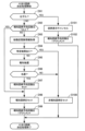
まず、第1の実施形態を図面にもとづいて説明する。図1は、第1の実施形態の遊技機
の一例を示す斜視図である。
Hereinafter, embodiments will be described in detail with reference to the drawings.
[First embodiment]
First, a first embodiment will be described with reference to the drawings. FIG. 1 is a perspective view showing an example of a gaming machine according to the first embodiment.
第1の実施形態の遊技機10は、前面枠12を備え、該前面枠12は、外枠(支持枠)
11に開閉回動可能に組み付けられている。遊技盤30(図2参照)は、前面枠12の表
側に形成された収納部(図示省略)に収納されている。また、前面枠(本体枠)12には
、遊技盤30の前面を覆うカバーガラス(透明部材)14を備えたガラス枠(透明板保持
枠)15が取り付けられている。
The
11 is assembled so as to be openable and rotatable. The game board 30 (see FIG. 2) is housed in a housing (not shown) formed on the front side of the
また、ガラス枠15の左右には、内部にランプやLED等を内蔵し装飾や演出、および
異常発生時の報知(たとえば、払出異常が発生した場合はランプやLED等を異常報知色
(たとえば、赤色)で点灯(点滅)させる)のために発光する枠装飾装置18や、音響(
たとえば、効果音)を発するスピーカ(上スピーカ)19aが設けられている。さらに、
前面枠12の下部にもスピーカ(下スピーカ)19bが設けられている。また、異常発生
時はスピーカ19a,19bから音声で異常内容が報知されるようになっている。なお、
ガラス枠15の所定部位に払出異常報知用のランプを設けるようにしてもよい。
Also, on the left and right of the
For example, a speaker (upper speaker) 19a for emitting sound effects is provided. moreover,
A speaker (lower speaker) 19b is also provided below the
A lamp may be provided at a predetermined portion of the
また、前面枠12の下部には、図示しない打球発射装置に遊技球を供給する上皿(貯留
皿)21、遊技機10の裏面側に設けられている払出ユニットから払い出された遊技球が
流出する上皿球出口22、上皿21が一杯になった状態で払い出された遊技球を貯留する
下皿(受皿)23および打球発射装置の操作部24等が設けられている。さらに、上皿2
1の上縁部には、遊技者が各種オプションの設定をおこなうオプション設定部25が設け
られている。このオプション設定部25の上面の周囲には複数の選択ボタンスイッチ25
aが設けられ、オプション設定部25の上面の中央には決定ボタンスイッチ25bが設け
られている。なお、オプション設定部25は、遊技者が演出態様を設定する演出設定部と
して機能する。この場合、選択ボタンスイッチ25aは、演出態様を選択する演出ボタン
スイッチとして機能し、決定ボタンスイッチ25bは、演出態様を決定する決定ボタンス
イッチとして機能する。さらに、前面枠12下部右側には、前面枠12やガラス枠15を
開放したり施錠したりする鍵を挿入するための鍵穴26が設けられている。
In the lower part of the
1 is provided with an
a, and a
なお、選択ボタンスイッチ25aが演出ボタンスイッチとして機能する場合、遊技機1
0は、選択ボタンスイッチ25aと決定ボタンスイッチ25bとから受け付けた遊技者の
操作にもとづいて、遊技者の操作を介入させた演出をおこなうことができる。たとえば、
遊技者の操作を介入させた演出は、表示装置(変動表示装置)41(図2参照)における
変動表示ゲーム(飾り特図変動表示ゲーム)における演出があり、遊技機10は、表示装
置41に表示するキャラクタを動作させたり、表示装置41に表示される飾り特図変動表
示ゲームにおける識別情報を停止させたりすることができる。
In addition, when the
Based on the player's operation received from the
The effect in which the player's operation is intervened includes the effect in the variable display game (decorative special figure variable display game) on the display device (variable display device) 41 (see FIG. 2). The character to be displayed can be operated, or the identification information in the decoration special figure variation display game displayed on the
また、オプション設定部25の右方には、遊技者が隣接する球貸機から球貸しを受ける
場合に操作する球貸ボタン27、球貸機のカードユニットからプリペイドカードを排出さ
せるために操作する排出ボタン28、プリペイドカードの残高を表示する残高表示部(図
示省略)等が設けられている。この第1の実施形態の遊技機10においては、遊技者が上
記操作部24を回動操作することによって、打球発射装置が上皿21から供給される遊技
球を遊技盤30前面の遊技領域32(図2参照)に向かって発射する。また、遊技者が選
択ボタンスイッチ25aおよび決定ボタンスイッチ25bを操作することによって、たと
えば、スピーカ19a,19bから放射される音量を設定したり、遊技盤30の明るさを
設定したりすることができる。
Also, on the right side of the
次に、遊技盤30について図2を用いて説明する。図2は、第1の実施形態の遊技盤の
一例を示す正面図である。
遊技盤30の表面には、ガイドレール31で囲われた略円形状の遊技領域32が形成さ
れている。遊技領域32は、遊技盤30の四隅に各々設けられた樹脂製のサイドケース3
3およびガイドレール31に囲繞されて構成される。遊技領域32には、ほぼ中央に表示
装置(変動表示装置)41を備えたセンターケース(遊技演出構成体)40が配置されて
いる。表示装置41は、センターケース40に設けられた凹部に、センターケース40の
前面より奥まった位置に取り付けられている。すなわち、センターケース40は表示装置
41の表示領域の周囲を囲い、表示装置41の表示面よりも前方へ突出し、周囲の遊技領
域32から遊技球が飛び込みにくくなるように形成されている。
Next, the
A substantially
3 and a
表示装置41は、たとえば、LCD(液晶表示器)、CRT(Cathode Ray Tube:ブラ
ウン管)等の表示画面を有する装置で構成されている。表示画面の画像を表示可能な領域
(表示領域)には、複数の識別情報(特別図柄)や特図変動表示ゲームを演出するキャラ
クタや演出効果を高める背景画像等の遊技に関する情報が表示される。表示装置41の表
示画面においては、識別情報として割り当てられた複数の特別図柄が変動表示(可変表示
)されて、特図変動表示ゲームに対応した飾り特図変動表示ゲームがおこなわれる。また
、表示画面には、遊技の進行にもとづく演出のための画像(たとえば、大当り表示画像、
ファンファーレ表示画像、エンディング表示画像等)が表示される。
The
fanfare display image, ending display image, etc.) are displayed.
また、センターケース40の上部には、動作することによって遊技の演出をおこなう盤
演出装置44が備えられている。この盤演出装置44は、図2に示す状態から表示装置4
1の中央へ向けて動作可能となっている。
Further, a
It is operable toward the center of 1.
遊技領域32におけるセンターケース40の側方右側には、普図変動表示ゲームの開始
条件を与える普通図柄始動ゲート(普図始動ゲート)34が設けられている。普図始動ゲ
ート34に入賞した遊技球(普図始動ゲート34を通過する遊技球)は、ゲートスイッチ
34a(図3参照)により検出される。
On the right side of the
また、遊技領域32におけるセンターケース40の下方左側には、二つの一般入賞口3
5が配置され、センターケース40の下方右側であって後述する特別変動入賞装置38の
右部には、一つの一般入賞口35が配置されている。これら一般入賞口35に入賞した遊
技球は、入賞口スイッチ35a(図3参照)により検出される。
In addition, on the lower left side of the
5 is arranged, and one general
また、遊技領域32におけるセンターケース40の下方には、第1特図変動表示ゲーム
(特図1変動表示ゲーム)の開始条件を与える第1始動入賞口(始動入賞領域)をなす始
動入賞口36(始動口1)が設けられている。始動入賞口36に入賞した遊技球は、始動
口1スイッチ36a(図3参照)により検出される。
In addition, below the
また、普図始動ゲート34よりも下方位置であって、センターケース40の右部には、
第1特図変動表示ゲーム(特図1変動表示ゲーム)の開始条件を与える普通変動入賞装置
37(第1始動入賞口、始動入賞領域)が設けられている。普通変動入賞装置37(始動
口1)は、上端側が右方に倒れる方向に回動することで開放して遊技球が流入し易い状態
に変換可能な可動部材37bを備えており、この可動部材37bは、常時はほぼ鉛直とな
って遊技球が流入できない閉じた閉状態(遊技者にとって不利な状態)を保持している。
そして、普図変動表示ゲームの結果が所定の停止表示態様となった場合には、駆動装置と
しての普電ソレノイド37c(図3参照)によって上端側が右方に倒れるように回動して
普通変動入賞装置37に遊技球が流入し易い開状態(遊技者にとって有利な状態)に変化
させられるようになっている。普通変動入賞装置37に入賞した遊技球は、始動口1スイ
ッチ37a(図3参照)により検出される。なお、普通変動入賞装置37が閉状態でも入
賞できるようにし、閉状態では開状態よりは入賞しにくいものとしても良い。普通変動入
賞装置37は普通電動役物(普電)に相当する。
In addition, on the right side of the
A normal variable winning device 37 (first starting winning port, starting winning area) is provided to give a starting condition for the first special figure variation display game (special figure 1 variation display game). The normal variable winning device 37 (starting port 1) is equipped with a
Then, when the result of the normal pattern fluctuation display game becomes a predetermined stop display mode, the upper end side is rotated to the right by the general
普通変動入賞装置37の右方には、遊技球が流下可能な流下路91が形成され、普通変
動入賞装置37に入賞しなかった遊技球は流下路91を通って下方へ流下する。この流下
路91の下部には始動入賞口92が設けられ、またこの流下路91の下方には誘導部93
が設けられている。誘導部93は上面94が左方へ下る傾斜面とされており、始動入賞口
92に入賞せずに下方へ流下する遊技球を上面94で受け止め、後述する特別変動入賞装
置38が存在する左方へ誘導するようになっている。
A
is provided. The
始動入賞口92は、第2特図変動表示ゲーム(特図2変動表示ゲーム)の開始条件を与
える第2始動入賞口(始動入賞領域)であり、この始動入賞口92(始動口2)に入賞し
た遊技球は、始動口2スイッチ92a(図3参照)により検出される。
The
また、遊技領域32における始動入賞口36の下方には、特図変動表示ゲームの結果に
よって遊技球を受け入れない状態と受け入れ易い状態とに変換可能な特別変動入賞装置(
下大入賞口、大入賞口1)95が配設されている。特別変動入賞装置95は、開閉部材9
5cを有しており、補助遊技としての特図変動表示ゲームの結果如何によって開閉部材9
5cが大入賞口を閉じた閉状態(遊技者にとって不利な閉塞状態)から開閉部材95cが
遊技領域32を流下する遊技球を受け入れ可能な開状態(遊技者にとって有利な状態)に
変換する。すなわち特別変動入賞装置95は、駆動装置としての大入賞口1ソレノイド9
5b(図3参照)により駆動される開閉部材95cによって開閉される大入賞口(下大入
賞口、大入賞口1)を備え、特図1変動表示ゲームの結果による小当り遊技状態(第2特
別遊技状態)中は、大入賞口を閉じた状態から開いた状態に変換することにより大入賞口
内への遊技球の流入を容易にさせ、遊技者に所定の遊技価値(賞球)を付与するようにな
っている。なお、大入賞口の内部(入賞領域)には、当該大入賞口に入った遊技球を検出
する検出手段としての大入賞口スイッチ(カウントスイッチ)38a(図3参照)が配設
されている。
In addition, below the
A lower prize winning port and a prize winning port 1) 95 are provided. The special variable winning
5c, and depending on the result of the special figure fluctuation display game as an auxiliary game, the opening and closing member 9
The open/
5b (see FIG. 3), which is opened and closed by an opening and closing
また、遊技領域32におけるセンターケース40の右下には、特図変動表示ゲームの結
果によって遊技球を受け入れない状態と受け入れ易い状態とに変換可能な特別変動入賞装
置(上大入賞口、大入賞口2)38が配設されている。特別変動入賞装置38は、開閉部
材(開閉扉)38cを有しており、補助遊技としての特図変動表示ゲームの結果如何によ
って開閉部材38cが大入賞口を閉じた閉状態(遊技者にとって不利な閉塞状態)から開
閉部材38cが退避して遊技領域32を流下する遊技球を受け入れ可能な開状態(遊技者
にとって有利な状態)に変換する。すなわち特別変動入賞装置38は、駆動装置としての
大入賞口2ソレノイド38b(図3参照)により駆動される開閉部材38cによって開閉
される大入賞口(上大入賞口、大入賞口2)を備え、特図1変動表示ゲーム及び特図2変
動表示ゲームの結果による大当り遊技状態(第1特別遊技状態)中や、特図2変動表示ゲ
ームの結果による小当り遊技状態(第2特別遊技状態)中は、大入賞口を閉じた状態から
開いた状態に変換することにより大入賞口内への遊技球の流入を容易にさせ、遊技者に所
定の遊技価値(賞球)を付与するようになっている。なお、大入賞口の内部(入賞領域)
には、当該大入賞口に入った遊技球を検出する検出手段としての大入賞口スイッチ(カウ
ントスイッチ)38a(図3参照)が配設されている。
In addition, at the lower right of the
is provided with a big winning hole switch (count switch) 38a (see FIG. 3) as a detection means for detecting a game ball that has entered the big winning hole.
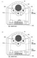
なお、大入賞口スイッチ38aは、本実施形態のように大入賞口が複数個あるときには
、それぞれに1個又は2個程度、全体としてx個設けられる(図3参照)。この第1の実
施形態の場合、第1特別変動入賞装置(下大入賞口、大入賞口1)をなす特別変動入賞装
置95は、大入賞口スイッチ38aが1個だけ配設されている。一方、第2特別変動入賞
装置(上大入賞口、大入賞口2)をなす特別変動入賞装置38は、大入賞口スイッチ38
aが複数個(たとえば2個)配設されている。また特別変動入賞装置95は、たとえば特
別変動入賞装置38に比べて大入賞口が小さい入賞装置(いわゆるミニアタッカー)であ
る。
When there are a plurality of large winning openings as in the present embodiment, one or two large
A is provided in plural numbers (for example, two). Also, the special variable winning
また、センターケース40の左側側部には、ワープ口(ワープ入口)39aが設けられ
ている。ワープ口39aからワープ流路に流入した遊技球は、センターケース40内のス
テージ上を転動し、その一部がワープ出口39bに案内される。ワープ出口39bは、始
動入賞口36の直上に位置し、ワープ出口39bに案内された遊技球は、始動入賞口36
に入賞しやすくなる。
A warp port (warp entrance) 39a is provided on the left side portion of the
It becomes easier to win a prize.
第1の実施形態の遊技機10においては、遊技球が流下する遊技領域32のうち、セン
ターケース40の左方の領域が左側遊技領域とされ、センターケース40の右方の領域が
右側遊技領域とされている。そして、遊技者が発射勢を調節して左側遊技領域へ遊技球を
発射(いわゆる左打ち)することで始動入賞口36や特別変動入賞装置95、一般入賞口
35(特別変動入賞装置38の右部にある一般入賞口35を除く)への入賞を狙うことが
でき、右側遊技領域へ遊技球を発射(いわゆる右打ち)することで普図始動ゲート34や
普通変動入賞装置37、特別変動入賞装置38などへの入賞を狙うことができるようにな
っている。
In the
また、遊技領域32の外側(ここでは遊技盤30の右下部)には、特図変動表示ゲーム
をなす第1特図変動表示ゲームや第2特図変動表示ゲームおよび普図始動ゲート34への
入賞をトリガとする普図変動表示ゲームの表示や、各種情報を表示する一括表示装置50
が設けられている。
In addition, outside the game area 32 (here, the lower right part of the game board 30), the first special figure fluctuation display game and the second special figure fluctuation display game that constitute the special figure fluctuation display game, and the normal figure start gate 34 A
is provided.
一括表示装置50は、LED等で構成されたラウンド表示部51と、特図1保留表示部
52と、特図1図柄表示部53と、特図2図柄表示部54と、普図図柄表示部55と、普
図保留表示部56と状態表示部57とを備える(図5参照)。一括表示装置50の詳細は
、後述する。
The
次に、遊技機の制御システムについて図3を用いて説明する。図3は、第1の実施形態
の遊技機の制御システムの一例を示すブロック図である。
遊技機10は、遊技制御装置100を備え、遊技制御装置100は、遊技を統括的に制
御する主制御装置(主基板)であって、遊技用マイクロコンピュータ(以下、遊技用マイ
コンと称する)111を有するCPU(Central Processing Unit)部110と、入力ポ
ートを有する入力部120と、出力ポートやドライバ等を有する出力部130と、CPU
部110と入力部120と出力部130との間を接続するデータバス140等からなる。
Next, the control system of the gaming machine will be explained using FIG. FIG. 3 is a block diagram showing an example of the gaming machine control system of the first embodiment.
The
It consists of a
CPU部110は、アミューズメントチップ(IC(Integrated Circuit))と呼ばれ
る遊技用マイコン111と、水晶振動子のような発振子を備え、遊技用マイコン111の
動作クロックやタイマ割込み、乱数生成回路の基準となるクロックを生成する発振回路(
水晶発振器)113等を有する。遊技制御装置100および該遊技制御装置100によっ
て駆動されるソレノイドやモータ等の電子部品は、電源装置400で生成されたDC(Di
rect Current)32V、DC12V、DC5V等所定のレベルの直流電圧が供給されて動
作可能にされる。
The CPU unit 110 includes a
crystal oscillator) 113 and the like. The
rect current) 32 V,
電源装置400は、24Vの交流電源から上記DC32Vの直流電圧を生成するAC(
Alternating Current)-DCコンバータやDC32Vの電圧からDC12V、DC5V
等のより低いレベルの直流電圧を生成するDC-DCコンバータ等を有する通常電源部4
10と、遊技用マイコン111の内部のRAM(Random Access Memory)に対して停電時
に電源電圧を供給するバックアップ電源部420と、停電監視回路を有し、遊技制御装置
100に停電の発生、回復を知らせる停電監視信号やリセット信号等の制御信号を生成し
て出力する制御信号生成部430等を備える。
The
Alternating Current)-DC converter or DC32V voltage to DC12V, DC5V
A normal
10, a backup
第1の実施形態では、電源装置400は、遊技制御装置100と別個に構成されている
が、バックアップ電源部420および制御信号生成部430は、別個の基板上または遊技
制御装置100と一体、すなわち、主基板上に設けるように構成してもよい。遊技盤30
および遊技制御装置100は、機種変更の際に交換の対象となるので、第1の実施形態の
ように、電源装置400または主基板とは別の基板にバックアップ電源部420および制
御信号生成部430を設けることにより、交換の対象から外しコストダウンを図ることが
できる。
In the first embodiment, the
And the
バックアップ電源部420は、電解コンデンサのような大容量のコンデンサ1つで構成
することができる。バックアップ電源は、遊技制御装置100の遊技用マイコン111(
特に内蔵RAM)に供給され、停電中または電源遮断後もRAMに記憶されたデータが保
持されるようになっている。制御信号生成部430は、たとえば通常電源部410で生成
された32Vの電圧を監視してそれがたとえば17V以下に下がると停電発生を検出して
停電監視信号を変化させるとともに、所定時間後にリセット信号を出力する。また、電源
投入時や停電回復時にもその時点から所定時間経過後にリセット信号を出力する。
The backup
In particular, the data is supplied to the built-in RAM), and the data stored in the RAM is retained even during a power failure or after the power is turned off. Control
また、遊技制御装置100にはRAM初期化スイッチ112が設けられている。このR
AM初期化スイッチ112が操作されると初期化スイッチ信号が生成され、これにもとづ
き遊技用マイコン111内のRAM111Cおよび払出制御装置200内のRAMに記憶
されている情報を強制的に初期化する処理がおこなわれる。特に限定されるわけではない
が、初期化スイッチ信号は、電源投入時に読み込まれ、停電監視信号は遊技用マイコン1
11が実行するメインプログラムのメインループの中で繰り返し読み込まれる。リセット
信号は強制割込み信号の一種であり、制御システム全体をリセットさせる。
Also, the
When the
It is read repeatedly in the main loop of the main program executed by 11. A reset signal is a kind of forced interrupt signal and resets the entire control system.
遊技用マイコン111は、CPU(中央処理ユニット:マイクロプロセッサ)111A
、読出し専用のROM(Read Only Memory)111Bおよび随時読出し書込み可能なRA
M111Cを備える。
The
, a read-only ROM (Read Only Memory) 111B and an RA that can be read and written at any time
Equipped with M111C.
ROM111Bは、遊技制御のための不変の情報(プログラム、固定データ、各種乱数
の判定値等)を不揮発的に記憶し、RAM111Cは、遊技制御時にCPU111Aの作
業領域あるいは各種信号や乱数値の記憶領域として利用される。ROM111BまたはR
AM111Cとして、EEPROM(Electrically Erasable Programmable ROM)のよう
な電気的に書換え可能な不揮発性メモリを用いてもよい。
The ROM 111B nonvolatilely stores immutable information for game control (programs, fixed data, judgment values of various random numbers, etc.), and the RAM 111C is a work area for the CPU 111A during game control or a storage area for various signals and random values. used as ROM 111B or R
An electrically rewritable non-volatile memory such as EEPROM (Electrically Erasable Programmable ROM) may be used as the AM 111C.
また、ROM111Bは、たとえば、特図変動表示ゲームの実行時間、演出内容、リー
チ状態の発生の有無等を規定する変動パターン(変動態様)を決定するための変動パター
ンテーブルを記憶している。変動パターンテーブルとは、始動記憶として記憶されている
変動パターン乱数1、変動パターン乱数2、および変動パターン乱数3をCPU111A
が参照して変動パターンを決定するためのテーブルである。また、変動パターンテーブル
には、結果がはずれとなる場合に選択されるはずれ変動パターンテーブル、結果が大当り
となる場合に選択される大当り変動パターンテーブル等が含まれる。さらに、これらのパ
ターンテーブルには、リーチ状態となった後の変動パターンである後半変動パターンを決
定するためのテーブル(後半変動グループテーブルや後半変動パターン選択テーブル等)
、リーチ状態となる前の変動パターンである前半変動パターンを決定するためのテーブル
(前半変動グループテーブルや前半変動パターン選択テーブル等)が含まれている。
Further, the ROM 111B stores a variation pattern table for determining a variation pattern (variation mode) that defines, for example, the execution time of the special figure variation display game, the content of the effect, the occurrence of the ready-to-win state, and the like. The variation pattern table stores variation pattern
is a table for determining a variation pattern with reference to. In addition, the variation pattern table includes a winning variation pattern table selected when the result is a loss, a big hit variation pattern table selected when the result is a big hit, and the like. Furthermore, these pattern tables include tables for determining the second half fluctuation pattern, which is the fluctuation pattern after reaching the reach state (second half fluctuation group table, second half fluctuation pattern selection table, etc.)
, Contains a table (first half fluctuation group table, first half fluctuation pattern selection table, etc.) for determining the first half fluctuation pattern, which is the fluctuation pattern before reaching the reach state.
ここで、リーチ(リーチ状態)とは、表示状態が変化可能な表示装置を有し、該表示装
置が時期を異ならせて複数の表示結果を導出表示し、該複数の表示結果があらかじめ定め
られた特別結果態様となった場合に、遊技状態が遊技者にとって有利な遊技状態(特別遊
技状態)となる遊技機10において、複数の表示結果の一部がまだ導出表示されていない
段階で、既に導出表示されている表示結果が特別結果態様となる条件を満たしている表示
状態をいう。また、別の表現をすれば、リーチ状態とは、表示装置の変動表示制御が進行
して表示結果が導出表示される前段階にまで達した時点でも、特別結果態様となる表示条
件からはずれていない表示態様をいう。そして、たとえば、特別結果態様が揃った状態を
維持しながら複数の変動表示領域による変動表示をおこなう状態(いわゆる全回転リーチ
)もリーチ状態に含まれる。また、リーチ状態とは、表示装置の表示制御が進行して表示
結果が導出表示される前段階にまで達した時点での表示状態であって、表示結果が導出表
示される以前に決定されている複数の変動表示領域の表示結果の少なくとも一部が特別結
果態様となる条件を満たしている場合の表示状態をいう。
Here, reach (reach state) means that the display device has a display device whose display state can be changed, the display device derives and displays a plurality of display results at different times, and the plurality of display results are determined in advance. In the
よって、たとえば、特図変動表示ゲームに対応して表示装置に表示される飾り特図変動
表示ゲームが、表示装置における左、中、右の変動表示領域の各々で所定時間複数の識別
情報を変動表示した後、左、右、中の順で変動表示を停止して結果態様を表示するもので
ある場合、左、右の変動表示領域で、特別結果態様となる条件を満たした状態(たとえば
、同一の識別情報)で変動表示が停止した状態がリーチ状態となる。またこの他に、すべ
ての変動表示領域の変動表示を一旦停止した時点で、左、中、右のうちいずれか二つの変
動表示領域で特別結果態様となる条件を満たした状態(たとえば、同一の識別情報となっ
た状態、ただし特別結果態様は除く)をリーチ状態とし、このリーチ状態から残りの一つ
の変動表示領域を変動表示するようにしてもよい。
Therefore, for example, the decorative special figure variation display game displayed on the display device corresponding to the special figure variation display game changes the plurality of identification information for a predetermined time in each of the left, middle, and right variation display areas on the display device. After displaying, if the variable display is stopped in the order of left, right, and middle to display the result mode, the condition for the special result mode is satisfied in the left and right variable display areas (for example, The state in which the variable display is stopped with the same identification information) is the reach state. In addition, when the variable display of all the variable display areas is temporarily stopped, any two of the left, middle, and right variable display areas satisfy the condition for the special result mode (for example, the same The state of the identification information (excluding the special result mode) may be set as the ready-to-win state, and the remaining one variable display area may be variably displayed from this ready-to-win state.
そして、このリーチ状態には複数のリーチ演出が含まれ、特別結果態様が導出される可
能性が異なる(期待値が異なる)リーチ演出として、ノーマルリーチ(Nリーチ)、スペ
シャル1リーチ(SP1リーチ)、スペシャル2リーチ(SP2リーチ)、スペシャル3
リーチ(SP3リーチ)、プレミアリーチが設定されている。なお、期待値は、「リーチ
なし」<「ノーマルリーチ」<「スペシャル1リーチ」<「スペシャル2リーチ」<「ス
ペシャル3リーチ」<「プレミアリーチ」の順に高くなるようになっている。また、この
リーチ状態は、少なくとも特図変動表示ゲームで特別結果態様が導出される場合(大当り
となる場合)における変動表示態様に含まれるようになっている。すなわち、特図変動表
示ゲームで特別結果態様が導出されないと判定する場合(はずれとなる場合)における変
動表示態様に含まれることもある。よって、リーチ状態が発生した状態は、リーチ状態が
発生しない場合に比べて大当りとなる可能性の高い状態である。
This ready-to-reach state includes a plurality of ready-to-reach effects, and as ready-to-win effects with different possibilities of deriving special result modes (different expected values), normal reach (N reach), special 1 reach (SP1 reach),
Reach (SP3 Reach) and Premier Reach are set. The expected value is higher in the order of "no reach"<"normalreach"<"special 1 reach"<"special 2 reach"<"special 3 reach"<"premierreach". Further, this ready-to-win state is included in the variable display mode at least when the special result mode is derived in the special figure variable display game (when a big hit is achieved). That is, it may be included in the variation display mode when it is determined that the special result mode is not derived in the special figure variation display game (when it becomes a loss). Therefore, the state in which the ready-to-win state occurs is a state with a higher possibility of winning a big hit than the case in which the ready-to-win state does not occur.
CPU111Aは、ROM111B内の遊技制御用プログラムを実行して、払出制御装
置200や演出制御装置300に対する制御信号(コマンド)を生成したりソレノイドや
表示装置の駆動信号を生成し出力して遊技機10全体の制御をおこなう。また、図示しな
いが、遊技用マイコン111は、特図変動表示ゲームの当りを判定するための大当り乱数
や大当りの図柄を決定するための大当り図柄乱数、特図変動表示ゲームでの変動パターン
(各種リーチやリーチ無しの変動表示における変動表示ゲームの実行時間等を含む)を決
定するための変動パターン乱数、普図変動表示ゲームの当りを判定するための当り乱数等
を生成するための乱数生成回路と、発振回路113からの発振信号(原クロック信号)に
もとづいてCPU111Aに対する所定周期(たとえば、4m秒(ms))のタイマ割込
み信号や乱数生成回路の更新タイミングを与えるクロックを生成するクロックジェネレー
タを備えている。
The CPU 111A executes a game control program in the ROM 111B to generate control signals (commands) for the
また、CPU111Aは、特図変動表示ゲームに関する処理において、ROM111B
に記憶されている複数の変動パターンテーブルの中から、いずれか一の変動パターンテー
ブルを取得する。具体的には、CPU111Aは、特図変動表示ゲームの遊技結果(当り
(大当りまたは小当り)またははずれ)や、現在の遊技状態としての特図変動表示ゲーム
の確率状態(通常確率状態または高確率状態)、現在の遊技状態としての普通変動入賞装
置37の動作状態(時短動作状態)、始動記憶数等にもとづいて、複数の変動パターンテ
ーブルの中から、いずれか一の変動パターンテーブルを選択して取得する。ここで、CP
U111Aは、特図変動表示ゲームを実行する場合に、ROM111Bに記憶された複数
の変動パターンテーブルのうち、いずれか一の変動パターンテーブルを取得する変動振り
分け情報取得手段をなす。
In addition, the CPU 111A uses the ROM 111B in processing related to the special figure variation display game.
Any one variation pattern table is acquired from among a plurality of variation pattern tables stored in the . Specifically, the CPU 111A determines the game result of the special figure variation display game (hit (big hit or small win) or loss) and the probability state of the special figure variation display game as the current game state (normal probability state or high probability state), the operating state of the normal
U111A constitutes variation distribution information acquisition means for acquiring any one of a plurality of variation pattern tables stored in ROM 111B when executing a special figure variation display game.
払出制御装置200は、CPU、ROM、RAM、入力インタフェース、出力インタフ
ェース等を備え、遊技制御装置100からの賞球払出し指令(コマンドやデータ)に従っ
て、遊技機10に設けられた払出ユニットの払出モータを駆動させ、賞球を払い出させる
ための制御をおこなう。また、払出制御装置200は、遊技機10に付設される球貸機の
カードユニットからの貸球要求信号にもとづいて払出ユニットの払出モータを駆動させ、
貸球を払い出させるための制御をおこなう。
The
Perform control for paying out the rental balls.
遊技用マイコン111の入力部120には、始動入賞口36内の始動口1スイッチ36
a、普通変動入賞装置37内の始動口1スイッチ37a、始動入賞口92内の始動口2ス
イッチ92a、普図始動ゲート34内のゲートスイッチ34a、入賞口スイッチ35a、
特別変動入賞装置38や特別変動入賞装置95の大入賞口スイッチ38aに接続され、こ
れらのスイッチから供給されるハイレベルが11Vでロウレベルが7Vのような負論理の
信号が入力され、0V-5Vの正論理の信号に変換するインタフェースチップ(近接I/
F)121が設けられている。この近接I/F121には、遊技機10に対する電波の発
射を検出する盤電波センサ62の検出信号も入力される。また近接I/F121は、入力
の範囲が7V-11Vとされることで、センサや近接スイッチのリード線が不正にショー
トされたり、センサやスイッチがコネクタから外されたり、リード線が切断されてフロー
ティングになったような異常な状態を検出することができ、異常検知信号を出力するよう
に構成されている。
The
a, the starting
It is connected to the big winning
F) 121 is provided. The proximity I/
なお、入賞口スイッチ35aについて説明すると、図3では入賞口スイッチ35aが1
個のブロックで示されているが、実際には複数(N個)の入賞口スイッチ35a(本実施
形態では3個)が遊技盤30に設けられており、それぞれの信号が異なる信号線で近接I
/F121に入力されている。また、図3では大入賞口スイッチ38aが1個のブロック
で示されているが、実際には複数(X個)の大入賞口スイッチ38a(本実施形態では3
個)が遊技盤30に設けられている。そして、これら複数の大入賞口スイッチ38aが、
それぞれ異なる信号線で接続されるか、あるいは、たとえばスイッチと遊技制御装置10
0(主基板)の間に存在する図示省略した中継基板上でワイヤードオア(wired OR)とい
う方式で遊技制御装置100に接続されている。盤電波センサ62や後述する磁気センサ
61も、異なる複数の信号線で接続されてもよいし、同様にワイヤードオアという方式で
遊技制御装置100に接続されていてもよい。
In addition, when explaining the winning
, but actually, a plurality (N) of winning
/F121. Also, in FIG. 3, the large winning
) are provided on the
Either connected by different signal lines, or, for example, the switch and the
It is connected to the
近接I/F121の出力は、第2入力ポート123または第3入力ポート124へ供給
されデータバス140を介して遊技用マイコン111に読み込まれる。なお、近接I/F
121の出力のうち、始動口1スイッチ36a,37a、始動口2スイッチ92a、ゲー
トスイッチ34a、入賞口スイッチ35a、および大入賞口スイッチ38aの検出信号は
、第2入力ポート123へ入力される。なお、特図1の始動口スイッチである始動口1ス
イッチ36a,37aの信号の出力(近接I/F121からの出力)については、図3で
は1本の信号線で示しているが、実際には2本ある。
The output of the proximity I/
Among the outputs of 121, the detection signals of the starting
また、近接I/F121の出力のうち、盤電波センサ62の検出信号およびセンサやス
イッチの異常を検出した際に出力される異常検知信号は、第3入力ポート124に入力さ
れる。また、第3入力ポート124には、遊技機10の前面枠12等に設けられた不正検
出用の磁気センサ61の検出信号、払出制御装置200からの枠電波不正信号(前面枠1
2に設けられた枠電波センサが電波を検出することにもとづき出力される信号)、払出ビ
ジー信号(払出制御装置200がコマンドを受付可能な状態か否かを示す信号)も入力さ
れるようになっている。なお、振動を検出する振動センサスイッチを遊技機に設け、この
振動センサスイッチの検出信号が第3入力ポート124に入力されるようにしてもよい。
Among the outputs of the proximity I/
2) and a payout busy signal (a signal indicating whether or not the
また、近接I/F121の出力のうち、第2入力ポート123への出力は、遊技制御装
置100から中継基板70を介して図示しない試射試験装置へも供給されるようになって
いる。さらに、近接I/F121の出力のうち、始動口1スイッチ36a,37aと始動
口2スイッチ92aの検出信号は、第2入力ポート123の他、遊技用マイコン111へ
入力されるように構成されている。
In addition, among the outputs of the proximity I/
上記のように近接I/F121は、信号のレベル変換機能を有する。このようなレベル
変換機能を可能にするため、近接I/F121には、電源装置400から通常のICの動
作に必要なたとえば5Vのような電圧の他に、12Vの電圧が供給されるようになってい
る。
As described above, the proximity I/
第2入力ポート123が保持しているデータは、遊技用マイコン111が第2入力ポー
ト123に割り当てられているアドレスをデコードすることによって図示省略したイネー
ブル信号CE(Chip Enable)をアサート(有効レベルに変化)することによって、読み
出すことができる。第3入力ポート124や後述の第1入力ポート122も同様である。
The data held by the
また、入力部120には、遊技機10のガラス枠15等に設けられたガラス枠開放検出
スイッチ63の検出信号、遊技機10の前面枠(本体枠)12等に設けられた本体枠開放
検出スイッチ64の検出信号、払出異常ステータス信号(払出異常を示すステータス信号
)、シュート球切れスイッチ信号(払出し前の遊技球の不足を示す信号)、オーバーフロ
ースイッチ信号(下皿23に遊技球が所定量以上貯留されていること(満杯になったこと
)を検出したときに出力される信号)、タッチスイッチ信号(操作部24に設けられたタ
ッチスイッチの入力にもとづく信号)を取り込んでデータバス140を介して遊技用マイ
コン111に供給する第1入力ポート122が設けられている。
The
また、遊技制御装置100には、電源装置400からの停電監視信号やリセット信号等
の信号を遊技用マイコン111等に入力するためのシュミットバッファ125が設けられ
ており、シュミットバッファ125はこれらの入力信号からノイズを除去する機能を有す
る。電源装置400からの停電監視信号や、RAM初期化スイッチ112からの初期化ス
イッチ信号は、一旦、第1入力ポート122に入力され、データバス140を介して遊技
用マイコン111に取り込まれる。つまり、前述の各種スイッチからの信号と同等の信号
として扱われる。遊技用マイコン111に設けられている外部からの信号を受ける端子の
数には制約があるためである。
In addition, the
一方、シュミットバッファ125によりノイズ除去されたリセット信号RESETは、
遊技用マイコン111に設けられているリセット端子に直接入力されるとともに、出力部
130の各ポートに供給される。また、リセット信号RESETは、出力部130を介さ
ずに直接中継基板70に出力することで、試射試験装置へ出力するために中継基板70の
ポート(図示省略)に保持される試射試験信号をオフするように構成されている。また、
リセット信号RESETは、中継基板70を介して試射試験装置へ出力可能に構成される
ようにしてもよい。なお、リセット信号RESETは、入力部120の第1乃至第3ポー
ト122,123,124には供給されない。リセット信号RESETが入る直前に遊技
用マイコン111によって出力部130の各ポートに設定されたデータは、システムの誤
動作を防止するためリセットする必要があるが、リセット信号RESETが入る直前に入
力部120の各ポートから遊技用マイコン111が読み込んだデータは、遊技用マイコン
111のリセットによって廃棄されるためである。
On the other hand, the reset signal RESET from which noise has been removed by the Schmitt buffer 125 is
It is directly input to the reset terminal provided in the
The reset signal RESET may be configured to be output to the test-firing test apparatus via the
出力部130には、遊技用マイコン111から演出制御装置300への通信経路および
遊技用マイコン111から払出制御装置200への通信経路に配されるシュミットバッフ
ァ132が設けられている。遊技制御装置100から演出制御装置300および払出制御
装置200へは、シリアル通信でデータが送信される。なお、演出制御装置300の側か
ら遊技制御装置100へ信号を入力できないようにした片方向通信とされている。
The
さらに、出力部130には、データバス140に接続され図示しない認定機関の試射試
験装置へ変動表示ゲームの特図図柄情報を知らせるデータや大当りの確率状態を示す信号
等を中継基板70を介して出力するバッファ133が実装可能に構成されている。このバ
ッファ133は遊技店に設置される実機(量産販売品)としてのパチンコ遊技機の遊技制
御装置(主基板)には実装されない部品である。なお、近接I/F121から出力される
始動口スイッチ等加工の必要のないスイッチの検出信号は、バッファ133を通さずに中
継基板70を介して試射試験装置へ供給される。
Further, the
一方、磁気センサ61や盤電波センサ62のようにそのままでは試射試験装置へ供給で
きない検出信号は、一旦、遊技用マイコン111に取り込まれて他の信号または情報に加
工されて、たとえば遊技機が遊技制御できない状態であることを示すエラー信号としてデ
ータバス140からバッファ133、中継基板70を介して試射試験装置へ供給される。
なお、中継基板70には、上記バッファ133から出力された信号を取り込んで試射試験
装置へ供給するポートや、バッファを介さないスイッチの検出信号の信号線を中継して伝
達するコネクタ等が設けられている。中継基板70上のポートには、遊技用マイコン11
1から出力されるチップイネーブル信号CE(図示省略)も供給され、このチップイネー
ブル信号CEにより選択制御されたポートの信号が試射試験装置へ供給されるようになっ
ている。
On the other hand, detection signals such as those from the
The
A chip enable signal CE (not shown) output from 1 is also supplied, and signals of ports selectively controlled by this chip enable signal CE are supplied to the test-firing test apparatus.
また、出力部130には、データバス140に接続され、特別変動入賞装置95(第入
賞口1)の開閉部材95cを開閉させる大入賞口1ソレノイド95b、特別変動入賞装置
38(大入賞口2)の開閉部材38cを開閉させる大入賞口2ソレノイド38bおよび普
通変動入賞装置37の可動部材37bを開閉させる普電ソレノイド37cの開閉データを
出力するための第2出力ポート134が設けられている。また、出力部130には、一括
表示装置50に表示する内容に応じてLEDのアノード端子が接続されているセグメント
線のオン/オフデータを出力するための第3出力ポート135、一括表示装置50のLE
Dのカソード端子が接続されているデジット線のオン/オフデータを出力するための第4
出力ポート136が設けられている。
In addition, the
a fourth for outputting on/off data of the digit line to which the cathode terminal of D is connected;
An
また、出力部130には、大当り情報等遊技機10に関する情報を外部情報端子板71
へ出力するための第5出力ポート137が設けられている。外部情報端子板71には、フ
ォトリレーが備えられ、たとえば遊技店に設置された外部装置(情報収集端末や遊技場内
部管理装置(ホールコンピュータ)等)に接続可能であり、遊技機10に関する情報をフ
ォトリレーを介して外部装置に供給することができるようになっている。なお、外部装置
に供給する情報の一部は、第4出力ポート136から出力される。また、第5出力ポート
137からは、シュミットバッファ132を介して払出制御装置200に発射許可信号も
出力される。
In addition, the
A
さらに、出力部130には、第2出力ポート134から出力される大入賞口1ソレノイ
ド95b、大入賞口2ソレノイド38b、普電ソレノイド37cの開閉データ信号を受け
てソレノイド駆動信号を生成し出力する第1ドライバ(駆動回路)138a、第3出力ポ
ート135から出力される一括表示装置50の電流供給側のセグメント線のオン/オフ駆
動信号を出力する第2ドライバ138b、第4出力ポート136から出力される一括表示
装置50の電流引き込み側のデジット線のオン/オフ駆動信号を出力する第3ドライバ1
38c、第5出力ポート137や第4出力ポート136から管理装置等の外部装置へ供給
する外部情報信号を外部情報端子板71へ出力する第4ドライバ138dが設けられてい
る。
Further, the
38c, a
上記第1ドライバ138aには、32Vで動作するソレノイドを駆動できるようにする
ため、電源電圧としてDC32Vが電源装置400から供給される。また、一括表示装置
50のセグメント線を駆動する第2ドライバ138bには、DC12Vが供給される。デ
ジット線を駆動する第3ドライバ138cは、表示データに応じたデジット線を電流で引
き抜くためのものであるため、電源電圧は12Vまたは5Vのいずれであってもよい。
12Vを出力する第2ドライバ138bによりセグメント線を介してLEDのアノード
端子に電流を流し込み、接地電位を出力する第3ドライバ138cによりカソード端子よ
りセグメント線を介して電流を引き抜くことで、ダイナミック駆動方式で順次選択された
LEDに電源電圧が流れて点灯される。外部情報信号を外部情報端子板71へ出力する第
4ドライバ138dは、外部情報信号に12Vのレベルを与えるため、DC12Vが供給
される。なお、バッファ133や第2出力ポート134、第1ドライバ138a等は、遊
技制御装置100の出力部130、すなわち、主基板ではなく、中継基板70側に設ける
ようにしてもよい。
A
さらに、出力部130には、外部の検査装置490へ各遊技機の識別コードやプログラ
ム等の情報を送信するためのフォトカプラ139が設けられている。フォトカプラ139
は、遊技用マイコン111が検査装置490との間でシリアル通信によってデータの送受
信をおこなえるように双方通信可能に構成されている。なお、かかるデータの送受信は、
通常の汎用マイクロプロセッサと同様に遊技用マイコン111が有するシリアル通信端子
を利用しておこなわれるため、第1乃至第3入力ポート122,123,124のような
ポートは設けられていない。
Further, the
is configured so that the
Since the serial communication terminals of the
次に、演出制御装置300の構成について図4を用いて説明する。図4は、第1の実施
形態の演出制御装置の構成の一例を示すブロック図である。
演出制御装置300は、遊技用マイコン111と同様にアミューズメントチップ(IC
)からなる主制御用マイコン(CPU)311と、主制御用マイコン311からのコマン
ドやデータに従って表示装置41への映像表示のための画像処理をおこなうグラフィック
プロセッサとしてのVDP(Video Display Processor)312と、各種のメロディや効
果音等をスピーカ19a,19bから再生させるため音の出力を制御する音源LSI31
4を備えている。
Next, the configuration of the
The
), and a VDP (Video Display Processor) 312 as a graphic processor that performs image processing for video display on the
4.
主制御用マイコン311には、CPUが実行するプログラムや各種データを格納したP
ROM(プログラマブルリードオンリメモリ)からなるPROM321、作業領域を提供
するRAM322、停電時に電力が供給されなくとも記憶内容を保持可能なFeRAM(
Ferroelectric RAM)323、現在の日時(年月日や曜日、時刻等)を示す情報を生成す
る計時手段をなすRTC(リアルタイムクロック)338が接続されている。なお、主制
御用マイコン311の内部にも作業領域を提供するRAM311aが設けられている。ま
た、主制御用マイコン311には、WDT(ウォッチドッグ・タイマ)回路324が接続
されている。主制御用マイコン311は、遊技用マイコン111からのコマンド(演出コ
マンド)を解析し、演出内容を決定してVDP312へ出力映像の内容を指示したり、音
源LSI314への再生音の指示、装飾ランプの点灯、モータやソレノイドの駆動制御、
演出時間の管理等の処理を実行したりする。
The
Ferroelectric RAM) 323, and an RTC (real time clock) 338 that constitutes timekeeping means for generating information indicating the current date and time (year, month, day of the week, time, etc.) are connected. A RAM 311a that provides a work area is also provided inside the
It also executes processing such as performance time management.
VDP312には、作業領域を提供するRAM312aや、画像を拡大、縮小処理する
ためのスケーラ312bが設けられている。また、VDP312には、キャラクタ画像や
映像データが記憶された画像ROM325や、画像ROM325から読み出されたキャラ
クタ等の画像データを展開したり加工したりするのに使用される超高速なVRAM326
が接続されている。
The
is connected.
特に限定されるわけではないが、主制御用マイコン311とVDP312との間は、パ
ラレル方式でデータの送受信がおこなわれるように構成されている。パラレル方式でデー
タを送受信することで、シリアルの場合よりも短時間にコマンドやデータを送信すること
ができる。
Although not particularly limited, the
VDP312から主制御用マイコン311へは、表示装置41の映像とガラス枠15や
遊技盤30に設けられている装飾ランプの点灯を同期させるための垂直同期信号VSYN
C、データの送信タイミングを与える同期信号STSが入力される。なお、VDP312
から主制御用マイコン311へは、VRAMへの描画の終了等処理状況を知らせるため割
込み信号INT0~nおよび主制御用マイコン311からのコマンドやデータの受信待ち
の状態にあることを知らせるためのウェイト信号WAIT等も入力される。
From
C. Synchronization signal STS that provides data transmission timing is input. Note that VDP312
to the
演出制御装置300には、LVDS(Low Voltage Differential Signaling:小振幅信
号伝送)方式で表示装置41へ送信する映像信号を生成する信号変換回路313が設けら
れている。VDP312から信号変換回路313へは、映像データ、水平同期信号HSY
NCおよび垂直同期信号VSYNCが入力されるようになっており、VDP312で生成
された映像は、信号変換回路313を介して表示装置41に表示される。
The
NC and a vertical synchronization signal VSYNC are input, and the video generated by the
音源LSI314には、音声データが記憶された音声ROM327が接続されている。
主制御用マイコン311と音源LSI314は、アドレス/データバス340を介して接
続されている。また、音源LSI314から主制御用マイコン311へは、割込み信号I
NTが入力されるようになっている。演出制御装置300には、ガラス枠15に設けられ
た上スピーカ19aおよび前面枠12に設けられた下スピーカ19bを駆動するオーディ
オパワーアンプ等からなるアンプ回路337が設けられており、音源LSI314で生成
された音声はアンプ回路337を介して上スピーカ19aおよび下スピーカ19bから出
力される。
An audio ROM 327 storing audio data is connected to the
The
NT is to be input. The
また、演出制御装置300には、遊技制御装置100から送信されてくるコマンドを受
信するインタフェースチップ(コマンドI/F)331が設けられている。このコマンド
I/F331を介して、遊技制御装置100から演出制御装置300へ送信された飾り特
図保留数コマンド、飾り特図コマンド、変動コマンド、停止情報コマンド等を、演出制御
指令信号(演出コマンド)として受信する。遊技制御装置100の遊技用マイコン111
はDC5Vで動作し、演出制御装置300の主制御用マイコン311はDC3.3Vで動
作するため、コマンドI/F331には信号のレベル変換の機能が設けられている。
Also, the
operates at DC5V, and since the
また、演出制御装置300には、遊技盤30(センターケース40を含む)に設けられ
ているLED(発光ダイオード)などを有する盤装飾装置46を駆動制御する盤装飾LE
D制御回路332、ガラス枠15に設けられているLED(発光ダイオード)を有する枠
装飾装置(たとえば枠装飾装置18等)を駆動制御する枠装飾LED制御回路333、遊
技盤30(センターケース40を含む)に設けられている盤演出装置44(たとえば表示
装置41における演出表示と協働して演出効果を高める可動役物等)を駆動制御する盤演
出可動体制御回路334が設けられている。ランプやモータおよびソレノイド等を駆動制
御するこれらの制御回路332~334は、アドレス/データバス340を介して主制御
用マイコン311と接続されている。なお、ガラス枠15にモータ(たとえば演出用の装
置を動作させるモータ)等の駆動源を備えた枠演出装置を設け、この枠演出装置を駆動制
御する枠演出可動体制御回路を備えていてもよい。
In addition, the
さらに、演出制御装置300には、ガラス枠15に設けられたオプション設定部25の
選択ボタンスイッチ25aおよび決定ボタンスイッチ25bと、盤演出装置44内のモー
タの初期位置等を検出する演出役物スイッチ47(演出モータスイッチ)のオン/オフ状
態を検出して主制御用マイコン311へ検出信号を入力する機能や、演出制御装置300
に設けられた音量調節スイッチ335の状態を検出して主制御用マイコン311へ検出信
号を入力する機能を有するスイッチ入力回路336が設けられている。
Furthermore, the
A
電源装置400の通常電源部410は、上記のような構成を有する演出制御装置300
やそれによって制御される電子部品に対して所望のレベルの直流電圧を供給するため、モ
ータやソレノイドを駆動するためのDC32V、液晶パネルからなる表示装置41、モー
タやLEDを駆動するためのDC12V、コマンドI/F331の電源電圧となるDC5
Vの他に、モータやLED、スピーカを駆動するためのDC15Vの電圧を生成するよう
に構成されている。さらに、主制御用マイコン311として、3.3Vまたは1.2Vの
ような低電圧で動作するLSIを使用する場合には、DC5VにもとづいてDC3.3V
やDC1.2Vを生成するためのDC-DCコンバータが演出制御装置300に設けられ
る。なお、DC-DCコンバータは通常電源部410に設けるようにしてもよい。
The normal
32 VDC for driving motors and solenoids, 12 VDC for driving motors and LEDs, 32 VDC for driving motors and solenoids, and 12 VDC for driving motors and LEDs. DC5, which is the power supply voltage of the command I/
In addition to V, it is configured to generate a voltage of DC 15V for driving motors, LEDs, and speakers. Furthermore, when using an LSI that operates at a low voltage such as 3.3 V or 1.2 V as the
The
電源装置400の制御信号生成部430により生成されたリセット信号は、主制御用マ
イコン311に供給され、当該デバイスをリセット状態にする。また、主制御用マイコン
311から出力される形で、VDP312(VDPRESET信号)、音源LSI314
およびアンプ回路337(SNDRESET信号)、ランプやモータ等を駆動制御する制
御回路332~334(IORESET信号)に供給され、これらをリセット状態にする
。また、演出制御装置300には遊技機10の各所を冷却する冷却FAN45が接続され
、演出制御装置300の電源が投入された状態では冷却FAN45が駆動するようにされ
ている。また、演出制御装置300を構成する回路基板は、サブ制御基板(サブ基板とも
いう)に相当する。
The reset signal generated by the
and an amplifier circuit 337 (SNDRESET signal), and control
次に、これらの制御回路においておこなわれる遊技制御について説明する。
遊技制御装置100の遊技用マイコン111のCPU111Aでは、普図始動ゲート3
4に備えられたゲートスイッチ34aからの遊技球の検出信号の入力にもとづき、普図の
当り判定用乱数値を抽出してROM111Bに記憶されている判定値と比較し、普図変動
表示ゲームの当りはずれを判定する処理をおこなう。そして、一括表示装置50の普図図
柄表示部55に、識別図柄(識別情報)を所定時間変動表示した後、停止表示する普図変
動表示ゲームを表示する処理をおこなう。この普図変動表示ゲームの結果が当りの場合は
、普図図柄表示部55に第1当り停止図柄~第3当り停止図柄の各々に対応した特別の結
果態様を表示するとともに、普電ソレノイド37cを動作させ、普通変動入賞装置37の
可動部材37bを所定時間(たとえば、0.5秒間または1.7秒間)上述のように開放
する制御をおこなう。すなわち、遊技制御装置100が、変換部材(可動部材37b)の
変換制御をおこなう変換制御実行手段をなす。なお、普図変動表示ゲームの結果がはずれ
の場合は、普図図柄表示部55にはずれの結果態様を表示する制御をおこなう。
Next, game control performed in these control circuits will be described.
In the CPU 111A of the
Based on the input of the detection signal of the game ball from the
また、始動入賞口36に備えられた始動口1スイッチ36aと普通変動入賞装置37に
備えられた始動口1スイッチ37aからの遊技球の検出信号の入力にもとづき始動入賞(
始動記憶)を記憶し、この始動記憶にもとづき、第1特図変動表示ゲームの大当り判定用
乱数値を抽出してROM111Bに記憶されている判定値と比較し、第1特図変動表示ゲ
ームの当りはずれを判定する処理をおこなう。また、始動入賞口92に備えられた始動口
2スイッチ92aからの遊技球の検出信号の入力にもとづき始動記憶を記憶し、この始動
記憶にもとづき、第2特図変動表示ゲームの大当り判定用乱数値を抽出してROM111
Bに記憶されている判定値と比較し、第2特図変動表示ゲームの当りはずれを判定する処
理をおこなう。
In addition, the start winning (
start memory), based on this start memory, a random number value for judging the jackpot of the first special figure variation display game is extracted, compared with the judgment value stored in the ROM 111B, and the first special figure variation display game is extracted. A process of judging hit or miss is performed. In addition, based on the input of the detection signal of the game ball from the starting
It is compared with the judgment value stored in B, and the process of judging hit/loss of the second special figure variation display game is performed.
そして、遊技制御装置100のCPU111Aは、上記の第1特図変動表示ゲームや第
2特図変動表示ゲームの判定結果を含む制御信号(演出制御コマンド、演出コマンド)を
、演出制御装置300に出力する。そして、一括表示装置50の特図1図柄表示部53や
特図2図柄表示部54に、識別図柄(識別情報)を所定時間変動表示した後、停止表示す
る特図変動表示ゲームを表示する処理をおこなう。すなわち、遊技制御装置100が、遊
技領域32を流下する遊技球の始動入賞領域(始動入賞口36、普通変動入賞装置37、
始動入賞口92)への入賞にもとづき変動表示ゲームの進行制御をおこなう遊技制御手段
をなす。
Then, the CPU 111A of the
It constitutes game control means for controlling the progress of the variable display game based on the winning to the starting winning port 92).
また、演出制御装置300では、遊技制御装置100からの制御信号にもとづき、表示
装置41で特図変動表示ゲームに対応した飾り特図変動表示ゲームを表示する処理をおこ
なう。さらに、演出制御装置300では、遊技制御装置100からの制御信号にもとづき
、演出状態の設定や、スピーカ19a,19bからの音の出力、各種LEDの発光を制御
する処理等をおこなう。すなわち、演出制御装置300が、遊技(変動表示ゲーム等)に
関する演出を制御する演出制御手段をなす。
Also, in the
そして、遊技制御装置100のCPU111Aは、特図変動表示ゲームの結果が大当り
や小当りの場合は、特図1図柄表示部53や特図2図柄表示部54に特別結果態様や小当
り結果態様を表示するとともに、特別遊技状態や小当り遊技状態を発生させる処理(すな
わち、特別遊技や小当り遊技を実行する処理)をおこなう。第1特図変動表示ゲームや第
2特図変動表示ゲームの結果が大当りとなったことによる特別遊技状態を発生させる処理
においては、CPU111Aは、たとえば、大入賞口2ソレノイド38bにより特別変動
入賞装置38の開閉部材38cを開放させ、大入賞口2内への遊技球の流入を可能とする
制御をおこなう。この特別遊技状態でCPU111Aは、たとえば大入賞口2に所定個数
(たとえば、9個)の遊技球が入賞するか、大入賞口2の開放から所定の開放可能時間が
経過するかのいずれかの条件が達成されるまで大入賞口2を開放することを1ラウンドと
し、これを所定ラウンド回数継続する(繰り返す)制御(サイクル遊技)をおこなう。ま
た、第1特図変動表示ゲーム(特図1変動表示ゲーム)の結果が小当りとなったことによ
る小当り遊技状態を発生させる処理においては、CPU111Aは、たとえば、大入賞口
1ソレノイド95bにより特別変動入賞装置95の開閉部材95cを開放させ、大入賞口
1内への遊技球の流入を可能とする制御をおこなう。また、第2特図変動表示ゲーム(特
図2変動表示ゲーム)の結果が小当りとなったことによる小当り遊技状態を発生させる処
理においては、CPU111Aは、たとえば、大入賞口2ソレノイド38bにより特別変
動入賞装置38の開閉部材38cを開放させ、大入賞口2内への遊技球の流入を可能とす
る制御をおこなう。なお、これら小当り遊技状態で行われる大入賞口の開閉動作パターン
(開閉動作態様)は、たとえば200m秒だけ開閉部材を開状態に維持する動作を150
0m秒間隔で4回行うといったものである。このように、遊技制御装置100は、停止結
果態様が特別結果態様となった場合に、大入賞口を開閉する制御をおこなう大入賞口開閉
制御手段をなす。またCPU111Aは、特図変動表示ゲームの結果がはずれの場合は、
一括表示装置50の特図1図柄表示部53や特図2図柄表示部54にはずれの結果態様を
表示する制御をおこなう。
Then, when the result of the special figure variation display game is a big hit or a small hit, the CPU 111A of the
It is performed four times at intervals of 0 msec. In this way, the
The special figure 1 symbol display portion 53 and the special figure 2 symbol display portion 54 of the
また、遊技制御装置100は、特図変動表示ゲームの結果態様にもとづき、特別遊技状
態の終了後に、遊技状態として高確率状態を発生可能となっている。この高確率状態は、
特図変動表示ゲームにて当り結果となる確率が、通常確率状態に比べて高い状態である。
また、第1特図変動表示ゲームおよび第2特図変動表示ゲームのどちらの特図変動表示ゲ
ームの結果態様にもとづき高確率状態となっても、第1特図変動表示ゲームおよび第2特
図変動表示ゲームの両方が高確率状態となる。
In addition, the
It is a state in which the probability of winning results in the special figure variation display game is higher than in the normal probability state.
In addition, even if a high probability state is reached based on the result mode of either the first special figure variation display game or the second special figure variation display game, the first special figure variation display game and the second special figure Both of the variable display games are in a high probability state.
また、遊技制御装置100は、特図変動表示ゲームの結果態様にもとづき、特別遊技状
態の終了後に、遊技状態として時短状態(特定遊技状態、普図高確率状態)を発生可能と
なっている。この時短状態においては、普図変動表示ゲームの当り結果となる確率(普図
確率)を通常確率(普図低確率状態)である0よりも高い高確率(普図高確率状態)とす
ることが可能である。これにより、普通変動入賞装置37が普図低確率状態である場合よ
りも、単位時間当りの普通変動入賞装置37の開放時間が多くなるように制御するように
なっている。ここで、本実施形態における普通変動入賞装置37は、通常遊技状態におい
ては可動部材37bを開放しないように普図確率が「0」に設定されている。
In addition, the
また、時短状態において、普図変動表示ゲームの実行時間(普図変動時間)は、たとえ
ば、500m秒となり、普図変動表示ゲームの結果を表示する普図停止時間は、たとえば
、600m秒となり、普図変動表示ゲームが当り結果となって普通変動入賞装置37が開
放される場合に、第1当り停止図柄の開放時間(普電開放時間)と開放回数(たとえば、
500m秒×1回)、第2当り停止図柄の開放時間(普電開放時間)と開放回数(たとえ
ば、1700m秒×2回)、第3当り停止図柄の開放時間(普電開放時間)と開放回数(
たとえば、1700m秒×3回)、となるように設定することが可能である。
Further, in the time saving state, the execution time of the normal pattern fluctuation display game (normal pattern fluctuation time) is, for example, 500 ms, and the normal pattern stop time for displaying the result of the normal pattern fluctuation display game is, for example, 600 ms, When the normal fluctuation display game results in a winning result and the normal
500 ms x 1 time), the opening time of the second hit stop pattern (electrical open time) and the number of times of opening (for example, 1700 ms x 2 times), the open time of the third hit stop pattern (electrical open time) and opening number of times (
For example, 1700 ms×3 times) can be set.
なお、普図変動表示ゲームおよび普通変動入賞装置37を時短動作状態とする制御をお
こなうよう適宜普図変動表示ゲームの実行時間、普図停止時間、普電開放回数、普電開放
時間を設定してもよく、たとえば、時短状態においては、上述の普図変動表示ゲームの実
行時間(普図変動時間)を第1変動表示時間よりも短い第2変動表示時間となるように制
御することが可能である(たとえば、10000m秒が1000m秒)。また、時短状態
においては、普図変動表示ゲームの結果を表示する普図停止時間を第1停止時間よりも短
い第2停止時間となるように制御することが可能である(たとえば、1604m秒が70
4m秒)。また、時短状態においては、普図変動表示ゲームが当り結果となって普通変動
入賞装置37が開放される場合に、開放時間(普電開放時間)を通常状態(普図低確率状
態)の第1開放時間よりも長い第2開放時間となるように制御することが可能である(た
とえば、100m秒が1352m秒)。また、時短状態においては、普図変動表示ゲーム
の1回の当り結果に対して、普通変動入賞装置37の開放回数(普電開放回数)を第1開
放回数(たとえば、2回)よりも多い回数(たとえば、4回)の第2開放回数に設定する
ことが可能である。また、時短状態においては、普図変動表示ゲームの当り結果となる確
率(普図確率)を通常動作状態である場合の通常確率(普図低確率状態、たとえば、1/
251)よりも高い高確率(普図高確率状態、たとえば、250/251)とすることが
可能である。
In addition, the execution time of the normal pattern fluctuation display game, the normal pattern stop time, the number of times the normal pattern is opened, and the normal pattern open time are set appropriately so as to control the normal pattern fluctuation display game and the normal fluctuation
4 ms). In addition, in the time saving state, when the normal fluctuation display game results in a winning result and the normal
251) can be set to a higher probability (normal pattern high probability state, eg, 250/251).
時短状態においては、普図変動時間、普図停止時間、普電開放回数、普電開放時間、普
図確率のいずれか一つまたは複数を変化させることで普通変動入賞装置37を開状態に状
態変換する時間を通常よりも延長するようにする。また、変化させるものが異なる複数種
類の時短状態を設定することも可能である。また、当りとなった場合に第1開放態様と第
2開放態様のいずれかを選択するようにしてもよい。この場合、第1開放態様と第2開放
態様の選択確率を異ならせてもよい。また、高確率状態と時短状態は、それぞれ独立して
発生可能であり、両方を同時に発生することも可能であるし、一方のみを発生させること
も可能である。また時短状態は、普電サポート状態(普電サポート中、或いは電サポ中)
と称することもできる。
In the time saving state, the normal
can also be called
また、第1の実施形態の遊技機10の場合、遊技制御装置100は、所定の大当りによ
り発生した時短状態終了後(電サポ終了後)に、第2特図変動表示ゲーム(特図2変動表
示ゲーム)の結果が小当りとなる確率をたとえば規定期間だけ高める特図2特別モード(
第2特図変動表示ゲームが特定結果となる確率を高める特定結果高確率状態)を発生可能
となっている。この特図2特別モードは一種の高確率状態である。
Further, in the case of the
It is possible to generate a specific result high probability state) that increases the probability that the second special figure fluctuation display game will be a specific result. This special figure 2 special mode is a kind of high probability state.
次に、この第1の実施形態の遊技機10のゲーム性(標準的な攻略法)の概略について
説明する。この遊技機10のゲーム性は、通常遊技状態(上述した特図2特別モード、特
別遊技状態、時短状態のうちの何れでもない状態)では左打ちを行って特図1変動表示ゲ
ームで大当りを狙い、特別遊技状態(大当り状態)や時短状態(電サポ中)では右打ちを
行い、特図2特別モードでは右打ちで特図2変動表示ゲームの小当りを狙い、特別遊技状
態や時短状態や特図2特別モードが終了して通常遊技状態になると左打ちに戻す、という
ものである。なお、上述の特図2特別モードが設けられていることにより、遊技者は、時
短状態終了後も通常遊技状態よりも高い期待感を維持して遊技できる可能性が生じ、遊技
の興趣が向上する。
Next, an overview of the game characteristics (standard strategy) of the
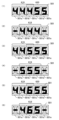
次に、一括表示装置の構成について図5を用いて説明する。図5は、第1の実施形態の
一括表示装置の一例を示す図である。一括表示装置50は、7セグメントLED_d1と
7セグメントLED_d2、およびLED_d3からLED_d18までの16個のLE
Dを備える。一括表示装置50は、7セグメントLED_d1と7セグメントLED_d
2、およびLED_d3からLED_d18の点灯態様により各種状態表示をおこなう。
Next, the configuration of the collective display device will be described with reference to FIG. FIG. 5 is a diagram showing an example of a batch display device according to the first embodiment. The
Have D. The
2, and LED_d3 to LED_d18 display various states.
一括表示装置50は、7セグメントLED_d1と7セグメントLED_d2、および
LED_d3からLED_d18に各種状態表示機能を振り分けることで、ラウンド表示
部51と、特図1保留表示部52と、特図1図柄表示部53と、特図2図柄表示部54と
、普図図柄表示部55と、普図保留表示部56と、状態表示部57と、特図2保留表示部
58とを備える。ラウンド表示部51は、LED_d3からLED_d6の4個のLED
の点灯態様により、特図ゲームにおけるラウンド数を表示する。特図1保留表示部52は
、LED_d11とLED_d12の2個のLEDの点灯態様により、特図1ゲームにお
ける保留数を表示する。特図1図柄表示部53は、7セグメントLED_d1の8個のL
ED(7個のセグメントLEDと1個のドットLED)の点灯態様により、特図1ゲーム
における図柄を表示する。特図2図柄表示部54は、7セグメントLED_d2の8個の
LED(7個のセグメントLEDと1個のドットLED)の点灯態様により、特図2ゲー
ムにおける図柄を表示する。普図図柄表示部55は、LED_d8、LED_d10、お
よびLED_d18の3個のLEDの点灯態様により、普図ゲームにおける図柄を表示す
る。普図保留表示部56は、LED_d15とLED_d16の2個のLEDの点灯態様
により、普図ゲームにおける保留数を表示する。状態表示部57は、LED_d7、LE
D_d9、およびLED_d17の3個のLEDの点灯態様により、特図ゲームにおける
遊技状態を表示する。特図2保留表示部58は、LED_d13とLED_d14の2個
のLEDの点灯態様により、特図2ゲームにおける保留数を表示する。
The number of rounds in the special game is displayed by the lighting mode of . The special figure 1 pending display unit 52 displays the number of reservations in the special figure 1 game by the lighting mode of two LEDs, LED_d11 and LED_d12. The special figure 1 pattern display unit 53 has 8 L of 7 segment LED_d1
The pattern in the special figure 1 game is displayed by the lighting mode of the ED (7 segment LEDs and 1 dot LED). The special figure 2 design display unit 54 displays the design in the special figure 2 game by the lighting mode of the 8 LEDs (7 segment LEDs and 1 dot LED) of the 7 segment LED_d2. The general pattern display unit 55 displays the patterns in the general pattern game by lighting modes of three LEDs, LED_d8, LED_d10, and LED_d18. The normal-pattern reservation display unit 56 displays the number of reserves in the normal-pattern game by the lighting modes of the two LEDs, LED_d15 and LED_d16. The state display unit 57 displays LED_d7, LE
The game state in the special figure game is displayed by the lighting modes of the three LEDs D_d9 and LED_d17. The special figure 2 reservation display unit 58 displays the number of reservations in the special figure 2 game by the lighting mode of two LEDs, LED_d13 and LED_d14.
以下、このような遊技をおこなう遊技機の制御について説明する。まず、遊技制御装置
100の遊技用マイコン111によって実行される制御について説明する。遊技用マイコ
ン111による制御処理は、主に図6および図7に示すメイン処理と、所定時間周期(た
とえば4m秒)でおこなわれる図8に示すタイマ割込み処理とからなる。
The control of the gaming machine that performs such games will be described below. First, the control executed by the
〔メイン処理〕
まず、メイン処理について説明する。図6は、第1の実施形態のメイン処理のフローチ
ャートを示す図(その1)であり、図7は、第1の実施形態のメイン処理のフローチャー
トを示す図(その2)である。メイン処理は、CPU111Aが実行する処理である。
[Main processing]
First, the main processing will be explained. FIG. 6 is a diagram (part 1) showing a flowchart of the main processing of the first embodiment, and FIG. 7 is a diagram (part 2) showing a flowchart of the main processing of the first embodiment. The main processing is processing executed by the CPU 111A.
メイン処理は、電源が投入されることで開始される。このメイン処理においては、図6
および図7に示すように、まず、割込みを禁止する処理(ステップS1)をおこなってか
ら、割込みが発生したときにレジスタ等の値を退避する領域の先頭アドレスであるスタッ
クポインタを設定するスタックポインタ設定処理(ステップS2)をおこなう。次に、レ
ジスタバンク0を指定し(ステップS3)、所定のレジスタ(たとえばDレジスタ)にR
AM先頭アドレスの上位アドレスをセットする(ステップS4)。第1の実施形態の場合
、RAM111Cのアドレスの範囲は、0000h~01FFhで、上位としては00h
か01hをとる。ステップS4ではRAM111Cのアドレスの範囲のうち先頭側にある
00hをセットする。
Main processing is started when the power is turned on. In this main process, FIG.
And as shown in FIG. 7, first, processing for inhibiting interrupts (step S1) is performed, and then a stack pointer for setting a stack pointer, which is the top address of an area where values such as registers are saved when an interrupt occurs. A setting process (step S2) is performed. Next, register
The upper address of the AM head address is set (step S4). In the case of the first embodiment, the range of addresses in the RAM 111C is 0000h to 01FFh, with 00h as the higher order.
or take 01h. In step S4, 00h at the top of the address range of the RAM 111C is set.
次に、発射停止の信号を出力して発射許可信号を禁止状態に設定する(ステップS5)
。発射許可信号は、遊技制御装置100と払出制御装置200の少なくとも一方が発射停
止の信号を出力している場合に禁止状態に設定され、遊技球の発射が禁止されるようにな
っている。
Next, a firing stop signal is output to set the firing permission signal to a prohibited state (step S5).
. The launch permission signal is set to a prohibited state when at least one of the
その後、入力ポート1(第1入力ポート122)の状態を読み込み(ステップS6)、
電源投入ディレイタイマを設定する処理をおこなう(ステップS7)。この処理では、所
定の初期値を設定することにより、主制御手段をなす遊技制御装置100からの指示にし
たがい種々の制御をおこなう従制御手段(たとえば、払出制御装置200や演出制御装置
300)のプログラムが正常に起動するのを待つための待機時間(たとえば3秒)が設定
される。これにより、電源投入の際に仮に遊技制御装置100が先に立ち上がって従制御
装置(たとえば払出制御装置200や演出制御装置300)が立ち上がる前にコマンドを
従制御装置へ送ってしまい、従制御装置がコマンドを取りこぼすのを回避することができ
る。すなわち、遊技制御装置100が、電源投入時において、主制御手段(遊技制御装置
100)の起動を遅らせて従制御装置(払出制御装置200、演出制御装置300等)の
起動を待つための所定の待機時間を設定する待機手段をなす。
After that, the state of input port 1 (first input port 122) is read (step S6),
Processing for setting a power-on delay timer is performed (step S7). In this process, by setting a predetermined initial value, sub-control means (for example,
また、電源投入ディレイタイマの計時は、RAM領域が保持するデータの正当性判定(
チェックサム算出)の対象とならない記憶領域(正当性判定対象外のRAM領域またはレ
ジスタ等)を用いておこなわれる。これにより、RAM領域のチェックサム等のチェック
データを算出する際に、一部のRAM領域を除外して算出する必要がないため電源投入時
の制御が複雑になることを防止することができる。
Also, the timing of the power-on delay timer is used to determine the validity of the data held in the RAM area (
This is performed using a storage area not subject to checksum calculation (RAM area, registers, etc. not subject to validity determination). As a result, when calculating check data such as a checksum of the RAM area, there is no need to exclude a part of the RAM area from the calculation, so control at power-on can be prevented from becoming complicated.
なお、第1入力ポート122には、初期化スイッチ信号が入力されるようになっており
、待機時間の開始前に第1入力ポート122の状態を読み込むことで、RAM初期化スイ
ッチ112の操作を確実に検出できる。すなわち、待機時間の経過後にRAM初期化スイ
ッチ112の状態を読み込むようにすると、待機時間の経過を待ってからRAM初期化ス
イッチ112を操作したり、電源投入から待機時間の経過までRAM初期化スイッチ11
2を操作し続けたりする必要がある。しかし、待機時間の開始前に状態を読み込むことで
、このような煩わしい操作をおこなわなくても電源投入後すぐに操作をおこなうことで検
出されるようになり、電源投入時におこなった初期化の操作が受け付けられないような事
態を防止できる。
An initialization switch signal is input to the
It is necessary to continue to operate 2. However, by reading the status before the start of the standby time, even if you do not perform such a troublesome operation, it will be detected by performing an operation immediately after turning on the power, and the initialization operation performed at the time of turning on the power will be detected. It is possible to prevent a situation in which the
次に、電源投入ディレイタイマ(たとえば、約3秒)を設定する処理(ステップS7)
をおこなった後、待機時間の計時と、待機時間中における停電の発生を監視する処理(ス
テップS8からS12)をおこなう。まず、電源装置400から入力されている停電監視
信号をポートおよびデータバスを介して読み込んでチェックする回数(たとえば2回)を
設定し(ステップS8)、停電監視信号がオンであるか否かの判定をおこなう(ステップ
S9)。
Next, processing for setting a power-on delay timer (for example, about 3 seconds) (step S7)
After that, the process of measuring the standby time and monitoring the occurrence of a power failure during the standby time (steps S8 to S12) is performed. First, the power failure monitoring signal input from the
停電監視信号がオンである場合(ステップS9;Y)は、ステップS8で設定したチェ
ック回数分停電監視信号のオン状態が継続しているか否かを判定する(ステップS10)
。そして、チェック回数分停電監視信号のオン状態が継続していない場合(ステップS1
0;N)は、停電監視信号がオンであるか否かの判定(ステップS9)に戻される。また
、チェック回数分停電監視信号のオン状態が継続している場合(ステップS10;Y)、
すなわち、停電が発生していると判定した場合は、遊技機10の電源が遮断されるのを待
つ。このように、所定期間にわたり停電監視信号を受信し続けた場合に停電が発生したと
判定することで、ノイズ等により停電を誤検知することを防止でき、電源投入時における
不具合に適切に対処することができる。
If the power failure monitoring signal is on (step S9; Y), it is determined whether the power failure monitoring signal has been on for the number of checks set in step S8 (step S10).
. Then, if the ON state of the power failure monitoring signal does not continue for the number of checks (step S1
0; N) is returned to the determination of whether or not the power failure monitor signal is on (step S9). Further, when the ON state of the power failure monitoring signal continues for the number of checks (step S10; Y),
In other words, when it is determined that a power failure has occurred, the
すなわち、遊技制御装置100が、所定の待機時間において停電の発生を監視する停電
監視手段をなす。これにより、主制御手段をなす遊技制御装置100の起動を遅らせてい
る期間において発生した停電に対応することが可能となり、電源投入時における不具合に
適切に対処することができる。なお、待機時間の終了まではRAM111Cへのアクセス
が許可されておらず、前回の電源遮断時の記憶内容が保持されたままとなっているため、
ここでの停電発生時にはバックアップの処理等はおこなう必要がない。このため、待機時
間中に停電が発生してもRAM111Cのバックアップを取る必要がなく、制御の負担を
軽減することができる。
That is, the
When a power failure occurs here, there is no need to perform backup processing or the like. Therefore, even if a power failure occurs during the standby time, there is no need to back up the RAM 111C, and the burden of control can be reduced.
一方、停電監視信号がオンでない場合(ステップS9;N)、すなわち、停電が発生し
ていない場合には、電源投入ディレイタイマを「-1」更新し(ステップS11)、タイ
マの値が「0」であるか否かを判定する(ステップS12)。タイマの値が0でない場合
(ステップS12;N)、すなわち、待機時間が終了していない場合は、停電監視信号の
チェック回数を設定する処理(ステップS8)に戻される。また、タイマの値が「0」で
ある場合(ステップS12;Y)、すなわち、待機時間が終了した場合、RAM111C
やEEPROM等の読出し書込み可能なRWM(Read Write Memory)のアクセス許可を
し(ステップS13)、全出力ポートにオフデータを出力(出力がない状態に設定)する
(ステップS14)。
On the other hand, if the power failure monitoring signal is not on (step S9; N), that is, if no power failure has occurred, the power-on delay timer is updated by "-1" (step S11), and the value of the timer changes to "0". '' (step S12). If the timer value is not 0 (step S12; N), that is, if the standby time has not ended, the process returns to the process of setting the number of checks of the power failure monitoring signal (step S8). Moreover, when the value of the timer is "0" (step S12; Y), that is, when the waiting time has ended, the RAM 111C
, EEPROM or other readable and writable RWM (Read Write Memory) is permitted (step S13), and off data is output to all output ports (set to no output state) (step S14).
次に、シリアルポート(遊技用マイコン111にあらかじめ搭載されているポートで、
この第1の実施形態では、演出制御装置300や払出制御装置200との通信に使用)を
設定し(ステップS15)、RWM内の停電検査領域1の値が正常な停電検査領域チェッ
クデータ1(たとえば5Ah)であるか否かを判定する(ステップS16)。
Next, the serial port (a port pre-installed in the
In this first embodiment, use for communication with the
そして、停電検査領域1の値が正常であれば(ステップS16;Y)、RWM内の停電
検査領域2の値が正常な停電検査領域チェックデータ2(たとえばA5h)であるか否か
を判定し(ステップS17)、停電検査領域2の値が正常であれば(ステップS17;Y
)、RWM内の所定領域のチェックサムを算出するチェックサム算出処理をおこない(ス
テップS18)、算出したチェックサムと電源断時のチェックサムが一致するか否かを判
定する(ステップS19)。
If the value of power
), a checksum calculation process for calculating a checksum of a predetermined area in the RWM is performed (step S18), and it is determined whether or not the calculated checksum matches the checksum at the time of power failure (step S19).
ここで、ステップS18及び後述するステップS43でおこなうチェックサム算出処理
では、遊技制御用ワーク領域のデータと状態表示用ワーク領域のデータを合算したものを
チェックサムとして算出してもよいし、遊技制御用ワーク領域のデータと状態表示用ワー
ク領域のデータからそれぞれ別々にチェックサムを算出してもよいし、遊技制御用ワーク
領域のデータだけからチェックサムを算出してもよい。遊技制御用ワーク領域とは、RW
M内の記憶領域のうち遊技制御用に使用される作業領域である。状態表示用ワーク領域と
は、RWM内の記憶領域のうち状態表示用に使用される作業領域である。
Here, in the checksum calculation process performed in step S18 and step S43 to be described later, the sum of the data in the game control work area and the data in the status display work area may be calculated as the checksum. The checksum may be calculated separately from the data in the work area for game control and the data in the work area for status display, or the checksum may be calculated only from the data in the work area for game control. The game control work area is RW
It is a work area used for game control among the storage areas in M. The work area for status display is a work area used for status display among the storage areas in the RWM.
次に、チェックサムが一致する場合(ステップS19;Y)は、先に読み込んだ第1入
力ポート122の状態からRAM初期化スイッチ112がオンにされたか否かを判定し(
ステップS20)、RAM初期化スイッチ112がオフである場合(ステップS20;N
)は、ステップS25(図7)へ移行し、停電から正常に復旧した場合の処理をおこなう
。
Next, if the checksums match (step S19; Y), it is determined whether or not the
Step S20), if the
) moves to step S25 (FIG. 7), and performs processing when normal recovery from the power failure is performed.
また、停電検査領域のチェックデータが正常なデータでない(ステップS16;Nまた
はステップS17;N)と判定された場合や、チェックサムが正常でない(ステップS1
9;N)と判定された場合は、ステップS21へ移行してステップS21乃至S24でデ
ータ異常時の初期化の処理(第1初期化処理)をおこなう。すなわち、遊技制御装置10
0が、RWM(たとえばRAM111C)内のデータが異常であると判定されたことにも
とづいて、RWMに記憶されたデータ(アクセス禁止領域を含むすべての領域のデータ)
を初期化する第1初期化手段をなす。
Also, if it is determined that the check data in the power failure inspection area is not normal data (step S16; N or step S17; N), or if the checksum is not normal (step S1
9; N), the process proceeds to step S21, and the initialization process (first initialization process) at the time of data abnormality is performed in steps S21 to S24. That is, the
0 is the data stored in the RWM (data in all areas including the access prohibited area) based on the determination that the data in the RWM (eg RAM 111C) is abnormal
constitutes a first initialization means for initializing the
そして、ステップS21へ移行した場合には、RAMアクセス禁止領域をアクセス許可
に設定し(ステップS21)、ビジー信号ステータス領域やタッチスイッチ信号状態監視
領域を含むすべてのRAM領域をゼロクリアして(ステップS22)、RAMアクセス禁
止領域をアクセス禁止に設定する(ステップS23)。次に、初期化すべき領域にRAM
初期化時の初期値をセーブし(ステップS24)、ステップS29へ移行する。ここでの
初期化すべき領域とは、遊技制御用ワーク領域と状態表示用ワーク領域のうちのステップ
S22において書き込まれた値(ゼロ)ではない値を初期値とする領域であり、本実施形
態では客待ちデモの設定および演出モードの設定に係る領域である。
When the process proceeds to step S21, the RAM access prohibition area is set to access permission (step S21), and all RAM areas including the busy signal status area and the touch switch signal state monitoring area are cleared to zero (step S22). ), and sets the RAM access prohibition area to access prohibition (step S23). Next, place the RAM in the area to be initialized.
The initial values at the time of initialization are saved (step S24), and the process proceeds to step S29. The area to be initialized here is an area whose initial value is a value other than the value (zero) written in step S22 of the game control work area and the state display work area, and in the present embodiment This is an area related to the setting of the customer waiting demo and the setting of the presentation mode.
一方、RAM初期化スイッチ112がオンである(ステップS20;Y)と判定された
場合は、ステップS27(図7)へ移行してステップS27、S28で初期化操作時の初
期化の処理(第2初期化処理)をおこなう。すなわち、RAM初期化スイッチ112が外
部からの操作が可能な初期化操作部をなし、遊技制御装置100が、初期化操作部が操作
されたことにもとづきRWM(たとえばRAM111C)に記憶されたデータ(アクセス
禁止領域を含まない領域のデータ)を初期化する第2初期化手段をなす。
On the other hand, if it is determined that the
そして、ステップS27(図7)へ移行した場合には、RWM(たとえばRAM111
C)の記憶領域(アクセス禁止領域を含まない領域)のうちの遊技制御用ワーク領域のデ
ータをゼロクリアして(ステップS27)、初期化すべき領域にRAM初期化時の初期値
をセーブし(ステップS28)、ステップS29へ移行する。ここでの初期化すべき領域
とは、本実施形態では客待ちデモの設定および演出モードの設定に係る領域である。
Then, when the process proceeds to step S27 (FIG. 7), the RWM (for example, the
C) Clear the data in the game control work area in the storage area (area not including the access prohibited area) to zero (step S27), save the initial value at the time of RAM initialization in the area to be initialized (step S28), and the process proceeds to step S29. The area to be initialized here is an area related to the setting of the customer waiting demonstration and the setting of the production mode in this embodiment.
このように、第1の実施形態の遊技制御装置100は、データ異常時の初期化の処理(
第1初期化処理)と、初期化操作時の初期化の処理(第2初期化処理)とを区別して実行
する機能(第1初期化手段、第2初期化手段)を有するため、状況に応じた最適かつ無駄
のない初期化の処理が実現できる。
Thus, the
(first initialization process) and initialization process (second initialization process) at the time of initialization operation (first initialization means, second initialization means). Optimal and efficient initialization processing can be realized.
次に、ステップS25(図7)へ移行した場合には、初期化すべき領域に停電復旧時の
初期値をセーブし(ステップS25)、特図ステータス(後述する特図ステータス領域に
セットされているデータが示す状態)に対応する停電復旧時のコマンドを演出制御基板(
演出制御装置300)へ送信し(ステップS26)、ステップS31へ進む。
Next, when the process proceeds to step S25 (FIG. 7), the initial value at the time of power failure recovery is saved in the area to be initialized (step S25), and the special figure status (which is set in the special figure status area described later) Control board (
Effect control device 300) (step S26), and proceeds to step S31.
ここで、ステップS25で初期化すべき領域とは、停電検査領域、チェックサム領域お
よびエラー不正監視に係る領域である。なおステップS25では、払出制御装置200が
コマンドを受付可能な状態か否かを示す信号である払出ビジー信号の状態を記憶するビジ
ー信号ステータス領域もクリアされ、払出ビジー信号の状態を確定していないことを示す
不定状態とされる。同様にタッチスイッチ信号の状態を記憶するタッチスイッチ信号状態
監視領域もクリアされ、タッチスイッチ信号の状態を確定していないことを示す不定状態
とされる。
Here, the areas to be initialized in step S25 are a power failure inspection area, a checksum area, and an area related to error monitoring. In step S25, the busy signal status area for storing the state of the payout busy signal, which is a signal indicating whether or not the
また第1の実施形態の場合、ステップS26では、機種指定コマンド、特図1保留数コ
マンド、特図2保留数コマンド、確率情報コマンド、画面指定のコマンド等の複数のコマ
ンドを送信する。また、機種によっては、これらのコマンドに加えて、演出回数情報や高
確率回数情報を送信する。なお、画面指定のコマンドとは、特図1変動表示ゲームと特図
2変動表示ゲームの制御状態がいずれも普段処理中(変動中、大当り中(第1特別遊技状
態)、小当り中(第2特別遊技状態)のうちの何れでもない状態)である場合には、客待
ちデモ画面の表示を指令するコマンドであり、それ以外である場合には復旧画面の表示を
指令するコマンドである。
In the case of the first embodiment, in step S26, a plurality of commands such as a model designation command, a special figure 1 reservation number command, a special figure 2 reservation number command, a probability information command, and a screen designation command are transmitted. Also, depending on the model, in addition to these commands, information about the number of presentations and high-probability number information is transmitted. In addition, the screen designation command means that the control state of the special figure 1 fluctuation display game and the special figure 2 fluctuation display game are both normal processing (during fluctuation, during big hit (first special game state), during small hit (second If the state is neither of the two special game states, the command instructs the display of the customer waiting demonstration screen, and otherwise, the command instructs the display of the restoration screen.
一方、ステップS24またはS28からステップS29へ移行した場合には、RAM初
期化時のコマンドを演出制御基板(演出制御装置300)へ送信して(ステップS29)
、ステップS31へ進む。第1の実施形態の場合、ステップS29では、機種指定コマン
ド、特図1保留数コマンド、特図2保留数コマンド、確率情報コマンド、RAM初期化の
コマンド(客待ちデモ画面を表示させるとともに、所定時間(たとえば30秒間)光と音
でRAM初期化の報知をおこなわせるためのコマンド)等の複数のコマンドを送信する。
また、機種によっては、これらのコマンドに加えて、演出回数情報や高確率回数情報を送
信する。
On the other hand, when the process proceeds from step S24 or S28 to step S29, the command at the time of RAM initialization is transmitted to the effect control board (effect control device 300) (step S29).
, the process proceeds to step S31. In the case of the first embodiment, in step S29, a model designation command, a special figure 1 reservation number command, a special figure 2 reservation number command, a probability information command, a RAM initialization command (displaying a customer waiting demo screen, a predetermined A plurality of commands such as a command for notifying RAM initialization with light and sound for a period of time (for example, 30 seconds) are transmitted.
Also, depending on the model, in addition to these commands, information about the number of presentations and high-probability number information is transmitted.
ステップS31では、遊技用マイコン111(クロックジェネレータ)内のタイマ割込
み信号および乱数更新トリガ信号(CTC(Counter/Timer Circuit))を発生するCT
C回路を起動する処理をおこなう。なお、CTC回路は、遊技用マイコン111内のクロ
ックジェネレータに設けられている。クロックジェネレータは、発振回路113からの発
振信号(原クロック信号)を分周する分周回路と、分周された信号にもとづいてCPU1
11Aに対して所定周期(たとえば、4m秒)のタイマ割込み信号および乱数生成回路へ
供給する乱数更新のトリガを与える信号CTCを発生するCTC回路とを備えている。
In step S31, a CT for generating a timer interrupt signal and a random number update trigger signal (CTC (Counter/Timer Circuit)) in the gaming microcomputer 111 (clock generator)
Perform processing to activate the C circuit. Incidentally, the CTC circuit is provided in the clock generator in the
11A has a CTC circuit for generating a timer interrupt signal of a predetermined period (for example, 4 ms) and a signal CTC for triggering random number update to be supplied to the random number generation circuit.
上記ステップS31のCTC起動処理の後、乱数生成回路を起動設定する処理をおこな
う(ステップS32)。具体的には、乱数生成回路内の所定のレジスタ(CTC更新許可
レジスタ)へ乱数生成回路を起動させるためのコード(指定値)の設定等がCPU111
Aによっておこなわれる。また、乱数生成回路のハードウェアで生成されるハード乱数(
ここでは大当り乱数)のビット転置パターンの設定もおこなわれる。ビット転置パターン
とは、抽出した乱数のビット配置(ビット転置前の配置)を、あらかじめ定められた順で
入れ替えて異なるビット配置(ビット転置後の配置)として格納する際の入れ替え方を定
めるパターンである。このビット転置パターンにしたがい乱数のビットを入れ替えること
で、乱数の規則性を崩すことができるとともに、乱数の秘匿性を高めることができる。な
お、ビット転置パターンは、固定された単一のパターンであってもよいし、あらかじめ用
意された複数のパターンから選択するようにしてもよい。また、ユーザーが任意に設定で
きるようにしてもよい。
After the CTC start-up process of step S31, a process of starting and setting the random number generation circuit is performed (step S32). Specifically, the
performed by A. Hard random numbers generated by the hardware of the random number generator (
Here, the bit transposition pattern of the jackpot random number) is also set. A bit permutation pattern is a pattern that defines how to permute the extracted random number bit arrangement (arrangement before bit transposition) when storing it as a different bit arrangement (arrangement after bit transposition) by permuting it in a predetermined order. be. By replacing the bits of the random number according to this bit permutation pattern, it is possible to break the regularity of the random number and improve the secrecy of the random number. The bit transposition pattern may be a single fixed pattern, or may be selected from a plurality of prepared patterns. In addition, the user may be able to set them arbitrarily.
その後、電源投入時の乱数生成回路内の所定のレジスタ(ソフト乱数レジスタ1~n)
の値を抽出し、対応する各種初期値乱数(第1の実施形態の場合、大当り図柄初期値乱数
、小当り図柄初期値乱数、当り初期値乱数、当り図柄初期値乱数)の初期値(スタート値
)としてRWMの所定領域にセーブしてから(ステップS33)、割込みを許可する(ス
テップS34)。
After that, predetermined registers (soft random number registers 1 to n) in the random number generation circuit when the power is turned on
Extract the value of the corresponding various initial random numbers (in the case of the first embodiment, the initial value of the initial value (start value) in a predetermined area of the RWM (step S33), and then the interrupt is permitted (step S34).
ここで、「大当り図柄初期値乱数」は、特図の大当り停止図柄を決定する乱数(大当り
図柄乱数)の初期値となる乱数、「小当り図柄初期値乱数」は、特図の小当り停止図柄を
決定する乱数(小当り図柄乱数)の初期値となる乱数のことである。また、「当り初期値
乱数」は、普図変動ゲームの当りを決定する乱数(当り乱数)の初期値となる乱数、「当
り図柄初期値乱数」は、普図変動ゲームの当り図柄を決定する乱数(当り図柄乱数)の初
期値となる乱数のことである。なお、小当り図柄乱数は、小当りのない機種では存在せず
、当り図柄初期値乱数も機種により存在しない場合がある。
Here, the "jackpot design initial value random number" is a random number that is the initial value of the random number (jackpot pattern random number) that determines the jackpot stop pattern of the special pattern, and the "small hit design initial value random number" is the small hit stop of the special pattern. It is a random number that is the initial value of the random number that determines the design (small hit design random number). In addition, the "hit initial value random number" is a random number that is the initial value of the random number (hit random number) that determines the hit of the normal pattern fluctuation game, and the "hit pattern initial value random number" determines the winning pattern of the normal pattern fluctuation game. It is a random number that is the initial value of the random number (per pattern random number). It should be noted that the small winning symbol random number does not exist in models without a small winning, and the winning symbol initial value random number may not exist depending on the model.
また、第1の実施形態で使用するCPU111A内の乱数生成回路においては、電源投
入ごとにソフト乱数レジスタの初期値が変わるように構成されているため、この値を各種
初期値乱数の初期値(スタート値)とすることで、ソフトウェアで生成される乱数の規則
性を崩すことができ、遊技者による不正な乱数の取得を困難にすることができる。
In the random number generating circuit in the CPU 111A used in the first embodiment, the initial value of the soft random number register is changed each time power is turned on. By setting the starting value), the regularity of the random numbers generated by the software can be broken, making it difficult for the player to acquire illegal random numbers.
続いて、各種初期値乱数の値を更新して乱数の規則性を崩すための初期値乱数更新処理
(ステップS35)をおこなう。この初期値乱数更新処理は、各初期値乱数をたとえばそ
れぞれ「+1」更新(インクリメント)する処理である。このように、メイン処理の中で
時間が許す限り初期値乱数を更新し続けることによって、乱数のランダム性を高めること
ができるようにしている。
Subsequently, an initial value random number update process (step S35) is performed to update the values of various initial value random numbers and destroy the regularity of the random numbers. This initial value random number update process is a process of updating (incrementing) each initial value random number by, for example, "+1". In this way, the randomness of the random numbers can be enhanced by continuing to update the initial value random numbers as long as time permits in the main processing.
なお、特に限定されるわけではないが、第1の実施形態においては、大当り乱数、大当
り図柄乱数、小当り図柄乱数、当り乱数、当り図柄乱数は乱数生成回路において生成され
る乱数を使用して生成するように構成されている。ただし、大当り乱数は、CPUの動作
クロックと同等以上の速度のクロックを基にして更新されるいわゆる「高速カウンタ」で
あり、大当り図柄乱数、小当り図柄乱数、当り乱数、当り図柄乱数はプログラムの処理単
位であるタイマ割込み処理と同周期となるCTC出力(タイマ割込み処理のCTC(CT
C0)とは別のCTC(CTC2))をもとにして更新される「低速カウンタ」である。
また、大当り図柄乱数、小当り図柄乱数、当り乱数、当り図柄乱数においては、乱数が一
巡するごとに各々の初期値乱数(ソフトウェアで生成)を用いてスタート値を変更するい
わゆる「初期値変更方式」を採用している。なお、上記各乱数は、「+1」または「-1
」によるカウンタ式更新でもよいし、一巡するまで範囲内のすべての値が重複なくバラバ
ラに出現するランダム式更新でもよい。つまり、大当り乱数はハードウェアのみで更新さ
れる乱数であり、大当り図柄乱数、小当り図柄乱数、当り乱数、当り図柄乱数はハードウ
ェアおよびソフトウェアで更新される乱数である。
Although it is not particularly limited, in the first embodiment, random numbers generated in a random number generating circuit are used for the jackpot random numbers, jackpot pattern random numbers, small hit pattern random numbers, hit random numbers, and hit pattern random numbers. configured to generate However, the jackpot random number is a so-called "high-speed counter" that is updated based on a clock that is equal to or faster than the operating clock of the CPU. CTC output (CTC of timer interrupt processing (CT
C0) is a "slow counter" that is updated based on another CTC (CTC2)).
In addition, in the jackpot pattern random number, small hit pattern random number, hit random number, and hit pattern random number, each initial value random number (generated by software) is used to change the start value each time the random number is cycled. ” is adopted. In addition, each random number above is "+1" or "-1
, or random update in which all the values within the range appear randomly without duplication until a cycle is completed. That is, the jackpot random number is a random number updated only by hardware, and the jackpot pattern random number, small hit pattern random number, hit random number, and hit pattern random number are random numbers updated by hardware and software.
ステップS35の初期値乱数更新処理の後、電源装置400から入力されている停電監
視信号をポートおよびデータバスを介して読み込んでチェックする回数(たとえば2回)
を設定し(ステップS36)、停電監視信号がオンであるかの判定をおこなう(ステップ
S37)。停電監視信号がオンでない場合(ステップS37;N)、初期値乱数更新処理
(ステップS35)に戻される。すなわち、停電が発生していない場合には、初期値乱数
更新処理と停電監視信号のチェック(ループ処理)を繰り返しおこなう。初期値乱数更新
処理(ステップS35)の前に割込みを許可する(ステップS34)ことによって、初期
値乱数更新処理中にタイマ割込みが発生すると割込み処理が優先して実行されるようにな
り、タイマ割込みが初期値乱数更新処理によって待たされることで割込み処理が圧迫され
るのを回避することができる。
After the initial value random number update process in step S35, the number of times (for example, twice) that the power failure monitoring signal input from the
is set (step S36), and it is determined whether or not the power failure monitoring signal is on (step S37). If the power failure monitoring signal is not ON (step S37; N), the process returns to the initial value random number update process (step S35). That is, when a power failure has not occurred, the initial value random number updating process and the power failure monitoring signal check (loop process) are repeated. By enabling the interrupt (step S34) before the initial value random number update process (step S35), if a timer interrupt occurs during the initial value random number update process, the interrupt process is preferentially executed. It is possible to avoid pressure on the interrupt processing due to the waiting due to the initial value random number update processing.
なお、上記ステップS35での初期値乱数更新処理は、メイン処理のほか、タイマ割込
み処理の中においても初期値乱数更新処理をおこなう方法もあり、そのような方法を採用
した場合には、両方で初期値乱数更新処理が実行されるのを回避するため、メイン処理で
初期値乱数更新処理をおこなう場合には、割込みを禁止してから更新して割込みを解除す
る必要があるが、第1の実施形態のようにタイマ割込み処理の中での初期値乱数更新処理
はせず、メイン処理内のみにした場合には、初期値乱数更新処理の前に割込みを解除して
も何ら問題はなく、それによってメイン処理が簡素化されるという利点がある。
The initial value random number update process in step S35 may be performed in the main process or in the timer interrupt process. In order to avoid executing the initial value random number update process, when performing the initial value random number update process in the main process, it is necessary to disable interrupts and then update to cancel the interrupts. If the initial value random number update process is not performed in the timer interrupt process as in the embodiment, but only in the main process, there is no problem even if the interrupt is canceled before the initial value random number update process. This has the advantage of simplifying the main processing.
停電監視信号がオンである場合(ステップS37;Y)、ステップS36で設定したチ
ェック回数分停電監視信号のオン状態が継続しているか否かを判定する(ステップS38
)。そして、チェック回数分停電監視信号のオン状態が継続していない場合(ステップS
38;N)には、停電監視信号がオンであるか否かの判定(ステップS37)に戻される
。また、チェック回数分停電監視信号のオン状態が継続している場合(ステップS38;
Y)、すなわち、停電が発生していると判定した場合、一旦、割込みを禁止する処理(ス
テップS39)、全出力ポートにオフデータを出力する処理(ステップS40)をおこな
う。
If the power failure monitoring signal is on (step S37; Y), it is determined whether the power failure monitoring signal has been on for the number of checks set in step S36 (step S38).
). Then, if the ON state of the power failure monitoring signal does not continue for the number of checks (step S
38;N), the process returns to the determination of whether or not the power failure monitor signal is ON (step S37). Further, when the power failure monitoring signal continues to be on for the number of checks (step S38;
Y), that is, when it is determined that a power failure has occurred, a process of temporarily prohibiting interrupts (step S39) and a process of outputting OFF data to all output ports (step S40) are performed.
その後、停電検査領域1に停電検査領域チェックデータ1をセーブし(ステップS41
)、停電検査領域2に停電検査領域チェックデータ2をセーブする(ステップS42)。
さらに、RWMの電源遮断時のチェックサムを算出するチェックサム算出処理(ステップ
S43)、算出したチェックサムをチェックサム領域にセーブする処理(ステップS44
)をおこなった後、RAMへのアクセスを禁止する処理(ステップS45)をおこなって
から、遊技機の電源が遮断されるのを待つ。このように、停電検査領域にチェックデータ
をセーブするとともに、電源遮断時のチェックサムを算出することで、電源の遮断の前に
RWMに記憶されていた情報が正しくバックアップされているか否かを電源再投入時に判
定することができる。
After that, the power failure inspection
), the power failure inspection
Furthermore, checksum calculation processing (step S43) for calculating the checksum at the time of power shutdown of the RWM, processing for saving the calculated checksum in the checksum area (step S44).
), a process of prohibiting access to the RAM (step S45) is performed, and then the game machine is waited for the power supply to be turned off. In this way, by saving the check data in the power failure inspection area and calculating the checksum when the power is shut off, it is possible to check whether the information stored in the RWM before the power shutoff has been correctly backed up. It can be judged at the time of re-insertion.
以上のことから、遊技を統括的に制御する主制御手段(遊技制御装置100)と、該主
制御手段からの指示にしたがい種々の制御をおこなう従制御手段(払出制御装置200、
演出制御装置300等)と、を備える遊技機において、主制御手段は、電源投入時におい
て、当該主制御手段の起動を遅らせて従制御装置の起動を待つための所定の待機時間を設
定する待機手段(遊技制御装置100)と、当該所定の待機時間において停電の発生を監
視する停電監視手段(遊技制御装置100)と、を備えていることとなる。
From the above, the main control means (game control device 100) that controls the overall game, and the sub-control means (
At the time of power-on, the main control means delays the activation of the main control means and waits for the activation of the slave control device. Means (game control device 100) and power failure monitoring means (game control device 100) for monitoring the occurrence of a power failure during the predetermined waiting time.
また、各種装置に電力を供給する電源装置400を備え、当該電源装置400は、停電
の発生を検出した際に停電監視信号を出力するように構成され、停電監視手段(遊技制御
装置100)は、所定期間にわたり停電監視信号を受信し続けた場合に停電が発生したと
判定するようにしていることとなる。
Also, a
また、主制御手段(遊技制御装置100)は、データを記憶可能なRAM111Cと、
外部からの操作が可能な初期化操作部(RAM初期化スイッチ112)と、初期化操作部
が操作されたことにもとづきRAM111Cに記憶されたデータを初期化する初期化手段
(遊技制御装置100)と、を備え、当該初期化操作部の操作状態を待機時間の開始前に
読み込むようにしていることとなる。
In addition, the main control means (game control device 100) includes a RAM 111C capable of storing data,
Initialization operation unit (RAM initialization switch 112) that can be operated from the outside, and initialization means (game control device 100) for initializing data stored in RAM 111C based on the operation of the initialization operation unit , and the operation state of the initialization operation unit is read before the standby time starts.
また、主制御手段(遊技制御装置100)は、待機時間の経過後にRAM111Cへの
アクセスを許可するようにしていることとなる。
〔タイマ割込み処理〕
次に、遊技制御装置100のタイマ割込み処理について説明する。図8は、第1の実施
形態のタイマ割込み処理のフローチャートを示す図である。このタイマ割込み処理は、上
述のメイン処理において、割込み許可が出てから割込みが禁止されるまでの間(ステップ
S34からS39)に生じる割込み処理である。タイマ割込み処理は、CPU111Aが
実行する処理である。
Also, the main control means (game control device 100) permits access to the RAM 111C after the waiting time has elapsed.
[Timer interrupt processing]
Next, timer interrupt processing of the
タイマ割込み処理は、クロックジェネレータ内のCTC回路で生成される周期的なタイ
マ割込み信号がCPU111Aに入力されることで開始される。遊技用マイコン111に
おいて、タイマ割込みが発生すると、自動的に割込み禁止状態になって、タイマ割込み処
理が開始される。
Timer interrupt processing is started when a periodic timer interrupt signal generated by the CTC circuit in the clock generator is input to the CPU 111A. When a timer interrupt occurs in the
タイマ割込み処理が開始されると、まず、レジスタバンク1を指定する(ステップS1
21)。レジスタバンク1に切り替えたことで、所定のレジスタ(たとえば、メイン処理
で使っているレジスタ)に保持されている値をRWMに移すレジスタ退避の処理をおこな
ったのと同等になる。次に、所定のレジスタ(たとえばDレジスタ)にRAM先頭アドレ
スの上位アドレスをセットする(ステップS122)。ステップS122では、メイン処
理におけるステップS4と同じ処理をおこなっているが、レジスタバンクが異なる。次に
、各種センサやスイッチからの入力や、信号の取り込み、すなわち、各入力ポートの状態
を読み込む入力処理(ステップS123)をおこなう。それから、各種処理でセットされ
た出力データにもとづき、ソレノイド(大入賞口1ソレノイド95b、大入賞口2ソレノ
イド38b、普電ソレノイド37c)等のアクチュエータの駆動制御等をおこなうための
出力処理(ステップS124)をおこなう。なお、メイン処理におけるステップS5で発
射停止の信号を出力すると、この出力処理がおこなわれることで発射許可の信号が出力さ
れ、発射許可信号を許可状態に設定可能な状態とされる。この発射許可信号は、払出制御
装置を経由して発射制御装置に出力される。その際、信号の加工等はおこなわれない。ま
た、当該発射許可信号は、遊技制御装置100から見た発射許可の状態を示す第1の信号
であり、払出制御装置200から見た発射許可の状態を示す第2の信号(発射許可信号)
も払出制御装置200内で生成され、発射制御装置に出力される。つまり、2つの発射許
可信号が発射制御装置に出力されており、両者がともに発射許可となっている場合に、遊
技球が発射可能な状態となるよう構成されている。
When timer interrupt processing is started, first,
21). Switching to register
is also generated within the
次に、各種処理で送信バッファにセットされたコマンドを払出制御装置200に出力す
る払出コマンド送信処理(ステップS125)、乱数更新処理1(ステップS126)、
乱数更新処理2(ステップS127)をおこなう。ここで、乱数更新処理1は、初期値乱
数更新処理の対象となっている大当り図柄乱数、小当り図柄乱数、当り乱数、当り図柄乱
数の初期値(スタート値)を更新するための処理である。また、乱数更新処理2は、特図
1,特図2の変動表示ゲームにおける変動パターンを決定するための変動パターン乱数を
更新する処理である。
Next, payout command transmission processing (step S125) for outputting commands set in the transmission buffer in various processes to the
Random number update processing 2 (step S127) is performed. Here, the random
その後、始動口1スイッチ36a,37a、始動口2スイッチ92a、普図のゲートス
イッチ34a、入賞口スイッチ35a、大入賞口スイッチ38aから正常な信号の入力が
あるか否かの監視や、エラーの監視(前面枠やガラス枠が開放されていないか等)をおこ
なう入賞口スイッチ/状態監視処理(ステップS128)をおこなう。また、始動口1ス
イッチ36a,37aおよび始動口2スイッチ92aの入賞を監視する始動口スイッチ監
視処理(ステップS129)、特図1変動表示ゲームに関する処理をおこなう特図1ゲー
ム処理(ステップS130a)、特図2変動表示ゲームに関する処理をおこなう特図2ゲ
ーム処理(ステップS130b)、普図変動表示ゲームに関する処理をおこなう普図ゲー
ム処理(ステップS130c)をおこなう。
After that, it is monitored whether there is a normal signal input from the starting
なお、始動口スイッチ監視処理では、第1始動入賞口をなす始動入賞口36または普通
変動入賞装置37、あるいは第2始動入賞口をなす始動入賞口92に遊技球の入賞がある
と、各種乱数(大当り乱数等)の抽出をおこない、特図変動表示ゲームの開始前の段階で
当該入賞にもとづく遊技結果を事前に判定する遊技結果事前判定をおこなう。
In the starting opening switch monitoring process, when a game ball wins in the
次に、遊技機10に設けられ、特図変動表示ゲームの表示や遊技に関する各種情報を表
示するセグメントLED(たとえば、一括表示装置50の特図1図柄表示部53等のLE
D)を所望の内容を表示するように駆動するセグメントLED編集処理(ステップS13
1)、磁気センサ61からの検出信号をチェックして異常がないか判定する処理をおこな
う磁石不正監視処理(ステップS132)、盤電波センサ62からの検出信号をチェック
して異常がないか判定する処理をおこなう盤電波不正監視処理(ステップS133)をお
こなう。それから、外部の各種装置に出力する信号を出力バッファにセットする外部情報
編集処理(ステップS134)、状態表示のための状態表示編集出力処理(ステップS1
35)をおこなって、タイマ割込み処理を終了する。
Next, the segment LED provided in the
D) segment LED editing processing (step S13
1) Magnet fraud monitoring processing (step S132) in which the detection signal from the
35) is performed to end the timer interrupt processing.
ここで、第1の実施形態では、割込み禁止状態を復元する処理(すなわち、割込みを許
可する処理)や、レジスタバンクの指定を復元する処理(すなわち、レジスタバンク0を
指定する処理)は、割込みリターンの際(タイマ割込み処理の終了時)に自動的におこな
われる。なお、使用するCPUによっては、割込み禁止状態を復元する処理やレジスタバ
ンクの指定を復元する処理の実行を命令する必要がある遊技機もある。
Here, in the first embodiment, the process of restoring the interrupt disabled state (that is, the process of enabling interrupts) and the process of restoring the specification of the register bank (that is, the process of specifying register bank 0) It is automatically performed at the time of return (at the end of timer interrupt processing). It should be noted that depending on the CPU used, there are game machines that require a command to execute a process for restoring the interrupt disabled state or a process for restoring the designation of the register bank.
〔払出コマンド送信処理〕
次に、前述のタイマ割込み処理における払出コマンド送信処理(ステップS125)の
詳細について説明する。図9は、第1の実施形態の払出コマンド送信処理のフローチャー
トを示す図である。また図10は、第1の実施形態の入賞数カウンタ領域の構造例を示す
図である。
[Payout command transmission process]
Next, details of the payout command transmission process (step S125) in the timer interrupt process described above will be described. FIG. 9 is a diagram showing a flowchart of payout command transmission processing of the first embodiment. FIG. 10 is a diagram showing an example of the structure of the win number counter area of the first embodiment.
まず、入賞数カウンタ領域の一例について説明すると、入賞数カウンタ領域1は、たと
えば図10に示すように、3個賞球カウンタ、10個賞球カウンタ、及び14個賞球カウ
ンタからなり、各々の入賞数カウンタは65535入賞まで記憶可能になっている。次に
、入賞数カウンタ領域2は、たとえば図10に示すように、3個賞球カウンタ、10個賞
球カウンタ、及び14個賞球カウンタからなり、各々の入賞数カウンタは255入賞まで
記憶可能になっている。これら入賞数カウンタ領域のカウント数のチェックでは、入賞数
カウンタ領域のアドレスを後述するステップS202等で更新することにより、上述した
カウンタを上から(3個賞球カウンタから)順にチェックしていく。
First, an example of the winning number counter area will be described. The winning
次に、図9において、左列はメイン賞球信号の出力回数を更新する(増やす)処理であ
り、右列は払出コマンドを送信する処理である。
払出コマンド送信処理では、まず、図10で説明したように賞球数別(たとえば、3個
賞球、10個賞球、14個賞球)に設けられた複数の入賞数カウンタ領域2のカウンタの
うち、チェック対象とされたカウンタに「0」でないカウント数があるか否かを判定する
(ステップS201)。そして、カウント数がない場合(ステップS201;N)、チェ
ック対象となる入賞数カウンタ領域2のアドレスを更新し(ステップS202)、入賞数
カウンタ領域2のすべてのカウンタのカウント数のチェックが終了したか否かを判定する
(ステップS203)。
Next, in FIG. 9, the left column is processing for updating (increasing) the number of times the main prize ball signal is output, and the right column is processing for transmitting a payout command.
In the payout command transmission process, first, as described with reference to FIG. Among them, it is determined whether or not the counter to be checked has a count number other than "0" (step S201). If there is no count (step S201; N), the address of the winning
ステップS201で、カウント数がある(ステップS201;Y)と判定された場合、
対象の入賞数カウンタ領域2のカウンタのカウント数を減算(「-1」更新)し(ステッ
プS204)、入賞数カウンタ領域2のアドレスに対応する払出数(たとえば、上述した
3個、10個、14個のうちの何れか)を取得する(ステップS205)。次に、賞球残
数領域の値と払出数を加算し(ステップS206)、加算結果を賞球残数領域にセーブし
(ステップS207)、加算結果から10を減算し(ステップS208)、その減算結果
が「0」以上かを判定する(ステップS209)。ステップS209で、減算結果が「0
」以上(ステップS209;Y)と判定された場合、メイン賞球信号出力回数を「+1」
更新し(ステップS210)、減算結果を賞球残数領域にセーブする(ステップS211
)。
If it is determined in step S201 that there is a count (step S201; Y),
The counter count of the target winning
" or more (step S209; Y), the number of times the main prize ball signal is output is "+1"
update (step S210), and save the subtraction result in the prize ball remaining number area (step S211)
).
なお、後述する外部情報編集処理におけるメイン賞球信号編集処理では、上記ステップ
S210で更新されるメイン賞球信号出力回数にもとづいてメイン賞球信号を出力する処
理が行われる。ここで、賞球信号(メイン賞球信号)としては、主基板(遊技制御装置1
00)からは10個払出予定ごとに1パルスが出力され、払出基板(払出制御装置200
)からは10個払出ごとに1パルスが出力される。
In the main prize ball signal editing process in the external information editing process described later, a process of outputting the main prize ball signal is performed based on the number of main prize ball signal output times updated in step S210. Here, as the prize signal (main prize signal), the main board (
00) outputs one pulse for every 10 payout schedules, and the payout board (
) outputs one pulse every
次に、ステップS203の判定で、すべてのチェックが終了した(ステップS203;
Y)と判定、または、ステップS209の判定で、減算結果が「0」以上でない(ステッ
プS209;N)と判定された場合、払出コマンド送信タイマの値が「0」でなければ払
出コマンド送信タイマの値を「-1」更新する(ステップS212)。この払出コマンド
送信処理が最初のタイマ割込み処理であれば、この払出コマンド送信処理の最後のステッ
プS221で設定される初期値が設定されていないので、払出コマンド送信タイマの値は
「0」であるから、減算はおこなわれないことになる。
Next, it is determined in step S203 that all checks have been completed (step S203;
Y), or if it is determined that the subtraction result is not "0" or more in the determination of step S209 (step S209; N), the value of the payout command transmission timer is not "0", the payout command transmission timer is updated by "-1" (step S212). If this payout command transmission process is the first timer interrupt process, the value of the payout command transmission timer is "0" because the initial value set in the last step S221 of this payout command transmission process is not set. , no subtraction will be performed.
次に、払出コマンド送信タイマの値が「0」であるか否かを判定し(ステップS213
)、払出コマンド送信タイマの値が「0」である(ステップS213;Y)と判定された
場合、払出ビジー信号がビジー中か否かを判定する(ステップS214)。なお、払出ビ
ジー信号がビジー中か否かは、ポートの状態の参照ではなく、払出ビジー信号フラグの参
照により判定している。ここで、払出ビジー信号がオン(ビジー中)となる条件としては
、「払出動作中」、「球貸し動作中」、「シュート球切れエラー中」、「オーバーフロー
エラー中」、「枠電波不正発生中」、「払出球検出スイッチの異常中(払い出された球を
監視するスイッチ)」、「払出不足エラー中」、「払出過剰エラー中」、「払出制御基板
のメモリ内に払い出すべき賞球数のカウント(未払い出しの賞球数=獲得遊技球数残)が
あるとき(=0でないとき)」等である。
Next, it is determined whether or not the value of the payout command transmission timer is "0" (step S213
), and if it is determined that the value of the payout command transmission timer is "0" (step S213; Y), it is determined whether or not the payout busy signal is busy (step S214). Whether or not the payout busy signal is busy is determined by referring to the payout busy signal flag, not by referring to the state of the port. Here, the conditions for the payout busy signal to turn on (busy) are: "during payout operation", "during ball lending operation", "shot ball running out error", "overflow error", "framing radio wave illegal occurrence Medium", "Abnormality in payout ball detection switch (switch to monitor paid out balls)", "Insufficient payout error", "Excess payout error", "Award to be paid out in the memory of the payout control board When there is a count of the number of balls (the number of unpaid prize balls=the number of acquired game balls remaining) (=not 0).
次に、払出ビジー信号がビジー中でない(ステップS214;N)場合、入賞数カウン
タ領域1の対象のカウンタにカウントありか否かを判定し(ステップS215)、入賞数
カウンタ領域1の対象のカウンタにカウントがなければ(ステップS215;N)、チェ
ックする入賞数カウンタ領域1のアドレスを更新し(ステップS216)、全領域のチェ
ックが終了したか否かを判定する(ステップS217)。全領域のチェックが終了してい
ない(ステップS217;N)場合、ステップS215に戻される。
Next, when the payout busy signal is not busy (step S214; N), it is determined whether or not the target counter of the winning
ステップS215において、入賞数カウンタ領域1の対象のカウンタにカウントがある
(ステップS215;Y)場合、対象の入賞数カウンタを「-1」更新し(ステップS2
18)、入賞数カウンタ領域1のアドレスに対応する払出数コマンドを取得し(ステップ
S219)、取得したコマンドを払出用シリアル送信バッファに書き込む(ステップS2
20)。そして、払出コマンド送信タイマ領域に初期値(たとえば、200ms)をセー
ブする(ステップS221)。
In step S215, if there is a count in the target counter in the winning number counter area 1 (step S215; Y), the target winning number counter is updated by "-1" (step S2
18) Acquires a payout number command corresponding to the address of the winning number counter area 1 (step S219), and writes the acquired command to the payout serial transmission buffer (step S2).
20). Then, the initial value (for example, 200 ms) is saved in the payout command transmission timer area (step S221).
ステップS213において、払出コマンド送信タイマの値が「0」でない(ステップS
213;N)と判定された場合、ステップS214において、払出ビジー信号がビジー中
である(ステップS214;Y)と判定された場合、ステップS217において、全領域
のチェックが終了している(ステップS217;Y)と判定された場合、または、ステッ
プS221の処理が終了した場合に、この払出コマンド送信処理を終了する。
In step S213, the value of the payout command transmission timer is not "0" (step S
213; N), if it is determined that the payout busy signal is busy in step S214 (step S214; Y), then in step S217, all areas have been checked (step S217 ;Y), or when the process of step S221 ends, this payout command transmission process ends.
なお、上記ステップS213、S214の判定結果によってはステップS215以降を
実行しないで処理を終了する構成であることから分かるように、払出コマンドは、タイマ
割込みごとに送信するのではなく、所定時間経過してから送っている。また、払出コマン
ドの送信は、払出制御基板側が賞球を払い出せる状態であることも条件である。
It should be noted that, depending on the determination results of steps S213 and S214, the processing is terminated without executing steps S215 and subsequent steps. I am sending it from In addition, the transmission of the payout command is also conditional on the payout control board being in a state where the prize balls can be paid out.
〔入賞口スイッチ/状態監視処理〕
次に、タイマ割込み処理(図8参照)における入賞口スイッチ/状態監視処理(ステッ
プS128)について説明する。図11は、第1の実施形態の入賞口スイッチ/状態監視
処理のフローチャートを示す図である。この入賞口スイッチ/状態監視処理では、まず、
上大入賞口(特別変動入賞装置38)内の2個の大入賞口スイッチ38a(カウントスイ
ッチ)に対応する入賞口監視テーブル1(たとえば、カウントスイッチからの検出信号が
入力されるポートの番号や該信号のポート内でのビット位置等を示すデータが格納されて
いる)を準備する(ステップS271)。次に、大入賞口が開いていないにもかかわらず
大入賞口に入賞する不正(不正な入賞)がないか監視するとともに正常な入賞を検出する
不正&入賞監視処理(ステップS272)を実行する。
[Winning gate switch/state monitoring process]
Next, the winning opening switch/state monitoring process (step S128) in the timer interrupt process (see FIG. 8) will be described. FIG. 11 is a diagram showing a flow chart of the winning opening switch/state monitoring process of the first embodiment. In this winning slot switch/state monitoring process, first,
Winning hole monitoring table 1 (for example, the number of the port to which the detection signal from the count switch is input) corresponding to the two big
その後、下大入賞口(特別変動入賞装置95)内の1個の大入賞口スイッチ38aに対
応する入賞口監視テーブル2を準備し(ステップS273)、不正な入賞がないか監視す
るとともに正常な入賞を検出する不正&入賞監視処理(ステップS274)を実行する。
そして、普電内の入賞口スイッチ(始動口1スイッチ37a)の入賞口監視テーブルを準
備し(ステップS275a)、不正な入賞がないか監視するとともに正常な入賞を検出す
る不正&入賞監視処理(ステップS275b)を実行する。
After that, a winning opening monitoring table 2 corresponding to one big winning
Then, a winning opening monitoring table for the winning opening switch (starting
次に、不正監視処理が不要な入賞口スイッチ、つまり常時入賞可能な入賞口スイッチ(
ここでは始動口1スイッチ36a、始動口2スイッチ92a、一般入賞口35の入賞口ス
イッチ35a)の入賞口監視テーブルを準備し(ステップS276)、入賞数を更新する
入賞数カウンタ更新処理(ステップS277)をおこない、さらに特図2異常変動監視処
理(ステップS278)をおこなう。
Next, a winning opening switch that does not require fraud monitoring processing, that is, a winning opening switch that can always win a prize (
Here, a winning opening monitoring table for the starting
次に、遊技機10のエラー状態を監視すべき複数のスイッチおよび信号のうちいずれの
スイッチまたは信号を今回の監視の対象とするかを順番に指定するための状態スキャンカ
ウンタの値を「0」から「3」の範囲で更新する(ステップS279)。その後、状態ス
キャンカウンタの値に応じて、スイッチのコネクタ抜け等の発生により出力されるスイッ
チ異常1エラー、払出制御装置200からのシュート球切れエラー、オーバーフロースイ
ッチからのオーバーフローエラーおよび払出異常エラーのいずれかにもとづくエラーの監
視を対象として設定するための遊技機状態監視テーブル1を準備する(ステップS280
)。そして、エラーが発生しているか否かを判定する遊技機状態チェック処理(ステップ
S281)をおこなう。
Next, the value of the state scan counter for sequentially designating which of the plurality of switches and signals to be monitored for the error state of the
). Then, gaming machine state check processing (step S281) for determining whether or not an error has occurred is performed.
次に、状態スキャンカウンタの値に応じて、ガラス枠開放、本体枠開放、枠電波不正お
よびタッチスイッチのいずれかにもとづくエラーの監視を対象として設定するための遊技
機状態監視テーブル2を準備する(ステップS282)。そして、エラーが発生している
か否かを判定する遊技機状態チェック処理(ステップS283)をおこなう。
Next, a gaming machine state monitoring table 2 is prepared for setting an error monitoring target based on one of glass frame opening, main body frame opening, frame radio wave fraud, and touch switch according to the value of the state scan counter. (Step S282). Then, gaming machine state check processing (step S283) for determining whether or not an error has occurred is performed.
次に、状態スキャンカウンタの値が「0」であるか否かを判定し(ステップS284)
、状態スキャンカウンタの値が「0」でない場合(ステップS284;N)は、入賞口ス
イッチ/状態監視処理を終了する。この場合は、次に参照する遊技機状態監視テーブル3
に遊技機状態の監視対象がない場合である。また、状態スキャンカウンタの値が「0」で
ある場合(ステップS284;Y)、状態スキャンカウンタの値に応じて、スイッチのコ
ネクタ抜け等の発生により出力されるスイッチ異常2エラーにもとづく遊技機状態の監視
を対象として設定するための遊技機状態監視テーブル3を準備する(ステップS285)
。そして、エラーが発生しているか否かを判定する遊技機状態チェック処理(ステップS
286)をおこない、払出ビジー信号チェック処理(ステップS287)をおこない、入
賞口スイッチ/状態監視処理を終了する。なお、払出ビジー信号チェック処理は、毎回お
こなわれるのではなく、4回に1回実行されるようにしてあり、残りの3回がパスされる
ので、16ms周期の監視となっている。
Next, it is determined whether or not the value of the state scan counter is "0" (step S284).
If the value of the state scan counter is not "0" (step S284; N), the winning opening switch/state monitoring process is terminated. In this case, gaming machine status monitoring table 3 to be referred to next
This is the case where there is no gaming machine status monitoring target. If the value of the state scan counter is "0" (step S284; Y), the game machine state based on the
. Then, gaming machine state check processing (step S
286) is performed, payout busy signal check processing (step S287) is performed, and winning opening switch/state monitoring processing is terminated. Note that the payout busy signal check process is not performed every time, but is performed once every four times, and the remaining three times are passed, so that the monitoring period is 16 ms.
〔始動口スイッチ監視処理〕
次に、上述のタイマ割込み処理における始動口スイッチ監視処理(ステップS129)
の詳細について図12を用いて説明する。図12は、第1の実施形態の始動口スイッチ監
視処理のフローチャートを示す図である。
[Starting port switch monitoring process]
Next, the starting port switch monitoring process in the above timer interrupt process (step S129)
will be described in detail with reference to FIG. FIG. 12 is a diagram showing a flowchart of the starting port switch monitoring process of the first embodiment.
始動口スイッチ監視処理では、まず、始動口1(始動入賞口36、普通変動入賞装置3
7)の入賞監視テーブルを準備し(ステップA101)、ハード乱数取得処理(ステップ
A102)をおこなって、始動口1への入賞があるか否かを判定する(ステップA103
)。
In the starting opening switch monitoring process, first, starting opening 1 (
7) The winning monitoring table is prepared (step A101), hardware random number acquisition processing (step A102) is performed, and it is determined whether or not there is a winning at the start gate 1 (step A103).
).
ステップA103にて、始動口1への入賞がないと判定した場合(ステップA103;
N)には、ステップA109の処理に移行して、それ以降の処理をおこなう。
一方、ステップA103にて、始動口1への入賞があると判定した場合(ステップA1
03;Y)には、遊技状態が右打ちすべき所定状態(たとえば、普電サポート状態、大当
り中など)であるか否かを判定する(ステップA104)。
In step A103, when it is determined that there is no winning to the starting port 1 (step A103;
In N), the process proceeds to step A109 and the subsequent processes are performed.
On the other hand, in step A103, if it is determined that there is a prize to the starting port 1 (step A1
03; Y), it is determined whether or not the game state is a predetermined state in which the player should hit to the right (for example, normal electric support state, during a big hit, etc.) (step A104).
ステップA104にて、右打ちすべき所定状態でないと判定した場合(ステップA10
4;N)には、ステップA107の処理に移行して、それ以降の処理をおこなう。
一方、ステップA104にて、右打ちすべき所定状態であると判定した場合(ステップ
A104;Y)には、右打ち指示報知コマンドを準備して(ステップA105)、演出コ
マンド設定処理(ステップA106)をおこなう。すなわち、第1の実施形態の遊技機1
0の場合、普電サポート状態を除いて始動口1へは左打ちでないとほとんど入賞せず、右
打ちすべき所定状態で始動口1に入賞があった場合、右打ちすべき所定状態であるのに左
打ちされたと推定できるので、右打ち指示報知コマンドを演出制御装置300に送信して
、右打ちするよう指示する報知(警告)を演出制御装置300によっておこなうよう構成
されている。
If it is determined in step A104 that it is not in a predetermined state that should be hit to the right (step A10
In 4;N), the process proceeds to step A107 and the subsequent processes are performed.
On the other hand, in step A104, when it is determined that the predetermined state to hit to the right (step A104; Y), to prepare a right hitting instruction notification command (step A105), effect command setting processing (step A106) do That is, the
In the case of 0, except for the general electric support state, it is almost impossible to win unless it is left-handed to the starting
次いで、始動口1による保留の情報を設定するテーブルを準備した後(ステップA10
7)、特図始動口1スイッチ処理(ステップA108)をおこなう。
次に、始動口2(始動入賞口92)の入賞監視テーブルを準備し(ステップA109)
、ハード乱数取得処理(ステップA110)をおこなって、始動口2への入賞があるか否
かを判定する(ステップA111)。
Next, after preparing a table for setting hold information by start port 1 (step A10
7), the special
Next, prepare a prize-winning monitoring table for the starting port 2 (starting prize-winning port 92) (step A109)
, a hardware random number acquisition process (step A110) is performed, and it is determined whether or not there is a winning at the starting gate 2 (step A111).
ステップA111にて、始動口2への入賞がないと判定した場合(ステップA111;
N)には、始動口スイッチ監視処理を終了する。
一方、ステップA111にて、始動口2への入賞があると判定した場合(ステップA1
11;Y)には、遊技状態が普電サポート状態(時短状態)となっているか否かを判定し
(ステップA112)、普電サポート状態でない(ステップA112;N)と判定すると
、大当り中であるか否かを判定する(ステップA113)。また、ステップA113にて
、大当り中でない(ステップA113;N)と判定すると、特図変動表示ゲームが普電サ
ポート最終変動中であるか否かを判定する(ステップA114)。
If it is determined in step A111 that there is no winning to the starting port 2 (step A111;
At N), the starting port switch monitoring process is terminated.
On the other hand, in step A111, if it is determined that there is a prize to the starting port 2 (step A1
At 11; Y), it is determined whether or not the game state is in the normal electric support state (time saving state) (step A112). It is determined whether or not there is (step A113). Further, when it is determined at step A113 that the big hit is not in progress (step A113; N), it is determined whether or not the special figure variation display game is during the general electric support final variation (step A114).
ステップA114にて、普電サポート最終変動中でない(ステップA114;N)と判
定すると、左打ち指示報知コマンドを準備して(ステップA115)、演出コマンド設定
処理(ステップA116)をおこなう。すなわち、普電サポート状態、大当り中、普電サ
ポート最終変動中のいずれでもなければ、左打ちすべきなので、左打ち指示報知コマンド
を演出制御装置300に送信する処理をおこなう。
At step A114, when it is determined that the general electric support is not in the final fluctuation (step A114; N), a left-handed instruction notification command is prepared (step A115), and effect command setting processing (step A116) is performed. That is, if it is neither the general electric support state, the jackpot, or the general electric support final fluctuation, it should be hit to the left, so the process of transmitting the instruction notification command to the
そして、ステップA112にて普電サポート状態である(ステップA112;Y)と判
定した場合、ステップA113にて大当り中である(ステップA113;Y)と判定した
場合、ステップA114にて普電サポート最終変動中である(ステップA114;Y)と
判定した場合、ステップA116の処理が終了した場合には、ステップA117に移行す
る。
Then, if it is determined in step A112 that it is in the general electricity support state (step A112; Y), if it is determined that the jackpot is being hit in step A113 (step A113; Y), in step A114 the general electricity support final If it is determined to be fluctuating (step A114; Y), and if the process of step A116 is completed, the process proceeds to step A117.
ステップA117に移行すると、始動口2による保留の情報を設定するテーブルを準備
した後(ステップA117)、特図始動口2スイッチ処理(ステップA118)をおこな
って、始動口スイッチ監視処理を終了する。
If it moves to step A117, after preparing the table which sets the information of the hold by the starting mouth 2 (step A117), special
なお、上記ステップA111にて始動口2への入賞があると判定した場合には、たとえ
ばステップA112を実行する前に、普電不正(普通変動入賞装置37が閉状態であるに
もかかわらず普通変動入賞装置37への入賞が検出される不正)があったか判定するステ
ップを設け、この普電不正発生中であると判定した場合は、ステップA112以降を実行
しないで始動口スイッチ監視処理を終了する構成とし、普電不正があった場合には第2始
動記憶(特図2の始動記憶)をそれ以上発生させないようにしてもよい。
In addition, when it is determined that there is a prize to the starting
〔ハード乱数取得処理〕
次に、上述の始動口スイッチ監視処理におけるハード乱数取得処理(ステップA102
、A110)の詳細について図13を用いて説明する。図13は、第1の実施形態のハー
ド乱数取得処理のフローチャートを示す図である。
[Hard random number acquisition process]
Next, hardware random number acquisition processing (step A102
, A110) will be described in detail with reference to FIG. FIG. 13 is a diagram showing a flowchart of hard random number acquisition processing according to the first embodiment.
ハード乱数取得処理では、まず、始動口1(始動入賞口36、普通変動入賞装置37)
および始動口2(始動入賞口92)のうち、監視対象の始動口の入賞なし情報を設定して
(ステップA121)、始動口1スイッチ36a,37aおよび始動口2スイッチ92a
のうち、監視対象の始動口スイッチに入力があるか否かを判定する(ステップA122)
。そして、監視対象の始動口スイッチに入力がない場合(ステップA122;N)は、ハ
ード乱数取得処理を終了する。一方、監視対象の始動口スイッチに入力がある場合(ステ
ップA122;Y)は、乱数ラッチレジスタステータスを読み込み(ステップA123)
、対象の乱数ラッチレジスタにラッチデータがあるか否かを判定する(ステップA124
)。
In the hardware random number acquisition process, first, the starting port 1 (
and the starting opening 2 (starting winning opening 92), setting no winning information for the starting opening to be monitored (step A121), starting
Among them, it is determined whether or not there is an input to the starting switch to be monitored (step A122)
. If there is no input to the starting switch to be monitored (step A122; N), the hard random number acquisition process is terminated. On the other hand, if there is an input to the starting switch to be monitored (step A122; Y), the random number latch register status is read (step A123).
, determine whether or not there is latch data in the target random number latch register (step A124
).
対象の乱数ラッチレジスタにラッチデータがない場合(ステップA124;N)、すな
わち乱数が抽出されていない場合は、ハード乱数取得処理を終了する。また、対象の乱数
ラッチレジスタにラッチデータがある場合(ステップA124;Y)は、監視対象のハー
ド乱数ラッチレジスタに抽出された大当り乱数をロードし、準備する(ステップA125
)。そして、始動口1および始動口2のうち、監視対象の始動口の入賞あり情報を設定し
て(ステップA126)、ハード乱数取得処理を終了する。
If there is no latch data in the target random number latch register (step A124; N), that is, if no random number has been extracted, the hard random number acquisition process is terminated. Also, if there is latch data in the target random number latch register (step A124; Y), the extracted jackpot random number is loaded into the monitored hard random number latch register and prepared (step A125
). Then, of the starting
〔特図始動口1スイッチ処理〕
次に、上述の始動口スイッチ監視処理における特図始動口1スイッチ処理(ステップA
108)の詳細について図14を用いて説明する。図14は、第1の実施形態の特図始動
口1スイッチ処理のフローチャートを示す図である。
[Special figure start
Next, the special
108) will be described in detail with reference to FIG. FIG. 14 is a diagram showing a flowchart of special
特図始動口1スイッチ処理は、監視対象である始動口1スイッチ36a,37aの入力
(監視対象である特図1の始動入賞)があった場合に、おこなわれる処理である。
特図始動口1スイッチ処理では、まず、監視対象の始動口1スイッチ36a,37aへ
の入賞の回数に関する情報を遊技機10の外部の管理装置に対して出力する回数である始
動口信号1出力回数をロードし(ステップA131)、ロードした値を「+1」更新して
(ステップA132)、出力回数がオーバーフローするか否かを判定する(ステップA1
33)。出力回数がオーバーフローしない場合(ステップA133;N)は、更新後の値
をRWMの始動口信号1出力回数領域にセーブして(ステップA134)、ステップA1
35の処理に移行する。一方、出力回数がオーバーフローする場合(ステップA133;
Y)は、ステップA134をパスしてステップA135の処理に移行する。第1の実施形
態では、始動口信号1出力回数領域に「0」から「255」までの値を記憶することがで
きる。そして、ロードした値が「255」である場合には「+1」更新されると更新後の
値は「0」になり、出力回数がオーバーフローすると判定するよう構成されている。
The special
In the special
33). If the number of outputs does not overflow (step A133; N), the updated value is saved in the RWM start
35 is processed. On the other hand, when the number of outputs overflows (step A133;
Y) skips step A134 and proceeds to the process of step A135. In the first embodiment, a value from "0" to "255" can be stored in the starting
次に、監視対象の始動口1スイッチ36a,37aに対応する更新対象の特図1保留数
(特図1の始動記憶数)が上限値未満(たとえば4個未満)であるか否かを判定する(ス
テップA135)。更新対象の特図1保留数が上限値未満でない場合(ステップA135
;N)は、特図始動口1スイッチ処理を終了する。更新対象の特図1保留数が上限値未満
である場合(ステップA135;Y)は、変動情報の設定用(たとえば先読み変動パター
ンの振り分け用)に使う特図1情報設定フラグをセットして(ステップA136)、更新
対象の特図1保留数を「+1」更新する(ステップA137)。
Next, it is determined whether or not the update target special figure 1 reservation number (special figure 1 start memory number) corresponding to the
; N) ends the special
続けて、特図1保留数に対応する乱数格納領域(特図1用の乱数格納領域)のアドレス
を算出して(ステップA138)、ステップA125にて準備した大当り乱数をRWMの
大当り乱数格納領域にセーブする(ステップA139)。次に、特図1の大当り図柄乱数
を抽出し、準備して(ステップA140)、RWMの大当り図柄乱数格納領域にセーブす
る(ステップA141)。
Subsequently, the address of the random number storage area (random number storage area for special figure 1) corresponding to the special figure 1 reserved number is calculated (step A138), and the jackpot random number prepared in step A125 is stored in the RWM jackpot random number storage area. (step A139). Next, the special figure 1 jackpot pattern random number is extracted and prepared (step A140), and saved in the jackpot pattern random number storage area of RWM (step A141).
次いで、特図1の小当り図柄乱数を抽出し、準備して、RWMの小当り図柄乱数格納領
域にセーブし(ステップA142)、変動パターン乱数1、変動パターン乱数2、および
変動パターン乱数3を対応するRWMの変動パターン乱数格納領域にセーブして(ステッ
プA143)、特図保留情報判定処理(ステップA144)をおこなう。その後、監視対
象の特図1保留数に対応する飾り特図1保留数コマンドを準備し(ステップA145)、
演出コマンド設定処理(ステップA146)をおこなって、特図始動口1スイッチ処理を
終了する。
Next, extract the small hit pattern random number of special figure 1, prepare it, save it in the small hit pattern random number storage area of RWM (step A142), change the variation pattern
Effect command setting processing (step A146) is performed, and the special
ここで、遊技制御装置100の遊技用マイコン111のRAM111Cは、始動入賞口
36や普通変動入賞装置37の始動入賞領域への遊技球の流入にもとづき、所定の乱数を
抽出し特図変動表示ゲームの実行権利となる始動記憶として所定数を上限に記憶する始動
入賞記憶手段をなす。また、始動入賞記憶手段(RAM111C)は、始動口1(始動入
賞口36、普通変動入賞装置37)への遊技球の入賞にもとづき抽出した各種の乱数値を
、所定数を上限に第1始動記憶として記憶する。
Here, the RAM 111C of the
〔特図始動口2スイッチ処理〕
次に、上述の始動口スイッチ監視処理における特図始動口2スイッチ処理(ステップA
118)の詳細について図15を用いて説明する。図15は、第1の実施形態の特図始動
口2スイッチ処理のフローチャートを示す図である。
[Special figure start
Next, the special
118) will be described in detail with reference to FIG. FIG. 15 is a diagram showing a flowchart of special
特図始動口2スイッチ処理は、監視対象である始動口2スイッチ92aの入力(監視対
象である特図2の始動入賞)があった場合に、おこなわれる処理である。
特図始動口2スイッチ処理では、まず、始動口2スイッチ92aへの入賞の回数に関す
る情報を遊技機10の外部の管理装置に対して出力する回数である始動口信号2出力回数
をロードし(ステップA151)、ロードした値を「+1」更新して(ステップA152
)、出力回数がオーバーフローするか否かを判定する(ステップA153)。出力回数が
オーバーフローしない場合(ステップA153;N)は、更新後の値をRWMの始動口信
号2出力回数領域にセーブして(ステップA154)、ステップA155の処理に移行す
る。一方、出力回数がオーバーフローする場合(ステップA153;Y)は、ステップA
154をパスしてステップA155の処理に移行する。第1の実施形態では、始動口信号
2出力回数領域に「0」から「255」までの値を記憶することができる。そして、ロー
ドした値が「255」である場合には「+1」更新されると更新後の値は「0」になり、
出力回数がオーバーフローすると判定するよう構成されている。
The special
In the special
), and it is determined whether or not the number of outputs overflows (step A153). If the number of outputs does not overflow (step A153; N), the updated value is saved in the
154 is passed and the process proceeds to step A155. In the first embodiment, a value from "0" to "255" can be stored in the starting
It is configured to determine that the number of outputs overflows.
次に、監視対象の始動口2スイッチ92aに対応する更新対象の特図2保留(始動記憶
)数が上限値未満(たとえば4個未満)であるか否かを判定する(ステップA155)。
更新対象の特図2保留数が上限値未満でない場合(ステップA155;N)は、特図始動
口2スイッチ処理を終了する。更新対象の特図2保留数が上限値未満である場合(ステッ
プA155;Y)は、変動情報の設定用(たとえば先読み変動パターンの振り分け用)に
使う特図2情報設定フラグをセットして(ステップA156)、更新対象の特図2保留数
を「+1」更新する(ステップA157)。
Next, it is determined whether or not the update target special figure 2 pending (starting memory) number corresponding to the monitoring
If the special figure 2 reservation number to be updated is not less than the upper limit (step A155; N), the special figure start opening 2 switch processing is terminated. If the special figure 2 pending number to be updated is less than the upper limit (step A155; Y), set the special figure 2 information setting flag used for setting the variation information (for example, for distributing the prefetch variation pattern) ( Step A156), update the special figure 2 pending number to be updated by "+1" (step A157).
続けて、特図2保留数に対応する乱数格納領域(特図2用の乱数格納領域)のアドレス
を算出して(ステップA158)、ステップA125にて準備した大当り乱数をRWMの
大当り乱数格納領域にセーブする(ステップA159)。次に、特図2の大当り図柄乱数
を抽出し、準備して(ステップA160)、RWMの大当り図柄乱数格納領域にセーブす
る(ステップA161)。
Subsequently, the address of the random number storage area corresponding to the special figure 2 reservation number (random number storage area for special figure 2) is calculated (step A158), and the jackpot random number prepared at step A125 is RWM's jackpot random number storage area (step A159). Next, the special figure 2 jackpot pattern random number is extracted and prepared (step A160), and saved in the jackpot pattern random number storage area of RWM (step A161).
次いで、特図2の小当り図柄乱数を抽出し、準備して、RWMの小当り図柄乱数格納領
域にセーブし(ステップA162)、変動パターン乱数1、変動パターン乱数2、および
変動パターン乱数3を対応するRWMの変動パターン乱数格納領域にセーブして(ステッ
プA163)、特図保留情報判定処理(ステップA164)をおこなう。その後、監視対
象の特図2保留数に対応する飾り特図2保留数コマンドを準備し(ステップA165)、
演出コマンド設定処理(ステップA166)をおこなって、特図始動口2スイッチ処理を
終了する。
Next, extract the small hit pattern random number of special figure 2, prepare it, save it in the small hit pattern random number storage area of RWM (step A162), change the variation pattern
Effect command setting processing (step A166) is performed, and the special
ここで、遊技制御装置100の遊技用マイコン111のRAM111Cは、始動入賞口
92の始動入賞領域への遊技球の流入にもとづき、所定の乱数を抽出し特図変動表示ゲー
ムの実行権利となる始動記憶として所定数を上限に記憶する始動入賞記憶手段をなす。ま
た、始動入賞記憶手段(RAM111C)は、始動口2(始動入賞口92)への遊技球の
入賞にもとづき抽出した各種の乱数値を、所定数を上限に第2始動記憶として記憶する。
Here, the RAM 111C of the
〔特図保留情報判定処理〕
次に、上述の特図始動口1スイッチ処理及び特図始動口2スイッチ処理における特図保
留情報判定処理(ステップA144、ステップA164)の詳細について図16を用いて
説明する。図16は、第1の実施形態の特図保留情報判定処理のフローチャートを示す図
である。
[Special Figure Reservation Information Judgment Process]
Next, the details of the special figure reservation information determination processing (step A144, step A164) in the above-mentioned special figure start opening 1 switch processing and special figure start opening 2 switch processing will be described using FIG. FIG. 16 is a diagram showing a flowchart of special figure reservation information determination processing of the first embodiment.
特図保留情報判定処理は、対応する始動記憶にもとづく特図変動表示ゲームの開始タイ
ミングより前に当該始動記憶に対応した結果関連情報の判定をおこなう先読み処理である
。
The special figure reservation information determination process is a look-ahead process that determines the result related information corresponding to the start memory before the start timing of the special figure variation display game based on the corresponding start memory.
特図保留情報判定処理では、まず、特図変動表示ゲームの確率状態が高確率状態(高確
率中)であるか否かを判定する(ステップA172)。ステップA172にて、高確率中
であると判定した場合(ステップA172;Y)には、特図保留情報判定処理を終了する
。
In the special figure reservation information determination process, first, it is determined whether or not the probability state of the special figure variation display game is a high probability state (high probability) (step A172). In step A172, when it determines with it being in high probability (step A172; Y), it complete|finishes special figure reservation information determination processing.
一方、ステップA172にて、高確率中でないと判定した場合(ステップA172;N
)には、大当り中であるか否かを判定する(ステップA173)。ステップA173にて
、大当り中であると判定した場合(ステップA173;Y)には、特図保留情報判定処理
を終了する。
On the other hand, in step A172, if it is determined that the probability is not high (step A172; N
), it is determined whether or not the jackpot is in progress (step A173). In step A173, when it determines with it being a big hit (step A173; Y), it complete|finishes special figure reservation information determination processing.
一方、ステップA173にて、大当り中でないと判定した場合(ステップA173;N
)には、大当り乱数値が大当り判定値と一致するか否かにより大当りであるか否かを判定
する大当り判定処理(ステップA174)をおこなう。
On the other hand, in step A173, when it is determined that it is not in the big hit (step A173; N
), a big-hit determination process (step A174) is performed to determine whether or not the big-hit is a big-hit according to whether or not the big-hit random number matches the big-hit determination value.
その後、大当り判定処理の判定結果が大当りであるか否かを判定する(ステップA17
5)。そして、判定結果が大当りである場合(ステップA175;Y)は、対象の始動口
スイッチ(いいかえると、特図種別;特図1か特図2かの種別)に対応する大当り図柄乱
数チェックテーブルを設定し(ステップA176)、ステップA140またはA160に
て準備した大当り図柄乱数に対応する停止図柄情報を取得して(ステップA177)、ス
テップA184の処理に移行して、それ以降の処理をおこなう。
After that, it is determined whether or not the determination result of the big hit determination process is a big hit (step A17
5). Then, if the judgment result is a big hit (step A175; Y), the big hit pattern random number check table corresponding to the target starting switch (in other words, special figure type; special figure 1 or special figure 2) Set (step A176), acquire the stop symbol information corresponding to the jackpot symbol random number prepared in step A140 or A160 (step A177), move to the process of step A184, and perform the subsequent processes.
一方、判定結果が大当りでない場合(ステップA175;N)は、大当り乱数値が小当
り判定値と一致するか否かにより小当りであるか否かを判定する小当り判定処理(ステッ
プA179)をおこなう。その後、小当り判定処理の判定結果が小当りであるか否かを判
定する(ステップA180)。そして、判定結果が小当りでない場合(ステップA180
;N)は、はずれの停止図柄情報を設定して(ステップA183)、ステップA184の
処理に移行して、それ以降の処理をおこなう。
On the other hand, if the determination result is not a big hit (step A175; N), a small hit determination process (step A179) that determines whether or not it is a small hit depending on whether the big hit random value matches the small hit determination value. Do. Thereafter, it is determined whether or not the determination result of the small hit determination process is a small hit (step A180). And, if the judgment result is not a small hit (step A180
;N) sets the stop symbol information of the lost (step A183), shifts to the processing of step A184, and performs the subsequent processing.
一方、判定結果が小当りである場合(ステップA180;Y)には、小当り図柄乱数チ
ェックテーブルを設定し、ステップA142またはA162にて準備した小当り図柄乱数
に対応する小当りの停止図柄情報を設定し(ステップA182)、ステップA184の処
理に移行して、それ以降の処理をおこなう。
On the other hand, if the determination result is a small hit (step A180; Y), a small hit symbol random number check table is set, and the small hit stop symbol information corresponding to the small hit symbol random number prepared in step A142 or A162. is set (step A182), the process proceeds to step A184, and the subsequent processes are performed.
そして、ステップA184に移行すると、ステップA177、ステップA182、ある
いはステップA183のいずれかで取得又は設定された停止図柄情報に対応する先読み停
止図柄コマンドを準備し(ステップA184)、演出コマンド設定処理(ステップA18
5)をおこなう。次に、変動パターンを設定するためのパラメータである特図情報を設定
する特図情報設定処理(ステップA186)をおこない、特図変動表示ゲームの変動態様
を設定する変動パターン設定処理(ステップA187)をおこなう。
Then, when the process proceeds to step A184, step A177, step A182, or step A183 to prepare a look-ahead stop symbol command corresponding to the stop symbol information acquired or set (step A184), production command setting process (step A18
5). Next, a special figure information setting process (step A186) for setting special figure information which is a parameter for setting a variation pattern is performed, and a variation pattern setting process (step A187) for setting the variation mode of the special figure variation display game. do
その後、特図変動表示ゲームの変動態様における前半変動パターン(リーチアクション
開始までの変動パターン)を示す前半変動番号および後半変動パターン(リーチアクショ
ン開始以降の変動パターン)を示す後半変動番号に対応する先読み変動パターンコマンド
を準備して(ステップA188)、演出コマンド設定処理(ステップA189)をおこな
い、特図保留情報判定処理を終了する。
After that, the first half variation number indicating the first half variation pattern (variation pattern until the start of the reach action) and the second half variation number indicating the second half variation pattern (the variation pattern after the start of the reach action) in the variation mode of the special figure variation display game Prefetch variation pattern corresponding to A command is prepared (step A188), effect command setting processing (step A189) is performed, and the special figure reservation information determination processing is terminated.
なお、ステップA186における特図情報設定処理、ステップA187における変動パ
ターン設定処理は、特図普段処理(後述する特図1普段処理または特図2普段処理)で特
図変動表示ゲームの開始時に実行される処理と同様である。すなわち、特図保留情報判定
処理がステップA144で実行される場合には、特図種別は特図1であるため、ステップ
A186およびA187の処理は後述する特図1情報設定処理および特図1変動パターン
設定処理とそれぞれ同じであり、特図保留情報判定処理がステップA164で実行される
場合には、特図種別は特図2であるため、ステップA186およびA187の処理は後述
する特図2情報設定処理および特図2変動パターン設定処理とそれぞれ同じである。
In addition, the special figure information setting process in step A186 and the variation pattern setting process in step A187 are executed at the start of the special figure variation display game in the special figure normal process (special figure 1 normal process or special figure 2 normal process described later). is the same as the processing That is, when the special figure reservation information determination process is executed in step A144, since the special figure type is special figure 1, the processing of steps A186 and A187 is the special figure 1 information setting process and special figure 1 variation which will be described later. When the pattern setting process is the same and the special figure reservation information determination process is executed in step A164, the special figure type is special figure 2, so the processing of steps A186 and A187 is special figure 2 information to be described later. It is the same as the setting process and special figure 2 variation pattern setting process.
以上の処理により、先読み対象の始動記憶にもとづく特図変動表示ゲームの結果を含む
先読み停止図柄コマンドと、当該始動記憶にもとづく特図変動表示ゲームでの変動パター
ンの情報を含む先読み変動パターンコマンドが準備され、演出制御装置300に送信され
る。これにより、始動記憶に対応した結果関連情報(大当りか否かや変動パターンの種類
)の判定結果(先読み結果)を、対応する始動記憶にもとづく特図変動表示ゲームの開始
タイミングより前に演出制御装置300に対して知らせることができ、特に表示装置41
に表示される飾り特図始動記憶表示を変化させる等して、その特図変動表示ゲームの開始
タイミングより前に遊技者に結果関連情報を報知することが可能となる。
By the above processing, the look-ahead stop pattern command including the result of the special figure variation display game based on the start memory of the look-ahead target and the look-ahead variation pattern command including the information of the variation pattern in the special figure variation display game based on the start memory are generated. It is prepared and transmitted to the
By changing the decorative special figure start memory display displayed in , it is possible to inform the player of the result related information before the start timing of the special figure fluctuation display game.
すなわち、遊技制御装置100が、始動入賞記憶手段(RAM111C)に始動記憶と
して記憶される乱数を、当該始動記憶にもとづく変動表示ゲームの実行前に判定する(た
とえば特別結果となるか否か等を判定)事前判定手段をなす。なお、始動記憶に対応して
記憶された乱数値を事前に判定する時期は、当該始動記憶が発生した始動入賞時だけでは
なく、当該始動記憶にもとづく変動表示ゲームがおこなわれる前であればいつでもよい。
That is, the
〔特図1ゲーム処理〕
次に、上述のタイマ割込み処理における特図1ゲーム処理(ステップS130a)の詳
細について図17を用いて説明する。図17は、第1の実施形態の特図1ゲーム処理のフ
ローチャートを示す図である。
[Special figure 1 game processing]
Next, the details of the special figure 1 game process (step S130a) in the timer interrupt process described above will be described with reference to FIG. FIG. 17 is a diagram showing a flowchart of special figure 1 game processing of the first embodiment.
特図1ゲーム処理では、大入賞口スイッチ38aの入力の監視と、特図1変動表示ゲー
ムに関する処理全体の制御、特図1(特図1変動表示ゲームで変動表示される識別情報)
の表示の設定をおこなう。特図1ゲーム処理では、まず、特図2の大当り中又は小当り中
(特図2変動表示ゲームの結果による大当り遊技状態又は小当り遊技状態)であるか否か
を判定する(ステップA1)。特図2の大当り中又は小当り中でない場合(ステップA1
;N)には、大入賞口スイッチ監視処理(ステップA2)をおこなう。この大入賞口スイ
ッチ監視処理では、特別変動入賞装置38及び特別変動入賞装置95内に設けられた大入
賞口スイッチ38aでの遊技球の検出を監視する処理をおこなう。
In the special figure 1 game process, monitoring of the input of the big winning
Set the display of . In the special figure 1 game processing, first, it is determined whether or not the special figure 2 is in the middle of a big hit or a small hit (a big hit game state or a small hit game state according to the result of the special figure 2 variation display game) (step A1). . If it is not during the special figure 2 jackpot or small hit (step A1
At ;N), a big winning opening switch monitoring process (step A2) is performed. In this big winning opening switch monitoring process, a process of monitoring the detection of a game ball by the special winning
一方、特図2の大当り中又は小当り中であると判定された場合(ステップA1;Y)と
、大入賞口スイッチ監視処理(ステップA2)が終了した場合には、ステップA3に移行
し、特図1ゲーム処理タイマが「0」でなければ「-1」更新する(ステップA3)。な
お、特図1ゲーム処理タイマの最小値は「0」に設定されている。そして、特図1ゲーム
処理タイマの値が「0」であるか否かを判定する(ステップA4)。特図1ゲーム処理タ
イマの値が「0」である場合(ステップA4;Y)、すなわちタイムアップしたまたはす
でにタイムアップしていた場合は、特図1ゲーム処理番号に対応する処理に分岐させるた
めに参照する特図1ゲームシーケンス分岐テーブルをレジスタに設定し(ステップA5)
、当該テーブルを用いて特図1ゲーム処理番号に対応する処理の分岐先アドレスを取得す
る(ステップA6)。そして、特図1ゲーム処理番号に応じてサブルーチンコールをおこ
なう(ステップA7)。
On the other hand, when it is determined that the special figure 2 is during the big hit or during the small hit (step A1; Y), and when the big winning opening switch monitoring process (step A2) is completed, the process proceeds to step A3, If the special figure 1 game processing timer is not "0", it is updated by "-1" (step A3). In addition, the minimum value of the special figure 1 game processing timer is set to "0". Then, it is determined whether or not the value of the special figure 1 game processing timer is "0" (step A4). If the value of the special figure 1 game processing timer is "0" (step A4; Y), that is, if the time has expired or has already timed up, to branch to the process corresponding to the special figure 1 game process number Set the special figure 1 game sequence branch table to be referred to in the register (step A5)
, obtains the branch destination address of the process corresponding to the special figure 1 game process number using the table (step A6). Then, a subroutine call is made according to the special figure 1 game processing number (step A7).
ステップA7にて、特図1ゲーム処理番号が「0」の場合は、特図1変動表示ゲームの
変動開始を監視し、特図1変動表示ゲームの変動開始の設定や演出の設定や、特図1変動
中処理をおこなうために必要な情報の設定等をおこなう特図1普段処理(ステップA8)
をおこなう。
In step A7, if the special figure 1 game processing number is "0", the start of variation of the special figure 1 variation display game is monitored, and the setting of the variation start of the special figure 1 variation display game, the setting of the effect, and the special Fig. 1 Special figure 1 normal processing (step A8) for setting information necessary for performing processing during fluctuation
do
ステップA7にて、特図1ゲーム処理番号が「1」の場合は、特図1の停止表示時間の
設定や、特図1表示中処理をおこなうために必要な情報の設定等をおこなう特図1変動中
処理(ステップA9)をおこなう。
At step A7, if the special figure 1 game processing number is "1", the setting of the stop display time of the special figure 1, the setting of the information necessary for performing the special figure 1 display process, etc. 1 During fluctuation processing (step A9) is performed.
ステップA7にて、特図1ゲーム処理番号が「2」の場合は、特図1変動表示ゲームの
遊技結果が大当りであれば、大当りの種類に応じたファンファーレコマンドの設定や、各
大当りの大入賞口開放パターンに応じたファンファーレ時間の設定や、ファンファーレ/
インターバル中処理をおこなうために必要な情報の設定等をおこなう特図1表示中処理(
ステップA10)をおこなう。
At step A7, if the special figure 1 game processing number is "2", if the game result of the special figure 1 variation display game is a big hit, the setting of the fanfare command according to the kind of big win and the size of each big win are performed. Setting the fanfare time according to the winning opening pattern, fanfare /
Special figure 1 display process (
Step A10) is performed.
ステップA7にて、特図1ゲーム処理番号が「3」の場合は、大入賞口の開放時間の設
定や開放回数の更新、大入賞口開放中処理をおこなうために必要な情報の設定等をおこな
うファンファーレ/インターバル中処理(ステップA11)をおこなう。
At step A7, if the special figure 1 game processing number is "3", the setting of the opening time of the big winning opening, the update of the number of times of opening, the setting of information necessary for performing the processing during the opening of the big winning opening, etc. Perform fanfare/interval processing (step A11).
ステップA7にて、特図1ゲーム処理番号が「4」の場合は、大当りラウンドが最終ラ
ウンドでなければインターバルコマンドを設定する一方で最終ラウンドであればエンディ
ングコマンドを設定する処理や、大入賞口残存球処理をおこなうために必要な情報を設定
する処理等をおこなう大入賞口開放中処理(ステップA12)をおこなう。
In step A7, when the special figure 1 game processing number is "4", if the big hit round is not the final round, the interval command is set, and if it is the final round, the ending command is set, and the big winning opening is performed. A process (step A12) during the opening of the big prize winning opening, which performs a process of setting information necessary for performing the remaining ball process, etc., is performed.
ステップA7にて、特図1ゲーム処理番号が「5」の場合は、大当りラウンドが最終ラ
ウンドでなければファンファーレ/インターバル中処理をおこなうために必要な情報の設
定等をおこなう一方で最終ラウンドであれば大入賞口内にある残存球が排出されるための
時間を設定する処理や、特図1大当り終了処理をおこなうために必要な情報の設定等をお
こなう大入賞口残存球処理(ステップA13)をおこなう。
At step A7, if the special figure 1 game processing number is "5", if the big hit round is not the final round, the fanfare/interval process is performed. For example, the process of setting the time for the remaining balls in the big winning hole to be discharged, and the big winning hole remaining ball processing (step A13) for setting the information necessary for performing the special figure 1 jackpot end process. Do.
ステップA7にて、特図1ゲーム処理番号が「6」の場合は、特図1普段処理をおこな
うために必要な情報の設定等をおこなう特図1大当り終了処理(ステップA14)をおこ
なう。
At step A7, when the special figure 1 game processing number is "6", the special figure 1 jackpot end processing (step A14) for setting information necessary for performing the special figure 1 normal processing is performed.
ステップA7にて、特図1ゲーム処理番号が「7」の場合は、小当りが発生した際の所
定の大入賞口の開放時間・開放パターンの設定、ファンファーレコマンドの設定、小当り
中処理をおこなうために必要な情報の設定等をおこなう小当りファンファーレ中処理(ス
テップA15)をおこなう。
At step A7, if the special figure 1 game processing number is "7", the setting of the opening time and opening pattern of the predetermined large winning opening when the small hit occurs, the setting of the fanfare command, and the processing during the small hit are performed. Processing (step A15) during a small hit fanfare for setting information necessary for performing is performed.
ステップA7にて、特図1ゲーム処理番号が「8」の場合は、小当り中動作移行処理や
小当り終了画面のコマンドの設定や小当り残存球処理をおこなうために必要な情報の設定
等をおこなう小当り中処理(ステップA16)をおこなう。
At step A7, if the special figure 1 game processing number is "8", the setting of the command for the transition process during the small hit, the command for the small hit end screen, the setting of information necessary for performing the small hit remaining ball processing, etc. Perform small hit middle processing (step A16).
ステップA7にて、特図1ゲーム処理番号が「9」の場合は、特図1小当り終了処理を
おこなうために必要な情報の設定等をおこなう小当り残存球処理(ステップA17)をお
こなう。
At step A7, if the special figure 1 game processing number is "9", small hit remaining ball processing (step A17) for setting information necessary for performing special figure 1 small hit end processing is performed.
ステップA7にて、特図1ゲーム処理番号が「10」の場合は、特図1普段処理をおこ
なうために必要な情報の設定等をおこなう特図1小当り終了処理(ステップA18)をお
こなう。
At step A7, when the special figure 1 game processing number is "10", the special figure 1 small winning end processing (step A18) for setting information necessary for performing special figure 1 normal processing is performed.
その後、特図1図柄表示部53の変動を制御するためのテーブルを準備した後(ステッ
プA19)、特図1図柄表示部53に係る図柄変動制御処理(ステップA20)をおこな
い、特図ゲーム処理を終了する。一方、ステップA4にて、特図1ゲーム処理タイマの値
が「0」でない場合(ステップA4;N)、すなわちタイムアップしていない場合は、ス
テップA19の処理に移行して、それ以降の処理をおこなう。
Thereafter, after preparing a table for controlling the variation of the special figure 1 symbol display unit 53 (step A19), the symbol variation control process (step A20) relating to the special figure 1 symbol display unit 53 is performed, and the special figure game process. exit. On the other hand, in step A4, if the value of the special figure 1 game processing timer is not "0" (step A4; N), that is, if the time has not expired, the process proceeds to step A19, and the subsequent processes do
なお、小当りは条件装置の作動を伴わない結果態様であり、大当りとは条件装置の作動
を伴う特別結果である。条件装置とは、特図変動表示ゲームで大当りが発生(大当り図柄
の停止表示)した場合に作動するもので、条件装置が作動するとは、たとえば大当り状態
が発生して特別電動役物としての特別変動入賞装置38を連続して作動させるための特定
のフラグがセットされる(役物連続作動装置が作動される)ことを意味する。条件装置が
作動しないとは、たとえば小当り抽選に当選したような場合のように前述のフラグはセッ
トされないことを意味する。なお、「条件装置」は上記のようなソフトウェア的にオンオ
フされるフラグのようなソフトウェア手段であってもよいし、電気的にオンオフされるス
イッチのようなハードウェア手段であってもよい。また、「条件装置」は、その作動が電
動役物の連続作動に必要条件とされる装置として、パチンコ遊技機の分野においては一般
的に使用されている用語であり、本明細書においても同様な意味を有する用語として使用
している。
Incidentally, a small hit is a result mode that does not involve the operation of a conditional device, and a big win is a special result that accompanies the operation of a conditional device. The condition device operates when a big hit occurs in the special figure fluctuation display game (stop display of the big hit pattern). It means that a specific flag for continuously operating the variable
〔特図2ゲーム処理〕
次に、上述のタイマ割込み処理における特図2ゲーム処理(ステップS130b)の詳
細について図18を用いて説明する。図18は、第1の実施形態の特図2ゲーム処理のフ
ローチャートを示す図である。
[
Next, the details of the special figure 2 game process (step S130b) in the timer interrupt process described above will be described with reference to FIG. FIG. 18 is a diagram showing a flowchart of special figure 2 game processing of the first embodiment.
特図2ゲーム処理では、大入賞口スイッチ38aの入力の監視と、特図2変動表示ゲー
ムに関する処理全体の制御、特図2(特図2変動表示ゲームで変動表示される識別情報)
の表示の設定をおこなう。特図2ゲーム処理では、まず、特図1の大当り中又は小当り中
(特図1変動表示ゲームの結果による大当り遊技状態又は小当り遊技状態)であるか否か
を判定する(ステップA31)。特図1の大当り中又は小当り中でない場合(ステップA
31;N)には、大入賞口スイッチ監視処理(ステップA32)をおこなう。この大入賞
口スイッチ監視処理では、特別変動入賞装置38及び特別変動入賞装置95内に設けられ
た大入賞口スイッチ38aでの遊技球の検出を監視する処理をおこなう。
In the special figure 2 game processing, monitoring of the input of the big winning
Set the display of . In the special figure 2 game processing, first, it is determined whether or not the special figure 1 is in the middle of a big hit or a small hit (a big hit game state or a small hit game state according to the result of the special figure 1 variation display game) (step A31). . If it is not during the special figure 1 jackpot or small hit (step A
31;N), a big winning opening switch monitoring process (step A32) is performed. In this big winning opening switch monitoring process, a process of monitoring the detection of a game ball by the special winning
次に、特図1の大当り中又は小当り中であると判定された場合(ステップA31;Y)
と、大入賞口スイッチ監視処理(ステップA32)が終了した場合には、ステップA33
に移行し、特図2ゲーム処理タイマが「0」でなければ「-1」更新する(ステップA3
3)。なお、特図2ゲーム処理タイマの最小値は「0」に設定されている。そして、特図
2ゲーム処理タイマの値が「0」であるか否かを判定する(ステップA34)。特図2ゲ
ーム処理タイマの値が「0」である場合(ステップA34;Y)、すなわちタイムアップ
したまたはすでにタイムアップしていた場合は、特図2ゲーム処理タイマの繰り返し回数
が「0」であるか否か判定する(ステップA35)。特図2ゲーム処理タイマの繰り返し
回数が「0」でない場合(ステップA35;N)には、特図2ゲーム処理タイマの繰り返
し回数を「-1」更新し(ステップA36)、RWMにおいて特図2ゲーム処理タイマの
値を記憶する領域である特図2ゲーム処理タイマ領域に長変動用タイマ値(たとえば、6
0000m秒)をセーブし(ステップA37)、ステップA59に移行する。
Next, when it is determined that it is during the special figure 1 big hit or small hit (step A31; Y)
And, when the big winning opening switch monitoring process (step A32) is completed, step A33
, and if the special figure 2 game processing timer is not "0", it is updated by "-1" (step A3
3). In addition, the minimum value of the special figure 2 game processing timer is set to "0". Then, it is determined whether or not the value of the special figure 2 game processing timer is "0" (step A34). If the value of the special figure 2 game processing timer is "0" (step A34; Y), that is, if the time has expired or has already timed up, the number of repetitions of the special figure 2 game processing timer is "0". It is determined whether or not there is (step A35). If the number of repetitions of the special figure 2 game processing timer is not "0" (step A35; N), the number of repetitions of the special figure 2 game processing timer is updated by "-1" (step A36), and special figure 2 in RWM Long fluctuation timer value (for example, 6
0000 ms) is saved (step A37), and the process proceeds to step A59.
一方、特図2ゲーム処理タイマの繰り返し回数が「0」である場合(ステップA35;
Y)には、特図2ゲーム処理番号に対応する処理に分岐させるために参照する特図2ゲー
ムシーケンス分岐テーブルをレジスタに設定し(ステップA38)、当該テーブルを用い
て特図2ゲーム処理番号に対応する処理の分岐先アドレスを取得する(ステップA39)
。そして、特図2ゲーム処理番号に応じてサブルーチンコールをおこなう(ステップA4
7)。
On the other hand, if the number of repetitions of the special figure 2 game processing timer is "0" (step A35;
In Y), the special figure 2 game sequence branch table to be referred to for branching to the process corresponding to the special figure 2 game process number is set in the register (step A38), and the special figure 2 game process number is set using the table Acquire the branch destination address of the process corresponding to (step A39)
. Then, a subroutine call is performed according to the special figure 2 game processing number (step A4
7).
ステップA47にて、特図2ゲーム処理番号が「0」の場合は、特図2変動表示ゲーム
の変動開始を監視し、特図2変動表示ゲームの変動開始の設定や演出の設定や、特図2変
動中処理をおこなうために必要な情報の設定等をおこなう特図2普段処理(ステップA4
8)をおこなう。
At step A47, if the special figure 2 game processing number is "0", monitor the start of variation of the special figure 2 variation display game, set the variation start of the special figure 2 variation display game, set the effect, Fig. 2 Special figure 2 normal processing (step A4
8).
ステップA47にて、特図2ゲーム処理番号が「1」の場合は、特図2の停止表示時間
の設定や、特図2表示中処理をおこなうために必要な情報の設定等をおこなう特図2変動
中処理(ステップA49)をおこなう。
At step A47, if the special figure 2 game processing number is "1", the setting of the stop display time of the special figure 2, the setting of the information necessary for performing the special figure 2 display process, etc. 2 Perform processing during fluctuation (step A49).
ステップA47にて、特図2ゲーム処理番号が「2」の場合は、特図2変動表示ゲーム
の遊技結果が大当りであれば、大当りの種類に応じたファンファーレコマンドの設定や、
各大当りの大入賞口開放パターンに応じたファンファーレ時間の設定や、ファンファーレ
/インターバル中処理をおこなうために必要な情報の設定等をおこなう特図2表示中処理
(ステップA50)をおこなう。
At step A47, when the special figure 2 game processing number is "2", if the game result of the special figure 2 variation display game is a big hit, setting a fanfare command according to the kind of big win,
Processing during special figure 2 display (step A50) for setting fanfare time according to the jackpot opening pattern of each jackpot and setting information necessary for performing processing during fanfare/interval is performed.
ステップA47にて、特図2ゲーム処理番号が「3」の場合は、大入賞口の開放時間の
設定や開放回数の更新、大入賞口開放中処理をおこなうために必要な情報の設定等をおこ
なうファンファーレ/インターバル中処理(ステップA51)をおこなう。
At step A47, if the special figure 2 game processing number is "3", the setting of the opening time of the large winning opening, the update of the number of times of opening, the setting of information necessary for performing the processing during the opening of the large winning opening, etc. Perform fanfare/interval processing (step A51).
ステップA47にて、特図ゲーム処理番号が「4」の場合は、大当りラウンドが最終ラ
ウンドでなければインターバルコマンドを設定する一方で最終ラウンドであればエンディ
ングコマンドを設定する処理や、大入賞口残存球処理をおこなうために必要な情報を設定
する処理等をおこなう大入賞口開放中処理(ステップA52)をおこなう。
At step A47, if the special game processing number is "4", if the jackpot round is not the final round, an interval command is set, and if it is the final round, an ending command is set; A process (step A52) during the opening of the big prize winning opening, which performs a process of setting information necessary for ball processing, etc., is performed.
ステップA47にて、特図2ゲーム処理番号が「5」の場合は、大当りラウンドが最終
ラウンドでなければファンファーレ/インターバル中処理をおこなうために必要な情報の
設定等をおこなう一方で最終ラウンドであれば大入賞口内にある残存球が排出されるため
の時間を設定する処理や、特図2大当り終了処理をおこなうために必要な情報の設定等を
おこなう大入賞口残存球処理(ステップA53)をおこなう。
At step A47, if the special figure 2 game processing number is "5", if the big hit round is not the final round, the information necessary for fanfare/interval processing is set, etc. For example, the process of setting the time for the remaining balls in the big winning hole to be discharged, and the big winning hole remaining ball processing (step A53) for setting the information necessary for performing the special figure 2 jackpot ending process. Do.
ステップA47にて、特図2ゲーム処理番号が「6」の場合は、特図2普段処理をおこ
なうために必要な情報の設定等をおこなう特図2大当り終了処理(ステップA54)をお
こなう。
At step A47, if the special figure 2 game processing number is "6", special figure 2 big hit end processing (step A54) for setting information necessary for performing special figure 2 normal processing is performed.
ステップA47にて、特図2ゲーム処理番号が「7」の場合は、小当りが発生した際の
所定の大入賞口の開放時間・開放パターンの設定、ファンファーレコマンドの設定、小当
り中処理をおこなうために必要な情報の設定等をおこなう小当りファンファーレ中処理(
ステップA55)をおこなう。
In step A47, if the special figure 2 game processing number is "7", the setting of the opening time and opening pattern of the predetermined large winning opening when the small hit occurs, the setting of the fanfare command, and the processing during the small hit are performed. Small hit fanfare middle processing (
Step A55) is performed.
ステップA47にて、特図2ゲーム処理番号が「8」の場合は、小当り中動作移行処理
や小当り終了画面のコマンドの設定や小当り残存球処理をおこなうために必要な情報の設
定等をおこなう小当り中処理(ステップA56)をおこなう。
At step A47, if the special figure 2 game processing number is "8", the setting of the command for the operation transition processing during the small hit, the command for the small hit end screen, the setting of information necessary for performing the small hit remaining ball processing, etc. Perform small hit middle processing (step A56).
ステップA47にて、特図2ゲーム処理番号が「9」の場合は、特図2小当り終了処理
をおこなうために必要な情報の設定等をおこなう小当り残存球処理(ステップA57)を
おこなう。
At step A47, if the special figure 2 game processing number is "9", small hit remaining ball processing (step A57) for setting information necessary for performing special figure 2 small hit end processing is performed.
ステップA47にて、特図2ゲーム処理番号が「10」の場合は、特図2普段処理をお
こなうために必要な情報の設定等をおこなう特図2小当り終了処理(ステップA58)を
おこなう。
At step A47, when the special figure 2 game processing number is "10", the special figure 2 small hit end processing (step A58) for setting information necessary for performing the special figure 2 normal processing is performed.
その後、特図2図柄表示部54の変動を制御するためのテーブルを準備した後(ステッ
プA59)、特図2図柄表示部54に係る図柄変動制御処理(ステップA60)をおこな
い、特図ゲーム処理を終了する。一方、ステップA34にて、特図2ゲーム処理タイマの
値が「0」でない場合(ステップA34;N)、すなわちタイムアップしていない場合や
、ステップA37の処理を終了した場合は、ステップA59の処理に移行して、それ以降
の処理をおこなう。
Thereafter, after preparing a table for controlling the variation of the special figure 2 symbol display unit 54 (step A59), the symbol variation control process (step A60) relating to the special figure 2 symbol display unit 54 is performed, and the special figure game process. exit. On the other hand, in step A34, if the value of the special figure 2 game processing timer is not "0" (step A34; N), that is, if the time is not up, or if the process of step A37 is completed, step A59 Move to processing and perform subsequent processing.
〔特図1普段処理〕
次に、上述の特図1ゲーム処理における特図1普段処理(ステップA8)の詳細につい
て図19を用いて説明する。図19は、第1の実施形態の特図1普段処理のフローチャー
トを示す図である。
[Special figure 1 normal processing]
Next, the details of the special figure 1 normal processing (step A8) in the special figure 1 game processing described above will be described with reference to FIG. FIG. 19 is a diagram showing a flowchart of special figure 1 normal processing of the first embodiment.
特図1普段処理では、まず、特図1が変動開始可能か否か(すなわち特図1変動表示ゲ
ームを開始可能か否か)を判定する(ステップA251)。この判定では、遊技状態が、
特図2の当り(大当りまたは小当り)の変動終了(特図2表示中処理の開始)から当り動
作(大当り遊技状態または小当り遊技状態)の終了までの期間の状態である場合、つまり
特図2が当たっているときには、特図1は変動開始可能でないと判定し、前記期間でない
場合には特図1は変動開始可能と判定する。
In the special figure 1 normal processing, first, it is determined whether or not the special figure 1 can start to fluctuate (that is, whether or not the special figure 1 variation display game can be started) (step A251). In this judgment, the game state is
If it is in the state of the period from the end of the variation of the special figure 2 (big hit or small hit) (start of special figure 2 display processing) to the end of the hit operation (big hit game state or small hit game state), that is, special When FIG. 2 hits, it is determined that the special figure 1 cannot start fluctuation, and when it is not the period, it is determined that the special figure 1 can start fluctuation.
そして、特図1が変動開始可能と判定した場合(ステップA251;Y)には、左打ち
指示報知済みか否か(すなわち左打ち指示報知コマンドを演出制御装置300に送信し、
その後右打ち指示報知コマンドを送信していない状態か否か)を判定する(ステップA2
52)。なお、ステップA252では、左打ち指示報知フラグがセットされていると、左
打ち指示報知済みであると判定し、左打ち指示報知フラグがセットされていないと、左打
ち指示報知済みでないと判定する構成でもよい。
And when it is determined that the special figure 1 can start fluctuation (step A251; Y), whether or not the left-handed instruction notification has been completed (that is, the left-handed instruction notification command is sent to the
After that, it is determined whether or not the right-handed instruction notification command has been transmitted (step A2
52). In step A252, if the left-handed instruction notification flag is set, it is determined that the left-handed instruction has been notified, and if the left-handed instruction notification flag is not set, it is determined that the left-handed instruction has not been notified. may be configured.
左打ち指示報知済みでない場合(ステップA252;N)には、左打ち指示報知コマン
ドを準備し(ステップA253)、演出コマンド設定処理(ステップA254)をおこな
い、左打ち指示報知フラグをセットする(ステップA255)。
If the left-handed instruction notification has not been completed (step A252; N), a left-handed instruction notification command is prepared (step A253), effect command setting processing (step A254) is performed, and a left-handed instruction notification flag is set (step A255).
左打ち指示報知済みである場合(ステップA252;Y)と、ステップA255を終了
した場合には、ステップA256に移行し、特図1保留数(第1始動記憶数)が「0」で
あるか否かを判定する(ステップA256)。そして、特図1保留数が「0」でない(ス
テップA256;N)と判定すると、現在の特図変動表示ゲームの確率状態に対応する変
動開始確率情報コマンドを準備し(ステップA257)、演出コマンド設定処理(ステッ
プA258)をおこない、特図1変動開始処理(ステップA259)をおこない、特図1
保留数に対応する飾り特図保留数コマンドを準備し(ステップA260)、演出コマンド
設定処理(ステップA261)をおこない、RWMにおける特図ステータス領域に特図1
変動中(特図1変動表示ゲームを実行中)を示す情報をセット(情報加算)し(ステップ
A262)、特図変動表示ゲームの確率状態が高確率中か否か判定する(ステップA26
3)。
If the left-handed instruction has been notified (step A252; Y) and if step A255 is completed, the process proceeds to step A256, and the special figure 1 reservation number (first start memory number) is "0" It is determined whether or not (step A256). Then, when it is determined that the special figure 1 pending number is not "0" (step A256; N), a variation start probability information command corresponding to the probability state of the current special figure variation display game is prepared (step A257), and the production command Perform setting processing (step A258), perform special figure 1 fluctuation start processing (step A259), special figure 1
Prepare a decoration special figure reservation number command corresponding to the number of reservations (step A260), perform production command setting processing (step A261), special figure 1 in the special figure status area in RWM
Set (add information) information indicating that the game is changing (executing the special figure 1 variation display game) (step A262), and determine whether the probability state of the special figure variation display game is high probability (step A26
3).
なお、特図ステータス領域は、特図1変動中(特図1変動表示ゲームを実行中)を示す
情報と、特図2変動中(特図2変動表示ゲームを実行中)を示す情報を、それぞれ独立に
記憶する領域であり、この特図ステータス領域にセットされている情報が示す状態が特図
ステータスである。ステップA262を実行した場合、特図ステータスは、「特図1変動
中」と「特図1変動中+特図2変動中」のうちのいずれかの状態になる。
In addition, the special figure status area includes information indicating that the special figure 1 is changing (running the special figure 1 variation display game) and information indicating that the special figure 2 is changing (running the special figure 2 variation display game), It is an area to be stored independently, and the state indicated by the information set in this special figure status area is the special figure status. When step A262 is executed, the special figure status becomes either of "special figure 1 changing" and "special figure 1 changing + special figure 2 changing".
また、特図1変動開始処理(ステップA259)では、特図1変動中処理に係る処理番
号である「1」を特図1ゲーム処理番号領域にセーブする処理(後述するステップA31
8、A319)、特図1変動制御フラグ領域に変動中フラグをセーブする処理(後述する
ステップA322)、特図1ゲーム処理タイマの値として変動時間が設定される処理(後
述するステップA307、A497)などが行われる。
In addition, in the special figure 1 fluctuation start process (step A259), the process of saving "1", which is the processing number related to the special figure 1 fluctuation process, in the special figure 1 game processing number area (step A31 described later
8, A319), processing to save the fluctuating flag in the special figure 1 fluctuation control flag area (step A322 described later), processing for setting the fluctuation time as the value of the special figure 1 game processing timer (steps A307, A497 described later ), etc. are performed.
そして、高確率中でない場合(ステップA263;N)には、高確率最終変動中である
か否か判定し(ステップA264)、高確率最終変動中でない場合(ステップA264;
N)には、特図1変動チェックフラグをセットする(ステップA265)。なお、高確率
最終変動中であるか否かの判定は、後述する高確率最終変動フラグによりおこなう。すな
わち、高確率最終変動フラグがセットされていれば高確率最終変動中であると判定する。
Then, if it is not in the high probability (step A263; N), it is determined whether it is in the high probability final fluctuation (step A264), and if it is not in the high probability final fluctuation (step A264;
N), set the special figure 1 fluctuation check flag (step A265). It should be noted that whether or not the high-probability final fluctuation is in progress is determined by a high-probability final fluctuation flag described later. That is, if the high-probability final change flag is set, it is determined that the high-probability final change is in progress.
そして、ステップA265が終了した場合と、高確率中であると判定された場合(ステ
ップA263;Y)と、高確率最終変動中であると判定された場合(ステップA264;
Y)は、特図1変動中処理移行設定処理(ステップA266)をおこない、特図1普段処
理を終了する。
Then, when step A265 is completed, when it is determined to be in the high probability (step A263; Y), and when it is determined to be in the high probability final fluctuation (step A264;
Y) performs the special figure 1 fluctuating process transition setting process (step A266) and ends the special figure 1 usual process.
一方、特図1が変動開始可能でないと判定した場合(ステップA251;N)と、ステ
ップA256にて、特図1保留数が「0」である場合(ステップA256;Y)は、処理
番号として「0」を設定し(ステップA267)、RWMにおいて特図1ゲーム処理番号
を記憶する領域である特図1ゲーム処理番号領域に当該処理番号すなわち「0」をセーブ
し(ステップA268)、特図1普段処理を終了する。
On the other hand, if it is determined that Toku-
このように本実施形態では、ステップA251の判定結果が肯定的になる状態であり、
特図1保留数が「0」でない場合には、特図1変動開始処理(ステップA259)等が実
行され、特図2が変動中(特図2変動表示ゲーム実行中)であったとしても、特図1変動
表示ゲームが開始される。つまり、遊技制御装置100が、第1始動記憶手段(遊技制御
装置100)に第1始動記憶がある場合には、当該第1始動記憶にもとづく変動表示ゲー
ムを、第2始動記憶にもとづく変動表示ゲームと同時に実行可能な制御手段をなす。
Thus, in this embodiment, the determination result of step A251 is affirmative,
If the special figure 1 pending number is not "0", the special figure 1 fluctuation start processing (step A259) etc. is executed, and even if the special figure 2 is fluctuating (special figure 2 fluctuation display game is running) , the special figure 1 variable display game is started. That is, when the
〔特図2普段処理〕
次に、上述の特図2ゲーム処理における特図2普段処理(ステップA48)の詳細につ
いて図20を用いて説明する。図20は、第1の実施形態の特図2普段処理のフローチャ
ートを示す図である。
[Special figure 2 normal processing]
Next, the details of the special figure 2 normal processing (step A48) in the special figure 2 game processing described above will be described with reference to FIG. FIG. 20 is a diagram showing a flowchart of special figure 2 normal processing of the first embodiment.
特図2普段処理では、まず、特図2が変動開始可能か否か(すなわち特図2変動表示ゲ
ームを開始可能か否か)を判定する(ステップA271)。この判定では、遊技状態が、
特図1の当り(大当りまたは小当り)の変動終了(特図1表示中処理の開始)から当り動
作(大当り遊技状態または小当り遊技状態)の終了までの期間の状態である場合、つまり
特図1が当たっているときには、特図2は変動開始可能でないと判定し、前記期間でない
場合には特図2は変動開始可能と判定する。
In the special figure 2 normal processing, first, it is determined whether or not the special figure 2 can start fluctuation (ie, whether or not the special figure 2 fluctuation display game can be started) (step A271). In this judgment, the game state is
If it is in the state of the period from the end of the special figure 1 hit (big hit or small hit) fluctuation end (the start of the special figure 1 display processing) to the end of the hit operation (big hit game state or small hit game state), that is, the special When FIG. 1 hits, it is determined that the special figure 2 cannot start fluctuation, and when it is not the period, it is determined that the special figure 2 can start fluctuation.
そして、特図2が変動開始可能と判定した場合(ステップA271;Y)には、特図2
保留数(第2始動記憶数)が「0」であるか否かを判定する(ステップA272)。そし
て、特図2保留数が「0」でない(ステップA272;N)と判定すると、現在の特図変
動表示ゲームの確率状態に対応する変動開始確率情報コマンドを準備し(ステップA27
3)、演出コマンド設定処理(ステップA274)をおこない、特図2変動開始処理(ス
テップA275)をおこない、RWMにおける特図ステータス領域に特図2変動中(特図
2変動表示ゲームを実行中)を示す情報をセット(情報加算)し(ステップA276)、
特図変動表示ゲームの確率状態が高確率中か否か判定する(ステップA277)。
And, when it is determined that special figure 2 can start fluctuation (step A271; Y), special figure 2
It is determined whether or not the number of reservations (the number of second starting memories) is "0" (step A272). Then, when it is determined that the special figure 2 pending number is not "0" (step A272; N), prepare a variation start probability information command corresponding to the probability state of the current special figure variation display game (step A27
3) Performs production command setting processing (step A274), performs special figure 2 fluctuation start processing (step A275), and special figure 2 is changing in special figure status area in RWM (special figure 2 variation display game is being executed) is set (addition of information) (step A276),
It is determined whether or not the probability state of the special figure variation display game is in the high probability (step A277).
ここで、特図ステータス領域にセットされた情報が示す状態(すなわち特図ステータス
)は、ステップA276を実行した場合、「特図2変動中」と「特図1変動中+特図2変
動中」のうちのいずれかの状態になる。
Here, the state indicated by the information set in the special figure status area (that is, the special figure status) is, when step A276 is executed, "special figure 2 changing" and "special figure 1 changing + special figure 2 changing ” will be in one of the states.
また、特図2変動開始処理(ステップA275)では、特図2変動中処理に係る処理番
号である「1」を特図2ゲーム処理番号領域にセーブする処理(後述するステップA34
8、A349)、特図2変動制御フラグ領域に変動中フラグをセーブする処理(後述する
ステップA352)、特図2ゲーム処理タイマの値として変動時間が設定される処理(後
述するステップA337、A497)などが行われる。
Also, in the special figure 2 fluctuation start process (step A275), the process of saving "1", which is the processing number related to the special figure 2 fluctuation process, in the special figure 2 game processing number area (step A34 described later
8, A349), processing to save the fluctuating flag in the special figure 2 fluctuation control flag area (step A352 described later), processing in which the fluctuation time is set as the value of the special figure 2 game processing timer (steps A337, A497 described later ), etc. are performed.
なお、たとえばステップA275を実行した後、特図2保留数に対応する飾り特図保留
数コマンドを準備し、次いで演出コマンド設定処理を実行し、その後ステップA276に
移行する構成(すなわち、特図2についても、普段処理において飾り特図保留数コマンド
を演出制御装置300に送信する構成)としてもよい。
For example, after executing step A275, prepare a decoration special figure reservation number command corresponding to the special figure 2 reservation number, then execute the production command setting process, and then move to step A276 Configuration (that is, special figure 2 Also, it may be configured to transmit the decoration special figure pending number command to the
そして、高確率中でない場合(ステップA277;N)には、高確率最終変動中である
か否か判定し(ステップA278)、高確率最終変動中でない場合(ステップA278;
N)には、特図2変動チェックフラグをセットする(ステップA279)。
Then, if it is not in the high probability (step A277; N), it is determined whether it is in the high probability final fluctuation (step A278), and if it is not in the high probability final fluctuation (step A278;
N), set the special figure 2 fluctuation check flag (step A279).
そして、ステップA279が終了した場合と、高確率中であると判定された場合(ステ
ップA277;Y)と、高確率最終変動中であると判定された場合(ステップA278;
Y)は、特図2変動中処理移行設定処理(ステップA280)をおこない、特図2普段処
理を終了する。
Then, when step A279 is completed, when it is determined to be in the high probability (step A277; Y), and when it is determined to be in the high probability final fluctuation (step A278;
Y) performs the special figure 2 fluctuation process transition setting process (step A280), and ends the special figure 2 usual process.
一方、特図2保留数が「0」である場合(ステップA272;Y)は、特図1保留数が
「0」であるか否かを判定し(ステップA281)、特図1保留数が「0」である(ステ
ップA281;Y)と判定すると、特図1が変動中(特図1変動表示ゲーム実行中)であ
るか否か判定する(ステップA282)。そして、特図1が変動中でない場合(ステップ
A282;N)は、客待ちデモが開始済みであるか否かを判定し(ステップA283)、
客待ちデモが開始済みでない場合(ステップA283;N)は、客待ちデモフラグ領域に
客待ちデモ中フラグをセットする(ステップA284)。続けて、現在の確率状態に対応
する客待ちデモコマンドを準備して(ステップA285)、演出コマンド設定処理(ステ
ップA286)をおこなう。なお、演出コマンド設定処理を行うと準備されたコマンド(
ここでは、客待ちデモコマンド)が演出制御装置300に送信される。
On the other hand, when the special figure 2 reservation number is "0" (step A272; Y), it is determined whether the special figure 1 reservation number is "0" (step A281), and the special figure 1 reservation number is When it is determined to be "0" (step A281; Y), it is determined whether or not the special figure 1 is changing (the special figure 1 variation display game is being executed) (step A282). And, when the special figure 1 is not fluctuating (step A282; N), it is determined whether or not the customer waiting demonstration has been started (step A283),
If the customer waiting demonstration has not started yet (step A283; N), the customer waiting demonstration flag is set in the customer waiting demonstration flag area (step A284). Subsequently, a customer waiting demo command corresponding to the current probability state is prepared (step A285), and effect command setting processing (step A286) is performed. In addition, when the effect command setting process is performed, the prepared command (
Here, a customer waiting demo command) is transmitted to the
そして、ステップA286が終了した場合と、特図2が変動開始可能でないと判定した
場合(ステップA271;N)と、特図1保留数が「0」でない場合(ステップA281
;N)と、特図1が変動中である場合(ステップA282;Y)と、客待ちデモが開始済
みである場合(ステップA283;Y)には、処理番号として「0」を設定し(ステップ
A287)、RWMにおいて特図2ゲーム処理番号を記憶する領域である特図2ゲーム処
理番号領域に当該処理番号すなわち「0」をセーブし(ステップA288)、特図2普段
処理を終了する。
And, if step A286 is completed, if it is determined that the special figure 2 is not able to start fluctuation (step A271; N), if the special figure 1 pending number is not "0" (step A281
; N), if the special figure 1 is fluctuating (step A282; Y), and if the customer waiting demonstration has already started (step A283; Y), set "0" as the processing number ( Step A287), the processing number, ie, "0", is saved in the special figure 2 game processing number area, which is an area for storing the special figure 2 game processing number in RWM (step A288), and the special figure 2 normal processing ends.
このように本実施形態では、ステップA271の判定結果が肯定的になる状態であり、
特図2保留数が「0」でない場合には、特図2変動開始処理(ステップA275)等が実
行され、特図1が変動中(特図1変動表示ゲーム実行中)であったとしても、特図2変動
表示ゲームが開始される。つまり、遊技制御装置100が、第2始動記憶手段(遊技制御
装置100)に第2始動記憶がある場合には、当該第2始動記憶にもとづく変動表示ゲー
ムを、第1始動記憶にもとづく変動表示ゲームと同時に実行可能な制御手段をなす。
Thus, in this embodiment, the determination result of step A271 is affirmative,
If the special figure 2 pending number is not "0", special figure 2 fluctuation start processing (step A275) etc. are executed, even if special figure 1 is fluctuating (special figure 1 fluctuation display game is running) , the special figure 2 variable display game is started. That is, when the second start memory means (game control device 100) has the second start memory, the
〔特図1変動開始処理〕
次に、上述の特図1普段処理における特図1変動開始処理(ステップA259)の詳細
について図21、図22を用いて説明する。図21は、第1の実施形態の特図1変動開始
処理のフローチャートを示す図(その1)である。図22は、第1の実施形態の特図1変
動開始処理のフローチャートを示す図(その2)である。
[Special figure 1 fluctuation start process]
Next, the details of the special figure 1 fluctuation start processing (step A259) in the special figure 1 normal processing described above will be described with reference to FIGS. 21 and 22. FIG. FIG. 21 is a diagram (part 1) showing a flowchart of special figure 1 fluctuation start processing of the first embodiment. FIG. 22 is a diagram (part 2) showing a flowchart of special figure 1 fluctuation start processing of the first embodiment.
特図1変動開始処理は、第1特図変動表示ゲーム(特図1変動表示ゲーム)の開始時に
おこなう処理である。特図1変動開始処理では、まず、実行する特図変動表示ゲームの種
別(ここでは特図1)を示す特図1情報設定フラグをセットし(ステップA301)、第
1特図変動表示ゲームが大当りであるか否かを判別するための大当りフラグ1にはずれ情
報や大当り情報を設定する大当りフラグ1設定処理(ステップA302)をおこなう。
The special figure 1 variation start process is a process performed at the start of the first special figure variation display game (special figure 1 variation display game). In the special figure 1 variation start process, first, a special figure 1 information setting flag indicating the type of special figure variation display game to be executed (here special figure 1) is set (step A301), and the first special figure variation display game
次に、特図1停止図柄(図柄情報)の設定に係る特図1停止図柄設定処理(ステップA
303)をおこなった後、特図1の変動パターンを設定するためのパラメータである特図
1情報を設定する特図1情報設定処理(ステップA304)をおこない、第1特図変動表
示ゲームの変動パターンの設定に関する種々の情報を参照するための情報が設定されたテ
ーブルである特図1変動パターン設定情報テーブルを準備する(ステップA305)。そ
の後、第1特図変動表示ゲームにおける変動態様である変動パターンを設定する特図1変
動パターン設定処理(ステップA306)をおこない、特図変動表示ゲームの変動開始の
情報を設定する変動開始情報設定処理(ステップA307)をおこない、特図変動表示ゲ
ームの確率状態が高確率中か否か判定する(ステップA308)。
Next, special figure 1 stop design setting process (step A
303), perform special figure 1 information setting processing (step A304) for setting special figure 1 information, which is a parameter for setting the variation pattern of special figure 1, and change the first special figure variation display game Prepare a special figure 1 variation pattern setting information table, which is a table in which information for referring to various information related to pattern setting is set (step A305). After that, a special figure 1 variation pattern setting process (step A306) for setting a variation pattern which is a variation mode in the first special figure variation display game is performed, and variation start information setting for setting information on the start of variation of the special figure variation display game. Processing (step A307) is performed, and it is determined whether or not the probability state of the special figure variation display game is high probability (step A308).
そして、高確率中でない場合(ステップA308;N)には、高確率最終変動中である
か否か判定し(ステップA309)、高確率最終変動中でない場合(ステップA309;
N)には、特図2が変動中(特図2変動表示ゲーム実行中)であるか否か判定する(ステ
ップA310)。特図2が変動中である場合(ステップA310;Y)は、特図2ゲーム
処理タイマの繰り返し回数が「0」であるか否か判定する(ステップA311)。特図2
ゲーム処理タイマの繰り返し回数が「0」でない場合(ステップA311;N)には、特
図2ゲーム処理タイマの繰り返し回数がたとえば「4」以上であるか判定し(ステップA
312)、特図2ゲーム処理タイマの繰り返し回数がたとえば「4」以上でない場合(ス
テップA312;N)、特図2の残り変動時間を算出する(ステップA313)。
Then, if it is not in the high probability (step A308; N), it is determined whether it is in the high probability final fluctuation (step A309), and if it is not in the high probability final fluctuation (step A309;
N), it is determined whether or not special figure 2 is changing (special figure 2 variation display game is being executed) (step A310). If the special figure 2 is fluctuating (step A310; Y), it is determined whether or not the number of repetitions of the special figure 2 game processing timer is "0" (step A311). special figure 2
If the number of repetitions of the game processing timer is not "0" (step A311; N), it is determined whether the number of repetitions of the special figure 2 game processing timer is, for example, "4" or more (step A
312), when the number of repetitions of the special figure 2 game processing timer is not, for example, "4" or more (step A312; N), the remaining fluctuation time of the special figure 2 is calculated (step A313).
なお、特図2ゲーム処理タイマの繰り返し回数は、特図2ゲーム処理タイマが2バイト
範囲内で足りる時間値(たとえば60000m秒など)の状態のときには、後述するステ
ップA337の変動開始情報設定処理において「0」に設定されている(たとえば、後述
のステップA500を参照)。
It should be noted that the number of repetitions of the special figure 2 game processing timer, when the special figure 2 game processing timer is a sufficient time value within the 2-byte range (for example, 60000 ms), in the fluctuation start information setting process of step A337 described later It is set to "0" (see, for example, step A500 below).
また、特図2の変動時間(特図2変動表示ゲームの実行時間)は、特図2ゲーム処理タ
イマの値(特図2ゲーム処理タイマ領域の値)から計算できる。具体的には、ステップA
313では、前述のステップA37でセーブする長変動用タイマ値(たとえば60000
m秒)に特図2ゲーム処理タイマの繰り返し回数を乗じた結果に、その時点の特図2ゲー
ム処理タイマ領域の値を加算することで、特図2の残り変動時間を算出できる。
In addition, the fluctuation time of the special figure 2 (execution time of the special figure 2 fluctuation display game) can be calculated from the value of the special figure 2 game processing timer (the value of the special figure 2 game processing timer area). Specifically, step A
At 313, the long fluctuation timer value (for example, 60000
m seconds) to the result of multiplying the number of repetitions of the special figure 2 game processing timer, by adding the value of the special figure 2 game processing timer area at that time, the remaining variation time of the special figure 2 can be calculated.
また、長変動用タイマ値がたとえば60000m秒(=60秒)である場合、特図2ゲ
ーム処理タイマの繰り返し回数の値が4以上であるということは、特図2の残り変動時間
は、240秒(=4×60秒)以上であり、特図1の最長変動時間より長いことになり、
その場合、後述するステップA315、ステップA316を実行する必要がないので、そ
れを判定するためにステップA312が設けられている。したがって、ステップA312
における「4」という数値は、特図1の最長変動時間より特図2の残り変動時間が長いか
否かを、特図2ゲーム処理タイマの繰り返し回数により事前判定するための数値の一例に
すぎない。
Also, if the long fluctuation timer value is, for example, 60000 ms (= 60 seconds), the fact that the value of the number of repetitions of the special figure 2 game processing timer is 4 or more means that the remaining fluctuation time of special figure 2 is 240 Seconds (= 4 x 60 seconds) or longer, which is longer than the longest fluctuation time of Toku-
In that case, since it is not necessary to execute steps A315 and A316, which will be described later, step A312 is provided to determine this. Therefore, step A312
The numerical value "4" in is whether or not the remaining variation time of the special figure 2 is longer than the maximum variation time of the special figure 1. do not have.
次に、ステップA313が終了した場合と、特図2ゲーム処理タイマの繰り返し回数が
「0」である場合(ステップA311;Y)には、ステップA314へ移行し、これから
開始しようとする特図1の変動時間(たとえばステップA306で設定された変動時間)
が、現在変動中の特図2の残り変動時間(ステップA313の算出結果、または、特図2
ゲーム処理タイマの繰り返し回数がゼロの場合は特図2ゲーム処理タイマの値で決まる時
間)よりも短いか否か判定する(ステップA314)。
Next, when step A313 is completed and when the number of repetitions of the special figure 2 game processing timer is "0" (step A311; Y), the process moves to step A314, and the special figure 1 to be started from now on variation time (for example, the variation time set in step A306)
However, the remaining variation time of the special figure 2 currently fluctuating (the calculation result of step A313, or the special figure 2
If the number of repetitions of the game processing timer is zero, it is determined whether it is shorter than the time determined by the value of the special figure 2 game processing timer) (step A314).
そして、特図1の変動時間が特図2の残り変動時間よりも短くない場合(ステップA3
14;N)は、特図1の変動時間の方が長いことを通知するコマンドを準備し(ステップ
A315)、演出コマンド設定処理(ステップA316)をおこなう。
And, if the variation time of special figure 1 is not shorter than the remaining variation time of special figure 2 (step A3
14; N) prepares a command to notify that the fluctuation time of special figure 1 is longer (step A315), and performs effect command setting processing (step A316).
次に、高確率中である場合(ステップA308;Y)、高確率最終変動中である場合(
ステップA309;Y)、特図2が変動中でない場合(ステップA310;N)、特図2
ゲーム処理タイマの繰り返し回数がたとえば「4」以上である場合(ステップA312;
Y)、特図1の変動時間が特図2の残り変動時間よりも短い場合(ステップA314;Y
)、および、ステップA316が終了した場合は、ステップA317(図22)へ移行す
る。
Next, if it is during high probability (step A308; Y), if it is during high probability final fluctuation (
Step A309; Y), if special figure 2 is not fluctuating (step A310; N), special figure 2
If the number of repetitions of the game processing timer is, for example, "4" or more (step A312;
Y), if the variation time of special figure 1 is shorter than the remaining variation time of special figure 2 (step A314; Y
), and when step A316 is completed, the process proceeds to step A317 (FIG. 22).
ステップA317へ移行すると、高確率変動回数更新処理(ステップA317)をおこ
ない、処理番号として「1」を設定し(ステップA318)、RWMにおいて特図1ゲー
ム処理番号を記憶する領域である特図1ゲーム処理番号領域に当該処理番号すなわち「1
」をセーブし(ステップA319)、RWMにおいて客待ちデモ中フラグをセットする領
域である客待ちデモフラグ領域をクリアする(ステップA320)。その後、特図1変動
開始に関する信号(特別図柄1変動中信号をオン)を試験信号出力データ領域にセーブし
(ステップA321)、RWMの特図1変動制御フラグ領域に変動中フラグをセーブし(
ステップA322)、RWMの特図1点滅制御タイマ領域に点滅制御タイマ(特図1図柄
表示部53の点滅の周期のタイマ)の初期値(たとえば100ms)をセーブし(ステッ
プA323)、RWMの特図1変動中図柄番号領域に初期値(たとえばブランク図柄に対
応する「0」)をセーブし(ステップA324)、特図1変動開始処理を終了する。なお
、ステップA324で特図1変動中図柄番号領域に「0」をセーブするのは、ブランク図
柄から特図1の変動表示をスタートするためである。
When the process proceeds to step A317, the high probability fluctuation number update process (step A317) is performed, "1" is set as the processing number (step A318), and the special figure 1 which is an area for storing the special figure 1 game processing number in RWM The corresponding processing number, that is, "1" is displayed in the game processing number area.
' is saved (step A319), and the customer waiting demonstration flag area, which is an area for setting the customer waiting demonstration flag in the RWM, is cleared (step A320). After that, save the special figure 1 fluctuation start signal (turn on the
Step A322), save the initial value (for example, 100ms) of the blinking control timer in the special figure 1 blinking control timer area of the RWM (the blinking period timer of the special figure 1 symbol display unit 53) (step A323), The initial value (for example, "0" corresponding to the blank design) is saved in the pattern number area during the FIG. 1 fluctuation (step A324), and the special figure 1 fluctuation start process is terminated. The reason why "0" is saved in the symbol number area during special figure 1 fluctuation in step A324 is to start the variable display of special figure 1 from a blank design.
〔特図2変動開始処理〕
次に、上述の特図2普段処理における特図2変動開始処理(ステップA275)の詳細
について図23、図24を用いて説明する。図23は、第1の実施形態の特図2変動開始
処理のフローチャートを示す図(その1)である。図24は、第1の実施形態の特図2変
動開始処理のフローチャートを示す図(その2)である。
[Special figure 2 fluctuation start process]
Next, the details of the special figure 2 fluctuation start processing (step A275) in the special figure 2 normal processing described above will be described with reference to FIGS. 23 and 24. FIG. FIG. 23 is a diagram (part 1) showing a flowchart of special figure 2 fluctuation start processing of the first embodiment. FIG. 24 is a diagram (part 2) showing a flowchart of special figure 2 fluctuation start processing of the first embodiment.
特図2変動開始処理は、第2特図変動表示ゲーム(特図2変動表示ゲーム)の開始時に
おこなう処理である。特図2変動開始処理では、まず、実行する特図変動表示ゲームの種
別(ここでは特図2)を示す特図2情報設定フラグをセットし(ステップA331)、第
2特図変動表示ゲームが大当りであるか否かを判別するための大当りフラグ2にはずれ情
報や大当り情報を設定する大当りフラグ2設定処理(ステップA332)をおこなう。
The special figure 2 variation start process is a process performed at the start of the second special figure variation display game (special figure 2 variation display game). In the special figure 2 variation start process, first, a special figure 2 information setting flag indicating the type of the special figure variation display game to be executed (here special figure 2) is set (step A331), and the second special figure variation display game A
次に、特図2停止図柄(図柄情報)の設定に係る特図2停止図柄設定処理(ステップA
333)をおこなった後、特図2の変動パターンを設定するためのパラメータである特図
2情報を設定する特図2情報設定処理(ステップA334)をおこない、第2特図変動表
示ゲームの変動パターンの設定に関する種々の情報を参照するための情報が設定されたテ
ーブルである特図2変動パターン設定情報テーブルを準備する(ステップA335)。そ
の後、第2特図変動表示ゲームにおける変動態様である変動パターンを設定する特図2変
動パターン設定処理(ステップA336)をおこない、特図変動表示ゲームの変動開始の
情報を設定する変動開始情報設定処理(ステップA337)をおこない、特図変動表示ゲ
ームの確率状態が高確率中か否か判定する(ステップA338)。
Next, special figure 2 stop design setting processing (step A
333), perform special figure 2 information setting processing (step A334) for setting special figure 2 information which is a parameter for setting the special figure 2 variation pattern, and change the second special figure variation display game Prepare a special figure 2 variation pattern setting information table, which is a table in which information for referring to various information related to pattern setting is set (step A335). After that, a special figure 2 variation pattern setting process (step A336) for setting a variation pattern which is a variation mode in the second special figure variation display game is performed, and variation start information setting for setting information on the start of variation of the special figure variation display game Processing (step A337) is performed, and it is determined whether or not the probability state of the special figure variation display game is in the high probability (step A338).
そして、高確率中でない場合(ステップA338;N)には、高確率最終変動中である
か否か判定し(ステップA339)、高確率最終変動中でない場合(ステップA339;
N)には、特図1が変動中(特図1変動表示ゲーム実行中)であるか否か判定する(ステ
ップA340)。特図1が変動中である場合(ステップA340;Y)は、特図1の残り
変動時間を算出する(ステップA343)。なお、特図1の残り変動時間は、特図1ゲー
ム処理タイマの値(特図1ゲーム処理タイマ領域の値)から計算できる。
Then, if it is not in the high probability (step A338; N), it is determined whether it is in the high probability final fluctuation (step A339), and if it is not in the high probability final fluctuation (step A339;
N), it is determined whether or not the special figure 1 is changing (the special figure 1 variation display game is being executed) (step A340). When the special figure 1 is fluctuating (step A340; Y), the remaining variation time of the special figure 1 is calculated (step A343). In addition, the remaining variation time of the special figure 1 can be calculated from the value of the special figure 1 game processing timer (the value of the special figure 1 game processing timer area).
次に、ステップA343が終了した場合には、ステップA344へ移行し、これから開
始しようとする特図2の変動時間(たとえばステップA336で設定された変動時間)が
、現在変動中の特図1の残り変動時間(ステップA343の算出結果)よりも短いか否か
判定する(ステップA344)。
Next, when step A343 is completed, the process moves to step A344, and the fluctuation time of special figure 2 about to start from now (for example, the fluctuation time set in step A336) is currently fluctuating special figure 1 It is determined whether or not it is shorter than the remaining fluctuation time (calculated result of step A343) (step A344).
そして、特図2の変動時間が特図1の残り変動時間よりも短くない場合(ステップA3
44;N)は、特図2の変動時間の方が長いことを通知するコマンドを準備し(ステップ
A345)、演出コマンド設定処理(ステップA346)をおこなう。
And if the variation time of special figure 2 is not shorter than the remaining variation time of special figure 1 (step A3
44; N) prepares a command to notify that the fluctuation time of special figure 2 is longer (step A345), and performs the effect command setting process (step A346).
次に、高確率中である場合(ステップA338;Y)、高確率最終変動中である場合(
ステップA339;Y)、特図1が変動中でない場合(ステップA340;N)、特図2
の変動時間が特図1の残り変動時間よりも短い場合(ステップA344;Y)、および、
ステップA346が終了した場合は、ステップA347(図24)へ移行する。
Next, if it is during high probability (step A338; Y), if it is during high probability final fluctuation (
Step A339; Y), if Toku-
If the fluctuation time of the special figure 1 is shorter than the remaining fluctuation time (step A344; Y), and
When step A346 is completed, the process proceeds to step A347 (FIG. 24).
ステップA347へ移行すると、高確率変動回数更新処理(ステップA347)をおこ
ない、処理番号として「1」を設定し(ステップA348)、RWMにおいて特図2ゲー
ム処理番号を記憶する領域である特図2ゲーム処理番号領域に当該処理番号すなわち「1
」をセーブし(ステップA349)、RWMにおいて客待ちデモ中フラグをセットする領
域である客待ちデモフラグ領域をクリアする(ステップA350)。その後、特図2変動
開始に関する信号(特別図柄2変動中信号をオン)を試験信号出力データ領域にセーブし
(ステップA351)、RWMの特図2変動制御フラグ領域に変動中フラグをセーブし(
ステップA352)、RWMの特図2点滅制御タイマ領域に点滅制御タイマ(特図2図柄
表示部54の点滅の周期のタイマ)の初期値(たとえば100ms)をセーブし(ステッ
プA353)、RWMの特図2変動中図柄番号領域に初期値(たとえばブランク図柄に対
応する「0」)をセーブし(ステップA354)、特図2変動開始処理を終了する。なお
、ステップA354で特図2変動中図柄番号領域に「0」をセーブするのは、ブランク図
柄から特図2の変動表示をスタートするためである。
When the process proceeds to step A347, the high probability fluctuation count update process (step A347) is performed, "1" is set as the processing number (step A348), and the special figure 2 is an area for storing the special figure 2 game processing number in RWM. The corresponding processing number, that is, "1" is displayed in the game processing number area.
' is saved (step A349), and the customer waiting demonstration flag area, which is an area for setting the customer waiting demonstration flag in the RWM, is cleared (step A350). After that, save the special figure 2 fluctuation start signal (turn on the
Step A352), save the initial value (for example, 100ms) of the blinking control timer (the blinking period timer of the special figure 2 symbol display unit 54) in the special figure 2 blinking control timer area of RWM (step A353), The initial value (for example, "0" corresponding to the blank design) is saved in the pattern number area during the FIG. 2 fluctuation (step A354), and the special figure 2 fluctuation start process is terminated. It should be noted that the reason why "0" is saved in the special figure 2 fluctuation pattern number area in step A354 is to start the variation display of the special figure 2 from the blank design.
〔変動開始情報設定処理〕
次に、上述の特図1変動開始処理および特図2変動開始処理における変動開始情報設定
処理(ステップA307、A337)の詳細について図25、図26を用いて説明する。
図25は、第1の実施形態の変動開始情報設定処理のフローチャートを示す図(その1)
である。図26は、第1の実施形態の変動開始情報設定処理のフローチャートを示す図(
その2)である。
[Variation start information setting process]
Next, the details of the fluctuation start information setting process (steps A307 and A337) in the special figure 1 fluctuation start process and the special figure 2 fluctuation start process will be described with reference to FIGS. 25 and 26. FIG.
FIG. 25 is a diagram (part 1) showing a flowchart of a change start information setting process according to the first embodiment;
is. FIG. 26 is a diagram (
2).
変動開始情報設定処理では、まず、対象の変動パターン乱数1、変動パターン乱数2、
および変動パターン乱数3の乱数格納領域の情報をクリアする。すなわち、特図1の情報
設定中か否か判定し(ステップA491)、特図1の情報設定中である場合(ステップA
491;Y)には、特図1の変動パターン乱数1、変動パターン乱数2、および変動パタ
ーン乱数3の乱数格納領域(保留球1用)の情報(保留球1用)をクリアする(ステップ
A491a)。また、特図1の情報設定中でない場合(ステップA491;N)には、特
図2の変動パターン乱数1、変動パターン乱数2、および変動パターン乱数3の乱数格納
領域の情報をクリアする(ステップA491b)。
In the fluctuation start information setting process, first, the target fluctuation pattern
And the information in the random number storage area for the fluctuation pattern
In 491; Y), the information (for holding ball 1) in the random number storage area (for holding ball 1) of fluctuation pattern
次に、前半変動時間値テーブルを設定し(ステップA492)、前半変動番号に対応す
る前半変動時間値を取得する(ステップA493)。さらに、後半変動時間値テーブルを
設定し(ステップA494)、後半変動番号に対応する後半変動時間値を取得する(ステ
ップA495)。
Next, the first half variation time value table is set (step A492), and the first half variation time value corresponding to the first half variation number is acquired (step A493). Further, the second half fluctuation time value table is set (step A494), and the second half fluctuation time value corresponding to the second half fluctuation number is acquired (step A495).
そして、前半変動時間値と後半変動時間値を加算し(ステップA496)、加算値を対
象の特図ゲーム処理タイマ領域(すなわち、特図1の情報設定中には特図1ゲーム処理タ
イマ領域、特図2の情報設定中には特図2ゲーム処理タイマ領域)にセーブする(ステッ
プA497)。
Then, the first half variable time value and the second half variable time value are added (step A496), and the added value is the target special figure game processing timer area (that is, special figure 1 game processing timer area during information setting of special figure 1, During the information setting of the special figure 2, it saves in the special figure 2 game processing timer area) (step A497).
次に、特図1の情報設定中か否か判定し(ステップA498)、特図1の情報設定中で
ない場合(ステップA498;N)、特図2の長変動開始か否か判定し(ステップA49
9)、特図2の長変動開始でない場合(ステップA499;N)には、特図2ゲーム処理
タイマの繰り返し回数領域(RWMにおいて特図2ゲーム処理タイマの繰り返し回数を記
憶する領域)に「0」をセーブする(ステップA500)。
Next, it is determined whether or not special figure 1 information is being set (step A498), and if the special figure 1 information is not being set (step A498; N), it is determined whether or not the special figure 2 is a long fluctuation start (step A49
9), if it is not a long fluctuation start of special figure 2 (step A499; N), in the repetition number area of the special figure 2 game processing timer (an area that stores the number of repetitions of the special figure 2 game processing timer in RWM) " 0” is saved (step A500).
一方、特図2の長変動開始である場合(ステップA499;Y)には、特図2ゲーム処
理タイマの繰り返し回数領域に「9」をセーブする(ステップA501)。そして、特図
1の情報設定中である場合(ステップA498;Y)、ステップA500、A501の処
理が終了した場合には、ステップA502へ移行する。
On the other hand, if it is a long fluctuation start of special figure 2 (step A499; Y), "9" is saved in the repetition number area of the special figure 2 game processing timer (step A501). And when the information setting of special figure 1 is in progress (step A498; Y), when the processing of steps A500 and A501 is completed, the process proceeds to step A502.
なお、2バイトの特図ゲーム処理タイマでは足らない時間の変動をさせるため、特図2
の長変動には繰り返し回数(特図2ゲーム処理タイマの繰り返し回数)が設定される。ま
た、ステップA496の加算結果としてたとえば60000msがステップA497で特
図2ゲーム処理タイマ領域に設定され、ステップA501で繰り返し回数として「9」が
セーブされた場合、タイマ割込み処理(前述のステップA33)で特図2ゲーム処理タイ
マの値が減算されてゆき、タイムアップした時に特図ゲーム処理タイマの繰り返し回数が
前記ステップA36で1減算され、さらに前記ステップA37で特図2ゲーム処理タイマ
領域に60000msがセットされる。このためこの場合、結果として特図2の全変動時
間は、この実施形態では60000ms×10で10分の変動時間になる。実際には、4
msのタイマ割込みなので、2バイトでは約262秒まで設定できるが、理解しやすさの
ため60秒の掛け算で表せる場合を例に挙げて説明している。
In addition, in order to change the time that is not enough with a 2-byte special game processing timer, special figure 2
The number of repetitions (the number of repetitions of the special figure 2 game processing timer) is set for the long fluctuation. Also, as the addition result of step A496, for example, 60000 ms is set in the special figure 2 game processing timer area at step A497, and when "9" is saved as the number of repetitions at step A501, timer interrupt processing (step A33 described above) The value of the special figure 2 game processing timer is decremented, and when the time is up, the number of repetitions of the special figure game processing timer is subtracted by 1 at step A36, and 60000 ms is added to the special figure 2 game processing timer area at step A37. set. Therefore, in this case, as a result, the total variable time of Special Figure 2 is 60000ms×10=10 minute variable time in this embodiment. In fact, 4
Since it is a timer interrupt of ms, it can be set up to about 262 seconds with 2 bytes, but for ease of understanding, the case where it can be expressed by multiplying by 60 seconds is described as an example.
次に、ステップA502へ移行すると、前半変動番号に対応する変動コマンドのデータ
(MODE)を準備し(ステップA502)、後半変動番号に対応する変動コマンドのデータ
(ACTION)を準備して(ステップA503)、演出コマンド設定処理をおこなう(ステッ
プA504)。
Next, at step A502, the variable command data (MODE) corresponding to the first half variable number is prepared (step A502), and the variable command data (ACTION) corresponding to the second half variable number is prepared (step A503). ), effect command setting processing is performed (step A504).
なお、詳細説明は省略するが、演出コマンド設定処理では、演出用シリアル送信バッフ
ァが満杯でない限り、準備されたコマンドデータ(MODEとACTION)が演出用シリアル送信
バッファに書き込まれる。これにより、遊技制御装置100におけるCPU111Aのシ
リアル通信機能を用いてシリアル通信により、準備されたコマンドデータよりなる演出コ
マンドが遊技制御装置100から演出制御装置300へ送信される。他のステップでコー
ルされて演出コマンド設定処理が実行される場合も同様である。また、本フローチャート
の場合、コマンドは演出コマンドのように、「MODE」、「ACTION」といった2バイト構成
で送信しているが、それ以上のバイト構成にしてもよい。それらの場合、複数バイト構成
に対応したフローチャートにすればよい。
Although detailed explanation is omitted, in the effect command setting process, the prepared command data (MODE and ACTION) are written into the effect serial transmission buffer as long as the effect serial transmission buffer is not full. As a result, an effect command composed of prepared command data is transmitted from the
次に、ステップA504を終了すると、特図1の情報設定中か否か判定し(ステップA
505)、特図1の情報設定中である場合(ステップA505;Y)には、特図1保留数
を「-1」更新して(ステップA506)、特図1の乱数格納領域のアドレスを設定して
当該アドレスの乱数格納領域をシフトし(ステップA507)、シフト後の空き領域の情
報をクリアして(ステップA508)、変動開始情報設定処理を終了する。
Next, when step A504 ends, it is determined whether or not the information of special figure 1 is being set (step A
505), if the information of the special figure 1 is being set (step A505; Y), the special figure 1 reservation number is updated by "-1" (step A506), the address of the random number storage area of the special figure 1 After setting, the random number storage area of the address is shifted (step A507), the information on the free area after the shift is cleared (step A508), and the fluctuation start information setting process is terminated.
一方、特図1の情報設定中でない場合(ステップA505;N)には、特図2保留数を
「-1」更新して(ステップA506a)、特図2の乱数格納領域のアドレスを設定して
当該アドレスの乱数格納領域をシフトし(ステップA507a)、シフト後の空き領域の
情報をクリアして(ステップA508a)、変動開始情報設定処理を終了する。
On the other hand, if the information of the special figure 1 is not set (step A505; N), the special figure 2 reservation number is updated by "-1" (step A506a), and the address of the random number storage area of the special figure 2 is set Then, the random number storage area of the address is shifted (step A507a), the information on the free area after the shift is cleared (step A508a), and the fluctuation start information setting process is terminated.
以上の処理により、特図変動表示ゲームの開始に関する情報が設定される。すなわち、
遊技制御装置100が、始動記憶手段(RAM111C)に記憶された各種の乱数値の判
定をおこなう判定手段をなす。また、遊技制御装置100が、始動記憶の判定情報にもと
づいて、変動表示ゲームで実行する識別情報の変動パターンを決定することが可能な変動
パターン決定手段をなす。
Information about the start of the special figure variation display game is set by the above processing. i.e.
The
そして、これらの特図変動表示ゲームの開始に関する情報は、前述した演出コマンド設
定処理によって演出制御装置300に送信され、演出制御装置300では、特図変動表示
ゲームの開始に関する情報の受信にもとづき、決定された変動パターンに応じて飾り特図
変動表示ゲームでの詳細な演出内容を設定し、飾り特図変動表示ゲームを実行する。これ
らの特図変動表示ゲームの開始に関する情報としては、始動記憶数(保留数)に関する情
報を含む飾り特図保留数コマンド、停止図柄に関する情報を含む飾り特図コマンド、特図
変動表示ゲームの変動パターンに関する情報を含む変動コマンド(変動パターンコマンド
などと称する場合もある)などが挙げられ、たとえば本実施形態のフローチャートで示さ
れるような所定の順番で各演出コマンドが演出制御装置300に送信される。
Then, the information on the start of these special figure fluctuation display games is transmitted to the
〔高確率変動回数更新処理〕
次に、特図1変動開始処理及び特図2変動開始処理における高確率変動回数更新処理(
ステップA317、A347)の詳細について図27を用いて説明する。図27は、第1
の実施形態の高確率変動回数更新処理のフローチャートを示す図である。
[High-probability fluctuation frequency update process]
Next, high probability fluctuation number update processing in special figure 1 fluctuation start process and special figure 2 fluctuation start process (
Details of steps A317 and A347) will be described with reference to FIG. FIG. 27 shows the first
It is a diagram showing a flowchart of high probability fluctuation frequency update processing of the embodiment.
高確率変動回数更新処理では、まず、特図変動表示ゲームの確率状態が高確率中である
か否かを判定し(ステップA551)、特図高確率中でない場合(ステップA551;N
)には、高確率変動回数更新処理を終了する。
In the high probability fluctuation count update process, first, it is determined whether the probability state of the special figure fluctuation display game is in the high probability (step A551), and if it is not in the special figure high probability (step A551; N
), the high-probability variation count update process ends.
なお、特図1と特図2の特図変動表示ゲームの種別のうちの一方が大当り遊技状態であ
る場合は、他方の変動表示ゲームの当り確率は必ず低確率に制御するが、一方が小当りの
場合は他方が高確率中である可能性がある。
In addition, when one of the types of special figure variation display games of special figure 1 and special figure 2 is in the jackpot gaming state, the winning probability of the other variation display game is always controlled to be low, but one is low. In the case of a hit, the other may be in high probability.
高確率中である場合(ステップA551;Y)には、高確率状態とする特図変動表示ゲ
ームの実行回数を管理する高確率変動回数を「-1」更新し(ステップA552)、高確
率変動回数が「0」であるか否かを判定する(ステップA553)。
If it is in the high probability (step A551; Y), the number of high probability fluctuations managing the number of executions of the special figure fluctuation display game to be in the high probability state is updated by "-1" (step A552), and the high probability fluctuation It is determined whether or not the number of times is "0" (step A553).
高確率変動回数が「0」でない場合(ステップA553;N)には、高確率変動回数更
新処理を終了する。高確率変動回数が「0」である場合(ステップA553;Y)には、
高確率終了に関する信号を外部情報出力データ領域にセーブする(ステップA555)。
なお、高確率終了に関する信号は、大当り2信号をオフにする信号である。
If the high probability variation count is not "0" (step A553; N), the high probability variation count update process is terminated. If the number of high probability fluctuations is "0" (step A553; Y),
A signal relating to high-probability termination is saved in the external information output data area (step A555).
It should be noted that the signal relating to the high-probability end is a signal that turns off the
そして、高確率&時短(高確率&時短なし、または高確率&時短あり)の終了に関する
信号を試験信号出力データ領域にセーブする(ステップA556)。なお、高確率&時短
の終了に関する信号は、特別図柄1高確率状態信号をオフにする信号と、特別図柄2高確
率状態信号をオフにする信号と、特別図柄1変動時間短縮状態信号をオフにする信号と、
特別図柄2変動時間短縮状態信号をオフにする信号と、普通図柄1高確率状態信号をオフ
にする信号を含む。また、特図高確率中でも、普図は確率状態しか変化しないので、普通
図柄1変動時間短縮状態信号および普通電動役物1開放延長状態信号は常時オフされてい
る。
And the signal regarding the end of high probability & time saving (high probability & no time saving or high probability & time saving) is saved in the test signal output data area (step A556). In addition, the signal related to the end of high probability & time reduction is a signal to turn off the
It includes a signal to turn off the
そして、遊技状態表示番号領域に低確率中の番号をセーブし(ステップA557)、特
図ゲームモードフラグ領域に特図低確率&時短なしフラグをセーブし(ステップA559
)、変動開始する図柄(特図1または特図2)に対応する高確率最終変動フラグをセット
し(ステップA560)、高確率変動回数更新処理を終了する。
Then, save the number in the low probability in the game state display number area (step A557), save the special figure low probability & no time saving flag in the special figure game mode flag area (step A559
), set the high probability final fluctuation flag corresponding to the pattern (special figure 1 or special figure 2) to start fluctuation (step A560), and end the high probability fluctuation frequency update process.
なお、高確率最終変動フラグは、高確率最終変動である特図変動表示ゲームの種別(特
図1か特図2か)を判定できる情報を含む。また、高確率最終変動では変動開始時点で内
部確率が低確率となってしまうので、今は低確率中であっても高確率中に開始した変動で
あることを示すための情報が、この高確率最終変動フラグである。このように本実施形態
の場合、高確率最終変動では、対象の特図の確率状態(遊技制御装置100における設定
状態)を変動開始時点で低確率に戻す構成である。これにより、高確率状態での最終回と
なる特図変動中に遊技球が始動口に入賞したときに、この始動入賞に対する当り判定が高
確率で判定されてしまうという不具合が防止できる。
In addition, the high probability final variation flag includes information that can determine the type of the special figure variation display game (special figure 1 or special figure 2) that is the high probability final variation. Also, in the high-probability final fluctuation, the internal probability becomes low at the start of the fluctuation. This is the probability final change flag. Thus, in the case of the present embodiment, in the high probability final fluctuation, the probability state of the target special figure (the setting state in the game control device 100) is returned to the low probability at the start of fluctuation. As a result, when the game ball enters the starting hole during the special figure variation which is the final round in the high probability state, it is possible to prevent the problem that the hit judgment for this starting prize is judged with a high probability.
〔特図1変動中処理〕
次に、上述の特図1ゲーム処理における特図1変動中処理(ステップA9)の詳細につ
いて図28、図29を用いて説明する。図28は、第1の実施形態の特図1変動中処理の
フローチャートを示す図(その1)である。図29は、第1の実施形態の特図1変動中処
理のフローチャートを示す図(その2)である。
[Special figure 1 processing during fluctuation]
Next, the details of the special figure 1 changing process (step A9) in the special figure 1 game process described above will be described with reference to FIGS. 28 and 29. FIG. FIG. 28 is a diagram (part 1) showing a flowchart of processing during special figure 1 fluctuation of the first embodiment. FIG. 29 is a diagram (part 2) showing a flowchart of processing during special figure 1 fluctuation of the first embodiment.
特図1変動中処理では、まず、図柄確定回数出力回数を「+1」更新し(ステップA5
71)、飾り特図1コマンド領域からコマンド(特図1についての停止図柄の情報を含む
飾り特図1コマンド)をロードし、準備し(ステップA572)、演出コマンド設定処理
(ステップA573)をおこなう。
In the special figure 1 fluctuation process, first, the number of times of output of the fixed number of symbols is updated by "+1" (step A5
71), load the command from the decoration special figure 1 command area (decoration special figure 1 command including the information of the stop pattern about the special figure 1), prepare (step A572), and perform the production command setting process (step A573) .
次に、飾り特図1停止コマンド(特図1についての図柄停止コマンド)を準備し(ステ
ップA574)、演出コマンド設定処理(ステップA575)をおこない、高確率最終変
動フラグの状態により高確率の最終変動か否かを判定する(ステップA576)。そして
、高確率最終変動でない場合(ステップA576;N)は、特図1停止図柄設定処理で停
止図柄パターン領域にセーブされている停止図柄パターンに対応する表示時間を今回の特
図1変動表示ゲームの停止表示時間として設定し(ステップA577)、高確率最終変動
である場合(ステップA576;Y)には、高確率最終変動時の表示時間を今回の特図1
変動表示ゲームの停止表示時間として設定し(ステップA578)、ステップA579へ
移行する。ここで、ステップA577、A578で設定された停止表示時間は、たとえば
ステップA579の直前に設けられた図示省略したステップにおいて特図1ゲーム処理タ
イマ領域にセーブされる。
Next, prepare a decorative special figure 1 stop command (symbol stop command for special figure 1) (step A574), perform production command setting processing (step A575), high probability final depending on the state of the high probability final variation flag It is determined whether or not there is a change (step A576). Then, if it is not a high probability final variation (step A576; N), the display time corresponding to the stop symbol pattern saved in the stop symbol pattern area in the special figure 1 stop symbol setting process is displayed in the special figure 1 variation display game this time. (step A577), and if it is a high probability final fluctuation (step A576; Y), the display time at the time of the high probability final fluctuation is this special figure 1
The stop display time of the variable display game is set (step A578), and the process proceeds to step A579. Here, the stop display time set in steps A577 and A578 is saved in the special figure 1 game processing timer area in a step (not shown) provided immediately before step A579, for example.
なお、特図1の表示時間の一例を挙げると、第1の実施形態の場合、停止図柄パターン
がはずれ図柄パターンである場合には表示時間として600msを設定し、停止図柄パタ
ーンが大当り図柄パターンである場合には表示時間として2000msを設定し、停止図
柄パターンが小当り図柄パターンである場合には表示時間として136msを設定する。
また、高確率最終変動の表示時間は7000msを設定する。
As an example of the display time of the special figure 1, in the case of the first embodiment, 600 ms is set as the display time when the stop symbol pattern is the lost symbol pattern, and the stop symbol pattern is the jackpot symbol pattern. In some cases, 2000 ms is set as the display time, and 136 ms is set as the display time when the stop symbol pattern is a small hit symbol pattern.
Also, the display time of the high-probability final variation is set to 7000 ms.
次に、ステップA579(図29)へ移行すると、大当りフラグ1設定処理で判定され
て設定された情報にもとづいて今回の(現在実行中の)特図1変動表示ゲームがはずれか
否か判定し(ステップA579)、はずれの場合(ステップA579;Y)はステップA
594へ移行し、はずれでない場合(ステップA579;N)は、現在特図2も変動中(
特図2変動表示ゲーム実行中)であるか否か判定する(ステップA580)。
Next, when moving to step A579 (FIG. 29), it is determined whether or not the current (currently running) special figure 1 variation display game is lost based on the information determined and set in the
Move to 594, if not lost (step A579; N), the current special figure 2 is also changing (
It is determined whether or not special figure 2 variation display game is being executed (step A580).
なお、特図2が変動中か否かの判定は、特図2ゲーム処理番号領域の情報、特図ステー
タス領域の情報、あるいは特図2変動制御フラグ領域の情報のうちのいずれかによってお
こなうことができる。すなわち、特図2ゲーム処理番号領域に「1」がセーブされていれ
ば変動中と判定する構成でもよいし、特図ステータス領域に特図2変動中がセットされて
いれば変動中と判定する構成でもよいし、特図2変動制御フラグ領域に変動中フラグがセ
ーブされていれば変動中と判定する構成でもよいし、これら条件の組み合わせで判定する
構成でもよい。
It should be noted that the determination of whether or not the special figure 2 is fluctuating is performed by either the information of the special figure 2 game processing number area, the information of the special figure status area, or the information of the special figure 2 fluctuation control flag area can be done. That is, if "1" is saved in the special figure 2 game processing number area, it may be determined that it is changing, and if the special figure 2 is changing is set in the special figure status area, it is determined that it is changing It may be a configuration, it may be a configuration that determines that it is fluctuating if the flag is saved in the special figure 2 variation control flag area, or it may be a configuration that determines a combination of these conditions.
そして、特図2も変動中である場合(ステップA580;Y)は、特図2表示中処理を
実行中であるか否か判定し(ステップA581)、特図2表示中処理を実行中でない場合
(ステップA581;N)には、図柄確定回数出力回数を「+1」更新する(ステップA
582)。
And, when the special figure 2 is also fluctuating (step A580; Y), it is determined whether or not the special figure 2 displaying process is being executed (step A581), and the special figure 2 displaying process is not being executed In case (step A581; N), the design determination number output number is updated by "+1" (step A
582).
次に、ステップA582を終了した場合と、特図2表示中処理を実行中である場合(ス
テップA581;Y)は、今回の特図1の表示時間(ステップA577等で設定された時
間)にたとえば4msを加算した結果を特図2の表示時間として設定し(ステップA58
3)、当該特図2の表示時間を特図2ゲーム処理タイマ領域にセーブする(ステップA5
84)。このステップA583、A584の処理により、特図2がすでに停止表示を開始
していた場合には、特図2の表示時間が再設定されることになる。この再設定により、特
図2の表示時間は基本的に延長されるが、場合によっては短縮される場合もある。
Next, if step A582 is completed and if the special figure 2 displaying process is being executed (step A581; Y), the special figure 1 display time (the time set in step A577 etc.) For example, the result of adding 4 ms is set as the display time of special figure 2 (step A58
3), save the display time of the special figure 2 in the special figure 2 game processing timer area (step A5
84). By the processing of this step A583, A584, if the special figure 2 has already started the stop display, the display time of the special figure 2 will be reset. Due to this resetting, the display time of Toku-
その後、飾り特図2コマンド領域からコマンド(特図2についての停止図柄の情報を含
む飾り特図2コマンド)をロードし、準備し(ステップA585)、演出コマンド設定処
理(ステップA586)をおこなう。次に、飾り特図2停止コマンド(特図2についての
図柄停止コマンド)を準備し(ステップA587)、演出コマンド設定処理(ステップA
588)をおこない、特図2表示中処理移行設定処理2(ステップA589)をおこなう
。
After that, load the command (decorative special figure 2 command including the information of the stop symbol about the special figure 2) from the decorative special figure 2 command area, prepare (step A585), and perform the production command setting process (step A586). Next, prepare a decorative special figure 2 stop command (symbol stop command for special figure 2) (step A587), production command setting process (step A
588) is performed, and the processing transition setting processing 2 (step A589) during special figure 2 display is performed.
なお、以上説明したステップA579乃至A589の処理によれば、これから飾り図柄
を停止表示する今回の特図1変動表示ゲームが当り(大当りまたは小当り)である場合に
は、同時に変動中の特図2の変動表示を強制的に終了させることになる。
In addition, according to the processing of steps A579 to A589 described above, when the special figure 1 fluctuation display game of this time in which the decoration pattern is stopped and displayed is a hit (big hit or small hit), the special figure that is fluctuating at the
次に、ステップA589を終了した場合と、特図2が変動中でない場合(ステップA5
80;N)は、飾り特図1コマンド領域からコマンドをロードし、当り図柄コマンド領域
にセーブし(ステップA590)、今回の特図1変動表示ゲームが小当りか否か判定する
(ステップA591)。
Next, when step A589 is completed, and when special figure 2 is not fluctuating (step A5
80; N) loads the command from the decorative special figure 1 command area, saves it in the winning pattern command area (step A590), and determines whether or not the special figure 1 fluctuation display game of this time is a small hit (step A591) .
そして、大当りであって小当りでない場合(ステップA591;N)は、特図1変動終
了後の大当り遊技を制御するために、特図1ラウンド数上限値情報領域から情報(特図1
ラウンド数上限値を決める特図1ラウンド数上限値情報)をロードし、ラウンド数上限値
情報領域にセーブし(ステップA592)、特図1大入賞口開放情報領域から情報をロー
ドし、大入賞口開放情報領域にセーブする(ステップA593)。
Then, if it is a big hit and not a small hit (step A591; N), information from the special figure 1 round number upper limit information area (special figure 1
Load the special figure 1 round number upper limit information that determines the round number upper limit value), save it in the round number upper limit information area (step A592), load the information from the special figure 1 large winning opening information area, and win a big prize Save in the mouth open information area (step A593).
次に、今回の特図1変動表示ゲームがはずれの場合(ステップA579;Y)と、今回
の特図1変動表示ゲームが小当りである場合(ステップA591;Y)と、ステップA5
93を終了した場合は、ステップA594へ移行する。ステップA594へ移行すると、
特図1停止図柄退避領域から情報(停止図柄番号)をロードし、特図1停止図柄領域にセ
ーブし(ステップA594)、特図1表示中処理移行設定処理1(ステップA595)を
おこなって、特図1変動中処理を終了する。なお、特図1停止図柄退避領域には、特図1
停止図柄設定処理において所定の停止図柄番号がセーブされている。
Next, if this special figure 1 variation display game is lost (step A579; Y), if this special figure 1 variation display game is a small hit (step A591; Y), and step A5
If
Load the information (stop design number) from the special figure 1 stop design save area, save it in the special figure 1 stop design area (step A594), perform the special figure 1 display process transition setting process 1 (step A595), Special figure 1 end processing during fluctuation. In addition, in the special figure 1 stop symbol evacuation area, special figure 1
A predetermined stop symbol number is saved in the stop symbol setting process.
このように、遊技制御装置100が、変動表示ゲームの停止結果態様を表示する停止時
間を設定する停止時間設定手段をなす。また遊技制御装置100が、第1始動記憶にもと
づく変動表示ゲームが特別結果(当り)となる場合には、同時に実行中の第2始動記憶に
もとづく変動表示ゲームを終了させる手段をなす。
Thus, the
〔特図2変動中処理〕
次に、上述の特図2ゲーム処理における特図2変動中処理(ステップA49)の詳細に
ついて図30、図31を用いて説明する。図30は、第1の実施形態の特図2変動中処理
のフローチャートを示す図(その1)である。図31は、第1の実施形態の特図2変動中
処理のフローチャートを示す図(その2)である。
[Special Figure 2 Fluctuation Processing]
Next, the details of the special figure 2 changing process (step A49) in the special figure 2 game process described above will be described with reference to FIGS. 30 and 31. FIG. FIG. 30 is a diagram (part 1) showing a flowchart of processing during special figure 2 fluctuation of the first embodiment. FIG. 31 is a diagram (part 2) showing a flowchart of processing during special figure 2 fluctuation of the first embodiment.
特図2変動中処理では、まず、図柄確定回数出力回数を「+1」更新し(ステップA6
01)、飾り特図2コマンド領域からコマンド(特図2についての停止図柄の情報を含む
飾り特図2コマンド)をロードし、準備し(ステップA602)、演出コマンド設定処理
(ステップA603)をおこなう。
In the special figure 2 fluctuation process, first, the design determination number output number is updated by "+1" (step A6
01), load the command from the decorative special figure 2 command area (decorative special figure 2 command including information on the stop pattern for the special figure 2), prepare (step A602), and perform the production command setting process (step A603) .
次に、飾り特図2停止コマンド(特図2についての図柄停止コマンド)を準備し(ステ
ップA604)、演出コマンド設定処理(ステップA605)をおこない、高確率最終変
動フラグの状態により高確率の最終変動か否かを判定する(ステップA606)。そして
、高確率最終変動でない場合(ステップA606;N)は、特図2停止図柄設定処理で停
止図柄パターン領域にセーブされている停止図柄パターンに対応する表示時間を今回の特
図2変動表示ゲームの停止表示時間として設定し(ステップA607)、高確率最終変動
である場合(ステップA606;Y)には、高確率最終変動時の表示時間を今回の特図2
変動表示ゲームの停止表示時間として設定し(ステップA608)、ステップA609へ
移行する。ここで、ステップA607、A608で設定された停止表示時間は、たとえば
ステップA609の直前に設けられた図示省略したステップにおいて特図2ゲーム処理タ
イマ領域にセーブされる。
Next, prepare a decorative special figure 2 stop command (symbol stop command for special figure 2) (step A604), perform production command setting processing (step A605), high probability final depending on the state of the high probability final variation flag It is determined whether or not there is a change (step A606). Then, if it is not a high probability final variation (step A606; N), the display time corresponding to the stop symbol pattern saved in the stop symbol pattern area in the special figure 2 stop symbol setting process is displayed in the special figure 2 variation display game this time. (step A607), and if it is a high probability final fluctuation (step A606; Y), the display time at the time of the high probability final fluctuation is this special figure 2
It is set as the stop display time of the variable display game (step A608), and the process proceeds to step A609. Here, the stop display time set in steps A607 and A608 is saved in the special figure 2 game processing timer area in a step (not shown) provided immediately before step A609, for example.
なお、特図2の表示時間の一例を挙げると、第1の実施形態の場合、停止図柄パターン
がはずれ図柄パターンである場合には表示時間として600msを設定し、停止図柄パタ
ーンが大当り図柄パターンである場合にも表示時間として600msを設定し、停止図柄
パターンが小当り図柄パターンである場合にも表示時間として600msを設定する。ま
た、高確率最終変動の表示時間は7000msを設定する。なお、第1の実施形態の場合
、停止図柄パターンがはずれ図柄パターン、大当り図柄パターン、および小当り図柄パタ
ーンで同じ表示時間を設定するが、それぞれ異なる表示時間を設定する態様であってもよ
い。
As an example of the display time of the special figure 2, in the case of the first embodiment, 600 ms is set as the display time when the stop symbol pattern is the lost symbol pattern, and the stop symbol pattern is the jackpot symbol pattern. 600 ms is set as the display time even in the case where there is, and 600 ms is set as the display time even when the stop symbol pattern is the small hit symbol pattern. Also, the display time of the high-probability final variation is set to 7000 ms. In the case of the first embodiment, the same display time is set for the stop symbol pattern, the big-hit symbol pattern, and the small-hit symbol pattern, but different display times may be set for each.
次に、ステップA609(図31)へ移行すると、大当りフラグ2設定処理で判定され
て設定された情報にもとづいて今回の(現在実行中の)特図2変動表示ゲームがはずれか
否か判定し(ステップA609)、はずれの場合(ステップA609;Y)はステップA
624へ移行し、はずれでない場合(ステップA609;N)は、現在特図1も変動中(
特図2変動表示ゲーム実行中)であるか否か判定する(ステップA610)。
Next, when moving to step A609 (FIG. 31), it is determined whether or not the special figure 2 variation display game of this time (currently being executed) is lost based on the information determined and set in the
624, if it is not lost (step A609; N), the current special figure 1 is also changing (
It is determined whether or not special figure 2 variation display game is being executed (step A610).
なお、特図1が変動中か否かの判定は、特図1ゲーム処理番号領域の情報、特図ステー
タス領域の情報、あるいは特図1変動制御フラグ領域の情報のうちのいずれかによってお
こなうことができる。すなわち、特図1ゲーム処理番号領域に「1」がセーブされていれ
ば変動中と判定する構成でもよいし、特図ステータス領域に特図1変動中がセットされて
いれば変動中と判定する構成でもよいし、特図1変動制御フラグ領域に変動中フラグがセ
ーブされていれば変動中と判定する構成でもよいし、これら条件の組み合わせで判定する
構成でもよい。
It should be noted that the determination of whether or not the special figure 1 is fluctuating is performed by either the information of the special figure 1 game processing number area, the information of the special figure status area, or the information of the special figure 1 fluctuation control flag area can be done. That is, if "1" is saved in the special figure 1 game processing number area, it may be determined that it is changing, and if special figure 1 is changing is set in the special figure status area, it is determined that it is changing It may be a configuration, it may be configured to determine that it is fluctuating if the fluctuating flag is saved in the special figure 1 fluctuation control flag area, or it may be a configuration that is determined by a combination of these conditions.
そして、特図1も変動中である場合(ステップA610;Y)は、特図1表示中処理を
実行中であるか否か判定し(ステップA611)、特図1表示中処理を実行中でない場合
(ステップA611;N)には、図柄確定回数出力回数を「+1」更新する(ステップA
612)。
And, if the special figure 1 is also fluctuating (step A610; Y), it is determined whether or not the special figure 1 displaying process is being executed (step A611), and the special figure 1 displaying process is not being executed In case (step A611; N), the design determination number output number is updated by "+1" (step A
612).
次に、ステップA612を終了した場合と、特図1表示中処理を実行中である場合(ス
テップA611;Y)は、今回の特図2の表示時間(ステップA607等で設定された時
間)にたとえば4msを加算した結果を特図1の表示時間として設定し(ステップA61
3)、当該特図1の表示時間を特図1ゲーム処理タイマ領域にセーブする(ステップA6
14)。このステップA613、A614の処理により、特図1がすでに停止表示を開始
していた場合には、特図1の表示時間が再設定されることになる。この再設定により、特
図1の表示時間は基本的に延長されるが、場合によっては短縮される場合もある。
Next, if step A612 is completed and if the special figure 1 display process is being executed (step A611; Y), the special figure 2 display time (step A607 etc.) For example, the result of adding 4 ms is set as the display time of special figure 1 (step A61
3), save the display time of the special figure 1 in the special figure 1 game processing timer area (step A6
14). By the processing of steps A613 and A614, when the special figure 1 has already started the stop display, the display time of the special figure 1 is reset. Due to this resetting, the display time of Toku-
その後、飾り特図1コマンド領域からコマンド(特図1についての停止図柄の情報を含
む飾り特図1コマンド)をロードし、準備し(ステップA615)、演出コマンド設定処
理(ステップA616)をおこなう。次に、飾り特図1停止コマンド(特図1についての
図柄停止コマンド)を準備し(ステップA617)、演出コマンド設定処理(ステップA
618)をおこない、特図1表示中処理移行設定処理2(ステップA619)をおこなう
。
After that, load the command (decorative special figure 1 command including the information of the stop symbol about the special figure 1) from the decorative special figure 1 command area, prepare (step A615), and perform the production command setting process (step A616). Next, prepare a decorative special figure 1 stop command (symbol stop command for special figure 1) (step A617), production command setting process (step A
618) is performed, and the process shift setting process 2 (step A619) during special figure 1 display is performed.
なお、以上説明したステップA609乃至A619の処理によれば、これから飾り図柄
を停止表示する今回の特図2変動表示ゲームが当り(大当りまたは小当り)である場合に
は、同時に変動中の特図1の変動表示を強制的に終了させることになる。
In addition, according to the processing of steps A609 to A619 described above, if the special figure 2 fluctuation display game of this time in which the decoration pattern is stopped and displayed is a hit (big hit or small hit), the special figure that is changing at the same time The variable display of 1 is forcibly terminated.
次に、ステップA619を終了した場合と、特図1が変動中でない場合(ステップA6
10;N)は、飾り特図2コマンド領域からコマンドをロードし、当り図柄コマンド領域
にセーブし(ステップA620)、今回の特図2変動表示ゲームが小当りか否か判定する
(ステップA621)。
Next, when step A619 is completed and when special figure 1 is not changing (step A6
10; N) loads the command from the decorative special figure 2 command area, saves it in the hit pattern command area (step A620), and determines whether or not this special figure 2 fluctuation display game is a small hit (step A621) .
そして、大当りであって小当りでない場合(ステップA621;N)は、特図2変動終
了後の大当り遊技を制御するために、特図2ラウンド数上限値情報領域から情報(特図2
ラウンド数上限値を決める特図2ラウンド数上限値情報)をロードし、ラウンド数上限値
情報領域にセーブし(ステップA622)、特図2大入賞口開放情報領域から情報をロー
ドし、大入賞口開放情報領域にセーブする(ステップA623)。
Then, if it is a big hit and not a small hit (step A621; N), information (special figure 2
Load the special figure 2 round number upper limit information that determines the round number upper limit value), save it in the round number upper limit information area (step A622), load the information from the special figure 2 large winning opening information area, and win a big prize Save in the open mouth information area (step A623).
次に、今回の特図2変動表示ゲームがはずれの場合(ステップA609;Y)と、今回
の特図2変動表示ゲームが小当りである場合(ステップA621;Y)と、ステップA6
23を終了した場合は、ステップA624へ移行する。ステップA624へ移行すると、
特図2停止図柄退避領域から情報(停止図柄番号)をロードし、特図2停止図柄領域にセ
ーブし(ステップA624)、特図2表示中処理移行設定処理1(ステップA625)を
おこなって、特図2変動中処理を終了する。なお、特図2停止図柄退避領域には、特図2
停止図柄設定処理において所定の停止図柄番号がセーブされている。
Next, if this special figure 2 variation display game is lost (step A609; Y), if this special figure 2 variation display game is a small hit (step A621; Y), and step A6
23 is completed, the process proceeds to step A624. When moving to step A624,
Load the information (stop design number) from the special figure 2 stop design save area, save it in the special figure 2 stop design area (step A624), perform the special figure 2 display process transition setting process 1 (step A625), End the special figure 2 during fluctuation processing. In addition, in the special figure 2 stop symbol evacuation area, special figure 2
A predetermined stop symbol number is saved in the stop symbol setting process.
このように、遊技制御装置100が、変動表示ゲームの停止結果態様を表示する停止時
間を設定する停止時間設定手段をなす。また遊技制御装置100が、第2始動記憶にもと
づく変動表示ゲームが特別結果(当り)となる場合には、同時に実行中の第1始動記憶に
もとづく変動表示ゲームを終了させる手段をなす。
Thus, the
〔特図1表示中処理移行設定処理1〕
次に、上述の特図1変動中処理における特図1表示中処理移行設定処理1(ステップA
595)の詳細について図32を用いて説明する。図32は、第1の実施形態の特図1表
示中処理移行設定処理1のフローチャートを示す図である。
[Special figure 1 display process transition setting process 1]
Next, special figure 1 display processing transition setting processing 1 (step A
595) will be described with reference to FIG. FIG. 32 is a diagram showing a flow chart of processing
特図1表示中処理移行設定処理1では、まず、特図1表示中処理に係る処理番号である
「2」を処理番号として設定し(ステップA631)、特図1ゲーム処理番号領域に当該
処理番号すなわち「2」をセーブする(ステップA632)。
In the special figure 1 displaying process
次に、特図1変動終了に関する信号を試験信号出力データ領域にセーブする(ステップ
A633)。なお、特図1変動終了に関する信号は、特別図柄1変動中信号をオフにする
信号である。
Next, the signal related to the special figure 1 fluctuation end is saved in the test signal output data area (step A633). In addition, the signal regarding the special figure 1 fluctuation end is a signal that turns off the signal during
その後、特図1図柄表示部53における特図1変動表示ゲームの制御用の情報として、
特図1図柄表示部53での変動停止に係る停止フラグを特図1変動制御フラグ領域にセー
ブし(ステップA634)、特図1表示中処理移行設定処理1を終了する。
After that, as information for controlling the special figure 1 fluctuation display game in the special figure 1 pattern display unit 53,
The stop flag related to the fluctuation stop in the special figure 1 symbol display section 53 is saved in the special figure 1 variation control flag area (step A634), and the special figure 1 displaying process
〔特図2表示中処理移行設定処理1〕
次に、上述の特図2変動中処理における特図2表示中処理移行設定処理1(ステップA
625)の詳細について図33を用いて説明する。図33は、第1の実施形態の特図2表
示中処理移行設定処理1のフローチャートを示す図である。
[Special figure 2 display process transition setting process 1]
Next, special figure 2 display processing transition setting processing 1 (step A
625) will be described with reference to FIG. FIG. 33 is a diagram showing a flow chart of the process
特図2表示中処理移行設定処理1では、まず、特図2表示中処理に係る処理番号である
「2」を処理番号として設定し(ステップA641)、特図2ゲーム処理番号領域に当該
処理番号すなわち「2」をセーブする(ステップA642)。
In the special figure 2 displaying processing
次に、特図2変動終了に関する信号を試験信号出力データ領域にセーブする(ステップ
A643)。なお、特図2変動終了に関する信号は、特別図柄2変動中信号をオフにする
信号である。
Next, the signal related to the special figure 2 fluctuation end is saved in the test signal output data area (step A643). In addition, the signal related to the end of the special figure 2 fluctuation is a signal that turns off the
その後、特図2図柄表示部54における特図2変動表示ゲームの制御用の情報として、
特図2図柄表示部54での変動停止に係る停止フラグを特図2変動制御フラグ領域にセー
ブし(ステップA644)、特図2表示中処理移行設定処理1を終了する。
After that, as information for controlling the special figure 2 fluctuation display game in the special figure 2 pattern display unit 54,
The stop flag related to the fluctuation stop in the special figure 2 design display section 54 is saved in the special figure 2 variation control flag area (step A644), and the special figure 2 displaying process
〔特図1表示中処理移行設定処理2〕
次に、上述の特図2変動中処理における特図1表示中処理移行設定処理2(ステップA
619)の詳細について図34を用いて説明する。図34は、第1の実施形態の特図1表
示中処理移行設定処理2のフローチャートを示す図である。なお、この特図1表示中処理
移行設定処理2は、変動を開始した特図2変動表示ゲームが当りである場合に、同時に変
動していた特図1変動表示ゲームを強制的にはずれで終了させるための処理である。すな
わち、他方の図柄が当たったことで、強制的に停止させられるときの情報設定のための処
理である。
[Special figure 1 display process transition setting process 2]
Next, special figure 1 display processing transition setting processing 2 (step A
619) will be described with reference to FIG. FIG. 34 is a diagram showing a flowchart of processing
特図1表示中処理移行設定処理2では、まず、特図1表示中処理に係る処理番号である
「2」を処理番号として設定し(ステップA651)、特図1ゲーム処理番号領域に当該
処理番号すなわち「2」をセーブする(ステップA652)。
In the special figure 1 displaying processing
次に、特図1変動終了に関する信号を試験信号出力データ領域にセーブする(ステップ
A653)。なお、特図1変動終了に関する信号は、特別図柄1変動中信号をオフにする
信号である。
Next, the signal related to the special figure 1 fluctuation end is saved in the test signal output data area (step A653). In addition, the signal regarding the special figure 1 fluctuation end is a signal that turns off the signal during
その後、特図1図柄表示部53における特図1変動表示ゲームの制御用の情報として、
特図1図柄表示部53での変動停止に係る停止フラグを特図1変動制御フラグ領域にセー
ブし(ステップA654)、はずれ停止図柄パターンを停止図柄パターン領域(RWMに
おける停止図柄パターンを記憶する領域)にセーブする(ステップA655)。なお、こ
の停止図柄パターン領域には、実行中の特図1変動表示ゲームについて、通常すでに、特
図1停止図柄設定処理において所定の停止図柄パターン(抽出された乱数によっては当り
の停止図柄パターンである場合もある)がセーブされているが、ここでは、セーブされて
いる停止図柄パターンが当りであった場合でも、強制的にはずれ停止図柄パターンに書き
かえる。本ルーチンの以降のステップA656~661でも、同様に、一旦正規のステッ
プで設定されたデータがある場合でも、はずれでの強制終了のために、クリアしたり、設
定し直したりしている。
After that, as information for controlling the special figure 1 fluctuation display game in the special figure 1 pattern display unit 53,
The stop flag related to the fluctuation stop in the special figure 1 symbol display unit 53 is saved in the special figure 1 variation control flag area (step A654), and the stop symbol pattern is stored in the stop symbol pattern area (area for storing the stop symbol pattern in RWM ) (step A655). In addition, in the stop symbol pattern area, a predetermined stop symbol pattern (depending on the extracted random number, a winning stop symbol pattern is usually already set in the special figure 1 stop symbol setting process) for the special figure 1 variable display game being executed. ) is saved, but here, even if the saved stop symbol pattern is a win, it is forcibly rewritten to the lost stop symbol pattern. Similarly, in steps A656 to A661 subsequent to this routine, even if there is data once set in the regular steps, it is cleared or set again due to forced termination due to a mistake.
次に、特図1ラウンド数上限値情報領域(RWMにおける特図1ラウンド数上限値情報
を記憶する領域)をクリアし(ステップA656)、特図1大入賞口開放情報領域(RW
Mにおける特図1大入賞口開放情報を記憶する領域)をクリアし(ステップA657)、
小当りフラグ1領域にはずれ情報をセーブし(ステップA658)。大当りフラグ1領域
にはずれ情報をセーブする(ステップA659)。ここで、小当りフラグ1領域や大当り
フラグ1領域は、特図1についての小当りフラグ領域や大当りフラグ領域であって、特図
1変動表示ゲームが小当りか否かの情報あるいは大当りか否かの情報をそれぞれ記憶する
RWMの領域であり、正規には大当りフラグ1設定処理において情報が設定されており、
その情報がここで設定し直しされる。
Next, clear the special figure 1 round number upper limit information area (area for storing special figure 1 round number upper limit information in RWM) (step A656), special figure 1 large winning opening information area (RW
Area for storing special figure 1 big winning mouth open information in M) clear (step A657),
The offset information is saved in the small hit
That information is reconfigured here.
次に、特図1停止図柄退避領域をクリアし(ステップA660)、特図1停止図柄領域
にはずれ停止図柄番号をセーブし(ステップA661)、特図1表示中処理移行設定処理
2を終了する。
Next, clear the special figure 1 stop design save area (step A660), save the deviation stop design number in the special figure 1 stop design area (step A661), and end the special figure 1 displaying process
〔特図2表示中処理移行設定処理2〕
次に、上述の特図1変動中処理における特図2表示中処理移行設定処理2(ステップA
589)の詳細について図35を用いて説明する。図35は、第1の実施形態の特図2表
示中処理移行設定処理2のフローチャートを示す図である。なお、この特図2表示中処理
移行設定処理2は、変動を開始した特図1変動表示ゲームが当りである場合に、同時に変
動していた特図2変動表示ゲームを強制的にはずれで終了させるための処理である。すな
わち、他方の図柄が当たったことで、強制的に停止させられるときの情報設定のための処
理である。
[Special figure 2 display process transition setting process 2]
Next, special figure 2 display processing transition setting processing 2 (step A
589) will be described in detail with reference to FIG. FIG. 35 is a diagram showing a flow chart of processing
特図2表示中処理移行設定処理2では、まず、特図2表示中処理に係る処理番号である
「2」を処理番号として設定し(ステップA671)、特図2ゲーム処理番号領域に当該
処理番号すなわち「2」をセーブする(ステップA672)。
In the special figure 2 displaying process
次に、特図2変動終了に関する信号を試験信号出力データ領域にセーブする(ステップ
A673)。なお、特図2変動終了に関する信号は、特別図柄2変動中信号をオフにする
信号である。
Next, the signal related to the special figure 2 fluctuation end is saved in the test signal output data area (step A673). In addition, the signal related to the end of the special figure 2 fluctuation is a signal that turns off the
その後、特図2図柄表示部54における特図2変動表示ゲームの制御用の情報として、
特図2図柄表示部54での変動停止に係る停止フラグを特図2変動制御フラグ領域にセー
ブし(ステップA674)、はずれ停止図柄パターンを停止図柄パターン領域(RWMに
おける停止図柄パターンを記憶する領域)にセーブする(ステップA675)。なお、こ
の停止図柄パターン領域には、実行中の特図2変動表示ゲームについて、通常すでに、特
図2停止図柄設定処理において所定の停止図柄パターン(抽出された乱数によっては当り
の停止図柄パターンである場合もある)がセーブされているが、ここでは、セーブされて
いる停止図柄パターンが当りであった場合でも、強制的にはずれ停止図柄パターンに書き
かえる。本ルーチンの以降のステップA676~681でも、同様に、一旦正規のステッ
プで設定されたデータがある場合でも、はずれでの強制終了のために、クリアしたり、設
定し直したりしている。
After that, as information for controlling the special figure 2 fluctuation display game in the special figure 2 pattern display unit 54,
The stop flag related to the fluctuation stop in the special figure 2 symbol display unit 54 is saved in the special figure 2 variation control flag area (step A674), and the stop symbol pattern is stored in the stop symbol pattern area (area for storing the stop symbol pattern in RWM ) (step A675). In addition, in this stop design pattern area, for the special figure 2 variable display game being executed, a predetermined stop design pattern (depending on the extracted random number, it is a winning stop design pattern) is usually already set in the special figure 2 stop design setting process. ) is saved, but here, even if the saved stop symbol pattern is a win, it is forcibly rewritten to the lost stop symbol pattern. Similarly, in steps A676 to A681 subsequent to this routine, even if there is data once set in the regular steps, it is cleared or set again due to forced termination due to a mistake.
次に、特図2ラウンド数上限値情報領域(RWMにおける特図2ラウンド数上限値情報
を記憶する領域)をクリアし(ステップA676)、特図2大入賞口開放情報領域(RW
Mにおける特図2大入賞口開放情報を記憶する領域)をクリアし(ステップA677)、
小当りフラグ2領域にはずれ情報をセーブし(ステップA678)。大当りフラグ2領域
にはずれ情報をセーブする(ステップA679)。ここで、小当りフラグ2領域や大当り
フラグ2領域は、特図2についての小当りフラグ領域や大当りフラグ領域であって、特図
2変動表示ゲームが小当りか否かの情報あるいは大当りか否かの情報をそれぞれ記憶する
RWMの領域であり、正規には大当りフラグ2設定処理において情報が設定されており、
その情報がここで設定し直しされる。
Next, clear the special figure 2 round number upper limit information area (area for storing special figure 2 round number upper limit information in RWM) (step A676), special figure 2 large winning opening information area (RW
Area for storing special figure 2 big winning mouth open information in M) clear (step A677),
The offset information is saved in the small hit
That information is reconfigured here.
次に、特図2停止図柄退避領域をクリアし(ステップA680)、特図2停止図柄領域
にはずれ停止図柄番号をセーブし(ステップA681)、特図2表示中処理移行設定処理
2を終了する。
Next, clear the special figure 2 stop design save area (step A680), save the deviation stop design number in the special figure 2 stop design area (step A681), and end the special figure 2 displaying process
〔特図1表示中処理〕
次に、上述の特図1ゲーム処理における特図1表示中処理(ステップA10)の詳細に
ついて図36、37、38を用いて説明する。図36は、第1の実施形態の特図1表示中
処理のフローチャートを示す図(その1)である。図37は、第1の実施形態の特図1表
示中処理のフローチャートを示す図(その2)である。図38は、第1の実施形態の特図
1表示中処理のフローチャートを示す図(その3)である。
[Special figure 1 display processing]
Next, the details of the special figure 1 displaying process (step A10) in the special figure 1 game process described above will be described with reference to FIGS. FIG. 36 is a diagram (part 1) showing a flowchart of processing during special figure 1 display of the first embodiment. FIG. 37 is a diagram (part 2) showing a flowchart of processing during special figure 1 display of the first embodiment. FIG. 38 is a diagram (part 3) showing a flowchart of processing during special figure 1 display of the first embodiment.
特図1表示中処理では、まず、特図1変動開始処理における大当りフラグ1設定処理に
て設定された小当りフラグ1をロードして(ステップA701)、RWMの小当りフラグ
1領域の情報をクリアする(ステップA702)。
In the special figure 1 display process, first, the small hit
次いで、特図1変動開始処理における大当りフラグ1設定処理にて設定された大当りフ
ラグ1をロードして(ステップA703)、RWMの大当りフラグ1領域の情報をクリア
する(ステップA704)。そして、ロードされた大当りフラグ1が大当りであるか否か
を判定して(ステップA705)、大当りである(ステップA705;Y)と判定すると
、第1特図変動表示ゲームの大当り(特図1大当り)の開始に関する信号をRWMの試験
信号出力データ領域にセーブし(ステップA706)、特図2異常変動解除コマンドを準
備し(ステップA707)、演出コマンド設定処理(ステップA708)をおこない、ラ
ウンド数上限値テーブルを設定する(ステップA709)。なお、特図1大当りの開始に
関する信号は、条件装置作動中信号をオンにする信号と、役物連続作動装置作動中信号を
オンにする信号と、特別図柄1当り信号をオンにする信号を含む。
Then, the
次に、ラウンド数上限値テーブルを設定した(ステップA709)後、ラウンド数上限
値情報に対応するラウンド数上限値(第1の実施形態の場合、たとえば「16」または「
4」、その他、たとえば「8」や「2」があってもよい)を取得し、RWMのラウンド数
上限値領域にセーブする(ステップA710)。続けて、ラウンド数上限値情報に対応す
るラウンドLEDポインタを取得し、RWMのラウンドLEDポインタ領域にセーブする
(ステップA711)。
Next, after setting the round number upper limit table (step A709), the round number upper limit value corresponding to the round number upper limit information (in the case of the first embodiment, for example, "16" or "
4", and others, such as "8" or "2", are acquired, and saved in the round number upper limit area of the RWM (step A710). Subsequently, a round LED pointer corresponding to the round number upper limit information is acquired and saved in the round LED pointer area of the RWM (step A711).
次に、停止図柄パターンに対応した飾り特図コマンドをRWMの当り図柄コマンド領域
からロードし、準備して(ステップA712)、演出コマンド設定処理(ステップA71
3)をおこなう。続けて、特図1停止図柄設定処理にて設定された図柄情報(停止図柄番
号または停止図柄パターン)に対応するファンファーレコマンドを準備して(ステップA
714)、演出コマンド設定処理(ステップA715)をおこなう。
Next, the decoration special figure command corresponding to the stop symbol pattern is loaded from the winning symbol command area of RWM, prepared (step A712), and the effect command setting process (step A71
3). Subsequently, prepare a fanfare command corresponding to the pattern information (stop pattern number or stop pattern pattern) set in the special figure 1 stop pattern setting process (step A
714), effect command setting processing (step A715) is performed.
次に、大入賞口開放情報と、普図変動表示ゲームおよび特図変動表示ゲームにて当り結
果となる確率の状態に対応する信号をRWMの外部情報出力データ領域にセーブする(ス
テップA716)。第1の実施形態の場合、ステップA716において、大入賞口開放情
報と確率の状態に対応する信号として、大当り2信号と大当り3信号をセーブする。なお
、それぞれのオン/オフは大入賞口開放情報と確率の状態とで決まる。たとえば、大当り
2信号は、2R突確以外の大当りであればオン、高確率中の2R突確大当りであればオン
、低確率中の2R突確大当りであればオフとなる。また、大当り3信号は、2R突確以外
の大当りであればオン、高確率中の2R突確大当りであればオフ、低確率中の2R突確大
当りであればオンとなる。
Next, the big winning hole opening information and the signal corresponding to the state of the probability of winning results in the normal figure variation display game and the special figure variation display game are saved in the external information output data area of the RWM (step A716). In the case of the first embodiment, in step A716, the
その後、大入賞口開放情報に対応する大当りファンファーレ時間(たとえば5000m
s、4700ms、7700ms、または300ms)を設定して(ステップA717)
、設定した大当りファンファーレ時間を特図1ゲーム処理タイマ領域にセーブし(ステッ
プA718)、上大入賞口(特別変動入賞装置38)を開放する大当りであるか否か判定
する(ステップA719)。
After that, the jackpot fanfare time (for example, 5000m
s, 4700ms, 7700ms, or 300ms) (step A717)
, Save the set jackpot fanfare time in the special figure 1 game processing timer area (step A718), and determine whether or not it is a jackpot opening the upper jackpot (special variable prize winning device 38) (step A719).
上大入賞口開放の大当りであれば(ステップA719;Y)、上大入賞口不正入賞数領
域の情報をクリアし(ステップA720)、上大入賞口不正監視期間フラグ領域に不正監
視期間外フラグをセーブし(ステップA721)、ステップA724へ移行する。
If it is a jackpot with an upper special winning opening open (step A719; Y), the information in the upper special winning opening fraudulent winning number area is cleared (step A720), and a flag outside the fraud monitoring period is placed in the upper special winning opening fraud monitoring period flag area. is saved (step A721), and the process proceeds to step A724.
一方、上大入賞口開放の大当りでない場合(ステップA719;N)には、下大入賞口
不正入賞数領域の情報をクリアし(ステップA722)、下大入賞口不正監視期間フラグ
領域に不正監視期間外フラグをセーブし(ステップA723)、ステップA724へ移行
する。
On the other hand, if it is not a big hit when the upper special winning opening is opened (step A719; N), the information in the lower special winning opening fraudulent winning number area is cleared (step A722), and fraud monitoring is performed in the lower special winning opening fraud monitoring period flag area. The out-of-period flag is saved (step A723), and the process proceeds to step A724.
ステップA724へ移行すると、処理番号として3を設定し(ステップA724)、特
図1ゲーム処理番号領域に処理番号すなわち「3」をセーブし(ステップA725)、フ
ァンファーレ/インターバル中処理移行設定処理(ステップA726)をおこない、特図
1表示中処理を終了する。
When the process proceeds to step A724, 3 is set as the processing number (step A724), the processing number, that is, "3" is saved in the special figure 1 game processing number area (step A725), and the fanfare/interval processing transition setting processing (step A726) is performed, and the processing during special figure 1 display is terminated.
一方、ステップA705にて、大当りフラグ1が大当りでない場合(ステップA705
;N)は、ロードした小当りフラグ1が小当りであるか否かを判定し(ステップA727
)、小当りフラグ1が小当りであると判定した場合(ステップA727;Y)、高確率最
終変動中であるか否か判定する(ステップA728)。
On the other hand, in step A705, if the
;N) determines whether or not the loaded small hit
), when it is determined that the small hit
そして、ステップA728にて、高確率最終変動中であると判定した場合(ステップA
728;Y)には、普図変動表示ゲームおよび特図変動表示ゲームにて当り結果となる確
率を通常確率状態(低確率状態)とする情報に係る確率情報コマンドを準備して(ステッ
プA729)、演出コマンド設定処理(ステップA730)をおこなう。続いて、停電復
旧時に演出制御装置300に出力されるコマンドをセーブする停電復旧時送信コマンド領
域に確率情報コマンド(低確率)をセーブし(ステップA731)、右打ち指示報知フラ
グをクリアする(ステップA732)。なお、ステップA732は、高確率状態において
右打ち指示報知がなされる態様を想定し、高確率最終変動と判定されて高確率状態が終了
した状態であるので右打ち指示報知フラグをクリアする構成を例示している。しかし、本
実施形態が高確率状態において右打ち指示報知をしない態様である場合には、ステップA
732は削除した構成(あるいは、高確率状態で左打ち指示報知をしてステップA732
では左打ち指示報知フラグをクリアする構成)とする態様もあり得る。
Then, in step A728, if it is determined that the high-probability final fluctuation is in progress (step A
In 728; Y), prepare a probability information command relating to information that sets the probability of winning results in the normal pattern variation display game and the special pattern variation display game to the normal probability state (low probability state) (step A729). , effect command setting processing (step A730) is performed. Subsequently, the probability information command (low probability) is saved in the transmission command area at the time of power failure recovery to save the command output to the
732 is the deleted configuration (or step A732
Then, there is also a configuration in which the left-handed instruction notification flag is cleared).
次に、ステップA732を終了した場合と、高確率最終変動中でない場合(ステップA
728;N)には、当り図柄コマンド領域からコマンドをロードし、準備し(ステップA
733)、演出コマンド設定処理(ステップA734)をおこなう。続けて、特図1停止
図柄設定処理にて設定された図柄情報(停止図柄番号または停止図柄パターン)に対応す
る小当りファンファーレコマンドを準備して(ステップA735)、演出コマンド設定処
理(ステップA736)をおこない、遊技状態が左打ちすべき所定状態(たとえば、普電
サポート状態でも大当り中でも特別モード中でもない状態)であるか否かを判定する(ス
テップA737)。
Next, when step A732 is completed and when the high probability final fluctuation is not in progress (step A
728;N), load a command from the hit symbol command area and prepare (step A
733), effect command setting processing (step A734) is performed. Subsequently, prepare a small hit fanfare command corresponding to the pattern information (stop pattern number or stop pattern pattern) set in the special figure 1 stop pattern setting process (step A735), and effect command setting process (step A736) and determines whether or not the game state is a predetermined state in which left-handed hitting is to be performed (for example, neither the general electric support state nor the jackpot state nor the special mode state) (step A737).
ステップA737にて、左打ちすべき所定状態であると判定した場合(ステップA73
7;Y)には、左打ち指示に関する信号を試験信号出力データ領域にセーブする(ステッ
プA738)。なお、左打ち指示に関する信号は、たとえば、発射位置指定信号1をオフ
にする信号である。次に、右打ち中の表示LEDを消灯させるため、遊技状態表示番号2
領域に左打ち状態中の番号をセーブして(ステップA739)、ステップA742に移行
する。
When it is determined in step A737 that the predetermined state should be left-handed (step A73
In 7; Y), the signal relating to the instruction to hit to the left is saved in the test signal output data area (step A738). It should be noted that the signal relating to the instruction to hit left is, for example, a signal that turns off firing
The number in the left-handed state is saved in the area (step A739), and the process proceeds to step A742.
一方、左打ちすべき所定状態であると判定しなかった場合(ステップA737;N)に
は、右打ち指示に関する信号を試験信号出力データ領域にセーブする(ステップA740
)。なお、右打ち指示に関する信号は、たとえば、発射位置指定信号1をオンにする信号
である。次に、右打ち中の表示LEDを点灯させるため、遊技状態表示番号2領域に右打
ち状態中の番号をセーブして(ステップA741)、ステップA742に移行する。
On the other hand, if it is not determined that the predetermined state should be left-handed (step A737; N), the signal related to the right-handed instruction is saved in the test signal output data area (step A740).
). The signal related to the instruction to hit to the right is, for example, a signal that turns on firing
ステップA742に移行すると、上大入賞口(特別変動入賞装置38)を開放する小当
りであるか否か判定する(ステップA742)。上大入賞口開放の小当りであれば(ステ
ップA742;Y)、上大入賞口不正入賞数領域の情報をクリアし(ステップA743)
、上大入賞口不正監視期間フラグ領域に不正監視期間外フラグをセーブし(ステップA7
44)、ステップA747へ移行する。
When the process proceeds to step A742, it is determined whether or not it is a small hit to open the upper big winning opening (special variable winning device 38) (step A742). If it is a small hit with the opening of the upper special prize opening (step A742; Y), the information of the upper special prize opening fraudulent winning number area is cleared (step A743).
, save the flag outside the fraud monitoring period in the upper grand prize opening fraud monitoring period flag area (step A7
44) and move to step A747.
一方、上大入賞口開放の小当りでない場合(ステップA742;N)には、下大入賞口
不正入賞数領域の情報をクリアし(ステップA745)、下大入賞口不正監視期間フラグ
領域に不正監視期間外フラグをセーブし(ステップA746)、ステップA747へ移行
する。
On the other hand, if it is not a small hit of opening the upper special winning opening (step A742; N), the information in the lower special winning opening fraudulent winning number area is cleared (step A745), and the lower special winning opening fraud monitoring period flag area is illegal. The non-monitoring period flag is saved (step A746), and the process proceeds to step A747.
ステップA747へ移行すると、特図1小当りファンファーレ中処理移行設定処理(ス
テップA747)をおこない、特図1表示中処理を終了する。なお、特図1小当りファン
ファーレ中処理移行設定処理では、特図1ゲーム処理番号領域に処理番号として「7」を
セーブする処理、特図1ゲーム処理タイマ領域に小当りファンファーレ時間(たとえば4
m秒)をセーブする処理などをおこなう。
When the process proceeds to step A747, special figure 1 small per fanfare middle process transition setting process (step A747) is performed, and special figure 1 during display process is terminated. In addition, in the special figure 1 small winning fanfare middle process transition setting process, the process of saving "7" as the processing number in the special figure 1 game processing number area, the small winning fanfare time (for example, 4
m seconds) is saved.
一方、ステップA727にて、小当りフラグ1が小当りでないと判定した場合(ステッ
プA727;N)には、高確率最終変動中であるか否か判定する(ステップA748)。
そして、ステップA748にて、高確率最終変動中であると判定した場合(ステップA
748;Y)には、普図変動表示ゲームおよび特図変動表示ゲームにて当り結果となる確
率を通常確率状態(低確率状態)とする情報に係る確率情報コマンドを準備して(ステッ
プA749)、演出コマンド設定処理(ステップA750)をおこなう。続いて、停電復
旧時に演出制御装置300に出力されるコマンドをセーブする停電復旧時送信コマンド領
域に確率情報コマンド(低確率)をセーブし(ステップA751)、右打ち指示報知フラ
グをクリアし(ステップA752)、特図2変動表示ゲームが当り中(大当り中または小
当り中)であるか否か判定する(ステップA753)。なお、ステップA752は、前述
のステップA732と同様に、高確率状態において右打ち指示報知がなされる態様を想定
した一例にすぎない。
On the other hand, in step A727, when it is determined that the small hit
Then, in step A748, if it is determined that the high-probability final fluctuation is in progress (step A
In 748; Y), prepare a probability information command relating to information that sets the probability of winning results in the normal pattern variation display game and the special pattern variation display game to the normal probability state (low probability state) (step A749). , effect command setting processing (step A750) is performed. Subsequently, the probability information command (low probability) is saved in the transmission command area at the time of power failure recovery to save the command output to the
次に、特図2変動表示ゲームが当り中でないと判定した場合(ステップA753;N)
には、左打ち指示に関する信号(発射位置指定信号1をオフ)を試験信号出力データ領域
にセーブし(ステップA754)、右打ち中の表示LEDを消灯させるため、遊技状態表
示番号2領域に左打ち状態中の番号をセーブする(ステップA755)。なお、本実施形
態は、特図2変動表示ゲームが当り中(大当り中または小当り中)である場合は、その際
に開放される上大入賞口(特別変動入賞装置38)をねらって右打ちをすべき状態となる
ため、特図2が当り中である場合(ステップA753;Y)には、ステップA754、A
755をパスしてステップA756へ移行する。また、ステップA755が終了した場合
も、ステップA756へ移行する。
Next, when it is determined that the special figure 2 fluctuation display game is not hit (step A753; N)
, the signal related to the left-handed instruction (fire
755 is passed to move to step A756. Also, when step A755 is completed, the process proceeds to step A756.
そして、ステップA756へ移行すると、RWMにおける特図ステータス領域の特図1
変動中(特図1変動表示ゲームを実行中)を示す情報をクリア(情報減算)し(ステップ
A756)、特図1ゲーム処理番号領域に特図1普段処理に係る処理番号すなわち「0」
をセーブし(ステップA757)、特図1表示中処理を終了する。なお、ステップA75
6を実行した場合、特図ステータスは、特図2のみ変動中の状態か、特図1も特図2も変
動中でない状態のうちのいずれかの状態になる。
Then, when moving to step A756, the special figure 1 of the special figure status area in RWM
Clear (information subtraction) (step A756) the information indicating that it is changing (executing the special figure 1 fluctuation display game) (step A756), and the processing number related to the special figure 1 normal processing in the special figure 1 game processing number area, that is, "0"
is saved (step A757), and the processing during special figure 1 display is terminated. Note that step A75
When 6 is executed, the special figure status is either the state in which only the special figure 2 is fluctuating, or the state in which neither the special figure 1 nor the special figure 2 is fluctuating.
〔特図2表示中処理〕
次に、上述の特図2ゲーム処理における特図2表示中処理(ステップA50)の詳細に
ついて図39、40、41を用いて説明する。図39は、第1の実施形態の特図2表示中
処理のフローチャートを示す図(その1)である。図40は、第1の実施形態の特図2表
示中処理のフローチャートを示す図(その2)である。図41は、第1の実施形態の特図
2表示中処理のフローチャートを示す図(その3)である。
[Special figure 2 display process]
Next, the details of the special figure 2 displaying process (step A50) in the special figure 2 game process described above will be described with reference to FIGS. FIG. 39 is a diagram (part 1) showing a flowchart of processing during special figure 2 display of the first embodiment. FIG. 40 is a diagram (part 2) showing a flowchart of processing during special figure 2 display of the first embodiment. FIG. 41 is a diagram (part 3) showing a flowchart of processing during special figure 2 display of the first embodiment.
特図2表示中処理では、まず、特図2変動開始処理における大当りフラグ2設定処理に
て設定された小当りフラグ2をロードして(ステップA761)、RWMの小当りフラグ
2領域の情報をクリアする(ステップA762)。
In the special figure 2 display process, first, the small hit
次いで、特図2変動開始処理における大当りフラグ2設定処理にて設定された大当りフ
ラグ2をロードして(ステップA763)、RWMの大当りフラグ2領域の情報をクリア
する(ステップA764)。そして、ロードされた大当りフラグ2が大当りであるか否か
を判定して(ステップA765)、大当りである(ステップA765;Y)と判定すると
、第2特図変動表示ゲームの大当り(特図2大当り)の開始に関する信号をRWMの試験
信号出力データ領域にセーブし(ステップA766)、特図2異常変動解除コマンドを準
備し(ステップA767)、演出コマンド設定処理(ステップA768)をおこない、ラ
ウンド数上限値テーブルを設定する(ステップA769)。なお、特図2大当りの開始に
関する信号は、条件装置作動中信号をオンにする信号と、役物連続作動装置作動中信号を
オンにする信号と、特別図柄2当り信号をオンにする信号を含む。
Then, the
次に、ラウンド数上限値テーブルを設定した(ステップA769)後、ラウンド数上限
値情報に対応するラウンド数上限値(第1の実施形態の場合、たとえば「16」または「
4」、その他、たとえば「8」や「2」があってもよい)を取得し、RWMのラウンド数
上限値領域にセーブする(ステップA770)。続けて、ラウンド数上限値情報に対応す
るラウンドLEDポインタを取得し、RWMのラウンドLEDポインタ領域にセーブする
(ステップA771)。
Next, after setting the round number upper limit table (step A769), the round number upper limit value corresponding to the round number upper limit information (in the case of the first embodiment, for example, "16" or "
4", and others, such as "8" and "2") are acquired and saved in the round number upper limit area of the RWM (step A770). Subsequently, a round LED pointer corresponding to the round number upper limit information is acquired and saved in the round LED pointer area of the RWM (step A771).
次に、停止図柄パターンに対応した飾り特図コマンドをRWMの当り特図コマンド領域
からロードし、準備して(ステップA772)、演出コマンド設定処理(ステップA77
3)をおこなう。続けて、特図2停止図柄設定処理にて設定された図柄情報(停止図柄番
号または停止図柄パターン)に対応するファンファーレコマンドを準備して(ステップA
774)、演出コマンド設定処理(ステップA775)をおこなう。
Next, the decoration special figure command corresponding to the stop symbol pattern is loaded from the winning special figure command area of RWM, prepared (step A772), and the effect command setting process (step A77
3). Subsequently, prepare a fanfare command corresponding to the design information (stop design number or stop design pattern) set in the special figure 2 stop design setting process (step A
774), effect command setting processing (step A775) is performed.
次に、大入賞口開放情報と、普図変動表示ゲームおよび特図変動表示ゲームにて当り結
果となる確率の状態に対応する信号をRWMの外部情報出力データ領域にセーブする(ス
テップA776)。第1の実施形態の場合、ステップA776において、大入賞口開放情
報と確率の状態に対応する信号として、大当り2信号と大当り3信号をセーブする。なお
、それぞれのオン/オフは大入賞口開放情報と確率の状態とで決まる。たとえば、大当り
2信号は、2R突確以外の大当りであればオン、高確率中の2R突確大当りであればオン
、低確率中の2R突確大当りであればオフとなる。また、大当り3信号は、2R突確以外
の大当りであればオン、高確率中の2R突確大当りであればオフ、低確率中の2R突確大
当りであればオンとなる。
Next, the big winning hole opening information and the signal corresponding to the state of the probability of winning results in the normal figure variation display game and the special figure variation display game are saved in the external information output data area of the RWM (step A776). In the case of the first embodiment, in step A776, the
その後、大入賞口開放情報に対応する大当りファンファーレ時間(たとえば5000m
s、4700ms、7700ms、または300ms)を設定して(ステップA777)
、設定した大当りファンファーレ時間を特図2ゲーム処理タイマ領域にセーブし(ステッ
プA778)、上大入賞口(特別変動入賞装置38)を開放する大当りであるか否か判定
する(ステップA779)。
After that, the jackpot fanfare time (for example, 5000m
s, 4700ms, 7700ms, or 300ms) (step A777)
, The set jackpot fanfare time is saved in the special figure 2 game processing timer area (step A778), and it is determined whether or not it is a jackpot opening the upper jackpot (special variable prize winning device 38) (step A779).
上大入賞口開放の大当りであれば(ステップA779;Y)、上大入賞口不正入賞数領
域の情報をクリアし(ステップA780)、上大入賞口不正監視期間フラグ領域に不正監
視期間外フラグをセーブし(ステップA781)、ステップA784へ移行する。
If it is a big hit with the opening of the upper special winning opening (step A779; Y), the information in the upper special winning opening fraudulent winning number area is cleared (step A780), and the flag outside the fraud monitoring period is stored in the upper special winning opening fraud monitoring period flag area. is saved (step A781), and the process proceeds to step A784.
一方、上大入賞口開放の大当りでない場合(ステップA779;N)には、下大入賞口
不正入賞数領域の情報をクリアし(ステップA782)、下大入賞口不正監視期間フラグ
領域に不正監視期間外フラグをセーブし(ステップA783)、ステップA784へ移行
する。
On the other hand, if it is not a big hit when the upper special winning opening is opened (step A779; N), the information in the lower special winning opening fraudulent winning number area is cleared (step A782), and fraud monitoring is performed in the lower special winning opening fraud monitoring period flag area. The out-of-period flag is saved (step A783), and the process proceeds to step A784.
ステップA784へ移行すると、処理番号として3を設定し(ステップA784)、特
図2ゲーム処理番号領域に処理番号すなわち「3」をセーブし(ステップA785)、フ
ァンファーレ/インターバル中処理移行設定処理(ステップA786)をおこない、特図
2表示中処理を終了する。
When the process proceeds to step A784, 3 is set as the processing number (step A784), the processing number, that is, "3" is saved in the special figure 2 game processing number area (step A785), and the fanfare/interval processing transition setting processing (step A786) is performed, and the processing during special figure 2 display is terminated.
一方、ステップA765にて、大当りフラグ2が大当りでない場合(ステップA765
;N)は、ロードした小当りフラグ2が小当りであるか否かを判定し(ステップA787
)、小当りフラグ2が小当りであると判定した場合(ステップA787;Y)、高確率最
終変動中であるか否か判定する(ステップA788)。
On the other hand, in step A765, if the
;N) determines whether or not the loaded small hit
), when it is determined that the small hit
そして、ステップA788にて、高確率最終変動中であると判定した場合(ステップA
788;Y)には、普図変動表示ゲームおよび特図変動表示ゲームにて当り結果となる確
率を通常確率状態(低確率状態)とする情報に係る確率情報コマンドを準備して(ステッ
プA789)、演出コマンド設定処理(ステップA790)をおこなう。続いて、停電復
旧時に演出制御装置300に出力されるコマンドをセーブする停電復旧時送信コマンド領
域に確率情報コマンド(低確率)をセーブし(ステップA791)、右打ち指示報知フラ
グをクリアする(ステップA792)。なお、ステップA792は、高確率状態において
右打ち指示報知がなされる態様を想定し、高確率最終変動と判定されて高確率状態が終了
した状態であるので右打ち指示報知フラグをクリアする構成を例示している。しかし、本
実施形態が高確率状態において右打ち指示報知をしない態様である場合には、ステップA
792は削除した構成(あるいは、高確率状態で左打ち指示報知をしてステップA792
では左打ち指示報知フラグをクリアする構成)とする態様もあり得る。
Then, in step A788, when it is determined that the high-probability final fluctuation is in progress (step A
In 788; Y), prepare a probability information command relating to information that sets the probability of winning results in the normal pattern variation display game and the special pattern variation display game to the normal probability state (low probability state) (step A789). , effect command setting processing (step A790) is performed. Subsequently, the probability information command (low probability) is saved in the transmission command area at the time of power failure recovery to save the command output to the
792 is the deleted configuration (or step A792
Then, there is also a configuration in which the left-handed instruction notification flag is cleared).
次に、ステップA792を終了した場合と、高確率最終変動中でない場合(ステップA
788;N)には、当り図柄コマンド領域からコマンドをロードし、準備し(ステップA
793)、演出コマンド設定処理(ステップA794)をおこなう。続けて、特図2停止
図柄設定処理にて設定された図柄情報(停止図柄番号または停止図柄パターン)に対応す
る小当りファンファーレコマンドを準備して(ステップA795)、演出コマンド設定処
理(ステップA796)をおこない、遊技状態が左打ちすべき所定状態(たとえば、普電
サポート状態でも大当り中でも特別モード中でもない状態)であるか否かを判定する(ス
テップA797)。
Next, when step A792 is completed and when the high probability final fluctuation is not in progress (step A
788;N), load a command from the hit symbol command area and prepare (step A
793), effect command setting processing (step A794) is performed. Subsequently, prepare a small hit fanfare command corresponding to the pattern information (stop pattern number or stop pattern pattern) set in the special figure 2 stop pattern setting process (step A795), and effect command setting process (step A796) to determine whether or not the game state is a predetermined state in which left-handed hitting is to be performed (for example, neither the general electric support state nor the jackpot state nor the special mode state) (step A797).
ステップA797にて、左打ちすべき所定状態であると判定した場合(ステップA79
7;Y)には、左打ち指示に関する信号を試験信号出力データ領域にセーブする(ステッ
プA798)。なお、左打ち指示に関する信号は、たとえば、発射位置指定信号1をオフ
にする信号である。次に、右打ち中の表示LEDを消灯させるため、遊技状態表示番号2
領域に左打ち状態中の番号をセーブして(ステップA799)、ステップA802に移行
する。
If it is determined in step A797 that the predetermined state should be left-handed (step A79
7; Y), the signal relating to the instruction to hit left is saved in the test signal output data area (step A798). It should be noted that the signal relating to the instruction to hit left is, for example, a signal that turns off firing
The number in the left-handed state is saved in the area (step A799), and the process proceeds to step A802.
一方、左打ちすべき所定状態であると判定しなかった場合(ステップA797;N)に
は、右打ち指示に関する信号を試験信号出力データ領域にセーブする(ステップA800
)。なお、右打ち指示に関する信号は、たとえば、発射位置指定信号1をオンにする信号
である。次に、右打ち中の表示LEDを点灯させるため、遊技状態表示番号2領域に右打
ち状態中の番号をセーブして(ステップA801)、ステップA802に移行する。
On the other hand, if it is not determined that the predetermined state should be left-handed (step A797; N), the signal related to the right-handed instruction is saved in the test signal output data area (step A800).
). The signal related to the instruction to hit to the right is, for example, a signal that turns on firing
ステップA802に移行すると、上大入賞口(特別変動入賞装置38)を開放する小当
りであるか否か判定する(ステップA802)。上大入賞口開放の小当りであれば(ステ
ップA802;Y)、上大入賞口不正入賞数領域の情報をクリアし(ステップA803)
、上大入賞口不正監視期間フラグ領域に不正監視期間外フラグをセーブし(ステップA8
04)、ステップA807へ移行する。
When the process proceeds to step A802, it is determined whether or not it is a small hit to open the upper big winning opening (special variable winning device 38) (step A802). If it is a small hit by opening the upper special prize opening (step A802; Y), clear the information of the upper special prize opening fraudulent winning number area (step A803)
, save the flag outside the fraud monitoring period in the upper grand prize opening fraud monitoring period flag area (step A8
04) and move to step A807.
一方、上大入賞口開放の小当りでない場合(ステップA802;N)には、下大入賞口
不正入賞数領域の情報をクリアし(ステップA805)、下大入賞口不正監視期間フラグ
領域に不正監視期間外フラグをセーブし(ステップA806)、ステップA807へ移行
する。
On the other hand, if it is not a small hit of opening the upper special winning opening (step A802; N), the information in the lower special winning opening fraudulent winning number area is cleared (step A805), and the lower special winning opening fraud monitoring period flag area is illegal. The monitoring period outside flag is saved (step A806), and the process proceeds to step A807.
ステップA807へ移行すると、特図2小当りファンファーレ中処理移行設定処理(ス
テップA807)をおこない、特図2表示中処理を終了する。なお、特図2小当りファン
ファーレ中処理移行設定処理では、特図2ゲーム処理番号領域に処理番号として「7」を
セーブする処理、特図2ゲーム処理タイマ領域に小当りファンファーレ時間(たとえば4
m秒)をセーブする処理などをおこなう。
When the process proceeds to step A807, special figure 2 small hit fanfare middle process transition setting process (step A807) is performed, and the special figure 2 display process is terminated. In addition, in the special figure 2 small winning fanfare medium process transition setting process, the process of saving "7" as the processing number in the special figure 2 game processing number area, the small winning fanfare time (for example, 4
m seconds) is saved.
一方、ステップA787にて、小当りフラグ2が小当りでないと判定した場合(ステッ
プA787;N)には、高確率最終変動中であるか否か判定する(ステップA808)。
そして、ステップA808にて、高確率最終変動中であると判定した場合(ステップA
808;Y)には、普図変動表示ゲームおよび特図変動表示ゲームにて当り結果となる確
率を通常確率状態(低確率状態)とする情報に係る確率情報コマンドを準備して(ステッ
プA809)、演出コマンド設定処理(ステップA810)をおこなう。続いて、停電復
旧時に演出制御装置300に出力されるコマンドをセーブする停電復旧時送信コマンド領
域に確率情報コマンド(低確率)をセーブし(ステップA811)、右打ち指示報知フラ
グをクリアし(ステップA812)、特図1変動表示ゲームが大当り中か否か判定する(
ステップA813)。なお、ステップA812は、前述のステップA792と同様に、高
確率状態において右打ち指示報知がなされる態様を想定した一例にすぎない。
On the other hand, in step A787, when it is determined that the small hit
Then, in step A808, when it is determined that the high-probability final fluctuation is in progress (step A
In 808; Y), prepare a probability information command relating to information that sets the probability of winning results in the normal pattern variation display game and the special pattern variation display game to the normal probability state (low probability state) (step A809). , effect command setting processing (step A810) is performed. Subsequently, the probability information command (low probability) is saved in the transmission command area at the time of power failure recovery to save the command output to the
Step A813). It should be noted that step A812 is merely an example assuming a mode in which an instruction to hit to the right is given in a high-probability state, similarly to step A792 described above.
次に、特図1変動表示ゲームが大当り中でないと判定した場合(ステップA813;N
)には、左打ち指示に関する信号(発射位置指定信号1をオフ)を試験信号出力データ領
域にセーブし(ステップA814)、右打ち中の表示LEDを消灯させるため、遊技状態
表示番号2領域に左打ち状態中の番号をセーブする(ステップA815)。なお、本実施
形態は、特図1変動表示ゲームが大当り中である場合は、その際に開放される上大入賞口
(特別変動入賞装置38)をねらって右打ちをすべき状態となるため、特図1が大当り中
である場合(ステップA813;Y)には、ステップA814、A815をパスしてステ
ップA816へ移行する。また本実施形態は、特図1変動表示ゲームが小当り中である場
合は、その際に開放される下大入賞口(特別変動入賞装置95)をねらって左打ちをすべ
き状態となるため、特図1が大当り中でない場合(ステップA813;N)(特図1が小
当り中である場合も含む)には、ステップA814、A815を実行後にステップA81
6へ移行する。ただし、このような右打ち左打ちに関する処理内容は、遊技機の盤面構成
やゲーム性によって変わるものであり、一例にすぎない。またここで、ステップA815
が終了した場合も、ステップA816へ移行する。
Next, when it is determined that the special figure 1 fluctuation display game is not in the big hit (step A813; N
), the signal related to the left-handed instruction (turning off the firing position designation signal 1) is saved in the test signal output data area (step A814), and the game
Go to 6. However, the content of the processing relating to such a right-handed and left-handed player changes depending on the board configuration of the game machine and game characteristics, and is merely an example. Also here, step A815
is completed, the process also proceeds to step A816.
そして、ステップA816へ移行すると、RWMにおける特図ステータス領域の特図2
変動中(特図2変動表示ゲームを実行中)を示す情報をクリア(情報減算)し(ステップ
A816)、特図2ゲーム処理番号領域に特図2普段処理に係る処理番号すなわち「0」
をセーブし(ステップA817)、特図2表示中処理を終了する。なお、ステップA81
6を実行した場合、特図ステータスは、特図1のみ変動中の状態か、特図1も特図2も変
動中でない状態のうちのいずれかの状態になる。
Then, when moving to step A816, the special figure 2 of the special figure status area in RWM
Clear (information subtraction) (step A816) information indicating that it is fluctuating (running the special figure 2 fluctuation display game), and the special figure 2 game processing number area The processing number related to special figure 2 normal processing, that is, "0"
Save (step A817), and end the special figure 2 display process. Note that step A81
When 6 is executed, the special figure status is either a state in which only special figure 1 is changing, or a state in which neither special figure 1 nor special figure 2 is changing.
〔外部情報編集処理〕
次に、上述のタイマ割込み処理における外部情報編集処理(ステップS134)の詳細
について図42と図43を用いて説明する。図42は、第1の実施形態の外部情報編集処
理のフローチャートを示す図(その1)である。図43は、第1の実施形態の外部情報編
集処理のフローチャートを示す図(その2)である。
[External information editing process]
Next, details of the external information editing process (step S134) in the timer interrupt process described above will be described with reference to FIGS. 42 and 43. FIG. FIG. 42 is a diagram (part 1) illustrating a flowchart of external information editing processing according to the first embodiment. FIG. 43 is a diagram (part 2) showing a flowchart of external information editing processing according to the first embodiment.
外部情報編集処理では、払出コマンド送信処理(ステップS125)、入賞口スイッチ
/状態監視処理(ステップS128)、磁石不正監視処理(ステップS132)および盤
電波不正監視処理(ステップS133)での監視結果にもとづいて、情報収集端末や遊技
場内部管理装置等の外部装置や試射試験装置に出力する情報を作成して出力バッファにセ
ットする処理等をおこなう。
In the external information editing process, payout command transmission process (step S125), winning opening switch/state monitoring process (step S128), magnet fraud monitoring process (step S132) and board radio fraud monitoring process (step S133) Based on this, information to be output to an external device such as an information collection terminal, amusement center internal management device, or a test firing test device is created and a process of setting it in an output buffer is performed.
外部情報編集処理では、まず、エラー状態やセキュリティ状態に応じて情報を設定する
処理をおこなう。エラー状態やセキュリティ状態に応じて情報を設定する処理では、ガラ
ス枠開放エラーの発生中(ステップC71;Y)、本体枠開放エラーの発生中(ステップ
C72;Y)である場合に、扉・枠開放信号のオンデータを外部情報出力データ領域にセ
ーブし(ステップC73)、遊技機エラー状態信号のオンデータを試験信号出力データ領
域にセーブする(ステップC74)。すなわち、ガラス枠開放エラーと本体枠開放エラー
の発生が、外部情報および試験信号として出力される。
In the external information editing process, first, a process of setting information according to the error state and security state is performed. In the process of setting information according to the error state and security state, when a glass frame open error is occurring (step C71; Y) and a body frame open error is occurring (step C72; Y), the door/frame The ON data of the release signal is saved in the external information output data area (step C73), and the ON data of the gaming machine error state signal is saved in the test signal output data area (step C74). That is, the occurrence of the glass frame open error and the body frame open error are output as external information and test signals.
一方、ガラス枠開放エラーと本体枠開放エラーのいずれのエラーも発生していない場合
(ステップC71からC72;N)は、扉・枠開放信号のオフデータを外部情報出力デー
タ領域にセーブし(ステップC75)、セキュリティ信号のオフデータを外部情報出力デ
ータ領域にセーブする(ステップC76)。
On the other hand, if neither the glass frame open error nor the body frame open error has occurred (steps C71 to C72; N), the OFF data of the door/frame open signal is saved in the external information output data area (step C75), the security signal OFF data is saved in the external information output data area (step C76).
次に、初期化スイッチの操作等によりRAMに記憶されたデータの初期化がおこなわれ
た時から所定時間(たとえば256ms)を計時するセキュリティ信号制御タイマが「0
」でなければ「-1」更新する(ステップC77)。なお、セキュリティ信号制御タイマ
の最小値は「0」に設定されている。そして、セキュリティ信号制御タイマの値が「0」
であるか否かを判定する(ステップC78)。
Next, a security signal control timer that counts a predetermined time (for example, 256 ms) from the time the data stored in the RAM is initialized by operating the initialization switch or the like is set to "0".
If not, it is updated by "-1" (step C77). Note that the minimum value of the security signal control timer is set to "0". And the value of the security signal control timer is "0"
(step C78).
セキュリティ信号制御タイマの値が「0」でない場合(ステップC78;N)、すなわ
ちタイムアップしていない場合は、セキュリティ信号のオンデータを外部情報出力データ
領域にセーブ(ステップC79)する。一方、セキュリティ信号制御タイマの値が「0」
の場合(ステップC78;Y)、すなわちタイムアップしている場合は、ステップC79
の処理がパスされる。すなわち、前述したメイン処理においてRAMに記憶されたデータ
の初期化がおこなわれてセキュリティ信号制御タイマに初期値(たとえば256ms)が
セーブされたときから、セキュリティ信号制御タイマがタイムアップするまでの間、セキ
ュリティ信号のオンデータが外部情報として出力される。
If the value of the security signal control timer is not "0" (step C78; N), that is, if the time has not expired, the security signal ON data is saved in the external information output data area (step C79). On the other hand, if the value of the security signal control timer is "0"
(step C78; Y), that is, if the time is up, step C79
is passed. That is, during the period from when the data stored in the RAM is initialized in the main processing described above and the initial value (for example, 256 ms) is saved in the security signal control timer until the security signal control timer times out, ON data of the security signal is output as external information.
次に、磁石不正発生中(ステップC80;Y)、盤電波不正発生中(ステップC81;
Y)、枠電波不正発生中(ステップC82;Y)、大入賞口不正発生中(ステップC83
;Y)、または特図2異常変動発生中(ステップC84;Y)である場合にセキュリティ
信号のオンデータを外部情報出力データ領域にセーブし(ステップC85)、遊技機エラ
ー状態信号のオンデータを試験信号出力データ領域にセーブする(ステップC86)。な
お、普電不正発生中の場合も、同様に、セキュリティ信号のオンデータを外部情報出力デ
ータ領域にセーブし(ステップC85)、遊技機エラー状態信号のオンデータを試験信号
出力データ領域にセーブする(ステップC86)構成としてもよい。
Next, magnet fraud is occurring (step C80; Y), board radio fraud is occurring (step C81;
Y), frame radio fraud is occurring (step C82; Y), big winning mouth fraud is occurring (step C83
; Y), or when special figure 2 abnormal fluctuation is occurring (step C84; Y), the security signal ON data is saved in the external information output data area (step C85), and the gaming machine error state signal ON data is saved. Save in the test signal output data area (step C86). In addition, even when electric fraud is occurring, similarly, the ON data of the security signal is saved in the external information output data area (step C85), and the ON data of the game machine error state signal is saved in the test signal output data area. (Step C86) It is good also as composition.
一方、磁石不正、盤電波不正、枠電波不正、普電不正、大入賞口不正、または特図2異
常変動のいずれも発生していない場合(ステップC80からC84;N)は、スイッチ異
常1またはスイッチ異常2のスイッチ異常発生中であるか否か判定し(ステップC87)
、いずれのスイッチ異常も発生中でない場合(ステップC87;N)には、遊技機エラー
状態信号のオフデータを試験信号出力データ領域にセーブする(ステップC88)。
On the other hand, if neither magnet fraud, board radio fraud, frame radio fraud, general electricity fraud, big winning mouth fraud, or special figure 2 abnormal change has occurred (steps C80 to C84; N),
If none of the switch abnormalities are occurring (step C87; N), the OFF data of the gaming machine error state signal is saved in the test signal output data area (step C88).
そして、いずれかのスイッチ異常が発生中である場合(ステップC87;Y)には、遊
技機エラー状態信号のオンデータを試験信号出力データ領域にセーブする(ステップC8
6)。ここで、特図2異常変動やスイッチ異常などは、タイマ割込み処理における入賞口
スイッチ/状態監視処理で監視される異常である。
If any switch abnormality is occurring (step C87; Y), the ON data of the gaming machine error state signal is saved in the test signal output data area (step C8).
6). Here, the special figure 2 abnormal variation and switch abnormality are abnormalities monitored by the winning opening switch/state monitoring process in the timer interrupt process.
次に、ステップC86またはC88を終了した後、外部情報編集処理では、始動口1(
特図1の始動入賞口である始動入賞口36、普通変動入賞装置37)の入賞信号(始動口
1信号)を編集する始動口1信号編集処理(ステップC89)をおこない、始動口2(特
図2の始動入賞口である始動入賞口92)の入賞信号(始動口2信号)を編集する始動口
2信号編集処理(ステップC90)をおこなう。続いて、払出予定の賞球数に関するメイ
ン賞球信号を編集するメイン賞球信号編集処理(ステップC91)をおこない、図柄確定
回数出力回数(図柄確定回数信号出力回数)にもとづいて図柄確定回数信号を編集する図
柄確定回数信号編集処理(ステップC92)をおこない、外部情報編集処理を終了する。
Next, after completing step C86 or C88, in the external information editing process, start port 1 (
The starting
〔メイン処理〕
次に、演出制御装置300のメイン処理を図44を用いて説明する。図44は、第1の
実施形態の演出制御装置におけるメイン処理のフローチャートを示す図である。
[Main processing]
Next, the main processing of the
メイン処理は、パチンコ機1の電源供給が開始された時点で演出制御装置300の制御
部(CPU311)によって実行される処理である。
[ステップD11]制御部は、割込みを禁止する。
The main process is a process executed by the control unit (CPU 311) of the
[Step D11] The controller prohibits interrupts.
[ステップD12]制御部は、CPU311の初期設定をおこなう。
[ステップD13]制御部は、VDP312の初期設定をおこなう。
[ステップD14]制御部は、割込みを許可する。
[Step D<b>12 ] The controller initializes the
[Step D<b>13 ] The controller initializes the
[Step D14] The controller permits an interrupt.
[ステップD15]制御部は、表示用データ生成を許可する。すなわち、制御部は、V
DP312内の表示回路(図示省略)がVDP312内のVRAM(図示省略)へアクセ
スをおこない、表示データを生成することを許可する。
[Step D15] The controller permits generation of display data. That is, the control unit
A display circuit (not shown) in the
[ステップD16]制御部は、乱数シードを設定する。これは、たとえばsrand関
数を用いて擬似乱数の発生系列を設定する処理である。ここで、制御部は、srand関
数に与える引数として0(ゼロ)等の固定値を使用してもよいし、遊技機ごとに異なるよ
うにCPU等のID値等を基に作成した値を使用してもよい。
[Step D16] The controller sets a random number seed. This is a process of setting a pseudo-random number generation sequence using, for example, the srand function. Here, the control unit may use a fixed value such as 0 (zero) as an argument given to the srand function, or use a value created based on the ID value of the CPU etc. so that it differs for each gaming machine. You may
[ステップD17]制御部は、演出制御装置300のRWM(たとえばRAM322)
における初期化すべき領域(たとえば、演出用フラグ領域(当該演出制御装置300の制
御処理において後述する各種のフラグとして使う記憶領域))に電源投入時の初期値をセ
ーブする。
[Step D17] The control unit uses the RWM of the effect control device 300 (for example, the RAM 322)
The initial value at the time of power-on is saved in an area to be initialized (for example, a flag area for production (storage area used as various flags described later in the control processing of the production control device 300)).
[ステップD18]制御部は、WDT(ウォッチドッグ・タイマ)をクリアする。
[ステップD19]制御部は、演出ボタン入力処理を実行する。演出ボタン入力処理は
、演出ボタン(選択ボタンスイッチ25aおよび決定ボタンスイッチ25b)が有効時に
操作された場合の編集をおこなう処理である。なお、演出ボタンは高速でオンオフしない
ので、制御部は、演出ボタンの入力を感知する処理を演出ボタン入力処理内でおこなって
もよいし、図示していない短周期のタイマ割込み内でおこなってもよい。
[Step D18] The controller clears the WDT (watchdog timer).
[Step D19] The control unit executes effect button input processing. The effect button input process is a process of editing when the effect buttons (the
[ステップD20]制御部は、ホール・遊技者設定モード処理を実行する。ホール・遊
技者設定モード処理は、LEDや表示装置41の輝度、音量等の変更可能範囲の設定や、
遊技者によるLEDや表示装置41の輝度、音量の変更等の操作を受け付ける処理である
。
[Step D20] The control section executes hall/player setting mode processing. Hall/player setting mode processing includes setting the changeable range of the brightness of the LEDs and the
This is a process of accepting an operation such as changing the brightness of the LED or the
[ステップD21]制御部は、乱数更新処理を実行する。乱数更新処理は、たとえばr
and関数を用いてメイン処理の制御周期ごとに少なくとも1回の擬似乱数の更新をおこ
なう処理である。rand関数は、再計算がおこなわれる度に指定の生成系列にもとづい
て乱数を生成するので、制御部は、rand関数を実行するだけで乱数を得ることができ
る。なお、主基板(遊技制御装置100)のように「1」ずつインクリメントするカウン
タを乱数として用いてもよい。
[Step D21] The control unit executes random number update processing. For example, the random number update process is performed by r
This is a process of updating the pseudo-random numbers at least once in each control cycle of the main process using an and function. Since the rand function generates a random number based on the designated generation sequence each time recalculation is performed, the control unit can obtain the random number simply by executing the rand function. A counter that increments by "1" like the main board (game control device 100) may be used as the random number.
[ステップD22]制御部は、受信コマンドチェック処理を実行する。受信コマンドチ
ェック処理については、後で図45を用いて説明する。
[ステップD23]制御部は、演出表示編集処理を実行する。演出表示編集処理は、V
DP312に表示装置41での描画内容を指示するための各種コマンドとそのパラメータ
の設定をおこなう処理である。たとえば、制御部は、演出表示編集処理においてコマンド
をテーブル状に設定する。
[Step D22] The controller executes a received command check process. The received command check processing will be described later with reference to FIG.
[Step D23] The control unit executes effect display editing processing. The effect display editing process is performed by V
This is processing for setting various commands and their parameters for instructing the
[ステップD24]制御部は、描画コマンド準備終了設定を実行する。描画コマンド準
備終了設定は、演出表示編集処理で設定されるVDP312へのすべてのコマンドの準備
が終了したことを設定する処理である。
[Step D24] The control unit executes drawing command preparation end setting. The drawing command preparation end setting is a process of setting that preparation of all commands to the
[ステップD25]制御部は、フレーム切替タイミングであるか否かを判定し、フレー
ム切替タイミングであればステップD26に進み、フレーム切替タイミングでなければフ
レーム切替タイミングを待つ。ここで、フレーム切替タイミングは、Vブランク割込み(
Vシンク割込みともいう)の周期(たとえば1/60秒)を基に作成された処理周期(た
とえば1/30秒≒33.333ms)に相当する時間的間隔で到来するタイミングであ
る。なお、Vブランク割込みは、VDP312によって描画のための画面全体の1回の走
査が終了する度に発生する。このVブランク割込みの発生周期は、前述したように、たと
えば1/60秒である。本実施例の場合、同じ描画が2回繰り返されてVブランク割込み
が2回発生するとフレーム切替がおこなわれ、フレーム切替タイミングの周期は、Vブラ
ンク割込みの周期(たとえば1/60秒)の2倍(たとえば1/30秒≒33.33ms
)になる。但し、この態様に限られず、フレーム切替タイミングは適宜任意に変更可能で
あり、たとえば、1/30秒以上の周期でフレーム切替(画像の更新)をおこなってもよ
いし、1/30秒未満の周期でフレーム切替をおこなってもよい。
[Step D25] The controller determines whether or not it is time to switch frames. If it is time to switch frames, the process proceeds to step D26. If it is time to switch frames, it waits for the time to switch frames. Here, the frame switching timing is determined by the V blank interrupt (
It is timing that arrives at a time interval corresponding to a processing cycle (for example, 1/30 second≈33.333 ms) created based on the cycle (for example, 1/60 second) of V sync interrupt). Note that the V blank interrupt occurs each time the
)become. However, the frame switching timing is not limited to this mode, and the frame switching timing can be changed arbitrarily. Frame switching may be performed periodically.
フレーム切替タイミングの判定処理によって、これより後の処理(ステップD26乃至
ステップD30、およびその後のステップD18乃至ステップD24)は、このフレーム
切替タイミングで上記処理周期ごとに実行される。なお、演出内容と同期する必要のある
時間管理は、このフレーム単位(即ち、上記処理周期単位)でおこなわれる。上記処理周
期が、1/30秒の場合、たとえば3フレームでは100msになる。このことは、主基
板(遊技制御装置)がタイマ割込み周期の4ms単位で時間値管理しているのと同様であ
る。
By the frame switching timing determination process, subsequent processes (steps D26 to D30 and subsequent steps D18 to D24) are executed at the frame switching timing for each processing cycle. Note that the time management that needs to be synchronized with the content of the presentation is performed in units of frames (that is, in units of processing cycles). If the processing period is 1/30 second, for example, 3 frames will be 100 ms. This is the same as that the main board (game control device) manages the time value in units of 4ms of the timer interrupt period.
[ステップD26]制御部は、ステップD23で設定したコマンドにしたがいVDP3
12に画面描画を指示する。たとえば、制御部は、テーブル状に設定したコマンドを順次
送信して、VDP312に画面描画を指示する。
[Step D26] The controller controls VDP3 according to the command set in step D23.
12 is instructed to draw the screen. For example, the control unit sequentially transmits commands set in a table to instruct the
[ステップD27]制御部は、サウンド制御処理を実行する。サウンド制御処理は、ス
ピーカ(上スピーカ19a、下スピーカ19b)からの音声の音量制御に関する処理であ
る。
[Step D27] The controller executes sound control processing. The sound control processing is processing related to volume control of sounds from the speakers (the
[ステップD28]制御部は、装飾制御処理を実行する。装飾制御処理は、盤装飾装置
46や枠装飾装置18等の各種LED等を制御する処理である。
[ステップD29]制御部は、可動体制御処理を実行する。可動体制御処理は、各種モ
ータやSOL(ソレノイド)を含む可動体(たとえば、盤演出装置44)を制御する処理
である。
[Step D28] The controller executes decoration control processing. The decoration control process is a process for controlling various LEDs of the
[Step D29] The controller executes a movable body control process. The movable body control process is a process of controlling a movable body (for example, board effect device 44) including various motors and SOL (solenoid).
[ステップD30]制御部は、発射情報制御処理を実行する。発射情報制御処理は、発
射状態フラグにもとづいて、発射関連情報を設定するとともに、特図回転状態(所定金額
分(即ち所定貸球数分)の遊技あたりの特図変動回数)に応じた演出のモード補正をおこ
なう処理である。
[Step D30] The control section executes a firing information control process. The launch information control process sets the launch-related information based on the launch status flag, and the special figure rotation state (the number of special figure fluctuations per game for a predetermined amount (that is, a predetermined number of rental balls)). mode correction.
制御部は、ステップD30を実行した後にステップD18に戻り、以降、ステップD1
8乃至ステップD30の処理を繰り返し実行する。即ち、ステップD18乃至ステップD
30は、演出制御装置300の起動後に上記処理周期で繰り返し実行されるループ処理(
場合によりメインループ処理という)を構成している。
After executing step D30, the control unit returns to step D18, and thereafter returns to step D1.
8 to step D30 are repeatedly executed. That is, step D18 to step D
30 is a loop process (
Sometimes referred to as main loop processing).
なお、制御部は、画面の演出に合わせるためメインループ処理内でステップD27乃至
ステップD29の処理を実行しているが、これら制御処理で生成または設定された信号や
データ(特に各種LEDやモータを駆動制御する信号等)を実際にポートに出力する処理
は、図示していない短周期のタイマ割込み内でおこなわれる。ただし、各種デバイスの制
御に特化したICを使用している場合は、シリアル通信等で指示するだけで、タイマ割込
みで信号等の出力をおこなわない場合もある。
Note that the control unit executes the processing of steps D27 to D29 in the main loop processing in order to match the screen effects. A signal for driving control, etc.) is actually output to the port in a short cycle timer interrupt (not shown). However, when an IC specialized for controlling various devices is used, there are cases in which signals, etc., are not output by timer interrupts, just by giving instructions through serial communication or the like.
〔受信コマンドチェック処理〕
次に、受信コマンドチェック処理について図45を用いて説明する。図45は、第1の
実施形態の演出制御装置における受信コマンドチェック処理のフローチャートを示す図で
ある。受信コマンドチェック処理は、メイン処理のステップD22で制御部によって実行
される処理である。
[Receive command check processing]
Next, reception command check processing will be described with reference to FIG. FIG. 45 is a diagram showing a flowchart of received command check processing in the effect control device of the first embodiment. The received command check process is a process executed by the control unit in step D22 of the main process.
なお、受信コマンド(演出コマンド)は、MODEのデータ(1バイト)とACTIO
Nのデータ(1バイト)とを含む構成となっており、遊技制御装置(主基板)100から
演出制御装置300に演出コマンドが順次送信される。以下では、コマンドを構成するこ
のようなデータを、コマンドのデータあるいはコマンドデータという。
The received command (effect command) consists of MODE data (1 byte) and ACTIO
N data (1 byte), and effect commands are sequentially transmitted from the game control device (main board) 100 to the
また、主基板からのコマンド受信の処理は、図示省略した「コマンド受信割込み処理」
によっておこなわれる。即ち、本例のシリアル通信では、ハード的に(CPU自身の機能
により)自動で送受信がおこなわれ、コマンドを受信完了すると割込み(コマンド受信割
込み)が発生して知らせてくれるので、あとはシリアル受信バッファから取り出すだけで
よいが、上記「コマンド受信割込み処理」では、コマンド受信割込みがあるごとに、シリ
アル受信バッファからコマンドをロードし、ロードしたコマンドデータに異常がないかチ
ェックした上で、当該コマンドデータ(MODEとACTIONのデータ)をコマンドバ
ッファに格納し、格納した分だけコマンド受信カウンタの値を「1」だけ増やす更新をお
こなう。なお、制御処理の説明において、単に「格納する」というときは、後の制御処理
に使用するために所定の記憶領域に読出し可能に記憶保存することを意味する(以下同様
)。また、コマンドバッファは、たとえばリングバッファである。このコマンドバッファ
は、たとえばCPU311のRAM311a(あるいはRAM322)内の記憶領域によ
って構成される。コマンドバッファの容量は、システム制御周期(前述の処理周期;たと
えば1/30秒)で主基板から送信される可能性のあるコマンド数以上になっていればよ
い。
In addition, the processing of command reception from the main board is performed by "command reception interrupt processing" (not shown).
performed by That is, in the serial communication of this example, transmission and reception are automatically performed by the hardware (by the function of the CPU itself), and when the command reception is completed, an interrupt (command reception interrupt) is generated to notify the user. It is sufficient to just retrieve it from the buffer, but in the above "command reception interrupt processing", each time there is a command reception interrupt, the command is loaded from the serial reception buffer, and after checking whether there is an error in the loaded command data, the command is processed. Data (MODE and ACTION data) is stored in the command buffer, and the value of the command reception counter is incremented by "1" for the stored amount. In the description of the control process, simply "storing" means storing and storing in a readable manner in a predetermined storage area for later use in the control process (the same applies hereinafter). Also, the command buffer is, for example, a ring buffer. This command buffer is configured by a storage area in the RAM 311a (or RAM 322) of the
[ステップD41]制御部は、コマンド受信カウンタの値をコマンド受信数としてロー
ドする。なお、コマンド受信カウンタは、RWM(RAM322またはRAM311a)
に設定される。コマンド受信カウンタは、ステップD43において原則として「0」クリ
アされるので、1フレーム(1/30秒間)の間(前述の処理周期の1周期分の時間)に
受信したコマンド数を記憶する。
[Step D41] The controller loads the value of the command reception counter as the command reception count. Note that the command reception counter is the RWM (
is set to Since the command reception counter is cleared to "0" in principle at step D43, it stores the number of commands received during one frame (1/30 second) (time for one period of the processing period described above).
[ステップD42]制御部は、コマンド受信数が「0(ゼロ)」でないか否かを判定し
、コマンド受信数が「0」でなければステップD43に進み、コマンド受信数が「0」で
あれば受信コマンドチェック処理を終了する。なお本願では、上記ステップD41のよう
に、制御処理においてデータを「ロードする」とは、RAM(本例の演出制御装置300
ではRAM322またはRAM311a)からデータを取り出すことを意味する。
[Step D42] The controller determines whether or not the number of command receptions is "0 (zero)". terminates the received command check process. In the present application, as in step D41, "loading" data in the control process means RAM (the
means to retrieve data from
[ステップD43]制御部は、コマンド受信カウンタ領域の内容(即ち、コマンド受信
カウンタの値)をコマンド受信数分減算する。
なお、A:コマンド受信カウンタの値、B:コマンド受信数とすると、ステップD41
の実行直後で「A=B」である。そして、ステップD43の実行直後では「A=A-B=
0」となるのが通常の動きだが、本例の態様では、演出制御装置300は遊技制御装置(
主基板)100からのコマンド受信割込みを割込み禁止にせず最優先にしているので、ス
テップD41の処理からステップD43の処理までの間にAの値が増えている可能性があ
る。よって、ステップD43の処理を「A←0」(即ち、コマンド受信カウンタの値をゼ
ロとする処理)としてしまうとコマンドのカウントがずれてしまうので、ステップD43
では「A-B」という減算処理をおこなっている。但し、本実施例のように主基板からの
コマンドの送受信にシリアル通信を使用した場合は、割込み禁止にしてステップD41の
処理からステップD153までの処理の間にAの値が増えることがないようして、ステッ
プD43の処理内容を「A←0」としてもよい。
[Step D43] The controller decrements the contents of the command reception counter area (that is, the value of the command reception counter) by the number of received commands.
Assuming that A is the value of the command reception counter and B is the number of commands received, step D41
Immediately after the execution of , "A=B". Immediately after execution of step D43, "A=AB=
0” is a normal movement, but in the aspect of this example, the
Since the command reception interrupt from the
In , a subtraction process of "A - B" is performed. However, when serial communication is used for sending and receiving commands from the main board as in this embodiment, interrupts are disabled so that the value of A does not increase during the processing from step D41 to step D153. Then, the processing content of step D43 may be set to "A←0".
[ステップD44]制御部は、受信コマンドバッファ(コマンドバッファに相当、以下
単にコマンドバッファという場合もある)の内容(即ち、コマンドバッファの読出用ポイ
ンタに対応するアドレスに記憶されているコマンドデータ)をコマンド領域(場合により
、コマンド格納領域という)にコピーする。コマンド領域は、たとえばRAM322また
はRAM311a内の記憶領域にあって、いわゆるFIFO形式(先入れ先出し形式)の
バッファである。
[Step D44] The control section reads the contents of the receive command buffer (corresponding to the command buffer, hereinafter simply referred to as the command buffer) (that is, the command data stored at the address corresponding to the read pointer of the command buffer). Copy to command area (sometimes called command storage area). The command area is, for example, a storage area in the
[ステップD45]制御部は、コマンドバッファのデータを読み出したので、コマンド
バッファの読出用ポインタであるコマンド読出インデックスの値を、たとえば「0」乃至
「31」の範囲で「1」だけ増やす更新をおこなう。なお、ここでの「0」乃至「31」
の範囲は、コマンドバッファの容量(たとえば、「32」)に対応している。
[Step D45] Since the control unit has read the data in the command buffer, it updates the value of the command read index, which is the read pointer of the command buffer, by increasing it by "1", for example, within the range of "0" to "31". Do. Note that "0" to "31" here
corresponds to the capacity of the command buffer (for example, "32").
[ステップD46]制御部は、コマンド受信数分のコマンドをコピー完了したか否か(
即ち、コマンド受信数分だけステップD44およびステップD45を繰り返し実行したか
否か)を判定する。制御部は、コマンド受信数分のコマンドをコピー完了した場合にステ
ップD47に進み、コピー完了していない場合にステップD44に進む。
[Step D46] The control unit determines whether or not the commands for the number of received commands have been copied (
That is, it is determined whether steps D44 and D45 have been repeatedly executed for the number of command receptions. The control unit advances to step D47 if copying of the commands for the number of received commands has been completed, and advances to step D44 if copying has not been completed.
[ステップD47]制御部は、コマンド領域の内容(コマンド領域の未だ読み出されて
いないデータのうちで一番先に格納されたデータ、即ち、次に読み出すべきデータ)をロ
ード(即ち、読み出し)する。
[Step D47] The control unit loads (reads) the contents of the command area (the data stored first among the data in the command area that has not yet been read, i.e., the data to be read next). do.
[ステップD48]制御部は、受信コマンド解析処理を実行する。受信コマンド解析処
理は、ロードしたコマンド(以下、今回のコマンドという)のデータを解析する処理であ
る。受信コマンド解析処理については、図46を用いて後で説明する。
[Step D48] The control section executes a received command analysis process. The received command analysis process is a process of analyzing the data of the loaded command (hereinafter referred to as the current command). The received command analysis processing will be described later using FIG.
[ステップD49]制御部は、コマンド領域のアドレス(次に読み出すべきデータのア
ドレス)を更新する。
[ステップD50]制御部は、コマンド受信数分のコマンドを解析完了したか否か(即
ち、コマンド受信数分だけステップD47乃至ステップD49を繰り返し実行したか否か
)を判定する。制御部は、コマンド受信数分のコマンドを解析完了していない場合にステ
ップD47に進み、解析完了した場合に受信コマンドチェック処理を終了する。
[Step D49] The controller updates the address of the command area (the address of the data to be read next).
[Step D50] The controller determines whether or not the analysis of the commands equal to the number of commands received has been completed (that is, whether steps D47 to D49 have been repeatedly executed for the number of commands received). The control unit proceeds to step D47 if analysis of the commands equal to the number of commands received has not been completed, and ends the received command check processing if analysis has been completed.
〔受信コマンド解析処理〕
次に、受信コマンド解析処理について図46を用いて説明する。図46は、第1の実施
形態の演出制御装置における受信コマンド解析処理のフローチャートを示す図である。受
信コマンド解析処理は、受信コマンドチェック処理のステップD48で制御部によって実
行される処理である。
[Receive command analysis processing]
Next, the received command analysis processing will be explained using FIG. FIG. 46 is a diagram showing a flowchart of received command analysis processing in the effect control device of the first embodiment. The received command analysis process is a process executed by the control unit in step D48 of the received command check process.
[ステップD51]制御部は、受信コマンドチェック処理のステップD47においてロ
ードした今回のコマンドのデータのうちの上位バイトをMODEに、下位バイトをACT
にそれぞれ分離して記憶する。なお、特図の変動パターンを指令する変動系のコマンドの
場合、MODEとして記憶される上位バイトのデータは前半変動パターンを指令し、AC
Tとして記憶される下位バイトのデータは後半変動パターンを指令するものである。
[Step D51] The control unit sets the upper byte of the current command data loaded in step D47 of the received command check process to MODE and the lower byte to ACT.
are stored separately. In addition, in the case of a variation command that commands a special figure variation pattern, the upper byte data stored as MODE commands the first half variation pattern, AC
The lower byte of data stored as T commands the second half variation pattern.
[ステップD52]制御部は、ステップD51で分離されたMODEの値が正常範囲に
あるか否かを判定する。制御部は、MODEの値が正常範囲にある場合にステップD53
に進み、MODEの値が正常範囲にない場合に受信コマンド解析処理を終了する。なお、
MODEの値は定義されずに使用されていない値もあり、このような使用されていない値
である場合には、ステップD52の判定で正常範囲でないと判定される。
[Step D52] The controller determines whether the MODE value separated in step D51 is within the normal range. If the value of MODE is within the normal range, the control unit
, and if the value of MODE is not within the normal range, terminate the received command analysis process. note that,
Some MODE values are not defined and are not used, and in the case of such unused values, it is determined in step D52 that they are not within the normal range.
[ステップD53]制御部は、ステップD51で分離されたACTの値が正常範囲にあ
るか否かを判定する。制御部は、ACTの値が正常範囲にある場合にステップD54に進
み、ACTの値が正常範囲にない場合に受信コマンド解析処理を終了する。
[Step D53] The controller determines whether the ACT value separated in step D51 is within the normal range. If the ACT value is within the normal range, the control unit proceeds to step D54, and if the ACT value is not within the normal range, ends the received command analysis process.
また、上記ステップD53における、ステップD51で分離されたACTの値が正常範
囲か否かの判定は、たとえば次のようにおこなう。即ち、MODEごとに有効なACTの
値は異なり、このACTの有効値の上限~下限は所定のACTIONチェックテーブル(
図示省略)に定義されており、ステップD53ではこの上限~下限の範囲内に分離された
ACTの値が収まっているかをチェックし、収まっていれば正常範囲と判定する(この時
点では後述する歯抜けチェックが出来ていない)。
Further, determination in step D53 as to whether or not the value of ACT separated in step D51 is within the normal range is performed, for example, as follows. That is, the valid ACT value differs for each MODE, and the upper and lower limits of the valid ACT value are determined by a predetermined ACTION check table (
In step D53, it is checked whether the separated ACT values fall within the range between the upper limit and the lower limit. omission check is not possible).
[ステップD54]制御部は、分離されたMODEの値に対する分離されたACTの値
が正しい組み合わせであるか否かを判定する。制御部は、ACTの値が正しい組み合わせ
である場合にステップD55に進み、正しい組み合わせでない場合に受信コマンド解析処
理を終了する。ACTの値が正しい組み合わせであるか否かの判定は、たとえば一致チェ
ックテーブルを使っておこなうことができる。一致チェックテーブルは、MODEの値に
対して有効なすべてのACTの値(ACTIONの値)が先頭アドレスから順に登録され
たものであり、MODEの値ごとに設けられている。そして、MODEの値に対応するこ
の一致チェックテーブルの中に、分離されたACTの値が有れば正しい組み合わせである
と判定でき、一致チェックテーブルの中に分離されたACTの値が無ければ正しい組み合
わせでないと判定できる。
[Step D54] The control section determines whether or not the separated ACT values for the separated MODE values are a correct combination. The control unit proceeds to step D55 if the ACT values are a correct combination, and ends the received command analysis process if the combination is not correct. A match check table, for example, can be used to determine whether or not the ACT values are a correct combination. The match check table is a table in which all ACT values (ACTION values) valid for MODE values are registered in order from the leading address, and is provided for each MODE value. If there is a separated ACT value in this matching check table corresponding to the MODE value, it can be determined that the combination is correct, and if there is no separated ACT value in the matching check table, it is correct. It can be determined that it is not a combination.
なお、ACTの値が正しい組み合わせであるか否かの判定は、MODEに対して正常な
ACTの組み合わせになっているか否かの歯抜けチェックを含めて実行している。1つの
MODEに対し、有効なACTは複数あるがそれらの値が連続しているとは限らない(即
ち、不連続に存在していない値、歯抜けになっている値がある)ので、コマンドが有効値
であるかを比較確認している。そして、一致チェックテーブル中には有効値のみ定義され
ているので、それらの何れかと一致するかを1つ1つ比較確認している。
It should be noted that the determination as to whether or not the ACT values are a correct combination is performed including a missing check to determine whether or not the MODE is a normal combination of ACT values. Although there are multiple valid ACTs for one MODE, their values are not necessarily continuous (that is, there are values that are not discontinuous and values that are missing), so the command is a valid value. Since only valid values are defined in the match check table, it is checked one by one to see if it matches any of them.
[ステップD55]制御部は、MODEのデータが変動系コマンド範囲内にあるか否か
を判定する。制御部は、MODEの値が変動系コマンド範囲内にある場合に変動系コマン
ド処理(詳細省略)を実行し(ステップD56)、MODEのデータが変動系コマンド範
囲内にない場合にステップD57に進む。
[Step D55] The controller determines whether or not the MODE data is within the range of the variable command. If the MODE value is within the variable command range, the control unit executes the variable command process (details omitted) (step D56), and proceeds to step D57 if the MODE data is not within the variable command range. .
ここで、MODEのデータとは、ステップD51で分離されて記憶されたMODEのデ
ータである(後述のステップD57等でも同様)。また、変動系コマンド(変動コマンド
あるいは変動パターンコマンドという場合もある)は、特図の変動パターンを指令するコ
マンドであり、この変動コマンドのデータがとり得る範囲が変動系コマンド範囲である。
Here, the MODE data is the MODE data separated and stored in step D51 (the same applies to step D57 and the like described later). Also, the variation command (sometimes referred to as variation command or variation pattern command) is a command to command the variation pattern of the special figure, and the range that the data of this variation command can take is the variation command range.
[ステップD57]制御部は、MODEのデータが大当り系コマンド範囲内にあるか否
かを判定する。制御部は、MODEのデータが大当り系コマンド範囲内にある場合に大当
り系コマンド処理(詳細省略)を実行し(ステップD58)、MODEのデータが大当り
系コマンド範囲内にない場合にステップD59に進む。大当り系コマンドは、大当り中演
出に関する動作(ファンファーレ画面やラウンド画面の表示等)を指令するコマンドであ
り、この大当り系コマンドのデータがとり得る範囲が大当り系コマンド範囲である。
[Step D57] The controller determines whether or not the MODE data is within the jackpot command range. The control unit executes a jackpot command process (details omitted) when the MODE data is within the jackpot command range (step D58), and proceeds to step D59 when the MODE data is not within the jackpot command range. . The jackpot command is a command for commanding an operation (display of a fanfare screen, a round screen, etc.) during the jackpot effect, and the range of the jackpot command data is the jackpot command range.
[ステップD59]制御部は、MODEのデータが図柄系コマンド範囲内にあるか否か
を判定する。制御部は、MODEの値が図柄系コマンド範囲内にある場合に図柄系コマン
ド処理(詳細省略)を実行し(ステップD60)、MODEのデータが図柄系コマンド範
囲内にない場合にステップD61に進む。図柄系コマンド(図柄コマンド、あるいは飾り
特図コマンドという場合もある)は、特図の図柄に関する情報(たとえば、特図の停止図
柄を何にするか等)を指令するコマンドであり、この図柄コマンドのデータがとり得る範
囲が図柄系コマンド範囲である。
[Step D59] The control section determines whether or not the MODE data is within the range of the symbol-based command. If the value of MODE is within the range of the symbol-based command, the control unit executes symbol-based command processing (details omitted) (step D60), and proceeds to step D61 if the data of MODE is not within the range of the symbol-based command. . Symbol system command (sometimes referred to as symbol command or decorative special figure command) is a command to command information about the special figure symbol (for example, what to do with the special figure stop symbol etc.), this symbol command The range that can be taken by the data of is the pattern system command range.
[ステップD61]制御部は、MODEのデータが単発系コマンド範囲内にあるか否か
を判定する。制御部は、MODEの値が単発系コマンド範囲内にある場合に単発系コマン
ド処理(詳細省略)を実行し(ステップD62)、MODEのデータが単発系コマンド範
囲内にない場合にステップD63に進む。なお、図柄コマンドと変動系コマンドのように
組み合わせで意味をなすコマンドと違い、単独で成立するコマンドを単発系コマンドとい
う。単発系コマンド(単発コマンドという場合もある)には、客待ちデモコマンド、保留
数コマンド、図柄停止コマンド、確率情報系コマンド、エラー/不正系コマンド、機種指
定コマンド等がある。この単発コマンドのデータがとり得る範囲が単発系コマンド範囲で
ある。
[Step D61] The control unit determines whether or not the MODE data is within the single-shot command range. If the MODE value is within the single-shot command range, the control unit executes single-shot command processing (details omitted) (step D62), and if the MODE data is not within the single-shot command range, proceeds to step D63. . In addition, unlike a command that makes sense in combination, such as a symbol command and a variable command, a command that is established independently is called a single-shot command. Single-shot commands (sometimes referred to as single-shot commands) include a customer waiting demo command, a pending number command, a pattern stop command, a probability information command, an error/illegal command, and a model designation command. The range that the data of this one-shot command can take is the one-shot system command range.
[ステップD63]制御部は、MODEのデータが先読み図柄系コマンド範囲内にある
か否かを判定する。制御部は、MODEのデータが先読み図柄系コマンド範囲内にある場
合に先読み図柄系コマンド処理(詳細省略)を実行し(ステップD64)、MODEのデ
ータが先読み図柄系コマンド範囲内にない場合にステップD65に進む。
[Step D63] The control section determines whether or not the MODE data is within the range of the look-ahead symbol system command. The control unit executes the prefetching pattern system command processing (details omitted) when the MODE data is within the prefetching symbol system command range (step D64), and when the MODE data is not within the prefetching symbol system command range, step Go to D65.
[ステップD65]制御部は、MODEのデータが先読み変動系コマンド範囲内にある
か否かを判定する。制御部は、MODEのデータが先読み変動系コマンド範囲内にある場
合に先読み変動系コマンド処理(詳細省略)を実行し(ステップD66)、MODEのデ
ータが先読み変動系コマンド範囲内にない場合に受信コマンド解析処理を終了する。
[Step D65] The control unit determines whether or not the MODE data is within the prefetch variation command range. If the MODE data is within the prefetch variation command range, the control unit executes prefetch variation command processing (details omitted) (step D66), and receives if the MODE data is not within the prefetch variation command range. End command analysis processing.
なお、先読み図柄系コマンドおよび先読み変動系コマンドは、先読み演出のためのコマ
ンドである。また、ステップD56、D58、D60、D62、D64、D66のいずれ
かの処理が終了すると、受信コマンド解析処理を終了する。
In addition, the look-ahead symbol system command and the look-ahead variation system command are commands for look-ahead production. Further, when any one of steps D56, D58, D60, D62, D64, and D66 ends, the received command analysis process ends.
ここで、先読み演出(先読み予告、あるいは先読み予告演出ともいう)とは、特図の変
動表示ゲームが未実行の始動入賞記憶(始動入賞記憶の保留、あるいは単に保留という)
に対応する変動表示ゲームがその後実行された時に大当りになるか否か(あるいはどんな
変動パターンになるか)を、所定の信頼度で遊技者に事前報知すべく、始動入賞記憶の保
留表示等を通常と異なる態様でおこなう等の演出である。そして、先読み系コマンド(先
読み変動系コマンド、および先読み図柄系コマンド)は、先読み演出の対象となる始動入
賞記憶の保留に対応する変動パターンや停止図柄を事前に知らせるコマンドであり、始動
入賞時に遊技制御装置100から演出制御装置300に送信される。なお、先読みでない
通常の変動系コマンドや図柄系コマンドは、変動表示開始時に遊技制御装置100から演
出制御装置300に送信される。
Here, the look-ahead effect (also referred to as a look-ahead notice or a look-ahead notice effect) is the start winning memory of the special figure variable display game not executed (suspension of the start winning memory or simply suspension)
In order to notify the player in advance with a predetermined degree of reliability whether or not the game will result in a big hit (or what kind of variation pattern it will be) when the variation display game corresponding to the game is subsequently executed, the display of the start winning memory is suspended or the like. It is a production such as performing in a manner different from usual. Then, the look-ahead system command (look-ahead variation system command and look-ahead pattern system command) is a command to notify in advance the variation pattern and stop design corresponding to the holding of the start winning memory to be the target of the look-ahead effect, and the game at the time of start winning It is transmitted from the
[第2の実施形態]
第2の実施形態では、遊技機10は、位置を可動切替可能(移動可能)なサブ表示装置
(可動役物)を備え、サブ表示装置を用いた表示演出をおこなう。
[Second embodiment]
In the second embodiment, the
まず、第2の実施形態の遊技機10のサブ表示装置について図47、図48を用いて説
明する。図47は、第2の実施形態の遊技機の遊技盤の一例を示す正面図である。図48
は、第2の実施形態のサブ表示装置の一例を示す図である。
First, the sub-display device of the
[Fig. 10] is a diagram showing an example of a sub-display device according to the second embodiment.
図47(1)、(2)に示すように遊技盤500は、表示装置41と、盤演出装置44
(可動役物)と、サブ表示装置501(可動役物)とを備える。
サブ表示装置501は、位置を図47(1)に示す位置(第1位置)または図47(2
)に示す位置(第2位置)に可動切替可能である。なお、第2位置は、第1位置よりも表
示装置41の中央寄りの位置である。すなわち、第2位置におけるサブ表示装置501の
視認性は、第1位置におけるサブ表示装置501の視認性よりも高い。また、サブ表示装
置501は、表示装置41(メイン表示装置)の前面側(遊技者側)に設けられる。
As shown in FIGS. 47(1) and 47(2), the
(movable accessory) and a sub-display device 501 (movable accessory).
The
) (second position). The second position is closer to the center of the
サブ表示装置501は、表示部501a、表示部501b、表示部501c、表示部5
01d、表示部501eの5つの7セグメント型LEDと、可動機構501fとを含んで
構成される。
The
01d, which includes five 7-segment LEDs of the
可動機構501fは、サブ表示装置501の位置の移動(可動切替)を担当する。可動
機構501fは、図示しないモータ等を備え、モータ等の駆動によって、サブ表示装置5
01の位置の可動切替をおこなう。
The
01 position is switched.
なお、可動機構501fは、サブ表示装置501の位置を第1位置および第2位置に限
らず、他の位置(たとえば、第1位置と第2位置との間の位置)に可動切替させることも
できる。たとえば、可動機構501fは、サブ表示装置501を上下方向にずらした位置
に可動切替させることに限らず、左右方向にずらした位置に可動切替させることもできる
。
The
また、可動機構501fは、サブ表示装置501の位置の可動切替だけに限らず、傾き
の可動切替をすることもできる。たとえば、可動機構501fは、サブ表示装置501を
右側が上方(左側が下方)に傾いた向きに傾けることができるし、サブ表示装置501を
上部が前方側(下部が後方側)に傾いた向きに傾けることもできる。なお、遊技機10は
、後述する小図柄群、特図1保留数表示および特図2保留数表示の視認性を害さないよう
な位置にサブ表示装置501を可動切替させることが好ましい。
Further, the
なお、表示部501aから表示部501eと、演出制御装置300とは電気的に接続し
、表示部501aから表示部501eは、演出制御装置300によって制御される。演出
制御装置300は、表示部501aから表示部501eの制御信号をサブ表示装置501
に出力する。
The
output to
また、可動機構501fのモータ等と、演出制御装置300とは電気的に接続し、可動
機構501fは、演出制御装置300によって制御される。演出制御装置300は、可動
機構501fの制御信号をサブ表示装置501に出力する。
Moreover, the motor etc. of 501 f of movable mechanisms and the production|
次に第2の実施形態の表示装置41における表示画面の構成について説明する。図49
は、第2の実施形態の表示装置の表示画面の一例を示す図である。
図49(1)に示す表示画面502は、変動表示ゲームが図柄変動中であって、サブ表
示装置501が第1位置である場合の表示装置41の表示内容である。
Next, the configuration of the display screen in the
[Fig. 10] is a diagram showing an example of a display screen of a display device according to a second embodiment.
The
表示画面502は、2組の飾り図柄と、特図1保留数表示505と、特図2保留数表示
506と、保留表示507と、保留消化表示508を表示内容に含む。
2組の飾り図柄は、第1飾り図柄として大図柄群503と、第2飾り図柄として小図柄
群504とがある。大図柄群503は、興趣向上を目的として遊技演出を担当する。その
ため、大図柄群503は、表示装置41の略中央部に大きく表示される。大図柄群503
は、左図柄503Lと中図柄503Cと右図柄503Rとを含む。表示画面502の左図
柄503Lと中図柄503Cと右図柄503Rは、いずれも対応する特図変動表示ゲーム
が図柄変動状態であることを示す。
The
The two sets of decorative patterns include a
includes a
一般に、大図柄群503は、左図柄503L、右図柄503R、中図柄503Cの順に
変動を開始し、左図柄503L、右図柄503R、中図柄503Cの順に停止(仮停止を
含む)する。そのため、大図柄群503は、多くの場合において、左図柄503Lと右図
柄503Rとでリーチ態様を形成し、中図柄503Cの停止を待って大当り態様を形成可
能にする。
Generally, the
大図柄群503を構成する図柄(左図柄503Lと中図柄503Cと右図柄503R)
は、主として意匠性の高い装飾図柄による。
小図柄群504は、遊技者の遊技状態把握の容易性向上を目的として変動表示状態の報
知を担当する。そのため、小図柄群504は、大図柄群503による表示演出を邪魔せず
視認性を確保するように表示装置41の周縁部(サブ表示装置501が第1位置および第
2位置のいずれである場合であっても重ならない部分)に小さく表示される。小図柄群5
04は、左図柄と中図柄と右図柄とを含む。表示画面502の小図柄群504における左
図柄と中図柄と右図柄は、いずれも対応する特図変動表示ゲームが図柄変動状態であるこ
とを示す。
Designs constituting the large design group 503 (left
is mainly due to decorative patterns with high design.
The
04 includes left symbols, middle symbols and right symbols. The left symbols, medium symbols, and right symbols in the
一般に、大図柄群503は、小図柄群504と比較して、大きく表示され、表示位置の
自由度が高く、またその表示態様が大きく変化可能である。反対に、小図柄群504は、
大図柄群503と比較して、小さく表示され、表示位置の自由度が低い(たとえば位置固
定)。
In general, the
Compared to the
これらによって遊技機10は、大図柄群503について表示演出の多様性を確保しなが
ら小図柄群504について視認性を確保し、遊技者の遊技状態把握を容易にすることがで
きる。
As a result, the
特図1保留数表示505は、特図1ゲームの保留記憶数(始動記憶数)を表示する。た
とえば、特図1ゲームの保留記憶は、始動入賞口36への入賞を契機にして生じる。特図
2保留数表示506は、特図2ゲームの保留記憶数を表示する。たとえば、特図2ゲーム
の保留記憶は、普通変動入賞装置37への入賞を契機にして生じる。特図1保留数表示5
05および特図2保留数表示506は、サブ表示装置501が第2位置である場合であっ
ても重ならない部分に表示される。
The special figure 1 reserved number display 505 displays the number of reserved memories (starting memory number) of the special figure 1 game. For example, the reserved memory of the special figure 1 game is triggered by winning the
05 and special figure 2 reservation number display 506 are displayed in a non-overlapping portion even when the
保留表示507は、その表示態様により、特図変動表示ゲームの保留記憶数を明示する
とともに、保留記憶ごとのゲーム結果に対する期待度を報知できる。保留表示507が表
示する保留記憶数は、遊技状態に応じて、特図1保留数表示505が表示する保留記憶数
、または特図2保留数表示506が表示する保留記憶数のいずれか、または双方の合計数
に相当する。
The pending display 507 can clearly indicate the number of pending memories of the special figure fluctuation display game and inform the degree of expectation for the game result for each pending memory by its display mode. The number of reserved memories displayed by the reserved display 507 is either the number of reserved memories displayed by the special figure 1 reserved number display 505 or the number of reserved memories displayed by the special figure 2 reserved number display 506, or It corresponds to the total number of both.
なお、保留表示507が表示する保留記憶数は、「0」から「4」までの値とし、これ
を超える保留記憶数を表示対象外とする。遊技機10は、保留表示507が一部の保留記
憶を表示対象外としても、特図1保留数表示505と特図2保留数表示506とによって
正確な保留記憶数の表示を担保できる。
The number of reserved memories displayed by the reserved display 507 is a value from "0" to "4", and the number of reserved memories exceeding this value is excluded from display. The
保留消化表示508は、その表示態様により、特図変動表示ゲームが変動表示状態にあ
ることを示すとともにゲーム結果に対する期待度を報知できる。すなわち、遊技機10は
、保留表示507と保留消化表示508とを用いて保留予告演出をおこなうことができる
。保留予告演出は、保留表示507と保留消化表示508とを用いておこなう先読み演出
の一態様である。
The pending digestion display 508 can indicate, by its display mode, that the special figure variation display game is in a variation display state, and can notify the degree of expectation for the game result. That is, the
表示画面502は、特図1保留数表示505が示す特図1ゲームの保留記憶数が「1」
であり、特図2保留数表示506が示す特図2ゲームの保留記憶数が「0」であることか
ら、保留表示507が示す保留記憶数も「1」である。また、表示画面502は、保留消
化表示508により特図変動表示ゲームが図柄変動中であることを示す。
On the
Since the reserved memory number of the special figure 2 game indicated by the special figure 2 reserved number display 506 is "0", the reserved memory number indicated by the reserved display 507 is also "1". In addition, the
また、遊技機10は、大図柄群503と小図柄群504について変動表示中の変動態様
を異なるものとすることができる。たとえば、遊技機10は、大図柄群503について縦
スクロールとするとき、大図柄群503と小図柄群504との区別を容易にすることがで
きる。また、遊技機10は、大図柄群503と小図柄群504とで非同期に図柄を更新す
る場合があっても、遊技者に与える違和感を軽減できる。
Also, the
図49(2)に示す表示画面509は、変動表示ゲームが図柄変動中であって、サブ表
示装置501が第2位置である場合の表示装置41の表示内容である。
サブ表示装置501が第2位置である場合、表示画面502における保留表示507と
保留消化表示508とに対応する位置にサブ表示装置501が配置される。そのため、表
示画面509は、表示画面502の表示要素のうち、保留表示507と保留消化表示50
8が除かれている。なお、この場合であっても、特図1保留数表示505と特図2保留数
表示506とはサブ表示装置501が第2位置である場合であっても重ならない部分に表
示されるため、遊技機10は、特図1保留数表示505と特図2保留数表示506とによ
って正確な保留記憶数の表示を担保できる。
The
When the
8 is removed. It should be noted that even in this case, the special figure 1 reservation number display 505 and the special figure 2 reservation number display 506 are displayed in a portion that does not overlap even if the
このように、表示装置41が、サブ表示装置501と重なる部分の表示要素を除去した
表示画面を表示することで、遊技機10は、重なった部分の表示要素の一部が見えなくな
る(一部が見切れる)ことによって生じる違和感を低減できる。さらに、表示装置41が
サブ表示装置501と重なる部分の表示要素を除去した表示画面を表示することで、遊技
機10は、サブ表示装置501の視認性を向上できる。
In this way, the
次に遊技機10がサブ表示装置501を用いて実行する変動表示ゲームの演出について
図50~図52を用いて説明する。図50は、第2の実施形態の遊技機における演出態様
の一例を示す図(その1)である。図51は、第2の実施形態の遊技機における演出態様
の一例を示す図(その2)である。図52は、第2の実施形態の遊技機における演出態様
の一例を示す図(その3)である。
Next, the effect of the variable display game executed by the
図50(1)に示す演出態様511は、変動表示開始時の状態(変動表示ゲームが開始
された状態)を示す。演出態様511では、サブ表示装置501は第1位置であり、盤演
出装置44は停止しており、表示装置41はサブ表示装置501が第1位置である場合の
構成の表示画面502を表示している。
A
図50(2)に示す演出態様512は、演出態様511の後の態様であって、サブ表示
装置501を用いた演出(第2位置に位置する継続時間に対応して「0」から数字をカウ
ントアップ表示するカウント演出)を開始した後の態様を示す。なお、カウント演出は、
第2位置に位置する継続時間に対応した表示をサブ表示装置501が表示する演出の一例
である。
A
This is an example of an effect in which the
演出態様512では、サブ表示装置501は、カウント演出を開始するのに伴い第1位
置から第2位置に可動切替されている。そして、表示装置41は、サブ表示装置501が
第1位置から第2位置に可動切替されたことに伴って、サブ表示装置501が第2位置で
ある場合の構成の表示画面509を表示している。
In the
図50(3)に示す演出態様513は、演出態様512の後の態様であって、サブ表示
装置501がカウント演出において第2位置に位置する継続時間に対応した「0」から数
字をカウントアップ表示し始めた状態を示す。
An
演出態様513では、サブ表示装置501は、数字をカウントアップ表示中であり、現
在カウント数が「0」(開始直後)であることを示す。
サブ表示装置501は、カウントアップ表示中においては、真ん中の3つの7セグメン
ト型LED(表示部)によってカウントアップ表示中の数字(カウント数)を表示すると
ともに、両サイドの2つの7セグメント型LEDによってカウントアップ表示中であるこ
とを明示する。
In the
During the count-up display, the
すなわち、サブ表示装置501の両サイドの2つの7セグメント型LEDは、カウント
アップ表示の実行状態の報知を担当し、サブ表示装置501の真ん中の3つの7セグメン
ト型LEDは、カウントアップ表示中の数字の報知を担当する。
That is, the two 7-segment LEDs on both sides of the
たとえば、サブ表示装置501は、両サイドの2つの7セグメント型LEDのいずれか
1ヵ所を所定順序で点灯箇所を変えながら点灯させることで、カウントアップ表示が継続
中であることを明示する。たとえば、カウント演出においては、サブ表示装置501は、
最大「100」まで数字をカウントアップする。
For example, the
Count up to a maximum of "100".
また、カウント演出におけるカウントアップ終了時のカウント数、すなわち、カウント
アップの結果(カウント結果)には変動表示ゲームの結果態様に対応する期待度(信頼度
)が設定されており、遊技機10は、期待度に応じたカウント結果になるようにカウント
アップする。すなわち、遊技機10は、サブ表示装置501のカウント結果によって変動
表示ゲームの結果態様に対応する期待度を明示する。
In addition, an expectation level (reliability level) corresponding to the result mode of the variable display game is set for the count number at the end of the count-up in the count effect, that is, the result of the count-up (count result). , count up so that the count result corresponds to the degree of expectation. That is, the
このように、期待度に応じたカウント結果になるようにカウントアップするため、遊技
機10は、サブ表示装置501のカウント演出の演出内容(カウント結果)に対する遊技
者の関心を高め、遊技者にサブ表示装置501で実行される演出をより注視させることが
できる。これによって遊技機10は、サブ表示装置501が実行する演出によって遊技者
の興趣向上を図ることができる。
In this way, the
なお、期待度は、たとえば、カウント結果が大きな値になればなるほど高くなるように
設定される。このように期待度を設定することで、第2位置に位置する時間(継続時間)
が長くなるほど、期待度も上昇することとなり、遊技機10は、サブ表示装置501(可
動役物)が第2位置に待機する時間(継続時間)に価値(意味)を持たせることができる
。すなわち、遊技機10は、可動役物を変位させた後においても興趣を維持、向上できる
。また、期待度は、大当りの導出可能性に対応するものに限らず、リーチやスーパーリー
チ等、変動表示演出の発展段階に対応するものであってもよい。
The degree of expectation is set, for example, so that the greater the count result, the higher the expectation. By setting the degree of expectation in this way, the time (duration) at the second position
The longer the time, the higher the degree of expectation, and the
なお、遊技機10は、カウント演出におけるカウント数の増加速度は固定速度であるこ
とに限らず可変速度としてもよい。たとえば、遊技機10は、表示画面の表示と同期(た
とえば、大図柄群の回転速度と同期)してカウント数の増加速度を変化させてもよいし、
カウント開始直後である場合に増加速度を高速(カウント数の更新頻度を高頻度)とし、
カウント終了間近である場合にはカウントの増加速度を低速(カウント数の更新頻度を低
頻度)とすることもできる。これによって、遊技機10は、カウント結果にかかわらずカ
ウント演出の時間を調整することができ、たとえば、カウント結果が大きい場合とカウン
ト結果が小さい場合とでカウント演出の時間が同一となるようにすることもできる。
In the
If it is just after the start of counting, the increase speed is set to high (the frequency of updating the count number is high),
When the count is about to end, the count increment speed can be slowed (the frequency of update of the count number is low). Thereby, the
また、カウント演出におけるカウントの増加値は固定であることに限らず可変値として
もよい。たとえば、遊技機10は、カウント開始直後である場合には「5」ずつカウント
アップし、カウント終了間近である場合には「1」ずつカウントアップすることもできる
。これによって、遊技機10は、カウント結果にかかわらずカウント演出の時間を調整す
ることができ、たとえば、カウント結果が大きい場合とカウント結果が小さい場合とでカ
ウント演出の時間が同一となるようにすることもできる。
Also, the increment value of the count in the count effect is not limited to being fixed, and may be a variable value. For example, the
なお、遊技機10は、所定のカウント数を契機(たとえば、カウント数「20」、「4
0」、「60」、「80」)に表示画面にメッセージ(たとえば、カウント数と期待度と
の関係を明示するメッセージ)を表示するようにしてもよい。このようにカウント数が期
待度に関係していることをメッセージとして表示することで、遊技機10は、演出の内容
(カウント数の増加が期待度に関係していること)を理解容易にできる。
Note that the
0", "60", and "80"), a message (for example, a message clearly indicating the relationship between the count number and the degree of expectation) may be displayed on the display screen. By displaying the fact that the count number is related to the degree of expectation as a message in this way, the
図51(1)に示す演出態様514は、演出態様513の後の態様であって、サブ表示
装置501がカウント演出において数字をカウントアップ表示中の状態を示す。
演出態様514では、サブ表示装置501は、両サイドの2つの7セグメント型LED
のいずれか1ヵ所を点灯状態にすることによってカウントアップ継続中であることを明示
している。また、サブ表示装置501は、真ん中の3つの7セグメント型LEDによって
現在のカウント数が「20」であることを示す。
An
In
It is clearly indicated that the count-up is being continued by turning on any one of the lights. The
図51(2)に示す演出態様515は、演出態様514の後の態様であって、サブ表示
装置501がカウント演出において数字のカウントアップ表示を終了した後の状態を示す
。
An
演出態様515では、サブ表示装置501は、両サイドの2つの7セグメント型LED
を消灯させることによってカウントアップ表示が終了したことを明示している。また、サ
ブ表示装置501は、真ん中の3つの7セグメント型LEDによってカウント結果が「3
0」であることを示している。
In
is extinguished to indicate that the count-up display has ended. In addition, the
0”.
図52(1)に示す演出態様516は、演出態様515の後の態様であって、サブ表示
装置501を用いたカウント演出を終了した後の態様を示す。
演出態様516では、サブ表示装置501は、カウント演出が終了したのに伴い第2位
置から第1位置に可動切替されている。そして、表示装置41は、サブ表示装置501が
第2位置から第1位置に可動切替されたことに伴って、サブ表示装置501が第1位置で
ある場合の構成の表示画面502を表示している。
An
In the
図52(2)に示す演出態様517は、演出態様516の後の態様であって、表示装置
41が、カウント結果に対応した演出を実行している状態の態様を示す。
演出態様517では、表示装置41は、表示画面518を表示している。表示画面51
8は、表示画面502が表示する表示要素に加え、さらに、カウント結果に対応した演出
を表示する演出表示519を含む。
An
In
8 includes, in addition to the display elements displayed by the
演出表示519は、カウント結果に応じた表示態様の演出(導火線演出)を表示する。
演出表示519は、一端が盤演出装置44と対応する位置の導火線の他端側に表示された
炎が盤演出装置44に近づいていく表示態様の演出を表示する。演出表示519は、カウ
ント結果に応じた表示態様の炎を表示する。換言すれば、演出表示519は、炎の表示態
様によって変動表示ゲームの結果態様に対応する期待度を明示する。
The
The
ここで炎の表示態様とカウント結果と期待度との関係について図53を用いて詳細に説
明する。図53は、第2の実施形態の炎の表示態様と、カウント結果と、期待度との関係
の一例を示す図である。
Here, the relationship between the flame display mode, the count result, and the degree of expectation will be described in detail with reference to FIG. FIG. 53 is a diagram showing an example of the relationship between the flame display mode, the count result, and the degree of expectation according to the second embodiment.
導火線演出における炎の表示態様は、P1からP11までの11パターンがある。パタ
ーンP1は、小さいサイズ(第1サイズ)の白色の炎である。パターンP2は、小さいサ
イズの青色の炎である。パターンP3は、小さいサイズの緑色の炎である。パターンP4
は、中くらいのサイズ(第1サイズよりも大きい第2サイズ)の緑色の炎である。パター
ンP5は、中くらいのサイズの黄色の炎である。パターンP6は、中くらいのサイズの橙
色の炎である。パターンP7は、大きいサイズ(第2サイズよりも大きい第3サイズ)の
橙色の炎である。パターンP8は、大きいサイズの赤色の炎である。パターンP9は、大
きいサイズの桜色の炎である。パターンP10は、大きいサイズの炎と中くらいのサイズ
の炎とが重畳した形状(第3サイズと第2サイズとを組み合わせた形状)の桜色の炎であ
る。パターンP11は、大きいサイズの炎と中くらいのサイズの炎とが重畳した形状の虹
色の炎である。
There are 11 patterns from P1 to P11 for the flame display mode in the fuse production. The pattern P1 is a small size (first size) white flame. Pattern P2 is a small size blue flame. Pattern P3 is a small size green flame. pattern P4
is a medium sized (second size larger than the first) green flame. Pattern P5 is a medium sized yellow flame. Pattern P6 is a medium sized orange flame. Pattern P7 is a large size (third size larger than the second size) orange flame. Pattern P8 is a large size red flame. Pattern P9 is a large size cherry blossom flame. The pattern P10 is a cherry-colored flame in a shape in which a large-sized flame and a medium-sized flame are superimposed (a shape in which a third size and a second size are combined). The pattern P11 is a rainbow-colored flame in which a large-sized flame and a medium-sized flame are superimposed.
パターンP1の炎の表示態様は、カウント演出のカウント結果「0」から「9」と対応
する。すなわち、遊技機10は、カウント演出のカウント結果が「0」から「9」である
場合にパターンP1の炎を伴う導火線演出をおこなう。
The flame display mode of the pattern P1 corresponds to the count result "0" to "9" of the count effect. That is, the
パターンP2の炎の表示態様は、カウント演出のカウント結果が「10」から「19」
と対応する。すなわち、遊技機10は、カウント演出のカウント結果が「10」から「1
9」である場合にパターンP2の炎を伴う導火線演出をおこなう。
The display mode of the flame of the pattern P2 is that the count result of the count effect is from "10" to "19".
corresponds to That is, the
9", the fuse effect with the flame of the pattern P2 is performed.
パターンP3の炎の表示態様は、カウント演出のカウント結果が「20」から「29」
と対応する。すなわち、遊技機10は、カウント演出のカウント結果が「20」から「2
9」である場合にパターンP3の炎を伴う導火線演出をおこなう。
In the flame display mode of pattern P3, the count result of the count effect is from "20" to "29".
corresponds to That is, the
9", the fuse effect with the flame of the pattern P3 is performed.
パターンP4の炎の表示態様は、カウント演出のカウント結果が「30」から「39」
と対応する。すなわち、遊技機10は、カウント演出のカウント結果が「30」から「3
9」である場合にパターンP4の炎を伴う導火線演出をおこなう。
In the flame display mode of pattern P4, the count result of the count effect is from "30" to "39".
corresponds to That is, the
9", the fuse effect with the flame of the pattern P4 is performed.
パターンP5の炎の表示態様は、カウント演出のカウント結果が「40」から「49」
と対応する。すなわち、遊技機10は、カウント演出のカウント結果が「40」から「4
9」である場合にパターンP5の炎を伴う導火線演出をおこなう。
In the flame display mode of pattern P5, the count result of the count effect is from "40" to "49".
corresponds to That is, the
9", the fuse effect with the flame of the pattern P5 is performed.
パターンP6の炎の表示態様は、カウント演出のカウント結果が「50」から「59」
と対応する。すなわち、遊技機10は、カウント演出のカウント結果が「50」から「5
9」である場合にパターンP6の炎を伴う導火線演出をおこなう。
In the flame display mode of pattern P6, the count result of the count effect is from "50" to "59".
corresponds to That is, the
9", the fuse effect with the flame of the pattern P6 is performed.
パターンP7の炎の表示態様は、カウント演出のカウント結果が「60」から「69」
と対応する。すなわち、遊技機10は、カウント演出のカウント結果が「60」から「6
9」である場合にパターンP7の炎を伴う導火線演出をおこなう。
In the flame display mode of pattern P7, the count result of the count effect is from "60" to "69".
corresponds to That is, the
9", the fuse effect with the flame of the pattern P7 is performed.
パターンP8の炎の表示態様は、カウント演出のカウント結果が「70」から「79」
と対応する。すなわち、遊技機10は、カウント演出のカウント結果が「70」から「7
9」である場合にパターンP8の炎を伴う導火線演出をおこなう。
In the flame display mode of pattern P8, the count result of the count effect is from "70" to "79".
corresponds to That is, the
9", the fuse effect with the flame of the pattern P8 is performed.
パターンP9の炎の表示態様は、カウント演出のカウント結果が「80」から「89」
と対応する。すなわち、遊技機10は、カウント演出のカウント結果が「80」から「8
9」である場合にパターンP9の炎を伴う導火線演出をおこなう。
In the flame display mode of pattern P9, the count result of the count effect is from "80" to "89".
corresponds to That is, the
9", the fuse effect with the flame of the pattern P9 is performed.
パターンP10の炎の表示態様は、カウント演出のカウント結果が「90」から「99
」と対応する。すなわち、遊技機10は、カウント演出のカウント結果が「90」から「
99」である場合にパターンP10の炎を伴う導火線演出をおこなう。
The display mode of the flame of the pattern P10 is that the count result of the count effect is from "90" to "99".
”. That is, the
99", the fuse effect with the flame of the pattern P10 is performed.
パターンP11の炎の表示態様は、カウント演出のカウント結果が「100」と対応す
る。すなわち、遊技機10は、カウント演出のカウント結果が「100」である場合にパ
ターンP11の炎を伴う導火線演出をおこなう。
The flame display mode of the pattern P11 corresponds to the count result of the count effect of "100". That is, the
遊技機10は、パターンP1に最も低い期待度を設定し、パターンP11に最も高い期
待度(たとえば、大当り確定)を設定し、パターンP1からパターンP11まで段階的に
高くなるよう期待度を設定する。なお、遊技機10は、たとえば0%~100%までの具
体的な期待度をパターンP1からパターンP11に設定するものであってもよいし、たと
えば「低」、「中」、「高」のように、大まかな期待度の大きさを設定するものであって
もよい。
The
なお、遊技機10は、各パターンに対応するカウント結果それぞれについてより具体的
に期待度を設定してもよい。たとえば、遊技機10は、カウント数が大きくなるほど段階
的に高くなるよう期待度を設定(カウント結果「30」よりもカウント結果「39」のほ
うが期待度を高く設定)する。以上が炎の表示態様と、カウント結果と、期待度との関係
である。図52(2)に戻って説明を続ける。
Note that the
たとえば、演出表示519は、演出を終了(変動表示ゲームを終了)する場合には、導
火線の一部が燃え残る演出(炎が盤演出装置44に対応する位置まで到達しない演出)を
表示し、演出を継続(発展)する場合には、導火線がすべて燃え切る演出(炎が盤演出装
置44に対応する位置まで到達する演出)を表示する。このような演出によれば、遊技者
は、導火線の長さによって演出終了タイミングを把握できる。すなわち、導火線は、演出
終了タイミングの明示を担当する。
For example, the
たとえば、遊技機10は、導火線の一部が燃え残る演出を表示した場合には、演出を終
了し(大図柄群をはずれの態様で仮停止し)、変動表示ゲームを終了する。一方で、遊技
機10は、導火線がすべて燃え切る演出を表示した場合には、演出を継続(発展)し、(
図52(3)の演出態様に移行する。遊技機10は、たとえば、変動表示ゲームの結果態
様がはずれである場合には、演出を終了し、変動表示ゲームの結果態様が大当りである場
合には演出を継続する(図52(3)の演出態様に移行する)。
For example, when the
It shifts to the presentation mode of FIG. 52 (3). The
なお、炎の態様をカウント結果と対応する態様とするとして説明したがこれにかぎらな
い。たとえば、遊技機10は、導火線の長さをカウント結果と対応する態様とすることも
できる。この場合には、たとえば、遊技機10は、カウント結果が小さいほど導火線が長
くなる態様としてもよいし、カウント結果が大きいほど導火線が長くなる態様としてもよ
い。また、遊技機10は、導火線の表示態様(たとえば、形状、色彩、模様等)をカウン
ト結果と対応する態様とすることもできる。
It should be noted that although it has been described that the mode of the flame corresponds to the count result, the present invention is not limited to this. For example, the
また遊技機10は、導火線の短縮速度を固定速度とすることもできるし、可変速度とす
ることもできる。これによって、遊技機10は、導火線の長さをカウント結果と対応する
態様とした場合であっても、導火線の短縮速度によって演出の時間を任意に調整できる。
たとえば、遊技機10は、導火線が長い場合と導火線が短い場合とで導火線演出の時間が
同一となるようにすることもできる。なお、遊技機10は、導火線の短縮速度をカウント
結果と対応する態様とし、導火線の長さによって演出の時間を任意に調整するようにして
もよい。
In addition, the
For example, the
なお、遊技機10は、導火線演出の終了タイミングとあうようにサブ表示装置501が
表示するカウント結果(図では「30」)を「0」になるまでカウントダウンさせて導火
線演出の終了タイミングを明示してもよい。なお、この場合には、遊技機10は、サブ表
示装置501によるカウントダウンがより視認しやすいようにサブ表示装置501の位置
を第2位置に可動切替してもよい。
The
図52(3)に示す演出態様520は、演出態様517の後の態様であって、盤演出装
置44を用いて変動表示結果が大当りであることを報知する演出(大当り報知演出)をお
こなっている状態の態様を示す。
A
演出態様520では、表示装置41は、導火線演出が終了したことに伴い表示画面50
2を表示している。また、演出態様520では、盤演出装置44は、下方(表示装置41
の中央)に向かって動作し、変動表示結果が大当りであることの報知をおこなっている。
In the
2 is displayed. In addition, in the
center), and the result of the variable display is a big hit.
演出態様520では、サブ表示装置501は、大当り図柄を明示する演出をおこなって
いる。サブ表示装置501は、両サイドの2つの7セグメント型LEDのいずれか1ヵ所
を点灯状態にすることによって変動中であることを明示し、真ん中の3つの7セグメント
型LEDに大当り態様を構成した組み合わせ(「111」、「222」、「333」、「
444」、「555」、「666」、「777」)を順番に表示する。そして、サブ表示
装置501は、所定のタイミングで両サイドの2つの7セグメント型LEDを消灯状態と
し、真ん中の3つの7セグメント型LEDに大当り態様を構成した組み合わせのいずれか
を表示することで、当該表示された組み合わせが大当り図柄であることを明示する。
In the
444", "555", "666", and "777") are displayed in order. Then, the
すなわち、サブ表示装置501の両サイドの2つの7セグメント型LEDは、大当り報
知演出において大当り図柄が変動継続中であることの報知を担当し、サブ表示装置501
の真ん中の3つの7セグメント型LEDは、大当り図柄の組み合わせの報知を担当する。
That is, the two 7-segment type LEDs on both sides of the
The middle three 7-segment LEDs are responsible for announcing jackpot symbol combinations.
次に、カウント演出、導火線演出、および大当り報知演出の実行タイミングについて図
54を用いて説明する。図54は、第2の実施形態におけるカウント演出、導火線演出、
および大当り報知演出の実行タイミングの一例を示すタイミングチャートである。
Next, the execution timing of the count effect, the fuse effect, and the big hit notification effect will be described with reference to FIG. FIG. 54 shows the count effect, the fuse effect,
And it is a timing chart showing an example of execution timing of the jackpot notification effect.
遊技機10は、タイミングt1にN回目の変動表示ゲームを開始する(図50(1))
。遊技機10は、N回目の変動表示ゲームを開始してから所定時間経過後のタイミングt
2にカウント演出を開始し、サブ表示装置501を第1位置から第2位置へと可動切替さ
せる(図50(2))。
The
. The
At 2, the count effect is started, and the
遊技機10は、サブ表示装置501を第2位置へと可動切替させた後、所定時間経過後
のタイミングt3からサブ表示装置501を用いてカウントアップ表示を開始する(図5
0(3)、図51(1))。遊技機10は、所定時間実行するとタイミングt4にカウン
トアップを終了する(図51(2))。
After movably switching the
0(3), FIG. 51(1)). The
遊技機10は、カウントアップ終了後から所定時間の間、カウント結果を表示した後、
タイミングt5にサブ表示装置501を第2位置から第1位置へと可動切替させ、カウン
ト演出を終了する(図52(1))。遊技機10は、カウント演出を終了してから所定時
間経過後のタイミングt6に導火線演出を開始する(図52(2))。
After the
At timing t5, the
遊技機10は、導火線演出を所定時間実行するとタイミングt7に導火線演出を終了し
、大当り報知演出を開始する(図52(3))。
次に、カウント演出実行時の演出態様決定処理について説明する。図55は、第2の実
施形態のカウント演出実行時の演出態様決定処理のフローチャートを示す図である。演出
態様決定処理は、演出制御装置300の制御部(CPU311)によっておこなわれる処
理である。演出態様決定処理は、メイン処理のステップD23(図44参照)内で制御部
によって実行される処理である。
After executing the fuse effect for a predetermined time, the
Next, the effect mode determination process when executing the count effect will be described. FIG. 55 is a diagram showing a flow chart of effect mode determination processing when the count effect is executed according to the second embodiment. The effect mode determination process is a process performed by the control unit (CPU 311) of the
[ステップD71]制御部は、受信コマンドにもとづいて対象の変動表示ゲームの変動
結果を取得する。
[ステップD72]制御部は、受信コマンドにもとづいてカウント演出の態様(カウン
ト結果)を決定する。たとえば、制御部は、受信コマンドにもとづいて抽選テーブルを用
いてカウント結果を決定する。
[Step D71] The control unit acquires the variation result of the target variation display game based on the received command.
[Step D72] Based on the received command, the control unit determines the mode of count effect (count result). For example, the control unit determines the count result using a lottery table based on the received command.
[ステップD73]制御部は、変動結果(受信コマンド)およびカウント結果にもとづ
いて導火線演出の態様を決定する。制御部は、変動結果(受信コマンド)にもとづいて演
出の成否(演出を継続するか否か)を決定し、カウント結果にもとづいて炎の表示態様を
決定する。
[Step D73] The control unit determines the mode of the fuse effect based on the variation result (received command) and the count result. The control unit determines success or failure of the effect (whether to continue the effect) based on the variation result (received command), and determines the flame display mode based on the count result.
[ステップD74]制御部は、導火線演出が成功して演出が継続するか否かを判定する
。制御部は、演出が継続しない(変動結果が大当りでない)と判定した場合には演出態様
決定処理を終了し、演出が継続する(変動結果が大当りである)と判定した場合にはステ
ップD75に進む。
[Step D74] The control section determines whether or not the fuse effect is successful and the effect continues. When the control unit determines that the performance will not continue (the variation result is not a big hit), it ends the performance mode determination process, and if it determines that the performance continues (the variation result is a big hit), it proceeds to step D75. move on.
[ステップD75]制御部は、受信コマンドにもとづいて大当り報知演出の態様を決定
する。たとえば、制御部は、受信コマンドにもとづいて大当り報知演出においてサブ表示
装置501が明示する大当り図柄を決定する。
[Step D75] Based on the received command, the control unit determines the aspect of the big hit notification effect. For example, the control unit determines the jackpot pattern that the
なお、上記実施形態においては、遊技機10は、変動表示ゲーム内において当該変動表
示ゲームの結果態様に対応する期待度を、サブ表示装置501を用いて報知したがこれに
限らない。
In the above-described embodiment, the
たとえば、遊技機10は、変動表示ゲームを跨がって変動表示ゲームの結果態様に対応
する期待度を報知することもできる。たとえば、遊技機10は、消化待機中の始動記憶(
保留表示に表示されているアイコンに対応する始動記憶)の変動表示ゲームの結果態様に
対応する期待度を、消化待機中から消化開始後まで継続してサブ表示装置501を用いて
おこなってもよい。この場合には、遊技機10は、たとえば、保留表示に表示されている
アイコンを点灯させることで、当該アイコンに対応する始動記憶の変動表示ゲームの結果
態様に対応する期待度を報知していることを明示する。
For example, the
The degree of expectation corresponding to the result mode of the variable display game (starting memory corresponding to the icon displayed in the pending display) may be continuously performed using the
なお、上記実施形態ではサブ表示装置501が第2位置に位置する時間(にある状態の
継続時間)に対応する演出をするとして説明したがこれにかぎらない。第1位置と異なる
位置であればよく、たとえば、遊技機10は、第1位置からの移動限界(可動限界)を第
2位置とした場合に、第1位置と第2位置との間であって第1位置を含まない第3位置に
ある状態の継続時間に対応する演出をするようにすることもできる。なお、ここでいう第
3位置は、第2位置を含む位置である。
In the above-described embodiment, an effect corresponding to the time when the
上述した第2の実施形態の遊技機10は、一側面において以下のような特徴を有する。
(1)遊技機10は、第1表示手段(表示装置41)と、第2表示手段(サブ表示装置
501)と、制御手段(遊技制御装置100、演出制御装置300)とを備える。第1表
示手段は、変動表示ゲームを表示可能である。第2表示手段は、第1位置(図47(1)
)と第2位置(図47(2))との間を移動可能であって、所定の演出表示を表示可能で
ある。制御手段は、第1位置と第2位置との間であって第1位置を含まない第3位置に第
2表示手段がある状態の継続時間に対応して演出表示の表示態様を異ならせ(カウントア
ップ表示)て変動表示ゲームの結果態様に関する情報(期待度)を第2表示手段に表示さ
せる。
The
(1) The
) and the second position ((2) in FIG. 47), and can display a predetermined effect display. The control means varies the display mode of the effect display corresponding to the duration of the state in which the second display means is at a third position which is between the first position and the second position and does not include the first position ( (count-up display) to display information (expectation level) regarding the result mode of the variable display game on the second display means.
(2)(1)の変動表示ゲームの結果態様に関する情報は、特別変動表示ゲームが特別
結果態様(大当り)を導出する期待度である。
(3)(1)の制御手段は、変動表示ゲームの結果態様に関する情報を報知する表示要
素の表示態様を継続時間に応じて異ならせる。
(2) The information related to the result mode of the variable display game in (1) is the degree of expectation that the special variable display game derives the special result mode (big win).
(3) The control means of (1) changes the display mode of the display element that informs the information regarding the result mode of the variable display game according to the duration time.
(4)(1)の制御手段は、第2表示手段による変動表示ゲームの結果態様に関する情
報の表示が終了した後に、第2表示手段が報知した変動表示ゲームの結果態様に関する情
報に対応した表示態様(炎の表示態様)の表示演出(導火線演出)を第1表示手段におこ
なわせる。
(4) The control means of (1) provides display corresponding to the information on the result mode of the variable display game notified by the second display means after the display of the information on the result mode of the variable display game by the second display means is completed. The display effect (fuse effect) of the mode (flame display mode) is caused to be performed by the first display means.
(5)(1)の第2表示手段は、第1表示手段の前面側に配置されており、制御手段は
、第2表示手段の位置に応じて第1表示手段の表示態様(表示画面502、表示画面50
9)を変更させる。
(5) The second display means of (1) is arranged on the front side of the first display means, and the control means controls the display mode (display screen 502) of the first display means according to the position of the second display means. ,
9) is changed.
(6)(5)の制御手段は、第1表示手段の表示態様を、第2表示手段の背面側に位置
する部分に表示要素が配置されないように変更させる。
[第3の実施形態]
第3の実施形態の遊技機10は、サブ表示装置501の姿勢状態を変更可能であり、サ
ブ表示装置501の姿勢状態に対応して図柄の変動表示をおこなうことができる。まず、
サブ表示装置501の姿勢状態について図56を用いて説明する。図56は、第3の実施
形態のサブ表示装置の姿勢状態の一例を示す図である。
(6) The control means of (5) changes the display mode of the first display means so that the display element is not arranged in the portion located on the back side of the second display means.
[Third Embodiment]
The
The attitude state of the
遊技機10は、サブ表示装置501について4つの姿勢状態に変更可能である。図56
(1)は、サブ表示装置501の標準となる姿勢状態(標準姿勢状態)を示す。サブ表示
装置501は、横一列に配置された5桁の7セグメント表示器を含む。サブ表示装置50
1の標準姿勢状態は、表示装置41(メイン表示装置)の前面で5桁の7セグメント表示
器が水平方向となる姿勢状態である。サブ表示装置501は、表示装置41の前面で5桁
の7セグメント表示器が遊技者にとって容易に視認可能になる位置まで突出する。たとえ
ば、サブ表示装置501は、表示装置41の表示領域の下端から距離d1だけ表示領域内
に突出する。
The
(1) indicates a standard posture state (standard posture state) of the
A standard posture state of 1 is a posture state in which a 5-digit 7-segment display on the front surface of the display device 41 (main display device) is horizontally oriented. The
これにより、遊技機10は、標準姿勢状態におけるサブ表示装置501の良好な視認性
を確保することができる。また、遊技機10は、表示装置41に対してサブ表示装置50
1の視認性を優位にすることができる。
Thereby, the
The visibility of 1 can be prioritized.
図56(2)は、サブ表示装置501が表示装置41の前面から少なくとも一部が退避
した姿勢状態(退避姿勢状態)を示す。サブ表示装置501の退避姿勢状態は、表示装置
41の前面で5桁の7セグメント表示器が水平方向となる姿勢状態である。ただし、サブ
表示装置501は、5桁の7セグメント表示器が遊技者にとって容易に視認可能とならな
い位置まで表示装置41の前面から退避する。たとえば、サブ表示装置501は、センタ
ーケース(遊技演出構成体)40に一部が収容され、表示装置41の表示領域の下端から
距離d2(ただしd2<d1)だけ表示領域内に突出する。
FIG. 56(2) shows a posture state (retracted posture state) in which at least a part of the
これにより、遊技機10は、退避姿勢状態における表示装置41の良好な視認性を確保
することができる。また、遊技機10は、表示装置41に対してサブ表示装置501の視
認性を劣位にすることができる。
Thereby, the
図56(3)は、サブ表示装置501が左傾斜した姿勢状態(左傾斜姿勢状態)を示す
。サブ表示装置501の左傾斜姿勢状態は、表示装置41の前面で5桁の7セグメント表
示器が左下がりに傾斜した姿勢状態である。サブ表示装置501は、表示装置41の前面
で5桁の7セグメント表示器が左傾斜しながらに遊技者にとって容易に視認可能になる位
置まで突出する。たとえば、サブ表示装置501は、表示装置41の表示領域の下端から
角度αの左傾斜で表示領域内に突出する。
FIG. 56(3) shows a posture state in which the
これにより、遊技機10は、左傾斜姿勢状態におけるサブ表示装置501の良好な視認
性を確保することができる。また、遊技機10は、表示装置41に対してサブ表示装置5
01の視認性を優位にすることができる。
Thereby, the
01 can be made superior.
図56(4)は、サブ表示装置501が右傾斜した姿勢状態(右傾斜姿勢状態)を示す
。サブ表示装置501の右傾斜姿勢状態は、表示装置41の前面で5桁の7セグメント表
示器が右下がりに傾斜した姿勢状態である。サブ表示装置501は、表示装置41の前面
で5桁の7セグメント表示器が右傾斜しながらに遊技者にとって容易に視認可能になる位
置まで突出する。たとえば、サブ表示装置501は、表示装置41の表示領域の下端から
角度αの右傾斜で表示領域内に突出する。
FIG. 56(4) shows a posture state in which the
これにより、遊技機10は、右傾斜姿勢状態におけるサブ表示装置501の良好な視認
性を確保することができる。また、遊技機10は、表示装置41に対してサブ表示装置5
01の視認性を優位にすることができる。
Thereby, the
01 can be made superior.
まず、表示装置41における表示画面の構成について図57を用いて説明する。図57
は、第3の実施形態の表示装置における表示画面の一例を示す図(その1)である。
図57(1)に変動表示ゲームにおいて図柄停止中の表示装置41とサブ表示装置50
1の表示内容を示す。遊技機10は、変動表示ゲームにおける表示内容を表示装置41と
サブ表示装置501とで分担することができるが、図57(1)に示す表示装置41は、
変動表示ゲームにおける表示を表示装置41だけで分担する。表示装置41は、2組の飾
り図柄と、特図1保留数表示603と、特図2保留数表示604と、遊技案内610とを
変動表示ゲームの図柄停止中の表示内容に含む。
First, the configuration of the display screen of the
[Fig. 11] Fig. 11 is a diagram (No. 1) showing an example of a display screen in the display device of the third embodiment. [Fig.
FIG. 57(1) shows the
1 shows the display contents. The
The display in the variable display game is shared by the
2組の飾り図柄は、第1飾り図柄として大図柄群601と、第2飾り図柄として小図柄
群602とがある。大図柄群601は、興趣向上を目的として遊技演出を担当する。その
ため、大図柄群601は、表示装置41の略中央部に大きく表示される。大図柄群601
は、左図柄601Lと中図柄601Cと右図柄601Rとを含む。左図柄601Lと中図
柄601Cと右図柄601Rは、いずれも対応する特図変動表示ゲームが図柄停止状態で
あることを示す。
The two sets of decorative patterns include a
includes a
一般に、大図柄群601は、左図柄601L、右図柄601R、中図柄601Cの順に
変動を開始し、左図柄601L、右図柄601R、中図柄601Cの順に停止(仮停止を
含む)する。そのため、大図柄群601は、多くの場合において、左図柄601Lと右図
柄601Rとでリーチ態様を形成し、中図柄601Cの停止を待って当り態様を形成可能
にする。
Generally, the
小図柄群602は、遊技者の遊技状態把握の容易性向上を目的として変動表示状態の報
知を担当する。そのため、小図柄群602は、大図柄群601による表示演出を邪魔せず
視認性を確保するように表示装置41の周縁部に小さく表示される。小図柄群602は、
左図柄と中図柄と右図柄とを含む。表示画面600の小図柄群602における左図柄と中
図柄と右図柄は、いずれも対応する特図変動表示ゲームが図柄停止状態であることを示す
。
The
It includes a left symbol, a middle symbol and a right symbol. The left symbols, medium symbols, and right symbols in the
一般に、大図柄群601は、小図柄群602と比較して、大きく表示され、表示位置の
自由度が高く、またその表示態様が大きく変化可能である。反対に、小図柄群602は、
大図柄群601と比較して、小さく表示され、表示位置の自由度が低い(たとえば位置固
定)。
In general, the
Compared to the
特図1保留数表示603は、特図1ゲームの保留記憶数(始動記憶数)を表示する。特
図2保留数表示604は、特図2ゲームの保留記憶数を表示する。表示装置41は、特図
1保留数表示603に特図1ゲームの保留記憶数「0」を表示し、特図2保留数表示60
4に特図2ゲームの保留記憶数「0」を表示する。
The special figure 1
4 displays the reserved memory number "0" of the special figure 2 game.
遊技案内610は、遊技者に遊技状態を案内する表示である。たとえば、遊技案内61
は、遊技状態が右打ちに対応した遊技状態(より具体的には普電サポート状態等)である
ことをメッセージ「右打ち」により遊技者に案内する。
The
informs the player that the game state is a game state corresponding to right-handed hitting (more specifically, general electric support state, etc.) with the message "right-handed hitting".
なお、表示装置41は、保留表示と、保留消化表示を表示内容に含むものであってもよ
い。保留表示は、その表示態様により、特図変動表示ゲームの保留記憶数を明示するとと
もに、保留記憶ごとのゲーム結果に対する期待度を報知できる。保留表示が表示する保留
記憶数は、特図1保留数表示603が表示する保留記憶数と特図2保留数表示604が表
示する保留記憶数の和に相当する。保留消化表示は、その表示態様により、特図変動表示
ゲームが変動表示状態にあることを示すとともにゲーム結果に対する期待度を報知できる
。
In addition, the
また、遊技機10は、大図柄群601と小図柄群602とをそれぞれ3桁の図柄で構成
したが、1つ以上の図柄を含むものであれば何桁であってもよい。また、遊技機10は、
大図柄群601と小図柄群602とで図柄の桁数を揃えているが、大図柄群601と小図
柄群602とで図柄の桁数を異ならせるものであってもよい。
Also, in the
Although the
また、遊技機10は、変動表示中と停止表示中とで、あるいは変動表示中において大図
柄群601について図柄の透明度を変更(たとえば透明度0%から50%に変更)するこ
とがあっても、小図柄群602について図柄の透明度を固定(たとえば透明度0%に固定
)することができる。これにより、遊技機10は、大図柄群601について表示演出の多
様性を確保しながら小図柄群602について視認性を確保し、遊技者の遊技状態把握を容
易にすることができる。
In addition, even if the
また、遊技機10は、変動表示中と停止表示中とで、あるいは変動表示中において大図
柄群601について図柄の色相を変更(たとえば赤から青に変更)することがあっても、
小図柄群602について図柄の色相を固定(たとえば赤に固定)することができる。また
、遊技機10は、変動表示中と停止表示中とで、あるいは変動表示中において大図柄群6
01について図柄の彩度を変更(たとえば彩度100%から0%に変更)することがあっ
ても、小図柄群602について図柄の彩度を固定(たとえば彩度100%に固定)するこ
とができる。また、遊技機10は、変動表示中と停止表示中とで、あるいは変動表示中に
おいて大図柄群601について図柄の明度を変更(たとえば明度100%から10%に変
更)することがあっても、小図柄群602について図柄の明度を固定(たとえば明度10
0%に固定)することができる。また、遊技機10は、変動表示中と停止表示中とで、あ
るいは変動表示中において大図柄群601について図柄の大きさを変更(たとえば、標準
サイズから拡大(縮小)サイズに変更)することがあっても、小図柄群602について図
柄の大きさを固定することができる。また、遊技機10は、変動表示中と停止表示中とで
、あるいは変動表示中において大図柄群601について図柄の表示位置を変更(たとえば
画面中央から画面左上に変更)することがあっても、小図柄群602について図柄の表示
位置を固定(たとえば画面右下に固定)することができる。また、遊技機10は、変動表
示中と停止表示中とで、あるいは変動表示中において大図柄群601について図柄のデザ
インを変更(たとえば矩形から円形に変更、あるいは数字からキャラクタに変更)するこ
とがあっても、小図柄群602について図柄のデザインを固定(たとえば数字に固定)す
ることができる。また、遊技機10は、変動表示中において大図柄群601について図柄
の変動表示態様を変更(たとえば縦スクロールから横スクロールに変更)することがあっ
ても、小図柄群602について図柄の変動表示態様を固定(たとえば軸回転変動に固定)
することができる。
Further, even if the
For the
01 may change the saturation of the pattern (for example, change the saturation from 100% to 0%), the saturation of the
fixed at 0%). In addition, the
can do.
これらによっても遊技機10は、大図柄群601について表示演出の多様性を確保しな
がら小図柄群602について視認性を確保し、遊技者の遊技状態把握を容易にすることが
できる。
These also allow the
また、遊技機10は、大図柄群601と小図柄群602について変動表示中の変動態様
を異なるものとすることができる。たとえば、遊技機10は、大図柄群601について縦
スクロールとするとき、大図柄群601と小図柄群602との区別を容易にすることがで
きる。また、遊技機10は、大図柄群601と小図柄群602とで非同期に図柄を更新す
る場合があっても、遊技者に与える違和感を軽減できる。
Also, the
サブ表示装置501は、5つの7セグメント型LEDからなる5桁の表示器である。各
7セグメント型LEDは、1つの表示部として機能することから、サブ表示装置501は
5つの表示部501a,501b,501c,501d,501eを含む。サブ表示装置
501は、表示部501a,501b,501c,501d,501eによって変動表示
ゲームに関連した表示内容、あるいは変動表示ゲームから独立した表示内容を表示するこ
とができる。たとえば、サブ表示装置501は、獲得遊技球数や累積変動回数、大当り継
続回数等を表示できるほか、賑やかし表示、エラー報知等を表示できる。たとえば、図5
7(1)に示すサブ表示装置501は、表示部501a,501b,501c,501d
,501eが同期して1セグメントずつ順次点灯する賑やかし表示をおこなう。
The
7(1) includes
, 501e synchronously light up one segment at a time to perform lively display.
図57(2)に変動表示ゲームにおいて図柄変動中の表示装置41とサブ表示装置50
1の表示内容を示す。図57(2)に示す表示装置41は、変動表示ゲームにおける表示
を表示装置41だけで分担する。
FIG. 57(2) shows the
1 shows the display contents. The
表示装置41は、特図1保留数表示603に特図1ゲームの保留記憶数「0」を表示し
、特図2保留数表示604に特図2ゲームの保留記憶数「4」を表示する。また、表示装
置41が表示する左図柄601Lと中図柄601Cと右図柄601Rは、いずれも対応す
る特図変動表示ゲームが図柄変動状態であることを示す。また、表示装置41が表示する
小図柄群602における左図柄と中図柄と右図柄は、いずれも対応する特図変動表示ゲー
ムが図柄変動状態であることを示す。
The
遊技機10は、図柄停止から図柄変動を開始した場合に多くの遊技者がリーチ態様の形
成に関心を抱くことから、リーチ態様の形成過程においてリーチ態様を形成する左図柄6
01Lと右図柄601Rを中図柄601Cよりも大きく表示する。
Since many players are interested in the formation of the ready-to-win state when the pattern fluctuation is started from the stop of the symbols, the
01L and the
サブ表示装置501は、図柄停止中と同様の表示をおこなう。なお、サブ表示装置50
1は、図柄変動中と図柄停止中とで異なる表示をおこなうようにしてもよい。たとえば、
サブ表示装置501は、図柄停止中に変動表示ゲームから独立した表示内容として賑やか
し表示をおこない、変動表示ゲームに関連した表示内容として獲得遊技球数や累積変動回
数の表示をおこなう。
The
1, different displays may be performed during symbol fluctuation and during symbol stop. for example,
The
次に、サブ表示装置501が変動表示ゲームにおける表示内容の一部を分担する表示例
を図58を用いて説明する。図58は、第3の実施形態の表示装置における表示画面の一
例を示す図(その2)である。
Next, a display example in which the
変動表示ゲームにおいて図柄変動中の表示装置41と、標準姿勢状態のサブ表示装置5
01の表示内容とを図58(1)に示す。表示装置41は、小図柄群602と、特図1保
留数表示603と、特図2保留数表示604と、遊技案内610と、演出表示611とを
変動表示ゲームの図柄変動中の表示内容に含む。サブ表示装置501は、変動表示ゲーム
の図柄変動中の表示内容に大図柄群601sを含む。
A
01 is shown in FIG. 58(1). The
すなわち、遊技機10は、表示装置41で表示していた大図柄群601(図57(1)
、(2)参照)に代えて、サブ表示装置501で大図柄群601sを表示することができ
る。サブ表示装置501が表示する大図柄群601sは、大図柄群601と同様に小図柄
群602に対応する。
That is, the
, (2)), the
サブ表示装置501は、標準姿勢状態において表示部501b,501c,501dの
中央に並ぶ3つを用いて図柄を表示し、表示部501a,501eの端部に位置する2つ
を用いて装飾表示する。表示部501b,501c,501dは、それぞれ左図柄601
L、中図柄601C、右図柄601Rを表示し、図柄切替による図柄変動を表示する。図
柄切替による図柄変動については、図59を用いて後で説明する。
The
The L,
表示装置41は、大図柄群601に代えて演出表示611を表示する。演出表示611
は、キャラクタ612や背景613等を含む。これにより、表示装置41は、大図柄群6
01の表示をサブ表示装置501に委ねることで、大きな表示領域を用いて表示演出をお
こなうことができる。また、表示装置41は、大図柄群601の表示をサブ表示装置50
1に委ねることで、大図柄群601と表示演出との干渉を排除できる。
The
includes a
By entrusting the display of 01 to the
1, interference between the
変動表示ゲームにおいて図柄変動中の表示装置41と、左傾斜姿勢状態のサブ表示装置
501の表示内容とを図58(2)に示す。サブ表示装置501は、左傾斜姿勢状態にお
いて表示部501a,501b,501c,501d,501eの5つを用いて図柄を表
示する。表示部501a,501b,501c,501d,501eは、横スクロールに
よる図柄変動を表示する。横スクロールによる図柄変動については、図60を用いて後で
説明する。
FIG. 58(2) shows the display contents of the
表示装置41は、サブ表示装置501の姿勢に応じて表示内容を変更する。表示装置4
1は、演出表示611についてサブ表示装置501の姿勢に対応して表示内容を変更する
。たとえば、キャラクタ612は、サブ表示装置501の傾きに対応して左側にスライド
表示される。また、背景613は、サブ表示装置501の傾きに対応して傾斜し、サブ表
示装置501の姿勢と演出表示611との対応関係を明示する。
The
1 changes the display contents of the
なお、表示装置41は、小図柄群602と、特図1保留数表示603と、特図2保留数
表示604と、遊技案内610について、サブ表示装置501の姿勢から独立した表示内
容とする。これにより、表示装置41は、サブ表示装置501の姿勢に応じた演出があっ
ても、遊技者による遊技状態の容易な把握を担保する。
In addition, the
なお、サブ表示装置501が左傾斜姿勢状態のときの表示装置41の表示内容について
説明したが、サブ表示装置501が右傾斜姿勢状態のときの表示装置41の表示内容につ
いても同様とすることができる。たとえば、表示装置41は、サブ表示装置501が右傾
斜姿勢状態のとき、サブ表示装置501の傾きに対応してキャラクタ612を右側にスラ
イド表示する。
Although the display contents of the
次に、サブ表示装置501における図柄切替による図柄変動について図59を用いて説
明する。図59は、第3の実施形態のサブ表示装置における図柄切替による図柄変動の一
例を示す図である。
Next, the pattern variation due to pattern switching in the
図59(1)に示すサブ表示装置501は、図柄切替による図柄変動中で大図柄群60
1sを表示中である。図59(1)に示すサブ表示装置501は、表示部501b,50
1c,501dの中央に並ぶ3つを用いて図柄を切替表示し、表示部501a,501e
の端部に位置する2つを用いて装飾表示(たとえばGセグメント点灯、その他消灯)する
。図59(1)に示すサブ表示装置501は、表示部501bが左図柄601Lを、表示
部501cが中図柄601Cを、表示部501dが右図柄601Rをそれぞれ高速切替中
であることを交差ハッチングで示す。すなわち、図59(1)に示すサブ表示装置501
は、左図柄601Lと右図柄601Rと中図柄601Cとの図柄切替による変動中である
ことを示す。
The
1s is being displayed. The
1c and 501d are arranged in the center to switch and display the pattern, and
are used to display decorations (for example, G segment lighting and other lighting). The
indicates that the
図59(2)に示すサブ表示装置501は、表示部501bが左図柄601Lを「1」
で停止表示(仮停止を含む)中であることを黒色塗り潰しの数字で示す。また、図59(
2)に示すサブ表示装置501は、表示部501cが中図柄601Cを、表示部501d
が右図柄601Rをそれぞれ図柄切替中であることを交差ハッチングで示す。
In the
A black number indicates that the stop display (including temporary stop) is being performed with . Also, FIG. 59 (
2), the
indicate by cross hatching that the
図59(3)に示すサブ表示装置501は、表示部501bが左図柄601Lを「1」
で停止表示中であることと、表示部501cが中図柄601Cを「1」で停止表示中であ
ることとを黒色塗り潰しの数字で示す。また、図59(3)に示すサブ表示装置501は
、表示部501dが右図柄601Rを図柄切替中であることを交差ハッチングで示す。す
なわち、図59(3)に示すサブ表示装置501は、リーチ変動中の様子を示す。
In the
, and that the
図59(4)に示すサブ表示装置501は、表示部501bが左図柄601Lを「1」
で停止表示中であることと、表示部501cが中図柄601Cを「1」で停止表示中であ
ることと、表示部501dが右図柄601Rを「7」で停止表示中であることとを黒色塗
り潰しの数字で示す。すなわち、図59(4)に示すサブ表示装置501は、リーチ変動
後のはずれ停止態様を示す。
In the
, the
図59(5)に示すサブ表示装置501は、表示部501bが左図柄601Lを「1」
で停止表示中であることと、表示部501cが中図柄601Cを「1」で停止表示中であ
ることと、表示部501dが右図柄601Rを「1」で停止表示中であることとを黒色塗
り潰しの数字で示す。すなわち、図59(5)に示すサブ表示装置501は、リーチ変動
後の当り停止態様を示す。
In the
, the
このように、遊技機10は、サブ表示装置501を用いて図柄切替による図柄変動をお
こなうことができる。なお、サブ表示装置501は、点灯態様(たとえば、図柄の色彩、
輝度、点滅周期等)により停止状態と仮停止状態とを区別可能にして図柄を表示すること
ができる。
In this way, the
The pattern can be displayed in such a manner that the stop state and the temporary stop state can be distinguished by the brightness, blinking cycle, etc.).
次に、サブ表示装置501における横スクロールによる図柄変動について図60を用い
て説明する。図60は、第3の実施形態のサブ表示装置における横スクロールによる図柄
変動の一例を示す図である。
Next, the pattern variation due to horizontal scrolling on the
サブ表示装置501は、横スクロールによる図柄変動をおこなうとき、横方向に図柄が
並ぶ図柄配列615を設定する。図柄配列615は、3つの図柄とその両側に位置する2
つの装飾表示(たとえばGセグメント点灯、その他消灯)を繰返し配列する。たとえば、
図柄配列615は、装飾表示を含む部分図柄配列「-,1,1,2,-」、「-,1,1
,1,-」、「-,1,1,2,-」、「-,1,1,2,-」、「-,1,1,1,-
」を左から順に並べる。
The
One decoration display (for example, G segment ON, other OFF) is arranged repeatedly. for example,
The
, 1,-”, “-, 1, 1, 2,-”, “-, 1, 1, 2,-”, “-, 1, 1, 1,-”
” from left to right.
遊技機10は、サブ表示装置501の姿勢状態を変更しながら横スクロールをおこなう
。まず、サブ表示装置501は、標準姿勢状態において図60(1)に示す部分図柄配列
「-,1,1,2,-」を大図柄群601sとして表示する。
The
次に、遊技機10は、サブ表示装置501の姿勢状態を標準姿勢状態から右傾斜姿勢状
態に変更する。遊技機10は、サブ表示装置501の姿勢状態が右傾斜姿勢状態であると
きに、図柄配列615上で大図柄群601sを左移動する。すなわち、サブ表示装置50
1は、大図柄群601sが右方向に横スクロールする図柄変動を表示する。
Next, the
1 displays a symbol variation in which the
サブ表示装置501は、部分図柄配列「-,1,1,2,-」(図60(1)参照)か
ら1単位(1桁)だけ右方向に横スクロールすると、大図柄群601sに部分図柄配列「
-,-,1,1,2」(図60(2)参照)を表示する。
When the
-, -, 1, 1, 2" (see Fig. 60 (2)) is displayed.
同様にして、サブ表示装置501は、部分図柄配列「-,-,1,1,2」(図60(
2)参照)から4単位(4桁)だけ右方向に横スクロールすると、大図柄群601sに部
分図柄配列「-,1,1,1,-」(図60(3)参照)を表示する。
Similarly, the
2)) is scrolled rightward by 4 units (4 digits), the partial pattern array "-, 1, 1, 1, -" (see Fig. 60 (3)) is displayed in the
そして、サブ表示装置501は、図柄配列615の終端に至って、大図柄群601sに
部分図柄配列「-,1,1,2,-」(図60(4)参照)を表示すると、サブ表示装置
501の姿勢状態を右傾斜姿勢状態から標準姿勢状態に変更する。このとき、遊技機10
は、大図柄群601sに表示中の部分図柄配列を停止図柄とすることができる。また、遊
技機10は、大図柄群601sに表示中の部分図柄配列を仮停止図柄とし、再変動するこ
とができる。
Then, when the
can use the partial symbol array being displayed in the
たとえば、遊技機10は、サブ表示装置501の姿勢状態を標準姿勢状態から左傾斜姿
勢状態に変更する。遊技機10は、サブ表示装置501の姿勢状態が左傾斜姿勢状態であ
るときに、図柄配列615で大図柄群601sを右移動する。すなわち、サブ表示装置5
01は、大図柄群601sが左方向に横スクロールする図柄変動を表示する。
For example, the
01 displays a symbol variation in which the
サブ表示装置501は、部分図柄配列「-,1,1,2,-」(図60(4)参照)か
ら1単位(1桁)だけ左方向に横スクロールすると、大図柄群601sに部分図柄配列「
1,1,2,-,-」(図60(5)参照)を表示する。
When the
1, 1, 2, -, -" (see FIG. 60 (5)) is displayed.
このように、遊技機10は、サブ表示装置501の姿勢状態を変更することができると
ともに、サブ表示装置501の姿勢状態に応じた図柄変動をおこなうことができる。これ
により、遊技機10は、遊技者に対して斬新な表示演出をおこなうことができ、一層の興
趣向上を図ることができる。また、遊技機10は、サブ表示装置501の姿勢状態(動作
状態)における遊技者の興趣を向上することができる。
Thus, the
なお、図柄配列615は、部分図柄配列に含まれる3つの図柄を「1,1,1」と「1
,1,2,-」だけとしたが、これに限らない図柄組合せであってもよい。また、図柄配
列615は、同じ部分図柄配列を重複して有するとしたが、重複のない部分図柄配列を有
するものであってもよい。
In addition, the
, 1, 2, -", but the symbol combination is not limited to this. Also, although the
次に、サブ表示装置501の姿勢状態に応じた表示演出を決定する表示演出決定処理に
ついて図61を用いて説明する。図61は、第3の実施形態の演出制御装置における表示
演出決定処理のフローチャートを示す図である。
Next, a display effect determination process for determining a display effect according to the posture state of the
表示演出決定処理は、演出制御装置300の制御部(CPU311)によっておこなわ
れる処理である。表示演出決定処理は、メイン処理のステップD23(図44参照)で制
御部によって実行される処理である。
The display effect determination process is a process performed by the control unit (CPU 311) of the
[ステップD81]制御部は、サブ表示装置501における変動表示演出の有無を判定
する。制御部は、サブ表示装置501における変動表示演出がない場合に、すなわち変動
表示ゲームにおける表示を表示装置41だけで分担する場合に、ステップD82に進む。
制御部は、サブ表示装置501における変動表示演出がある場合に、すなわち変動表示ゲ
ームにおける表示を表示装置41とサブ表示装置501とで分担する場合に、ステップD
83に進む。
[Step D81] The control unit determines whether or not the
When there is a variable display effect on the
Proceed to 83.
[ステップD82]制御部は、変動表示ゲームにおける表示を表示装置(メイン表示装
置)41だけで分担することから、表示装置41による変動表示演出をセットして表示演
出決定処理を終了する。
[Step D82] Since the display in the variable display game is shared only by the display device (main display device) 41, the control section sets the variable display effect by the
[ステップD83]制御部は、サブ表示装置501における姿勢変更があるか否かを判
定する。制御部は、サブ表示装置501における姿勢変更がある場合にステップD84に
進み、姿勢変更がない場合にステップD88に進む。
[Step D83] The control unit determines whether or not there is a change in the posture of the
[ステップD84]制御部は、サブ表示装置501における姿勢変更が左傾斜姿勢状態
であるか否かを判定する。制御部は、サブ表示装置501における姿勢変更が左傾斜姿勢
状態である場合にステップD85に進み、左傾斜姿勢状態でない場合にステップD86に
進む。
[Step D84] The control unit determines whether or not the attitude change in the
[ステップD85]制御部は、表示装置(メイン表示装置)41とサブ表示装置501
による左傾斜変動表示演出をセットする。表示装置41における左傾斜変動表示演出は、
サブ表示装置501の左傾斜姿勢状態に応じた演出表示611を表示内容に含む。また、
サブ表示装置501における左傾斜変動表示演出は、表示部501a,501b,501
c,501d,501eを用いた横スクロールによる図柄変動を含む。
[Step D85] The controller controls the display device (main display device) 41 and the
Set the left tilt fluctuation display effect by . The left tilt variation display effect in the
The display contents include an
The left tilt variation display effect in the
Includes pattern variations by horizontal scrolling using c, 501d, and 501e.
[ステップD86]制御部は、サブ表示装置501における姿勢変更が右傾斜姿勢状態
であるか否かを判定する。制御部は、サブ表示装置501における姿勢変更が右傾斜姿勢
状態である場合にステップD87に進み、右傾斜姿勢状態でない場合にステップD88に
進む。
[Step D86] The control unit determines whether or not the posture change in the
[ステップD87]制御部は、表示装置(メイン表示装置)41とサブ表示装置501
による右傾斜変動表示演出をセットする。表示装置41における右傾斜変動表示演出は、
サブ表示装置501の右傾斜姿勢状態に応じた演出表示611を表示内容に含む。また、
サブ表示装置501における右傾斜変動表示演出は、表示部501a,501b,501
c,501d,501eを用いた横スクロールによる図柄変動を含む。
[Step D87] The controller controls the display device (main display device) 41 and the
Set the right tilt fluctuation display effect by . The right tilt fluctuation display effect in the
The display contents include an
The right-tilt fluctuation display effect in the
Includes pattern variations by horizontal scrolling using c, 501d, and 501e.
[ステップD88]制御部は、変動表示演出のうちサブ表示装置501が分担していな
い変動表示演出(一部変動表示演出)をセットする。
[ステップD89]制御部は、サブ表示装置501が分担する変動表示演出のうち姿勢
変更を伴うことがない変動表示演出(一部変動表示演出)をセットし、表示演出決定処理
を終了する。
[Step D88] The control unit sets a variable display effect (partial variable display effect) that the
[Step D89] The control unit sets a variable display effect (partial variable display effect) that does not involve a change in posture among the variable display effects shared by the
これにより、遊技機10は、サブ表示装置501の姿勢状態に応じた表示演出を、表示
装置41とサブ表示装置501とでおこなうことができる。
次に、プッシュボタン25から受け付けた遊技者操作にもとづくサブ表示装置501の
姿勢変更について図62と図63を用いて説明する。まず、遊技機10が備えるプッシュ
ボタン(オプション設定部)25について図62を用いて説明する。図62は、第3の実
施形態のプッシュボタンにおけるプッシュボタンLEDおよびタッチセンサの配置例を示
す図である。
As a result, the
Next, the attitude change of the
プッシュボタン25は、プッシュボタンLEDと、タッチセンサと、プッシュボタンS
Wを含む。プッシュボタンLEDは、9系統のフルカラーLEDである。タッチセンサは
、遊技者のタッチ操作を8か所で検出できる。プッシュボタンSWは、プッシュボタン2
5の押下操作を検出できる。
The
Including W. The push button LEDs are nine full-color LEDs. The touch sensor can detect a player's touch operation at eight locations. Push button SW is
5 can be detected.
なお、演出制御装置300とプッシュボタン25とは電気的に接続する。演出制御装置
300は、プッシュボタンLEDの制御信号をプッシュボタン25に出力し、タッチセン
サの検出信号およびプッシュボタンSWの検出信号をプッシュボタン25から入力する。
Note that the
ここで、図4を用いて説明した選択ボタンスイッチ25aと決定ボタンスイッチ25b
についてあらためて説明する。選択ボタンスイッチ25aと決定ボタンスイッチ25bと
は、タッチセンサの検出信号とプッシュボタンSWの検出信号との組み合わせにより検出
される信号である。たとえば、選択操作に対応する左右位置のタッチ操作をタッチセンサ
が検出し、かつプッシュボタン25の押下操作をプッシュボタンSWが検出した状態が、
選択ボタンスイッチ25aのON状態に相当する。また、決定操作に対応する中央位置の
タッチ操作をタッチセンサが検出し、かつプッシュボタン25の押下操作をプッシュボタ
ンSWが検出した状態が、決定ボタンスイッチ25bのON状態に相当する。
Here, the
will be explained again. The
This corresponds to the ON state of the
プッシュボタン25は、遊技者が俯瞰した際に上面となる面の概形を略円形とする円柱
形状である。プッシュボタン25は、その上面に指先程度の大きさの9つの小円部250
~258を有し、上面の中央部に小円部250を配置し、小円部250を囲む円周上に8
つの小円部251~258を配置する。
The
258, with a
Two small circular portions 251-258 are arranged.
小円部250は、1系統のプッシュボタンLEDと1つのタッチセンサ(TSW4)と
をその円周内に配置する。小円部251は、小円部250の左方向に位置し、1系統のプ
ッシュボタンLEDと1つのタッチセンサ(TSW1)とをその円周内に配置する。小円
部252は、小円部250の左斜め上方向に位置し、1系統のプッシュボタンLEDと1
つのタッチセンサ(TSW2)とをその円周内に配置する。小円部253は、小円部25
0の上方向に位置し、1系統のプッシュボタンLEDと1つのタッチセンサ(TSW3)
とをその円周内に配置する。小円部254は、小円部250の右斜め上方向に位置し、1
系統のプッシュボタンLEDと1つのタッチセンサ(TSW5)とをその円周内に配置す
る。小円部255は、小円部250の右方向に位置し、1系統のプッシュボタンLEDと
1つのタッチセンサ(TSW6)とをその円周内に配置する。小円部256は、小円部2
50の右斜め下方向に位置し、1系統のプッシュボタンLEDと1つのタッチセンサ(T
SW7)とをその円周内に配置する。小円部257は、小円部250の下方向に位置し、
1系統のプッシュボタンLEDと1つのタッチセンサ(TSW8)とをその円周内に配置
する。小円部258は、小円部250の左斜め下方向に位置し、1系統のプッシュボタン
LEDをその円周内に配置する。小円部258は、タッチセンサを配置しないことから、
タッチセンサを配置する小円部250~257と区別容易にするために星型多角形の意匠
を有する。また、小円部258は、タッチセンサを配置しないことから、遊技者が8つの
タッチセンサを操作する際のホームポジションとなり得る。この小円部258は、プッシ
ュボタン25が遊技機10の中央部にあって操作部24が右側にあるときに、遊技者側か
らみると小円部251~258のうちで手前左側に位置し、遊技者が小円部258をホー
ムポジションと扱うことを容易にしている。
The
and two touch sensors (TSW2) are arranged within its circumference. The
0, one push button LED and one touch sensor (TSW3)
and within its circumference. The
A series of push button LEDs and one touch sensor (TSW5) are arranged within the circumference. The
50, located diagonally downward to the right, with one push button LED and one touch sensor (T
SW7) are arranged within the circumference thereof. The
One system of push button LEDs and one touch sensor (TSW8) are arranged in the circumference. A
It has a star-shaped polygonal design for easy distinction from the small
なお、プッシュボタン25は、小円部258にタッチセンサを配置しないとしたが、小
円部250~257と同様にタッチセンサを配置してもよい。また、プッシュボタン25
は、タッチセンサに代えて、遊技者のタッチ操作の位置座標を検出可能なタッチパネルを
備えるものであってもよい。その場合、演出制御装置300は、小円部250~258に
対応する座標と、タッチパネルで検出した位置座標とから、小円部250~258のタッ
チ操作を検出できる。
Although the
may be provided with a touch panel capable of detecting the position coordinates of the player's touch operation instead of the touch sensor. In that case, the
次に、プッシュボタン操作とサブ表示装置の姿勢変更状態との関係を図63を用いて説
明する。図63は、第3の実施形態のプッシュボタン操作とサブ表示装置の姿勢変更状態
との関係の一例を示す図である。
Next, the relationship between the push button operation and the attitude change state of the sub-display device will be described with reference to FIG. FIG. 63 is a diagram showing an example of the relationship between the push button operation and the attitude change state of the sub display device according to the third embodiment.
演出制御装置300の制御部(CPU311)は、プッシュボタン25のタッチセンサ
の検出信号から所定のタッチ操作を検出することができる。制御部は、表示装置41の前
面に位置するサブ表示装置501の姿勢状態を、検出したタッチ操作に対応して変更する
ことができる。
The control unit (CPU 311 ) of the
たとえば、制御部は、プッシュボタン25のタッチセンサの検出信号から(1A)に示
すような反時計回りのタッチ操作を検出することができ、プッシュボタン25の反時計回
りのタッチ操作を検出してサブ表示装置501の姿勢状態を(1B)に示すように標準姿
勢状態から左傾斜姿勢状態に変更することができる。
For example, the control unit can detect a counterclockwise touch operation as shown in (1A) from the detection signal of the touch sensor of
また、制御部は、プッシュボタン25のタッチセンサの検出信号から(2A)に示すよ
うな時計回りのタッチ操作を検出することができ、プッシュボタン25の時計回りのタッ
チ操作を検出してサブ表示装置501の姿勢状態を(2B)に示すように標準姿勢状態か
ら右傾斜姿勢状態に変更することができる。
Further, the control unit can detect a clockwise touch operation as shown in (2A) from the detection signal of the touch sensor of the
また、遊技機10は、サブ表示装置501の姿勢状態に応じた図柄変動表示をおこなう
ことができるから、遊技者操作が図柄変動表示に介入する演出をおこなうことができる。
このような遊技機10は、サブ表示装置501の姿勢状態(動作状態)における遊技者の
興趣を向上することができる。
In addition, since the
Such a
なお、遊技機10は、サブ表示装置501を5つの7セグメント型LEDからなる5桁
の表示器としたが、ドットマトリクス型の表示器や、LCD表示器を用いるものであって
もよい。また、遊技機10は、遊技者操作をプッシュボタン25のタッチセンサの検出信
号から受け付けるとしたが、タッチ操作に限らず、ボタンSWの押下操作、レバー操作や
スティック操作、ジェスチャーや音声による入力操作等であってもよい。
In the
なお、図示省略するが、遊技機10は、サブ表示装置501の姿勢を1以上のアクチュ
エータ(モータやソレノイド等)の動作により変更制御することができる。
[第3の実施形態の変形例1]
第3の実施形態の変形例1の遊技機10は、サブ表示装置501の姿勢状態を前後方向
に変更可能であり、サブ表示装置501の姿勢状態に対応して図柄の変動表示をおこなう
ことができる。第3の実施形態の変形例1のサブ表示装置501の姿勢状態について図6
4を用いて説明する。図64は、第3の実施形態の変形例1のサブ表示装置の姿勢変更状
態と変動表示の一例を示す図である。図64(1A)、(2A)、(3A)に示す図は、
表示装置41およびサブ表示装置501を側方視したイメージ図である。図64(1B)
、(2B)、(3B)に示す図は、サブ表示装置501における変動表示態様を示す図で
ある。遊技機10は、サブ表示装置501について、たとえば3つの姿勢状態に変更可能
である。
Although not shown, the
[
The
4 will be used for explanation. 64A and 64B are diagrams showing an example of the posture change state and the variable display of the sub display device according to
FIG. 4 is an image diagram of the
, (2B), and (3B) are diagrams showing the variable display modes in the
(1A)に示す図は、サブ表示装置501の標準となる姿勢状態(標準姿勢状態)を示
す。サブ表示装置501は、表示装置41(メイン表示装置)の前面にある。サブ表示装
置501の標準姿勢状態は、表示装置41の表示面とサブ表示装置501の表示面とが概
ね平行関係にある姿勢状態であり、サブ表示装置501の表示面が正面を向く姿勢状態で
ある。このとき、遊技機10は、サブ表示装置501において図柄切替による図柄変動表
示をおこなう((1B))。
1A shows a standard posture state (standard posture state) of the
(2A)に示す図は、サブ表示装置501が後傾した姿勢状態(後傾姿勢状態)を示す
。サブ表示装置501は、表示装置41の前面にある。サブ表示装置501の後傾姿勢状
態は、サブ表示装置501の表示面上端側が表示面下端側と比較して表示装置41の表示
面に近接する姿勢状態であり、サブ表示装置501の表示面が斜め上を向く姿勢状態であ
る。このとき、遊技機10は、サブ表示装置501において下向きの縦スクロールによる
図柄変動表示をおこなう((2B))。
2A shows a state in which the
(3A)に示す図は、サブ表示装置501が前傾した姿勢状態(前傾姿勢状態)を示す
。サブ表示装置501は、表示装置41の前面にある。サブ表示装置501の前傾姿勢状
態は、サブ表示装置501の表示面下端側が表示面上端側と比較して表示装置41の表示
面に近接する姿勢状態であり、サブ表示装置501の表示面が斜め下を向く姿勢状態であ
る。このとき、遊技機10は、サブ表示装置501において上向きの縦スクロールによる
図柄変動表示をおこなう((3B))。
The figure shown in (3A) shows a posture state in which the
このように、遊技機10は、サブ表示装置501の姿勢状態に応じた図柄変動表示をお
こなうことができる。また、遊技機10は、サブ表示装置501について遊技者操作に応
じて姿勢状態を変更可能にしてもよく、図柄変動表示に遊技者が介入する演出をおこなう
ものであってもよい。このような遊技機10は、サブ表示装置501の姿勢状態(動作状
態)における遊技者の興趣を向上することができる。
In this way, the
[第3の実施形態の変形例2]
第3の実施形態の変形例2の遊技機10は、サブ表示装置501の姿勢状態を左右方向
に変更可能であり、サブ表示装置501の姿勢状態に対応して図柄の変動表示をおこなう
ことができる。第3の実施形態の変形例2のサブ表示装置501の姿勢状態について図6
5を用いて説明する。図65は、第3の実施形態の変形例2のサブ表示装置の姿勢変更状
態と変動表示の一例を示す図である。図65(1A)、(2A)、(3A)に示す図は、
表示装置41およびサブ表示装置501を上方視したイメージ図である。図65(1B)
、(2B)、(3B)に示す図は、サブ表示装置501における変動表示態様を示す図で
ある。遊技機10は、サブ表示装置501について、たとえば3つの姿勢状態に変更可能
である。
[
The
5 will be used for explanation. FIG. 65 is a diagram showing an example of the posture change state and the variable display of the sub-display device according to
4 is an image diagram of the
, (2B), and (3B) are diagrams showing the variable display modes in the
(1A)に示す図は、サブ表示装置501の標準となる姿勢状態(標準姿勢状態)を示
す。サブ表示装置501は、表示装置41(メイン表示装置)の前面にある。サブ表示装
置501の標準姿勢状態は、表示装置41の表示面とサブ表示装置501の表示面とが概
ね平行関係にある姿勢状態であり、サブ表示装置501の表示面が正面を向く姿勢状態で
ある。このとき、遊技機10は、サブ表示装置501において図柄切替による図柄変動表
示をおこなう((1B))。
1A shows a standard posture state (standard posture state) of the
(2A)に示す図は、サブ表示装置501が右向きに後傾した姿勢状態(右傾姿勢状態
)を示す。サブ表示装置501は、表示装置41の前面にある。サブ表示装置501の右
傾姿勢状態は、サブ表示装置501の表示面右端側が表示面左端側と比較して表示装置4
1の表示面に近接する姿勢状態であり、サブ表示装置501の表示面が斜め右を向く姿勢
状態である。このとき、遊技機10は、サブ表示装置501において右向きの横スクロー
ルによる図柄変動表示をおこなう((2B))。
The figure shown in (2A) shows a posture state in which the
1, and the display surface of the
(3A)に示す図は、サブ表示装置501が左向きに後傾した姿勢状態(左傾姿勢状態
)を示す。サブ表示装置501は、表示装置41の前面にある。サブ表示装置501の左
傾姿勢状態は、サブ表示装置501の表示面左端側が表示面右端側と比較して表示装置4
1の表示面に近接する姿勢状態であり、サブ表示装置501の表示面が斜め左を向く姿勢
状態である。このとき、遊技機10は、サブ表示装置501において左向きの横スクロー
ルによる図柄変動表示をおこなう((3B))。
The figure shown in (3A) shows a posture state in which the
1, and the display surface of the
このように、遊技機10は、サブ表示装置501の姿勢状態に応じた図柄変動表示をお
こなうことができる。また、遊技機10は、サブ表示装置501について遊技者操作に応
じて姿勢状態を変更可能にしてもよく、図柄変動表示に遊技者が介入する演出をおこなう
ものであってもよい。このような遊技機10は、サブ表示装置501の姿勢状態(動作状
態)における遊技者の興趣を向上することができる。
In this way, the
[第3の実施形態の変形例3]
第3の実施形態の遊技機10の図柄配列615は、3つの図柄とその両側に位置する2
つの装飾表示を繰返し配列したが、第3の実施形態の変形例3の遊技機10は、装飾表示
を含まずに図柄だけを繰返し配列する。第3の実施形態の変形例3のサブ表示装置501
における横スクロールによる図柄変動について図66を用いて説明する。図66は、第3
の実施形態の変形例3のサブ表示装置における変動表示の一例を示す図である。
[
The
However, the
The symbol variation due to horizontal scrolling in . FIG. 66 shows the third
FIG. 12 is a diagram showing an example of variable display in the sub-display device of
サブ表示装置501は、横スクロールによる図柄変動をおこなうとき、横方向に図柄が
並ぶ図柄配列616を設定する。図柄配列616は、当り図柄の組合せ(たとえば、「1
,1,1」、「2,2,2」等)を繰返し配列する。
The
, 1,1”, “2,2,2”, etc.) are arranged repeatedly.
遊技機10は、サブ表示装置501の姿勢状態を変更しながら横スクロールをおこなう
。まず、サブ表示装置501は、標準姿勢状態において図66(1)に示す部分図柄配列
「4,4,5」を大図柄群601sとして表示する。
The
次に、遊技機10は、サブ表示装置501の姿勢状態を標準姿勢状態から右傾斜姿勢状
態に変更する。遊技機10は、サブ表示装置501の姿勢状態が右傾斜姿勢状態であると
きに、図柄配列616上で大図柄群617を左移動する。すなわち、サブ表示装置501
は、大図柄群617が右方向に横スクロールする図柄変動を表示する。
Next, the
displays a symbol variation in which the
サブ表示装置501は、部分図柄配列「4,4,5」(図66(1)参照)から1単位
(1桁)だけ右方向に横スクロールすると、大図柄群617に部分図柄配列「4,4,4
」(図66(2)参照)を表示する。
When the
” (see FIG. 66(2)) is displayed.
同様にして、サブ表示装置501は、部分図柄配列「4,4,4」(図66(2)参照
)から1単位(1桁)だけ右方向に横スクロールすると、大図柄群617に部分図柄配列
「3,4,4」(図66(3)参照)を表示する。
Similarly, when the
そして、サブ表示装置501は、図柄配列616の終端に至って、大図柄群617に部
分図柄配列「7,1,1」(図66(4)参照)を表示すると、サブ表示装置501の姿
勢状態を右傾斜姿勢状態から標準姿勢状態に変更する。このとき、遊技機10は、大図柄
群617に表示中の部分図柄配列を停止図柄とすることができる。また、遊技機10は、
大図柄群617に表示中の部分図柄配列を仮停止図柄とし、再変動することができる。
When the
The partial symbol array being displayed in the
たとえば、遊技機10は、サブ表示装置501の姿勢状態を標準姿勢状態から左傾斜姿
勢状態に変更する。遊技機10は、サブ表示装置501の姿勢状態が左傾斜姿勢状態であ
るときに、図柄配列616で大図柄群617を右移動する。すなわち、サブ表示装置50
1は、大図柄群617が左方向に横スクロールする図柄変動を表示する。
For example, the
1 displays a symbol variation in which the
サブ表示装置501は、部分図柄配列「7,1,1」(図66(4)参照)から1単位
(1桁)だけ左方向に横スクロールすると、大図柄群617に部分図柄配列「1,1,1
」(図66(5)参照)を表示する。
When the
” (see FIG. 66(5)) is displayed.
このように、遊技機10は、サブ表示装置501の姿勢状態を変更することができると
ともに、サブ表示装置501の姿勢状態に応じた図柄変動をおこなうことができる。また
、遊技機10は、当り図柄の組合せを繰返し配列したことで、図柄配列616上で大図柄
群617が移動するだけで当りとなる図柄組み合わせや「はずれ」となる図柄組合せを表
示することができる。
Thus, the
これにより、遊技機10は、遊技者に対して斬新な表示演出をおこなうことができ、一
層の興趣向上を図ることができる。また、遊技機10は、サブ表示装置501の姿勢状態
(動作状態)における遊技者の興趣を向上することができる。
As a result, the
なお、遊技機10は、表示装置41を基準にしてサブ表示装置501の姿勢状態を変更
できるとしたが、遊技盤30を基準にしてサブ表示装置501の姿勢状態を変更できると
いう側面を有する。
Although the
[第3の実施形態の変形例4]
第3の実施形態の変形例4の遊技機10は、5つの7セグメント型LEDからなる5桁
の表示器(サブ表示装置501)を用いてダブルリーチを演出することができる。サブ表
示装置501を用いて演出するダブルリーチについて図67と図68とを用いて説明する
。図67は、第3の実施形態の変形例4のサブ表示装置における変動表示の一例を示す図
(その1)である。図68は、第3の実施形態の変形例4のサブ表示装置における変動表
示の一例を示す図(その2)である。
[
The
図67(1)に示すサブ表示装置501は、図柄切替による図柄変動中で大図柄群61
8を表示中である。図67(1)に示すサブ表示装置501は、表示部501b,501
c,501dの中央に並ぶ3つを用いて図柄を切替表示し、表示部501a,501eの
端部に位置する2つを用いて装飾表示(たとえばGセグメント点灯、その他消灯)する。
図67(1)に示すサブ表示装置501は、表示部501bが左図柄601Lを、表示部
501cが中図柄601Cを、表示部501dが右図柄601Rをそれぞれ高速切替中で
あることを交差ハッチングで示す。すなわち、図67(1)に示すサブ表示装置501は
、左図柄601Lと右図柄601Rと中図柄601Cとの図柄切替による変動中であるこ
とを示す。
The
8 is being displayed. The
The central three of 501d and c, 501d are used to switch and display the pattern, and the two located at the ends of the
In the
図67(2)に示すサブ表示装置501は、表示部501bが左図柄601Lを「4」
で停止表示(仮停止を含む)中であることを黒色塗り潰しの数字で示す。また、図67(
2)に示すサブ表示装置501は、表示部501cが中図柄601Cを、表示部501d
が右図柄601Rをそれぞれ図柄切替中であることを交差ハッチングで示す。
In the
A black number indicates that the stop display (including temporary stop) is being performed with . Also, FIG. 67 (
2), the
indicate by cross hatching that the
図67(3)に示すサブ表示装置501は、表示部501bが左図柄601Lを「4」
で停止表示中であることと、表示部501dが右図柄601Rを「5」で停止表示中であ
ることとを黒色塗り潰しの数字で示す。また、図67(3)に示すサブ表示装置501は
、表示部501cが中図柄601Cを図柄切替中であることを交差ハッチングで示す。す
なわち、図67(3)に示すサブ表示装置501は、リーチとならない変動中の様子を示
す。
In the
, and that the
そして、図67(3)に示すサブ表示装置501は、リーチを導出しない場合に、中図
柄601Cを停止表示して「はずれ停止態様」となる。たとえば、サブ表示装置501は
、図68(6)に示すような「はずれ停止態様」を示す。サブ表示装置501は、表示部
501bが左図柄601Lを「4」で停止表示中であることと、表示部501cが中図柄
601Cを「6」で停止表示中であることと、表示部501dが右図柄601Rを「5」
で停止表示中であることとを黒色塗り潰しの数字で示す。
Then, when the reach is not derived, the
It is indicated by a number filled in black that the display is stopped at .
一方で、図67(3)に示すサブ表示装置501は、リーチを導出する場合に、中図柄
601Cを停止表示する前に、表示部501a,501eの装飾表示を図柄表示に切り替
える。このとき、サブ表示装置501は、表示部501bが表示している図柄を表示部5
01aにも表示する。また、サブ表示装置501は、表示部501dが表示している図柄
を表示部501eにも表示する。
On the other hand, when deriving the reach, the
01a. Further, the
これにより、サブ表示装置501は、図67(4)に示すような表示態様を示す。図6
7(4)に示すサブ表示装置501は、ダブルリーチを演出する表示態様である。サブ表
示装置501は、表示部501a,501bがそれぞれ「4」で停止表示中であることと
、表示部501d,501eがそれぞれ「5」で停止表示中であることとを黒色塗り潰し
の数字で示し、表示部501cが図柄切替中であることを交差ハッチングで示す。
As a result, the
The
サブ表示装置501は、大図柄群618に代えて2つの大図柄群619,620を設定
する。これにより、サブ表示装置501は、大図柄群619によるリーチと、大図柄群6
20によるリーチとからなるダブルリーチを演出する。
The
A double reach consisting of a reach by 20 is produced.
大図柄群619は、表示部501a,501b,501cの左端から並ぶ3つの図柄を
、左図柄601L、中図柄601C、右図柄601Rとして含む。大図柄群620は、表
示部501c,501d,501eの右端から並ぶ3つの図柄を、左図柄601L、中図
柄601C、右図柄601Rとして含む。すなわち、表示部501aは、大図柄群619
における左図柄601Lを表示し、表示部501bは、大図柄群619における中図柄6
01Cを表示し、表示部501cは、大図柄群619における右図柄601Rと大図柄群
620における左図柄601Lとを表示し、表示部501dは、大図柄群620における
中図柄601Cを表示し、表示部501eは、大図柄群620における右図柄601Rを
表示する。
The
, and the
01C, the
これにより、サブ表示装置501は、大図柄群619において右図柄601Rの停止を
待つリーチを表示し、大図柄群620において左図柄601Lの停止を待つリーチを表示
する。
As a result, the
そして、サブ表示装置501は、大図柄群619において当り停止態様を導出する場合
に、図68(1)に示すように表示部501cに「4」を停止表示する。これにより、サ
ブ表示装置501は、大図柄群619で当り停止態様を表示し、大図柄群620で「はず
れ停止態様」を表示する。そして、サブ表示装置501は、大図柄群619の停止態様と
大図柄群620の停止態様とのうちから当り停止態様を導出した大図柄群619にもとづ
いて、図68(2)に示すように大図柄群618における停止態様を表示する。
Then, the
また、サブ表示装置501は、大図柄群620において当り停止態様を導出する場合に
、図68(3)に示すように表示部501cに「5」を停止表示する。これにより、サブ
表示装置501は、大図柄群620で当り停止態様を表示し、大図柄群619で「はずれ
停止態様」を表示する。そして、サブ表示装置501は、大図柄群619の停止態様と大
図柄群620の停止態様とのうちから当り停止態様を導出した大図柄群620にもとづい
て、図68(4)に示すように大図柄群618における停止態様を表示する。
Further, when deriving the winning stop mode in the
また、サブ表示装置501は、大図柄群620において「はずれ停止態様」を導出する
場合に、図68(5)に示すように表示部501cにたとえば「6」を停止表示する。こ
れにより、サブ表示装置501は、大図柄群619,620で「はずれ停止態様」を表示
する。そして、サブ表示装置501は、大図柄群619の停止態様と大図柄群620の停
止態様とにもとづいて、図68(6)に示すように大図柄群618における停止態様を表
示する。
Further, when the
このように、遊技機10は、サブ表示装置501を用いてダブルリーチを演出すること
ができる。
上述した第3の実施形態(変形例を含む)の遊技機10は、一側面において以下のよう
な特徴を有する。
Thus, the
The
(1)遊技機10は、表示装置(サブ表示装置501)と、制御手段(遊技制御装置1
00、演出制御装置300)と、を含む。表示装置は、姿勢を変更可能である。制御手段
は、表示装置を第1の姿勢(たとえば左傾斜姿勢状態)に変更したときに表示装置に第1
の表示演出(たとえば左方向に横スクロール)を表示させ、表示装置を第2の姿勢(たと
えば右傾斜姿勢状態)に変更したときに表示装置に第2の表示演出(たとえば右方向に横
スクロール)を表示させる。
(1) The
00, effect control device 300). The display device can change its orientation. The control means causes the display device to display the first position when the display device is changed to the first position (for example, the left tilt position state).
(for example, leftward horizontal scrolling) is displayed, and when the display device is changed to a second posture (for example, rightward tilting posture state), the second display effect (for example, rightward horizontal scrolling) is displayed on the display device. display.
(2)(1)の遊技機10は、表示装置(サブ表示装置501)の背面側で表示装置と
重なる位置に背面側表示装置(表示装置41)を備える。さらに、(1)の制御手段は、
表示装置を第1の姿勢に変更したときに背面側表示装置に第3の表示演出(たとえば、サ
ブ表示装置501の傾きに対応して傾斜した背景613、左側にスライド表示するキャラ
クタ612)を表示させ、表示装置を第2の姿勢に変更したときに背面側表示装置に第4
の表示演出(たとえば、サブ表示装置501の傾きに対応して傾斜した背景613、右側
にスライド表示するキャラクタ612)を表示させる。
(2) The
When the display device is changed to the first posture, a third display effect (for example, a
(for example, a
(3)遊技機10は、表示手段(サブ表示装置501)と、制御手段(遊技制御装置1
00、演出制御装置300)と、を含む。表示手段は、それぞれ図柄を表示可能な5つの
表示器(7セグメント型LED)を列状配置して変動表示ゲームを表示可能である。制御
手段は、5つの表示器のうち3つの表示器により形成される第1の有効ライン(大図柄群
618)上で変動表示ゲームを表示可能な第1の状態(図67(3)参照)と、5つの表
示器のうち一側端から3つの表示器により形成される第2の有効ライン(大図柄群619
)上と、5つの表示器のうち他側端から3つの表示器により形成される第3の有効ライン
(大図柄群620)上とで変動表示ゲームを表示可能な第2の状態(図67(4)参照)
と、を切替制御可能である。
(3) The
00, effect control device 300). The display means can display a variable display game by arranging five indicators (seven-segment type LEDs) each capable of displaying a pattern in a row. The control means is in a first state in which a variable display game can be displayed on the first effective line (large symbol group 618) formed by three indicators out of five indicators (see FIG. 67 (3)). and a second active line formed by three indicators from one end of the five indicators (
) and on the third active line (large symbol group 620) formed by three indicators from the other end of the five indicators (see FIG. 67). See (4))
and can be controlled by switching.
[第4の実施形態]
第4の実施形態の遊技機10は、特図1と特図2とを同時に変動表示可能な遊技性を有
する。第4の実施形態の遊技機10の遊技性について図69を用いて説明する。図69は
、第4の実施形態の遊技状態遷移図と確率変動状態の一例を示す図である。
[Fourth embodiment]
The
遊技機10の遊技状態に関する状態遷移図を図69(1)に示す。遊技機10は、通常
状態St1と、大当り状態St2と、特定状態1St3と、特定状態2St4とを主要な
遊技状態とする。
FIG. 69(1) shows a state transition diagram regarding the game state of the
通常状態St1は、主となる遊技状態であり、特図1変動表示ゲームと特図2変動表示
ゲームとがともに低確率状態であり、普電サポートがない遊技状態である。通常状態St
1は、遊技者に左打ち遊技を案内する遊技状態である。遊技機10は、左打ち遊技におい
ては遊技領域32におけるセンターケース40の下方左側を遊技球が流下することとなる
。したがって、遊技機10は、通常状態St1において主として始動入賞口36(始動口
1)に遊技球を入賞させて大当りの発生を待つ遊技性を有する。すなわち、遊技機10は
、通常状態St1において特図1変動表示ゲームによって導出される大当りの発生を待つ
遊技性を有する。遊技機10は、通常状態St1から大当り状態St2への遷移条件Tr
12を大当りの発生とする。
The normal state St1 is a main game state, in which both the special figure 1 variation display game and the special figure 2 variation display game are in a low probability state, and there is no general electric support. Normal state St
1 is a game state in which the player is guided to a left-handed game. In the
12 is the occurrence of a big hit.
大当り状態St2は、特図1変動表示ゲームによって導出される大当り状態と、特図2
変動表示ゲームによって導出される大当り状態とを含む遊技状態である。遊技機10は、
大当り状態において、特図1変動表示ゲームによって導出される大当りと、特図2変動表
示ゲームによって導出される大当りとで特別変動入賞装置(上大入賞口、大入賞口2)3
8を開状態に変換する。
The big hit state St2 is the big hit state derived by the special figure 1 variation display game and the special figure 2
It is a game state including a jackpot state derived by the variable display game. The
In a big win state, a special variable winning device (upper big winning opening, big winning opening 2) 3 with a big winning derived from a special figure 1 variable display game and a big winning derived from a special figure 2 variable displaying game.
8 is converted to the open state.
遊技機10は、大当りの終了を大当り状態St2から他の遊技状態への遷移条件とし、
そのうち大当り終了後の遊技状態が低確率かつ普電サポートなしを大当り状態St2から
通常状態St1への遷移条件Tr21とし、大当り終了後の遊技状態が高確率かつ普電サ
ポートありを大当り状態St2から特定状態1St3への遷移条件Tr23とし、大当り
終了後の遊技状態が高確率かつ普電サポートなしを大当り状態St2から特定状態2St
4への遷移条件Tr24とする。
The
Among them, a game state with a low probability and no general electric support after the end of the big win is set as a transition condition Tr21 from the big win state St2 to the normal state St1, and a high probability of the game state after the end of the big win and with the general electric support is specified from the big win state St2. A transition condition Tr23 to the state 1St3 is assumed, and the game state after the end of the big win has a high probability and no general electric support is changed from the big win state St2 to the specific state 2St.
4 as a transition condition Tr24.
特定状態1St3は、特図1変動表示ゲームと特図2変動表示ゲームとがともに高確率
状態であり、普電サポートがある遊技状態である。特定状態1St3は、遊技者に右打ち
遊技を案内する遊技状態である。遊技機10は、右打ち遊技においては遊技領域32にお
けるセンターケース40の右側を遊技球が流下することとなる。したがって、遊技機10
は、特定状態1St3において主として普通変動入賞装置37(始動口1)に遊技球を入
賞させて大当りの発生を待つ遊技性を有する。すなわち、遊技機10は、特定状態1St
3において特図1変動表示ゲームによって導出される大当りの発生を待つ遊技性を有する
。遊技機10は、特定状態1St3から大当り状態St2への遷移条件Tr32を大当り
の発生とする。また、遊技機10は、特定状態1St3から特定状態2St4への遷移条
件Tr34を普電サポートの終了とする。たとえば、遊技機10は、特定状態1St3に
おいて特図1変動表示ゲームと特図2変動表示ゲームとが所定回数(たとえば50回)だ
け変動表示したときに普電サポートを終了する。
The specific state 1St3 is a state in which both the special figure 1 variation display game and the special figure 2 variation display game are in a high probability state, and is a gaming state with general electric support. The specific state 1St3 is a game state that guides the player to a right-handed game. In the
has a game property of waiting for the occurrence of a big hit by winning a game ball mainly in the normal variable winning device 37 (starting port 1) in the specific state 1St3. That is, the
In 3, it has a playability of waiting for the occurrence of a big hit derived by the special figure 1 variable display game. The
特定状態2St4は、特図1変動表示ゲームと特図2変動表示ゲームとがともに高確率
状態であり、普電サポートがない遊技状態である。特定状態2St4は、遊技者に右打ち
遊技を案内する遊技状態である。遊技機10は、右打ち遊技においては遊技領域32にお
けるセンターケース40の右側を遊技球が流下することとなる。したがって、遊技機10
は、特定状態2St4において主として始動入賞口92(始動口2)に遊技球を入賞させ
て大当りの発生を待つ遊技性を有する。すなわち、遊技機10は、特定状態2St4にお
いて特図2変動表示ゲームによって導出される大当りの発生を待つ遊技性を有する。遊技
機10は、特定状態2St4から大当り状態St2への遷移条件Tr42を大当りの発生
とする。
The specific state 2St4 is a game state in which both the special figure 1 variation display game and the special figure 2 variation display game are in a high probability state, and there is no general electric support. The specific state 2St4 is a game state that guides the player to a right-handed game. In the
has a game property of waiting for the occurrence of a big hit by winning a game ball mainly in the starting winning opening 92 (starting opening 2) in the specific state 2St4. That is, the
ここで、図69(2)に示す特図1変動表示ゲームと特図2変動表示ゲームの確率変動
状態について説明する。特図1変動表示ゲームと特図2変動表示ゲームは、大当りのほか
に小当りを導出し得る。遊技機10は、特図1変動表示ゲームと特図2変動表示ゲームに
おける大当りの発生により、特別変動入賞装置38を開状態に変換する。一方で、遊技機
10は、特図1変動表示ゲームの小当りの発生により特別変動入賞装置95を開状態に変
換し、特図2変動表示ゲームの小当りの発生により特別変動入賞装置38を開状態に変換
する。特図2変動表示ゲームの小当りは、特図1変動表示ゲームの小当りよりも獲得可能
な賞球数が多いことから相対的に価値が高い小当りである。
Here, the probability variation state of the special figure 1 variation display game and the special figure 2 variation display game shown in FIG. 69(2) will be described. The special figure 1 variation display game and the special figure 2 variation display game can derive a small win in addition to the big win. The
特図1変動表示ゲームは、低確率状態において大当り確率、小当り確率ともに低確率が
設定され、高確率状態において大当り確率に高確率が設定され、小当り確率に低確率が設
定される。たとえば、特図1変動表示ゲームは、大当り確率を低確率状態において1/2
50とし、高確率状態において1/50とする。また、特図1変動表示ゲームは、小当り
確率を1/10000(低確率状態)とする。
In the special figure 1 variation display game, low probability is set for both the big win probability and the small win probability in the low probability state, high probability is set for the big win probability and low probability is set for the small win probability in the high probability state. For example, the special figure 1 variable display game has a jackpot probability of 1/2 in a low probability state.
50, and 1/50 in the high-probability state. Also, the special figure 1 variation display game has a small hit probability of 1/10000 (low probability state).
特図2変動表示ゲームは、低確率状態において大当り確率、小当り確率ともに低確率が
設定され、高確率状態において大当り確率、小当り確率ともに高確率が設定される。たと
えば、特図2変動表示ゲームは、大当り確率を低確率状態において1/250とし、高確
率状態において1/50とする。また、特図2変動表示ゲームは、小当り確率を低確率状
態において1/10000とし、高確率状態において9999/10000とする。
In the special figure 2 variation display game, low probability is set for both the big hit probability and the small hit probability in the low probability state, and high probability is set for both the big hit probability and the small hit probability in the high probability state. For example, in the special figure 2 variation display game, the jackpot probability is 1/250 in the low probability state and 1/50 in the high probability state. In the special figure 2 variation display game, the small hit probability is 1/10000 in the low probability state and 9999/10000 in the high probability state.
これにより遊技機10は、大当り状態St2で大当りにより獲得賞球数を増大させる遊
技性に加え、特定状態2St4で小当りにより獲得賞球数を増大させる遊技性を有する。
ここで、特定状態2St4における表示装置41における表示画面の構成について図7
0から図72を用いて説明する。図70は、第4の実施形態の表示装置における表示画面
の一例を示す図(その1)である。図71は、第4の実施形態の表示装置における表示画
面の一例を示す図(その2)である。図72は、第4の実施形態の表示装置における表示
画面の一例を示す図(その3)である。
Thus, the
Here, the configuration of the display screen in the
0 through FIG. 72 . 70 is a diagram (part 1) showing an example of a display screen in the display device of the fourth embodiment; FIG. 71 is a diagram (part 2) showing an example of a display screen in the display device according to the fourth embodiment; FIG. 72 is a diagram (part 3) showing an example of a display screen in the display device according to the fourth embodiment; FIG.
特定状態2St4における表示装置41とサブ表示装置501の表示内容を図70(1
)に示す。図70(1)に示す表示装置41の表示内容は、変動表示ゲームにおいて図柄
変動中の様子を示す。表示装置41は、小図柄625と、特図1保留数表示603と、特
図2保留数表示604と、遊技案内610とを変動表示ゲームの図柄停止中の表示内容に
含む。小図柄625は、飾り図柄の1つであって、表示装置41の周縁部に小さく表示さ
れる。小図柄625は、1桁の図柄変動として表示される。
The display contents of the
). The display contents of the
また、表示装置41は、演出領域622を設定し、演出表示623を表示する。たとえ
ば、演出表示623は、2つのキャラクタ(主人公キャラ(左)と敵キャラ(右))の勝
負を演出する。
Also, the
また、遊技機10は、特定状態2St4における表示装置41の前面にサブ表示装置5
01を出現させ、特定状態2St4中に獲得した累積獲得賞球数をサブ表示装置501に
表示する。累積獲得賞球数は、通常状態St1でリセットされる。たとえば、サブ表示装
置501は、累積獲得賞球数が「410」であることを示す。なお、累積獲得賞球数は、
大当り状態St2と、特定状態1St3と、特定状態2St4とにおいて獲得した累積獲
得賞球数であってもよい。
In addition, the
01 is made to appear, and the
It may be the cumulative winning number of winning balls acquired in the jackpot state St2, the specific state 1St3, and the specific state 2St4.
図70(2)に示す表示装置41の表示内容は、変動表示ゲームにおいて図柄停止時の
様子を示す。表示装置41は、小図柄625の小当り図柄として「○」を表示する。また
、表示装置41は、演出領域622を設定し、演出表示624を表示する。たとえば、演
出表示624は、2つのキャラクタ(主人公キャラ(左)と敵キャラ(右))のうち主人
公キャラ(左)の勝利を演出する。これにより、遊技機10は、小図柄625と演出領域
622とで小当り発生を案内する。
The display contents of the
図71(1)に示す表示装置41の表示内容は、変動表示ゲームにおける小当り中の様
子を示す。表示装置41は、小図柄625の小当り図柄として「○」を表示する。また、
表示装置41は、演出領域622に大図柄626を表示する。大図柄626は、飾り図柄
の1つであって、演出領域622の中央部に大きく表示される。大図柄626は、図柄変
動を省略して表示される。表示装置41は、大図柄626の小当り図柄として、たとえば
白色の「7」(以下、「白7」)を表示する。したがって、大図柄626は、変動表示ゲ
ームの結果が小当りであったことを報知する図柄である。
The display contents of the
The
図71(2)に示す表示装置41の表示内容もまた、変動表示ゲームにおける小当り中
の様子を示す。表示装置41は、小図柄625の小当り図柄として「○」を表示する。ま
た、表示装置41は、演出領域622に大図柄627を表示する。大図柄627は、飾り
図柄の1つであって、演出領域622の中央部に大きく表示される。大図柄627は、図
柄変動を省略して表示される。表示装置41は、大図柄627の小当り図柄として、たと
えば金色(ハッチングで示す)の「7」(以下、「金7」)を表示する。したがって、大
図柄627もまた、変動表示ゲームの結果が小当りであったことを報知する図柄である。
The display contents of the
しかしながら、遊技機10は、変動表示ゲームの結果が小当りであっただけでは大図柄
627を表示することをしない。遊技機10は、変動表示ゲームの結果が小当りであり、
かつ特定状態2St4が所定回数だけ継続するときに所定確率で大図柄627を表示する
。
However, the
In addition, when the specific state 2St4 continues for a predetermined number of times, the
たとえば、遊技機10は、保留中の始動記憶のうちに大当りを導出する始動記憶がない
場合に、大図柄626(すなわち「白7」)に代えて大図柄627(すなわち「金7」)
を表示し得る。これにより、遊技機10は、遊技者に対して保留中の始動記憶のうちに大
当りを導出する始動記憶がないことを案内することができる。たとえば、図71(2)に
示す表示装置41は、特図2保留数表示604に「4」を表示することから、4つの始動
記憶のいずれにも大当りが含まれないことを案内することができる。
For example, the
can be displayed. As a result, the
なお、遊技機10は、特定状態2St4中においては、「金7」を表示することで特定
状態2St4が少なくとも保留中の始動記憶が消化されるまで継続することを案内するこ
とができる。遊技機10は、特定状態2St4において小当りにより獲得賞球数を増大さ
せる遊技性であることから、「金7」を表示することで遊技者が感得する興趣を向上する
ことができる。
Note that the
また、図71(2)に示す表示装置41は、演出領域622に状態案内表示628を表
示する。状態案内表示628は、帯状のメッセージ表示であり、演出領域622の両側に
縦方向に配列され、メッセージ「絶対無敵」を表示し、特定状態2St4が継続すること
を案内する。遊技機10は、「金7」と状態案内表示628とを同時に表示することで、
遊技者が感得する興趣を一層向上することができる。
In addition, the
The amusement felt by the player can be further improved.
なお、遊技機10は、大図柄626(すなわち「白7」)や大図柄627(すなわち「
金7」)を表示する間も累積獲得賞球数を更新する。たとえば、サブ表示装置501は、
累積獲得賞球数が「420」であることを示す。
Note that the
It indicates that the cumulative number of winning balls is "420".
「金7」を表示した後の次回変動の表示装置41の表示内容を図72(1)に示す。図
72(1)に示す表示装置41は、変動表示ゲームにおいて図柄変動中の様子を示す。表
示装置41は、「金7」を表示した後に、特定状態2St4が所定回数だけ継続するとし
た間、演出領域622に状態案内表示628を継続して表示する。これにより、遊技機1
0は、「金7」の表示がない時でも、状態案内表示628の表示によって特定状態2St
4の継続を案内することができる。なお、遊技機10は、「金7」を表示した後の図柄変
動中も累積獲得賞球数を更新する。たとえば、サブ表示装置501は、累積獲得賞球数が
「440」であることを示す。
FIG. 72(1) shows the display contents of the
0, even when "
4 continuation can be guided. Note that the
図72(2)に示す表示装置41の表示内容は、変動表示ゲームにおいて図柄停止時の
様子を示す。表示装置41は、小図柄625の小当り図柄として「○」を表示する。表示
装置41は、小図柄625の図柄変動中だけでなく小図柄625の図柄停止時においても
、特定状態2St4が所定回数だけ継続するとした間、演出領域622に状態案内表示6
28を継続して表示する。これにより、遊技機10は、「金7」の表示がない時でも、状
態案内表示628の表示によって特定状態2St4の継続を案内することができる。なお
、遊技機10は、「金7」を表示した後の図柄停止中も累積獲得賞球数を更新する。たと
えば、サブ表示装置501は、累積獲得賞球数が「450」であることを示す。
The display contents of the
28 is displayed continuously. Thereby, the
この後、遊技機10は、図70(1)あるいは図70(2)に示したように、大図柄6
26(すなわち「白7」)や大図柄627(すなわち「金7」)を表示する。なお、遊技
機10が小当りを導出する場合を説明したが、大当りや「はずれ」を導出する場合には対
応する変動表示をおこない、対応する結果を導出することとなる。
After that, the
26 (that is, "white 7") and a large pattern 627 (that is, "
なお、大図柄626,627は、飾り図柄として表示されるとしたが、小当り中の演出
表示として表示されるものであってもよい。
なお、大図柄627は、保留中の始動記憶のうちに大当りを導出する始動記憶がない場
合に表示されるとしたが、保留中の始動記憶のうちに特定の結果態様を導出する始動記憶
がない場合に表示されるものであってもよい。たとえば、大図柄627は、保留中の始動
記憶のうちに確率変動を伴わない大当りを導出する始動記憶がない場合に表示されるよう
にしてもよい。
Although the
It should be noted that the
次に、小当り時に選択される大図柄の表示態様について図73を用いて説明する。図7
3は、第4の実施形態の小当り時の条件別大図柄表示態様の一例を示す図である。
遊技機10は、特図2保留数表示604が「1」以上のとき、この「1」以上の始動記
憶に加えて消化中の始動記憶のすべてで大当りを導出することがない場合に、小当り時に
選択される大図柄の表示態様を「金7」と「白7」のいずれかとする。たとえば、遊技機
10は、10%の確率で「金7」を選択し、90%の確率で「白7」を選択する。
Next, with reference to FIG. 73, the display mode of the large symbols selected at the time of the small winning will be described. Figure 7
3 is a diagram showing an example of a condition-based large symbol display mode at the time of a small hit in the fourth embodiment.
When the special figure 2 pending
なお、遊技機10は、「金7」を選択した場合に、始動記憶数の範囲内で次回以降の変
動表示における小当りに対して「金7」の選択を予約できる。これにより、遊技機10は
、「金7」の連続的な選択を実現することができる。たとえば、遊技機10は、特図2保
留数表示604が「4」のとき消化中の始動記憶を含めて5回連続で「金7」を選択し得
る。
In addition, when "
また、遊技機10は、特図2保留数表示604が「1」以上のとき、この「1」以上の
始動記憶で大当りを導出することがある場合に、小当り時に選択される大図柄の表示態様
を「白7」とする。遊技機10は、特図2保留数表示604が「0」のとき、消化中の始
動記憶で大当りを導出するか否かに関わらず、小当り時に選択される大図柄の表示態様を
「白7」とする。
In addition, when the special figure 2
これにより、遊技機10は、大図柄の表示態様を「金7」とすることにより特定状態2
St4の継続を案内することができる。また、遊技機10は、大図柄の表示態様を「白7
」としても特定状態2St4の継続可能性を案内することができる。
As a result, the
Continuation of St4 can be guided. In addition, the
' can also guide the continuation possibility of the specific state 2St4.
なお、遊技機10は、大図柄の表示態様を「金7」と「白7」のいずれかとするときに
、10%の確率で「金7」を選択し、90%の確率で「白7」を選択するとしたが、始動
記憶数に応じて選択確率を違えるようにしてもよい。
In addition, when the display mode of the large pattern is set to either "
たとえば、遊技機10は、特図2保留数表示604が「4」のときに10%の確率で「
金7」を選択し、90%の確率で「白7」を選択し、特図2保留数表示604が「1」の
ときに30%の確率で「金7」を選択し、70%の確率で「白7」を選択するようにして
もよい。これにより、遊技機10は、全体としての「金7」の出現率を抑えながら、遊技
者が焦燥する始動記憶数が少ない状態で「金7」の出現率を高めることができる。また、
遊技機10は、特図2保留数表示604が「4」のときに10%の確率で「金7」を選択
し、90%の確率で「白7」を選択し、特図2保留数表示604が「1」のときに1%の
確率で「金7」を選択し、99%の確率で「白7」を選択するようにしてもよい。これに
より、遊技機10は、全体としての「金7」の出現率を抑えながら、始動記憶数が多い状
態に特典を与えて稼働率向上を図ることができる。
For example, the
Select "
The
次に、特定状態2St4において小当り時に表示される大図柄の表示態様(小当り図柄
)を決定する小当り図柄決定処理について図74を用いて説明する。図74は、第4の実
施形態の演出制御装置における小当り図柄決定処理のフローチャートを示す図である。
Next, with reference to FIG. 74, a description will be given of the small winning symbol determination processing for determining the display mode (small winning symbol) of the large symbol displayed at the time of the small winning in the specific state 2St4. FIG. 74 is a diagram showing a flowchart of a small winning symbol determination process in the effect control device of the fourth embodiment.
小当り図柄決定処理は、演出制御装置300の制御部(CPU311)によっておこな
われる処理である。小当り図柄決定処理は、メイン処理のステップD23(図44参照)
で制御部によって特定状態2St4にあるときに実行される処理である。
The small hit symbol determination process is a process performed by the control unit (CPU 311) of the
, which is executed by the control unit when the state is in the specific state 2St4.
[ステップD91]制御部は、特図1変動表示ゲームと特図2変動表示ゲームのいずれ
もが導出する結果態様が「はずれ」であるか否かを判定する。制御部は、特図1変動表示
ゲームと特図2変動表示ゲームのいずれもが導出する結果態様が「はずれ」である場合に
ステップD101に進み、「はずれ」でない場合にステップD92に進む。
[Step D91] The control unit determines whether or not the result mode derived from both the special figure 1 variation display game and the special figure 2 variation display game is "loss". The control unit proceeds to step D101 when the result mode derived from both the special figure 1 variation display game and the special figure 2 variation display game is "loss", and proceeds to step D92 when it is not "loss".
[ステップD92]制御部は、報知図柄予約回数が「1」以上か否かを判定する。制御
部は、報知図柄予約回数が「1」以上である場合にステップD98に進み、「1」未満(
すなわち「0」)である場合にステップD93に進む。なお、報知図柄予約回数は、始動
記憶数の範囲内で次回以降の変動表示における小当りに対して「金7」(報知図柄)の選
択を予約した始動記憶数(予約回数)である。
[Step D92] The control section determines whether or not the notification symbol reservation count is "1" or more. If the notification symbol reservation count is greater than or equal to "1", the control unit proceeds to step D98 and is less than "1" (
That is, if it is "0"), the process proceeds to step D93. The notification symbol reservation number is the start memory number (reservation number) in which the selection of "
[ステップD93]制御部は、特図1変動表示ゲームと特図2変動表示ゲームの始動記
憶に関する情報(始動記憶数情報)を取得する。始動記憶数情報は、特図1変動表示ゲー
ムと特図2変動表示ゲームの始動記憶数と、それぞれの始動記憶から導出される結果態様
とを含む。
[Step D93] The control unit acquires information (starting memory number information) on the starting memories of the special figure 1 variation display game and the special figure 2 variation display game. The starting memory number information includes the starting memory numbers of the special figure 1 variation display game and the special figure 2 variation display game, and the result mode derived from each starting memory.
[ステップD94]制御部は、始動記憶数情報のうちに特定の結果態様(特定結果)が
あるか否かを判定する。制御部は、始動記憶数情報のうちに特定結果がある場合にステッ
プD100に進み、特定結果がない場合にステップD95に進む。なお、特定結果は、単
に大当りとしてもよいし、確率変動を伴わない大当りとするなど、任意に設定できる。
[Step D94] The control unit determines whether or not there is a specific result mode (specific result) in the starting memory number information. The control unit proceeds to step D100 if there is a specified result in the starting memory number information, and proceeds to step D95 if there is no specified result. Incidentally, the specified result can be arbitrarily set, such as simply a big win or a big win without a change in probability.
[ステップD95]制御部は、報知抽選をおこなう。
[ステップD96]制御部は、報知抽選の結果が当選か落選かを判定する。制御部は、
報知抽選の結果が当選の場合にステップD97に進み、結果が落選の場合にステップD1
00に進む。
[Step D95] The control section conducts a notification lottery.
[Step D96] The control unit determines whether the result of the notification lottery is winning or losing. The control unit
If the result of the notification lottery is winning, the process proceeds to step D97, and if the result is losing, step D1.
Go to 00.
[ステップD97]制御部は、報知図柄予約回数をセットする。なお、制御部は、始動
記憶数を報知図柄予約回数としてもよいし、始動記憶数を上限として決定する数を報知図
柄予約回数としてもよい。
[Step D97] The controller sets the notification symbol reservation count. In addition, the control unit may use the start memory number as the notification symbol reservation frequency, or may set a number determined with the start memory number as the upper limit as the notification symbol reservation frequency.
[ステップD98]制御部は、報知図柄をセット、すなわち「金7」をセットする。
[ステップD99]制御部は、報知図柄予約回数を「1」デクリメントして小当り図柄
決定処理を終了する。
[Step D98] The control unit sets the notification symbol, that is, sets "
[Step D99] The control unit decrements the notification symbol reservation count by "1" and terminates the small winning symbol determination process.
[ステップD100]制御部は、非報知図柄をセット、すなわち「白7」をセットして
小当り図柄決定処理を終了する。
[ステップD101]制御部は、変動表示の結果として小当りを導出しないので、小当
り図柄の表示をキャンセルする。
[Step D100] The control unit sets a non-report symbol, that is, "
[Step D101] Since the control unit does not derive a small win as a result of the variable display, it cancels the display of the small winning symbols.
[ステップD102]制御部は、報知図柄予約回数を「1」デクリメントして小当り図
柄決定処理を終了する。
このようにして、遊技機10は、特定状態2St4において小当り時に表示される大図
柄の表示態様を、始動記憶から導出される結果態様に応じて決定することができる。また
、遊技機10は、「金7」を選択した場合に、始動記憶数の範囲内で次回以降の変動表示
における小当りに対して「金7」の選択を予約できる。
[Step D102] The control unit decrements the notification symbol reservation count by "1" and terminates the small winning symbol determination process.
In this way, the
これにより、遊技機10は、遊技者に対して保留中の始動記憶のうちに特定の結果態様
(たとえば大当り)を導出する始動記憶がないことを案内することができる。このような
遊技機10は、保留予告演出に対する遊技者の関心を高めることができるという側面を有
する。
As a result, the
次に、小当りが連続するときに小当り図柄の選択例について図75を用いて説明する。
図75は、第4の実施形態の保留記憶と小当り図柄の一例を示す図である。
保留中始動記憶630は、保留中の始動記憶について始動記憶の数を丸表示の数で表わ
し、特定結果を導出する始動記憶をハッチング表示で表わし、特定結果を導出しない始動
記憶を白抜き表示で表わす。消化中始動記憶631は、消化中の始動記憶について始動記
憶の有無を丸表示の有無で表わし、特定結果を導出する始動記憶をハッチング表示で表わ
し、特定結果を導出しない始動記憶を白抜き表示で表わす。太線の丸印は、報知図柄とし
て予約されていることを示し、細線の丸印は、報知図柄として予約されていないことを示
す。
Next, an example of selection of the small winning symbols when the small winning continues will be described with reference to FIG.
FIG. 75 is a diagram showing an example of reserved storage and small winning symbols of the fourth embodiment.
In the pending starting memories 630, the number of starting memories of the pending starting memories is represented by the number of circles, the starting memories that derive specific results are represented by hatching, and the starting memories that do not derive specific results are represented by white. Represent. The starting memory during digestion 631 indicates the presence or absence of the starting memory for the starting memory being digested by circle display, the starting memory that derives the specific result is indicated by hatching, and the starting memory that does not derive the specific result is indicated by white. Represent. A thick-line circle indicates that it is reserved as a notification pattern, and a thin-line circle indicates that it is not reserved as a notification pattern.
図75(1)に示す小当り図柄の選択例は、保留中始動記憶630の3つ目に特定結果
を導出する始動記憶があることから、遊技機10は、消化中始動記憶631が導出する結
果として大図柄626(すなわち「白7」)を表示する。
In the selection example of the small winning symbol shown in FIG. 75 (1), since there is a starting memory for deriving a specific result in the third of the pending starting memory 630, the
図75(2)に示す小当り図柄の選択例は、保留中始動記憶630と消化中始動記憶6
31のいずれにも特定結果を導出する始動記憶がない。遊技機10は、小当り図柄決定処
理のステップD95の報知抽選で落選した場合に、消化中始動記憶631が導出する結果
として大図柄626を表示する。
The selection example of the small winning pattern shown in FIG.
None of the 31 have a starting memory to derive a specific result. The
図75(3)に示す小当り図柄の選択例は、保留中始動記憶630と消化中始動記憶6
31のいずれにも特定結果を導出する始動記憶がない。遊技機10は、小当り図柄決定処
理のステップD95の報知抽選で当選した場合に、消化中始動記憶631が導出する結果
として大図柄627(すなわち「金7」)を表示する。このとき、遊技機10は、消化中
始動記憶631の記憶数の範囲内(たとえば3つ)で報知図柄の予約をおこなう。
The selection example of the small winning pattern shown in FIG.
None of the 31 have a starting memory to derive a specific result. The
図75(4)に示す小当り図柄の選択例は、図75(3)に示した小当り図柄の選択例
の次回変動である。図75(4)に示す小当り図柄の選択例は、報知図柄が予約されてい
ることから消化中始動記憶631が導出する結果として大図柄627を表示する。
The selection example of the small winning design shown in FIG. 75(4) is the next variation of the selection example of the small winning design shown in FIG. 75(3). In the selection example of the small winning symbol shown in FIG. 75(4), a
図75(5)に示す小当り図柄の選択例は、図75(4)に示した小当り図柄の選択例
の次回変動である。図75(5)に示す小当り図柄の選択例は、報知図柄が予約されてい
ることから消化中始動記憶631が導出する結果として大図柄627を表示する。
The selection example of the small winning design shown in FIG. 75(5) is the next variation of the selection example of the small winning design shown in FIG. 75(4). In the selection example of the small winning symbol shown in FIG. 75(5), a
図75(6)に示す小当り図柄の選択例は、図75(5)に示した小当り図柄の選択例
の次回変動である。図75(6)に示す小当り図柄の選択例は、報知図柄が予約されてい
ることから消化中始動記憶631が導出する結果として大図柄627を表示する。なお、
図75(5)の選択例および図75(6)の選択例では、保留中始動記憶630に新たな
始動記憶が発生しているが、新たな始動記憶は、報知図柄として予約されていない。また
、新たな始動記憶は、特定結果を導出する始動記憶ではないが、特定結果を導出する始動
記憶である場合に、図75(5)の選択例および図75(6)の選択例において大図柄6
27を大図柄626に差し替えるようにしてもよい。
The selection example of the small winning design shown in FIG. 75(6) is the next variation of the selection example of the small winning design shown in FIG. 75(5). In the selection example of the small winning symbol shown in FIG. 75(6), a
In the selection example of FIG. 75(5) and the selection example of FIG. 75(6), a new start memory is generated in the pending start memory 630, but the new start memory is not reserved as a notification symbol. Further, when the new starting memory is not the starting memory from which the specific result is derived, but is the starting memory from which the specific result is derived, the selection example of FIG. 75(5) and the selection example of FIG.
27 may be replaced with a
上述した第4の実施形態の遊技機10は、一側面において以下のような特徴を有する。
(1)遊技機10は、変動表示ゲームの実行権利として始動記憶を複数記憶可能な遊技
機であって、制御手段(遊技制御装置100、演出制御装置300)を含む。制御手段は
、変動表示ゲームの結果態様に対応して所定の識別情報を表示手段(表示装置41)に表
示させるとき、実行権利として記憶中の始動記憶のうちに変動表示ゲームの結果として特
定の結果態様(大当り)を導出するものがないときに第1の識別情報(たとえば、「金7
」)を表示手段に表示させ、実行権利として記憶中の始動記憶のうちに変動表示ゲームの
結果として特定の結果態様を導出するものがあるときに第1の識別情報と異なる第2の識
別情報(たとえば、「白7」を含むその他図柄)を表示手段に表示させる。
The
(1) The
”) is displayed on the display means, and the second identification information different from the first identification information when there is a start memory stored as an execution right that derives a specific result mode as a result of the variable display game (for example, other symbols including "white 7") are displayed on the display means.
(2)(1)の制御手段は、実行権利として記憶中の始動記憶のうちに変動表示ゲーム
の結果として特定の結果態様を導出するものがあっても変動表示ゲームの結果態様が特定
の結果態様を導出するものでない場合に所定の識別情報を表示手段に表示させるとき、第
1の識別情報(たとえば、「金7」)と異なる第3の識別情報(たとえば、「白7」)を
表示手段に表示させる。
(2) In the control means of (1), even if there is a starting memory stored as an execution right that derives a specific result mode as a result of the variable display game, the result mode of the variable display game is the specified result. When the predetermined identification information is displayed on the display means when the mode is not derived, the third identification information (for example, "white 7") different from the first identification information (for example, "
(3)(1)の制御手段は、第1の識別情報(たとえば、「金7」)を表示手段に表示
させたときに第1の表示演出(状態案内表示628あり)を表示手段に表示させ、第2の
識別情報(たとえば、「白7」を含むその他図柄)を表示手段に表示させたときに第2の
表示演出(状態案内表示628なし)を表示手段に表示させる。
(3) The control means of (1) displays the first display effect (there is a state guidance display 628) on the display means when the first identification information (for example, "
(4)(3)の制御手段は、第1の識別情報(たとえば、「金7」)を表示手段に表示
させたときに、少なくとも実行権利として記憶中の始動記憶に対応する結果態様を導出す
るまでの間、第1の表示演出(状態案内表示628あり)を表示手段に継続して表示させ
る。
(4) The control means of (3) derives the result mode corresponding to the starting memory being stored at least as the right of execution when the first identification information (for example, "
[第5の実施形態]
次に、第5の実施形態の遊技機10について説明する。第5の実施形態の遊技機10は
、第1の実施形態の遊技機10が備えた遊技盤30に代わる遊技盤を備える点で相違する
。なお、第5の実施形態の説明において第1の実施形態と同様の構成については符号を同
じにして説明を省略する。
[Fifth embodiment]
Next, the
まず、第5の実施形態の遊技機10が備える遊技盤について図76を用いて説明する。
図76は、第5の実施形態の遊技盤の一例を示す正面図である。
遊技盤3000の表面には、ガイドレール31で囲われた略円形状の遊技領域32が形
成されている。遊技領域32は、遊技盤3000の四隅に各々設けられた樹脂製のサイド
ケースおよびガイドレール31に囲繞されて構成される。遊技領域32には、ほぼ中央に
表示装置(変動表示装置)41を備えたセンターケース40が配置されている。表示装置
41は、センターケース40に設けられた凹部に、センターケース40の前面より奥まっ
た位置に取り付けられている。また、センターケース40の上部には、表示態様を変更可
能な演出ランプ540と、動作することによって遊技の演出をおこなう盤演出装置550
,551が備えられている。
First, a game board included in the
FIG. 76 is a front view showing an example of the game board of the fifth embodiment.
A substantially
, 551 are provided.
遊技領域32におけるセンターケース40の下方には、特図変動表示ゲームの開始条件
を与える始動入賞口36(第1始動入賞口、始動入賞領域)が設けられている。始動入賞
口36に入賞した遊技球は、始動口1スイッチ36a(図3参照)により検出される。
Below the
また、遊技領域32におけるセンターケース40の側方右側には、普図変動表示ゲーム
の開始条件を与える普通図柄始動ゲート(普図始動ゲート)34が設けられている。普図
始動ゲート34に入賞した遊技球は、ゲートスイッチ34a(図3参照)により検出され
る。
In addition, on the lateral right side of the
また、始動入賞口36の下方には、特図変動表示ゲームの開始条件を与える普通変動入
賞装置37(第2始動入賞口、始動入賞領域)が設けられている。普通変動入賞装置37
は、上端側が右側に倒れる方向に回動することで開放して遊技球が流入し易い状態に変換
可能な可動部材37bを備えており、この可動部材37bは、常時は遊技球が流入できな
い閉じた閉状態(遊技者にとって不利な状態)を保持している。そして、普図変動表示ゲ
ームの結果が所定の停止表示態様となった場合には、駆動装置としての普電ソレノイド3
7c(図3参照)によって、普通変動入賞装置37に遊技球が流入し易い開状態(遊技者
にとって有利な状態)に変化させられるようになっている。普通変動入賞装置37に入賞
した遊技球は、始動口2スイッチ92a(図3参照)により検出される。
In addition, below the
has a
By 7c (see FIG. 3), the variable winning
また、普通変動入賞装置37の下方には、入賞口等に入賞しなかった遊技球を回収する
アウト口30aが設けられている。
さらに、遊技領域32におけるセンターケース40の右下側であって、普図始動ゲート
34よりも下側には、特図変動表示ゲームの結果によって遊技球を受け入れない状態と受
け入れ易い状態とに変換可能な特別変動入賞装置(大入賞口)38が配設されている。
In addition, below the normal variable
Furthermore, on the lower right side of the
特別変動入賞装置38は、開閉部材(開閉扉)38cを有しており、補助遊技としての
特図変動表示ゲームの結果如何によって開閉部材38cが大入賞口を閉じた閉状態(遊技
者にとって不利な閉塞状態)から開閉部材38cが退避して遊技領域32を流下する遊技
球を受け入れ可能な開状態(遊技者にとって有利な状態)に変換する。すなわち特別変動
入賞装置38は、駆動装置としての大入賞口2ソレノイド38b(図3参照)により駆動
される開閉部材38cによって開閉される大入賞口を備え、特図1変動表示ゲーム及び特
図2変動表示ゲームの結果による大当り遊技状態(第1特別遊技状態、第2特別遊技状態
)中は、大入賞口を閉じた状態から開いた状態に変換することにより大入賞口内への遊技
球の流入を容易にさせ、遊技者に所定の遊技価値(賞球)を付与するようになっている。
なお、大入賞口の内部(入賞領域)には、当該大入賞口に入った遊技球を検出する検出手
段としての大入賞口スイッチ(カウントスイッチ)38a(図3参照)が配設されている
。
The special variable winning
Inside the big winning hole (winning area), a big winning hole switch (count switch) 38a (see FIG. 3) is arranged as a detecting means for detecting a game ball that has entered the big winning hole. .
また、遊技領域32におけるセンターケース40の下方左側には、一般入賞口(図示省
略)が配置され、センターケース40の右側には、一つの一般入賞口351が配置されて
いる。一般入賞口351に入賞した遊技球は、入賞口スイッチ35a(図3参照)により
検出される。
In addition, a general winning opening (not shown) is arranged on the lower left side of the
また、入賞口スイッチ35aにより検出された遊技球は、直下に配置された振分ゲート
353により遊技球を回収する回収流路(図示省略)と、遊技球を演出用に再利用する演
出流路354とに振り分けられる。振分ゲートは、演出制御装置300が制御するアクチ
ュエータ(たとえば、ソレノイドやモータ等)により振分状態を切替可能にする。なお、
演出制御装置300は、遊技制御装置100が入賞口スイッチ35aにより遊技球を検出
したことにもとづいて送信するコマンドを受信することと、振分ゲート353の切替状態
とにもとづいて遊技球の演出流路354の流下を検出することができる。
In addition, the game balls detected by the prize winning
The
演出流路354は、一般入賞口351の下方からセンターケース40の下方にある演出
始動記憶表示355へと続く流路であり、たとえば、管状の透明部材により形成されて一
般入賞口351に入賞した遊技球を視認可能にする。なお、演出流路354は、遊技球の
回収流路の一形態であり、演出流路354を流下する遊技球と、遊技領域32を流下する
遊技球とを隔絶する。
The
演出始動記憶表示355は、演出流路354を流下する遊技球によって実行権利を得る
演出ゲームの始動記憶(演出始動記憶)を表示する表示装置である。サブ表示装置530
は、演出始動記憶表示355が表示する演出始動記憶にもとづいて演出ゲームを表示する
。
The effect
displays an effect game based on the effect start memory displayed by the effect
なお、演出制御装置300は、遊技制御装置100が入賞口スイッチ35aにより遊技
球を検出したことにもとづいて送信するコマンドの受信を演出始動記憶の発生契機とする
ことができる。また、演出制御装置300は、演出始動記憶の発生契機を、所定条件下(
たとえば、あらかじめ定める遊技状態であるときや、演出始動記憶の数が所定の上限数以
下であるとき)におけるコマンドの受信時に限ってもよい。
In addition, the
For example, it may be limited to when a command is received in a predetermined game state or when the number of effect start memories is equal to or less than a predetermined upper limit number.
次に、サブ表示装置530について図77を用いて説明する。図77は、第5の実施形
態のサブ表示装置の一例を示す図である。
サブ表示装置530は、3つのマトリクス表示部530L,530C,530Rを含む
。マトリクス表示部530L,530C,530Rは、56個の花弁形状のドット表示部
531を8行7列に配置し、各ドット表示部531を階調制御(たとえば256階調)で
表示可能である。なお、マトリクス表示部530L,530C,530Rは、演出制御装
置300の制御対象である。
Next,
The
サブ表示装置530は、演出ゲームにおいて3桁の図柄変動を表示可能であって、マト
リクス表示部530Lが左図柄の変動表示を担当し、マトリクス表示部530Cが中図柄
の変動表示を担当し、マトリクス表示部530Rが右図柄の変動表示を担当する。
The
なお、サブ表示装置530は、3つのマトリクス表示部530L,530C,530R
を、1つの8行21列のマトリクス表示装置として用いることができる。また、サブ表示
装置530は、図柄変動に限らず、その他の表示をおこなうことができ、たとえば階調制
御を用いて写実的なキャラクタ表示等をおこなうことができる。
Note that the
can be used as one matrix display with 8 rows and 21 columns. In addition, the
次に、演出始動記憶表示355と演出始動記憶表示355の表示態様について図78を
用いて説明する。図78は、第5の実施形態の演出始動記憶表示とその表示態様の一例を
示す図である。
Next, the display modes of the effect
図78(1)に演出始動記憶表示355の概観を示す。演出始動記憶表示355は、花
弁上の5つの表示部355a,355b,355c,355d,355eを有する。5つ
の表示部355a,355b,355c,355d,355eは、たとえばフルカラーL
EDであって、点灯、消灯、点滅を切り替えることができるほか、任意の色彩で点灯でき
る。表示部355a,355b,355c,355d,355eは、1つの変動中始動記
憶表示と、4つの保留中始動記憶表示とを分担する。なお、表示部355a,355b,
355c,355d,355eは、1つの変動中始動記憶表示と、4つの保留中始動記憶
表示との分担を随時変更可能とする。なお、表示部355a,355b,355c,35
5d,355eは、演出制御装置300の制御対象である。
FIG. 78(1) shows an overview of the effect
It is an ED that can switch between lighting, lighting, and blinking, and can also light in any color. The
355c, 355d, and 355e make it possible to change at any time the sharing of one variable starting memory display and four pending starting memory displays. Note that the
5d and 355e are controlled objects of the
図78(2)に演出始動記憶表示355の表示態様の一例を示す。演出始動記憶表示3
55は、変動状態「停止」かつ始動記憶数「0」のときに、表示部355a,355b,
355c,355d,355eのすべてを消灯する。
FIG. 78(2) shows an example of the display mode of the effect
55, when the variable state is "stopped" and the start memory number is "0", the
All of 355c, 355d and 355e are turned off.
表示例1に示す演出始動記憶表示355は、変動状態「停止」かつ始動記憶数「1」の
ときに、初期状態として表示部355aを点灯する。このとき、表示部355aは1つ目
の保留中始動記憶表示を担当する。
The effect
表示例2は、表示例1に続く表示例である。表示例2に示す演出始動記憶表示355は
、変動状態「停止」かつ始動記憶数「1」のときに、初期状態として表示部355aを点
灯する。このとき、表示部355aは1つ目の保留中始動記憶表示を担当する。
Display example 2 is a display example following display example 1. FIG. The effect
表示例3は、表示例2に続く表示例である。表示例3に示す演出始動記憶表示355は
、変動状態「変動」かつ始動記憶数「0」のときに、表示部355aを点滅する。このと
き、表示部355aは、変動中始動記憶表示を担当する。
Display example 3 is a display example following display example 2. FIG. The effect
表示例4は、表示例3に続く表示例である。表示例4に示す演出始動記憶表示355は
、変動状態「変動」かつ始動記憶数「1」のときに、表示部355aを点滅し、表示部3
55bを点灯する。このとき、表示部355aは変動中始動記憶表示を担当し、表示部3
55bは1つ目の保留中始動記憶表示を担当する。
Display example 4 is a display example following display example 3. FIG. The effect
55b is turned on. At this time, the
55b is responsible for the first pending start memory display.
表示例5は、表示例4に続く表示例である。表示例5に示す演出始動記憶表示355は
、変動状態「停止」かつ始動記憶数「1」のときに、表示部355aを消灯し、表示部3
55bを点灯する。このとき、表示部355bは1つ目の保留中始動記憶表示を担当する
。
Display example 5 is a display example following display example 4. FIG. The effect
55b is turned on. At this time, the
表示例6は、表示例5に続く表示例である。表示例6に示す演出始動記憶表示355は
、変動状態「変動」かつ始動記憶数「0」のときに、表示部355bを点滅する。このと
き、表示部355bは、変動中始動記憶表示を担当する。すなわち、演出始動記憶表示3
55は、変動状態「変動」かつ始動記憶数「0」という状態であっても、表示例3と表示
例6のように、前の状態次第で異なる表示態様を取り得る。
Display example 6 is a display example following display example 5. FIG. The effect
55 can take different display modes depending on the previous state, as shown in display example 3 and display example 6, even in the state of "fluctuation" and the number of starting memories "0".
表示例nは、表示例6の後に4つの始動記憶が発生した表示例である。表示例nに示す
演出始動記憶表示355は、変動状態「変動」かつ始動記憶数「4」のときに、表示部3
55bを点滅し、表示部355a,355c,355d,355eのすべてを点灯する。
このとき、表示部355bは変動中始動記憶表示を担当し、表示部355cは1つ目の保
留中始動記憶表示を担当し、表示部355dは2つ目の保留中始動記憶表示を担当し、表
示部355eは3つ目の保留中始動記憶表示を担当し、表示部355aは4つ目の保留中
始動記憶表示を担当する。
Display example n is a display example in which four starting memories occur after display example 6. FIG. The effect
55b is flashed, and all the
At this time, the
これにより、演出始動記憶表示355は、シフト表示を不要にして1つの変動中始動記
憶表示と4つの保留中始動記憶表示とを実現する。このような演出始動記憶表示355は
、シフト前の表示部とシフト後の表示部との対応関係の把握を遊技者に求めることを要し
ないので、遊技者にとって理解容易な始動記憶表示を実現できる。
As a result, the effect starting
なお、表示部355a,355b,355c,355d,355eは、表示色を変更可
能にしてもよく、表示色によって期待感等を演出することができる。また、演出始動記憶
表示355は、表示部355a,355b,355c,355d,355eにおける1つ
の変動中始動記憶表示と4つの保留中始動記憶表示の担当をあらかじめ固定するものであ
ってもよい。
The
また、演出始動記憶表示355は、特図ゲームにおける保留待機表示(たとえば、図4
9(1)に示す保留表示507)や保留消化表示(たとえば、図49(1)に示す保留消
化表示508)を兼ねるものであってもよく、保留待機表示や保留消化表示の対象を遊技
状態や演出モード等に応じて特図ゲームと演出ゲームとで切り替え可能にしてもよい。た
とえば、遊技機10は、演出始動記憶表示355における保留待機表示や保留消化表示の
対象を左打ち遊技状態において特図ゲームとし、右打ち遊技状態において演出ゲームとす
ることができる。また、遊技機10は、演出始動記憶表示355における保留待機表示や
保留消化表示の対象を普電サポート遊技状態において演出ゲームとし、非普電サポート遊
技状態において特図ゲームとすることができる。
In addition, the effect
9 (1)) or a pending digestion display (for example, a pending digestion display 508 shown in FIG. 49 (1)). It may be possible to switch between the special game and the performance game according to the performance mode or the like. For example, the
次に、演出ランプ540の構造と演出ランプ540の表示態様について図79を用いて
説明する。図79は、第5の実施形態の演出ランプの構造と表示態様の一例を示す図であ
る。
Next, the structure of the
図79(1)に演出ランプ540の構造について示す。演出ランプ540は、投影レン
ズ541と表示内容選択盤542と光源543とを含む。光源543は、たとえばフルカ
ラーLEDであって、点灯、消灯、点滅を切り替えることができるほか、任意の色彩で点
灯できる。表示内容選択盤542は、円盤状であってアクチュエータによって円周方向に
回転可能である。表示内容選択盤542は、光源543の照射光を透過可能な小円状の表
示板544~549を円周方向に並べて備える(図79(2))。なお、演出ランプ54
0は、演出制御装置300の制御対象である。
The structure of the
0 is a control target of the
表示板544~549は、所定のイメージを有する。たとえば、表示板544は固定イ
メージとしてメッセージ「激熱」を透過面に有する。また、表示板546は固定イメージ
としてキャラクタ「トラ」を透過面に有する。また、表示板545,547,549はそ
れぞれアニメーションイメージの所要のコマを透過面に有する。また、表示板548は無
地の透過面を有する。なお、表示板548は、通常時から表示される標準透過面であって
、必ずしも無地であることを要せず所定の絵柄を透過面に有するものであってもよい。た
とえば、表示板548は、遊技テーマに沿った背景表示(月や山河等)を透過面に有する
ものであってもよい。
The display boards 544-549 have predetermined images. For example, the
光源543は、表示板544~549のうちの1つを照射可能であって、表示内容選択
盤542は、回転によって照射される表示板を切替可能にしている。投影レンズ541は
、表示板544~549のうちの1つの透過光を投影面に拡大して投影する。これにより
、演出ランプ540は、光源543の発光態様と表示板544~549の組合せとにより
、所定の表示を投影レンズ541に投影することができる。
The
たとえば、図79(3)に示すように、演出ランプ540は、固定イメージ表示として
表示板544に対応するメッセージ「激熱」を表示したり、表示板546に対応するキャ
ラクタ「トラ」を表示したりすることができる。また、演出ランプ540は、アニメーシ
ョン表示として、表示板545,547,549を切替表示することで、花弁が舞うよう
なアニメーションを表示することができる。このとき、演出ランプ540は、表示内容選
択盤542を等速回転させて、光源543の発光タイミングを制御することでアニメーシ
ョン表示を実現できる。なお、演出ランプ540は、発光タイミングの切替で表示板54
5,547,549の表示順序を切り替えて花弁が舞う態様を変更することもできる。た
とえば、演出ランプ540は、表示板545,547,549のうちの2つを用いて切替
表示することができるし、表示板545,547,549の順、あるいは表示板549,
547,545の順に切替表示することもできる。
For example, as shown in FIG. 79(3), the
It is also possible to switch the display order of 5,547,549 to change the manner in which the petals dance. For example, the
It is also possible to switch and display 547 and 545 in order.
なお、演出ランプ540におけるアニメーション表示は、その他の表示部でおこなう表
示と連携するものであってもよい。たとえば、演出ランプ540におけるアニメーション
表示は、表示装置41や演出始動記憶表示355における保留待機表示や保留消化表示で
おこなうアニメーション表示と同様の表示態様としてもよい。このとき、遊技機10は、
演出ランプ540におけるアニメーション表示と表示装置41や演出始動記憶表示355
におけるアニメーション表示とを同期させることで一体感のある表示演出をおこなうこと
ができる。また、遊技機10は、演出ランプ540におけるアニメーション表示を表示装
置41や演出始動記憶表示355におけるアニメーション表示が引き継ぐことで連続性の
ある表示演出をおこなうことができる。また、遊技機10は、演出ランプ540における
アニメーション表示を表示装置41や演出始動記憶表示355におけるアニメーション表
示と非同期とすることで多様な演出機会を有する表示演出をおこなうことができる。
It should be noted that the animation display on the
Animation display in
By synchronizing with the animation display in , a display effect with a sense of unity can be performed. In addition, the
また、演出ランプ540は、表示板548において光源543の発光色を切り替えるこ
とで、白色、青色、赤色、緑色、黄色、桜色、虹色等の色彩変更表示をおこなうことがで
きる。
Also, by switching the light emission color of the
次に、盤演出装置550,551の動作態様について図80を用いて説明する。図80
は、第5の実施形態の盤演出装置の動作態様の一例を示す図である。
図80(1)に、盤演出装置550,551の非作動状態を示す。盤演出装置550は
、演出ランプ540の左側下方に位置し、盤演出装置551は、演出ランプ540の右側
下方に位置する。盤演出装置550は、円盤状の構造体に文字「花」を有し、盤演出装置
551は、円盤状の構造体に文字「雪」を有する。これにより、盤演出装置550,55
1の非作動状態は、文字「花、雪」を表示する。
Next, operation modes of the board rendering
[FIG. 12] is a diagram showing an example of an operation mode of the board effect device of the fifth embodiment.
FIG. 80(1) shows a non-operating state of the
An inactive state of 1 displays the characters "flower, snow".
図80(2)に、盤演出装置550の非作動状態と、盤演出装置551の作動状態を示
す。盤演出装置551の作動状態は、背面側に隠れていた可動部材551aが演出ランプ
540の直下に移動した状態である。可動部材551aは、円盤状の構造体に文字「吹」
を有する。これにより、盤演出装置550の非作動状態と、盤演出装置551の作動状態
は、文字「花、吹、雪」、左読みで「花吹雪」を表示する。
FIG. 80(2) shows the non-operating state of the
have As a result, the non-operating state of the
図80(3)に、盤演出装置551の非作動状態と、盤演出装置550の作動状態を示
す。盤演出装置550の作動状態は、背面側に隠れていた可動部材550aが演出ランプ
540の直下に移動した状態である。可動部材550aは、円盤状の構造体に文字「月」
を有する。これにより、盤演出装置551の非作動状態と、盤演出装置550の作動状態
は、文字「花、月、雪」、右読みで「雪月花」を表示する。
FIG. 80(3) shows the non-operating state of the
have As a result, the non-operating state of the
これにより、盤演出装置550,551は、動作態様や動作態様に応じて表示される文
字によって遊技者に期待感を演出することができる。なお、盤演出装置550,551は
、可動部材550a,551aの動作状態を演出制御装置300が制御対象とするアクチ
ュエータによって切り替えることができる。
As a result, the
なお、盤演出装置550,551は、盤演出装置551の背面側に可動部材551aを
配置したが、盤演出装置551の前面側に可動部材551aを配置してもよい。この場合
、盤演出装置550が文字「花」を表示し、可動部材551aが文字「吹」を表示し、盤
演出装置551が文字「雪」を表示することで、盤演出装置550,551の非作動状態
において文字「花、吹」を表示し、盤演出装置550,551の作動状態において文字「
花、吹、雪」を表示する。同様に、盤演出装置550,551は、盤演出装置550の背
面側に可動部材550aを配置したが、盤演出装置550の前面側に可動部材550aを
配置してもよい。この場合、盤演出装置550が文字「花」を表示し、可動部材550a
が文字「月」を表示し、盤演出装置551が文字「雪」を表示することで、盤演出装置5
50,551の非作動状態において文字「月、雪」を表示し、盤演出装置550,551
の作動状態において文字「花、月、雪」を表示する。
Note that the
"Flowers, Fubuki, Snow". Similarly, in the
displays the character "moon", and the
50, 551 in the non-operating state, the characters "moon, snow" are displayed, and the
displays the characters "Flower, Moon, Snow" in the operating state of .
次に、サブ表示装置530がおこなう演出ゲームについて説明する。図81は、第5の
実施形態のサブ表示装置がおこなう演出ゲームのパターンの一例を示す図である。サブ表
示装置530は、表示装置41(メイン表示装置)で同時に実行される特図変動表示ゲー
ムに対応するパターン(態様)の演出ゲームをおこなう。サブ表示装置530は、特図変
動表示ゲームがリーチ演出を導出する場合に、当該特図変動表示ゲームに対応するパター
ンの演出ゲームをおこなう。
Next, the effect game performed by the
サブ表示装置530が実行する演出ゲームでは、表示装置41で同時に実行される特図
変動表示ゲームの結果態様(図柄の組み合わせ)と対応する結果態様(図柄の組み合わせ
)を導出して表示する。
In the effect game executed by the
サブ表示装置530が実行する演出ゲームのパターンとしては、パターン1、パターン
2、パターン3、パターン4、パターン5の5つのパターンがある。
パターン1は、特図変動表示ゲームの残り時間が29秒以上であって、変動表示の結果
態様が当りの場合に実行される演出ゲームのパターンである。パターン1は、5秒間のリ
ーチ導出表示と、22秒間のリーチ演出表示と、2秒間の3図柄仮停止表示と、特図変動
表示ゲームが終了するまでのn秒間の揺動表示とを含んで構成される。したがって、パタ
ーン1における演出時間は、29秒+n秒である。
There are five
リーチ導出表示では、サブ表示装置530は、左図柄、中図柄、右図柄を高速変動させ
ている状態から2つの図柄を順番に(たとえば、左図柄、中図柄の順番)仮停止させて、
特図変動表示ゲームで導出されるリーチと対応するリーチの組み合わせを導出する表示を
おこなう。
In the reach derivation display, the
A display that derives a combination of the reach derived in the special figure fluctuation display game and the corresponding reach is displayed.
リーチ演出表示では、サブ表示装置530は、賑やかし演出(当りを導出するか否かを
煽り、興趣向上を図る演出)をおこなった後に変動中の残りの1図柄(3図柄目)を仮停
止させて、特図変動表示ゲームの結果態様(図柄の組み合わせ)と対応する図柄の組み合
わせを導出する表示をおこなう。
In the ready-to-win effect display, the
3図柄仮停止表示では、サブ表示装置530は、仮停止させた状態の3図柄(特図変動
表示ゲームの結果態様(図柄の組み合わせ)と対応する図柄の組み合わせ)の表示をおこ
なう。揺動表示では、サブ表示装置530は、サブ表示装置530を揺動させながら、当
りの組み合わせで仮停止させた3図柄の表示をおこなう。
In the 3-symbol temporary stop display, the
パターン2は、特図変動表示ゲームの残り時間が29秒以上であって、変動表示の結果
態様がはずれの場合に実行される演出ゲームのパターンである。パターン2は、5秒間の
リーチ導出表示と、22秒間のリーチ演出表示と、2秒間の3図柄仮停止表示とを含んで
構成される。したがって、パターン2における演出時間は、29秒である。
パターン3は、特図変動表示ゲームの残り時間が29秒未満9秒以上である場合に実行
される演出ゲームのパターンである。パターン3は、7秒間の3図柄仮停止導出表示と、
2秒間の3図柄仮停止表示とを含んで構成される。したがって、パターン3における演出
時間は、9秒である。
3 symbol temporary stop display for 2 seconds. Therefore, the rendering time in
3図柄仮停止導出表示では、サブ表示装置530は、左図柄、中図柄、右図柄を高速変
動させている状態から3つの図柄を順番に(たとえば、左図柄、中図柄、右図柄の順番)
仮停止させて、特図変動表示ゲームの結果態様(図柄の組み合わせ)と対応する図柄の組
み合わせを導出する表示をおこなう。
In the 3-symbol temporary stop derivation display, the
It is temporarily stopped, and a display for deriving the combination of symbols corresponding to the result mode (combination of symbols) of the special figure variation display game is performed.
パターン4は、特図変動表示ゲームの残り時間が9秒未満3秒以上である場合に実行さ
れる演出ゲームのパターンである。パターン4は、特図変動表示ゲームの残り時間から3
図柄仮停止表示時間をおこなうための2秒を除いたn秒間(たとえば、特図変動表示ゲー
ムの残り時間が6秒である場合には4秒間)の3図柄仮停止導出表示と、2秒間の3図柄
仮停止表示とを含んで構成される。
3 symbols temporary stop derivation display for n seconds (for example, 4 seconds if the remaining time of the special figure fluctuation display game is 6 seconds) excluding 2 seconds for performing the symbol temporary stop display time, and 2
パターン5は、特図変動表示ゲームの残り時間が3秒未満2秒以上(3図柄仮停止表示
をおこなうのに必要な時間以上)である場合に実行される演出ゲームのパターンである。
パターン5は、2秒間の3図柄仮停止表示を含んで構成される。
次に、リーチ導出表示、リーチ演出表示、揺動表示、3図柄仮停止導出表示の具体例に
ついて図82~86を用いて説明する。図82は、第5の実施形態のサブ表示装置におけ
るリーチ導出表示の一例を示す図である。図83は、第5の実施形態のサブ表示装置にお
けるリーチ演出表示の一例を示す図(その1)である。図84は、第5の実施形態のサブ
表示装置におけるリーチ演出表示の一例を示す図(その2)である。図85は、第5の実
施形態のサブ表示装置における揺動表示の一例を示す図である。図86は、第5の実施形
態のサブ表示装置における3図柄仮停止導出表示の一例を示す図である。
Next, specific examples of the ready-to-win derivation display, ready-to-win effect display, rocking display, and three-symbol temporary stop deriving display will be described with reference to FIGS. FIG. 82 is a diagram showing an example of reach derivation display on the sub-display device of the fifth embodiment. FIG. 83 is a diagram (Part 1) showing an example of the ready-to-win effect display on the sub-display device of the fifth embodiment. FIG. 84 is a diagram (part 2) showing an example of the ready-to-win effect display on the sub-display device of the fifth embodiment. FIG. 85 is a diagram showing an example of swing display in the sub-display device of the fifth embodiment. FIG. 86 is a diagram showing an example of a three-symbol temporary stop derivation display on the sub-display device of the fifth embodiment.
なお、以下では、表示装置41が表示する特図変動表示ゲームで、リーチ目(当りを導
出する図柄)が「宝」であるリーチを導出した後に、左図柄、中図柄、右図柄それぞれが
「宝」で仮停止して当りを導出するリーチ演出を実行する場合に対応する具体例を説明す
る。
In the following, in the special figure variation display game displayed by the
まず、リーチ導出表示の具体例について図82を用いて説明する。
リーチ導出表示では、サブ表示装置530は、3図柄が高速変動(高速縦スクロール変
動)している状態(図82(a1))から、左図柄を特図変動表示ゲームの結果態様にお
ける左図柄と対応する図柄(「宝」)で仮停止状態にし(図82(a2))、その後、中
図柄を特図変動表示ゲームの結果態様における中図柄と対応する図柄(「宝」)で仮停止
状態にし(図82(a3))、特図変動表示ゲームで導出されるリーチと対応するリーチ
の組み合わせ(当りを導出する図柄が「宝」であるリーチ)を導出する。
First, a specific example of reach derivation display will be described with reference to FIG.
In the reach derivation display, the
次に、リーチ演出表示の具体例について図83、図84を用いて説明する。
リーチ演出表示では、サブ表示装置530は、右図柄の変動速度を図82(a3)より
も低速変動(低速縦スクロール変動)に切り替える(図83(b1))。サブ表示装置5
30は、右図柄を低速変動させている際に、当りを導出する図柄である「宝」の一つ前の
図柄(ここでは「月」)を表示した状態(図83(b2))になると、変動態様を低速変
動(低速縦スクロール変動)から異なる変動態様(漸次変化態様)に切り替える。具体的
には漸次変化態様では、サブ表示装置530は、「月」の文字が徐々に消失(漸次消失)
するように文字部分を担当しているドット表示部531を徐々に消灯させ(図83(b3
)、図83(b4)、図83(b5))、「宝」の文字が徐々に出現(漸次出現)するよ
うに文字部分を担当しているドット表示部531を徐々に点灯させる(図83(b6)、
図83(b7)、図83(b8))。また、サブ表示装置530は、「宝」の文字が徐々
に消失するように文字部分を担当しているドット表示部531を徐々に消灯させ(図84
(b9)、図84(b10)、図84(b11))、「宝」の一つ後の図柄(ここでは「
桜」)の文字が徐々に出現するように文字部分を担当しているドット表示部531を徐々
に点灯させる(図84(b12)、図84(b13)、図84(b14))。サブ表示装
置530は、「宝」の一つ後ろの図柄を表示した状態(図84(b14))になると、再
度、変動態様を低速変動に切り替える(図83(b1))。
Next, a specific example of the ready-to-win effect display will be described with reference to FIGS. 83 and 84. FIG.
In the ready-to-win effect display, the
30, when the right symbol is fluctuating at a low speed, when the symbol (here, "moon") immediately before "treasure", which is the symbol for deriving the win, is displayed (Fig. 83 (b2)). , the variation mode is switched from low-speed variation (low-speed vertical scroll variation) to a different variation mode (gradual change mode). Specifically, in the gradual change mode, the
83 (b3
), FIG. 83(b4), FIG. 83(b5)), the
Figure 83(b7), Figure 83(b8)). In addition, the
(b9), FIG. 84(b10), FIG. 84(b11)), the pattern one after "treasure" (here, "
The
サブ表示装置530は、このような変動を繰り返しながら、最終的には、右図柄を特図
変動表示ゲームの結果態様における右図柄と対応する図柄(「宝」)で仮停止状態にする
。
While repeating such fluctuations, the
このように当りを導出する図柄(「宝」)への変動と、当りを導出する図柄(「宝」)
から次の図柄(「桜」)への変動における変動態様を、他の図柄から図柄への変動におけ
る変動態様と異ならせることで、遊技機10は、当りを導出する図柄が仮停止する期待感
を遊技者に抱かせることができる。これにより遊技機10は、遊技者の遊技に対する興趣
を向上できる。
In this way, the change to the pattern ("treasure") that derives the hit and the pattern ("treasure") that derives the hit
By making the variation mode in the variation from one pattern to the next symbol (“cherry blossom”) different from the variation mode in the variation from another symbol to another symbol, the
なお、遊技機10は、サブ表示装置530が表示する3図柄のうちに、盤演出装置55
0,551(可動部材550a,551aを含む)の装飾(たとえば、「花」、「雪」、
「月」、「吹」等)に対応する図柄(盤装飾図柄)が含まれる場合に、盤演出装置550
,551を動作させるようにしてもよい。あるいは、遊技機10は、サブ表示装置530
が表示する3図柄のうちに盤装飾図柄が含まれる場合に、盤演出装置550,551を動
作可能とし、プッシュボタン25操作の検出等の動作条件の成立を待って動作させるよう
にしてもよい。なお、サブ表示装置530が表示する3図柄のうちに盤装飾図柄が含まれ
る場合とは、3図柄のうちのいずれか1図柄だけとしてもよいし、特定の1図柄(たとえ
ば最終停止図柄)としてもよいし、3図柄のうちのいずれか2図柄としてもよいし、特定
の2図柄(たとえばリーチ構成図柄)としてもよいし、3図柄すべてとしてもよい。たと
えば、遊技機10は、サブ表示装置530が左図柄と中図柄に「月(盤装飾図柄)」を表
示してリーチ系となった場合に盤演出装置550,551を動作させる。また、遊技機1
0は、サブ表示装置530が左図柄と中図柄に「宝(非盤装飾図柄)」を表示してリーチ
系となった後、右図柄に「月(盤装飾図柄)」を表示してはずれ(仮停止を含む)を表示
した場合に盤演出装置550,551を動作可能とし、プッシュボタン25操作を検出し
て盤演出装置550,551を動作させるとともにサブ表示装置530を再変動させる。
なお、遊技機10は、サブ表示装置530が表示する盤装飾図柄の種別、組み合わせ等に
したがい盤演出装置550,551の動作態様を違えるようにしてもよい。
In addition, the
0,551 (including
"Moon", "Blowing", etc.), when the pattern (board decoration pattern) corresponding to
, 551 may be operated. Alternatively, the
When a board decoration pattern is included in the three patterns displayed by , the
0, after the
The
なお、遊技機10は、サブ表示装置530が表示する3図柄のうちに盤装飾図柄が含ま
れる場合であっても十分な演出時間を確保できない場合には盤演出装置550,551を
動作させないようにしてもよい。たとえば、遊技機10は、サブ表示装置530の変動時
間を短縮する場合、あるいは短縮可能な状態において盤演出装置550,551を動作さ
せないようにしてもよい。これにより、遊技機10は、盤演出装置550,551の動作
時間(復帰動作時間を含む)を考慮せずに、サブ表示装置530における演出ゲームの速
やかな進行を図ることができる。
Note that the
次に、揺動表示の具体例について図85を用いて説明する。
揺動表示では、サブ表示装置530は、装置を揺動させながら、左図柄、中図柄、右図
柄が「宝」の図柄で仮停止している状態を継続して表示し、特図変動表示ゲームが終了す
るタイミングに近づくにつれ徐々に揺れ幅を小さくする(図85(c1)、図85(c2
)、図85(c3))。
Next, a specific example of swing display will be described with reference to FIG.
In the swing display, the
), FIG. 85(c3)).
このように、サブ表示装置530を揺動させることにより、特図変動表示ゲームにおけ
る演出が実行中(変動中)であることを明示できる。また、サブ表示装置530は、特図
変動表示ゲームが終了するタイミングに近づくにつれ徐々に揺れ幅を小さくすることで、
特図変動表示ゲームが終了するタイミングを明示できる。
In this way, by swinging the
The timing at which the special figure fluctuation display game ends can be specified.
次に、3図柄仮停止導出表示について図86を用いて説明する。
3図柄仮停止導出表示では、サブ表示装置530は、3図柄が高速変動(高速縦スクロ
ール変動)している状態(図86(d1))から、左図柄を特図変動表示ゲームの結果態
様における左図柄と対応する図柄(「宝」)で仮停止状態にし(図86(d2))、その
後、中図柄を特図変動表示ゲームの結果態様における中図柄と対応する図柄(「宝」)で
仮停止状態にし(図86(d3))、右図柄を特図変動表示ゲームの結果態様における右
図柄と対応する図柄(「宝」)で仮停止状態にして(図86(d4))、特図変動表示ゲ
ームの結果態様(図柄の組み合わせ)と対応する図柄の組み合わせを導出する。これによ
り、サブ表示装置530は、結果態様(当りまたははずれ)に加え、確率変動を伴う当り
であるか否かについても報知できる。
Next, the 3-symbol temporary stop derivation display will be described with reference to FIG.
In the 3-symbol temporary stop derivation display, the
次に、サブ表示装置530における演出ゲームの実行権利である演出始動記憶をカウン
トアップする処理について図87を用いて説明する。
図87は、第5の実施形態の演出制御装置における演出始動記憶カウント増加処理のフ
ローチャートを示す図である。演出始動記憶カウント増加処理は、演出制御装置300の
制御部(CPU311)によっておこなわれる処理である。表示演出決定処理は、遊技制
御装置100から入賞口スイッチ35aにより遊技球を検出したことにもとづいて送信さ
れるコマンドを受信した場合に実行される処理であり、受信コマンド解析処理のステップ
D63(図46参照)内で制御部によって実行される処理である。
Next, the processing for counting up the effect start memory which is the right to execute the effect game in the
FIG. 87 is a diagram showing a flow chart of production start storage count increase processing in the production control device of the fifth embodiment. The effect start storage count increase process is a process performed by the control unit (CPU 311) of the
[ステップD111]制御部は、遊技状態を特定する。
[ステップD112]制御部は、遊技状態にもとづいて振分ゲート353を操作するか
否かを判定する。たとえば、制御部は、右打ち状態である場合に振分ゲート353を操作
すると判定する。なお、制御部は、振分ゲート353の操作をするか否かを、特定の遊技
状態(右打ち状態)であるか否かにもとづいて判定することは一例であってこれに限らな
い。たとえば、制御部は、特定の遊技状態になった後の回転数にもとづいて振分ゲート3
53を操作するか否かを判定してもよい。
[Step D111] The control section identifies the game state.
[Step D112] The control unit determines whether or not to operate the
It may be determined whether or not to operate 53 .
制御部は、振分ゲート353を操作しないと判定した場合には、演出始動記憶カウント
増加処理を終了し、振分ゲート353を操作すると判定した場合にはステップD113に
進む。
If the control unit determines not to operate the
[ステップD113]制御部は、振分ゲート353を演出流路354に遊技球が流入す
るようにルートを切替える。
[ステップD114]制御部は、ウェイト時間を設定する。
[Step D<b>113 ] The control unit switches the route so that the game balls flow into the
[Step D114] The controller sets a wait time.
[ステップD115]制御部は、演出始動記憶のカウントを+1する。
[ステップD116]制御部は、遊技制御装置100から入賞口スイッチ35aにより
遊技球を検出したことにもとづいて送信されるコマンドを受信したか否かを判定する。
[Step D115] The control section increments the count of the effect start memory by one.
[Step D116] The control unit determines whether or not it has received a command transmitted from the
制御部は、遊技制御装置100から入賞口スイッチ35aにより遊技球を検出したこと
にもとづいて送信されるコマンドを受信と判定した場合にはステップD115に進み、遊
技制御装置100から入賞口スイッチ35aにより遊技球を検出したことにもとづいて送
信されるコマンドを受信していないと判定した場合にはステップD117に進む。
When the control unit determines that the command transmitted from the
[ステップD117]制御部は、設定したウェイト時間がタイムアウトしたか否かを判
定する。制御部は、ウェイト時間がタイムアウトしていないと判定した場合にはステップ
D116に進み、ウェイト時間がタイムアウトしたと判定した場合にはステップD118
に進む。
[Step D117] The controller determines whether or not the set wait time has timed out. If the control unit determines that the wait time has not timed out, it proceeds to step D116, and if it determines that the wait time has timed out, it proceeds to step D118.
proceed to
[ステップD118]制御部は、振分ゲート353を演出流路354に遊技球が流入し
ないようにルートを切替え、演出始動記憶カウント増加処理を終了する。
次にサブ表示装置530における演出ゲームの実行契機を判定する処理について図88
を用いて説明する。図88は、第5の実施形態の演出制御装置における演出ゲーム実行契
機判定処理のフローチャートを示す図である。
[Step D118] The control section switches the route so that the game ball does not flow into the
FIG. 88 shows the processing for judging the trigger for execution of the effect game in the
will be used to explain. FIG. 88 is a diagram showing a flowchart of the effect game execution opportunity determination process in the effect control device of the fifth embodiment.
演出ゲーム実行契機判定処理は、演出制御装置300の制御部(CPU311)によっ
ておこなわれる処理である。演出ゲーム実行契機判定処理は、演出始動記憶が増加した場
合、利用者がプッシュボタン25を操作した場合および特図変動表示ゲームの開始タイミ
ングにおいて実行される処理であり、メイン処理のステップD23(図44参照)内で制
御部によって実行される処理である。
The effect game execution opportunity determination process is a process performed by the control unit (CPU 311 ) of the
[ステップD121]制御部は、演出始動記憶が増加したことを契機に演出ゲーム実行
契機判定処理が開始されたか否かを判定する。制御部は、特図変動表示ゲームの開始また
はプッシュボタン25の操作を受付けたことによって演出ゲーム実行契機判定処理が開始
されたと判定した場合にはステップD122に進み、演出始動記憶が増加したことを契機
に演出ゲーム実行契機判定処理が開始されたと判定した場合にはステップD123に進む
。
[Step D121] The control section determines whether or not the effect game execution opportunity determination process has been started in response to the increase in the effect start memory. When the control unit determines that the effect game execution opportunity determination process is started by accepting the start of the special figure variation display game or the operation of the
[ステップD122]制御部は、演出始動記憶が有るか否かを判定する。制御部は、演
出始動記憶が「0」である場合にはステップD129に進み、演出始動記憶が「0」以外
である場合、すなわち、演出始動記憶が有る場合にはステップD125に進む。
[Step D122] The control section determines whether or not there is an effect start memory. The control unit proceeds to step D129 when the performance start memory is "0", and proceeds to step D125 when the performance start memory is other than "0", that is, when there is a performance start memory.
[ステップD123]制御部は、特図変動表示ゲームが実行中であるか否かを判定する
。制御部は、特図変動表示ゲームが実行中でないと判定した場合にはステップD129に
進み、特図変動表示ゲームが実行中であると判定した場合にはステップD124に進む。
[Step D123] The control unit determines whether or not the special figure variation display game is being executed. When the control section determines that the special figure variation display game is not being executed, the process proceeds to step D129, and when it is determined that the special figure variation display game is being performed, the process proceeds to step D124.
[ステップD124]制御部は、実行中の特図変動表示ゲームで演出ゲームを実行済み
であるか否かを判定する。制御部は、実行中の特図変動表示ゲームで演出ゲームを実行済
みであると判定した場合にはステップD129に進み、実行中の特図変動表示ゲームで演
出ゲームを実行済みでないと判定した場合にはステップD125に進む。
[Step D124] The control section determines whether or not the effect game has been executed in the special figure variation display game being executed. If the control unit determines that the effect game has been executed in the special figure fluctuation display game being executed, the process proceeds to step D129, and if it is determined that the effect game has not been executed in the special figure fluctuation display game being executed. to step D125.
[ステップD125]制御部は、特図変動表示ゲームの演出内容を特定する。
[ステップD126]制御部は、特図変動表示ゲームがリーチ演出を導出するか否かを
判定する。制御部は、特図変動表示ゲームがリーチ演出を導出しないと判定した場合には
ステップD129に進み、特図変動表示ゲームがリーチ演出を導出すると判定した場合に
はステップD127に進む。
[Step D125] The control section identifies the effect contents of the special figure variation display game.
[Step D126] The control section determines whether or not the special figure variation display game derives the ready-to-win effect. If the control section determines that the special figure variation display game does not lead to the reach effect, the process proceeds to step D129, and if it determines that the special figure variation display game leads to the reach effect, the process proceeds to step D127.
[ステップD127]制御部は、特図変動表示ゲームの残り時間が2秒以上あるか否か
を判定する。制御部は、特図変動表示ゲームの残り時間が2秒以上ないと判定した場合に
はステップD129に進み、特図変動表示ゲームの残り時間が2秒以上あると判定した場
合にはステップD128に進む。
[Step D127] The control section determines whether or not the remaining time of the special figure variation display game is two seconds or more. If the control unit determines that the remaining time of the special figure variation display game is not longer than 2 seconds, it proceeds to step D129, and if it determines that the remaining time of the special figure variation display game is 2 seconds or longer, it proceeds to step D128. move on.
[ステップD128]制御部は、演出ゲームの実行契機であると判定し、演出ゲーム実
行契機判定処理を終了する。
[ステップD129]制御部は、演出ゲームの実行契機でないと判定し、演出ゲーム実
行契機判定処理を終了する。
[Step D128] The control unit determines that it is time to execute the effect game, and terminates the process for determining the effect game execution condition.
[Step D129] The control unit determines that there is no opportunity for execution of the effect game, and terminates the effect game execution opportunity determination process.
これによれば、遊技機10は、特図変動表示ゲームの開始タイミングと同期したタイミ
ングに加え、特図変動表示ゲームの開始タイミングと非同期なタイミングで演出ゲームを
開始(を演出ゲームの実行契機)とすることができる。
According to this, the
次にサブ表示装置が実行する演出ゲームのパターンを設定する処理について図89を用
いて説明する。図89は、第5の実施形態の演出制御装置における演出ゲームパターン設
定処理のフローチャートを示す図である。
Next, the process of setting the pattern of the effect game executed by the sub display device will be described with reference to FIG. FIG. 89 is a diagram showing a flowchart of effect game pattern setting processing in the effect control device of the fifth embodiment.
演出ゲームパターン設定処理は、演出制御装置300の制御部(CPU311)によっ
ておこなわれる処理である。演出ゲームパターン設定処理は、演出ゲームの実行契機であ
ると判定した場合において実行される処理であり、メイン処理のステップD23(図44
参照)内で制御部によって実行される処理である。
The effect game pattern setting process is a process performed by the control unit (CPU 311) of the
reference) is executed by the control unit.
[ステップD131]制御部は、特図変動表示ゲームの残り時間を特定する。
[ステップD132]制御部は、特図変動表示ゲームの結果態様を特定する。
[ステップD133]制御部は、特図変動表示ゲームの残り時間が29秒以上であるか
否かを判定する。制御部は、特図変動表示ゲームの残り時間が29秒以上であると判定し
た場合にはステップD134に進み、特図変動表示ゲームの残り時間が29秒以上でない
と判定した場合にはステップD137に進む。
[Step D131] The control section identifies the remaining time of the special figure variation display game.
[Step D132] The control section identifies the result mode of the special figure variation display game.
[Step D133] The control unit determines whether or not the remaining time of the special figure variation display game is 29 seconds or longer. If the control unit determines that the remaining time of the special figure variation display game is 29 seconds or more, it proceeds to step D134, and if it determines that the remaining time of the special figure variation display game is not 29 seconds or more, step D137. proceed to
[ステップD134]制御部は、特図変動表示ゲームの結果態様が当りであるか否かを
判定する。制御部は、特図変動表示ゲームの結果態様が当りであると判定した場合にはス
テップD135に進み、特図変動表示ゲームの結果態様が当りでないと判定した場合には
ステップD136に進む。
[Step D134] The control section determines whether or not the result mode of the special figure variation display game is a hit. If the control unit determines that the result mode of the special figure variation display game is winning, it proceeds to step D135, and if it determines that the result mode of the special figure variation display game is not winning, it proceeds to step D136.
[ステップD135]制御部は、演出ゲームのパターンとしてパターン1をセットして
、演出ゲームパターン設定処理を終了する。
[ステップD136]制御部は、演出ゲームのパターンとしてパターン2をセットして
、演出ゲームパターン設定処理を終了する。
[Step D135] The control unit sets
[Step D136] The control unit sets
[ステップD137]制御部は、特図変動表示ゲームの残り時間が9秒以上であるか否
かを判定する。制御部は、特図変動表示ゲームの残り時間が9秒以上であると判定した場
合にはステップD138に進み、特図変動表示ゲームの残り時間が9秒以上でないと判定
した場合にはステップD139に進む。
[Step D137] The control unit determines whether or not the remaining time of the special figure variation display game is 9 seconds or longer. If the control unit determines that the remaining time of the special figure variation display game is 9 seconds or more, it proceeds to step D138, and if it determines that the remaining time of the special figure variation display game is not 9 seconds or more, step D139. proceed to
[ステップD138]制御部は、演出ゲームのパターンとしてパターン3をセットして
、演出ゲームパターン設定処理を終了する。
[ステップD139]制御部は、特図変動表示ゲームの残り時間が3秒以上であるか否
かを判定する。制御部は、特図変動表示ゲームの残り時間が3秒以上であると判定した場
合にはステップD140に進み、特図変動表示ゲームの残り時間が3秒以上でないと判定
した場合にはステップD141に進む。
[Step D138] The control unit sets
[Step D139] The control unit determines whether or not the remaining time of the special figure variation display game is 3 seconds or longer. If the control unit determines that the remaining time of the special figure variation display game is 3 seconds or more, it proceeds to step D140, and if it determines that the remaining time of the special figure variation display game is not 3 seconds or more, step D141. proceed to
[ステップD140]制御部は、演出ゲームのパターンとしてパターン4をセットして
、演出ゲームパターン設定処理を終了する。
[ステップD141]制御部は、演出ゲームのパターンとしてパターン5をセットして
、演出ゲームパターン設定処理を終了する。
[Step D140] The control unit sets
[Step D141] The control unit sets
このように演出ゲームのパターンを設定することにより、遊技機10は、演出ゲームを
対応する特図変動表示ゲームの演出時間内に収めることができる。
ところで、サブ表示装置530が実行する演出ゲームでは、遊技者からの指示にもとづ
いて演出のスキップが可能である。このような遊技者からの指示にもとづく演出のスキッ
プについて図90を用いて説明する。図90は、第5の実施形態の演出制御装置における
演出ゲームスキップ処理のフローチャートを示す図である。
By setting the pattern of the effect game in this way, the
By the way, in the effect game executed by the
演出ゲームスキップ処理は、遊技者の操作(プッシュボタン25の押下)によりサブ表
示装置530で実行中の演出ゲームの演出のスキップをおこなう処理である。
演出ゲームスキップ処理は、演出制御装置300の制御部(CPU311)によってお
こなわれる処理である。演出ゲームスキップ処理は、遊技者の操作(プッシュボタンの押
下)を検出した場合において実行される処理であり、メイン処理のステップD19(図4
4参照)内で制御部によって実行される処理である。
The effect game skip process is a process of skipping the effect of the effect game being executed on the
The effect game skip process is a process performed by the control unit (CPU 311) of the
4) is executed by the control unit.
[ステップD151]制御部は、演出ゲームがスキップ可能なタイミングであるか否か
を判定する。制御部は、演出ゲームが3図柄仮停止表示中または揺動表示中である場合、
すなわち、特図変動表示ゲームの結果態様と対応する結果態様をすでに導出している場合
には演出ゲームがスキップ不可能なタイミングであると判定する。一方、制御部は、リー
チ導出表示中、リーチ演出表示中、または3図柄仮停止導出表示中(3図柄が特図変動表
示ゲームの結果態様と対応する図柄の組み合わせで仮停止する前の状態)である場合には
演出ゲームがスキップ可能なタイミングであると判定する。
[Step D151] The control unit determines whether or not it is time to skip the effect game. When the effect game is in the temporary stop display of 3 symbols or in the swing display,
That is, when the result mode corresponding to the result mode of the special figure variation display game has already been derived, it is determined that the effect game is a timing that cannot be skipped. On the other hand, the control unit is during the reach derivation display, during the reach effect display, or during the three-symbol temporary stop derivation display (the state before the three symbols are temporarily stopped in a combination of patterns corresponding to the result mode of the special figure fluctuation display game). In the case of , it is determined that the effect game can be skipped.
制御部は、演出ゲームがスキップ可能なタイミングであると判定した場合にはステップ
D152に進み、演出ゲームがスキップ不可能なタイミングであると判定した場合には演
出ゲームスキップ処理を終了する。
If the control unit determines that the effect game can be skipped, it proceeds to step D152, and if it determines that the effect game cannot be skipped, it ends the effect game skip processing.
[ステップD152]制御部は、実行中の演出ゲームをスキップして、2秒間の3図柄
仮停止表示を実行する。
[ステップD153]制御部は、3図柄仮停止表示を実行すると演出ゲームを終了し、
演出ゲームスキップ処理を終了する。
[Step D152] The control unit skips the effect game being executed and executes a 3-symbol temporary stop display for 2 seconds.
[Step D153] After executing the three-symbol temporary stop display, the control unit terminates the effect game.
Terminate the effect game skip processing.
このような演出スキップによれば、遊技機10は、演出ゲームを実行している場合に、
遊技者が希望するタイミングで特図変動表示ゲームの結果態様と対応する結果態様のサブ
表示装置530への導出を可能とすることができる。これにより遊技機10は、遊技者が
特図変動表示ゲームの結果態様を任意のタイミング(たとえば、早期)に把握することを
可能にできる。
According to such an effect skip, the
It is possible to derive the result mode corresponding to the result mode of the special figure variation display game to the
なお、演出スキップは、演出ゲーム内の演出の一部をスキップするものであってもよい
。たとえば、遊技機10は、リーチ導出表示中に演出スキップの指示を受付けた場合には
、リーチ演出までスキップするようにしてもよい。
Note that the production skip may skip part of the production in the production game. For example, the
次に、演出ゲームをパターン1でおこなう場合、パターン2でおこなう場合、パターン
3でおこなう場合、パターン4でおこなう場合、パターン5でおこなう場合の処理の流れ
について説明する。図91は、第5の実施形態の演出制御装置が演出ゲームをパターン1
でおこなう場合の処理の流れを示すタイミングチャートである。図92は、第5の実施形
態の演出制御装置が演出ゲームをパターン2でおこなう場合の処理の流れを示すタイミン
グチャートである。図93は、第5の実施形態の演出制御装置が演出ゲームをパターン3
でおこなう場合の処理の流れを示すタイミングチャートである。図94は、第5の実施形
態の演出制御装置が演出ゲームをパターン4でおこなう場合の処理の流れを示すタイミン
グチャートである。図95は、第5の実施形態の演出制御装置が演出ゲームをパターン5
でおこなう場合の処理の流れを示すタイミングチャートである。なお、以下のタイミング
チャートでは、演出ゲームが特図変動表示ゲームと非同期なタイミングで開始する場合、
すなわち、演出始動記憶の増加、または利用者によるプッシュボタン25の操作を受付け
たことによって実行契機であると判定した場合の例を用いて説明する。
Next, the flow of processing when the effect game is performed in
4 is a timing chart showing the flow of processing in the case of performing with . FIG. 92 is a timing chart showing the flow of processing when the effect control device of the fifth embodiment performs the effect game in
4 is a timing chart showing the flow of processing in the case of performing with . 94 is a timing chart showing the flow of processing when the effect control device of the fifth embodiment performs the effect game in
4 is a timing chart showing the flow of processing in the case of performing with . In addition, in the timing chart below, if the production game starts at a timing asynchronous with the special figure fluctuation display game,
In other words, an example will be described in which it is determined that the execution opportunity is due to an increase in the performance start memory or an operation of the
まず演出ゲームをパターン1でおこなう場合の処理の流れについて図91を用いて説明
する。図91(1)は、遊技者が演出スキップをおこなわない場合の処理の流れを示す。
図91(2)、(3)は、遊技者が演出スキップをおこなった場合の処理の流れを示す。
First, the flow of processing when the effect game is performed in
(2) and (3) of FIG. 91 show the flow of processing when the player skips the effect.
図91(1)では、遊技機10は、タイミングt11からN回目の特図変動表示ゲーム
を開始し、タイミングt12にサブ表示装置530で演出ゲーム(パターン1)を開始し
てリーチ導出表示をおこないはじめる。サブ表示装置530でおこなわれている演出ゲー
ム(パターン1)は、リーチ導出表示がおこなわれはじめたことに伴い、演出スキップが
可能な状態となる。
In FIG. 91 (1), the
遊技機10は、タイミングt12からリーチ導出表示をタイミングt14までの5秒間
おこない、タイミングt14からリーチ演出表示をタイミングt18までの22秒間おこ
ない、タイミングt18から3図柄仮停止表示をおこなう。サブ表示装置530でおこな
われている演出ゲーム(パターン1)は、タイミングt18に3図柄仮停止表示によって
特図変動表示ゲームの結果態様と対応する結果態様を導出したことに伴い、演出スキップ
が不可能な状態となる。
The
遊技機10は、タイミングt18から3図柄仮停止表示をタイミングt19までの2秒
間おこない、タイミングt19からN回目の特図変動表示ゲームが終了するタイミングt
20までのn秒間揺動表示をおこない、演出ゲーム(パターン1)を終了し、N回目の特
図変動表示ゲームも終了する。
The
The swing display is performed for n seconds up to 20, the production game (pattern 1) is finished, and the N-th special figure variation display game is also finished.
図91(2)では、遊技機10は、タイミングt11からN回目の特図変動表示ゲーム
を開始し、タイミングt12にサブ表示装置530で演出ゲーム(パターン1)を開始し
てリーチ導出表示をおこないはじめる。サブ表示装置530でおこなわれている演出ゲー
ム(パターン1)は、リーチ導出表示がおこなわれはじめたことに伴い、演出スキップが
可能な状態となる。
In FIG. 91 (2), the
遊技機10は、リーチ導出表示中であるタイミングt13に遊技者によるスキップ操作
(プッシュボタン25の押下)を受付けると、リーチ導出表示を終了し、3図柄仮停止表
示を開始する。遊技機10は、タイミングt13から2秒後のタイミングt15まで3図
柄仮停止表示をおこなうと演出ゲーム(パターン1)を終了し、N回目の特図変動表示ゲ
ームをタイミングt20に終了する。
When the
図91(3)では、遊技機10は、タイミングt11からN回目の特図変動表示ゲーム
を開始し、タイミングt12にサブ表示装置530で演出ゲーム(パターン1)を開始し
てリーチ導出表示をおこないはじめる。サブ表示装置530でおこなわれている演出ゲー
ム(パターン1)は、リーチ導出表示がおこなわれはじめたことに伴い、演出スキップが
可能な状態となる。
In FIG. 91 (3), the
遊技機10は、タイミングt12からリーチ導出表示をタイミングt14までの5秒間
おこない、タイミングt14からリーチ演出表示を開始する。遊技機10は、リーチ演出
表示中であるタイミングt16に遊技者によるスキップ操作(プッシュボタン25の押下
)を受付けると、リーチ演出表示を終了し、3図柄仮停止表示を開始する。遊技機10は
、タイミングt16から2秒後のタイミングt17まで3図柄仮停止表示をおこなうと演
出ゲーム(パターン1)を終了し、N回目の特図変動表示ゲームをタイミングt20に終
了する。以上が、演出ゲーム(パターン1)において演出スキップがおこなわれた場合と
、演出スキップがおこなわれない場合の処理の流れである。
The
次に演出ゲームをパターン2でおこなう場合の処理の流れについて図92を用いて説明
する。図92(1)は、遊技者が演出スキップをおこなわない場合の処理の流れを示す。
図92(2)、(3)は、遊技者が演出スキップをおこなった場合の処理の流れを示す。
Next, the flow of processing when the effect game is performed in
Figures 92 (2) and (3) show the flow of processing when the player skips the effect.
図92(1)では、遊技機10は、タイミングt21からN回目の特図変動表示ゲーム
を開始し、タイミングt22にサブ表示装置530で演出ゲーム(パターン2)を開始し
てリーチ導出表示をおこないはじめる。サブ表示装置530でおこなわれている演出ゲー
ム(パターン2)は、リーチ導出表示がおこなわれはじめたことに伴い、演出スキップが
可能な状態となる。
In FIG. 92 (1), the
遊技機10は、タイミングt22からリーチ導出表示をタイミングt24までの5秒間
おこない、タイミングt24からリーチ演出表示をタイミングt28までの22秒間おこ
ない、タイミングt28から3図柄仮停止表示をおこなう。サブ表示装置530でおこな
われている演出ゲーム(パターン2)は、タイミングt28に3図柄仮停止表示によって
特図変動表示ゲームの結果態様と対応する結果態様を導出したことに伴い、遊技者のプッ
シュボタン25の操作による演出ゲームの演出スキップが不可能な状態となる。
The
遊技機10は、タイミングt28から3図柄仮停止表示をタイミングt29までの2秒
間おこない、演出ゲーム(パターン2)を終了し、N回目の特図変動表示ゲームをタイミ
ングt30に終了する。
The
図92(2)では、遊技機10は、タイミングt21からN回目の特図変動表示ゲーム
を開始し、タイミングt22にサブ表示装置530で演出ゲーム(パターン2)を開始し
てリーチ導出表示をおこないはじめる。サブ表示装置530でおこなわれている演出ゲー
ム(パターン2)は、リーチ導出表示がおこなわれはじめたことに伴い、演出スキップが
可能な状態となる。
In FIG. 92 (2), the
遊技機10は、リーチ導出表示中であるタイミングt23に遊技者によるスキップ操作
(プッシュボタン25の押下)を受付けると、リーチ導出表示を終了し、3図柄仮停止表
示を開始する。遊技機10は、タイミングt23から2秒後のタイミングt25まで3図
柄仮停止表示をおこなうと演出ゲーム(パターン2)を終了し、N回目の特図変動表示ゲ
ームをタイミングt30に終了する。
When the player's skip operation (pressing of the push button 25) is received at timing t23 during the reach derivation display, the
図92(3)では、遊技機10は、タイミングt21からN回目の特図変動表示ゲーム
を開始し、タイミングt22にサブ表示装置530で演出ゲーム(パターン2)を開始し
てリーチ導出表示をおこないはじめる。サブ表示装置530でおこなわれている演出ゲー
ム(パターン2)は、タイミングt21にリーチ導出表示をおこないはじめたことに伴い
、演出スキップが可能な状態となる。
In FIG. 92 (3), the
遊技機10は、タイミングt22からリーチ導出表示をタイミングt24までの5秒間
おこない、タイミングt24からリーチ演出表示を開始する。遊技機10は、リーチ演出
表示中であるタイミングt26に遊技者によるスキップ操作(プッシュボタン25の押下
)を受付けると、リーチ演出表示を終了し、3図柄仮停止表示を開始する。遊技機10は
、タイミングt26から2秒後のタイミングt27まで3図柄仮停止表示をおこなうと演
出ゲーム(パターン2)を終了し、N回目の特図変動表示ゲームをタイミングt30に終
了する。以上が、演出ゲーム(パターン2)において演出スキップがおこなわれた場合と
、演出スキップがおこなわれない場合の処理の流れである。
The
次に演出ゲームをパターン3でおこなう場合の処理の流れについて図93を用いて説明
する。図93(1)は、遊技者が演出スキップをおこなわない場合の処理の流れを示す。
図93(2)は、遊技者が演出スキップをおこなった場合の処理の流れを示す。
Next, the flow of processing when the effect game is performed in
FIG. 93(2) shows the flow of processing when the player skips the effect.
図93(1)では、遊技機10は、タイミングt31からN回目の特図変動表示ゲーム
を開始し、タイミングt32にサブ表示装置530で演出ゲーム(パターン3)を開始し
て3図柄仮停止導出表示をおこないはじめる。サブ表示装置530でおこなわれている演
出ゲーム(パターン3)は、3図柄仮停止導出表示がおこなわれはじめたことに伴い、演
出スキップが可能な状態となる。
In FIG. 93 (1), the
遊技機10は、タイミングt32から3図柄仮停止導出表示をタイミングt35までの
7秒間おこない、タイミングt35から3図柄仮停止表示をおこなう。サブ表示装置53
0でおこなわれている演出ゲーム(パターン3)は、タイミングt35に3図柄仮停止表
示によって特図変動表示ゲームの結果態様と対応する結果態様を導出したことに伴い、演
出スキップが不可能な状態となる。
The
The effect game (pattern 3) being performed at 0 is a state in which the effect skip is impossible due to the result mode corresponding to the result mode of the special figure fluctuation display game being derived by the three-symbol temporary stop display at timing t35. becomes.
遊技機10は、タイミングt35から3図柄仮停止表示をタイミングt36までの2秒
間おこない、演出ゲーム(パターン3)を終了し、N回目の特図変動表示ゲームをタイミ
ングt36に終了する。
The
図93(2)では、遊技機10は、タイミングt31からN回目の特図変動表示ゲーム
を開始し、タイミングt32にサブ表示装置530で演出ゲーム(パターン3)を開始し
て3図柄仮停止導出表示をおこないはじめる。サブ表示装置530でおこなわれている演
出ゲーム(パターン3)は、3図柄仮停止導出表示がおこなわれはじめたことに伴い、演
出スキップが可能な状態となる。
In FIG. 93 (2), the
遊技機10は、3図柄仮停止導出表示中であるタイミングt33に遊技者によるスキッ
プ操作(プッシュボタン25の押下)を受付けると、3図柄仮停止導出表示を終了し、3
図柄仮停止表示を開始する。遊技機10は、タイミングt33から2秒後のタイミングt
34まで3図柄仮停止表示をおこなうと演出ゲーム(パターン3)を終了し、N回目の特
図変動表示ゲームをタイミングt36に終了する。以上が、演出ゲーム(パターン3)に
おいて演出スキップがおこなわれた場合と、演出スキップがおこなわれない場合の処理の
流れである。
When receiving the player's skip operation (pressing the push button 25) at timing t33 during the 3-symbol temporary stop derivation display, the
Symbol temporary stop display is started. The
When the 3 symbols temporary stop display is performed up to 34, the effect game (pattern 3) is ended, and the N-th special figure fluctuation display game is ended at timing t36. The above is the flow of processing when the effect skip is performed in the effect game (pattern 3) and when the effect skip is not performed.
次に演出ゲームをパターン4でおこなう場合の処理の流れについて図94を用いて説明
する。図94(1)は、遊技者が演出スキップをおこなわない場合の処理の流れを示す。
図94(2)は、遊技者が演出スキップをおこなった場合の処理の流れを示す。
Next, the flow of processing when the effect game is performed in
FIG. 94(2) shows the flow of processing when the player skips the effect.
図94(1)では、遊技機10は、タイミングt41からN回目の特図変動表示ゲーム
を開始し、タイミングt42にサブ表示装置530で演出ゲーム(パターン4)を開始し
て3図柄仮停止導出表示をおこないはじめる。サブ表示装置530でおこなわれている演
出ゲーム(パターン4)は、3図柄仮停止導出表示がおこなわれはじめたことに伴い、演
出スキップが可能な状態となる。
In FIG. 94 (1), the
遊技機10は、タイミングt42から3図柄仮停止導出表示をタイミングt45までの
n秒間(特図変動表示ゲームが終了するまでの残り時間-2秒)おこない、タイミングt
45から3図柄仮停止表示をおこなう。サブ表示装置530でおこなわれている演出ゲー
ム(パターン4)は、タイミングt45に3図柄仮停止表示によって特図変動表示ゲーム
の結果態様と対応する結果態様を導出したことに伴い、演出スキップが不可能な状態とな
る。
The
From 45, three symbols are temporarily stopped and displayed. The effect game (pattern 4) performed on the
遊技機10は、タイミングt45から3図柄仮停止表示をタイミングt46までの2秒
間おこない、演出ゲーム(パターン4)を終了し、N回目の特図変動表示ゲームをタイミ
ングt46に終了する。
The
図94(2)では、遊技機10は、タイミングt41からN回目の特図変動表示ゲーム
を開始し、タイミングt42にサブ表示装置530で演出ゲーム(パターン4)を開始し
て3図柄仮停止導出表示をおこないはじめる。サブ表示装置530でおこなわれている演
出ゲーム(パターン4)は、3図柄仮停止導出表示がおこなわれはじめたことに伴い、演
出スキップが可能な状態となる。
In FIG. 94 (2), the
遊技機10は、3図柄仮停止導出表示中であるタイミングt43に遊技者によるスキッ
プ操作(プッシュボタン25の押下)を受付けると、3図柄仮停止導出表示を終了し、3
図柄仮停止表示を開始する。遊技機10は、タイミングt43から2秒後のタイミングt
44まで3図柄仮停止表示をおこなうと演出ゲーム(パターン4)を終了し、N回目の特
図変動表示ゲームをタイミングt46に終了する。以上が、演出ゲーム(パターン4)に
おいて演出スキップがおこなわれた場合と、演出スキップがおこなわれない場合の処理の
流れである。
When receiving the player's skip operation (pressing the push button 25) at timing t43 during the 3-symbol temporary stop derivation display, the
Symbol temporary stop display is started. The
When the 3 symbols temporary stop display is performed up to 44, the production game (pattern 4) is ended, and the N-th special figure fluctuation display game is ended at timing t46. The above is the flow of processing when the effect skip is performed and when the effect skip is not performed in the effect game (pattern 4).
次に演出ゲームをパターン5でおこなう場合の処理の流れについて図95を用いて説明
する。
遊技機10は、タイミングt51からN回目の特図変動表示ゲームを開始し、タイミン
グt52にサブ表示装置530で演出ゲーム(パターン5)を開始して3図柄仮停止表示
をおこないはじめる。遊技機10は、タイミングt52から3図柄仮停止表示をタイミン
グt53までの2秒間おこない、演出ゲーム(パターン5)を終了し、N回目の特図変動
表示ゲームをタイミングt54に終了する。以上が、演出ゲーム(パターン5)の処理の
流れである。
Next, the flow of processing when the effect game is performed in
The
このように、遊技機10は、導出する結果態様が、同時にメイン表示装置(表示装置4
1)で実行される特図変動表示ゲームの結果態様と対応する結果態様であって、メイン表
示装置で行われる特図変動表示ゲームと非同期に制御可能な演出ゲームをサブ表示装置5
30で実行する。
In this way, the
1) is a result mode corresponding to the result mode of the special figure variation display game executed in the
30.
これによれば、遊技機10は、メイン表示装置における特図変動表示ゲームで遊技性能
(遊技規則)を担保しつつ、サブ表示装置530において自由なタイミングでの結果態様
の導出を可能にできる。これにより、遊技機10は、遊技の幅を広げることができる。
According to this, the
なお、上記実施形態においては、特図変動表示ゲームの実行中にのみ演出ゲームを実行
する場合を例として用いて説明したがこれにかぎらない。たとえば、遊技機10は、特図
変動表示ゲームが停止状態である場合においても変動始動記憶が増加(発生)した場合に
は3図柄を高速変動状態にして、条件を満たす特図変動表示ゲームが開始するまで(実行
契機であると判定するまで)高速変動状態で待機させてもよい。
In addition, in the above-described embodiment, the case where the effect game is executed only during execution of the special figure variation display game has been described as an example, but the present invention is not limited to this. For example, even when the special figure variation display game is in the stopped state, the
[第5の実施形態の変形例1]
第5の実施形態では、演出ゲームのパターン1において3図柄仮停止表示(当りの組み
合わせ表示)した後、揺動表示をおこなうとして説明した。第5の実施形態の変形例1で
は、特図変動表示ゲームが当りを導出した後にメイン表示装置がおこなう特別遊技状態に
おける演出(当り演出)の演出態様の設定を揺動表示に替えておこなう。
[
In the fifth embodiment, it has been described that the swing display is performed after the three-symbol temporary stop display (win combination display) in
まず、揺動表示に替えて行う表示について図96を用いて説明する。図96は、第5の
実施形態の変形例1のサブ表示装置における曲選択表示の一例を示す図である。
曲選択表示は、特別遊技状態における演出(当り演出)の演出態様を設定するための表
示の一例である。遊技機10は、特別遊技状態における演出(当り演出)の演出態様の設
定として、曲選択表示に替えてまたは加えて、たとえば、キャラ選択表示、モード選択表
示などをおこなうこともできる。
First, the display performed instead of the swing display will be described with reference to FIG. FIG. 96 is a diagram showing an example of song selection display on the sub-display device of
The song selection display is an example of a display for setting the effect mode of the effect (hit effect) in the special game state. The
曲選択表示では、サブ表示装置530は、図96(e1)、(e2)、(e3)に示す
ように選択可能な曲を表示(「曲A?」、「曲B?」、「曲C?」)し、いずれの曲を特
別遊技状態における演出で使用するか遊技者に選択させる。そして、サブ表示装置530
は、プッシュボタン25の操作によって遊技者による曲選択を受付けると、図96(e4
)に示すように受付けた曲を表示(「曲A!!」)して曲選択表示を終了する。
In the song selection display, the
96 (e4
), the received song is displayed (“Song A!!”), and the song selection display ends.
次に、図91において揺動表示を曲選択表示に替えた場合の処理の流れについて図97
を用いて説明する。
図97は、第5の実施形態の変形例1の演出制御装置が演出ゲームをパターン1でおこ
なう場合の処理の流れを示すタイミングチャートである。なおここでは、図91との対比
として同じタイミングを用いて説明する。
Next, FIG. 97 shows the flow of processing when the rocking display is changed to the song selection display in FIG.
will be used to explain.
FIG. 97 is a timing chart showing the flow of processing when the effect control device of
遊技機10は、タイミングt11からN回目の特図変動表示ゲームを開始し、タイミン
グt12にサブ表示装置530で演出ゲーム(パターン1)を開始してリーチ導出表示を
おこないはじめる。サブ表示装置530でおこなわれている演出ゲーム(パターン1)は
、リーチ導出表示がおこなわれはじめたことに伴い、演出スキップが可能な状態となる。
The
遊技機10は、タイミングt12からリーチ導出表示をタイミングt14までの5秒間
おこない、タイミングt14からリーチ演出表示をタイミングt18までの22秒間おこ
ない、タイミングt18から3図柄仮停止表示をおこなう。サブ表示装置530でおこな
われている演出ゲーム(パターン1)は、タイミングt18に3図柄仮停止表示によって
特図変動表示ゲームの結果態様と対応する結果態様を導出したことに伴い、演出スキップ
が不可能な状態となる。
The
遊技機10は、タイミングt18から3図柄仮停止表示をタイミングt19までの2秒
間おこない、タイミングt19からN回目の特図変動表示ゲームが終了するタイミングt
20までのn秒間曲選択表示をおこない、演出ゲーム(パターン1)を終了する。
The
The song selection display is performed for n seconds up to 20, and the effect game (pattern 1) is finished.
このように、サブ表示装置530を用いてメイン表示装置側で特別遊技状態における演
出を実行する前(結果態様を導出する前)に、特別遊技状態における演出の演出態様を設
定可能にすることで、特別遊技状態開始時に演出態様の設定をさせる必要がなくなり、特
別遊技状態における演出の演出時間を長くとることができる(特別遊技状態における演出
の演出時間が演出態様を設定する時間によって削減されることがない)。これにより、遊
技機10は、特別遊技状態における演出の演出時間をより長く確保でき、演出の自由度を
高め、興趣向上を図ることができる。
In this way, before the main display device side executes the effect in the special game state using the sub display device 530 (before deriving the result mode), it is possible to set the effect mode of the effect in the special game state. It is not necessary to set the performance mode at the start of the special game state, and the performance time of the performance in the special game state can be lengthened (the performance time of the performance in the special game state is reduced by the time for setting the performance mode. never). As a result, the
なお、揺動表示に替えておこなうとして説明したがこれにかぎらない。たとえば、遊技
機10は、特図変動表示ゲームが当りを導出する場合であって、3図柄仮停止表示後に特
図変動表示ゲームが終了するまでの時間がある場合には、当該終了するまでの時間におい
て実行(たとえば、図91(2)のt15において実行)してもよい。
It should be noted that although it has been explained that it is performed in place of the swing display, it is not limited to this. For example, the
また、遊技機10は、メイン表示装置側で特別遊技状態における演出を実行する前(当
りが導出される前)に、サブ表示装置530において特別遊技状態の演出の一部(たとえ
ば、導入部分など)を実行してもよい。
In addition, the
なお、曲選択時における選択肢となる曲の切替は、遊技者による操作によっておこなう
ようにしてもよいし、時間を契機に選択肢となる曲の切替がおこなわれる(たとえば、2
秒毎に曲の切替がおこなわれる)ようにしてもよい。なお、時間を契機に選択肢となる曲
を切替える場合には、曲選択表示の表示時間にもとづいて切替わるタイミングを調整する
ようにしてもよい。たとえば、遊技機10は、曲選択表示時間が4秒であり、選択肢とな
る曲が4曲である場合には、1秒以内に曲が切替わるようにして、すべての選択肢から選
択できるようにする。
It should be noted that the selection of songs to be selected at the time of song selection may be switched by the player's operation, or the selection of songs to be selected may be switched with time (for example, 2
The song may be switched every second). When the songs to be selected are switched with time, the switching timing may be adjusted based on the display time of the song selection display. For example, if the song selection display time is 4 seconds and there are 4 songs to be selected, the
[第5の実施形態の変形例2]
第5の実施形態の変形例2では、演出ゲームの実行契機であるか否かの判定において特
図変動表示ゲームの演出内容に加えて、遊技機10の遊技状態を考慮して判定する。図9
8は、第5の実施形態の変形例2の演出制御装置における演出ゲーム実行契機判定処理の
フローチャートを示す図である。
[
In the
8 is a diagram showing a flowchart of effect game execution opportunity determination processing in the effect control device of
[ステップD161]制御部は、演出始動記憶が増加したことを契機に演出ゲーム実行
契機判定処理が開始されたか否かを判定する。制御部は、特図変動表示ゲームの開始また
はプッシュボタン25の操作を受付けたことによって演出ゲーム実行契機判定処理が開始
されたと判定した場合にはステップD162に進み、演出始動記憶が増加したことを契機
に演出ゲーム実行契機判定処理が開始されたと判定した場合にはステップD163に進む
。
[Step D161] The control section determines whether or not the effect game execution opportunity determination process has been started in response to the increase in the effect start memory. When the control unit determines that the effect game execution opportunity determination process is started by accepting the start of the special figure variation display game or the operation of the
[ステップD162]制御部は、演出始動記憶が有るか否かを判定する。制御部は、演
出始動記憶が「0」である場合にはステップD170に進み、演出始動記憶が「0」以外
である場合、すなわち、演出始動記憶が有る場合にはステップD165に進む。
[Step D162] The control section determines whether or not there is an effect start memory. The control unit proceeds to step D170 when the performance start memory is "0", and proceeds to step D165 when the performance start memory is other than "0", ie, there is a performance start memory.
[ステップD163]制御部は、特図変動表示ゲームが実行中であるか否かを判定する
。制御部は、特図変動表示ゲームが実行中でないと判定した場合にはステップD170に
進み、特図変動表示ゲームが実行中であると判定した場合にはステップD164に進む。
[Step D163] The control section determines whether or not the special figure variation display game is being executed. If the control unit determines that the special figure variation display game is not being executed, it proceeds to step D170, and if it determines that the special figure variation display game is being performed, it proceeds to step D164.
[ステップD164]制御部は、実行中の特図変動表示ゲームで演出ゲームを実行済み
であるか否かを判定する。制御部は、実行中の特図変動表示ゲームで演出ゲームを実行済
みであると判定した場合にはステップD170に進み、実行中の特図変動表示ゲームで演
出ゲームを実行済みでないと判定した場合にはステップD165に進む。
[Step D164] The control section determines whether or not the effect game has been executed in the special figure variation display game being executed. When determining that the effect game has been executed in the special figure variation display game being executed, the control unit proceeds to step D170, and when determining that the effect game has not been executed in the special figure variation display game being executed. to step D165.
[ステップD165]制御部は、特図変動表示ゲームの演出内容を特定する。
[ステップD166]制御部は、遊技機10の遊技状態が演出ゲームの実行契機となり
得る遊技状態であるか否かを判定する。たとえば、制御部は、遊技機10の遊技状態が右
打ちすべき所定状態である場合に、実行契機となり得る遊技状態であると判定する。
[Step D165] The control section identifies the effect contents of the special figure variation display game.
[Step D166] The control section determines whether or not the gaming state of the
制御部は、遊技機10の遊技状態が演出ゲームの実行契機となり得る遊技状態であると
判定した場合にはステップD167に進み、遊技機10の遊技状態が演出ゲームの実行契
機となり得ない遊技状態であると判定した場合にはステップD170に進む。
When the control unit determines that the game state of the
[ステップD167]制御部は、特図変動表示ゲームがリーチ演出を導出するか否かを
判定する。制御部は、特図変動表示ゲームがリーチ演出を導出しないと判定した場合には
ステップD170に進み、特図変動表示ゲームがリーチ演出を導出すると判定した場合に
はステップD168に進む。
[Step D167] The control section determines whether or not the special figure variation display game derives the ready-to-win effect. If the control unit determines that the special figure variation display game does not lead to the reach effect, it proceeds to step D170, and if it determines that the special figure variation display game leads to the reach effect, it proceeds to step D168.
[ステップD168]制御部は、特図変動表示ゲームの残り時間が2秒以上あるか否か
を判定する。制御部は、特図変動表示ゲームの残り時間が2秒以上ないと判定した場合に
はステップD170に進み、特図変動表示ゲームの残り時間が2秒以上あると判定した場
合にはステップD169に進む。
[Step D168] The control unit determines whether or not the remaining time of the special figure variation display game is two seconds or more. If the control unit determines that the remaining time of the special figure variation display game is not longer than 2 seconds, it proceeds to step D170, and if it determines that the remaining time of the special figure variation display game is 2 seconds or longer, it proceeds to step D169. move on.
[ステップD169]制御部は、演出ゲームの実行契機であると判定し、演出ゲーム実
行契機判定処理を終了する。
[ステップD170]制御部は、演出ゲームの実行契機でないと判定し、演出ゲーム実
行契機判定処理を終了する。
[Step D169] The control unit determines that it is time to execute the effect game, and terminates the effect game execution opportunity determination process.
[Step D170] The control unit determines that there is no opportunity for execution of the effect game, and terminates the effect game execution opportunity determination process.
このように遊技機10は、遊技状態を実行契機であるか否かの判定に用いることで、た
とえば、演出ゲームの実行の是非によっても遊技者が遊技状態を把握することを可能にで
きる。
In this way, the
[第5の実施形態の変形例3]
第5の実施形態では1回の特図変動表示ゲーム内において1回の演出ゲームをおこなっ
た。第5の実施形態では1回の特図変動表示ゲーム内において複数回の演出ゲームを実行
可能である。
[
In the fifth embodiment, one production game is performed in one special figure variation display game. In the fifth embodiment, multiple production games can be executed in one special figure variation display game.
たとえば、遊技機10は、1回の特図変動表示ゲーム内において実行する演出ゲームの
回数およびその演出時間を演出ゲームの実行契機判定時に決定する。たとえば、遊技機1
0は、実行契機判定処理において実行契機であると判定した場合に、特図変動表示ゲーム
内において実行する演出ゲームの回数、および各演出ゲームに割り当てる演出時間を特図
変動表示ゲームの残り時間と保留中の演出始動記憶の数とにもとづいて決定する。
For example, the
0 is the remaining time of the special figure variation display game and the number of times of the effect game to be executed in the special figure variation display game and the effect time allocated to each effect game when it is determined to be an execution opportunity in the execution opportunity determination process. Based on the number of pending performance start memories.
1回の特図変動表示ゲーム内において複数回の演出ゲームを実行する場合の処理の流れ
について図99を用いて説明する。図99は、第5の実施形態の変形例3の演出制御装置
が演出ゲームを1回の特図変動表示ゲーム内で複数回おこなう場合の処理の流れを示すタ
イミングチャートである。図99に示したタイミングチャートは、特図変動表示ゲームが
当りを導出する場合において3回の演出ゲームをおこなう場合の処理の流れを示す。
The flow of processing in the case of executing the effect game a plurality of times in one special figure variation display game will be described with reference to FIG. FIG. 99 is a timing chart showing the flow of processing when the effect control device of
遊技機10は、タイミングt61からN回目の特図変動表示ゲームを開始するとともに
1回目の演出ゲーム(パターン3)を開始して3図柄仮停止導出表示をおこないはじめる
。サブ表示装置530でおこなわれている1回目の演出ゲーム(パターン3)は、3図柄
仮停止導出表示がおこなわれはじめたことに伴い、演出スキップが可能な状態となる。
The
遊技機10は、タイミングt61から3図柄仮停止導出表示をタイミングt62までの
7秒間おこない、タイミングt62から3図柄仮停止表示をおこなう。サブ表示装置53
0でおこなわれている1回目の演出ゲーム(パターン3)は、タイミングt62に3図柄
仮停止表示を開始したことに伴い、演出スキップが不可能な状態となる。
The
In the first effect game (pattern 3) being performed at 0, the effect skipping is disabled due to the start of the 3-symbol temporary stop display at timing t62.
遊技機10は、タイミングt62から3図柄仮停止表示をタイミングt63までの2秒
間おこない、1回目の演出ゲーム(パターン3)を終了し、2回目の演出ゲーム(パター
ン3)を開始して3図柄仮停止導出表示をおこないはじめる。サブ表示装置530でおこ
なわれている2回目の演出ゲーム(パターン3)は、3図柄仮停止導出表示がおこなわれ
はじめたことに伴い、演出スキップが可能な状態となる。
The
遊技機10は、タイミングt63から3図柄仮停止導出表示をタイミングt64までの
7秒間おこない、タイミングt64から3図柄仮停止表示をおこなう。サブ表示装置53
0でおこなわれている2回目の演出ゲーム(パターン3)は、タイミングt64に3図柄
仮停止表示を開始したことに伴い、演出スキップが不可能な状態となる。
The
In the second effect game (pattern 3) being performed at 0, the effect skipping is disabled due to the start of the 3-symbol temporary stop display at timing t64.
遊技機10は、タイミングt64から3図柄仮停止表示をタイミングt65までの2秒
間おこない、2回目の演出ゲーム(パターン3)を終了し、3回目の演出ゲーム(パター
ン1)を開始してリーチ導出表示をおこないはじめる。サブ表示装置530でおこなわれ
ている3回目の演出ゲーム(パターン1)は、リーチ導出表示がおこなわれはじめたこと
に伴い、演出スキップが可能な状態となる。
The
遊技機10は、タイミングt65からリーチ導出表示をタイミングt66までの5秒間
おこない、タイミングt66からリーチ演出表示をタイミングt67までの22秒間おこ
ない、タイミングt67から3図柄仮停止表示をおこなう。サブ表示装置530でおこな
われている3回目の演出ゲーム(パターン1)は、タイミングt67に3図柄仮停止導出
表示がおこなわれはじめたことに伴い、演出スキップが不可能な状態となる。
The
遊技機10は、タイミングt67から3図柄仮停止表示をタイミングt68までの2秒
間おこない、タイミングt68からN回目の特図変動表示ゲームが終了するタイミングt
69までのn秒間揺動表示をおこない、3回目の演出ゲーム(パターン1)を終了する。
The
The swinging display is performed for n seconds up to 69, and the third effect game (pattern 1) ends.
なお、遊技機10は、複数回のうちの最後の演出ゲームにおいて導出する結果態様(3
図柄仮停止表示における図柄の組み合わせ)を特図変動表示ゲームの結果態様と対応する
結果態様とし、それ以外の演出ゲームにおいて導出する結果態様を特図変動表示ゲームの
結果態様と対応しないはずれの結果態様とする。
In addition, the
The combination of symbols in the symbol temporary stop display) is set as the result mode corresponding to the result mode of the special figure fluctuation display game, and the result mode derived in other production games is the result that does not correspond to the result mode of the special figure fluctuation display game. mode.
これによれば、遊技機10は、1回目、2回目の演出ゲームで特図変動表示ゲームの結
果態様がはずれであるように遊技者に把握させたのち、3回目の演出ゲームで特図変動表
示ゲームの結果態様が実際には当りであることを把握させることができる。これにより遊
技機10は、1回の演出ゲームで特図変動表示ゲームの結果態様が当りであることを把握
させる場合よりも、興趣を向上できる。
According to this, the
なお、遊技機10は、各演出ゲーム中における演出スキップを、各演出ゲームの演出を
スキップするものとして機能(たとえば、1回目の演出ゲーム中に演出スキップした場合
には1回目の演出ゲームの3図柄仮停止表示までスキップ)させてもよいし、3回の演出
ゲーム全体のスキップとして機能(たとえば、1回目の演出ゲーム中に演出スキップした
場合には3回目の演出ゲームの3図柄仮停止表示までスキップ)させてもよい。
Note that the
なお、1回の特図変動表示ゲーム内において3回の演出ゲームを実行するとして説明し
たがこれに替えて、遊技機10は、1回の演出ゲームにおいて3回の演出ゲームが実行さ
れているように知得させる演出(いわゆる疑似連)をおこなうことにより図99に示した
処理を実現してもよい。
Although it has been described that three performance games are executed in one special figure variation display game, instead of this, the
[第5の実施形態の変形例4]
第5の実施形態では図88に示すように演出始動記憶が増加時(D121:YES)に
特図変動表示ゲームが実行されている場合(D123:YES)、当該特図変動表示ゲー
ムで演出ゲームが実行済みでない場合(D124:NO)であっても、当該特図変動表示
ゲームが演出ゲームの実行の対象となる特図変動表示ゲームではない場合(D126:N
OまたはD127:NO)には、実行契機ではないと判定した。
[
In the fifth embodiment, as shown in FIG. 88, when the special figure fluctuation display game is being executed (D123: YES) when the production start memory increases (D121: YES), the special figure fluctuation display game is the production game is not executed (D124: NO), but if the special figure variation display game is not a special figure variation display game to be executed in the effect game (D126: N
O or D127: NO) was determined not to be an execution trigger.
一方、第5の実施形態の変形例4では、実行中の特図変動表示ゲームがリーチ演出を導
出しない場合(D126:NO)や、実行中の特図変動表示ゲームの残り時間が短時間で
ある場合(D127:NO)であっても、保留記憶内にリーチ演出を導出し、2秒以上の
演出をおこなう特図変動表示ゲーム(演出ゲームの実行の対象となる特図変動表示ゲーム
)を実行する保留記憶がある場合であって、当該特図変動表示ゲーム開始前に当りが発生
しない場合には、実行契機であると判定し、当該保留記憶の特図変動表示ゲームに対応す
る演出ゲームを対応する特図変動表示ゲームの演出が開始する前から実行する。
On the other hand, in the fourth modification of the fifth embodiment, when the special figure variation display game being executed does not derive the ready-to-win effect (D126: NO), or the remaining time of the special figure variation display game being executed is short. Even if there is (D127: NO), a special figure variation display game (a special figure variation display game that is the target of execution of the effect game) that derives the reach effect in the reserved memory and performs the effect for 2 seconds or more is performed. When there is a reserved memory to be executed and no win occurs before the start of the special figure variation display game, it is determined that it is an execution opportunity, and the production game corresponding to the special figure variation display game of the reserved memory. is executed before the production of the corresponding special figure fluctuation display game starts.
たとえば、遊技機10は、対応する特図変動表示ゲームが開始するまでの間は左図柄、
中図柄、右図柄を高速回転(高速変動表示)し続け、対応する特図変動表示ゲームが開始
すると第5の実施形態で説明した演出ゲーム(パターン1~パターン5)を開始する。
For example, the
The medium pattern and the right pattern continue to rotate at high speed (high speed fluctuation display), and when the corresponding special figure fluctuation display game starts, the production game (
第5の実施形態の変形例4の処理の流れについて図100を用いて説明する。
図100は、第5の実施形態の変形例4の演出制御装置が演出ゲームを複数の特図変動
表示ゲームに跨っておこなう場合の処理の流れを示すタイミングチャートである。
The flow of processing in
FIG. 100 is a timing chart showing the flow of processing when the effect control device of
なお、図100に示すタイミングチャートでは、N回目の特図変動表示ゲームは、演出
ゲームの実行の対象とならない特図変動表示ゲーム(たとえば、リーチ演出を導出しない
特図変動表示ゲーム、残り時間が2秒未満である特図変動表示ゲーム、または演出ゲーム
を実行済みである特図変動表示ゲーム)であるものとする。また、N+1回目の変動表示
ゲームは、演出ゲームの実行の対象となる特図変動表示ゲームであるものとする。
In the timing chart shown in FIG. 100, the N-th special figure variation display game is a special figure variation display game that is not subject to execution of the effect game (for example, a special figure variation display game that does not derive a reach effect, the remaining time is It shall be a special figure variation display game that is less than 2 seconds, or a special figure variation display game that has been executed. Also, it is assumed that the (N+1)-th variation display game is a special figure variation display game to be executed in the effect game.
遊技機10は、N回目の特図変動表示ゲームのタイミングt71に、始動記憶が発生す
ると、保留記憶内から演出ゲームの実行の対象となる特図変動表示ゲームを検出し、N+
1回目の特図変動表示ゲームが、演出ゲームの実行の対象となる特図変動表示ゲームであ
ることを特定する。たとえば、遊技機10は、演出制御装置300が保留記憶の発生時(
保留記憶の発生の契機となる入賞時)に遊技制御装置100から受信した受信コマンドに
もとづいて保留記憶内から演出ゲームの実行の対象となる特図変動表示ゲームを検出する
。
The
It is specified that the first special figure variation display game is a special figure variation display game to be executed in the effect game. For example, the
A special figure variation display game to be executed in the reserved memory is detected from the reserved memory on the basis of the received command received from the
そして、遊技機10は、タイミングt71からN+1回目の特図変動表示ゲームに対応
する演出ゲームを開始して高速変動表示をおこないはじめる。サブ表示装置530でおこ
なわれている演出ゲームは、対応する特図変動表示ゲーム(N+1回目)が開始されてい
ないため、演出スキップが不可能な状態となる。
Then, the
遊技機10は、タイミングt72にN回目の特図変動表示ゲームを終了し、N+1回目
の特図変動表示ゲームを開始し、高速変動表示を終了し、リーチ導出表示を開始する。サ
ブ表示装置530でおこなわれている演出ゲームは、N+1回目の特図変動表示ゲームが
開始されたことに伴い、演出スキップが可能な状態となる。
The
遊技機10は、タイミングt72から5秒後のタイミングt73までリーチ導出表示を
おこない、タイミングt73からリーチ演出表示をタイミングt74までの22秒間おこ
ない、タイミングt74から3図柄仮停止表示をおこなう。サブ表示装置530でおこな
われている演出ゲームは、タイミングt74に3図柄仮停止表示がおこなわれはじめたこ
とに伴い、演出スキップが不可能な状態となる。
The
遊技機10は、タイミングt74から3図柄仮停止表示をタイミングt75までの2秒
間おこない、タイミングt75からN+1回目の特図変動表示ゲームが終了するタイミン
グt76までのn秒間揺動表示をおこない、演出ゲームを終了する。
The
これによれば、遊技機10は、演出ゲームの実行の対象とならない特図変動表示ゲーム
の間も演出ゲームを実行することができる。これにより、遊技機10は、遊技者の興趣向
上を図ることができる。
According to this, the
また、遊技機10は、保留記憶内に演出ゲームの実行の対象となる特図変動表示ゲーム
が存在する場合に特図変動表示ゲームを跨がって、当該演出ゲームの実行の対象となる特
図変動表示ゲームに対応する演出ゲームをおこなうため、遊技者にリーチ演出を導出する
保留記憶が存在することを明示できる。これにより、遊技機10は、リーチ演出を遊技者
が見逃すことを抑止できる。
In addition, the
[第5の実施形態の変形例5]
第5の実施形態の変形例4では、実行中の特図変動表示ゲームがリーチ演出を導出しな
い場合(D126:NO)や、実行中の特図変動表示ゲームの残り時間が短時間である場
合(D127:NO)であっても、保留記憶内にリーチ演出を導出し、2秒以上の演出を
おこなう特図変動表示ゲーム(演出ゲームの実行の対象となる特図変動表示ゲーム)を実
行する保留記憶がある場合であって、当該特図変動表示ゲーム開始前に当りが発生しない
場合には、実行契機であると判定し、当該保留記憶の特図変動表示ゲームに対応する演出
ゲームを対応する特図変動表示ゲームの演出が開始する前から実行するとした。
[
In
第5の実施形態の変形例5では、実行中の特図変動表示ゲームがリーチ演出を導出しな
い場合(D126:NO)や、実行中の特図変動表示ゲームの残り時間が短時間である場
合(D127:NO)であっても(実行中の特図変動表示ゲームが演出ゲームの実行の対
象とならない特図変動表示ゲームであっても)、保留記憶が存在する場合には演出ゲーム
を実行する。
In
たとえば、遊技機10は、現在実行中の次に実行される特図変動表示ゲームの演出内容
にかかわらず、3図柄仮停止導出表示と、3図柄仮停止表示(2秒)からなる演出ゲーム
を実行する。この場合、遊技機10は、たとえば、次に実行される特図変動表示ゲーム内
で3図柄仮停止表示(2秒)ができるように3図柄仮停止導出表示の実行時間を設定する
。
For example, the
第5の実施形態の変形例5の処理の流れについて図101を用いて説明する。
図101は、第5の実施形態の変形例5の演出制御装置が演出ゲームを複数の特図変動
表示ゲームに跨っておこなう場合の処理の流れを示すタイミングチャートである。
The flow of processing in
FIG. 101 is a timing chart showing the flow of processing when the effect control device of Modified Example 5 of the fifth embodiment performs the effect game over a plurality of special figure fluctuation display games.
なお、図101に示すタイミングチャートでは、N回目の特図変動表示ゲームは、演出
ゲームの実行の対象とならない特図変動表示ゲーム(たとえば、リーチ演出を導出しない
特図変動表示ゲーム、残り時間が2秒未満である特図変動表示ゲーム、または演出ゲーム
を実行済みである特図変動表示ゲーム)であるものとする。
In the timing chart shown in FIG. 101, the N-th special figure variation display game is a special figure variation display game that is not subject to execution of the effect game (for example, a special figure variation display game that does not derive a reach effect, the remaining time is It shall be a special figure variation display game that is less than 2 seconds, or a special figure variation display game that has been executed.
遊技機10は、N回目の特図変動表示ゲームのタイミングt81に、始動記憶が発生す
ると、保留記憶があること(保留記憶が0でないこと)を特定する。
そして、遊技機10は、タイミングt81からN+1回目の特図変動表示ゲームに対応
する演出ゲームを開始して3図柄仮停止導出表示をおこないはじめる。サブ表示装置53
0でおこなわれている演出ゲームは、3図柄仮停止導出表示がおこなわれはじめたことに
伴い、対応する特図変動表示ゲーム(N+1回目)が開始されていないため、演出スキッ
プが不可能な状態となる。
The
Then, the
The effect game being performed at 0 is a state in which the effect skip is impossible because the corresponding special figure variation display game (N+1th time) has not started with the start of the 3-symbol temporary stop derivation display. becomes.
遊技機10は、タイミングt82にN回目の特図変動表示ゲームを終了し、N+1回目
の特図変動表示ゲームを開始する。サブ表示装置530でおこなわれている演出ゲームは
、N+1回目の特図変動表示ゲームが開始されたことに伴い、演出スキップが可能な状態
となる。
The
遊技機10は、タイミングt82からタイミングt83まで3図柄仮停止導出表示をお
こない、タイミングt83から3図柄仮停止表示をおこなう。サブ表示装置530でおこ
なわれている演出ゲームは、タイミングt83に3図柄仮停止表示がおこなわれはじめた
ことに伴い、演出スキップが不可能な状態となる。
The
遊技機10は、タイミングt83から3図柄仮停止表示をタイミングt84までの2秒
間おこない、演出ゲームを終了する。
これによれば、遊技機10は、演出ゲームの実行機会を確保することができる。すなわ
ち、遊技機10は、始動記憶が飽和するのを(最大数を超えることを)抑止できる。
The
According to this, the
なお、遊技機10は、役物と演出ゲームとを連動させてもよい。たとえば、演出ゲーム
において図柄が「月」で仮停止した場合に、役物の月を中央に動作させるようにし、他の
図柄で仮停止した場合には停止又は初期位置に戻すようにしてもよい。
Note that the
また、遊技機10は、役物と演出ゲームとを連動させる場合であっても、演出ゲームが
スキップ可能である場合にはスキップによって動作が間に合わないおそれがあるため役物
を動作させないようにしてもよい。
In addition, even when the character and the performance game are interlocked, the
また、遊技機10は、役物と演出ゲームとを連動させる場合であっても、上記に替えて
演出ゲームがスキップ不可能である場合にはゲームの境界を明確にするために役物を動作
させないようにしてもよい。
Further, even when the character and the performance game are interlocked, the
また、遊技機10は、役物と演出ゲームを連動させる場合であっても、演出ゲーム実行
中であっても、対応する特図変動表示ゲームの残り時間が短い場合には、演出ゲームも終
了間近であるため役物を動作させないようにしてもよい。
Further, the
また、遊技機10は、役物と演出ゲームを連動させる場合であっても、特図変動表示ゲ
ームで特定演出(たとえば、役物で演出が隠れてしまうおそれがある演出)をおこなわれ
る場合には役物を動作させないようにしてもよい。これにより、遊技機10は、特図変動
表示ゲームでおこなわれる演出の視認性が低下するのを抑止できる。
Further, even when the character and the effect game are interlocked, the
上述した第5の実施形態(変形例1から変形例4を含む)の遊技機10は、一側面にお
いて以下のような特徴を有する。
(1)遊技機10は、主制御手段(遊技制御装置100)と、従制御手段(演出制御装
置300)とを備える。主制御手段は、第1条件の成立(始動入賞口36への入賞、普通
変動入賞装置37)の検出を実行権利とする第1の変動表示ゲーム(特図変動表示ゲーム
)の進行を統括的に制御する。従制御手段は、主制御手段から指示を受けて第1の変動表
示ゲームを第1表示手段(表示装置41)に表示させ、第1条件と異なる第2条件の成立
(遊技球の演出流路354の流下)の検出を実行権利とする第2の変動表示ゲーム(演出
ゲーム)の進行(開始タイミング、終了タイミング)を第1の変動表示ゲームと非同期に
して制御し、第2の変動表示ゲームを第2表示手段(サブ表示装置530)に表示させ、
同時に変動表示中の第1の変動表示ゲームが導出する結果態様にもとづいて第2の変動表
示ゲームの結果態様を導出する。
The
(1) The
At the same time, the result mode of the second variable display game is derived based on the result mode derived by the first variable display game during variable display.
(2)(1)の遊技機10は、操作を受け付け可能な操作手段(プッシュボタン25)
をさらに備え、操作手段の操作を受け付けた場合に、第1の変動表示ゲームの結果態様に
もとづいた第2の変動表示ゲームの結果態様を第1の変動表示ゲームの結果態様が導出さ
れるよりも前に導出可能である。
(2) The
wherein when an operation of the operation means is received, the result mode of the second variable display game based on the result mode of the first variable display game is derived from the result mode of the first variable display game can also be derived before
(3)(1)の遊技機10は、操作手段(プッシュボタン25)をさらに備え、第2の
変動表示ゲームは、演出を短縮可能(演出スキップ可能)であり、従制御装置は、操作手
段の操作を検出した場合に第2の変動表示ゲームの演出を短縮する。
(3) The
(4)(3)の第2の変動表示ゲームの結果態様は、第1の変動表示ゲームの結果態様
と同じ態様である。
(5)(4)の従制御手段は、第1の変動表示ゲームで結果態様を導出するよりも前の
タイミングで、第2の変動表示ゲームで結果態様を導出する。
(4) The result mode of the second variable display game in (3) is the same as the result mode of the first variable display game.
(5) The slave control means of (4) derives the result mode of the second variable display game at a timing prior to deriving the result mode of the first variable display game.
(6)(5)の従制御手段は、操作手段が操作されたタイミングで第2の変動表示ゲー
ムの結果態様を導出する。
(7)(6)の従制御手段は、第2の変動表示ゲームの演出態様を、同時に実行する第
1の変動表示ゲームの残り時間にもとづいて決定する。
(6) The slave control means of (5) derives the result mode of the second variable display game at the timing when the operation means is operated.
(7) The slave control means of (6) determines the effect mode of the second variable display game based on the remaining time of the first variable display game that is simultaneously executed.
(8)(7)の従制御手段は、第2の変動表示ゲームの演出態様を、同時に実行する第
1の変動表示ゲームの結果態様にもとづいて決定する。
(9)(8)の従制御手段は、第1の変動表示ゲームが特別遊技状態に移行の契機とな
る結果態様(当り)を導出する場合には、第1の変動表示ゲームが結果態様を導出する前
に、第2の表示手段を用いて特別遊技状態における演出態様を設定させる。
(8) The slave control means of (7) determines the effect mode of the second variable display game based on the result mode of the first variable display game executed simultaneously.
(9) The slave control means of (8), when the first variable display game derives the result mode (hit) that triggers the transition to the special game state, the first variable display game determines the result mode. Before deriving, the effect mode in the special game state is set using the second display means.
[第6の実施形態]
次に、第6の実施形態の遊技機10について説明する。第6の実施形態の遊技機10は
、第5の実施形態の遊技機10と同様に遊技盤3000(図76参照)を備える。第6の
実施形態の遊技機10は、表示装置41に加え、サブ表示装置530と、プッシュボタン
25(図62参照)と、演出ランプ540と、盤演出装置550,551とを用いて保留
予告演出をおこなう。
[Sixth embodiment]
Next, the
まず、表示装置41における表示画面の構成について図102を用いて説明する。図1
02は、第6の実施形態の表示装置における表示画面の一例を示す図である。
第6の実施形態の遊技機10は、サブ表示装置530の位置を変更可能にしていてセン
ターケース40の下端に退避する位置(退避位置)と、表示装置41の前面に進出する位
置(進出位置)とを切り替え可能にしている。
First, the configuration of the display screen of the
02 is a diagram showing an example of a display screen in the display device of the sixth embodiment.
In the
まず、変動表示ゲームにおける図柄変動中であって、サブ表示装置530が退避位置に
あるときのセンターケース40と表示装置41の表示画面を図102(1)に示す。演出
ランプ540および盤演出装置550,551は、図柄変動に対応する態様で点灯する。
たとえば、演出ランプ540および盤演出装置550,551は、白色で点滅する。盤演
出装置550,551は、非作動状態にある。
First, FIG. 102(1) shows the display screens of the
For example, the
図102(1)に示す表示装置41は、2組の飾り図柄と、特図1保留数表示603と
、特図2保留数表示604と、保留表示605と、保留消化表示606を表示内容に含む
。
The
2組の飾り図柄は、第1飾り図柄として大図柄群601と、第2飾り図柄として小図柄
群602とがある。大図柄群601は、興趣向上を目的として遊技演出を担当する。その
ため、大図柄群601は、表示装置41の略中央部に大きく表示される。大図柄群601
は、左図柄601Lと中図柄601Cと右図柄601Rとを含む。表示画面600の左図
柄601Lと中図柄601Cと右図柄601Rは、いずれも対応する特図変動表示ゲーム
が図柄変動状態であることを示す。
The two sets of decorative patterns include a
includes a
大図柄群601は、左図柄601L、中図柄601C、右図柄601Rの順に変動を開
始し、左図柄601L、中図柄601C、右図柄601Rの順に停止(仮停止を含む)す
る。そのため、大図柄群601は、多くの場合において、左図柄601Lと中図柄601
Cとでリーチ態様を形成し、右図柄601Rの停止を待って当り態様を形成可能にする。
The
C and C form the ready-to-win mode, and wait for the stop of the
小図柄群602は、遊技者の遊技状態把握の容易性向上を目的として変動表示状態の報
知を担当する。そのため、小図柄群602は、大図柄群601による表示演出を邪魔せず
視認性を確保するように表示装置41の周縁部に小さく表示される。小図柄群602は、
左図柄と中図柄と右図柄とを含む。表示画面600の小図柄群602における左図柄と中
図柄と右図柄は、いずれも対応する特図変動表示ゲームが図柄変動状態であることを示す
。
The
It includes a left symbol, a middle symbol and a right symbol. The left symbols, medium symbols, and right symbols in the
一般に、大図柄群601は、小図柄群602と比較して、大きく表示され、表示位置の
自由度が高く、またその表示態様が大きく変化可能である。反対に、小図柄群602は、
大図柄群601と比較して、小さく表示され、表示位置の自由度が低い(たとえば位置固
定)。
In general, the
Compared to the
特図1保留数表示603は、特図1ゲームの保留記憶数(始動記憶数)を表示する。特
図2保留数表示604は、特図2ゲームの保留記憶数を表示する。保留表示605は、そ
の表示態様により、特図変動表示ゲームの保留記憶数を明示するとともに、保留記憶ごと
のゲーム結果に対する期待度を報知できる。保留表示605が表示する保留記憶数は、特
図1保留数表示603が表示する保留記憶数と特図2保留数表示604が表示する保留記
憶数の和に相当する。保留消化表示606は、その表示態様により、特図変動表示ゲーム
が変動表示状態にあることを示すとともにゲーム結果に対する期待度を報知できる。
The special figure 1
特図1保留数表示603が示す特図1ゲームの保留記憶数は「2」であり、特図2保留
数表示604が示す特図2ゲームの保留記憶数は「0」であることから、保留表示605
が示す保留記憶数は「2」である。また、保留消化表示606は特図変動表示ゲームが図
柄変動中であることを示す。
Since the reserved memory number of the special figure 1 game indicated by the special figure 1
is "2". In addition, the pending digestion display 606 indicates that the special figure variation display game is in the process of symbol variation.
次に、変動表示ゲームにおける図柄変動中であって、サブ表示装置530が進出位置に
あるときのセンターケース40と表示装置41の表示画面を図102(2)に示す。演出
ランプ540および盤演出装置550,551は、図柄変動に対応する態様で点灯する。
盤演出装置550,551は、非作動状態にある。
Next, FIG. 102(2) shows the display screens of the
The
図102(2)に示す表示装置41は、小図柄群602と、特図1保留数表示603と
、特図2保留数表示604と、保留消化表示606を表示内容に含む。
サブ表示装置530は、進出位置にあって表示装置41の表示領域の一部を隠蔽する。
たとえば、サブ表示装置530は、保留表示605を隠蔽する位置にある。なお、このと
き、表示装置41は、サブ表示装置530によって隠蔽される表示領域に保留表示605
を表示してもよいし、表示しなくともよい。表示装置41は、サブ表示装置530によっ
て隠蔽される表示領域に保留表示605を表示しないことにより演出制御装置300の処
理負担を軽減できる。
The
The
For example,
may or may not be displayed. The
サブ表示装置530は、演出ゲームを表示可能である。表示装置41は、遊技者の関心
を演出ゲームに向けるため大図柄群601の表示に代えて演出領域560を設定して所要
の演出表示を表示する。演出ゲームは、保留予告演出に関連しておこなう変動表示ゲーム
である。演出ゲームは、特図変動表示ゲーム(特図1変動表示ゲームと特図2変動表示ゲ
ームを含む)や普図変動表示と異なる演出用の変動表示ゲームである。なお、保留予告演
出は、先読み演出の一態様であって、遊技機10は、保留表示605と保留消化表示60
6とを用いて保留予告演出をおこなう。
The
6 is used to perform the suspension notice effect.
先読み演出(先読み予告、あるいは先読み予告演出ともいう)とは、特図の変動表示ゲ
ームが未実行の始動入賞記憶(始動入賞記憶の保留、あるいは単に保留という)に対応す
る変動表示ゲームがその後実行された時に大当りになるか否か(あるいはどんな変動パタ
ーンになるか)を、所定の信頼度で遊技者に事前報知すべく、始動入賞記憶の保留表示等
を通常と異なる態様でおこなう等の演出である。そして、先読み系コマンド(先読み変動
系コマンド、および先読み図柄系コマンド)は、先読み演出の対象となる始動入賞記憶の
保留に対応する変動パターンや停止図柄を事前に知らせるコマンドであり、始動入賞時に
遊技制御装置100から演出制御装置300に送信される。なお、先読みでない通常の変
動系コマンドや図柄系コマンドは、変動表示開始時に遊技制御装置100から演出制御装
置300に送信される。
A look-ahead effect (also called a look-ahead notice or a look-ahead notice effect) is a variable display game that corresponds to a start winning memory that has not been executed by a special variable display game (suspension of starting winning memory or simply suspension). In order to notify the player in advance with a predetermined degree of reliability whether or not it will be a big hit when it is won (or what kind of variation pattern it will be), effects such as holding display of start winning memory etc. are performed in a manner different from usual. is. Then, the look-ahead system command (look-ahead variation system command and look-ahead pattern system command) is a command to notify in advance the variation pattern and stop design corresponding to the holding of the start winning memory to be the target of the look-ahead effect, and the game at the time of start winning It is transmitted from the
ここで、サブ表示装置530が表示する演出ゲームについて図103を用いて説明する
。図103は、第6の実施形態のサブ表示装置における演出ゲームの表示例を示す図であ
る。
Here, the effect game displayed by the
図103(1)に示すように、サブ表示装置530は、3つのマトリクス表示部530
L,530C,530Rごとに図柄またはイメージを変動表示することができる。たとえ
ば、サブ表示装置530は、マトリクス表示部530Lにプッシュボタン25の左部分イ
メージを停止表示し、マトリクス表示部530C,530Rを変動表示する(図103(
2))。続いて、サブ表示装置530は、マトリクス表示部530Cにプッシュボタン2
5の中部分イメージを停止表示し、マトリクス表示部530Rを変動表示する(図103
(3))。続いて、サブ表示装置530は、マトリクス表示部530Rにプッシュボタン
25の右部分イメージを停止表示し、マトリクス表示部530L,530C,530Rに
プッシュボタン25の全体イメージを表示する(図103(4))。
As shown in FIG. 103(1), the
Patterns or images can be variably displayed for each of L, 530C, and 530R. For example, the
2)). Subsequently, the
5 is statically displayed, and the
(3)). Subsequently, the
このように、遊技機10は、サブ表示装置530においてプッシュボタン25の全体イ
メージを導出する演出ゲームをおこなうことができる。演出ゲームは、プッシュボタン2
5の全体イメージを導出することを演出の成功とし、プッシュボタン25の全体イメージ
を導出しないことを演出の失敗とする。
In this way, the
Deriving the overall image of the
なお、遊技機10は、サブ表示装置530においてプッシュボタン25の全体イメージ
を導出しないはずれ変動をおこなってもよいし、サブ表示装置530においてプッシュボ
タン25の全体イメージを導出する前にリーチ変動をおこなってもよい。また、演出ゲー
ムの実行契機は、所定のイベントトリガの成立とし、たとえば先読み系コマンドの受信契
機としてもよいし、所定の入賞口への入賞契機としてもよい。
Note that the
遊技機10は、サブ表示装置530における演出ゲームの成功を受けて、表示装置41
とサブ表示装置530と演出ランプ540とを用いて遊技者に対してプッシュボタン25
の操作を案内する。ここで、プッシュボタン25の操作案内について図104と図105
を用いて説明する。図104は、第6の実施形態の表示装置とサブ表示装置と演出ランプ
とを用いたプッシュボタンの操作案内の一例を示す図(その1)である。図105は、第
6の実施形態の表示装置とサブ表示装置と演出ランプとを用いたプッシュボタンの操作案
内の一例を示す図(その2)である。
In response to the success of the effect game on the
, the
guides the operation of 104 and 105 for operation guidance of the
will be used to explain. FIG. 104 is a diagram (part 1) showing an example of push button operation guidance using the display device, the sub-display device, and the effect lamp of the sixth embodiment. FIG. 105 is a diagram (part 2) showing an example of push button operation guidance using the display device, the sub-display device, and the effect lamp of the sixth embodiment.
まず、遊技機10は、プッシュボタン25の全体イメージを導出した状態をサブ表示装
置530に表示したまま、演出ランプ540を所定の態様で点灯させて演出ゲームの成功
を報知する(図104(1))。
次に、遊技機10は、サブ表示装置530に表示したプッシュボタン25の全体イメージ
を上方向にスクロール表示する。このとき、遊技機10は、プッシュボタン25の全体イ
メージのうち、サブ表示装置530の表示範囲から欠けた範囲を表示装置41の演出領域
560に表示する(図104(2))。すなわち、遊技機10は、表示装置41とサブ表
示装置530とでプッシュボタン25の全体イメージを表示しながら、サブ表示装置53
0の表示範囲から表示装置41の演出領域560までプッシュボタン25の全体イメージ
を上方向にスクロール表示する。これにより、遊技機10は、サブ表示装置530でおこ
なった演出ゲームの結果に関する表示と、表示装置41でおこなうプッシュボタン25の
操作案内に関する表示との関連性を、遊技者に容易に感得させることができる。
First, the
Next, the
The entire image of the
なお、遊技機10は、サブ表示装置530にプッシュボタン25の全体イメージ(演出
ゲームの結果態様)を表示する場合において、演出ランプ540でプッシュボタン25の
操作結果に対する予告報知をおこなうようにしてもよい。たとえば、遊技機10は、プッ
シュボタン25の押下操作を検出して保留表示態様(保留待機表示または保留消化表示)
を変更するとき、演出ランプ540の表示態様を変更後の保留表示態様に対応する表示態
様とする。より具体的には、遊技機10は、プッシュボタン25の押下操作を検出して特
定の保留待機表示の表示態様を白色表示から赤色表示に変更するとき、プッシュボタン2
5の押下操作の検出前から演出ランプ540を赤色の表示態様として保留表示態様の変化
をあらかじめ示唆する。なお、遊技機10は、保留表示態様の変化の示唆において演出ラ
ンプ540の表示態様を必ずしも変更後の保留表示態様に一致する表示態様としなくても
よく、変更後の保留表示態様に一致する表示態様よりも程度(期待度や信頼度等)の低い
表示態様とするものであってもよい。
In addition, when the
is changed, the display mode of the
Before the detection of the pressing operation of 5, the
遊技機10は、表示装置41の演出領域560でプッシュボタン25の全体イメージを
表示すると、サブ表示装置530にプッシュボタン25の操作案内に関するメッセージを
表示する。たとえば、サブ表示装置530は、プッシュボタン25の操作受付タイミング
の前にメッセージ「READY」を横スクロール表示して遊技者にプッシュボタン25の
操作準備を促す(図105(1))。
When the
そして、遊技機10は、表示装置41の演出領域560でプッシュボタン25の全体イ
メージの表示態様を変更(たとえば、明度を大きくする)してプッシュボタン25の操作
受付タイミングであることを遊技者に案内する。さらに、遊技機10は、サブ表示装置5
30にプッシュボタン25の操作案内に関するメッセージを表示する。たとえば、サブ表
示装置530は、プッシュボタン25の操作受付タイミングで、メッセージ「押せ!」を
表示して遊技者にプッシュボタン25の操作を促す(図105(2))。
Then, the
30 displays a message regarding operation guidance of the
このように、遊技機10は、表示装置41とサブ表示装置530とが協働してプッシュ
ボタン25の操作案内をおこなうことで、遊技者に対してより確かに操作案内を報知でき
るとともに興趣向上を図ることができる。なお、遊技機10は、サブ表示装置530によ
ってメッセージ等を表示するとしたが、サブ表示装置530に加えて、あるいはサブ表示
装置530に代えて表示装置41によってメッセージ等を表示するようにしてもよい。
In this way, the
なお、遊技機10は、サブ表示装置530に表示するメッセージ「READY」やメッ
セージ「押せ!」をプッシュボタン25の全体イメージと同様に、サブ表示装置530の
表示範囲から表示装置41の演出領域560まで上方向にスクロール表示するようにして
もよい。
Note that the
なお、遊技機10は、演出領域560までスクロールして表示される画像を、サブ表示
装置530が表示していたドット表示のような表示態様としてもよいし、ドット表示のよ
うな低解像度の表示態様に代えて高解像度の表示態様に切り替えて表示してもよい。
Note that the
遊技機10は、プッシュボタン25の操作を受け付けて、保留表示605または保留消
化表示606の表示態様の変更を伴う保留予告演出をおこなう。保留表示605または保
留消化表示606の表示態様の変更を伴う保留予告演出について図106から図108を
用いて説明する。図106は、第6の実施形態の保留表示または保留消化表示の表示態様
の変更を伴う保留予告演出の一例を示す図(その1)である。図107は、第6の実施形
態の保留表示または保留消化表示の表示態様の変更を伴う保留予告演出の一例を示す図(
その2)である。図108は、第6の実施形態の保留表示または保留消化表示の表示態様
の変更を伴う保留予告演出の一例を示す図(その3)である。
The
2). FIG. 108 is a diagram (Part 3) showing an example of a pending notice effect involving a change in the display mode of the pending display or the pending completion display according to the sixth embodiment.
遊技機10は、プッシュボタン25の操作(たとえば押下操作)を受け付けて、先読み
演出として報知する信頼度に応じて演出ランプ540の表示態様を変更する(図106(
1))。たとえば、遊技機10は、保留表示605または保留消化表示606の変更後の
表示態様に対応する表示態様で演出ランプ540を点灯する。より具体的には、遊技機1
0は、保留表示605または保留消化表示606を赤色に変更するとき、演出ランプ54
0を赤色で点灯する。
The
1)). For example, the
0, when changing the
0 is lit in red.
また、遊技機10は、演出ランプ540の表示態様の変更とともに、盤演出装置550
,551の動作態様を変更する(図106(1))。たとえば、遊技機10は、盤演出装
置551の背面側に隠れていた可動部材551aを演出ランプ540の直下に移動する。
このような盤演出装置550,551の動作態様の変更は、表示装置41の上部に遊技者
の注意を向けることができ、同時におこなう演出ランプ540の表示態様の変更にも遊技
者の注意を向けることができる。これにより、遊技機10は、演出ランプ540および盤
演出装置550,551が保留予告演出に関連した演出を担うことを遊技者に容易に感得
させることができる。また、遊技機10は、遊技者の注意を表示装置41に向けることが
できる。
In addition, the
, 551 are changed (FIG. 106(1)). For example, the
Such a change in the operation mode of the
また、遊技機10は、サブ表示装置530の位置を進出位置から退避位置に変更する(
図106(1)、(2))。これにより、表示装置41は、保留表示605を明示する。
このようにして、遊技機10は、サブ表示装置530の退避と保留表示605の明示との
連動から演出ゲームと保留予告演出との対応関係を遊技者に感得させることができる。な
お、表示装置41は、サブ表示装置530の位置が退避位置にあってからも所定時間の間
、保留表示605または保留消化表示606の表示態様の変更をおこなわないタイムラグ
を設ける(図106(2))。すなわち、遊技機10は、演出ランプ540が表示態様を
変更し、盤演出装置550,551が動作態様を変更し、サブ表示装置530が位置を変
更した状態にあって、保留表示605または保留消化表示606の表示態様を維持する。
Also, the
Figure 106 (1), (2)). As a result, the
In this way, the
なお、遊技機10は、プッシュボタン25の操作を受け付けて、サブ表示装置530の
位置を進出位置から退避位置に変更するとしたが、進出位置で待機してプッシュボタン2
5の操作に応じた画像を表示するようにしてもよい。これにより、遊技機10は、進出位
置で待機するサブ表示装置530と、表示装置41とを用いて多彩な表示演出をおこなう
ことができる。
Although the
An image corresponding to the operation of 5 may be displayed. As a result, the
次に、遊技機10は、盤演出装置550,551の動作態様を初期状態に変更する(図
107(1))。たとえば、遊技機10は、演出ランプ540の直下に移動していた可動
部材551aを盤演出装置551の背面側に隠れる位置(初期状態)まで移動する。
Next, the
さらに、遊技機10は、演出ランプ540から保留表示605または保留消化表示60
6に向かう対応表示562を表示装置41の演出領域560に表示する(図107(1)
)。対応表示562は、演出ランプ540と保留表示605または保留消化表示606と
の対応関係を報知する表示であって、たとえば演出ランプ540の発光態様と同色の稲妻
様のエフェクトであり、大図柄群601のうち中図柄601Cに重畳する。より具体的に
は、遊技機10は、演出ランプ540が赤色に変更されているとき、対応表示562を赤
色のエフェクトとする。なお、対応表示562は、演出ランプ540の表示態様に関係な
く、先読み演出として報知する信頼度に応じて形状、大きさ、色彩、表示時間等を変更可
能にしてもよい。なお、対応表示562は、大図柄群601のうち中図柄601Cに重畳
するとしたが中図柄以外の図柄(たとえば左図柄601Lや右図柄601R)に重畳する
としてもよく、いずれの図柄に重畳するかによって保留表示605または保留消化表示6
06の表示態様を異ならせるようにしてもよい。たとえば、対応表示562は、いずれの
図柄に重畳するかによって保留表示605または保留消化表示606のうちいずれの表示
態様を切り替えるかを示唆してもよいし、いずれの図柄に重畳するかによって保留表示6
05または保留消化表示606の変化後の表示態様の色や形状、大きさ等を異ならせるよ
うにしてもよい。
Furthermore, the
6 is displayed in the
).
06 may be displayed differently. For example, the
The color, shape, size, etc. of the display mode after the change of 05 or pending digestion display 606 may be made different.
さらに、遊技機10は、保留表示605または保留消化表示606の表示態様を、先読
み演出として報知する信頼度に応じて変更する(図107(1))。たとえば、遊技機1
0は、保留表示605または保留消化表示606を白色から赤色に変更する。
Furthermore, the
A 0 changes the
たとえば、保留表示605または保留消化表示606が表示態様を変更しただけでは遊
技者は変更タイミングや変更内容の把握が容易でない。しかしながら、遊技機10は、各
種演出装置(表示装置41、サブ表示装置530、プッシュボタン25、演出ランプ54
0、盤演出装置550,551等)により注意喚起を図ることで、遊技者の関心を保留表
示605または保留消化表示606に導くことができる。
For example, it is not easy for the player to grasp the change timing and change contents only by changing the display mode of the
0,
なお、遊技機10は、保留予告演出の実行中、表示装置41の表示領域内に保留予告用
の演出領域560を設定したときに演出領域560の表示内容を大図柄群601の表示内
容に優先する。このとき、遊技機10は、大図柄群601を非表示にしてもよいし、大図
柄群601の透明度を落とすなどして表示してもよい。
It should be noted that the
次に、遊技機10は、演出ランプ540の表示態様を通常の表示態様(たとえば、白色
点灯)に復帰する(図107(2))。また、遊技機10は、表示装置41の表示領域内
に保留予告用の演出領域560の設定を解除する(図107(2))。
Next, the
このようにして、遊技機10は、演出ランプ540と、盤演出装置550,551と、
対応表示562と、保留表示605または保留消化表示606とが連携して、演出態様(
表示態様や動作態様)を変更するので、報知対象や報知内容を遊技者に容易に知らしめる
ことができる。
In this way, the
Since the display mode and operation mode) are changed, it is possible to easily inform the player of the target of notification and the content of notification.
なお、演出ランプ540は、表示板548(図79参照)を通して光源543(図79
参照)の発光色を投影レンズ541(図79参照)に投影することで発光色を切り替える
ことができる。また、演出ランプ540は、表示板546(図79参照)を通して光源5
43からの出射光を投影レンズ541に投影することでトラのようなキャラクタを表示す
ることができる(図108(1))。このとき、遊技機10は、演出ランプ540の表示
態様に対応させて対応表示562や保留表示605または保留消化表示606を縞模様で
表示することができる。
The
) can be projected onto a projection lens 541 (see FIG. 79) to switch the emission color. Also, the
A character such as a tiger can be displayed by projecting the emitted light from 43 onto the projection lens 541 (FIG. 108(1)). At this time, the
また、演出ランプ540は、表示板544(図79参照)を通して光源543からの出
射光を投影レンズ541に投影することで「激熱」のようなメッセージを表示することが
できる(図108(2))。このとき、遊技機10は、演出ランプ540の表示態様に対
応させて対応表示562や保留表示605または保留消化表示606を炎のような表示態
様で表示することができる。なお、図示を省略するが、演出ランプ540は、複数の表示
板545,547,549を切り替えながら光源543からの出射光を投影レンズ541
に投影することで花弁が舞うようなアニメーションを表示することができる。このとき、
遊技機10は、演出ランプ540の表示態様に対応させて対応表示562や保留表示60
5または保留消化表示606を花弁柄のような表示態様で表示してもよい。
In addition, the
It is possible to display an animation in which the petals are dancing by projecting onto the At this time,
The
5 or the pending digestion indication 606 may be displayed in a display manner such as a petal pattern.
次に、保留表示605または保留消化表示606における表示態様と期待度の関係につ
いて図109を用いて説明する。図109は、第6の実施形態の保留予告演出における表
示態様と期待度の関係の一例を示す図である。なお、保留表示605の表示態様について
説明するが、保留消化表示606の表示態様についても同様とすることができる。
Next, the relationship between the display mode and the degree of expectation in the
保留表示605の表示態様は、パターンP10からパターンP19まである。パターン
P10とパターンP11は、デフォルト(標準)表示態様であり、たとえば円形かつ白色
の表示態様である。パターンP10は、保留予告演出が予定されていない保留記憶に関す
る表示態様(非潜伏)である。パターンP11は、保留予告演出が予定されている保留記
憶に関する表示態様(潜伏A)である。
The display mode of the
パターンP12は、非デフォルト(非標準)表示態様であり、たとえば円形かつ白色の
点滅表示態様である。パターンP12は、保留予告演出が予定されている保留記憶に関す
る表示態様(潜伏B)である。
Pattern P12 is a non-default (non-standard) display mode, for example, a circular and white blinking display mode. A pattern P12 is a display mode (latency B) relating to pending memory in which a pending advance notice effect is scheduled.
パターンP11とパターンP12は、いずれも保留予告演出が予定されている保留記憶
に関するが、パターンP11は保留予告演出が予定されていることを明らかにせず、パタ
ーンP12は保留予告演出が予定されていることを明らかにする点で相違する。
Patterns P11 and P12 both relate to pending storage in which a pending advance notice effect is scheduled, but the pattern P11 does not reveal that the pending notice effect is scheduled, and the pattern P12 is scheduled to be a pending notice effect. It is different in that it clarifies
パターンP13は、非デフォルト表示態様であり、たとえば円形かつ青色の表示態様で
ある。パターンP14は、非デフォルト表示態様であり、たとえば円形かつ緑色の表示態
様である。パターンP15は、非デフォルト表示態様であり、たとえば円形かつ赤色の表
示態様である。パターンP16は、非デフォルト表示態様であり、たとえば円形かつ花弁
(桜)模様の表示態様である。パターンP17は、非デフォルト表示態様であり、たとえ
ば円形かつ虹色の表示態様である。
The pattern P13 is a non-default display mode, for example, a circular and blue display mode. Pattern P14 is a non-default display mode, for example, a circular and green display mode. Pattern P15 is a non-default display mode, for example, a circular and red display mode. The pattern P16 is a non-default display mode, for example, a circular and petal (cherry blossom) display mode. The pattern P17 is a non-default display mode, such as a circular and rainbow display mode.
パターンP13からパターンP17には、それぞれ変動表示ゲームの結果態様に対応す
る期待度(たとえば、当り期待度)が設定される。なお、期待度は、当りの導出可能性に
対応するものに限らず、リーチやスーパーリーチ等、変動表示演出の発展段階に対応する
ものであってもよい。なお、一般入賞口予告表示演出は、他の段階の保留予告演出と独立
に期待度を報知するものであってもよいし、他の段階の保留予告演出との組合せで期待度
を報知するものであってもよい。
For patterns P13 to P17, expectations (for example, expectations for winning) corresponding to the results of the variable display game are set. The degree of expectation is not limited to that corresponding to the possibility of deriving a win, and may correspond to the stage of development of variable display effects such as reach and super reach. In addition, the general winning entrance notice display effect may notify the degree of expectation independently of the pending notice effect of other stages, or may notify the degree of expectation in combination with the pending notice effect of other stages. may be
パターンP18は、非デフォルト表示態様であり、たとえば円形かつトラ柄の表示態様
である。パターンP18は、一時的な表示態様であり、保留シフト時などの遅れたタイミ
ングでパターンP15からパターンP17のいずれかに変化する。すなわち、パターンP
18は、パターンP15からパターンP17のいずれかに発展する期待感を示す表示態様
である。
The pattern P18 is a non-default display mode, for example, a circular and tiger pattern display mode. The pattern P18 is a temporary display mode, and changes from the pattern P15 to the pattern P17 at a delayed timing such as during a hold shift. That is, pattern P
パターンP19は、非デフォルト表示態様であり、たとえば炎のような表示態様である
。パターンP19は、一時的な表示態様であり、保留シフト時などの遅れたタイミングで
パターンP16またはパターンP17のいずれかに変化する。すなわち、パターンP19
は、パターンP16またはパターンP17のいずれかに発展する期待感を示す表示態様で
ある。
Pattern P19 is a non-default display mode, for example, a flame-like display mode. The pattern P19 is a temporary display mode, and changes to either the pattern P16 or the pattern P17 at a delayed timing such as during a hold shift. That is, pattern P19
is a display mode indicating the expectation that the pattern P16 or P17 will develop.
遊技機10は、パターンP13に最も低い期待度を設定し、パターンP17に最も高い
期待度を設定し、パターンP13からパターンP17まで段階的に高くなる期待度を設定
する。なお、遊技機10は、たとえば0%~100%までの具体的な期待度をパターンP
13からパターンP17に設定するものであってもよいし、たとえば「低」、「中」、「
高」のように、大まかな期待度の大きさを設定するものであってもよい。
The
13 to pattern P17, for example, "low", "medium", "
It may be something that sets a rough level of expectation, such as "high".
なお、パターンP18およびパターン19は、非一時的な表示態様であってもよい。そ
の場合、遊技機10は、パターンP13からパターンP17と同様にパターンP18およ
びパターン19に所定の期待度を設定することができる。
Note that the pattern P18 and the pattern 19 may be non-temporary display modes. In that case, the
このようにして、遊技機10は、サブ表示装置530における演出ゲームの開始起点か
ら保留表示605または保留消化表示606の表示態様の変化に至る一連のものとして保
留予告演出をおこなうことができる。このような遊技機10は、遊技進行の中で遊技者の
注意を役物動作(たとえば、サブ表示装置530の位置切替や盤演出装置550,551
の動作態様)に惹きつけながらも保留予告演出に対する遊技者の関心を高めることができ
る。さらには、遊技機10は、役物動作を介在させることで保留予告演出を遊技者にとっ
て一層理解容易なものとすることができる。
In this way, the
It is possible to increase the player's interest in the pending notice effect while attracting the player to the operation mode). Furthermore, the
次に、保留予告演出の変形例について図110を用いて説明する。図110は、第6の
実施形態の変形例の保留表示または保留消化表示の表示態様の変更を伴う保留予告演出の
一例を示す図である。
Next, a modified example of the suspension notice effect will be described with reference to FIG. 110. FIG. FIG. 110 is a diagram showing an example of a suspension notice effect accompanying a change in the display mode of suspension display or suspension consumption display according to the modification of the sixth embodiment.
図107(1)に示した盤演出装置550,551は、対応表示562が演出ランプ5
40から保留表示605または保留消化表示606に向かうのを待たずに可動部材551
aを盤演出装置551の背面側に隠れる位置まで移動したが、対応表示562が演出ラン
プ540から保留表示605または保留消化表示606に向かうのを待って可動部材55
1aを盤演出装置551の背面側に隠れる位置まで移動するようにしてもよい(図110
(1))。
The
40 to pending
a is moved to a position hidden behind the
1a may be moved to a position hidden behind the board effect device 551 (FIG. 110).
(1)).
このとき、対応表示562は、可動部材551aの位置にかかわらず同一の表示態様と
することができる。これにより、遊技機10は、演出制御装置300の処理負担を軽減す
るとともに、可動部材551aが作動しない不測の事態においても違和感のない対応表示
をおこなうことができる。
At this time, the
また、盤演出装置550,551は、可動部材551aを含めて発光部(たとえばフル
カラーLED)を備えるようにしてもよく、可動部材551aが備える発光部を演出ラン
プ540に対応した発光態様(たとえば同期表示)とする(図110(1))。これによ
り、遊技機10は、可動部材551aによって演出ランプ540に対する遊技者の関心を
高めることができる。また、遊技機10は、盤演出装置550,551が備えるその他の
発光部の発光態様を可動部材551aが備える発光部と異なる発光態様としてもよい。こ
れにより、遊技機10は、センターケース40から可動部材551aと演出ランプ540
とを際立たせて演出ランプ540に対する遊技者の関心を一層高めることができる。
Also, the
By highlighting , the player's interest in the
図106(1)、(2)に示した盤演出装置550,551は、盤演出装置551の背
面から可動部材551aを演出ランプ540の直下に移動していたが、盤演出装置550
の背面から可動部材550aを演出ランプ540の直下に移動するようにしてもよい(図
110(2))。また、遊技機10は、盤演出装置550,551が可動部材550a,
551aのいずれを移動させるかを保留予告演出によって報知する信頼度に関係して選択
するようにしてもよい。たとえば、遊技機10は、可動部材551aが移動したときと可
動部材550aが移動したときとで異なる信頼度を報知することにより、可動部材550
a,551aの移動について遊技者に新たな興趣を与えることができる。
106(1) and 106(2), the
It is also possible to move the
551a to be moved may be selected in relation to the reliability of notifying by the suspension notice effect. For example, the
The movement of a, 551a can give new interest to the player.
また、遊技機10は、可動部材550a,551aのいずれを移動させるかによって、
プッシュボタン25の操作内容を違えるようにしてもよい。たとえば、可動部材551a
の移動は、プッシュボタン25の1回の押下操作に対応し、可動部材550aの移動は、
プッシュボタン25の複数回の押下操作(連打操作)に対応する。このとき、可動部材5
50aは、プッシュボタン25の押下操作の回数に関連して移動するようにしてもよい(
図110(2))。たとえば、可動部材550aは、プッシュボタン25の押下操作ごと
に少しずつ移動し、押下操作回数が10回に達したところで演出ランプ540の直下に移
動する。
In addition, the
The operation contents of the
corresponds to one pressing operation of the
It corresponds to multiple pressing operations (continuous pressing operations) of the
50a may move in relation to the number of times the
FIG. 110(2)). For example, the
また、遊技機10は、表示装置41の演出領域560に操作案内表示561を表示して
プッシュボタン25の連打操作を案内することができる。たとえば、遊技機10は、操作
案内表示561としてプッシュボタン25の連打操作イメージを表示することができる。
また、遊技機10は、操作案内表示561に加えて、あるいは操作案内表示561に代え
てサブ表示装置530にメッセージ「連打!」等を表示するようにしてもよい。
In addition, the
In addition to the
次に、保留予告演出の実行タイミングについて図111を用いて説明する。図111は
、第6の実施形態の保留予告演出のタイミングチャートの一例を示す図である。まず、タ
イミングt0における始動入賞は、保留予告演出の起点となり得る。演出制御装置300
は、タイミングt0において遊技制御装置100から先読み系コマンドを受信することで
保留予告演出の起点となり得る始動入賞を検出する。
Next, the execution timing of the suspension notice effect will be explained using FIG. 111 . FIG. 111 is a diagram showing an example of a timing chart of the pending notice effect of the sixth embodiment. First, the start winning at timing t0 can be the starting point of the suspension notice effect.
, detects a start winning that can be the starting point of the suspension notice effect by receiving a look-ahead command from the
また、タイミングt0における始動入賞は、始動入賞前の保留記憶数が「m(たとえば
、0から7までの整数のいずれか)」であるとき、「1」インクリメントして保留記憶数
を「m+1」に更新する。
In addition, when the start winning at timing t0 is ``m (for example, any integer from 0 to 7)'', the number of pending memories before the starting winning is incremented by ``1'' to increase the number of reserved memories to ``m+1''. update to
また、演出制御装置300は、保留予告演出の実行を待機する保留予告演出待機状態を
設定できる。これにより、演出制御装置300は、サブ表示装置530における演出ゲー
ムの開始タイミングや実行時間を調整することができる。たとえば、演出制御装置300
は、保留シフトタイミングを超えるタイミングt1以降で保留予告演出待機状態を解除可
能とし、タイミングt2で保留予告演出実行契機を検出することで演出ゲームを開始する
。なお、保留シフトタイミングは、変動表示回数が「n(たとえば、1以上の整数のいず
れか)」であるとき、「1」インクリメントして変動表示回数を「n+1」に更新するタ
イミングである。また、保留予告演出実行契機は、保留予告演出待機状態を解除可能とす
るタイミング以降のタイマトリガやイベントトリガとすることができる。より具体的には
、演出制御装置300は、保留シフトタイミングから3000ms経過したタイミングを
タイマトリガとして保留予告演出待機状態を解除し、演出ゲームを開始してもよい。ある
いは、演出制御装置300は、保留シフトタイミング以降の遊技球の演出流路354の流
下検出(図76参照)をイベントトリガとして保留予告演出待機状態を解除し、演出ゲー
ムを開始してもよい。また、演出制御装置300は、必ずしも保留シフトタイミングを超
えて保留予告演出待機状態を解除可能とすることを要しない。また、演出制御装置300
は、保留予告演出待機状態を設定することなく先読み系コマンドの受信を演出ゲームの開
始タイミングとしてもよい。
In addition, the
makes it possible to cancel the pending notice performance waiting state after timing t1 exceeding the pending shift timing, and starts the performance game by detecting the pending notice performance execution opportunity at timing t2. The pending shift timing is the timing of incrementing by "1" and updating the variable display count to "n+1" when the variable display count is "n" (for example, any integer equal to or greater than 1). Further, the holding notice effect execution opportunity can be a timer trigger or an event trigger after the timing at which the holding notice effect waiting state can be released. More specifically, the
, the reception of the prefetch-related command may be used as the start timing of the effect game without setting the pending advance notice effect standby state.
演出制御装置300は、タイミングt2で演出ゲームを開始すると所定時間だけ演出ゲ
ームを継続して、タイミングt3で演出ゲームの結果を導出(表示)する。演出制御装置
300は、演出ゲームの結果としてサブ表示装置530においてプッシュボタン25の全
体イメージを導出した場合に、タイミングt3からプッシュボタン25の操作案内表示を
所定時間だけおこなう。なお、演出制御装置300は、タイミングt4でプッシュボタン
25の操作を検出すると所定時間の経過を待つことなく対応案内(たとえば対応表示56
2)を表示する。演出制御装置300は、タイミングt5で対応案内に対応して保留表示
605または保留消化表示606の表示態様(保留態様)を変化させる。
The
2) is displayed. The
このようにして、遊技機10は、始動入賞から保留態様変化までの間で複数の演出装置
が連携するので、高い興趣を維持しながら報知対象や報知内容を遊技者に容易に知らしめ
ることができる。また、遊技機10は、可動する演出装置(たとえば、サブ表示装置53
0や盤演出装置550,551等)が動作しても、保留予告演出と連携するため遊技者の
注意が保留予告演出から離れることを抑止できる。また、遊技機10は、演出個所(たと
えば、サブ表示装置530や盤演出装置550,551、演出ランプ540、保留表示6
05や保留消化表示606の表示位置等)が分散して配置されていても、各演出個所が連
携するため遊技者の注意が保留予告演出から離れることを抑止できる。
In this way, in the
0, the
05 and the display positions of the pending completion display 606, etc.) are arranged in a distributed manner, the player's attention can be prevented from leaving the pending notice effect because the respective performance locations are linked.
なお、遊技機10は、保留予告演出待機状態において保留予告演出以外の演出(たとえ
ば、第5の実施形態の演出ゲーム)を実行可能としてもよい。また、遊技機10は、保留
予告演出待機状態において、保留予告演出以外の演出(たとえば、第5の実施形態の演出
ゲーム)を含む演出の実行を待機するようにしてもよい。この場合において、遊技機10
は、保留予告演出待機状態の継続時間を報知するようにしてもよく、たとえばサブ表示装
置530あるいはその他の表示装置によって保留予告演出待機状態の継続時間や保留予告
演出待機状態中の特図ゲームの変動表示回数等を表示するようにしてもよい。また、遊技
機10は、保留予告演出待機状態において、スピーカ19a,19bが出力するBGMや
効果音(音声を含む)によって保留予告演出待機状態の継続時間や保留予告演出待機状態
中の特図ゲームの変動表示回数等を報知するようにしてもよい。これにより、遊技機10
は、保留予告演出待機状態の解除に対する遊技者の期待感を向上させることができる。ま
た、遊技機10は、保留予告演出待機状態の解除に対する遊技者の注目を維持し、保留予
告演出待機状態の解除後の遊技者の保留予告演出の見逃しを抑止することができる。
The
may notify the duration of the pending notice effect standby state, for example, the
can improve the player's sense of anticipation for the cancellation of the pending announcement effect standby state. In addition, the
なお、遊技機10は、演出制御装置300にバックアップメモリ(たとえば、EEPR
OM等)を備えるようにしてもよく、電源遮断状態において保留予告演出待機状態に関す
る情報をバックアップメモリに記憶保持して電源復旧後に保留予告演出待機状態に復帰可
能にしてもよい。たとえば、保留予告演出待機状態に関する情報は、保留予告演出待機状
態の有無や、演出個所(たとえば、サブ表示装置530や盤演出装置550,551、演
出ランプ540、保留表示605や保留消化表示606の表示位置等)ごとの現表示態様
や最終表示態様を含む。このとき、遊技機10は、演出個所を電源復旧後にデフォルト態
様とし、遊技制御装置100から所定のコマンド(たとえば、変動開始コマンドや、保留
数コマンド、先読み系コマンド等)を受信したことを契機にしてバックアップメモリから
保留予告演出待機状態に関する情報を読み出して保留予告演出待機状態に復帰する。なお
、遊技機10は、電源復旧後に保留予告演出待機状態に復帰する場合、保留予告演出実行
契機を待って保留予告演出をおこなうようにしてもよいし、保留予告演出実行契機の成立
の有無にかかわらず成立したものとみなして保留予告演出をおこなうようにしてもよい。
また、遊技機10は、電源復旧後に保留予告演出待機状態に復帰する場合、保留予告演出
の中間過程を経ずに最終態様を表示するようにしてもよい。また、遊技機10は、演出制
御装置300にバックアップメモリを備えない場合に、電源復旧後に保留予告演出待機状
態に関する一切の保留予告演出を実行しないようにしてもよい。
In addition, the
OM, etc.) may be provided, and information about the pending notice effect waiting state may be stored in a backup memory in the power cut-off state so that the pending notice effect waiting state can be restored after the power is restored. For example, the information about the pending notice effect standby state includes whether or not there is a pending notice effect waiting state, and the effect locations (for example, the
In addition, when the
次に、第6の実施形態の変形例として演出ランプ540と盤演出装置550,551と
でおこなう詳細な期待度報知について図112を用いて説明する。図112は、第6の実
施形態の変形例の期待度報知の一例を示す図である。
Next, as a modified example of the sixth embodiment, detailed expectation level notification performed by the
第6の実施形態の遊技機10は、プッシュボタン25の操作(たとえば押下操作)を受
け付けて、先読み演出として報知する信頼度に応じて演出ランプ540の表示態様を変更
した(図106(1))。第6の実施形態の変形例の遊技機10は、演出ランプ540に
加え、盤演出装置550,551が有する発光部、さらに可動部材550a,551aが
有する発光部の5つの発光態様により期待度報知をおこなう。
The
演出ランプ540は、大凡の期待度を報知し、盤演出装置550,551(可動部材5
50a,551aを含む)が詳細な期待度を報知する。たとえば、演出ランプ540は、
図109に示したような表示態様で大凡の期待度を報知する。より具体的には、演出ラン
プ540は、発光態様が赤色の時、緑色よりも期待度が高く、花弁(桜)柄よりも期待度
が低い。しかしながら、遊技機10が報知する期待度は、演出ランプ540の発光態様が
赤色であるなかでも期待度が緑色に近いときや花弁(桜)柄に近いときがある。
The
50a, 551a) provide detailed expectations. For example, the
A general degree of expectation is reported in a display form as shown in FIG. More specifically, when the lighting mode of the
このような演出ランプ540の発光態様だけでは表せない期待度報知を、盤演出装置5
50,551が補助する。なお、盤演出装置550,551、可動部材550a,551
aをそれぞれ各構造体が有する文字により、「花」、「雪」、「月」、「吹」と称して説
明する。
The
50,551 assist. In addition,
A will be referred to as "flower", "snow", "moon", and "fuki" according to the character of each structure.
「花」、「雪」、「月」、「吹」は、それぞれの表示態様が「消灯」であるときに詳細
な期待度が「1」であることを報知する。これは、演出ランプ540の発光態様が赤色の
うちでも期待度が最低であることを示す。また、「花」の表示態様が「点灯」で、「雪」
と「月」と「吹」の表示態様が「消灯」であるときに詳細な期待度が「2」であることを
報知する。これは、演出ランプ540の発光態様が赤色のうちでも期待度が低いものであ
ることを示す。また、「花」と「雪」の表示態様が「点灯」で、「月」と「吹」の表示態
様が「消灯」であるときに詳細な期待度が「3」であることを報知する。これは、演出ラ
ンプ540の発光態様が赤色のうちでも期待度が中程度のものであることを示す。また、
「花」と「雪」と「吹」の表示態様が「点灯」で、「月」の表示態様が「消灯」であると
きに詳細な期待度が「4」であることを報知する。これは、演出ランプ540の発光態様
が赤色のうちでも期待度が高いものであることを示す。また、「花」と「雪」と「月」の
表示態様が「点灯」で、「吹」の表示態様が「消灯」であるときに詳細な期待度が「5」
であることを報知する。これは、演出ランプ540の発光態様が赤色のうちでも期待度が
最高であることを示す。
"Flower", "Snow", "Moon", and "Blowing" indicate that the detailed degree of expectation is "1" when the respective display modes are "OFF". This indicates that the light emission mode of the
, and when the display modes of "moon" and "blow" are "off", it is notified that the detailed expectation level is "2". This indicates that the light emission mode of the
When the display mode of "flower", "snow" and "blowing" is "lighting" and the display mode of "moon" is "lights out", it is notified that the detailed degree of expectation is "4". This indicates that the lighting mode of the
to notify that This indicates that the degree of expectation is the highest among the red light emission modes of the
このようにして、遊技機10は、1つの演出ランプ540だけでは表せない期待度を、
盤演出装置550,551(可動部材550a,551aを含む)の補助により表わすこ
とができる。また、遊技機10は、始動入賞から保留態様変化までの間で連携する演出ラ
ンプ540と盤演出装置550,551(可動部材550a,551aを含む)とを用い
ることで、相互の関連性を遊技者に知らしめ、興趣性を向上しながら遊技者にとって理解
容易にして詳細な期待度報知をおこなうことができる。
In this way, the
It can be represented with the aid of
なお、盤演出装置550,551(可動部材550a,551aを含む)の補助は、盤
演出装置550,551(可動部材550a,551aを含む)のそれぞれが備える表示
部の表示態様による補助と、可動部材550a,551aの動作態様による補助とを含む
。
In addition, the assistance of the
次に、保留変化態様決定処理について図113を用いて説明する。図113は、第6の
実施形態の演出制御装置における保留変化態様決定処理のフローチャートを示す図である
。保留変化態様決定処理は、一連の保留予告演出を設定する処理である。保留変化態様決
定処理は、演出制御装置300の制御部(CPU311)によって始動入賞発生ごとにお
こなわれる処理である。保留変化態様決定処理は、メイン処理のステップD23(図44
参照)で制御部によって実行される処理である。
Next, the pending change mode determination process will be described with reference to FIG. 113 . FIG. 113 is a diagram showing a flowchart of pending change mode determination processing in the effect control device of the sixth embodiment. The pending change mode determination process is a process of setting a series of pending notice effects. The pending change mode determination process is a process performed by the control unit (CPU 311) of the
), which is executed by the control unit.
[ステップD171]制御部は、保留表示605または保留消化表示606について保
留変化可能な状態にあるか否かを判定する。たとえば、制御部は、所定数の保留記憶があ
るときや、先読み予告コマンドを受信したとき、所定時間の演出時間が確保できるとき等
、さらにはこれらを組合せた条件の成立時に保留変化可能な状態であると判定できる。制
御部は、保留表示605または保留消化表示606について保留変化可能な状態にあると
きにステップD172に進み、保留変化可能な状態にないときに保留変化態様決定処理を
終了する。
[Step D171] The control section determines whether or not the
[ステップD172]制御部は、演出ゲーム設定処理を実行する。演出ゲーム設定処理
は、サブ表示装置530にておこなう演出ゲームを設定する処理である。演出ゲーム設定
処理については、後で図114を用いて説明する。
[Step D172] The control section executes the effect game setting process. The effect game setting process is a process of setting the effect game to be performed on the
[ステップD173]制御部は、操作案内設定処理を実行する。操作案内設定処理は、
プッシュボタン25の操作案内を設定する処理である。操作案内設定処理については、後
で図115を用いて説明する。
[Step D173] The control section executes operation guidance setting processing. The operation guidance setting process is
This is the process of setting the operation guidance of the
[ステップD174]制御部は、対応案内設定処理を実行する。対応案内設定処理は、
演出ランプ540と、盤演出装置550,551と、対応表示562と、保留表示605
または保留消化表示606の演出態様を設定する処理である。対応案内設定処理について
は、後で図116を用いて説明する。制御部は、対応案内設定処理を実行後に保留変化態
様決定処理を終了する。
[Step D174] The control section executes a response guidance setting process. Correspondence guidance setting processing is
Alternatively, it is a process of setting the effect mode of the pending digestion display 606 . The response guide setting process will be described later with reference to FIG. 116 . After executing the response guidance setting process, the control unit ends the pending change mode determination process.
次に、演出ゲーム設定処理について図114を用いて説明する。図114は、第6の実
施形態の演出制御装置における演出ゲーム設定処理のフローチャートを示す図である。演
出ゲーム設定処理は、保留変化態様決定処理のステップD172で演出制御装置300の
制御部(CPU311)によっておこなわれる処理である。
Next, the effect game setting process will be explained using FIG. FIG. 114 is a diagram showing a flowchart of effect game setting processing in the effect control device of the sixth embodiment. The effect game setting process is a process performed by the control unit (CPU 311) of the
[ステップD181]制御部は、対象となる保留記憶の最終保留態様を決定する。最終
保留態様は、保留表示605または保留消化表示606における最終的な表示態様をいい
、たとえば図109で示したパターンP10からパターンP17(パターンP18、パタ
ーンP19を含んでもよい)のいずれかとする。制御部は、先読み予告コマンド等にもと
づいて最終保留態様を決定することができる。
[Step D181] The control section determines the final pending mode of the target pending storage. The final pending mode refers to the final display mode in the
[ステップD182]制御部は、保留予告演出待機状態を設定する。
[ステップD183]制御部は、保留予告演出実行契機の成立を判定し、保留予告演出
実行契機が成立する場合にステップD185に進み、保留予告演出実行契機が成立しない
場合にステップD184に進む。
[Step D182] The control section sets a pending notice effect waiting state.
[Step D183] The control section determines whether or not the opportunity to execute the pending notice effect is established, and proceeds to step D185 when the opportunity to execute the pending notice effect is established, and to step D184 when the opportunity to execute the pending notice effect is not established.
[ステップD184]制御部は、保留予告演出待機状態が終了したか否かを判定し、保
留予告演出待機状態が終了していない場合にステップD183に進み、保留予告演出実行
契機の成立を待つ。一方、制御部は、保留予告演出待機状態が終了している場合に演出ゲ
ーム設定処理を終了する。なお、制御部は、あらかじめ定めるタイマトリガあるいはイベ
ントトリガによって保留予告演出待機状態を終了する。
[Step D184] The control unit determines whether or not the pending notice effect waiting state has ended, and if the pending notice effect standby state has not ended, proceeds to step D183 and waits for establishment of a holding notice effect execution opportunity. On the other hand, the control unit ends the effect game setting process when the pending notice effect standby state has ended. Note that the control unit terminates the pending notice effect waiting state by a predetermined timer trigger or event trigger.
[ステップD185]制御部は、保留予告演出実行契機の成立によって演出ゲームを設
定する。演出ゲームの設定には、演出時間、演出態様、結果態様を含む。制御部は、演出
ゲームを設定後に保留予告演出待機状態を終了する。
[Step D185] The control unit sets the effect game when the pending notice effect execution trigger is established. The setting of the effect game includes effect time, effect mode, and result mode. After setting the effect game, the control unit ends the pending notice effect standby state.
次に、操作案内設定処理について図115を用いて説明する。図115は、第6の実施
形態の演出制御装置における操作案内設定処理のフローチャートを示す図である。操作案
内設定処理は、保留変化態様決定処理のステップD173で演出制御装置300の制御部
(CPU311)によっておこなわれる処理である。
Next, operation guidance setting processing will be described with reference to FIG. 115 . FIG. 115 is a diagram showing a flowchart of operation guidance setting processing in the effect control device of the sixth embodiment. The operation guidance setting process is a process performed by the control unit (CPU 311) of the
[ステップD191]制御部は、演出ゲームにおいて特定の結果態様(たとえば、プッ
シュボタン25の全体イメージ)を導出したか否かを判定する。制御部は、演出ゲームに
おいて特定の結果態様を導出した場合にステップD192に進み、特定の結果態様を導出
しない場合に操作案内設定処理を終了する。
[Step D191] The control section determines whether or not a specific result mode (for example, the overall image of the push button 25) has been derived in the effect game. The control unit advances to step D192 when the specific result mode is derived in the effect game, and terminates the operation guidance setting process when the specific result mode is not derived.
[ステップD192]制御部は、操作案内態様を決定する。たとえば、操作案内態様に
は、プッシュボタン25の一回の押下操作を案内する単打案内と、プッシュボタン25の
複数回の押下操作を案内する連打案内とがある。制御部は、演出ゲーム設定処理のステッ
プD181で決定した最終保留態様に応じて操作案内態様を決定することができる。
[Step D192] The control unit determines the operation guidance mode. For example, the operation guidance mode includes a single-hit guidance that guides a single pressing operation of the
[ステップD193]制御部は、ステップD192で決定した操作案内態様にしたがい
操作受付時間を設定する。たとえば、制御部は、単打案内をおこなうときに3秒の操作受
付時間を設定し、連打案内をおこなうときに5秒の操作受付時間を設定する。
[Step D193] The control section sets the operation reception time according to the operation guidance mode determined in step D192. For example, the control unit sets the operation reception time to 3 seconds when performing the single-hit guidance, and sets the operation reception time to 5 seconds when performing the repeated-hit guidance.
[ステップD194]制御部は、操作案内表示を設定する。たとえば、制御部は、単打
案内や連打案内に対応して表示装置41の表示内容やサブ表示装置530の表示内容を設
定する。制御部は、操作案内表示を設定後に操作案内設定処理を終了する。
[Step D194] The controller sets the operation guidance display. For example, the control unit sets the display content of the
次に、対応案内設定処理について図116を用いて説明する。図116は、第6の実施
形態の演出制御装置における対応案内設定処理のフローチャートを示す図である。対応案
内設定処理は、保留変化態様決定処理のステップD174で演出制御装置300の制御部
(CPU311)によっておこなわれる処理である。
Next, the handling guide setting process will be described with reference to FIG. 116 . FIG. 116 is a diagram showing a flowchart of corresponding guidance setting processing in the effect control device of the sixth embodiment. The corresponding guidance setting process is a process performed by the control unit (CPU 311) of the
[ステップD201]制御部は、操作受付時間内にプッシュボタン25の押下操作を検
出したか否かを判定する。制御部は、操作受付時間内にプッシュボタン25の押下操作を
検出した場合にステップD202に進み、プッシュボタン25の押下操作を検出しない場
合に対応案内設定処理を終了する。
[Step D201] The control section determines whether or not an operation to press the
なお、制御部は、プッシュボタン25の押下操作を検出しないことで保留予告演出のす
べてをおこなわないようにしてもよいし、対応する保留待機表示が保留消化表示に切り替
わるタイミング、あるいはそれ以降のタイミング(たとえば、リーチ発生や、リーチ中の
演出発展時等)で最終保留態様に切り替えるようにしてもよい。
Note that the control unit may not perform all of the suspension notice effect by not detecting the pressing operation of the
[ステップD202]制御部は、演出ゲーム設定処理のステップD181で決定した最
終保留態様を取得する。
[ステップD203]制御部は、最終保留態様に応じて対応案内態様を決定する。ここ
でいう対応案内態様は、演出ランプ540の表示態様、盤演出装置550,551の動作
態様、対応表示562の表示態様を含む。
[Step D202] The control unit acquires the final pending mode determined in step D181 of the effect game setting process.
[Step D203] The control unit determines a corresponding guidance mode according to the final pending mode. The corresponding guidance mode referred to here includes the display mode of the
[ステップD204]制御部は、決定した対応案内態様を対応案内として設定する。
[ステップD205]制御部は、最終保留態様にしたがい対応する保留表示605また
は保留消化表示606の表示態様(保留表示態様)を設定する。制御部は、保留表示態様
を設定後に対応案内設定処理を終了する。
[Step D204] The control unit sets the determined response guidance mode as response guidance.
[Step D205] The control unit sets the display mode (suspension display mode) of the
これにより、遊技機10は、一連の保留予告演出を設定することができる。
次に、第6の実施形態の変形例1の表示装置41における表示画面の構成について図1
17を用いて説明する。図117は、第6の実施形態の変形例1の表示装置における表示
画面の一例を示す図である。なお、図102を用いて説明した第6の実施形態の表示装置
41と同様の構成については符号を同じにして説明を省略する。
Thereby, the
Next, FIG. 1 shows the configuration of the display screen in the
17 will be used. FIG. 117 is a diagram showing an example of a display screen in a display device according to
第6の実施形態の変形例1の遊技機10もまた、サブ表示装置530の位置を変更可能
にしていてセンターケース40の下端に退避する位置(退避位置)と、表示装置41の前
面に進出する位置(進出位置)とを切り替え可能にしている。
In the
まず、変動表示ゲームにおける図柄変動中であって、サブ表示装置530が退避位置に
あるときのセンターケース40と表示装置41の表示画面を図117(1)に示す。表示
装置41は、2組の飾り図柄と、特図1保留数表示603と、特図2保留数表示604と
、保留表示605aと、保留消化表示606を表示内容に含む。
First, FIG. 117(1) shows the display screens of the
保留表示605aは、その表示態様により、特図変動表示ゲームの保留記憶数を明示す
るとともに、保留記憶ごとのゲーム結果に対する期待度を報知できる。保留表示605a
が表示する保留記憶数は、特図1保留数表示603が表示する保留記憶数と特図2保留数
表示604が表示する保留記憶数の和に相当する。保留表示605aは、サブ表示装置5
30の移動範囲にない表示領域に表示され、たとえば表示領域左側に保留記憶ごとに縦一
列にして表示される。なお、表示装置41は、大図柄群601を挟んで左側に保留表示6
05aを配置し、右側に特図1保留数表示603と特図2保留数表示604とを配置する
ことから、遊技者の視線が表示領域内で大きく移動する場合があっても良好に保留記憶数
を確認可能にしている。
The pending
The number of reserved memories displayed corresponds to the sum of the number of reserved memories displayed by the special figure 1
30 are displayed in a display area outside the movement range of 30, and are displayed, for example, in a vertical line on the left side of the display area for each reserved memory. The
05a is placed, and the special figure 1
次に、変動表示ゲームにおける図柄変動中であって、サブ表示装置530が進出位置に
あるときのセンターケース40と表示装置41の表示画面を図117(2)に示す。表示
装置41は、小図柄群602と、特図1保留数表示603と、特図2保留数表示604と
、保留表示605aと、保留消化表示606を表示内容に含む。
Next, FIG. 117(2) shows the display screens of the
サブ表示装置530は、進出位置にあって表示装置41の表示領域の一部を隠蔽するが
、保留表示605aは、サブ表示装置530の移動範囲にないことから良好に視認可能で
ある。
The
次に、第6の実施形態の変形例2の保留予告演出の実行タイミングについて図118を
用いて説明する。図118は、第6の実施形態の変形例2の保留予告演出のタイミングチ
ャートの一例を示す図である。第6の実施形態では保留予告演出において演出ゲームから
保留態様変化までを1つの変動表示のうちでおこなっていたが、第6の実施形態の変形例
2は、保留予告演出において演出ゲームから保留態様変化までを2以上の変動表示に跨っ
ておこなう。
Next, the execution timing of the suspension notice effect of
まず、タイミングt10における始動入賞は、保留予告演出の起点となり得る。演出制
御装置300は、タイミングt10において遊技制御装置100から先読み系コマンドを
受信することで保留予告演出の起点となり得る始動入賞を検出する。
First, the start winning at timing t10 can be the starting point of the suspension notice effect. The
また、演出制御装置300は、保留予告演出の実行を待機する保留予告演出待機状態を
設定できる。これにより、演出制御装置300は、サブ表示装置530における演出ゲー
ムの開始タイミングや実行時間を調整することができる。たとえば、演出制御装置300
は、保留シフトタイミングを超えるタイミングt11以降で保留予告演出待機状態を解除
可能とし、タイミングt12で保留予告演出実行契機を検出することで演出ゲームを開始
する。
In addition, the
makes it possible to release the pending notice performance waiting state after timing t11 exceeding the pending shift timing, and starts the performance game by detecting the pending notice performance execution opportunity at timing t12.
演出制御装置300は、タイミングt12で演出ゲームを開始すると所定時間だけ演出
ゲームを継続して、タイミングt13で演出ゲームの結果を導出(表示)する。なお、演
出ゲームの継続期間(演出ゲーム開始から演出ゲームの結果導出まで)は、並行して実行
されている1回の変動表示の範囲内の期間であってもよいし、2回以上の変動表示に跨る
期間であってもよい。
When the effect game is started at timing t12, the
演出制御装置300は、演出ゲームの結果としてサブ表示装置530においてプッシュ
ボタン25の全体イメージを導出した場合に、タイミングt13から演出ランプ540の
表示態様を変更するとともにプッシュボタン25の操作案内表示をおこなう。演出ランプ
540の表示態様の変更は、保留態様変化に対する先予告として機能する。
When the overall image of the
演出制御装置300は、演出ランプ540の表示態様の変更と、プッシュボタン25の
操作案内表示とを所定時間だけ継続する。なお、ここでいう所定時間は、並行して実行さ
れている1回の変動表示の範囲内の期間であってもよいし、2回以上の変動表示に跨る期
間であってもよい。
The
演出制御装置300は、タイミングt14でプッシュボタン25の操作を検出すると所
定時間の経過を待つことなく対応案内(たとえば対応表示562)を表示する。演出制御
装置300は、タイミングt15で対応案内に対応して保留表示605または保留消化表
示606の表示態様(保留態様)を変化させる。
すなわち、遊技機10は、変動表示回数「n+1」のときに演出ゲームを開始して、変
動表示回数「n+k(ただし、k≧2)」のタイミングで対応案内を表示することができ
る。たとえば、遊技機10は、複数回の変動表示ゲームに跨って演出ランプ540に先予
告としての表示態様(たとえば、赤色)を表示し、演出ランプ540の表示態様に対応す
る表示態様を対応表示によって保留表示605aや保留消化表示606に引き継ぐ。これ
により、遊技機10は、プッシュボタン25の操作を受け付けるまでの間に遊技者に対し
てより具体的な期待感を感得させることができる。また、遊技機10は、多様な演出をお
こなうのに十分な保留演出時間を確保することができる。なお、先予告としての表示態様
を変化させる演出部は、演出ランプ540に限らず盤演出装置550,551等、その他
の演出箇所であってもよい。また、先予告としての表示態様を変化させる演出部の表示態
様を引き継ぐ保留表示605aや保留消化表示606は、必ずしも同じ表示態様であるこ
とを要せず、発展や降格を含む表示態様であってもよい。
That is, the
なお、遊技機10は、十分に確保した演出時間において保留予告演出以外の演出(たと
えば、第5の実施形態の演出ゲーム)を実行可能としてもよい。この場合において、遊技
機10は、十分に確保した演出時間の継続時間を報知するようにしてもよく、たとえばサ
ブ表示装置530あるいはその他の表示装置によって十分に確保した演出時間の継続時間
や演出時間中の特図ゲームの変動表示回数等を表示するようにしてもよい。また、遊技機
10は、十分に確保した演出時間において、スピーカ19a,19bが出力するBGMや
効果音(音声を含む)によって十分に確保した演出時間の継続時間や演出時間中の特図ゲ
ームの変動表示回数等を報知するようにしてもよい。これにより、遊技機10は、保留予
告演出待機状態の解除に対する遊技者の期待感を向上させることができる。また、遊技機
10は、十分に確保した演出時間中の遊技者の注目を維持し、遊技者の保留予告演出の見
逃しを抑止することができる。
Note that the
なお、遊技機10は、演出ゲームの結果導出を遅延させることがあってもよい。たとえ
ば、遊技機10は、特図変動表示ゲームの進行により演出ゲームの結果導出を制限する場
合に演出ゲームの変動状態を維持する。演出ゲームの変動状態の維持は、変動時間に対す
る所定時間の延長や、所定条件成立(たとえば、制限解除)までの延長等がある。たとえ
ば、遊技機10は、所定の演出が発生した場合や特図ゲームが当りを導出した場合、所定
のエラーを検出した場合等に演出ゲームの変動状態を維持する。また、遊技機10は、演
出ゲームの結果導出の遅延中にプッシュボタン25の操作を受け付けないようにしてもよ
いし、プッシュボタン25の操作を検出した場合であっても暫定的な表示態様(たとえば
、デフォルト表示態様や、あらかじめ設定する表示態様、前回のはずれ態様等)を一時表
示するようにしてもよい。また、遊技機10は、演出ゲームの進行を強制停止させること
があってもよい。たとえば、遊技機10は、特図変動表示ゲームの進行により演出ゲーム
の進行を制限する場合に演出ゲームの変動を強制停止する。演出ゲームの変動の強制停止
は、変動時間の一部短縮や全部短縮等がある。たとえば、遊技機10は、所定の演出が発
生した場合や特図ゲームが当りを導出した場合、所定のエラーを検出した場合等に演出ゲ
ームの変動を強制停止する。また、遊技機10は、演出ゲームの変動を強制停止した場合
に予定していた表示態様を表示するようにしてもよいし、暫定的な表示態様(たとえば、
デフォルト表示態様や、あらかじめ設定する表示態様、前回のはずれ態様等)を表示する
ようにしてもよい。なお、遊技機10は、演出ゲームの変動を強制停止する場合に、演出
ゲームをおこなうこととなった保留予告演出を含めて強制終了(キャンセル)するように
してもよい。
Note that the
A default display mode, a display mode set in advance, a previous failure mode, etc.) may be displayed. Note that the
また、遊技機10は、先予告としての表示態様を変化させる演出部を2以上としてもよ
く、たとえば演出ランプ540と盤演出装置550,551とで保留予告演出の先予告を
おこなうようにしてもよい。ここで、演出ランプ540と盤演出装置550,551とで
おこなう保留予告演出の先予告について図119を用いて説明する。図119は、第6の
実施形態の変形例2の保留予告演出の先予告における演出態様の一例を示す図である。
In addition, the
遊技機10は、保留予告演出の先予告において先に演出ランプ540の表示態様を切り
替え、追って盤演出装置550,551の発光部の発光態様を切り替える。このとき、遊
技機10は、十分に確保した演出時間において盤演出装置550,551の発光部の発光
態様の切り替えを複数段階でおこなうことができる。
The
図119(1)に示す切替例は、変化トリガtr1で演出ランプ540の表示態様を赤
色に切り替え、消灯中の盤演出装置550,551が変化トリガtr1以降で同期しなが
ら発光態様を切り替える様子を示す。なお、ここでは盤演出装置550を「花」、盤演出
装置551を「雪」と称して説明する。また、変化トリガは、保留シフトや所定時間経過
、プッシュボタン25の操作検出等、所定のイベントトリガやタイマトリガとすることが
できる。「花」と「雪」は、変化トリガtr2で同期して青色に切り替え、変化トリガt
r3で同期して緑色に切り替え、変化トリガtr4で同期して赤色に切り替える。
In the switching example shown in FIG. 119(1), the display mode of the
It switches to green in synchronization with r3, and switches to red in synchronization with change trigger tr4.
図119(2)に示す切替例は、変化トリガtr1で演出ランプ540の表示態様を赤
色に切り替え、消灯中の「花」と「雪」が変化トリガtr1以降で非同期に発光態様を切
り替える様子を示す。なお、「花」は、変化トリガtr2で青色に切り替え、変化トリガ
tr3で緑色に切り替え、変化トリガtr4で赤色に切り替える。一方、「雪」は、変化
トリガtr3で青色に切り替え、変化トリガtr4で緑色に切り替え、変化トリガtr5
で赤色に切り替える。
In the switching example shown in FIG. 119(2), the display mode of the
to switch to red.
このように、「花」と「雪」(盤演出装置550,551)は、同期しながら、あるい
は非同期に発光態様を切り替えることで段階的に演出ランプ540の表示態様となる。な
お、「花」と「雪」の発光態様は、図109に示したような表示態様に対応し順次に期待
度が大きくなるように変化する。なお、遊技機10は、変化トリガの数次第では「花」と
「雪」の発光態様が演出ランプ540の表示態様に対応する発光態様に至らない場合があ
ってもよいし、演出ランプ540の表示態様に対応する発光態様を超える場合があっても
よい。遊技機10は、「花」と「雪」の発光態様が演出ランプ540の表示態様を補完し
てより詳細な信頼度を報知してもよい。たとえば、演出ランプ540の発光態様が赤色で
あるとき、「花」と「雪」の発光態様がそれぞれ赤色であれば演出ランプ540による先
予告の信頼度が向上し、「花」と「雪」の発光態様がそれぞれ赤色に至らなければ(たと
えば青色)演出ランプ540による先予告の信頼度が低下し、「花」と「雪」の発光態様
がそれぞれ赤色を超えれば(たとえば花弁(桜)柄)演出ランプ540による先予告の信
頼度が低下する。また、「花」と「雪」の最終発光態様は、異なるものであってもよく、
その場合「花」と「雪」の最終発光態様とが同じ場合と比較して、遊技機10は、「花」
と「雪」の発光態様が演出ランプ540の表示態様を補完してさらに詳細な信頼度を報知
することができる。
In this way, "flower" and "snow" (
In that case, compared to the case where the final light emission modes of "flower" and "snow" are the same, the
, and "snow" can complement the display mode of the
次に、第6の実施形態の変形例3の保留予告演出について図120を用いて説明する。
図120は、第6の実施形態の変形例3の保留表示または保留消化表示の表示態様の変更
を伴う保留予告演出の一例を示す図である。第6の実施形態では保留予告演出において対
応表示562は、大図柄群601に重畳して表示されていたが、第6の実施形態の変形例
3では、保留予告演出において対応表示は、大図柄群601との重畳を回避して表示され
る。
Next, the suspension notice effect of
FIG. 120 is a diagram showing an example of a pending notice effect involving a change in the display mode of the pending display or the pending completion display according to
遊技機10は、演出ランプ540から保留表示605または保留消化表示606に向か
う対応表示563を表示装置41の演出領域560に表示する(図120(1))。対応
表示563は、演出ランプ540と保留表示605または保留消化表示606との対応関
係を報知する表示であって、たとえば演出ランプ540の発光態様と同色の稲妻様のエフ
ェクトである。より具体的には、遊技機10は、演出ランプ540が赤色に変更されてい
るとき、対応表示563を赤色のエフェクトとする。なお、対応表示563は、演出ラン
プ540の表示態様に関係なく、先読み演出として報知する信頼度に応じて形状、大きさ
、色彩、表示時間等を変更可能にしてもよい。なお、対応表示563は、大図柄群601
に重畳しないように大図柄群601の左方を回り込み保留表示605または保留消化表示
606に向かう。また、対応表示563は、大図柄群601の右方を回り込むものや、大
図柄と重畳しないようにして左図柄601Lと中図柄601C、中図柄601Cと右図柄
601Rとの間を通るものであってもよい。また、対応表示563は、演出ランプ540
から保留表示605または保留消化表示606に必ずしも1本道で向かうことを要せず、
図120(2)に示すように演出ランプ540から道を複数に分岐してそのうちの1つま
たは2以上が保留表示605または保留消化表示606に向かうものであってもよい。ま
た、対応表示563は、演出ランプ540から保留表示605または保留消化表示606
にいずれの経路を通って至るかによって保留表示605または保留消化表示606のうち
いずれの表示態様を切り替えるかを示唆してもよいし、変化後の表示態様の色や形状、大
きさ等を異ならせるようにしてもよい。
The
Turn around to the left of the
It is not necessary to go from one way to the
As shown in FIG. 120(2), the
It may be suggested to switch between the display mode of the
これにより、遊技機10は、対応表示563を表示中の大図柄群601の視認性を確保
することができる。また、遊技機10は、対応表示563に対する遊技者の関心を高める
ことができる。
Thereby, the
次に、第6の実施形態の変形例4の保留予告演出の実行タイミングについて図121と
図122を用いて説明する。図121は、第6の実施形態の変形例4の保留表示または保
留消化表示の表示態様の変更を伴う保留予告演出の一例を示す図(その1)である。図1
22は、第6の実施形態の変形例4の保留表示または保留消化表示の表示態様の変更を伴
う保留予告演出の一例を示す図(その2)である。第6の実施形態では保留予告演出にお
いて対応表示562は、演出ランプ540から保留表示605または保留消化表示606
に直接に向かったが、第6の実施形態の変形例4では、保留予告演出において対応表示は
、演出ランプ540から保留表示605または保留消化表示606に中継点を経て向かう
。
Next, the execution timing of the suspension notice effect of
22 is a diagram (No. 2) showing an example of a pending notice effect accompanied by a change in the display mode of the pending display or the pending completion display in
However, in the modified example 4 of the sixth embodiment, the correspondence display in the suspension notice effect goes from the
遊技機10は、演出ランプ540の表示態様を切り替える(たとえば、白色から緑色)
とともに、表示装置41の演出領域560にキャラクタ564を表示する(図121(1
))。遊技機10は、演出ランプ540からキャラクタ564に向かう対応表示565を
表示装置41の演出領域560に表示する(図121(2))。遊技機10は、キャラク
タ564と対応表示566とを一体にして表示する(図122(1))。なお、図118
の説明において、遊技機10は複数回の変動表示ゲームに跨って演出ランプ540に先予
告としての表示態様を表示するとしたが、第6の実施形態の変形例4の遊技機10は、キ
ャラクタ564と一体にして表示する対応表示566に先予告としての表示態様(たとえ
ば、緑色)を表示することができる。これにより、遊技機10は、保留予告演出の進行を
待機する間、保留予告演出に対する遊技者の関心を維持することができる。なお、対応表
示565は、それ自体をキャラクタ564と区別可能にすることを要しない。たとえば、
キャラクタ564の表示態様を変更することにより、キャラクタ564が対応表示565
としての機能を有するものであってもよい。たとえば、対応表示565は、キャラクタ5
64の背面にあるエフェクトであってもよいし、キャラクタ564の外観変更(色彩変更
や形態変更等)であってもよい。遊技機10は、キャラクタ564から保留表示605ま
たは保留消化表示606に向かう対応表示567を表示装置41の演出領域560に表示
し、保留表示605または保留消化表示606の表示態様を切り替える(図122(2)
)。
The
At the same time, a
)). The
, the
By changing the display mode of the
It may have a function as For example,
64 may be an effect behind the
).
このようにして、遊技機10は、演出ランプ540から対応表示565、キャラクタ5
64と対応表示566、対応表示567と複数のステップを経て保留表示605または保
留消化表示606の表示態様の切替をおこなうことができる。これにより、遊技機10は
、保留予告演出の進行が長期に渡っても保留予告演出に対する遊技者の関心を維持するこ
とができる。
In this way, the
64,
なお、対応表示565,566,567は、演出ランプ540と、キャラクタ564と
、保留表示605または保留消化表示606との対応関係を報知する表示である。また、
キャラクタ564は、演出ランプ540と、保留表示605または保留消化表示606と
を中継する中継表示としての機能を有するとともに、複数回の変動表示ゲームに跨って先
予告をおこなう場合の先予告保留としての機能を有する。
Correspondence displays 565 , 566 , 567 are displays for notifying the correspondence relationship between the
The
また、遊技機10は、対応表示565,566,567により演出ランプ540と保留
表示605または保留消化表示606との対応関係を明らかにしたが、これと別に対応表
示562(図110(1)参照)や対応表示563(図120(1),(2)参照)によ
る対応関係の明示をおこなうようにしてもよい。たとえば、対応表示565,566,5
67による演出ランプ540と保留表示605または保留消化表示606との対応関係の
明示を第1の対応関係の明示とし、対応表示562または対応表示563による演出ラン
プ540と保留表示605または保留消化表示606との対応関係の明示を第2の対応関
係の明示とし、遊技機10は、第1の対応関係の明示に遅れて第2の対応関係の明示をお
こなうようにしてもよい。その場合、遊技機10は、第1の対応関係の明示による保留表
示605または保留消化表示606の表示態様を、第2の対応関係の明示による保留表示
605または保留消化表示606の表示態様より期待感の低い表示態様とすることで、2
段階の対応関係の明示に対する高い期待感を演出することができる。
In addition, the
Clarification of the correspondence relationship between the
It is possible to produce a high sense of expectation for the clarification of the corresponding relationships of the stages.
次に、第6の実施形態の変形例5の保留予告演出について図123を用いて説明する。
図123は、第6の実施形態の変形例5の保留表示または保留消化表示の表示態様の変更
を伴う保留予告演出の一例を示す図である。第6の実施形態では保留予告演出において対
応表示562は、演出ランプ540から保留表示605または保留消化表示606に直線
的に向かっていたが、第6の実施形態の変形例5では、保留予告演出において対応表示は
、演出ランプ540から保留表示605aまたは保留消化表示606に折れ線的に向かう
。
Next, the suspension notice effect of
FIG. 123 is a diagram showing an example of a pending notice effect involving a change in the display mode of the pending display or the pending completion display according to
図123(1)に示す対応表示568は、演出ランプ540から中図柄601Cに向か
い、中図柄601C上で一時停止した後に保留表示605aまたは保留消化表示606に
向かう。また、遊技機10は、保留表示605aまたは保留消化表示606のうちの1つ
に限らず対応表示568を分岐して2以上の表示態様を変更することができ、対応表示5
68を分岐する。たとえば、遊技機10は、対応表示568を中図柄601C上で2つに
分岐し、保留表示605aの1つ目と2つ目とに向かう。この後、遊技機10は、保留表
示605aの1つ目と2つ目の表示態様を切り替える。このように、遊技機10は、対応
表示568を折れ線的に表示することで演出ランプ540を起点とする対応表示568の
終点を予測困難にすることができる。また、遊技機10は、対応表示568を中間点(屈
曲点)で分岐可能とすることで保留表示605aまたは保留消化表示606のうちの2以
上が同時に表示態様を変更する期待感を遊技者に与えることができる。
branch 68; For example, the
なお、遊技機10は、対応表示568の中間点を1つに限らず2以上設定してもよい。
また、遊技機10は、対応表示568の中間点を中図柄601C上に限らず、左図柄60
1Lや右図柄601R上に設定してもよい。このとき、遊技機10は、左図柄601L、
中図柄601C、および右図柄601Rのいずれに中間点を設定するかによって期待度を
異ならせるようにしてもよい。また、遊技機10は、対応表示の中間点が設定された図柄
の表示態様を変更するようにしてもよい。たとえば、図123(2)に示す対応表示56
9は、中間点を右図柄601R上に設定し、右図柄601Rは拡大表示態様に変更される
。なお、対応表示の中間点が設定された図柄の表示態様の変更は、図柄の拡大や縮小に限
らず、色彩の変更、図柄種別の変更(数字図柄からキャラクタ図柄や、数字とキャラクタ
からなる図柄のキャラクタ変更等)等であってもよい。
The
Further, the
It may be set on 1L or on the
The degree of expectation may be varied depending on which of the
9 sets the midpoint on the
次に、第6の実施形態の変形例6の保留予告演出について図124を用いて説明する。
図124は、第6の実施形態の変形例6の演出ランプと対応表示と保留表示の関係の一例
を示す図である。第6の実施形態の対応表示562は、演出ランプ540の表示態様と保
留表示605(保留表示605a、保留消化表示606を含む)の表示態様とに対応する
表示対応を原則としていたが、第6の実施形態の変形例6の対応表示は、演出ランプ54
0の表示態様と保留表示605の表示態様との対応関係を1対1に限らない。
Next, the suspension notice effect of
FIG. 124 is a diagram showing an example of the relationship between the effect lamp, the corresponding display, and the pending display in
The correspondence between the display mode of 0 and the display mode of the
図124(1)に示す演出ランプ540と対応表示の関係は、演出ランプ540の表示
態様が白色のとき対応表示の表示態様が白色であることから1対1の対応関係である。一
方、表示態様が白色の対応表示は、表示態様が白色、青色、緑色、または赤色の保留表示
605と対応可能であることから、対応表示と保留表示605との関係は1対多の対応関
係である。なお、表示態様が白色の対応表示は、白色に設定されている期待度以上の期待
度が設定されている表示態様との対応関係を有する。すなわち、遊技機10は、演出ラン
プ540と対応表示が白色であっても、保留表示605が白色、青色、緑色、または赤色
になる可能性に対する期待感を遊技者に感得させることができる。
The relationship between the
図124(2)に示す演出ランプ540と対応表示の関係は、演出ランプ540の表示
態様がトラ柄のとき対応表示の表示態様がトラ柄であることから1対1の対応関係である
。一方、表示態様がトラ柄の対応表示は、表示態様が白色、青色、緑色、またはトラ柄の
保留表示605と対応可能であることから、対応表示と保留表示605との関係は1対多
の対応関係である。なお、表示態様がトラ柄の対応表示は、トラ柄に設定されている期待
度以下の期待度が設定されている表示態様との対応関係を有する。すわわち、遊技機10
は、演出ランプ540と対応表示がトラ柄であっても保留表示605がトラ柄となること
が保証されないが、遊技者がトラ柄に接する機会を拡大することができる。
The relationship between the
, even if the
なお、演出ランプと対応表示の関係は、必ずしも1対1に限らない。図124(3)に
示すように、演出ランプと対応表示の関係を1対多の対応関係とし、対応表示と保留表示
605との関係との関係を1対1としてもよい。なお、図124(1)に示す演出ランプ
540と対応表示の関係は、演出ランプ540の表示態様が白色のとき対応表示をより期
待度の高いものとしているが、たとえば演出ランプ540の表示態様がトラ柄のとき対応
表示をより期待度の低いものとしてもよい。このように、遊技機10は、演出ランプ54
0の表示態様によって対応関係を違えるようにしてもよい。同様に、遊技機10は、対応
表示の表示態様によって対応関係を違えるようにしてもよい。
Note that the relationship between the effect lamp and the corresponding display is not necessarily limited to one-to-one. As shown in FIG. 124(3), the relationship between the effect lamp and the corresponding display may be one-to-many, and the relationship between the corresponding display and the
The correspondence relationship may be changed according to the display mode of 0. Similarly, the
次に、第6の実施形態の変形例7の保留予告演出について図125を用いて説明する。
図125は、第6の実施形態の変形例7の演出ランプと対応表示と保留表示の関係の一例
を示す図である。第6の実施形態の対応表示562は、演出ランプ540の表示態様と保
留表示605(保留表示605a、保留消化表示606を含む)の表示態様とに対応する
表示対応を原則としていたが、第6の実施形態の変形例7の対応表示は、演出ランプ54
0の表示態様と対応表示との対応関係が対応表示と保留表示605の表示態様との対応関
係に関係する。すなわち、第6の実施形態の変形例7の対応表示は、対応表示の表示態様
だけで保留表示605の表示態様がいずれになるかが定まらず、演出ランプ540の表示
態様と対応表示の表示態様との組み合わせで保留表示605の表示態様が定まり得る。言
い換えると、第6の実施形態の変形例7の対応表示は、対応表示の表示態様だけで保留表
示605の表示態様がいずれになるかを遊技者が予測できず、演出ランプ540の表示態
様と対応表示の表示態様との組み合わせで保留表示605の表示態様を遊技者が予測し得
る。なお、演出ランプ540の表示態様と対応表示の表示態様と保留表示605の表示態
様とは、その都度決定されるものであってもよいし、あらかじめ組み合わせとして決定さ
れるものであってもよい。
Next, the suspension notice effect of
FIG. 125 is a diagram showing an example of the relationship between the effect lamp, the corresponding display, and the pending display in
The correspondence relationship between the display mode of 0 and the corresponding display is related to the correspondence relationship between the corresponding display and the display mode of the
まず、図125(1)に示す関係例について説明する。演出制御装置300は、演出ラ
ンプ540の表示態様が赤色の時に対応表示の表示態様を赤色としたとき、保留表示60
5の表示態様を確率p11で桜(花弁)柄とし確率p12で赤色とし、確率p13で白色
とする。また、演出制御装置300は、演出ランプ540の表示態様が赤色の時に対応表
示の表示態様を白色としたとき、保留表示605の表示態様を確率p21で桜(花弁)柄
とし確率p22で赤色とし、確率p23で白色とする。このとき、遊技機10は、p11
<p21とすることで、演出ランプ540で示した期待度が対応表示によって降格されて
も保留表示605で一層高い期待度を得る期待感を演出することができる。なお、遊技機
10は、p11=0とすることで、遊技者が監督可能な期待感をより明確にしてもよい。
また、遊技機10は、p12≠p13(たとえば、p12>p13)、p22≠p23(
たとえば、p22<p23)とすることで、演出ランプ540の表示態様と対応表示の表
示態様との組み合わせで保留表示605の表示態様を遊技者に予測させる興趣を演出する
ことができる。
First, the relationship example shown in FIG. 125(1) will be described. When the display mode of the
The display mode of 5 is a cherry blossom (petal) pattern with probability p11, red with probability p12, and white with probability p13. In addition, when the display mode of the
By setting <p21, even if the level of expectation indicated by the
In addition, the
For example, by setting p22<p23), it is possible to produce an interest in which the player can predict the display mode of the
次に、図125(2)に示す関係例について説明する。ここでは説明を簡単にするため
に一部の表示態様を省略するが図109を用いて説明したように、演出制御装置300は
、保留表示605(保留表示605a、保留消化表示606を含む)の表示態様に赤色>
緑色>青色>白色となるように期待度を設定する。なお、演出制御装置300は、演出ラ
ンプ540の表示態様が赤色、保留表示605の表示態様が赤色であっても、対応表示の
表示態様によって期待度を差別化することができる。たとえば、演出制御装置300は、
対応表示の表示態様を赤色とする経路r1と、緑色とする経路r2と、青色とする経路r
3と、白色とする経路r4とがあるとき、r4>r3>r2>r1となるように経路ごと
の期待度を設定する。
Next, the relationship example shown in FIG. 125(2) will be described. Although some display modes are omitted here for the sake of simplicity of explanation, as described with reference to FIG. Red in display mode>
Set expectations such that green > blue > white. Even if the display mode of the
A route r1 whose corresponding display mode is red, a route r2 which is green, and a route r which is blue
3 and a route r4 to be white, the expectations for each route are set so that r4>r3>r2>r1.
なお、図125(3)に示す関係例のように、経路の起点となる演出ランプ540の表
示態様が異なる場合にも同様とすることができる。たとえば、演出制御装置300は、演
出ランプ540の表示態様および対応表示の表示態様を赤色とする経路r11と、緑色と
する経路r12と、青色とする経路r13と、白色とする経路r14とがあるとき、r1
4>r13>r12>r11となるように経路ごとの期待度を設定する。
It should be noted that, as in the relational example shown in FIG. 125(3), the same can be applied to the case where the display mode of the
4>r13>r12>r11.
なお、図102等に示した保留表示605や保留消化表示606、図117に示した保
留表示605aや保留消化表示606は、表示装置41に表示することに加えて、あるい
は表示装置41に表示することに代えて、表示装置41と異なる表示装置に表示されるも
のであってもよい。たとえば、遊技機10は、保留表示605,605aや保留消化表示
606を専用表示する専用表示装置を備えるようにしてもよい。より具体的には、遊技機
10は、専用表示装置として保留表示605,605aや保留消化表示606ごとにフル
カラーLEDを備え、図109に示した表示態様に対応する発光色でフルカラーLEDを
発光させる。なお、遊技機10は、図109に示した表示態様に対応する発光態様の区別
を、フルカラーLEDの点灯色、点滅周期、明度、あるいはこれらの組み合わせにより実
現することができる。たとえば、遊技機10は、「白」、「青」、「緑」、「赤」、「桜
」等の表示態様については対応する発光色によりフルカラーLEDを点灯し、「虹」の表
示態様については7色の順次切り替え点灯とし、「トラ」の表示態様については、黄色の
点滅とし、「激熱」の表示態様については赤色での明度の順次切り替えにより実現できる
。また、遊技機10は、フルカラーLEDに代えて単色LEDを備えてもよく、図109
に示した表示態様に対応する発光態様で単色LEDを発光させる。なお、遊技機10は、
図109に示した表示態様に対応する発光態様の区別を、単色LEDの点滅周期、明度、
あるいはこれらの組み合わせにより実現することができる。たとえば、遊技機10は、期
待度が低いほど点滅周期を遅くし、期待度が高いほど点滅周期を早くすることで表示態様
に対応する期待度を表すことができる。また、遊技機10は、表示装置41に加えてサブ
液晶表示装置として第2の液晶表示装置を備えてもよく、表示装置41と同様の表示態様
で保留表示605,605aや保留消化表示606を第2の液晶表示装置に表示するよう
にしてもよい。
The
A single-color LED is caused to emit light in a light emission mode corresponding to the display mode shown in FIG. In addition, the
The distinction of the light emission mode corresponding to the display mode shown in FIG.
Alternatively, it can be realized by a combination of these. For example, the
なお、演出ランプ540と盤演出装置550,551は、同一のユニットとして構成さ
れていてもよいし、別体にして構成されていてもよい。また、演出ランプ540と盤演出
装置550,551は、両機能を有する1つの演出装置であってもよい。
The
なお、遊技機10は、遊技制御装置100が所要のエラーの監視をおこなうことに加え
て、演出制御装置300が盤演出装置550,551の動作エラーを監視する。盤演出装
置550,551の動作エラーは、初期状態において盤演出装置550,551が初期位
置に復帰していない状態や、作動状態において盤演出装置550,551の位置移動が確
認できない状態等を異常として報知するエラーである。盤演出装置550,551の動作
エラーは、表示装置41等により表示による報知をおこなってもよいし、スピーカ19a
,19b等により音(音声を含む)による報知をおこなってもよいし、盤演出装置550
,551が有する発光部により発光態様による報知をおこなってもよい。盤演出装置55
0,551の動作エラーは、エラー原因の除去により報知終了としてもよいし、エラー原
因の除去にかかわらず所定条件の成立をもって報知終了としてもよい。たとえば、演出制
御装置300は、プッシュボタン25の押下操作の検出や、エラー発生から所定時間の経
過や、電源遮断後の再投入によって報知終了としてもよいし、これらの組み合わせ(たと
えば、電源再投入後にエラー報知をおこない30秒経過後にエラー報知終了等)によって
報知終了としてもよい。また、演出制御装置300は、節電中(客待ち中)に盤演出装置
550,551の動作エラーを検出した場合に節電を解除してエラー報知をおこなうよう
にしてもよいし、直ちに遊技の結果に影響を及ぼすものでないことから節電の解除条件の
成立(たとえば、遊技開始)を待ってエラー報知をおこなうようにしてもよい。また、演
出制御装置300は、電源投入時に盤演出装置550,551の動作エラーを検出した場
合に、初期化処理を終了後(たとえば、通常処理状態)になってからエラー報知をおこな
うようにしてもよい。このとき、演出制御装置300は、所定の遊技状態であるか否かで
報知態様を違えるようにしてもよい。たとえば、演出制御装置300は、遊技状態が特図
ゲームの変動中である場合に動作エラーを音声とランプ・LEDにより報知し、遊技状態
が特図ゲームの変動中でない場合に動作エラーを音声とランプ・LEDに加えて表示によ
り報知するようにしてもよい。また、演出制御装置300は、電源投入後に遊技制御装置
100からのコマンド受信を待たずに盤演出装置550,551の動作エラーを報知して
もよいし、遊技制御装置100からの所定のコマンド受信を待って盤演出装置550,5
51の動作エラーを報知してもよい。ここでいう所定のコマンドは、たとえば、遊技制御
装置100の立ち上がりを確認できる初期化系コマンド(電源投入コマンドや停電復旧コ
マンド、機種指定コマンド等)でもよいし、遊技者の遊技開始を確認できる遊技進行系の
コマンド(たとえば、保留数コマンドや図柄変動コマンド、図柄停止コマンド等)でもよ
い。
In the
, 19b or the like may be used to notify by sound (including voice), or the
, 551 may be used to notify by a light emitting mode. Board production device 55
For 0,551 operation errors, the notification may be terminated by removing the cause of the error, or may be terminated when a predetermined condition is met regardless of the removal of the cause of the error. For example, the
51 operational errors may be reported. The predetermined command here may be, for example, an initialization command (power-on command, power failure recovery command, model designation command, etc.) that can confirm the startup of the
上述した第6の実施形態(変形例を含む)の遊技機10は、一側面において以下のよう
な特徴を有する。
(1)遊技機10は、第1ゲーム(特図1変動表示ゲーム、特図2変動表示ゲーム:大
図柄群601、小図柄群602)の実行権利として始動記憶を記憶し、該始動記憶に対応
する第1ゲームの結果に関連して始動記憶に応じた保留表示(たとえば、保留表示605
や保留消化表示606)の表示態様(たとえば、図109)を変更して保留予告演出を実
行可能であって、第1表示部(たとえば、表示装置41における大図柄群601や小図柄
群602の表示領域)と、第2表示部(たとえば、表示装置41における保留表示605
や保留消化表示606の表示領域)と、第3表示部(たとえば、サブ表示装置530にお
ける演出ゲームの表示領域)と、第4表示部(たとえば、演出ランプ540)と、可動部
(たとえば、盤演出装置550,551)と、操作部(たとえば、プッシュボタン25)
と、制御部(遊技制御装置100、演出制御装置300)と、を含む。第1表示部は、第
1ゲームを表示可能である。第2表示部は、保留表示を表示可能である。第3表示部は、
第1ゲームと並行して実行される第2ゲーム(演出ゲーム)を表示可能である。第4表示
部は、所定表示を表示可能である。可動部は、所定の動作態様で動作可能である。操作部
は、操作を受け付け可能である。制御部は、第3表示部が第2ゲームにおける特定の結果
態様(たとえば、図103(4))を表示した場合に操作部の操作を案内する案内表示(
たとえば、操作案内表示561)を第1表示部に表示させ、操作部において操作を受け付
けた場合に可動部を第1状態(たとえば、図80(1))から第2状態(たとえば、図8
0(2))に変更するとともに所定表示を第4表示部に表示させ(図106)、第4表示
部における所定表示の表示態様と第2表示部における保留表示の表示態様との対応関係を
報知する対応関係報知表示(たとえば、対応表示562)を第1表示部に表示させ、第2
表示部における保留表示の表示態様を変更(図107(1))する保留予告演出を実行可
能である。
The
(1) The
and hold digest display 606) can be executed by changing the display mode (for example, FIG. 109), and the first display unit (for example, the
and display area of the pending digestion display 606), a third display unit (for example, the display area of the effect game in the sub display device 530), a fourth display unit (for example, the effect lamp 540), and a movable part (for example, the
and a control unit (
A second game (effect game) that is executed in parallel with the first game can be displayed. The fourth display section can display a predetermined display. The movable part is operable in a predetermined operation mode. The operation unit is capable of receiving operations. The control unit displays a guide display (
For example, the operation guidance display 561) is displayed on the first display unit, and when an operation is received on the operation unit, the movable unit is changed from the first state (eg, FIG. 80(1)) to the second state (eg, FIG. 8).
0 (2)) and display a predetermined display on the fourth display unit (Fig. 106), and the correspondence relationship between the display mode of the predetermined display on the fourth display unit and the display mode of the hold display on the second display unit is determined. The correspondence notification display (for example, correspondence display 562) to be notified is displayed on the first display unit, and the second
It is possible to execute a pending notice effect of changing the display mode of the pending display on the display unit ((1) in FIG. 107).
(2)(1)の制御部は、保留予告演出において、第4表示部における所定表示の表示
態様および可動部の動作態様のうち少なくともいずれか一方と、保留表示の表示態様との
組合せにより、第1ゲームの結果に関する期待度を報知する(図112)。
(2) The control unit of (1) combines at least one of the display mode of the predetermined display on the fourth display unit and the operation mode of the movable part with the display mode of the suspension display in the suspension notice effect, The degree of expectation regarding the result of the first game is notified (Fig. 112).
(3)遊技機10は、ゲーム(特図1変動表示ゲーム、特図2変動表示ゲーム:大図柄
群601、小図柄群602)の実行権利として始動記憶を記憶し、該始動記憶に対応する
ゲームの結果に関連して始動記憶に応じた保留表示(たとえば、保留表示605や保留消
化表示606)の表示態様(たとえば、図109)を変更して保留予告演出を実行可能で
あって、第1表示部(たとえば、表示装置41における大図柄群601や小図柄群602
の表示領域)と、第2表示部(たとえば、演出ランプ540)と、制御部(遊技制御装置
100、演出制御装置300)と、を含む。第1表示部は、ゲーム及び保留表示を表示可
能である。第2表示部は、所定表示を表示可能である。制御部は、所定表示を複数のゲー
ムに跨って第2表示部に待機させ、第2表示部に待機された所定表示と第1表示部におけ
る保留表示の表示態様との対応関係を報知する対応関係報知表示を、保留表示の表示態様
を変更するタイミングで第1表示部に表示する(図118、図121、図122他参照)
。
(3) The
display area), a second display unit (for example, effect lamp 540), and a control unit (
.
(4)遊技機10は、所定条件が成立することにもとづいてゲーム(特図1変動表示ゲ
ーム、特図2変動表示ゲーム:大図柄群601、小図柄群602)の実行権利として始動
記憶を記憶し、該始動記憶に対応して複数の識別情報を変動表示するゲームを実行し、該
ゲームの結果に関連して始動記憶に応じた保留表示(たとえば、保留表示605や保留消
化表示606)の表示態様(たとえば、図109)を変更して保留予告演出を実行可能で
あって、第1表示部(たとえば、表示装置41における大図柄群601や小図柄群602
の表示領域)と、第2表示部(たとえば、表示装置41における保留表示605や保留消
化表示606の表示領域)と、第3表示部(たとえば、演出ランプ540)と、制御部(
遊技制御装置100、演出制御装置300)と、を含む。第1表示部は、ゲームを表示可
能である。第2表示部は、保留表示を表示可能である。第3表示部と、所定表示を表示可
能である。制御部は、第3表示部における所定表示の表示態様と第2表示部における保留
表示の表示態様との対応関係を報知する対応関係報知表示を、保留表示の表示態様を変更
するタイミングにおいて変動表示中の識別情報に跨るように第1表示部に表示する(図1
18、図120他参照)。
(4) The
display area), a second display unit (for example, the display area of the
18, FIG. 120, etc.).
(5)遊技機10は、ゲーム(特図1変動表示ゲーム、特図2変動表示ゲーム:大図柄
群601、小図柄群602)の実行権利として始動記憶を記憶し、該始動記憶に対応する
ゲームの結果に関連して始動記憶に応じた保留表示(たとえば、保留表示605や保留消
化表示606)の表示態様(たとえば、図109)を変更して保留予告演出を実行可能で
あって、第1表示部(たとえば、表示装置41における大図柄群601や小図柄群602
の表示領域、表示装置41における保留表示605や保留消化表示606の表示領域)と
、第2表示部(たとえば、演出ランプ540)と、制御部(遊技制御装置100、演出制
御装置300)と、を含む。第1表示部は、ゲーム及び保留表示を表示可能である。第2
表示部は、所定表示を表示可能である。制御部は、第2表示部における所定表示の表示態
様と第1表示部における保留表示の表示態様との対応関係を報知する対応関係報知表示を
第1表示部に表示し、該対応関係報知表示が第1表示部に表示可能な特定表示(たとえば
、キャラクタ564)を介して保留表示の表示態様に作用する保留予告演出を実行可能で
ある(図118、図121、図122他参照)。
(5) The
display area, display area of pending
The display unit can display a predetermined display. The control unit displays, on the first display unit, a correspondence notification display that notifies a correspondence relationship between the display mode of the predetermined display on the second display unit and the display mode of the hold display on the first display unit, and displays the correspondence notification display. is possible to execute a suspension notice effect that affects the display mode of the suspension display via a specific display (for example, character 564) that can be displayed on the first display unit (see FIGS. 118, 121, 122, etc.).
(6)遊技機10は、ゲーム(特図1変動表示ゲーム、特図2変動表示ゲーム:大図柄
群601、小図柄群602)の実行権利として始動記憶を記憶し、該始動記憶に対応する
ゲームの結果に関連して始動記憶に応じた保留表示(たとえば、保留表示605や保留消
化表示606)の表示態様(たとえば、図109)を変更して保留予告演出を実行可能で
あって、第1表示部(たとえば、表示装置41における大図柄群601や小図柄群602
の表示領域)と、第2表示部(表示装置41における保留表示605や保留消化表示60
6の表示領域)と、制御部(遊技制御装置100、演出制御装置300)と、を含む。第
1表示部は、ゲームを表示可能である。第2表示部は、保留表示を表示可能である。制御
部は、第1表示部における保留表示に作用する保留予告演出を実行可能な複数種類の作用
表示(たとえば、対応表示563)を第1表示部に表示可能であり、該複数種類の作用表
示のうちの一の作用表示を表示し、保留表示の表示態様を一の作用表示に対応した表示態
様に変更する(図120他参照)。
(6) The
display area) and the second display section (holding
6 display area) and a control unit (
なお、上記の処理機能は、コンピュータによって実現することができる。その場合、実
施形態の遊技機が有すべき機能の処理内容を記述したプログラムが提供される。そのプロ
グラムをコンピュータで実行することにより、上記処理機能がコンピュータ上で実現され
る。処理内容を記述したプログラムは、コンピュータで読み取り可能な記録媒体に記録し
ておくことができる。コンピュータで読み取り可能な記録媒体としては、磁気記憶装置、
光ディスク、光磁気記録媒体、半導体メモリ等がある。磁気記憶装置には、ハードディス
ク装置(HDD)、フレキシブルディスク(FD)、磁気テープ等がある。光ディスクに
は、DVD(Digital Versatile Disk)、DVD-RAM、CD(Compact Disk)-RO
M/RW(ReWritable)等がある。光磁気記録媒体には、MO(Magneto-Optical disk)
等がある。
Note that the processing functions described above can be realized by a computer. In that case, a program describing the processing contents of the functions that the gaming machine of the embodiment should have is provided. By executing the program on a computer, the above processing functions are realized on the computer. A program describing the processing content can be recorded in a computer-readable recording medium. Computer-readable recording media include magnetic storage devices,
There are optical discs, magneto-optical recording media, semiconductor memories, and the like. Magnetic storage devices include hard disk devices (HDD), flexible disks (FD), magnetic tapes, and the like. Optical disks include DVD (Digital Versatile Disk), DVD-RAM, CD (Compact Disk)-RO
M/RW (ReWritable) and the like. MO (Magneto-Optical disk) is used as a magneto-optical recording medium.
etc.
プログラムを流通させる場合には、たとえば、そのプログラムが記録されたDVD、C
D-ROM等の可搬型記録媒体が販売される。また、プログラムをサーバコンピュータの
記憶装置に格納しておき、ネットワークを介して、サーバコンピュータから他のコンピュ
ータにそのプログラムを転送することもできる。
When distributing the program, for example, DVD, C
Portable recording media such as D-ROM are sold. It is also possible to store the program in the storage device of the server computer and transfer the program from the server computer to another computer via the network.
プログラムを実行するコンピュータは、たとえば、可搬型記録媒体に記録されたプログ
ラムもしくはサーバコンピュータから転送されたプログラムを、自己の記憶装置に格納す
る。そして、コンピュータは、自己の記憶装置からプログラムを読み取り、プログラムに
したがった処理を実行する。なお、コンピュータは、可搬型記録媒体から直接プログラム
を読み取り、そのプログラムにしたがった処理を実行することもできる。また、コンピュ
ータは、ネットワークを介して接続されたサーバコンピュータからプログラムが転送され
るごとに、逐次、受け取ったプログラムにしたがった処理を実行することもできる。
A computer that executes a program stores, for example, a program recorded on a portable recording medium or a program transferred from a server computer in its own storage device. The computer then reads the program from its own storage device and executes processing according to the program. The computer can also read the program directly from the portable recording medium and execute processing according to the program. Also, the computer can execute processing according to the received program every time the program is transferred from a server computer connected via a network.
また、上記の処理機能の少なくとも一部を、DSP(Digital Signal Processor)、A
SIC(Application Specific Integrated Circuit)、PLD(Programmable Logic De
vice)等の電子回路で実現することもできる。
In addition, at least part of the above processing functions are DSP (Digital Signal Processor), A
SIC (Application Specific Integrated Circuit), PLD (Programmable Logic De
vice) or other electronic circuits.
なお、本発明の遊技機は、遊技機として、開示した実施形態に示されるようなパチンコ
遊技機に限られるものではなく、たとえば、その他のパチンコ遊技機、アレンジボール遊
技機、雀球遊技機等の遊技球を使用するすべての遊技機、およびメダルを使用する遊技機
であるスロットマシンに適用可能である。
It should be noted that the gaming machine of the present invention is not limited to the pachinko gaming machine as shown in the disclosed embodiments, but may include, for example, other pachinko gaming machines, arrange ball gaming machines, mahball gaming machines, and the like. It can be applied to all gaming machines that use game balls and slot machines that are gaming machines that use medals.
また、開示した実施形態はすべての点で例示されるものであって制限的なものではない
と考えられるべきである。また、上述の実施形態および変形例の各構成を組み合わせて適
用してもよい。本発明の範囲は上記した説明ではなくて特許請求の範囲によって示され、
特許請求の範囲と均等の意味および範囲内でのすべての変更が含まれることが意図される
。
Also, the disclosed embodiments should be considered as illustrative in all respects and not restrictive. Also, the configurations of the above-described embodiment and modifications may be combined and applied. The scope of the invention is indicated by the appended claims rather than by the foregoing description,
All changes within the meaning and range of equivalence to the claims are intended to be included.
10 遊技機
41 表示装置
100 遊技制御装置
300 演出制御装置
10
Claims (2)
前記ゲームを表示可能な第1表示部と、
前記保留予告演出に係る所定表示を表示可能な第2表示部と、
前記保留表示を複数表示可能な第3表示部と、
前記保留表示を遊技者に視認不能とする保留表示視認不能手段と、
前記保留表示視認不能手段により前記保留表示が遊技者に視認不能とされていない場合に、前記第3表示部に表示される前記保留表示のうち前記所定表示における保留予告演出の対象となる特定保留表示を対応関係報知画像により報知可能な対応関係報知表示を、前記第1表示部に表示可能な制御部と、
を含み、
前記制御部は、前記所定表示と前記保留表示との間に前記保留予告演出に係る特定表示を表示可能であり、
前記対応関係報知画像は、当該対応関係報知画像の少なくとも一部として、前記特定保留表示に対応して前記特定表示側に表示される特定表示側対応画像と、前記特定保留表示に対応して前記保留表示側に表示される保留表示側対応画像とを含み、
前記制御部は、前記所定表示の態様が変化する状況において、前記対応関係報知画像を、前記特定表示を介して前記特定保留表示に向けて表示する、
遊技機。 A start memory is stored as a right to execute a game in which identification information is variably displayed , and the display mode of the hold display corresponding to the start memory is changed in relation to the result of the game corresponding to the start memory to execute a hold notice effect. A game machine capable of
a first display unit capable of displaying the game;
a second display unit capable of displaying a predetermined display related to the suspension notice effect ;
a third display unit capable of displaying a plurality of the pending displays;
a holding display invisible means for making the holding display invisible to the player;
When the holding display is not made invisible to the player by the holding display invisible means, a specific holding to be subjected to a holding notice effect in the predetermined display among the holding displays displayed on the third display unit a control unit capable of displaying , on the first display unit , a correspondence notification display that can be notified by a correspondence notification image ;
including
The control unit is capable of displaying a specific display related to the suspension notice effect between the predetermined display and the suspension display,
The correspondence notification image includes, as at least part of the correspondence notification image, a specific display side corresponding image displayed on the specific display side corresponding to the specific pending display, and the specific display side corresponding image corresponding to the specific pending display. and a holding display side corresponding image displayed on the holding display side,
The control unit displays the correspondence notification image toward the specific pending display via the specific display in a situation where the predetermined display mode changes.
game machine.
前記ゲームを表示可能な第1表示部と、a first display unit capable of displaying the game;
前記保留予告演出に係る所定表示を表示可能な第2表示部と、a second display unit capable of displaying a predetermined display related to the suspension notice effect;
前記保留表示を複数表示可能な第3表示部と、a third display unit capable of displaying a plurality of the pending displays;
前記保留表示を遊技者に視認不能とする保留表示視認不能手段と、a holding display invisible means for making the holding display invisible to the player;
前記保留表示視認不能手段により前記保留表示が遊技者に視認不能とされていない場合に、前記第3表示部に表示される前記保留表示のうち前記所定表示における保留予告演出の対象となる特定保留表示を対応関係報知画像により報知可能な対応関係報知表示を、前記第1表示部に表示可能な制御部と、When the holding display is not made invisible to the player by the holding display invisible means, a specific holding to be subjected to a holding notice effect in the predetermined display among the holding displays displayed on the third display unit a control unit capable of displaying, on the first display unit, a correspondence notification display that can be notified by a correspondence notification image;
を含み、including
前記対応関係報知画像は、当該対応関係報知画像の少なくとも一部として、前記識別情報に対応して前記識別情報近傍に表示される識別情報近傍対応画像と、前記特定保留表示に対応して前記保留表示近傍に表示される保留表示近傍対応画像とを含み、The correspondence notification image includes, as at least a part of the correspondence notification image, an identification information proximity corresponding image displayed in the vicinity of the identification information corresponding to the identification information, and the suspension corresponding to the specific suspension display. and a pending display neighborhood corresponding image displayed in the display neighborhood,
前記制御部は、前記所定表示の態様が変化する状況において前記対応関係報知画像を表示し、前記対応関係報知画像を表示する際に前記識別情報の表示態様を変化可能である、The control unit displays the correspondence notification image in a situation where the predetermined display mode changes, and is capable of changing the display mode of the identification information when displaying the correspondence notification image.
遊技機。game machine.
Priority Applications (1)
| Application Number | Priority Date | Filing Date | Title |
|---|---|---|---|
| JP2019004153A JP7264433B2 (en) | 2019-01-15 | 2019-01-15 | game machine |
Applications Claiming Priority (1)
| Application Number | Priority Date | Filing Date | Title |
|---|---|---|---|
| JP2019004153A JP7264433B2 (en) | 2019-01-15 | 2019-01-15 | game machine |
Publications (3)
| Publication Number | Publication Date |
|---|---|
| JP2020110412A JP2020110412A (en) | 2020-07-27 |
| JP2020110412A5 JP2020110412A5 (en) | 2021-12-02 |
| JP7264433B2 true JP7264433B2 (en) | 2023-04-25 |
Family
ID=71666197
Family Applications (1)
| Application Number | Title | Priority Date | Filing Date |
|---|---|---|---|
| JP2019004153A Active JP7264433B2 (en) | 2019-01-15 | 2019-01-15 | game machine |
Country Status (1)
| Country | Link |
|---|---|
| JP (1) | JP7264433B2 (en) |
Citations (1)
| Publication number | Priority date | Publication date | Assignee | Title |
|---|---|---|---|---|
| JP2017042242A (en) | 2015-08-24 | 2017-03-02 | 株式会社藤商事 | Game machine |
-
2019
- 2019-01-15 JP JP2019004153A patent/JP7264433B2/en active Active
Patent Citations (1)
| Publication number | Priority date | Publication date | Assignee | Title |
|---|---|---|---|---|
| JP2017042242A (en) | 2015-08-24 | 2017-03-02 | 株式会社藤商事 | Game machine |
Also Published As
| Publication number | Publication date |
|---|---|
| JP2020110412A (en) | 2020-07-27 |
Similar Documents
| Publication | Publication Date | Title |
|---|---|---|
| JP6709197B2 (en) | Amusement machine | |
| JP2019068886A (en) | Game machine | |
| JP6618019B2 (en) | Game machine | |
| JP2019042065A (en) | Game machine | |
| JP6990414B2 (en) | Pachinko machine | |
| JP2019005313A (en) | Game machine | |
| JP6709202B2 (en) | Amusement machine | |
| JP7264433B2 (en) | game machine | |
| JP6709196B2 (en) | Amusement machine | |
| JP7201993B2 (en) | game machine | |
| JP2020110413A (en) | Game machine | |
| JP2019024694A (en) | Game machine | |
| JP2019062965A (en) | Game machine | |
| JP6955276B2 (en) | Pachinko machine | |
| JP6518732B2 (en) | Gaming machine | |
| JP6694422B2 (en) | Amusement machine | |
| JP2020110414A (en) | Game machine | |
| JP7020664B2 (en) | Pachinko machine | |
| JP2019005314A (en) | Game machine | |
| JP2020192026A (en) | Game machine | |
| JP2019024691A (en) | Game machine | |
| JP7011345B2 (en) | Pachinko machine | |
| JP6999944B2 (en) | Pachinko machine | |
| JP6993702B2 (en) | Pachinko machine | |
| JP7044260B2 (en) | Pachinko machine |
Legal Events
| Date | Code | Title | Description |
|---|---|---|---|
| A521 | Request for written amendment filed |
Free format text: JAPANESE INTERMEDIATE CODE: A523 Effective date: 20211025 |
|
| A621 | Written request for application examination |
Free format text: JAPANESE INTERMEDIATE CODE: A621 Effective date: 20211025 |
|
| A977 | Report on retrieval |
Free format text: JAPANESE INTERMEDIATE CODE: A971007 Effective date: 20220930 |
|
| A131 | Notification of reasons for refusal |
Free format text: JAPANESE INTERMEDIATE CODE: A131 Effective date: 20221004 |
|
| RD02 | Notification of acceptance of power of attorney |
Free format text: JAPANESE INTERMEDIATE CODE: A7422 Effective date: 20221101 |
|
| A521 | Request for written amendment filed |
Free format text: JAPANESE INTERMEDIATE CODE: A523 Effective date: 20221130 |
|
| TRDD | Decision of grant or rejection written | ||
| A01 | Written decision to grant a patent or to grant a registration (utility model) |
Free format text: JAPANESE INTERMEDIATE CODE: A01 Effective date: 20230404 |
|
| A61 | First payment of annual fees (during grant procedure) |
Free format text: JAPANESE INTERMEDIATE CODE: A61 Effective date: 20230406 |
|
| R150 | Certificate of patent or registration of utility model |
Ref document number: 7264433 Country of ref document: JP Free format text: JAPANESE INTERMEDIATE CODE: R150 |