JP7263229B2 - work machine - Google Patents
work machine Download PDFInfo
- Publication number
- JP7263229B2 JP7263229B2 JP2019238285A JP2019238285A JP7263229B2 JP 7263229 B2 JP7263229 B2 JP 7263229B2 JP 2019238285 A JP2019238285 A JP 2019238285A JP 2019238285 A JP2019238285 A JP 2019238285A JP 7263229 B2 JP7263229 B2 JP 7263229B2
- Authority
- JP
- Japan
- Prior art keywords
- pressure
- valve
- relief
- hydraulic
- oil
- Prior art date
- Legal status (The legal status is an assumption and is not a legal conclusion. Google has not performed a legal analysis and makes no representation as to the accuracy of the status listed.)
- Active
Links
Images


Description
本発明は、作業機に関する。 The present invention relates to working machines.
従来、特許文献1に開示された作業機が知られている。
特許文献1に開示された作業機は、操作部材の操作量に応じて作動する油圧アクチュエータを備えていると共に、該油圧アクチュエータを作動させる作動油を吐出するポンプ及び該ポンプから吐出される作動油の圧力を規定するリリーフ弁を備えている。
BACKGROUND ART Conventionally, a working machine disclosed in
A working machine disclosed in
特許文献1に開示のリリーフ弁は、規定する圧力であるリリーフセット圧は一定である。そのため、操作部材を急操作した場合に、油圧アクチュエータの起動ショックが大きいという問題がある。
本発明は、前記問題点に鑑み、油圧アクチュエータの起動ショックを抑制することができる作業機を提供することを目的とする。
The relief valve disclosed in
SUMMARY OF THE INVENTION An object of the present invention is to provide a working machine capable of suppressing a start-up shock of a hydraulic actuator.
本発明の一態様に係る作業機は、操作部材と、前記操作部材の操作量に応じて作動する油圧アクチュエータと、前記油圧アクチュエータを作動させる作動油を吐出するポンプと、前記ポンプから吐出される作動油の圧力を変更可能に規定する可変リリーフ弁と、前記可変リリーフ弁で規定される圧力であるリリーフセット圧を制御するリリーフ制御部と、を備え、前記リリーフ制御部は、前記操作部材の操作量に応じて前記リリーフセット圧を変更するものであり、前記操作部材の操作を開始してから所定時間内に、前記リリーフセット圧を、前記操作部材の非操作時の前記リリーフセット圧である第1設定値から前記第1設定値よりも高い第2設定値に時間経過に比例して上昇させる。 A work machine according to an aspect of the present invention includes an operation member, a hydraulic actuator that operates according to an operation amount of the operation member, a pump that discharges hydraulic fluid that operates the hydraulic actuator, and hydraulic fluid that is discharged from the pump. A variable relief valve that regulates the pressure of hydraulic fluid to be variable; and a relief control unit that controls a relief set pressure that is the pressure defined by the variable relief valve, wherein the relief control unit controls the operation member. The relief set pressure is changed according to the operation amount, and within a predetermined time after the operation of the operation member is started, the relief set pressure is changed to the relief set pressure when the operation member is not operated. A certain first set value is increased to a second set value higher than the first set value in proportion to the passage of time.
上記の作業機によれば、操作部材の非操作時のリリーフセット圧を低く抑えることができる。これにより、操作部材を急操作した場合に、リリーフセット圧が低いところから立ち上がるので、油圧アクチュエータの起動ショックを抑制することができる。 According to the working machine described above, it is possible to keep the relief set pressure low when the operating member is not operated. As a result, when the operating member is suddenly operated, the relief set pressure rises from a position where it is low, so it is possible to suppress the activation shock of the hydraulic actuator.
以下、本発明の一実施形態について、図面を適宜参照しつつ説明する。
図1は、本実施形態に係る作業機1の全体構成を示す概略側面図である。図2は、作業機1の概略側面図である。本実施形態では、作業機1として旋回作業機であるバックホーが例示されている。なお、作業機としては、バックホーに限定されることはなく、トラクタ、ホイルローダ、コンバイン等であってもよい。
An embodiment of the present invention will be described below with appropriate reference to the drawings.
FIG. 1 is a schematic side view showing the overall configuration of a
図1、図2に示すように、作業機1は、走行体1Aと、走行体1Aに装備された作業装置4とを備えている。走行体1Aは、走行装置3と、走行装置3に搭載された機体(旋回台)2と、機体2に搭載されたキャビン5とを有している。
キャビン5の室内には、オペレータ(運転者)が着座する運転席(座席)6が設けられている。運転席6は機体2に搭載され、キャビン5は運転席6を包囲している。つまり、キャビン5は、運転席保護装置である。運転席保護装置としては、キャノピであってもよい。
As shown in FIGS. 1 and 2, the
A driver's seat (seat) 6 on which an operator (driver) sits is provided in the interior of the
本実施形態においては、作業機1の運転席6に着座したオペレータの前側(図1、図2の矢印A1方向)を前方、オペレータの後側(図1、図2の矢印A2方向)を後方、運転者の左側(図1の矢印A3方向)を左方、オペレータの右側(図1の矢印A4方向)を右方として説明する。
また、図1に示すように、前後方向K1に直交する方向である水平方向を機体幅方向K2(機体2の幅方向)として説明する。機体2の幅方向の中央部から右部、或いは、左部へ向かう方向を機体外方(機体幅方向K2の外方)として説明する。つまり、機体外方とは、機体幅方向K2であって機体2の幅方向の中心から離れる方向のことである。機体外方とは反対の方向を、機体内方(機体幅方向K2の内方)として説明する。つまり、機体内方とは、機体幅方向K2であって機体2の幅方向の中心に近づく方向である。
In the present embodiment, the front side of the operator seated in the driver's
Also, as shown in FIG. 1, the horizontal direction perpendicular to the longitudinal direction K1 will be described as the body width direction K2 (the width direction of the body 2). The direction from the central portion in the width direction of the
図1、図2に示すように、走行装置3は、機体2を走行可能に支持する装置である。この走行装置3は、走行フレーム3Aと、走行フレーム3Aの左側に設けられた第1走行装置3Lと、走行フレーム3Aの右側に設けられた第2走行装置3Rとを有する。第1走行装置3L及び第2走行装置3Rは、クローラ式の走行装置である。第1走行装置3Lは、第1走行モータMLによって駆動される。第2走行装置3Rは、第2走行モータMRによって駆動される。第1走行モータML及び第2走行モータMRは、油圧モータ(油圧アクチュエータ)によって構成されている。
As shown in FIGS. 1 and 2, the
走行装置3の前部には、ドーザ装置7が装着されている。ドーザ装置7は、ドーザシリンダC1によって駆動される。詳しくは、ドーザシリンダC1は、油圧シリンダ(油圧アクチュエータ)によって構成され、ドーザシリンダC1を伸縮することによりドーザ装置7のブレード7Aが上げ下げされる。
図1に示すように、機体2は、走行フレーム3A上に旋回ベアリング8を介して旋回軸心(縦軸)X1回りに旋回可能に支持されている。旋回軸心X1は、旋回ベアリング8の中心を通る上下方向に延伸する軸心である。
A
As shown in FIG. 1, the
図2に示すように、キャビン5は、機体2の幅方向K2の一側部(左側部)に搭載されている。このキャビン5は、旋回軸心X1を通り且つ前後方向K1に延伸する中央線Y1より機体幅方向K2の一側部(左側部)寄りに配置されている。また、キャビン5は、機体2の前部寄りに設けられている。
図2に示すように、機体2の幅方向K2の他側部(右側部)には、原動機E1が搭載されている。原動機E1は、機体2に縦置きに搭載されている。縦置きとは、原動機E1のクランク軸の軸心が前後方向に延伸する状態に配置されることである。
As shown in FIG. 2 , the
As shown in FIG. 2, a motor E1 is mounted on the other side (right side) of the
原動機E1は、中央線Y1より機体幅方向K2の他側部(右側部)寄りに配置されている。原動機E1は、ディーゼルエンジンである。なお、原動機E1は、ガソリンエンジン、電動モータであってもよいし、エンジン及び電動モータを有するハイブリッド型であってもよい。
原動機E1の後部には、圧油供給ユニット18が設けられている。圧油供給ユニット18は、原動機E1の動力によって駆動されて油圧駆動部に使用される作動油を加圧して吐出する。油圧駆動部は、例えば、作業機1に装備された油圧アクチュエータ等である。原動機E1の前方には、ラジエータR1、オイルクーラO1及びコンデンサD1が配置されて機体2に搭載されている。ラジエータR1は、原動機E1の冷却水(流体)を冷却する冷却機器(第1冷却機器)であり、オイルクーラO1は、作動油(流体)を冷却する冷却機器(第2冷却機器)である。また、コンデンサD1は、作業機1に装備された空調装置(エアコンディショナ)の冷媒(流体)を冷却する冷却機器(凝縮器)である。
The prime mover E1 is arranged closer to the other side (right side) in the body width direction K2 than the center line Y1. Prime mover E1 is a diesel engine. The prime mover E1 may be a gasoline engine, an electric motor, or a hybrid type having an engine and an electric motor.
A pressure
ラジエータR1と原動機E1との間には、原動機E1を冷却する冷却風を発生させる冷却ファンF1が設けられている。冷却ファンF1は、原動機E1の動力によって駆動されて前方から後方に流れる冷却風を発生させる。
図2に示すように、機体2は、旋回軸心X1回りに旋回する基板(以下、旋回基板という)9を有する。旋回基板9は、鋼板等から形成されており、機体2の底部を構成する。原動機E1は、この旋回基板9に搭載されている。旋回基板9の上面の中央側には、補強部材である縦リブ9L,9Rが前部から後部にわたって設けられている。縦リブ9Lは、機体2の幅方向K2の中央から一側寄りに配置され、縦リブ9Rは他側寄りに配置されている。また、旋回基板9に、縦リブ9L,9Rの他、機体2に搭載される機器等の搭載物を支持する部材等が設けられることにより、機体2の骨格となる旋回フレームが構成される。旋回フレームの水平方向の周囲は、旋回カバーによって覆われる。
A cooling fan F1 that generates cooling air for cooling the engine E1 is provided between the radiator R1 and the engine E1. The cooling fan F1 is driven by the power of the prime mover E1 to generate cooling air that flows from the front to the rear.
As shown in FIG. 2, the
機体2の後部には、ウエイト10が設けられている。ウエイト10は、機体2の後部に配置されて下部が旋回基板9に取り付けられている。
図2に示すように、機体2の後部には、機体幅方向K2に沿って並べて配置された燃料タンクT1及び作動油タンクT2が搭載されている。燃料タンクT1は、原動機E1の燃料を貯留するタンクである。作動油タンクT2は、作動油を貯留するタンクである。
A
As shown in FIG. 2 , a fuel tank T1 and a hydraulic oil tank T2 arranged side by side along the width direction K2 of the
図2に示すように、旋回基板9(機体2)の前部且つ機体幅方向K2の中央部には、旋回モータMTが配置され、この旋回モータMTによって旋回基板9が旋回軸心X1回りに旋回駆動される。旋回モータMTは、油圧モータ(油圧アクチュエータ)である。旋回軸心X1位置には、スイベルジョイント(油圧機器)S1が設けられている。スイベルジョイントS1は、作動油を流通させる油圧機器であって、機体2側の油圧機器と走行装置3側の油圧機器との間で作動油を流通させる回転継手(ロータリジョイント)である。スイベルジョイントS1の前方に旋回モータMTが配置されている。スイベルジョイントS1の後方にコントロールバルブ(油圧機器)CVが配置されている。コントロールバルブCVは、上下方向に積み重ねて結合された複数の制御弁(バルブ)を有するセクショナルタイプの複合制御弁(油圧機器)である。キャビン5の下方には、制御装置U1が設けられている。
As shown in FIG. 2, a turning motor MT is arranged at the front part of the turning board 9 (machine body 2) and at the center part in the machine body width direction K2. swivel driven. The turning motor MT is a hydraulic motor (hydraulic actuator). A swivel joint (hydraulic device) S1 is provided at the pivot axis X1 position. The swivel joint S1 is a hydraulic device that circulates hydraulic oil, and is a rotary joint that circulates hydraulic oil between the hydraulic device on the
また、キャビン5内には、作業機1を操縦する操縦装置1Bが設けられている。操縦装置1Bは、運転席6の前方に設置されている。運転席6と操縦装置1Bとで運転部1Cが構成されている。
図2に示すように、機体2は、機体幅方向K2の中央のやや右寄りの前部に支持ブラケット13を有している。支持ブラケット13は、縦リブ9L,9Rの前部に固定され、機体2から前方に突出状に設けられている。
Further, in the
As shown in FIG. 2, the
図1、図2に示すように、支持ブラケット13の前部(機体2から突出した部分)には、スイング軸14Aを介してスイングブラケット14が縦軸(上下方向に延伸する軸心)回りに揺動可能に取り付けられている。したがって、スイングブラケット14は、機体幅方向K2に(スイング軸14Aを中心として水平方向に)回動可能である。
図1に示すように、スイングブラケット14は、旋回軸心X1の前方で且つ後述するブーム15が機体正面方向(前方)を向いている状態のときに少なくとも一部が中央線Y1とオーバーラップする位置に配置されている。また、スイング軸14Aの軸心(スイング軸心)X2を通る前後方向の線Y2と、キャビン5の右側面との間(略中央)に中央線Y1が位置している。
As shown in FIGS. 1 and 2, the front portion of the support bracket 13 (the portion protruding from the fuselage 2) has a
As shown in FIG. 1, at least a portion of the
図1に示すように、スイングブラケット14(機体2)には、作業装置4がスイング軸心X2回りに回動可能に支持されている。作業装置4は、ブーム15と、アーム16と、作業具(バケット)17とを有している。ブーム15の基部は、枢軸を介してスイングブラケット14の上部に枢支されている。詳しくは、ブーム15の基部は、ブーム15が機体正面方向を向く状態において、スイングブラケット14の上部に横軸心(機体幅方向K2に延伸する軸心)回りに回動可能に枢着されている。これによって、ブーム15が上下方向に揺動可能とされている。また、ブーム15は、図1に示す最上げ位置において、長手方向の中央部が後方に凸となるように屈曲している。
As shown in FIG. 1, the
アーム16は、ブーム15の先端側に枢軸を介して枢支されている。詳しくは、アーム16は、ブーム15が機体正面方向を向く状態において、該ブーム15に横軸心回りに回動可能に枢着されている。これによって、アーム16は、前後方向K1或いは上下方向に揺動可能とされている。また、アーム16は、ブーム15に対して近接する方向(クラウド方向)及び離反する方向(ダンプ方向)に揺動可能である。
The
作業具17は、アーム16の先端側に枢軸を介して枢支されている。詳しくは、作業具17は、ブーム15が機体正面方向を向く状態において、アーム16に横軸心回りに回動可能に枢着されている。これによって、作業具17は、アーム16に対して近接する方向(クラウド方向)及び離反する方向(ダンプ方向)に揺動可能である。また、作業具17としてのバケットは、アーム16に、スクイ動作及びダンプ動作可能に設けられている。スクイ動作とは、作業具17をブーム15に近づける方向に揺動させる動作であり、例えば、土砂等を掬う場合の動作である。また、ダンプ動作とは、作業具17をブーム15から遠ざける方向に揺動させる動作であり、例えば、掬った土砂等を落下(排出)させる場合の動作である。
The
なお、作業具17として、バケットの代わりに、パレットフォーク、マニアフォーク等の作業具(アタッチメント)や、グラップル、油圧圧砕機、アングルブルーム、アースオーガ、スノウブロア、スイーパー、モアー、油圧ブレーカ等の油圧アクチュエータを有する作業具(油圧アタッチメント)を取り付け可能である。
スイングブラケット14は、機体2内に備えられたスイングシリンダC2の伸縮によって揺動可能である。ブーム15は、ブームシリンダC3の伸縮によって揺動可能である。アーム16は、アームシリンダC4の伸縮によって揺動可能である。作業具17は、作業具シリンダ(バケットシリンダ)C5の伸縮によって揺動可能である。スイングシリンダC2、ブームシリンダC3、アームシリンダC4、作業具シリンダC5は、油圧シリンダ(油圧アクチュエータ)によって構成されている。
Instead of the bucket, the
The
次に、図3~図7を参照して作業機1に装備された各種油圧アクチュエータML,MR,MT,C1~C6を作動させるための油圧システムについて説明する。
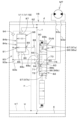
油圧システムは、図3に示すように、コントロールバルブCVと、圧油供給ユニット18と、流量制御部19とを有する。
前記コントロールバルブCVは、各種油圧アクチュエータML,MR,MT,C1~C6を制御する制御バルブV1~V10、圧油取入れ用のインレットブロックB2油排出用の一対のアウトレットブロックB1,B3を一方向に配置して集約してなるものである。
Next, a hydraulic system for operating various hydraulic actuators ML, MR, MT, C1 to C6 provided in the
The hydraulic system has a control valve CV, a pressure
The control valve CV includes control valves V1 to V10 for controlling various hydraulic actuators ML, MR, MT and C1 to C6, an inlet block B2 for taking in pressure oil, and a pair of outlet blocks B1 and B3 for discharging oil in one direction. It is arranged and aggregated.
図3に示すように、コントロールバルブCVは、本実施形態では、第1アウトレットブロックB1、作業具シリンダC5を制御する作業具制御バルブV1、ブームシリンダC3を制御するブーム制御バルブV2、ドーザシリンダC1を制御するドーザ用第1制御バルブV3、第2走行装置3Rの走行モータMRを制御する第2走行制御バルブV4、インレットブロックB2、第1走行装置3Lの走行モータMLを制御する第1走行制御バルブV5、ドーザシリンダC1を制御するドーザ用第2制御バルブV6、アームシリンダC4を制御するアーム制御バルブV7、旋回モータMTを制御する旋回制御バルブV8、スイングシリンダC2を制御するスイング制御バルブV9、作業具17として油圧アタッチメントが取り付けられた場合に該油圧アタッチメントに装備された油圧アクチュエータC6を制御するSP制御バルブV10、第2アウトレットブロックB3を、順に配置(図3においては右から順に配置)すると共にこれらを相互に連結してなる。
As shown in FIG. 3, in this embodiment, the control valves CV include a first outlet block B1, a work implement control valve V1 that controls a work implement cylinder C5, a boom control valve V2 that controls a boom cylinder C3, a dozer cylinder C1, and a dozer cylinder C1. , a second travel control valve V4 that controls the travel motor MR of the
図4~図7に示すように、各制御バルブV1~V10は、バルブボディ内に方向切換弁DV1~DV10と圧力補償弁(コンペンセータバルブ)V11とを組み込んで構成されている。方向切換弁DV1~DV10は、制御対象となる油圧アクチュエータML,MR,MT,C1~C6に対して作動油の方向を切り換える弁である。圧力補償弁V11は、方向切換弁DV1~DV10に対する圧油供給下手側で且つ制御対象となる油圧アクチュエータML,MR,MT,C1~C6に対する圧油供給上手側に配備されている。圧力補償弁V11は、制御バルブV1~V10のうちの複数を使用したときに、油圧アクチュエータML,MR,MT,C1~C6間の負荷の調整として機能する。 As shown in FIGS. 4 to 7, each of the control valves V1 to V10 includes direction switching valves DV1 to DV10 and a pressure compensation valve (compensator valve) V11 in a valve body. The direction switching valves DV1 to DV10 are valves for switching the direction of hydraulic fluid to the hydraulic actuators ML, MR, MT and C1 to C6 to be controlled. The pressure compensating valve V11 is provided on the downstream side of the pressure oil supply to the directional control valves DV1 to DV10 and on the upstream side of the pressure oil supply to the hydraulic actuators ML, MR, MT, C1 to C6 to be controlled. Pressure compensating valve V11 functions as a load regulator between hydraulic actuators ML, MR, MT and C1-C6 when using a plurality of control valves V1-V10.
第1アウトレットブロックB1には、第1リリーフ弁V12と第1アンロード弁V13とが組み込まれ、インレットブロックB2には走行独立弁V14が組み込まれている。第1リリーフ弁V12は、後述する第1圧油吐出ポートP1から吐出される作動油の圧力を規定するメインリリーフ弁である。
走行独立弁V14は、直動スプール形切換弁から構成されていると共にパイロット圧によって切換操作されるパイロット操作切換弁によって構成されている。
A first relief valve V12 and a first unload valve V13 are incorporated in the first outlet block B1, and an independent travel valve V14 is incorporated in the inlet block B2. The first relief valve V12 is a main relief valve that regulates the pressure of hydraulic oil discharged from a first pressure oil discharge port P1, which will be described later.
The independent travel valve V14 is composed of a direct-acting spool type switching valve and a pilot-operated switching valve that is switched by pilot pressure.
第2アウトレットブロックB3には、第2リリーフ弁V15と第2アンロード弁V16とが組み込まれている。第2リリーフ弁V15は、後述する第2圧油吐出ポートP2から吐出される作動油の圧力を規定するメインリリーフ弁である。
各方向切換弁DV1~DV10は、直動スプール形切換弁によって構成されている。また、各方向切換弁DV1~DV10は、制御装置U1によって電気的に制御される制御弁である。詳しくは、各方向切換弁DV1~DV10は、例えば、パイロット式の電磁弁が採用される。パイロット式の電磁弁は、ソレノイドによって制御されるパイロット圧によりスプールを動かして作動油の流れを制御する弁である。
A second relief valve V15 and a second unload valve V16 are incorporated in the second outlet block B3. The second relief valve V15 is a main relief valve that regulates the pressure of hydraulic oil discharged from a second pressure oil discharge port P2, which will be described later.
Each of the direction switching valves DV1 to DV10 is composed of a direct acting spool type switching valve. Each of the directional switching valves DV1 to DV10 is a control valve electrically controlled by the control device U1. Specifically, each of the directional switching valves DV1 to DV10 employs, for example, a pilot type solenoid valve. A pilot solenoid valve is a valve that controls the flow of hydraulic fluid by moving a spool with pilot pressure controlled by a solenoid.
図8に示すように、各方向切換弁DV1~DV10のソレノイドは、制御装置U1に接続されており、制御装置U1から送信される指令信号(電流値)に応じたパイロット圧により、各方向切換弁DV1~DV10が切り換え操作される。また、制御装置U1には、各方向切換弁DV1~DV10を操作する操作部材41(第1操作具41A~第7操作具41G)が接続されている。制御装置U1は、操作部材41の操作量に応じた電流値を操作対象の方向切換弁DV1~DV10のソレノイドに送信する。第1操作具41A、第2操作具41B、第3操作具41C及び第7操作具41Gは、例えば、操縦装置1Bに設けられ、運転席6に着座したオペレータが把持して操作するハンドルやレバーによって構成される。また、第4操作具41D、第5操作具41E及び第6操作具41Fは、例えば、運転席6の前方の床部に設けられ、オペレータの踏み操作によって操作されるペダルによって構成される。
As shown in FIG. 8, the solenoids of the direction switching valves DV1 to DV10 are connected to the control device U1, and the direction switching valves DV1 to DV10 are controlled by pilot pressure corresponding to command signals (current values) transmitted from the control device U1. The valves DV1 to DV10 are switched. Further, an operating member 41 (
第1操作具41Aは、作業機1に装備された2つの操作対象を操作可能であり、例えば、方向切換弁DV8を操作可能(機体2を旋回操作可能)であり且つ方向切換弁DV7を操作可能(アーム16を揺動操作可能)である。また、第1操作具41Aは、操作方向及び操作量を検出するセンサ42(第1センサ42A)を有している。第1センサ42Aは、制御装置U1に接続されている。制御装置U1は、第1センサ42Aからの検出信号に基づいて、旋回制御バルブV8及びアーム制御バルブV7を制御する。
The
第2操作具41Bも、作業機1に装備された2つの操作対象を操作可能であり、例えば、方向切換弁DV2を操作可能(ブーム15を揺動操作可能)であり且つ方向切換弁DV1を操作可能(作業具17を揺動操作可能)である。また、第2操作具41Bは、操作方向及び操作量を検出するセンサ(操作検出部)42(第2センサ42B)を有している。第2センサ42Bの構成は特に限定されるものではないが、例えば、ポテンショメータ等を用いることができる。第2センサ42Bは、制御装置U1に接続されている。制御装置U1は、第2センサ42Bからの検出信号に基づいて、ブーム制御バルブV2及び作業具制御バルブV1を制御する。
The
第3操作具41Cは、方向切換弁DV3及び方向切換弁DV6を操作可能(ドーザ装置7を操作可能)である。また、第3操作具41Cは、操作方向及び操作量を検出するセンサ42(第3センサ42C)を有している。第3センサ42Cは、制御装置U1に接続されている。制御装置U1は、第3センサ42Cからの検出信号に基づいて、ドーザ用第1制御バルブV3及びドーザ用第2制御バルブV6を制御する。
The
第4操作具41Dは、方向切換弁DV9を操作可能(スイングブラケット14を操作可能)である。また、第4操作具41Dは、操作方向及び操作量を検出するセンサ42(第4センサ42D)を有している。第4センサ42Dは、制御装置U1に接続されている。制御装置U1は、第4センサ42Dからの検出信号に基づいて、スイング制御バルブV9を制御する。
The
第5操作具41Eは、方向切換弁DV5を操作可能(第1走行装置3Lを操作可能)である。また、第5操作具41Eは、操作方向及び操作量を検出するセンサ42(第5センサ42E)を有している。第5センサ42Eは、制御装置U1に接続されている。制御装置U1は、第5センサ42Eからの検出信号に基づいて、第1走行制御バルブV5を制御する。
The
第6操作具41Fは、方向切換弁DV4を操作可能(第2走行装置3Rを操作可能)である。また、第6操作具41Fは、操作方向及び操作量を検出するセンサ42(第6センサ42F)を有している。第6センサ42Fは、制御装置U1に接続されている。制御装置U1は、第6センサ42Fからの検出信号に基づいて、第2走行制御バルブV4を制御する。
The
第7操作具41Gは、方向切換弁DV10を操作可能(作業具としての油圧アタッチメントを操作可能)である。また、第7操作具41Gは、操作方向及び操作量を検出するセンサ42(第7センサ42G)を有している。第7センサ42Gは、制御装置U1に接続されている。制御装置U1は、第7センサ42Gからの検出信号に基づいて、SP制御バルブV4を制御する。
The
第1センサ42A~第7センサ42Gは、例えば、ポジションセンサ等によって構成される。
各方向切換弁DV1~DV10のスプールは、該各方向切換弁DV1~DV10を操作する各操作部材41の操作量に比例して動かされ、各方向切換弁DV1~DV10が動かされた量に比例する量の作動油を制御対象の油圧アクチュエータML,MR,MT,C1~C6に供給するように構成されており、各操作部材41の操作量に比例して操作対象(制御対象)の作動速度が変速可能とされている。
The
The spools of the directional switching valves DV1 to DV10 are moved in proportion to the amount of operation of the operating
この油圧システムにおける圧油供給源としての油圧ポンプは、油圧アクチュエータML,MR,MT,C1~C6を作動させる作動油の供給用の第1ポンプ21と、パイロット圧や検出信号等の信号圧油の供給用の第2ポンプ22とが装備されている。
これら第1ポンプ21と第2ポンプ22とは、前記圧油供給ユニット18に備えられ、原動機E1によって駆動される。
Hydraulic pumps as pressure oil supply sources in this hydraulic system include a
The
前記第1ポンプ21は、本実施形態では、独立した2つの圧油吐出ポートP1,P2から等しい量の作動油を吐出する等流量ダブルポンプの機能を有する斜板形可変容量アキシャルポンプで構成されている。詳しくは、第1ポンプ21は、1つのピストン・シリンダバレルキットからバルブプレートの内外に形成した吐出溝へ交互に作動油を吐き出す機構をもったスプリットフロー式の油圧ポンプが採用されている。
In this embodiment, the
この第1ポンプ21から吐出される一方の圧油吐出ポートを第1圧油吐出ポートP1といい、他方の圧油吐出ポートを第2圧油吐出ポートP2という。
なお、本実施形態では、2つのポンプ機能を有する油圧ポンプから吐出される圧油吐出ポートを第1・2圧油吐出ポートP1,P2としているが、別個に形成された2つの油圧ポンプの一方の油圧ポンプの圧油吐出ポートを第1圧油吐出ポートとし、他方の油圧ポンプの圧油吐出ポートを第2圧油吐出ポートとしてもよい。
One pressure oil discharge port discharged from the
In this embodiment, the pressure oil discharge ports discharged from the hydraulic pumps having two pump functions are the first and second pressure oil discharge ports P1 and P2. The pressure oil discharge port of one hydraulic pump may be the first pressure oil discharge port, and the pressure oil discharge port of the other hydraulic pump may be the second pressure oil discharge port.
また、圧油供給ユニット18には、第1ポンプ21の斜板を押圧する押圧ピストン23と、第1ポンプ21の斜板を制御する流量補償用ピストン24とが装備されている。
第1ポンプ21は、該第1ポンプ21の自己圧によって押圧ピストン23を介して斜板がポンプ流量を増加する方向に押圧されるよう構成されていると共に、この押圧ピストン23の押圧力に対抗する力を前記流量補償用ピストン24によって斜板に作用させるように構成され、流量補償用ピストン24に作用する圧力を制御することにより、該第1ポンプ21の吐出流量が制御される。
The pressure
The
したがって、流量補償用ピストン24に作用する圧力が抜けると、第1ポンプ21は、斜板角がMAXとなって最大流量を吐出する。
前記流量制御部19は第1ポンプ21の斜板制御を行うものであり、該第1ポンプ21の斜板制御は、前記流量補償用ピストン24に作用する圧力を、流量制御部19に装備された流量補償用バルブV17を制御することにより行われる。
Therefore, when the pressure acting on the flow
The flow
また、圧油供給ユニット18には、第1ポンプ21のポンプ馬力(トルク)制御用のバネ25とスプール26とが設けられており、第1ポンプ21の吐出圧が、予め設定していた圧力になると、第1ポンプ21が原動機E1から吸収する馬力(トルク)を制限するよう構成されている。
前記第2ポンプ22は定容量形のギヤポンプによって構成されており、該第2ポンプ22の吐出油は第3圧油吐出ポートP3から吐出される。
In addition, the pressure
The
第1圧油吐出ポートP1は第1吐出路aを介してインレットブロックB2に接続され、第2圧油吐出ポートP2は第2吐出路bを介してインレットブロックB2に接続されている。
第1吐出路aは第1圧油供給路dに接続され、該第1圧油供給路dは、インレットブロックB2から第2走行制御バルブV4のバルブボディ→ドーザ用第1制御バルブV3のバルブボディ→ブーム制御バルブV2のバルブボディ→作業具制御バルブV1のバルブボディを経て第1アウトレットブロックB1に至るように形成され、該第1アウトレットブロックB1にて(流路終端側にて)分岐されて第1リリーフ弁V12と第1アンロード弁V13とに接続されている。
The first pressure oil discharge port P1 is connected to the inlet block B2 via the first discharge passage a, and the second pressure oil discharge port P2 is connected to the inlet block B2 via the second discharge passage b.
The first discharge passage a is connected to a first pressure oil supply passage d. The first pressure oil supply passage d extends from the inlet block B2 to the valve body of the second travel control valve V4→the valve of the first dozer control valve V3. It is formed so as to reach the first outlet block B1 via the body→the valve body of the boom control valve V2→the valve body of the work tool control valve V1, and is branched at the first outlet block B1 (at the end of the flow path). are connected to the first relief valve V12 and the first unload valve V13.
前記第1圧油供給路dから第2走行制御バルブV4、ドーザ用第1制御バルブV3、ブーム制御バルブV2、作業具制御バルブV1の各方向切換弁DV4,DV3,DV2,DV1に圧油分岐路fを介して作動油が供給可能とされている。
第1リリーフ弁V12と第1アンロード弁V13とはドレン油路gに接続されている。ドレン油路gは、第1アウトレットブロックB1から作業具制御バルブV1のバルブボディ→ブーム制御バルブV2のバルブボディ→ドーザ用第1制御バルブV3のバルブボディ→第2走行制御バルブV4のバルブボディ→インレットブロックB2→第1走行制御バルブV5のバルブボディ→ドーザ用第2制御バルブV6のバルブボディ→アーム制御バルブV7のバルブボディ→旋回制御バルブV8のバルブボディ→スイング制御バルブV9のバルブボディ→SP制御バルブV10のバルブボディを経て第2アウトレットブロックB3に至るように形成されている。ドレン油路gを流れる作動油は、第2アウトレットブロックB3から作動油タンクT2へ排出される。
From the first pressure oil supply path d, a pressure oil branch path to each direction switching valve DV4, DV3, DV2, DV1 of the second travel control valve V4, the first dozer control valve V3, the boom control valve V2, and the work tool control valve V1. Hydraulic oil can be supplied via f.
The first relief valve V12 and the first unload valve V13 are connected to the drain oil passage g. The drain oil passage g runs from the first outlet block B1 to the work implement control valve V1 valve body→boom control valve V2 valve body→dozer first control valve V3 valve body→second travel control valve V4 valve body→ Inlet block B2→valve body of first travel control valve V5→valve body of second dozer control valve V6→valve body of arm control valve V7→valve body of swing control valve V8→valve body of swing control valve V9→SP It is formed to reach the second outlet block B3 through the valve body of the control valve V10. Hydraulic oil flowing through the drain oil passage g is discharged from the second outlet block B3 to the hydraulic oil tank T2.
第2吐出路bは第2圧油供給路eに接続されている。第2圧油供給路eはインレットブロックB2から第1走行制御バルブV5のバルブボディ→ドーザ用第2制御バルブV6のバルブボディ→アーム制御バルブV7のバルブボディ→旋回制御バルブV8のバルブボディ→スイング制御バルブV9のバルブボディ→SP制御バルブV10のバルブボディを経て第2アウトレットブロックB3に至るように形成されると共に、第2アウトレットブロックB3にて(流路終端側にて)分岐されて第2リリーフ弁V15と第2アンロード弁V16とに接続されている。 The second discharge passage b is connected to the second pressure oil supply passage e. The second pressure oil supply path e is from the inlet block B2 to the valve body of the first travel control valve V5→the valve body of the second dozer control valve V6→the valve body of the arm control valve V7→the valve body of the turning control valve V8→swing. It is formed so as to reach the second outlet block B3 via the valve body of the control valve V9→the valve body of the SP control valve V10, and is branched at the second outlet block B3 (at the end of the flow path) to form the second outlet block B3. It is connected to the relief valve V15 and the second unload valve V16.
前記第2圧油供給路eから第1走行制御バルブV5、ドーザ用第2制御バルブV6、アーム制御バルブV7、旋回制御バルブV8、スイング制御バルブV9、SP制御バルブV10の各方向切換弁DV5,DV6,DV7,DV8,DV9,DV10に圧油分岐路hを介して作動油が供給可能とされている。
各制御バルブV1~V10に供給された作動油は、各油圧アクチュエータML,MR,MT,C1~C6に対して給排される。つまり、油圧システムは、各油圧アクチュエータML,MR,MT,C1~C6に作動油を給排する油圧回路を有している。
Direction switching valves DV5 of a first travel control valve V5, a second dozer control valve V6, an arm control valve V7, a swing control valve V8, a swing control valve V9, and an SP control valve V10 are connected from the second pressure oil supply passage e. Hydraulic oil can be supplied to DV6, DV7, DV8, DV9, and DV10 via a pressure oil branch passage h.
The hydraulic fluid supplied to each control valve V1-V10 is supplied to and discharged from each hydraulic actuator ML, MR, MT, C1-C6. That is, the hydraulic system has a hydraulic circuit for supplying and discharging working oil to each of the hydraulic actuators ML, MR, MT, C1-C6.
第2リリーフ弁V15と第2アンロード弁V16とはドレン油路gに接続されている。
第1圧油供給路dと第2圧油供給路eとは、インレットブロックB2内において、走行独立弁V14を横切る連通路jを介して相互に接続されている。
走行独立弁V14は、連通路jの圧油流通を遮断する独立位置27と、連通路jの圧油流通を許容する合流位置28とに切換自在とされている。
The second relief valve V15 and the second unload valve V16 are connected to the drain oil passage g.
The first pressure oil supply path d and the second pressure oil supply path e are connected to each other via a communication path j that traverses the independent travel valve V14 in the inlet block B2.
The independent travel valve V14 is switchable between an
走行独立弁V14が独立位置27に切り換えられていると、第1圧油吐出ポートP1からの作動油が第2走行制御バルブV4、ドーザ用第1制御バルブV3の各方向切換弁DV4,DV3に供給可能とされると共に、第2圧油吐出ポートP2からの作動油が第1走行制御バルブV5、ドーザ用第2制御バルブV6の各方向切換弁DV5,DV6に供給可能とされ、第1圧油吐出ポートP1からの作動油が第1走行制御バルブV5、ドーザ用第2制御バルブV6には供給されず、また、第2圧油吐出ポートP2からの作動油が第2走行制御バルブV4、ドーザ用第1制御バルブV3には供給されない。
When the independent travel valve V14 is switched to the
また、走行独立弁V14が合流位置28に切り換えられると、第1圧油吐出ポートP1からの作動油と第2圧油吐出ポートP2からの作動油とが合流されて各制御バルブV1~V10の方向切換弁DV1~DV10に供給可能とされる。
第3圧油吐出ポートP3は第3吐出路mを介してインレットブロックB2に接続され、該第3吐出路mは、途中で第1分岐油路m1と第2分岐油路m2とに分岐されてインレットブロックB2に接続されている。
Further, when the independent travel valve V14 is switched to the merging
The third pressure oil discharge port P3 is connected to the inlet block B2 via a third discharge passage m, and the third discharge passage m is branched into a first branched oil passage m1 and a second branched oil passage m2. connected to the inlet block B2.
第1分岐油路m1は第1信号油路n1を介して走行独立弁V14の一側の受圧部14aに接続され、第2分岐油路m2は第2信号油路n2を介して走行独立弁V14の他側の受圧部14bに接続されている。
前記第1信号油路n1には第1検出油路r1が接続され、前記第2信号油路n2には第2検出油路r2が接続されている。
The first branch oil passage m1 is connected to the
A first detection oil passage r1 is connected to the first signal oil passage n1, and a second detection oil passage r2 is connected to the second signal oil passage n2.
前記第1検出油路r1は、第1信号油路n1からドーザ用第2制御バルブV6の方向切換弁DV6→第1走行制御バルブV5の方向切換弁DV5→第2走行制御バルブV4の方向切換弁DV4→ドーザ用第1制御バルブV3の方向切換弁DV3を経てドレン油路gに接続されている。
前記第2検出油路r2は、第2信号油路n2からSP制御バルブV10の方向切換弁DV10→スイング制御バルブV9の方向切換弁DV9→旋回制御バルブV8の方向切換弁DV8→アーム制御バルブV7の方向切換弁DV7→ドーザ用第2制御バルブV6の方向切換弁DV6→第1走行制御バルブV5の方向切換弁DV5→第2走行制御バルブV4の方向切換弁DV4→ドーザ用第1制御バルブV3の方向切換弁DV3→ブーム制御バルブV2の方向切換弁DV2→作業具制御バルブV1の方向切換弁DV1を経てドレン油路gに接続されている。
The first detection oil passage r1 is arranged from the first signal oil passage n1 to the direction switching valve DV6 of the second dozer control valve V6→the direction switching valve DV5 of the first travel control valve V5→the direction switching of the second travel control valve V4. The valve DV4 is connected to the drain oil passage g via the directional switching valve DV3 of the first dozer control valve V3.
The second detection oil passage r2 is arranged from the second signal oil passage n2 to the direction switching valve DV10 of the SP control valve V10→the direction switching valve DV9 of the swing control valve V9→the direction switching valve DV8 of the swing control valve V8→the arm control valve V7. directional switching valve DV7→direction switching valve DV6 of second dozer control valve V6→direction switching valve DV5 of first travel control valve V5→direction switching valve DV4 of second travel control valve V4→first dozer control valve V3 →the direction switching valve DV2 of the boom control valve V2→the direction switching valve DV1 of the work tool control valve V1 to the drain oil passage g.
前記走行独立弁V14は、各制御バルブV1~V10の方向切換弁DV1~DV10が中立である場合は、バネの力によって合流位置28に保持されている。
そして、第2走行制御バルブV4、第1走行制御バルブV5、ドーザ用第1制御バルブV3、ドーザ用第2制御バルブV6の各方向切換弁DVのいずれかが中立位置から操作されたときに、第1検出油路r1及び第1信号油路n1に圧が立って、走行独立弁V14が合流位置28から独立位置27に切り換えられる。
The independent travel valve V14 is held at the merging
When any one of the direction switching valves DV of the second travel control valve V4, the first travel control valve V5, the first dozer control valve V3, and the second dozer control valve V6 is operated from the neutral position, The independent travel valve V14 is switched from the
したがって、走行のみする場合、走行しながらドーザ装置7を使用する場合、又は、ドーザ装置7のみ使用する場合には、第1圧油吐出ポートP1からの作動油が第2走行制御バルブV4、ドーザ用第1制御バルブV3の各方向切換弁DVに供給され、且つ、第2圧油吐出ポートP2からの作動油が第1走行制御バルブV5、ドーザ用第1制御バルブV3の各方向切換弁DVに供給される。
Therefore, when only traveling, when using the
このとき、SP制御バルブV10、スイング制御バルブV9、旋回制御バルブV8、アーム制御バルブV7、ブーム制御バルブV2、作業具制御バルブV1の方向切換弁DV10,DV9,DV8,DV7,DV2,DV1のいずれかが中立位置から操作されたときには、第2検出油路r2及び第2信号油路n2に圧が立って、走行独立弁V14が独立位置27から合流位置28に切り換えられる。
At this time, any of the SP control valve V10, the swing control valve V9, the swing control valve V8, the arm control valve V7, the boom control valve V2, and the directional switching valves DV10, DV9, DV8, DV7, DV2, and DV1 of the work implement control valve V1 When V is operated from the neutral position, pressure builds up in the second detection oil passage r2 and the second signal oil passage n2, and the travel independent valve V14 is switched from the
また、各制御バルブV1~V10の方向切換弁DV1~DV10が中立である場合において、SP制御バルブV10、スイング制御バルブV9、旋回制御バルブV8、アーム制御バルブV7、ブーム制御バルブV2、作業具制御バルブV1の方向切換弁DV10,DV9,DV8,DV7,DV2,DV1のいずれかが中立位置から操作されたときにも、走行独立弁V14は合流位置28である。
Further, when the directional switching valves DV1 to DV10 of the respective control valves V1 to V10 are neutral, the SP control valve V10, the swing control valve V9, the turning control valve V8, the arm control valve V7, the boom control valve V2, the work implement control valve The independent travel valve V14 is also at the merging
したがって、非走行時又は走行時において、ブーム15、アーム16、作業具17、スイングブラケット14、機体2、ドーザ装置7の同時操作が可能とされている。
また、この油圧システムにあっては、原動機E1のアクセル装置を自動的に操作するオートアイドリング制御システム(AIシステム)が備えられている。
このAIシステムは、第3吐出路mの第1分岐油路m1と第2分岐油路m2とに感知油路s及びシャトル弁V18を介して接続されたAIスイッチ(圧力スイッチ)29と、原動機E1のガバナを制御する電気アクチュエータと、この電気アクチュエータを制御する制御装置とを備え、前記AIスイッチ29は制御装置に接続されている。
Therefore, the
This hydraulic system is also provided with an auto idling control system (AI system) that automatically operates the accelerator device of the prime mover E1.
This AI system includes an AI switch (pressure switch) 29 connected to the first branched oil passage m1 and the second branched oil passage m2 of the third discharge passage m via the sensing oil passage s and the shuttle valve V18, It has an electric actuator that controls the governor of E1 and a control device that controls this electric actuator, and the
このAIシステムにあっては、各制御バルブV1~V10の方向切換弁DV1~DV10が中立であるときには、第1分岐油路m1と第2分岐油路m2とに圧が立たないので、AIスイッチ29が感圧作動することがなく、この状態では、ガバナが、予め設定されているアイドリング位置にまでアクセルダウンするよう電気アクチュエータ等によって自動制御される。 In this AI system, when the directional switching valves DV1 to DV10 of the control valves V1 to V10 are neutral, the first branch oil passage m1 and the second branch oil passage m2 are not pressurized. In this state, the governor is automatically controlled by an electric actuator or the like to decelerate to a preset idling position.
また、制御バルブV1~V10の方向切換弁DV1~DV10のうちのいずれか一つでも操作されると、第1分岐油路m1又は第2分岐油路m2に圧が立ち、この圧がAIスイッチ29によって感知されて該AIスイッチ29が感圧作動する。すると、制御装置から電気アクチュエータ等に指令信号が出され、該電気アクチュエータ等によってガバナが設定されたアクセル位置までアクセルアップするよう自動制御される。
Further, when any one of the direction switching valves DV1 to DV10 of the control valves V1 to V10 is operated, the pressure rises in the first branch oil passage m1 or the second branch oil passage m2, and this pressure is applied to the AI switch. 29 to operate the
また、この油圧システムにあってはロードセンシングシステムが採用されている。
本実施形態のロードセンシングシステムは、各制御バルブV1~V10に設けられた圧力補償弁V11、第1ポンプ21の斜板を制御する流量補償用ピストン24、前記流量制御部19に装備された流量補償用バルブV17、前記第1・2リリーフ弁V12,V15、前記第1・2アンロード弁V13,V16を有する。
In addition, a load sensing system is employed in this hydraulic system.
The load sensing system of this embodiment includes a pressure compensating valve V11 provided in each of the control valves V1 to V10, a flow
また、本実施形態のロードセンシングシステムは、圧力補償弁V11が方向切換弁DV1~DV10に対する圧油供給下手側に配備されたアフターオリフィス型のロードセンシングシステムが採用されている。
このロードセンシングシステムにあっては、作業機1に装備された油圧アクチュエータML,MR,MT,C1~C6の複数を同時操作したとき、該油圧アクチュエータML,MR,MT,C1~C6間の負荷の調整として圧力補償弁V11が機能し、低負荷圧側の制御バルブV1~V10に最高負荷圧との差圧分の圧力損失を発生させ、負荷の大きさによらず、方向切換弁DV1~DV10のスプールの操作量に応じた流量を流す(配分する)ことができる。
Further, the load sensing system of the present embodiment employs an after-orifice type load sensing system in which the pressure compensating valve V11 is arranged on the downstream side of the pressure oil supply to the direction switching valves DV1 to DV10.
In this load sensing system, when a plurality of the hydraulic actuators ML, MR, MT, C1-C6 provided in the working
また、ロードセンシングシステムは、作業機1に装備された各油圧アクチュエータML,MR,MT,C1~C6の負荷圧に応じて第1ポンプ21の吐出量を制御して、負荷に必要とされる油圧動力を第1ポンプ21から吐出させることにより、動力の節約と操作性を向上することができる。
本実施形態のロードセンシングシステムをさらに詳しく説明する。
In addition, the load sensing system controls the discharge amount of the
The load sensing system of this embodiment will be described in more detail.
ロードセンシングシステムは、各制御バルブV1~V10の負荷圧のうちの最高の負荷圧をPLS信号圧として流量補償用バルブV17に伝達するPLS信号油路wと、第1ポンプ21の吐出圧をPPS信号圧として流量補償用バルブV17に伝達するPPS信号油路xとを有する。
PLS信号油路wは、第1アウトレットブロックB1から作業具制御バルブV1のバルブボディ→ブーム制御バルブV2のバルブボディ→ドーザ用第1制御バルブV3のバルブボディ→第2走行制御バルブV4のバルブボディにわたって設けられると共に、走行独立弁V14を横切って第1走行制御バルブV5のバルブボディ→ドーザ用第2制御バルブV6のバルブボディ→アーム制御バルブV7のバルブボディ→旋回制御バルブV8のバルブボディ→スイング制御バルブV9のバルブボディ→SP制御バルブV10のバルブボディ→第2アウトレットブロックB3にわたって設けられており、該PLS信号油路wは各制御バルブにおいて、圧力補償弁V11に負荷伝達ラインyを介して接続されている。
The load sensing system includes a PLS signal oil passage w that transmits the highest load pressure among the load pressures of the control valves V1 to V10 as a PLS signal pressure to the flow rate compensating valve V17, and a discharge pressure of the
The PLS signal oil path w runs from the first outlet block B1 to the valve body of the work implement control valve V1→the valve body of the boom control valve V2→the valve body of the first dozer control valve V3→the valve body of the second travel control valve V4. The valve body of the first travel control valve V5→valve body of the second dozer control valve V6→valve body of the arm control valve V7→valve body of the swing control valve V8→swing across the independent travel valve V14. The PLS signal oil passage w extends from the valve body of the control valve V9 to the valve body of the SP control valve V10 to the second outlet block B3. It is connected.
また、このPLS信号油路wは、第2アウトレットブロックB3から流量補償用バルブV17のスプールの一側に接続され、PPS信号圧が流量補償用バルブV17のスプールの一側に作用する。
さらに、PLS信号油路wは、第1アウトレットブロックB1において第1アンロード弁V13とドレン油路gに接続され、第2アウトレットブロックB3において第2アンロード弁V16とドレン油路gに接続されている。
The PLS signal oil passage w is connected from the second outlet block B3 to one side of the spool of the flow rate compensating valve V17, and the PPS signal pressure acts on one side of the spool of the flow rate compensating valve V17.
Further, the PLS signal oil passage w is connected to the first unload valve V13 and the drain oil passage g in the first outlet block B1, and is connected to the second unload valve V16 and the drain oil passage g in the second outlet block B3. ing.
前記走行独立弁V14が合流位置28にあるときには、PLS信号油路wの、走行独立弁V14から第1アウトレットブロックB1に至るラインw1と、走行独立弁V14から第2アウトレットブロックB3に至るラインw2とが連通しており、走行独立弁V14が合流位置28から独立位置27に切り換えられると、該走行独立弁V14にてPLS信号油路wが遮断される。
When the independent travel valve V14 is at the merging
これによって、PLS信号油路wが、走行独立弁V14を独立位置27にしたときに、第1圧油吐出ポートP1から作動油が供給される側のラインw1と、第2圧油吐出ポートP2から圧油が供給される側のラインw2とに分断される。
PPS信号油路xは、走行独立弁V14から流量補償用バルブV17のスプールの他側にわたって設けられており、該PPS信号油路xは、走行独立弁V14が合流位置28にあるときには第2圧油供給路eに接続油路zを介して連通されていてPPS信号圧(第1ポンプ21の吐出圧)が流量補償用バルブV17のスプールの他側に作用し、走行独立弁V14が独立位置27に切り換えられると、該PPS信号油路xは逃し油路qを介してドレン油路gに連通し、PPS信号圧が零となるよう構成されている。
As a result, when the independent travel valve V14 is set to the
The PPS signal oil passage x extends from the independent travel valve V14 to the other side of the spool of the flow rate compensating valve V17. The PPS signal pressure (discharge pressure of the first pump 21) acts on the other side of the spool of the flow rate compensating valve V17, and the travel independent valve V14 is in the independent position. 27, the PPS signal oil passage x communicates with the drain oil passage g via the escape oil passage q, and the PPS signal pressure becomes zero.
また、流量補償用バルブV17のスプールの一側には、該流量補償用バルブV17に制御差圧を与えるバネ30と差圧ピストン31とが設けられている。
前記構成の油圧システムにあっては、各制御バルブV1~V10の方向切換弁DV1~DV10が中立位置にあるときには走行独立弁V14が合流位置28であり、このとき、第1圧油供給路dの流路終端側が第1アンロード弁V13によってブロックされ且つ第2圧油供給路eの流路終端側が第2アンロード弁V16によってブロックされるようになっている。したがって、第1ポンプ21の吐出圧(PPS信号圧)が上昇し、このPPS信号圧とPLS信号圧(この時は零である)との差が制御差圧よりも大きくなると、第1ポンプ21が吐出量を減少させる方向に流量制御されると共に第1・第2アンロード弁V16が開いて第1ポンプ21からの吐出油を作動油タンクT2に落とす。
A spring 30 and a differential pressure piston 31 for applying a control differential pressure to the flow compensation valve V17 are provided on one side of the spool of the flow compensation valve V17.
In the hydraulic system configured as described above, when the directional switching valves DV1 to DV10 of the respective control valves V1 to V10 are in the neutral position, the independent travel valve V14 is in the
したがって、この状態では、第1ポンプ21の吐出圧は第1・第2アンロード弁V13,V16で設定される圧となり、第1ポンプ21の吐出流量は最小吐出量となる。
次に、ブームシリンダC3、アームシリンダC4、作業具シリンダC5、スイングシリンダC2、旋回モータMT、油圧アタッチメントのうちのいずれか二つ以上を同時操作する場合、又は、これらの一つ以上と、左右走行モータML,MR、ドーザシリンダC1のうちのいずれか一つ以上とを同時操作する場合について説明する。
Therefore, in this state, the discharge pressure of the
Next, when any two or more of the boom cylinder C3, the arm cylinder C4, the work implement cylinder C5, the swing cylinder C2, the swing motor MT, and the hydraulic attachment are operated simultaneously, or when one or more of these and the left and right A case in which one or more of the travel motors ML, MR and the dozer cylinder C1 are simultaneously operated will be described.
この場合にあっては、走行独立弁V14は合流位置28であり、操作された油圧アクチュエータML,MR,MT,C1~C6に作用する最高負荷圧がPLS信号圧となり、PPS信号圧-PLS信号圧が制御差圧となるように(PPS信号圧とPLS信号圧との差を設定値に維持するように)第1ポンプ21の吐出圧(吐出流量)が自動制御される。
すなわち、第1・第2アンロード弁V13,V16を介してのアンロード流量が零になると、第1ポンプ21の吐出流量が増加し始め、操作された制御バルブの操作量に応じて第1ポンプ21の吐出油の全量が操作された油圧アクチュエータML,MR,MT,C1~C6に流れる。
In this case, the independent travel valve V14 is at the
That is, when the unload flow rate through the first and second unload valves V13 and V16 becomes zero, the discharge flow rate of the
また、圧力補償弁V11によって、操作された制御バルブV1~V10の方向切換弁DV1~DV10のスプールの前後差圧が一定となり、操作された油圧アクチュエータML,MR,MT,C1~C6に作用する負荷の大きさの違いにかかわらず、第1ポンプ21の吐出流量が、操作された各油圧アクチュエータML,MR,MT,C1~C6に対して操作量に応じた量、分流される。
Further, the differential pressure across the spools of the directional switching valves DV1 to DV10 of the operated control valves V1 to V10 is made constant by the pressure compensating valve V11, and acts on the operated hydraulic actuators ML, MR, MT, C1 to C6. Regardless of the difference in the magnitude of the load, the discharge flow rate of the
なお、油圧アクチュエータML,MR,MT,C1~C6の要求流量が第1ポンプ21の最大吐出流量を超える場合は、第1ポンプ21の吐出油は操作された各油圧アクチュエータML,MR,MT,C1~C6に比例配分される。
前記場合にあっては、効率的なシステムで同時操作(複合操作)が可能となる。
次に、走行しながらドーザ装置7によって土工作業をする場合について説明する。
When the required flow rate of the hydraulic actuators ML, MR, MT, C1 to C6 exceeds the maximum discharge flow rate of the
In the above case, simultaneous operations (compound operations) are possible in an efficient system.
Next, a case where earthwork is carried out by the
この場合にあっては、走行独立弁V14が独立位置27に切り換えられ、該走行独立弁V14によって、連通路j及びPLS信号油路wが遮断され、また、PPS信号油路xは逃し油路qを介してドレン油路gに連通し、PPS信号圧が零となる。
したがって、第1圧油吐出ポートP1からの作動油は第2走行制御バルブV4及びドーザ用第1制御バルブV3に流れ、第1走行制御バルブV5及びドーザ用第2制御バルブV6には流れない。また、第2圧油吐出ポートP2からの作動油は第1走行制御バルブV5及びドーザ用第2制御バルブV6に流れ、走行右制御バルブV4及びドーザ用第1制御バルブV3には流れない。さらに、PPS信号圧が零であるので、第1ポンプ21は斜板角がMAXとなって最大流量を吐出する。
In this case, the independent travel valve V14 is switched to the
Therefore, hydraulic fluid from the first pressure oil discharge port P1 flows to the second travel control valve V4 and the first dozer control valve V3, but does not flow to the first travel control valve V5 and the second dozer control valve V6. The hydraulic oil from the second pressure oil discharge port P2 flows to the first travel control valve V5 and the second dozer control valve V6, but does not flow to the right travel control valve V4 and the first dozer control valve V3. Furthermore, since the PPS signal pressure is zero, the
本実施形態の油圧システムにあっては、ドーザ用第1制御バルブV3及びドーザ用第2制御バルブV6によって、第1圧油供給路dと第2圧油供給路eとから作動油が均等に抜き取られてドーザシリンダC1に送られるので、作業機1の走行直進性を確保することができる。
また、作業機1を左右一方にターンさせる場合にあっては、圧力補償弁V11が分流制御するため、走行モータML,MRにかかる負荷が高く、ドーザシリンダC1にかかる負荷が低くても、設定流量以上の作動油がドーザシリンダC1に流入しないことから、第1圧油吐出ポートP1からの作動油を第2走行制御バルブV4に、第2圧油吐出ポートP2からの作動油を第1走行制御バルブV5に、それぞれ独立して供給するという独立回路構成を維持でき且つ第1、2圧油吐出ポートP1,P2からの作動油が均等に抜き取られるので、左右の走行モータML,MRへの圧油供給流量が確保され、ターン性能を確保することができる。
In the hydraulic system of this embodiment, the first dozer control valve V3 and the second dozer control valve V6 evenly distribute the working oil from the first pressure oil supply path d and the second pressure oil supply path e. Since it is extracted and sent to the dozer cylinder C1, it is possible to ensure straight traveling of the work implement 1. - 特許庁
Further, when the work implement 1 is turned to one of the left and right sides, the pressure compensating valve V11 performs branch flow control. Since hydraulic oil exceeding the flow rate does not flow into the dozer cylinder C1, the hydraulic oil from the first pressure oil discharge port P1 is applied to the second travel control valve V4, and the hydraulic oil from the second pressure oil discharge port P2 is applied to the first travel control valve V4. Since the independent circuit configuration in which the control valve V5 is independently supplied to each of the control valves V5 can be maintained, and the hydraulic oil from the first and second pressure oil discharge ports P1 and P2 is evenly withdrawn, the left and right travel motors ML and MR can be supplied with the hydraulic oil. The pressure oil supply flow rate is ensured, and the turning performance can be ensured.
例えば、ドーザシリンダを制御するドーザ用制御バルブが1つである場合、該ドーザ用制御バルブは、第1圧油供給路又は第2圧油供給路の一方から作動油が供給されるように設けられるが、この場合、該一方の圧油供給路からドーザシリンダに作動油がとられると、直進走行の場合には斜行するという問題が生じる。また、ターンする場合には、ドーザ用制御バルブを設けた側の圧油供給系統の圧力損失が大きく、動きが遅くなる(具体的には、第1圧油吐出ポートP1からの圧油供給系統にドーザ用制御バルブを設けた場合、ドーザ装置7を操作しながら左ターンする場合では動くが、ドーザ装置7を操作しながら右ターンする場合は、ドーザ装置7を操作した時点で、動きが遅くなる)。
For example, when there is one dozer control valve for controlling the dozer cylinder, the dozer control valve is provided so that hydraulic oil is supplied from either the first pressure oil supply passage or the second pressure oil supply passage. However, in this case, if hydraulic oil is taken from the one pressure oil supply passage to the dozer cylinder, there arises a problem that the dozer cylinder travels obliquely when traveling straight ahead. Also, when turning, the pressure loss in the pressure oil supply system on the side where the dozer control valve is provided is large, and the movement becomes slow (specifically, the pressure oil supply system from the first pressure oil discharge port P1 When a dozer control valve is provided in the dozer, when the
また、ドーザシリンダを制御するドーザ用制御バルブを1つとし、第1圧油供給路、及び第2圧油供給路の両方から均等にドーザ用制御バルブに作動油を送るように構成することが考えられるが、この場合、直進性を確保することは可能ではあるが、ターン性能が大幅に低下する。
すなわち、ターン時にあっては、ドーザシリンダに高圧側の圧油供給路から多くの流量の作動油が流入してしまう為にターン性能が大幅に低下するのである。
Further, the dozer cylinder may be controlled by a single dozer control valve, and the working oil may be equally supplied to the dozer control valve from both the first pressure oil supply passage and the second pressure oil supply passage. Conceivably, in this case, although it is possible to ensure straightness, the turning performance is significantly degraded.
That is, at the time of turning, a large amount of hydraulic oil flows into the dozer cylinder from the pressure oil supply passage on the high pressure side, so that the turning performance is greatly deteriorated.
また、この場合、第1圧油吐出ポートP1からの作動油か、或いは第2圧油吐出ポートP2からの作動油かのどちらの信号を基準に分流制御するのか、回路構成上決められないので、ロードセンシングシステムの構成が困難になる。
また、走行しながらドーザ装置7によって土工作業をする場合にあっては、走行独立弁V14が独立位置27になると、PLS信号油路wも遮断されるので、第1圧油吐出ポートP1からの圧油供給系統と第2圧油吐出ポートP2からの圧油供給系統との間で、負荷信号の干渉がなく、作動油を走行用制御バルブV4,V5とドーザ用制御バルブV3,V6とに分流し且つ余剰の作動油をアンロード弁V13,V16から作動油タンクT2へ排出させるという制御を、第1圧油吐出ポートP1からの圧油供給系統、第2圧油吐出ポートP2からの圧油供給系統のそれぞれの回路で独立して行うことができ、圧力補償弁V11の機能を確保することができる。
Further, in this case, it is not possible to determine whether the branch control is performed based on the signal of the hydraulic fluid from the first pressure oil discharge port P1 or the hydraulic fluid from the second pressure oil discharge port P2 due to the circuit configuration. , making it difficult to configure the load sensing system.
In the case of carrying out earthwork work with the
また、走行体1Aのみ或いはドーザ装置7のみ駆動する場合も、前記走行しながらドーザ装置7によって土工作業をする場合と同様、走行独立弁V14が独立位置27に切り換えられ、該走行独立弁V14によって、連通路j及びPLS信号油路wが遮断され、また、PPS信号油路xは逃し油路を介してドレン油路gに連通し、PPS信号圧が零となる。
Also, when only the traveling body 1A or only the
また、各走行用制御バルブV4,V5を第1ポンプ21の圧油吐出ポートP1,P2からの圧油供給系統の最上流側に配置しているので、第1ポンプ21から走行モータML,MRに至る油圧管路における圧力損失(圧損)の低減を図ることができる。
なお、前記構成の油圧システムにあっては、第1ポンプ21は、スプリットフロー式の油圧ポンプが採用されていて、第1圧油吐出ポートP1からの吐出流量と、第2圧油吐出ポートP2からの吐出流量とを独立して制御できないものであるので、第1圧油供給路dと第2圧油供給路eとを独立させる際(合流させない場合)において、第1ポンプ21の吐出流量が最大となるように構成しているが、2つの油圧ポンプを設け、この2つの油圧ポンプのうちの一方の油圧ポンプの吐出ポートを第1圧油吐出ポートP1とし、他方の油圧ポンプの吐出ポートを第2圧油吐出ポートP2とする場合は、各油圧ポンプは、走行独立弁V14が独立位置27の場合でも、それぞれ独立に制御して、必要流量のみ吐出させるよう構成される(この場合でも、2つの油圧ポンプが合流時に同時に最大流量を吐出するように制御してもよい)。
Further, since the travel control valves V4 and V5 are arranged on the most upstream side of the pressure oil supply system from the pressure oil discharge ports P1 and P2 of the
In the hydraulic system having the above configuration, the
また、ドーザ装置7のみを操作したときに、走行独立弁V14が合流位置28になるように構成することも考えられるが、そうすると、走行しながらドーザ装置7を操作した場合において、走行独立弁V14を独立位置27に保持するために、ドーザ用制御バルブV3,V6の方向切換弁DV3,DV6を操作したことを検出するための第3の検出油路を設けなければならず、検出回路の回路構成構成が複雑化するが、本実施形態では、第1検出油路r1で走行用制御バルブV4,V5及び/又はドーザ用制御バルブV3,V6を操作したことを検出するよう構成しているので、検出回路の回路構成の簡素化を図ることができる。
It is also conceivable to configure the independent travel valve V14 to be in the
また、本実施形態の油圧システムにあっては、走行用制御バルブV4,V5とドーザ用制御バルブV3,V6とを並べて配置し、且つ、一方の走行用制御バルブV4及び一方のドーザ用制御バルブV3と、他方の走行用制御バルブV5及び他方のドーザ用制御バルブV6とを走行独立弁V14を挟んで配置しているので、走行用制御バルブV4,V5及び/又はドーザ用制御バルブV3,V6を操作したことを検出する検出回路の回路構成の簡素化を図ることができる。 In the hydraulic system of this embodiment, the control valves V4 and V5 for travel and the control valves V3 and V6 for dozers are arranged side by side, and one travel control valve V4 and one dozer control valve Since V3, the other travel control valve V5 and the other dozer control valve V6 are arranged with the travel independent valve V14 interposed therebetween, the travel control valves V4, V5 and/or the dozer control valves V3, V6 It is possible to simplify the circuit configuration of the detection circuit that detects that the
なお、制御バルブV1~V10、インレットブロックB2の配列としては、図例の配列に限定されることはなく、2つの独立した圧油吐出ポートP1,P2からの圧油供給系統のうちの一方に、一方の走行用制御バルブV4,V5及び一方のドーザ用制御バルブV3,V6並びに一方のアウトレットブロックB1,B3を設け、他方の圧油供給系統に、他方の走行用制御バルブV4,V5及び他方のドーザ用制御バルブV3,V6並びに他方のアウトレットブロックB1,B3を設けていれば、その他の制御バルブV1,V2,V7~10の配置は特に限定はされない。 The arrangement of the control valves V1 to V10 and the inlet block B2 is not limited to the arrangement shown in the drawing. , one traveling control valves V4, V5, one dozer control valves V3, V6, and one outlet block B1, B3 are provided. The arrangement of the other control valves V1, V2, V7-10 is not particularly limited as long as the other dozer control valves V3, V6 and the other outlet blocks B1, B3 are provided.
また、各制御バルブV1~V10の配列方向の順番も限定されることはない。
図4に示すように、第1リリーフ弁V12及び第2リリーフ弁V15は、電磁式の可変リリーフ弁によって構成されている。第1リリーフ弁V12及び第2リリーフ弁V15(可変リリーフ弁)は、第1ポンプ21(ポンプ)から吐出される作動油の圧力を変更可能に規定する。以下、第1リリーフ弁V12及び第2リリーフ弁V15で規定(設定)される設定圧力であるリリーフセット圧を、メインリリーフ圧という。
Also, the order in which the control valves V1 to V10 are arranged is not limited.
As shown in FIG. 4, the first relief valve V12 and the second relief valve V15 are composed of electromagnetic variable relief valves. The first relief valve V12 and the second relief valve V15 (variable relief valve) variably regulate the pressure of hydraulic fluid discharged from the first pump 21 (pump). Hereinafter, the relief set pressure, which is the set pressure defined (set) by the first relief valve V12 and the second relief valve V15, is referred to as main relief pressure.
図8に示すように、第1リリーフ弁V12のソレノイドV12aと第2リリーフ弁V15のソレノイドV15aは、制御装置U1に接続されている。つまり、第1リリーフ弁V12及び第2リリーフ弁V15は、制御装置U1によって制御される。
図9に示すように、作業機1は、メインリリーフ圧を変更する複数のモードを有している。本実施形態では、複数のモードは、第1モード(ハードモード)、第2モード(ノーマルモード)、第3モード(ソフトモード)である。例えば、ハードモードは、標準作業を行うときのモードであり、ノーマルモードは、軽作業を行うときのモードであり、ソフトモードは、整地作業を行うときのモードである。
As shown in FIG. 8, the solenoid V12a of the first relief valve V12 and the solenoid V15a of the second relief valve V15 are connected to the control device U1. That is, the first relief valve V12 and the second relief valve V15 are controlled by the control device U1.
As shown in FIG. 9, the work implement 1 has a plurality of modes for changing the main relief pressure. In this embodiment, the multiple modes are a first mode (hard mode), a second mode (normal mode), and a third mode (soft mode). For example, the hard mode is for standard work, the normal mode is for light work, and the soft mode is for leveling work.
図8に示すように、制御装置U1には、モード切換えスイッチ43が接続されている。また、制御装置U1は、モードを切り換えるモード切換え部Uaを有している。モード切換え部Uaは、モード切換えスイッチ43の操作によって、モードをハードモード、ノーマルモード或いはソフトモードに切り換える。
図9は、モードごとのメインリリーフ圧の設定値を表にした図であり、図10は、メインリリーフ圧の変化を、メインリリーフ圧を縦軸にとり、時間を横軸にとって表した図である。図9に示すメインリリーフ圧の設定値は、一例を示したものであり、限定されることはなく種々変更することができる。
As shown in FIG. 8, a
FIG. 9 is a table showing set values of the main relief pressure for each mode, and FIG. 10 is a graph showing changes in the main relief pressure with the main relief pressure on the vertical axis and the time on the horizontal axis. . The set value of the main relief pressure shown in FIG. 9 is an example, and can be changed in various ways without limitation.
以下の説明において、制御装置U1から方向切換弁DV1~DV10のソレノイドへ送信される、操作部材41の操作量に応じた電流値を指令電流値と言う。また、複数の油圧アクチュエータML,MR,MT,C1~C6が操作された場合、操作された油圧アクチュエータML,MR,MT,C1~C6に対応する方向切換弁DV1~DV10に立つパイロット圧のうちで一番高いパイロット圧を最高パイロット圧という。1つの油圧アクチュエータML,MR,MT,C1~C6だけが操作された場合は、該操作された油圧アクチュエータML,MR,MT,C1~C6に対応する方向切換弁DV1~DV10に立つパイロット圧が最高パイロット圧である。
In the following description, the current value corresponding to the amount of operation of the operating
図8に示すように、制御装置U1は、リリーフ制御部Ubを有している。リリーフ制御部Ubは、操作部材41の操作量に応じてメインリリーフ圧(リリーフセット圧)を複数の設定値に変更する。詳しくは、リリーフ制御部Ubは、操作部材41の操作量の増加に応じてリリーフセット圧の設定値を段階的に上げていく。
以下、リリーフ制御部Ubによるリリーフセット圧の制御について、図9、図10を参照して、さらに詳しく説明する。
As shown in FIG. 8, the controller U1 has a relief controller Ub. The relief control unit Ub changes the main relief pressure (relief set pressure) to a plurality of set values according to the amount of operation of the
The control of the relief set pressure by the relief control unit Ub will be described in more detail below with reference to FIGS. 9 and 10. FIG.
図9に示すように、各モードは、複数の設定値を有している。複数の設定値は、第1設定値P_A、第2設定値P_B及び第3設定値P_Cを有している。第1設定値P_Aは、操作部材41の非操作時(すべての操作部材41を操作していない場合)のリリーフセット
圧の設定値であり、15.0MPaである。即ち、メインリリーフ圧の初期圧は、15.0MPaである。また、本実施形態では、第1設定値P_Aは、ハードモード、ノーマルモード及びソフトモード共に15.0MPaである。
As shown in FIG. 9, each mode has multiple set values. The multiple setting values include a first setting value P_A , a second setting value P_B and a third setting value P_C . The first set value P_A is the set value of the relief set pressure when the
第2設定値P_Bは、操作部材41の操作量が所定量を超えない範囲での設定値である。詳しくは、第2設定値P_Bは、操作部材41の操作範囲の始端位置(中立位置)と終端位置(フル操作位置)との間の所定位置(中間位置)を超えない範囲で操作部材41が操作されるときの設定値である。始端位置とは、操作部材41を操作していない位置(非操作位置)であり、終端位置とは、操作部材41を最大に操作した位置である。第2設定値P_Bは、ハードモードが一番高く、ノーマルモードがハードモードよりも低く、ソフトモードがノーマルモードよりも低い。具体的には、ハードモードの第2設定値P_Bは24.5MPaであり、ノーマルモードの第2設定値P_Bは20.6MPaであり、ソフトモードの第2設定値P_Bは15.0MPaである。
The second set value P_B is a set value within a range in which the operation amount of the
第3設定値P_Cは、操作部材41の操作量が所定量を超えて操作されたときの設定値である。詳しくは、第3設定値P_Cは、操作部材41の始端位置と終端位置との間の所定位置を超えた範囲で操作部材41が操作されるときの設定値である。第3設定値P_Cは、ハードモードが一番高く、ノーマルモードがハードモードよりも低く、ソフトモードがノーマルモードよりも低い。具体的には、ハードモードの第3設定値P_Cは27.4MPaであり、ノーマルモードの第3設定値P_Cは24.5MPaであり、ソフトモードの第3設定値P_Cは15.0MPaである。本実施形態では、ソフトモードは、第1設定値P_A、第2設定値P_B及び第3設定値P_C共に15.0MPaである。
The third set value P_C is a set value when the operation amount of the
次に、図10を参照して、操作部材41の操作に応じたメインリリーフ圧の変化について説明する。本実施形態においては、メインリリーフ圧を第3設定値P_Cに変更するか否かの判定の基準となる閾値Ipを有している。閾値Ipは、各方向切換弁DV1~DV10を操作する電流値であって、操作部材41の始端位置と終端位置との間の所定位置(中間位置)における電流値である。下記の説明においては、閾値Ipは、各方向切換弁DV1~DV10を操作するパイロット圧であって、当該閾値Ipに対応するパイロット圧である閾値Ip1で説明する。
Next, referring to FIG. 10, changes in the main relief pressure according to the operation of the operating
図10に示すように、モードをハードモード又はノーマルモードに設定している場合において、いずれかの操作部材41を操作した後、所定時間t1内に、最高パイロット圧が閾値Ip1(指令電流値が閾値Ip)を超えない場合には、メインリリーフ圧は、第1設定値P_Aから第2設定値P_Bへ時間経過に比例して上昇する。
また、メインリリーフ圧が第1設定値P_Aから第2設定値P_Bに変更された後に、最高パイロット圧が閾値Ip1を超えた場合には、メインリリーフ圧は、第2設定値P_Bから第3設定値P_Cに切り換わる。その後、最高パイロット圧が閾値Ip1未満になったときには、メインリリーフ圧は、第3設定値P_Cから第2設定値P_Bに切り換わる。その後、操作された操作部材41のすべてが中立位置に操作されると、メインリリーフ圧は、第2設定値P_Bから第1設定値P_Aに切り換わる。
As shown in FIG. 10, when the mode is set to the hard mode or the normal mode, the maximum pilot pressure reaches the threshold Ip1 (the command current value is If the threshold value Ip) is not exceeded, the main relief pressure increases from the first set value P_A to the second set value P_B in proportion to the passage of time.
Further, when the maximum pilot pressure exceeds the threshold value Ip1 after the main relief pressure is changed from the first set value P_A to the second set value P_B , the main relief pressure is changed from the second set value P_B to the third set value P_B. Switch to value P_C . After that, when the maximum pilot pressure becomes less than the threshold value Ip1, the main relief pressure switches from the third set value P_C to the second set value P_B . After that, when all the operated operating
また、いずれかの操作部材41を操作した後、所定時間t1未満に、最高パイロット圧が閾値Ip1(指令電流値が閾値Ip)を超えた場合には、図11に示すように、メインリリーフ圧は、第1設定値P_Aから第2設定値P_Bへ上昇している途中で第3設定値P_Cに切り換わる。
なお、第2設定値P_Bを第3設定値P_Cの数値と同じ数値にし、閾値Ip1を方向切換弁DV1~DV10に立つ最高パイロット圧以上とすれば、方向切換弁DV1~DV10にどのようなパイロット入力があっても一定時間最高メインリリーフ圧の設定を遅延させることができる。
Further, when the maximum pilot pressure exceeds the threshold value Ip1 (the command current value is the threshold value Ip) within the predetermined time t1 after operating any of the
If the second set value P_B is set to the same value as the third set value P_C , and the threshold value Ip1 is set to be equal to or higher than the maximum pilot pressure at the directional switching valves DV1 to DV10, what kind of pilot pressure will be applied to the directional switching valves DV1 to DV10? Even if there is an input, setting of the maximum main relief pressure can be delayed for a certain period of time.
図9に示すように、所定時間t1は、ハードモードの場合は、所定時間t1=0.5secであり、ノーマルモードの場合は、所定時間t1=1secである。
なお、第2設定値P_Bから第3設定値P_Cに切り換わる際、第3設定値P_Cから第2設定値P_Bに切り換わる際、第2設定値P_Bから第1設定値P_Aに切り換わる際は、急激に切り換わるようにしているが、時間的変化を付けてもよい。また、ハードモードは、27.4MPaで固定であってもよい。即ち、ハードモードの場合、第1設定値P_A、第2設定値P_B、第3設定値P_Cがともに27.4MPaであってもよい。
As shown in FIG. 9, the predetermined time t1 is 0.5 sec in the hard mode, and 1 sec in the normal mode.
When switching from the second setting value P_B to the third setting value P_C , when switching from the third setting value P_C to the second setting value P_B, when switching from the second setting value P_B to the first setting value P_A , is abruptly switched, but it may be changed with time. Also, the hard mode may be fixed at 27.4 MPa. That is, in the hard mode, the first set value P_A , the second set value P_B , and the third set value P_C may all be 27.4 MPa.
また、ソフトモードを選択している場合にあっては、第1設定値P_A、第2設定値P_B、第3設定値P_Cがともに15.0MPaである。
操作部材41を操作する際に、メインリリーフ圧を15.0MPaという低いところから立ち上がるようにすることで、例えば、ブーム15を上げ下げする場合や機体2を旋回させる場合や走行装置3を駆動する場合などにおいて、操作部材41を急操作をした場合、動き出しが緩和され(起動ショックが穏やかになり)、起動時のショックを抑制することができる。
Also, when the soft mode is selected, the first set value P_A , the second set value P_B , and the third set value P_C are all 15.0 MPa.
When operating the
また、ハードモードでは、ノーマルモードに比べてメインリリーフ圧の第3設定値P_Cが高いので、メインリリーフ圧が最高圧になるような動作を操作対象にさせる場合に、高い能力を発揮させることができる。また、逆に、ノーマルモードでは、ハードモードに比べてメインリリーフ圧の第3設定値P_Cが低いので、操作対象を構成する部材等に作用する負荷を低減することができ、耐久性を向上させることができる。 Also, in hard mode, the third set value P_C of the main relief pressure is higher than in normal mode, so that high performance can be exhibited when an operation in which the main relief pressure becomes the maximum pressure is to be operated. can. Conversely, in the normal mode, the third set value P_C of the main relief pressure is lower than in the hard mode, so the load acting on the members constituting the operation target can be reduced, and the durability is improved. be able to.
また、ハードモード、ノーマルモード共に、メインリリーフ圧の第2設定値P_Bが第3設定値P_Cよりも低いので、操作部材41の操作範囲の中間操作域において、ロードセンシングシステム特有の敏感さを低減させることができ、操作部材41を急操作しても操作対象の作動動作によるショックが穏やかになる。
また、作業機1で整地作業を行う場合がある。整地作業は、例えば、ブーム15やアーム16を揺動させながら作業具17で整地する場合、機体2を旋回させながら作業具17で整地する場合、作業機1を前後進させて走行装置3で整地する場合、作業機1を前進させながらドーザ装置7で整地する場合等がある。
In addition, in both the hard mode and normal mode, the second set value P_B of the main relief pressure is lower than the third set value P_C , so that in the intermediate operating range of the operating range of the operating
In addition, there is a case where the working
ソフトモードでは、ハードモード、ノーマルモードに比べて、メインリリーフ圧が低いので、ソフトモードを選択することにより、整地作業をする場合に整地を行いやすい。つまり、ロードセンシングシステムは流量制御であるので、従来の場合(メインリリーフ圧が固定で高い圧に設定されている場合)では、操作部材41を微操作した場合でも、操作対象が敏感に動くが、本実施形態では、ソフトモードを選択することにより、ロードセンシングシステム特有の敏感さを低減させることができ、これにより、整地を行いやすい。また、必要以上に力がでないので、整地作業が行いやすい。さらに、操作対象の動きに不具合が発生するのを抑制することができる。
In the soft mode, the main relief pressure is lower than in the hard mode and the normal mode, so selecting the soft mode makes it easier to level the ground. In other words, since the load sensing system is for flow rate control, in the conventional case (when the main relief pressure is fixed and set to a high pressure), even if the
上記の実施形態にあっては、操作部材41の操作をセンサ42で検出し、この検出情報に基づいて方向切換弁DV1~DV10を電気的に制御することで操作対象を作動させる場合について説明したが、操作部材41をパイロット弁で構成し、方向切換弁DV1~DV10を、操作部材41から出力されるパイロット圧によって操作されるパイロット操作切換弁によって構成するようにしてもよい。パイロット弁とは、操作量に応じたパイロット圧を出力し、該出力したパイロット圧で他のバルブを操作する制御弁である。パイロット操作切換弁とは、パイロット弁からのパイロット圧で直接操作される切換弁である。
In the above embodiment, the operation of the
操作部材41をパイロット弁で構成し、方向切換弁DV1~DV10を、操作部材41パイロット操作切換弁によって構成する場合におけるメインリリーフ圧については、以下のようにする。
方向切換弁DV1~DV10をパイロット操作切換弁によって構成する場合における操作部材41が操作されたことの検出はAIスイッチ29によって行う。
The main relief pressure in the case where the operating
The
図12に示すように、第1設定値P_Aは、15.0MPaである。操作部材41のいずれか1つ以上が操作されたことがAIスイッチ29で検出されると、所定時間t1後に、メインリリーフ圧を第1設定値P_Aから第2設定値P_Bに変更する。この場合も、図10に示すように、第1設定値P_Aから第2設定値P_Bへ時間経過に比例して上昇する。所定時間t1は、ハードモード、ノーマルモード、ソフトモード共に、0.5secである。また、ハードモードの場合は、第2設定値P_B=第3設定値P_C=27.4MPaである。ノーマルモードの場合は、第2設定値P_B=20.6MPa、第3設定値P_C=24.5MPaである。ソフトモードの場合は、第2設定値P_B=第3設定値P_C=24.5MPaである。
As shown in FIG. 12, the first set value P_A is 15.0 MPa. When the
ノーマルモードの場合において、第2設定値P_Bから第3設定値P_Cに変更する場合は、例えば、操作部材(パイロット弁)41から出力される圧力を検出することにより、制御装置U1に操作部材41の操作量を把握させることができる。即ち、操作部材41が
操作範囲の中間域で操作されていることを検出しているときには、メインリリーフ圧を第2設定値P_Bに維持し、操作部材41が操作範囲の終端位置(フル操作位置)に操作されたことを検出した場合は、メインリリーフ圧を第3設定値P_Cに変更する。
In the case of the normal mode, when changing from the second set value P_B to the third set value P_C , for example, by detecting the pressure output from the operating member (pilot valve) 41, the operating
なお、ノーマルモードの場合においても、第2設定値P_B=第3設定値P_Cとしてもよい。また、方向切換弁DV1~DV10をパイロット操作切換弁によって構成する場合において、操作部材(パイロット弁)41が操作されたことの検出を操作部材41から出力されるパイロット圧によって検出してもよい。
また、作業機1に装備される方向切換弁DV1~DV10の一部をパイロット式の電磁弁で構成し、他の一部をパイロット操作切換弁によって構成してもよい。例えば、機体2及び作業装置4を操作する方向切換弁DV1,DV2,DV7,DV8は、パイロット式の電磁弁で構成し、その他の操作対象を操作する方向切換弁DV3~DV6,DV9,DV10を、パイロット操作切換弁によって構成してもよい。方向切換弁DV1~DV10の一部をパイロット式の電磁弁で構成し、他の一部をパイロット操作切換弁によって構成する場合において、パイロット式の電磁弁とパイロット操作切換弁との両方を操作する場合は、メインリリーフ圧を、図12に示す設定値を優先する。
Note that the second set value P_B may be equal to the third set value P_C even in the normal mode. Further, when the directional switching valves DV1 to DV10 are pilot-operated switching valves, the pilot pressure output from the operating
Moreover, some of the directional switching valves DV1 to DV10 installed in the
また、方向切換弁DV1~DV10の一部をパイロット式の電磁弁で構成し、他の一部をパイロット操作切換弁によって構成する場合、例えば、機体2及び作業装置4を操作する方向切換弁DV1,DV2,DV7,DV8をパイロット式の電磁弁で構成し、走行装置3を操作する方向切換弁DV4,DV5をパイロット操作切換弁で構成し、且つソフトモードを選択した場合において、機体2及び作業装置4を操作して整地する場合は必要以上に力がでないようにすることができ、走行する場合は必要な力をだせるようにすることができる。
Further, when a part of the directional switching valves DV1 to DV10 is composed of a pilot type solenoid valve and the other part is composed of a pilot operated switching valve, for example, the directional switching valve DV1 for operating the
図8に示すように、作業機1は、作動油の油温を検出する油温センサ44を有している。油温センサ44は、例えば、第1ポンプ21のサクション側の作動油(例えば、作動油タンクT2内の作動油)の油温を検出するセンサである。油温センサ44は、制御装置U1に接続されている。制御装置U1は、油温センサ44の検出情報を取得可能である。制御装置U1は、作動油の油温に応じてモードを自動的に切り換える自動切換え部Ucを有している。自動切換え部Ucは、油温が第1所定温度以下の低温(例えば、-10°C以下)と判定された場合、モード選択がどこにあっても、つまりノーマルモード又はソフトモードを選択していても自動的にハードモードに切り換える。その後、自動切換え部Ucは、油温が第2所定温度以上の常温(例えば、0°C以上)と判定された場合に、選択されている元のモードに自動的に復帰させる。
As shown in FIG. 8, the working
低温時にあっては、油圧ホースを流通する作動油の圧力損失などにより油圧アクチュエータML,MR,MT,C1~C6を作動させる作動油の作動圧が上昇し、メインリリーフ圧が低いと速度が低下する場合があるので、ノーマルモード、ソフトモードを選択しているままでは、操作対象の速度が低下する。このような場合に、自動的にハードモードに切り換わることにより、オペレータがモードをハードモードに手動で切り換えなくても、低温時での起動後の速度低下を自動回避することができる。 When the temperature is low, the operating pressure of the hydraulic fluid that actuates the hydraulic actuators ML, MR, MT, C1-C6 increases due to pressure loss in the hydraulic fluid flowing through the hydraulic hoses, and if the main relief pressure is low, the speed decreases. Therefore, if the normal mode or soft mode is selected, the speed of the operation target will decrease. In such a case, by automatically switching to the hard mode, even if the operator does not manually switch the mode to the hard mode, it is possible to automatically avoid the speed drop after startup at low temperature.
上記作業機1は、操作部材41と、操作部材41の操作量に応じて作動する油圧アクチュエータML,MR,MT,C1~C6と、油圧アクチュエータML,MR,MT,C1~C6を作動させる作動油を吐出するポンプ(第1ポンプ21)と、ポンプ21から吐出される作動油の圧力を変更可能に規定する可変リリーフ弁V12,V15と、可変リリーフ弁V12,V15で規定される圧力であるリリーフセット圧を制御するリリーフ制御部Ubと、を備え、リリーフ制御部Ubは、操作部材41の操作量に応じてリリーフセット圧を変更する。
The
この構成によれば、操作部材41の非操作時のリリーフセット圧を低く抑えることができる。これにより、操作部材41を急操作した場合に、リリーフセット圧が低いところから立ち上がるので、油圧アクチュエータML,MR,MT,C1~C6の起動ショックを抑制することができる。
また、リリーフ制御部Ubは、リリーフセット圧を複数の設定値のいずれかに設定し、且つ操作部材41の操作量の増加に応じてリリーフセット圧の設定値を段階的に上げていく。
With this configuration, it is possible to keep the relief set pressure low when the
Further, the relief control unit Ub sets the relief set pressure to one of a plurality of set values, and gradually increases the set value of the relief set pressure according to an increase in the amount of operation of the operating
この構成によっても、操作部材41の非操作時のリリーフセット圧を低く抑えることができ、油圧アクチュエータML,MR,MT,C1~C6の起動ショックを抑制することができる。
また、リリーフ制御部Ubは、操作部材41の非操作時のリリーフセット圧を第1設定値P_Aに規定し、操作部材41を操作した後、所定時間t1でリリーフセット圧を第1設定値P_Aよりも高い第2設定値P_Bに変更し、操作部材41の操作量が所定量を超えたときに第2設定値P_Bよりも高い第3設定値P_Cに変更する。
With this configuration as well, the relief set pressure when the
Further, the relief control unit Ub sets the relief set pressure to the first set value P_A when the
この構成によれば、各種作業に必要な力を操作部材41の操作量に応じて設定することができる。
また、リリーフ制御部Ubは、操作部材41を操作した後の所定時間t1内に操作部材41の操作量が所定量を超えた場合は、リリーフセット圧を第3設定値P_Cに変更する。
According to this configuration, it is possible to set the force required for various operations according to the amount of operation of the
Further, if the amount of operation of the
この構成によれば、応答性を良好にすることができる。
また、リリーフセット圧の異なる設定値を有する複数のモードを備え、複数のモードは、リリーフセット圧の最高圧の設定値が異なる。
この構成によれば、作業種類に応じてモードを切り換えることにより、作業種類に応じた力で作業をすることができる。
According to this configuration, responsiveness can be improved.
In addition, a plurality of modes having different set values of the relief set pressure are provided, and the plurality of modes have different set values of the maximum pressure of the relief set pressure.
According to this configuration, by switching the mode according to the type of work, it is possible to perform the work with a force corresponding to the type of work.
また、複数のモードは、リリーフセット圧の最高圧の設定値が最も高い第1モードと、リリーフセット圧の最高圧の設定値が第1モードよりも低い第2モードと、リリーフセット圧の最高圧の設定値が第2モードよりも低い第3モードとを含み、第1モード、第2モード及び第3モードの操作部材41の非操作時のリリーフセット圧が同じ設定値である。
この構成によっても、作業種類に応じた力で作業をすることができる。
The plurality of modes are a first mode having the highest set value of the maximum relief set pressure, a second mode having a lower set value of the maximum relief set pressure than the first mode, and a mode having the highest set value of the relief set pressure. Including a third mode in which the set value of the high pressure is lower than that in the second mode, the relief set pressure when the
Also with this configuration, it is possible to work with a force corresponding to the type of work.
また、作動油の油温を検出する油温センサ44と、油温が第1所定温度よりも低い場合に複数のモードのうちのリリーフセット圧の最高圧の設定値が一番高いモードに切り換え、油温が第1所定温度よりも高い第2所定温度よりも高くなると元のモードに復帰させる自動切換え部Ucと、を備えている。
この構成によれば、オペレータがモードを手動で切り換えなくても、低温時での起動後の速度低下を自動回避することができる。
Also, an
According to this configuration, even if the operator does not manually switch the mode, it is possible to automatically avoid a decrease in speed after startup at low temperatures.
また、作業機1は、油圧アクチュエータML,MR,MT,C1~C6が複数備えられ、ポンプ21が可変容量型に構成され、ポンプ21の吐出圧から複数の油圧アクチュエータML,MR,MT,C1~C6のうちの最高負荷圧を引いた差圧を一定圧にするようにポンプ21を制御するロードセンシングシステムを備えている。
図5、図6、図7に示すように、制御バルブV1,V2,V6,V7,V10には、対応する油圧アクチュエータC1,C3~C6に作用する過負荷を防止するために、該油圧アクチュエータC1,C3~C6に作用する最高圧力(リリーフセット圧)を規定するオーバーロードリリーフ弁(ポートリリーフ弁)V19が組み込まれている。
The
As shown in FIGS. 5, 6 and 7, the control valves V1, V2, V6, V7 and V10 are provided with hydraulic actuators C1, C3-C6 to prevent overloads acting on the corresponding hydraulic actuators C1, C3-C6. An overload relief valve (port relief valve) V19 is incorporated that defines the maximum pressure (relief set pressure) acting on C1, C3-C6.
図6に示すように、作業具シリンダC5(作業具駆動アクチュエータ)のボトム側(クラウド側)のポートC5aに連通するオーバーロードリリーフ弁V19は、リリーフセット圧を変更可能な電磁式の可変オーバーロードリリーフ弁V19Aによって構成されている。
可変オーバーロードリリーフ弁V19Aは、作業具制御バルブV1(アクチュエータ制御バルブ)と作業具シリンダC5のクラウド側のポートC5aとを接続する給排油路51に第1接続油路52を介して接続されている。また、可変オーバーロードリリーフ弁V19Aは、ドレン油路gに第2接続油路53を介して接続されている。
As shown in FIG. 6, an overload relief valve V19 communicating with a port C5a on the bottom side (cloud side) of the work implement cylinder C5 (work implement drive actuator) is an electromagnetic variable overload relief valve V19 capable of changing the relief set pressure. It is composed of a relief valve V19A.
The variable overload relief valve V19A is connected via a first
図8に示すように、可変オーバーロードリリーフ弁V19AのソレノイドV19aは、制御装置U1に接続されている。つまり、制御装置U1は、可変オーバーロードリリーフ弁V19Aを制御可能である。
図8に示すように、制御装置U1は、旋回検出部Udを有している。旋回検出部Udは、旋回制御バルブV8(方向切換弁DV8)が操作されていること、つまり、機体2を旋回させていることを検出する。詳しくは、第1操作具41Aが旋回モータMTを操作する方向に操作された場合に、第1操作具41Aから送信される操作信号を制御装置U1が取得したことによって検出する。なお、機体2が旋回動作されたことは、機体2の回転又は旋回モータMTの回転を検出する回転センサによって検出するようにしてもよい。この場合、機体2が旋回動作されたことは、前記回転センサを制御装置U1に接続することで、制御装置U1(旋回検出部Ud)に認識させることができる。また、旋回制御バルブV8の方向切換弁DV8がパイロット操作切換弁で構成される場合は、該パイロット操作切換弁に立つパイロット圧を検出することによって機体2が旋回されていることを検出するようにしてもよい。
As shown in FIG. 8, the solenoid V19a of the variable overload relief valve V19A is connected to the controller U1. That is, the controller U1 can control the variable overload relief valve V19A.
As shown in FIG. 8, the control device U1 has a turning detector Ud. The turning detection unit Ud detects that the turning control valve V8 (direction switching valve DV8) is being operated, that is, the
図8に示すように、制御装置U1には、動作センサ(作業具動作検出部)54が接続されている。動作センサ54は、作業具17が動作しているか否かの検出を行う。動作センサ54は、作業具17の揺動を直接検出するポテンショメータや、作業具シリンダC5の伸縮状態を検出するストロークセンサ等によって構成される。
また、制御装置U1は、作業動作検出部Ueを有している。作業動作検出部Ueは、第2操作具41B(操作部材41)で作業具17を操作し且つ作業具17が動作していないことを動作センサ54が検出することで、作業具17に起因してメインリリーフ弁V12(V15)がリリーフしているリリーフ状態(高負荷作業状態)であることを検出する。高負荷作業状態の一例を挙げると、作業具17がバケットの場合に、作業具17をクラウド方向に操作して該作業具17がワーク(岩等)を掴み且つ動かないままの状態である。このとき、メインリリーフ圧は例えば24.5MPaに制御している。
As shown in FIG. 8, a motion sensor (work implement motion detector) 54 is connected to the control device U1. The motion sensor 54 detects whether the work implement 17 is in motion. The motion sensor 54 is composed of a potentiometer that directly detects swinging of the work implement 17, a stroke sensor that detects the expansion and contraction state of the work implement cylinder C5, and the like.
Further, the control device U1 has a work motion detector Ue. The work motion detection unit Ue operates the
図8に示すように、制御装置U1は、オーバーロード制御部Ugを有している。オーバーロード制御部Ugは、メインリリーフ弁V12(V15)がリリーフ状態で機体2が旋回した場合に、可変オーバーロードリリーフ弁V19Aのリリーフセット圧を低下させる。例えば、可変オーバーロードリリーフ弁V19Aで規定される作業具シリンダC5のクラウド側のポートC5aの最高圧を29.4MPaとすると、メインリリーフ圧より低い20.6MPaまで低下させる。この数値は、一例であって限定されることはない。
As shown in FIG. 8, the controller U1 has an overload controller Ug. The overload control unit Ug reduces the relief set pressure of the variable overload relief valve V19A when the
従来、作業具シリンダC5がリリーフしたままで、機体2を旋回させると、作業具シリンダC5はリリーフ圧で作動し、旋回モータMTは低圧で作動する。すると、ロードセンシングシステムでは、作動油を適正に分流させるために、低圧側である旋回制御バルブV8の圧力補償弁V11で疑似負荷をつくって、油圧アクチュエータ間の負荷を揃える。即ち、負荷が軽いセクションに、負荷が重いセクションに合わせて疑似負荷をつくって負荷を揃える。そうすると、疑似負荷をつくったところが圧損となって作動油の温度をあげてしまい、旋回側のセクションに流れる作動油の油温が高くなる。その結果、旋回モータMTの構成部品(シール部材)を劣化させる場合がある。
Conventionally, when the
このような場合、即ち、可変オーバーロードリリーフ弁V19Aがリリーフ状態で機体2が旋回した場合に、可変オーバーロードリリーフ弁V19Aのリリーフセット圧を低下させることにより、旋回制御バルブV8の圧力補償弁V11で生成される疑似負荷(疑似圧損)が減少する。これにより、疑似負荷に起因する作動油の油温の上昇を抑制することができる。即ち、旋回モータMTに流れる作動油の油温の上昇を抑えることができる。また、省エネ化を図ることもできる。
In such a case, that is, when the
本実施形態では、作業具17がバケットである場合を例に挙げて説明したが、作業具17は、バケット以外の作業具であってもよい。例えば、作業具17はグラップルであってもよい。作業具17がグラップルである場合は、可変オーバーロードリリーフ弁V19Aは、SP制御バルブV10のオーバーロードリリーフ弁V19に採用される。即ち、グラップルに装備された掴み具を開閉して掴み動作または離し動作させるための油圧アクチュエータ(作業具駆動アクチュエータ)C6は、SP制御バルブV10で操作される。したがって、SP制御バルブV10の2つのオーバーロードリリーフ弁V19のうち、油圧アクチュエータC6の掴み側のポートに接続されるオーバーロードリリーフ弁V19に可変オーバーロードリリーフ弁V19Aが採用される。つまり、作業具17がグラップルである場合は、グラップルで木材等のワークを掴みながら機体2が旋回する場合に、油圧アクチュエータC6の掴み側のポートに接続される可変オーバーロードリリーフ弁V19Aのリリーフセット圧を低下させる。
In the present embodiment, the case where the
また、本実施形態では、第2操作具41Bで作業具17を操作し且つ作業具17が動作していないことを動作センサ54が検出した場合に、可変オーバーロードリリーフ弁V19Aのリリーフセット圧を低下させている。そのため、メインリリーフ弁V12(V15)がリリーフ状態である場合であっても、作業具17が動作している場合は、可変オーバーロードリリーフ弁V19Aのリリーフセット圧は低下させない。例えば、掘削作業として、機体2を旋回させて作業具17を壁等に押し当てながら該作業具17を揺動させて掘削する旋回横当て掘削作業がある。この作業を行うときに可変オーバーロードリリーフ弁V19Aのリリーフセット圧を落とすと作業具17の力が落ちて掘削力が低下する。したがって、このような旋回横当て掘削作業をする場合は、可変オーバーロードリリーフ弁V19Aのリリーフセット圧を低下させないで、作業具17の力を落とさないようにしている。
Further, in this embodiment, when the
図8に示すように、制御装置U1は、ストローク制限部Uhを有している。
ストローク制限部Uhは、オーバーロード制御部Ugが可変オーバーロードリリーフ弁V19Aのリリーフセット圧を低下させる際に、作業具制御バルブV1のスプールV1aのストロークを所定量までに制限する。SP制御バルブV10の場合は、スプールV10aを所定量までに制限する。これにより、無駄にドレンされる作動油の流量を減少させることができ、省エネ化を図ることができる。
As shown in FIG. 8, the control device U1 has a stroke limiter Uh.
The stroke limiter Uh limits the stroke of the spool V1a of the work implement control valve V1 to a predetermined amount when the overload controller Ug reduces the relief set pressure of the variable overload relief valve V19A. In the case of the SP control valve V10, the spool V10a is limited to a predetermined amount. As a result, it is possible to reduce the flow rate of hydraulic oil that is wastefully drained, so that energy saving can be achieved.
即ち、作業具17などでワークを掴んでいるときは、操作部材41は、フル操作されていて、作業具制御バルブV1からポートC5aへ向けて流れる作動油は、全量が可変オーバーロードリリーフ弁V19Aから無駄にドレンされる。即ち、作業具17などでワークを掴んでいる(可変オーバーロードリリーフ弁V19Aがリリーフ状態である)ときに、可変オーバーロードリリーフ弁V19Aのリリーフセット圧を低下させて作業具17の力を落としているのに、作動油の流量が多いままであるので、スプールV10aを所定量戻すことにより作動油の余分な流量を減らして省エネ化を図っている。
That is, when a workpiece is gripped by the work implement 17 or the like, the operating
本実施形態では、作業具制御バルブV1(方向切換弁DV1)は、パイロット圧によってスプールV10aのストロークを制御しているので、パイロット圧によってスプールV10aのストローク制限をすることで、該ストローク制限を容易に行える。即ち、ストローク制限部Uhは、閾値を有し、作業具制御バルブV1(方向切換弁DV1のソレノイド)に作用するパイロット圧が閾値よりも高い場合に、閾値まで低下させることでスプールV10aのストロークを制限する。SP制御バルブV10の場合も同様である。 In the present embodiment, the work implement control valve V1 (direction switching valve DV1) controls the stroke of the spool V10a by pilot pressure. can be done That is, the stroke limiting unit Uh has a threshold value, and when the pilot pressure acting on the work implement control valve V1 (the solenoid of the direction switching valve DV1) is higher than the threshold value, the stroke of the spool V10a is reduced by reducing it to the threshold value. Restrict. The same applies to the SP control valve V10.
また、上記の作業機1は、機体2と、機体2を旋回駆動する旋回モータMTと、機体2に装備される作業具17と、作業具17を駆動する作業具駆動アクチュエータ(作業具シリンダC5,油圧アクチュエータC6)と、旋回モータMT及び作業具アクチュエータC5,C6に作動油を給排する油圧回路と、前記油圧回路の作動油の圧力が設定圧以上になった際に該作動油をリリーフするメインリリーフ弁V12(V15)と、作業具駆動アクチュエータC5,C6の作動油の圧力が所定以上になった際に該作動油をリリーフする可変オーバーロードリリーフ弁V19Aと、可変オーバーロードリリーフ弁V19Aを制御するオーバーロード制御部Ugと、を備え、オーバーロード制御部Ugは、メインリリーフ弁V12(V15)がリリーフしているリリーフ状態で機体2が旋回した場合に、可変オーバーロードリリーフ弁V19Aのリリーフセット圧を低下させる。
The
この構成によれば、メインリリーフ弁V12(V15)がリリーフしている状態で機体2が旋回した場合に、可変オーバーロードリリーフ弁V19Aのリリーフセット圧を低下させることにより、旋回側に流れる作動油の温度上昇を抑制することができる。
また、作業具17を操作する操作部材(第2操作具41B)の動作を検出する操作検出部(第2センサ42B)と、作業具17の動作を検出する作業具動作検出部(動作センサ54)と、を備え、オーバーロード制御部Ugは、操作部材で作業具17を操作し且つ作業具17が動作していない状態で機体2が旋回した場合に、可変オーバーロードリリーフ弁V19Aのリリーフセット圧を低下させ、前記機体が旋回した場合であっても、操作部材で作業具17を操作していない場合、及び作業具17が動作している場合には可変オーバーロードリリーフ弁V19Aのリリーフセット圧を低下させない。
According to this configuration, when the
Further, an operation detection unit (
この構成によれば、作業具17が動作している場合には可変オーバーロードリリーフ弁V19Aのリリーフセット圧を低下させないので、作業具17を用いた作業の作業性が低下することを防止できる。
また、作業具駆動アクチュエータC5,C6を制御するアクチュエータ制御バルブ(作業具制御バルブV1,SP制御バルブV10)を備え、オーバーロード制御部Ugが可変オーバーロードリリーフ弁V19Aのリリーフセット圧を低下させる際に、アクチュエータ制御バルブV1,V10のスプールV1a,V10aのストロークを所定量までに制限するストローク制限部Uhを備えている
この構成によれば、無駄にドレンされる作動油の量を減らして省エネ化を図ることができる。
According to this configuration, the relief set pressure of the variable overload relief valve V19A is not lowered when the work implement 17 is in operation, so that workability using the work implement 17 can be prevented from deteriorating.
Further, actuator control valves (work implement control valve V1 and SP control valve V10) that control the work implement drive actuators C5 and C6 are provided, and when the overload control unit Ug reduces the relief set pressure of the variable overload relief valve V19A, is provided with a stroke limiter Uh that limits the strokes of the spools V1a and V10a of the actuator control valves V1 and V10 to a predetermined amount. According to this configuration, the amount of hydraulic oil drained unnecessarily is reduced to save energy. can be achieved.
また、アクチュエータ制御バルブV1,V10は、パイロット圧で操作され、ストローク制限部Uhは、アクチュエータ制御バルブV1,V10に作用するパイロット圧が閾値よりも高い場合に、閾値まで低下させることでストロークを制限する。
この構成によれば、ストローク制限部Uhを容易に構成することができる。
また、作業機1は、機体2を旋回する旋回モータMT及び作業具駆動アクチュエータC5,C6を含む複数の油圧アクチュエータML,MR,MT,C1~C6と、複数の油圧アクチュエータML,MR,MT,C1~C6に供給する作動油を吐出するポンプ21と、ポンプ21の吐出圧から複数の油圧アクチュエータML,MR,MT,C1~C6のうちの最高負荷圧を引いた差圧を一定圧にするようにポンプ21を制御するロードセンシングシステムとを備えている。
Further, the actuator control valves V1 and V10 are operated by the pilot pressure, and the stroke limiter Uh limits the stroke by reducing the pilot pressure acting on the actuator control valves V1 and V10 to the threshold when the pilot pressure is higher than the threshold. do.
According to this configuration, the stroke limiting portion Uh can be easily configured.
The
図13、図14は、他の実施形態を示している。図13は、ブーム制御バルブ(第1制御バルブ)V2を示している。図14は、旋回制御バルブ(第2制御バルブ)V8を示している。以下、図13、図14を参照して、他の実施形態について説明する。
上述したように、ロードセンシングシステムは、PPS信号圧とPLS信号圧との圧力差(PPS信号圧-PLS信号圧:第1差圧)が予め定められた圧力となるように(第1差圧が一定となるように)、第1ポンプ21の斜板の角度を変更し、第1ポンプ21の吐出量を調整する。
13 and 14 show another embodiment. FIG. 13 shows the boom control valve (first control valve) V2. FIG. 14 shows the swing control valve (second control valve) V8. Another embodiment will be described below with reference to FIGS. 13 and 14. FIG.
As described above, the load sensing system adjusts the pressure difference between the PPS signal pressure and the PLS signal pressure (PPS signal pressure - PLS signal pressure: first differential pressure) to a predetermined pressure (first differential pressure is constant), the angle of the swash plate of the
図13に示すように、ブーム制御バルブV2は、方向切換弁DV2と、圧力補償弁V11(V11A)とを有している。方向切換弁DV2は、ブームシリンダ(高負荷油圧アクチュエータ)C3に向かう作動油の方向を切換可能であって、例えば、第1位置61、第2位置62、第3位置(中立位置)63に切り換わる三位置切換弁である。
方向切換弁DV2が第1位置61である場合には、方向切換弁DV2は、ブームシリンダC3のボトム側に作動油を流す方向に切り換わると共に、ブームシリンダC3のロッド側から戻ってきた作動油(戻り油)をドレン油路g(作動油タンクT2)に排出する方向に切り換わる。また、方向切換弁DV2が第2位置62である場合には、方向切換弁DV2は、ブームシリンダC3のボトム側から戻ってきた作動油(戻り油)をドレン油路g(作動油タンクT2)に排出する方向に切り換わり、ブームシリンダC3のロッド側に作動油を流す方向に切り換わる。方向切換弁DV2が第3位置63である場合には、方向切換弁DV2は、ブームシリンダC3に作動油を供給しない。
As shown in FIG. 13, the boom control valve V2 has a directional switching valve DV2 and a pressure compensating valve V11 (V11A). The directional switching valve DV2 is capable of switching the direction of hydraulic fluid toward the boom cylinder (high-load hydraulic actuator) C3, for example, switching between a
When the directional switching valve DV2 is in the
方向切換弁DV2のポンプポート64は、第1圧油供給路dから分岐した圧油分岐路fに接続されている。圧油分岐路fによって、第1ポンプ21から吐出した作動油が当該方向切換弁DV2に供給される。方向切換弁DV2と圧力補償弁V11Aとは、接続油路65により接続されている。接続油路65は、第1接続油路65aと、第2接続油路65bとを含む。第1接続油路65aは、方向切換弁DV2の第1出力ポート66と圧力補償弁V11Aの導入ポート67とを接続する油路である。第2接続油路65bは、方向切換弁DV2のポンプポート64と方向切換弁DV2の第1出力ポート66とを接続する油路である。第2接続油路65bは、方向切換弁DV2に形成されている。第2接続油路65bには、絞り(流路絞り)68が設けられている。
A
圧力補償弁V11AとブームシリンダC3とは接続油路69により接続されている。接続油路69は、第1接続油路69aと、第2接続油路69b、第3接続油路69cと、第4接続油路69dとを含む。第1接続油路69aは、圧力補償弁V11Aの出力ポート70と方向切換弁DV2の第1入力ポート71とを接続する油路である。第2接続油路69bは、圧力補償弁V11Aの出力ポート70と方向切換弁DV2の第2入力ポート72とを接続する油路である。第3接続油路69cは、方向切換弁DV2の第2出力ポート73とブームシリンダC3のボトム側のポートを接続する油路である。第4接続油路69dは、方向切換弁DV2の第3出力ポート74とブームシリンダC3のロッド側のポートを接続する油路である。なお、圧力補償弁V11Aの出力ポート70と負荷伝達ラインyとは、逆止弁75を介して接続されている。
A
圧力補償弁V11Aは、当該圧力補償弁V11Aに導入された作動油の圧力と当該圧力補償弁V11Aから出力する作動油の圧力との差圧を所定範囲(所定値)に設定する弁である。言い換えれば、圧力補償弁V11Aは、方向切換弁DV2のスプールにおける前後差圧(上流側の作動油の圧力と下流側の作動油の圧力との差圧)を一定とすることで、複合動作時に油圧アクチュエータに作用する負荷の大きさに関わらず、作動油を操作量に応じた量に分流する。詳しくは、圧力補償弁V11Aは、導入ポート67に導入された作動油の圧力を受ける受圧部76aと、出力ポート70から出力する作動油の圧力を受ける受圧部76bとを有している。導入ポート67と受圧部76aとは接続油路77により接続されている。出力ポート70と受圧部76bとは接続油路78により接続されている。
The pressure compensating valve V11A is a valve that sets the differential pressure between the pressure of hydraulic fluid introduced into the pressure compensating valve V11A and the pressure of hydraulic fluid output from the pressure compensating valve V11A within a predetermined range (predetermined value). In other words, the pressure compensating valve V11A keeps the differential pressure across the spool of the directional control valve DV2 constant (the differential pressure between the pressure of the hydraulic fluid on the upstream side and the pressure of the hydraulic fluid on the downstream side), so that To divert hydraulic oil in an amount corresponding to an operation amount regardless of the magnitude of the load acting on the hydraulic actuator. Specifically, the pressure compensating valve V11A has a
したがって、方向切換弁DV2から圧力補償弁V11Aに向けて出力した作動油の圧力が受圧部76aに作用すると共に、圧力補償弁V11Aの出力ポート70から出力する作動油の圧力が受圧部76bに作用する。そして、両者の作動油の圧力差に応じて圧力補償弁V11Aのスプール98が移動し、圧力補償弁V11Aの開口面積が変化する。
上記ブーム制御バルブV2の圧力補償弁V11Aの構成、圧力補償弁V11Aと方向切換弁DV2との接続構造は、作業具制御バルブV1、ドーザ用第1制御バルブV3、第2走行制御バルブV4、第1走行制御バルブV5、ドーザ用第2制御バルブV6、アーム制御バルブV7、スイング制御バルブV9、SP制御バルブV10に適用される。
Therefore, the pressure of the hydraulic fluid output from the direction switching valve DV2 toward the pressure compensating valve V11A acts on the
The configuration of the pressure compensating valve V11A of the boom control valve V2 and the connection structure between the pressure compensating valve V11A and the directional switching valve DV2 consist of the work implement control valve V1, the dozer first control valve V3, the second travel control valve V4, the 1 travel control valve V5, second dozer control valve V6, arm control valve V7, swing control valve V9, and SP control valve V10.
さて、油圧システムは、上述したように、油圧アクチュエータML,MR,MT,C1~C6の作動時の最高負荷圧に応じて第1ポンプ21の吐出量が制御され、上述の圧力補償弁V11によって油圧アクチュエータML,MR,MT,C1~C6に供給する作動油の圧力を補償している。
しかしながら、制御バルブによっては、油圧アクチュエータML,MR,MT,C1~C6に供給する作動油の流量を優先することも必要である。
Now, in the hydraulic system, as described above, the discharge amount of the
However, depending on the control valve, it is also necessary to give priority to the flow rate of hydraulic fluid supplied to the hydraulic actuators ML, MR, MT, C1-C6.
この他の実施形態では、作業具制御バルブV1、ブーム制御バルブV2、ドーザ用第1制御バルブV3、第2走行制御バルブV4、第1走行制御バルブV5、ドーザ用第2制御バルブV6、アーム制御バルブV7、スイング制御バルブV9、SP制御バルブV10は、作動油の圧力を補償することを有する制御バルブであり、旋回制御バルブV8は、作動油の流量を優先することができる制御バルブである。 In this other embodiment, a work implement control valve V1, a boom control valve V2, a first dozer control valve V3, a second travel control valve V4, a first travel control valve V5, a second dozer control valve V6, and an arm control. The valve V7, the swing control valve V9, and the SP control valve V10 are control valves that compensate for the pressure of hydraulic fluid, and the swing control valve V8 is a control valve that can prioritize the flow rate of hydraulic fluid.
図14に示すように、旋回制御バルブV8は、方向切換弁(低負荷側の方向切換弁)DV8と、流量優先弁V11Bとを有している。方向切換弁DV8は、旋回モータ(低負荷油圧アクチュエータ)MTへ向かう作動油の方向を切換可能であって、例えば、第1位置81、第2位置82、第3位置(中立位置)83に切り換わる三位置切換弁である。方向切換弁DV8が第1位置81である場合には、方向切換弁DV8は、旋回モータMTの一方側に作動油を流す方向に切り換わると共に、旋回モータMTの他方側から戻ってきた作動油(戻り油)をドレン油路g(作動油タンクT2)に排出する方向に切り換わる。また、方向切換弁DV8が第2位置82である場合には、方向切換弁DV8は、旋回モータMTの他方側に作動油を流す方向に切り換わると共に、旋回モータMTの一方側から戻ってきた作動油(戻り油)をドレン油路g(作動油タンクT2)に排出する方向に切り換わる。方向切換弁DV8が第3位置83である場合には、方向切換弁DV8は、旋回モータMTに作動油を供給しない。
As shown in FIG. 14, the swing control valve V8 has a directional switching valve (low load side directional switching valve) DV8 and a flow rate priority valve V11B. The directional switching valve DV8 is capable of switching the direction of hydraulic fluid toward the turning motor (low-load hydraulic actuator) MT, and switches to, for example, a
流量優先弁V11Bは、スプール98を移動することにより油圧アクチュエータに出力する作動油の流量を優先する弁である。流量優先弁V11Bのスプール98は、第1位置84aと、第2位置84bとの間を移動可能である。第1位置84aは、方向切換弁DV8から出力する作動油の流量を増加させる位置である。第2位置84bは、方向切換弁DV8から出力する作動油の流量を低減(減少)させる位置である。即ち、第1位置84aと第2位置84bとの間の中間位置での作動油の流量に比べて、流量優先弁V11Bが第1位置84aの場合の作動油の流量は大きく、第2位置84bの場合の作動油の流量は小さい。
The flow rate priority valve V11B is a valve that, by moving the
流量優先弁V11Bは、押圧部材85と、第1受圧部86と、第2受圧部87とを有している。押圧部材85は、第1位置84a側に設けられた部材である。押圧部材85は、流量優先弁V11Bのスプール98を第1位置84a、即ち、開放側へ押圧する。押圧部材85は、例えば、スプリングで構成されている。押圧部材85において、スプール98を第1位置84aへ押圧する力、即ち、スプール98がフルストローク(面積最大時)における流量優先弁V11Bの設定圧(第2差圧)は、PPS信号圧-PLS信号圧との差圧である第1差圧以下に設定する。流量優先弁V11Bにおける設定圧(押圧部材85による設定圧)が、第1差圧を超えてしまうと、流量優先弁V11Bから出力する流量が単独操作時よりも多くなってしまうことがある。
The flow rate priority valve V11B has a pressing
なお、スプール98を第1位置84aに向けて押圧する押圧部材85を、スプリングで構成したが、作動油の圧力(パイロット油の圧力)でスプール98を押圧してもよい。例えば、流量優先弁V11Bにスプール98を押圧するための制御ピン等の受圧部を設けて、受圧部にパイロット圧を作用させる。受圧部に向けて作用させるパイロット圧は、操作部材に応じてパイロット圧が変化するリモコン弁の圧力であってもよいし、リモコン弁の圧力を減圧弁で減圧した圧力であってもよい。
Although the pressing
第1受圧部86は、方向切換弁DV8から出力した作動油を受圧する部分である。第2受圧部87は、第1ポンプ21から旋回制御バルブV8へ吐出した作動油を受圧する部分である。言い換えれば、第2受圧部87は、方向切換弁DV8のスプール98の上流側の作動油を受圧する部分である。
流量優先弁V11Bと方向切換弁DV8とは、接続油路(第2油路)88により接続されている。接続油路(第2油路)88は、第1接続油路(接続油路)88aと、第2接続油路(接続油路)88bと、第3接続油路(接続油路)88cとを含む。第1接続油路88aは、方向切換弁DV8の第1出力ポート(出力ポート)66と流量優先弁V11Bの導入ポート89とを接続する油路である。第2接続油路88bは、方向切換弁DV8のポンプポート64と方向切換弁DV8の第1出力ポート66とを接続する油路である。第2接続油路88bは、方向切換弁DV8に形成されている。第2接続油路88bには、絞り(流路絞り)90が設けられている。第3接続油路88cは、流量優先弁V11Bの導入ポート89と第1受圧部86とを接続する油路である。
The first pressure receiving portion 86 is a portion that receives the pressure of hydraulic fluid output from the direction switching valve DV8. The second
A connection oil passage (second oil passage) 88 connects the flow rate priority valve V11B and the direction switching valve DV8. The connection oil passage (second oil passage) 88 includes a first connection oil passage (connection oil passage) 88a, a second connection oil passage (connection oil passage) 88b, and a third connection oil passage (connection oil passage) 88c. including. The first
なお、第1位置81側の流路絞り90の圧損と第2位置82側の流路絞り90による圧損は、同じ数値に設定されている。
第1圧油供給路dと流量優先弁V11Bの第2受圧部87とは、接続油路(第3油路)92により接続されている。具体的には、接続油路(第3油路)92は、第1圧油供給路dの圧油分岐路fと第2受圧部87とを接続する油路である。
It should be noted that the pressure loss due to the
A connecting oil passage (third oil passage) 92 connects the first pressure oil supply passage d and the second
流量優先弁V11Bと旋回モータMTとは接続油路93により接続されている。接続油路93は、第1接続油路93aと、第2接続油路93b、第3接続油路93cと、第4接続油路93dとを含む。第1接続油路93aは、流量優先弁V11Bの出力ポート91と方向切換弁DV8の第1入力ポート71とを接続する油路である。第2接続油路93bは、流量優先弁V11Bの出力ポート91と方向切換弁DV8の第2入力ポート72とを接続する油路である。第3接続油路93cは、方向切換弁DV8の第2出力ポート73と旋回モータMTの一方側のポートを接続する油路である。第4接続油路93dは、方向切換弁DV8の第3出力ポート74と旋回モータMTの他方側のポートを接続する油路である。なお、流量優先弁V11Bの出力ポート91と負荷伝達ラインyとは、逆止弁94を介して接続されている。
A
したがって、流量優先弁V11Bのスプール98は、第1受圧部86で受圧した作動油の圧力(方向切換弁DV8の第1出力ポート66から出力した作動油の圧力)及び押圧部材85で第1位置84aに押圧される。また、第2受圧部87で受圧した作動油の圧力(方向切換弁DV8のスプールの上流側における作動油の圧力)で第2位置84bに押圧される。
Therefore, the
上記油圧システムによれば、ブームシリンダC3、旋回モータMTを操作した複合操作時において、例えば、ブームシリンダC3の作動時の負荷圧が10MPa、旋回モータMTの作動時の負荷圧が3MPa、流量制御部19の設定圧が1.4MPaであるとする。この場合、作動油の最高負荷圧は10MPaであり、第1ポンプ21から吐出する作動油の圧力は11.4MPaとなる。ここで、流量優先弁V11Bにおける設定圧が1.0MPaであるとすると、設定圧が1.0MPaを維持するように流量優先弁V11Bのスプール98が移動して流量優先弁V11Bの開口面積が変化する。流量優先弁V11Bから出力する流量が一定に設定される。言い換えれば、流量優先弁V11Bによって方向切換弁DV8の前後差圧が1.0MPaに設定され(1.0MPaの圧損が生じるように動作する)、ブームシリンダC3の負荷に関わらず、旋回モータMTに作動油を優先的に流すことができる。
According to the hydraulic system described above, during a combined operation in which the boom cylinder C3 and the swing motor MT are operated, for example, the load pressure when the boom cylinder C3 is actuated is 10 MPa, the load pressure when the swing motor MT is actuated is 3 MPa, and the flow rate is controlled. Assume that the set pressure of the
したがって、圧力補償弁V11を備えた作業機1であっても、所定の制御弁から出力する作動油の流量を確保することができ、単独操作時と複合操作時との旋回速度の変化を少なくすることができる。
なお、旋回モータMTを単独操作した単独操作時(他の制御弁は操作していないとき)であっても、流量優先弁V11Bから出力する流量を一定に設定することができる。即ち、方向切換弁DV8から旋回モータMTに向けて優先的に作動油を流すことができる。
Therefore, even with the
Even when the turning motor MT is operated alone (when other control valves are not operated), the flow rate output from the flow rate priority valve V11B can be set constant. That is, it is possible to preferentially flow hydraulic oil from the direction switching valve DV8 toward the turning motor MT.
しかしながら、上記流量優先弁V11Bは、押圧部材85によってスプール98を制御しているので、例えば、ブーム制御バルブV1と旋回制御バルブV8とを複合操作したときに、ブーム15側の作動圧によって流量優先弁V11Bのスプール98が微妙に動いてしまい、機体2の旋回速度が若干変わる場合が考えられる。つまり、ブームシリンダC3の作動圧が高いのに対して旋回モータMTの作動圧は低いので、その圧力差の分だけ、旋回単独操作のときと旋回(機体2)とブーム15との複合操作のときとで流量優先弁V11Bの制御位置が若干変わり、旋回速度が変わる。
However, since the flow rate priority valve V11B controls the
これを抑制すべく、旋回モータMTに対して作動油の方向を切り換える方向切換弁DV8に疑似負荷を形成している。具体的には、図14に示すように、当該他の実施形態の方向切換弁DV8(旋回制御バルブV8)に疑似負荷を形成する疑似負荷形成部97を、旋回モータMTへ向けて作動油を流す流路96に設けている。流路96は、方向切換弁DV8が第1位置81である場合に、旋回モータMTの一方側に作動油を流す流路である第1流通路96aと、方向切換弁DV8が第2位置82である場合に、旋回モータMTの他方側に作動油を流す流路である第2流通路96bとを含む。疑似負荷形成部97は、第1流通路96aと第2流通路96bとのそれぞれに設けられた絞り97a,97bによって構成されている。即ち、疑似負荷形成部97は、第1流通路96aに設けられた第1の絞り97aと、第2流通路96bに設けられた第2の絞り97bとを含む。第1の絞り97aによる圧損と、第2の絞り97bによる圧損とは、同じである。また、第1の絞り97aによる圧損と、第2の絞り97bによる圧損とは、絞り90による圧損よりも大である。
In order to suppress this, a dummy load is formed on the directional switching valve DV8 that switches the direction of the hydraulic fluid to the turning motor MT. Specifically, as shown in FIG. 14, a pseudo
上記構成の旋回制御バルブV8にあっては、第1の絞り97a、第2の絞り97bによって旋回制御バルブV8の方向切換弁DV8に疑似負荷をつくって、最初から旋回モータMTの作動圧を上げておくことで、作動圧の高いブームシリンダC3と、負荷の低い旋回モータMTとを複合操作したときに、作動圧のバランスをとることができる。詳しくは、旋回モータMTの作動時の負荷圧が3MPaで、第1の絞り97aによって立つ圧損と第2の絞り97bによって立つ圧損とがそれぞれ3MPaとすると、負荷圧(旋回モータMTの作動圧)が6MPaになる。そして、該負荷圧に合わせて旋回速度を調整しておけば、複合操作したときの圧力差が減る。これにより、流量優先弁V11Bの制御面積変更量が減少し(流量優先弁V11Bで生成される疑似負荷が減少し)、旋回単独操作のときと機体2(旋回)とブーム15とを複合操作したときとの機体2の旋回速度の速度変化を抑制することができる。また、複合操作したときの流量優先弁V11Bの制御位置を安定させることができる。
In the swing control valve V8 configured as described above, the
上記他の実施形態では、高負荷油圧アクチュエータとしてブームシリンダC3を例示し、低負荷油圧アクチュエータとして旋回モータMTを例示して説明したが、これに限定されることはない。
また、作業機1は、複数の油圧アクチュエータC3,MTと、複数の油圧アクチュエータC3,MTに対応して設けられ、油圧アクチュエータC3,MTに対する作動油の方向を切り換える複数の方向切換弁DV2,DV8と、複数の油圧アクチュエータC3,MTのうちの作動圧の高い高負荷油圧アクチュエータC3と該高負荷油圧アクチュエータC3よりも作動圧の低い低負荷油圧アクチュエータMTとを複合操作したときと、低負荷油圧アクチュエータMTを単独操作したときとの低負荷油圧アクチュエータMTの作動速度の速度変化を抑制すべく、低負荷油圧アクチュエータMTに対して作動油の方向を切り換える低負荷側の方向切換弁DV8に疑似負荷を形成する疑似負荷形成部97と、を備えている。
In the other embodiments described above, the boom cylinder C3 is exemplified as the high-load hydraulic actuator and the swing motor MT is exemplified as the low-load hydraulic actuator, but the present invention is not limited to this.
The
この構成によれば、疑似負荷形成部97によって、低負荷側の方向切換弁DV8に予め疑似負荷をつくって、低負荷油圧アクチュエータMTの作動圧を上げておくことで、高負荷油圧アクチュエータC3と低負荷油圧アクチュエータMTとを複合操作したときの圧力差を減少させることができる。これにより、高負荷油圧アクチュエータC3と低負荷油圧アクチュエータMTとを複合操作したときと、低負荷油圧アクチュエータMTを単独操作したときとの低負荷油圧アクチュエータMTの作動速度の速度変化を抑制することができる。
According to this configuration, the
また、低負荷側の方向切換弁DV8は、低負荷油圧アクチュエータMTに向けて作動油を流す流路96を有し、疑似負荷形成部97は、流路96に設けられた絞り97a,97bによって構成されている。
この構成によれば、疑似負荷形成部97を低負荷側の方向切換弁DV8に設けることができる。
Further, the low-load-side directional switching valve DV8 has a
According to this configuration, the pseudo
また、高負荷油圧アクチュエータC3を制御する制御弁であって、導入された作動油の圧力と出力する作動油の圧力との差圧を一定に設定する圧力補償弁V11Aを有する第1制御バルブV2と、低負荷油圧アクチュエータMTを制御する制御弁であって、低負荷側の方向切換弁DV8と、低負荷側の方向切換弁DV8を介して低負荷油圧アクチュエータMTに出力する作動油の流量を優先する流量優先弁V11Bとを有する第2制御バルブV8と、を備えている。 Also, the first control valve V2, which is a control valve for controlling the high-load hydraulic actuator C3, has a pressure compensating valve V11A for setting a constant differential pressure between the pressure of the introduced hydraulic fluid and the pressure of the hydraulic fluid to be output. and a control valve for controlling the low-load hydraulic actuator MT, which is a direction-switching valve DV8 on the low-load side and the flow rate of hydraulic oil output to the low-load hydraulic actuator MT via the direction-switching valve DV8 on the low-load side. and a second control valve V8 having a preferential flow rate priority valve V11B.
この構成によれば、高負荷油圧アクチュエータC3が圧力補償弁V11Aを備えていても、低負荷油圧アクチュエータMTに対して作動油を優先的に供給することができる。
また、流量優先弁V11Bは、低負荷側の方向切換弁DV8から出力する作動油の流量を増加させる第1位置84aと、低負荷側の方向切換弁DV8から出力する作動油の流量を減少させる第2位置84bとの間を移動可能なスプール98と、スプール98を第1位置84aに向けて押圧する押圧部材85とを含み、低負荷側の方向切換弁DV8は、低負荷油圧アクチュエータMTの一方側に作動油を流す流路96である第1流通路96aと、低負荷油圧アクチュエータMTの他方側に作動油を流す流路96である第2流通路96bとを含み、疑似負荷形成部97は、第1流通路96aに設けられた絞りである第1絞り97aと、第2流通路96bに設けられた絞りである第2絞り97bとを含む。
According to this configuration, even if the high-load hydraulic actuator C3 is provided with the pressure compensating valve V11A, hydraulic fluid can be preferentially supplied to the low-load hydraulic actuator MT.
In addition, the flow rate priority valve V11B has a
この構成によれば、高負荷油圧アクチュエータC3と低負荷油圧アクチュエータMTとを複合操作したときに、流量優先弁V11Bから出力される作動油の流量が、押圧部材85のセッティングによって変動してしまうのを抑制し、流量優先弁V11Bの制御位置を安定させることができ、低負荷油圧アクチュエータMTの速度変化を抑制することができる。
According to this configuration, when the high-load hydraulic actuator C3 and the low-load hydraulic actuator MT are operated in combination, the flow rate of hydraulic oil output from the flow rate priority valve V11B does not fluctuate depending on the setting of the pressing
また、低負荷側の方向切換弁DV8は、作動油が供給されるポンプポート64と、流量優先弁V11Bに作動油を出力する出力ポート66と、ポンプポート64と出力ポート66とを接続する接続油路88bと、接続油路88bに設けられた流路絞り90とを有し、第1絞り97aよる圧力損失と第2絞り97aによる圧力損失とは、流路絞り90による圧力損失よりも大である。
The direction switching valve DV8 on the low load side connects the
この構成によれば、低負荷側の方向切換弁DV8に疑似負荷を形成することができる。
また、縦軸回りに旋回可能な機体2と、機体2を旋回させる旋回モータMTと、機体2の前部に上下揺動可能に設けられたブーム15と、ブーム15を上下揺動させるブームシリンダC3と、を備え、高負荷油圧アクチュエータは、ブームシリンダC3で構成され、低負荷油圧アクチュエータは、旋回モータMTで構成される。
According to this configuration, a dummy load can be formed in the direction switching valve DV8 on the low load side.
In addition, the
この構成によれば、ブームシリンダC3と旋回モータMTとを複合操作したときと、旋回モータMTを単独操作したときとの旋回モータMTの作動速度の速度変化を抑制することができる。
また、複数の油圧アクチュエータML,MR,MT,C1~C6を作動させる作動油を吐出する可変容量型のポンプ21と、ポンプ21の吐出圧から複数の油圧アクチュエータML,MR,MT,C1~C6のうちの最高負荷圧を引いた差圧を一定圧にするようにポンプ21を制御するロードセンシングシステムを備えていてもよい。
According to this configuration, it is possible to suppress the change in the operating speed of the swing motor MT between when the boom cylinder C3 and the swing motor MT are operated in combination and when the swing motor MT is operated singly.
In addition, a
以上、本発明の一実施形態について説明したが、今回開示された実施の形態はすべての点で例示であって制限的なものではないと考えられるべきである。本発明の範囲は上記した説明ではなくて特許請求の範囲によって示され、特許請求の範囲と均等の意味及び範囲内でのすべての変更が含まれることが意図される。 Although one embodiment of the present invention has been described above, it should be considered that the embodiment disclosed this time is illustrative in all respects and is not restrictive. The scope of the present invention is indicated by the scope of the claims rather than the above description, and is intended to include all modifications within the scope and meaning equivalent to the scope of the claims.
21 ポンプ(第1ポンプ)
41 操作部材
44 油温センサ
C1 油圧アクチュエータ
C2 油圧アクチュエータ
C3 油圧アクチュエータ
C4 油圧アクチュエータ
C5 油圧アクチュエータ
C6 油圧アクチュエータ
ML 油圧アクチュエータ
MR 油圧アクチュエータ
MT 油圧アクチュエータ
P_A 第1設定値
P_B 第2設定値
P_C 第3設定値
t1 所定時間
Ub リリーフ制御部
Uc 自動切換え部
V12 可変リリーフ弁
V15 可変リリーフ弁
21 pump (first pump)
41
P_A first set value
P_B 2nd set value
P_C third set value t1 Predetermined time Ub Relief control unit Uc Automatic switching unit V12 Variable relief valve V15 Variable relief valve
Claims (8)
前記操作部材の操作量に応じて作動する油圧アクチュエータと、
前記油圧アクチュエータを作動させる作動油を吐出するポンプと、
前記ポンプから吐出される作動油の圧力を変更可能に規定する可変リリーフ弁と、
前記可変リリーフ弁で規定される圧力であるリリーフセット圧を制御するリリーフ制御部と、
を備え、
前記リリーフ制御部は、前記操作部材の操作量に応じて前記リリーフセット圧を変更するものであり、前記操作部材の操作を開始してから所定時間内に、前記リリーフセット圧を、前記操作部材の非操作時の前記リリーフセット圧である第1設定値から前記第1設定値よりも高い第2設定値に時間経過に比例して上昇させる作業機。 an operating member;
a hydraulic actuator that operates according to the amount of operation of the operating member;
a pump that discharges hydraulic oil for operating the hydraulic actuator;
a variable relief valve that variably regulates the pressure of hydraulic oil discharged from the pump;
a relief control unit that controls a relief set pressure that is the pressure defined by the variable relief valve;
with
The relief control unit changes the relief set pressure according to the amount of operation of the operation member, and changes the relief set pressure to the operation member within a predetermined time after the operation of the operation member is started. a work machine that raises the relief set pressure at the time of no operation from a first set value to a second set value that is higher than the first set value in proportion to the passage of time.
前記操作部材の操作量に応じて作動する油圧アクチュエータと、
前記油圧アクチュエータを作動させる作動油を吐出するポンプと、
前記ポンプから吐出される作動油の圧力を変更可能に規定する可変リリーフ弁と、
前記可変リリーフ弁で規定される圧力であるリリーフセット圧を制御するリリーフ制御部と、
を備え、
前記リリーフ制御部は、前記操作部材の操作量に応じて前記リリーフセット圧を変更するものであり、
さらに、前記リリーフ制御部は、前記操作部材の非操作時の前記リリーフセット圧を第1設定値に規定し、前記操作部材を操作した後、所定時間で前記リリーフセット圧を前記第1設定値よりも高い第2設定値に変更し、前記操作部材の操作量が所定量を超えたときに前記第2設定値よりも高い第3設定値に変更する作業機。 an operating member;
a hydraulic actuator that operates according to the amount of operation of the operating member;
a pump that discharges hydraulic oil for operating the hydraulic actuator;
a variable relief valve that variably regulates the pressure of hydraulic oil discharged from the pump;
a relief control unit that controls a relief set pressure that is the pressure defined by the variable relief valve;
with
The relief control unit changes the relief set pressure according to the amount of operation of the operation member,
Further, the relief control unit sets the relief set pressure to the first set value when the operation member is not operated, and sets the relief set pressure to the first set value a predetermined time after the operation member is operated. and a third set value higher than the second set value when the operation amount of the operating member exceeds a predetermined amount.
当該作業機は、前記リリーフセット圧の異なる設定値を有する複数のモードを備え、
前記複数のモードは、リリーフセット圧の最高圧の設定値が異なる作業機。 The working machine according to any one of claims 1 to 4,
The work machine has a plurality of modes having different set values for the relief set pressure,
The plurality of modes of the working machine have different set values for the maximum pressure of the relief set pressure.
前記第1モード、前記第2モード及び前記第3モードの前記操作部材の非操作時の前記リリーフセット圧が同じ設定値である請求項5に記載の作業機。 The plurality of modes include a first mode having the highest set value of the maximum relief set pressure, a second mode having a lower set value of the maximum relief set pressure than the first mode, and a maximum relief set pressure. A third mode in which the set value of is lower than the second mode,
6. The working machine according to claim 5, wherein the relief set pressure when the operating member is not operated in the first mode, the second mode and the third mode has the same set value.
前記油温が第1所定温度よりも低い場合に前記複数のモードのうちの前記リリーフセット圧の最高圧の設定値が一番高いモードに切り換え、前記油温が前記第1所定温度よりも高い第2所定温度よりも高くなると元のモードに復帰させる自動切換え部と、
を備えている請求項5または6に記載の作業機。 an oil temperature sensor that detects the oil temperature of the hydraulic oil;
When the oil temperature is lower than the first predetermined temperature, the mode is switched to the mode having the highest set value of the maximum pressure of the relief set pressure among the plurality of modes, and the oil temperature is higher than the first predetermined temperature. an automatic switching unit that returns to the original mode when the temperature exceeds the second predetermined temperature;
The work machine according to claim 5 or 6, comprising:
前記油圧アクチュエータは複数備えられ、
前記ポンプは可変容量型に構成され、
前記ポンプの吐出圧から前記複数の油圧アクチュエータのうちの最高負荷圧を引いた差圧を一定圧にするように前記ポンプを制御するロードセンシングシステムを備えている作業機。 A working machine having the configuration according to any one of claims 1 to 7,
A plurality of hydraulic actuators are provided,
The pump is configured as a variable displacement type,
A working machine comprising a load sensing system that controls the pump so that a differential pressure obtained by subtracting the maximum load pressure of the plurality of hydraulic actuators from the discharge pressure of the pump is constant.
Priority Applications (5)
| Application Number | Priority Date | Filing Date | Title |
|---|---|---|---|
| JP2019238285A JP7263229B2 (en) | 2019-12-27 | 2019-12-27 | work machine |
| PCT/JP2020/048557 WO2021132514A1 (en) | 2019-12-27 | 2020-12-24 | Work machine |
| EP20906822.0A EP4083337A4 (en) | 2019-12-27 | 2020-12-24 | Working machine |
| CN202080082377.XA CN114746612B (en) | 2019-12-27 | 2020-12-24 | Working machine |
| US17/840,235 US20230021137A1 (en) | 2019-12-27 | 2022-06-14 | Working machine |
Applications Claiming Priority (1)
| Application Number | Priority Date | Filing Date | Title |
|---|---|---|---|
| JP2019238285A JP7263229B2 (en) | 2019-12-27 | 2019-12-27 | work machine |
Publications (2)
| Publication Number | Publication Date |
|---|---|
| JP2021105327A JP2021105327A (en) | 2021-07-26 |
| JP7263229B2 true JP7263229B2 (en) | 2023-04-24 |
Family
ID=76919223
Family Applications (1)
| Application Number | Title | Priority Date | Filing Date |
|---|---|---|---|
| JP2019238285A Active JP7263229B2 (en) | 2019-12-27 | 2019-12-27 | work machine |
Country Status (1)
| Country | Link |
|---|---|
| JP (1) | JP7263229B2 (en) |
Citations (2)
| Publication number | Priority date | Publication date | Assignee | Title |
|---|---|---|---|---|
| JP2000145705A (en) | 1998-11-06 | 2000-05-26 | Toshiba Mach Co Ltd | Hydraulic motor device having slow booster relief valve |
| JP2016008624A (en) | 2014-06-23 | 2016-01-18 | 日立建機株式会社 | Hydraulic driving device for construction machine |
Family Cites Families (2)
| Publication number | Priority date | Publication date | Assignee | Title |
|---|---|---|---|---|
| JPH0552301U (en) * | 1991-12-20 | 1993-07-13 | 住友建機株式会社 | Hydraulic motor drive circuit device |
| JPH1136376A (en) * | 1997-07-17 | 1999-02-09 | Komatsu Ltd | Swing starting-controlling device in work machine |
-
2019
- 2019-12-27 JP JP2019238285A patent/JP7263229B2/en active Active
Patent Citations (2)
| Publication number | Priority date | Publication date | Assignee | Title |
|---|---|---|---|---|
| JP2000145705A (en) | 1998-11-06 | 2000-05-26 | Toshiba Mach Co Ltd | Hydraulic motor device having slow booster relief valve |
| JP2016008624A (en) | 2014-06-23 | 2016-01-18 | 日立建機株式会社 | Hydraulic driving device for construction machine |
Also Published As
| Publication number | Publication date |
|---|---|
| JP2021105327A (en) | 2021-07-26 |
Similar Documents
| Publication | Publication Date | Title |
|---|---|---|
| EP2431538B1 (en) | Hydraulic system for working machine | |
| KR101932304B1 (en) | Hydraulic drive device for working machine | |
| JP5340032B2 (en) | Working machine | |
| JP3497947B2 (en) | Hydraulic drive | |
| JP5480847B2 (en) | Working machine | |
| KR20110093660A (en) | Hydraulic drive device for hydraulic excavator | |
| WO2017131189A1 (en) | Shovel | |
| WO2021132514A1 (en) | Work machine | |
| JP7263229B2 (en) | work machine | |
| JP7263230B2 (en) | work machine | |
| JP2018145984A (en) | Hydraulic transmission for construction machine | |
| JP6663539B2 (en) | Hydraulic drive | |
| JP7131138B2 (en) | Working machine hydraulic drive | |
| JP2021105328A (en) | Work machine | |
| WO2022163303A1 (en) | Work machine | |
| JP5430548B2 (en) | Working machine hydraulic system | |
| JP2017187116A (en) | Hydraulic system of work machine | |
| EP4286606A1 (en) | Work machine | |
| JP6668148B2 (en) | Working machine hydraulic system | |
| JP2022115075A (en) | work machine | |
| JP2022114941A (en) | work machine | |
| JP2004092247A (en) | Hydraulic drive system for construction machine | |
| WO2023127672A1 (en) | Work machine | |
| JP6989548B2 (en) | Construction machinery | |
| JP7051961B2 (en) | Work machine hydraulic system |
Legal Events
| Date | Code | Title | Description |
|---|---|---|---|
| A621 | Written request for application examination |
Free format text: JAPANESE INTERMEDIATE CODE: A621 Effective date: 20211222 |
|
| A131 | Notification of reasons for refusal |
Free format text: JAPANESE INTERMEDIATE CODE: A131 Effective date: 20221101 |
|
| A601 | Written request for extension of time |
Free format text: JAPANESE INTERMEDIATE CODE: A601 Effective date: 20221222 |
|
| A521 | Request for written amendment filed |
Free format text: JAPANESE INTERMEDIATE CODE: A523 Effective date: 20230224 |
|
| TRDD | Decision of grant or rejection written | ||
| A01 | Written decision to grant a patent or to grant a registration (utility model) |
Free format text: JAPANESE INTERMEDIATE CODE: A01 Effective date: 20230314 |
|
| A61 | First payment of annual fees (during grant procedure) |
Free format text: JAPANESE INTERMEDIATE CODE: A61 Effective date: 20230412 |
|
| R150 | Certificate of patent or registration of utility model |
Ref document number: 7263229 Country of ref document: JP Free format text: JAPANESE INTERMEDIATE CODE: R150 |