JP7261748B2 - Chamberless smoke detector with indoor air quality detection and monitoring - Google Patents
Chamberless smoke detector with indoor air quality detection and monitoring Download PDFInfo
- Publication number
- JP7261748B2 JP7261748B2 JP2019567547A JP2019567547A JP7261748B2 JP 7261748 B2 JP7261748 B2 JP 7261748B2 JP 2019567547 A JP2019567547 A JP 2019567547A JP 2019567547 A JP2019567547 A JP 2019567547A JP 7261748 B2 JP7261748 B2 JP 7261748B2
- Authority
- JP
- Japan
- Prior art keywords
- light
- air quality
- indoor air
- wavelength
- light source
- Prior art date
- Legal status (The legal status is an assumption and is not a legal conclusion. Google has not performed a legal analysis and makes no representation as to the accuracy of the status listed.)
- Active
Links
Images


Classifications
-
- G—PHYSICS
- G08—SIGNALLING
- G08B—SIGNALLING OR CALLING SYSTEMS; ORDER TELEGRAPHS; ALARM SYSTEMS
- G08B17/00—Fire alarms; Alarms responsive to explosion
- G08B17/10—Actuation by presence of smoke or gases, e.g. automatic alarm devices for analysing flowing fluid materials by the use of optical means
- G08B17/103—Actuation by presence of smoke or gases, e.g. automatic alarm devices for analysing flowing fluid materials by the use of optical means using a light emitting and receiving device
- G08B17/107—Actuation by presence of smoke or gases, e.g. automatic alarm devices for analysing flowing fluid materials by the use of optical means using a light emitting and receiving device for detecting light-scattering due to smoke
-
- G—PHYSICS
- G01—MEASURING; TESTING
- G01N—INVESTIGATING OR ANALYSING MATERIALS BY DETERMINING THEIR CHEMICAL OR PHYSICAL PROPERTIES
- G01N21/00—Investigating or analysing materials by the use of optical means, i.e. using sub-millimetre waves, infrared, visible or ultraviolet light
- G01N21/17—Systems in which incident light is modified in accordance with the properties of the material investigated
- G01N21/47—Scattering, i.e. diffuse reflection
- G01N21/49—Scattering, i.e. diffuse reflection within a body or fluid
- G01N21/53—Scattering, i.e. diffuse reflection within a body or fluid within a flowing fluid, e.g. smoke
- G01N21/532—Scattering, i.e. diffuse reflection within a body or fluid within a flowing fluid, e.g. smoke with measurement of scattering and transmission
-
- G—PHYSICS
- G01—MEASURING; TESTING
- G01N—INVESTIGATING OR ANALYSING MATERIALS BY DETERMINING THEIR CHEMICAL OR PHYSICAL PROPERTIES
- G01N21/00—Investigating or analysing materials by the use of optical means, i.e. using sub-millimetre waves, infrared, visible or ultraviolet light
- G01N21/17—Systems in which incident light is modified in accordance with the properties of the material investigated
- G01N21/47—Scattering, i.e. diffuse reflection
- G01N2021/4792—Polarisation of scatter light
-
- Y—GENERAL TAGGING OF NEW TECHNOLOGICAL DEVELOPMENTS; GENERAL TAGGING OF CROSS-SECTIONAL TECHNOLOGIES SPANNING OVER SEVERAL SECTIONS OF THE IPC; TECHNICAL SUBJECTS COVERED BY FORMER USPC CROSS-REFERENCE ART COLLECTIONS [XRACs] AND DIGESTS
- Y02—TECHNOLOGIES OR APPLICATIONS FOR MITIGATION OR ADAPTATION AGAINST CLIMATE CHANGE
- Y02B—CLIMATE CHANGE MITIGATION TECHNOLOGIES RELATED TO BUILDINGS, e.g. HOUSING, HOUSE APPLIANCES OR RELATED END-USER APPLICATIONS
- Y02B30/00—Energy efficient heating, ventilation or air conditioning [HVAC]
- Y02B30/70—Efficient control or regulation technologies, e.g. for control of refrigerant flow, motor or heating
Description
例示的な実施形態は、室内空気の品質センサ、煙感知器の技術に関し、より詳細にはチャンバレス煙感知器及びチャンバのない室内空気の品質センサに関する。 Exemplary embodiments relate to indoor air quality sensor, smoke detector technology, and more particularly to chamberless smoke detectors and chamberless indoor air quality sensors.
市販の煙感知器などの煙感知器は、筐体または容器の中に配置されることが多く、近赤外線または他の波長の光を使用して、これを、不要な粒子が入るのを防ぐように寸法の制御された入口を備えた容器の中に位置する小さなプラスチックチャンバ内で散乱させる。しかし、不要な空中浮遊粒子の一部は、チャンバ内に進んで、誤報を鳴らす。これらの粒子は、時間と共に、センサのチャンバの入口に集まる場合もあり、煙の粒子がチャンバ内に拡散するのをさらに難しくする。さらに、チャンバの表面に集まる粒子は、敏感さが増す場合があり、誤報や迷惑警報の頻度が高くなる。 Smoke detectors, such as commercial smoke detectors, are often placed in a housing or container and use near-infrared or other wavelengths of light to prevent unwanted particles from entering. scatter in a small plastic chamber located in a container with an inlet whose dimensions are controlled to . However, some of the unwanted airborne particles make their way into the chamber and sound a false alarm. Over time, these particles may also collect at the entrance of the sensor's chamber, making it more difficult for the smoke particles to diffuse into the chamber. Additionally, particles that collect on the surfaces of the chamber may be more sensitive, resulting in a higher frequency of false alarms and nuisance alarms.
これらの課題を緩和するため、チャンバレス煙検出器を使用することができる。しかし、チャンバなしでは、物理的に良く保護された測定ボリュームがなく、良く定義された動作戦略が、測定の完全度を維持するための鍵であることを意味する。さらに、検出用に使用される光が、場合によっては、ほとんどいつも点灯していて、ユーザには迷惑である可能性があり、電力を多く消費する。従って、改良されたチャンバレス煙検出が必要とされている。 To alleviate these challenges, chamberless smoke detectors can be used. However, without a chamber, there is no well-protected physical measurement volume, meaning that a well-defined operating strategy is key to maintaining the integrity of the measurement. Furthermore, the light used for detection is sometimes on almost all the time, which can be annoying to the user and consumes a lot of power. Accordingly, there is a need for improved chamberless smoke detection.
さらに、PM2.5およびPM10粒子の存在を検出することにより煙感知器が配置される同じ空間の室内空気の品質を監視することの要望が多い。しかし、通常、室内空気の品質を監視することでは、バッテリまたは有線接続により、それ自体の電源を必要とするスタンドアロンのユニットが必要とされる。 Further, there is a great desire to monitor indoor air quality in the same space where smoke detectors are located by detecting the presence of PM2.5 and PM10 particles. However, indoor air quality monitoring typically requires a stand-alone unit that requires its own power source, either by battery or a wired connection.
一実施形態では、検出システムを動作させる方法は、煙を感知する通常モードから空中浮遊粒子を感知する高感度モードにシステムを切り替えることを含んで、それにより高感度モードでは、検出システムは、直径2.5マイクロメートル未満の粒子と直径10マイクロメートル未満の粒子とを区別するように構成される。検出システムの1つまたは複数の光源から監視された空間に光を放射し、検出システムの1つまたは複数の光感知デバイスで散乱光を検出する。散乱光の検出は、監視された空間内の1つまたは複数の室内空気の品質の状態を示す。 In one embodiment, a method of operating a detection system includes switching the system from a normal mode of sensing smoke to a high sensitivity mode of sensing airborne particles, whereby in the high sensitivity mode the detection system detects a diameter It is configured to distinguish between particles less than 2.5 micrometers and particles less than 10 micrometers in diameter. Light is emitted into the monitored space from one or more light sources of the detection system and scattered light is detected with one or more light sensing devices of the detection system. Detection of scattered light is indicative of one or more indoor air quality conditions within the monitored space.
追加でまたは代替で、本実施形態または他の実施形態では、1つまたは複数の室内空気の品質の状態は、2.5マイクロメートル及び10マイクロメートルのうちの1つ以上より小さい径の空中浮遊粒子を含む。 Additionally or alternatively, in this or other embodiments, the one or more indoor air quality conditions are airborne particles having a diameter smaller than one or more of 2.5 microns and 10 microns. Contains particles.
追加でまたは代替で、本実施形態または他の実施形態では、1つまたは複数の室内空気の品質の状態は、2.5マイクロメートル及び/または10マイクロメートルより小さい径の空中浮遊粒子を含む。 Additionally or alternatively, in this or other embodiments, the one or more indoor air quality conditions include airborne particles less than 2.5 micrometers and/or 10 micrometers in diameter.
追加でまたは代替で、本実施形態または他の実施形態では、高感度モードに切り替えることは、通常モードに対して1つまたは複数の光源のオン時間を増やすこと、通常モードに対して放射された光の強度を上げること、及び検出回路のゲインを増やすことのうちの1つ以上を含む。 Additionally or alternatively, in this or other embodiments, switching to a high sensitivity mode includes increasing the on-time of one or more light sources relative to normal mode, Including one or more of increasing the intensity of the light and increasing the gain of the detection circuit.
追加でまたは代替で、本実施形態または他の実施形態では、1つまたは複数の蛍光空中浮遊粒子は、1つまたは複数の光源から放射された光を介して監視された空間で励起し、1つまたは複数の蛍光空中浮遊粒子によって放出された光は、検出システムの1つまたは複数の光感知デバイスで検出される。監視された空間における空中浮遊粒子の種類の存在は、1つまたは複数の光感知での1つまたは複数の蛍光空中浮遊粒子によって放出された光の検出によって決定される。 Additionally or alternatively, in this or other embodiments, the one or more fluorescent airborne particles are excited in the monitored space via light emitted from one or more light sources, Light emitted by the one or more fluorescent airborne particles is detected with one or more photo-sensing devices of the detection system. The presence of airborne particle species in the monitored space is determined by detection of light emitted by one or more fluorescent airborne particles with one or more optical sensing.
追加でまたは代替で、本実施形態または他の実施形態では、空中浮遊粒子の種類は、1つまたは複数の光感知デバイスでの1つまたは複数のフィルタの使用を介して区別される。 Additionally or alternatively, in this or other embodiments, airborne particle types are distinguished through the use of one or more filters in one or more light sensing devices.
追加でまたは代替で、本実施形態または他の実施形態では、1つまたは複数のフィルタは、1つまたは複数の偏光フィルタである。 Additionally or alternatively, in this or other embodiments, the one or more filters are one or more polarizing filters.
追加でまたは代替で、本実施形態または他の実施形態では、微粒子の粒径は検出システムで区別され、そこで、粒径は空中浮遊粒子の種類を示す。 Additionally or alternatively, in this or other embodiments, the particle size of the particulate is differentiated in the detection system, where the particle size indicates the type of airborne particle.
追加でまたは代替で、本実施形態または他の実施形態では、光は第1の波長で放出され、第1の波長での一定の量の光の後方散乱が、煙検出器で検出され、光は第2の波長で放出され、第2の波長での一定の量の光の後方散乱が煙検出器で検出される。微粒子の粒径は、第1の波長での光の後方散乱の量の第2の波長での光の後方散乱の量に対する比により決定される。 Additionally or alternatively, in this or other embodiments, light is emitted at a first wavelength and a certain amount of backscattering of the light at the first wavelength is detected by the smoke detector and the light is is emitted at a second wavelength and a certain amount of backscattered light at the second wavelength is detected by the smoke detector. The particle size of the microparticles is determined by the ratio of the amount of backscattering of light at the first wavelength to the amount of backscattering of light at the second wavelength.
追加でまたは代替で、本実施形態または他の実施形態では、第1の波長は、UVスペクトルまたは可視スペクトルのうちの一方であり、第2の波長は、可視スペクトルまたはIRスペクトルのうちの一方である。 Additionally or alternatively, in this or other embodiments, the first wavelength is one of the UV spectrum or the visible spectrum and the second wavelength is one of the visible spectrum or the IR spectrum. be.
追加でまたは代替で、本実施形態または他の実施形態では、散乱光の第1の量は、煙検出器の第1の光感知デバイスで検出され、散乱光の第2の量は、煙検出器の第2の光感知デバイスで検出される。微粒子の粒径は、光の第1の量の光の第2の量に対する比により決定される。 Additionally or alternatively, in this or other embodiments, the first amount of scattered light is detected with a first photo-sensing device of the smoke detector and the second amount of scattered light is detected by the smoke detector. detected by a second photo-sensing device of the device. The particle size of the microparticles is determined by the ratio of the first amount of light to the second amount of light.
追加でまたは代替で、本実施形態または他の実施形態では、1つまたは複数の光源は、可視光源または紫外線源を含む。 Additionally or alternatively, in this or other embodiments, the one or more light sources include visible light sources or ultraviolet light sources.
追加でまたは代替で、本実施形態または他の実施形態では、1つまたは複数の光源は、LED、UVLED、またはレーザダイオードを含む。 Additionally or alternatively, in this or other embodiments, the one or more light sources include LEDs, UVLEDs, or laser diodes.
追加でまたは代替で、本実施形態または他の実施形態では、感知された検出光レベルは、補正される。 Additionally or alternatively, in this or other embodiments, the sensed detected light level is corrected.
別の実施形態では、検出システムを動作させる方法は、検出システムの1つまたは複数の光源から監視された空間内に光を送ること、検出システムの1つまたは複数の光感知デバイスで散乱光信号を受信することを含み、そこで散乱光信号は、監視された空間内の障害物から受信される。標的ガス種の存在は、選択された波長で受信された散乱光の量の減少を介して決定される。 In another embodiment, a method of operating a detection system comprises directing light from one or more light sources of the detection system into a monitored space; where the scattered light signal is received from an obstacle within the monitored space. The presence of the target gas species is determined via a decrease in the amount of scattered light received at the selected wavelength.
追加でまたは代替で、本実施形態または他の実施形態では、検出されたガス種は、煙検出器で吸収分光を介して区別される。 Additionally or alternatively, in this or other embodiments, detected gas species are differentiated via absorption spectroscopy in a smoke detector.
追加でまたは代替で、本実施形態または他の実施形態では、1つまたは複数の光源は、可視光源または赤外線源を含む。 Additionally or alternatively, in this or other embodiments, the one or more light sources include visible light sources or infrared light sources.
追加でまたは代替で、本実施形態または他の実施形態では、ガス種は、CO、ラドン、またはH2Sのうちの1つである。 Additionally or alternatively, in this or other embodiments, the gas species is one of CO, Radon, or H2S .
さらに別の実施形態では、室内空気の品質モニタは、監視された空間内に光を放出するように構成された1つまたは複数の光源、1つまたは複数の光源から放出された散乱光を受信するように構成された1つまたは複数の光感知デバイス、および監視された空間内の1つまたは複数の室内空気の品質の状態の存在について受信した散乱光信号を評価するように構成されたプロセッサを含む。1つまたは複数の室内空気の品質の状態は、2.5マイクロメートル及び/または10マイクロメートルより小さい径の空中浮遊粒子を含む。 In yet another embodiment, the indoor air quality monitor receives one or more light sources configured to emit light into the monitored space and scattered light emitted from the one or more light sources. and a processor configured to evaluate received scattered light signals for the presence of one or more indoor air quality conditions within the monitored space. including. The one or more indoor air quality conditions include airborne particles smaller than 2.5 microns and/or 10 microns in diameter.
追加でまたは代替で、本実施形態または他の実施形態では、室内空気の品質モニタは、2.5マイクロメートル及び/または10マイクロメートルより小さい径の空中浮遊粒子を含む室内空気の品質の状態の監視用に高感度モードで動作するように構成されており、煙の検出用に比較的低い感度の通常モードに切り替え可能である。 Additionally or alternatively, in this or other embodiments, the indoor air quality monitor measures the state of indoor air quality containing airborne particles smaller than 2.5 microns and/or 10 microns in diameter. It is configured to operate in a high sensitivity mode for surveillance and is switchable to a relatively low sensitivity normal mode for smoke detection.
追加でまたは代替で、本実施形態または他の実施形態では、通常モードに比べた場合、高感度モードは、通常モードに対して増やされた1つまたは複数の光源のオン時間、通常モードに対して上げられた放射された光の強度、及び通常モードに対して増やされた検出回路のゲインのうちの1つ以上を含む。 Additionally or alternatively, in this or other embodiments, when compared to the normal mode, the high sensitivity mode has an increased on-time of one or more light sources relative to the normal mode, and one or more of an increased emitted light intensity and an increased detector circuit gain relative to the normal mode.
以下の説明を、決して制限するものとみなしてはならない。 The following description should not be considered limiting in any way.
添付の図面を参照すると、同様の要素は同様の番号を付けている。 Referring to the accompanying drawings, like elements are like numbered.
本開示の装置及び方法の1つまたは複数の実施形態の詳細の説明は、図面を参照して例証として本明細書に提示されるもので、制限として提示されるものではない。 Detailed descriptions of one or more embodiments of the disclosed apparatus and methods are presented herein by way of example and not limitation with reference to the drawings.
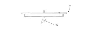
図1は、全体的に10で示される、煙検出器の例示的な実施形態を示す。煙検出器10は、複数の光源及び複数の光感知デバイスを含む。一実施形態では、複数の光源は、第1の光源12及び第2の光源14を含む。第1の光源12及び第2の光源14は、発光ダイオード(LED)を含み得る。第1の光源12及び第2の光源14は、後述では「監視された空間」と呼ばれ、中に光が放出される建物、部屋、または部屋の一部とすることができる空間に、1つまたは複数の波長で光を放出できる。一実施形態では、第1の光源12は、赤外線に特有の波長の光を放出でき、第2の光源14は、青色可視光に特有の波長の光を放出できる。赤外線は、煙の検出および煙を区別する誤報に使用することができ、青色可視光は、煙を区別する誤報に使用され得る。さらに、実施形態によっては、赤外線と可視光の組み合わせを使用して、検出器10のまたはその近くの粒子の大きさを決定することができる。 FIG. 1 shows an exemplary embodiment of a smoke detector, generally indicated at 10. As shown in FIG. Smoke detector 10 includes multiple light sources and multiple light sensing devices. In one embodiment, the plurality of light sources includes first light source 12 and second light source 14 . First light source 12 and second light source 14 may include light emitting diodes (LEDs). The first light source 12 and the second light source 14 are placed in a space, hereinafter referred to as a "monitored space", which can be a building, room, or part of a room into which light is emitted. It can emit light at one or more wavelengths. In one embodiment, the first light source 12 can emit light at wavelengths characteristic of infrared light, and the second light source 14 can emit light at wavelengths characteristic of blue visible light. Infrared can be used for smoke detection and smoke distinguishing false alarms, and blue visible light can be used for smoke distinguishing false alarms. Additionally, in some embodiments, a combination of infrared and visible light can be used to determine particle size at or near detector 10 .
一実施形態では、複数の光感知デバイスは、第1の光源12及び第2の光源14から放出される光の視野を有する煙検出器10の異なる領域に配置された第1の光感知デバイス16、第2の光感知デバイス18、及び第3の光感知デバイス20を含む。第1の光源12及び第2の光源14の放出と第1の光感知デバイス16、第2の光感知デバイス18、及び第3の光感知デバイス20の視野の重なりは、異なって重なる感知ボリュームを形成する。複数の光感知デバイスは、第1の光源12及び第2の光源14からの信号を測定するように構成される。
In one embodiment, the plurality of light sensing devices are first light sensing devices 16 positioned at different regions of the smoke detector 10 having a field of view of light emitted from the first light source 12 and the second light source 14. , a second photo-sensing device 18 and a third photo-sensing
一実施形態では、第1の光感知デバイス16、第2の光感知デバイス18、及び第3の光感知デバイス20は、フォトダイオードを含む。光感知デバイスは、フォトダイオードに制限されず、アバランシェフォトダイオード(APD)、マルチピクセルフォトンカウンタ(MPPC)、及び他の光検出器などの光感知デバイスを含んでもよい。例えば、第1の光感知デバイス16を使用して、一致する第1の角度を有する第1の光源12及び第2の光源14からの放出の重なりによって形成される前方散乱感知検出ボリューム38(図2に示す)を定義できる。図2に示す実施形態では、一致する第1の角度は、第1の光感知デバイス16と約130度をなす。その他の値または角度が実施形態によっては使用され得ることが、理解されよう。一致する角度は、第1の光源12及び第2の光源14の光錐の対称軸と光感知デバイス16、18、20の受光コーンの対称軸との間の角度として定義することができ、そこで、光源12、14を光感知デバイス16、18、20に直接向ける場合、180度が定義され得る。光の散乱角度は、180度から一致する角度を引くことで計算できることが理解されよう。
In one embodiment, the first photo-sensing device 16, the second photo-sensing device 18, and the third photo-sensing
ここで図3を参照すると、第2の光感知デバイス18を使用して、第1の光源12及び第2の光感知デバイス18と一致する第2の角度を有する第2の光源14からの放出の重なりによって形成される第1の後方散乱感知検出ボリューム40を定義できる。図3に示す実施形態では、一致する第2の角度は、約65度をなす。その他の値または角度が実施形態によっては使用され得ることが、理解されよう。
Referring now to FIG. 3, using a second photo-sensing device 18, the emission from the second light source 14 having a second angle coinciding with the first light source 12 and the second photo-sensing device 18 A first backscatter-
第3の光感知デバイス20を使用して、第1の光源12及び第3の光感知デバイス20と一致する第3の角度を有する第2の光源14からの放出の重なりによって形成される第2の後方散乱感知検出ボリューム42(図4及び図5に示す)を定義できる。図示の実施形態では、一致する第3の角度は、約0度をなす。
Using a third photo-sensing
煙検出器10は、複数の光源及び複数のセンサと電気的に通信する処理デバイス30をさらに含む。処理デバイス30は、実行可能な命令を保存できるメモリ(図示せず)を含む。実行可能な命令は、1つまたは複数のアプリケーション、プロセスまたはルーチンと共になど任意の方法及び任意の抽象化のレベルで保存または整理されて、複数のセンサによって検出された信号を分析して本明細書に記載の方法に従って、事前設定された閾値レベルに達した後、警報判定をすることができる。
Smoke detector 10 further includes a
実施形態によっては、煙検出器10は、煙の検出用に「通常」モード及び周囲空間の室内空気の品質の監視に使用され得る「高感度」モードで動作可能である。本開示における室内空気の品質(IAQ)の監視は、PM2.5粒子(これらの粒子は2.5マイクロメートル以下の直径を有する)及びPM10粒子(これらの粒子は、10マイクロメートル以下の直径を有する)と呼ばれる空中のほこりまたはその他の空中浮遊粒子の検出に関する。こうした実施形態では、煙検出器10は、追加の電子機器またはその他の構成要素を含んで、同じ感知領域及び波長から煙検出器10の動的範囲を拡大し、煙検出器10の検出感度を向上させて高感度モードでの動作を容易にする。実施形態によっては、追加の電子機器またはその他の構成要素は、二次アナログデジタル変換機(ADC)及びスイッチを含んで、通常モード一次下位ビットADCから高感度モードの二次高ビットADCに切り替えて、検出回路のゲインを変更できる。さらに、高感度モードでは、1つまたは複数の光学フィルタを使用して、光源12、14により放出された波長の外側の波長などの望まない波長を除去できる。 In some embodiments, smoke detector 10 is operable in a "normal" mode for smoke detection and a "high sensitivity" mode that can be used to monitor indoor air quality in the surrounding space. Indoor air quality (IAQ) monitoring in this disclosure includes PM2.5 particles (those particles have a diameter of 2.5 microns or less) and PM10 particles (those particles have a diameter of 10 microns or less). It relates to the detection of airborne dust or other airborne particles called airborne particles. In such embodiments, smoke detector 10 includes additional electronics or other components to extend the dynamic range of smoke detector 10 from the same sensing region and wavelength, and to increase the detection sensitivity of smoke detector 10. to facilitate operation in high sensitivity mode. In some embodiments, the additional electronics or other components include a secondary analog-to-digital converter (ADC) and a switch to switch from the normal mode primary low bit ADC to the high sensitivity mode secondary high bit ADC. , the gain of the detection circuit can be changed. Additionally, in the high sensitivity mode, one or more optical filters can be used to remove unwanted wavelengths, such as wavelengths outside those emitted by the light sources 12,14.
しかし、感知領域及び/または波長は、通常モードと高感度モードでは異なる場合があることを同業者なら理解するであろう。さらに、高感度モードは、プロセッサ30での検出回路の増幅、通常モードの動作に対して増やされた光源12、14のオン時間、及び/または増やされた光源12、14の強度を含み得る。実施形態によっては、通常モードでは、1~2秒毎に1回の測定であるのに対して、高感度モードでの動作は、例えば、1~10分毎に1回の測定の割合で測定値を取得することを含み得る。第1の波長で第1の光源12からの散乱光の、第2の波長で第2の光源14からの散乱光に対する比の閾値は、PM2.5の範囲とPM10の範囲内である粒子を区別するように設定され得る。前方散乱感知領域と後方散乱感知領域の比はまた、粒径情報を提供するほか、使用されて、PM2.5とPM10の粒径の決定及び測定値の正確さを向上させることができる。例えば、光を第1の光源12から第1の波長で放出することができ、第1の波長での光の後方散乱の量を煙検出器10で検出する。光を第2の光源14から第2の波長で放出することができ、第2の波長での光の後方散乱の量を煙検出器で検出する。第1の波長での光の後方散乱の量の、第2の波長での光の後方散乱の量に対する比は、微粒子の粒径を示す。
However, those skilled in the art will appreciate that the sensitive area and/or wavelength may be different for normal and enhanced modes. Additionally, the high sensitivity mode may include amplification of the detection circuitry in the
さらに、他の実施形態では、例えば、第1の光感知デバイス16、第2の光感知デバイス18、及び第3の光感知デバイス20のうちの2つ以上からの一致する複数の角度から検出された散乱光信号の比を使用して、検出された粒径を決定できる。上述の通り、実施形態によっては、光感知デバイス16、18,20は、感知検出ボリューム38、40、42によって少なくとも部分的に定義される一致する異なる角度を有する。従って、第1の感知検出ボリューム38によって定義された、一致する第1の角度を有する第1の光感知デバイス16で検出された散乱光の第1の量の、一致する第2の角度を有する第2の光感知デバイス18で検出された散乱光の第2の量に対する比を使用して、微粒子の粒径を決定できる。
Further, in other embodiments, for example, the detected from a plurality of matching angles from two or more of the first, second, and third
ここで、図6を参照すると、室内空気の品質を監視し、PM2.5粒子の検出(2.5マイクロメートル以下の直径と有する)及びPM10の検出(10マイクロメートル以下の直径を有する)のため煙検出器10を作動させる方法。 Referring now to FIG. 6, indoor air quality is monitored to detect PM2.5 particles (having a diameter of 2.5 micrometers or less) and PM10 (having a diameter of 10 micrometers or less). a method of operating a smoke detector 10;
ブロック100で、煙検出器10を、煙の検出に使用される通常モードから空中浮遊粒子の検出に使用される高感度モードに切り替える。ブロック102で、例えば、LEDまたはUV LEDを介して第2の光源14からなど、光をUVまたは青色可視スペクトルで煙検出器から放射する。さらに、光ファイバエミッタまたはレーザダイオードなどの光源を使用してもよい。ブロック104で、放射光は、放射光の経路で空中浮遊粒子により散乱される。ブロック106で、散乱光を煙検出器10の光感知デバイス16、18、20の1つ以上で受信する。ブロック108で、処理デバイス30を使用して、PM2.5およびPM10の粒子の存在について光感知デバイス16、18、20で受信した散乱光を分析する。
At
実施形態によっては、ブロック110で、放射光は、空中のかびまたは花粉粒子若しくはその他の汚染微生物などの蛍光粒子を励起する。ブロック112で、煙検出器10の光感知デバイス16、18、20のうちの1つ以上を使用して、蛍光粒子からの放出光を感知する。光感知デバイス16、18、20は、第2の光源14によって放出された波長より長い波長の光だけを受け入れるように構成され得る。より長い波長は、蛍光粒子によって放出された光を示し、従って、空中の花粉などの蛍光粒子の存在を示す。実施形態によっては、フィルタ(図示せず)を適切な光感知デバイス16、18、20で使用して、放出された波長より長いもののみ受け入れるように光感知デバイス16、18、20を構成してもよい。
In some embodiments, at
さらに、例えば、実施形態によっては、ブロック114で、ブロック112で検出された粒子の種類を区別する。これは、蛍光粒子から放出された光を偏光し、その後、蛍光粒子と光感知デバイス16、18、20との間に1つまたは複数の偏光フィルタを備える光感知デバイス16、18、20が感知することによって達成され得る。特定の粒子を検出するため、1つまたは複数の異なる偏光フィルタを、各偏光フィルタが特定の粒子または粒子の種類の検出または区別をできるように適合して、使用できる。
Further, for example, in some embodiments, block 114 distinguishes between types of particles detected in
ブロック116で、第1の光源12及び第2の光源14を使用して、後方散乱光感知デバイス18及び後方散乱光感知デバイス20によって感知された青色光の後方散乱の、赤外の後方散乱に対する比を評価することにより、粒径を決定することができる。
At
さらに、煙検出器10を使用して、空中のガス種の存在について空間を検出または監視できる。標的ガス種には、CO、ラドン、H2S、VOC、冷却剤、炭化水素などが含まれ得る。図7を参照すると、ブロック202で、光が、第1の光源12及び/または第2の光源14から、例えば、壁または他の空中の障害物の方に放出されている。ブロック204で、1つまたは複数の光感知デバイス16、18、20は、散乱光を受信する。具体的には、後方散乱フォトダイオード18、20を使用して、壁または障害物から離れて散乱する放出された光を検出でき、次に、処理デバイス30で受信した散乱光の吸収分光を介して、ブロック206でガス種を検出および区別する。
Additionally, the smoke detector 10 can be used to detect or monitor a space for the presence of airborne gaseous species. Target gas species may include CO, radon, H2S , VOCs, coolants, hydrocarbons, and the like. Referring to FIG. 7, at
実施形態によっては、煙検出器10は、空中の周囲光レベルを検出して、煙の検出及びその他の室内空気の品質監視と検出の感度並びに信頼性を向上するように構成される。 In some embodiments, smoke detector 10 is configured to detect ambient light levels in the air to improve the sensitivity and reliability of smoke detection and other indoor air quality monitoring and detection.
図8を参照すると、周囲光監視回路32は、煙検出器10で処理デバイス30に動作可能に接続されている。監視回路32は、定期的に、監視回路32によって評価され得る周囲光信号を受信するように構成され得る受光デバイス16、18、20のうちの1つ以上に接続される。光が、煙及び/またはその他の室内空気の品質の検出及び監視のため第1の光源12及び/または第2の光源14により放射されると、受光信号は、受信した周囲光信号の強度に基づいて、処理デバイス30で調節され得る。例えば、受光信号は、受光デバイス16、18、20に接続された1つまたは複数のアンプ34によって増幅され得る。さらに、可変増幅回路36を使用して、監視回路32によって感知された周囲光レベルに基づいて、1つまたは複数のアンプ34により印加された増幅の量を変えることができる。
Referring to FIG. 8, ambient
実施形態によっては、監視回路32は、第1の光源12及び第2の光源14が検出動作をトリガされる直前に周囲光レベルの測定をトリガする。次に、検出された周囲光レベルは、第1の光源12及び第2の光源14のトリガで生じる受光信号から差し引くことができる。さらに、感知された周囲光レベルが有効な検出がなされ得る閾値を超える場合、第1の光源12及び第2の光源14は、その時はトリガしなくてもよく、所定の時間の遅延後、周囲光レベルを測定するプロセスを再度始めてもよい。
In some embodiments, monitoring
本明細書に開示された実施形態により、煙検出器10を使用して、煙に加えて、標的ガス、汚染微粒子、汚染微生物またはその他の状態など他の室内空気の品質の状態を検出及び監視できるようになる。これにより、煙検出器が配置される同じ空間で使用される、追加で別個に給電される室内空気の品質センサの必要性をなくし、実質的に消費者と会社にコスト節減をもたらす。 In addition to smoke, the smoke detector 10 is used to detect and monitor other indoor air quality conditions, such as target gases, particulate contaminants, microbes or other conditions, according to embodiments disclosed herein. become able to. This eliminates the need for an additional, separately powered indoor air quality sensor to be used in the same space where the smoke detector is located, resulting in substantial cost savings for consumers and companies.
用語「約」は、用途を満たすときに利用可能な機器に基づいて特定の量の測定に関連した誤りの程度を含むように意図される。例えば、「約」は、所与の値の±8%または5%、若しくは2%の範囲を含み得る。 The term "about" is intended to include the degree of error associated with measuring the specified quantity based on the equipment available in fulfilling the application. For example, "about" can include ±8% or 5% or 2% of a given value.
本明細書に使用される用語は、特定の実施形態のみを説明する目的を持っており、本開示を制限することを意図するものではない。単数形(「1つの(a)」、「1つの(an)」及び「その(the)」)は本明細書で使用される場合、別段の指示がない限り、複数形も同様に含むことを意図する。用語「備える(comprises)」及び/または「備えている(comprising)」は、本明細書で使用される場合、述べられた特徴、整数、ステップ、動作、要素、及び/または構成要素の存在を明示するが、1つ以上の他の特徴、整数、ステップ、動作、要素、構成要素、及び/またはイベントその群の存在または追加を除外しないことがさらに理解されよう。 The terminology used herein is for the purpose of describing particular embodiments only and is not intended to be limiting of the disclosure. As used herein, the singular forms (“a,” “an,” and “the”) include the plural as well, unless otherwise indicated. intended to The terms "comprises" and/or "comprising", as used herein, denote the presence of the stated features, integers, steps, acts, elements, and/or components. It is further understood that, although explicitly stated, it does not preclude the presence or addition of one or more other features, integers, steps, acts, elements, components, and/or groups of events.
本開示は、例示的な実施形態(複数可)を参照して説明されているが、本開示の範囲から逸脱することなく、様々な変更が可能であり、等価物がその構成要素と代用可能であることは、当業者には理解されよう。さらに、特定の状況または材料を本開示の教示に適合するため、その本質的な範囲から逸脱しない限り、多くの修正を行うことが可能である。従って、本開示は、本開示を実行するために考えられた最良の方法として開示された特定の実施形態に制限されるものではなく、本開示は、特許請求の範囲に含まれるすべての実施形態を含むことを意図するものである。 Although this disclosure has been described with reference to exemplary embodiment(s), various modifications can be made and equivalents can be substituted for elements thereof without departing from the scope of this disclosure. It will be understood by those skilled in the art that In addition, many modifications may be made to adapt a particular situation or material to the teachings of this disclosure without departing from its essential scope. Therefore, it is not intended that the present disclosure be limited to the particular embodiments disclosed as the best mode contemplated for carrying out the disclosure, but that the present disclosure includes all embodiments falling within the scope of the claims. is intended to include
Claims (10)
煙を感知する通常モードから空中浮遊粒子を感知する高感度モードに前記システムを切り替えることであって、前記高感度モードでは、前記検出システムが、直径2.5マイクロメートル未満の粒子と直径10マイクロメートル未満の粒子とを検出するように構成される、前記切り替えることと、
前記検出システムの第1の光源から監視された室内空間に、IRスペクトルを含む第1の波長で光を放出し、前記検出システムの1つまたは複数の光検知デバイスにより、前記第1の波長の光の後方散乱の量を検出することと、
前記検出システムの第2の光源から、前記監視された室内空間に、UVスペクトルを含む第2の波長で光を放出し、前記検出システムの1つまたは複数の光検知デバイスにより、前記第2の波長の光の後方散乱の量を検出することと、
微粒子の粒径を、前記第1の波長での前記光の後方散乱の量の、前記第2の波長での前記光の後方散乱の量に対する比により決定することと、
を備えた、方法。 A method of operating a chamberless detection system for sensing smoke and monitoring indoor air quality, comprising:
Switching the system from a normal mode of sensing smoke to a high sensitivity mode of sensing airborne particles, wherein the detection system detects particles less than 2.5 micrometers in diameter and 10 micrometers in diameter. said switching configured to detect sub-meter particles;
emitting light at a first wavelength comprising an IR spectrum from a first light source of the detection system into a monitored room space, detecting the amount of backscattering of light;
emitting light at a second wavelength comprising the UV spectrum into the monitored room space from a second light source of the detection system; detecting the amount of backscattering of light at the wavelength;
determining the particle size of microparticles by the ratio of the amount of backscattering of the light at the first wavelength to the amount of backscattering of the light at the second wavelength;
A method with
前記通常モードに対して前記第1および第2の光源のオン時間を増やすことと、
前記通常モードに対して前記放出される光の強度を上げることと、
検出回路のゲインを増やすことと、
のうちの1つ以上を含む、請求項1に記載の方法。 switching to the high sensitivity mode;
increasing the on-time of the first and second light sources relative to the normal mode;
increasing the intensity of the emitted light relative to the normal mode;
increasing the gain of the detection circuit;
2. The method of claim 1, comprising one or more of:
監視された室内空間に、IRスペクトルを含む第1の波長で光を放出するように構成された第1の光源と、
前記監視された室内空間に、UVスペクトルを含む第2の波長で光を放出するように構成された第2の光源と、
前記第1および第2の光源から放出された散乱光を受信するように構成された1つまたは複数の光感知デバイスと、
微粒子の粒径を、前記第1の波長での前記光の後方散乱の量の、前記第2の波長での前記光の後方散乱の量に対する比により決定することにより、前記監視された室内空間内の室内空気の品質の状態について前記受信した散乱光信号を評価するように構成されたプロセッサと、を備え、
前記室内空気の品質の状態が、直径2.5マイクロメートルより小さい直径、及び直径10マイクロメートルより小さい直径の空中浮遊粒子を含む、
室内空気の品質モニタ。 A room air quality monitor with a chamberless detection system for sensing smoke and monitoring room air quality, comprising:
a first light source configured to emit light into the monitored room space at a first wavelength comprising an IR spectrum;
a second light source configured to emit light into the monitored indoor space at a second wavelength comprising the UV spectrum;
one or more light sensing devices configured to receive scattered light emitted from the first and second light sources;
by determining the particle size of a particulate by the ratio of the amount of backscattering of the light at the first wavelength to the amount of backscattering of the light at the second wavelength; a processor configured to evaluate the received scattered light signal for a state of indoor air quality within
wherein said indoor air quality state comprises airborne particles of diameter less than 2.5 micrometers in diameter and less than 10 micrometers in diameter;
Indoor air quality monitor.
前記通常モードに対して増やされた前記第1および第2の光源のオン時間と、
前記通常モードに対して上げられた前記放出される光の強度と、
前記通常モードに対して増やされた検出回路のゲインとのうちの1つ以上を含む、
請求項9に記載の室内空気の品質モニタ。 When compared with the normal mode, the high sensitivity mode is
increased on-time of the first and second light sources relative to the normal mode;
an intensity of the emitted light raised relative to the normal mode;
a detection circuit gain increased relative to the normal mode;
Indoor air quality monitor according to claim 9 .
Priority Applications (1)
| Application Number | Priority Date | Filing Date | Title |
|---|---|---|---|
| JP2023063130A JP2023086777A (en) | 2017-06-09 | 2023-04-10 | Chamberless smoke detector with indoor air quality detection and monitoring |
Applications Claiming Priority (3)
| Application Number | Priority Date | Filing Date | Title |
|---|---|---|---|
| US201762517614P | 2017-06-09 | 2017-06-09 | |
| US62/517,614 | 2017-06-09 | ||
| PCT/US2018/035819 WO2018226567A1 (en) | 2017-06-09 | 2018-06-04 | Chamberless smoke detector with indoor air quality detection and monitoring |
Related Child Applications (1)
| Application Number | Title | Priority Date | Filing Date |
|---|---|---|---|
| JP2023063130A Division JP2023086777A (en) | 2017-06-09 | 2023-04-10 | Chamberless smoke detector with indoor air quality detection and monitoring |
Publications (2)
| Publication Number | Publication Date |
|---|---|
| JP2020523572A JP2020523572A (en) | 2020-08-06 |
| JP7261748B2 true JP7261748B2 (en) | 2023-04-20 |
Family
ID=62685241
Family Applications (2)
| Application Number | Title | Priority Date | Filing Date |
|---|---|---|---|
| JP2019567547A Active JP7261748B2 (en) | 2017-06-09 | 2018-06-04 | Chamberless smoke detector with indoor air quality detection and monitoring |
| JP2023063130A Pending JP2023086777A (en) | 2017-06-09 | 2023-04-10 | Chamberless smoke detector with indoor air quality detection and monitoring |
Family Applications After (1)
| Application Number | Title | Priority Date | Filing Date |
|---|---|---|---|
| JP2023063130A Pending JP2023086777A (en) | 2017-06-09 | 2023-04-10 | Chamberless smoke detector with indoor air quality detection and monitoring |
Country Status (8)
| Country | Link |
|---|---|
| US (2) | US11295594B2 (en) |
| EP (1) | EP3635699B1 (en) |
| JP (2) | JP7261748B2 (en) |
| CN (1) | CN110892460B (en) |
| CA (1) | CA3066748A1 (en) |
| ES (1) | ES2924274T3 (en) |
| MX (1) | MX2019014764A (en) |
| WO (1) | WO2018226567A1 (en) |
Families Citing this family (4)
| Publication number | Priority date | Publication date | Assignee | Title |
|---|---|---|---|---|
| CN110892460B (en) | 2017-06-09 | 2022-08-02 | 开利公司 | Chamber-less smoke detector with indoor air quality detection and monitoring |
| US11474018B2 (en) | 2019-12-05 | 2022-10-18 | Carrier Corporation | Fluorescence enhanced LIDAR based particulate detector |
| US11813926B2 (en) * | 2020-08-20 | 2023-11-14 | Denso International America, Inc. | Binding agent and olfaction sensor |
| US11726035B2 (en) * | 2020-12-11 | 2023-08-15 | Raytheon Technologies Corporation | Terahertz enhanced foreign object debris discrimination for optical particulate sensor |
Citations (7)
| Publication number | Priority date | Publication date | Assignee | Title |
|---|---|---|---|---|
| JP2001116692A (en) | 1999-10-18 | 2001-04-27 | Nittan Co Ltd | Smoke sensor and particulate size measuring device and particulate kind discriminating device |
| JP2002168776A (en) | 2000-12-01 | 2002-06-14 | Advantest Corp | Environment monitoring method and device and semiconductor manufacturing device |
| JP2003038163A (en) | 2001-07-26 | 2003-02-12 | Yamato Seisakusho:Kk | Microorganism detector |
| JP2009229414A (en) | 2008-03-25 | 2009-10-08 | Osaka Gas Co Ltd | Detector |
| JP2015052860A (en) | 2013-09-06 | 2015-03-19 | ホーチキ株式会社 | Alarm unit |
| WO2015156037A1 (en) | 2014-04-08 | 2015-10-15 | 三菱電機株式会社 | Floating particle detection device |
| WO2016165945A1 (en) | 2015-04-17 | 2016-10-20 | Koninklijke Philips N.V. | Dust processing |
Family Cites Families (25)
| Publication number | Priority date | Publication date | Assignee | Title |
|---|---|---|---|---|
| JPS5214940A (en) | 1975-07-26 | 1977-02-04 | Osaka Gas Co Ltd | Storage type hot water supplyer |
| US3982130A (en) | 1975-10-10 | 1976-09-21 | The United States Of America As Represented By The Secretary Of The Air Force | Ultraviolet wavelength smoke detector |
| JPS551501A (en) * | 1978-06-05 | 1980-01-08 | Chloride Inc | Smoke detector with sensitivity raiser |
| GB2274333B (en) | 1993-01-07 | 1996-12-11 | Hochiki Co | Smoke detecting apparatus capable of detecting both smoke and fine particles |
| US5451787A (en) * | 1993-05-04 | 1995-09-19 | Westinghouse Electric Corporation | Hazardous air pollutants monitor |
| JPH08136455A (en) * | 1994-11-02 | 1996-05-31 | Kobe Steel Ltd | Air pollution monitoring method by laser radar and its monitoring device |
| JPH11160238A (en) * | 1997-11-28 | 1999-06-18 | Matsushita Electric Works Ltd | Photoelectric smoke sensor |
| DE10046992C1 (en) | 2000-09-22 | 2002-06-06 | Bosch Gmbh Robert | Scattered light smoke |
| DE10246756B4 (en) * | 2002-10-07 | 2006-03-16 | Novar Gmbh | Fire detection procedure and fire detector for its implementation |
| DE102004001699A1 (en) | 2004-01-13 | 2005-08-04 | Robert Bosch Gmbh | fire alarm |
| US8047055B2 (en) * | 2007-08-08 | 2011-11-01 | Tsi, Incorporated | Size segregated aerosol mass concentration measurement with inlet conditioners and multiple detectors |
| US8085157B2 (en) | 2007-10-24 | 2011-12-27 | Honeywell International Inc. | Smoke detectors |
| US8249811B2 (en) | 2008-07-09 | 2012-08-21 | Honeywell International Inc. | Multi-sensor detectors |
| US9140646B2 (en) * | 2012-04-29 | 2015-09-22 | Valor Fire Safety, Llc | Smoke detector with external sampling volume using two different wavelengths and ambient light detection for measurement correction |
| US8907802B2 (en) * | 2012-04-29 | 2014-12-09 | Valor Fire Safety, Llc | Smoke detector with external sampling volume and ambient light rejection |
| CA2875258A1 (en) | 2012-06-08 | 2013-12-12 | Xtralis Technologies Ltd | Multi-mode detection |
| DE102014200243A1 (en) | 2014-01-09 | 2015-07-09 | Robert Bosch Gmbh | Smoke detector with ambient light detection |
| WO2015179347A1 (en) | 2014-05-22 | 2015-11-26 | Carrier Corporation | Wide-area chamberless point smoke detector |
| US9652958B2 (en) | 2014-06-19 | 2017-05-16 | Carrier Corporation | Chamber-less smoke sensor |
| CN104392577B (en) * | 2014-12-08 | 2016-08-31 | 王殊 | A kind of aerosol particle diameter method for sensing based on dual wavelength scattered signal |
| DE102014019773B4 (en) | 2014-12-17 | 2023-12-07 | Elmos Semiconductor Se | Device and method for distinguishing between solid objects, cooking fumes and smoke using the display of a mobile telephone |
| US9443631B1 (en) * | 2015-03-04 | 2016-09-13 | The United States Of America As Represented By The Secretary Of The Army | Optical trap using a focused hollow-beam for trapping and holding both absorbing and non-absorbing airborne particles |
| JP6688966B2 (en) * | 2015-07-27 | 2020-04-28 | パナソニックIpマネジメント株式会社 | Particle detection sensor |
| JP6083660B1 (en) * | 2016-01-29 | 2017-02-22 | パナソニックIpマネジメント株式会社 | Particle detection sensor, dust sensor, smoke detector, air conditioner, and particle detection method |
| CN110892460B (en) | 2017-06-09 | 2022-08-02 | 开利公司 | Chamber-less smoke detector with indoor air quality detection and monitoring |
-
2018
- 2018-06-04 CN CN201880051507.6A patent/CN110892460B/en active Active
- 2018-06-04 JP JP2019567547A patent/JP7261748B2/en active Active
- 2018-06-04 WO PCT/US2018/035819 patent/WO2018226567A1/en active Application Filing
- 2018-06-04 CA CA3066748A patent/CA3066748A1/en not_active Abandoned
- 2018-06-04 EP EP18733134.3A patent/EP3635699B1/en active Active
- 2018-06-04 MX MX2019014764A patent/MX2019014764A/en unknown
- 2018-06-04 US US16/620,731 patent/US11295594B2/en active Active
- 2018-06-04 ES ES18733134T patent/ES2924274T3/en active Active
-
2022
- 2022-02-28 US US17/682,467 patent/US11605278B2/en active Active
-
2023
- 2023-04-10 JP JP2023063130A patent/JP2023086777A/en active Pending
Patent Citations (7)
| Publication number | Priority date | Publication date | Assignee | Title |
|---|---|---|---|---|
| JP2001116692A (en) | 1999-10-18 | 2001-04-27 | Nittan Co Ltd | Smoke sensor and particulate size measuring device and particulate kind discriminating device |
| JP2002168776A (en) | 2000-12-01 | 2002-06-14 | Advantest Corp | Environment monitoring method and device and semiconductor manufacturing device |
| JP2003038163A (en) | 2001-07-26 | 2003-02-12 | Yamato Seisakusho:Kk | Microorganism detector |
| JP2009229414A (en) | 2008-03-25 | 2009-10-08 | Osaka Gas Co Ltd | Detector |
| JP2015052860A (en) | 2013-09-06 | 2015-03-19 | ホーチキ株式会社 | Alarm unit |
| WO2015156037A1 (en) | 2014-04-08 | 2015-10-15 | 三菱電機株式会社 | Floating particle detection device |
| WO2016165945A1 (en) | 2015-04-17 | 2016-10-20 | Koninklijke Philips N.V. | Dust processing |
Also Published As
| Publication number | Publication date |
|---|---|
| EP3635699B1 (en) | 2022-07-27 |
| ES2924274T3 (en) | 2022-10-05 |
| CN110892460A (en) | 2020-03-17 |
| US11295594B2 (en) | 2022-04-05 |
| CN110892460B (en) | 2022-08-02 |
| MX2019014764A (en) | 2020-02-12 |
| US11605278B2 (en) | 2023-03-14 |
| WO2018226567A1 (en) | 2018-12-13 |
| CA3066748A1 (en) | 2018-12-13 |
| US20200193790A1 (en) | 2020-06-18 |
| EP3635699A1 (en) | 2020-04-15 |
| JP2023086777A (en) | 2023-06-22 |
| JP2020523572A (en) | 2020-08-06 |
| US20220180721A1 (en) | 2022-06-09 |
Similar Documents
| Publication | Publication Date | Title |
|---|---|---|
| JP7261748B2 (en) | Chamberless smoke detector with indoor air quality detection and monitoring | |
| JP5974143B2 (en) | Photodetection of particle characteristics | |
| US9470626B2 (en) | Method of smoke detection with direct detection of light and detection of light reflected from an external sampling volume | |
| US10001438B2 (en) | Method of sensing aerosol characteristic parameter using dual-wavelength scattered signal and application thereof | |
| US10852233B2 (en) | Systems and methods for chamberless smoke detection and indoor air quality monitoring | |
| US11087605B2 (en) | Smoke detection methodology | |
| GB2397122A (en) | Smoke detector with a low false alarm rate | |
| EP3413279B1 (en) | System and method for chamberless smoke detection and indoor air quality monitoring | |
| US9881491B2 (en) | Fire detector comprising a MOS gas sensor and a photoelectric detector | |
| US11959857B2 (en) | Apparatus for measuring Raman scattering, and apparatus and method for determining true fire using the apparatus | |
| TW202104872A (en) | Particle sensor | |
| EP3460428A1 (en) | Dual wavelength detector | |
| KR20220041719A (en) | Apparatus for measuring raman scattering, and apparatus and method for determining true fire using the apparatus | |
| JPH11339157A (en) | Smoke sensor |
Legal Events
| Date | Code | Title | Description |
|---|---|---|---|
| A621 | Written request for application examination |
Free format text: JAPANESE INTERMEDIATE CODE: A621 Effective date: 20210524 |
|
| A977 | Report on retrieval |
Free format text: JAPANESE INTERMEDIATE CODE: A971007 Effective date: 20220331 |
|
| A131 | Notification of reasons for refusal |
Free format text: JAPANESE INTERMEDIATE CODE: A131 Effective date: 20220405 |
|
| A521 | Request for written amendment filed |
Free format text: JAPANESE INTERMEDIATE CODE: A523 Effective date: 20220705 |
|
| A131 | Notification of reasons for refusal |
Free format text: JAPANESE INTERMEDIATE CODE: A131 Effective date: 20220726 |
|
| A601 | Written request for extension of time |
Free format text: JAPANESE INTERMEDIATE CODE: A601 Effective date: 20221025 |
|
| A521 | Request for written amendment filed |
Free format text: JAPANESE INTERMEDIATE CODE: A523 Effective date: 20221125 |
|
| TRDD | Decision of grant or rejection written | ||
| A01 | Written decision to grant a patent or to grant a registration (utility model) |
Free format text: JAPANESE INTERMEDIATE CODE: A01 Effective date: 20230314 |
|
| A61 | First payment of annual fees (during grant procedure) |
Free format text: JAPANESE INTERMEDIATE CODE: A61 Effective date: 20230410 |
|
| R150 | Certificate of patent or registration of utility model |
Ref document number: 7261748 Country of ref document: JP Free format text: JAPANESE INTERMEDIATE CODE: R150 |