JP7261319B2 - Pathological diagnosis support system and pathological diagnosis support device - Google Patents
Pathological diagnosis support system and pathological diagnosis support device Download PDFInfo
- Publication number
- JP7261319B2 JP7261319B2 JP2021563828A JP2021563828A JP7261319B2 JP 7261319 B2 JP7261319 B2 JP 7261319B2 JP 2021563828 A JP2021563828 A JP 2021563828A JP 2021563828 A JP2021563828 A JP 2021563828A JP 7261319 B2 JP7261319 B2 JP 7261319B2
- Authority
- JP
- Japan
- Prior art keywords
- image
- pathological diagnosis
- confirmation
- frame
- displayed
- Prior art date
- Legal status (The legal status is an assumption and is not a legal conclusion. Google has not performed a legal analysis and makes no representation as to the accuracy of the status listed.)
- Active
Links
- 238000010827 pathological analysis Methods 0.000 title claims description 122
- 238000012790 confirmation Methods 0.000 claims description 157
- 230000005856 abnormality Effects 0.000 claims description 41
- 238000010191 image analysis Methods 0.000 claims description 27
- 238000003745 diagnosis Methods 0.000 claims description 22
- 230000003902 lesion Effects 0.000 claims description 14
- 238000002059 diagnostic imaging Methods 0.000 claims description 10
- 230000001575 pathological effect Effects 0.000 claims description 4
- 206010028980 Neoplasm Diseases 0.000 description 20
- 201000011510 cancer Diseases 0.000 description 20
- 238000010586 diagram Methods 0.000 description 18
- 238000004891 communication Methods 0.000 description 10
- 230000002159 abnormal effect Effects 0.000 description 6
- 210000004027 cell Anatomy 0.000 description 6
- 238000004458 analytical method Methods 0.000 description 3
- 239000003086 colorant Substances 0.000 description 3
- 239000012141 concentrate Substances 0.000 description 3
- 238000000034 method Methods 0.000 description 3
- 210000001519 tissue Anatomy 0.000 description 3
- 206010006187 Breast cancer Diseases 0.000 description 2
- 208000026310 Breast neoplasm Diseases 0.000 description 2
- 210000003855 cell nucleus Anatomy 0.000 description 2
- 238000001514 detection method Methods 0.000 description 2
- 230000000694 effects Effects 0.000 description 2
- 208000019901 Anxiety disease Diseases 0.000 description 1
- 230000036506 anxiety Effects 0.000 description 1
- 238000004040 coloring Methods 0.000 description 1
- 230000002380 cytological effect Effects 0.000 description 1
- 230000007170 pathology Effects 0.000 description 1
Images


Classifications
-
- G—PHYSICS
- G16—INFORMATION AND COMMUNICATION TECHNOLOGY [ICT] SPECIALLY ADAPTED FOR SPECIFIC APPLICATION FIELDS
- G16H—HEALTHCARE INFORMATICS, i.e. INFORMATION AND COMMUNICATION TECHNOLOGY [ICT] SPECIALLY ADAPTED FOR THE HANDLING OR PROCESSING OF MEDICAL OR HEALTHCARE DATA
- G16H40/00—ICT specially adapted for the management or administration of healthcare resources or facilities; ICT specially adapted for the management or operation of medical equipment or devices
- G16H40/60—ICT specially adapted for the management or administration of healthcare resources or facilities; ICT specially adapted for the management or operation of medical equipment or devices for the operation of medical equipment or devices
- G16H40/67—ICT specially adapted for the management or administration of healthcare resources or facilities; ICT specially adapted for the management or operation of medical equipment or devices for the operation of medical equipment or devices for remote operation
-
- G—PHYSICS
- G06—COMPUTING; CALCULATING OR COUNTING
- G06T—IMAGE DATA PROCESSING OR GENERATION, IN GENERAL
- G06T7/00—Image analysis
- G06T7/0002—Inspection of images, e.g. flaw detection
- G06T7/0012—Biomedical image inspection
-
- G—PHYSICS
- G01—MEASURING; TESTING
- G01N—INVESTIGATING OR ANALYSING MATERIALS BY DETERMINING THEIR CHEMICAL OR PHYSICAL PROPERTIES
- G01N33/00—Investigating or analysing materials by specific methods not covered by groups G01N1/00 - G01N31/00
- G01N33/48—Biological material, e.g. blood, urine; Haemocytometers
- G01N33/483—Physical analysis of biological material
-
- G—PHYSICS
- G06—COMPUTING; CALCULATING OR COUNTING
- G06T—IMAGE DATA PROCESSING OR GENERATION, IN GENERAL
- G06T1/00—General purpose image data processing
-
- G—PHYSICS
- G16—INFORMATION AND COMMUNICATION TECHNOLOGY [ICT] SPECIALLY ADAPTED FOR SPECIFIC APPLICATION FIELDS
- G16H—HEALTHCARE INFORMATICS, i.e. INFORMATION AND COMMUNICATION TECHNOLOGY [ICT] SPECIALLY ADAPTED FOR THE HANDLING OR PROCESSING OF MEDICAL OR HEALTHCARE DATA
- G16H30/00—ICT specially adapted for the handling or processing of medical images
- G16H30/20—ICT specially adapted for the handling or processing of medical images for handling medical images, e.g. DICOM, HL7 or PACS
-
- G—PHYSICS
- G16—INFORMATION AND COMMUNICATION TECHNOLOGY [ICT] SPECIALLY ADAPTED FOR SPECIFIC APPLICATION FIELDS
- G16H—HEALTHCARE INFORMATICS, i.e. INFORMATION AND COMMUNICATION TECHNOLOGY [ICT] SPECIALLY ADAPTED FOR THE HANDLING OR PROCESSING OF MEDICAL OR HEALTHCARE DATA
- G16H30/00—ICT specially adapted for the handling or processing of medical images
- G16H30/40—ICT specially adapted for the handling or processing of medical images for processing medical images, e.g. editing
-
- G—PHYSICS
- G16—INFORMATION AND COMMUNICATION TECHNOLOGY [ICT] SPECIALLY ADAPTED FOR SPECIFIC APPLICATION FIELDS
- G16H—HEALTHCARE INFORMATICS, i.e. INFORMATION AND COMMUNICATION TECHNOLOGY [ICT] SPECIALLY ADAPTED FOR THE HANDLING OR PROCESSING OF MEDICAL OR HEALTHCARE DATA
- G16H50/00—ICT specially adapted for medical diagnosis, medical simulation or medical data mining; ICT specially adapted for detecting, monitoring or modelling epidemics or pandemics
- G16H50/20—ICT specially adapted for medical diagnosis, medical simulation or medical data mining; ICT specially adapted for detecting, monitoring or modelling epidemics or pandemics for computer-aided diagnosis, e.g. based on medical expert systems
-
- G—PHYSICS
- G16—INFORMATION AND COMMUNICATION TECHNOLOGY [ICT] SPECIALLY ADAPTED FOR SPECIFIC APPLICATION FIELDS
- G16H—HEALTHCARE INFORMATICS, i.e. INFORMATION AND COMMUNICATION TECHNOLOGY [ICT] SPECIALLY ADAPTED FOR THE HANDLING OR PROCESSING OF MEDICAL OR HEALTHCARE DATA
- G16H50/00—ICT specially adapted for medical diagnosis, medical simulation or medical data mining; ICT specially adapted for detecting, monitoring or modelling epidemics or pandemics
- G16H50/70—ICT specially adapted for medical diagnosis, medical simulation or medical data mining; ICT specially adapted for detecting, monitoring or modelling epidemics or pandemics for mining of medical data, e.g. analysing previous cases of other patients
-
- G—PHYSICS
- G06—COMPUTING; CALCULATING OR COUNTING
- G06T—IMAGE DATA PROCESSING OR GENERATION, IN GENERAL
- G06T2207/00—Indexing scheme for image analysis or image enhancement
- G06T2207/30—Subject of image; Context of image processing
- G06T2207/30004—Biomedical image processing
- G06T2207/30096—Tumor; Lesion
Description
本発明は、例えば、がんの病理診断に用いられる病理診断サポートシステムおよび病理診断サポート装置に関するものである。 The present invention relates to, for example, a pathological diagnosis support system and a pathological diagnosis support apparatus used for pathological diagnosis of cancer.
がんの病理診断は、病理診断用標本(患者から採取された検体について、病理診断を目的に作成された標本)をスキャンした病理診断用画像を、病理医が目視で確認することによって行われている。この時、病理医は病理診断用画像の疑わしい領域を拡大して観察し病理を確定する。
つまり、画像を拡大表示させないと、病理医が小さながん細胞の存在を見落としてしまうおそれがあるため、病理医はこの病理診断に極めて多くの時間をかけざるをえない。Pathological diagnosis of cancer is performed by a pathologist visually confirming an image for pathological diagnosis obtained by scanning a specimen for pathological diagnosis (a specimen prepared for the purpose of pathological diagnosis of a sample collected from a patient). ing. At this time, the pathologist magnifies and observes the suspicious region of the pathological diagnosis image to confirm the pathology.
In other words, if the image is not magnified and displayed, the pathologist may overlook the presence of small cancer cells, so the pathologist has to spend an extremely large amount of time on this pathological diagnosis.
そこで、病理医の負担を軽減するために、病理診断用画像を複数の分割画像にすると共に、各分割画像で異常の可能性があるものには表示部上で注目点を着色して表示する方法が提案されている(これに類似する先行文献としては、例えば、下記特許文献1)。
Therefore, in order to reduce the burden on the pathologist, the image for pathological diagnosis is divided into a plurality of divided images, and each divided image that may be abnormal is displayed with a colored attention point on the display unit. A method has been proposed (as a prior document similar to this, for example,
上記従来例によれば、表示部に表示された病理診断用画像には、注目点として着色が施されている。このため、病理医はこの着色部分に注目することで、異常部分を見落としてはいけないという緊張状態を緩和することができるため、病理医の負担を軽減することができる。
しかしながら、病理診断用画像中において注目点が極めて小さなポイントであった場合には、注目点が着色されていたとしても、見落としてしまうおそれがある。According to the conventional example described above, the pathological diagnosis image displayed on the display unit is colored as a point of interest. Therefore, by paying attention to the colored portion, the pathologist can relax the strained state of not overlooking the abnormal portion, thereby reducing the burden on the pathologist.
However, when the point of interest is extremely small in the pathological diagnosis image, even if the point of interest is colored, it may be overlooked.
つまり、病理診断用画像は、様々な色や組織形態が混在する画像であるため、病理医が前記小さなポイントを確実に捉えることは難しい。このため、病理医は、従来通り、病理診断用画像の全体を集中して確認する必要があるため、十分に病理医の負担を軽減することができていない。
そこで本発明は、病理医の負担を軽減するが可能な病理診断サポートシステムおよび病理診断サポート装置を提供することを目的とするものである。In other words, since the pathological diagnosis image is an image in which various colors and tissue morphologies are mixed, it is difficult for the pathologist to reliably capture the small points. For this reason, pathologists need to concentrate on checking the entire pathological diagnosis image as before, and the burden on pathologists cannot be sufficiently reduced.
SUMMARY OF THE INVENTION Accordingly, it is an object of the present invention to provide a pathological diagnosis support system and a pathological diagnosis support apparatus that can reduce the burden on pathologists.
この目的を達成するために、病理診断用画像を解析する画像診断サーバと、画像診断サーバと交信する病理医端末と、を備えている。画像診断サーバは、病理診断用画像の画像解析を行う画像解析部と、画像解析部が接続された第1の制御部と、を有している。第1の制御部は、画像解析部を用いて、病理診断用画像を複数の分割画像に分割すると共に分割画像毎に異常スコアを算出し、異常スコアが閾値を超えた分割画像を含む確認枠を設定すると共に確認枠毎に枠番号を付与し、病理診断用画像および確認枠の設定情報および確認枠の枠番号を、病理医端末に送信する。病理医端末は、表示部と、第2の制御部と、を有している。第2の制御部は、病理診断用画像を表示部に表示させた際に、病理診断用画像内に確認枠と確認枠の枠番号とを表示し、病理診断用画像の外側に確認枠の枠番号を表示するように、表示部を制御する。
(発明の効果)
本発明の構成によれば、病理医の病理医端末に病理診断用画像を表示させた際に、病理診断用画像内には確認枠と枠番号が表示され、病理診断用画像の外側には、病理診断用画像内に表示された枠番号に対応する枠番号が表示される。In order to achieve this purpose, an image diagnosis server that analyzes pathological diagnosis images and a pathologist terminal that communicates with the image diagnosis server are provided. The image diagnosis server has an image analysis unit that performs image analysis of images for pathological diagnosis, and a first control unit to which the image analysis unit is connected. The first control unit uses the image analysis unit to divide the image for pathological diagnosis into a plurality of divided images, calculates an abnormality score for each divided image, and calculates the confirmation frame including the divided image whose abnormality score exceeds the threshold. is set, a frame number is assigned to each confirmation frame, and the pathological diagnosis image, setting information of the confirmation frame, and the frame number of the confirmation frame are transmitted to the terminal of the pathologist. The pathologist terminal has a display section and a second control section. When the pathological diagnosis image is displayed on the display unit, the second control unit displays the confirmation frame and the frame number of the confirmation frame within the pathological diagnosis image, and displays the confirmation frame outside the pathological diagnosis image. Control the display to display the frame number.
(Effect of the invention)
According to the configuration of the present invention, when a pathological diagnosis image is displayed on a pathologist's terminal, a confirmation frame and a frame number are displayed within the pathological diagnosis image, and a frame number is displayed outside the pathological diagnosis image. , a frame number corresponding to the frame number displayed in the pathological diagnosis image is displayed.
このため、病理医は、病理診断用画像の外側に表示された枠番号を見ることで、病理診断用画像内に確認すべき注目点があることを即座に認識することができる。そして、病理医は、病理診断用画像内に表示された枠番号と確認枠によって、病理診断用画像内の確認枠の位置や大きさを即座に把握することができる。
よって、病理医は、病理診断用画像の外側に表示された枠番号に対応する確認枠に対して集中的な確認を行うことができるため、病理医の負担を軽減することができる。Therefore, by looking at the frame number displayed outside the pathological diagnosis image, the pathologist can immediately recognize that there is a point of interest to be confirmed in the pathological diagnosis image. The pathologist can immediately grasp the position and size of the confirmation frame in the pathological diagnosis image from the frame number and the confirmation frame displayed in the pathological diagnosis image.
Therefore, the pathologist can intensively check the confirmation frame corresponding to the frame number displayed outside the pathological diagnosis image, thereby reducing the burden on the pathologist.
つまり、確認すべき注目点には枠番号と確認枠とが付されているため、注目点を決して見逃すことなく、確認に対する自信と安心感を得ることで、病理医の負担を軽減することができる。 In other words, since the points of interest to be confirmed are marked with a frame number and a confirmation frame, the burden on the pathologist can be reduced by never overlooking the points of interest and gaining confidence and a sense of security in confirmation. can.
以下に、本発明の一実施形態を、添付図面を用いて説明する。
(実施の形態1)
図1は、本実施形態の病理診断サポートシステムの構成を示している。
画像スキャナ1は、臨床検査技師のパソコン2に接続されており、病理診断用標本(患者から採取された検体について、病理診断を目的に作成された標本)をスキャンした病理診断用画像を、臨床検査技師のパソコン2へ送信する。An embodiment of the present invention will be described below with reference to the accompanying drawings.
(Embodiment 1)
FIG. 1 shows the configuration of the pathological diagnosis support system of this embodiment.
The
パソコン2は、画像スキャナ1によって得られた病理診断用画像を、画像診断サーバ3へ送信する。
画像診断サーバ3は、病理診断用画像を解析した解析結果と病理診断用画像とを、病理医のパソコン4(病理医端末の一例)に送信する。
病理医は、パソコン4に送られた病理診断用画像を用いて病理診断を行う。The
The
A pathologist makes a pathological diagnosis using the pathological diagnosis image sent to the
図2は、臨床検査技師のパソコン2、画像診断サーバ3、病理医のパソコン4のそれぞれの構成を示す制御ブロック図である。
パソコン2は、画像スキャナ1が接続された制御部5と、制御部5に接続された通信部6、表示部7、記憶部8とを備えている。
画像診断サーバ3は、パソコン2の通信部6と通信する通信部9と、通信部9と接続された制御部(第1の制御部)10と、制御部10に接続された記憶部11、病理診断用画像の画像解析を行う画像解析部12とを備えている。制御部10は、制御部10に接続された各部の制御を行う。制御部10に各種動作を実行させるための制御プログラムは、記憶部11に保持されている。FIG. 2 is a control block diagram showing the configuration of each of the clinical laboratory technologist's
The
The
病理医のパソコン4は、画像診断サーバ3の通信部9と通信する通信部13と、記憶部14、表示部15、表示等の制御コマンドが入力される入力部16と、これらは全てが接続された制御部(第2の制御部)17と、を備えている。制御部17は、制御部17に接続された各部の制御を行う。制御部17に各種動作を実行させるための制御プログラムは、記憶部14に保持されている。
The pathologist's
本実施形態では、病理医のパソコン4の表示部15に、図3に示すような画像が表示される。そして、表示部15にこのような画像を表示させるために、画像診断サーバ3は、以下のような病理診断データを作成する。
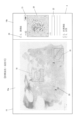
図3は、画面の大部分を占めるビューワ部15aと、ビューワ部15aの右側に表示された案内部15bとを表示した表示部15の表示画面を示している。In this embodiment, an image as shown in FIG. 3 is displayed on the
FIG. 3 shows a display screen of the
ビューワ部15aには、病理診断用画像の全体が表示されている。
案内部15bには、後述する病理診断用画像内に確認すべき注目点があることを示す枠番号と異常理由として、例えば、「3.浸潤癌」「2.非浸潤癌「1.良性」と表示されている。
ビューワ部15aに表示された病理診断用画像は、画像診断サーバ3に送付されたもので、例えば、大きさが30mm×20mmである。この病理診断用画像は、画像解析部12によってX方向にm列(69列)、Y方向にn行(47行)に分割され、この3243個(=69×47)の分割画像毎に異常判断が行われた後の状態が、ビューワ部15aに表示される。The entire pathological diagnosis image is displayed on the
In the guiding
The pathological diagnosis image displayed on the
また、画像診断サーバ3は、分割画像毎に異常スコアを算出し、異常スコアが閾値を超えた分割画像を含む確認枠18、確認枠19、確認枠20を形成する。そして、これら確認枠18,19,20が、病理診断用画像内に、枠番号「1」、「2」、「3」と共に表示されている。
さらに、病理診断用画像の右外側に設けられた案内部15b部分には、確認枠18,19,20の枠番号「1」、「2」、「3」と、それぞれの枠番号に対応する異常理由とが表示されている。The
Further, the frame numbers "1", "2", and "3" of the
すなわち、異常スコアが閾値を超えた分割画像を含む確認枠(図3の確認枠18,19,20)においては、案内部15bに枠番号「1」、「2」、「3」とそれらに対応する異常理由とが表示されるとともに、ビューワ部15aに枠番号「1」、「2」、「3」と確認枠18,19,20とが表示される。
このため、パソコン4の表示部15を見た病理医は、案内部15bに表示された枠番号「1」、「2」、「3」によって、病理診断用画像内に確認すべき注目点が3個あることを即座に認識することができる。That is, in the confirmation frames (confirmation frames 18, 19, and 20 in FIG. 3) including the divided images whose abnormal scores exceed the threshold, the
For this reason, the pathologist looking at the
そして、ビューワ部15aの病理診断用画像内に表示された3個の枠番号「1」、「2」、「3」と3個の確認枠18,19,20によって、確認枠18~20の位置、大きさ、位置関係を即座に把握することができる。
なお、ビューワ部15aに表示される全ての確認枠18,19,20は、枠線のみが表示され枠内は可視状態で表示される。これにより、3個の注目点の状態を容易に把握することができる。Then, the three frame numbers "1", "2", "3" and the three confirmation frames 18, 19, 20 displayed in the pathological diagnosis image of the
In all the confirmation frames 18, 19, 20 displayed on the
なお、図3に示す表示例では、枠番号は「1」、「2」、「3」と数字で表したが、枠番号は確認枠18,19,20が特定できるものであればよい。枠番号としては、例えば、数字の代わりに、アルファベット、ローマ数字、アイコン、あるいはそれらの組み合わせを用いてもよい。
また、本実施形態では、ビューワ部15aの病理診断用画像の右外側に案内部15bが設けられているが、病理診断用画像外にいわゆるウインドウ表示を行って案内部15bがウインドウ内に設けられていてもよい。In the display example shown in FIG. 3, the frame numbers are represented by numerals "1", "2", and "3", but any frame number may be used as long as the confirmation frames 18, 19, and 20 can be specified. As the frame numbers, for example, alphabets, Roman numerals, icons, or combinations thereof may be used instead of numerals.
Further, in the present embodiment, the
以下、図9および図10のフローチャートを用いて、臨床検査技師のパソコン2、画像診断サーバ3、および病理医のパソコン4における処理について説明を続ける。
図9に示すように、パソコン2は、臨床検査技師による操作によって、画像スキャナ1を用いて病理診断用標本をスキャンし(ステップR1)、この病理診断用画像を取得した(ステップR2)後、画像診断サーバ3に病理診断用画像を送信する(ステップR3)。The processing in the clinical laboratory technologist's
As shown in FIG. 9, the
画像診断サーバ3の制御部10は、病理診断用画像を受信する(ステップG1)と、上述したように、画像解析部12を用いて、m×n個(3243区画)の分割画像を生成する(ステップG2)。
次に、制御部10は、各分割画像を学習済みの異常検知モデルに入力し分割画像の画素毎に異常スコアを算出する(ステップG3)。なお、学習済みの異常検知モデルは、予め、画像診断サーバ3の記憶部11に保存されている。When the
Next, the
次に、制御部10は、異常スコアが閾値を超えた画素に対して色付けを行う(ステップG4)。
次に、制御部10は、色付けされた分割画像を3243区画集めて、病理診断用画像を再構成する(ステップG5)。
なお、再構成された病理診断用画像において、色付けされた領域は、画像解析部12によって異常が検出され、病変組織を含む可能性の高い領域であることを示している。つまり、色付けされた領域は、病理医に集中的な確認を行ってもらいたい注目点であることを示している。Next, the
Next, the
In the reconstructed pathological diagnosis image, the colored region indicates that the
画像解析部12は、病理診断用画像において、色付けされた分割画像で隣接するものがあるか否かの検出を行う(ステップG6)。そして、隣接するものがある場合には、統合した状態で四角形の確認枠18,19,20を設定すると共に、確認枠18,19,20内の画像を病変部画像として切り出し、各確認枠18,19,20毎に、枠番号「1」、「2」、「3」を付与する(ステップG7)。
The
なお、枠番号は、確認枠18,19,20の位置が病理診断用画像における上部に位置するほど、若い番号が付与される。
次に、図10に示すように、画像診断サーバ3は、病変部画像を学習済み分類色分けモデルに入力し、病変部画像の病変領域を、異常理由「良性」、「浸潤癌」、「非浸潤癌」に判定すると共に、確認枠の色を決定する。It should be noted that frame numbers are given smaller numbers as the positions of the confirmation frames 18, 19, and 20 are positioned higher in the pathological diagnosis image.
Next, as shown in FIG. 10, the
本実施形態では、例えば、「良性」の確認枠は赤色、「浸潤癌」の確認枠は緑色、「非浸潤癌」の確認枠は黒色とした。このようにして、確認枠18,19,20毎に異常理由と表示色とが付与される(ステップG8)。
次に、画像診断サーバ3は、確認枠18,19,20の位置情報(設定情報の一例)、その枠番号、その異常理由、その表示色、その病変部画像、が含まれた病理診断データを作成して、病理診断用画像および病理診断データを、病理医のパソコン4に送信する(ステップG9)。In this embodiment, for example, the confirmation frame for “benign” is red, the confirmation frame for “invasive cancer” is green, and the confirmation frame for “non-invasive cancer” is black. In this way, the reason for abnormality and the display color are given to each of the confirmation frames 18, 19 and 20 (step G8).
Next, the
病理医のパソコン4の制御部17は、画像診断サーバ3から受信した病理診断データを基にして、図3に示す案内画面Aを表示するように、表示部15を制御する(ステップS1、S2)。
図3に示す案内画面Aでは、ビューワ部15aに病理診断用画像が表示され、病理診断用画像中に確認枠18,19,20が枠番号「1」、「2」、「3」と共に表示されている。また、病理診断用画像の右外側に設けられた案内部15bには、各確認枠18,19,20の枠番号「1」、「2」、「3」が異常理由「良性」、「非浸潤癌」、「浸潤癌」と共に表示されている。The
In the guide screen A shown in FIG. 3, a pathological diagnosis image is displayed on the
図3において、病理診断用画像内の確認枠18,19は、は、確認枠18,19内の画像が複数の分割画像から構成されるため、確認枠20よりも大きい枠として表示されている。一方、確認枠20はただ1つの分割画像から構成されているため、確認枠18,19よりも小さい枠として表示されている。
しかし、案内部15bに表示された異常理由をみると、小さな確認枠20である枠番号「3」の異常理由は「浸潤癌」であって、大きな確認枠19である枠番号「2」の異常理由「非浸潤癌」、大きな確認枠18である枠番号「1」の異常理由「良性」よりも、リスクが高くなっている。In FIG. 3, the confirmation frames 18 and 19 in the pathological diagnosis image are displayed as frames larger than the
However, looking at the reasons for abnormality displayed in the
すなわち、本実施形態においては、案内部15bには、確認枠18~20の大きさにかかわらず、そのリスクの高い順に上位から下方に向けて、枠番号と、その異常理由とが表示される。よって、図3に示す案内部15bには、確認枠20の枠番号「3」が最もリスクの高いものとして表示されている。
病理医は、案内部15bにリスクが高い順に表示された確認枠の内容に従って、まずは、最もリスクが高い案内部15bの枠番号「3」を選択する。具体的には、病理医による入力部16の操作で案内部15bの文字「3、浸潤癌」部分が指定されることにより、枠番号「3」が選択される。すると、表示部15には、図4に示す診療画面Bが表示される(図10のステップS3、S4)。That is, in the present embodiment, regardless of the sizes of the confirmation frames 18 to 20, the frame number and the reason for the abnormality are displayed in order from the highest risk to the lowest in the
The pathologist first selects the frame number "3" of the
図4に示す診療画面Bでは、案内部15bに、確認枠20の枠番号「3」、異常理由「浸潤癌」、確認枠20の40倍の拡大図、が表示される。
病理医は、診療画面Bを確認することで、枠番号「3」が付与された確認枠20部分のリスクを認識することができる。したがって、病理医は、確認枠20に対して集中的な確認を行うために、詳細キー21を操作する。In the medical care screen B shown in FIG. 4, the frame number "3" of the
By confirming the medical screen B, the pathologist can recognize the risk of the
詳細キー21が操作されると、図5に示すように、表示部15のビューワ部15aには、病理診断用画像の確認枠20部分が拡大表示される(図10のステップS5、S6)。したがって、病理医は、ビューワ部15aに拡大表示された病理診断用画像を集中的に確認し、メモ欄22にメモへの入力を行う。
なお、確認枠20を消して確認を続けたい場合には、病理医は、ガイドオンオフキー23を操作し、確認枠20を消去して確認を続ける(図10のステップS5、S7)。When the
If the pathologist wishes to erase the
メモ欄22にメモへの入力が完了すると、病理医は、枠番号「3」に対して付与された確認済みであることを示すために、入力欄24(確認入力ボタンの一例)にチェック入力(確認済み入力)を行う。
入力欄24へのチェック入力は、枠番号「3」に対応する確認枠20の確認が終了したことを意味する。入力欄24にチェック入力されると、確認枠20に確認済み入力が行われた旨の情報が付与される。そして、確認済み入力が行われた確認枠20は、以後、ビューワ部15aに表示される時には確認済みと表示される。After completing the memo entry in the
A check input in the
具体的には、制御部17は、確認枠20内を不可視状態(黒色の塗りつぶし)とし、確認済みであることが分かるように表示部15を制御する(図10のステップS5、S8)。
続いて、病理医は、リスクが2番目に高い枠番号「2」に対応する確認枠19、リスクが3番目に高い枠番号「1」に対応する確認枠18の順に確認を続け、その確認が終わると、図7に示すように、最終診療画面Cが表示される。Specifically, the
Subsequently, the pathologist continues to confirm the
具体的には、それぞれの確認枠18,19,20に対応する入力欄24にチェックが入力されているか否か、すなわち、全ての案内情報の確認が終了したか否かが判定される(図11のステップS9)。ここで、全ての確認が終了すると、最終診療画面Cが表示される(図11のステップS10)。
本実施形態では、制御部17は、ビューワ部15aに表示された病理診断用画像において、表示部15が、確認済みであると入力された全ての確認枠を確認済みであることが分かるように表示する。このため、図7では、ビューワ部15aにおいて、確認枠20、確認枠19、確認枠18は、確認済みであることが分かるように、枠内が不可視状態(黒色の塗りつぶし)で表示されている。Specifically, it is determined whether or not a check has been entered in the
In the present embodiment, the
一方、図11のステップS9において、全ての確認が終了していないと判定されると、図10のステップS2へ戻り、ステップS2以降の処理を繰り返し実施する。
なお、今回の不可視状態は、枠内を黒色の塗りつぶしで表わしたが、不可視状態とは枠内が正確に認識できない状態であればよい。例えば、枠内を半透明にする、あるいは、枠内に斜線を表示することで、枠内を正確に認識できない状態にしてもよい。On the other hand, if it is determined in step S9 of FIG. 11 that all confirmations have not been completed, the process returns to step S2 of FIG. 10, and the processes after step S2 are repeated.
In this case, the invisible state is indicated by filling the inside of the frame with black, but the invisible state may be any state as long as the inside of the frame cannot be recognized accurately. For example, by making the inside of the frame translucent or displaying diagonal lines inside the frame, the inside of the frame may not be recognized accurately.
以上のように、本実施形態の病理診断サポートシステムでは、病理医が病理診断用画像の診断を開始するときには、図3に示すように、案内部15bに、枠番号「1」、「2」、「3」と、それぞれに対応する異常理由とが表示される。このため、病理医は、病理診断用画像内に確認すべき注目点が3個あることを容易に認識することができる。
そして、病理診断用画像に表示された枠番号「1」、「2」、「3」と確認枠18,19,20とによって、病理診断用画像内の確認枠18,19,20のそれぞれの位置、大きさ、位置関係を即座に把握することができる。この時、確認枠18,19,20は枠線のみが表示され、枠内は可視状態で表示されるので、注目点の状態も把握しやすい。As described above, in the pathological diagnosis support system of the present embodiment, when a pathologist starts diagnosing an image for pathological diagnosis, as shown in FIG. , "3" and the corresponding abnormal reasons are displayed. Therefore, the pathologist can easily recognize that there are three points of interest to be confirmed in the pathological diagnosis image.
Then, the confirmation frames 18, 19, and 20 in the pathological diagnosis image are displayed by the frame numbers "1", "2", "3" and the confirmation frames 18, 19, and 20 displayed in the pathological diagnosis image. The position, size, and positional relationship can be grasped immediately. At this time, only the frame lines of the confirmation frames 18, 19, and 20 are displayed, and the inside of the frames is displayed in a visible state, making it easy to grasp the state of the point of interest.
このため、病理医は、意識的に、それらの確認枠18,19,20に対して集中的な確認を行うことができる。
つまり、確認すべき注目点には確認枠18,19,20、枠番号「1」、「2」、「3」が表示されているので、病理医がこれらの部分を見逃してしまうリスクが軽減されるとともに、確認に対する自信と安心感を得ることができるため、病理医の負担を軽減することができる。Therefore, the pathologist can consciously perform intensive checks on those check frames 18 , 19 , 20 .
That is, since the confirmation frames 18, 19, 20 and the frame numbers "1", "2", and "3" are displayed for the points of interest to be confirmed, the risk of the pathologist overlooking these parts is reduced. In addition, the burden on the pathologist can be reduced because the confirmation can be performed with confidence and a sense of security.
そして、注目点の診断が終了すると、病理医は、確認枠18,19,20以外の部分について、病理診断に漏れがないように、ビューワ部15aを用いて確認する。
本実施形態においては、図7に示すように、ビューワ部15aに表示された病理診断用画像内に、複数の確認枠18,19,20を表示させる場合、確認済み入力が行われた全ての確認枠18,19,20は、枠内が不可視状態で表示される。When the diagnosis of the point of interest is completed, the pathologist uses the
In this embodiment, as shown in FIG. 7, when a plurality of confirmation frames 18, 19, and 20 are displayed in the pathological diagnosis image displayed on the
これにより、病理医は、確認すべき残りの部位(確認枠18,19,20以外の部位)を一目で認識することができるため、病理医の負担をさらに軽減することができる。
具体的には、病理医は、図8に示すように、従来と同様に、上方から下方に向けて格段毎に水平方向に視線を移動させながら、案内部15bに表示された点以外に疑わしいポイントがあれば、それぞれ対応する位置で拡大確認作業を実行する。As a result, the pathologist can recognize the remaining parts to be checked (parts other than the confirmation frames 18, 19, and 20) at a glance, thereby further reducing the burden on the pathologist.
Specifically, as shown in FIG. 8, the pathologist moves his/her line of sight in the horizontal direction from top to bottom in the same manner as in the conventional art, and looks at the suspicious points other than the points displayed on the
本実施形態では、図8の右上の図に示すように、病理診断用画像を表示部15に拡大表示させる時には、確認済み入力が行われた全ての確認枠を確認済み表示させる。今回は、確認済み入力が行われた確認枠18,19,20の内、表示部15に拡大表示されている確認枠18が、すでに確認済みであることを示す不可視状態で表示される。
このように、疑わしいポイントに対応する位置で拡大確認作業を実行する時においても、確認作業が最も求められる確認枠18については、すでに確認したことが不可視状態で表示されている。このため、病理医は、「この部分の確認は確実に終わった」と安心することができる。そして、その他の部分は、平常心を持って順次確認作業をスムーズに実行することができ、病理医の負担をさらに軽減することができる。In this embodiment, as shown in the upper right diagram of FIG. 8, when the pathological diagnosis image is enlarged and displayed on the
In this way, even when the enlarged confirmation work is executed at the position corresponding to the questionable point, the
また、図6は、確認枠19で枠番号「2」の部分の診療画面Bを示している。
案内部15bの確認枠19内には、分割画像が複数個存在しており、異常が検出された領域が大きいことを示している。この時、ビューワ部15aの確認枠19は、確認枠19内に分割画像が複数個存在している状態で表示される。
このため、異常が検出された領域が大きい時も、適切な範囲(大きさ)に設定された確認枠19がビューワ部15aに表示されるため、病理医は、注目点の位置や範囲を容易に認識できる。Also, FIG. 6 shows the medical care screen B of the portion of the
A plurality of divided images are present in the
Therefore, even when the area in which an abnormality is detected is large, the
病理医は、ビューワ部15aの病理診断用画像を、例えば、拡大縮小キー(図示せず)を用いて拡大縮小表示させながら、確認枠19の確認を行う。
図12は、確認枠25の診療画面Bを示している。
確認枠25内には、複数の病変領域、具体的には、「良性」の病変領域25a、「浸潤癌」の病変領域25b、「浸潤癌」の病変領域25cが表示されている。The pathologist confirms the
FIG. 12 shows the medical treatment screen B of the
Within the
このように、1つの確認枠25内に複数の病変領域が含まれている場合には、画像解析部12は、確認枠25の異常理由を最もリスクの高い異常理由に設定する。すなわち、画像解析部12は、確認枠25の異常理由を「浸潤癌」に設定する。
そして、病理医のパソコン4の表示部15に、複数の分割画像を含む確認枠25を表示させる場合には、図12に示すように、確認枠25内の分割画像に対する異常理由の内、最もリスクの高い異常理由を病理診断用画像の外側の領域(つまり、案内部15b)に表示させる。In this way, when a plurality of lesion areas are included in one
When the
このため、病理医が見落としにくいように安全に配慮した表示がなされ、この点からも、病理医の負担を軽減することができる。
図13および図14は、病理診断用画像中に多くの確認枠が存在した状態を示している。このように多くの確認枠が存在する場合でも、各確認枠に対して枠番号とその異常理由を付し、案内部15bに確認案内することで、病理医がそれらを見逃すリスクを軽減することができる。For this reason, the display is made in consideration of safety so that the pathologist is unlikely to overlook it, and from this point as well, the burden on the pathologist can be reduced.
13 and 14 show a state in which many confirmation frames exist in the pathological diagnosis image. To reduce the risk of a pathologist overlooking even when there are many confirmation frames in this way by assigning a frame number and the reason for its abnormality to each confirmation frame and providing confirmation guidance to the guiding
つまり、病理医が確認すべき部分に単に色を付けるだけではなく、確認をするための枠番号およびその異常理由を付与し、案内表示することで、病理医が確認すべき部分を見逃してしまうことを防止することができる。
また、図14に示すように、確認した確認枠には、不可視状態(黒色の塗りつぶし)に移行するように表示制御されるため、全ての確認枠を確認したか否かを容易に把握することができるため、確認漏れに対する不安感を解消することができる。In other words, instead of simply coloring the parts to be checked by the pathologist, a frame number for checking and the reason for the abnormality are given and displayed as a guide, so that the pathologist will miss the part to be checked. can be prevented.
In addition, as shown in FIG. 14, display control is performed so that the confirmed confirmation frames are shifted to an invisible state (filled in black), so that it is possible to easily grasp whether or not all the confirmation frames have been confirmed. Therefore, it is possible to eliminate the anxiety about omission of confirmation.
なお、図13、図14においては、多くの確認枠が存在しているため、図面の見易さを考慮して、各確認枠に対する枠番号は標記していないが、実際には、病理診断用画像中に確認枠と枠番号とが表示され、案内部15bに枠番号と異常理由が表示される。
(実施の形態2)
本発明の他の実施形態に係る病理診断サポート装置について、図15~図17を用いて説明すれば以下の通りである。In FIGS. 13 and 14, since there are many confirmation frames, the frame number for each confirmation frame is not indicated in consideration of the ease of viewing the drawings. A confirmation frame and a frame number are displayed in the display image, and the frame number and the reason for the abnormality are displayed in the
(Embodiment 2)
A pathological diagnosis support device according to another embodiment of the present invention will be described below with reference to FIGS. 15 to 17. FIG.
すなわち、上記実施形態1では、画像診断サーバ3の画像解析部12が病理診断用画像の解析を行う構成としたが、図15に示すように、上記実施の形態1のパソコン4(病理診断サポート装置の一例)に画像解析部26が設けられており、病理医のパソコン4において、病理診断用画像の解析を行う構成であってもよい。
すなわち、病理医のパソコン4は、図15に示すように、病理診断用画像の画像解析を行う画像解析部26と、画像解析部26が接続された制御部(第3の制御部)17と、制御部17に接続された通信部13、記憶部14および表示部15と、を備えている。That is, in the first embodiment, the
That is, as shown in FIG. 15, the
制御部17は、画像解析部26を用いて、病理診断用画像を複数の分割画像に分割すると共に分割画像毎に異常スコアを算出し、異常スコアが閾値を超えた前記分割画像を含む確認枠を設定すると共に前記確認枠毎に枠番号を付与する。そして、制御部17は、病理診断用画像を表示部15に表示させた時に、病理診断用画像上に確認枠とこれに対応する枠番号とを表示させ、病理診断用画像の外側に確認枠の枠番号を表示させる。
Using the
本実施形態では、画像診断サーバ3から病理医のパソコン4に病理診断用画像が送られてくると、画像解析部26が、上記実施の形態1における画像診断サーバ3の画像解析部12と同様の解析動作を行う。すなわち、画像解析部26が、図9のステップG1~G7、図10のステップG8~G9の解析動作を行う。
その後、パソコン4は、上記実施の形態1と同じ動作を行う。In this embodiment, when an image for pathological diagnosis is sent from the
After that, the
これにより、上記実施の形態1において得られる効果を、本実施形態においても同様に得ることができる。
ここで、上記実施形態1の病理診断サポートシステムおよび実施形態2の病理診断サポート装置は、例えば、乳がんなどの病理診断(組織診、細胞診を含む)にも活用される。
具体的には、図16および図17は、乳がんの細胞診を行う時にパソコン4に表示される画像であって、ビューワ部15aには、病理診断用画像として細胞の画像が表示されている。この細胞の画像は焦点深度合成にて取得された画像であって、病理診断用標本の撮影時に焦点位置を少しずつずらして複数枚の撮影が行われ、これら複数枚の画像のピントが合っている所だけを合成した画像となっている。As a result, the effects obtained in the first embodiment can be similarly obtained in the present embodiment.
Here, the pathological diagnosis support system of
Specifically, FIGS. 16 and 17 are images displayed on the
このような細胞診を行う場合でも、図16に示すように、病理医が病理診断用画像の診断を開始するときには、案内部15bには、枠番号と異常理由とがリスクの高い順に表示される。
具体的には、「2.重度の核異型」「1.軽度の核異型」などの異常理由と、それぞれの入力欄24(確認入力ボタンの一例)とが表示されている。Even when such cytodiagnosis is performed, as shown in FIG. 16, when the pathologist starts diagnosing images for pathological diagnosis, the
Specifically, abnormal reasons such as "2. Severe nuclear atypia" and "1. Mild nuclear atypia" and respective input fields 24 (an example of confirmation input buttons) are displayed.
一方、ビューワ部15aには、枠番号「1」に対応する確認枠27が枠番号「1」と共に表示され、枠番号「2」に対応する確認枠28が枠番号「2」と共に表示される。
このため、病理医は、注目点である確認枠27,28の位置、異常な細胞が存在する範囲、位置関係を容易に認識することができる。
また、この場合、確認枠27,28は、枠線のみが表示され、枠内は可視状態で表示されているため、枠内の状態を容易に把握することができる。すなわち、細胞診の場合、病理医が診るべき所見は、細胞核の状態、細胞の配置や色などである。このため、そのような注目すべき特徴(細胞核の状態、細胞の配置や色)が確認枠27,28の中にあることを容易に認識することができる。On the other hand, in the
Therefore, the pathologist can easily recognize the positions of the confirmation frames 27 and 28, which are points of interest, the range in which abnormal cells are present, and the positional relationship.
Further, in this case, only the frame lines of the confirmation frames 27 and 28 are displayed, and the inside of the frames is displayed in a visible state, so that the state inside the frames can be easily grasped. That is, in the case of cytodiagnosis, findings to be examined by a pathologist include the state of cell nuclei, arrangement and color of cells, and the like. Therefore, it is possible to easily recognize that such notable features (state of cell nucleus, arrangement and color of cells) are within confirmation frames 27 and 28 .
この結果、病理医は、確認枠27,28の状態を把握した上で、確認枠27,28に対して集中的に病理診断を行うことができる。
その後、病理医は、注目点の診断が終了すると、確認枠27,28以外の部分について、病理診断に漏れがないように、ビューワ部15aを用いて確認する。
この時、図17に示すように、ビューワ部15aの病理診断用画像内において、確認済み入力が行われた全ての確認枠27,28は、枠内が不可視状態で表示される。As a result, the pathologist can intensively perform pathological diagnosis on the confirmation frames 27 and 28 after grasping the states of the confirmation frames 27 and 28 .
After that, when the diagnosis of the point of interest is completed, the pathologist uses the
At this time, as shown in FIG. 17, all the confirmation frames 27 and 28 for which confirmation input has been performed are displayed in an invisible state within the pathological diagnosis image of the
これにより、病理医は、確認すべき残りの部位(確認枠27,28以外の部位)を一目で認識することができるため、病理医の負担を軽減することができる。 As a result, the pathologist can recognize the remaining parts to be checked (parts other than the confirmation frames 27 and 28) at a glance, thereby reducing the burden on the pathologist.
本発明は、例えば、癌の病理診断に用いられる病理診断サポートシステムおよび病理診断サポート装置として活用が期待される。 INDUSTRIAL APPLICABILITY The present invention is expected to be utilized, for example, as a pathological diagnosis support system and a pathological diagnosis support apparatus used for pathological diagnosis of cancer.
1 画像スキャナ
2 パソコン
3 画像診断サーバ
4 パソコン(病理医端末の一例)
5 制御部
6 通信部
7 表示部
8 記憶部
9 通信部
10 制御部(第1の制御部)
11 記憶部
12 画像解析部
13 通信部
14 記憶部
15 表示部
15a ビューワ部
15b 案内部
16 入力部
17 制御部(第2の制御部、第3の制御部)
18 確認枠
19 確認枠
20 確認枠
21 詳細キー
22 メモ欄
23 ガイドオンオフキー
24 入力欄(確認済み入力ボタンの一例)
25 確認枠
25a 病変領域
25b 病変領域
25c 病変領域
26 画像解析部
27 確認枠
28 確認枠1
5
11
18
25
Claims (7)
表示部と、
病理診断用画像を前記表示部に表示させた際に、前記病理診断用画像の外側に前記確認枠の確認が終了したことを示す確認済み入力が行われる確認入力ボタンを表示し、前記病理診断用画像内に前記確認枠を表示すると共に前記確認枠内を可視状態で表示するように、前記表示部を制御する第2の制御部と、
前記第2の制御部は、前記確認入力ボタンを表示して使用者に確認済み入力を行わせ、前記表示部に前記確認枠を表示する際に前記確認済み入力が行われた前記確認枠を確認済み表示させる、
病理診断用画像表示端末装置。 A pathological diagnostic image display terminal device for displaying a pathological diagnostic image and a confirmation frame including an image whose abnormality score exceeds a threshold value of the pathological diagnostic image,
a display unit;
When the pathological diagnosis image is displayed on the display unit, a confirmation input button is displayed outside the pathological diagnosis image to perform a confirmed input indicating that the confirmation frame has been confirmed, and the pathological diagnosis is performed. a second control unit that controls the display unit so as to display the confirmation frame in the image for use and to display the inside of the confirmation frame in a visible state;
The second control unit displays the confirmation input button to prompt the user to perform a confirmed input, and when displaying the confirmation frame on the display unit, displays the confirmation frame in which the confirmed input has been performed. Show confirmed
An image display terminal device for pathological diagnosis.
請求項1に記載の病理診断用画像表示端末装置。 The second control unit controls the display unit so as to display in an invisible state the inside of the confirmation frame in which the confirmed input is performed.
The image display terminal device for pathological diagnosis according to claim 1.
請求項1または2に記載の病理診断用画像表示端末装置。 The second control unit, when displaying a plurality of confirmation frames on the display unit, controls the display unit so that it can be seen that all the confirmation frames for which the confirmation input has been performed have been confirmed. to control the
The image display terminal device for pathological diagnosis according to claim 1 or 2.
請求項1から3のいずれか一つに記載の病理診断用画像表示端末装置。 The second control unit further displays the frame number of the confirmation frame and the reason for the abnormality outside the pathological diagnosis image, and further displays the frame number of the confirmation frame within the diagnostic image.
The image display terminal device for pathological diagnosis according to any one of claims 1 to 3.
前記画像解析部が接続された第1の制御部と、を有し、
前記第1の制御部は、前記画像解析部を用いて、前記病理診断用画像を複数の分割画像に分割すると共に、前記分割画像毎に異常スコアを算出し、異常スコアが閾値を超えた前記分割画像を含む確認枠を設定した病理診断データを作成し、前記病理診断用画像および前記病理診断データを、病理診断用画像表示端末装置に送信する、
画像診断サーバ装置。 an image analysis unit that performs image analysis of images for pathological diagnosis;
a first control unit to which the image analysis unit is connected;
The first control unit uses the image analysis unit to divide the pathological diagnosis image into a plurality of divided images, calculates an abnormality score for each of the divided images, and calculates the abnormality score for each of the divided images. creating pathological diagnosis data in which a confirmation frame including the divided image is set, and transmitting the pathological diagnosis image and the pathological diagnosis data to a pathological diagnosis image display terminal device;
Image diagnosis server device.
請求項5に記載の画像診断サーバ装置。 A confirmation frame including the divided image whose abnormality score exceeds the threshold is set, and pathological diagnosis data having a frame number assigned to each confirmation frame, an abnormality reason, and a lesion image is created, transmitting the image and the pathological diagnosis data to the pathological diagnosis image display terminal device ;
The diagnostic imaging server device according to claim 5 .
前記画像診断サーバ装置と交信する請求項1から4のいずれか一つに記載の病理診断用画像表示端末装置と、
を備えた病理診断サポートシステム。 The diagnostic imaging server device according to claim 5 or 6;
an image display terminal device for pathological diagnosis according to any one of claims 1 to 4, which communicates with the image diagnosis server device;
A pathological diagnosis support system with
Applications Claiming Priority (3)
| Application Number | Priority Date | Filing Date | Title |
|---|---|---|---|
| JP2019222977 | 2019-12-10 | ||
| JP2019222977 | 2019-12-10 | ||
| PCT/JP2020/043364 WO2021117466A1 (en) | 2019-12-10 | 2020-11-20 | Pathological diagnosis support system, and pathological diagnosis support device |
Publications (3)
| Publication Number | Publication Date |
|---|---|
| JPWO2021117466A1 JPWO2021117466A1 (en) | 2021-06-17 |
| JPWO2021117466A5 JPWO2021117466A5 (en) | 2022-04-13 |
| JP7261319B2 true JP7261319B2 (en) | 2023-04-19 |
Family
ID=76329815
Family Applications (1)
| Application Number | Title | Priority Date | Filing Date |
|---|---|---|---|
| JP2021563828A Active JP7261319B2 (en) | 2019-12-10 | 2020-11-20 | Pathological diagnosis support system and pathological diagnosis support device |
Country Status (3)
| Country | Link |
|---|---|
| US (1) | US20240119585A1 (en) |
| JP (1) | JP7261319B2 (en) |
| WO (1) | WO2021117466A1 (en) |
Citations (3)
| Publication number | Priority date | Publication date | Assignee | Title |
|---|---|---|---|---|
| WO2012105281A1 (en) | 2011-01-31 | 2012-08-09 | 日本電気株式会社 | Information processing system, information processing method, information processing device and method for control of same, and recording medium storing control program for same |
| JP2012245090A (en) | 2011-05-26 | 2012-12-13 | Fujifilm Corp | Image processing device, method and program |
| JP2018000454A (en) | 2016-06-30 | 2018-01-11 | キヤノンマーケティングジャパン株式会社 | Medical image diagnostic apparatus, control method thereof, and program |
Family Cites Families (1)
| Publication number | Priority date | Publication date | Assignee | Title |
|---|---|---|---|---|
| JPH06251038A (en) * | 1993-03-01 | 1994-09-09 | Toshiba Corp | Medical diagnosis support system |
-
2020
- 2020-11-20 WO PCT/JP2020/043364 patent/WO2021117466A1/en active Application Filing
- 2020-11-20 US US17/767,700 patent/US20240119585A1/en active Pending
- 2020-11-20 JP JP2021563828A patent/JP7261319B2/en active Active
Patent Citations (3)
| Publication number | Priority date | Publication date | Assignee | Title |
|---|---|---|---|---|
| WO2012105281A1 (en) | 2011-01-31 | 2012-08-09 | 日本電気株式会社 | Information processing system, information processing method, information processing device and method for control of same, and recording medium storing control program for same |
| JP2012245090A (en) | 2011-05-26 | 2012-12-13 | Fujifilm Corp | Image processing device, method and program |
| JP2018000454A (en) | 2016-06-30 | 2018-01-11 | キヤノンマーケティングジャパン株式会社 | Medical image diagnostic apparatus, control method thereof, and program |
Also Published As
| Publication number | Publication date |
|---|---|
| WO2021117466A1 (en) | 2021-06-17 |
| JPWO2021117466A1 (en) | 2021-06-17 |
| US20240119585A1 (en) | 2024-04-11 |
Similar Documents
| Publication | Publication Date | Title |
|---|---|---|
| US10782862B2 (en) | Systems and methods for viewing medical images | |
| CN113015476A (en) | System and method for generating and displaying studies of in vivo image flow | |
| AU2010315291B2 (en) | Showing skin lesion information | |
| US9363507B2 (en) | Showing skin lesion information | |
| JP5630674B2 (en) | Information processing apparatus, information processing system, information processing method, program, and recording medium | |
| EP1635295A1 (en) | User interface for CT scan analysis | |
| US20070195165A1 (en) | Image display apparatus | |
| EP2172902A2 (en) | Image display apparatus, image display method, and image display program | |
| CN102959579A (en) | Medical information display apparatus, operation method and program | |
| KR20140030042A (en) | Diagnosis support apparatus and method | |
| EP3806101A1 (en) | Training data collecting device, training data collecting method and program, training system, trained model, and endoscope image processing device | |
| JP6812685B2 (en) | Dynamic analyzer | |
| CN101208042A (en) | Abnormal shadow candidate detecting method, abnormal shadow candidate detecting device | |
| DE10160611A1 (en) | Medical imaging facility | |
| JP2000287955A (en) | Image diagnostic supporting apparatus | |
| JPH11306264A (en) | Computer aided diagnostic device | |
| JP7261319B2 (en) | Pathological diagnosis support system and pathological diagnosis support device | |
| JP2003190134A (en) | Medical image processor, medical image processing method, program and storage medium | |
| WO2006027536A1 (en) | User interface for ct scan analysis | |
| CN106778036A (en) | A kind of method and device of data processing | |
| JP5395393B2 (en) | Diagnostic imaging equipment | |
| KR20160115269A (en) | System and application for providing information of health examinations | |
| EP3037939A1 (en) | Image display device | |
| CN114783575A (en) | Medical image processing system and method | |
| Ersoy et al. | Eye gaze pattern analysis of whole slide image viewing behavior in pathedex platform |
Legal Events
| Date | Code | Title | Description |
|---|---|---|---|
| A521 | Request for written amendment filed |
Free format text: JAPANESE INTERMEDIATE CODE: A523 Effective date: 20220111 |
|
| A621 | Written request for application examination |
Free format text: JAPANESE INTERMEDIATE CODE: A621 Effective date: 20220111 |
|
| A131 | Notification of reasons for refusal |
Free format text: JAPANESE INTERMEDIATE CODE: A131 Effective date: 20230221 |
|
| A521 | Request for written amendment filed |
Free format text: JAPANESE INTERMEDIATE CODE: A523 Effective date: 20230224 |
|
| TRDD | Decision of grant or rejection written | ||
| A01 | Written decision to grant a patent or to grant a registration (utility model) |
Free format text: JAPANESE INTERMEDIATE CODE: A01 Effective date: 20230404 |
|
| A61 | First payment of annual fees (during grant procedure) |
Free format text: JAPANESE INTERMEDIATE CODE: A61 Effective date: 20230407 |
|
| R150 | Certificate of patent or registration of utility model |
Ref document number: 7261319 Country of ref document: JP Free format text: JAPANESE INTERMEDIATE CODE: R150 |