JP7260909B2 - Protective film application device - Google Patents
Protective film application device Download PDFInfo
- Publication number
- JP7260909B2 JP7260909B2 JP2019197561A JP2019197561A JP7260909B2 JP 7260909 B2 JP7260909 B2 JP 7260909B2 JP 2019197561 A JP2019197561 A JP 2019197561A JP 2019197561 A JP2019197561 A JP 2019197561A JP 7260909 B2 JP7260909 B2 JP 7260909B2
- Authority
- JP
- Japan
- Prior art keywords
- protective film
- flat portion
- sheet
- protective
- case
- Prior art date
- Legal status (The legal status is an assumption and is not a legal conclusion. Google has not performed a legal analysis and makes no representation as to the accuracy of the status listed.)
- Active
Links
Images


Landscapes
- Devices For Indicating Variable Information By Combining Individual Elements (AREA)
Description
特許法第30条第2項適用 令和1年9月11日販売、販売場所 株式会社エフテル商事、他(証明書の別紙1参照) 令和1年9月11日掲載、掲載アドレス https://www.owltech.co.jp/product/guib58、他(証明書の別紙2参照)Article 30,
本発明は、スマートフォン等の電子機器の表示画面に保護フィルムを貼り付けるために用いる保護フィルム貼付器具に関する。 TECHNICAL FIELD The present invention relates to a protective film sticking tool used for sticking a protective film onto the display screen of an electronic device such as a smart phone.
近年、スマートフォンやタブレット等の電子機器が普及しており、表示画面を保護するために、ガラス及び/または樹脂からなる保護フィルムが広く用いられている。保護フィルムは、一方面に粘着層と離型フィルムが設けられた構成が一般的であり、使用時には離型フィルムを剥離した後、粘着層を介して保護フィルムを電子機器の表示画面に貼り付ける。 In recent years, electronic devices such as smart phones and tablets have become widespread, and protective films made of glass and/or resin are widely used to protect display screens. The protective film generally has a structure in which an adhesive layer and a release film are provided on one side, and after peeling off the release film at the time of use, the protective film is attached to the display screen of the electronic device via the adhesive layer. .
保護フィルムを手作業で貼り付ける場合、電子機器の表示画面に対して保護フィルムを位置決めすることが難しいため、位置決めを容易にできる貼付器具が種々提案されている。 When manually attaching a protective film, it is difficult to position the protective film on the display screen of the electronic device.
例えば、特許文献1には、モバイル機器の周縁部に沿って嵌め合わせ可能なフレームを備えた保護フィルムの貼り付け補助具が記載されている。特許文献1には、モバイル機器に嵌め合わせたフレームの内枠をガイドとして利用することにより、保護フィルムを位置決めできることが記載されている。
For example,
また、特許文献2は、フレーム構造の本体に予め保護フィルムを取り付けた保護フィルム貼付装着装置が記載されている。特許文献2に記載の保護フィルムは、電子機器に貼り付けられる粘着フィルム層と、粘着フィルム層の粘着面に設けられる離型層と、粘着フィルム層の他方面(貼付後に最外面となる面)を保護する保護層とを備える。特許文献2においては、保護層の寸法を粘着フィルム層より大きくし、粘着フィルム層の外側に延伸した保護層の側辺部をフレーム構造の本体の上面に貼り付けることにより、本体と保護フィルムとが一体化されている。
Further,
特許文献1に記載の構成では、フレームと保護フィルムとが別体であるため、保護フィルムの離型フィルムを剥離した後、粘着層が露出した保護フィルムを手で保持する必要がある。この際、保護フィルムの粘着層に指が触れて指紋が付着する可能性がある。また、保護フィルムを電子機器の表示画面に貼り合わせる際に、表示画面に指が触れて指紋が付着する可能性がある。
In the configuration described in
特許文献2に記載の構成では、フレームと保護フィルムとが一体化されているため貼り合わせ時における指紋の付着は抑制されるものの、枠形状のフレームは剛性が高くないため、貼り合わせ時にフレームが変形しやすく、粘着層と表示画面との間に気泡が入るなどの貼り付けミスが生じやすい。また、特許文献2に記載されるような、フレームの上面に保護層を貼り付ける構成では、フレーム上面の面積が限られるために保護層の貼り付けが難しく、製造効率が低下する可能性がある。
In the configuration described in
それ故に、本発明は、保護フィルムの貼り付け時における指紋の付着を抑制できると共に、電子機器への保護フィルムの貼り付けミスを低減でき、更に、製造効率が良好な保護フィルム貼付器具を提供することを目的とする。 Therefore, the present invention provides a protective film sticking tool that can suppress adhesion of fingerprints when sticking a protective film, can reduce mistakes in sticking the protective film to an electronic device, and has good manufacturing efficiency. for the purpose.
本発明に係る保護フィルム貼付器具は、窓部を有する略矩形状の平面部と、平面部の外周縁から平面部と略直交する方向に立ち上がる周壁部とを有し、平面部の内面と周壁部の内面とにより電子機器を収容可能な収容空間を構成するケースと、平面部の内面に沿うように配置され、平面部の内面に沿う面と反対側に粘着面を有する保護フィルムと、ケースの窓部と窓部の周縁部とを覆うように平面部の外面に剥離可能に貼り付けられ、保護フィルムと平面部とを連結する保護シートと、窓部の内側に設けられ、保護シートと保護フィルムとの間に挟まれて、保護シート及び保護フィルムに貼り付けられる粘着シートとを備える。 A protective film applying device according to the present invention has a substantially rectangular flat portion having a window portion, and a peripheral wall portion rising from the outer peripheral edge of the flat portion in a direction substantially perpendicular to the flat portion. a protective film arranged along the inner surface of the flat portion and having an adhesive surface on the side opposite to the surface along the inner surface of the flat portion; and the case. A protective sheet that is detachably attached to the outer surface of the flat portion so as to cover the window and the peripheral portion of the window and connects the protective film and the flat portion , and a protective sheet that is provided inside the window and A protective sheet sandwiched between the protective film and an adhesive sheet attached to the protective film are provided.
本発明によれば、保護フィルムの貼り付け時における指紋の付着を抑制できると共に、電子機器への保護フィルムの貼り付けミスを低減でき、更に、製造効率が良好な保護フィルム貼付器具を提供できる。 According to the present invention, it is possible to provide a protective film sticking tool that can suppress adhesion of fingerprints when sticking a protective film, can reduce mistakes in sticking a protective film to an electronic device, and has good manufacturing efficiency.
(実施形態)
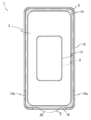
図1は、実施形態に係る保護フィルム貼付器具の斜視図であり、図2は、図1に示した保護フィルム貼付器具のケース内側を示す平面図であり、図3は、図1に示した保護フィルム貼付器具の分解斜視図である。尚、図2は、離型シート6が剥離された状態を示しており、離型シート6の貼付位置を二点鎖線で特定している。
(embodiment)
1 is a perspective view of a protective film applying instrument according to an embodiment, FIG. 2 is a plan view showing the inside of the case of the protective film applying instrument shown in FIG. 1, and FIG. 3 is shown in FIG. It is an exploded perspective view of a protective film sticking instrument. Note that FIG. 2 shows a state in which the
保護フィルム貼付器具1は、ケース2と、保護フィルム3と、保護シート4と、粘着シート5と、離型シート6とを備える。保護フィルム貼付器具1は、保護フィルム3とこの貼付に用いる治具とを一体化したものであり、スマートフォンやタブレット等の電子機器の表示画面に保護フィルム3を位置決めして貼り付けるために用いられる。保護フィルム3の貼付対象となる電子機器は、表示画面を有しているものであれば特に限定されない。
A protective
ケース2は、略矩形状の平面部11と、平面部11の外周縁に接続され、平面部11と略直交する方向に立ち上がる周壁部12とを備える。ケース2は、例えば、樹脂の一体成形品として形成される。平面部11の内面は、貼付対象の電子機器の表示画面を含む面と略同一形状かつ同寸法に構成されており、平面部11の内面と周壁部12の内面とで電子機器を収容可能な収容空間を構成している。ケース2の収容空間内部に電子機器を嵌め込んだ状態では、平面部11の内面が電子機器の表示画面を含む面に沿い、周壁部12の内面が電子機器の側面に沿った状態となる。平面部11には、略矩形状の開口部である窓部13が設けられている。ただし、窓部13の形状は、特に限定されない。平面部11の外面には、窓部13を取り囲む浅い凹部14(図1及び図3において、凹部14の外周縁を細線で示す)が設けられている。凹部14は、窓部13の周縁部に設けられており、後述する保護シート4の周縁部が貼り付けられる部分である。平面部11の内面には、保護フィルム3を収容するための浅い凹部19が設けられている。凹部19の高さ及び幅は、保護フィルムの高さ及び幅と略等しく、凹部19の深さは、保護フィルム3の厚みと同じであることが好ましい。凹部19は、保護フィルム貼付器具1の組み立て時に、ケース2に対して保護フィルム3を位置決めする位置決め部として機能する。凹部19に収容された保護フィルム3は、凹部19の外周縁部分の段差によって平面方向への移動が規制される。
The
周壁部12には、切欠15a、15b及び16が設けられている。切欠15a及び15bは、図2に示すように、互いに対向する位置に設けられている。切欠15a及び15bは、保護フィルム3を電子機器に貼り付けた後、ケース2を電子機器から取り外す際の手掛かりとして用いることができる。また、切欠16は、後述する離型シート6のタブ20を周壁部12より外側に引き出すためのものである。その他、図示を省略しているが、周壁部12には、電子機器の側面に設けられたボタン等の突出部を収容するための凹部や切欠等が適宜設けられる。
Notches 15 a , 15 b and 16 are provided in the
保護フィルム3は、電子機器の表示画面の保護や画像の視認性の向上等を目的として、表示画面に貼り付けられる部材である。保護フィルム3としては、例えば、薄膜状のガラスと1層以上の樹脂層を積層した複合フィルム(「ガラスフィルム」とも称される)や、複数の樹脂層を積層した樹脂フィルム等を例示できるが、保護フィルム3の材質は特に限定されない。保護フィルム3の一方の面は、保護フィルム3を表示画面に貼合するための粘着面である。この粘着面は、例えば、粘着剤を塗布することによって形成することができる。保護フィルム3は、粘着面が平面部11の内面と反対側(ケース2の収容空間の外側)を向き、粘着面と反対側の面が平面部11の内面に沿った状態で、平面部11の内面に設けられた凹部19に収容されている。
The
保護シート4は、平面部11の外面に剥離可能に接着され、保護フィルム3と平面部11とを連結する。また、保護シート4は、窓部13とその周縁部とを覆うことにより、窓部13から露出した保護フィルム3を保護することができる。保護シート4は、保護フィルム3の貼り付け時に、保護フィルム3をケース2から分離するために剥離される部材であり、その一部に剥離時に用いられるタブ17が設けられている。タブ17は、保護シート4を剥離する際の起点として把持される部分であり、平面部11に接着されていない。
The protective sheet 4 is detachably adhered to the outer surface of the flat portion 11 and connects the
また、保護シート4には、マーク18が設けられている。このマーク18は、ケース2の収容空間に電子機器を嵌め込む際の電子機器の向きを示すものである。本実施形態におけるマーク18は、矢印の図形からなり、矢印が指し示す方向が電子機器の上側に対応することを表している。マーク18が設けられていることにより、保護フィルム貼付器具1を電子機器に装着する際に両者の向きを容易に合わせることができ、貼り付け時の作業性が向上する。尚、マーク18は必ずしも矢印である必要はなく、電子機器の向きを特定できるものであれば、他の図形や文字であっても良い。
A
粘着シート5は、窓部13から露出した保護フィルム3の一部と保護シート4との間に挟まれ、保護シート4及び保護フィルム3のそれぞれに貼り付けられる。粘着シート5は、窓部13から露出した保護フィルム3の一部と保護シート4の粘着面とが直接接着する部分の面積を小さくし、保護シート4の粘着剤が保護フィルム3の表面に残ってしまうことを抑制するために設けられる。粘着シート5は、窓部13の内側に設けられていれば良いが、保護シート4から保護フィルム3への粘着剤移りをできるだけ低減するために、粘着シート5は、窓部13と略同一形状であって、窓部13と同じ寸法もしくは窓部13より僅かに小さい寸法を有することが好ましい。また、保護シート4の剥離時に、粘着シート5を保護シート4と共に保護フィルム3から剥離できるように、弱粘着の粘着剤を使用するなどして、保護フィルム3に対する粘着シート5の粘着強度が調整される。
The
離型シート6は、保護フィルム3の粘着面を保護するためのものであり、保護フィルム3の粘着面に剥離可能に貼り付けられる。離型シート6には、剥離時に把持するためのタブ20が設けられており、タブ20は、ケース2の周壁部12に設けられた切欠16から外部へと突出するように配置される。離型シート6は、保護フィルム3の粘着面に埃等が付着することを防止するためのものであるので、保護フィルム3の粘着面の全体を覆うことができる形状に形成される。離型シート6のタブ20を除く部分は、保護フィルム3と同一形状であっても良いが、図2に示すように、保護フィルム3の外周縁の全周に渡って、離型シート6の外周縁が保護フィルム3の外周縁より外側に位置するよう、保護フィルム3より大きく形成することが好ましい。本実施形態では、図2に示すように、離型シート6のタブ20を除く部分は、平面部11の内面と略同一形状を有しており、保護フィルム3の外周縁より外側に延伸した離型シート6の一部が、平面部11の内面のうち、凹部19の周縁部分に貼り付けられている。このように、保護フィルム3の外周縁より外側に延伸した離型シート6の一部を平面部11に貼り付けると、保護シート4に支持されていない保護フィルム3の外周縁部分を平面部に固定できるので、ケース2に対する保護フィルム3の取り付け状態を安定させることができる。また、保護フィルム3と平面部11との隙間を離型シート6で塞ぐことにより、保護フィルム貼付器具1の使用前に保護フィルム3と平面部11の内面との間に埃等が侵入することを防止できる。本実施形態では、保護フィルム3を位置決めするための凹部19の深さを保護フィルム3の厚みと等しくしていることで、保護フィルム3の粘着面と凹部19の周縁部とが面一となるので、皺を生じさせることなく離型シート6を平面部11に貼り付けることができ、上述した取り付け状態の安定性と埃の侵入抑制の面でより好ましい。
The
ここで、保護フィルム貼付器具1の使用方法を説明する。
Here, the usage method of the protective
まず、図1に示す状態の保護フィルム貼付器具1から離型シート6を剥離し、図2に示すように、保護フィルム3の粘着面を露出させる。離型シート6には、切欠16を通じて周壁部12の外側に延伸するタブ20が設けられているので、タブ20を把持することにより離型シート6を容易に剥離することができる。
First, the
次に、離型シート6を剥離した状態の保護フィルム貼付器具1と電子機器の向きを合わせると共に、露出した保護フィルム3の粘着面と電子機器の表示画面とを対向させ、ケース2の収容空間に電子機器を嵌め込む。保護シート4には、電子機器の向きを示すマーク18が設けられているので、保護フィルム貼付器具1と電子機器の向きを容易に合わせることができる。ただし、電子機器の表示画面における非貼付面が対称であり、保護フィルム3の貼り付け方向に制限がない場合には、保護フィルム貼付器具1と電子機器の向きを合わせる作業を省略することができる。
Next, the direction of the protective
次に、電子機器をケース2の収容空間に嵌め込んだまま、保護シート4と粘着シート5とを剥離する。保護シート4には、平面部11に接着されていないタブ17が設けられているので、タブ17を把持することにより保護シート4を容易に剥離することができる。保護シート4及び粘着シート5を剥離した状態で、保護フィルム3を電子機器側に押圧するなどして、保護フィルム3を電子機器の表示画面に密着させる。
Next, the protective sheet 4 and the
その後、ケース2のみを電子機器から分離することによって、保護フィルム3の貼付作業が完了する。保護シート4及び粘着シート5を剥離することにより、保護フィルム3とケース2との連結が解除されているので、保護フィルム3が貼り付けられた電子機器からケース2を容易に分離することができる。
After that, by separating only the
上述の通り、本実施形態に係る保護フィルム貼付器具1においては、ケース2に平面部11が設けられている。平面部11によりケース2の剛性が向上するので、ケース2に電子機器を嵌め込む際や、ケース2に電子機器を嵌め込んだ状態でのケース2の変形を抑制することができる。ケース2の変形が抑制されることにより、保護フィルム3の粘着面を電子機器の表示画面に接触させる際の保護フィルム3の撓みを小さくできるので、保護フィルム3と表示画面との間への気泡の混入を低減できる。また、ケース2の剛性が高いことにより、保護フィルム3の貼り付け時における位置決め精度も向上できる。したがって、本実施形態に係る保護フィルム貼付器具1を用いることにより、電子機器への保護フィルム3の貼付ミスを低減することが可能となる。
As described above, in the protective
また、本実施形態に係る保護フィルム貼付器具1では、電子機器の表示画面に保護フィルム3の粘着面が接触するまで、ケース2に保護フィルム3が保持され、粘着面が露出した保護フィルム3を手で直接把持する必要がないため、保護フィルム3の貼り付け時に粘着面や表示画面に指紋を付着させてしまうことを抑制することができる。
Further, in the protective
また、本実施形態に係る保護フィルム貼付器具1は、保護フィルム3の表面を保護するための保護シート4を備えるが、この保護シート4はケース2の周壁部12ではなく、平面部11に貼り付ければ良いため、保護シート4の貼り付け位置の精度を厳密に管理する必要がなく、保護シート4の貼付作業も容易である。したがって、本実施形態に係る保護フィルム貼付器具1であれば、組み立て製造時における製造効率も良好である。
In addition, the protective
以下、図3を参照して、平面部11の寸法について好ましい条件を説明する。 Preferred conditions for the dimensions of the plane portion 11 will be described below with reference to FIG.
平面部11の一辺と平行な方向D1及びこれと直交する方向D2における窓部13の外周縁から平面部11の外周縁までの距離L1~L4(すなわち窓部13の外周縁から平面部11の外周縁までの最短距離)は、どの部分においても10mm以上であることが好ましい。窓部13の外周縁から平面部11の外周縁までの距離L1~L4が10mm以上となるように平面部11を構成すると、ケース2の剛性をより向上させてケース2の変形を十分に抑制できるのでより好ましい。窓部13の外周縁から平面部11の外周縁までの距離が10mm未満の場合、ケース2の剛性を担保する部分が少なくなるため、使用時にケース2が変形しやすくなる可能性がある。
Distances L1 to L4 from the outer peripheral edge of the
また、平面部11の面積に対する窓部13の面積の割合が50%以下であることが好ましい。平面部11の面積は、ケース2を平面視したときの面積であって、窓部13とその周囲の実態のある部分との面積である。窓部13の面積が平面部11の面積の50%以下であれば、平面部11に対して窓部13が十分に小さくなることにより、ケース2の剛性をより一層向上させてケース2の変形を更に抑制することができるので更に好ましい。また、窓部13の大きさを十分に小さくすることにより、組み立て製造時における保護シート4の貼り付け位置の調整を更に容易とすることができる。窓部13の面積が平面部11の面積の50%を超える場合、窓部13の外周縁から平面部11の外周縁までの距離が短くなり、ケース2の剛性を担保する部分が少なくなるため、使用時にケース2が変形しやすくなる可能性がある。また、窓部13の外周縁から平面部11の外周縁までの距離が短くなり、保護シート4の貼り付けやすさにも影響する可能性がある。
Moreover, it is preferable that the ratio of the area of the
以上説明したように、本発明によれば、保護フィルムの貼り付け時に気泡が混入したり指紋が付着したりすることを低減でき、製造効率も良好な保護フィルム貼付器具を実現できる。 As described above, according to the present invention, it is possible to reduce the inclusion of air bubbles and the adherence of fingerprints during the application of the protective film, and to realize a protective film applying device with good manufacturing efficiency.
(その他の変形例)
上記の実施形態では、保護フィルム3と保護シート4との間に粘着シート5を挟んだ構成を例示したが、粘着シート5は省略しても良い。この場合、保護シート4の粘着面の粘着強度を調整するなどして、保護シート4から保護フィルム3への粘着剤が移ることを抑制することが好ましい。
(Other modifications)
In the above embodiment, the
また、上記の実施形態では、保護シート4にマーク18を設けた構成を例示したが、マーク18は省略しても良い。また、電子機器の向きを示すマークは、ケース2に設けても良いし、ケース2と保護シート4の両方に設けても良い。
Further, in the above-described embodiment, the
また、上記の実施形態では、平面部11の内面に設けた凹部19により保護フィルム3を位置決めする構成を説明したが、ケース2に対する保護フィルム3の位置を規定し、保護フィルム3の平面方向の移動を規制できるものであれば、平面部11の内面に設けた凸部等により位置決め部を構成しても良い。また、平面部11の内面には凹部19等の位置決め部がなくても良い。平面部11の内面に位置決め部がない場合、保護フィルム貼付器具1の組み立て時に治具等を用いてケース2内における保護フィルム3の位置決めを行い、保護シート4を貼り付けることによって保護フィルム3をケース2に固定すれば良い。
Further, in the above-described embodiment, the configuration in which the
また、上記の実施形態では、平面部11の外面に凹部14を設けた構成例を例示したが、平面部11の外面の凹部14はなくても良い。ただし、凹部14を設けることによって、保護シート4の貼り付けがしやすくなるという利点がある。
Further, in the above-described embodiment, the configuration example in which the
また、上記の実施形態では、離型シート6にタブ20を設けた構成例を例示したが、タブ20はなくても良い。離型シート6にタブ20を設けない場合、例えば、離型シート6とは別体のシール等の部材を離型シート6の表面に部分的に貼り付け、この部材をタブの代わりに用いることで離型シート6の剥離を容易に行うことができる。
Further, in the above-described embodiment, the configuration example in which the
本発明は、スマートフォンやタブレット等の電子機器の表示画面に保護フィルムを貼り付けるための保護フィルム付き貼付器具として利用できる。 INDUSTRIAL APPLICABILITY The present invention can be used as a sticking device with a protective film for sticking a protective film on the display screen of an electronic device such as a smart phone or a tablet.
1 保護フィルム貼付器具
2 ケース
3 保護フィルム
4 保護シート
5 粘着シート
6 離型シート
11 平面部
12 周壁部
13 窓部
18 マーク
19 凹部
1 protective
Claims (6)
窓部を有する略矩形状の平面部と、前記平面部の外周縁から前記平面部と略直交する方向に立ち上がる周壁部とを有し、前記平面部の内面と前記周壁部の内面とにより電子機器を収容可能な収容空間を構成するケースと、
前記平面部の内面に沿うように配置され、前記平面部の内面に沿う面と反対側に粘着面を有する保護フィルムと、
前記ケースの前記窓部と前記窓部の周縁部とを覆うように前記平面部の外面に剥離可能に貼り付けられ、前記保護フィルムと前記平面部とを連結する保護シートと、
前記窓部の内側に設けられ、前記保護シートと前記保護フィルムとの間に挟まれて、前記保護シート及び前記保護フィルムに貼り付けられる粘着シートとを備える、保護フィルム貼付器具。 A protective film application device,
It has a substantially rectangular flat portion having a window portion, and a peripheral wall portion rising from the outer peripheral edge of the flat portion in a direction substantially orthogonal to the flat portion. a case forming an accommodation space capable of accommodating the device;
a protective film arranged along the inner surface of the flat portion and having an adhesive surface on the side opposite to the surface along the inner surface of the flat portion;
a protective sheet that is detachably attached to the outer surface of the flat portion so as to cover the window portion of the case and a peripheral portion of the window portion, and that connects the protective film and the flat portion ;
A protective film sticking instrument provided inside the window portion, comprising: an adhesive sheet sandwiched between the protective sheet and the protective film and stuck to the protective sheet and the protective film.
Priority Applications (1)
| Application Number | Priority Date | Filing Date | Title |
|---|---|---|---|
| JP2019197561A JP7260909B2 (en) | 2019-10-30 | 2019-10-30 | Protective film application device |
Applications Claiming Priority (1)
| Application Number | Priority Date | Filing Date | Title |
|---|---|---|---|
| JP2019197561A JP7260909B2 (en) | 2019-10-30 | 2019-10-30 | Protective film application device |
Publications (3)
| Publication Number | Publication Date |
|---|---|
| JP2021071568A JP2021071568A (en) | 2021-05-06 |
| JP2021071568A5 JP2021071568A5 (en) | 2022-02-24 |
| JP7260909B2 true JP7260909B2 (en) | 2023-04-19 |
Family
ID=75713722
Family Applications (1)
| Application Number | Title | Priority Date | Filing Date |
|---|---|---|---|
| JP2019197561A Active JP7260909B2 (en) | 2019-10-30 | 2019-10-30 | Protective film application device |
Country Status (1)
| Country | Link |
|---|---|
| JP (1) | JP7260909B2 (en) |
Families Citing this family (1)
| Publication number | Priority date | Publication date | Assignee | Title |
|---|---|---|---|---|
| JP2023081846A (en) * | 2021-11-17 | 2023-06-13 | 東莞市菠蘿光電智造有限公司 | Sticking film and film sticking assembly |
Citations (5)
| Publication number | Priority date | Publication date | Assignee | Title |
|---|---|---|---|---|
| JP2010134117A (en) | 2008-12-03 | 2010-06-17 | Panasonic Corp | Image display device |
| JP2016098028A (en) | 2014-11-26 | 2016-05-30 | 株式会社 共栄精機 | Package of protection film for smartphone |
| JP2017097007A (en) | 2015-11-18 | 2017-06-01 | 株式会社Kalbas | Sticking jig of flat panel display device protection cover, and sticking kit of flat panel display device protection cover |
| JP2017130907A (en) | 2016-01-21 | 2017-07-27 | エレコム株式会社 | Protection film attachment instrument and protection film attachment method using the same |
| CN206750242U (en) | 2017-07-06 | 2017-12-15 | 深圳比途科技有限公司 | A kind of screen sticking film device and multifunctional packing box |
-
2019
- 2019-10-30 JP JP2019197561A patent/JP7260909B2/en active Active
Patent Citations (5)
| Publication number | Priority date | Publication date | Assignee | Title |
|---|---|---|---|---|
| JP2010134117A (en) | 2008-12-03 | 2010-06-17 | Panasonic Corp | Image display device |
| JP2016098028A (en) | 2014-11-26 | 2016-05-30 | 株式会社 共栄精機 | Package of protection film for smartphone |
| JP2017097007A (en) | 2015-11-18 | 2017-06-01 | 株式会社Kalbas | Sticking jig of flat panel display device protection cover, and sticking kit of flat panel display device protection cover |
| JP2017130907A (en) | 2016-01-21 | 2017-07-27 | エレコム株式会社 | Protection film attachment instrument and protection film attachment method using the same |
| CN206750242U (en) | 2017-07-06 | 2017-12-15 | 深圳比途科技有限公司 | A kind of screen sticking film device and multifunctional packing box |
Also Published As
| Publication number | Publication date |
|---|---|
| JP2021071568A (en) | 2021-05-06 |
Similar Documents
| Publication | Publication Date | Title |
|---|---|---|
| US9192086B2 (en) | Application device for screen protector and application method thereof | |
| JP5845370B1 (en) | Protective film sticking jig | |
| JP2014525167A (en) | Protective film attaching device, protective film attaching module including the same, and protective film attaching method using the protective film attaching device | |
| TWI510364B (en) | Adhesive component | |
| KR20120071195A (en) | Panel protective film unit and method of assembling panel using thereof | |
| TW201413324A (en) | Tool for attaching protection film for display of mobile electronic device, apparatus for attaching protection film for display of mobile electronic device, kit for attaching protection film for display of mobile electronic device | |
| JP7260909B2 (en) | Protective film application device | |
| KR101341865B1 (en) | Module for attaching protective film | |
| JP2017161575A (en) | Jig and system | |
| JP5328422B2 (en) | Electronic component holder | |
| KR101341869B1 (en) | Device for attaching protective film, module with the same, and method for attaching protective film using the device | |
| JP5995636B2 (en) | Support jig for semiconductor wafer plating | |
| KR20150082132A (en) | Smart phone protective film and method for installing the same | |
| JP2023007871A (en) | Sheet for adhering protection sheet on display screen, and adhering system for adhering the same | |
| US11012547B2 (en) | Electronic device | |
| US11548210B2 (en) | Screen protector application system | |
| US9753594B2 (en) | Electrostatic capacitance operation device fabrication method, operation panel, and electrostatic capacitance operation device | |
| JP6137830B2 (en) | Display device | |
| JP5191158B2 (en) | Display device | |
| WO2021052118A1 (en) | Protective film, protective film assembly, display screen assembly, and terminal | |
| JP2016147676A (en) | Packaging body of touch panel, protective film and manufacturing method for packaging body of touch panel | |
| JPWO2016035196A1 (en) | Protective sheet | |
| JP6662586B2 (en) | Sticking jig double-purpose packaging member and sticking method | |
| CN211194913U (en) | Camera lens protection pastes tool of pasting | |
| JP2019148978A (en) | panel |
Legal Events
| Date | Code | Title | Description |
|---|---|---|---|
| A80 | Written request to apply exceptions to lack of novelty of invention |
Free format text: JAPANESE INTERMEDIATE CODE: A80 Effective date: 20191125 |
|
| RD01 | Notification of change of attorney |
Free format text: JAPANESE INTERMEDIATE CODE: A7426 Effective date: 20191213 |
|
| A521 | Request for written amendment filed |
Free format text: JAPANESE INTERMEDIATE CODE: A821 Effective date: 20191213 |
|
| A521 | Request for written amendment filed |
Free format text: JAPANESE INTERMEDIATE CODE: A523 Effective date: 20220215 |
|
| A621 | Written request for application examination |
Free format text: JAPANESE INTERMEDIATE CODE: A621 Effective date: 20220215 |
|
| A977 | Report on retrieval |
Free format text: JAPANESE INTERMEDIATE CODE: A971007 Effective date: 20220915 |
|
| A131 | Notification of reasons for refusal |
Free format text: JAPANESE INTERMEDIATE CODE: A131 Effective date: 20221004 |
|
| A521 | Request for written amendment filed |
Free format text: JAPANESE INTERMEDIATE CODE: A523 Effective date: 20221122 |
|
| TRDD | Decision of grant or rejection written | ||
| A01 | Written decision to grant a patent or to grant a registration (utility model) |
Free format text: JAPANESE INTERMEDIATE CODE: A01 Effective date: 20230328 |
|
| A61 | First payment of annual fees (during grant procedure) |
Free format text: JAPANESE INTERMEDIATE CODE: A61 Effective date: 20230331 |
|
| R150 | Certificate of patent or registration of utility model |
Ref document number: 7260909 Country of ref document: JP Free format text: JAPANESE INTERMEDIATE CODE: R150 |
|
| R250 | Receipt of annual fees |
Free format text: JAPANESE INTERMEDIATE CODE: R250 |