JP7258755B2 - Apparatus for flexible instrument insertion - Google Patents
Apparatus for flexible instrument insertion Download PDFInfo
- Publication number
- JP7258755B2 JP7258755B2 JP2019534667A JP2019534667A JP7258755B2 JP 7258755 B2 JP7258755 B2 JP 7258755B2 JP 2019534667 A JP2019534667 A JP 2019534667A JP 2019534667 A JP2019534667 A JP 2019534667A JP 7258755 B2 JP7258755 B2 JP 7258755B2
- Authority
- JP
- Japan
- Prior art keywords
- controller
- sheath
- sensor
- endoscope
- elongated body
- Prior art date
- Legal status (The legal status is an assumption and is not a legal conclusion. Google has not performed a legal analysis and makes no representation as to the accuracy of the status listed.)
- Active
Links
Images


Classifications
-
- A—HUMAN NECESSITIES
- A61—MEDICAL OR VETERINARY SCIENCE; HYGIENE
- A61B—DIAGNOSIS; SURGERY; IDENTIFICATION
- A61B34/00—Computer-aided surgery; Manipulators or robots specially adapted for use in surgery
- A61B34/30—Surgical robots
-
- A—HUMAN NECESSITIES
- A61—MEDICAL OR VETERINARY SCIENCE; HYGIENE
- A61B—DIAGNOSIS; SURGERY; IDENTIFICATION
- A61B34/00—Computer-aided surgery; Manipulators or robots specially adapted for use in surgery
- A61B34/20—Surgical navigation systems; Devices for tracking or guiding surgical instruments, e.g. for frameless stereotaxis
-
- A—HUMAN NECESSITIES
- A61—MEDICAL OR VETERINARY SCIENCE; HYGIENE
- A61B—DIAGNOSIS; SURGERY; IDENTIFICATION
- A61B34/00—Computer-aided surgery; Manipulators or robots specially adapted for use in surgery
- A61B34/70—Manipulators specially adapted for use in surgery
- A61B34/71—Manipulators operated by drive cable mechanisms
-
- A—HUMAN NECESSITIES
- A61—MEDICAL OR VETERINARY SCIENCE; HYGIENE
- A61B—DIAGNOSIS; SURGERY; IDENTIFICATION
- A61B90/00—Instruments, implements or accessories specially adapted for surgery or diagnosis and not covered by any of the groups A61B1/00 - A61B50/00, e.g. for luxation treatment or for protecting wound edges
- A61B90/06—Measuring instruments not otherwise provided for
-
- B—PERFORMING OPERATIONS; TRANSPORTING
- B25—HAND TOOLS; PORTABLE POWER-DRIVEN TOOLS; MANIPULATORS
- B25J—MANIPULATORS; CHAMBERS PROVIDED WITH MANIPULATION DEVICES
- B25J9/00—Programme-controlled manipulators
- B25J9/16—Programme controls
- B25J9/1628—Programme controls characterised by the control loop
- B25J9/1633—Programme controls characterised by the control loop compliant, force, torque control, e.g. combined with position control
-
- A—HUMAN NECESSITIES
- A61—MEDICAL OR VETERINARY SCIENCE; HYGIENE
- A61B—DIAGNOSIS; SURGERY; IDENTIFICATION
- A61B17/00—Surgical instruments, devices or methods, e.g. tourniquets
- A61B2017/00743—Type of operation; Specification of treatment sites
- A61B2017/00809—Lung operations
-
- A—HUMAN NECESSITIES
- A61—MEDICAL OR VETERINARY SCIENCE; HYGIENE
- A61B—DIAGNOSIS; SURGERY; IDENTIFICATION
- A61B17/00—Surgical instruments, devices or methods, e.g. tourniquets
- A61B17/22—Implements for squeezing-off ulcers or the like on the inside of inner organs of the body; Implements for scraping-out cavities of body organs, e.g. bones; Calculus removers; Calculus smashing apparatus; Apparatus for removing obstructions in blood vessels, not otherwise provided for
- A61B2017/22072—Implements for squeezing-off ulcers or the like on the inside of inner organs of the body; Implements for scraping-out cavities of body organs, e.g. bones; Calculus removers; Calculus smashing apparatus; Apparatus for removing obstructions in blood vessels, not otherwise provided for with an instrument channel, e.g. for replacing one instrument by the other
- A61B2017/22074—Implements for squeezing-off ulcers or the like on the inside of inner organs of the body; Implements for scraping-out cavities of body organs, e.g. bones; Calculus removers; Calculus smashing apparatus; Apparatus for removing obstructions in blood vessels, not otherwise provided for with an instrument channel, e.g. for replacing one instrument by the other the instrument being only slidable in a channel, e.g. advancing optical fibre through a channel
- A61B2017/22075—Implements for squeezing-off ulcers or the like on the inside of inner organs of the body; Implements for scraping-out cavities of body organs, e.g. bones; Calculus removers; Calculus smashing apparatus; Apparatus for removing obstructions in blood vessels, not otherwise provided for with an instrument channel, e.g. for replacing one instrument by the other the instrument being only slidable in a channel, e.g. advancing optical fibre through a channel with motorized advancing or retracting means
-
- A—HUMAN NECESSITIES
- A61—MEDICAL OR VETERINARY SCIENCE; HYGIENE
- A61B—DIAGNOSIS; SURGERY; IDENTIFICATION
- A61B34/00—Computer-aided surgery; Manipulators or robots specially adapted for use in surgery
- A61B34/20—Surgical navigation systems; Devices for tracking or guiding surgical instruments, e.g. for frameless stereotaxis
- A61B2034/2046—Tracking techniques
- A61B2034/2048—Tracking techniques using an accelerometer or inertia sensor
-
- A—HUMAN NECESSITIES
- A61—MEDICAL OR VETERINARY SCIENCE; HYGIENE
- A61B—DIAGNOSIS; SURGERY; IDENTIFICATION
- A61B34/00—Computer-aided surgery; Manipulators or robots specially adapted for use in surgery
- A61B34/20—Surgical navigation systems; Devices for tracking or guiding surgical instruments, e.g. for frameless stereotaxis
- A61B2034/2046—Tracking techniques
- A61B2034/2051—Electromagnetic tracking systems
-
- A—HUMAN NECESSITIES
- A61—MEDICAL OR VETERINARY SCIENCE; HYGIENE
- A61B—DIAGNOSIS; SURGERY; IDENTIFICATION
- A61B34/00—Computer-aided surgery; Manipulators or robots specially adapted for use in surgery
- A61B34/20—Surgical navigation systems; Devices for tracking or guiding surgical instruments, e.g. for frameless stereotaxis
- A61B2034/2046—Tracking techniques
- A61B2034/2055—Optical tracking systems
-
- A—HUMAN NECESSITIES
- A61—MEDICAL OR VETERINARY SCIENCE; HYGIENE
- A61B—DIAGNOSIS; SURGERY; IDENTIFICATION
- A61B34/00—Computer-aided surgery; Manipulators or robots specially adapted for use in surgery
- A61B34/20—Surgical navigation systems; Devices for tracking or guiding surgical instruments, e.g. for frameless stereotaxis
- A61B2034/2046—Tracking techniques
- A61B2034/2061—Tracking techniques using shape-sensors, e.g. fiber shape sensors with Bragg gratings
-
- A—HUMAN NECESSITIES
- A61—MEDICAL OR VETERINARY SCIENCE; HYGIENE
- A61B—DIAGNOSIS; SURGERY; IDENTIFICATION
- A61B34/00—Computer-aided surgery; Manipulators or robots specially adapted for use in surgery
- A61B34/30—Surgical robots
- A61B2034/301—Surgical robots for introducing or steering flexible instruments inserted into the body, e.g. catheters or endoscopes
-
- A—HUMAN NECESSITIES
- A61—MEDICAL OR VETERINARY SCIENCE; HYGIENE
- A61B—DIAGNOSIS; SURGERY; IDENTIFICATION
- A61B34/00—Computer-aided surgery; Manipulators or robots specially adapted for use in surgery
- A61B34/30—Surgical robots
- A61B2034/303—Surgical robots specifically adapted for manipulations within body lumens, e.g. within lumen of gut, spine, or blood vessels
-
- A—HUMAN NECESSITIES
- A61—MEDICAL OR VETERINARY SCIENCE; HYGIENE
- A61B—DIAGNOSIS; SURGERY; IDENTIFICATION
- A61B34/00—Computer-aided surgery; Manipulators or robots specially adapted for use in surgery
- A61B34/70—Manipulators specially adapted for use in surgery
- A61B34/71—Manipulators operated by drive cable mechanisms
- A61B2034/715—Cable tensioning mechanisms for removing slack
-
- A—HUMAN NECESSITIES
- A61—MEDICAL OR VETERINARY SCIENCE; HYGIENE
- A61B—DIAGNOSIS; SURGERY; IDENTIFICATION
- A61B90/00—Instruments, implements or accessories specially adapted for surgery or diagnosis and not covered by any of the groups A61B1/00 - A61B50/00, e.g. for luxation treatment or for protecting wound edges
- A61B90/06—Measuring instruments not otherwise provided for
- A61B2090/064—Measuring instruments not otherwise provided for for measuring force, pressure or mechanical tension
-
- A—HUMAN NECESSITIES
- A61—MEDICAL OR VETERINARY SCIENCE; HYGIENE
- A61B—DIAGNOSIS; SURGERY; IDENTIFICATION
- A61B90/00—Instruments, implements or accessories specially adapted for surgery or diagnosis and not covered by any of the groups A61B1/00 - A61B50/00, e.g. for luxation treatment or for protecting wound edges
- A61B90/06—Measuring instruments not otherwise provided for
- A61B2090/067—Measuring instruments not otherwise provided for for measuring angles
-
- G—PHYSICS
- G05—CONTROLLING; REGULATING
- G05B—CONTROL OR REGULATING SYSTEMS IN GENERAL; FUNCTIONAL ELEMENTS OF SUCH SYSTEMS; MONITORING OR TESTING ARRANGEMENTS FOR SUCH SYSTEMS OR ELEMENTS
- G05B2219/00—Program-control systems
- G05B2219/30—Nc systems
- G05B2219/40—Robotics, robotics mapping to robotics vision
- G05B2219/40223—If insertion force to high, alarm, stop for operator assistance
-
- G—PHYSICS
- G05—CONTROLLING; REGULATING
- G05B—CONTROL OR REGULATING SYSTEMS IN GENERAL; FUNCTIONAL ELEMENTS OF SUCH SYSTEMS; MONITORING OR TESTING ARRANGEMENTS FOR SUCH SYSTEMS OR ELEMENTS
- G05B2219/00—Program-control systems
- G05B2219/30—Nc systems
- G05B2219/40—Robotics, robotics mapping to robotics vision
- G05B2219/40599—Force, torque sensor integrated in joint
-
- G—PHYSICS
- G05—CONTROLLING; REGULATING
- G05B—CONTROL OR REGULATING SYSTEMS IN GENERAL; FUNCTIONAL ELEMENTS OF SUCH SYSTEMS; MONITORING OR TESTING ARRANGEMENTS FOR SUCH SYSTEMS OR ELEMENTS
- G05B2219/00—Program-control systems
- G05B2219/30—Nc systems
- G05B2219/45—Nc applications
- G05B2219/45118—Endoscopic, laparoscopic manipulator
Description
関連出願の相互参照
本出願は、「DETECTING ENDOLUMENAL BUCKLING OF
FLEXIBLE INSTRUMENTS」と題され2016年12月28日に出願された米国特許出願第15/392,917号と、「FLEXIBLE INSTRUMENT INSERTION USING AN ADAPTIVE INSERTION FORCE THRESHOLD」と題され2016年12月28日に出願された米国特許出願第15/392,868号とに対する優先権を主張する。これらのおのおのは、すべての目的のために全体が参照により本明細書に組み入れられる。
CROSS-REFERENCE TO RELATED APPLICATIONS
No. 15/392,917, filed December 28, 2016, entitled "FLEXIBLE INSTRUMENTS" and "FLEXIBLE INSTRUMENT INSERTION USING AN ADAPTIVE INSERTION FORCE THRESHOLD," filed December 28, 2016. No. 15/392,868, filed herewith. each of which is hereby incorporated by reference in its entirety for all purposes.
本記載は、一般に、手術用ロボット工学に関し、特に、患者の生体構造的内腔内への手術用器具の挿入を制御することに関する。 TECHNICAL FIELD This description relates generally to surgical robotics and, more particularly, to controlling the insertion of surgical instruments into anatomical lumens of a patient.
ロボット技術には様々な用途がある。特に、ロボットアームは、人間が通常実行するであろうタスクを完成させることに役立つ。たとえば、工場では、ロボットアームを使用して、自動車や家電製品を製造している。さらに、科学施設は、マイクロプレートを輸送するなど、実験手順を自動化するためにロボットアームを使用する。最近、内科医および/または外科医は、手術手順の実行に役立てるためにロボットアームを使用し始めている。たとえば、内科医および/または外科医は、ロボットアームを使用して、内視鏡などの手術用器具を制御する。 Robot technology has many uses. In particular, robotic arms are useful in completing tasks that humans would normally perform. For example, factories are using robotic arms to make cars and home appliances. In addition, scientific facilities use robotic arms to automate experimental procedures, such as transporting microplates. Recently, physicians and/or surgeons have begun using robotic arms to help perform surgical procedures. For example, physicians and/or surgeons use robotic arms to control surgical instruments such as endoscopes.
内視鏡は、低侵襲的な方式で手術手順を実行することができる。内視鏡は、肺または血管などの患者の目標位置に向けられる。ロボットアームは、患者の内腔内の目標位置へ向けて、内視鏡を、患者の開いたアクセスポイント、たとえば口、肛門、尿道に挿入するために力を加える。内視鏡が、患者の生体構造へより深く挿入されると、内視鏡は、挿入力が大きすぎると壊れやすく破れやすくなり得る内部の生体構造に対して、ブラッシングし、擦り、そして押し付ける可能性がある。
さらに、内視鏡が目標位置に移動する間、内視鏡は、典型的には、内視鏡の弛みまたは挿入の固着および患者の生体構造と接触することによる偶発的な力に応答して座屈することがある。内視鏡が座屈すると、内科医および/または外科医はスコープを押し続け、内視鏡を前進させるために、挿入力を通常のレベルを超えて増大させる。これは内視鏡の座屈部分が、望ましくない潜在エネルギーを蓄積する危険性を生み出す。これは患者の内腔/腔内で制御不可能な手法で巻き戻る、または内視鏡を損傷させる可能性がある。
Endoscopes can perform surgical procedures in a minimally invasive manner. The endoscope is aimed at a target location in the patient, such as the lungs or blood vessels. The robotic arm is directed to a target location within the patient's lumen and applies force to insert the endoscope into the patient's open access point, such as the mouth, anus, or urethra. As the endoscope is inserted deeper into the patient's anatomy, the endoscope can brush, scrape, and press against internal anatomy that can become fragile and brittle if too much insertion force is applied. have a nature.
Furthermore, while the endoscope is moving to a target location, the endoscope typically responds to accidental forces due to loosening or sticking of the insertion and contact with the patient's anatomy. Buckling may occur. As the endoscope buckles, the physician and/or surgeon continues to push on the scope, increasing insertion force beyond normal levels to advance the endoscope. This creates the risk that the buckling portion of the endoscope will accumulate unwanted potential energy. This can roll back in an uncontrolled manner within the patient lumen/cavity or damage the endoscope.
本開示は、座屈を検出するために、可撓性器具の長尺体の1つまたは複数の部分に配置された1つまたは複数のセンサを有する可撓性器具について説明する。1つまたは複数のセンサは、同じ種類でも異なる種類でもよい。コマンドが長尺体に指示されると、1つまたは複数のセンサから捕捉されたセンサデータは、座屈が生じたか否かを判定するためのコマンドに応じて受信されると予想されるデータと比較される。 This disclosure describes a flexible instrument having one or more sensors positioned on one or more portions of the elongate body of the flexible instrument to detect buckling. The one or more sensors may be of the same type or of different types. When a command is directed to the elongated body, the sensor data captured from the one or more sensors is combined with data expected to be received in response to the command to determine whether buckling has occurred. be compared.
本開示は、器具の座屈または患者への起こり得る損傷を回避するために、患者の内腔内での器具の挿入力を調節するための挿入力閾値の決定について説明する。挿入力閾値は、器具が手術部位に移動するとき、器具から捕捉されたリアルタイムデータ、および、患者に関連付けられるデータに基づいて動的に決定され得る。さらに、または、代わりに、挿
入力閾値は、少なくとも部分的にあらかじめ決定され、術前モデルの異なる部分にタグ付けされ得る。
The present disclosure describes determination of an insertion force threshold for adjusting the insertion force of an instrument within a patient's lumen to avoid buckling of the instrument or possible injury to the patient. The insertion force threshold can be dynamically determined based on real-time data captured from the instrument and data associated with the patient as the instrument is moved to the surgical site. Additionally or alternatively, the insertion force thresholds may be at least partially predetermined and tagged to different portions of the preoperative model.
他の態様には、方法、構成要素、デバイス、システム、改良、方法、プロセス、アプリケーション、コンピュータ可読媒体、および上記のいずれかに関連する他の技術が含まれる。 Other aspects include methods, components, devices, systems, improvements, methods, processes, applications, computer-readable media, and other techniques related to any of the above.
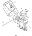
図6Bは、一実施形態による、手術部位で使用される図6Aに図示される内視鏡を例示する。 Figure 6B illustrates the endoscope illustrated in Figure 6A being used at a surgical site, according to one embodiment.
図面は、例示のみを目的として本発明の実施形態を描写する。当業者は、本明細書に記載された本発明の原理から逸脱することなく、本明細書に例示された構造および方法の代替実施形態が適用され得ることを以下の議論から容易に認識するであろう。 The drawings depict embodiments of the present invention for purposes of illustration only. A person skilled in the art will readily recognize from the following discussion that alternative embodiments of the structures and methods illustrated herein may be applied without departing from the inventive principles described herein. be.
I.ロボット工学的な可撓性器具システムの基本
本明細書に開示されている方法および装置は、「SYSTEM FOR ROBOTI
C-ASSISTED ENDOLUMENAL SURGERY AND RELATED METHODS」と題され、2014年10月24日に出願され、米国特許出願第2015/0119637号として公開された米国特許出願第14/523,760号に記載されているような1つまたは複数の内視鏡構成要素またはステップと共に使用するのに非常に適しており、その全開示は参照により本明細書に組み込まれる。前述の出願は、システム構成要素、管腔内システム、仮想レール構成、機構チェンジャインターフェース、器具デバイスマニピュレータ(IDM)、内視鏡ツール設計、制御コンソール、内視鏡、器具デバイスマニピュレータ、管腔内ナビゲーション、および本明細書に開示された実施形態にしたがう組合せのために適切な管腔内手順を記載している。上記出願に記載されている原理はカテーテル設計にも適用可能である。概して、この記載の以下のセクションは内視鏡の実施形態を記載するが、これは単なる一例であり、以下の記載は、カテーテル、またはより一般的には長尺体を有する任意の可撓性器具と連携して実装および/または使用され得る。
I. Fundamentals of Robotic Flexible Instrument Systems The methods and apparatus disclosed herein are "SYSTEM FOR ROBOTI
C-ASSISTED ENDOLUMENAL SURGERY AND RELATED METHODS”, filed Oct. 24, 2014 and published as U.S. Patent Application No. 2015/0119637. , the full disclosure of which is incorporated herein by reference. The aforementioned applications describe system components, endoluminal systems, virtual rail configurations, mechanism changer interfaces, instrument device manipulators (IDMs), endoscopic tool designs, control consoles, endoscopes, instrument device manipulators, endoluminal navigation. , and suitable endoluminal procedures for combination according to embodiments disclosed herein. The principles described in the above application are also applicable to catheter design. In general, the following sections of this description describe embodiments of an endoscope, which is by way of example only, and the following description may refer to a catheter, or more generally any flexible tube having an elongated body. It can be implemented and/or used in conjunction with instruments.
I.A 手術用ロボットシステム
図1Aは、一実施形態による、手術用ロボットシステム100を例示する。手術用ロボットシステム100は、1つまたは複数のロボットアーム、たとえばロボットアーム102に結合されたベース101を含む。ベース101はコマンドコンソールに通信可能に結合されており、これは図2を参照してセクションI.B.コマンドコンソールにさらに記載されている。ベース101は、ロボットアーム102が患者に対して手術手順を実行するためのアクセスを有する一方で、内科医などのユーザが、コマンドコンソールの快適さから、手術用ロボットシステム100を制御できるように配置され得る。いくつかの実施形態において、ベース101は、患者を支持するために手術台またはベッドに結合され得る。明確にするために図1には図示されていないが、ベース101は、制御電子回路、空気圧、電源、光源などのサブシステムを含み得る。ロボットアーム102は、関節111で結合された多数のアームセグメント110を含み、それはロボットアーム102に多数の自由度、たとえば、7つのアームセグメントに対応する7つの自由度を提供する。ベース101は、電源112、空気圧113、および-中央処理装置、データバス、制御回路構成、メモリなどの構成要素-を含む制御およびセンサ電子回路114、およびロボットアーム102を移動させるためのモータなどの関連アクチュエータを含み得る。ベース101内の電子回路114はまた、コマンドコンソールから通信された制御信号を処理し送信し得る。
I. A. Surgical Robotic System FIG. 1A illustrates a surgical
いくつかの実施形態において、ベース101は、手術用ロボットシステム100を搬送するための車輪115を含む。手術用ロボットシステム100の可動性は、手術室における空間的制約に適応するのに役立ち、ならびに手術用器具の適切な位置決めおよび移動を容易にする。さらに、この可動性は、ロボットアーム102が患者、内科医、麻酔科医、または他の任意の機器と干渉しないようにロボットアーム102を構成することを可能にする。手順中、ユーザは、コマンドコンソールなどの制御デバイスを使用してロボットアーム102を制御し得る。
In some embodiments,
いくつかの実施形態では、ロボットアーム102は、ロボットアーム102の位置を維持するためにブレーキとカウンタバランスの組合せを使用するセットアップジョイントを含む。カウンタバランスは、ガススプリングまたはコイルスプリングを含み得る。ブレーキ、たとえばフェールセーフブレーキは、機械的および/または電気的構成要素を含み得る。さらに、ロボットアーム102は、重力支援受動支持型ロボットアームであってもよい。
In some embodiments, the
各ロボットアーム102は、機構チェンジャインターフェース(MCI)116を使用して器具デバイスマニピュレータ(IDM)117に結合され得る。IDM117は、取
り外されて、異なる種類のIDMと交換され得、たとえば、第1の種類のIDMは内視鏡を操作し、第2の種類のIDMは腹腔鏡を操作する。MCI116は、空気圧、電力、電気信号、および光信号をロボットアーム102からIDM117に伝送するためのコネクタを含む。MCI116は、止めねじまたはベースプレートコネクタとすることができる。IDM117は、直接駆動、ハーモニック駆動、ギヤ駆動、ベルトおよびプーリ、磁気駆動などを含む技術を使用して内視鏡118などの手術用器具を操作する。MCI116は、IDM117の種類に基づいて相互交換可能であり、特定の種類の手術手順用にカスタマイズすることができる。ロボットアーム102は、KUKA AG(R)LBR5ロボットアームのような、関節レベルのトルク感知と、遠位端におけるリストを含むことができる。
Each
内視鏡118は、生体構造(たとえば、体組織)の画像を捕捉するために患者の生体構造に挿入される管状の可撓性手術用器具であり、特に、内視鏡118は、画像を捕捉する1つまたは複数の撮像デバイス(たとえば、カメラまたはセンサ)を含む。撮像デバイスは、光ファイバ、ファイバアレイ、またはレンズなどの1つまたは複数の光学構成要素を含むことができる。光学構成要素は、内視鏡118の先端部の移動が、撮像デバイスによって捕捉された画像への変化をもたらすように、内視鏡118の先端部と共に移動する。内視鏡118については、図3A~図3Cを参照して、セクションI.C.内視鏡にさらに記載される。
手術用ロボットシステム100のロボットアーム102は、長尺移動部材を用いて内視鏡118を操作する。長尺移動部材は、プルまたはプッシュワイヤとも称されるプルワイヤ、ケーブル、ファイバ、または可撓性シャフトを含み得る。たとえば、ロボットアーム102は、内視鏡18に結合された多数のプルワイヤを作動させて、内視鏡118の先端部を撓ませる。プルワイヤは、ステンレス鋼、ケブラー、タングステン、炭素繊維など、金属材料と非金属材料との両方を含み得る。内視鏡118は、長尺移動部材によって加えられる力に応答して非線形挙動を示し得る。非線形挙動は、内視鏡118の剛性および圧縮性、ならびに異なる長尺移動部材間の弛みまたは剛性の変動性に基づき得る。
手術用ロボットシステム100は、コントローラ120、たとえばコンピュータプロセッサを含む。コントローラ120は、画像位置合わせモジュール130、および記憶装置135を含む。手術用ロボットシステム100は、内視鏡の移動を判定するために画像位置合わせモジュール130を使用する。これは、セクションI.C.2.光学フローおよびI.C.3.EM位置合わせにさらに記載される。いくつかの実施形態では、コントローラ20のいくつかのまたはすべての機能は、手術用ロボットシステム100の外部で、たとえば、手術用ロボットシステム100に通信可能に結合された別のコンピュータシステムまたはサーバにおいて実行される。
Surgical
図1B~図1Fは、様々な実施形態による、ロボットプラットフォーム150(または、手術用ベッド)に結合された手術用ロボットシステム100の様々な斜視図を図示する。
具体的には、図1Bは、ロボットアーム102が内視鏡118を操作して内視鏡を患者の体の内部に挿入し、患者がロボットプラットフォーム150上に横たわっている手術用ロボットシステム100の側面図を図示する。図1Cは、手術用ロボットシステム100およびロボットプラットフォーム150の上面図を図示しており、ロボットアームによって操作される内視鏡118が患者の体の内部に挿入されている。図1Dは、手術用ロボットシステム100およびロボットプラットフォーム150の斜視図を図示し、内視鏡118は、ロボットプラットフォームと水平に平行に配置されるように制御される。図1Eは、手術用ロボットシステム100およびロボットプラットフォーム150の別の斜視図を図示し、内視鏡118は、ロボットプラットフォームに対して比較的垂直に位置決めされ
るように制御される。より詳細には、図1Eにおいて、ロボットプラットフォーム150の水平面と内視鏡118との間の角度は75度である。図1Fは、図1Eに図示される手術用ロボットシステム100およびロボットプラットフォーム150の斜視図を図示し、より詳細には、内視鏡118の端部180とロボットプラットフォームから比較的遠く離れて配置されているロボットアーム102とを接続している仮想線160と、内視鏡118との間の角度は90度である。
1B-1F illustrate various perspective views of surgical
Specifically, FIG. 1B illustrates surgical
1.B コマンドコンソール
図2は、一実施形態による、手術用ロボットシステム100用のコマンドコンソール200を例示する。コマンドコンソール200は、コンソールベース201、ディスプレイモジュール202、たとえばモニタ、および制御モジュール、たとえばキーボード203およびジョイスティック204を含む。いくつかの実施形態では、コマンドモジュール200の機能のうちの1つまたは複数は、手術用ロボットシステム100のベース101、または手術用ロボットシステム100に通信可能に結合された別のシステムに統合され得る。ユーザ205、たとえば内科医は、コマンドコンソール200を使用して人間工学的位置から手術用ロボットシステム100を遠隔制御する。
1. B Command Console FIG. 2 illustrates a
コンソールベース201は、中央処理ユニットと、メモリユニットと、データバスと、カメラ画像などの信号の解釈および処理、および、たとえば図1に図示される内視鏡118からのセンサデータの追跡を担当する関連付けられたデータ通信ポートとを含み得る。いくつかの実施形態では、コンソールベース201とベース101の両方が、負荷分散のための信号処理を実行する。コンソールベース201はまた、制御モジュール203、204を介してユーザ205によって提供されたコマンドおよび命令を処理し得る。図2に図示されるキーボード203およびジョイスティック204に加えて、制御モジュールは、他のデバイス、たとえばコンピュータマウス、トラックパッド、トラックボール、制御パッド、ビデオゲームコントローラ、および、手のジェスチャおよび指のジェスチャを捕捉するセンサ(たとえば、運動センサまたはカメラ)を含み得る。
ユーザ205は、速度モードまたは位置制御モードでコマンドコンソール200を使用して、内視鏡118などの手術用器具を制御することができる。速度モードでは、ユーザ205は、制御モジュールを用いた直接手動制御に基づいて、内視鏡118の遠位端のピッチおよびヨー運動を直接制御する。たとえば、ジョイスティック204における移動は、内視鏡118の遠位端におけるヨーおよびピッチの移動にマップされ得る。ジョイスティック204は、ユーザ205に触覚フィードバックを提供することができる。たとえば、ジョイスティック204は、内視鏡118がさらに並進または特定の方向に回転できないことを示すために振動する。コマンドコンソール200はまた、内視鏡118が最大の並進または回転に到達したことを示すために、視覚的フィードバック(たとえば、ポップアップメッセージ)および/またはオーディオフィードバック(たとえば、ビープ音)を提供することができる。
A
位置制御モードでは、コマンドコンソール200は、患者の三次元(3D)マップおよび患者のあらかじめ決定されたコンピュータモデルを使用して、手術用器具、たとえば内視鏡118を制御する。コマンドコンソール200は、手術用ロボットシステム100のロボットアーム102に制御信号を提供し、内視鏡118を目標位置に操作する。3Dマップに依存しているため、位置制御モードは、患者の生体構造の正確なマッピングが必要である。
In position control mode,
いくつかの実施形態では、ユーザ205は、コマンドコンソール200を使用せずに手術用ロボットシステム100のロボットアーム102を手動で操作することができる。手術室でのセットアップ中に、ユーザ205は、患者にアクセスするためにロボットアーム
102、内視鏡118、および他の手術用器具を移動させ得る。手術用ロボットシステム100は、ロボットアーム102および機器の適切な構成を決定するために、ユーザ205からの力のフィードバックおよび慣性制御に依存し得る。
In some embodiments,
ディスプレイモジュール202は、電子モニタと、ゴーグルまたは眼鏡などの仮想現実ビューイングデバイスと、および/または、他の手段のディスプレイデバイスとを含み得る。いくつかの実施形態では、ディスプレイモジュール202は、たとえばタッチスクリーンを備えたタブレットデバイスとして、制御モジュールと一体化されている。さらに、ユーザ205は、一体型ディスプレイモジュール202および制御モジュールを使用して、データを見ることも手術用ロボットシステム100にコマンドを入力することもできる。
ディスプレイモジュール202は、立体視デバイス、たとえばバイザーまたはゴーグルを使用して3D画像を表示することができる。3D画像は、「内部ビュー」(すなわち、内視鏡ビュー)を提供し、これは患者の生体構造を例示するコンピュータ3Dモデルである。「内部ビュー」は、患者の内部の仮想環境および患者の内部の内視鏡118の予想位置を提供する。ユーザ205は、内視鏡118が患者内の正しい、またはほぼ正しい位置にあることを心の中で方向付け、確認するのに役立てるために、「内部ビュー」モデルを、カメラによって捕捉された実際の画像と比較する。「内部ビュー」は、内視鏡118の遠位端の周りの生体構造的構造、たとえば患者の腸または結腸の形状に関する情報を提供する。ディスプレイモジュール202は、生体構造の3Dモデルスキャンおよびコンピュータ断層撮影(CT)スキャンを、内視鏡118の遠位端付近に同時に表示することができる。さらに、ディスプレイモジュール202は、3DモデルおよびCTスキャン上に内視鏡118のあらかじめ決定された最適なナビゲーション経路を重ね合わせ得る。
The
いくつかの実施形態において、内視鏡8のモデルは、手術手順の状態を示すのに役立てるために3Dモデルと共に表示される。たとえば、CTスキャンは、生検が必要となり得る生体構造内の病巣を特定する。操作中、ディスプレイモジュール202は、内視鏡118の現在位置に対応する、内視鏡118によって捕捉された基準画像を図示し得る。ディスプレイモジュール202は、ユーザ設定および特定の手術手順に応じて内視鏡118のモデルの異なる図を自動的に表示し得る。たとえば、ディスプレイモジュール202は、内視鏡118が患者の手術領域に近づくと、ナビゲーションステップ中に、内視鏡118の俯瞰透視図を図示する。
In some embodiments, a model of endoscope 8 is displayed along with a 3D model to help illustrate the status of the surgical procedure. For example, CT scans identify lesions within anatomy that may require biopsies. During operation,
I.C.内視鏡
図3Aは、一実施形態による内視鏡118の多数の運動度を示す。内視鏡118は、図1に図示される内視鏡118の実施形態である。図3Aに図示されるように、内視鏡118の先端部301は、長手方向軸306(ロール軸306とも称される)に対して撓みがゼロになるように向けられる。先端部301の異なる方位で画像を捕捉するために、手術用ロボットシステム100は、先端部301を、正のヨー軸302、負のヨー軸303、正のピッチ軸304、負のピッチ軸305、またはロール軸306上に撓ませる。内視鏡118の先端部301または本体310は、長手方向軸306、x軸308、またはy軸309において延長または並進され得る。
I. C. Endoscope FIG. 3A illustrates multiple degrees of motion of
内視鏡118は、内視鏡118の位置を較正するための基準構造307を含む。たとえば、手術用ロボットシステム100は、基準構造307に対する内視鏡118の撓みを測定する。基準構造307は、内視鏡118の近位端に位置し、キー、スロット、またはフランジを含み得る。基準構造307は、移動を計算するための第1の駆動機構に結合され、手術手順を実行するために第2の駆動機構、たとえばIDM117に結合される。
図3Bは、一実施形態による、内視鏡118の平面図である。内視鏡118は、内部に入れ子にされるかまたは部分的に入れ子にされ、シース311の管状構成要素と長手方向に整列され、リーダがシースから入れ子式になっているリーダ315管状構成要素を含む。シース311は、近位シース部312および遠位シース部313を含む。リーダ315は、シース311よりも小さい外径を有し、近位リーダ部316および遠位リーダ部317を含む。シースベース314およびリーダベース318は、たとえば手術用ロボットシステム100の使用者からの制御信号に基づいて、それぞれ遠位シース部313および遠位リーダ部317を作動させる。シースベース314およびリーダベース318は、たとえば、図1に図示されるIDM117の一部である。
FIG. 3B is a plan view of
シースベース314およびリーダベース318の両方は、シース311およびリーダ315に結合されたプルワイヤを制御するための駆動機構(たとえば、図4A~図4Dを参照して、セクションII.C.4.器具デバイスマニピュレータにおいてさらに記載される独立駆動機構)を含む。たとえば、シースベース314は、シース311に結合されたプルワイヤに引張荷重を生成させて遠位シース部313を撓ませる。同様に、リーダベース318は、リーダ315に結合されたプルワイヤに引張荷重を生成させて遠位リーダ部317を撓ませる。シースベース314およびリーダベース318の両方は、空気圧、電力、電気信号、または光信号をそれぞれIDMからシース311およびリーダ314にルーティングするためのカップリングも含み得る。プルワイヤは、シース311またはリーダ315内に、プルワイヤの長さに沿ったスチールコイルパイプを含み得る。スチールコイルパイプは、軸方向の圧縮を、荷重の起点、たとえば、それぞれシースベース314またはリーダベース318に戻す。
Both the sheath base 314 and the leader base 318 have a drive mechanism for controlling the pull wires coupled to the
内視鏡118は、シース311およびリーダ315に結合されたプルワイヤによって提供される多数の自由度によって、患者の生体構造を容易にナビゲートすることができる。たとえば、4つ以上のプルワイヤをシース311および/またはリーダ315のいずれかに使用して、8つ以上の自由度を提供することができる。他の実施形態では、最大3つのプルワイヤを使用して、最大6つの自由度を提供することができる。シース311およびリーダ315は、長手方向軸306に沿って360度まで回転させ、より多くの運動度を提供することができる。回転角度と多自由度との組合せは、手術用ロボットシステム100のユーザに内視鏡118のユーザフレンドリーで直感的な制御を提供する。
図3Cは、一実施形態による内視鏡118のリーダ315の断面等角図である。リーダ315は、撮像デバイス349(たとえば、画像センサ、スチルまたはビデオカメラ、2Dまたは3D検出器アレイ、電荷結合素子(CCD)、または相補型金属酸化膜半導体(CMOS)カメラ、イメージファイバ束など)、光源350(たとえば、白色光源、レーザダイオード、発光ダイオード(LED)、光ファイバイルミネータなど)、および他の構成要素用の少なくとも1つのワーキングチャネル343を含む。たとえば、他の構成要素は、カメラワイヤ、通気デバイス、吸引デバイス、電線、光ファイバ、超音波トランスデューサ、位置検知構成要素、電磁(EM)検知構成要素、および光コヒーレンストモグラフィ(OCT)検知構成要素を含む。いくつかの実施形態では、リーダ315は、構成要素のワーキングチャネル343への挿入を収容するためのポケット穴を含む。
FIG. 3C is a cross-sectional isometric view of the
I.C.1.器具デバイスマニピュレータ
図4Aは、一実施形態による手術用ロボットシステム100の器具デバイスマニピュレータ117の等角図である。ロボットアーム102は、関節運動インターフェース401を介してIDM117に結合されている。IDM117は、内視鏡118に結合されている。関節運動インターフェース401は、ロボットアーム102およびIDM117との間で空気圧、電力信号、制御信号、およびフィードバック信号を伝送し得る。IDM117は、ギヤヘッド、モータ、ロータリエンコーダ、電力回路、および制御回路を含み得る
。IDM117から制御信号を受信するためのツールベース403が、内視鏡118の近位端に結合されている。制御信号に基づいて、IDM117は、出力シャフトを作動させることによって内視鏡118を操作する。これについては、図4Bを参照して以下にさらに記載される。
I. C. 1. Instrument Device Manipulator FIG. 4A is an isometric view of the
図4Bは、一実施形態による、図4Aに図示された器具デバイスマニピュレータの分解等角図である。図4Bでは、内視鏡118は、出力シャフト405、406、407、および408を明らかにするために、IDM117から取り外されている。
Figure 4B is an exploded isometric view of the instrument device manipulator illustrated in Figure 4A, according to one embodiment. In FIG. 4B,
図4Cは、一実施形態による、図4Aに図示される器具デバイスマニピュレータ117の独立駆動機構の等角図である。独立駆動機構は、IDM117の出力シャフト405、406、407、および408をそれぞれ回転させることによって、内視鏡のプルワイヤ421、422、423、および424を(たとえば、互いに独立して)締め付け、または、緩めることができる。出力シャフト405、406、407、および408が、角運動を介してそれぞれプルワイヤ421、422、423、および424に力を伝達するように、プルワイヤ421、422、423、および424は、力を出力シャフトに伝達して戻す。IDM117および/または手術用ロボットシステム100は、センサ、たとえば、以下にさらに記載される歪みゲージを使用して、伝達された力を測定することができる。
FIG. 4C is an isometric view of an independent drive mechanism of the
図4Dは、一実施形態による、図4Cに図示される独立駆動機構の歪みゲージ434によって力がどのように測定され得るかを図示する概念図を例示する。力431は、モータ437のモータマウント433に結合された出力シャフト405から離れる方向に向けられ得る。したがって、力431は、モータマウント433の水平方向の変位をもたらす。さらに、モータマウント433に水平に結合された歪みゲージ434が、力431の方向における歪みを受ける。歪みは、歪みゲージ434の先端部435の水平方向の変位と、歪みゲージ434の水平方向の全幅436との比として測定され得る。
FIG. 4D illustrates a conceptual diagram illustrating how force may be measured by the strain gauges 434 of the independently driven mechanism illustrated in FIG. 4C, according to one embodiment.
いくつかの実施形態では、IDM117は、IDM117の方位を決定するために、たとえば傾斜計または加速度計などの追加のセンサを含む。追加のセンサおよび/または歪みゲージ434からの測定値に基づいて、手術用ロボットシステム100は、歪みゲージ434からの読みを較正して、重力負荷効果を考慮することができる。たとえば、IDM117が、IDM117の水平方向に向けられている場合、IDM117の特定の構成要素の重量が、モータマウント433に負荷をかける可能性がある。したがって、重力負荷効果を考慮せずに、歪みゲージ434は、出力シャフト上の歪みから生じなかった歪みを測定し得る。
In some embodiments,
I.C.2.光学フロー
内視鏡が移動すると、その移動は、ある画像から次の画像への変化に反映される。これらの変化は、ある画像を別の画像に位置合わせする光学フロー技術を使用して検出され得、そこから移動が推定され得る。
I. C. 2. Optical Flow As the endoscope moves, that movement is reflected in changes from one image to the next. These changes can be detected using optical flow techniques that align one image to another, from which movement can be estimated.
図5Aは、一実施形態による一連の記録された画像から内視鏡の移動を判定するためのプロセスのフローチャートである。プロセス500は、いくつかの実施形態において図5Aと連携して記載されたものとは異なるまたは追加のステップを含み得るか、または、図5Aと連携して記載された順序とは異なる順序でステップを実行し得る。
FIG. 5A is a flowchart of a process for determining endoscope movement from a series of recorded images according to one embodiment.
図1に図示される手術用ロボットシステム100の画像位置合わせモジュール130は、内視鏡先端部に結合された画像センサ、たとえば、図3Cに図示される内視鏡118の撮像デバイス349によって捕捉された画像のサンプルの特性(たとえば、グレースケー
ルまたは色)の変化に基づいて、内視鏡先端部の移動を判定する。画像センサが、内視鏡118に結合されているので、画像位置合わせモジュール130は、試料の一対の画像間の変化が、内視鏡先端部の移動、たとえば、ピッチまたはヨー軸における並進、回転、および/または拡大縮小に対応する画像センサの遠近におけるシフトによるものであると仮定する。
画像位置合わせモジュール130は、たとえば、試料を処理するのに必要な時間を短縮するのに役立てるために、試料の1つおきの画像を除去することによって、画像の試料をフィルタすることができる。いくつかの実施形態では、画像位置合わせモジュール130は、画像センサによって捕捉されたビデオから画像のサンプルを抽出する。画像位置合わせは、ソース画像および目標画像が、カメラの後続のフレームであることを必要としない。しかしながら、画像位置合わせによって推定された動きの精度は、画像間の期間が減少するにつれて大きくなる傾向がある。したがって、画像位置合わせモジュール130は、多数の画像を順番に位置合わせすることによって、より正確な動き推定(たとえば、内視鏡の移動に関連付けられたパラメータのほぼ連続的な測定)を生成する。
並進移動を判定するために、画像位置合わせモジュール130は、画像のサンプルを受け取り(510)、光学フロー技術を用いてサンプルの画像の対を分析する。一対の画像において、一番目に現れる画像はソース画像と称され、二番目に現れる画像は目標画像と称される。一番目および二番目の画像の順序は任意である。したがって、並進の方向(たとえば、時間的に前後に移動する)は、どの画像がソースとみなされ、どの画像が目標とみなされるかに基づいて決定される。一実施形態では、各画像は、(たとえば、グレースケール画像用の)光強度、(たとえば、カラー画像用の)異なる色の光の強度を表すベクトルなどに対応するN個の画素値の二次元画素アレイである。画像位置合わせモジュール130は、二次元画素アレイを、処理のためにN個の要素を有する対応する一次元アレイに変換することができる。
To determine translational movement,
画像位置合わせモジュール130は、一対の画像に基づいて差分アレイDを生成し(520)、勾配アレイGを生成する(530)。いくつかの実施形態において、画像位置合わせモジュール130は、サンプルの画像の各対について差分アレイ(510)および勾配アレイ(520)を生成する。差分アレイDは、目標画像の画素値と、ソース画像の対応する画素値との間の差分に基づく。勾配アレイGは、目標画像の画素値の変化率(たとえば、微分関数)と、ソース画像の対応する画素値の変化率との加重平均に基づく。二次元(たとえば、xとyの次元)画素アレイを有する実施形態では、x次元Gxにおける画素の変化率は、画素と、x方向における2つ以上の隣接画素のおのおのとの間の差分に基づく。同様に、y次元Gyにおける画素の変化率は、画素と、y方向における2つ以上の隣接画素のおのおのとの間の差分に基づく。勾配アレイは、x次元およびy次元における変化率の加重平均、たとえば、等しく加重されたものであり得る。画像位置合わせモジュール130は、2D勾配アレイを、x方向およびy方向の部分的な微分関数にそれぞれ対応する2つのサブアレイGxおよびGyに分解することができる。したがって、画像位置合わせモジュール130は、GをN×2行列、G=(Gx、Gy)として表す。ここで、GxおよびGyはおのおのN個の成分を含む。
画像位置合わせモジュール130は、差分アレイDおよび勾配アレイGに基づいて内視鏡ベースの動きを判定する。この動きは、ベクトルpによって表すことができる。ベクトルpは、しばしば1組のモデルパラメータを備え、これらのパラメータの識別情報は、異なる動き特性を検出するために変えられ得る。一般に、pは、Ap=vの形の線形方程式を満たすようにモデル化され得、ここで、Aは、Gおよびpの形によって決定される行列であり、vは、Dに対応するベクトルである。上式におけるpの値は、最小二乗フィッティングなどの方法によって解くことができ、ここで、pは、p=(ATA)-1ATvと
して推定することができ、ここで、ATは、Aの転置を表し、(ATA)-1は、ATとAの積の逆数を表す。解かれたpは、内視鏡の動き(たとえば、並進、回転)を表す。画像位置合わせモジュール130は、サンプルの多数の対の画像についてプロセス500のステップ520~540を繰り返すことができる。したがって、画像位置合わせモジュール130は、処理された各画像の対に対応する1組の動きベクトルを生成する。
I.C.3.EM位置合わせ
図5Bは、一実施形態による、電磁追跡システムの図である。内視鏡118の先端部に結合された空間センサ550は、内視鏡118の近くにある1つまたは複数のEMF生成器600によって生成された電磁場(EMF)を検出するEMセンサ550である。検出されたEMFの強度は、内視鏡118の位置および/または方位の関数である。一実施形態では、多くのEMF生成器600が、患者の外部に位置する。EMF生成器600は、EMセンサ550によってピックアップされるEM場を放出する。異なるEMF生成器600は、それらの放出された場がEMセンサ550によって捕捉され、コントローラ120(または手術用ロボットシステム100の外部にある任意のコンピュータシステム)によって処理されるときに、それらの信号が分離可能であるように、多くの異なる手法で変調され得る。さらに、EMF生成器600は、EMセンサ550の方位の変化によって、EMセンサ550がいつでもEMF生成器600の少なくとも1つから少なくともいくつかの信号を受信するように、デカルト空間内でゼロではない、非直交角度で互いに対して向けられ得る。
I. C. 3. EM Alignment FIG. 5B is a diagram of an electromagnetic tracking system, according to one embodiment.
コントローラ120は、EMセンサ550によって捕捉されたEMデータを、コンピュータ断層撮影法(CT)スキャンのような、EM以外の異なる技術(または、位置合わせセンサのデータを捕捉するために使用されるあらゆる機構)で捕捉された患者の画像に位置合わせし、EMデータ用の基準フレームを確立する。いくつかの実施形態では、内視鏡の遠位端は、先端部に位置するEMセンサによって追跡され得る。患者内の相対位置は、CTデータから生成された術前モデルを、EM追跡システムによって測定された絶対位置と比較することによって決定され得る。
The controller 120 may transfer the EM data captured by the
たとえば、CTデータから生成された3Dモデルを用いてEMデータを位置合わせする前に、EMデータから導出されたデータ点は、当初、3Dモデルから予想される計画されたナビゲーション経路に沿って移動する内視鏡先端部の位置から離れて位置する。EMデータと3Dモデルとの間のこの位置差は、EM座標と3Dモデル座標との間の位置合わせの欠如を反映している。コントローラ120は、3Dモデル自体と、先端部の撮像デバイス(たとえば、カメラ)から受信した画像データと、(たとえば、手術用ロボットシステム100のロボットアームに提供された)ロボットコマンドからのロボットデータとの間の相関に基づいて、3Dモデル上の点を決定し調整する。コントローラ120は、これらの点と、収集されたEMデータ点との間の3D変換を使用して、3Dモデル座標系に対するEM座標系の初期位置合わせを決定する。3DモデルにEMデータを位置合わせした後、EMデータから導出されたデータ点は、3Dモデルから導出された計画されたナビゲーション経路に沿っており、データ点中の各データ点は、3Dモデルの座標系における内視鏡先端部の位置の測定値を反映する。 For example, prior to registering the EM data with the 3D model generated from the CT data, the data points derived from the EM data initially move along the planned navigation path expected from the 3D model. It is located away from the position of the endoscope tip. This position difference between the EM data and the 3D model reflects the lack of alignment between the EM coordinates and the 3D model coordinates. The controller 120 combines the 3D model itself, image data received from an imaging device (e.g., camera) at the distal end, and robotic data from robotic commands (e.g., provided to a robotic arm of the surgical robotic system 100). Based on the correlation between the points on the 3D model are determined and adjusted. Controller 120 uses the 3D transformation between these points and the collected EM data points to determine an initial alignment of the EM coordinate system to the 3D model coordinate system. After registering the EM data to the 3D model, the data points derived from the EM data are along the planned navigation path derived from the 3D model, each data point in the data points being the coordinates of the 3D model. It reflects the measurement of the position of the endoscope tip in the system.
I.C.4.内視鏡手順
図6A~図6Cは、内視鏡、たとえば、図3Aに図示された内視鏡118を用いた例示的な手術手順を例示する。図6Aは、一実施形態による生体構造的内腔602内の内視鏡118の遠位端を例示する。内視鏡118はシース311を含み、手術手順のために患者の内側の生体構造的内腔602を通って手術部位603に向かってナビゲートする。
I. C. 4. Endoscopic Procedures FIGS. 6A-6C illustrate an exemplary surgical procedure using an endoscope, such as
図6Bは、一実施形態による、手術部位603で使用されている図6Aに図示される内
視鏡118を例示する。手術部位603に到達した後、内視鏡118は、矢印605によって印される方向に、シース311と長手方向に整列した遠位リーダ部317を延ばす。内視鏡はまた、遠位リーダ部317を関節運動させて手術用器具を手術部位603に向けることができる。
FIG. 6B illustrates the
図6Cは、一実施形態による吸引針1007を有する図6Bに図示される内視鏡118を例示する。手術部位603が生検のための病巣を含む場合、遠位リーダ部317は、病巣を目標とするために吸引針1007を送るために矢印606によって印される方向に関節運動する。
FIG. 6C illustrates the
いくつかの実施形態では、遠位リーダ部317は、シース311(図6には図示されていない)と一体化されている。遠位リーダ部317は、手術手順のために、シース311と共に患者の内部の生体構造的内腔602を通って手術部位603に向かってナビゲートする。手術部位603に到達した後、手術用ツールは、遠位リーダ部317を介して手術部位603に向けられ得る。
In some embodiments,
いくつかの実施形態では、遠位リーダ部317は、シース311の軸外(中立軸)であるワーキングチャネルを通して展開することができ、これにより、遠位リーダ部317は、シース311の端部(または、内視鏡118の他の任意の位置)に結合された(図6に図示されていない)イメージセンサを覆うことなく動作することができる。この構成により、内視鏡118が遠位リーダ部317を関節運動させてシース311を静止させたままにしながら、イメージセンサが、生体構造的内腔の内部の画像を捕捉することが可能になる。
In some embodiments,
屈曲部とも称され得る遠位リーダ部317の構造、構成、機能、および用途は、2014年3月7日に出願された米国特許出願第14/201,610号および2014年9月5日に出願された米国特許出願第14/479,095号に開示されており、その全内容は参照により本明細書に組み込まれる。
The structure, configuration, function, and use of the
II.管腔内座屈検出
上述したように、管腔内座屈は、生体構造的内腔内を手術部位または切開部位に向かってナビゲートされた可撓性器具(たとえば内視鏡)が、挿入力に応答して、生体構造的内腔内の望ましくない方向に脱出する現象である。
II. Intraluminal Buckling Detection As described above, intraluminal buckling is the detection of a flexible instrument (e.g., an endoscope) navigated within an anatomical lumen toward a surgical or incision site. It is the phenomenon of prolapse in an unwanted direction within an anatomical lumen in response to force.
図7Aおよび図7Bは、内視鏡が手術部位710に向けて患者の肺700に挿入されたときに生じる管腔内座屈の例を例示する。内視鏡118は、患者の口の中へ挿入され、患者の気管を下って、特許の肺700へ挿入される。図7Aに図示されるように、内視鏡は、肺700の左上葉に位置する手術部位710に向かって垂直に曲がる。内視鏡のシース740は、最初に左主気管支へナビゲートされ、次いでリーダ730が、手術部位710に向かって三次気管支内をナビゲートする。図7Bに図示されるように、リーダ730が手術部位710に向かってナビゲートしているとき、リーダ730の遠位リーダ部は、動けなくなるかまたは塞がれ、したがって前方に移動しない。より大きな挿入力が加えられると、内視鏡の一部は、リーダをさらに進めるのではなく、座屈720する。
7A and 7B illustrate an example of intraluminal buckling that occurs when an endoscope is inserted into a patient's
手術部位710に対するシース740の不適切な配置もまた、内視鏡の望ましくない座屈をもたらし得る。たとえば、シース740が挿入されて気管のみに向けて進められる場合、手術部位710に到達するために患者の肺700の上葉に挿入しようと試みるときにリーダ730は支持されないであろう。この例では、シース740への挿入力は、「下向き」、すなわち、手術部位710が位置する上葉の反対方向に、患者の肺700の下葉に向けられる。対照的に、シース740が肺のより深く、すなわち手術部位に近い位置にあ
るとき、シース740はより「上方」の位置、または少なくともより「中立」の位置に向けられ、リーダ730上の挿入力ベクトルは、手術部位710の方向に、より揃えられ得る。後者の例では、リーダ730による逸脱または座屈の減少に加えて、シース740に加えられるより少ない量の挿入力で、より大きな挿入が達成され得る。
Improper placement of
II.A.患者の管腔内での管腔内座屈の検出
管腔内座屈は様々な様式で起こり得る。たとえば、内視鏡のリーダの先端部が動けなくなるか、または、ほとんど動けなくなり、内視鏡がさらに患者の内部に挿入されるにつれて、リーダまたはシースの一部が、大きな曲率で曲がることがある。座屈部分は、潜在的なエネルギーを蓄え、内視鏡を後方に押すことを試みる反力を生成する。
II. A. Detection of Intraluminal Buckling in a Patient's Lumen Intraluminal buckling can occur in a variety of ways. For example, the tip of the endoscope's leader can get stuck or nearly get stuck, and a portion of the leader or sheath can bend with a large curvature as the endoscope is inserted further into the patient. . The buckling portion stores potential energy and creates a reaction force that attempts to push the endoscope backwards.
したがって、座屈を検出するためにセンサを配置することが有利であり得る多くの関心領域がある。例として、任意の「サイズ」の3つの主な領域を画定することができる。第1の領域は、リーダの先端部付近の体積を覆い得る。第2の領域は、患者内のシースの端部から第1の領域の縁部までの範囲内のリーダの一部を覆う。第3の領域は、リーダが延在するシースの端部、およびその端部に近いシースの一部(遠位シース部とも称される)を覆い得る。 Therefore, there are many areas of interest where it may be advantageous to place sensors to detect buckling. As an example, three main regions of arbitrary "size" can be defined. The first region may cover a volume near the tip of the reader. The second region covers a portion of the reader within the patient from the end of the sheath to the edge of the first region. A third region may cover the end of the sheath through which the leader extends and a portion of the sheath near that end (also referred to as the distal sheath portion).
各センサ領域に対して、1つまたは複数のセンサをいくつかの位置のうちのいずれかに配置することができる。センサ位置の例は、シースまたはリーダの外面、シースまたはリーダの壁、シースの内腔の内面、リーダまたはシースの導管の内面、リーダまたはシースのプルワイヤ上の1つまたは複数の位置、センサを配置するためのセンサ領域内の別の適切な位置、または、それらの何らかの組合せを含む。 For each sensor area, one or more sensors can be placed in any of several locations. Examples of sensor locations include the outer surface of the sheath or leader, the wall of the sheath or reader, the inner surface of the lumen of the sheath, the inner surface of the conduit of the leader or sheath, one or more locations on the pull wire of the leader or sheath, the location of the sensor. or any combination thereof.
図8Aおよび図8Bは、一実施形態によるセンサを配置するために使用されるセンサ領域の例を例示する。図8Aは、リーダ730が時間T=T1860Aにおいて手術部位710に向かって垂直に曲がることを図示し、図8Bは、リーダ730が時間T=T2860Bにおいてさらに挿入されたときに、リーダ730が座屈することを図示する。T1860AおよびT2860Bは連続しているか、または時間間隔で分離されている。図8Aおよび図8Bに図示されているように、関心領域(ROI)810が選択されて拡大される。ROI810は、リーダ730とシース740の一部とを含む。肺構造を含まない拡大されたROIは、それぞれ図8Aおよび図8Bの下部に図示されている。センサ領域A820は、リーダ730の先端部と、その先端部に近い小さな部分とを含む。センサ領域B830は、患者内のシース740の端部からリーダ730の先端部までの範囲において、リーダ730の一部を覆っている。センサ領域C840は、シースの端部と、遠位シース部の小さな部分とを含む。
8A and 8B illustrate examples of sensor areas used to place sensors according to one embodiment. FIG. 8A illustrates
各センサ領域には、1つまたは複数の異なる種類のセンサが配置され得る。たとえば、1つまたは複数の位置センサ、1つまたは複数の力センサ、1つまたは複数の形状センサ、またはそれらの何らかの組合せが、各センサ領域に配置され得る。センサの種類の例は、位置センサ(たとえば、EMセンサ、光学センサ、加速度計、ジャイロスコープ、磁力計、動きを検出する別の種類の適切なセンサ、またはそれらの何らかの組合せ)、力センサ(たとえば、抵抗センサ、圧力センサ、歪みゲージ、トルクセンサ、摩擦センサ、様々な種類の力を検出する別の種類の適切なセンサ、またはそれらの何らかの組合せ)、画像センサ(たとえば、CCD、CMOS、NMOS、画像を構成する情報を検出および送る別の種類の適切なセンサ、またはそれらの何らかの組合せ)、形状センサ(たとえば、光ファイバ形状センサ、物体の境界、輪郭、または表面を検出する別の種類の適切なセンサ、またはそれらの何らかの組合せ)を含む。 One or more different types of sensors may be placed in each sensor area. For example, one or more position sensors, one or more force sensors, one or more shape sensors, or some combination thereof may be placed in each sensor area. Examples of types of sensors include position sensors (e.g. EM sensors, optical sensors, accelerometers, gyroscopes, magnetometers, another type of suitable sensor that detects motion, or some combination thereof), force sensors (e.g. , resistance sensors, pressure sensors, strain gauges, torque sensors, friction sensors, another type of suitable sensor that detects various types of force, or any combination thereof), image sensors (e.g., CCD, CMOS, NMOS, any other type of suitable sensor that detects and transmits information that constitutes an image, or some combination thereof); a shape sensor (e.g., a fiber optic shape sensor; sensors, or some combination thereof).
1つまたは複数のセンサ領域から捕捉されたセンサデータは、座屈が生じたか否かを判
定するために、予想されるデータ(履歴データまたは基準データとも称される)と比較される。予想されるデータは、ナビゲーション中の内視鏡の動きによって生じる様々な特性に関連付けられたデータを記載する。予想されるデータの例は、内視鏡の動きによって生じる様々な予想状態に関連付けられたデータ、1つまたは複数の異なるセンサ領域から捕捉されたセンサデータ、同じセンサ領域から捕捉された異なる種類のセンサデータ、1つまたは複数の異なるセンサ領域から捕捉された異なる種類のセンサデータ、またはそれらの何らかの組合せを含む。より具体的には、予想されるデータは、内視鏡の動きによって生じる様々な可能性のある状態/複数の状態に関連付けられたデータを含む。予想される状態の例は、シースの先端部または遠位端の予想位置、リーダまたはシースの一部の予想位置、リーダまたはシースの予想される曲げ形状、リーダまたはシースの予想される曲げによって生成される予想される力、リーダまたはシースの先端部によって検出される予想される力、または、限定されないが、形状、距離、長さ、傾き、勾配、曲率、角度等、または、それらの何らかの組合せを含み得る内視鏡の状態に関連する他の任意の測定可能または導出可能な量を含む。
Sensor data captured from one or more sensor regions are compared to expected data (also referred to as historical or reference data) to determine whether buckling has occurred. The expected data describes data associated with various properties caused by movement of the endoscope during navigation. Examples of expected data include data associated with various expected conditions caused by movement of the endoscope, sensor data captured from one or more different sensor areas, and different types of sensor data captured from the same sensor area. It includes sensor data, different types of sensor data captured from one or more different sensor areas, or some combination thereof. More specifically, the expected data includes data associated with various possible conditions/conditions resulting from movement of the endoscope. Examples of expected conditions are the expected position of the tip or distal end of the sheath, the expected position of a portion of the leader or sheath, the expected bending shape of the leader or sheath, and the expected bending of the leader or sheath. Expected force to be expected, expected force detected by the tip of the leader or sheath, or shape, distance, length, slope, gradient, curvature, angle, etc., including but not limited to, or any combination thereof any other measurable or derivable quantity related to the state of the endoscope, which may include
操作中に器具内のセンサから収集されたセンサデータ(測定データとも称される)は、それらのセンサが配置されている対応するセンサ領域の実際の動きに基づいて測定された状態を示す。測定された状態の例は、直前の段落で提供された予想される状態のリストと同様の状態のリストを含む。たとえば、先端部における撮像デバイスから収集されたセンサデータ(光学フローデータとも称される)、または、先端部上に位置するEMセンサから収集されたセンサデータは、両方とも測定状態(たとえば、先端部の位置)を示すことができる。いくつかの実施形態では、「内部視界」をセンサデータと比較することによって、手術用ロボットシステム100は、患者内の先端部の相対位置を示す測定状態を判定する。センサデータによって示される測定状態が、予想されるデータによって示される予想状態と一致または相関しない場合、手術用ロボットシステム100は、管腔内座屈が生じたと判定する。例は、セクションII.A.1.にさらに記載されている。
Sensor data (also referred to as measurement data) collected from sensors in the instrument during operation indicate measured conditions based on actual movement of the corresponding sensor areas in which they are located. Examples of measured conditions include a list of conditions similar to the list of expected conditions provided in the previous paragraph. For example, sensor data collected from an imaging device at the tip (also referred to as optical flow data) or sensor data collected from an EM sensor located on the tip are both measured states (e.g., the tip position). In some embodiments, by comparing the "internal view" to sensor data, surgical
1つまたは複数のセンサ領域から捕捉されたセンサデータは、管腔内座屈が生じたか否かを判定するために、同じおよび/または異なるセンサ領域からのセンサデータと比較され得る。たとえば、1つまたは複数のセンサ領域から捕捉されたセンサデータが、内視鏡の、対応するセンサ領域が、第1の状態変化(たとえば、第1の領域における力の変化を示す状態変化)を受けたことを示し、異なるセンサ領域からのセンサデータ、または、同じセンサ領域からの異なる種類のセンサデータが、対応するセンサ領域またはセンサ種類が、第2の状態変化(たとえば、第3の領域における力の変化を示す状態変化、または、先端部が第1の領域内を移動していないことを示す状態変化)を受けたことを示す場合、手術用ロボットシステム100は、管腔内座屈が生じたと判定する。例は、セクションII.A.2.にさらに記載されている。
Sensor data captured from one or more sensor regions may be compared with sensor data from the same and/or different sensor regions to determine whether intraluminal buckling has occurred. For example, sensor data captured from one or more sensor areas indicates that a corresponding sensor area of the endoscope indicates a first state change (e.g., a state change indicative of a change in force in the first area). sensor data from a different sensor area, or a different type of sensor data from the same sensor area, indicates that the corresponding sensor area or sensor type has received a second state change (e.g., a state change indicative of a change in force, or a state change indicative that the tip is not moving within the first region), surgical
一般に、状態変化は、測定および予想されたセンサデータを含み得る、センサデータからの測定可能または導出可能な量が、ある期間(たとえば、T1およびT2)にわたってしばしば測定される閾値より多く、または、少なく変化したことを示す。状態変化には多くの異なる種類がある。 In general, state changes may include measured and predicted sensor data, where a measurable or derivable quantity from sensor data is greater than a threshold often measured over a period of time (e.g., T 1 and T 2 ); Or, it indicates that there has been little change. There are many different types of state changes.
第1の種類の状態変化は、内視鏡のある部分の位置変化が、閾値上の位置よりも小さく、一般に内視鏡挿入コマンドに応答して、内視鏡の一部が、相応な距離を移動していない動きの範囲を表す。第1の種類の状態変化の第1の例は、コマンドに応答して、リーダの先端部または患者内のシースの端が移動していないか、または閾値量未満しか移動していない場合である。たとえば、内視鏡が複雑な管状網(たとえば、可変の屈曲を有する、または可変の直径を有する管状網)を有する臓器に入ると、内視鏡を目標位置に移動させるために特定の挿入力が内視鏡に加えられる。状態変化が、患者内のリーダの先端部または
シースの端部が、コマンドに応答して閾値量未満しか移動していないことを示す場合、手術用ロボットシステム100は、セクションII.A.2.にさらに記載されているように、この状態変化のみに基づいて、または他の種類の状態変化と組み合わせて、管腔内座屈が生じたと判定し得る。第2の例は、コマンドに応答して、リーダの一部またはシースの一部が、予想位置に移動していない場合である。第3の例は、シースの一部(たとえば、シースの端部、遠位シース部)が、コマンドに応答して、後退された場合である。
A first type of state change is where the change in position of a portion of the endoscope is less than a threshold position, generally in response to a command to insert the endoscope, the portion of the endoscope moving a reasonable distance. represents the range of motion without moving. A first example of the first type of state change is when the tip of the reader or the end of the sheath within the patient has not moved or has moved less than a threshold amount in response to a command. . For example, when an endoscope enters an organ with a complex tubular network (eg, a tubular network with variable curvature or a variable diameter), a specific insertion force may be required to move the endoscope to the target location. is added to the endoscope. If the state change indicates that the leader tip or sheath end within the patient has moved less than the threshold amount in response to the command, surgical
第2の種類の状態変化は、リーダの先端部、遠位先端部の一部、シースの端部、遠位シースの一部で検出されるコマンドに応答した、閾値を超える力の変化である。 A second type of state change is a force change exceeding a threshold in response to a command detected at the tip of the reader, a portion of the distal tip, the end of the sheath, or a portion of the distal sheath. .
第3の種類の状態変化は、一般に内視鏡挿入コマンドに応答して、一般に、リーダまたはシースに沿って曲がる、望ましくない動きを識別する。第3の種類の状態変化の一例は、リーダまたはシースに沿った2つ以上の点の間の曲げ変化(たとえば、傾斜変化、勾配変化、曲率変化など)が、曲げ閾値に等しいかまたは超えることを含み、これは、リーダまたはシースが、コマンドに応答して、予想外の方式で、かなりの程度曲がっている状況を表す。第3の種類の状態変化の別の例は、リーダまたはシースに沿った2点間の距離変化が、距離閾値未満であることを含み、これは、2点間の距離が、コマンドに応答して、予想外に短くなった状況を表す。第3の種類の状態変化の別の例は、患者の管腔内網内の曲がりを介して内視鏡をナビゲートするとき、曲げが予想されるが、その曲げが、予想される内視鏡の部分に沿って生じない場合などに生じる。したがって、内視鏡のいくつかの点に沿ってセンサによって測定されるような曲げ変化の欠如は、代わりに曲げが内視鏡に沿った他の場所で生じたことを示唆し得る。 A third type of state change identifies undesirable motion, typically bending along the leader or sheath, typically in response to an endoscope insertion command. An example of a third type of state change is that a bend change (e.g., tilt change, slope change, curvature change, etc.) between two or more points along the leader or sheath equals or exceeds a bend threshold. , which represents situations where the leader or sheath bends by a significant amount in an unexpected manner in response to a command. Another example of a third type of state change includes the distance change between two points along the leader or sheath being less than a distance threshold, which means that the distance between the two points is responsive to a command. to indicate an unexpectedly shortened situation. Another example of a third type of state change is when navigating an endoscope through bends in a patient's endoluminal network, the bend is expected, but the bend is less than the expected endoscopy. It occurs when it does not occur along the mirror part. Thus, the lack of bending change as measured by sensors along some points of the endoscope may instead suggest that bending has occurred elsewhere along the endoscope.
上記の記載は、センサが領域に関連付けられているとして記載されているが、この領域の関連付けは、座屈が生じたか否かを判定するためにセンサデータを使用するデータ処理システムにおいて明示的に使用される必要はない。そのような実装形態では、領域へのセンサの割当は、器具内に配置された異なるセンサを区別するための便利な手法として役立つだけであり、実際には、シースまたはリーダに沿った位置などの他の区別可能な特性が使用され得る。 Although the above description describes the sensors as being associated with regions, this region association is made explicit in data processing systems that use sensor data to determine whether buckling has occurred. need not be used. In such implementations, the assignment of sensors to regions only serves as a convenient technique for distinguishing between different sensors placed within the instrument, and in fact is not the same as position along the sheath or reader. Other distinguishing characteristics can be used.
II.a.1.測定状態と予想状態との間の比較に基づく管腔内座屈検出
図9A~図9Lは、一実施形態による、測定状態と予想状態との間の比較に基づく管腔内座屈検出の例を例示する。上述したように、管腔内座屈を検出するために、1つまたは複数の異なる種類のセンサを、同じセンサ領域に配置することができる。図9Aおよび図9Bに図示されるように、位置または力センサなどのセンサAが、第1のセンサ領域(たとえば、内視鏡の先端部)に配置されている。図9Aおよび図9Bは、センサA910によって示される測定位置A915Aおよび予想位置A915Bを図示する。たとえば、内視鏡を予想位置A915Bに移動させる挿入コマンドに応答して、内視鏡は測定位置A915Aに挿入される。図9Bに図示される予想位置Aと比較すると、図9Aに図示される測定位置Aは静止しているか、またはほんのわずかしか移動していないため、座屈が生じたことを示している。同様に、図9Aで測定された力(たとえば、先端部と肺構造との間で生成された摩擦力)は、コマンド入力に基づいて、図9Bで予想された力よりも大きくなり得、これによって座屈が生じたことを示す。
II. a. 1. Intraluminal Buckling Detection Based on Comparison Between Measured and Expected States FIGS. 9A-9L are examples of endoluminal buckling detection based on comparison between measured and expected states, according to one embodiment. is exemplified. As noted above, one or more different types of sensors can be placed in the same sensor area to detect intraluminal buckling. As illustrated in Figures 9A and 9B, a sensor A, such as a position or force sensor, is positioned in a first sensor area (eg, the distal end of the endoscope). 9A and 9B illustrate measured position A 915A and predicted position A 915B indicated by
図9Cおよび図9Dに図示されるように、センサCおよびセンサDは、第2のセンサ領域(たとえば、リーダの一部)に配置されている。第1の実施形態では、センサCおよびセンサDは、両方とも位置センサである。図9Cにおいて、第2の領域を予想位置CおよびDに移動させるコマンドに応答して、センサCは、測定位置Cを検出し、センサDは、測定位置Dを検出する。測定位置Cおよび測定位置Dは、予想位置Cおよび予想位置Dと比較される。この比較は、測定された位置(生データ、または、それらの間の距離などの
その派生物に基づく)が、予想位置から閾値を超えて(一致しない)、または、閾値未満(一致する)逸脱しているかを示す。測定と予想とが一致すれば、手術用ロボットシステムは、座屈は生じていないと判定し、一致しなければ、座屈が生じたと判定する。座屈を検出するために使用される導出パラメータの例は、傾き、距離、曲率、勾配、2つの位置から導出される別の適切なパラメータ、またはこれらの何らかの組合せを含む。
As illustrated in FIGS. 9C and 9D, sensor C and sensor D are located in a second sensor area (eg, part of the reader). In a first embodiment, sensor C and sensor D are both position sensors. In FIG. 9C, sensor C detects measured position C and sensor D detects measured position D in response to a command to move the second region to expected positions C and D. In FIG. Measured position C and measured position D are compared to expected position C and expected position D. FIG. This comparison indicates that the measured positions (based on the raw data or its derivatives, such as the distances between them) deviate from the expected positions by more than a threshold (disagree) or below a threshold (match). indicate whether If the measurements and predictions match, the surgical robotic system determines that no buckling has occurred, otherwise it determines that buckling has occurred. Examples of derived parameters used to detect buckling include tilt, distance, curvature, slope, another suitable parameter derived from two positions, or some combination thereof.
第2の実施形態では、図9Cにおいて、センサCおよびセンサDは力センサであり、予想される力Aおよび力Bを有する内視鏡を第2の領域に挿入するコマンドに応答して、センサCは、測定された力A(たとえば、第1のトルク)を検出し、センサDは、測定された力B(たとえば、第1のトルク)を検出する。測定された力Aおよび測定された力Bは、予想された力Aおよび予想された力Bと比較される。この比較は、測定された力(生データまたはその派生物に基づく)が、予想された力から閾値を超えて(一致しない)、または閾値未満(一致する)逸脱しているかを示す。測定と予想が一致した力であると、手術用ロボットシステム100は、座屈が生じていないと判定し、一致していなければ、座屈が生じたと判定する。
In a second embodiment, in FIG. 9C, sensor C and sensor D are force sensors, and in response to a command to insert the endoscope with expected force A and force B into the second region, sensor C detects measured force A (eg, first torque) and sensor D detects measured force B (eg, first torque). Measured Force A and Measured Force B are compared to Expected Force A and Expected Force B. FIG. This comparison indicates whether the measured force (based on raw data or its derivatives) deviates from the expected force by more than a threshold (disagree) or below a threshold (agree). If the measured and expected forces match, the surgical
第3の実施形態では、センサCとセンサDは、異なるセンサ種類を有する。たとえば、センサCは位置センサであり、センサDは力センサである。予想位置Cおよび予想された力Bを有する内視鏡を、第2の領域に挿入するコマンドに応答して、センサCは、測定位置Cを検出し、センサDは、測定された力Bを検出する。測定位置Cは、予想位置Cと比較され、測定された力Bは、予想された力Bと比較される。比較は、測定位置Cが予想位置Cから閾値を超えて(一致しない)、または閾値未満(一致する)逸脱しているかと、測定された力Bが予想された力Bから閾値を超えて(一致しない)、または閾値未満(一致する)逸脱しているかとを示す。測定と予想が一致した場合、手術用ロボットシステムは、座屈が生じていないと判定し、一致しない場合、座屈が生じたと判定する In a third embodiment, sensors C and D have different sensor types. For example, sensor C is a position sensor and sensor D is a force sensor. In response to a command to insert an endoscope having an expected position C and an expected force B into the second region, sensor C detects measured position C and sensor D detects measured force B. To detect. The measured position C is compared to the expected position C and the measured force B is compared to the expected force B. The comparison is whether the measured position C deviates from the expected position C by more than a threshold (disagree) or less than a threshold (consistent), and whether the measured force B deviates from the expected force B by more than a threshold ( does not match) or deviates below a threshold (matches). If the measurements and predictions match, the surgical robotic system determines that no buckling has occurred, otherwise it determines that buckling has occurred.
図9Eおよび図9Fに図示されるように、センサBが、第3のセンサ領域(たとえば、遠位シース部の一部)に配置される。内視鏡を第3の領域内の予想位置Eに移動させるコマンドに応答して、測定位置Eは、図9Fに図示される予想位置Eと比較される。図9Eに図示される測定位置Eは後方960に向かって移動し、測定位置Eが予想位置Eと一致しないことを示し、手術用ロボットシステムは、座屈が生じたと判定する。センサBは、力センサとすることもできる。たとえば、内視鏡を移動させるコマンドに応答して、内視鏡は、第3の領域において、予想された力Cを有する。センサBは、測定された力C(たとえば、第3のセンサ領域とリーダとの間の摩擦)を検出し、測定された力Cが、予想される力Cと比較される。測定された力は、図9Fにおける予想された力Cよりも大きく、測定された力Cが、予想された力Cと一致しないことを示し、手術用ロボットシステムは座屈が生じたと判定する。 As illustrated in FIGS. 9E and 9F, sensor B is positioned in a third sensor area (eg, part of the distal sheath portion). In response to a command to move the endoscope to an expected position E within the third region, the measured position E is compared to the expected position E illustrated in FIG. 9F. The measured position E illustrated in FIG. 9E moves toward the rear 960, indicating that the measured position E does not match the expected position E, and the surgical robotic system determines that buckling has occurred. Sensor B can also be a force sensor. For example, in response to a command to move the endoscope, the endoscope has an expected force C in the third region. Sensor B detects a measured force C (eg, friction between the third sensor area and the reader) and the measured force C is compared to the expected force C. The measured force is greater than the expected force C in FIG. 9F, indicating that the measured force C does not match the expected force C, and the surgical robotic system determines that buckling has occurred.
このセクションに例示された例示的な実施形態は、内視鏡のための他の可能なセンサ設定のみならず、座屈が生じたことを識別または検証するために、一度に複数の領域における状態変化の検出を使用する座屈検出プロセスを提供するために、互いに様々に組み合わされ得る。たとえば、図9Gおよび図9Hに図示されるように、第1のセンサ領域A内のセンサAからの予想データ対測定データが、第3のセンサ領域内のセンサBからの予想データ対測定データと組み合わされ得る。図9Cおよび図9Dと同様に、センサCおよびセンサDは、同じまたは異なるセンサ種類を有することができる。 The exemplary embodiments illustrated in this section use conditions in multiple regions at once to identify or verify that buckling has occurred, as well as other possible sensor setups for the endoscope. They can be variously combined with each other to provide a buckling detection process that uses change detection. For example, as illustrated in FIGS. 9G and 9H, expected data versus measured data from sensor A in the first sensor area A is expected versus measured data from sensor B in the third sensor area. can be combined. Similar to Figures 9C and 9D, sensors C and D can have the same or different sensor types.
リーダ(またはシース)の形状は、図9Iおよび図9Jに図示されるように、多数の位置センサを使用して、または図9Kおよび図9Lに図示されるように、形状感知光ファイバによって検出することができる。形状感知光ファイバは、ファイバブラッググレーティング(FBG)のセグメントを含み得る。FBGは、特定の波長の光を反射し、他の波長
を透過する。手術用ロボットシステムは、FBGによって反射された光の波長に基づいて反射スペクトルデータを生成する。システムは、反射スペクトルデータを分析して、二次元または三次元空間における内視鏡の位置および方位データを生成することができる。特に、内視鏡が曲がると、内部に埋め込まれた形状感知光ファイバも曲がる。FBGによって反射された光の特定の波長は、形状感知光ファイバの形状に基づいて変化する(たとえば、「真っ直ぐな」内視鏡は、「湾曲した」内視鏡とは異なる形状にある)。したがって、システムは、反射スペクトルデータにおける相違を識別することによって、たとえば、(たとえば、手術用ロボットシステムからのコマンドに応答して)内視鏡が1つまたは複数の方向に何度曲がったかを判定することができる。
The shape of the reader (or sheath) is detected using multiple position sensors, as illustrated in FIGS. 9I and 9J, or by shape-sensing optical fibers, as illustrated in FIGS. 9K and 9L. be able to. A shape sensing optical fiber may include a segment of a fiber Bragg grating (FBG). FBGs reflect certain wavelengths of light and transmit other wavelengths. A surgical robotic system generates reflectance spectrum data based on the wavelength of light reflected by the FBG. The system can analyze the reflectance spectrum data to generate endoscope position and orientation data in two- or three-dimensional space. Specifically, when the endoscope bends, so does the internally embedded shape-sensing optical fiber. The specific wavelength of light reflected by the FBG will vary based on the shape of the shape-sensing optical fiber (eg, a "straight" endoscope will be in a different shape than a "curved" endoscope). Thus, the system determines, for example, how many times the endoscope has bent in one or more directions (e.g., in response to commands from a surgical robotic system) by identifying differences in reflectance spectrum data. can do.
管腔内座屈は、形状感知光学センサまたは個別のセンサによって提供される測定形状と予想形状との間の比較に基づいて検出される。たとえば、線形補間(たとえば、多項式補間)または非線形補間(たとえば、スプライン補間)、1つまたは複数の適合関数に基づく曲線適合、線形または非線形の回帰分析、またはこれらの何らかの組合せのような関数を用いて、リーダ(またはシース)の形状を推定することができる。 Intraluminal buckling is detected based on a comparison between a measured shape provided by a shape-sensitive optical sensor or a separate sensor and an expected shape. For example, using functions such as linear interpolation (e.g., polynomial interpolation) or nonlinear interpolation (e.g., spline interpolation), curve fitting based on one or more fitting functions, linear or nonlinear regression analysis, or some combination thereof. can be used to estimate the shape of the leader (or sheath).
図9Kおよび図9Lに図示されるように、形状感知光ファイバ950がリーダ(または、図示しないシース)に沿って配置される。たとえば、形状感知センサは、プルワイヤがリーダ(または、シース)の壁の長さの内側にある導管内に配置することができる。形状感知センサは、導管の外側であるが、リーダ(または、シース)の壁の長さの内側に配置することができる。
A shape sensing
図10は、一実施形態による、測定状態と予想状態との間の比較に基づいて管腔内座屈を検出するための一般的なプロセス1000のフローチャートである。手術用ロボットシステムのコントローラ、たとえば、図1に図示される手術用ロボットシステム100のコントローラ120は、内腔内座屈を検出するためにプロセス1000を使用する。プロセス1000は、いくつかの実施形態において図10と連携して記載されたものとは異なるまたは追加のステップを含み得るか、または、図10と連携して記載された順序とは異なる順序でステップを実行し得る。
FIG. 10 is a flowchart of a
コントローラ120は、患者の内腔内に位置する内視鏡の一部に位置する第1のセンサから生成されたセンサデータを受信し(1010)、センサデータは、内視鏡の一部の実際の動きに基づく測定状態を示す。内視鏡の一部は、図8Aおよび図8Bに図示されるように、上述した3つのセンサ領域であり得る。例が、図9A~図9Lに記載されている。コントローラ120は、内視鏡の予想される動きによって生じる予想状態に関連付けられたデータを記載する予想データを受け取る(1020)。いくつかの実施形態では、予想データは、内視鏡に物理的に結合された器具デバイスマニピュレータ(EDM)から生成されたロボットコマンドデータであり、ロボットコマンドデータは、IDMを制御して、内視鏡の一部を、予想位置に向けて、患者内を移動させるように構成される。ロボットコマンドデータは、予想される動きに基づいて、予想状態を示す。コントローラ130は、測定状態を、予想状態と比較する(1030)。測定状態が、予想状態から、関連付けられた閾値より多くまたは少なく逸脱したことに応答して、コントローラ130は、内視鏡が座屈したと判定する(1040)。いくつかの実施形態において、閾値は、測定状態と予想状態との間の一致を示す。
The controller 120 receives 1010 sensor data generated from a first sensor located on a portion of the endoscope located within the patient's lumen, the sensor data being an actual sensor of the portion of the endoscope. shows the measurement state based on the movement of the Part of the endoscope can be the three sensor areas described above, as illustrated in Figures 8A and 8B. Examples are described in FIGS. 9A-9L. Controller 120 receives (1020) expected data describing data associated with expected conditions resulting from expected movement of the endoscope. In some embodiments, the expected data is robotic command data generated from an instrument device manipulator (EDM) physically coupled to the endoscope, the robotic command data controlling the IDM to A portion of the mirror is configured to move within the patient toward the expected position. The robot command data indicates expected states based on expected movements.
II.A.2.センサデータにより示される状態変化に基づく管腔内座屈検出
前のセクションでは、座屈は、予想された挙動と測定された挙動との間の相違に基づいて検出されるものとして記載された。このセクションでは、一般に内視鏡による動きコマンド(たとえば、挿入)の実行中、2つの時点間の内視鏡状態の変化に対してどのようにして座屈を検出することができるかについて記載している。
II. A. 2. Intraluminal Buckling Detection Based on State Changes Indicated by Sensor Data In the previous section, buckling was described as being detected based on the difference between expected and measured behavior. This section generally describes how buckling can be detected for changes in endoscope state between two points in time during execution of a movement command (e.g., insertion) by the endoscope. ing.
図11A~図11Hは、一実施形態による、コマンドの前後(または途中)に基づく管腔内座屈検出の例を例示する。各センサ領域に対する状態変化検出は、状態変化を検出するために予想データおよび測定データを使用する代わりに、2つの異なる時点における測定データが代わりに使用されることを除いて、図9A~図9Hに記載された例と同様である。 11A-11H illustrate examples of endoluminal buckling detection based on before (or during) commands, according to one embodiment. State change detection for each sensor region is shown in FIGS. 9A-9H, except that instead of using expected and measured data to detect state changes, measured data at two different times are used instead. is similar to the example described in
第1の例として、図11Aおよび図11Bに図示されるように、センサA1125が、センサ領域A1120(たとえば、内視鏡の先端部)に配置される。T=T1において、センサA1125は、測定状態A(たとえば、センサAのセンサタイプに応じて位置A、または力A)を検出する。T=T2において、センサA1125は、測定状態B(たとえば、位置B、または力B)を検出する。T1およびT2における測定状態が、先端部付近に位置するセンサAについての状態変化(たとえば力の増加、位置の不十分な変化)のうちの1つの閾値の1つをトリガする場合、システムは、座屈が生じたと判定する。
As a first example, as illustrated in FIGS. 11A and 11B,
状態変化は、座屈を検出するのに十分であり得るが、場合によっては、2つ以上の状態変化の識別は、座屈が生じたことを判定または検証するのに役立つ。これら検出された状態変化は、同じまたは異なる領域内の同じまたは異なる種類の異なるセンサから生じ得る。たとえば、異なる種類の別のセンサ(たとえば、力センサ)がセンサ領域A1120に配置されている場合、他のセンサも、対応する状態変化を検出していれば、座屈が生じたことをより良く判定または検証することができる。 A state change may be sufficient to detect buckling, but in some cases identification of more than one state change is helpful in determining or verifying that buckling has occurred. These detected state changes may originate from different sensors of the same or different types in the same or different regions. For example, if another sensor of a different type (e.g., a force sensor) is placed in sensor area A1120, it will be better to know that buckling has occurred if the other sensor also detects a corresponding state change. Can be determined or verified.
同様に、内視鏡が、それぞれのセンサ領域に関連付けられた対応する状態変化を受けたか否かを評価するために、同じセンサ種類の、または異なるセンサ種類の1つまたは複数のセンサを配置することができる。2つの異なる時点での測定データに基づいて、異なる領域から検出された少なくとも2つの状態変化を組み合わせることによって、システムは、それが生じたときに座屈を検出するためのより優れた能力を有するであろう。図11C~図11Hは、2つの異なる領域で検出されている2つの状態変化の例を例示する。例は、領域A、領域B、および領域Cにおけるセンサの様々な組合せを含む。図11Cおよび図11Dは、領域Aおよび領域Bにおける状態変化に基づいて座屈を検出することを例示する。図11Eおよび図11Fは、領域Aおよび領域Cにおける状態変化に基づいて座屈を検出することを例示し、図11Gおよび図11Hは、領域Bおよび領域Cにおける状態変化に基づいて座屈を検出することを例示する。図示されていないが、座屈は、3つの領域すべてにおける状態変化に基づいて検出され得る。 Similarly, one or more sensors of the same sensor type or different sensor types are positioned to assess whether the endoscope has undergone corresponding state changes associated with each sensor area. be able to. By combining at least two state changes detected from different regions based on measured data at two different times, the system has a better ability to detect buckling when it occurs. Will. Figures 11C-11H illustrate two examples of state changes being detected in two different regions. Examples include various combinations of sensors in Area A, Area B, and Area C. 11C and 11D illustrate detecting buckling based on state changes in regions A and B. FIG. 11E and 11F illustrate buckling detection based on state changes in regions A and C, and FIGS. 11G and 11H illustrate buckling detection based on state changes in regions B and C. exemplify what to do. Although not shown, buckling can be detected based on state changes in all three regions.
II.A.3 センサデータと光学フローデータとによって示される状態変化間の比較に基づく管腔内座屈検出
図12は、1つの例示的な実施形態による、センサデータによって示される状態変化に基づいて管腔内座屈を検出するためのプロセス1200のフローチャートである。プロセス1200は、いくつかの実施形態では、図12と連携して記載されたものとは異なるまたは追加のステップを含み得るか、または、図12と連携して記載された順序とは異なる順序でステップを実行し得る。
II. A. 3 Intraluminal Buckling Detection Based on Comparison Between State Change Indicated by Sensor Data and Optical Flow Data FIG. 12 is a flowchart of a
手術用ロボットシステムのコントローラ120は、患者の内腔内に位置する内視鏡の一部に配置された第1のセンサから生成された第1のセンサデータを受信し(1210)、第1のセンサデータは、内視鏡の一部の動きを示す。いくつかの実施形態では、第1のセンサは、3つのセンサ領域(たとえば、センサ領域A~C)のうちの1つに位置する。たとえば、第1のセンサは、センサ領域Cに位置する。第1のセンサの例は、位置センサ(たとえば、EMセンサ)、画像センサ、力センサ、または抵抗センサを含む。 The controller 120 of the surgical robotic system receives 1210 first sensor data generated from a first sensor located on a portion of the endoscope located within the patient's lumen, Sensor data indicates movement of the portion of the endoscope. In some embodiments, the first sensor is located in one of three sensor areas (eg, sensor areas AC). For example, the first sensor is located in the sensor area C; Examples of first sensors include position sensors (eg, EM sensors), image sensors, force sensors, or resistance sensors.
コントローラ120は、内視鏡の遠位先端部に位置する第2のセンサから生成された第2のセンサデータを受信し(1220)、第2のセンサデータは、内視鏡の遠位端の動きを示す。いくつかの実施形態では、第2のセンサは、遠位先端部に取り付けられた撮像デバイス(たとえば、図3Cの内視鏡118の撮像デバイス349)である。第2のセンサデータ(光学フローデータとも称される)は、撮像デバイスで撮影された画像である。セクションI.C.2.で記載されたように、第2のセンサデータは、画像の対間の変化に基づいて、内視鏡の動きを推定するために使用される。
The controller 120 receives 1220 second sensor data generated from a second sensor located at the distal tip of the endoscope, the second sensor data being measured at the distal end of the endoscope. show movement. In some embodiments, the second sensor is an imaging device attached to the distal tip (eg,
コントローラ120は、内視鏡の一部が第1の状態変化(たとえば、上述した任意の種類の状態変化)を受けたか否かを判定するために第1のセンサデータを評価する(1230)。コントローラ120は、内視鏡の遠位先端部が第2の状態変化を受けた(たとえば、先端部が移動しない)か否かを判定するために、第2のセンサデータを評価する(1240)。第1のセンサデータが、内視鏡の遠位部分に、第1の状態変化があったことを示し、第2のセンサデータが、内視鏡の遠位先端部に、第2の状態変化があったことを示していると判定することに応答して、コントローラ120は、内視鏡が座屈したと判定する(1250)。 Controller 120 evaluates the first sensor data to determine if a portion of the endoscope has undergone a first state change (eg, any type of state change described above) (1230). Controller 120 evaluates the second sensor data to determine if the distal tip of the endoscope has undergone a second state change (eg, the tip does not move) (1240). . The first sensor data indicates that the distal portion of the endoscope has experienced a first state change, and the second sensor data indicates that the distal tip of the endoscope has experienced a second state change. , controller 120 determines 1250 that the endoscope has buckled.
II.B.患者の外部での座屈検出
内視鏡の座屈は、患者の外部で生じ得る。たとえば、座屈は、リーダベースとシースベースとの間の近位リーダ部に沿って生じ得る。図13A~図13Fは、一実施形態による、患者の外部の内視鏡の座屈を検出する例である。図13Aに図示されるように、センサ1340は、リーダベース1310とシースベース1320との両方に配置される。2つのセンサが、送信機-受信機対を構成する。たとえば、送信機は、赤外光または可視光の光ビーム1345を送信し、送信機と同軸の、または送信機に隣接する受信機は、光ビーム1345を検出する。送信機1340は、図13Aに図示されるように受信機1343と反対側に配置され、またはその逆もある。
II. B. Buckling Detection External to the Patient Buckling of an endoscope can occur external to the patient. For example, buckling can occur along the proximal leader portion between the leader base and the sheath base. 13A-13F are examples of detecting buckling of an endoscope external to a patient, according to one embodiment. As illustrated in FIG. 13A,
送信機1340は、送信機と出口との間の距離1350で、リーダベース1310上の近位リーダ部1330の出口1315の周りに配置される。対応する受信機1343は、受信機と入口1325との間の同じ距離で、シースベース1320上の近位リーダ部1330の入口1325の周りに配置される。距離1350は閾値内にあり、座屈を検出するための適切な距離範囲を表す。座屈が生じると、図13D~図13Fに図示されるように、近位リーダ部の座屈部分が、光ビームを完全にまたは部分的に遮断し、受信機によって光信号が検出されないか、または受信機によって検出される光信号がそれに応じて減少する。
The
図13Cに図示されるように、送信機-受信機対は、近位リーダ部の同じ側に配置され得る。たとえば、送信機-受信機対が、出口1315の周りに配置され、反射体1360が、入口1325の周りに配置され、送信機から、対応する受信機に送信された光ビームを反射する。図13Cに図示されるように、送信機1340は、距離A1350に配置され、受信機1343は距離B1355に配置される。距離A1350および距離B1355は、座屈を検出するための閾値内にある。座屈が生じると、近位リーダ部の座屈部分が、光ビームを完全にまたは部分的に遮断し、受信機によって光信号が検出されないか、または受信機によって検出された光信号がそれに応じて減少する。
As illustrated in FIG. 13C, the transmitter-receiver pair can be placed on the same side of the proximal reader section. For example, a transmitter-receiver pair is positioned around the
異なる方向での座屈を検出するために、一組以上の送信機-受信機対が使用され得る。たとえば、多数の送信機が、各送信機と出口1315との間の出口1315の周りに配置される。多数の送信機-受信機対は、互いに平行な光ビームを生成するように分散され得るか、または、内視鏡の周りの円筒形表面領域をより良く覆うように交差光ビームを生成するように分散され得る。いくつかの実施形態では、送信された光ビームは、レーザビー
ムのように焦点に集められた光であるが、多数の送信機-受信機対は、本来分散され、放射された種類の光を受信するように構成された受信機と一致され得る。
One or more transmitter-receiver pairs can be used to detect buckling in different directions. For example, multiple transmitters are positioned around the
図14は、一実施形態による、送信機-受信機対を使用することに基づいて患者の外部の座屈を検出するためのプロセス1400のフローチャートである。手術用ロボットシステムのコントローラ、たとえば、図1に図示される手術用ロボットシステム100のコントローラ120は、座屈を検出するためにプロセス1400を使用する。プロセス1400は、いくつかの実施形態において、図14と連携して記載されたものとは異なるまたは追加のステップを含み得るか、または、図14と連携して記載された順序とは異なる順序でステップを実行し得る。
FIG. 14 is a flowchart of a
手術手順のために内視鏡118を移動させるために、コントローラ120は、手術用ロボットシステム100からの1つまたは複数のコマンドを、たとえば図13A~図13Fに図示されるシースベース1320およびリーダベース1310のような1つまたは複数のアクチュエータへ提供する(1410)。
To move
コントローラ120は、患者の外部の内視鏡の長さに沿って配置された、少なくとも1つの送信機-受信機対から生成された受信機データを受信し(1420)、送信機-受信機対は、送信機から受信機へ光ビームを送信するように構成され、受信機データは、受信機が、送信機から送信された光ビームを受信したか否かを示す。たとえば、図13Bおよび図13D~図13Fに図示されるように、送信機は、シースベース上に配置され、受信機は、リーダベース上に配置される。 The controller 120 receives (1420) receiver data generated from at least one transmitter-receiver pair positioned along the length of the endoscope external to the patient, and is configured to transmit a light beam from a transmitter to a receiver, the receiver data indicating whether the receiver received the light beam transmitted from the transmitter. For example, as illustrated in Figures 13B and 13D-13F, the transmitter is located on the sheath base and the receiver is located on the reader base.
送信機からの光が遮断されたことを示す受信機データに応答して、コントローラ120は、内視鏡が座屈したと判定する(1430)。 In response to receiver data indicating that light from the transmitter has been blocked, controller 120 determines (1430) that the endoscope has buckled.
光学センサを使用するのではなく、代替の実装形態では、患者の外部の座屈を検出するために、1つまたは複数の力センサを、シースベース上の入口の周りのセンサ領域に配置することができる。図15は、一実施形態による、患者の外部の内視鏡の座屈を検出する別の例を例示する。図15に図示されるように、リーダベース1520の接続部1525の周りに位置するセンサ領域1540は、近位リーダ部1530と接触している。近位リーダ部に沿って座屈が生じると、センサと近位リーダ部の接触部分との間の力が増加する。センサは、近位リーダ部1530と強固に接続している歪みゲージまたはロードセルを含む。歪み構成の例は、「INSTRUMENT DEVICE MANIPULATOR WITH TENSION SENSING APPARATUS」と題され米国特許出願公開第2015/0119638号として公開された、2014年11月14日出願の米国特許出願第14/542,403号に記載され、その全開示は参照により本明細書に組み込まれる。
Rather than using optical sensors, an alternative implementation is to place one or more force sensors in the sensor area around the inlet on the sheath base to detect external buckling of the patient. can be done. FIG. 15 illustrates another example of detecting buckling of an endoscope external to a patient, according to one embodiment. As illustrated in FIG. 15, sensor area 1540 located around connecting
III.他の座屈に関する考慮事項
コントローラ120は、内視鏡が座屈したことを示す、ユーザのためのフィードバックを生成し、そのフィードバックをユーザに提供する。たとえば、コントローラ120は、内視鏡が座屈したことを示すメッセージまたは警告を生成する。このメッセージまたは警告は、たとえば操作を制御するためにオペレータによって使用されている1つまたは複数のモニタなどのグラフィカルユーザインターフェース(GUT)上に表示するために提供され得る。コントローラ120はまた、ユーザへの推奨を生成することができる。これを行うために、コントローラ120は、内視鏡を移動させるためのコマンドに対する1つまたは複数の修正を決定する。修正は、少なくとも部分的にセンサデータに基づく。たとえば、コントローラ120は、内視鏡の座屈部分を滑らかにするためのコマンドを調整し得る。コマンドの例には、内視鏡を後退させること、先端部の移動を調整すること、IDM
によって提供される挿入力を調整すること、内視鏡の移動を調整する別の適切なコマンド、内視鏡の移動を停止させること、またはこれらの組合せを含む。
III. Other Buckling Considerations Controller 120 generates and provides feedback for the user indicating that the endoscope has buckled. For example, controller 120 generates a message or warning indicating that the endoscope has buckled. This message or warning may be provided for display on a graphical user interface (GUT), such as one or more monitors being used by an operator to control operations. Controller 120 can also generate recommendations for the user. To do this, controller 120 determines one or more modifications to the commands to move the endoscope. The correction is based at least in part on sensor data. For example, controller 120 may adjust commands to smooth out buckling portions of the endoscope. Examples of commands include retracting the endoscope, adjusting tip movement, IDM
another suitable command to adjust endoscope movement, stop endoscope movement, or a combination thereof.
上記の記載は、リーダに焦点を当てた例に関して一般的に記載されているが、内腔内座屈はシースに沿っても生じ得る。リーダについて上述したものと同様の方法を、シースにも適用することができる。たとえば、第1のセンサ領域は、内視鏡の先端部、または、シースの端部の周りの小さな領域であり得る。第2のセンサ領域は、シースの一部であり得る。第3のセンサ領域は、省略されてもよく、または第2の領域よりもシース先端部から遠くに位置するシースに沿った別の領域として解釈されてもよい。 Although the above description is generally described in terms of a reader-focused example, intraluminal buckling can also occur along the sheath. Methods similar to those described above for the leader can also be applied to the sheath. For example, the first sensor area can be the tip of an endoscope or a small area around the end of a sheath. The second sensor area can be part of the sheath. The third sensor area may be omitted or interpreted as another area along the sheath located further from the sheath tip than the second area.
IV.適応型挿入力閾値を用いた内視鏡挿入
前述のように、手術用ロボットシステム100は、手術手順のために患者内の内視鏡118を制御するために、1つまたは複数のロボットアーム102を使用する。ロボットアームは、挿入力を加えて内視鏡を挿入し、内視鏡を手術部位まで前進させる。内視鏡が前進するにつれて、内視鏡をさらに前進させるのに必要とされる力は、手術部位の位置、そこに到達するために患者の腔内を通る経路、内視鏡のサイズなどを含む様々な要因に依存して経時的に変化する。それに対応して、少なくとも選択された経路に応じて、患者の内腔を損傷することなく安全に加えられ得る力の量は変化するであろう。たとえば、患者内の単一の肺網内では、損傷を回避するために設定され得る単一の力閾値制限は、すべての肺葉に適用可能ではない。一般に、上葉は、内視鏡がこれらの領域に入るために曲がるので、下葉よりも大きな挿入力を必要とする。そのようなものとして、動的な閾値を超えるレベルの力の適用を依然として回避しながら、手術を安全に実行することを可能にするために、その動的な力挿入閾値が必要とされる。
IV. Endoscope Insertion Using Adaptive Insertion Force Thresholds As previously described, the surgical
IV.A.適応型挿入力閾値の決定
本明細書に記載されるように、手術用ロボットシステムは、患者への安全ではないさらなる挿入を回避するために、患者の内腔内の異なる位置に対する挿入力を調整するために適応型挿入力閾値を利用する。適応型挿入力閾値は、内視鏡データおよび患者データに基づいて決定される。
IV. A. Adaptive Insertion Force Threshold Determination As described herein, a surgical robotic system adjusts the insertion force for different locations within a patient lumen to avoid unsafe further insertion into the patient. Use an adaptive insertion force threshold to An adaptive insertion force threshold is determined based on endoscopic data and patient data.
内視鏡データは、ナビゲーション中の内視鏡に関連付けられたデータを記載している。内視鏡データの例は、シースとリーダとの間の摩擦力、シースと内部の生体構造との間の摩擦力、リーダと内部の生体構造との間の摩擦力、内視鏡の現在位置、内視鏡の目標位置、シースの挿入長さ、リーダの挿入長さ、シースとリーダとの間の距離(たとえば、シースの挿入長さと、リーダの挿入長さとの間の差、シースの遠位端と、内視鏡の先端部との間の距離)、リーダの動き(たとえば、並進、回転、混合など)、シースの動き(たとえば、並進、回転、混合など)、先端部の動き(たとえば、並進、回転、撓みなど)、先端部と患者内の組織の一部との間の接触相互作用(たとえば、接触力)、患者内のリーダへの力、患者内のシースへの力、先端部への力、内視鏡の移動に影響を及ぼす別の適切なデータ、またはこれらの何らかの組合せを含む。 Endoscope data describes data associated with the endoscope during navigation. Examples of endoscope data are the friction force between the sheath and the reader, the friction force between the sheath and the internal anatomy, the friction force between the reader and the internal anatomy, the current position of the endoscope , the target position of the endoscope, the insertion length of the sheath, the insertion length of the reader, the distance between the sheath and the reader (for example, the difference between the insertion length of the sheath and the insertion length of the reader, the distance of the sheath). distance between the extremity and the tip of the endoscope), reader movement (e.g., translation, rotation, mixing, etc.), sheath movement (e.g., translation, rotation, mixing, etc.), tip movement ( translation, rotation, deflection, etc.), contact interaction between the tip and a portion of tissue within the patient (e.g., contact force), force on the reader in the patient, force on the sheath in the patient, Including force on the tip, other suitable data affecting movement of the endoscope, or some combination thereof.
内視鏡データは、内視鏡に配置された1つまたは複数のセンサから取得することができる。たとえば、内視鏡の先端部の位置センサまたは画像センサは、内視鏡の現在位置および先端部の動きを取得することができる。先端部上の力センサは、先端部と患者内の組織の一部との間の接触力、または、先端部と、接触する組織との間の他の種類の力(たとえば、摩擦、圧力など)を取得することができる。異なるセンサ種類の1つまたは複数のセンサ(たとえば、位置センサ、力センサ、形状センサなど)を、リーダまたはシースの一部に配置して、長さ、動き、またはリーダもしくはシースに関連付けられた異なる種類の力を検出することができる。例は、上記セクションII.に記載されている。 Endoscope data can be obtained from one or more sensors located on the endoscope. For example, a position sensor or image sensor in the tip of the endoscope can capture the current position of the endoscope and movement of the tip. A force sensor on the tip measures the contact force between the tip and a portion of tissue within the patient, or other types of forces (e.g., friction, pressure, etc.) between the tip and contacting tissue. ) can be obtained. One or more sensors of different sensor types (e.g., position sensors, force sensors, shape sensors, etc.) can be placed on a portion of the reader or sheath to detect length, movement, or different motions associated with the reader or sheath. It can detect forces of any kind. Examples are given in section II. It is described in.
内視鏡によって挿入された患者に関連付けられた患者データが記載される。特許データの例は、医療データ(たとえば、医療診断、医療治療、病気、病歴、ナビゲーションに影響を及ぼす他の適切な医療データ、または、これらの何らかの組合せ)、一般的な情報(たとえば、性別、年齢、習慣など)、または、これらの何らかの組合せ含む。患者データは、ロボット手術システムに含まれ、ロボット手術システムによってアクセス可能なデータベースに記憶され得る。 Patient data associated with a patient inserted by an endoscope is described. Examples of patent data include medical data (e.g., medical diagnoses, medical treatments, illnesses, medical histories, other pertinent medical data affecting navigation, or any combination thereof), general information (e.g., gender, age, habits, etc.), or any combination thereof. Patient data may be stored in a database included in and accessible by the robotic surgical system.
上記で紹介したように、適応型挿入力閾値は、内視鏡データと患者データとに関連付けられた関数によって決定される。第1の実施形態では、適応型挿入力閾値は、挿入力閾値、内視鏡データ、および患者データの間の関係に関連付けられた非線形関数に基づいて決定される。内視鏡データと患者データとを入力することによって、この関数は、挿入力閾値を生成する。第2の実施形態では、適応型挿入力閾値は、測定基準の最適化に基づいて決定される。この測定基準は、安全範囲内で挿入力を加える効果を考慮している。安全範囲は、挿入力が患者内の接触する組織または臓器を損傷しない範囲を表す。たとえば、安全範囲内の最大挿入力を発見するために、最適化関数が使用される。第3の実施形態では、挿入力閾値は、機械学習アルゴリズムに基づいて決定される。たとえば、過去の内視鏡データによって、以前の同様の手術に関する患者データを、トレーニングデータセットとして機械学習モデルに渡すことができ、挿入力閾値を決定するための様々なパラメータが生成される。これらパラメータは、上記で紹介した種類の患者および内視鏡データと同じパラメータであり得るが、追加のまたは異なるパラメータも使用され得る。いくつかの実施形態では、患者データを、上記の実施形態における関数に対する制約として使用することができる。たとえば、患者が喘息疾患を患っている場合、気道の壁は炎症を起こし、過敏になる。その結果、力挿入閾値は、喘息のない患者の場合よりも低い値に設定され得る。 As introduced above, the adaptive insertion force threshold is determined by a function associated with endoscope data and patient data. In a first embodiment, an adaptive insertion force threshold is determined based on a nonlinear function associated with a relationship between the insertion force threshold, endoscope data, and patient data. By inputting endoscope data and patient data, this function generates an insertion force threshold. In a second embodiment, the adaptive insertion force threshold is determined based on metric optimization. This metric considers the effect of applying an insertion force within a safe margin. The safe range represents the range within which the insertion force will not damage the contacted tissue or organ within the patient. For example, an optimization function is used to find the maximum insertion force within a safe range. In a third embodiment, the insertion force threshold is determined based on a machine learning algorithm. For example, historical endoscopy data allows patient data from previous similar surgeries to be passed as a training data set to a machine learning model to generate various parameters for determining insertion force thresholds. These parameters can be the same parameters as the types of patient and endoscopy data introduced above, but additional or different parameters can also be used. In some embodiments, patient data can be used as constraints on the functions in the above embodiments. For example, if a patient has an asthmatic disease, the walls of the airways become inflamed and hypersensitive. As a result, the force insertion threshold can be set to a lower value than for patients without asthma.
挿入力閾値はまた、ルックアップテーブルに基づいて決定され得る。ルックアップテーブルは、様々な特性を有する複数の挿入力閾値を記載するデータを含む。たとえば、ルックアップテーブルは、患者または患者のグループの異なる内視鏡の位置に関連付けられた複数の挿入力閾値を記載する。ルックアップテーブルは、様々な内視鏡データおよび様々な患者データの統計分析、様々な内視鏡データおよび様々な患者データに適用される機械学習、様々な内視鏡データおよび様々な患者データのデータマイニング、または他の任意の適切な方法によって取得され得る。異なる実施形態において、手術用ロボットシステムによって様々な種類のルックアップテーブルが記憶され得る。コントローラによって記憶されるルックアップテーブルの種類の例は、内視鏡の異なる位置に対する挿入力閾値の可能性の確率分布、異なる特性を有する挿入力閾値のクラスタ、または、他の適切な情報(たとえば、数、密度、分類)を含む。一例では、ルックアップテーブルは、1つまたは複数のロボット手術システムによる、異なる特性(たとえば、性別、年齢)を有する患者の適用から取得される。ルックアップテーブルは、患者から取得された挿入力閾値、または、患者の閾値数もしくは割合から取得された、挿入力閾値の特性を識別し得る。いくつかの実施形態では、ルックアップテーブルは各患者について生成される。患者データおよび内視鏡データに基づいて、挿入力閾値が決定され得る。いくつかの実施形態では、ルックアップテーブルは、異なる種類の患者について生成される。 The insertion force threshold can also be determined based on a lookup table. The lookup table contains data describing multiple insertion force thresholds having different characteristics. For example, the lookup table lists multiple insertion force thresholds associated with different endoscope positions for a patient or group of patients. Lookup tables are used for statistical analysis of various endoscopic data and various patient data, machine learning applied to various endoscopic data and various patient data, analysis of various endoscopic data and various patient data. It may be obtained by data mining, or any other suitable method. Various types of lookup tables may be stored by the surgical robotic system in different embodiments. Examples of types of lookup tables stored by the controller are probability distributions of insertion force threshold probabilities for different positions of the endoscope, clusters of insertion force thresholds with different characteristics, or other suitable information (e.g. , number, density, classification). In one example, the lookup table is obtained from application of patients with different characteristics (eg, gender, age) by one or more robotic surgical systems. The lookup table may identify insertion force thresholds obtained from patients or characteristics of insertion force thresholds obtained from a threshold number or percentage of patients. In some embodiments, a lookup table is generated for each patient. An insertion force threshold may be determined based on patient data and endoscope data. In some embodiments, lookup tables are generated for different types of patients.
図16A~図16Cは、実施形態による、異なる患者で内視鏡の異なる位置において使用される適応型挿入力閾値の例を例示する。図16Aは、内視鏡を手術部位に挿入する2つの例を図示する。第1の例は、内視鏡が肺1600の左上葉に位置する手術部位A1610Aに挿入されることを図示する。第2の例は、内視鏡が肺1600の右下葉に位置する手術部位B1610Bに挿入されることを図示する。図16Aに図示されるように、2つの例は、異なる内視鏡データを有する。たとえば、2つの例は、内視鏡の異なる位置、異なる挿入長さのシース1630、異なる長さのリーダ1620、シース1630とリー
ダ1620との間の異なる距離、内視鏡の異なる動き(たとえば、リーダ1620Aは、リーダ1620Bよりも大きく曲がる)などを有する。内視鏡データが異なると、挿入力閾値も異なる。たとえば、第1の例は、曲げにより発生する力(たとえば、トルク、摩擦)を克服するために、より多くの挿入力を必要とする。さらに、異なる患者は、同じ手術部位において異なる挿入力閾値を有し得る。
16A-16C illustrate examples of adaptive insertion force thresholds used in different positions of the endoscope on different patients, according to embodiments. FIG. 16A illustrates two examples of inserting an endoscope into a surgical site. The first example illustrates that an endoscope is inserted into surgical site A 1610A located in the upper left lobe of
図16Bおよび図16Cに図示されるように、損傷を回避しながら内視鏡の挿入を可能にするための挿入力閾値は、利用可能なデータに基づいて正確に決定することができる値ではない場合がある。その結果、システムは、代わりに、前述した技術のうちのいずれかに基づいて決定されたサイズを用いて挿入力閾値を決定し得る。挿入力閾値領域は、内視鏡の位置(たとえば、手術部位に近い位置)に対して安全である(すなわち、患者に害を及ぼさない)挿入力閾値の可能性の確率分布(たとえば、クラスタまたは密度)、または、内視鏡の位置に対する挿入力閾値の統計データを示す。いくつかの実施形態では、挿入力閾値領域は、手術部位へのナビゲーション中に複数の可能な位置に対する複数の可能な挿入力閾値を示す。 As illustrated in FIGS. 16B and 16C, the insertion force threshold to allow endoscope insertion while avoiding injury is not a value that can be accurately determined based on available data. Sometimes. As a result, the system may instead determine the insertion force threshold using a size determined based on any of the techniques described above. The insertion force threshold region is a probability distribution (e.g., cluster or density), or statistics of insertion force threshold versus endoscope position. In some embodiments, the insertion force threshold region indicates multiple possible insertion force thresholds for multiple possible locations during navigation to the surgical site.
図16Bおよび図16Cは、ともに手術部位A1610Aに関連付けられた、第1の患者1640からの領域1645Aおよび第2の患者1650からの挿入力閾値領域1655Aと、第2の手術部位1610Bに対する第1および第2の患者のための同様な挿入力閾値領域1645B、1655Bを例示する。これらの図は、同様な手術部位および手順についての患者間の閾値領域間の可能性のある差異、ならびに同様な手順についての手術部位間の不一致もまた例示する。
Figures 16B and 16C show an
いくつかの実施形態において、手術用ロボットシステムは、ナビゲーション中に挿入力閾値を能動的に決定する。いくつかの実施形態において、挿入力閾値は、ロボットによる術前計画段階の一部として、あらかじめ決定され、術前モデルの異なる部分にタグ付けされ得る。 In some embodiments, the surgical robotic system actively determines the insertion force threshold during navigation. In some embodiments, insertion force thresholds may be predetermined and tagged to different portions of the pre-operative model as part of the robotic pre-operative planning stage.
手術用ロボットシステムは、挿入力を、決定された挿入力閾値と比較する。挿入力は、手術用ロボットシステムのロボットアームに結合された1つまたは複数の力センサによって検出することができる。挿入力が、あらかじめ画定された範囲内で挿入力閾値に近づいているとき、または挿入力閾値に近づくとき、手術用ロボットシステムは、システムGUIを介して、視覚および/またはオーディオフィードバックをユーザに送信する。たとえば、挿入力が、挿入力閾値に非常に近いか、または挿入力閾値に近づいていることを示す警告。挿入力閾値に対する相対距離を示すために、緑色、黄色、および赤色などの異なる色が使用され得る。他の実施形態では、挿入力閾値に達すると、手術用ロボットシステムはユーザへの推奨を生成する。これを行うために、手術用ロボットシステムは、内視鏡を挿入するためのコマンドに対する1つまたは複数の修正を決定する。修正は、内視鏡データおよび患者データに少なくとも部分的に基づく。コマンドの例は、手術用ロボットシステムからの1つまたは複数の挿入力を止めること、挿入力を減少させること、挿入力を調整する別の適切なコマンド、またはそれらの何らかの組合せを含む。 The surgical robotic system compares the insertion force to the determined insertion force threshold. The insertion force can be detected by one or more force sensors coupled to the robotic arm of the surgical robotic system. The surgical robotic system transmits visual and/or audio feedback to the user via the system GUI when the insertion force approaches or approaches the insertion force threshold within a predefined range. do. For example, a warning that the insertion force is very close to or approaching the insertion force threshold. Different colors such as green, yellow, and red may be used to indicate the relative distance to the insertion force threshold. In other embodiments, the surgical robotic system generates a recommendation to the user when the insertion force threshold is reached. To do this, the surgical robotic system determines one or more modifications to the command to insert the endoscope. The correction is based at least in part on endoscopic data and patient data. Examples of commands include stopping one or more insertion forces from the surgical robotic system, decreasing the insertion forces, another suitable command to adjust the insertion forces, or some combination thereof.
IV.B.適応型挿入力閾値を用いた内視鏡挿入
図17は、一実施形態による、適応型挿入力閾値を用いて内視鏡を挿入するためのプロセス1700のフローチャートである。手術用ロボットシステムのコントローラ、たとえば図1に図示される手術用ロボットシステム100のコントローラ120は、適応型挿入力閾値を用いて内視鏡を挿入するためにプロセス1700を用いる。プロセス1700は、いくつかの実施形態では、図17と連携して記載したものとは異なるまたは追加のステップを含み得るか、または、図17と連携して記載した順序とは異なる順序で、ステップを実行することができる。
IV. B. Endoscope Insertion Using Adaptive Insertion Force Threshold FIG. 17 is a flowchart of a
コントローラ120は、ロボット手術システムの内視鏡から内視鏡データを受信し(1710)、内視鏡データは、内視鏡の現在位置に部分的に基づく。たとえば、コントローラ20は、内視鏡(たとえば、シース、リーダ、または先端部)に配置された1つまたは複数のセンサから、内視鏡データとして、センサデータを取得することができる。 The controller 120 receives 1710 endoscope data from an endoscope of the robotic surgical system, the endoscope data being based in part on the current position of the endoscope. For example, controller 20 may acquire sensor data, as endoscopic data, from one or more sensors located on the endoscope (eg, sheath, reader, or tip).
コントローラ120は、患者に関連付けられた患者データにアクセスし(1720)、患者データは、患者に関連付けられた医療データに部分的に基づく。たとえば、コントローラ20は、ロボット手術システムに記憶されている患者データのデータベースにアクセスすることができる。コントローラ120は、ネットワークを介して1つまたは複数の外部データベースにアクセスすることによって患者データを取得することができる。
The controller 120
コントローラ120は、内視鏡データおよび患者データに基づいて適応力挿入閾値を決定する(1730)。たとえば、コントローラ20は、1つまたは複数の機能またはモデル、ルックアップテーブルに基づいて、または挿入力閾値領域に基づいて、適応力挿入閾値を決定する。 Controller 120 determines (1730) an adaptive force insertion threshold based on the endoscope data and the patient data. For example, controller 20 determines adaptive force insertion thresholds based on one or more functions or models, lookup tables, or based on insertion force threshold regions.
コントローラ120は、ロボット手術システムのロボットアームに結合された1つまたは複数の力センサによって検出された挿入力を受け取り(1740)、挿入力は、アームによって内視鏡に加えられる。たとえば、1つまたは複数の力センサを、ロボットアームの1つまたは複数のアームセグメント、ロボットアームの1つまたは複数の関節、ロボットアームとIMDとの間の接続、ロボットアームの移動に影響を及ぼす他の適切な位置、またはこれらの何らかの組合せに配置することができる。 The controller 120 receives 1740 an insertion force detected by one or more force sensors coupled to a robotic arm of the robotic surgical system, where the insertion force is applied by the arm to the endoscope. For example, one or more force sensors may be used to influence one or more arm segments of the robotic arm, one or more joints of the robotic arm, connections between the robotic arm and the IMD, movement of the robotic arm. It can be placed in other suitable locations, or some combination thereof.
コントローラ120は、挿入力を、適応型挿入力閾値と比較する(1750)。適応力閾値を超える挿入力に応答して、コントローラ120は、内視鏡コマンド推奨を、ロボット手術システムに送信する(1760)。たとえば、挿入力が適応力閾値を超える場合、コントローラ120は、挿入力が挿入力閾値を超えることを示すメッセージまたは警告を送信する。コントローラ120は、挿入力を調整するためのコマンドに対する1つまたは複数の修正を決定する。 Controller 120 compares the insertion force to an adaptive insertion force threshold (1750). In response to the insertion force exceeding the adaptive force threshold, controller 120 sends endoscopic command recommendations to the robotic surgical system (1760). For example, if the insertion force exceeds the adaptive force threshold, controller 120 sends a message or warning indicating that the insertion force exceeds the insertion force threshold. Controller 120 determines one or more modifications to the commands to adjust the insertion force.
V.別の考慮事項
この開示を読めば、当業者は、本明細書に開示された原理を通して、さらなる追加の代替の構造的および機能的設計を理解するであろう。したがって、特定の実施形態および用途を例示および記載してきたが、開示された実施形態は、本明細書に開示された厳密な構造および構成要素に限定されないことを理解されたい。添付の特許請求の範囲に規定された精神および範囲から逸脱することなく、本明細書に開示された方法および装置の構成、動作および詳細において、当業者に明らかな様々な修正、変更、および変形がなされ得る。
V. OTHER CONSIDERATIONS After reading this disclosure, those skilled in the art will appreciate still additional alternative structural and functional designs through the principles disclosed herein. Therefore, while specific embodiments and applications have been illustrated and described, it is to be understood that the disclosed embodiments are not limited to the precise structures and components disclosed herein. Various modifications, changes and variations in the structure, operation and details of the methods and apparatus disclosed herein will be apparent to those skilled in the art without departing from the spirit and scope defined in the appended claims. can be done.
本明細書で使用されるとき、「一実施形態」または「実施形態」への言及は、その実施形態に関連して記載された特定の要素、特徴、構造、または特性が、少なくとも1つの実施形態に含まれることを意味する。本明細書の様々な箇所における「一実施形態では」という句の出現は、必ずしもすべてが同じ実施形態を称しているとは限らない。 As used herein, references to "one embodiment" or "an embodiment" mean that the particular element, feature, structure, or property described in connection with that embodiment It means to be included in the form. The appearances of the phrase "in one embodiment" in various places in this specification are not necessarily all referring to the same embodiment.
いくつかの実施形態は、派生語と共に「結合された」および「接続された」という表現を使用して記載され得る。たとえば、いくつかの実施形態は、2つ以上の要素が直接的に物理的または電気的に接触していることを示すために「結合された」という用語を使用して記載され得る。しかしながら、「結合された」という用語はまた、2つ以上の要素が互いに直接的に接触していないが、それでもなお互いに協働または相互作用することを意味
し得る。別段に明記しない限り、実施形態はこの文脈に限定されない。
Some embodiments may be described using the terms "coupled" and "connected" along with derivatives. For example, some embodiments may be described using the term "coupled" to indicate that two or more elements are in direct physical or electrical contact. However, the term "coupled" can also mean that two or more elements are not in direct contact with each other, but still cooperate or interact with each other. Embodiments are not limited to this context unless stated otherwise.
本明細書で使用されるとき、「備える」、「備えている」、「含む」、「含んでいる」、「有する」、「有している」という用語、またはこれらの他の任意の変形は、非排他的な包含をカバーすることが意図されている。たとえば、要素のリストを備えるプロセス、方法、物品、または装置は、必ずしもそれらの要素だけに限定されず、明示的に列挙されていない、またはそのようなプロセス、方法、物品、または装置に固有の、他の要素を含み得る。さらに、そうではないと明示的に述べられていない限り、「または」は、包括的なまたはを称し、排他的なまたはを称していない。たとえば、条件Aまたは条件Bは、次のうちのいずれかに一方によって満たされる。Aが真(または、存在する)でBが偽(または、存在しない)、Aが偽(または、存在しない)でBが真(または、存在する)、および、AとBとの両方が真(または、存在する)。 As used herein, the terms "comprising", "comprising", "including", "contains", "having", "having" or any other variation thereof is intended to cover non-exclusive inclusion. For example, a process, method, article, or apparatus comprising a list of elements is not necessarily limited to only those elements, nor are any elements not explicitly listed or specific to such process, method, article, or apparatus. , may contain other elements. Further, unless expressly stated otherwise, "or" refers to an inclusive or and not to an exclusive or. For example, condition A or condition B is satisfied by either one of the following: A is true (or exists) and B is false (or does not exist), A is false (or does not exist) and B is true (or exists), and both A and B are true (or exist).
さらに、「a」または「an」の使用は、本明細書の実施形態の要素および構成要素を記載するために採用されている。これは単に、便宜上、および本発明の一般的な意味を与えるために、行われている。この記載は、そうでないことを意味することが明らかではない限り、1つまたは少なくとも1つを含むように読まれるべきであり、単数形は複数形も含む。 Additionally, use of "a" or "an" are employed to describe elements and components of the embodiments herein. This is done merely for convenience and to give a general sense of the invention. This description should be read to include one or at least one and the singular also includes the plural unless it is obvious that it is meant otherwise.
Claims (24)
前記コントローラが、前記長尺体の第1の部分に配置された、形状センサを有する第1のセンサから生成された第1のセンサデータを受信することであって、前記第1のセンサデータは、前記長尺体の前記第1の部分の測定形状を含む第1の測定状態に関する情報を含む、ことと、
前記コントローラが、前記長尺体に結合されたマニピュレータを制御して前記長尺体の移動をもたらすために使用可能なコマンドデータから、前記長尺体の前記第1の部分の第1の予想状態を決定することと、
前記コントローラが、前記第1の測定状態を、前記第1の予想状態と比較することと、
前記コントローラが、前記第1の測定状態が、関連付けられた第1の閾値に対して、前記第1の予想状態から逸脱したことに応答して、前記長尺体が座屈したと判定することと、
を含むコントローラの動作方法。 A method of operating a controller for detecting buckling of an elongated medical device, comprising:
said controller receiving first sensor data generated from a first sensor having a shape sensor located on a first portion of said elongated body, said first sensor data comprising: , including information about a first measurement state including a measurement shape of the first portion of the elongated body;
a first expected state of the first portion of the elongated body from command data usable by the controller to control a manipulator coupled to the elongated body to effect movement of the elongated body; and
the controller comparing the first measured state to the first expected state;
the controller determining that the elongated body has buckled in response to the first measured state deviating from the first expected state with respect to an associated first threshold. and,
How the controller works, including
前記リーダの先端部付近の体積を覆う第1の領域と、
前記シースの遠位端から前記第1の領域の縁部までの範囲内の前記リーダの一部を覆う第2の領域と、
前記リーダが延在する前記シースの前記遠位端、およびその遠位端に近位の前記シースの一部を覆う第3の領域と、
のうちの少なくとも1つを有する、請求項3に記載のコントローラの動作方法。 The first portion of the elongated body includes:
a first region covering a volume near the tip of the reader;
a second region covering a portion of the leader within the range from the distal end of the sheath to the edge of the first region;
a third region covering the distal end of the sheath from which the leader extends and a portion of the sheath proximal to the distal end;
4. The method of operating a controller of claim 3, comprising at least one of:
前記シースの端部付近の体積を覆う第1の領域であって、前記シースの前記端部は、前記リーダが延在する、第1の領域と、
前記シースの第1の位置から前記第1の領域の縁部までの範囲内の前記シースの第1の部分を覆う第2の領域と、
前記シースの第2の位置から前記第2の領域の縁部までの範囲内の前記シースの第2の部分を覆う第3の領域であって、前記第2の位置は、前記第1の位置よりも、前記第1の領域から離れている、第3の領域と、
のうちの少なくとも1つを有する、請求項3に記載のコントローラの動作方法。 The first portion of the elongated body includes:
a first region covering a volume near an end of the sheath, the end of the sheath from which the leader extends;
a second region covering a first portion of the sheath within a range from a first location of the sheath to an edge of the first region;
A third region covering a second portion of the sheath within a range from a second position of the sheath to an edge of the second region, wherein the second position is equal to the first position. a third region spaced from the first region by more than
4. The method of operating a controller of claim 3, comprising at least one of:
前記長尺体内の内腔内のプルワイヤの一部に結合されている、請求項1に記載のコントローラの動作方法。 The first sensor is
2. The method of operating a controller of claim 1, wherein the controller is coupled to a portion of a pull wire within a lumen within the elongated body.
前記コントローラが、前記第2の測定状態を、前記コマンドデータによって生じると予想される第2の予想状態と比較することと、
前記コントローラが、前記第1の測定状態が、関連付けられた第1の閾値に対して前記第1の予想状態から逸脱し、前記第2の測定状態が、関連付けられた第2の閾値に対して前記第2の予想状態から逸脱したことに応答して、前記長尺体が座屈したと判定することと
をさらに含む、請求項1に記載のコントローラの動作方法。 wherein the controller receives second sensor data generated from a second sensor located on a second portion of the elongate body, the second sensor data comprising: including information about a second measurement state of the second portion of
the controller comparing the second measured state to a second expected state expected to result from the command data;
The controller determines that the first measured state deviates from the first expected state with respect to an associated first threshold and the second measured state deviates from the first expected state with respect to an associated second threshold. 2. The method of operating a controller of claim 1, further comprising determining that the elongate body has buckled in response to deviation from the second expected state.
前記コントローラが、前記ユーザのためのフィードバックを生成することは、
前記コントローラが、前記長尺体を移動させるための推奨コマンドを生成することと、
前記コントローラが、前記長尺体が座屈したことを示すメッセージを生成することと、
前記コントローラが、前記長尺体が座屈したことを示す警告を生成することと、
のうちの少なくとも1つを含み、
前記コントローラが、前記ユーザのためのフィードバックを前記ユーザに提供することをさらに含む、請求項1に記載のコントローラの動作方法。 further comprising generating feedback for a user indicating that the elongated body has buckled;
The controller generating feedback for the user includes:
the controller generating recommended commands for moving the elongate body;
the controller generating a message indicating that the elongate body has buckled;
the controller generating an alert indicating that the elongated body has buckled;
including at least one of
2. The method of operating a controller of claim 1, further comprising: said controller providing feedback for said user to said user.
前記長尺体を後退させることと、
前記長尺体の先端部の移動を調整することと、
ロボットマニピュレータによって提供される挿入力を調整することと、
前記長尺体の移動を停止させることと、
のうちの少なくとも1つを含む、請求項11に記載のコントローラの動作方法。 The recommended command is
retracting the elongated body;
adjusting the movement of the distal end of the elongated body;
adjusting the insertion force provided by the robotic manipulator;
stopping the movement of the elongate body;
12. The method of operating a controller of claim 11, comprising at least one of:
長尺体を有する医療器具と、
前記長尺体の第1の部分に配置された、形状センサを有する第1のセンサと、
コントローラであって、
前記長尺体を移動させるためのコマンドを指示し、
前記第1のセンサから生成された第1のセンサデータを受信し、前記第1のセンサデータは、前記長尺体の前記第1の部分の測定形状を含む第1の測定状態に関する情報を含み、
前記長尺体に結合されたマニピュレータを制御して前記長尺体の移動をもたらすために使用可能なコマンドデータから、前記長尺体の前記第1の部分の第1の予想状態を決定し、
前記第1の測定状態を、前記第1の予想状態と比較し、
前記第1の測定状態が、関連付けられた第1の閾値に対して、前記第1の予想状態から逸脱したことに応答して、前記長尺体が座屈したと判定するように構成されたコントローラと、
を有する、ロボットシステム。 a robot system,
a medical device having an elongated body;
a first sensor having a shape sensor located on the first portion of the elongated body;
is a controller,
instructing a command to move the elongated body;
receiving first sensor data generated from the first sensor, the first sensor data including information about a first measurement state including a measurement shape of the first portion of the elongate body; ,
determining a first expected state of the first portion of the elongated body from command data usable to control a manipulator coupled to the elongated body to effect movement of the elongated body;
comparing the first measured state to the first expected state;
The first measured state is configured to determine that the elongated body has buckled in response to a deviation from the first expected state with respect to an associated first threshold. a controller;
A robot system having
前記リーダの先端部付近の体積を覆う第1の領域と、
前記患者の内部の前記長尺体のシースの遠位端から、前記第1の領域の縁部までの範囲内の前記リーダの一部を覆う第2の領域と、
前記リーダが延在する前記シースの前記遠位端、およびその遠位端に近位の前記シースの一部を覆う第3の領域と、
のうちの少なくとも1つを有する、請求項15に記載のロボットシステム。 The first portion of the elongated body includes:
a first region covering a volume near the tip of the reader;
a second region covering a portion of the reader within the patient from the distal end of the elongated sheath to the edge of the first region;
a third region covering the distal end of the sheath from which the leader extends and a portion of the sheath proximal to the distal end;
16. The robotic system of claim 15, comprising at least one of:
前記シースの端部付近の体積を覆う第1の領域と、
前記患者の内部の前記シースの第1の位置から前記第1の領域の縁部までの範囲内の前記シースの第1の部分を覆う第2の領域と、
前記シースの第2の位置から前記第2の領域の縁部までの範囲内の前記シースの第2の部分を覆う第3の領域であって、前記第2の位置は、前記第1の位置よりも、前記第1の領域から離れている、第3の領域と、
のうちの少なくとも1つを有する、請求項15に記載のロボットシステム。 The first portion of the elongated body includes:
a first region covering a volume near the end of the sheath;
a second region covering a first portion of the sheath within the patient from a first position of the sheath to an edge of the first region;
A third region covering a second portion of the sheath within a range from a second position of the sheath to an edge of the second region, wherein the second position is equal to the first position. a third region spaced from the first region by more than
16. The robotic system of claim 15, comprising at least one of:
前記長尺体の内腔内のプルワイヤの一部に結合されている、請求項13に記載のロボットシステム。 The first sensor is
14. The robotic system of claim 13, coupled to a portion of a pull wire within the lumen of said elongated body.
前記コントローラはさらに、
前記第2のセンサから生成された第2のセンサデータを受信し、前記第2のセンサデータは、前記長尺体の前記第2の部分の第2の測定状態に関する情報を含み、
前記第2の測定状態を、前記コマンドデータによって生じると予想される第2の予想状態と比較し、
前記第1の測定状態が、関連付けられた第1の閾値に対して前記第1の予想状態から逸脱し、前記第2の測定状態が、関連付けられた第2の閾値に対して前記第2の予想状態から逸脱したことに応答して、前記長尺体が座屈したと判定するように構成されている、請求項13に記載のロボットシステム。 further comprising a second sensor positioned on a second portion of the elongated body;
The controller further
receiving second sensor data generated from the second sensor, the second sensor data including information about a second measurement state of the second portion of the elongate body;
comparing the second measured state to a second expected state expected to result from the command data;
the first measured state deviates from the first expected state with respect to a first associated threshold and the second measured state deviates from the second expected state with respect to a second associated threshold; 14. The robotic system of claim 13, configured to determine that the elongated body has buckled in response to deviation from an expected condition.
前記長尺体が座屈したことを示す、ユーザのためのフィードバックを生成するように構成され、
前記ユーザのためのフィードバックを生成することは、
前記長尺体を移動させるための推奨コマンドを生成することと、
前記長尺体が座屈したことを示すメッセージを生成することと、
前記長尺体が座屈したことを示す警告を生成することと、
のうちの少なくとも1つを含み、
前記コントローラはさらに前記ユーザのためのフィードバックを前記ユーザに提供するように構成されている、請求項13に記載のロボットシステム。 The controller further
configured to generate feedback for a user indicating that the elongated body has buckled;
Generating feedback for the user includes:
generating recommended commands for moving the elongate body;
generating a message indicating that the elongated body has buckled;
generating an alert indicating that the elongated body has buckled;
including at least one of
14. The robotic system of claim 13, wherein the controller is further configured to provide feedback for the user to the user.
前記長尺体を後退させることと、
前記長尺体の先端部の移動を調整することと、
ロボットマニピュレータによって提供される挿入力を調整することと、
前記長尺体の移動を停止させることと、
のうちの少なくとも1つを含む、請求項23に記載のロボットシステム。 The recommended command is
retracting the elongated body;
adjusting the movement of the distal end of the elongated body;
adjusting the insertion force provided by the robotic manipulator;
stopping the movement of the elongate body;
24. The robotic system of claim 23, comprising at least one of:
Priority Applications (1)
| Application Number | Priority Date | Filing Date | Title |
|---|---|---|---|
| JP2023061290A JP7427829B2 (en) | 2016-12-28 | 2023-04-05 | Device for insertion of flexible instruments |
Applications Claiming Priority (5)
| Application Number | Priority Date | Filing Date | Title |
|---|---|---|---|
| US15/392,868 US10543048B2 (en) | 2016-12-28 | 2016-12-28 | Flexible instrument insertion using an adaptive insertion force threshold |
| US15/392,868 | 2016-12-28 | ||
| US15/392,917 | 2016-12-28 | ||
| US15/392,917 US10244926B2 (en) | 2016-12-28 | 2016-12-28 | Detecting endolumenal buckling of flexible instruments |
| PCT/US2017/068535 WO2018125917A1 (en) | 2016-12-28 | 2017-12-27 | Apparatus for flexible instrument insertion |
Related Child Applications (1)
| Application Number | Title | Priority Date | Filing Date |
|---|---|---|---|
| JP2023061290A Division JP7427829B2 (en) | 2016-12-28 | 2023-04-05 | Device for insertion of flexible instruments |
Publications (3)
| Publication Number | Publication Date |
|---|---|
| JP2020513904A JP2020513904A (en) | 2020-05-21 |
| JP2020513904A5 JP2020513904A5 (en) | 2021-02-12 |
| JP7258755B2 true JP7258755B2 (en) | 2023-04-17 |
Family
ID=61054492
Family Applications (2)
| Application Number | Title | Priority Date | Filing Date |
|---|---|---|---|
| JP2019534667A Active JP7258755B2 (en) | 2016-12-28 | 2017-12-27 | Apparatus for flexible instrument insertion |
| JP2023061290A Active JP7427829B2 (en) | 2016-12-28 | 2023-04-05 | Device for insertion of flexible instruments |
Family Applications After (1)
| Application Number | Title | Priority Date | Filing Date |
|---|---|---|---|
| JP2023061290A Active JP7427829B2 (en) | 2016-12-28 | 2023-04-05 | Device for insertion of flexible instruments |
Country Status (6)
| Country | Link |
|---|---|
| EP (1) | EP3562423A1 (en) |
| JP (2) | JP7258755B2 (en) |
| KR (2) | KR102536940B1 (en) |
| CN (1) | CN108882966B (en) |
| AU (1) | AU2017388217B2 (en) |
| WO (1) | WO2018125917A1 (en) |
Families Citing this family (23)
| Publication number | Priority date | Publication date | Assignee | Title |
|---|---|---|---|---|
| US10244926B2 (en) | 2016-12-28 | 2019-04-02 | Auris Health, Inc. | Detecting endolumenal buckling of flexible instruments |
| AU2018384820A1 (en) | 2017-12-14 | 2020-05-21 | Auris Health, Inc. | System and method for estimating instrument location |
| US10872449B2 (en) | 2018-05-02 | 2020-12-22 | Covidien Lp | System and method for constructing virtual radial ultrasound images from CT data and performing a surgical navigation procedure using virtual ultrasound images |
| WO2020055972A1 (en) * | 2018-09-11 | 2020-03-19 | Intuitive Surgical Operations, Inc. | Generation of graphical representation of force |
| US10383694B1 (en) | 2018-09-12 | 2019-08-20 | Johnson & Johnson Innovation—Jjdc, Inc. | Machine-learning-based visual-haptic feedback system for robotic surgical platforms |
| WO2020072415A1 (en) * | 2018-10-04 | 2020-04-09 | Intuitive Surgical Operations, Inc. | Systems and methods for control of steerable devices |
| US11497566B2 (en) | 2018-10-26 | 2022-11-15 | Biosense Webster (Israel) Ltd. | Loose mode for robot |
| US11161244B2 (en) * | 2019-01-22 | 2021-11-02 | Mitsubishi Electric Research Laboratories, Inc. | System and method for automatic error recovery in robotic assembly |
| EP3914141A4 (en) * | 2019-01-24 | 2022-10-12 | Noah Medical Corporation | Single use devices with integrated vision capabilities |
| CN110940301B (en) * | 2019-11-28 | 2021-06-01 | 杭州电子科技大学 | Real-time main dynamic moment compensation type balancing method of joint type coordinate measuring machine |
| CN111086004B (en) * | 2020-01-08 | 2022-09-13 | 山东理工大学 | Human-simulated flexible joint arm electromechanical coupling modeling method |
| CN111281544B (en) * | 2020-02-26 | 2023-05-12 | 陕西中医药大学 | Automatic guiding robot system for in-vivo medical instrument and automatic guiding method thereof |
| CN111568558B (en) * | 2020-04-13 | 2022-02-22 | 上海市胸科医院 | Electronic device, surgical robot system, and control method thereof |
| DE102020205091A1 (en) * | 2020-04-22 | 2021-10-28 | Siemens Healthcare Gmbh | Method for generating a control signal |
| US11701492B2 (en) | 2020-06-04 | 2023-07-18 | Covidien Lp | Active distal tip drive |
| DE102020211999A1 (en) * | 2020-09-24 | 2022-03-24 | Siemens Healthcare Gmbh | Device for moving a medical object and method for providing a signal |
| US20240016370A1 (en) * | 2020-11-06 | 2024-01-18 | Universität Basel | Endodevice |
| CN113116475B (en) * | 2020-12-31 | 2023-06-20 | 杭州堃博生物科技有限公司 | Transcatheter navigation processing method, device, medium, equipment and navigation system |
| CN117042715A (en) * | 2021-02-17 | 2023-11-10 | 奥瑞斯健康公司 | Instrument shaft tensioning system and method |
| CN113786238B (en) * | 2021-11-17 | 2022-02-08 | 极限人工智能有限公司 | Method and system for sensing operation stress of surgical instrument |
| WO2023163037A1 (en) * | 2022-02-28 | 2023-08-31 | キヤノン株式会社 | Medical system equipped with catheter device |
| CN114886571B (en) * | 2022-05-05 | 2022-12-16 | 北京唯迈医疗设备有限公司 | Control method and system of interventional operation robot |
| CN116871709B (en) * | 2023-09-08 | 2023-12-08 | 常州市鹏瑞自动化设备有限公司 | Method for cutting special-shaped round pipe fitting by laser |
Citations (4)
| Publication number | Priority date | Publication date | Assignee | Title |
|---|---|---|---|---|
| JP2014134530A (en) | 2012-12-14 | 2014-07-24 | Panasonic Corp | Force measurement device, force measurement method, force measurement program, force measurement integrated electronic circuit and master-slave device |
| JP2015505507A (en) | 2012-02-03 | 2015-02-23 | インテュイティブ サージカル オペレーションズ, インコーポレイテッド | Steerable flexible needle with implantable shape sensing function |
| US20150297864A1 (en) | 2014-04-21 | 2015-10-22 | Hansen Medical, Inc. | Devices, systems, and methods for controlling active drive systems |
| WO2018057633A1 (en) | 2016-09-21 | 2018-03-29 | Intuitive Surgical Operations, Inc. | Systems and methods for instrument buckling detection |
Family Cites Families (8)
| Publication number | Priority date | Publication date | Assignee | Title |
|---|---|---|---|---|
| SI0901341T1 (en) * | 1997-01-03 | 2005-04-30 | Biosense Webster, Inc. | Bend-responsive catheter |
| US6780197B2 (en) * | 2000-01-05 | 2004-08-24 | Integrated Vascular Systems, Inc. | Apparatus and methods for delivering a vascular closure device to a body lumen |
| US8226580B2 (en) * | 2010-06-30 | 2012-07-24 | Biosense Webster (Israel), Ltd. | Pressure sensing for a multi-arm catheter |
| JP5065538B2 (en) * | 2010-09-14 | 2012-11-07 | オリンパスメディカルシステムズ株式会社 | ENDOSCOPE SYSTEM AND METHOD OF OPERATING VISUAL DEFECT JUDGING SYSTEM |
| US8900131B2 (en) * | 2011-05-13 | 2014-12-02 | Intuitive Surgical Operations, Inc. | Medical system providing dynamic registration of a model of an anatomical structure for image-guided surgery |
| WO2014150509A1 (en) * | 2013-03-15 | 2014-09-25 | Intuitive Surgical Operations, Inc. | Shape sensor systems for tracking interventional instruments and methods of use |
| JP6037964B2 (en) * | 2013-07-26 | 2016-12-07 | オリンパス株式会社 | Manipulator system |
| US9763741B2 (en) | 2013-10-24 | 2017-09-19 | Auris Surgical Robotics, Inc. | System for robotic-assisted endolumenal surgery and related methods |
-
2017
- 2017-12-27 KR KR1020187028120A patent/KR102536940B1/en active IP Right Grant
- 2017-12-27 JP JP2019534667A patent/JP7258755B2/en active Active
- 2017-12-27 WO PCT/US2017/068535 patent/WO2018125917A1/en unknown
- 2017-12-27 EP EP17835908.9A patent/EP3562423A1/en active Pending
- 2017-12-27 CN CN201780021723.1A patent/CN108882966B/en active Active
- 2017-12-27 AU AU2017388217A patent/AU2017388217B2/en active Active
- 2017-12-27 KR KR1020237017365A patent/KR102619317B1/en active IP Right Grant
-
2023
- 2023-04-05 JP JP2023061290A patent/JP7427829B2/en active Active
Patent Citations (4)
| Publication number | Priority date | Publication date | Assignee | Title |
|---|---|---|---|---|
| JP2015505507A (en) | 2012-02-03 | 2015-02-23 | インテュイティブ サージカル オペレーションズ, インコーポレイテッド | Steerable flexible needle with implantable shape sensing function |
| JP2014134530A (en) | 2012-12-14 | 2014-07-24 | Panasonic Corp | Force measurement device, force measurement method, force measurement program, force measurement integrated electronic circuit and master-slave device |
| US20150297864A1 (en) | 2014-04-21 | 2015-10-22 | Hansen Medical, Inc. | Devices, systems, and methods for controlling active drive systems |
| WO2018057633A1 (en) | 2016-09-21 | 2018-03-29 | Intuitive Surgical Operations, Inc. | Systems and methods for instrument buckling detection |
Also Published As
| Publication number | Publication date |
|---|---|
| KR20190101860A (en) | 2019-09-02 |
| EP3562423A1 (en) | 2019-11-06 |
| WO2018125917A8 (en) | 2018-10-11 |
| CN108882966A (en) | 2018-11-23 |
| JP7427829B2 (en) | 2024-02-05 |
| KR102536940B1 (en) | 2023-05-30 |
| WO2018125917A1 (en) | 2018-07-05 |
| CN108882966B (en) | 2022-04-12 |
| AU2017388217B2 (en) | 2022-10-27 |
| KR20230082051A (en) | 2023-06-08 |
| JP2020513904A (en) | 2020-05-21 |
| JP2023103211A (en) | 2023-07-26 |
| AU2017388217A1 (en) | 2019-05-02 |
| KR102619317B1 (en) | 2024-01-03 |
Similar Documents
| Publication | Publication Date | Title |
|---|---|---|
| JP7258755B2 (en) | Apparatus for flexible instrument insertion | |
| US11771309B2 (en) | Detecting endolumenal buckling of flexible instruments | |
| US20200268459A1 (en) | Flexible instrument insertion using an adaptive insertion force threshold | |
| US11911011B2 (en) | Endolumenal object sizing | |
| US11403759B2 (en) | Navigation of tubular networks | |
| US11779400B2 (en) | Combining strain-based shape sensing with catheter control | |
| US11850008B2 (en) | Image-based branch detection and mapping for navigation | |
| US20210153956A1 (en) | Patient introducer alignment | |
| JP7019683B2 (en) | Automatic calibration of endoscopes using pull wires | |
| WO2022208253A1 (en) | Vision-based 6dof camera pose estimation in bronchoscopy |
Legal Events
| Date | Code | Title | Description |
|---|---|---|---|
| A521 | Request for written amendment filed |
Free format text: JAPANESE INTERMEDIATE CODE: A523 Effective date: 20201224 |
|
| A621 | Written request for application examination |
Free format text: JAPANESE INTERMEDIATE CODE: A621 Effective date: 20201224 |
|
| A521 | Request for written amendment filed |
Free format text: JAPANESE INTERMEDIATE CODE: A821 Effective date: 20210428 |
|
| RD02 | Notification of acceptance of power of attorney |
Free format text: JAPANESE INTERMEDIATE CODE: A7422 Effective date: 20210428 |
|
| RD04 | Notification of resignation of power of attorney |
Free format text: JAPANESE INTERMEDIATE CODE: A7424 Effective date: 20210511 |
|
| A977 | Report on retrieval |
Free format text: JAPANESE INTERMEDIATE CODE: A971007 Effective date: 20211015 |
|
| A131 | Notification of reasons for refusal |
Free format text: JAPANESE INTERMEDIATE CODE: A131 Effective date: 20211019 |
|
| A601 | Written request for extension of time |
Free format text: JAPANESE INTERMEDIATE CODE: A601 Effective date: 20220119 |
|
| A601 | Written request for extension of time |
Free format text: JAPANESE INTERMEDIATE CODE: A601 Effective date: 20220318 |
|
| A521 | Request for written amendment filed |
Free format text: JAPANESE INTERMEDIATE CODE: A523 Effective date: 20220415 |
|
| A131 | Notification of reasons for refusal |
Free format text: JAPANESE INTERMEDIATE CODE: A131 Effective date: 20220913 |
|
| A601 | Written request for extension of time |
Free format text: JAPANESE INTERMEDIATE CODE: A601 Effective date: 20221213 |
|
| A521 | Request for written amendment filed |
Free format text: JAPANESE INTERMEDIATE CODE: A523 Effective date: 20230119 |
|
| TRDD | Decision of grant or rejection written | ||
| A01 | Written decision to grant a patent or to grant a registration (utility model) |
Free format text: JAPANESE INTERMEDIATE CODE: A01 Effective date: 20230207 |
|
| A601 | Written request for extension of time |
Free format text: JAPANESE INTERMEDIATE CODE: A601 Effective date: 20230309 |
|
| A61 | First payment of annual fees (during grant procedure) |
Free format text: JAPANESE INTERMEDIATE CODE: A61 Effective date: 20230405 |
|
| R150 | Certificate of patent or registration of utility model |
Ref document number: 7258755 Country of ref document: JP Free format text: JAPANESE INTERMEDIATE CODE: R150 |