JP7253992B2 - heating cooker - Google Patents

heating cooker Download PDF

Info

Publication number
JP7253992B2
JP7253992B2 JP2019133532A JP2019133532A JP7253992B2 JP 7253992 B2 JP7253992 B2 JP 7253992B2 JP 2019133532 A JP2019133532 A JP 2019133532A JP 2019133532 A JP2019133532 A JP 2019133532A JP 7253992 B2 JP7253992 B2 JP 7253992B2
Authority
JP
Japan
Prior art keywords
cooking
heating
cooking chamber
cooling
cooling means
Prior art date
Legal status (The legal status is an assumption and is not a legal conclusion. Google has not performed a legal analysis and makes no representation as to the accuracy of the status listed.)
Active
Application number
JP2019133532A
Other languages
Japanese (ja)
Other versions
JP2021018913A (en
Inventor
昭彦 小林
Current Assignee (The listed assignees may be inaccurate. Google has not performed a legal analysis and makes no representation or warranty as to the accuracy of the list.)
Mitsubishi Electric Home Appliance Co Ltd
Mitsubishi Electric Corp
Original Assignee
Mitsubishi Electric Home Appliance Co Ltd
Mitsubishi Electric Corp
Priority date (The priority date is an assumption and is not a legal conclusion. Google has not performed a legal analysis and makes no representation as to the accuracy of the date listed.)
Filing date
Publication date
Application filed by Mitsubishi Electric Home Appliance Co Ltd, Mitsubishi Electric Corp filed Critical Mitsubishi Electric Home Appliance Co Ltd
Priority to JP2019133532A priority Critical patent/JP7253992B2/en
Publication of JP2021018913A publication Critical patent/JP2021018913A/en
Application granted granted Critical
Publication of JP7253992B2 publication Critical patent/JP7253992B2/en
Active legal-status Critical Current
Anticipated expiration legal-status Critical

Links

Images

Description

本発明は、調理庫内に格納された調理容器の加熱手段と冷却手段とを有する加熱調理器に関する。 TECHNICAL FIELD The present invention relates to a heating cooker having heating means and cooling means for a cooking container stored in a cooking chamber.

従来、1台で加熱と冷却とを行う加熱調理器がある。このような加熱調理器として、調理庫に、誘導加熱コイルと、冷気を作る冷却手段と、冷却手段によって作られた冷気を調理庫内に送り込む冷却ファンとを備えた加熱調理器が提案されている(例えば、特許文献1参照)。この特許文献1に記載の加熱調理器は、誘導加熱コイルと冷却手段とを個別または同時に動作させ、調理庫内の被調理物を調理する。冷却手段は、ヒートポンプ方式又はペルチェ方式であり、調理庫の下部に設置されている。冷却手段で作られた冷気は、調理庫の側壁に沿って設けられたダクトを通って、調理庫内の被調理物に供給される。 Conventionally, there is a heating cooker that performs heating and cooling with one unit. As such a heating cooker, there has been proposed a heating cooker equipped with an induction heating coil, a cooling means for producing cold air, and a cooling fan for sending the cold air produced by the cooling means into the cooking chamber. (See Patent Document 1, for example). The heating cooker described in Patent Document 1 operates the induction heating coil and the cooling means individually or simultaneously to cook the food in the cooking chamber. The cooling means is a heat pump system or a Peltier system, and is installed in the lower part of the cooking chamber. Cool air produced by the cooling means is supplied to the food items in the cooking chamber through ducts along the side walls of the cooking chamber.

特開2006-108022号公報Japanese Patent Application Laid-Open No. 2006-108022

特許文献1に記載の加熱調理器は、調理庫内に格納される鍋等の調理容器の下に、加熱コイルが設置され、調理容器の側方上部に冷気の供給口となるダクトの出口が配置されている。すなわち、上面視において、調理容器の底に配置された加熱コイルが調理容器に加熱作用を生じさせる位置と、調理容器の側方上部にある冷気の供給口の位置とが、異なる。このように、特許文献1の加熱調理器は、加熱及び冷却の対象である調理容器に対し、加熱手段と冷却手段の配置が異なっているため、上面視における調理容器の、加熱時の熱分布と冷却時の熱分布とが異なる。そうすると、加熱制御と冷却制御とを精度よく行うためには、加熱時と冷却時とで調理容器の温度を検出するセンサ又は温度の検出方法を異ならせるなどの対応をとる必要があり、制御に要する構造と処理が複雑化してしまう。 In the heating cooker described in Patent Document 1, a heating coil is installed under a cooking container such as a pot stored in a cooking chamber, and a duct outlet serving as a cold air supply port is provided at the upper side of the cooking container. are placed. That is, when viewed from the top, the position at which the heating coil arranged at the bottom of the cooking container heats the cooking container differs from the position of the cold air supply port at the lateral upper portion of the cooking container. As described above, in the heating cooker of Patent Document 1, the arrangement of the heating means and the cooling means is different with respect to the cooking container to be heated and cooled. and the heat distribution during cooling are different. Then, in order to perform heating control and cooling control with high accuracy, it is necessary to take measures such as using different sensors for detecting the temperature of the cooking vessel or different temperature detection methods for heating and cooling. The required structure and processing become complicated.

本発明は、上記のような課題を背景とした発明であり、加熱時と冷却時との調理容器の温度分布の差を抑制することのできる加熱調理器を提供するものである。 The present invention was made against the background of the above problems, and provides a heating cooker capable of suppressing the difference in temperature distribution of the cooking container between heating and cooling.

本発明に係る加熱調理器は、調理容器を格納する調理庫と、前記調理庫内に格納された前記調理容器を加熱する加熱手段と、前記調理庫内に格納された前記調理容器を冷却する冷却手段とを備え、上面透視において、前記冷却手段は、前記加熱手段の外周よりも内側に配置されており、かつ、前記加熱手段の中心は、前記冷却手段の外周よりも内側に配置されているものである。 A heating cooker according to the present invention includes a cooking chamber that stores a cooking container, a heating means that heats the cooking container stored in the cooking chamber, and a cooling unit that cools the cooking container stored in the cooking chamber. and a cooling means, wherein the cooling means is arranged inside the outer periphery of the heating means, and the center of the heating means is arranged inside the outer periphery of the cooling means when viewed through the top surface. There is.

本発明の加熱調理器によれば、加熱時と冷却時との調理容器の温度分布の差を抑制することができる。 According to the heating cooker of the present invention, it is possible to suppress the difference in temperature distribution of the cooking container between heating and cooling.

実施の形態1に係る加熱調理器100の設置例を説明する図である。Fig. 2 is a diagram illustrating an installation example of the cooking device 100 according to Embodiment 1; 実施の形態1に係る加熱調理器100のトッププレート3が取り外された状態の外観斜視図である。Fig. 2 is an external perspective view of the heating cooker 100 according to Embodiment 1 with the top plate 3 removed. 実施の形態1に係る加熱調理器100の下からの斜視図である。1 is a bottom perspective view of cooking device 100 according to Embodiment 1. FIG. 実施の形態1に係る第2筐体2及びこれに収容される部材を説明する図である。4A and 4B are diagrams illustrating a second housing 2 according to Embodiment 1 and members accommodated therein; FIG. 実施の形態1に係る第2筐体2の下からの斜視図である。2 is a bottom perspective view of the second housing 2 according to Embodiment 1. FIG. 実施の形態1に係る第1筐体1内の調理庫20とこれに関連する部材を説明する図である。FIG. 2 is a diagram illustrating a cooking chamber 20 in the first housing 1 and members related thereto according to Embodiment 1; 実施の形態1に係る調理庫20の後ろからの斜視図である。Fig. 2 is a rear perspective view of cooking chamber 20 according to Embodiment 1; 実施の形態1に係る調理庫20の下からの斜視図である。2 is a bottom perspective view of cooking chamber 20 according to Embodiment 1. FIG. 実施の形態1に係る調理庫20の下からの斜視図である。2 is a bottom perspective view of cooking chamber 20 according to Embodiment 1. FIG. 実施の形態1に係る調理庫20の斜視図である。1 is a perspective view of cooking chamber 20 according to Embodiment 1. FIG. 実施の形態1に係る調理庫20の内部構造を説明する図である。2 is a diagram illustrating the internal structure of cooking chamber 20 according to Embodiment 1. FIG. 実施の形態1に係る調理庫20の内部構造を説明する図である。2 is a diagram illustrating the internal structure of cooking chamber 20 according to Embodiment 1. FIG. 実施の形態1に係る調理庫20の内部構造を説明する図である。2 is a diagram illustrating the internal structure of cooking chamber 20 according to Embodiment 1. FIG. 実施の形態1に係る加熱調理器100の縦断面模式図である。BRIEF DESCRIPTION OF THE DRAWINGS Fig. 1 is a schematic vertical cross-sectional view of a heating cooker 100 according to Embodiment 1; 実施の形態1に係る調理庫排気ダクト40の部分断面図である。4 is a partial cross-sectional view of the cooking chamber exhaust duct 40 according to Embodiment 1. FIG. 実施の形態1に係る調理庫排気ダクト40の部分断面図であり、シャッター44が開いた状態を示す図である。Fig. 4 is a partial cross-sectional view of the cooking chamber exhaust duct 40 according to Embodiment 1, showing a state in which the shutter 44 is opened. 実施の形態1に係る調理庫20の、縦断面模式図である。2 is a schematic vertical cross-sectional view of cooking chamber 20 according to Embodiment 1. FIG. 図17の調理容器温度センサ77を中心とした部分拡大図である。FIG. 18 is a partially enlarged view centering on the cooking vessel temperature sensor 77 of FIG. 17; 実施の形態1に係る調理庫20の、加熱手段と冷却手段の平面的な位置関係を説明する図である。FIG. 3 is a diagram illustrating a planar positional relationship between heating means and cooling means in the cooking chamber 20 according to Embodiment 1; 実施の形態1に係る操作表示ユニット5を説明する図である。4A and 4B are diagrams illustrating the operation display unit 5 according to the first embodiment; FIG. 実施の形態1に係る加熱調理器100の予約調理動作を説明するフローチャートである。4 is a flowchart for explaining a reserved cooking operation of the heating cooker 100 according to Embodiment 1. FIG.

以下、本発明に係る加熱調理器をビルトイン型(組込み型)IHクッキングヒータに適用した場合を例に説明する。本発明は、以下の実施の形態に限定されるものではなく、本発明の主旨を逸脱しない範囲で種々に変形することが可能である。また、本発明は、以下の各実施の形態に示す構成のうち、組合せ可能な構成のあらゆる組合せを含むものである。また、図面に示す加熱調理器は、本発明の加熱調理器が適用される機器の一例を示すものであり、図面に示された加熱調理器によって本発明の適用機器が限定されるものではない。また、以下の説明において、理解を容易にするために方向を表す用語(例えば「上」、「下」、「右」、「左」、「前」、「後」など)を適宜用いるが、これらは説明のためのものであって、本発明を限定するものではない。また、各図において、同一の符号を付したものは、同一の又はこれに相当するものであり、これは明細書の全文において共通している。 A case where the heating cooker according to the present invention is applied to a built-in IH cooking heater will be described below as an example. The present invention is not limited to the following embodiments, and various modifications can be made without departing from the gist of the present invention. In addition, the present invention includes all possible combinations of the configurations shown in the following embodiments. Further, the heating cooker shown in the drawings is an example of equipment to which the heating cooker of the present invention is applied, and the applicable equipment of the present invention is not limited by the heating cooker shown in the drawings. . Also, in the following description, terms representing directions (for example, "up", "down", "right", "left", "front", "back", etc.) are used as appropriate for ease of understanding. They are for illustrative purposes and are not intended to limit the invention. Also, in each figure, the same reference numerals denote the same or corresponding parts, which are common throughout the specification.

実施の形態1.
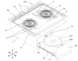
図1は、実施の形態1に係る加熱調理器100の設置例を説明する図である。本実施の形態の加熱調理器100は、上部に調理台を備えたキッチン家具200に組み込まれて使用される。加熱調理器100は、第1筐体1と、第1筐体1の上に設置されたトッププレート3とを有する。トッププレート3は、キッチン家具200の天面を構成するキッチン天板の上に露出している。トッププレート3の後方には、排気口カバー4が設けられている。排気口カバー4は、通気性を有するパンチングメタル又は格子状の金属部材で構成されていて通気性があり、通気抵抗が少ない。加熱調理器100からの排気は、排気口カバー4を通過して加熱調理器100の外へ流出する。加熱調理器100は、調理庫20を有し、調理庫20の調理庫扉26がキッチン家具200の前面に露出している。
Embodiment 1.
FIG. 1 is a diagram illustrating an installation example of the heating cooker 100 according to Embodiment 1. FIG. Heating cooker 100 of the present embodiment is used by being incorporated in kitchen furniture 200 having a cooking table at the top. Heating cooker 100 has first housing 1 and top plate 3 installed on first housing 1 . The top plate 3 is exposed above the kitchen top plate forming the top surface of the kitchen furniture 200. - 特許庁An exhaust port cover 4 is provided behind the top plate 3 . The exhaust port cover 4 is made of a permeable punching metal or a grid-shaped metal member, and has air permeability and low air resistance. Exhaust from the heating cooker 100 passes through the exhaust port cover 4 and flows out of the heating cooker 100 . The heating cooker 100 has a cooking chamber 20, and a cooking chamber door 26 of the cooking chamber 20 is exposed to the front surface of the kitchen furniture 200. - 特許庁

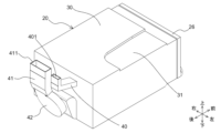
図2は、実施の形態1に係る加熱調理器100のトッププレート3が取り外された状態の外観斜視図である。図2では、調理庫20の調理庫扉26が開けられた状態が示されており、調理庫20に収容される調理容器300とその蓋301も併せて図示されている。 FIG. 2 is an external perspective view of the heating cooker 100 according to Embodiment 1 with the top plate 3 removed. FIG. 2 shows a state in which the cooking chamber door 26 of the cooking chamber 20 is opened, and also shows a cooking container 300 housed in the cooking chamber 20 and its lid 301 .

加熱調理器100は、第1筐体1と、第1筐体1内に収容されている第2筐体2と、操作表示ユニット5と、第1冷却ファン8と、加熱コイル9と、冷却ダクト10とを備える。第1筐体1は、加熱調理器100を構成する部材を収容する筐体である。第2筐体2は、第1筐体1よりも高さの低い筐体であり、第1筐体1内であって調理庫20の上側に設置されている。第2筐体2の底は、第1筐体1内を上下に仕切る仕切板として機能する。操作表示ユニット5は、使用者の操作入力を受け付けるスイッチ等の入力装置と、使用者に視覚的に情報を報知するランプ又は液晶表示装置等の表示装置とを有する。操作表示ユニット5は、静電容量式のスイッチと表示装置とが一体化されたタッチパネルで構成されうる。 The heating cooker 100 includes a first housing 1, a second housing 2 housed in the first housing 1, an operation display unit 5, a first cooling fan 8, a heating coil 9, a cooling a duct 10; The first housing 1 is a housing that accommodates members that constitute the heating cooker 100 . The second housing 2 is a housing lower in height than the first housing 1 and is installed inside the first housing 1 and above the cooking chamber 20 . The bottom of the second housing 2 functions as a partition plate that divides the inside of the first housing 1 vertically. The operation display unit 5 has an input device such as a switch for accepting user's operation input, and a display device such as a lamp or a liquid crystal display device for visually notifying the user of information. The operation display unit 5 can be configured by a touch panel in which a capacitive switch and a display device are integrated.

第1筐体1の左側の側面には、筐体吸気口6が形成されている。筐体吸気口6は、第1筐体1内への冷却風の流入口である。第1筐体1の左側の側面の筐体吸気口6は、左へ向かって開口している。第1筐体1の後部上面には、筐体排気口7が形成されている。筐体排気口7は、上へ向かって開口している。筐体排気口7は、第1筐体1内からの排気の流出口である。筐体排気口7の下には、調理庫排気ダクト40と冷却風排気ダクト41とが設けられている。調理庫排気ダクト40からの排気と、冷却風排気ダクト41からの排気とは、筐体排気口7の下流側にて混合されて、筐体排気口7から排出される。 A housing intake port 6 is formed on the left side surface of the first housing 1 . The housing intake port 6 is an inlet for cooling air into the first housing 1 . A housing intake port 6 on the left side surface of the first housing 1 opens toward the left. A housing exhaust port 7 is formed on the rear top surface of the first housing 1 . The housing exhaust port 7 is open upward. The housing exhaust port 7 is an outlet for exhaust air from the inside of the first housing 1 . A cooking chamber exhaust duct 40 and a cooling air exhaust duct 41 are provided under the housing exhaust port 7 . The exhaust from the cooking chamber exhaust duct 40 and the exhaust from the cooling air exhaust duct 41 are mixed on the downstream side of the housing exhaust port 7 and discharged from the housing exhaust port 7 .

加熱コイル9は、トッププレート3の上に載置される鍋又はフライパンなどの調理容器を加熱する加熱手段である。本実施の形態では、2つの加熱コイル9が左右に並んで配置されている。加熱コイル9の数は2つに限定されず、1つあるいは3つ以上であってもよい。また、トッププレート3の上に載置される調理容器を加熱する加熱手段として、加熱コイル9に代えてあるいはこれに加えて、シーズヒータ又は赤外線ヒータを設けてもよい。 The heating coil 9 is heating means for heating a cooking container such as a pot or frying pan placed on the top plate 3 . In this embodiment, two heating coils 9 are arranged side by side. The number of heating coils 9 is not limited to two, and may be one or three or more. As a heating means for heating the cooking vessel placed on the top plate 3, instead of or in addition to the heating coil 9, a sheathed heater or an infrared heater may be provided.

第1冷却ファン8は、加熱調理器100の発熱部品を冷却する冷却風を生成する。本実施の形態において、発熱部品は、加熱コイル9、加熱コイル9を駆動する後述の第1駆動回路11及び第2駆動回路12、並びに加熱調理器100の動作を制御する制御回路等が該当する。本実施の形態では、2つの第1冷却ファン8が前後に並んで配置されているが、第1冷却ファン8の数及び配置は例示のものに限定されない。 First cooling fan 8 generates cooling air that cools the heat-generating components of cooker 100 . In the present embodiment, the heat-generating components correspond to the heating coil 9, a first driving circuit 11 and a second driving circuit 12 that drive the heating coil 9, and a control circuit that controls the operation of the heating cooker 100. . In the present embodiment, two first cooling fans 8 are arranged side by side, but the number and arrangement of the first cooling fans 8 are not limited to those illustrated.

冷却ダクト10は、第1冷却ファン8が送出する冷却風を冷却対象である発熱部品に導くための部材である。本実施の形態の冷却ダクト10は、第1筐体1の左側に設けられた第1冷却ファン8の吹出し口から右へ向かって延びる流路を内部に有しており、冷却風を左から右へ導く。 The cooling duct 10 is a member for guiding the cooling air sent by the first cooling fan 8 to the heat-generating components to be cooled. The cooling duct 10 of the present embodiment has therein a flow path extending rightward from the outlet of the first cooling fan 8 provided on the left side of the first housing 1, and the cooling air flows from the left. lead to the right.

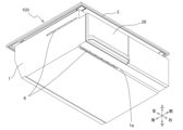
調理庫20は、調理庫20内に収容される調理容器300内の被調理物を加熱又は冷却するための装置である。調理庫20は、引き出し可能な調理庫扉26を有する。調理庫扉26は、スライドレールによって、調理容器300を下方から支持する容器支持部材71と一体的に引き出される。スライドレールは、調理庫20内に設けられ前後に延びる固定レール74と、容器支持部材71及び調理庫扉26と連結され前後に延びる可動レール75とを有する。固定レール74に対して可動レール75が摺動することで、調理庫扉26及び容器支持部材71が前後に移動する。 The cooking chamber 20 is a device for heating or cooling the food in the cooking container 300 housed in the cooking chamber 20 . The cooking chamber 20 has a retractable cooking chamber door 26 . The cooking chamber door 26 is pulled out integrally with the container supporting member 71 that supports the cooking container 300 from below by the slide rail. The slide rail has a fixed rail 74 provided in the cooking chamber 20 and extending back and forth, and a movable rail 75 connected to the container support member 71 and the cooking chamber door 26 and extending back and forth. The sliding of the movable rail 75 with respect to the fixed rail 74 moves the cooking chamber door 26 and the container support member 71 back and forth.

図3は、実施の形態1に係る加熱調理器100の下からの斜視図である。筐体吸気口6は、第1筐体1の下部にも設けられている。第1筐体1の下部に設けられた筐体吸気口6は、前に向かって開口している。より詳しくは、第1筐体1の下面の一部には、高低差が設けられており、前方にある高部と後方にある低部とを接続する傾斜面1aに、筐体吸気口6が形成されている。傾斜面1aは、後から前に向かって上昇しているので、筐体吸気口6の開口面もまた前から後に向かって上昇している。このように、傾斜面1aに筐体吸気口6を設けることで、上下方向に平行な面に筐体吸気口6を設ける場合よりも、筐体吸気口6の面積、すなわち空気の流路断面積を大きくすることができる。筐体吸気口6の面積を大きくすることで、筐体吸気口6における圧力損失を低下させ、筐体吸気口6から空気を吸引する送風手段の風量を増加させることができる。 FIG. 3 is a bottom perspective view of the heating cooker 100 according to Embodiment 1. FIG. The housing intake port 6 is also provided in the lower portion of the first housing 1 . A housing intake port 6 provided at the bottom of the first housing 1 opens forward. More specifically, a portion of the lower surface of the first housing 1 is provided with a height difference, and the housing intake port 6 is formed. Since the inclined surface 1a rises from the rear to the front, the opening surface of the housing intake port 6 also rises from the front to the rear. In this way, by providing the housing air inlet 6 on the inclined surface 1a, the area of the housing air inlet 6, that is, the flow path section of the air, is larger than when the housing air inlet 6 is provided on a plane parallel to the vertical direction. area can be increased. By increasing the area of the housing air inlet 6, the pressure loss at the housing air inlet 6 can be reduced, and the air volume of the air blowing means for sucking air from the housing air inlet 6 can be increased.

図4は、実施の形態1に係る第2筐体2及びこれに収容される部材を説明する図である。図4では、図2に示した加熱コイル9及び冷却ダクト10が取り外された状態を示している。第2筐体2内には、第1駆動回路11と、第2駆動回路12と、放熱手段13と、制御部16とが設けられている。 4A and 4B are diagrams illustrating the second housing 2 and the members accommodated therein according to Embodiment 1. FIG. FIG. 4 shows a state in which the heating coil 9 and the cooling duct 10 shown in FIG. 2 are removed. A first drive circuit 11 , a second drive circuit 12 , a heat dissipation means 13 , and a control section 16 are provided in the second housing 2 .

第1駆動回路11は、図2に示した2つの加熱コイル9のうちの一方に高周波電流を供給するインバータ回路である。第2駆動回路12は、図2に示した2つの加熱コイル9のうちの他方に高周波電流を供給するインバータ回路である。 The first drive circuit 11 is an inverter circuit that supplies high-frequency current to one of the two heating coils 9 shown in FIG. The second drive circuit 12 is an inverter circuit that supplies high-frequency current to the other of the two heating coils 9 shown in FIG.

放熱手段13は、第1駆動回路11及び第2駆動回路12の放熱を促進する部材である。放熱手段13は、アルミ等の熱伝導性の高い金属で構成された平板部材であるフィンを複数有し、第1駆動回路11及び第2駆動回路12と熱的に接続される。本実施の形態の放熱手段13は、平板面が上下に向くようにして配置された複数の平板部材が、上下に隙間をあけて配置されており、平板部材同士の隙間が、冷却風の流路として機能する。 The heat dissipation means 13 is a member that promotes heat dissipation of the first drive circuit 11 and the second drive circuit 12 . The heat dissipation means 13 has a plurality of fins, which are flat plate members made of metal with high thermal conductivity such as aluminum, and is thermally connected to the first drive circuit 11 and the second drive circuit 12 . In the heat dissipation means 13 of the present embodiment, a plurality of flat plate members are arranged so that the flat plate surfaces face up and down, and are arranged with a gap in the vertical direction. function as a road.

第2筐体2の底には、第1貫通孔14と、第2貫通孔15とが形成されている。第1貫通孔14は、図2に示した調理庫排気ダクト40が挿入される孔である。第2貫通孔15は、図2に示した冷却風排気ダクト41が挿入される孔である。第1貫通孔14及び第2貫通孔15は、筐体排気口7の下に形成されている。 A first through hole 14 and a second through hole 15 are formed in the bottom of the second housing 2 . The first through hole 14 is a hole into which the cooking chamber exhaust duct 40 shown in FIG. 2 is inserted. The second through hole 15 is a hole into which the cooling air exhaust duct 41 shown in FIG. 2 is inserted. The first through hole 14 and the second through hole 15 are formed below the housing exhaust port 7 .

制御部16は、加熱調理器100を構成する電気部品の動作を制御する。制御部16は、加熱調理器100を構成する部材の動作を制御する制御回路などの電子部品が実装された電子回路基板である。 Control unit 16 controls the operation of the electrical components that make up cooker 100 . The control unit 16 is an electronic circuit board on which electronic components such as a control circuit for controlling the operation of the members constituting the heating cooker 100 are mounted.

図5は、実施の形態1に係る第2筐体2の下からの斜視図である。第2筐体2の底には、冷却ファン吸気口17が設けられている。冷却ファン吸気口17は、図4に示した第1冷却ファン8と連通しており、第1冷却ファン8に吸引される空気が通過する開口である。 FIG. 5 is a bottom perspective view of the second housing 2 according to the first embodiment. A cooling fan intake port 17 is provided at the bottom of the second housing 2 . The cooling fan intake port 17 communicates with the first cooling fan 8 shown in FIG. 4 and is an opening through which the air sucked by the first cooling fan 8 passes.

図6は、実施の形態1に係る第1筐体1内の調理庫20とこれに関連する部材を説明する図である。図6では、図2に示した第2筐体2及び調理庫扉26が取り外された状態を示している。筐体吸気口6は、第1筐体1の前面にも設けられている。第1筐体1の前面に設けられた筐体吸気口6は、前に向かって開口している。 FIG. 6 is a diagram illustrating the cooking chamber 20 in the first housing 1 and related members according to Embodiment 1. As shown in FIG. FIG. 6 shows a state in which the second housing 2 and the cooking chamber door 26 shown in FIG. 2 are removed. The housing intake port 6 is also provided on the front surface of the first housing 1 . A housing intake port 6 provided on the front surface of the first housing 1 opens forward.

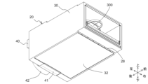
調理庫20は、外郭を構成する外断熱材30を有している。外断熱材30は、調理庫20内からの熱及び冷気の漏れを抑制するための部材である。外断熱材30は、第1筐体1及び第2筐体2を構成する金属又は合成樹脂よりも、熱伝導率の低い材料で構成されている。外断熱材30は、外断熱材30の内側に配置される部材との間に隙間を設けて配置される。外断熱材30の内側に配置される部材と外断熱材30との間の隙間には、空気層あるいはグラスウール等の断熱材が設けられうる。 The cooking chamber 20 has an external heat insulating material 30 forming an outer shell. The external heat insulating material 30 is a member for suppressing leakage of heat and cool air from inside the cooking chamber 20 . The external heat insulating material 30 is made of a material having a lower thermal conductivity than the metal or synthetic resin forming the first housing 1 and the second housing 2 . The external heat insulating material 30 is arranged with a gap provided between it and members arranged inside the external heat insulating material 30 . An air layer or a heat insulating material such as glass wool may be provided in the gap between the member arranged inside the external heat insulating material 30 and the external heat insulating material 30 .

外断熱材30の上面の一部には、下に凹んだ凹部31が形成されている。凹部31は、図4に示した第1冷却ファン8及び図5に示した冷却ファン吸気口17の下に配置される。図4に示した第2筐体2が第1筐体1内に設置された状態において、図5に示した冷却ファン吸気口17の下に凹部31が位置し、凹部31の上側の空間が、冷却ファン吸気口17へ流入する空気の流路として機能する。 A concave portion 31 recessed downward is formed in a part of the upper surface of the external heat insulating material 30 . The recess 31 is arranged below the first cooling fan 8 shown in FIG. 4 and the cooling fan inlet 17 shown in FIG. When the second housing 2 shown in FIG. 4 is installed inside the first housing 1, the recess 31 is positioned below the cooling fan inlet 17 shown in FIG. , function as a flow path for air flowing into the cooling fan inlet 17 .

図7は、実施の形態1に係る調理庫20の後ろからの斜視図である。調理庫20の後部には、調理庫排気ダクト40と、冷却風排気ダクト41とが取り付けられている。調理庫排気ダクト40は、調理庫20内で生じた排気を導くダクトである。調理庫排気ダクト40の出口401は、上に向いて開口しており、図2に示したように筐体排気口7に連通するようにして第1筐体1内に設置される。冷却風排気ダクト41は、発熱部品を冷却した後の冷却風を、調理庫20外へと導くダクトである。冷却風排気ダクト41の出口411は、上に向いて開口しており、図2に示したように筐体排気口7に連通するようにして第1筐体1内に設置される。調理庫排気ダクト40と冷却風排気ダクト41とは、連通しておらず、独立したダクトとして構成されている。 FIG. 7 is a rear perspective view of the cooking chamber 20 according to Embodiment 1. FIG. A cooking chamber exhaust duct 40 and a cooling air exhaust duct 41 are attached to the rear portion of the cooking chamber 20 . The cooking chamber exhaust duct 40 is a duct that guides the exhaust generated within the cooking chamber 20 . An outlet 401 of the cooking chamber exhaust duct 40 opens upward, and is installed in the first housing 1 so as to communicate with the housing exhaust port 7 as shown in FIG. The cooling air exhaust duct 41 is a duct that guides the cooling air after cooling the heat-generating parts to the outside of the cooking chamber 20 . An outlet 411 of the cooling air exhaust duct 41 is open upward, and is installed in the first housing 1 so as to communicate with the housing exhaust port 7 as shown in FIG. The cooking chamber exhaust duct 40 and the cooling air exhaust duct 41 are configured as independent ducts without communicating with each other.

冷却風排気ダクト41内には、送風手段である第2冷却ファン42が設けられている。第2冷却ファン42は、冷却風排気ダクト41内に、出口411へ向かう気流を生じさせる。第2冷却ファン42は、例えば軸流ファン又は遠心ファンである。 A second cooling fan 42 serving as air blowing means is provided in the cooling air exhaust duct 41 . The second cooling fan 42 generates an airflow in the cooling air exhaust duct 41 toward the outlet 411 . The second cooling fan 42 is, for example, an axial fan or a centrifugal fan.

図8は、実施の形態1に係る調理庫20の下からの斜視図である。冷却風排気ダクト41は、調理庫20の後方下部に接続されている。調理庫20の底には、吸気口28が形成されている。吸気口28は、調理庫20内に流入する冷却風の入口である。吸気口28は、前に向かって開口している。本実施の形態の吸気口28は、調理庫20の前端よりも後ろ寄りに設けられている。また、調理庫20の底の一部には、高低差が設けられており、前方にある高部と後方にある低部とを接続する傾斜面に、吸気口28が設けられている。吸気口28が設けられた傾斜面は、後から前に向かって上昇しており、吸気口28の開口面もまた前から後に向かって上昇している。このように、吸気口28の開口面を前後に傾斜させることで、上下方向に平行な吸気口28を設ける場合よりも、吸気口28の面積、すなわち空気の流路断面積を大きくすることができる。吸気口28の面積を大きくすることで、吸気口28における圧力損失を低下させ、吸気口28を吸引する送風手段の風量を増加させることができる。吸気口28は、図3に示した傾斜面1aに設けられた筐体吸気口6と対向する位置に、配置される。また、吸気口28と冷却風排気ダクト41との間には、調理庫20の最下面の一部を構成する外底板32が設けられている。 FIG. 8 is a bottom perspective view of the cooking chamber 20 according to Embodiment 1. FIG. The cooling air exhaust duct 41 is connected to the rear lower portion of the cooking chamber 20 . An intake port 28 is formed at the bottom of the cooking chamber 20 . The intake port 28 is an inlet for cooling air flowing into the cooking chamber 20 . The intake port 28 opens forward. The intake port 28 of the present embodiment is provided behind the front end of the cooking chamber 20 . A portion of the bottom of the cooking chamber 20 is provided with a height difference, and an intake port 28 is provided on an inclined surface connecting a high portion in the front and a low portion in the rear. The inclined surface on which the intake port 28 is provided rises from the rear to the front, and the opening surface of the intake port 28 also rises from the front to the rear. By inclining the opening surface of the intake port 28 in the front-rear direction in this way, the area of the intake port 28, that is, the cross-sectional area of the air flow path, can be made larger than when the intake port 28 is provided parallel to the vertical direction. can. By increasing the area of the intake port 28, the pressure loss in the intake port 28 can be reduced, and the air volume of the air blowing means that sucks the air into the intake port 28 can be increased. The intake port 28 is arranged at a position facing the housing intake port 6 provided on the inclined surface 1a shown in FIG. An outer bottom plate 32 forming part of the bottom surface of the cooking chamber 20 is provided between the intake port 28 and the cooling air exhaust duct 41 .

図9は、実施の形態1に係る調理庫20の下からの斜視図である。図9は、図8の調理庫20から外底板32が取り外された状態を示している。調理庫20の下部には、放熱部材64が設けられている。放熱部材64は、後述する冷却手段に生じた廃熱の放出を促進する部材である。本実施の形態の放熱部材64は、アルミ等の熱伝導性の高い金属で構成された平板部材であるフィンを有する。本実施の形態の放熱部材64は、平板面が左右に向くようにして配置された複数の平板部材が、左右に隙間あけて配置されており、平板部材同士の隙間が、冷却風の流路として機能する。 FIG. 9 is a bottom perspective view of the cooking chamber 20 according to Embodiment 1. FIG. FIG. 9 shows the cooking chamber 20 of FIG. 8 with the outer bottom plate 32 removed. A heat radiating member 64 is provided in the lower portion of the cooking chamber 20 . The heat radiation member 64 is a member that promotes the radiation of waste heat generated in the cooling means, which will be described later. The heat dissipating member 64 of the present embodiment has fins that are flat plate members made of metal with high thermal conductivity such as aluminum. In the heat dissipating member 64 of the present embodiment, a plurality of flat plate members are arranged so that the flat plate surfaces face left and right, and are arranged with a gap left and right. function as

調理庫20の後方下部には、冷却風排気ダクト41への冷気の入口となる第1流出口34が設けられている。放熱部材64の後端と第1流出口34との間には、隙間が設けられており、この隙間を合流部36と称する。前述のとおり、放熱部材64を構成する平板部材同士の隙間は、冷却風の流路として機能するが、平板部材同士の間に形成される流路を流れた冷却風が、この合流部36にて合流し、第1流出口34を介して冷却風排気ダクト41に流入する。冷却風の流れの詳細については後述する。 A first outflow port 34 serving as an inlet of cool air to the cooling air exhaust duct 41 is provided in the lower rear portion of the cooking chamber 20 . A gap is provided between the rear end of the heat radiating member 64 and the first outlet 34 , and this gap is referred to as a confluence portion 36 . As described above, the gaps between the flat plate members forming the heat radiating member 64 function as flow paths for the cooling air. , and flows into the cooling air exhaust duct 41 via the first outlet 34 . The details of the cooling air flow will be described later.

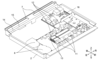
図10は、実施の形態1に係る調理庫20の斜視図である。図10は、図7等で示した外断熱材30が取り外された状態を示している。調理庫20の外郭を構成する外断熱材30の内側においては、左右の側面及び底面が、内断熱材29によって覆われている。内断熱材29は、調理庫20内からの熱及び冷気の漏れを抑制するための部材である。内断熱材29は、内断熱材29の内側に配置される第1側壁22及び第2側壁23等よりも熱伝導率の低い材料で構成されている。内断熱材29は、グラスウールを含んでいてもよい。また、内断熱材29と、内断熱材29の内側に配置される部材との間に、断熱層として空気層が設けられていてもよい。 10 is a perspective view of cooking chamber 20 according to Embodiment 1. FIG. FIG. 10 shows a state in which the external heat insulating material 30 shown in FIG. 7 and the like is removed. Inside the outer heat insulating material 30 forming the outer shell of the cooking chamber 20 , the left and right side surfaces and the bottom surface are covered with an inner heat insulating material 29 . The internal heat insulating material 29 is a member for suppressing leakage of heat and cold air from inside the cooking chamber 20 . The inner heat insulating material 29 is made of a material having a lower thermal conductivity than the first side wall 22 and the second side wall 23 arranged inside the inner heat insulating material 29 . The internal heat insulator 29 may contain glass wool. Also, an air layer may be provided as a heat insulating layer between the inner heat insulating material 29 and a member arranged inside the inner heat insulating material 29 .

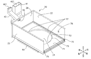
左右の内断熱材29の内側には、第1側壁22と、第2側壁23とが設けられている。第1側壁22と第2側壁23の上端に跨るようにして、天板25が設けられている。第1側壁22、第2側壁23及び天板25と、後述する図11に示す底板21及び後壁24とで、調理容器300を収容する調理空間が形成される。 A first side wall 22 and a second side wall 23 are provided inside the left and right inner heat insulating materials 29 . A top plate 25 is provided so as to straddle the upper ends of the first side wall 22 and the second side wall 23 . The first side wall 22, the second side wall 23, the top plate 25, and the bottom plate 21 and the rear wall 24 shown in FIG.

天板25の上には、上部加熱手段53が設けられている。上部加熱手段53は、調理庫20内を上から加熱する。上部加熱手段53は、シーズヒータ又は赤外線ヒータ等の電気ヒータである。上部加熱手段53として、加熱コイルと、加熱コイルによって誘導加熱される金属板とを設けてもよい。 An upper heating means 53 is provided on the top plate 25 . The upper heating means 53 heats the inside of the cooking chamber 20 from above. The upper heating means 53 is an electric heater such as a sheathed heater or an infrared heater. A heating coil and a metal plate that is induction-heated by the heating coil may be provided as the upper heating means 53 .

図11は、実施の形態1に係る調理庫20の内部構造を説明する図である。図11は、図10から上部加熱手段53及び天板25が取り外された状態を示している。調理庫20の後壁24には、第2流出口35が形成されている。第2流出口35は、調理庫排気ダクト40と連通しており、調理庫20内の排気は第2流出口35を介して調理庫排気ダクト40に流入する。 FIG. 11 is a diagram illustrating the internal structure of cooking chamber 20 according to Embodiment 1. As shown in FIG. FIG. 11 shows a state in which the upper heating means 53 and the top plate 25 are removed from FIG. A second outlet 35 is formed in the rear wall 24 of the cooking chamber 20 . The second outflow port 35 communicates with the cooking chamber exhaust duct 40 , and the exhaust air in the cooking chamber 20 flows into the cooking chamber exhaust duct 40 via the second outflow port 35 .

調理庫排気ダクト40は、後壁24の後面に接続されている。調理庫排気ダクト40は、後壁24の後面から後ろへ向かって上昇するように傾斜しており、後端部において曲がって上に延びている。調理庫排気ダクト40は、側面視において概ねL字状である。調理庫排気ダクト40の出口401は、上に向かって開口している。 A cooking chamber exhaust duct 40 is connected to the rear surface of the rear wall 24 . The cooking chamber exhaust duct 40 slopes rearwardly upward from the rear surface of the rear wall 24 and bends upward at its rear end. The cooking chamber exhaust duct 40 is substantially L-shaped in side view. An outlet 401 of the cooking chamber exhaust duct 40 opens upward.

冷却風排気ダクト41は、後壁24の後面に接続されている。冷却風排気ダクト41の出口411は、上に向かって開口している。 The cooling air exhaust duct 41 is connected to the rear surface of the rear wall 24 . An outlet 411 of the cooling air exhaust duct 41 opens upward.

底板21の上には、容器支持部材71が設けられている。容器支持部材71は、図2等に示した調理容器300を下から支持する部材である。容器支持部材71は、概ね平板状の部材であり、中央には開口73が形成されている。本実施の形態の開口73は、円形であり、調理容器300の底が開口73に嵌まるようになっている。調理容器300の底が開口73に嵌まった状態において、図2に示すように調理庫扉26が引き出されたときに、調理容器300の少なくとも一部が調理庫20から外に出る位置に、開口73が設けられているとよい。このようにすることで、調理庫20内への調理容器300の出し入れの利便性を向上させることができる。 A container support member 71 is provided on the bottom plate 21 . The container support member 71 is a member that supports the cooking container 300 shown in FIG. 2 and the like from below. The container support member 71 is a generally flat plate-shaped member and has an opening 73 formed in the center. The opening 73 of this embodiment is circular so that the bottom of the cooking vessel 300 fits into the opening 73 . With the bottom of the cooking container 300 fitted in the opening 73, when the cooking container door 26 is pulled out as shown in FIG. An opening 73 may be provided. By doing so, the convenience of putting the cooking container 300 in and out of the cooking chamber 20 can be improved.

容器支持部材71に設けられた開口73は、開口73から離れるほど上へ向かって傾斜する斜面72となっている。斜面72は、開口73から放射状に広がり、容器支持部材71の平板部分に連なっている。 An opening 73 provided in the container support member 71 forms a slope 72 that slopes upward with increasing distance from the opening 73 . The slope 72 extends radially from the opening 73 and continues to the flat plate portion of the container support member 71 .

調理庫20の底板21は、容器支持部材71の下に位置している。容器支持部材71の開口73を介して、底板21が露出している。調理容器300が開口73に嵌め込まれると、調理容器300の底が底板21に接触する。 A bottom plate 21 of the cooking chamber 20 is positioned below the container support member 71 . The bottom plate 21 is exposed through the opening 73 of the container support member 71 . When the cooking container 300 is fitted into the opening 73 , the bottom of the cooking container 300 contacts the bottom plate 21 .

第1側壁22の内面には、調理庫温度センサ76が設けられている。調理庫温度センサ76は、調理庫20内の空気温度を検出するセンサである。調理庫温度センサ76は、サーミスタ又は赤外線センサなどの温度センサである。 A cooking chamber temperature sensor 76 is provided on the inner surface of the first side wall 22 . The cooking chamber temperature sensor 76 is a sensor that detects the air temperature inside the cooking chamber 20 . The cooking chamber temperature sensor 76 is a temperature sensor such as a thermistor or an infrared sensor.

容器支持部材71の斜面72には、調理容器温度センサ77が設けられている。調理容器温度センサ77は、調理容器300に直接または間接的に熱的に接続され、調理容器300の温度を検出する。調理容器温度センサ77は、例えばサーミスタである。本実施の形態では、3つ以上の調理容器温度センサ77が設けられている。 A cooking container temperature sensor 77 is provided on the slope 72 of the container support member 71 . Cooking vessel temperature sensor 77 is directly or indirectly thermally connected to cooking vessel 300 to detect the temperature of cooking vessel 300 . The cooking vessel temperature sensor 77 is, for example, a thermistor. In this embodiment, three or more cooking vessel temperature sensors 77 are provided.

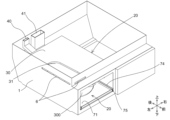
図12は、実施の形態1に係る調理庫20の内部構造を説明する図である。図12は、図11から第2側壁23、容器支持部材71及び底板21が取り外された状態を示している。調理庫20の下部には、加熱コイル50と、加熱コイル50を支持するコイル支持体51と、フェライト52とが設けられている。コイル支持体51は、図11に示した底板21の下側に、加熱コイル50を挟んで底板21と対向するようにして配置される。フェライト52は、加熱コイル50からの漏洩磁束を抑制するための防磁部材である。加熱コイル50は、導線が環状に巻かれて構成されており、中央には導線のない領域がある。コイル支持体51には、加熱コイル50の導線のない領域と概ね同じ位置に、この領域と概ね同じ形状の開口54が形成されており、開口54にペルチェ素子60が配置されている。 FIG. 12 is a diagram illustrating the internal structure of cooking chamber 20 according to Embodiment 1. As shown in FIG. FIG. 12 shows a state in which the second side wall 23, container support member 71 and bottom plate 21 are removed from FIG. A heating coil 50 , a coil support 51 that supports the heating coil 50 , and ferrite 52 are provided in the lower portion of the cooking chamber 20 . The coil support 51 is arranged below the bottom plate 21 shown in FIG. 11 so as to face the bottom plate 21 with the heating coil 50 interposed therebetween. The ferrite 52 is a magnetic shield member for suppressing leakage magnetic flux from the heating coil 50 . The heating coil 50 is constructed by winding a conductor wire in a ring shape, and has a region in the center where there is no conductor wire. An opening 54 having substantially the same shape as the area of the heating coil 50 is formed in the coil support 51 at substantially the same position as the area where the heating coil 50 does not have a conductor wire.

ペルチェ素子60は、調理庫20内の調理容器300を冷却する冷却手段である。ペルチェ素子60は、吸熱面が上、すなわち調理容器300側に向くようにして、設置されている。ペルチェ素子60の放熱面は、下を向いており、コイル支持体51の下側に配置されている放熱部材64と熱的に接続されている。 The Peltier element 60 is cooling means for cooling the cooking container 300 inside the cooking chamber 20 . The Peltier element 60 is installed so that the heat absorption surface faces upward, that is, faces the cooking vessel 300 side. The heat dissipation surface of the Peltier element 60 faces downward and is thermally connected to a heat dissipation member 64 arranged below the coil support 51 .

図13は、実施の形態1に係る調理庫20の内部構造を説明する図である。図13は、図12に示す状態からコイル支持体51が取り外された状態を示している。放熱部材64の上には、ペルチェ素子60を中心として、複数のフェライト52が放射状に配置されている。本実施の形態のフェライト52は、放熱部材64の上面に沿って延びる長尺部分521と、長尺部分521の端部から上へ延びる起立部分522とを有し、側面視でL字形状を有している。フェライト52の上下に起立する起立部分522が、ペルチェ素子60の周囲を囲むようにして、複数のフェライト52が配置されている。フェライト52の起立部分522で、ペルチェ素子60の周囲を囲むことで、図12に示した加熱コイル50からの磁束によって、ペルチェ素子60が加熱されることを抑制することができる。なお、ここで例示したL字形状のフェライト52に代えて、円筒状又は角筒状のフェライト又はアルミ板等を、ペルチェ素子60の周囲に設けてもよい。 FIG. 13 is a diagram illustrating the internal structure of cooking chamber 20 according to Embodiment 1. As shown in FIG. FIG. 13 shows the state in which the coil support 51 is removed from the state shown in FIG. A plurality of ferrites 52 are radially arranged on the heat dissipation member 64 with the Peltier element 60 at the center. The ferrite 52 of the present embodiment has a long portion 521 extending along the upper surface of the heat radiating member 64 and an upright portion 522 extending upward from the end of the long portion 521, and is L-shaped in side view. have. A plurality of ferrites 52 are arranged so that upright portions 522 standing up and down of the ferrites 52 surround the periphery of the Peltier element 60 . By surrounding the Peltier element 60 with the upright portions 522 of the ferrite 52, it is possible to suppress the Peltier element 60 from being heated by the magnetic flux from the heating coil 50 shown in FIG. Instead of the L-shaped ferrite 52 exemplified here, a cylindrical or prismatic ferrite, an aluminum plate, or the like may be provided around the Peltier element 60 .

放熱部材64の前端と吸気口28との間には、隙間33が設けられている。隙間33は、複数の開口で構成されている吸気口28から流入した空気を、調理庫20の左右幅方向に分散させるための空間である。吸気口28から流入した空気を、調理庫20の幅方向に分散させることで、放熱部材64の幅方向にまんべんなく空気を通過させることができ、放熱部材64の放熱効果を高めることができる。 A gap 33 is provided between the front end of the heat radiating member 64 and the intake port 28 . The gap 33 is a space for dispersing the air that has flowed in from the intake port 28 configured by a plurality of openings in the lateral width direction of the cooking chamber 20 . By dispersing the air flowing in from the intake port 28 in the width direction of the cooking chamber 20, the air can be uniformly passed in the width direction of the heat radiating member 64, and the heat radiating effect of the heat radiating member 64 can be enhanced.

調理庫20の後壁24の下部には、第1流出口34が形成されている。第1流出口34は、冷却風排気ダクト41と連通している。 A first outlet 34 is formed in the lower portion of the rear wall 24 of the cooking chamber 20 . The first outlet 34 communicates with the cooling air exhaust duct 41 .

図14は、実施の形態1に係る加熱調理器100の縦断面模式図である。図14では、調理庫20のペルチェ素子60を通る前後縦断面を、キッチン家具200も併せて図示している。 FIG. 14 is a vertical cross-sectional schematic diagram of the heating cooker 100 according to Embodiment 1. FIG. FIG. 14 shows a front-rear longitudinal section passing through the Peltier element 60 of the cooking chamber 20 together with the kitchen furniture 200 .

調理庫20の下部に設けられた、調理庫20の冷却に係る構成を説明する。調理庫20の底板21の下面には、冷却手段であるペルチェ素子60の吸熱面が接触している。ペルチェ素子60と底板21との間には、サーマルグリス又はサーマルシートなどの熱抵抗を軽減する部材を設けるとよい。ペルチェ素子60と底板21との間の熱抵抗を軽減することで、ペルチェ素子60は効率よく底板21を冷却でき、この底板21を介して調理容器300も効率よく冷却される。加熱コイル50を支持するコイル支持体51には、環状の加熱コイル50の中央の導線が設けられていない部分に対応した位置に、開口54が設けられている。開口54の外形は、加熱コイル50の内周端の外形と概ね一致する。上下方向において、ペルチェ素子60と加熱コイル50とは概ね同じ位置にある。ペルチェ素子60の上面と加熱コイル50の上面との高低差は、なるべく少なくするとよい。このようにすることで、高さ寸法に制限のある組み込み式の加熱調理器100において、調理庫20の高さ方向の内寸を確保することができる。 A configuration relating to cooling of the cooking chamber 20 provided in the lower portion of the cooking chamber 20 will be described. The lower surface of the bottom plate 21 of the cooking chamber 20 is in contact with the heat absorbing surface of the Peltier element 60 as cooling means. A member such as thermal grease or a thermal sheet may be provided between the Peltier element 60 and the bottom plate 21 to reduce thermal resistance. By reducing the thermal resistance between the Peltier element 60 and the bottom plate 21 , the Peltier element 60 can efficiently cool the bottom plate 21 , and the cooking vessel 300 is also efficiently cooled through the bottom plate 21 . A coil support 51 that supports the heating coil 50 is provided with an opening 54 at a position corresponding to the central portion of the annular heating coil 50 where the conducting wire is not provided. The outer shape of the opening 54 substantially matches the outer shape of the inner peripheral end of the heating coil 50 . In the vertical direction, the Peltier element 60 and the heating coil 50 are generally at the same position. The height difference between the upper surface of the Peltier element 60 and the upper surface of the heating coil 50 should be as small as possible. By doing so, it is possible to secure the inner dimension in the height direction of the cooking chamber 20 in the built-in cooking device 100 having a limited height.

ペルチェ素子60と放熱部材64との間には、伝熱部材63が設けられている。伝熱部材63は、ペルチェ素子60の放熱面と熱的に接触しており、ペルチェ素子60で生じた廃熱を放熱部材64に伝える。伝熱部材63は、サーマルグリス、サーマルシート、又はヒートパイプ等で構成される。伝熱部材63を設けることで、ペルチェ素子60の放熱面からの廃熱の放熱部材64への熱伝達が促進される。 A heat transfer member 63 is provided between the Peltier element 60 and the heat dissipation member 64 . The heat transfer member 63 is in thermal contact with the heat dissipation surface of the Peltier element 60 and transfers waste heat generated by the Peltier element 60 to the heat dissipation member 64 . The heat transfer member 63 is composed of thermal grease, thermal sheet, heat pipe, or the like. By providing the heat transfer member 63 , heat transfer of waste heat from the heat dissipation surface of the Peltier element 60 to the heat dissipation member 64 is promoted.

調理庫20の底板21と、底板21の下側にある加熱コイル50又はコイル支持体51との間には、内断熱材29が設けられている。また、ペルチェ素子60と、フェライト52又はコイル支持体51との間にも、内断熱材29が設けられている。内断熱材29は、調理庫20の底板21よりも熱伝導率が低く、磁束を透過する材料で構成されている。このような内断熱材29を設けることで、加熱コイル50から底板21への熱伝達及び加熱コイル50からペルチェ素子60への熱伝達を抑制することができる。加熱コイル50での加熱を行った後は、加熱コイル50が高温化しうるが、内断熱材29を設けることにより、加熱コイル50からペルチェ素子60及び底板21への熱伝達が抑制され、ペルチェ素子60による冷却効率を高めることができる。 An internal heat insulator 29 is provided between the bottom plate 21 of the cooking chamber 20 and the heating coil 50 or coil support 51 below the bottom plate 21 . An internal heat insulating material 29 is also provided between the Peltier element 60 and the ferrite 52 or the coil support 51 . The inner heat insulating material 29 has a lower thermal conductivity than the bottom plate 21 of the cooking chamber 20 and is made of a material that allows magnetic flux to pass through. By providing such an internal heat insulating material 29, heat transfer from the heating coil 50 to the bottom plate 21 and heat transfer from the heating coil 50 to the Peltier element 60 can be suppressed. After heating by the heating coil 50, the temperature of the heating coil 50 may rise. The cooling efficiency by 60 can be increased.

放熱部材64の下側に配置された外底板32と、コイル支持体51との間には、空気を冷却風排気ダクト41へと導く底部風路43が形成されている。この底部風路43への空気の入口は吸気口28であり、出口は第1流出口34である。なお、吸気口28と、図3に示した傾斜面1aに設けられた筐体吸気口6とは、重なるようにして設けられるが、図14では図の煩雑化を回避するために、筐体吸気口6の符号の図示を省略している。吸気口28から第1流出口34に至る底部風路43に、放熱部材64が配置されている。底部風路43は、冷却風排気ダクト41に連なっており、底部風路43と冷却風排気ダクト41内の風路からなる一連の風路により、冷却手段であるペルチェ素子60からの廃熱を排出する第1風路が形成されている。この第1風路の入口は吸気口28、出口は冷却風排気ダクト41の出口411である。 A bottom air passage 43 that guides air to the cooling air exhaust duct 41 is formed between the outer bottom plate 32 arranged below the heat radiating member 64 and the coil support 51 . The air inlet to this bottom air passage 43 is the intake port 28 and the outlet is the first outlet port 34 . Note that the intake port 28 and the housing intake port 6 provided on the inclined surface 1a shown in FIG. 3 are provided so as to overlap each other, but in FIG. The illustration of the reference numerals of the intake port 6 is omitted. A heat radiating member 64 is arranged in the bottom air passage 43 from the intake port 28 to the first outflow port 34 . The bottom air passage 43 continues to the cooling air exhaust duct 41, and waste heat from the Peltier element 60, which is a cooling means, is removed by a series of air passages consisting of the bottom air passage 43 and the air passages in the cooling air exhaust duct 41. A first air passage for discharging is formed. The first air passage has an inlet port 28 and an outlet port 411 of the cooling air exhaust duct 41 .

冷却風排気ダクト41内には、第2冷却ファン42が設けられている。第2冷却ファン42が動作すると、吸気口28から底部風路43内に空気が流入し、底部風路43に流入した空気は放熱部材64の周囲を第1流出口34に向かって流れる。放熱部材64は、周囲を流れる空気との熱交換によって冷却される。放熱部材64の周囲を通過した空気は、放熱部材64の後端と第1流出口34との間に設けられた合流部36に流れ込む。前述のように、放熱部材64は、複数の平板部材が隙間をあけて配置されて構成されており、この隙間それぞれが空気の流路となる。放熱部材64に形成された複数の流路を流れた空気が、合流部36において合流することで、流路間での空気の流量の偏りが軽減され、空気流れのよどみを軽減することができる。合流部36に流入した空気は、第1流出口34を介して冷却風排気ダクト41内に流入する。 A second cooling fan 42 is provided in the cooling air exhaust duct 41 . When the second cooling fan 42 operates, air flows into the bottom air passage 43 from the air inlet 28 , and the air flowing into the bottom air passage 43 flows around the heat radiating member 64 toward the first outlet 34 . The heat radiating member 64 is cooled by heat exchange with air flowing around it. The air passing around the heat radiating member 64 flows into the confluence portion 36 provided between the rear end of the heat radiating member 64 and the first outlet 34 . As described above, the heat radiating member 64 is configured by arranging a plurality of flat plate members with gaps therebetween, and each of these gaps serves as an air flow path. The air that has flowed through the plurality of flow paths formed in the heat radiating member 64 merges at the confluence portion 36, thereby reducing unevenness in the flow rate of the air between the flow paths and reducing stagnation of the air flow. . The air that has flowed into the confluence portion 36 flows into the cooling air exhaust duct 41 via the first outlet 34 .

冷却風排気ダクト41は、上昇する風路を内部に有している。冷却風排気ダクト41の出口411は、筐体排気口7の下に位置し、上に向かって開口している。冷却風排気ダクト41内に流入した空気は、出口411及び筐体排気口7を通って、加熱調理器100の外へと流出する。底部風路43と冷却風排気ダクト41内の風路からなる風路であって、ペルチェ素子60からの廃熱を発する放熱部材64が配置された第1風路の入口である吸気口28と出口である出口411は、異なる方向に向かって開口している。このように、前へ向かって開口した吸気口28から空気が吸い込まれ、上へ向かって開口した出口411及び筐体排気口7から空気が流出するので、流出した空気がたちまち吸気口28に吸い込まれるショートサイクルが発生しにくい。したがって、吸気口28には、比較的低温の室内空気が流入しやすく、ペルチェ素子60の廃熱の排出を促進することができる。なお、第1風路の入口と出口とは、互いに異なる方向に向かって開口していればよく、具体的な方向はここで例示したもの以外であってもよい。 The cooling air exhaust duct 41 has an ascending air passage inside. An outlet 411 of the cooling air exhaust duct 41 is located below the housing exhaust port 7 and opens upward. The air that has flowed into the cooling air exhaust duct 41 flows out of the heating cooker 100 through the outlet 411 and the housing exhaust port 7 . an air passage consisting of the bottom air passage 43 and the air passage in the cooling air exhaust duct 41, and an intake port 28 that is the entrance of the first air passage in which the heat dissipation member 64 that emits the waste heat from the Peltier element 60 is arranged; An exit 411 opens in different directions. In this manner, the air is sucked in through the air intake port 28 that opens forward, and the air flows out from the outlet 411 that opens upward and the housing exhaust port 7 , so that the outflowing air is immediately sucked into the air intake port 28 . It is difficult for short cycles to occur. Therefore, relatively low-temperature room air easily flows into the air intake port 28, and the waste heat of the Peltier element 60 can be expedited. In addition, the entrance and the exit of the first air passage need only open in mutually different directions, and the specific directions may be other than those exemplified here.

冷却風排気ダクト41の出口411は、加熱コイル9等が収容される第2筐体2の底よりも高い位置にある。図14では図示されていないが、調理庫排気ダクト40の出口401もまた、第2筐体2の底よりも高い位置にある。このようにすることで、図4等に示した第1冷却ファン8から送出され、加熱コイル9、第1駆動回路11及び第2駆動回路12等を冷却して高温化して第2筐体2内を流れる排気が、調理庫排気ダクト40及び冷却風排気ダクト41内に流入することを抑制できる。 An outlet 411 of the cooling air exhaust duct 41 is positioned higher than the bottom of the second housing 2 in which the heating coil 9 and the like are accommodated. Although not shown in FIG. 14, the outlet 401 of the cooking chamber exhaust duct 40 is also located higher than the bottom of the second housing 2 . By doing so, the heat is sent from the first cooling fan 8 shown in FIG. Exhaust air flowing inside can be suppressed from flowing into the cooking chamber exhaust duct 40 and the cooling air exhaust duct 41 .

調理庫20内を冷却する場合には、ペルチェ素子60に通電されるとともに、第2冷却ファン42が動作する。ペルチェ素子60の吸熱面は、底板21に熱的に接続されており、底板21の上には調理容器300の底が接触している。このため、ペルチェ素子60によって底板21が冷却され、冷却された底板21からの熱伝達によって調理容器300が冷却される。調理容器300が冷却されることで、調理容器300内の被調理物も冷却される。また、第2冷却ファン42が動作することで、吸気口28から底部風路43へ流入した空気が底部風路43を流れ、底部風路43内に配置されている放熱部材64と空気との間で強制対流熱伝達が生じる。放熱部材64には、ペルチェ素子60の放熱面が熱的に接続されているため、放熱部材64を介してペルチェ素子60の放熱面からの放熱が促進される。ペルチェ素子60の放熱が促進されることで、ペルチェ素子60による冷却効率を向上させることができる。 When cooling the interior of the cooking chamber 20, the Peltier element 60 is energized and the second cooling fan 42 operates. The heat absorbing surface of the Peltier element 60 is thermally connected to the bottom plate 21, and the bottom of the cooking vessel 300 is in contact with the top of the bottom plate 21. Therefore, the bottom plate 21 is cooled by the Peltier element 60 , and heat transfer from the cooled bottom plate 21 cools the cooking vessel 300 . As the cooking vessel 300 is cooled, the food in the cooking vessel 300 is also cooled. In addition, the operation of the second cooling fan 42 causes the air that has flowed into the bottom air passage 43 from the air intake port 28 to flow through the bottom air passage 43, and the heat dissipating member 64 arranged in the bottom air passage 43 and the air. Forced convective heat transfer occurs between Since the heat dissipation surface of the Peltier element 60 is thermally connected to the heat dissipation member 64 , heat dissipation from the heat dissipation surface of the Peltier element 60 is promoted through the heat dissipation member 64 . By promoting the heat dissipation of the Peltier element 60, the cooling efficiency of the Peltier element 60 can be improved.

調理庫20内を加熱する場合には、加熱コイル50に高周波電流が供給される。加熱コイル50への高周波電流の供給は、図4に示した第1駆動回路11又は第2駆動回路12によって行われうる。第1駆動回路11及び第2駆動回路12のそれぞれは、トッププレート3上の被加熱物を加熱する加熱コイル9に高周波電流を供給するものであるが、第1駆動回路11と第2駆動回路12のいずれかは、加熱コイル50にも高周波電流を供給する。例えば、第1駆動回路11が、加熱コイル9と加熱コイル50の双方に高周波電流を供給する。加熱コイル9と加熱コイル50の両方で加熱を行う場合には、第1駆動回路11は、加熱コイル9と加熱コイル50に時分割で高周波電流を供給する。このようにすることで、駆動回路の数を加熱コイルの数よりも少なくすることができる。駆動回路の数を少なくすることで、第1筐体1内の部品の実装スペースを小さくすることができ、また駆動回路及びこれを冷却する放熱部材に係るコストを低減できる。 A high-frequency current is supplied to the heating coil 50 when heating the inside of the cooking chamber 20 . A high-frequency current can be supplied to the heating coil 50 by the first drive circuit 11 or the second drive circuit 12 shown in FIG. Each of the first drive circuit 11 and the second drive circuit 12 supplies high-frequency current to the heating coil 9 that heats the object on the top plate 3. The first drive circuit 11 and the second drive circuit 12 also supplies high frequency current to the heating coil 50 . For example, the first drive circuit 11 supplies high frequency current to both the heating coil 9 and the heating coil 50 . When heating is performed by both the heating coil 9 and the heating coil 50, the first drive circuit 11 supplies high-frequency current to the heating coil 9 and the heating coil 50 in a time division manner. By doing so, the number of drive circuits can be made smaller than the number of heating coils. By reducing the number of drive circuits, it is possible to reduce the mounting space for components in the first housing 1, and to reduce the cost of the drive circuits and the heat radiation members for cooling them.

次に、調理庫扉26に関連する構造を説明する。調理庫扉26は、例えば前後一対の二重ガラス構造であり、二重ガラスの間には、扉内断熱材37が配置されている。扉内断熱材37は、空気層であってもよいし、グラスウールであってもよい。調理庫扉26の後面には、パッキン38が設けられている。パッキン38は、調理庫20の前面開口の縁と接触し、調理庫扉26が閉じられたときに調理庫20内の気密性を確保する。 Next, the structure associated with the cooking chamber door 26 will be described. The cooking chamber door 26 has, for example, a pair of front and rear double glazing structures, and an in-door heat insulating material 37 is arranged between the double glazings. The in-door heat insulating material 37 may be an air layer or glass wool. A packing 38 is provided on the rear surface of the cooking chamber door 26 . The packing 38 contacts the edge of the front opening of the cooking chamber 20 and ensures airtightness within the cooking chamber 20 when the cooking chamber door 26 is closed.

次に、調理庫20の上部の構造を説明する。調理庫20の天板25の上側には、内断熱材29が設けられている。内断熱材29の上側には、外断熱材30が設けられている。このように、調理庫20の上部は、外断熱材30、内断熱材29、及び天板25の三重壁構造である。天板25に対して内断熱材29と外断熱材30とを重ねて設けることで、調理庫20の上に配置される第2筐体2内の部材への伝熱を抑制している。本実施の形態では、天板25の上に、上部加熱手段53が配置されていて、上部加熱手段53の熱は、調理庫20内のみならず上方へも漏洩しうるが、内断熱材29を設けることで上部加熱手段53から上方への熱漏洩を抑制している。内断熱材29のみで必要な断熱性能を得られる場合には、外断熱材30を設けなくともよい。 Next, the upper structure of the cooking chamber 20 will be described. An inner heat insulating material 29 is provided on the upper side of the top plate 25 of the cooking chamber 20 . An outer heat insulator 30 is provided above the inner heat insulator 29 . Thus, the upper part of the cooking chamber 20 has a triple-wall structure of the outer heat insulating material 30, the inner heat insulating material 29, and the top plate 25. By overlapping the inner heat insulating material 29 and the outer heat insulating material 30 with respect to the top plate 25, heat transfer to the members inside the second housing 2 arranged on the cooking chamber 20 is suppressed. In this embodiment, the upper heating means 53 is arranged on the top plate 25, and the heat of the upper heating means 53 can leak not only inside the cooking chamber 20 but also upward. is provided to suppress upward heat leakage from the upper heating means 53 . If the necessary heat insulating performance can be obtained only with the internal heat insulating material 29, the external heat insulating material 30 may not be provided.

図15は、実施の形態1に係る調理庫排気ダクト40の部分断面図である。図16は、実施の形態1に係る調理庫排気ダクト40の部分断面図であり、シャッター44が開いた状態を示す図である。図15及び図16では、調理庫排気ダクト40の、後壁24周辺の前後方向の縦断面を示している。図15及び図16に示すように、調理庫排気ダクト40は、後壁24に形成された第2流出口35に接続されている。調理庫排気ダクト40内には、シャッター44が設けられている。シャッター44は、軸441にて前後に回動可能に調理庫排気ダクト40の側壁に取り付けられている。図16に示すシャッター44は、シャッター44の上部に取り付けられた軸441を中心に、後ろへ回動した状態である。シャッター44は、第2流出口35を覆うことのできる形状及び大きさである。 15 is a partial cross-sectional view of the cooking chamber exhaust duct 40 according to Embodiment 1. FIG. FIG. 16 is a partial cross-sectional view of the cooking chamber exhaust duct 40 according to Embodiment 1, showing a state in which the shutter 44 is open. FIGS. 15 and 16 show vertical cross sections around the rear wall 24 of the cooking chamber exhaust duct 40 in the front-rear direction. As shown in FIGS. 15 and 16 , the cooking chamber exhaust duct 40 is connected to a second outlet 35 formed in the rear wall 24 . A shutter 44 is provided in the cooking chamber exhaust duct 40 . The shutter 44 is attached to the side wall of the cooking chamber exhaust duct 40 so as to be rotatable back and forth on a shaft 441 . The shutter 44 shown in FIG. 16 is in a state of being rotated backward around a shaft 441 attached to the top of the shutter 44 . The shutter 44 has a shape and size that can cover the second outlet 35 .

図15に示すシャッター44が閉じられた状態において、シャッター44は第2流出口35を閉じている。なお、シャッター44は、軸441から重力で垂れ下がり、図15に示す状態となる。このとき、調理庫20内と調理庫排気ダクト40内との間では、空気の流れが遮断されている。 In the closed state of the shutter 44 shown in FIG. 15, the shutter 44 closes the second outflow port 35 . Note that the shutter 44 hangs down from the shaft 441 due to gravity, and is in the state shown in FIG. At this time, air flow is interrupted between the inside of the cooking chamber 20 and the inside of the cooking chamber exhaust duct 40 .

調理庫20内が高温となった場合、あるいは調理庫20内での調理に伴って蒸気が発生した場合には、調理庫20内の圧力が上昇する。そうすると、調理庫20内の上昇した圧力によって、シャッター44が第2流出口35側から押され、シャッター44は軸441を中心に後方へ回動し、図16に示す状態となる。シャッター44が開かれた状態において、調理庫20内と調理庫排気ダクト40内との間で、空気が流通可能となり、調理庫20内の蒸気等が調理庫排気ダクト40内に流入する。調理庫排気ダクト40内に流入した蒸気等は、図2に示すように調理庫排気ダクト40の上にある筐体排気口7を介して、排出される。調理庫20内及び第1筐体1内に蒸気が拡散した状態となると、拡散した蒸気が結露して、電気部品の絶縁低下等が生じ、加熱調理器100の動作不良が生じうる。しかし、本実施の形態のように、調理庫20内の蒸気を排出することで、このような不具合を回避しうる。 When the temperature inside the cooking chamber 20 becomes high, or when steam is generated as a result of cooking in the cooking chamber 20, the pressure inside the cooking chamber 20 increases. Then, the increased pressure in the cooking chamber 20 pushes the shutter 44 from the second outflow port 35 side, and the shutter 44 rotates rearward about the shaft 441, resulting in the state shown in FIG. When the shutter 44 is open, air can flow between the cooking chamber 20 and the cooking chamber exhaust duct 40 , and steam and the like in the cooking chamber 20 flow into the cooking chamber exhaust duct 40 . The steam or the like that has flowed into the cooking chamber exhaust duct 40 is discharged through the housing exhaust port 7 above the cooking chamber exhaust duct 40 as shown in FIG. When the steam diffuses into the cooking chamber 20 and the first housing 1 , the diffused steam may condense, resulting in insulation deterioration of electric parts and the like, and malfunction of the heating cooker 100 . However, by discharging the steam in the cooking chamber 20 as in the present embodiment, such problems can be avoided.

また、シャッター44が開いて調理庫20から蒸気等が排出された後、あるいは調理庫20内が冷却されて調理庫20内の温度が低下した場合には、調理庫20内の圧力が低下する。そうすると、シャッター44は、調理庫20内の圧力低下に伴って、第2流出口35側に引き寄せられ、第2流出口35を閉じ、図15に示す状態となる。調理庫20内が安定的に冷却されている状態において、シャッター44は第2流出口35を閉じるように構成されている。このようにシャッター44が第2流出口35を閉じることで、調理庫20内の温度変化が抑制され、調理庫20内の加熱時には加熱効率の低下が抑制され、調理庫20内の冷却時には冷却効率の低下が抑制される。 Further, after the shutter 44 is opened and steam or the like is discharged from the cooking chamber 20, or when the inside of the cooking chamber 20 is cooled and the temperature in the cooking chamber 20 is lowered, the pressure in the cooking chamber 20 is lowered. . As a result, the shutter 44 is drawn toward the second outlet 35 as the pressure in the cooking chamber 20 is reduced, closing the second outlet 35, resulting in the state shown in FIG. The shutter 44 is configured to close the second outlet 35 while the interior of the cooking chamber 20 is stably cooled. Since the shutter 44 closes the second outlet 35 in this way, the temperature change in the cooking chamber 20 is suppressed, the decrease in heating efficiency is suppressed when heating the cooking chamber 20, and the cooling is performed when cooling the cooking chamber 20. Reduction in efficiency is suppressed.

図17は、実施の形態1に係る調理庫20の、縦断面模式図である。図17では、調理庫20のペルチェ素子60を通る左右縦断面を図示している。 FIG. 17 is a schematic vertical cross-sectional view of the cooking chamber 20 according to Embodiment 1. FIG. FIG. 17 shows a left-right longitudinal section passing through the Peltier element 60 of the cooking chamber 20. As shown in FIG.

調理庫排気ダクト40と冷却風排気ダクト41とを正面視した状態において、調理庫排気ダクト40と冷却風排気ダクト41との間には、隙間45が設けられている。底部風路43と冷却風排気ダクト41内の風路からなる一連の風路を第1風路とし、調理庫排気ダクト40内の風路を第2風路とすると、第1風路の出口411と、第2風路の出口401とは、左右方向に隙間45の距離だけ離間して配置されているといえる。前述のように、調理庫20内を冷却しているときには、放熱部材64を冷却した冷却風が、冷却風排気ダクト41を通って出口411から排出され、出口411から出る気流の周囲は負圧となる。このとき、調理庫排気ダクト40の出口401と冷却風排気ダクト41の出口411との距離が近いと、調理庫排気ダクト40の出口401の周囲も負圧となり、シャッター44が開いて調理庫20内の空気が調理庫排気ダクト40から流出しうる。そうすると、調理庫20内の冷却効率及び加熱効率が低下してしまう。しかし、本実施の形態では、調理庫排気ダクト40と冷却風排気ダクト41との間に、左右方向に隙間45を設けることで、出口401と出口411との間に距離をおいている。このため、上述した不具合が生じにくい。なお、隙間45の具体的な長さは特に限定されず、第2冷却ファン42を動作させたときに、シャッター44が閉じた状態を維持できるような寸法の隙間45とすればよい。また、調理庫20の左右方向に隙間45を設けることに加えて、あるいはこれに代えて、調理庫20の前後方向において出口401と出口411との間に隙間を設けてもよい。このように調理庫20の前後方向において、出口401と出口411との間に隙間を設けても、上述の負圧による影響を低減しうる。なお、第1風路の出口411と第2風路の出口401とを、上下方向に異なる位置に配置することでも、上述の負圧による影響を低減しうる。そのような構成の場合、図2等に示した筐体排気口7から出口411と出口401の一方が突出しないようにするとよい。また、筐体排気口7から出口411と出口401までの距離をなるべく短くして、第1筐体1内又は第2筐体2内への排気の滞留を抑制するとよい。 A gap 45 is provided between the cooking chamber exhaust duct 40 and the cooling air exhaust duct 41 when the cooking chamber exhaust duct 40 and the cooling air exhaust duct 41 are viewed from the front. Assuming that a series of air passages consisting of the bottom air passage 43 and the air passage in the cooling air exhaust duct 41 is the first air passage, and the air passage in the cooking chamber exhaust duct 40 is the second air passage, the exit of the first air passage is It can be said that 411 and the outlet 401 of the second air passage are spaced apart by the distance of the gap 45 in the horizontal direction. As described above, when the inside of the cooking chamber 20 is being cooled, the cooling air that has cooled the heat radiating member 64 passes through the cooling air exhaust duct 41 and is discharged from the outlet 411, and the air flow exiting from the outlet 411 has a negative pressure around it. becomes. At this time, if the distance between the exit 401 of the cooking chamber exhaust duct 40 and the exit 411 of the cooling air exhaust duct 41 is close, the pressure around the exit 401 of the cooking chamber exhaust duct 40 also becomes negative, and the shutter 44 opens to open the cooking chamber 20. The air inside can flow out from the cooking chamber exhaust duct 40 . If it does so, the cooling efficiency and heating efficiency in the cooking chamber 20 will fall. However, in the present embodiment, a gap 45 is provided in the left-right direction between the cooking chamber exhaust duct 40 and the cooling air exhaust duct 41 to provide a distance between the outlets 401 and 411 . Therefore, the above-described problems are less likely to occur. The specific length of the gap 45 is not particularly limited, and the gap 45 may be of a size that allows the shutter 44 to remain closed when the second cooling fan 42 is operated. In addition to or instead of providing the gap 45 in the lateral direction of the cooking chamber 20 , a gap may be provided between the outlet 401 and the outlet 411 in the longitudinal direction of the cooking chamber 20 . Thus, even if a gap is provided between the outlet 401 and the outlet 411 in the front-rear direction of the cooking chamber 20, the negative pressure described above can be reduced. It should be noted that the influence of the negative pressure described above can also be reduced by arranging the outlet 411 of the first air passage and the outlet 401 of the second air passage at different positions in the vertical direction. In such a configuration, it is preferable that one of the outlet 411 and the outlet 401 does not protrude from the housing exhaust port 7 shown in FIG. 2 and the like. In addition, it is preferable that the distance from the housing exhaust port 7 to the outlets 411 and 401 is made as short as possible to suppress retention of the exhaust gas in the first housing 1 or the second housing 2 .

次に、調理庫20の側部の構造を説明する。調理庫20の第1側壁22及び第2側壁23の外側には、内断熱材29が設けられている。内断熱材29の外側には、外断熱材30が設けられている。このように、調理庫20の側部は、外断熱材30、内断熱材29、及び第1側壁22又は第2側壁23の三重壁構造である。第1側壁22又は第2側壁23と内断熱材29と外断熱材30とを重ねて設けることで、調理庫20の横に配置される第1筐体1内の部材への伝熱を抑制している。 Next, the structure of the side portion of the cooking chamber 20 will be described. An internal heat insulating material 29 is provided outside the first side wall 22 and the second side wall 23 of the cooking chamber 20 . An external heat insulating material 30 is provided outside the internal heat insulating material 29 . Thus, the sides of the cooking chamber 20 have a triple-wall structure of external insulation 30 , internal insulation 29 , and first side wall 22 or second side wall 23 . By overlapping the first side wall 22 or the second side wall 23, the inner heat insulating material 29, and the outer heat insulating material 30, heat transfer to the members in the first housing 1 arranged beside the cooking chamber 20 is suppressed. are doing.

図18は、図17の調理容器温度センサ77を中心とした部分拡大図である。図11に示した容器支持部材71に形成された開口73の縁が、斜面72である。斜面72には、調理容器温度センサ77が設けられている。調理容器温度センサ77は、斜面72の表面から突出している。調理容器300が開口73に挿入されると、突出した調理容器温度センサ77が、調理容器300の表面に接触する。調理容器温度センサ77は、接触している調理容器300の温度を検出することができる。図11に示したように、本実施の形態では、複数の調理容器温度センサ77が設けられているが、すべての調理容器温度センサ77が、斜面72から突出して設けられている。調理容器300の底部は、調理容器温度センサ77によって支持されている。 FIG. 18 is a partially enlarged view centering on the cooking vessel temperature sensor 77 of FIG. The edge of the opening 73 formed in the container support member 71 shown in FIG. 11 is the slope 72 . A cooking container temperature sensor 77 is provided on the slope 72 . A cooking vessel temperature sensor 77 protrudes from the surface of the slope 72 . When the cooking vessel 300 is inserted into the opening 73 , the protruding cooking vessel temperature sensor 77 contacts the surface of the cooking vessel 300 . The cooking vessel temperature sensor 77 can detect the temperature of the cooking vessel 300 in contact. As shown in FIG. 11 , a plurality of cooking vessel temperature sensors 77 are provided in this embodiment, and all the cooking vessel temperature sensors 77 are provided so as to protrude from the slope 72 . The bottom of cooking vessel 300 is supported by cooking vessel temperature sensor 77 .

図19は、実施の形態1に係る調理庫20の、加熱手段と冷却手段の平面的な位置関係を説明する図である。図19では、上部加熱手段53、加熱コイル50及びペルチェ素子60を上面透視した状態を示している。ペルチェ素子60は、上部加熱手段53の外周よりも内側に配置されている。また、ペルチェ素子60は、加熱コイル50の外周よりも内側に配置されている。また、上部加熱手段53の中心は、ペルチェ素子60の外周よりも内側に配置されている。より具体的には、角丸矩形の外形を有する上部加熱手段53の中心は、ペルチェ素子60と重なる。また、加熱コイル50の中心は、ペルチェ素子60の外周よりも内側に配置されている。より具体的には、環状の外形を有する加熱コイル50の中心は、ペルチェ素子60と重なる。このように、調理庫20の加熱手段である上部加熱手段53と加熱コイル50の中心を、冷却手段であるペルチェ素子60の中心と近づけている。このような構成とすることで、加熱時の調理容器300の温度分布と、冷却時の調理容器300の温度分布との差を、抑制することができる。加熱時の調理容器300の温度分布と冷却時の調理容器300の温度分布との差を抑制することで、加熱時と冷却時とで、同じ温度センサを用いて調理容器300の温度を精度よく検出することができる。本実施の形態では、容器支持部材71の開口73の縁である斜面72に設けた調理容器温度センサ77を用いて、加熱時と冷却時の双方で、調理容器300の温度を検出することができる。 FIG. 19 is a diagram illustrating the planar positional relationship between the heating means and the cooling means in the cooking chamber 20 according to Embodiment 1. As shown in FIG. FIG. 19 shows a state in which the upper heating means 53, the heating coil 50 and the Peltier element 60 are seen through from above. The Peltier element 60 is arranged inside the outer periphery of the upper heating means 53 . Also, the Peltier element 60 is arranged inside the outer circumference of the heating coil 50 . Also, the center of the upper heating means 53 is arranged inside the outer circumference of the Peltier element 60 . More specifically, the center of the upper heating means 53 having a rounded rectangular outline overlaps the Peltier element 60 . Also, the center of the heating coil 50 is arranged inside the outer circumference of the Peltier element 60 . More specifically, the center of the heating coil 50 having an annular outer shape overlaps the Peltier element 60 . In this way, the centers of the upper heating means 53 and the heating coil 50, which are the heating means of the cooking chamber 20, are brought closer to the center of the Peltier element 60, which is the cooling means. With such a configuration, it is possible to suppress the difference between the temperature distribution of the cooking vessel 300 during heating and the temperature distribution of the cooking vessel 300 during cooling. By suppressing the difference between the temperature distribution of the cooking vessel 300 during heating and the temperature distribution of the cooking vessel 300 during cooling, the temperature of the cooking vessel 300 can be accurately determined using the same temperature sensor during heating and cooling. can be detected. In this embodiment, the temperature of the cooking vessel 300 can be detected during both heating and cooling by using the cooking vessel temperature sensor 77 provided on the slope 72 that is the edge of the opening 73 of the vessel support member 71. can.

また、図11等で示した容器支持部材71の開口73は、上面透視した状態において、加熱コイル50及び上部加熱手段53の外周よりも内側、かつペルチェ素子60の外周よりも内側の領域を含む位置に、設けられている。また、開口73の中心は、ペルチェ素子60の外周よりも内側に位置している。このため、開口73に底が嵌め込まれた調理容器300は、加熱コイル50及び上部加熱手段53によって効率よく加熱されるとともに、ペルチェ素子60によって効率よく冷却される。 Further, the opening 73 of the container support member 71 shown in FIG. 11 and the like includes a region inside the outer circumferences of the heating coil 50 and the upper heating means 53 and inside the outer circumference of the Peltier element 60 when viewed through the upper surface. position. Also, the center of the opening 73 is located inside the outer circumference of the Peltier element 60 . Therefore, the cooking vessel 300 whose bottom is fitted in the opening 73 is efficiently heated by the heating coil 50 and the upper heating means 53 and efficiently cooled by the Peltier element 60 .

図20は、実施の形態1に係る操作表示ユニット5を説明する図である。図20では、操作表示ユニット5のうち、調理庫20での調理に関する表示及び操作に関する構成を示している。操作表示ユニット5は、制御部16と電気的に接続されており、制御部16に操作に基づく信号を入力するとともに、制御部16からの信号に基づいて表示を切り替える。制御部16は、タイマー161を有しており、タイマー161の計時結果に基づいて、後述する調理庫20内での加熱及び冷却の制御を行う。 FIG. 20 is a diagram explaining the operation display unit 5 according to the first embodiment. FIG. 20 shows a configuration related to display and operation related to cooking in the cooking chamber 20 in the operation display unit 5. As shown in FIG. The operation display unit 5 is electrically connected to the control section 16 , inputs a signal based on an operation to the control section 16 , and switches display based on a signal from the control section 16 . The control unit 16 has a timer 161, and controls heating and cooling in the cooking chamber 20, which will be described later, based on the timing result of the timer 161. FIG.

本実施の形態の操作表示ユニット5は、情報を表示する表示部として、メニュー表示部501と、調理後の動作を表示する調理後動作表示部502と、予約調理の内容を表示する予約表示部503と、設定された調理条件を表示する条件表示部504とを備える。操作表示ユニット5は、使用者の操作入力を受け付ける入力部として、開始停止入力部510と、メニュー入力部511と、調理後動作入力部512と、予約入力部513と、自動手動入力部514と、仕上がり入力部515と、時間入力部516とを備える。 The operation display unit 5 of the present embodiment includes a menu display portion 501, a post-cooking operation display portion 502 that displays the operation after cooking, and a reservation display portion that displays the contents of reserved cooking as display portions for displaying information. 503 and a condition display section 504 for displaying the set cooking conditions. The operation display unit 5 includes a start/stop input unit 510, a menu input unit 511, a post-cooking operation input unit 512, a reservation input unit 513, and an automatic manual input unit 514 as input units for receiving operation inputs from the user. , a finish input section 515 and a time input section 516 .

開始停止入力部510は、調理庫20内における加熱又は冷却の、開始と停止とが入力される入力部を有している。 The start/stop input unit 510 has an input unit for inputting start and stop of heating or cooling in the cooking chamber 20 .

メニュー表示部501は、調理庫20内で実行される加熱調理メニューの一覧を表示する。メニュー表示部501では、メニュー入力部511で選択されたメニューが、他のメニューと区別されて表示される。メニュー入力部511は、煮物、炊飯、再加熱などの調理の種類を選択する種類入力部と、調理の種類ごとに詳細な調理メニューを選択する調理メニュー入力部とを有している。図20の例では、種類入力部及び調理メニュー入力部への入力がなされる度に、メニュー表示部501において選択された項目が切り替えられて表示される。煮物の調理メニューの例として、みそ汁、カレー、シチュー、肉じゃが、おでん、ポトフ、ロールキャベツ、麻婆豆腐、麻婆茄子が挙げられる。炊飯の調理メニューとして、白米、急速、玄米、おかゆ、炊込みが挙げられる。再加熱の調理メニューとして、冷蔵再加熱メニュー、冷凍再加熱メニューが挙げられる。冷蔵再加熱とは、調理庫20内で後述する冷蔵モードにて冷却されていた調理容器300を、冷蔵に続けて加熱するメニューである。冷凍再加熱とは、調理庫20内で後述する冷凍モードにて冷却されていた調理容器300を、冷凍に続けて加熱するメニューである。 The menu display unit 501 displays a list of heat cooking menus to be executed in the cooking chamber 20 . In menu display portion 501, the menu selected by menu input portion 511 is displayed in a manner distinguishable from other menus. The menu input unit 511 has a type input unit for selecting the type of cooking such as boiled food, rice cooking, and reheating, and a cooking menu input unit for selecting a detailed cooking menu for each type of cooking. In the example of FIG. 20, the item selected in the menu display section 501 is switched and displayed each time an input is made to the type input section and the cooking menu input section. Examples of simmered dishes include miso soup, curry, stew, meat and potatoes, oden, pot-au-feu, cabbage rolls, mapo tofu, and mapo eggplant. Cooking menus for rice cooking include white rice, rapid cooking, brown rice, rice porridge, and cooked rice. The cooking menu for reheating includes a refrigerated reheating menu and a frozen reheating menu. Refrigeration reheating is a menu for heating the cooking vessel 300 that has been cooled in the refrigeration mode described later in the cooking chamber 20 following refrigeration. Freezing and reheating is a menu for heating the cooking container 300 that has been cooled in the freezing mode described later in the cooking chamber 20 following freezing.

調理後動作表示部502は、調理庫20内での加熱調理の後に実行可能な動作項目の一覧を表示する。調理後動作表示部502では、調理後の動作を入力する調理後動作入力部512で選択された調理後の動作項目が、他の動作項目と区別されて表示される。調理後動作表示部502に表示される動作項目としては、「停止」、「保温」、「保冷(冷蔵)」、「冷凍」が例示される。「停止」は、加熱調理後に加熱も冷却も行わない動作モードである。「保温」は、加熱調理後に、加熱コイル50と上部加熱手段53のいずれか又は両方にて調理庫20内を保温する動作モードである。「保冷(冷蔵)」は、加熱調理後に、加熱コイル50及び上部加熱手段53の動作を停止させた状態で、ペルチェ素子60及び第2冷却ファン42に通電させて調理庫20内を冷蔵温度帯に保冷する動作モードであり、冷蔵モードとも称する。この冷蔵モードでは、制御部16は、調理容器300の温度が0℃以上10℃未満の温度に維持されるように、ペルチェ素子60及び第2冷却ファン42を動作させる。「冷凍」は、加熱調理後に、加熱コイル50及び上部加熱手段53の動作を停止させた状態で、ペルチェ素子60及び第2冷却ファン42に通電させて調理庫20内を冷凍温度帯に保冷する動作モードであり、冷凍モードとも称する。この冷凍モードでは、制御部16は、調理容器300の温度が-22℃以上0℃未満の温度に維持されるように、ペルチェ素子60及び第2冷却ファン42を動作させる。また、加熱調理の後に冷凍モードが実行されることで、調理済みの食品から冷凍食品を作ることができ、使用者の利便性が高まる。夜間等の加熱調理器100での加熱調理を行わない時間帯に、冷凍食品を作ることで、使用者の時間を有効活用できるとともに、加熱調理器100の稼働率を高めることができる。 The post-cooking action display section 502 displays a list of action items that can be executed after cooking in the cooking chamber 20 . In the post-cooking action display section 502, the post-cooking action item selected in the post-cooking action input section 512 for inputting the post-cooking action is displayed so as to be distinguished from other action items. Examples of operation items displayed in the post-cooking operation display section 502 include "stop", "warming", "cold storage (refrigeration)", and "freezing". "Stop" is an operation mode in which neither heating nor cooling is performed after cooking. "Keep warm" is an operation mode in which the inside of the cooking chamber 20 is kept warm by either or both of the heating coil 50 and the upper heating means 53 after cooking. "Cold storage (refrigeration)" is a state in which the operation of the heating coil 50 and the upper heating means 53 is stopped after cooking, and the Peltier element 60 and the second cooling fan 42 are energized to keep the inside of the cooking chamber 20 in the refrigeration temperature range. This is an operation mode in which the refrigerator is kept cold, and is also referred to as a refrigeration mode. In this refrigerating mode, the control unit 16 operates the Peltier device 60 and the second cooling fan 42 so that the temperature of the cooking vessel 300 is maintained at 0°C or higher and lower than 10°C. "Freezing" refers to cooling the inside of the cooking chamber 20 in the freezing temperature range by energizing the Peltier device 60 and the second cooling fan 42 while stopping the operation of the heating coil 50 and the upper heating means 53 after cooking. This is the operating mode, also called freezing mode. In this freezing mode, the controller 16 operates the Peltier device 60 and the second cooling fan 42 so that the temperature of the cooking vessel 300 is maintained at -22°C or higher and below 0°C. In addition, since the freezing mode is executed after cooking, frozen food can be made from cooked food, increasing convenience for the user. By making frozen food in a time zone such as nighttime when the heating cooker 100 is not cooking, the user's time can be effectively utilized and the operation rate of the heating cooker 100 can be increased.

なお、冷蔵モード及び冷凍モードの温度帯は、ここで例示した値に限定されないが、いずれの場合であっても10℃未満であるのが好ましい。食中毒を引き起こす黄色ブドウ球菌、ボツリヌスA型及びボツリヌスB型の毒素産生限度温度は、10℃であるので、この10℃よりも低温に調理庫20内を冷却することで、これらの菌による食中毒の発生を抑制することができる。 Note that the temperature ranges in the refrigerating mode and the freezing mode are not limited to the values exemplified here, but are preferably less than 10°C in either case. Staphylococcus aureus, botulinum serotype A, and botulinum serotype B have a toxin production limit temperature of 10°C, which causes food poisoning. The occurrence can be suppressed.

予約表示部503は、調理庫20内で実行される予約調理モードでの予約調理メニューの一覧を表示する。予約表示部503では、予約調理の設定を入力する予約入力部513で選択された予約調理メニューが、他のメニューと区別されて表示される。予約表示部503に表示される予約調理メニューは、調理庫20内での冷却と加熱とを実行する順番を規定したものである。予約調理メニューの一例としては、冷蔵モード、加熱調理、保温加熱を連続して実行するメニュー、冷蔵モード、冷蔵再加熱、保温加熱を連続して実行するメニュー、が挙げられる。予約入力部513への入力が行われると、予約表示部503において、選択された予約調理メニューが切り替えられて表示される。 The reservation display section 503 displays a list of reserved cooking menus in the reserved cooking mode executed in the cooking chamber 20 . In reservation display section 503, the reservation cooking menu selected in reservation input section 513 for inputting settings for reservation cooking is displayed in a manner distinguishable from other menus. The reserved cooking menu displayed in the reserved cooking display section 503 defines the order in which cooling and heating are performed in the cooking chamber 20 . An example of the reserved cooking menu includes a menu in which refrigeration mode, cooking with heat, and heating are continuously performed, and a menu in which refrigeration mode, refrigeration reheating, and heating are performed in succession. When an input is made to the reservation input section 513 , the selected reservation cooking menu is switched and displayed in the reservation display section 503 .

条件表示部504は、調理庫20内での加熱及び冷却の条件を表示する。表示する条件の例としては、自動調理と手動調理の区別、加熱又は冷却の温度、仕上がりの強度、予約調理の調理完了時間、が挙げられる。自動調理とは、制御部16が、予め記憶されたシーケンスで、加熱コイル50、上部加熱手段53及びペルチェ素子60のいずれか一以上を制御して、調理庫20内での加熱と冷却の何れか又は両方を行うものである。上述した調理メニューは、自動調理の一例である。手動調理は、使用者が設定した加熱又は冷却条件に従って、制御部16が加熱コイル50、上部加熱手段53及びペルチェ素子60のいずれか一以上を制御して、調理庫20内での加熱又は冷却を行うものである。自動調理と手動調理の切り替えは、自動手動入力部514への入力によって行われる。加熱又は冷却の温度は、仕上がり度合いを入力する仕上がり入力部515によって設定される。仕上がり入力部515は、温度設定を上昇させる入力部と、低下させる入力部とを有し、仕上がり入力部515への入力に基づいて設定された温度が、加熱又は冷却の温度として、条件表示部504に表示される。仕上がりの強度は、加熱及び冷却の度合いを、温度又は時間ではなく、強、中、弱のように強度で表示するものである。本実施の形態では、仕上がり入力部515への入力が行われると、条件表示部504において、強、中、弱のうち選択された項目が切り替えられて表示される。調理完了時間は、予約調理において調理を完了させる時間である。調理完了時間は、時間入力部516によって設定される。時間入力部516への入力が行われると、条件表示部504に、時間入力部516に入力された時刻が表示される。 The condition display section 504 displays the heating and cooling conditions within the cooking chamber 20 . Examples of conditions to be displayed include the distinction between automatic cooking and manual cooking, heating or cooling temperature, finished strength, and cooking completion time for reserved cooking. Automatic cooking means that the control unit 16 controls one or more of the heating coil 50, the upper heating means 53, and the Peltier element 60 in a pre-stored sequence to perform either heating or cooling in the cooking chamber 20. or both. The cooking menu described above is an example of automatic cooking. In manual cooking, the controller 16 controls one or more of the heating coil 50, the upper heating means 53, and the Peltier element 60 according to the heating or cooling conditions set by the user to heat or cool the inside of the cooking chamber 20. is performed. Switching between automatic cooking and manual cooking is performed by input to the automatic manual input unit 514 . The heating or cooling temperature is set by the finish input unit 515 for inputting the degree of finish. The finish input unit 515 has an input unit for increasing the temperature setting and an input unit for decreasing the temperature setting. 504. The strength of finish indicates the degree of heating and cooling in terms of strength, such as high, medium, or low, rather than temperature or time. In the present embodiment, when an input is made to the finishing input section 515, the condition display section 504 switches and displays the selected item among strong, medium, and weak. The cooking completion time is the time to complete cooking in reserved cooking. The cooking completion time is set by time input unit 516 . When an input to the time input portion 516 is performed, the time input to the time input portion 516 is displayed on the condition display portion 504 .

制御部16は、操作表示ユニット5にて設定された内容に基づいて、加熱コイル50、上部加熱手段53、ペルチェ素子60及び第2冷却ファン42の動作を制御する。調理庫20内での加熱調理及び冷却においては、制御部16は、調理庫温度センサ76が検出する調理庫20内の温度及び調理容器温度センサ77が検出する調理容器300の温度を利用する。本実施の形態のように複数の調理容器温度センサ77を設けた場合、複数の調理容器温度センサ77の検出温度の平均値又は中央値を、調理容器300の温度として扱ってもよい。 The control section 16 controls the operations of the heating coil 50 , the upper heating means 53 , the Peltier element 60 and the second cooling fan 42 based on the contents set by the operation display unit 5 . For cooking and cooling in the cooking chamber 20 , the control unit 16 uses the temperature in the cooking chamber 20 detected by the cooking chamber temperature sensor 76 and the temperature of the cooking container 300 detected by the cooking container temperature sensor 77 . When a plurality of cooking vessel temperature sensors 77 are provided as in this embodiment, the average value or median of the temperatures detected by the plurality of cooking vessel temperature sensors 77 may be treated as the temperature of cooking vessel 300 .

図21は、実施の形態1に係る加熱調理器100の予約調理動作を説明するフローチャートである。予約調理の設定がなされた時点から調理完了時間までの時間の長さの方が、調理完了に要する時間よりも長い場合を例に、予約調理動作を説明する。図21に示す処理は、制御部16によって実行される。 FIG. 21 is a flow chart for explaining the reserved cooking operation of the heating cooker 100 according to Embodiment 1. FIG. The reserved cooking operation will be described with an example in which the length of time from the time when the reserved cooking is set until the cooking completion time is longer than the time required for the completion of cooking. The processing shown in FIG. 21 is executed by the control unit 16 .

まず、使用者から操作表示ユニット5に対し、予約設定が入力される(S1)。予約設定は、予約調理の調理完了時間と、調理内容とを含む。調理内容は、自動調理と手動調理のいずれかを含む。自動調理の場合には、前述した調理メニューを含み、手動調理の場合には、加熱又は冷却の温度と時間のいずれか又は両方を含む。 First, the user inputs a reservation setting to the operation display unit 5 (S1). The reservation setting includes the cooking completion time of the reserved cooking and the cooking content. The cooking content includes either automatic cooking or manual cooking. Automatic cooking includes the aforementioned cooking menu, and manual cooking includes either or both of heating or cooling temperature and time.

ステップS1にて予約設定が入力されると、調理容器300の初期温度T0が測定される(S2)。調理容器300の初期温度T0は、調理容器温度センサ77の検出値に基づいて測定される。次に、保冷が開始される(S3)。保冷が開始されると、ペルチェ素子60及び第2冷却ファン42が駆動される。第1時間が経過するまでは保冷を継続し(S4:NO)、第1時間が経過すると(S4:YES)、調理容器300の温度T1が測定される(S5)。第1時間が経過したか否かは、制御部16に設けられたタイマー161によって測定される。調理容器300の温度T1は、調理容器温度センサ77の検出値に基づいて測定される。続けて、熱容量判定が行われる(S6)。 When the reservation setting is input in step S1, the initial temperature T0 of the cooking vessel 300 is measured (S2). The initial temperature T0 of cooking vessel 300 is measured based on the detection value of cooking vessel temperature sensor 77 . Next, cold storage is started (S3). When cold storage is started, the Peltier element 60 and the second cooling fan 42 are driven. The cold insulation is continued until the first time elapses (S4: NO), and when the first time elapses (S4: YES), the temperature T1 of the cooking vessel 300 is measured (S5). Whether or not the first time has elapsed is measured by a timer 161 provided in the control section 16 . Temperature T<b>1 of cooking vessel 300 is measured based on the detection value of cooking vessel temperature sensor 77 . Subsequently, heat capacity determination is performed (S6).

ここで、熱容量判定は、調理容器300及び調理容器300内の被調理物の熱容量を判定する処理である。熱容量判定は、ステップS2で測定された調理容器300の初期温度T0とステップS5で測定された温度T1との温度差Tdと、調理庫温度センサ76で検出された調理庫20内の空気温度Taと、を用いて行われる。制御部16は、温度差Tdと、空気温度Taと、熱容量とを対応づけたテーブルを記憶している。制御部16は、このテーブルを参照して、測定された温度差Td及び測定された空気温度Taから調理容器300及び被調理物の熱容量を判定する。 Here, the heat capacity determination is a process of determining the heat capacity of the cooking vessel 300 and the food to be cooked in the cooking vessel 300 . The heat capacity determination is based on the temperature difference Td between the initial temperature T0 of the cooking container 300 measured in step S2 and the temperature T1 measured in step S5, and the air temperature Ta inside the cooking chamber 20 detected by the cooking chamber temperature sensor 76. and . The control unit 16 stores a table that associates the temperature difference Td, the air temperature Ta, and the heat capacity. The control unit 16 refers to this table and determines the heat capacities of the cooking vessel 300 and the food to be cooked from the measured temperature difference Td and the measured air temperature Ta.

続けて、加熱開始タイミングが決定される(S7)。加熱開始タイミングは、ステップS6にて判定された熱容量と、ステップS1にて設定された予約設定の加熱又は冷却条件に基づいて決定される。調理容器300及び調理容器300内の被調理物の熱容量の大きさによって、調理容器300の温度を目標温度に到達させるのに要する時間が異なる。このため、ステップS6にて判定された熱容量に応じて、加熱開始タイミングを決定している。 Subsequently, the heating start timing is determined (S7). The heating start timing is determined based on the heat capacity determined in step S6 and the reserved heating or cooling conditions set in step S1. The time required for the temperature of the cooking vessel 300 to reach the target temperature varies depending on the heat capacity of the cooking vessel 300 and the food to be cooked in the cooking vessel 300 . Therefore, the heating start timing is determined according to the heat capacity determined in step S6.

続けて、ステップS7で決定された加熱開始タイミングになっていない場合には(S8:NO)、調理庫20内の冷却が行われる(S9)。ステップS9の調理庫20内の冷却においては、調理容器300の温度が、冷蔵温度帯又は冷凍温度帯になるように、ペルチェ素子60及び第2冷却ファン42が駆動される。加熱開始タイミングになると(S8:YES)、加熱が開始される(S10)。加熱開始タイミングは、制御部16に設けられたタイマーの計時結果に基づいて判定される。ステップS10においては、ステップS1での予約設定入力と、その予約設定入力に対応づけられた制御プログラムに基づいて、加熱コイル50と上部加熱手段53のいずれか又は両方が駆動制御される。 Subsequently, when the heating start timing determined in step S7 has not come (S8: NO), the inside of the cooking chamber 20 is cooled (S9). In cooling the inside of the cooking chamber 20 in step S9, the Peltier device 60 and the second cooling fan 42 are driven so that the temperature of the cooking container 300 falls within the refrigerating temperature range or the freezing temperature range. When it is time to start heating (S8: YES), heating is started (S10). The timing to start heating is determined based on the timing result of the timer provided in the control section 16 . In step S10, one or both of the heating coil 50 and the upper heating means 53 are driven and controlled based on the reservation setting input in step S1 and the control program associated with the reservation setting input.

このように、予約調理の際に、加熱開始前に調理庫20内を第1時間保冷し、保冷したときの調理容器300の温度変化に基づいて、調理容器300及び被調理物の熱容量を判定するようにした。そして、判定した熱容量に基づいて、予約調理の加熱開始タイミングを決定することで、被調理物の内容量が異なることにより調理容器300及び被調理物の熱容量が異なる場合でも、被調理物の内容量に応じた予約調理を行うことができる。 In this way, during reserved cooking, the inside of the cooking chamber 20 is kept cool for the first hour before the start of heating, and the heat capacity of the cooking vessel 300 and the food to be cooked is determined based on the temperature change of the cooking vessel 300 when kept cold. I made it By determining the heating start timing for reserved cooking based on the determined heat capacity, even when the heat capacities of the cooking vessel 300 and the object to be cooked differ due to the difference in the contents of the object to be cooked, the contents of the object to be cooked can be determined. You can reserve cooking according to the amount.

また、ステップS10にて加熱開始する前に、ステップS9にて調理容器300を冷蔵温度帯又は冷凍温度帯の何れかに冷却することで、加熱開始タイミングに至る前の期間における被調理物の劣化又は雑菌の繁殖を抑制することができる。なお、加熱開始タイミングに至るまで調理庫20内を冷却することに代えて、予約設定された加熱調理を実行した後に調理容器300を例えば60℃以上に保温することでも、被調理物の雑菌の繁殖を抑制できる。しかし、長時間高温で保存すると、葉野菜及び根菜等が柔らかくなりすぎたり、肉及び魚等がぱさついたり、といった食味の低下が生じうる。本実施の形態のように、調理庫20内を保冷した後に、加熱調理を開始することで、上述した食味の低下を抑制しつつ雑菌の繁殖を抑制することができる。 In addition, before starting heating in step S10, by cooling the cooking vessel 300 to either the refrigeration temperature range or the freezing temperature range in step S9, the deterioration of the food to be cooked during the period before the heating start timing can be reduced. Alternatively, it is possible to suppress the propagation of germs. Instead of cooling the inside of the cooking chamber 20 until the timing of starting heating, it is also possible to heat the cooking container 300 at, for example, 60° C. or higher after executing the reserved heat cooking. Reproduction can be suppressed. However, when stored at high temperature for a long period of time, leaf vegetables and root vegetables become too soft, and meat and fish become dry. As in the present embodiment, by starting cooking with heat after keeping the inside of the cooking chamber 20 cold, it is possible to suppress the above-described decrease in taste and suppress the propagation of various germs.

調理庫20内での調理において、制御部16は、上部加熱手段53での加熱を実行すると同時に、ペルチェ素子60による冷却を実行してもよい。このような調理制御は、例えば、刺身の上面を炙り焦げ目をつける炙りサーモン等の調理、又はプリンの上面のカラメルに焦げ目を付けるクレームブリュレ等の調理に適している。このように、上部加熱手段53とペルチェ素子60とを同時に動作させることで、被調理物の上面を加熱しながら被調理物全体の温度上昇を抑えて、多様な調理メニューを調理庫20内で実現することができる。なお、被調理物の上面に焦げ目を付ける調理の場合には、調理庫20内の調理容器300から蓋301を取り外すことを促す表示を操作表示ユニット5にて行うことで、使用者に円滑な調理作業を促すことができる。 During cooking in the cooking chamber 20 , the control unit 16 may perform heating by the upper heating means 53 and cooling by the Peltier element 60 . Such cooking control is suitable, for example, for cooking broiled salmon in which the top surface of sashimi is seared and browned, or for cooking creme brulee in which the caramelized top surface of pudding is browned. By simultaneously operating the upper heating means 53 and the Peltier element 60 in this way, the upper surface of the food to be cooked is heated while suppressing the temperature rise of the entire food to be cooked, so that various cooking menus can be prepared in the cooking chamber 20. can be realized. In the case of cooking in which the upper surface of the food to be cooked is browned, the operation display unit 5 displays a prompt to remove the lid 301 from the cooking container 300 in the cooking chamber 20, thereby smoothing the user. You can encourage cooking.

また、本実施の形態の加熱調理器100は、トッププレート3に載置された被調理物を加熱する第2加熱手段として、加熱コイル9を備える。加熱コイル9を用いた被調理物の加熱は、被調理物の下方からの加熱が中心となるが、被調理物が入れられた鍋又はフライパンなどの調理容器内を攪拌する、調味するといった調理動作を、使用者が行いやすい。このように、加熱調理器100において、調理庫20に加えてトッププレート3での加熱調理を可能とすることで、多様な調理を実現し、使用者の利便性を向上させることができる。 Heat cooker 100 of the present embodiment also includes heating coil 9 as second heating means for heating the food placed on top plate 3 . The heating of the object to be cooked using the heating coil 9 is mainly performed by heating the object to be cooked from below. It is easy for the user to operate. In this way, in the heat cooker 100, by enabling heat cooking not only in the cooking chamber 20 but also in the top plate 3, it is possible to realize various types of cooking and improve convenience for the user.

上述した実施の形態1の制御部16の各機能は、処理回路によって実現される。各機能を実現する処理回路は、専用のハードウェアであってもよく、メモリに格納されるプログラムを実行するプロセッサであってもよい。 Each function of the control unit 16 of the first embodiment described above is implemented by a processing circuit. A processing circuit that implements each function may be dedicated hardware, or may be a processor that executes a program stored in a memory.

処理回路が専用のハードウェアである場合、処理回路は、例えば、単一回路、複合回路、プログラム化したプロセッサ、並列プログラム化したプロセッサ、ASIC(Application Specific Integrated Circuit)、FPGA(Field Programmable Gate Array)、またはこれらを組み合わせたものが該当する。制御部16が有する機能それぞれを個別の処理回路で実現してもよいし、各機能をまとめて1つの処理回路で実現してもよい。 If the processing circuit is dedicated hardware, the processing circuit may be, for example, a single circuit, a composite circuit, a programmed processor, a parallel programmed processor, an ASIC (Application Specific Integrated Circuit), an FPGA (Field Programmable Gate Array). , or a combination thereof. Each function of the control unit 16 may be realized by an individual processing circuit, or each function may be collectively realized by one processing circuit.

一方、処理回路がプロセッサの場合、制御部16の機能は、ソフトウェア、ファームウェア、またはソフトウェアとファームウェアとの組み合わせにより実現される。ソフトウェアおよびファームウェアは、プログラムとして記述され、メモリに格納される。プロセッサは、メモリに記憶されたプログラムを読み出して実行することにより、各部の機能を実現する。すなわち、制御部16は、図21で示した各処理が実行されることになるプログラムを格納するためのメモリを備える。 On the other hand, when the processing circuit is a processor, the functions of the control unit 16 are implemented by software, firmware, or a combination of software and firmware. Software and firmware are written as programs and stored in memory. The processor implements the function of each part by reading and executing the program stored in the memory. That is, the control unit 16 has a memory for storing a program for executing each process shown in FIG.

これらのプログラムは、上述した制御部16の制御手順をコンピュータに実行させるものである。ここで、メモリとは、例えば、RAM(Random Access Memory)、ROM(Read Only Memory)、フラッシュメモリ、EPROM(Erasable Programmable Read Only Memory)、EEPROM(Electrically Erasable and Programmable Read Only Memory)等の、不揮発性または揮発性の半導体メモリが該当する。 These programs cause the computer to execute the control procedure of the control unit 16 described above. Here, the memory means, for example, RAM (Random Access Memory), ROM (Read Only Memory), flash memory, EPROM (Erasable Programmable Read Only Memory), EEPROM (Electrically Erasable and Programmable Read Only Memory), and other non-volatile memories. Or a volatile semiconductor memory corresponds.

なお、上述した各部の機能について、一部を専用のハードウェアで実現し、一部をソフトウェアまたはファームウェアで実現するようにしてもよい。 It should be noted that the functions of the respective units described above may be partly realized by dedicated hardware and partly by software or firmware.

このように、制御部16の各機能を実現する処理回路は、ハードウェア、ソフトウェア、ファームウェア、またはこれらの組み合わせによって、上述した各部の機能を実現することができる。 In this way, the processing circuit that implements each function of the control unit 16 can implement the function of each unit described above by hardware, software, firmware, or a combination thereof.

なお、実施の形態1では、調理庫20内の調理容器300を冷却する冷却手段として、ペルチェ素子60を用いた例を示した。冷却手段は、ペルチェ素子60に限定されず、ヒートポンプを用いることもできる。ヒートポンプを用いる場合、冷却手段の具体的構造としては、冷媒を圧縮する圧縮機と、凝縮器と、減圧器と、蒸発器と、蒸発器で冷却された空気を吹き出す吹出口を有するダクトとを少なくとも備える。この場合、冷却手段の一部であるダクトの吹出口を、実施の形態1で説明したペルチェ素子60と同じ場所に配置する。 In addition, in Embodiment 1, as a cooling means for cooling the cooking container 300 in the cooking chamber 20, the example using the Peltier element 60 was shown. The cooling means is not limited to the Peltier element 60, and a heat pump can also be used. When a heat pump is used, the specific structure of the cooling means includes a compressor for compressing the refrigerant, a condenser, a pressure reducer, an evaporator, and a duct having an outlet for blowing out the air cooled by the evaporator. At least prepare. In this case, the outlet of the duct, which is part of the cooling means, is arranged at the same location as the Peltier element 60 described in the first embodiment.

また、実施の形態1では、調理庫20内の調理容器300を加熱する加熱手段として、誘導加熱により調理容器300を加熱する加熱コイル50と、輻射によって調理庫20内を加熱する上部加熱手段53を設けた例を示した。しかし、調理庫20内を加熱する加熱手段として、加熱コイル50と上部加熱手段53のいずれか一方のみを設けてもよい。 Moreover, in Embodiment 1, as heating means for heating the cooking container 300 in the cooking chamber 20, the heating coil 50 heats the cooking container 300 by induction heating, and the upper heating means 53 for heating the inside of the cooking chamber 20 by radiation. is provided. However, either one of the heating coil 50 and the upper heating means 53 may be provided as the heating means for heating the interior of the cooking chamber 20 .

1 第1筐体、1a 傾斜面、2 第2筐体、3 トッププレート、4 排気口カバー、5 操作表示ユニット、6 筐体吸気口、7 筐体排気口、8 第1冷却ファン、9 加熱コイル、10 冷却ダクト、11 第1駆動回路、12 第2駆動回路、13 放熱手段、14 第1貫通孔、15 第2貫通孔、16 制御部、17 冷却ファン吸気口、20 調理庫、21 底板、22 第1側壁、23 第2側壁、24 後壁、25 天板、26 調理庫扉、28 吸気口、29 内断熱材、30 外断熱材、31 凹部、32 外底板、33 隙間、34 第1流出口、35 第2流出口、36 合流部、37 扉内断熱材、38 パッキン、40 調理庫排気ダクト、41 冷却風排気ダクト、42 第2冷却ファン、43 底部風路、44 シャッター、45 隙間、50 加熱コイル、51 コイル支持体、52 フェライト、53 上部加熱手段、54 開口、60 ペルチェ素子、63 伝熱部材、64 放熱部材、71 容器支持部材、72 斜面、73 開口、74 固定レール、75 可動レール、76 調理庫温度センサ、77 調理容器温度センサ、100 加熱調理器、200 キッチン家具、300 調理容器、301 蓋、401 出口、411 出口、441 軸、501 メニュー表示部、502 調理後動作表示部、503 予約表示部、504 条件表示部、510 開始停止入力部、511 メニュー入力部、512 調理後動作入力部、513 予約入力部、514 自動手動入力部、515 仕上がり入力部、516 時間入力部、521 長尺部分、522 起立部分。 1 first housing 1a inclined surface 2 second housing 3 top plate 4 exhaust port cover 5 operation display unit 6 housing intake port 7 housing exhaust port 8 first cooling fan 9 heating Coil 10 Cooling duct 11 First drive circuit 12 Second drive circuit 13 Heat dissipation means 14 First through hole 15 Second through hole 16 Control unit 17 Cooling fan inlet 20 Cooking chamber 21 Bottom plate , 22 first side wall, 23 second side wall, 24 rear wall, 25 top plate, 26 cooking chamber door, 28 intake port, 29 inner heat insulating material, 30 outer heat insulating material, 31 recess, 32 outer bottom plate, 33 gap, 34 second 1 outflow port 35 second outflow port 36 confluence portion 37 door heat insulating material 38 packing 40 cooking chamber exhaust duct 41 cooling air exhaust duct 42 second cooling fan 43 bottom air passage 44 shutter 45 Gap 50 heating coil 51 coil support 52 ferrite 53 upper heating means 54 opening 60 Peltier element 63 heat transfer member 64 heat radiation member 71 container support member 72 slope 73 opening 74 fixed rail 75 Movable rail 76 Cooking chamber temperature sensor 77 Cooking container temperature sensor 100 Heating cooker 200 Kitchen furniture 300 Cooking container 301 Lid 401 Exit 411 Exit 441 Axis 501 Menu display unit 502 Post-cooking operation display unit 503 reservation display unit 504 condition display unit 510 start/stop input unit 511 menu input unit 512 post-cooking operation input unit 513 reservation input unit 514 automatic manual input unit 515 finish input unit 516 time input Part, 521 elongated portion, 522 standing portion.

Claims (20)

調理容器を格納する調理庫と、
前記調理庫内に格納された前記調理容器を加熱する加熱手段と、
前記調理庫内に格納された前記調理容器を冷却する冷却手段とを備え、
上面透視において、前記冷却手段は、前記加熱手段の外周よりも内側に配置されており、かつ、前記加熱手段の中心は、前記冷却手段の外周よりも内側に配置されている
加熱調理器。
a cooking chamber for storing cooking containers;
heating means for heating the cooking container stored in the cooking chamber;
A cooling means for cooling the cooking container stored in the cooking chamber,
As viewed through the top surface, the cooling means is arranged inside the outer circumference of the heating means, and the center of the heating means is arranged inside the outer circumference of the cooling means.
第1風路と、
前記第1風路内に気流を生じさせる送風手段とを備え、
前記冷却手段が前記調理容器を冷却するときに生じた熱を発する放熱部が、前記第1風路内に配置されており、
前記第1風路の入口と出口とは、互いに異なる方向に向かって開口している
請求項1記載の加熱調理器。
a first air passage;
A blowing means for generating an airflow in the first air passage,
a heat radiating portion that emits heat generated when the cooling means cools the cooking container is arranged in the first air passage;
2. The heating cooker according to claim 1, wherein the inlet and outlet of the first air passage open in different directions.
前記調理庫の内部に連通し、前記調理庫からの排気が流通する第2風路を備え、
前記第1風路の出口と前記第2風路の出口とは、離間して設けられている
請求項2記載の加熱調理器。
A second air passage communicating with the interior of the cooking chamber and through which exhaust air from the cooking chamber flows,
The heating cooker according to claim 2, wherein the outlet of the first air passage and the outlet of the second air passage are provided apart from each other.
前記第2風路に設けられ、前記第2風路の内部における排気の流通を遮断するシャッターを備えた
請求項3記載の加熱調理器。
4. The heating cooker according to claim 3, further comprising a shutter provided in the second air passage and blocking circulation of the exhaust air inside the second air passage.
前記加熱手段は、前記調理容器を誘導加熱する加熱コイルを含み、
前記冷却手段は、前記加熱コイルの導線よりも内側に配置されている
請求項1~請求項4のいずれか一項に記載の加熱調理器。
The heating means includes a heating coil that induction-heats the cooking vessel,
The heating cooker according to any one of claims 1 to 4, wherein the cooling means is arranged inside the conducting wire of the heating coil.
前記冷却手段と前記加熱コイルの導線との間には、上下に起立する防磁部材が設けられている
請求項5記載の加熱調理器。
6. The heating cooker according to claim 5, wherein vertically standing magnetic shielding members are provided between the cooling means and the conducting wire of the heating coil.
前記冷却手段と前記加熱コイルとの間には、断熱材が設けられている
請求項5又は請求項6に記載の加熱調理器。
The heating cooker according to claim 5 or 6, wherein a heat insulating material is provided between the cooling means and the heating coil.
前記加熱手段は、前記調理庫内を上から加熱する上部加熱手段を含む
請求項1~請求項7のいずれか一項に記載の加熱調理器。
The heating cooker according to any one of claims 1 to 7, wherein the heating means includes upper heating means for heating the interior of the cooking chamber from above.
前記調理庫に対して出し入れ可能に設けられ、前記調理容器を支持する容器支持部材を備え、
前記容器支持部材は、上面透視において前記加熱手段の外周よりも内側かつ前記冷却手段の外周よりも内側の領域を含む位置に、前記調理容器の一部が挿入される開口が設けられており、前記開口の中心は、前記冷却手段の外周よりも内側にあり、前記開口に挿入された前記調理容器が、前記冷却手段と熱的に接続される
請求項1~請求項8のいずれか一項に記載の加熱調理器。
A container support member that is provided so as to be able to be put in and taken out of the cooking chamber and supports the cooking container,
The container support member is provided with an opening into which a part of the cooking container is inserted at a position including a region inside the outer circumference of the heating means and inside the outer circumference of the cooling means when seen from the top, The center of the opening is located inside the outer periphery of the cooling means, and the cooking container inserted into the opening is thermally connected to the cooling means. The heating cooker described in .
前記調理庫の底板は、前記冷却手段と熱的に接続されており、
前記容器支持部材の前記開口に挿入される前記調理容器の一部は、前記底板と接触し、前記底板を介して前記冷却手段によって冷却される
請求項9記載の加熱調理器。
The bottom plate of the cooking chamber is thermally connected to the cooling means,
10. The heating cooker according to claim 9, wherein a portion of said cooking container inserted into said opening of said container support member is in contact with said bottom plate and cooled by said cooling means via said bottom plate.
前記調理容器の温度を検出する温度センサと、
前記温度センサの検出値に基づいて前記加熱手段及び前記冷却手段を制御する制御部とを備え、
前記制御部は、前記加熱手段と前記冷却手段の一方を動作させた後に、他方を動作させる
請求項1~請求項10のいずれか一項に記載の加熱調理器。
a temperature sensor that detects the temperature of the cooking vessel;
A control unit that controls the heating means and the cooling means based on the detection value of the temperature sensor,
The heating cooker according to any one of claims 1 to 10, wherein the control unit operates one of the heating means and the cooling means and then operates the other.
前記温度センサは、前記容器支持部材に設けられている
請求項9に従属する請求項11又は請求項10に従属する請求項11記載の加熱調理器。
The heating cooker according to claim 11 or claim 10 depending on claim 9, wherein the temperature sensor is provided on the container support member.
前記容器支持部材の前記開口の縁は、前記開口から離れるほど上へ向かう斜面であり、
前記温度センサは、前記斜面から突出するようにして前記斜面に設けられている
請求項12記載の加熱調理器。
an edge of the opening of the container support member is a sloping surface that rises with increasing distance from the opening;
The heating cooker according to claim 12, wherein the temperature sensor is provided on the slope so as to protrude from the slope.
前記制御部は、前記調理容器を0℃以上10℃未満の温度に維持する冷蔵モードで前記冷却手段を制御する
請求項11~請求項13のいずれか一項に記載の加熱調理器。
The heating cooker according to any one of claims 11 to 13, wherein the control unit controls the cooling means in a refrigerating mode in which the temperature of the cooking container is maintained at 0°C or higher and lower than 10°C.
前記制御部は、前記調理容器を-22℃以上0℃未満の温度に維持する冷凍モードで前記冷却手段を制御する
請求項11~請求項14のいずれか一項に記載の加熱調理器。
The heating cooker according to any one of claims 11 to 14, wherein the control unit controls the cooling means in a freezing mode in which the temperature of the cooking container is maintained at -22°C or higher and lower than 0°C.
前記制御部は、前記冷却手段及び前記加熱手段を制御するメニューとして、
前記冷蔵モードで前記冷却手段を制御した後に前記加熱手段を動作させる冷蔵再加熱メニューと、
前記冷凍モードで前記冷却手段を制御した後に前記加熱手段を動作させる冷凍再加熱メニューと、を備える
請求項14に従属する請求項15記載の加熱調理器。
The control unit, as a menu for controlling the cooling means and the heating means,
a refrigeration reheating menu for operating the heating means after controlling the cooling means in the refrigeration mode;
16. The heating cooker according to claim 14, further comprising a freeze reheat menu for operating the heating means after controlling the cooling means in the freezing mode.
調理完了時間の入力を受け付ける時間入力部と、
タイマーとを備え、
前記制御部は、前記時間入力部に入力された前記調理完了時間と前記タイマーからの出力とに基づいて、前記調理完了時間に調理を完了させる予約調理モードで、前記加熱手段及び前記冷却手段を制御し、
前記予約調理モードにおいて前記制御部は、
前記冷却手段を動作させて前記調理容器を冷却した後に、前記加熱手段を動作させて前記調理容器を加熱する
請求項11~請求項16のいずれか一項に記載の加熱調理器。
a time input unit for receiving input of cooking completion time;
with a timer and
The control unit operates the heating means and the cooling means in a reserved cooking mode in which cooking is completed at the cooking completion time based on the cooking completion time input to the time input unit and the output from the timer. control and
In the reservation cooking mode, the control unit
The heating cooker according to any one of claims 11 to 16, wherein the heating means is operated to heat the cooking vessel after operating the cooling means to cool the cooking vessel.
前記加熱手段及び前記冷却手段が制御されて実行される調理メニューの入力を受け付けるメニュー入力部を備え、
前記調理メニューは、炊飯、みそ汁、カレー、シチュー、肉じゃが、おでん、ポトフ、ロールキャベツ、麻婆豆腐、麻婆茄子、冷蔵再加熱、及び冷凍再加熱のうちの1つ以上を含む
請求項11~請求項17のいずれか一項に記載の加熱調理器。
A menu input unit that receives input of a cooking menu executed by controlling the heating means and the cooling means,
The cooking menu includes at least one of rice cooking, miso soup, curry, stew, meat and potatoes, oden, pot-au-feu, cabbage rolls, mapo tofu, mapo eggplant, refrigerated reheating, and frozen reheating. The heating cooker according to any one of claims 17 to 18.
前記調理庫よりも上に設けられたトッププレートと、
前記トッププレートの下に設けられ、前記トッププレートの上に載置される被調理物を加熱する第2加熱手段とを備えた
請求項1~請求項18のいずれか一項に記載の加熱調理器。
a top plate provided above the cooking chamber;
The heat cooking according to any one of claims 1 to 18, further comprising a second heating means that is provided under the top plate and heats the food to be cooked placed on the top plate. vessel.
前記加熱手段及び前記第2加熱手段は、それぞれ、加熱コイルを有し、
前記加熱手段の前記加熱コイルと、前記第2加熱手段の前記加熱コイルとを、時分割で駆動する駆動回路を備えた
請求項19記載の加熱調理器。
The heating means and the second heating means each have a heating coil,
The heating cooker according to claim 19, further comprising a drive circuit that drives the heating coil of the heating means and the heating coil of the second heating means in a time-sharing manner.
JP2019133532A 2019-07-19 2019-07-19 heating cooker Active JP7253992B2 (en)

Priority Applications (1)

Application Number Priority Date Filing Date Title
JP2019133532A JP7253992B2 (en) 2019-07-19 2019-07-19 heating cooker

Applications Claiming Priority (1)

Application Number Priority Date Filing Date Title
JP2019133532A JP7253992B2 (en) 2019-07-19 2019-07-19 heating cooker

Publications (2)

Publication Number Publication Date
JP2021018913A JP2021018913A (en) 2021-02-15
JP7253992B2 true JP7253992B2 (en) 2023-04-07

Family

ID=74566094

Family Applications (1)

Application Number Title Priority Date Filing Date
JP2019133532A Active JP7253992B2 (en) 2019-07-19 2019-07-19 heating cooker

Country Status (1)

Country Link
JP (1) JP7253992B2 (en)

Citations (3)

* Cited by examiner, † Cited by third party
Publication number Priority date Publication date Assignee Title
JP2006108022A (en) 2004-10-08 2006-04-20 Matsushita Electric Ind Co Ltd Cooking device
JP2008287938A (en) 2007-05-15 2008-11-27 Chugoku Electric Power Co Inc:The Electromagnetic cooker
JP2013191586A (en) 2013-07-03 2013-09-26 Mitsubishi Electric Corp Induction heating cooker

Family Cites Families (1)

* Cited by examiner, † Cited by third party
Publication number Priority date Publication date Assignee Title
JPS61256171A (en) * 1985-05-10 1986-11-13 三菱電機株式会社 Cooling device with induction heating apparatus

Patent Citations (3)

* Cited by examiner, † Cited by third party
Publication number Priority date Publication date Assignee Title
JP2006108022A (en) 2004-10-08 2006-04-20 Matsushita Electric Ind Co Ltd Cooking device
JP2008287938A (en) 2007-05-15 2008-11-27 Chugoku Electric Power Co Inc:The Electromagnetic cooker
JP2013191586A (en) 2013-07-03 2013-09-26 Mitsubishi Electric Corp Induction heating cooker

Also Published As

Publication number Publication date
JP2021018913A (en) 2021-02-15

Similar Documents

Publication Publication Date Title
US10231292B2 (en) Cooking apparatus and controlling method thereof
KR101531060B1 (en) Oven range including an air circulation means
JP7432826B2 (en) heating cooker
US10006639B2 (en) Appliance side panel with air channel
JP6846623B2 (en) Cooker
JP2002228353A (en) Cooling cooking chamber
JP2005300053A (en) Heating cooker
JP5460229B2 (en) Cooker
JP7253992B2 (en) heating cooker
US10024547B2 (en) Cooling system for an oven appliance
JP5731315B2 (en) Cooker
JP2017107766A (en) Induction heating cooker
JP2017067325A (en) Heating cooker
JP6488247B2 (en) Cooker
JP6905957B2 (en) High frequency cooker
JP6491937B2 (en) Cooker
TWI711792B (en) Heating conditioner
JP7341032B2 (en) heating cooker
JP7117271B2 (en) heating cooker
JP5766056B2 (en) Cooker
JP6824136B2 (en) Cooker
JP2017009178A (en) Heating cooker
JP2017009229A (en) Heating cooker
KR100632013B1 (en) Thawing apparatus in refrigerator
JP6292574B2 (en) Refrigeration equipment

Legal Events

Date Code Title Description
A621 Written request for application examination

Free format text: JAPANESE INTERMEDIATE CODE: A621

Effective date: 20220617

TRDD Decision of grant or rejection written
A977 Report on retrieval

Free format text: JAPANESE INTERMEDIATE CODE: A971007

Effective date: 20230224

A01 Written decision to grant a patent or to grant a registration (utility model)

Free format text: JAPANESE INTERMEDIATE CODE: A01

Effective date: 20230228

A61 First payment of annual fees (during grant procedure)

Free format text: JAPANESE INTERMEDIATE CODE: A61

Effective date: 20230328

R150 Certificate of patent or registration of utility model

Ref document number: 7253992

Country of ref document: JP

Free format text: JAPANESE INTERMEDIATE CODE: R150