JP7253323B2 - Three-dimensional measurement system and three-dimensional measurement method - Google Patents
Three-dimensional measurement system and three-dimensional measurement method Download PDFInfo
- Publication number
- JP7253323B2 JP7253323B2 JP2018023744A JP2018023744A JP7253323B2 JP 7253323 B2 JP7253323 B2 JP 7253323B2 JP 2018023744 A JP2018023744 A JP 2018023744A JP 2018023744 A JP2018023744 A JP 2018023744A JP 7253323 B2 JP7253323 B2 JP 7253323B2
- Authority
- JP
- Japan
- Prior art keywords
- dimensional
- parallax
- imaging unit
- feature point
- optical axis
- Prior art date
- Legal status (The legal status is an assumption and is not a legal conclusion. Google has not performed a legal analysis and makes no representation as to the accuracy of the status listed.)
- Active
Links
Images


Classifications
-
- G—PHYSICS
- G06—COMPUTING; CALCULATING OR COUNTING
- G06T—IMAGE DATA PROCESSING OR GENERATION, IN GENERAL
- G06T7/00—Image analysis
- G06T7/50—Depth or shape recovery
- G06T7/55—Depth or shape recovery from multiple images
- G06T7/593—Depth or shape recovery from multiple images from stereo images
-
- G—PHYSICS
- G01—MEASURING; TESTING
- G01B—MEASURING LENGTH, THICKNESS OR SIMILAR LINEAR DIMENSIONS; MEASURING ANGLES; MEASURING AREAS; MEASURING IRREGULARITIES OF SURFACES OR CONTOURS
- G01B11/00—Measuring arrangements characterised by the use of optical techniques
- G01B11/24—Measuring arrangements characterised by the use of optical techniques for measuring contours or curvatures
- G01B11/25—Measuring arrangements characterised by the use of optical techniques for measuring contours or curvatures by projecting a pattern, e.g. one or more lines, moiré fringes on the object
- G01B11/2545—Measuring arrangements characterised by the use of optical techniques for measuring contours or curvatures by projecting a pattern, e.g. one or more lines, moiré fringes on the object with one projection direction and several detection directions, e.g. stereo
-
- G—PHYSICS
- G01—MEASURING; TESTING
- G01B—MEASURING LENGTH, THICKNESS OR SIMILAR LINEAR DIMENSIONS; MEASURING ANGLES; MEASURING AREAS; MEASURING IRREGULARITIES OF SURFACES OR CONTOURS
- G01B11/00—Measuring arrangements characterised by the use of optical techniques
- G01B11/24—Measuring arrangements characterised by the use of optical techniques for measuring contours or curvatures
- G01B11/245—Measuring arrangements characterised by the use of optical techniques for measuring contours or curvatures using a plurality of fixed, simultaneously operating transducers
-
- G—PHYSICS
- G01—MEASURING; TESTING
- G01B—MEASURING LENGTH, THICKNESS OR SIMILAR LINEAR DIMENSIONS; MEASURING ANGLES; MEASURING AREAS; MEASURING IRREGULARITIES OF SURFACES OR CONTOURS
- G01B11/00—Measuring arrangements characterised by the use of optical techniques
- G01B11/24—Measuring arrangements characterised by the use of optical techniques for measuring contours or curvatures
- G01B11/25—Measuring arrangements characterised by the use of optical techniques for measuring contours or curvatures by projecting a pattern, e.g. one or more lines, moiré fringes on the object
- G01B11/2513—Measuring arrangements characterised by the use of optical techniques for measuring contours or curvatures by projecting a pattern, e.g. one or more lines, moiré fringes on the object with several lines being projected in more than one direction, e.g. grids, patterns
-
- G—PHYSICS
- G06—COMPUTING; CALCULATING OR COUNTING
- G06T—IMAGE DATA PROCESSING OR GENERATION, IN GENERAL
- G06T7/00—Image analysis
- G06T7/50—Depth or shape recovery
- G06T7/521—Depth or shape recovery from laser ranging, e.g. using interferometry; from the projection of structured light
-
- H—ELECTRICITY
- H04—ELECTRIC COMMUNICATION TECHNIQUE
- H04N—PICTORIAL COMMUNICATION, e.g. TELEVISION
- H04N13/00—Stereoscopic video systems; Multi-view video systems; Details thereof
- H04N13/20—Image signal generators
- H04N13/204—Image signal generators using stereoscopic image cameras
- H04N13/239—Image signal generators using stereoscopic image cameras using two 2D image sensors having a relative position equal to or related to the interocular distance
-
- H—ELECTRICITY
- H04—ELECTRIC COMMUNICATION TECHNIQUE
- H04N—PICTORIAL COMMUNICATION, e.g. TELEVISION
- H04N13/00—Stereoscopic video systems; Multi-view video systems; Details thereof
- H04N13/20—Image signal generators
- H04N13/204—Image signal generators using stereoscopic image cameras
- H04N13/254—Image signal generators using stereoscopic image cameras in combination with electromagnetic radiation sources for illuminating objects
-
- G—PHYSICS
- G01—MEASURING; TESTING
- G01C—MEASURING DISTANCES, LEVELS OR BEARINGS; SURVEYING; NAVIGATION; GYROSCOPIC INSTRUMENTS; PHOTOGRAMMETRY OR VIDEOGRAMMETRY
- G01C3/00—Measuring distances in line of sight; Optical rangefinders
- G01C3/02—Details
- G01C3/06—Use of electric means to obtain final indication
-
- G—PHYSICS
- G06—COMPUTING; CALCULATING OR COUNTING
- G06T—IMAGE DATA PROCESSING OR GENERATION, IN GENERAL
- G06T2207/00—Indexing scheme for image analysis or image enhancement
- G06T2207/10—Image acquisition modality
- G06T2207/10004—Still image; Photographic image
- G06T2207/10012—Stereo images
-
- G—PHYSICS
- G06—COMPUTING; CALCULATING OR COUNTING
- G06T—IMAGE DATA PROCESSING OR GENERATION, IN GENERAL
- G06T2207/00—Indexing scheme for image analysis or image enhancement
- G06T2207/10—Image acquisition modality
- G06T2207/10141—Special mode during image acquisition
- G06T2207/10152—Varying illumination
-
- G—PHYSICS
- G06—COMPUTING; CALCULATING OR COUNTING
- G06T—IMAGE DATA PROCESSING OR GENERATION, IN GENERAL
- G06T2207/00—Indexing scheme for image analysis or image enhancement
- G06T2207/20—Special algorithmic details
- G06T2207/20021—Dividing image into blocks, subimages or windows
-
- G—PHYSICS
- G06—COMPUTING; CALCULATING OR COUNTING
- G06T—IMAGE DATA PROCESSING OR GENERATION, IN GENERAL
- G06T2207/00—Indexing scheme for image analysis or image enhancement
- G06T2207/20—Special algorithmic details
- G06T2207/20212—Image combination
- G06T2207/20221—Image fusion; Image merging
Description
本発明は、3次元計測システム及び3次元計測方法に関する。 The present invention relates to a three-dimensional measurement system and a three-dimensional measurement method.
従来、対象物の3次元計測を行うための種々の手法が知られており、それらは、光の性質に着目して、光の直進性を用いる手法と光の速度を用いる手法に大別される。これらのうち、光の直進性を用いる手法には、アクティブ計測(能動型計測)及びパッシブ計測(受動型計測)の何れかに分類される方式が含まれ、光の速度を用いる手法には、アクティブ計測(能動型計測)に分類される方式が含まれる。 Conventionally, various techniques are known for performing three-dimensional measurement of an object, and they are roughly divided into techniques that use the straightness of light and techniques that use the speed of light, focusing on the properties of light. be. Among these, methods that use the straightness of light include methods classified into either active measurement (active type measurement) or passive measurement (passive type measurement), and methods that use the speed of light include: It includes methods classified as active measurement.
ここで、例えば非特許文献1には、アクティブ計測方式の一例である空間コード化パターン投影法の具体例として、空間的な符号化(コード化)がなされたパターンの単一画像を含むパターン光を対象物に投影し、その単一画像が投影された対象物を撮像装置で撮像して距離計算することにより3次元形状を取得するいわゆるアクティブワンショット方式を用いた方法が記載されている。
Here, for example, in Non-Patent
また、パッシブ計測方式の一例として、2台の撮像装置を用いて対象物の3次元形状を求めるいわゆるステレオカメラ方式による方法が知られている。このステレオカメラ方式では、カメラ等の撮像装置を例えば左右に配置して対象物を同時に撮像し、得られた左右画像から対応する画素の対(すなわち基準画像における特徴点と比較画像における対応点)を探索し、左右画像における特徴点と対応点との視差(離間距離)を求め、この視差に基づいて各画素の3次元位置を算出することにより、対象物の3次元形状を特定する。 Also, as an example of a passive measurement method, a so-called stereo camera method is known, in which two imaging devices are used to determine the three-dimensional shape of an object. In this stereo camera method, imaging devices such as cameras are placed on the left and right, for example, to simultaneously image an object, and pairs of corresponding pixels from the obtained left and right images (that is, feature points in the reference image and corresponding points in the comparison image) , the parallax (separation distance) between the feature point and the corresponding point in the left and right images is obtained, and the three-dimensional position of each pixel is calculated based on this parallax, thereby specifying the three-dimensional shape of the object.
しかしながら、従来のステレオカメラ方式による方法では、計測分解能を撮像装置の画素単位まで高めることが可能である反面、その原理に起因して、計測時間が比較的長くかかってしまうと不都合があった。 However, in the conventional stereo camera method, although it is possible to increase the measurement resolution to the pixel unit of the imaging device, it is inconvenient that the measurement takes a relatively long time due to its principle.
そこで、本発明は、一側面では、かかる事情を鑑みてなされたものであり、3次元計測における計測分解能が高く、探索範囲を狭くすることにより高速処理を実現することが可能な3次元計測技術を提供することを目的とする。 Therefore, in one aspect, the present invention has been made in view of such circumstances, and is a three-dimensional measurement technology that has a high measurement resolution in three-dimensional measurement and can realize high-speed processing by narrowing the search range. intended to provide
本発明は、上述した課題を解決するために、以下の構成を採用する。 The present invention adopts the following configurations in order to solve the above-described problems.
すなわち、本開示に係る3次元計測システムの一例は、概して、ステレオカメラ方式とは異なる3次元計測方式により、対象物の3次元情報として第1特徴点の視差を取得し、その結果に基づいて設定された制限された探索範囲においてステレオマッチングを行うステレオカメラ方式により、対象物の3次元情報として、第2特徴点の視差を取得し、得られた第1特徴点の視差及び第2特徴点の視差の両方を用いて、対象物の3次元形状を特定するものである。このとおり、本開示に係る3次元計測システムの一例では、ステレオカメラ方式とは異なる3次元計測方式により3次元計測を行った後に、ステレオカメラ方式による3次元計測を行う。 That is, an example of the three-dimensional measurement system according to the present disclosure generally acquires the parallax of the first feature point as the three-dimensional information of the object by a three-dimensional measurement method different from the stereo camera method, and based on the result A stereo camera method that performs stereo matching in a set limited search range acquires the parallax of the second feature point as the three-dimensional information of the object, and obtains the parallax of the first feature point and the second feature point. , to specify the three-dimensional shape of the object. As described above, in one example of the three-dimensional measurement system according to the present disclosure, three-dimensional measurement is performed using a stereo camera method after performing three-dimensional measurement using a three-dimensional measurement method different from the stereo camera method.
かかる構成では、ステレオカメラ方式とは異なる3次元計測方式によって得られた3次元情報に基づいて、その後に実施されるステレオカメラ方式による3次元計測の探索範囲を従来のステレオカメラ方式の探索範囲に比して狭くすることができるので、従来の如くステレオカメラ方式単独で3次元計測を行う手法に比して、処理速度を向上させることが可能となる。また、ステレオカメラ方式によって取得される3次元情報を用いるので、高い計測分解能を実現することができる。 In such a configuration, based on three-dimensional information obtained by a three-dimensional measurement method different from the stereo camera method, the search range of the three-dimensional measurement by the stereo camera method to be performed later is changed to the search range of the conventional stereo camera method. Therefore, the processing speed can be improved compared to the conventional method of performing three-dimensional measurement using only the stereo camera method. Moreover, since the three-dimensional information acquired by the stereo camera method is used, high measurement resolution can be realized.
〔1〕具体的には、本開示に係る3次元計測システムの一例は、互いに離間配置された第1撮像部及び第2撮像部を有しており、且つ、前記対象物における互いに異なる画像を撮像する撮像部と、前記第1撮像部及び前記第2撮像部の少なくとも何れか一方を用い、ステレオカメラ方式とは異なる3次元計測方式の距離情報又は距離を算出するための情報を用いることにより、前記画像における第1特徴点の視差を算出する第1算出部と、前記第1撮像部及び前記第2撮像部を用い、ステレオカメラ方式により、第2特徴点に対する対応点を探索し、該探索結果に基づいて前記第2特徴点の視差を算出し、前記第1特徴点の視差及び前記第2特徴点の視差から前記対象物の3次元形状を特定する第2算出部とを備える。そして、前記第2算出部は、前記第2特徴点に対する前記対応点の探索範囲を前記第1特徴点の視差に基づいて設定する。 [1] Specifically, an example of a three-dimensional measurement system according to the present disclosure includes a first imaging unit and a second imaging unit that are spaced apart from each other, and captures different images of the object. By using an imaging unit for imaging and at least one of the first imaging unit and the second imaging unit, and using distance information or information for calculating the distance of a three-dimensional measurement method different from the stereo camera method , using a first calculation unit for calculating a parallax of a first feature point in the image, the first imaging unit and the second imaging unit, using a stereo camera method to search for a corresponding point for the second feature point, a second calculation unit that calculates the parallax of the second feature points based on the search result, and specifies the three-dimensional shape of the object from the parallax of the first feature points and the parallax of the second feature points. Then, the second calculation unit sets a search range of the corresponding points for the second feature points based on the parallax of the first feature points.
当該構成では、第1撮像部及び第2撮像部の少なくとも何れか一方を用い、ステレオカメラ方式とは異なる3次元計測方式の距離情報又は距離を算出するための情報を用いることにより、第1特徴点の視差を算出することで、第1特徴点の間隔に応じた比較的粗い密度分布の視差マップが得られる。それから、ステレオカメラ方式により、第1撮像部及び第2撮像部を用いて、第2特徴点に対する対応点の探索を行い、その探索結果に基づいて第2特徴点の視差を算出することにより、撮像された画像の画素単位での比較的細かい密度分布の視差マップが得られる。そして、両者の視差マップから対象物の3次元形状が特定される。 In the configuration, at least one of the first imaging unit and the second imaging unit is used, and distance information or information for calculating the distance of a three-dimensional measurement method different from the stereo camera method is used to obtain the first feature By calculating the parallax of the points, a parallax map with a relatively coarse density distribution corresponding to the interval between the first feature points is obtained. Then, using a stereo camera method, using the first imaging unit and the second imaging unit, searching for corresponding points for the second feature points, and based on the search results, calculating the parallax of the second feature points, A parallax map with a relatively fine density distribution for each pixel of the captured image is obtained. Then, the three-dimensional shape of the object is specified from both parallax maps.
ここで、従来のステレオカメラ方式のみによる画像処理では、通常、撮像された画像における広い範囲(計測レンジ)でのステレオマッチングによって特徴点に対する対応点の探索を行う必要があるため、処理時間が不可避的に長くなってしまう。これに対し、当該構成では、ステレオカメラ方式以外の3次元計測方式の距離情報又は距離を算出するための情報(例えば、位相情報、波長情報、焦点ぼけ情報等)を用いて得た第1特徴点の視差に基づいて、ステレオカメラ方式による探索を行う。これにより、各第2特徴点に対する対応点の探索範囲を、従来のステレオカメラ方式に比して格段に狭い範囲に限定することができる。その結果、ステレオマッチングの探索時間を格別に短縮して高速処理が可能となる。その一方で、ステレオマッチングにおける第2特徴点と対応点の探索は、撮像された画像の画素単位で行うことができるので、高い計測分解能を実現することができる。 Here, in conventional image processing using only the stereo camera method, it is usually necessary to search for corresponding points with respect to feature points by stereo matching over a wide range (measurement range) in the captured image, so processing time is unavoidable. It's going to be long. On the other hand, in this configuration, the first feature obtained using distance information or information for calculating the distance (for example, phase information, wavelength information, defocus information, etc.) of a three-dimensional measurement method other than the stereo camera method Based on the parallax of the points, the search is performed by the stereo camera method. This makes it possible to limit the search range of corresponding points for each second feature point to a much narrower range than in the conventional stereo camera method. As a result, the search time for stereo matching can be remarkably shortened, enabling high-speed processing. On the other hand, since the search for the second feature points and the corresponding points in the stereo matching can be performed in units of pixels of the captured image, high measurement resolution can be achieved.
なお、当該構成では、第2特徴点の視差を求めるための探索範囲を、各第1特徴点について得られた視差のうち1つの視差に基づいて設定してもよいし、各第1特徴点について得られた視差のうち複数の視差に基づいて設定してもよい。複数の視差に基づいて探索範囲を設定する場合、1つの視差に基づいて探索範囲を設定する場合に比して、探索領域をより正確に限定することができ、その結果、処理時間の更なる短縮、及び/又は、ステレオマッチング精度の更なる向上を実現することができる。 In this configuration, the search range for obtaining the parallax of the second feature point may be set based on one parallax among the parallaxes obtained for each first feature point. may be set based on a plurality of parallaxes among the parallaxes obtained for . When the search range is set based on a plurality of parallaxes, the search area can be limited more accurately than when the search range is set based on one parallax. Shortening and/or further improvement in stereo matching accuracy can be achieved.
〔2〕上記構成において、より具体的には、3次元形状を特定するために前記対象物に計測光を投射する投射部を備えてもよい。 [2] In the above configuration, more specifically, a projection unit may be provided for projecting measurement light onto the object in order to specify the three-dimensional shape.
ここで、「計測光」としては、各種3次元計測方式で用いられる投射光又は照明光であれば特に制限されず、例えば、所定の固定ドットパターンを有するパターン光、ランダムドットパターンを有するパターン光、スリット光等を挙げることができる。かかる構成では、ステレオカメラ方式とは異なる3次元計測方式として特にアクティブ計測方式を用いて所定の計測光を投射する場合に有用である。 Here, the "measurement light" is not particularly limited as long as it is projection light or illumination light used in various three-dimensional measurement methods. For example, pattern light having a predetermined fixed dot pattern and pattern light having a random dot pattern. , slit light, and the like. Such a configuration is particularly useful when projecting predetermined measurement light using an active measurement method as a three-dimensional measurement method different from the stereo camera method.
〔3〕上記構成において、前記第1特徴点及び前記第2特徴点は、同一点であっても異なる点であってもよい。特に、前記第1特徴点及び前記第2特徴点が、同一点であるか、又は、互いの近傍位置に存在するようにすると、第2の特徴点の探索範囲を更に正確に限定することができ、これにより、処理時間をより一層短縮し、及び/又は、ステレオマッチング精度をより一層向上させることができる。 [3] In the above configuration, the first feature point and the second feature point may be the same point or different points. In particular, if the first feature point and the second feature point are the same point or are located near each other, it is possible to more accurately limit the search range of the second feature point. This can further reduce the processing time and/or further improve the stereo matching accuracy.
ここで、一般に、対象物の3次元計測方式のうち光の直進性を用いるアクティブ計測方式としては、例えば、三角測距を基本原理とする空間コード化パターン投影方式、時間コード化パターン投影方式、モアレトポグラフィ方式(等高線方式)、照度差ステレオ方式(照射方向/Photometric Stereo)等、及び、同軸測距を基本原理とする照度差方式(単照射/Inverse Square+ Regression Forest)、レーザ共焦点方式、白色共焦点方式、干渉方式等が挙げられる。また、光の直進性を用いるパッシブ計測方式としては、例えば、三角測距を基本原理とするステレオカメラ方式(マルチベースラインステレオ含む)、視体積交差方式(Shape from silhouette)、因子分解方式(factorization)、Depth from Motion(Structure from Motion)方式、Depth from Shading方式等、及び、同軸測距を基本原理とするDepth from focusing方式、Depth from defocus方式、Depth from zoom方式等が挙げられる。さらに、光の速度を用いるアクティブ計測方式としては、例えば、同時測距を基本原理とする光時間差(TOF)測定方式、レーザースキャン方式、光時間差(TOF)測定方式、シングルショット方式、光位相差(TOF)測定方式、並びに、電波、音波及びミリ波による(TOF)方式等が挙げられる。 Among three-dimensional measurement methods for an object, active measurement methods that use the straightness of light include, for example, a space-encoded pattern projection method based on triangulation, a time-encoded pattern projection method, Moire topography method (contour line method), photometric stereo method (irradiation direction/Photometric Stereo), photometric stereo method (single irradiation/Inverse Square + Regression Forest) based on the principle of coaxial distance measurement, laser confocal method, white color A confocal method, an interference method, and the like can be mentioned. Passive measurement methods that use the straightness of light include, for example, the stereo camera method (including multi-baseline stereo) based on triangulation, the shape from silhouette method, and the factorization method. ), the Depth from Motion (Structure from Motion) method, the Depth from Shading method, etc., and the Depth from focusing method, the Depth from defocus method, the Depth from zoom method, etc. based on coaxial distance measurement. Furthermore, active measurement methods that use the speed of light include, for example, optical time difference (TOF) measurement methods based on simultaneous ranging, laser scanning methods, optical time difference (TOF) measurement methods, single-shot methods, and optical phase difference methods. (TOF) measurement method, and (TOF) method using radio waves, sound waves, and millimeter waves.
〔4〕そして、本開示に係る3次元計測システムの一例における「ステレオカメラ方式とは異なる3次元計測方式」としては、上述の各方式のうちステレオカメラ方式を除く方式であれば何れも制限なく適用することができ、また、これらの方式のなかでも、前記ステレオマッチングとは異なる3次元計測方式として、前記撮像部による1度の撮影により前記対象物の3次元情報を得るものを用いてもよい。 [4] And, as the "three-dimensional measurement method different from the stereo camera method" in the example of the three-dimensional measurement system according to the present disclosure, any method other than the stereo camera method among the above-mentioned methods is not limited. Also, among these methods, as a three-dimensional measurement method different from the stereo matching, a method that obtains three-dimensional information of the object by one-time photographing by the imaging unit may be used. good.
かかる構成では、ステレオカメラ方式による3次元計測の前に実施するステレオカメラ方式とは異なる3次元計測方式における撮像にかかる時間を短くすることができ、ひいては3次元計測システム全体で必要とする処理時間を短くすることができる。 With such a configuration, it is possible to shorten the time required for imaging in a three-dimensional measurement method that is different from the stereo camera method that is performed before three-dimensional measurement by the stereo camera method, thereby reducing the processing time required for the entire three-dimensional measurement system. can be shortened.
〔5〕上記構成において、前記第2算出部は、前記探索範囲を前記第1特徴点の視差に基づいて設定しない場合に比して、前記ステレオカメラ方式における(ステレオマッチング)のマッチング度合いの指標の閾値を下げるように構成してもよい。 [5] In the above configuration, the second calculation unit provides an index of the degree of matching (stereo matching) in the stereo camera method as compared to the case where the search range is not set based on the parallax of the first feature point. may be configured to lower the threshold of .
かかる構成では、従来のステレオカメラ方式では達成不能であった相互反射に対する優れたロバスト性を実現することもできる。 With such a configuration, it is also possible to achieve excellent robustness against interreflections, which cannot be achieved with conventional stereo camera systems.
〔6〕上記構成において、前記第1算出部は、前記第1特徴点の3次元位置を示す3次元点群を復元するものであり、前記第2算出部は、前記第1特徴点の一部について前記3次元点群が復元されなかった場合に、前記3次元点群が復元された前記第1特徴点の領域に対応する前記第2特徴点については、前記探索範囲を前記第1特徴点の視差に基づいて設定し、前記3次元点群が復元されなかった前記第1特徴点の領域に対応する前記第2特徴点については、前記探索範囲を予め定めた所定の範囲に設定してもよい。 [6] In the above configuration, the first calculation unit restores a three-dimensional point group indicating the three-dimensional position of the first feature point, and the second calculation unit restores one of the first feature points. If the three-dimensional point cloud is not restored for the part, the second feature points corresponding to the region of the first feature points for which the three-dimensional point cloud is restored are set to the first feature For the second feature points set based on point parallax and corresponding to the region of the first feature points for which the three-dimensional point group has not been restored, the search range is set to a predetermined range. may
かかる構成によれば、対象物のうちの一部について、ステレオカメラ方式による3次元計測に先立つ最初の3次元計測(ステレオカメラ方式とは異なる3次元計測方式による3次元計測)で3次元点群を復元できない場合であっても、撮像された画像の全体に対して探索範囲を広げたステレオマッチングを行う必要がなく、処理の高速化が可能である。 According to such a configuration, for a part of the object, the first three-dimensional measurement (three-dimensional measurement by a three-dimensional measurement method different from the stereo camera method) prior to the three-dimensional measurement by the stereo camera method is performed to obtain a three-dimensional point cloud. cannot be restored, it is not necessary to perform stereo matching with a wider search range for the entire captured image, and the speed of processing can be increased.
〔7〕上記構成において、前記第1算出部が、前記第1特徴点の3次元位置を示す3次元点群を復元する第1画像処理部と、復元された前記3次元点群における各第1特徴点の3次元座標を前記画像に2次元投影して前記各第1特徴点の2次元座標を求め、該2次元座標から前記各第1特徴点の視差を算出する第2画像処理部とを有してもよい。また、前記第2算出部が、前記第2特徴点の視差の推定値を、前記第1特徴点の視差から求め、前記第2特徴点の視差の推定値に基づいて前記対応点の探索領域を設定し、該探索領域において前記第2特徴点と前記対応点とのステレオマッチングを行うことにより、前記第2特徴点の視差を算出する第3画像処理部と、前記第1特徴点の視差及び前記第2特徴点の視差に基づいて前記対象物の3次元形状を特定する第4画像処理部とを有してもよい。 [7] In the above configuration, the first calculation unit includes a first image processing unit that restores a three-dimensional point group indicating the three-dimensional position of the first feature point, and each third in the restored three-dimensional point group. A second image processing unit that two-dimensionally projects the three-dimensional coordinates of one feature point onto the image to obtain the two-dimensional coordinates of each of the first feature points, and calculates the parallax of each of the first feature points from the two-dimensional coordinates. and may have Further, the second calculation unit obtains an estimated value of parallax of the second feature point from the parallax of the first feature point, and calculates a search area of the corresponding point based on the estimated value of parallax of the second feature point. and performing stereo matching between the second feature points and the corresponding points in the search area to calculate the parallax of the second feature points; and the parallax of the first feature points. and a fourth image processing unit that specifies the three-dimensional shape of the object based on the parallax of the second feature points.
当該構成では、上述した第1特徴点の視差の算出及び第2特徴点の視差の算出を好適に実行することができ、これにより、3次元計測における高い計測分解能と高速処理を一層確実に実現することができる。 With this configuration, the calculation of the parallax of the first feature point and the calculation of the parallax of the second feature point described above can be suitably executed, thereby more reliably realizing high measurement resolution and high-speed processing in three-dimensional measurement. can do.
〔8〕上記構成において、前記第1撮像部の光軸と前記第2撮像部の光軸との距離が、前記投射部の光軸(計測光の光軸)と前記第1撮像部の光軸又は前記第2撮像部の光軸との距離と同等であるようにしてもよい。ここで、「撮像部の光軸」とは、撮像部の光学的な中心軸を示し、撮像部における光学系の構成によらず、撮像素子によって画成される撮像面の中心に垂直に入射する光線の光路(換言すれば、撮像面に垂直で且つ撮像面の中心を通る方向)をいう。また、「投射部の光軸」とは、投射部の光学的な中心軸を示し、投射部における光学系の構成によらず、光源又は発光素子によって画成される投射面の中心から垂直に出射される光線の光路(換言すれば、投射面に垂直で且つ投射面の中心を通る方向、或いは、投射面から投射される光の強度が最も大きくなる方向)をいう。 [8] In the above configuration, the distance between the optical axis of the first imaging unit and the optical axis of the second imaging unit is equal to the optical axis of the projection unit (optical axis of measurement light) and the light of the first imaging unit. The distance may be the same as the distance to the axis or the optical axis of the second imaging section. Here, the “optical axis of the imaging unit” refers to the optical center axis of the imaging unit, and regardless of the configuration of the optical system in the imaging unit, the incident light perpendicularly enters the center of the imaging plane defined by the imaging element. It means the optical path of a light ray (in other words, the direction perpendicular to the imaging plane and passing through the center of the imaging plane). In addition, the “optical axis of the projection unit” refers to the optical center axis of the projection unit, and regardless of the configuration of the optical system in the projection unit, The optical path of the emitted light (in other words, the direction perpendicular to the projection surface and passing through the center of the projection surface, or the direction in which the intensity of the light projected from the projection surface is maximized).
当該構成では、第1撮像部と第2撮像部との基線長が、投射部と第1撮像部又は第2撮像部との基線長と同等となり得るので、3次元計測における計測精度を向上させることができる。 With this configuration, the baseline length between the first imaging unit and the second imaging unit can be the same as the baseline length between the projection unit and the first imaging unit or the second imaging unit, thereby improving measurement accuracy in three-dimensional measurement. be able to.
〔9〕上記構成において、前記第1撮像部の光軸と前記第2撮像部の光軸との距離が、前記投射部の光軸(計測光の光軸)と前記第1撮像部の光軸又は前記第2撮像部の光軸との距離よりも長いようにしてもよい。 [9] In the above configuration, the distance between the optical axis of the first imaging unit and the optical axis of the second imaging unit is equal to the optical axis of the projection unit (optical axis of measurement light) and the light of the first imaging unit. It may be longer than the distance to the axis or the optical axis of the second imaging section.
当該構成では、第1撮像部と第2撮像部との基線長が、投射部と第1撮像部又は第2撮像部との基線長よりも大きくなり得るので、3次元計測における計測精度を向上させることができる。 With this configuration, the baseline length between the first imaging unit and the second imaging unit can be longer than the baseline length between the projection unit and the first imaging unit or the second imaging unit, thereby improving measurement accuracy in three-dimensional measurement. can be made
〔10〕上記構成において、前記投射部の光軸(計測光の光軸)と前記第1撮像部の光軸と前記第2撮像部の光軸が同一平面上に配置されるようにしてもよい。 [10] In the above configuration, the optical axis of the projection section (the optical axis of the measurement light), the optical axis of the first imaging section, and the optical axis of the second imaging section may be arranged on the same plane. good.
当該構成では、上記〔8〕及び〔9〕の何れの配置も構成することができ、また、投射部と第1撮像部及び第2撮像部を一体化して例えばセンサユニットを構成する場合に、第1撮像部と第2撮像部との基線長を比較的大きくすることができるので、ステレオカメラ方式による計測精度を更に向上させることが可能となる。 With this configuration, any of the arrangements of [8] and [9] above can be configured, and when the projection unit, the first imaging unit, and the second imaging unit are integrated to configure, for example, a sensor unit, Since the baseline length between the first imaging unit and the second imaging unit can be made relatively large, it is possible to further improve the measurement accuracy by the stereo camera method.
〔11〕上記構成において、前記第1撮像部の光軸と前記第2撮像部の光軸が同一平面上に配置され、前記投射部の光軸(計測光の光軸)が該平面上に配置されないようにしてもよい。 [11] In the above configuration, the optical axis of the first imaging section and the optical axis of the second imaging section are arranged on the same plane, and the optical axis of the projection section (the optical axis of the measurement light) is on the same plane. It may not be arranged.
当該構成でも、上記〔8〕及び〔9〕の何れの配置も構成することができ、また、投射部と第1撮像部及び第2撮像部を一体化して例えばセンサユニットを構成する場合に、そのセンサユニットのフットプリントを比較的小さくしてシステムの設置面積を低減することができる。 With this configuration, any of the arrangements of [8] and [9] above can be configured, and when the projection unit, the first imaging unit, and the second imaging unit are integrated to configure, for example, a sensor unit, The footprint of the sensor unit can be relatively small to reduce the footprint of the system.
〔12〕上記構成において、前記投射部が、前記計測光とは異なる通常照明光を前記対象物に投射するようにしてもよい。なお、便宜的に、後記の実施形態においては、計測光を対象物に投射する構成要素を「第1投射部」と呼び、通常照明光を対象物に投射する構成要素を「第2投射部」と呼ぶことがある。 [12] In the above configuration, the projection unit may project normal illumination light different from the measurement light onto the object. For the sake of convenience, in the embodiments described later, the component that projects the measurement light onto the target object will be referred to as the "first projection unit", and the component that projects the normal illumination light onto the target object will be referred to as the "second projection unit". ” is sometimes called.
当該構成では、計測光とは異なる通常照明光を例えば検査用途の一般照明として使用することができるので、対象物が暗い周辺環境下にある場合においても、3次元計測を好適に実施することができる。さらに、通常照明が投射された対象物を撮像した画像と、予め設定又は保持された対象物の形状設計データ(CADモデルデータ)とを対比し、例えばいわゆるCADマッチングを行うことにより、対象物の位置姿勢をより正確に把握することが可能となる。 In this configuration, normal illumination light different from measurement light can be used, for example, as general illumination for inspection purposes, so three-dimensional measurement can be preferably performed even when the object is in a dark surrounding environment. can. Furthermore, an image of an object on which normal illumination is projected is compared with shape design data (CAD model data) of the object set or held in advance, and, for example, by performing so-called CAD matching, the object It becomes possible to grasp the position and orientation more accurately.
〔13〕本開示に係る3次元計測方法の一例は、上記構成の3次元計測システムの一例を用いて有効に実施し得る方法であり、以下の各ステップを含む。すなわち、当該方法は、互いに離間配置された第1撮像部及び第2撮像部を有する撮像部と、第1算出部と、第2算出部とを備える3次元計測システムを用い、前記撮像部が、前記対象物における互いに異なる画像を撮像するステップと、前記第1算出部が、前記第1撮像部及び前記第2撮像部の少なくとも何れか一方を用い、ステレオカメラ方式とは異なる3次元計測方式の距離情報又は距離を算出するための情報を用いることにより、前記画像における第1特徴点の視差を算出するステップと、前記第2算出部が、ステレオカメラ方式により、第2特徴点に対する対応点を探索し、該探索結果に基づいて前記第2特徴点の視差を算出し、該第2特徴点の視差から前記対象物の3次元形状を特定するステップとを含む。そして、前記対象物の3次元形状を特定するステップにおいては、前記第2算出部が、前記第2特徴点に対する前記対応点の探索範囲を前記第1特徴点の視差に基づいて設定する。 [13] An example of a three-dimensional measurement method according to the present disclosure is a method that can be effectively implemented using an example of the three-dimensional measurement system configured as described above, and includes the following steps. That is, the method uses a three-dimensional measurement system including an imaging unit having a first imaging unit and a second imaging unit spaced apart from each other, a first calculation unit, and a second calculation unit, and the imaging unit a step of capturing different images of the object; and a three-dimensional measurement method different from a stereo camera method, wherein the first calculation unit uses at least one of the first imaging unit and the second imaging unit. A step of calculating the parallax of the first feature point in the image by using the distance information or information for calculating the distance, and the second calculation unit calculates a corresponding point for the second feature point by a stereo camera method , calculating the parallax of the second feature points based on the search result, and specifying the three-dimensional shape of the object from the parallax of the second feature points. Then, in the step of identifying the three-dimensional shape of the object, the second calculator sets a search range of the corresponding points for the second feature points based on the parallax of the first feature points.
なお、本開示において、「部」、「手段」、「装置」、及び「システム」とは、単に物理的手段を意味するものではなく、その「部」、「手段」、「装置」、及び「システム」が有する機能をソフトウェアによって実現する構成も含む。また、1つの「部」、「手段」、「装置」、及び「システム」が有する機能が2つ以上の物理的手段や装置によって実現されてよく、或いは、2つ以上の「部」、「手段」、「装置」、及び「システム」の機能が1つの物理的手段や装置によって実現されてもよい。 In the present disclosure, "part", "means", "device", and "system" do not simply mean physical means, but the "part", "means", "device", and It also includes a configuration that realizes the functions of the "system" by software. In addition, the functions of one "part", "means", "device", and "system" may be realized by two or more physical means or devices, or two or more "parts", " The functions of "means", "device" and "system" may be embodied by one physical means or device.
本発明によれば、3次元計測における計測分解能を高め、探索範囲を狭くすることにより高速処理を実現することが可能となる。 According to the present invention, high-speed processing can be realized by increasing the measurement resolution in three-dimensional measurement and narrowing the search range.
以下、本開示の一例に係る実施の形態(以下「実施形態」とも表記する)について、図面を参照して説明する。但し、以下に説明する実施形態は、あくまでも例示であり、以下に明示しない種々の変形や技術の適用を排除する意図はない。すなわち、本開示の一例は、その趣旨を逸脱しない範囲で種々変形して実施することができる。また、以下の図面の記載において、同一又は類似の部分には同一又は類似の符号を付しており、図面は模式的なものであって、必ずしも実際の寸法や比率等とは一致しない。さらに、図面相互間においても互いの寸法の関係や比率が異なる部分が含まれていることがある。 Hereinafter, embodiments (hereinafter also referred to as “embodiments”) according to examples of the present disclosure will be described with reference to the drawings. However, the embodiments described below are merely examples, and are not intended to exclude various modifications and application of techniques not explicitly described below. That is, the example of the present disclosure can be modified in various ways without departing from the scope of the present disclosure. In addition, in the description of the drawings below, the same or similar parts are denoted by the same or similar reference numerals, and the drawings are schematic and do not necessarily correspond to actual dimensions, proportions, and the like. Furthermore, even between drawings, there are cases where portions having different dimensional relationships and ratios are included.
§1 適用例
まず、図1を用いて、本開示の一例が適用される場面の一例について説明する。図1は、本実施形態に係る3次元計測システム100の適用場面の一例の概略を模式的に示す平面図である。本実施形態に係る3次元計測システム100は、計測対象である対象物OBの3次元形状を計測するためのシステムである。
§1 Application Example First, an example of a scene to which an example of the present disclosure is applied will be described with reference to FIG. FIG. 1 is a plan view schematically showing an outline of an application scene of a three-dimensional measurement system 100 according to this embodiment. A three-dimensional measurement system 100 according to this embodiment is a system for measuring the three-dimensional shape of an object OB to be measured.
図1の例では、3次元計測システム100は、対象物OBに対向配置されたセンサユニット200、及び、センサユニット200に接続されたコンピュータ300を備える。センサユニット200は、3D用プロジェクタ110と、例えばその3D用プロジェクタ110を挟むように配置された第1カメラ210及び第2カメラ220とが、一体に構成されたものである。なお、3D用プロジェクタ110、第1カメラ210、及び第2カメラ220は、センサユニット200として全部が一体化されておらず、それぞれ別体に設けられてもよく、一部が一体化されていてもよい。
In the example of FIG. 1, the three-dimensional measurement system 100 includes a
3D用プロジェクタ110は、対象物OBの3次元計測を行うための計測光(例えばパターン光)を含む照明(以下「3D用照明」ともいう)を、投射エリアS110で対象物OBへ投射する。また、第1カメラ210及び第2カメラ220は、それぞれ例えば一般的な光学センサが搭載されたカメラ装置を含んで構成されており、3D用照明が投射された対象物OBをそれぞれ視野角S210,S220で撮像する。
The
コンピュータ300は、3D用プロジェクタ110による投射処理、並びに、第1カメラ210及び第2カメラ220による撮像処理を制御するとともに、第1カメラ210及び第2カメラ220によってそれぞれ撮像された互いに異なる画像Img1,Img2の画像処理を実行して、対象物OBの3次元形状を特定する。
The
より具体的には、コンピュータ300は、画像Img1,Img2の画像処理として、以下の(1)乃至(4)に示す第1画像処理乃至第4画像処理を行う。
More specifically, the
(1)第1画像処理
例えばアクティブワンショット方式による3次元計測であり、画像Img1,Img2の少なくも何れか一方から、計測光(パターン光)に含まれるパターンに応じた複数の対象画素の3次元位置を示す3次元点群を復元する。このとき、例えば、複数の対象画素は、画像Img1,Img2における画素単位よりも粗い密度で分布している。なお、ステレオカメラ方式とは異なる3次元計測方式としてパッシブ計測方式を用いる場合には、計測光の投射を行わない、すなわち3D用プロジェクタ110を備えなくともよい。
(1) First image processing This is, for example, three-dimensional measurement by an active one-shot method, and three pixels of a plurality of target pixels according to the pattern included in the measurement light (pattern light) are obtained from at least one of the images Img1 and Img2. Reconstruct a 3D point cloud showing the dimensional positions. At this time, for example, the plurality of target pixels are distributed with a coarser density than the pixel units in the images Img1 and Img2. Note that when a passive measurement method is used as a three-dimensional measurement method different from the stereo camera method, measurement light may not be projected, that is, the
(2)第2画像処理
複数の第1特徴点(対象画素)について復元された3次元点群における各点(復元3次元点)の3次元座標を画像Img1,Img2(それらに対して必要に応じて適宜の処理が施された画像を含む。以下同様とする。)に2次元投影し、画像Img1,Img2のそれぞれにおける各第1特徴点の2次元座標を求め、その2次元座標から各第1特徴点の視差を算出する。これにより、複数の第1特徴点の間隔に応じた比較的粗い密度分布の視差マップが得られる。
(2) Second image processing The three-dimensional coordinates of each point (restored three-dimensional point) in the three-dimensional point group that has been reconstructed for a plurality of first feature points (target pixels) are obtained from the images Img1 and Img2 (if necessary for them). including images that have undergone appropriate processing according to the requirements; A parallax of the first feature point is calculated. As a result, a parallax map with a relatively coarse density distribution corresponding to the intervals between the plurality of first feature points is obtained.
(3)第3画像処理
ステレオカメラ方式による3次元計測であり、画像Img1,Img2の一方を基準画像とし且つ他方を比較画像とし、ステレオマッチングを行う。ここでは、まず、基準画像において、第2特徴点の所定の近傍位置に存在する第1特徴点の視差に基づいて、第2特徴点と対応点との視差の推定値を求める。それから、その第2特徴点の視差の推定値に基づいて、第2特徴点に対する対応点の探索領域を限定的に設定(すなわち、探索領域を狭い範囲に限定)する。そして、その探索領域においてステレオマッチングを行って、第2特徴点の視差を算出する。これにより、上記(2)で得られた比較的粗い密度分布の視差マップを補完するように、画像Img1,Img2の画素単位での比較的細かい密度分布の視差マップが得られる。なお、第2特徴点の視差を求めるための探索範囲は、各第1特徴点について得られた視差のうち1つの視差に基づいて設定してもよいし、各第1特徴点について得られた視差のうち複数の視差に基づいて設定してもよい(後述する図8の説明も参照されたい。)。
(3) Third image processing This is three-dimensional measurement using a stereo camera method, and stereo matching is performed using one of the images Img1 and Img2 as a reference image and the other as a comparison image. Here, first, an estimated value of parallax between the second feature point and the corresponding point is obtained based on the parallax of the first feature point existing at a predetermined neighboring position of the second feature point in the reference image. Then, based on the parallax estimated value of the second feature point, a limited search area for corresponding points to the second feature point is set (that is, the search area is limited to a narrow range). Then, stereo matching is performed in the search area to calculate the parallax of the second feature point. As a result, disparity maps with a relatively fine density distribution for each pixel of the images Img1 and Img2 are obtained so as to complement the disparity maps with a relatively coarse density distribution obtained in (2) above. Note that the search range for obtaining the parallax of the second feature point may be set based on one of the parallaxes obtained for each first feature point, or may be set based on the parallax obtained for each first feature point. It may be set based on a plurality of parallaxes out of the parallaxes (see also the description of FIG. 8, which will be described later).
(4)第4画像処理
上記(1)乃至(3)で得られたそれぞれの視差マップを統合して統合視差マップを作成し、その統合視差マップに対して必要に応じて適宜のフィルタリング等の後処理を実施した後、視差が求められた各画素(上記(1)における第1特徴点と上記(3)における第2特徴点)の視差を深さ方向の距離に変換(いわゆる視差・デプス変換)することにより、対象物OBの3次元形状を特定する。
(4) Fourth image processing Create an integrated parallax map by integrating the respective parallax maps obtained in (1) to (3) above, and perform appropriate filtering or the like on the integrated parallax map as necessary. After performing post-processing, the parallax of each pixel (the first feature point in (1) above and the second feature point in (3) above) for which the parallax is obtained is converted into a distance in the depth direction (so-called parallax/depth The three-dimensional shape of the target object OB is specified by transforming.
このとおり、センサユニット200は、本発明における「投射部」(「第1投射部」)及び「撮像部」の一例に相当し、3D用プロジェクタ110は、本発明における「投射部」(「第1投射部」)の一例に相当し、第1カメラ210及び第2カメラ220は、それぞれ本発明における「第1撮像部」及び「第2撮像部」の一例に相当する。また、画像Img1,Img2は、本発明における「対象物における互いに異なる画像」の一例に相当する。さらに、コンピュータ300における特に画像処理を行う部分(例えば後述する画像処理部350)は、本発明における「第1画像処理部」、「第2画像処理部」、及びそれらを有する「第1算出部」、並びに、「第3画像処理部」、「第4画像処理部」、及びそれらを有する「第2算出部」のそれぞれの一例に相当する。
As described above, the
以上のとおり、本実施形態は、対象物OBの3次元形状を求めることができるステレオカメラ方式とは異なる3次元計測方式(例えば、計測光としてパターン光を対象物に投射するアクティブワンショット方式。但し、これに限定されない。)による3次元計測と、ステレオマッチングによって対象物OBの3次元形状を求めることができるステレオカメラ方式による3次元計測を融合したハイブリッド3次元計測システム及びその方法の一例であるといえる。しかし、たとえ従来の両方式を単に組み合わせて用いたとしても、計測分解能を高めつつ、高速処理を実現し得ないことは、既述の個々の従来技術の課題から明らかである。 As described above, the present embodiment employs a three-dimensional measurement method different from the stereo camera method capable of determining the three-dimensional shape of the object OB (for example, an active one-shot method in which pattern light is projected onto the object as measurement light. However, it is not limited to this.), and an example of a hybrid three-dimensional measurement system and method that combines three-dimensional measurement by a stereo camera method that can obtain the three-dimensional shape of an object OB by stereo matching. It can be said that there is. However, even if the two conventional methods are simply used in combination, it is clear from the above-described problems of the individual conventional techniques that high-speed processing cannot be achieved while improving the measurement resolution.
これに対し、本実施形態は、ステレオカメラ方式とは異なる3次元計測方式とステレオカメラ方式をただ単に組み合わせただけのものではなく、ステレオカメラ方式とは異なる3次元計測方式で得られた3次元情報(第1特徴点の視差)を用いることにより、ステレオマッチングにおける第2特徴点に対する対応点の探索領域を、通常のステレオカメラ方式に比して格段に狭い範囲に限定することを可能にしたものである。 In contrast, the present embodiment is not simply a combination of a three-dimensional measurement method different from the stereo camera method and a stereo camera method, but a three-dimensional measurement method obtained by a three-dimensional measurement method different from the stereo camera method. By using the information (parallax of the first feature point), it is possible to limit the search area of the corresponding point for the second feature point in stereo matching to a much narrower range compared to the normal stereo camera method. It is.
換言すれば、本実施形態によれば、まず、ステレオカメラ方式とは異なる3次元計測方式で視差情報が得られた第1特徴点間に位置する他の画素(第2特徴点とその対応点)に関する視差情報をステレオカメラ方式によって補完することができる。そして、その際のステレオマッチングの探索領域を確からしい狭い範囲に限定することによって極めて短い処理時間を達成することができる。それらの結果、ステレオカメラ方式による高い計測分解能を保持しつつ、ステレオマッチングにおける探索時間ひいては処理時間を大幅に短縮することができる。しかも、そのように探索領域を限定することにより、相互反射に対する優れたロバスト性を実現することができるとともに、ステレオマッチングにおける画素間の誤対応を軽減することも可能となる。 In other words, according to the present embodiment, first, other pixels located between the first feature points (second feature points and corresponding points ) can be complemented by the stereo camera method. By limiting the search area for stereo matching at that time to a probable narrow range, an extremely short processing time can be achieved. As a result, it is possible to greatly reduce the search time and thus the processing time in stereo matching while maintaining the high measurement resolution of the stereo camera method. Moreover, by limiting the search area in this way, excellent robustness against interreflection can be achieved, and erroneous correspondence between pixels in stereo matching can be reduced.
§2 構成例
[ハードウェア構成]
次に、図2を用いて、本実施形態に係る3次元計測システム100のハードウェア構成の一例について説明する。図2は、本実施形態に係る3次元計測システム100のハードウェアの構成の一例を模式的に示す平面図である。
§2 Configuration example [Hardware configuration]
Next, an example of the hardware configuration of the three-dimensional measurement system 100 according to this embodiment will be described using FIG. FIG. 2 is a plan view schematically showing an example of the hardware configuration of the three-dimensional measurement system 100 according to this embodiment.
図2の例では、3次元計測システム100は、図1にも例示した3D用プロジェクタ110並びに第1カメラ210及び第2カメラ220を有して一体に構成されたセンサユニット200と、センサユニット200に接続されたコンピュータ300を備える。
In the example of FIG. 2, the three-dimensional measurement system 100 includes a
3D用プロジェクタ110は、例えば、レーザ光源111と、パターンマスク112と、レンズ113とを備える。レーザ光源111から出射された光は、パターンマスク112によって所定のパターンを有する計測光(パターン光)に変換され、レンズ113を介して外部へ投射される。レーザ光源111が生成するレーザ光の波長は特に限定されず、例えば赤外光、可視光、紫外光等を用いることができる。パターンマスク112は、所定のパターンが形成されたパターンマスクである。なお、3D用プロジェクタ110は、上記構成に限定されず、一般的なプロジェクタを利用してもよい。この場合、所定のパターンを形成するパターンマスク112をプロジェクタ本体に保存等して対応すればよい。なお、3D用プロジェクタ110の構成は上記に限定されず、各種の3次元計測方式で用いられる適宜の光源及び他の光学系部位を含む投影装置等を適用することができる。
The
コンピュータ300は、制御演算部301、通信インタフェース(I/F)部302、記憶部303、入力部304、及び出力部305を含み、各部はバスライン306を介して相互に通信可能に接続され得る。
The
制御演算部301は、CPU(Central Processing Unit)、RAM(Random Access Memory)、ROM(Read Only Memory)等を含み、情報処理に応じて各構成要素の制御及び各種演算を行う。
The
通信I/F部302は、例えば、有線又は無線により他の装置と通信するための通信モジュールである。通信I/F部302が他の装置との通信に用いる通信方式は任意であり、例えば、LAN(Local Area Network)やUSB(Universal Serial Bus)等が挙げられる。特に、センサユニット200における3D用プロジェクタ110、第1カメラ210、及び第2カメラ220は、通信I/F部302を介して、制御演算部301等と通信可能に設けることが可能である。
A communication I/
記憶部303は、例えばハード・ディスク・ドライブ(HDD)、ソリッド・ステート・ドライブ(SSD)等の補助記憶装置であり制御演算部301で実行される各種プログラム(センサユニット200等のハードウェアの制御プログラム、画像処理プログラム等)、及び、計測光(例えば所定のパターンを有するパターン光)、撮像される画像Img1,Img2等のデータを記憶する。この他、対象物OBのCADモデルデータ等も記憶部303に記憶されてもよい。ここで、画像処理プログラムは、上記適用例で説明した第1画像処理乃至第4画像処理を実行させるためのプログラムを含むものであり、かかる画像処理プログラムが制御演算部301で実行されることにより、後述する機能構成例における画像処理機能が実現される。
The
入力部304は、例えば、マウスやキーボード、タッチパネル等で実現し得る、ユーザからの各種入力操作を受け付けるためのインタフェースデバイスである。出力部305は、例えば、ディスプレイ、スピーカ、プリンタ等、表示、音声、印刷等により、3次元計測システム100を利用するユーザ等へ各種情報を報知するためのインタフェースデバイスである。
The
[機能構成]
次に、図3を用いて、本実施形態に係る3次元計測システム100の機能構成の一例を説明する。図3は、本実施形態に係る3次元計測システム100の機能構成の一例を模式的に示す平面図である。
[Function configuration]
Next, an example of the functional configuration of the three-dimensional measurement system 100 according to this embodiment will be described using FIG. FIG. 3 is a plan view schematically showing an example of the functional configuration of the three-dimensional measurement system 100 according to this embodiment.
図2に示す3次元計測システム100の制御演算部301は、記憶部303に記憶された各種プログラム(制御プログラム、画像処理プログラム等)をRAMに展開する。そして、制御演算部301は、RAMに展開された各種プログラムをCPUにより解釈及び実行して、各構成要素を制御する。これにより、図3に例示の如く、本実施形態に係る3次元計測システム100は、制御部310、画像取得部320、画像記録部330、画像出力部340、及び画像処理部350を備える構成を実現し得る。
The
制御部310は、特に、センサユニット200における3D用プロジェクタ110から対象物OBへの3D用照明の投射、及び3D用照明が投射された対象物OBの第1カメラ210及び第2カメラ220による撮像を制御する。画像取得部320は、第1カメラ210及び第2カメラ220から、それらによって撮像された対象物OBの画像Img1,Img2を取得する。画像記録部330は、画像取得部320によって取得された対象物OBの画像Img1,Img2、及び、画像処理部350での画像処理によって最終的に得られる対象物OBの3次元形状を示す3次元点群画像等を保持する。画像出力部340は、そうして得られた対象物OBの3次元形状を示す3次元点群画像等を、3次元計測システム100のユーザが視認可能なようにディスプレイやプリンタ等に出力する。
In particular, the
画像処理部350は、第1画像処理部351、第2画像処理部352、第3画像処理部353、及び第4画像処理部354を備えて構成される。これらの第1画像処理部351、第2画像処理部352、第3画像処理部353、及び第4画像処理部354は、それぞれ、前記(1)乃至(4)に示す第1画像処理乃至第4画像処理を実行し、対象物OBの3次元形状を示す3次元点群画像を得る。
The
なお、本実施形態では、3次元計測システム100に備わるコンピュータ300で実現される各機能が汎用のCPUによって実現される例について説明したが、以上の機能の一部又は全部が、1又は複数の専用のプロセッサにより実現されてもよい。また、3次元計測システム100に備わるコンピュータ300の機能構成に関して、実施形態に応じて、適宜、機能の省略、置換及び追加が行われてももちろんよい。また、「コンピュータ」とは、一般的な情報処理装置と解することができる。
In this embodiment, an example in which each function realized by the
§3 動作例
次いで、図4乃至図8を用いて、3次元計測システム100の動作の一例について説明する。図4は、本実施形態に係る3次元計測システム100の処理手順の一例を示すフローチャートであり、3次元計測システム100を用いた3次元計測方法の処理手順の一例を示すフローチャートでもある。また、図5は、本実施形態に係る3次元計測システム100の処理手順の一例におけるタイミングチャートである。なお、以下で説明する処理手順は一例に過ぎず、各処理は可能な限り変更されてよい。また、以下で説明する処理手順について、実施の形態に応じて、適宜、ステップの省略、置換、及び追加が可能である。さらに、以下に説明する各「時刻t」は、図5における処理の開始及び終了のタイミングを示す。
§3 Operation Example Next, an operation example of the three-dimensional measurement system 100 will be described with reference to FIGS. 4 to 8. FIG. FIG. 4 is a flowchart showing an example of a processing procedure of the three-dimensional measurement system 100 according to the present embodiment, and is also a flowchart showing an example of a processing procedure of a three-dimensional measurement method using the three-dimensional measurement system 100. FIG. Also, FIG. 5 is a timing chart in an example of the processing procedure of the three-dimensional measurement system 100 according to this embodiment. Note that the processing procedure described below is merely an example, and each processing may be changed as much as possible. Further, in the processing procedures described below, steps can be omitted, replaced, and added as appropriate according to the embodiment. Further, each "time t" described below indicates the timing of starting and ending the processing in FIG.
(起動)
まず、3次元計測システム100のユーザは、3次元計測システム100を起動し、起動した3次元計測システム100に各種プログラム(制御プログラム、画像処理プログラム等)を実行させる。それから、コンピュータ300における制御部310は、以下の処理手順に従って、センサユニット200及びコンピュータ300における各動作を制御し、また、対象物OBの画像Img1,Img2の画像処理を行う。
(start up)
First, the user of the three-dimensional measurement system 100 activates the three-dimensional measurement system 100 and causes the activated three-dimensional measurement system 100 to execute various programs (control program, image processing program, etc.). Then, the
(ステップS10)
まず、ステップS10では、必要に応じて対象物OBとセンサユニット200との相対的な配置を調整し、また、3D用プロジェクタ110からの3D用照明の投射条件、並びに、第1カメラ210及び第2カメラ220の撮像条件を設定した後、時刻t1における適宜のトリガ(タイミング信号)に基づいて、時刻t1から時刻t2において、3D用プロジェクタ110からパターン光を含む3D用照明を対象物OBへ投射する。
(Step S10)
First, in step S10, the relative arrangement of the object OB and the
(ステップS20)
次に、ステップS20では、3D用照明が投射されている時刻t1から時刻t2までの間に、第1カメラ210及び第2カメラ220による対象物OBの撮像を行い、時刻t1から時刻t3において、それぞれ得られた画像Img1,Img2を第1カメラ210及び第2カメラ220から読み出す。続いて、時刻t3から時刻t5において、画像Img1,Img2を、それぞれ個別に連続して又は同時にコンピュータ300へ転送する。なお、図5においては、時刻t3から時刻t4の間に画像Img1を転送し,時刻t4から時刻t5の間に画像Img2を転送する場合について例示する。
(Step S20)
Next, in step S20, the
(ステップS30)
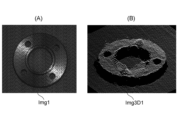
次いで、ステップS30では、画像Img1,Img2の少なくとも何れか一方を用いて、時刻t4から時刻t6において、前記(1)の第1画像処理(例えばアクティブワンショット方式による3次元計測)を実行し、画像Img1,Img2の少なくも何れか一方から、計測光(パターン光)に含まれるパターンに応じた複数の第1特徴点の3次元位置を示す3次元点群を復元する。なお、図4及び図5においては、画像Img1を用いる場合について例示するが、画像Img2を用いてもよく、画像Img1,Img2の両方を用いてもよい。ここで、図6(A)及び図6(B)は、それぞれ、3次元計測システム100により対象物OBの一例(金属製のワーク)を撮像した画像Img1、及び、該画像Img1を用いてステップS30における第1画像処理を行って復元した3次元点群画像Img3D1を示す。
(Step S30)
Next, in step S30, using at least one of the images Img1 and Img2, from time t4 to time t6, the first image processing of (1) (for example, three-dimensional measurement by the active one-shot method) is performed, From at least one of the images Img1 and Img2, a three-dimensional point group representing the three-dimensional positions of a plurality of first feature points according to the pattern included in the measurement light (pattern light) is restored. 4 and 5 illustrate the case where the image Img1 is used, but the image Img2 may be used, or both the images Img1 and Img2 may be used. Here, FIGS. 6A and 6B are respectively an image Img1 obtained by imaging an example of the object OB (metal work) by the three-dimensional measurement system 100, and a step using the image Img1. 3 shows a three-dimensional point cloud image Img3D1 restored by performing the first image processing in S30.
(ステップS40)
続いて、ステップS40では、時刻t6から時刻t7において、以下の処理を行う。すなわち、ここでは、まず、画像Img1,Img2の一般的な平行化処理を行い、平行化された画像Img1,Img2(平行化画像)を用いて、前記(2)の第2画像処理(復元3次元点群投影)を実行する。これにより、復元3次元点群における各第1特徴点(復元3次元点)の3次元座標(つまり図6(B)における各点の3次元座標)が画像Img1,Img2に2次元投影される。なお、画像Img1への2次元投影はステップS30における画像Img1の処理において、時刻t4から時刻t6の間に、実質的に同時に実行され得る。
(Step S40)
Subsequently, in step S40, the following processing is performed from time t6 to time t7. That is, here, first, general parallelization processing is performed on the images Img1 and Img2, and the parallelized images Img1 and Img2 (parallelized images) are used to perform the second image processing (reconstruction 3 2D point cloud projection). As a result, the three-dimensional coordinates of each first feature point (restored three-dimensional point) in the restored three-dimensional point group (that is, the three-dimensional coordinates of each point in FIG. 6B) are two-dimensionally projected onto the images Img1 and Img2. . Note that the two-dimensional projection onto image Img1 can be performed substantially simultaneously between time t4 and time t6 in the processing of image Img1 in step S30.
ここで、図7(A)は、3次元計測システム100により対象物OBの一例(金属製のワーク)を撮像した画像Img1の平行化画像Img1’(図6(A)と実質的に同等)、及び、その平行化画像Img1’に復元3次元点の3次元座標を2次元投影した画像Img10の部分拡大図を示す。同様に、図7(B)は、3次元計測システム100により対象物OBの一例(金属製のワーク)を撮像した画像Img2の平行化画像Img2’、及び、その平行化画像Img2’に復元3次元点の3次元座標を2次元投影した画像Img20の部分拡大図を示す。画像Img10,20における「+」印のシンボルが復元3次元点(対象画素)の2次元投影点に相当する。 Here, FIG. 7(A) is a parallelized image Img1′ of an image Img1 (substantially equivalent to FIG. 6(A)) obtained by imaging an example of the object OB (a work made of metal) by the three-dimensional measurement system 100. , and a partially enlarged view of an image Img10 obtained by two-dimensionally projecting the three-dimensional coordinates of the restored three-dimensional point onto the parallelized image Img1′. Similarly, FIG. 7(B) shows a parallelized image Img2′ of an image Img2 captured by the three-dimensional measurement system 100 of an example of an object OB (a work made of metal), and a reconstruction 3 of the parallelized image Img2′. FIG. 10 shows a partially enlarged view of an image Img20 obtained by two-dimensionally projecting the three-dimensional coordinates of dimensional points. The "+" symbols in the images Img10 and 20 correspond to the two-dimensional projection points of the restored three-dimensional points (target pixels).
次に、画像Img1,Img2間における複数の第1特徴点(対象画素)の各視差として、画像Img10,Img20間における各復元3次元点の視差を算出する。ここで、図7(A)の画像Img10に符号を例示した対象画素G10~G13は、それぞれ、図7(B)の画像Img20に符号を例示した対象画素G20~G23に対応し、対応する対象画素間の2次元座標から各第1特徴点(対象画素)の視差が算出される。これにより、複数の第1特徴点の間隔に応じた比較的粗い密度分布の視差マップを得る。 Next, the parallax of each restored three-dimensional point between images Img10 and Img20 is calculated as each parallax of a plurality of first feature points (target pixels) between images Img1 and Img2. Here, the target pixels G10 to G13 whose symbols are illustrated in the image Img10 of FIG. 7A respectively correspond to the target pixels G20 to G23 whose symbols are illustrated in the image Img20 of FIG. A parallax of each first feature point (target pixel) is calculated from the two-dimensional coordinates between the pixels. As a result, a parallax map with a relatively coarse density distribution corresponding to the intervals of the plurality of first feature points is obtained.
ここでさらに、上述した画像Img1,Img2の平行化処理と、平行化画像に復元3次元点の3次元座標を2次元投影して2次元座標を得るための数値処理のより具体的な一例について、以下に説明する。 Here, a more specific example of the parallelization processing of the images Img1 and Img2 described above and the numerical processing for obtaining the two-dimensional coordinates by two-dimensionally projecting the three-dimensional coordinates of the restored three-dimensional points onto the parallelized images. , are described below.
まず、平行化処理において、第1カメラ210の原点座標を基準座標と設定する。次に、第1カメラ210及び第2カメラ220のレンズの歪みは画像Img1,Img2から事前に除去されているとし、線形モデルで考えると、アクティブワンショット方式における3次元点XA、第1カメラ210による画像Img1における対応2次元座標点UL、及び、第2カメラ220による画像Img2における対応2次元座標点URは、下記式(1)及び式(2)で表される関係としてモデル化することができる。
First, in the parallelization process, the origin coordinates of the

上記式中、KLは、第1カメラ210の内部行列を示し、KRは、第2カメラ220の内部行列を示し、回転行列R2と並進ベクトルt2は、第1カメラ210に対する第2カメラ220の姿勢を表す。
where K L denotes the internal matrix of the
次に、第1カメラ210及び第2カメラ220が水平設置されている場合、両者の画像Img1,Img2における対応画素が垂直方向において同じ位置に現れるようにするため、仮想的に第1カメラ210及び第2カメラ220の両方を回転させ、理想的な平行状態とする。ここでの平行化処理では、下記式(3)で表される条件を満たす回転行列Rrectと仮想的なカメラ行列Krectと用い、第1カメラ210をRrect・R2だけ、第2カメラ220をRrectだけ、仮想的に回転させる。
Next, when the

そして、下記式(4)及び式(5)で表される関係から、ステレオカメラ方式とは異なる3次元計測方式(例えばアクティブワンショット方式)による復元3次元点XAに対応する平行化画像Img1’における対応2次元座標U’L、及び、平行化画像Img2’における対応2次元座標U’Rを求めることができる。 Then, from the relationship represented by the following formulas (4) and (5), a parallelized image Img1 ' and a corresponding two-dimensional coordinate U' R in the parallelized image Img2' can be obtained.

(ステップS50)
次に、ステップS50では、画像Img1,Img2を用いて、ステップS40と同じく時刻t6から時刻t7において、前記の(3)第3画像処理(ステレオカメラ方式による3次元計測)を実行し、画像Img1,Img2(平行化処理を行った場合には、画像Img1’,Img2’)の一方を基準画像とし且つ他方を比較画像とし、基準画像における任意の第2特徴点とそれに対する比較画像における対応点とのステレオマッチングを行う。なお、画像Img2を基準画像とし、画像Img1を比較画像としてもよい。
(Step S50)
Next, in step S50, the images Img1 and Img2 are used to perform the above-mentioned (3) third image processing (three-dimensional measurement by the stereo camera method) from time t6 to time t7 as in step S40. , Img2 (images Img1′ and Img2′ when parallelization is performed), one of which is a reference image and the other is a comparison image, and an arbitrary second feature point in the reference image and a corresponding point in the comparison image Perform stereo matching with Note that the image Img2 may be used as the reference image, and the image Img1 may be used as the comparison image.
まず、基準画像(例えば画像Img1’)における第2特徴点を抽出し、その第2特徴点の所定の近傍位置に存在する第1特徴点の視差に基づいて、第2特徴点と対応点との視差の推定値を算出する。 First, a second feature point in a reference image (for example, image Img1′) is extracted, and based on the parallax of the first feature point existing at a predetermined neighboring position of the second feature point, the second feature point and the corresponding point are Calculate an estimate of the parallax of .
ここで、図8は、ステップS40で得た複数の第1特徴点の間隔に応じた比較的粗い密度分布の視差マップを模式的に示す概念図である。図8においては、行列に区分けされた各領域が基準画像における単位画素に相当し、任意に抽出された第2特徴点である画素GAと、その近傍位置に存在し且つ視差マップにおいて視差が既知である第1特徴点である例えば対象画素G10~G13(図7(A)参照)を併せて示す。ここで、第2特徴点である画素GAとその対応点との視差の推定値を算出する手法の一例について、以下に説明する。但し、かかる推定方法は以下の手法に限定されない。また、ここでは、第1特徴点及び第2特徴点が異なる点であり且つ互いの近傍位置に存在する場合を例に説明するが、第1特徴点及び第2特徴点は、同一点であってもよく、また、異なる点である場合でも、両者が互いに近傍位置に存在する例に限定されない。さらに、第1特徴点及び第2特徴点が異なる点であり、ステレオカメラ以外の3次元計測方式により求めた第1特徴点の距離情報の精度が十分であれば、ステレオカメラ方式により第1特徴点の距離情報を求める処理を除外することで、計算速度を速めることが可能となる。 Here, FIG. 8 is a conceptual diagram schematically showing a parallax map with a relatively coarse density distribution corresponding to the intervals between the plurality of first feature points obtained in step S40. In FIG. 8, each region divided into a matrix corresponds to a unit pixel in the reference image, and a pixel GA, which is an arbitrarily extracted second feature point, and a pixel GA existing in a neighboring position and having a known parallax in the parallax map. , for example, target pixels G10 to G13 (see FIG. 7A), which are first feature points, are also shown. Here, an example of a method of calculating an estimated parallax value between the pixel GA, which is the second feature point, and its corresponding point will be described below. However, such an estimation method is not limited to the following method. Further, here, a case where the first feature point and the second feature point are different points and exist near each other will be described as an example, but the first feature point and the second feature point are the same point. Also, even if they are different points, they are not limited to an example in which both are present in close proximity to each other. Furthermore, if the first feature point and the second feature point are different points and the accuracy of the distance information of the first feature point obtained by a three-dimensional measurement method other than a stereo camera is sufficient, the stereo camera method can be used to obtain the first feature point. By excluding the process of obtaining the distance information of the points, it is possible to increase the calculation speed.
すなわち、第2特徴点である画素GAの近傍位置に存在する第1特徴点である画素の視差がdであった場合、第2特徴点である画素GAの視差dGAは、例えば下記式(6)を満たす範囲内の値であると推定することができる。下記式(6)中、Δdは、適宜設定され得るマージンを示す(以下同様)。 That is, if the parallax of the pixel that is the first feature point that exists in the vicinity of the pixel GA that is the second feature point is d, the parallax d GA of the pixel GA that is the second feature point is given by the following formula ( 6) can be estimated as a value within the range that satisfies. In the following formula (6), Δd indicates a margin that can be set appropriately (the same applies hereinafter).
![]()
![]()
また、例えば図8に示すように、第2特徴点である画素GAの近傍位置に、視差が得られている第1特徴点である複数の対象画素G10~G13が存在する場合、式(6)の概念を発展させ、第2特徴点である画素GAの視差dGAは、例えば下記式(7)を満たす範囲内の値であると推定することもできる。下記式(7)中、min(dn)は、最小のdnを選択する演算を示し、max(dn)は、最大のdnを選択する演算を示し、d0~d3は、それぞれ、第1特徴点である画素G10~G13の視差を示す。 Further, for example, as shown in FIG. 8, when a plurality of target pixels G10 to G13, which are first feature points for which parallax is obtained, exist in the vicinity of a pixel GA, which is a second feature point, the formula (6 ), it is also possible to estimate that the disparity d GA of the pixel GA, which is the second feature point, is a value within the range that satisfies the following equation (7), for example. In the following formula (7), min(d n ) indicates the calculation for selecting the minimum d n , max(d n ) indicates the calculation for selecting the maximum d n , and d 0 to d 3 are Each shows the parallax of the pixels G10 to G13, which are the first feature points.
![]()
![]()
こうして推定された第2特徴点である画素GAの視差dGAに基づいて、その第2特徴点に対する対応点の探索領域を限定的に設定(すなわち、探索領域を狭い範囲に限定)する。そして、その探索領域において、平行化画像Img1’,Img2’のステレオマッチングを行い、第2特徴点である画素GAにおける真の視差を算出する。なお、ステレオマッチングに先立って、必要に応じて、平行化画像Img1’,Img2’に対して適宜のフィルタリング等の前処理を実施してもよい。なお、ここでは、第2特徴点の視差を求めるための探索範囲を、各第1特徴点について得られた視差のうち複数の(4つの)視差に基づいて設定したが、これに限定されず、各第1特徴点について得られた視差のうち、1つ、2つ、3つ、又は5つ以上の視差に基づいて、第2特徴点の視差を求めるための探索範囲を設定してもよい。 Based on the parallax d GA of the pixel GA that is the second feature point estimated in this way, the search area for corresponding points to the second feature point is limited (that is, the search area is limited to a narrow range). Then, in the search area, the parallelized images Img1' and Img2' are subjected to stereo matching to calculate the true parallax at the pixel GA, which is the second feature point. Prior to stereo matching, preprocessing such as appropriate filtering may be performed on the parallelized images Img1' and Img2' as necessary. Note that here, the search range for obtaining the parallax of the second feature point is set based on a plurality of (four) parallaxes among the parallaxes obtained for each first feature point, but the search range is not limited to this. , the search range for obtaining the parallax of the second feature point may be set based on one, two, three, or five or more parallaxes among the parallaxes obtained for each first feature point. good.
以上の処理を複数の第2特徴点(例えば、図8に示す第1特徴点である画素以外の全ての画素)に対して実行することにより、複数の第1特徴点の間隔に応じた比較的粗い密度分布の視差マップ(図8)を補完するように、画像Img1,Img2の画素単位での比較的細かい密度分布の視差マップを得る(例えば、図8に示す第1特徴点である画素G10~G13以外の全ての第2特徴点の画素の視差が算出される。)。 By executing the above processing for a plurality of second feature points (for example, all pixels other than the pixels that are the first feature points shown in FIG. 8), comparison according to the intervals between the plurality of first feature points A disparity map with a relatively fine density distribution for each pixel of the images Img1 and Img2 is obtained so as to complement the disparity map with a coarse density distribution (FIG. 8). Parallaxes of pixels of all second feature points other than G10 to G13 are calculated.).
(ステップS60)
それから、ステップS60では、時刻t7から時刻t8において、ステップS30,S50で得た視差情報を統合し、換言すれば、ステップS30で得た比較的粗い密度分布の視差マップとステップS50で得た比較的細かい密度分布の視差マップを統合して統合視差マップ(例えば、図8に示す全ての画素の視差が判明したマップ)を得る。次いで、その統合視差マップに対して必要に応じて適宜のフィルタリング等の後処理を実施した後、第1特徴点及び第2特徴点の全画素の視差を深さ方向の距離に変換(いわゆる視差・デプス変換)することにより、対象物OBの3次元形状を特定する。
(Step S60)
Then, in step S60, from time t7 to time t8, the parallax information obtained in steps S30 and S50 is integrated. An integrated parallax map (for example, a map in which the parallaxes of all pixels shown in FIG. 8 are known) is obtained by integrating parallax maps with a finer density distribution. Next, after performing appropriate post-processing such as filtering on the integrated parallax map as necessary, the parallax of all pixels of the first feature point and the second feature point is converted into a distance in the depth direction (so-called parallax・Specify the three-dimensional shape of the object OB by performing depth transformation.
そして、得られた対象物OBの3次元形状を示す3次元点群画像を、必要に応じて、3次元計測システム100のユーザが視認可能なようにディスプレイやプリンタ等に出力して、一連の処理を終了する。ここで、図9(A)及び図9(B)は、それぞれ、対象物OBの一例(金属製のワーク)に対して3次元計測システム100によって得た統合視差マップの一例を示す画像ImgM(ここでは、視差の大小をグレースケールで模式的に示す。)、及び、該画像ImgMを用いて復元した3次元形状を表す3次元点群画像Img3DMを示す。 Then, the obtained three-dimensional point cloud image showing the three-dimensional shape of the target object OB is output to a display, printer, or the like so that the user of the three-dimensional measurement system 100 can visually recognize it, if necessary. End the process. Here, FIGS. 9A and 9B each show an image ImgM ( Here, the magnitude of parallax is schematically shown in grayscale.), and a three-dimensional point cloud image Img3DM representing a three-dimensional shape restored using the image ImgM.
§4 作用・効果
以上のとおり、本実施形態に係る3次元計測システム及び3次元計測方法の一例は、ステレオカメラ方式とは異なる3次元計測方式による3次元計測と、ステレオマッチングによって対象物の3次元位置を求めることができるステレオカメラ方式による3次元計測を融合したハイブリッド3次元計測システム及びその方法を提供する。
§4 Actions and effects As described above, an example of the three-dimensional measurement system and the three-dimensional measurement method according to the present embodiment includes three-dimensional measurement by a three-dimensional measurement method different from the stereo camera method, and three-dimensional measurement of an object by stereo matching. Provided is a hybrid three-dimensional measurement system and method that integrates three-dimensional measurement by a stereo camera method that can obtain a dimensional position.
但し、本実施形態の一例は、ステレオカメラ方式とは異なる3次元計測方式とステレオカメラ方式をただ単に組み合わせただけのものではなく、ステレオカメラ方式とは異なる3次元計測方式で得られた3次元情報(第1特徴点の視差)を用いることにより、ステレオマッチングにおける第2特徴点に対する対応点の探索領域を、通常のステレオカメラ方式に比して格段に狭い範囲に限定することができる。 However, an example of the present embodiment is not simply a combination of a three-dimensional measurement method different from the stereo camera method and a stereo camera method, but a three-dimensional measurement method obtained by a three-dimensional measurement method different from the stereo camera method. By using the information (the parallax of the first feature point), the search area for the corresponding points for the second feature point in stereo matching can be limited to a much narrower range than in the normal stereo camera method.
換言すれば、本実施形態の一例によれば、ステレオカメラ方式とは異なる3次元計測方式で得られた第1特徴点間の画素に注目し、その画素(第2特徴点とその対応点)に対する視差情報をステレオカメラ方式によって補完することができ、その際のステレオマッチングの探索領域を確からしい狭い範囲に限定することにより、極めて短い処理時間を達成することができる。その結果、画素単位の高い計測分解能を有するステレオカメラ方式のステレオマッチングにおける探索時間(図5に示す如く、ステップS40の処理時間は時刻t6から時刻t7までの極めて短時間である。)及び全体の処理時間を大幅に短縮することができる。しかも、そのように探索領域を限定することにより、相互反射に対する優れたロバスト性を実現することができるとともに、ステレオマッチングにおける画素間の誤対応を軽減することも可能となる。 In other words, according to one example of the present embodiment, attention is paid to pixels between first feature points obtained by a three-dimensional measurement method different from the stereo camera method, and the pixels (second feature points and their corresponding points) are Parallax information can be complemented by a stereo camera method, and an extremely short processing time can be achieved by limiting the search area for stereo matching at that time to a probable narrow range. As a result, the search time (as shown in FIG. 5, the processing time of step S40 is extremely short from time t6 to time t7) and the overall Processing time can be greatly reduced. Moreover, by limiting the search area in this way, excellent robustness against interreflection can be achieved, and erroneous correspondence between pixels in stereo matching can be reduced.
ここで、図10は、表面の性状が種々異なる対象物OBについて、種々の方式による3次元計測を行った結果として最終的に得られた視差マップを表す画像の一覧を表形式で示す。なお、何れの方式においても、センサユニットとしては、本実施形態の3次元計測システム100におけるセンサユニット200を用い、図10には、得られた2種類の画像Img1,Img2(但し、パターンを消去)を示す。また、アクティブワンショット方式による画像処理のみを行って得た結果、及び、ステレオカメラ方式による画像処理のみを行って得た結果を、それぞれ便宜的に、「比較例1」及び「比較例2」として示す。また、本実施形態の3次元計測システム100による画像処理を行って得た結果を「実施例1」として示す。さらに、対象物OBとしては、A. テクスチャなしのもの、B.形状エッジを有するもの、C.テクスチャを有するもの、及び、D.正反射を生じるワークを選定した。またさらに、図10においては、各対象物OBに対して各方式によって得られた視差マップの画像の欄に、良好な結果を示したものには「○」印を付し、良好な結果を示さなかったものには「×」印を付した。
Here, FIG. 10 shows, in tabular form, a list of images representing parallax maps finally obtained as a result of three-dimensional measurement by various methods for objects OB having various surface properties. In either method, the
図10に示すとおり、比較例1(アクティブワンショット方式による画像処理のみ)では、A. テクスチャなしのもの、及び、D.正反射を生じるワークに対しては良好な結果が得られたものの、B.形状エッジを有するもの、及び、C.テクスチャを有するものに対しては良好な結果が得られなかった。反対に、比較例2(ステレオカメラ方式による画像処理のみ)では、B.形状エッジを有するもの、及び、C.テクスチャを有するものに対しては良好な結果が得られたものの、A. テクスチャなしのもの、及び、D.正反射を生じるワークに対しては良好な結果が得られなかった。これらに対し、実施例1(本実施形態の3次元計測システム100による画像処理)では、何れの対象物OBに対しても良好な結果が得られた。これらの結果は、本実施形態の3次元計測システム100の他方式に対する優位性(特に対象物OBの表面の性状の相違に対する高いロバスト性)の一例を示すものといえる。このとおり、本実施形態の一例は、ステレオカメラ方式とは異なる3次元計測方式(例えばアクティブワンショット方式)及びステレオカメラ方式のそれぞれの計測原理の相違に基づく計測可能領域の違いを効果的に組み合わせることにより、従来に比して優位な効果を得ることが確認された。 As shown in FIG. 10, in Comparative Example 1 (only image processing by the active one-shot method), A. no texture and D. Although good results were obtained for works that produce specular reflection, B.I. B. with shape edges; Good results were not obtained for those with texture. On the contrary, in Comparative Example 2 (only image processing by the stereo camera method), B. B. with shape edges; Although good results were obtained for those with texture, A. no texture and D. Good results were not obtained for works that produce specular reflection. On the other hand, in Example 1 (image processing by the three-dimensional measurement system 100 of the present embodiment), good results were obtained for any object OB. These results can be said to show an example of the superiority of the three-dimensional measurement system 100 of the present embodiment over other methods (in particular, high robustness against differences in surface properties of the object OB). As described above, one example of the present embodiment effectively combines the difference in the measurable area based on the difference in measurement principle between the three-dimensional measurement method (for example, the active one-shot method) and the stereo camera method, which are different from the stereo camera method. Therefore, it was confirmed that a superior effect can be obtained as compared with the conventional method.
§5 変形例
以上、本開示の一例としての実施形態について詳細に説明してきたが、前述までの説明はあらゆる点において本開示の一例を示すに過ぎず、本開示の範囲を逸脱することなく種々の改良や変形を行うことができることは言うまでもない。例えば、以下のような変更が可能である。なお、以下では、上記実施形態と同様の構成要素に関しては同様の符号を用い、上記実施形態と同様の点については、適宜説明を省略した。以下の変形例は適宜組み合わせ可能である。
§ 5 Modifications Although the embodiment as an example of the present disclosure has been described in detail above, the above description merely shows an example of the present disclosure in all respects, and various modifications can be made without departing from the scope of the present disclosure. It goes without saying that improvements and modifications can be made. For example, the following changes are possible. In addition, below, the same code|symbol is used about the component similar to the said embodiment, and description is abbreviate|omitted suitably about the point similar to the said embodiment. The following modified examples can be combined as appropriate.
<5.1>
例えば、上記実施形態の動作例におけるステップS30における(1)第1画像処理においては、画像Img1,Img2のうち画像Img1のみを用いる場合について言及したが、(1)第1画像処理は、画像Img1,Img2のうち画像Img2のみを用いて実施してもよく、画像Img1,Img2の両方を用いて実施してもよい。
<5.1>
For example, in the (1) first image processing in step S30 in the operation example of the above embodiment, only the image Img1 of the images Img1 and Img2 is used. , Img2, only the image Img2 may be used, or both the images Img1 and Img2 may be used.
特に、画像Img1,Img2の両方を用いる構成によれば、比較的粗い密度分布の視差マップが2つ得られるので、特徴点の未知の視差の推定における精度及び/又は確度を向上させ得る。また、2つの画像のうち比較的良好な何れか一方の画像を選択的に用いる構成によっても、比較的粗い密度分布の視差マップ自体の精度が高まるので、この場合にも、特徴点の未知の視差の推定における精度及び/又は確度を向上させ得る。 In particular, with the configuration using both images Img1 and Img2, two disparity maps with relatively coarse density distributions can be obtained, so that the accuracy and/or accuracy in estimating the unknown disparity of feature points can be improved. Also, by selectively using one of the two images that is relatively good, the accuracy of the disparity map itself with a relatively coarse density distribution is increased. Precision and/or accuracy in estimating parallax may be improved.
なお、センサユニット200に備わるカメラも各1台の第1カメラ210及び第2カメラ220(合計2台)に限られず、第1カメラ210及び第2カメラ220の少なくとも何れか一方が複数台(合計3台以上)であってもよい。また、各カメラで撮像される画像Img1,Img2は、それぞれ1画像に限られず、それぞれ複数画像であってももちろんよい。これらの構成によれば、比較的粗い密度分布の視差マップを得るために用いる画像の選択の幅が広がるので、この場合にも、特徴点の未知の視差の推定における精度及び/又は確度を更に向上させ得るとともに、ステレオカメラ方式で用いる2つの画像の選択性も高めることができるので、最終的に特定される3次元形状の精度及び/又は確度を一層向上させ得る。
Note that the cameras provided in the
<5.2>
ここでは、図11(A)乃至(D)を用いて、センサユニット200における3D用プロジェクタ110並びに第1カメラ210及び第2カメラ220の相対的な幾何学的配置に係る構成例について説明する。
<5.2>
11A to 11D, configuration examples relating to the relative geometric arrangement of the
<5.2.1>
図11(A)は、センサユニット200の第1構成例を模式的に示す斜視図である。当該第1構成例は、第1カメラ210の光軸P21と第2カメラ220の光軸P22が同一平面P1上に配置され、3D用プロジェクタ110の光軸P11がその平面P1上に配置されないように構成されたものである。換言すれば、当該第1構成例では、3D用プロジェクタ110の光軸P11が、第1カメラ210の光軸P21及び第2カメラ220の光軸P22によって画定される仮想的な平面P1上の位置とは異なる位置に配置されるように構成される。また、当該第1構成例は、第1カメラ210の光軸P21と第2カメラ220の光軸P22との距離が、3D用プロジェクタ110の光軸P11と第1カメラ210の光軸P21との距離、及び、3D用プロジェクタ110の光軸P11と第2カメラ220の光軸P22との距離の何れとも同等となるように構成される。
<5.2.1>
FIG. 11A is a perspective view schematically showing a first configuration example of the
当該第1構成例では、第1カメラ210と第2カメラ220との基線長(距離)が、3D用プロジェクタ110と第1カメラ210との基線長、及び、3D用プロジェクタ110と第2カメラ220との基線長の何れとも同等となるので、3次元計測における計測精度を向上させることができる。また、この場合、第1カメラ210を用いたアクティブワンショット方式による計測精度と、第2カメラ220を用いたアクティブワンショット方式による計測精度を同等にすることができ、両方のカメラでアクティブワンショット方式による3次元計測を行う場合に有用である。さらに、センサユニット200のフットプリントを比較的小さくすることができるので、3次元計測システムの設置面積を低減することができる。
In the first configuration example, the baseline length (distance) between the
<5.2.2>
図11(B)は、センサユニット200の第2構成例を模式的に示す斜視図である。当該第2構成例も、第1カメラ210の光軸P21と第2カメラ220の光軸P22が同一平面P1上に配置され、3D用プロジェクタ110の光軸P11がその平面P1上に配置されないように構成されたものである。換言すれば、当該第2構成例でも、3D用プロジェクタ110の光軸P11が、第1カメラ210の光軸P21及び第2カメラ220の光軸P22によって画定される仮想的な平面P1上の位置とは異なる位置に配置されるように構成される。また、当該第2構成例は、第1カメラ210の光軸P21と第2カメラ220の光軸P22との距離が、3D用プロジェクタ110の光軸P11と第1カメラ210の光軸P21との距離よりも長くなるように構成される。
<5.2.2>
FIG. 11B is a perspective view schematically showing a second configuration example of the
当該第2構成例では、第1カメラ210と第2カメラ220との基線長が、3D用プロジェクタ110と第1カメラ210との基線長よりも大きくなるので、3次元計測における計測精度を向上させることができる。また、この場合、第2カメラ220を用いたアクティブワンショット方式による計測精度を、第1構成例(図11(A))におけるアクティブワンショット方式による計測精度よりも高めることができ、片方のカメラでアクティブワンショット方式による3次元計測を行う場合に有用である。さらに、センサユニット200のフットプリントを比較的小さくすることができるので、3次元計測システムの設置面積を低減することができる。
In the second configuration example, the baseline lengths of the
<5.2.3>
図11(C)は、センサユニット200の第3構成例を模式的に示す斜視図である。当該第3構成例は、3D用プロジェクタ110の光軸P11が、第1カメラ210の光軸P21及び第2カメラ220の光軸P22によって画定される仮想的な平面P2上に(すなわち全て同一平面上に)配置されるように構成される。また、当該第3構成例は、第1カメラ210の光軸P21と第2カメラ220の光軸P22との距離が、3D用プロジェクタ110の光軸P11と第1カメラ210の光軸P21との距離、及び、3D用プロジェクタ110の光軸P11と第2カメラ220の光軸P22との距離の何れとも同等となるように構成される。
<5.2.3>
FIG. 11C is a perspective view schematically showing a third configuration example of the
当該第3構成例では、第1カメラ210と第2カメラ220との基線長が、3D用プロジェクタ110と第1カメラ210との基線長、及び、3D用プロジェクタ110と第2カメラ220との基線長の何れよりも大きくなるので、3次元計測における計測精度を向上させることができる。また、3D用プロジェクタ110と第1カメラ210との基線長、及び、3D用プロジェクタ110と第2カメラ220との基線長が同等となるので、第1カメラ210を用いたアクティブワンショット方式による計測精度と、第2カメラ220を用いたアクティブワンショット方式による計測精度を同等にすることができ、両方のカメラでアクティブワンショット方式による3次元計測を行う場合に有用である。さらに、第1カメラ210と第2カメラ220との基線長を、例えば第1構成例(図11(A))や第2構成例(図11(B))に比して大きくすることが可能となるので、他の計測パラメータやアルゴリズムが同一の条件であれば、ステレオカメラ方式による計測精度を更に向上させることができ、センサユニット200の設置面積を広くしてでもステレオカメラ方式による計測精度を高めたい場合に有用である。
In the third configuration example, the baseline length between the
<5.2.4>
図11(D)は、センサユニット200の第4構成例を模式的に示す斜視図である。当該第4構成例も、3D用プロジェクタ110の光軸P11が、第1カメラ210の光軸P21及び第2カメラ220の光軸P22によって画定される仮想的な平面P2上に(すなわち全て同一平面P2上に)配置されるように構成される。また、当該第4構成例は、第1カメラ210の光軸P21と第2カメラ220の光軸P22との距離が、3D用プロジェクタ110の光軸P11と第1カメラ210の光軸P21との距離と同等になるように構成される。
<5.2.4>
FIG. 11D is a perspective view schematically showing a fourth configuration example of the
当該第4構成例では、第1カメラ210と第2カメラ220との基線長が、3D用プロジェクタ110と第1カメラ210との基線長と同等になるので、3次元計測における計測精度を向上させることができる。また、この場合、第2カメラ220を用いたアクティブワンショット方式による計測精度を、第3構成例(図11(C))におけるアクティブワンショット方式による計測精度よりも高めることができ、片方のカメラでアクティブワンショット方式による3次元計測を行い、且つ、アクティブワンショット方式による計測精度を更に高めたい場合に有用である。
In the fourth configuration example, the baseline lengths of the
<5.3>
次に、図12(A)及び(B)を用いて、センサユニット200に、通常照明光を対象物OBに投射するための2D用プロジェクタ120を加えて配置した構成例について説明する。このとおり、2D用プロジェクタ120は、本発明における「投射部」(「第2投射部」)の一例に相当し、3D用プロジェクタ110及び2D用プロジェクタ120は、本発明における「投射部」の一例に相当し、2D用プロジェクタ120を有するセンサユニット200も、本発明における「投射部」の一例に相当する。
<5.3>
Next, a configuration example in which a
<5.3.1>
図12(A)は、センサユニット200の第5構成例を模式的に示す斜視図である。当該第5構成例は、図11(B)に示す第2構成例に、2D用プロジェクタ120が追設された配置を有している。また、当該第5構成例は、第1カメラ210の光軸P21と第2カメラ220の光軸P22が同一平面P1上に配置され、3D用プロジェクタ110の光軸P11と2D用プロジェクタ120の光軸P12が、平面P1とは異なる同一平面P3上に配置されるように構成される。なお、平面P1と平面P3は、平行とされている。
<5.3.1>
FIG. 12A is a perspective view schematically showing a fifth configuration example of the
当該第5構成例では、2D用プロジェクタ120を例えば検査用途の一般照明として使用することができるので、対象物OBが暗い周辺環境下にある場合においても、3次元形状の計測を好適に実施することができる。また、2D用プロジェクタ120から通常照明が投射された対象物OBを撮像した画像を取得し、その画像と、例えばコンピュータ300の記憶部303又は画像記録部330に予め設定又は保持された対象物OBの形状設計データ(CADモデルデータ)とを対比し、例えばいわゆるCADマッチングを行うことにより、対象物OBの位置姿勢をより正確に把握することが可能となる。
In the fifth configuration example, the
また、当該第5構成例は、2D用プロジェクタ120を除くセンサユニット200の構成が第2構成例と同様であるので、第2構成例と同じく、3次元計測における計測精度を向上させることができる。また、この場合、第2カメラ220を用いたアクティブワンショット方式による計測精度を、第1構成例(図11(A))におけるアクティブワンショット方式による計測精度よりも高めることができ、片方のカメラでアクティブワンショット方式による3次元計測を行う場合に有用である。さらに、センサユニット200のフットプリントを比較的小さくすることができるので、3次元計測システムの設置面積を低減することができる。
In addition, in the fifth configuration example, the configuration of the
<5.3.2>
図12(B)は、センサユニット200の第6構成例を模式的に示す斜視図である。当該第6構成例は、図11(C)に示す第3構成例に、2D用プロジェクタ120が追設された配置を有している。また、当該第6構成例は、2D用プロジェクタ120の光軸P12が、3D用プロジェクタ110の光軸P11、第1カメラ210の光軸P21、及び第2カメラ220の光軸P22によって画定される仮想的な平面P4上の位置に(すなわち全て同一平面P4上に)配置されるように、且つ、2D用プロジェクタ120が、3D用プロジェクタ110と第2カメラ220との間に配置されるように構成される。
<5.3.2>
FIG. 12B is a perspective view schematically showing a sixth configuration example of the
当該第6構成例では、第5構成例と同様に、2D用プロジェクタ120を例えば検査用途の一般照明として使用することができるので、対象物OBが暗い周辺環境下にある場合においても、3次元形状の計測を好適に実施することができる。また、2D用プロジェクタ120から通常照明が投射された対象物OBを撮像した画像を取得し、その画像と、例えばコンピュータ300の記憶部303又は画像記録部330に予め設定又は保持された対象物OBの形状設計データ(CADモデルデータ)とを対比し、例えばいわゆるCADマッチングを行うことにより、対象物OBの位置姿勢をより正確に把握することが可能となる。
In the sixth configuration example, as in the fifth configuration example, the
また、当該第6構成例は、第1カメラ210と第2カメラ220との基線長が、3D用プロジェクタ110と第1カメラ210との基線長、及び、3D用プロジェクタ110と第2カメラ220との基線長の何れよりも大きくなるので、3次元計測における計測精度を向上させることができる。また、この場合、第2カメラ220を用いたアクティブワンショット方式による計測精度を、第3構成例(図11(C))におけるアクティブワンショット方式による計測精度よりも高めることができ、片方のカメラでアクティブワンショット方式による3次元計測を行い、且つ、アクティブワンショット方式による計測精度を更に高めたい場合に有用である。さらに、第1カメラ210と第2カメラ220との基線長を、例えば第3構成例(図11(C))に比して更に大きくすることが可能となるので、他の計測パラメータやアルゴリズムが同一の条件であれば、ステレオカメラ方式による計測精度を更に一層向上させることができ、センサユニット200の設置面積を更に広くしてでもステレオカメラ方式による計測精度を更に高めたい場合に有用である。
Further, in the sixth configuration example, the baseline length between the
<5.4>
なお、上記第1構成例乃至第6構成例におけるセンサユニット200の配置は、ステレオカメラ方式とは異なる3次元計測方式として三角測距を基本原理とする計測方式によって得た計測情報に基づいて、ステレオカメラ方式によるステレオマッチングを実施する際に有用な構成として例示した。
<5.4>
The arrangement of the
一方、他の3次元計測方式を用いた形態として、ステレオカメラ方式とは異なる3次元計測方式として同軸測距を基本原理とする計測方式(各種TOF測定方式等)によって得た計測情報に基づいて、ステレオカメラ方式によるステレオマッチングを実施する第7構成例が挙げられる。当該第7構成例の場合でも、図11(A)乃至(D)並びに図12(A)及び(B)に示すセンサユニット200を用いることができ、これらのなかでは、3D用プロジェクタ110(時間計測用の照明光)と第1カメラ210との基線長が極力短く(距離が近づく)なり、且つ、第1カメラ210と第2カメラとの基線長が極力長く(距離が離れる)なる図11(C)及び図12(B)に示す配置のものが、計測精度をより高めることができ、殊に図12(B)に示す配置が有用である。
On the other hand, as a form using other three-dimensional measurement methods, based on measurement information obtained by measurement methods (various TOF measurement methods, etc.) based on coaxial distance measurement as a three-dimensional measurement method different from the stereo camera method , and a seventh configuration example in which stereo matching is performed by a stereo camera method. Even in the case of the seventh configuration example, the
<5.5>
また、上記実施形態においては、例えば、第1カメラ210及び第2カメラ220のうちの一方(片方)を用い、アクティブワンショット方式による計測で測距した後に、第1特徴点の視差を求める構成について説明した。一方、更に他の3次元計測方式を用いた形態として、対象物OBにパターン光を投影した状態で第1カメラ210及び第2カメラ220の両方を用いて空間コードを特定することにより、第1特徴点の視差を求める第8構成例が挙げられる。当該第8構成例による計測は、具体的には、空間コード化パターン投影方式、及び/又は、時間コード化パターン投影方式によって実施することができる。
<5.5>
Further, in the above embodiment, for example, one (one) of the
<5.6>
さらに、図13(A)乃至(C)を用いて、センサユニット200における3D用プロジェクタ110から投射される3D用照明の投射エリアS110に係る構成例について説明する。
<5.6>
Further, a configuration example relating to a projection area S110 of the 3D illumination projected from the
<5.6.1>
図13(A)は、センサユニット200の第9構成例を模式的に示す平面図である。当該第9構成例は、3D用プロジェクタ110として、3D用照明の投射エリアS110が、第1カメラ210の視野角S210及び第2カメラ220の視野角S220の重複部分(共通視野)を覆うものを備える。当該第9構成例は、上述した実施形態における3次元計測システム100において、1度の3D用照明の投射時に画像Img1,Img2を撮像し、それらの画像Img1,Img2を用いてハイブリッド3次元計測を行う場合に特に好適である。
<5.6.1>
FIG. 13A is a plan view schematically showing a ninth configuration example of the
<5.6.2>
図13(B)は、センサユニット200の第10構成例を模式的に示す平面図である。当該第10構成例は、3D用プロジェクタ110として、3D用照明の投射エリアS110が、第1カメラ210の視野角S210及び第2カメラ220の視野角S220の何れか一方(単一視野)の全体を覆うものを備える。当該第10構成例は、上述した実施形態における3次元計測システム100において、アクティブワンショット方式で用いる画像を撮像する際に有用であり、この場合、ステレオカメラ方式で用いる画像は、異なる投射エリアの別の照明(例えば2D用プロジェクタ)で撮像することができる。
<5.6.2>
FIG. 13B is a plan view schematically showing a tenth configuration example of the
<5.6.3>
図13(C)は、センサユニット200の第11構成例を模式的に示す平面図である。当該第11構成例は、3D用プロジェクタ110として、3D用照明の投射エリアS110が、第1カメラ210の視野角S210及び第2カメラ220の視野角S220の両方の全体部分(複数視野)を覆うものを備える。当該第11構成例では、上述した実施形態における3次元計測システム100において、1度の3D用照明の投射時に画像Img1,Img2を撮像し、それらの画像Img1,Img2を用いてハイブリッド3次元計測を行う場合、及び、アクティブワンショット方式で用いる画像とステレオカメラ方式で用いる画像を別々に撮像する場合の何れにも好適に対応することができる。
<5.6.3>
FIG. 13C is a plan view schematically showing an eleventh configuration example of the
<5.7>
上記実施形態においては、ステップS30において、画像Img1,Img2の少なくとも何れか一方を用いて、計測光(パターン光)に含まれるパターンに応じた複数の第1特徴点の3次元位置を示す3次元点群を復元したが、対象物OBの形状や計測条件によっては、第1特徴点の一部について3次元点群を復元することができない場合も想定される。そこで、当該第12構成例では、かかる場合に、例えば、3次元点群が復元された第1特徴点の領域に対応する第2特徴点については、ステレオマッチングにおける探索範囲を第1特徴点の視差に基づいて狭い範囲に設定する一方、3次元点群が復元されなかった第1特徴点の領域に対応する第2特徴点については、ステレオマッチングにおける探索範囲を予め定めた所定の範囲に設定するように構成する。なお、当該第12構成例におけるハード構成は、他の実施形態及び他の構成例と同等のものとすることができる。
<5.7>
In the above embodiment, in step S30, at least one of the images Img1 and Img2 is used to perform a three-dimensional image showing the three-dimensional positions of the plurality of first feature points according to the pattern included in the measurement light (pattern light). Although the point cloud is restored, it may be impossible to restore the three-dimensional point cloud for some of the first feature points depending on the shape of the object OB and measurement conditions. Therefore, in the twelfth configuration example, in such a case, for example, for the second feature points corresponding to the region of the first feature points in which the three-dimensional point group is restored, the search range in stereo matching is set to the first feature point While setting a narrow range based on parallax, for the second feature points corresponding to the area of the first feature points for which the 3D point group was not restored, the search range in stereo matching is set to a predetermined range. configured to Note that the hardware configuration in the twelfth configuration example can be the same as those of the other embodiments and other configuration examples.
当該第12構成例によれば、対象物OBのうちの一部について、ステレオカメラ方式による3次元計測に先立つ最初の3次元計測(ステレオカメラ方式とは異なる3次元計測方式による3次元計測;例えばアクティブワンショット方式)で3次元点群を復元できない場合であっても、画像Img1,Img2の全体に対して探索範囲を広げたステレオマッチングを行う必要がなく、処理の高速化が可能となる。 According to the twelfth configuration example, the first three-dimensional measurement prior to three-dimensional measurement by the stereo camera method (three-dimensional measurement by a three-dimensional measurement method different from the stereo camera method; for example, Even if the three-dimensional point cloud cannot be restored by the active one-shot method), there is no need to perform stereo matching with a wider search range for the entire images Img1 and Img2, which makes it possible to speed up processing.
§6 付記
以上説明した実施形態は、本発明の理解を容易にするためのものであり、本発明を限定して解釈するためのものではない。実施形態が備える各要素並びにその配置、材料、条件、形状及びサイズ等は、例示したものに限定されるわけではなく適宜変更することができる。また、異なる実施形態で示した構成同士を部分的に置換し又は組み合わせることが可能である。
§6 Supplementary Note The embodiments described above are for facilitating understanding of the present invention, and are not intended to limit and interpret the present invention. Each element included in the embodiment and its arrangement, materials, conditions, shape, size, etc. are not limited to those illustrated and can be changed as appropriate. Also, it is possible to partially replace or combine the configurations shown in different embodiments.
(付記1)
互いに離間配置された第1撮像部(210)及び第2撮像部(220)を有しており、且つ、前記対象物(OB)における互いに異なる画像(Img1,Img2)を撮像する撮像部(200)と、
前記第1撮像部(210)及び前記第2撮像部(220)の少なくとも何れか一方を用い、ステレオカメラ方式とは異なる3次元計測方式の距離情報又は距離を算出するための情報を用いることにより、前記画像における第1特徴点の視差(d0~d3)を算出する第1算出部(350)と、
前記第1撮像部(210)及び前記第2撮像部(220)を用い、ステレオカメラ方式により、第2特徴点に対する対応点を探索し、該探索結果に基づいて前記第2特徴点の視差を算出し、前記第1特徴点の視差(d0~d3)と前記第2特徴点の視差から前記対象物(OB)の3次元形状を特定する第2算出部(350)と、
を備え、
前記第2算出部(350)は、前記第2特徴点に対する前記対応点の探索範囲を前記第1特徴点の視差(d0~d3)に基づいて設定する、
3次元計測システム(100)。
(Appendix 1)
An imaging unit (200) having a first imaging unit (210) and a second imaging unit (220) spaced apart from each other, and for capturing mutually different images (Img1, Img2) of the object (OB) )and,
By using at least one of the first imaging unit (210) and the second imaging unit (220) and using distance information or information for calculating the distance of a three-dimensional measurement method different from the stereo camera method , a first calculator (350) for calculating a parallax (d 0 to d 3 ) of a first feature point in the image;
Using the first imaging unit (210) and the second imaging unit (220), a stereo camera method is used to search for points corresponding to the second feature points, and based on the search results, the parallax of the second feature points is calculated. a second calculation unit (350) for calculating and specifying the three-dimensional shape of the object (OB) from the parallax (d 0 to d 3 ) of the first feature points and the parallax of the second feature points;
with
The second calculation unit (350) sets the search range of the corresponding points for the second feature points based on the parallax (d 0 to d 3 ) of the first feature points.
A three-dimensional measurement system (100).
(付記2)
3次元形状を特定するために前記対象物(OB)に計測光を投射する投射部(200,110)を備える、
付記1記載の3次元計測システム(100)。
(Appendix 2)
A projection unit (200, 110) that projects measurement light onto the object (OB) to specify a three-dimensional shape,
The three-dimensional measurement system (100) according to
(付記3)
前記第1特徴点及び前記第2特徴点は、同一点であるか、又は、互いの近傍位置に存在する、
付記1又は2記載の3次元計測システム(100)。
(Appendix 3)
The first feature point and the second feature point are the same point or exist in positions near each other,
The three-dimensional measurement system (100) according to
(付記4)
前記ステレオカメラ方式とは異なる3次元計測方式は、前記撮像部(200)による1度の撮像により前記対象物(OB)の3次元情報を得るものである、
付記1乃至3の何れか記載の3次元計測システム(100)。
(Appendix 4)
A three-dimensional measurement method different from the stereo camera method obtains three-dimensional information of the object (OB) by one-time imaging by the imaging unit (200).
A three-dimensional measurement system (100) according to any one of
(付記5)
前記第2算出部(350)は、前記探索範囲を前記第1特徴点の視差(d0~d3)に基づいて設定しない場合に比して、前記ステレオカメラ方式におけるマッチング度合いの指標の閾値を下げる、
付記1乃至4の何れか記載の3次元計測システム(100)。
(Appendix 5)
The second calculation unit (350) sets the threshold of the degree of matching index in the stereo camera method as compared to the case where the search range is not set based on the parallax (d 0 to d 3 ) of the first feature points. lower the
A three-dimensional measurement system (100) according to any one of
(付記6)
前記第1算出部(350)は、前記第1特徴点の3次元位置を示す3次元点群を復元するものであり、
前記第2算出部(350)は、前記第1特徴点の一部について前記3次元点群が復元されなかった場合に、前記3次元点群が復元された前記第1特徴点の領域に対応する前記第2特徴点については、前記探索範囲を前記第1特徴点の視差(d0~d3)に基づいて設定し、前記3次元点群が復元されなかった前記第1特徴点の領域に対応する前記第2特徴点については、前記探索範囲を予め定めた所定の範囲に設定する、
付記1乃至5の何れか記載の3次元計測システム。
(Appendix 6)
The first calculation unit (350) restores a three-dimensional point group indicating the three-dimensional position of the first feature point,
The second calculation unit (350), when the three-dimensional point group is not restored for a part of the first feature points, corresponds to the region of the first feature points where the three-dimensional point group is restored. for the second feature points, the search range is set based on the parallax (d 0 to d 3 ) of the first feature points, and the area of the first feature points where the three-dimensional point group has not been restored For the second feature point corresponding to, the search range is set to a predetermined range,
6. The three-dimensional measurement system according to any one of
(付記7)
前記第1算出部(350)が、前記第1特徴点の3次元位置を示す3次元点群を復元する第1画像処理部(351)と、復元された前記3次元点群における各第1特徴点の3次元座標を前記画像に2次元投影して前記各第1特徴点の2次元座標を求め、該2次元座標から前記各第1特徴点の視差(d0~d3)を算出する第2画像処理部(352)とを有し、
前記第2算出部(350)が、前記第2特徴点の視差の推定値を、前記第1特徴点の視差(d0~d3)から求め、前記第2特徴点の視差の推定値に基づいて前記対応点の探索領域を設定し、該探索領域において前記第2特徴点と前記対応点とのステレオマッチングを行うことにより、前記第2特徴点の視差を算出する第3画像処理部(353)と、前記第1特徴点の視差(d0~d3)及び前記第2特徴点の視差に基づいて前記対象物(OB)の3次元形状を特定する第4画像処理部(354)とを有する、
付記1乃至6の何れか記載の3次元計測システム(100)。
(Appendix 7)
The first calculation unit (350) includes a first image processing unit (351) for restoring a three-dimensional point group indicating the three-dimensional position of the first feature point, and each first image processing unit (351) in the restored three-dimensional point group. The three-dimensional coordinates of the feature points are two-dimensionally projected onto the image to obtain the two-dimensional coordinates of the first feature points, and the parallax (d 0 to d 3 ) of the first feature points is calculated from the two-dimensional coordinates. and a second image processing unit (352) for
The second calculation unit (350) obtains an estimated value of parallax of the second feature point from the parallax of the first feature point (d 0 to d 3 ), and calculates the estimated value of parallax of the second feature point. A third image processing unit ( 353), and a fourth image processing unit (354) that identifies the three-dimensional shape of the object (OB) based on the parallax of the first feature points (d 0 to d 3 ) and the parallax of the second feature points. and
A three-dimensional measurement system (100) according to any one of
(付記8)
前記第1撮像部(210)の光軸(P21)と前記第2撮像部(220)の光軸(P22)との距離が、前記投射部(110)の光軸(P11)と前記第1撮像部(210)の光軸(P21)又は前記第2撮像部(220)の光軸(P22)との距離と同等である、
付記2乃至7の何れか記載の3次元計測システム(100)。
(Appendix 8)
The distance between the optical axis (P21) of the first imaging section (210) and the optical axis (P22) of the second imaging section (220) is the distance between the optical axis (P11) of the projection section (110) and the first imaging section (210). is equivalent to the distance from the optical axis (P21) of the imaging unit (210) or the optical axis (P22) of the second imaging unit (220),
A three-dimensional measurement system (100) according to any one of Appendices 2 to 7.
(付記9)
前記第1撮像部(210)の光軸(P21)と前記第2撮像部(220)の光軸(P22)との距離が、前記投射部(110)の光軸(P11)と前記第1撮像部(210)の光軸(P21)又は前記第2撮像部(220)の光軸(P22)との距離よりも長い、
付記2乃至7の何れか記載の3次元計測システム(100)。
(Appendix 9)
The distance between the optical axis (P21) of the first imaging section (210) and the optical axis (P22) of the second imaging section (220) is the distance between the optical axis (P11) of the projection section (110) and the first imaging section (210). longer than the optical axis (P21) of the imaging unit (210) or the optical axis (P22) of the second imaging unit (220),
A three-dimensional measurement system (100) according to any one of Appendices 2 to 7.
(付記10)
前記投射部(110)の光軸(P11)と前記第1撮像部(210)の光軸(P21)と前記第2撮像部(220)の光軸(P22)が同一平面(P2)上に配置される、
付記2乃至9の何れか記載の3次元計測システム(100)。
(Appendix 10)
The optical axis (P11) of the projection unit (110), the optical axis (P21) of the first imaging unit (210), and the optical axis (P22) of the second imaging unit (220) are on the same plane (P2). to be placed,
A three-dimensional measurement system (100) according to any one of Appendices 2 to 9.
(付記11)
前記第1撮像部(210)の光軸(P21)と前記第2撮像部(220)の光軸(P22)が同一平面(P1)上に配置され、前記投射部(110)の光軸(P11)が該平面(P1)上に配置されない、
付記2乃至9の何れか記載の3次元計測システム(100)。
(Appendix 11)
The optical axis (P21) of the first imaging section (210) and the optical axis (P22) of the second imaging section (220) are arranged on the same plane (P1), and the optical axis (P22) of the projection section (110) P11) is not located on said plane (P1),
A three-dimensional measurement system (100) according to any one of Appendices 2 to 9.
(付記12)
前記投射部(200,120)は、前記計測光とは異なる通常照明光を前記対象物(OB)に投射する、
付記2乃至11の何れか記載の3次元計測システム(100)。
(Appendix 12)
The projection unit (200, 120) projects normal illumination light different from the measurement light onto the object (OB).
A three-dimensional measurement system (100) according to any one of Appendices 2 to 11.
(付記13)
互いに離間配置された第1撮像部(210)及び第2撮像部(220)を有する撮像部(200)と、第1算出部(350)と、第2算出部(350)とを備える3次元計測システム(100)を用い、
前記撮像部(200)が、前記対象物(OB)における互いに異なる画像(Img1,Img2)を撮像するステップと、
前記第1算出部(350)が、前記第1撮像部(210)及び前記第2撮像部(220)の少なくとも何れか一方を用い、ステレオカメラ方式とは異なる3次元計測方式の距離情報又は距離を算出するための情報を用いることにより、前記画像における第1特徴点の視差(d0~d3)を算出するステップと、
前記第2算出部(350)が、前記第1撮像部(210)及び前記第2撮像部(220)を用い、ステレオカメラ方式により、第2特徴点に対する対応点を探索し、該探索結果に基づいて前記第2特徴点の視差を算出し、前記第1特徴点の視差(d0~d3)及び前記第2特徴点の視差から前記対象物(OB)の3次元形状を特定するステップと、
を含み、
前記対象物(OB)の3次元形状を特定するステップにおいては、前記第2算出部(350)が、前記第2特徴点に対する前記対応点の探索範囲を前記第1特徴点の視差(d0~d3)に基づいて設定する、
3次元計測方法。
(Appendix 13)
A three-dimensional image comprising an imaging unit (200) having a first imaging unit (210) and a second imaging unit (220) spaced apart from each other, a first calculation unit (350), and a second calculation unit (350) Using the measurement system (100),
a step in which the imaging unit (200) captures different images (Img1, Img2) of the object (OB);
The first calculation unit (350) uses at least one of the first imaging unit (210) and the second imaging unit (220), and distance information or distance in a three-dimensional measurement method different from the stereo camera method calculating the parallax (d 0 to d 3 ) of the first feature point in the image by using the information for calculating
The second calculation unit (350) uses the first imaging unit (210) and the second imaging unit (220) to search for points corresponding to the second feature points by a stereo camera method, and based on the search result, calculating the parallax of the second feature points based on the above, and specifying the three-dimensional shape of the object (OB) from the parallax of the first feature points (d 0 to d 3 ) and the parallax of the second feature points and,
including
In the step of identifying the three-dimensional shape of the object (OB), the second calculator (350) determines the search range of the corresponding points for the second feature points as the parallax (d 0 d 3 ),
Three-dimensional measurement method.
100…3次元計測システム、110…3D用プロジェクタ、111…レーザ光源、112…パターンマスク、113…レンズ、120…2D用プロジェクタ、200…センサユニット、210…第1カメラ、220…第2カメラ、300…コンピュータ、301…制御演算部、302…通信I/F部、303…記憶部、304…入力部、305…出力部、306…バスライン、310…制御部、320…画像取得部、330…画像記録部、340…画像出力部、350…画像処理部、351…第1画像処理部、352…第2画像処理部、353…第3画像処理部、354…第4画像処理部、OB…対象物、d0~d3…第1特徴点の視差、dGA…画素(第2特徴点)の視差(の推定値)、G10~G13…第1特徴点である画素、G20~G23…第1特徴点である画素、GA…画素(第2特徴点)、Img1,Img2…画像、Img1’,Img2’…平行化画像、Img10,20…2次元投影した画像、Img3D1,Img3DM…3次元点群画像、ImgM…画像(統合視差マップ)、P1,P2,P3,P4…仮想的な平面、P11,P12,P21,P22…光軸、S10~S60…ステップ、S110…投射エリア、S210,S220…視野角、t1~t8…時刻。
DESCRIPTION OF SYMBOLS 100... Three-dimensional measurement system, 110... 3D projector, 111... Laser light source, 112... Pattern mask, 113... Lens, 120... 2D projector, 200... Sensor unit, 210... First camera, 220... Second camera, DESCRIPTION OF
Claims (10)
互いに離間配置された第1撮像部及び第2撮像部を有しており、且つ、前記対象物における互いに異なる画像を同時に撮像する撮像部と、
前記第1撮像部及び前記第2撮像部により撮像した前記対象物の画像の少なくとも何れか一方を用い、パターン投影方式に基づく画像処理により、前記計測光に含まれるパターンに応じた複数の第1特徴点の3次元位置を示す3次元点群を復元し、該3次元点群における各第1特徴点の3次元座標を、前記第1撮像部及び前記第2撮像部により撮像した前記対象物の画像の両方に2次元投影し、前記各第1特徴点の2次元座標を求め、該2次元座標から前記第1特徴点の視差を算出する第1算出部と、
前記第1撮像部及び前記第2撮像部により撮像した前記対象物の画像の一方を基準画像とし且つ他方を比較画像として用い、ステレオカメラ方式に基づく画像処理により、前記基準画像における第2特徴点を抽出し、該第2特徴点の所定の近傍位置に存在する前記第1特徴点の視差に基づいて、所定の補間方法により前記第2特徴点の視差を推定し、前記第1特徴点の視差及び前記第2特徴点の視差から前記対象物の3次元形状を特定する第2算出部と、
を備え、
前記第2算出部は、前記第2特徴点の探索範囲を前記第1特徴点の視差に基づいて設定
する、
3次元計測システム。 a light source that projects measurement light onto an object to identify a three-dimensional shape;
an imaging unit that has a first imaging unit and a second imaging unit that are spaced apart from each other, and simultaneously captures different images of the object;
Using at least one of images of the object captured by the first imaging unit and the second imaging unit, image processing based on a pattern projection method is performed to obtain a plurality of first images corresponding to patterns included in the measurement light. The object obtained by reconstructing a three-dimensional point group indicating the three-dimensional positions of the feature points, and capturing the three-dimensional coordinates of each first feature point in the three-dimensional point group by the first imaging unit and the second imaging unit. a first calculation unit that performs two-dimensional projection on both of the images of and obtains the two-dimensional coordinates of each of the first feature points, and calculates the parallax of the first feature points from the two-dimensional coordinates;
Using one of the images of the object captured by the first imaging unit and the second imaging unit as a reference image and the other as a comparison image, image processing based on a stereo camera method is performed to obtain a second feature point in the reference image. is extracted, based on the parallax of the first feature point existing at a predetermined neighboring position of the second feature point, the parallax of the second feature point is estimated by a predetermined interpolation method , and the parallax of the first feature point is a second calculator that identifies the three-dimensional shape of the object from the parallax and the parallax of the second feature point;
with
The second calculation unit sets the search range of the second feature point based on the parallax of the first feature point.
3D measurement system.
請求項1記載の3次元計測システム。 The second calculation unit lowers the threshold of the matching degree index in the stereo camera method compared to when the search range is not set based on the parallax of the first feature point,
The three-dimensional measurement system according to claim 1.
請求項1又は2記載の3次元計測システム。 When the three-dimensional point group is not restored for a part of the first feature points, the second calculation unit calculates the first feature points corresponding to the region of the first feature points where the three-dimensional point group is restored. For the two feature points, the search range is set based on the parallax of the first feature point, and for the second feature point corresponding to the area of the first feature point where the three-dimensional point group has not been restored, , setting the search range to a predetermined range;
The three-dimensional measurement system according to claim 1 or 2.
前記第2算出部が、前記第2特徴点の視差の推定値を、前記第1特徴点の視差から求め、前記第2特徴点の視差の推定値に基づいて前記第2特徴点の探索範囲を設定し、該探索範囲において前記第2特徴点のステレオマッチングを行うことにより、前記第2特徴点の視差を算出する第3画像処理部と、前記第1特徴点の視差及び前記第2特徴点の視差に基づいて前記対象物の3次元形状を特定する第4画像処理部とを有する、
請求項1乃至3の何れか1項記載の3次元計測システム。 The first calculation unit includes a first image processing unit that restores a three-dimensional point group indicating the three-dimensional position of the first feature point, and the three-dimensional coordinates of each first feature point in the restored three-dimensional point group. onto both images of the object to obtain two-dimensional coordinates of each of the first feature points, and calculating the parallax of each of the first feature points from the two-dimensional coordinates; have
The second calculation unit obtains an estimated value of parallax of the second feature point from the parallax of the first feature point, and a search range of the second feature point based on the estimated value of parallax of the second feature point. and performing stereo matching of the second feature points in the search range , a third image processing unit that calculates the parallax of the second feature points, and the parallax of the first feature points and the second feature a fourth image processing unit that identifies the three-dimensional shape of the object based on point parallax;
The three-dimensional measurement system according to any one of claims 1 to 3.
請求項1乃至4の何れか1項記載の3次元計測システム。 The distance between the optical axis of the first imaging section and the optical axis of the second imaging section is equivalent to the distance between the optical axis of the light source and the optical axis of the first imaging section or the optical axis of the second imaging section. is
The three-dimensional measurement system according to any one of claims 1 to 4.
請求項1乃至4の何れか1項記載の3次元計測システム。 The distance between the optical axis of the first imaging unit and the optical axis of the second imaging unit is longer than the distance between the optical axis of the light source and the optical axis of the first imaging unit or the optical axis of the second imaging unit long,
The three-dimensional measurement system according to any one of claims 1 to 4.
請求項1乃至6の何れか1項記載の3次元計測システム。 The optical axis of the light source , the optical axis of the first imaging unit, and the optical axis of the second imaging unit are arranged on the same plane,
The three-dimensional measurement system according to any one of claims 1 to 6.
請求項1乃至6の何れか1項記載の3次元計測システム。 The optical axis of the first imaging unit and the optical axis of the second imaging unit are arranged on the same plane, and the optical axis of the light source is not arranged on the plane,
The three-dimensional measurement system according to any one of claims 1 to 6.
請求項1乃至8の何れか1項記載の3次元計測システム。 A light source that projects normal illumination light different from the measurement light onto the object,
The three-dimensional measurement system according to any one of claims 1 to 8.
前記撮像部が、前記第1撮像部及び前記第2撮像部により前記対象物における互いに異なる画像を同時に撮像するステップと、
前記第1算出部が、前記第1撮像部及び前記第2撮像部により撮像した前記対象物の画像の少なくとも何れか一方を用い、パターン投影方式に基づく画像処理により、前記計測光に含まれるパターンに応じた複数の第1特徴点の3次元位置を示す3次元点群を復元し、該3次元点群における各第1特徴点の3次元座標を、前記第1撮像部及び前記第2撮像部により撮像した前記対象物の画像の両方に2次元投影し、前記各第1特徴点の2次元座標を求め、該2次元座標から前記第1特徴点の視差を算出するステップと、
前記第2算出部が、前記第1撮像部及び前記第2撮像部により撮像した前記対象物の画像の一方を基準画像とし且つ他方を比較画像として用い、ステレオカメラ方式に基づく画像処理により、前記基準画像における第2特徴点を抽出し、該第2特徴点の所定の近傍位置に存在する前記第1特徴点の視差に基づいて、所定の補間方法により前記第2特徴点の視差を推定し、前記第1特徴点の視差及び前記第2特徴点の視差から前記対象物の3次元形状を特定するステップと、
を含み、
前記対象物の3次元形状を特定するステップにおいては、前記第2算出部が、前記第2特徴点の探索範囲を前記第1特徴点の視差に基づいて設定する、
3次元計測方法。
A light source for projecting measurement light onto an object to identify a three-dimensional shape, an imaging unit having a first imaging unit and a second imaging unit spaced apart from each other, a first calculation unit, and a second calculation unit Using a three-dimensional measurement system comprising
a step in which the imaging unit simultaneously captures different images of the object using the first imaging unit and the second imaging unit;
The first calculation unit uses at least one of the images of the object captured by the first imaging unit and the second imaging unit, and performs image processing based on a pattern projection method to determine the pattern included in the measurement light. restore a three-dimensional point group indicating three-dimensional positions of a plurality of first feature points according to the three-dimensional point group, and obtain three-dimensional coordinates of each first feature point in the three-dimensional point group by the first imaging unit and the second imaging two-dimensional projection on both images of the object captured by a unit , obtaining two-dimensional coordinates of each of the first feature points, and calculating a parallax of the first feature points from the two-dimensional coordinates;
The second calculation unit uses one of the images of the object captured by the first imaging unit and the second imaging unit as a reference image and the other as a comparison image, and performs image processing based on a stereo camera method to obtain the extracting a second feature point in the reference image, and estimating the parallax of the second feature point by a predetermined interpolation method based on the parallax of the first feature point existing at a predetermined neighboring position of the second feature point; , identifying a three-dimensional shape of the object from the parallax of the first feature point and the parallax of the second feature point;
including
In the step of identifying the three-dimensional shape of the object, the second calculation unit sets a search range for the second feature points based on the parallax of the first feature points.
Three-dimensional measurement method.
Priority Applications (6)
| Application Number | Priority Date | Filing Date | Title |
|---|---|---|---|
| JP2018023744A JP7253323B2 (en) | 2018-02-14 | 2018-02-14 | Three-dimensional measurement system and three-dimensional measurement method |
| CN201980007572.3A CN111566437B (en) | 2018-02-14 | 2019-02-14 | Three-dimensional measurement system and three-dimensional measurement method |
| EP19753905.9A EP3754295B1 (en) | 2018-02-14 | 2019-02-14 | Three-dimensional measuring system and three-dimensional measuring method |
| PCT/JP2019/005332 WO2019160032A1 (en) | 2018-02-14 | 2019-02-14 | Three-dimensional measuring system and three-dimensional measuring method |
| US16/963,248 US11302022B2 (en) | 2018-02-14 | 2019-02-14 | Three-dimensional measurement system and three-dimensional measurement method |
| JP2021155958A JP7282317B2 (en) | 2018-02-14 | 2021-09-24 | Three-dimensional measurement system and three-dimensional measurement method |
Applications Claiming Priority (1)
| Application Number | Priority Date | Filing Date | Title |
|---|---|---|---|
| JP2018023744A JP7253323B2 (en) | 2018-02-14 | 2018-02-14 | Three-dimensional measurement system and three-dimensional measurement method |
Related Child Applications (1)
| Application Number | Title | Priority Date | Filing Date |
|---|---|---|---|
| JP2021155958A Division JP7282317B2 (en) | 2018-02-14 | 2021-09-24 | Three-dimensional measurement system and three-dimensional measurement method |
Publications (2)
| Publication Number | Publication Date |
|---|---|
| JP2019138822A JP2019138822A (en) | 2019-08-22 |
| JP7253323B2 true JP7253323B2 (en) | 2023-04-06 |
Family
ID=67619431
Family Applications (2)
| Application Number | Title | Priority Date | Filing Date |
|---|---|---|---|
| JP2018023744A Active JP7253323B2 (en) | 2018-02-14 | 2018-02-14 | Three-dimensional measurement system and three-dimensional measurement method |
| JP2021155958A Active JP7282317B2 (en) | 2018-02-14 | 2021-09-24 | Three-dimensional measurement system and three-dimensional measurement method |
Family Applications After (1)
| Application Number | Title | Priority Date | Filing Date |
|---|---|---|---|
| JP2021155958A Active JP7282317B2 (en) | 2018-02-14 | 2021-09-24 | Three-dimensional measurement system and three-dimensional measurement method |
Country Status (5)
| Country | Link |
|---|---|
| US (1) | US11302022B2 (en) |
| EP (1) | EP3754295B1 (en) |
| JP (2) | JP7253323B2 (en) |
| CN (1) | CN111566437B (en) |
| WO (1) | WO2019160032A1 (en) |
Families Citing this family (14)
| Publication number | Priority date | Publication date | Assignee | Title |
|---|---|---|---|---|
| CN111829456A (en) | 2019-04-19 | 2020-10-27 | 株式会社三丰 | Three-dimensional shape measuring device and three-dimensional shape measuring method |
| JP7184203B2 (en) * | 2019-09-10 | 2022-12-06 | オムロン株式会社 | Image processing device, three-dimensional measurement system, image processing method |
| TWI748696B (en) * | 2019-11-18 | 2021-12-01 | 德商博斯特比勒費爾德有限公司 | Method for determining print parameters of a printing machine and test stand |
| US20210156881A1 (en) * | 2019-11-26 | 2021-05-27 | Faro Technologies, Inc. | Dynamic machine vision sensor (dmvs) that performs integrated 3d tracking |
| WO2021193672A1 (en) * | 2020-03-27 | 2021-09-30 | パナソニックIpマネジメント株式会社 | Three-dimensional model generation method and three-dimensional model generation device |
| US20210304550A1 (en) * | 2020-03-30 | 2021-09-30 | Sg Gaming, Inc. | Gaming state object tracking |
| CN112118438B (en) * | 2020-06-30 | 2022-04-05 | 中兴通讯股份有限公司 | Camera system, mobile terminal and three-dimensional image acquisition method |
| CN116210026A (en) * | 2020-09-28 | 2023-06-02 | 发那科株式会社 | Imaging condition adjustment device and imaging condition adjustment method |
| US11252386B1 (en) * | 2020-10-23 | 2022-02-15 | Himax Technologies Limited | Structured-light scanning system and method |
| US11677921B2 (en) * | 2021-01-02 | 2023-06-13 | Dreamvu Inc. | System and method for generating dewarped image using projection patterns captured from omni-directional stereo cameras |
| TWI762182B (en) * | 2021-02-05 | 2022-04-21 | 德制國際有限公司 | Automatic processing method and automatic processing system |
| CN113763545A (en) * | 2021-09-22 | 2021-12-07 | 拉扎斯网络科技(上海)有限公司 | Image determination method, image determination device, electronic equipment and computer-readable storage medium |
| WO2023139254A1 (en) * | 2022-01-24 | 2023-07-27 | Trinamix Gmbh | Enhanced material detection by stereo beam profile analysis |
| CN116481456B (en) * | 2023-06-25 | 2023-09-08 | 湖南大学 | Single-camera three-dimensional morphology and deformation measurement method based on luminosity stereoscopic vision |
Citations (4)
| Publication number | Priority date | Publication date | Assignee | Title |
|---|---|---|---|---|
| JP2009053059A (en) | 2007-08-27 | 2009-03-12 | Mitsubishi Electric Corp | Object specifying device, object specifying method, and object specifying program |
| US20160205378A1 (en) | 2015-01-08 | 2016-07-14 | Amir Nevet | Multimode depth imaging |
| JP2017517737A (en) | 2014-06-11 | 2017-06-29 | ソフトキネティク センサーズ エヌブイ | TOF camera system and method for measuring distance with the system |
| WO2017123452A1 (en) | 2016-01-15 | 2017-07-20 | Oculus Vr, Llc | Depth mapping using structured light and time of flight |
Family Cites Families (19)
| Publication number | Priority date | Publication date | Assignee | Title |
|---|---|---|---|---|
| US6028672A (en) | 1996-09-30 | 2000-02-22 | Zheng J. Geng | High speed three dimensional imaging method |
| JPH0942940A (en) * | 1995-08-03 | 1997-02-14 | Canon Inc | Shape measuring method and device for three-dimensional object |
| JP4752918B2 (en) | 2009-01-16 | 2011-08-17 | カシオ計算機株式会社 | Image processing apparatus, image collation method, and program |
| JP5874649B2 (en) * | 2011-02-17 | 2016-03-02 | コニカミノルタ株式会社 | Image processing apparatus, program thereof, and image processing method |
| JP2012247364A (en) | 2011-05-30 | 2012-12-13 | Panasonic Corp | Stereo camera apparatus, stereo camera system and program |
| JP5942203B2 (en) * | 2011-06-17 | 2016-06-29 | パナソニックIpマネジメント株式会社 | Stereo image processing apparatus and stereo image processing method |
| JP5769248B2 (en) | 2011-09-20 | 2015-08-26 | Necソリューションイノベータ株式会社 | Stereo matching processing device, stereo matching processing method, and program |
| JP2013156109A (en) * | 2012-01-30 | 2013-08-15 | Hitachi Ltd | Distance measurement device |
| JP6182866B2 (en) * | 2012-03-21 | 2017-08-23 | 株式会社リコー | Calibration device, distance measuring device, and vehicle |
| JP5773944B2 (en) * | 2012-05-22 | 2015-09-02 | 株式会社ソニー・コンピュータエンタテインメント | Information processing apparatus and information processing method |
| CN103900494B (en) * | 2014-03-31 | 2016-06-08 | 中国科学院上海光学精密机械研究所 | For the homologous points fast matching method of binocular vision 3 D measurement |
| CN104268880A (en) | 2014-09-29 | 2015-01-07 | 沈阳工业大学 | Depth information obtaining method based on combination of features and region matching |
| US9794543B2 (en) * | 2015-03-02 | 2017-10-17 | Ricoh Company, Ltd. | Information processing apparatus, image capturing apparatus, control system applicable to moveable apparatus, information processing method, and storage medium of program of method |
| US10853625B2 (en) * | 2015-03-21 | 2020-12-01 | Mine One Gmbh | Facial signature methods, systems and software |
| US9694498B2 (en) * | 2015-03-30 | 2017-07-04 | X Development Llc | Imager for detecting visual light and projected patterns |
| JP6397801B2 (en) * | 2015-06-30 | 2018-09-26 | 日立オートモティブシステムズ株式会社 | Object detection device |
| US10455216B2 (en) * | 2015-08-19 | 2019-10-22 | Faro Technologies, Inc. | Three-dimensional imager |
| JP6744632B2 (en) | 2016-06-30 | 2020-08-19 | 株式会社サンセイアールアンドディ | Amusement machine |
| CN106355570B (en) | 2016-10-21 | 2019-03-19 | 昆明理工大学 | A kind of binocular stereo vision matching method of combination depth characteristic |
-
2018
- 2018-02-14 JP JP2018023744A patent/JP7253323B2/en active Active
-
2019
- 2019-02-14 WO PCT/JP2019/005332 patent/WO2019160032A1/en unknown
- 2019-02-14 CN CN201980007572.3A patent/CN111566437B/en active Active
- 2019-02-14 US US16/963,248 patent/US11302022B2/en active Active
- 2019-02-14 EP EP19753905.9A patent/EP3754295B1/en active Active
-
2021
- 2021-09-24 JP JP2021155958A patent/JP7282317B2/en active Active
Patent Citations (4)
| Publication number | Priority date | Publication date | Assignee | Title |
|---|---|---|---|---|
| JP2009053059A (en) | 2007-08-27 | 2009-03-12 | Mitsubishi Electric Corp | Object specifying device, object specifying method, and object specifying program |
| JP2017517737A (en) | 2014-06-11 | 2017-06-29 | ソフトキネティク センサーズ エヌブイ | TOF camera system and method for measuring distance with the system |
| US20160205378A1 (en) | 2015-01-08 | 2016-07-14 | Amir Nevet | Multimode depth imaging |
| WO2017123452A1 (en) | 2016-01-15 | 2017-07-20 | Oculus Vr, Llc | Depth mapping using structured light and time of flight |
Also Published As
| Publication number | Publication date |
|---|---|
| CN111566437B (en) | 2021-10-29 |
| US11302022B2 (en) | 2022-04-12 |
| JP2021192064A (en) | 2021-12-16 |
| WO2019160032A1 (en) | 2019-08-22 |
| EP3754295B1 (en) | 2023-07-19 |
| JP2019138822A (en) | 2019-08-22 |
| EP3754295A1 (en) | 2020-12-23 |
| EP3754295A4 (en) | 2021-10-27 |
| CN111566437A (en) | 2020-08-21 |
| JP7282317B2 (en) | 2023-05-29 |
| US20210358157A1 (en) | 2021-11-18 |
Similar Documents
| Publication | Publication Date | Title |
|---|---|---|
| JP7282317B2 (en) | Three-dimensional measurement system and three-dimensional measurement method | |
| JP6363863B2 (en) | Information processing apparatus and information processing method | |
| JP6426968B2 (en) | INFORMATION PROCESSING APPARATUS AND METHOD THEREOF | |
| US8447099B2 (en) | Forming 3D models using two images | |
| US20120176478A1 (en) | Forming range maps using periodic illumination patterns | |
| US20120176380A1 (en) | Forming 3d models using periodic illumination patterns | |
| JP2012504771A (en) | Method and system for providing three-dimensional and distance inter-surface estimation | |
| JP2019120591A (en) | Parallax value calculation device, parallax value calculation method and program | |
| JP2021520008A (en) | Vehicle inspection system and its method | |
| JP2015206768A (en) | Foreground area extraction device, foreground area extraction method and program | |
| US11348271B2 (en) | Image processing device and three-dimensional measuring system | |
| JP6285686B2 (en) | Parallax image generation device | |
| JP2019120590A (en) | Parallax value calculation device, parallax value calculation method and program | |
| JP6388806B2 (en) | Projection image generation apparatus, projection image generation program, and projection image generation method | |
| JP6867766B2 (en) | Information processing device and its control method, program | |
| Kawasaki et al. | Optimized aperture for estimating depth from projector's defocus | |
| US11143499B2 (en) | Three-dimensional information generating device and method capable of self-calibration | |
| JP7374433B2 (en) | How to generate three-dimensional shape data of a structure | |
| JP6655869B2 (en) | Image processing apparatus, image processing method, and program | |
| KR102195762B1 (en) | Acquisition method for high quality 3-dimension spatial information using photogrammetry | |
| JP2005091115A (en) | Depth measuring instrument | |
| JPWO2019187216A1 (en) | Object identification device, object identification method, and control program | |
| JP2006065472A (en) | Three-dimensional model generating device and method | |
| JP5516365B2 (en) | Image processing apparatus, program thereof, and image processing method | |
| KR20170119524A (en) | Three dimensional image restoring device and three dimensional image restoring method |
Legal Events
| Date | Code | Title | Description |
|---|---|---|---|
| A621 | Written request for application examination |
Free format text: JAPANESE INTERMEDIATE CODE: A621 Effective date: 20200310 |
|
| A131 | Notification of reasons for refusal |
Free format text: JAPANESE INTERMEDIATE CODE: A131 Effective date: 20200902 |
|
| A521 | Request for written amendment filed |
Free format text: JAPANESE INTERMEDIATE CODE: A523 Effective date: 20201027 |
|
| A131 | Notification of reasons for refusal |
Free format text: JAPANESE INTERMEDIATE CODE: A131 Effective date: 20201225 |
|
| A02 | Decision of refusal |
Free format text: JAPANESE INTERMEDIATE CODE: A02 Effective date: 20210624 |
|
| A521 | Request for written amendment filed |
Free format text: JAPANESE INTERMEDIATE CODE: A523 Effective date: 20210924 |
|
| C60 | Trial request (containing other claim documents, opposition documents) |
Free format text: JAPANESE INTERMEDIATE CODE: C60 Effective date: 20210924 |
|
| A911 | Transfer to examiner for re-examination before appeal (zenchi) |
Free format text: JAPANESE INTERMEDIATE CODE: A911 Effective date: 20211004 |
|
| C21 | Notice of transfer of a case for reconsideration by examiners before appeal proceedings |
Free format text: JAPANESE INTERMEDIATE CODE: C21 Effective date: 20211005 |
|
| A912 | Re-examination (zenchi) completed and case transferred to appeal board |
Free format text: JAPANESE INTERMEDIATE CODE: A912 Effective date: 20211105 |
|
| C211 | Notice of termination of reconsideration by examiners before appeal proceedings |
Free format text: JAPANESE INTERMEDIATE CODE: C211 Effective date: 20211109 |
|
| C22 | Notice of designation (change) of administrative judge |
Free format text: JAPANESE INTERMEDIATE CODE: C22 Effective date: 20220215 |
|
| C22 | Notice of designation (change) of administrative judge |
Free format text: JAPANESE INTERMEDIATE CODE: C22 Effective date: 20220404 |
|
| C13 | Notice of reasons for refusal |
Free format text: JAPANESE INTERMEDIATE CODE: C13 Effective date: 20220502 |
|
| A521 | Request for written amendment filed |
Free format text: JAPANESE INTERMEDIATE CODE: A523 Effective date: 20220621 |
|
| C141 | Inquiry by the administrative judge |
Free format text: JAPANESE INTERMEDIATE CODE: C141 Effective date: 20220805 |
|
| C54 | Written response to inquiry |
Free format text: JAPANESE INTERMEDIATE CODE: C54 Effective date: 20220930 |
|
| C22 | Notice of designation (change) of administrative judge |
Free format text: JAPANESE INTERMEDIATE CODE: C22 Effective date: 20221018 |
|
| C13 | Notice of reasons for refusal |
Free format text: JAPANESE INTERMEDIATE CODE: C13 Effective date: 20221202 |
|
| A521 | Request for written amendment filed |
Free format text: JAPANESE INTERMEDIATE CODE: A523 Effective date: 20230126 |
|
| C23 | Notice of termination of proceedings |
Free format text: JAPANESE INTERMEDIATE CODE: C23 Effective date: 20230214 |
|
| C03 | Trial/appeal decision taken |
Free format text: JAPANESE INTERMEDIATE CODE: C03 Effective date: 20230309 |
|
| C30A | Notification sent |
Free format text: JAPANESE INTERMEDIATE CODE: C3012 Effective date: 20230309 |
|
| A61 | First payment of annual fees (during grant procedure) |
Free format text: JAPANESE INTERMEDIATE CODE: A61 Effective date: 20230327 |
|
| R150 | Certificate of patent or registration of utility model |
Ref document number: 7253323 Country of ref document: JP Free format text: JAPANESE INTERMEDIATE CODE: R150 |