JP7253244B2 - casing protection bit - Google Patents
casing protection bit Download PDFInfo
- Publication number
- JP7253244B2 JP7253244B2 JP2019182563A JP2019182563A JP7253244B2 JP 7253244 B2 JP7253244 B2 JP 7253244B2 JP 2019182563 A JP2019182563 A JP 2019182563A JP 2019182563 A JP2019182563 A JP 2019182563A JP 7253244 B2 JP7253244 B2 JP 7253244B2
- Authority
- JP
- Japan
- Prior art keywords
- casing
- casing tube
- protection bit
- bit
- axial direction
- Prior art date
- Legal status (The legal status is an assumption and is not a legal conclusion. Google has not performed a legal analysis and makes no representation as to the accuracy of the status listed.)
- Active
Links
Images


Landscapes
- Earth Drilling (AREA)
Description
本発明は、ケーシングチューブに装着されるケーシング保護ビットに関する。 The present invention relates to a casing protection bit attached to a casing tube.
従来、地中にコンクリートを打設し、杭を形成する杭工法として、ケーシングチューブを地中に圧入し、孔壁を保護しながら、グラブバケットで掘削及び土砂の排出を行い、掘削によりできた孔にコンクリートを打設する所謂オールケーシング工法が一般に知られている。このオールケーシング工法では、ケーシングチューブの先端にビット取付ホルダを介して内刃、中刃、外刃用のカッタービットを取付け、ケーシングチューブを回転させることで、カッタービットによる掘削を行う。 Conventionally, as a pile construction method that casts concrete into the ground and forms a pile, the casing tube is pressed into the ground, and while protecting the hole wall, the grab bucket is used to excavate and discharge the earth and sand. A so-called all-casing method of pouring concrete into a hole is generally known. In this all-casing construction method, cutter bits for the inner blade, middle blade, and outer blade are attached to the tip of the casing tube via bit attachment holders, and the casing tube is rotated to excavate with the cutter bits.
ここで、このようなカッタービットとしては、ケ-シングパイプの先端部に該ケ-シングパイプの円周方向に沿って取り付けられる掘削用カッタービットであって、先端部に超硬チップの刃体が固着された頭部と、ケ-シングパイプに固着したホルダに対する固定手段が設けられた脚部とを備え、前記超硬チップの刃体の外周部には、掘削時に先端部から脚部側にかけて所定長さで孔内壁面に摺接して移動する直線状陵縁部が形成されているカッタービットがある(例えば特許文献1参照)。 Here, such a cutter bit is a cutter bit for excavation that is attached to the tip of a casing pipe along the circumferential direction of the casing pipe, and has a carbide-tipped blade at the tip. and a leg provided with fixing means for a holder fixed to a casing pipe. There is a cutter bit in which a straight edge portion is formed that slides and moves on the inner wall surface of the hole over a predetermined length (see, for example, Patent Document 1).
しかしながら、特許文献1に開示されたものは、掘削を目的としたカッタービットを開示しているにすぎず、カッタービットと併用してケーシングチューブに装着することでカッタービットの摩耗や欠損、ケーシングチューブの摩耗、及びホルダの摩耗を防ぐケーシング保護ビットを開示してはない。そして、このようなケーシング保護ビットに係る従来技術は、存在しない。
However, what is disclosed in
本発明は、このような課題に鑑みてなされたものであり、その目的とするところは、カッタービットと併用してケーシングチューブに装着することで当該カッタービットの摩耗や欠損、ケーシングチューブの摩耗、及びホルダの摩耗を防ぐケーシング保護ビットを提供することにある。 The present invention has been made in view of such problems, and the object thereof is to attach a cutter bit to a casing tube in combination with a cutter bit to wear or break the cutter bit, wear the casing tube, and to provide a casing protection bit that prevents wear of the holder.
上記課題を解決するため、本発明の第1の態様に係るケーシング保護ビットは、カッタービットと共にケーシングチューブに装着され、前記カッタービットや前記ケーシングチューブを欠損や摩耗を防止するケーシング保護ビットであって、前記ケーシングチューブの軸方向に突出した山型の基部と、前記基部に連続して延出した所定の間隔をあけて対向する2つの脚部と、を備え、前記脚部の前記ケーシングチューブの軸方向に延びた両縁には、長尺状の超硬チップが配設されている。 In order to solve the above-described problems, a casing protection bit according to a first aspect of the present invention is a casing protection bit that is attached to a casing tube together with a cutter bit and prevents the cutter bit and the casing tube from being damaged or worn. , a mountain-shaped base projecting in the axial direction of the casing tube, and two legs extending continuously from the base and facing each other at a predetermined interval, Long cemented carbide tips are provided on both edges extending in the axial direction.
本発明の第2の態様に係るケーシング保護ビットは、上記第1の態様において、前記基部は、前記脚部の平面と平行で連続した平面部と、前記平面部から前記ケーシングチューブの軸方向、先端側に向けて傾斜した第1傾斜部と、前記平面部及び前記第1傾斜部から連続した側面部と、前記第1傾斜部から前記ケーシングチューブの軸方向、前記脚部側に向けて傾斜した第2傾斜部とからなる。 In the casing protection bit according to a second aspect of the present invention, in the above first aspect, the base portion includes a flat portion parallel to and continuous with the plane of the leg portion, an axial direction from the flat portion to the casing tube , A first inclined portion inclined toward the distal end side, a side surface portion continuous from the flat portion and the first inclined portion, and an axial direction of the casing tube from the first inclined portion toward the leg portion side and a second inclined portion.
本発明によれば、カッタービットと併用してケーシングパイプに装着することで当該カッタービットの摩耗や欠損、ケーシングチューブの摩耗、及びホルダの摩耗を防ぐケーシング保護ビットを提供することができる。 According to the present invention, it is possible to provide a casing protection bit that prevents wear and tear of the cutter bit, wear of the casing tube, and wear of the holder by attaching it to the casing pipe in combination with the cutter bit.
以下、図面を参照して、本発明の実施形態について説明する。 Hereinafter, embodiments of the present invention will be described with reference to the drawings.
本発明の実施形態に係るケーシング保護ビットは、ケーシングチューブに装着して使用されるものである。カッタービットと併用してケーシングチューブに装着することで、カッタービットの摩耗、欠損、ケーシングチューブの摩耗、及びホルダの摩耗を防止することができる。特に、ケーシングチューブの先端部、即ち、例えばカッタービット装着部付近の摩耗、欠損は効果的に防止することができる。 A casing protection bit according to an embodiment of the present invention is used by being attached to a casing tube. By attaching the cutter bit to the casing tube together with the cutter bit, it is possible to prevent abrasion and chipping of the cutter bit, abrasion of the casing tube, and abrasion of the holder. In particular, it is possible to effectively prevent the tip of the casing tube, that is, the wear and tear of the cutter bit mounting portion, for example.
また、詳細は後述するが、外刃用のケーシング保護ビットによれば当り面外側のケーシングチューブ自体の摩耗とホルダ自体の摩耗を防止でき、内刃用のケーシング保護ビットによればケーシングチューブ自体の摩耗とホルダ自体の摩耗を防止することができる。以下、外刃用のケーシング保護ビット、内刃用のケーシング保護ビットについて、各構成及び作用を詳述する。 Further, although the details will be described later, the casing protection bit for the outer blade can prevent wear of the casing tube itself on the outside of the contact surface and the wear of the holder itself, and the casing protection bit for the inner blade can prevent the casing tube itself from wearing. Wear and wear of the holder itself can be prevented. The configurations and functions of the casing protection bit for the outer cutter and the casing protection bit for the inner cutter will be described in detail below.
<第1実施形態> <First embodiment>
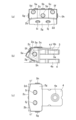
図1、図2(a)乃至図2(c)には、本発明の第1実施形態に係る内刃用のケーシング保護ビットの構成を示し、説明する。より詳細には、図1には、同ケーシング保護ビットの斜視図、図2(a)には、同ケーシング保護ビットの前面図、図2(b)には、同ケーシング保護ビットの側面図、図2(c)には、同ケーシング保護ビットの平面図をそれぞれ示し、説明する。 1, 2(a) to 2(c) show and explain the configuration of a casing protection bit for an inner cutter according to a first embodiment of the present invention. More specifically, Fig. 1 is a perspective view of the casing protection bit, Fig. 2(a) is a front view of the casing protection bit, Fig. 2(b) is a side view of the casing protection bit, FIG. 2(c) shows a plan view of the same casing protection bit for explanation.
これらの図に示されるように、ケーシング保護ビット1は、基部2と、当該基部2から延びた2本の脚部3,4で構成されている。この実施形態では、基部2側を、ケーシング保護ビット1の先端とも称し、脚部3,4側を、ケーシングチューブへの装着側、又はケーシング保護ビット1の後端とも称することとする。
As shown in these figures, the
基部2は、ケーシングチューブの軸方向、ケーシング保護ビット1の先端側に向けて頂部が突出した所謂山型となっている。より具体的には、ケーシング保護ビット1の基部2の平面部2aは、脚部3、4の平面と平行であり、平面部2aからは、ケーシングチューブの軸方向、先端側に向けて所定角度で傾斜した3つの傾斜部2b、2c、2dが連続している。傾斜部2bは、ケーシングチューブの軸方向、先端側から見て左端が側面部2eと連続しており、傾斜部2dは、ケーシングチューブの軸方向、先端側から見て右端が側面部2fと連続している。
The
そして、基部2の傾斜部2b、2c、2dは、ケーシングチューブの軸方向、先端側から見て横方向に、つまりケーシングチューブの周方向に、この順で連続している。この例では、傾斜部2bは、傾斜部2cに対してケーシングチューブの周方向に向けて12度で傾斜しており、傾斜部2dは、傾斜部2cに対して傾斜部2bのケーシングチューブの周方向(傾斜部2cの傾斜方向とは逆方向)に向けて12度で傾斜している。基部2の傾斜部2b、2c、2dの下端は、傾斜部2gに連続している。この傾斜部2gは、平面部2aと平行な平面に対して25度で、ケーシングチューブの軸方向、後端側、つまりケーシング保護ビット1のケーシングチューブへの装着側に向けて傾斜している。
The
脚部3,4は、所定間隔を隔てて、コの字状に、基部2からケーシングチューブの軸方向、後端側に向けて延びている。そして、脚部3の、脚部4と対向する平面とは反対側の上面は、脚部4と対向する平面に対して6.5度で、後端側に向けて傾斜している。このように、脚部3に6.5度の傾斜角度を設けることで、ケーシングチューブの内圧/外圧を緩和することができる。傾斜角度は、ケーシングチューブの外板、内板からの出具合とケーシングチューブに掛かる土圧緩和を考えて6.5度としている。脚部3,4には、ケーシングチューブにケーシング保護ビット1をボルト等で装着するための、孔部3a,4aが設けられている。更に、脚部3のケーシングチューブの軸方向に伸びた両縁には、超硬チップ6a、6bが配設されている。
The
平面部2aには、超硬チップ5a、5b、5cが配設されている。この例では、超硬チップ5aと5cを結ぶ線分よりもケーシング保護ビット1の後端側に超硬チップ5bが配設されており、超硬チップ5bの一部は脚部3の上に配設されている。そして、傾斜部2b、2c、2dには、それぞれ超硬チップ5d、5e、5fが配設されている。この例では、超硬チップ5dと5fとを結ぶ線分よりも、ケーシングチューブの半径方向、つまり図中下方に超硬チップ5eが配設されている。そして、側面部2e、2fには、超硬チップ5g、5hがそれぞれ配設されている。傾斜部2gには、2つの超硬チップ5i、5jが配設されている。このように、この例では、基部2の全ての面に、超硬チップ5a乃至5jが配設されている。
これら超硬チップ5a乃至5jによれば、当り面外側のケーシングチューブ自体の摩耗及びホルダの摩耗も防止することができる。更に、複数の超硬チップの材種及び硬度を、ビットの硬さ及び掘削対象の地盤(又は障害)に応じて適宜自由に組み合わせ可能としている。例えば、本実施形態に係るケーシング保護ビット1では、最大5材種の超硬チップを任意に組み合わせて使用することも可能となっており、幅広い掘削対象に対する掘削時のケーシングチューブの欠損及びホルダの欠損等を効果的に防止できる。
These cemented
ケーシング保護ビット1の基部2は、ケーシングチューブの軸方向、平面部2aの中心を通る線分を対象軸として、左右対称な形状となっている。このように、左右対称な形状とすると共に、傾斜部2b乃至2d、2gの各面に傾斜角を設け、各面に超硬ビットを所定間隔で配列することで、保護性能を高めている。
The
さらに、傾斜部2b、2dの掘削の当り面角度を12度と、広角の大きい当り面角度としたので、傾斜部2b、2c、2dに配設された超硬チップの欠損を抑制できる。当り面に関しては、平面部2aがそれぞれ内側の当り面になり、傾斜部2gが、掘削土圧やコンクリートや鉄筋・鉄骨等の障害物の衝撃や耐圧を緩和する役割を担う。
Furthermore, since the contact surface angle for excavation of the
材質については、脚部3,4の母材は、SCM440(クロモリ鋼)等を採用することができ、超硬チップ5a乃至5jとしては、JIS使用分類記号でいうE3(材質名MG30)、E4(材質名MG40)、E5(材質名MG50)、E6(材質名MG60)等やCIS規格のG4(CIS材種記号VC-40)、G5(CIS材種記号VC-50)等を採用することができる。
As for the material, the base material of the
<第2実施形態> <Second embodiment>
図3、図4(a)乃至図4(c)には、本発明の第1実施形態に係る外刃用のケーシング保護ビットの構成を示し、説明する。より詳細には、図3には、同ケーシング保護ビットの斜視図、図4(a)には、同ケーシング保護ビットの平面図、図4(b)には、同ケーシング保護ビットの前面図、図4(c)には、同ケーシング保護ビットの側面図をそれぞれ示し、説明する。 FIGS. 3 and 4(a) to 4(c) show and explain the configuration of the outer cutter casing protection bit according to the first embodiment of the present invention. More specifically, Fig. 3 is a perspective view of the casing protection bit, Fig. 4(a) is a plan view of the casing protection bit, Fig. 4(b) is a front view of the casing protection bit, FIG. 4(c) shows a side view of the same casing protection bit for explanation.
これらの図に示されるように、ケーシング保護ビット11は、基部12と、当該基部12から延びた2本の脚部13,14で構成されている。この第2実施形態では、基部12側を、ケーシング保護ビット11の先端とも称し、脚部13、14側を、ケーシングチューブへの装着側、又はケーシング保護ビット11の後端とも称することとする。
As shown in these figures, the
基部12は、ケーシングチューブの軸方向、ケーシング保護ビット11の先端側に向けて頂部が突出した所謂山型となっている。より具体的には、ケーシング保護ビット11の基部12の平面部12aは、脚部13、14の平面と平行であり、更に平面部12aからは、ケーシングチューブの軸方向に対して先端側に向けて所定角度で傾斜した3つの傾斜部12b、12c、12dが連続している。傾斜部12bは、ケーシングチューブの軸方向、先端側から見て左端が側面部12eと連続しており、傾斜部12dは、ケーシングチューブの軸方向、先端側から見て右端が側面部12fと連続している。
The
基部12の傾斜部12b、12c、12dは、ケーシングチューブの軸方向、先端側から見て横方向に、つまりケーシングチューブの周方向に、この順で連続している。この例では、傾斜部12bは、傾斜部12cに対してケーシングチューブの周方向に向けて12度で傾斜しており、傾斜部2dは、傾斜部12cに対してケーシングチューブの周方向(傾斜部12bの傾斜方向とは逆方向)に向けて12度で傾斜している。傾斜部12b、12c、12dの下端は、傾斜部12gに連続している。この傾斜部12gは、平面部12aと平行な平面に対して25度で、ケーシングチューブの軸方向、後端側、つまりケーシング保護ビット1のケーシングチューブへの装着側に向けて傾斜している。
The
脚部13,14は、所定間隔を隔てて、コの字状に、基部12からケーシングチューブの軸方向、後端側に向けて延びている。そして、脚部13の、脚部14と対向する平面とは反対側の上面は、脚部14と対向する平面に対して6.5度で、後端側に向けて傾斜している。このように、脚部13に6.5度の傾斜角度を設けることで、ケーシングチューブの内圧/外圧を緩和することができる。傾斜角度は、ケーシングチューブの外板、内板からの出具合とケーシングチューブに掛かる土圧緩和を考えて6.5度としている。脚部13、14には、ケーシングチューブにケーシング保護ビット11をボルト等で装着するための、孔部13a,14aが設けられている。更に、脚部13のケーシングチューブの軸方向に伸びた両縁には、超硬チップ16a、16bが配設されている。この直方体形状の超硬チップ16a、16bは、主にケーシングチューブとホルダの欠損と摩耗を防ぐ役割を果たしているが、前後に配したカッタービットのホルダ取り付け部分をも保護する作用がある。
The
平面部12aには、超硬チップ15a、15b、15cが配設されている。第2実施形態では、超硬チップ15aと15cを結ぶ線分よりもケーシング保護ビット11の後端側に超硬チップ15bが配設されており、超硬チップ15bの一部は脚部13の上に配設されている。そして、傾斜部12b、12c、12dには、それぞれ超硬チップ15d、15e、15fが配設されている。この第2実施形態では、超硬チップ15dと15fとを結ぶ線分よりも、ケーシングチューブの半径方向、図中下方に超硬チップ15eが配設されている。側面部12e、12fには、超硬チップ15g、15hがそれぞれ配設されている。傾斜部12gには、2つの超硬チップ15i、15jが配設されている。このように、この第2実施形態では、基部12の全ての面に、超硬チップ15a乃至15jが配設されている。この断面が円形の円柱形状の超硬チップ15a乃至15jは、前後に配したカッタービットで掘削した掘削対象から、カッタービットが直接影響を受けないように緩和すると共に、掘削対象の流れを妨げない配置になっているだけでなく、掘削対象が直接、ケーシングチューブやホルダに影響を及ぼさないように配置している。
従って、これら超硬チップ15a乃至15jによれば、当り面外側のケーシングチューブ自体の摩耗及びホルダの摩耗も防止することができる。さらに、複数の超硬チップの材種及び硬度を、ビットの硬さ及び掘削対象の地盤(又は障害)に応じて適宜自由に組み合わせ可能としている。例えば、第2実施形態に係るケーシング保護ビット11では、最大5材種の超硬チップを任意に組み合わせて使用することも可能となっており、幅広い掘削対象に対する掘削時のケーシングチューブの欠損及びホルダの欠損等を効果的に防止できる。
Therefore, these cemented
ケーシング保護ビット11の基部12は、ケーシングチューブの軸方向、平面部12aの中心を通る線分を対象軸として、左右対称な形状となっている。このように、左右対称な形状とすると共に、傾斜部12b乃至12d、12gの各面に傾斜角を設け、各面に超硬ビットを所定間隔で配列することで、保護性能を高めている。
The
さらに、傾斜部12b、12dの掘削の当り面角度を12度と、広角の大きい当り面角度としたので、傾斜部12b、12c、12dに配設された超硬チップの欠損を抑制できる。そして、当り面に関しては、平面部12aがそれぞれ外側の当り面になり、傾斜部12gが、掘削土圧やコンクリートや鉄筋・鉄骨等の障害物の衝撃や耐圧を緩和する役割を担っている。
Furthermore, since the contact surface angle for excavation of the
材質については、脚部13,14の母材は、SCM440(クロモリ鋼)等を採用することができ、超硬チップ15a乃至15jとしては、JIS使用分類記号でいうE3(材質名MG30)、E4(材質名MG40)、E5(材質名MG50)、E6(材質名MG60)等や、CIS規格のG4(CIS材種記号VC-40)、G5(CIS材種記号VC-50)等を採用することができる。
As for the material, the base material of the
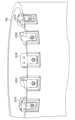
ここで、図5には、本発明の第1及び第2実施形態に係るケーシング保護ビットのケーシングチューブへの取り付け例を示し、説明する。 Here, FIG. 5 shows an example of attaching the casing protection bit according to the first and second embodiments of the present invention to the casing tube, and will be described.
同図に示されるように、ケーシングチューブ100の端部に等間隔で設けられるホルダには、外刃用ケーシング保護ビット101Aと内刃用ケーシング保護ビット101Bが内刃用のカッタービット102Aを間に介在させるような形式で交互に装着される。外刃用のカッタービット102Bも、内刃用ケーシング保護ビット101Bと外刃用ケーシング保護ビット101Cとの間に介在するような形式となる。即ち、間にカッタービットを介在させるように外刃用ケーシング保護ビットと内刃用ケーシング保護ビットとが交互に装着される。外刃用ケーシング保護ビット102Aは、カッタービットの外刃に対して、内刃用ケーシング保護ビット102Bは、カッタービットの内刃に対して、それぞれ欠損と摩耗を防ぐ作用があると共に、カッタービットが装着されているホルダに対しても欠損と摩耗を防ぐ役割を果たしている。即ち、このようなレイアウトにより、掘削時のケーシングチューブ、ホルダ、及びカッタービットへのダメージを軽減すると共に、掘削により発生した土砂等の流れを円滑にすることが可能となる。
As shown in the figure, the holder provided at the end of the
以上説明したように、本発明の実施形態によれば、ケーシングチューブに装着されるケーシング保護ビットが提供される。このケーシング保護ビットを、ケーシングチューブにカッタービットを間に介在させるように、外刃用、内刃用と交互に装着することで、ケーシングチューブやカッタービットの欠損や摩耗及びホルダの欠損や摩耗を防止できると共に、掘削作業の円滑化を図ることが可能となる。 As described above, according to an embodiment of the present invention, a casing protection bit attached to a casing tube is provided. By alternately attaching the casing protection bits for the outer blade and the inner blade so that the cutter bit is interposed between the casing tubes, damage and wear of the casing tube and cutter bits as well as damage and wear of the holder can be prevented. While being able to prevent, it becomes possible to attain smooth excavation work.
以上、本発明の第1及び第2実施形態について説明したが、本発明はこれに限定されることなくその趣旨を逸脱しない範囲で種々の改良・変更が可能である。 Although the first and second embodiments of the present invention have been described above, the present invention is not limited to these, and various improvements and modifications can be made without departing from the scope of the invention.
例えば、本実施形態に係るケーシング保護ビットは、例えば、地中障害撤去工事に用いることができ、鉄筋コンクリート造の構造物や鋼管矢板、H鋼等の地中障害撤去工事において、ケーシングチューブ、ホルダ、及びカッタービットの摩耗や欠損を防止することができる。さらに、転石層掘削にも用いることができ、その場合、川石や硬質岩の転石層での掘削において、ケーシングチューブ、ホルダ、及びカッタービットの摩耗や欠損を防止することができる。 For example, the casing protection bit according to the present embodiment can be used, for example, in underground obstruction removal work. And it is possible to prevent abrasion and chipping of the cutter bit. Furthermore, it can also be used for boulder layer excavation, in which case it is possible to prevent wear and breakage of casing tubes, holders, and cutter bits during excavation in boulder layers of river stones and hard rocks.
なお、本発明には、以下の態様も含まれる。
(1)ケーシングチューブに装着されるケーシング保護ビットであって、
前記ケーシングチューブの軸方向に突出した山型の基部と、
前記基部に連続して延出した所定の間隔をあけて対向する2つの脚部と、を備え、
前記基部の前記脚部が延出している平面を除く全ての平面には超硬チップが配設されているケーシング保護ビット。
(2)ケーシングチューブに装着されるケーシング保護ビットであって、
前記ケーシングチューブの軸方向に先端が突出した基部と、
前記基部に連続して延出した所定の間隔をあけて対向する2つの脚部と、を備え、
前記基部は、前記脚部の平面と平行で連続した平面部と、前記平面部から前記ケーシングチューブの軸方向、前記先端側に向けて傾斜した第1傾斜部と、前記平面部及び前記第1傾斜部から連続した側面部と、前記第1傾斜部から前記ケーシングチューブの軸方向、前記脚部側に向けて傾斜した第2傾斜部とからなり、
前記平面部、前記第1傾斜部、前記側面部、及び前記第2傾斜部には、超硬チップが配設されている
ケーシング保護ビット。
(3)前記平面部から連続する脚部の前記ケーシングチューブの軸方向に延びた両縁には、長尺状の超硬チップが配設されている
上記(2)に記載のケーシング保護ビット。
(4)前記第1傾斜部は、第1乃至第3部分からなり、
前記第1部分は、前記2部分の平面に対して、前記ケーシングチューブの軸方向に所定角度で傾斜しており、前記第3部分は、前記2部分の平面に対して、前記ケーシングチューブの軸方向に所定角度で傾斜している
上記(3)に記載のケーシング保護ビット。
(5)前記平面部、前記第1傾斜部、前記側面部、及び前記第2傾斜部に配設される超硬チップとして、異なる材種のものの任意の組み合わせを用いる
上記(2)乃至(4)のいずれかに記載のケーシング保護ビット。
In addition, the following aspects are also included in this invention.
(1) A casing protection bit attached to a casing tube,
a mountain-shaped base projecting in the axial direction of the casing tube;
and two legs that extend continuously from the base and face each other at a predetermined interval,
A casing protection bit having carbide tips on all planes except the plane from which said legs of said base extend.
(2) A casing protection bit attached to the casing tube,
a base with a tip projecting in the axial direction of the casing tube;
and two legs that extend continuously from the base and face each other at a predetermined interval,
The base portion includes a flat portion parallel to and continuous with the plane of the leg portion, a first inclined portion inclined from the flat portion in the axial direction of the casing tube toward the distal end, the flat portion and the first A side surface portion continuous from the inclined portion, and a second inclined portion inclined from the first inclined portion in the axial direction of the casing tube toward the leg portion,
A casing protection bit, wherein carbide tips are arranged on the flat portion, the first inclined portion, the side portion, and the second inclined portion.
(3) The casing protection bit according to (2) above, wherein a long cemented carbide tip is disposed on both edges of the leg portion extending in the axial direction of the casing tube, the leg portion continuing from the flat portion.
(4) the first inclined portion is composed of first to third portions;
The first portion is inclined at a predetermined angle in the axial direction of the casing tube with respect to the plane of the two portions, and the third portion is inclined with respect to the plane of the two portions with respect to the axis of the casing tube. The casing protection bit according to (3) above, which is inclined at a predetermined angle in a direction.
(5) Any combination of different grades is used as the carbide tips provided on the flat surface portion, the first inclined portion, the side surface portion, and the second inclined portion. ).
1…ケーシング保護ビット、2…基部、2a…平面部、2b~2d…傾斜部、2e,2f…側面部、2g…傾斜部、3…脚部、3a…孔部、4…脚部、4a…孔部、5a~5j…超硬チップ、6a,6b…超硬チップ、11…ケーシング保護ビット、12…基部、12a…平面部、12b~12d…傾斜部、12e,12f…側面部、12g…傾斜部、13…脚部、13a…孔部、14…脚部、14a…孔部、15a~15j…超硬チップ、16a,16b…超硬チップ。
DESCRIPTION OF
Claims (2)
前記ケーシングチューブの軸方向に突出した山型の基部と、
前記基部に連続して延出した所定の間隔をあけて対向する2つの脚部と、を備え、
前記脚部の前記ケーシングチューブの軸方向に延びた両縁には、長尺状の超硬チップが配設されている
ケーシング保護ビット。 A casing protection bit that is attached to a casing tube together with a cutter bit and prevents the cutter bit and the casing tube from being damaged or worn,
a mountain-shaped base projecting in the axial direction of the casing tube;
and two legs that extend continuously from the base and face each other at a predetermined interval,
Long cemented carbide tips are arranged on both edges of the leg extending in the axial direction of the casing tube.
請求項1に記載のケーシング保護ビット。 The base portion includes a flat portion that is parallel to and continuous with the plane of the leg portion, a first inclined portion that is inclined from the flat portion toward the tip side in the axial direction of the casing tube, the flat portion and the first 2. The casing protection bit according to claim 1, further comprising a side surface portion continuous from the inclined portion, and a second inclined portion inclined from the first inclined portion toward the leg portion side in the axial direction of the casing tube.
Priority Applications (1)
| Application Number | Priority Date | Filing Date | Title |
|---|---|---|---|
| JP2019182563A JP7253244B2 (en) | 2019-10-03 | 2019-10-03 | casing protection bit |
Applications Claiming Priority (1)
| Application Number | Priority Date | Filing Date | Title |
|---|---|---|---|
| JP2019182563A JP7253244B2 (en) | 2019-10-03 | 2019-10-03 | casing protection bit |
Related Parent Applications (1)
| Application Number | Title | Priority Date | Filing Date |
|---|---|---|---|
| JP2019073281A Division JP6601897B1 (en) | 2019-04-08 | 2019-04-08 | Casing protection bit |
Publications (3)
| Publication Number | Publication Date |
|---|---|
| JP2020172841A JP2020172841A (en) | 2020-10-22 |
| JP2020172841A5 JP2020172841A5 (en) | 2022-05-02 |
| JP7253244B2 true JP7253244B2 (en) | 2023-04-06 |
Family
ID=72830197
Family Applications (1)
| Application Number | Title | Priority Date | Filing Date |
|---|---|---|---|
| JP2019182563A Active JP7253244B2 (en) | 2019-10-03 | 2019-10-03 | casing protection bit |
Country Status (1)
| Country | Link |
|---|---|
| JP (1) | JP7253244B2 (en) |
Families Citing this family (1)
| Publication number | Priority date | Publication date | Assignee | Title |
|---|---|---|---|---|
| JP6978628B1 (en) * | 2021-07-09 | 2021-12-08 | 株式会社不動テトラ | Sand pile construction equipment |
Citations (4)
| Publication number | Priority date | Publication date | Assignee | Title |
|---|---|---|---|---|
| JP2003193795A (en) | 2001-12-28 | 2003-07-09 | Mitsubishi Materials Corp | Cutter bit |
| JP2013147814A (en) | 2012-01-18 | 2013-08-01 | Giken Seisakusho Co Ltd | Steel pipe pile for excavation |
| JP2018135683A (en) | 2017-02-21 | 2018-08-30 | 株式会社三誠 | Ground improvement device and ground improvement method |
| JP6472150B1 (en) | 2018-06-26 | 2019-02-20 | 金属工具株式会社 | Cutter bit |
-
2019
- 2019-10-03 JP JP2019182563A patent/JP7253244B2/en active Active
Patent Citations (4)
| Publication number | Priority date | Publication date | Assignee | Title |
|---|---|---|---|---|
| JP2003193795A (en) | 2001-12-28 | 2003-07-09 | Mitsubishi Materials Corp | Cutter bit |
| JP2013147814A (en) | 2012-01-18 | 2013-08-01 | Giken Seisakusho Co Ltd | Steel pipe pile for excavation |
| JP2018135683A (en) | 2017-02-21 | 2018-08-30 | 株式会社三誠 | Ground improvement device and ground improvement method |
| JP6472150B1 (en) | 2018-06-26 | 2019-02-20 | 金属工具株式会社 | Cutter bit |
Also Published As
| Publication number | Publication date |
|---|---|
| JP2020172841A (en) | 2020-10-22 |
Similar Documents
| Publication | Publication Date | Title |
|---|---|---|
| WO2020209129A1 (en) | Casing protection bit | |
| KR101037881B1 (en) | Rotary cutting bit with material-deflecting ledge | |
| WO2020004294A1 (en) | Cutter bit | |
| CN104411895B (en) | For removing the cutter head of material from the bottom | |
| JP7253244B2 (en) | casing protection bit | |
| JP6487277B2 (en) | Leading cutter bit | |
| JP3250663B2 (en) | Cutter bit for shield machine and shield machine | |
| JP3428430B2 (en) | Casing cutter and casing cutter bit | |
| JP2011236644A (en) | Bit for casing cutter | |
| JP7360231B2 (en) | Cutting tips and bits | |
| JP2022047086A (en) | Casing bit | |
| JP6739195B2 (en) | Cutter bit | |
| US20090224596A1 (en) | Cutting Elements Disposed On A Drum | |
| KR102632811B1 (en) | auger bit | |
| US11426810B2 (en) | Asphalt saw blade | |
| JP2006188873A (en) | Excavating equipment | |
| JP6826765B1 (en) | Cutting bit | |
| JPH09287375A (en) | Bit for excavation and excavator | |
| WO2024057916A1 (en) | Twin bit | |
| JP5205005B2 (en) | Drilling tools and drill bits | |
| JP2020159066A (en) | Drilling bit | |
| JP6218299B2 (en) | Cutter bit, excavator and excavation method | |
| JP4734735B2 (en) | Bi-directional drilling bit | |
| JP2010065415A (en) | Cutter device | |
| JPH11210379A (en) | Cutter bit of tunnel excavating machine and its cutter head |
Legal Events
| Date | Code | Title | Description |
|---|---|---|---|
| A521 | Request for written amendment filed |
Free format text: JAPANESE INTERMEDIATE CODE: A523 Effective date: 20220325 |
|
| A621 | Written request for application examination |
Free format text: JAPANESE INTERMEDIATE CODE: A621 Effective date: 20220325 |
|
| A521 | Request for written amendment filed |
Free format text: JAPANESE INTERMEDIATE CODE: A523 Effective date: 20220418 |
|
| A131 | Notification of reasons for refusal |
Free format text: JAPANESE INTERMEDIATE CODE: A131 Effective date: 20230110 |
|
| A521 | Request for written amendment filed |
Free format text: JAPANESE INTERMEDIATE CODE: A523 Effective date: 20230201 |
|
| TRDD | Decision of grant or rejection written | ||
| A01 | Written decision to grant a patent or to grant a registration (utility model) |
Free format text: JAPANESE INTERMEDIATE CODE: A01 Effective date: 20230307 |
|
| A61 | First payment of annual fees (during grant procedure) |
Free format text: JAPANESE INTERMEDIATE CODE: A61 Effective date: 20230317 |
|
| R150 | Certificate of patent or registration of utility model |
Ref document number: 7253244 Country of ref document: JP Free format text: JAPANESE INTERMEDIATE CODE: R150 |
|
| S531 | Written request for registration of change of domicile |
Free format text: JAPANESE INTERMEDIATE CODE: R313531 |
|
| R350 | Written notification of registration of transfer |
Free format text: JAPANESE INTERMEDIATE CODE: R350 |