JP7253204B2 - bag storage box - Google Patents
bag storage box Download PDFInfo
- Publication number
- JP7253204B2 JP7253204B2 JP2020026206A JP2020026206A JP7253204B2 JP 7253204 B2 JP7253204 B2 JP 7253204B2 JP 2020026206 A JP2020026206 A JP 2020026206A JP 2020026206 A JP2020026206 A JP 2020026206A JP 7253204 B2 JP7253204 B2 JP 7253204B2
- Authority
- JP
- Japan
- Prior art keywords
- wall portion
- side wall
- bag
- storage box
- bottom wall
- Prior art date
- Legal status (The legal status is an assumption and is not a legal conclusion. Google has not performed a legal analysis and makes no representation as to the accuracy of the status listed.)
- Active
Links
- 238000003860 storage Methods 0.000 title claims description 245
- 235000013305 food Nutrition 0.000 description 46
- 210000002105 tongue Anatomy 0.000 description 21
- 238000010586 diagram Methods 0.000 description 18
- 238000005520 cutting process Methods 0.000 description 16
- 239000000853 adhesive Substances 0.000 description 12
- 230000001070 adhesive effect Effects 0.000 description 12
- 238000003780 insertion Methods 0.000 description 10
- 230000037431 insertion Effects 0.000 description 10
- 238000004519 manufacturing process Methods 0.000 description 10
- 210000005182 tip of the tongue Anatomy 0.000 description 9
- 238000000034 method Methods 0.000 description 8
- 230000000694 effects Effects 0.000 description 4
- 238000005452 bending Methods 0.000 description 3
- 239000000463 material Substances 0.000 description 3
- 238000004806 packaging method and process Methods 0.000 description 3
- 239000007787 solid Substances 0.000 description 3
- 238000003825 pressing Methods 0.000 description 1
- 235000012046 side dish Nutrition 0.000 description 1
Images


Landscapes
- Containers And Packaging Bodies Having A Special Means To Remove Contents (AREA)
- Cartons (AREA)
Description
この発明は、袋収納箱に関する。すなわち、この発明は、食品の店頭販売場において使用するのに適した袋収納箱に関する。 The present invention relates to a bag storage box. That is, the present invention relates to a bag storage box that is suitable for use in food stores.
食品の店頭販売は、コンビニエンスストアやデパートの地下街の食料品売り場などにおいて、広く行われている。ここでの食品は、主に、揚げ物、惣菜、まんじゅう、その他の食品である。 Over-the-counter food sales are widely carried out at convenience stores, grocery stores in underground malls of department stores, and the like. The foodstuffs here are mainly fried foods, side dishes, steamed buns, and other foodstuffs.
この食品の店頭販売においては、一般に、下記の行為が行われる。すなわち、お客が食品を注文する。そして、店員が、袋収納箱から1枚の袋を取り出し、取り出した袋の口を開け、トングを使ってお客が注文した食品を袋の口から袋の中に入れ、袋を介して食品をお客に手渡す。 In the over-the-counter sales of this food, the following acts are generally carried out. That is, a customer orders food. Then, the store clerk takes out one bag from the bag storage box, opens the mouth of the bag taken out, puts the food ordered by the customer into the bag from the mouth of the bag using tongs, and pushes the food through the bag. hand over to the customer.
この店員の行為は、お客の目の前で行われる。このため、食品の店頭販売においては、店員の行為、すなわち、袋収納箱から袋を取り出してから袋の中に食品を入れるまでの間の行為において、店員の手が袋の口付近を触れないようにすることが、重要である。 This clerk's act is performed in front of the customer. For this reason, when selling food over the counter, the clerk's hand does not touch the vicinity of the mouth of the bag during the act of taking the bag out of the bag storage box and before putting the food in the bag. It is important to do so.
ここで、袋収納箱として、以下の特許文献1がある。特許文献1の収納箱は、六面体の紙質箱体の平面部にシート取り出し口が形成された、ものである。特許文献1の収納箱は、シート取り出し口からシート類を取り出す、ものである。
Here, as a bag storage box, there is
しかしながら、特許文献1の収納箱は、店員がシート取り出し口からシート類を取り出す時に、店員の手がシート類である袋の口付近を触れる、ことがある。このため、特許文献1の収納箱は、食品の店頭販売場において使用するのに適していない。
However, in the case of the storage box disclosed in
この発明が解決しようとする課題は、食品の店頭販売場において使用するのに適した袋収納箱を提供することにある。 The problem to be solved by the present invention is to provide a bag storage box that is suitable for use in food stores.
この発明の袋収納箱は、口を有する袋が、フラットの状態で複数枚束ねられて収納される、本体部と、本体部に設けられていて、本体部を載置面上に載置する、載置部と、本体部に設けられていて、袋を、載置面に対して、傾斜させて保持する、保持部と、を備え、本体部には、袋の少なくとも口の部分が露出する、第1開口部と、口が開いた状態で、袋が本体部から取り出される、第2開口部とが、設けられていて、かつ、口の部分を撓ませて口を開く時に、口の部分を支える支え部が、設けられている、ことを特徴とする。 The bag storage box of the present invention includes a main body part in which a plurality of bags having openings are bundled and stored in a flat state, and the main body part is provided on the main body part, and the main body part is placed on a placing surface. a placing portion; and a holding portion provided in the main body portion for holding the bag while being inclined with respect to the placing surface, wherein at least the mouth portion of the bag is exposed in the main portion. a first opening and a second opening through which the bag is taken out from the main body with the mouth open; A supporting portion for supporting the portion of is provided.
この発明の袋収納箱において、本体部が、底壁部と、底壁部の辺に立てて設けられた側壁部と、から構成されていて、載置部が、少なくとも底壁部から、構成されていて、保持部が、少なくとも側壁部の一部分から、構成されていて、第1開口部および第2開口部が、側壁部の底壁部側に対して反対側に、設けられていて、支え部が、側壁部の底壁部側に対して反対側の一部分に、設けられている、ことが好ましい。 In the bag storage box of the present invention, the main body portion is composed of a bottom wall portion and side wall portions erected on sides of the bottom wall portion, and the placing portion is composed of at least the bottom wall portion. the holding part is composed of at least a part of the side wall, the first opening and the second opening are provided on the side of the side wall opposite to the bottom wall side, It is preferable that the support portion is provided on a portion of the side wall portion opposite to the bottom wall portion side.
この発明の袋収納箱において、底壁部が、長方形形状をなし、側壁部が、底壁部の長辺に立てて設けられた第1側壁部および第2側壁部と、底壁部の短辺に立てて設けられた第3側壁部および第4側壁部と、からなり、第1側壁部の高さが、第2側壁部の高さより高く、第3側壁部の高さが、第4側壁部の高さより高く、保持部が、少なくとも第1側壁部から、構成されていて、支え部が、第1側壁部の底壁部側に対して反対側の一部分に、設けられている、ことが好ましい。 In the bag storage box of the present invention, the bottom wall portion has a rectangular shape, and the side wall portions include first and second side wall portions provided upright on the long sides of the bottom wall portion, and short sides of the bottom wall portion. A third side wall portion and a fourth side wall portion provided upright on the sides, the height of the first side wall portion being higher than the height of the second side wall portion, and the height of the third side wall portion being higher than the height of the fourth side wall portion The holding part is higher than the height of the side wall part and is composed of at least the first side wall part, and the support part is provided on a part of the first side wall part opposite to the bottom wall part side, is preferred.
この発明の袋収納箱において、第1側壁部が、底壁部の長辺に、第2側壁部に対して反対側に傾斜させた状態で、立てて設けられている、ことが好ましい。 In the bag storage box of the present invention, it is preferable that the first side wall is provided upright on the long side of the bottom wall while being inclined in the opposite direction to the second side wall.
この発明の袋収納箱において、保持部が、袋を、第3側壁部から第4側壁部にかけて底壁部に対して反対側に傾斜させた状態で、保持する、ことが好ましい。 In the bag storage box of the present invention, it is preferable that the holding section holds the bag in a state in which the bag is inclined from the third side wall to the fourth side wall toward the opposite side of the bottom wall.
この発明の袋収納箱において、保持部の一部分が、第1側壁部であって、保持部の一部分と支え部とが、兼用である、ことが好ましい。 In the bag storage box of the present invention, it is preferable that a portion of the holding portion is the first side wall portion, and that a portion of the holding portion and the support portion are also used.
この発明の袋収納箱において、本体部が、対向する天壁部および底壁部と、天壁部の辺および底壁部の辺に設けられていて、天壁部と底壁部との間に配置された側壁部と、から構成されていて、載置部が、底壁部に設けられていて、保持部が、少なくとも側壁部の一部分および底壁部の一部分から、構成されていて、第1開口部および第2開口部が、天壁部と底壁部との間に、設けられていて、支え部が、底壁部に設けられている、ことが好ましい。 In the bag storage box of the present invention, the main body portion is provided on the opposing top wall portion and bottom wall portion, and on the side of the top wall portion and the side of the bottom wall portion, and between the top wall portion and the bottom wall portion. a side wall portion disposed on the bottom wall portion; Preferably, the first opening and the second opening are provided between the top wall and the bottom wall, and the support is provided on the bottom wall.
この発明の袋収納箱において、天壁部および底壁部が、四角形形状をなし、側壁部が、天壁部の3辺および底壁部の3辺に設けられていて、天壁部の3辺と底壁部の3辺との間に配置された、第1側壁部、第2側壁部および第3側壁部からなり、第1開口部が、天壁部と底壁部との間であって、第1側壁部と第3側壁部との間に、設けられていて、第2開口部が、天壁部と底壁部との間であって、天壁部と第3側壁部との間に、設けられている、ことが好ましい。 In the bag storage box of the present invention, the top wall portion and the bottom wall portion are rectangular, and the side walls are provided on three sides of the top wall portion and three sides of the bottom wall portion. It consists of a first side wall, a second side wall, and a third side wall, which are arranged between the side and three sides of the bottom wall, and the first opening extends between the top wall and the bottom wall. provided between the first side wall and the third side wall, the second opening being between the top wall and the bottom wall and between the top wall and the third side wall It is preferably provided between.
この発明の袋収納箱において、底壁部と第3側壁部との間には、ガイド部が、設けられていて、ガイド部が、袋を、底壁部から第3側壁部にかけて底壁部に対して反対側に傾斜させた状態で、ガイドする、ことが好ましい。 In the bag storage box of the present invention, a guide portion is provided between the bottom wall portion and the third side wall portion, and the guide portion guides the bag from the bottom wall portion to the third side wall portion. It is preferable to guide while being inclined in the opposite direction to the .
この発明の袋収納箱は、保持部の一部分が、底壁部から天壁部側に突出して設けられていて、袋の口側の部分を保持し、保持部の一部分と支え部とが、兼用である、ことが好ましい。 In the bag storage box of the present invention, a portion of the holding portion protrudes from the bottom wall portion toward the top wall portion to hold the opening side portion of the bag, and the portion of the holding portion and the support portion are It is preferable that it is also used.
この発明の袋収納箱は、フラットの状態で複数枚束ねられている袋を、備える、ことが好ましい。 The bag storage box of the present invention preferably includes a plurality of bags bundled in a flat state.
この発明の袋収納箱は、食品の店頭販売場において使用するのに適している。 The bag storage box of the present invention is suitable for use in food stores.
以下、この発明にかかる袋収納箱の実施形態(実施例)の2例について、図面を参照しながら詳細に説明する。なお、この明細書において、上、下、前、後、左、右は、この発明にかかる袋収納箱を、載置面上に載置した時の、上、下、前、後、左、右である。また、図面は、概略図である。このため、図に示された袋収納箱の形状と実際の製品の袋収納箱の形状とが異なる、場合がある。さらに、図において、袋収納箱の板厚(厚み、厚さ)を省略する場合がある。 Two examples of embodiments (examples) of the bag storage box according to the present invention will be described in detail below with reference to the drawings. In this specification, top, bottom, front, back, left, and right refer to top, bottom, front, back, left, and right when the bag storage box according to the present invention is placed on the placement surface. Right. Also, the drawings are schematic diagrams. For this reason, the shape of the bag storage box shown in the drawing may differ from the shape of the bag storage box of the actual product. Furthermore, in the drawings, the plate thickness (thickness, thickness) of the bag storage box may be omitted.
(実施形態1にかかる袋収納箱の構成の説明)
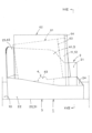
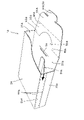
図1~図21は、この発明にかかる袋収納箱の実施形態1を示す。以下、この実施形態1にかかる袋収納箱1の構成について説明する。図1~図6において、符号「U」は「上」、符号「D」は「下」、符号「F」は「前」、符号「B」は「後」、符号「L」は「左」、符号「R」は「右」である。すなわち、図1の袋収納箱1の正面図(袋収納箱1を前から後を見た図)を基準とする。
(Description of the configuration of the bag storage box according to the first embodiment)
1 to 21
(袋収納箱1の説明)
図に示すように、この実施形態1にかかる袋収納箱1は、本体部2と、載置部3と、保持部4と、支え部5と、を備える。袋収納箱1は、袋61、62を収納する。袋収納箱1は、載置面10上に載置される。載置面10は、たとえば、店頭のカウンター、テーブル、棚などの面である。
(Description of bag storage box 1)
As shown in the figure, the
袋収納箱1は、この例では、紙の平板からなる。なお、袋収納箱1の材質(材料)は、袋収納箱1の形状を保つものであれば、特に限定しない。
The
(袋61、62の説明)
図14~図21に示すように、袋61、62は、口63、64を有する。袋61、62は、フラットの状態で、複数枚束ねられて袋収納箱1の本体部2の中に収納される。袋61、62は、後側(裏側)が前側(表側)に対して口63、64から突出した、形状をなす。
(Description of
As shown in FIGS. 14-21, the
図14~図21に示す袋61の幅(口63方向の幅)は、図14、図18に示す袋62の幅(口64方向の幅)より小さい。以下、口63方向の幅が小さい袋61を第1袋61と称する場合がある。また、口64方向の幅が大きい袋62を第2袋62と称する場合がある。なお、袋61、62は、口63、64と別個の口(図示せず)を設けても良い。たとえば、図14~図17において、別個の口は、右側の口63、64に対して下側に設けられる。
The width of the
袋61、62は、この例では、紙袋などの簡易包装袋、すなわち、紙製の平袋であって、耐油性を有する。袋61、62は、揚げ物などの食品(図示せず)を開けた状態の口63、64から中に入れる、ものである。この例の袋61、62は、耐油性を有するので、揚げ物などの食品を包装するのに適している。なお、袋61、62としては、耐油性の紙製の平袋以外の袋であっても良い。また、中に入れる物としては、揚げ物以外の食品であっても良い。
In this example, the
(本体部2の説明)
本体部2は、口63、64を有する袋61、62を、フラットの状態で複数枚束ねて収納する、ものである。すなわち、本体部2は、大きさが異なる2種類の袋61、62を1つに集約して収納する袋収納箱1である。本体部2は、底壁部20と、側壁部21、22、23、24と、から構成されている。
(Description of main body 2)
The
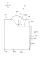
底壁部20は、上から見て長方形形状をなす。側壁部21、22、23、24は、底壁部20の4辺に立てて設けられている。すなわち、側壁部21、22、23、24は、底壁部20の4辺からほぼ直角に折り曲げられて設けられている。
The
側壁部は、底壁部20の長辺に立てて設けられた第1側壁部21および第2側壁部22と、底壁部20の短辺に立てて設けられた第3側壁部23および第4側壁部24と、からなる。第1側壁部21は、後側の側壁部である。第2側壁部22は、前側の側壁部である。第3側壁部23は、左側の側壁部である。第4側壁部24は、右側の側壁部である。
The side wall portions include a first
第1側壁部21の高さは、第2側壁部22の高さより高い。第3側壁部23の高さは、第4側壁部24の高さより高い。第1側壁部21の高さと第3側壁部23の高さとは、ほぼ等しい。第2側壁部22の高さと第4側壁部24の高さとは、ほぼ等しい。
The height of the first
第1側壁部21は、前または後から見て左右に長いほぼ長方形形状であって、上右角の一部分が切り取られた形状をなす。第2側壁部22は、前または後から見て左右に細長いほぼ長方形形状をなす。第3側壁部23は、左または右から見て上下に長いほぼ長方形形状をなす。第4側壁部24は、右または左から見て左右に長いほぼ長方形形状をなす。
The first
第1側壁部21および第2側壁部22は、下側から上側に行くに従って、前側から後側に傾斜している。この結果、第1側壁部21は、底壁部20の長辺に、第2側壁部22に対して反対側に傾斜させた状態で、立てて設けられている。
The first
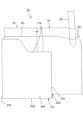
(載置部3の説明)
載置部3は、本体部2に設けられていて、本体部2を載置面10上に載置する。載置部3は、少なくとも底壁部20から、構成されている。すなわち、載置部3は、底壁部20から構成されている第1載置部31と、底壁部20と別個の第2載置部32とから、構成されている。
(Description of Placement Unit 3)
The mounting
第2載置部32は、第1載置部31と面一の状態で、載置面10上に載置する。第2載置部32は、第1側壁部21から後側に突出している。また、第2載置部32は、第1側壁部21から第1連結部25を介して設けられている。
The second mounting
(保持部4の説明)
保持部4は、本体部2に設けられていて、袋61、62を、載置面10に対して、傾斜させて保持する。すなわち、第1袋61は、図14~図17に示すように、後記する第4保持部44の上面に載置されていて、前から見て、左側から右側にかけて、下側から上側に傾斜した状態に、保持される。一方、第2袋62は、図14に示すように、本体部2の底壁部20(載置部3の第1載置部)の上面に載置されていて、前から見て、水平状態で保持される。また、袋61、62は、図18~図21に示すように、右から見て、下側から上側にかけて、前側から後側に傾斜した状態に、保持される。
(Description of holding portion 4)
The holding
保持部4は、少なくとも側壁部の一部分から、構成されている。すなわち、保持部4は、第1側壁部21の第1保持部41と、第3側壁部23の第2保持部42と、第3保持部43と、第4保持部44とから、構成されている。第3保持部43および第4保持部44は、底壁部20から第2連結部26を介して設けられている。
The holding
第1側壁部21の第1保持部41および第3保持部43は、右から見て、載置面10に対して、下側から上側にかけて、前側から後側に傾斜した状態にある。この結果、第1側壁部21の第1保持部41および第3保持部43は、第1袋61を、右から見て、載置面10に対して、下側から上側にかけて、前側から後側に傾斜した状態に、保持する。
The first holding portion 41 and the third holding
すなわち、第1側壁部21の第1保持部41および第3保持部43は、第1袋61を、後と前とから挟み込んで、保持する。なお、第3保持部43は、第4保持部44上に載っている第1袋61の下側の縁が後側から前側に滑り落ちる、事態を防ぐストッパである。
That is, the first holding portion 41 and the third holding
第4保持部44は、前から見て、載置面10に対して、左側から右側にかけて、下側から上側に傾斜した状態にある。この結果、第4保持部44は、第1袋61を、前から見て、載置面10に対して、左側から右側にかけて、下側から上側に傾斜した状態に、保持する。
The
すなわち、第4保持部44は、第1袋61を、第3側壁部23(左側)から第4側壁部24(右側)にかけて底壁部20(下側)に対して反対側(上側)に傾斜させた状態で、保持する。なお、第3側壁部23の第2保持部42は、第4保持部44上に載っている第1袋61が右側から左側に滑る、事態を防ぐストッパである。
That is, the fourth holding
また、第3保持部43は、第2袋62を、右から見て、載置面10に対して、下側から上側にかけて、前側から後側に傾斜した状態に、保持する。なお、第3保持部43は、本体部2の第2側壁部22と共に、枚数が多く束が厚くなった第2袋62を、後と前とから挟み込んで、保持する場合がある。ここで、本体部2の底壁部20(載置部3の第1載置部)は、第2袋62を、前から見て、載置面10に対して、水平状態に、保持する。
In addition, the third holding
(支え部5の説明)
支え部5は、本体部2に設けられていて、袋61、62の口63、64の部分(以下、「口63、64部分」と称する)を撓ませて口63、64を開く時に、口63、64部分を支える。
(Explanation of support part 5)
The support part 5 is provided in the
支え部5は、第1側壁部21の底壁部20側(下側)に対して反対側(上側)の一部分(この例では、右側部分)に、設けられている。一方、保持部の一部分である第1保持部分41は、第1側壁部21である。この結果、保持部の一部分である第1保持部分41(第1側壁部21)と、支え部5(第1側壁部21の一部分)とは、第1側壁部21を介して、兼用である。
The support portion 5 is provided on a portion (right side portion in this example) of the first
(第1開口部11および第2開口部12の説明)
本体部2には、第1開口部11および第2開口部12が設けられている。第1開口部11は、袋61、62の少なくとも口63、64部分が露出する、開口部である。第2開口部12は、口63、64が開いた状態で、袋61、62が本体部2から取り出される、開口部である。
(Description of
The
第1開口部11および第2開口部12は、側壁部21、22、23、24の底壁部20側(下側)に対して反対側(上側)に、設けられている。すなわち、第1開口部11および第2開口部12は、側壁部21、22、23、24の上縁に設けられている。これにより、第1開口部11および第2開口部12は、本体部2の上側の部分に、一体に連続して、設けられている。
The
(実施形態1にかかる袋収納箱1の製造加工の説明)
この実施形態1にかかる袋収納箱1は、以上のごとき構成からなり、以下、その製造加工について、図7~図9を参照して説明する。図7は、展開状態の袋収納箱1を示す説明図(展開図)である。図8は、折り畳み状態の袋収納箱1を示す説明図(正面図、表面図)である。図9は、折り畳み状態の袋収納箱1を示す説明図(背面図、裏面図)である。
(Description of the manufacturing process of the
The
以下の説明において、「表面」とは、図7における紙面であり、「裏面」とは、図7における紙面の反対側の面であり、「上下」とは、図7における紙面の上下であり、「左右」とは、図7における紙面の左右である。また、以下の説明において、「表側」とは、表面側であり、「裏側」とは、裏面側である。 In the following description, the “front surface” is the paper surface in FIG. 7, the “back surface” is the surface opposite to the paper surface in FIG. 7, and the “top and bottom” are the top and bottom of the paper surface in FIG. , "left and right" are the left and right sides of the paper surface in FIG. Further, in the following description, "front side" means the front side, and "back side" means the back side.
まず、図7に示すように、原板(図示せず)をプレス機などにより打ち抜き加工して、展開状態の袋収納箱1を製造する。つぎに、図8、図9に示すように、展開状態の袋収納箱1を折曲線に沿って折り曲げ、それと同時に、接着部分を接着して、折り畳み状態の袋収納箱1を製造する。この結果、この実施形態1にかかる袋収納箱1が、製造加工される。
First, as shown in FIG. 7, an original plate (not shown) is punched by a pressing machine or the like to manufacture the
(展開状態の袋収納箱1の説明)
図7に示すように、展開状態の袋収納箱1には、上下の第1折曲線71、上下の第2折曲線72、上下の第3折曲線73、上下の第4折曲線74、上下の第5折曲線75(以下、「上下の折曲線71~75」と称する)が、それぞれ、直線状に設けられている。
(Description of
As shown in FIG. 7, the
また、展開状態の袋収納箱1には、左右の第1折曲線81、左右の第2折曲線82、左右の第3折曲線83、左右の第4折曲線84、左右の第5折曲線85、左右の第6折曲線86、左右の第7折曲線87、左右の第8折曲線88、左右の第9折曲線89、左右の第10折曲線80(以下、「左右の折曲線81~80」と称する)が、それぞれ、直線状に設けられている。
In addition, the
上下の折曲線71~75および左右の折曲線81~80は、ミシン目(図7中の破線を参照)、凹み、スリット(図7中の実線を参照)、その他の手段を、1つもしくは複数組み合わせてなる。 The upper and lower folding lines 71-75 and the left and right folding lines 81-80 are formed by perforations (see dashed lines in FIG. 7), recesses, slits (see solid lines in FIG. 7), or other means. Combining multiple.
さらに、展開状態の袋収納箱1には、左右の差込スリット90が、直線状に設けられている(図7中の実線を参照)。 Further, left and right insertion slits 90 are linearly provided in the unfolded bag storage box 1 (see solid lines in FIG. 7).
さらにまた、展開状態の袋収納箱1には、上下の第1切り欠き91、上下の第2切り欠き92、逆凹形の第3切り欠き93、左右の第4切り欠き94が、それぞれ、設けられている。上下の第1切り欠き91、上下の第2切り欠き92および左右の第4切り欠き94は、それぞれ、直線状もしくはほぼ直線上に設けられている。
Furthermore, in the unfolded
さらにまた、展開状態の袋収納箱1には、上下の第1切線95、上下の第2切線96、左右のほぼ直線の第3切線97が、それぞれ、設けられている(図7中の実線を参照)。
Furthermore, the
(展開状態の袋収納箱1の各部の説明)
図7に示すように、展開状態の袋収納箱1には、前記の構成の各部が、形成されている。すなわち、底壁部20(第1載置部31)の第1部分201は、左右の第1折曲線81から下側の部分に形成されている。底壁部20(第1載置部31)の第2部分202は、左右の第2折曲線82から下側の部分に形成されている。底壁部20(第1載置部31)の第3部分203は、左右の第3折曲線83から下側の部分に形成されている。底壁部20(第1載置部31)の第4部分204は、左右の第4折曲線84から下側の部分に形成されている。
(Description of each part of the
As shown in FIG. 7, the
第1側壁部21の裏側部分210は、上下の第1折曲線71と上下の第2折曲線72との間の部分であって、左右の第1折曲線81から上側の部分に形成されている。第1側壁部21の表側部分211は、上下の第2折曲線72の上半分と上下の第4折曲線74との間の部分であって、第3切線97から上側の部分に形成されている。
The back side portion 210 of the first
第2側壁部22は、上下の第3折曲線73と上下の第5折曲線75の下半分との間の部分であって、左右の第1折曲線81と第3切線97の中間分および右側分との間の部分に形成されている。
The second
第3側壁部23の裏側部分230は、上下の第5折曲線75から右側の部分であって、左右の第4折曲線84から上側の部分に形成されている。第3側壁部23の表側部分231は、上下の第4折曲線74と上下の第5折曲線75の上半分との間の部分であって、第3切線97から上側の部分に形成されている。
The
第4側壁部24は、上下の第2折曲線72の下半分と上下の第3折曲線73との間の部分であって、左右の第2折曲線82と第3切線97の左側分との間の部分に形成されている。
The fourth
第1連結部25は、上下の第1切線95と上下の第2切線96との間の部分であって、左右の第5折曲線85と左右の第6折曲線86との間の部分に形成されている。
The first connecting
第2載置部32は、左右の第5折曲線85から上側の部分に形成されている。この結果、第2載置部32は、第1側壁部21から第1連結部25を介して設けられている。第2載置部32の上縁の中間には、半円形状の差込凸部27が形成されている。
The second mounting
第2連結部26は、上下の第1切り欠き91の下半分と上下のほぼ直線の第2切り欠き92の下半分との間の部分であって、左右の第9折曲線89と左右の第10折曲線80との間の部分に形成されている。
The second connecting
第3保持部43は、第2連結部26の上縁の中間に、第3切り欠き93に囲まれて形成されている。また、第4保持部44は、上下の第1切り欠き91の上半分および上下のほぼ直線の第2切り欠き92の上半分と第3切り欠き93との間の部分であって、左右の第7折曲線87と左右の第9折曲線89との間の部分に形成されている。
The
この結果、第3保持部43および第4保持部44は、底壁部20から第2連結部26を介して設けられている。なお、第4保持部44の中間の左右の第8折曲線88は、第4保持部44の中間を若干下側に凹ませるためのものである(図6を参照)。なお、この左右の第8折曲線88を必ずしも設ける必要は、無い。
As a result, the third holding
そして、第1側壁部21の裏側部分210の左側には、接着代部28が、上下の第1折曲線71を介して形成されている。
On the left side of the back side portion 210 of the first
(折り畳み状態の袋収納箱1の説明)
図7に示す展開状態の袋収納箱1は、以下のようにして、図8、図9に示すように、折り畳まれる。
(Description of
The unfolded
まず、上下の第2折曲線72において、上下の第2折曲線72から右側の部分を、上下の第2折曲線72から左側の部分の表面の上に折り畳む。それと同時に、上下の第5折曲線75において、第3側壁部23の裏側部分230を、接着代部28の裏面の下に折り畳む。
First, on the upper and lower
つぎに、接着代部28の裏面と第3側壁部23の裏側部分230の表面とを接着する。それと同時に、第1側壁部21の裏側部分210(第1連結部25および第2載置部32の下側部分を除いた部分)の表面と第1側壁部21の表側部分211の左右のほぼ直線の第3切線97から上側の部分の裏面とを接着する。
Next, the back surface of the
この結果、図7に示す展開状態の袋収納箱1は、図8、図9に示す折り畳み状態の袋収納箱1に、折り畳まれる。
As a result, the unfolded
(実施形態1にかかる袋収納箱1の組立の説明)
この実施形態1にかかる袋収納箱1は、以上のごとき構成からなり、かつ、以上のごとき製造加工を経て、図8、図9に示すように、折り畳まれた状態で、製造される。以下、この実施形態1にかかる袋収納箱1を使用するに際して、この実施形態1にかかる袋収納箱1を組み立てる手順(組立手順)について、図10~図14を参照して説明する。
(Description of Assembly of
The
(図10に示す組立手順の説明)
まず、上下の第1折曲線71および上下の第4折曲線74において、第3側壁部23を、実線矢印に示すように、第1側壁部21に向けて折り込む。つぎに、上下の第2折曲線72の下半分の部分および上下の第3折曲線73において、第4側壁部24を、実線矢印に示すように、第1側壁部21から折り出す。それから、上下の第3折曲線73および上下の第5折曲線75の下半分の部分において、第2側壁部22を、実線矢印に示すように、第1側壁部21から折り出す。
(Description of assembly procedure shown in FIG. 10)
First, at the upper and lower
(図11に示す組立手順の説明)
まず、左右の第1折曲線81において、底壁部20の第1部分201を、実線矢印に示すように、第1側壁部21に対して、ほぼ直角に折り曲げる。それと同時に、左右の第9折曲線89において、第2連結部26および第3保持部43を、第4保持部44に対して、ほぼ直角に折り曲げる。
(Description of assembly procedure shown in FIG. 11)
First, the first portion 201 of the
つぎに、左右の第2折曲線82において、底壁部20の第2部分202を、実線矢印に示すように、第4側壁部24に対して、ほぼ直角に折り曲げる。それと同時に、左右の第4折曲線84において、底壁部20の第4部分204を、実線矢印に示すように、第3側壁部23(図11においては、図示されていない)に対して、ほぼ直角に折り曲げる。それから、左右の第3折曲線83において、底壁部20の第3部分203を、実線矢印に示すように、第2側壁部22に対して、ほぼ直角に折り曲げる。
Next, the second portion 202 of the
ここで、底壁部20の第3部分203の左右の差込片部を、底壁部20の第1部分201と底壁部20の第2部分202および第4部分204との間の隙間に差し込む。この結果、図12に示すように、底壁部20の第1部分201、第2部分202、第3部分203および第4部分204により、載置部3(第1載置部31)が形成される。
Here, the left and right insertion pieces of the
(図12に示す組立手順の説明)
まず、第2連結部26および第3保持部43を、実線矢印方向に、押し込む。なお、第2連結部26および第3保持部43に押し込み力を作用させる箇所は、左右の第9折曲線89の近傍であって、図11および図12中の楕円にて図示する。
(Description of assembly procedure shown in FIG. 12)
First, the second connecting
この結果、左右の第10折曲線80において、第2連結部26および第3保持部43が、底壁部20の第1部分201に対して、ほぼ直角に折り曲がる。それと同時に、左右の第7折曲線87において、第4保持部44が、第1側壁部21に対して、ほぼ直角に折り曲がる。また、左右の第9折曲線89において、第2連結部26および第3保持部43と第4保持部44とが、相互にほぼ直角に折り曲がる。
As a result, the second connecting
(図13に示す組立手順の説明)
まず、上下の第1切線95および上下の第2切線96において、第1連結部25および第2載置部32を、第1側壁部21から切り離す。それと同時に、左右の第6折曲線86において、第1連結部25および第2載置部32を、第1側壁部21に対して、折り曲げる。
(Description of assembly procedure shown in FIG. 13)
First, the first connecting
つぎに、左右の第5折曲線85において、第2載置部32を、第1連結部25に対して、折り曲げる。それと同時に、差込凸部27(図13中の黒三角形を参照)を、左右の差込スリット90(図13中の白三角形を参照)に、差し込む。
Next, the
この結果、この実施形態1にかかる袋収納箱1は、図1~図6に示すように、組み立てられる。
As a result, the
(実施形態1にかかる袋収納箱1の作用の説明)
この実施形態1にかかる袋収納箱1は、以上のごとき構成からなり、以下、その作用について、図1~図6、図14~図21を参照して説明する。なお、図14、図18においては、2種類の袋61、62を示すが、図15~図17、図19~図21においては、1種類の袋61を示す。
(Description of the action of the
The
この作用において、使用されるトング65は、先端で物を挟む通常のトングである。トング65の基端(図示せず)は、2つ折りされていて、トング65の先端は、弾性力(ばね力)により適宜の寸法で開いている。そして、トング65の先端を、弾性力に抗して、閉じることにより物(図示せず。この例では、揚げ物などの食品)を挟むことができ、また、弾性力によって、開くことにより物を離すことができる。
In this action, the
まず、図1~図6に示すように、組み立てた袋収納箱1を、載置面10上に載置させる。この時、袋収納箱1の載置部3(第1載置部31および第2載置部32)が、載置面10上に載置する。
First, as shown in FIGS. 1 to 6, the assembled
つぎに、図14、図18に示すように、袋収納箱1の本体部2中に、複種類(この例では、2種類)の袋61、62を、フラットの状態で複数枚束ねて収納させる。すなわち、袋61、62は、口63、64が袋収納箱1(本体部2)の第1開口部11および第2開口部12側に向けられた状態で、袋収納箱1中に収納されている。
Next, as shown in FIGS. 14 and 18, a plurality of types (in this example, two types) of
ここで、第1袋61は、保持部4の第4保持部44の上面に載置されている。第2袋62は、本体部2の底壁部20(載置部3の第1載置部)の上面に載置されている。
Here, the
この時、袋61、62の少なくとも口63、64の部分が、袋収納箱1(本体部2)の第1開口部11(第2開口部12を含む)において、露出している。また、袋61、62は、保持部4(第1保持部41、第2保持部42、第3保持部43および第4保持部44)により、載置面10に対して、傾斜した状態で保持されている。
At this time, at least the
それから、図15、図19に示すように、一方の手(図示せず)でトング65を持って、トング65の先端を閉じた状態で袋61の口63の付近の部分(以下、「口63の部分」と称する)に当てる。トング65を介して、袋61の口63の部分を、束ごと、後側に撓ませて、前側の1枚の袋61の口63を若干開ける。この時、第1保持部41と兼用の支え部5(第1側壁部21の第1開口部11および第2開口部12の縁部)は、袋61の口63の部分を支える。この結果、トング65を使用して袋61の口63が、開け易くなる。
Then, as shown in FIGS. 15 and 19, hold the
つづけて、図16、図20に示すように、トング65の先端を袋61の口63から袋61の中に挿入させる。それと同時に、トング65を若干開いて袋61の口63を若干開ける。この時、袋61の若干開いた口63がフラットの状態に戻ろうとする、力の作用により、袋61はトング65に保持される。
Subsequently, as shown in FIGS. 16 and 20, the tip of the
そして、図17、図21に示すように、トング65を介して、前側の1枚の袋61を、袋61の束から、実線矢印方向に取り出す。この結果、口63が開いた状態で、袋61は、袋収納箱1(本体部2)の第2開口部12(第1開口部11を含む)から、取り出される。
Then, as shown in FIGS. 17 and 21, one
以上のようにして、取り出した袋61を、他方の手(図示せず)で持ち、口63が開いた状態を保ちながら、トング65を袋61から取り出す。このトング65を使って、食品を、他方の手で持っている袋61の中に、開いている口63から入れる。
The
このようにして、店員は、トング65を使用して、店員の手が袋61の口63付近を触れることなく、食品を袋61の中に入れることができる。
In this way, the clerk can use the
なお、トング65を袋61の口63に挿入させる位置、および、トング65を介して袋61の口63を開く大きさなどは、図15~図17、図19~図21に示す以外の位置および大きさであっても良い。
The position where the
(実施形態1にかかる袋収納箱1の効果の説明)
この実施形態1にかかる袋収納箱1は、以上のごとき構成、作用からなり、以下、その効果について説明する。
(Description of the effect of the
The
この実施形態1にかかる袋収納箱1は、食品の店頭販売場において使用するのに適している。
The
すなわち、この実施形態1にかかる袋収納箱1は、第1開口部11により、袋61、62の口63、64の部分を、本体部2から露出させることができる。これにより、この実施形態1にかかる袋収納箱1は、トング65の先端を、第1開口部11を通して、袋61、62の口63、64の部分に当てることができる。
That is, in the
また、この実施形態1にかかる袋収納箱1は、支え部5により、袋61、62の口63、64の部分を撓ませて口63、64を開く時に、口63、64の部分を支えることができる。これにより、この実施形態1にかかる袋収納箱1は、トング65の先端を使って、袋61、62の口63、64を開けることができる。しかも、この実施形態1にかかる袋収納箱1は、トング65の先端を、開けた口63、64から袋61、62の中に挿入させることができる。
Further, in the
さらに、この実施形態1にかかる袋収納箱1は、第2開口部12により、トング65を使って、口63、64が開いたままの状態で、袋61、62を第2開口部12を通して本体部2から取り出すことができる。
Furthermore, in the
以上から、この実施形態1にかかる袋収納箱1は、袋収納箱1から袋61、62を取り出してから袋61、62の中に食品を入れるまでの間の店員の行為において、店員の手が袋61、62の口63、64付近を触れないようなことが無い。この結果、この実施形態1にかかる袋収納箱1は、食品の店頭販売場において使用するのに適している。
As described above, the
しかも、この実施形態1にかかる袋収納箱1は、保持部4により、袋61、62を、載置面10に対して、傾斜させて保持することができる。これにより、この実施形態1にかかる袋収納箱1は、トング65を使って、袋61、62の口63、64を容易に開き、かつ、口63、64が開いたままの状態で、袋61、62を本体部2から容易に取り出すことができる。
Moreover, in the
この実施形態1にかかる袋収納箱1は、フラットの状態で複数枚束ねられている袋61、62を備える、ものであるから、袋61、62を本体2中に簡単に収納させることができる。
Since the
特に、この実施形態1にかかる袋収納箱1は、本体部2が底壁部20と側壁部21、22、23、24とから構成されている、ものである。この結果、この実施形態1にかかる袋収納箱1は、袋61、62のフラット面が載置面10に対して垂直もしくはほぼ垂直に立てた状態において、袋61、62を収納することができる。
In particular, in the
これにより、この実施形態1にかかる袋収納箱1は、袋61、62の取り出し方向が載置面10に対して垂直もしくはほぼ垂直となる、ものである。このため、この実施形態1にかかる袋収納箱1は、袋61、62を取り出す作業スペースが載置面10に対して垂直方向もしくはほぼ垂直方向にある、場合において適している。
As a result, in the
また、この実施形態1にかかる袋収納箱1は、載置部3を構成する底壁部20が長方形形状をなし、側壁部21、22、23、24が底壁部20の4辺にそれぞれ設けられている、ものである。この結果、この実施形態1にかかる袋収納箱1は、載置面10に対する載置スペースを小さくできるので、載置面10が狭い、場合において適している。
Further, in the
さらに、この実施形態1にかかる袋収納箱1は、第1側壁部21の高さが第2側壁部22の高さより高く、また、第3側壁部23の高さが第4側壁部24の高さより高い。この結果、この実施形態1にかかる袋収納箱1は、袋61、62の口63、64の部分を露出させる第1開口部11と、口63、64が開いた状態で袋61、62を本体部2から取り出す第2開口部12とを、側壁21、22、23、24の底壁部20に対して反対側に、設けることができる。
Further, in the
さらにまた、この実施形態1にかかる袋収納箱1は、第1側壁部21が底壁部20の長辺に第2側壁部22に対して反対側に傾斜させた状態で立てて設けられている、ものである。この結果、この実施形態1にかかる袋収納箱1は、第1側壁部21の傾斜に沿って、袋61、62を傾斜させた状態で収納する、ことができる。これにより、この実施形態1にかかる袋収納箱1は、トング65を使って、袋61、62の口63、64を開き、かつ、口63、64が開いたままの状態で、袋61、62を取り出すことができる。
Furthermore, in the
さらにまた、この実施形態1にかかる袋収納箱1は、保持部4が袋61、62を第3側壁部23から第4側壁部24にかけて底壁部20に対して反対側に傾斜させた状態で保持する、ものである。この結果、この実施形態1にかかる袋収納箱1は、トング65を使って、1枚の袋61、62を、袋61、62の口63、64を開けかつ開けたままの状態で、本体部2から取り出すことができる。
Furthermore, in the
さらにまた、この実施形態1にかかる袋収納箱1は、保持部4の一部分が第1側壁部21であって、保持部4の一部分と支え部5とが兼用であるから、構造や組み立てが簡単である、袋収納箱である。
Furthermore, in the
この実施形態1にかかる袋収納箱1は、本体部2、載置部3および保持部4を、備え、本体部2に、第1開口部11、第2開口部12および支え部5を、設けた、ものである。この結果、この実施形態1にかかる袋収納箱1は、トング65を使って、1枚の袋61、62を、袋61、62の口63、64を開けかつ開けたままの状態で、本体部2から取り出すことができる。
The
これにより、この実施形態1にかかる袋収納箱1は、食品の店頭販売における店員の行為、すなわち、袋収納箱1から袋61、62を取り出す行為から、袋61、62の中に食品を入れる行為まで、の間において、店員の手が袋61、62の口63、64付近を触れるようなことが無い。以上から、この実施形態1にかかる袋収納箱1は、食品の店頭販売場において使用するのに適している。
As a result, the
しかも、この実施形態1にかかる袋収納箱1は、本体部2が底壁部20と側壁部21、22、23、24とから構成されていて、また、載置部3が少なくとも底壁部20から構成されていて、さらに、保持部4が少なくとも側壁部21、22、23、24の一部から構成されていて、さらにまた、第1開口部11および第2開口部12が側壁部21、22、23、24の底壁部20側に対して反対側に設けられていて、さらにまた、支え部5が側壁部21、22、23、24の底壁部20側に対して反対側の一部分に設けられている、ものである。この結果、この実施形態1にかかる袋収納箱1は、トング65を使って、1枚の袋61、62を、袋61、62の口63、64を開けかつ開けたままの状態で、本体部2から取り出すことが確実にできる。
Moreover, in the
これにより、この実施形態1にかかる袋収納箱1は、食品の店頭販売における店員の行為、すなわち、袋収納箱1から袋61、62を取り出す行為から、袋61、62の中に食品を入れる行為まで、の間において、店員の手が袋61、62の口63、64付近を触れるようなことが確実に無い。以上から、この実施形態1にかかる袋収納箱1は、食品の店頭販売場において使用するのに適している。
As a result, the
この実施形態1にかかる袋収納箱1は、底壁部20が長方形形状をなし、また、側壁部が底壁部20の長辺に立てて設けられた第1側壁部21および第2側壁部22と底壁部20の短辺に立てて設けられた第3側壁部23および第4側壁部24とからなり、さらに、第1側壁部21の高さが第2側壁部22の高さより高く、かつ、第3側壁部23の高さが第4側壁部24の高さより高く、さらにまた、保持部4が少なくとも第1側壁部21から構成されていて、さらにまた、支え部5が第1側壁部21の底壁部20側に対して反対側の一部分に設けられている、ものである。この結果、この実施形態1にかかる袋収納箱1は、トング65を使って、1枚の袋61、62を、袋61、62の口63、64を開けかつ開けたままの状態で、本体部2から取り出すことがさらに確実にできる。
In the
これにより、この実施形態1にかかる袋収納箱1は、食品の店頭販売における店員の行為、すなわち、袋収納箱1から袋61、62を取り出す行為から、袋61、62の中に食品を入れる行為まで、の間において、店員の手が袋61、62の口63、64付近を触れるようなことがさらに確実に無い。以上から、この実施形態1にかかる袋収納箱1は、食品の店頭販売場において使用するのに適している。
As a result, the
この実施形態1にかかる袋収納箱1は、第1側壁部21が底壁部20の長辺に第2側壁部22に対して反対側に傾斜させた状態で立てて設けられている、ものである。この結果、この実施形態1にかかる袋収納箱1は、トング65を使って、1枚の袋61、62を、袋61、62の口63、64を開けかつ開けたままの状態で、本体部2から取り出すことがさらに確実にできる。
In the
これにより、この実施形態1にかかる袋収納箱1は、食品の店頭販売における店員の行為、すなわち、袋収納箱1から袋61、62を取り出す行為から、袋61、62の中に食品を入れる行為まで、の間において、店員の手が袋61、62の口63、64付近を触れるようなことがさらに確実に無い。以上から、この実施形態1にかかる袋収納箱1は、食品の店頭販売場において使用するのに適している。
As a result, the
この実施形態1にかかる袋収納箱1は、保持部4が袋61、62を第3側壁部23から第4側壁部24にかけて底壁部20に対して反対側に傾斜させた状態で保持する、ものである。この結果、この実施形態1にかかる袋収納箱1は、トング65を使って、1枚の袋61、62を、袋61、62の口63、64を開けかつ開けたままの状態で、本体部2から取り出すことがさらに確実にできる。
In the
これにより、この実施形態1にかかる袋収納箱1は、食品の店頭販売における店員の行為、すなわち、袋収納箱1から袋61、62を取り出す行為から、袋61、62の中に食品を入れる行為まで、の間において、店員の手が袋61、62の口63、64付近を触れるようなことがさらに確実に無い。以上から、この実施形態1にかかる袋収納箱1は、食品の店頭販売場において使用するのに適している。
As a result, the
この実施形態1にかかる袋収納箱1は、保持部4の一部分が第1側壁部21であって、保持部4の一部分と支え部5とが兼用である、ものである。この結果、この実施形態1にかかる袋収納箱1は、構造が簡単であるから、組み立てが簡単となり、食品の店頭販売場において使用するのに適している。
In the
この実施形態1にかかる袋収納箱1は、フラットの状態で複数枚束ねられている袋61、62を備える、ものである。この結果、この実施形態1にかかる袋収納箱1は、袋61、62として、食品を包装するのに適した材質の袋を使用することにより、食品の店頭販売場において使用するのに適している。
The
特に、この実施形態1にかかる袋収納箱1は、大きさが異なる2種類の袋61、62を1つに集約して収納することができる。また、この実施形態1にかかる袋収納箱1は、大きさが異なる2種類の袋61、62以外に、大きさが異なる3種類以上の袋を1つに集約して収納することができる。さらに、この実施形態1にかかる袋収納箱1は、大きさが異なる2種類の袋61、62以外に、形状が異なる2種類以上の袋を1つに集約して収納することができる。さらにまた、この実施形態1にかかる袋収納箱1は、大きさと形状とが異なる2種類以上の袋を1つに集約して収納することができる。すなわち、この実施形態1にかかる袋収納箱1は、収納する袋について特に限定しない。
In particular, the
(実施形態2にかかる袋収納箱1Aの構成の説明)
図22~図36は、この発明にかかる袋収納箱の実施形態2を示す。以下、この実施形態2にかかる袋収納箱1Aの構成について説明する。図中、図1~図21と同符号は、同一の物を示す。図22、図28、図33において、符号「U」は「上」、符号「D」は「下」、符号「F」は「前」、符号「B」は「後」、符号「L」は「左」、符号「R」は「右」である。すなわち、図22の袋収納箱1Aの斜視図(袋収納箱1Aを斜め上から斜め下を見た図)、図28の袋収納箱1Aの平面図(袋収納箱1Aを上から下を見た図)および図33の袋収納箱1Aの側面図(袋収納箱1Aを右から左を見た図)を基準とする。
(Description of the configuration of the
22 to 36
(袋収納箱1Aの説明)
図に示すように、この実施形態2にかかる袋収納箱1Aは、本体部2Aと、載置部3Aと、保持部4Aと、支え部5A、50Aと、ガイド部51Aと、を備える。袋収納箱1Aは、袋61を収納する。袋収納箱1Aは、載置面10上に載置される。袋収納箱1Aは、前記の実施形態1の袋収納箱1と同様に、紙の平板からなる。
(Description of
As shown in the figure, the
(袋61の説明)
この実施形態2の袋61は、前記の実施形態1の袋61を使用する。なお、袋は、前記の実施形態1の袋62やその他の袋を使用しても良い。
(Description of Bag 61)
The
(本体部2Aの説明)
本体部2Aは、袋収納箱1Aであって、上側の天壁部24Aおよび下側の底壁部20Aと、側壁部21A、22A、23Aと、から構成されている。
(Description of
The
天壁部24Aは、上から見て上下に若干長いほぼ長方形形状であって、上右角の一部分が切り取られた形状をなす。底壁部20は、上から見て上下に若干長い長方形形状をなす。側壁部21A、22A、23Aは、天壁部24Aの3辺および底壁部20Aの3辺に、ほぼ直角に折り曲げられて設けられている。側壁部21A、22A、23Aは、天壁部24Aと底壁部20Aとの間に配置されている。
The
側壁部は、第1側壁部21A、第2側壁部22Aおよび第3側壁部23A、からなる。第1側壁部21Aは、天壁部24Aの左辺および底壁部20Aの左辺に、設けられている左側の側壁部である。第2側壁部22Aは、天壁部24Aの後辺および底壁部20Aの後辺に、設けられている後側の側壁部である。第3側壁部23Aは、天壁部24Aの右辺および底壁部20Aの右辺に、設けられている右側の側壁部である。
The side wall portion is composed of a first
第1側壁部21Aの高さ、第2側壁部22Aの高さおよび第3側壁部23Aの高さは、同等である。第1側壁部21Aの長さは、第3側壁部23Aの長さよりも、天壁部24Aの上右角の一部分が切り取られて分長い。
The height of the first
第1側壁部21Aは、左から見て前後に長いほぼ長方形形状をなす。第2側壁部22Aは、後から見て左右に細長いほぼ長方形形状をなす。第3側壁部23Aは、右から見て前後に長いほぼ長方形形状をなす。
The first
第3側壁部23Aの天壁部24A側の部分には、切取部分25Aが設けられている。
A
(載置部3Aの説明)
載置部3Aは、本体部2Aに設けられていて、本体部2Aを載置面10上に、後側から前側にかけて下側から上側に傾斜させた状態で、載置する。載置部3Aは、底壁部20Aに設けられている。すなわち、載置部3Aは、底壁部20Aの前側に設けられた第1載置部31Aと、底壁部20Aの後側に設けられた第2載置部32Aとから、構成されている。
(Description of
The mounting
第1載置部31Aは、前側板部33Aと、後側板部34Aと、からなる。第2載置部32Aは、底壁部20Aの後側の縁と第2側壁部22Aの下側の縁とが交差する角部からなる。
The first mounting
(保持部4Aの説明)
保持部4Aは、本体部2Aに設けられていて、袋61を、載置面10に対して、傾斜させて保持する。すなわち、図34に示すように、袋61は、右から見て、後側から前側にかけて、下側から上側に傾斜した状態に、保持される。保持部4Aは、第1保持部41Aと、第2保持部42Aとから、構成されている。
(Description of holding
The holding
図33~図36に示すように、第1保持部41Aは、底壁部20Aから第1載置部31Aの前側板部33Aおよび後側板部34Aを介して設けられている。第1保持部41Aは、底壁部20Aから上側に突出している。第1保持部41Aは、袋61の口63側の部分を、下側から保持する。
As shown in FIGS. 33 to 36, the
図29に示すように、第2保持部42Aは、第2側壁部22Aの内面に設けられている。第2保持部42Aは、袋61の口63に対して反対側の部分を、後側から保持する。
As shown in FIG. 29, the
(支え部5A、50Aの説明)
図33~図36に示すように、支え部5A、50Aは、本体部2Aに設けられていて、袋61の口63の部分(以下、「口63部分」と称する)を撓ませて口63を開く時に、口63部分を支える。支え部は、第1支え部51Aと、第2支え部52Aと、から構成されている。
(Description of
As shown in FIGS. 33 to 36, the
第1支え部5Aは、第1保持部41Aと同様に、底壁部20Aから第1載置部31Aの前側板部33Aおよび後側板部34Aを介して設けられている。この結果、第1支え部5Aと第1保持部41Aとは、兼用である。第2支え部50Aは、底壁部20Aから円弧形状に突出して設けられている。
Like the
(第1開口部11Aおよび第2開口部12Aの説明)
図33~図36に示すように、本体部2Aには、第1開口部11Aおよび第2開口部12Aが設けられている。第1開口部11Aは、袋61の少なくとも口63部分が露出する、開口部である。第2開口部12Aは、口63が開いた状態で、袋61が本体部2Aから取り出される、開口部である。
(Description of
As shown in FIGS. 33 to 36, the
第1開口部11Aは、天壁部24Aと底壁部20Aとの間であって、第1側壁部21Aと第3側壁部23Aとの間に、設けられている。第2開口部12Aは、天壁部24Aと底壁部20Aとの間であって、天壁部24Aと第3側壁部23Aとの間に、設けられている。
The
(ガイド部51Aの説明)
図22、図33に示すように、ガイド部51Aは、底壁部20Aと第3側壁部23Aとの間に設けられている。ガイド部51Aは、第2開口部12Aに臨んでいる。ガイド部51Aは、袋61を、底壁部20Aから第3側壁部23Aにかけて底壁部20Aに対して反対側に傾斜させた状態で、ガイドする。
(Description of
As shown in FIGS. 22 and 33, the
すなわち、ガイド部51Aは、袋61を、左側から右側の第2開口部12Aにかけて、下側から上側に傾斜させた状態で、ガイドする。この結果、ガイド部51Aのガイドにより、本体部2A中の袋61を、第2開口部12Aから、容易に取り出すことができる。
That is, the
(実施形態2にかかる袋収納箱1Aの製造加工の説明)
この実施形態2にかかる袋収納箱1Aは、以上のごとき構成からなり、以下、その製造加工について、図23~図26を参照して説明する。図23は、展開状態の袋収納箱1Aを示す説明図(展開図)である。図24は、折り畳み状態の袋収納箱1Aを示す説明図(正面図、表面図)である。図25は、折り畳み状態の袋収納箱1Aを示す説明図(背面図、裏面図)である。図26は、折り畳み状態の袋収納箱1Aを示す斜視図であって、袋収納箱1Aを斜め上から見た状態を示す斜視図である。
(Description of manufacturing process of the
The
以下の説明において、「表面」とは、図23における紙面であり、「裏面」とは、図23における紙面の反対側の面であり、「上下」とは、図23における紙面の上下であり、「左右」とは、図23における紙面の左右である。また、以下の説明において、「表側」とは、表面側であり、「裏側」とは、裏面側である。 In the following description, the “front surface” is the paper surface in FIG. 23, the “back surface” is the surface opposite to the paper surface in FIG. 23, and the “top and bottom” are the top and bottom of the paper surface in FIG. , "right and left" are left and right of the paper surface in FIG. Further, in the following description, "front side" means the front side, and "back side" means the back side.
まず、図23に示すように、原板(図示せず)をプレス機などにより打ち抜き加工して、展開状態の袋収納箱1Aを製造する。つぎに、図24、図25、図26に示すように、展開状態の袋収納箱1Aを折曲線に沿って折り曲げ、それと同時に、接着部分を接着して、折り畳み状態の袋収納箱1Aを製造する。この結果、この実施形態2にかかる袋収納箱1Aが、製造加工される。
First, as shown in FIG. 23, an original plate (not shown) is punched by a press machine or the like to manufacture a
(展開状態の袋収納箱1Aの説明)
図23に示すように、展開状態の袋収納箱1には、上下の第1折曲線71A、上下の第2折曲線72A、上下の第3折曲線73A、上下の第4折曲線74A、上下の第5折曲線75A、上下の第6折曲線76A(以下、「上下の折曲線71A~76A」と称する)が、それぞれ、直線状に設けられている。
(Description of
As shown in FIG. 23, the
また、展開状態の袋収納箱1Aには、2本の上下のジグザグ形状の切取線77Aが、平行に設けられている。
Two
さらに、展開状態の袋収納箱1Aには、左右の第1折曲線81A、左右の第2折曲線82A、左右の第3折曲線83A、左右の第4折曲線84A、左右の第5折曲線85A、左右の第6折曲線86A(以下、「左右の折曲線81A~86A」と称する)が、それぞれ、直線状に設けられている。
Further, in the unfolded
さらにまた、展開状態の袋収納箱1Aには、斜めの第1折曲線87A、斜めの第2折曲線88A(以下、「斜めの折曲線87A、88A」と称する)が、それぞれ、直線状に設けられている。
Furthermore, in the unfolded
上下の折曲線71A~76A、左右の折曲線81A~86Aおよび斜めの折曲線87A、88Aは、ミシン目(図23中の破線を参照)、凹み、スリット(図23中の実線を参照)、その他の手段を、1つもしくは複数組み合わせてなる。
The upper and
さらに、展開状態の袋収納箱1Aには、左右の直線状の差込スリット9Aと、円弧形状の切線90Aが、それぞれ、設けられている(図23中の実線を参照)。
Further, left and right
(展開状態の袋収納箱1の各部の説明)
図23に示すように、展開状態の袋収納箱1Aには、前記の構成の各部が、形成されている。すなわち、第1載置部31Aの前側板部33Aは、左右の第2折曲線82Aおよび切線90Aから上側の部分に形成されている。第1載置部31Aの後側板部34Aは、左右の第1折曲線81Aから上側の部分に形成されている。
(Description of each part of the
As shown in FIG. 23, the
兼用の第1保持部41Aおよび第1支え部5Aは、第1載置部31Aの後側板部34Aの上側の縁から上側の部分に形成されている。第2支え部50Aは、切線90Aから下側の部分であって、切線90Aに囲まれている部分に形成されている。
The combined first holding
第2側壁部22Aの第1部分221Aは、左右の第3折曲線83Aから下側の部分に形成されている。第2側壁部22Aの第2部分222Aは、左右の第4折曲線843Aから下側の部分に形成されている。第2側壁部22Aの第3部分223Aは、左右の第5折曲線853Aから下側の部分に形成されている。第2側壁部22Aの第4部分224Aは、左右の第6折曲線86Aから下側の部分に形成されている。
The
第2側壁部22Aの第1部分221Aの左側には、接着代部26Aが、斜めの第1折曲線87Aを介して形成されている。第2側壁部22Aの第3部分223Aの左側には、接着代部27Aが、斜めの第2折曲線88Aを介して形成されている。
On the left side of the
第1側壁部21Aは、上下の第1折曲線71Aと上下の第2折曲線72Aとの間の部分であって、左右の第4折曲線84Aから上側の部分に形成されている。底壁部20Aは、上下の第2折曲線72Aと上下の第3折曲線73Aとの間の部分であって、左右の第3折曲線83Aから上側の部分に形成されている。
The first
ガイド部51Aの第1部分511Aは、上下の第3折曲線73Aと上下の第4折曲線74Aとの間の部分に形成されている。ガイド部51Aの第2部分512Aは、上下の第4折曲線74Aと上下の第5折曲線75Aとの間の部分に形成されている。ガイド部51Aの第3部分513Aは、上下の第5折曲線75Aと上下の第6折曲線76Aとの間の部分に形成されている。ガイド部51Aの第4部分514Aは、上下の第6折曲線76Aから右側の部分に形成されている。
The
天壁部24Aは、上下の第1折曲線71Aと右側の上下の切取線77Aとの間の部分であって、左右の第5折曲線85Aから上側の部分に形成されている。切取部分25Aは、2本の上下の切取線77Aの間の部分に形成されている。第3側壁部23Aは、左側の上下の切取線77Aから左側の部分に形成されている。なお、切取部分25Aは、第3側壁部23Aの一部分(天壁部24A側であって、右側の部分)を形成する。
The
(折り畳み状態の袋収納箱1Aの説明)
図7に示す展開状態の袋収納箱1Aは、以下のようにして、図24、図25、図26に示すように、折り畳まれる。
(Description of
The unfolded
まず、上下の第4折曲線74Aにおいて、上下の第4折曲線74Aから右側の部分(ガイド部51Aの第2部分512A、第3部分513Aおよび第4部分514A)を、上下の第4折曲線74Aから左側の部分(底壁部20Aおよびガイド部51Aの第1部分511A)の表面の上に折り畳む。ガイド部51Aの第4部分514Aの表面と底壁部20Aの表面とを接着する。
First, on the upper and lower
つぎに、左右の第3折曲線83A、左右の第4折曲線84A、左右の第5折曲線85Aおよび左右の第6折曲線86A(以下、「第3折曲線83A~第6折曲線86A」と称する)において、第3折曲線83A~第6折曲線86Aから下側の部分(第2側壁部22A。すなわち、第1部分221A、第2部分222A、第3部分223Aおよび第4部分224A)を、第3折曲線83A~第6折曲線86Aから上側の部分(底壁部20A、第1側壁部21A、天壁部24A、切取部分25Aおよび第3側壁部23A)の表面の上に折り畳む。
Next, left and right
同様に、斜めの第1折曲線87Aにおいて、接着代部26Aを第2側壁部22Aの第1部分221Aの裏面の上に折り曲げる。また、斜めの第2折曲線88Aにおいて、接着代部27Aを第2側壁部22Aの第3部分223Aの裏面の上に折り曲げる。
Similarly, at the oblique
つづけて、上下の第2折曲線72Aにおいて、上下の第2折曲線72Aから左側の部分(第1側壁部21A、天壁部24A、切取部分25Aおよび第3側壁部23A)を、上下の第2折曲線72Aから右側の部分(底壁部20Aおよびガイド部51A)の表面の上に折り畳む。それと同時に、右側の上下の切取線77Aにおいて、切取部分25Aおよび第3側壁部23Aを、ガイド部51Aの第1部分511Aの裏面の下に折り畳む。
Subsequently, on the upper and lower
それから、接着代部26Aの表面と第2側壁部22Aの第2部分222Aの裏面とを接着する。接着代部27Aの表面と第2側壁部22Aの第4部分224Aの裏面とを接着する。ガイド部51Aの第1部分511Aの裏面と第3側壁部23Aの表面とを接着する。
Then, the front surface of the
この結果、図23に示す展開状態の袋収納箱1Aは、図24、図25、図26に示す折り畳み状態の袋収納箱1Aに、折り畳まれる。
As a result, the unfolded
(実施形態2にかかる袋収納箱1Aの組立の説明)
この実施形態2にかかる袋収納箱1Aは、以上のごとき構成からなり、かつ、以上のごとき製造加工を経て、図24、図25、図26に示すように、折り畳まれた状態で、製造される。以下、この実施形態2にかかる袋収納箱1Aを使用するに際して、この実施形態2にかかる袋収納箱1Aを組み立てる手順(組立手順)について、図22、図26、図27、図28、図33を参照して説明する。
(Description of assembly of the
24, 25 and 26, the
まず、図26に示す折り畳まれた状態の袋収納箱1Aの上下の第1折曲線71A、上下の第2折曲線72A、上下の第3折曲線73Aおよび右側の上下の切取線77Aにおいて、第1側壁部21Aと第3側壁部23Aとを、底壁部20Aと天壁部24Aに対して、それぞれ、直角に折り曲げる。
First, at the upper and lower
同時に、第3折曲線83A~第6折曲線86A、斜めの第1折曲線87Aおよび第2折曲線88Aにおいて、第2側壁部22Aおよび接着代部26A、27Aを、底壁部20A、第1側壁部21A、第3側壁部23Aおよび天壁部24Aに対して、それぞれ、直角に折り曲げる。これにより、袋収納箱1Aは、図27に示すように、組み立てられる。
At the same time, at the
つぎに、左右の第1折曲線81A、左右の第2折曲線82Aおよび切線90Aにおいて、第1載置部31Aの前側板部33Aおよび後側板部34Aと、兼用の第1保持部41Aおよび第1支え部5Aとを、底壁部20Aおよび第2支え部50Aに対して、裏面側に折り曲げる。
Next, on the left and right
それから、兼用の第1保持部41Aおよび第1支え部5Aを、底壁部20Aの差込スリット9A中に差し込んで、底壁部20Aから天壁部24A側に突出させる。また、2本の切取線77Aの間の切取部分25Aを、図25、図27中の矢印方向に、切り取る。これにより、袋収納箱1Aは、図22、図28、図33に示すように、組み立てられて、使用に供される。
Then, the combined first holding
(実施形態2にかかる袋収納箱1Aの作用の説明)
この実施形態2にかかる袋収納箱1Aは、以上のごとき構成からなり、以下、その作用について、図22、図28~図36を参照して説明する。なお、載置面10は、図33~図36に図示し、図22、図28~図32において、省略する。
(Description of the action of the
The
まず、図22、図28、図33に示すように、組み立てた袋収納箱1Aを、載置面10上に載置させる。この時、袋収納箱1Aの載置部3A(第1載置部31Aおよび第2載置部32A)が、載置面10上に載置する。
First, as shown in FIGS. 22, 28, and 33, the assembled
つぎに、図29、図34に示すように、袋収納箱1Aの本体部2A中に、袋61を、フラットの状態で複数枚束ねて収納させる。すなわち、袋61は、口63が袋収納箱1A(本体部2A)の第1開口部11A側に向けられた状態で、袋収納箱1A中に収納されている。
Next, as shown in FIGS. 29 and 34, a plurality of
この時、袋61の少なくとも口63の部分が、袋収納箱1A(本体部2A)の第1開口部11Aにおいて、露出している。また、袋61は、保持部4A(第1保持部41Aおよび第2保持部42)および第2支え部50Aにより、載置面10に対して、傾斜した状態で保持されている。
At this time, at least the
それから、図30、図35に示すように、一方の手(図示せず)でトング65を持って、トング65の先端を閉じた状態で袋61の口63の部分に当てる。トング65を介して、袋61の口63の部分を、束ごと、下側に撓ませて、上側の1枚の袋61の口63を若干開ける。この時、第1保持部41Aと兼用の第1支え部5Aおよび第2支え部50Aは、袋61の口63の部分を支える。この結果、トング65を使用して袋61の口63が、開け易くなる。
Then, as shown in FIGS. 30 and 35, hold the
つづけて、図31、図36に示すように、トング65の先端を袋61の口63から袋61の中に挿入させる。それと同時に、トング65を若干開いて袋61の口63を若干開ける。この時、袋61の若干開いた口63がフラットの状態に戻ろうとする、力の作用により、袋61はトング65に保持される。
Subsequently, as shown in FIGS. 31 and 36, the tip of the
そして、図32に示すように、トング65を介して、上側の1枚の袋61を、袋61の束から、実線矢印方向に取り出す。この結果、口63が開いた状態で、袋61は、袋収納箱1A(本体部2A)の第2開口部12Aから、取り出される。
Then, as shown in FIG. 32, one
以上のようにして、取り出した袋61を、他方の手(図示せず)で持ち、口63が開いた状態を保ちながら、トング65を袋61から取り出す。このトング65を使って、食品を、他方の手で持っている袋61の中に、開いている口63から入れる。
The
このようにして、店員は、トング65を使用して、店員の手が袋61の口63付近を触れることなく、食品を袋61の中に入れることができる。
In this way, the clerk can use the
なお、トング65を袋61の口63に挿入させる位置、および、トング65を介して袋61の口63を開く大きさなどは、図30~図32、図35、図36に示す以外の位置および大きさであっても良い。
The position at which the
(実施形態2にかかる袋収納箱1Aの効果の説明)
この実施形態2にかかる袋収納箱1Aは、以上のごとき構成、作用からなり、以下、その効果について説明する。
(Description of the effects of the
The
この実施形態2にかかる袋収納箱1Aは、以上のごとき構成、作用からなるので、前記の実施形態1にかかる袋収納箱1と同様に、食品の店頭販売場において使用するのに適している。
Since the
特に、この実施形態2にかかる袋収納箱1Aは、本体部2Aが天壁部24A、底壁部20Aおよび側壁部21A、22A、23Aから構成されている、ものである。この結果、この実施形態2にかかる袋収納箱1Aは、袋61のフラット面が載置面10に対して平行もしくはほぼ平行に横にした状態において、袋61を収納することができる。
In particular, the
これにより、この実施形態2にかかる袋収納箱1Aは、袋61の取り出し方向が載置面10に対して平行もしくはほぼ平行となる、ものである。このため、この実施形態2にかかる袋収納箱1Aは、袋61を取り出す作業スペースが載置面10に対して平行方向もしくはほぼ平行方向にある、場合において適している。
Thus, in the
また、この実施形態2にかかる袋収納箱1Aは、天壁部24Aおよび底壁部20Aが四角形形状をなし、側壁部21A、22A、23Aが天壁部24Aの3辺および底壁部20Aの3辺にそれぞれ設けられている、ものである。この結果、この実施形態2にかかる袋収納箱1Aは、本体部2Aの上側のスペースを小さくできるので、本体部2Aの上側のスペースが狭い、場合において適している。
In addition, the
さらに、この実施形態2にかかる袋収納箱1Aは、底壁部20Aと第3側壁部23Aとの間に設けたガイド部51Aにより、袋61を傾斜させた状態でガイドすることができる。この結果、この実施形態2にかかる袋収納箱1Aは、トング65を使って、袋61の口63を開き、かつ、口63が開いたままの状態で、袋61を取り出すことができる。
Further, the
さらにまた、この実施形態2にかかる袋収納箱1Aは、保持部4Aの一部分の第1保持部41Aと支え部5Aとが兼用であるから、構造や組み立てが簡単である、袋収納箱である。
Furthermore, the
(実施形態1、2以外の例の説明)
以上、この発明にかかる実施形態1、2について説明したが、この発明は、上記した実施形態1、2に限定されることはなく、これ以外にも種々変形可能である。たとえば、袋収納箱1、1Aの形状は、前記の実施形態1、2の形状以外の形状であっても良い。
(Description of examples other than
Although
前記の実施形態1においては、大きさが異なる2種類の袋61、62を1つに集約して収納させて使用する例について説明するものである。しかしながら、この発明においては、大きさや形状が異なる2種類以上の袋を1つに集約して収納させて使用しても良い。すなわち、この発明においては、使用する袋の大きさや形状は、特に限定されずに任意である。
In the above-described first embodiment, an example in which two types of
1 袋収納箱
10 載置面
11 第1開口部
12 第2開口部
2 本体部
20 底壁部
201 第1部分
202 第2部分
203 第3部分
204 第4部分
21 第1側壁部(側壁部)
210 裏側部分
211 表側部分
22 第2側壁部(側壁部)
23 第3側壁部(側壁部)
230 裏側部分
231 表側部分
24 第4側壁部(側壁部)
25 第1連結部
26 第2連結部
27 差込凸部
28 接着代部
3 載置部
31 第1載置部(底壁部20)
32 第2載置部
4 保持部
41 第1保持部(第1側壁部21)
42 第2保持部(第3側壁部23)
43 第3保持部
44 第4保持部
5 支え部(第1側壁部21の一部分)
61 袋(第1袋)
62 袋(第2袋)
63、64 口
65 トング
71 上下の第1折曲線
72 上下の第2折曲線
73 上下の第3折曲線
74 上下の第4折曲線
75 上下の第5折曲線
81 左右の第1折曲線
82 左右の第2折曲線
83 左右の第3折曲線
84 左右の第4折曲線
85 左右の第5折曲線
86 左右の第6折曲線
87 左右の第7折曲線
88 左右の第8折曲線
89 左右の第9折曲線
80 左右の第10折曲線
90 左右の差込スリット
91 上下の第1切り欠き
92 上下の第2切り欠き
93 逆凹形の第3切り欠き
94 左右の第4切り欠き
95 上下の第1切線
96 上下の第2切線
97 左右の第3切線
1A 袋収納箱
11A 第1開口部
12A 第2開口部
2A 本体部
20A 底壁部
21A 第1側壁部(側壁部)
22A 第2側壁部(側壁部)
221A 第1部分
222A 第2部分
233A 第3部分
224A 第4部分
23A 第3側壁部(側壁部)
24A 天壁部
25A 切取部分
26A 接着代部
27A 接着代部
3A 載置部
31A 第1載置部
32A 第2載置部
33A 前側部分
34A 後側部分
4A 保持部
41A 第1保持部
42A 第2保持部
5A 第1支え部
50A 第2支え部
51A ガイド部
511A 第1部分
512A 第2部分
513A 第3部分
514A 第4部分
71A 上下の第1折曲線
72A 上下の第2折曲線
73A 上下の第3折曲線
74A 上下の第4折曲線
75A 上下の第5折曲線
76A 上下の第6折曲線
77A 切取線
81A 左右の第1折曲線
82A 左右の第2折曲線
83A 左右の第3折曲線
84A 左右の第4折曲線
85A 左右の第5折曲線
86A 左右の第6折曲線
87A 斜めの第1折曲線
88A 斜めの第2折曲線
9A 左右の差込スリット
90A 切線
B 後
D 下
F 前
L 左
R 右
U 上
1
210 back side portion 211
23 third side wall (side wall)
230 back side portion 231
25
32 second mounting
42 second holding portion (third side wall portion 23)
43
61 bags (1st bag)
62 bags (2nd bag)
63, 64
22A second side wall portion (side wall portion)
221A
24A
Claims (9)
前記本体部に設けられていて、前記本体部を載置面上に載置する、載置部と、
前記本体部に設けられていて、前記袋を、前記載置面に対して、傾斜させて保持する、保持部と、
を備え、
前記本体部には、
前記袋の少なくとも前記口の部分が露出する、第1開口部と、
前記口が開いた状態で、前記袋が前記本体部から取り出される、第2開口部とが、
設けられていて、
かつ、
前記口の部分を撓ませて前記口を開く時に、前記口の部分を支える支え部が、
設けられていて、
前記本体部は、
底壁部と、
前記底壁部の辺に立てて設けられた側壁部と、
から構成されていて、
前記載置部は、少なくとも前記底壁部から、構成されていて、
前記保持部は、少なくとも前記側壁部の一部分から、構成されていて、
前記第1開口部および前記第2開口部は、前記側壁部の前記底壁部側に対して反対側に、設けられていて、
前記支え部は、前記側壁部の前記底壁部側に対して反対側の一部分に、設けられている、
ことを特徴とする袋収納箱。 a main body in which a plurality of bags having openings are bundled and stored in a flat state;
a placing portion provided on the main body portion for placing the main body portion on a placing surface;
a holding portion provided in the body portion for holding the bag while being inclined with respect to the placement surface;
with
The main body includes
a first opening through which at least the mouth portion of the bag is exposed;
a second opening through which the bag is removed from the main body while the mouth is open;
is provided,
and,
a supporting portion that supports the mouth portion when the mouth portion is flexed to open the mouth,
is provided,
The main body is
a bottom wall;
a side wall portion provided upright on a side of the bottom wall portion;
is composed of
The mounting portion is composed of at least the bottom wall portion,
The holding portion is composed of at least a portion of the side wall portion,
The first opening and the second opening are provided on the side opposite to the bottom wall side of the side wall,
The support portion is provided on a portion of the side wall portion opposite to the bottom wall portion side ,
A bag storage box characterized by:
前記側壁部は、
前記底壁部の長辺に立てて設けられた第1側壁部および第2側壁部と、
前記底壁部の短辺に立てて設けられた第3側壁部および第4側壁部と、
からなり、
前記第1側壁部の高さは、前記第2側壁部の高さより高く、
前記第3側壁部の高さは、前記第4側壁部の高さより高く、
前記保持部は、少なくとも前記第1側壁部から、構成されていて、
前記支え部は、前記第1側壁部の前記底壁部側に対して反対側の一部分に、設けられている、
ことを特徴とする請求項1に記載の袋収納箱。 The bottom wall portion has a rectangular shape,
The side wall portion
a first side wall portion and a second side wall portion provided upright on the long side of the bottom wall portion;
a third side wall portion and a fourth side wall portion provided upright on the short side of the bottom wall portion;
consists of
The height of the first side wall is higher than the height of the second side wall,
The height of the third side wall is higher than the height of the fourth side wall,
The holding portion is composed of at least the first side wall portion,
The support portion is provided on a portion of the first side wall portion opposite to the bottom wall portion side,
The bag storage box according to claim 1 , characterized by:
ことを特徴とする請求項2に記載の袋収納箱。 The first side wall portion is provided upright on a long side of the bottom wall portion in a state of being inclined opposite to the second side wall portion.
The bag storage box according to claim 2 , characterized by:
ことを特徴とする請求項2または3に記載の袋収納箱。 The holding part holds the bag in a state in which the bag is inclined from the third side wall part to the fourth side wall part in a direction opposite to the bottom wall part,
4. The bag storage box according to claim 2 or 3 , characterized in that:
前記保持部の一部分と前記支え部とは、兼用である、
ことを特徴とする請求項2~4のいずれか1項に記載の袋収納箱。 A portion of the holding portion is the first side wall portion,
A part of the holding part and the supporting part are used in common,
The bag storage box according to any one of claims 2 to 4 , characterized in that:
前記本体部に設けられていて、前記本体部を載置面上に載置する、載置部と、
前記本体部に設けられていて、前記袋を、前記載置面に対して、傾斜させて保持する、保持部と、
を備え、
前記本体部には、
前記袋の少なくとも前記口の部分が露出する、第1開口部と、
前記口が開いた状態で、前記袋が前記本体部から取り出される、第2開口部とが、
設けられていて、
かつ、
前記口の部分を撓ませて前記口を開く時に、前記口の部分を支える支え部が、
設けられていて、
前記本体部は、
対向する天壁部および底壁部と、
前記天壁部の辺および前記底壁部の辺に設けられていて、前記天壁部と前記底壁部との間に配置された側壁部と、
から構成されていて、
前記載置部は、前記底壁部に設けられていて、
前記保持部は、少なくとも前記側壁部の一部分および前記底壁部の一部分から、構成されていて、
前記第1開口部および前記第2開口部は、前記天壁部と前記底壁部との間に、設けられていて、
前記支え部は、前記底壁部に設けられていて、
前記天壁部および前記底壁部は、四角形形状をなし、
前記側壁部は、前記天壁部の3辺および前記底壁部の3辺に設けられていて、前記天壁部の前記3辺と前記底壁部の前記3辺との間に配置された、第1側壁部、第2側壁部および第3側壁部からなり、
前記第1開口部は、前記天壁部と前記底壁部との間であって、前記第1側壁部と前記第3側壁部との間に、設けられていて、
前記第2開口部は、前記天壁部と前記底壁部との間であって、前記天壁部と前記第3側壁部との間に、設けられている、
ことを特徴とする袋収納箱。 a main body in which a plurality of bags having openings are bundled and stored in a flat state;
a placing portion provided on the main body portion for placing the main body portion on a placing surface;
a holding portion provided in the body portion for holding the bag while being inclined with respect to the placement surface;
with
The main body includes
a first opening through which at least the mouth portion of the bag is exposed;
a second opening through which the bag is removed from the main body while the mouth is open;
is provided,
and,
a supporting portion that supports the mouth portion when the mouth portion is flexed to open the mouth,
is provided,
The main body is
a top wall portion and a bottom wall portion facing each other;
side wall portions provided on the sides of the top wall portion and the sides of the bottom wall portion and arranged between the top wall portion and the bottom wall portion;
is composed of
The mounting portion is provided on the bottom wall portion,
The holding portion is composed of at least a portion of the side wall portion and a portion of the bottom wall portion,
The first opening and the second opening are provided between the top wall and the bottom wall,
The support portion is provided on the bottom wall portion,
the top wall portion and the bottom wall portion have a quadrilateral shape,
The side wall portions are provided on three sides of the top wall portion and three sides of the bottom wall portion, and are arranged between the three sides of the top wall portion and the three sides of the bottom wall portion. , a first side wall, a second side wall and a third side wall,
The first opening is provided between the top wall portion and the bottom wall portion and between the first side wall portion and the third side wall portion,
The second opening is provided between the top wall portion and the bottom wall portion and between the top wall portion and the third side wall portion,
A bag storage box characterized by:
前記ガイド部は、前記袋を、前記底壁部から前記第3側壁部にかけて前記底壁部に対して反対側に傾斜させた状態で、ガイドする、
ことを特徴とする請求項6に記載の袋収納箱。 A guide portion is provided between the bottom wall portion and the third side wall portion,
The guide part guides the bag in a state in which the bag is inclined from the bottom wall part to the third side wall part in a direction opposite to the bottom wall part.
The bag storage box according to claim 6 , characterized by:
前記保持部の一部分と前記支え部とは、兼用である、
ことを特徴とする請求項6または7に記載の袋収納箱。 A part of the holding part is provided so as to protrude from the bottom wall part toward the top wall part, and holds the mouth side part of the bag,
A part of the holding part and the supporting part are used in common,
The bag storage box according to claim 6 or 7, characterized in that:
ことを特徴とする請求項1~8のいずれか1項に記載の袋収納箱。 comprising a plurality of the bags bundled in a flat state,
The bag storage box according to any one of claims 1 to 8 , characterized by:
Priority Applications (1)
| Application Number | Priority Date | Filing Date | Title |
|---|---|---|---|
| JP2020026206A JP7253204B2 (en) | 2020-02-19 | 2020-02-19 | bag storage box |
Applications Claiming Priority (1)
| Application Number | Priority Date | Filing Date | Title |
|---|---|---|---|
| JP2020026206A JP7253204B2 (en) | 2020-02-19 | 2020-02-19 | bag storage box |
Publications (2)
| Publication Number | Publication Date |
|---|---|
| JP2021130485A JP2021130485A (en) | 2021-09-09 |
| JP7253204B2 true JP7253204B2 (en) | 2023-04-06 |
Family
ID=77551986
Family Applications (1)
| Application Number | Title | Priority Date | Filing Date |
|---|---|---|---|
| JP2020026206A Active JP7253204B2 (en) | 2020-02-19 | 2020-02-19 | bag storage box |
Country Status (1)
| Country | Link |
|---|---|
| JP (1) | JP7253204B2 (en) |
Citations (2)
| Publication number | Priority date | Publication date | Assignee | Title |
|---|---|---|---|---|
| JP2007276874A (en) | 2006-04-10 | 2007-10-25 | Hisao Nishimura | Vinyl bag pull-out case |
| US20160280448A1 (en) | 2013-08-24 | 2016-09-29 | Robert B. DeMatteis | Article dispenser and methods relating to same |
Family Cites Families (3)
| Publication number | Priority date | Publication date | Assignee | Title |
|---|---|---|---|---|
| US4305503A (en) * | 1980-04-24 | 1981-12-15 | Hercules Membrino | Package of plastic bags |
| JPS59112774U (en) * | 1983-01-18 | 1984-07-30 | 松本 公平 | Shopping bag removal device |
| JPH0582877U (en) * | 1992-04-10 | 1993-11-09 | 東罐興業株式会社 | Packaging box |
-
2020
- 2020-02-19 JP JP2020026206A patent/JP7253204B2/en active Active
Patent Citations (2)
| Publication number | Priority date | Publication date | Assignee | Title |
|---|---|---|---|---|
| JP2007276874A (en) | 2006-04-10 | 2007-10-25 | Hisao Nishimura | Vinyl bag pull-out case |
| US20160280448A1 (en) | 2013-08-24 | 2016-09-29 | Robert B. DeMatteis | Article dispenser and methods relating to same |
Also Published As
| Publication number | Publication date |
|---|---|
| JP2021130485A (en) | 2021-09-09 |
Similar Documents
| Publication | Publication Date | Title |
|---|---|---|
| AU718590B2 (en) | A package assembly for keeping, storing, displaying and handling disc-shaped products | |
| JP7253204B2 (en) | bag storage box | |
| JP3168680U (en) | Transport tray | |
| JP6842297B2 (en) | Auxiliary support for form rack | |
| JP2002370730A (en) | Packaging container | |
| JP5987416B2 (en) | Packing box | |
| JP2023077012A (en) | Storage containers and packaging containers | |
| JP3461456B2 (en) | Display stand | |
| JP2021091475A (en) | Deformable packing box to displaying stand | |
| JP3251943U (en) | Display fixtures | |
| JP3408717B2 (en) | Packaging box | |
| JP3235587U (en) | Calendar holder and calendar | |
| JP5522603B2 (en) | A partition and a storage box with this partition | |
| CN112239000B (en) | Packing box (Chinese character' jiangsu | |
| JPH0950237A (en) | Housing body for display pamphlet or the like | |
| CN2855912Y (en) | Improved structure of the packaging box | |
| JPS5910033Y2 (en) | Tray type holder | |
| JP2012056204A (en) | Desk-top calendar holder and blank for forming holder | |
| JP2021084668A (en) | Packaging box | |
| JP3118142U (en) | Box container for confectionery packaging | |
| JP2007117162A (en) | Holding pieces and display boards using the holding pieces | |
| JPH0212183Y2 (en) | ||
| JP2024036812A (en) | Containment case | |
| JP2022062522A (en) | Packaging container and developed body | |
| JP2024088556A (en) | Calendar stand |
Legal Events
| Date | Code | Title | Description |
|---|---|---|---|
| A621 | Written request for application examination |
Free format text: JAPANESE INTERMEDIATE CODE: A621 Effective date: 20211105 |
|
| A977 | Report on retrieval |
Free format text: JAPANESE INTERMEDIATE CODE: A971007 Effective date: 20221019 |
|
| A131 | Notification of reasons for refusal |
Free format text: JAPANESE INTERMEDIATE CODE: A131 Effective date: 20221101 |
|
| A521 | Request for written amendment filed |
Free format text: JAPANESE INTERMEDIATE CODE: A523 Effective date: 20221227 |
|
| TRDD | Decision of grant or rejection written | ||
| A01 | Written decision to grant a patent or to grant a registration (utility model) |
Free format text: JAPANESE INTERMEDIATE CODE: A01 Effective date: 20230228 |
|
| A61 | First payment of annual fees (during grant procedure) |
Free format text: JAPANESE INTERMEDIATE CODE: A61 Effective date: 20230316 |
|
| R150 | Certificate of patent or registration of utility model |
Ref document number: 7253204 Country of ref document: JP Free format text: JAPANESE INTERMEDIATE CODE: R150 |
|
| S111 | Request for change of ownership or part of ownership |
Free format text: JAPANESE INTERMEDIATE CODE: R313115 |
|
| R350 | Written notification of registration of transfer |
Free format text: JAPANESE INTERMEDIATE CODE: R350 |