JP7250020B2 - Multi-pass flow restriction nozzle, method of multi-pass flow restriction, and method of manufacturing same - Google Patents
Multi-pass flow restriction nozzle, method of multi-pass flow restriction, and method of manufacturing same Download PDFInfo
- Publication number
- JP7250020B2 JP7250020B2 JP2020532910A JP2020532910A JP7250020B2 JP 7250020 B2 JP7250020 B2 JP 7250020B2 JP 2020532910 A JP2020532910 A JP 2020532910A JP 2020532910 A JP2020532910 A JP 2020532910A JP 7250020 B2 JP7250020 B2 JP 7250020B2
- Authority
- JP
- Japan
- Prior art keywords
- nozzle
- flow
- nozzle body
- throat
- internal
- Prior art date
- Legal status (The legal status is an assumption and is not a legal conclusion. Google has not performed a legal analysis and makes no representation as to the accuracy of the status listed.)
- Active
Links
Images


Classifications
-
- G—PHYSICS
- G21—NUCLEAR PHYSICS; NUCLEAR ENGINEERING
- G21C—NUCLEAR REACTORS
- G21C13/00—Pressure vessels; Containment vessels; Containment in general
- G21C13/02—Details
- G21C13/022—Ventilating arrangements
-
- B—PERFORMING OPERATIONS; TRANSPORTING
- B05—SPRAYING OR ATOMISING IN GENERAL; APPLYING FLUENT MATERIALS TO SURFACES, IN GENERAL
- B05B—SPRAYING APPARATUS; ATOMISING APPARATUS; NOZZLES
- B05B7/00—Spraying apparatus for discharge of liquids or other fluent materials from two or more sources, e.g. of liquid and air, of powder and gas
- B05B7/02—Spray pistols; Apparatus for discharge
- B05B7/06—Spray pistols; Apparatus for discharge with at least one outlet orifice surrounding another approximately in the same plane
-
- F—MECHANICAL ENGINEERING; LIGHTING; HEATING; WEAPONS; BLASTING
- F22—STEAM GENERATION
- F22B—METHODS OF STEAM GENERATION; STEAM BOILERS
- F22B37/00—Component parts or details of steam boilers
- F22B37/02—Component parts or details of steam boilers applicable to more than one kind or type of steam boiler
- F22B37/26—Steam-separating arrangements
- F22B37/268—Steam-separating arrangements specially adapted for steam generators of nuclear power plants
-
- G—PHYSICS
- G21—NUCLEAR PHYSICS; NUCLEAR ENGINEERING
- G21C—NUCLEAR REACTORS
- G21C13/00—Pressure vessels; Containment vessels; Containment in general
- G21C13/02—Details
- G21C13/032—Joints between tubes and vessel walls, e.g. taking into account thermal stresses
-
- G—PHYSICS
- G21—NUCLEAR PHYSICS; NUCLEAR ENGINEERING
- G21C—NUCLEAR REACTORS
- G21C15/00—Cooling arrangements within the pressure vessel containing the core; Selection of specific coolants
- G21C15/16—Cooling arrangements within the pressure vessel containing the core; Selection of specific coolants comprising means for separating liquid and steam
-
- B—PERFORMING OPERATIONS; TRANSPORTING
- B05—SPRAYING OR ATOMISING IN GENERAL; APPLYING FLUENT MATERIALS TO SURFACES, IN GENERAL
- B05B—SPRAYING APPARATUS; ATOMISING APPARATUS; NOZZLES
- B05B1/00—Nozzles, spray heads or other outlets, with or without auxiliary devices such as valves, heating means
- B05B1/005—Nozzles or other outlets specially adapted for discharging one or more gases
-
- B—PERFORMING OPERATIONS; TRANSPORTING
- B05—SPRAYING OR ATOMISING IN GENERAL; APPLYING FLUENT MATERIALS TO SURFACES, IN GENERAL
- B05B—SPRAYING APPARATUS; ATOMISING APPARATUS; NOZZLES
- B05B1/00—Nozzles, spray heads or other outlets, with or without auxiliary devices such as valves, heating means
- B05B1/14—Nozzles, spray heads or other outlets, with or without auxiliary devices such as valves, heating means with multiple outlet openings; with strainers in or outside the outlet opening
-
- Y—GENERAL TAGGING OF NEW TECHNOLOGICAL DEVELOPMENTS; GENERAL TAGGING OF CROSS-SECTIONAL TECHNOLOGIES SPANNING OVER SEVERAL SECTIONS OF THE IPC; TECHNICAL SUBJECTS COVERED BY FORMER USPC CROSS-REFERENCE ART COLLECTIONS [XRACs] AND DIGESTS
- Y02—TECHNOLOGIES OR APPLICATIONS FOR MITIGATION OR ADAPTATION AGAINST CLIMATE CHANGE
- Y02E—REDUCTION OF GREENHOUSE GAS [GHG] EMISSIONS, RELATED TO ENERGY GENERATION, TRANSMISSION OR DISTRIBUTION
- Y02E30/00—Energy generation of nuclear origin
- Y02E30/30—Nuclear fission reactors
Landscapes
- Physics & Mathematics (AREA)
- Engineering & Computer Science (AREA)
- General Engineering & Computer Science (AREA)
- High Energy & Nuclear Physics (AREA)
- Plasma & Fusion (AREA)
- Thermal Sciences (AREA)
- Mechanical Engineering (AREA)
- Nozzles (AREA)
- Jet Pumps And Other Pumps (AREA)
- Monitoring And Testing Of Nuclear Reactors (AREA)
Description
本開示は、加圧容器からの気体の流量を制限するための装置に関する。 FIELD OF THE DISCLOSURE The present disclosure relates to an apparatus for restricting the flow of gas from a pressurized vessel.
加圧容器からの気体の流量を制限するための従来の装置は、(例えば、蒸気ラインの遮断時に)必要な流量の制限を行うために作動するように構成された可動部材を含む。 Conventional devices for restricting the flow of gas from a pressurized vessel include a movable member configured to act to provide the required flow restriction (eg, upon interruption of the steam line).
しかしながら、可動部材が設けられることにより、装置の複雑さが増大するとともに、故障の危険性が高まる。 However, the provision of movable members increases the complexity of the device and increases the risk of failure.
原子炉の加圧容器のための流量制限ノズルは、入口面と出口面とを含むノズル本体を備えてもよい。ノズル本体は、入口面から出口面に延びる複数の内部流路を形成してもよい。複数の内部流路の各々は、収束部、スロート部、および発散部を含んでもよい。 A flow restriction nozzle for a pressurized nuclear reactor vessel may comprise a nozzle body including an inlet face and an outlet face. The nozzle body may define a plurality of internal channels extending from the inlet face to the outlet face. Each of the plurality of internal flow passages may include a converging portion, a throat portion, and a diverging portion.
ノズル本体は、可動部のない受動的構造体であってもよい。 The nozzle body may be a passive structure with no moving parts.
ノズル本体は、モノリシック構造体であってもよい。 The nozzle body may be a monolithic structure.
複数の内部流路は、ノズル本体を通って平行に延びてもよい。 The plurality of internal channels may extend in parallel through the nozzle body.
スロート部は、ノズル本体の出口面よりも入口面に近接してもよい。 The throat may be closer to the inlet face than to the outlet face of the nozzle body.
収束部は、入口面に第1の領域を有してもよい。発散部は、出口面に第2の領域を有してもよい。スロート部は、スロート部の最も狭い部分に第3の領域を有してもよい。第3の領域は、第1の領域および第2の領域よりも小さくてもよい。 The converging portion may have a first region at the entrance face. The diverging portion may have a second region on the exit face. The throat may have a third region at the narrowest portion of the throat. The third area may be smaller than the first area and the second area.
収束部は、第1の長さを有してもよい。発散部は、第2の長さを有してもよい。第1の長さは、第2の長さよりも小さくてもよい。 The converging portion may have a first length. The diverging portion may have a second length. The first length may be less than the second length.
複数の内部流路は、中央流路と、中央流路を取り囲む周辺流路とを含んでもよい。 The plurality of internal channels may include a central channel and peripheral channels surrounding the central channel.
中央流路のスロート部は、周辺流路の各々のスロート部よりもノズル本体の入口面から離れていてもよい。 The throat of the central channel may be further from the inlet face of the nozzle body than the throat of each of the peripheral channels.
ノズル本体は、ノズル本体の外部から中央流路および周辺流路のうちの少なくとも一方に延びるチャネルをさらに形成してもよい。 The nozzle body may further form a channel extending from an exterior of the nozzle body to at least one of the central flow path and the peripheral flow path.
チャネルは、ノズル本体の入口面に向かって斜めに内向きに延びてもよい。 The channel may extend obliquely inward toward the inlet face of the nozzle body.
チャネルは、複数の内部流路のうちの隣接する周辺流路の間に延びてもよい。 A channel may extend between adjacent peripheral channels of the plurality of internal channels.
チャネルは、中央流路および周辺流路のうちの少なくとも一方のスロート部に延びてもよい。 The channel may extend into the throat of at least one of the central channel and the peripheral channel.
ノズル本体は、ノズル本体の外部から突出する接続スタブをさらに含んでもよい。接続スタブは、チャネルと流体連通する内部通路を形成してもよい。 The nozzle body may further include a connecting stub protruding from the exterior of the nozzle body. The connecting stub may form an internal passageway in fluid communication with the channel.
原子炉の加圧容器からの流量を制限する方法は、加圧容器に流量制限ノズルを固定する工程を含んでもよい。流量制限ノズルは、入口面と出口面とを含むノズル本体を有してもよい。ノズル本体は、入口面から出口面に延びる複数の内部流路を形成してもよい。複数の内部流路の各々は、収束部、スロート部、および発散部を含んでもよい。方法は、さらに、流量制限ノズルの複数の内部流路を介して加圧容器からの流れを配向する工程を含んでもよい。 A method of restricting flow from a pressurized vessel of a nuclear reactor may include securing a flow restriction nozzle to the pressurized vessel. A flow restricting nozzle may have a nozzle body that includes an inlet face and an outlet face. The nozzle body may define a plurality of internal channels extending from the inlet face to the outlet face. Each of the plurality of internal flow passages may include a converging portion, a throat portion, and a diverging portion. The method may further include directing flow from the pressurized vessel through the plurality of internal flow paths of the flow restricting nozzle.
固定工程は、流量制限ノズルを加圧容器の外部に溶接する工程を含んでもよい。流量制限ノズルは、モノリシック構造体であってもよい。 The securing step may include welding the flow restricting nozzle to the exterior of the pressurized vessel. The flow restricting nozzle may be a monolithic structure.
これに代えて、固定工程は、流量制限ノズルの第1のセクションを加圧容器に取り付ける工程と、流量制限ノズルの第2のセクションを第1のセクションに取り付ける工程とを含んでもよい。 Alternatively, the securing step may include attaching a first section of the flow restriction nozzle to the pressurized vessel and attaching a second section of the flow restriction nozzle to the first section.
流れの配向工程は、流量制限ノズルを出るチョーク流れを生じさせてもよい。 The flow directing step may cause choked flow exiting the flow restricting nozzle.
流れの配向工程は、流量制限ノズルから等速で出る安定化された流れを生じさせてもよい。 The flow directing step may result in a stabilized flow exiting the flow restricting nozzle at a constant velocity.
原子炉の加圧容器のための流量制限ノズルを製造する方法は、入口面と出口面とを含むノズル本体を製造する工程を含んでもよい。ノズル本体は、入口面から出口面に延びる複数の内部流路を形成してもよい。複数の内部流路の各々は、収束部、スロート部、および発散部を含んでもよい。方法は、さらに、加圧容器の予測された圧力変動に基づいて、入口面上の複数の内部流路の各々の収束部を独立して整形し、寸法決めをし、位置決めする工程を含んでもよい。方法は、音響波の補強を緩和するために、複数の内部流路の各々のスロート部を入口面に対して相対的に独立して間隔をあけて配置する工程をさらに含んでもよい。 A method of manufacturing a flow restricting nozzle for a pressurized nuclear reactor vessel may include manufacturing a nozzle body including an inlet face and an outlet face. The nozzle body may define a plurality of internal channels extending from the inlet face to the outlet face. Each of the plurality of internal flow passages may include a converging portion, a throat portion, and a diverging portion. The method may further include independently shaping, sizing, and positioning the convergence of each of the plurality of internal channels on the inlet face based on the predicted pressure fluctuations of the pressurized vessel. good. The method may further comprise independently spacing the throat of each of the plurality of internal channels relative to the inlet surface to mitigate acoustic wave reinforcement.
本明細書の非限定的な実施形態の様々な特徴および利点は、添付の図面と併せて詳細な説明を検討すると、より明らかになるであろう。添付の図面は、単に例示目的で提供されているに過ぎず、特許請求の範囲を限定するように解釈されるべきではない。添付の図面は、特に明記されていない限り、縮尺で描かれたものとはみなされない。明瞭にするために、図面の様々な寸法が誇張されている場合がある。 Various features and advantages of non-limiting embodiments herein will become more apparent when the detailed description is considered in conjunction with the accompanying drawings. The accompanying drawings are merely provided for illustrative purposes and should not be interpreted to limit the scope of the claims. The accompanying drawings are not considered to be drawn to scale unless specified otherwise. Various dimensions in the drawings may be exaggerated for clarity.
要素または層が、別の要素または層の「上にある」、「接続されている」、「結合されている」、または「覆っている」と言及される場合、これは、他の要素または層の直接上にあるか、接続されているか、結合されているか、若しくは覆っているか、または介在する要素若しくは層が存在していてもよいことが理解されるべきである。これに対して、ある要素が「直接上にある」、「直接接続されて」、または「他の要素または層に直接結合されて」いると言及される場合、介在する要素または層は存在しない。同様の符号は、本明細書全体を通して同様の要素を示す。本明細書で使用されるように、「および/または」という用語は、関連付けられて記載された1つ以上の項目の任意のおよびすべての組み合わせを含む。 When an element or layer is referred to as being “on,” “connected to,” “coupled with,” or “covering” another element or layer, this refers to the other element or layer. It should be understood that there may be elements or layers directly on, connected to, bound to, overlying, or intervening layers. In contrast, when an element is referred to as being "directly on," "directly connected to," or "directly coupled to another element or layer," there are no intervening elements or layers present. . Like numbers refer to like elements throughout the specification. As used herein, the term "and/or" includes any and all combinations of one or more of the associated listed items.
本明細書では、第1、第2、第3などの用語が、様々な要素、構成要素、領域、層、および/またはセクションを説明するために使用されることがあるが、これらの要素、構成要素、領域、層、および/またはセクションは、これらの用語によって限定されるべきではないことが理解されるべきである。これらの用語は、1つの要素、構成要素、領域、層、またはセクションを他の領域、層、またはセクションと区別するためにのみ使用される。したがって、後述する第1の要素、構成要素、領域、層、またはセクションは、例示的な実施形態の教示から逸脱することなく、第2の要素、構成要素、領域、層、またはセクションと称することができる。 Although the terms first, second, third, etc. may be used herein to describe various elements, components, regions, layers and/or sections, these elements, It should be understood that components, regions, layers, and/or sections should not be limited by these terms. These terms are only used to distinguish one element, component, region, layer or section from another region, layer or section. Thus, a first element, component, region, layer or section discussed below could be termed a second element, component, region, layer or section without departing from the teachings of the exemplary embodiments. can be done.
空間的に相対的な用語(例えば、「beneath」、「below」、「lower」、「above」、「upper」など)は、説明を容易にするために、本明細書では、図示のような別の1つ以上の要素または特徴に対する1つの要素または特徴の関係を説明するために使用されてもよい。空間的に相対的な用語は、図に描かれている配向に加えて、使用中または操作中の装置の異なる配向を包含することを意図していることが理解されるべきである。例えば、図の装置が裏返しされた場合、他の要素または特徴の「below」または「beneath」と記載されている要素は、続いて、他の要素または特徴の「above」に配向されるであろう。したがって、「below」という用語は、「上」の配向と「下」の配向の両者を包含してもよい。装置は、他の配向(90度回転または他の配向)であってもよく、本明細書で使用される空間的に相対的な記述子は、それに応じて解釈される。 Spatially relative terms (e.g., "beneath," "below," "lower," "above," "upper," etc.) are used herein for ease of explanation as shown. May be used to describe the relationship of one element or feature to another element or feature. It should be understood that spatially relative terms are intended to encompass different orientations of the device during use or operation in addition to the orientation depicted in the figures. For example, if the device in the figures were flipped over, elements labeled "below" or "beneath" other elements or features would subsequently be oriented "above" the other elements or features. deaf. Thus, the term "below" may encompass both "above" and "below" orientations. The device may be in other orientations (rotated 90 degrees or other orientations) and the spatially relative descriptors used herein interpreted accordingly.
本明細書で使用される用語は、様々な実施形態のみを説明する目的であり、例示的な実施形態を限定することを意図していない。本明細書で使用されるように、単数形「a」、「an」、および「the」は、文脈が明確にそうでないことを示さない限り、複数形も含むことが意図される。本明細書で使用される場合、用語「includes」、「including」、「comprises」、および「comprising」のうちの少なくともいずれかは、記載された特徴、整数、ステップ、操作、要素、および構成要素のうちの少なくともいずれかの存在を特定するが、それらの1つ以上の他の特徴、整数、ステップ、操作、要素、構成要素、および群のうちの少なくともいずれかの存在または追加を排除するものではないことが、さらに理解されるであろう。 The terminology used herein is for the purpose of describing various embodiments only and is not intended to be limiting of example embodiments. As used herein, the singular forms "a," "an," and "the" are intended to include the plural forms as well, unless the context clearly indicates otherwise. As used herein, the terms “includes,” “including,” “comprises,” and/or “comprising” refer to the features, integers, steps, operations, elements, and/or components described. but excludes the presence or addition of one or more other features, integers, steps, operations, elements, constituents, and groups thereof It will be further understood that no
例示的な実施形態は、例示的な実施形態の理想化された実施形態(および中間構造体)の概略図である断面図を参照して本明細書に記載されている。したがって、例えば、製造技術および許容誤差のうちの少なくともいずれかの結果として、図示の形状からの変動が予想される。以上により、例示的な実施形態は、本明細書に図示された領域の形状に限定されるものと解釈されるべきではなく、例えば、製造に起因する形状の逸脱を含むものである。 Example embodiments are described herein with reference to cross-section illustrations that are schematic illustrations of idealized embodiments (and intermediate structures) of example embodiments. Thus, variations from the illustrated shapes are expected, for example, as a result of manufacturing techniques and/or tolerances. Accordingly, the exemplary embodiments should not be construed as limited to the shapes of the regions illustrated herein, including deviations in shape due to manufacturing, for example.
別段の定義がない限り、本明細書で使用されるすべての用語(技術用語および科学用語を含む)は、例示的な実施形態が属する当該技術分野において通常の知識を有する者によって一般的に理解されるものと同じ意味を有する。一般的に使用されている辞書で定義されている用語を含む用語は、関連する技術の文脈においてその意味と一致する意味を有するものとして解釈されるべきであり、本明細書で明示的にそう定義されていない限り、理想化されたまたは過度に形式的な意味で解釈されないことが、さらに理解されるであろう。 Unless defined otherwise, all terms (including technical and scientific terms) used herein are commonly understood by one of ordinary skill in the art to which the exemplary embodiments belong. have the same meaning as Terms, including those defined in commonly used dictionaries, are to be construed as having a meaning consistent with that meaning in the context of the relevant art and are expressly so defined herein. It will further be understood that unless defined, it is not to be construed in an idealized or overly formal sense.
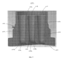
図1は、例示的な実施形態による原子炉の加圧容器のための流量制限ノズルを示す側面図である。図1を参照すると、流量制限ノズル100は、入口面104および出口面106を含むノズル本体102を備える。ノズル本体102は、入口面104から出口面106まで延びる複数の内部流路を形成する。複数の内部流路の各々は、収束部、スロート部、および発散部を含む。
1 is a side view of a flow restricting nozzle for a pressurized reactor vessel in accordance with an exemplary embodiment; FIG. Referring to FIG. 1, a
流量制限ノズル100の入口面104は、ノズル本体102のフランジ部であり、流量制限ノズル100の出口面106は、ノズル本体102のテーパ部である。このように、入口面104は、出口面106よりも周長および表面積が大きい。ノズル本体102のフランジ部により、流量制限ノズル100の原子炉を加圧容器(例えば、蒸気発生容器)に対して容易に取り付けることができる。入口面104は凹面であるように示されているが、代替的な実施形態では、入口面104は、流量制限ノズル100が取り付けられる対象面に応じて凸面であってもよいことが理解されるべきである。
The inlet face 104 of the
ノズル本体102は、ノズル本体102の外部から突出する器具タップまたは接続スタブ112をさらに含む。例えば、対向して配置された2つの接続スタブ112が設けられる。接続スタブ112には、圧力センサが接続される。ノズル本体102は、可動部を有しない受動的な構造体である。例えば、ノズル本体102は、モノリシック構造体である。
図2は、図1の流量制限ノズルの断面を示す出口端面図である。図2を参照すると、例示的な実施形態はこれに限定されるものではないが、流量制限ノズル100のノズル本体102は、円形の断面を有する。例えば、ノズル本体102は、これに代えて多角形の断面を有してもよい。
2 is an outlet end view showing a cross-section of the flow restricting nozzle of FIG. 1; FIG. Referring to FIG. 2, the
ノズル本体102は、その内部を通って延びる複数の内部流路を形成する。複数の内部流路は、等間隔に配列(例えば、六角形格子、三角格子)され、ノズル本体102内に中央に配置される。例示的な実施形態では、複数の内部流路は、同じ断面形状および大きさである。例えば、複数の内部流路の各々は、断面形状が円形であってもよいし、他の形状(例えば、断面形状が楕円形)であってもよい。複数の内部流路は、中央流路108と、中央流路108を取り囲む周辺流路110とを含む。中央流路108は、ノズル本体102の中央長手方向軸線と一致する。周辺流路110の各々は、隣接する周辺流路110と同様に、中央流路108から等距離に離間する。6つの周辺流路110が示されているが、条件に応じて異なる数が実施されてもよいことが理解されるべきである。
両接続スタブ112の各々は、ノズル本体102の中心、ひいては中央流路108に向かって指示するように径方向に配向されており、かつ隣接する周辺流路110の間に配置される。両接続スタブ112は、約180度離れているように、9時の位置および3時の位置に配置される。
Each of the connecting stubs 112 are radially oriented to point toward the center of the
図3は、例示的な実施形態による別の流量制限ノズルの断面を示す出口端面図である。図3を参照すると、接続スタブ112’を除いて、流量制限ノズル100’は、図2の流量制限ノズル100に関連して記載された通りである。特に、図3のノズル本体102’、中央流路108’、および周辺流路110’は、図2のノズル本体102、中央流路108、および周辺流路110に対応する。したがって、簡潔にするために、以前に記載された対応する開示は、本項では繰り返されない。
FIG. 3 is an outlet end view showing a cross section of another flow restricting nozzle in accordance with an exemplary embodiment; 3, flow restricting nozzle 100' is as described in connection with
図3に示すように、両接続スタブ112’の各々は、ノズル本体102’の中心、ひいては中央流路108’に向かって指示するように径方向に配向されており、隣接する周辺流路110’の間に配置される。接続スタブ112’は、120度離れているように、10時の位置および2時の位置に配置される。しかしながら、流量制限ノズル100’の視野が(例えば、時計回りに)回転された場合、接続スタブ112’は、12時の位置および4時の位置(または回転に応じた他の位置)に配置されているとみなされてもよいことが理解されるべきである。いずれにしても、図3に示す接続スタブ112’は、回転に関係なく約120度離れている。 As shown in FIG. 3, each of the connecting stubs 112' are radially oriented to point toward the center of the nozzle body 102' and thus toward the central channel 108' and the adjacent peripheral channel 110. ' is placed between Connecting stubs 112' are positioned at the 10 o'clock and 2 o'clock positions such that they are 120 degrees apart. However, if the field of view of the flow restricting nozzle 100' is rotated (eg, clockwise), the connecting stubs 112' are positioned at the 12 o'clock and 4 o'clock positions (or other positions depending on the rotation). It should be understood that the In any event, the connecting stubs 112' shown in FIG. 3 are approximately 120 degrees apart regardless of rotation.
図4は、例示的な実施形態による別の流量制限ノズルの断面を示す出口端面図である。図4を参照すると、流量制限ノズル100”は、図2の流量制限ノズル100に関連して一般的に記載されているようなものである。したがって、簡潔にするために、以前に記載された対応する開示は、本項では繰り返されない。図4の流量制限ノズル100”に示された相違点を後述する。
FIG. 4 is an outlet end view showing a cross section of another flow restricting nozzle in accordance with an exemplary embodiment; Referring to FIG. 4, the flow restricting nozzle 100'' is as generally described in relation to the
図4の流量制限ノズル100”に示すように、複数の内部流路は、(ノズル本体102”内で中央に位置しているのではなく)ノズル本体102”の一方の側にシフトしてもよい。複数の内部流路は、同じ断面形状(例えば、円形断面形状)であってもよいが、異なる大きさであってもよい。例示的な実施形態では、中央流路108”は、周辺流路110”よりも大きくてもよい。中央流路108”はまた、ノズル本体102”の中央長手方向軸線に対して中心からずれていてもよい。周辺流路110”は、互いに大きさが異なっていてもよい。例えば、例示的な実施形態は、周辺流路110”のうちの4つの周辺流路110”が、(中央流路108”に対して)中間的なサイズであってもよいし、周辺流路110”のうちの3つの周辺流路110”が、より小さいサイズであってもよいが、これらに限定されるものではない。加えて、1つ以上の周辺流路110”は、互いに対して中央流路108”とは異なる間隔を有してもよい。さらに、1つの中央流路108”と7つの周辺流路110”とが示されているが、条件に応じて異なる数が実施されてもよいことが理解されるべきである。
As shown in the
接続スタブ112”の各々は、隣接する周辺流路110”の間に配置されてもよく、また、中央流路108”に向かうように径方向に配向されてもよい。接続スタブ112”は、60度離れているように、11時の位置および1時の位置に配置される。しかしながら、流量制限ノズル100”の視野が(例えば、時計回りに)回転された場合、接続スタブ112”は、12時の位置および2時の位置(または回転に応じた他の位置)に配置されているとみなされてもよいことが理解されるべきである。いずれにしても、図4に示すように、接続スタブ112”は、回転に関係なく60度離れていることになる。
Each of the connecting stubs 112 ″ may be disposed between adjacent peripheral channels 110 ″ and may be oriented radially toward the central channel 108 ″. They are located at the 11 o'clock and 1 o'clock positions so that they are 60 degrees apart. However, if the view of the
図5は、例示的な実施形態による別の流量制限ノズルの断面を示す出口端面図である。図5を参照すると、周辺流路110”’を除いた流量制限ノズル100”’は、図4の流量制限ノズル100”に関連して記載された通りである。特に、図5のノズル本体102”’、中央流路108”’、および接続スタブ112”’は、図4のノズル本体102”、中央流路108”、および接続スタブ112”に対応する。したがって、簡潔にするために、以前に記載された対応する開示は、本明細書では繰り返されない。図5の流量制限ノズル100”’に示された相違点を後述する。
FIG. 5 is an outlet end view showing a cross-section of another flow restricting nozzle in accordance with an exemplary embodiment; Referring to FIG. 5, the flow restricting nozzle 100''', except for the peripheral passageway 110''', is as described with respect to the flow restricting nozzle 100'' of FIG. 4. Specifically, the
図5に示すように、周辺流路110”’は、断面寸法および形状が互いに異なっていてもよい。例えば、周辺流路110”’のうちの4つの周辺流路110”’が中間サイズであり、周辺流路110”’のうちの3つの周辺流路110”’がより小さいサイズであることに加えて、より小さいサイズの周辺流路110”’のうちの2つの周辺流路110”’が楕円形の断面形状を有していてもよい。図示しないが、条件によっては、ノズル本体102”’は、これに代えて中央流路108”’が周辺流路110”’よりも小さい寸法であるように構成されてもよいことが理解されるべきである。さらに、中央流路108”’は、図示されているものとは異なる形状(例えば、楕円形の断面形状)を有していてもよい。 As shown in FIG. 5, the peripheral channels 110"' may differ from one another in cross-sectional dimensions and shapes. For example, four of the peripheral channels 110"' may be of intermediate size. Yes, two of the smaller-sized peripheral channels 110''' in addition to the smaller size of the three peripheral channels 110''' of the peripheral channels 110'''. ' may have an elliptical cross-sectional shape. Although not shown, under certain conditions, the nozzle body 102''' may alternatively have a central channel 108''' smaller than the peripheral channel 110'''. It should be understood that it may be configured to be dimensional. Additionally, the central channel 108''' may have a different shape (eg, an elliptical cross-sectional shape) than that shown.
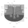
図6は、例示的な実施形態による原子炉の加圧容器のための流量制限ノズルの断面を示す上面透視図である。図6を参照すると、流量制限ノズル200は、入口面204および出口面206を含むノズル本体202を備える。ノズル本体202は、入口面204から出口面206まで延びる複数の内部流路を形成する。図6の複数の内部流路は、例示的な実施形態はこれに限定されないが、図2の複数の内部流路に対応することができる。図6において、複数の内部流路は、ノズル本体202を通って平行に延びてもよい。複数の内部流路の各々は、収束部、スロート部、および発散部を含む。非限定的な実施形態では、複数の内部流路の各々のスロート部は、ノズル本体202の出口面206よりも入口面204の近傍にある。
FIG. 6 is a top perspective view in cross section of a flow restricting nozzle for a pressurized reactor vessel in accordance with an exemplary embodiment; Referring to FIG. 6, flow
図6に示すように、複数の内部流路は、中央流路208と、中央流路208を取り囲む周辺流路210とを含む。中央流路208は、収束部208a、スロート部208b、および発散部208cを含み、周辺流路210の各々は、収束部210a、スロート部210b、および発散部210cを含む。中央流路208は、ノズル本体202の中央長手方向軸線と一致する。周辺流路210の各々は、例示的な実施形態ではこれに限定されないが、隣接する周辺流路210と同様に、中央流路208から等距離に離れていてもよい。
As shown in FIG. 6, the plurality of internal channels includes a central channel 208 and peripheral channels 210 surrounding the central channel 208 . Central channel 208 includes a converging portion 208a, a throat portion 208b, and a diverging
流量制限ノズル200の入口面204は、ノズル本体202のフランジ部であり、流量制限ノズル200の出口面206は、ノズル本体202のテーパ部である。このように、入口面204は、出口面206よりも周長および表面積が大きくてもよい。ノズル本体202のフランジ部により、流量制限ノズル200の原子炉の加圧容器(例えば、蒸気発生容器)に対して容易に取り付けることができる。入口面204は凹面であるように示されているが、代替的な実施形態では、入口面204は、流量制限ノズル200が取り付けられる対象面に応じて凸面であってもよいことが理解されるべきである。
The inlet face 204 of the
ノズル本体202は、ノズル本体202の外部から突出する器具タップまたは接続スタブ212をさらに含む。例えば、対向して配置された2つの接続スタブ212が設けられてもよい。接続スタブ212には、圧力センサが接続されていてもよい。接続スタブ212は、開口部216を介して中央流路208のスロート部208bと流体連通する。別例では、図示しないが、開口部216は、接続スタブ212が開口部216を介してスロート部210bと流体連通するように、周辺流路210のスロート部210bにこれに代えて(または追加的に)配置されてもよい。さらに、ノズル本体202は、可動部を有さない受動的な構造体であってもよい。例えば、ノズル本体202は、モノリシック構造体であってもよい。
図7は、図6の流量制限ノズルの断面を示す側面図である。図7を参照すると、中央流路208の収束部208aは、ノズル本体202の入口面204に第1の領域を有する。中央流路208の発散部208cは、ノズル本体202の出口面206に第2の領域を有する。中央流路208のスロート部208bは、スロート部208bの最も狭い部分に第3の領域を有する。中央流路208の第3の領域は、第1の領域および第2の領域よりも小さい。
7 is a cross-sectional side view of the flow restricting nozzle of FIG. 6; FIG. Referring to FIG. 7, the converging portion 208a of the central channel 208 has a first region at the inlet face 204 of the
同様に、周辺流路210に関して、各周辺流路210の収束部210aは、ノズル本体202の入口面204に第1の領域を有する。各周辺流路210の発散部210cは、ノズル本体202の出口面206に第2の領域を有する。各周辺流路210のスロート部210bは、スロート部210bの最も狭い部分に第3の領域を有する。各周辺流路210の第3の領域は、第1の領域および第2の領域よりも小さい。
Similarly, with respect to the peripheral channels 210 , the converging portion 210 a of each peripheral channel 210 has a first region at the inlet face 204 of the
加えて、中央流路208の収束部208aは、第1の長さを有する。中央流路208の発散部208cは、第2の長さを有する。中央流路208の第1の長さは、第2の長さよりも短い。
Additionally, the converging portion 208a of the central channel 208 has a first length. Diverging
同様に、周辺流路210に関して、各周辺流路210の収束部210aは、第1の長さを有する。各周辺流路210の発散部210cは、第2の長さを有する。各周辺流路210の第1の長さは、第2の長さよりも短い。 Similarly, with respect to the peripheral channels 210, the converging portion 210a of each peripheral channel 210 has a first length. Diverging portion 210c of each peripheral channel 210 has a second length. The first length of each peripheral channel 210 is shorter than the second length.
さらに、中央流路208のスロート部208bは、周辺流路210の各スロート部210bよりもノズル本体202の入口面204から離れている。このような例では、原子炉の加圧容器に関連して流量制限ノズル200を使用する間、中央流路208のスロート部208bは、周辺流路210の各スロート部210bに対して下流側に位置することになる。
In addition, the throat 208b of the central channel 208 is further from the inlet face 204 of the
図8は、図6の流量制限ノズルの別の断面を示す上面透視図である。特に、図8の流量制限ノズル200の断面は、ノズル本体202の隣接する周辺流路210の間にある。図8を参照すると、ノズル本体202は、ノズル本体202の外部から中央流路208に向かって延びる一対のチャネル214をさらに形成する。接続スタブ212の各々は、チャネル214の対応する1つと流体連通する内部通路を形成する。これらにより、チャネル214は、接続スタブ212を中央流路208のスロート部208bに流体的に接続する。加えて、図8に示すように、チャネル214は、複数の内部流路のうち隣接する周辺流路210の間を延びる。例示的な実施形態によれば、接続スタブ212およびチャネル214は、対向する接続スタブ212および関連付けられたチャネル214が互いに反映するように、正に対称的に配置される。別の実施例では、図示していないが、チャネル214はまた、接続スタブ212を1つ以上の周辺流路210のスロート部210bに流体的に接続するように設けられてもよい。
8 is a top perspective view of another cross-section of the flow restricting nozzle of FIG. 6; FIG. In particular, the cross section of the
図9は、図8の流量制限ノズルの断面を示す側面図である。図9を参照すると、チャネル214は、ノズル本体202の入口面204に向かって斜めに内向きに延びる。例示的な実施形態によれば、チャネル214は、中央流路208のスロート部208bまで延びる。異なる開口部216(図6)が各チャネル214に関連付けられているが、チャネル214は、中央流路208のスロート部208bに収束しているものとみなされる。さらに、例示的な実施形態はこれに限定されないが、接続スタブ212は、ノズル本体202の入口面204と出口面206との間のほぼ中間点に配置されてもよい。
9 is a cross-sectional side view of the flow restricting nozzle of FIG. 8; FIG. Referring to FIG. 9, channel 214 extends obliquely inward toward inlet face 204 of
図10は、図8の流量制限ノズルの断面を示す下側透視図である。図10を参照すると、中央流路208の収束部208aと周辺流路210の収束部210aは、ノズル本体202の入口面204で共有の境界を有するように、互いに直接隣接している。例えば、ノズル本体202の入口面204における周辺流路210のうちの1つの収束部210aの境界は、それに隣接する周辺流路210の2つの収束部210aの境界の一部をさらに形成する。加えて、周辺流路210の収束部210aの境界は、ノズル本体202の入口面204における中央流路208の収束部208aの境界を形成する。
10 is a bottom perspective view showing a cross-section of the flow restricting nozzle of FIG. 8; FIG. 10, the converging portion 208a of the central channel 208 and the converging portion 210a of the peripheral channel 210 are directly adjacent to each other so as to have a common boundary at the inlet face 204 of the
本明細書に開示された流量制限ノズルは、原子炉の加圧容器からの流量を制限するために使用することができる。例として図6乃至10を参照して、原子炉の加圧容器からの流量を制限する方法は、加圧容器に流量制限ノズル200を固定する工程を含む。流量制限ノズル200は、入口面204および出口面206を含むノズル本体202を有する。ノズル本体202は、入口面204から出口面206まで延びる複数の内部流路を形成する。複数の内部流路の各々は、収束部、スロート部、および発散部を含む。方法は、さらに、流量制限ノズル200の複数の内部流路を介して加圧容器からの流れを配向する工程を付加的に含む。
The flow restriction nozzles disclosed herein can be used to restrict flow from a pressurized vessel of a nuclear reactor. By way of example and referring to FIGS. 6-10, a method of restricting flow from a pressurized vessel of a nuclear reactor includes securing a
固定工程は、流量制限ノズル200を加圧容器の外部に溶接する工程を含む。流量制限ノズル200は、モノリシック構造体である。これに代えて、固定工程は、流量制限ノズルの第1のセクションを加圧容器に取り付ける工程と、流量制限ノズルの第2のセクションを第1のセクションに取り付ける工程とを含んでもよい。
The securing step includes welding the
流れの配向工程は、流量制限ノズル200を出るチョーク流れを生じさせる。流れの配向工程は、流量制限ノズル200から等速で出る安定化された流れを生じさせる。
The flow directing process produces choked flow exiting the
さらに、例として図6乃至10を参照すると、原子炉の加圧容器のための流量制限ノズル200を製造する方法は、入口面204および出口面206を含むノズル本体202を形成する工程を含む。ノズル本体202は、入口面204から出口面206まで延びる複数の内部流路を形成する。複数の内部流路の各々は、収束部、スロート部、および発散部を含む。方法は、さらに、加圧容器の予測された圧力変動に基づいて、入口面204上の複数の内部流路の各々の収束部を独立して整形し、寸法決めをし、位置決めする工程を含む。方法は、音響波の補強を緩和するために、複数の内部流路の各々のスロート部を入口面204に対して相対的に独立して間隔をあけて配置する工程をさらに含む。
Further by way of example and referring to FIGS. 6-10, a method of manufacturing a
本明細書に開示された流量制限ノズル、およびそれに関連する設計、使用、および製造は、本出願の例示的な実施形態に従って、以下でさらに詳細に論じられる。本明細書に開示されているものは、複数の平行通路を用いたコンパクト化、ノズル軸の角度調整、圧力変動、流量分布、流れのスワール、音響圧力波の伝達を制御するための流入・流出ポートの整形を特徴とする蒸気発生容器に使用するための流量制限ノズルである。流量制限ノズルは、設置後に交換可能/更新可能なように構成される。例示的な実施形態によれば、流量制限ノズルは可動部分を有さない。流量制限ノズルは、新規または既存の容器に適用することができる。流量制限ノズルは、飽和状態または過熱状態の蒸気サービス容器の流量制限に関連して利用することができる。しかしながら、流量制限ノズルは、容器流量制限ノズルの要件を有する他の蒸気、気体、および/または液体(例えば、水)の用途にも適用され得ることが理解されるべきである。 The flow restricting nozzles disclosed herein and their associated design, use, and manufacture are discussed in greater detail below in accordance with exemplary embodiments of the present application. Disclosed herein are compactification using multiple parallel passages, angular adjustment of the nozzle axis, pressure fluctuations, flow distribution, flow swirl, inflow and outflow to control the transmission of acoustic pressure waves. A flow restricting nozzle for use with steam generating vessels featuring port shaping. The flow restricting nozzle is configured to be replaceable/renewable after installation. According to an exemplary embodiment, the flow restricting nozzle has no moving parts. The flow restricting nozzle can be applied to new or existing vessels. Flow restricting nozzles can be utilized in connection with restricting the flow of saturated or superheated steam service vessels. However, it should be understood that the flow restriction nozzle may also be applied to other vapor, gas, and/or liquid (eg, water) applications that have vessel flow restriction nozzle requirements.
流体力学の原理は、現在のノズルに影響を与える問題に対処するために適用される。例示的な実施形態によれば、複数の平行な流路は、フローノズル吸気およびベンチュリノズル吐出流の原理の組み合わせを使用してそれぞれ形成される。 Principles of fluid mechanics are applied to address problems affecting current nozzles. According to an exemplary embodiment, the plurality of parallel flow paths are each formed using a combination of flow nozzle intake and venturi nozzle discharge principles.
入口圧力場と流れは一般的に不均一かつ不安定であり、多くの場合、巻き込み渦とスワールを生じる。高度な解析的な流れシミュレーションを適用することにより、複数の平行流路制限ノズル内の個々の流路ポートの数、ポートの形状、入口角、ポートの位置、付属機能、および個々のスロートの寸法は、これらの入口条件の悪影響を軽減するように対応して変化させることができる。入口ポートの表面は円滑かつ均一なものであってもよいし、凸凹や溝があってもよい。加えて、形状は、円形、楕円形、または楕円形の非対称版であってもよい。 The inlet pressure field and flow are generally non-uniform and unstable, often producing entrained vortices and swirls. Applying advanced analytical flow simulations to determine the number of individual flow ports, port geometry, inlet angles, port locations, accessory features, and individual throat dimensions in multiple parallel flow restricted nozzles can be correspondingly varied to mitigate the adverse effects of these inlet conditions. The surface of the inlet port can be smooth and uniform, or it can be rough and grooved. Additionally, the shape may be circular, oval, or an asymmetric version of an oval.
スロート面積は、ノズルのすべてのポートに対して一様であってもよく、または、より高い圧力を有するノズル入口面の部分がより大きなスロート流量面積を有する一方で、より低い圧力を有する入口面の部分がより小さなスロート流量面積を有するように、入口での非一様な圧力場予測を利用するために変化させてもよい。全体の流れ領域は、シングルパスの流量制限ノズルの流れ領域とほぼ同等である。ノズル内のスロートの位置は、入口面から一様な距離であってもよいし、複数通路の流量制限ノズルの入口または出口における音響波の補強を防止または低減するために、音響分析に応じて変化させてもよい。 The throat area may be uniform for all ports of the nozzle, or the inlet face with lower pressure while the portion of the nozzle inlet face with higher pressure has a larger throat flow area. may be varied to take advantage of the non-uniform pressure field prediction at the inlet such that the portion of has a smaller throat flow area. The overall flow area is approximately equivalent to that of a single pass flow restricting nozzle. The location of the throat within the nozzle may be a uniform distance from the inlet face or, depending on the acoustic analysis, to prevent or reduce acoustic wave reinforcement at the inlet or outlet of a multi-pass flow restricting nozzle. You can change it.
吐出ノズルは、ベンチュリ膨張のための工学的規則に従って、スロートからノズル出口面までの総圧力損失を最小にして最大の圧力回復を得るために、比較的浅い角度になっている。吐出ノズルは、ノズル出口端部に直交する一本の直線状の管路軸線に平行に配置可能である。これに代えて、スロート部からの出口流路は、ノズル出口端での配管接続界面を最適化するために、数度の角度が付けられていてもよい。付属機能は、入口または出口のアンチスワール(流れを直線的にする)ブレードを含み、耐腐食性を備えた溶接オーバーレイ材料の厚みを変化させることができ、また、圧力センサタップを含むことができる。 The discharge nozzle is at a relatively shallow angle for maximum pressure recovery with minimum total pressure loss from the throat to the nozzle exit face, according to engineering rules for venturi expansion. The discharge nozzles can be arranged parallel to a single linear conduit axis perpendicular to the nozzle outlet end. Alternatively, the outlet flow path from the throat may be angled a few degrees to optimize the tubing connection interface at the nozzle outlet end. Ancillary features include inlet or outlet anti-swirl (flow straightening) blades, can vary the thickness of the corrosion resistant weld overlay material, and can include pressure sensor taps. .
ノズル全体を一体的に形成してもよい。これに代えて、ノズルは2部分から構成されてもよく、2部分の形態では、装置の耐用年数中にノズルを取り外したり、交換したりすることができる。ノズル形状は、少なくとも3つのアプローチに従って製造することができる。第1のアプローチでは、一体型の複数の平行流路の流量制限ノズルは、元の工場製作の間に容器に溶接された恒久的な形態である。第2のアプローチでは、オリジナルの製作または後付けの容器の修正のために、2部分からなるノズル形態の第1の部分は、容器に溶接されているとともにソケットまたはチャンバを形成し、これに第2のマルチポート制限要素の部分が機械的に挿入され、かつユニットサービスの前に固定される。第3のアプローチでは、後付け容器のノズル変形のために、第1の部分は、材料の極低温収縮による干渉適合の原理を用いて既存のノズルボア内の所定の位置に挿入される機械的ロック機構であって、熱平衡化によってこの部分が再膨張する際に当該部分を恒久的にシールするとともにロックする外部機械的パターンを有するものである。ロック機構が所定の位置にある状態で、第2のマルチパス制限要素部分がユニットサービスの前に機械的に挿入されるとともに固定される。 The entire nozzle may be integrally formed. Alternatively, the nozzle may consist of two parts, in which case the nozzle can be removed and replaced during the useful life of the device. Nozzle shapes can be manufactured according to at least three approaches. In the first approach, the integral multiple parallel flow flow restricting nozzle is a permanent form welded to the vessel during original factory fabrication. In a second approach, for original fabrication or retrofitted container modifications, a first part of a two-part nozzle configuration is welded to the container and forms a socket or chamber to which a second is mechanically inserted and fixed before unit service. In a third approach, for nozzle deformation of the retrofit container, the first part is inserted into place within the existing nozzle bore using the principle of interference fit by cryogenic shrinkage of the material mechanical locking mechanism. with external mechanical patterns that permanently seal and lock the part as it re-expands due to thermal equilibration. With the locking mechanism in place, a second multipath restriction element portion is mechanically inserted and secured in front of the unit service.
ノズルを通る質量流量を複数のサブ流量に分離することにより、各流路のスロート径を減少させて、平行流路制限の総和効果によって総流量制限機能が満たされるようにして、ベンチュリ吐出の全体的な回復長さを低減し、これによりノズル全長が等価な単一流路ノズルよりもはるかに短くなる。マルチパスの流量制限ノズルの全直径は、容器製造への影響が無視できるほど、同等のシングルパスノズルのそれに非常に近い状態を保持する。ノズルの長さは、スロートオリフィスの直径に直接比例するベンチュリ吐出膨張長の関数である。個々の流路の小さなスロートオリフィスからノズル吐出面までの流量回復長さを短縮したことにより、工場での製作中に容器に完全に取り付けるのに充分にノズルがコンパクトになり、現場配置後に容器のノズル製作を完了させるために、ノズル延長部の高価で時間とスペースのかかる現場でのフィッティング、溶接、熱処理が必要なくなる。 By splitting the mass flow through the nozzle into multiple sub-flows, the throat diameter of each flow path is reduced such that the total flow restriction function is met by the summation effect of the parallel flow restrictions, thus reducing the overall venturi discharge. reduces the effective recovery length, which makes the total nozzle length much shorter than an equivalent single-pass nozzle. The overall diameter of the multi-pass flow restricting nozzle remains very close to that of the equivalent single-pass nozzle with negligible impact on container production. The nozzle length is a function of the venturi discharge expansion length which is directly proportional to the throat orifice diameter. Shortening the flow recovery length from the small throat orifice of each individual flow path to the nozzle discharge face allows the nozzle to be compact enough to be fully attached to the vessel during factory fabrication, and to be easily removed from the vessel after field placement. Expensive, time-consuming and space-consuming on-site fitting, welding, and heat treating of nozzle extensions are no longer required to complete nozzle fabrication.
ポート入口の形状および寸法を変更することにより、利用可能な流れ領域をノズル入口面での入口圧力分布に対してより密接に一致させることにより、流路の単位面積当たりの質量流量を均一化することができる。その結果、流れは続いて、等速で平行な流路を通過する。これは、ノズルの他のポートと比較した相対的な流量の「飢餓」に起因する、任意の個々の流路における不利な流れ現象を発生させる可能性の最小化に寄与し、また、異なる流速での個々の流路の流れの再結合に起因する再循環流失条件によって生じるノズル出口での渦または下流の流路領域の変位に起因する可能性の最小化に寄与する。 Equalize the mass flow rate per unit area of the channel by matching the available flow area more closely to the inlet pressure distribution at the nozzle inlet face by changing the shape and dimensions of the port inlet be able to. As a result, the flow continues through parallel channels at constant velocity. This helps minimize the potential for adverse flow phenomena in any individual flow path due to relative flow "starvation" compared to other ports of the nozzle, and also for different flow velocities. contributes to minimizing the potential for vortices at the nozzle exit or displacement of the downstream channel region caused by recirculation washout conditions due to recombination of individual channel flows at .
例えば、ポート入口の数、個々のポートのスロート径、およびノズル入口面上のそれらの相対的な位置を選択することにより、主蒸気ノズル昇降とBWR原子炉容器蒸気乾燥機構造物昇降との間の蒸気流干渉を緩和することができる。非対称な入口配置により、ノズルの公称中心線軸に対して小さな角度で個々の流路を製造することができ、これにより、ノズル出口面で出口流領域を均一に満たすために吐出ポートの再分配が可能となる。 For example, by selecting the number of port inlets, the throat diameters of the individual ports, and their relative positions on the nozzle inlet face, the Vapor flow interference can be mitigated. Asymmetric inlet placement allows individual flow passages to be produced at small angles to the nominal centerline axis of the nozzle, which allows for redistribution of the discharge ports to evenly fill the outlet flow area at the nozzle exit face. It becomes possible.
ノズルから下流の配管に発生する音響波は、高サイクル疲労により容器内構造物に対して損傷を与える可能性がある。低周波音響波は最もエネルギーを運搬し、容器内部構造物の金属疲労破壊を引き起こす可能性が高い。音響圧力波は、複数の平行流路の流量制限ノズルによって波エネルギーの一部が反射されて部分的に減衰される。波エネルギーの残りは、ノズルのより小さい直径の平行流路のそれぞれで生成される個々のより高い周波数の波パケットによる周波数変換およびエネルギー分割の対象となる。構造体の音響的な調整により、これらの送信された高周波数波のパケットが互いに強化するために再結合されることが回避される。したがって、容器内構造物に到達するエネルギーインパルスは、内部構造物の共振周波数からさらに離れており、より低いエネルギーのものとなる。これにより、配管系の音響的に誘起される高サイクル疲労による内部構造物破損の可能性が緩和される。 Acoustic waves generated in the piping downstream from the nozzle can damage the internal structures of the vessel due to high cycle fatigue. Low-frequency acoustic waves carry the most energy and are most likely to cause metal fatigue failure of vessel internals. The acoustic pressure wave is partially attenuated by reflection of a portion of the wave energy by the plurality of parallel flow restricting nozzles. The remainder of the wave energy is subject to frequency conversion and energy splitting by individual higher frequency wave packets produced in each of the nozzle's smaller diameter parallel flow paths. Acoustic tuning of the structure prevents these transmitted packets of high frequency waves from recombining to reinforce each other. Therefore, the energy impulses reaching the internal structure are further away from the resonant frequency of the internal structure and are of lower energy. This mitigates the potential for internal structural failure due to acoustically induced high cycle fatigue of the piping system.
ノズル構造体の付属機能が使用されることにより、性能がさらに向上し、質量エネルギー伝達効率が向上し、流量監視が支援される。流れのスワールを最小限に抑えるために、流れ軸線方向への流入を強化するとともに、スワールに起因する寄生抗力現象を中断するために、溝付き入口を使用してもよい。頂点は、交差する流れを移動させるために鋭く尖っていてもよいし、二等分ブレード、三等分ブレード、または四等分ブレードパターンのような流れを矯正するブレード(フォイル、ベーン)を形成するために接合されていてもよい。さらに、流れが全管径に達する前に形成される遷移渦に起因するスワールの発生を制限するために、個々のベンチュリ膨張出口に流れを矯正するブレードを備えることができる。アンチスワールブレードは、抗力の源となる交差流の流れや下流側の渦を打ち消すことで、流れを安定化させてもよい。 Additional features of the nozzle structure are used to further improve performance, improve mass energy transfer efficiency, and assist in flow rate monitoring. To minimize flow swirl, slotted inlets may be used to enhance flow axial inflow and to interrupt swirl-induced parasitic drag phenomena. The apex may be sharply pointed to displace crossing flows, or form flow straightening blades (foils, vanes) such as a bisected, trisected, or quartered blade pattern. may be joined together to In addition, flow straightening blades can be provided at the individual venturi expansion outlets to limit swirling due to transitional vortices that form before the flow reaches the full pipe diameter. Anti-swirl blades may stabilize the flow by counteracting cross-flow flow and downstream vortices that are sources of drag.
吐出ベンチュリ膨張ノズルを数度でも角度をつけることで、ノズル吐出面と配管との接続位置を調整してシステムの配管界面を改善することができ、下流側の流れにスワールを再導入する傾向にある必要な配管の屈曲を低減することができる。 By angling the discharge venturi expansion nozzle by even a few degrees, the position of the connection between the nozzle discharge face and the pipe can be adjusted to improve the pipe interface of the system, tending to reintroduce swirl into the downstream flow. Some necessary piping bends can be reduced.
溶接金属オーバーレイの変形例は、より高い侵食の可能性を有する領域に対処し、選択的な機械加工および表面の平滑化によって、製作中の流路形成が可能となる。 The weld metal overlay variation addresses areas with higher erosion potential and selective machining and surface smoothing allow channeling during fabrication.
圧力感知ポートは、差圧と流量との等価性を用いて、ノズルを通る質量流量を決定することができるように、上流側(入口面)圧力およびスロート部の圧力を測定することができる。 The pressure sensing port can measure upstream (inlet face) pressure and throat pressure so that the equivalence of differential pressure and flow can be used to determine the mass flow rate through the nozzle.
任意により2部分からなる複数の平行流路の流量制限ノズルを使用することにより、マルチポート制限要素部分を除去、および改装または交換することによって、稼働中に発生する摩耗および浸食を管理することができる。これにより、さらに、容器の圧力境界に対する変更を伴うことなく、制限ノズルの総質量流量を増加または減少させるための変更が可能となる。 The wear and erosion that occurs during operation can be managed by removing and retrofitting or replacing portions of the multi-port restriction element, optionally using a two-part, multiple parallel flow flow restriction nozzle. can. This also allows modifications to increase or decrease the total mass flow rate of the restrictive nozzles without modification to the pressure boundary of the vessel.
本明細書のノズル設計により、解析的に実証されている流れのスワールによって引き起こされる圧力損失が実質的に低減され、また、ノズル設計は、蒸気ノズルに直接対向する蒸気乾燥機の外側バンク表面上の観察可能な研磨効果によって明示されている。 The nozzle design herein substantially reduces the pressure drop caused by flow swirl, which has been analytically demonstrated, and the nozzle design is located on the outer bank surface of the steam dryer directly opposite the steam nozzle. is manifested by the observable polishing effect of .
改善された蒸気流送達により、付加的なコアエネルギーを追加することなく、ユニットの潜在的なメガワット電気出力が増加する。 Improved vapor flow delivery increases the unit's potential megawatt electrical output without adding additional core energy.
現在の制限ノズル設計の現場における容器製作ステップを排除することで、大幅な建設コストを節約することができる。また、主蒸気配管とのインターフェイスの改善により、蒸気の送出量の向上にも貢献している。 Significant construction cost savings can be achieved by eliminating the on-site vessel fabrication step of current restrictive nozzle designs. In addition, the improvement of the interface with the main steam piping contributes to the improvement of the steam delivery rate.
マルチパス流量制限ノズルのコンパクトな設計により、完全なノズルを、容器を取り囲む他の構造物や蒸気ノズルの近傍に干渉することなく、圧力容器内に設置することができる。 The compact design of the multi-pass flow restricting nozzle allows the complete nozzle to be installed within the pressure vessel without interfering with other structures surrounding the vessel or the proximity of the steam nozzle.
後付けプラントについては、インラインベンチュリ制限器を容器マルチパス流量制限ノズル設計に置き換えることで、現在の無制限蒸気管破断の仮定と比較してLOCAの影響を低減することができる。 For retrofit plants, replacing the in-line venturi restrictor with a vessel multi-pass flow restriction nozzle design can reduce the effects of LOCA compared to current unlimited steam line break assumptions.
音響波の減衰により、下流の音響発生器(例えば、リリーフバルブ分岐配管)による蒸気乾燥機アセンブリの周期的な負荷が低減される。これにより、乾燥機の故障の可能性を軽減することができる。さらに、複数パスの流量制限ノズルの設計のより小さい流路オリフィスは、破片のより小さい部分を除くすべての破片が蒸気ラインに排出されることを効果的に防止するであろう。この破片のスクリーニングは、任意の特定のプラントの容器に設置されたノズルの設計が、入口、出口、または入口と出口の流量を矯正するブレードを含む場合に特に効果的である。 Acoustic wave attenuation reduces the cyclic loading of the steam dryer assembly by downstream acoustic generators (eg, relief valve branch piping). This can reduce the possibility of dryer failure. Additionally, the smaller flow orifice of the multi-pass flow restricting nozzle design will effectively prevent all but a smaller portion of the debris from being discharged into the steam line. This debris screening is particularly effective when the design of the nozzles installed in any particular plant vessel includes inlet, outlet, or inlet and outlet flow correction blades.
加えて、音響波の部分的な閉塞は、下流の配管系における突然の弁閉鎖によるインパルス波または衝撃波を含み、容器内部で経験される過渡的な負荷を緩和する。その結果、蒸気システムの過渡現象の早期に大量排出を低減するために、下流側配管を閉じるための閉鎖時間をより速くすることが容易になる。 In addition, partial occlusion of acoustic waves, including impulse or shock waves due to abrupt valve closures in the downstream piping system, mitigates transient loads experienced inside the vessel. As a result, it facilitates faster closure times for closing downstream piping to reduce bulk emissions early in a steam system transient.
初期の肉厚オーバーレイクラッド用に制限ノズルを設計することにより、通路の外形再構成と制限ノズルの容量定格の再認証のためにクラッドの一部を機械加工することを可能にすることによって、後の稼働におけるパワー/流量の増加のためにノズルを適応させるための作り付けの手段が提供される。 By designing the restrictive nozzle for the initial thick overlay cladding, the later A built-in means is provided for adapting the nozzle for increased power/flow rate in operation.
本明細書に記載されている2部分からなる設計により、元の構成部分の工場製作が簡素化される。この概念により、また、容器の外側にある制限要素のルーチン検査が可能となる。容器から離れた場所でのメンテナンスにより、溶接が関与せず、かつすべての作業を制御された工場環境で行うことができるため、制限要素の改修または交換が容易になり、簡素化される。容器から離れた場所でメンテナンス作業を行うことで、容器の破損や容器内の異物の紛失などの物質的リスクが大幅に軽減され、また、作業を行うメンテナンス要員のリスクを軽減することができる。また、これにより、標準的な精密工場工具を使用することができ、原位置検査や修理で可能な限りより正確かつ複雑な方法が可能となる。新しいインサート部品を製造し、変更の前に認定することができるので、制限要素を交換する能力により、設計質量流量の変更のために容器を迅速に修理することができる。 The two-part design described herein simplifies factory fabrication of the original components. This concept also allows routine inspection of restrictive elements outside the container. Maintenance away from the vessel facilitates and simplifies refurbishment or replacement of restrictive elements because no welds are involved and all work can be done in a controlled factory environment. By performing maintenance work away from the container, material risks such as damage to the container and loss of foreign matter in the container can be greatly reduced, and the risk of maintenance personnel performing the work can be reduced. This also allows the use of standard precision factory tools and allows for the most accurate and complex methods possible for in-situ inspection and repair. The ability to replace the restrictive element allows rapid repair of the vessel for design mass flow changes, as new insert parts can be manufactured and qualified prior to the change.
容器への溶接が必要とされないので、制限要素インサートを製造するための材料選択の選択肢として、容器およびメインノズルチャンバの基材と熱的に互換性もある利用可能な耐腐食性または耐浸食性材料および合金のより広い選択を利用することができる。 Corrosion or erosion resistance available that is also thermally compatible with the base material of the vessel and main nozzle chamber as a material selection option for manufacturing the restrictive element insert as welding to the vessel is not required A wider selection of materials and alloys are available.
入口面静圧および支配的経路(例えば、中央ポート)ベンチュリ・スロート圧力のための一体型圧力感知ポートを有するマルチパス流蒸気流制限要素を設計することにより、制限ノズルは、試験台で較正されるとともに容量が認証され得る。これは、プラントから外部で行うことができる。ノズルの差圧計装接続は簡素化され、ノズル性能の正確な供用中測定が確実に行われる。 The restriction nozzle is calibrated on a test bench by designing a multi-pass flow steam flow restriction element with integral pressure sensing ports for inlet face static pressure and dominant path (e.g., central port) venturi throat pressure. capacity can be authenticated as well. This can be done externally from the plant. The nozzle differential pressure instrumentation connection is simplified to ensure accurate in-service measurement of nozzle performance.
多くの例示的な実施形態が本明細書に開示されているが、他の変形が可能であることが理解されるべきである。そのような変形は、本開示の趣旨および範囲からの逸脱とみなされるべきではなく、当業者には自明であろうそのような修正はすべて、以下の特許請求の範囲に含まれることが意図されている。 While many exemplary embodiments are disclosed herein, it should be understood that other variations are possible. Such variations are not to be regarded as a departure from the spirit and scope of this disclosure, and all such modifications that would be obvious to those skilled in the art are intended to be included within the scope of the following claims. ing.
Claims (12)
前記加圧容器に流量制限ノズル(200)を固定する工程であって、前記流量制限ノズル(200)は、入口面(204)および出口面(206)を含むとともにモノリシック構造体であるノズル本体(202)を有し、前記ノズル本体(202)は、前記入口面(204)から前記出口面(206)まで延びる複数の内部流路(208/210)を形成し、前記複数の内部流路(208/210)の各々は、収束部(208a/210a)、スロート部(208b/210b)、および発散部(208c/210c)を含み、前記複数の内部流路(208/210)が、中央流路(208)と、同中央流路(208)を取り囲む複数の周辺流路(210)とを含み、前記中央流路(208)の前記スロート部(208b)が、前記周辺流路(210)の各々の前記スロート部(210b)よりも前記ノズル本体(202)の前記入口面(204)から遠い、固定工程と、
前記加圧容器からの流れを、前記流量制限ノズル(200)の前記複数の内部流路(208/210)を介して配向する工程とを含む、原子炉の加圧容器からの流れを制限する方法。 A method of restricting flow from a pressurized vessel of a nuclear reactor comprising:
securing a flow restricting nozzle (200) to said pressurized vessel, said flow restricting nozzle (200) comprising an inlet face (204) and an outlet face (206) and being a monolithic nozzle body ( 202), said nozzle body (202) defining a plurality of internal passages (208/210) extending from said inlet surface (204) to said outlet surface (206), said plurality of internal passages ( 208/210) includes a converging portion (208a/210a), a throat portion (208b/210b), and a diverging portion (208c/210c), wherein said plurality of internal flow passages (208/210) includes a central a channel (208) and a plurality of peripheral channels (210) surrounding the central channel (208), the throat (208b) of the central channel (208) ) further from said inlet face (204) of said nozzle body (202) than said throat (210b) of each of said nozzle bodies (202);
and directing flow from said pressurized vessel through said plurality of internal passages (208/210) of said flow restriction nozzle (200). Method.
入口面(204)および出口面(206)を含むとともにモノリシック構造体であるノズル本体(202)であって、同ノズル本体(202)は、前記入口面(204)から前記出口面(206)まで延びる複数の内部流路(208/210)を形成し、同複数の内部流路(208/210)の各々は、収束部(208a/210a)、スロート部(208b/210b)、および発散部(208c/210c)を含み、前記複数の内部流路(208/210)が、中央流路(208)と、同中央流路(208)を取り囲む複数の周辺流路(210)とを含む、ノズル本体(202)を形成する工程と、
前記加圧容器の予測された圧力変動に基づいて、前記入口面(204)上の複数の内部流路(208/210)の各々の前記収束部(208a/210a)を独立して整形し、寸法決めをし、位置決めする工程であって、前記中央流路(208)の前記スロート部(208b)が、前記周辺流路(210)の各々の前記スロート部(210b)よりも前記ノズル本体(202)の前記入口面(204)から遠い、整形、寸法決め、位置決め工程と、
音響波の補強を緩和するために、前記複数の内部流路(208/210)の各々の前記スロート部(208b/210b)を前記入口面(204)に対して相対的に独立して間隔をあけて配置する工程とを含む、原子炉の加圧容器のための流量制限ノズル(200)を製造する方法。 A method of manufacturing a flow restriction nozzle (200) for a pressurized reactor vessel, comprising:
A nozzle body (202) comprising an inlet face (204) and an outlet face (206) and being a monolithic structure , the nozzle body (202) extending from said inlet face (204) to said outlet face (206) forming a plurality of internal flow passages (208/210) extending therethrough, each of the plurality of internal flow passages (208/210) having a converging portion (208a/210a), a throat portion (208b/210b), and a diverging portion ( 208c/210c), wherein said plurality of internal channels (208/210) comprises a central channel (208) and a plurality of peripheral channels (210) surrounding said central channel (208); forming a nozzle body (202);
independently shaping the convergence (208a/210a) of each of the plurality of internal channels (208/210) on the inlet face (204) based on the predicted pressure fluctuations of the pressurized vessel; A step of dimensioning and positioning wherein the throat (208b) of the central channel (208) is closer to the nozzle body (210b) than the throat (210b) of each of the peripheral channels (210). 202) remote from said entry face (204), a shaping, sizing and positioning step ;
the throats (208b/210b) of each of the plurality of internal passages (208/210) are relatively independently spaced with respect to the inlet face (204) to mitigate acoustic wave build-up; A method of manufacturing a flow restriction nozzle (200) for a nuclear reactor pressurized vessel, comprising:
Applications Claiming Priority (3)
| Application Number | Priority Date | Filing Date | Title |
|---|---|---|---|
| US15/845,277 | 2017-12-18 | ||
| US15/845,277 US11232874B2 (en) | 2017-12-18 | 2017-12-18 | Multiple-path flow restrictor nozzle |
| PCT/US2018/062632 WO2019168572A2 (en) | 2017-12-18 | 2018-11-27 | Multiple-path flow restrictor nozzle |
Publications (3)
| Publication Number | Publication Date |
|---|---|
| JP2021506572A JP2021506572A (en) | 2021-02-22 |
| JP2021506572A5 JP2021506572A5 (en) | 2021-11-25 |
| JP7250020B2 true JP7250020B2 (en) | 2023-03-31 |
Family
ID=66816211
Family Applications (1)
| Application Number | Title | Priority Date | Filing Date |
|---|---|---|---|
| JP2020532910A Active JP7250020B2 (en) | 2017-12-18 | 2018-11-27 | Multi-pass flow restriction nozzle, method of multi-pass flow restriction, and method of manufacturing same |
Country Status (6)
| Country | Link |
|---|---|
| US (1) | US11232874B2 (en) |
| EP (1) | EP3729465B1 (en) |
| JP (1) | JP7250020B2 (en) |
| FI (1) | FI3729465T3 (en) |
| PL (1) | PL3729465T3 (en) |
| WO (1) | WO2019168572A2 (en) |
Families Citing this family (2)
| Publication number | Priority date | Publication date | Assignee | Title |
|---|---|---|---|---|
| US11232874B2 (en) * | 2017-12-18 | 2022-01-25 | Ge-Hitachi Nuclear Energy Americas Llc | Multiple-path flow restrictor nozzle |
| US11293298B2 (en) * | 2019-12-05 | 2022-04-05 | Raytheon Technologies Corporation | Heat transfer coefficients in a compressor case for improved tip clearance control system |
Citations (2)
| Publication number | Priority date | Publication date | Assignee | Title |
|---|---|---|---|---|
| JP2002515337A (en) | 1998-05-15 | 2002-05-28 | シルベント アクティボラグ | Silent spray nozzle |
| CN103187113A (en) | 2013-01-18 | 2013-07-03 | 上海核工程研究设计院 | Steam flow-limiting device for steam generator in nuclear power station |
Family Cites Families (42)
| Publication number | Priority date | Publication date | Assignee | Title |
|---|---|---|---|---|
| US1626047A (en) * | 1925-12-11 | 1927-04-26 | Majestic Mfg Company | Gas stove |
| GB1264241A (en) * | 1969-01-23 | 1972-02-16 | ||
| US3622081A (en) * | 1969-06-20 | 1971-11-23 | Nestle Sa | Nozzle |
| US3945574A (en) | 1972-07-24 | 1976-03-23 | Polnauer Frederick F | Dual orifice spray nozzle using two swirl chambers |
| US3878991A (en) | 1974-02-14 | 1975-04-22 | Gen Foods Corp | Steam nozzle |
| US4071403A (en) | 1974-08-01 | 1978-01-31 | Westinghouse Electric Corporation | Method and apparatus for protecting the core of a nuclear reactor |
| US4361285A (en) | 1980-06-03 | 1982-11-30 | Fluid Kinetics, Inc. | Mixing nozzle |
| US4652234A (en) | 1984-03-01 | 1987-03-24 | Voorheis Industries, Inc. | Constant pressure-variable orifice burner nozzle assembly |
| FR2602309B1 (en) * | 1986-07-30 | 1988-11-10 | Soudure Autogene Francaise | STEEL CUTTING NOZZLE WITH DOUBLE HEATER CROWN |
| JP2811682B2 (en) * | 1988-09-22 | 1998-10-15 | 石川島播磨重工業株式会社 | Main steam nozzle of reactor pressure vessel |
| JPH087274B2 (en) * | 1990-08-22 | 1996-01-29 | 株式会社日立製作所 | Directly attached reactor pressure vessel flow measurement nozzle |
| US5090619A (en) * | 1990-08-29 | 1992-02-25 | Pinnacle Innovations | Snow gun having optimized mixing of compressed air and water flows |
| JP2509753B2 (en) * | 1990-11-15 | 1996-06-26 | 株式会社東芝 | Reactor main steam flow meter |
| US5103800A (en) | 1991-05-13 | 1992-04-14 | Cleveland Range, Inc. | Nozzle for steam cooking device |
| US5385121A (en) | 1993-01-19 | 1995-01-31 | Keystone International Holdings Corp. | Steam desuperheater |
| EP0681301A1 (en) | 1994-05-04 | 1995-11-08 | General Electric Company | Feedwater nozzle and method of repair |
| JPH087274A (en) | 1994-06-16 | 1996-01-12 | Sony Magnescale Inc | Transfer device |
| US5613535A (en) * | 1995-06-05 | 1997-03-25 | Shell Oil Company | Fuel dispenser shutoff switch |
| US6585063B2 (en) * | 2000-12-14 | 2003-07-01 | Smith International, Inc. | Multi-stage diffuser nozzle |
| DE60122709D1 (en) * | 2001-08-20 | 2006-10-12 | Schlumberger Services Petrol | Multi-phase flow meter with variable Venturi nozzle |
| US6969489B2 (en) * | 2001-08-24 | 2005-11-29 | Cytoplex Biosciences | Micro array for high throughout screening |
| US7270713B2 (en) * | 2003-01-07 | 2007-09-18 | Applied Materials, Inc. | Tunable gas distribution plate assembly |
| KR20050007941A (en) * | 2003-07-12 | 2005-01-21 | 두산중공업 주식회사 | Method for Designing Multi-Venturi Nozzle of Steam Generator |
| FR2866410B1 (en) * | 2004-02-17 | 2006-05-19 | Gaz De France | FLOW CONDITIONER FOR FLUID TRANSPORT PIPING |
| JP2006300535A (en) | 2005-04-15 | 2006-11-02 | Nuclear Fuel Ind Ltd | Gas introduction nozzle of coated fuel particle manufacturing equipment for high-temperature gas-cooled reactor |
| US7945938B2 (en) | 2005-05-11 | 2011-05-17 | Canon Kabushiki Kaisha | Network camera system and control method therefore |
| SE534983C2 (en) | 2006-06-21 | 2012-03-06 | Clyde Bergemann Inc | Black liquor nozzle with variable orifice |
| US8312931B2 (en) * | 2007-10-12 | 2012-11-20 | Baker Hughes Incorporated | Flow restriction device |
| JP5470656B2 (en) | 2010-03-16 | 2014-04-16 | 株式会社マスダック | Superheated steam generation nozzle |
| EP2813220A3 (en) * | 2010-04-09 | 2015-06-17 | Pacira Pharmaceuticals, Inc. | Method for formulating large diameter synthetic membrane vesicles |
| CN107376071B (en) * | 2011-05-09 | 2021-07-09 | 英倍尔药业股份有限公司 | Nozzle for delivering a compound to the upper olfactory region of a user |
| US9091429B2 (en) | 2011-08-03 | 2015-07-28 | Westinghouse Electric Company Llc | Nuclear steam generator steam nozzle flow restrictor |
| US8646486B2 (en) * | 2011-08-14 | 2014-02-11 | Watermiser, LLC. | Elliptical chambered flow restrictor |
| DE102012000536B3 (en) | 2012-01-16 | 2013-05-16 | Areva Np Gmbh | Passive reflux limiter for a flow medium |
| US10182696B2 (en) * | 2012-09-27 | 2019-01-22 | Dehn's Innovations, Llc | Steam nozzle system and method |
| US9463342B2 (en) * | 2014-03-17 | 2016-10-11 | International Fog, Inc. | Fog-cloud generated nozzle |
| KR101817212B1 (en) * | 2016-04-29 | 2018-02-21 | 세메스 주식회사 | Chemical nozzle and apparatus for treating substrate |
| US20180056100A1 (en) * | 2016-08-31 | 2018-03-01 | Emerson Process Management Regulator Technologies Tulsa, Llc | Method for Manufacturing a Flame Arrestor |
| US9987508B2 (en) * | 2016-08-31 | 2018-06-05 | Emerson Process Management Regulator Technologies Tulsa, Llc | Hybrid composite flame cell |
| JP6876447B2 (en) * | 2017-01-24 | 2021-05-26 | 日立Geニュークリア・エナジー株式会社 | Nuclear power plant |
| US10811232B2 (en) * | 2017-08-08 | 2020-10-20 | Applied Materials, Inc. | Multi-plate faceplate for a processing chamber |
| US11232874B2 (en) * | 2017-12-18 | 2022-01-25 | Ge-Hitachi Nuclear Energy Americas Llc | Multiple-path flow restrictor nozzle |
-
2017
- 2017-12-18 US US15/845,277 patent/US11232874B2/en active Active
-
2018
- 2018-11-27 WO PCT/US2018/062632 patent/WO2019168572A2/en unknown
- 2018-11-27 JP JP2020532910A patent/JP7250020B2/en active Active
- 2018-11-27 FI FIEP18907542.7T patent/FI3729465T3/en active
- 2018-11-27 EP EP18907542.7A patent/EP3729465B1/en active Active
- 2018-11-27 PL PL18907542.7T patent/PL3729465T3/en unknown
Patent Citations (2)
| Publication number | Priority date | Publication date | Assignee | Title |
|---|---|---|---|---|
| JP2002515337A (en) | 1998-05-15 | 2002-05-28 | シルベント アクティボラグ | Silent spray nozzle |
| CN103187113A (en) | 2013-01-18 | 2013-07-03 | 上海核工程研究设计院 | Steam flow-limiting device for steam generator in nuclear power station |
Also Published As
| Publication number | Publication date |
|---|---|
| PL3729465T3 (en) | 2023-08-21 |
| WO2019168572A3 (en) | 2019-11-07 |
| US11232874B2 (en) | 2022-01-25 |
| JP2021506572A (en) | 2021-02-22 |
| FI3729465T3 (en) | 2023-07-19 |
| EP3729465A2 (en) | 2020-10-28 |
| EP3729465B1 (en) | 2023-06-21 |
| WO2019168572A2 (en) | 2019-09-06 |
| US20190189297A1 (en) | 2019-06-20 |
| EP3729465A4 (en) | 2021-09-08 |
Similar Documents
| Publication | Publication Date | Title |
|---|---|---|
| JP7250020B2 (en) | Multi-pass flow restriction nozzle, method of multi-pass flow restriction, and method of manufacturing same | |
| EP1574764B1 (en) | Valve | |
| EP1914393B1 (en) | Steam valve and steam turbine plant | |
| JP5701019B2 (en) | Combination steam valve and steam turbine | |
| EP2503105B1 (en) | Steam valve device and steam turbine plant | |
| CN103851604B (en) | A kind of orifice union for once through steam generator | |
| US11858078B2 (en) | Disk stack repair insert | |
| US8998169B2 (en) | Toothed gate valve seat | |
| JP3968181B2 (en) | Combination valve structure in steam circulation system. | |
| US4230410A (en) | Mixing device for fluids of different and varying temperatures | |
| US4803841A (en) | Moisture separator for steam turbine exhaust | |
| EP3296514A1 (en) | Fluidically controlled steam turbine inlet scroll | |
| KR20170045307A (en) | Swirl stabilized high capacity duct burner | |
| JP6306434B2 (en) | Ultrasonic flow meter | |
| KR101389054B1 (en) | Hhydrodynamic machine including monolithic structure casing system | |
| KR20140136099A (en) | Cylindrical Multi Helical One Step Stage Trim, Flow Control Valve | |
| US20230100209A1 (en) | Impingement device for heat exchanger inlet tube protection | |
| JP6491052B2 (en) | Turbine inlet structure and steam turbine using the same | |
| CN114364919A (en) | Steam generator liquid separator and method for manufacturing the same | |
| WO2018098703A1 (en) | Fuel assembly and tube base thereof | |
| JP2019060265A (en) | Steam valve device and steam turbine plant with the same | |
| JP2012211525A5 (en) | ||
| Kondo et al. | Engineering design and construction of IFMIF/EVEDA lithium test loop: design and fabrication of integrated target assembly | |
| JP2012211525A (en) | Entrance structure of low-pressure steam turbine | |
| JPH0411792B2 (en) |
Legal Events
| Date | Code | Title | Description |
|---|---|---|---|
| A521 | Request for written amendment filed |
Free format text: JAPANESE INTERMEDIATE CODE: A523 Effective date: 20200819 |
|
| A521 | Request for written amendment filed |
Free format text: JAPANESE INTERMEDIATE CODE: A523 Effective date: 20211011 |
|
| A621 | Written request for application examination |
Free format text: JAPANESE INTERMEDIATE CODE: A621 Effective date: 20211011 |
|
| A977 | Report on retrieval |
Free format text: JAPANESE INTERMEDIATE CODE: A971007 Effective date: 20221028 |
|
| A131 | Notification of reasons for refusal |
Free format text: JAPANESE INTERMEDIATE CODE: A131 Effective date: 20221108 |
|
| A521 | Request for written amendment filed |
Free format text: JAPANESE INTERMEDIATE CODE: A523 Effective date: 20230202 |
|
| TRDD | Decision of grant or rejection written | ||
| A01 | Written decision to grant a patent or to grant a registration (utility model) |
Free format text: JAPANESE INTERMEDIATE CODE: A01 Effective date: 20230228 |
|
| A61 | First payment of annual fees (during grant procedure) |
Free format text: JAPANESE INTERMEDIATE CODE: A61 Effective date: 20230320 |
|
| R150 | Certificate of patent or registration of utility model |
Ref document number: 7250020 Country of ref document: JP Free format text: JAPANESE INTERMEDIATE CODE: R150 |