JP6876447B2 - Nuclear power plant - Google Patents
Nuclear power plant Download PDFInfo
- Publication number
- JP6876447B2 JP6876447B2 JP2017009920A JP2017009920A JP6876447B2 JP 6876447 B2 JP6876447 B2 JP 6876447B2 JP 2017009920 A JP2017009920 A JP 2017009920A JP 2017009920 A JP2017009920 A JP 2017009920A JP 6876447 B2 JP6876447 B2 JP 6876447B2
- Authority
- JP
- Japan
- Prior art keywords
- power plant
- nuclear power
- containment vessel
- reactor containment
- radioactive material
- Prior art date
- Legal status (The legal status is an assumption and is not a legal conclusion. Google has not performed a legal analysis and makes no representation as to the accuracy of the status listed.)
- Active
Links
Images


Classifications
-
- G—PHYSICS
- G21—NUCLEAR PHYSICS; NUCLEAR ENGINEERING
- G21C—NUCLEAR REACTORS
- G21C9/00—Emergency protection arrangements structurally associated with the reactor, e.g. safety valves provided with pressure equalisation devices
- G21C9/004—Pressure suppression
- G21C9/008—Pressure suppression by rupture-discs or -diaphragms
-
- B—PERFORMING OPERATIONS; TRANSPORTING
- B01—PHYSICAL OR CHEMICAL PROCESSES OR APPARATUS IN GENERAL
- B01D—SEPARATION
- B01D53/00—Separation of gases or vapours; Recovering vapours of volatile solvents from gases; Chemical or biological purification of waste gases, e.g. engine exhaust gases, smoke, fumes, flue gases, aerosols
- B01D53/22—Separation of gases or vapours; Recovering vapours of volatile solvents from gases; Chemical or biological purification of waste gases, e.g. engine exhaust gases, smoke, fumes, flue gases, aerosols by diffusion
- B01D53/228—Separation of gases or vapours; Recovering vapours of volatile solvents from gases; Chemical or biological purification of waste gases, e.g. engine exhaust gases, smoke, fumes, flue gases, aerosols by diffusion characterised by specific membranes
-
- B—PERFORMING OPERATIONS; TRANSPORTING
- B01—PHYSICAL OR CHEMICAL PROCESSES OR APPARATUS IN GENERAL
- B01D—SEPARATION
- B01D53/00—Separation of gases or vapours; Recovering vapours of volatile solvents from gases; Chemical or biological purification of waste gases, e.g. engine exhaust gases, smoke, fumes, flue gases, aerosols
- B01D53/22—Separation of gases or vapours; Recovering vapours of volatile solvents from gases; Chemical or biological purification of waste gases, e.g. engine exhaust gases, smoke, fumes, flue gases, aerosols by diffusion
-
- B—PERFORMING OPERATIONS; TRANSPORTING
- B01—PHYSICAL OR CHEMICAL PROCESSES OR APPARATUS IN GENERAL
- B01D—SEPARATION
- B01D53/00—Separation of gases or vapours; Recovering vapours of volatile solvents from gases; Chemical or biological purification of waste gases, e.g. engine exhaust gases, smoke, fumes, flue gases, aerosols
- B01D53/34—Chemical or biological purification of waste gases
- B01D53/74—General processes for purification of waste gases; Apparatus or devices specially adapted therefor
- B01D53/86—Catalytic processes
- B01D53/8671—Removing components of defined structure not provided for in B01D53/8603 - B01D53/8668
-
- B—PERFORMING OPERATIONS; TRANSPORTING
- B01—PHYSICAL OR CHEMICAL PROCESSES OR APPARATUS IN GENERAL
- B01D—SEPARATION
- B01D63/00—Apparatus in general for separation processes using semi-permeable membranes
- B01D63/02—Hollow fibre modules
-
- B—PERFORMING OPERATIONS; TRANSPORTING
- B01—PHYSICAL OR CHEMICAL PROCESSES OR APPARATUS IN GENERAL
- B01D—SEPARATION
- B01D63/00—Apparatus in general for separation processes using semi-permeable membranes
- B01D63/06—Tubular membrane modules
-
- B—PERFORMING OPERATIONS; TRANSPORTING
- B01—PHYSICAL OR CHEMICAL PROCESSES OR APPARATUS IN GENERAL
- B01D—SEPARATION
- B01D69/00—Semi-permeable membranes for separation processes or apparatus characterised by their form, structure or properties; Manufacturing processes specially adapted therefor
- B01D69/08—Hollow fibre membranes
-
- B—PERFORMING OPERATIONS; TRANSPORTING
- B01—PHYSICAL OR CHEMICAL PROCESSES OR APPARATUS IN GENERAL
- B01D—SEPARATION
- B01D71/00—Semi-permeable membranes for separation processes or apparatus characterised by the material; Manufacturing processes specially adapted therefor
- B01D71/02—Inorganic material
- B01D71/021—Carbon
- B01D71/0211—Graphene or derivates thereof
-
- B—PERFORMING OPERATIONS; TRANSPORTING
- B01—PHYSICAL OR CHEMICAL PROCESSES OR APPARATUS IN GENERAL
- B01D—SEPARATION
- B01D71/00—Semi-permeable membranes for separation processes or apparatus characterised by the material; Manufacturing processes specially adapted therefor
- B01D71/02—Inorganic material
- B01D71/0215—Silicon carbide; Silicon nitride; Silicon oxycarbide
-
- B—PERFORMING OPERATIONS; TRANSPORTING
- B01—PHYSICAL OR CHEMICAL PROCESSES OR APPARATUS IN GENERAL
- B01D—SEPARATION
- B01D71/00—Semi-permeable membranes for separation processes or apparatus characterised by the material; Manufacturing processes specially adapted therefor
- B01D71/02—Inorganic material
- B01D71/024—Oxides
-
- B—PERFORMING OPERATIONS; TRANSPORTING
- B01—PHYSICAL OR CHEMICAL PROCESSES OR APPARATUS IN GENERAL
- B01D—SEPARATION
- B01D71/00—Semi-permeable membranes for separation processes or apparatus characterised by the material; Manufacturing processes specially adapted therefor
- B01D71/06—Organic material
- B01D71/58—Other polymers having nitrogen in the main chain, with or without oxygen or carbon only
- B01D71/62—Polycondensates having nitrogen-containing heterocyclic rings in the main chain
- B01D71/64—Polyimides; Polyamide-imides; Polyester-imides; Polyamide acids or similar polyimide precursors
-
- G—PHYSICS
- G21—NUCLEAR PHYSICS; NUCLEAR ENGINEERING
- G21C—NUCLEAR REACTORS
- G21C13/00—Pressure vessels; Containment vessels; Containment in general
- G21C13/02—Details
- G21C13/022—Ventilating arrangements
-
- G—PHYSICS
- G21—NUCLEAR PHYSICS; NUCLEAR ENGINEERING
- G21C—NUCLEAR REACTORS
- G21C9/00—Emergency protection arrangements structurally associated with the reactor, e.g. safety valves provided with pressure equalisation devices
- G21C9/004—Pressure suppression
-
- G—PHYSICS
- G21—NUCLEAR PHYSICS; NUCLEAR ENGINEERING
- G21D—NUCLEAR POWER PLANT
- G21D5/00—Arrangements of reactor and engine in which reactor-produced heat is converted into mechanical energy
-
- G—PHYSICS
- G21—NUCLEAR PHYSICS; NUCLEAR ENGINEERING
- G21F—PROTECTION AGAINST X-RADIATION, GAMMA RADIATION, CORPUSCULAR RADIATION OR PARTICLE BOMBARDMENT; TREATING RADIOACTIVELY CONTAMINATED MATERIAL; DECONTAMINATION ARRANGEMENTS THEREFOR
- G21F9/00—Treating radioactively contaminated material; Decontamination arrangements therefor
- G21F9/02—Treating gases
-
- B—PERFORMING OPERATIONS; TRANSPORTING
- B01—PHYSICAL OR CHEMICAL PROCESSES OR APPARATUS IN GENERAL
- B01D—SEPARATION
- B01D2255/00—Catalysts
- B01D2255/10—Noble metals or compounds thereof
- B01D2255/102—Platinum group metals
- B01D2255/1021—Platinum
-
- B—PERFORMING OPERATIONS; TRANSPORTING
- B01—PHYSICAL OR CHEMICAL PROCESSES OR APPARATUS IN GENERAL
- B01D—SEPARATION
- B01D2255/00—Catalysts
- B01D2255/10—Noble metals or compounds thereof
- B01D2255/102—Platinum group metals
- B01D2255/1023—Palladium
-
- B—PERFORMING OPERATIONS; TRANSPORTING
- B01—PHYSICAL OR CHEMICAL PROCESSES OR APPARATUS IN GENERAL
- B01D—SEPARATION
- B01D2255/00—Catalysts
- B01D2255/10—Noble metals or compounds thereof
- B01D2255/104—Silver
-
- B—PERFORMING OPERATIONS; TRANSPORTING
- B01—PHYSICAL OR CHEMICAL PROCESSES OR APPARATUS IN GENERAL
- B01D—SEPARATION
- B01D2255/00—Catalysts
- B01D2255/20—Metals or compounds thereof
- B01D2255/202—Alkali metals
- B01D2255/2025—Lithium
-
- B—PERFORMING OPERATIONS; TRANSPORTING
- B01—PHYSICAL OR CHEMICAL PROCESSES OR APPARATUS IN GENERAL
- B01D—SEPARATION
- B01D2255/00—Catalysts
- B01D2255/20—Metals or compounds thereof
- B01D2255/202—Alkali metals
- B01D2255/2027—Sodium
-
- B—PERFORMING OPERATIONS; TRANSPORTING
- B01—PHYSICAL OR CHEMICAL PROCESSES OR APPARATUS IN GENERAL
- B01D—SEPARATION
- B01D2255/00—Catalysts
- B01D2255/20—Metals or compounds thereof
- B01D2255/204—Alkaline earth metals
-
- B—PERFORMING OPERATIONS; TRANSPORTING
- B01—PHYSICAL OR CHEMICAL PROCESSES OR APPARATUS IN GENERAL
- B01D—SEPARATION
- B01D2255/00—Catalysts
- B01D2255/20—Metals or compounds thereof
- B01D2255/204—Alkaline earth metals
- B01D2255/2045—Calcium
-
- B—PERFORMING OPERATIONS; TRANSPORTING
- B01—PHYSICAL OR CHEMICAL PROCESSES OR APPARATUS IN GENERAL
- B01D—SEPARATION
- B01D2255/00—Catalysts
- B01D2255/20—Metals or compounds thereof
- B01D2255/204—Alkaline earth metals
- B01D2255/2047—Magnesium
-
- B—PERFORMING OPERATIONS; TRANSPORTING
- B01—PHYSICAL OR CHEMICAL PROCESSES OR APPARATUS IN GENERAL
- B01D—SEPARATION
- B01D2255/00—Catalysts
- B01D2255/20—Metals or compounds thereof
- B01D2255/206—Rare earth metals
- B01D2255/2065—Cerium
-
- B—PERFORMING OPERATIONS; TRANSPORTING
- B01—PHYSICAL OR CHEMICAL PROCESSES OR APPARATUS IN GENERAL
- B01D—SEPARATION
- B01D2255/00—Catalysts
- B01D2255/20—Metals or compounds thereof
- B01D2255/207—Transition metals
- B01D2255/20738—Iron
-
- B—PERFORMING OPERATIONS; TRANSPORTING
- B01—PHYSICAL OR CHEMICAL PROCESSES OR APPARATUS IN GENERAL
- B01D—SEPARATION
- B01D2255/00—Catalysts
- B01D2255/20—Metals or compounds thereof
- B01D2255/207—Transition metals
- B01D2255/20753—Nickel
-
- B—PERFORMING OPERATIONS; TRANSPORTING
- B01—PHYSICAL OR CHEMICAL PROCESSES OR APPARATUS IN GENERAL
- B01D—SEPARATION
- B01D2255/00—Catalysts
- B01D2255/20—Metals or compounds thereof
- B01D2255/207—Transition metals
- B01D2255/20761—Copper
-
- B—PERFORMING OPERATIONS; TRANSPORTING
- B01—PHYSICAL OR CHEMICAL PROCESSES OR APPARATUS IN GENERAL
- B01D—SEPARATION
- B01D2255/00—Catalysts
- B01D2255/40—Mixed oxides
- B01D2255/407—Zr-Ce mixed oxides
-
- B—PERFORMING OPERATIONS; TRANSPORTING
- B01—PHYSICAL OR CHEMICAL PROCESSES OR APPARATUS IN GENERAL
- B01D—SEPARATION
- B01D2256/00—Main component in the product gas stream after treatment
- B01D2256/10—Nitrogen
-
- B—PERFORMING OPERATIONS; TRANSPORTING
- B01—PHYSICAL OR CHEMICAL PROCESSES OR APPARATUS IN GENERAL
- B01D—SEPARATION
- B01D2256/00—Main component in the product gas stream after treatment
- B01D2256/12—Oxygen
-
- B—PERFORMING OPERATIONS; TRANSPORTING
- B01—PHYSICAL OR CHEMICAL PROCESSES OR APPARATUS IN GENERAL
- B01D—SEPARATION
- B01D2257/00—Components to be removed
- B01D2257/10—Single element gases other than halogens
- B01D2257/11—Noble gases
-
- B—PERFORMING OPERATIONS; TRANSPORTING
- B01—PHYSICAL OR CHEMICAL PROCESSES OR APPARATUS IN GENERAL
- B01D—SEPARATION
- B01D2257/00—Components to be removed
- B01D2257/80—Water
-
- B—PERFORMING OPERATIONS; TRANSPORTING
- B01—PHYSICAL OR CHEMICAL PROCESSES OR APPARATUS IN GENERAL
- B01D—SEPARATION
- B01D2258/00—Sources of waste gases
- B01D2258/02—Other waste gases
-
- B—PERFORMING OPERATIONS; TRANSPORTING
- B01—PHYSICAL OR CHEMICAL PROCESSES OR APPARATUS IN GENERAL
- B01D—SEPARATION
- B01D2259/00—Type of treatment
- B01D2259/65—Employing advanced heat integration, e.g. Pinch technology
-
- Y—GENERAL TAGGING OF NEW TECHNOLOGICAL DEVELOPMENTS; GENERAL TAGGING OF CROSS-SECTIONAL TECHNOLOGIES SPANNING OVER SEVERAL SECTIONS OF THE IPC; TECHNICAL SUBJECTS COVERED BY FORMER USPC CROSS-REFERENCE ART COLLECTIONS [XRACs] AND DIGESTS
- Y02—TECHNOLOGIES OR APPLICATIONS FOR MITIGATION OR ADAPTATION AGAINST CLIMATE CHANGE
- Y02E—REDUCTION OF GREENHOUSE GAS [GHG] EMISSIONS, RELATED TO ENERGY GENERATION, TRANSMISSION OR DISTRIBUTION
- Y02E30/00—Energy generation of nuclear origin
- Y02E30/30—Nuclear fission reactors
Description
本発明は原子炉格納容器ベントシステムを備えた原子力発電プラントに関する。 The present invention relates to a nuclear power plant equipped with a reactor containment vent system.
特許文献1に記載の一般的な原子炉格納容器ベントシステム(以下、フィルタベント装置)では、ベントガスから放射性物質を除去するためのフィルタベント装置として、水を内包するタンク、タンクの水中にベントガスを導く配管、およびタンクからベントガスを排出する出口に金属フィルタやよう素フィルタを備えている。ベントガスは、タンク内の水中に放出されることによりスクラビングされて、粒子状放射性物質が除去される。また、金属フィルタではスクラビングで除去しきれなかった粒子状放射性物質がさらに除去される。よう素フィルタでは化学反応および吸着によって、よう素などのガス状放射性物質が除去される。 In the general reactor containment vessel vent system (hereinafter, filter vent device) described in Patent Document 1, as a filter vent device for removing radioactive substances from the vent gas, a tank containing water and a vent gas in the water of the tank are used. It is equipped with a metal filter and a radioactive filter at the leading pipe and the outlet for discharging vent gas from the tank. The bent gas is scrubbed by being released into the water in the tank to remove the particulate radioactive material. In addition, the particulate radioactive material that could not be completely removed by scrubbing with the metal filter is further removed. In the iodine filter, gaseous radioactive substances such as iodine are removed by chemical reaction and adsorption.
さらに特許文献2のように、原子炉格納容器に配管を接続し、原子炉格納容器外部に放射性物質分離装置や放射性物質封入装置を設け、ベントガスからキセノンやクリプトンなど反応性の乏しい放射性希ガスを分離し封入する原子炉格納容器ベントシステムも提案されている。
Further, as in
放射性希ガスの除去までを目的とした原子炉格納容器ベントシステムは、特許文献2のように放射性物質分離装置や放射性物質封入装置を備える必要がある。全ての放射性物質を分離し、分離した放射性物質を元素種類または放射性物質の形態ごとに封入するには多数の封入容器または大型の封入容器が必要となる。また、放射性物質分離装置を原子炉格納容器外部に設置する場合は、放射性物質分離装置内部に収納された分離膜が蒸気を透過できるとしても、分離膜近辺に透過しない希ガスを含む気体が滞留し、上記の透過性能を維持できず、原子炉格納容器内の蒸気を継続的に系外に排出できず、原子炉格納容器の圧力を継続的に下げることができない。そのため分離膜近辺での不純物の滞留を防止するためにはベントしたガスを常時循環させる格納容器内への戻し配管、ベントガスを輸送するポンプなどの装置およびポンプなどの装置を使用するための電源を確保する必要がある。
The reactor containment vessel vent system for the purpose of removing radioactive noble gases needs to be provided with a radioactive material separation device and a radioactive material encapsulation device as in
そこで本発明は、上記の課題を考慮し、封入容器や電源を使用せずとも格納容器外部に放射性希ガスを放出することなく、継続的に原子炉格納容器内の蒸気を系外に放出し、原子炉格納容器の圧力を継続的に減圧できる構造を持つ原子炉格納容器ベントシステムを提供することを目的とする。 Therefore, in consideration of the above problems, the present invention continuously releases the steam inside the reactor containment vessel to the outside of the system without releasing the radioactive rare gas to the outside of the containment vessel without using the containment vessel or the power source. It is an object of the present invention to provide a reactor containment vessel vent system having a structure capable of continuously reducing the pressure of the reactor containment vessel.
上記目的を達成するために、本発明は、原子炉圧力容器を内包する原子炉格納容器と、前記原子炉格納容器の内部に配置された、放射性希ガスを透過せず、蒸気を透過する放射性物質分離装置と、前記放射性物質分離装置に接続されたベント配管と、前記ベント配管に接続され、放射性物質が除去されたガスを外部に放出する排気塔を備えることを特徴とする。 In order to achieve the above object, the present invention has a reactor containment vessel containing a reactor pressure vessel and radioactive substances arranged inside the reactor containment vessel that do not permeate radioactive rare gas but permeate steam. It is characterized by including a substance separation device, a vent pipe connected to the radioactive substance separation device, and an exhaust tower connected to the vent pipe and discharging a gas from which radioactive substances have been removed to the outside.
本発明によれば、原子炉圧力容器から原子炉格納容器内に放射性物質を含む気体が流出し、原子炉格納容器が加圧された事態が万一発生した場合においても、外部電源を使用せずに原子炉格納容器の加圧を防止すると共に、周辺環境に放射性物質が漏洩することを防止することができる。 According to the present invention, even if a gas containing radioactive substances flows out from the reactor pressure vessel into the reactor containment vessel and the reactor containment vessel is pressurized, an external power source can be used. It is possible to prevent pressurization of the reactor containment vessel and prevent radioactive materials from leaking to the surrounding environment.
原子力発電プラントに備えられた原子炉格納容器の機能の一つは、原子炉圧力容器内に配置された炉心が万一溶融するような事態(以下、過酷事故)が発生しても、放射性物質を原子炉格納容器内に閉じ込め、外部への漏出を防ぐことである。過酷事故が発生した場合においても、その後に十分な注水が行われ、かつ原子炉格納容器が冷却されれば、事故は収束する。しかし万が一蒸気の生成が継続し、原子炉格納容器の冷却が不十分な場合、原子炉格納容器が加圧される可能性がある。原子炉格納容器が加圧された場合には、原子炉格納容器内の気体を管理された状態で大気中に放出し、原子炉格納容器を減圧する場合がある。この操作をベント操作と呼ぶ。この操作を行う場合は、沸騰水型原子炉では公衆の被ばくが最小限となるように、サプレッションプールのプール水によって放射性物質を除去した上で原子炉格納容器内の気体(以下、ベントガス)を大気中に放出する。 One of the functions of the reactor containment vessel provided in a nuclear power plant is that even if the core placed in the reactor pressure vessel should melt (hereinafter referred to as a severe accident), radioactive material Is to be confined in the reactor containment vessel to prevent leakage to the outside. Even if a severe accident occurs, the accident will be resolved if sufficient water injection is performed after that and the reactor containment vessel is cooled. However, in the unlikely event that steam continues to be generated and the reactor containment vessel is insufficiently cooled, the reactor containment vessel may be pressurized. When the reactor containment vessel is pressurized, the gas in the reactor containment vessel may be released into the atmosphere in a controlled state to reduce the pressure in the reactor containment vessel. This operation is called a vent operation. When performing this operation, in order to minimize public exposure in boiling water reactors, the radioactive substances are removed by the pool water of the suppression pool, and then the gas in the reactor containment vessel (hereinafter referred to as bent gas) is removed. Release into the atmosphere.
沸騰水型原子炉では前述のようにサプレッションプールのプール水により十分に放射性物質を除去した上で、ベントガスを大気中に放出しているが、このベントガスからさらに放射性物質を取り除くシステムとして原子炉格納容器ベントシステムがある。 In boiling water reactors, as mentioned above, radioactive substances are sufficiently removed from the pool water in the suppression pool, and then bent gas is released into the atmosphere. The reactor is stored as a system that further removes radioactive substances from this bent gas. There is a vessel vent system.
本発明に係る原子炉格納容器ベントシステムの実施形態の詳細を以下に説明する。 Details of the embodiment of the reactor containment vessel vent system according to the present invention will be described below.
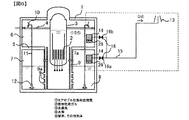
前記目的を達成するために好適な実施例の一つである実施例1の原子炉格納容器ベントシステムを備えた原子力発電プラントについて図1を用いて説明する。図1は原子炉格納容器および原子炉格納容器ベントシステムの第1の実施形態の概略構成を示す縦断面図である。図中破線囲み内が実施例1の原子炉格納容器ベントシステムである。 The nuclear power plant provided with the reactor containment vessel vent system of Example 1, which is one of the preferred examples for achieving the above object, will be described with reference to FIG. FIG. 1 is a vertical cross-sectional view showing a schematic configuration of a first embodiment of a reactor containment vessel and a reactor containment vessel vent system. The inside of the broken line in the figure is the reactor containment vessel vent system of Example 1.
原子炉格納容器ベントシステムの第1の実施形態は、原子炉圧力容器が破損するなどの過酷事故時において、原子炉格納容器内の圧力を減少させ、またその減圧時に放射性物質を極力除去するものである。 The first embodiment of the reactor containment vessel vent system reduces the pressure inside the reactor containment vessel in the event of a severe accident such as damage to the reactor pressure vessel, and removes radioactive substances as much as possible when the pressure is reduced. Is.
図1に示す原子炉格納容器ベントシステムは、改良型沸騰水型原子炉に適用した例であり、以下のようなシステム構成を持っている。原子炉格納容器1内に、炉心2を内包する原子炉圧力容器3が設置されている。原子炉圧力容器3には、原子炉圧力容器3内で発生した蒸気をタービン(図示せず)に送る主蒸気管4が接続されている。
The reactor containment vessel vent system shown in FIG. 1 is an example applied to an improved boiling water reactor, and has the following system configuration. A
原子炉格納容器1内部は、鉄筋コンクリート製のダイヤフラムフロア5によってドライウェル6とウェットウェル7に区画されている。ウェットウェル7は、内部にプール水を貯めている領域のことを言う。このウェットウェル7内のプールのことをサプレッションプール8と呼ぶ。ドライウェル6とウェットウェル7は、ベント管9によって相互に連通されており、ベント管排気部9aは、ウェットウェル7内のサプレッションプール8の水面下に開口している。万が一配管類の一部が損傷し、原子炉格納容器1内に蒸気が放出される配管破断事故(一般的にLOCAの名称で知られ、配管が通るドライウェル6で発生する)が発生した場合、ドライウェル6の圧力が破断口から流出する蒸気により上昇する。その際、ドライウェル6内に放出された蒸気は、ドライウェル6とウェットウェル7の圧力差により、ベント管9を通ってウェットウェル7内のサプレッションプール8水中に導かれる。サプレッションプール8の水で蒸気を凝縮することで原子炉格納容器1内の圧力上昇を抑制する。この際に蒸気内に放射性物質が含まれていた場合、サプレッションプール8水のスクラビング効果により大半の放射性物質が除去される。
The inside of the reactor containment vessel 1 is divided into a
前述したとおり、ドライウェル6で配管破断事故が発生した場合、破断口から流出する蒸気はベント管9を通ってサプレッションプール8で凝縮される。同様に原子炉圧力容器3や主蒸気管4の圧力が高くなった場合も、蒸気をサプレッションプール8に放出し、原子炉圧力容器3や主蒸気管4の圧力を下げる。またそれと共に、放出した蒸気をサプレッションプール8で凝縮することで原子炉格納容器1の圧力上昇を緩和する。そのための装置としてABWRでは、原子炉格納容器1内のドライウェル6の領域に蒸気逃し安全弁10が設置されている。蒸気逃し安全弁10を通して放出された蒸気は、蒸気逃し安全弁排気管11を通って、最終的にクエンチャ12からサプレッションプール8内に放出され、サプレッションプール8のプール水により凝縮される。蒸気をサプレッションプール8で凝縮して液体の水にすることで、蒸気の体積が大幅に減少し、原子炉格納容器1の圧力上昇を抑制することができる。またその際に蒸気に放射性物質が含まれている場合、サプレッションプール8水のスクラビング効果により大半の放射性物質が除去される。
As described above, when a pipe breakage accident occurs in the
サプレッションプール8で蒸気を凝縮し、サプレッションプール8内のプール水を残留熱除去系(図示せず)で冷却することで、原子炉格納容器1の温度上昇と圧力上昇を防止し、事故を収束させることができる。しかし非常に低い可能性ではあるが、残留熱除去系が機能を喪失した場合、サプレッションプール8のプール水の温度が上昇する。プール水の温度が上昇するに伴い、原子炉格納容器1内の蒸気の分圧はプール水の温度の飽和蒸気圧まで上昇するため、原子炉格納容器1の圧力が上昇する。このような圧力上昇が起きた場合、原子炉格納容器1内に冷却水をスプレイすることで圧力上昇を抑えることができる。またこのスプレイは外部から消防ポンプなどを接続して作動させることも可能である。しかし、さらに非常に低い可能性ではあるが、このスプレイも作動しない場合、原子炉格納容器1の圧力は上昇する。このような原子炉格納容器1の圧力上昇が起きた場合、原子炉格納容器1内の気体を外部に放出することで原子炉格納容器1の圧力上昇を抑えることができる。この操作のことをベント操作と呼ぶ。沸騰水型原子炉では、このベント操作をウェットウェル7内の気体を放出することにより行うことで、サプレッションプール8の水で最大限放射性物質を除去した上で、外部へ気体を放出することができる。
By condensing steam in the
上記の操作でほとんどの放射性物質は除去され、放射性物質が除去された放出ガスは排気塔13から放出される。しかし、放射性希ガスは反応性が乏しいため、ウェットウェル7からのベントシステムでは除去できない。そのため現行のベント操作は、この放射性希ガスが減衰するまで待ってから行う必要があるため、原子炉スクラム後から比較的短い時間の間は行うことができない。
Most of the radioactive substances are removed by the above operation, and the exhaust gas from which the radioactive substances have been removed is released from the
そこで実施例1に関わる原子炉格納容器ベントシステムは、原子炉格納容器1の内部に放射性物質分離装置14を設置し、この放射性物質分離装置14で放射性希ガスを閉じ込めると共に、この放射性物質分離装置14に蒸気を透過することができる分離膜を用いることで蒸気を外部に放出し、原子炉格納容器1の圧力を下げることができる。放射性物質分離装置14に接続されたベント配管15は、原子炉格納容器1のドライウェル6とウェットウェル7に位置しており、このベント配管15には隔離弁16が配設されている。隔離弁16は電源が使用せずとも開閉可能な空気作動弁や破裂弁、手動操作可能な弁としても構わない。ベント操作は通常はウェットウェル7側の隔離弁16aを開くことで行う。このベント配管15は、最終的に排気塔13から外部に気体を排出する。なおドライウェル6側の隔離弁16bを開くことでも放射性物質分離装置14で放射性物質が除去され、蒸気を外部に排出することが可能である。
Therefore, in the reactor containment vessel vent system according to the first embodiment, a radioactive
またこの放射性物質分離装置14は、原子炉格納容器1外部やベント配管上のどの位置に置いても放射性希ガスを除去できるが、原子炉格納容器1の内部に置くことで、放射性物質分離装置14の分離膜で除去した放射性希ガスを再度原子炉格納容器1に戻すためのポンプあるいは放射性希ガスを封入する封入容器などが必要なく、よりシンプルな構造となっている。さらに非常に低い可能性ではあるが、万が一原子炉格納容器1に接続されるベント配管15が破断した場合にもベント配管15内部を流れるガスは非放射性物質のみなので作業運転員の被ばくを限りなく低く抑えることができる。このように放射性物質分離装置14を原子炉格納容器1の内部に置くことで、(1)エアロゾル状放射性物質、(2)希ガス、(5)窒素は原子炉格納容器1の内部に留め、(3)水蒸気と(4)水素のみをベント配管15から排気塔13へ放出することができる。このように、原子炉格納容器の内部に配置された、放射性希ガスを透過せず、蒸気を透過する放射性物質分離装置を備えることにより、原子炉圧力容器から原子炉格納容器内に放射性物質を含む気体が流出し、原子炉格納容器が加圧された事態が万一発生した場合においても、放射性希ガスを再度原子炉格納容器1に戻すためにポンプを利用する必要はない。そのため、外部電源を使用せずに原子炉格納容器の加圧を防止すると共に、周辺環境に放射性物質が漏洩することを防止することができる。
Further, the radioactive
また放射性物質分離装置14の構造材として以下がある。放射性物質分離装置14は蒸気を透過する必要がある。また原子炉格納容器1の加圧防止のためには炉心2が溶融した際に発生する可能性のある水素も透過できることが望ましい。透過するべき水蒸気、水素は分子径が0.3nm以下と小さく、透過させない放射性希ガス(主にクリプトンやキセノン)はそれよりもかなり大きい。そこで分子径が小さい蒸気や水素を選択的に透過するには分子ふるいで分離できる膜を利用することが考えられる。沸騰水型原子炉の場合、原子炉格納容器1内の気体は窒素置換されているが、分子サイズを利用して分子ふるいでガスを選択する場合、クリプトンやキセノンと分子サイズの近い窒素は透過しない。このような用途に最適な分離膜として、ポリイミドを主成分とした高分子膜、窒化ケイ素を主成分としたセラミック膜、炭素を主成分とした酸化グラフェン膜等の分子ふるいにより分離が可能な膜の使用が望ましい。これら分離膜は一般的には水素の精製に用いるフィルタに用いられている。またその他、クリプトンやキセノンを透過せず、水素と水蒸気を透過する膜であるならば、それらの使用でも構わない。例えば、窒素精製用に使用されている水素と水蒸気、酸素を透過し、窒素を透過しない窒素分離膜など、水素と水蒸気、酸素、窒素まで透過する分離膜でも構わない。
Further, the structural materials of the radioactive
図11、12、13は放射性物質分離装置14の形状を示した模式図である。分離膜40の形状として、図11に示すように板状、図12、13に示すようにチューブ状、中空糸状がある。図11(板状)の場合、放射性物質分離装置14の内部空間は内部を流れる流体の流れ方向と平行に配置された分離膜40で仕切られており、原子炉格納容器1内の流体は放射性物質分離装置14の底部から流入し、上部へ流れる。また、分離膜40で仕切られた空間のうち一部は閉止板43で塞がれている。そのため、底部から流入した流体のうち、(1)エアロゾル状放射性物質、(2)放射性希ガス、(6)窒素または(5)酸素は分離膜40を透過できないため、閉止板43で塞がれていない部屋の上部から原子炉格納容器1に戻される。一方、(3)水蒸気、(4)水素または(5)酸素は分離膜40を透過して隣接する部屋に入り、底部からベント配管15へ向かう。
FIGS. 11, 12, and 13 are schematic views showing the shape of the radioactive
図12(チューブ状)の場合、放射性物質分離装置14の内部空間は内部を流れる流体の流れ方向と平行に配置されたチューブ状の分離膜40で仕切られており、原子炉格納容器1内の流体はチューブ状の分離膜40の底部から流入し、上部へ流れる。底部から流入した流体のうち、(1)エアロゾル状放射性物質、(2)放射性希ガス、(6)窒素または(5)酸素は分離膜40を透過できないため、分離膜40の上部から原子炉格納容器1に戻される。一方、(3)水蒸気、(4)水素または(5)酸素は分離膜40を透過して1カ所に集められ、ベント配管15へ向かう。
In the case of FIG. 12 (tube shape), the internal space of the radioactive
図13(中空糸状)の場合、放射性物質分離装置14の内部空間は内部を流れる流体の流れ方向に対して中空糸状の分離膜40が垂直に配置されており、原子炉格納容器1内の流体は放射性物質分離装置14の底部から流入し、上部へ流れる。底部から流入した流体のうち、(1)エアロゾル状放射性物質、(2)放射性希ガス、(6)窒素または(5)酸素は分離膜40を透過できないため、放射性物質分離装置14の上部から原子炉格納容器1に戻される。一方、(3)水蒸気、(4)水素または(5)酸素は分離膜40を透過して中空糸の内部に入り、1カ所へ集められてベント配管15へ向かう。
In the case of FIG. 13 (hollow filament), in the internal space of the radioactive
これら形状に問わず分離膜40は上流側空間41と下流側空間42を完全に仕切る構造となっており、放出したいガス量に応じて分離膜40の分量を決定しても構わない。上流側空間41は原子炉格納容器1内の気体に晒されている空間であり、事故時に発生した水蒸気や水素のみを分離膜40を介して下流側空間42へと放出可能である。図11、12、13に示す上流側空間41でのガスは底部から上部への流れであっても上部から底部への流れであっても分離膜40の分離性能に影響することはない。下流側空間42はベント配管15と連結しており、放出した水蒸気や水素を放出する構成となっている。分離膜40は補強板で保持することにより破損の可能性を極めて小さくすることができ、補強板としては金属のメッシュシートやパンチングメタル、多孔質セラミック層などが有効である(図示せず)。
Regardless of these shapes, the
前記目的を達成するために好適な実施例の一つである実施例2の原子炉格納容器ベントシステムについて図2を用いて説明する。図2は原子炉格納容器を含む原子炉格納容器および原子炉格納容器ベントシステムの第2の実施形態の概略構成を示す縦断面図である。図中破線囲み内が実施例2の原子炉格納容器ベントシステムである。実施例2においても、放射性物質分離装置14の配置構成は実施例1と同様であり、ここでは実施例1との違いのみを説明する。
The reactor containment vessel vent system of Example 2, which is one of the preferred examples for achieving the above object, will be described with reference to FIG. FIG. 2 is a vertical cross-sectional view showing a schematic configuration of a second embodiment of a reactor containment vessel including a reactor containment vessel and a reactor containment vessel vent system. The inside of the broken line in the figure is the reactor containment vessel vent system of the second embodiment. Also in the second embodiment, the arrangement configuration of the radioactive
実施例2においては万が一に放射性物質分離装置14内部の分離膜40が破損した時のために放射性物質分離装置14の下流に一般的なフィルタベント装置17を備えた例である。ベント配管15は、原子炉格納容器1のドライウェル6とウェットウェル7に接続されており、このベント配管15には隔離弁16が配設されている。このベント配管15は、フィルタベント装置17の入口配管18に接続されている。この入口配管18の先端側は、フィルタベント装置17内に開口する。フィルタベント装置17内の下部側には、スクラビング用プール水19が貯留されている。フィルタベント装置17の上部側には金網状の金属フィルタ20およびよう素フィルタ21が設置されている。このよう素フィルタ21には、フィルタベント装置17の出口配管22の一端が接続されている。出口配管22の他端は遮蔽壁23を貫通して遮蔽壁23外部に導出されている。そして最終的に排気塔13から外部に気体を排出する。
In the second embodiment, a general
放射性物質分離装置14内部の分離膜40が破損していない場合には主にこのフィルタベント装置17はスクラビング用プール水19で原子炉格納容器1から放出された蒸気を凝縮する機能として使用される。万が一に分離膜40が破損した場合にはフィルタベント装置17に入った放出ガスは、スクラビング用プール水19でスクラビングされることで、主に粒子状の放射性物質のほとんどが除去される。さらに金属フィルタ20によりスクラビングで除去しきれなかった粒子状の放射性物質を除去し、よう素フィルタ21によりヨウ素などの気体状の放射性物質を除去することができる。これにより環境に放射性物質が放出されるリスクを低減し、原子炉格納容器ベントシステムの信頼性を向上させることができる。
When the
前記目的を達成するために好適な実施例の一つである実施例3の原子炉格納容器ベントシステムについて図3を用いて説明する。図3は原子炉格納容器を含む原子炉格納容器および原子炉格納容器ベントシステムの第3の実施形態の概略構成を示す縦断面図である。図中破線囲み内が実施例3の原子炉格納容器ベントシステムである。実施例3においても、フィルタベント装置17の構成のみを実施例2から変更しており、その違いのみを説明する。
The reactor containment vessel vent system of Example 3, which is one of the preferred examples for achieving the above object, will be described with reference to FIG. FIG. 3 is a vertical cross-sectional view showing a schematic configuration of a third embodiment of a reactor containment vessel including a reactor containment vessel and a reactor containment vessel vent system. The inside of the broken line in the figure is the reactor containment vessel vent system of Example 3. Also in the third embodiment, only the configuration of the
フィルタベント装置17は一般に湿式と乾式のフィルタベント装置があり、実施例2のように容器内のスクラビング用プール水19で粒子を除去するものが湿式のベント装置である。一方で実施例3のフィルタベント装置17は、上部に邪魔板25を備え、フィルタベント装置17の中に放射性物質除去用の砂フィルタ24を敷き詰め、その砂フィルタにより放射性物質を除去するフィルタベント装置である。これは乾式のベント装置であり、湿式と比較してスクラビング用プール水19の水質の管理などは必要ないが、事故時にこの装置を加熱する必要がある。このフィルタベント装置17でも放射性希ガスは除去できないため、本発明の放射性物質分離装置14が必要であり、それらの構成は実施例2と同様である。
The
前記目的を達成するために好適な実施例の一つである実施例3の原子炉格納容器ベントシステムについて図4を用いて説明する。図4は原子炉格納容器を含む原子炉格納容器および原子炉格納容器ベントシステムの第4の実施形態の概略構成を示す縦断面図である。図中破線囲み内が実施例4の原子炉格納容器ベントシステムである。実施例4においても、実施例2、3を基に変更しており、その違いのみを説明する。 The reactor containment vessel vent system of Example 3, which is one of the preferred examples for achieving the above object, will be described with reference to FIG. FIG. 4 is a vertical cross-sectional view showing a schematic configuration of a fourth embodiment of a reactor containment vessel including a reactor containment vessel and a reactor containment vessel vent system. The inside of the broken line in the figure is the reactor containment vessel vent system of Example 4. Also in the fourth embodiment, the changes are made based on the second and third embodiments, and only the difference will be described.
実施例4は、実施例2、3の原子炉格納容器フィルタベントシステムに放射性物質分離装置14をパイパスし、放射性物質分離装置14下流部に接続するバイパス管26を設置する。さらにそのバイパス管26の上流部に、ある一定以上の圧力を超えると仕切り板が破れることで弁が開くラプチャディスク27を設置することで、万が一に放射性物質分離装置14内部の分離膜40が目詰まりを起こし、原子炉格納容器1の圧力が上昇した場合、このラプチャディスク27が開くことで原子炉格納容器1を減圧できる構造とする。なおこのラプチャディスク27は、爆破弁やその他のバルブでも構わない。また放射性物質分離装置14自体がある一定圧力以上で破れる構造とすることで、この機能を代替しても構わない。
In the fourth embodiment, the radioactive
前記目的を達成するために好適な実施例の一つである実施例5の原子炉格納容器ベントシステムについて図5を用いて説明する。図5は原子炉格納容器を含む原子炉格納容器および原子炉格納容器ベントシステムの第5の実施形態の概略構成を示す縦断面図である。図中破線囲み内が実施例5の原子炉格納容器ベントシステムである。実施例5においても、放射性物質分離装置14の配置構成は実施例1と同様であり、ここでは実施例1との違いのみを説明する。
The reactor containment vessel vent system of Example 5, which is one of the preferred examples for achieving the above object, will be described with reference to FIG. FIG. 5 is a vertical cross-sectional view showing a schematic configuration of a fifth embodiment of a reactor containment vessel including a reactor containment vessel and a reactor containment vessel vent system. The inside of the broken line in the figure is the reactor containment vessel vent system of Example 5. Also in the fifth embodiment, the arrangement configuration of the radioactive
原子炉格納容器1内の気体は粒子状の放射性物質を含む。放射性物質分離装置14の入口部に粒子捕集装置28を設置し、極力大きな粒子を捕集する体系とする。この機構により、粒子の分離膜40への吸着による目詰まりを防止することができ、かつ強い放射線に晒されることによる分離膜40の劣化を防止することができる。粒子捕集装置28には繊維状の金属フィルタやヘパフィルターまたは吸着材などが有効である。
The gas in the reactor containment vessel 1 contains particulate radioactive material. A
前記目的を達成するために好適な実施例の一つである実施例6の原子炉格納容器ベントシステムについて図6を用いて説明する。図6は原子炉格納容器を含む原子炉格納容器および原子炉格納容器ベントシステムの第6の実施形態の概略構成を示す縦断面図である。図中破線囲み内が実施例6の原子炉格納容器ベントシステムである。実施例6においても、放射性物質分離装置14の配置構成は実施例1と同様であり、ここでは実施例1との違いのみを説明する。
The reactor containment vessel vent system of Example 6, which is one of the preferred examples for achieving the above object, will be described with reference to FIG. FIG. 6 is a vertical cross-sectional view showing a schematic configuration of a sixth embodiment of a reactor containment vessel including a reactor containment vessel and a reactor containment vessel vent system. The inside of the broken line in the figure is the reactor containment vessel vent system of Example 6. Also in the sixth embodiment, the arrangement configuration of the radioactive
原子炉格納容器1内の気体はガス状のよう素を含む。放射性物質分離装置14の入口部によう素捕集装置29を設置し、極力ガス状よう素を捕集する体系とする。この機構により、極めて反応性の高いガス状よう素が分離膜40への物理吸着および化学吸着により、分離膜40の劣化を防止することができる。よう素捕集装置29には銀が添着されたゼオライトや銀シリカゲル、銀アルミナ、KI3添着炭などが有効である。
The gas in the reactor containment vessel 1 contains gaseous iodine. An
前記目的を達成するために好適な実施例の一つである実施例6の原子炉格納容器ベントシステムについて図7を用いて説明する。図7は原子炉格納容器を含む原子炉格納容器および原子炉格納容器ベントシステムの第7の実施形態の概略構成を示す縦断面図である。図中破線囲み内が実施例7の原子炉格納容器ベントシステムである。実施例7においても、放射性物質分離装置14の配置構成は実施例1と同様であり、ここでは実施例1との違いのみを説明する。
The reactor containment vessel vent system of Example 6, which is one of the preferred examples for achieving the above object, will be described with reference to FIG. FIG. 7 is a vertical cross-sectional view showing a schematic configuration of a seventh embodiment of a reactor containment vessel including a reactor containment vessel and a reactor containment vessel vent system. The inside of the broken line in the figure is the reactor containment vessel vent system of Example 7. Also in the seventh embodiment, the arrangement configuration of the radioactive
原子炉格納容器1内の気体は窒素置換されているが、事故時には水の放射線分解により3%以下の酸素が存在している。放射性物質分離装置14の入口部に水素再結合装置30を設置し、原子炉格納容器1内の水素と酸素を結合し水にすることで発熱反応を生じる。この発熱反応により加熱されたガスが放射性物質分離装置14内部を通過することで分離膜40の温度を高く維持することができる。分離膜は一般に温度が高いほどガスの拡散速度が向上し分離速度が向上する。この機構により、分離膜によるガス放出速度を高く維持することができ、より迅速に原子炉格納容器1の減圧を可能とする。また、加熱による副次的効果として、分離膜40の上流側空間41内部で上昇気流を生じ、そのため分離膜40近辺での放射性希ガスなどの不純物の滞留を防止することができる。
The gas in the reactor containment vessel 1 is replaced with nitrogen, but at the time of the accident, 3% or less of oxygen is present due to the radiolysis of water. A
水素再結合装置30は上記のようにガスを加熱することにより分離膜40の温度を直接高めることも可能であり、放射性物質分離装置14の外周に水素再結合装置30を設置することで放射性物質分離装置14自体の温度を高め分離膜40を加熱することもできる。水素再結合装置30には酸化セリウムおよび酸化ジルコニウムなどの混合酸化物で構成された担体にパラジウムや白金を添着している触媒であること。またはリチウム、ナトリウム、マグネシウム、カルシウム、鉄、ニッケル、銅、ストロンチウム、銀、セリウムなどの金属を含む金属酸化物触媒などが有効である。
The
また、加圧水型原子炉では原子炉格納容器1内部に水素処理対策としてイグナイタが設置されているが、このイグナイタを放射性物質分離装置14の入口部または外周に設置することで水素再結合による反応熱を利用し分離膜40の加熱が可能である。
Further, in a pressurized water reactor, an igniter is installed inside the reactor containment vessel 1 as a measure against hydrogen treatment. By installing this igniter at the inlet or the outer periphery of the radioactive
前記目的を達成するために好適な実施例の一つである実施例8の原子炉格納容器ベントシステムについて図8を用いて説明する。図8は原子炉格納容器を含む原子炉格納容器および原子炉格納容器ベントシステムの第8の実施形態の概略構成を示す縦断面図である。図中破線囲み内が実施例8の原子炉格納容器ベントシステムである。実施例8においても、放射性物質分離装置14の配置構成は実施例1と同様であり、ここでは実施例1との違いのみを説明する。
The reactor containment vessel vent system of Example 8, which is one of the preferred examples for achieving the above object, will be described with reference to FIG. FIG. 8 is a vertical cross-sectional view showing a schematic configuration of an eighth embodiment of a reactor containment vessel including a reactor containment vessel and a reactor containment vessel vent system. The inside of the broken line in the figure is the reactor containment vessel vent system of Example 8. Also in the eighth embodiment, the arrangement configuration of the radioactive
放射性物質分離装置14では水蒸気や水素を選択的に分離しベント配管15へ放出することができる。放射性物質分離装置14の出口底部にチムニー31を設置することにより、放射性物質分離装置14の上流側空間41では水蒸気や水素濃度が減少し原子炉格納容器1の主成分である窒素または酸素濃度が上昇する。窒素または酸素濃度が上昇したことによる流体密度差が下降気流を生じる駆動力となり、そのため分離膜40近辺での放射性希ガスなどの不純物の滞留を防止することができる。
The radioactive
前記目的を達成するために好適な実施例の一つである実施例9の原子炉格納容器ベントシステムについて図9を用いて説明する。図9は原子炉格納容器を含む原子炉格納容器および原子炉格納容器ベントシステムの第9の実施形態の概略構成を示す縦断面図である。図中破線囲み内が実施例9の原子炉格納容器ベントシステムである。 The reactor containment vessel vent system of Example 9, which is one of the preferred examples for achieving the above object, will be described with reference to FIG. FIG. 9 is a vertical cross-sectional view showing a schematic configuration of a ninth embodiment of a reactor containment vessel including a reactor containment vessel and a reactor containment vessel vent system. The inside of the broken line in the figure is the reactor containment vessel vent system of Example 9.
実施例9は、実施例1の原子炉格納容器フィルタベントシステムを加圧水型原子炉に適用した例である。一次系の冷却水は、原子炉圧力容器内の加圧器32により加圧され、再循環ポンプ34によって循環され、蒸気発生器33(一次側)に輸送される。蒸気発生器33内では伝熱管によって熱交換され、一次側から二次側に熱輸送されて蒸気が発生し、蒸気は主蒸気管4を流れる。
Example 9 is an example in which the reactor containment filter vent system of Example 1 is applied to a pressurized water reactor. The cooling water of the primary system is pressurized by the pressurizer 32 in the reactor pressure vessel, circulated by the
加圧水型原子炉は原子炉格納容器1の圧力上昇を抑えるためのウェットウェル7とサプレッションプール8を持たないため、サプレッションプール8によるスクラビングを用いた放射性物質の除去は期待できない。従って、ドライウェル6の隔離弁16を開くことで、放射性物質分離装置14で放射性物質が除去され、蒸気を外部に排出する構成となっている。ウェットウェル7側からのベントがない以外は実施例1と同様である。なお実施例2〜8のように湿式のフィルタベント装置17、乾式のフィルタベント装置17、ラプチャディスク27、粒子捕集装置28、よう素捕集装置29、水素再結合装置30、チムニー31を用いても構わない。
Since the pressurized water reactor does not have a
前記目的を達成するために好適な実施例の一つである実施例10の原子炉格納容器ベントシステムについて図10を用いて説明する。図10は原子炉格納容器を含む原子炉格納容器および原子炉格納容器ベントシステムの第10の実施形態の概略構成を示す縦断面図である。図中破線囲み内が実施例10の原子炉格納容器ベントシステムである。 The reactor containment vessel vent system of Example 10, which is one of the preferred examples for achieving the above object, will be described with reference to FIG. FIG. 10 is a vertical cross-sectional view showing a schematic configuration of a tenth embodiment of a reactor containment vessel including a reactor containment vessel and a reactor containment vessel vent system. The inside of the broken line in the figure is the reactor containment vessel vent system of Example 10.
実施例10は、原子炉格納容器として一次原子炉格納容器35を内包する二次原子炉格納容器36を持つ。二次原子炉格納容器36は、一次原子炉格納容器35内部のドライウェル6とウェットウェル7にベント配管15および隔離弁16を介して連通している。一次原子炉格納容器35からベントされた気体は一次原子炉格納容器35内部に設置された放射性物質分離装置14を介してベント配管15に流入し、二次原子炉格納容器36内部に放出される。放射性物質分離装置14により二次原子炉格納容器36への放射性物質の移行を防止することができる。また外部ではなく二次原子炉格納容器36内部に気体を放出することで、万が一に放射性物質分離装置14内部の分離膜40が破れ、放射性物質がベント配管15を通して放出されるようになったとしても、二次原子炉格納容器36内部に放射性物質を閉じ込めることができる。また、水素再結合装置30を水素濃度の高いベント配管15の出口付近に設置することで、効率の良い水素処理を行うことができる。その他の構成に関しては実施例1と同様である。放射性物質分離装置14を二次原子炉格納容器36内部に備え、放射性物質分離装置14がベント配管15を介して二次原子炉格納容器36外部に排気塔13を設置した構成としても構わない。実施例2、3のフィルタベント装置17を二次原子炉格納容器36内部に備え、出口配管22を排気塔13の代わりに二次原子炉格納容器36内部に連通した構成としても構わない。またフィルタベント装置17を二次原子炉格納容器36外部に設置し、二次原子炉格納容器36からさらにこのフィルタベント装置17を通して外部にベントできる構成としてもよい。実施例5、6、8のように粒子捕集装置28、よう素捕集装置29、チムニー31を用いても構わない。また加圧水型原子炉やその他の炉型に適用してもよい。
Example 10 has a secondary
1…原子炉格納容器、2…炉心、3…原子炉圧力容器、4…主蒸気管、5…ダイヤフラムフロア、6…ドライウェル、7…ウェットウェル、7a…ウェットウェル気相部、8…サプレッションプール、9…ベント管、9a…ベント管排気部、10…蒸気逃し安全弁、11…蒸気逃し安全弁排気管、12…クエンチャ、13…排気塔、14…放射性物質分離装置、15…ベント配管、16…隔離弁、16a…ウェットウェル側隔離弁、16b…ドライウェル側隔離弁、17…フィルタベント装置、18…入口配管、19…スクラビング用プール水、20…金属フィルタ、21…よう素フィルタ、22…出口配管、23…遮蔽壁、24…放射性物質除去用の砂フィルタ、25…邪魔板、26…バイパス管、27…ラプチャディスク、28…粒子捕集装置、29…よう素捕集装置、30…水素再結合装置、31…チムニー、32…加圧器、33…蒸気発生器、34…再循環ポンプ、35…一次原子炉格納容器、36…二次原子炉格納容器、40…分離膜、41…上流側空間、42…下流側空間、43…閉止板 1 ... Reactor containment vessel, 2 ... Reactor core, 3 ... Reactor pressure vessel, 4 ... Main steam pipe, 5 ... Diaphragm floor, 6 ... Dry well, 7 ... Wet well, 7a ... Wet well vapor phase part, 8 ... Suppression Pool, 9 ... Vent pipe, 9a ... Vent pipe exhaust section, 10 ... Steam escape safety valve, 11 ... Steam escape safety valve exhaust pipe, 12 ... Quencher, 13 ... Exhaust tower, 14 ... Radioactive material separator, 15 ... Vent pipe, 16 ... Isolation valve, 16a ... Wet well side isolation valve, 16b ... Drywell side isolation valve, 17 ... Filter venting device, 18 ... Inlet piping, 19 ... Scrubbing pool water, 20 ... Metal filter, 21 ... Isolite filter, 22 ... outlet piping, 23 ... shielding wall, 24 ... sand filter for removing radioactive substances, 25 ... obstruction plate, 26 ... bypass pipe, 27 ... rupture disc, 28 ... particle collecting device, 29 ... iodine collecting device, 30 ... Hydrogen recombination device, 31 ... Chimney, 32 ... Pressurizer, 33 ... Steam generator, 34 ... Recirculation pump, 35 ... Primary reactor containment vessel, 36 ... Secondary reactor containment vessel, 40 ... Separation membrane, 41 … Upstream space, 42… Downstream space, 43… Closure plate
Claims (18)
前記原子炉格納容器の内部に配置された、放射性希ガスを透過せず、水蒸気を透過する分離膜を備えた放射性物質分離装置と、
前記原子炉格納容器の外部に配置された、気体を排出する排気塔と、
前記放射性物質分離装置と前記排気塔を接続するベント配管と、
前記ベント配管に設けられた隔離弁と、を備え、
ベント操作時には、前記隔離弁を開くことにより、前記放射性物質分離装置により放射性希ガスが除去された気体を前記ベント配管を経由して前記排気塔から排出し、前記放射性物質分離装置に流入し前記分離膜を透過しなかった放射性希ガスを前記原子炉格納容器に戻す
ことを特徴とする原子力発電プラント。 Reactor containment vessel containing reactor pressure vessel and
A radioactive material separation device provided inside the reactor containment vessel, which is provided with a separation membrane that does not allow radioactive noble gases to permeate but allows water vapor to permeate.
An exhaust tower that discharges gas and is located outside the reactor containment vessel.
A vent pipe connecting the radioactive material separation device and the exhaust tower,
The isolation valve provided in the vent pipe is provided.
At the time of the vent operation, by opening the isolation valve, the gas from which the radioactive noble gas has been removed by the radioactive substance separation device is discharged from the exhaust tower via the vent pipe and flows into the radioactive substance separation device. A nuclear power plant characterized in that radioactive noble gas that has not penetrated the separation membrane is returned to the reactor containment vessel.
前記放射性物質分離装置と前記排気塔の間に、湿式または乾式のフィルタベント装置を備えることを特徴とする原子力発電プラント。 In the nuclear power plant according to claim 1,
A nuclear power plant comprising a wet or dry filter vent device between the radioactive material separation device and the exhaust tower.
前記原子炉格納容器の内部の気体を前記放射性物質分離装置を経由せずに前記フィルタベント装置へ送るバイパス管を備えたことを特徴とする原子力発電プラント。 In the nuclear power plant according to claim 2.
A nuclear power plant comprising a bypass pipe for sending a gas inside the reactor containment vessel to the filter vent device without passing through the radioactive material separation device.
前記バイパス管の上流部に、圧力が一定以上になると過剰圧力を開放するラプチャディスクを備えることを特徴とする原子力発電プラント。 In the nuclear power plant according to claim 3,
A nuclear power plant characterized in that a rupture disk that releases excess pressure when the pressure exceeds a certain level is provided in an upstream portion of the bypass pipe.
前記放射性物質分離装置の入口部に、粒子捕集装置を備えたことを特徴とする原子力発電プラント。 In the nuclear power plant according to claim 1,
A nuclear power plant characterized in that a particle collecting device is provided at the inlet of the radioactive material separating device.
前記放射性物質分離装置の入口部に、よう素捕集装置を備えたことを特徴とする原子力発電プラント。 In the nuclear power plant according to claim 1,
A nuclear power plant characterized in that an iodine collecting device is provided at the inlet of the radioactive material separating device.
前記放射性物質分離装置の入口部に、水素再結合装置を備えたことを特徴とする原子力発電プラント。 In the nuclear power plant according to claim 1,
A nuclear power plant characterized in that a hydrogen recombination device is provided at the inlet of the radioactive material separation device.
前記放射性物質分離装置の出口部に、チムニーを備えたことを特徴とする原子力発電プラント。 In the nuclear power plant according to claim 1,
A nuclear power plant characterized in that a chimney is provided at the outlet of the radioactive material separator.
前記放射性物質分離装置が、放射性希ガスと窒素を透過せず、水素と水蒸気を透過することを特徴とする原子力発電プラント。 In the nuclear power plant according to claim 1,
A nuclear power plant characterized in that the radioactive substance separator does not permeate radioactive noble gas and nitrogen, but permeates hydrogen and water vapor.
前記放射性物質分離装置の分離膜が高分子膜、セラミック膜及び酸化グラフェン膜のいずれかであることを特徴とする原子力発電プラント。 In the nuclear power plant according to claim 1,
A nuclear power plant characterized in that the separation membrane of the radioactive substance separation device is any of a polymer membrane, a ceramic membrane, and a graphene oxide membrane.
前記放射性物質分離装置の分離膜がポリイミドを主成分とした高分子膜であることを特徴とする原子力発電プラント。 In the nuclear power plant according to claim 1,
A nuclear power plant characterized in that the separation membrane of the radioactive material separation device is a polymer membrane containing polyimide as a main component.
前記放射性物質分離装置の分離膜が窒化ケイ素を主成分としたセラミック膜であることを特徴とする原子力発電プラント。 In the nuclear power plant according to claim 1,
A nuclear power plant characterized in that the separation membrane of the radioactive material separation device is a ceramic membrane containing silicon nitride as a main component.
前記放射性物質分離装置の分離膜が炭素を主成分とした酸化グラフェン膜であることを特徴とする原子力発電プラント。 In the nuclear power plant according to claim 1,
A nuclear power plant characterized in that the separation membrane of the radioactive material separation device is a graphene oxide film containing carbon as a main component.
前記原子炉圧力容器で発生した蒸気はタービンに供給される沸騰水型原子炉であることを特徴とする原子力発電プラント。 In the nuclear power plant according to claim 1,
A nuclear power plant characterized in that the steam generated in the reactor pressure vessel is a boiling water reactor supplied to a turbine.
前記原子炉圧力容器で発生した蒸気は蒸気発生器に供給される加圧水型原子炉であることを特徴とする原子力発電プラント。 In the nuclear power plant according to claim 1,
A nuclear power plant characterized in that the steam generated in the reactor pressure vessel is a pressurized water reactor supplied to a steam generator.
前記放射性物質分離装置の内部空間は、内部を流れる流体の流れ方向と平行に配置された前記分離膜で仕切られ、
前記分離膜で仕切られた前記放射性物質分離装置の内部空間の一部は、閉止板で塞がれ、
前記放射性物質分離装置の底部から流入し、前記分離膜を透過しない流体は、前記閉止板で塞がれていない部屋の上部から前記原子炉格納容器に戻され、
前記放射性物質分離装置の底部から流入し、前記分離膜を透過した流体は、隣接する部屋を経由してベント配管に向かうことを特徴とする原子力発電プラント。 In the nuclear power plant according to claim 1 ,
The inner space of the pre-Symbol radioactive substance separating device is partitioned by the separation membrane, which is arranged parallel to the flow direction of the fluid flowing through the inside,
A part of the internal space of the radioactive material separation device partitioned by the separation membrane is closed with a closing plate.
The fluid that flows in from the bottom of the radioactive material separation device and does not permeate the separation membrane is returned to the reactor containment vessel from the upper part of the room not blocked by the closing plate.
A nuclear power plant characterized in that a fluid that flows in from the bottom of the radioactive material separation device and permeates the separation membrane goes to a vent pipe via an adjacent room.
前記分離膜は、チューブ状であり、
前記放射性物質分離装置の内部空間は、内部を流れる流体の流れ方向と平行に配置された前記分離膜で仕切られ、
前記放射性物質分離装置の底部から流入し、前記分離膜を透過しない流体は、前記分離膜の上部から前記原子炉格納容器に戻され、
前記放射性物質分離装置の底部から流入し、前記分離膜を透過した流体は、ベント配管に向かうことを特徴とする原子力発電プラント。 In the nuclear power plant according to claim 1,
The separation membrane is tubular,
The internal space of the radioactive material separation device is partitioned by the separation membrane arranged in parallel with the flow direction of the fluid flowing inside.
The fluid that flows in from the bottom of the radioactive material separation device and does not permeate the separation membrane is returned to the reactor containment vessel from the top of the separation membrane.
A nuclear power plant characterized in that a fluid that flows in from the bottom of the radioactive material separation device and permeates the separation membrane goes to a vent pipe.
前記分離膜は、中空糸状であり、
前記放射性物質分離装置の内部空間は、内部を流れる流体の流れ方向と垂直に配置された前記分離膜で仕切られ、
前記放射性物質分離装置の底部から流入し、前記分離膜を透過しない流体は、前記分離膜の上部から前記原子炉格納容器に戻され、
前記放射性物質分離装置の底部から流入し、前記分離膜を透過した流体は、ベント配管に向かうことを特徴とする原子力発電プラント。 In the nuclear power plant according to claim 1,
The separation membrane is a hollow fiber,
The internal space of the radioactive material separation device is partitioned by the separation membrane arranged perpendicular to the flow direction of the fluid flowing inside.
The fluid that flows in from the bottom of the radioactive material separation device and does not permeate the separation membrane is returned to the reactor containment vessel from the top of the separation membrane.
A nuclear power plant characterized in that a fluid that flows in from the bottom of the radioactive material separation device and permeates the separation membrane goes to a vent pipe.
Priority Applications (3)
| Application Number | Priority Date | Filing Date | Title |
|---|---|---|---|
| JP2017009920A JP6876447B2 (en) | 2017-01-24 | 2017-01-24 | Nuclear power plant |
| US16/479,989 US11515051B2 (en) | 2017-01-24 | 2018-01-12 | Nuclear power plant |
| PCT/JP2018/000564 WO2018139208A1 (en) | 2017-01-24 | 2018-01-12 | Nuclear power plant |
Applications Claiming Priority (1)
| Application Number | Priority Date | Filing Date | Title |
|---|---|---|---|
| JP2017009920A JP6876447B2 (en) | 2017-01-24 | 2017-01-24 | Nuclear power plant |
Publications (3)
| Publication Number | Publication Date |
|---|---|
| JP2018119821A JP2018119821A (en) | 2018-08-02 |
| JP2018119821A5 JP2018119821A5 (en) | 2019-10-03 |
| JP6876447B2 true JP6876447B2 (en) | 2021-05-26 |
Family
ID=62979015
Family Applications (1)
| Application Number | Title | Priority Date | Filing Date |
|---|---|---|---|
| JP2017009920A Active JP6876447B2 (en) | 2017-01-24 | 2017-01-24 | Nuclear power plant |
Country Status (3)
| Country | Link |
|---|---|
| US (1) | US11515051B2 (en) |
| JP (1) | JP6876447B2 (en) |
| WO (1) | WO2018139208A1 (en) |
Families Citing this family (11)
| Publication number | Priority date | Publication date | Assignee | Title |
|---|---|---|---|---|
| US11232874B2 (en) * | 2017-12-18 | 2022-01-25 | Ge-Hitachi Nuclear Energy Americas Llc | Multiple-path flow restrictor nozzle |
| JP7082016B2 (en) * | 2018-09-13 | 2022-06-07 | 日立Geニュークリア・エナジー株式会社 | Ventilation and air conditioning system of nuclear plant |
| JP2020046226A (en) * | 2018-09-14 | 2020-03-26 | 三菱重工業株式会社 | Nuclear power plant |
| JP7045966B2 (en) * | 2018-09-20 | 2022-04-01 | 日立Geニュークリア・エナジー株式会社 | Nuclear plant and its operation method |
| KR102097215B1 (en) * | 2018-11-02 | 2020-04-03 | 한국과학기술원 | Nuclear power plant system comprising particle bed with silica gel particles |
| JP2020094979A (en) * | 2018-12-14 | 2020-06-18 | 日立Geニュークリア・エナジー株式会社 | Organic iodine collection apparatus and organic iodine collection method |
| JP7285201B2 (en) * | 2019-11-26 | 2023-06-01 | 日立Geニュークリア・エナジー株式会社 | Hydrogen treatment system |
| JP7417484B2 (en) * | 2020-07-07 | 2024-01-18 | 日立Geニュークリア・エナジー株式会社 | Radioactive noble gas removal filters, filter units and reactor containment vent systems |
| JP7261776B2 (en) * | 2020-09-18 | 2023-04-20 | 日立Geニュークリア・エナジー株式会社 | Reactor containment venting system |
| JP7457617B2 (en) | 2020-09-25 | 2024-03-28 | 日立Geニュークリア・エナジー株式会社 | Reactor containment vent systems and nuclear power plants |
| JP7417508B2 (en) | 2020-11-20 | 2024-01-18 | 日立Geニュークリア・エナジー株式会社 | Reactor containment vessel venting method |
Family Cites Families (16)
| Publication number | Priority date | Publication date | Assignee | Title |
|---|---|---|---|---|
| US6854602B2 (en) * | 2002-06-04 | 2005-02-15 | Conocophillips Company | Hydrogen-selective silica-based membrane |
| US20070151447A1 (en) * | 2005-12-30 | 2007-07-05 | Membrane Technology And Research, Inc. | Gas separation membranes and processes for controlled environmental management |
| US8431508B2 (en) * | 2007-10-30 | 2013-04-30 | Cerahelix, Inc. | Inorganic structure for molecular separations |
| JP5686527B2 (en) * | 2010-04-26 | 2015-03-18 | 大陽日酸株式会社 | Recovery method of residual gas |
| CN102858431B (en) | 2010-04-26 | 2014-10-22 | 大阳日酸株式会社 | Method for operating gas separation device |
| DE102010035509A1 (en) * | 2010-08-25 | 2012-03-01 | Areva Np Gmbh | Process for pressure relief of a nuclear power plant, pressure relief system for a nuclear power plant and associated nuclear power plant |
| FR2985595A1 (en) * | 2012-01-10 | 2013-07-12 | Alstom Technology Ltd | PROCESS FOR FILTRATION OF HARMFUL GASEOUS EFFLUENTS OF A NUCLEAR POWER PLANT |
| US9527043B2 (en) * | 2012-05-17 | 2016-12-27 | Samsung Electronics Co., Ltd. | Gas separation membrane and method of preparing the same |
| DE102012211897B3 (en) * | 2012-07-09 | 2013-06-06 | Areva Np Gmbh | Nuclear plant e.g. boiling-water reactor type nuclear power plant, for producing current, has flow channel, where mixture flows into channel according to forced flow principle, and disperses above discharge line as pressure discharge flow |
| JP2014020997A (en) * | 2012-07-20 | 2014-02-03 | Toshiba Corp | Hydrogen remover and hydrogen removing method for reactor containment vessel |
| JP5898018B2 (en) | 2012-08-27 | 2016-04-06 | 日立Geニュークリア・エナジー株式会社 | Containment Vessel Filter Vent Device and Reactor Containment Vessel |
| DE102013205525A1 (en) * | 2013-03-27 | 2014-10-02 | Areva Gmbh | Venting system for the containment of a nuclear facility |
| CN105960276A (en) | 2013-12-10 | 2016-09-21 | 南卡罗来纳大学 | Ultrathin, graphene-based membranes for water treatment and methods of their formation and use |
| SE1451118A1 (en) * | 2014-09-22 | 2016-03-23 | Westinghouse Electric Sweden | A method for cleaning contaminated gas |
| US10937555B2 (en) * | 2014-12-19 | 2021-03-02 | Caverion Deutschland GmbH | Nuclear power plant |
| JP6284889B2 (en) * | 2015-01-07 | 2018-02-28 | 日立Geニュークリア・エナジー株式会社 | Radioactive substance removal filter device |
-
2017
- 2017-01-24 JP JP2017009920A patent/JP6876447B2/en active Active
-
2018
- 2018-01-12 US US16/479,989 patent/US11515051B2/en active Active
- 2018-01-12 WO PCT/JP2018/000564 patent/WO2018139208A1/en active Application Filing
Also Published As
| Publication number | Publication date |
|---|---|
| JP2018119821A (en) | 2018-08-02 |
| WO2018139208A1 (en) | 2018-08-02 |
| US11515051B2 (en) | 2022-11-29 |
| US20190371481A1 (en) | 2019-12-05 |
Similar Documents
| Publication | Publication Date | Title |
|---|---|---|
| JP6876447B2 (en) | Nuclear power plant | |
| JP6798912B2 (en) | Reactor containment vent system | |
| JP6288781B2 (en) | Filter for reactor containment ventilation system | |
| JP7133691B2 (en) | Reactor containment venting system | |
| CN103890858B (en) | Trap the equipment of the fuel gas produced by the radiolysis in confined space or pyrolysis | |
| JP6754719B2 (en) | Reactor containment vent system | |
| JP7057852B2 (en) | Static reactor containment heat removal system and nuclear plant | |
| JP2018169252A (en) | Storage container maintenance facility and method for maintaining storage container | |
| WO2020121714A1 (en) | Organic iodine collection device and organic iodine collection method | |
| JP4073065B2 (en) | Reactor containment hydrogen removal equipment | |
| JP7348814B2 (en) | nuclear power plant | |
| JP6284889B2 (en) | Radioactive substance removal filter device | |
| JP7121669B2 (en) | Gaseous waste treatment facility and gaseous waste treatment method | |
| JP7331030B2 (en) | Reactor containment venting system | |
| JP7457617B2 (en) | Reactor containment vent systems and nuclear power plants | |
| JPH09197085A (en) | Method and device for ventilating nuclea reactor containment vessel | |
| JP7285201B2 (en) | Hydrogen treatment system | |
| JP3726689B2 (en) | Hydrogen treatment facility and hydrogen treatment method | |
| JP2022082008A (en) | Reactor containment vessel vent method | |
| JP2022051390A (en) | Reactor container vent system | |
| JP2015059884A (en) | Emergency exhaust system |
Legal Events
| Date | Code | Title | Description |
|---|---|---|---|
| A521 | Request for written amendment filed |
Free format text: JAPANESE INTERMEDIATE CODE: A523 Effective date: 20170125 |
|
| A521 | Request for written amendment filed |
Free format text: JAPANESE INTERMEDIATE CODE: A523 Effective date: 20190821 |
|
| A621 | Written request for application examination |
Free format text: JAPANESE INTERMEDIATE CODE: A621 Effective date: 20190821 |
|
| A521 | Request for written amendment filed |
Free format text: JAPANESE INTERMEDIATE CODE: A523 Effective date: 20190821 |
|
| A131 | Notification of reasons for refusal |
Free format text: JAPANESE INTERMEDIATE CODE: A131 Effective date: 20200721 |
|
| A521 | Request for written amendment filed |
Free format text: JAPANESE INTERMEDIATE CODE: A523 Effective date: 20200915 |
|
| A02 | Decision of refusal |
Free format text: JAPANESE INTERMEDIATE CODE: A02 Effective date: 20201215 |
|
| RD02 | Notification of acceptance of power of attorney |
Free format text: JAPANESE INTERMEDIATE CODE: A7422 Effective date: 20210125 |
|
| RD04 | Notification of resignation of power of attorney |
Free format text: JAPANESE INTERMEDIATE CODE: A7424 Effective date: 20210129 |
|
| A521 | Request for written amendment filed |
Free format text: JAPANESE INTERMEDIATE CODE: A523 Effective date: 20210311 |
|
| C60 | Trial request (containing other claim documents, opposition documents) |
Free format text: JAPANESE INTERMEDIATE CODE: C60 Effective date: 20210311 |
|
| A911 | Transfer to examiner for re-examination before appeal (zenchi) |
Free format text: JAPANESE INTERMEDIATE CODE: A911 Effective date: 20210318 |
|
| C21 | Notice of transfer of a case for reconsideration by examiners before appeal proceedings |
Free format text: JAPANESE INTERMEDIATE CODE: C21 Effective date: 20210323 |
|
| TRDD | Decision of grant or rejection written | ||
| A01 | Written decision to grant a patent or to grant a registration (utility model) |
Free format text: JAPANESE INTERMEDIATE CODE: A01 Effective date: 20210420 |
|
| A61 | First payment of annual fees (during grant procedure) |
Free format text: JAPANESE INTERMEDIATE CODE: A61 Effective date: 20210426 |
|
| R150 | Certificate of patent or registration of utility model |
Ref document number: 6876447 Country of ref document: JP Free format text: JAPANESE INTERMEDIATE CODE: R150 |