JP7248430B2 - Adjustable diameter endoprosthesis and related systems and methods - Google Patents
Adjustable diameter endoprosthesis and related systems and methods Download PDFInfo
- Publication number
- JP7248430B2 JP7248430B2 JP2018555257A JP2018555257A JP7248430B2 JP 7248430 B2 JP7248430 B2 JP 7248430B2 JP 2018555257 A JP2018555257 A JP 2018555257A JP 2018555257 A JP2018555257 A JP 2018555257A JP 7248430 B2 JP7248430 B2 JP 7248430B2
- Authority
- JP
- Japan
- Prior art keywords
- graft
- stent
- endoprosthesis
- diameter
- expansion element
- Prior art date
- Legal status (The legal status is an assumption and is not a legal conclusion. Google has not performed a legal analysis and makes no representation as to the accuracy of the status listed.)
- Active
Links
Images


Classifications
-
- A—HUMAN NECESSITIES
- A61—MEDICAL OR VETERINARY SCIENCE; HYGIENE
- A61F—FILTERS IMPLANTABLE INTO BLOOD VESSELS; PROSTHESES; DEVICES PROVIDING PATENCY TO, OR PREVENTING COLLAPSING OF, TUBULAR STRUCTURES OF THE BODY, e.g. STENTS; ORTHOPAEDIC, NURSING OR CONTRACEPTIVE DEVICES; FOMENTATION; TREATMENT OR PROTECTION OF EYES OR EARS; BANDAGES, DRESSINGS OR ABSORBENT PADS; FIRST-AID KITS
- A61F2/00—Filters implantable into blood vessels; Prostheses, i.e. artificial substitutes or replacements for parts of the body; Appliances for connecting them with the body; Devices providing patency to, or preventing collapsing of, tubular structures of the body, e.g. stents
- A61F2/02—Prostheses implantable into the body
- A61F2/04—Hollow or tubular parts of organs, e.g. bladders, tracheae, bronchi or bile ducts
- A61F2/06—Blood vessels
- A61F2/07—Stent-grafts
-
- A—HUMAN NECESSITIES
- A61—MEDICAL OR VETERINARY SCIENCE; HYGIENE
- A61F—FILTERS IMPLANTABLE INTO BLOOD VESSELS; PROSTHESES; DEVICES PROVIDING PATENCY TO, OR PREVENTING COLLAPSING OF, TUBULAR STRUCTURES OF THE BODY, e.g. STENTS; ORTHOPAEDIC, NURSING OR CONTRACEPTIVE DEVICES; FOMENTATION; TREATMENT OR PROTECTION OF EYES OR EARS; BANDAGES, DRESSINGS OR ABSORBENT PADS; FIRST-AID KITS
- A61F2/00—Filters implantable into blood vessels; Prostheses, i.e. artificial substitutes or replacements for parts of the body; Appliances for connecting them with the body; Devices providing patency to, or preventing collapsing of, tubular structures of the body, e.g. stents
- A61F2/95—Instruments specially adapted for placement or removal of stents or stent-grafts
- A61F2/958—Inflatable balloons for placing stents or stent-grafts
-
- A—HUMAN NECESSITIES
- A61—MEDICAL OR VETERINARY SCIENCE; HYGIENE
- A61M—DEVICES FOR INTRODUCING MEDIA INTO, OR ONTO, THE BODY; DEVICES FOR TRANSDUCING BODY MEDIA OR FOR TAKING MEDIA FROM THE BODY; DEVICES FOR PRODUCING OR ENDING SLEEP OR STUPOR
- A61M27/00—Drainage appliance for wounds or the like, i.e. wound drains, implanted drains
- A61M27/002—Implant devices for drainage of body fluids from one part of the body to another
-
- A—HUMAN NECESSITIES
- A61—MEDICAL OR VETERINARY SCIENCE; HYGIENE
- A61F—FILTERS IMPLANTABLE INTO BLOOD VESSELS; PROSTHESES; DEVICES PROVIDING PATENCY TO, OR PREVENTING COLLAPSING OF, TUBULAR STRUCTURES OF THE BODY, e.g. STENTS; ORTHOPAEDIC, NURSING OR CONTRACEPTIVE DEVICES; FOMENTATION; TREATMENT OR PROTECTION OF EYES OR EARS; BANDAGES, DRESSINGS OR ABSORBENT PADS; FIRST-AID KITS
- A61F2/00—Filters implantable into blood vessels; Prostheses, i.e. artificial substitutes or replacements for parts of the body; Appliances for connecting them with the body; Devices providing patency to, or preventing collapsing of, tubular structures of the body, e.g. stents
- A61F2/02—Prostheses implantable into the body
- A61F2/04—Hollow or tubular parts of organs, e.g. bladders, tracheae, bronchi or bile ducts
- A61F2/06—Blood vessels
- A61F2/07—Stent-grafts
- A61F2002/072—Encapsulated stents, e.g. wire or whole stent embedded in lining
-
- A—HUMAN NECESSITIES
- A61—MEDICAL OR VETERINARY SCIENCE; HYGIENE
- A61F—FILTERS IMPLANTABLE INTO BLOOD VESSELS; PROSTHESES; DEVICES PROVIDING PATENCY TO, OR PREVENTING COLLAPSING OF, TUBULAR STRUCTURES OF THE BODY, e.g. STENTS; ORTHOPAEDIC, NURSING OR CONTRACEPTIVE DEVICES; FOMENTATION; TREATMENT OR PROTECTION OF EYES OR EARS; BANDAGES, DRESSINGS OR ABSORBENT PADS; FIRST-AID KITS
- A61F2/00—Filters implantable into blood vessels; Prostheses, i.e. artificial substitutes or replacements for parts of the body; Appliances for connecting them with the body; Devices providing patency to, or preventing collapsing of, tubular structures of the body, e.g. stents
- A61F2/95—Instruments specially adapted for placement or removal of stents or stent-grafts
- A61F2/958—Inflatable balloons for placing stents or stent-grafts
- A61F2002/9583—Means for holding the stent on the balloon, e.g. using protrusions, adhesives or an outer sleeve
-
- A—HUMAN NECESSITIES
- A61—MEDICAL OR VETERINARY SCIENCE; HYGIENE
- A61F—FILTERS IMPLANTABLE INTO BLOOD VESSELS; PROSTHESES; DEVICES PROVIDING PATENCY TO, OR PREVENTING COLLAPSING OF, TUBULAR STRUCTURES OF THE BODY, e.g. STENTS; ORTHOPAEDIC, NURSING OR CONTRACEPTIVE DEVICES; FOMENTATION; TREATMENT OR PROTECTION OF EYES OR EARS; BANDAGES, DRESSINGS OR ABSORBENT PADS; FIRST-AID KITS
- A61F2230/00—Geometry of prostheses classified in groups A61F2/00 - A61F2/26 or A61F2/82 or A61F9/00 or A61F11/00 or subgroups thereof
- A61F2230/0002—Two-dimensional shapes, e.g. cross-sections
- A61F2230/0004—Rounded shapes, e.g. with rounded corners
- A61F2230/001—Figure-8-shaped, e.g. hourglass-shaped
-
- A—HUMAN NECESSITIES
- A61—MEDICAL OR VETERINARY SCIENCE; HYGIENE
- A61F—FILTERS IMPLANTABLE INTO BLOOD VESSELS; PROSTHESES; DEVICES PROVIDING PATENCY TO, OR PREVENTING COLLAPSING OF, TUBULAR STRUCTURES OF THE BODY, e.g. STENTS; ORTHOPAEDIC, NURSING OR CONTRACEPTIVE DEVICES; FOMENTATION; TREATMENT OR PROTECTION OF EYES OR EARS; BANDAGES, DRESSINGS OR ABSORBENT PADS; FIRST-AID KITS
- A61F2250/00—Special features of prostheses classified in groups A61F2/00 - A61F2/26 or A61F2/82 or A61F9/00 or A61F11/00 or subgroups thereof
- A61F2250/0004—Special features of prostheses classified in groups A61F2/00 - A61F2/26 or A61F2/82 or A61F9/00 or A61F11/00 or subgroups thereof adjustable
- A61F2250/001—Special features of prostheses classified in groups A61F2/00 - A61F2/26 or A61F2/82 or A61F9/00 or A61F11/00 or subgroups thereof adjustable for adjusting a diameter
-
- A—HUMAN NECESSITIES
- A61—MEDICAL OR VETERINARY SCIENCE; HYGIENE
- A61F—FILTERS IMPLANTABLE INTO BLOOD VESSELS; PROSTHESES; DEVICES PROVIDING PATENCY TO, OR PREVENTING COLLAPSING OF, TUBULAR STRUCTURES OF THE BODY, e.g. STENTS; ORTHOPAEDIC, NURSING OR CONTRACEPTIVE DEVICES; FOMENTATION; TREATMENT OR PROTECTION OF EYES OR EARS; BANDAGES, DRESSINGS OR ABSORBENT PADS; FIRST-AID KITS
- A61F2250/00—Special features of prostheses classified in groups A61F2/00 - A61F2/26 or A61F2/82 or A61F9/00 or A61F11/00 or subgroups thereof
- A61F2250/0014—Special features of prostheses classified in groups A61F2/00 - A61F2/26 or A61F2/82 or A61F9/00 or A61F11/00 or subgroups thereof having different values of a given property or geometrical feature, e.g. mechanical property or material property, at different locations within the same prosthesis
- A61F2250/0039—Special features of prostheses classified in groups A61F2/00 - A61F2/26 or A61F2/82 or A61F9/00 or A61F11/00 or subgroups thereof having different values of a given property or geometrical feature, e.g. mechanical property or material property, at different locations within the same prosthesis differing in diameter
-
- A—HUMAN NECESSITIES
- A61—MEDICAL OR VETERINARY SCIENCE; HYGIENE
- A61F—FILTERS IMPLANTABLE INTO BLOOD VESSELS; PROSTHESES; DEVICES PROVIDING PATENCY TO, OR PREVENTING COLLAPSING OF, TUBULAR STRUCTURES OF THE BODY, e.g. STENTS; ORTHOPAEDIC, NURSING OR CONTRACEPTIVE DEVICES; FOMENTATION; TREATMENT OR PROTECTION OF EYES OR EARS; BANDAGES, DRESSINGS OR ABSORBENT PADS; FIRST-AID KITS
- A61F2250/00—Special features of prostheses classified in groups A61F2/00 - A61F2/26 or A61F2/82 or A61F9/00 or A61F11/00 or subgroups thereof
- A61F2250/0014—Special features of prostheses classified in groups A61F2/00 - A61F2/26 or A61F2/82 or A61F9/00 or A61F11/00 or subgroups thereof having different values of a given property or geometrical feature, e.g. mechanical property or material property, at different locations within the same prosthesis
- A61F2250/0048—Special features of prostheses classified in groups A61F2/00 - A61F2/26 or A61F2/82 or A61F9/00 or A61F11/00 or subgroups thereof having different values of a given property or geometrical feature, e.g. mechanical property or material property, at different locations within the same prosthesis differing in mechanical expandability, e.g. in mechanical, self- or balloon expandability
-
- A—HUMAN NECESSITIES
- A61—MEDICAL OR VETERINARY SCIENCE; HYGIENE
- A61F—FILTERS IMPLANTABLE INTO BLOOD VESSELS; PROSTHESES; DEVICES PROVIDING PATENCY TO, OR PREVENTING COLLAPSING OF, TUBULAR STRUCTURES OF THE BODY, e.g. STENTS; ORTHOPAEDIC, NURSING OR CONTRACEPTIVE DEVICES; FOMENTATION; TREATMENT OR PROTECTION OF EYES OR EARS; BANDAGES, DRESSINGS OR ABSORBENT PADS; FIRST-AID KITS
- A61F2250/00—Special features of prostheses classified in groups A61F2/00 - A61F2/26 or A61F2/82 or A61F9/00 or A61F11/00 or subgroups thereof
- A61F2250/0058—Additional features; Implant or prostheses properties not otherwise provided for
- A61F2250/0096—Markers and sensors for detecting a position or changes of a position of an implant, e.g. RF sensors, ultrasound markers
- A61F2250/0098—Markers and sensors for detecting a position or changes of a position of an implant, e.g. RF sensors, ultrasound markers radio-opaque, e.g. radio-opaque markers
-
- A—HUMAN NECESSITIES
- A61—MEDICAL OR VETERINARY SCIENCE; HYGIENE
- A61M—DEVICES FOR INTRODUCING MEDIA INTO, OR ONTO, THE BODY; DEVICES FOR TRANSDUCING BODY MEDIA OR FOR TAKING MEDIA FROM THE BODY; DEVICES FOR PRODUCING OR ENDING SLEEP OR STUPOR
- A61M1/00—Suction or pumping devices for medical purposes; Devices for carrying-off, for treatment of, or for carrying-over, body-liquids; Drainage systems
- A61M1/36—Other treatment of blood in a by-pass of the natural circulatory system, e.g. temperature adaptation, irradiation ; Extra-corporeal blood circuits
- A61M1/3621—Extra-corporeal blood circuits
- A61M1/3653—Interfaces between patient blood circulation and extra-corporal blood circuit
- A61M1/3655—Arterio-venous shunts or fistulae
-
- A—HUMAN NECESSITIES
- A61—MEDICAL OR VETERINARY SCIENCE; HYGIENE
- A61M—DEVICES FOR INTRODUCING MEDIA INTO, OR ONTO, THE BODY; DEVICES FOR TRANSDUCING BODY MEDIA OR FOR TAKING MEDIA FROM THE BODY; DEVICES FOR PRODUCING OR ENDING SLEEP OR STUPOR
- A61M25/00—Catheters; Hollow probes
- A61M25/10—Balloon catheters
- A61M25/1002—Balloon catheters characterised by balloon shape
- A61M2025/1004—Balloons with folds, e.g. folded or multifolded
-
- A—HUMAN NECESSITIES
- A61—MEDICAL OR VETERINARY SCIENCE; HYGIENE
- A61M—DEVICES FOR INTRODUCING MEDIA INTO, OR ONTO, THE BODY; DEVICES FOR TRANSDUCING BODY MEDIA OR FOR TAKING MEDIA FROM THE BODY; DEVICES FOR PRODUCING OR ENDING SLEEP OR STUPOR
- A61M2210/00—Anatomical parts of the body
- A61M2210/10—Trunk
- A61M2210/1042—Alimentary tract
- A61M2210/1071—Liver; Hepar
Description
体の種々の循環系を含む種々の身体の管腔は、内部流体圧力に敏感である。例えば、病気のまたは損傷した肝臓組織は、過度かつ頻繁に門脈の血管循環における危険な流体圧力の増加となる、肝血流への抵抗を高める場合があることが知られている。この条件は、胃腸の静脈瘤の出血および病理上の条件、例えば、腹水となる場合がある。 Various body lumens, including various circulatory systems of the body, are sensitive to internal fluid pressure. For example, it is known that diseased or damaged liver tissue can increase resistance to hepatic blood flow, excessively and frequently resulting in a dangerous increase in fluid pressure in the portal vascular circulation. This condition can result in gastrointestinal varicose bleeding and pathological conditions such as ascites.
門脈循環の圧力を低下させるために、経頸静脈の肝臓内門脈体静脈シャント(transjugular intrahepatic portosystemic shunt:TIPS)は、肝静脈を介して下大静脈に門脈を接続することによって、肝臓組織を通して生じることができる。この手順は、門脈と肝静脈との間を直接流れることを可能にする肝臓を通る直接経路を形成することを含む。いくつかの治療方法において、経路は、ステントまたはステント-グラフトで維持されおよび裏打ちされてシャントを形成する。このTIPS手順は、例えば、門脈系の圧力を低下させることにおいて、および深刻な静脈瘤の出血を制御するのに、安全であり、および効果的であることが証明された。 To reduce pressure in the portal circulation, a transjugular intrahepatic portosystemic shunt (TIPS) is used to reduce pressure in the liver by connecting the portal vein to the inferior vena cava via the hepatic vein. Can arise through tissue. This procedure involves creating a direct pathway through the liver that allows direct flow between the portal and hepatic veins. In some treatment methods, the pathway is maintained and lined with a stent or stent-graft to form a shunt. This TIPS procedure has been proven to be safe and effective, for example, in reducing pressure in the portal system and in controlling severe varicose vein bleeding.
Voneshらの米国特許第6,673,102号明細書は、低浸透性膜を提供し、シャントおよび門脈中にあるように設計された覆いのないステント部分を並べる2部分のステント-グラフト構成を用いる機器を含む、経頸静脈の肝臓内門脈体静脈シャント(TIPS)手順での使用のための血管内機器を記載する。この機器は、圧縮された送達プロファイルを有し、正確に配置することが容易であり、および組織および胆汁の侵入に対する耐性の取り込みを有することを含む多くの特徴を提供する。 US Pat. No. 6,673,102 to Vonesh et al. provides a two-part stent-graft configuration that provides a low-permeability membrane and aligns a shunt and an uncovered stent part designed to reside in the portal vein. Intravascular devices for use in transjugular intrahepatic portosystemic shunt (TIPS) procedures are described, including devices using This device offers a number of features, including having a compact delivery profile, being easy to place accurately, and having a resistant uptake to tissue and bile intrusion.
本開示は、種々の利点を取り込む直径を調節可能な内部人工器官の設計ならびに関連したシステムおよび方法を提供し、これは内部人工器官の直径を調節し、したがって内部人工器官にわたって望ましい流量および流体圧力を達成する能力を含む。種々の実施形態において、内部人工器官は、グラフトまたはステント-グラフトに連結された被制御拡張エレメントを含む。自己拡張性ステント-グラフトを含むいくつかの設計において、1つまたは2つ以上の被制御拡張エレメントは、初期配置後に自己拡張性ステント-グラフトの拡張を直径方向で拘束しおよび制限する。ステント-グラフトは初期の直径へ自己拡張し、および生理学的条件下で調節された直径を維持できる拘束エレメントにより直径の範囲にわたって機械的に変化できる。初期配置後に、ステント-グラフトは、例えば、バルーン拡張を使用して、さらに直径方向で拡張されることができる。種々の実施形態において、これらのその後の、直径の調節は、被制御拡張エレメントによって設定された初期の直径を超えて、被制御拡張エレメントを機械的に変化(例えば、熱可塑的変形)させることによって達成される。いったん変化すると、被制御拡張エレメントは、生理学的条件において調節された直径を確かに維持するように構成されている。いくつかの設計において、直径の調節が初期の直径から最大の設計されたステント-グラフトの直径まで行うことができるように、ステント-グラフトは、内部人工器官が調節されることができる範囲の上限を規定する(例えば、製造された直径としての)最大直径拡張限界を有する。 The present disclosure provides an adjustable diameter endoprosthesis design and related systems and methods that incorporate various advantages that adjust the diameter of the endoprosthesis and thus the desired flow rate and fluid pressure across the endoprosthesis. including the ability to achieve In various embodiments, an endoprosthesis includes a controlled expansion element coupled to a graft or stent-graft. In some designs involving self-expanding stent-grafts, one or more controlled expansion elements diametrically constrain and limit expansion of the self-expanding stent-graft after initial deployment. The stent-graft self-expands to its initial diameter and can be mechanically varied over a range of diameters with a restraining element that can maintain the adjusted diameter under physiological conditions. After initial placement, the stent-graft can be further diametrically expanded using, for example, balloon expansion. In various embodiments, these subsequent diameter adjustments mechanically change (e.g., thermoplastically deform) the controlled expansion element beyond the initial diameter set by the controlled expansion element. achieved by Once changed, the controlled expansion element is configured to reliably maintain the adjusted diameter in physiological conditions. In some designs, the stent-graft is the upper limit of the range over which the endoprosthesis can be adjusted so that the diameter adjustment can be made from the initial diameter to the maximum designed stent-graft diameter. has a maximum diameter expansion limit (eg, as a manufactured diameter) that defines the
いくつかの態様は、ステント-グラフトおよび被制御拡張エレメントを含む直径を調節可能な内部人工器官に関する。ステント-グラフトは、ステントおよびステントに固定されたベースグラフトを含む。ベースグラフトは、第1終端および第2終端を有し、およびステント-グラフトは、自己拡張性であり、および自己拡張力を示す。ステント-グラフトは、最大直径拡張限界を有する。被制御拡張エレメントは、連続した壁および初期直径拡張限界を有する。被制御拡張エレメントは、ステント-グラフトの自己拡張力に加えて拡張力下に置かれると、初期直径拡張限界と最大直径拡張限界との間の直径の範囲の調節された直径に調節可能である。被制御拡張エレメントは、拡張力を除いた後で生理的条件下において調節された直径を維持するように構成されており、およびステント-グラフトは、調節された直径から最大直径拡張限界で直径の範囲を制限するように構成されている。 Some embodiments relate to adjustable diameter endoprostheses including stent-grafts and controlled expansion elements. A stent-graft includes a stent and a base-graft anchored to the stent. The base-graft has a first terminus and a second terminus, and the stent-graft is self-expanding and exhibits self-expanding strength. A stent-graft has a maximum diameter expansion limit. The controlled expansion element has a continuous wall and an initial diametric expansion limit. The controlled expansion element is adjustable to a controlled diameter in a range of diameters between an initial diametric expansion limit and a maximum diametric expansion limit when placed under an expansion force in addition to the self-expansion force of the stent-graft. . The controlled expansion element is configured to maintain the adjusted diameter under physiological conditions after the expansion force is removed, and the stent-graft expands in diameter from the adjusted diameter to a maximum diameter expansion limit. Configured to limit range.
いくつかの治療方法において、内部人工器官の初期配置および固定の後で、使用者(例えば、臨床医)は、内部人工器官がその中に置かれる循環系から1つまたは2つ以上の流体圧力測定を得る。次に、使用者は内部人工器官の直径を調節することによって系の圧力を調節でき、内部人工器官はその直径に調節されていることを維持するように構成されている。そうした測定および調節は、初期の移植時に、または数時間、数日、数週、もしくは数年後に行われる別の手順の一部として、行われることができる。いくつかの治療法において、使用者は、直径の調節が所望のものであり、および移植時に所望の直径の調節をすることができることを(例えば、初期の移植の前に)予め決定できる。 In some treatment methods, after initial placement and fixation of the endoprosthesis, a user (e.g., a clinician) applies one or more fluid pressures from the circulatory system in which the endoprosthesis is placed. get the measurements. The user can then adjust the pressure of the system by adjusting the diameter of the endoprosthesis, which is configured to remain adjusted to that diameter. Such measurements and adjustments can be made at the time of initial implantation, or as part of another procedure performed hours, days, weeks, or years later. In some treatments, the user can predetermine (e.g., prior to initial implantation) that a diameter adjustment is desired and that the desired diameter adjustment can be made at the time of implantation.
この調節可能な特徴から利益を受ける治療のいくつかの例は、肝臓内門脈体静脈シャントを含む。肝臓内門脈体静脈シャントは、通常頸静脈を通して腔内的に行われ、肝静脈を経由して門脈を下大静脈に接続する。そうした手順は、「経頸静脈の肝臓内門脈体静脈シャント」または短縮して「TIPS」または「TIPSS」と通常呼ばれる。しかし、当然のことながら、門脈と大静脈との間の肝臓を通るシャントは、他の方法によって達成できる。したがって、用語「肝臓内門脈体静脈シャント」は、本明細書中で使用される場合、門脈から全身システムへのシャントを経て門脈中に圧力が解放される任意の手順を含むことが意図される。さらに、当然のことながら、種々の概念はまた、他の種類の治療、例えば、とりわけ、エンドリーク、胆嚢ドレナージ、小児科シャント、瘻孔、AVアクセスの治療のための、サイドブランチデバイス(side branch device)の密閉のための、および将来の管腔狭窄を可能にしおよびテーパーしている組織にピッタリ合うように調節可能とするための直径の留保にまた適用可能であるが、本開示は内部人工器官の設計および一例として肝臓内門脈体静脈シャントを形成するための関連した治療方法の種々の利点を記載する。 Some examples of treatments that benefit from this adjustable feature include intrahepatic portosystemic shunts. An intrahepatic portosystemic shunt is usually performed intraluminally through the jugular vein, connecting the portal vein to the inferior vena cava via the hepatic vein. Such procedures are commonly referred to as "transjugular intrahepatic portosystemic shunts" or for short "TIPS" or "TIPSS". However, it should be appreciated that transhepatic shunting between the portal vein and the vena cava can be achieved by other methods. Thus, the term "intrahepatic portosystemic shunt" as used herein can include any procedure in which pressure is relieved into the portal vein via a shunt from the portal vein to the systemic system. intended. In addition, it should be appreciated that various concepts are also available as side branch devices for treatment of other types of treatment, such as endoleaks, gallbladder drainage, pediatric shunts, fistulas, AV access, among others. Although also applicable to retention of diameter for sealing of endoprostheses and to allow future luminal narrowing and adjustability to snugly fit tapering tissue, the present disclosure does not apply to endoprostheses. Various advantages of the design and associated treatment methods for forming an intrahepatic portosystemic shunt as an example are described.
いくつかの態様は、肝臓内門脈体静脈シャントを形成するための方法に関する。この方法は、送達直径寸法で患者の肝臓内に内部人工器官を配置することを含み、内部人工器官は、自己拡張性ステント-グラフトおよび被制御拡張エレメントを含む。内部人工器官が自己拡張し、および患者の肝臓内で固定されて肝臓内門脈体静脈シャントを形成するように、内部人工器官は配置され、初期配置直径寸法が生理学的条件下で維持されるように、被制御拡張エレメントは内部人工器官の直径被制御部分の拡張を初期配置直径寸法に制限する。被制御拡張エレメントの少なくとも一部が機械的に変化し、および内部人工器官の直径被制御部分の直径寸法が拡大された直径寸法に選択的に拡大され、および生理学的条件下で拡大された直径寸法に維持されるように、内部人工器官を配置した後で、内部圧力は内部人工器官に適用される。 Some embodiments relate to methods for forming an intrahepatic portosystemic shunt. The method includes placing an endoprosthesis within the patient's liver at a delivery diameter dimension, the endoprosthesis including a self-expanding stent-graft and a controlled expansion element. The endoprosthesis is deployed such that the endoprosthesis self-expands and is anchored within the patient's liver to form an intrahepatic portosystemic shunt, the initial deployed diameter dimension being maintained under physiological conditions. As such, the controlled expansion element limits the expansion of the diametrically controlled portion of the endoprosthesis to the initial deployed diametrical dimension. At least a portion of the controlled expansion element is mechanically altered and the diametrical dimension of the diametrically controlled portion of the endoprosthesis is selectively enlarged to the enlarged diametrical dimension and the enlarged diameter under physiological conditions. Internal pressure is applied to the endoprosthesis after placement of the endoprosthesis so that it remains dimensionally maintained.
いくつかの態様は、門脈圧亢進症を治療する方法に関連する。この方法は、ステント、第1グラフト部分、および第1グラフト部分の少なくとも一部に沿って延びる第2グラフト部分を含む内部人工器官を提供することを含み、内部人工器官は管腔中への挿入のための送達拘束部によって第1の直径寸法に拘束されており、および送達拘束部が解放された場合に、第2の拡大された直径寸法に自己拡張するように構成されており、第2グラフト部分は制限された直径への自己拡張によるさらなる直径の拡大が制限されている内部人工器官の直径被制御部分を規定する。内部人工器官は、門脈および肝静脈中に配置される。内部人工器官は、送達拘束部を解放することによって第2の拡大された直径寸法で配置され、および内部人工器官が自己拡張することを可能にし、直径被制御部分は、生理学的条件下で制限された直径を維持する。内部人工器官の直径の調節は、in situで行われ、これは内部人工器官の直径被制御部分に膨張力を掛けることによって、内部人工器官の直径被制御部分の少なくとも一部を調節された直径に直径方向で拡張させることを含み、内部人工器官の直径被制御部分は生理学的条件下で調節された直径を維持する。 Some embodiments relate to methods of treating portal hypertension. The method includes providing an endoprosthesis including a stent, a first graft portion, and a second graft portion extending along at least a portion of the first graft portion, the endoprosthesis being inserted into the lumen. constrained in a first diametric dimension by a delivery constraint for and configured to self-expand to a second enlarged diametric dimension when the delivery constraint is released; The graft portion defines a diameter controlled portion of the endoprosthesis that is restricted from further diameter expansion by self-expansion to a limited diameter. The endoprosthesis is placed in the portal and hepatic veins. The endoprosthesis is deployed in the second enlarged diameter dimension by releasing the delivery constraint and allowing the endoprosthesis to self-expand, the diameter controlled portion being restricted under physiological conditions. maintain the specified diameter. The adjustment of the diameter of the endoprosthesis is performed in situ by applying an expansion force to the diameter controlled portion of the endoprosthesis to force at least a portion of the diameter controlled portion of the endoprosthesis to the adjusted diameter. and the diameter controlled portion of the endoprosthesis maintains the adjusted diameter under physiological conditions.
いくつかの態様は、少なくとも1つの圧力測定を行って、シャントの形成後少なくとも24時間で門脈と全身の静脈循環との間での内部人工器官によって形成されるシャントから生じる圧力勾配を決定することを含む門脈圧亢進症を治療するための方法に関する。内部人工器官は、少なくとも第1セグメントおよび第2セグメント、第1セグメント上のグラフト構成部分を有する自己拡張性ステントを含み、グラフト構成部分の少なくとも一部は、機械的に調節できる被制御拡張エレメントによって初期配置直径で維持され、および膨張力を有する被制御拡張エレメントを機械的に調節することによって被制御拡張エレメントを直径方向で拡張させて、被制御拡張エレメントによって初期配置直径で維持されているグラフト構成部分の少なくとも一部が拡大され、および被制御拡張エレメントによって拡大された直径で維持され、圧力勾配を低下させるようになっている。 Some embodiments perform at least one pressure measurement to determine the pressure gradient resulting from the shunt formed by the endoprosthesis between the portal vein and the systemic venous circulation at least 24 hours after formation of the shunt. A method for treating portal hypertension comprising: The endoprosthesis includes a self-expanding stent having at least first and second segments, a graft component on the first segment, at least a portion of the graft component by a mechanically adjustable controlled expansion element. A graft maintained at an initial deployment diameter by a controlled expansion element maintained at the initial deployment diameter and diametrically expanding the controlled expansion element by mechanically adjusting the controlled expansion element having an expansion force. At least a portion of the component is enlarged and maintained at the enlarged diameter by a controlled expansion element to reduce pressure gradients.
いくつかの態様は、内部人工器官の製造方法に関する。いくつかの態様は、ステントをベースグラフトに固定してステント-グラフトを形成することと、ステント-グラフトに沿って被制御拡張エレメントを配置することと、被制御拡張エレメントをステント-グラフトに連結することとを含む。被制御拡張エレメントは、グラフト部分内の中間層、グラフト部分の外側の最外層、またはグラフト部分の内側の最内層であることができる。さらに、これらの位置のいずれかにおける複数の被制御拡張エレメントが考えられる。被制御拡張エレメントは、グラフト部分の少なくとも一部中に取り込まれているか、または内部人工器官のグラフト部分の少なくとも一部の下にあるかまたは上にあることができる。被制御拡張エレメントは、例えば、接着剤もしくは機械的嵌合によって、または被制御拡張エレメントをグラフト部分に取り込むことによって、ステント-グラフトに連結されていることができる。
いくつかの態様において、ステント-グラフトおよび被制御拡張部分は、第1の直径から初期直径拡張限界に被制御拡張エレメントを機械的に調節することによって連結されており、第1の直径は初期直径拡張限界より小さい。本開示による直径を調節可能な内部人工器官を製造する方法のさらなる形態は、自己拡張性であるステントをベースグラフトに固定してステント-グラフトを形成すること、ステント-グラフトの一部の周りに連続した壁を有する被制御拡張エレメントを配置することと、ステント-グラフトに被制御拡張エレメント連結することと、を含む。いくつかの態様において、被制御拡張エレメントをステント-グラフトに連結することは、被制御拡張エレメントを初期直径拡張限界に機械的に調節することを含み、初期直径拡張限界は、内部人工器官が拘束されていない状態で自己拡張する直径に対応する。
Some embodiments relate to methods of making endoprostheses. Some aspects include securing a stent to a base graft to form a stent-graft, positioning controlled expansion elements along the stent-graft, and coupling the controlled expansion elements to the stent-graft. Including things. The controlled expansion element can be the middle layer within the graft portion, the outermost layer outside the graft portion, or the innermost layer inside the graft portion. Furthermore, multiple controlled extension elements in any of these positions are possible. The controlled expansion element can be incorporated within at least a portion of the graft portion, or can underlie or overlie at least a portion of the graft portion of the endoprosthesis. A controlled expansion element can be coupled to the stent-graft, for example, by adhesive or mechanical engagement, or by incorporating the controlled expansion element into the graft portion.
In some embodiments, the stent-graft and controlled expansion portion are coupled by mechanically adjusting the controlled expansion element from a first diameter to an initial diameter expansion limit, the first diameter being the initial diameter Less than expansion limit. A further aspect of the method of manufacturing an adjustable diameter endoprosthesis according to the present disclosure is to secure a stent that is self-expanding to a base graft to form a stent-graft; Placing a controlled expansion element having a continuous wall and coupling the controlled expansion element to the stent-graft. In some embodiments, coupling the controlled expansion element to the stent-graft includes mechanically adjusting the controlled expansion element to an initial diametric expansion limit, the initial diametric expansion limit being the endoprosthesis restrained. Corresponds to a self-expanding diameter in the unstretched state.
ある例では、ベースグラフトは、結晶溶融温度を有する延伸PTFEを含み、およびさらに被制御拡張エレメントは、結晶溶融温度未満の温度でステント-グラフト構成部分に連結されている。また、被制御拡張エレメントが滑走界面においてステント-グラフトと異なる速度で縦寸法において変化(例えば、放射状の拡張の間の縦方向への収縮)できるように、被制御拡張エレメントは、任意選択的にステント-グラフト構成部分に連結されている。例えば、ステント-グラフトと被制御拡張エレメントとの間の界面の1つまたは2つ以上の部分は、内部人工器官の拡張の間に縦方向の収縮差を防ぐであろう様式で結合またはそうでなければ取り付けられていない。 In one example, the base graft comprises expanded PTFE having a crystalline melting temperature, and further controlled expansion elements are coupled to the stent-graft component at a temperature below the crystalline melting temperature. Also, the controlled expansion element optionally can change in longitudinal dimension (e.g., longitudinal contraction during radial expansion) at a different rate than the stent-graft at the gliding interface. Connected to the stent-graft component. For example, one or more portions of the interface between the stent-graft and the controlled expansion element may be bonded or otherwise bonded in a manner that will prevent longitudinal differential contraction during expansion of the endoprosthesis. If not, it is not installed.
複数の態様が開示されているが、本発明のまた他の態様は、本発明の態様の具体的な説明を示しおよび記載する以下の詳細な記載から当業者に明らかになるであろう。したがって、図および詳細な記載は、本質的に具体的に説明するものとみなされおよび限定するものとみなされるべきではない。 While multiple embodiments are disclosed, still other embodiments of the invention will become apparent to those skilled in the art from the following detailed description, which shows and describes specific illustrations of embodiments of the invention. Accordingly, the figures and detailed description should be considered illustrative in nature and should not be considered limiting.
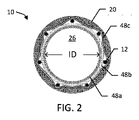
いくつかの態様により、図1は、直径を調節可能な内部人工器官10を示す。図に示すように、内部人工器官10は、ステントエレメントまたは支持体としてまた記載された、ステント12を含む。ステント12は、第1セグメント14および第2セグメント16を有する。図に示すように、第1グラフト部分、カバーまたは裏地としてまた記載されたベースグラフト18は、第1セグメント14の長さにわたって提供されており、第2セグメント16の一部はベースグラフト18を超えて延び、および概して覆いのないままである。用語「グラフト」、「カバー」および「裏地」は、本明細書中において交互に使用され、およびステント12に対してある相対的な位置を必要とすることを意味しない。「裏地」は、ステント12を取り囲むことができ、「カバー」は、ステント12内で全体を受けられることができ、およびグラフトが、内側にあるか、外側にあるか、挟まれているか、またはステントエレメントに対して他の状態で位置するかにかかわらず、「裏地のついた領域」は、グラフト層を含む内部人工器官の一部に相当する。内部人工器官10は、第2グラフト部分としてまた記載される、被制御拡張エレメント20をまた含む。図1および図3において、被制御拡張エレメント20は、視覚化を容易にするために図1および図3中のクロスハッチングで示されている。被制御拡張エレメント20はベースグラフト18の少なくとも一部に沿って延び、および任意選択的に、例えば、ベースグラフト18の機能性グラフト構成部分として機能して、ベースグラフト18の1つまたは2つ以上の機能を高めるかまたは増大させる。図に示すように、内部人工器官10は、近位末端22および遠位末端24を有し、および内側管腔26を画定する(図2)。内部人工器官10の配置を促進するために、放射線不透過性マーカーは、所望のように、内部人工器官10の長さに沿って提供されている。
According to some aspects, FIG. 1 shows an
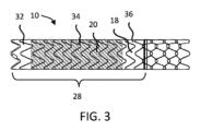
図1に示すように、組み立てられた内部人工器官10は、グラフト-裏地のついた領域28および裏地のついていない領域30を含むが、他の設計では内部人工器官10全体に裏地がついており、および裏地のついていない領域がないことによって特徴付けられている。肝臓内門脈体静脈シャントの配置において、グラフト-裏地のついた領域28は、肝臓内の領域に相当し、および裏地のついていない領域30は、門脈の領域に相当する。グラフト-裏地のついた領域28は、第1終端部32、中間部34、および第2終端部36を画定する。グラフト-裏地のついた領域28と裏地のついていない領域30との間の境界は、境界の近傍またはちょうど近くの外周の放射線不透過性金マーカーバンド38によって示されている。さらなる放射線不透過性金マーカーは、任意選択的に内部人工器官10の近位末端22上に位置する。
As shown in FIG. 1, the assembled
グラフト-裏地のついた領域28の中間部34、および特に被制御拡張エレメント20に対応する内部人工器官10の部分は、内部人工器官10の直径被制御部分を形成する。図に示すように、内部人工器官10の直径被制御部分(図1中の中間部34)は、内部人工器官10の全長未満で、および特にグラフト-裏地のついた領域28の全長未満で延びているが、他の態様において、制御された拡張は、所望の内部人工器官の全長を含む任意の所望の長さで延びている。
The
図に示すように、内部人工器官10の被制御拡張部分に対応する中間部34は、第1の広がっている終端40、中央部42、および広がっている第2終端44を有する。第1のおよび第2の広がっている終端40、44は、異なる方向でおよび内部人工器官10(例えば、約10~80°の相対的角度で、およびそれらの間の任意の値、例えば、約60°を含む角度で)の縦軸に対しテーパー角度で、テーパーしている。広がっている終端40、44は、概して直線のテーパーで示されているが、曲線のテーパー、反曲のテーパー、直線と曲線との組み合わせのテーパーなどが考えられる。第1のおよび第2の広がっている終端40、44は、初期配置後で内部人工器官10が拘束されていない状態の場合に、隣接した第1のおよび第2終端部32、36に滑らかな移行を提供することを助ける。中央部42は、実質的に均一の直径を有するように示されており、中央部42は、所望のように1つまたは2つ以上のテーパーを任意選択的に含み、内部人工器官10の他の部分のいずれかであることができる。
As shown, the
内部人工器官10が配置され、および1つまたは2つ以上のその後の機械的な調節ステップの前に、内部人工器官が保持する中間部34において内部人工器官10が初期直径拡張限界を示すように、グラフト-裏地のついた領域28の中間部34は、被制御拡張エレメント20で拘束されている。図1に示すように、拡張エレメント20は、中間部34がドッグボーン形または砂時計形となることを生じるが、任意の種々の形が考えられる。図1に示すように、内部人工器官10は、中央部42と第1の広がっている終端40との間の境界46で最小の内径(ID)を規定する。
The
被制御拡張エレメント20はステント12の自己拡張を直径方向で拘束するが、(例えば、バルーンカテーテルを使用した)膨張力によって機械的に調節されて、直径の調節を可能にすることができるので、中間部34における内部人工器官10の直径は、内部人工器官10の隣接した部分より小さい。そのためにも、被制御拡張エレメント20が内部人工器官10から除去された場合、ステント12およびベースグラフト18は、最大直径拡張限界に自己拡張する傾向があるであろう。特に、ステント-グラフト12、18は、最大直径(例えば、ステント-グラフトの製造直径)に拡張するように構成されており、その最大直径においてさらなる拡張は、著しい抵抗に会い(例えば、1000気圧以上の抵抗)およびその直径を超えるようにステント-グラフト18に力を掛ける試みが試されると、故障という結果にさえなる場合がある。ステント12、グラフト18、またはステント-グラフト12、18の組み合わせは、この最大直径の調節限界を設定するように構成されることができ、この調節限界を超えて、内部人工器官10が直径を調節されることを意図していない。同様に、バルーン拡張が被制御拡張エレメント20を直径方向で拡張するために使用される場合、中間部34は、(例えば、図3に示すような)ステント-グラフト12、18の充分に拡張した直径を表す、隣接した、第1および第2終端部32、36の直径までそれぞれ拡張するであろう。
The controlled
図3は、内部人工器官10が内部人工器官10の残りの部分によって与えられた、例えば、ベースグラフト18によって与えられた最大直径拡張限界に拡張することを示す。図に示すように、裏地のついた領域28は、第1終端部32、中間部34、および第2終端部36を通る連続した円筒型のプロファイルを有するベースグラフト18に相当する最大直径拡張限界を有する。上記で参照したように、ステント-グラフト12、18は、「製造されたままの」直径を有することができ、それを超えてステント-グラフト12、18が生理的条件下かまたはバルーン拡張によるかの、典型的な使用において拡張することが意図されていない。
FIG. 3 shows that endoprosthesis 10 expands to the maximum diameter expansion limit provided by the rest of
1つの例では、中間部34における配置で内部人工器官10のIDは約8mmであり、および約10mmに拡張可能である。いくつかの例において、中間部34で内部人工器官10の(例えば、最小のIDの場所46で測定した)IDは、例えば、12%~40%拡張できる。また他の態様において、中間部34における内部人工器官10は、40%超、例えば、70%までまたは70%超も拡張可能である。
In one example, the ID of the
TIPS手順の適用のために、内部人工器官10は、典型的には、以下の寸法:約5~12cmの長さ、さらに典型的には約6~10cmの長さ、約5~14mmの配置直径、さらに典型的には約8~12mmの直径、および約0.1~1.0mmの全壁厚、さらに典型的には約0.1~0.6mmの全壁厚を有することができるであろう。寸法「直径」が本明細書中で使用されるが、当然のことながら、この寸法は、平均断面寸法を規定することが意図され、および円形の断面形状に設計を限定することを意図しない。さらに、図1に示すように、内部人工器官10は、内部人工器官10の異なる部分に沿ったテーパーを含む、内部人工器官10の長さに沿った複数の平均断面寸法を示すように構成されることができる。
For TIPS procedure applications, the
いくつかの態様において、内部人工器官10それ自体は、腔内配置のために適した圧縮された寸法、例えば、16フレンチ(French)(5.3mm)以下を有するが、適用される治療によって種々の寸法が考えられる。いくつかの態様において、経皮的に送達されるために、内部人工器官10およびその配置装置は、例えば、約13フレンチ(4.3mm)未満の直径を有するが、種々の寸法が考えられる。「フレンチ」寸法は、本明細書中で使用される場合、機器が通過するであろう孔のサイズを規定する。例えば、「10フレンチ」の寸法を有する機器は、(3.3mmの直径を有する)10フレンチの孔を通るであろう。さらに、孔が内部人工器官10の最も広い断面寸法に適合するのに充分大きい限り、機器は円形の10フレンチ孔を通過するために円形の断面を有する必要はない。
In some embodiments, the
内部人工器官10の第1セグメント14は、典型的には、内部人工器官10の全長の約50~90%を構成するであろう。したがって、第1セグメント14は、典型的には、長さで約4~8cmであろうし、および第2セグメント16は、典型的には、長さで約1~3cmであろうが、種々の寸法が考えられる。被制御拡張エレメント20に対応するグラフト裏地のついた領域28の中間部34は、典型的には、約1~11.5cmの全長を有し、ここで第1の広がっている終端40は、約0.25~1.5cm、さらに典型的には、0.5cmの長さを有し、中央部42は、約0.5~8.5cm、さらに典型的には、1.5~5.5cmの長さを有し、および広がっている第2終端44は、約0.25~1.5cm、さらに典型的には、0.5cmの長さを有するが、種々の寸法が考えられる。
種々の態様により、ステント12は、任意選択的に任意の数のセグメントおよび配置を含む。図1に示すように、第1セグメント14は、波形の、らせん状のステントパターンを有するが、他の配置を考えられる。次に、第2セグメント16は、任意選択的に第1セグメント14のパターンと異なるステントパターンを用いる。例えば、第2セグメント16は、第2セグメント16が所定の所望の長さを超えて過度に縦方向に伸びることを防ぐことを助ける噛み合った(または「チェーンリンクした」)ステントパターンを有して示されているが、他の配置を考えられる。いくつかの噛み合った設計において、単一のワイヤーが第2セグメント16のために用いられており、ここで、ワイヤーがカバー18内で終了し、および内部人工器官10の遠位末端24においてワイヤーのそのままの終端が露出されることを防ぐように、ワイヤーは内部人工器官10のカバー18から遠位末端24まで、そして次にカバー18に戻って覆われている。
In accordance with various aspects,
第2セグメント16の噛み合った(または「チェーンリンクした」)ステントパターンを形成するいくつかの方法において、単一のワイヤーは、内部人工器官10の第1セグメント14から遠位末端24まで、そして次に第1セグメント14に戻って覆われている。第2セグメント16の長さに沿って、ワイヤーは、第1の経路に沿った第2の波形のパターンおよび第3の波形のパターンを提供されており、第2の経路に沿った第2の波形のパターンとインターロックしている。第2の波形のパターンおよび第3の波形のパターンとインターロックしていることにより、ステントパターンは、第2セグメント16が縦方向に圧縮されることを可能にし、したがって可撓性を与えるが、ステントパターンは、第2セグメント16が所定の最大の長さを超えて縦方向に伸びることを防ぐ。留意すべきは、機器が放射状に圧縮された配置にありおよび配置されたときより小さい場合に、噛み合ったステントパターンは、円柱状の支持体をまた与えることである。適したステントパターンおよび第1のおよび第2セグメントのための製造の関連した方法の例は、Voneshらの米国特許第6,673,102号明細書にまた記載されている。
In some methods of forming an interdigitated (or "chain-linked") stent pattern of
ステント12の第1のおよび第2セグメント14、16は、ステンレススチール、ニッケル-チタン合金(ニチノール)、タンタル、エルジロイ(elgiloy)、種々のポリマー材料、例えば、ポリ(エチレンテレフタレート)(PET)またはポリテトラフルオロエチレン(PTFE)、または生体吸収性材料、例えば、左旋性ポリ乳酸(L-PLA)またはポリグリコール酸(PGA)を含む、種々のワイヤー材料から形成されることができる。種々の例において、ステント12は自己拡張性であり、および拘束された場合に、内部人工器官10上に自己拡張力を働かせる。したがって、種々の設計において、ステント12の第1のおよび第2セグメント14、16は、圧縮された配置(直径)での緊密な圧縮に耐え、そして次に所定の場所に配置されていったん解放されると自己拡張するであろう、長弾性材料、例えば、ニチノール金属、例えば、Voneshらの米国特許第6,673,102号明細書に記載されたものでできていることができる。
The first and
内部人工器官10は、自己拡張性ステント12を含むものとして概して記載されているが、当然のことながら、ステント12は、1つまたは2つ以上のバルーン拡張可能部分を含むことができる(例えば、第2セグメント16は、バルーン拡張可能であることができる)か、またはステント12全体は、内部人工器官10になんらかの自己拡張性ステント構成部分がなくて、バルーン拡張可能であることができる。例えば、被制御拡張エレメント20は、任意選択的にバルーン拡張可能ステント-グラフトと共に用いられ、および複数の調節された直径を通して初期配置直径を超えてバルーン拡張可能ステント-グラフトの最大直径拡張限界までの直径の調節を可能にする。
Although
大まかに言えば、カバー18は、内部人工器官10に流れ管腔を提供することを助ける。肝臓内のシャント用途において、カバー18は、例えば、ステント12を通して肝臓組織の押し出しを防ぐこと、内部人工器官10の最大の直径寸法を保つこと、ステント12の制御されていない伸長を防ぐこと、胆汁がシャント中へ浸透することを減らすことまたは除くこと、およびよじれなしで曲がることを促進することを含む内部人工器官10中で多くの機能を果たす。上記に記載したように、被制御拡張エレメント20は、任意選択的に直径の調節可能性を超えてベースグラフト18の1つまたは2つ以上の機能を高めるかまたは増大させる。例えば、被制御拡張エレメント20は、任意選択的に高められた不浸透性能、縦強度、またはその他のものを提供する。
Generally speaking, cover 18 helps provide a flow lumen for
図2に示すように、ベースグラフト18のための好ましい材料は、ベースチューブ48a、内側フィルム48b、および外側フィルム48cを含む。ベースチューブ48aは、フルオロポリマー材料および特に延伸ポリテトラフルオロエチレン(PTFE)であることができる。内側フィルム48bはまた、任意選択的にフルオロポリマー、および特に延伸PTFEである。例えば、ベースチューブ48aは、押し出された、薄い壁の延伸PTFEベースチューブおよび内側フィルム48b、ベースチューブをらせん状に覆った複数層の延伸PTFEフィルムであることができる。外側フィルム48cはまた、任意選択的にフルオロポリマー、例えば、FEPおよび延伸PTFEの多孔質複合物フィルムである。ベースチューブ48a、内側フィルム48b、および外側フィルム48cのための適した材料の例は、Voneshらの米国特許第6,673,102号明細書に記載されている。図に示すように、ベースグラフト18は、実質的に連続しており、および生体内で閉じないままであるのに充分なサイズのなんらかの開口または孔を壁が有さない点で遮られていないが、生体内で閉じないままであるように構成された開口または穴(図に示されていない)を有するグラフト18はまた、他の用途において考えられる。内側および/または外側フィルム層48b、48cは任意選択的に増加した放射状となり、またはベースグラフト18に強度を与え、およびステント-グラフト12、18の製造されたままの直径において、ステント-グラフト12、18の最大直径拡張限界を設定するのを助ける。
As shown in FIG. 2, preferred materials for
ステント12およびベースグラフト18は共に固定されて、ステント-グラフト12、18を提供する。例えば、第1セグメント14は、ベースグラフト18に固定され、および第2セグメント16の終端は、任意選択的にベースグラフト18および/または第1セグメント14に固定される。図に示すように、1つまたは2つ以上の層のベースグラフト18は、ステント12の内部に配置されて、内側管腔26を画定するが、例えば、ベースグラフト18は任意選択的にステントエレメント12の外にすべて配置されるか、または、ステント12がベースグラフト18中に埋め込まれて配置される。図に示すように、第2セグメント16の終端をベースグラフト18(例えば、単一の「列」)に固定し、および第2セグメント16の残りの部分がベースグラフト18から延びていて、ステント12の第2セグメント16の大部分は覆いのないままである。図に示すように、流体がすき間を通って流れることができるように、第2セグメント16のすき間は覆われていない。肝臓内のシャント用途において、第2セグメント16は、覆いのないままであり、第2セグメント16のすき間を通って流れる血液を介して、門脈の静脈の灌流が分岐することを促進する。
ベースグラフト18は、好ましくは結合によってステント12に取り付けられているか、またはそうでなければ、適した接着剤、例えば、フッ素化エチレンプロピレン(FEP)、ポリウレタン、シアノアクリレート、またはその他のものの使用を通して共に2つを取り付けている。さらに、材料は、結合されているか、またはそうでなければ、熱処理(例えば、材料を共に焼結)を通してまたはステントおよびカバーに熱可塑性もしくは熱硬化性接着剤のいずれかで接着されているステントおよびカバー(連続したまたは不連続的のいずれかの)外側の周りの覆い(例えば、チューブ、テープ、または膜)の使用を通して、共に取り付けられていることができる。代わりに、ステント12はまた、サーモポリマー(thermopolymer)または熱硬化性接着剤で被覆されていることができ、およびカバーは、結合されているか、またはそうでなければ、ポリマー被膜の再流し込みまたは設定によって取り付けられている。また他の態様において、ステント12およびベースグラフト18は、機械的に(例えば、構造を使用して)取り付けられている。
The
内部人工器官10を製造するいくつかの方法において、ステント12は、所望のように、ベースグラフト18の一部にわたって(例えば、ベースチューブおよび覆われた延伸PTFEの層にわたって)配置されており、およびFEPおよび延伸PTFEの多孔質複合物フィルムは、ベースグラフト18の管腔に向かってFEPを含むフィルムの側部での構成にわたって覆われている。ステント12の第1セグメント14は、任意選択的にベースチューブ48aおよび内側フィルム48bの周りに置かれた、接着剤、例えば、FEPで被覆されており、および次に外側フィルム48cよって覆われている。次に、集成体は、集成プロセス中の1つまたは2つ以上の点において加熱されて結合されるか、またはそうでなければ、Voneshらの米国特許第6,673,102号明細書に記載されたように、種々の層を共に取り付けることができる。
In some methods of
いくつかの態様において、被制御拡張エレメント20は、典型的な生物学的圧力(例えば、典型的には循環圧力)およびステント12に掛けられたなんらかの拡張力より大きい圧力下で機械的に調節できるように構成されている。例えば、被制御拡張エレメント20は、エレメント20の1つまたは2つ以上の部分を形成する制御された拡張材料が押されるかまたは可塑的な変形を起こすことによって、そうした制御された拡張材料の繊維状のまたは他の微細構造の再組織化を起こすことによって、エレメント20の止め具もしくは折りたたみまたは被制御拡張エレメント20の他の機械的な調節の解放によって、任意選択的に機械的に調節できる。被制御拡張エレメント20がステント-グラフト12の最大直径拡張限界を超えることによってステント-グラフト12、18を破壊的なまでに故障させる傾向があるであろう圧力より低い圧力において調節された直径を維持できるように、被制御拡張エレメント20を機械的に調節するのに必要な圧力は、典型的な生理学的条件(例えば、典型的な最大の血圧)より大きい。被制御拡張エレメント20は、好ましくは典型的な生物学的条件下で長い間の実質的な直径のクリープまたは自発的な直径の拡張なしで機械的に調節される直径を維持するように構成されている。被制御拡張エレメント20は、任意選択的に1つまたは2つ以上の層を含み、およびフルオロポリマー材料、例えば、Goreの米国特許第3,953,556号明細書、米国特許第3,962,153号明細書、米国特許第4,096,227号明細書、米国特許第4,187,390号明細書、および米国特許第4,902,423号明細書、またはArmstrongらの米国特許公開第2013/0204347号明細書の膨張性格子に記載された膨張性の、延伸PTFEチューブを含む種々の材料で構成されていることができる。
In some embodiments, the controlled
いくつかの態様において、被制御拡張エレメント20は、未焼結の延伸PTFEおよび安定化層、例えば、FEPの連続層をそれぞれ含む層で形成された2層の圧縮された複合材料を含む制御された拡張材料で形成されている。いくつかの態様において、延伸PTFEの未焼結の形態は、制御された拡張材料の拡張性に寄与する。未焼結の延伸PTFEは、同時加熱および延伸後の押し出しによって製造できる。焼結した延伸PTFEは、押し出し、同時加熱および延伸、ならびに焼結(PTFE結晶溶融温度より上に加熱すること)によって製造される。未焼結の延伸PTFEは焼結した延伸PTFEより低い程度で加熱されるので、未焼結の延伸PTFE材料は、焼結した延伸PTFEより高い適応性およびより高い延伸可能性を有する。未焼結の延伸PTFEは、例えば、破裂前に約40%以上伸びることができる曲がっていない小線維を有する。
In some embodiments, the controlled
いくつかの製造方法において、1つまたは2つ以上のラップ(wrap)の未焼結の延伸PTFE/FEP複合材料が、被制御拡張エレメント20を含むように重なり合う。FEPは複数のラップの未焼結の延伸PTFEを共に結合させて、例えば、モノリシックのスリーブ構造を作るが、種々の配置を考えられる(例えば、リング、カラー、シリンダーセグメント)。例えば、被制御拡張エレメントは、未焼結のおよび圧縮され、または高密度化し、制御された拡張材料を円筒型の心棒の上にらせん状に巻かれたストリップに切断することによって任意選択的に形成される。1つまたは2つ以上の層は、1つまたは2つ以上の経路中で形成されてスリーブを形成する。いくつかの態様において、制御された拡張材料のFEP側が外側へ向くように、材料は巻かれる。任意の数の追加の層(例えば、取付層または結合層)はまた、被制御拡張エレメント20を形成する工程および/または内部人工器官10の集成体の間の任意の時点で、所望のように、被制御拡張エレメント20の上に適用される。円筒型の心棒の直径は、被制御拡張エレメント20の初期の内径を決定する。
In some manufacturing methods, one or more wraps of unsintered expanded PTFE/FEP composite material are overlaid to contain the controlled
いくつかの方法において、次に被制御拡張エレメント20は、心棒の上にあるまま加熱されて、FEP接着剤を活性化する。加熱によりFEPが流動し、それによって未焼結の延伸PTFEの機能的に単一の多層のスリーブを作る。冷却後に、被制御拡張エレメント20は心棒から除去され、および被制御拡張エレメント20の終端は、所望の長さのスリーブを作るようにトリムされる。被制御拡張エレメント20はまた、任意選択的に生体内で閉じないままであるように構成された開口または孔がないことによって特徴付けられた実質的に連続したおよび途切れない壁を有する。
In some methods, the controlled
集成体のいくつかの方法において、被制御拡張エレメント20は、内部人工器官10、例えば、ステント12およびベースグラフト18(全体として、「ステント-グラフト12、18」)下地部分の上に置かれるが、被制御拡張エレメント20がステント-グラフト12、18の内側に固定されていることを含む種々の配置を考えられる。集成体のいくつかの方法において、予め組み立てられたステント-グラフト12、18は、充填漏斗を通して引っ張られておよび被制御拡張エレメント20の内径より小さい外径を有するチューブの中へ入る。ステント-グラフト12、18を含むチューブは、被制御拡張エレメント20内に配置され、およびチューブは、ステント-グラフト12、18から除去される。チューブから出てくると、ステント-グラフト12、18は、自己拡張して被制御拡張エレメント20の内径にならう。図1に示すように、中間部34に対応するベースグラフト18の部分的なセグメントが被制御拡張エレメント20によって覆われるように、被制御拡張エレメント20は、ベースグラフト18より短くなるように選択された長さを有する。
In some methods of assembly, the controlled
いくつかの態様において、被制御拡張エレメント20は、内部人工器官10の残りの一部に、機械的に(例えば、締りばめ、摩擦嵌合、縫合、または他のものによって)連結されている。他の態様において、被制御拡張エレメント20は、代わりにまたはさらに内部人工器官と被制御拡張エレメント20との間で結合剤(例えば、接着剤、例えば、FEP)を使用して内部人工器官に固定される。結合剤は、被制御拡張エレメント20と残りの内部人工器官10との間の実質的にすべての界面にかけて、または被制御拡張エレメント20と残りの内部人工器官10との間の界面の1つまたは2つ以上の部分のみにかけて連続層または不連続層として任意選択的に適用される。材料が未焼結のままであることが望ましい被制御拡張エレメント20においてはあまり望ましくないが、いくつかの態様において被制御拡張エレメント20は、加熱作業によって(例えば、被制御拡張エレメント20と残りの内部人工器官10との間の界面の1つまたは2つ以上の選択された部分で全体焼結または局所的焼結によって)グラフトに代わりにまたはさらに連結されている。
In some aspects, the controlled
いくつかの態様において、内部人工器官10を送達配置につぶす前に、内径の設定工程が、被制御拡張エレメント20をステント-グラフト12、18に連結するために行なわれる。いくつかの設定工程は、組み立てられた内部人工器官10の初期IDより大きい外径を有する心棒(図に示されていない)にわたってステント-グラフト12、18と伴にその上に配置された被制御拡張エレメント20を引き出すことを含む。心棒は、中間部34の形および内部人工器官10の所望の初期直径拡張限界(被制御拡張エレメント20を機械的に調節する前に、配置後に内部人工器官が生体内で自己拡張するID)に相当する外径(OD)を有する。例えば、8~10mmで調節できる内部人工器官において、被制御拡張エレメント20は、内部人工器官10が8mm未満のIDを有することを生じるであろうし、および設定工程後に被制御拡張エレメント20が機械的に調節され、および内部人工器官10が8mmのIDを示すように、心棒のODは8mmになるであろう。いくつかの態様において、心棒は、被制御拡張エレメント20の終端に対応する広がっている終端を有し、被制御拡張エレメント20へ広がっている終端および被制御拡張エレメント20によって拘束されているステント-グラフト12、18のセグメントとステントグラフト12、18の隣接したセグメントとの間のより滑らかな移行を提供する。心棒は、広がっている終端間で連続した直径を有することができるが、被制御拡張エレメント20に対応する内部人工器官10の一部に対応する特徴を与えるための任意の数の広がり、テーパー、曲線、または他の特徴が考えられる。
In some embodiments, an inner diameter setting step is performed to couple the controlled
設定工程は被制御拡張エレメント20を内部人工器官10の外側表面にならうようにし、これは熱および/または接着剤結合の使用なしで内部人工器官10のその後の加工、配置、および移植を通して、被制御拡張エレメント20を定位置に保持することを助けると考えられる。いくつかの態様において、被制御拡張エレメント20とステント-グラフト12、18との間の界面の少なくとも一部に沿って熱および/または接着剤結合または他の取付具がないことは、滑走界面を画定し、これは、膨らんだ場合に被制御拡張エレメント20がステント-グラフト12、18の表面上を滑るのを可能にすることを助け、したがって被制御拡張エレメント20の縮小量を制限することは、ステント-グラフト12、18につたわる(translate to)。いくつかの態様により、例えば、ステントグラフト12、18と被制御拡張エレメント20との間の締りばめは、構成部分間で滑走界面を提供する。別の言葉でいうと、内部人工器官10の直径の拡張の間に、被制御拡張エレメント20とステント-グラフト12、18との間の滑走界面は、被制御拡張エレメント20の少なくとも一部が滑走界面においてステント-グラフト12、18と異なる速度で、縦寸法において変化すること(例えば、放射状拡張の間の収縮)を可能にする。
The setting process causes the controlled
いくつかの他の態様、被制御拡張エレメント20とステント-グラフト12、18との間の界面の一部は、接着剤的に結合されている。例えば、いくつかの態様において、フルオロポリマー接着剤、例えば、Changらの米国特許第7,462,675号明細書中に記載されたテトラフルオロエチレン(TFE)およびペルフルオロメチルビニルエーテル(PMVE)、FEP(フッ素化エチレンプロピレン)、またはPFA(ペルフルオロアルキルビニルエーテル/テトラフルオロエチレンコポリマー)が、例えば使用される。接着剤は、任意選択的に被制御拡張エレメント20の内径上、例えば、被制御拡張エレメント20の中央の領域でなくそれぞれの終端に適用されるが、種々の配置を考えられる。被制御拡張エレメント20がステント-グラフト12、18の上に配置された後で、接着剤は、例えば、制御された拡張材料20の焼結を生じることなく、または少なくとも大幅な焼結を生じることなく、そこへ熱を掛けることによって活性化される。
In some other aspects, a portion of the interface between controlled
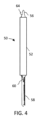
また他の態様において、被制御拡張エレメント20は、界面全体または界面の大部分に沿って接着されており、被制御拡張エレメント20は、残りの内部人工器官10とともに形成される。例えば、FEPの外側層を有する被制御拡張エレメントを含むいくつかの態様において、ステント-グラフト12、18にわたって適用される前に、被制御拡張エレメント20は、裏返される(everted)。被制御拡張エレメント20の裏返しは、被制御拡張エレメント20の外径(反管腔側表面)上に予めあったFEPを、内径(管腔表面)へ位置変更する。図4および図5は、いくつかの態様による内部人工器官10を治療のための所望の場所に送達しおよび配置するための送達システム50の遠位部分を具体的に示す。送達システム50は、種々の特徴、例えば、Voneshらの米国特許第6,673,102号明細書中に記載されたものを含むカテーテル系の、多段階的な配置システムである。図に示すように、送達システム50は、拘束部52、送達拘束部54、遠位カテーテルシャフト56、および近位カテーテルシャフト58(図4および図5において部分的に示されており近位に延びている)を導入すること(または覆うこと)を含む。図4および図5はまた、外面的に操作されて内部人工器官10から送達拘束部54を解放するのに充分な長さを有する送達拘束部54に取り付けられた配置ライン60の切断図を示す。血管内配置の間は、送達システム50は、患者の体中のターゲット場所に延びる導入カテーテル(図に示されていない)を通る。
In yet another aspect, the controlled
いくつかの態様において、導入拘束部52は、内部人工器官にわたって滑って受け入れられ、および圧縮された、送達プロファイルにおいてステント12の第2セグメント16を維持するように機能するチューブである。下記の様に、導入拘束部52は、第2セグメント16をカテーテルチューブ(図に示されていない)中で圧縮された、送達プロファイルに維持しつつ、外側のカテーテルチューブ(例えば、導入器)中へ内部人工器官10を移送することを助ける。
In some aspects, the lead-in
例えば、図4は、内部人工器官10が送達直径寸法において充分に拘束されている状態に相当し、および図5は、部分的に配置された内部人工器官10、および特にステント12の第2セグメント16が(例えば、自己拡張を介して)配置されることを可能にしていることを示す。内部人工器官10の第2セグメント16が拘束されていない場合、第2セグメント16は、その配置直径近くまで充分に拡張するであろう。しかし、内部人工器官10の残りの部分は、送達直径寸法で送達拘束部54中において抑えられている。作業において、拘束された内部人工器官10は、導入拘束部52から究極配置部位を通って延びるほぼ等しい内径(図に示されていない)のカテーテルチューブの中へ入る。内部人工器官10が配置部位(例えば、カテーテルチューブを引っ込めること、カテーテルチューブから第2セグメント16を延ばすこと、またはそれらの組み合わせによって)でカテーテルチューブ(図に示されていない)から延びている場合、第2セグメント16の配置は生じるであろう。
For example, FIG. 4 corresponds to the
送達拘束部54は、第1セグメント14、ベースグラフト18、および送達直径寸法でつぶれた状態の被制御拡張エレメント20を保持する。いくつかの態様において、拘束エレメントとしてまた記載された送達拘束部54は不織であることができる複数の織り合わされたスレッドを含み、配置ライン60を引くことで、その場所で送達拘束部54が解体されおよび送達システム50を通って内部人工器官10から引き抜かれる。例えば、配置ライン60は、近位シャフト58を通って、使用者によって患者に外部的に操作できるシステム50の近位末端に向かって延びている。編まれた、または織り合わされた送達拘束部の例は、Voneshらの米国特許第6,673,102号明細書およびArmstrongらの米国特許第6,224,627号明細書に開示されている。他の態様において、送達拘束部54は、配置ラインの作動により解放されることができる共に固定された2つの終端を有する材料のシートである。また他の態様において、送達拘束部54は、作動されおよびステント-グラフト12、18から除去されることができ、ステント-グラフト12、18の初期の配置状態への自己拡張を可能にするカテーテルシースの遠位末端である。
図6は、肝臓内門脈体静脈シャント中に配置された内部人工器官を示す。送達システム操作する方法およびその後内部人工器官を配置する方法は、肝臓内のシャント手順に触れて図4~6を参照してなされるが、種々の適用が考えられる。 FIG. 6 shows an endoprosthesis placed in an intrahepatic portosystemic shunt. A method of operating the delivery system and subsequently placing the endoprosthesis is described with reference to FIGS. 4-6 with reference to an intrahepatic shunt procedure, although various applications are contemplated.
カテーテルチューブ(図に示されていない)は、肝静脈Hから門脈Pまで肝臓を通って形成される経路を通って患者の門脈Pに進む。導入拘束部52内に組み込まれた圧縮された内部人工器官10は、近位シャフト58を操作することによってカテーテルチューブの近位末端中に挿入されて、第2セグメント16を導入拘束部52からカテーテルチューブ中に移送させる。次に内部人工器官10は、下大静脈、肝静脈H、肝臓の中に形成された肝臓内の経路(シャント)を通るカテーテルチューブを通り、および門脈Pの中に充分に進む。放射線不透過性の先端64は、カテーテルチューブの終端と位置合わせされることができる。第2セグメント16が門脈P中に延びるように、内部人工器官10、例えば、バンド38(図1)と関連する放射線不透過性マーカーは、肝臓内の連絡部位Yに隣接したベースグラフト18の終端を配置するのに使用できる。カテーテルチューブは近位で回収され、これは第2セグメント16が門脈P内で充分に膨張することを可能にする。次に、裏地のついていない門脈の領域が肝臓の門脈P中にあり、およびグラフト-裏地のついた領域28は、肝臓内の連絡部位Yに対応して内部人工器官10が配置されるトンネルの小孔と係合するように、近位カテーテルシャフト58はカテーテルチューブを通して回収されて、内部人工器官10を固定する。位置合わせは、1つまたは2つ以上の放射線不透過性マーカーの正しい配向により蛍光顕微鏡で確認できる。いくつかの態様において、内部人工器官10は、シャントを形成するあらかじめ配置された内部人工器官(図に示されていない)の管腔の中へ任意選択的に配置されて、例えば、増大するか、またはあらかじめ配置された内部人工器官の性能を修正する。
A catheter tube (not shown) is advanced to the patient's portal vein P through a pathway formed through the liver from the hepatic vein H to the portal vein P. FIG.
いったん内部人工器官10が適切に位置合わせされると、送達拘束部54は配置ライン60を作動させることによって除去され、内部人工器官10の第1セグメント14が、先端から中心への(tip-to-hub)方向で適切に増大することを可能にする。図6中に具体的に説明されたように、配置手順は、肝臓内の経路(シャント)内の内部人工器官の覆われた部分10の位置合わせをする。さらに、覆いのない第2セグメント16は、血流が内部人工器官10に入ること、および門脈Pを通り続けることの両方を可能にする。門脈Pを通して通常の血流を完全に除去することなく、門脈系から(内部人工器官10によって形成されたシャントを通して)過剰圧力を除く結果となる。図6中の破線は、内部人工器官が被制御拡張エレメント20中に予め設定された初期直径拡張限界に拡張することを具体的に示す。必要に応じて、内部人工器官10の修正は、被制御拡張エレメント20を調節された直径に機械的に調節するのに必要な直径より小さいバルーン直径で内部人工器官10の続くバルーン拡張によって行うことができる。
Once
肝臓内門脈体静脈シャントを形成するいくつかの方法は、送達直径寸法で患者の肝臓中に内部人工器官10を配置することを含む。内部人工器官がin situで自己拡張しおよび患者の肝臓中に充分に固定されて、図6に示すように、被制御拡張エレメント20がステント-グラフト12、18の初期配置直径寸法への部分的なセグメントの拡張を制限する肝臓内門脈体静脈シャントを形成するように、内部人工器官10は充分に配置される。この限定された拡張はシャントを通して流量を制限し、および門脈Pと全身の静脈循環との間の圧力勾配に影響を与える。第1終端部32(図1)および第2終端部36(図1)は、組織に対して内部人工器官10を固着および密閉することを助け、および内部人工器官10の移動を防ぐ。使用者(例えば、臨床医)が流量を増加させて圧力勾配を調節することを望む場合、使用者は、例えば、バルーンカテーテル80(図7)を使用することによって、被制御拡張エレメント20に膨張力を適用して、被制御拡張エレメント20を所望の量に(例えば、図6中に実線で表されているベースグラフト18の最大直径拡張限界まで)機械的に調節できる。
Some methods of forming an intrahepatic portosystemic shunt include placing the
図8は、バルーンカテーテル80を使用した内部人工器官10の一部の拡張の図式の具体的な説明である。図式の具体的な説明において、ステント12およびベースグラフト18は、まとめて層として示されている。概して示されているように、内部人工器官10の被制御拡張部分に対応するすべての中間部34は、膨らまされているか、またはそうでなければ、単一のステップに直径を調節されている(例えば、バルーン長が中間部34より小さい)必要はない。
FIG. 8 is a schematic illustration of the expansion of a portion of
被制御拡張エレメント20に対応するステント-グラフト12、18のセグメントの直径は、最大のバルーン直径および/またはバルーン圧力の選択によって、初期の送達拡張限界と最大の拡張限界との間の任意の直径に調節されることができる。言い換えれば、直径(例えば、場所46での最小内径(ID)を含む)は、拡大されたまたは調節された直径としてまた記載された、拡大された直径寸法に選択的に拡大されることができる。被制御拡張エレメント20は拡大された直径寸法で内部人工器官10を保持し、および典型的な生理学的条件下でIDのクリープを可能にしない。したがって、被制御拡張エレメント20は、内部人工器官10が、シャントを通して増加した流量を可能にする拡大された直径寸法を維持することを助ける(例えば、ベースグラフト18の最大直径拡張限界まで、これは次になんらかのさらなる拡張を制限する。)。
The diameter of the stent-
治療の種々の方法は、1つまたは2つ以上の圧力測定を行うこと、およびそれにしたがって内部人工器官10を調節することを含む。例えば、肝臓内のシャント手順において、門脈圧亢進症は、1つまたは2つ以上のそうした圧力測定および調節を使用して評価および治療することができる。門脈圧亢進症は、門脈静脈系内の血圧の増加である。くさび形の肝臓静脈圧(WHVP)は、実際の肝臓の門脈圧でなく肝類洞圧力を反映することにより、門脈の静脈圧を評価するのに使用される。肝臓静脈圧勾配(HVPG)は、WHVPと制限のない(free)肝臓静脈圧との間の圧力勾配の臨床測定であり、したがって門脈と下大静脈との間の圧力勾配の評価である。
Various methods of treatment include taking one or more pressure measurements and adjusting the
いくつかの態様において、使用者は、内部人工器官を充分に配置した後で少なくとも1つの圧力測定を行って、門脈と全身の静脈循環との間の圧力勾配を決定し、必要な調節を決定し、および被制御拡張エレメント20に対応するベースグラフト18の部分的なセグメントの直径を調節する。単一の手順または複数の手順の一部として、任意の数のその後の圧力測定および拡張する調節が考えられる。例えば、いくつかの治療方法において、1つまたは2つ以上の圧力測定および/または内部人工器官10の調節の間に少なくとも24時間、またはさらにより長い時間までもが経過する。例えば、直径の調節は、初期の送達手順およびシャントの形成から別個の手順として、またはその前の直径の調節手順後の別個の調節手順として行われることができる(例えば、日、月、または年までも後に行われる)ことが考えられる。
In some embodiments, the user takes at least one pressure measurement after the endoprosthesis is fully deployed to determine the pressure gradient between the portal vein and the systemic venous circulation and make any necessary adjustments. determine and adjust the diameter of the partial segment of the
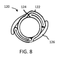
制御された拡張材料でできていることに加えて、または代わりの方法として、被制御拡張エレメント20は、任意選択的に、閉じた配置(例えば、結合剤または材料によって)で選択的に固定され、および後で膨張力の適用によって開かれるかまたは分離されることができる、1つまたは2つ以上の物理的形状、例えば、ひだ、折りたたみ、またはしわ(図8)を含み、それによって形状を拡張させて、被制御拡張エレメント20の直径を機械的に調節することを可能にする。例えば、図9は、内部人工器官10と関連する上記の種々の形状のいずれかを用いて使用できる被制御拡張エレメント120を示す。被制御拡張エレメント120は、概してスリーブ状であるか、または円筒型配置であり、典型的な生理学的条件(例えば、血圧)より高い膨張力で機械的に調節でき、および図8中に示されていない内部人工器官10の直径被制御部分に相当できる。図8に示したように、被制御拡張エレメント120は、縦のひだまたは折りたたみの形態で、1つまたは2つ以上の拡張形状124を規定するスリーブ122を形成する1つまたは2つ以上の層を含む。1つまたは2つ以上の固定エレメント126、例えば、テープ材料、例えば、FEPで被覆されたePTFEは、閉じた状態で拡張形状を固定する。膨張力(例えば、バルーン拡張)の適用により、固定エレメント126は、拡張形状124が、膨張(例えば、それらが可塑的に変形、破断、または解放)し、内部人工器官10の直径被制御部分の直径の調節となることを可能にする。
In addition to being made of a controlled expansion material, or alternatively, controlled
本発明の範囲から離れることなく、記載された例示的な態様に種々の改変および追加をなすことができる。例えば、上記の態様は、特定の特徴をいうが、本発明の範囲はまた、上記の特徴のすべてを含まない異なる組み合わせの特徴および態様を有する態様を含む。
(態様)
(態様1)
ステントと前記ステントに固定されたベースグラフトとを含むステント-グラフトと、
連続した壁を有する被制御拡張エレメントと、
を含む、
直径を調節可能な内部人工器官であって、
前記ベースグラフトは第1終端および第2終端を有し、ならびに前記ステント-グラフトは自己拡張性でありおよび自己拡張力を有し、前記ステント-グラフトは最大直径拡張限界を有し、
前記被制御拡張エレメントは、初期直径拡張限界を有し、および前記ステント-グラフトの前記自己拡張力に加えて拡張力下で配置された場合に前記初期直径拡張限界と前記最大直径拡張限界との間の直径の範囲内の調節された直径に調節可能であり、前記拡張力を除いた後で前記被制御拡張エレメントは生理的条件下で前記調節された直径を維持するように構成されており、および前記ステント-グラフトは、前記調節された直径のための前記直径の範囲を前記最大直径拡張限界に制限するように構成されている、内部人工器官。
(態様2)
前記内部人工器官の直径の拡張の間に、前記被制御拡張エレメントと前記ステント-グラフトとの間の滑走界面は、前記被制御拡張エレメントの少なくとも一部が前記滑走界面で前記ステント-グラフトと異なる速度で縦寸法を変化させることを可能にするように、前記被制御拡張エレメントは、前記ステント-グラフトで前記滑走界面を画定している、態様1に記載の内部人工器官。
(態様3)
前記内部人工器官は生体体液を運ぶように構成された内側管腔を有し、およびさらに前記ベースグラフトは前記内部人工器官の前記内側管腔を画定している、態様1に記載の内部人工器官。
(態様4)
前記初期直径拡張限界において前記被制御拡張エレメントは直径で1つまたは2つ以上のテーパーを画定する、態様1に記載の内部人工器官。
(態様5)
前記被制御拡張エレメントは、第1終端部と、第2終端部と、前記第1終端部と前記第2終端部との間の中央部とを有し、およびさらに前記初期直径拡張限界において前記被制御拡張エレメントは、第1の直径へ外側に向かってテーパーしている前記第1終端部と、第2の直径へ外側に向かってテーパーしている前記第2終端部と、前記第1の直径および第2の直径より小さい直径を有する前記中央部と含む、態様1に記載の内部人工器官。
(態様6)
前記被制御拡張エレメントは、前記拡張力の適用で変形し、および生理的条件で前記調節された直径を維持するように構成された制御された拡張材料のスリーブを含む、態様1に記載の内部人工器官。
(態様7)
前記ベースグラフトは長さを有し、および前記ステント-グラフトは、裏地のついた領域および裏地のついていない領域を含み、前記裏地のついた領域は前記グラフトの前記長さに相当し、および前記裏地のついていない領域は覆いのないままである、態様1に記載の内部人工器官。
(態様8)
前記ステントは鎖リンクパターンを画定する区間を含み、前記区間は前記ステント-グラフトの前記裏地のついていない領域に相当する、態様8に記載の内部人工器官。
(態様9)
態様1~8のいずれか一項に記載の前記内部人工器官を用いて肝臓内門脈体静脈シャントを形成する方法であって、
送達直径寸法で患者の肝臓内に前記内部人工器官を配置することと、
前記内部人工器官がin situで前記初期直径拡張限界に自己拡張し、および前記患者の前記肝臓に固定されて肝臓内門脈体静脈シャントを形成するように、前記内部人工器官を配置することと、
前記被制御拡張エレメントの少なくとも一部が前記ステント-グラフトの前記最大直径拡張限界未満の調節された直径に選択的に拡大し、および前記調節された直径が生理的条件下で維持されるように、前記内部人工器官を配置した後で前記内部人工器官に内部圧力を掛けることと、
を含む、方法。
(態様10)
肝臓内門脈体静脈シャントを形成する方法であって、
送達直径寸法で内部人工器官を患者の肝臓内に配置することであって、前記内部人工器官は自己拡張性ステント-グラフトおよび被制御拡張エレメントを含むことと、
前記内部人工器官が、自己拡張しおよび前記患者の前記肝臓に固定されて肝臓内門脈体静脈シャントを形成するように、前記内部人工器官を配置することであって、初期の配置された直径寸法が生理学的条件下で維持されるように、前記被制御拡張エレメントは、前記内部人工器官の直径被制御部分の拡張を前記初期の配置された直径寸法に制限することと、
前記被制御拡張エレメントの少なくとも一部が機械的に変化されおよび前記内部人工器官の前記直径被制御部分の直径寸法が拡大された直径寸法に選択的に拡大し、および生理学的条件下で前記拡大された直径寸法に維持されるように、前記内部人工器官を配置した後で前記内部人工器官に内部圧力を掛けることと、
を含む、方法。
(態様11)
前記内部圧力は、膨らませることができるバルーンによって掛けられる、態様10に記載の方法。
(態様12)
内部人工器官の性能を評価し、そして次に前記内部人工器官の前記直径寸法をin situでさらに拡大させることをさらに含む、態様10に記載の方法。
(態様13)
前記内部人工器官の前記部分を選択的に拡大させることは、血液が前記内部人工器官を通って流れることの増加となる、態様10に記載の方法。
(態様14)
前記内部人工器官を配置した後で少なくとも1つの圧力測定を行って、門脈と全身の静脈循環との間の圧力勾配を決定することをさらに含む、態様10~13のいずれか一項に記載の方法。
(態様15)
前記内部人工器官の前記直径被制御部分を選択的に拡張した後で少なくとも1つの圧力測定を行って患者の門脈と全身の静脈循環との間の圧力勾配を決定することと、前記内部人工器官の前記直径被制御部分を機械的に変化させて前記直径被制御部分を選択的にさらに拡張することと、をさらに含む、態様10~13のいずれか一項に記載の方法。
(態様16)
前記内部圧力は前記内部人工器官の前記直径被制御部分に適用されて、前記被制御拡張エレメントを変形させる、態様10~13のいずれか一項に記載の方法。
(態様17)
前記内部人工器官の前記直径被制御部分は、前記ステント-グラフトの全長未満で延びている、態様10~13のいずれか一項に記載の方法。
(態様18)
門脈圧亢進症を治療するための方法であって、
ステントと、第1グラフト部分と、前記第1グラフト部分の少なくとも一部に沿って延びている第2グラフト部分と、を含む内部人工器官を提供することであって、前記内部人工器官は管腔内に挿入されるための送達拘束部によって第1の直径寸法に拘束され、および前記送達拘束部が解放された場合に、第2の拡大された直径寸法に自己拡張するように構成されており、前記第2グラフト部分は、制限された直径への自己拡張によるさらなる直径の拡大を制限されている前記内部人工器官の直径被制御部分を画定していることと、
門脈および肝静脈中に前記内部人工器官を配置することと、
前記送達拘束部を解放することおよび前記内部人工器官を自己拡張可能にすることにより前記内部人工器官を前記第2の拡大された直径寸法に配置することであって、前記直径被制御部分は、生理学的条件下で前記制限された直径を維持することと、
前記内部人工器官の前記直径被制御部分に膨張力を掛けることによって、前記内部人工器官の前記直径被制御部分の少なくとも一部を調節された直径に直径方向で拡張させることを含む、in situで前記内部人工器官の直径の調節を行うことであって、前記内部人工器官の前記直径被制御部分は、生理学的条件下で前記調節された直径を維持することと、を含む、方法。
(態様19)
前記内部人工器官の前記直径被制御部分を直径方向で拡張させることは、門脈と全身の静脈循環との間の圧力勾配を低下させる、態様18に記載の方法。
(態様20)
前記内部人工器官の前記直径被制御部分を直径方向で拡張させることは、前記第2グラフト部分を変形させる、態様18に記載の方法。
(態様21)
少なくとも1つの圧力測定を行い、そして次にさらに前記内部人工器官の前記直径被制御部分を第2の拡大された直径に直径方向で拡張させること、をさらに含む、態様18に記載の方法。
(態様22)
前記内部人工器官の前記直径被制御部分を前記調節された直径より大きいさらに拡大された直径に直径方向で拡張させることをさらに含む、態様18に記載の方法。
(態様23)
前記内部人工器官の前記直径被制御部分を前記ステントおよび前記第1グラフト部分によって画定された最大直径拡張限界に直径方向で拡張させることをさらに含む、態様18に記載の方法。
(態様24)
前記内部人工器官の複数の直径の調節をin situで行うことをさらに含む、態様18に記載の方法。
(態様25)
前記内部人工器官は、裏地のついていない領域を含み、前記方法は前記門脈中に前記裏地のついていない領域を配置することをさらに含む、態様18に記載の方法。
(態様26)
門脈圧亢進症を治療するための方法であって、
シャントの形成の少なくとも24時間後に、少なくとも1つの圧力測定を行って、門脈と全身の静脈循環との間の内部人工器官によって形成された前記シャントから生じる圧力勾配を決定することであって、前記内部人工器官は、
少なくとも第1セグメントおよび第2セグメントを有する自己拡張性ステントと、
前記第1セグメント上のグラフト構成部分と、
を含み、機械的に調節できる被制御拡張エレメントによって前記グラフト構成部分の少なくとも一部は初期配置直径に維持されていることと、
前記被制御拡張エレメントによって前記初期配置直径に維持されている前記グラフト構成部分の少なくとも一部が前記被制御拡張エレメントによって拡大された直径に拡大されおよび維持されて前記圧力勾配を低下させるように、膨張力で前記被制御拡張エレメントを機械的に調節することによって前記被制御拡張エレメントの直径方向で拡張させることと、を含む、方法。
(態様27)
前記被制御拡張エレメントを直径方向で拡張させた後に少なくとも1つの圧力測定を行うこと、そして次に前記被制御拡張エレメントによって前記拡大された直径で維持されている前記グラフト構成部分の少なくとも一部が前記被制御拡張エレメントを前記圧力勾配に低下させることによってさらに拡大された直径にさらに拡大されおよび維持されるように、前記被制御拡張エレメントをさらに直径方向で拡張させることをさらに含む、態様26に記載の方法。
Various modifications and additions can be made to the exemplary embodiments described without departing from the scope of the invention. For example, while the embodiments above refer to particular features, the scope of the invention also includes embodiments having different combinations of features and aspects that do not include all of the above features.
(mode)
(Aspect 1)
a stent-graft comprising a stent and a base-graft secured to the stent;
a controlled expansion element having a continuous wall;
including,
An adjustable diameter endoprosthesis comprising:
said base-graft having a first end and a second end and said stent-graft being self-expanding and having a self-expanding force, said stent-graft having a maximum diameter expansion limit;
The controlled expansion element has an initial diametric expansion limit and is between the initial diametric expansion limit and the maximum diametric expansion limit when placed under an expansion force in addition to the self-expansion force of the stent-graft. wherein the controlled expansion element is configured to maintain the adjusted diameter under physiological conditions after removal of the expansion force. and said stent-graft is configured to limit said range of diameters for said adjusted diameter to said maximum diameter expansion limit.
(Aspect 2)
During diametric expansion of the endoprosthesis, a gliding interface between the controlled expansion element and the stent-graft is such that at least a portion of the controlled expansion element differs from the stent-graft at the gliding interface. Aspect 1. The endoprosthesis of aspect 1, wherein the controlled expansion element defines the gliding interface at the stent-graft to allow the longitudinal dimension to change with velocity .
(Aspect 3)
The endoprosthesis of aspect 1, wherein the endoprosthesis has an inner lumen configured to carry biological fluids, and further wherein the base graft defines the inner lumen of the endoprosthesis. .
(Aspect 4)
Aspect 1. The endoprosthesis of aspect 1, wherein at the initial diametric expansion limit the controlled expansion element defines one or more tapers in diameter.
(Aspect 5)
The controlled expansion element has a first terminal end, a second terminal end, a central portion between the first terminal end and the second terminal end, and further at the initial diametric expansion limit the The controlled expansion element has said first terminal end tapering outwardly to a first diameter, said second terminal end tapering outwardly to a second diameter, and said first terminal end tapering outwardly to a second diameter. Aspect 1. The endoprosthesis of aspect 1, comprising said central portion having a diameter smaller than a diameter and a second diameter.
(Aspect 6)
The interior of aspect 1, wherein the controlled expansion element comprises a sleeve of controlled expansion material configured to deform upon application of the expansion force and maintain the adjusted diameter at physiological conditions. prosthesis.
(Aspect 7)
The base graft has a length, and the stent-graft includes a lined region and an unlined region, the lined region corresponding to the length of the graft, and the The endoprosthesis of aspect 1, wherein the unlined area remains uncovered.
(Aspect 8)
9. The endoprosthesis of aspect 8, wherein said stent includes sections defining a chain link pattern, said sections corresponding to said unlined regions of said stent-graft.
(Aspect 9)
A method of forming an intrahepatic portosystemic shunt using the endoprosthesis of any one of aspects 1-8, comprising:
placing the endoprosthesis within the patient's liver at a delivery diameter dimension;
positioning the endoprosthesis such that it self-expands in situ to the initial diameter expansion limit and is secured to the liver of the patient to form an intrahepatic portosystemic shunt; ,
at least a portion of the controlled expansion element selectively expands to an adjusted diameter below the maximum diameter expansion limit of the stent-graft, and such that the adjusted diameter is maintained under physiological conditions. , applying internal pressure to the endoprosthesis after placing the endoprosthesis;
A method, including
(Mode 10)
A method of forming an intrahepatic portosystemic shunt comprising:
placing an endoprosthesis within a patient's liver at a delivery diameter dimension, said endoprosthesis comprising a self-expanding stent-graft and a controlled expansion element;
deploying the endoprosthesis so that the endoprosthesis self-expands and is secured to the liver of the patient to form an intrahepatic portosystemic shunt, wherein the initial deployed diameter wherein the controlled expansion element limits expansion of the diameter controlled portion of the endoprosthesis to the initial deployed diameter dimension such that the dimension is maintained under physiological conditions;
at least a portion of said controlled expansion element being mechanically altered and selectively expanding a diameter dimension of said diameter controlled portion of said endoprosthesis to an enlarged diameter dimension, and said expansion under physiological conditions; applying internal pressure to the endoprosthesis after positioning the endoprosthesis so that the endoprosthesis is maintained at a set diametrical dimension;
A method, including
(Aspect 11)
11. The method of
(Aspect 12)
11. The method of
(Aspect 13)
11. The method of
(Aspect 14)
14. Aspects 10-13, further comprising performing at least one pressure measurement after placing the endoprosthesis to determine a pressure gradient between the portal vein and systemic venous circulation. the method of.
(Aspect 15)
performing at least one pressure measurement after selectively expanding the diameter-controlled portion of the endoprosthesis to determine a pressure gradient between the patient's portal vein and systemic venous circulation; 14. The method of any one of aspects 10-13, further comprising mechanically altering the diameter controlled portion of the organ to selectively further expand the diameter controlled portion.
(Aspect 16)
14. The method of any one of aspects 10-13, wherein the internal pressure is applied to the diameter controlled portion of the endoprosthesis to deform the controlled expansion element.
(Aspect 17)
14. The method of any one of aspects 10-13, wherein the diameter controlled portion of the endoprosthesis extends less than the full length of the stent-graft.
(Aspect 18)
A method for treating portal hypertension comprising:
An endoprosthesis is provided that includes a stent, a first graft portion, and a second graft portion that extends along at least a portion of the first graft portion, the endoprosthesis having a lumen. constrained in a first diametrical dimension by a delivery restraint for insertion therein and configured to self-expand to a second enlarged diametrical dimension when said delivery restraint is released. , the second graft portion defines a diameter-controlled portion of the endoprosthesis that is restricted from further diameter expansion by self-expansion to a limited diameter;
placing the endoprosthesis in the portal and hepatic veins;
deploying the endoprosthesis to the second enlarged diameter dimension by releasing the delivery constraint and allowing the endoprosthesis to self-expand, wherein the diameter controlled portion comprises: maintaining said restricted diameter under physiological conditions;
diametrically expanding at least a portion of the diameter-controlled portion of the endoprosthesis to an adjusted diameter by applying an expansion force to the diameter-controlled portion of the endoprosthesis. A method comprising adjusting the diameter of the endoprosthesis, wherein the diameter controlled portion of the endoprosthesis maintains the adjusted diameter under physiological conditions.
(Aspect 19)
19. The method of
(Aspect 20)
19. The method of
(Aspect 21)
19. The method of
(Aspect 22)
19. The method of
(Aspect 23)
19. The method of
(Aspect 24)
19. The method of
(Aspect 25)
19. The method of
(Aspect 26)
A method for treating portal hypertension comprising:
At least 24 hours after formation of the shunt, taking at least one pressure measurement to determine the pressure gradient resulting from the shunt formed by the endoprosthesis between the portal vein and the systemic venous circulation; The endoprosthesis comprises
a self-expanding stent having at least a first segment and a second segment;
a graft component on the first segment;
at least a portion of said graft component being maintained at an initial deployment diameter by a mechanically adjustable controlled expansion element;
such that at least a portion of the graft component maintained at the initial deployment diameter by the controlled expansion element is expanded to and maintained at the expanded diameter by the controlled expansion element to reduce the pressure gradient; diametrically expanding the controlled expansion element by mechanically adjusting the controlled expansion element with an expansion force.
(Aspect 27)
taking at least one pressure measurement after diametrically expanding the controlled expansion element; and then at least a portion of the graft component maintained at the expanded diameter by the controlled expansion element.
Claims (17)
連続した壁を有する被制御拡張エレメントと、
を含む、
直径を調節可能な内部人工器官であって、
前記ベースグラフトは第1終端および第2終端を有し、ならびに前記ステント-グラフトは自己拡張性でありおよび自己拡張力を有し、前記ステント-グラフトは最大直径拡張限界を有し、
前記被制御拡張エレメントは、初期直径拡張限界を有し、および前記ステント-グラフトの前記自己拡張力に加えて拡張力下で配置された場合に前記初期直径拡張限界と前記最大直径拡張限界との間の直径の範囲内の調節された直径に調節可能であり、前記拡張力を除いた後で前記被制御拡張エレメントは生理的条件下で前記調節された直径を維持するように構成されており、および前記ステント-グラフトは、前記調節可能な直径の範囲の上限を前記最大直径拡張限界に制限するように構成されており、
前記内部人工器官の直径の拡張の間に、前記被制御拡張エレメントと前記ステント-グラフトとの間の滑走界面は、前記被制御拡張エレメントの少なくとも一部の縦寸法の変化の速度が前記滑走界面で前記ステント-グラフトの縦寸法の変化の速度と異なるように、前記被制御拡張エレメントは、前記ステント-グラフトで前記滑走界面を画定している、内部人工器官。 a stent-graft comprising a stent and a base-graft secured to the stent;
a controlled expansion element having a continuous wall;
including,
An adjustable diameter endoprosthesis comprising:
said base-graft having a first end and a second end and said stent-graft being self-expanding and having a self-expanding force, said stent-graft having a maximum diameter expansion limit;
The controlled expansion element has an initial diametric expansion limit and is between the initial diametric expansion limit and the maximum diametric expansion limit when placed under an expansion force in addition to the self-expansion force of the stent-graft. wherein the controlled expansion element is configured to maintain the adjusted diameter under physiological conditions after removal of the expansion force. and the stent-graft is configured to limit the upper limit of the adjustable diameter range to the maximum diameter expansion limit;
During diametric expansion of the endoprosthesis, the gliding interface between the controlled expansion element and the stent-graft is such that the rate of change in the longitudinal dimension of at least a portion of the controlled expansion element is equal to the gliding interface. wherein the controlled expansion element defines the gliding interface at the stent-graft so as to differ from the rate of change in longitudinal dimension of the stent-graft at .
ステントをベースグラフトに固定してステント-グラフトを形成させることと、
前記ステント-グラフトに沿って被制御拡張エレメントを配置することと、
前記被制御拡張エレメントを前記ステント-グラフトに連結することと、
を含み、
前記ステント-グラフトは自己拡張性でありおよび自己拡張力を有し、前記ステント-グラフトは最大直径拡張限界を有し、
前記被制御拡張エレメントは、初期直径拡張限界を有し、および前記ステント-グラフトの前記自己拡張力に加えて拡張力下で配置された場合に前記初期直径拡張限界と前記最大直径拡張限界との間の直径の範囲内の調節された直径に調節可能であり、前記拡張力を除いた後で前記被制御拡張エレメントは生理的条件下で前記調節された直径を維持するように構成されており、
前記ステント-グラフトは、前記調節可能な直径の範囲の上限を前記最大直径拡張限界に制限するように構成されており、
前記内部人工器官の直径の拡張の間に、前記被制御拡張エレメントと前記ステント-グラフトとの間の滑走界面は、前記被制御拡張エレメントの少なくとも一部の縦寸法の変化の速度が前記滑走界面で前記ステント-グラフトの縦寸法の変化の速度と異なるように、前記被制御拡張エレメントは、前記ステント-グラフトで前記滑走界面を画定している、方法。 A method of manufacturing an endoprosthesis, comprising:
securing the stent to the base graft to form a stent-graft;
placing a controlled expansion element along the stent-graft;
connecting the controlled expansion element to the stent-graft;
including
said stent-graft being self-expanding and having a self-expanding power, said stent-graft having a maximum diameter expansion limit;
The controlled expansion element has an initial diametric expansion limit and is between the initial diametric expansion limit and the maximum diametric expansion limit when placed under an expansion force in addition to the self-expansion force of the stent-graft. wherein the controlled expansion element is configured to maintain the adjusted diameter under physiological conditions after removal of the expansion force. ,
the stent-graft is configured to limit the upper limit of the adjustable diameter range to the maximum diameter expansion limit;
During diametric expansion of the endoprosthesis, the gliding interface between the controlled expansion element and the stent-graft is such that the rate of change in the longitudinal dimension of at least a portion of the controlled expansion element is equal to the gliding interface. wherein the controlled expansion element defines the gliding interface at the stent-graft so as to differ from the rate of change in longitudinal dimension of the stent-graft at .
自己拡張性であるステントをベースグラフトに固定してステント-グラフトを形成させることと、
前記ステント-グラフトの一部の周りに連続した壁を有する被制御拡張エレメントを配置することと、
前記ステント-グラフトに前記被制御拡張エレメントを連結することと、
を含み、
前記ステント-グラフトは自己拡張性でありおよび自己拡張力を有し、前記ステント-グラフトは最大直径拡張限界を有し、
前記被制御拡張エレメントは、初期直径拡張限界を有し、および前記ステント-グラフトの前記自己拡張力に加えて拡張力下で配置された場合に前記初期直径拡張限界と前記最大直径拡張限界との間の直径の範囲内の調節された直径に調節可能であり、前記拡張力を除いた後で前記被制御拡張エレメントは生理的条件下で前記調節された直径を維持するように構成されており、
前記ステント-グラフトは、前記調節可能な直径の範囲の上限を前記最大直径拡張限界に制限するように構成されており、
前記内部人工器官の直径の拡張の間に、前記被制御拡張エレメントと前記ステント-グラフトとの間の滑走界面は、前記被制御拡張エレメントの少なくとも一部の縦寸法の変化の速度が前記滑走界面で前記ステント-グラフトの縦寸法の変化の速度と異なるように、前記被制御拡張エレメントは、前記ステント-グラフトで前記滑走界面を画定している、方法。 A method for manufacturing an adjustable diameter endoprosthesis comprising:
securing a self-expanding stent to a base graft to form a stent-graft;
placing a controlled expansion element having a continuous wall around a portion of the stent-graft;
connecting the controlled expansion element to the stent-graft;
including
said stent-graft being self-expanding and having a self-expanding power, said stent-graft having a maximum diameter expansion limit;
The controlled expansion element has an initial diametric expansion limit and is between the initial diametric expansion limit and the maximum diametric expansion limit when placed under an expansion force in addition to the self-expansion force of the stent-graft. wherein the controlled expansion element is configured to maintain the adjusted diameter under physiological conditions after removal of the expansion force. ,
the stent-graft is configured to limit the upper limit of the adjustable diameter range to the maximum diameter expansion limit;
During diametric expansion of the endoprosthesis, the gliding interface between the controlled expansion element and the stent-graft is such that the rate of change in the longitudinal dimension of at least a portion of the controlled expansion element is equal to the gliding interface. wherein the controlled expansion element defines the gliding interface at the stent-graft so as to differ from the rate of change in longitudinal dimension of the stent-graft at .
Priority Applications (1)
| Application Number | Priority Date | Filing Date | Title |
|---|---|---|---|
| JP2021122433A JP7248749B2 (en) | 2016-04-21 | 2021-07-27 | Adjustable diameter endoprosthesis and related systems and methods |
Applications Claiming Priority (1)
| Application Number | Priority Date | Filing Date | Title |
|---|---|---|---|
| PCT/US2016/028671 WO2017184153A1 (en) | 2016-04-21 | 2016-04-21 | Diametrically adjustable endoprostheses and associated systems and methods |
Related Child Applications (1)
| Application Number | Title | Priority Date | Filing Date |
|---|---|---|---|
| JP2021122433A Division JP7248749B2 (en) | 2016-04-21 | 2021-07-27 | Adjustable diameter endoprosthesis and related systems and methods |
Publications (4)
| Publication Number | Publication Date |
|---|---|
| JP2019514493A JP2019514493A (en) | 2019-06-06 |
| JP2019514493A5 JP2019514493A5 (en) | 2020-12-03 |
| JPWO2017184153A5 JPWO2017184153A5 (en) | 2022-06-09 |
| JP7248430B2 true JP7248430B2 (en) | 2023-03-29 |
Family
ID=60116284
Family Applications (2)
| Application Number | Title | Priority Date | Filing Date |
|---|---|---|---|
| JP2018555257A Active JP7248430B2 (en) | 2016-04-21 | 2016-04-21 | Adjustable diameter endoprosthesis and related systems and methods |
| JP2021122433A Active JP7248749B2 (en) | 2016-04-21 | 2021-07-27 | Adjustable diameter endoprosthesis and related systems and methods |
Family Applications After (1)
| Application Number | Title | Priority Date | Filing Date |
|---|---|---|---|
| JP2021122433A Active JP7248749B2 (en) | 2016-04-21 | 2021-07-27 | Adjustable diameter endoprosthesis and related systems and methods |
Country Status (8)
| Country | Link |
|---|---|
| US (2) | US11229512B2 (en) |
| EP (2) | EP3445282B1 (en) |
| JP (2) | JP7248430B2 (en) |
| CN (1) | CN109069257B (en) |
| AU (1) | AU2016403450B2 (en) |
| CA (1) | CA3021860C (en) |
| ES (1) | ES2956016T3 (en) |
| WO (1) | WO2017184153A1 (en) |
Families Citing this family (29)
| Publication number | Priority date | Publication date | Assignee | Title |
|---|---|---|---|---|
| US10166128B2 (en) | 2011-01-14 | 2019-01-01 | W. L. Gore & Associates. Inc. | Lattice |
| US9839540B2 (en) | 2011-01-14 | 2017-12-12 | W. L. Gore & Associates, Inc. | Stent |
| US9283072B2 (en) | 2012-07-25 | 2016-03-15 | W. L. Gore & Associates, Inc. | Everting transcatheter valve and methods |
| US9931193B2 (en) | 2012-11-13 | 2018-04-03 | W. L. Gore & Associates, Inc. | Elastic stent graft |
| US9968443B2 (en) | 2012-12-19 | 2018-05-15 | W. L. Gore & Associates, Inc. | Vertical coaptation zone in a planar portion of prosthetic heart valve leaflet |
| US9101469B2 (en) | 2012-12-19 | 2015-08-11 | W. L. Gore & Associates, Inc. | Prosthetic heart valve with leaflet shelving |
| US9144492B2 (en) | 2012-12-19 | 2015-09-29 | W. L. Gore & Associates, Inc. | Truncated leaflet for prosthetic heart valves, preformed valve |
| US10842918B2 (en) | 2013-12-05 | 2020-11-24 | W.L. Gore & Associates, Inc. | Length extensible implantable device and methods for making such devices |
| US9827094B2 (en) | 2014-09-15 | 2017-11-28 | W. L. Gore & Associates, Inc. | Prosthetic heart valve with retention elements |
| EP3445282B1 (en) * | 2016-04-21 | 2023-06-28 | W. L. Gore & Associates, Inc. | Diametrically adjustable endoprostheses |
| US10595874B2 (en) | 2017-09-21 | 2020-03-24 | W. L. Gore & Associates, Inc. | Multiple inflation endovascular medical device |
| JP7068444B2 (en) | 2017-09-27 | 2022-05-16 | ダブリュ.エル.ゴア アンド アソシエイツ,インコーポレイティド | Artificial valves with expandable frames, as well as related systems and methods |
| DE102017123461A1 (en) * | 2017-10-10 | 2019-04-11 | Jotec Gmbh | Expandable vascular implant |
| US20190117369A1 (en) * | 2017-10-25 | 2019-04-25 | Cook Medical Technologies Llc | Layered cover material and method of use thereof |
| WO2019108217A1 (en) | 2017-12-01 | 2019-06-06 | C.R. Bard, Inc. | Adjustable vascular graft for custom inner diameter reduction and related methods |
| WO2019209745A1 (en) * | 2018-04-23 | 2019-10-31 | Boston Scientific Scimed, Inc. | Stent with selectively covered region |
| US20200121845A1 (en) * | 2018-10-19 | 2020-04-23 | Stan Batiste | AV Flow Restrictors |
| IT201900000981A1 (en) * | 2019-01-23 | 2020-07-23 | Giancarlo Salsano | ENDOVASCULAR DEVICE FOR DYSFUNCTIONAL FISTULAS |
| CN113382694A (en) * | 2019-01-31 | 2021-09-10 | 贝克顿·迪金森公司 | Hybrid frame endoluminal prosthesis and method |
| US10702407B1 (en) | 2019-02-28 | 2020-07-07 | Renata Medical, Inc. | Growth stent for congenital narrowings |
| US11497601B2 (en) | 2019-03-01 | 2022-11-15 | W. L. Gore & Associates, Inc. | Telescoping prosthetic valve with retention element |
| CN109953780A (en) * | 2019-04-30 | 2019-07-02 | 靖海岭 | A kind of TIPS operation inlays overlay film frame with sacculus |
| CN110215313B (en) * | 2019-06-13 | 2021-03-09 | 吉林大学 | Cardiovascular blood vessel support system |
| WO2021148105A1 (en) | 2020-01-20 | 2021-07-29 | Angiomed Gmbh & Co. Medizintechnik Kg | Stent graft and kit |
| CN111643221A (en) * | 2020-06-16 | 2020-09-11 | 郑州大学第一附属医院 | Intrahepatic portosystemic shunt bracket with diameter capable of being automatically adjusted |
| CN113208791B (en) * | 2021-04-28 | 2022-05-10 | 聚辉医疗科技(深圳)有限公司 | Conveyor and blood flow guiding bracket system |
| CN112972082A (en) * | 2021-05-12 | 2021-06-18 | 上海微创心脉医疗科技(集团)股份有限公司 | Medical support |
| CN113397762B (en) * | 2021-05-31 | 2022-02-08 | 上海心瑞医疗科技有限公司 | Atrium shunting implantation device |
| CN117357316B (en) * | 2023-12-06 | 2024-02-20 | 苏州美创医疗科技有限公司 | Tectorial membrane bracket and manufacturing method thereof |
Citations (2)
| Publication number | Priority date | Publication date | Assignee | Title |
|---|---|---|---|---|
| JP2002531219A (en) | 1998-12-09 | 2002-09-24 | ゴア エンタープライズ ホールディングス,インコーポレイティド | Multi-stage expandable stent / graft |
| WO2013074663A2 (en) | 2011-11-16 | 2013-05-23 | W.L. Gore & Associates, Inc. | Lattice |
Family Cites Families (208)
| Publication number | Priority date | Publication date | Assignee | Title |
|---|---|---|---|---|
| SE392582B (en) | 1970-05-21 | 1977-04-04 | Gore & Ass | PROCEDURE FOR THE PREPARATION OF A POROST MATERIAL, BY EXPANDING AND STRETCHING A TETRAFLUORETENE POLYMER PREPARED IN AN PASTE-FORMING EXTENSION PROCEDURE |
| US3962153A (en) | 1970-05-21 | 1976-06-08 | W. L. Gore & Associates, Inc. | Very highly stretched polytetrafluoroethylene and process therefor |
| US3953556A (en) | 1973-01-12 | 1976-04-27 | The United States Of America As Represented By The United States Energy Research And Development Administration | Method of preparing uranium nitride or uranium carbonitride bodies |
| US4096227A (en) | 1973-07-03 | 1978-06-20 | W. L. Gore & Associates, Inc. | Process for producing filled porous PTFE products |
| DE2947743C2 (en) | 1978-11-30 | 1983-12-08 | Sumitomo Electric Industries, Ltd., Osaka | Uniform, porous tubular structure made of polytetrafluoroethylene |
| US5071609A (en) | 1986-11-26 | 1991-12-10 | Baxter International Inc. | Process of manufacturing porous multi-expanded fluoropolymers |
| US4816339A (en) | 1987-04-28 | 1989-03-28 | Baxter International Inc. | Multi-layered poly(tetrafluoroethylene)/elastomer materials useful for in vivo implantation |
| US4877661A (en) | 1987-10-19 | 1989-10-31 | W. L. Gore & Associates, Inc. | Rapidly recoverable PTFE and process therefore |
| GB2211190A (en) | 1987-10-19 | 1989-06-28 | Gore & Ass | Rapid recoverable ptfe and a process for its manufacture |
| US5026513A (en) | 1987-10-19 | 1991-06-25 | W. L. Gore & Associates, Inc. | Process for making rapidly recoverable PTFE |
| US4902423A (en) | 1989-02-02 | 1990-02-20 | W. L. Gore & Associates, Inc. | Highly air permeable expanded polytetrafluoroethylene membranes and process for making them |
| US4955899A (en) | 1989-05-26 | 1990-09-11 | Impra, Inc. | Longitudinally compliant vascular graft |
| US5064435A (en) | 1990-06-28 | 1991-11-12 | Schneider (Usa) Inc. | Self-expanding prosthesis having stable axial length |
| US5673102A (en) | 1991-02-22 | 1997-09-30 | Canon Kabushiki Kaisha | Image farming and microdevice manufacturing method and exposure apparatus in which a light source includes four quadrants of predetermined intensity |
| US5342305A (en) | 1992-08-13 | 1994-08-30 | Cordis Corporation | Variable distention angioplasty balloon assembly |
| US5628782A (en) | 1992-12-11 | 1997-05-13 | W. L. Gore & Associates, Inc. | Method of making a prosthetic vascular graft |
| EP0743089B1 (en) | 1993-01-25 | 2000-05-17 | Daikin Industries, Limited | Porous polytetrafluoroethylene film |
| JPH09501583A (en) | 1993-08-18 | 1997-02-18 | ダブリュ.エル.ゴア アンド アソシエイツ,インコーポレイティド | Tubular endoluminal implant |
| US6027779A (en) | 1993-08-18 | 2000-02-22 | W. L. Gore & Associates, Inc. | Thin-wall polytetrafluoroethylene tube |
| WO1995009586A1 (en) | 1993-10-01 | 1995-04-13 | Emory University | Self-expanding intraluminal composite prosthesis |
| US5549663A (en) | 1994-03-09 | 1996-08-27 | Cordis Corporation | Endoprosthesis having graft member and exposed welded end junctions, method and procedure |
| CA2189662C (en) | 1994-05-06 | 2004-12-14 | William M. Colone | Radially expandable polytetrafluoroethylene |
| DE69528216T2 (en) | 1994-06-17 | 2003-04-17 | Terumo Corp | Process for the production of a permanent stent |
| DE69428056T2 (en) | 1994-09-02 | 2002-01-03 | Gore & Ass | POROUS POLYTETRAFLUORETHYLENE COMPOSITIONS |
| JPH10505266A (en) | 1994-09-02 | 1998-05-26 | ダブリュ.エル.ゴア アンド アソシエイツ,インコーポレイティド | Asymmetric porous polytetrafluoroethylene molded article and method for producing the same |
| CA2301351C (en) | 1994-11-28 | 2002-01-22 | Advanced Cardiovascular Systems, Inc. | Method and apparatus for direct laser cutting of metal stents |
| US6896696B2 (en) | 1998-11-20 | 2005-05-24 | Scimed Life Systems, Inc. | Flexible and expandable stent |
| US6451047B2 (en) | 1995-03-10 | 2002-09-17 | Impra, Inc. | Encapsulated intraluminal stent-graft and methods of making same |
| US5476589A (en) | 1995-03-10 | 1995-12-19 | W. L. Gore & Associates, Inc. | Porpous PTFE film and a manufacturing method therefor |
| US5534007A (en) | 1995-05-18 | 1996-07-09 | Scimed Life Systems, Inc. | Stent deployment catheter with collapsible sheath |
| US5766201A (en) | 1995-06-07 | 1998-06-16 | Boston Scientific Corporation | Expandable catheter |
| US5814405A (en) | 1995-08-04 | 1998-09-29 | W. L. Gore & Associates, Inc. | Strong, air permeable membranes of polytetrafluoroethylene |
| US20060271091A1 (en) | 1995-09-18 | 2006-11-30 | Campbell Carey V | Balloon catheter device |
| US5868704A (en) | 1995-09-18 | 1999-02-09 | W. L. Gore & Associates, Inc. | Balloon catheter device |
| US5752934A (en) | 1995-09-18 | 1998-05-19 | W. L. Gore & Associates, Inc. | Balloon catheter device |
| US6193745B1 (en) | 1995-10-03 | 2001-02-27 | Medtronic, Inc. | Modular intraluminal prosteheses construction and methods |
| US5824037A (en) * | 1995-10-03 | 1998-10-20 | Medtronic, Inc. | Modular intraluminal prostheses construction and methods |
| US6689162B1 (en) | 1995-10-11 | 2004-02-10 | Boston Scientific Scimed, Inc. | Braided composite prosthesis |
| US5788626A (en) | 1995-11-21 | 1998-08-04 | Schneider (Usa) Inc | Method of making a stent-graft covered with expanded polytetrafluoroethylene |
| US6042605A (en) | 1995-12-14 | 2000-03-28 | Gore Enterprose Holdings, Inc. | Kink resistant stent-graft |
| US5843158A (en) | 1996-01-05 | 1998-12-01 | Medtronic, Inc. | Limited expansion endoluminal prostheses and methods for their use |
| US5747128A (en) | 1996-01-29 | 1998-05-05 | W. L. Gore & Associates, Inc. | Radially supported polytetrafluoroethylene vascular graft |
| JPH09241412A (en) | 1996-03-07 | 1997-09-16 | Sumitomo Electric Ind Ltd | Drawn polytetrafluoroethylene tube and its production |
| US5843161A (en) | 1996-06-26 | 1998-12-01 | Cordis Corporation | Endoprosthesis assembly for percutaneous deployment and method of deploying same |
| US5769884A (en) | 1996-06-27 | 1998-06-23 | Cordis Corporation | Controlled porosity endovascular implant |
| US5749852A (en) | 1996-07-23 | 1998-05-12 | Medtronic, Inc. | Sheath system for autoperfusion dilatation catheter balloon |
| US6174329B1 (en) | 1996-08-22 | 2001-01-16 | Advanced Cardiovascular Systems, Inc. | Protective coating for a stent with intermediate radiopaque coating |
| US6261320B1 (en) | 1996-11-21 | 2001-07-17 | Radiance Medical Systems, Inc. | Radioactive vascular liner |
| US6010529A (en) | 1996-12-03 | 2000-01-04 | Atrium Medical Corporation | Expandable shielded vessel support |
| US6315791B1 (en) | 1996-12-03 | 2001-11-13 | Atrium Medical Corporation | Self-expanding prothesis |
| US5925061A (en) | 1997-01-13 | 1999-07-20 | Gore Enterprise Holdings, Inc. | Low profile vascular stent |
| US5957974A (en) | 1997-01-23 | 1999-09-28 | Schneider (Usa) Inc | Stent graft with braided polymeric sleeve |
| US5853419A (en) | 1997-03-17 | 1998-12-29 | Surface Genesis, Inc. | Stent |
| CA2235911C (en) | 1997-05-27 | 2003-07-29 | Schneider (Usa) Inc. | Stent and stent-graft for treating branched vessels |
| US6203536B1 (en) | 1997-06-17 | 2001-03-20 | Medtronic, Inc. | Medical device for delivering a therapeutic substance and method therefor |
| US6500174B1 (en) | 1997-07-08 | 2002-12-31 | Atrionix, Inc. | Circumferential ablation device assembly and methods of use and manufacture providing an ablative circumferential band along an expandable member |
| US6042606A (en) | 1997-09-29 | 2000-03-28 | Cook Incorporated | Radially expandable non-axially contracting surgical stent |
| US6161399A (en) | 1997-10-24 | 2000-12-19 | Iowa-India Investments Company Limited | Process for manufacturing a wire reinforced monolayer fabric stent |
| US5931865A (en) | 1997-11-24 | 1999-08-03 | Gore Enterprise Holdings, Inc. | Multiple-layered leak resistant tube |
| US6626939B1 (en) | 1997-12-18 | 2003-09-30 | Boston Scientific Scimed, Inc. | Stent-graft with bioabsorbable structural support |
| US6190406B1 (en) | 1998-01-09 | 2001-02-20 | Nitinal Development Corporation | Intravascular stent having tapered struts |
| US6488701B1 (en) | 1998-03-31 | 2002-12-03 | Medtronic Ave, Inc. | Stent-graft assembly with thin-walled graft component and method of manufacture |
| US6042588A (en) | 1998-03-03 | 2000-03-28 | Scimed Life Systems, Inc | Stent delivery system |
| US5935162A (en) | 1998-03-16 | 1999-08-10 | Medtronic, Inc. | Wire-tubular hybrid stent |
| JP4222655B2 (en) | 1998-04-06 | 2009-02-12 | ジャパンゴアテックス株式会社 | Medical tube |
| US6224627B1 (en) | 1998-06-15 | 2001-05-01 | Gore Enterprise Holdings, Inc. | Remotely removable covering and support |
| US6217609B1 (en) * | 1998-06-30 | 2001-04-17 | Schneider (Usa) Inc | Implantable endoprosthesis with patterned terminated ends and methods for making same |
| US6156064A (en) * | 1998-08-14 | 2000-12-05 | Schneider (Usa) Inc | Stent-graft-membrane and method of making the same |
| US7815763B2 (en) | 2001-09-28 | 2010-10-19 | Abbott Laboratories Vascular Enterprises Limited | Porous membranes for medical implants and methods of manufacture |
| US6755856B2 (en) | 1998-09-05 | 2004-06-29 | Abbott Laboratories Vascular Enterprises Limited | Methods and apparatus for stenting comprising enhanced embolic protection, coupled with improved protection against restenosis and thrombus formation |
| NO984143L (en) | 1998-09-09 | 2000-03-10 | Norsk Hydro As | New process for producing surface modifying substances |
| US6350277B1 (en) | 1999-01-15 | 2002-02-26 | Scimed Life Systems, Inc. | Stents with temporary retaining bands |
| US7049380B1 (en) | 1999-01-19 | 2006-05-23 | Gore Enterprise Holdings, Inc. | Thermoplastic copolymer of tetrafluoroethylene and perfluoromethyl vinyl ether and medical devices employing the copolymer |
| ATE326197T1 (en) * | 1999-01-22 | 2006-06-15 | Gore Enterprise Holdings Inc | COVERED ENDOPROSTHESIS |
| US6673102B1 (en) | 1999-01-22 | 2004-01-06 | Gore Enterprises Holdings, Inc. | Covered endoprosthesis and delivery system |
| WO2000047271A1 (en) | 1999-02-11 | 2000-08-17 | Gore Enterprise Holdings, Inc. | Multiple-layered leak-resistant tube |
| US6245012B1 (en) | 1999-03-19 | 2001-06-12 | Nmt Medical, Inc. | Free standing filter |
| GB2352205A (en) | 1999-06-28 | 2001-01-24 | Nestle Sa | Chilled roller for moulding a food product |
| US6890350B1 (en) * | 1999-07-28 | 2005-05-10 | Scimed Life Systems, Inc. | Combination self-expandable, balloon-expandable endoluminal device |
| US6673107B1 (en) | 1999-12-06 | 2004-01-06 | Advanced Cardiovascular Systems, Inc. | Bifurcated stent and method of making |
| US6740962B1 (en) | 2000-02-24 | 2004-05-25 | Micron Technology, Inc. | Tape stiffener, semiconductor device component assemblies including same, and stereolithographic methods for fabricating same |
| US6756094B1 (en) | 2000-02-28 | 2004-06-29 | Scimed Life Systems, Inc. | Balloon structure with PTFE component |
| US6379382B1 (en) | 2000-03-13 | 2002-04-30 | Jun Yang | Stent having cover with drug delivery capability |
| US6436132B1 (en) | 2000-03-30 | 2002-08-20 | Advanced Cardiovascular Systems, Inc. | Composite intraluminal prostheses |
| US6352552B1 (en) | 2000-05-02 | 2002-03-05 | Scion Cardio-Vascular, Inc. | Stent |
| US7419678B2 (en) | 2000-05-12 | 2008-09-02 | Cordis Corporation | Coated medical devices for the prevention and treatment of vascular disease |
| US8252044B1 (en) | 2000-11-17 | 2012-08-28 | Advanced Bio Prosthestic Surfaces, Ltd. | Device for in vivo delivery of bioactive agents and method of manufacture thereof |
| US6554841B1 (en) | 2000-09-22 | 2003-04-29 | Scimed Life Systems, Inc. | Striped sleeve for stent delivery |
| US8690910B2 (en) | 2000-12-07 | 2014-04-08 | Integrated Vascular Systems, Inc. | Closure device and methods for making and using them |
| DE10061936A1 (en) | 2000-12-13 | 2002-07-04 | Valentin Kramer | Object from ePTFE and method of manufacturing the same |
| US7083642B2 (en) | 2000-12-22 | 2006-08-01 | Avantec Vascular Corporation | Delivery of therapeutic capable agents |
| US20020161388A1 (en) | 2001-02-27 | 2002-10-31 | Samuels Sam L. | Elastomeric balloon support fabric |
| US6716239B2 (en) | 2001-07-03 | 2004-04-06 | Scimed Life Systems, Inc. | ePTFE graft with axial elongation properties |
| EP1414369A2 (en) | 2001-07-27 | 2004-05-06 | Medtronic, Inc. | Adventitial fabric reinforced porous prosthetic graft |
| US7288105B2 (en) | 2001-08-01 | 2007-10-30 | Ev3 Endovascular, Inc. | Tissue opening occluder |
| US20030045923A1 (en) | 2001-08-31 | 2003-03-06 | Mehran Bashiri | Hybrid balloon expandable/self expanding stent |
| US6827737B2 (en) | 2001-09-25 | 2004-12-07 | Scimed Life Systems, Inc. | EPTFE covering for endovascular prostheses and method of manufacture |
| DK1450727T3 (en) | 2001-10-04 | 2010-10-18 | Neovasc Medical Ltd | Power reducing implant |
| US6541589B1 (en) | 2001-10-15 | 2003-04-01 | Gore Enterprise Holdings, Inc. | Tetrafluoroethylene copolymer |
| US6946173B2 (en) | 2002-03-21 | 2005-09-20 | Advanced Cardiovascular Systems, Inc. | Catheter balloon formed of ePTFE and a diene polymer |
| JP2005521447A (en) | 2002-03-25 | 2005-07-21 | エヌエムティー メディカル インコーポレイテッド | Closure clip of patent foramen ovale (PFO) |
| US7789908B2 (en) | 2002-06-25 | 2010-09-07 | Boston Scientific Scimed, Inc. | Elastomerically impregnated ePTFE to enhance stretch and recovery properties for vascular grafts and coverings |
| US20040024448A1 (en) | 2002-08-05 | 2004-02-05 | Chang James W. | Thermoplastic fluoropolymer-coated medical devices |
| US8591782B2 (en) | 2002-08-23 | 2013-11-26 | National Cerebral And Cardiovascular Center | Process for producing stent |
| US7273492B2 (en) | 2002-08-27 | 2007-09-25 | Advanced Cardiovascular Systems Inc. | Stent for treating vulnerable plaque |
| US6878162B2 (en) | 2002-08-30 | 2005-04-12 | Edwards Lifesciences Ag | Helical stent having improved flexibility and expandability |
| WO2004028340A2 (en) | 2002-09-26 | 2004-04-08 | Advanced Bio Prosthetic Surfaces, Ltd. | High strength vacuum deposited nitionol alloy films, medical thin film graft materials and method of making same |
| US7001425B2 (en) | 2002-11-15 | 2006-02-21 | Scimed Life Systems, Inc. | Braided stent method for its manufacture |
| US7105018B1 (en) | 2002-12-30 | 2006-09-12 | Advanced Cardiovascular Systems, Inc. | Drug-eluting stent cover and method of use |
| US9125733B2 (en) | 2003-01-14 | 2015-09-08 | The Cleveland Clinic Foundation | Branched vessel endoluminal device |
| US20070207816A1 (en) | 2003-02-24 | 2007-09-06 | Polaris Wireless, Inc. | Location Estimation of Wireless Terminals Based on Combinations of Signal-Strength Measurements and Geometry-of-Arrival Measurements |
| US7011646B2 (en) | 2003-06-24 | 2006-03-14 | Advanced Cardiovascular Systems, Inc. | Balloon catheter having a balloon with a thickened wall portion |
| US7967829B2 (en) | 2003-10-09 | 2011-06-28 | Boston Scientific Scimed, Inc. | Medical device delivery system |
| US7763011B2 (en) | 2003-12-22 | 2010-07-27 | Boston Scientific Scimed, Inc. | Variable density braid stent |
| EP1725187A1 (en) | 2004-03-02 | 2006-11-29 | Boston Scientific Scimed, Inc. | Medical devices including metallic films and methods for making same |
| US20050273149A1 (en) | 2004-06-08 | 2005-12-08 | Tran Thomas T | Bifurcated stent delivery system |
| US7794490B2 (en) | 2004-06-22 | 2010-09-14 | Boston Scientific Scimed, Inc. | Implantable medical devices with antimicrobial and biodegradable matrices |
| WO2006014592A1 (en) | 2004-07-07 | 2006-02-09 | Cook Incorporated | Graft, stent graft and method for manufacture |
| US8308789B2 (en) | 2004-07-16 | 2012-11-13 | W. L. Gore & Associates, Inc. | Deployment system for intraluminal devices |
| US7763065B2 (en) * | 2004-07-21 | 2010-07-27 | Reva Medical, Inc. | Balloon expandable crush-recoverable stent device |
| CN2768714Y (en) * | 2004-11-22 | 2006-04-05 | 微创医疗器械(上海)有限公司 | Flexible blood vessel stent |
| US8029563B2 (en) | 2004-11-29 | 2011-10-04 | Gore Enterprise Holdings, Inc. | Implantable devices with reduced needle puncture site leakage |
| US8262720B2 (en) | 2004-12-02 | 2012-09-11 | Nitinol Development Corporation | Prosthesis comprising dual tapered stent |
| US20060135985A1 (en) | 2004-12-21 | 2006-06-22 | Cox Daniel L | Vulnerable plaque modification methods and apparatuses |
| US20060161241A1 (en) | 2005-01-14 | 2006-07-20 | Denise Barbut | Methods and devices for treating aortic atheroma |
| US20060190070A1 (en) | 2005-02-23 | 2006-08-24 | Dieck Martin S | Rail stent and methods of use |
| US20060276883A1 (en) | 2005-06-01 | 2006-12-07 | Cook Incorporated | Tapered and distally stented elephant trunk stent graft |
| US7531611B2 (en) | 2005-07-05 | 2009-05-12 | Gore Enterprise Holdings, Inc. | Copolymers of tetrafluoroethylene |
| US7306729B2 (en) | 2005-07-18 | 2007-12-11 | Gore Enterprise Holdings, Inc. | Porous PTFE materials and articles produced therefrom |
| EP2179709B1 (en) | 2005-08-17 | 2011-10-05 | C. R. Bard, Inc. | Variable speed stent delivery system |
| DE602006011632D1 (en) | 2005-10-14 | 2010-02-25 | Gore Enterprise Holdings Inc | DEVICE FOR STORING AN IMPLANTABLE MEDICINE PRODUCT |
| US8956400B2 (en) | 2005-10-14 | 2015-02-17 | Flexible Stenting Solutions, Inc. | Helical stent |
| CA2857815C (en) | 2005-12-30 | 2016-10-11 | C.R. Bard Inc. | Stent with bio-resorbable connector and methods |
| US9681948B2 (en) | 2006-01-23 | 2017-06-20 | V-Wave Ltd. | Heart anchor device |
| ATE447370T1 (en) | 2006-02-24 | 2009-11-15 | Nat Univ Ireland | MINIMAL INVASIVE INTRAVASCULAR TREATMENT DEVICE |
| CA2643720A1 (en) | 2006-02-28 | 2007-09-07 | Debra A. Bebb | Flexible stretch stent-graft |
| US8025693B2 (en) | 2006-03-01 | 2011-09-27 | Boston Scientific Scimed, Inc. | Stent-graft having flexible geometries and methods of producing the same |
| US8585753B2 (en) | 2006-03-04 | 2013-11-19 | John James Scanlon | Fibrillated biodegradable prosthesis |
| US8425584B2 (en) | 2006-04-21 | 2013-04-23 | W. L. Gore & Associates, Inc. | Expandable covered stent with wide range of wrinkle-free deployed diameters |
| US8721704B2 (en) | 2006-04-21 | 2014-05-13 | W. L. Gore & Associates, Inc. | Expandable stent with wrinkle-free elastomeric cover |
| US20070254012A1 (en) | 2006-04-28 | 2007-11-01 | Ludwig Florian N | Controlled degradation and drug release in stents |
| US9114194B2 (en) | 2006-05-12 | 2015-08-25 | W. L. Gore & Associates, Inc. | Immobilized biologically active entities having high biological activity following mechanical manipulation |
| US20080140173A1 (en) | 2006-08-07 | 2008-06-12 | Sherif Eskaros | Non-shortening wrapped balloon |
| US7785290B2 (en) | 2006-08-07 | 2010-08-31 | Gore Enterprise Holdings, Inc. | Non-shortening high angle wrapped balloons |
| US8882826B2 (en) | 2006-08-22 | 2014-11-11 | Abbott Cardiovascular Systems Inc. | Intravascular stent |
| WO2008028964A2 (en) | 2006-09-07 | 2008-03-13 | Angiomed Gmbh & Co. Medizintechnik Kg | Helical implant having different ends |
| AU2007299659B2 (en) | 2006-09-21 | 2011-09-29 | Mico Innovations, Llc | A specially configured and surface modified medical device with certain design features that utilize the intrinsic properties of tungsten, zirconium, tantalum and/or niobium |
| US20080097401A1 (en) | 2006-09-22 | 2008-04-24 | Trapp Benjamin M | Cerebral vasculature device |
| US20080097583A1 (en) | 2006-10-18 | 2008-04-24 | Conor Medsystems, Inc. | Stent with flexible hinges |
| US20080097582A1 (en) | 2006-10-18 | 2008-04-24 | Conor Medsystems, Inc. | Stent with flexible hinges |
| US9622888B2 (en) | 2006-11-16 | 2017-04-18 | W. L. Gore & Associates, Inc. | Stent having flexibly connected adjacent stent elements |
| JP5313928B2 (en) | 2007-02-05 | 2013-10-09 | ボストン サイエンティフィック リミテッド | Percutaneous valves and systems |
| WO2008098252A2 (en) | 2007-02-09 | 2008-08-14 | Taheri Laduca Llc | Vascular implants and methods of fabricating the same |
| US8057531B2 (en) | 2007-06-29 | 2011-11-15 | Abbott Cardiovascular Systems Inc. | Stent having circumferentially deformable struts |
| US20100094405A1 (en) | 2008-10-10 | 2010-04-15 | Orbusneich Medical, Inc. | Bioabsorbable Polymeric Medical Device |
| US7988723B2 (en) | 2007-08-02 | 2011-08-02 | Flexible Stenting Solutions, Inc. | Flexible stent |
| US8679519B2 (en) | 2007-10-23 | 2014-03-25 | Abbott Cardiovascular Systems Inc. | Coating designs for the tailored release of dual drugs from polymeric coatings |
| US8317857B2 (en) | 2008-01-10 | 2012-11-27 | Telesis Research, Llc | Biodegradable self-expanding prosthesis |
| US8926688B2 (en) | 2008-01-11 | 2015-01-06 | W. L. Gore & Assoc. Inc. | Stent having adjacent elements connected by flexible webs |
| CN101983040A (en) | 2008-02-05 | 2011-03-02 | 丝绸之路医药公司 | Interventional catheter system and methods |
| EP3915525A1 (en) | 2008-02-28 | 2021-12-01 | Medtronic, Inc. | Prosthetic heart valve systems |
| EP2106820A1 (en) | 2008-03-31 | 2009-10-07 | Torsten Heilmann | Expansible biocompatible coats comprising a biologically active substance |
| ES2389274T3 (en) | 2008-07-17 | 2012-10-24 | W.L. Gore & Associates Gmbh | Polymer coating containing a complex of an ionic fluoropolyether and a counterionic agent |
| WO2010030766A1 (en) | 2008-09-10 | 2010-03-18 | Ev3 Inc. | Stents and catheters having improved stent depoyment |
| US9149376B2 (en) | 2008-10-06 | 2015-10-06 | Cordis Corporation | Reconstrainable stent delivery system |
| WO2010048177A2 (en) | 2008-10-20 | 2010-04-29 | IMDS, Inc. | Systems and methods for aneurysm treatment and vessel occlusion |
| US7968190B2 (en) | 2008-12-19 | 2011-06-28 | Gore Enterprise Holdings, Inc. | PTFE fabric articles and method of making same |
| US8764813B2 (en) | 2008-12-23 | 2014-07-01 | Cook Medical Technologies Llc | Gradually self-expanding stent |
| US8888836B2 (en) | 2009-04-07 | 2014-11-18 | Medtronic Vascular, Inc. | Implantable temporary flow restrictor device |
| AU2010238636A1 (en) | 2009-04-24 | 2011-11-17 | Flexible Stenting Solutions, Inc. | Flexible devices |
| CN106137479B (en) | 2009-05-14 | 2017-12-05 | 奥巴斯尼茨医学公司 | Self-expandable stent with polygon transition region |
| EP2445444B1 (en) | 2009-06-23 | 2018-09-26 | Endospan Ltd. | Vascular prostheses for treating aneurysms |
| EP2445418B1 (en) | 2009-06-26 | 2015-03-18 | Cook Medical Technologies LLC | Linear clamps for anastomosis |
| US9327060B2 (en) | 2009-07-09 | 2016-05-03 | CARDINAL HEALTH SWITZERLAND 515 GmbH | Rapamycin reservoir eluting stent |
| US8435282B2 (en) | 2009-07-15 | 2013-05-07 | W. L. Gore & Associates, Inc. | Tube with reverse necking properties |
| US8936634B2 (en) | 2009-07-15 | 2015-01-20 | W. L. Gore & Associates, Inc. | Self constraining radially expandable medical devices |
| US8474120B2 (en) | 2009-10-09 | 2013-07-02 | W. L. Gore & Associates, Inc. | Bifurcated highly conformable medical device branch access |
| AU2010315651B2 (en) | 2009-11-03 | 2014-08-07 | Cook Medical Technologies Llc | Planar clamps for anastomosis |
| US20130204355A1 (en) | 2010-02-12 | 2013-08-08 | Spire Biomedical | Medical device made of eptfe partially coated with an antimicrobial material |
| CN101926699A (en) | 2010-07-13 | 2010-12-29 | 北京迈迪顶峰医疗科技有限公司 | Atrial septal pore-forming scaffold and conveyor thereof |
| KR20130096646A (en) | 2010-07-20 | 2013-08-30 | 가부시키가이샤 교토 이료 세케이 | Stent device |
| CN201744060U (en) | 2010-08-17 | 2011-02-16 | 天健医疗科技(苏州)有限公司 | Step-type artery balloon expansion conduit |
| WO2012097287A1 (en) | 2011-01-13 | 2012-07-19 | Innovia Llc | Endoluminal drug applicator and method of treating diseased vessels of the body |
| US9839540B2 (en) | 2011-01-14 | 2017-12-12 | W. L. Gore & Associates, Inc. | Stent |
| CA3098835C (en) | 2011-01-18 | 2023-09-19 | Loma Vista Medical, Inc. | Inflatable medical devices |
| US9744033B2 (en) | 2011-04-01 | 2017-08-29 | W.L. Gore & Associates, Inc. | Elastomeric leaflet for prosthetic heart valves |
| JP2014516695A (en) | 2011-05-18 | 2014-07-17 | バトリックス・メディカル・インコーポレイテッド | Coated balloon for vascular stabilization |
| US10016579B2 (en) | 2011-06-23 | 2018-07-10 | W.L. Gore & Associates, Inc. | Controllable inflation profile balloon cover apparatus |
| CN104066401B (en) | 2011-11-16 | 2016-11-09 | 波顿医疗公司 | Apparatus and method for the reparation of aortic branch blood vessel |
| US20130183515A1 (en) | 2012-01-16 | 2013-07-18 | Charles F. White | Articles including expanded polytetrafluoroethylene membranes with serpentine fibrils |
| KR101626234B1 (en) | 2012-01-16 | 2016-05-31 | 더블유.엘. 고어 앤드 어소시에이트스, 인코포레이티드 | Articles including expanded polytetrafluoroethylene membranes with serpentine fibrils and having a discontinuous fluoropolymer layer thereon |
| US9510935B2 (en) | 2012-01-16 | 2016-12-06 | W. L. Gore & Associates, Inc. | Articles including expanded polytetrafluoroethylene membranes with serpentine fibrils and having a discontinuous fluoropolymer layer thereon |
| CN102764165B (en) * | 2012-08-13 | 2015-01-07 | 宁波健世生物科技有限公司 | Percutaneous aorta or aorta valve stent conveying system |
| US9931193B2 (en) | 2012-11-13 | 2018-04-03 | W. L. Gore & Associates, Inc. | Elastic stent graft |
| EP2931273A1 (en) * | 2012-12-12 | 2015-10-21 | The Charlotte-Mecklenburg Hospital Authority D/B/A Carolinas Healthcare System | Methods of treating portal hypertension |
| US10279084B2 (en) | 2012-12-19 | 2019-05-07 | W. L. Gore & Associates, Inc. | Medical balloon devices and methods |
| US10905539B2 (en) | 2013-03-15 | 2021-02-02 | W. L. Gore & Associates, Inc. | Self-expanding, balloon expandable stent-grafts |
| AU2014293273B2 (en) * | 2013-07-22 | 2019-04-04 | Atrium Medical Corporation | Graft with expandable region and methods of making and using the same |
| US10842918B2 (en) | 2013-12-05 | 2020-11-24 | W.L. Gore & Associates, Inc. | Length extensible implantable device and methods for making such devices |
| US9814560B2 (en) * | 2013-12-05 | 2017-11-14 | W. L. Gore & Associates, Inc. | Tapered implantable device and methods for making such devices |
| CN106535773A (en) | 2014-07-15 | 2017-03-22 | 皇家飞利浦有限公司 | Devices and methods for intrahepatic shunts |
| JP6470150B2 (en) | 2015-09-03 | 2019-02-13 | 日本ライフライン株式会社 | Stents and medical devices |
| US9789294B2 (en) | 2015-10-07 | 2017-10-17 | Edwards Lifesciences Corporation | Expandable cardiac shunt |
| US10004617B2 (en) | 2015-10-20 | 2018-06-26 | Cook Medical Technologies Llc | Woven stent device and manufacturing method |
| EP3445282B1 (en) * | 2016-04-21 | 2023-06-28 | W. L. Gore & Associates, Inc. | Diametrically adjustable endoprostheses |
| CN111194190A (en) | 2017-10-09 | 2020-05-22 | W.L.戈尔及同仁股份有限公司 | Matched support covering piece |
| US20200179663A1 (en) | 2018-12-11 | 2020-06-11 | W. L. Gore & Associates, Inc. | Medical devices for shunts, occluders, fenestrations and related systems and methods |
| JP7436007B2 (en) | 2020-02-04 | 2024-02-21 | 豊丸産業株式会社 | gaming machine |
-
2016
- 2016-04-21 EP EP16899644.5A patent/EP3445282B1/en active Active
- 2016-04-21 US US16/094,400 patent/US11229512B2/en active Active
- 2016-04-21 CN CN201680084809.4A patent/CN109069257B/en active Active
- 2016-04-21 WO PCT/US2016/028671 patent/WO2017184153A1/en active Application Filing
- 2016-04-21 JP JP2018555257A patent/JP7248430B2/en active Active
- 2016-04-21 ES ES16899644T patent/ES2956016T3/en active Active
- 2016-04-21 AU AU2016403450A patent/AU2016403450B2/en active Active
- 2016-04-21 CA CA3021860A patent/CA3021860C/en active Active
- 2016-04-21 EP EP23173714.9A patent/EP4233806A3/en active Pending
-
2020
- 2020-11-25 US US17/104,792 patent/US20210077246A1/en active Pending
-
2021
- 2021-07-27 JP JP2021122433A patent/JP7248749B2/en active Active
Patent Citations (2)
| Publication number | Priority date | Publication date | Assignee | Title |
|---|---|---|---|---|
| JP2002531219A (en) | 1998-12-09 | 2002-09-24 | ゴア エンタープライズ ホールディングス,インコーポレイティド | Multi-stage expandable stent / graft |
| WO2013074663A2 (en) | 2011-11-16 | 2013-05-23 | W.L. Gore & Associates, Inc. | Lattice |
Also Published As
| Publication number | Publication date |
|---|---|
| JP2019514493A (en) | 2019-06-06 |
| CN109069257A (en) | 2018-12-21 |
| WO2017184153A1 (en) | 2017-10-26 |
| EP4233806A3 (en) | 2023-09-06 |
| EP3445282A1 (en) | 2019-02-27 |
| US20210077246A1 (en) | 2021-03-18 |
| EP3445282A4 (en) | 2019-11-27 |
| EP4233806A2 (en) | 2023-08-30 |
| EP3445282B1 (en) | 2023-06-28 |
| CN109069257B (en) | 2021-08-24 |
| US11229512B2 (en) | 2022-01-25 |
| ES2956016T3 (en) | 2023-12-11 |
| US20190125517A1 (en) | 2019-05-02 |
| AU2016403450A1 (en) | 2018-11-15 |
| AU2016403450B2 (en) | 2019-10-03 |
| CA3021860C (en) | 2021-06-08 |
| JP7248749B2 (en) | 2023-03-29 |
| JP2021168971A (en) | 2021-10-28 |
| CA3021860A1 (en) | 2017-10-26 |
Similar Documents
| Publication | Publication Date | Title |
|---|---|---|
| JP7248749B2 (en) | Adjustable diameter endoprosthesis and related systems and methods | |
| US11857407B2 (en) | Implantable intraluminal device | |
| EP1121066B1 (en) | Covered endoprosthesis | |
| US6673102B1 (en) | Covered endoprosthesis and delivery system | |
| CA2354526C (en) | Multi-stage expandable stent-graft | |
| AU2017228553B2 (en) | Implantable Intraluminal Device | |
| CA2473623C (en) | Covered endoprosthesis and delivery system |
Legal Events
| Date | Code | Title | Description |
|---|---|---|---|
| A521 | Request for written amendment filed |
Free format text: JAPANESE INTERMEDIATE CODE: A523 Effective date: 20181107 |
|
| A621 | Written request for application examination |
Free format text: JAPANESE INTERMEDIATE CODE: A621 Effective date: 20181107 |
|
| A977 | Report on retrieval |
Free format text: JAPANESE INTERMEDIATE CODE: A971007 Effective date: 20190918 |
|
| A131 | Notification of reasons for refusal |
Free format text: JAPANESE INTERMEDIATE CODE: A131 Effective date: 20190924 |
|
| A601 | Written request for extension of time |
Free format text: JAPANESE INTERMEDIATE CODE: A601 Effective date: 20191220 |
|
| A521 | Request for written amendment filed |
Free format text: JAPANESE INTERMEDIATE CODE: A523 Effective date: 20200131 |
|
| A131 | Notification of reasons for refusal |
Free format text: JAPANESE INTERMEDIATE CODE: A131 Effective date: 20200623 |
|
| A601 | Written request for extension of time |
Free format text: JAPANESE INTERMEDIATE CODE: A601 Effective date: 20200918 |
|
| A524 | Written submission of copy of amendment under article 19 pct |
Free format text: JAPANESE INTERMEDIATE CODE: A524 Effective date: 20201022 |
|
| A02 | Decision of refusal |
Free format text: JAPANESE INTERMEDIATE CODE: A02 Effective date: 20210330 |
|
| A521 | Request for written amendment filed |
Free format text: JAPANESE INTERMEDIATE CODE: A523 Effective date: 20210727 |
|
| C60 | Trial request (containing other claim documents, opposition documents) |
Free format text: JAPANESE INTERMEDIATE CODE: C60 Effective date: 20210727 |
|
| A911 | Transfer to examiner for re-examination before appeal (zenchi) |
Free format text: JAPANESE INTERMEDIATE CODE: A911 Effective date: 20210804 |
|
| C21 | Notice of transfer of a case for reconsideration by examiners before appeal proceedings |
Free format text: JAPANESE INTERMEDIATE CODE: C21 Effective date: 20210810 |
|
| A912 | Re-examination (zenchi) completed and case transferred to appeal board |
Free format text: JAPANESE INTERMEDIATE CODE: A912 Effective date: 20211001 |
|
| C211 | Notice of termination of reconsideration by examiners before appeal proceedings |
Free format text: JAPANESE INTERMEDIATE CODE: C211 Effective date: 20211005 |
|
| C22 | Notice of designation (change) of administrative judge |
Free format text: JAPANESE INTERMEDIATE CODE: C22 Effective date: 20211221 |
|
| C13 | Notice of reasons for refusal |
Free format text: JAPANESE INTERMEDIATE CODE: C13 Effective date: 20220308 |
|
| A524 | Written submission of copy of amendment under article 19 pct |
Free format text: JAPANESE INTERMEDIATE CODE: A524 Effective date: 20220527 |
|
| C13 | Notice of reasons for refusal |
Free format text: JAPANESE INTERMEDIATE CODE: C13 Effective date: 20220705 |
|
| C22 | Notice of designation (change) of administrative judge |
Free format text: JAPANESE INTERMEDIATE CODE: C22 Effective date: 20220705 |
|
| A601 | Written request for extension of time |
Free format text: JAPANESE INTERMEDIATE CODE: A601 Effective date: 20221004 |
|
| A521 | Request for written amendment filed |
Free format text: JAPANESE INTERMEDIATE CODE: A523 Effective date: 20221020 |
|
| C23 | Notice of termination of proceedings |
Free format text: JAPANESE INTERMEDIATE CODE: C23 Effective date: 20230117 |
|
| C03 | Trial/appeal decision taken |
Free format text: JAPANESE INTERMEDIATE CODE: C03 Effective date: 20230214 |
|
| C30A | Notification sent |
Free format text: JAPANESE INTERMEDIATE CODE: C3012 Effective date: 20230214 |
|
| A61 | First payment of annual fees (during grant procedure) |
Free format text: JAPANESE INTERMEDIATE CODE: A61 Effective date: 20230316 |
|
| R150 | Certificate of patent or registration of utility model |
Ref document number: 7248430 Country of ref document: JP Free format text: JAPANESE INTERMEDIATE CODE: R150 |