JP7248115B2 - hammer - Google Patents
hammer Download PDFInfo
- Publication number
- JP7248115B2 JP7248115B2 JP2021527527A JP2021527527A JP7248115B2 JP 7248115 B2 JP7248115 B2 JP 7248115B2 JP 2021527527 A JP2021527527 A JP 2021527527A JP 2021527527 A JP2021527527 A JP 2021527527A JP 7248115 B2 JP7248115 B2 JP 7248115B2
- Authority
- JP
- Japan
- Prior art keywords
- push lever
- striking
- fastener
- section
- injection
- Prior art date
- Legal status (The legal status is an assumption and is not a legal conclusion. Google has not performed a legal analysis and makes no representation as to the accuracy of the status listed.)
- Active
Links
Images


Classifications
-
- B—PERFORMING OPERATIONS; TRANSPORTING
- B25—HAND TOOLS; PORTABLE POWER-DRIVEN TOOLS; MANIPULATORS
- B25C—HAND-HELD NAILING OR STAPLING TOOLS; MANUALLY OPERATED PORTABLE STAPLING TOOLS
- B25C1/00—Hand-held nailing tools; Nail feeding devices
- B25C1/06—Hand-held nailing tools; Nail feeding devices operated by electric power
-
- B—PERFORMING OPERATIONS; TRANSPORTING
- B25—HAND TOOLS; PORTABLE POWER-DRIVEN TOOLS; MANIPULATORS
- B25C—HAND-HELD NAILING OR STAPLING TOOLS; MANUALLY OPERATED PORTABLE STAPLING TOOLS
- B25C1/00—Hand-held nailing tools; Nail feeding devices
- B25C1/001—Nail feeding devices
- B25C1/005—Nail feeding devices for rows of contiguous nails
-
- B—PERFORMING OPERATIONS; TRANSPORTING
- B25—HAND TOOLS; PORTABLE POWER-DRIVEN TOOLS; MANIPULATORS
- B25C—HAND-HELD NAILING OR STAPLING TOOLS; MANUALLY OPERATED PORTABLE STAPLING TOOLS
- B25C1/00—Hand-held nailing tools; Nail feeding devices
- B25C1/008—Safety devices
-
- B—PERFORMING OPERATIONS; TRANSPORTING
- B25—HAND TOOLS; PORTABLE POWER-DRIVEN TOOLS; MANIPULATORS
- B25C—HAND-HELD NAILING OR STAPLING TOOLS; MANUALLY OPERATED PORTABLE STAPLING TOOLS
- B25C1/00—Hand-held nailing tools; Nail feeding devices
- B25C1/08—Hand-held nailing tools; Nail feeding devices operated by combustion pressure
- B25C1/10—Hand-held nailing tools; Nail feeding devices operated by combustion pressure generated by detonation of a cartridge
- B25C1/18—Details and accessories, e.g. splinter guards, spall minimisers
- B25C1/188—Arrangements at the forward end of the barrel, e.g. splinter guards, spall minimisers, safety arrangements, silencers, bolt retainers
Landscapes
- Engineering & Computer Science (AREA)
- Mechanical Engineering (AREA)
- Chemical & Material Sciences (AREA)
- Combustion & Propulsion (AREA)
- Portable Nailing Machines And Staplers (AREA)
Description
本発明は、射出部と、射出部へ供給される留具を打撃する打撃部と、射出部に対して移動可能な第1プッシュレバーと、第1プッシュレバーと連動して移動可能な第2プッシュレバーと、を備えた打込機に関する。 The present invention comprises an injection section, a striking section for striking a fastener supplied to the injection section, a first push lever movable with respect to the injection section, and a second push lever movable in conjunction with the first push lever. A driving tool with a push lever.
射出部と、射出部へ供給される留具を打撃する打撃部と、射出部に対して移動可能な第1プッシュレバーと、第1プッシュレバーと連動して移動可能な第2プッシュレバーと、を備えた打込機の一例が、特許文献1に記載されている。特許文献1に記載された打込機は、本体、射出部、打撃部、シリンダ、トリガ、第1プッシュレバー、第2プッシュレバー、マガジンを有する。射出部は、本体に設けられ、第1プッシュレバー及び第2プッシュレバーは、射出部に対して移動可能である。マガジンは留具を収容し、留具は射出部へ送られる。シリンダは、本体内に設けられ、打撃部はシリンダに沿って作動可能である。
an injection section, a striking section for striking a fastener supplied to the injection section, a first push lever movable with respect to the injection section, a second push lever movable in conjunction with the first push lever; An example of a tool with a is described in US Pat. The driving tool described in
特許文献1に記載された打込機は、圧縮空気が本体内へ供給される。トリガが操作され射出部が相手材に押し付けられると、圧縮空気がシリンダ内へ供給される。打撃部は、シリンダ内の圧縮空気の圧力で作動し、射出部へ送られた留具を打撃する。特許文献1に記載された打込機は、射出部に対する第1プッシュレバー及び第2プッシュレバーの位置を調整すると、留具の打ち込み深さを調整可能である。
Compressed air is supplied into the main body of the fastening tool described in
本願発明者は、射出部に対する第1プッシュレバー及び第2プッシュレバーの移動方向を定める部材をそれぞれ設けると、部品点数が増加する、という課題を認識した。 The inventors of the present application have recognized the problem that the number of parts increases when members are provided for determining the moving directions of the first push lever and the second push lever with respect to the injection section.
本発明の目的は、部品点数の増加を抑制可能な打込機を提供することにある。 SUMMARY OF THE INVENTION An object of the present invention is to provide a fastening tool capable of suppressing an increase in the number of parts.
一実施形態の打込機は、留具が供給される射出部と、前記射出部へ供給された前記留具を相手材に打ち込むように、前記射出部に対して移動可能な打撃部と、を有する、打込機であって、前記射出部に設けられて前記相手材に接触及び離間可能であり、かつ、前記射出部に対して移動可能な第1プッシュレバーと、前記射出部に設けられ、前記第1プッシュレバーと連動して移動可能な第2プッシュレバーと、を備えている。前記射出部は、前記打撃部の移動をガイドするブレードガイドと、前記ブレードガイドに固定されるカバーと、を有する。前記ブレードガイドと前記カバーとの間に前記第1プッシュレバー及び前記第2プッシュレバーが配置されることで、前記第1プッシュレバー及び前記第2プッシュレバーは、前記射出部に対する移動が前記打撃部の移動方向に沿うようにガイドされる。
一実施の形態の打込機は、留具が供給される射出部と、前記射出部へ供給された前記留具を相手材に打ち込むように、前記射出部に対して移動可能な打撃部と、を有する、打込機であって、前記射出部に設けられて前記相手材に接触及び離間可能であり、かつ、前記射出部に対して移動可能な第1プッシュレバーと、前記射出部に設けられ、前記第1プッシュレバーと連動して移動可能な第2プッシュレバーと、前記射出部に対する前記第1プッシュレバー及び前記第2プッシュレバーの移動を所定方向にガイドするガイド部と、前記留具を打撃する第1の向きに前記打撃部を移動させる付勢部と、前記打撃部を前記第1の向きとは逆の第2の向きに移動させるモータと、前記第2プッシュレバーが前記第2の向きで移動したことを検出する検出部と、前記第2プッシュレバーが前記第2の向きで移動したことを前記検出部が検出すると、前記モータによって前記打撃部を前記第2の向きで移動させる制御部と、を備える。
A driving tool of one embodiment includes an injection section to which a fastener is supplied, a striking section movable with respect to the injection section so as to drive the fastener supplied to the injection section into a mating material, a first push lever provided in the injection section, capable of coming into contact with and separating from the counterpart material and movable with respect to the injection section; and and a second push lever movable in conjunction with the first push lever . The injection section has a blade guide that guides movement of the striking section, and a cover that is fixed to the blade guide. By arranging the first push lever and the second push lever between the blade guide and the cover, the movement of the first push lever and the second push lever with respect to the ejection portion is the impact portion. is guided along the direction of movement of
A driving tool according to one embodiment includes an injection section to which a fastener is supplied, and a striking section movable with respect to the injection section so as to drive the fastener supplied to the injection section into a mating material. a first push lever provided in the injection section, capable of coming into contact with and separating from the counterpart material and movable with respect to the injection section; a second push lever that is provided and is movable in conjunction with the first push lever; a guide portion that guides movement of the first push lever and the second push lever relative to the ejection portion in a predetermined direction; An urging part for moving the hitting part in a first direction for hitting the tool, a motor for moving the hitting part in a second direction opposite to the first direction, and the second push lever. a detecting portion for detecting that the second push lever has moved in the second direction; and when the detecting portion detects that the second push lever has moved in the second direction, the motor moves the hitting portion in the second direction. and a control unit for moving with.
一実施形態の打込機は、射出部に対する第1プッシュレバー及び第2プッシュレバーの移動方向を、共通のガイド部材が設定する。したがって、打込機の部品点数が増加することを抑制可能である。 In one embodiment of the fastening tool, a common guide member sets the moving directions of the first push lever and the second push lever with respect to the injection part. Therefore, it is possible to suppress an increase in the number of parts of the fastening tool.
本発明の打込機の実施形態を、図面を参照して説明する。 An embodiment of a fastening tool of the present invention will be described with reference to the drawings.
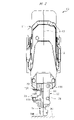
図1に示す打込機10は、ハウジング11、打撃部12、マガジン13、電動モータ14、変換機構15、制御部16、電源部としての電池パック17、及びウェイト18を有する。ハウジング11は、筒形状の本体部19と、本体部19に接続されたハンドル20と、本体部19に接続されたモータケース21と、を有する。装着部22がハンドル20及びモータケース21に接続されている。
The
打撃部12は、本体部19内に配置されたプランジャ26と、プランジャ26に固定されたドライバブレード27と、を有する。ドライバブレード27は金属製である。ガイドシャフト28が本体部19内に固定されている。中心線A1は、ガイドシャフト28の中心である。プランジャ26は、ガイドシャフト28に取り付けられており、打撃部12は、中心線A1に沿った方向に移動可能である。
The
射出部23は、本体部19の外に設けられ、射出部23は、本体部19に取り付けられている。射出部23は、ノーズ部と定義可能である。射出部23は、ブレードガイド120、マガジンプレート105及びカバー30を有する。ブレードガイド120は、金属製または合成樹脂製の何れでもよい。マガジンプレート105は、金属製または合成樹脂製の何れでもよい。カバー30は、金属製または合成樹脂製の何れでもよい。射出路24が、ブレードガイド120及びマガジンプレート105によって形成されている。射出路24は、溝、通路、孔、隙間、空間の何れでもよい。ドライバブレード27は射出路24内を移動可能である。
The
図2及び図3のように、第1プッシュレバー74が、射出部23に取り付けられている。第1プッシュレバー74は、射出部23に対して移動及び停止が可能である。射出部23は、ドライバブレード27に接触することにより、ドライバブレード27が、中心線A1に対して交差する方向に移動することを阻止する。マガジン13は、射出部23及びハウジング11によって支持されている。
As shown in FIGS. 2 and 3, a
図1に示すウェイト18は、ハウジング11が受ける反動を抑制する。ウェイト18は、一例として金属製である。ウェイト18はガイドシャフト28に取り付けられている。ウェイトアーム部35が、ウェイト18に設けられている。ウェイト18は、ガイドシャフト28に取り付けられている。ウェイト18は、中心線A1に沿った方向に移動可能である。ウェイト18は、外面から突出した突起部18Aを有する。
The
金属製のスプリング36が本体部19内に配置され、スプリング36は、中心線A1に沿った方向でプランジャ26とウェイト18との間に配置されている。プランジャ26は、中心線A1に沿った方向で、射出部23に近づく第1の向きD1の付勢力を、スプリング36から受ける。ウェイト18は、中心線A1に沿った方向で射出部23から離間する第2の向きD2の付勢力を、スプリング36から受ける。第1の向きD1と第2の向きD2とは互いに逆である。ウェイトバンパ37及びプランジャバンパ38が、本体部19内に設けられている。ウェイトバンパ37及びプランジャバンパ38は、共に合成ゴム製である。
A
図1において、打撃部12またはプランジャ26またはウェイト18が、第1の向きD1でそれぞれ移動することを下降と呼ぶ。打撃部12またはプランジャ26またはウェイト18が、第2の向きD2でそれぞれ移動することを上昇と呼ぶ。打撃部12及びウェイト18は、中心線A1に沿った方向にそれぞれ往復移動可能である。
In FIG. 1, movement of the
電池パック17は、装着部22に対して取り付け及び取り外し可能である。電池パック17は、収容ケース39と、収容ケース39内に収容した複数の電池セルとを有する。電池セルは、充電及び放電が可能な二次電池であり、電池セルは、リチウムイオン電池、ニッケル水素電池、リチウムイオンポリマー電池、ニッケルカドミウム電池の何れかを用いることができる。電池パック17は直流電源であり、電池パック17から電動モータ14に電圧が印加される。
The
図1に示す制御部16は、装着部22内に設けられており、制御部16は、入力ポート、出力ポート、演算処理部及び記憶部を有するマイクロコンピュータである。図1に示すトリガ42及びトリガスイッチ43がハンドル20に設けられており、ユーザがトリガ42に操作力を付加するとトリガスイッチ43がオンする。ユーザがトリガ42に加えた操作力を解除すると、トリガスイッチ43がオフする。図4(A)に示すインバータ回路72が、モータケース21内に設けられている。インバータ回路72は、オン及びオフが可能なスイッチング素子を複数備えている。
The
位置検出センサ44が、ハウジング11内に設けられている。位置検出センサ44は、例えば、マイクロスイッチである。ウェイト18の突起部18Aが位置検出センサ44に接触すると、位置検出センサ44はオンする。突起部18Aが位置検出センサ44から離間すると、位置検出センサ44はオフする。位置検出センサ44から出力される信号は、制御部16に入力される。制御部16は、位置検出センサ44の信号を処理して、プランジャ26及びウェイト18の中心線A1に沿った方向における位置を推定する。
A
プッシュレバースイッチ73が、マガジン13に設けられている。プッシュレバースイッチ73は、接触片73Aを有する接触形スイッチである。プッシュレバースイッチ73は、第1プッシュレバー74が相手材W1に押し付けられて移動したこと、第1プッシュレバー74が相手材W1から離間して移動したこと、を検出して信号を出力する。制御部16は、トリガスイッチ43の信号、プッシュレバースイッチ73の信号、位置検出センサ44の信号を受信し、かつ、インバータ回路72を制御する信号を出力する。
A
電動モータ14は、ロータ14A及びステータ14Bを有し、モータ軸46がロータ14Aに取り付けられている。電動モータ14は、電池パック17から電圧が印加されてモータ軸46が回転する。モータ軸46は、減速機75を介して回転部材76に接続されている。電動モータ14、モータ軸46及び回転部材76は、中心線A2を中心として同心状に配置されている。中心線A2は中心線A1に対して交差するように配置されている。
The
変換機構15は、回転部材76の回転力を打撃部12の移動力及びウェイト18の移動力に変換する。変換機構15は、第1ギヤ50、第2ギヤ51及び第3ギヤ52を有する。カムローラ57が第1ギヤ50に設けられ、カムローラ58が第2ギヤ51に設けられ、カムローラ59が第3ギヤ52に設けられている。
The conversion mechanism 15 converts the rotational force of the rotating
電池パック17から電動モータ14に電圧が印加されてモータ軸46が正回転すると、モータ軸46の回転力が減速機47を介して第1ギヤ50に伝達される。第1ギヤ50の回転力は、第2ギヤ51を経由して第3ギヤ52に伝達される。
When voltage is applied from the
第1係合部77がプランジャ26に設けられている。カムローラ57,58は第1係合部77に係合及び解放可能である。第2係合部78がウェイト18に設けられている。カムローラ59は、第2係合部78に係合及び解放可能である。
A first engaging
マガジン13は、本体部80及びガイド部81を有し、本体部80は、ハウジング11及び射出部23に固定されている。プッシュレバースイッチ73は、本体部80に取り付けられている。ガイド部81は、本体部80に対して中心線A2に沿った方向に移動及び停止可能である。ロックレバー107が、ガイド部81に設けられている。ユーザがロックレバー107を操作すると、ガイド部81を本体部80に対して移動可能になる。ガイド部81は、マガジンプレート105を有し、ガイド部81が本体部80に位置決めされていると、マガジンプレート105は、ブレードガイド120に接触する。収容室が、本体部80とガイド部81との間に収容室が形成されている。収容室は、複数の留具25を1列に並べた状態で収容可能である。隣り合う留具25同士は、接着剤で接続されている。
The
フィーダ70がマガジン13に設けられている。フィーダ70は、金属製のスプリング71の付勢力により、射出部23に接近する第5の向きB1で付勢される。第5の向きB1は、中心線A2に沿った向きである。フィーダ70は、マガジン13に収容された留具25を射出路24へ送る。留具25はガイド部81に沿って移動する。接触部材114が、マガジン13に取り付けられている。接触部材114は、ベースと定義可能である。接触部材114は、留具25の送り方向で、射出部23から間隔をおいて配置されている。
A
次に、打込機10の使用例を説明する。制御部16は、トリガスイッチ43またはプッシュレバースイッチ73の少なくとも一方がオフであると、電動モータ14に対する電力の供給を行わないように制御している。打撃部12は待機位置で停止している。ここでは、打撃部12が待機位置で停止していると、プランジャ26がプランジャバンパ38から離間している例を説明する。
Next, a usage example of the
ユーザが、トリガ42に操作力を付加するとトリガスイッチ43がオンし、かつ、第1プッシュレバー74を相手材W1に押し付けると、プッシュレバースイッチ73がオンする。すると、制御部16は、電動モータ14に電圧を印加し、モータ軸46を回転させる。モータ軸46の回転力は、減速機75で増幅されて第1ギヤ50に伝達され、第1ギヤ50、第2ギヤ51及び第3ギヤ52が回転する。
When the user applies an operating force to the
カムローラ57,58の少なくとも一方が第1係合部77に係合すると、打撃部12は待機位置から上昇する。また、第3ギヤ52のカムローラ59が第2係合部78に係合すると、ウェイト18は下降する。
When at least one of the
次いで、カムローラ57,58が共に第1係合部77から解放されると、打撃部12はスプリング36の付勢力で下降する。また、カムローラ59が第2係合部78から解放されると、ウェイト18がスプリング36の付勢力で上昇する。ドライバブレード27は、マガジン13から射出路24へ到達した1本の留具25を打撃し、留具25は相手材W1に打ち込まれる。
Next, when the
ドライバブレード27が留具25を打撃した後、プランジャ26がプランジャバンパ38に衝突する。プランジャバンパ38は、打撃部12の運動エネルギの一部を吸収する。また、ウェイト18はウェイトバンパ37に衝突する。ウェイトバンパ37はウェイト18の運動エネルギの一部を吸収する。このように、打撃部12が第1の向きD1で移動して留具25を打撃する際、ウェイト18は、打撃部12が留具25を打撃する際の反動を低減可能である。
After
制御部16は、留具25が相手材W1に打ち込まれた後に、ユーザが第1プッシュレバー74を相手材W1から離し、かつ、トリガスイッチ43がオフされた後も、電動モータ14を回転させている。そして、打撃部12がスプリング36の付勢力に抗して下死点から上昇し、プランジャ26は、プランジャバンパ38から離間する。制御部16は、打撃部12が待機位置に到達したことを検出すると、電動モータ14を停止させる。
The
ユーザは、第1プッシュレバー74を相手材W1に押し付け、かつ、接触部材114を相手材W1に接触させることが可能である。つまり、第1プッシュレバー74と、接触部材114とが、留具25の送り方向に間隔をおいた2箇所で、相手材W1に接触する。なお、ユーザは、接触部材114をマガジン13から取り外した状態で、打込機10を使用することも可能である。
The user can press the
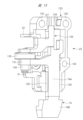
本実施形態における射出部23は、次の構成を有する。図5、図6及び図7のように、ブレードガイド120は、ストッパ31、突起32,33、ガイド部121,122,123,124,125,126,127,128,129を有する。中心線A1に沿った方向で、ガイド部121,122は、同じ範囲に配置され、ガイド部123,124は、同じ範囲に配置されている。中心線A1に沿った方向で、ガイド部121,122と、ガイド部123,124とが、間隔をおいて配置されている。ガイド部121,122,123,124,125は平坦面であり、かつ、同一平面上に位置する。
The
中心線A1に沿った方向で、ガイド部126,127と、ガイド部128,129とが、間隔をおいて配置されている。ガイド部126とガイド部127とが、中心線A1を隔てて配置されている。ガイド部128とガイド部129とが、中心線A1を隔てて配置されている。
また、複数の取り付け孔130が、ブレードガイド120に設けられている。図2及び図3に示すねじ部材136が、取り付け孔130にそれぞれ配置される。ねじ部材136が締め付けられて、カバー30及びブレードガイド120が、本体部19に固定されている。第1プッシュレバー74は、中心線A2に沿った方向で、ブレードガイド120とカバー30との間に配置されている。
A plurality of mounting
第1プッシュレバー74は、図6及び図7のように、プレート形状の本体74A、アーム131及びヘッド部74Bを有する。アーム131は、本体74Aから中心線A1に交差する方向に突出されている。ヘッド部74Bは、本体74Aに接続されている。ヘッド部74Bは、端部74Cを有する。第1プッシュレバー74の本体74Aは、ガイド部126とガイド部127との間に配置され、かつ、ガイド部128とガイド部129との間に配置されている。
The
軸孔132がアーム131に設けられている。軸孔132の内面に雌ねじが設けられている。ガイド孔138が、第1プッシュレバー74に設けられている。突起33はガイド孔138内に位置している。第1プッシュレバー74がブレードガイド120に対して中心線A1に沿った方向に移動すると、突起33はガイド孔138内で移動する。スプリング139が、ガイド孔138に配置されている。スプリング139は、突起33に接触して圧縮されており、スプリング139は、第1プッシュレバー74を本体部19から離間するように、第3の向きD4で付勢する。
A
アジャスタ133が、アーム131と突起32との間に配置されている。アジャスタ133は軸部134を有する。軸部134の外面に雄ねじが設けられている。アジャスタ133は、円柱形状のダイヤルである。軸部134は、軸孔132内に配置されている。ユーザがアジャスタ133を回転させると、アジャスタ133は、アーム131に対して中心線A1に沿った方向に移動する。
An
図7のように、アジャスタ133はピン164を有する。第2プッシュレバー135が、アジャスタ133と突起32との間に配置されている。第2プッシュレバー135は、アーム135A及び軸孔163を有する。アーム135Aは、第2プッシュレバー135から中心線A1に対して交差する方向に突出している。また、ピン164が軸孔163に配置されている。スプリング137が、突起32と第2プッシュレバー135との間に設けられている。スプリング137は、中心線A1に沿った方向に圧縮されており、スプリング137は、第2プッシュレバー135をアジャスタ133に押し付ける。第2プッシュレバー135は、ブレードガイド120に対して中心線A1に沿った方向に移動可能である。第2プッシュレバー135が移動することにより、プッシュレバースイッチ73のオンとオフとが切り替わる。
The
第1プッシュレバー74、第2プッシュレバー135及びアジャスタ133の機能及び作用は、次の通りである。第1プッシュレバー74は、ヘッド部74Bが相手材W1から離間している場合、または、ヘッド部74Bが相手材W1に押し付けられている場合、の何れであっても、スプリング139の力で第3の向きD4で付勢されている。
The functions and actions of the
また、第2プッシュレバー135は、ヘッド部74Bが相手材W1から離間している場合、または、ヘッド部74Bが相手材W1に押し付けられている場合、の何れであっても、スプリング137の力で第3の向きD4で付勢され、かつ、アジャスタ133に接触している。
Further, the
先ず、第1プッシュレバー74のヘッド部74Bが、相手材W1から離間している場合を説明する。スプリング139の力は、第1プッシュレバー74を経由して軸部134に伝達され、軸部134は、図7のようにストッパ31に接触している。つまり、第1プッシュレバー74は、初期位置で停止している。さらに、端部74Cは、ブレードガイド120から離間している。第1プッシュレバー74が初期位置で停止していると、第2プッシュレバー135は、図3のように接触片73Aから離間した位置、つまり、初期位置で停止している。このため、プッシュレバースイッチ73は、オフしている。
First, the case where the
そして、ヘッド部74Bが相手材W1に押し付けられると、第1プッシュレバー74は、スプリング139の力に抗し、射出部23に対して第4の向きD5で移動する。このため、軸部134はストッパ31から離間する。第4の向きD5は、中心線A1に沿った向きであり、かつ、第3の向きD4とは逆である。
Then, when the
第1プッシュレバー74が第4の向きD5で移動すると、第1プッシュレバー74の移動力は、アジャスタ133を経由して第2プッシュレバー135に伝達される。このため、第2プッシュレバー135は、スプリング137の力に抗して第4の向きD5で移動する。第2プッシュレバー135が接触片73Aに接触して、接触片73Aが作動すると、プッシュレバースイッチ73は、オフからオンに切り替わる。そして、第1プッシュレバー74は、端部74Cがブレードガイド120に接触すると停止する。つまり、第1プッシュレバー74は作動位置で停止する。第1プッシュレバー74が作動位置で停止すると、第2プッシュレバー135は作動位置で停止する。
When the
第1プッシュレバー74が作動位置で停止している状態において、ヘッド部74Bが相手材W1から離間されると、第1プッシュレバー74は、作動位置から、スプリング139の力で第3の向きD4で移動する。このため、端部74Cはブレードガイド120から離間する。
When the
また、第1プッシュレバー74が作動位置から第3の向きD4で移動すると、第2プッシュレバー135は、アジャスタ133に接触した状態を維持し、かつ、スプリング137の力で、作動位置から第3の向きD4で移動する。第2プッシュレバー135が接触片73Aから離間すると、プッシュレバースイッチ73は、オンからオフに切り替わる。第1プッシュレバー74は、軸部134がストッパ31に接触すると、初期位置で停止する。第1プッシュレバー74が初期位置で停止していると、ヘッド部74Bは、マガジンプレート105の先端105Aに対して長さL1突出する。長さL1は、中心線A1に沿った方向の長さである。また、第2プッシュレバー135は、初期位置で停止する。
Further, when the
ヘッド部74Bが相手材W1から離間している状態で、ユーザがアジャスタ133を回転させると、第1プッシュレバー74は、アーム131と軸部134とが接続された状態で、射出部23に対して中心線A1に沿った方向に移動する。ユーザがアジャスタ133を回転させる方向を切り替えると、第1プッシュレバー74が移動する向きは、第3の向きD4と第4の向きD5で切り替わる。つまり、ユーザがアジャスタ133を回転させると、長さL1を調整可能である。
When the user rotates the
そして、第1プッシュレバー74が初期位置から作動位置へ移動する量は、長さL1に応じて定まる。長さL1が増加することに伴い、第1プッシュレバー74が初期位置から作動位置へ移動する量が増加する。したがって、ユーザは、アジャスタ133を回転させることにより、中心線A1に沿った方向で、マガジンプレート105の先端105Aに対する第1プッシュレバー74のヘッド部74Bの位置を調整可能である。
The amount by which the
さらに、打撃部12が下死点に到達した状態において、ドライバブレード27の先端は、マガジンプレート105の先端105Aに位置する。つまり、ユーザは、ヘッド部74Bが先端105Aから突出する長さL1を調整することにより、相手材W1に対する留具25の打ち込み量を調整可能である。
Further, the tip of the
打込機10は、位置決め機構を有する。位置決機構は、射出部23に対する第1プッシュレバー74及び第2プッシュレバー135の移動を、所定方向に定めるものである。図4(B)は、射出部23に対する第1プッシュレバー74及び第2プッシュレバー135の移動を、所定方向に定める一例を示す3次元の座標系である。図4(B)には、第1平面160、第2平面161、第1軸Z1、第2軸Y1及び第3軸X1が示されている。第1平面160は、第2平面161に対して垂直である。第3軸X1は、中心線A1に対応し、第1軸Z1は、中心線A2に対応する。第2軸Y1は、図2及び図7において左右方向に相当する軸である。第1軸Z1は、第1平面160に沿って位置し、第2軸Y1は、第2平面161に沿って位置する。第3軸X1は、第1平面160と第2平面161との交差箇所を通る。
The
図4(B)に示す座標系は、第1平面160内において、第1軸Z1と第3軸X1との間に形成される角度が90度の例である。図4(B)に示す座標系は、第2平面161内において、第2軸Y1と第3軸X1との間に形成される角度が90度の例である。
The coordinate system shown in FIG. 4B is an example in which the angle formed between the first axis Z1 and the third axis X1 in the
本実施形態は、位置決め機構の具体例1、具体例2及び具体例3を開示する。 This embodiment discloses specific examples 1, 2, and 3 of the positioning mechanism.
(具体例1) 第1プッシュレバー74は、ガイド部121,122,123,124及びカバー30にそれぞれ接触することにより、第1平面160内で第3軸X1に対して交差する方向に移動することが規制される。第1プッシュレバー74は、ガイド部126,127,128,129にそれぞれ接触することにより、第2平面161内で第3軸X1に対して交差する方向に移動することが規制される。
(Specific Example 1) The
また、第2プッシュレバー135は、アーム135Aがガイド部125及びカバー30に接触することにより、第1平面160内で第3軸X1に対して交差する方向に移動することが規制される。第2プッシュレバー135は、アーム135Aがガイド部127に接触することにより、第2平面161内で第3軸X1に対して交差する方向に移動することが規制される。
Further, the
つまり、ブレードガイド120及びカバー30は、共に第1プッシュレバー74及び第2プッシュレバー135を射出部23に対して位置決めする部材としての役割を有する。このため、第1プッシュレバー74の位置決め部材と、第2プッシュレバー135の位置決め部材とを、それぞれ別々に設けずに済む。したがって、打込機10の部品点数の増加を抑制できる、小型化、軽量化、低コスト化を図ることができる。
In other words, both the
また、第1プッシュレバー74及び第2プッシュレバー135の移動方向が、共に第3軸X1に沿った方向となるように位置決めされている。このため、一方の要素の移動力が、他方の要素を、所定位置を支点として回転させるモーメントとして作用することを抑制できる。したがって、第1プッシュレバー74の作動、及び第2プッシュレバー135の作動抵抗が増加することを、それぞれ抑制できる。さらに、アジャスタ133と第2プッシュレバー135との接触抵抗の増加を抑制でき、アジャスタ133の操作性が低下することを抑制できる。
Further, the
また、ガイド部121,122,123,124,125は、同一平面上に位置する。したがって、第1プッシュレバー74及び第2プッシュレバー135が第3軸X1に沿った方向に移動する場合の摺動抵抗を低減可能である。
Moreover, the
ガイド部126,127と、ガイド部128,129とが、第3軸X1に沿った方向に間隔をおいた2つの範囲で、第1プッシュレバー74に接触して位置決めする。したがって、第1プッシュレバー74が、第2平面161内で第3軸X1に対して交差する方向に移動することを、確実に防止可能である。
(具体例2) 位置決め機構の具体例2は、図8、図9及び図10に示されている。ブレードガイド120は、ガイド部140,141,142,143を有する。ガイド部140,141は、中心線A1に沿った方向で同じ範囲に設けられている。ガイド部142,143は、中心線A1に沿った方向で同じ範囲に設けられている。ガイド部140,141の配置範囲と、ガイド部142,143の配置範囲とは、異なる。
(Specific Example 2) A specific example 2 of the positioning mechanism is shown in FIGS. 8, 9 and 10. FIG. The
第1プッシュレバー74は、中心線A2に沿った方向で、マガジン13とカバー30との間に配置されている。第1プッシュレバー74及び第2プッシュレバー135は、ブレードガイド120及びカバー30にそれぞれ接触することにより、第1軸Z1に沿った方向に位置決めされている。第1軸Z1は、図8において左右方向に相当する。ガイド部140,141は、第1プッシュレバー74の本体74Aに接触することより、第1プッシュレバー74を第2軸Y1に沿った方向に位置決めする。第2軸Y1は、図9において左右方向に相当する。ガイド部142,143は、第2プッシュレバー135に接触することにより、第2プッシュレバー135を第2軸Y1に沿った方向に位置決めする。
The
カバー30は、開口部144、ストッパ148及び、取り付け孔149を有する。取り付け孔149,130にねじ部材が挿入されて締め付けられ、カバー30及びブレードガイド120が、図1の本体部19に固定されている。
The
第2プッシュレバー135の一部及びアーム131の一部は、開口部144に配置されている。突起145がカバー30に設けられ、突起145は軸孔146を有する。ピン164は、軸孔163,146に配置されている。スプリング147が、突起145と第2プッシュレバー135との間に配置されている。スプリング147は、第2プッシュレバー135を、第3の向きD4で付勢し、第2プッシュレバー135はアジャスタ133に接触して停止する。スプリング147の力は、第2プッシュレバー135及びアジャスタ133を経由してアーム131に伝達され、第1プッシュレバー74は、常に、第3の向きD4で付勢される。
A portion of the
具体例2における第1プッシュレバー74、第2プッシュレバー135及びアジャスタ133の機能及び作用は、次の通りである。第2プッシュレバー135は、ヘッド部74Bが相手材W1から離間している場合、または、ヘッド部74Bが相手材W1に押し付けられている場合、の何れであっても、スプリング147の力で第3の向きD4で付勢され、かつ、アジャスタ133に接触している。
The functions and actions of the
先ず、第1プッシュレバー74のヘッド部74Bが、相手材W1から離間している場合を説明する。スプリング147の力は、第2プッシュレバー135及びアジャスタ133を経由して軸部134に伝達され、軸部134は、図8のようにストッパ148に接触している。つまり、第1プッシュレバー74は、初期位置で停止している。さらに、端部74Cは、ブレードガイド120から離間している。第1プッシュレバー74が初期位置で停止していると、第2プッシュレバー135は、図8のように接触片73Aから離間した位置、つまり、初期位置で停止している。このため、プッシュレバースイッチ73は、オフしている。
First, the case where the
そして、ヘッド部74Bが相手材W1に押し付けられると、第1プッシュレバー74がスプリング147の力に抗して、射出部23に対して第4の向きD5で移動する。このため、軸部134はストッパ148から離間する。
Then, when the
第1プッシュレバー74が第4の向きD5で移動すると、第1プッシュレバー74の移動力は、アジャスタ133を経由して第2プッシュレバー135に伝達される。このため、第2プッシュレバー135は、スプリング137の力に抗して第4の向きD5で移動する。第2プッシュレバー135が接触片73Aに接触して、接触片73Aが作動すると、プッシュレバースイッチ73は、オフからオンに切り替わる。そして、第1プッシュレバー74は、端部74Cがブレードガイド120に接触すると停止する。つまり、第1プッシュレバー74は作動位置で停止する。第1プッシュレバー74が作動位置で停止すると、第2プッシュレバー135は作動位置で停止する。
When the
第1プッシュレバー74が作動位置で停止している状態において、ヘッド部74Bが相手材W1から離間されると、第1プッシュレバー74は、作動位置からスプリング147の力で第3の向きD4に移動する。このため、端部74Cはブレードガイド120から離間する。
When the
また、第1プッシュレバー74が作動位置から第3の向きD4で移動すると、第2プッシュレバー135は、アジャスタ133に接触した状態を維持し、かつ、スプリング147の力で、作動位置から第3の向きD4で移動する。第2プッシュレバー135が接触片73Aから離間すると、プッシュレバースイッチ73は、オンからオフに切り替わる。第1プッシュレバー74は、軸部134がストッパ148に接触すると、初期位置で停止する。また、第2プッシュレバー135は、初期位置で停止する。ヘッド部74Bが相手材W1から離間している状態で、ユーザがアジャスタ133を回転させると、ヘッド部74Bが先端105Aから突出する長さL1を調整可能である。
Further, when the
なお、図10のように、ブレードガイド120は、切り欠き部150を有し、第2プッシュレバー135のうち接触片73Aに接触及び離間する部位135Bは、切り欠き150内で移動するため、第2プッシュレバー135の移動は阻害されない。
As shown in FIG. 10, the
ブレードガイド120及びカバー30は、第1プッシュレバー74及び第2プッシュレバー135を、第1平面160内で第3軸X1に対して交差する方向に移動することを規制する。このため、第1プッシュレバー74を、第1平面160内で第3軸X1に対して交差する方向に位置決めする部材と、第2プッシュレバー135を第1平面160内で第3軸X1に対して交差する方向に位置決めする部材とを、それぞれ別々に設けずに済む。したがって、打込機10の部品点数の低減、小型化、軽量化を図ることができる。
The
ブレードガイド120及びカバー30は、第1プッシュレバー74及び第2プッシュレバー135が、第1平面160内で第3軸X1に対して交差する方向に移動することを阻止する。また、第1プッシュレバー74を位置決めするガイド部140,141と、第2プッシュレバー135を位置決めするガイド部142,143とが、物理的に同じ部品、すなわち、単独の部品であるブレードガイド120に設けられている。このため、第1プッシュレバー74及び第2プッシュレバー135が、第2平面161内で第3軸X1に対して交差する方向に移動することを阻止する部材を、それぞれ別々に設けずに済む。したがって、打込機10の部品点数の低減、小型化、軽量化を図ることができる。
The
さらに、位置決め機構の具体例2において、位置決め機構の具体例1と同様の構成については、位置決め機構の具体例1と同様の効果を得ることができる。 Furthermore, in the second specific example of the positioning mechanism, the same configuration as in the first specific example of the positioning mechanism can provide the same effects as in the first specific example of the positioning mechanism.
(具体例3) 位置決め機構の具体例3は、図11、図12及び図13に示されている。具体例3は、具体例1と略同様の構成を有する。ガイド部126,127は、第2プッシュレバー135に接触する。ガイド部126,127は、第1プッシュレバー74から離間している。ガイド部128,129は、第1プッシュレバー74に接触する。ブレードガイド120及びカバー30は、第1プッシュレバー74及び第2プッシュレバー135を、図1の中心線A2に沿った方向で位置決めする。スプリング139は、ガイド部126と第1プッシュレバー74との間に配置され、スプリング139は、第1プッシュレバー74を第3の向きD4で付勢する。
(Specific Example 3) A specific example 3 of the positioning mechanism is shown in FIGS. Specific example 3 has substantially the same configuration as specific example 1. FIG.
第1プッシュレバー74は、ブレードガイド120及びカバー30にそれぞれ接触することにより、第1平面160内で第3軸X1に対して交差する方向に移動することが規制されている。第1プッシュレバー74は、ガイド部128,129にそれぞれ接触することにより、第2平面161内で、第3軸X1に対して交差する方向に移動することが規制されている。
The
また、第2プッシュレバー135は、ブレードガイド120及びカバー30に接触することにより、第1平面160内で第3軸X1に対して交差する方向に移動することが規制されている。第2プッシュレバー135は、ガイド部127,128に接触することにより、第2平面161内で第3軸X1に対して交差する方向に移動することが規制されている。
Further, the
なお、第1プッシュレバー74及び第2プッシュレバー135は、それぞれ移動方向が規制されている。これに対して、部品の寸法誤差、部品の加工公差等により、部品同士の間に隙間がある。したがって、第1プッシュレバー74及び第2プッシュレバー135は、本来の移動方向への移動は阻害されず、かつ、スムーズに移動が可能である。
The moving directions of the
つまり、ブレードガイド120及びカバー30は、共に第1プッシュレバー74及び第2プッシュレバー135の位置決め部材としての役割を兼ねている。つまり、第1プッシュレバー74及び第2プッシュレバー135を位置決めする共通の部品を有する。このため、第1プッシュレバー74の位置決め部材と、第2プッシュレバー135の位置決め部材とを、それぞれ別々に設けずに済む。したがって、打込機10の部品点数の増加を抑制できる、小型化、軽量化、低コスト化を図ることができる。具体例3における他の効果は、具体例1における効果と同じである。
In other words, both the
実施形態で開示した事項の技術的意味の一例は、次の通りである。打込機10は、打込機の一例である。留具25は、留具の一例であり、マガジン13は、マガジンの一例である。射出部23は、射出部の一例である。打撃部12は、打撃部の一例である。第1プッシュレバー74は、第1プッシュレバーの一例である。第2プッシュレバー135は、第2プッシュレバーの一例である。ブレードガイド120及びカバー30は、ガイド部材の一例である。
An example of the technical meaning of the items disclosed in the embodiments is as follows. The
ガイド部材は、第1プッシュレバー及び第2プッシュレバーの移動方向を、共に所定方向に定める機能を兼ねる。したがって、ガイド部材は、単数または複数の何れでもよい。例えば、実施形態で説明した第1プッシュレバー及び第2プッシュレバーにガイド孔をそれぞれ設けることが可能である。そして、ブレードガイド120に、ガイド孔内に配置されるピンを設けることで、単数のブレードガイド120は、第1プッシュレバー及び第2プッシュレバーの移動方向を、共に所定方向に定める機能を兼ねる。ブレードガイド120は、ブレードガイドの一例である。カバー30は、カバーの一例である。アジャスタ133は、調整機構の一例である。
The guide member also has the function of determining the moving directions of the first push lever and the second push lever in a predetermined direction. Therefore, the guide member may be singular or plural. For example, a guide hole can be provided in each of the first push lever and the second push lever described in the embodiment. By providing the
中心線A1に沿った方向、つまり、第3軸X1に沿った方向は、打撃部の移動方向及び所定方向の一例である。第1の向きD1は、第1の向きの一例である。第2の向きD2は、第2の向きの一例である。長さL1は、第1プッシュレバーが射出部に対して第1の向きに突出する量の一例である。中心線A2に沿った方向は、留具が射出部へ供給される方向の一例である。スプリング36はスプリングの一例である。電動モータ14は、モータの一例である。プッシュレバースイッチ73及び制御部16は、検出部の一例である。制御部16は、制御部の一例である。マガジンプレート105は、マガジンプレートの一例である。射出路24は、射出路の一例である。ガイド部121,122,123,124は、第1ガイド部の一例である。ガイド部125は、第2ガイド部の一例である。第1プッシュレバーと連動して移動可能な第2プッシュレバーは、第1プッシュレバーの移動力が伝達されて移動可能な第2プッシュレバーという意味を含む。
The direction along the center line A1, that is, the direction along the third axis X1 is an example of the movement direction and the predetermined direction of the striking portion. The first orientation D1 is an example of the first orientation. The second orientation D2 is an example of the second orientation. The length L1 is an example of the amount by which the first push lever protrudes in the first direction with respect to the ejector. The direction along the centerline A2 is an example of the direction in which the fastener is supplied to the injection section.
打込機は、図面を用いて開示された実施形態に限定されるものではなく、その要旨を逸脱しない範囲で種々変更可能である。例えば、第1プッシュレバー及び第2プッシュレバーの形状は、それぞれ、軸形状、ブロック形状、アーム形状等の何れでもよい。また、第1プッシュレバー及び第2プッシュレバーは、射出部に対して打撃部の移動方向と同じ所定方向にそれぞれ移動可能であればよい。第1プッシュレバー及び第2プッシュレバーは、それぞれ移動する場合に支点の有無は問わない。 The fastening tool is not limited to the embodiments disclosed using the drawings, and can be modified in various ways without departing from the scope of the invention. For example, the shape of the first push lever and the second push lever may be shaft-shaped, block-shaped, arm-shaped, or the like. Also, the first push lever and the second push lever need only be able to move in the same predetermined direction as the movement direction of the striking portion with respect to the ejection portion. The first push lever and the second push lever may or may not have a fulcrum when they move.
また、打撃部を第1の向きで移動させるスプリングは、金属製のスプリングに代えて、ガススプリングを用いることも可能である。モータは、電動モータに代えて、油圧モータまたは空気圧モータまたはエンジンの何れかを用いることも可能である。電動モータに電圧を印加する電源部は、直流電源または交流電源の何れでもよい。 Also, a gas spring can be used instead of a metal spring for moving the striking part in the first direction. The motor can be either a hydraulic or pneumatic motor or an engine instead of an electric motor. A power source that applies voltage to the electric motor may be either a DC power source or an AC power source.
打撃部を第1の向きで付勢する機構は、スプリングに代えて、ハウジング内に設けた蓄圧室及び圧力室でもよい。蓄圧室は、ハウジングの外部からエアホースを介して圧縮性気体が供給される。蓄圧室と圧力室とを接続及び遮断するバルブが設けられる。圧力室は、蓄圧室から圧縮性気体が供給される空間である。打撃部は、圧力室の圧力で第1の向きで移動する。第1プッシュレバーの移動力で第2プッシュレバーが作動すると、バルブが蓄圧室と圧力室とを接続または遮断する。また、打撃部の待機位置は、プランジャがプランジャバンパから離間している位置でもよい。 The mechanism for urging the striking portion in the first direction may be an accumulator chamber and a pressure chamber provided in the housing instead of the spring. Compressible gas is supplied to the accumulator from the outside of the housing through an air hose. A valve is provided for connecting and disconnecting the accumulator and the pressure chamber. The pressure chamber is a space to which compressible gas is supplied from the accumulator. The striking part moves in the first direction under the pressure of the pressure chamber. When the second push lever is actuated by the moving force of the first push lever, the valve connects or disconnects the pressure accumulation chamber and the pressure chamber. Also, the standby position of the striking part may be a position where the plunger is separated from the plunger bumper.
検出部は、第2プッシュレバーに接触または離間して信号を発生する接触形センサまたは接触形スイッチに代えて、非接触センサを備えていてもよい。非接触センサは、第2プッシュレバーに接触することなく信号を発生する。非接触センサは、光学センサ、磁気センサを含む。制御部は、電気部品または電子部品の単体でもよいし、複数の電気部品または複数の電子部品を有するユニットでもよい。電気部品または電子部品は、プロセッサ、制御回路及びモジュールを含む。 The detection section may include a non-contact sensor instead of a contact sensor or contact switch that generates a signal by contacting or separating from the second push lever. A non-contact sensor generates a signal without contacting the second push lever. Non-contact sensors include optical sensors and magnetic sensors. The control unit may be a single electric component or electronic component, or may be a unit having a plurality of electric components or a plurality of electronic components. Electrical or electronic components include processors, control circuits and modules.
さらに、図4(B)の座標系において、第1平面160と第2平面161との間に形成される角度は、90度でなくてもよい。第1平面160と第2平面161とが交差していればよい。また、第1平面160内で第1軸Z1と第3軸X1との間に形成される角度は、90度でなくてもよい。第1平面160内で第1軸Z1と第3軸X1とが交差していればよい。さらに、第2平面161内で第2軸Y1と第3軸X1との間に形成される角度は、90度でなくてもよい。第2平面161内で第2軸Y1と第3軸X1とが交差していればよい。
Furthermore, in the coordinate system of FIG. 4B, the angle formed between the
10…打込機、12…打撃部、13…マガジン、14…電動モータ、16…制御部、23…射出部、24…射出路、25…留具、30…カバー、36…スプリング、73…プッシュレバースイッチ、74…第1プッシュレバー、105…マガジンプレート、120…ブレードガイド、121,122,123,124,125,127,128,129…ガイド部、133…アジャスタ、135…第2プッシュレバー、A1,A2…中心線、D1…第1の向き、D2…第2の向き、L1…長さ、X1…第3軸
DESCRIPTION OF
Claims (11)
前記射出部へ供給された前記留具を相手材に打ち込むように、前記射出部に対して移動可能な打撃部と、
を有する、打込機であって、
前記射出部に設けられて前記相手材に接触及び離間可能であり、かつ、前記射出部に対して移動可能な第1プッシュレバーと、
前記射出部に設けられ、前記第1プッシュレバーと連動して移動可能な第2プッシュレバーと、を備え、
前記射出部は、前記打撃部の移動をガイドするブレードガイドと、前記ブレードガイドに固定されるカバーと、を有し、
前記ブレードガイドと前記カバーとの間に前記第1プッシュレバー及び前記第2プッシュレバーが配置されることで、前記第1プッシュレバー及び前記第2プッシュレバーは、前記射出部に対する移動が前記打撃部の移動方向に沿うようにガイドされる、打込機。 an injection section to which the fastener is fed;
a striking portion movable with respect to the injection portion so as to strike the fastener supplied to the injection portion into a mating member;
A fastening tool comprising:
a first push lever provided in the injection section, capable of contacting and separating from the mating member, and movable with respect to the injection section;
a second push lever provided in the injection section and movable in conjunction with the first push lever ;
The injection section has a blade guide that guides the movement of the striking section, and a cover that is fixed to the blade guide,
By arranging the first push lever and the second push lever between the blade guide and the cover, the movement of the first push lever and the second push lever with respect to the ejection portion is the impact portion. The tool is guided along the direction of movement of the
前記第1プッシュレバーが前記射出部に対して前記第1の向きに突出する量を調整可能な調整機構が設けられている、請求項1記載の打込機。 the striking part is movable in a first direction for striking the fastener and in a second direction opposite to the first direction;
2. The driving tool according to claim 1 , further comprising an adjustment mechanism capable of adjusting the amount by which said first push lever protrudes in said first direction with respect to said ejection portion.
前記留具が前記射出部へ供給される方向は、前記打撃部の移動方向に対して交差し、
前記ブレードガイド及び前記カバーが、前記留具が前記射出部へ送られる方向に並べて配置されている、請求項1乃至3の何れか1項記載の打込機。 a magazine for supplying the fasteners to the ejection part is further provided,
a direction in which the fastener is supplied to the injection section intersects with a moving direction of the striking section;
4. The driving tool according to any one of claims 1 to 3 , wherein said blade guide and said cover are arranged side by side in a direction in which said fastener is sent to said injection section.
前記留具が前記射出部へ供給される方向は、前記打撃部の移動方向に対して交差する方向であり、
前記第1プッシュレバーは、前記留具が前記射出部へ供給される方向で、前記マガジンと前記調整機構との間に配置されている、請求項3記載の打込機。 a magazine for supplying the fasteners to the ejection part is further provided,
the direction in which the fastener is supplied to the injection part is a direction that intersects the moving direction of the striking part;
4. The driving tool according to claim 3 , wherein said first push lever is arranged between said magazine and said adjusting mechanism in a direction in which said fastener is supplied to said ejection section.
前記打撃部を前記第1の向きとは逆の第2の向きに移動させるモータと、
が、更に設けられている、請求項1乃至5の何れか1項記載の打込機。 a spring for moving the striking portion in a first direction for striking the fastener;
a motor for moving the striking part in a second direction opposite to the first direction;
6. A tool according to any one of the preceding claims, further comprising a.
前記第2プッシュレバーが前記第2の向きで移動したことを前記検出部が検出すると、
前記モータによって前記打撃部を前記第2の向きで移動させる制御部と、を備えている、請求項6記載の打込機。 a detection unit that detects that the second push lever has moved in the second direction;
When the detection unit detects that the second push lever has moved in the second direction,
7. The fastening tool according to claim 6 , further comprising a control section for moving said striking section in said second direction by means of said motor.
前記射出部は、前記マガジンプレートを含み、
前記マガジンプレート及び前記ブレードガイドは、前記打撃部により打ち込まれる前記留具が通る射出路を有する、請求項4記載の打込機。 The magazine has a magazine plate that contacts the blade guide,
the injection unit includes the magazine plate,
5. The driving tool according to claim 4 , wherein said magazine plate and said blade guide have an ejection path through which said fastener driven by said striking part passes.
前記第1プッシュレバーは、前記第1ガイド部に接触してガイドされ、
前記第2プッシュレバーは、前記第2ガイド部に接触してガイドされる、請求項1乃至5の何れか1項記載の打込機。 The blade guide has a first guide portion and a second guide portion located in the same plane,
The first push lever is guided in contact with the first guide portion,
The fastening tool according to any one of claims 1 to 5 , wherein the second push lever is guided in contact with the second guide portion.
前記射出部へ供給された前記留具を相手材に打ち込むように、前記射出部に対して移動可能な打撃部と、a striking portion movable with respect to the injection portion so as to strike the fastener supplied to the injection portion into a mating member;
を有する、打込機であって、A fastening tool comprising:
前記射出部に設けられて前記相手材に接触及び離間可能であり、かつ、前記射出部に対して移動可能な第1プッシュレバーと、a first push lever provided in the injection section, capable of contacting and separating from the mating member, and movable with respect to the injection section;
前記射出部に設けられ、前記第1プッシュレバーと連動して移動可能な第2プッシュレバーと、a second push lever provided in the injection section and movable in conjunction with the first push lever;
前記射出部に対する前記第1プッシュレバー及び前記第2プッシュレバーの移動を所定方向にガイドするガイド部と、a guide portion that guides movement of the first push lever and the second push lever with respect to the ejection portion in a predetermined direction;
前記留具を打撃する第1の向きに前記打撃部を移動させる付勢部と、a biasing portion that moves the hitting portion in a first direction for hitting the fastener;
前記打撃部を前記第1の向きとは逆の第2の向きに移動させるモータと、a motor for moving the striking part in a second direction opposite to the first direction;
前記第2プッシュレバーが前記第2の向きで移動したことを検出する検出部と、a detection unit that detects that the second push lever has moved in the second direction;
前記第2プッシュレバーが前記第2の向きで移動したことを前記検出部が検出すると、前記モータによって前記打撃部を前記第2の向きで移動させる制御部と、を備える、打込機。a control section that causes the motor to move the hitting section in the second direction when the detection section detects that the second push lever has moved in the second direction.
Applications Claiming Priority (3)
| Application Number | Priority Date | Filing Date | Title |
|---|---|---|---|
| JP2019119303 | 2019-06-27 | ||
| JP2019119303 | 2019-06-27 | ||
| PCT/JP2020/021330 WO2020261878A1 (en) | 2019-06-27 | 2020-05-29 | Driving tool |
Publications (3)
| Publication Number | Publication Date |
|---|---|
| JPWO2020261878A1 JPWO2020261878A1 (en) | 2020-12-30 |
| JPWO2020261878A5 JPWO2020261878A5 (en) | 2022-03-04 |
| JP7248115B2 true JP7248115B2 (en) | 2023-03-29 |
Family
ID=74060857
Family Applications (1)
| Application Number | Title | Priority Date | Filing Date |
|---|---|---|---|
| JP2021527527A Active JP7248115B2 (en) | 2019-06-27 | 2020-05-29 | hammer |
Country Status (6)
| Country | Link |
|---|---|
| US (1) | US20220355452A1 (en) |
| EP (1) | EP3991917A4 (en) |
| JP (1) | JP7248115B2 (en) |
| CN (1) | CN114025921A (en) |
| TW (1) | TW202100315A (en) |
| WO (1) | WO2020261878A1 (en) |
Citations (5)
| Publication number | Priority date | Publication date | Assignee | Title |
|---|---|---|---|---|
| JP2002283253A (en) | 2001-03-28 | 2002-10-03 | Hitachi Koki Co Ltd | Nailing machine |
| WO2006040911A1 (en) | 2004-10-08 | 2006-04-20 | Max Co., Ltd. | Powered nailing machine |
| JP2014108468A (en) | 2012-11-30 | 2014-06-12 | Hitachi Koki Co Ltd | Driving machine |
| JP5589578B2 (en) | 2010-06-10 | 2014-09-17 | 富士通株式会社 | X-ray analyzer |
| WO2016199670A1 (en) | 2015-06-10 | 2016-12-15 | 日立工機株式会社 | Driving machine |
Family Cites Families (7)
| Publication number | Priority date | Publication date | Assignee | Title |
|---|---|---|---|---|
| JPS5928782Y2 (en) * | 1978-12-19 | 1984-08-18 | マックス株式会社 | Safety device for clasp driving machine |
| JPH0549278U (en) * | 1991-12-04 | 1993-06-29 | マックス株式会社 | Nail driving depth adjustment device for nailer for loose nails |
| JP3243927B2 (en) | 1994-04-15 | 2002-01-07 | 日立工機株式会社 | Driving depth adjusting device for driving machine |
| US5988477A (en) * | 1998-06-03 | 1999-11-23 | Illinois Tools Works, Inc. | Nosepiece shield for combustion powered tool |
| CN103391832A (en) * | 2011-02-28 | 2013-11-13 | 日立工机株式会社 | Electric tool and method of driving electric tool |
| CA2985054C (en) * | 2016-11-09 | 2023-03-21 | Tti (Macao Commercial Offshore) Limited | Depth of drive adjustment mechanism for gas spring fastener driver |
| US11407094B2 (en) * | 2018-04-06 | 2022-08-09 | Black & Decker, Inc. | Fastening tool having a low nail, lockout mechanism |
-
2020
- 2020-04-22 TW TW109113472A patent/TW202100315A/en unknown
- 2020-05-29 US US17/622,405 patent/US20220355452A1/en active Pending
- 2020-05-29 JP JP2021527527A patent/JP7248115B2/en active Active
- 2020-05-29 CN CN202080047307.0A patent/CN114025921A/en active Pending
- 2020-05-29 WO PCT/JP2020/021330 patent/WO2020261878A1/en active Application Filing
- 2020-05-29 EP EP20830770.2A patent/EP3991917A4/en active Pending
Patent Citations (5)
| Publication number | Priority date | Publication date | Assignee | Title |
|---|---|---|---|---|
| JP2002283253A (en) | 2001-03-28 | 2002-10-03 | Hitachi Koki Co Ltd | Nailing machine |
| WO2006040911A1 (en) | 2004-10-08 | 2006-04-20 | Max Co., Ltd. | Powered nailing machine |
| JP5589578B2 (en) | 2010-06-10 | 2014-09-17 | 富士通株式会社 | X-ray analyzer |
| JP2014108468A (en) | 2012-11-30 | 2014-06-12 | Hitachi Koki Co Ltd | Driving machine |
| WO2016199670A1 (en) | 2015-06-10 | 2016-12-15 | 日立工機株式会社 | Driving machine |
Also Published As
| Publication number | Publication date |
|---|---|
| WO2020261878A1 (en) | 2020-12-30 |
| JPWO2020261878A1 (en) | 2020-12-30 |
| US20220355452A1 (en) | 2022-11-10 |
| EP3991917A4 (en) | 2022-11-16 |
| CN114025921A (en) | 2022-02-08 |
| EP3991917A1 (en) | 2022-05-04 |
| TW202100315A (en) | 2021-01-01 |
Similar Documents
| Publication | Publication Date | Title |
|---|---|---|
| US20190168366A1 (en) | Driver | |
| JPWO2018198672A1 (en) | Driving machine | |
| JP6790598B2 (en) | Driving machine | |
| CN113490574B (en) | Driving machine | |
| JP7115544B2 (en) | hammer | |
| CN115135456A (en) | Driving machine | |
| JP7248115B2 (en) | hammer | |
| JP2018051724A (en) | Driving machine | |
| US20230381937A1 (en) | Work machine | |
| WO2021020364A1 (en) | Driving machine | |
| JP6766727B2 (en) | Driving machine | |
| JP7099138B2 (en) | Driving machine | |
| JP6969671B2 (en) | Driving machine | |
| JP2021003777A (en) | Driving machine | |
| JP2020114610A (en) | Driving machine | |
| JP7115575B2 (en) | hammer | |
| JP7268395B2 (en) | hammer | |
| JP7115260B2 (en) | hammer | |
| JP2021186953A (en) | Working machine | |
| JP7533778B2 (en) | Work Machine | |
| JP2019107713A (en) | Screw driving machine | |
| JP7508777B2 (en) | Hammering machine | |
| JP7409391B2 (en) | driving machine | |
| JP2024144661A (en) | Work Machine | |
| JP2023034618A (en) | Working machine |
Legal Events
| Date | Code | Title | Description |
|---|---|---|---|
| A521 | Request for written amendment filed |
Free format text: JAPANESE INTERMEDIATE CODE: A523 Effective date: 20211208 |
|
| A621 | Written request for application examination |
Free format text: JAPANESE INTERMEDIATE CODE: A621 Effective date: 20211208 |
|
| TRDD | Decision of grant or rejection written | ||
| A01 | Written decision to grant a patent or to grant a registration (utility model) |
Free format text: JAPANESE INTERMEDIATE CODE: A01 Effective date: 20230214 |
|
| A61 | First payment of annual fees (during grant procedure) |
Free format text: JAPANESE INTERMEDIATE CODE: A61 Effective date: 20230227 |
|
| R150 | Certificate of patent or registration of utility model |
Ref document number: 7248115 Country of ref document: JP Free format text: JAPANESE INTERMEDIATE CODE: R150 |