JP7247272B2 - patient interface - Google Patents
patient interface Download PDFInfo
- Publication number
- JP7247272B2 JP7247272B2 JP2021104198A JP2021104198A JP7247272B2 JP 7247272 B2 JP7247272 B2 JP 7247272B2 JP 2021104198 A JP2021104198 A JP 2021104198A JP 2021104198 A JP2021104198 A JP 2021104198A JP 7247272 B2 JP7247272 B2 JP 7247272B2
- Authority
- JP
- Japan
- Prior art keywords
- patient interface
- user
- bridge
- sidearm
- nasal
- Prior art date
- Legal status (The legal status is an assumption and is not a legal conclusion. Google has not performed a legal analysis and makes no representation as to the accuracy of the status listed.)
- Active
Links
Images


Classifications
-
- A—HUMAN NECESSITIES
- A61—MEDICAL OR VETERINARY SCIENCE; HYGIENE
- A61M—DEVICES FOR INTRODUCING MEDIA INTO, OR ONTO, THE BODY; DEVICES FOR TRANSDUCING BODY MEDIA OR FOR TAKING MEDIA FROM THE BODY; DEVICES FOR PRODUCING OR ENDING SLEEP OR STUPOR
- A61M16/00—Devices for influencing the respiratory system of patients by gas treatment, e.g. mouth-to-mouth respiration; Tracheal tubes
- A61M16/06—Respiratory or anaesthetic masks
- A61M16/0683—Holding devices therefor
- A61M16/0688—Holding devices therefor by means of an adhesive
-
- A—HUMAN NECESSITIES
- A61—MEDICAL OR VETERINARY SCIENCE; HYGIENE
- A61M—DEVICES FOR INTRODUCING MEDIA INTO, OR ONTO, THE BODY; DEVICES FOR TRANSDUCING BODY MEDIA OR FOR TAKING MEDIA FROM THE BODY; DEVICES FOR PRODUCING OR ENDING SLEEP OR STUPOR
- A61M16/00—Devices for influencing the respiratory system of patients by gas treatment, e.g. mouth-to-mouth respiration; Tracheal tubes
- A61M16/06—Respiratory or anaesthetic masks
- A61M16/0666—Nasal cannulas or tubing
- A61M16/0672—Nasal cannula assemblies for oxygen therapy
-
- A—HUMAN NECESSITIES
- A61—MEDICAL OR VETERINARY SCIENCE; HYGIENE
- A61M—DEVICES FOR INTRODUCING MEDIA INTO, OR ONTO, THE BODY; DEVICES FOR TRANSDUCING BODY MEDIA OR FOR TAKING MEDIA FROM THE BODY; DEVICES FOR PRODUCING OR ENDING SLEEP OR STUPOR
- A61M2205/00—General characteristics of the apparatus
- A61M2205/02—General characteristics of the apparatus characterised by a particular materials
- A61M2205/0216—Materials providing elastic properties, e.g. for facilitating deformation and avoid breaking
-
- A—HUMAN NECESSITIES
- A61—MEDICAL OR VETERINARY SCIENCE; HYGIENE
- A61M—DEVICES FOR INTRODUCING MEDIA INTO, OR ONTO, THE BODY; DEVICES FOR TRANSDUCING BODY MEDIA OR FOR TAKING MEDIA FROM THE BODY; DEVICES FOR PRODUCING OR ENDING SLEEP OR STUPOR
- A61M2207/00—Methods of manufacture, assembly or production
Description
本開示は、ユーザにガスを送達するための患者インターフェースに関し、より具体的には、限定はしないものの、使用中、インターフェースに印加されるか伝えられ、インターフェースを、ユーザ上の治療送達位置から不安定にする動き若しくは力を補償する又はこれに適応する、ユーザにガスの流れを送達するための患者インターフェース、又はあるいはユーザの鼻孔若しくは鼻道にガスを送達する患者インターフェースに関する。 FIELD OF THE DISCLOSURE The present disclosure relates to a patient interface for delivering gases to a user, and more particularly, but not exclusively, to a patient interface that is applied or communicated to the interface during use to displace the interface from a therapy delivery location on the user. It relates to a patient interface for delivering a flow of gas to a user or alternatively to a user's nostrils or nasal passages that compensates for or adapts to stabilizing movements or forces.
ユーザにガスを送達するための患者インターフェースには多くの形態があり、例えば、フルフェイスマスク、口鼻マスク、鼻マスク及び鼻カニューラなどがある。ユーザの変化する顔面の幾何学的形状に合致する状態の、又はこのような患者インターフェースに外力が印加された場合にユーザ上で安定した位置を維持するような状態若しくは少なくとも安定性の維持の向上を補助するような状態で構成された患者インターフェースを提供することが望ましい。 There are many forms of patient interfaces for delivering gases to a user, including full face masks, oronasal masks, nasal masks and nasal cannulas. Improved maintenance of conditions or at least stability to conform to the user's changing facial geometry or to maintain a stable position on the user when external forces are applied to such patient interface. It would be desirable to provide a patient interface that is configured to assist in
ユーザが利用可能な患者インターフェースは非常に多様であり、そのそれぞれが特有の安定性の課題を有し得る。 There is a wide variety of patient interfaces available to users, each of which can have unique stability challenges.
ユーザ上におけるインターフェースの安定性は、少なくとも快適性及びユーザへの所望の治療送達の維持の理由から重要である。これら結果の1つ若しくは両方又は更に他の結果の実現において、ユーザの顔における安定性及び/又は性能を向上させた別の患者インターフェースを提供することが有用であろう。 The stability of the interface on the user is important, at least for reasons of comfort and maintenance of desired therapy delivery to the user. In achieving one or both of these results, or even others, it would be useful to provide another patient interface with improved stability and/or performance on the user's face.
インターフェースの不安定性は、インターフェース又はインターフェースの構成要素の脱落につながるおそれがあり、ユーザに対する治療の所望の送達又は完全性に影響するおそれがある。 Interface instability can lead to dislodgment of the interface or components of the interface, which can affect the desired delivery or integrity of therapy to the user.
種々のモードにおいて、ユーザ上におけるインターフェースの不安定性は、例えば、ユーザの発話及びインターフェースが配置されている自身の顔の幾何学的形状の変化などによる荷重の結果である可能性がある。ヒトなどの顔面の幾何学的形状は広範な要因により大きく変化する。これら要因としては、性別、年齢又は特定の病態が挙げられ得るが、これらに限定されない。特定のユーザに対するインターフェースの誤ったサイズ決め及び幾何学的形状もまた特定の患者インターフェースの安定性及び使用性に不利に影響する場合がある。 In various modes, instability of the interface on the user can be the result of loads such as, for example, changes in the user's speech and the geometry of their face on which the interface is placed. The geometry of the face, such as that of humans, varies greatly due to a wide range of factors. These factors may include, but are not limited to, gender, age or a particular medical condition. Incorrect sizing and geometry of the interface for a particular user can also adversely affect the stability and usability of a particular patient interface.
顔面の動きの点においては、ユーザが話すか、食べるか、泣くか、又は自身の顔面特徴をゆがめたか大きく動かした場合、このような動きは、例えば、ユーザの鼻の孔にガスを送達するためのガス送達位置から意図せずに出る場合がある鼻プロング若しくは鼻カニューラの一対のこのようなプロングなどの、ユーザ上の患者インターフェース又はインターフェースの構成要素の安定性に影響する可能性がある。また、例えば睡眠中のユーザの位置などの状況から、顔面特徴の変化がより長時間生じる可能性がある。幾何学的形状の長期の変化は、ユーザの成長及び怪我の回復によっても生じる可能性がある。 In terms of facial movements, if the user speaks, eats, cries, or contorts or moves their facial features, such movements deliver gas to the user's nostrils, for example. This can affect the stability of the patient interface or interface components on the user, such as nasal prongs or a pair of such prongs of a nasal cannula that may inadvertently exit from the gas delivery position for the patient. Also, circumstances such as the position of the user during sleep may cause facial feature changes to occur for longer periods of time. Long-term changes in geometry can also occur due to user growth and injury recovery.
上記に関連して、患者インターフェースが配置されているユーザの幾何学的形状の変化、又は例えば、チューブ若しくはインターフェース若しくはこれらに取り付けられた他の構成要素をユーザが引くことなどによる更に別の力のいずれかによって、インターフェース及びその構成要素に力又は動きが伝達され得ることは理解されよう。このような力の印加は、ユーザにとって患者インターフェースの安定性、快適性及び運用の問題を引き起こす可能性がある。 In relation to the above, a change in the geometry of the user in which the patient interface is placed, or the application of further forces such as, for example, by the user pulling on the tube or interface or other components attached thereto. It will be appreciated that either may transmit force or motion to the interface and its components. The application of such forces can pose stability, comfort and operational issues for the patient interface for the user.
本発明の更なる態様及び利点は、単に例として記載する以下の説明から明らかになろう。 Further aspects and advantages of the invention will become apparent from the following description given by way of example only.
したがって、本明細書中に開示される特定の実施形態の目的は、患者インターフェース、又は患者インターフェースに実装されたときに少なくとも幾分前述の課題に対処する又は少なくとも産業/公共に有用な選択を提供する患者インターフェースの少なくとも一部分を提供することである。 Accordingly, it is an object of certain embodiments disclosed herein to address at least somewhat the aforementioned challenges when implemented in a patient interface or patient interface, or at least provide an industry/public useful choice. to provide at least a portion of a patient interface that
本明細書中に開示される態様の少なくとも1つによれば、
a.使用時にユーザの顔上に配置される本体部分であって、本体部分が1つのサイドアーム又は好ましくは一対の前記サイドアームを有し、1つのサイドアーム又は好ましくは一対の前記サイドアームが、使用時にユーザの鼻中隔領域内又はその周りに配置される略中心ブリッジ部から側方に延びる、本体部分と、
b.ブリッジ部から延び、動作位置において、ユーザの鼻の1つの鼻孔若しくは複数の鼻孔内に挿入される、又はユーザの鼻の1つの鼻孔若しくは複数の鼻孔内にガスの流れを案内するための少なくとも1つの及び好ましくは一対の鼻プロングと、
を含み、
c.本体部分は、鼻プロングに接続された、ユーザの鼻の鼻孔にガスを供給するための少なくとも1つの流体通路を有し、
d.通路の断面は本体部分の長さに沿って変化し、本体部分に沿って変化する可撓性を持つ領域を提供する、
鼻カニューラなどの患者インターフェースが提供される。
According to at least one aspect disclosed herein,
a. A body portion to be placed on a user's face when in use, the body portion having a side arm or preferably a pair of said side arms, and a side arm or preferably a pair of said side arms a body portion extending laterally from a generally central bridge portion that is sometimes positioned in or around a user's nasal septum region;
b. Extending from the bridge portion and in the operative position, at least one for inserting into a nostril or nostrils of a user's nose or for guiding gas flow into a nostril or nostrils of a user's nose. two and preferably a pair of nasal prongs;
including
c. the body portion has at least one fluid passageway connected to the nasal prongs for supplying gas to the nostrils of the user's nose;
d. the passageway cross-section varies along the length of the body portion to provide a region of varying flexibility along the body portion;
A patient interface such as a nasal cannula is provided.
いくつかの実施形態では、この又は各前記サイドアームは、1つ以上の既定の若しくは予め配置された箇所又は局所的補償領域(若しくは場所)を含み、1つ以上の既定の若しくは予め配置された箇所又は局所的補償領域(若しくは場所)は、サイドアームに沿って配置され、補償領域(若しくは場所)の1つ以上内又は補償領域(若しくは場所)の1つ以上における患者インターフェースの補償に適応する又は補償を促進し、患者インターフェースに印加された力がインターフェースの1つのサイドアーム又は複数のサイドアームにかけられると、サイドアーム又はサイドアーム要素又はこの両方の補償領域(若しくは場所)は、サイドアーム若しくはサイドアーム要素若しくはこの両方の撓み又は曲げ又はヒンジ動作又は他の変位によって力に適応する。 In some embodiments, this or each said side arm includes one or more predetermined or pre-placed points or local compensation areas (or locations), including one or more predetermined or pre-placed A point or local compensation area (or location) is disposed along the sidearm to accommodate compensation of the patient interface within or at one or more of the compensation areas (or locations). or to facilitate compensation, when force applied to the patient interface is applied to a sidearm or sidearms of the interface, the compensation area (or location) of the sidearm or sidearm elements or both The force is accommodated by flexing or bending or hinging or other displacement of the sidearm element or both.
いくつかの実施形態では、補償領域(又は場所)の1つ以上は、インターフェースを通る少なくとも2つの異なる(非平行)面しかし(though)又は周りの曲げの領域若しくは場所又はヒンジ領域である。 In some embodiments, one or more of the compensation regions (or locations) are regions or locations of bending or hinge regions about or through at least two different (non-parallel) planes through the interface.
いくつかの実施形態では、ブリッジ部はブリッジ部要素を含み、ブリッジ部、ブリッジ部要素又はブリッジ部及びブリッジ部要素の両方は、患者インターフェース又はに(or to)印加される又は患者インターフェースにかけられる力から実質的に切り離される。 In some embodiments, the bridge includes a bridge element, and the bridge, the bridge element, or both the bridge and the bridge element are applied to or to the patient interface. substantially separated from
いくつかの実施形態では、ブリッジ部要素と1つのサイドアーム要素又は複数のサイドアーム要素とは、組み立てられて一体構造を形成することができる別個の部品である。 In some embodiments, the bridge element and the side arm element or side arm elements are separate pieces that can be assembled to form a unitary structure.
いくつかの実施形態では、ブリッジ部要素は、ユーザの鼻中隔領域の幅にわたるほどの十分な寸法のものである、又はガス出口間の距離若しくは幅である、又は実質的にユーザの1つの鼻唇溝から別の鼻唇溝までにわたる最大距離によって画定され、サイドアーム要素は、サイドアームの長さに沿って、少なくとも部分的に離れて延びるような寸法にされている。 In some embodiments, the bridging element is of sufficient size to span the width of the user's nasal septum region, or the distance or width between the gas outlets, or substantially the width of one nasolabial area of the user. Defined by the maximum distance spanned from a groove to another nasolabial groove, the sidearm elements are dimensioned to extend at least partially apart along the length of the sidearm.
いくつかの実施形態では、ブリッジ部要素は、ユーザの気道にガスを供給するガス送達システム用の少なくとも1つ又は一対の出口を配置、位置決め又は収容するための1つ又は一対の切り込み若しくは成形部分を含む。 In some embodiments, the bridging element includes one or a pair of cut or shaped portions for locating, positioning or accommodating at least one or a pair of outlets for a gas delivery system that supplies gas to the user's airway. including.
いくつかの実施形態では、ブリッジ部要素はテキスタイル材料である又はテキスタイル材料を含み、ブリッジ部の外部表面に配置されており、ブリッジ部要素は、プロング間の距離を維持するためにブリッジ部の剛性を増す。 In some embodiments, the bridge element is or comprises a textile material and is disposed on the outer surface of the bridge, and the bridge element provides stiffness to the bridge to maintain the distance between the prongs. increase.
いくつかの実施形態では、この又は各前記サイドアームは、少なくとも1つの実質的に弾性の又は比較的より剛性の高いサイドアーム要素を含み、サイドアーム要素は少なくとも部分的にこの若しくは各サイドアームの形態又は曲率を画定し、且つ1つ以上の既定の若しくは予め配置された箇所又は局所的補償領域(若しくは場所)を有し、1つ以上の既定の若しくは予め配置された箇所又は局所的補償領域(若しくは場所)は、この若しくは各サイドアーム及び/又はこの若しくは各サイドアーム要素に沿って配置され、補償領域(若しくは場所)における又は補償領域(若しくは場所)の1つ以上における患者インターフェースの補償に適応し、1つのサイドアーム又は複数のサイドアームは患者インターフェース安定具である。 In some embodiments, the or each side arm includes at least one substantially elastic or relatively stiffer side arm element, the side arm element at least partially extending the or each side arm. defining a form or curvature and having one or more predetermined or pre-placed points or local compensation areas (or locations), one or more predetermined or pre-placed points or local compensation areas (or locations) are located along this or each side arm and/or this or each side arm element to compensate for the patient interface in the compensation area (or location) or in one or more of the compensation areas (or locations). Adapted, one sidearm or multiple sidearms are patient interface stabilizers.
いくつかの実施形態では、サイドアーム要素は、サイドアーム部が力の印加に応答して曲がることができるようにサイドアーム要素の曲げを可能にするための1つ以上の切り込みを含む。 In some embodiments, the sidearm element includes one or more notches to allow bending of the sidearm element such that the sidearm portion can bend in response to the application of force.
いくつかの実施形態では、インターフェースは、ブリッジ部要素及びサイドアーム要素上にオーバーモールド成形されている。 In some embodiments, the interface is overmolded onto the bridge element and the sidearm element.
本明細書中に開示される態様の少なくとも1つによれば、
a.使用時にユーザの顔上に配置される本体部分であって、本体部分は、左サイドアーム及び右サイドアームと、左サイドアームと右サイドアームとの間のブリッジ部と、を有する、本体部分と、
b.ブリッジ部から延び、動作位置において、ユーザの鼻の1つの鼻孔若しくは複数の鼻孔内に挿入される、又はユーザの鼻の1つの鼻孔若しくは複数の鼻孔内にガスの流れを案内するための少なくとも1つの鼻プロングと、
を含み、
c.本体部分は、鼻プロングに接続された、ユーザの鼻の鼻孔にガスを供給するための少なくとも1つの流体通路を有し、
d.通路の断面は本体部分の長さに沿って変化し、本体部分に沿って変化する可撓性を持つ領域を提供する、
患者インターフェースが提供される。
According to at least one aspect disclosed herein,
a. a body portion to be placed on a user's face in use, the body portion having a left sidearm and a right sidearm, and a bridge portion between the left and right sidearms; ,
b. Extending from the bridge portion and in the operative position, at least one for inserting into a nostril or nostrils of a user's nose or for guiding gas flow into a nostril or nostrils of a user's nose. with four nasal prongs,
including
c. the body portion has at least one fluid passageway connected to the nasal prongs for supplying gas to the nostrils of the user's nose;
d. the passageway cross-section varies along the length of the body portion to provide a region of varying flexibility along the body portion;
A patient interface is provided.
いくつかの実施形態では、通路の断面の形状は本体部分の長さの少なくとも一部分に沿って変化し、呼吸チューブ又は導管と(着脱可能に若しくは永久的のいずれかにおいて)接続するための外端部における又はその近傍の略円形断面から、長尺状の断面へと変化し、長尺状の断面は、実質的に垂直に(ユーザの顔に平行に)配置された長軸を有する。 In some embodiments, the cross-sectional shape of the passageway varies along at least a portion of the length of the body portion and an outer end for connecting (either detachably or permanently) to a breathing tube or conduit. It changes from a generally circular cross-section at or near the part to an elongated cross-section, the elongated cross-section having a major axis oriented substantially vertically (parallel to the user's face).
いくつかの実施形態では、長尺状の断面は、本体部分の曲げ領域若しくはヒンジ部内に設けられるか、又は本体部分の曲げ領域若しくはヒンジ部を形成し、長尺状の断面は、長尺状の断面の短軸の方向に、ユーザの顔の方に又はユーザの顔から離れる方に本体部分を曲げるためのより高い可撓性を付与する。 In some embodiments, the elongated cross-section is provided within or forms a bend region or hinge portion of the body portion, and the elongated cross-section extends into the elongated in the direction of the minor axis of the cross-section of the , giving greater flexibility for bending the body portion toward or away from the user's face.
いくつかの実施形態では、少なくとも1つの鼻プロングは一対の鼻プロングを含み、ブリッジ領域が曲げ領域に比べてより剛性が高くなるように、ブリッジ領域はプロングの間に中実セクションを含み、ブリッジ領域は、ねじれ安定性を付与し且つ使用時にブリッジ領域がねじれるのを防ぐのに十分な高さ又は垂直寸法を有する。 In some embodiments, the at least one nasal prong comprises a pair of nasal prongs, the bridge region comprising a solid section between the prongs such that the bridge region is stiffer than the bending region, and the bridge The region has a height or vertical dimension sufficient to provide torsional stability and prevent the bridge region from twisting during use.
いくつかの実施形態では、ブリッジ部が曲げ領域に比べてより剛性が高くなるように、ブリッジ部は曲げ領域の壁セクションよりも厚い壁セクションを含む。 In some embodiments, the bridge includes wall sections that are thicker than the wall sections of the bend region such that the bridge is stiffer than the bend region.
いくつかの実施形態では、ブリッジ領域に剛性を付与するために、ブリッジ部は更により剛性のある材料を含み、ブリッジ部は、患者インターフェースの残部を形成する材料とは異なる剛性材料から形成されている。 In some embodiments, the bridge portion comprises an even stiffer material to impart stiffness to the bridge region, and the bridge portion is formed from a different stiff material than the material forming the remainder of the patient interface. there is
いくつかの実施形態では、サイドアームは、インターフェースのサイドアームに又はインターフェースのサイドアーム内に設けられた1つ以上のサイドアーム要素を含み、サイドアーム要素は、サイドアーム/部分に剛性を付与するために剛性材料から形成されており、サイドアーム要素は、サイドアームに印加される又はかけられる力に応答してサイドアームが曲がる/ヒンジ動作することを可能にするために1つ以上の切り込み又は切り欠きを更に含む。 In some embodiments, the sidearm includes one or more sidearm elements provided on or within the sidearm of the interface, the sidearm elements imparting stiffness to the sidearm/section The sidearm element includes one or more notches or slits to allow the sidearm to flex/hing in response to forces applied or exerted on the sidearm. Further includes a notch.
いくつかの実施形態では、ブリッジ部は、ブリッジ部のユーザの顔側から離れる方に張り出すか湾曲した状態で外側に延出することによって左サイドアーム及び右サイドアームへと移行し、左サイドアーム及び右サイドアームは、本体部分の前方範囲から後方に、ブリッジ部から離れる方に湾曲し、ブリッジ部のユーザの顔側及び/又はブリッジ部と左サイドアーム及び右サイドアームとの間の移行領域の湾曲は比較的大きな半径(若しくは半径(複数))を有するため、ユーザの顔にかかるブリッジ及び/又は移行領域からの圧力はユーザの人中又は上唇領域上で分散される。 In some embodiments, the bridge transitions into the left and right side arms by extending outward in a curved or overhanging manner away from the user's facial side of the bridge, The arm and right side arm curve rearwardly from the forward extent of the body portion and away from the bridge portion toward the user's face and/or transition between the bridge portion and the left side arm and right side arm. Because the curvature of the region has a relatively large radius (or radii), pressure from the bridge and/or transition region on the user's face is distributed over the user's philtrum or upper lip region.
いくつかの実施形態では、本体部分を上から見ると、本体部分は、少なくとも1つの鼻プロングと隣接する左又は右サイドアームとの間にU字形領域を含み、U字形領域の内側は使用時にユーザの顔に面しており、本体部分の左部分又は右部分がユーザの顔の方に又はユーザの顔から離れる方に撓むと、各U字形領域は、本体部分が優先的に曲がる曲げ領域を形成する又は本体部分が優先的に曲がる曲げ領域内に設けられ、曲げ領域はU字形領域の谷において曲がる傾向にある。 In some embodiments, when the body portion is viewed from above, the body portion includes a U-shaped region between at least one nasal prong and an adjacent left or right side arm, the interior of the U-shaped region being in use. Facing the user's face, each U-shaped region is a bending region in which the body portion preferentially bends when the left or right portion of the body portion is flexed toward or away from the user's face. or provided within a bending region where the body portion preferentially bends, the bending region tending to bend at the valley of the U-shaped region.
いくつかの実施形態では、U字形領域の内角は約130度、又は120度、又は110度、又は105度未満である。 In some embodiments, the interior angle of the U-shaped region is less than about 130 degrees, or 120 degrees, or 110 degrees, or 105 degrees.
いくつかの実施形態では、患者インターフェースは、単一材料から単一成形操作で形成された単一の一体形成構成要素であり、患者インターフェースは、約5~60のショアA硬度を持つ熱可塑性材料又はシリコーン材料から形成されている。 In some embodiments, the patient interface is a single integrally formed component formed from a single material in a single molding operation, wherein the patient interface is a thermoplastic material having a Shore A hardness of about 5-60. or made of silicone material.
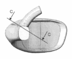
いくつかの実施形態では、少なくとも1つの鼻プロングの基部における通路の断面は非対称な断面であり、断面の一方の側は断面の他方の側よりも平坦であり、少なくとも1つの鼻プロングに沿って延在する通路は、少なくとも1つの鼻プロングの基部における又は基部の近傍の非対称な断面から、少なくとも1つの鼻プロングの先端における又は先端の近傍の円形断面へと形状が変化する。 In some embodiments, the cross-section of the passage at the base of the at least one nasal prong is an asymmetric cross-section, one side of the cross-section being flatter than the other side of the cross-section, and along the at least one nasal prong The extending passageway changes shape from an asymmetric cross-section at or near the base of the at least one nasal prong to a circular cross-section at or near the tip of the at least one nasal prong.
いくつかの実施形態では、断面積少なくとも1つの鼻プロングはプロングの基部から先端に向かって減少し、少なくとも1つの鼻プロングのより平坦な側は患者インターフェースの前方側(ユーザの顔とは逆側に面している)に向かって配置されている。 In some embodiments, the cross-sectional area of the at least one nasal prong decreases from the base to the tip of the prong and the flatter side of the at least one nasal prong is on the anterior side of the patient interface (away from the user's face). facing).
いくつかの実施形態では、少なくとも1つの鼻プロングは、患者インターフェースの本体部分のブリッジ部と一体形成された基部を有し、少なくとも1つの鼻プロングの基部は、プロングの壁とブリッジ部との間に隅肉部を含み、隅肉部は少なくとも1つの鼻プロングの外周部の周りに延在し、隅肉部の半径は、少なくとも1つの鼻プロングの外周部の周りにおいて変化する。 In some embodiments, at least one nasal prong has a base integrally formed with the bridge portion of the body portion of the patient interface, and the base of the at least one nasal prong is between the walls of the prong and the bridge portion. and a fillet extending around the circumference of the at least one nasal prong, the radius of the fillet varying around the circumference of the at least one nasal prong.
いくつかの実施形態では、患者インターフェースは、使用時にユーザが装着したときにインターフェースを所定の位置に保持するための、保持システムの少なくとも1つのパッドを含み、パッドは、本体部分の左サイドアーム及び右サイドアームの少なくとも1つに取り付けられており、同じ形状のパッドが本体部分の左サイドアーム及び右サイドアームの両方に適用され得るように、パッドは、パッドを左側と右側とに分割する中心略垂直軸の周りで実質的に対称であり、任意選択的に、パッド又はパッド(the pad or the pad)と一体成形されてインターフェースに取り付けられるか、インターフェースとパッドとのオーバーモールドによってインターフェースに後に取り付けられるかにかかわらず、1つのパッドの各パッドはオーバーモールド材料とのオーバーモールドによって左部分又は右部分それぞれに取り付けられている。 In some embodiments, the patient interface includes at least one pad of a retention system for holding the interface in place when worn by a user in use, the pad being located on the left side arm of the body portion and the Attached to at least one of the right side arms, the pad is centrally dividing the pad into left and right sides so that the same shaped pad can be applied to both the left and right side arms of the body portion. substantially symmetrical about a substantially vertical axis, optionally integrally molded with the pad or the pad and attached to the interface, or subsequently attached to the interface by overmolding the interface and the pad; Each pad of a pad, whether attached or not, is attached to the left or right portion, respectively, by overmolding with an overmolding material.
いくつかの実施形態では、保持システムは2部品式着脱可能取付(又は接続)機構を含み、この機構は、
a.皮膚パッチ及びユーザインターフェースパッチ
を含み、
b.皮膚パッチは患者側とインターフェース側とを有し、
c.皮膚パッチの患者側はユーザの皮膚に取り付け可能であり(例えば、ハイドロコロイドなどの一般に皮膚科学的に敏感な接着剤である接着剤によって)、
d.皮膚パッチのインターフェース側に2部品式着脱可能取付又は接続システムの第1の部品が提供されており、
e.ユーザインターフェースパッチはインターフェース側と患者側とを有し、
f.ユーザインターフェースパッチの患者側に2部品式着脱可能取付又は接続システムの相補的な第2の部品が提供されており、
g.ユーザインターフェースパッチのインターフェース側は、ユーザインターフェース及び/又はユーザインターフェースと対応付けられた構成要素(例えばチューブ又はチュービング)に取り付け可能(又は接続可能)である。
In some embodiments, the retention system includes a two-part detachable attachment (or connection) mechanism that:
a. including skin patches and user interface patches;
b. the skin patch has a patient side and an interface side;
c. The patient side of the dermal patch is attachable to the user's skin (e.g., by an adhesive, generally a dermatologically sensitive adhesive such as a hydrocolloid),
d. providing a first part of a two-part detachable attachment or connection system on the interface side of the skin patch;
e. The user interface patch has an interface side and a patient side,
f. providing a complementary second part of a two-part detachable attachment or connection system on the patient side of the user interface patch;
g. The interface side of the user interface patch is attachable (or connectable) to the user interface and/or a component (eg, tube or tubing) associated with the user interface.
いくつかの実施形態では、パッドがインターフェースのサイドアーム部上又はサイドアーム部内に保持されるように、本体部分、又は少なくとも左若しくは右サイドアームは保持システムと共成形又はオーバーモールド成形されている。 In some embodiments, the body portion, or at least the left or right side arm, is co-molded or over-molded with a retention system such that the pad is retained on or within the side arm portion of the interface.
いくつかの実施形態では、左サイドアーム及び右サイドアームのそれぞれは、1つ以上の既定の若しくは予め配置された箇所又は局所的補償領域(若しくは場所)を含み、1つ以上の既定の若しくは予め配置された箇所又は局所的補償領域(若しくは場所)は、この又は各サイドアームに沿って配置され、補償領域(若しくは場所)における又は補償領域(若しくは場所)の1つ以上における患者インターフェースの補償に適応し、撓み若しくは曲げ若しくはヒンジ動作若しくは他の変位による力に適応するように構成されている。 In some embodiments, each of the left side arm and the right side arm includes one or more predefined or pre-placed points or local compensation regions (or locations), wherein one or more predefined or pre-positioned Placed points or local compensation areas (or locations) are located along this or each sidearm to compensate for the patient interface at the compensation area (or location) or at one or more of the compensation areas (or locations). It is adapted and configured to accommodate forces due to flexing or bending or hinge action or other displacements.
いくつかの実施形態では、補償領域(又は場所)の1つ以上は、インターフェースを通る少なくとも2つの異なる(非平行)面しかし(though)又は周りの曲げの領域若しくは場所又はヒンジ領域である。 In some embodiments, one or more of the compensation regions (or locations) are regions or locations of bending or hinge regions about or through at least two different (non-parallel) planes through the interface.
いくつかの実施形態では、ブリッジ部はブリッジ部要素を含み、ブリッジ部、ブリッジ部要素又はブリッジ部及びブリッジ部要素の両方は、患者インターフェース又はに(or to)印加される又は患者インターフェースにかけられる力から実質的に切り離される。 In some embodiments, the bridge includes a bridge element, and the bridge, the bridge element, or both the bridge and the bridge element are applied to or to the patient interface. substantially separated from
本明細書中に開示される態様の少なくとも1つによれば、
a.使用時にユーザの鼻中隔領域内又はその周りに配置される略中心ブリッジ部から側方に延びる1つのサイドアーム又は好ましくは一対の前記サイドアーム
を含み、
b.この若しくは各前記サイドアームは実質的に弾性の又は比較的より剛性の高いブリッジ部要素に接続されており、ブリッジ部要素は、ガス送達システムの1つの出口又は複数の出口の、この又は各前記サイドアームとの実質的に既定された空間的関係を画定する、患者インターフェースが提供される。
According to at least one aspect disclosed herein,
a. a side arm or preferably a pair of said side arms extending laterally from a generally central bridge portion that in use is positioned in or around a user's nasal septum region;
b. This or each said side arm is connected to a substantially elastic or relatively more rigid bridge element which is connected to this or each of said outlets or outlets of the gas delivery system. A patient interface is provided that defines a substantially predetermined spatial relationship with the sidearm.
本明細書中に開示される態様の少なくとも1つによれば、
a.使用時にユーザの鼻中隔領域内又はその周りに配置される略中心ブリッジ部から側方に延びる1つのサイドアーム又は好ましくは一対の前記サイドアーム
を含み、
b.この又は各前記サイドアームは、1つ以上の既定の若しくは予め配置された箇所又は局所的補償領域(若しくは場所)を含み、1つ以上の既定の若しくは予め配置された箇所又は局所的補償領域(若しくは場所)は、サイドアームに沿って配置され、補償領域(若しくは場所)の1つ以上内又は補償領域(若しくは場所)の1つ以上における患者インターフェースの補償に適応する又は補償を促進し、
c.この若しくは各前記サイドアームは実質的に弾性の又は比較的より剛性の高いブリッジ部要素に接続されており、ブリッジ部要素は、ガス送達システムの1つの出口又は複数の出口の、この又は各前記サイドアームとの実質的に既定された空間的関係を画定する、患者インターフェースが提供される。
According to at least one aspect disclosed herein,
a. a side arm or preferably a pair of said side arms extending laterally from a generally central bridge portion that in use is positioned in or around a user's nasal septum region;
b. This or each said side arm includes one or more predetermined or pre-placed points or local compensation areas (or locations), wherein one or more predetermined or pre-placed points or local compensation areas ( or locations) are disposed along the sidearm to accommodate or facilitate compensation of the patient interface within or at one or more of the compensation regions (or locations);
c. This or each said side arm is connected to a substantially elastic or relatively more rigid bridge element which is connected to this or each of said outlets or outlets of the gas delivery system. A patient interface is provided that defines a substantially predetermined spatial relationship with the sidearm.
本明細書中に開示される態様の少なくとも1つによれば、
a.使用時にユーザの鼻中隔領域内又はその周りに配置される略中心ブリッジ部から側方に延びる1つのサイドアーム又は好ましくは一対の前記サイドアームを含み、
b.この若しくは各前記サイドアームは、少なくとも1つの実質的に弾性の又は比較的より剛性の高いサイドアーム要素を含み、サイドアーム要素は少なくとも部分的にこの若しくは各サイドアームの形態又は曲率を画定し、且つ1つ以上の既定の若しくは予め配置された箇所又は局所的補償領域(若しくは場所)を有し、1つ以上の既定の若しくは予め配置された箇所又は局所的補償領域(若しくは場所)は、この若しくは各サイドアーム及び/又はこの若しくは各サイドアーム要素に沿って配置され、補償領域(若しくは場所)における又は補償領域(若しくは場所)の1つ以上における患者インターフェースの補償に適応し、
c.この若しくは各前記サイドアーム要素は、接続材料を介して、実質的に弾性の若しくは比較的より剛性の高いブリッジ部要素に接続又は相互接続されており、ブリッジ部要素は、ガス送達システムの1つの出口又は複数の出口の、この又は各前記サイドアームとの実質的に既定された空間的関係を画定する、
患者インターフェースが提供される。
According to at least one aspect disclosed herein,
a. a side arm or preferably a pair of said side arms extending laterally from a generally central bridge portion that in use is positioned in or around a user's nasal septum region;
b. the or each side arm includes at least one substantially elastic or relatively stiffer side arm element, the side arm element at least partially defining the form or curvature of the or each side arm; and having one or more predetermined or pre-arranged points or local compensation areas (or locations), wherein the one or more predetermined or pre-arranged points or local compensation areas (or locations) are or disposed along each sidearm and/or this or each sidearm element, adapted to compensate the patient interface in the compensation area (or location) or in one or more of the compensation areas (or locations);
c. This or each said side arm element is connected or interconnected via a connecting material to a substantially elastic or relatively stiffer bridge element, the bridge element being one of the gas delivery systems. defining a substantially defined spatial relationship of the outlet or outlets with the or each said side arm;
A patient interface is provided.
上記態様の1つ以上によれば、以下の更なる実施形態の1つ以上が提供されてもよい。 According to one or more of the above aspects, one or more of the following further embodiments may be provided.
いくつかの実施形態では、ブリッジ部又はブリッジ部要素(又はこの両方)は、患者インターフェースに又は(or to)印加され得る、又は患者インターフェースにかけられ得る力から実質的に切り離されている。 In some embodiments, the bridge or bridge element (or both) is substantially decoupled from forces that may be applied or to the patient interface.
いくつかの実施形態では、患者インターフェースに印加された力はインターフェースの1つのサイドアーム又は複数のサイドアームにかけられてもよく、サイドアーム又はサイドアーム要素又はこの両方の補償領域(若しくは場所)は、サイドアーム若しくはサイドアーム要素若しくはこの両方の撓み又は曲げ又はヒンジ動作又は他の変位によって力に適応する。 In some embodiments, the force applied to the patient interface may be applied to one sidearm or multiple sidearms of the interface, wherein the compensation area (or location) of the sidearm or sidearm elements or both is: The force is accommodated by flexing or bending or hinging or other displacement of the sidearm or sidearm elements or both.
いくつかの実施形態では、1つのサイドアーム又は複数のサイドアームは患者インターフェース安定具である。 In some embodiments, the sidearm or sidearms are patient interface stabilizers.
いくつかの実施形態では、ブリッジ部要素と1つのサイドアーム要素又は複数のサイドアーム要素とは別個の部品であり、組み立てられて一体構成要素を形成する。 In some embodiments, the bridge element and the side arm element or elements are separate pieces that are assembled to form a unitary component.
いくつかの実施形態では、ブリッジ部要素と1つのサイドアーム要素若しくは複数のサイドアーム要素とは単一の構成要素である、又は少なくともブリッジ部と少なくとも1つのサイドアーム要素とは単一の構成要素である。 In some embodiments, the bridge element and the sidearm element or sidearm elements are a single component, or at least the bridge and the at least one sidearm element are a single component. is.
いくつかの実施形態では、ブリッジ部要素と1つのサイドアーム要素若しくは複数のサイドアーム要素とは単一の構成要素として一体形成されている、又は少なくともブリッジ部要素と少なくとも1つのサイドアーム要素とは単一の構成要素として一体形成されている。 In some embodiments, the bridge element and the sidearm element or sidearm elements are integrally formed as a single component, or at least the bridge element and the at least one sidearm element are It is integrally formed as a single component.
いくつかの実施形態では、ブリッジ部要素と1つのサイドアーム要素又は複数のサイドアーム要素とは一体構成要素として形成されている。 In some embodiments, the bridge element and the side arm element or side arm elements are formed as an integral component.
いくつかの実施形態では、ブリッジ部要素と1つのサイドアーム要素又は複数のサイドアーム要素の少なくとも1つとは別個の構成要素であり、そのそれぞれは、1つのサイドアーム若しくは複数のサイドアームなどの患者インターフェースの材料によって実質的に相互接続されていてもよく、又は互いに相互接続関係で設けられていてもよい。 In some embodiments, the bridge element and at least one of the sidearm element or sidearm elements are separate components, each of which is a patient arm, such as a sidearm or sidearms. They may be substantially interconnected by the material of the interface, or they may be provided in interconnected relation to each other.
いくつかの実施形態では、ブリッジ部要素は1つ以上のサイドアーム要素と連続しない構成要素である。 In some embodiments, the bridge element is a component that is discontinuous with one or more side arm elements.
いくつかの実施形態では、サイドアームは1つ以上の別個のサイドアーム要素を含み、前記1つ以上の別個のサイドアーム要素のそれぞれは、前記サイドアームの長さを通して又は前記サイドアームの長さに沿って離間して配置されている。 In some embodiments, the sidearm includes one or more separate sidearm elements, each of said one or more separate sidearm elements extending through or along the length of said sidearm. are spaced apart along the
いくつかの実施形態では、1つ以上の別個のサイドアーム要素のそれぞれは、1つ若しくは各前記サイドアームの長さを通して又は1つ若しくは各前記サイドアームの長さに沿ってアレイとして離間して配置されている。 In some embodiments, each of the one or more separate sidearm elements are spaced in an array through or along the length of the or each said sidearm. are placed.
いくつかの実施形態では、ブリッジ部要素と1つのサイドアーム要素又は複数のサイドアーム要素とは、1つ又は一対の対応するサイドアーム、及び任意選択的にブリッジ部、1つ以上の対応するサイドアーム要素を含む対応するサイドアームを介して互いに接続して設けられた又は相互接続された別個の部品である。 In some embodiments, the bridge element and the side arm element or side arm elements are one or a pair of corresponding side arms, and optionally the bridge, one or more corresponding side arm elements. Separate parts provided or interconnected to each other via corresponding side arms comprising arm elements.
いくつかの実施形態では、各別個のサイドアーム要素は比較的弾性の部分を提供し、サイドアームの材料は各別個のサイドアーム要素の間に挟まれた又は各別個のサイドアーム要素に隣接し、サイドアームの材料は補償領域(又は場所)を提供する。 In some embodiments, each separate sidearm element provides a relatively elastic portion and the sidearm material is sandwiched between or adjacent each separate sidearm element. , the sidearm material provides a compensation area (or location).
いくつかの実施形態では、患者インターフェースは、ブリッジ部要素と、一対のサイドアームの各1つ内に配置された少なくとも1つの別個のサイドアーム要素と、を含む。 In some embodiments, the patient interface includes a bridge element and at least one separate sidearm element disposed within each one of the pair of sidearms.
いくつかの実施形態では、ブリッジ部は一対のサイドアームの中間に配置されている。 In some embodiments, the bridge portion is positioned intermediate the pair of side arms.
いくつかの実施形態では、ブリッジ部要素は一対のサイドアームのサイドアーム要素の中間に配置されている。 In some embodiments, the bridge element is positioned intermediate the sidearm elements of the pair of sidearms.
いくつかの実施形態では、ブリッジ部要素は、ユーザの鼻中隔領域の幅にわたるほどの(十分な)寸法のものである、又はガス出口間の距離若しくは幅である、又は実質的にユーザの1つの鼻唇溝から別の鼻唇溝までにわたる最大距離によって画定される。 In some embodiments, the bridging element is (sufficiently) sized to span the width of the user's nasal septum region, or the distance or width between the gas outlets, or substantially one of the user's It is defined by the maximum distance spanned from one nasolabial sulcus to another nasolabial sulcus.
いくつかの実施形態では、ブリッジ部要素は、ユーザの気道にガスを供給するガス送達システム用の少なくとも1つ又は一対の出口を配置、位置決め又は収容するための1つ又は一対の切り込み若しくは成形部分を含む。 In some embodiments, the bridging element includes one or a pair of cut or shaped portions for locating, positioning or accommodating at least one or a pair of outlets for a gas delivery system that supplies gas to the user's airway. including.
いくつかの実施形態では、ブリッジ部要素は、ユーザの1つの鼻孔又は複数の鼻孔にガスを供給するガス送達システム用の1つの出口又は複数の出口として1つの鼻プロング又は一対の鼻プロングを配置、位置決め又は収容するための1つ又は一対の切り込み若しくは成形部分を含む。 In some embodiments, the bridging element positions a nasal prong or pair of nasal prongs as an outlet or outlets for a gas delivery system that supplies gas to a user's nostril or nares. , including one or a pair of notches or moldings for positioning or accommodation.
いくつかの実施形態では、補償領域(又は場所)の1つ以上は、撓み又は曲げ又はヒンジ動作又は局所変位及び/又は弾性変形を容易にする。 In some embodiments, one or more of the compensating regions (or locations) facilitate flexing or bending or hinging or local displacement and/or elastic deformation.
いくつかの実施形態では、補償領域(又は場所)の1つ以上は、インターフェースを通る少なくとも1つの面のしかし(though)又は周りの曲げの領域若しくは場所又はヒンジ領域である。 In some embodiments, one or more of the compensation regions (or locations) are regions or locations of bends or locations or hinge regions about or through at least one plane through the interface.
いくつかの実施形態では、補償領域(又は場所)の1つ以上は、インターフェースを通る複数の平行な面のしかし(though)又は周りの曲げの領域若しくは場所又はヒンジ領域である。 In some embodiments, one or more of the compensating regions (or locations) are regions or locations of bending around or through a plurality of parallel planes through the interface or hinge regions.
いくつかの実施形態では、補償領域(又は場所)の1つ以上は、インターフェースを通る少なくとも2つの異なる(非平行)面しかし(though)又は周りの曲げの領域若しくは場所又はヒンジ領域である。 In some embodiments, one or more of the compensation regions (or locations) are regions or locations of bending or hinge regions about or through at least two different (non-parallel) planes through the interface.
いくつかの実施形態では、補償領域(又は場所)の1つ以上は、インターフェースを通る少なくとも2つの異なる(直交)面しかし(though)又は周りの曲げの領域若しくは場所又はヒンジ領域である。 In some embodiments, one or more of the compensating regions (or locations) are at least two different (orthogonal) planes through or around the interface or bending regions or locations or hinge regions.
いくつかの実施形態では、1つ以上の補償領域(若しくは場所)は、より優先的には1つの、若しくは1つ以上の第1の方向、若しくは第1の方向セットに、より低い優先では、別の方向若しくは別の方向セットに屈曲する又は曲がる(又はヒンジ動作する、又は局所的に変位してもよい又は弾性的に変形しても動いてもよい)。 In some embodiments, one or more compensation regions (or locations) are more preferentially in one or more first directions or sets of directions, and less preferentially in Bend or bend (or hinge or may be locally displaced or elastically deformed and moved) in another direction or set of directions.
いくつかの実施形態では、1つ以上の補償領域(若しくは場所)は、より低い優先の方向若しくは方向セットにおける撓み又は曲げ(又はヒンジ動作又は局所変位又は弾性変形)に実質的に抵抗するように構成又は適合されている。 In some embodiments, one or more compensating regions (or locations) are configured to substantially resist flexure or bending (or hinge motion or local displacement or elastic deformation) in a less preferred direction or set of directions. configured or adapted.
いくつかの実施形態では、第1の方向又は第1のセット又は方向(first set or directions)は実質的に横断面にある。 In some embodiments, the first direction or first set or directions is substantially in the transverse plane.
いくつかの実施形態では、第1の方向若しくは第1の方向セットは、腹側方向若しくは背側方向の実質的に横断面にある、又は腹側方向及び背側方向の両方であってもよい。 In some embodiments, the first direction or first set of directions may be in a substantially transverse plane in the ventral direction, the dorsal direction, or both the ventral direction and the dorsal direction. .
いくつかの実施形態では、第1の方向若しくは第1の方向セットは、実質的に横断面、実質的に矢状面及び/又は実質的に冠状面の1つ以上にある。 In some embodiments, the first direction or first set of directions is in one or more of a substantially transverse plane, substantially sagittal plane and/or substantially coronal plane.
いくつかの実施形態では、第1の方向若しくは第1の方向セットは、サイドアーム要素をブリッジ部要素に対して動かす若しくは曲げることを実質的に容易にする1つの方向又は複数の方向である。 In some embodiments, the first direction or first set of directions is a direction or directions that substantially facilitate moving or bending the sidearm element relative to the bridge element.
いくつかの実施形態では、サイドアーム要素は実質的に弾性材料で形成されている、又は以下、
a.ブリッジ部要素から側方外側に配置された1つの補償領域(又は場所)と、サイドアーム要素の外端部との間に設けられている、
b.サイドアーム要素のより外側の補償領域(又は場所)とサイドアーム要素の外端部との間に設けられている、
c.サイドアーム要素の一連の補償領域(又は場所)のそれぞれの間に設けられている、d.ブリッジ部要素から側方外側に配置された2つの補償領域(又は場所)の間に、及びサイドアーム要素のより外側の補償領域(又は場所)とサイドアーム要素の外端部との間に設けられている、
の1つ以上から選択されるサイドアーム要素領域において撓み若しくは曲げ(若しくはヒンジ動作若しくは局所変位若しくは弾性変形)に対するかなりの弾性を提供するように構成又は適合されている。
In some embodiments, the sidearm element is formed of a substantially elastic material, or
a. provided between one compensation area (or location) located laterally outwardly from the bridge element and the outer end of the side arm element;
b. between the outer compensation area (or location) of the sidearm element and the outer end of the sidearm element;
c. provided between each of the series of compensation regions (or locations) of the sidearm element; d. provided between two compensation areas (or locations) located laterally outwardly from the bridge element and between the more outer compensation area (or location) of the side arm element and the outer end of the side arm element; is being
configured or adapted to provide significant resilience to flexure or bending (or hinge motion or local displacement or elastic deformation) in a sidearm element region selected from one or more of:
いくつかの実施形態では、各サイドアーム要素は1つの補償領域(又は場所)を含む。 In some embodiments, each sidearm element includes one compensation area (or location).
いくつかの実施形態では、各サイドアーム要素は2つの補償領域(又は場所)を含む。 In some embodiments, each sidearm element includes two compensation areas (or locations).
いくつかの実施形態では、各サイドアーム要素は3つの補償領域(又は場所)を含む。 In some embodiments, each sidearm element includes three compensation areas (or locations).
いくつかの実施形態では、各サイドアーム要素は複数の補償領域(又は場所)を含む。 In some embodiments, each sidearm element includes multiple compensation areas (or locations).
いくつかの実施形態では、少なくとも1つの補償領域(又は場所)は、ブリッジ部要素と接続した状態でサイドアーム要素のより内側の端部に配置されている。 In some embodiments, at least one compensation area (or location) is located at the inner end of the sidearm element in connection with the bridge element.
いくつかの実施形態では、補償領域(又は場所)の少なくとも1つは、サイドアーム要素とブリッジ部要素との間の接合部又は接続部に配置されている。 In some embodiments, at least one of the compensation regions (or locations) is located at the junction or connection between the sidearm element and the bridge element.
いくつかの実施形態では、補償領域(若しくは場所)の少なくとも1つは、実質的にユーザの鼻中隔領域の周辺又は側方外縁部によって画定されるブリッジ部要素のゾーン内に又はゾーンに配置されている。 In some embodiments, at least one of the compensation regions (or locations) is disposed within or in a zone of the bridging element substantially defined by the perimeter or lateral outer edge of the user's nasal septum region. there is
いくつかの実施形態では、この若しくは各サイドアーム要素は、ブリッジ部要素に対して屈曲する又は曲がる(又はヒンジ動作する又は局所的に変位する、又は弾性的に変形しても動いてもよい)ように構成されている。 In some embodiments, this or each side arm element flexes or bends (or hinges or is locally displaced or may elastically deform and move) relative to the bridge element. is configured as
いくつかの実施形態では、サイドアーム要素は1つ以上の小突起を更に含む。 In some embodiments, the sidearm element further includes one or more small protrusions.
いくつかの実施形態では、1つ以上の小突起は係合可能である、又はサイドアームの材料に対応する形状若しくは形態のものであるように設けられている。 In some embodiments, one or more small projections are provided to be engageable or of a shape or configuration corresponding to the material of the sidearm.
いくつかの実施形態では、サイドアームの材料との小突起の相互作用又は係合は、サイドアーム要素の撓み又は曲げ(又はヒンジ動作又は弾性変形)に対する抵抗を提供する。 In some embodiments, the interaction or engagement of the prongs with the material of the sidearm provides resistance to flexing or bending (or hinging or elastic deformation) of the sidearm element.
いくつかの実施形態では、小突起は、サイドアーム要素にかけられた力又は動きをサイドアームの材料の圧縮として変換することができる(又は小突起により材料に張力がかけられたときに、サイドアーム要素にかけられた力又は動きを材料の伸張として変換することができる)ように、サイドアームの材料は少なくとも部分的に圧縮性である(又は実質的に非圧縮性であっても部分的に圧縮性であってもよい)。 In some embodiments, the microprojection can translate force or movement applied to the sidearm element as compression of the material of the sidearm (or when the material is tensioned by the microprojection, the sidearm The material of the sidearm is at least partially compressible (or substantially incompressible but partially compressible so that force or movement applied to the element can be translated as stretching of the material). may be gender).
いくつかの実施形態では、サイドアームの材料は少なくとも1つのサイドアーム要素を封入している又は覆っている。 In some embodiments, the sidearm material encapsulates or covers at least one sidearm element.
いくつかの実施形態では、サイドアームは少なくとも1つのサイドアーム要素を部分的に封入している又は部分的に覆っている。 In some embodiments, the sidearm partially encloses or partially covers at least one sidearm element.
いくつかの実施形態では、サイドアームは少なくとも1つのサイドアーム要素を完全に封入している又は覆っている。 In some embodiments, the sidearm completely encloses or covers at least one sidearm element.
いくつかの実施形態では、サイドアームの材料は、サイドアーム要素とサイドアームとの間の1つ以上のボイドを埋める。 In some embodiments, the sidearm material fills one or more voids between the sidearm element and the sidearm.
いくつかの実施形態では、サイドアームの材料はサイドアーム要素を取り囲み、サイドアーム要素を、1つ以上の既定の若しくは予め配置された箇所若しくは局所的補償領域(若しくは場所)内に、又は1つ以上の既定の若しくは予め配置された箇所若しくは局所的補償領域(若しくは場所)に、又は1つ以上の既定の若しくは予め配置された箇所若しくは局所的補償領域(若しくは場所)に隣接して配置する。 In some embodiments, the sidearm material surrounds the sidearm elements and positions the sidearm elements within one or more predetermined or pre-placed locations or localized compensation areas (or locations), or one At any of the above predetermined or pre-arranged points or local compensation areas (or locations), or adjacent to one or more predetermined or pre-arranged points or local compensation areas (or locations).
いくつかの実施形態では、一対のサイドアームが提供される場合、サイドアームのそれぞれはブリッジ部から側方に延び、一対のサイドアームの1つのサイドアームは実質的にユーザの顔の左側の周りに延びるように設けられ、一対のサイドアームのもう一方のサイドアームは実質的にユーザの顔の右側の周りに延びるように設けられている。 In some embodiments, where a pair of side arms are provided, each side arm extends laterally from the bridge portion, one side arm of the pair of side arms substantially extending around the left side of the user's face. and the other side arm of the pair of side arms is provided to extend substantially around the right side of the user's face.
いくつかの実施形態では、この又は各サイドアームは、実質的にユーザの顔の周りに、任意選択的にユーザの頬の少なくとも一部分に沿って延在する。 In some embodiments, the or each side arm extends substantially around the user's face, optionally along at least a portion of the user's cheeks.
いくつかの実施形態では、この又は各サイドアームは、ユーザの矢状面から離れる方に又は外側に向かって実質的に側方に延びる。 In some embodiments, the or each side arm extends substantially laterally away or outward from the user's sagittal plane.
いくつかの実施形態では、この又は各サイドアーム要素は、前記サイドアーム要素を含むこのような各サイドアームの長さの少なくとも一部分若しくはかなりの長さに、又は前記サイドアーム要素を含むこのような各サイドアームに沿って又はこのような各サイドアームを通して延びる。 In some embodiments, this or each sidearm element extends for at least a portion or a substantial length of the length of each such sidearm including said sidearm element, or such sidearm element including said sidearm element. Extending along or through each side arm.
いくつかの実施形態では、この又は各サイドアーム要素は複数のサイドアーム要素リムを含む。 In some embodiments, this or each sidearm element includes multiple sidearm element rims.
いくつかの実施形態では、サイドアーム要素リムは1つ以上の小突起を含む又は備える。 In some embodiments, the sidearm element rim includes or comprises one or more small protrusions.
いくつかの実施形態では、この若しくは各サイドアーム又はサイドアーム要素又はその両方は、1つの出口若しくは複数の出口を通してユーザに送達されるべきガス供給を受け入れるための、又は1つの出口若しくは複数の出口を通してユーザにガスを送達するための導管を受け入れるための通路の少なくとも一部分を形成している、又は提供するように形成されている。 In some embodiments, this or each side arm or side arm element or both are for receiving a gas supply to be delivered to the user through one outlet or multiple outlets or through one outlet or multiple outlets. forming or configured to provide at least a portion of a passageway for receiving a conduit for delivering gas therethrough to a user.
いくつかの実施形態では、サイドアームは通路を形成している。 In some embodiments, the sidearm forms a passageway.
いくつかの実施形態では、サイドアーム要素は通路を形成している。 In some embodiments, the sidearm element forms a passageway.
いくつかの実施形態では、少なくとも部分的にサイドアーム要素によって形成された通路の部分は、このように形成された通路の(例えば、単位長部分の)壁の周長又は壁の周辺長の少なくとも50%である。 In some embodiments, the portion of the passageway that is at least partially formed by the sidearm element is at least the wall perimeter or the wall perimeter (e.g., unit length portion) of the passageway so formed. 50%.
いくつかの実施形態では、サイドアームによって少なくとも部分的に形成された通路の部分は、サイドアーム要素によって形成されていたはずの(例えば、単位長部分の)壁の周長又は壁の周辺長の残部である。 In some embodiments, the portion of the passageway that is at least partially formed by the sidearm is the wall perimeter or the wall perimeter that would have been formed by the sidearm element (e.g., a unit length portion). The remainder.
いくつかの実施形態では、通路は、サイドアーム若しくはサイドアーム要素若しくはこの両方内の、又はサイドアーム若しくはサイドアーム要素若しくはこの両方を通るボイド空間又はキャビティ又は凹部であり、このボイド空間又はキャビティ又は凹部内に、1つの出口又は複数の出口への送達のためにガスが誘導又は供給されてもよい。 In some embodiments, the passageway is a void space or cavity or recess in or through the sidearm or sidearm element or both, wherein the void space or cavity or recess Gas may be directed or supplied therein for delivery to an outlet or outlets.
いくつかの実施形態では、通路は、少なくとも部分的にサイドアーム及び少なくとも部分的にサイドアーム要素によって画定される。 In some embodiments, the passageway is at least partially defined by the sidearm and at least partially by the sidearm element.
いくつかの実施形態では、サイドアームは、ガス出口にガスを送達するためにガス出口まで延びる通路にアクセスするためのポートを含む。 In some embodiments, the sidearm includes a port for accessing a passageway extending to the gas outlet for delivering gas to the gas outlet.
いくつかの実施形態では、一対のサイドアームの各サイドアームは、各サイドアーム内において対応するガス出口まで延びる通路にアクセスするためのポートを含む。 In some embodiments, each sidearm of the pair of sidearms includes a port for accessing a passage extending within each sidearm to a corresponding gas outlet.
いくつかの実施形態では、各サイドアームは、対応するガス出口にガスを別々に送達するための別個の通路を提供する。 In some embodiments, each side arm provides a separate passageway for separately delivering gas to the corresponding gas outlet.
いくつかの実施形態では、1つのサイドアーム又は複数のサイドアームは、使用時、ユーザの顔の上に配置される。 In some embodiments, the sidearm or sidearms are placed over the user's face when in use.
いくつかの実施形態では、1つのサイドアーム又は複数のサイドアームは、使用時、ユーザの顔の頬の上に配置される。 In some embodiments, the sidearm or sidearms are placed over the cheeks of the user's face when in use.
いくつかの実施形態では、インターフェースは、出口として一対の鼻プロングを含む鼻カニューラであり、使用時にユーザが装着したときに鼻カニューラを所定の位置に保持するためのヘッドギア又は保持システムを一対のサイドアームに取り付け可能である。 In some embodiments, the interface is a nasal cannula that includes a pair of nasal prongs as an outlet, and a pair of sides with a headgear or retention system to hold the nasal cannula in place when worn by the user in use. It can be attached to an arm.
いくつかの実施形態では、保持システムは、各サイドアームの少なくとも後部などの患者インターフェースをユーザの顔に着脱可能に接続するための着脱可能な接続システムを含む(例えば、着脱可能な接続システムは、このような着脱可能なシステムのためのフックアンドループ型コネクタ又はフックアンドフック型コネクタを含んでもよい)。 In some embodiments, the retention system includes a detachable connection system for detachably connecting a patient interface, such as at least the rear portion of each side arm, to the user's face (e.g., the detachable connection system hook-and-loop or hook-and-hook connectors for such detachable systems).
いくつかの実施形態では、着脱可能な接続システムは、ユーザの顔に取り付けられた少なくとも1つのパッドを含み、このパッド上に、患者インターフェースが着脱可能に係合可能であってもよい。 In some embodiments, the removable connection system may include at least one pad attached to the user's face on which the patient interface is removably engageable.
いくつかの実施形態では、ブリッジ部要素は、高分子材料である又は高分子材料を含む。 In some embodiments, the bridging element is or comprises a polymeric material.
いくつかの実施形態では、この又は各サイドアーム要素は、高分子材料である又は高分子材料を含む。 In some embodiments, the or each side arm element is or comprises a polymeric material.
いくつかの実施形態では、高分子材料は、熱可塑性エラストマー、ポリプロピレン系エラストマー、液状シリコーンゴム、又は通気性熱可塑性ポリウレタン、又は通気性ポリアミドの1つ又はいずれか1つ以上の組み合わせであり、より好ましくは、ポリマーは、ポリオレフィン、熱可塑性エラストマー又は通気性熱可塑性エラストマー、例えば、スチレンブロック共重合体、コポリエステルエラストマー、又は熱可塑性ポリオレフィンエラストマー、又は熱可塑性ポリウレタンエラストマーなどの熱可塑性エラストマー族などであってもよいが、これらに限定されず、更により好ましくは、ショアA硬度が約30~約90、又は約30~約80、又は約30~約70、又は約30~約60、又は約30~約50、又は約30~約40、又は約30、又は約40、又は約50、又は約60、又は約70、又は約80、又は約90のポリマーである。 In some embodiments, the polymeric material is one or a combination of any one or more of a thermoplastic elastomer, a polypropylene-based elastomer, a liquid silicone rubber, or a breathable thermoplastic polyurethane, or a breathable polyamide, and more Preferably, the polymer is a polyolefin, a thermoplastic elastomer or a breathable thermoplastic elastomer such as a styrenic block copolymer, a copolyester elastomer, or a thermoplastic elastomer family such as a thermoplastic polyolefin elastomer or a thermoplastic polyurethane elastomer. Even more preferably, Shore A hardness of about 30 to about 90, or about 30 to about 80, or about 30 to about 70, or about 30 to about 60, or about 30 from about 50, or about 30 to about 40, or about 30, or about 40, or about 50, or about 60, or about 70, or about 80, or about 90 polymers.
鼻カニューラは、ハイフロー療法システムにおいて患者インターフェースとして使用することができる。装着されると、患者の鼻孔内に載置された鼻カニューラの鼻送達要素(例えば管状プロング)を通してガスが送られる。一部の患者、特に、新生児又は乳児の患者では、(例えば、顔を枕又はベッドフレームに載せているときに)別の物体によって作用する圧縮力により又は(例えば、泣いているとき又は顔をしかめているときの)感情表現により顔がゆがむと、鼻カニューラに作用する力が鼻送達要素を鼻孔から押し出す可能性がある。鼻カニューラは、鼻送達要素がこのような力の多くによって鼻孔から外れる傾向を低下させるように構成され得るものの(例えば、所有者が共通する国際出願PCT/NZ2014/000217号明細書、所有者が共通する米国特許出願第61/891697号明細書、所有者が共通する米国特許出願第61/919579号明細書、所有者が共通する米国特許出願第62/052980号明細書又は所有者が共通する米国特許出願第62/064106号明細書、これらそれぞれの開示は全体が参照によって本明細書に援用される、を参照のこと)、場合によっては、鼻送達要素は、このような力が印加された場合に依然として互いに広がり離れる場合がある。上記の問題に対する解決策が求められる。 A nasal cannula can be used as a patient interface in a high flow therapy system. Once installed, gas is delivered through the nasal delivery elements (eg, tubular prongs) of the nasal cannula that rests within the patient's nostrils. In some patients, particularly neonatal or infant patients, the compressive force exerted by another object (e.g., when resting the face on a pillow or bed frame) or (e.g., when crying or pressing the face) If the face is distorted by an expression of emotion (when frowning), the force acting on the nasal cannula can push the nasal delivery element out of the nostril. Although the nasal cannula may be configured to reduce the tendency of the nasal delivery element to dislodge from the nostrils by many of these forces (e.g., commonly owned international application PCT/NZ2014/000217, commonly owned Commonly owned US patent application Ser. No. 61/891,697, Commonly owned US patent application Ser. No. 61/919,579, Commonly owned US patent application Ser. See U.S. Patent Application No. 62/064106, the disclosures of each of which are incorporated herein by reference in their entirety), in some cases the nasal delivery element is subjected to such forces. may still spread apart from each other. A solution to the above problems is sought.
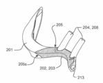
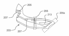
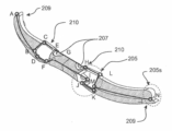
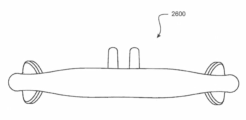
いくつかの実施形態では、患者インターフェースは、ユーザの顔の第1部分に配置されるように又はユーザの顔の第1部分隣接して配置されるように適合された第1のサイドアームと、ユーザの顔の第2部分に配置される又はユーザの顔の第2部分に隣接して配置されるように適合された第2のサイドアームと、第1のサイドアームと第2のサイドアームとの間に延び、第1のサイドアームと第2のサイドアームとを連結するブリッジと、ブリッジの少なくとも一部分にわたって配置された支持構造と、を含む。 In some embodiments, the patient interface includes a first side arm adapted to be positioned on or adjacent to the first portion of the user's face; a second side arm adapted to be positioned on or adjacent to the second portion of the user's face; a first side arm and a second side arm; a bridge extending between and connecting the first side arm and the second side arm; and a support structure disposed over at least a portion of the bridge.
いくつかの実施形態では、支持構造はブリッジ全体にわたって延在する。いくつかの構成では、支持構造はブリッジのユーザに面する部分の少なくとも一部分にわたって配置されている。いくつかの構成では、支持構造はブリッジのユーザに面していない部分の一部分にわたって配置されている。いくつかの構成では、支持構造はブリッジのユーザに面していない部分の全体にわたって配置されている。いくつかの構成では、ブリッジのユーザに面する部分はユーザの人中に載るように又は隣接するように適合されている。いくつかの構成では、支持構造は張力に抵抗するように構成されている。いくつかの構成では、支持構造は圧縮力に抵抗するように構成されている。いくつかの構成では、支持構造は剪断力に抵抗するように構成されている。いくつかの構成では、支持構造は、使用時に、ブリッジの中立軸を変更し、ブリッジセクション内の曲げを低減する又は曲げに抵抗する。 In some embodiments, the support structure extends across the bridge. In some configurations, the support structure is disposed over at least a portion of the user-facing portion of the bridge. In some configurations, the support structure is positioned over a portion of the user-facing portion of the bridge. In some configurations, the support structure is located throughout the non-user facing portion of the bridge. In some configurations, the user-facing portion of the bridge is adapted to rest on or adjacent to the user's philtrum. In some configurations, the support structure is configured to resist tension. In some configurations, the support structure is configured to resist compressive forces. In some configurations, the support structure is configured to resist shear forces. In some configurations, the support structure alters the neutral axis of the bridge during use to reduce or resist bending within the bridge section.
いくつかの実施形態では、支持構造は少なくとも部分的にテキスタイル材料から形成されている。いくつかのこのような構成では、テキスタイル材料は、織、不織又は編テキスタイル材料である。 In some embodiments, the support structure is at least partially formed from a textile material. In some such arrangements, the textile material is a woven, non-woven or knitted textile material.
いくつかの実施形態では、支持構造はシートである。いくつかの構成では、支持構造は剛性材料を含む。いくつかの構成では、支持構造は半剛性材料を含む。 In some embodiments, the support structure is a sheet. In some configurations, the support structure includes a rigid material. In some configurations the support structure comprises a semi-rigid material.
いくつかの実施形態では、支持構造はポリマー材料から形成されている。いくつかの構成では、支持構造とブリッジとは少なくとも部分的に同じポリマー材料から形成されている。いくつかの構成では、ポリマー材料は展性及び可撓性ポリマーを含む。いくつかの構成では、ポリマー材料は剛性ポリマーを含む。いくつかの構成では、支持構造は、ブリッジを形成している材料に比べてより剛性の高い材料から形成されている。 In some embodiments, the support structure is formed from polymeric material. In some configurations, the support structure and bridge are at least partially formed from the same polymeric material. In some configurations, the polymeric material includes malleable and flexible polymers. In some configurations, the polymeric material includes rigid polymers. In some configurations, the support structure is formed from a stiffer material than the material forming the bridge.
いくつかの構成では、第1の本体はユーザの頬に載るように適合されている。 In some configurations, the first body is adapted to rest on the user's cheek.
いくつかの実施形態では、第1及び第2のサイドアームはユーザの両頬に載るように適合されている。 In some embodiments, the first and second side arms are adapted to rest on both cheeks of the user.
いくつかの実施形態では、第1の及び/又は第2のサイドアームは、ユーザの1つ以上の鼻孔内に載置されるように適合された1つ以上の鼻送達要素又はプロングを含む。いくつかのこのような構成では、1つ以上の鼻送達要素は、患者インターフェースの外部の周囲ガスが鼻孔を通過するのを可能にするように構成されている。換言すると、鼻送達要素は、鼻孔内に非密封的に配置されてもよい。いくつかのこのような構成では、1つ以上の鼻送達要素は、ユーザの鼻中隔に向かって内側に延びるように形作られている又は角度をなしている。いくつかのこのような構成では、1つ以上の鼻送達要素は、使用時に、1つ以上の鼻送達要素の先端がユーザの頭部の後側の方に向くように形作られている又は角度をなしている。いくつかのこのような構成では、第1の及び/又は第2のサイドアームは、1つ以上の鼻送達要素と空気連通する1つ以上のガス送達ルーメンを含む。いくつかのこのような構成では、1つ以上のガス送達導管は1つ以上のガス送達ルーメンと空気連通していてもよい。他の構成では、1つ以上の鼻送達要素は鼻孔内に密封的に配置されるように構成されてもよい。 In some embodiments, the first and/or second side arms include one or more nasal delivery elements or prongs adapted to rest within one or more nostrils of the user. In some such configurations, one or more nasal delivery elements are configured to allow ambient gas outside the patient interface to pass through the nostrils. In other words, the nasal delivery element may be non-sealingly disposed within the nostril. In some such configurations, one or more nasal delivery elements are shaped or angled to extend inward toward the user's nasal septum. In some such configurations, the one or more nasal delivery elements are shaped or angled such that, in use, the tips of the one or more nasal delivery elements point toward the back of the user's head. is making In some such configurations, the first and/or second side arms include one or more gas delivery lumens in air communication with one or more nasal delivery elements. In some such configurations, one or more gas delivery conduits may be in pneumatic communication with one or more gas delivery lumens. In other configurations, one or more nasal delivery elements may be configured to be sealingly disposed within the nostrils.
いくつかの実施形態では、支持構造は第1の及び/又は第2のサイドアームに沿って延在する。いくつかのこのような構成では、支持構造は、第1の及び/又は第2のサイドアームのユーザに面する部分に沿って延在する。いくつかのこのような構成では、支持構造は、第1の及び/又は第2のサイドアームのユーザに面する部分のみに沿って延在する。いくつかのこのような構成では、第1の及び/又は第2のサイドアームのユーザに面する部分にある支持構造の少なくとも一部分は、顔に固定された1つ以上の固定構造と接続し、患者インターフェースを顔に固定するように適合されている。いくつかの構成では、支持構造は、第1の及び/又は第2のサイドアームのユーザに面していない部分に沿って延在する。 In some embodiments, the support structure extends along the first and/or second side arms. In some such configurations, the support structure extends along the user-facing portions of the first and/or second side arms. In some such configurations, the support structure extends only along the user-facing portions of the first and/or second side arms. In some such configurations, at least a portion of the support structure on the user-facing portion of the first and/or second side arm connects with one or more fixation structures secured to the face; adapted to secure the patient interface to the face; In some configurations, the support structure extends along non-user facing portions of the first and/or second side arms.
いくつかの実施形態では、患者インターフェースはユーザの顔の輪郭に一致するように形作られている。いくつかの構成では、第1のサイドアーム及び/又は第2のサイドアームは、互いに対する及び/又はブリッジに対する第1の及び/又は第2のサイドアームの動きを可能にする1つ以上のヒンジ又は枢動ジョイントを含む。 In some embodiments, the patient interface is shaped to match the contours of the user's face. In some configurations, the first side arm and/or the second side arm have one or more hinges that allow movement of the first and/or second side arm relative to each other and/or the bridge. or including a pivot joint.
いくつかの実施形態では、第1の及び/又は第2のサイドアームは、第1の及び/又は第2のサイドアームの隣接する領域に対し、1つ以上の低減された厚みを持つ領域を含む。いくつかのこのような構成では、1つ以上の、低減された厚みを持つ領域は、第1の及び/又は第2のサイドアームの、ユーザの1つ以上の頬に載る部分に配置されている。いくつかのこのような構成では、1つ以上の、低減された厚みを持つ領域は、第1の及び/又は第2のサイドアームの外縁部に配置されている。いくつかの構成では、1つ以上の、低減された厚みを持つ領域は、第1の及び/又は第2のサイドアームの外縁部のみに配置されている。 In some embodiments, the first and/or second side arms have one or more regions of reduced thickness relative to adjacent regions of the first and/or second side arms. include. In some such configurations, one or more regions of reduced thickness are disposed on portions of the first and/or second side arms that rest on one or more cheeks of the user. there is In some such configurations, one or more regions of reduced thickness are located at the outer edges of the first and/or second side arms. In some configurations, one or more regions of reduced thickness are located only at the outer edges of the first and/or second side arms.
いくつかの実施形態では、患者インターフェースは第1の及び/又は第2のサイドアームのユーザに面する部分に固定された1つ以上の取付構造を含み、1つ以上の取付構造は、顔に固定された1つ以上の固定構造と接続し、患者インターフェースを顔に固定するように適合されている。 In some embodiments, the patient interface includes one or more attachment structures secured to user-facing portions of the first and/or second side arms, the one or more attachment structures being attached to the face. It is adapted to interface with one or more fixed fixation structures to secure the patient interface to the face.
本明細書中に開示される態様の少なくとも1つによれば、ユーザの両頬に配置するように又はユーザの両頬に隣接するように適合された第1及び第2のサイドアームと、第1の及び/又は第2のサイドアームから延びる、ユーザの1つ以上の鼻孔内に非密封的に載置されるように適合された少なくとも1つの鼻送達要素と、第1のサイドアームと第2のサイドアームとを連結しているブリッジと、ブリッジの少なくとも一部分にわたって配置された補強構造と、を含む鼻カニューラが提供される。 According to at least one aspect disclosed herein, first and second side arms adapted to be positioned on or adjacent to the user's cheeks; at least one nasal delivery element adapted to non-sealingly rest within one or more nostrils of a user extending from the first and/or second sidearm; A nasal cannula is provided that includes a bridge connecting two side arms and a reinforcing structure disposed over at least a portion of the bridge.
他の実施形態では、少なくとも1つの鼻送達要素は、ユーザの1つ以上の鼻孔内に密封的に載置されるように適合されてもよい。 In other embodiments, at least one nasal delivery element may be adapted to sealingly rest within one or more nostrils of a user.
いくつかの実施形態では、補強構造はブリッジの一部分のみにわたって配置されている。いくつかの構成では、補強構造はブリッジのユーザに面する部分の少なくとも一部分にわたって配置されている。いくつかのこのような構成では、補強構造はブリッジのユーザに面する部分の一部分のみ又はすべてに配置されている。いくつかの構成では、補強構造は圧縮力に抵抗するように構成されている。いくつかの構成では、補強構造は張力に抵抗するように構成されている。いくつかの構成では、補強構造は剪断力に抵抗するように構成されている。いくつかの構成では、補強構造は、使用時に、ブリッジの中立軸を移動させることにより曲げに抵抗するように構成されている。 In some embodiments, the reinforcing structure is placed over only a portion of the bridge. In some configurations, the reinforcing structure is disposed over at least a portion of the user-facing portion of the bridge. In some such configurations, the reinforcing structure is placed on only some or all of the user-facing portion of the bridge. In some configurations, the reinforcing structure is configured to resist compressive forces. In some configurations, the reinforcing structure is configured to resist tension. In some configurations, the reinforcing structure is configured to resist shear forces. In some configurations, the stiffening structure is configured to resist bending in use by moving the neutral axis of the bridge.
いくつかの実施形態では、補強構造は少なくとも部分的にテキスタイル材料から形成されている。いくつかのこのような構成では、テキスタイル材料は、織、不織又は編テキスタイル材料である。 In some embodiments, the reinforcing structure is at least partially formed from a textile material. In some such arrangements, the textile material is a woven, non-woven or knitted textile material.
いくつかの実施形態では、補強構造はシートである。いくつかの構成では、補強構造は剛性材料を含む。いくつかの構成では、補強構造は半剛性材料を含む。 In some embodiments, the reinforcing structure is a sheet. In some configurations, the reinforcing structure includes rigid material. In some configurations, the reinforcement structure includes a semi-rigid material.
いくつかの実施形態では、補強構造とブリッジとは少なくとも部分的に同じポリマー材料から形成されている。いくつかの構成では、ポリマー材料は展性及び可撓性ポリマーを含む。いくつかの構成では、ポリマー材料は剛性ポリマーを含む。いくつかの構成では、補強構造は、ブリッジを形成している材料に比べてより剛性の高い材料を含む。 In some embodiments, the reinforcing structure and bridge are at least partially formed from the same polymeric material. In some configurations, the polymeric material includes malleable and flexible polymers. In some configurations, the polymeric material includes rigid polymers. In some configurations, the reinforcing structure comprises a stiffer material than the material forming the bridge.
いくつかの実施形態では、少なくとも1つの鼻送達要素は、ユーザの鼻中隔に向かって内側に延びるように形作られている又は角度をなしている。 In some embodiments, at least one nasal delivery element is shaped or angled to extend inward toward the user's nasal septum.
いくつかの実施形態では、少なくとも1つの鼻送達要素は、使用時に、先端がユーザの頭部の後側の方に向くように形作られている又は角度をなしている。 In some embodiments, the at least one nasal delivery element is shaped or angled such that the tip points toward the back of the user's head in use.
いくつかの実施形態では、第1の及び/又は第2のサイドアームは、少なくとも1つの鼻送達要素と空気連通する1つ以上のガス送達ルーメンを含む。いくつかのこのような構成では、鼻カニューラは、1つ以上のガス送達ルーメンと空気連通する1つ以上のガス送達導管を更に含む。 In some embodiments, the first and/or second sidearms include one or more gas delivery lumens in air communication with at least one nasal delivery element. In some such configurations, the nasal cannula further includes one or more gas delivery conduits in air communication with the one or more gas delivery lumens.
いくつかの実施形態では、補強構造は第1の及び/又は第2のサイドアームに沿って延在する。いくつかのこのような構成では、補強構造は、第1の及び/又は第2のサイドアームのユーザに面する部分に沿って延在する。いくつかのこのような構成では、補強構造は、第1の及び/又は第2のサイドアームのユーザに面する部分のみに沿って延在する。いくつかのこのような構成では、第1の及び/又は第2のサイドアームのユーザに面する部分にある補強構造の少なくとも一部分は、顔に固定された1つ以上の固定構造と接続し、鼻カニューラを顔に固定するように適合されている。いくつかの構成では、補強構造は、第1の及び/又は第2のサイドアームのユーザに面していない部分にわたって延在する。いくつかの構成では、補強構造は、ブリッジのユーザに面していない部分に配置されている。いくつかの構成では、ブリッジのユーザに面する部分はユーザの人中に載るように又は隣接するように適合されている。 In some embodiments, the reinforcing structure extends along the first and/or second side arms. In some such configurations, the reinforcing structure extends along the user-facing portions of the first and/or second side arms. In some such configurations, the reinforcing structure extends only along the user-facing portions of the first and/or second side arms. In some such configurations, at least a portion of the reinforcing structure on the user-facing portion of the first and/or second side arm connects with one or more fixing structures secured to the face; adapted to secure the nasal cannula to the face. In some configurations, the reinforcing structure extends across the user-facing portions of the first and/or second side arms. In some configurations, the reinforcing structure is located on the portion of the bridge that does not face the user. In some configurations, the user-facing portion of the bridge is adapted to rest on or adjacent to the user's philtrum.
いくつかの実施形態では、鼻カニューラはユーザの顔の輪郭に一致するように形作られている。 In some embodiments, the nasal cannula is shaped to match the contours of the user's face.
いくつかの実施形態では、第1の及び/又は第2のサイドアームは、第1の及び/又は第2のサイドアームの隣接する領域に対し、1つ以上の低減された厚みを持つ領域を含む。いくつかのこのような構成では、低減された厚みを持つ領域は、第1の及び/又は第2のサイドアームの外縁部に配置されている。いくつかのこのような構成では、低減された厚みを持つ領域は、第1の及び/又は第2のサイドアームの外縁部のみに配置されている。 In some embodiments, the first and/or second side arms have one or more regions of reduced thickness relative to adjacent regions of the first and/or second side arms. include. In some such configurations, the regions of reduced thickness are located at the outer edges of the first and/or second side arms. In some such configurations, regions of reduced thickness are located only at the outer edges of the first and/or second side arms.
いくつかの実施形態では、鼻カニューラは、第1の及び/又は第2のサイドアームのユーザに面する部分に固定された1つ以上の取付構造を更に含み、1つ以上の取付構造は、顔に固定された1つ以上の固定構造と接続し、鼻カニューラを顔に固定するように適合されている。 In some embodiments, the nasal cannula further includes one or more attachment structures secured to the user-facing portions of the first and/or second side arms, the one or more attachment structures comprising: It is adapted to interface with one or more fixation structures secured to the face and to secure the nasal cannula to the face.
本明細書中に開示される態様の少なくとも1つによれば、鼻カニューラが開示される。鼻カニューラは、ユーザの顔の第1部分に載るように適合された第1のサイドアームと、ユーザの顔の第2部分に載るように適合された第2のサイドアームと、第1の及び/又は第2のサイドアームから延びる、ユーザの1つ以上の鼻孔内に非密封的に載置されるように適合された少なくとも1つの鼻送達要素と、を含み、第1の及び/又は第2のサイドアームは、第1の及び/又は第2のサイドアームの隣接する領域に対し、1つ以上の低減された厚みを持つ領域を含む。 According to at least one aspect disclosed herein, a nasal cannula is disclosed. The nasal cannula has a first side arm adapted to rest on a first portion of the user's face, a second side arm adapted to rest on a second portion of the user's face, and a first and a second side arm adapted to rest on a second portion of the user's face. and/or at least one nasal delivery element adapted to non-sealingly rest within one or more nostrils of a user, extending from the second side arm; The two side arms include one or more regions of reduced thickness relative to adjacent regions of the first and/or second side arms.
いくつかの実施形態では、第1及び第2のサイドアームはユーザの両頬に載るように適合されている。 In some embodiments, the first and second side arms are adapted to rest on both cheeks of the user.
いくつかの実施形態では、1つ以上の、低減された厚みを持つ領域は、第1の及び/又は第2のサイドアームの、ユーザの1つ以上の頬に載る部分に配置されている。 In some embodiments, one or more regions of reduced thickness are positioned on portions of the first and/or second side arms that rest on one or more cheeks of the user.
いくつかの実施形態では、1つ以上の、低減された厚みを持つ領域は、第1の及び/又は第2のサイドアームの外縁部に配置されている。いくつかのこのような構成では、1つ以上の、低減された厚みを持つ領域は、第1の及び/又は第2のサイドアームの外縁部のみに配置されている。 In some embodiments, one or more regions of reduced thickness are located at outer edges of the first and/or second side arms. In some such configurations, one or more regions of reduced thickness are located only at the outer edges of the first and/or second side arms.
いくつかの実施形態では、鼻カニューラは、第1のサイドアームと第2のサイドアームとを連結しているブリッジを更に含む。 In some embodiments, the nasal cannula further includes a bridge connecting the first side arm and the second side arm.
本明細書中に開示される態様の少なくとも1つによれば、鼻カニューラなどの患者インターフェースが、
a.使用時、ユーザの顔上に配置される一対の各左サイドアーム及び右サイドアームと、b.ユーザの鼻の1つの鼻孔若しくは複数の鼻孔内に挿入される、又はユーザの鼻の1つの鼻孔若しくは複数の鼻孔内にガスの流れを案内するための少なくとも1つの及び好ましくは一対の鼻プロングと、
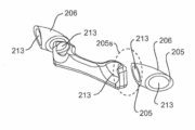
c.左サイドアームとの接続箇所と右サイドアームとの接続箇所とに取り付けられ、左サイドアームとの接続箇所から右サイドアームとの接続箇所まで延びるブリッジであって、各々の接続箇所の1つ又はそれぞれが、各々のサイドアームに対するブリッジの第1動作を可能にするヒンジ式又は枢動ジョイントなどの第1可動ジョイントを含む、ブリッジと、
を含む。
According to at least one aspect disclosed herein, a patient interface, such as a nasal cannula,
a. a pair of respective left and right side arms which, in use, are placed on the user's face; b. at least one and preferably a pair of nasal prongs for inserting into the nostril or nostrils of the user's nose or for guiding gas flow into the nostril or nostrils of the user's nose; ,
c. A bridge attached to the left sidearm connection point and the right sidearm connection point and extending from the left sidearm connection point to the right sidearm connection point, one of the respective connection points or a bridge, each including a first movable joint, such as a hinged or pivot joint, that allows a first movement of the bridge relative to its respective side arm;
including.
いくつかの実施形態では、第1可動ジョイントは、ブリッジの端部と各々のサイドアームとの間における、少なくとも1つの軸の周りの相対回転を可能にする。 In some embodiments, the first movable joint allows relative rotation about at least one axis between the end of the bridge and each side arm.
いくつかの実施形態では、第1動作ジョイントは、関節式ジョイント、ピンアンドバレル型ジョイント、ボールソケット型ジョイントの1つ又は組み合わせである。 In some embodiments, the first motion joint is one or a combination of an articulated joint, a pin and barrel type joint, a ball and socket type joint.
いくつかの実施形態では、各サイドアームは、ユーザの顔の領域に係合するように起伏が付けられている顔面パッドを含む。 In some embodiments, each side arm includes a facial pad that is contoured to engage an area of the user's face.
いくつかの実施形態では、少なくとも1つの及び好ましくは一対の鼻プロングは、左サイドアーム及び/若しくは右サイドアームそれぞれのより内側の端部の1つ若しくはそれぞれから、又はより内側の端部に実質的に隣接する各々のサイドアームの1つ若しくは両方の領域から延び、ブリッジは、前記鼻プロングにわたって又は隣接して延在するバーである。 In some embodiments, at least one and preferably a pair of nasal prongs are substantially pronged from or to the inner ends of one or each of the left sidearm and/or right sidearm, respectively. Extending from one or both regions of each laterally adjacent side arm, the bridge is a bar extending across or adjacent to the nasal prongs.
いくつかの実施形態では、インターフェースは、各々のサイドアームに取り付けられた、バーの接続箇所を補助するための取付具を更に含み、取付具は、ヒンジ式又は枢動ジョイントなどの第2可動ジョイントを含み、第2可動ジョイントは、マウントが取り付けられている各々のサイドアームに対するマウントの第2の動作を可能にし、バーは第1可動ジョイントを介して取付具に取り付けられている。 In some embodiments, the interface further includes a fixture attached to each side arm for assisting the connection point of the bar, the fixture being a second movable joint such as a hinged or pivot joint. and a second movable joint permits a second movement of the mount relative to each side arm to which the mount is attached, the bar being attached to the fixture via the first movable joint.
いくつかの実施形態では、取付具は各々のサイドアームに摺動可能に取り付けられており、サイドアームに沿った相対位置の調整を可能にし、これによりプロング間の距離を調整する。 In some embodiments, the fixture is slidably attached to each side arm and allows for adjustment of relative position along the side arm, thereby adjusting the distance between the prongs.
いくつかの実施形態では、患者インターフェースが本来の位置のユーザの顔の上にある場合、左サイドアーム及び/若しくは右サイドアームの1つ又は両方の位置の変位は、ユーザの鼻孔に対する1つのプロング又は複数のプロングの動きを最小にするような状態で、接続箇所又は取付具並びに第1及び/若しくは第2可動ジョイントそれぞれを介してバーに伝達される。 In some embodiments, displacement of the position of one or both of the left side arm and/or right side arm when the patient interface is on the user's face in its original position results in one prong relative to the user's nares. or transmitted to the bar via a connection point or fitting and first and/or second movable joints, respectively, in such a manner as to minimize movement of the prongs.
いくつかの実施形態では、第1可動ジョイントと第2可動ジョイントとは、取り付けられた構成要素の、実質的に同じ向きにおける動きを可能にするために整列されている。 In some embodiments, the first movable joint and the second movable joint are aligned to allow movement of the attached component in substantially the same direction.
いくつかの実施形態では、第1可動ジョイントと第2可動ジョイントとは、異なる向きにおける動きを可能にするために整列されていない。 In some embodiments, the first movable joint and the second movable joint are misaligned to allow movement in different orientations.
いくつかの実施形態では、バーは1つ以上の更なる可動ジョイントを含む。 In some embodiments, the bar includes one or more additional movable joints.
いくつかの実施形態では、鼻プロングを含む左サイドアーム及び右サイドアームは、バー及び/又は取付具に対し比較的可撓性又は適合性がある。 In some embodiments, the left and right side arms, including nasal prongs, are relatively flexible or conformable to the bar and/or attachments.
いくつかの実施形態では、接続箇所又は取付具は、接続箇所又は取付具から外側に延出する指部を含み、この指部上に、バーに接続するための第1可動ジョイントが配置されている。 In some embodiments, the connection point or fitting includes a finger extending outwardly from the connection point or fitting on which the first movable joint for connection to the bar is disposed. there is
いくつかの実施形態では、バーは患者インターフェースのオーバセンタ構成要素であり、接続箇所又は取付具は各々のサイドアームのそれぞれの上に対称に配置されている。 In some embodiments, the bar is the over-center component of the patient interface and the connection points or fittings are symmetrically located on each of the respective side arms.
いくつかの実施形態では、第2可動ジョイントは、関節式ジョイント、ピンアンドバレル型ジョイント及びボールソケット型ジョイントの1つ又は組み合わせである。 In some embodiments, the second movable joint is one or a combination of an articulated joint, a pin and barrel type joint, and a ball and socket type joint.
いくつかの実施形態では、ブリッジは、少なくとも1つの及び好ましくは対の鼻プロングを含む。 In some embodiments, the bridge includes at least one and preferably a pair of nasal prongs.
いくつかの実施形態では、各第1可動ジョイントはブリッジの端部と各々のサイドアームの内端部との間に設けられている。 In some embodiments, each first movable joint is provided between an end of the bridge and an inner end of each side arm.
いくつかの実施形態では、第1可動ジョイントは、ブリッジの端部と各々のサイドアームとの間における、3つの略直交軸の周りの相対回転を可能にする。 In some embodiments, the first movable joint allows relative rotation about three substantially orthogonal axes between the ends of the bridge and each side arm.
いくつかの実施形態では、第1可動ジョイントはボールソケット型ジョイントを含む。 In some embodiments, the first movable joint comprises a ball and socket joint.
いくつかの実施形態では、一対の第1可動ジョイントが、ブリッジの各端部と、左サイドアーム及び右サイドアームそれぞれの内端部との間に設けられている。 In some embodiments, a pair of first movable joints are provided between each end of the bridge and the inner ends of the respective left and right side arms.
いくつかの実施形態では、患者インターフェースが本来の位置のユーザの顔の上にある場合、左サイドアーム及び/若しくは右サイドアームの1つ又は両方の位置の変位は、ユーザの鼻孔に対するブリッジ及び1つのプロング又は複数のプロングの変位を最小にするような状態で1つの又は各第1可動ジョイントに伝達される。 In some embodiments, displacement of the position of one or both of the left sidearm and/or the right sidearm when the patient interface is on the user's face in its original position results in the bridge and 1 position relative to the user's nostrils. The force is transferred to the or each first movable joint in such a manner as to minimize the displacement of the prong or prongs.
本明細書中に開示される態様の少なくとも1つによれば、鼻カニューラなどの患者インターフェースは、
a.使用時にユーザの顔上に配置される本体部分と、
b.本体部分から延び、動作位置において、ユーザの鼻の1つの鼻孔若しくは複数の鼻孔内に挿入される、又はユーザの鼻の1つの鼻孔若しくは複数の鼻孔内にガスの流れを案内するための少なくとも1つの及び好ましくは一対の鼻プロングと、
を含み、
c.本体が、ユーザの鼻の鼻孔にガスを供給するための、鼻プロング)に接続された流体通路を有する少なくとも1つの中空領域を有し、
d.流体通路を通じた流体の供給中、中空領域本体部分の1つ以上の領域から鼻プロングへと変位力が伝達されることに実質的に抵抗し、プロングの動作位置を維持する。
According to at least one aspect disclosed herein, a patient interface, such as a nasal cannula, comprises:
a. a body portion that is placed on the user's face when in use;
b. At least one for extending from the body portion and being inserted into a nostril or nostrils of a user's nose in an operative position or for guiding gas flow into a nostril or nostrils of a user's nose. two and preferably a pair of nasal prongs;
including
c. the body has at least one hollow region having a fluid passageway connected to the nasal prongs for supplying gas to the nostrils of the user's nose;
d. During delivery of fluid through the fluid passageway, it substantially resists displacement forces being transmitted from one or more regions of the hollow region body portion to the nasal prongs to maintain the operating position of the prongs.
いくつかの実施形態では、本体部分は、略剛性フレームと、剛性フレームから延びる少なくとも1つの比較的軟質の中空領域と、を含む。 In some embodiments, the body portion includes a generally rigid frame and at least one relatively soft hollow region extending from the rigid frame.
いくつかの実施形態では、少なくとも1つの中空領域は膨張可能であり、1つの鼻プロング又は複数の鼻プロングが伸張する方向に膨張する。 In some embodiments, at least one hollow region is expandable and expands in the direction of elongation of the nasal prong or nasal prongs.
いくつかの実施形態では、中空領域は鼻プロングに結合されており、ユーザの鼻の鼻孔へのガスの供給時に膨張可能であり、中空領域はユーザの人中又は上唇領域に少なくとも膨張した状態で配置され、鼻プロングを動作位置に実質的に維持する。 In some embodiments, the hollow region is coupled to the nasal prongs and is inflatable upon delivery of gas to the nostrils of the user's nose, such that the hollow region extends into at least the philtrum or upper lip region of the user in its inflated state. positioned to substantially maintain the nasal prongs in an operative position.
いくつかの実施形態では、膨張した状態において、中空領域は、中空領域に隣接する本体部分のフレームの深さよりも実質的に深い。 In some embodiments, in the expanded state, the hollow region is substantially deeper than the frame depth of the body portion adjacent the hollow region.
いくつかの実施形態では、本体部分のいずれかの端部は、使用時、ユーザの顔の頬領域に係合するように起伏が付けられているユーザ顔面接触表面を含む。 In some embodiments, either end of the body portion includes a user face-contacting surface that is contoured to engage the cheek region of the user's face in use.
いくつかの実施形態では、本体部分又は本体部分の少なくともいずれかの端部は、使用時、ユーザの顔面構造を実質的に補完するように形作られている又は湾曲している。 In some embodiments, the body portion or at least one end of the body portion is shaped or curved to substantially complement a user's facial structure in use.
いくつかの実施形態では、本体部分は、一対の各左及び右本体セグメント又はサイドアームを含む。 In some embodiments, the body portion includes a pair of respective left and right body segments or sidearms.
いくつかの実施形態では、左及び右本体セグメント又はサイドアームは実質的に可撓性である。 In some embodiments, the left and right body segments or sidearms are substantially flexible.
いくつかの実施形態では、鼻プロングは、各左及び/若しくは右本体セグメント若しくはサイドアームのより内側の端部の1つ若しくはそれぞれから、又はより内側の端部に実質的に隣接する各本体部分若しくはサイドアームの1つ若しくは両方の領域から延びる。 In some embodiments, the nasal prongs extend from one or each of the inner ends of each left and/or right body segment or sidearm, or from each body portion substantially adjacent to the inner ends. or from one or both regions of the sidearm.
いくつかの実施形態では、ブリッジ部は、左サイドアーム及び右サイドアームそれぞれのより内側の端部に接続する。 In some embodiments, the bridge connects to the inner ends of each of the left and right side arms.
いくつかの実施形態では、ブリッジ部は左及び右本体セグメントに比して実質的に剛性が高い。 In some embodiments, the bridge portion is substantially stiffer than the left and right body segments.
いくつかの実施形態では、少なくとも1つの及び好ましくは両左及び/又は右本体セグメントは中空領域を含み、中空領域のそれぞれは、一定量のガスを各鼻プロングに送達するための流体通路を有する。 In some embodiments, at least one and preferably both left and/or right body segments include hollow regions, each hollow region having a fluid passageway for delivering a quantity of gas to each nasal prong. .
いくつかの実施形態では、インターフェースは1つ以上の内部支柱を更に含み、1つ以上の内部支柱は中空領域の対向する内部表面の間に延び、開放流体通路を維持する。 In some embodiments, the interface further includes one or more internal struts extending between opposing internal surfaces of the hollow region to maintain an open fluid passageway.
いくつかの実施形態では、1つ以上の内部支柱は、中空領域内に空間的に分配された複数の支柱を含む。 In some embodiments, the one or more internal struts comprises a plurality of struts spatially distributed within the hollow region.
本明細書中に開示される態様の少なくとも1つによれば、鼻カニューラなどの患者インターフェースは、
a.使用時にユーザの顔上に配置される本体部分と、
b.本体部分から離れる方に延びるブリッジ部と、
c.ブリッジ部から延び、動作位置において、ユーザの鼻の1つの鼻孔若しくは複数の鼻孔内に挿入される、又はユーザの鼻の1つの鼻孔若しくは複数の鼻孔内にガスの流れを案内するための少なくとも1つの及び好ましくは一対の鼻プロングと、
を含み、
d.本体部分は、システムからの又はカニューラに保存されたポテンシャルを用いて能動的に調整される。
According to at least one aspect disclosed herein, a patient interface, such as a nasal cannula, comprises:
a. a body portion that is placed on the user's face when in use;
b. a bridge portion extending away from the body portion;
c. Extending from the bridge portion and in the operative position, at least one for inserting into a nostril or nostrils of a user's nose or for guiding gas flow into a nostril or nostrils of a user's nose. two and preferably a pair of nasal prongs;
including
d. The body portion is actively adjusted using potentials from the system or stored in the cannula.
いくつかの実施形態では、本体部分は、使用時、ユーザの顔の1つの頬の上に配置され、ユーザの顔のもう一方の頬はインターフェースから解放されている。 In some embodiments, the body portion, in use, is positioned over one cheek of the user's face, leaving the other cheek of the user's face free from the interface.
本明細書中に開示される態様の少なくとも1つによれば、鼻カニューラなどの患者インターフェースは、
a.使用時にユーザの顔上に配置される本体部分と、
b.本体部分から延び、動作位置において、ユーザの鼻の1つの鼻孔若しくは複数の鼻孔内に挿入される、又はユーザの鼻の1つの鼻孔若しくは複数の鼻孔内にガスの流れを案内するための少なくとも1つの及び好ましくは一対の鼻プロングと、
を含み、
c.患者インターフェースは非使用構成を有し、非使用構成では、本体部分が実質的に平坦である又は本体部分の少なくともいずれかの端部が実質的に平坦であり、本体部分の他方の端部と同一平面上にあり、少なくとも1つの及び好ましくは一対の鼻プロングが本体部分の中心面から外側に向かって遠ざかる方向に延出し、
d.また、使用時の構成を有し、使用時の構成では、本体部分、又は本体部分の少なくともいずれかの端部が、使用時、ユーザの顔面構造を実質的に補完するように形作られる又は湾曲しており、鼻プロングが本体部分の中心面に実質的に平行な方向に延出する。
According to at least one aspect disclosed herein, a patient interface, such as a nasal cannula, comprises:
a. a body portion that is placed on the user's face when in use;
b. At least one for extending from the body portion and being inserted into a nostril or nostrils of a user's nose in an operative position or for guiding gas flow into a nostril or nostrils of a user's nose. two and preferably a pair of nasal prongs;
including
c. The patient interface has a non-use configuration in which the body portion is substantially flat or at least one end of the body portion is substantially flat and the other end of the body portion and the other end of the body portion are substantially flat. at least one and preferably a pair of coplanar nasal prongs extending outwardly away from a central plane of the body portion;
d. It also has an in-use configuration in which the body portion, or at least one end of the body portion, is shaped or curved to substantially complement the facial structure of the user in use. , with nasal prongs extending in a direction substantially parallel to the central plane of the body portion.
いくつかの実施形態では、本体部分は、単一の一体形成された構成要素である。 In some embodiments, the body portion is a single integrally formed component.
いくつかの実施形態では、本体部分と、少なくとも1つの及び好ましくは一対の鼻プロングとが、単一の一体形成された構成要素である。 In some embodiments, the body portion and at least one and preferably a pair of nasal prongs are a single integrally formed component.
いくつかの実施形態では、本体部分の端部は、使用時、ユーザの顔の上に配置される。 In some embodiments, the end of the body portion is placed over the user's face in use.
いくつかの実施形態では、本体部分の端部は、使用時、ユーザの顔の頬の上に配置される。 In some embodiments, the ends of the body portion are placed over the cheeks of the user's face in use.
いくつかの実施形態では、インターフェースは、ユーザの方向とは反対の方向から見ると凹状のキャビティを有するブリッジ部を更に含む。 In some embodiments, the interface further includes a bridge portion having a concave cavity when viewed from a direction opposite the direction of the user.
いくつかの実施形態では、この若しくは各キャビティに、比較的軟質の及び/若しくは可撓性材料が充填されている若しくは少なくとも部分的に充填されている、又は比較的より堅い材料若しくは補強材料が充填されている。 In some embodiments, the or each cavity is filled or at least partially filled with a relatively soft and/or flexible material, or filled with a relatively stiffer material or reinforcing material. It is
いくつかの実施形態では、インターフェースは、ブリッジと本体の隣接部分との間に弓状の移行部を更に含む。 In some embodiments, the interface further includes an arcuate transition between the bridge and the adjacent portion of the body.
いくつかの実施形態では、弓状の移行部は、プロングから外側に離間して配置されている。 In some embodiments, the arcuate transition is spaced outwardly from the prongs.
いくつかの実施形態では、使用時におけるプロングの動きを低減するために、各弓状の移行部の中心は、隣接するプロングの正中線又は長手方向の軸に対し外側に配置されている。 In some embodiments, the center of each arcuate transition is positioned outward relative to the midline or longitudinal axis of adjacent prongs to reduce movement of the prongs during use.
いくつかの実施形態では、ユーザの人中にかけられる弾性/ばね力を低減するために本体部分の厚みが比較的薄い。 In some embodiments, the thickness of the body portion is relatively thin to reduce the elastic/spring force exerted on the user's philtrum.
いくつかの実施形態では、患者インターフェースの屈曲する部分は、患者インターフェースのキンクを最小限にする若しくは排除するための隆起、波形構造又は切り込みを有してもよい。 In some embodiments, the bending portion of the patient interface may have ridges, corrugations or cuts to minimize or eliminate kinking of the patient interface.
いくつかの実施形態では、プロングは非使用構成において、約32°の角度で互いに外側に角度をなしてもよい。 In some embodiments, the prongs may angle outward from each other at an angle of about 32° in the non-use configuration.
いくつかの実施形態では、ユーザの人中に接触することになる患者インターフェースの領域は、快適性を高める表面仕上げを有する。 In some embodiments, areas of the patient interface that come into contact with the user's philtrum have a surface finish that enhances comfort.
いくつかの実施形態では、インターフェースは、患者インターフェースをユーザの顔に着脱可能に接続するためのループ材料を更に含む。 In some embodiments, the interface further includes a loop material for removably connecting the patient interface to the user's face.
いくつかの実施形態では、インターフェースは、出口として一対の鼻プロングを含む鼻カニューラであり、使用時にユーザが装着したときに鼻カニューラを所定の位置に保持するためのヘッドギア又は保持システムをカニューラに取り付け可能である。 In some embodiments, the interface is a nasal cannula including a pair of nasal prongs as an outlet, with headgear or a retention system attached to the cannula to hold the nasal cannula in place when worn by the user in use. It is possible.
いくつかの実施形態では、保持システムは、患者(patient)をユーザの顔に着脱可能に接続するための着脱可能な接続システムを含む(例えば、着脱可能な接続システムは、このような着脱可能なシステムのためのフックアンドループ型コネクタ又はフックアンドフック型コネクタを含んでもよい)。 In some embodiments, the retention system includes a removable connection system for removably connecting the patient to the user's face (e.g., the removable connection system includes such a removable connection system). (may include hook-and-loop connectors or hook-and-hook connectors for the system).
いくつかの実施形態では、着脱可能な接続システムの1つの部品は患者インターフェース上に設けられている。 In some embodiments, one component of the detachable connection system is provided on the patient interface.
いくつかの実施形態では、患者インターフェース上に設けられた着脱可能な接続システムの部品は、この部品への又はこの部品の周りにおけるインターフェースのオーバーモールド又はオーバーモールド接続によってインターフェースとともに設けられる。インターフェースの一部分を着脱可能な接続システムの部品にオーバーモールドすることによって、インターフェースへのこの部品のより耐久性のある又はより頑強な取り付け又は係合を実現してもよい。インターフェースを形成するため又はインターフェースへと成形するために使用される材料は、ループ(若しくはその代わりにフック)を含むパッド又はパッチなどの着脱可能な接続システムの部品の周りに又は上に同時に流れることを可能とされ得る。これにより、患者インターフェースにこのようなループ又はフックを含むより一体化された部品を可能にすることができる。 In some embodiments, a component of the removable connection system provided on the patient interface is provided with the interface by overmolding or overmolding the interface to or around the component. A more durable or robust attachment or engagement of this component to the interface may be achieved by overmolding a portion of the interface onto a component of the removable connection system. The materials used to form or mold into the interface may simultaneously flow around or onto components of the removable connection system, such as pads or patches containing loops (or alternatively hooks). can be enabled. This may allow for more integrated components including such loops or hooks in the patient interface.
いくつかの実施形態では、部品への又は周りにおけるインターフェースのオーバーモールド又はオーバーモールド接続は、少なくとも部品の外周部の周りに及び、任意選択的に、着脱可能な接続システムの構成要素が延出してもよい部品の面に部分的に又は全体的に及んでもよい。 In some embodiments, the overmolded or overmolded connection of the interface to or around the component extends at least around the perimeter of the component, optionally with components of the removable connection system extending may partially or wholly cover the surface of the component.
例えば、いくつかの実施形態では、この部品がフック若しくはループ、又は別の種類の2部品式の着脱可能な接続システムを提供する場合、オーバーモールドはこのような部品の外周部の周りに及んでもよく、又はフック若しくはループ、又は別の種類の2部品式の着脱可能な接続システムが延出してもよい面に部分的に又は全体的に及んでもよい。 For example, in some embodiments, if the part provides a hook or loop or another type of two-part detachable connection system, overmolding extends around the perimeter of such part. or may extend partially or wholly through a surface from which a hook or loop or other type of two-part detachable connection system may extend.
患者インターフェースへの部品の取り付けを、インターフェースがまず成形された又は形成された(又は製造された)後となるように行ってもよい代替的実施形態も提供される。例えば、成形された又は形成された(又は製造された)インターフェースを用いて、後の又は追加のオーバーモールド工程又は段階を行い、部品のそれぞれとインターフェースとをともにオーバーモールド接続により接続する又は取り付けるオーバーモールド成形を行ってもよい。上述のように、成形材料は、このような部品の外周部の周りに及ぶように流れることを可能としても、部品の面に部分的に又は全体的に及んでもよい。 Alternative embodiments are also provided in which the attachment of components to the patient interface may occur after the interface is first molded or formed (or manufactured). For example, using a molded or formed (or manufactured) interface, a subsequent or additional overmolding process or step may be performed to connect or attach each of the parts and the interface together with an overmolded connection. Molding may also be performed. As noted above, the molding material may be allowed to flow around the perimeter of such a component, or may extend partially or entirely over the face of the component.
いくつかの実施形態では、着脱可能な接続システムは、ユーザの顔に取り付けられた少なくとも1つのパッドを含み、このパッド上に、患者インターフェースが着脱可能に係合可能であってもよい。 In some embodiments, the removable connection system may include at least one pad attached to the user's face on which the patient interface is removably engageable.
いくつかの実施形態では、本体部分又は本体部分の少なくともいずれかの端部は弾性材料を含む。 In some embodiments, the body portion or at least one end of the body portion comprises an elastic material.
いくつかの実施形態では、本体部分又は本体部分の少なくともいずれかの端部は可撓性材料を含む。 In some embodiments, the body portion or at least one end of the body portion comprises a flexible material.
いくつかの実施形態では、インターフェースは高分子材料である又は高分子材料を含む。 In some embodiments, the interface is or includes a polymeric material.
いくつかの実施形態では、高分子材料は、熱可塑性エラストマー、ポリプロピレン系エラストマー、液状シリコーンゴム、又は通気性熱可塑性ポリウレタン、又は通気性ポリアミドの1つ又はいずれか1つ以上の組み合わせであり、より好ましくは、ポリマーは、ポリオレフィン、熱可塑性エラストマー又は通気性熱可塑性エラストマー、例えば、スチレンブロック共重合体、コポリエステルエラストマー、又は熱可塑性ポリオレフィンエラストマー、又は熱可塑性ポリウレタンエラストマーなどの熱可塑性エラストマー族などであってもよいが、これらに限定されず、更により好ましくは、ショアA硬度が約30未満、又は約30~約90、又は約30~約80又は約30~約70、又は約30~約60、又は約30~約50又は約30~約40、又は約30、又は約40、又は約50、又は約60、又は約70、又は約80、又は約90であるポリマーである。 In some embodiments, the polymeric material is one or a combination of any one or more of a thermoplastic elastomer, a polypropylene-based elastomer, a liquid silicone rubber, or a breathable thermoplastic polyurethane, or a breathable polyamide, and more Preferably, the polymer is a polyolefin, a thermoplastic elastomer or a breathable thermoplastic elastomer such as a styrenic block copolymer, a copolyester elastomer, or a thermoplastic elastomer family such as a thermoplastic polyolefin elastomer or a thermoplastic polyurethane elastomer. may, but are not limited to, and even more preferably have a Shore A hardness of less than about 30, or from about 30 to about 90, or from about 30 to about 80, or from about 30 to about 70, or from about 30 to about 60. or about 30 to about 50, or about 30 to about 40, or about 30, or about 40, or about 50, or about 60, or about 70, or about 80, or about 90.
本明細書中に開示される態様の少なくとも1つによれば、鼻カニューラなどの患者インターフェースは、使用時、ユーザの顔上に配置される長尺状の本体を含み、本体が、ユーザの鼻の1つの鼻孔若しくは複数の鼻孔内に挿入される、又はユーザの鼻の1つの鼻孔若しくは複数の鼻孔内にガスの流れを案内するための少なくとも1つの及び好ましくは一対の鼻プロングと、本体に可動的に結合され、顔面接触表面にかけられた力又は動き又はその両方に応答し、本体及び鼻プロングへのこのような力及び/又は動きの伝達を少なくとも一部軽減する少なくとも1つの及び好ましくは一対の顔面接触表面と、を含む。 According to at least one of the aspects disclosed herein, a patient interface, such as a nasal cannula, includes an elongated body that, in use, is placed on a user's face, the body extending from the user's nose. at least one and preferably a pair of nasal prongs for inserting into the nostril or nostrils of the user's nose or for guiding gas flow into the nostril or nostrils of the user's nose; at least one and preferably movably coupled to respond to force and/or movement exerted on the face-contacting surface to at least partially mitigate transmission of such force and/or movement to the body and nasal prongs; and a pair of face-contacting surfaces.
いくつかの実施形態では、それぞれの顔面接触表面は本体の端部部分に可動的に結合されている。 In some embodiments, each face-contacting surface is movably coupled to an end portion of the body.
いくつかの実施形態では、それぞれの顔面接触表面は本体に摺動可能に結合されている。 In some embodiments, each face contacting surface is slidably coupled to the body.
いくつかの実施形態では、それぞれの顔面接触表面は、それぞれの顔面接触表面に対応付けられた、本体の一部分を中に摺動可能に受け入れるための中空のガイドを有する。 In some embodiments, each face-contacting surface has a hollow guide associated therewith for slidably receiving a portion of the body therein.
いくつかの実施形態では、患者インターフェースは、それぞれの顔面接触表面に対応付けられた弾性部材を更に含む。 In some embodiments, the patient interface further includes an elastic member associated with each face-contacting surface.
いくつかの実施形態では、弾性部材は、顔面接触部分と本体との間に結合されている。 In some embodiments, the elastic member is coupled between the face-contacting portion and the body.
いくつかの実施形態では、弾性部材は、顔面接触表面を本体の中心に向かって押し動かす。 In some embodiments, the elastic member urges the face-contacting surface toward the center of the body.
いくつかの実施形態では、弾性部材は圧縮ばねを含む。 In some embodiments, the elastic member comprises a compression spring.
いくつかの実施形態では、本体は、鼻プロングが延出するブリッジ部を含む。いくつかの実施形態では、ブリッジ部は、内側に湾曲し、本来の位置のユーザの鼻中隔に向かって延びる。 In some embodiments, the body includes a bridge portion from which nasal prongs extend. In some embodiments, the bridge portion curves inward and extends toward the user's nasal septum in situ.
いくつかの実施形態では、本体は実質的に剛性である。 In some embodiments, the body is substantially rigid.
いくつかの実施形態では、本体は実質的に中空であり、本体内におけるガスの流れを可能にするために鼻プロングに流体的に結合されている。 In some embodiments, the body is substantially hollow and fluidly coupled to the nasal prongs to allow gas flow within the body.
いくつかの実施形態では、本体の少なくとも1つの端部及び好ましくは両端は、呼吸回路のガスの流路に流体的に結合するように構成されている。 In some embodiments, at least one end and preferably both ends of the body are configured to fluidly couple to the gas flow path of the breathing circuit.
いくつかの実施形態では、それぞれの顔面接触表面には、ユーザの顔の頬に係合するように起伏が付けられている。 In some embodiments, each face-contacting surface is contoured to engage the cheeks of the user's face.
本明細書中に開示される態様の少なくとも1つによれば、鼻カニューラなどの患者インターフェースは、使用時、ユーザの顔上に配置される本体を含み、本体が、動作位置において、ユーザの鼻の1つの鼻孔若しくは複数の鼻孔内に挿入される、又はユーザの鼻の1つの鼻孔若しくは複数の鼻孔内にガスの流れを案内するための少なくとも1つの及び好ましくは一対の鼻プロングと、それぞれが入カエネルギーに応答して作動し、本体の少なくとも1つの他の領域を移動させて鼻プロングを動作位置に保持するように構成されている少なくとも1つの及び好ましくは一対の能動要素と、を含む。 According to at least one aspect disclosed herein, a patient interface, such as a nasal cannula, includes a body that, in use, is positioned on a user's face, the body, in an operating position, extending from the user's nose. at least one and preferably a pair of nasal prongs for inserting into the nostril or nostrils of the user or for guiding gas flow into the nostril or nostrils of the user's nose; at least one and preferably a pair of active elements configured to act in response to incoming energy to move at least one other region of the body to retain the nasal prongs in the operative position. .
いくつかの実施形態では、入カエネルギーは非機械的エネルギーである。 In some embodiments, the incoming energy is non-mechanical energy.
いくつかの実施形態では、少なくとも1つの能動要素は、入カエネルギーを機械的エネルギーに変換し、本体の少なくとも1つの他の領域を移動させるように構成されている。 In some embodiments, the at least one active element is configured to convert incoming energy into mechanical energy to move at least one other region of the body.
いくつかの実施形態では、各能動要素は少なくとも1つの及び好ましくは一対の膨張要素を含み、少なくとも1つの及び好ましくは一対の膨張要素は入カエネルギーに応答して膨張し、鼻プロングに隣接する少なくとも1つの他の領域を移動させて、1つの鼻プロング又は複数の鼻プロングを動作位置に保持するように構成されている。 In some embodiments, each active element includes at least one and preferably a pair of inflatable elements, the at least one and preferably a pair of inflatable elements that expand in response to incoming energy and are adjacent the nasal prongs. At least one other region is configured to move to retain the nasal prong or nasal prongs in an operative position.
いくつかの実施形態では、膨張要素は本体のユーザ係合側に配置されている。 In some embodiments, the expansion element is located on the user-engaging side of the body.
いくつかの実施形態では、膨張要素は、本来の位置のユーザの顔の頬に隣接して配置されるように構成されている。 In some embodiments, the expansion elements are configured to be placed adjacent cheeks of the user's face in situ.
いくつかの実施形態では、患者インターフェースは、能動要素の1つ以上の作動に応答して動作可能な1つ以上のヒンジ、ピボット若しくは関節式ジョイント又はこれらの任意の組み合わせを更に含む。 In some embodiments, the patient interface further includes one or more hinges, pivots or articulated joints or any combination thereof operable in response to actuation of one or more of the active elements.
いくつかの実施形態では、鼻プロングが延出する本体のブリッジ部に、1つ以上のヒンジがある。 In some embodiments, there is one or more hinges at the bridge portion of the body from which the nasal prongs extend.
いくつかの実施形態では、膨張要素は、入カエネルギーに応答して膨張し、鼻プロングが本来の位置のユーザの人中に向かって及び/又は対して延びる、本体のブリッジ部を移動させるように構成されている。 In some embodiments, the expansion element expands in response to incoming energy to move the bridge portion of the body where the nasal prongs extend toward and/or against the user's philtrum in situ. is configured to
いくつかの実施形態では、本体は少なくとも1つ以上の領域が可撓性であり、膨張要素の膨張に応答して変形し、ブリッジ部を本来の位置の人中に向かって移動させる。 In some embodiments, the body is flexible in at least one or more regions and deforms in response to expansion of the expansion element to move the bridge toward the philtrum in situ.
いくつかの実施形態では、ブリッジ部は1つ以上のヒンジを含む。 In some embodiments, the bridge portion includes one or more hinges.
いくつかの実施形態では、少なくとも1つの能動要素は、本体の少なくとも1つの他の領域を移動させるための電気活性化エネルギーを受け取るように構成された電気機械要素である。 In some embodiments, the at least one active element is an electromechanical element configured to receive electrical activation energy to move at least one other region of the body.
いくつかの実施形態では、電気機械要素は電気回路に結合されており、電気回路における電圧、抵抗若しくは電流又は任意の組み合わせの変化によって発生した電気活性化信号に応答して作動される。 In some embodiments, the electromechanical element is coupled to an electrical circuit and is actuated in response to electrical activation signals generated by changes in voltage, resistance or current, or any combination, in the electrical circuit.
いくつかの実施形態では、本体の1つ以上の領域が受けた動き又は力又はこの両方が電気活性化信号を発生させる。 In some embodiments, motion and/or force experienced by one or more regions of the body generate an electrical activation signal.
いくつかの実施形態では、本体の1つ以上の領域の動きが回路の電気接点を係合させ、電気活性化信号を発生させる。 In some embodiments, movement of one or more regions of the body engages electrical contacts of the circuit to generate an electrical activation signal.
いくつかの実施形態では、本体の1つ以上の領域の動きが回路の電気抵抗の変化を生じさせ、電気活性化信号を発生させる。 In some embodiments, movement of one or more regions of the body causes a change in electrical resistance of the circuit, generating an electrical activation signal.
いくつかの実施形態では、電気機械要素は、導電性ポリマー又はバイメタルストリップ又はこれらの任意の組み合わせを含む。 In some embodiments, the electromechanical element comprises a conductive polymer or bimetallic strip or any combination thereof.
いくつかの実施形態では、電気機械要素は一対の電磁石を含む。 In some embodiments, the electromechanical element includes a pair of electromagnets.
いくつかの実施形態では、入カエネルギーは本体の1つ以上の領域の湿度の変化により示され、少なくとも1つの能動要素は、閾値湿度又は湿度の変化又はその両方に応答して作動し、本体の少なくとも1つの他の領域を移動させ、鼻プロングを動作位置に保持するように構成されている。 In some embodiments, the incoming energy is indicated by a change in humidity in one or more regions of the body, the at least one active element actuating in response to threshold humidity and/or changes in humidity, and and to hold the nasal prongs in an operative position.
いくつかの実施形態では、能動要素は、水を吸収し、閾値湿度又は湿度の変化又はその両方に応答して膨張し、それによって本体の少なくとも1つの他の領域を移動させるように構成されている。 In some embodiments, the active element is configured to absorb water and expand in response to threshold humidity and/or changes in humidity, thereby moving at least one other region of the body. there is
いくつかの実施形態では、能動要素又は能動要素の少なくとも一部分は対応する鼻プロングの基部に隣接して配置されており、本来の位置の人中に係合するように構成されており、能動要素又は能動要素の一部分の膨張は鼻プロングをユーザの各鼻孔の後部に向かって枢動させ、鼻プロングを動作位置に保持する。 In some embodiments, the active element or at least a portion of the active element is positioned adjacent the base of the corresponding nasal prong and is configured to engage the philtrum in situ, and the active element Alternatively, inflation of a portion of the active element pivots the nasal prongs toward the back of each nostril of the user, holding the nasal prongs in the operative position.
いくつかの実施形態では、少なくとも1つの能動要素は、湿度の増加により膨張するように構成された高分子材料を含む。 In some embodiments, at least one active element comprises a polymeric material configured to expand with increased humidity.
いくつかの実施形態では、少なくとも1つの能動要素は本体の少なくとも一部分を形成する。 In some embodiments, at least one active element forms at least part of the body.
いくつかの実施形態では、本体は、左本体部分又はサイドアームと、別個の右本体部分又はサイドアームと、を含み、左及び右本体部分又はサイドアームのそれぞれは、能動要素と、左及び右本体部分又はサイドアームのそれぞれに対応付けられた鼻プロングと、を有する。 In some embodiments, the body includes a left body portion or sidearm and a separate right body portion or sidearm, each of the left and right body portions or sidearms comprising an active element and left and right arms. and nasal prongs associated with each of the body portions or sidearms.
いくつかの実施形態では、患者インターフェースはブリッジ部を更に含み、ブリッジ部は、左サイドアーム及び右サイドアームそれぞれの能動要素の上をまたぎ、要素を本来の位置のユーザの人中に対し保持する。 In some embodiments, the patient interface further includes a bridge portion that straddles the active elements of each of the left and right side arms to hold the elements in situ against the user's philtrum. .
いくつかの実施形態では、患者インターフェースは、使用時、ユーザの顔に係合するように構成された少なくとも1つの及び好ましくは一対の顔面接触パッドを更に含み、ブリッジ部の端部又はいずれかの端部は、1つの顔面接触パッド又は複数の顔面接触パッドにそれぞれ結合されている。 In some embodiments, the patient interface further includes at least one and preferably a pair of face contact pads configured to engage the user's face in use, and the ends of the bridge portion or any of the The ends are each coupled to one face-contact pad or multiple face-contact pads.
本明細書中に開示される実施形態の少なくとも1つによれば、鼻カニューラなどの患者インターフェースは、
a.使用時にユーザの顔上に配置される本体部分であって、本体部分は、左サイドアーム及び右サイドアームと、左サイドアームと右サイドアームとの間のブリッジ部と、を有する、本体部分と、
b.ブリッジ部から延び、動作位置において、ユーザの鼻の1つの鼻孔若しくは複数の鼻孔内に挿入される、又はユーザの鼻の1つの鼻孔若しくは複数の鼻孔内にガスの流れを案内するための少なくとも1つの及び好ましくは一対の鼻プロングと、
を含み、
c.本体部分は、鼻プロングに接続された、ユーザの鼻の鼻孔にガスを供給するための少なくとも1つの流体通路を有し、
d.通路の断面は本体部分の長さに沿って変化し、本体部分に沿って変化する可撓性を持つ領域を提供する。
According to at least one embodiment disclosed herein, a patient interface, such as a nasal cannula, comprises:
a. a body portion to be placed on a user's face in use, the body portion having a left sidearm and a right sidearm, and a bridge portion between the left and right sidearms; ,
b. Extending from the bridge portion and in the operative position, at least one for inserting into a nostril or nostrils of a user's nose or for guiding gas flow into a nostril or nostrils of a user's nose. two and preferably a pair of nasal prongs;
including
c. the body portion has at least one fluid passageway connected to the nasal prongs for supplying gas to the nostrils of the user's nose;
d. The passageway cross-section varies along the length of the body portion to provide regions of varying flexibility along the body portion.
いくつかの実施形態では、通路の断面の形状は本体部分の長さの少なくとも一部分に沿って変化する。 In some embodiments, the cross-sectional shape of the passageway varies along at least a portion of the length of the body portion.
いくつかの実施形態では、断面は、呼吸チューブ又は導管と(着脱可能に若しくは永久的のいずれかにおいて)接続するための外端部における又はその近傍の略円形断面から、長尺状の断面へと変化し、長尺状の断面は、実質的に垂直に(ユーザの顔に平行に)配置された長軸を有する。 In some embodiments, the cross-section ranges from a generally circular cross-section at or near the outer end for connection (either detachably or permanently) to a breathing tube or conduit, to an elongated cross-section. , and the elongate cross-section has its major axis oriented substantially vertically (parallel to the user's face).
いくつかの実施形態では、長尺状の断面は、本体部分の曲げ領域若しくはヒンジ部内に設けられるか、又は本体部分の曲げ領域若しくはヒンジ部を形成し、長尺状の断面は、長尺状の断面の短軸の方向に、ユーザの顔の方に又はユーザの顔から離れる方に本体部分を曲げるためのより高い可撓性を付与する。 In some embodiments, the elongated cross-section is provided within or forms a bend region or hinge portion of the body portion, and the elongated cross-section extends into the elongated in the direction of the minor axis of the cross-section of the , giving greater flexibility for bending the body portion toward or away from the user's face.
いくつかの実施形態では、長尺状の断面は、前記プロングと、呼吸チューブ又は導管が取り付けられる通路への入口との間の、本体部分のブリッジ部に隣接している。 In some embodiments, the elongated cross-section is adjacent the bridge portion of the body portion between said prongs and the entrance to the passageway to which the breathing tube or conduit is attached.
いくつかの実施形態では、本体部分は、本体部分の曲げ領域においてユーザの顔の方及びユーザの顔から離れる方に優先的に曲がる。 In some embodiments, the body portion preferentially bends toward and away from the user's face in bending regions of the body portion.
いくつかの実施形態では、通路の断面積は本体部分の長さの一部分に沿って実質的に一定である。 In some embodiments, the cross-sectional area of the passageway is substantially constant along a portion of the length of the body portion.
いくつかの実施形態では、ブリッジ部は、患者インターフェースの他の部分と比して比較的剛性が高い。 In some embodiments, the bridge portion is relatively stiff compared to the rest of the patient interface.
いくつかの実施形態では、ブリッジ部は、ブリッジ部のユーザの顔側から離れる方に張り出すか湾曲した状態で外側に延出することによって左サイドアーム及び右サイドアームへと移行し、左サイドアーム及び右サイドアームは、本体部分の前方範囲から後方に、ブリッジ部から離れる方に湾曲する。 In some embodiments, the bridge transitions into the left and right side arms by extending outward in a curved or overhanging manner away from the user's facial side of the bridge, The arm and right side arm curve rearwardly from the forward extent of the body portion and away from the bridge portion.
いくつかの実施形態では、ブリッジ部のユーザの顔側並びに/又はブリッジ部と左サイドアーム及び右サイドアームとの間の移行領域の湾曲は比較的大きな半径(又は半径(複数))を有し、このため、ユーザの顔にかかるブリッジ及び/又は移行領域からの圧力がユーザの人中又は上唇領域上で分散される。 In some embodiments, the curvature of the bridge toward the user's face and/or the transition region between the bridge and the left and right side arms has a relatively large radius (or radii). Thus, the pressure from the bridge and/or transition areas on the user's face is distributed over the user's philtrum or upper lip area.
いくつかの実施形態では、本体部分はブリッジ部の各側から前方にブリッジ部の前方の位置へと延び、その後、少なくとも使用時の位置において、左サイドアーム及び右サイドアームの遠位端はブリッジ部の後方に配置されるように後方に延びる。 In some embodiments, the body portion extends forward from each side of the bridge to a location forward of the bridge, and thereafter, at least in the in-use position, the distal ends of the left and right side arms extend from the bridge. extending rearwardly so as to be positioned rearwardly of the portion.
いくつかの実施形態では、本体部分を上から見ると、本体部分は、各鼻プロングと、左サイドアーム及び右サイドアームとの間にU字形領域を含み、使用時、U字形領域の内側はユーザの顔に面している。 In some embodiments, when the body portion is viewed from above, the body portion includes a U-shaped region between each nasal prong and the left and right side arms, and in use the inside of the U-shaped region is Facing the user's face.
いくつかの実施形態では、本体部分の左部分又は右部分がユーザの顔の方に又はユーザの顔から離れる方に撓むと、各U字形領域は、本体部分が優先的に曲がる曲げ領域を形成する、又は本体部分が優先的に曲がる曲げ領域内に設けられる。 In some embodiments, each U-shaped region forms a bending region in which the body portion preferentially bends when the left or right portion of the body portion is flexed toward or away from the user's face. or provided within a bending region where the body portion preferentially bends.
いくつかの実施形態では、曲げ領域はU字形領域の谷において曲がる傾向にある。 In some embodiments, the bending region tends to bend at the valley of the U-shaped region.
いくつかの実施形態では、U字形領域の内角は約130度、又は120度、又は110度、又は105度未満である。 In some embodiments, the interior angle of the U-shaped region is less than about 130 degrees, or 120 degrees, or 110 degrees, or 105 degrees.
いくつかの実施形態では、曲げ領域は、本体部分の顔側に対し、鼻プロングから外側に且つ前方に配置されている。 In some embodiments, the bend region is positioned outwardly and anteriorly from the nasal prongs with respect to the facial side of the body portion.
いくつかの実施形態では、患者インターフェースは、単一材料から形成された単一の一体形成構成要素である。 In some embodiments, the patient interface is a single unitary component formed from a single material.
いくつかの実施形態では、患者インターフェースは単一成形操作から形成されている。 In some embodiments, the patient interface is formed from a single molding operation.
いくつかの実施形態では、患者インターフェースは、約5~60のショアA硬度を持つ熱可塑性材料又はシリコーン材料から形成されている。 In some embodiments, the patient interface is formed from a thermoplastic or silicone material having a Shore A hardness of about 5-60.
いくつかの実施形態では、患者インターフェース使用時にユーザが装着したときにインターフェースを所定の位置に保持するための、保持システムの少なくとも1つのパッドを含み、パッドは、本体部分の左サイドアーム及び右サイドアームの少なくとも1つに取り付けられており、同じ形状のパッドが本体部分の左サイドアーム及び右サイドアームの両方に適用され得るように、パッドは、パッドを左側と右側とに分割する中心略垂直軸の周りで実質的に対称である。 Some embodiments include at least one pad of a retention system for holding the interface in place when worn by a user when the patient interface is in use, the pad being the left side arm and right side of the body portion. Attached to at least one of the arms, the pad has a central generally vertical line dividing the pad into left and right sides so that the same shaped pad can be applied to both the left and right side arms of the body portion. substantially symmetrical about an axis;
いくつかの実施形態では、1つのパッド又は複数のパッドは、ユーザの顔上にある対応するパッドの相補的なフック又はループ部に接続するためのフック部を含む。 In some embodiments, the pad or pads include hook portions for connecting to complementary hook or loop portions of corresponding pads on the user's face.
いくつかの実施形態では、プロングの基部における通路の断面は非対称な断面であり、断面の一方の側は断面の他方の側よりも平坦である。 In some embodiments, the cross-section of the passageway at the base of the prong is an asymmetrical cross-section, with one side of the cross-section being flatter than the other side of the cross-section.
いくつかの実施形態では、プロングに沿って延在する通路は、プロングの基部における非対称な断面からプロングの先端における円形断面へと形状が変化する。 In some embodiments, the passageways extending along the prongs change shape from an asymmetric cross-section at the base of the prongs to a circular cross-section at the tips of the prongs.
いくつかの実施形態では、プロングの断面積はプロングの基部から先端に向かって減少する。 In some embodiments, the cross-sectional area of the prongs decreases from the base to the tip of the prongs.
いくつかの実施形態では、プロングのより平坦な側は患者インターフェースの前方側(ユーザの顔とは逆側に面している)に向かって配置されている。 In some embodiments, the flatter side of the prongs is positioned toward the front side (facing away from the user's face) of the patient interface.
いくつかの実施形態では、本体部分は、本体部分の他の部分よりもブリッジ部に、長さ当たりより多くの材料(より広い断面積)を含む。 In some embodiments, the body portion includes more material per length (larger cross-sectional area) in the bridge portion than in other portions of the body portion.
いくつかの実施形態では、ブリッジ領域が曲げ領域に比べてより剛性が高くなるように、ブリッジ領域はプロングの間に中実セクションを含む。 In some embodiments, the bridge region includes solid sections between the prongs such that the bridge region is stiffer than the bending region.
いくつかの実施形態では、ブリッジ部が曲げ領域に比べてより剛性が高くなるように、ブリッジ部は曲げ領域の壁セクションよりも厚い壁セクションを含む。 In some embodiments, the bridge includes wall sections that are thicker than the wall sections of the bend region such that the bridge is stiffer than the bend region.
いくつかの実施形態では、ブリッジ領域に剛性を付与するために、ブリッジ部は更により剛性の高い材料を含む。 In some embodiments, the bridge portion further comprises a stiffer material to impart stiffness to the bridge region.
いくつかの実施形態では、ブリッジ領域は、ねじれ安定性を付与し且つ使用時にブリッジ領域がねじれるのを防ぐのに十分な高さ又は垂直寸法を有する。 In some embodiments, the bridge region has a height or vertical dimension sufficient to provide torsional stability and prevent the bridge region from twisting during use.
いくつかの実施形態では、通路は、本体部分の左部分及び/又は右部分の垂直方向のほぼ中央に配置されている。 In some embodiments, the passageway is disposed approximately vertically centered in the left and/or right portion of the body portion.
いくつかの実施形態では、通路は、左サイドアーム及び右サイドアームそれぞれの上にある、使用時にユーザが装着したときにインターフェースを所定の位置に保持するための保持システムのパッド上のほぼ中央に配置されている。 In some embodiments, the passage is approximately centered over the pads of a retention system on each of the left and right side arms for holding the interface in place when worn by a user in use. are placed.
いくつかの実施形態では、本体部分の水平中立曲げ軸は、インターフェースをユーザの顔に固定するための固定システムの垂直方向のほぼ中央に配置されている。 In some embodiments, the horizontal neutral bending axis of the body portion is approximately vertically centered in a securing system for securing the interface to the user's face.
いくつかの実施形態では、本体部分は、より高い可撓性を有する領域及びより低い可撓性を有する領域を実現するために、変化する幾何学的形状を含む。 In some embodiments, the body portion includes varying geometries to achieve regions of greater flexibility and regions of lesser flexibility.
いくつかの実施形態では、異なる可撓性を有する領域を提供するために本体部分の厚さを変化させている。 In some embodiments, the thickness of the body portion is varied to provide regions of different flexibility.
いくつかの実施形態では、本体部分は、本体部分の他の領域よりも本体部分の曲げ領域に、通路を取り囲む厚さのより薄い壁又はセクションを有する。 In some embodiments, the body portion has a wall or section of lesser thickness surrounding the passageway in the bending region of the body portion than in other regions of the body portion.
いくつかの実施形態では、本体部分のU字形領域の谷における本体部分の断面積は、本体部分の隣接する領域の断面積よりも小さい。 In some embodiments, the cross-sectional area of the body portion at the root of the U-shaped region of the body portion is less than the cross-sectional area of adjacent regions of the body portion.
いくつかの実施形態では、本体部分は左通路と右通路とを有し、左通路と右通路とはブリッジ領域内の分割セクションによって分離されている。 In some embodiments, the body portion has a left passageway and a right passageway, the left and right passageways being separated by a split section in the bridge region.
いくつかの実施形態では、分割セクションは2つの鼻プロングの間にあるブリッジの中心領域である。 In some embodiments, the dividing section is the central region of the bridge between the two nasal prongs.
いくつかの実施形態では、ブリッジ領域の中心領域は中実である。 In some embodiments, the central region of the bridge region is solid.
いくつかの実施形態では、各プロングは患者インターフェースの本体部分のブリッジ部と一体形成された基部を有し、各プロングの基部はプロングの壁とブリッジ部との間に隅肉部を含み、隅肉部はプロングの外周部の周りに延在し、隅肉部の半径はプロングの外周部の周りで変化する。 In some embodiments, each prong has a base integrally formed with a bridge portion of the body portion of the patient interface, the base of each prong including a fillet portion between the wall of the prong and the bridge portion, wherein the corner is The meat extends around the circumference of the prongs and the radius of the fillet varies around the circumference of the prongs.
いくつかの実施形態では、隅肉部の半径はプロングの外周部の周りで変化し、プロングの基部におけるプロングの壁厚を変化させる。 In some embodiments, the fillet radius varies around the circumference of the prongs to vary the wall thickness of the prongs at the base of the prongs.
いくつかの実施形態では、プロング基部の厚みはプロングの外周部の周りで変化する。 In some embodiments, the thickness of the prong base varies around the perimeter of the prongs.
いくつかの実施形態では、本体部分の非顔側の隅肉部の半径は、プロングの内側(2つのプロングの間)の隅肉部の半径及びプロングの外側の隅肉部の半径よりも小さい。 In some embodiments, the radius of the fillet on the non-facial side of the body portion is smaller than the radius of the fillet on the inner side of the prongs (between two prongs) and the radius of the fillet on the outer side of the prongs. .
いくつかの実施形態では、プロングの内側の隅肉部の半径はプロングの外側の隅肉部の半径よりも大きい。 In some embodiments, the radius of the inner fillet of the prongs is greater than the radius of the outer fillet of the prongs.
いくつかの実施形態では、本体部分の顔側の隅肉部の半径は、プロングの内側の半径と外側の半径との間である。 In some embodiments, the radius of the face fillet of the body portion is between the inner and outer radii of the prongs.
いくつかの実施形態では、各プロングは患者インターフェースの本体部分のブリッジ部と一体形成された基部を有し、プロング基部の厚みはプロングの外周部の周りで変化する。 In some embodiments, each prong has a base integrally formed with the bridge portion of the body portion of the patient interface, and the thickness of the prong base varies around the perimeter of the prong.
本明細書中に開示される実施形態の少なくとも1つによれば、鼻カニューラなどの患者インターフェースは、
a.使用時にユーザの顔上に配置される本体部分であって、本体部分は、左サイドアーム及び右サイドアームと、左サイドアームと右サイドアームとの間のブリッジ部と、を有する、本体部分と、
b.ブリッジ部から延び、動作位置において、ユーザの鼻の1つの鼻孔若しくは複数の鼻孔内に挿入される、又はユーザの鼻の1つの鼻孔若しくは複数の鼻孔内にガスの流れを案内するための少なくとも1つの及び好ましくは一対の鼻プロングと、
を含む、患者インターフェースであって、
c.本体部分は、鼻プロングに接続された、ユーザの鼻の鼻孔にガスを供給するための少なくとも1つの流体通路を有し、
d.インターフェースをユーザの顔の所定の位置に保持するための保持システムの少なくとも1つのパッドであって、パッドは本体部分の左サイドアーム及び右サイドアームの少なくとも1つに取り付けられており、同じ形状のパッドが本体部分の左サイドアーム及び右サイドアームの両方に適用され得るように、パッドは、パッドを左側と右側とに分割する中心軸の周りで実質的に対称である、パッド、
を含む、患者インターフェース。
According to at least one embodiment disclosed herein, a patient interface, such as a nasal cannula, comprises:
a. a body portion to be placed on a user's face in use, the body portion having a left sidearm and a right sidearm, and a bridge portion between the left and right sidearms; ,
b. Extending from the bridge portion and in the operative position, at least one for inserting into a nostril or nostrils of a user's nose or for guiding gas flow into a nostril or nostrils of a user's nose. two and preferably a pair of nasal prongs;
A patient interface comprising:
c. the body portion has at least one fluid passageway connected to the nasal prongs for supplying gas to the nostrils of the user's nose;
d. At least one pad of a retention system for holding the interface in place on a user's face, the pad being attached to at least one of the left and right side arms of the body portion and having the same shape. the pad being substantially symmetrical about a central axis dividing the pad into left and right sides such that the pad can be applied to both the left and right side arms of the body portion;
patient interface, including
本明細書中に開示される実施形態の少なくとも1つによれば、鼻カニューラなどの患者インターフェースは、
a.使用時にユーザの顔上に配置される本体部分であって、本体部分は、左サイドアーム及び右サイドアームと、左サイドアームと右サイドアームとの間のブリッジ部と、を有する、本体部分と、
b.ブリッジ部から延び、動作位置において、ユーザの鼻の1つの鼻孔若しくは複数の鼻孔内に挿入される、又はユーザの鼻の1つの鼻孔若しくは複数の鼻孔内にガスの流れを案内するための少なくとも1つの及び好ましくは一対の鼻プロングと、
を含み、
c.本体部分は、鼻プロングに接続された、ユーザの鼻の鼻孔にガスを供給するための少なくとも1つの流体通路を有し、
d.通路はプロングの基部において非対称な断面を有し、非対称な断面の一方の側が非対称な断面の他方の側よりも平坦である。
According to at least one embodiment disclosed herein, a patient interface, such as a nasal cannula, comprises:
a. a body portion to be placed on a user's face in use, the body portion having a left sidearm and a right sidearm, and a bridge portion between the left and right sidearms; ,
b. Extending from the bridge portion and in the operative position, at least one for inserting into a nostril or nostrils of a user's nose or for guiding gas flow into a nostril or nostrils of a user's nose. two and preferably a pair of nasal prongs;
including
c. the body portion has at least one fluid passageway connected to the nasal prongs for supplying gas to the nostrils of the user's nose;
d. The passageway has an asymmetrical cross-section at the base of the prongs, with one side of the asymmetrical cross-section being flatter than the other side of the asymmetrical cross-section.
いくつかの実施形態では、プロングに沿って延在する通路は、プロングの基部における非対称な断面からプロングの先端における円形断面へと形状が変化する。 In some embodiments, the passageways extending along the prongs change shape from an asymmetric cross-section at the base of the prongs to a circular cross-section at the tips of the prongs.
いくつかの実施形態では、プロングの断面積はプロングの基部から先端に向かって減少する。 In some embodiments, the cross-sectional area of the prongs decreases from the base to the tip of the prongs.
いくつかの実施形態では、プロングのより平坦な側は患者インターフェースの前方側(ユーザの顔とは逆側に面している)に向かって配置されている。 In some embodiments, the flatter side of the prongs is positioned toward the front side (facing away from the user's face) of the patient interface.
本明細書中に開示される態様の少なくとも1つによれば、鼻カニューラなどの患者インターフェースは、
a.使用時にユーザの顔上に配置される本体部分であって、本体部分は、左サイドアーム及び右サイドアームと、左サイドアームと右サイドアームとの間のブリッジ部と、を有する、本体部分と、
b.ブリッジ部から延び、動作位置において、ユーザの鼻の1つの鼻孔若しくは複数の鼻孔内に挿入される、又はユーザの鼻の1つの鼻孔若しくは複数の鼻孔内にガスの流れを案内するための少なくとも1つの及び好ましくは一対の鼻プロングと、
を含み、
c.本体部分は、鼻プロングに接続された、ユーザの鼻の鼻孔にガスを供給するための少なくとも1つの流体通路を有し、
d.患者インターフェースは、単一材料から形成された単一の一体形成構成要素であり、ブリッジ部は、左サイドアーム及び右サイドアームを含む患者インターフェースの他の部分と比して比較的剛性が高い。
According to at least one aspect disclosed herein, a patient interface, such as a nasal cannula, comprises:
a. a body portion to be placed on a user's face in use, the body portion having a left sidearm and a right sidearm, and a bridge portion between the left and right sidearms; ,
b. Extending from the bridge portion and in the operative position, at least one for inserting into a nostril or nostrils of a user's nose or for guiding gas flow into a nostril or nostrils of a user's nose. two and preferably a pair of nasal prongs;
including
c. the body portion has at least one fluid passageway connected to the nasal prongs for supplying gas to the nostrils of the user's nose;
d. The patient interface is a single unitary component formed from a single material, and the bridge section is relatively stiff compared to the rest of the patient interface, including the left and right sidearms.
いくつかの実施形態では、患者インターフェースは、約5~60のショアA硬度を持つ熱可塑性材料又はシリコーン材料から形成されている。 In some embodiments, the patient interface is formed from a thermoplastic or silicone material having a Shore A hardness of about 5-60.
いくつかの実施形態では、本体部分は、本体部分の他の部分よりもブリッジ部に、長さ当たりより多くの材料(より広い断面積)を含む。 In some embodiments, the body portion includes more material per length (larger cross-sectional area) in the bridge portion than in other portions of the body portion.
いくつかの実施形態では、ブリッジ領域はプロングの間に中実セクションを含む。 In some embodiments, the bridge region includes solid sections between the prongs.
いくつかの実施形態では、ブリッジ領域は、ねじれ安定性を付与し且つ使用時にブリッジ領域がねじれるのを防ぐのに十分な高さ又は垂直寸法を有する。 In some embodiments, the bridge region has a height or vertical dimension sufficient to provide torsional stability and prevent the bridge region from twisting during use.
いくつかの実施形態では、本体部分は、より高い可撓性を有する領域及びより低い可撓性を有する領域を実現するために、変化する幾何学的形状を含む。 In some embodiments, the body portion includes varying geometries to achieve regions of greater flexibility and regions of lesser flexibility.
いくつかの実施形態では、異なる可撓性を有する領域を提供するために本体部分の厚さを変化させている。 In some embodiments, the thickness of the body portion is varied to provide regions of different flexibility.
いくつかの実施形態では、本体部分は、本体部分の他の領域よりも本体部分の曲げ領域に、通路を取り囲む厚さのより薄い壁又はセクションを有する。 In some embodiments, the body portion has a wall or section of lesser thickness surrounding the passageway in the bending region of the body portion than in other regions of the body portion.
いくつかの実施形態では、本体部分のU字形領域の谷における本体部分の断面積は、本体部分の隣接する領域の断面積よりも小さい。 In some embodiments, the cross-sectional area of the body portion at the root of the U-shaped region of the body portion is less than the cross-sectional area of adjacent regions of the body portion.
いくつかの実施形態では、本体部分は左通路と右通路とを有し、左通路と右通路とはブリッジ領域内の分割セクションによって分離されている。 In some embodiments, the body portion has a left passageway and a right passageway, the left and right passageways being separated by a split section in the bridge region.
いくつかの実施形態では、分割セクションは2つの鼻プロングの間にあるブリッジの中心領域である。 In some embodiments, the dividing section is the central region of the bridge between the two nasal prongs.
いくつかの実施形態では、ブリッジ領域の中心領域は中実である。 In some embodiments, the central region of the bridge region is solid.
本明細書中に開示される態様の少なくとも1つによれば、鼻カニューラなどの患者インターフェースは、
a.使用時にユーザの顔上に配置される本体部分であって、本体部分は、左サイドアーム及び右サイドアームと、左サイドアームと右サイドアームとの間のブリッジ部と、を有する、本体部分と、
b.ブリッジ部から延び、動作位置において、ユーザの鼻の1つの鼻孔若しくは複数の鼻孔内に挿入される、又はユーザの鼻の1つの鼻孔若しくは複数の鼻孔内にガスの流れを案内するための少なくとも1つの及び好ましくは一対の鼻プロングと、
を含み、
c.本体部分は、鼻プロングに接続された、ユーザの鼻の鼻孔にガスを供給するための少なくとも1つの流体通路を有し、通路は、本体部分の左及び/又は右サイドアームの垂直方向のほぼ中央に配置されている。
According to at least one aspect disclosed herein, a patient interface, such as a nasal cannula, comprises:
a. a body portion to be placed on a user's face in use, the body portion having a left sidearm and a right sidearm, and a bridge portion between the left and right sidearms; ,
b. Extending from the bridge portion and in the operative position, at least one for inserting into a nostril or nostrils of a user's nose or for guiding gas flow into a nostril or nostrils of a user's nose. two and preferably a pair of nasal prongs;
including
c. The body portion has at least one fluid passageway for supplying gas to the nostrils of the user's nose connected to the nasal prongs, the passageway extending approximately vertically through the left and/or right side arms of the body portion. placed in the center.
本明細書中に開示される態様の少なくとも1つによれば、鼻カニューラなどの患者インターフェースは、
a.使用時にユーザの顔上に配置される本体部分であって、本体部分は、左サイドアーム及び右サイドアームと、左サイドアームと右サイドアームとの間のブリッジ部と、を有する、本体部分と、
b.ブリッジ部から延び、動作位置において、ユーザの鼻の1つの鼻孔若しくは複数の鼻孔内に挿入される、又はユーザの鼻の1つの鼻孔若しくは複数の鼻孔内にガスの流れを案内するための少なくとも1つの及び好ましくは一対の鼻プロングと、
を含む、患者インターフェースであって、
c.本体部分は、鼻プロングに接続された、ユーザの鼻の鼻孔にガスを供給するための少なくとも1つの流体通路を有し、
d.左サイドアーム及び右サイドアームのそれぞれの上にある、インターフェースをユーザの顔の所定の位置に保持するための保持システムのパッドであって、通路がパッドのほぼ中央に配置されているパッド
を含む、患者インターフェース。
According to at least one aspect disclosed herein, a patient interface, such as a nasal cannula, comprises:
a. a body portion to be placed on a user's face in use, the body portion having a left sidearm and a right sidearm, and a bridge portion between the left and right sidearms; ,
b. Extending from the bridge portion and in the operative position, at least one for inserting into a nostril or nostrils of a user's nose or for guiding gas flow into a nostril or nostrils of a user's nose. two and preferably a pair of nasal prongs;
A patient interface comprising:
c. the body portion has at least one fluid passageway connected to the nasal prongs for supplying gas to the nostrils of the user's nose;
d. A retention system pad on each of the left side arm and the right side arm for holding the interface in place on the user's face, the pad including a passageway located approximately in the center of the pad. , patient interface.
本明細書中に開示される態様の少なくとも1つによれば、鼻カニューラなどの患者インターフェースは、
a.使用時にユーザの顔上に配置される本体部分であって、本体部分は、左サイドアーム及び右サイドアームと、左サイドアームと右サイドアームとの間のブリッジ部と、を有する、本体部分と、
b.ブリッジ部から延び、動作位置において、ユーザの鼻の1つの鼻孔若しくは複数の鼻孔内に挿入される、又はユーザの鼻の1つの鼻孔若しくは複数の鼻孔内にガスの流れを案内するための少なくとも1つの及び好ましくは一対の鼻プロングと、
を含む、患者インターフェースであって、
c.本体部分は、鼻プロングに接続された、ユーザの鼻の鼻孔にガスを供給するための少なくとも1つの流体通路を有し、
左サイドアーム及び右サイドアームのそれぞれの上にある、インターフェースをユーザの顔の所定の位置に保持するための保持システムのパッドであって、本体部分の水平中立曲げ軸がパッドの垂直方向のほぼ中央に配置されるパッド
を含む、患者インターフェース。
According to at least one aspect disclosed herein, a patient interface, such as a nasal cannula, comprises:
a. a body portion to be placed on a user's face in use, the body portion having a left sidearm and a right sidearm, and a bridge portion between the left and right sidearms; ,
b. Extending from the bridge portion and in the operative position, at least one for inserting into a nostril or nostrils of a user's nose or for guiding gas flow into a nostril or nostrils of a user's nose. two and preferably a pair of nasal prongs;
A patient interface comprising:
c. the body portion has at least one fluid passageway connected to the nasal prongs for supplying gas to the nostrils of the user's nose;
A pad of a retention system on each of the left side arm and the right side arm for holding the interface in place on the user's face, wherein the horizontal neutral bending axis of the body portion is approximately perpendicular to the pad. A patient interface including a centrally located pad.
本明細書中に開示される態様の少なくとも1つによれば、鼻カニューラなどの患者インターフェースは、
a.使用時にユーザの顔上に配置される本体部分であって、本体部分は、左サイドアーム及び右サイドアームと、左サイドアームと右サイドアームとの間のブリッジ部と、を有する、本体部分と、
b.ブリッジ部から延び、動作位置において、ユーザの鼻の1つの鼻孔若しくは複数の鼻孔内に挿入される、又はユーザの鼻の1つの鼻孔若しくは複数の鼻孔内にガスの流れを案内するための少なくとも1つの及び好ましくは一対の鼻プロングと、
を含み、
c.本体部分は、鼻プロングに接続された、ユーザの鼻の鼻孔にガスを供給するための少なくとも1つの流体通路を有し、
d.各プロングは患者インターフェースの本体部分のブリッジ部と一体形成された基部を有し、各プロングの基部はプロングの壁とブリッジ部との間に隅肉部を含み、隅肉部はプロングの外周部の周りに延在し、隅肉部の半径はプロングの外周部の周りで変化する。
According to at least one aspect disclosed herein, a patient interface, such as a nasal cannula, comprises:
a. a body portion to be placed on a user's face in use, the body portion having a left sidearm and a right sidearm, and a bridge portion between the left and right sidearms; ,
b. Extending from the bridge portion and in the operative position, at least one for inserting into a nostril or nostrils of a user's nose or for guiding gas flow into a nostril or nostrils of a user's nose. two and preferably a pair of nasal prongs;
including
c. the body portion has at least one fluid passageway connected to the nasal prongs for supplying gas to the nostrils of the user's nose;
d. Each prong has a base integrally formed with a bridge portion of the body portion of the patient interface, the base of each prong including a fillet between the walls of the prong and the bridge, the fillet being an outer circumference of the prong. and the radius of the fillet varies around the circumference of the prongs.
いくつかの実施形態では、隅肉部の半径はプロングの外周部の周りで変化し、プロングの基部におけるプロングの壁厚を変化させる。 In some embodiments, the fillet radius varies around the circumference of the prongs to vary the wall thickness of the prongs at the base of the prongs.
いくつかの実施形態では、プロング基部の厚みはプロングの外周部の周りで変化する。 In some embodiments, the thickness of the prong base varies around the perimeter of the prongs.
いくつかの実施形態では、本体部分の非顔側の隅肉部の半径は、プロングの内側(2つのプロングの間)の隅肉部の半径及びプロングの外側の隅肉部の半径よりも小さい。 In some embodiments, the radius of the fillet on the non-facial side of the body portion is smaller than the radius of the fillet on the inner side of the prongs (between two prongs) and the radius of the fillet on the outer side of the prongs. .
いくつかの実施形態では、プロングの内側の隅肉部の半径はプロングの外側の隅肉部の半径よりも大きい。 In some embodiments, the radius of the inner fillet of the prongs is greater than the radius of the outer fillet of the prongs.
いくつかの実施形態では、本体部分の顔側の隅肉部の半径は、プロングの内側の半径と外側の半径との間である。 In some embodiments, the radius of the face fillet of the body portion is between the inner and outer radii of the prongs.
本明細書中に開示される態様の少なくとも1つによれば、鼻カニューラなどの患者インターフェースは、
a.使用時にユーザの顔上に配置される本体部分であって、本体部分は、左サイドアーム及び右サイドアームと、左サイドアームと右サイドアームとの間のブリッジ部と、を有する、本体部分と、
b.ブリッジ部から延び、動作位置において、ユーザの鼻の1つの鼻孔若しくは複数の鼻孔内に挿入される、又はユーザの鼻の1つの鼻孔若しくは複数の鼻孔内にガスの流れを案内するための少なくとも1つの及び好ましくは一対の鼻プロングと、
を含み、
c.本体部分は、鼻プロングに接続された、ユーザの鼻の鼻孔にガスを供給するための少なくとも1つの流体通路を有し、
d.各プロングは患者インターフェースの本体部分のブリッジ部と一体形成された基部を有し、プロング基部の厚みはプロングの外周部の周りで変化する。
According to at least one aspect disclosed herein, a patient interface, such as a nasal cannula, comprises:
a. a body portion to be placed on a user's face in use, the body portion having a left sidearm and a right sidearm, and a bridge portion between the left and right sidearms; ,
b. Extending from the bridge portion and in the operative position, at least one for inserting into a nostril or nostrils of a user's nose or for guiding gas flow into a nostril or nostrils of a user's nose. two and preferably a pair of nasal prongs;
including
c. the body portion has at least one fluid passageway connected to the nasal prongs for supplying gas to the nostrils of the user's nose;
d. Each prong has a base integrally formed with a bridge portion of the body portion of the patient interface, and the thickness of the prong base varies around the perimeter of the prong.
本明細書中に開示される態様の少なくとも1つによれば、患者インターフェースは、1つ以上の曲げ又はヒンジ領域とともに単一材料から形成された単一の一体形成構成要素を含む。 According to at least one aspect disclosed herein, the patient interface includes a single unitary component formed from a single material along with one or more bending or hinge regions.
いくつかの実施形態では、患者インターフェースは、ブリッジ部と、ブリッジ部から延びる鼻プロングと、を含み、ブリッジ部は曲げ又はヒンジ領域に比べてより剛性が高い。 In some embodiments, the patient interface includes a bridge portion and nasal prongs extending from the bridge portion, the bridge portion being stiffer than the bending or hinge region.
いくつかの実施形態では、曲げ又はヒンジ領域は、少なくとも1つの曲げ若しくはヒンジ要素、例えば機械的なヒンジによって形成されてもよく、又は少なくとも1つの曲げ若しくはヒンジ要素、例えば機械的なヒンジを含んでもよい。 In some embodiments, the bending or hinge region may be formed by or include at least one bending or hinge element, such as a mechanical hinge. good.
本明細書及び特許請求の範囲で使用される「頬」という用語は、頬骨における又は頬骨に隣接するユーザの顔の任意の領域を意味し、頬骨の横及び/若しくは下の任意の領域を含んでもよく、並びに/又は対応するユーザの目、耳及び鼻の周りの間の任意の他の領域を含んでもよい。 The term "cheek" as used herein and in the claims means any region of a user's face at or adjacent to the cheekbone, including any region lateral to and/or below the cheekbone. and/or any other region between the corresponding user's eyes, ears and nose.
本明細書及び特許請求の範囲で、特にこのように識別される種々の領域又は場所に関して使用される「補償」という用語は、以下の少なくとも1つの以上が可能な領域又は場所を意味する。患者インターフェースの少なくとも一部分への力の印加若しくは印加された動きから生じた、又は患者インターフェースの少なくとも一部分にかけられた力若しくは動きから生じた形状変化、又は撓み、又は曲げ、又はねじれ、剪断若しくは剪断型の運動、又は局所変位、又は動的な挙動若しくは応答の少なくともいくつかの他の形態。 As used herein and in the claims, the term "compensation", particularly with respect to the various areas or locations so identified, means areas or locations where at least one or more of the following are possible: shape change or flexure or bending or twisting, shearing or shearing resulting from the application of force or applied motion to at least a portion of the patient interface or resulting from a force or motion applied to at least a portion of the patient interface motion, or local displacement, or at least some other form of dynamic behavior or response.
本明細書で使用する「含む(comprising)」という用語は、「少なくとも部分的に、からなる(consisting at least in part of」を意味する。「含む(comprising)」という用語を含む本明細書の各記載を解釈する場合、この用語の前に置かれた特徴以外の特徴も存在し得る。「含む(comprise)」及び「含む(comprises)」などの関連用語も同様に解釈すべきである。 As used herein, the term "comprising" means "consisting at least in part of." When interpreting each description, features other than those preceding the term may be present and related terms such as "comprise" and "comprises" should be interpreted in the same manner.
本発明は、また、本出願の明細書で参照される又は示される部品、要素及び特徴を個々に又は集合的に、また、任意の2つ以上の前記部品、要素若しくは特徴の一部又は全部の組み合わせを広く含むとされ得る。本明細書で、本発明が関係する技術分野における既知の均等物を有する特定の整数に言及する場合、このような既知の均等物は個々に説明するかのように本明細書中に組み込まれると考えられる。 The present invention also includes the parts, elements and features referred to or shown in the specification of this application, individually or collectively, and any two or more of said parts, elements or features in part or in whole. It can be said that it broadly includes a combination of When this specification refers to certain integers that have known equivalents in the art to which this invention pertains, such known equivalents are incorporated herein as if individually set forth. it is conceivable that.
本発明は上記を含むとともに、以下で単に例として記載する構造も想定する。 The invention includes the foregoing and also contemplates the structures described below merely by way of example.
本開示のこれら及び他の特徴、態様並びに利点を、例示的ではあるが本開示を限定すべきではない以下の図面を参照して記載する。 These and other features, aspects and advantages of the present disclosure are described with reference to the following drawings, which are illustrative but should not be limiting of the present disclosure.
本開示は、使用時、ユーザの顔の上に配置され、動きを補償する患者インターフェースに関する。 The present disclosure relates to patient interfaces that, in use, are placed on a user's face to compensate for motion.
動きの補償によって、患者インターフェースは、ユーザ上で安定性が向上した又は増した状態で提供され得る。 With motion compensation, the patient interface may be provided with improved or increased stability on the user.
安定性の向上により、インターフェースが装着され且つ使用されているとき、ユーザによる装着の快適性がより高くなる、及び/又はユーザにとって治療の送達が向上する若しくはより一貫する可能性がある。例えば、患者インターフェースのガス出口(すなわち、ユーザへのガスの送達に最も密接に関連するインターフェースの部分)への力若しくは動きの伝達若しくは移動を最小限にする又は少なくとも幾分緩和すると、治療の送達が妨害されない又は少なくとも最小にならないという点で特定の利点を提供する可能性があり、ユーザの快適性が維持される。 The improved stability may result in a more comfortable fit by the user and/or better or more consistent delivery of therapy to the user when the interface is worn and in use. For example, minimizing or at least somewhat mitigating the transmission or displacement of force or motion to the gas outlet of the patient interface (i.e., the portion of the interface most closely associated with the delivery of gas to the user) may improve the delivery of therapy. may provide certain advantages in that the noise is not disturbed, or at least minimized, while maintaining user comfort.
したがって、患者インターフェースに印加された力又は動きに応答し、効果的な自己補償デバイスとなるように動作可能な患者インターフェースが望ましい。 Accordingly, a patient interface that is operable to be an effective self-compensating device in response to force or motion applied to the patient interface is desirable.
鼻カニューラなどの患者インターフェースでは、鼻プロングは典型的には、インターフェースのガス出口に対応付けられる。プロングのフリッキングは、患者インターフェースの動きに関連する問題であり、鼻プロングがその所期の位置から動き、ユーザの鼻孔を刺激する場合がある、又は更には、鼻孔内にもはや適切に配置されないほど十分に乱される場合がある。ガス出口又は鼻プロングのこのような乱れは可能な限り避けるべきである。 In patient interfaces such as nasal cannulas, nasal prongs are typically associated with gas outlets of the interface. Prong flicking is a problem associated with movement of the patient interface, where the nasal prongs may move from their intended position and irritate the user's nostrils, or even to such an extent that they are no longer properly positioned within the nostrils. It can be disturbed enough. Such disturbance of gas outlets or nasal prongs should be avoided as much as possible.
本発明の患者インターフェースは、ベンチレータ若しくはガス供給による、又はガス加湿システム、若しくは患者にガスを供給するための若しくは任意の他のガスを患者に送達するための他のガス供給システムとの組み合わせにおける呼吸管理の提供の改善を有利に提供する。 The patient interface of the present invention can be used for breathing by a ventilator or gas supply, or in combination with a gas humidification system or other gas supply system for supplying gas to the patient or for delivering any other gas to the patient. Advantageously provides improved control offerings.
患者インターフェースの種々の好適な形態を、成人及び/又は小児及び/又は新生児によって使用され得る院内呼吸ケアシステムを参照しながら記載する。記載される患者インターフェースの実施形態は、ハイフロー療法、PAP療法(例えば、CPAP又はBIPAP)並びに換気療法などであるがこれらに限定されない種々の呼吸療法の送達において使用され、このような患者インターフェースは、所望の療法に応じて、密封型又は非密封型のものであってもよいことは理解されよう。 Various suitable forms of patient interfaces are described with reference to hospital respiratory care systems that may be used by adults and/or children and/or neonates. Embodiments of the patient interfaces described are used in the delivery of various respiratory therapies such as, but not limited to, high-flow therapy, PAP therapy (e.g., CPAP or BIPAP), and ventilation therapy, such patient interfaces: It will be appreciated that it may be sealed or unsealed depending on the desired therapy.
本明細書中に記載される実施形態又は構成では比較的高いガス送達流量が使用され得るため、ユーザ若しくは患者に供給される又は送達されるガスは、ユーザの又は患者の気道の様々な部分に送達され得る送達されてもよい。比較的高いガス送達流量を成人、小児又は乳児(例えば、新生児又は小児患者)のいずれかに使用してもよく、それに応じて流量が選択される又は調整されることは理解されよう。本明細書中に記載される患者インターフェースの実施形態は、成人における使用に好適な流量範囲と、新生児又は小児患者に好適な流量範囲とを含む。 Because relatively high gas delivery flow rates may be used in the embodiments or configurations described herein, gas supplied or delivered to a user or patient may be directed to various portions of the user's or patient's airway. It may be delivered. It will be appreciated that relatively high gas delivery rates may be used for either adult, pediatric or infant (eg, neonatal or pediatric patients), and the rates selected or adjusted accordingly. The patient interface embodiments described herein include flow ranges suitable for use in adults and flow ranges suitable for neonatal or pediatric patients.
例えば、本明細書中に記載されるこれら種々の実施形態及び構成によれば、インターフェースに、若しくは流路を通してなどシステムを介して供給される又は提供されるガスの流量は、少なくとも約2、3、4、5、10、20、30、40、50、60、70、80、90若しくは100L/min又はこれを超える流れを含んでもよいが、これらに限定されず、有効範囲はこれら値のいずれかの間で選択してもよい(例えば、約40~約80、約50~約80、約60~約80、約70~約100L/min、約70~80L/min)。 For example, according to these various embodiments and configurations described herein, the flow rate of gas supplied or provided through the system, such as to the interface or through the flow path, is at least about a few , 4, 5, 10, 20, 30, 40, 50, 60, 70, 80, 90 or 100 L/min or more, and the effective range is any of these values. (eg, about 40 to about 80, about 50 to about 80, about 60 to about 80, about 70 to about 100 L/min, about 70 to 80 L/min).
このような比較的高い流量のガスは、供給されたガスをユーザの気道へと、又はユーザの気道の様々な部分へと提供するのを補助してもよく、例えば、このような流量は、このようなガスの、上気道領域又は下気道領域への送達を可能にしてもよい。上気道領域は一般に鼻腔、咽頭及び喉頭を含み、下気道領域は一般に気管、一次気管支及び肺を含む。 Such relatively high flow rates of gas may assist in delivering the delivered gas to the user's airway, or to various portions of the user's airway, for example, such flow rates may be: Such gases may be enabled to be delivered to upper or lower airway regions. The upper airway region generally includes the nasal passages, pharynx and larynx, and the lower airway region generally includes the trachea, primary bronchi and lungs.
本開示で使用される「ハイフロー療法」は、成人の場合、約5又は10リットル/分(5又は10LPM)以上の流量で患者にガスを送達することを意味し得る。いくつかの構成では、「ハイフロー療法」は、約5若しくは10LPM~約100LPM、又は約15LPM~約95LPM、又は約20LPM~約90LPM、又は約25LPM~約85LPM、又は約30LPM~約80LPM、又は約35LPM~約75LPM、又は約40LPM~約70LPM、又は約45LPM~約65LPM、又は約50LPM~約60LPMの流量で成人患者にガスを送達することを意味し得る。例えば、本明細書中に記載されるこれら種々の実施形態及び構成によれば、インターフェースに、若しくは流路を通してなどシステムを介して供給される又は提供されるガスの流量は、少なくとも約5,10,20,30、40、50、60、70、80、90若しくは100L/min又はこれを超える流れを含んでもよいが、これらに限定されず、有効範囲はこれら値のいずれかの間で選択してもよい(例えば、約40~約80、約50~約80、約60~約80、約70~約1000L/min、約70~80L/min)。 As used in this disclosure, "high flow therapy" can mean delivering gas to a patient at a flow rate of about 5 or 10 liters per minute (5 or 10 LPM) or greater for adults. In some configurations, "high flow therapy" is from about 5 or 10 LPM to about 100 LPM, or from about 15 LPM to about 95 LPM, or from about 20 LPM to about 90 LPM, or from about 25 LPM to about 85 LPM, or from about 30 LPM to about 80 LPM, or about It can mean delivering gas to an adult patient at a flow rate of 35 LPM to about 75 LPM, or about 40 LPM to about 70 LPM, or about 45 LPM to about 65 LPM, or about 50 LPM to about 60 LPM. For example, according to these various embodiments and configurations described herein, the flow rate of gas supplied or provided through the system, such as to the interface or through the flow path, is at least about 5, 10 , 20, 30, 40, 50, 60, 70, 80, 90 or 100 L/min or more, and the effective range is selected between any of these values. (eg, about 40 to about 80, about 50 to about 80, about 60 to about 80, about 70 to about 1000 L/min, about 70 to 80 L/min).
新生児及び未熟児の場合、「ハイフロー療法」は、流量0LPM~40LPM、すなわち0.1LPM以上、又は約5LPM~35LPM、又は約10LPM~約30LPM、又は約15LPM~約25LPMでガスを送達することを意味し得る。例えば、本明細書中に記載されるこれら種々の実施形態及び構成によれば、インターフェースに、若しくは流路を通してなどシステムを介して供給される又は提供されるガスの流量は、少なくとも約0.1、5、10、15、20、25、30、35若しくは40LPM又はこれを超える流れを含んでもよいが、これらに限定されず、有効範囲はこれら値のいずれかの間で選択してもよい(例えば、約5~約15、約20~約40、約30~約40)。典型的には、8LPM~10LPMの流量でのガスの送達が新生児には好適である。 For neonates and premature infants, "high flow therapy" refers to delivering gas at a flow rate of 0 LPM to 40 LPM, ie 0.1 LPM or more, or about 5 LPM to 35 LPM, or about 10 LPM to about 30 LPM, or about 15 LPM to about 25 LPM. can mean For example, according to these various embodiments and configurations described herein, the flow rate of gas supplied or provided through the system, such as to the interface or through the flow path, is at least about 0.1 , 5, 10, 15, 20, 25, 30, 35 or 40 LPM or more, and the effective range may be selected between any of these values ( For example, about 5 to about 15, about 20 to about 40, about 30 to about 40). Typically, gas delivery at a flow rate of 8LPM to 10LPM is suitable for neonates.
小児患者の場合、「ハイフロー療法」は、約2若しくは5LPM~約100LPM、又は約15LPM~約95LPM、又は約20LPM~約90LPM、又は約25LPM~約85LPM、又は約30LPM~約80LPM、又は約35LPM~約75LPM、又は約40LPM~約70LPM、又は約45LPM~約65LPM、又は約50LPM~約60LPMの流量でガスを送達することを意味し得る。例えば、本明細書中に記載されるこれら種々の実施形態及び構成によれば、インターフェースに、若しくは流路を通してなどシステムを介して供給される又は提供されるガスの流量は、少なくとも約2、3、4、5、10、20、30、40、50、60、70、80、90若しくは100L/min又はこれを超える流れを含んでもよいが、これらに限定されず、有効範囲はこれら値のいずれかの間で選択してもよい(例えば、約40~約80、約50~約80、約60~約80、約70~約1000L/min、約70~80L/min)。一般に、小児患者の場合、流量は体重1kgあたり2Lで供給される。 For pediatric patients, "high flow therapy" is about 2 or 5 LPM to about 100 LPM, or about 15 LPM to about 95 LPM, or about 20 LPM to about 90 LPM, or about 25 LPM to about 85 LPM, or about 30 LPM to about 80 LPM, or about 35 LPM. It can mean delivering gas at a flow rate of to about 75 LPM, or about 40 LPM to about 70 LPM, or about 45 LPM to about 65 LPM, or about 50 LPM to about 60 LPM. For example, according to these various embodiments and configurations described herein, the flow rate of gas supplied or provided through the system, such as to the interface or through the flow path, is at least about a few , 4, 5, 10, 20, 30, 40, 50, 60, 70, 80, 90 or 100 L/min or more, and the effective range is any of these values. (eg, about 40 to about 80, about 50 to about 80, about 60 to about 80, about 70 to about 1000 L/min, about 70 to 80 L/min). Generally, for pediatric patients, the flow rate is delivered at 2 L/kg body weight.
送達されるガスは、ある比率の酸素を含んでもよい。いくつかの構成では、送達されるガス中の酸素の比率は、約20%~約100%、又は約30%~約100%、又は約40%~約100%、又は約50%~約100%、又は約60%~約100%、又は約70%~約100%、又は約80%~約100%、又は約90%~約100%、又は約100%、又は100%であってもよい。 The delivered gas may contain a proportion of oxygen. In some configurations, the percentage of oxygen in the gas delivered is from about 20% to about 100%, or from about 30% to about 100%, or from about 40% to about 100%, or from about 50% to about 100%. %, or about 60% to about 100%, or about 70% to about 100%, or about 80% to about 100%, or about 90% to about 100%, or about 100%, or even 100% good.
ハイフロー療法は、患者の酸素投与を増加する及び/又は呼吸仕事量を軽減するために、患者の正常最大吸気要求量を満たす又は超えるのに有効であることが分かっている。加えて、ハイフロー療法は、流入する高いガス流量によって上気道の解剖学的死腔が洗い出されるように、鼻咽腔の洗い出し効果を生じさせることができる。これにより、すべての呼吸で利用可能な新鮮なガスの貯蔵部を形成する一方で、二酸化炭素、窒素等の再呼吸を最小限にする。また、本発明の種々の態様は、間接鼻マスク(鼻を覆う)、装着者の鼻孔に入る若しくは係合するノズル又はピローを含む直接鼻マスク、口マスク(口を覆う)、又はフルフェイスマスク(鼻及び口を覆う)、並びにマウスピースを含むが、これらに限定されない任意の形態の患者インターフェースに適用されてもよいが、鼻カニューラを参照して記載されることは理解されよう。 High-flow therapy has been found to be effective in meeting or exceeding a patient's normal maximal inspiratory demand in order to increase the patient's oxygenation and/or reduce the work of breathing. In addition, high flow therapy can produce a nasopharyngeal flushing effect such that the high inflow gas flow flushes out the anatomical dead space of the upper airway. This creates a reservoir of fresh gas available for every breath while minimizing rebreathing of carbon dioxide, nitrogen, etc. Various aspects of the present invention also include an indirect nasal mask (covering the nose), a direct nasal mask including nozzles or pillows that enter or engage the nostrils of the wearer, an oral mask (covering the mouth), or a full face mask. It will be understood that it will be described with reference to a nasal cannula, although it may be applied to any form of patient interface, including but not limited to (covering the nose and mouth), and mouthpieces.
同様に、本発明の種々の態様は、患者インターフェースの任意の形態を、例えば、国際出願PCT/NZ2011/000218号明細書(国際公開第2012/053910号パンフレットとして公開、同内容は参照により本明細書中に援用される)に記載されているような固定システムなどの、所望の治療の送達のためにユーザ上に保持される患者インターフェースの保持に好適な、患者インターフェースをユーザ上に固定するための任意の適切な形態のヘッドギア又は保持システム又は固定システムとともに使用することで適用され得ることも理解されよう。 Similarly, various aspects of the present invention may be applied to any form of patient interface, e.g. to secure the patient interface on the user, suitable for holding the patient interface held on the user for delivery of the desired therapy, such as the securement systems described in It will also be appreciated that it may be adapted for use with any suitable form of headgear or retention or fastening system.
1つの特に好適な実施形態では、インターフェースは、送達システムの非密封鼻プロング型の鼻カニューラである。このような鼻カニューラは、ユーザへのハイフロー低圧療法の送達のために用いてもよい。 In one particularly preferred embodiment, the interface is a non-sealing nasal prong-type nasal cannula of the delivery system. Such nasal cannulas may be used for delivery of high flow low pressure therapy to the user.
ハイフロー、低圧での治療送達は、例えば、以下で提供してもよいが、これらに限定されない。9L/min強~120L/min、約20L/min~約50L/min(例えば、成人ユーザ)、約5L/min~約30L/min(例えば、小児ユーザ)、約0L/min強~約8L/min(例えば、新生児ユーザ)。 High flow, low pressure therapy delivery may be provided by, for example, but not limited to: about 20 L/min to about 50 L/min (eg, adult users); about 5 L/min to about 30 L/min (eg, pediatric users); about 0 L/min to about 8 L/min. min (eg, neonatal users).
本発明による患者インターフェースは、呼吸ケアシステム、例えば、加湿CPAP又は院内の呼吸ケアシステムにおいて使用してもよい。 A patient interface according to the present invention may be used in respiratory care systems, such as humidified CPAP or in-hospital respiratory care systems.
図1は、典型的な加湿呼吸システムを示す。患者1は、加湿及び加圧されたガスを、この例では鼻カニューラアセンブリとして示されている患者インターフェース100を介して受け取っている。鼻カニューラアセンブリは加湿ガス搬送経路又は吸気導管3に接続されており、加湿ガス搬送経路又は吸気導管3は、更に、加湿器8(加湿チャンバ5を含む)に接続されており、加湿器8には、ブロワ15又は他の適切なガス供給手段からガスが供給される。患者インターフェースを患者の顔に対して支持しかつ保持するためにヘッドギア20が提供されている。吸気導管3は、ある体積の水6を含む加湿チャンバ5の出口4に接続されている。加湿チャンバ5はプラスチック材料から形成されていることが好ましく、高熱伝導性の基部(例えば、アルミニウム基部)を有してもよい。高熱伝導性の基部は、加湿器8のヒータプレート7と直接接触している。加湿器8には、制御手段又は電子制御部9が提供されている。制御手段又は電子制御部9は、対応するメモリに保存されたコンピュータソフトウェアのコマンドを実行する、マイクロプロセッサをベースとする制御部を含んでもよい。吸気導管3を流れるガスは患者インターフェース100を介して患者へと送られる。
FIG. 1 shows a typical humidified breathing system. A
制御部9は、ユーザ入カ手段又はダイヤル10などのソースから入カを受け取る。ユーザ入カ手段又はダイヤル10を介して、デバイスのユーザは、例えば、患者1に供給されるガスの湿度又は温度の規定の必須値(事前設定値)を設定してもよい。ダイヤル10を介したユーザ設定湿度又は温度値の入カ、及びガスの流れ若しくは温度を検知する内部センサなどの他の可能な入カに応答して、又は制御部で算出されたパラメータによって、制御部9は、いつ(又はどのレベルまで)ヒータプレート7を作動し、加湿チャンバ5内の水6を加熱するかを決定する。加湿チャンバ5内の水6の体積が加熱されるにつれて、水蒸気が水の表面上方のチャンバの容積を満たし始め、加湿チャンバ5の出口4から送達される。ガス(例えば空気)の流れはガス供給手段又はブロワ15から供給され、入口16を通してチャンバに入る。加湿チャンバ5内のガスの湿度とヒータプレート7の温度との間に相関を得ることが可能であることに留意されたい。したがって、アルゴリズム又はルックアップテーブルのヒータプレート温度を用いてガスの湿度を決定することが可能である。
The control 9 receives input from a source such as user input means or dial 10 . Via the user input means or dials 10 the user of the device may set, for example, defined mandatory values (preset values) for the humidity or temperature of the gas supplied to the
ブロワ15には、ブロワ入口17を通して空気又は他のガスを引く可変速度ポンプ又はファン2が設けられてもよい。可変速度ポンプ又はファン2の速度は、制御部9からの、及びダイヤル19を介した圧力又はファン速度のユーザが設定した規定の必須値(事前設定値)の入カに応答して、更なる制御手段又は電子制御部18により制御してもよい(又はあるいは、この制御部18の機能は、他の制御部9によって実行され得る)。
導管又はチュービング3内に、導管内における加湿ガスの凝縮の防止を助けるための加熱要素11を設けてもよい。このような凝縮は、通常は導管内の加湿ガスの温度よりも低い導管の壁の温度が、周囲温度(周囲雰囲気の温度)に近接していることに起因する。ヒータ要素は導管を通過する間に伝導及び対流によりガスから失われたエネルギーを効果的に入れ替える。したがって、導管ヒータ要素は、送達されるガスが確実に最適な温度及び湿度にあるようにする。
A
図1は、呼吸治療システム100における患者インターフェース200の使用を示す。呼吸治療システム100は、フロージェネレータ104を含む。フロージェネレータ104はガス入口102からガスを受け取り、ガスを加湿器106へと進める。加湿器106はガスを加熱及び加湿する。加熱及び加湿されたガスは、ガス出口108を通して送られる。ガスはガス出口108からガス導管110へと移動する。ガス導管110は、ガス導管110の壁に沿った水分の凝縮を低減する又は防止するヒータ112を含む。ヒータ112は抵抗加熱ワイヤを含み得る。呼吸治療システム100は、フロージェネレータ104の動作を制御する制御部114を含む。制御部114は、また、加湿器106の動作を制御する。呼吸治療システム100は入出力モジュール116を含む。入出力モジュール(I/O)116は、ユーザがフロージェネレータ104及び/又は加湿器106と対話し、フロージェネレータ104及び/又は加湿器106のパラメータを設定し、呼吸治療システム100及びその構成要素の動作に関する情報を受け取るための手段を含む。I/Oモジュール116は、例えば、ボタン、つまみ、ダイヤル、スイッチ、レバー、タッチスクリーン、スピーカ、ディスプレイ及び/又は他の入カ要素若しくは出力要素を含んでもよい。いくつかの構成では、加湿器106はなくてもよい。いくつかの構成では、ガス導管110はヒータ112を有しなくてもよい。
FIG. 1 illustrates the use of
ここで図2~図17を参照して、本発明の患者インターフェース200の好適な実施形態について記載する。
2-17, a preferred embodiment of the
図2~図17を参照すると、患者インターフェースの種々の代替的構成及び好適な形態が示されている。 2-17, various alternative configurations and preferred forms of patient interfaces are shown.
第1の実施形態では、使用時にユーザの鼻中隔領域内又はその周りに配置される略中心ブリッジ部202から側方に延びる少なくとも1つのサイドアーム201(及び好ましくは一対のサイドアーム、各サイドアームには物品201と符号が付されている)を含む患者インターフェース200が提供される。
In a first embodiment, at least one side arm 201 (and preferably a pair of side arms, each side arm extending laterally from a generally
この又は各サイドアーム201は、実質的に弾性の又は比較的より剛性の高いブリッジ部要素203に接続されている。ブリッジ部要素203は、ガス送達システムの1つの出口又は複数の出口204と、この又は各サイドアーム201との実質的に既定された空間的関係を画定する。このようにして、出口204(と、例えば、このような出口204と流体連通して設けられ得る鼻プロング208と)の空間的関係が互いに一定基準関係に維持され得る。
This or each
鼻プロング208、又は患者インターフェースに応じて好適となり得る、ガス出口204に流体的に接続された他の形態のガス送達システムを一定基準の空間的関係で設けることは、鼻プロングがユーザに対し実質的に一定の位置に維持されるため有用である。これにより、プロングのフリッキング又はユーザの鼻へのプロングによる他の刺激を最小限にすることを可能にしてもよい。 Providing nasal prongs 208, or other form of gas delivery system fluidly connected to gas outlet 204 as may be suitable depending on the patient interface, in a regular spatial relationship ensures that the nasal prongs are substantially visible to the user. It is useful because it is kept in a fixed position. This may allow for minimizing flicking of the prongs or other irritation caused by the prongs to the user's nose.
第2の実施形態では、使用時にユーザの鼻中隔領域内又はその周りに配置される略中心ブリッジ部202から側方に延びる少なくとも1つのサイドアーム201(及び好ましくは一対のサイドアーム、各サイドアームには物品201と符号が付されている)を含む患者インターフェース200が提供される。
In a second embodiment, at least one side arm 201 (and preferably a pair of side arms, each side arm extending laterally from a generally
この又は各サイドアーム201は、サイドアーム201に沿って配置された1つ以上の既定の若しくは予め配置された箇所又は局所的補償領域(若しくは場所)205を含む。種々の1つ以上の補償領域(又は場所)は、患者の補償に適応する又は補償を促進することができ、インターフェースがそれに印加された力を受けているとき又は有するとき、補償領域(若しくは場所)の1つ以上内又は補償領域(若しくは場所)の1つ以上における患者インターフェースの補償に適応する若しくは補償を促進するように作用する又は機能することができる。
This or each
この又は各サイドアーム201は、実質的に弾性の又は比較的より剛性の高いブリッジ部要素203に接続されている。ブリッジ部要素203は、ガス送達システムの1つの出口又は複数の出口204と、この又は各サイドアーム201との実質的に既定された空間的関係を画定する。
This or each
第3の実施形態では、使用時にユーザの鼻中隔領域内又はその周りに配置される略中心ブリッジ部202から側方に延びる少なくとも1つのサイドアーム201(及び好ましくは一対のサイドアーム、各サイドアームには物品201と符号が付されている)を含む患者インターフェース200が提供される。
In a third embodiment, at least one side arm 201 (and preferably a pair of side arms, each side arm extending laterally from a generally
この又は各サイドアーム201は、少なくとも1つの実質的に弾性の又は比較的より剛性の高いサイドアーム要素206を含む。この又は各サイドアーム要素206は、この又は各サイドアーム201の形態又は曲率を少なくとも部分的に画定し、各サイドアーム201及び/又はサイドアーム要素は、1つ以上の既定の若しくは予め配置された箇所又は局所的補償領域(若しくは場所)205を含み得る。種々の1つ以上の補償領域(又は場所)は、この若しくは各サイドアーム及び/又はこの若しくは各サイドアーム要素206に沿って配置され、補償領域(若しくは場所)205の1つ以上内の又は補償領域(若しくは場所)205の1つ以上における患者インターフェースの補償に適応することができる。
This or each
この又は各サイドアーム要素206は、接続材料を介して、実質的に弾性の又は比較的より剛性の高いブリッジ部要素203に接続されている又は相互接続されている。ブリッジ部要素203は、ガス送達システムの1つの出口又は複数の出口204と、この又は各サイドアーム201との実質的に既定された空間的関係を画定する。
This or each
接続材料は、サイドアーム201又はサイドアーム201の一部を形成する材料であってもよく、例えば、熱可塑性エラストマーを含んでもよい。
The connecting material may be the material forming the
添付の記載を参照すると、添付の図で205又は205sと符号が付された領域又は場所は、サイドアーム201又はサイドアーム要素206のいずれかの補償領域(若しくは場所)を示す。
Referring to the accompanying description, the areas or locations labeled 205 or 205s in the accompanying figures indicate compensation areas (or locations) on either
以下の追加の記載は、上記実施形態を参照するとともに、添付の図を参照して提供する。本明細書中の記載によって種々の繰り返し及び代替的実施形態が提供され、図は説明の目的のために提供されることは理解されよう。 The following additional description is provided with reference to the above embodiments and with reference to the accompanying figures. It will be understood that the description herein provides for various iterations and alternative embodiments, and the figures are provided for illustrative purposes.
本発明の種々の形態では、患者インターフェース200に印加される若しくは患者インターフェース200にかけられる可能性のある力から実質的に切り離される若しくは隔離され得るブリッジ部202若しくはブリッジ部要素203、又はブリッジ部要素を介したブリッジ部を提供すると特に有利である。
Various forms of the present invention provide a
患者インターフェース200に印加される又はかけられる力は、インターフェースの1つのサイドアーム若しくは複数のサイドアーム201、又はサイドアーム要素206、又はインターフェース200の任意の他の部分にかけられてもよい。
Forces applied or applied to the
例えば、このような力は、患者インターフェース200の呼吸回路若しくはガス供給システムの一部であるチューブ又は導管の衝突の結果である可能性がある(すなわち、いわゆる「チューブの引っ張り」、又はユーザ若しくはそれ以外の誰かが故意か否かにかかわらず、チューブ又は導管を引くか強く引き、これにより更に、ユーザ上で所望の動作位置に保持されていたはずのインターフェースに力を印加する)。 For example, such forces may be the result of impingement of tubes or conduits that are part of the breathing circuit or gas delivery system of patient interface 200 (i.e., so-called "tube pulling" or someone else, intentionally or unintentionally, tugging or tugging on the tube or conduit, which in turn applies force to the interface that would otherwise be held in the desired operating position on the user).
力には、例えば、患者インターフェース200(若しくはインターフェースの部品)の動き又は撓み又は曲げ又はひねり又はねじり又は圧縮又は伸展(張力など)を含み得る。これらは(直接的であるか間接的であるかにかかわらず)上に患者インターフェースが配置されている自身の顔の形状をユーザが変えたことに起因する場合がある。形状の変化とは、患者インターフェース200が動く又はこれら力を受けることを意味する(すなわち、患者インターフェースが何らかの形態の動的な挙動を受ける)。
Forces may include, for example, movement or flexing or bending or twisting or twisting or compression or extension (such as tension) of patient interface 200 (or a component of the interface). These may result (whether directly or indirectly) from the user changing the shape of his or her face on which the patient interface is placed. A change in shape means that the
したがって、サイドアーム要素206を付加的に組み込んでもよい各サイドアーム201又はこれらのサイドアーム201には、サイドアーム要素206に沿う種々の場所又は位置に、1つ以上の既定の若しくは予め配置された箇所又は局所的補償領域(若しくは場所)205が提供されている。
Accordingly, each
種々の補償領域(若しくは場所)は、少なくとも幾分力を切り離す若しくは吸収する若しくは減衰するように、又は少なくとも任意のこのような力の伝達又は移動によりガス出口が所望の治療送達位置から乱されるのを最小限にするように、印加される力の補償に適応する又は補償を促進することができる。例えば、鼻プロング208がこれらの出口204に流体的に接続され得る場合、ユーザの鼻内におけるプロング208の動きを最小限にする又は防止することが望ましい。 The various compensating regions (or locations) are designed to decouple or absorb or attenuate at least some force, or at least any transmission or displacement of such force disturbs the gas outlet from the desired therapy delivery location. Compensation of the applied force can be adapted or accelerated to minimize . For example, if the nasal prongs 208 can be fluidly connected to these outlets 204, it is desirable to minimize or prevent movement of the prongs 208 within the user's nose.
サイドアーム(又はサイドアーム(複数))201、又はこの若しくは各サイドアーム要素206は、患者インターフェースに印加された力に応答する(又は応答して作動させる)ことができる。特に、補償領域(又は場所)205の1つ以上は、このような力又は力の少なくとも一部に適応するように応答する(又は作動させる)ことができる。領域(又は場所)205による補償は、サイドアーム201若しくはサイドアーム要素206(又はこれらの両方)の撓み又は曲げ(又は上記のようなその他の応答)によるものであってもよい。
The sidearm (or sidearm(s)) 201, or the or each
したがって、サイドアーム201の一部分として設けられてもよいこの若しくは各サイドアーム201及び/又はこの又は各サイドアーム要素206は、患者インターフェースにかかる力又は動きがブリッジ部202又はブリッジ部要素203に付与されるのを緩和するための自己補償的システムを促進し得る。例えば、これは、更に、ガス出口204及び任意選択的にユーザの鼻の孔内の任意の鼻プロング208の空間的安定性に影響を及ぼし得る。
Accordingly, the or each
同様に、サイドアーム201の一部分として設けられてもよいサイドアーム201又はサイドアーム要素206は、患者インターフェースにかかる力又は動きが他の部分又は患者インターフェース200自体の一部分に付与されるのを緩和するための自己補償的システムを促進し得る。このようにして、患者インターフェースの1つの部分若しくは領域にかかる力又は動きの、患者インターフェース200の残部への伝達又は移動を少なくとも幾分切り離してもよい。患者インターフェース200のその他の部品に伝達される又は移動されるこれらの力又は動きは、好ましくは軽減された力若しくはより低い動きのレベル/量でもよく、又は患者インターフェース200の他の部分が更に、力若しくは動きを切り離す又は吸収し得るように伝達若しくは移動されてもよい。
Similarly, the
上記に鑑み、1つのサイドアーム又は複数のサイドアーム201、及び任意選択的にサイドアーム要素206と組み合わせたものは、患者インターフェース安定具若しくは患者インターフェース安定システムとして又は少なくともこのような安定具若しくは安定システムの一部分として機能することができると理解されよう。
In view of the above, the sidearm or sidearms 201, and optionally in combination with the
ブリッジとサイドアームとは単一部品である又は複数の部品からともに組み立てられる
ブリッジ部202とサイドアーム201とは単一部品又は一体構成要素として提供されてもよい。仕上げ及び組立工程が比較的単純なことから、患者インターフェースは製造がより簡単な一体構成要素であると有利である。しかしながら、いくつかの実施形態では、ブリッジ部202とサイドアーム201又は、別個の又は複数の部品からともに組み立てられてもよい。
Bridge and Sidearms Are Single Piece or Assembled Together from Multiple
同様に、ブリッジ部要素203と1つのサイドアーム要素若しくは複数のサイドアーム要素206とは、単一部品若しくは一体構成要素として提供されてもよく、又は別個の若しくは複数の部品からともに組み立てられてもよい。例えば、ブリッジ部要素203と1つのサイドアーム要素又は複数のサイドアーム要素206とは、単一の構成要素として一体形成され得る。
Similarly, the
本明細書の種々の図に示すように、ブリッジ部202は、典型的には、一対のサイドアーム201の中間に配置されている。したがって、ブリッジ部要素203は、典型的には、一対のサイドアーム201のサイドアーム要素206の中間に配置されている。
As shown in the various figures herein, the
例えば、図17A~図17Eに示されるように、ブリッジ部要素203と、それぞれが別個の構成要素である1つのサイドアーム要素又は複数のサイドアーム要素206の少なくとも1つと、を有する患者インターフェース200を提供してもよい。これら別個の構成要素のそれぞれは、実質的に相互接続され得る、又はサイドアーム201の材料などの接続材料によって互いに相互接続された関係で提供され得る。
For example, as shown in FIGS. 17A-17E, a
上記に鑑み、ブリッジ部要素203は、ある実施形態では、1つ以上のサイドアーム要素206から又は1つ以上のサイドアーム要素206と連続していない構成要素として提供されてもよいことは理解されよう。
In view of the above, it will be appreciated that
更に他の実施形態では、サイドアーム201は、1つ以上の別個のサイドアーム要素206(例えば、図17A~図17Eを参照)を含んでもよい。これら1つ以上の別個のサイドアーム要素206のそれぞれは、それ若しくはそれらが配置されるサイドアーム201の長さを通して又はサイドアーム201の長さに沿って離間して配置され得る。複数の補償領域(又は場所)205を提供するために、サイドアーム201及びサイドアーム要素206の複雑さ又は精巧さに応じた種々の他の配置が考えられ得る。例えば、複数のサイドアーム要素206は、それらが配置される1つ若しくはそれぞれのサイドアーム201の長さを通して又は沿って、アレイとして離間して配置されてもよい。
In still other embodiments,
別個のブリッジ部要素203及び別個の1つのサイドアーム要素又は複数のサイドアーム要素206が設けられる場合、これらは、1つ又は一対の対応するサイドアーム201を介して互いに接続する又は相互接続されるように作製されてもよい。ブリッジ部要素203は、任意選択的に、単一の構成要素としてサイドアーム要素206と対応付けてもよいが、別個の構成要素として提供される更なるサイドアーム要素206を、サイドアーム要素に又はサイドアーム要素に沿って配置することができることは理解されよう。このようにして、いくつかの代替的な補償領域(又は場所)205を設けてもよい。
Where
例えば、図示しないものの、図17A~図17Eに示されるインターフェース200のサイドアームの長さに沿って更なるサイドアーム要素を配置してもよい。このような実施形態では、このような更なるサイドアーム要素206の位置及び構造に応じて、更なる補償領域(又は場所)205がサイドアーム201の長さに沿って設けられる。
For example, although not shown, additional sidearm elements may be positioned along the length of the sidearm of the
各サイドアーム要素206は、別個のものであるか、他のサイドアーム要素206を含む連続的な構成要素の一部分としてであるかにかかわらず、サイドアームの材料が各別個のサイドアーム要素の間に挟まれた又は各別個のサイドアーム要素に隣接した、比較的弾性の部分を提供することができる。換言すると、サイドアーム要素間に挟まれたサイドアーム201の材料はそれ自体が、力に応じた補償を促進する補償領域(又は場所)205を提供してもよい。
Each
本明細書の種々の図に示すように、ブリッジ部202は、典型的には、一対のサイドアーム201の中間に配置されている。したがって、ブリッジ部要素203は、典型的には、一対のサイドアーム201のサイドアーム要素206の中間に配置されている。
As shown in the various figures herein, the
ブリッジはプロング/ガス出口の間隔/空間的関係を画定する
ブリッジ部要素203は、有利には、ユーザの鼻中隔領域の幅にわたるほどの(十分な)寸法のものである、又はガス出口204間の距離若しくは幅を確立する若しくは画定するように構成されている、又は実質的にユーザの1つの鼻唇溝から別の鼻唇溝までにわたる最大距離によって画定される。
The bridge defines the spacing/spatial relationship of the prongs/gas outlets. It is configured to establish or define a distance or width, or substantially defined by the maximum distance from one nasolabial groove of the user to another nasolabial groove.
ブリッジ部要素203は、ユーザの気道にガスを供給するガス送達システム用の1つの出口又は一対の出口出口を配置、位置決め又は収容するための1つ又は一対の切り込み若しくは成形部分207を含んでもよい。
Bridging
切り込み又は成形部分207を有するブリッジ部要素203は、より好ましくは鼻プロング208が出口204と流体連通して提供される場合、ユーザの鼻内における鼻プロングの動き又はプロングのフリッキングの問題を最小限にするために、鼻プロング208が一定基準関係に維持されるように、ガス出口204を互いに一定基準関係に維持することを可能にすると有利である。
Bridging
ブリッジ部要素203は、1つ又は一対の切り込み若しくは成形部分207を含み得る。1つ又は一対の切り込み若しくは成形部分207は、ユーザの1つの鼻若しくは複数の鼻にガスを供給するガス送達システムのための1つの出口若しくは複数の出口204に接続されているか、又は1つの出口若しくは複数の出口自体としてのいずれかである、物品208と符号が付されているものなどの1つの鼻プロング若しくは一対の鼻プロングを配置、位置決め又は収容するためのものである。
異なる種類及び形式の患者係合用ガス送達システム出口が提供され得ることは理解されよう。図では、鼻プロング208が示されている。典型的には、これらは非密封式のものである又は鼻プロングである。しかしながら、送達される治療及び患者インターフェースの形式又は種類に応じて適切となり得る異なる形態の出口が設けられ得ることは理解されよう。例えば、密封式の鼻プロング(例えば、「鼻ピロー」若しくはその他の鼻プロング用鼻密封システムを用い得るもの)が使用されてもよく、又は気道陽圧治療の送達用にしばしば使用される場合がある鼻マスクシステム若しくはフルフェイスマスク、又はより一般にハイフロー療法の送達用に用いられる(しかし、密封型のものではない)患者インターフェースが用いられてもよい。 It will be appreciated that different types and styles of patient-engaging gas delivery system outlets may be provided. Illustrated are nasal prongs 208 . Typically these are non-sealing or nasal prongs. It will be appreciated, however, that different configurations of exits may be provided which may be appropriate depending on the type or type of patient interface and therapy to be delivered. For example, sealed nasal prongs (e.g., which may use "nasal pillows" or other nasal sealing systems for nasal prongs) may be used, or are often used for delivery of positive airway pressure therapy. Certain nasal mask systems or full face masks, or patient interfaces more commonly used for delivery of high flow therapy (but not of the sealed type) may be used.
患者インターフェースは任意の適切な材料で構成してもよいが、医療グレード材料が好適であることは理解されよう。例えば、ブリッジ部要素及びサイドアーム要素は、高分子材料とすることができる又は高分子材料を含む。 It will be appreciated that the patient interface may be constructed of any suitable material, although medical grade materials are preferred. For example, the bridge element and the sidearm elements can be or include a polymeric material.
種々の高分子材料は、単独で又は他のものと組み合わせて用いてもよい。特に好適なのは、医療グレードポリマーである。 Various polymeric materials may be used alone or in combination with one another. Especially preferred are medical grade polymers.
ポリマーは、熱可塑性エラストマー、ポリプロピレン系エラストマー、液状シリコーンゴム、又は通気性熱可塑性ポリウレタン又は通気性ポリアミドのいずれか1つ以上であり、より好ましくは、ポリマーは、ポリオレフィン、熱可塑性エラストマー又は通気性熱可塑性エラストマー、例えば、スチレンブロック共重合体、コポリエステルエラストマー、又は熱可塑性ポリオレフィンエラストマー、又は熱可塑性ポリウレタンエラストマーなどの熱可塑性エラストマー族、更により好ましくは、ショアA硬度が約30~約90、又は約30~約80、又は約30~約70、又は約30~約60、又は約30~約50、又は約30~約40、又は約30、又は約40、又は約50、又は約60、又は約70、又は約80、又は約90のポリマーなどであってもよいが、これらに限定されない。 The polymer is any one or more of thermoplastic elastomer, polypropylene-based elastomer, liquid silicone rubber, or breathable thermoplastic polyurethane or breathable polyamide, and more preferably, the polymer is polyolefin, thermoplastic elastomer or breathable thermal Thermoplastic elastomers, such as styrenic block copolymers, copolyester elastomers, or thermoplastic polyolefin elastomers, or thermoplastic polyurethane elastomers, even more preferably having a Shore A hardness of from about 30 to about 90, or about 30 to about 80, or about 30 to about 70, or about 30 to about 60, or about 30 to about 50, or about 30 to about 40, or about 30, or about 40, or about 50, or about 60, or It may be about 70, or about 80, or about 90 polymers and the like, but is not limited thereto.
曲げ方向
既定の若しくは予め配置された箇所又は局所領域(若しくは場所)205の各1つ以上が、力又は動きの入カに応答して、撓み又は曲げ又はヒンジ動作及び/又は弾性変形を容易にすることが好ましい。
Bending Direction Each one or more of the predetermined or pre-arranged points or localized regions (or locations) 205 facilitates flexing or bending or hinging and/or elastic deformation in response to force or motion input. preferably.
1つ以上の補償領域(又は場所)205は、以下のしかし(though)又は周りに、曲がる領域若しくは場所又はヒンジ領域を設けることができる。 One or more compensation regions (or locations) 205 may provide a bending region or location below or around or a hinge region.
インターフェースを通る少なくとも1つの面 at least one plane through the interface
インターフェースを通る複数の平行な面 Multiple parallel planes through interfaces
インターフェースを通る少なくとも2つの異なる(非平行)面 at least two different (non-parallel) planes through the interface
インターフェースを通る少なくとも2つの異なる(直交)面。 At least two different (orthogonal) planes through the interface.
例えば、図5、図6、図7、図8、図9の実施形態は、補償領域(又は場所)205を有するサイドアーム要素206を全体として示し、少なくとも1つの若しくは一連のヒンジ若しくは曲げ若しくは撓み領域又は場所(すなわち、補償領域(又は場所))があり、ヒンジ動作又は曲げ又は撓みは、(好ましくは主として)インターフェース200を通る1つの面内であり、これらの面は互いに平行である。
For example, the embodiments of Figures 5, 6, 7, 8, and 9 generally show a
補償領域(又は場所)205は、異なる曲げ又はヒンジ又は撓みの面、例えばオフセット面がそれぞれ設けられ、直交しているか否か、平行であるか否かにかかわらず、インターフェースにかかる力を切り離す又は吸収又は減衰して、ブリッジ部若しくはブリッジ部要素に伝達又は移動されないようにすることと併せて、種々の面における補償が有効に機能することを可能にするように構成され得ることは理解されよう。 Compensation regions (or locations) 205 may each be provided with a different bending or hinge or deflection plane, e.g. It will be appreciated that it may be configured to allow compensation in various aspects to function effectively in conjunction with absorbing or attenuating and preventing transmission or movement to the bridge or bridge elements. .
図10は、例えば、補償領域(若しくは場所)が、例えば、図10F~図10Iの線図により示されるような複数の面におけるヒンジ動作又は曲げ又は屈曲を可能にする一実施形態を示す。 FIG. 10, for example, illustrates an embodiment in which the compensating region (or location) allows for hinge motion or bending or bending in multiple planes, eg, as illustrated by the diagrams of FIGS. 10F-10I.
補償領域(若しくは場所)は、面内においてヒンジ動作又は曲げ又は曲げが優先的に促進され得る種々の面を提供するための、サイドアーム201若しくはサイドアーム要素206の成形された若しくは形作られた切り込み部分、又はテーパ(薄くした若しくは厚くした)部分であってもよい。
Compensation areas (or locations) are molded or shaped cutouts in
補償領域(又は場所)は、よりサイドアーム201若しくはサイドアーム要素206の後側の方に優先的に配置若しくは位置決めされても、又はよりサイドアーム若しくはサイドアーム要素の前側の方に配置若しくは位置決めされてもよい(又はより中心に設けられてもよい)。
The compensation area (or location) may be preferentially located or positioned more to the rear of the
特定の実施形態では、補償領域(又は場所)205の1つ以上は、力又は動きの入カに対し、より優先的には第1の方向又は第1の方向セットに、より低い優先では別の方向又は別の方向セットに屈曲する又は曲がることができる(又はヒンジ動作する、又は局所的に変位可能、又は弾性的に変形しても動いても応答してもよい)。例えば、種々の補償領域(又は場所)205の各1つ以上は、より優先的な方向の撓み又は曲げ(又は他のヒンジ動作又は弾性変形応答のいずれか)と比較すると、より低い優先の方向又は方向セットにおいて、撓み若しくは曲げ(若しくはヒンジ動作若しくは弾性変形)に実質的に耐える又はより抵抗するように適合又は構成され得る。 In certain embodiments, one or more of the compensation regions (or locations) 205 are more preferentially in a first direction or first set of directions and less preferentially otherwise in response to force or motion input. direction or another set of directions (or hinged or locally displaceable, or may elastically deform, move or respond). For example, each one or more of the various compensation regions (or locations) 205 may be in a less preferred direction as compared to a more preferred direction of flexure or bending (or any other hinge motion or elastic deformation response). or may be adapted or configured to substantially withstand or more resistant to flexing or bending (or hinging or elastic deformation) in an orientation set.
1つの特に好適なモードでは、第1の方向又は第1のセット又は方向は、実質的に横断面(例えばユーザの体のXY平面)内にある。より具体的には、第1の方向又は第1の方向セットは、腹側方向又は背側方向の実質的に横断面にあってもよく、又は腹側方向及び背側方向の両方であってもよい。 In one particularly preferred mode, the first direction or first set or directions are substantially in a transverse plane (eg, the XY plane of the user's body). More specifically, the first direction or first set of directions may be in a substantially transverse plane in the ventral direction or the dorsal direction, or in both the ventral direction and the dorsal direction. good too.
他の好適なモードでは、更なる優先方向又は方向セット(例えば、追加の第1の方向又は方向セット)は、実質的に横断面、実質的に矢状面、実質的に冠状面の1つ以上であってもよい。 In other preferred modes, the further preferred direction or set of directions (e.g., additional first direction or set of directions) is one of substantially transverse, substantially sagittal, substantially coronal. or more.
更に別の好適なモードでは、第1の方向又は第1の方向セットは、サイドアーム201又はサイドアーム要素206をブリッジ部202又はブリッジ部要素203に対して動かす又は曲げることを実質的に容易にする1つの方向又は複数の方向である。
In yet another preferred mode, the first direction or first set of directions substantially facilitates moving or bending
例えば、補償領域(又は場所)205は、ユーザの体の前方向又は後方における曲げ又は撓み等を可能にしてもよい。このようにして、種々の領域(又は場所)205のそれぞれは、このような方向における曲げ又は撓み等がより容易に若しくはより少ない抵抗で可能であるものの、別の方向における撓み又は曲げ等にはより抵抗するように適合又は構成されている。 For example, the compensation area (or location) 205 may allow bending or flexing, etc. in the forward or backward direction of the user's body. In this way, each of the various regions (or locations) 205 are capable of bending or flexing, etc. in such directions more easily or with less resistance, while bending or flexing, etc. in other directions are more easily or less resistively flexed. Adapted or configured to be more resistant.
したがって、患者インターフェース200にかかる力又は動きに応答することが可能な優先曲げ若しくは撓み等の領域又は場所205のカスタマイズされた配置を提供するために、1つ以上の又は一連のこのような補償領域(又は場所)205がサイドアーム201又はサイドアーム要素206に沿って設けられ得ることは理解されよう。このようにして、力若しくは動きの少なくともある程度の吸収、又はこのような力若しくは動きの、インターフェースの他の部分への移動又は伝わりの分離若しくは軽減が実現されてもよい。特に、好ましくは、ガス出口204、及び例えば、鼻プロング208への力若しくは動きの伝達又は移動は、回避される又は最小限になることが望まれる。
Accordingly, one or more or a series of such compensation regions may be used to provide customized placement of regions or
この実施形態によれば、サイドアーム201又はサイドアーム要素206(又はこの両方)は実質的に弾性材料で形成されてもよく、又は以下の1つ以上から選択されるサイドアーム201又はサイドアーム要素206補償領域(又は場所)205において、撓み又は曲げ(又はヒンジ動作又は弾性変形)に対しかなりの弾性を付与するように構成されてもよい。
According to this embodiment,
ブリッジ部202又はブリッジ部要素203から側方外側に配置された1つの補償領域(又は場所)205と、サイドアーム201又はサイドアーム要素206の外端部209との間に設けられる、
provided between one compensation area (or location) 205 located laterally outward from the
サイドアーム201又はサイドアーム要素206のより外側の補償領域(又は場所)205と、サイドアーム201又はサイドアーム要素206の外端部209との間に設けられる、
provided between the outer compensation area (or location) 205 of the
サイドアーム201又はサイドアーム要素206の一連の補償領域(又は場所)205のそれぞれの間に設けられる、
provided between each of the series of compensation regions (or locations) 205 of the
ブリッジ部202又はブリッジ部要素203から側方外側に配置された2つの補償領域(又は場所)205の間に、及びサイドアーム201又はサイドアーム要素206のより外側の補償領域(又は場所)205とサイドアーム要素206の外端部209との間に設けられる。
between two compensation areas (or locations) 205 located laterally outward from the
一実施形態では、図2A~図2Gは、各サイドアームの接続材料を介して一対のサイドアーム201に接続されたブリッジ部要素203を含む患者インターフェース200を示す。ブリッジ部要素203とサイドアーム201材料との間の接合部又は接続部に補償領域(又は場所)205が示されている。更なる補償領域(又は場所)205sがサイドアーム201上に示されている。サイドアーム201は、このような補償領域(又は場所)205sを提供するように形成されている又は形作られている。特に、図2Fは、インターフェース及び補償領域(又は場所)205、205sがインターフェースに印加された又はかけられた力に応答する前の患者インターフェースの形状を示す一方、図2Gは、補償領域(又は場所)が、印加された又はかけられた力を補償するように挙動しているときのインターフェース200の形状を示す。
In one embodiment, FIGS. 2A-2G show a
更なる実施形態では、図3A~図3C及び図4A~図4Cはそれぞれ、図2A~図2Eのものに類似する患者インターフェース200を示す。物品213によって収容された又は配置された、出口204及び鼻プロング208にガスを送達するためのガス供給導管が示されている。補償領域(又は場所)は205、205sとして示されている。補償領域(又は場所)205、205sは、患者インターフェースが印加された力に応答し、更には、ブリッジ部、更には、ガス出口204及び鼻プロング208への伝達又は移動を最小限にする又は切り離すことを可能にする。図3D及び図4Dは、インターフェースが力を補償するように機能する前の患者インターフェースの形状を示す一方で、図3E及び図4Eは、補償領域(又は場所)205、205sが力に応答して動作しているときのインターフェースの形状を示すことに留意されたい。
In a further embodiment, FIGS. 3A-3C and 4A-4C each show a
一実施形態では、1つ若しくは各サイドアーム201又は1つ若しくは各サイドアーム要素206は、このような屈曲又は曲がり(又はヒンジ動作又は局所変位又は弾性変形若しくは運動などのその他の応答のいずれか)のために構成された1つの補償領域(又は場所)205、205sを含んでもよい。例えば、補償領域(又は場所)205がブリッジ部の近傍に配置され、いくらかの材料が除去されたサイドアーム要素206の一部分である(例えば、スロット若しくは切り欠き若しくはスリット若しくは切り込みとすることができ、又はこのようにして形作られ得る若しくは成形され得る)1つのこのような実施形態を示す図5A~図5Eを参照のこと。補償領域(又は場所)205は、サイドアーム要素のより後側に設けられ、この領域におけるサイドアーム要素のヒンジ動作又は優先的な曲げ若しくは撓みを可能にする。この又は各サイドアーム要素206の外端部209には、任意選択的に更なる補償領域(又は場所)205、205sがあってもよく、そこでサイドアーム201がサイドアーム要素に取り付けられる又は接続(すなわち相互接続)されることは理解されよう。このような領域(又は場所)205、205sでは、材料特性の違いにより、屈曲する又は曲げる等のための効果的な更なる領域(又は場所)205、205sが生じてもよい。しかしながら、これは任意の特徴であってもよい。図5F、図5Gは、サイドアーム又はサイドアーム要素によって設けられてもよい好適な補償領域(又は場所)205、205sの種々のノードを示す。図5Fは、印加(又は補償領域(若しくは場所)による応答)の前のインターフェース200の形状である一方、図5Gは、補償領域(又は場所)が機能したのちのインターフェースの形状である。
In one embodiment, one or each
別の実施形態、例えば、図6A~図6Eの実施形態では、サイドアーム要素206に少なくとも2つの箇所又は局所的補償領域(若しくは場所)205、205sが設けられており、また、サイドアーム要素206の外端部の、サイドアーム201材料との接合部に任意の補償領域(又は場所)205があってもよく、例えば、サイドアームとサイドアーム要素との異なる材料特性が相互作用又は交差し、このような更なる補償領域(又は場所)を提供することができる。更に、サイドアーム201自体によって(例えば、保持システム又は固定システムを介してサイドアームが着脱可能に接続されてもよいユーザの顔/頬の形状の変化などの力に応答したサイドアーム材料の反りとして)更に別の補償領域(又は場所)が設けられ得る。示されるように、サイドアーム要素206は、サイドアーム要素のより内側の端部(ブリッジ部要素の近傍に又は隣接して)に配置された第1の補償領域(又は場所)205を有し、このような第1の領域(又は場所)205は、サイドアーム要素206の前側又は面の、スロット又は切り欠き又はスリット又は切り込み又は成形されたキャビティ若しくはボイドである。第2の補償領域(又は場所)205は、次いで、第1の領域又は場所からより側方外側に設けられ、サイドアーム要素の頂面及び底面に形成された傾斜又は凹部(又はそうでなければ薄くした部分又は削減された材料)として示される。
In another embodiment, such as the embodiment of FIGS. 6A-6E, the
図6F~図6Gの線図は、領域(又は場所)205が曲がる又はヒンジ動作する又は屈曲すると、図6Aのインターフェースが印加される力にどのように応答し得るかについての少なくとも一実施形態を示すものである。 The diagrams of FIGS. 6F-6G illustrate at least one embodiment of how the interface of FIG. 6A may respond to applied forces as region (or location) 205 bends or hinges or flexes. is shown.
示される種々の実施形態のそれぞれでは、この又は各サイドアーム要素206の外端部209に、サイドアーム201がサイドアーム要素206に取り付けられる又は接続される領域205又は任意選択的に205sがあってもよいことは理解されよう。このような領域(又は場所)205、205sでは、材料特性の違い、又はサイドアーム201若しくはサイドアーム要素206又はそれらの接合部の他の成形若しくは形成により、屈曲する又は曲げる等のための効果的な更なる領域(又は場所)205又は205sを生じてもよい。
In each of the various embodiments shown, the
図6F~図6G、図7F~図7G、図8F~図8G、図9F~図9G、図10F~図10G(図10Dに示されている節点の頂面図として)、図10H~図10I(図10Dに示されている節点の正面図として)、図11F~図11G、図11H~図11I(更なる補償領域(又は場所)が、外側に又はサイドアーム201の、サイドアーム要素206との接合部に提供する例として)、図12F~図12G、図13F~図13G、図14F~図14G、図15F~図15G、図16F~図16Gによって、これら実施形態のそれぞれの補償領域(又は場所)205、205sの位置及び動作を示すノードの線図が提供されている。再度、力が印加されて(又は補償領域(又は場所)が機能する前のインターフェース200の形状は上記載の第1の参照図のものであり、参照する第2の図は、補償領域(又は場所)205、205sが作動したのち又は機能している/印加された力に応答しているものである。
6F-6G, 7F-7G, 8F-8G, 9F-9G, 10F-10G (as top views of the nodes shown in FIG. 10D), 10H-10I. 11F-11G, 11H-11I (as a front view of the node shown in FIG. 10D), FIGS. 12F-12G, 13F-13G, 14F-14G, 15F-15G, and 16F-16G, the compensation regions ( or location) 205, 205s is provided. Again, the shape of the
上述の種々の実施形態を考慮すると、種々のモード、構成又は適応において、以下の1つ以上が定められてもよいことは理解されよう。 In view of the various embodiments described above, it will be appreciated that one or more of the following may be defined in various modes, configurations or adaptations.
少なくとも1つの箇所又は局所的補償領域(若しくは場所)205は、サイドアーム201又はサイドアーム要素206のより内側の端部210に、ブリッジ部202又はブリッジ部要素203と接続して配置されてもよい(例えば、この又は各サイドアーム要素206は、ブリッジ部要素203に対して屈曲する又は曲がる(又はヒンジ動作する又は局所的に変位する、又は弾性的に変形しても動いてもよい)ように構成されてもよい)。
At least one point or local compensation area (or location) 205 may be located at the
箇所又は局所領域(又は場所)205の少なくとも1つは、サイドアーム201又はサイドアーム要素206と、ブリッジ部202又はブリッジ部要素203との間の接合部又は接続部に配置されてもよい。
At least one of the points or localized regions (or locations) 205 may be located at a junction or connection between the sidearm 201 or
箇所又は局所領域(又は場所)205の少なくとも1つは、実質的にユーザの鼻中隔領域の周辺又は側方外縁部によって画定されるブリッジ部202又はブリッジ部要素203のゾーン内又はゾーンに配置されてもよい。
At least one of the points or localized regions (or locations) 205 is disposed within or in a zone of the
サイドアーム要素又はサイドアームは1つの出口又は複数の出口へのガス供給のための空間/間隙を設けることを可能にする
更に別の実施形態では、サイドアーム201若しくはサイドアーム要素206は、それぞれ単独で、又はそれらの組み合わせによるいずれかにおいて、通路213を提供するように形作られ得る又は構成され得る又は適合され得る。このような通路213は、サイドアーム201及び/又はサイドアーム要素206内のルーメン又はボイド空間又はキャビティ又は他の凹部の1つ以上によって形成される。
The sidearm element or sidearms can provide space/gap for gas supply to one outlet or multiple outlets. can be shaped or configured or adapted to provide the
このような通路213は、(源からの)ガス供給を受け取り、このガスを1つの出口又は複数の出口204を介してユーザに送達する経路を設けることを可能にする、又は別法として、ガス供給導管(図示しないものの、このような物品213に受け入れられても取り付けられてもよい)を受け入れ、次いで、1つの出口又は複数の出口204を介してガスをユーザに送達することを可能にする。
Such a
サイドアーム201若しくはサイドアーム要素206若しくはこの両方内又はこれらを通過するこのような通路213は導管又はルーメンの形成を可能にする。この導管又はルーメン内を、ガスが1つの出口又は複数の出口204への送達のために誘導又は供給されてもよい。
Such a
サイドアーム201及び/又はサイドアーム要素206内のルーメン又はボイド空間又はキャビティ又は他の凹部のいずれか1つ以上によってこのように形成された通路213又は導管若しくはルーメン(若しくはチャネル)は、少なくとも部分的にサイドアーム201によって、及び少なくとも部分的にサイドアーム要素206によって画定され得る(すなわち、サイドアーム要素206自体がこのような物品213の壁の一部分を形成してもよく、サイドアーム201自体が物品213の別の部分又は残部を形成してもよい)。
The
各サイドアーム201は、通路213にアクセスするためのポートを含み得る。このようなポートは、サイドアームのより外側の端部の、各サイドアームの前面に配置され得る。ポートは、好ましくは、患者インターフェースの水平中心線より下に配置され、より好ましくは、サイドアームの下又は下方の方向からガス供給導管又は他のガス接続部を受け入れるように方向付けられる。
Each
少なくとも部分的にサイドアーム要素によって形成された通路213の部分は、このように形成された通路の(例えば、単位長部分の)壁の周長又は壁の周辺長の少なくとも10%、若しくは少なくとも20%、若しくは少なくとも30%、若しくは少なくとも40%、若しくは少なくとも50%、若しくは少なくとも60%、若しくは少なくとも70%、若しくは少なくとも80%、若しくは少なくとも90%とすることができる、又は約1~99%、若しくは約5~95%、若しくは約10~90%、若しくは約15~85%、若しくは約20~80%、若しくは約30~70%、若しくは約40~60%、若しくは約30~50%の範囲内であってもよい。
The portion of the
通路の壁は、サイドアーム201とサイドアーム要素206との組み合わせにより形成されてもよいため、サイドアーム201は、サイドアーム要素によって形成されていたはずの壁の周長又は壁の周辺長の残部を提供してもよい。
Since the wall of the passageway may be formed by the combination of the
小突起
サイドアーム要素206が用いられる場合、このような要素206の周りに又はこのような要素206に沿って1つ以上の小突起211が設けられ得る。これら種々の小突起211は、サイドアーム201の材料と係合可能であるか、又はサイドアーム201の材料と対応付けられるような形状若しくは構成のものとなるように設けられる。例えば、このような小突起211を示す図15A~図15Eを参照のこと。
Protrusions If a
小突起211はサイドアーム要素206の伸張部を種々の方向又は面に提供するとともに、いくつかの実施形態では、例えば、オーバーモールド配置などにおいてサイドアーム201が係合し得るサイドアーム要素206の構造細部(structural detail)を提供してもよく、又はサイドアーム201の材料はそうでなければ小突起211と係合するために提供され得る。このようにして、このような小突起211はサイドアーム201に効果的に埋め込まれ得る。このような埋め込みにより、更に別の更なる領域(若しくは場所)205、又はサイドアーム201若しくはサイドアーム要素206の他の補剛若しくは補強、又はこれらの組み合わせを提供してもよい。例えば、サイドアーム201の材料との小突起211の相互作用は、サイドアーム201のサイドアーム要素206の撓み又は曲げ(又はヒンジ動作又は弾性変形)又はそれらの組み合わせに対する特定の抵抗を提供することができる。
The
例えば、図15A~図15Eに示されるように、サイドアーム201の材料は、小突起211を取り囲み得る。サイドアーム201の材料は、少なくとも部分的に圧縮性とすることができる(又は少なくとも部分的に非圧縮性であってもよい)、又は小突起211が、サイドアーム要素206の撓み又は曲げ(又はヒンジ動作又は弾性変形)を、サイドアーム201の材料の圧縮として(又は張力などの力に応答したサイドアーム材料の伸張又は伸展として)変換することができるように、所望の特性のものとされ得る。
For example, as shown in FIGS. 15A-15E, the material of
このようにして、小突起によって圧縮されたときのサイドアーム材料、又はサイドアーム要素の他の部分(サイドアーム材料が配置されてもよい切り欠き又はスリット又はスロット又は他の切り込みの壁など)は、その材料特性のため、ヒンジ動作又は曲げの撓みに抵抗するように機能する。同様に、サイドアーム材料は、例えば、切り欠き又はスリット又はスロット又は他の切り込みが印加された力に応答して形状を変える又はその角度を増すことによる伸張又は伸展に抵抗してもよい。 In this way, the sidearm material, or other portion of the sidearm element (such as the wall of the notch or slit or slot or other cutout in which the sidearm material may be placed) when compressed by the small projections , because of its material properties, it functions to resist deflection in hinging or bending. Similarly, the sidearm material may resist extension or extension, for example, by notches or slits or slots or other cuts changing shape or increasing its angle in response to applied force.
患者インターフェース200の種々の繰り返しが添付の図に示されている。しかしながら、これら図は、特定の配置を限定するものと捉えられるべきではない。患者インターフェース200がサイドアーム201をサイドアーム要素206と併せて用いる場合、サイドアーム201の材料は、例えば、いくつかの形態において、サイドアーム要素206を封入するか実質的に覆ってもよい(例えば、完全若しくは全体的な封入又は被覆であってもよい)が、他の代替的形態では、サイドアーム要素206を一部のみ封入しても覆ってもよい。
Various iterations of
サイドアーム201の材料は、サイドアーム201とサイドアーム要素206との間にそうでなければ存在し得る任意のボイド又は間隙を埋めるために使用され得る。このようにして、サイドアーム材料は、ボイド若しくは間隙内、又はサイドアーム要素206の他の形状(領域(若しくは場所)205など)の周りに挿入される材料を提供することができる。上記のように、サイドアーム201の材料は、サイドアーム要素206を完全に又は部分的に封入しても覆ってもよい。
The material of
サイドアーム201の材料は、特に好適な特性に従い選択され得る。領域(若しくは場所)205又は小突起211(又はこれらの両方)の、サイドアーム201の材料との相互作用は、既定の若しくは予め配置された箇所又は局所領域(若しくは場所)205の1つ以上とともに機能し、力又は動きの入カに対し、より優先的には第1の方向又は第1の方向セットに、より低い優先では別の方向又は別の方向セットに屈曲する又は曲がる(又はヒンジ動作又は弾性変形若しくは運動又は応答)ことを可能にするが、このような屈曲又は曲がりに対するいくらかの抵抗を提供してもよい。
The material of
サイドアームは顔の各側の周りに延びる
特定の実施形態では、及び例えば、患者インターフェースに一対のサイドアーム201が提供されている場合、サイドアーム201のそれぞれは、ブリッジ部202から側方に延びるように適合され、一対のサイドアームのサイドアーム201の1つは、実質的にユーザの顔の左側の周りに延びることができ、他方のサイドアームは実質的にユーザの顔の右側の周りに延びることができる。
Sidearms Extend Around Each Side of the Face In certain embodiments, and for example, where the patient interface is provided with a pair of
この又は各サイドアーム201はユーザの矢状面から側方に離れる方に又は外側に向かって実質的に延びることができる。この又は各サイドアーム要素206は、このようなサイドアーム要素を含むこのようなサイドアーム201のそれぞれのかなりの長さに、又はこれに沿って若しくはこの全体に延びることができる。
The or each
したがって、患者インターフェース200をユーザの顔の上に配置することができ、サイドアーム201のそれぞれが、ヘッドギアと結合され得る又は対応付けられ得る保持システム又は固定システムの一部分を提供する一対のサイドアーム201が提供されてもよい。このようにして、患者インターフェース200は、ユーザの顔の上の所望の動作位置に保持又は固定されてもよい。
Thus, the
サイドアーム201又はサイドアーム要素206のそれぞれは、更には、患者インターフェースにかかる力又は動きに応答して、このような力又は動きの、患者インターフェースの他の部分への伝達又は移動の可能性を切り離しても、吸収しても、減衰する少なくとも幾分緩和してもよい。
Each of the
好適な実施形態では、ブリッジ部202又はブリッジ部要素203(又はこの両方)に伝達される又は移動される力又は動きが最小になる。このことは、ガス出口204と、ブリッジ部202又はブリッジ部要素203と対応付けられた任意のこのような鼻プロング208とのより安定な配置又は位置決めを可能にしてもよい。更には、これにより、ユーザの鼻又はその孔の近傍に移動するこのようなガス出口又は鼻プロングの動きの低減を補助し、プロングのフリッキングの回避を補助してもよい。プロングのフリッキングは、ガス出口204又は鼻プロング208の動きによる望ましくない結果である。プロングのフリッキングはユーザをいらだたせる場合があり、治療の送達を妨げる場合がある。
In a preferred embodiment, minimal force or movement is transferred to or transferred to bridge 202 or bridge element 203 (or both). This may allow for more stable placement or positioning of gas outlet 204 and any such nasal prongs 208 associated with
特定の図に示されるように、この又は各サイドアーム要素206は、複数の要素リム212として構成されてもよい(すなわち、サイドアーム要素206は二股に分かれていても、そうでなければ一連の要素リム212へと分割又は分岐していてもよい)。これらサイドアーム要素リム212の1つ以上が、それ自体、上述の小突起211の1つ以上を含んでもよい。
As shown in certain figures, this or each
図2A~図2Eを参照すると、ブリッジ部202がブリッジ部要素203を含み、このようなブリッジ部要素203が一対の切り欠き切り込み又は成形部分207を画定する一実施形態が提供される。部分207は既定の出口204経路又はポートを提供し、ユーザの鼻の孔にガスの流れを誘導するために、この既定の出口204経路又はポートに鼻プロング208を流体的に接続してもよい。図2Cに見られるように、サイドアーム201内の又はサイドアーム201を通る通路213がある。同様に、ブリッジ部要素203は、ルーメン又はボイド空間又はキャビティ又は凹部213を通したガスの供給が、送達のため、1つの出口又は複数の出口204に誘導される又は供給されることを可能にするように形作られる又は形成される。
2A-2E, one embodiment is provided in which
図2A~図2Eの実施形態では、サイドアーム201は、その自己の領域(又は場所)205sを含み、これは、例えば、力に応答したサイドアーム材料によりサイドアームが全体的に反る部分(general bowing)であってもよい。
In the embodiment of Figures 2A-2E, the
図3A~図3C及び図4A~図4Cを参照すると、ブリッジ部202がブリッジ部要素203を含み、このようなブリッジ部要素203が出口204の空間的配置を画定する一対の切り込み又は成形部分を画定し、ブリッジ部要素203から一対の鼻プロング208が延出する一実施形態が提供される。加えて、各サイドアーム201の上に、通路213の一部として、ガス供給導管を位置決め又は収容するためのガス供給導管位置決め部214がある。ガス供給導管は、所定の位置において位置決め部とともに又は通路213内に(例えば、所定の位置に接着されてもよい)固定されてもよい。ブリッジ部要素203は、また、ガス供給の送達を受け取り、その後、このようなガスを出口204及び鼻プロング208に送るためにこのような物品213を含む。
3A-3C and 4A-4C,
図3A~図3Cの実施形態では、ガス供給導管は、サイドアームの側方外側へのサイドアーム201の伸張に関していくらかの抵抗又は少なくともいくらかの制限を与える。
In the embodiment of Figures 3A-3C, the gas supply conduit provides some resistance or at least some restriction on extension of the
図4A~図4Cの実施形態では、ガス供給導管は、位置決め部214の1つ又はそれぞれに固定された固定位置間に更に短い長さを与え、そうすることにより、ブリッジ部から側方外側へのサイドアームの伸張に対し更に大きな抵抗を与える。
In the embodiment of FIGS. 4A-4C, the gas supply conduit is provided with a shorter length between fixed positions fixed to one or each of the locating
図5A~図5Eを参照すると、ブリッジ部202が、一対の左及び右サイドアーム要素206を備えるブリッジ部要素203を含む一実施形態が提供される。ブリッジ部要素203は、出口204の空間的配置を画定する一対の切り込み又は成形部分207を画定し、ブリッジ部要素203から一対の鼻プロングが延出する。サイドアーム要素206は少なくとも1つの領域(又は場所)205を含み、この領域(又は場所)205の周りにヒンジ動作機能が提供される。ヒンジ動作機能は、サイドアーム要素206が曲がる又は屈曲する又はヒンジ動作することを可能にし、これらサイドアーム要素206に印加された力又は動きの伝達又は移動を吸収又は少なくともある程度緩和し、ガス出口204及びプロング208の空間的配置を画定するブリッジ部202及びブリッジ部要素203に達しないようにする。示されるように、領域(又は場所)205は、サイドアーム要素206の切り欠き又はスリット又はスロット又は切り込みとされ得る。加えて、サイドアーム201とサイドアーム要素206との間の材料の接合部又は接続部は、周りでいくらかの屈曲又は曲げ等が起こり得る更なる領域(又は場所)205を提供することができる。屈曲又は曲げ等が起こり得るレベルは、使用されるサイドアーム201及びサイドアーム要素206の材料と、それらの相対的な特性とに少なくとも一部依存する場合がある。図5Cに示されるように、サイドアーム201は、ガス供給導管を位置決め又は収容するための通路213を含む、又は少なくともこのようなルーメン又は通路の一部分を形成するように形作られる又は形成される。ブリッジ部要素203は、また、サイドアーム201と組み合わせたときにこのような通路213を補助するように形作られる。例えば、図5Eを参照のこと。
Referring to FIGS. 5A-5E, one embodiment is provided in which
図6A~図6Eを参照すると、ブリッジ部202が、一対の左及び右サイドアーム要素203を備えるブリッジ部要素203を含む一実施形態が提供される。ブリッジ部要素203は、出口204の空間的配置を画定する一対の切り込み又は成形部分207を画定し、ブリッジ部要素203から一対の鼻プロングが延出する。サイドアーム要素206は少なくとも2つの領域(又は場所)205を含む。第1の領域(又は場所)205は、サイドアーム要素206のより内側の端部210の、ブリッジ部要素203とサイドアーム要素206との間の接合部の近傍に配置されている。第2の領域又は場所(205)は、サイドアーム要素206のより外側の端部209の方に配置されている。第1の領域(又は場所)は、サイドアーム要素がユーザの顔から外側に(すなわち横方向腹側方向に)曲がる又は屈曲する又は動くことができる優先的な第1の方向又は第1の方向セットが提供されることを可能にする一方で、第2の領域(又は場所)は、サイドアーム要素がユーザの顔に向かって内側に(すなわち横方向背側方向に)曲がる又は屈曲する又は動くことができる優先的な第1の方向又は第1の方向セットが提供されることを可能にする。
Referring to FIGS. 6A-6E, one embodiment is provided in which the
加えて、サイドアーム201とサイドアーム要素206との間の材料の接合部又は接続部は、任意の更なる領域(又は場所)205を提供することができる。屈曲又は曲げ等が起こり得るレベルは、使用されるサイドアーム201及びサイドアーム要素206の材料と、それらの相対的な特性とに少なくとも一部依存する場合がある。図6Cに示されるように、サイドアーム201は、ガス供給導管を位置決め又は収容するためのルーメン又はボイド空間又はキャビティ又は他の凹部213を含む、又は少なくともこのようなルーメン又は通路の一部分を形成するように形作られる又は形成される。ブリッジ部要素203は、また、サイドアーム201と組み合わせたときにこのような物品213を促進するように形作られる。例えば、図6Dを参照のこと。
Additionally, the joint or connection of material between the
図6A~図6Eの実施形態では、サイドアーム201はその自己の領域(又は場所)205sを含む。
In the embodiment of Figures 6A-6E, the
図6A~図6Eに関連して記載した実施形態と同様に、図7~図16の実施形態のそれぞれは、複数の領域又は場所(205)と、患者インターフェースに印加される又はかかる力又は動きが、ブリッジ部202又はブリッジ部要素203、及び更には、ガス出口204及び例えば、ガス出口204に流体的に接続されてもよい鼻プロングに伝達される又は移動されるのを最小限にするための自己補償能力が備えられた患者インターフェース200を構成するための種々のより優先的な第1の方向と、を用いる更に別の配置を示す。
Similar to the embodiments described with respect to Figures 6A-6E, each of the embodiments of Figures 7-16 includes a plurality of regions or locations (205) and forces or motions applied or exerted on the patient interface. is transferred or displaced to bridge 202 or
図7A~図7Eの実施形態は、少なくとも3つの領域(又は場所)205と、サイドアーム要素206の外端部の、サイドアーム201との接合部において促進されてもよい任意の更なる領域(又は場所)205と、を示す。第1の領域(又は場所)205はサイドアーム要素206のより内側の端部210に配置されている一方で、第2及び第3の領域(又は場所)205は、サイドアーム要素206の長さに沿ってより外側の方に配置されている。第2及び第3の(すなわちより外側の方に配置された)領域(又は場所)205は、第1の領域(又は場所)と異なる方向のより内側へのより優先的な曲げ又は撓みのために構成されていることに留意されたい。これにより、サイドアーム要素206に沿った種々の曲げ又は撓み方向の提供を可能にすることができる。図7Cに示されるように、サイドアーム201は、ガス供給導管を位置決め又は収容するためのルーメン又はボイド空間又はキャビティ又は他の凹部213を含む、又は少なくともこのようなルーメン又は通路の一部分を形成するように形作られる又は形成される。ブリッジ部要素203は、また、サイドアーム201と組み合わせたときにこのような物品213を促進するように形作られる。例えば、図7Eを参照のこと。
The embodiment of FIGS. 7A-7E has at least three regions (or locations) 205 and any additional regions ( or location) 205. The first region (or location) 205 is located at the
少なくとも図7A~図7Eの実施形態では、サイドアーム201は、示されるように、その自己の領域(又は場所)205sを含み得る。このようなサイドアーム領域(又は場所)205sは、優先的方向又は面におけるヒンジ動作又は曲げ又は撓みを可能にするための、薄くした厚くした部分又はサイドアーム材料又はサイドアームの他の形状によって可能とされてもよい。
In at least the embodiment of Figures 7A-7E, the
図8A~図8Eの実施形態は、少なくとも2つの領域(又は場所)205と、サイドアーム要素206の外端部の、サイドアーム201との接合部において促進されてもよい任意の更なる領域(又は場所)205と、を示す。第1の領域(又は場所)205はより内側に(すなわちブリッジ部要素203のより近くに)配置されており、第2の領域(又は場所)205。各領域(又は場所)205の異なる幾何学的形状は、各領域(又は場所)205による異なるタイプ又はレベルの曲げ又は撓みを可能にする。図8Cに示されるように、サイドアーム201は、ガス供給導管を位置決め又は収容するためのルーメン又はボイド空間又はキャビティ又は他の凹部213を含む、又は少なくともこのようなルーメン又は通路の一部分を形成するように形作られる又は形成される。ブリッジ部要素203は、また、サイドアーム201と組み合わせたときにこのような物品213を促進するように形作られる。例えば、図8Eを参照のこと。
The embodiment of FIGS. 8A-8E has at least two regions (or locations) 205 and any additional regions ( or location) 205. A first region (or location) 205 is located more medially (ie, closer to the bridge element 203) and a second region (or location) 205; The different geometry of each region (or location) 205 allows for different types or levels of bending or deflection by each region (or location) 205 . As shown in FIG. 8C,
図9A~図9Eの実施形態は、少なくとも2つの領域(又は場所)205と、サイドアーム要素206の外端部の、サイドアーム201との接合部において促進されてもよい任意の更なる領域(又は場所)205と、を示す。この実施形態では、一連の領域(又は場所)205は、サイドアーム要素206の長さ又は本体に沿って順次配置又は配列されてもよい。第1の領域(又は場所)205は、より内側に、且つブリッジ部要素203の最も近くに配置されている。この第1の領域(又は場所)205は、この第1の領域(又は場所)205のより外側に配置された、後に配置される領域(又は場所)205によって提供される優先方向又は方向セットとは異なる第1の優先方向又は方向セットを可能にしてもよい。図9Cに示されるように、サイドアーム201は、ガス供給導管を位置決め又は収容するためのルーメン又はボイド空間又はキャビティ又は他の凹部213を含む、又は少なくともこのようなルーメン又は通路の一部分を形成するように形作られる又は形成される。ブリッジ部要素203は、また、サイドアーム201と組み合わせたときにこのような物品213を促進するように形作られる。例えば、図9Eを参照のこと。
The embodiment of FIGS. 9A-9E has at least two regions (or locations) 205 and any additional regions ( or location) 205. In this embodiment, a series of regions (or locations) 205 may be arranged or arranged sequentially along the length or body of
図10A~図10Eの実施形態は、少なくとも2つの領域(又は場所)205と、サイドアーム要素206の外端部の、サイドアーム201との接合部において促進されてもよい任意の更なる領域(又は場所)205と、を示す。この実施形態では、第1の領域(又は場所)205は、この第1の領域(又は場所)205のより外側に配置された、後に配置される領域(又は場所)205によって提供される優先方向又は方向セットとは異なる第1の優先方向又は方向セットを可能にしてもよい。例えば、サイドアーム要素206のより内側の位置210に配置された領域(又は場所)205は、例えば、複数の面における複雑な又は複数の屈曲又は曲げ機能を提供する。図10Cに示されるように、サイドアーム201は、ガス供給導管を位置決め又は収容するためのルーメン又はボイド空間又はキャビティ又は他の凹部213を含む、又は少なくともこのようなルーメン又は通路の一部分を形成するように形作られる又は形成される。ブリッジ部要素203は、また、サイドアーム201と組み合わせたときにこのような物品213を促進するように形作られる。例えば、図10Eを参照のこと。
The embodiment of FIGS. 10A-10E has at least two regions (or locations) 205 and any additional regions ( or location) 205. In this embodiment, a first region (or location) 205 has a preferred direction provided by a later located region (or location) 205 located outside this first region (or location) 205. Or it may allow a first preferred direction or set of directions that is different from the set of directions. For example, a region (or location) 205 located at a more
図11~図16のそれぞれは、ブリッジ部202と、ブリッジ部要素203と、サイドアーム201とともに用いられるサイドアーム要素206の更に別の配置を示す。これら実施形態のそれぞれでは、サイドアーム201は、ガス供給導管を位置決め又は収容するためのルーメン又はボイド空間又はキャビティ又は他の凹部213を含む、又は少なくともこのようなルーメン又は通路の一部分を形成するように形作られる又は形成される。ブリッジ部要素203は、また、サイドアーム201と組み合わせたときにこのような物品213を促進するように形作られる。また更に、これら図のそれぞれは、同じ又は異なる又はその他の組み合わせにかかわらず、別の方向又は別の方向セットよりも第1の方向又は第1の方向セットをより優先する曲げ又は撓み又はヒンジ動作等のセット又はアレイを提供する、種々の及び複数の配置された領域(又は場所)205を示す。したがって、患者インターフェース200には、本明細書中に提供される構成のいずれか1つ以上又はその代替的な組み合わせが提供され得る。
Each of FIGS. 11-16 shows yet another arrangement of
種々の図に示すように、サイドアーム201に使用される材料は、サイドアーム要素206又はサイドアーム201それ自体の動的性能の一部分を形成し得る。例えば、サイドアーム201材料は、(部分的又は全体的に)サイドアーム要素206を囲む又は封入する又は覆うことができる。サイドアーム201材料は、次いで、小突起211又はサイドアーム要素リム212の間に又はその周りに挿入され得る。このようにして、サイドアーム201材料は、撓み又は曲げ又はヒンジ動作に対し弾力又は抵抗を提供することができる、又はこのような抵抗を提供するものの、患者インターフェースにかかる力又は動きは吸収するように機能してもよい。
As shown in the various figures, the materials used for
使用時、1つのサイドアーム又は複数のサイドアーム201はユーザの顔の上に、例えば、顔の頬の上又は顔の頬の周りに配置されることになる。適切なタイプのヘッドギア(ヘッドストラップ及びバックストラップ又は他の変形形態のものなど)をサイドアーム201に接続可能であり、患者インターフェース200をユーザ上に維持又は保持するための保持システムを提供する。本発明の特に好適な実施形態では、患者インターフェース200は、一対のサイドアーム201と、ガス出口204と流体連通する一対の鼻プロング208と、を含む鼻カニューラである。
In use, the sidearm or sidearms 201 will be placed on the user's face, eg, on or around the cheeks of the face. Suitable types of headgear (such as head straps and back straps or other variations) can be connected to the
図18に示される非限定的な代表的実施形態を参照すると、患者インターフェース4200が示されている。示されている構成では、患者インターフェース4200は鼻カニューラを含む。いくつかの代替的構成では、患者インターフェース4200は、密封又は非密封インターフェースを含んでもよい。例えば、患者インターフェース4200は、鼻マスク、口マスク、口鼻マスク、フルフェイスマスク、鼻カニューラ、非密封口鼻インターフェース、鼻ピローマスク、気管内チューブ、上記の又はいくつかの他のガス搬送システム若しくは装置の組み合わせを含んでもよい。他の患者インターフェースにおいて、示される鼻カニューラの特定の特徴、態様及び利点が想定されてもよい。
Referring to the non-limiting representative embodiment shown in FIG. 18,
図18~図23を更に参照すると、患者インターフェース4200は、患者の鼻孔内に載置されるように適合された第1及び第2の鼻送達要素4202A、4202Bを含む。示される鼻送達要素4202A、4202Bは実質的に管状であり、患者インターフェース4200を通過するガスを患者へと案内する。鼻送達要素4202A、4202Bは、使用時、全体的に患者の鼻中隔に向かって内側に延びるように形作られるとともに角度をなしている。鼻送達要素4202A、4202Bは、使用時、患者の頭部の後側の方に向く先端において終端する。いくつかの構成では、鼻送達要素4202A、4202Bは異なる形状を有し得ることは理解すべきである。例えば、示される構成における鼻送達要素4202A、4202Bの平均的な断面は実質的に円形であるものの、いくつかの構成では、鼻送達要素4202A、4202Bの断面は、実質的に楕円形、実質的に正方形、又は実質的に矩形とされ得る。いくつかの構成では、鼻送達要素4202A、4202Bの断面は、鼻送達要素4202A、4202Bの長さに沿って変化し得る。いくつかの構成では、第1及び第2の鼻送達要素4202A、4202Bは異なる特徴を有してもよい。例えば、第1の鼻送達要素4202Aは第2の鼻送達要素4202Bよりも小さくても短くてもよい。異なる特徴を有する鼻送達要素のいくつかの例が、その開示の全体が参照により本明細書に援用される、所有者が共通する国際公開第2015/020540号パンフレットに示されている。いくつかの構成では、1つのみの鼻送達要素が使用されてもよい。いくつかの構成では、2つを超える(例えば、3つ又は4つの)鼻送達要素が使用されてもよい。
With further reference to FIGS. 18-23, the
第1及び第2の鼻送達要素4202A、4202Bは、患者インターフェース4200の第1及び第2のサイドアーム(第1及び第2のアームとも呼ばれる)4206A、4206Bから延びる。第1及び第2のサイドアーム4206A、4206Bは、内部ガス送達ルーメン4210A、4210Bを含む。内部ガス送達ルーメン4210A、4210Bは、第1及び第2のサイドアーム4206A、4206Bのガス入口4208A、4208Bからガスを受け取り、このガスを第1及び第2の鼻送達要素4202A、4202Bへと送る。ガス入口4208A、4208Bは一対のガス送達導管4218A、4218Bと接続する(図1を参照)。示される構成では、ガス送達導管4218A、4218Bは、ガス入口4208A、4208Bと一体形成されている、又はガス入口4208A、4208Bに分離不能に接続されている。ガス送達導管4218A、4218Bは、更には、ガス導管コネクタ222と一体形成されている、又はガス導管コネクタ222に分離不能に接続されている。ガス導管コネクタ222は、ガス導管110(図1を参照して本開示の別の場所に記載されている)と空気連通する相補的なコネクタ118と着脱可能に接続するように構成されている。他の構成も考えられる。例えば、いくつかの構成では、患者インターフェース4200は、第1及び第2の鼻送達要素4202A、4202Bが、第1又は第2のサイドアーム4206A、4206Bのいずれかに配置された単一の内部ガス送達ルーメンからガスを受け取り、単一の内部ガス送達ルーメンが、更には、単一ガス送達導管からガスを受け取るように構成されてもよい。いくつかの構成では、このようなガス送達導管4218A、4218Bは必要なく、1つ以上のガス入口4208A、4208Bをガス導管110と直接(又は相補的なコネクタ118及び/又はガス導管コネクタ222を介して間接的に)接続してもよい。いくつかのこのような構成では、第1又は第2のサイドアーム4206A、4206Bは一体形成されても、又はガス導管110とともに1つの連続的な部品の形態であってもよい。いくつかの構成では、ガス送達導管4218A、4218Bの1つ以上は、ガス入口4208A、4208Bの1つ以上に着脱可能に結合されている。いくつかの構成では、ガス送達導管4218A、4218Bの1つ以上は、ガス導管コネクタ222に着脱可能に結合されている。
First and second
患者インターフェース4200の第1及び第2のサイドアーム4206A、4206Bは患者の顔に載るように適合されている。示される構成では、第1及び第2のサイドアーム4206A、4206Bは患者の両頬に載るように適合されている。第1及び第2のサイドアーム4206A、4206Bを患者の顔の所定の位置に固定するために、第1及び第2のサイドアーム4206A、4206Bの患者の方に面する側に、取付構造4216A、4216Bが設けられる。取付構造4216A、4216Bは、患者インターフェース4200を望むように(例えばこの構成では、鼻送達要素4202A、4202Bが鼻孔内に快適に且つ非密封的に配置されるように)顔と位置合わせされた状態に維持するように適合されている。取付構造4216A、4216Bは、顔に取り付けられた固定構造と接続することができるように構成されている。いくつかの構成では、取付構造4216A、4216Bと固定構造とは、互いに相補的であるように構成され得る。例えば、取付構造4216A、4216Bは、「ループ」部(例えば、テキスタイル又はプラスチックから構築された)を含んでもよい。ループ部は、第1及び第2のサイドアーム4206A、4206Bの患者の方に面する側に接着されている又はそれ以外の手法で固定されている。また、固定構造は、「フック」パッドを含んでもよい。フックパッドは、顔に接着されている又はそれ以外の手法で固定されている(例えば、「フックアンドループ」型の接続のため)。フックアンドループ型の接続のいくつかの例は、所有者が共通する国際公開第2012/053910号パンフレットに開示されており、この開示は、その全体が参照により本明細書に援用される。他の構成も考えられる。例えば、いくつかの構成では、取付構造4216A、4216Bは(例えば、粘着パッド又は他の構造の使用により)顔と直接接続してもよい。いくつかの構成では、1つの取付構造のみを使用しても、2つを超える(例えば、3つ又は4つの)取付構造を使用してもよい。いくつかの構成では、取付構造4216A、4216Bは、「ループ」部以外の特徴を含んでもよい。例えば、取付構造4216A、4216Bは、固定構造上の相補的な「ループ」部と接続する「フック」部を含んでもよい。別の例として、取付構造4216A、4216Bは、固定構造上の機能部と接続するスナップフィット機能部又は他の機械的な相互係止機能部を含んでもよい。いくつかの構成では、患者インターフェース4200は取付構造を含まなくてもよい。いくつかの構成では、患者インターフェース4200は、顔上で患者インターフェース4200を所望の向き又はアライメントに保持するように適合されたヘッドギアを含んでもよい。ヘッドギアは、例えば、患者の頭の周りに延びるように構成された1つ以上のストラップ、ストラップの有効長を修正することによってストラップの締まりを調節するためのバックル、キャップ、頭巾、帽子、ヘルメット及び/又は1つ以上の他の特徴を含んでもよい。
First and
ブリッジ4204は、第1のサイドアーム4206Aと第2のサイドアーム4206Bとを接続する。ブリッジ4204は、内部ガスルーメンを含まない第1の及び/又は第2のサイドアーム4206A、4206Bの伸張部であり、鼻送達要素4202A、4202Bを互いに対し所望の向きに維持するのを補助するように機能する。他の構成も考えられる。例えば、いくつかの構成では、ブリッジ4204は、第2の材料、又はインターフェースの残り部分、例えば、第1及び第2のアームとは異なる材料から構成され得る。いくつかのこのような構成では、サイドアーム4206A、4206Bの1つのみが内部ガスルーメン及び/又はガス入口を含む。いくつかの構成では、ブリッジ4204は、第1のサイドアーム4206A上の第1の接続箇所と、第2のサイドアーム4206B上の第2の接続箇所との間に延びる。いくつかのこのような構成では、第1の及び/又は第2の接続箇所は、1つ以上の可動ジョイントを含んでもよい。いくつかのこのような構成では、1つ以上のジョイントは、1つ以上のヒンジ領域を含んでもよい。ヒンジ領域の一部分として、ヒンジ式ジョイントがあってもよい。いくつかのこのような構成では、1つ以上のジョイントは1つ以上の枢動ジョイントを含んでもよい。1つ以上のジョイントは、第1の及び/又は第2のサイドアーム4206A、4206Bに対するブリッジ4204の動きを可能にしてもよい。
図19に見られるように、第1及び第2のサイドアーム4206A、4206Bは、鼻送達要素4202A、4202B及び/又はブリッジ4204に向かって延びるにつれて幅が減少する。取付構造4216A、4216Bが固定構造とともに使用される場合、顔上での患者インターフェース4200の安定性を向上するために、取付構造4216A、4216Bは、第1及び第2のサイドアーム4206A、4206Bの外縁部の近位の、第1及び第2のサイドアーム4206A、4206Bの比較的広い部分に配置される。加えて、図23に見られるように、患者インターフェース4200は、全般的に、顔の輪郭に実質的に一致するように形作られている又は構成されている。患者インターフェース4200は、また、力F1が第1及び第2のサイドアーム4206A、4206Bに作用し、サイドアーム4206A、4206Bの外縁部をブリッジ4204に向かって内側に押しやると(例えば、顔が枕に対して圧迫されたことにより又は情緒状態の顔の表情により作用し得る)、サイドアーム4206A、4206B及び/又はブリッジ4204の内部部分がヒンジ領域として機能し、力F2を鼻送達要素4202A、4202Bに作用させ、鼻送達要素4202A、4202Bを患者の方へと移動させるように構成されている。この患者の方へと向かう鼻送達要素4202A、4202Bの動きは、鼻送達要素4202A、4202Bを患者の鼻孔内に保持するのを補助することができる。
As seen in FIG. 19, first and
図18を更に参照すると、第1及び第2のサイドアーム4206A、4206Bの外縁部は、係脱構造4212A、4212Bを含む。係脱構造4212A、4212Bはサイドアーム4206A、4206Bの外側部分に、ガス入口4208A、4208Bから離間して配置されている。示される構成では、係脱構造4212A、4212Bは、サイドアーム4206A、4206Bの隣接部分に対して低減された厚みを持つ内側領域を含むタブである。タブの内側領域の外側及びサイドアーム4206A、4206Bの外縁部の方に、タブは、通常の厚み又はサイドアーム4206A、4206Bの同じ隣接部分に対して増加した厚みを持つ外側領域を更に含む。タブは、外側領域は、患者又は別の人物(例えば、看護師又は医師などであるがこれに限定されない医療専門家)によって把持され、引っ張られてもよいように構成されている。引っ張られると、外側領域は内側領域の周りを回転してもよく、取付構造4216A、4216Bが顔上にある固定構造から取り外されるように患者インターフェース4200に十分な力が作用してもよい。係脱構造4212A、4212Bは、したがって、患者インターフェース4200を顔からより簡単に取り外すために使用してもよい。他の構成も考えられる。例えば、いくつかの構成では、患者インターフェース4200の1つの本体に1つの係脱構造のみを配置してもよい。いくつかの構成では、患者インターフェース4200は、2つを超える(例えば、3つ又は4つの)係脱構造を含んでもよい。いくつかの構成では、係脱構造4212A、4212Bは、サイドアーム4206A、4206Bの他の部分、又は患者インターフェース4200の他の部分に配置してもよい。いくつかの構成では、係脱構造4212A、4212Bは、タブ以外の構造を含んでもよい。例えば、係脱構造4212A、4212Bは、引っ張るか又はそれ以外の手法で操作して、顔から患者インターフェース4200を分離することができる第1の及び/又は第2のサイドアーム4206A、4206Bの伸張部を含んでもよい。
Still referring to FIG. 18, the outer edges of the first and
図21A及び図21Bを参照すると、患者インターフェース4200の拡大図が示されている。図24Bは、特に、ブリッジ4204及び鼻送達要素4202A、4202Bの概略図を示すとともに、ブリッジ4204を、ブリッジ4204の中立軸Nと、圧縮側Cと、伸張側(例えば、患者の方に面する側)Tとを示す、梁として示す。図23を参照して本開示の別の場所に記載されるように、第1及び第2のサイドアーム4206A、4206Bに力が作用し、サイドアームをブリッジ4204に向かって内側に押し動かすにつれて、鼻送達要素4202A、4202Bが患者の鼻孔内に保持されるように、患者インターフェース4200の形状によって鼻送達要素4202A、4202Bを患者の方へと移動させる。しかしながら、鼻送達要素4202A、4202Bを押し動かすように作用する力Fの一部は、鼻送達要素4202A、4202Bを引き離すようにも作用し、それらが互いにずれる原因となり得る。場合によっては、鼻送達要素4202A、4202Bは広がり離され、変位角D1を互いに実質的に反対方向に回転させる。図21Bに示すように、力Fがブリッジ4204の患者の方に面する側に張力をかけ、ブリッジ4204の患者の方に面する側を効果的に伸長して湾曲させ、鼻送達要素4202A、4202Bを広げる(鼻送達要素4202A、4202Bの広げられていない位置状態を示す図21Bの点線の輪郭を参照のこと)。ブリッジ4204の反対側も同様に圧縮された状態になり、概して、力Fが原因で、その湾曲又は形状を保持しない。鼻送達要素4202Aと鼻送達要素4202Bとが互いに広がり離れると、場合によっては、鼻送達要素4202A、4202Bは鼻孔の内側に対し歪み、「飛び出す」又はずれて鼻孔の外に位置する可能性があり、患者又は患者にサービスを提供する別の人物にとって不便となり得る。
21A and 21B, enlarged views of
図22A及び図22Bは、修正された患者インターフェース4200を示す。修正された患者インターフェース4200は、ブリッジ4204の患者の方に面する側に配置された支持構造4220を含む。示される構成では、支持構造4220は、ブリッジ4204を補強し、ブリッジ4204に力Fが印加されたときに鼻送達要素4202A、4202Bが広がる傾向に抵抗するように構成されている(例えば、支持構造4220は補強構造4204として機能する)。事実上、図22Bの概略図に示すように、ブリッジ4204の患者の方に面する側に支持構造4220があることで、中立軸Nをブリッジ4204のほぼ中心又は中央にある状態からブリッジ4204の伸張側Tにより近い状態へと移動させる。ブリッジ4204の引張強さは向上してもよい。したがって、同じ力Fに対し、鼻送達要素4202A、4202Bは小さな変位角D2しかずれず、鼻孔の内側に対し歪んだり、ずれて鼻孔の外に位置したりする傾向が低下する可能性がある。
22A and 22B show a
いくつかの構成では、支持構造4220は少なくとも部分的にテキスタイル材料から作製されている。例えば、支持構造4220は織、不織又は編テキスタイル材料から作製され得る。示される構成では、支持構造4220は、ポリマー(例えばポリプロピレン)シートから作製されている。支持構造4220をテキスタイル材料から作製すると、中立軸を移動し、鼻送達要素4202A、4202Bの広がりに抵抗するほどの十分な強度を支持構造4220に付与する。加えて、ブリッジ4204の患者の方に面する側にテキスタイル材料を使用すると、顔における患者インターフェース4200の快適性を維持又は向上し得るとともに、顔上での患者インターフェース4200の長期の使用の結果として生じる創を低減する又は防止するのを補助してもよい。しかしながら、他の構成では、シート、フィルム、プレート、パネル、スラブ、並びに種々の形状及び大きさの他の塊を含むが、これらに限定されない他の形態の支持構造、並びにポリマー、プラスチック、金属、セラミックス、布、ろう及び種々の品質の他の材料を含むが、これらに限定されない他の材料を支持構造4220のために使用してもよい。示される構成では、支持構造4220は、支持構造4220の長さ全体及び幅全体にわたりほぼ一定の厚みのものであるが、いくつかの構成では、支持構造4220は、支持構造4220の長さ及び/又は幅に沿って不均一な厚みを有してもよい(例えば、場合によっては、支持構造4220は「でこぼこの」又は「波状の」、患者の方に面する表面を有してもよい)。
In some configurations,
いくつかの構成では、支持構造4220はブリッジ4204の患者の方に面する側に接着されている。いくつかの構成では、支持構造4220及び/又はブリッジ4204は、ユーザの人中に載るように構成されている。いくつかの構成では、支持構造4220は、他の接合構造又は手段によりブリッジ4204の患者の方に面する側に取り付けてもよい。例えば、いくつかの構成では、支持構造4220は、ブリッジ4204の患者の方に面する側にオーバーモールド成形されても、ブリッジ4204の患者の方に面する側に接着されても(例えば、1つ以上の接着剤又はグルーの使用により)、ブリッジ4204の患者の方に面する側に溶融結合されても、超音波又は高周波溶接の使用により溶接されても、植え付けられても(sown)、留められても、ねじ止めされても及び/又はボルトで固定されてもよい。いくつかの構成では、支持構造4220は、ブリッジ4204に化学的に結合されてもよい。いくつかのこのような構成では、支持構造4220は、ブリッジ4204と同じ材料(例えば同じプラスチック、例えばポリプロピレン)(及び可能であれば、患者インターフェース4200の他の部分と同じ材料)から作製してもよい。例えば、支持構造4220及びブリッジ4204が両方ともポリプロピレンから作製される場合(この例では、支持構造4220はポリプロピレン製テキスタイルであり、ブリッジ4204は別のポリプロピレンマスである)、化学結合は促進がより簡単であってもよく、支持構造4220とブリッジ4204との間のよりシームレスで美的に許容可能な接合を可能にしてもよい。
In some configurations, the
支持構造4220はブリッジ4204の患者の方に面する側のみに必ずしも配置される必要はないことは理解すべきである。いくつかの構成では、及び図24に見られるように、支持構造4220は第1の及び/又は第2のサイドアーム4206A、4206Bの少なくとも一部分にわたり延在してもよい。支持構造4220は、支持構造4220の長さにわたってブリッジ4204と実質的に同じ幅を有するストリップの形態で存在してもよい。他の構成では、支持構造4220は支持構造4220の長さにわたって幅が減少してもよい。更に他の構成では、支持構造4220は支持構造4220の長さにわたって幅が増加してもよい。いくつかのこのような構成では、支持構造4220の幅は第1の及び/又は第2のサイドアーム4206A、4206B(示される構成では、第1の及び/又は第2のサイドアーム4206A、4206Bはブリッジ4204及び/又は鼻送達要素4202A、4202Bから外側に延びるにつれて幅が増加する)の幅に近くなる又は一致するように増加する。いくつかの構成では、及び図23に見られるように、支持構造4220は、ブリッジ4204並びに第1及び第2のサイドアーム4206A、4206Bを含む患者インターフェース4200の長さ全体にわたって延びてもよい。いくつかの構成では、支持構造4220は支持構造4220の長さにわたって不連続であってもよい(例えば、支持構造4220は3つの不連続なセグメントの形態であってもよい)。
It should be understood that the
いくつかの構成では、支持構造4220が、取付構造4216A、4216Bの1つ以上を通常保持するサイドアーム4206A、4206Bの患者の方に面する部分のセクションへと延びる場合、支持構造4220は取付構造4216A、4216Bの1つ以上として使用されるように構成され得る。いくつかのこのような構成では、取付構造4216A、4216Bの1つ以上は必要なく、支持構造4220は取付構造216、4216Bの1つ以上の機能を果たすように構成され得る。例えば、支持構造4220は、顔に固定される固定構造の相補的な「フック」セクションと接続してもよい「ループ」セクションを含んでもよい。別の例として、支持構造4220は顔に直接付着させてもよい。
In some configurations, when the
支持構造4220は患者インターフェース4200(第1のサイドアーム4206A、第2のサイドアーム4206B及び/又はブリッジ4204を含むが、これらに限定されない)の患者の方に面する側に必ずしも配置される必要はないことは理解すべきである。いくつかの構成では、支持構造4220の材料及び/又は構造及び/又は構成が、力の印加時、プロングが広がることに抵抗し、第1の及び/又は第2のサイドアームを、ブリッジ4204並びに/又は第1の及び/若しくは第2の鼻送達要素4202A、4202Bに向かって内側に押しやるように、中立軸を適切な手法で移動させることを考慮すれば、支持構造4220は患者インターフェース4200(顔とは逆に面する及び/又は1つ以上の患者の方に面する側に対向するブリッジ4204、第1のサイドアーム4206A及び/又は第2のサイドアーム4206Bの側を含むが、これらに限定されない)の他の側に配置されてもよい。いくつかの構成では、支持構造4220はブリッジ4204のユーザに面しない側に載る。いくつかの構成では、支持構造4220第1の及び/又は第2のサイドアーム4206A、4206Bのユーザに面しない側に載る。示される構成では、支持構造4220は張力に抵抗するように構成されている。支持構造4220は中立軸を移動させることによりブリッジ4204の曲げへの抵抗を提供する。いくつかの構成では、支持構造4220は中立軸を移動するための圧縮に抵抗し得る。更なる代替的構成では、支持構造4220は剪断力に抵抗するように構成されている。
The
本開示の患者インターフェースは、有利には、ベンチレータ若しくはガス供給による、又はガス加湿システム、若しくは患者にガスを供給するための若しくは任意の他のガスを患者に送達するための他のガス供給システムとの組み合わせにおける呼吸管理の提供の改善を提供する。 The patient interface of the present disclosure is advantageously used with a ventilator or gas supply, or with a gas humidification system or other gas supply system for supplying gas to the patient or for delivering any other gas to the patient. provides improved delivery of respiratory management in combination with
図25A~図26Cに示す実施形態を参照すると、鼻カニューラなどの患者インターフェース2201/2301は、使用時、ユーザの顔上に配置される一対の各左サイドアーム2201/2301と右サイドアーム2303/2303(本体部分とも呼ばれる)と、ユーザの鼻の1つの鼻孔若しくは複数の鼻孔に挿入される又はユーザの鼻の1つの鼻孔若しくは複数の鼻孔にガスの流れを案内するための少なくとも1つの及び好ましくは一対の鼻プロング2205/2305、2207/2307と、を有する。患者インターフェース2201/2301は、また、左サイドアーム又は本体部分との接続箇所から右サイドアーム又は本体部分との接続箇所まで、取り付けられて延びるブリッジ2209/2309を有する。ブリッジ2209/2309は、実質的に非弾性構成要素を含む。
Referring to the embodiment shown in FIGS. 25A-26C, a
各々の接続箇所の1つ又はそれぞれは、各々のサイドアーム又は本体部分に対するブリッジの第1動作を可能にするヒンジ式又は枢動ジョイントなどの第1可動ジョイント2211/2311、2213/2313を有する。第1可動ジョイントは、ブリッジ2209/2309の端部と各々のサイドアーム又は本体部分との間の、少なくとも1つの軸の周りの相対回転を可能にする。第1動作ジョイントは、関節式ジョイント、ピンアンドバレル型ジョイント、ボールソケット型ジョイントの1つ又は組み合わせである。インターフェースは、また、各サイドアームと対応付けられた顔面パッド2215/2315、2217/2317を有する。各顔面パッドには、ユーザの顔の領域に係合するように起伏が付けられている。
One or each of the respective connection points has a first movable joint 2211/2311, 2213/2313, such as a hinged or pivoting joint, that allows a first movement of the bridge relative to the respective side arm or body portion. A first movable joint allows relative rotation about at least one axis between the end of
図25A~図25Cに示す実施形態を参照すると、ブリッジ2209は、少なくとも1つの、及び好ましくは一対の鼻プロング2205、2207を含む。各第1可動ジョイントは、ブリッジ2209の端部と、各々のサイドアームの内端部との間に設けられている。第1可動ジョイントは、ブリッジの端部と各々のサイドアームとの間の、3つの略直交軸の周りの相対回転を可能にする。第1可動ジョイントは、ボールソケット型ジョイント2211、2213を含む。一対の第1可動ジョイントが、ブリッジ2209の各端部と、左サイドアーム2201及び右サイドアーム2203それぞれの内端部との間に設けられている。患者インターフェースが本来の位置のユーザの顔の上にある場合、左本体部分2201及び/又は右本体部分2203の1つ若しくは両方の位置の変位は、ユーザの鼻孔に対するブリッジ及び1つのプロング又は複数のプロングの変位を最小にするような状態で1つの又は各第1可動ジョイントに伝達される。
25A-25C,
図26A~図26Cを参照すると、少なくとも1つの及び好ましくは一対の鼻プロング2305、2307が左サイドアーム2301及び/若しくは右サイドアーム2303それぞれのより内側の端部の1つ又はそれぞれから、又はより内側の端部に実質的に隣接する各々のサイドアームの1つ若しくは両方の領域から延出し、ブリッジ2309は前記鼻プロングにわたって又は隣接して延在するバーである。
Referring to FIGS. 26A-26C, at least one and preferably a pair of
この実施形態では、患者インターフェースは、各々のサイドアームに取り付けられた、バー2309の接続箇所を促進するための取付具2319、2321を更に含む。取付具はヒンジ式又は枢動ジョイント2311、2313などの第2可動ジョイントを含み、マウントの、それが取り付けられている各々のサイドアームに対する第2の動作を可能にする。バーは第1可動ジョイントを介して取付具に取り付けられている。
In this embodiment, the patient interface further includes
取付具2319、2321は各々のサイドアームに摺動可能に取り付けられており、サイドアームに沿った相対位置の調整を可能にし、これによりプロング間の距離を調整する。患者インターフェースが本来の位置のユーザの顔の上にある場合、左サイドアーム2301及び/又は右サイドアーム2303の1つ又は両方の位置の変位は、ユーザの鼻孔に対する1つのプロング又は複数のプロングの動きを最小にするような状態で、接続箇所又は取付具並びに第1及び/若しくは第2可動ジョイントそれぞれを介してバーに伝達される。
第1可動ジョイントと第2可動ジョイントとは、取り付けられた構成要素の、実質的に同じ向きにおける動きを可能にするために位置合わせされている。代替的な実施形態では、第1可動ジョイントと第2可動ジョイントとは、異なる向きにおける動きを可能にするために位置合わせされていなくてもよい。別の代替的実施形態では、バーは1つ以上の更なる可動ジョイントを有してもよい。 The first movable joint and the second movable joint are aligned to allow movement of the attached component in substantially the same direction. In alternative embodiments, the first and second movable joints may be unaligned to allow movement in different orientations. In another alternative embodiment, the bar may have one or more additional movable joints.
鼻プロングを含むサイドアームは、比較的非可撓性又は非適合性であるバー及び/又は取付具に対し比較的可撓性又は適合性がある。接続箇所又は取付具はそこから外側に延出する指部を含み、この指部上に、バーに接続するための第1可動ジョイントが配置されている。バーは患者インターフェースのオーバセンタ構成要素であり、接続箇所又は取付具は各々のサイドアームのそれぞれの上に対称に配置されている。第2可動ジョイントは、関節式ジョイント、ピンアンドバレル型ジョイント及びボールソケット型ジョイントの1つ又は組み合わせである。 Sidearms, including nasal prongs, are relatively flexible or compatible with bars and/or attachments that are relatively inflexible or incompatible. The connection point or fixture includes a finger extending outwardly therefrom on which is disposed a first movable joint for connection to the bar. The bar is the over-center component of the patient interface, with connection points or fittings located symmetrically on each of the respective side arms. The second movable joint is one or a combination of an articulated joint, a pin and barrel type joint, and a ball and socket type joint.
図27A~図28Bに示す実施形態を参照すると、鼻カニューラなどの患者インターフェースは、使用時にユーザの顔上に配置される本体部分2601を有する。患者インターフェースは、本体部分から延び、動作位置において、ユーザの鼻の1つの鼻孔若しくは複数の鼻孔内に挿入される、又はユーザの鼻の1つの鼻孔若しくは複数の鼻孔内にガスの流れを案内するための少なくとも1つの及び好ましくは一対の鼻プロング2605/2705、2607/2707を有する。本体2601は、鼻プロングに接続された、ユーザの鼻の鼻孔にガスを供給するための流体通路を有する少なくとも1つの中空領域2619/2719、2721を有する。流体通路を通じた流体の供給中、中空領域2619/2719、2721は、本体部分の1つ以上の領域から鼻プロング2605/2705、2607/2707に変位力が伝達されることに実質的に抵抗し、プロングの動作位置を維持する。
Referring to the embodiment shown in Figures 27A-28B, a patient interface, such as a nasal cannula, has a
図27A~図27Cに示す実施形態を参照すると、本体部分2601は、略剛性フレーム2601aと、剛性フレームから延びる少なくとも1つの比較的軟質の中空領域2619と、を含む。少なくとも1つの中空領域2619は膨張可能であり、鼻プロングの伸張の方向に膨張する。中空領域2619は鼻プロングに結合されており、ユーザの鼻の鼻孔へのガスの供給時に膨張可能である。中空領域2619は少なくとも膨張した状態でユーザの人中又は上唇領域に配置され、鼻プロングを動作位置に実質的に維持する。
Referring to the embodiment shown in Figures 27A-27C,
膨張した状態において、中空領域2619は、中空領域に隣接する本体部分のフレームの深さよりも実質的に深い。本体部分2601のいずれの端部も、使用時、ユーザの顔の頬領域に係合するように起伏が付けられているユーザ顔面接触表面2615、2617を含む。本体部分2601又は本体部分の少なくともいずれかの端部は、使用時、ユーザの顔面構造を実質的に補完するように形作られている又は湾曲している。
In the expanded state,
図28A~図28Bに示す実施形態を参照すると、本体部分は、一対の各左サイドアーム2701及び右サイドアーム2703を含む。左サイドアーム2701及び右サイドアーム2703は実質的に可撓性である。鼻プロング2705、2707は、左サイドアーム及び/若しくは右サイドアームそれぞれのより内側の端部の1つ若しくはそれぞれから、又はより内側の端部に実質的に隣接する各々のサイドアームの1つ若しくは両方の領域から延びる。ブリッジ部2709は左及びサイドアームそれぞれのより内側の端部を接続する。ブリッジ部2707は左及び右サイドアームに比して実質的に剛性が高い。
Referring to the embodiment shown in FIGS. 28A-28B, the body portion includes a pair of
少なくとも1つの及び好ましくは両左本体セグメント2701及び/又は右本体セグメント2703は、中空領域2719、2721を含み、そのそれぞれは、一定量のガスを各鼻プロングに送達するための流体通路を有する。
At least one and preferably both left
患者インターフェース2700は、中空領域の対向する内部表面の間に延びる、開放流体通路を維持するための1つ以上の内部支柱を含む。1つ以上の内部支柱は、中空領域内に空間的に分配された複数の支柱を含む。
図29A~図29Cに示す実施形態を参照すると、鼻カニューラなどの患者インターフェース3100は、使用時にユーザの顔上に配置される本体部分3103と、本体部分から離れる方に延びるブリッジ部3102と、ブリッジ部から延び、動作位置において、ユーザの鼻の1つの鼻孔若しくは複数の鼻孔内に挿入される、又はユーザの鼻の1つの鼻孔若しくは複数の鼻孔内にガスの流れを案内するための少なくとも1つの及び好ましくは一対の鼻プロング3105、3107と、を有する。本体部分は、システムからの又はカニューラに保存されたポテンシャルを用いて能動的に調整する。本体部分は、使用時、ユーザの顔の1つの頬の上に配置され、ユーザの顔のもう一方の頬はインターフェースから解放されている。
Referring to the embodiment shown in FIGS. 29A-29C, a
図34A~図34Cに示す実施形態を参照すると、鼻カニューラなどの患者インターフェース3400は、使用時、ユーザの顔上に配置される長尺状の本体3402を有する。本体3402は、ユーザの鼻の1つの鼻孔若しくは複数の鼻孔内に挿入される、又はユーザの鼻の1つの鼻孔若しくは複数の鼻孔内にガスの流れを案内するための少なくとも1つの及び好ましくは一対の鼻プロング3405、3407と、本体3402に可動的に結合され、顔面接触表面にかけられた力又は動き又はその両方に応答し、本体及び鼻プロングへのこのような力及び/又は動きの伝達を少なくとも一部軽減する少なくとも1つの及び好ましくは一対の顔面接触表面3415、3417と、を有する。
Referring to the embodiment shown in Figures 34A-34C, a
それぞれの顔面接触表面3415、3417には、ユーザの顔の頬に係合するように起伏が付けられている。それぞれの顔面接触表面3415、3417は、本体の端部部分に可動的に結合され、好ましくは本体に摺動可能に結合されている。それぞれの顔面接触表面3415、3417は、これに対応付けられた、本体3402の一部分を摺動可能に中に受け入れるための中空のガイド3409、3411を有する。
Each face-contacting
患者インターフェース3400は、それぞれの顔面接触表面3415、3417に対応付けられた弾性部材(不図示)を更に含む。弾性部材は顔面接触表面3415、3417と本体との間に結合されており、顔面接触表面3415、3417を本体3402の中心に向かって押しやる。示される好適な実施形態では、弾性部材は圧縮ばねを含む。
本体3402はブリッジ部3409を含み、ブリッジ部3409から鼻プロング3405、3407が延出する。ブリッジ部3409は、内側に湾曲し、本来の位置のユーザの鼻中隔に向かって延びる。本体(好ましくは本体の全体)3402は略剛性且つ実質的に中空であり、鼻プロングに流体的に結合されており、その中におけるガスの流れを可能にする。本体の少なくとも1つの端部及び好ましくは両端は、呼吸回路のガスの流路に流体的に結合するように構成されている。
図32及び図33に示す実施形態を参照すると、鼻カニューラなどの患者インターフェース3500/3600は、使用時、ユーザの顔上に配置される本体3501/3601を有する。本体3501/3601は、動作位置において、ユーザの鼻の1つの鼻孔若しくは複数の鼻孔内に挿入される、又はユーザの鼻の1つの鼻孔若しくは複数の鼻孔内にガスの流れを案内するための少なくとも1つの及び好ましくは一対の鼻プロング3605、3607を含む。患者インターフェース3500/3600は、また、少なくとも1つの能動要素3501及び好ましくは一対の能動要素3601、3603を有し、そのそれぞれは、入カエネルギーに応答して作動し、本体の少なくとも1つの他の領域を移動させて鼻プロングを動作位置に保持するように構成されている。
Referring to the embodiments shown in Figures 32 and 33, a
入カエネルギーは非機械的エネルギーである。少なくとも1つの能動要素3501/3601、3603は、入カエネルギーを機械的エネルギーに変換し、本体の少なくとも1つの他の領域を移動させるように構成されている。各能動要素3501/3601、3603は少なくとも1つの及び好ましくは一対の膨張要素を含む。少なくとも1つの及び好ましくは一対の膨張要素は、入カエネルギーに応答して膨張し、鼻プロングに隣接する少なくとも1つの他の領域を移動させて、1つの鼻プロング又は複数の鼻プロングを動作位置に保持するように構成されている。
The input energy is non-mechanical energy. At least one
膨張要素は本体のユーザ係合側に配置されている。膨張要素は、本来の位置のユーザの顔の頬に隣接して配置されるように構成されている。 An expansion element is located on the user-engaging side of the body. The expansion element is configured to be placed adjacent the cheeks of the user's face in situ.
患者インターフェースは、また、能動要素の1つ以上の作動に応答して動作可能な1つ以上のヒンジ、ピボット若しくは関節式ジョイント又はこれらの任意の組み合わせを有する。患者インターフェースは、鼻プロングが延出する本体のブリッジ部に1つ以上のヒンジを有する。 The patient interface also has one or more hinges, pivots or articulated joints or any combination thereof operable in response to actuation of one or more of the active elements. The patient interface has one or more hinges on the bridge portion of the body from which the nasal prongs extend.
図32に示す実施形態を参照すると、膨張要素は本体3501を形成し、入カエネルギーに応答して膨張し、鼻プロングが本来の位置のユーザの人中に向かって及び/又は人中に対して延びる本体3501のブリッジ部3509を移動させるように構成されている。
With reference to the embodiment shown in FIG. 32, the inflatable element forms
少なくとも1つの能動要素3501は、本体の少なくとも1つの他の領域を移動させるための電気活性化エネルギーを受け取るように構成された電気機械要素である。電気機械要素は電気回路に結合されており、電気回路における電圧、抵抗若しくは電流又は任意の組み合わせの変化によって発生した電気活性化信号に応答して作動される。
At least one
本体の1つ以上の領域が受けた動き又は力又はその両方が電気活性化信号を発生させる。本体の1つ以上の領域の動きが回路の電気接点を係合させ、電気活性化信号を発生させる。本体の1つ以上の領域の動きが回路の電気抵抗の変化を生じさせ、電気活性化信号を発生させる。 Motion and/or force experienced by one or more regions of the body generate an electrical activation signal. Movement of one or more regions of the body engages electrical contacts of the circuit to generate an electrical activation signal. Movement of one or more regions of the body causes a change in electrical resistance of the circuit, generating an electrical activation signal.
電気機械要素は、導電性ポリマー若しくはバイメタルストリップ若しくはこれらの任意の組み合わせであるか、又は導電性ポリマー若しくはバイメタルストリップ若しくはこれらの任意の組み合わせを含む。あるいは、電気機械要素は一対の電磁石であっても、一対の電磁石を含んでもよい。 The electromechanical element is or includes a conductive polymer or bimetallic strip or any combination thereof. Alternatively, the electromechanical element may be or include a pair of electromagnets.
患者インターフェースは、使用時、ユーザの顔に係合するように構成されている少なくとも1つの及び好ましくは一対の顔面接触パッド3515、3517を更に含み、ブリッジ部の端部又はいずれかの端部は、1つの顔面接触パッド又は複数の顔面接触パッドにそれぞれ結合されている。
The patient interface further includes at least one and preferably a pair of
図33に示す実施形態を参照すると、入カエネルギーは本体の1つ以上の領域の湿度の変化により示され、少なくとも1つの能動要素3601、3603は、閾値湿度又は湿度の変化又はその両方に応答して作動し、本体の少なくとも1つの他の領域を移動させ、鼻プロングを動作位置に保持するように構成されている。
Referring to the embodiment shown in FIG. 33, incoming energy is indicated by changes in humidity in one or more regions of the body, and at least one
本体3501は少なくとも1つ以上の領域が可撓性であり、膨張要素の膨張に応答して変形し、ブリッジ部3609を本来の位置の人中に向かって移動させる。ブリッジ部3609は1つ以上のヒンジ3621、3623を含む。ブリッジ部3609は好ましくは、膨張要素が上に移動することを防ぐ又は少なくとも実質的に阻むための剛性構成要素であり、膨張要素をユーザの人中上に下方へと移動するよう促す。
能動要素3601、3603は水を吸収し、閾値湿度又は湿度の変化又はその両方に応答して膨張し、それによって本体の少なくとも1つの他の領域を移動させるように構成されている。能動要素3601、3603又は能動要素3601、3603の少なくとも一部分は対応する鼻プロングの基部に隣接して配置されており、本来の位置の人中に係合するように構成されており、能動要素又は能動要素の一部分の膨張は鼻プロングをユーザの各鼻孔の後部に向かって枢動させ、鼻プロングを動作位置に保持する。少なくとも1つの能動要素3601、3603は、湿度の増加により膨張するように構成された高分子材料である、又は湿度の増加により膨張するように構成された高分子材料を含む。少なくとも1つの能動要素は本体の少なくとも一部分を形成する。
The
本体は左サイドアーム及び別個の右サイドアームを含み、左サイドアーム及び右サイドアームのそれぞれは、能動要素と、能動要素に対応付けられた鼻プロングと、を有する。患者インターフェースは、左サイドアーム及び右サイドアームそれぞれの能動要素上をまたぎ、要素を本来の位置のユーザの人中に対し保持するブリッジ部3609を更に含む。
The body includes a left side arm and a separate right side arm, each having an active element and a nasal prong associated with the active element. The patient interface further includes a
患者インターフェースは、使用時、ユーザの顔に係合するように構成されている少なくとも1つの及び好ましくは一対の顔面接触パッド3615、3617を更に含み、ブリッジ部の端部又はいずれかの端部は、1つの顔面接触パッド又は複数の顔面接触パッドにそれぞれ結合されている。患者インターフェースは、使用時にユーザの顔、特にその人中に係合するように構成された別の顔面接触パッド3625を更に含む。
The patient interface further includes at least one and preferably a pair of
図30A~図30Fに示す実施形態を参照すると、鼻カニューラなどの患者インターフェース3700は、使用時、ユーザの顔上に配置される左サイドアーム3701及び右サイドアーム3703を有する本体部分を有する。患者インターフェース3700は、左サイドアーム及び右サイドアームから延び、動作位置において、ユーザの鼻の1つの鼻孔若しくは複数の鼻孔内に挿入される、又はユーザの鼻の1つの鼻孔若しくは複数の鼻孔内にガスの流れを案内するための少なくとも1つの及び好ましくは一対の鼻プロング3705、3707を有する。動作位置において、左サイドアーム及び右サイドアームはユーザの顔の頬の上に実質的に湾曲した状態で配置されている。これについては以下に更に詳細に記載する。
Referring to the embodiment shown in Figures 30A-30F, a
患者インターフェース3700は図30A~図30Cに示される非使用時の構成を有する。この構成では、本体部分が実質的に平坦であるか、又は本体部分の少なくともいずれかの端部が実質的に平坦であるとともに、本体部分の他方の端部と実質的に同一平面上にある。図30Cに示すように、この構成では、各端部にある顔面接触表面3715、3717は互いに実質的に同一平面上にある実質的に平坦表面である。少なくとも1つの及び好ましくは一対の鼻プロングが本体部分の中心面から外側に向かって遠ざかる方向に延出する。
代替的実施形態では、本体部分のいずれかの又は両方の端部3701、3703は実質的に同一平面上にある。つまり、これらは互いに対しオフセットしていてもよい。加えて又はあるいは、非使用時の構成にある間、本体部分のいずれかの又は両方の端部3701、3703、顔面接触表面3715、3717は、かすかな湾曲又は他の形状を有してもよい。本体部分のいずれかの又は両方の端部3701、3703には、それらが同一平面上の配置へと付勢されて戻るように予荷重/予応力がかけられている。
In alternative embodiments, either or both ends 3701, 3703 of the body portion are substantially coplanar. That is, they may be offset with respect to each other. Additionally or alternatively, while in the non-use configuration, either or both ends 3701, 3703, face contacting
患者インターフェース3700は、ユーザの方向とは反対の方向から見ると凹状のキャビティを有するブリッジ部3710を有する。キャビティには軟質及び/又は可撓性材料が充填されていても、少なくとも部分的に充填されていてもよい。あるいは、キャビティには、比較的より硬質の材料が充填されていても、少なくとも部分的に充填されていてもよい。キャビティに適切な材料を充填する利点は、キャビティがほこりを引きよせない及び/又は保持しないことである。上述のように、本体部分のいずれかの又は両方の端部3701、3703には予荷重がかけられている。顔接触部が伸展し、曲がり、ユーザの顔の上に配置されると、この予荷重によりブリッジ部をユーザの人中に近づけ、接触させる。
The
キャビティは、空洞であるか、部分的に充填されているか、充填されているかにかかわらず、ユーザの人中にかけられた弾性/ばね力を、キャビティのないブリッジに比して低下させる。患者インターフェースの1つ以上の他のセクションは、軟質及び/若しくは可撓性材料又は比較的より硬質の材料が充填されていなくても充填されていてもよい、又は少なくとも部分的に充填されていてもよいキャビティを有してもよい。好適な実施形態では、ブリッジは、比較的可撓性がある及び/又は弾性があるように示され且つ記載されてきた。代替的な実施形態では、ブリッジは、鼻プロングの少なくとも初期の向き及び/又は又は空間的位置を画定するために比較的剛性があるブリッジ部を含んでもよい。比較的剛性がある部分は、上述のような充填された若しくは部分的に充填されたキャビティであってもよく、又は患者インターフェースの共成形若しくはオーバーモールド成形部分であってもよい。 The cavity, whether hollow, partially filled or filled, reduces the elastic/spring force exerted on the user's philtrum compared to a bridge without a cavity. One or more other sections of the patient interface may be unfilled, filled, or at least partially filled with a soft and/or flexible material or a relatively harder material. may have a good cavity. In preferred embodiments, the bridges have been shown and described as being relatively flexible and/or resilient. In alternative embodiments, the bridge may include relatively rigid bridge portions to define at least the initial orientation and/or spatial position of the nasal prongs. The relatively rigid portion may be a filled or partially filled cavity as described above, or may be a co-molded or overmolded portion of the patient interface.
上から見ると、左サイドアーム及び右サイドアームは、まず、実質的に平坦なセクションへと移行する前にブリッジから張り出した状態で外側に向かって延びる。ブリッジと左サイドアーム及び右サイドアームとの間の移行部3719、3721は、滑らかな弓状の移行部である。移行部3719、3721は比較的大きな半径を有するため、ユーザの顔にかかるブリッジ及び移行部3719、3721からの圧力はその人中上で均一に分散される。移行部3719、3721はプロングから外側に離間して配置されている。特に、各移行部の曲線3720の中心は隣接するプロングの中線又は長手方向の軸Aに対して外側に配置され、使用時におけるプロングの動きを低減する。ユーザの人中が受ける弾性/ばね力を低減するために、患者インターフェースの、表面3721と表面3725との間の厚みは比較的薄い。
When viewed from above, the left and right side arms initially extend outward overhanging the bridge before transitioning into a substantially flat section. The
顔面接触表面3715、3717の反対側の、左サイドアーム及び右サイドアームの外部表面3727、3729は、ユーザの方向とは逆の方向から見るとわずかに弓状且つ凸状である。しかしながら、非使用時の構成にある際、左サイドアーム及び右サイドアームの全体的な形状は実質的に平坦である。患者インターフェースが可撓性を持つように、外部表面3727、3729は比較的薄型であり、比較的少ない材料を有する。顔面接触表面3715、3717は、左サイドアーム及び右サイドアームの隣接する部分から比較的わずかな距離離間して配置されている。患者インターフェースの屈曲する部分のプロファイルは、使用時又は非使用時の構成のいずれにおいてもキンクを最小限にするように設計してもよい。例えば、患者インターフェースの屈曲する部分は、患者インターフェースのキンクを最小限にする又は排除するための隆起、波形構造又は切り込みを有してもよい。
The
左サイドアーム及び右サイドアームは、使用時、ユーザの顔の上に配置される。好ましくは、本体部分の左サイドアーム及び右サイドアームは、使用時、ユーザの顔の頬の上に配置される。患者インターフェースは、図30D~図30Fに示される使用時の構成を有する。この構成では、本体部分又は少なくとも左サイドアーム及び右サイドアームが、使用時、ユーザの顔面構造を実質的に補完するように形作られる又は湾曲しており、鼻プロングが本体部分の中心面に実質的に平行な方向に延出する、又は少なくとも非使用時の構成の角度よりも小さい角度で延出する。特に、ユーザの位置から見ると、顔面接触表面3715、3717は弓状の凹状表面である。図30Fに示される位置から見ると、左サイドアーム及び右サイドアームは実質的に弓状である。この構成では、ブリッジと左サイドアーム及び右サイドアームとの間の移行部もまた、滑らかな弓状の移行部である。
The left side arm and right side arm are placed over the user's face when in use. Preferably, the left and right side arms of the body portion are positioned over the cheeks of the user's face when in use. The patient interface has the in-use configuration shown in FIGS. 30D-30F. In this configuration, the body portion, or at least the left and right side arms, are shaped or curved to substantially complement the user's facial structure in use, and the nasal prongs are substantially in the center plane of the body portion. or at least at an angle less than that of the non-use configuration. Specifically, when viewed from the user's position, the face-contacting
本体部分は単一の一体形成された構成要素である。図30A~図30Fに示すように、本体部分と、少なくとも1つの及び好ましくは一対の鼻プロングとは、単一の一体形成された構成要素である。つまり、患者インターフェース3700は単一の一体形成された構成要素である。
The body portion is a single integrally formed component. As shown in Figures 30A-30F, the body portion and at least one and preferably a pair of nasal prongs are a single integrally formed component. Thus,
プロングは非使用構成において0°超且つ180°未満の角度で互いに外側に角度をなしていてもよい。例えば、プロングの間の角度は、0°超且つ約60°以下、約5°~約55°、約10°~約50°、約15°~約45°、約20°~約40°、約5°、約10°、約30°、約32°、約45°、約60°、約80°、約90°、約100°、約120°、約140°、約160°又は約170°であってもよい。インターフェースが伸展する及び/又はユーザの顔に適用されると、インターフェース3700はプロングを実質的に平行な構成へと直立させる。
The prongs may be angled outwardly from each other at an angle greater than 0° and less than 180° in the non-use configuration. For example, the angle between the prongs is greater than 0° and less than or equal to about 60°, about 5° to about 55°, about 10° to about 50°, about 15° to about 45°, about 20° to about 40°, about 5°, about 10°, about 30°, about 32°, about 45°, about 60°, about 80°, about 90°, about 100°, about 120°, about 140°, about 160° or about 170 ° may be When the interface is extended and/or applied to the user's face, the
インターフェースはカニューラの出口として一対の鼻プロングを含む鼻カニューラであり、使用時にユーザが装着したときに鼻カニューラを所定の位置に保持するためのヘッドギア又は保持システムをカニューラに取り付け可能である。保持システム(又は固定システム)は、患者インターフェースをユーザの顔に着脱可能に接続する又は固定するための着脱可能な接続システムを含んでもよい(例えば、着脱可能な接続システムは、このようなシステムのためのフックアンドループ型コネクタ又はフックアンドフック型コネクタを含んでもよい)。このような着脱可能な接続又は固定システムは、ユーザの顔に取り付けられた少なくとも1つのパッド(ハイドロコロイドなどの材料を含む)を含んでもよく、このパッド上に、患者インターフェースが着脱可能に係合可能であってもよい。 The interface is a nasal cannula that includes a pair of nasal prongs as the outlet of the cannula, and headgear or a retention system can be attached to the cannula to hold the nasal cannula in place when worn by the user in use. A retention system (or fixation system) may include a removable connection system for removably connecting or securing the patient interface to a user's face (e.g., a removable connection system may be used for such a system). may include a hook-and-loop type connector or a hook-and-hook type connector for Such a detachable connection or fixation system may include at least one pad (comprising a material such as hydrocolloid) attached to the user's face, onto which the patient interface can be detachably engaged. may be
また、本開示の種々の態様は、患者インターフェースの任意の形態を、所望の治療の送達のためにユーザ上に保持される患者インターフェースの保持に好適な、例えば、国際出願PCT/NZ2011/000218号明細書(国際公開第2012/053910号パンフレットとして公開。同内容は参照により本明細書中に援用される)に記載されている固定システムなどの、患者インターフェースをユーザ上に固定するための任意の適切な形態のヘッドギア又は保持システム又は固定システムとともに使用することで適用されてもよいことは理解されよう。したがって、患者インターフェースをユーザの顔の上に配置することができ、サイドアームのそれぞれ又は両方が、ヘッドギアと結合され得る又は対応付けられ得る保持システム又は固定システムの一部分を提供する1つ又は一対のサイドアームが提供されてもよい。このようにして、患者インターフェースはユーザの顔の上の所望の動作位置に保持又は固定されてもよい。 Various aspects of the present disclosure also provide any form of patient interface suitable for holding the patient interface held on the user for delivery of the desired therapy, e.g. Any device for securing the patient interface on the user, such as the securing system described in the specification (published as WO2012/053910, the contents of which are incorporated herein by reference). It will be appreciated that it may be adapted for use with any suitable form of headgear or retention or fastening system. Thus, the patient interface can be placed on the user's face, and each or both of the side arms provide part of a retention or fixation system that can be coupled or associated with the headgear. A sidearm may be provided. In this manner, the patient interface may be held or secured in a desired operating position on the user's face.
本体部分又は本体部分の少なくともいずれかの端部は、弾性及び/又は可撓性材料を含む。 The body portion or at least either end of the body portion comprises an elastic and/or flexible material.
患者インターフェース3700は高分子材料である又は高分子材料を含む。高分子材料は、熱可塑性エラストマー、ポリプロピレン系エラストマー、液状シリコーンゴム、又は通気性熱可塑性ポリウレタン、又は通気性ポリアミドの1つ又はいずれか1つ以上の組み合わせであり、より好ましくは、ポリマーは、ポリオレフィン、熱可塑性エラストマー又は通気性熱可塑性エラストマー、例えば、スチレンブロック共重合体、コポリエステルエラストマー、又は熱可塑性ポリオレフィンエラストマー、又は熱可塑性ポリウレタンエラストマーなどの熱可塑性エラストマー族、更により好ましくはショアA硬度約30未満、又は約30~約90、又は約30~約80、又は約30~約70、又は約30~約60、又は約30~約50又は約30~約40、又は約30、又は約40、又は約50、又は約60、又は約70、又は約80、又は約90のポリマーなどであってもよいが、これらに限定されない。キャビティに材料が充填される実施形態では、この材料は、約0~約30、又は約10~約20、又は約10、又は約15、又は約20、又は約30のショアA硬度を有することが好ましい。
The
患者インターフェースの、ユーザの人中に接触することになる領域は、快適性を高める表面仕上げを有してもよい。例えば、浅いパターン、サンドブラスト表面仕上げ、ビーズブラスト表面仕上げ、粗面加工又はパターン化表面仕上げ、ドット、チャネル又はグルーブ又は他の表面レリーフ特徴である。 Areas of the patient interface that will come into contact with the user's philtrum may have a surface finish that enhances comfort. For example, shallow patterns, sandblasted surfacing, bead blasted surfacing, roughened or patterned surfacing, dots, channels or grooves or other surface relief features.
本体部分は、通路3711、3713を提供するように形作られ得る又は構成され得る又は適合され得る。このような通路3711、3713は、本体部分内に、ルーメン又はボイド空間又はキャビティ又は他の凹部の1つ以上によって形成される。
The body portion may be shaped or configured or adapted to provide the
このような通路3711、3713は、(源からの)ガス供給を受け取り、このガスを、プロング3705、3707を介してユーザに送達する経路を設けることを可能にする、又は別法として、ガス供給導管を受け入れ(図示しないものの、このような物品3711、3713に受け入れられても取り付けられてもよい)、その後、プロングを通してユーザにガスを送達することを可能にする。サイドアーム201若しくはサイドアーム要素206若しくはその両方内の又はサイドアーム201若しくはサイドアーム要素206若しくはその両方を通るこのような通路3711、3713は、ガスがプロング3705、3707への送達のために誘導又は供給されてもよい導管又はルーメンの形成を可能にする。
図31は、患者インターフェースをユーザの顔に着脱可能に接続するためのループ材料3816を含む、図30A~図30Fに示される実施形態の変更形態である代替的実施形態3800を示す。ループ材料3816は、患者インターフェースをユーザの顔に着脱可能に接続するための着脱可能な接続システムのフックアンドループコネクタの一部分であることが好ましい。示される実施形態では、ループ材料3816はセクションに分かれており、患者インターフェースがユーザの顔に配置されたときにループ材料が束になったり集まったりしないように、セクションの間にスペースを有する。あるいは、ループ材料3816は、この又は各サイドアームの端部から患者インターフェースの中心に向かって延びる単一材料片であってもよい。この実施形態では、患者インターフェースの使用時にループ材料が束になったり集まったりしないようにループ材料は可撓性である。別の代替的実施形態では、ループ材料は、患者インターフェースの使用時に、セクションを互いに対して移動させることを可能とし、束になったり集まったりしないように、セクション間に全体的な又は部分的な切り込みを有する、近接する又は隣接するセクションであってもよい。
FIG. 31 shows an
図30A~図30F及び図31、及び特に、図30F及び図31に示す実施形態を参照すると、プロング3705/3805、3707/3807のそれぞれは、患者インターフェースの中心面Pに対し角度θで延出する。この角度は、各プロングを通る中心軸と、中心面との間の角度によって画定される。上述のように、プロングは非使用構成において互いに外側に角度をなしていてもよい。これについては図31に示される。使用時の構成では、患者インターフェースの形状とともに、患者インターフェースが形成される材料の特性により、プロングが少なくとも非使用時の構成の角度よりも小さい角度で延出することが可能になる。
30A-30F and 31, and particularly the embodiment shown in FIGS. 30F and 31, each of the
図35~図45に示される実施形態を参照すると、鼻カニューラなどの患者インターフェース4700は、使用時、ユーザの顔上に配置される左サイドアーム4701及び右サイドアーム4703を有する本体部分を有する。患者インターフェース4700は、ユーザの鼻の1つの鼻孔若しくは複数の鼻孔内に挿入される、又はユーザの鼻の1つの鼻孔若しくは複数の鼻孔内にガスの流れを案内するための少なくとも1つの及び好ましくは一対の鼻プロング4705、4707を有する。使用時、左サイドアーム及び右サイドアームはユーザの顔の頬の上に配置される。
Referring to the embodiment shown in Figures 35-45, a
患者インターフェース4700はブリッジ部4710を有する。鼻プロング4705、4707はブリッジ部から延びる。いくつかの実施形態では、鼻プロングの少なくとも初期の向き及び/又は又は空間的位置を画定するように、ブリッジ部は比較的剛性であってもよい。「比較的剛性である」とは、使用時、ブリッジ部が曲がる又は変形する前に本体部分の他の部分が曲がる又はそうでなければ変形するように、ブリッジ部の剛性が本体部分の他の部分よりも高いことを意味する。ブリッジ部は、幅及び/又は高さがより厚い、のいずれかの理由でより剛性が高い。あるいは、ブリッジは、ブリッジ部要素を含むことによってより剛性が高くなってもよい。
上から見ると、ブリッジ部は、ブリッジ部のユーザの顔側から離れる方に張り出すか湾曲した状態で外側に延出することによって左サイドアーム及び右サイドアームへと移行する。左サイドアーム及び右サイドアーム4701、4703は、インターフェースの本体部分の前方範囲から後方に、ブリッジ部から離れる方に湾曲する。ブリッジ部のユーザの顔側4720及び/又はブリッジと左サイドアーム及び右サイドアームとの間の移行領域4719、4721の湾曲は滑らかである。ブリッジ部の顔側及び/又は移行領域4719、4721は比較的大きな半径を有するため、ユーザの顔にかかるブリッジ及び移行領域4719、4721からの圧力はその人中又はユーザの上唇と鼻との間の上唇領域上で均一に分散される。移行領域4719、4721はプロングから外側に離間して配置されている。
When viewed from above, the bridge transitions into left and right side arms by extending outward in a flared or curved manner away from the user's facial side of the bridge. The left and
いくつかの実施形態では、上述のように、本体部分はブリッジ部4710の各側からブリッジ部の前方の位置まで前方に延び、その後、本体部分の端部がブリッジ部の後方に配置されるように後方に延びる。この配置は、図36に示すように上から見たときに、各鼻プロング4705、4707と、本体部分の左又は右サイドアーム4701、4703との間に略「U」字形を設ける。U字形領域4723、4725はそれぞれ、本体部分の左側又は右側がユーザの顔に合うように内側に撓むと本体部分が曲がる傾向にあるヒンジ動作又は曲げ領域を提供する。いくつかの実施形態では、U字形領域は、U字形領域の谷4730の根元又は底において曲がる傾向にある。しかしながら、曲げ領域は、いくつかの実施形態では、本体部分に沿ってある距離にわたり延在する領域において曲がってもよい。曲げ領域は、本体部分の不連続な箇所において曲がってもよいだけでなく、本体部分のある面積又は領域にわたって曲がってもよい。
In some embodiments, as described above, the body portion extends anteriorly from each side of the
曲げ又はヒンジ領域4723、4725は、インターフェースの左側部分及び右側部分の屈曲を、ブリッジ部から、したがって、鼻プロングから切り離す。これにより、使用時に、ユーザの鼻孔内におけるプロングの位置がユーザの顔の動きによって乱されないように、インターフェースの左側及び右側に伝達される可能性のある顔面の動きをプロングから少なくとも一部切り離す。
Bend or hinge
本体部分の、曲げ領域におけるU字形は、曲げ領域を、本体部分の顔側に対し、鼻プロングから外側且つ前方に配置する。この配置は、本体部分の左側及び右側の全般的な面4750を鼻プロングから、例えば、図37の左手側の破線によって示されるようなU字形領域のないインターフェースに比べて更に遠くへと離間させるため、曲げ部分の可撓性を更に促進する。ユーザの顔の動きは、概して、左側部分及び右側部分の全般的な面4750上であり、この面を鼻プロングから更に離間させる(図37の矢印4751によって示される)ことで顔面の動きをプロングから更に引き離し、ユーザの鼻孔内のプロングの位置に対する顔面の動きの影響の低減を補助する。曲げ領域の可撓性により本体部分の左側及び右側それぞれの全般的な面と各鼻プロングとの間の距離をどれほどの大きさとすべきかを決定してもよい。
The U-shape in the bending region of the body portion positions the bending region laterally and forwardly from the nasal prongs to the facial side of the body portion. This arrangement spaces the left and right general faces 4750 of the body portion farther from the nasal prongs than, for example, an interface without a U-shaped region as shown by the dashed lines on the left hand side of FIG. Therefore, the flexibility of the bending portion is further promoted. Movement of the user's face is generally on a
いくつかの実施形態では、曲げ又はヒンジ領域は、少なくとも1つの曲げ若しくはヒンジ要素、例えば機械的なヒンジによって形成されてもよく、又は少なくとも1つの曲げ若しくはヒンジ要素、例えば機械的なヒンジを含んでもよい。例えば、機械的なヒンジはヒンジ領域へと成形されてもよく、又は本体部分の領域であってもよい。 In some embodiments, the bending or hinge region may be formed by or include at least one bending or hinge element, such as a mechanical hinge. good. For example, a mechanical hinge may be molded into the hinge area or may be an area of the body portion.
図35~図45のインターフェースの本体部分は単一の一体形成された構成要素である。示されるように、左サイドアーム及び右サイドアームと、曲げ部分と、ブリッジ部と、少なくとも1つの及び好ましくは一対の鼻プロングとは単一の一体形成された構成要素である。つまり、患者インターフェース4700は単一の一体形成された構成要素である。いくつかの実施形態では、患者インターフェースは単一成形操作から形成されている。
The body portion of the interface of Figures 35-45 is a single integrally formed component. As shown, the left and right side arms, the bent portion, the bridge portion, and at least one and preferably a pair of nasal prongs are a single integrally formed component. Thus,
患者インターフェース4700は高分子材料で形成されている。高分子材料は、熱可塑性エラストマー、ポリプロピレン系エラストマー、液状シリコーンゴム、又は通気性熱可塑性ポリウレタン、又は通気性ポリアミドの1つ又はいずれか1つ以上の組み合わせであり、より好ましくは、ポリマーは、ポリオレフィン、熱可塑性エラストマー又は通気性熱可塑性エラストマー、例えば、スチレンブロック共重合体、コポリエステルエラストマー、又は熱可塑性ポリオレフィンエラストマー、又は熱可塑性ポリウレタンエラストマーなどの熱可塑性エラストマー族などであってもよいが、これらに限定されない。好適な実施形態では、患者インターフェースは、約5~60のショアA硬度を持つ熱可塑性材料又はシリコーン材料から作製された本体部分を有する。いくつかの実施形態では本体部分は、約10~50、又は約10~40、又は約20~40、又は約10~30のショアA硬度を有する。いくつかの実施形態では、本体部分はThermolast(登録商標)Kから作製されている。
図35~図45のインターフェースは、先の実施形態に記載したように、使用時にユーザが装着したときにインターフェースを所定の位置に保持するための保持システムを含んでもよい。先に記載したように、保持システム(又は固定システム)は、フックアンドループ型コネクタ又はフックアンドフック型コネクタなどの、患者インターフェースをユーザの顔に着脱可能に接続する又は固定するための着脱可能な接続システムを含んでもよい。このような着脱可能な接続又は固定システムは、ユーザの顔に取り付けられた少なくとも1つのパッド(ハイドロコロイドなどの材料を含む)を含んでもよく、このパッド上に、患者インターフェースが着脱可能に係合可能であってもよい。例えば、インターフェースの本体部分の左手側及び右手側のそれぞれにパッドを取り付けてもよい。パッドは、フックアンドループ又はフックアンドフック接続の半分を含む。また、フックアンドループ又はフックアンドフック接続の第2の半分を含む対応するパッドは、ユーザの顔に取り付けてもよい。 The interface of FIGS. 35-45 may include a retention system to hold the interface in place when worn by a user during use, as described in previous embodiments. As previously mentioned, the retention system (or fixation system) is a detachable device for detachably connecting or securing the patient interface to the user's face, such as a hook-and-loop or hook-and-hook connector. It may also include a connection system. Such a detachable connection or fixation system may include at least one pad (comprising a material such as hydrocolloid) attached to the user's face, onto which the patient interface can be detachably engaged. may be For example, pads may be attached to each of the left and right hand sides of the body portion of the interface. The pad contains half a hook and loop or hook and hook connection. A corresponding pad containing a second half of a hook-and-loop or hook-and-hook connection may also be attached to the user's face.
いくつかの実施形態では、本体部分に取り付けられるパッドは、例えば図32Aに示すようにパッドを左側と右側とに分割する中心直立(例えば垂直又は略垂直)軸の周りで実質的に対称である。そのため、同じ形状のパッドが本体部分の左手側及び右手側4701、4703の両方に適用されてもよい。いくつかの実施形態では、パッドは水平軸の周りで対称であってもよい。いくつかの実施形態では、パッドは垂直軸及び水平軸両方の周りで対称であってもよい。
In some embodiments, the pad attached to the body portion is substantially symmetrical about a central upright (e.g., vertical or near-vertical) axis that divides the pad into left and right sides, e.g., as shown in FIG. 32A . As such, the same shaped pad may be applied to both the left and
対称な保持パッドでは、インターフェースの両側に同じループパッドを適用することができるため製造工程が簡略化され、生産速度が増し、オペレータのエラーが低減される。このことは、インターフェースの左側及び右側の両側に対し、一種類のパッドのみしか保管する必要がないことも意味する。パッドは水平線に沿って対称でなくてもよい。パッドは、インターフェースの本体部分の左サイドアーム及び右サイドアームのそれぞれの凹設領域に取り付けてもよい。凹設領域4760は図38Bに示されている。パッドの形状に合致するように凹部の左手側及び右手側が同じ又は類似の形状のものとなるように、パッドが配置される凹部もまた対称であってもよい。
A symmetrical retention pad allows the same loop pad to be applied to both sides of the interface, simplifying the manufacturing process, increasing production speed and reducing operator error. This also means that only one type of pad needs to be stored for both the left and right sides of the interface. The pads need not be symmetrical along the horizontal line. A pad may be attached to the recessed area of each of the left and right side arms of the body portion of the interface. Recessed
本明細書中に記載される種々の実施形態又は構成では、2部品接続システムを用いることで、ユーザの顔へのインターフェースの取り付け、取り外し及び再取り付けを可能にする。このことは、例えば、快適性の向上のため又は治療の送達のため(又はこの両方のため)インターフェースの適切な再位置決めを可能にすることができる。 Various embodiments or configurations described herein employ a two-part connection system to allow attachment, detachment, and reattachment of the interface to the user's face. This can, for example, allow appropriate repositioning of the interface for improved comfort or for delivery of therapy (or both).
更に、本明細書に記載する構成の種々の実施形態では、着脱可能な接続システムの1つの部分が患者インターフェースに設けられている。患者インターフェースに設けられる着脱可能な接続システムのこの部分はそれ自体、種々の手法でインターフェースとともに設けられる。その1つは、この部分への若しくはこの部分周りのインターフェースのオーバーモールド又はオーバーモールド接続によるものであり得る。インターフェースの一部分の、着脱可能な接続システムの一部へのオーバーモールドによって、この部分の、インターフェースへのより耐久性のある又はより頑強な取り付け又は係合を実現してもよい。インターフェースを形成する又はインターフェースへと成形するために使用される材料は、同時に、ループ(又はあるいはフック)を含むパッド又はパッチなどの着脱可能な接続システムの一部分の周り又は上に流され得る。これにより、患者インターフェースにこのようなループ又はフックを含むより一体化された部品を可能にすることができる。任意選択的に、例えば、オーバーモールド又はオーバーモールド接続は、少なくとも部品の外周部の周りに及び得る(この部品の、インターフェースへの接続/取り付けを行うために)とともに、このようなオーバーモールドの材料は、任意選択的に、着脱可能な接続システムの構成要素が延出してもよい部品の面に部分的に又は全体的に及んでもよい。例えば、この部品がフック若しくはループ、又は別の種類の2部品式の着脱可能な接続システムを提供する場合、オーバーモールドはこのような部品の外周部の周りに及んでもよく、又はフック若しくはループ、又は別の種類の2部品式の着脱可能な接続システムが延出してもよい面に部分的に又は全体的に及んでもよい。 Further, in various embodiments of the configurations described herein, one portion of the detachable connection system is provided at the patient interface. This portion of the detachable connection system provided with the patient interface can itself be provided with the interface in a variety of ways. One of which may be due to the overmolding or overmold connection of the interface to or around this part. Overmolding a portion of the interface onto a portion of the removable connection system may provide a more durable or robust attachment or engagement of this portion to the interface. The material used to form or mold into the interface can be simultaneously flowed around or over a portion of the removable connection system, such as a pad or patch containing loops (or alternatively hooks). This may allow for more integrated components including such loops or hooks in the patient interface. Optionally, for example, the overmold or overmold connection may extend at least around the perimeter of the component (to provide connection/attachment of this component to the interface) and the material of such overmold. may optionally extend partially or wholly to the face of the part from which the components of the detachable connection system may extend. For example, if the part provides a hook or loop or another type of two-part detachable connection system, the overmold may extend around the perimeter of such part, or hook or loop. , or a surface from which another type of two-part detachable connection system may extend, partially or wholly.
インターフェースにオーバーモールド成形されてもよい部品は、2部品接続システムのループ部品であってもフック部品であってもよい。 The part that may be overmolded to the interface may be the loop part or the hook part of the two part connection system.
図38A、図38Bは、凹設セクション4760内にフック又はループパッドセクション若しくは部品が配置され得る場所を示す。ループ部品がこのようなセクション4760に特に設けられてもよい一方で、フック部品は2部品接続システムのもう一方の部品に設けられてもよいと考えられる(例えば、ユーザの顔上に提供されてもよいパッド又はパッチ)。
38A, 38B show where hook or loop pad sections or components may be placed within recessed
このような部品のオーバーモールドは、ループ又はフックパッド部品を、多くの場合人によって行われる接着操作に比べてより正確に配置し且つ維持することを可能にし得ることから有利である。オーバーモールドは、ループ又はフックパッド部品セクションと患者インターフェースとの間により強固な結合を付与することができる。ループ又はフックパッド部品と患者インターフェースとの成形された配置はより頑強であってもよく、ループ又はフックパッド部品セクションが、それが取り付けられたインターフェースのセクションから剥離したり引き剥がされたりはぎ取られたりする可能性が低くなる。より具体的には、この部品にオーバーモールド成形されるのは患者インターフェース自体であるため、フック若しくはループ又は2部品接続システムの他の部品を含むこの部品は、インターフェースと着脱可能な接続システムの部品とのより一体化された配置を可能にし、したがって、インターフェースの、部品とのより頑強且つ永続的な又は耐久性のある接続を可能にする。 Overmolding such parts is advantageous because it may allow the loop or hook pad parts to be placed and maintained more precisely than gluing operations, which are often performed by humans. Overmolding can provide a stronger bond between the loop or hook pad component section and the patient interface. A molded arrangement of the loop or hook pad component and the patient interface may be more robust and the loop or hook pad component section may peel, tear or rip from the section of the interface to which it is attached. less likely to fall. More specifically, since it is the patient interface itself that is overmolded onto this part, this part, including hooks or loops or other parts of a two-part connection system, is a part of the interface and the detachable connection system. allows for a more integrated arrangement with the part, thus allowing a more robust and permanent or durable connection of the interface with the component.
別の構成では、また、患者インターフェースへの部品の取り付けを、インターフェースがまず成形された又は形成された(又は製造された)後となるように行ってもよい配置を提供してもよい。例えば、成形された又は形成された(又は製造された)インターフェースを用いて、後の又は追加のオーバーモールド工程又は段階を行い、部品のそれぞれとインターフェースとをともにオーバーモールド接続により接続する又は取り付けるオーバーモールドを行ってもよい。以下に記載するように、成形材料は、このような部品の外周部の周りに及ぶように流れることを可能としてもよく、又は部品の面に部分的に若しくは全体的に及んでもよい。 Alternate configurations may also provide an arrangement in which attachment of components to the patient interface may occur after the interface is first molded or formed (or manufactured). For example, using a molded or formed (or manufactured) interface, a subsequent or additional overmolding process or step may be performed to connect or attach each of the parts and the interface together with an overmolded connection. Molding may be performed. As will be described below, the molding material may be allowed to flow around the perimeter of such a part, or may partially or wholly extend over the face of the part.
ループ又はフックパッド部品セクションのオーバーモールド材料は、オーバーモールドにおけるポリマー又はプラスチックがループ又はフックパッド部品の一部を覆うものの、ループ又はフックパッド部品の全体を覆うことのないよう流れることを確実とするように制御してもよい。オーバーモールドセクションは部品のループ又はフックの十分な露出をなお維持し、2部品接続システムの対向する部品、例えば、ユーザの顔上に提供されたパッド又はパッチのフック部品への接続を可能にする。 The overmolding material of the loop or hook pad component section ensures that the polymer or plastic in the overmold flows such that it covers a portion of the loop or hook pad component but does not cover the entire loop or hook pad component. can be controlled as follows. The overmolded section still maintains sufficient exposure of the component's loops or hooks to allow connection to the hook component of the opposing component of a two-component connection system, e.g., a pad or patch provided on the user's face. .
いくつかの代替的実施形態では、部品を、それが取り付けられるインターフェースに一体的に結合するために、オーバーモールド材料を、ループ又はフック部品のいくつか内に延びる又は流れるように制御してもよい。 In some alternative embodiments, the overmolding material may be controlled to extend or flow into some of the loop or hook components to integrally bond the component to the interface to which it is attached. .
オーバーモールド成形は、インターフェース(例えば鼻カニューラ)成形プロセス自体の一部として実施してもよく、又は後のステップとして行ってもよい。あるいは、オーバーモールド成形はインターフェース本体(例えば鼻カニューラ本体)が形成された後に実施してもよい。 Overmolding may be performed as part of the interface (eg, nasal cannula) molding process itself, or may occur as a later step. Alternatively, overmolding may be performed after the interface body (eg, nasal cannula body) is formed.
他の実施形態又は構成では、ループ又はフック部品はインターフェース製造プロセスの一部としてオーバーモールド成形され、したがって、インターフェース本体(例えば鼻カニューラ本体)の残り部分と同じ材料を使用し、確実な結合(すなわち、インターフェースとオーバーモールド材料との間で材料の適合性が損なわれない)を確保する。 In other embodiments or configurations, the loop or hook component is overmolded as part of the interface manufacturing process, thus using the same material as the rest of the interface body (e.g., nasal cannula body) to provide a secure connection (i.e., , material compatibility is not compromised between the interface and the overmold material).
図38Aに示すようなパッドは、オーバーモールドプロセスによって、又はパッド若しくは「部品」をインターフェースに接続する若しくは取り付けるためのオーバーモールド材料によって患者インターフェースに取り付けてもよい、上述のような「部品」であってもよいことは理解されよう。図38Bは、好ましくは「部品」又はパッドを受け入れてもよい凹設領域4760を示す。ここで記載される、2部品式の着脱可能な接続システムの1つの部品である「部品」は、インターフェースの他の部分に設けられてもよく、例えば、他の図に示すように、2部品接続システムはインターフェースの他の領域に設けられたパッド又は部品を用いてもよいことは理解されよう。このような部品又はパッドの、インターフェースへのオーバーモールドはこれらが、例えば、より確実な又は頑強な接続若しくは取り付けを提供する、インターフェースに取り付け又は接続されてもよい別の手法として提供される。このようなオーバーモールドでは、このようなパッド又は部品の、インターフェースへの取り付け又は接続にそうでなければ必要となり得る接着剤又はグルーの使用を避けることができる。
A pad such as shown in FIG. 38A is a "part" as described above that may be attached to the patient interface by an overmolding process or by an overmolding material to connect or attach the pad or "part" to the interface. It should be understood that Figure 38B shows a recessed
特に好適な実施形態では、鼻カニューラは形成又は成形され、そうすることにより、同時に、ループ(2部品式の着脱可能な接続システムの1つの部品を形成する)を含むパッドなどの部品にオーバーモールド成形される。ループを有するこのような部品は所定の位置に保持され得るとともに、カニューラを形成するために使用されるプラスチック又はポリマーを、部品を含むループ上/周りに流すことを可能とし、したがって、カニューラ自体とともに一体型のループパッドとして形成されることになる。 In a particularly preferred embodiment, the nasal cannula is formed or molded such that it is at the same time overmolded onto a part such as a pad containing loops (forming one part of a two-part detachable connection system). molded. Such a component with a loop can be held in place while allowing the plastic or polymer used to form the cannula to flow over/around the loop containing the component, thus allowing the cannula itself to flow. It will be formed as an integral loop pad.
したがって、一実施形態では、患者インターフェースが成形プロセスなどによって形成されてもよく、このプロセスの間、2部品接続システムの1つを含む部品(例えばループ又はフック)を、このように形成されたインターフェースに組み込んでもよいことは理解されよう(すなわち、部品はインターフェース自体の形成時にインターフェースの一体部品として形成される)。代替的な実施形態では、患者インターフェースを成形プロセスなどによって形成してもよく、このプロセスの後、2部品接続システムを含む部品(例えばループ又はフック)を組み込み、インターフェースの一部分をオーバーモールド接続によって形成してもよい(すなわち、インターフェースと部品とがオーバーモールド材料によって互いに取り付けられる又は接続される)。 Thus, in one embodiment, the patient interface may be formed, such as by a molding process, during which process a part (eg, loop or hook) comprising one of the two-part connection systems is attached to the interface thus formed. (ie, the component is formed as an integral part of the interface when the interface itself is formed). In alternative embodiments, the patient interface may be formed by a molding process or the like, after which process a part (e.g. loop or hook) comprising a two-part connection system is incorporated and a portion of the interface is formed by an overmolded connection. (ie, the interface and the component are attached or connected to each other by the overmolding material).
上述のように、本体部分は、本体部分の左サイドアーム4701及び右サイドアーム4703とブリッジ部4710との間に曲げ領域4723、4725を含む。好ましくは、保持システムのパッドを受け入れるための本体部分のパッド領域4760は曲げ領域4723、4725の外側に配置されている。換言すると、保持システムは曲げ領域にまたがったり覆ったりしないため、固定システムは曲げ領域によってブリッジ部から分離されている又は切り離されている。
As mentioned above, the body portion includes
本体部分は、通路4711、4713を提供するように形作られ得る又は構成され得る又は適合され得る。このような通路4711、4713は、本体部分内に、ルーメン又はボイド空間又はキャビティ又は他の凹部の1つ以上によって形成されてもよい。
The body portions may be shaped or configured or adapted to provide the
このような通路4711、4713は、(源からの)ガス供給を受け取り、このガスを、プロング4705、4707を介してユーザに送達する経路を設けることを可能にする、又は別法として、ガス供給導管を受け入れ(図示しないものの、このような物品4711、4713に受け入れられても取り付けられてもよい)、その後、プロングを通してユーザにガスを送達することを可能にする。サイドアーム4701、4703内の又はサイドアーム4701、4703を通るこのような通路4711、4713は、ガスがプロング4705、4707への送達のために誘導又は供給されてもよい導管又はルーメンの形成を可能にする。
いくつかの実施形態では、通路4711、4713の断面は通路4711、4713の長さに沿って変化し、本体部分が異なる可撓性を持つ領域を有するように、インターフェースの本体部分に異なる構造特徴又は特性を提供する又は付与する。文脈において別段の示唆がない限り、用語「断面」は、通路の長さに沿ってではなく通路を横断する通路の横方向断面を意味するものである。通路は、通路の長さに沿って断面の移行箇所(cross sectional transition point)を通過してもよい。
In some embodiments, the cross-sections of the
流路の長さに沿う断面の変化は、図38A~図41Bに示される。図39Bに示すように、呼吸チューブ又は導管が通路と結合する場所における又はその近傍の通路の断面は、円形のチューブ又は導管に適合するように実質的に円形である。 The variation in cross-section along the length of the channel is shown in Figures 38A-41B. As shown in FIG. 39B, the cross-section of the passageway at or near where the respiratory tube or conduit joins the passageway is substantially circular to accommodate circular tubes or conduits.
呼吸チューブ又は導管から鼻プロングの方へと通路に沿って移動すると、通路の断面は、図40Bに示すように、円形から、ユーザの顔への方向に比して垂直又は直立方向に(使用時ユーザの顔に略平行に)配置された長軸を有する楕円形又は長尺状へと変化する。 Moving along the passageway from the breathing tube or conduit toward the nasal prongs, the cross-section of the passageway changes from a circular to a vertical or upright orientation relative to the orientation toward the user's face (as shown in FIG. 40B). It then transforms into an elliptical or elongated shape with the long axis positioned approximately parallel to the user's face.
長尺状の断面は薄型のインターフェースを提供する。これは、通路の所与の断面積に対して通路がより薄いため、インターフェースがユーザの顔からわずかな距離離れることを意味する。また、長尺状の断面は、横方向、例えば、長尺状の断面の短軸に沿うユーザの顔の方向に曲げるためのより高い可撓性を提供する。換言すると、より薄い又は長尺状の断面は、同じ又は類似の面積の円形断面に比してユーザの顔に略平行な軸の周りで曲げることがより簡単である。例えば、図38Bに示すように、上述の曲げ領域4723、4724の断面は好ましくは長尺状であり、長軸がユーザの顔に略平行に配置され、短軸がユーザの顔に略垂直に配置されている。本体部分の長尺状の断面とU字形とを組み合わせて、本体部分の他の領域と比して、ユーザの顔の方に及びユーザの顔から離れる方に側方に優先的に曲がる曲げ領域を作製する。曲げ領域は、顔面の動きによってプロングがユーザの鼻孔から(例えば前方に)飛び出す可能性を低下させる。記載した曲げ領域は、任意の種類の機械的なヒンジ構造を用いることなく作製されるがむしろ、空気通路の長尺状又は楕円形状により、本体部分がより薄い領域においてより容易に反る又は曲がることを可能にする。
The elongated cross section provides a low profile interface. This means that the interface is a small distance away from the user's face because the channel is thinner for a given cross-sectional area of the channel. The elongated cross-section also provides greater flexibility for bending laterally, eg, toward the user's face along the short axis of the elongated cross-section. In other words, a thinner or elongated cross-section is easier to bend about an axis generally parallel to the user's face than a circular cross-section of the same or similar area. For example, as shown in FIG. 38B, the cross-sections of the
図35~図45の実施形態を参照すると、患者インターフェースは上述のサイドアーム又はブリッジ要素の1つ以上を含んでもよいことは理解されよう。これらの要素は、患者インターフェースの残部よりも比較的より剛性の高い材料である又はこのような材料を含むとともに、先の実施形態に関連して上記した適切な特徴及び機能を有する。サイドアーム要素及び/又はブリッジ部要素は患者インターフェースに安定性及び構造を付加する一方でなお、患者インターフェースの他の特徴によって提供される可撓性を維持する。 35-45, it will be appreciated that the patient interface may include one or more of the sidearms or bridge elements described above. These elements are or include materials that are relatively more rigid than the remainder of the patient interface and have the appropriate features and functions described above in connection with previous embodiments. The side arm elements and/or bridge element add stability and structure to the patient interface while still maintaining the flexibility provided by other features of the patient interface.
曲げ領域は、ユーザの頬において動きのより高い柔軟性を可能にする。この曲げ領域は通路が円形であった場合の曲げ領域よりも広い。長尺状の断面の長軸は、本体部分が主に実質的に水平方向又は横方向に曲がり(すなわち、左部分又は右部分は本体部分のブリッジに向かって内側に曲がる)、他の方向にねじり又は反り(すなわち、ユーザの顔を横断する曲げ)のないようにすることを補助する。 The bending area allows greater flexibility of movement in the user's cheek. This bending area is wider than if the passage were circular. The long axis of the elongated cross-section is such that the body portion bends primarily in a substantially horizontal or lateral direction (i.e., the left or right portion bends inward toward the bridge of the body portion) and the other direction. Helps avoid twisting or warping (ie, bending across the user's face).
通路の断面は鼻プロングの基部において、図41Bに示すように、断面の一方の側が断面の反対側よりも平らである非対称形状へと移行する。非対称形状は、「D」字形を有するものとして概ね記載され得る。「D」字形の利点は以下に記載する。 The cross-section of the passageway transitions at the base of the nasal prongs to an asymmetrical shape where one side of the cross-section is flatter than the other side of the cross-section, as shown in FIG. 41B. Asymmetrical shapes may generally be described as having a "D" shape. The advantages of the "D" shape are described below.
いくつかの実施形態では、1つ又は両方のプロングは通路の長さの一部分に沿って「D」字形又は非対称形状の通路を含んでもよく、又はプロングの全長に沿って「D」字形/非対称形状の通路を含んでもよい。図39A~図43Bに示される実施形態においては、プロングに沿って進むと、図43Bに示すように通路がプロングの出口又は先端において略円形であるように、通路の断面はD字形から円形へと移行する。図42Bは、プロングのほぼ中程の断面を示す。断面積は、プロングの基部からプロングの先端に向かってわずかに減少してもよい。 In some embodiments, one or both prongs may include a "D"-shaped or asymmetrically shaped passageway along a portion of the length of the passageway, or a "D"-shaped/asymmetrical shape along the entire length of the prongs. It may also include shaped passageways. In the embodiment shown in FIGS. 39A-43B, the cross-section of the passageway goes from a D-shape to a circle as it progresses along the prongs, such that the passageway is generally circular at the exit or tip of the prongs as shown in FIG. 43B. and migrate. FIG. 42B shows a cross-section approximately midway through the prongs. The cross-sectional area may decrease slightly from the base of the prongs to the tip of the prongs.
チューブ又は導管端部からプロングの基部までの通路の異なる断面積は、通路に沿う流れに対し同様の抵抗を維持するために実質的に一定であることが好ましい。したがって、円形から平らな形状へと形状が変わることに起因する流れの抵抗は実質的に回避される。上で述べたように、通路はプロングに沿って、プロング先端に向かってわずかに狭くなってもよい。 The different cross-sectional areas of the passageway from the tube or conduit end to the base of the prong are preferably substantially constant to maintain similar resistance to flow along the passageway. Thus, flow resistance due to shape change from circular to flattened is substantially avoided. As noted above, the passage may narrow slightly along the prongs toward the prong tips.
図41Bを参照すると、いくつかの実施形態では、鼻プロングは非対称断面プロングの少なくとも基部領域又は端部を含む。非対称形状は一方の側4771を含み、一方の側4771は断面の他方の側4772よりも平坦である。非対称形状は、「D」字形を有するものとして概ね記載され得る。
Referring to FIG. 41B, in some embodiments, the nasal prongs include at least the base region or ends of asymmetrical cross-section prongs. The asymmetric shape includes one
プロングのより平坦な側は、患者インターフェースの前方側又は顔に接しない方の側(ユーザの顔とは逆側に面している)に向かって配置されている。非対称形状は製造の観点から特に有益である。この形状は分割線(part line)の改良を可能にするとともに、分割線を鼻の敏感な部分から離すことを可能にする。分割線は、成形構成要素の形成を可能とするためにモールドツールを引き離す場所に形成される。分割線は、多くの場合、粗い/鋭い線とされ得る。したがって、ツール設計がより簡単になるため、分割線を顔から離し、側面が平らなプロングを有することでその製造をより簡単にすることが望ましい。側面が平らな形状又は非対称形状では、ツールの平らな側は静止したままであり、ツールの湾曲した側は平らな部分の方に及び平らな部分から離れる方に動く。典型的により丸みのあるプロングでは、互いの方に及び互いから離れる方に動く2つの可動ツールを備えるより複雑な配置を要する。更に、この形状は、分割線に形状縁(shape edge)を付与することを回避又は低減し、使用中におけるユーザの快適性を補助する。 The flatter side of the prongs is positioned toward the anterior or non-facial side (facing away from the user's face) of the patient interface. Asymmetric shapes are particularly beneficial from a manufacturing point of view. This shape allows an improved part line and allows the part line to be moved away from the sensitive parts of the nose. A parting line is formed where the mold tools are pulled apart to allow formation of the molded component. The dividing line can often be a rough/sharp line. Therefore, it is desirable to keep the parting line away from the face and have flat-sided prongs to make its manufacture easier, as the tool design is simpler. In a flat sided or asymmetric geometry, the flat side of the tool remains stationary and the curved side of the tool moves toward and away from the flat portion. Typically, the more rounded prongs require a more complex arrangement with two movable tools moving towards and away from each other. Additionally, this shape avoids or reduces the provision of shape edges to the dividing line, which aids in user comfort during use.
プロングの分割線に鋭い縁は形成されない。これにより、鋭い縁が患者に接しないため患者がより快適になる。プロングのより丸みのある側はプロングのユーザの顔側に配置され、鼻孔の基部における快適性を維持する。後方の丸みのある形状もまたプロングの基部における構造安定性を維持し、「D」字形のより平坦な側は、丸みのある側と比較すると印加された力に応答して反る可能性が高くなる。更に、この非対称形状はプロングに沿う通路の空気流の抵抗を大幅に変えない。いくつかの実施形態では、プロングとブリッジ部との間の隅肉部の半径は、プロングの基部に更なる剛性を付与するために増加してもよい。この配置に関する更なる説明は以下に記載する。 No sharp edges are formed at the dividing line of the prongs. This makes the patient more comfortable as no sharp edges contact the patient. The more rounded side of the prongs is placed on the user's face side of the prongs to maintain comfort at the base of the nostrils. The posterior rounded shape also maintains structural stability at the base of the prongs, and the flatter side of the 'D' shape is more likely to warp in response to applied forces compared to the rounded side. get higher Moreover, this asymmetrical shape does not significantly change the airflow resistance of the passageway along the prongs. In some embodiments, the fillet radius between the prongs and the bridge may be increased to provide additional stiffness to the base of the prongs. Further discussion of this arrangement is provided below.
いくつかの実施形態では、プロングが延出する2つの曲げ部分4723、4725の間のブリッジ部4710は、プロングのそれぞれに対する外側の動きを防ぐために補強され得る。補強は、ブリッジ領域により多くの材料を含むことによって(例えば、より厚い壁セクション)本体部分に埋め込まれる補強部材を使用することなく実施してもよい。
In some embodiments, the
いくつかの実施形態では、ブリッジ領域4710の高さ又は垂直寸法は他の患者インターフェースに比してより大きい。ブリッジ領域の高さは図44の正面図に最も良く示されている。増加した垂直寸法はねじれ安定性を向上し、撓んだ際の本体部分のねじり及びプロングの鼻孔からの飛び出しの防止を補助するとともに、ユーザの人中にかかる荷重又は接触面積の分散も補助してもよい。患者の快適性を維持するためには、ブリッジ領域の高さは人中よりも低くすべきである。必要なブリッジ領域の高さは、左サイドアーム及び右サイドアームの動きをブリッジから引き離してユーザの鼻孔からのプロングの飛び出しの発生を防止する又は低減するために、どれほどの可撓性が本体部分の曲げ領域にあるかによってもよい。
In some embodiments, the height or vertical dimension of
上述のように、ブリッジ領域、及び曲げ領域4723、4725とブリッジ領域4710との間の本体部分の領域の曲率半径は比較的大きい。この配置により、鋭い縁が患者に接しないようにする。いくつかの実施形態では、プロングは図44に示すようにわずかに内側に角度をなしている。
As noted above, the radii of curvature of the bridge regions and the regions of the body portion between
いくつかの実施形態では、通路4711、4713は頬パッドの垂直方向のほぼ中央に配置されている。この配置は本体部分が変形する手法に関してより予測可能な挙動をもたらしてもよいとともに、呼吸チューブ又は導管に力が印加されたときにプロングが実質的に垂直方向ではなくむしろ実質的に水平方向に動くよう促してもよく、これにより、プロングがユーザの鼻孔から飛び出しおよび弾き出たりしないようにする。
In some embodiments, the
通路を本体部分の垂直方向のほぼ中央に配置することによって、本体部分の水平中立曲げ軸4780もまた垂直方向のほぼ中央に配置される。これにより、インターフェースをユーザの顔に固定するための固定システムのほぼ中央に中立軸を配置してもよく、これにより、インターフェースをユーザの顔から引っ張る又は引き離すように作用する力を、中立軸が本体部分の上縁又は下縁により近い場合と比して低下させる。
By locating the passage generally vertically centered in the body portion, the horizontal
また、インターフェースの中心に延びるチューブ又は導管を、通路が本体部分の中心に配置された状態で有することで、ユーザの鼻孔内においてプロングの正しい位置を維持するのを補助する。例えば、本体部分の基部のより近くに配置されたチューブにかかる上向きの力は、本体部分の中央を外側に移動させ、プロングをユーザの鼻から外側に回転させる原因となる場合があり、これはあまり好ましくない。 Also, having a tube or conduit extending through the center of the interface with the passageway centrally located in the body portion assists in maintaining the correct position of the prongs within the user's nostrils. For example, an upward force on a tube located closer to the base of the body portion may cause the center of the body portion to move outward, causing the prongs to rotate outward from the user's nose. I don't like it very much.
上述のように、インターフェース4700は、ユーザの顔との装着の向上のために、本体部分が必要な領域に必要な可撓性を有するようにするための特徴を含む。例えば、記載したように、曲がりやすい領域を付与して、例えばユーザの顔(例えば頬)の動きを鼻プロングから切り離すために、本体部分は、変化する形状の断面及び/又は変化する形状の領域を有する通路を含んでもよい。本体部分の可撓性は、ヒンジ動作箇所を含むセクションの材料、幾何学的形状又は厚みを変化させること、並びに上述のように本体部分及びプロングに沿う通路など管状部の形状を変化させることによって高められてもよい。
As noted above, the
上述のように、好適な実施形態では、患者インターフェース4700は、熱可塑性材料又はシリコーン材料から作製された単一の一体形成された構成要素である。単一の一体構成要素は、多くの部品及び/又は種々の材料、例えば、他の材料とオーバーモールド成形されたいくつかの材料を含むインターフェースよりも製造が簡単である。単一材料から形成された単一の一体構成要素においてより高い可撓性を有する領域及びより低い可撓性を有する領域を実現するために、様々な幾何学的形状の本体部分が選択される。
As noted above, in a preferred embodiment,
上述のように、好適な実施形態において、曲げ領域4723及び曲げ領域4725は、ブリッジ部並びに本体部分の左サイドアーム及び右サイドアームよりも高い可撓性がある。通路の少なくとも一部分は曲げ領域内に延び、可撓性を補助するような形状とされている。通路はブリッジ領域4710内に及びプロングに沿って延在する。しかしながら、ブリッジ領域のより剛性が高くなるように、ブリッジ領域は隣接する曲げ領域4723、4725よりも多くの材料を有する中実セクションを含むことが好ましい。プロングは鼻内でつぶれたり容易に圧縮されすぎたりするほど可撓性とすべきではない。したがって、本体部分の変化する幾何学的形状の目的は、あらゆる反り及び曲げ又は屈曲を、ブリッジ領域ではなくむしろ曲げ領域において発生させることである。
As noted above, in preferred embodiments,
本体部分の材料の厚みは、種々の可撓性のある領域及びより低い可撓性の領域の維持を補助するように変化させてもよい。本体部分は、本体部分の他の領域内よりも曲げ領域内において、通路を取り囲むより薄い壁又はセクションを有してもよい。いくつかの実施形態では、U字形領域4723、4725の谷4730における本体部分の材料の断面積は、本体部分の隣接する領域よりも小さい。好適な実施形態では、本体部分は左通路と右通路とを提供し、左及び右通路4711、4713はブリッジ領域内の分割セクションによって分離されている。分割セクションは2つの鼻プロングの間にあるブリッジの中心領域である。ブリッジ領域の中心領域は、ブリッジ領域に相対的剛性を付与するために中実であってもよい。いくつかの実施形態では、ブリッジ部が曲げ領域に比してより剛性が高くなるように、ブリッジ部は曲げ領域の壁セクションよりも厚い壁セクションを含む。ブリッジ部のより厚い壁によってヒンジ動作領域又は曲げ領域よりもブリッジ部により多くの材料を与え、ブリッジ部により高い剛性を付与する。いくつかの実施形態では、ブリッジ領域に剛性を付与するために、ブリッジ部は更により剛性の高い材料を含む。例えばより剛性の高い又は堅い材料を、例えば2ショットオーバーモールド又は複数の成形プロセスによってブリッジ部へと成形してもよい。
The thickness of the material of the body portion may vary to help maintain various flexible regions and less flexible regions. The body portion may have thinner walls or sections surrounding the passageway in the bending region than in other regions of the body portion. In some embodiments, the cross-sectional area of the body portion material at the
いくつかの実施形態では、ユーザの顔上で容易に曲がるように本体部分の左サイドアーム及び右サイドアーム又は領域は軟質である。左領域及び右領域はブリッジ領域よりも可撓性があることが好ましい。いくつかの実施形態では、左領域及び右領域は鼻プロングよりも可撓性が高い。いくつかの実施形態では、曲げ領域は、少なくとも1つの面において、プロング、ブリッジ領域及び左サイドアーム及び右サイドアームよりも可撓性が高い。 In some embodiments, the left and right side arms or regions of the body portion are flexible so that they bend easily on the user's face. The left and right regions are preferably more flexible than the bridge region. In some embodiments, the left and right regions are more flexible than the nasal prongs. In some embodiments, the bending region is more flexible in at least one plane than the prongs, bridge region and left and right side arms.
各プロングは、患者インターフェースの本体部分のブリッジ部4710と一体形成された基部4715、4717を有する。いくつかの実施形態では、各プロングの基部は、プロングの壁とブリッジ部との間に隅肉部を含む。隅肉部はプロングの外周部の周りに延びる。隅肉部は、プロングの外部表面をブリッジ部の外部表面へと湾曲させる。
Each prong has a
いくつかの実施形態では、各プロングの基部における隅肉部の半径はプロングの外周部の周りで変化して、プロングの安定性を向上し、プロングの基部におけるプロングの反り又は曲げを低減する。隅肉部の半径が大きくなるほどブリッジ部の外部表面からプロングの外部表面への移行部が滑らかになり、プロングが基部において曲がる又は折れる可能性が低下してもよい。 In some embodiments, the fillet radius at the base of each prong varies around the perimeter of the prong to improve prong stability and reduce bowing or bending of the prongs at the base of the prong. A larger fillet radius may provide a smoother transition from the outer surface of the bridge to the outer surface of the prongs, reducing the likelihood that the prongs will bend or snap at the base.
いくつかの実施形態では、各プロングの基部における隅肉部の半径はプロングの外周部の周りで変化し、プロング4705、4707の基部4715、4717におけるプロングの壁厚を変化させる。隅肉部の半径が大きくなるほどプロングの基部における材料が厚くなる可能性があり、したがって、基部の剛性がより高くなる。プロング基部の周りの隅肉部半径を変化させて基部の厚みを変化することを、プロングの外周部の周りのプロング基部の剛性を変化させるために使用してもよい。
In some embodiments, the fillet radius at the base of each prong varies around the perimeter of the prongs to vary the wall thickness of the prongs at the
プロング基部の厚みは他の手法で変化させてもよく、例えば、プロングとブリッジ部との間の本体部分の外側に一定の隅肉部半径を持つプロングの基部におけるプロングの壁厚を変化させるために、通路の幾何学的形状を変化させてもよい。しかしながら、この手法で壁厚を増加すると通路の断面積が低減される可能性があり、その結果、流れの抵抗が増加するため、プロング壁の厚みを変化させるためのこの配置はあまり好ましくない場合がある。 The thickness of the prong base may be varied in other ways, for example, to vary the wall thickness of the prongs at the base of the prongs with a constant fillet radius outside the body portion between the prongs and the bridge. Additionally, the geometry of the passageway may be varied. However, this arrangement for varying the thickness of the prong walls is less preferred because increasing the wall thickness in this manner can reduce the cross-sectional area of the passageway, resulting in increased resistance to flow. There is
隅肉部半径は特定の患者インターフェースの大きさの制約に従って変化させてもよい。例えば、図45を参照すると、いくつかの実施形態では、本体部分の非顔側のプロングとブリッジ部との間に小さな半径を持つ隅肉部、プロングの内側(2つのプロングの間)及びプロングの外側により大きな半径を持つ隅肉部を有することが望ましい場合がある。プロングの内側の隅肉部の半径はプロングの外側の隅肉部の半径よりも大きくてもよい。本体部分の顔側の隅肉部はプロングの内側の半径と外側の半径との間の半径を有してもよい。寸法の例は図45に示されているが、他の配置もまた有用であり得る。 The fillet radius may vary according to the size constraints of a particular patient interface. For example, referring to FIG. 45, in some embodiments, a fillet portion with a small radius between the non-facial prongs and the bridge portion of the body portion, the inside of the prongs (between the two prongs) and the prongs It may be desirable to have a fillet with a larger radius on the outside of the . The radius of the inner fillet of the prongs may be greater than the radius of the outer fillet of the prongs. The face fillet of the body portion may have a radius between the inner and outer radii of the prongs. Example dimensions are shown in FIG. 45, but other arrangements may also be useful.
代替的な実施形態では、患者インターフェースは、サイドアーム要素及び又はブリッジ部要素とともに、図35~図45に関連して記載した実施形態の特徴を含む。 In an alternative embodiment, the patient interface includes features of the embodiments described in connection with Figures 35-45, along with side arm elements and/or bridge elements.
特に、このような一実施形態は、使用時にユーザの顔上に配置される本体部分を含み、本体部分は、左サイドアーム及び右サイドアームと、左サイドアームと右サイドアームとの間のブリッジ部と、を有する。患者インターフェースは、ブリッジ部から延び、動作位置において、ユーザの鼻の1つの鼻孔若しくは複数の鼻孔内に挿入される、又はユーザの鼻の1つの鼻孔若しくは複数の鼻孔内にガスの流れを案内するための少なくとも1つの鼻プロングを有する。本体部分は、鼻プロングに接続された、ユーザの鼻の鼻孔にガスを供給するための少なくとも1つの流体通路を有する。通路の断面は本体部分の長さに沿って変化し、本体部分に沿って変化する可撓性を持つ領域を提供する。この実施形態では、左サイドアーム及び右サイドアームのそれぞれは、1つ以上の既定の若しくは予め配置された箇所又は局所的補償領域(若しくは場所)を含んでもよい。1つ以上の既定の若しくは予め配置された箇所又は局所的補償領域(若しくは場所)は、この又は各サイドアームに沿って配置され、補償領域(若しくは場所)における又は補償領域(若しくは場所)の1つ以上における患者インターフェースの補償に適応し、撓み若しくは曲げ若しくはヒンジ動作若しくは他の変位による力に適応するように構成されている。補償領域(又は場所)の1つ以上は、インターフェースを通る少なくとも2つの異なる(非平行)面しかし(though)又は周りの曲げの領域若しくは場所又はヒンジ領域であってもよい。この実施形態では、サイドアームが、インターフェースのサイドアームに又はサイドアーム内に設けられた1つ以上のサイドアーム要素を含んでもよく、サイドアーム要素は、サイドアーム/部分に剛性を付与するために剛性材料から形成されている。サイドアーム要素は、サイドアームに印加される又はかけられる力に応答してサイドアームが曲がる/ヒンジ動作することを可能にするために1つ以上の切り込み又は切り欠きを更に含んでもよい。1つ以上のサイドアーム要素に加えて又はその代わりに、ブリッジ部はブリッジ部要素を含んでもよく、ブリッジ部、ブリッジ部要素又はブリッジ部及びブリッジ部要素の両方は、患者インターフェース又はに(or to)印加される又は患者インターフェースにかけられる力から実質的に切り離される。 In particular, one such embodiment includes a body portion that is placed on the user's face in use, the body portion comprising left and right sidearms and a bridge between the left and right sidearms. and A patient interface extends from the bridge portion and, in the operative position, is inserted into the nostril or nostrils of the user's nose or directs gas flow into the nostril or nostrils of the user's nose. has at least one nasal prong for The body portion has at least one fluid passageway for supplying gas to the nostrils of the user's nose connected to the nasal prongs. The passageway cross-section varies along the length of the body portion to provide regions of varying flexibility along the body portion. In this embodiment, each of the left and right side arms may include one or more predefined or pre-placed points or local compensation areas (or locations). One or more predetermined or pre-placed points or local compensation areas (or locations) are located along this or each side arm, at or at one of the compensation areas (or locations). It accommodates patient interface compensation in more than one and is configured to accommodate forces due to flexing or bending or hinge movement or other displacements. One or more of the compensating regions (or locations) may be at least two different (non-parallel) planes through the interface or around bending regions or locations or hinge regions. In this embodiment, the sidearm may include one or more sidearm elements provided on or within the sidearm of the interface, the sidearm elements for imparting rigidity to the sidearm/portion. It is made of rigid material. The sidearm element may further include one or more notches or notches to allow the sidearm to flex/hing in response to forces applied or applied to the sidearm. In addition to or instead of one or more side arm elements, the bridge may include a bridge element, the bridge, the bridge element or both the bridge and the bridge element may be connected to the patient interface or to ) is substantially decoupled from the forces applied or exerted on the patient interface.
上述の実施形態に加えて又は代わりに、更に第1及び第2のサイドアーム4206A、4206Bに注目されたい。図46及び図47を参照すると、第2のサイドアーム4206Bが示されている。示される構成では、患者インターフェース4200は実質的に対称であることは理解すべきである。他の構成では、患者インターフェース4200は非対称であってもよい。図46及び図47に見られるように、第2のサイドアーム4206Bは、第2のサイドアーム4206Bの外縁部に配置された(第2の取付構造4216Bを保持するように適合された、本体4206Bの患者の方に面する部分の一セクションを画定するフランジの内側に面する部分の外縁部に配置された1つの領域4214B1以外)、低減された厚みを持つ領域4214B1、4214B2、4214B3、4214B4を含む。低減された厚みを持つ領域4214B1、4214B2、4214B3、4214B4は、例えば、第2のサイドアーム4206Bに沿った切り欠き又は切り込みであってもよい。低減された厚みを持つ領域4214B1、4214B2、4214B3、4214B4は、患者の頬の上に載るように構成された第2のサイドアーム4206Bの部分の可撓性を増すように構成されている。低減された厚みを持つ領域4214B1、4214B2、4214B3、4214B4を用いてこの領域における患者インターフェース4200の可撓性を向上させることで、特にサイドアーム4206A、4206B(図48を参照)に力F1が作用している際の顔の輪郭への患者インターフェース4200の順応性を向上することができる。他の構成も考えられる。例えば、いくつかの構成では、患者インターフェース4200の順応性を向上させるために、低減された厚みを持つ領域は、第2のサイドアーム4206B又はブリッジ4204の別の場所に配置されてもよい。開示されるように、同様の低減された厚みを持つ領域が第1のサイドアーム4206A上に配置されることは理解すべきである。しかしながら、いくつかの構成では、1つの本体のみが低減された厚みを持つ領域を含む可能性がある。示される構成では、第2のサイドアーム4206B上に4つの低減された厚みを持つ領域4214B1、4214B2、4214B3、4214B4が用いられているが、4つよりも少ない又は多い領域(例えば、1つ、2つ、3つ、5つ又は6つの領域)を用いてもよいことは理解すべきである。いくつかの構成では、第2のサイドアーム4206Bは、低減された厚みを持つ領域を含まなくてもよい。いくつかの構成では(図示せず)、第1の及び/又は第2のサイドアーム4206A、4206Bは、各それぞれの本体と対応付けられた、各本体がブリッジ4204又は他の各々の本体に対して枢動する又は動くことを可能にするための1つ以上のヒンジ動作箇所を含んでもよい。いくつかの構成では、サイドアームの1つの少なくとも一部分は、ブリッジ4204及び/又は他の各々の本体に対して枢動することができる。
Note further the first and
本明細書中に記載されるインターフェースの特定の実施形態は、乳児、新生児又は小児にとって、及びこれらの患者にフロー療法を提供するのに好適であり得る。乳児、新生児又は小児の顔は多く動くことから、本明細書中に記載されるインターフェースの特定の実施形態は、乳児、新生児又は小児に使用するのが特に有用である。しかしながら、本明細書中に記載されるインターフェースの特定の実施形態は、ハイフロー療法を用いて成人を治療するためにも使用され得ることは理解されよう。 Certain embodiments of the interfaces described herein may be suitable for infants, neonates or children and for providing flow therapy to these patients. Certain embodiments of the interfaces described herein are particularly useful for use with infants, newborns, or children, as their faces move a lot. However, it will be appreciated that certain embodiments of the interfaces described herein can also be used to treat adults with high flow therapy.
文脈で明確に必要としない限り、明細書及び特許請求の範囲全体を通して、「含む(comprise)」、「含む(comprising)」等の語は、排他的又は網羅的意味とは対照的に、包含的な意味で、すなわち、「含むが、これに限定されない(including,but not limited to)」の意味で解釈されるべきである。 Throughout the specification and claims, unless the context clearly requires, the words "comprise," "comprising," etc., include as opposed to exclusive or exhaustive meanings. ie, in the sense of "including, but not limited to."
本開示を特定の実施形態の観点において記載してきたが、当業者に明らかな他の実施形態もまた本開示の範囲内である。したがって、本発明の趣旨及び範囲から逸脱することなく種々の変更及び修正を施してもよい。例えば、種々の構成要素は所望のように位置変更してもよい。更に、特徴、態様及び利点のすべてが本開示の実施に必須であるわけではない。したがって、本開示の範囲は以下の特許請求の範囲によってのみ定義されるものである。 Although the disclosure has been described in terms of particular embodiments, other embodiments apparent to those skilled in the art are also within the scope of the disclosure. Accordingly, various changes and modifications may be made without departing from the spirit and scope of the invention. For example, various components may be repositioned as desired. Moreover, not all features, aspects and advantages are essential to practice of the disclosure. Accordingly, the scope of the disclosure is to be defined only by the following claims.
種々の実施形態を例として記載してきた。いくつかの実施形態では、記載した実施形態の1つ以上の特徴のいずれか1つ以上を他の実施形態の1つ以上の特徴と組み合わせてもよい。 Various embodiments have been described by way of example. In some embodiments, any one or more of the features of one or more of the described embodiments may be combined with one or more features of other embodiments.
本明細書で使用される、用語「ほぼ(approximately)」、「約(about)」、「略(generally)」及び「実質的に(substantially)」などの程度に関する語を本明細書で使用する場合、所望の機能を依然として実施する又は所望の結果を達成する、記載した値、量若しくは特性に近い値、量又は特性を示す。例えば、用語「略平行」及び「実質的に平行」は、厳密な平行から15度、10度、5度、3度、1度、0.1度以下若しくはこれ以外で離れ得る値、量又は特性を意味する。 As used herein, terms of degree, such as the terms "approximately," "about," "generally," and "substantially," are used herein. In some cases, it indicates a value, quantity or property proximate to the stated value, quantity or property that still performs the desired function or achieves the desired result. For example, the terms "substantially parallel" and "substantially parallel" refer to values, amounts or means characteristic.
本明細書及び特許請求の範囲において、頂部(top)、底部(bottom)、上方(above)、下方(below)、垂直に(vertically)及び水平に(horizontally)などの用語は、文脈で特に示唆しない限り、ユーザが起立位の状態において患者インターフェースをユーザの顔に配置したユーザを基準とするものである。内側(inner)又は内方(inward)及び外側(outer)又は外方(outward)という用語並びに類似のこのような用語は、文脈で特に示唆しない限り、患者インターフェースをユーザの顔に配置した状態の患者インターフェースの中心垂直面(すなわちユーザの矢状面)を基準とするものである。前方(forwards)、後方(backwards)、後部(rearwards)という用語は、文脈で特に示唆しない限り、患者インターフェースをユーザの顔に配置したユーザを基準とするものである。 In the specification and claims, terms such as top, bottom, above, below, vertically and horizontally are specifically indicated by the context. Unless otherwise specified, reference is made to the user with the patient interface placed on the user's face while the user is in an upright position. The terms inner or inward and outer or outward and similar such terms refer to the patient interface with the patient interface positioned on the user's face, unless the context indicates otherwise. It is referenced to the central vertical plane of the patient interface (ie, the user's sagittal plane). The terms forwards, backwards, and rearwards refer to the user with the patient interface positioned on the user's face, unless the context indicates otherwise.
本明細書では特許明細書、他の外部文書又は他の情報源を参照してきたが、これは全般的に本発明の特徴について論じるための背景を提供する目的である。別段の定めがない限り、このような外部文書の参照は、このような文書又はこのような情報源が、あらゆる管轄権において、先行技術である、又は当該技術における共通一般知識の一部を成すという承認として解釈されるべきではない。 Although references have been made herein to patent specifications, other external documents, or other sources of information, this is generally for the purpose of providing a background for discussing aspects of the invention. Unless otherwise specified, references to such external documents do not imply that such documents or such sources are prior art or form part of the common general knowledge in the art in any jurisdiction. should not be construed as an endorsement that
本発明の前述の記載はその好適な形態を含む。本発明の範囲から逸脱することなくこれに修正を施してもよい。 The foregoing description of the invention includes preferred forms thereof. Modifications may be made to this without departing from the scope of the invention.
付加的な特徴
項目A1。
a.ユーザの顔の第1部分に載るように適合された第1の本体と、
b.ユーザの顔の第2部分に載るように適合された第2の本体(以下、第1の本体及び第2の本体は、一対のサイドアームを意味する)と、
c.第1の本体と第2の本体とを連結するブリッジと、
d.ブリッジの少なくとも一部分にわたって配置された支持構造と、
を含む、患者インターフェース。
Additional Features Item A1.
a. a first body adapted to rest on a first portion of a user's face;
b. a second body adapted to rest on a second portion of a user's face (hereinafter first body and second body means a pair of side arms);
c. a bridge connecting the first body and the second body;
d. a support structure disposed over at least a portion of the bridge;
patient interface, including
項目A2。支持構造はブリッジのユーザに面する部分の少なくとも一部分にわたって配置されている、項目A1の患者インターフェース。 Item A2. The patient interface of item A1, wherein the support structure is disposed over at least a portion of the user-facing portion of the bridge.
項目A3。支持構造は少なくとも部分的にテキスタイル材料から形成されている、項目A1~A2のいずれか1つに記載の患者インターフェース。 Item A3. A patient interface according to any one of items A1-A2, wherein the support structure is at least partially formed from a textile material.
項目A4。テキスタイル材料は、織、不織又は編テキスタイル材料である、項目A3の患者インターフェース。 Item A4. The patient interface of item A3, wherein the textile material is a woven, non-woven or knitted textile material.
項目A5。支持構造は少なくとも部分的に成形ポリマーから形成されている、項目A1~A2のいずれか1つに記載の患者インターフェース。 Item A5. A patient interface according to any one of items A1-A2, wherein the support structure is at least partially formed from a molded polymer.
項目A6。支持構造は成形ポリマーシートから形成されている、項目A5の患者インターフェース。 Item A6. The patient interface of item A5, wherein the support structure is formed from a molded polymer sheet.
項目A7。支持構造とブリッジとが少なくとも部分的に同じポリマーから形成されている、項目A1~A6のいずれか1つに記載の患者インターフェース。 Item A7. A patient interface according to any one of items A1-A6, wherein the support structure and the bridge are at least partially formed from the same polymer.
項目A8。第1の本体はユーザの頬に載るように適合されている、項目A1~A7のいずれか1つに記載の患者インターフェース。 Item A8. A patient interface according to any one of items A1-A7, wherein the first body is adapted to rest on the user's cheek.
項目A9。第1及び第2の本体はユーザの両頬に載るように適合されている、項目A1~A8のいずれか1つに記載の患者インターフェース。 Item A9. A patient interface according to any one of items A1-A8, wherein the first and second bodies are adapted to rest on both cheeks of a user.
項目A10。第1の及び/又は第2の本体は、ユーザの1つ以上の鼻孔内に載置されるように適合された1つ以上の鼻送達要素を含む、項目A1~A9のいずれか1つに記載の患者インターフェース。 Item A10. any one of items A1-A9, wherein the first and/or second body comprises one or more nasal delivery elements adapted to be placed in one or more nostrils of the user; Patient interface as described.
項目A11。1つ以上の鼻送達要素は、患者インターフェースの外部の周囲ガスが鼻孔を通過するのを可能にするように構成されている、項目A10の患者インターフェース。 Item A11. The patient interface of item A10, wherein the one or more nasal delivery elements are configured to allow ambient gases external to the patient interface to pass through the nostrils.
項目A12。1つ以上の鼻送達要素は、ユーザの鼻中隔に向かって内側に延びるように形作られている又は角度をなしている、項目A10~A11のいずれか1つに記載の患者インターフェース。 Item A12. The patient interface of any one of items A10-A11, wherein the one or more nasal delivery elements are shaped or angled to extend inwardly toward the user's nasal septum.
項目A13。1つ以上の鼻送達要素は、使用時に、1つ以上の鼻送達要素の先端がユーザの頭部の後側の方に向くように形作られている又は角度をなしている、項目A10~A12のいずれか1つに記載の患者インターフェース。 Item A13. The one or more nasal delivery elements are shaped or angled such that, in use, the tip of the one or more nasal delivery elements points toward the back of the user's head. A patient interface according to any one of A10-A12.
項目A14。第1の及び/又は第2の本体は、1つ以上の鼻送達要素と空気連通する1つ以上のガス送達ルーメンを含む、項目A10~A13のいずれか1つに記載の患者インターフェース。 Item A14. A patient interface according to any one of items A10-A13, wherein the first and/or second body includes one or more gas delivery lumens in air communication with one or more nasal delivery elements.
項目A15。1つ以上のガス送達ルーメンと空気連通する1つ以上のガス送達導管を更に含む、項目A14に記載の患者インターフェース。 Item A15. The patient interface of item A14, further comprising one or more gas delivery conduits in pneumatic communication with the one or more gas delivery lumens.
項目A16。支持構造は第1の及び/又は第2の本体に沿って延在する、項目A1~A15のいずれか1つに記載の患者インターフェース。 Item A16. A patient interface according to any one of items A1-A15, wherein the support structure extends along the first and/or second body.
項目A17。支持構造は、第1の及び/又は第2の本体のユーザに面する部分に沿って延在する、項目A16の患者インターフェース。 Item A17. The patient interface of item A16, wherein the support structure extends along a user-facing portion of the first and/or second body.
項目A18。第1の及び/又は第2の本体のユーザに面する部分にある支持構造の少なくとも一部分は顔に固定された1つ以上の固定構造と接続し、患者インターフェースを顔に固定するように適合されている、項目A17の患者インターフェース。 Item A18. At least a portion of the support structure on the user-facing portion of the first and/or second body connects with one or more fixation structures secured to the face and is adapted to secure the patient interface to the face. patient interface of item A17.
項目A19。患者インターフェースはユーザの顔の輪郭に一致するように形作られている、項目A1~A18のいずれか1つに記載の患者インターフェース。 Item A19. A patient interface according to any one of items A1-A18, wherein the patient interface is shaped to match the contours of the user's face.
項目A20。第1の及び/又は第2の本体は、1つ以上の、第1の及び/又は第2の本体の隣接する領域に対して低減された厚みを持つ領域を含む、項目A1~A19のいずれか1つに記載の患者インターフェース。 Item A20. Any of items A1-A19, wherein the first and/or second body comprises one or more regions with reduced thickness relative to adjacent regions of the first and/or second body or a patient interface according to one of the preceding claims.
項目A21。1つ以上の、低減された厚みを持つ領域は、第1の及び/又は第2の本体の、ユーザの1つ以上の頬に載る部分に配置されている、項目A20の患者インターフェース。 Item A21. The patient interface of item A20, wherein the one or more regions of reduced thickness are disposed on portions of the first and/or second body that rest on one or more cheeks of the user. .
項目A22。1つ以上の、低減された厚みを持つ領域は第1の及び/又は第2の本体の外縁部に配置されている、項目A20~A21のいずれか1つに記載の患者インターフェース。 Item A22. The patient interface of any one of items A20-A21, wherein the one or more regions of reduced thickness are disposed at the outer edge of the first and/or second body.
項目A23。第1の及び/又は第2の本体のユーザに面する部分に固定された1つ以上の取付構造を更に含み、1つ以上の取付構造は、顔に固定された1つ以上の固定構造と接続し、患者インターフェースを顔に固定するように適合されている、項目A1~A22のいずれか1つに記載の患者インターフェース。 Item A23. further comprising one or more attachment structures secured to the user-facing portion of the first and/or second body, the one or more attachment structures being secured to the face and the one or more securing structures being secured to the face; A patient interface according to any one of items A1-A22, adapted to connect and secure the patient interface to the face.
項目A24。
a.ユーザの両頬に載るように適合された第1及び第2の本体と、
b.ユーザの1つ以上の鼻孔内に非密封的に載置されるように適合された第1の及び/又は第2の本体から延びる少なくとも1つの鼻送達要素と、
c.第1の本体と第2の本体とを連結するブリッジと、
d.ブリッジの少なくとも一部分にわたって配置された補強構造と、
を含む、鼻カニューラ。
Item A24.
a. first and second bodies adapted to rest on the cheeks of a user;
b. at least one nasal delivery element extending from the first and/or second body adapted to be non-sealingly seated within one or more nostrils of a user;
c. a bridge connecting the first body and the second body;
d. a reinforcing structure disposed over at least a portion of the bridge;
including a nasal cannula.
項目A25。補強構造はブリッジのユーザに面する部分の少なくとも一部分にわたって配置されている、項目A24の鼻カニューラ。 Item A25. The nasal cannula of item A24, wherein the reinforcing structure is disposed over at least a portion of the user-facing portion of the bridge.
項目A26。補強構造は少なくとも部分的に成形ポリマーから形成されている、項目A24~A25のいずれか1つに記載の鼻カニューラ。 Item A26. Nasal cannula according to any one of items A24-A25, wherein the reinforcing structure is at least partially formed from a molded polymer.
項目A27。補強構造は成形ポリマーシートから形成されている、項目A26の鼻カニューラ。 Item A27. The nasal cannula of item A26, wherein the reinforcing structure is formed from a molded polymer sheet.
項目A28。補強構造は少なくとも部分的にテキスタイル材料から形成されている、項目A24~A25のいずれか1つに記載の鼻カニューラ。 Item A28. Nasal cannula according to any one of items A24-A25, wherein the reinforcing structure is at least partially formed from a textile material.
項目A29。テキスタイル材料は、織、不織又は編テキスタイル材料である、項目A28に記載の鼻カニューラ。 Item A29. Nasal cannula according to item A28, wherein the textile material is a woven, non-woven or knitted textile material.
項目A30。補強構造とブリッジとは少なくとも部分的に同じポリマーから形成されている、項目A24~A29のいずれか1つに記載の鼻カニューラ。 Item A30. Nasal cannula according to any one of items A24-A29, wherein the reinforcing structure and the bridge are at least partially formed from the same polymer.
項目A31。少なくとも1つの鼻送達要素は、ユーザの鼻中隔に向かって内側に延びるように形作られている又は角度をなしている、項目A24~A30のいずれか1つに記載の鼻カニューラ。 Item A31. The nasal cannula of any one of items A24-A30, wherein the at least one nasal delivery element is shaped or angled to extend inwardly toward the user's nasal septum.
項目A32。少なくとも1つの鼻送達要素は、使用時に、先端がユーザの頭部の後側の方に向くように形作られている又は角度をなしている、項目A24~A31のいずれか1つに記載の鼻カニューラ。 Item A32. The nose of any one of items A24-A31, wherein the at least one nasal delivery element is shaped or angled such that the tip points toward the back of the user's head in use. cannula.
項目A33。第1の及び/又は第2の本体は、少なくとも1つの鼻送達要素と空気連通する1つ以上のガス送達ルーメンを含む、項目A24~A32のいずれか1つに記載の鼻カニューラ。 Item A33. A nasal cannula according to any one of items A24-A32, wherein the first and/or second body comprises one or more gas delivery lumens in air communication with at least one nasal delivery element.
項目A34。1つ以上のガス送達ルーメンと空気連通する1つ以上のガス送達導管を更に含む、項目A33に記載の鼻カニューラ。 Item A34. The nasal cannula of item A33, further comprising one or more gas delivery conduits in pneumatic communication with the one or more gas delivery lumens.
項目A35。補強構造は第1の及び/又は第2の本体に沿って延在する、項目A24~A34のいずれか1つに記載の鼻カニューラ。 Item A35. Nasal cannula according to any one of items A24-A34, wherein the reinforcing structure extends along the first and/or second body.
項目A36。補強構造は、第1の及び/又は第2の本体のユーザに面する部分に沿って延在する、項目A35に記載の鼻カニューラ。 Item A36. Nasal cannula according to item A35, wherein the stiffening structure extends along the user-facing portion of the first and/or second body.
項目A37。第1の及び/又は第2の本体のユーザに面する部分にある補強構造の少なくとも一部分は、顔に固定された1つ以上の固定構造と接続し、鼻カニューラを顔に固定するように適合されている、項目A36に記載の鼻カニューラ。 Item A37. At least a portion of the reinforcing structure on the user-facing portion of the first and/or second body connects with one or more securing structures secured to the face and is adapted to secure the nasal cannula to the face. A nasal cannula according to item A36, wherein:
項目A38。鼻カニューラはユーザの顔の輪郭に一致するように形作られている、項目A24~A37のいずれか1つに記載の鼻カニューラ。 Item A38. The nasal cannula according to any one of items A24-A37, wherein the nasal cannula is shaped to match the contours of the user's face.
項目A39。第1の及び/又は第2の本体は、1つ以上の、第1の及び/又は第2の本体の隣接する領域に対して低減された厚みを持つ領域を含む、項目A24~A38のいずれか1つに記載の鼻カニューラ。 Item A39. Any of items A24-A38, wherein the first and/or second body comprises one or more regions with reduced thickness relative to adjacent regions of the first and/or second body or a nasal cannula according to one.
項目A40。1つ以上の、低減された厚みを持つ領域は第1の及び/又は第2の本体の外縁部に配置されている、項目A39の鼻カニューラ。 Item A40. The nasal cannula of item A39, wherein the one or more regions of reduced thickness are located at the outer edge of the first and/or second body.
項目A41。第1の及び/又は第2の本体のユーザに面する部分に固定された1つ以上の取付構造を更に含み、1つ以上の取付構造は、顔に固定された1つ以上の固定構造と接続し、鼻カニューラを顔に固定するように適合されている、項目A24~A40のいずれか1つに記載の鼻カニューラ。 Item A41. further comprising one or more attachment structures secured to the user-facing portion of the first and/or second body, the one or more attachment structures being secured to the face and the one or more securing structures being secured to the face; Nasal cannula according to any one of items A24-A40, adapted to connect and secure the nasal cannula to the face.
項目A42。
a.ユーザの顔の第1部分に載るように適合された第1の本体と、
b.ユーザの顔の第2部分に載るように適合された第2の本体と、
c.ユーザの1つ以上の鼻孔内に非密封的に載置されるように適合された第1の及び/又は第2の本体から延びる少なくとも1つの鼻送達要素と、
を含み、
d.第1の及び/又は第2の本体は、1つ以上の、第1の及び/又は第2の本体の隣接する領域に対して低減された厚みを持つ領域を含む、
鼻カニューラ。
Item A42.
a. a first body adapted to rest on a first portion of a user's face;
b. a second body adapted to rest on a second portion of the user's face;
c. at least one nasal delivery element extending from the first and/or second body adapted to be non-sealingly seated within one or more nostrils of a user;
including
d. the first and/or second body comprises one or more regions with reduced thickness relative to adjacent regions of the first and/or second body;
nasal cannula.
項目A43。第1及び第2の本体はユーザの両頬に載るように適合されている、項目A42に記載の鼻カニューラ。 Item A43. The nasal cannula of item A42, wherein the first and second bodies are adapted to rest on the user's cheeks.
項目A44。1つ以上の、低減された厚みを持つ領域は、第1の及び/又は第2の本体の、ユーザの1つ以上の頬に載る部分に配置されている、項目A42~A43のいずれか1つに記載の鼻カニューラ。 Item A44. of items A42-A43, wherein the one or more regions of reduced thickness are disposed on portions of the first and/or second body that rest on one or more cheeks of the user. A nasal cannula according to any one of the preceding claims.
項目A45。1つ以上の、低減された厚みを持つ領域は第1の及び/又は第2の本体の外縁部に配置されている、項目A42~A44のいずれか1つに記載の鼻カニューラ。 Item A45. The nasal cannula of any one of items A42-A44, wherein the one or more regions of reduced thickness are located at the outer edge of the first and/or second body.
項目A46。第1の本体と第2の本体とを連結するブリッジを更に含む、項目A42~A45のいずれか1つに記載の鼻カニューラ。 Item A46. The nasal cannula of any one of items A42-A45, further comprising a bridge connecting the first body and the second body.
項目B1。
a.使用時にユーザの鼻中隔領域内又はその周りに配置される略中心ブリッジ部から側方に延びる1つのサイドアーム又は好ましくは一対の前記サイドアーム
を含み、
b.この若しくは各前記サイドアームは実質的に弾性の又は比較的より剛性の高いブリッジ部要素に接続されており、ブリッジ部要素は、ガス送達システムの1つの出口又は複数の出口の、この又は各前記サイドアームとの実質的に既定された空間的関係を画定する、患者インターフェース。
Item B1.
a. a side arm or preferably a pair of said side arms extending laterally from a generally central bridge portion that in use is positioned in or around a user's nasal septum region;
b. This or each said side arm is connected to a substantially elastic or relatively more rigid bridge element which is connected to this or each of said outlets or outlets of the gas delivery system. A patient interface defining a substantially defined spatial relationship with the sidearm.
項目B2。
a.使用時にユーザの鼻中隔領域内又はその周りに配置される略中心ブリッジ部から側方に延びる1つのサイドアーム又は好ましくは一対の前記サイドアーム
を含み、
b.この又は各前記サイドアームは、1つ以上の既定の若しくは予め配置された箇所又は局所的補償領域(若しくは場所)を含み、1つ以上の既定の若しくは予め配置された箇所又は局所的補償領域(若しくは場所)は、サイドアームに沿って配置され、補償領域(若しくは場所)の1つ以上内又は補償領域(若しくは場所)の1つ以上における患者インターフェースの補償に適応する又は補償を促進し、
c.この若しくは各前記サイドアームは実質的に弾性の又は比較的より剛性の高いブリッジ部要素に接続されており、ブリッジ部要素は、ガス送達システムの1つの出口又は複数の出口の、この又は各前記サイドアームとの実質的に既定された空間的関係を画定する、患者インターフェース。
Item B2.
a. a side arm or preferably a pair of said side arms extending laterally from a generally central bridge portion that in use is positioned in or around a user's nasal septum region;
b. This or each said side arm includes one or more predetermined or pre-placed points or local compensation areas (or locations), wherein one or more predetermined or pre-placed points or local compensation areas ( or locations) are disposed along the sidearm to accommodate or facilitate compensation of the patient interface within or at one or more of the compensation regions (or locations);
c. This or each said side arm is connected to a substantially elastic or relatively more rigid bridge element which is connected to this or each of said outlets or outlets of the gas delivery system. A patient interface defining a substantially defined spatial relationship with the sidearm.
項目B3。
a.使用時にユーザの鼻中隔領域内又はその周りに配置される略中心ブリッジ部から側方に延びる1つのサイドアーム又は好ましくは一対の前記サイドアーム
を含み、
b.この若しくは各前記サイドアームは、少なくとも1つの実質的に弾性の又は比較的より剛性の高いサイドアーム要素を含み、サイドアーム要素は少なくとも部分的にこの若しくは各サイドアームの形態又は曲率を画定し、且つ1つ以上の既定の若しくは予め配置された箇所又は局所的補償領域(若しくは場所)を有し、1つ以上の既定の若しくは予め配置された箇所又は局所的補償領域(若しくは場所)は、この若しくは各サイドアーム及び/又はこの若しくは各サイドアーム要素に沿って配置され、補償領域(又は場所)の1つ以上内又は補償領域(又は場所)の1つ以上における患者インターフェースの補償に適応し、
c.この若しくは各前記サイドアーム要素は、接続材料を介して、実質的に弾性の若しくは比較的より剛性の高いブリッジ部要素に接続又は相互接続されており、ブリッジ部要素は、ガス送達システムの1つの出口又は複数の出口の、この又は各前記サイドアームとの実質的に既定された空間的関係を画定する、
患者インターフェース。
Item B3.
a. a side arm or preferably a pair of said side arms extending laterally from a generally central bridge portion that in use is positioned in or around a user's nasal septum region;
b. the or each side arm includes at least one substantially elastic or relatively stiffer side arm element, the side arm element at least partially defining the form or curvature of the or each side arm; and having one or more predetermined or pre-arranged points or local compensation areas (or locations), wherein the one or more predetermined or pre-arranged points or local compensation areas (or locations) are or disposed along each sidearm and/or this or each sidearm element adapted to compensate the patient interface within or at one or more of the compensation areas (or locations);
c. This or each said side arm element is connected or interconnected via a connecting material to a substantially elastic or relatively stiffer bridge element, the bridge element being one of the gas delivery systems. defining a substantially defined spatial relationship of the outlet or outlets with the or each said side arm;
patient interface.
項目B4。ブリッジ部又はブリッジ部要素(又はこの両方)は、患者インターフェースに又は(or to)印加され得る、又は患者インターフェースにかけられ得る力から実質的に切り離されている、項目B1~B3のいずれか1つに記載のインターフェース。 Item B4. any one of items B1-B3, wherein the bridge or bridge element (or both) is substantially decoupled from forces that may be applied to or to the patient interface; interface described in .
項目B5。患者インターフェースに印加された力はインターフェースの1つのサイドアーム又は複数のサイドアームにかけられてもよく、サイドアーム又はサイドアーム要素又はこの両方の補償領域(若しくは場所)は、サイドアーム若しくはサイドアーム要素若しくはこの両方の撓み又は曲げ又はヒンジ動作又は他の変位によって力に適応する、項目B1~B4のいずれか1つに記載のインターフェース。 Item B5. Forces applied to the patient interface may be applied to one sidearm or multiple sidearms of the interface, and the compensating area (or location) of the sidearm or sidearm element or both may be the sidearm or sidearm element or An interface according to any one of items B1-B4, which accommodates forces by both flexing or bending or hinge action or other displacement.
項目B6。1つのサイドアーム又は複数のサイドアームは患者インターフェース安定具である、項目B1~B5のいずれか1つに記載のインターフェース。 Item B6. The interface of any one of Items B1-B5, wherein the sidearm or sidearms are patient interface stabilizers.
項目B7。ブリッジ部要素と1つのサイドアーム要素又は複数のサイドアーム要素とは別個の部品であり、組み立てられて一体構成要素を形成する、項目B1~B6のいずれか1つに記載のインターフェース。 Item B7. An interface according to any one of items B1-B6, wherein the bridge element and the side arm element or elements are separate parts assembled to form an integral component.
項目B8。ブリッジ部要素と1つのサイドアーム要素若しくは複数のサイドアーム要素とは単一の構成要素である、又は少なくともブリッジ部と少なくとも1つのサイドアーム要素とは単一の構成要素である、項目B1~B7のいずれか1つに記載のインターフェース。 Item B8. The bridge element and the sidearm element or sidearm elements are a single component, or at least the bridge and the at least one sidearm element are a single component, items B1-B7 An interface according to any one of .
項目B9。ブリッジ部要素と1つのサイドアーム要素若しくは複数のサイドアーム要素とは単一の構成要素として一体形成されている、又は少なくともブリッジ部要素と少なくとも1つのサイドアーム要素とは単一の構成要素として一体形成されている、項目B1~B8のいずれか1つに記載のインターフェース。 Item B9. The bridge element and the side arm element or side arm elements are integrally formed as a single component, or at least the bridge element and the at least one side arm element are integrally formed as a single component. An interface according to any one of items B1-B8, formed.
項目B10。ブリッジ部要素と1つのサイドアーム要素又は複数のサイドアーム要素とは一体構成要素として形成されている、項目B1~B9のいずれか1つに記載のインターフェース。 Item B10. Interface according to any one of items B1 to B9, wherein the bridge element and the side arm element or side arm elements are formed as an integral component.
項目B11。ブリッジ部要素と1つのサイドアーム要素又は複数のサイドアーム要素の少なくとも1つとは別個の構成要素であり、そのそれぞれは、1つのサイドアーム若しくは複数のサイドアームなどの患者インターフェースの材料によって実質的に相互接続されていてもよく、又は互いに相互接続関係で設けられていてもよい、項目B1~B6のいずれか1つに記載のインターフェース。 Item B11. The bridge element and at least one of the sidearm element or sidearm elements are separate components, each of which is substantially dependent on the material of the patient interface, such as the sidearm or sidearms. Interfaces according to any one of items B1-B6 which may be interconnected or provided in interconnected relation to each other.
項目B12。ブリッジ部要素は1つ以上のサイドアーム要素と連続しない構成要素である、項目B1~B6のいずれか1つに記載のインターフェース。 Item B12. An interface according to any one of items B1-B6, wherein the bridge element is a component that is discontinuous with the one or more sidearm elements.
項目B13。サイドアームは1つ以上の別個のサイドアーム要素を含み、前記1つ以上の別個のサイドアーム要素のそれぞれは、前記サイドアームの長さを通して又は前記サイドアームの長さに沿って離間して配置されている、項目B1~B6のいずれか1つに記載のインターフェース。 Item B13. The sidearm includes one or more separate sidearm elements, each of said one or more separate sidearm elements being spaced apart through or along the length of said sidearm. The interface according to any one of items B1-B6,
項目B14。1つ以上の別個のサイドアーム要素のそれぞれは、1つ若しくは各前記サイドアームの長さを通して又は1つ若しくは各前記サイドアームの長さに沿ってアレイとして離間して配置されている、項目BB13に記載のインターフェース。 Item B14. Each of the one or more separate sidearm elements are spaced apart in an array through or along the length of the or each said sidearm , item BB13.
項目B15。ブリッジ部要素と1つのサイドアーム要素又は複数のサイドアーム要素とは、1つ又は一対の対応するサイドアーム、及び任意選択的にブリッジ部、1つ以上の対応するサイドアーム要素を含む対応するサイドアームを介して互いに接続して設けられた又は相互接続された別個の部品である、項目B1~B6のいずれか1つに記載のインターフェース。 Item B15. A bridge element and a side arm element or side arm elements means one or a pair of corresponding side arms, and optionally a bridge, corresponding side arm elements comprising one or more corresponding side arm elements. An interface according to any one of items B1-B6, wherein the interface is separate parts provided or interconnected to each other via arms.
項目B16。各別個のサイドアーム要素は比較的弾性の部分を提供し、サイドアームの材料は各別個のサイドアーム要素の間に挟まれた又は各別個のサイドアーム要素に隣接し、サイドアームの材料は補償領域(又は場所)を提供する、項目B13~B15のいずれか1つに記載のインターフェース。 Item B16. Each separate sidearm element provides a relatively resilient portion, the sidearm material is sandwiched between or adjacent each separate sidearm element, and the sidearm material is compensating. An interface according to any one of items B13-B15, providing a region (or location).
項目B17。患者インターフェースは、ブリッジ部要素と、一対のサイドアームの各1つ内に配置された少なくとも1つの別個のサイドアーム要素と、を含む、項目B1~B6のいずれか1つに記載のインターフェース。 Item B17. An interface according to any one of items B1-B6, wherein the patient interface includes a bridge element and at least one separate sidearm element positioned within each one of a pair of sidearms.
項目B18。ブリッジ部は一対のサイドアームの中間に配置されている、項目B1~B17のいずれか1つに記載のインターフェース。 Item B18. The interface of any one of items B1-B17, wherein the bridge portion is located intermediate the pair of side arms.
項目B19。ブリッジ部要素は一対のサイドアームのサイドアーム要素の中間に配置されている、項目B1~B18のいずれか1つに記載のインターフェース。 Item B19. An interface according to any one of items B1-B18, wherein the bridge element is arranged intermediate the side arm elements of the pair of side arms.
項目B20。ブリッジ部要素は、ユーザの鼻中隔領域の幅にわたるほどの(十分な)寸法のものである、又はガス出口間の距離若しくは幅である、又は実質的にユーザの1つの鼻唇溝から別の鼻唇溝までにわたる最大距離によって画定される、項目B1~B19のいずれか1つに記載のインターフェース。 Item B20. The bridging element is of (sufficient) size to span the width of the user's nasal septum region, or is the distance or width between the gas outlets, or substantially extends from one nasolabial fold of the user to another. An interface according to any one of items B1-B19 defined by the maximum distance spanned to the labial groove.
項目B21。ブリッジ部要素は、ユーザの気道にガスを供給するガス送達システム用の少なくとも1つ又は一対の出口を配置、位置決め又は収容するための1つ又は一対の切り込み若しくは成形部分を含む、項目B1~B20のいずれか1つに記載のインターフェース。 Item B21. The bridging element includes one or a pair of cut or shaped portions for locating, positioning or accommodating at least one or a pair of outlets for a gas delivery system that supplies gas to the user's airway, paragraphs B1-B20. An interface according to any one of .
項目B22。ブリッジ部要素は、ユーザの1つの鼻孔又は複数の鼻孔にガスを供給するガス送達システム用の1つの出口又は複数の出口として1つの鼻プロング又は一対の鼻プロングを配置、位置決め又は収容するための1つ又は一対の切り込み若しくは成形部分を含む、項目B1~B21のいずれか1つに記載のインターフェース。 Item B22. The bridging element is for positioning, positioning or housing a nasal prong or pair of nasal prongs as an outlet or outlets for a gas delivery system that supplies gas to a user's nostril or nares. An interface according to any one of items B1-B21, comprising one or a pair of cut or molded portions.
項目B23。補償領域(又は場所)の1つ以上は、撓み又は曲げ又はヒンジ動作又は局所変位及び/又は弾性変形を容易にする、項目B1~B22のいずれか1つに記載のインターフェース。 Item B23. An interface according to any one of items B1-B22, wherein one or more of the compensating regions (or locations) facilitate flexing or bending or hinging or local displacement and/or elastic deformation.
項目B24。補償領域(又は場所)の1つ以上は、インターフェースを通る少なくとも1つの面のしかし(though)又は周りの曲げの領域若しくは場所又はヒンジ領域である、項目B1~B23のいずれか1つに記載のインターフェース。 Item B24. according to any one of paragraphs B1 to B23, wherein one or more of the compensation areas (or locations) is an area or location of bending or a hinge area of or around at least one plane through the interface interface.
項目B25。補償領域(又は場所)の1つ以上は、インターフェースを通る複数の平行な面のしかし(though)又は周りの曲げの領域若しくは場所又はヒンジ領域である、項目B1~B23のいずれか1つに記載のインターフェース。 Item B25. according to any one of paragraphs B1 to B23, wherein one or more of the compensation regions (or locations) are regions or locations of bending or locations of multiple parallel planes though or around the interface or hinge regions interface.
項目B26。補償領域(又は場所)の1つ以上は、インターフェースを通る少なくとも2つの異なる(非平行)面しかし(though)又は周りの曲げの領域若しくは場所又はヒンジ領域である、項目B1~B23のいずれか1つに記載のインターフェース。 Item B26. any one of items B1 to B23, wherein one or more of the compensation areas (or locations) are areas or locations of bending or hinge areas about at least two different (non-parallel) planes through the interface or hinge areas Interfaces described in one.
項目B27。補償領域(又は場所)の1つ以上は、インターフェースを通る少なくとも2つの異なる(直交)面しかし(though)又は周りの曲げの領域若しくは場所又はヒンジ領域である、項目B1~B23のいずれか1つに記載のインターフェース。 Item B27. any one of items B1 to B23, wherein one or more of the compensation regions (or locations) are at least two different (orthogonal) planes through the interface or regions or locations of bending around or hinge regions interface described in .
項目B28。1つ以上の補償領域(若しくは場所)は、より優先的には1つの、若しくは1つ以上の第1の方向、若しくは第1の方向セットに、より低い優先では、別の方向若しくは別の方向セットに屈曲する又は曲がる(又はヒンジ動作する、又は局所的に変位してもよい又は弾性的に変形しても動いてもよい)、項目B1~B27のいずれか1つに記載のインターフェース。 Item B28. One or more compensation regions (or locations) are more preferentially in one or more first directions or sets of directions and less preferred in another direction or flexing or bending (or hinged or may be locally displaced or may be elastically deformed and moved) in another set of directions; interface.
項目B29。1つ以上の補償領域(若しくは場所)は、より低い優先の方向若しくは方向セットにおける撓み又は曲げ(又はヒンジ動作又は局所変位又は弾性変形)に実質的に抵抗するように構成又は適合されている、項目BB28に記載のインターフェース。 Item B29. The one or more compensating regions (or locations) are configured or adapted to substantially resist flexure or bending (or hinge motion or local displacement or elastic deformation) in a less preferred direction or set of directions. interface according to item BB28.
項目B30。第1の方向又は第1のセット又は方向(first set or directions)は実質的に横断面にある、項目BB28又は29に記載のインターフェース。 Item B30. 30. The interface of item BB28 or 29, wherein the first direction or first set or directions is substantially in a transverse plane.
項目B31。第1の方向若しくは第1の方向セットは、腹側方向若しくは背側方向の実質的に横断面にある、又は腹側方向及び背側方向の両方であってもよい、項目B28~B30のいずれか1つに記載のインターフェース。 Item B31. Any of items B28-B30, wherein the first direction or first set of directions is in a substantially transverse plane in the ventral direction or the dorsal direction, or may be both the ventral direction and the dorsal direction or an interface according to one.
項目B32。第1の方向若しくは第1の方向セットは、実質的に横断面、実質的に矢状面及び/又は実質的に冠状面の1つ以上にある、項目B28~B31のいずれか1つに記載のインターフェース。 Item B32. according to any one of items B28-B31, wherein the first direction or first set of directions is in one or more of the substantially transverse, substantially sagittal and/or substantially coronal planes interface.
項目B33。第1の方向若しくは第1の方向セットは、サイドアーム要素をブリッジ部要素に対して動かす若しくは曲げることを実質的に容易にする1つの方向又は複数の方向である、項目B28~B32のいずれか1つに記載のインターフェース。 Item B33. Any of items B28-B32, wherein the first direction or first set of directions is a direction or directions that substantially facilitate moving or bending the sidearm element relative to the bridge element. 1 described interface.
項目B34。
サイドアーム要素は実質的に弾性材料で形成されている、又は以下、
a.ブリッジ部要素から側方外側に配置された1つの補償領域(又は場所)と、サイドアーム要素の外端部との間に設けられている、
b.サイドアーム要素のより外側の補償領域(又は場所)とサイドアーム要素の外端部との間に設けられている、
c.サイドアーム要素の一連の補償領域(又は場所)のそれぞれの間に設けられている、d.ブリッジ部要素から側方外側に配置された2つの補償領域(又は場所)の間に、及びサイドアーム要素のより外側の補償領域(又は場所)とサイドアーム要素の外端部との間に設けられている、
の1つ以上から選択されるサイドアーム要素領域において撓み若しくは曲げ(若しくはヒンジ動作若しくは局所変位若しくは弾性変形)に対するかなりの弾性を提供するように構成又は適合されている、項目B1~B33のいずれか1つに記載のインターフェース。
Item B34.
the sidearm element is formed of a substantially elastic material, or
a. provided between one compensation area (or location) located laterally outwardly from the bridge element and the outer end of the side arm element;
b. between the outer compensation area (or location) of the sidearm element and the outer end of the sidearm element;
c. provided between each of the series of compensation regions (or locations) of the sidearm element; d. provided between two compensation areas (or locations) located laterally outwardly from the bridge element and between the more outer compensation area (or location) of the side arm element and the outer end of the side arm element; is being
any of items B1-B33, configured or adapted to provide substantial resilience to flexure or bending (or hinge motion or local displacement or elastic deformation) in a sidearm element region selected from one or more of 1 described interface.
項目B35。各サイドアーム要素は1つの補償領域(又は場所)を含む、項目B1~B34のいずれか1つに記載のインターフェース。 Item B35. An interface according to any one of items B1-B34, wherein each sidearm element includes one compensation area (or location).
項目B36。各サイドアーム要素は2つの補償領域(又は場所)を含む、項目B1~B34のいずれか1つに記載のインターフェース。 Item B36. The interface of any one of items B1-B34, wherein each sidearm element includes two compensation areas (or locations).
項目B37。各サイドアーム要素は3つの補償領域(又は場所)を含む、項目B1~B34のいずれか1つに記載のインターフェース。 Item B37. The interface of any one of items B1-B34, wherein each sidearm element includes three compensation areas (or locations).
項目B38。各サイドアーム要素は複数の補償領域(又は場所)を含む、項目B1~B34のいずれか1つに記載のインターフェース。 Item B38. The interface of any one of items B1-B34, wherein each sidearm element includes a plurality of compensation areas (or locations).
項目B39。少なくとも1つの補償領域(又は場所)は、ブリッジ部要素と接続した状態でサイドアーム要素のより内側の端部に配置されている、項目B1~B34のいずれか1つに記載のインターフェース。 Item B39. The interface of any one of items B1-B34, wherein at least one compensation area (or location) is located at the inner end of the sidearm element in connection with the bridge element.
項目B40。補償領域(又は場所)の少なくとも1つは、サイドアーム要素とブリッジ部要素との間の接合部又は接続部に配置されている、項目B1~B39のいずれか1つに記載のインターフェース。 Item B40. An interface according to any one of items B1-B39, wherein at least one of the compensation areas (or locations) is arranged at the junction or connection between the sidearm element and the bridge element.
項目B41。補償領域(若しくは場所)の少なくとも1つは、実質的にユーザの鼻中隔領域の周辺又は側方外縁部によって画定されるブリッジ部要素のゾーン内に又はゾーンに配置されている、項目B1~B40のいずれか1つに記載のインターフェース。 Item B41. of items B1-B40, wherein at least one of the compensation regions (or locations) is disposed within or in a zone of the bridging element substantially defined by the perimeter or lateral outer edge of the user's nasal septum region. An interface according to any one.
項目B42。この若しくは各サイドアーム要素は、ブリッジ部要素に対して屈曲する又は曲がる(又はヒンジ動作する又は局所的に変位する、又は弾性的に変形しても動いてもよい)ように構成されている、項目B1~B41のいずれか1つに記載のインターフェース。 Item B42. the or each side arm element is configured to flex or bend (or hinge or locally displace or may elastically deform and move) relative to the bridge element; An interface according to any one of items B1-B41.
項目B43。サイドアーム要素は1つ以上の小突起を更に含む、項目B1~B42のいずれか1つに記載のインターフェース。 Item B43. The interface of any one of items B1-B42, wherein the sidearm element further comprises one or more small protrusions.
項目B44。1つ以上の小突起は係合可能である、又はサイドアームの材料に対応する形状若しくは形態のものであるように設けられている、項目BB43に記載のインターフェース。 Item B44. The interface of item BB43, wherein the one or more small projections are provided to be engageable or of a shape or configuration corresponding to the material of the side arm.
項目B45。サイドアームの材料との小突起の相互作用又は係合は、サイドアーム要素の撓み又は曲げ(又はヒンジ動作又は弾性変形)に対する抵抗を提供する、項目BB43又は44に記載のインターフェース。 Item B45. 45. An interface according to paragraphs BB43 or 44, wherein the interaction or engagement of the small projections with the material of the sidearm provides resistance to flexing or bending (or hinging or elastic deformation) of the sidearm element.
項目B46。小突起は、サイドアーム要素にかけられた力又は動きをサイドアームの材料の圧縮として変換することができる(又は小突起により材料に張力がかけられたときに、サイドアーム要素にかけられた力又は動きを材料の伸張として変換することができる)ように、サイドアームの材料は少なくとも部分的に圧縮性である(又は実質的に非圧縮性であっても部分的に圧縮性であってもよい)、項目B43~B45のいずれか1つに記載のインターフェース。 Item B46. The microprotrusion can translate force or motion exerted on the sidearm element as compression of the material of the sidearm (or force or motion exerted on the sidearm element when the material is tensioned by the microprotrusion). can be converted as a stretch of the material), the material of the sidearm is at least partially compressible (or may be substantially incompressible or partially compressible) , items B43-B45.
項目B47。サイドアームの材料は少なくとも1つのサイドアーム要素を封入している又は覆っている、項目B43~B46のいずれか1つに記載のインターフェース。 Item B47. The interface of any one of items B43-B46, wherein the sidearm material encloses or covers at least one sidearm element.
項目B48。サイドアームは少なくとも1つのサイドアーム要素を部分的に封入している又は部分的に覆っている、項目BB47のインターフェース。 Item B48. The interface of item BB47, wherein the sidearm partially encloses or partially covers at least one sidearm element.
項目B49。サイドアームは少なくとも1つのサイドアーム要素を完全に封入している又は覆っている、項目BB47のインターフェース。 Item B49. The interface of item BB47, wherein the sidearm completely encloses or covers at least one sidearm element.
項目B50。サイドアームの材料は、サイドアーム要素とサイドアームとの間の1つ以上のボイドを埋める、項目B1~B49のいずれか1つに記載のインターフェース。 Item B50. The interface of any one of items B1-B49, wherein the sidearm material fills one or more voids between the sidearm element and the sidearm.
項目B51。サイドアームの材料はサイドアーム要素を取り囲み、サイドアーム要素を、1つ以上の既定の若しくは予め配置された箇所若しくは局所的補償領域(若しくは場所)内に、又は1つ以上の既定の若しくは予め配置された箇所若しくは局所的補償領域(若しくは場所)に、又は1つ以上の既定の若しくは予め配置された箇所若しくは局所的補償領域(若しくは場所)に隣接して配置する、項目B1~B50のいずれか1つに記載のインターフェース。 Item B51. A material of the sidearm surrounds the sidearm element and positions the sidearm element within one or more predetermined or pre-arranged points or local compensation areas (or locations), or in one or more predetermined or pre-arranged areas. any of items B1-B50, at a fixed point or local compensation area (or location), or adjacent to one or more pre-determined or pre-placed points or local compensation areas (or locations) 1 described interface.
項目B52。一対のサイドアームが提供される場合、サイドアームのそれぞれはブリッジ部から側方に延び、一対のサイドアームの1つのサイドアームは実質的にユーザの顔の左側の周りに延びるように設けられ、一対のサイドアームのもう一方のサイドアームは実質的にユーザの顔の右側の周りに延びるように設けられている、項目B1~B51のいずれか1つに記載のインターフェース。 Item B52. if a pair of side arms are provided, each of the side arms extending laterally from the bridge portion, one side arm of the pair of side arms being provided to extend substantially around the left side of the user's face; The interface according to any one of items B1-B51, wherein the other side arm of the pair of side arms is provided to extend substantially around the right side of the user's face.
項目B53。この又は各サイドアームは、実質的にユーザの顔の周りに、任意選択的にユーザの頬の少なくとも一部分に沿って延在する、項目B1~B48のいずれか1つに記載のインターフェース。 Item B53. The interface of any one of items B1-B48, wherein the or each side arm extends substantially around the user's face, optionally along at least part of the user's cheeks.
項目B54。この又は各サイドアームは、ユーザの矢状面から離れる方に又は外側に向かって実質的に側方に延びる、項目B1~B53のいずれか1つに記載のインターフェース。 Item B54. The interface of any one of items B1-B53, wherein the or each side arm extends substantially laterally away from or outward from the user's sagittal plane.
項目B55。この又は各サイドアーム要素は、前記サイドアーム要素を含むこのような各サイドアームの長さの少なくとも一部分若しくはかなりの長さに、又は前記サイドアーム要素を含むこのような各サイドアームに沿って又はこのような各サイドアームを通して延びる、項目B1~B54のいずれか1つに記載のインターフェース。 Item B55. This or each sidearm element extends along at least a portion or a substantial length of the length of each such sidearm including said sidearm element, or along each such sidearm including said sidearm element; An interface according to any one of items B1-B54 extending through each such side arm.
項目B56。この又は各サイドアーム要素は複数のサイドアーム要素リムを含む、項目B1~B55のいずれか1つに記載のインターフェース。 Item B56. The interface of any one of items B1-B55, wherein the or each sidearm element includes a plurality of sidearm element rims.
項目B57。サイドアーム要素リムは1つ以上の小突起を含む又は備える、項目BB56に記載のインターフェース。 Item B57. The interface of item BB56, wherein the sidearm element rim includes or comprises one or more small protrusions.
項目B58。この若しくは各サイドアーム又はサイドアーム要素又はその両方は、1つの出口若しくは複数の出口を通してユーザに送達されるべきガス供給を受け入れるための、又は1つの出口若しくは複数の出口を通してユーザにガスを送達するための導管を受け入れるための通路の少なくとも一部分を形成している、又は提供するように形成されている、項目B1~B57のいずれか1つに記載のインターフェース。 Item B58. This or each side arm or side arm element or both for receiving a supply of gas to be delivered to the user through the outlet or outlets or for delivering gas to the user through the outlet or outlets An interface according to any one of items B1-B57, forming or being configured to provide at least part of a passageway for receiving a conduit for.
項目B59。サイドアームは通路を形成している、項目BB58に記載のインターフェース。 Item B59. The interface of item BB58, wherein the side arm forms a passageway.
項目B60。サイドアーム要素は通路を形成している、項目BB59に記載のインターフェース。 Item B60. Interface according to item BB59, wherein the side arm element forms a passageway.
項目B61。少なくとも部分的にサイドアーム要素によって形成された通路の部分は、このように形成された通路の(例えば、単位長部分の)壁の周長又は壁の周辺長の少なくとも50%である、項目B58~B60のいずれか1つに記載のインターフェース。 Item B61. Item B58, wherein the portion of the passageway formed at least partially by the side arm element is a wall perimeter or at least 50% of the wall perimeter (e.g., unit length portion) of the passageway so formed. -B60.
項目B62。サイドアームによって少なくとも部分的に形成された通路の部分は、サイドアーム要素によって形成されていたはずの(例えば、単位長部分の)壁の周長又は壁の周辺長の残部である、項目BB61に記載のインターフェース。 Item B62. Item BB61, wherein the portion of the passageway at least partially formed by the sidearm is the wall perimeter or remainder of the wall perimeter (e.g., unit length portion) that would have been formed by the sidearm element. Described interface.
項目B63。通路は、サイドアーム若しくはサイドアーム要素若しくはこの両方内の、又はサイドアーム若しくはサイドアーム要素若しくはこの両方を通るボイド空間又はキャビティ又は凹部であり、このボイド空間又はキャビティ又は凹部内に、1つの出口又は複数の出口への送達のためにガスが誘導又は供給されてもよい、項目B58~B62のいずれか1つに記載のインターフェース。 Item B63. A passageway is a void space or cavity or recess in or through the sidearm or sidearm element or both, and within this void space or cavity or recess, one outlet or The interface of any one of items B58-B62, wherein gas may be directed or supplied for delivery to multiple outlets.
項目B64。通路は、少なくとも部分的にサイドアーム及び少なくとも部分的にサイドアーム要素によって画定される、項目B58~B63のいずれか1つに記載のインターフェース。 Item B64. The interface of any one of paragraphs B58-B63, wherein the passageway is at least partially defined by the sidearm and at least partially by the sidearm element.
項目B65。サイドアームは、ガス出口にガスを送達するためにガス出口まで延びる通路にアクセスするためのポートを含む、項目B1~B64のいずれか1つに記載のインターフェース。 Item B65. The interface of any one of paragraphs B1-B64, wherein the side arm includes a port for accessing a passageway extending to the gas outlet for delivering gas to the gas outlet.
項目B66。一対のサイドアームの各サイドアームは、各サイドアーム内において対応するガス出口まで延びる通路にアクセスするためのポートを含む、項目BB65に記載のインターフェース。 Item B66. The interface of paragraph BB65, wherein each sidearm of the pair of sidearms includes a port for accessing a passageway extending within each sidearm to a corresponding gas outlet.
項目B67。各サイドアームは、対応するガス出口にガスを別々に送達するための別個の通路を提供する、項目BB65又は66に記載のインターフェース。 Item B67. 67. The interface of paragraphs BB65 or 66, wherein each side arm provides a separate passageway for separately delivering gas to the corresponding gas outlet.
項目B68。1つのサイドアーム又は複数のサイドアームは、使用時、ユーザの顔の上に配置される、項目B1~B67のいずれか1つに記載のインターフェース。 Item B68. The interface of any one of items B1-B67, wherein the sidearm or sidearms are placed over the user's face when in use.
項目B69。1つのサイドアーム又は複数のサイドアームは、使用時、ユーザの顔の頬の上に配置される、項目B1~B68のいずれか1つに記載のインターフェース。 Item B69. The interface of any one of items B1-B68, wherein the sidearm or sidearms, in use, are placed on the cheeks of the user's face.
項目B70。インターフェースは、出口として一対の鼻プロングを含む鼻カニューラであり、使用時にユーザが装着したときに鼻カニューラを所定の位置に保持するためのヘッドギア又は保持システムを一対のサイドアームに取り付け可能である、項目B1~B69のいずれか1つに記載のインターフェース。 Item B70. The interface is a nasal cannula that includes a pair of nasal prongs as an outlet, and headgear or a retention system can be attached to the pair of side arms to hold the nasal cannula in place when worn by the user in use. An interface according to any one of items B1-B69.
項目B71。保持システムは、各サイドアームの少なくとも後部などの患者インターフェースをユーザの顔に着脱可能に接続するための着脱可能な接続システムを含む(例えば、着脱可能な接続システムは、このような着脱可能なシステムのためのフックアンドループ型コネクタ又はフックアンドフック型コネクタを含んでもよい)、項目BB70に記載のインターフェース。 Item B71. The retention system includes a detachable connection system for detachably connecting a patient interface, such as at least the rear portion of each side arm, to a user's face (e.g., a detachable connection system may refer to such a detachable system as ), the interface described in item BB70.
項目B72。着脱可能な接続システムは、ユーザの顔に取り付けられた少なくとも1つのパッドを含み、このパッド上に、患者インターフェースが着脱可能に係合可能であってもよい、項目BB71に記載のインターフェース。 Item B72. The interface of paragraph BB71, wherein the removable connection system includes at least one pad attached to the user's face, on which the patient interface may be removably engageable.
項目B73。ブリッジ部要素は、高分子材料である又は高分子材料を含む、項目B1~B72のいずれか1つに記載のインターフェース。 Item B73. The interface of any one of items B1-B72, wherein the bridging element is or comprises a polymeric material.
項目B74。この又は各サイドアーム要素は、高分子材料である又は高分子材料を含む、項目B1~B73のいずれか1つに記載のインターフェース。 Item B74. The interface of any one of items B1-B73, wherein the or each side arm element is or comprises a polymeric material.
項目B75。高分子材料は、熱可塑性エラストマー、ポリプロピレン系エラストマー、液状シリコーンゴム、又は通気性熱可塑性ポリウレタン、又は通気性ポリアミドの1つ又はいずれか1つ以上の組み合わせであり、より好ましくは、ポリマーは、ポリオレフィン、熱可塑性エラストマー又は通気性熱可塑性エラストマー、例えば、スチレンブロック共重合体、コポリエステルエラストマー、又は熱可塑性ポリオレフィンエラストマー、又は熱可塑性ポリウレタンエラストマーなどの熱可塑性エラストマー族などであってもよいが、これらに限定されず、更により好ましくは、ショアAが約30~約90、又は約30~約80又は約30~約70、又は約30~約60、又は約30~約50又は約30~約40、又は約30、又は約40、又は約50、又は約60、又は約70、又は約80、又は約90のポリマーである、項目BB73又は74に記載のインターフェース。 Item B75. The polymeric material is one or a combination of any one or more of thermoplastic elastomer, polypropylene-based elastomer, liquid silicone rubber, or breathable thermoplastic polyurethane, or breathable polyamide, more preferably the polymer is polyolefin , a thermoplastic elastomer or a breathable thermoplastic elastomer such as a styrenic block copolymer, a copolyester elastomer, or a thermoplastic polyolefin elastomer, or a family of thermoplastic elastomers such as a thermoplastic polyurethane elastomer. but still more preferably Shore A of about 30 to about 90, or about 30 to about 80, or about 30 to about 70, or about 30 to about 60, or about 30 to about 50, or about 30 to about 40 , or about 30, or about 40, or about 50, or about 60, or about 70, or about 80, or about 90 polymers.
項目C1。
a.使用時にユーザの顔上に配置される本体部分であって、本体部分は、左サイドアーム及び右サイドアームと、左サイドアームと右サイドアームとの間のブリッジ部と、を有する、本体部分と、
b.ブリッジ部から延び、動作位置において、ユーザの鼻の1つの鼻孔若しくは複数の鼻孔内に挿入される、又はユーザの鼻の1つの鼻孔若しくは複数の鼻孔内にガスの流れを案内するための少なくとも1つの及び好ましくは一対の鼻プロングと、
を含み、
c.本体部分は、鼻プロングに接続された、ユーザの鼻の鼻孔にガスを供給するための少なくとも1つの流体通路を有し、
d.通路の断面は本体部分の長さに沿って変化し、本体部分に沿って変化する可撓性を持つ領域を提供する、
鼻カニューラなどの患者インターフェース。
Item C1.
a. a body portion to be placed on a user's face in use, the body portion having a left sidearm and a right sidearm, and a bridge portion between the left and right sidearms; ,
b. Extending from the bridge portion and in the operative position, at least one for inserting into a nostril or nostrils of a user's nose or for guiding gas flow into a nostril or nostrils of a user's nose. two and preferably a pair of nasal prongs;
including
c. the body portion has at least one fluid passageway connected to the nasal prongs for supplying gas to the nostrils of the user's nose;
d. the passageway cross-section varies along the length of the body portion to provide a region of varying flexibility along the body portion;
Patient interfaces such as nasal cannulas.
項目C2。通路の断面の形状は本体部分の長さの少なくとも一部分に沿って変化する、項目C1に記載の患者インターフェース。 Item C2. A patient interface according to item C1, wherein the cross-sectional shape of the passageway varies along at least a portion of the length of the body portion.
項目C3。断面は、呼吸チューブ又は導管と(着脱可能に若しくは永久的のいずれかにおいて)接続するための外端部における又はその近傍の略円形断面から、長尺状の断面へと変化し、長尺状の断面は、実質的に垂直に(ユーザの顔に平行に)配置された長軸を有する、項目C2に記載の患者インターフェース。 Item C3. The cross-section varies from a generally circular cross-section at or near the outer end for connection (either detachably or permanently) to a breathing tube or conduit to an elongated cross-section. A patient interface according to item C2, wherein the cross-section of has a major axis oriented substantially vertically (parallel to the user's face).
項目C4。長尺状の断面は、本体部分の曲げ領域若しくはヒンジ部内に設けられるか、又は本体部分の曲げ領域若しくはヒンジ部を形成し、長尺状の断面は、長尺状の断面の短軸の方向に、ユーザの顔の方に又はユーザの顔から離れる方に本体部分を曲げるためのより高い可撓性を付与する、項目C3に記載の患者インターフェース。 Item C4. The elongated cross-section is located within or forms a bend region or hinge portion of the body portion, the elongated cross-section being oriented along the minor axis of the elongated cross-section. In addition, the patient interface of item C3 provides greater flexibility for bending the body portion toward or away from the user's face.
項目C5。長尺状の断面は、前記プロングと、呼吸チューブ又は導管が取り付けられる通路への入口との間の、本体部分のブリッジ部に隣接している、項目C3又はC4に記載の患者インターフェース。 Item C5. The patient interface of paragraphs C3 or C4, wherein the elongated cross-section is adjacent the bridge portion of the body portion between the prongs and the entrance to the passageway to which the breathing tube or conduit is attached.
項目C6。本体部分は、本体部分の曲げ領域においてユーザの顔の方及びユーザの顔から離れる方に優先的に曲がる、項目C4に記載の患者インターフェース。 Item C6. A patient interface according to item C4, wherein the body portion preferentially bends toward and away from the user's face in bending regions of the body portion.
項目C7。通路の断面積は本体部分の長さの一部分に沿って実質的に一定である、項目C2~C6のいずれか1つに記載の患者インターフェース。 Item C7. A patient interface according to any one of items C2-C6, wherein the cross-sectional area of the passageway is substantially constant along a portion of the length of the body portion.
項目C8。ブリッジ部は、患者インターフェースの他の部分と比して比較的剛性が高い、先行するC項目のいずれか1つに記載の患者インターフェース。 Item C8. A patient interface according to any one of the preceding paragraphs C, wherein the bridge portion is relatively stiff relative to the rest of the patient interface.
項目C9。ブリッジ部は、ブリッジ部のユーザの顔側から離れる方に張り出すか湾曲した状態で外側に延出することによって左サイドアーム及び右サイドアームへと移行し、左サイドアーム及び右サイドアームは、本体部分の前方範囲から後方に、ブリッジ部から離れる方に湾曲する、先行するC項目のいずれか1つに記載の患者インターフェース。 Item C9. The bridge portion transitions to the left side arm and the right side arm by projecting away from the user's face side of the bridge portion or extending outward in a curved state, and the left side arm and the right side arm are: A patient interface according to any one of the preceding paragraphs C, curving rearwardly from the forward extent of the body portion and away from the bridge portion.
項目C10。ブリッジ部のユーザの顔側並びに/又はブリッジ部と左サイドアーム及び右サイドアームとの間の移行領域の湾曲は比較的大きな半径(又は半径(複数))を有し、このため、ユーザの顔にかかるブリッジ及び/又は移行領域からの圧力がユーザの人中又は上唇領域上で分散される、先行するC項目のいずれか1つに記載の患者インターフェース。 Item C10. The curvature of the bridge portion toward the user's face and/or the transition region between the bridge portion and the left and right side arms has a relatively large radius (or radii), so that the user's face C. Any one of the preceding clauses C, wherein the pressure from the bridge and/or transition area is distributed over the user's philtrum or upper lip area.
項目C11。本体部分はブリッジ部の各側から前方にブリッジ部の前方の位置へと延び、その後、少なくとも使用時の位置において、左サイドアーム及び右サイドアームの遠位端はブリッジ部の後方に配置されるように後方に延びる、先行するC項目のいずれか1つに記載の患者インターフェース。 Item C11. The body portion extends forward from each side of the bridge to a position forward of the bridge, and thereafter, at least in the in-use position, the distal ends of the left and right side arms are positioned rearward of the bridge. A patient interface according to any one of the preceding paragraphs C, wherein the patient interface extends posteriorly as in any one of the preceding paragraphs C.
項目C12。本体部分を上から見ると、本体部分は、各鼻プロングと、左サイドアーム及び右サイドアームとの間にU字形領域を含み、使用時、U字形領域の内側はユーザの顔に面している、項目C11に記載の患者インターフェース。 Item C12. When the body portion is viewed from above, the body portion includes a U-shaped region between each nasal prong and left and right side arms, the inside of the U-shaped region facing the user's face in use. A patient interface according to item C11.
項目C13。左又は右サイドアームがユーザの顔の方に又はユーザの顔から離れる方に撓むと、各U字形領域は、本体部分が優先的に曲がる曲げ領域を形成する、又は本体部分が優先的に曲がる曲げ領域内に設けられる、項目C12に記載の患者インターフェース。 Item C13. When the left or right side arm is flexed toward or away from the user's face, each U-shaped region forms a bending region in which the body portion preferentially bends, or the body portion preferentially bends. A patient interface according to item C12, provided within a bending region.
項目C14。曲げ領域はU字形領域の谷において曲がる傾向にある、項目C13に記載の患者インターフェース。 Item C14. A patient interface according to item C13, wherein the bending region tends to bend at the valley of the U-shaped region.
項目C15。U字形領域の内角は約130度、又は120度、又は110度、又は105度未満である、項目C12に記載の患者インターフェース。 Item C15. The patient interface of item C12, wherein the interior angle of the U-shaped region is less than about 130 degrees, or 120 degrees, or 110 degrees, or 105 degrees.
項目C16。曲げ領域は、本体部分の顔側に対し、鼻プロングから外側に且つ前方に配置されている、項目C13に記載の患者インターフェース。 Item C16. A patient interface according to item C13, wherein the bending region is positioned outwardly and anteriorly from the nasal prongs with respect to the facial side of the body portion.
項目C17。患者インターフェースは、単一材料から形成された単一の一体形成構成要素である、先行するC項目のいずれか1つに記載の患者インターフェース。 Item C17. A patient interface according to any one of the preceding paragraphs C, wherein the patient interface is a single unitary component formed from a single material.
項目C18。患者インターフェースは単一成形操作から形成されている、項目C17に記載の患者インターフェース。 Item C18. A patient interface according to item C17, wherein the patient interface is formed from a single molding operation.
項目C19。患者インターフェースは、約5~60のショアA硬度を持つ熱可塑性材料又はシリコーン材料から形成されている、項目C17に記載の患者インターフェース。 Item C19. A patient interface according to item C17, wherein the patient interface is formed from a thermoplastic or silicone material having a Shore A hardness of about 5-60.
項目C20。使用時にユーザが装着したときにインターフェースを所定の位置に保持するための、保持システムの少なくとも1つのパッドを含み、パッドは左サイドアーム及び右サイドアームの少なくとも1つに取り付けられており、同じ形状のパッドが左サイドアーム及び右サイドアームの両方に適用され得るように、パッドは、パッドを左側と右側とに分割する中心略垂直軸の周りで実質的に対称であり、任意選択的に、パッド又はパッド(the pad or the pad)と一体成形されてインターフェースに取り付けられるか、インターフェースとパッドとのオーバーモールドによってインターフェースに後に取り付けられるかにかかわらず、1つのパッドの各パッドは、オーバーモールド材料とのオーバーモールドによって各左又は右サイドアームに取り付けられている、先行するC項目のいずれか1つに記載の患者インターフェース。 Item C20. including at least one pad of a retention system for holding the interface in place when worn by a user in use, the pad being attached to at least one of the left and right side arms and having the same shape; The pad is substantially symmetrical about a central, generally vertical axis that divides the pad into left and right sides, such that the pad of can be applied to both the left and right side arms; Each pad of a single pad, whether integrally molded with the pad or the pad and attached to the interface, or subsequently attached to the interface by overmolding the interface and the pad, is made of overmolded material. A patient interface according to any one of the preceding items C, attached to each left or right side arm by overmolding with.
項目C21。1つのパッド又は複数のパッドは、ユーザの顔上にある対応するパッドの相補的なフック又はループ部に接続するためのフック部を含む、項目C20に記載の患者インターフェース。 Item C21. The patient interface of item C20, wherein the pad or pads include hook portions for connecting to complementary hook or loop portions of corresponding pads on the user's face.
項目C22。プロングの基部における通路の断面は非対称な断面であり、断面の一方の側は断面の他方の側よりも平坦である、先行するC項目のいずれか1つに記載の患者インターフェース。 Item C22. A patient interface according to any one of the preceding items C, wherein the cross-section of the passageway at the base of the prongs is an asymmetrical cross-section and one side of the cross-section is flatter than the other side of the cross-section.
項目C23。プロングに沿って延在する通路は、プロングの基部における非対称な断面からプロングの先端における円形断面へと形状が変化する、項目C22に記載の患者インターフェース。 Item C23. C23. A patient interface according to item C22, wherein the passageway extending along the prongs changes shape from an asymmetrical cross-section at the base of the prongs to a circular cross-section at the tips of the prongs.
項目C24。プロングの断面積はプロングの基部から先端に向かって減少する、項目C22又はC23に記載の患者インターフェース。 Item C24. A patient interface according to item C22 or C23, wherein the cross-sectional area of the prongs decreases from the base to the tip of the prongs.
項目C25。プロングのより平坦な側は患者インターフェースの前方側(ユーザの顔とは逆側に面している)に向かって配置されている、項目C22~C24のいずれか1つに記載の患者インターフェース。 Item C25. A patient interface according to any one of items C22-C24, wherein the flatter side of the prongs is positioned toward the front side of the patient interface (facing away from the user's face).
項目C26。サイドアームが本体部分の他の部分よりもブリッジ部において、長さ当たりより多くの材料(より広い断面積)を含む、先行するC項目のいずれか1つに記載の患者インターフェース。 Item C26. A patient interface according to any one of the preceding paragraphs C, wherein the side arms include more material per length (larger cross-sectional area) in the bridge portion than in other portions of the body portion.
項目C27。ブリッジ領域が曲げ領域に比べてより剛性が高くなるように、ブリッジ領域はプロングの間に中実セクションを含む、先行するC項目のいずれか1つに記載の患者インターフェース。 Item C27. A patient interface according to any one of the preceding paragraphs C, wherein the bridge region includes a solid section between the prongs such that the bridge region is stiffer than the bending region.
項目C28。ブリッジ部が曲げ領域に比べてより剛性が高くなるように、ブリッジ部は曲げ領域の壁セクションよりも厚い壁セクションを含む、先行するC項目のいずれか1つに記載の患者インターフェース。 Item C28. A patient interface according to any one of the preceding clauses C, wherein the bridge portion includes a wall section that is thicker than the wall section of the bending region such that the bridge portion is stiffer than the bending region.
項目C29。ブリッジ部は、ブリッジ領域に剛性を付与するために更により剛性のある材料を含む、先行するC項目のいずれか1つに記載の患者インターフェース。 Item C29. A patient interface according to any one of the preceding items C, wherein the bridge portion comprises an even stiffer material to impart stiffness to the bridge region.
項目C30。ブリッジ領域は、ねじれ安定性を付与し且つ使用時にブリッジ領域がねじれるのを防ぐのに十分な高さ又は垂直寸法を有する、先行するC項目のいずれか1つに記載の患者インターフェース。 Item C30. A patient interface according to any one of the preceding paragraphs C, wherein the bridge region has a height or vertical dimension sufficient to provide torsional stability and prevent the bridge region from twisting in use.
項目C31。通路は、左及び/又は右サイドアーム上の垂直方向のほぼ中央に配置されている、先行するC項目のいずれか1つに記載の患者インターフェース。 Item C31. A patient interface according to any one of the preceding paragraphs C, wherein the passageway is substantially vertically centered on the left and/or right side arm.
項目C32。通路は、左サイドアーム及び右サイドアームそれぞれの上にある、使用時にユーザが装着したときにインターフェースを所定の位置に保持するための保持システムのパッド上のほぼ中央に配置されている、先行するC項目のいずれか1つに記載の患者インターフェース。 Item C32. A passageway precedes each of the left and right sidearms, approximately centered over the pads of a retention system for holding the interface in place when worn by a user in use. A patient interface according to any one of clauses C.
項目C33。本体部分の水平中立曲げ軸は、インターフェースをユーザの顔に固定するための固定システムの垂直方向のほぼ中央に配置されている、先行するC項目のいずれか1つに記載の患者インターフェース。 Item C33. A patient interface according to any one of the preceding paragraphs C, wherein the horizontal neutral bending axis of the body portion is approximately vertically centered in a fixation system for securing the interface to the user's face.
項目C34。本体部分は、より高い可撓性を有する領域及びより低い可撓性を有する領域を実現するために、変化する幾何学的形状を含む、先行するC項目のいずれか1つに記載の患者インターフェース。 Item C34. A patient interface according to any one of the preceding paragraphs C, wherein the body portion includes varying geometries to achieve regions of greater flexibility and regions of lesser flexibility. .
項目C35。異なる可撓性を有する領域を提供するために本体部分の厚さを変化させている、項目C34に記載の患者インターフェース。 Item C35. A patient interface according to item C34, wherein the thickness of the body portion varies to provide regions of different flexibility.
項目C36。本体部分は、本体部分の他の領域よりも本体部分の曲げ領域に、通路を取り囲む厚さのより薄い壁又はセクションを有する、項目C35に記載の患者インターフェース。 Item C36. A patient interface according to item C35, wherein the body portion has a thinner wall or section surrounding the passageway in the bending region of the body portion than in other regions of the body portion.
項目C37。本体部分のU字形領域の谷における本体部分の断面積は、本体部分の隣接する領域の断面積よりも小さい、項目C34に記載の患者インターフェース。 Item C37. A patient interface according to item C34, wherein the cross-sectional area of the body portion at the root of the U-shaped region of the body portion is less than the cross-sectional area of adjacent regions of the body portion.
項目C38。本体部分は左通路と右通路とを有し、左通路と右通路とはブリッジ領域内の分割セクションによって分離されている、先行するC項目のいずれか1つに記載の患者インターフェース。 Item C38. A patient interface according to any one of the preceding items C, wherein the body portion has a left passageway and a right passageway, the left and right passageways being separated by a dividing section in the bridge region.
項目C39。分割セクションは2つの鼻プロングの間にあるブリッジの中心領域である、項目C38に記載の患者インターフェース。 Item C39. The patient interface of item C38, wherein the split section is the central area of the bridge between the two nasal prongs.
項目C40。ブリッジ領域の中心領域は中実である、項目C39に記載の患者インターフェース。 Item C40. A patient interface according to item C39, wherein the central region of the bridge region is solid.
項目C41。各プロングは患者インターフェースの本体部分のブリッジ部と一体形成された基部を有し、各プロングの基部はプロングの壁とブリッジ部との間に隅肉部を含み、隅肉部はプロングの外周部の周りに延在し、隅肉部の半径はプロングの外周部の周りで変化する、先行するC項目のいずれか1つに記載の患者インターフェース。 Item C41. Each prong has a base integrally formed with a bridge portion of the body portion of the patient interface, the base of each prong including a fillet between the walls of the prong and the bridge, the fillet being an outer circumference of the prong. , and wherein the fillet radius varies about the circumference of the prongs.
項目C42。隅肉部の半径はプロングの外周部の周りで変化し、プロングの基部におけるプロングの壁厚を変化させる、項目C41に記載の患者インターフェース。 Item C42. A patient interface according to item C41, wherein the fillet radius varies around the perimeter of the prongs to vary the wall thickness of the prongs at the base of the prongs.
項目C43。プロング基部の厚みはプロングの外周部の周りで変化する、項目C41又はC42に記載の患者インターフェース。 Item C43. The patient interface of item C41 or C42, wherein the thickness of the prong base varies around the perimeter of the prong.
項目C44。本体部分の非顔側の隅肉部の半径は、プロングの内側(2つのプロングの間)の隅肉部の半径及びプロングの外側の隅肉部の半径よりも小さい、項目C41~C43のいずれか1つに記載の患者インターフェース。 Item C44. Any of items C41-C43, wherein the radius of the fillet on the non-facial side of the body portion is less than the radius of the fillet on the inner side of the prongs (between the two prongs) and the radius of the fillet on the outer side of the prongs. or a patient interface according to one of the preceding claims.
項目C45。プロングの内側の隅肉部の半径はプロングの外側の隅肉部の半径よりも大きい、項目C44に記載の患者インターフェース。 Item C45. The patient interface of clause C44, wherein the radius of the inner fillet of the prongs is greater than the radius of the outer fillet of the prongs.
項目C46。本体部分の顔側の隅肉部の半径は、プロングの内側の半径と外側の半径との間である、項目C45に記載の患者インターフェース。 Item C46. The patient interface of item C45, wherein the radius of the facial fillet of the body portion is between the inner and outer radii of the prongs.
項目C47。各プロングは患者インターフェースの本体部分のブリッジ部と一体形成された基部を有し、プロング基部の厚みはプロングの外周部の周りで変化する、先行するC項目のいずれか1つに記載の患者インターフェース。 Item C47. A patient interface according to any one of the preceding paragraphs C, wherein each prong has a base integrally formed with a bridge portion of the body portion of the patient interface, the thickness of the prong base varying around the perimeter of the prong. .
項目C48。
a.使用時にユーザの顔上に配置される本体部分であって、本体部分は、左サイドアーム及び右サイドアームと、左サイドアームと右サイドアームとの間のブリッジ部と、を有する、本体部分と、
b.ブリッジ部から延び、動作位置において、ユーザの鼻の1つの鼻孔若しくは複数の鼻孔内に挿入される、又はユーザの鼻の1つの鼻孔若しくは複数の鼻孔内にガスの流れを案内するための少なくとも1つの及び好ましくは一対の鼻プロングと、
含む、鼻カニューラなどの患者インターフェースであって、
c.本体部分は、鼻プロングに接続された、ユーザの鼻の鼻孔にガスを供給するための少なくとも1つの流体通路を有し、
d.インターフェースをユーザの顔の所定の位置に保持するための保持システムの少なくとも1つのパッドであって、パッドがサイドアームの少なくとも1つに取り付けられており、同じ形状のパッドが左サイドアーム及び右サイドアームの両方に適用され得るように、パッドは、パッドを左側と右側とに分割する中心軸の周りで実質的に対称である、少なくとも1つのパッド、
を含む、鼻カニューラなどの患者インターフェース。
Item C48.
a. a body portion to be placed on a user's face in use, the body portion having a left sidearm and a right sidearm, and a bridge portion between the left and right sidearms; ,
b. Extending from the bridge portion and in the operative position, at least one for inserting into a nostril or nostrils of a user's nose or for guiding gas flow into a nostril or nostrils of a user's nose. two and preferably a pair of nasal prongs;
A patient interface, such as a nasal cannula, comprising:
c. the body portion has at least one fluid passageway connected to the nasal prongs for supplying gas to the nostrils of the user's nose;
d. at least one pad of a retention system for holding the interface in place on a user's face, the pad being attached to at least one of the side arms, the same shaped pad being attached to the left side arm and the right side; at least one pad that is substantially symmetrical about a central axis that divides the pad into left and right sides so that it can be applied to both arms;
Patient interfaces such as nasal cannulas, including
項目C49。
a.使用時にユーザの顔上に配置される本体部分であって、本体部分は、左サイドアーム及び右サイドアームと、サイドアームの間のブリッジ部と、を有する、本体部分と、
b.ブリッジ部から延び、動作位置において、ユーザの鼻の1つの鼻孔若しくは複数の鼻孔内に挿入される、又はユーザの鼻の1つの鼻孔若しくは複数の鼻孔内にガスの流れを案内するための少なくとも1つの及び好ましくは一対の鼻プロングと、
を含み、
c.本体部分は、鼻プロングに接続された、ユーザの鼻の鼻孔にガスを供給するための少なくとも1つの流体通路を有し、
d.通路はプロングの基部において非対称な断面を有し、非対称な断面の一方の側が非対称な断面の他方の側よりも平坦である、
鼻カニューラなどの患者インターフェース。
Item C49.
a. a body portion to be placed on a user's face in use, the body portion having a left sidearm and a right sidearm and a bridge portion between the sidearms;
b. Extending from the bridge portion and in the operative position, at least one for inserting into a nostril or nostrils of a user's nose or for guiding gas flow into a nostril or nostrils of a user's nose. two and preferably a pair of nasal prongs;
including
c. the body portion has at least one fluid passageway connected to the nasal prongs for supplying gas to the nostrils of the user's nose;
d. the passageway has an asymmetric cross-section at the base of the prongs, one side of the asymmetric cross-section being flatter than the other side of the asymmetric cross-section;
Patient interfaces such as nasal cannulas.
項目C50。プロングに沿って延在する通路は、プロングの基部における非対称な断面からプロングの先端における円形断面へと形状が変化する、項目C49に記載の患者インターフェース。 Item C50. C49. A patient interface according to item C49, wherein the passageway extending along the prongs changes shape from an asymmetric cross-section at the base of the prongs to a circular cross-section at the tips of the prongs.
項目C51。プロングの断面積はプロングの基部から先端に向かって減少する、項目C49又はC50に記載の患者インターフェース。 Item C51. A patient interface according to item C49 or C50, wherein the cross-sectional area of the prongs decreases from the base to the tip of the prongs.
項目C52。プロングのより平坦な側は患者インターフェースの前方側(ユーザの顔とは逆側に面している)に向かって配置されている、項目C49~C51のいずれか1つに記載の患者インターフェース。 Item C52. A patient interface according to any one of items C49-C51, wherein the flatter side of the prongs is positioned toward the anterior side of the patient interface (facing away from the user's face).
項目C53。
a.使用時にユーザの顔上に配置される本体部分であって、本体部分は、左サイドアーム及び右サイドアームと、左サイドアームと右サイドアームとの間のブリッジ部と、を有する、本体部分と、
b.ブリッジ部から延び、動作位置において、ユーザの鼻の1つの鼻孔若しくは複数の鼻孔内に挿入される、又はユーザの鼻の1つの鼻孔若しくは複数の鼻孔内にガスの流れを案内するための少なくとも1つの及び好ましくは一対の鼻プロングと、
を含み、
c.本体部分は、鼻プロングに接続された、ユーザの鼻の鼻孔にガスを供給するための少なくとも1つの流体通路を有し、
d.患者インターフェースは、単一材料から形成された単一の一体形成構成要素であり、ブリッジ部は、左サイドアーム及び右サイドアームを含む患者インターフェースの他の部分と比して比較的剛性が高い、
鼻カニューラなどの患者インターフェース。
Item C53.
a. a body portion to be placed on a user's face in use, the body portion having a left sidearm and a right sidearm, and a bridge portion between the left and right sidearms; ,
b. Extending from the bridge portion and in the operative position, at least one for inserting into a nostril or nostrils of a user's nose or for guiding gas flow into a nostril or nostrils of a user's nose. two and preferably a pair of nasal prongs;
including
c. the body portion has at least one fluid passageway connected to the nasal prongs for supplying gas to the nostrils of the user's nose;
d. the patient interface is a single unitary component formed from a single material and the bridge portion is relatively stiff compared to the rest of the patient interface, including the left and right sidearms;
Patient interfaces such as nasal cannulas.
項目C54。患者インターフェースは、約5~60のショアA硬度を持つ熱可塑性材料又はシリコーン材料から形成されている、項目C53に記載の患者インターフェース。 Item C54. A patient interface according to item C53, wherein the patient interface is formed from a thermoplastic or silicone material having a Shore A hardness of about 5-60.
項目C55。本体部分は、本体部分の他の部分よりもブリッジ部に、長さ当たりより多くの材料(より広い断面積)を含む、先行するC項目のいずれか1つに記載の患者インターフェース。 Item C55. A patient interface according to any one of the preceding paragraphs C, wherein the body portion includes more material per length (larger cross-sectional area) in the bridge portion than in other portions of the body portion.
項目C56。ブリッジ領域はプロングの間に中実セクションを含む、項目C53~C55のいずれか1つに記載の患者インターフェース。 Item C56. A patient interface according to any one of items C53-C55, wherein the bridge region includes a solid section between the prongs.
項目C57。ブリッジ領域は、ねじれ安定性を付与し且つ使用時にブリッジ領域がねじれるのを防ぐのに十分な高さ又は垂直寸法を有する、項目C53~C56のいずれか1つに記載の患者インターフェース。 Item C57. A patient interface according to any one of paragraphs C53-C56, wherein the bridge region has a height or vertical dimension sufficient to impart torsional stability and prevent the bridge region from twisting in use.
項目C58。本体部分は、より高い可撓性を有する領域及びより低い可撓性を有する領域を実現するために、変化する幾何学的形状を含む、項目C53~C57のいずれか1つに記載の患者インターフェース。 Item C58. A patient interface according to any one of items C53-C57, wherein the body portion includes varying geometries to achieve regions of greater flexibility and regions of lesser flexibility. .
項目C59。異なる可撓性を有する領域を提供するために本体部分の厚さを変化させている、項目C58に記載の患者インターフェース。 Item C59. A patient interface according to item C58, wherein the thickness of the body portion varies to provide regions of different flexibility.
項目C60。本体部分は、本体部分の他の領域よりも本体部分の曲げ領域に、通路を取り囲む厚さのより薄い壁又はセクションを有する、項目C59に記載の患者インターフェース。 Item C60. A patient interface according to item C59, wherein the body portion has a wall or section of lesser thickness surrounding the passageway in the bending region of the body portion than in other regions of the body portion.
項目C61。本体部分のU字形領域の谷における本体部分の断面積は、本体部分の隣接する領域の断面積よりも小さい、項目C58に記載の患者インターフェース。 Item C61. A patient interface according to item C58, wherein the cross-sectional area of the body portion at the root of the U-shaped region of the body portion is less than the cross-sectional area of adjacent regions of the body portion.
項目C62。本体部分は左通路と右通路とを有し、左通路と右通路とはブリッジ領域内の分割セクションによって分離されている、項目C53~C61のいずれか1つに記載の患者インターフェース。 Item C62. A patient interface according to any one of paragraphs C53-C61, wherein the body portion has a left passageway and a right passageway, the left and right passageways being separated by a dividing section in the bridge region.
項目C63。分割セクションは2つの鼻プロングの間にあるブリッジの中心領域である、項目C62に記載の患者インターフェース。 Item C63. The patient interface of item C62, wherein the split section is the central area of the bridge between the two nasal prongs.
項目C64。ブリッジ領域の中心領域は中実である、項目C63に記載の患者インターフェース。 Item C64. A patient interface according to item C63, wherein the central region of the bridge region is solid.
項目C65。
a.使用時にユーザの顔上に配置される本体部分であって、本体部分は、左サイドアーム及び右サイドアームと、左サイドアームと右サイドアームとの間のブリッジ部と、を有する、本体部分と、
b.ブリッジ部から延び、動作位置において、ユーザの鼻の1つの鼻孔若しくは複数の鼻孔内に挿入される、又はユーザの鼻の1つの鼻孔若しくは複数の鼻孔内にガスの流れを案内するための少なくとも1つの及び好ましくは一対の鼻プロングと、
を含み、
c.本体部分は、鼻プロングに接続された、ユーザの鼻の鼻孔にガスを供給するための少なくとも1つの流体通路を有し、
d.通路は、本体部分の左部分及び/又は右部分の垂直方向のほぼ中央に配置されている、
鼻カニューラなどの患者インターフェース。
Item C65.
a. a body portion to be placed on a user's face in use, the body portion having a left sidearm and a right sidearm, and a bridge portion between the left and right sidearms; ,
b. Extending from the bridge portion and in the operative position, at least one for inserting into a nostril or nostrils of a user's nose or for guiding gas flow into a nostril or nostrils of a user's nose. two and preferably a pair of nasal prongs;
including
c. the body portion has at least one fluid passageway connected to the nasal prongs for supplying gas to the nostrils of the user's nose;
d. the passageway is disposed approximately vertically centered in the left and/or right portion of the body portion;
Patient interfaces such as nasal cannulas.
項目C66。
a.使用時にユーザの顔上に配置される本体部分であって、本体部分は、左サイドアーム及び右サイドアームと、左サイドアームと右サイドアームとの間のブリッジ部と、を有する、本体部分と、
b.ブリッジ部から延び、動作位置において、ユーザの鼻の1つの鼻孔若しくは複数の鼻孔内に挿入される、又はユーザの鼻の1つの鼻孔若しくは複数の鼻孔内にガスの流れを案内するための少なくとも1つの及び好ましくは一対の鼻プロングと、
を含む、鼻カニューラなどの患者インターフェースであって、
c.本体部分は、鼻プロングに接続された、ユーザの鼻の鼻孔にガスを供給するための少なくとも1つの流体通路を有し、
d.左サイドアーム及び右サイドアームのそれぞれの上にある、インターフェースをユーザの顔の所定の位置に保持するための保持システムのパッドであって、通路がパッドのほぼ中央に配置されている、パッド
を含む、鼻カニューラなどの患者インターフェース。
Item C66.
a. a body portion to be placed on a user's face in use, the body portion having a left sidearm and a right sidearm, and a bridge portion between the left and right sidearms; ,
b. Extending from the bridge portion and in the operative position, at least one for inserting into a nostril or nostrils of a user's nose or for guiding gas flow into a nostril or nostrils of a user's nose. two and preferably a pair of nasal prongs;
A patient interface, such as a nasal cannula, comprising
c. the body portion has at least one fluid passageway connected to the nasal prongs for supplying gas to the nostrils of the user's nose;
d. A retention system pad on each of the left side arm and the right side arm for holding the interface in place on the user's face, the pad having a passageway located approximately in the center of the pad. including, patient interfaces such as nasal cannulas.
項目C67。
a.使用時にユーザの顔上に配置される本体部分であって、本体部分は、左サイドアーム及び右サイドアームと、左サイドアームと右サイドアームとの間のブリッジ部と、を有する、本体部分と、
b.ブリッジ部から延び、動作位置において、ユーザの鼻の1つの鼻孔若しくは複数の鼻孔内に挿入される、又はユーザの鼻の1つの鼻孔若しくは複数の鼻孔内にガスの流れを案内するための少なくとも1つの及び好ましくは一対の鼻プロングと、
を含む、鼻カニューラなどの患者インターフェースであって、
c.本体部分は、鼻プロングに接続された、ユーザの鼻の鼻孔にガスを供給するための少なくとも1つの流体通路を有し、
d.左サイドアーム及び右サイドアームのそれぞれの上にある、インターフェースをユーザの顔の所定の位置に保持するための保持システムのパッドであって、本体部分の水平中立曲げ軸がパッドの垂直方向のほぼ中央に配置されるパッド
を含む、鼻カニューラなどの患者インターフェース。
Item C67.
a. a body portion to be placed on a user's face in use, the body portion having a left sidearm and a right sidearm, and a bridge portion between the left and right sidearms; ,
b. Extending from the bridge portion and in the operative position, at least one for inserting into a nostril or nostrils of a user's nose or for guiding gas flow into a nostril or nostrils of a user's nose. two and preferably a pair of nasal prongs;
A patient interface, such as a nasal cannula, comprising
c. the body portion has at least one fluid passageway connected to the nasal prongs for supplying gas to the nostrils of the user's nose;
d. A pad of a retention system on each of the left side arm and the right side arm for holding the interface in place on the user's face, wherein the horizontal neutral bending axis of the body portion is approximately perpendicular to the pad. A patient interface, such as a nasal cannula, that includes a centrally located pad.
項目C68。
a.使用時にユーザの顔上に配置される本体部分であって、本体部分は、左サイドアーム及び右サイドアームと、左サイドアームと右サイドアームとの間のブリッジ部と、を有する、本体部分と、
b.ブリッジ部から延び、動作位置において、ユーザの鼻の1つの鼻孔若しくは複数の鼻孔内に挿入される、又はユーザの鼻の1つの鼻孔若しくは複数の鼻孔内にガスの流れを案内するための少なくとも1つの及び好ましくは一対の鼻プロングと、
を含み、
c.本体部分は、鼻プロングに接続された、ユーザの鼻の鼻孔にガスを供給するための少なくとも1つの流体通路を有し、
d.各プロングは患者インターフェースの本体部分のブリッジ部と一体形成された基部を有し、各プロングの基部はプロングの壁とブリッジ部との間に隅肉部を含み、隅肉部はプロングの外周部の周りに延在し、隅肉部の半径はプロングの外周部の周りで変化する
鼻カニューラなどの患者インターフェース。
Item C68.
a. a body portion to be placed on a user's face in use, the body portion having a left sidearm and a right sidearm, and a bridge portion between the left and right sidearms; ,
b. Extending from the bridge portion and in the operative position, at least one for inserting into a nostril or nostrils of a user's nose or for guiding gas flow into a nostril or nostrils of a user's nose. two and preferably a pair of nasal prongs;
including
c. the body portion has at least one fluid passageway connected to the nasal prongs for supplying gas to the nostrils of the user's nose;
d. Each prong has a base integrally formed with a bridge portion of the body portion of the patient interface, the base of each prong including a fillet between the walls of the prong and the bridge, the fillet being an outer circumference of the prong. A patient interface such as a nasal cannula that extends around and where the fillet radius varies around the circumference of the prongs.
項目C69。隅肉部の半径はプロングの外周部の周りで変化し、プロングの基部におけるプロングの壁厚を変化させる、項目C68に記載の患者インターフェース。 Item C69. A patient interface according to item C68, wherein the fillet radius varies around the perimeter of the prongs to vary the wall thickness of the prongs at the base of the prongs.
項目C70。プロング基部の厚みはプロングの外周部の周りで変化する、項目C68又はC69に記載の患者インターフェース。 Item C70. A patient interface according to item C68 or C69, wherein the thickness of the prong base varies around the perimeter of the prong.
項目C71。本体部分の非顔側の隅肉部の半径は、プロングの内側(2つのプロングの間)の隅肉部の半径及びプロングの外側の隅肉部の半径よりも小さい、請求項68~70のいずれか一項に記載の患者インターフェース。 Item C71. of claims 68-70, wherein the radius of the fillet on the non-facial side of the body portion is less than the radius of the fillet on the inner side of the prongs (between the two prongs) and the radius of the fillet on the outer side of the prongs. A patient interface according to any one of clauses.
項目C72。プロングの内側の隅肉部の半径はプロングの外側の隅肉部の半径よりも大きい、項目C71に記載の患者インターフェース。 Item C72. The patient interface of clause C71, wherein the radius of the inner fillet of the prongs is greater than the radius of the outer fillet of the prongs.
項目C73。本体部分の顔側の隅肉部の半径は、プロングの内側の半径と外側の半径との間である、項目C72に記載の患者インターフェース。 Item C73. A patient interface according to item C72, wherein the radius of the facial fillet of the body portion is between the inner and outer radii of the prongs.
項目C74。
a.使用時にユーザの顔上に配置される本体部分であって、本体部分は、左サイドアーム及び右サイドアームと、左サイドアームと右サイドアームとの間のブリッジ部と、を有する、本体部分と、
b.ブリッジ部から延び、動作位置において、ユーザの鼻の1つの鼻孔若しくは複数の鼻孔内に挿入される、又はユーザの鼻の1つの鼻孔若しくは複数の鼻孔内にガスの流れを案内するための少なくとも1つの及び好ましくは一対の鼻プロングと、
を含み、
c.本体部分は、鼻プロングに接続された、ユーザの鼻の鼻孔にガスを供給するための少なくとも1つの流体通路を有し、
d.各プロングは患者インターフェースの本体部分のブリッジ部と一体形成された基部を有し、プロング基部の厚みはプロングの外周部の周りで変化する
鼻カニューラなどの患者インターフェース。
Item C74.
a. a body portion to be placed on a user's face in use, the body portion having a left sidearm and a right sidearm, and a bridge portion between the left and right sidearms; ,
b. Extending from the bridge portion and in the operative position, at least one for inserting into a nostril or nostrils of a user's nose or for guiding gas flow into a nostril or nostrils of a user's nose. two and preferably a pair of nasal prongs;
including
c. the body portion has at least one fluid passageway connected to the nasal prongs for supplying gas to the nostrils of the user's nose;
d. A patient interface, such as a nasal cannula, wherein each prong has a base integrally formed with a bridge portion of the body portion of the patient interface, wherein the thickness of the prong base varies around the circumference of the prong.
項目C75。1つ以上の曲げ又はヒンジ領域とともに単一材料から形成された単一の一体形成構成要素を含む患者インターフェース。 Item C75. A patient interface comprising a single unitary component formed from a single material with one or more bending or hinge regions.
項目C76。ブリッジ部と、ブリッジ部から延びる鼻プロングと、を含み、ブリッジ部は曲げ又はヒンジ領域に比べてより剛性が高い、項目C75に記載の患者インターフェース。 Item C76. The patient interface of item C75, including a bridge portion and nasal prongs extending from the bridge portion, wherein the bridge portion is stiffer than the bending or hinge region.
項目C77。曲げ又はヒンジ領域は、少なくとも1つの曲げ若しくはヒンジ要素、例えば機械的なヒンジによって形成されてもよく、又は少なくとも1つの曲げ若しくはヒンジ要素、例えば機械的なヒンジを含んでもよい、項目C75又はC76に記載の患者インターフェース。 Item C77. The bending or hinge region may be formed by or may include at least one bending or hinge element, such as a mechanical hinge, to item C75 or C76. Patient interface as described.
Claims (33)
b.前記本体部分は、少なくとも1つの鼻プロングに接続された、ユーザの鼻の鼻孔にガスを供給するための少なくとも1つの流体通路を有し、動作位置において前記少なくとも1つの鼻プロングが前記鼻孔に挿入される、又は前記鼻孔内にガスの流れを案内し、
c.前記流体通路の断面は前記本体部分の長さの少なくとも一部に沿って変化し、呼吸チューブ又は導管と接続するための外端部における又は外端部の近傍の略円形断面から、垂直に配置された長軸であって、使用時にユーザの顔に位置するときユーザの顔に対して平行に延びる長軸を有する長尺状の断面へと変化し、
d.前記長尺状の断面は、前記ブリッジ部と前記左サイドアーム及び前記右サイドアームの各々との間の前記本体部分の曲げ領域内に設けられるか、又は該本体部分の曲げ領域を形成する、
患者インターフェース。 a. a body portion to be placed on a user's face in use, the body portion having a left side arm, a right side arm, and a bridge portion between the left side arm and the right side arm; a body portion;
b. The body portion has at least one fluid passageway connected to at least one nasal prong for supplying gas to a nostril of a user's nose, the at least one nasal prong inserted into the nostril in an operative position. or direct gas flow into said nostrils;
c. The cross-section of the fluid passageway varies along at least a portion of the length of the body portion and is vertically oriented from a generally circular cross-section at or near the outer end for connection with a breathing tube or conduit. transformed into an elongated cross-section having a long axis that extends parallel to the user's face when in use and positioned on the user's face;
d. the elongated cross -section is located within or forms a bending region of the body portion between the bridge portion and each of the left and right side arms ;
patient interface.
前記本体部分の顔側の前記鼻プロングの外周部の周りに延在する前記隅肉部の半径は、前記鼻プロングの内側の半径と外側の半径との間である、請求項28に記載の患者インターフェース。 The radius of the fillets extending around the perimeter of the nasal prongs inside the nasal prongs is greater than the radius of the fillets extending around the perimeter of the nasal prongs outside the nasal prongs. and/or the radius of the fillets extending around the perimeter of the nasal prongs on the facial side of the body portion is between the inner and outer radii of the nasal prongs . 29. A patient interface according to claim 28 .
Priority Applications (1)
| Application Number | Priority Date | Filing Date | Title |
|---|---|---|---|
| JP2023041056A JP2023085330A (en) | 2014-09-19 | 2023-03-15 | patient interface |
Applications Claiming Priority (11)
| Application Number | Priority Date | Filing Date | Title |
|---|---|---|---|
| US201462052980P | 2014-09-19 | 2014-09-19 | |
| US62/052,980 | 2014-09-19 | ||
| US201462064106P | 2014-10-15 | 2014-10-15 | |
| US62/064,106 | 2014-10-15 | ||
| US201562121144P | 2015-02-26 | 2015-02-26 | |
| US62/121,144 | 2015-02-26 | ||
| US201562183099P | 2015-06-22 | 2015-06-22 | |
| US62/183,099 | 2015-06-22 | ||
| US201562198851P | 2015-07-30 | 2015-07-30 | |
| US62/198,851 | 2015-07-30 | ||
| JP2017515742A JP6903573B2 (en) | 2014-09-19 | 2015-09-18 | Patient interface |
Related Parent Applications (1)
| Application Number | Title | Priority Date | Filing Date |
|---|---|---|---|
| JP2017515742A Division JP6903573B2 (en) | 2014-09-19 | 2015-09-18 | Patient interface |
Related Child Applications (1)
| Application Number | Title | Priority Date | Filing Date |
|---|---|---|---|
| JP2023041056A Division JP2023085330A (en) | 2014-09-19 | 2023-03-15 | patient interface |
Publications (3)
| Publication Number | Publication Date |
|---|---|
| JP2021176538A JP2021176538A (en) | 2021-11-11 |
| JP2021176538A5 JP2021176538A5 (en) | 2022-02-08 |
| JP7247272B2 true JP7247272B2 (en) | 2023-03-28 |
Family
ID=55533543
Family Applications (3)
| Application Number | Title | Priority Date | Filing Date |
|---|---|---|---|
| JP2017515742A Active JP6903573B2 (en) | 2014-09-19 | 2015-09-18 | Patient interface |
| JP2021104198A Active JP7247272B2 (en) | 2014-09-19 | 2021-06-23 | patient interface |
| JP2023041056A Pending JP2023085330A (en) | 2014-09-19 | 2023-03-15 | patient interface |
Family Applications Before (1)
| Application Number | Title | Priority Date | Filing Date |
|---|---|---|---|
| JP2017515742A Active JP6903573B2 (en) | 2014-09-19 | 2015-09-18 | Patient interface |
Family Applications After (1)
| Application Number | Title | Priority Date | Filing Date |
|---|---|---|---|
| JP2023041056A Pending JP2023085330A (en) | 2014-09-19 | 2023-03-15 | patient interface |
Country Status (8)
| Country | Link |
|---|---|
| US (2) | US11058841B2 (en) |
| EP (2) | EP3193995B1 (en) |
| JP (3) | JP6903573B2 (en) |
| CN (3) | CN106999693B (en) |
| AU (3) | AU2015318732B2 (en) |
| ES (1) | ES2928472T3 (en) |
| PL (1) | PL3193995T3 (en) |
| WO (1) | WO2016043607A1 (en) |
Families Citing this family (19)
| Publication number | Priority date | Publication date | Assignee | Title |
|---|---|---|---|---|
| GB2585796B (en) | 2013-10-16 | 2021-07-21 | Fisher & Paykel Healthcare Ltd | A patient interface |
| ES2928472T3 (en) | 2014-09-19 | 2022-11-18 | Fisher & Paykel Healthcare Ltd | patient interface |
| EP4268873A3 (en) | 2015-03-27 | 2024-02-14 | Fisher & Paykel Healthcare Limited | Patient interface and aspects thereof |
| SG10201909092SA (en) | 2015-03-31 | 2019-11-28 | Fisher & Paykel Healthcare Ltd | A user interface and system for supplying gases to an airway |
| EP3782684A1 (en) | 2015-06-30 | 2021-02-24 | Vapotherm, Inc. | Nasal cannula for continuous and simultaneous delivery of aerosolized medicament and high flow therapy |
| US11229761B2 (en) | 2016-04-22 | 2022-01-25 | Fisher & Paykel Healthcare Limited | Patient interface and aspects thereof |
| CN211214855U (en) | 2016-06-30 | 2020-08-11 | 蒸汽热能公司 | Nasal cannula for respiratory therapy and kit for high flow therapy system |
| CN114569856A (en) | 2016-08-11 | 2022-06-03 | 费雪派克医疗保健有限公司 | Collapsible catheter, patient interface and headgear connector |
| WO2019051245A1 (en) * | 2017-09-08 | 2019-03-14 | Vapotherm, Inc. | Birfurcated cannula device |
| USD849243S1 (en) * | 2017-11-21 | 2019-05-21 | Fisher & Paykel Healthcare Limited | Nasal cannula |
| USD849242S1 (en) * | 2017-11-21 | 2019-05-21 | Fisher & Paykel Healthcare Limited | Nasal cannula assembly |
| WO2019245391A1 (en) * | 2018-06-19 | 2019-12-26 | Fisher & Paykel Healthcare Limited | Nasal cannula and securement system |
| GB201819185D0 (en) * | 2018-11-26 | 2019-01-09 | Royal Liverpool & Broadgreen Univ | Securement device for an endotracheal tube |
| EP3930812A4 (en) * | 2019-03-01 | 2022-11-30 | Fisher & Paykel Healthcare Limited | Nasal mask and securement system |
| CN114269411A (en) | 2019-06-28 | 2022-04-01 | 蒸汽热能公司 | Variable geometry cannula |
| DE102019124424A1 (en) * | 2019-09-11 | 2021-03-11 | Fritz Stephan Gmbh Medizintechnik | Nasal mask |
| US11878115B2 (en) | 2019-09-26 | 2024-01-23 | Vapotherm, Inc. | Internal cannula mounted nebulizer |
| WO2022229909A1 (en) * | 2021-04-30 | 2022-11-03 | Fisher & Paykel Healthcare Limited | Patient interface |
| GB2621096A (en) * | 2021-04-30 | 2024-01-31 | Fisher & Paykel Healthcare Ltd | Patient interface |
Citations (2)
| Publication number | Priority date | Publication date | Assignee | Title |
|---|---|---|---|---|
| JP2010512193A (en) | 2006-12-15 | 2010-04-22 | レスメド・リミテッド | Respiratory therapy |
| JP2013540037A (en) | 2010-10-18 | 2013-10-31 | フィッシャー アンド ペイケル ヘルスケア リミテッド | Nasal cannula, conduit and fixation system |
Family Cites Families (59)
| Publication number | Priority date | Publication date | Assignee | Title |
|---|---|---|---|---|
| US2693800A (en) | 1951-04-27 | 1954-11-09 | Caldwell Lyle | Nasal cannula |
| US3513844A (en) | 1968-04-30 | 1970-05-26 | Metro Hospital Supply Co Inc | Adjustable nonrestrictive nasal cannula |
| US3754552A (en) | 1971-06-08 | 1973-08-28 | Sandoz Ag | Flexible nasal cannula |
| US4106505A (en) * | 1977-01-17 | 1978-08-15 | Salter Labs., Inc. | Nasal cannula assembly |
| US4278082A (en) | 1979-05-11 | 1981-07-14 | Blackmer Richard H | Adjustable nasal cannula |
| US4753233A (en) | 1987-02-10 | 1988-06-28 | Advantage Medical | Nasal cannula |
| US20100113956A1 (en) * | 1997-04-29 | 2010-05-06 | Salter Labs | Nasal cannula for acquiring breathing information |
| AU4910900A (en) | 1999-05-28 | 2000-12-18 | Euromedico Ltd. | Gas-supplying device |
| US6561192B2 (en) * | 2000-03-03 | 2003-05-13 | The Penn State Research Foundation | Nasal oral respiratory interface |
| US6743321B2 (en) * | 2001-09-14 | 2004-06-01 | Kimberly-Clark Worldwide, Inc. | Method and apparatus for assembling refastenable absorbent garments |
| US6679265B2 (en) * | 2001-10-25 | 2004-01-20 | Worldwide Medical Technologies | Nasal cannula |
| JP2003204809A (en) * | 2002-01-10 | 2003-07-22 | Three M Innovative Properties Co | Hook-and-loop fastener |
| NZ626589A (en) * | 2003-02-21 | 2016-01-29 | Resmed Ltd | Nasal assembly |
| US7493902B2 (en) * | 2003-05-30 | 2009-02-24 | Fisher & Paykel Healthcare Limited | Breathing assistance apparatus |
| US20050011524A1 (en) | 2003-07-17 | 2005-01-20 | Marguerite Thomlinson | Nasal interface apparatus |
| US7614401B2 (en) * | 2003-08-06 | 2009-11-10 | Paul S. Thompson | Nasal cannula assembly |
| US7353826B2 (en) | 2003-08-08 | 2008-04-08 | Cardinal Health 205, Inc. | Sealing nasal cannula |
| US7406966B2 (en) * | 2003-08-18 | 2008-08-05 | Menlo Lifesciences, Llc | Method and device for non-invasive ventilation with nasal interface |
| US7856982B2 (en) * | 2004-03-11 | 2010-12-28 | Ric Investments, Llc | Patient interface device |
| DE202005022090U1 (en) | 2004-06-16 | 2013-05-28 | Resmed Ltd. | The breathing mask arrangement |
| US20060107958A1 (en) | 2004-11-22 | 2006-05-25 | Sleeper Geoffrey P | Adjustable sealing nasal cannula |
| DE102005000922A1 (en) * | 2005-01-07 | 2006-07-20 | Seleon Gmbh | Aerial goggles, nosepiece, Y-piece and procedures |
| US7735490B2 (en) | 2005-02-12 | 2010-06-15 | Tracey Lyn Rinaldi | Adjustable nasal cannula apparatus and method of use |
| US20060266359A1 (en) * | 2005-02-28 | 2006-11-30 | Van Beurden Jason P | Pressure relief valve |
| US9032955B2 (en) | 2005-06-06 | 2015-05-19 | Resmed Limited | Mask system |
| US8522782B2 (en) * | 2005-09-12 | 2013-09-03 | Mergenet Medical, Inc. | High flow therapy device utilizing a non-sealing respiratory interface and related methods |
| US20090151729A1 (en) * | 2005-11-08 | 2009-06-18 | Resmed Limited | Nasal Assembly |
| JP2009544371A (en) | 2006-07-28 | 2009-12-17 | レスメド・リミテッド | Providing respiratory therapy |
| US8161971B2 (en) * | 2006-08-04 | 2012-04-24 | Ric Investments, Llc | Nasal and oral patient interface |
| WO2008060587A2 (en) * | 2006-11-15 | 2008-05-22 | Vapotherm, Inc. | Nasal cannula with reduced heat loss to reduce rainout |
| NZ615330A (en) | 2006-12-15 | 2015-03-27 | Resmed Ltd | Delivery of respiratory therapy |
| NZ582559A (en) | 2007-07-30 | 2011-04-29 | Resmed Ltd | Breathable gas patient interface interlocking nasal prongs and frame unit |
| US8215301B2 (en) * | 2007-08-29 | 2012-07-10 | Smiths Medical Asd, Inc. | Nose cannula heated/humidified gas delivery system |
| US20090095303A1 (en) | 2007-10-16 | 2009-04-16 | Bruce Sher | Nasal prongs |
| US8573201B2 (en) | 2007-10-22 | 2013-11-05 | Resmed Limited | Patient interface systems |
| WO2009089239A2 (en) * | 2008-01-07 | 2009-07-16 | Mergenet Solutions, Inc. | Nasal ventilation interface |
| WO2009092057A1 (en) | 2008-01-18 | 2009-07-23 | Menlolife, Inc. | Methods and devices for improving efficacy of non-invasive ventilation |
| US20100294281A1 (en) * | 2008-01-22 | 2010-11-25 | Ric Investments, Llc | Respiratory face mask |
| WO2009094532A1 (en) | 2008-01-25 | 2009-07-30 | Salter Labs | Respiratory therapy system including a nasal cannula assembly |
| WO2009109005A1 (en) * | 2008-03-04 | 2009-09-11 | Resmed Ltd | Unobtrusive interface systems |
| CN105126222A (en) | 2008-06-04 | 2015-12-09 | 瑞思迈有限公司 | Patient interface system |
| CN101653632A (en) | 2008-06-04 | 2010-02-24 | 雷斯梅德有限公司 | Patient interface systems |
| US9044565B2 (en) * | 2008-10-30 | 2015-06-02 | Oridion Medical (1987) Ltd. | Oral-nasal cannula system enabling CO2 and breath flow measurement |
| DE102009047246A1 (en) * | 2008-12-01 | 2010-06-10 | Fisher & Paykel Healthcare Ltd., East Tamaki | nasal cannula |
| US9132250B2 (en) * | 2009-09-03 | 2015-09-15 | Breathe Technologies, Inc. | Methods, systems and devices for non-invasive ventilation including a non-sealing ventilation interface with an entrainment port and/or pressure feature |
| US8684005B2 (en) * | 2009-03-04 | 2014-04-01 | JeMi Airway Management LLC | Nasal cannula assembly |
| JP5575223B2 (en) | 2009-04-02 | 2014-08-20 | ブリーズ・テクノロジーズ・インコーポレーテッド | Non-invasive ventilation systems, systems that reduce patient airway obstruction, and devices that treat sleep apnea |
| EP2473220B1 (en) | 2009-09-03 | 2018-11-07 | Breathe Technologies, Inc. | System for non-invasive ventilation including a non-sealing ventilation interface with a free space nozzle feature |
| WO2011062510A1 (en) * | 2009-11-18 | 2011-05-26 | Fisher & Paykel Healthcare Limited | Nasal interface |
| JP2013542809A (en) * | 2010-11-04 | 2013-11-28 | インスリープ テクノロジーズ,エルエルシー | Breathing apparatus |
| US20140166019A1 (en) | 2011-07-26 | 2014-06-19 | Koninklijke Philips N.V. | Headgear apparatus for nasal interface |
| MX2014007777A (en) * | 2011-12-27 | 2014-09-15 | Koninkl Philips Nv | Patient interface, cushion thereof, and manufacturing method. |
| US9468732B2 (en) * | 2012-07-31 | 2016-10-18 | Inovo, Inc. | Fluidic-controlled reservoir cannula |
| EP2928532A4 (en) * | 2012-12-07 | 2016-06-29 | Parion Sciences Inc | Nasal cannula for delivery of aerosolized medicaments |
| EP4275731A3 (en) | 2013-03-15 | 2023-12-27 | Fisher & Paykel Healthcare Limited | Nasal cannula assemblies |
| ES2914031T3 (en) | 2013-08-09 | 2022-06-07 | Fisher & Paykel Healthcare Ltd | Asymmetric nasal delivery elements and accessories for nasal interfaces |
| GB2585796B (en) | 2013-10-16 | 2021-07-21 | Fisher & Paykel Healthcare Ltd | A patient interface |
| ES2928472T3 (en) | 2014-09-19 | 2022-11-18 | Fisher & Paykel Healthcare Ltd | patient interface |
| EP3259004B1 (en) * | 2015-03-31 | 2024-02-21 | Fisher & Paykel Healthcare Limited | Nasal cannula |
-
2015
- 2015-09-18 ES ES15841985T patent/ES2928472T3/en active Active
- 2015-09-18 WO PCT/NZ2015/050156 patent/WO2016043607A1/en active Application Filing
- 2015-09-18 JP JP2017515742A patent/JP6903573B2/en active Active
- 2015-09-18 EP EP15841985.3A patent/EP3193995B1/en active Active
- 2015-09-18 CN CN201580060077.0A patent/CN106999693B/en active Active
- 2015-09-18 US US15/512,498 patent/US11058841B2/en active Active
- 2015-09-18 PL PL15841985.3T patent/PL3193995T3/en unknown
- 2015-09-18 CN CN202110100908.XA patent/CN113144364A/en active Pending
- 2015-09-18 EP EP22186714.6A patent/EP4137188A1/en active Pending
- 2015-09-18 AU AU2015318732A patent/AU2015318732B2/en active Active
- 2015-09-18 CN CN202110101053.2A patent/CN113181494A/en active Pending
-
2020
- 2020-10-23 AU AU2020257153A patent/AU2020257153B2/en active Active
-
2021
- 2021-06-16 US US17/304,233 patent/US20210379314A1/en active Pending
- 2021-06-23 JP JP2021104198A patent/JP7247272B2/en active Active
-
2022
- 2022-09-29 AU AU2022241569A patent/AU2022241569A1/en active Pending
-
2023
- 2023-03-15 JP JP2023041056A patent/JP2023085330A/en active Pending
Patent Citations (2)
| Publication number | Priority date | Publication date | Assignee | Title |
|---|---|---|---|---|
| JP2010512193A (en) | 2006-12-15 | 2010-04-22 | レスメド・リミテッド | Respiratory therapy |
| JP2013540037A (en) | 2010-10-18 | 2013-10-31 | フィッシャー アンド ペイケル ヘルスケア リミテッド | Nasal cannula, conduit and fixation system |
Also Published As
| Publication number | Publication date |
|---|---|
| CN106999693A (en) | 2017-08-01 |
| AU2015318732B2 (en) | 2020-07-30 |
| EP4137188A1 (en) | 2023-02-22 |
| US20210379314A1 (en) | 2021-12-09 |
| AU2022241569A1 (en) | 2022-10-27 |
| AU2015318732A1 (en) | 2017-04-06 |
| EP3193995A1 (en) | 2017-07-26 |
| AU2020257153A1 (en) | 2020-11-19 |
| JP2023085330A (en) | 2023-06-20 |
| US20170348500A1 (en) | 2017-12-07 |
| CN106999693B (en) | 2021-01-12 |
| EP3193995B1 (en) | 2022-07-27 |
| EP3193995A4 (en) | 2018-03-21 |
| CN113181494A (en) | 2021-07-30 |
| JP2017528257A (en) | 2017-09-28 |
| JP2021176538A (en) | 2021-11-11 |
| ES2928472T3 (en) | 2022-11-18 |
| PL3193995T3 (en) | 2022-12-05 |
| JP6903573B2 (en) | 2021-07-14 |
| AU2020257153B2 (en) | 2022-06-30 |
| US11058841B2 (en) | 2021-07-13 |
| WO2016043607A1 (en) | 2016-03-24 |
| CN113144364A (en) | 2021-07-23 |
Similar Documents
| Publication | Publication Date | Title |
|---|---|---|
| JP7247272B2 (en) | patient interface | |
| US11660415B2 (en) | Patient interface | |
| JP6671330B2 (en) | Mask system | |
| AU2021202249B2 (en) | Patient interface and headgear for a respiratory apparatus | |
| JP6509816B2 (en) | Patient interface device | |
| JP5254787B2 (en) | Mask system | |
| WO2011048510A1 (en) | Patient interface device with adjustable headgear and frame | |
| EP3801721B1 (en) | Interface assemblies for respiratory therapy |
Legal Events
| Date | Code | Title | Description |
|---|---|---|---|
| A521 | Request for written amendment filed |
Free format text: JAPANESE INTERMEDIATE CODE: A523 Effective date: 20210721 |
|
| A621 | Written request for application examination |
Free format text: JAPANESE INTERMEDIATE CODE: A621 Effective date: 20210721 |
|
| A521 | Request for written amendment filed |
Free format text: JAPANESE INTERMEDIATE CODE: A523 Effective date: 20220131 |
|
| A131 | Notification of reasons for refusal |
Free format text: JAPANESE INTERMEDIATE CODE: A131 Effective date: 20220727 |
|
| A977 | Report on retrieval |
Free format text: JAPANESE INTERMEDIATE CODE: A971007 Effective date: 20220729 |
|
| A601 | Written request for extension of time |
Free format text: JAPANESE INTERMEDIATE CODE: A601 Effective date: 20221027 |
|
| A601 | Written request for extension of time |
Free format text: JAPANESE INTERMEDIATE CODE: A601 Effective date: 20221227 |
|
| A521 | Request for written amendment filed |
Free format text: JAPANESE INTERMEDIATE CODE: A523 Effective date: 20230127 |
|
| TRDD | Decision of grant or rejection written | ||
| A01 | Written decision to grant a patent or to grant a registration (utility model) |
Free format text: JAPANESE INTERMEDIATE CODE: A01 Effective date: 20230213 |
|
| A61 | First payment of annual fees (during grant procedure) |
Free format text: JAPANESE INTERMEDIATE CODE: A61 Effective date: 20230315 |
|
| R150 | Certificate of patent or registration of utility model |
Ref document number: 7247272 Country of ref document: JP Free format text: JAPANESE INTERMEDIATE CODE: R150 |