JP7246773B1 - Air supply and exhaust system for gas massage machine and gas massage machine provided with the same - Google Patents
Air supply and exhaust system for gas massage machine and gas massage machine provided with the same Download PDFInfo
- Publication number
- JP7246773B1 JP7246773B1 JP2021206348A JP2021206348A JP7246773B1 JP 7246773 B1 JP7246773 B1 JP 7246773B1 JP 2021206348 A JP2021206348 A JP 2021206348A JP 2021206348 A JP2021206348 A JP 2021206348A JP 7246773 B1 JP7246773 B1 JP 7246773B1
- Authority
- JP
- Japan
- Prior art keywords
- connection port
- gas
- port
- valve unit
- air pump
- Prior art date
- Legal status (The legal status is an assumption and is not a legal conclusion. Google has not performed a legal analysis and makes no representation as to the accuracy of the status listed.)
- Active
Links
- 230000007246 mechanism Effects 0.000 claims abstract description 36
- 230000009467 reduction Effects 0.000 abstract description 20
- 239000007789 gas Substances 0.000 description 149
- 238000010586 diagram Methods 0.000 description 16
- 238000004898 kneading Methods 0.000 description 12
- 239000011347 resin Substances 0.000 description 4
- 229920005989 resin Polymers 0.000 description 4
- 230000006835 compression Effects 0.000 description 3
- 238000007906 compression Methods 0.000 description 3
- 230000006866 deterioration Effects 0.000 description 3
- 238000007599 discharging Methods 0.000 description 3
- 210000002414 leg Anatomy 0.000 description 3
- IJGRMHOSHXDMSA-UHFFFAOYSA-N Atomic nitrogen Chemical compound N#N IJGRMHOSHXDMSA-UHFFFAOYSA-N 0.000 description 2
- XEEYBQQBJWHFJM-UHFFFAOYSA-N Iron Chemical compound [Fe] XEEYBQQBJWHFJM-UHFFFAOYSA-N 0.000 description 2
- 230000006870 function Effects 0.000 description 2
- 239000000463 material Substances 0.000 description 2
- 230000001737 promoting effect Effects 0.000 description 2
- QVGXLLKOCUKJST-UHFFFAOYSA-N atomic oxygen Chemical compound [O] QVGXLLKOCUKJST-UHFFFAOYSA-N 0.000 description 1
- 230000008901 benefit Effects 0.000 description 1
- 239000008280 blood Substances 0.000 description 1
- 210000004369 blood Anatomy 0.000 description 1
- 230000017531 blood circulation Effects 0.000 description 1
- 229910010293 ceramic material Inorganic materials 0.000 description 1
- 230000008602 contraction Effects 0.000 description 1
- 230000006837 decompression Effects 0.000 description 1
- 230000000694 effects Effects 0.000 description 1
- 239000013013 elastic material Substances 0.000 description 1
- 210000003414 extremity Anatomy 0.000 description 1
- 239000012530 fluid Substances 0.000 description 1
- 239000001307 helium Substances 0.000 description 1
- 229910052734 helium Inorganic materials 0.000 description 1
- SWQJXJOGLNCZEY-UHFFFAOYSA-N helium atom Chemical compound [He] SWQJXJOGLNCZEY-UHFFFAOYSA-N 0.000 description 1
- 239000011261 inert gas Substances 0.000 description 1
- 229910052742 iron Inorganic materials 0.000 description 1
- 239000007788 liquid Substances 0.000 description 1
- 210000002751 lymph Anatomy 0.000 description 1
- 210000001165 lymph node Anatomy 0.000 description 1
- 239000000696 magnetic material Substances 0.000 description 1
- 239000007769 metal material Substances 0.000 description 1
- 230000004048 modification Effects 0.000 description 1
- 238000012986 modification Methods 0.000 description 1
- 229910052757 nitrogen Inorganic materials 0.000 description 1
- 239000001301 oxygen Substances 0.000 description 1
- 229910052760 oxygen Inorganic materials 0.000 description 1
- 238000007789 sealing Methods 0.000 description 1
- 210000003371 toe Anatomy 0.000 description 1
- 210000000689 upper leg Anatomy 0.000 description 1
- 238000011144 upstream manufacturing Methods 0.000 description 1
- 210000003462 vein Anatomy 0.000 description 1
Images


Classifications
-
- A—HUMAN NECESSITIES
- A61—MEDICAL OR VETERINARY SCIENCE; HYGIENE
- A61H—PHYSICAL THERAPY APPARATUS, e.g. DEVICES FOR LOCATING OR STIMULATING REFLEX POINTS IN THE BODY; ARTIFICIAL RESPIRATION; MASSAGE; BATHING DEVICES FOR SPECIAL THERAPEUTIC OR HYGIENIC PURPOSES OR SPECIFIC PARTS OF THE BODY
- A61H9/00—Pneumatic or hydraulic massage
- A61H9/005—Pneumatic massage
- A61H9/0078—Pneumatic massage with intermittent or alternately inflated bladders or cuffs
-
- A—HUMAN NECESSITIES
- A61—MEDICAL OR VETERINARY SCIENCE; HYGIENE
- A61H—PHYSICAL THERAPY APPARATUS, e.g. DEVICES FOR LOCATING OR STIMULATING REFLEX POINTS IN THE BODY; ARTIFICIAL RESPIRATION; MASSAGE; BATHING DEVICES FOR SPECIAL THERAPEUTIC OR HYGIENIC PURPOSES OR SPECIFIC PARTS OF THE BODY
- A61H9/00—Pneumatic or hydraulic massage
- A61H9/005—Pneumatic massage
-
- A—HUMAN NECESSITIES
- A61—MEDICAL OR VETERINARY SCIENCE; HYGIENE
- A61H—PHYSICAL THERAPY APPARATUS, e.g. DEVICES FOR LOCATING OR STIMULATING REFLEX POINTS IN THE BODY; ARTIFICIAL RESPIRATION; MASSAGE; BATHING DEVICES FOR SPECIAL THERAPEUTIC OR HYGIENIC PURPOSES OR SPECIFIC PARTS OF THE BODY
- A61H2201/00—Characteristics of apparatus not provided for in the preceding codes
- A61H2201/01—Constructive details
- A61H2201/0107—Constructive details modular
-
- A—HUMAN NECESSITIES
- A61—MEDICAL OR VETERINARY SCIENCE; HYGIENE
- A61H—PHYSICAL THERAPY APPARATUS, e.g. DEVICES FOR LOCATING OR STIMULATING REFLEX POINTS IN THE BODY; ARTIFICIAL RESPIRATION; MASSAGE; BATHING DEVICES FOR SPECIAL THERAPEUTIC OR HYGIENIC PURPOSES OR SPECIFIC PARTS OF THE BODY
- A61H2201/00—Characteristics of apparatus not provided for in the preceding codes
- A61H2201/12—Driving means
- A61H2201/1238—Driving means with hydraulic or pneumatic drive
-
- A—HUMAN NECESSITIES
- A61—MEDICAL OR VETERINARY SCIENCE; HYGIENE
- A61H—PHYSICAL THERAPY APPARATUS, e.g. DEVICES FOR LOCATING OR STIMULATING REFLEX POINTS IN THE BODY; ARTIFICIAL RESPIRATION; MASSAGE; BATHING DEVICES FOR SPECIAL THERAPEUTIC OR HYGIENIC PURPOSES OR SPECIFIC PARTS OF THE BODY
- A61H2201/00—Characteristics of apparatus not provided for in the preceding codes
- A61H2201/14—Special force transmission means, i.e. between the driving means and the interface with the user
- A61H2201/1409—Hydraulic or pneumatic means
-
- A—HUMAN NECESSITIES
- A61—MEDICAL OR VETERINARY SCIENCE; HYGIENE
- A61H—PHYSICAL THERAPY APPARATUS, e.g. DEVICES FOR LOCATING OR STIMULATING REFLEX POINTS IN THE BODY; ARTIFICIAL RESPIRATION; MASSAGE; BATHING DEVICES FOR SPECIAL THERAPEUTIC OR HYGIENIC PURPOSES OR SPECIFIC PARTS OF THE BODY
- A61H2201/00—Characteristics of apparatus not provided for in the preceding codes
- A61H2201/16—Physical interface with patient
- A61H2201/1602—Physical interface with patient kind of interface, e.g. head rest, knee support or lumbar support
- A61H2201/165—Wearable interfaces
-
- A—HUMAN NECESSITIES
- A61—MEDICAL OR VETERINARY SCIENCE; HYGIENE
- A61H—PHYSICAL THERAPY APPARATUS, e.g. DEVICES FOR LOCATING OR STIMULATING REFLEX POINTS IN THE BODY; ARTIFICIAL RESPIRATION; MASSAGE; BATHING DEVICES FOR SPECIAL THERAPEUTIC OR HYGIENIC PURPOSES OR SPECIFIC PARTS OF THE BODY
- A61H2201/00—Characteristics of apparatus not provided for in the preceding codes
- A61H2201/50—Control means thereof
- A61H2201/5002—Means for controlling a set of similar massage devices acting in sequence at different locations on a patient
-
- A—HUMAN NECESSITIES
- A61—MEDICAL OR VETERINARY SCIENCE; HYGIENE
- A61H—PHYSICAL THERAPY APPARATUS, e.g. DEVICES FOR LOCATING OR STIMULATING REFLEX POINTS IN THE BODY; ARTIFICIAL RESPIRATION; MASSAGE; BATHING DEVICES FOR SPECIAL THERAPEUTIC OR HYGIENIC PURPOSES OR SPECIFIC PARTS OF THE BODY
- A61H2201/00—Characteristics of apparatus not provided for in the preceding codes
- A61H2201/50—Control means thereof
- A61H2201/5056—Control means thereof pneumatically controlled
-
- A—HUMAN NECESSITIES
- A61—MEDICAL OR VETERINARY SCIENCE; HYGIENE
- A61H—PHYSICAL THERAPY APPARATUS, e.g. DEVICES FOR LOCATING OR STIMULATING REFLEX POINTS IN THE BODY; ARTIFICIAL RESPIRATION; MASSAGE; BATHING DEVICES FOR SPECIAL THERAPEUTIC OR HYGIENIC PURPOSES OR SPECIFIC PARTS OF THE BODY
- A61H2205/00—Devices for specific parts of the body
- A61H2205/10—Leg
-
- A—HUMAN NECESSITIES
- A61—MEDICAL OR VETERINARY SCIENCE; HYGIENE
- A61H—PHYSICAL THERAPY APPARATUS, e.g. DEVICES FOR LOCATING OR STIMULATING REFLEX POINTS IN THE BODY; ARTIFICIAL RESPIRATION; MASSAGE; BATHING DEVICES FOR SPECIAL THERAPEUTIC OR HYGIENIC PURPOSES OR SPECIFIC PARTS OF THE BODY
- A61H2209/00—Devices for avoiding blood stagnation, e.g. Deep Vein Thrombosis [DVT] devices
Landscapes
- Health & Medical Sciences (AREA)
- Epidemiology (AREA)
- Pain & Pain Management (AREA)
- Physical Education & Sports Medicine (AREA)
- Rehabilitation Therapy (AREA)
- Life Sciences & Earth Sciences (AREA)
- Animal Behavior & Ethology (AREA)
- General Health & Medical Sciences (AREA)
- Public Health (AREA)
- Veterinary Medicine (AREA)
- Massaging Devices (AREA)
Abstract
【課題】強制的な内圧低下を容易に実現可能な気体式マッサージ機用給排気システム及びそれを備える気体式マッサージ機を提供すること。【解決手段】気体式マッサージ機用給排気システムは、エアポンプと、エアポンプに接続される分配用バルブユニットと、分配用バルブユニットに接続されるメインバルブユニットと、を備える。分配用バルブユニットは、エアポンプの供給口に接続される第1フリーポート、メインバルブユニットに接続される第1接続ポート、外部に接続される第2接続ポート、並びに、第1開閉機構を有する第1部分と、エアポンプの吸入口に接続される第2フリーポート、メインバルブユニットに接続される第3接続ポート、外部に接続される第4接続ポート、並びに、第2開閉機構を有する第2部分と、を備える。【選択図】図3An air supply/exhaust system for a gas massage machine and a gas massage machine having the system are provided, which can easily realize a forced reduction in internal pressure. A supply and exhaust system for a gas massage machine includes an air pump, a distribution valve unit connected to the air pump, and a main valve unit connected to the distribution valve unit. The distribution valve unit has a first free port connected to the supply port of the air pump, a first connection port connected to the main valve unit, a second connection port connected to the outside, and a first opening/closing mechanism. A second portion having a first portion, a second free port connected to the suction port of the air pump, a third connection port connected to the main valve unit, a fourth connection port connected to the outside, and a second opening/closing mechanism. And prepare. [Selection drawing] Fig. 3
Description
本発明は、気体式マッサージ機用給排気システム及びそれを備える気体式マッサージ機に関する。 TECHNICAL FIELD The present invention relates to an air supply/exhaust system for a gas massage machine and a gas massage machine having the same.
疲労回復、血行促進等を目的とするマッサージ機の一種として、圧縮空気の供給及び排出を利用した気体式マッサージ機(エアマッサージ機)が知られている。下記特許文献1では、膨張可能ブラダ(気体室)を含む圧縮ガーメントとの使用のための圧縮システムが開示される。下記特許文献1では、各膨張可能ブラダの開閉を制御する双方向弁の入口ポートと、通気弁の入口ポートとの両方が、同一のマニホールドに接続される。 BACKGROUND ART A gas type massage machine (air massage machine) that utilizes the supply and discharge of compressed air is known as a type of massage machine for the purpose of recovering from fatigue, promoting blood circulation, and the like. US Pat. No. 5,400,002 discloses a compression system for use with a compression garment that includes an inflatable bladder. In US Pat. No. 5,400,001, both the inlet port of the two-way valve that controls the opening and closing of each inflatable bladder and the inlet port of the vent valve are connected to the same manifold.
上記特許文献1に開示される圧力システムにおいては、通気弁を介して膨張可能ブラダ内の気体が排出される。このため、膨張可能ブラダの内圧を強制的に下げたい場合などにおいても、通気弁の性能によっては困難なことがある。 In the pressure system disclosed in U.S. Pat. No. 6,200,001, gas within the inflatable bladder is discharged through a vent valve. Therefore, even when it is desired to forcibly lower the internal pressure of the inflatable bladder, it may be difficult depending on the performance of the vent valve.
本発明の目的は、強制的な内圧低下を容易に実現可能な気体式マッサージ機用給排気システム及びそれを備える気体式マッサージ機を提供することである。 SUMMARY OF THE INVENTION An object of the present invention is to provide an air supply/exhaust system for a gas massage machine and a gas massage machine having the same, which can easily achieve a forced reduction in internal pressure.
本発明の一側面に係る気体式マッサージ機用給排気システムは、エアポンプと、エアポンプに接続される分配用バルブユニットと、分配用バルブユニットに接続される複数の電磁弁ユニットを有するメインバルブユニットと、を備える。分配用バルブユニットは、エアポンプの供給口に接続される第1フリーポート、メインバルブユニットに接続される第1接続ポート、外部に接続される第2接続ポート、並びに、第1接続ポートの開閉及び第2接続ポートの開閉を制御する第1開閉機構を有する第1部分と、エアポンプの吸入口に接続される第2フリーポート、メインバルブユニットに接続される第3接続ポート、外部に接続される第4接続ポート、並びに、第3接続ポートの開閉及び第4接続ポートの開閉を制御する第2開閉機構を有する第2部分と、を備える。 An air supply/exhaust system for a gas massage machine according to one aspect of the present invention includes an air pump, a distribution valve unit connected to the air pump, and a main valve unit having a plurality of electromagnetic valve units connected to the distribution valve unit. , provided. The distribution valve unit has a first free port connected to the supply port of the air pump, a first connection port connected to the main valve unit, a second connection port connected to the outside, and opening and closing of the first connection port. A first portion having a first opening/closing mechanism for controlling opening/closing of the second connection port, a second free port connected to the suction port of the air pump, a third connection port connected to the main valve unit, and externally connected. a fourth connection port; and a second portion having a second opening and closing mechanism for controlling opening and closing of the third connection port and opening and closing of the fourth connection port.
この気体式マッサージ機用給排気システムによれば、メインバルブユニットは、分配用バルブユニットを介して、エアポンプの供給口と吸入口との両方に接続される。このため、分配用バルブユニットを利用して、エアポンプによるメインバルブユニットへの気体供給だけでなく、エアポンプによるメインバルブユニットからの気体吸入を実施できる。よって、上記気体式マッサージ機用給排気システムによれば、分配用バルブユニットの制御によって、メインバルブユニットの内部空間などに対して、強制的な内圧低下を容易に実現できる。 According to this gas massage machine air supply/exhaust system, the main valve unit is connected to both the supply port and the suction port of the air pump via the distribution valve unit. Therefore, by using the distribution valve unit, it is possible not only to supply gas to the main valve unit by the air pump, but also to suck gas from the main valve unit by the air pump. Therefore, according to the air supply/exhaust system for a gas massage machine, by controlling the distribution valve unit, it is possible to forcibly reduce the internal pressure of the internal space of the main valve unit.
複数の電磁弁ユニットのそれぞれは、チャンバを有し、エアポンプによる気体供給時、第1接続ポート及び第4接続ポートが開放されると共に、第2接続ポート及び第3接続ポートが閉塞され、エアポンプによる気体吸入時、第2接続ポート及び第3接続ポートが開放されると共に、第1接続ポート及び第4接続ポートが閉塞され、エアポンプが停止状態であって少なくとも一つのチャンバの内圧が調整されるとき、第3接続ポート及び第4接続ポートが開放されると共に第1接続ポート及び第2接続ポートが閉塞され、エアポンプが停止状態であって各チャンバが減圧されるとき、第1接続ポート及び第2接続ポートが開放されると共に第3接続ポート及び第4接続ポートが閉塞されてもよい。この場合、分配用バルブユニットを利用して、チャンバに対して多様な圧力制御が可能になる。加えて、気体排出口が第2接続ポート及び第4接続ポートの一方に限定されないので、第1開閉機構及び第2開閉機構の一方の劣化が促進しにくくなる。 Each of the plurality of solenoid valve units has a chamber, and when gas is supplied by the air pump, the first connection port and the fourth connection port are opened, the second connection port and the third connection port are closed, and the air pump When gas is sucked, the second connection port and the third connection port are opened, the first connection port and the fourth connection port are closed, the air pump is stopped, and the internal pressure of at least one chamber is adjusted. , the third connection port and the fourth connection port are opened, the first connection port and the second connection port are closed, and when the air pump is stopped and each chamber is decompressed, the first connection port and the second connection port The connection port may be opened and the third connection port and the fourth connection port may be closed. In this case, a distribution valve unit can be used to enable variable pressure control for the chamber. In addition, since the gas discharge port is not limited to one of the second connection port and the fourth connection port, deterioration of one of the first opening/closing mechanism and the second opening/closing mechanism is less likely to occur.
第1開閉機構は、第1接続ポートの開閉を制御する第1二方弁と、第2接続ポートの開閉を制御する第2二方弁とを有し、第2開閉機構は、第3接続ポートの開閉を制御する第3二方弁と、第4接続ポートの開閉を制御する第4二方弁とを有してもよい。この場合、分配用バルブユニットの構造を簡易化できる。 The first opening/closing mechanism has a first two-way valve that controls opening/closing of the first connection port, and a second two-way valve that controls opening/closing of the second connection port. It may have a third two-way valve that controls opening and closing of the port, and a fourth two-way valve that controls opening and closing of the fourth connection port. In this case, the structure of the distribution valve unit can be simplified.
分配用バルブユニットと、複数の電磁弁ユニットのそれぞれとは、互いに同一構成を有してもよい。この場合、給排気システム内の共通部品点数が多くなるので、コストダウンの実現と共にメンテナンス性を向上できる。 The distribution valve unit and each of the plurality of solenoid valve units may have the same configuration. In this case, since the number of common parts in the air supply/exhaust system increases, it is possible to reduce costs and improve maintainability.
第2部分は、外部に接続される第5接続ポートをさらに有し、第1開閉機構は、互いに直列接続される第1三方弁及び第2三方弁を有し、第2開閉機構は、第2フリーポート、第3接続ポート及び第4接続ポートに接続される第3三方弁を有し、第1三方弁は、第1フリーポート、第2接続ポート及び第2三方弁に接続され、第2三方弁は、第1接続ポート、第5接続ポート及び第1三方弁に接続されてもよい。この場合、二方弁を用いる場合と比較して、分配用バルブユニットに含まれる弁の数を低減できる。 The second part further has a fifth connection port connected to the outside, the first opening/closing mechanism has a first three-way valve and a second three-way valve connected in series with each other, and the second opening/closing mechanism has a second a third three-way valve connected to the second free port, the third connection port and the fourth connection port; the first three-way valve connected to the first free port, the second connection port and the second three-way valve; The two three-way valves may be connected to the first connection port, the fifth connection port and the first three-way valve. In this case, the number of valves included in the distribution valve unit can be reduced compared to the case of using two-way valves.
複数の電磁弁ユニットのそれぞれは、チャンバを有し、エアポンプによる気体供給時、第1接続ポート及び第4接続ポートを開放すると共に、第2接続ポート、第3接続ポート及び第5接続ポートを閉塞し、エアポンプによる気体吸入時、第2接続ポート及び第3接続ポートを開放すると共に、第1接続ポート、第4接続ポート及び第5接続ポートを閉塞し、エアポンプが停止状態であって少なくとも一つのチャンバの内圧が調整されるとき、第5接続ポートが開放されると共に第1接続ポート、第2接続ポート、第3接続ポート及び第4接続ポートが閉塞されてもよい。この場合、気体排出口が第2接続ポート及び第5接続ポートの一方に限定されないので、第1三方弁と第2三方弁との一方の劣化が促進しにくくなる。 Each of the plurality of solenoid valve units has a chamber and opens the first connection port and the fourth connection port and closes the second connection port, the third connection port and the fifth connection port when gas is supplied by the air pump. When gas is sucked by the air pump, the second connection port and the third connection port are opened, the first connection port, the fourth connection port and the fifth connection port are closed, and when the air pump is stopped, at least one When the internal pressure of the chamber is adjusted, the fifth connection port may be opened and the first, second, third and fourth connection ports may be closed. In this case, since the gas discharge port is not limited to one of the second connection port and the fifth connection port, deterioration of one of the first three-way valve and the second three-way valve is less likely to be accelerated.
本発明の一側面に係る気体式マッサージ機は、上記給排気システムと、メインバルブユニットに接続されるマッサージ具と、を備える。この気体式マッサージ機によれば、分配用バルブユニットの制御によって、マッサージ具の内部空間などに対して、強制的な内圧低下を容易に実現できる。 A gas massage machine according to one aspect of the present invention includes the air supply/exhaust system described above and a massage tool connected to the main valve unit. According to this gas massager, it is possible to easily achieve a forced reduction in the internal pressure of the internal space of the massager by controlling the distribution valve unit.
本発明の一側面によれば、強制的な内圧低下を容易に実現可能な気体式マッサージ機用給排気システム及びそれを備える気体式マッサージ機を提供できる。 ADVANTAGE OF THE INVENTION According to one aspect of the present invention, it is possible to provide an air supply/exhaust system for a gas massage machine and a gas massage machine including the same, which can easily realize forced internal pressure reduction.
以下、添付図面を参照して、本発明の一側面の好適な実施形態について詳細に説明する。なお、以下の説明において、同一要素又は同一機能を有する要素には、同一符号を用いることとし、重複する説明は省略する。 Preferred embodiments of one aspect of the present invention will now be described in detail with reference to the accompanying drawings. In the following description, the same reference numerals are used for the same elements or elements having the same functions, and overlapping descriptions are omitted.
(第1実施形態)
第1実施形態の気体式マッサージ機は、高圧気体を使用して被施術者の身体をマッサージする機器である。気体式マッサージ機は、例えば、被施術者の静脈、リンパの滞りを改善し、その流れを促進するなど、身体状態を改善することを目的に、被施術者の身体を「揉む」など、被施術者の身体に刺激を与えるために用いられる。ここで、本明細書において、「高圧気体」は、大気圧より高い気圧を有する気体を指す。第1実施形態では、気体は、利便性の観点から、空気である。しかしながら、気体は、特に限定されず、He(ヘリウム)およびN2(窒素)などの不活性ガス、ならびにO2(酸素)などのその他のガスであってもよい。
(First embodiment)
The gas massage machine of the first embodiment is a device that uses high-pressure gas to massage the body of a subject. The pneumatic massage machine is used to "massage" the body of the subject for the purpose of improving the subject's physical condition, for example, by improving the stagnation of the subject's veins and lymph nodes and promoting their flow. Used to stimulate the practitioner's body. As used herein, "high-pressure gas" refers to a gas having a pressure higher than atmospheric pressure. In the first embodiment, the gas is air for convenience. However, the gas is not particularly limited, and may be inert gases such as He (helium) and N 2 (nitrogen), and other gases such as O 2 (oxygen).
気体式マッサージ機1は、図1に示されるように、マッサージ具2と、マッサージ具2に接続される給排気システム3とを備える。第1実施形態における「接続」は、単なる物理的接続に限定されない。例えば、ホース、チューブ、タンクなどの中間部材を介して2つの装置間を気体、液体などの流体が流れるとき、当該2つの装置は互いに接続する(流体接続する)とみなされる。
The
マッサージ具2は、被施術者の身体にマッサージを施すために、身体に装着される器具である。マッサージ具2は、図1に示されるように、ホースHおよびコネクタCを介して給排気システム3(気体式マッサージ機用給排気システム)に接続される。マッサージ具2は、給排気システム3から高圧気体が供給されて膨張し、給排気システム3を介して高圧気体が排出されて収縮する。マッサージ具2は、膨張することで身体を圧迫し、収縮することで身体の圧迫を解除する。マッサージ具2は、身体の圧迫と圧迫解除を繰り返すことで、被施術者の身体をマッサージする。マッサージ具2は、第1実施形態では、図2に示されるように、被施術者の身体Bを囲むように装着されて、身体Bの周囲から身体Bを圧迫し、その後その圧迫を解除するように構成される。より具体的には、マッサージ具2は、右足を囲むように装着される第1マッサージ具21と、左足を囲むように装着される第2マッサージ具22とを備えている。
The
第1および第2マッサージ具21、22はそれぞれ、第1および第2ホースH1、H2および第1および第2コネクタC1、C2を介して給排気システム3に接続される。ただし、マッサージ具2は、マッサージする身体Bに対応した形状を有していれば、図示されたような2つに分かれたブーツ形状に限定されない。例えば、左右のいずれか片側のみのブーツ形状であってもよいし、身体Bの下半身全体にマッサージを施すために左右の両足用に一体となったズボン形状を有していてもよいし、身体Bの腰部の周囲にマッサージを施すために半ズボン形状を有していてもよいし、身体Bの上半身全体にマッサージを施すためにシャツ形状を有していてもよい。
The first and
マッサージ具2は、図1および図2に示されるように、高圧気体を受容して膨張し、高圧気体を排出して収縮する気体室211~218,221~228を有している。マッサージ具2は、気体室211~218,221~228が給排気システム3に流体接続されることにより、給排気システム3に流体接続される。また、マッサージ具2は、気体室211~218,221~228が膨張および収縮することにより、膨張および収縮するように構成される。マッサージ具2は、第1実施形態では、複数(図示された例では16)の気体室211~218,221~228を有している。マッサージ具2は、気体室211~218,221~228を備えることにより、それぞれに対応する場所毎に膨張および収縮することができる。ただし、マッサージ具2は、膨張して身体Bを圧迫し、収縮して身体Bの圧迫を解除するように構成されていればよく、その目的のために、少なくとも1つの気体室を有していればよい。
As shown in FIGS. 1 and 2, the
気体室211~218,221~228はそれぞれ、図2に示されるように、マッサージ対象となる身体Bのそれぞれの部位に対応するように設けられている。マッサージ具2は、第1実施形態では、図2に示されるように、第1マッサージ具21および第2マッサージ具22用にそれぞれ、連続して設けられた気体室211~218,221~228を備えている。気体室211~218,221~228は、足先に対応する部位に設けられた気体室211,221から、上腿部に対応する部位に設けられた気体室218,228に向かって、順に配置されている。なお、マッサージ具2は、マッサージする身体Bの部位に応じて、また実施するマッサージの制御モードに応じて気体室の配置や数を適宜設定することが可能である。
As shown in FIG. 2, the gas chambers 211-218 and 221-228 are provided corresponding to respective parts of the body B to be massaged. In the first embodiment, as shown in FIG. 2, the
気体室211~218,221~228はそれぞれ、マッサージ対象となる身体Bの部位を囲むように、略筒状の袋体として形成される。気体室211~218,221~228はそれぞれ、膨張して身体Bの対応部位を圧迫し、収縮して身体Bの対応部位の圧迫を解除できるような大きさに形成される。気体室211~218,221~228の形状および大きさは、装着される身体Bの部位に応じて適宜決定することができる。また、気体室211~218,221~228は、高圧気体を蓄える気密性を有し、高圧気体の受容および排出によって変形可能であれば、特に限定されなく、例えば樹脂材料によって形成される。
Each of the
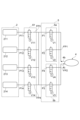
給排気システム3は、少なくとも1つの気体室211~218,221~228に高圧気体を供給し、少なくとも1つの気体室211~218,221~228から高圧気体を排出する。給排気システム3は、図1に示されるように、エアポンプ4と、エアポンプ4に接続される分配用バルブユニット5と、分配用バルブユニット5に接続されるメインバルブユニット6と、エアポンプ4、分配用バルブユニット5、及びメインバルブユニット6を制御する制御装置7とを有する。メインバルブユニット6は、第1マッサージ具21及び第2マッサージ具22に接続される。給排気システム3には、例えば動作モード(後述する揉みパターンなど)を表示する表示部などが設けられ得る。
The supply/
図3は、給排気システムの内部を示す概略斜視図である。図3に示されるように、エアポンプ4と、分配用バルブユニット5と、メインバルブユニット6とは、筐体30上に載置される。筐体30は、図示しない蓋体と組み合わされることによって、給排気システム3の内部を保護する箱として機能する。
FIG. 3 is a schematic perspective view showing the inside of the air supply/exhaust system. As shown in FIG. 3 , the
エアポンプ4は、分配用バルブユニット5に高圧気体を供給すると共に、分配用バルブユニット5から気体を吸入する装置である。エアポンプ4は、例えば、高圧気体を送出するポンプ、バルブの開放によって高圧気体が噴出するボンベなどを備え得る。平面視にて、エアポンプ4は、方向Xに沿ってメインバルブユニット6と並び、方向Xに直交する方向Yに沿って分配用バルブユニット5と並ぶ。以下では、方向Xは前後方向とも称され、方向Yは左右方向とも称される。加えて、方向X及び方向Yに直交する方向Zは上下方向とも称される。
The
エアポンプ4は、本体4aと、本体4aから外部へ気体を供給する供給口4b(図7参照)と、外部から本体4aへ気体を吸入する吸入口4c(図7参照)とを備える。供給口4bと吸入口4cとのそれぞれは、分配用バルブユニット5に接続される。例えば、エアポンプ4は、供給口4b及び分配用バルブユニット5を介してメインバルブユニット6へ気体を供給する(気体供給動作)。このとき、エアポンプ4は、吸入口4c及び分配用バルブユニット5を介して外部から気体を吸入する。また、エアポンプ4は、吸入口4c及び分配用バルブユニット5を介してメインバルブユニット6から気体を吸入する。このとき、エアポンプ4は、供給口4b及び分配用バルブユニット5を介して外部へ気体を供給(排出)する(強制減圧動作)。上記気体供給動作及び上記強制減圧動作の詳細については、後述する。
The
図4(a)は、分配用バルブユニットを示す斜視図であり、図4(b)は、分配用バルブユニットを示す正面図である。図5(a)は、図4(b)のVa-Va線に沿った概略断面図であり、図5(b)は、図4(b)のVb-Vb線に沿った概略断面図である。図6は、分配用バルブユニットの回路図を示す。図3、図4(a),(b)、図5(a),(b)及び図6に示される分配用バルブユニット5は、メインバルブユニット6への高圧気体の供給と、メインバルブユニット6からの気体の吸入とを制御する装置である。分配用バルブユニット5は、例えば、エアポンプ4とメインバルブユニット6との間の流路を、エアポンプ4からメインバルブユニット6へ気体が供給される流路、メインバルブユニット6からエアポンプ4へ気体が吸入される流路などに切り替える装置である。分配用バルブユニット5は、エアポンプ4よりも下流に位置し、メインバルブユニット6よりも上流に位置する。
FIG. 4(a) is a perspective view showing a distribution valve unit, and FIG. 4(b) is a front view showing the distribution valve unit. 5(a) is a schematic cross-sectional view along line Va-Va in FIG. 4(b), and FIG. 5(b) is a schematic cross-sectional view along line Vb-Vb in FIG. 4(b). be. FIG. 6 shows a circuit diagram of a distribution valve unit. 3, 4(a), 4(b), 5(a), 5(b) and 6, the
分配用バルブユニット5は、本体部50、第1フリーポートFP1、第2フリーポートFP2、第1接続ポートP1、第2接続ポートP2、第3接続ポートP3、及び第4接続ポートP4、第1開閉機構51、及び第2開閉機構52を有する。
The
本体部50は、第1部材50a及び第2部材50bと、第1部材50aと第2部材50bとの間に位置するシール部材50cとを有する。第1部材50aは、本体部50における主要部であって、第1フリーポートFP1、第2フリーポートFP2、第1開閉機構51及び第2開閉機構52が設けられる。図示しないが、第1部材50aにおいて第2部材50bに対向する部分には窪みが設けられ、当該窪みには第1フリーポートFP1と第2フリーポートFP2とが連通する。第2部材50bは、本体部50における蓋部であって、第1接続ポートP1、第2接続ポートP2、第3接続ポートP3、及び第4接続ポートP4が設けられる。シール部材50cは、第1部材50aと第2部材50bとの気密性を付与する部材である。
The
第1部材50a、第2部材50b、及びシール部材50cは、例えば、図示しない公知の固定手段(嵌合、ネジ止めなど)により互いに固定される。第1部材50aおよび第2部材50bは、高圧気体による押圧力、電磁弁によるポートの開閉に伴う押圧力に対して変形が抑制され得るような剛性を有していればよい。第1部材50aおよび第2部材50bのそれぞれは、例えば、樹脂材料、セラミック材料、金属材料などにより形成される。シール部材50cは、例えば環状の樹脂部材などである。樹脂部材は、例えば弾性を有してもよい。
The
分配用バルブユニット5は、方向Yに沿って並ぶ第1部分5aと第2部分5bとを有する。第1部分5aと第2部分5bとは、互いに独立している。すなわち、第1部分5aの内部空間と、第2部分5bの内部空間とは、互いに仕切られている。このため、第1部分5aに流入する気体は、第2部分5bに直接的に流入しない。換言すると、分配用バルブユニット5内にて、第1部分5a内の気体と、第2部分5b内の気体とは、互いに混合されない。
The
第1部分5aは、チャンバCA1、エアポンプ4の供給口4bに接続される第1フリーポートFP1、メインバルブユニット6に接続される第1接続ポートP1、外部に接続される第2接続ポートP2、並びに、第1接続ポートP1の開閉及び第2接続ポートP2の開閉を制御する第1開閉機構51を有する。第2部分5bは、チャンバCA1とは異なるチャンバCA2、エアポンプ4の吸入口4cに接続される第2フリーポートFP2、メインバルブユニット6に接続される第3接続ポートP3、外部に接続される第4接続ポートP4、並びに、第3接続ポートP3の開閉及び第4接続ポートP4の開閉を制御する第2開閉機構52を有する。なお、分配用バルブユニット5の外部は、例えば、給排気システム3の外気である。
The
図5(a)に示されるように、チャンバCA1は、第1部分5aに設けられる内部空間であり、第1フリーポートFP1、第1接続ポートP1、及び第2接続ポートP2に連通する。チャンバCA1に流入する気体は、第1フリーポートFP1を介してエアポンプ4から供給され、第1接続ポートP1を介してメインバルブユニット6に供給される。もしくは、当該気体は、第2接続ポートP2を介して外部に排出される。
As shown in FIG. 5(a), the chamber CA1 is an internal space provided in the
第1フリーポートFP1は、方向Xにおいて給排気システム3の後側に向かって延在するポートである。第1フリーポートFP1は、例えば、チューブ、タンクなどを介してエアポンプ4に接続される。第1接続ポートP1と第2接続ポートP2とのそれぞれは、方向Zにおいて給排気システム3の底側に向かって延在するポートである。
The first free port FP1 is a port extending toward the rear side of the air supply/
図5(b)に示されるように、チャンバCA2は、第2部分5bに設けられる内部空間であり、第2フリーポートFP2、第3接続ポートP3、及び第4接続ポートP4に連通する。チャンバCA2は、チャンバCA1とは独立しており、チャンバCA1と略同一形状を有する。チャンバCA2に流入する気体は、第2フリーポートFP2を介してエアポンプ4に吸入される、もしくは、第4接続ポートP4を介して外部に排出される。
As shown in FIG. 5(b), the chamber CA2 is an internal space provided in the
第2フリーポートFP2は、方向Xにおいて給排気システム3の後側に向かって延在するポートである。第2フリーポートFP2は、例えば、チューブ、タンクなどを介してエアポンプ4に接続される。第3接続ポートP3と第4接続ポートP4とのそれぞれは、方向Zにおいて給排気システム3の底側に向かって延在するポートである。
The second free port FP2 is a port extending toward the rear side of the air supply/
第1開閉機構51は、第1部分5aのチャンバCA1に流入される気体の流路を切り替える機構であり、第1接続ポートP1を開閉するための第1電磁弁V1と、第2接続ポートP2を開閉するための第2電磁弁V2とを有する。第1電磁弁V1は、電気で駆動することによって第1接続ポートP1を開閉する二方弁である。第2電磁弁V2は、電気で駆動することによって第2接続ポートP2を開閉する二方弁である。第1実施形態では、第1電磁弁V1と第2電磁弁V2とは、互いに同一構造を有する。
The first opening/
第2開閉機構52は、第2部分5bのチャンバCA2に流入される気体の流路を切り替える機構である。図6に示されるように、第2開閉機構52は、第3接続ポートP3を開閉するための第3電磁弁V3と、第4接続ポートP4を開閉するための第4電磁弁V4とを有する。第1実施形態では、第3電磁弁V3及び第4電磁弁V4のそれぞれは、第1電磁弁V1と同一構造を有する二方弁である。このため、以下では第1電磁弁V1の構造について説明し、第2電磁弁V2、第3電磁弁V3、及び第4電磁弁V4の説明を割愛する。
The second opening/
第1電磁弁V1は、弁座Vaと、弁体Vbと、電磁石Vcと、付勢体Vdとを有する。弁座Vaは、開閉対象となる第1接続ポートP1に隣接しており、弁体Vbが当接可能に設けられる部分である。弁座Vaは、弁体Vbが当接された際に第1接続ポートP1が閉鎖されるように形成される。弁座Vaは、例えば、弁体Vbに向かって延在する略円筒台形状を有する。 The first solenoid valve V1 has a valve seat Va, a valve body Vb, an electromagnet Vc, and a biasing body Vd. The valve seat Va is adjacent to the first connection port P1 to be opened and closed, and is a portion provided so that the valve body Vb can come into contact therewith. The valve seat Va is formed such that the first connection port P1 is closed when the valve body Vb is brought into contact therewith. The valve seat Va has, for example, a substantially cylindrical truncated shape extending toward the valve body Vb.
弁体Vbは、弁座Vaと共働して、第1接続ポートP1を開閉する部分であり、方向Zに沿って延在する棒状部分である。弁体Vbは、例えば、弁座Vaに当接する位置と、弁座Vaを露出させる位置との間で動作する。弁体Vbは、電磁石Vcの電磁力および付勢体Vdの付勢力によって、方向Zに沿って移動可能である。弁体Vbは、電磁石Vcの電磁力によって駆動されるように、鉄などの磁性体を含んでいる。弁座Vaに当接する弁体Vbの先端部は、ゴムなどの弾性体によって構成されてもよい。この場合、弁体Vbの先端部が弁座Vaに当接する際に、弁体Vbの先端部が弁座Vaの形状に追従して変形できる。これにより、弁座Vaと弁体Vbとが良好に密着する。 The valve body Vb is a portion that opens and closes the first connection port P1 in cooperation with the valve seat Va, and is a rod-shaped portion that extends along the direction Z. As shown in FIG. The valve body Vb moves, for example, between a position in contact with the valve seat Va and a position in which the valve seat Va is exposed. The valve body Vb is movable along the direction Z by the electromagnetic force of the electromagnet Vc and the biasing force of the biasing body Vd. The valve body Vb contains a magnetic material such as iron so as to be driven by the electromagnetic force of the electromagnet Vc. The tip of the valve body Vb that contacts the valve seat Va may be made of an elastic material such as rubber. In this case, when the tip of the valve body Vb comes into contact with the valve seat Va, the tip of the valve body Vb can deform to follow the shape of the valve seat Va. As a result, the valve seat Va and the valve body Vb are brought into close contact with each other.
電磁石Vcは、電力が供給されることによって、弁体Vbに電磁力を印加する。電磁石Vcは、第1実施形態では、電力が供給された際に、弁座Vaから離間する方向に弁体Vbを付勢する電磁力を弁体Vbに印加することができるように構成される。しかし、電磁石Vcは、電力が供給された際に、弁座Vaに向かって弁体Vbを付勢する電磁力を弁体Vbに印加することができるように構成されてもよい。電磁石Vcは、特に限定されることはないが、構造の簡易性の観点から、弁体Vbを内部に収容する円筒状のソレノイドコイルを採用することができる。 The electromagnet Vc applies an electromagnetic force to the valve body Vb by being supplied with electric power. In the first embodiment, the electromagnet Vc is configured to apply to the valve body Vb an electromagnetic force that urges the valve body Vb in a direction away from the valve seat Va when power is supplied. . However, the electromagnet Vc may be configured to apply an electromagnetic force to the valve body Vb to urge the valve body Vb toward the valve seat Va when power is supplied. The electromagnet Vc is not particularly limited, but from the viewpoint of structural simplicity, a cylindrical solenoid coil that accommodates the valve body Vb inside can be adopted.
付勢体Vdは、第1接続ポートP1の開状態もしくは閉状態を維持するために、弁体Vbを所定の方向に付勢する。付勢体Vdは、例えば、上記閉状態を維持するために、弁体Vbを弁座Vaに向かって付勢する。この場合は、第1電磁弁V1は、電力が供給されないときに閉状態が維持される常時閉弁となる。付勢体Vdは、上記開状態を維持するために、弁体Vbを弁座Vaから離間する方向に付勢してもよい。この場合は、第1電磁弁V1は、電力が供給されないときに開状態が維持される常時開弁となる。付勢体Vdは、弁体Vbを所定の方向に付勢することができれば、特に限定されることはなく、公知のバネなどであればよい。 The biasing body Vd biases the valve body Vb in a predetermined direction to maintain the open state or closed state of the first connection port P1. The biasing body Vd biases the valve body Vb toward the valve seat Va, for example, to maintain the closed state. In this case, the first electromagnetic valve V1 is a normally closed valve that remains closed when power is not supplied. The biasing body Vd may bias the valve body Vb in the direction away from the valve seat Va in order to maintain the open state. In this case, the first solenoid valve V1 is a normally open valve that is kept open when power is not supplied. The biasing body Vd is not particularly limited as long as it can bias the valve body Vb in a predetermined direction, and a known spring or the like may be used.
図3に戻って、メインバルブユニット6は、分配用バルブユニット5と連動して、マッサージ具2の気体室211~218,221~228のそれぞれに高圧気体を供給する流路と、マッサージ具2の気体室211~218,221~228のそれぞれから高圧気体を排出する流路とを切り替える装置である。第1実施形態では、メインバルブユニット6は、4つの電磁弁ユニット61~64を有する。電磁弁ユニット61~64は、方向Yに沿って順に並ぶ装置であり、少なくとも1つの電磁弁を有する。
Returning to FIG. 3, the
第1実施形態では、電磁弁ユニット61~64のそれぞれは、分配用バルブユニット5と同一構造を有する。このため、電磁弁ユニット61~64のそれぞれは、2つのチャンバ(第1チャンバ及び第2チャンバ)と、2つのフリーポートと、4つの接続ポートと、4つの電磁弁とを有する。電磁弁ユニット61~64のそれぞれにおいて、各フリーポートは方向Zにおいて筐体30の底側に向かって延在するポートであり、各接続ポートは方向Xにおいて筐体30の前側に向かって延在するポートである。このため方向Xにおいて、当該各接続ポートと、分配用バルブユニット5の第1フリーポートFP1及び第2フリーポートFP2とは、互いに反対側に延在する。
In the first embodiment, each of the solenoid valve units 61-64 has the same structure as the
図7は、マッサージ具の一部、エアポンプ、分配用バルブユニット、及び1つの電磁弁ユニットの回路図である。図7に示されるように、電磁弁ユニット61に含まれるフリーポートFP3,FP4の両方は、互いに分配用バルブユニット5の第1接続ポートP1及び第3接続ポートP3に接続される。また、電磁弁ユニット61に含まれる接続ポートP11~P14は、気体室211~214にそれぞれ接続される。気体室211~214への気体供給もしくは気体室211~214からの気体排出は、電磁弁ユニット61に含まれる電磁弁V11~V14によって制御される。また、例えば、電磁弁ユニット62に含まれる接続ポートP15~P18(図3を参照)は、気体室215~218にそれぞれ接続される。同様に、電磁弁ユニット63に含まれる接続ポートP21~P24(図3を参照)は、気体室221~224にそれぞれ接続され、電磁弁ユニット64に含まれる接続ポートP25~P28(図3を参照)は、気体室225~228にそれぞれ接続される。接続ポートP11~18,P21~28のそれぞれの開閉は、対応する電磁弁(不図示)によって制御される。
FIG. 7 is a circuit diagram of part of the massager, the air pump, the dispensing valve unit and one solenoid valve unit. As shown in FIG. 7, both free ports FP3 and FP4 included in the
図8(a)は、給排気システムの底面図であり、図8(b)は、図8(a)において筐体の一部を除外した概略図である。図8(a)に示されるように、筐体30の底面30aには、複数の開口30bと、孔30cとが設けられる。開口30bは、気体が通過する部分であり、例えば分配用バルブユニット5の第2接続ポートP2及び第4接続ポートP4に接続される。孔30cは、ネジなどの締結手段が挿入可能な部分であり、ネジ溝などが設けられ得る。
FIG. 8(a) is a bottom view of the air supply/exhaust system, and FIG. 8(b) is a schematic view of FIG. 8(a) with a part of the housing removed. As shown in FIG. 8A, the
図8(b)に示されるように、筐体30には、互いに仕切られるタンク31~33と、室35,36とが設けられる。タンク31は、エアポンプ4の吸入口4cと分配用バルブユニット5の第1フリーポートFP1とが接続される密室部分(吸入用タンク)であり、中継ポート311,312が設けられる。中継ポート311はチューブ等を介してエアポンプ4の吸入口4cに接続される部分であり、中継ポート312はチューブ等を介して分配用バルブユニット5の第1フリーポートFP1に接続される部分である。タンク32は、エアポンプ4の供給口4bと分配用バルブユニット5の第2フリーポートFP2とが接続される密室部分(供給用タンク)であり、中継ポート321,322が設けられる。中継ポート321はチューブ等を介してエアポンプ4の供給口4bに接続される部分であり、中継ポート322はチューブ等を介して分配用バルブユニット5の第2フリーポートFP2に接続される部分である。
As shown in FIG. 8B, the
タンク33は、分配用バルブユニット5の第1接続ポートP1及び第3接続ポートP3と、メインバルブユニット6に含まれる各フリーポートとが接続される密室部分(共通タンク)であり、中継ポート331~340を有する。中継ポート331は分配用バルブユニット5の第1接続ポートP1に接続される部分であり、中継ポート332は分配用バルブユニット5の第3接続ポートP3に接続される部分である。中継ポート333~340のそれぞれは、メインバルブユニット6に含まれるフリーポートのいずれかに接続される部分である。なお、タンク33の内圧は、気圧計などによって計測されてもよい。
The
室35,36のそれぞれは、開口30bを介して外部に接続される非密室である。室35に設けられる中継ポート351には分配用バルブユニット5の第2接続ポートP2が接続される。室36に設けられる中継ポート361には分配用バルブユニット5の第4接続ポートP4が接続される。
Each of the
図3に戻って、給排気システム3が備える制御装置7は、エアポンプ4、分配用バルブユニット5及びメインバルブユニット6の動作を制御する装置である。制御装置7は、例えば、CPU(Central Processing Unit)と、RAM(Random Access Memory)と、ROM(Read-Only Memory)とを備えている。制御装置7は、例えば、ROMに格納されている制御プログラムを実行することができるように構成されている。制御プログラムは、例えば、気体室211~218,221~228を膨張および収縮させる所望の順番に基づいて、エアポンプ4、分配用バルブユニット5及びメインバルブユニット6を動作させるように記述されている。制御装置7は、給排気システム3の筐体30内に設けられてもよいし、筐体30の外部に設けられてもよい。
Returning to FIG. 3 , the control device 7 provided in the air supply/
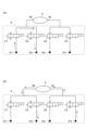
次に、第1実施形態に係る給排気システム3の動作を、図9(a),(b)及び図10(a),(b)を参照しながら説明する。図9(a),(b)及び図10(a),(b)のそれぞれは、エアポンプ及び分配用バルブユニットの回路図である。
Next, the operation of the air supply/
まず、図9(a)を参照しながら、給排気システム3によるメインバルブユニット6への気体供給動作を説明する。図9(a)に示されるように、エアポンプ4によるメインバルブユニット6への気体供給時、第1電磁弁V1及び第4電磁弁V4が開放される一方で、第2電磁弁V2及び第3電磁弁V3が閉塞される。このため、当該気体供給時、第1接続ポートP1及び第4接続ポートP4が開放されると共に、第2接続ポートP2及び第3接続ポートP3が閉塞される。これにより、図9(a)に示される矢印のように、第4接続ポートP4を介して外部からエアポンプ4に流入した気体は、第1接続ポートP1を介してメインバルブユニット6に供給される。第1実施形態では、上記気体供給時、メインバルブユニット6の動作によって、気体室211~218,221~228の少なくとも一つに高圧気体が供給される。気体室211~218,221~228のそれぞれが所望の内圧になるように、上記気体供給が実施される。
First, the operation of supplying gas to the
次に、図9(b)を参照しながら、給排気システム3による内圧調整動作を説明する。内圧調整動作にて実施される内圧調整は、例えば、メインバルブユニット6に含まれる少なくとも一つのチャンバの内圧の調整、気体室211~218,221~228の少なくとも一つの内圧の調整などである。内圧調整時においては、エアポンプ4は停止状態になっている。図9(b)に示されるように、内圧調整時、第3電磁弁V3及び第4電磁弁V4が開放される一方で、第1電磁弁V1及び第2電磁弁V2が閉塞される。このため、当該内圧調整時、第3接続ポートP3及び第4接続ポートP4が開放されると共に、第1接続ポートP1及び第2接続ポートP2が閉塞される。これにより、図9(b)に示される矢印のように、第3接続ポートP3及び第4接続ポートP4を介して、少なくとも一つの上記チャンバ、及び/または、気体室211~218,221~228の少なくとも一つから気体が排出される。第1実施形態では、上記内圧調整時、メインバルブユニット6の動作によって、上記チャンバの少なくとも一つの内圧と、気体室211~218,221~228の少なくとも一つの内圧とが調整され得る。
Next, the operation of adjusting the internal pressure by the air supply/
次に、図10(a)を参照しながら、給排気システム3による自然減圧動作を説明する。自然減圧動作にて実施される自然減圧は、例えば、メインバルブユニット6に含まれる少なくとも一つのチャンバの自然減圧、気体室211~218,221~228の少なくとも一つの内圧の自然減圧などである。自然減圧時においては、エアポンプ4は停止状態になっている。図10(a)に示されるように、内圧調整時、第1電磁弁V1及び第2電磁弁V2が開放される一方で、第3電磁弁V3及び第4電磁弁V4が閉塞される。このため、当該自然減圧時、第1接続ポートP1及び第2接続ポートP2が開放されると共に、第3接続ポートP3及び第4接続ポートP4が閉塞される。これにより、図10(a)に示される矢印のように、第1接続ポートP1及び第2接続ポートP2を介して、上記チャンバ、及び気体室211~218,221~228から気体が排出される。第1実施形態では、上記自然減圧時、メインバルブユニット6の動作によって、各チャンバと、気体室211~218,221~228とを自然減圧する。
Next, referring to FIG. 10(a), the natural pressure reduction operation by the air supply/
次に、図10(b)を参照しながら、給排気システム3による強制減圧動作を説明する。強制減圧動作にて実施される強制減圧は、例えば、緊急事態時などにおいて、メインバルブユニット6に含まれる全てのチャンバをエアポンプ4の気体吸入によって強制的に減圧すること、気体室211~218,221~228の全てをエアポンプ4の気体吸入によって強制的に減圧することである。図10(b)に示されるように、エアポンプ4の気体吸入時、第2電磁弁V2及び第3電磁弁V3が開放される一方で、第1電磁弁V1及び第4電磁弁V4が閉塞される。このため、当該強制減圧時、第2接続ポートP2及び第3接続ポートP3が開放されると共に、第1接続ポートP1及び第4接続ポートP4が閉塞される。これにより、図10(b)に示される矢印のように、第3接続ポートP3を介してメインバルブユニット6からエアポンプ4に流入した気体は、第2接続ポートP2を介して給排気システム3の外部に排出される。
Next, the forced pressure reduction operation by the air supply/
次に、第1実施形態の気体式マッサージ機1の動作を、図11及び図12を参照しながら説明する。図11及び図12のそれぞれは、マッサージ具を用いた揉みパターンの例を示す図である。本明細書では、マッサージ具2の気体室211~218,221~228に高圧気体を供給し、または気体室211~218,221~228から高圧気体を排出することにより、気体室211~218,221~228を膨張または収縮させる順序を「揉みパターン」と呼ぶ。なお、以下に示す気体式マッサージ機1の動作はあくまで一例である。
Next, operation of the
血液および/またはリンパ液の流れを良くするために身体にマッサージを施す場合、四肢の先端部から胴体に向かう順番で身体を圧迫していくことがある。これに対応するマッサージ具2による揉みパターンとして、図2及び図11に示されるように、気体室211,221から気体室218,228まで順に気体室211~218,221~228を膨張させ、気体室218,228を膨張させ終わるまで、気体室211~217,221~227の膨張を保持するような揉みパターンが考えられる。本明細書では、図12に示される揉みパターンのモードおよびこれに類する揉みパターンのモードを「スクイーズモード(squeeze-mode)」と呼ぶ。また、気体室211から気体室218まで順に膨張させ、気体室221から気体室228まで順に膨張させ、膨張させた気体室211~218,221~228の膨張状態を保持した後に(膨張させた気体室211~218,221~228を一旦保圧した後に)、膨張させた順に気体室211~218,221~228を収縮させるような揉みパターンが考えられる。本明細書では、このような揉みパターンのモードおよびこれに類する揉みパターンのモードを「ウェーブモード(wave-mode)」と呼ぶ。
When massaging the body to improve blood and/or lymph flow, the body may be compressed in order from the extremities to the torso. As a kneading pattern by the
スクイーズモードにおける給排気システム3の動作の具体例と、ウェーブモードにおける給排気システム3の動作の具体例とのそれぞれは、例えば特願2020-082607号に記載される。なお、制御装置7は、上述したスクイーズモード及びウェーブモードに限らず、分配用バルブユニット5及びメインバルブユニット6を制御することによって、さまざまな揉みパターンを実施可能である。
A specific example of the operation of the air supply/
以上に説明した第1実施形態に係る給排気システム3を備える気体式マッサージ機1によれば、メインバルブユニット6は、分配用バルブユニット5を介して、エアポンプ4の供給口4bと吸入口4cとの両方に接続される。このため、分配用バルブユニット5を利用して、メインバルブユニット6は、エアポンプ4からの気体供給と、エアポンプ4による気体吸入との両方が実施できる。したがって、給排気システム3を利用することによって、メインバルブユニット6の内部空間、マッサージ具2の気体室211~218,221~228などに対して、強制的な内圧低下を容易に実現できる。
According to the
第1実施形態では、電磁弁ユニット61~64のそれぞれは、チャンバを有し、エアポンプ4による気体供給時、第1接続ポートP1及び第4接続ポートP4が開放されると共に、第2接続ポートP2及び第3接続ポートP3が閉塞され、エアポンプ4による気体吸入時、第2接続ポートP2及び第3接続ポートP3が開放されると共に、第1接続ポートP1及び第4接続ポートP4が閉塞され、エアポンプ4が停止状態であって少なくとも一つのチャンバの内圧が調整されるとき、第3接続ポートP3及び第4接続ポートP4が開放されると共に第1接続ポートP1及び第2接続ポートP2が閉塞され、エアポンプ4が停止状態であって各チャンバが減圧されるとき、第1接続ポートP1及び第2接続ポートP2が開放されると共に第3接続ポートP3及び第4接続ポートP4が閉塞される。このため、分配用バルブユニット5を利用して、メインバルブユニット6内のチャンバなどに対して多様な圧力制御が可能になる。加えて、給排気システム3における気体排出口が第2接続ポートP2及び第4接続ポートP4の一方に限定されないので、第1開閉機構51及び第2開閉機構52の一方の劣化が促進しにくくなる。
In the first embodiment, each of the
第1実施形態では、第1開閉機構51は、第1接続ポートP1の開閉を制御する第1二方弁である第1電磁弁V1と、第2接続ポートP2の開閉を制御する第2二方弁である第2電磁弁V2とを有し、第2開閉機構52は、第3接続ポートP3の開閉を制御する第3二方弁であるである第3電磁弁V3と、第4接続ポートP4の開閉を制御する第4二方弁であるである第4電磁弁V4とを有する。このため、分配用バルブユニット5の構造を簡易化できる。
In the first embodiment, the first opening/
第1実施形態では、分配用バルブユニット5と、電磁弁ユニット61~64のそれぞれとは、互いに同一構成を有する。この場合、給排気システム3内の共通部品点数が多くなるので、コストダウンの実現と共にメンテナンス性を向上できる。
In the first embodiment, the
(第2実施形態)
以下では、第2実施形態に係る給排気システム及びそれを備える気体式マッサージ機について説明する。第2実施形態の説明において第1実施形態と重複する記載は省略し、第1実施形態と異なる部分を記載する。つまり、技術的に可能な範囲において、第2実施形態に第1実施形態の記載を適宜用いてもよい。
(Second embodiment)
Below, the gas-type massage machine provided with the air supply/exhaustion system which concerns on 2nd Embodiment, and the same is demonstrated. In the description of the second embodiment, descriptions overlapping those of the first embodiment will be omitted, and portions different from the first embodiment will be described. In other words, the description of the first embodiment may be appropriately applied to the second embodiment as long as it is technically possible.
図12は、第2実施形態に係る分配用バルブユニット及びエアポンプの回路図である。図12に示されるように、分配用バルブユニット5Aの第2部分5bは、第3接続ポートP3及び第4接続ポートP4に加えて、外部に接続される第5接続ポートP5を有する。また、第1開閉機構51Aは、互いに直列接続される第1三方弁TV1及び第2三方弁TV2を有し、第2開閉機構52Aは、第3三方弁TV3を有する。第1三方弁TV1は、第1フリーポートFP1、第2接続ポート及び第2三方弁TV2に接続される電磁弁である。第2三方弁TV2は、第1接続ポートP1、第5接続ポートP5及び第1三方弁TV1に接続される。第3三方弁TV3は、第2フリーポートFP2、第3接続ポートP3及び第4接続ポートP4に接続される。このため、第2実施形態では、分配用バルブユニット5Aと、電磁弁ユニット61~64とは、互いに異なる形状を有する。
FIG. 12 is a circuit diagram of the distribution valve unit and air pump according to the second embodiment. As shown in FIG. 12, the
次に、第2実施形態に係る給排気システムの動作を、図13~図15を参照しながら説明する。図13~15のそれぞれは、エアポンプ及び分配用バルブユニットの回路図である。 Next, the operation of the air supply/exhaust system according to the second embodiment will be described with reference to FIGS. 13 to 15. FIG. Each of Figures 13-15 is a circuit diagram of the air pump and dispensing valve unit.
まず、図13を参照しながら、第2実施形態に係るメインバルブユニット6への気体供給動作を説明する。図13に示されるように、エアポンプ4によるメインバルブユニット6への気体供給時、第1三方弁TV1及び第2三方弁TV2が開放される一方で、第3三方弁TV3が閉塞される。このため、当該気体供給時、第1接続ポートP1及び第4接続ポートP4が開放されると共に、第2接続ポートP2、第3接続ポートP3及び第5接続ポートP5が閉塞される。これにより、図13に示される矢印のように、第4接続ポートP4を介して外部からエアポンプ4に流入した気体は、第1接続ポートP1を介してメインバルブユニット6に供給される。
First, the gas supply operation to the
次に、図14を参照しながら、内圧調整動作及び自然減圧動作を説明する。図14に示されるように、内圧調整時、第1三方弁TV1、第2三方弁TV2及び第3三方弁TV3の全てが閉塞される。このため、当該内圧調整時、第5接続ポートP5が開放されると共に、第1接続ポートP1~第4接続ポートP4が閉塞される。これにより、図14に示される矢印のように、第5接続ポートP5を介して、少なくとも一つの上記チャンバ、及び/または、気体室211~218,221~228の少なくとも一つから気体が排出される。
Next, the internal pressure adjustment operation and the natural pressure reduction operation will be described with reference to FIG. 14 . As shown in FIG. 14, the first three-way valve TV1, the second three-way valve TV2 and the third three-way valve TV3 are all closed during the internal pressure adjustment. Therefore, when adjusting the internal pressure, the fifth connection port P5 is opened and the first to fourth connection ports P1 to P4 are closed. As a result, gas is discharged from at least one of the chambers and/or at least one of the
次に、図15を参照しながら、強制減圧動作を説明する。図15に示されるように、エアポンプ4の気体吸入時、第3三方弁TV3が開放される一方で、第1三方弁TV1及び第2三方弁TV2が閉塞される。このため、当該強制減圧時、第2接続ポートP2及び第3接続ポートP3が開放されると共に、第1接続ポートP1、第4接続ポートP4及び第5接続ポートP5が閉塞される。これにより、図15に示される矢印のように、第3接続ポートP3を介してメインバルブユニット6からエアポンプ4に流入した気体は、第2接続ポートP2を介して給排気システム3の外部に排出される。
Next, the forced pressure reduction operation will be described with reference to FIG. As shown in FIG. 15, when the
以上に説明した第2実施形態においても、上記第1実施形態と同様の作用効果が奏される。加えて、第2実施形態では、上記第1実施形態と比較して、分配用バルブユニット5Aに含まれる電磁弁の数を低減できる。
Also in the second embodiment described above, the same effects as those of the first embodiment are achieved. In addition, in the second embodiment, the number of solenoid valves included in the
本発明に係る気体式マッサージ機用給排気システム及びそれを備える気体式マッサージ機は、上記実施形態に限定されず、他に様々な変形が可能である。例えば、上記実施形態は適宜組み合わされてもよい。例えば、分配用バルブユニットには、二方弁と三方弁の両方が設けられてもよい。 The air supply/exhaust system for a gas massage machine and the gas massage machine provided with the same according to the present invention are not limited to the above-described embodiments, and various other modifications are possible. For example, the above embodiments may be combined as appropriate. For example, a distribution valve unit may be provided with both a two-way valve and a three-way valve.
上記実施形態では、メインバルブユニットは4つの電磁弁ユニットを有するが、これに限られない。電磁弁ユニットの数は、マッサージ具に含まれる気体室の数によって定められてもよい。 Although the main valve unit has four solenoid valve units in the above embodiment, it is not limited to this. The number of solenoid valve units may be determined by the number of gas chambers included in the massage tool.
上記実施形態では、複数の電磁弁ユニットのそれぞれは、第1マッサージ具及び第2マッサージ具の一方のみに接続されるが、これに限られない。例えば、複数の電磁弁ユニットのそれぞれは第1マッサージ具及び第2マッサージ具の両方に接続されてもよい。この場合、各電磁弁ユニットのうち、一部の接続ポートが第1マッサージ具に接続され、その他の接続ポートが第2マッサージ具に接続される。もしくは、一部の電磁弁ユニットは第1マッサージ具のみに接続され、別の一部の電磁弁ユニットは第2マッサージ具のみに接続され、更に別の一部の電磁弁ユニットは第1マッサージ具と第2マッサージ具との両方に接続されてもよい。 In the above embodiment, each of the plurality of electromagnetic valve units is connected to only one of the first massager and the second massager, but the present invention is not limited to this. For example, each of the plurality of electromagnetic valve units may be connected to both the first massager and the second massager. In this case, some of the connection ports of each electromagnetic valve unit are connected to the first massage tool, and the other connection ports are connected to the second massage tool. Alternatively, some solenoid valve units are connected only to the first massager, some solenoid valve units are connected only to the second massager, and some solenoid valve units are connected to the first massager. and the second massager.
上記実施形態では、複数の電磁弁ユニットのそれぞれに含まれる2つの部分は、第1マッサージ具及び第2マッサージ具の一方に接続されるが、これに限られない。例えば、複数の電磁弁ユニットのそれぞれにおいて、一方の部分は第1マッサージ具及び第2マッサージ具の一方に接続され、他方の部分は第1マッサージ具及び第2マッサージ具の他方に接続されてもよい。 In the above embodiment, the two parts included in each of the plurality of electromagnetic valve units are connected to one of the first massage tool and the second massage tool, but the present invention is not limited to this. For example, in each of the plurality of electromagnetic valve units, one portion may be connected to one of the first massage device and the second massage device, and the other portion may be connected to the other of the first massage device and the second massage device. good.
上記第1実施形態では、内圧調整時には第3接続ポート及び第4接続ポートが開放されるが、これに限られない。例えば、内圧調整時には第1接続ポート及び第2接続ポートが開放されてもよい。この場合、自然減圧時には第3接続ポート及び第4接続ポートが開放されてもよい。また、自然減圧時には第1接続ポート、第2接続ポート、第3接続ポート及び第4接続ポートが開放されてもよい。この場合、減圧に要する時間を短縮できる。 In the first embodiment, the third connection port and the fourth connection port are opened during internal pressure adjustment, but this is not the only option. For example, the first connection port and the second connection port may be opened during internal pressure adjustment. In this case, the third connection port and the fourth connection port may be opened during natural pressure reduction. Also, the first connection port, the second connection port, the third connection port, and the fourth connection port may be opened during natural pressure reduction. In this case, the time required for pressure reduction can be shortened.
上記第1実施形態では、分配用バルブユニットと電磁弁ユニットとは互いに同一形状を有するが、これに限られない。 In the first embodiment, the distribution valve unit and the solenoid valve unit have the same shape, but the present invention is not limited to this.
1…気体式マッサージ機、2…マッサージ具、3…給排気システム(気体式マッサージ機用給排気システム)、4…エアポンプ、4b…供給口、4c…吸入口、5,5A…分配用バルブユニット、5a…第1部分、5b…第2部分、6…メインバルブユニット、7…制御装置、21…第1マッサージ具、22…第2マッサージ具、30…筐体、31~33…タンク、51,51A…第1開閉機構、52,52A…第2開閉機構、61~64…電磁弁ユニット、211~218,221~228…気体室、FP1…第1フリーポート、FP2…第2フリーポート、P1…第1接続ポート、P2…第2接続ポート、P3…第3接続ポート、P4…第4接続ポート、P5…第5接続ポート、TV1…第1三方弁、TV2…第2三方弁、TV3…第3三方弁、V1…第1電磁弁、V2…第2電磁弁、V3…第3電磁弁、V4…第4電磁弁。
DESCRIPTION OF
Claims (7)
前記エアポンプに接続される分配用バルブユニットと、
前記分配用バルブユニットに接続される複数の電磁弁ユニットを有するメインバルブユニットと、
を備え、
前記分配用バルブユニットは、
前記エアポンプの供給口に接続される第1フリーポート、前記メインバルブユニットに接続される第1接続ポート、外部に接続される第2接続ポート、並びに、前記第1接続ポートの開閉及び前記第2接続ポートの開閉を制御する第1開閉機構を有する第1部分と、
前記エアポンプの吸入口に接続される第2フリーポート、前記メインバルブユニットに接続される第3接続ポート、外部に接続される第4接続ポート、並びに、前記第3接続ポートの開閉及び前記第4接続ポートの開閉を制御する第2開閉機構を有する第2部分と、を備える、
気体式マッサージ機用給排気システム。 air pump and
a distribution valve unit connected to the air pump;
a main valve unit having a plurality of solenoid valve units connected to the distribution valve unit;
with
The distribution valve unit is
A first free port connected to the supply port of the air pump, a first connection port connected to the main valve unit, a second connection port connected to the outside, and opening and closing of the first connection port and the second connection port. a first portion having a first opening/closing mechanism for controlling opening/closing of the connection port;
A second free port connected to the suction port of the air pump, a third connection port connected to the main valve unit, a fourth connection port connected to the outside, and opening and closing of the third connection port and the fourth connection port. a second portion having a second opening/closing mechanism for controlling opening/closing of the connection port;
Air supply and exhaust system for gas massage machine.
前記エアポンプによる気体供給時、前記第1接続ポート及び前記第4接続ポートが開放されると共に、前記第2接続ポート及び前記第3接続ポートが閉塞され、
前記エアポンプによる気体吸入時、前記第2接続ポート及び前記第3接続ポートが開放されると共に、前記第1接続ポート及び前記第4接続ポートが閉塞され、
第1タイミングにおいて、前記エアポンプが停止状態であって少なくとも一つの前記チャンバの内圧が減圧されるとき、前記第3接続ポート及び前記第4接続ポートが開放されると共に前記第1接続ポート及び前記第2接続ポートが閉塞され、
前記第1タイミングとは異なる第2タイミングにおいて、前記エアポンプが停止状態であって各前記チャンバが減圧されるとき、前記第1接続ポート及び前記第2接続ポートが開放されると共に前記第3接続ポート及び前記第4接続ポートが閉塞される、請求項1に記載の気体式マッサージ機用給排気システム。 each of the plurality of solenoid valve units has a chamber,
When gas is supplied by the air pump, the first connection port and the fourth connection port are opened, and the second connection port and the third connection port are closed,
When gas is sucked by the air pump, the second connection port and the third connection port are opened, and the first connection port and the fourth connection port are closed,
At a first timing, when the air pump is in a stopped state and the internal pressure of at least one of the chambers is reduced , the third connection port and the fourth connection port are opened and the first connection port and the first connection port are opened. 2 connection port is blocked,
At a second timing different from the first timing, when the air pump is stopped and each of the chambers is decompressed, the first connection port and the second connection port are opened and the third connection port is opened. and the fourth connection port are closed.
前記第2開閉機構は、前記第3接続ポートの開閉を制御する第3二方弁と、前記第4接続ポートの開閉を制御する第4二方弁とを有する、請求項1または2に記載の気体式マッサージ機用給排気システム。 The first opening/closing mechanism has a first two-way valve that controls opening and closing of the first connection port, and a second two-way valve that controls opening and closing of the second connection port,
3. The second opening/closing mechanism according to claim 1, wherein the second opening/closing mechanism has a third two-way valve that controls opening/closing of the third connection port, and a fourth two-way valve that controls opening/closing of the fourth connection port. air supply and exhaust system for gas massage machine.
前記第1開閉機構は、互いに直列接続される第1三方弁及び第2三方弁を有し、
前記第2開閉機構は、前記第2フリーポート、前記第3接続ポート及び前記第4接続ポートに接続される第3三方弁を有し、
前記第1三方弁は、前記第1フリーポート、前記第2接続ポート及び前記第2三方弁に接続され、
前記第2三方弁は、前記第1接続ポート、前記第5接続ポート及び前記第1三方弁に接続される、請求項1に記載の気体式マッサージ機用給排気システム。 The first portion further has a fifth connection port connected to the outside,
The first opening/closing mechanism has a first three-way valve and a second three-way valve that are connected in series with each other,
The second opening/closing mechanism has a third three-way valve connected to the second free port, the third connection port and the fourth connection port,
the first three-way valve is connected to the first free port, the second connection port and the second three-way valve;
2. The air supply/exhaust system for a gas massage machine according to claim 1, wherein said second three-way valve is connected to said first connection port, said fifth connection port and said first three-way valve.
前記エアポンプによる気体供給時、前記第1接続ポート及び前記第4接続ポートを開放すると共に、前記第2接続ポート、前記第3接続ポート及び前記第5接続ポートを閉塞し、
前記エアポンプによる気体吸入時、前記第2接続ポート及び前記第3接続ポートを開放すると共に、前記第1接続ポート、前記第4接続ポート及び前記第5接続ポートを閉塞し、
前記エアポンプが停止状態であって少なくとも一つの前記チャンバの内圧が減圧されるとき、前記第1接続ポート及び前記第5接続ポートが開放されると共に、前記第2接続ポート、前記第3接続ポート及び前記第4接続ポートが閉塞される、請求項5に記載の気体式マッサージ機用給排気システム。 each of the plurality of solenoid valve units has a chamber,
When gas is supplied by the air pump, the first connection port and the fourth connection port are opened, and the second connection port, the third connection port and the fifth connection port are closed,
When gas is sucked by the air pump, the second connection port and the third connection port are opened and the first connection port, the fourth connection port and the fifth connection port are closed,
When the air pump is stopped and the internal pressure of at least one of the chambers is reduced , the first connection port and the fifth connection port are opened , and the second connection port and the third connection are opened. 6. The air supply/exhaust system for a gas massage machine according to claim 5, wherein the port and the fourth connection port are closed.
前記メインバルブユニットに接続されるマッサージ具と、を備える、
気体式マッサージ機。 The air supply and exhaust system according to any one of claims 1 to 6,
a massage tool connected to the main valve unit,
pneumatic massager.
Priority Applications (3)
| Application Number | Priority Date | Filing Date | Title |
|---|---|---|---|
| JP2021206348A JP7246773B1 (en) | 2021-12-20 | 2021-12-20 | Air supply and exhaust system for gas massage machine and gas massage machine provided with the same |
| EP22213019.7A EP4197516A1 (en) | 2021-12-20 | 2022-12-13 | Air supply/exhaust system for air massager and air massager including the same |
| US18/065,623 US20230190571A1 (en) | 2021-12-20 | 2022-12-14 | Air pump system for massager |
Applications Claiming Priority (1)
| Application Number | Priority Date | Filing Date | Title |
|---|---|---|---|
| JP2021206348A JP7246773B1 (en) | 2021-12-20 | 2021-12-20 | Air supply and exhaust system for gas massage machine and gas massage machine provided with the same |
Publications (2)
| Publication Number | Publication Date |
|---|---|
| JP7246773B1 true JP7246773B1 (en) | 2023-03-28 |
| JP2023091548A JP2023091548A (en) | 2023-06-30 |
Family
ID=84519351
Family Applications (1)
| Application Number | Title | Priority Date | Filing Date |
|---|---|---|---|
| JP2021206348A Active JP7246773B1 (en) | 2021-12-20 | 2021-12-20 | Air supply and exhaust system for gas massage machine and gas massage machine provided with the same |
Country Status (3)
| Country | Link |
|---|---|
| US (1) | US20230190571A1 (en) |
| EP (1) | EP4197516A1 (en) |
| JP (1) | JP7246773B1 (en) |
Citations (4)
| Publication number | Priority date | Publication date | Assignee | Title |
|---|---|---|---|---|
| JP2000189477A (en) | 1998-12-28 | 2000-07-11 | Nitto Kohki Co Ltd | Pressure control system for air massage |
| JP2005058647A (en) | 2003-08-20 | 2005-03-10 | Kuroda Precision Ind Ltd | Pressure controller for air massager |
| CN2751791Y (en) | 2004-12-11 | 2006-01-18 | 浙江大学 | Instrument for preventing deep phlebothrombosis |
| KR101888920B1 (en) | 2017-12-21 | 2018-09-21 | (주)세븐라이너 | The limbs pressure circulation control system and control method thereof |
Family Cites Families (6)
| Publication number | Priority date | Publication date | Assignee | Title |
|---|---|---|---|---|
| DE19846922C2 (en) * | 1998-10-12 | 2003-12-11 | Manuel Fernandez | treatment device |
| JP3765971B2 (en) | 2000-03-06 | 2006-04-12 | 富士通株式会社 | Ring configuration method and its node device |
| AU2015308928B2 (en) | 2014-08-27 | 2019-03-14 | Kpr U.S., Llc | Compression garment inflation |
| WO2016120689A1 (en) * | 2015-01-27 | 2016-08-04 | Yeung Eliza Wai Yi | Pillow |
| JP2020082607A (en) | 2018-11-29 | 2020-06-04 | パナソニックIpマネジメント株式会社 | Ink jet head and ink jet device |
| JP7401133B2 (en) * | 2020-05-08 | 2023-12-19 | 株式会社テクノ高槻 | gas massage machine |
-
2021
- 2021-12-20 JP JP2021206348A patent/JP7246773B1/en active Active
-
2022
- 2022-12-13 EP EP22213019.7A patent/EP4197516A1/en active Pending
- 2022-12-14 US US18/065,623 patent/US20230190571A1/en active Pending
Patent Citations (4)
| Publication number | Priority date | Publication date | Assignee | Title |
|---|---|---|---|---|
| JP2000189477A (en) | 1998-12-28 | 2000-07-11 | Nitto Kohki Co Ltd | Pressure control system for air massage |
| JP2005058647A (en) | 2003-08-20 | 2005-03-10 | Kuroda Precision Ind Ltd | Pressure controller for air massager |
| CN2751791Y (en) | 2004-12-11 | 2006-01-18 | 浙江大学 | Instrument for preventing deep phlebothrombosis |
| KR101888920B1 (en) | 2017-12-21 | 2018-09-21 | (주)세븐라이너 | The limbs pressure circulation control system and control method thereof |
Also Published As
| Publication number | Publication date |
|---|---|
| JP2023091548A (en) | 2023-06-30 |
| EP4197516A1 (en) | 2023-06-21 |
| US20230190571A1 (en) | 2023-06-22 |
Similar Documents
| Publication | Publication Date | Title |
|---|---|---|
| JP3909789B2 (en) | Air massager | |
| JP7401133B2 (en) | gas massage machine | |
| GB2379611B (en) | Inflatable compression sleeve | |
| JPS6068854A (en) | Heart and lung revival device | |
| US20130226043A1 (en) | Slimming apparatus | |
| US8591439B1 (en) | Extended term patient resuscitation/ventilation system | |
| JP7246773B1 (en) | Air supply and exhaust system for gas massage machine and gas massage machine provided with the same | |
| JP2012170611A (en) | Massage machine | |
| JP7356770B2 (en) | gas massage machine | |
| JP4059956B2 (en) | Pneumatic massager | |
| KR100858260B1 (en) | Air-massager anomaly detecting system | |
| JP7246772B1 (en) | Air supply and exhaust system for gas massage machine and gas massage machine provided with the same | |
| KR102171879B1 (en) | Body for air pressure massage with solenoid valve block assembly | |
| CN216455967U (en) | Portable leg massage instrument | |
| KR200444112Y1 (en) | Eye care massager | |
| WO2021225109A1 (en) | Gas-type massage device | |
| JP2004073236A (en) | Air massage apparatus | |
| CN219184728U (en) | Air massage machine | |
| KR900001414B1 (en) | Vacuum massager and vacuum generating method | |
| JP3609925B2 (en) | Air massage machine | |
| CN117915877A (en) | Air massage device | |
| JP2004195115A (en) | Air massage machine | |
| JP2000288055A (en) | Air massage machine | |
| JP2020137903A (en) | Presser for air massage machine and air massage device including presser for air massage machine | |
| KR20230102843A (en) | Wearable cuff apparatus |
Legal Events
| Date | Code | Title | Description |
|---|---|---|---|
| A621 | Written request for application examination |
Free format text: JAPANESE INTERMEDIATE CODE: A621 Effective date: 20211220 |
|
| A131 | Notification of reasons for refusal |
Free format text: JAPANESE INTERMEDIATE CODE: A131 Effective date: 20221220 |
|
| A521 | Request for written amendment filed |
Free format text: JAPANESE INTERMEDIATE CODE: A523 Effective date: 20230210 |
|
| TRDD | Decision of grant or rejection written | ||
| A01 | Written decision to grant a patent or to grant a registration (utility model) |
Free format text: JAPANESE INTERMEDIATE CODE: A01 Effective date: 20230228 |
|
| A61 | First payment of annual fees (during grant procedure) |
Free format text: JAPANESE INTERMEDIATE CODE: A61 Effective date: 20230308 |
|
| R150 | Certificate of patent or registration of utility model |
Ref document number: 7246773 Country of ref document: JP Free format text: JAPANESE INTERMEDIATE CODE: R150 |
|
| S531 | Written request for registration of change of domicile |
Free format text: JAPANESE INTERMEDIATE CODE: R313531 |
|
| R350 | Written notification of registration of transfer |
Free format text: JAPANESE INTERMEDIATE CODE: R350 |