JP7245388B2 - Endoscope bending section, endoscope insertion section, endoscope - Google Patents
Endoscope bending section, endoscope insertion section, endoscope Download PDFInfo
- Publication number
- JP7245388B2 JP7245388B2 JP2022512920A JP2022512920A JP7245388B2 JP 7245388 B2 JP7245388 B2 JP 7245388B2 JP 2022512920 A JP2022512920 A JP 2022512920A JP 2022512920 A JP2022512920 A JP 2022512920A JP 7245388 B2 JP7245388 B2 JP 7245388B2
- Authority
- JP
- Japan
- Prior art keywords
- bending
- bending piece
- endoscope
- wire
- groove
- Prior art date
- Legal status (The legal status is an assumption and is not a legal conclusion. Google has not performed a legal analysis and makes no representation as to the accuracy of the status listed.)
- Active
Links
Images


Classifications
-
- A—HUMAN NECESSITIES
- A61—MEDICAL OR VETERINARY SCIENCE; HYGIENE
- A61B—DIAGNOSIS; SURGERY; IDENTIFICATION
- A61B1/00—Instruments for performing medical examinations of the interior of cavities or tubes of the body by visual or photographical inspection, e.g. endoscopes; Illuminating arrangements therefor
- A61B1/005—Flexible endoscopes
- A61B1/0051—Flexible endoscopes with controlled bending of insertion part
- A61B1/0055—Constructional details of insertion parts, e.g. vertebral elements
-
- A—HUMAN NECESSITIES
- A61—MEDICAL OR VETERINARY SCIENCE; HYGIENE
- A61B—DIAGNOSIS; SURGERY; IDENTIFICATION
- A61B1/00—Instruments for performing medical examinations of the interior of cavities or tubes of the body by visual or photographical inspection, e.g. endoscopes; Illuminating arrangements therefor
- A61B1/005—Flexible endoscopes
- A61B1/0051—Flexible endoscopes with controlled bending of insertion part
- A61B1/0057—Constructional details of force transmission elements, e.g. control wires
-
- A—HUMAN NECESSITIES
- A61—MEDICAL OR VETERINARY SCIENCE; HYGIENE
- A61B—DIAGNOSIS; SURGERY; IDENTIFICATION
- A61B1/00—Instruments for performing medical examinations of the interior of cavities or tubes of the body by visual or photographical inspection, e.g. endoscopes; Illuminating arrangements therefor
- A61B1/005—Flexible endoscopes
- A61B1/008—Articulations
Description
本発明は、ワイヤが牽引されることによって湾曲される、内視鏡挿入部に設けられた内視鏡の湾曲部、内視鏡挿入部、内視鏡に関する。 The present invention relates to an endoscope bending section provided in an endoscope insertion section that is bent by pulling a wire, an endoscope insertion section, and an endoscope.
近年、内視鏡は、医療分野及び工業用分野において広く利用されている。内視鏡は、細長い挿入部を被検体内に挿入することにより、被検体内の被検部位の観察や処置等を行うことができる。 In recent years, endoscopes have been widely used in the medical and industrial fields. 2. Description of the Related Art An endoscope can perform observation, treatment, and the like of a site to be examined in a subject by inserting an elongated insertion portion into the subject.
また、内視鏡の挿入部における先端側に、複数方向に湾曲自在な湾曲部が設けられた構成が周知である。 Also, there is known a configuration in which a bending portion capable of bending in a plurality of directions is provided on the distal end side of the insertion portion of an endoscope.
湾曲部は、管路内の屈曲部における挿入部の進行性を向上させる他、挿入部において、湾曲部よりも前方に位置する先端部に設けられた観察光学系の観察方向を可変させる。 The bending portion improves the progressability of the insertion portion at the bend in the duct, and also changes the observation direction of the observation optical system provided at the distal end located in front of the bending portion in the insertion portion.
また、湾曲部は、例えばそれぞれ挿入部の長手軸に沿って所定の長さを有するとともに筒状の肉部を有する複数の湾曲駒から構成されている。 Further, the bending portion is composed of, for example, a plurality of bending pieces each having a predetermined length along the longitudinal axis of the insertion portion and having a cylindrical meat portion.
湾曲部としては、複数の湾曲駒の長手軸に沿った方向(以下、長手軸方向と称す)において隣り合う湾曲駒同士が、湾曲部を上下方向に湾曲させる複数の回動自在なリベットと湾曲部を左右方向に湾曲させる複数の回動自在なリベットとを介して連結されることにより、上下左右の4方向に湾曲自在となる構成が周知である。 As the bending portion, the bending pieces adjacent to each other in the direction along the longitudinal axis of the plurality of bending pieces (hereinafter referred to as the longitudinal axis direction) are provided with a plurality of rotatable rivets for bending the bending portion in the vertical direction and the bending portion. is connected via a plurality of rotatable rivets that bend left and right, so that it can bend in four directions (up, down, left, and right).
尚、挿入部内には、長手軸方向の前後に移動自在であるとともに、複数の湾曲駒の内、最も先端側に位置する湾曲駒に先端が固定された2対、即ち4本の牽引ワイヤ(以下、単にワイヤと称す)が挿通されている。 In addition, in the insertion portion, there are two pairs of pulling wires (hereinafter referred to as four pulling wires) which are movable back and forth in the longitudinal direction and whose distal ends are fixed to the most distal bending piece among the plurality of bending pieces. , simply referred to as wires) are inserted.
4本のワイヤのいずれかが内視鏡の操作部から牽引操作されることにより、湾曲部は上下左右のいずれかの方向に湾曲自在となっている。 By pulling any one of the four wires from the operation section of the endoscope, the bending section can be bent in any direction up, down, left, or right.
また、湾曲部においては、長手軸方向に隣り合う湾曲駒同士が一対のリベットにより連結されるとともに、挿入部内に挿通された1対、即ち2本のワイヤにより、上下いずれかの方向または左右いずれかの方向の2方向に湾曲自在な構成も周知である。 In the bending portion, the bending pieces adjacent to each other in the longitudinal direction are connected by a pair of rivets, and a pair of wires, that is, two wires inserted into the insertion portion, allows the bending pieces to move vertically or horizontally. A configuration that is flexible in two of these directions is also known.
ここで、医療分野に用いられる内視鏡において、例えば腎盂尿管鏡のような5mmまたは3mm以下となる小径の挿入部が要求される構成においては、上述したようなリベットを用いた構成においては、各リベットを用いる分だけ湾曲部の小径化が難しくなってしまうといった問題があった。 Here, in endoscopes used in the medical field, for example, in a configuration that requires an insertion portion with a small diameter of 5 mm or 3 mm or less, such as a pelvic ureteroscope, the above-described configuration using rivets , there is a problem that it becomes difficult to reduce the diameter of the curved portion by using each rivet.
このような問題に鑑み、日本国特開2005-7068号公報には、湾曲部の小径化を実現するため、長手軸方向を指向する端部に設けられた当接部が互いに当接するとともに互いに回動自在である複数の湾曲駒が、長手軸方向に沿って連設され、各湾曲駒の環状の肉部を4本のワイヤが貫通することにより、環状の肉部がワイヤ受けとして機能するリベットレス構造を有する湾曲部の構成が開示されている。 In view of such problems, in Japanese Patent Laid-Open No. 2005-7068, in order to reduce the diameter of the curved portion, the contact portions provided at the ends oriented in the longitudinal axis direction contact each other and A rivet in which a plurality of rotatable bending pieces are connected along the longitudinal axis direction, and four wires pass through the annular meat portions of the respective bending pieces so that the annular meat portions function as wire receivers. A flexure configuration with a less structure is disclosed.
尚、リベットレス構造においても、湾曲部を2方向に湾曲させるため、各湾曲駒の環状の肉部を2本のワイヤが貫通する構成も周知である。 Also in the rivetless structure, it is well known that two wires pass through the annular meat portion of each bending piece in order to bend the bending portion in two directions.
しかしながら、各湾曲駒の環状の肉部をワイヤが貫通する構成においては、肉部は所定の肉厚を有するととともに、湾曲駒の内周から長手軸の半径方向内側に突出する構成を有している。 However, in the configuration in which the wire passes through the annular thick portion of each bending piece, the thick portion has a predetermined thickness and protrudes inward in the radial direction of the longitudinal axis from the inner circumference of the bending piece. .
このことから、更なる湾曲部の小径化を図ると、肉部によって湾曲部に内蔵できる内蔵物の収容空間が減少してしまい、内蔵物の性能が制限されてしまう、例えば既知のチャンネルの大きさが小さくなってしまうといった問題があった。このような問題に鑑み、湾曲部に内蔵できる内蔵物の収容空間を従来と同じ大きさに確保しようとすると、やはり肉部により湾曲部が大径化してしまうといった問題もあった。 For this reason, if the diameter of the curved portion is further reduced, the internal space that can be contained in the curved portion will be reduced by the meat portion, and the performance of the internal objects will be limited. However, there is a problem that the size becomes smaller. In view of such problems, if an attempt is made to secure the same size as the conventional storage space for an internal object that can be contained in the curved portion, there is also the problem that the curved portion will have a large diameter due to the meat portion.
よって、各湾曲駒の肉部を薄く形成する構成が考えられるが、各湾曲駒を樹脂から形成する場合においては、成形上の問題から、肉部を薄肉に形成することができないといった問題もあった。 Therefore, it is conceivable to form a thin wall portion of each bending piece, but in the case of forming each bending piece from resin, there is also a problem that the wall portion cannot be formed thin due to molding problems. .
尚、以上の問題は、ワイヤ受けが、湾曲駒とは一体的に形成されておらず、別体の場合においても同様である。 Incidentally, the above problem is the same even if the wire receiver is not formed integrally with the bending piece, but is formed separately.
さらに、リベット構造、リベットレス構造、また、周知の湾曲部がナイチノール等の超弾性合金の筒状部材から構成されている構造のいずれにおいても、各湾曲駒または筒状部材の複数のワイヤ受けの貫通孔に対して、湾曲部の長手軸方向の全長に亘ってワイヤを前方または後方から1つずつ貫通させていく構成のため、ワイヤの組み付けに時間が掛かる、即ち湾曲部に対するワイヤの組み付け性が悪く、製造コストが高くなってしまうといった問題もあった。 Further, in any of the rivet structure, the rivetless structure, and the known structure in which the bending portion is composed of a tubular member made of a superelastic alloy such as Nitinol, each bending piece or tubular member has a plurality of wire receivers. Wires are passed through the through-holes one by one from the front or rear over the entire length of the bending portion in the longitudinal direction. There is also a problem that the manufacturing cost is high due to the poor performance.
本発明は上記問題点に鑑みてなされたものであり、小径化を図りつつ、内蔵物の収容空間を出来るだけ大きく確保できるとともに、ワイヤの組み付け性が向上された構成を具備する内視鏡の湾曲部、内視鏡挿入部、内視鏡を提供することを目的とする。 SUMMARY OF THE INVENTION The present invention has been made in view of the above-mentioned problems, and provides an endoscope having a configuration in which a space for accommodating internal objects can be secured as large as possible while the diameter is reduced, and wire attachment is improved. An object of the present invention is to provide a bending section, an endoscope insertion section, and an endoscope.
上記目的を達成するため本発明の一態様による内視鏡の湾曲部は、ワイヤが牽引されることによって湾曲される、内視鏡挿入部に設けられた内視鏡の湾曲部であって、前記内視鏡の内蔵物が配置される孔が前記内視鏡挿入部の長手軸に沿って形成された、筒状かつそれぞれ1つまたは複数の第1の湾曲駒および第2の湾曲駒を有し、前記第1の湾曲駒は、前記孔に連通するとともに前記第1の湾曲駒の内周から前記長手軸の半径方向外側に向かって形成された、前記ワイヤの外径と略同じ幅であって前記ワイヤの外径以上の深さに形成された第1の溝を有し、前記第2の湾曲駒は、前記第1の湾曲駒に対して前記長手軸に沿って隣り合って配置され、さらに、前記第2の湾曲駒は、該第2の湾曲駒の外周から前記孔に向かって形成された、前記ワイヤの外径と略同じ幅であって前記ワイヤの外径以上の深さに形成された第2の溝を有し、前記ワイヤは、前記第1の溝および前記第2の溝に配置される。 A bending portion of an endoscope according to one aspect of the present invention to achieve the above object is a bending portion of an endoscope provided in an endoscope insertion portion that is bent by pulling a wire, one or a plurality of cylindrical first and second bending pieces each having a hole in which an internal object of the endoscope is arranged is formed along the longitudinal axis of the insertion portion of the endoscope; and the first bending piece communicates with the hole and has a width substantially the same as the outer diameter of the wire formed radially outward of the longitudinal axis from the inner periphery of the first bending piece. and a first groove formed to a depth equal to or greater than the outer diameter of the wire, and the second bending piece is arranged adjacent to the first bending piece along the longitudinal axis. Further, the second bending piece is formed from the outer periphery of the second bending piece toward the hole and has a width substantially equal to the outer diameter of the wire and a depth greater than or equal to the outer diameter of the wire. a second groove formed in the wire, the wire being disposed in the first groove and the second groove.
また、本発明の一態様による内視鏡挿入部は、チューブ状に形成される内視鏡挿入部であって、ワイヤが牽引されることによって湾曲され、内視鏡の内蔵物が配置される孔が前記内視鏡挿入部の長手軸に沿って形成され、筒状かつそれぞれ1つまたは複数の第1の湾曲駒および第2の湾曲駒を有し、前記第1の湾曲駒は、前記孔に連通するとともに前記第1の湾曲駒の内周から前記長手軸の半径方向外側に向かって形成され、前記ワイヤの外径と略同じ幅であって前記ワイヤの外径以上の深さに形成された第1の溝を有し、前記第2の湾曲駒は、前記第1の湾曲駒に対して前記長手軸に沿って隣り合って配置され、さらに、前記第2の湾曲駒は、該第2の湾曲駒の外周から前記孔に向かって形成され、前記ワイヤの外径と略同じ幅であって前記ワイヤの外径以上の深さに形成された第2の溝を有し、前記ワイヤは、前記第1の溝および前記第2の溝に配置される湾曲部を具備する。 Further, an endoscope insertion section according to one aspect of the present invention is an endoscope insertion section formed in a tubular shape, which is curved by being pulled by a wire, and an internal object of an endoscope is arranged. A hole is formed along the longitudinal axis of the endoscope insertion portion and has a tubular shape and one or more first and second bending pieces, respectively, wherein the first bending piece It communicates with the hole and is formed from the inner circumference of the first bending piece toward the radially outer side of the longitudinal axis, and is formed to have a width substantially equal to the outer diameter of the wire and a depth equal to or greater than the outer diameter of the wire. the second bending piece is arranged adjacent to the first bending piece along the longitudinal axis; A second groove is formed from the outer periphery of the second bending piece toward the hole, and has a width substantially equal to the outer diameter of the wire and a depth equal to or greater than the outer diameter of the wire. comprises curved portions disposed in said first groove and said second groove .
さらに、本発明の一態様による内視鏡は、チューブ状に形成される内視鏡挿入部であり、ワイヤが牽引されることによって湾曲され、内視鏡の内蔵物が配置される孔が前記内視鏡挿入部の長手軸に沿って形成され、筒状かつそれぞれ1つまたは複数の第1の湾曲駒および第2の湾曲駒を有し、前記第1の湾曲駒は、前記孔に連通するとともに前記第1の湾曲駒の内周から前記長手軸の半径方向外側に向かって形成され、前記ワイヤの外径と略同じ幅であって前記ワイヤの外径以上の深さに形成された第1の溝を有し、前記第2の湾曲駒は、前記第1の湾曲駒に対して前記長手軸に沿って隣り合って配置され、さらに、前記第2の湾曲駒は、該第2の湾曲駒の外周から前記孔に向かって形成され、前記ワイヤの外径と略同じ幅であって前記ワイヤの外径以上の深さに形成された第2の溝を有し、前記ワイヤは、前記第1の溝および前記第2の溝に配置される湾曲部を具備する内視鏡挿入部を具備する。 Further, an endoscope according to one aspect of the present invention is an endoscope insertion section formed in a tubular shape, which is curved by being pulled by a wire, and has a hole in which an internal object of the endoscope is arranged. It is formed along the longitudinal axis of the endoscope insertion section and has a tubular shape and one or more first and second bending pieces, respectively, the first bending piece communicating with the hole. In addition, the first bending piece is formed radially outward of the longitudinal axis from the inner circumference of the first bending piece, and has a width substantially equal to the outer diameter of the wire and a depth greater than or equal to the outer diameter of the wire. 1 groove, the second bending piece is arranged adjacent to the first bending piece along the longitudinal axis, and the second bending piece A second groove is formed from the outer periphery of the bending piece toward the hole and has a width substantially equal to the outer diameter of the wire and a depth greater than or equal to the outer diameter of the wire. It comprises an endoscope insertion section comprising a curved portion disposed in the first groove and the second groove .
以下、図面を参照して本発明の実施の形態を説明する。尚、以下に示す実施の形態において、内視鏡は、腎盂尿管鏡を例に挙げて説明する。 BEST MODE FOR CARRYING OUT THE INVENTION Hereinafter, embodiments of the present invention will be described with reference to the drawings. In the embodiments described below, the endoscope will be described by taking a pyeloscope as an example.
(第1実施の形態) (First embodiment)
図1は、本実施の形態の内視鏡の湾曲部を内視鏡挿入部に具備する内視鏡を示す部分斜視図である。 FIG. 1 is a partial perspective view showing an endoscope having a bending portion of the endoscope according to the present embodiment in an endoscope insertion portion.
図1に示すように、内視鏡1は、長手軸に沿った方向(以下、長手軸方向と称す)Nに沿って細長で可撓性を有するチューブ状の内視鏡挿入部(以下、単に挿入部と称す)2と、該挿入部2の基端側に設けられた操作部3と、該操作部3から延出するユニバーサルコード5と、該ユニバーサルコード5の延出端に設けられた、図示しない画像処理装置及び光源装置等に接続される図示しないコネクタとにより主要部が構成されている。
As shown in FIG. 1, an
挿入部2は、先端側から順に、図示しない観察光学系等を内部に備えた硬質な先端部10と、該先端部10の基端側に連設された、複数方向、例えば上(U)下(D)の2方向に能動的に湾曲自在な能動湾曲部である湾曲部11と、該湾曲部11の基端側に連設された複数方向に受動的に湾曲自在な受動湾曲部12と、該受動湾曲部12の基端側に連設されるとともに可撓性を有する柔軟な可撓管部13とにより主要部が構成されている。
The
尚、湾曲部11は、後述する湾曲操作レバー15の操作に伴って、後述するワイヤ30uと30d(いずれも図2参照)とのいずれかが牽引されることにより、上下のいずれかの方向に湾曲される。
It should be noted that the bending
また、湾曲部11は、左右の2方向に湾曲自在な構成であっても構わないし、上下左右の4方向、さらには、上下左右の複合方向に湾曲自在な構成であっても構わない。
Further, the bending
さらに、本実施の形態においては、内視鏡1に受動湾曲部12が設けられている構成を例に挙げて示しているが、湾曲部11の基端側に、直接可撓管部13が連設されている構成であっても良い。
Furthermore, in the present embodiment, the configuration in which the
また、操作部3の基端側に、フリーズ、レリーズなどの画像制御指示等を行う用のリモートスイッチ14や、湾曲部11の湾曲操作用の湾曲操作レバー15や、吸引操作を行う用の吸引ボタン16や、挿入部2内に設けられた図示しない吸引チャンネルに連通する吸引口金17等が設けられている。
Further, on the base end side of the
さらに、操作部3の先端側に、鉗子などの処置具を吸引チャンネルに挿入する用の処置具挿入口18が設けられており、該処置具挿入口18に、鉗子栓19が着脱自在となっている。
Furthermore, a treatment
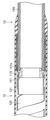
次に、湾曲部11の構成を、図2~図4を用いて示す。図2は、図1の湾曲部を構成する複数の湾曲駒を、2本のワイヤとともに示す部分断面図、図3は、図2中のIII-III線に沿う湾曲部の第1の湾曲駒の断面を、ワイヤとともに示す図、図4は、図2中のIV-IV線に沿う湾曲部の第2の湾曲駒の断面を、ワイヤとともに示す図である。
Next, the configuration of the bending
図2に示すように、本実施の形態においては、湾曲部11は、複数の第1の湾曲駒21と、複数の第2の湾曲駒22とが長手軸方向Nに沿って連結されることにより構成されている。
As shown in FIG. 2, in the present embodiment, the bending
具体的には、第1の湾曲駒21と第2の湾曲駒22とが、長手軸方向Nに沿って隣りあうよう連結されて配置されている。
Specifically, the
より具体的には、長手軸方向Nに沿って、第1の湾曲駒21、第2の湾曲駒22、第1の湾曲駒21、第2の湾曲駒22‥といったように、長手軸方向Nに沿って交互に連結されて配置されている。
More specifically, along the longitudinal axis direction N, the
尚、図2においては、第1の湾曲駒21が2個、第2の湾曲駒22が3個長手軸方向Nに沿って交互に連結されている場合を例に挙げて示しているが、第1の湾曲駒21及び第2の湾曲駒22の個数は、これらに限定されない。
2 shows an example in which two
即ち、第1の湾曲駒21及び第2の湾曲駒22は、それぞれ1個であっても良いし、複数個であっても構わない。また、第1の湾曲駒21と第2の湾曲駒22とは、同数であっても構わないし、個数が異なっていても構わない。
That is, each of the
また、第1の湾曲駒21及び第2の湾曲駒22の外周には、既知のブレードや、既知の湾曲ゴムが被覆されるが、図2においては、図面を簡略化するため省略して示している。
Further, although the outer circumferences of the
第1の湾曲駒21は、長手軸方向Nに沿って所定の長さを有するとともに、内部に長手軸方向に貫通するとともにライトガイドや撮像ケーブル等の湾曲部11の各種既知の内蔵物が配置される孔21iが形成されることによって筒状に形成されている。尚、第1の湾曲駒21は、例えば樹脂から形成されている。
The
また、第2の湾曲駒22も、長手軸方向Nに沿って所定の長さを有するとともに、内部に長手軸方向に貫通するとともに上述した各種既知の内蔵物が配置される孔22iが形成されることによって筒状に形成されている。尚、第2の湾曲駒22は、例えば樹脂から形成されている。
The
尚、第1の湾曲駒21と第2の湾曲駒22とは、長手軸の半径方向Rにおいて、外径が同径に形成されている。また、第1の湾曲駒21と第2の湾曲駒22とは、長手軸方向Nにおいて、同じ長さに形成されていても違う長さに形成されていてもどちらでも構わない。
The
また、第1の湾曲駒21は、長手軸方向Nの端部である基端面に、長手軸方向Nの後方に延出するとともに第1の湾曲駒21の中心軸に対称な一対かつ半円状の凸部21tを有している。
Further, the
さらに、第1の湾曲駒21は、長手軸方向Nの端部である先端面に、長手軸方向Nの後方に凹むとともに第1の湾曲駒21の中心軸に対称な一対かつ半円状の凹部21hを有している。
Further, the
また、第2の湾曲駒22は、長手軸方向Nの端部である基端面に、それぞれ長手軸方向Nの後方に延出するとともに第2の湾曲駒22の中心軸に対称な一対かつ半円状の凸部22tを有している。
Further, the
さらに、第2の湾曲駒22は、長手軸方向Nの端部である先端面に、長手軸方向Nの後方に凹むとともに第2の湾曲駒22の中心軸に対称な一対かつ半円状の凹部22hを有している。
Furthermore, the
長手軸方向Nに沿って第1の湾曲駒21と第2の湾曲駒22とが交互に配置されていることにより、第2の湾曲駒22の一対の凸部22tは、第1の湾曲駒21の一対の凹部21hに当接し、第1の湾曲駒21の一対の凸部21tは、第2の湾曲駒22の一対の凹部22h‥といったように当接している。
By alternately arranging the
尚、第1の湾曲駒21と第2の湾曲駒22との当接は、後述するワイヤ30u、30dにより、長手軸方向Nにおいて圧縮された状態(食い込んだ状態)において行われる。
The contact between the
このことにより、第1の湾曲駒21、第2の湾曲駒22は、長手軸方向Nにおいて隣り合う湾曲駒同士において互いに回動自在となるよう構成されている。
As a result, the
具体的には、長手軸方向Nにおいて隣り合う第1の湾曲駒21と第2の湾曲駒22とは、上下方向(UD)に回動自在となるよう当接している。
Specifically, the
よって、例えば後述するワイヤ30uが後方に牽引されると、一対の凹部22hに当接する一対の凸部21tが上方向(U)に回転し、一対の凹部21hに当接する一対の凸部22tが上方向に回転することにより、湾曲部11は、図2中の上方向(U)に湾曲する。
Therefore, for example, when a
尚、一対の凹部22hに当接する一対の凸部21tの上方向(U)への最大回転角度は、第2の湾曲駒22の先端の肩部22aに、第1の湾曲駒21の基端の肩部21bが当接することにより規定される。また、一対の凹部21hに当接する一対の凸部22tの上方向(U)への最大回転角度は、第1の湾曲駒21の先端の肩部21aに、第2の湾曲駒22の基端の肩部22bが当接することにより規定される。
The maximum rotation angle in the upward direction (U) of the pair of
これとは反対に、後述するワイヤ30dが後方に牽引されると、一対の凹部22hに当接する一対の凸部21tが下方向に回転し、一対の凹部21hに当接する一対の凸部22tが下方向に回転することにより、湾曲部11は、図2中の下方向(D)に湾曲する。
Conversely, when a
尚、一対の凹部22hに当接する一対の凸部21tの下方向(D)への最大回転角度は、第2の湾曲駒22の先端の肩部22aに、第1の湾曲駒21の基端の肩部21bが当接することにより規定される。また、一対の凹部21hに当接する一対の凸部22tの下方向(D)への最大回転角度は、第1の湾曲駒21の先端の肩部21aに、第2の湾曲駒22の基端の肩部22bが当接することにより規定される。
The maximum rotation angle in the downward direction (D) of the pair of
即ち、本実施の形態の湾曲部11は、第1の湾曲駒21、第2の湾曲駒22の互いの連結にリベットを用いない既知のリベットレス構造を有している。
That is, the bending
ここで、図3に示すように、第1の湾曲駒21の内周21nにおいて、互いに対向する位置、例えば上下方向(UD)に、孔21iに連通するとともに、内周21nから半径方向Rの外側に向かって2つの第1の溝21mが形成されている。
Here, as shown in FIG. 3, on the
第1の溝21mは、後述するワイヤ30u、30dの外径Kと略同じ幅Hを有するとともに、外径K以上の深さDに形成され、さらに、第1の湾曲駒21の先端から基端まで長手軸方向Nに沿って形成されている。尚、第1の溝21mは、第1の湾曲駒21の先端から基端まで一定の深さDに形成されている。また、第1の溝21mの形成に伴い、第1の湾曲駒21に、長手軸方向Nの先端から基端まで上下方向(UD)から略90°回動した方向に壁面が形成されている。
The
また、第1の溝21mに対し、ワイヤ30u、30dは、孔21iから半径方向Rに挿抜自在となっている。
Also, the
また、図4に示すように、第2の湾曲駒22の外周22gにおいて、互いに対向する位置、例えば上下方向(UD)に、外周22gから孔22iに向かって2つの第2の溝22mが形成されている。
Further, as shown in FIG. 4, two
第2の溝22mは、後述するワイヤ30u、30dの外径Kと略同じ幅Hを有するとともに、外径K以上の深さDに形成され、さらに、第2の湾曲駒22の先端から基端まで長手軸方向Nに沿って形成されている。尚、第2の溝22mは、第2の湾曲駒22の先端から基端まで一定の深さDに形成されている。また、第2の溝22mの形成に伴い、第2の湾曲駒22に、長手軸方向Nの先端から基端まで上下方向(UD)から略90°回動した方向に壁面が形成されている。
The
尚、本実施の形態においては、第1の溝21mの幅H、深さDは、第2の溝22mの幅H、深さDと同一である。
In this embodiment, the width H and depth D of the
また、第2の溝22mに対し、ワイヤ30u、30dは、半径方向Rの外側から挿抜自在となっている。
Also, the
また、第1の溝21m及び第2の溝22mに、牽引により第1の湾曲駒21、第2の湾曲駒22を上述したように回動させる2本のワイヤ30u、30dが配置されている。
Two
具体的には、上方向(U)に位置する第1の溝21m及び第2の溝22mに、ワイヤ30uが長手軸方向Nに沿って配置され、下方向(D)に位置する第1の溝21m及び第2の溝22mに、ワイヤ30dが長手軸方向Nに沿って配置されている。
Specifically, the
尚、ワイヤ30u、30dの先端は、長手軸方向Nに沿って連結された第1の湾曲駒21及び第2の湾曲駒の内、尤も先端側に位置する湾曲駒に接続されており、ワイヤ30u、30dの基端は、湾曲操作レバー15によって回動するプーリ等に接続されている。
The ends of the
また、第1の溝21m及び第2の溝22mに対してワイヤ30u、30dを挿通させる作業は、先ず、複数の第1の湾曲駒21の孔21iに対し、前方または後方からワイヤ30u、30dを長手軸方向Nに沿って挿通させる。
The work of inserting the
その後、ワイヤ30u、30dに長手軸方向Nに沿って張力を付与させることにより、ワイヤ30u、30dを、孔21iから半径方向Rに移動させ、それぞれ上下の第1の溝21mに嵌入させる。
Thereafter, tension is applied to the
最後に、長手軸方向における第1の湾曲駒21間の隙間に、第2の湾曲駒22を、半径方向Rの外側から、第2の溝22mに、ワイヤ30u、30dが嵌入するよう配置させる。このようにして第1の湾曲駒21及び第2の湾曲駒22がリベットレスにて連結されて配置される。
Finally, the
尚、その他の湾曲部11の構成、組み立て方法は、従来のリベットレス湾曲部構造に用いる湾曲部と同様である。
The rest of the configuration and assembly method of the bending
このように、本実施の形態においては、第1の湾曲駒21の第1の溝21m及び第2の湾曲駒22の第2の溝22mに対し、ワイヤ30u、30dは、半径方向Rに挿抜自在であると示した。
Thus, in the present embodiment, the
また、湾曲部11は、第1の溝21mに対してワイヤ30u、30dが半径方向Rの内側に挿抜自在な第1の湾曲駒21と、第2の溝22mに対してワイヤ30u、30dが半径方向Rの外側から挿抜自在な第2の湾曲駒22とが、長手軸方向Nに沿って連結されることにより構成されていると示した。
The bending
このことによれば、長手軸方向Nに沿って、第1の湾曲駒21と第2の湾曲駒22とが交互に連結されていれば、または、第1の湾曲駒21と、第2の湾曲駒22とが長手軸方向Nにおいて所定の間隔を有して連結されておれば、ワイヤ30u、30dが、半径方向Rにおいて、内側(孔21i側)に抜けてしまうことを第2の溝22mが防ぐとともに、外側に抜けてしまうことを第1の溝21mが防ぐことができる。
According to this, if the
また、第1の溝21mは、孔21iに連通しているため、従来のワイヤ30u、30dが挿通される貫通孔を有する十分な厚みの肉部を、内周21n側に設ける必要がなくなるため、その分、第1の湾曲駒21を小径化することができる。
In addition, since the
さらに、第2の溝22mは、外部に連通しているため、従来のワイヤ30u、30dが挿通される貫通孔を有する十分な厚みの肉部を、外周22g側に設ける必要がなくなるため、その分、第2の湾曲駒22を小径化することができる。
Furthermore, since the
即ち、小径化された第1の湾曲駒21及び第2の湾曲駒22により、湾曲部11を小径化することができる。また、湾曲部11の小径化を図っても、上述したような第1の溝21m、第2の溝22mの形状により、湾曲部11に内蔵できる内蔵物の収容空間が減少してしまうことがないことから、内蔵物の性能が制限されてしまうこともない。
That is, the diameter of the bending
また、第1の溝21mに対して、ワイヤ30u、30dは、孔21iから半径方向Rの外側に移動させるだけで簡単に嵌入させることができ、第2の溝22mに対して、ワイヤ30u、30dは、外側から半径方向Rの内側に移動させるだけで簡単に嵌入させることができる。このことから、従来の長手軸方向Nに複数連結された各湾曲駒の肉部に形成された貫通孔に対して、前方または後方からワイヤを挿通させていく手法よりも簡単にワイヤ30u、30dを短時間にて組み付けることができることから、安価に湾曲部11を製造することができる。
Further, the
また、上述した本実施の形態においては、長手軸方向Nにおいて、第1の湾曲駒21と第2の湾曲駒22とは、交互に配置されていると示した。
Further, in the present embodiment described above, the
このことによれば、湾曲部11を上方向(U)または下方向(D)に湾曲させるため、ワイヤ30uまたはワイヤ30dを牽引した際、第1の湾曲駒21及び第2の湾曲駒22に対して、ワイヤ30uまたはワイヤ30dから付与される湾曲力、即ち上述した回動力が均一となることから、湾曲部11の湾曲形状を安定させることができる。
According to this, in order to bend the bending
これは、例えば、第2の湾曲部22が長手軸方向Nに沿って一定個以上、複数連続して連結されていると、ワイヤ30uまたはワイヤ30dを牽引して湾曲部11を上下いずれかの方向に湾曲させる際、各第2の溝22mからワイヤ30uまたはワイヤ30dが半径方向Rの外側に抜けてしまい、長手軸方向Nに沿って複数連結された第1の湾曲駒21及び第2の湾曲駒22に対して上方向(U)への回動力を十分付与できず、即ちワイヤ30uから付与される湾曲力が不均一となり、湾曲部11の湾曲形状が不安定になってしまうためである。
For example, if a certain number or more of the
また、第1の湾曲部21が長手軸方向Nに沿って一定個以上、複数連続して連結されていると、ワイヤ30u、ワイヤ30dが、孔21iに抜けやすくなってしまうためである。
Also, if a certain number or more of the
また、第1の溝21m及び第2の溝22mから、ワイヤ30u、30dが半径方向Rに移動し難くなることから、半径方向Rの外側への移動に伴う第1の湾曲駒21及び第2の湾曲駒22の外周に被覆される湾曲ゴムへの負荷や、半径方向Rの内側への移動に伴う内蔵物への負荷を最小限にすることができる。
Further, since it becomes difficult for the
以上から、小径化を図りつつ、内蔵物の収容空間を出来るだけ大きく確保できるとともに、ワイヤの組み付け性が向上された構成を具備する内視鏡の湾曲部11、内視鏡挿入部2、内視鏡1を提供することができる。
As described above, the bending
(第2実施の形態) (Second embodiment)
図5は、図2の第2の湾曲駒に対して、第1の湾曲駒が最大回転角度まで上方向に回転した状態を示す断面図、図6は、本実施の形態の内視鏡の湾曲部を構成する湾曲駒において、第2の湾曲駒に対して第1の湾曲駒が最大回転角度まで上方向に回転した状態を示す断面図である。 FIG. 5 is a cross-sectional view showing a state in which the first bending piece is rotated upward to the maximum rotation angle with respect to the second bending piece of FIG. 2, and FIG. FIG. 5 is a cross-sectional view showing a state in which the first bending piece rotates upward to the maximum rotation angle with respect to the second bending piece, in the bending piece that configures the bending portion.
また、図7は、図6の第2の湾曲駒の第2の溝の形状の変形例を示す断面図、図8は、図6の第1の湾曲駒の第1の溝の形状の変形例を示す断面図である。 7 is a cross-sectional view showing a modification of the shape of the second groove of the second bending piece of FIG. 6, and FIG. 8 is a modification of the shape of the first groove of the first bending piece of FIG. It is a sectional view showing.
この第2実施の形態の内視鏡の湾曲部、挿入部、内視鏡の構成は、上述した図1~図4に示した第1実施の形態と比して、第1の溝と第2の溝との少なくとも一方の形状が異なる。 The configuration of the bending section, the insertion section, and the endoscope of the second embodiment is different from that of the first embodiment shown in FIGS. The shape of at least one of the grooves of No. 2 is different.
よって、この相違点のみを説明し、上述した第1実施の形態と同様の構成には同じ符号を付し、その説明は省略する。 Therefore, only this difference will be described, and the same reference numerals will be given to the same configurations as in the above-described first embodiment, and the description thereof will be omitted.
尚、本実施の形態においては、図面及び説明を簡略化するため、1個の第1の湾曲駒21と1個の第2の湾曲駒22との連結を例に挙げて示す。また、図面を簡略化するため、図5~図8においては、ワイヤ30dを省略して示す。
In this embodiment, for the sake of simplification of the drawings and description, an example of connection between one
図2に示すように、上述した第1実施の形態においては、第1の湾曲駒21に対して第1の溝21mは、第1の湾曲駒21の先端から基端まで長手軸方向Nに一定の深さDに形成されていた。
As shown in FIG. 2, in the above-described first embodiment, the
また、第2の湾曲駒22に対して第2の溝22mは、第2の湾曲駒22の先端から基端まで長手軸方向Nに一定の深さDに形成されていた。
Further, the
しかしながら、この構成においては、図5に示すように、例えばワイヤ30uが牽引されることにより、第2の湾曲駒22に対して第1の湾曲駒21が、肩部22aが肩部21bに当接する最大回転角度まで上方向(U)に回転した際、一点鎖線で囲って示すように、肩部22aと肩部21bとの当接部において、ワイヤ30uに屈曲部Tが形成されてしまう、または屈曲部Tが形成されてしまう。このため、ワイヤ30uの長手軸方向Nへの移動が妨げられてしまい、肩部22aと肩部21bとが当接するまで回転出来ず、湾曲部11に対して所望の湾曲形状や湾曲角度を得られないといった問題があった。また、屈曲部Tによりワイヤ30uが破損してしまう可能性があった。
However, in this configuration, as shown in FIG. 5, by pulling the
そこで、図6に示すように、本実施の形態においては、第1の溝21mにおいて、長手軸方向Nの先端部21ms及び基端部21mkの深さが、中間部21mcよりも深く形成されている。
Therefore, as shown in FIG. 6, in the present embodiment, in the
言い換えれば、第1の湾曲駒21における第1の溝21mが形成された部位の肉厚において、先端部21ms及び基端部21mkが、中間部21mcよりも薄く形成されている。
In other words, in the thickness of the portion of the
即ち、第1の溝21mの底面は、先端部21ms及び基端部21mkが、中間部21mcよりも半径方向Rの外側に形成されており、先端部21ms及び基端部21mkと中間部21mcとの間に、傾斜面が形成されている。
That is, on the bottom surface of the
また、第2の溝22mにおいて、長手軸方向Nの先端部22ms及び基端部22mkの深さが、中間部22mcよりも深く形成されている。言い換えれば、第2の湾曲駒22における第2の溝22mが形成された部位の肉厚において、先端部22ms及び基端部22mkが、中間部22mcよりも薄く形成されている。
Also, in the
即ち、第2の溝22mの底面は、先端部22ms及び基端部22mkが、中間部22mcよりも半径方向Rの内側に形成されており、先端部22ms及び基端部22mkと中間部22mcとの間に、傾斜面が形成されている。
That is, on the bottom surface of the
尚、図7に示すように、第2の溝22mは、長手軸方向Nに沿って一定の深さDに形成され、第1の溝21mのみ、図6と同じ形状に形成されていても構わないし、図8に示すように、第1の溝21mは、長手軸方向Nに沿って一定の深さDに形成され、第2の溝22mのみ、図6と同じ形状に形成されていても構わない。
As shown in FIG. 7, even if the
尚、その他の構成は、上述した第1実施の形態と同じである。 Other configurations are the same as those of the first embodiment described above.
このような構成によれば、図6~図8に示すように、例えばワイヤ30uが牽引されることにより、第2の湾曲駒22に対して第1の湾曲駒21が、肩部22aが肩部21bに当接する最大回転角度まで上方向(U)に回転する。この際、肩部22aと肩部21bとの当接部において、第1の溝21m及び第2の溝22mの図6~図8に示す形状により、図5に示すように、ワイヤ30uに屈曲部Tが形成されてしまうことがない。よって、ワイヤ30uの破損を防止することができる。
According to such a configuration, as shown in FIGS. 6 to 8, for example, by pulling the
以上から、湾曲部11を上方向(U)に湾曲させる際、ワイヤ30uが長手軸方向Nにスムーズに移動出来ることから、肩部22aと肩部21bとが当接するまで最大回転角度まで容易に回転出来るため、湾曲部11に対して所望の湾曲形状や湾曲角度を得ることが出来る。
As described above, when bending the bending
尚、その他の効果は、上述した第1実施の形態と同じである。 Other effects are the same as those of the first embodiment described above.
また、以上のことは、ワイヤ30dが挿通される第1の溝21m及び第2の溝22mにおいても同様である。
The above also applies to the
尚、以下、変形例を、図9~図11を用いて示す。図9は、図6の第1の湾曲駒の第1の溝及び第2の湾曲駒の第2の溝における各先端部並びに各基端部を、切り欠きにした変形例を示す断面図である。 Modified examples are shown below with reference to FIGS. 9 to 11. FIG. FIG. 9 is a cross-sectional view showing a modification in which the distal end portions and the proximal end portions of the first groove of the first bending piece and the second groove of the second bending piece of FIG. 6 are notched.
また、図10は、図7の第1の湾曲駒の第1の溝及び第2の湾曲駒の第2の溝における各先端部並びに各基端部を、切り欠きにした変形例を示す断面図、図11は、図8の第1の湾曲駒の第1の溝及び第2の湾曲駒の第2の溝における各先端部並びに各基端部を、切り欠きにした変形例を示す断面図である。 10 is a cross-sectional view showing a modification in which the distal end portions and the proximal end portions of the first groove of the first bending piece and the second groove of the second bending piece of FIG. 7 are notched; 11 is a cross-sectional view showing a modification in which the distal end portions and the proximal end portions of the first groove of the first bending piece and the second groove of the second bending piece of FIG. 8 are notched.
図9~図11に示すように、第1の湾曲駒21における第1の溝21mの先端部21ms及び基端部21mkを、中間部21mcよりも深くする構成や、第2の湾曲駒22における第2の溝22mの先端部22ms及び基端部22mkを、中間部22mcよりも深くする構成は、上述した図6~図8に示すような、第1の湾曲駒21及び第2の湾曲駒22において先端部21ms、22ms、基端部21mk、22mkが形成された部位の肉厚を薄くする他に、先端部21ms、22ms、基端部21mk、22mkに、半径方向Rに貫通する切り欠きを形成する構成も考えられる。
As shown in FIGS. 9 to 11, a configuration in which the distal end portion 21ms and the proximal end portion 21mk of the
このような構成によっても、上述した本実施の形態と同様の効果を得ることができる。 Even with such a configuration, it is possible to obtain the same effects as in the present embodiment described above.
(第3実施の形態) (Third Embodiment)
図12は、本実施の形態の湾曲部を構成する複数の湾曲駒を、2本のワイヤとともに示す部分断面図、図13は、図12中のXIII-XIII線に沿う第1の湾曲駒の断面を、図12中のXIII'-XIII'線に沿う第2の湾曲駒の断面と並べて、ワイヤとともに示す図である。 12 is a partial cross-sectional view showing a plurality of bending pieces forming the bending portion of the present embodiment together with two wires, and FIG. 13 is a cross section of the first bending piece taken along line XIII-XIII in FIG. 13 is a diagram showing the cross section of the second bending piece along the line XIII'-XIII' in FIG. 12 together with the wire.
この第3実施の形態の内視鏡の湾曲部、内視鏡挿入部、内視鏡の構成は、上述した図1~図4に示した第1実施の形態、図5~図11に示したと第2実施の形態と比して、第1の溝及び第2の溝の形状が異なる。 The configuration of the bending section, endoscope insertion section, and endoscope of the third embodiment is shown in the first embodiment shown in FIGS. 1 to 4 and FIGS. 5 to 11. The shapes of the first groove and the second groove are different from those of the second embodiment.
よって、この相違点のみを説明し、上述した第1、第2実施の形態と同様の構成には同じ符号を付し、その説明は省略する。 Therefore, only this point of difference will be described, and the same reference numerals will be given to the same configurations as in the above-described first and second embodiments, and the description thereof will be omitted.
図13に示すように、本実施の形態においては、第1の湾曲駒21と第2の湾曲駒22とを長手軸方向Nに連結させた際、第1の溝21mの半径方向Rの外側の底部は、第2の溝22mの半径方向Rの内側の底部よりも、半径方向Rの外側に位置する。
As shown in FIG. 13, in the present embodiment, when the
この際、各底部間の半径方向Rの長さZは、ワイヤ30u、30dの外径Kよりも小さい。
At this time, the length Z in the radial direction R between the bottoms is smaller than the outer diameter K of the
よって、第1の溝21m及び第2の溝22mの各底部に突き当たるよう、ワイヤ30u、30dを挿通させた際、ワイヤ30u、30dの半径方向Rにおける位置が、第1の溝21mよりも第2の溝22mにおいて半径方向Rの外側に位置する。
Therefore, when the
尚、このことは、第1の溝21m及び第2の溝22mが、長手軸方向Nに沿って一定の深さDに形成されている場合や、図12に示すように、第1の溝21mにおいて、先端部21ms及び基端部21mkが中間部21mcよりも深く形成され、第2の溝22mにおいて、先端部22ms及び基端部22mkが中間部22mcよりも深く形成されている場合においても同様である。
Note that this is true when the
その結果、図12に示すように、第1の溝21m及び第2の溝22mに長手軸方向Nに沿って挿通されたワイヤ30u、30dは、長手軸方向Nに沿って蛇行する。
As a result, the
尚、その他の構成は、上述した第1、第2実施の形態と同じである。 Other configurations are the same as those of the above-described first and second embodiments.
このような構成によれば、第1の溝21m及び第2の溝22mにおいて、蛇行しているワイヤ30u、30dは、長手軸方向Nに沿った形状に戻ろうとするため、第1の溝21m及び第2の溝22mの各底部に半径方向Rに押し付けられることから、第1、第2実施の形態の構成よりも半径方向Rの外側や内側に移動し難くなる。
According to such a configuration, in the
また、ワイヤ30u、30dの蛇行に伴い、第1の溝21m及び第2の溝22mの各底部への摩擦が増えることから、湾曲部11を上方向(U)または下方向(D)に湾曲させた際、湾曲形状を、操作部3に別途設けた既知の形状ロック機構を用いることなく容易に固定することができるため、製造コストを削減することができる。
In addition, as the
さらに、湾曲操作レバー15を用いて湾曲部11の湾曲操作を行う際、操作者は、湾曲操作レバー15から手指を離しても湾曲部11の湾曲形状を固定することができることから、操作した湾曲操作レバー15を手指で押さえ続ける必要がなくなるため、手指への負担を軽減させることができる。
Furthermore, when performing the bending operation of the bending
尚、その他の効果は、上述した第1、第2実施の形態と同じである。 Other effects are the same as those of the above-described first and second embodiments.
また、上述した第1~第3実施の形態においては、湾曲部11は、ワイヤ30u、30dにより上下方向に湾曲自在であると示したが、左右方向に湾曲自在な構成であっても構わない。
Further, in the first to third embodiments described above, the bending
この場合、第1の溝21mは、第1の湾曲駒21の内周21nに対して、第1の湾曲駒21の周方向における左右方向に対応する位置に、それぞれ対向するよう2箇所形成され、第2の溝22mは、第2の湾曲駒22の外周22gに対して、第2の湾曲駒22の周方向における左右方向に対応する位置に、それぞれ対向するよう2箇所形成される。
In this case, two
さらに、湾曲部11は、4本のワイヤにより、上下左右方向に湾曲自在であっても構わない。
Furthermore, the bending
この場合、第1の溝21mは、第1の湾曲駒21の内周21nに対して、第1の湾曲駒21の周方向における上下左右方向に対応する位置に、周方向に略90°毎に4箇所形成され、第2の溝22mは、第2の湾曲駒22の外周22gに対して、第2の湾曲駒22の周方向における上下左右方向に対応する位置に、周方向に略90°毎に4箇所形成される。
In this case, the
また、上述した第1~第3実施の形態においては、第1の湾曲駒21及び第2の湾曲駒22は、樹脂から構成されていると示したが、金属から構成されていても構わない。しかしながら、例えばディスポーザブル式の内視鏡1に用いる湾曲部11を安価に製造するため、第1の湾曲駒21及び第2の湾曲駒22が樹脂から構成されているとともに、湾曲部11をより小径化する際に、上述した第1~第3実施の形態の構成はより効果的である。
Further, in the first to third embodiments described above, the
さらに、上述した第1~第3実施の形態においては、第1の湾曲駒21と第2の湾曲駒22とはリベットレス構造により連結されていると示したが、これに限らず、従来のリベット構造にも上述した第1~第3実施の形態の構成は適用可能であることは勿論である。
Furthermore, in the above-described first to third embodiments, the
また、上述した第1~第3実施の形態においては、第1の湾曲駒21と第2の湾曲駒22とは、長手軸方向Nにおいて交互に配置されていると示したが、これに限らず、上述したような湾曲部11の湾曲形状が不安定にならなければ、必ずしも交互に配置されている必要はない。
Further, in the first to third embodiments described above, the
例えば、長手軸方向Nに沿って、第1の湾曲駒21、第1の湾曲駒21、第2の湾曲駒22、第2の湾曲駒22、第1の湾曲駒21‥のように配置されていても構わない。
For example, along the longitudinal axis direction N, the
さらに、上述した第1~第3実施の形態においては、内視鏡1は、腎盂尿管鏡を例に挙げて示したが、腎盂尿管鏡に限定されないことは云うまでもない。特に小径化や製造コストの低減が求められる内視鏡に適用されることが望ましい。
Furthermore, in the above-described first to third embodiments, the
図14は、一般的な内視鏡の湾曲部の部分断面図である。 FIG. 14 is a partial cross-sectional view of a bending portion of a general endoscope.
ところで、上述した第1~第3実施の形態においては、第1の溝21mは、第1の湾曲駒21の先端から基端まで全長に亘って長手軸方向Nに貫通するよう形成されており、第2の溝22mも第2の湾曲駒22の先端から基端まで全長に亘って長手軸方向Nに貫通するよう形成されていると示した。
By the way, in the above-described first to third embodiments, the
このことは、図14に示すように、一般的な内視鏡の湾曲部を構成する湾曲駒41、42のワイヤ受けに形成される貫通孔41v、42vにおいても適用可能である。
As shown in FIG. 14, this is also applicable to through
即ち、貫通孔41vは、湾曲駒41の先端から基端まで全長に亘って長手軸方向Nに沿ってワイヤ受けに形成されており、貫通孔42vは、湾曲駒42の先端から基端まで全長に亘って長手軸方向Nに沿ってワイヤ受けに形成されている。
That is, the through
よって、湾曲駒41同士の長手軸方向Nの肩間N1、湾曲駒41と湾曲駒42との長手軸方向Nの肩間N2、湾曲駒42同士の長手軸方向の肩間N3は、貫通孔41v同士の長手軸方向Nの隙間距離N4、貫通孔41vと貫通孔42vとの長手軸方向Nの隙間距離N5、貫通孔42v同士の隙間距離N6と略一致する(N1=N4、N2=N5、N3=N6)。
Therefore, N1 between the shoulders of the bending
このような構成においては、第1の湾曲駒21、第2の湾曲駒22、湾曲駒41、42の長手軸方向Nにおける一部にのみ、第1の溝21m、第2の溝22m、貫通孔41v、42vが部分的に形成されている構成よりも、第1の溝21m、貫通孔41v、42vに対して長手軸方向Nの前方または後方からワイヤ30u、30dを挿通させていく際、挿通させやすい。
In such a configuration, only a part of the
また、図14に示すように、湾曲駒41、42の外周に、熱収縮チューブ40が被覆されていれば、湾曲駒41、42同士が、半径方向Rにずれてしまうことを効果的に防止することができる。
Further, as shown in FIG. 14, if the outer peripheries of the bending
尚、このことは、湾曲駒41、42の外周に既知のブレードが被覆されている場合においても適用可能であり、この場合、ブレードの外周に熱収縮チューブ40を被覆すれば良い。
It should be noted that this is also applicable when the peripheries of the bending
また、本構成は、上述した第1~第3実施の形態においても適用可能であり、第1の湾曲駒21及び第2の湾曲駒22の外周に、熱収縮チューブが被覆されていれば、第1の湾曲駒21及び第2の湾曲駒22が半径方向Rにずれてしまうことを効果的に防止することができる。
Further, this configuration can also be applied to the first to third embodiments described above. It is possible to effectively prevent the
ところで、内視鏡の湾曲部を湾曲させるため、内視鏡挿入部の長手軸方向において隣り合う湾曲駒同士において、一方の湾曲駒の端部に形成された半円状(扇形状)の凹部に、他方の湾曲駒の端部に形成された半円状(扇形状)の凸部を突き当てるのみの湾曲駒のリベットレス連結構成が周知であり、例えば米国特許第8465420号公報に開示されている。 By the way, in order to bend the bending portion of the endoscope, between the bending pieces adjacent to each other in the longitudinal axis direction of the endoscope insertion portion, a semicircular (fan-shaped) concave portion formed at the end of one of the bending pieces A rivetless connection structure of bending pieces is known, in which a semicircular (fan-shaped) protrusion formed at the end of the other bending piece is only abutted against the bending piece, and is disclosed, for example, in US Pat. No. 8,465,420.
しかしながら、湾曲部には、長手軸方向に対してだけでなく長手軸の半径方向に力が付与されたり、捩り力が付与されたりする場合がある。 However, in some cases, force is applied not only in the direction of the longitudinal axis but also in the radial direction of the longitudinal axis, or torsional force is applied to the curved portion.
この場合、連結された湾曲駒において、一方の湾曲駒に対して他方の湾曲駒が長手軸の半径方向における湾曲部の上下方向にずれてしまう可能性が有り、湾曲部を所望の湾曲形状に湾曲させ難くなるといった問題があった。 In this case, among the connected bending pieces, there is a possibility that the other bending piece may be displaced in the vertical direction of the bending portion in the radial direction of the longitudinal axis. There is a problem that it becomes difficult to bend.
このような問題に鑑み、連結された複数の湾曲駒の外周に、既知のずれ防止用のブレード等が被覆された構成が周知である。しかしながら、この構成では、湾曲部の湾曲力量が大きくなってしまったり、即ち湾曲部を湾曲させるワイヤの牽引力に対する湾曲部のトルク追従性が低下してしまったり、湾曲部の組み立てが難しくなってしまったりするといった問題があった。 In view of such problems, there is a well-known configuration in which the outer peripheries of a plurality of connected bending pieces are covered with known blades or the like for preventing slippage. However, in this configuration, the amount of bending force of the bending portion is increased, that is, the ability of the bending portion to follow the torque of the wire that bends the bending portion is reduced, and the assembly of the bending portion is difficult. There was a problem of getting stuck.
本構成は、連結された複数の湾曲駒の上下方向へのずれや捩れを防止できる湾曲部の構成を提供する。 This configuration provides a configuration of a bending portion that can prevent vertical displacement and twisting of a plurality of connected bending pieces.
以下、図15~図17を参照して本構成の実施の形態を説明する。図15は、本構成の湾曲部を構成する複数の湾曲駒を示す部分断面図、図16は、図15の一方の湾曲駒の斜視図、図17は、図15の他方の湾曲駒の斜視図である。 An embodiment of this configuration will be described below with reference to FIGS. 15 to 17. FIG. 15 is a partial cross-sectional view showing a plurality of bending pieces forming the bending portion of this configuration, FIG. 16 is a perspective view of one bending piece in FIG. 15, and FIG. 17 is a perspective view of the other bending piece in FIG. be.
尚、図15においては、図面及び説明を簡略するため2つの湾曲駒の連結を例に挙げて示している。 In addition, in FIG. 15, in order to simplify the drawing and explanation, the connection of two bending pieces is shown as an example.
図15に示すように、湾曲駒51は、挿入部の長手軸方向Nの端部である基端面に、長手軸方向Nの後方に延出するとともに湾曲駒51の中心軸に対称な一対の凸部51tを有している。尚、凸部51tは、半円形状(扇形状)を有している。
As shown in FIG. 15, the bending
さらに、湾曲駒51は、長手軸方向Nの端部である先端面に、長手軸方向Nの後方に凹むとともに湾曲駒51の中心軸に対称な一対の凹部51hを有している。尚、凹部51hは、半円形状(扇形状)を有している。
Furthermore, the bending
また、湾曲駒52は、長手軸方向Nの端部である基端面に、それぞれ長手軸方向Nの後方に延出するとともに湾曲駒52の中心軸に対称な一対の凸部52tを有している。尚、凸部52tは、半円形状(扇形状)を有している。
In addition, the bending
さらに、湾曲駒52は、長手軸方向Nの端部である先端面に、長手軸方向Nの後方に凹むとともに湾曲駒52の中心軸に対称な一対の凹部52hを有している。尚、凹部52hは、半円形状(扇形状)を有している。
Furthermore, the bending
長手軸方向Nに沿って湾曲駒51と湾曲駒52とが配置されていることにより、湾曲駒51の一対の凸部51tは、湾曲駒52の一対の凹部52hに当接している。
By arranging the bending
尚、湾曲駒51と湾曲駒52との当接は、各湾曲駒51、52に設けられたワイヤ受けの貫通孔51v、52vにそれぞれ挿通された図示しないワイヤにより、長手軸方向Nにおいて圧縮された状態において行われる。
The contact between the bending
このことにより、湾曲駒51、湾曲駒52は、互いに回動自在となるよう構成されている。具体的には、湾曲駒51と湾曲駒52とは、長手軸Nの半径方向Rにおける上下方向(UD)に回動自在となるよう当接している。
As a result, the bending
よって、例えば上方向(U)に位置するワイヤが後方に牽引されると、一対の凹部52hに当接する一対の凸部51tが上方向(U)に回転することにより、湾曲部は、図15中の上方向(U)に湾曲する。
Therefore, for example, when the wire positioned in the upward direction (U) is pulled rearward, the pair of
尚、一対の凹部52hに当接する一対の凸部51tの上方向(U)への最大回転角度は、湾曲駒52の先端の肩部52aに、第1の湾曲駒21の基端の肩部51bが当接することにより規定される。
The maximum rotation angle in the upward direction (U) of the pair of
これとは反対に、下方向(D)に位置するワイヤが後方に牽引されると、一対の凹部52hに当接する一対の凸部51tが下方向に回転し、一対の凹部52hに当接する一対の凸部51tが下方向に回転することにより、湾曲部11は、図2中の下方向(D)に湾曲する。
Conversely, when the wire positioned in the downward direction (D) is pulled backward, the pair of
尚、一対の凹部52hに当接する一対の凸部51tの下方向(D)への最大回転角度は、肩部52aに、肩部51bが当接することにより規定される。
The maximum rotation angle in the downward direction (D) of the pair of
即ち、本構成の湾曲部は、湾曲駒51、52の互いの連結にリベットを用いない既知のリベットレス構造を有している。
That is, the bending portion of this configuration has a known rivetless structure that does not use rivets for connecting the bending
ここで、連結された湾曲駒51と湾曲駒52との上下方向のずれ、及び捩れを防止するため、凹部52hに対して凸部51tは、出来るだけ食い込んで当接することが望ましい。
Here, in order to prevent vertical displacement and twisting of the connected bending
しかしながら、食い込み量が大きいと、湾曲駒52と湾曲駒51との相互において上下方向に回転し難くなってしまう。
However, if the biting amount is large, it becomes difficult for the
そこで、図15に示すように、本構成においては、湾曲駒51の凸部51tの扇形状の半径をJとした場合の中心点(半径中心)51tcが、半径方向Rにおいて湾曲駒52の肩部52aと同一平面に構成されている。尚、中心点51tcは、湾曲駒51、52の長手軸方向における中心軸と、同一平面に位置している。
Therefore, as shown in FIG. 15, in this configuration, the center point (radius center) 51tc when the radius of the fan shape of the
尚、図示しないが、湾曲駒52の凸部52tの半径中心も同様に構成されている。
Although not shown, the radius center of the
また、以上の構成は、湾曲駒52の先端に凸部52tが設けられ、湾曲駒51の基端に設けられた凹部51hに当接する構成においても適用可能である。
Further, the above configuration can also be applied to a configuration in which the
このような構成によれば、凹部51hに対して凸部52tが食い込み過ぎることなく適切な当接量で食い込んで当接することから、連結された湾曲駒51、52が上下方向にずれてしまったり、捻れてしまったりすることを確実に防止することができるため、湾曲部の湾曲が妨げられることがない。
According to such a configuration, the
よって、ワイヤの牽引力に対する湾曲部のトルク追従性を確保できるとともに、湾曲部を所望の湾曲形状に湾曲させることができる。尚、本構成は、上述した第1~第3実施の形態においても適用可能である。 Therefore, it is possible to secure the torque followability of the bending portion with respect to the pulling force of the wire, and to bend the bending portion into a desired curved shape. This configuration can also be applied to the first to third embodiments described above.
また、図15においては、凸部51t、凹部51h、凸部52t、凹部52hは、半円形状(扇形状)に形成されていると示した。
Also, FIG. 15 shows that the
これに限らず、図16、図17に示すように、凸部51tは、凹部52hに当接する面が湾曲駒51、52の長手軸に略垂直な面ではなく斜めに当接する円錐形状に形成されていても構わず、凹部52hも、凸部51tが当接する面が、凸部51tの形状に合わせて斜めに当接する円錐形状に形成されていても構わない。
However, as shown in FIGS. 16 and 17, the
尚、この場合、凹部52h、51hの外径は、凸部51t、52tの外径よりも大きく形成されていることが望ましい。
In this case, it is desirable that the outer diameters of the
また、図示しないが、凸部52t、凹部51hも、凸部51t、凹部52hと同様の形状に形成されていても構わない。
Moreover, although not shown, the
このような構成によれば、凹部52hに対して凸部51tは、斜めに当接するため、凹部52hに対して凸部51tがより食い込みやすくなることから、湾曲駒51、52の上下方向のずれを効果的に抑制することができる。
According to such a configuration, since the
尚、本構成は、上述した第1~第3実施の形態においても適用可能である。 This configuration can also be applied to the first to third embodiments described above.
ところで、内視鏡湾曲部において、能動的に湾曲する能動湾曲部と、該湾曲部の基端側に連設された受動的に湾曲する受動湾曲部とを有する構成が周知であり、日本国特開2016-174670号公報に開示されている。 By the way, in the bending section of an endoscope, a configuration having an active bending section that actively bends and a passive bending section that is connected to the base end side of the bending section and passively bends is well known. It is disclosed in JP-A-2016-174670.
ここで、能動湾曲部を構成する複数の湾曲駒において、内視鏡挿入部の長手軸方向における尤も基端側に位置するとともに、受動湾曲部の先端が接続される基端湾曲駒に設けられるワイヤ受けのワイヤ貫通孔は、他の湾曲駒のワイヤ受けのワイヤ貫通孔よりも、挿入部の長手軸における半径方向の内側に配置されるのが一般的である。 Here, among the plurality of bending pieces that constitute the active bending section, the bending piece is located on the most proximal side in the longitudinal axis direction of the endoscope insertion section and is provided on the proximal bending piece to which the distal end of the passive bending section is connected. The wire through-hole of the wire receiver is generally arranged radially inside the longitudinal axis of the insertion portion relative to the wire through-holes of the wire receivers of the other bending pieces.
これは、受動湾曲部の小径化を図るため、受動湾曲部内においても出来るだけ半径方向内側においてワイヤを挿通させたいためである。 This is because it is desired to insert the wire inside the passive bending portion as much as possible in the radial direction in order to reduce the diameter of the passive bending portion.
しかしながら、基端湾曲駒のワイヤ貫通孔が、基端貫通孔よりも1つ前の湾曲駒のワイヤ貫通孔よりも半径方向の内側に位置していると、各湾曲駒のワイヤ貫通孔にワイヤが挿通された際、基端湾曲駒と1つ前の湾曲駒との間において、ワイヤが大きく蛇行してしまい、ワイヤに折れが発生してしまう可能性がある。 However, if the wire through-hole of the proximal end bending piece is located radially inside the wire through-hole of the bending piece immediately before the proximal end through-hole, the wire is inserted through the wire through-hole of each bending piece. In this case, the wire may meander greatly between the base end bending piece and the immediately preceding bending piece, and the wire may be broken.
その結果、ワイヤを牽引する際、異音が生じたり、ワイヤの牽引力量が大きくなってしまったりするといった問題があった。 As a result, when the wire is pulled, there are problems such as abnormal noise being generated and the wire pulling force being increased.
本構成は、上記問題に鑑み、能動湾曲部の基端に位置する湾曲駒と、該湾曲駒の1つ前の湾曲駒との間におけるワイヤの蛇行を軽減させることを目的とする内視鏡の湾曲部の構成を提供する。 In view of the above problems, the present configuration of an endoscope aims to reduce meandering of a wire between a bending piece positioned at the proximal end of an active bending portion and a bending piece immediately preceding the bending piece. A flexure configuration is provided.
以下、上記問題を解決する構成を、図18を用いて示す。図18は、本構成の湾曲部における能動湾曲部と受動湾曲との連結部位における部分断面図である。 A configuration for solving the above problem will be shown below with reference to FIG. FIG. 18 is a partial cross-sectional view of the connecting portion between the active bending portion and the passive bending portion in the bending portion of this configuration.
図18に示すように、本構成においては、内視鏡の湾曲部は、能動湾曲部(以下、単に湾曲部と称す)11と、受動湾曲部12とから構成されている。
As shown in FIG. 18 , in this configuration, the bending portion of the endoscope is composed of an active bending portion (hereinafter simply referred to as bending portion) 11 and a
湾曲部11は、ワイヤ30u、30dの牽引に伴い、例えば上下方向の2方向に湾曲自在に構成されている。尚、湾曲部11は、左右方向の2方向に湾曲自在に構成されていても構わないし、上下左右の4方向に湾曲自在に構成されていても構わない。
The bending
また、湾曲部11は、複数の湾曲駒61が挿入部の長手軸方向Nに連結されることにより構成されている。尚、連結された複数の湾曲駒において尤も基端側に位置する湾曲駒に符号62を付している。
Further, the bending
受動湾曲部12は、既知のフレックス等から構成されており、外力に伴い受動的に湾曲出来るよう、柔軟に構成されている。
The
ここで、湾曲部11において、ワイヤ30u、30dが挿通されるワイヤ受けの貫通孔61v、ワイヤ受けの貫通孔62vが、各湾曲駒61、62に形成されている。
Here, in the bending
本構成においては、各湾曲駒61の先端側に、ワイヤ受けが形成されており、該各ワイヤ受けに、貫通孔61vが形成されている。また、各湾曲駒62の基端側にも、ワイヤ受けが形成されており、該ワイヤ受けに、貫通孔62vが形成されている。
In this configuration, a wire receiver is formed on the distal end side of each bending
このような構成によれば、長手軸方向Nにおいて、湾曲駒62と湾曲駒61との間Wに発生してしまう上述したワイヤ30u、30dの蛇行を、貫通孔62vと、湾曲駒62の1個前の湾曲駒61の貫通孔61vとが長手軸方向Nにおいて大きく離間して配置されていることから軽減することができる。
According to such a configuration, the above-described meandering of the
尚、以上の構成は、上述した第1~第3実施の形態においても適用可能である。 The above configuration can also be applied to the first to third embodiments described above.
また、内視鏡挿入部に受動湾曲部12を設けずに、湾曲部の基端に、既知の可撓管部が直接連設された構成においても適用可能であるということは勿論である。
Further, it is of course possible to apply a configuration in which a known flexible tube is directly connected to the proximal end of the bending portion without providing the
従来の内視鏡においては、挿入部の先端部の内部に、例えば、撮像ユニット、照明ユニット、処置具チャンネル等の各種の内蔵ユニットが配設されている。これら各種の内蔵ユニットは、内視鏡先端部を構成する先端硬質部材に対して、例えば接着材等を用いて、それぞれが所定の位置に固定されている。 2. Description of the Related Art In a conventional endoscope, various built-in units such as an imaging unit, a lighting unit, and a treatment instrument channel are arranged inside the distal end of an insertion section. Each of these various built-in units is fixed at a predetermined position to a distal end hard member that constitutes the distal end portion of the endoscope using, for example, an adhesive.
従来、内視鏡先端部の製造工程においては、これら各種の内蔵ユニットの個々の部品や構成ユニットを、先端硬質部材の内部の所定の位置に対して、例えば治具等を用いて、正確に組み込む作業が行われている。そして、その組み込み作業には、高い精度が要求されている。 Conventionally, in the manufacturing process of the distal end portion of an endoscope, the individual parts and constituent units of these various built-in units are accurately placed in predetermined positions inside the distal rigid member using, for example, jigs. Installation work is underway. High precision is required for the assembly work.
具体的には、例えば、照明レンズとライトガイドケーブルとからなる照明ユニットを、先端硬質部材の内部の所定の位置に配設するためには、まず、非常に小さな照明レンズを先端硬質部材の先端面近傍の所定の位置に配設する。その後、ライトガイドケーブルの先端を、先端硬質部材に組み込み済みの照明レンズに当接する所定の位置に配設するといった作業になる。 Specifically, for example, in order to dispose an illumination unit consisting of an illumination lens and a light guide cable at a predetermined position inside the tip hard member, first, a very small illumination lens is attached to the tip of the tip hard member. It is arranged at a predetermined position near the surface. After that, the tip of the light guide cable is arranged at a predetermined position where it abuts on the illumination lens that has already been incorporated in the tip rigid member.
この場合において、照明レンズとライトガイドケーブルの先端との相対的な位置関係は、厳密に規定されている。このことから、照明ユニットの組み込み一つにも、高精度な組み込み技術が要求されている。 In this case, the relative positional relationship between the illumination lens and the tip of the light guide cable is strictly defined. For this reason, a high-precision embedding technique is required even for the embedding of the lighting unit.
上述したようなことから、内視鏡先端部の先端硬質部材に対して各種の内蔵ユニットを高精度に組み込む作業は、時間を要する作業となっており、このことは、内視鏡の製造コストを引き上げてしまう要因となっている。 As described above, it takes time to assemble various built-in units with high precision into the rigid member of the distal end of the endoscope, which increases the manufacturing cost of the endoscope. is a factor that raises
近年、内視鏡においては、シングルユースの内視鏡が普及し始めていることから、製造コストの低減化の要求は常にある。特に、組み込み作業の精度を確保しながら、組み立て工程の簡略化を実現することで、製造コストを低減化するといった要望がある。 In recent years, single-use endoscopes have started to spread among endoscopes, so there is always a demand for a reduction in manufacturing costs. In particular, there is a demand to reduce the manufacturing cost by realizing simplification of the assembling process while ensuring the accuracy of the assembling work.
また、上述したように、先端硬質部材に組み込んだ照明レンズに対してライトガイドケーブルの先端を、先端硬質部材の内部の所定の位置に正確に配置する作業を安定的に行いたいという要望もある。 In addition, as described above, there is also a demand to stably perform the operation of accurately arranging the tip of the light guide cable at a predetermined position inside the tip hard member with respect to the illumination lens incorporated in the tip hard member. .
そのための工夫として、例えば、組み立て作業の直後若しくは作業中に、各部品や構成ユニットの組み込み状態を確認することができれば至便である。 As a device for this purpose, for example, it would be convenient if it was possible to check the built-in state of each part or component unit immediately after or during the assembly work.
本構成は、上述した点に鑑みてなされたものであって、その目的は、内視鏡先端部の内部に配設される各種の内蔵ユニットを、先端硬質部材に組み込む際の作業工程を簡素化しつつ、高精度に安定した組み込み精度を確保することのできる構造を備えた内視鏡先端部を提供することである。 This configuration has been made in view of the above-mentioned points, and its purpose is to simplify the work process when incorporating various built-in units arranged inside the distal end portion of the endoscope into the distal end rigid member. It is an object of the present invention to provide an endoscope distal end portion having a structure capable of ensuring highly accurate and stable assembling accuracy while making it more flexible.
上記目的を達成するために、本構成の一態様の内視鏡先端部は、略筒状に形成され内視鏡先端部の外面を覆う先端カバー部材と、前記内視鏡先端部の内部に組み込まれる複数の内蔵ユニットを固定した状態で、前記先端カバー部材の内部に装填される先端ベース部材(足場部材)と、からなる先端硬質部材を具備し、前記先端ベース部材(足場部材)は、前記複数の内蔵ユニットを各所定の位置に固定した状態としたとき、前記複数の内蔵ユニットのそれぞれの一部を外部に露呈する切欠部を有している。 In order to achieve the above object, an endoscope distal end in one aspect of the present configuration includes a distal end cover member formed in a substantially cylindrical shape and covering the outer surface of the endoscope distal end, and a member inside the endoscope distal end. a distal end base member (scaffolding member) loaded inside the distal end cover member in a state in which a plurality of built-in units to be incorporated are fixed, the distal end base member (scaffolding member) comprising: A notch portion is provided to expose a part of each of the plurality of built-in units to the outside when the plurality of built-in units are fixed at respective predetermined positions.
本構成によれば、内視鏡先端部の内部に配設される各種の内蔵ユニットを、先端硬質部材に組み込む際の作業工程を簡素化しつつ、高精度に安定した組み込み精度を確保することのできる構造を備えた内視鏡先端部を提供することができる。 According to this configuration, it is possible to simplify the work process for assembling various built-in units arranged inside the distal end portion of the endoscope into the rigid distal end member, while ensuring high and stable assembling accuracy. An endoscopic tip can be provided with a structure that allows
(第4実施の形態) (Fourth embodiment)
図19~図21は、本構成の第4実施の形態を示す図である。このうち、図19は、本実施形態の内視鏡先端部の概略構成を拡大して示す要部拡大斜視図である。図20は、図19の内視鏡先端部の側面図である。図21は、図19の内視鏡先端部において、先端カバーを取り外した状態を示す分解斜視図である。 19 to 21 are diagrams showing a fourth embodiment of this configuration. Among them, FIG. 19 is an enlarged perspective view of a main part showing an enlarged schematic configuration of the distal end portion of the endoscope according to the present embodiment. FIG. 20 is a side view of the distal end of the endoscope of FIG. 19; 21 is an exploded perspective view of the distal end portion of the endoscope of FIG. 19 with the distal end cover removed; FIG.
本構成の内視鏡の先端部10には、図19~図21に示すように、例えば撮像ユニット201、照明ユニット202、処置具チャンネル203等の各種の内蔵ユニットを内蔵し固定する先端枠部材である先端硬質部材200が配設されている。そして、本実施形態において、先端硬質部材200は、先端カバー部材10aと、先端ベース部材10bとの二体化構造として構成されている。
As shown in FIGS. 19 to 21, the
先端カバー部材10aは、略円柱形状に形成され、内側に先端ベース部材10bを装填したとき、各種内蔵ユニットの外面を覆う枠部品である。この先端カバー部材10aの先端面には、図21に示すように、観察窓10aaと、照明窓10abと、チャンネル開口10acが形成されている。なお、本実施形態では、照明窓10abは、2つ設けた例を示している。この場合において、2つの照明窓10abは、観察窓10aaの周囲近傍において、当該観察窓10aaを挟むように配置されている。
The
先端ベース部材10bは、先端部10に内蔵される複数の内蔵ユニット(201,202,203)の各先端部分近傍の一部を固定した状態として一体化する基台部材である。この先端ベース部材10bは、上記複数の内蔵ユニット(201,202,203)を固定して一体化させた状態とした後、先端カバー部材10aの内側に装填される。そして、先端ベース部材10bは、先端カバー部材10aの内側の所定の位置に装填された状態で、例えば接着固定される。
The distal
ここで、撮像ユニット201は、例えばCCDやCMOS等の撮像素子と、この撮像素子を駆動する駆動回路などを実装した撮像基板と、この撮像基板から延出する撮像信号ケーブルなどによって構成される。
Here, the
照明ユニット202は、照明用レンズ202aと、ライトガイドケーブル202bとによって主に構成されている。照明用レンズ202aは、ライトガイドケーブル202bによって不図示の光源装置から導光されてきた照明光を、先端部10の前方に向けて照射する際に、所定の配光を得られるように設けられる光学レンズである。この照明用レンズ202aは、先端ベース部材10bの所定の位置に固定される。そして、この先端ベース部材10bが先端カバー部材10aに装填された状態とされたとき、照明用レンズ202aは先端カバー部材10aの照明窓10abに配置される。また、ライトガイドケーブル202bは、不図示の光源装置からの照明光を先端部10まで導光するための光ファイバーケーブルである。このライトガイドケーブル202bは、その先端面が照明用レンズ202aに対向する位置に配置された状態で、先端ベース部材10bの所定の位置に固定される。
The
処置具チャンネル203は、一端が内視鏡における操作部(図19等には不図示)の処置具挿通口(不図示)に連設され、他端が内視鏡における先端部10の先端ベース部材10bの所定の位置に固定された状態で、内視鏡における挿入部の内部に挿通配置される管状部材である。この処置具チャンネル203には、処置具挿通口から挿入された各種所定の処置具が挿通される。そして、処置具チャンネル203に挿通された当該処置具の先端は、先端部10の先端カバー部材10aの前面のチャンネル開口10acから前方に向けて突出する。
One end of the
なお、これら複数の内蔵ユニットは、従来の内視鏡において適用されている一般的な構成を有する構成ユニットと略同様の構成からなるものである。したがって、これ以上の説明及び図示は省略する。 It should be noted that these plurality of built-in units have substantially the same configuration as a configuration unit having a general configuration applied to a conventional endoscope. Therefore, further description and illustration are omitted.
先端ベース部材10bには、各種内蔵ユニット(201,202,203)の各先端部分近傍の一部を配置し固定するための複数の受部(10ba,10bb,10bc)が形成されている。即ち、撮像ユニット201が配置される受部10baと、照明ユニット202が配置される受部10bbと、処置具チャンネル203が配置される受部10bcとがある。なお、本実施形態では照明ユニット202を2つ配設する構成例としていることから、照明ユニット202に対応する受部10bbも2つ設けられている。これら2つの受部10bbは、撮像ユニット201に対応する受部10baを挟むように配置されている。そして、これら複数の受部(10ba,10bb,10bc)には、それぞれに各所定の内蔵ユニットが固定された状態としたときに、各内蔵ユニットのそれぞれの一部を外部に露呈するための切欠部が形成されている。
The
また、先端ベース部材10bの所定の部位には、湾曲ワイヤ30の先端を固定するワイヤ固定部204が形成されている。この場合において、ワイヤ固定部204は、湾曲ワイヤ30を挿通させる溝と、湾曲ワイヤ30の先端に固設されている球状係止部材30aを収納する収納室とを有して形成されている。なお、本実施形態においては、ワイヤ固定部204は、先端ベース部材10bの基端寄りの外周面上に設けた構成例を示している。
A
ここで、湾曲ワイヤ30は、内視鏡の挿入部の先端部の先端面の向く方向を、例えば左右若しくは上下の二方向若しくは上下左右の四方向に湾曲させるための牽引用ワイヤである。そのために、湾曲ワイヤ30は、二本若しくは四本配置されている。本実施形態では、湾曲ワイヤ30を2本設けた例を示している。ただし、図19~図21においては、1本の湾曲ワイヤ30のみが図示されており、他の1本は隠れた位置に配置されている。
Here, the
なお、先端カバー部材10aと先端ベース部材10bとは、例えば、絶縁性を有する樹脂材料などを用いて形成されている。
The
以上のように構成された内視鏡先端部10は、概略、次のようにして組み立てられる。まず、先端ベース部材10bに対して各種内蔵ユニット(201,202,203)が、それぞれ所定の位置に所定の形態で組み込まれる。
The endoscope
即ち、先端ベース部材10bの受部10baには、撮像ユニット201を配置して、例えば紫外線硬化接着剤等を用いて接着する。このとき、例えば、撮像ユニット201の受光面が、受部10baの先端面に面一となるように配置する。
That is, the
同様に、先端ベース部材10bの2つの受部10bbには、2つの照明ユニット202のそれぞれの先端を配置して、例えば紫外線硬化接着剤等を用いて接着する。この場合においては、まず、照明用レンズ202aを、先端ベース部材10bの各受部10bbの先端部分に配置し接着する。このとき、照明用レンズ202aの光軸(不図示)を、受部10bbの先端面に対して略直交するように配置する。次に、ライトガイドケーブル202bの先端面を、既に先端ベース部材10bの所定の位置に固定されている照明用レンズ202aに対向させるように配置し接着する。このとき、照明用レンズ202aの光軸とライトガイドケーブル202bの照明光軸とが略一致するように配置する。
Similarly, the tips of the two
同様に、先端ベース部材10bの受部10bbには、処置具チャンネル203の先端を配置して、例えば紫外線硬化接着剤等を用いて接着する。
Similarly, the tip of the
これら各種内蔵ユニット(201,202,203)のそれぞれを、先端ベース部材10bの各所定の受部(10ba,10bb,10bc)に対して配置するとき、各内蔵ユニット(201,202,203)のそれぞれの一部が切欠部より外部に露呈している。このため、作業者は、各内蔵ユニット(201,202,203)のそれぞれが、先端ベース部材10bにおける所定の位置に所定の状態で配置されているかどうかを、作業中に容易に確認することができる。
When each of these various built-in units (201, 202, 203) is placed on each predetermined receiving portion (10ba, 10bb, 10bc) of the
この場合において、照明用レンズ202aとライトガイドケーブル202bとの相対的な位置関係は、特に、正確な配置を行う必要があることから、作業中に位置関係を確認できることは、作業効率の上でも至便である。
In this case, the relative positional relationship between the illuminating
したがって、作業者は、各内蔵ユニット(201,202,203)を先端ベース部材10bに組み付ける作業中に、組み付け状態を確認しながら作業を進めることができるので、常に確実で正確な組み付け作業を行うことができる。
Therefore, the worker can proceed with the work while confirming the state of assembly during the work of assembling the built-in units (201, 202, 203) to the
続いて、各内蔵ユニット(201,202,203)が組み付けられて一体化された先端ベース部材10bを、先端カバー部材10aの内側の所定の位置に装填して、例えば紫外線硬化接着剤等を用いて接着する。これにより、先端カバー部材10aと先端ベース部材10bとが一体化された状態の先端硬質部材200として組み上がる。
Subsequently, the
以上説明したように上記第4実施の形態によれば、先端硬質部材200を先端カバー部材10aと先端ベース部材10bとの二部品で構成し、予め先端ベース部材10bに対して各種内蔵ユニット(201,202,203)を組み付けた後に、この一体化された先端ベース部材10bを先端カバー部材10aに組み付けるようにしたので、組み立て精度を確保しながら、煩雑な作業の簡略化を実現し、作業効率の向上に寄与することができる。
As described above, according to the fourth embodiment, the tip
また、先端ベース部材10bに対して各種内蔵ユニット(201,202,203)を組み付ける作業中には、各ユニットの組み付け状態を確認しながら作業を進めることができる。したがって、常に確実で正確な組み付け作業を確保することができ、よって、高精度な組み立てを常に維持することができると共に、歩留まりの向上に寄与することができる。
Also, during the work of assembling the various built-in units (201, 202, 203) to the
(第5実施の形態) (Fifth embodiment)
図22~図24は、本構成の第5実施の形態を示す図である。このうち、図22は、本実施形態の内視鏡先端部の概略構成を拡大して示す要部拡大斜視図である。図23は、図22の内視鏡先端部の側面図である。図24は、図22の内視鏡先端部において、先端カバーを取り外した状態を示す分解斜視図である。 22 to 24 are diagrams showing a fifth embodiment of this configuration. Among them, FIG. 22 is an enlarged perspective view of a main part showing an enlarged schematic configuration of the distal end portion of the endoscope according to the present embodiment. 23 is a side view of the distal end of the endoscope of FIG. 22; FIG. 24 is an exploded perspective view of the distal end portion of the endoscope of FIG. 22 with the distal end cover removed; FIG.
本実施形態の基本的な構成は、上述の第4実施の形態と略同様である。本実施形態においては、先端ベース部材10Abの構成を若干異ならせて構成している。したがって、上述の第4実施の形態と同様の構成については、同じ符号を付して、その説明は省略し、異なる部分のみ、以下に説明する。 The basic configuration of this embodiment is substantially the same as that of the above-described fourth embodiment. In this embodiment, the configuration of the tip base member 10Ab is slightly different. Therefore, the same reference numerals are assigned to the same configurations as in the above-described fourth embodiment, and the description thereof will be omitted, and only the different portions will be described below.
上述の第4実施の形態の内視鏡の先端部10においては、先端ベース部材10bの各受部(10ba,10bb,10bc)に対して、各種内蔵ユニット(201,202,203)のそれぞれを配置し固定するのに際し、各種内蔵ユニットの各先端部分近傍の一部を固定するようにしていた。
In the
これに対し、本実施形態の内視鏡の先端部10Aにおいては、先端硬質部材200Aを構成する先端カバー部材10Aaとケーブル保持部10Abaとの構成が若干異なる。
On the other hand, in the
即ち、先端カバー部材10Aaは、基端面から基端側に向けて一部が突出するように形成され、外周面の一部を覆い保護する保護壁10Aaaを設けて形成している。この保護壁10Aaaは、主に照明ユニット202の側面を覆うように形成されている。したがって、当該保護壁10Aaaは、照明ユニット202のライトガイドケーブル202bから側方等に向けて漏れ出る不要光を遮光する機能を有している。
That is, the distal end cover member 10Aa is formed so as to partially protrude from the proximal end surface toward the proximal end side, and is provided with a protective wall 10Aaa that covers and protects a part of the outer peripheral surface. This protective wall 10Aaa is formed so as to mainly cover the side surface of the
また、先端ベース部材10Abは、先端部近傍の一部を接着固定する構成(第4実施の形態と同様構成)に加えて、基端側にケーブル保持部10Abaを設けて構成している。このケーブル保持部10Abaは、各種内蔵ユニット(201,202)から後方(基端側)に向けて延出する各種ケーブル類(例えば撮像信号ケーブル201a,ライトガイドケーブル202b等)と、処置具チャンネル203とを束ねた形態で保持する構成部である。ケーブル保持部10Abaは、先端ベース部材10Abの基端寄りの部位に一体に形成され、例えば円環形状に形成されている。
Further, the distal end base member 10Ab has a configuration in which a portion near the distal end portion is adhesively fixed (the same configuration as in the fourth embodiment), and in addition, a cable holding portion 10Aba is provided on the proximal end side. The cable holding portion 10Aba includes various cables (for example, an
また、このケーブル保持部10Abaの外周面側には、湾曲ワイヤ30の先端を固定するワイヤ固定部204Aが形成されている。このワイヤ固定部204Aは、湾曲ワイヤ30を挿通させる溝と、湾曲ワイヤ30の先端球状係止部材30aを収納する収納室とを有して形成されるのは、第4実施の形態と同様である。本実施形態においては、ワイヤ固定部204Aは、先端ベース部材10Abのケーブル保持部10Abaを切り欠いた形態で形成され、湾曲ワイヤ30及び先端球状係止部材30aを、ケーブル保持部10Abaに埋め込む形態で配置されるように形成されている点において異なる。その他の構成は、上述の第4実施の形態と同様である。
A
また、本実施形態の内視鏡先端部10Aの組み立て手順についても、上述の第4実施の形態と略同様である。
Also, the procedure for assembling the
なお、本実施形態においては、先端ベース部材10Abに対して各種内蔵ユニット(201,202,203)を組み込むのに際しては、まず、撮像ユニット201から延出する撮像信号ケーブル201aと、照明ユニット202から延出するライトガイドケーブル202bと、処置具チャンネル203と、ケーブル保持部10Abaの基端側から先端側に向けて挿通させる。その後、各種内蔵ユニット(201,202,203)の先端部近傍の一部を接着固定する。その後の組み込み作業手順は、上述の第4実施の形態と同様である。
In addition, in this embodiment, when the various built-in units (201, 202, 203) are incorporated into the tip base member 10Ab, first, the
以上説明したように上記第5実施の形態によれば、上述の第4実施の形態と同様の効果を得ることができる。これに加えて、本実施形態においては、先端カバー部材10Aaに保護壁10Aaaを設けたので、ライトガイドケーブル202bから漏れ出る不要光を遮光することができる。よって、撮像ユニット201により取得される映像データへの悪影響を抑止することができる。
As described above, according to the fifth embodiment, the same effects as those of the fourth embodiment can be obtained. In addition to this, in this embodiment, since the protective wall 10Aaa is provided on the tip cover member 10Aa, unnecessary light leaking from the
また、本実施形態においては、先端ベース部材10Abにケーブル保持部10Abaを設けたので、各種内蔵ユニットから後方に延出する撮像信号ケーブル201a及びライトガイドケーブル202bや、処置具チャンネル203を束ねた形態で保持することができる。この構成により、各種ケーブル類(201a,202b)及び処置具チャンネル203は、先端側が接着固定されると共に、基端側がケーブル保持部10Abaで保持されることになる。よって、各種ケーブル類(201a,202b)及び処置具チャンネル203が、より安定した形態で先端ベース部材10Ab(先端硬質部材200A)に固定することができる。
Further, in this embodiment, since the cable holding portion 10Aba is provided on the distal base member 10Ab, the
さらに、先端ベース部材10Abのケーブル保持部10Abaに対し、湾曲ワイヤ30及び先端球状係止部材30aを埋め込む形態で配置するようにワイヤ固定部204Aを構成したので、ワイヤ固定部分の径方向への突出を抑止することができる。したがって、先端硬質部材200Aの小径化に寄与することができる。
Furthermore, since the
従来の内視鏡においては、挿入部の先端部の内部に、例えば撮像ユニット、照明ユニット、処置具チャンネル等の各種の内蔵ユニットが配設されている。これら各種の内蔵ユニットは、内視鏡先端部を構成する先端硬質部材に対して、例えば接着材等を用いて、それぞれが所定の位置に固定されている。 2. Description of the Related Art In a conventional endoscope, various built-in units such as an imaging unit, an illumination unit, and a treatment instrument channel are arranged inside the distal end of an insertion section. Each of these various built-in units is fixed at a predetermined position to a distal end hard member that constitutes the distal end portion of the endoscope using, for example, an adhesive.
このうち、照明ユニットは、照明レンズとライトガイドケーブル等によって構成されているのが一般的な構成である。ここで、ライトガイドケーブルは、ユニバーサルケーブルから操作部及び内視鏡挿入部の内部を挿通し内視鏡先端部まで延引されており、ユニバーサルケーブルコネクタが接続される光源装置から出射された照明光を内視鏡先端部まで導光する構成部材である。こうして、内視鏡先端部まで導光された照明光は、内視鏡先端部の前面窓から当該内視鏡の前方に向けて出射されるように構成されている。この場合において、内視鏡の前方の広い範囲に対して照明光を配光するような構成が望ましい。 Among them, the illumination unit is generally configured by an illumination lens, a light guide cable, and the like. Here, the light guide cable extends from the universal cable through the operation section and the insertion section of the endoscope to the distal end of the endoscope. to the endoscope distal end. Thus, the illumination light guided to the distal end of the endoscope is emitted from the front window of the distal end of the endoscope toward the front of the endoscope. In this case, it is desirable that the illumination light be distributed over a wide range in front of the endoscope.
そこで、従来の一般的な内視鏡においては、ライトガイドケーブルの先端から出射される照明光を、より広い範囲に拡散させて配光するために、内視鏡先端部において、ライトガイドケーブルの最先端面に対向する位置であって、例えば内視鏡先端部の前面窓に、所定の形状(例えば凹形状若しくは凸形状等)の光学レンズを設けて構成した内視鏡がある。 Therefore, in a conventional general endoscope, in order to diffuse and distribute the illumination light emitted from the tip of the light guide cable over a wider range, the tip of the endoscope has a light guide cable. 2. Description of the Related Art There is an endoscope configured by providing an optical lens having a predetermined shape (for example, a concave shape or a convex shape) at a position facing a distal end surface, for example, in a front window of the distal end of the endoscope.
ところが、照明光を拡散させるために、上述のような形態の光学レンズを用いる場合、部品点数が増加してしまうことに加えて、その組立作業が煩雑になることから、製造コストを増大させてしまうという問題点がある。 However, if an optical lens having the above configuration is used to diffuse the illumination light, the number of parts increases and the assembly work becomes complicated, resulting in an increase in manufacturing cost. There is a problem that it is lost.
そこで、従来の内視鏡においては、例えばライトガイドケーブルを固定するための部材であって、例えば先端硬質部材の所定の部位(即ちライトガイドケーブルの先端面に対向する位置)を、光学レンズの機能を持たせた形態で一体化して構成した内視鏡が考えられている。 Therefore, in the conventional endoscope, for example, a member for fixing the light guide cable, for example, a predetermined portion of the tip hard member (that is, the position facing the tip surface of the light guide cable) is attached to the optical lens. An endoscope that is integrated in a functional form is being considered.
このような構成とする場合、ライトガイドケーブルを固定する部材(先端硬質部材)自体を透明な素材で形成する必要がある。そのために、ライトガイドケーブルから出射される照明光が、意図しない方向、例えば撮像ユニットの撮像面へと入り込んでしまう可能性がある。この場合、撮像ユニットは、正常な画像を取得できないという問題が発生してしまう。そのために、この種の従来の内視鏡においては、例えば、撮像ユニットへの不要光の侵入を抑止するための遮光部材等が必要になる。したがって、この場合においても、部品点数が増加することで、製造工程の煩雑化及び製造コストの増大化という問題点がある。 In such a configuration, it is necessary to form the member (hard tip member) itself for fixing the light guide cable from a transparent material. Therefore, the illumination light emitted from the light guide cable may enter an unintended direction, for example, the imaging surface of the imaging unit. In this case, a problem arises that the imaging unit cannot obtain a normal image. For this reason, conventional endoscopes of this type require, for example, a light shielding member or the like for preventing unwanted light from entering the imaging unit. Therefore, even in this case, the number of parts increases, which causes problems such as complication of the manufacturing process and an increase in manufacturing cost.
そこで、従来の内視鏡においては、ライトガイドケーブルの先端形状を工夫して照明光を広い範囲に配光するための構成に関する提案が、例えば特開平09-80324号公報等によって種々提案されている。 Therefore, in conventional endoscopes, various proposals have been made, for example, in Japanese Unexamined Patent Application Publication No. 09-80324, etc., regarding configurations for distributing illumination light over a wide range by devising the tip shape of the light guide cable. there is
上記特開平09-80324号公報等によって開示されている内視鏡は、撮像ユニットの周囲に複数の光ファイバを配置し、各光ファイバの先端面に外向きのテーパ面を設けることで、大きな照射角を得て、配光の広範囲化を実現するというものである。 The endoscope disclosed in Japanese Unexamined Patent Application Publication No. 09-80324 or the like has a plurality of optical fibers arranged around an imaging unit, and the distal end surface of each optical fiber is provided with an outwardly tapered surface to achieve a large endoscope. The illumination angle is obtained, and widening of the light distribution is realized.
上記特開平09-80324号公報等によって開示されている内視鏡においては、各光ファイバの先端面に設けた外向きのテーパ面からの出射光は、外向きへの配光の拡大に寄与することができると共に、複数の光ファイバに囲まれて配置されている撮像ユニットの受光面への不要光の入射を避けることができる。 In the endoscope disclosed in Japanese Patent Application Laid-Open No. 09-80324, the light emitted from the outward tapered surface provided on the tip surface of each optical fiber contributes to the expansion of the outward light distribution. In addition, it is possible to prevent unnecessary light from entering the light receiving surface of the image pickup unit that is surrounded by a plurality of optical fibers.
しかしながら、内視鏡(特に撮像ユニットの撮像面(受光面))の前面の観察対象物に対する照明光の光量制御という点においては、充分な明るさを確保できず、よって、撮像ユニットの受光面に結像される観察対象物の被写体像が充分な明るさで照明できない場合が考えられる。 However, in terms of controlling the amount of illumination light for the object to be observed in front of the endoscope (especially the imaging surface (light receiving surface) of the imaging unit), sufficient brightness cannot be ensured. It is conceivable that the subject image of the object to be observed formed in the image cannot be illuminated with sufficient brightness.
本構成は、上述した点に鑑みてなされたものであって、その目的は、内視鏡の前面の観察対象物に対して充分な照明光を照射することができると共に、部品点数の増加を伴うこと無く、より広い範囲への照明光の配光を実現し得る構造を備えた内視鏡先端部を提供することである。 This configuration has been made in view of the above-mentioned points, and its purpose is to irradiate sufficient illumination light to the observation object in front of the endoscope and to reduce the number of parts. An object of the present invention is to provide a distal end portion of an endoscope having a structure capable of realizing light distribution of illumination light over a wider range.
上記目的を達成するために、本構成の一態様の内視鏡先端部は、撮像ユニットと、複数のライトガイドと、前記撮像ユニット及び前記ライトガイドの先端を固定保持する先端硬質部材と、を有し、前記複数のライトガイドは、先端形状が前方に向けた凸球形状若しくは後方に向けた凹形状に形成されている。 In order to achieve the above object, the distal end portion of an endoscope according to one aspect of the present configuration includes an imaging unit, a plurality of light guides, and a distal end rigid member for fixing and holding the distal ends of the imaging unit and the light guides. The plurality of light guides are formed so that the tip shape thereof is formed in a convex spherical shape facing forward or in a concave shape facing rearward.
本構成によれば、内視鏡の前面の観察対象物に対して充分な照明光を照射することができると共に、部品点数の増加を伴うこと無く、より広い範囲への照明光の配光を実現し得る構造を備えた内視鏡先端部を提供することができる。 According to this configuration, it is possible to irradiate sufficient illumination light onto the observation object in front of the endoscope, and to distribute the illumination light over a wider range without increasing the number of parts. An endoscopic tip with a feasible structure can be provided.
(第6実施の形態) (Sixth embodiment)
図25~図27は、本構成の第6実施の形態を示す図である。このうち、図25は、本実施形態の内視鏡先端部の外観を示す要部拡大外観斜視図である。図26は、本実施形態の内視鏡先端部に適用される一形態のライトガイドケーブルについて、その先端部近傍を示す側面図である。図27は、本実施形態の内視鏡先端部に適用される他の形態のライトガイドケーブルの先端部近傍を示す側面図である。 25 to 27 are diagrams showing a sixth embodiment of this configuration. Among them, FIG. 25 is an enlarged external perspective view of a main part showing the external appearance of the distal end portion of the endoscope according to this embodiment. FIG. 26 is a side view showing the vicinity of the distal end portion of one form of light guide cable applied to the distal end portion of the endoscope of the present embodiment. FIG. 27 is a side view showing the vicinity of the distal end portion of another form of light guide cable applied to the distal end portion of the endoscope of this embodiment.
まず、本構成の内視鏡の先端部10Bの概略構成を説明する。当該先端部10Bには、図25に示すように、例えば撮像ユニット201、照明ユニットであるライトガイドケーブル202B、処置具チャンネル203等の各種の内蔵ユニットを内蔵し固定する先端枠部材である先端硬質部材200Bが配設されている。
First, a schematic configuration of the
先端硬質部材200Bは、略円柱形状に形成され、内部に各種の内蔵ユニットが配設される枠部品である。この先端硬質部材200Bの先端面には、図25に示すように、観察窓10aaと、照明窓10abと、チャンネル開口10acが形成されている。なお、本実施形態では、照明窓10abは、2つ設けた例を示している。この場合において、2つの照明窓10abは、観察窓10aaの周囲近傍において、当該観察窓10aaを挟むように配置されている。
The distal end
そして、観察窓10aaの内部には、撮像ユニット201が接着固定されている。また、照明窓10abの内部には、ライトガイドケーブル202Bの先端部分が接着固定されている。さらに、チャンネル開口10acの内部には、処置具チャンネル203の先端部分が接着固定されている。
An
ここで、撮像ユニット201は、例えばCCDやCMOS等の撮像素子と、この撮像素子を駆動する駆動回路などを実装した撮像基板と、この撮像基板から延出する撮像信号ケーブルなどによって構成される。
Here, the
また、本実施形態において、照明ユニットはライトガイドケーブル202Bを用いて構成されている。このライトガイドケーブル202Bは、図26に示すように、先端部の形状が前方に向けた凸球形状(以下、単に凸形状と呼称する)202Baとなるように形成されている。なお、この場合の「前方」とは、例えば内視鏡における挿入部の先端側(先端部寄りの側)を指すものとする。このライトガイドケーブル202Bは、不図示の光源装置からの照明光を先端部10Bまで導光するための光ファイバーケーブルである。
Also, in this embodiment, the illumination unit is configured using the
上述したように、ライトガイドケーブル202Bの先端部は凸形状202Baに形成されている。このような形状とすることにより、ライトガイドケーブル202Bによって不図示の光源装置から導光されてきた照明光を、先端部10Bの前方に向けて照射する際に、所定の配光を得ることができる。
As described above, the tip of the
即ち、本実施形態においては、従来の照明ユニットにおいて前面配光のために用いられている照明用レンズに代えて、ライトガイドケーブル202Bの先端部を凸形状202Baとなるように形成することによって、所定の前面配光を得ることができる。
That is, in this embodiment, instead of the lighting lens used for front light distribution in the conventional lighting unit, the tip of the
処置具チャンネル203は、一端が内視鏡における操作部(不図示)の処置具挿通口(不図示)に連設され、他端が内視鏡における先端部10Bの先端硬質部材200Bの内部の所定の位置に固定された状態で、内視鏡における挿入部の内部に挿通配置される管状部材である。この処置具チャンネル203には、処置具挿通口から挿入された各種所定の処置具が挿通される。そして、処置具チャンネル203に挿通された当該処置具の先端は、先端部10Bの先端硬質部材200Bの前面のチャンネル開口10acから前方に向けて突出する。
One end of the
なお、照明ユニットを構成するライトガイドケーブル202Bの先端部は、先端硬質部材200Bの内部における所定の位置に接着固定される。そして、本実施形態では、図25に示すように、ライトガイドケーブル202Bは2つ設けられている。ここで、これら2つのライトガイドケーブル202Bは、撮像ユニット201を挟むようにして配置されている。
The tip of the
このことから、ライトガイドケーブル202Bの側面などから漏れ出る不要光が、例えば撮像ユニット201の受光面へと入射してしまう可能性が考えられる。そこで、本実施形態の先端硬質部材200Bは、この種の不要光の漏光を遮光するために、透明以外の着色(例えば黒色など)が施されている。その他の構成は、従来の内視鏡先端部と同様の構成である。
For this reason, unnecessary light leaking from the side surface of the
以上説明したように上記第6実施の形態によれば、照明ユニットを構成するライトガイドケーブル202Bの先端部の形状を凸形状202Baとすることにより、照明用レンズを設けることなく、照明用レンズを用いた場合の構成と同等の機能、即ち、所望の配光特性の照明ユニットを構成できる。例えば、上述の構成によれば、照明用レンズを用いることなく、より広い範囲の配光を得ることができる。
As described above, according to the sixth embodiment, the shape of the tip portion of the
したがって、照明ユニットとしてのライトガイドケーブル202Bにおいて、部品点数を削減することができるので、組み立て工程の簡略化に寄与すると同時に、製造コストの低減化に寄与することができる。
Therefore, in the
なお、ライトガイドケーブル202Bの先端部の形状は、上述した構成のように凸形状202Baとする構成に限られることはなく、当該ライトガイドケーブル202Bの先端部の形状は、適宜、設計変更することにより、所望の配光を得ることができる。例えば、ライトガイドケーブル202Bの先端部の形状を、図27に示すように、後方に向けた凹形状202Bbとする構成例とすることもできる。なお、この場合の「後方」とは、例えば内視鏡における挿入部の基端側(操作部寄りの側)を指すものとする。このような構成とした場合にも、所望の配光特性を得ることができる。
Note that the shape of the tip of the
ところで、上記第6実施の形態の内視鏡先端部においては、上述したように、先端硬質部材200Bの内部には、各種の内蔵ユニット、例えば撮像ユニット201、照明ユニット(ライトガイドケーブル202B)、処置具チャンネル203等が配置される(図25等参照)。
By the way, in the distal end portion of the endoscope of the sixth embodiment, as described above, various built-in units such as the
図28は、図25の二点鎖線で示す切断面を矢印[28]方向から見た際の断面図である。この図28に示すように、先端硬質部材200Bには、各種の内蔵ユニットのそれぞれに対応させた形状の複数の配置部(10Baa,10Bab,10Bac)が形成されている。
FIG. 28 is a cross-sectional view of the cross-section indicated by the two-dot chain line in FIG. 25 as viewed in the direction of arrow [28]. As shown in FIG. 28, a plurality of arrangement portions (10Baa, 10Bab, 10Bac) having shapes corresponding to various built-in units are formed in the distal end
これら複数の配置部のうち、符号10Baaで示す部位は、撮像ユニット201を配置するための配置部である。また、符号10Babで示す部位は、照明ユニット202を配置するための配置部(複数)である。そして、符号10Bacで示す部位は、処置具チャンネル203を配置するための配置部である。
Among the plurality of arrangement portions, the portion indicated by reference numeral 10Baa is the arrangement portion for arranging the
これら複数の配置部(10Baa,10Bab,10Bac)は、先端硬質部材200Bの先端面に設けられる観察窓10aa、照明窓10ab、チャンネル開口10acに連通し、後方(基端寄り)に向けて貫通孔状に形成されている。
These plurality of arrangement portions (10Baa, 10Bab, 10Bac) communicate with an observation window 10aa, an illumination window 10ab, and a channel opening 10ac provided on the distal end surface of the distal end
これにより、配置部10Baaに撮像ユニット201を配置した状態で、撮像ユニット201の外面と配置部10Baaの内面とが接着固定される。同様に、配置部10Babにライトガイドケーブル202Bの先端部分を配置した状態で、ライトガイドケーブル202Bの外面と配置部10Babの内面とが接着固定される。そして、配置部10Bacに処置具チャンネル203の先端部分を配置した状態で、処置具チャンネル203の外面と配置部10Bacの内面とが接着固定される。なお、この場合に適用される接着剤としては、例えば紫外線硬化接着剤等である。
As a result, the outer surface of the
ここで、ライトガイドケーブル202Bや処置具チャンネル203は、細長管形状に形成されている部材である。したがって、例えば配置部10Babの内径寸法はライトガイドケーブル202Bの外径寸法よりも、やや大径となるように設定されている。また、例えば配置部10Bacの内径寸法は処置具チャンネル203の外径寸法よりも、やや大径となるように設定されている。
Here, the
そして、これらの管状部材(202B,203)を、各対応する配置部(10Bab,10Bac)に配置して接着する際には、接着剤は、各管状部材(202B,203)の外周面及び各配置部の内面との間に塗布されることになる。しかしながら、管状部材(202B,203)を配置部(10Bab,10Bac)のそれぞれの内周面との間の隙間は僅少である。 When these tubular members (202B, 203) are arranged and adhered to the corresponding arrangement portions (10Bab, 10Bac), the adhesive is applied to the outer peripheral surface of each tubular member (202B, 203) and each It is applied between the inner surface of the arrangement portion. However, the gaps between the tubular members (202B, 203) and the respective inner peripheral surfaces of the arrangement portions (10Bab, 10Bac) are very small.
そこで、本構成の先端硬質部材200Bにおいては、接着剤の塗布量を確保するための工夫として、図28に示すように、配置部10Babに連通する部位に接着剤貯留部10Bdを、配置部10Bacと連通する部位に接着剤貯留部10Beを、それぞれ形成されている。そして、これら接着剤貯留部10Bd,10Beは、先端硬質部材200Bの基端側から先端側に向けて連通する溝状に形成されている。
Therefore, in the
このように、本構成の先端硬質部材200Bにおいては、所定の配置部10Bab,10Bacに対し、接着剤貯留部10Bd,10Beを設けて形成するようにしたので、接着剤の塗布量をより多く確保することができる。したがって、先端硬質部材200Bの内部に各種内蔵ユニットを接着固定するのに際し、より強固に、かつ短時間での接着を行うことができる。
As described above, in the
ところで、内視鏡における操作部の内部には、各種の構成ユニットが配置されており、例えば、挿入部から延出される各種のケーブル類(撮像信号ケーブル,ライトガイドケーブル,湾曲ワイヤ等)や各種の管状部材(吸引管路,送気送水管路等)などが挿通配置されている。これらのケーブル類や管状部材は、操作部内を挿通した後、さらにユニバーサルケーブルへと延出している。 By the way, various structural units are arranged inside the operation portion of the endoscope. , tubular members (suction conduit, air/water supply conduit, etc.) are inserted through. These cables and tubular members are extended to the universal cable after passing through the operating section.
また、操作部には処置具挿入口が設けられている。この処置具挿入口には、処置具チャンネルが連通している。処置具挿入口から挿入された各種の処置具は、処置具チャンネルに挿通配置される。 Further, the operating portion is provided with a treatment instrument insertion opening. A treatment instrument channel communicates with the treatment instrument insertion port. Various treatment instruments inserted from the treatment instrument insertion port are arranged to pass through the treatment instrument channel.
このように、内視鏡操作部の内部においては、多くの内蔵物が配設されていることから、内蔵物同士が互いに干渉する可能性がある。しかしながら、内蔵物同士が干渉することは、できるだけ回避したいという要望がある。 In this way, since many built-in objects are arranged inside the endoscope operation unit, there is a possibility that the built-in objects interfere with each other. However, there is a demand to avoid interference between built-in objects as much as possible.
そこで、本構成例の内視鏡操作部においては、内部に配設される各種の構成ユニット同士の干渉を回避するための工夫として、次に示すような構造が設けられている。 Therefore, in the endoscope operation section of this configuration example, the following structure is provided as a device for avoiding interference between various constituent units arranged inside.
ここで、図29は、内視鏡操作部の内部構造の一部を示す概略斜視図である。なお、この図29は、操作部内部に配設される各種の構成ユニットなどの図示を省略しており、操作部を構成する筐体ユニットの一部のみを示している。 Here, FIG. 29 is a schematic perspective view showing part of the internal structure of the endoscope operating section. It should be noted that FIG. 29 omits illustration of various structural units disposed inside the operating section, and shows only a part of the casing unit that constitutes the operating section.
本構成例で示される内視鏡操作部3においては、例えば、操作部3の内部を挿通する各種ケーブル類(撮像信号ケーブル,ライトガイドケーブル等;不図示)の配置経路を確保して、これら各種のケーブル類と他の内蔵物(不図示)との干渉を防ぐための構造物である複数のリブ3a,3b,3cが設けられている。これら複数のリブ3a,3b,3cは、断面が略凹形状に形成される部位を一つ又は複数有する薄板壁状部である。なお、リブ3a,3b,3cについては、図29に示す通り、形状が若干異なることから異なる符号を付して示している。しかしながら、リブの構成は、基本的には、上述したように、断面が略凹形状に形成される部位を有していればよく、略凹形状部位の数やリブ自体の全体形状については、対応するケーブル類等に合わせて適宜設定すればよい。
In the
また、これら複数のリブ3a,3b,3cは、例えば、操作部3の筐体部材と一体成形により形成されている。また、この構成に限らず、リブ3aは、操作部3とは別体部材で形成し、これを操作部3の内部の所定の位置に対して接着などによって適宜配置するような構成としてもよい。
Further, the plurality of
これら複数のリブ3aは、各所定のケーブル類に対応する所定の配置経路に沿って配設されている。具体的には、例えば、挿入部(不図示)を挿通して、当該操作部3の内部へと延出された後、当該操作部3を挿通して、さらにユニバーサルケーブル(不図示)へと延出されるケーブル類がある。このうち、例えばライトガイドケーブル等は、操作部3の内部においては、例えば、図29に示す符号L1,L2を付した二点鎖線に沿って配置される。
The plurality of
そこで、複数のリブ3aは、当該ライトガイドケーブルの配置経路に沿って、所定の間隔をおいて、複数並べて配置されている。このときライトガイドケーブルは、リブ3aの凹状部間で挿通されることにより、その配置経路が確保される。これと同時に、ライトガイドケーブルは、他の内蔵物との干渉を回避することができる。
Therefore, the plurality of
また、図示及び説明は省略するが、他のケーブル類についても、それぞれ対応する位置に当該リブ(3a,3b,3c)と同形態のリブ部材を配設し、これに沿わせて各ケーブル類を配置すれば、同様の効果を得ることができる。 Also, although illustration and description are omitted, for other cables, rib members having the same shape as the ribs (3a, 3b, 3c) are arranged at corresponding positions, and each cable is arranged along the ribs (3a, 3b, 3c). A similar effect can be obtained by placing
一方、処置具挿入口18には、処置具(不図示)が挿入される。そして、処置具挿入口18から挿入された処置具は、処置具チャンネルへと無理なく自然に挿通されるように構成されている。なお、この場合における処置具の配置経路の例示として、図29に示す符号Tを付した二点鎖線に沿う経路を示している。
On the other hand, a treatment instrument (not shown) is inserted into the treatment
そのために、操作部3の内部において、処置具挿入口18の近傍には、当該処置具挿入口18から処置具チャンネルに処置具を挿入したときに処置具の先端が処置具チャンネルにおいてライトガイドケーブル等が配置されるL1、L2の方向に移動してしまい、ライトガイドケーブル等を圧迫するのを防ぐガイド壁18aが形成されている。さらに、このガイド壁18aに沿うようにして、上記リブ3aと略同形態のリブ18bが、所定の間隔をおいて複数並べて配設されている。
For this reason, inside the
この構成によって、処置具挿入口18から挿入された処置具は、処置具チャンネルに挿入された際、ガイド壁18aとリブ18bとの間を挿通することで、他の内蔵物との干渉を回避することができる。
With this configuration, a treatment instrument inserted from the treatment
上述した実施形態の内視鏡1に関連する技術について、さらに説明する。
A technique related to the
(第7実施の形態) (Seventh embodiment)
図30および図31は第7実施の形態を示したものであり、図30は先端湾曲駒101Aにワイヤ30の先端のスリーブ102を接続する構成例を示す断面図、図31はワイヤ30を挿通するために先端湾曲駒101Aに設けられた切欠孔101bの構成例を示す斜視図である。
30 and 31 show a seventh embodiment, FIG. 30 is a cross-sectional view showing a configuration example in which the
この第7実施の形態において、上述の各実施形態と同様である部分については同一の符号を付すなどして説明を適宜省略し、主として異なる点についてのみ説明する。 In the seventh embodiment, portions that are the same as those of the above-described embodiments are denoted by the same reference numerals, and descriptions thereof are omitted as appropriate, and only different points are mainly described.
従来は、湾曲部11を湾曲するためのワイヤ30の先端部を、先端湾曲駒101Aに接着剤、半田、溶接などで固定していたために、湾曲部11を組み立てる工数が多くなって、組立コストが増加していた。そこで、ワイヤ30の先端部を先端湾曲駒101Aに固定する工程を省略する構成例について説明する。
Conventionally, the tip portion of the
図30および図31に示すように、湾曲部11内には複数の湾曲駒101が連設されており、最も先端に位置する湾曲駒101が先端湾曲駒101Aである。そして、筒状の先端湾曲駒101Aに、例えば矩形状の切欠孔101bが設けられている。
As shown in FIGS. 30 and 31, a plurality of bending
この切欠孔101bから、先端湾曲駒101Aの孔101aにワイヤ30の後端側(操作部3側)を挿通することができる。ワイヤ30の先端側には、例えばスウェージング加工などによりスリーブ102が一体的に設けられている。
The rear end side (
そして、スリーブ102が孔101aの先端側の出口端面101cに当接したところで、孔101aへのワイヤ30の挿通が終了する。挿通終了時には、スリーブ102の全体が、切欠孔101b内に収容されている。
The insertion of the
スリーブ102と先端湾曲駒101Aは、接着剤、半田、溶接などによる固定が行われないために、ワイヤ30は孔101aを摺動して移動することができる。
Since the
ただし、挿入軸方向の後端側へのワイヤ30の移動は、上述したように、スリーブ102と孔101aの出口端面101cとの当接により規制される。また、挿入軸方向の先端側へのワイヤ30の移動は、スリーブ102と切欠孔101bの先端面101dとの当接により規制される。
However, the movement of the
なお、図30(または後述する図32)に示すように、先端湾曲駒101A内におけるワイヤ30の径方向の位置は、先端湾曲駒101Aに隣接する湾曲駒101内におけるワイヤ30の径方向の位置よりも外径側となっている。このような構成により、先端湾曲駒101Aの先端面101dの部分を厚くしなくても、スリーブ102の挿入軸方向への移動経路上に先端面101dが位置することが可能となっている。
Note that, as shown in FIG. 30 (or FIG. 32 to be described later), the radial position of the
このような第7実施の形態によれば、ワイヤ30の先端側および後端側への移動をスリーブ102により規制することができるために、スリーブ102の位置ずれを防止して、湾曲のアングルダウン、湾曲ロックなどを防ぐことができる。
According to the seventh embodiment as described above, the movement of the
また、ワイヤ30の先端側への移動が規制されるために、ワイヤ30が先端部10内に延出することはなく、ワイヤ30が先端部10の内蔵物と接触するのを防止することができる。
In addition, since the movement of the
さらに、スリーブ102を先端湾曲駒101Aに接着剤、半田、溶接などで固定する工程を省略したために、安価に組み立てることが可能となる。
Furthermore, since the step of fixing the
次に、図32は、第7実施の形態の第1変形例を示したものであり、ワイヤ30の先端に設けたスリーブ102を、切欠孔101bを通して湾曲部外皮103に熱溶着(融着)する構成例を示す断面図である。
Next, FIG. 32 shows a first modification of the seventh embodiment, in which the
湾曲部11の外周側は、樹脂(またはゴムなど)で構成される湾曲部外皮103により覆われるようになっている。
The outer peripheral side of the bending
この湾曲部外皮103は、先端湾曲駒101Aの周面に熱溶着されることで、湾曲部11に固定される。このとき同時に、湾曲部外皮103をスリーブ102にも熱溶着することで、スリーブ102を先端湾曲駒101Aと一体的に固定する。この場合でも、スリーブ102と先端湾曲駒101Aとを接着剤、半田、溶接などで固定する工程を省略することができる。
The bending
このような第7実施の形態の第1変形例によれば、湾曲部外皮103を先端湾曲駒101Aの周面に熱溶着する際に、スリーブ102にも熱溶着するようにした。このために、工程を増やすことなく、スリーブ102が挿入軸方向へ移動するのを、より確実に規制することができる。
According to the first modification of the seventh embodiment, the
図33は、第7実施の形態の第2変形例を示したものであり、ワイヤ30の先端に設けたスリーブ102を、先端湾曲駒101Aに設けた取付孔101eに圧入する構成例を示す断面図である。
FIG. 33 shows a second modification of the seventh embodiment, and is a cross section showing a configuration example in which the
先端湾曲駒101Aには、ワイヤ30が挿通される孔101aの先端側に、取付孔101eが設けられている。取付孔101eは、孔101aと同軸に連通している。ここに、取付孔101eは、先端湾曲駒101Aの壁により囲まれていて、孔101aよりも大径(ただし、スリーブ102の外径よりも幾らか小径)となっている。この取付孔101eの挿入軸方向の長さは、例えば、スリーブ102の挿入軸方向の長さと同程度である。
The
そして、スリーブ102を取付孔101eに圧入することで、スリーブ102を先端湾曲駒101Aに固定する(ただし、接着剤、半田、溶接などによる固定の工程は省略されている)。これにより、ワイヤ30が引張され、または弛緩しても、スリーブ102は取付孔101eから移動することがない。
Then, the
このような第7実施の形態の第2変形例によれば、スリーブ102が挿入軸方向へ移動するのを、より確実に規制することができる。
According to the second modification of the seventh embodiment, it is possible to more reliably restrict movement of the
図34は、第7実施の形態の第3変形例を示したものであり、ワイヤ30の先端に設けたスリーブ102が挿入軸方向の先端側へ移動するのを規制部材111により規制する構成例を示す断面図である。
FIG. 34 shows a third modified example of the seventh embodiment, in which a restricting
スリーブ102の先端側には、例えば筒状をなす規制部材111が配置されている。規制部材111は、先端湾曲駒101Aよりも先端側にある別の部材に設けられており、例えば、先端部10内の先端硬質部150(図51等参照)と一体的に構成されている。
A restricting
スリーブ102の後端面が出口端面101cに当接しているときに、スリーブ102の先端面が規制部材111の後端面111aに接触しないように、スリーブ102の先端面と所定の距離をおいて規制部材111が配置されている。
When the rear end face of the
また、規制部材111の筒状の内部には、例えば、スリーブ102の先端面から突出するワイヤ30の先端部が収容されている。
In addition, for example, the distal end portion of the
なお、図34には規制部材111が筒状をなす例を示したが、これに限定されるものではなく、例えば柱状でも構わないし、その他のボス形状等であってもよい。
Although FIG. 34 shows an example in which the restricting
このような第7実施の形態の第3変形例によれば、ワイヤ30が緩んだ場合でも、スリーブ102の先端面が規制部材111の後端面111aに当接することで、湾曲部11に対するスリーブ102の位置ずれを防ぐことができる。スリーブ102の位置ずれが防止されるために、ワイヤ30を引張したときに、スリーブ102の後端面が先端湾曲駒101Aの出口端面101cに突き当たり、湾曲を確実に行うことができる。
According to the third modification of the seventh embodiment, even when the
(第8実施の形態) (Eighth embodiment)
図35および図36は第8実施の形態を示したものであり、図35は、湾曲部外皮103を熱溶着するために、金属製の先端湾曲駒101Aの表面に設けた粗面101fの構成例を示す断面図である。
35 and 36 show an eighth embodiment, and FIG. 35 shows the configuration of a
この第8実施の形態において、上述の各実施形態と同様である部分については同一の符号を付すなどして説明を適宜省略し、主として異なる点についてのみ説明する。 In the eighth embodiment, portions that are the same as those of the above-described embodiments are denoted by the same reference numerals, and the description thereof is omitted as appropriate, and only the points of difference will be mainly described.
湾曲部11内には、ワイヤ30、ライトガイド202b、処置具チャンネル203などが挿通され、さらに図示はしないが撮像ケーブルなども挿通されている。
The
このような湾曲部11における先端湾曲駒101Aは、ワイヤ30の牽引に対する強度が必要となるために、素材として例えば、樹脂ではなく金属が選択される。一方、湾曲部外皮103は、樹脂(またはゴムなど)で形成される。この場合、先端湾曲駒101Aと湾曲部外皮103との接着強度が弱くなり、湾曲部外皮103がめくれてしまう可能性がある。
Since the
そこで、図35に示すように、金属で形成された先端湾曲駒101Aの、湾曲部外皮103と接触する外周面に、化学処理、機械処理などにより粗面化(表面をあらす処理)を行って、粗面101fを形成している。そして、先端湾曲駒101Aの粗面101fに対し、湾曲部外皮103が熱溶着される。なお、粗面101fよりも後端側の、湾曲部外皮103の内周側には、湾曲部ブレード130が配置されている。
Therefore, as shown in FIG. 35, the outer peripheral surface of the
また、図36は、先端湾曲駒101Aの周状凸部101gの後端側にカット面101hを設けた構成例を示す断面図である。図示のように、カット面101hは、例えば周状凸部101gの高さに対応する面取り斜面として構成されていて、湾曲部外皮103の熱溶着を容易かつ確実にするための構造である。
FIG. 36 is a cross-sectional view showing a configuration example in which a
このような第8実施の形態によれば、先端湾曲駒101Aに粗面101fを設けて湾曲部外皮103を熱溶着するようにしたために、先端湾曲駒101Aに対する湾曲部外皮103の接続強度を高めることができる。こうして、湾曲部外皮103の先端側に糸を巻回して固定する等の工程を省略しても、湾曲部外皮103のめくれを防止することができる。
According to the eighth embodiment, since the
図37は、第8実施の形態の変形例を示したものであり、湾曲部外皮103を接続チューブ110と先端湾曲駒101Aで挟み込む構成例を示す断面図である。
FIG. 37 shows a modification of the eighth embodiment, and is a sectional view showing a configuration example in which the bending
図37に示す構成例においては、湾曲部外皮103の先端部103aが、周状凸部101gよりも先端側において、内周側の先端湾曲駒101Aと外周側の接続チューブ110との間に挟み込まれている。ここに、接続チューブ110は、先端湾曲駒101Aと先端部10内の先端硬質部150とを接続する、例えば金属等で形成された筒状部材である(図51等参照)。
In the configuration example shown in FIG. 37, the
このような第8実施の形態の変形例によれば、湾曲部外皮103の先端部103aを、先端湾曲駒101Aと接続チューブ110との間に挟み込むことによっても、湾曲部外皮103のめくれを確実に防止することができる。
According to such a modification of the eighth embodiment, the
(第9実施の形態) (Ninth embodiment)
図38から図44は第9実施の形態を示したものであり、図38は湾曲部11と可撓管部13との間に設けられた受動湾曲部12の構成例を示す断面図、図39は3層フレキシブルチューブ120の構成例を示す斜視図、図40は3層フレキシブルチューブ120の構成例を示す断面図、図41は3層フレキシブルチューブ120を受動湾曲部外皮121で覆って受動湾曲部12を構成した例を示す断面図、図42は3層フレキシブルチューブ120の先端部を後端湾曲駒101Bの外周面101kに接続し、3層フレキシブルチューブ120の後端部を可撓管部13の前口金115の外周面に接続した構成例を示す断面図、図43は3層フレキシブルチューブ120の先端部と後端湾曲駒101Bの外周面101k、および3層フレキシブルチューブ120の後端部と可撓管部13の前口金115の外周面の接続を、レーザ溶接により行う構成例を示す断面図、図44は3層フレキシブルチューブ120の先端部を後端湾曲駒101Bの内周面101mに接続し、3層フレキシブルチューブ120の後端部を可撓管部13の前口金115の内周面に接続した構成例を示す断面図である。
FIGS. 38 to 44 show the ninth embodiment, and FIG. 38 is a cross-sectional view showing a configuration example of the
この第9実施の形態において、上述の各実施形態と同様である部分については同一の符号を付すなどして説明を適宜省略し、主として異なる点についてのみ説明する。 In the ninth embodiment, portions that are the same as those of the above-described embodiments are denoted by the same reference numerals, and the description thereof is omitted as appropriate, and only the points of difference will be mainly described.
図1および図38に示すように、受動湾曲部12は、湾曲部11と可撓管部13との間に設けられている。受動湾曲部12は、外部からの力を受けると受動的に湾曲する部位である。
As shown in FIGS. 1 and 38 , the
こうした受動湾曲部12は、トルク追従性を確保しながら、安価かつ容易に組み立て得ることが好ましい。また、受動湾曲部12は、外径が小径であることも求められている。さらに、受動湾曲部12は、湾曲操作レバー15により湾曲部11の湾曲操作を行うときの力量を低減することができる(または、力量を増加させない)構成であるとよい。
It is preferable that such a
そこで、本実施の形態における受動湾曲部12は、図39および図40に示すように、従来のような1層フレキシブルチューブではなく、3層フレキシブルチューブ120により構成されている。
Therefore, as shown in FIGS. 39 and 40, the
すなわち、3層フレキシブルチューブ120は、例えば金属で形成されていて、外層フレキシブルチューブ120aと、中層フレキシブルチューブ120bと、内層フレキシブルチューブ120cと、の3層構造となっている。そして、外層フレキシブルチューブ120aと、中層フレキシブルチューブ120bと、内層フレキシブルチューブ120cとは、右巻、左巻、および右巻の順で構成されるか、または左巻、右巻、および左巻の順で構成されている。
That is, the three-layer
また、外層フレキシブルチューブ120a、中層フレキシブルチューブ120b、および内層フレキシブルチューブ120cは、螺旋状に巻回した素材の幅および厚みと、巻回する際のピッチと、をそれぞれ異ならせてもよい。各層の幅、厚み、ピッチを適切に選ぶことにより、受動湾曲部12に必要な曲げ応力を、所望に調整することが可能である。従って、調整された3層フレキシブルチューブ120を用いることで、内視鏡1の適用分野に応じた好ましい特性の受動湾曲部12を構成することができる。
In addition, the outer layer
さらに、図41に示すように、3層フレキシブルチューブ120の外周側には、樹脂(例えば、PETF)で構成される受動湾曲部外皮121が、例えば一体成形で設けられている。ただし、3層フレキシブルチューブ120の外周側には、従来のような、トルク追従性をもたせるための網状のブレードは設けられていない。従って、受動湾曲部12は、ブレードレス構造となっている。
Furthermore, as shown in FIG. 41, the outer peripheral side of the three-layer
そして、3層フレキシブルチューブ120の方が、受動湾曲部外皮121よりも挿入軸方向の長さが長くなるように成形されている。これにより、受動湾曲部外皮121の両端から、3層フレキシブルチューブ120の両端部が延出して、レーザ溶接が可能となっている。
The three-layer
また、図41~図43に示す例では、3層フレキシブルチューブ120の先端部(カット端部を含む)は、金属で形成された後端湾曲駒101Bの外周面101kに接続されている。ここに、後端湾曲駒101Bは、湾曲部11内に連設される複数の湾曲駒101の内の、最も後端に位置する湾曲駒101である。
41 to 43, the distal end (including the cut end) of the three-layer
そして、3層フレキシブルチューブ120の後端部(カット端部を含む)は、可撓管部13の先端側に設けられた前口金115(金属製)の外周面に接続されている。
The rear end portion (including the cut end portion) of the three-layer
これらの接続を確実なものとするために、3層フレキシブルチューブ120単体の内径(内層フレキシブルチューブ120cの内径)は、後端湾曲駒101Bの外周面101kの外径よりも小さく、かつ前口金115の外径よりも小さくなるように構成されている。
In order to ensure these connections, the inner diameter of the three-layer
そして、3層フレキシブルチューブ120の先端部は、拡径させてから後端湾曲駒101Bに組み付けた上で、カット端部を含む部分が例えばレーザ溶接で後端湾曲駒101Bに接続される。
Then, the distal end of the three-layer
同様に、3層フレキシブルチューブ120の後端部は、拡径させてから前口金115に組み付けた上で、カット端部を含む部分が例えばレーザ溶接で前口金115に接続される。
Similarly, the rear end of the three-layer
これにより、3層フレキシブルチューブ120は、先端部において後端湾曲駒101Bと一体化され、後端部において前口金115と一体化される。
As a result, the three-layer
一方、図44に示す例では、3層フレキシブルチューブ120の先端部(カット端部を含む)は、後端湾曲駒101Bの内周面101mに接続されている。また、3層フレキシブルチューブ120の後端部(カット端部を含む)は、可撓管部13の先端側に設けられた前口金115の内周面に接続されている。
On the other hand, in the example shown in FIG. 44, the distal end portion (including the cut end portion) of the three-layer
このような接続を確実なものとするために、3層フレキシブルチューブ120単体の外径(外層フレキシブルチューブ120aの外径)は、後端湾曲駒101Bの内周面101mの内径よりも大きく、かつ前口金115の内径よりも大きくなるように構成されている。
In order to ensure such connection, the outer diameter of the three-layer
そして、3層フレキシブルチューブ120の先端部は、縮径させてから後端湾曲駒101Bに組み付けた上で、カット端部を含む部分が例えばレーザ溶接で後端湾曲駒101Bに接続される。
Then, the distal end of the three-layer
同様に、3層フレキシブルチューブ120の後端部は、縮径させてから前口金115に組み付けた上で、カット端部を含む部分が例えばレーザ溶接で前口金115に接続される。
Similarly, the rear end of the three-layer
これにより、3層フレキシブルチューブ120は、先端部において後端湾曲駒101Bと一体化され、後端部において前口金115と一体化される。
As a result, the three-layer
このような第9実施の形態によれば、受動湾曲部12を3層フレキシブルチューブ120により構成したために、トルク追従性を確保しながら、受動湾曲部外皮121における網状のブレードを省略することができる。そして、網状のブレードを省略したために、価格を抑制し、組立を容易にすることができる。さらに、ブレードレス構成により、受動湾曲部12の外径を小径化し、湾曲操作レバー15による湾曲部11の湾曲操作の力量を低減することができる。
According to the ninth embodiment, since the
図45は、第9実施の形態の第1変形例を示したものであり、金属パイプ125に後端湾曲駒101B'をインサート成形して、金属パイプ125に受動湾曲部12の3層フレキシブルチューブ120をレーザ溶接する構成例を示す断面図である。
FIG. 45 shows a first modification of the ninth embodiment, in which a
3層フレキシブルチューブ120をレーザ溶接するためには、上述したように、後端湾曲駒101Bを金属で形成する方法があるが、後端湾曲駒101Bは形状が複雑であるために金属で形成するとコストを要する。
In order to laser-weld the three-layer
そこで、図45に示すように、金属パイプ125に対し、後端湾曲駒101B'が樹脂によりインサート成形されている。これにより、複雑な形状部分を樹脂で構成することができ、簡単な形状の金属パイプ125のみを金属で形成すれば足りる。
Therefore, as shown in FIG. 45, a rear
そして、金属パイプ125の例えば内周面125a(または外周面であっても構わない)に対して、3層フレキシブルチューブ120のカット端部を含む先端部をレーザ溶接することで、3層フレキシブルチューブ120が金属パイプ125に一体化され、ひいては後端湾曲駒101B'に一体化される。
Then, the tip portion including the cut end portion of the three-layer
このような第9実施の形態の第1変形例によれば、組み立てを簡単にしてコストを削減し、3層フレキシブルチューブ120のカット端部が金属パイプ125から解離するのを防ぐことができる。
According to the first modification of the ninth embodiment, the assembly can be simplified, the cost can be reduced, and the cut end of the three-layer
なお、金属パイプ125を用いることなく、3層フレキシブルチューブ120自体に対して、後端湾曲駒101B'を樹脂によりインサート成形しても構わない。この場合には、より一層コストを抑制することができる。
Instead of using the
図46は、第9実施の形態の第2変形例を示したものであり、受動湾曲部12に2層フレキシブルチューブ122および熱収縮チューブ123を用いた構成例を示す断面図である。
FIG. 46 shows a second modification of the ninth embodiment, and is a sectional view showing a configuration example using a two-layer
受動湾曲部12の外径を小径化する構成の他の例として、図46に示すように、2層フレキシブルチューブ122および熱収縮チューブ123を用いてもよい。
As another example of the configuration for reducing the outer diameter of the
2層フレキシブルチューブ122は、例えば金属で形成されていて、外層フレキシブルチューブ122aと、内層フレキシブルチューブ122bと、の2層構造となっている。ここに、外層フレキシブルチューブ122aと内層フレキシブルチューブ122bとは、右巻および左巻の順で構成されるか、または左巻および右巻の順で構成されている。
The two-layer
そして、2層フレキシブルチューブ122の外周側には、トルク追従性を確保するための熱収縮チューブ123が配置され、熱を加えることで2層フレキシブルチューブ122と一体化される。
A heat-
このような第9実施の形態の第2変形例によっても、ブレードレス構造を達成しながら、トルク追従性を確保し、受動湾曲部12の小径化を図ることができる。
According to the second modified example of the ninth embodiment as well, it is possible to secure the torque followability and reduce the diameter of the
(第10実施の形態) (Tenth embodiment)
図47は第10実施の形態を示したものであり、湾曲部ブレード130の構成例を示す側面図である。
FIG. 47 shows a tenth embodiment, and is a side view showing a configuration example of the bending
この第10実施の形態において、上述の各実施形態と同様である部分については同一の符号を付すなどして説明を適宜省略し、主として異なる点についてのみ説明する。 In the tenth embodiment, portions that are the same as those of the above-described embodiments are denoted by the same reference numerals, and the description thereof is omitted as appropriate, and only the points of difference will be mainly described.
湾曲部11の湾曲駒101(先端湾曲駒101Aと、後端湾曲駒101Bまたは101B'と、を含む)の外周側には、湾曲部11のねじり強度を上げるために湾曲部ブレード130が配置される。湾曲部ブレード130は、金属製の網として構成されるために、湾曲部11に固定するには半田付け等の工程が必要となり、組立コストが増加していた。
A
図47に示す構成は、こうした点を考慮してなされたものとなっている。 The configuration shown in FIG. 47 has been made in consideration of these points.
すなわち、湾曲部ブレード130の先端部130fおよび後端部130rに、樹脂を含有させている。
That is, the
このような構成の湾曲部ブレード130の、先端部130fの樹脂部分を熱溶着することで先端側の部材に固定し、後端部130rの樹脂部分を熱溶着することで後端側の部材に固定することができる。
The resin portion of the
なお、先端部130fは、先端湾曲駒101Aと隣接する湾曲駒101との間よりも先端側のみにあることが好ましい。同様に、後端部130rは、後端湾曲駒101Bまたは101B'と隣接する湾曲駒101との間よりも後端側のみにあることが好ましい。こうした構成を採用すれば、樹脂により湾曲操作の力量が増加するのを抑制することができる。
In addition, it is preferable that the
このような第10実施の形態によれば、湾曲部ブレード130の先端部130fおよび後端部130rに樹脂を含有させたために、樹脂を熱溶着すれば湾曲部ブレード130を固定することが可能となる。これにより、半田付け工程が不要となって固定作業が容易となり、組立コストを低減することができる。
According to the tenth embodiment, since resin is contained in the
図48は第10実施の形態の変形例を示したものであり、湾曲部ブレード130を製造する処理例を示す図表である。なお、図48の各欄には、要部の断面を示している。
FIG. 48 shows a modification of the tenth embodiment, and is a chart showing an example of processing for manufacturing the
図48のA欄は、湾曲部ブレード130を製造する第1の方法を示している。ブレード素材130mに、挿入軸方向の長さがブレード素材130mと同一の樹脂材料131を重ね合わせて、熱を加えてラミネートすることにより、ブレード素材130mと樹脂材料131とが一体化された湾曲部ブレード130を形成する。
Column A of FIG. 48 shows a first method of manufacturing the
こうして形成された湾曲部ブレード130は、樹脂が含有されたブレード層130aの上に、樹脂層130bが形成されている。
The bending
また、図48のB欄は、湾曲部ブレード130を製造する第2の方法を示している。ブレード素材130mに、挿入軸方向の長さがブレード素材130mよりも長い樹脂材料132を両端がはみ出るように重ね合わせて、熱を加えてラミネートすることにより、ブレード素材130mと樹脂材料131とが一体化された湾曲部ブレード130を形成する。
Column B of FIG. 48 shows a second method of manufacturing the
こうして形成された湾曲部ブレード130は、樹脂が含有されたブレード層130aの上に、樹脂層130bが形成され、さらに、先端側にブレード素材130mが入っていない樹脂部130cが、後端側にブレード素材130mが入っていない樹脂部130dが、それぞれ形成される。
The bending
このような第10実施の形態の変形例によっても、熱溶着による湾曲部ブレード130の固定が可能となり、固定作業が容易となって組立コストを低減することができる。そして、樹脂層130bが湾曲部ブレード130に一体化して形成されているために、受動湾曲部外皮を別部品として設ける必要がなく、製造工程を簡略化することができる。
According to such a modification of the tenth embodiment as well, it is possible to fix the
さらに、樹脂をラミネートしたために、湾曲部11のトルク追従性を確保して、湾曲部ブレード130の外径方向への飛び出しを防止することができる。
Furthermore, since the resin is laminated, the torque followability of the bending
(第11実施の形態) (Eleventh embodiment)
図49は第11実施の形態を示したものであり、可撓管部13の前口金115に可撓管部ブレード140を内挿して、可撓管部ブレード140をテーパ部材141により外径方向に係止する構成例を示す断面図である。
FIG. 49 shows an eleventh embodiment, in which the
この第11実施の形態において、上述の各実施形態と同様である部分については同一の符号を付すなどして説明を適宜省略し、主として異なる点についてのみ説明する。 In the eleventh embodiment, portions that are the same as those of the above-described embodiments are denoted by the same reference numerals, and the description thereof is omitted as appropriate, and only the points of difference will be mainly described.
可撓管部ブレード140は、例えば、ブレードの両面を樹脂で挟み込んだ3層構造となっている。
The flexible
このような可撓管部ブレード140を前口金115の内径側に熱溶着する際に、前口金115の径が変化する部分で可撓管部ブレード140が内径側に飛び出してくることがある。
When such a
そこで、図49に示すように、外周側にテーパ面141aが設けられたテーパ部材141を設けて、テーパ面141aで可撓管部ブレード140を外径方向に係止するようにしている。
Therefore, as shown in FIG. 49, a
そして、可撓管部ブレード140を前口金115の内径側に熱溶着する際に、テーパ部材141も同時に熱溶着する。
When the flexible
このような第11実施の形態によれば、可撓管部ブレード140が内径側に飛び出すのを防止することができる。従って、可撓管部ブレード140が内蔵物と接触せず、内蔵物の損傷を防止することができる。
According to the eleventh embodiment, it is possible to prevent the flexible
図50は第11実施の形態の変形例を示したものであり、可撓管部13の前口金115に可撓管部ブレード140を外挿して、可撓管部ブレード140を樹脂チューブにより内径方向に係止する構成例を示す断面図である。
FIG. 50 shows a modification of the eleventh embodiment, in which the
可撓管部ブレード140を前口金115の外径側に接続する際に、可撓管部ブレード140の端部が外径側に飛び出してくることがある。
When connecting the
そこで、可撓管部ブレード140の端部を樹脂チューブ142で覆い、樹脂チューブ142を熱溶着するか、または熱収縮させることにより、可撓管部ブレード140の端部が外径側に飛び出さないように保持する。
Therefore, by covering the end portion of the flexible
ここに、樹脂チューブ142の挿入軸方向の長さは、可撓管部ブレード140の先端および前口金115の一部を少なくとも覆える長さLm以上で、前口金115全体を覆える長さLM以下とすれば足りる。
Here, the length of the
さらに図50に示す構成では、樹脂チューブ142の外周側に樹脂層143を設けて、樹脂チューブ142の端部における径変化をなだらかにするようにしている。
Furthermore, in the configuration shown in FIG. 50, a
なお、図50には、可撓管部13の先端側に湾曲部11が連設されていて、受動湾曲部12が省略されている構成例を示したが、受動湾曲部12が設けられている構成に対しても同様に適用することができる。
Although FIG. 50 shows a configuration example in which the bending
また、同様の構成を、湾曲部11の外周側に配置する湾曲部ブレード130に対して適用しても、勿論構わない。
Moreover, of course, the same configuration may be applied to the bending
このような第11実施の形態の変形例によれば、可撓管部ブレード140(または湾曲部ブレード130)が外径側に飛び出すのを防止することができる。 According to such a modification of the eleventh embodiment, it is possible to prevent the flexible tube portion blade 140 (or the bending portion blade 130) from protruding to the outer diameter side.
(第12実施の形態) (Twelfth Embodiment)
図51は第12実施の形態を示したものであり、先端湾曲駒101Aに接続チューブ110および湾曲部ブレード130をレーザ溶接する構成例を示す断面図である。
FIG. 51 shows a twelfth embodiment, and is a sectional view showing a configuration example in which the
この第12実施の形態において、上述の各実施形態と同様である部分については同一の符号を付すなどして説明を適宜省略し、主として異なる点についてのみ説明する。 In this twelfth embodiment, portions that are the same as those of the above-described embodiments are denoted by the same reference numerals, and the description thereof is omitted as appropriate, and only the points of difference will be mainly described.
内視鏡1の先端部10および湾曲部11は、できるだけ安価に組み立てることが望ましく、そのための構成例を説明する。
It is desirable to assemble the
内視鏡1の先端部10には、先端硬質部150、撮像レンズおよび撮像素子などを含む撮像部151、撮像部151と電気的に接続される回路基板152、処置具チャンネル203などの内蔵物が配置されている。
The
そして、先端硬質部150の外周の後端側と、金属製の先端湾曲駒101Aの外周の先端側と、の間に金属製の接続チューブ110を配設する。金属製の接続チューブ110の後端部110rは、金属製の先端湾曲駒101Aに対し、挿入軸方向範囲RW1においてレーザ溶接により接続される。
A
また、湾曲部11に金属製の湾曲部ブレード130が設けられている場合は、湾曲部ブレード130の先端部130gが、金属製の先端湾曲駒101Aに対し、挿入軸方向範囲RW2においてレーザ溶接により接続される。このときには、接続チューブ110のレーザ溶接と湾曲部ブレード130のレーザ溶接とを同一工程内でまとめて行うことで、製造工程をより簡略化することができる。
When the bending
このような第12実施の形態によれば、先端湾曲駒101Aに接続チューブ110と湾曲部ブレード130とをまとめてレーザ溶接するようにしたために、製造工程を簡略にして組立コストを低減することができる。
According to the twelfth embodiment, since the connecting
さらに、本発明は、上述した実施形態に限られるものではなく、請求項の範囲及び明細書全体、図面から読み取れる発明の要旨あるいは思想に反しない範囲で適宜変更可能である。 Furthermore, the present invention is not limited to the above-described embodiments, and can be appropriately modified within the scope of the claims, the entire specification, and the gist or idea of the invention that can be read from the drawings.
Claims (7)
前記内視鏡の内蔵物が配置される孔が前記内視鏡挿入部の長手軸に沿って形成され、筒状かつそれぞれ1つまたは複数の第1の湾曲駒および第2の湾曲駒を有し、
前記第1の湾曲駒は、前記孔に連通するとともに前記第1の湾曲駒の内周から前記長手軸の半径方向外側に向かって形成され、前記ワイヤの外径と略同じ幅であって前記ワイヤの外径以上の深さに形成された第1の溝を有し、
前記第2の湾曲駒は、前記第1の湾曲駒に対して前記長手軸に沿って隣り合って配置され、さらに、前記第2の湾曲駒は、該第2の湾曲駒の外周から前記孔に向かって形成され、前記ワイヤの外径と略同じ幅であって前記ワイヤの外径以上の深さに形成された第2の溝を有し、
前記ワイヤは、前記第1の溝および前記第2の溝に配置されることを特徴とする内視鏡の湾曲部。 A bending portion of an endoscope provided in an endoscope insertion portion that is bent by pulling a wire,
A hole in which an internal object of the endoscope is arranged is formed along the longitudinal axis of the endoscope insertion portion , and has a tubular shape and includes one or a plurality of first bending pieces and second bending pieces, respectively. have
The first bending piece communicates with the hole and extends from the inner periphery of the first bending piece toward the radially outer side of the longitudinal axis, and has a width substantially equal to the outer diameter of the wire. Having a first groove formed to a depth equal to or greater than the outer diameter of the wire,
The second bending piece is arranged adjacent to the first bending piece along the longitudinal axis, and the second bending piece extends from the outer circumference of the second bending piece to the hole. a second groove formed toward the wire, having a width substantially equal to the outer diameter of the wire and having a depth greater than or equal to the outer diameter of the wire;
The bending portion of an endoscope, wherein the wires are arranged in the first groove and the second groove.
前記先端部または前記基端部は、前記中間部よりも深く形成されることを特徴とする請求項1に記載の内視鏡の湾曲部。 the first groove has a distal end, a proximal end, and an intermediate portion provided between the distal end and the proximal end along the longitudinal axis;
2. The bending section of an endoscope according to claim 1, wherein the distal end portion or the proximal end portion is formed deeper than the intermediate portion.
前記先端部または前記基端部は、前記中間部よりも深く形成されることを特徴とする請求項1に記載の内視鏡の湾曲部。 the second groove has a distal portion, a proximal portion, and an intermediate portion provided between the distal portion and the proximal portion along the longitudinal axis;
2. The bending section of an endoscope according to claim 1, wherein the distal end portion or the proximal end portion is formed deeper than the intermediate portion.
前記ワイヤの前記半径方向における位置が、前記第1の溝の前記中間部よりも前記第2の溝の前記中間部において前記半径方向外側に配置されることを特徴とする請求項4に記載の内視鏡の湾曲部。 the first groove and the second groove each have a distal end, a proximal end, and an intermediate portion provided between the distal end and the proximal end along the longitudinal axis;
5. The wire according to claim 4, wherein the radial position of the wire is arranged radially outward in the intermediate portion of the second groove than in the intermediate portion of the first groove. The bending section of an endoscope.
ワイヤが牽引されることによって湾曲され、
内視鏡の内蔵物が配置される孔が前記内視鏡挿入部の長手軸に沿って形成され、筒状かつそれぞれ1つまたは複数の第1の湾曲駒および第2の湾曲駒を有し、
前記第1の湾曲駒は、前記孔に連通するとともに前記第1の湾曲駒の内周から前記長手軸の半径方向外側に向かって形成され、前記ワイヤの外径と略同じ幅であって前記ワイヤの外径以上の深さに形成された第1の溝を有し、
前記第2の湾曲駒は、前記第1の湾曲駒に対して前記長手軸に沿って隣り合って配置され、さらに、前記第2の湾曲駒は、該第2の湾曲駒の外周から前記孔に向かって形成され、前記ワイヤの外径と略同じ幅であって前記ワイヤの外径以上の深さに形成された第2の溝を有し、
前記ワイヤは、前記第1の溝および前記第2の溝に配置される湾曲部を具備することを特徴とする内視鏡挿入部。 An endoscope insertion section formed in a tubular shape,
The wire is bent by being pulled,
A hole in which an internal object of the endoscope is arranged is formed along the longitudinal axis of the endoscope insertion section, and has a cylindrical shape and one or more first bending pieces and second bending pieces, respectively. ,
The first bending piece communicates with the hole and is formed radially outward of the longitudinal axis from the inner periphery of the first bending piece. having a first groove formed to a depth equal to or greater than the outer diameter of the
The second bending piece is arranged adjacent to the first bending piece along the longitudinal axis, and the second bending piece extends from the outer circumference of the second bending piece to the hole. a second groove formed toward the wire, having a width substantially equal to the outer diameter of the wire and having a depth greater than or equal to the outer diameter of the wire;
The endoscope insertion section , wherein the wire includes curved portions arranged in the first groove and the second groove .
チューブ状に形成される内視鏡挿入部であり、
ワイヤが牽引されることによって湾曲され、
内視鏡の内蔵物が配置される孔が前記内視鏡挿入部の長手軸に沿って形成され、筒状かつそれぞれ1つまたは複数の第1の湾曲駒および第2の湾曲駒を有し、
前記第1の湾曲駒は、前記孔に連通するとともに前記第1の湾曲駒の内周から前記長手軸の半径方向外側に向かって形成され、前記ワイヤの外径と略同じ幅であって前記ワイヤの外径以上の深さに形成された第1の溝を有し、
前記第2の湾曲駒は、前記第1の湾曲駒に対して前記長手軸に沿って隣り合って配置され、さらに、前記第2の湾曲駒は、該第2の湾曲駒の外周から前記孔に向かって形成され、前記ワイヤの外径と略同じ幅であって前記ワイヤの外径以上の深さに形成された第2の溝を有し、
前記ワイヤは、前記第1の溝および前記第2の溝に配置される湾曲部を具備する内視鏡挿入部を具備することを特徴とする内視鏡。 an endoscope ,
An endoscope insertion section formed in a tubular shape,
The wire is bent by being pulled,
A hole in which an internal object of the endoscope is arranged is formed along the longitudinal axis of the endoscope insertion section, and has a cylindrical shape and one or more first bending pieces and second bending pieces, respectively. ,
The first bending piece communicates with the hole and is formed radially outward of the longitudinal axis from the inner periphery of the first bending piece. having a first groove formed to a depth equal to or greater than the outer diameter of the
The second bending piece is arranged adjacent to the first bending piece along the longitudinal axis, and the second bending piece extends from the outer circumference of the second bending piece to the hole. a second groove formed toward the wire, having a width substantially equal to the outer diameter of the wire and having a depth greater than or equal to the outer diameter of the wire;
An endoscope, wherein the wire comprises an endoscope insertion portion having curved portions arranged in the first groove and the second groove .
Applications Claiming Priority (1)
| Application Number | Priority Date | Filing Date | Title |
|---|---|---|---|
| PCT/JP2020/014614 WO2021199180A1 (en) | 2020-03-30 | 2020-03-30 | Curved section in endoscope, endoscope insertion section, and endoscope |
Publications (3)
| Publication Number | Publication Date |
|---|---|
| JPWO2021199180A1 JPWO2021199180A1 (en) | 2021-10-07 |
| JPWO2021199180A5 JPWO2021199180A5 (en) | 2022-09-15 |
| JP7245388B2 true JP7245388B2 (en) | 2023-03-23 |
Family
ID=77928164
Family Applications (1)
| Application Number | Title | Priority Date | Filing Date |
|---|---|---|---|
| JP2022512920A Active JP7245388B2 (en) | 2020-03-30 | 2020-03-30 | Endoscope bending section, endoscope insertion section, endoscope |
Country Status (4)
| Country | Link |
|---|---|
| US (1) | US20230016068A1 (en) |
| JP (1) | JP7245388B2 (en) |
| CN (1) | CN115397302A (en) |
| WO (1) | WO2021199180A1 (en) |
Families Citing this family (1)
| Publication number | Priority date | Publication date | Assignee | Title |
|---|---|---|---|---|
| DE102022103586A1 (en) | 2022-02-15 | 2023-08-17 | Olympus Winter & Ibe Gmbh | Procedure for handling medical device status information, and system |
Citations (3)
| Publication number | Priority date | Publication date | Assignee | Title |
|---|---|---|---|---|
| JP2005230182A (en) | 2004-02-18 | 2005-09-02 | Seiko Instruments Inc | Curving device, manufacturing method for curving device and catheter |
| US20070208294A1 (en) | 2004-06-17 | 2007-09-06 | Biomet Sports Medicine, Inc. | Method And Apparatus For Retaining A Fixation Pin To A Cannula |
| JP2016034352A (en) | 2014-08-01 | 2016-03-17 | 富士フイルム株式会社 | Endoscope, part fixing structure for endoscope, and part fixing method for endoscope |
-
2020
- 2020-03-30 CN CN202080099205.3A patent/CN115397302A/en active Pending
- 2020-03-30 JP JP2022512920A patent/JP7245388B2/en active Active
- 2020-03-30 WO PCT/JP2020/014614 patent/WO2021199180A1/en active Application Filing
-
2022
- 2022-09-28 US US17/954,797 patent/US20230016068A1/en active Pending
Patent Citations (3)
| Publication number | Priority date | Publication date | Assignee | Title |
|---|---|---|---|---|
| JP2005230182A (en) | 2004-02-18 | 2005-09-02 | Seiko Instruments Inc | Curving device, manufacturing method for curving device and catheter |
| US20070208294A1 (en) | 2004-06-17 | 2007-09-06 | Biomet Sports Medicine, Inc. | Method And Apparatus For Retaining A Fixation Pin To A Cannula |
| JP2016034352A (en) | 2014-08-01 | 2016-03-17 | 富士フイルム株式会社 | Endoscope, part fixing structure for endoscope, and part fixing method for endoscope |
Also Published As
| Publication number | Publication date |
|---|---|
| CN115397302A (en) | 2022-11-25 |
| JPWO2021199180A1 (en) | 2021-10-07 |
| WO2021199180A1 (en) | 2021-10-07 |
| US20230016068A1 (en) | 2023-01-19 |
Similar Documents
| Publication | Publication Date | Title |
|---|---|---|
| CN110167416B (en) | Endoscope with a detachable handle | |
| JP3721882B2 (en) | Endoscope insertion part | |
| US4805596A (en) | Endoscope | |
| JP5444516B1 (en) | Curved tube, medical equipment | |
| JP5702818B2 (en) | Endoscope insertion part and joining method thereof | |
| JP7245388B2 (en) | Endoscope bending section, endoscope insertion section, endoscope | |
| JP2005055811A (en) | Optical member, optical apparatus having the optical member incorporated therein, and method of assembling the optical apparatus | |
| CN111065312B (en) | Insertion section of endoscope and endoscope | |
| EP2510867B1 (en) | Endoscope | |
| JP4959934B2 (en) | Endoscope | |
| JP2010005277A (en) | Endoscope and method of assembling the same | |
| JP4709593B2 (en) | Imaging device for electronic endoscope | |
| JP5462135B2 (en) | Endoscope | |
| JPH1156763A (en) | Endoscope | |
| JP3183820U (en) | Endoscope insertion part | |
| JP4418071B2 (en) | Endoscope device | |
| JP2831331B2 (en) | Endoscope | |
| CN218651752U (en) | Optical fiber mounting seat, endoscope handle and endoscope | |
| JP5085208B2 (en) | Flexible tube of medical instrument | |
| JP5259493B2 (en) | Endoscope caulking, Endoscope flexible tube, Endoscope, Endoscope base | |
| WO2021117202A1 (en) | Insertion device | |
| JP5059663B2 (en) | Endoscope illumination mechanism and method for assembling endoscope illumination mechanism | |
| JP2001252242A (en) | Endoscope | |
| JP3653908B2 (en) | Endoscope treatment instrument insertion channel | |
| JP2960014B2 (en) | Endoscope |
Legal Events
| Date | Code | Title | Description |
|---|---|---|---|
| A521 | Request for written amendment filed |
Free format text: JAPANESE INTERMEDIATE CODE: A523 Effective date: 20220725 |
|
| A621 | Written request for application examination |
Free format text: JAPANESE INTERMEDIATE CODE: A621 Effective date: 20220725 |
|
| TRDD | Decision of grant or rejection written | ||
| A01 | Written decision to grant a patent or to grant a registration (utility model) |
Free format text: JAPANESE INTERMEDIATE CODE: A01 Effective date: 20230221 |
|
| A61 | First payment of annual fees (during grant procedure) |
Free format text: JAPANESE INTERMEDIATE CODE: A61 Effective date: 20230310 |
|
| R151 | Written notification of patent or utility model registration |
Ref document number: 7245388 Country of ref document: JP Free format text: JAPANESE INTERMEDIATE CODE: R151 |