JP7244101B2 - coin processing equipment - Google Patents

coin processing equipment Download PDF

Info

Publication number
JP7244101B2
JP7244101B2 JP2020130204A JP2020130204A JP7244101B2 JP 7244101 B2 JP7244101 B2 JP 7244101B2 JP 2020130204 A JP2020130204 A JP 2020130204A JP 2020130204 A JP2020130204 A JP 2020130204A JP 7244101 B2 JP7244101 B2 JP 7244101B2
Authority
JP
Japan
Prior art keywords
coin
coins
section
support
curved
Prior art date
Legal status (The legal status is an assumption and is not a legal conclusion. Google has not performed a legal analysis and makes no representation as to the accuracy of the status listed.)
Active
Application number
JP2020130204A
Other languages
Japanese (ja)
Other versions
JP2022026640A (en
Inventor
稔 榎本
Current Assignee (The listed assignees may be inaccurate. Google has not performed a legal analysis and makes no representation or warranty as to the accuracy of the list.)
Asahi Seiko Co Ltd
Original Assignee
Asahi Seiko Co Ltd
Priority date (The priority date is an assumption and is not a legal conclusion. Google has not performed a legal analysis and makes no representation as to the accuracy of the date listed.)
Filing date
Publication date
Application filed by Asahi Seiko Co Ltd filed Critical Asahi Seiko Co Ltd
Priority to JP2020130204A priority Critical patent/JP7244101B2/en
Publication of JP2022026640A publication Critical patent/JP2022026640A/en
Application granted granted Critical
Publication of JP7244101B2 publication Critical patent/JP7244101B2/en
Active legal-status Critical Current
Anticipated expiration legal-status Critical

Links

Images

Description

本発明は、コインを金種毎に容器に格納し、容器に格納されたコインを一枚ずつ送り出すコイン処理装置に関する。 The present invention relates to a coin processing apparatus that stores coins by denomination in containers and feeds out the coins stored in the containers one by one.

一般に、国家によって発行する流通貨幣は、複数の金種のコインを含む。コインは金種毎に直径、厚み、材質、デザインが異なるので、誰にでも容易に金種が識別できる。金種毎に異なる特徴を有するので、機械により金種を識別することも可能である。また、識別したコインを、金種毎に容器に格納することも可能である。コイン処理装置では、コインの金種を識別し、金種毎にコインを格納し、必要に応じて格納されているコインの払出を行う。 Commonly, circulating currency issued by a nation includes coins of multiple denominations. Coins differ in diameter, thickness, material, and design for each denomination, so that anyone can easily identify the denomination. Since each denomination has different characteristics, it is also possible to identify the denomination by machine. It is also possible to store the identified coins in containers by denomination. The coin processing device identifies the denomination of coins, stores coins by denomination, and pays out the stored coins as needed.

例えば、貯留容器に投入された複数のコインを一枚ずつ送り出し、金種を識別する装置として、特開2011-165003号公報のコイン送出装置が知られている。この様なコイン送出装置は、2段階の工程を備える。まず、複数枚のコインを1枚ずつ送り出す工程、次に、1枚ずつ搬送されるコインの金種を識別する工程である。 For example, a coin feeding device disclosed in Japanese Unexamined Patent Application Publication No. 2011-165003 is known as a device that feeds out a plurality of coins put into a storage container one by one and identifies the denomination of each coin. Such a coin dispensing device has a two-stage process. First, there is a step of sending out a plurality of coins one by one, and then there is a step of identifying the denomination of the coins that are conveyed one by one.

識別されたコインを、金種毎に分けて格納する工程を備える装置として、例えば、特開2013-152628号公報の硬貨選別装置が知られている。ベルトには、コインを押動するローラーが設けられている。ベルトを駆動することで、ローラーをガイドレールに沿って移動させる。金種識別済みのコインは、ベルトに装着されたローラーに押され、ガイドレールに沿って移動する。コインの搬送路の途中には、金種毎に硬貨選別部が配置されている。硬貨選別部は、金種が一致するコインをコインホッパーに導き、不一致のコインを通過させる。硬貨選別部は、金種毎に配置されたコインホッパーに同一金種のコインを導く。 For example, a coin sorting device disclosed in Japanese Unexamined Patent Application Publication No. 2013-152628 is known as a device having a step of sorting and storing identified coins by denomination. The belt is provided with a roller that pushes the coin. By driving the belt, the roller is moved along the guide rail. A coin whose denomination has been identified is pushed by a roller attached to a belt and moved along a guide rail. A coin sorting unit is arranged for each denomination in the middle of the coin transport path. The coin sorting unit guides coins of matching denominations to the coin hopper and passes coins of non-matching denominations. The coin sorting unit guides coins of the same denomination to coin hoppers arranged for each denomination.

コインホッパーには同一金種のコインが格納されている。コインホッパーを制御することで、コインホッパーから所望の枚数のコインを排出することができる。コイン処理装置の例として、自動釣銭機などがある。自動釣銭機は、投入されたコインを金種毎に格納する。また、自動釣銭機は、釣銭の額に基づき排出するコインの金種および枚数を演算する。演算された金種および枚数に基づいて、自動釣銭機は、各金種に対応するコインホッパーを制御してコインを排出する。 Coins of the same denomination are stored in the coin hopper. A desired number of coins can be discharged from the coin hopper by controlling the coin hopper. An example of a coin processing device is an automatic change machine. The automatic change dispenser stores inserted coins by denomination. Also, the automatic change machine calculates the denomination and number of coins to be discharged based on the amount of change. Based on the calculated denomination and number of coins, the automatic change dispenser controls coin hoppers corresponding to each denomination to eject coins.

特開2011-165003号公報JP 2011-165003 A 特開2013-152628号公報JP 2013-152628 A

国家によって使用するコインの金種は様々である。例えば日本では1、5、10、50、100、500円の6種類のコインが広く使用されている。また、ヨーロッパでは1、2、5、10、20、50セント、1、2ユーロの8金種、アメリカ合衆国では1、5、10、25、50セント、1ドルの6金種のコインが広く使用されている。多くの国家では、複数の金種のコインを発行し、流通させている。 There are various denominations of coins used by nations. For example, six kinds of coins of 1, 5, 10, 50, 100 and 500 yen are widely used in Japan. In Europe, 8 denominations of 1, 2, 5, 10, 20, 50 cents, 1, 2 euros, and 6 denominations of 1, 5, 10, 25, 50 cents, and 1 dollar coins are widely used in the United States. It is Many countries issue and circulate coins of multiple denominations.

コイン処理装置は、複数の金種のコインを扱うので、金種毎にコインホッパーを配置する必要がある。コインの金種が多ければ多いほど、コイン処理装置のサイズが大きくなる。また、コイン処理装置のサイズが大きければ、コイン処理装置の設置に広い場所が必要となる。そこで、コイン処理装置の小型化が望まれていた。また、コイン処理装置を小型化した場合に、コイン処理装置内のコインの搬送に不具合が生じる場合があった。 Since the coin processing device handles coins of a plurality of denominations, it is necessary to arrange a coin hopper for each denomination. The more denominations of coins, the larger the size of the coin processing device. Also, if the size of the coin processing device is large, a large space is required to install the coin processing device. Therefore, miniaturization of the coin processing device has been desired. In addition, when the coin processing device is downsized, there is a case where a problem occurs in the transportation of the coins in the coin processing device.

本発明は、コイン処理装置を小型化すると共にコイン処理装置内のコインを好適に搬送できるコイン処理装置を提供する。 SUMMARY OF THE INVENTION The present invention provides a coin processing device that can be downsized and can suitably transport coins in the coin processing device.

本発明のコイン処理装置は、一枚ずつ分離されたコインの金種を識別する識別部と、水平方向に対して傾斜した面を備え、前記識別部から受け渡される前記コインが前記傾斜した面上を摺動する第1支持部と、前記第1支持部の下縁から離間すると共に前記下縁に沿って配置され、前記コインの周面を支持する第2支持部と、少なくとも2つのプーリーに掛け回され、前記プーリーに噛合う歯を備え、前記プーリーに連動して回動する搬送ベルトと、前記搬送ベルトに装着され、前記コインの側面に接し、前記コインを押動する押動体と、を有し、前記搬送ベルトには複数の前記押動体が装着されており、隣り合う前記押動体の間に前記識別部から送り出された前記コインが1枚入り、前記第1支持部と前記第2支持部の間を前記押動体が移動することで前記第1支持部と前記第2支持部に支持される前記コインを押動するコイン処理装置において、前記第1支持部が、上面視で前記搬送ベルトに重なる位置に配置され、前記第2支持部が、上面視で前記搬送ベルトの外側に配置され、前記第1支持部の前記コインを搬送する基端側には、上面視で前記搬送ベルトに沿って湾曲する第1湾曲部を備え、前記第2支持部の前記コインを搬送する基端側には、上面視で前記搬送ベルトに沿って湾曲する第2湾曲部を備え、前記識別部から前記第1支持部および前記第2支持部への前記コインの受け渡し位置は、前記第1湾曲部および前記第2湾曲部であり、前記識別部から前記第1湾曲部および前記第2湾曲部に送り出される前記コインは、隣り合う前記押動体の間に入ることを特徴とする。 The coin processing apparatus of the present invention comprises an identification section for identifying the denomination of coins separated one by one, and a surface inclined with respect to a horizontal direction, and the coins delivered from the identification section are provided with the inclined surface. a first support that slides upward; a second support that is spaced apart from and along the lower edge of the first support for supporting the peripheral surface of the coin; and at least two pulleys. a conveying belt that is hung around the belt, has teeth that mesh with the pulley, and rotates in conjunction with the pulley; , wherein the conveying belt is equipped with a plurality of the pushing bodies, one of the coins sent out from the identification section is inserted between the adjacent pushing bodies, and the first supporting section and the In the coin processing device that pushes the coin supported by the first support and the second support by moving the pushing body between the second supports, the first support is arranged in a top view. is arranged at a position overlapping with the conveying belt, the second supporting portion is arranged outside the conveying belt in top view, and the base end side of the first supporting portion for conveying the coin has, in top view A first curved portion that curves along the conveyor belt is provided, and a second curved portion that curves along the conveyor belt in a top view is provided on a base end side of the second support portion that conveys the coin, The delivery positions of the coin from the identification section to the first support section and the second support section are the first curved section and the second curved section, and the coins are transferred from the identification section to the first curved section and the second support section. It is characterized in that the coin delivered to the two curved portions enters between the adjacent pushing bodies.

本発明によれば、コイン処理装置の長手方向及び短手方向の長さを短縮し、コイン処理装置を小型化できる。また、コインの搬送経路におけるコインの挙動を抑制でき、好適にコインを搬送することができる。 ADVANTAGE OF THE INVENTION According to this invention, the length of the longitudinal direction and width direction of a coin processing apparatus can be shortened, and a coin processing apparatus can be miniaturized. In addition, the behavior of coins in the coin transport path can be suppressed, and coins can be suitably transported.

図1は、コイン処理装置の外観の斜視図である。FIG. 1 is a perspective view of the appearance of the coin processing device. 図2は、コイン処理装置の構成を説明する図である。FIG. 2 is a diagram for explaining the configuration of the coin processing device. 図3は、コイン処理装置の主要部の斜視図である。FIG. 3 is a perspective view of the main part of the coin processing machine. 図4は、コイン処理装置の主要部の上面図である。FIG. 4 is a top view of the main part of the coin processing machine. 図5は、コインホッパーのコインの格納容器を外した状態の上面図である。FIG. 5 is a top view of the coin hopper with the coin storage container removed. 図6は、コイン処理装置の振分部を説明する分解図である。FIG. 6 is an exploded view for explaining the sorting section of the coin processing device. 図7は、コイン処理装置の振分部を説明する断面図である。FIG. 7 is a cross-sectional view for explaining the sorting section of the coin processing device. 図8は、コインを搬送するベルトと搬送ピンローラーを説明する図である。FIG. 8 is a diagram illustrating a belt for conveying coins and a conveying pin roller. 図9(a)は、搬送ピンローラーの分解図である。図9(b)は、搬送ピンローラーを説明する図である。FIG. 9(a) is an exploded view of the transport pin roller. FIG.9(b) is a figure explaining a conveyance pin roller. 図10は、振分部の湾曲部のコインの移動を説明する図である。FIG. 10 is a diagram for explaining the movement of coins on the curved portion of the sorting section.

以下、図面を参照して、本発明の実施の形態について詳細に説明する。各図は、本発明を十分に理解できる程度に、概略的に示してあるに過ぎない。よって、本発明は、図示例のみに限定されるものではない。また、各図において、共通する構成要素や同様な構成要素については、同一の符号を付し、それらの重複する説明を省略する。 BEST MODE FOR CARRYING OUT THE INVENTION Hereinafter, embodiments of the present invention will be described in detail with reference to the drawings. Each drawing is merely a schematic representation to the extent that the present invention can be fully understood. Accordingly, the present invention is not limited to the illustrated examples only. Moreover, in each figure, the same code|symbol is attached|subjected about a common component and a similar component, and those overlapping description is abbreviate|omitted.

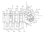
図1は、コイン処理装置の外観の斜視図である。コイン処理装置1は、略立方体状の外装ケースに覆われている。コイン処理装置1には、コインを投入する投入口2、払出されるコインを受けるトレー3が備えられている。 FIG. 1 is a perspective view of the appearance of the coin processing device. The coin processing device 1 is covered with a substantially cubic exterior case. A coin processing device 1 is provided with an insertion slot 2 for inserting coins and a tray 3 for receiving coins to be paid out.

コインを投入する投入口2の開口が、外装ケースの上面の手前側に配置されている。払出されるコインを受けるトレー3が、外装ケースのフロント面に配置されている。コイン処理装置1の内側と外側とを貫通する出金口4が、外装ケースのフロント面のトレー3に対応する位置に設けられている。出金口4を介して払出されるコインを、トレー3が受け止める。外装ケースの上面の手前側の投入口2の隣には、表示装置5が配置されている。表示装置5は、コイン処理装置1の状態や、入金額、出金額、案内などを表示する。投入されたコインを分離、識別、格納、払出す装置が外装ケースに覆われている。 An opening of an insertion slot 2 for inserting coins is arranged on the front side of the upper surface of the exterior case. A tray 3 for receiving coins to be paid out is arranged on the front surface of the exterior case. A payout port 4 passing through the inside and outside of the coin processing device 1 is provided at a position corresponding to the tray 3 on the front surface of the exterior case. A tray 3 receives coins paid out through a payout port 4. - 特許庁A display device 5 is arranged next to the inlet 2 on the front side of the upper surface of the exterior case. The display device 5 displays the state of the coin processing device 1, the amount of deposit, the amount of withdrawal, guidance, and the like. A device that separates, identifies, stores, and pays out inserted coins is covered with an exterior case.

例えば、コイン処理装置1は、自動釣銭機、自動両替機等のコインを入出金する装置である。投入口2にコインが投入される。投入されたコインの金種及び枚数を不図示の制御部が取得し、投入された金額を把握する。不図示の制御部によってコインの払出しの有無が演算される。コインの払出しがある場合は、不図示の制御部は、払出すコインの金種、枚数を演算し、コインホッパーを制御してコインを排出する。排出されたコインは、トレー3に送られる。 For example, the coin processing device 1 is a device for depositing and withdrawing coins such as an automatic change machine and an automatic change machine. A coin is inserted into the slot 2. A control unit (not shown) acquires the denomination and number of inserted coins, and grasps the amount of money inserted. Whether or not coins are to be paid out is calculated by a control unit (not shown). When coins are to be paid out, a control unit (not shown) calculates the denomination and number of coins to be paid out, controls the coin hopper, and discharges the coins. The ejected coins are sent to the tray 3.

次に、コイン処理装置1の構成について概略的な図を用いて説明する。図2は、コイン処理装置の構成を説明する図である。一般に使用されているコインは、複数の金種から構成される。コインは、サイズ、材質、デザインなどの要素が金種毎に異なっている。 Next, the configuration of the coin processing device 1 will be described with reference to schematic diagrams. FIG. 2 is a diagram for explaining the configuration of the coin processing device. Commonly used coins consist of multiple denominations. Coins have different elements such as size, material, and design for each denomination.

コイン処理装置1の投入口2には、複数の金種のコインが混ぜられた状態で投入される。コイン処理装置1は、投入されたコインを一枚ずつに分け、分けられたコインの金種を識別する。コイン処理装置1は、識別されたコインを金種毎に格納する。また、コイン処理装置1は、金種毎に分けて格納されたコインを、払出に再利用する。 Coins of a plurality of denominations are mixed and thrown into the slot 2 of the coin processing device 1.例文帳に追加The coin processing device 1 divides the inserted coins one by one and identifies the denominations of the divided coins. The coin processing device 1 stores the identified coins by denomination. In addition, the coin processing device 1 reuses coins stored separately for each denomination for payout.

コイン処理装置1は、3つの部分に分けられる。3つの部分とは、投入されたコインを1枚ずつ区分して送り出す分離部6、コインの金種を識別する識別部8、コインを金種毎に分けて格納する振分部9である。 The coin processing device 1 is divided into three parts. The three parts are a separation unit 6 for sorting and sending out inserted coins one by one, an identification unit 8 for discriminating coin denominations, and a sorting unit 9 for sorting and storing coins by denomination.

投入口2に投入されるコイン10は、コイン通路11を通り、貯留容器12に格納される。図2においては、投入口2、コイン通路11、貯留容器12は破線で示されている。投入口2に投入されるコイン10は、1枚ずつ分離して搬送されるまで、貯留容器12に一時的に格納される。 A coin 10 inserted into the slot 2 passes through a coin passage 11 and is stored in a storage container 12 . In FIG. 2, the slot 2, the coin passage 11, and the storage container 12 are indicated by broken lines. The coins 10 inserted into the slot 2 are temporarily stored in the storage container 12 until they are separated and conveyed one by one.

コイン処理装置1の基台の保持ベース13上に、ディスク15が回動可能に配置されている。ディスク15の下方に貯留容器12が配置されている。貯留容器12には、ディスク15の外周に沿った形状の底部が形成されている。貯留容器12は、ディスク15の下側半分から三分の一程度を覆う。また、保持ベース13とディスク15は、水平方向に対して傾斜して配置されている。コイン10がディスク15側にもたれかかる。ディスク15を回転させることで、ディスク15にもたれているコイン10が、後述の凹部16に入り込み、搬送される。 A disk 15 is rotatably arranged on a holding base 13 of the base of the coin processing device 1 . A reservoir 12 is arranged below the disk 15 . The storage container 12 has a bottom shaped along the outer circumference of the disk 15 . The reservoir 12 covers the lower half to one-third of the disc 15 . Also, the holding base 13 and the disk 15 are arranged to be inclined with respect to the horizontal direction. The coin 10 leans against the disk 15 side. By rotating the disc 15, the coin 10 leaning against the disc 15 enters a concave portion 16, which will be described later, and is conveyed.

ディスク15には、コイン10が収容される凹部16が3カ所に設けられている。コイン10は、この凹部16内に保持される。凹部16のディスク15の外周側の領域が開放されている。コイン10は、受渡部7で分離部6から識別部8に受け渡される。 The disc 15 is provided with three concave portions 16 for accommodating the coins 10 . The coin 10 is held within this recess 16 . The area of the recess 16 on the outer peripheral side of the disc 15 is open. The coin 10 is delivered from the separation section 6 to the identification section 8 at the delivery section 7 .

凹部16に入り込んだコイン10の側面は、凹部16の内壁に当接する。保持ベース13及びディスク15は、水平方向に対して斜めの姿勢をとるように配置されているので、コイン10をディスク15の凹部16内に保持することができる。保持ベース13の傾斜角度としては、30度~80度程度が好ましい。その中でも40度~50度がより好ましい。傾斜角度が小さいと不要なコイン10を凹部16から滑り落とせなくなり、傾斜角度が大きいと凹部16内にコインを入り込ませ難くなる。また、凹部16の内壁の高さは、コイン10の厚みより低く構成され、コイン10が1枚しか入らないようにしている。 The side surface of the coin 10 that has entered the recess 16 contacts the inner wall of the recess 16 . Since the holding base 13 and the disc 15 are arranged so as to take an oblique posture with respect to the horizontal direction, the coin 10 can be held in the concave portion 16 of the disc 15 . The inclination angle of the holding base 13 is preferably about 30 degrees to 80 degrees. Among them, 40 to 50 degrees is more preferable. If the inclination angle is small, the unnecessary coin 10 cannot slide down from the recess 16, and if the inclination angle is large, it becomes difficult for the coin to enter the recess 16. - 特許庁In addition, the height of the inner wall of the recess 16 is lower than the thickness of the coin 10 so that only one coin 10 can be inserted.

コイン10は、凹部16の平坦な底面にコイン10の表面又は裏面を対向させる姿勢で、保持される。また、凹部16の内壁は、ディスク15の外周側には配置されていない。コイン10は、この内壁の無い領域を通り、次工程に渡される。ディスク15の外周の外側には、コイン10をディスク回転方向に案内する案内壁が配置されている。コイン10は、周面が、案内壁と、凹部16の内壁とに接触した状態で搬送される。 The coin 10 is held in such a posture that the front surface or rear surface of the coin 10 faces the flat bottom surface of the recess 16 . Further, the inner wall of the recess 16 is not arranged on the outer peripheral side of the disk 15 . The coin 10 passes through this area without inner walls and is passed to the next process. A guide wall that guides the coin 10 in the direction of rotation of the disk is arranged outside the outer circumference of the disk 15 . The coin 10 is conveyed with its peripheral surface in contact with the guide wall and the inner wall of the recess 16 .

ディスク15は、矢印で示されたディスク回転方向17の方向に回転する。ディスク15は、貯留容器12に格納されたコイン10を凹部16で一枚ずつ拾い上げる。ディスク15が水平方向に対して斜めに配置されているので、貯留容器12内のコイン10は、ディスク15にもたれ掛り、凹部16に入り込みやすくなっている。 The disk 15 rotates in a disk rotation direction 17 indicated by an arrow. The disk 15 picks up the coins 10 stored in the storage container 12 one by one at the concave portion 16 . Since the disk 15 is arranged obliquely with respect to the horizontal direction, the coin 10 in the storage container 12 leans against the disk 15 and easily enters the concave portion 16 .

分離部6の上方であり、識別部8の下方の位置においてコイン10が受け渡される。図2では、識別部8と分離部6とを上下に配置した例を示したが、後述する図3の様に識別部8と分離部6を左右に配置することもできる。ディスク15は、コイン10を1枚ずつ、受渡部7に搬送し、次工程である識別部8に送ることができる。 A coin 10 is delivered at a position above the separation section 6 and below the identification section 8 . Although FIG. 2 shows an example in which the identification section 8 and the separation section 6 are arranged vertically, the identification section 8 and the separation section 6 can be arranged horizontally as shown in FIG. 3 which will be described later. The disk 15 can convey the coins 10 one by one to the delivery section 7 and then to the identification section 8 which is the next process.

識別部8には、コイン処理装置1の基台の保持ベース13上にホイール21が配置されている。ホイール21は、矢印で示されるホイール回転方向22の方向に回転する。ホイール21は、ディスク15の回転と連動して回転する。分離部6から送り出されるコイン10は、コイン10の周面をホイール21が押す。コイン10は、ホイール21によって、保持ベース13上を移動する。保持ベース13は平坦な平面である。識別部8には、コイン10のサイズ、材質等の特徴を検出する識別センサー19が配置されている。保持ベース13上を移動するコイン10の特徴を、識別センサー19で検出する。不図示の制御部は、識別センサー19の検出結果に基づきコイン10の金種を識別する。ホイール21によってコイン10が一枚ずつ区分されるので、識別センサー19はコイン10の特徴を好適に検出することができる。コイン10は、表面又は裏面を前述の保持ベース13に接触させ、且つ周面を案内部18に接触させた状態で、ホイール21に押される。コイン10は、案内部18に沿って移動する。識別部8で金種を識別されたコイン10は、次工程の振分部9に受け渡される。 A wheel 21 is arranged on the holding base 13 of the base of the coin processing device 1 in the identification unit 8 . The wheel 21 rotates in a wheel rotation direction 22 indicated by an arrow. The wheel 21 rotates in conjunction with the rotation of the disc 15 . A wheel 21 pushes the peripheral surface of the coin 10 delivered from the separation unit 6 . The coin 10 is moved on the holding base 13 by the wheels 21 . The holding base 13 is a flat plane. An identification sensor 19 for detecting characteristics such as the size and material of the coin 10 is arranged in the identification unit 8 . An identification sensor 19 detects features of the coin 10 moving on the holding base 13 . A control unit (not shown) identifies the denomination of the coin 10 based on the detection result of the identification sensor 19 . Since the coins 10 are sorted one by one by the wheel 21, the identification sensor 19 can preferably detect the characteristics of the coins 10. FIG. The coin 10 is pushed by the wheel 21 with its front or rear surface in contact with the holding base 13 and its peripheral surface in contact with the guide portion 18 . The coin 10 moves along the guide portion 18 . The coin 10 whose denomination has been identified by the identification unit 8 is transferred to the distribution unit 9 in the next process.

振分部9では、コイン10を案内するレール25が配置されている。識別部8から振分部9のレール25にコイン10が渡される。このレール25に沿ってコイン10が搬送される。レール25に沿って搬送ベルト24が配置されている。搬送ベルト24には、搬送ピンローラー23が等間隔で配置されている。隣り合う搬送ピンローラー23の間に、1枚のコイン10が入る。コイン10は、1枚ずつ搬送ピンローラー23に押されてレール25に沿って搬送される。搬送ピンローラー23は、コイン10を押して搬送する押動体とも言える。搬送ベルト24は、無端ベルトであり、ディスク15およびホイール21と連動して、矢印で示されている搬送ベルト回転方向26の方向に回転する。 Rails 25 for guiding the coins 10 are arranged in the sorting section 9 . A coin 10 is passed from the identifying section 8 to the rail 25 of the sorting section 9 . A coin 10 is conveyed along this rail 25 . A conveyor belt 24 is arranged along the rail 25 . Conveying pin rollers 23 are arranged at regular intervals on the conveying belt 24 . One coin 10 enters between adjacent conveying pin rollers 23. - 特許庁The coins 10 are pushed one by one by the transport pin rollers 23 and transported along the rails 25 . The conveying pin roller 23 can also be said to be a pushing body that pushes and conveys the coin 10 . The transport belt 24 is an endless belt and rotates in conjunction with the disc 15 and the wheel 21 in the transport belt rotation direction 26 indicated by the arrow.

レール25に沿って、第1スライダー27、第2スライダー29、第3スライダー31、第4スライダー33、第5スライダー35、第6スライダー37、第7スライダー39が配置されている。これらのスライダーは、予め決められた金種のコインホッパーに接続されている。識別部8で識別されたコイン10は、対応する金種のスライダーに落とされ、対応する金種のコインホッパーに格納される。 A first slider 27 , a second slider 29 , a third slider 31 , a fourth slider 33 , a fifth slider 35 , a sixth slider 37 and a seventh slider 39 are arranged along the rail 25 . These sliders are connected to coin hoppers of predetermined denominations. The coin 10 identified by the identification unit 8 is dropped onto the corresponding denomination slider and stored in the corresponding denomination coin hopper.

第1スライダー27は第1コインホッパー28に接続されている。第2スライダー29は第2コインホッパー30に接続されている。第3スライダー31は第3コインホッパー32に接続されている。第4スライダー33は第4コインホッパー34に接続されている。第5スライダー35は第5コインホッパー36に接続されている。第6スライダー37は第6コインホッパー38に接続されている。また、第7スライダー39はオーバーフロー容器40に、接続されている。 The first slider 27 is connected to the first coin hopper 28 . A second slider 29 is connected to a second coin hopper 30 . A third slider 31 is connected to a third coin hopper 32 . A fourth slider 33 is connected to a fourth coin hopper 34 . A fifth slider 35 is connected to a fifth coin hopper 36 . A sixth slider 37 is connected to a sixth coin hopper 38 . Also, the seventh slider 39 is connected to the overflow container 40 .

第8スライダー41は、排出ベルト42にコイン10を導く。金種が識別不能であったコイン10や、利用できないコイン10を排出ベルト42上に導き、トレー3に排出する。 The eighth slider 41 guides the coin 10 to the ejection belt 42 . A coin 10 whose denomination cannot be identified or a coin 10 that cannot be used is guided onto a discharge belt 42 and discharged to a tray 3.例文帳に追加

コインホッパーに格納されるコイン10が所定量を超えると、不具合が生じる恐れがある。そのため、コインホッパーに格納されているコイン10の枚数が所定量を超えた場合、当該コインホッパーへのコイン10の格納を停止する。すなわち、不図示の制御部は、コインホッパーに格納されているコイン10の枚数と、予め決められた許容可能な格納枚数とを比較し、その結果に基づいてコインホッパーへのコイン10の格納を継続するか、停止するかを制御している。コインホッパーへのコイン10の格納が停止された場合に、格納されないコイン10は、オーバーフロー容器40に格納される。その後、フルになったコインホッパーからコイン10が払出されれば、再び、コイン10をコインホッパーに格納することが可能となる。オーバーフロー容器40に余剰のコイン10を格納することができる構成にすることで、メンテナンスの回数を減らすことができる。よって、コイン処理装置1の効率的な運用が可能となる。オーバーフロー容器40は、コインホッパーであっても良いし、コインを排出する機能が無い格納容器でも良い。 If the number of coins 10 stored in the coin hopper exceeds a predetermined amount, problems may occur. Therefore, when the number of coins 10 stored in the coin hopper exceeds a predetermined amount, storage of coins 10 in the coin hopper is stopped. That is, the control unit (not shown) compares the number of coins 10 stored in the coin hopper with a predetermined allowable number of stored coins, and based on the result, stores the coins 10 in the coin hopper. It controls whether to continue or stop. When the storage of the coins 10 in the coin hopper is stopped, the coins 10 not stored are stored in the overflow container 40 . After that, when the coins 10 are dispensed from the coin hopper which has become full, the coins 10 can be stored in the coin hopper again. By adopting a configuration in which surplus coins 10 can be stored in the overflow container 40, the frequency of maintenance can be reduced. Therefore, efficient operation of the coin processing device 1 becomes possible. The overflow container 40 may be a coin hopper or a storage container that does not have a function to eject coins.

各コインホッパーは、排出ベルト42に沿って配置されている。振分部9では、排出ベルト42を駆動することで、各コインホッパーから排出されたコイン10をトレー3に搬送できる。投入口2に入れられたコイン10を、払出用のコイン10として再利用することができる。 Each coin hopper is arranged along the discharge belt 42 . In the sorting section 9 , the coins 10 discharged from each coin hopper can be transported to the tray 3 by driving the discharge belt 42 . A coin 10 put into the slot 2 can be reused as a coin 10 for payout.

ディスク15はディスク回転軸14を中心に回転する。ホイール21はホイール回転軸20を中心に回転する。ディスク回転軸14とホイール回転軸20は、不図示のモーターによって回転する。モーターとディスク回転軸14の間は不図示の輪列によって接続されている。また、モーターとホイール回転軸20の間は不図示の輪列によって接続されている。モーター及び輪列はディスク15、ホイール21を回転させる駆動部を構成している。 The disc 15 rotates around the disc rotating shaft 14 . Wheel 21 rotates around wheel rotation axis 20 . The disk rotating shaft 14 and the wheel rotating shaft 20 are rotated by a motor (not shown). A gear train (not shown) connects the motor and the disk rotating shaft 14 . Further, the motor and the wheel rotation shaft 20 are connected by a train wheel (not shown). The motor and train wheel constitute a drive for rotating the disc 15 and wheel 21 .

コイン10は、分離部6から受渡部7を介して識別部8に摺動させるので、それぞれが段差無く配置され、平坦な面を備えている。 Since the coins 10 are slid from the separation section 6 to the identification section 8 via the transfer section 7, they are arranged without steps and have a flat surface.

ディスク15には、凹部16がディスク回転軸14を中心として、等角に複数箇所設けられている。例えば、120度間隔に3カ所設けられている。 The disk 15 is provided with a plurality of concave portions 16 equiangularly around the disk rotating shaft 14 . For example, three locations are provided at intervals of 120 degrees.

各凹部16には、後述するレバーが配置されている。受渡部7にコイン10が運ばれると、このレバーによって、ディスク15の外周方向、すなわち識別部8の方向にコイン10を移動させ、識別部8にコイン10を受け渡すことができる。 A lever, which will be described later, is arranged in each recess 16 . When the coin 10 is carried to the delivery section 7 , the lever moves the coin 10 in the outer peripheral direction of the disc 15 , that is, in the direction of the identification section 8 , so that the coin 10 can be delivered to the identification section 8 .

コイン10は、分離部6のディスク15から押し出され、識別部8のホイール21に拾われる。保持ベース13は平坦なので、スムースに受け渡しができる。 A coin 10 is pushed out of the disc 15 of the separating section 6 and picked up by the wheel 21 of the identifying section 8 . Since the holding base 13 is flat, it can be delivered smoothly.

ホイール21には、ホイール回転軸20を中心として120度の間隔で受取体が放線状に配置されている。コイン10は、各受取体の間に1枚ずつ入る。コイン10は、受取体の側面の押動壁によって押される。ホイール21によって押されるコイン10は、保持ベース13上を摺動する。ホイール21はディスク15と連動して回転し、その回転方向は逆方向である。 Receiving bodies are radially arranged on the wheel 21 at intervals of 120 degrees around the wheel rotation axis 20 . One coin 10 enters between each recipient. The coin 10 is pushed by the pushing wall on the side of the receiver. A coin 10 pushed by the wheel 21 slides on the holding base 13 . The wheel 21 rotates in conjunction with the disk 15 and rotates in the opposite direction.

案内部18は、直線状に配置されている。コイン10は、案内部18に沿って直線状に移動する。識別部8では、案内部18に沿って直線状に移動するコイン10を、識別センサー19によって検出し、金種を識別する。 The guide portions 18 are arranged linearly. The coin 10 moves linearly along the guide portion 18 . In the identification section 8, the identification sensor 19 detects the coin 10 moving linearly along the guide section 18 to identify the denomination of the coin.

コイン10は、ホイール21に押され、識別部8から振分部9に渡される。ホイール21と搬送ベルト24は、連動して回転している。隣り合う搬送ピンローラー23間に1枚のコイン10が入るように、搬送ピンローラー23が配置されている。 The coin 10 is pushed by the wheel 21 and passed from the identifying section 8 to the sorting section 9 . The wheel 21 and the conveyor belt 24 rotate together. The conveying pin rollers 23 are arranged so that one coin 10 enters between the adjacent conveying pin rollers 23 .

コイン10は、搬送ピンローラー23によって押され、レール25に沿って移動する。コイン10は、対応する金種のスライダーに落とされる。同一の金種のコイン10は、スライダーに導かれ、コインホッパーに格納される。 The coin 10 is pushed by the transport pin roller 23 and moved along the rail 25 . The coin 10 is dropped on the corresponding denomination slider. Coins 10 of the same denomination are guided by a slider and stored in a coin hopper.

次に、コイン処理装置1の主要部分について説明する。図3は、コイン処理装置の主要部の斜視図である。 Next, main parts of the coin processing device 1 will be described. FIG. 3 is a perspective view of the main part of the coin processing machine.

分離部6では、投入された複数のコイン10を一時的に貯留容器12に貯留する。貯留されたコイン10は、ディスク15によって、1枚ずつ搬送される。コイン10が受渡部7の位置に搬送されると、レバー54が動作し、コイン10を識別部8の方向に押し出す。押し出されたコイン10は、受渡部7を通り、ホイール21の受取体間に入る。 The separating unit 6 temporarily stores the inserted coins 10 in the storage container 12 . The stored coins 10 are conveyed one by one by the disk 15 . When the coin 10 is transported to the delivery section 7 , the lever 54 operates to push the coin 10 toward the identification section 8 . The extruded coin 10 passes through the delivery section 7 and enters between the receivers of the wheel 21 .

図3においては、識別部8を覆うセンサーカバー53が開いている状態を図示している。通常の使用状態では、ホイール21を覆うように、センサーカバー53は閉じている。 FIG. 3 shows a state in which the sensor cover 53 covering the identification section 8 is open. In normal use, the sensor cover 53 is closed so as to cover the wheel 21 .

識別部8では、ホイール21によってコイン10が1枚ずつ保持ベース13上を移動する。識別部8の下方には、案内部18が配置されている。案内部18は、ホイール21の外周の外側に配置された案内壁の一部である。案内部18は、コイン10を一定の条件で検出するために、直線状に配置されている。コイン10は、案内部18に沿って、ホイール21に押されて保持ベース13上を摺動する。保持ベース13が水平方向に対して傾斜して配置されているので、コイン10は、重力によって下方に力が加わる。コイン10は、周面が案内壁に接し、表面または裏面が保持ベース13に接する。最下点を通過したホイール21は、コイン10を重力に抗して上方に搬送する。コイン10は、案内部18に接した状態で搬送される。コイン10の周面が、案内部18と接しながら、摺動あるいは転動する。識別センサー19の検出領域において、コイン10を一定条件で通過させることができる。 In the identification unit 8 , the coins 10 are moved one by one on the holding base 13 by the wheel 21 . A guide portion 18 is arranged below the identification portion 8 . The guide part 18 is part of a guide wall arranged outside the outer circumference of the wheel 21 . The guide portion 18 is arranged linearly so as to detect the coin 10 under certain conditions. The coin 10 is pushed by the wheel 21 and slides on the holding base 13 along the guide portion 18 . Since the holding base 13 is inclined with respect to the horizontal direction, the coin 10 is forced downward by gravity. The coin 10 is in contact with the guide wall at its peripheral surface and in contact with the holding base 13 at its front surface or rear surface. After passing the lowest point, the wheel 21 conveys the coin 10 upward against gravity. The coin 10 is conveyed while being in contact with the guide portion 18 . The peripheral surface of the coin 10 slides or rolls while being in contact with the guide portion 18 . The coin 10 can pass through the detection area of the identification sensor 19 under certain conditions.

識別センサー19によって金種を識別されたコイン10は、受渡口50を通り、識別部8から振分部9へ渡される。 The coin 10 whose denomination has been identified by the identification sensor 19 passes through the delivery port 50 and is transferred from the identification section 8 to the sorting section 9 .

受渡口50は、保持ベース13の表裏を貫通する貫通孔である。受渡口50の奥側には、振分部9の搬送路51及びレール25が配置されている。搬送路51及びレール25は、コイン10の案内路である。コイン10は、ホイール21によって押され、受渡口50に落とされる。コイン10は、受渡口50を通り抜けて、搬送路51及びレール25に到達する。すなわち、受渡口50に対向する部分が、振分部9のコイン10の受渡領域である。 The delivery port 50 is a through hole penetrating the front and back of the holding base 13 . A conveying path 51 and a rail 25 of the sorting section 9 are arranged on the far side of the delivery port 50 . The transport path 51 and the rail 25 are guide paths for the coins 10 . The coin 10 is pushed by the wheel 21 and dropped into the delivery port 50. - 特許庁The coin 10 passes through the delivery port 50 and reaches the transport path 51 and rail 25 . That is, the portion facing the delivery port 50 is the delivery area for the coins 10 of the sorting section 9 .

搬送路51は水平方向に対して傾斜して配置されている。約45度の角度で傾斜している。コイン10を識別部8から振分部9に受け渡し易くするため、保持ベース13の傾斜角度と搬送路51の傾斜角度が同じか、プラスマイナス10度以内の小さい差であることが好まし。コイン10は、コイン10の外周面である側面がレール25に接し、コイン10の表面又は裏面が搬送路51に接した状態で、搬送ピンローラー23に押されて搬送路51及びレール25に沿って移動する。コイン10は、搬送ピンローラー23に押され、搬送路51の傾斜した面上を摺動すると共に、レール25の上を転動または摺動する。搬送ピンローラー23は、コイン10に接し、押し動かす押動体とも言える。すなわち、コイン10は、搬送路51を第1支持部、レール25を第2支持部とする支持部によって支持された状態で、押動体に押されて搬送される。搬送ベルト24、搬送ピンローラー23、搬送路51、レール25などのコイン10を搬送するための通路を構成する部材が、フロントカバー55によって覆われている。また、搬送路51は、搬送路カバー52の一部によって構成されている。また、識別部8が搬送路51の上方に配置されているので、コイン10を識別部8から振分部9に受け渡す受渡領域は、フロントカバー55には覆われていない。 The transport path 51 is arranged to be inclined with respect to the horizontal direction. It is slanted at an angle of about 45 degrees. In order to facilitate delivery of the coins 10 from the identifying section 8 to the sorting section 9, it is preferable that the inclination angle of the holding base 13 and the inclination angle of the transport path 51 are the same or have a small difference of plus or minus 10 degrees or less. The coin 10 is pushed by the conveying pin rollers 23 along the conveying path 51 and the rail 25 in a state in which the side surface which is the outer peripheral surface of the coin 10 is in contact with the rail 25 and the front surface or the back surface of the coin 10 is in contact with the conveying path 51 . to move. The coin 10 is pushed by the conveying pin roller 23 , slides on the inclined surface of the conveying path 51 , and rolls or slides on the rail 25 . The transport pin roller 23 can also be said to be a pushing body that contacts the coin 10 and pushes it. In other words, the coin 10 is pushed by the pushing body and conveyed while being supported by the support portion having the conveying path 51 as the first support portion and the rail 25 as the second support portion. A front cover 55 covers the members forming the passage for conveying the coins 10 , such as the conveying belt 24 , the conveying pin rollers 23 , the conveying path 51 and the rails 25 . Further, the transport path 51 is configured by a part of the transport path cover 52 . Further, since the identifying section 8 is arranged above the transport path 51 , the delivery area where the coins 10 are transferred from the identifying section 8 to the sorting section 9 is not covered with the front cover 55 .

搬送路51を傾斜させ、更に上面視で搬送路51及びレール25を湾曲させ、湾曲させた部分でコイン10を受け渡す構成とした。湾曲させた部分の上側に、分離部6及び識別部8を重ねて配置することを可能とした。すなわち、識別部8の下側に振分部9が配置されている。また、搬送ベルト24はプーリーに掛け回されている。上面視で、搬送路51及びレール25は、プーリーに掛け回されている搬送ベルト24に沿って、湾曲している。搬送ベルト24に沿って搬送路51およびレール25を配置することで、コイン処理装置1の長手方向の長さを短くしている。また、搬送路51を傾斜させ、搬送路51の下側に搬送ベルト24などの駆動部を配置することで、コイン処理装置1の短手方向の長さを短くしている。このような構成は、コイン処理装置1の小型化を可能にしている。 The conveying path 51 is inclined, the conveying path 51 and the rail 25 are curved when viewed from above, and the coin 10 is delivered at the curved portion. It is possible to arrange the separation part 6 and the identification part 8 to overlap on the upper side of the curved part. That is, the distribution section 9 is arranged below the identification section 8 . Further, the conveying belt 24 is wound around pulleys. As viewed from above, the transport path 51 and the rails 25 are curved along the transport belt 24 that is looped around the pulleys. By arranging the transport path 51 and the rails 25 along the transport belt 24, the length of the coin processing machine 1 in the longitudinal direction is shortened. In addition, by inclining the conveying path 51 and arranging the driving portion such as the conveying belt 24 below the conveying path 51, the length of the coin processing apparatus 1 in the lateral direction is shortened. Such a configuration enables the size of the coin processing device 1 to be reduced.

図4は、コイン処理装置の主要部の上面図である。図4は、センサーカバー53が閉じられた状態であり、フロントカバー55が外された状態を上方から見た上面視の図である。 FIG. 4 is a top view of the main part of the coin processing machine. FIG. 4 is a top plan view showing a state in which the sensor cover 53 is closed and the front cover 55 is removed.

分離部6は、貯留容器12に堆積したコイン10を一枚ずつ分離し、分離したコイン10を識別部8に渡す。識別部8は、コイン10の金種を識別し、一枚ずつ振分部9に渡す。 The separating unit 6 separates the coins 10 accumulated in the storage container 12 one by one and passes the separated coins 10 to the identifying unit 8 . The identification unit 8 identifies the denomination of the coins 10 and passes them to the distribution unit 9 one by one.

振分部9では、コイン10がレール25に沿って搬送ピンローラー23に押されて移動する。第1フラップ56、第2フラップ57、第3フラップ58がレール25に沿って配置されている。第1フラップ56は、コイン10を通過させる第1状態、コイン10を第1スライダー27に移動させる第2状態、コイン10を第4スライダー33に移動させる第3状態の何れかの状態をとる。第1フラップ56は、不図示の駆動部によって第1状態、第2状態、第3状態が切り替えられる。第1フラップ56と同様に、第2フラップ57は、コイン10を通過させる第1状態、コイン10を第2スライダー29に移動させる第2状態、コイン10を第5スライダー35に移動させる第3状態の何れかの状態に、不図示の駆動部によって切り替えることができる。第1フラップ56と同様に、第3フラップ58は、コイン10を通過させる第1状態、コイン10を第3スライダー31に移動させる第2状態、コイン10を第6スライダー37に移動させる第3状態の何れかの状態に、不図示の駆動部によって切り替えることができる。この様に構成することで、コイン10は7方向の進路の何れかに導かれる。 In the sorting section 9, the coins 10 are moved along the rails 25 by being pushed by the transport pin rollers 23. - 特許庁A first flap 56 , a second flap 57 and a third flap 58 are arranged along the rail 25 . The first flap 56 takes any one of a first state for passing the coin 10 , a second state for moving the coin 10 to the first slider 27 , and a third state for moving the coin 10 to the fourth slider 33 . The first flap 56 is switched between a first state, a second state, and a third state by a drive section (not shown). Similar to the first flap 56, the second flap 57 has a first state for passing the coin 10, a second state for moving the coin 10 to the second slider 29, and a third state for moving the coin 10 to the fifth slider 35. can be switched to either state by a driving unit (not shown). Similar to the first flap 56 , the third flap 58 has a first state for passing the coin 10 , a second state for moving the coin 10 to the third slider 31 , and a third state for moving the coin 10 to the sixth slider 37 . can be switched to either state by a driving unit (not shown). By configuring in this way, the coin 10 is guided to any one of seven paths.

第1コインホッパー28、第2コインホッパー30、第3コインホッパー32がレール25に沿って一列に並び配置され、第4コインホッパー34、第5コインホッパー36、第6コインホッパー38がレール25に沿って一列に並び配置されている。 A first coin hopper 28, a second coin hopper 30, and a third coin hopper 32 are arranged in a line along the rail 25, and a fourth coin hopper 34, a fifth coin hopper 36, and a sixth coin hopper 38 are arranged on the rail 25. arranged in a row along the

第7スライダー39はレール25の、コイン10の搬送方向の先端に配置され、第1フラップ56、第2フラップ57、第3フラップ58を通過したコイン10をオーバーフロー容器40に導く。レール25の端部を上面視で湾曲させ、湾曲部分に第7スライダー39を配置する。フラップを設けることなく、コイン10をオーバーフロー容器40に導くことができる。 The seventh slider 39 is arranged at the leading end of the rail 25 in the direction in which the coins 10 are conveyed, and guides the coins 10 that have passed through the first flap 56 , the second flap 57 and the third flap 58 to the overflow container 40 . The end of the rail 25 is curved when viewed from above, and the seventh slider 39 is arranged on the curved portion. Coins 10 can be led to the overflow container 40 without providing a flap.

コイン処理装置1には、レール25の途中に3つのフラップが設けられており、コイン10を7つの格納部の何れかに導くことができる。 The coin processing device 1 is provided with three flaps in the middle of the rail 25 so that the coin 10 can be guided to any one of the seven storage sections.

振分部9の搬送路51の基端は、識別部8の下方に重なるように構成されている。また搬送路51の先端には、第7スライダー39が配置されている。搬送路51の基端側と先端側を上面視で湾曲させて構成することで、コイン処理装置1の長手方向の長さを短くし、小型化している。 A base end of the transport path 51 of the sorting section 9 is configured to overlap with the identification section 8 below. A seventh slider 39 is arranged at the tip of the transport path 51 . By curving the base end side and the tip end side of the conveying path 51 when viewed from above, the length in the longitudinal direction of the coin processing apparatus 1 is shortened and the size is reduced.

搬送路カバー52には搬送路51が設けられている。搬送路51は、搬送路カバー52のレール25側に設けられた傾斜面である。搬送路51は、コイン10の表面または裏面が接する。コイン10は、搬送路51上を摺動する。搬送路51の下縁とレール25との間に所定間隔の隙間が設けられている。その隙間から搬送ピンローラー23が外側に突出している。すなわち、搬送路51の下縁に沿ってレール25が配置されている。搬送ピンローラー23は、搬送路51とレール25の間を移動する。コイン10は、搬送ピンローラー23によって押されて移動する。 A transport path 51 is provided in the transport path cover 52 . The transport path 51 is an inclined surface provided on the rail 25 side of the transport path cover 52 . The transport path 51 is in contact with the front surface or the rear surface of the coin 10 . The coin 10 slides on the transport path 51 . A predetermined gap is provided between the lower edge of the transport path 51 and the rail 25 . A conveying pin roller 23 protrudes outward from the gap. That is, the rail 25 is arranged along the lower edge of the transport path 51 . The transport pin roller 23 moves between the transport path 51 and the rail 25 . The coin 10 is pushed by the transport pin roller 23 to move.

金種を識別されたコイン10は、振分部9によって金種毎に進路が決められ、コインホッパーに格納される。図2で示されている様に、格納されたコイン10は、独立に制御される各コインホッパーから、排出ベルト42に排出され、出金口4を通り、トレー3に払出される。 The coins 10 whose denominations have been identified are routed according to their denominations by the sorting unit 9 and stored in the coin hopper. As shown in FIG. 2, the stored coins 10 are discharged from the independently controlled coin hoppers onto the discharge belt 42, passed through the payout port 4, and paid out to the tray 3. As shown in FIG.

図5は、コインホッパーを説明する図である。各コインホッパーは同様の構成を備える。コインホッパーは、本体60とコイン10を格納する格納容器とから構成されている。図5は、格納容器を取り外した状態で上方から見た場合の上面視の図である。格納容器は、本体60の上方に着脱自在に取り付けることができる。格納容器に設けられた凸部が本体60の固定部67に挿入され、固定される。固定部67は、回転体61を囲うように4カ所設けられている。格納容器の底部には、回転体61に対向する位置に開口部が設けられている。コインホッパーは、回転体61及びホッパベース66を底面とし、格納容器を側面とした、コイン10の格納部を備える。 FIG. 5 is a diagram for explaining the coin hopper. Each coin hopper has a similar configuration. The coin hopper is composed of a main body 60 and a storage container for storing coins 10 . FIG. 5 is a top view when viewed from above with the containment vessel removed. The containment can be removably mounted above the body 60 . A convex portion provided on the containment vessel is inserted into the fixing portion 67 of the main body 60 and fixed. Four fixing portions 67 are provided so as to surround the rotating body 61 . An opening is provided in the bottom of the containment vessel at a position facing the rotating body 61 . The coin hopper includes a coin 10 storing portion having a rotating body 61 and a hopper base 66 as a bottom surface and a storage container as a side surface.

ホッパベース66は、平坦な面を有し、その上をコイン10の表面または裏面が接し、摺動する。回転体61は、ホッパベース66の上方に配置され、回転軸62を中心に反時計回りに回転する。回転体61は、4カ所にコイン10が入るホッパー凹部65が設けられている。ホッパー凹部65に入ったコイン10は、回転体61の回転に伴い、ホッパベース66の上を摺動する。ホッパベース66には、コイン10の搬送を妨げるように制限ピン63が設けられている。回転体61の裏面側には、制限ピン63を避ける円周状の窪みが設けられている。回転体61の裏面側であってホッパー凹部65の外周側には、コイン10が通過可能な溝が設けられている。回転体61によって搬送されるコイン10は、制限ピン63に当接すことで移動方向が変り、排出口の方向に移動する。回転体61の外周側に設けられた溝がコイン10の通路となり、コイン10が回転体61から排出される。排出されるコイン10は、払出センサー64によって検出される。払出センサー64からの出力される検出信号をカウントすることで、排出されるコイン10の枚数を把握することができる。例えば、不図示の制御回路を用いて、排出するコイン10の枚数を計数する。不図示の制御回路は、排出されたコイン10の枚数が、所望の枚数に達した場合に、回転体61の回転を停止させる。不図示の制御回路は、コインホッパーから排出するコイン10の枚数を制御することができる。 The hopper base 66 has a flat surface on which the front or rear surface of the coin 10 contacts and slides. The rotating body 61 is arranged above the hopper base 66 and rotates counterclockwise around the rotating shaft 62 . The rotating body 61 is provided with hopper recesses 65 in which coins 10 are inserted at four locations. The coin 10 entering the hopper recess 65 slides on the hopper base 66 as the rotating body 61 rotates. A restriction pin 63 is provided on the hopper base 66 so as to prevent the coin 10 from being conveyed. A circular depression is provided on the back side of the rotating body 61 to avoid the restriction pin 63 . A groove through which the coin 10 can pass is provided on the outer peripheral side of the hopper concave portion 65 on the back side of the rotating body 61 . The coin 10 transported by the rotating body 61 changes its direction of movement by abutting the limit pin 63, and moves toward the ejection port. A groove provided on the outer peripheral side of the rotating body 61 serves as a passage for the coins 10 , and the coins 10 are ejected from the rotating body 61 . The ejected coin 10 is detected by the payout sensor 64 . By counting the detection signals output from the payout sensor 64, the number of coins 10 to be discharged can be grasped. For example, a control circuit (not shown) is used to count the number of coins 10 to be ejected. A control circuit (not shown) stops the rotation of the rotating body 61 when the number of ejected coins 10 reaches a desired number. A control circuit (not shown) can control the number of coins 10 discharged from the coin hopper.

図2で説明した様に、コイン処理装置1は、排出ベルト42に沿ってコインホッパーが3台ずつ2列に配置されている。また、コインホッパーのコイン10の排出側を相互に対向させている。コイン10は、排出ベルト42に向かってそれぞれのコインホッパーから排出される。 As described with reference to FIG. 2, the coin processing apparatus 1 has three coin hoppers arranged in two rows along the discharge belt 42 . In addition, the coin hopper discharge sides of the coins 10 are opposed to each other. Coins 10 are ejected from each coin hopper toward ejection belt 42 .

次に、コイン処理装置1の振分部9について説明する。図6は、コイン処理装置の振分部を説明する分解図である。 Next, the sorting unit 9 of the coin processing device 1 will be described. FIG. 6 is an exploded view for explaining the sorting section of the coin processing device.

ケース基部78には、第1プーリー軸76、第2プーリー軸77が配置されている。第1プーリー軸76には駆動プーリー73が挿入される。第2プーリー軸77には従動プーリー74が挿入される。駆動プーリー73には、不図示のモーターが輪列を介して接続されている。また、駆動プーリー73と従動プーリー74には搬送ベルト24が掛け回される。搬送ベルト24は歯付きのベルトであり、搬送ベルト24の歯が駆動プーリー73の歯車と従動プーリー74の歯車に噛合う。駆動プーリー73を不図示のモーターによって駆動すると、駆動プーリー73の回転に伴って搬送ベルト24と従動プーリー74が回転する。搬送ベルト24には、等間隔に12個の搬送ピンローラー23が固定されている。 A first pulley shaft 76 and a second pulley shaft 77 are arranged on the case base portion 78 . A drive pulley 73 is inserted into the first pulley shaft 76 . A driven pulley 74 is inserted into the second pulley shaft 77 . A motor (not shown) is connected to the drive pulley 73 via a wheel train. A conveyor belt 24 is wound around the drive pulley 73 and the driven pulley 74 . The conveying belt 24 is a toothed belt, and the teeth of the conveying belt 24 mesh with the gears of the drive pulley 73 and the driven pulley 74 . When the drive pulley 73 is driven by a motor (not shown), the conveyor belt 24 and the driven pulley 74 rotate as the drive pulley 73 rotates. Twelve conveying pin rollers 23 are fixed to the conveying belt 24 at regular intervals.

ケース基部78には、コイン10を案内するレール25が配置されている。レール25は、コイン10の側面と接する底部と、コイン10の表面又は裏面の一部と接する側部とが、約90度の角度をなして形成されている。側部は、コイン10の直径の1/3~1/10程度の高さとなる。側部は、搬送路51を補助する。側部が無くとも、搬送路51が有れば、コイン10の表面又は裏面を支持することができる。コイン10が、搬送路51とレール25との間に入らないようにするため、側部が設けられている。 A rail 25 for guiding the coin 10 is arranged on the case base 78 . The rail 25 has a bottom portion in contact with the side surface of the coin 10 and a side portion in contact with part of the front surface or the back surface of the coin 10 at an angle of approximately 90 degrees. The side portion has a height of about ⅓ to 1/10 of the diameter of the coin 10 . The side part assists the transport path 51 . Even if there is no side part, the front side or the back side of the coin 10 can be supported as long as the transport path 51 is provided. A side portion is provided to prevent the coin 10 from entering between the transport path 51 and the rail 25 .

レール25のコイン10の搬送経路の途中に、第1フラップ56、第2フラップ57、第3フラップ58が配置されている。各フラップには、フラップ頂部75が設けられている。フラップ頂部75とレール25の底部とが面一なる状態にすることで、コイン10を通過させることができる。フラップ頂部75とレール25とを面一にすることで、コイン10を、搬送路51に沿って移動させることができる。レール25の基端側は湾曲した第1湾曲レール79が形成され、先端側は湾曲した第2湾曲レール80が形成されている。第1湾曲レール79では、識別部8からコイン10が受け渡される。第2湾曲レール80の端部は、第7スライダー39に接続される。 A first flap 56 , a second flap 57 and a third flap 58 are arranged in the middle of the coin 10 conveying path of the rail 25 . Each flap is provided with a flap top 75 . The coin 10 can be passed by making the flap top portion 75 and the bottom portion of the rail 25 flush with each other. By making the flap top portion 75 and the rail 25 flush with each other, the coin 10 can be moved along the transport path 51 . A curved first curved rail 79 is formed on the base end side of the rail 25, and a curved second curved rail 80 is formed on the distal end side. The coin 10 is transferred from the identification section 8 to the first curved rail 79 . An end of the second curved rail 80 is connected to the seventh slider 39 .

第3フラップ58のフラップ頂部は、レール25の底部と面一の状態となっている例である。コイン10は、第3フラップ58のフラップ頂部の上を通り、搬送路51に沿って搬送される。この場合には、コイン10は第3スライダー31または第6スライダー37(図2)側に移動しない。 In this example, the flap top of the third flap 58 is flush with the bottom of the rail 25 . The coin 10 passes over the flap top of the third flap 58 and is transported along the transport path 51 . In this case, the coin 10 does not move toward the third slider 31 or the sixth slider 37 (FIG. 2).

第2フラップ57のフラップ頂部は、レール25の底部と面一の状態ではない。図6では不図示であるが、第2スライダー29の奥側に第5スライダー35(図2)が設けられている。第2フラップ57は、第5スライダー35(図2)にコイン10を案内するため、レール25を断絶する。第2フラップ57をレール25から離し、コイン10が下に落ちる隙間を設ける。レール25の断絶した部分からコイン10が第5スライダー35(図2)に落ちる。第2フラップ57のフラップ頂部の状態によって、コイン10を第2スライダー29または第5スライダー35(図2)に導く。 The flap top of the second flap 57 is not flush with the bottom of the rail 25 . Although not shown in FIG. 6, a fifth slider 35 (FIG. 2) is provided behind the second slider 29 . The second flap 57 breaks the rail 25 to guide the coin 10 to the fifth slider 35 (FIG. 2). The second flap 57 is separated from the rail 25 to provide a clearance for the coin 10 to drop downward. A coin 10 falls onto a fifth slider 35 (FIG. 2) from the discontinued portion of the rail 25 . The coin 10 is led to the second slider 29 or the fifth slider 35 (FIG. 2) depending on the state of the flap top of the second flap 57 .

第1フラップ56のフラップ頂部は、レール25の底部と面一の状態ではない。第1フラップ56は、フラップ頂部を図面奥側に倒し、レール25を断絶する。コイン10は、断絶した部分に落ち込み、手前側に滑り落ちる。図6では、不図示であるが、手前側に第1スライダー27が配置され、滑り落ちてくるコイン10を第1コインホッパー28に導く。第1スライダー27の奥側には、第6スライダー37(図2)が設けられている。第1フラップ56の状態を変えることで、コイン10を通過させるか、第1スライダー27に案内するか、第6スライダー37(図2)に案内するかを切り替えることができる。 The flap top of first flap 56 is not flush with the bottom of rail 25 . The top portion of the first flap 56 is laid down in the drawing to cut off the rail 25 . The coin 10 falls into the discontinued portion and slides down to the front side. In FIG. 6 , although not shown, a first slider 27 is arranged on the front side to guide the coins 10 sliding down to the first coin hopper 28 . A sixth slider 37 (FIG. 2) is provided behind the first slider 27 . By changing the state of the first flap 56, it is possible to switch between passing the coin 10, guiding it to the first slider 27, and guiding it to the sixth slider 37 (FIG. 2).

搬送路カバー52は、第1プーリー軸76、第2プーリー軸77、駆動プーリー73、従動プーリー74、搬送ベルト24を覆う。搬送路カバー52には、レール25に沿って搬送路51が設けられている。搬送路51は傾斜しているので、コイン10は、搬送路51にもたれ掛かる。また、レール25は、コイン10を搬送する場合の基端側に第1湾曲レール79、先端側に第2湾曲レール80を有する。搬送路51は、第1湾曲レール79、第2湾曲レール80に対応する位置に、第1湾曲搬送路70、第2湾曲搬送路71を有する。この様に、レール25と搬送路51は、それぞれ湾曲部を備えている。湾曲した面に沿ってコイン10を移動させることができる。コイン10がレール25の上を重力によって転がらないように、レール25が水平方向に平行に配置されていることが好ましい。また傾けるとしても、搬送ピンローラー23でコイン10を押すことができるように、レール25の基端側を先端側に比べ低くする。このときの傾きが大きすぎると、コイン10の受け渡しや搬送に異常を生じる恐れがあるので、傾きは小さくする。例えば、傾きは水平に対して10度までにする。 The transport path cover 52 covers the first pulley shaft 76 , the second pulley shaft 77 , the drive pulley 73 , the driven pulley 74 and the transport belt 24 . A transport path 51 is provided on the transport path cover 52 along the rails 25 . Since the conveying path 51 is inclined, the coin 10 leans against the conveying path 51 . The rail 25 also has a first curved rail 79 on the base end side and a second curved rail 80 on the distal end side when the coin 10 is conveyed. The transport path 51 has a first curved transport path 70 and a second curved transport path 71 at positions corresponding to the first curved rail 79 and the second curved rail 80 . Thus, the rail 25 and the transport path 51 each have a curved portion. A coin 10 can be moved along a curved surface. Preferably, the rails 25 are arranged horizontally in parallel so that the coin 10 does not roll on the rails 25 due to gravity. In addition, even if it is tilted, the base end side of the rail 25 is made lower than the tip side so that the coin 10 can be pushed by the transport pin roller 23 . If the inclination at this time is too large, there is a risk that the coin 10 will be delivered or transported abnormally, so the inclination is made small. For example, tilt up to 10 degrees from the horizontal.

レール25と搬送路51とは、所定の間隔で離間している。レール25と搬送路51の間を搬送ピンローラー23が移動する。搬送ピンローラー23を、搬送路51のコイン10の接する面よりも突出させて配置し、搬送ピンローラー23をコイン10の側面に当接させる。もちろん、レール25と搬送路51のそれぞれの湾曲部においても、所定の間隔で離間し、それぞれ湾曲部の間を搬送ピンローラー23が移動する。 The rail 25 and the transport path 51 are separated by a predetermined distance. A transport pin roller 23 moves between the rail 25 and the transport path 51 . The transport pin roller 23 is arranged so as to protrude from the surface of the transport path 51 with which the coin 10 contacts, and the transport pin roller 23 is brought into contact with the side surface of the coin 10 . Of course, the curved portions of the rail 25 and the conveying path 51 are also separated by a predetermined interval, and the conveying pin roller 23 moves between the curved portions.

フロントカバー55は、搬送路51、レール25、第1フラップ56、第2フラップ57、第3フラップ58を覆う。フロントカバー55と搬送路51との間には、コイン10が移動可能な隙間が設けられる。フロントカバー55は、コイン10がレール25から外れないように移動範囲を規制する。 The front cover 55 covers the transport path 51 , the rails 25 , the first flaps 56 , the second flaps 57 and the third flaps 58 . A gap is provided between the front cover 55 and the transport path 51 to allow the coin 10 to move. The front cover 55 regulates the movement range so that the coin 10 does not come off the rail 25. - 特許庁

コイン10には、外周形状が円形のものだけではなく、例えば12角形や8角形などの、多角形状のものがある。外周形状が多角形状のコイン10はレール25の上を摺動する。第1フラップ56、第2フラップ57、第3フラップ58は、レール25の途中に直線状に配置されている。直線状にコイン10を搬送することで、搬送中に生じる跳ねや振動を抑えることができる。コイン10の挙動を抑制し、コイン10を安定して搬送することができる。コイン10は、第1フラップ56、第2フラップ57、第3フラップ58によって進路が変更されるときでもスムースに移動できる。振分部9では、コイン10を搬送する部分を湾曲部と直線部に分けることができる。直線部には、第1フラップ56、第2フラップ57、第3フラップ58が配置されている。湾曲部には、コイン10の受渡部が配置されている。湾曲部では、コイン10の挙動が変化しやすいので搬送に注意する必要がある。また、第1湾曲レール79から第1フラップ56までの距離は、使用する最大直径のコイン10の半径よりも長くするのが好ましい。湾曲部から直線部に完全に切り替わってから、第1フラップ56にコイン10を到達させる。第2湾曲レール80から第7スライダー39までの道程は、コイン10の半径よりも長くするのが好ましい。直線部から湾曲部に完全に切り替わってから第7スライダー39にコイン10を到達させる。 The coin 10 does not only have a circular outer peripheral shape, but also has a polygonal shape such as a dodecagon or an octagon. A coin 10 having a polygonal outer circumference slides on rails 25 . The first flap 56 , the second flap 57 and the third flap 58 are linearly arranged in the middle of the rail 25 . By conveying the coin 10 in a straight line, bounces and vibrations that occur during conveyance can be suppressed. The behavior of the coin 10 can be suppressed and the coin 10 can be stably conveyed. The coin 10 can move smoothly even when the course is changed by the first flap 56, the second flap 57 and the third flap 58. - 特許庁In the sorting section 9, the section for conveying the coins 10 can be divided into a curved section and a straight section. A first flap 56, a second flap 57, and a third flap 58 are arranged in the straight portion. A delivery section for the coin 10 is arranged in the curved section. Since the behavior of the coin 10 is likely to change at the curved portion, it is necessary to pay attention to its transportation. Also, the distance from the first curved rail 79 to the first flap 56 is preferably longer than the radius of the maximum diameter coin 10 to be used. The coin 10 is made to reach the first flap 56 after the curved portion is completely switched to the straight portion. The distance from the second curved rail 80 to the seventh slider 39 is preferably longer than the radius of the coin 10. The coin 10 is made to reach the seventh slider 39 after the straight portion is completely switched to the curved portion.

第1フラップ56を例にして多角形状のコイン10の移動について説明する。多角形状のコイン10は、レール25の上を摺動する。円形状のコイン10はレール25の上を摺動または転動する。第1フラップ56がレール25より高く配置されると段差が生じる。段差がある場合に、多角形状のコイン10を摺動させると、コイン10が段差に突き当たる。コイン10は、搬送ピンローラー23に押される力で、飛び跳ねるなど、予期せぬ挙動が生じ、搬送不良を起こす恐れがある。そこで、第1フラップ56を、レール25に対して、面一にすることが好ましい。しかし、第1フラップ56とレール25を面一にすることが難しい場合には、第1フラップ56のコイン10の進行方向上流側をレール25より低く配置し、第1フラップ56のコイン10の進行方向下流側をレール25より高く配置する。多少の段差があっても、多角形のコイン10は、高い方から低い方に移動するので、段差で止められること無く、レール25に沿って搬送される。コイン10は、多少は振動するが、問題は生じない。 The movement of the polygonal coin 10 will be described using the first flap 56 as an example. A polygonal coin 10 slides on the rail 25 . A circular coin 10 slides or rolls on the rail 25 . When the first flap 56 is arranged higher than the rail 25, a step occurs. When a polygonal coin 10 is slid when there is a step, the coin 10 hits the step. The coin 10 may cause an unexpected behavior such as jumping due to the force of being pushed by the conveying pin roller 23, resulting in a conveying failure. Therefore, it is preferable to make the first flap 56 flush with the rail 25 . However, if it is difficult to make the first flap 56 and the rail 25 flush with each other, the upstream side of the first flap 56 in the direction in which the coin 10 advances is arranged lower than the rail 25 so that the coin 10 advances on the first flap 56. The direction downstream side is arranged higher than the rail 25. - 特許庁Since the polygonal coin 10 moves from the higher side to the lower side even if there is a slight step, it is conveyed along the rail 25 without being stopped by the step. The coin 10 vibrates somewhat, but no problem arises.

湾曲部には第1フラップ56を配置しないことが好ましい。さらに好ましくは、第1フラップ56を湾曲部からコイン10の半径以上離れた直線部に配置する。湾曲部では、コイン10の縁が搬送路51から浮いてしまう。湾曲部では、コイン10が不安定な状態で搬送される。この様なときにはコイン10の進路を切り替えることを避ける。予期せぬ挙動によるコイン10の搬送不良を防止する。 It is preferable not to place the first flap 56 on the bend. More preferably, the first flap 56 is arranged on a straight portion separated from the curved portion by at least the radius of the coin 10 . At the curved portion, the edge of the coin 10 is lifted from the conveying path 51 . In the curved portion, the coin 10 is conveyed in an unstable state. In such a case, avoid switching the course of the coin 10 . To prevent defective transportation of a coin 10 due to unexpected behavior.

次に、コイン処理装置の断面図を用いてコインを任意のコインホッパーに導く動作について説明する。図7は、コイン処理装置の振分部を説明する断面図である。第2フラップ57を例に説明する。他のフラップも同様の構成である。 Next, the operation of guiding a coin to an arbitrary coin hopper will be described with reference to a sectional view of the coin processing device. FIG. 7 is a cross-sectional view for explaining the sorting section of the coin processing device. The second flap 57 will be described as an example. Other flaps have similar configurations.

搬送路51は、水平方向に対して傾斜している。例えば、搬送路51は45度傾いている。搬送路51にもたれ掛ったコイン10を、搬送ベルト24に固定された搬送ピンローラー23によって搬送する。フロントカバー55は、搬送路51に対向して配置されている。コイン10が搬送経路を外れないようにしている。また、フラップ頂部75はレール25に面一に配置され、コイン10の搬送経路の一部を構成している。コイン10は、搬送中に第2フラップ57のフラップ頂部75を移動する。図7は、第2フラップ57の位置における断面図である。レール25のコイン10の側面に接する面と、フラップ頂部75とが面一の状態では、コイン10は通過する。この状態の場合は、コイン10は第2スライダー29、第5スライダー35の方向へは移動しない。 The transport path 51 is inclined with respect to the horizontal direction. For example, the transport path 51 is inclined at 45 degrees. A coin 10 leaning against a conveying path 51 is conveyed by a conveying pin roller 23 fixed to a conveying belt 24.例文帳に追加The front cover 55 is arranged to face the transport path 51 . The coin 10 is kept from deviating from the conveying route. Further, the flap top portion 75 is arranged flush with the rail 25 and constitutes a part of the coin 10 conveying path. The coin 10 moves on the flap top 75 of the second flap 57 during transportation. 7 is a cross-sectional view at the position of the second flap 57. FIG. When the surface of the rail 25 in contact with the side surface of the coin 10 and the flap top portion 75 are flush with each other, the coin 10 passes through. In this state, the coin 10 does not move toward the second slider 29 and the fifth slider 35 .

搬送路カバー52に設けられた搬送路51は、上面視で、従動プーリー74の上方に一部が重なる位置に配置されている。また、同様に搬送路51は、上面視で、駆動プーリー73の上方に一部重なる位置に配置されている。コイン10を搬送する搬送路51が、上面視でプーリーに一部が重なる。 The transport path 51 provided in the transport path cover 52 is arranged at a position partially overlapping the driven pulley 74 when viewed from above. Similarly, the transport path 51 is arranged at a position that partially overlaps above the drive pulley 73 when viewed from above. The transport path 51 that transports the coin 10 partially overlaps the pulley when viewed from above.

搬送ピンローラー23は、搬送路51の下端側とレール25との間から、突出している。搬送ベルト24の平坦な面は、鉛直方向に並行に配置され、その面から45度の角度で斜め上方に搬送ピンローラー23が設けられている。搬送路51は水平方向に対して、45度の角度で傾斜して配置されている。搬送ピンローラー23の回転軸は、搬送路51に対して略垂直となっている。搬送ピンローラー23の回転軸がコイン10の厚み方向に沿っている。搬送ピンローラー23がコイン10を押す場合に、搬送路51あるいはレール25に沿った方向以外の力が加わると、搬送ピンローラー23が回転する。搬送ピンローラー23が回転することで、余分な方向の力を逃がし、コイン10を搬送方向に向かわせる。 The transport pin roller 23 protrudes from between the lower end side of the transport path 51 and the rail 25 . The flat surface of the transport belt 24 is arranged in parallel with the vertical direction, and the transport pin roller 23 is provided obliquely upward from the surface at an angle of 45 degrees. The transport path 51 is arranged at an angle of 45 degrees with respect to the horizontal direction. The rotation axis of the transport pin roller 23 is substantially perpendicular to the transport path 51 . The rotation axis of the conveying pin roller 23 extends along the thickness direction of the coin 10 . When the conveying pin roller 23 pushes the coin 10, the conveying pin roller 23 rotates if a force other than the direction along the conveying path 51 or the rail 25 is applied. By rotating the conveying pin roller 23, the force in the extra direction is released and the coin 10 is directed in the conveying direction.

第2フラップ57は、フラップ軸81を回動の中心にして、図中矢印で示したフラップ第1移動方向82またはフラップ第2移動方向83の方向に移動できる。不図示の駆動機構で、第2フラップ57の位置を切り替えることができる。 The second flap 57 can move in a first flap moving direction 82 or a second flap moving direction 83 indicated by arrows in the drawing, with the flap shaft 81 as the center of rotation. A drive mechanism (not shown) can switch the position of the second flap 57 .

第2フラップ57が、フラップ第1移動方向82の方向に駆動された場合、レール25が断絶し、コイン10が、第2スライダー29の方向に滑り落ちる。図中点線で示したコイン43は、第2スライダー29上を滑り落ち、第2コインホッパー30(図2)に導かれる。 When the second flap 57 is driven in the flap first movement direction 82 , the rail 25 breaks and the coin 10 slides down in the direction of the second slider 29 . A coin 43 indicated by a dotted line in the figure slides down on the second slider 29 and is led to the second coin hopper 30 (FIG. 2).

第2フラップ57が、フラップ第2移動方向83の方向に駆動された場合、レール25が断絶し、コイン10が、第5スライダー35の方向に滑り落ちる。図中点線で示したコイン44は、第5スライダー35上を滑り落ち、第5コインホッパー36(図2)に導かれる。 When the second flap 57 is driven in the flap second moving direction 83 , the rail 25 breaks and the coin 10 slides down toward the fifth slider 35 . A coin 44 indicated by a dotted line in the drawing slides down on the fifth slider 35 and is guided to the fifth coin hopper 36 (FIG. 2).

この様に、第2フラップ57は、フラップ軸81を回動の中心にして揺動させることができる。フラップ頂部75の位置を切り替えることで、コイン10を3方向に案内することができる。他の第1フラップ56、第3フラップ58も同様にコイン10を3方向に案内することができる。振分部9は、識別部8によって識別されたコイン10の金種に基づいて、3つのフラップの状態を切り替え、コイン10を金種に対応するコインホッパーに格納する。 In this manner, the second flap 57 can be swung with the flap shaft 81 as the center of rotation. By switching the position of the flap top portion 75, the coin 10 can be guided in three directions. The other first flap 56 and third flap 58 can similarly guide the coin 10 in three directions. Based on the denomination of the coin 10 identified by the identifying section 8, the sorting section 9 switches between the three flap states and stores the coin 10 in the coin hopper corresponding to the denomination.

次に、コイン10を搬送する搬送ピンローラー23を固定する搬送ベルト24について説明する。図8は、コインを搬送するベルトと搬送ピンローラーを説明する図である。 Next, the transport belt 24 that fixes the transport pin rollers 23 that transport the coins 10 will be described. FIG. 8 is a diagram illustrating a belt for conveying coins and a conveying pin roller.

搬送ベルト24には、等間隔に搬送ピンローラー23が12個固定されている。二点鎖線の円内に、搬送ピンローラー23の拡大図を示している。また、搬送ベルト24は、歯付きのベルトであり、搬送ベルト24の内側の面にベルト歯84が一定間隔で設けられている。搬送ベルト24は、駆動プーリー73(図6)、従動プーリー74(図6)に掛け回され、歯車の歯とベルト歯84が噛合う。また、識別部8から受け渡されるコイン10は、隣り合う搬送ピンローラー23の間に1枚ずつ入る。 Twelve conveying pin rollers 23 are fixed to the conveying belt 24 at regular intervals. An enlarged view of the conveying pin roller 23 is shown in the circle of the two-dot chain line. The conveyor belt 24 is a toothed belt, and belt teeth 84 are provided on the inner surface of the conveyor belt 24 at regular intervals. The conveying belt 24 is wound around a drive pulley 73 (FIG. 6) and a driven pulley 74 (FIG. 6), and gear teeth and belt teeth 84 are meshed with each other. Also, the coins 10 delivered from the identification unit 8 enter between the adjacent conveying pin rollers 23 one by one.

フレーム部86の一方の端部には、フック部88が揺動可能に設けられている。フレーム部86の他方の端部に係止部87が設けられている。フレーム部86とフック部88の間に搬送ベルト24を挟み、フック部88を係止部87に掛けて固定する。隣り合うベルト歯84の間にフック部88が入る。 A hook portion 88 is swingably provided at one end of the frame portion 86 . A locking portion 87 is provided at the other end of the frame portion 86 . The conveying belt 24 is sandwiched between the frame portion 86 and the hook portion 88, and the hook portion 88 is hung on the locking portion 87 and fixed. A hook portion 88 enters between adjacent belt teeth 84 .

駆動プーリー73(図6)及び従動プーリー74(図6)の歯車は、フック部88に対応する位置の歯が無い。駆動プーリー73(図6)及び従動プーリー74(図6)は、120度間隔で3カ所、歯が無い部分が設けられている。駆動プーリー73及び従動プーリー74を回転させたときに、歯の無い部分に対応して搬送ピンローラー23が設けられているとも言える。これにより、歯車と搬送ベルト24とは好適に噛み合うので、搬送ベルト24の振動などの問題も防止できる。 The gears of drive pulley 73 (FIG. 6) and driven pulley 74 (FIG. 6) are toothless at positions corresponding to hook portions 88 . Drive pulley 73 (FIG. 6) and driven pulley 74 (FIG. 6) are provided with three toothless portions at 120 degree intervals. It can be said that the conveying pin roller 23 is provided corresponding to the toothless portion when the driving pulley 73 and the driven pulley 74 are rotated. As a result, the gear and the conveying belt 24 are preferably meshed with each other, so that problems such as vibration of the conveying belt 24 can be prevented.

フレーム部86には、係合部89が設けられている。ローラー部85を係合部89に差し込む。ローラー部85は、係合部89を軸にして正逆どちらの方向にも回動することができる。搬送ピンローラー23のローラー部85は、コイン10と接するローラーである。コイン10と接する部分が、回動するので、コイン10との当接による損傷や摩耗を低減できる。コイン10に搬送方向以外の方向の力が加わると、ローラー部85が回転し、力を逃がす。 An engaging portion 89 is provided on the frame portion 86 . The roller portion 85 is inserted into the engagement portion 89 . The roller portion 85 can rotate in both forward and reverse directions around the engaging portion 89 as an axis. A roller portion 85 of the conveying pin roller 23 is a roller that contacts the coin 10 . Since the portion in contact with the coin 10 rotates, damage and wear due to contact with the coin 10 can be reduced. When a force in a direction other than the conveying direction is applied to the coin 10, the roller portion 85 rotates to release the force.

次に、搬送ピンローラー23について説明する。図9(a)は、搬送ピンローラーの分解図である。図9(b)は、搬送ピンローラーを説明する図である。 Next, the transport pin roller 23 will be described. FIG. 9(a) is an exploded view of the transport pin roller. FIG.9(b) is a figure explaining a conveyance pin roller.

フレーム部86に設けられるフック部88は、一端側が屈曲部92に接続され、他端側に係止突起90が設けられている。フック部88の内側、すなわち閉じたときに搬送ベルト24に接触する側には、接触部91が設けられている。接触部91は、搬送ベルト24に設けられベルト歯84の形状に対応して凹凸が設けられている。フレーム部86とフック部88との間に搬送ベルト24を挟み込む。当接部97は、係止部87に設けられた窪みであり、この窪みに係止突起90を掛けて固定する。係止突起90の外側の面と、当接部97の窪みの壁面とが当接し、フック部88を搬送ベルト24に圧接した状態で固定する。搬送ベルト24の隣り合う歯の間にフック部88が嵌るので、搬送ベルト24の回転方向に、歯を超えて移動することはない。フレーム部86とフック部88を近づける方向に力が加わった状態で固定するので、反発する力が係止突起90と当接部97に加わり固定される。 A hook portion 88 provided on the frame portion 86 has one end connected to the bent portion 92 and the other end provided with a locking projection 90 . A contact portion 91 is provided on the inner side of the hook portion 88, that is, on the side that contacts the conveyor belt 24 when the hook portion 88 is closed. The contact portion 91 is provided on the conveying belt 24 and has unevenness corresponding to the shape of the belt teeth 84 . The conveyor belt 24 is sandwiched between the frame portion 86 and the hook portion 88 . The abutting portion 97 is a depression provided in the locking portion 87, and the locking projection 90 is hooked and fixed to this depression. The outer surface of the locking projection 90 and the wall surface of the recess of the contact portion 97 are brought into contact with each other to fix the hook portion 88 in pressure contact with the conveyor belt 24 . Since the hook portions 88 fit between adjacent teeth of the conveyor belt 24, they do not move beyond the teeth in the direction of rotation of the conveyor belt 24. Since the frame portion 86 and the hook portion 88 are fixed in a state in which a force is applied in the direction of approaching them, a repulsive force is applied to the locking projection 90 and the contact portion 97 to fix them.

フレーム部86の搬送ベルト24と接触する面は平坦でも良い。また、搬送ベルト24の搬送方向および、搬送方向に対して直交する方向、交差する方向に沿って線状の微細な凹凸や、ランダムに配置される点状の凹凸を設けることもできる。搬送ピンローラー23が搬送ベルト24に固定されたときに、搬送ベルト24の表面に食い込み、摩擦力を高め、ズレを防止できる。搬送ベルト24は一対のプーリーに掛け回されているので、搬送ベルト24は移動に伴い湾曲する。搬送ベルト24が湾曲したとき、搬送ピンローラー23のズレや振動が生じやすくなるが、緩みを抑止した固定方法によってズレや振動を低減できる。 The surface of the frame portion 86 that contacts the conveyor belt 24 may be flat. In addition, it is also possible to provide linear fine irregularities or point-shaped irregularities randomly arranged along the conveying direction of the conveying belt 24 and the directions perpendicular to and crossing the conveying direction. When the conveying pin roller 23 is fixed to the conveying belt 24, it bites into the surface of the conveying belt 24, increases frictional force, and prevents displacement. Since the conveying belt 24 is wound around a pair of pulleys, the conveying belt 24 bends as it moves. When the conveying belt 24 is curved, the conveying pin rollers 23 are likely to shift or vibrate, but a fixing method that prevents looseness can reduce the shift and vibration.

フレーム部86には、中継部93が設けられている。中継部93は、フレーム部86から45度上向きに中継部93の先端が向くように設けられている。中継部93の先端には、係合部89が設けられている。搬送路51とレール25の間から突出するローラー部85が、搬送路51に対して略垂直となるように、中継部93の先端には係合部89が設けられている。中継部93はフレーム部86の上部に設けられ、中継部93と屈曲部92は隣接している。搬送ベルト24の幅方向が鉛直方向に沿っている場合に、中継部93は、フレーム部86の端部から斜め上方に向けて配置される。すなわち、係合部89は、フレーム部86の端部から斜め上方に向けて配置される。フレーム部86、フック部88、屈曲部92、当接部97は、樹脂製であり、一体で形成されている。 A relay portion 93 is provided in the frame portion 86 . The relay portion 93 is provided so that the tip of the relay portion 93 faces upward from the frame portion 86 by 45 degrees. An engaging portion 89 is provided at the tip of the relay portion 93 . An engagement portion 89 is provided at the tip of the relay portion 93 so that the roller portion 85 protruding from between the transport path 51 and the rail 25 is substantially perpendicular to the transport path 51 . The relay portion 93 is provided on the upper portion of the frame portion 86, and the relay portion 93 and the bent portion 92 are adjacent to each other. When the width direction of the conveying belt 24 is along the vertical direction, the relay portion 93 is arranged obliquely upward from the end portion of the frame portion 86 . That is, the engaging portion 89 is arranged obliquely upward from the end portion of the frame portion 86 . The frame portion 86, the hook portion 88, the bent portion 92, and the contact portion 97 are made of resin and are integrally formed.

ローラー部85の回転中心の延長線が、搬送ベルト24の幅方向の大凡中央部を通るように配置されている。これは、ローラー部85がコインに当接したときに、搬送ベルト24に伝わる力が幅方向において偏らないようにするためである。搬送ベルト24のよれや振動を防止できる。また、ローラー部85の回転中心の延長線が、フック部88と、係止部87の接続位置を通るように配置されている。搬送ベルト24の裏側の強度の高い位置を通るように構成している。フック部88と、係止部87は、屈曲部92よりも変形し難いように構成されている。フック部88の先端は、外側にリブを形成し補強され、フック部88と係止部87との係合後に変形し難くしている。 The extension line of the rotation center of the roller portion 85 is arranged so as to pass through approximately the central portion of the transport belt 24 in the width direction. This is to prevent the force transmitted to the conveying belt 24 from being biased in the width direction when the roller portion 85 comes into contact with the coin. Twisting and vibration of the conveying belt 24 can be prevented. Further, an extension line of the center of rotation of the roller portion 85 is arranged so as to pass through the connecting position of the hook portion 88 and the locking portion 87 . It is constructed so as to pass through a high-strength position on the back side of the conveying belt 24. - 特許庁The hook portion 88 and the locking portion 87 are configured to be less deformable than the bent portion 92 . The tip of the hook portion 88 is reinforced by forming ribs on the outside to make it difficult to deform after the hook portion 88 and the engaging portion 87 are engaged.

中継部93の先端に、係合部89が設けられている。係合部89は、ローラー部85の内径より細い円柱状の凸部である。凸部の先端側を二分し、2つに分かれた先端のそれぞれに折り返し部94が設けられている。係合部89の先端側を撓ませて、ローラー部85を挿入させる。ローラー部85の内側には、段差部98が備えられている。係合部89の撓みが解除された状態では、段差部98に折り返し部94が引っ掛かる。段差部98に折り返し部94が掛った状態では、ローラー部85は係合部89から抜けない。また、ローラー部85は、係合部89に回動自在に支持される。係合部89は、ローラー部85の回動軸ともいえる。 An engaging portion 89 is provided at the tip of the relay portion 93 . The engaging portion 89 is a columnar protrusion that is thinner than the inner diameter of the roller portion 85 . The tip side of the projection is divided into two parts, and a folded part 94 is provided at each of the two split tips. The distal end side of the engaging portion 89 is bent to insert the roller portion 85 . A stepped portion 98 is provided inside the roller portion 85 . When the engaging portion 89 is released from bending, the folded portion 94 is caught by the stepped portion 98 . The roller portion 85 does not come off from the engaging portion 89 when the folded portion 94 is caught on the stepped portion 98 . Further, the roller portion 85 is rotatably supported by the engaging portion 89 . The engaging portion 89 can also be said to be a rotating shaft of the roller portion 85 .

ローラー部85には、円筒部95と拡張部96が備わる。円筒部95の先端部に拡張部96が配置されている。円筒部95は、外径が一定の円筒である。拡張部96は、基部の外径が円筒部95と同じであり、先端に行くに従い漸次拡径する。拡張部96を、ローラー部85に設けることで、コインの搬送時にコインが径路から外れ難くなる。 The roller portion 85 is provided with a cylindrical portion 95 and an extension portion 96 . An extended portion 96 is arranged at the tip of the cylindrical portion 95 . The cylindrical portion 95 is a cylinder with a constant outer diameter. The expanded portion 96 has the same outer diameter as the cylindrical portion 95 at the base, and gradually increases in diameter toward the tip. By providing the extended portion 96 in the roller portion 85, the coin is less likely to come off the path during transport.

係合部89に設けられた先端を2分する溝は、搬送ピンローラー23の移動方向に沿って配置されている。ローラー部85が外れた場合でも、係合部89が、コインを押すことができる。溝が移動方向に沿っているので、コインに当接しても係合部89が撓むことなくコインを押すことができる。 A groove that bisects the tip provided in the engaging portion 89 is arranged along the moving direction of the conveying pin roller 23 . Even when the roller portion 85 is disengaged, the engaging portion 89 can push the coin. Since the groove extends along the direction of movement, the coin can be pushed without bending the engaging portion 89 even when it comes into contact with the coin.

屈曲部92は、フレーム部86の端部から延在させた肉厚の薄い部分であり、屈曲可能に構成されている。屈曲部92の先端からフック部88が延在する。搬送ピンローラー23は、搬送ベルト24に容易に着脱ができる。また、搬送ベルト24に装着した搬送ピンローラー23はズレにくい。搬送ピンローラー23のローラー部85を除いた部分は、品質を一定にするために一体成型されていることが好ましい。また、搬送ピンローラー23におけるローラー部85は、回動可能であることが好ましい。一方、使用するコインの種類によっては、湾曲部でも安定的にコインを搬送できる場合がある。このような場合には、ローラー部85を係合部89に固定し、回動させずに用いることもできる。また、このような場合には、一体成型した搬送ピンローラー23を用いてもよい。 The bent portion 92 is a thin portion extending from the end portion of the frame portion 86 and is configured to be bendable. A hook portion 88 extends from the tip of the bent portion 92 . The transport pin roller 23 can be easily attached to and detached from the transport belt 24 . Further, the conveying pin roller 23 attached to the conveying belt 24 is less likely to shift. It is preferable that the portions of the conveying pin rollers 23 other than the roller portion 85 are integrally molded in order to keep the quality constant. Moreover, it is preferable that the roller portion 85 in the transport pin roller 23 is rotatable. On the other hand, depending on the type of coin used, the coin may be stably transported even on the curved portion. In such a case, the roller portion 85 can be fixed to the engaging portion 89 and used without being rotated. Further, in such a case, a transport pin roller 23 integrally molded may be used.

搬送路51を搬送ベルト24の上方に配置し、また、搬送ピンローラー23を搬送ベルト24に対して斜め上向きに構成している。この様にすることで、搬送ベルト24及びプーリーを水平に配置することができる。また、搬送路51、レール25の下方に広い空間を設けることが可能となり、コインをコインホッパーに案内する通路や機構、例えばスライダーやフラップなど、の配置が容易となる。 The conveying path 51 is arranged above the conveying belt 24 , and the conveying pin rollers 23 are arranged obliquely upward with respect to the conveying belt 24 . By doing so, the conveyor belt 24 and the pulleys can be arranged horizontally. Further, it is possible to provide a wide space below the transport path 51 and the rails 25, which facilitates the arrangement of passages and mechanisms for guiding coins to the coin hopper, such as sliders and flaps.

次に、搬送路51の上面視で湾曲している部分、例えば、第1湾曲搬送路70におけるコインの搬送について説明する。図10は、振分部の湾曲部のコインの移動を説明する図である。構成を説明するために模式的に記載した図である。 Next, the conveying of coins in the curved portion of the conveying path 51 when viewed from above, for example, the first curved conveying path 70 will be described. FIG. 10 is a diagram for explaining the movement of coins on the curved portion of the sorting section. FIG. 3 is a schematic diagram for explaining the configuration;

湾曲している部分においても好適にコイン10を搬送する必要がある。そのため、搬送ピンローラー23はローラー部85に円筒部95と漸次拡径された拡張部96とを備えている。直線状の搬送路51において、コイン10を、コイン10の側面に円筒部95が当接し、搬送する。湾曲部においては、搬送路51の接線方向に沿ってコイン10が傾くので、搬送路51とコイン10の縁との間に隙間が生じる。コイン10の搬送時に、ローラー部85からコイン10が外れないように、拡張部96によってコイン10の移動方向を制限する。また、拡張部96によってコイン10を好適に捉えることができる。コイン10のサイズにもよるが、湾曲部においては、コイン10の縁に、円筒部95と拡張部96が当接しながら、コイン10を搬送する場合もある。コイン10のサイズによらず、拡張部96によってコイン10の挙動を抑えながら搬送することができる。円筒部95の高さは、投入されるコイン10の最大の厚みの1.2から3倍程度の高さのものを用いるのが好ましい。識別部8(図3)から振分部9(図3)に受け渡された直後のコイン10は、受渡領域で跳ねたり、振動したりするが、拡張部96を備えた搬送ピンローラー23によって、コイン10を好適に捉え、搬送ピンローラー23から外れないように搬送することができる。 It is necessary to convey the coin 10 appropriately even in the curved portion. Therefore, the conveying pin roller 23 includes a cylindrical portion 95 and an expanded portion 96 whose diameter is gradually increased in the roller portion 85 . In the linear conveying path 51 , the coin 10 is conveyed while the cylindrical portion 95 is in contact with the side surface of the coin 10 . Since the coin 10 is inclined along the tangential direction of the transport path 51 at the curved portion, a gap is generated between the transport path 51 and the edge of the coin 10 . The moving direction of the coin 10 is restricted by the extension part 96 so that the coin 10 does not come off the roller part 85 when the coin 10 is conveyed. In addition, the coin 10 can be favorably caught by the extended portion 96 . Depending on the size of the coin 10, the coin 10 may be conveyed while the cylindrical portion 95 and the extended portion 96 are in contact with the edge of the coin 10 in the curved portion. Regardless of the size of the coin 10, it is possible to convey the coin 10 while suppressing its movement by the expansion part 96. - 特許庁The height of the cylindrical portion 95 is preferably about 1.2 to 3 times the maximum thickness of the coin 10 to be inserted. The coin 10 immediately after being transferred from the identifying section 8 (FIG. 3) to the sorting section 9 (FIG. 3) bounces and vibrates in the transfer area. , the coin 10 can be suitably caught and conveyed so as not to come off the conveying pin roller 23 .

また、搬送路51とフロントカバー55(図7)とは、所定距離離れてお互いに対向して配置され、コイン10を搬送する通路を形成している。コイン10が、搬送経路から外れることを防止している。しかし、識別部8(図3)から振分部9(図3)にコイン10を受け渡す領域では、フロントカバー55によって搬送路51が覆われていない。第1湾曲搬送路70に対向する部分は、識別部8(図3)が配置されているので、フロントカバー55(図3)に覆われていない。識別部8(図3)から送られたコイン10は、レール25および搬送路51の上で跳ねたり、振動したりする。そのため、第1湾曲搬送路70の部分では、円筒部95の先端側からコイン10が外れないように拡張部96によって移動を制限する必要がある。第1湾曲搬送路70では、湾曲している部分でコイン10の受け渡しが行われるので、コイン10の予期せぬ挙動が生じ易い場所でもある。しかし、この様な構成にすることで、搬送路51とレール25の上のコイン10は、挙動が抑制され、また、好適に搬送を行うことができる。また、搬送径路を湾曲させ、また傾斜させることで、コイン処理装置の長手方向および短手方向の長さを短くでき、コイン処理装置を小型化できる。 In addition, the transport path 51 and the front cover 55 (FIG. 7) are arranged facing each other with a predetermined distance therebetween to form a path for transporting the coins 10 . This prevents the coin 10 from deviating from the conveying route. However, the transport path 51 is not covered by the front cover 55 in the area where the coins 10 are transferred from the identifying section 8 (FIG. 3) to the sorting section 9 (FIG. 3). The portion facing the first curved transport path 70 is not covered with the front cover 55 (FIG. 3) because the identification portion 8 (FIG. 3) is arranged there. The coin 10 sent from the identification unit 8 (FIG. 3) bounces and vibrates on the rail 25 and the transport path 51. As shown in FIG. Therefore, in the portion of the first curved conveying path 70 , it is necessary to restrict the movement by the extension portion 96 so that the coin 10 does not come off the tip side of the cylindrical portion 95 . In the first curved conveying path 70, since the coin 10 is transferred in the curved portion, it is also a place where unexpected behavior of the coin 10 is likely to occur. However, by adopting such a configuration, the behavior of the coins 10 on the conveying path 51 and the rail 25 is suppressed, and the coins 10 can be suitably conveyed. In addition, by curving and inclining the conveying path, the length in the longitudinal direction and the width direction of the coin processing device can be shortened, and the size of the coin processing device can be reduced.

1 コイン処理装置
2 投入口
3 トレー
4 出金口
5 表示装置
6 分離部
7 受渡部
8 識別部
9 振分部
10 コイン
11 コイン通路
12 貯留容器
13 保持ベース
14 ディスク回転軸
15 ディスク
16 凹部
17 ディスク回転方向
18 案内部
19 識別センサー
20 ホイール回転軸
21 ホイール
22 ホイール回転方向
23 搬送ピンローラー
24 搬送ベルト
25 レール
26 搬送ベルト回転方向
27 第1スライダー
28 第1コインホッパー
29 第2スライダー
30 第2コインホッパー
31 第3スライダー
32 第3コインホッパー
33 第4スライダー
34 第4コインホッパー
35 第5スライダー
36 第5コインホッパー
37 第6スライダー
38 第6コインホッパー
39 第7スライダー
40 オーバーフロー容器
41 第8スライダー
42 排出ベルト
50 受渡口
51 搬送路
52 搬送路カバー
53 センサーカバー
54 レバー
55 フロントカバー
56 第1フラップ
57 第2フラップ
58 第3フラップ
60本体
61回転体
62回転体回転軸
63制限ピン
64排出センサー
65凹部
66ベース
67固定部
70 第1湾曲搬送路
71 第2湾曲搬送路
73 駆動プーリー
74 従動プーリー
75 フラップ頂部
76 第1プーリー軸
77 第2プーリー軸
78 ケース基部
79 第1湾曲レール
80 第2湾曲レール
81:フラップ軸
82:フラップ第1移動方向
83:フラップ第2移動方向
84:ベルト歯
85:ローラー部
86:フレーム部
87:係止部
88:フック部
89:係合部
90:係止突起
91:接触部
92:屈曲部
93:中継部
94:折り返し部
95:円筒部
96:拡張部
97:当接部
98:段差部

1 Coin processing device 2 Slot 3 Tray 4 Withdrawal slot 5 Display device 6 Separating part 7 Delivery part 8 Identification part 9 Distributing part 10 Coin 11 Coin passage 12 Storage container 13 Holding base 14 Disk rotating shaft 15 Disk 16 Recess 17 Disk Rotational direction 18 Guide part 19 Identification sensor 20 Wheel rotating shaft 21 Wheel 22 Wheel rotating direction 23 Conveying pin roller 24 Conveying belt 25 Rail 26 Conveying belt rotating direction 27 First slider 28 First coin hopper 29 Second slider 30 Second coin hopper 31 Third slider 32 Third coin hopper 33 Fourth slider 34 Fourth coin hopper 35 Fifth slider 36 Fifth coin hopper 37 Sixth slider 38 Sixth coin hopper 39 Seventh slider 40 Overflow container 41 Eighth slider 42 Discharge belt 50 Delivery port 51 Conveyance path 52 Conveyance path cover 53 Sensor cover 54 Lever 55 Front cover 56 First flap 57 Second flap 58 Third flap 60 Main body 61 Rotating body 62 Rotating body rotating shaft 63 Restriction pin 64 Discharge sensor 65 Concave part 66 Base 67 fixing part 70 first curved conveying path 71 second curved conveying path 73 driving pulley 74 driven pulley 75 flap top 76 first pulley shaft 77 second pulley shaft 78 case base 79 first curved rail 80 second curved rail 81: flap Shaft 82: flap first moving direction 83: flap second moving direction 84: belt teeth 85: roller portion 86: frame portion 87: locking portion 88: hook portion 89: engaging portion 90: locking protrusion 91: contact portion 92: bent portion 93: relay portion 94: folded portion 95: cylindrical portion 96: extended portion 97: contact portion 98: stepped portion

Claims (7)

一枚ずつ分離されたコインの金種を識別する識別部と、
水平方向に対して傾斜した面を備え、前記識別部から受け渡される前記コインが前記傾斜した面上を摺動する第1支持部と、
前記第1支持部の下縁から離間すると共に前記下縁に沿って配置され、前記コインの周面を支持する第2支持部と、
少なくとも2つのプーリーに掛け回され、前記プーリーに噛合う歯を備え、前記プーリーに連動して回動する搬送ベルトと、
前記搬送ベルトに装着され、前記コインの側面に接し、前記コインを押動する押動体と、を有し、
前記搬送ベルトには複数の前記押動体が装着されており、隣り合う前記押動体の間に前記識別部から送り出された前記コインが1枚入り、前記第1支持部と前記第2支持部の間を前記押動体が移動することで前記第1支持部と前記第2支持部に支持される前記コインを押動するコイン処理装置において、
前記第1支持部が、上面視で前記搬送ベルトに重なる位置に配置され、
前記第2支持部が、上面視で前記搬送ベルトの外側に配置され、
前記第1支持部の前記コインを搬送する基端側には、上面視で前記搬送ベルトに沿って湾曲する第1湾曲部を備え、
前記第2支持部の前記コインを搬送する基端側には、上面視で前記搬送ベルトに沿って湾曲する第2湾曲部を備え、
前記識別部から前記第1支持部および前記第2支持部への前記コインの受け渡し位置は、前記第1湾曲部および前記第2湾曲部であり、前記識別部から前記第1湾曲部および前記第2湾曲部に送り出される前記コインは、隣り合う前記押動体の間に入ることを特徴とするコイン処理装置。
an identification unit that identifies the denomination of the coins separated one by one;
a first support portion having a surface inclined with respect to a horizontal direction, on which the coin transferred from the identification portion slides on the inclined surface;
a second support spaced apart from the lower edge of the first support and arranged along the lower edge for supporting the peripheral surface of the coin;
a conveyor belt that is wound around at least two pulleys, has teeth that mesh with the pulleys, and rotates in conjunction with the pulleys;
a pushing body attached to the conveyor belt, in contact with the side surface of the coin, and pushing the coin;
A plurality of the pushing bodies are attached to the conveying belt, and one of the coins sent out from the identification section is inserted between the adjacent pushing bodies, and the first supporting section and the second supporting section are connected. In a coin processing device that pushes the coin supported by the first support portion and the second support portion by moving the pushing body between,
The first support portion is arranged at a position overlapping the conveying belt in a top view,
The second support portion is arranged outside the conveying belt in a top view,
A first curved portion that curves along the conveyor belt in a top view is provided on the base end side of the first support portion that conveys the coin,
A second curved portion that curves along the conveyor belt in a top view is provided on the base end side of the second support portion that conveys the coin,
The delivery positions of the coin from the identification section to the first support section and the second support section are the first curved section and the second curved section. 2. The coin processing device, wherein the coin sent out to the curved portion enters between the adjacent pushing bodies.
前記押動体は、前記コインと接するローラーを有し、
記ローラーの先端部には、先端に向かい漸次拡径する拡張部を有することを特徴とする請求項1に記載のコイン処理装置。
The pushing body has a roller that contacts the coin,
2. The coin processing apparatus according to claim 1, wherein the tip of said roller has an enlarged portion whose diameter gradually increases toward the tip.
前記押動体は、前記搬送ベルトの前記歯を備えた側である裏面に接するフック部と、前記搬送ベルトの表面に接するフレーム部と、前記フレーム部に設けられ、前記押動体が前記搬送ベルトに装着されたときに前記表面に対して斜め方向に突出し、前記ローラーを回動可能に支持する係合部と、を有し、
前記フック部と前記フレーム部とで前記搬送ベルトの予め決められた位置を挟み、前記フック部と前記フレーム部とを係合することで装着し、
前記ローラーの回動軸が、前記第1支持部の前記コインが摺動する面に対して略垂直に配置されることを特徴とする請求項2に記載のコイン処理装置。
The pressing body is provided in a hook portion that contacts the back surface of the conveying belt that is the toothed side, a frame portion that contacts the front surface of the conveying belt, and the frame portion. an engaging portion that projects obliquely from the surface when mounted and supports the roller in a rotatable manner;
A predetermined position of the conveyor belt is sandwiched between the hook portion and the frame portion, and the hook portion and the frame portion are engaged to mount the transport belt,
3. The coin processing device according to claim 2, wherein the rotation axis of the roller is arranged substantially perpendicular to the surface of the first support portion on which the coin slides.
前記第1支持部の前記コインを搬送する先端側には、上面視で前記搬送ベルトに沿って湾曲する第3湾曲部を備え、
前記第2支持部の前記コインを搬送する先端側には、上面視で前記搬送ベルトに沿って湾曲する第4湾曲部を備え、
前記第4湾曲部に設けられ、前記第3湾曲部および前記第4湾曲部に搬送される前記コインを、オーバーフロー容器に導く開口を備えることを特徴とする請求項1から請求項3の何れか1項に記載のコイン処理装置。
A third curved portion that curves along the conveyor belt in a top view is provided on the tip end side of the first support portion that conveys the coin,
A fourth curved portion that curves along the conveyor belt in a top view is provided on the tip end side of the second support portion that conveys the coin,
4. The opening according to any one of claims 1 to 3, further comprising an opening provided in the fourth curved portion for guiding the third curved portion and the coins conveyed to the fourth curved portion to an overflow container. The coin processing device according to item 1.
前記第1支持部に対向して設けられ、前記第1支持部および前記第2支持部の一部を覆うカバーを有し、
前記識別部から前記第1支持部および前記第2支持部に前記コインを受け渡す受渡領域には、前記カバーが配置されないことを特徴とする請求項1から請求項4の何れか1項に記載のコイン処理装置。
a cover provided opposite to the first support and covering a part of the first support and the second support;
5. The cover is not arranged in a delivery area where the coin is delivered from the identification section to the first support section and the second support section. of coin processing equipment.
前記受渡領域を含み、前記第1湾曲部に対向する位置に前記カバーを配置しないことを特徴とする請求項5に記載のコイン処理装置。 6. The coin processing device according to claim 5, wherein the cover is not arranged at a position that includes the delivery area and faces the first curved portion. 前記第2支持部には、前記コインを金種毎に配置されたコインホッパーに案内するフラップが備えられ、前記フラップは前記第2支持部の直線状の部分に配置され、前記フラップは、前記第2湾曲部から前記コインの半径以上の離れていることを特徴とする請求項1から請求項6の何れか1項に記載するコイン処理装置。 The second support portion is provided with flaps for guiding the coins to coin hoppers arranged for each denomination, the flaps being arranged in a linear portion of the second support portion, and the flaps 7. The coin processing device according to any one of claims 1 to 6, wherein the coin processing device is separated from the second curved portion by a radius of the coin or more.
JP2020130204A 2020-07-31 2020-07-31 coin processing equipment Active JP7244101B2 (en)

Priority Applications (1)

Application Number Priority Date Filing Date Title
JP2020130204A JP7244101B2 (en) 2020-07-31 2020-07-31 coin processing equipment

Applications Claiming Priority (1)

Application Number Priority Date Filing Date Title
JP2020130204A JP7244101B2 (en) 2020-07-31 2020-07-31 coin processing equipment

Publications (2)

Publication Number Publication Date
JP2022026640A JP2022026640A (en) 2022-02-10
JP7244101B2 true JP7244101B2 (en) 2023-03-22

Family

ID=80264166

Family Applications (1)

Application Number Title Priority Date Filing Date
JP2020130204A Active JP7244101B2 (en) 2020-07-31 2020-07-31 coin processing equipment

Country Status (1)

Country Link
JP (1) JP7244101B2 (en)

Families Citing this family (1)

* Cited by examiner, † Cited by third party
Publication number Priority date Publication date Assignee Title
WO2023054478A1 (en) 2021-09-30 2023-04-06 日東電工株式会社 Adhesive composition, adhesive sheet, and joined body

Citations (2)

* Cited by examiner, † Cited by third party
Publication number Priority date Publication date Assignee Title
JP2000163619A (en) 1998-11-25 2000-06-16 Asahi Seiko Kk Coin denomination sorting device
JP2011170903A (en) 2011-06-10 2011-09-01 Asahi Seiko Co Ltd Denomination discriminating device of coin

Family Cites Families (1)

* Cited by examiner, † Cited by third party
Publication number Priority date Publication date Assignee Title
JPS61251989A (en) * 1985-04-30 1986-11-08 ロ−レルバンクマシン株式会社 Coin paying apparatus

Patent Citations (2)

* Cited by examiner, † Cited by third party
Publication number Priority date Publication date Assignee Title
JP2000163619A (en) 1998-11-25 2000-06-16 Asahi Seiko Kk Coin denomination sorting device
JP2011170903A (en) 2011-06-10 2011-09-01 Asahi Seiko Co Ltd Denomination discriminating device of coin

Also Published As

Publication number Publication date
JP2022026640A (en) 2022-02-10

Similar Documents

Publication Publication Date Title
US7806756B2 (en) Coin receiving device in coin processing apparatus
JP2008506172A (en) Money item dispensing device
JP4988748B2 (en) Coin storage and dispensing device
JP5014419B2 (en) Coin dispensing device and coin processor
US20160284151A1 (en) Coin-roll ejecting device and money changer
JP2006230541A (en) Paper money identification device and game medium dispenser
JP7244101B2 (en) coin processing equipment
JP2018147271A (en) Coin processing device and coin depositing/dispensing device including the same
JP7385933B2 (en) coin processing equipment
US5558197A (en) Coin escalator for gaming devices
JP5002130B2 (en) Coin collection processing equipment
JP2004302520A (en) Coin depositing/dispensing machine
JP2002260047A (en) Coin change machine
JP4579176B2 (en) Medal feeder
JP6722011B2 (en) Coin handling equipment
JP7187067B2 (en) Roll processing equipment
JP7198673B2 (en) Disk-shaped medium feeding device
JP7227576B2 (en) Coin storage device
JP6187193B2 (en) Coin processing equipment
JP2018092257A (en) Coin delivery device
JP6411419B2 (en) Deposit / withdrawal device, settlement device
JP2024012842A (en) Coin processor
JP3647782B2 (en) Coin dispenser
JP4391849B2 (en) Coin deposit and withdrawal machine
JP2024012848A (en) Currency processor and currency processing method

Legal Events

Date Code Title Description
A621 Written request for application examination

Free format text: JAPANESE INTERMEDIATE CODE: A621

Effective date: 20220215

A977 Report on retrieval

Free format text: JAPANESE INTERMEDIATE CODE: A971007

Effective date: 20221219

A131 Notification of reasons for refusal

Free format text: JAPANESE INTERMEDIATE CODE: A131

Effective date: 20221222

A521 Request for written amendment filed

Free format text: JAPANESE INTERMEDIATE CODE: A523

Effective date: 20221223

TRDD Decision of grant or rejection written
A01 Written decision to grant a patent or to grant a registration (utility model)

Free format text: JAPANESE INTERMEDIATE CODE: A01

Effective date: 20230221

A61 First payment of annual fees (during grant procedure)

Free format text: JAPANESE INTERMEDIATE CODE: A61

Effective date: 20230302

R150 Certificate of patent or registration of utility model

Ref document number: 7244101

Country of ref document: JP

Free format text: JAPANESE INTERMEDIATE CODE: R150