JP7243945B1 - Condition detection system, method and program - Google Patents
Condition detection system, method and program Download PDFInfo
- Publication number
- JP7243945B1 JP7243945B1 JP2022575362A JP2022575362A JP7243945B1 JP 7243945 B1 JP7243945 B1 JP 7243945B1 JP 2022575362 A JP2022575362 A JP 2022575362A JP 2022575362 A JP2022575362 A JP 2022575362A JP 7243945 B1 JP7243945 B1 JP 7243945B1
- Authority
- JP
- Japan
- Prior art keywords
- milling tool
- external force
- force
- load torque
- shaft portion
- Prior art date
- Legal status (The legal status is an assumption and is not a legal conclusion. Google has not performed a legal analysis and makes no representation as to the accuracy of the status listed.)
- Active
Links
- 238000001514 detection method Methods 0.000 title claims abstract description 66
- 238000000034 method Methods 0.000 title claims description 26
- 238000003801 milling Methods 0.000 claims abstract description 160
- 238000005259 measurement Methods 0.000 description 24
- 238000010586 diagram Methods 0.000 description 16
- 230000035945 sensitivity Effects 0.000 description 16
- 238000003754 machining Methods 0.000 description 15
- 238000012545 processing Methods 0.000 description 12
- 230000005856 abnormality Effects 0.000 description 11
- 238000005452 bending Methods 0.000 description 9
- 238000012360 testing method Methods 0.000 description 8
- 230000000694 effects Effects 0.000 description 7
- 238000004891 communication Methods 0.000 description 5
- 230000007423 decrease Effects 0.000 description 4
- 238000012986 modification Methods 0.000 description 3
- 230000004048 modification Effects 0.000 description 3
- 238000012544 monitoring process Methods 0.000 description 3
- 238000005401 electroluminescence Methods 0.000 description 2
- 238000002474 experimental method Methods 0.000 description 2
- 239000000463 material Substances 0.000 description 2
- 230000015654 memory Effects 0.000 description 2
- 229910000975 Carbon steel Inorganic materials 0.000 description 1
- 230000002159 abnormal effect Effects 0.000 description 1
- 239000010962 carbon steel Substances 0.000 description 1
- 230000006835 compression Effects 0.000 description 1
- 238000007906 compression Methods 0.000 description 1
- 230000007547 defect Effects 0.000 description 1
- 238000005553 drilling Methods 0.000 description 1
- 230000008030 elimination Effects 0.000 description 1
- 238000003379 elimination reaction Methods 0.000 description 1
- 230000007717 exclusion Effects 0.000 description 1
- 239000004973 liquid crystal related substance Substances 0.000 description 1
- 102220005308 rs33960931 Human genes 0.000 description 1
- 239000007787 solid Substances 0.000 description 1
- 239000010935 stainless steel Substances 0.000 description 1
- 229910001220 stainless steel Inorganic materials 0.000 description 1
Images


Classifications
-
- B—PERFORMING OPERATIONS; TRANSPORTING
- B23—MACHINE TOOLS; METAL-WORKING NOT OTHERWISE PROVIDED FOR
- B23Q—DETAILS, COMPONENTS, OR ACCESSORIES FOR MACHINE TOOLS, e.g. ARRANGEMENTS FOR COPYING OR CONTROLLING; MACHINE TOOLS IN GENERAL CHARACTERISED BY THE CONSTRUCTION OF PARTICULAR DETAILS OR COMPONENTS; COMBINATIONS OR ASSOCIATIONS OF METAL-WORKING MACHINES, NOT DIRECTED TO A PARTICULAR RESULT
- B23Q17/00—Arrangements for observing, indicating or measuring on machine tools
- B23Q17/09—Arrangements for observing, indicating or measuring on machine tools for indicating or measuring cutting pressure or for determining cutting-tool condition, e.g. cutting ability, load on tool
Abstract
転削加工に用いられる転削工具の状態検出システムであって、第1端部と第2端部とを有するシャフト部を含み、シャフト部の回転軸を中心に回転可能な転削工具と、シャフト部に取り付けられ転削工具に作用する外力を検出する複数のセンサと、表示装置と、管理装置とを備え、複数のセンサは、転削工具に対して、回転軸に沿った第1方向に作用する第1力と、回転軸を法線とする平面に沿った方向に作用する第2力と、転削工具の回転を妨げる方向に作用する負荷トルクとを検出し、管理装置は、第1力、第2力、および負荷トルクのうち少なくとも2つに基づく第1情報を表示装置に表示させる。A milling tool condition detection system for milling, the milling tool including a shaft portion having a first end and a second end, the milling tool being rotatable about an axis of rotation of the shaft portion; a plurality of sensors attached to the shaft portion for detecting an external force acting on the milling tool; a display; a second force acting in a direction along a plane normal to the rotation axis; and a load torque acting in a direction that prevents the rotation of the milling tool. A display device is caused to display first information based on at least two of the first force, the second force, and the load torque.
Description
本開示は、状態検出システム、方法、およびプログラムに関する。 The present disclosure relates to state detection systems, methods, and programs.
近年、様々な転削条件下において転削工具の状態を検出するシステムが求められている。特開昭59-142048(特許文献1)には、切削において発生する主分力、送り分力および背分力の相互関係を用いて工具に発生している異常を検出する工具異常検出装置が開示されている。特開昭58-217247(特許文献2)には、主分力、送り分力および背分力の切削分力比率並びに該分力比率の時間に対する微分係数を求めて欠損を判断する異状現象監視方法が記載されており、特開平09-076144(特許文献3)には、工作機械の穴あけ加工において、X軸,Y軸の負荷を検出して加工状態を監視する加工状態監視方法が記載されている。 In recent years, there has been a demand for a system that detects the condition of a milling tool under various milling conditions. Japanese Patent Application Laid-Open No. 59-142048 (Patent Document 1) discloses a tool abnormality detection device that detects an abnormality occurring in a tool by using the interrelationship between the principal force, the feed force and the thrust force generated in cutting. disclosed. Japanese Unexamined Patent Application Publication No. 58-217247 (Patent Document 2) describes an abnormal phenomenon monitoring method for determining a defect by obtaining the cutting component force ratio of the principal force, the feed component force and the back force and the differential coefficient of the component force ratio with respect to time. Japanese Patent Application Laid-Open No. 09-076144 (Patent Document 3) describes a machining state monitoring method for monitoring the machining state by detecting loads on the X-axis and Y-axis in drilling of a machine tool. ing.
本開示に係る転削加工に用いられる転削工具の状態検出システムは、被切削物を切削するための刃部が設けられた第1端部と、工作機械に取り付けられる第2端部とを有するシャフト部を含み、シャフト部の回転軸を中心に回転可能な転削工具と、シャフト部に取り付けられ、転削工具に作用する外力を検出する複数のセンサと、表示装置と、管理装置とを備える。複数のセンサは、転削工具に対して、回転軸に沿った第1方向に作用する第1力と、回転軸を法線とする平面に沿った方向に作用する第2力と、転削工具の回転を妨げる方向に作用する負荷トルクとを検出する。管理装置は、第1力、第2力、および負荷トルクのうち少なくとも2つに基づく情報を表示装置に表示させる。 A state detection system for a milling tool used for milling according to the present disclosure includes a first end provided with a blade for cutting an object to be cut and a second end attached to a machine tool. a milling tool that is rotatable about the rotation axis of the shaft, a plurality of sensors attached to the shaft that detect external forces acting on the milling tool, a display device, and a management device; Prepare. The plurality of sensors provide a first force acting on the milling tool in a first direction along the axis of rotation, a second force acting in a direction along a plane normal to the axis of rotation, and a milling force. A load torque acting in a direction that hinders the rotation of the tool is detected. The management device causes the display device to display information based on at least two of the first force, the second force, and the load torque.
[本開示が解決しようとする課題]
本開示の目的は、転削加工に用いられる転削工具の状態を検出する状態検出システムを提供することである。[Problems to be Solved by the Present Disclosure]
An object of the present disclosure is to provide a condition detection system for detecting the condition of a milling tool used for milling.
[本開示の効果]
本開示によれば、転削工具に発生する回転軸に沿った方向に作用する外力、回転軸を法線とする平面に沿った方向に作用する外力、および回転を妨げる方向に作用する負荷トルクに基づいて、転削工具の異常判定に用いられる転削工具の状態を検出可能な状態検出システムを提供することができる。[Effect of the present disclosure]
According to the present disclosure, the external force acting in the direction along the rotation axis generated in the milling tool, the external force acting in the direction along the plane normal to the rotation axis, and the load torque acting in the direction to prevent rotation Based on this, it is possible to provide a state detection system capable of detecting the state of the milling tool used for abnormality determination of the milling tool.
[本開示の実施形態の説明]
最初に本開示の実施態様を列記して説明する。[Description of Embodiments of the Present Disclosure]
First, the embodiments of the present disclosure are listed and described.
(1) 本開示に係る転削加工に用いられる転削工具の状態検出システムは、被切削物を切削するための刃部が設けられた第1端部と、工作機械に取り付けられる第2端部とを有するシャフト部を含み、シャフト部の回転軸を中心に回転可能な転削工具と、シャフト部に取り付けられ、転削工具に作用する外力を検出する複数のセンサと、表示装置と、管理装置とを備える。複数のセンサは、転削工具に対して、回転軸に沿った第1方向に作用する第1力と、回転軸を法線とする平面に沿った方向に作用する第2力と、転削工具の回転を妨げる方向に作用する負荷トルクとを検出する。管理装置は、第1力、第2力、および負荷トルクのうち少なくとも2つに基づく第1情報を表示装置に表示させる。 (1) A state detection system for a milling tool used for milling according to the present disclosure includes a first end provided with a blade for cutting an object to be cut, and a second end attached to a machine tool. a milling tool rotatable about a rotation axis of the shaft portion, a plurality of sensors attached to the shaft portion for detecting an external force acting on the milling tool, and a display device; and a management device. The plurality of sensors provide a first force acting on the milling tool in a first direction along the axis of rotation, a second force acting in a direction along a plane normal to the axis of rotation, and a milling force. A load torque acting in a direction that hinders the rotation of the tool is detected. The management device causes the display device to display first information based on at least two of the first force, the second force, and the load torque.
(2) 上記(1)に係る状態検出システムにおいて、管理装置は、グラフを用いて第1情報を表示する。 (2) In the state detection system according to (1) above, the management device displays the first information using a graph.
(3) 上記(1)また(2)に係る状態検出システムにおいて、管理装置は、第1情報に加えて、第1力、第2力、および負荷トルクのうち少なくとも2つに基づく第2情報を表示装置に表示させる。第2情報は、第1情報と異なる情報である。 (3) In the state detection system according to (1) or (2) above, in addition to the first information, the management device provides second information based on at least two of the first force, the second force, and the load torque. is displayed on the display device. The second information is information different from the first information.
(4) 上記(1)に係る状態検出システムにおいて、第1情報は、負荷トルクに対する第1力の割合と負荷トルクに対する第2力の割合に基づく情報である。 (4) In the state detection system according to (1) above, the first information is information based on the ratio of the first force to the load torque and the ratio of the second force to the load torque.
(5) 上記(1)から(4)のいずれかに係る状態検出システムにおいて、複数のセンサは、第1方向の歪みを検出し、シャフト部に取り付けられる第1歪センサ、第2歪センサ、および第3歪センサと、シャフト部の周方向の歪みを検出し、シャフト部に取り付けられる第4歪センサとを含む。 (5) In the state detection system according to any one of (1) to (4) above, the plurality of sensors detect strain in the first direction, and include a first strain sensor, a second strain sensor, and a second strain sensor attached to the shaft. and a third strain sensor, and a fourth strain sensor that detects circumferential strain of the shaft portion and is attached to the shaft portion.
(6) 本開示に係る方法は、転削加工に用いられる転削工具の状態を検出する方法である。転削工具は、被切削物を切削するための刃部が設けられた第1端部と工作機械に取り付けられる第2端部とを有するシャフト部を含み、シャフト部の回転軸を中心に回転可能であり、シャフト部には、転削工具に作用する外力を検出する複数のセンサが取り付けられる。方法は、複数のセンサの検出値を用いて、回転軸に沿った第1方向に作用する第1力を取得するステップと、複数のセンサの検出値を用いて、回転軸を法線とする平面に沿った方向に作用する第2力を取得するステップと、複数のセンサの検出値を用いて、転削工具の回転を妨げる方向に作用する負荷トルクを取得するステップと、第1力、第2力、および負荷トルクのうち少なくとも2つに基づく第1情報を表示するステップとを含む。 (6) A method according to the present disclosure is a method for detecting the state of a milling tool used for milling. The milling tool includes a shaft portion having a first end provided with a blade portion for cutting an object to be cut and a second end portion attached to the machine tool, and rotates about the axis of rotation of the shaft portion. It is possible and the shaft portion is fitted with a plurality of sensors for detecting external forces acting on the milling tool. The method includes the steps of obtaining a first force acting in a first direction along the axis of rotation using detection values of a plurality of sensors; acquiring a second force acting in a direction along the plane; acquiring a load torque acting in a direction that hinders rotation of the milling tool using detection values of a plurality of sensors; a first force; and displaying first information based on at least two of the second force and the load torque.
(7) 本開示に係るプログラムは、転削加工に用いられる転削工具の状態を検出するプログラムである。転削工具は、被切削物を切削するための刃部が設けられた第1端部と工作機械に取り付けられる第2端部とを有するシャフト部を含み、シャフト部の回転軸を中心に回転可能であり、シャフト部には、転削工具に作用する外力を検出する複数のセンサが取り付けられる。コンピュータに、複数のセンサの検出値を用いて、回転軸に沿った第1方向に作用する第1力を取得するステップと、回転軸を法線とする平面に沿った方向に作用する第2力を取得するステップと、転削工具の回転を妨げる方向に作用する負荷トルクを取得するステップと、第1力、第2力、および負荷トルクのうち少なくとも2つに基づく第1情報を表示するステップとを実行させる。 (7) A program according to the present disclosure is a program for detecting the state of a milling tool used for milling. The milling tool includes a shaft portion having a first end provided with a blade portion for cutting an object to be cut and a second end portion attached to the machine tool, and rotates about the axis of rotation of the shaft portion. It is possible and the shaft portion is fitted with a plurality of sensors for detecting external forces acting on the milling tool. obtaining a first force acting in a first direction along the rotation axis, and a second force acting in a direction along a plane normal to the rotation axis, using the detection values of the plurality of sensors in the computer; obtaining a force; obtaining a load torque acting in a direction to prevent rotation of the milling tool; and displaying first information based on at least two of the first force, the second force, and the load torque. to execute the steps.
[本開示の実施形態の詳細]
以下、本開示の実施の形態について、図面を参照しながら詳細に説明する。なお、図中同一または相当部分には同一符号を付してその説明は繰り返さない。[Details of the embodiment of the present disclosure]
Hereinafter, embodiments of the present disclosure will be described in detail with reference to the drawings. The same or corresponding parts in the drawings are denoted by the same reference numerals, and the description thereof will not be repeated.
(状態検出システムの概要)
図1は、本実施の形態における転削工具50の状態検出システム100の概略図である。図1における転削工具50の状態検出システム100は、マシニングセンタまたはフライス盤などの工作機械の転削工具に対して適用され得る。状態検出システム100は、管理装置10と、工作機械70とを備える。工作機械70は、モータ20と、転削工具50とを含む。(Outline of state detection system)
FIG. 1 is a schematic diagram of a
転削工具50は、固定されている被切削物(ワーク)を切削する転削工具であって、マシニングセンタまたはフライス盤などの工作機械において使用される転削工具である。本実施の形態における転削工具50は、エンドミルである。なお、転削工具50は、エンドミル以外の転削工具であってもよく、たとえば、ドリルまたはフライスカッターなどであってもよい。転削工具50は、刃部が形成されたシャフト部106を含む。転削工具50は、当該シャフト部106を保持する工具ホルダ30を介して工作機械70に取り付けられる。すなわち、鉛直方向の下方側のシャフト部106の端部に刃部が設けられており、鉛直方向の上方側のシャフト部106の端部が工作機械70側の工具ホルダ30に取り付けられている。鉛直方向の下方側のシャフト部106の端部は、本開示における「第1端部」の一例であり、鉛直方向の上方側のシャフト部106の端部は、本開示における「第2端部」の一例である。なお、工具ホルダ30は、鉛直方向の上方側のシャフト部106の端部に形成されていてもよい。その場合、転削工具50は工具ホルダ30を含む。
The
工具ホルダ30は、シャフト部106と接続され、鉛直方向の上方からシャフト部106を支持する。工具ホルダ30はZ軸の正方向側に円錐形状を有する端部を有し、当該円錐形状の端部が工作機械70へと取り付けられている。工作機械70に含まれるモータ20は、転削工具50を一体的に回転させる。換言すれば、モータ20は、転削工具50を回転駆動させる。モータ20は、たとえば、サーボモータである。
The
本実施の形態においてエンドミルである転削工具50は、少なくとも1つの刃部を有する。モータ20の駆動により転削工具50が回転することにより、転削工具50の刃部とワークの表面とが接触してワークの表面が削り取られる。これにより、ワークの形状は、ユーザの所望の形状となる。
The
歪センサN1~N3,S4は、シャフト部106に取り付けられる。歪センサN1~N3,S4は、シャフト部106に発生する歪みを検出可能なセンサであって、たとえば、ブリッジ回路によって構成される歪みゲージである。歪センサN1~N3,S4は、管理装置10と無線によって接続されており、各々が検出した値を管理装置10に送信する。
Strain sensors N1 to N3 and S4 are attached to shaft portion . The strain sensors N1 to N3 and S4 are sensors capable of detecting strain occurring in the
管理装置10は、転削工具50に取り付けられた歪センサN1~N3,S4の検出値を用いて、転削工具50の状態を検出する。管理装置10は、通信装置210と、制御装置であるCPU(Central Processing Unit)220と、記憶装置230と、入出力インターフェース(I/F)240と、表示装置40と、入力装置270とを含む。
The
通信装置210、CPU220、記憶装置230、および入出力I/F240は、共通のバス250に接続されており、互いに信号の授受が可能に構成されている。表示装置260および入力装置270は、入出力I/F240に有線あるいは無線で接続されている。
The
通信装置210は無線通信装置であり、工具ホルダ30に取り付けられた歪センサN1~N3,S4の検出値を無線で取得する。CPU220は、記憶装置230に記憶されたプログラムを実行し、通信装置210で取得した歪センサN1~N3,S4の検出値を処理することによって、転削工具50の状態を検出する。
The
記憶装置230は、ROM(Read Only Memory)およびRAM(Random Access Memory)などのメモリ、ならびに、HDD(Hard Disc Drive)あるいはSSD(Solid State Disk)などの大容量記憶機器を含む。記憶装置230は、CPU220の処理の際のバッファとして用いられるとともに、CPU220で実行されるプログラム、歪センサN1~N3,S4の検出値、および/または、CPU220による演算結果等を記憶するために用いられる。
The
入力装置270は、たとえば、キーボード、マウス、トラックボールまたはタッチパネルのようなポインティングデバイスであり、ユーザからの操作信号を受け付ける。表示装置40は、代表的には、液晶パネルあるいは有機EL(Electro Luminescence)パネルであり、CPU220の演算結果および記憶装置230に記憶された情報をユーザに対して表示する。本実施の形態において、管理装置10は、歪センサN1~N3,S4の検出値に基づく情報を表示装置40に表示させることで、転削工具50の状態をユーザに認識させる。
入出力I/F240は、表示装置40および入力装置270を接続するためのインターフェースである。入出力I/F240を介して、入力装置270からのユーザ操作信号を受けるともに、ユーザへ通知するための情報を表示装置40へ出力する。
Input/output I/
(歪センサの詳細)
図2は、転削工具50の斜視図である。図2に示されているZ軸は、転削工具50の回転軸である。すなわち、転削工具50は、モータ20が駆動することによりZ軸を中心に回転する。転削工具50は、Z軸の正方向側からみたときに時計回りの回転方向Rdで回転する。互いに垂直なX軸およびY軸は、Z軸に対しても垂直な軸である。以降の説明において、各図におけるZ軸の正方向を上面側、負方向を下面側と称する場合がある。(Details of the strain sensor)
FIG. 2 is a perspective view of the
上述したように、回転する転削工具50は、ワークの表面と接触してワークの表面を削り取る。転削工具50とワークとが接触することによって、転削工具50には、外力が作用する。図2に示されるように、転削工具50とワークとの接触によって転削工具50に対して作用する外力は、X軸、Y軸、Z軸方向に対してそれぞれ作用する外力Fx,Fy,Fzおよび転削工具50の回転を妨げる方向に作用する負荷トルクMzを含む。負荷トルクMzは、転削工具50の回転を妨げる方向に作用するため、転削工具50の回転方向Rdと逆向きの回転方向に作用する。すなわち、Z軸の正方向側からみたときに、負荷トルクMzは反時計回りに作用する。
As described above, the
図2においては、外力Fxが作用する方向はX軸の正方向、外力Fyが作用する方向はY軸の負方向、外力Fzが作用する方向はZ軸の負方向として図示されている。図2に示されるように外力Fx,外力Fy,外力Fzには、異なるハッチングが付されている。なお、外力Fx,Fy,Fzは、図2に示される方向と逆向きに作用する場合もある。 In FIG. 2, the direction in which the external force Fx acts is the positive direction of the X-axis, the direction in which the external force Fy acts is the negative direction of the Y-axis, and the direction in which the external force Fz acts is the negative direction of the Z-axis. As shown in FIG. 2, the external force Fx, the external force Fy, and the external force Fz are hatched differently. It should be noted that the external forces Fx, Fy, and Fz may act in directions opposite to those shown in FIG.
歪センサN1~N3,S4は、同一のXY平面上に配置されている。歪センサN1~N3,S4は、シャフト部106の表面において、シャフト部106の周方向に90°間隔で配置されている。すなわち、Y軸の負方向側からシャフト部106を見たとき、歪センサN1と歪センサN3とは、Z軸に対して線対称に配置されている。また、X軸の正方向側からシャフト部106を見たとき、歪センサN2と歪センサS4とは、Z軸に対して線対称に配置されている。
The strain sensors N1 to N3, S4 are arranged on the same XY plane. The strain sensors N1 to N3 and S4 are arranged on the surface of the
歪センサN1~N3は、シャフト部106のZ軸方向の歪みに対して測定感度を有する。一方で、歪センサS4は、シャフト部106の周方向の歪みに対して測定感度を有する。以下、歪センサN1~N3,S4を用いて、外力Fx,Fy,Fz、および負荷トルクMzの検出方法を説明する。
The strain sensors N1 to N3 have measurement sensitivity to the strain of the
図3は、図2における転削工具50をY軸の負方向側から視た図である。図3には、外力Fx,Fzが示されている。シャフト部106は、Z軸の正方向側に固定端を有し、刃部が形成されているZ軸の負方向側が自由端となる片持ち梁である。そのため、転削工具50に対して外力Fxが作用することによって、曲げモーメントが発生する。曲げモーメントの大きさは、外力Fxの大きさとZ軸方向における歪センサN1,N3とシャフト部106の自由端との間の距離D1とから定められる。
FIG. 3 is a view of the
曲げモーメントが作用することによって、シャフト部106は、X軸の負方向側に凸が形成されるようにわずかに反り曲がった状態に変形する。すなわち、シャフト部106は外力Fxによって撓む。曲げモーメントは、シャフト部106の断面係数に応じて、曲げ応力として圧縮応力Cxと引張応力Txとを発生させる。図3において、外力Fxによって、発生する圧縮応力Cxおよび引張応力Txには、外力Fxと同じハッチングが付されている。
When the bending moment acts, the
シャフト部106のX軸の正方向側に配置されている歪センサN1は、圧縮応力Cxに対して測定感度を有する。また、歪センサN1は、外力Fzによって生じる引張応力Tzに対しても測定感度を有する。図3において、外力Fzによって、発生する引張応力Tzには、外力Fzと同じハッチングが付されている。そのため、歪センサN1は、圧縮応力Cxと引張応力Tzとの合力を検出する。換言すれば、歪センサN1の検出値Dv1は、圧縮応力Cxと引張応力Tzとの合力となる。歪センサN1は、検出値Dv1を管理装置10へ送信する。
The strain sensor N1 arranged on the positive side of the X-axis of the
歪センサN3は、歪センサN1と同様に、外力Fzによる引張応力Tzに加えて外力Fxによって生じる引張応力Txに対して測定感度を有する。そのため、歪センサN3の検出値Dv3は、引張応力Txと引張応力Tzとの合力となる。歪センサN3は、検出値Dv3を管理装置10へ送信する。
The strain sensor N3, like the strain sensor N1, has measurement sensitivity to the tensile stress Tx caused by the external force Fx in addition to the tensile stress Tz caused by the external force Fz. Therefore, the detected value Dv3 of the strain sensor N3 is the resultant force of the tensile stress Tx and the tensile stress Tz. The strain sensor N3 transmits the detected value Dv3 to the
管理装置10は、圧縮応力Cxと引張応力Tzとの合力を示す検出値Dv1および引張応力Txと引張応力Tzとの合力を示す検出値Dv3から、引張応力Tz、引張応力Tx、および圧縮応力Cxの各々の値を算出する。歪センサN1,N3とは同一のXY平面上においてZ軸に対して線対称に配置されており、圧縮応力Cxと引張応力Txとは同一の曲げモーメントに基づいて発生する曲げ応力であるため、圧縮応力Cxおよび引張応力Txは、同じ大きさの応力である。
Based on the detected value Dv1 indicating the resultant force of the compressive stress Cx and the tensile stress Tz and the detected value Dv3 indicating the resultant force of the tensile stress Tx and the tensile stress Tz, the
管理装置10は、検出値Dv1と検出値Dv3との差を算出することによって、圧縮応力Cxおよび引張応力Txの各々の大きさを算出する。圧縮応力Cxおよび引張応力Txの各々の大きさは、外力Fxの大きさと距離D1とから定められる曲げモーメントによって変化する。すなわち、管理装置10は、圧縮応力Cxおよび引張応力Txの各々の大きさと、距離D1とから外力Fxの大きさを算出できる。
さらに、管理装置10は、圧縮応力Cxおよび引張応力Txの各々の大きさを算出した後、検出値Dv1から圧縮応力Cxの大きさを差し引くか、検出値Dv3から引張応力Txの大きさを差し引くかのいずれかの処理によって、引張応力Tzの大きさも算出できる。引張応力Tzは、外力Fzによって発生する力であるため、管理装置10は、引張応力Tzの大きさに基づいて外力Fzの大きさを算出できる。このようにして、管理装置10は、歪センサN1,N3の検出値Dv1,Dv3から、外力Fxの大きさ、外力Fzの大きさを算出する。
Furthermore, after calculating the respective magnitudes of the compressive stress Cx and the tensile stress Tx, the
図4は、図2における転削工具50をX軸の正方向側から視た図である。図4には、転削工具50とワークとが接触することによって生じる外力Fy,Fzが示されている。上述したように、歪センサN2は、Z軸方向に測定感度を有する。
FIG. 4 is a view of the
外力Fxに基づいて発生する曲げモーメントによってシャフト部106がX軸の負方向側に凸を形成することと同様に、外力Fyは、シャフト部106がY軸の正方向側に凸を形成する曲げモーメントを発生させる。すなわち、シャフト部106のY軸の正方向側に配置されている歪センサN2は、引張応力Tyと引張応力Tzとの合力を、検出値Dv2として検出する。
In the same way that the bending moment generated based on the external force Fx causes the
図3にて説明したように、管理装置10は、歪センサN1,N3の検出値Dv1,Dv3とから引張応力Tzの大きさを算出する。管理装置10は、検出値Dv2から引張応力Tzを差し引くことによって、引張応力Tyの大きさを算出できる。また、管理装置10は、外力Fxの大きさの算出と同様に、引張応力Tyの大きさと距離D1とから外力Fyの大きさを算出できる。
As described with reference to FIG. 3, the
図5は、図2におけるシャフト部106をZ軸の正方向側から視た図である。図5では、歪センサS4の検出値について説明する。歪センサS4は、工具ホルダ30の周方向に測定感度を有する。そのため、転削工具50がワークと接触することによって、工具ホルダ30には、転削工具50および工具ホルダ30の回転方向Rdと逆向きの回転方向に負荷トルクMzが作用する。すなわち、回転している転削工具50がワークと接触している限り、歪センサS4の検出値には、負荷トルクMzが含まれる。
FIG. 5 is a diagram of the
上述にて説明したように、ワークと接触する転削工具50には、外力Fxと外力Fyとが作用する。外力Fxと外力Fyとは、負荷トルクMzと同様にXY平面に沿う方向であるため、歪センサS4の検出値には、負荷トルクMzに加えて、外力Fxおよび外力Fyの少なくとも一方が含まれる。
As described above, the external force Fx and the external force Fy act on the
歪センサS4は、工具ホルダ30の回転角度に応じてXY平面における配置が変化する。たとえば、図5に示されるように、配置Ag1の歪センサS4は、歪センサS4の測定方向がX軸方向と平行であるため、外力Fxに対して測定感度を有する。また、配置Ag2の歪センサS4は、歪センサS4の測定方向がY軸方向と平行であるため、外力Fyに対して測定感度を有する。さらに、配置Ag3の歪センサS4は、歪センサS4の測定方向がX軸方向およびY軸方向の両方と交差することから外力Fx,外力Fyの両方に対して測定感度を有する。歪センサS4は、外力Fxと外力Fyと負荷トルクMzとの合力を検出する。
The strain sensor S4 changes its position on the XY plane according to the rotation angle of the
図3,4にて説明したように管理装置10は、歪センサN1~N3の検出値Dv1~Dv3に基づいて、外力Fxの大きさと外力Fyの大きさとを算出する。管理装置10は、歪センサS4の検出値から、外力Fxと外力Fyとの影響を取り除くことによって、負荷トルクMzを算出できる。このように、本実施の形態においては、Z軸方向に測定感度を有する歪センサN1~N3と、シャフト部106の周方向に測定感度を有するS4とによって、外力Fx,Fy,Fz、および負荷トルクMzの大きさを算出できる。
As described with reference to FIGS. 3 and 4, the
なお、状態検出システム100では、上述の手法のみならず、他の手法で外力Fx,Fy,Fz、負荷トルクMzを算出してもよい。ある局面においては、状態検出システム100は、周方向に測定感度を有する3つの歪センサと、Z軸方向に測定感度を有する3つの歪センサとの合計6つの歪センサを有する構成、または、周方向に測定感度を有する3つの歪センサと、Z軸方向に測定感度を有する2つの歪センサとの合計5つの歪センサを有する構成であってよい。このように、歪センサの数を増加させることによって直接的に負荷トルクMzなどを検出することができるため、状態検出システム100では、管理装置10によって行われる演算処理を軽減できる。
In addition, in the
図6は、図2におけるシャフト部106の自由端をZ軸の正方向側から視た図である。本実施の形態では、転削工具50は、刃部6A,6B,6Cの3つの刃部を有する。図1~図5において説明した外力Fx,Fy,Fz、および負荷トルクMzは、刃部6A~6Cの各々がワークと接触することによって発生する。
FIG. 6 is a view of the free end of the
すなわち、歪センサS4を用いて算出される負荷トルクMzは、図6に示される刃部6Aに作用する負荷トルクMzAと、刃部6Bに作用する負荷トルクMzBと、刃部6Cに作用する負荷トルクMzCとの合力である。各負荷トルクMzA,MzB,MzCの全ては、同一の周方向に向かって作用する力であるため、歪センサS4を用いて算出される負荷トルクMzは、各負荷トルクMzA,MzB,MzCの絶対値を合計した値となる。
That is, the load torque Mz calculated using the strain sensor S4 is the load torque MzA acting on the
一方で、外力Fx,Fyは、各刃部に発生する外力の絶対値の和ではなくベクトルの和として算出される。そのため、各刃部に発生する外力は、互いに打ち消し合う場合がある。以下では、外力Fx,Fyの合力を「外力Fxy」と称する。図6に示されるように、刃部6Aには外力FxyAが作用し、刃部6Bには外力FxyBが作用し、刃部6Cには外力FxyCが作用する。
On the other hand, the external forces Fx and Fy are calculated as vector sums rather than sums of absolute values of the external forces generated on the blades. Therefore, the external forces generated on each blade may cancel each other out. Below, the resultant force of the external forces Fx and Fy is called "external force Fxy". As shown in FIG. 6, an external force FxyA acts on the
外力Fx,Fyは、XY平面に沿った方向に作用するため、図6に示されるように、転削工具50全体に作用する外力Fxyは、外力FxyAと外力FxyBと外力FxyCとを示すベクトルの和となる。そのため、転削工具50とワークとが接触している場合であっても、各刃部6A~6Cに作用する外力FxyA~外力FxyCが互いに打ち消し合い、転削工具50全体に作用する外力Fxyは、「0」となることがあり得る。換言すれば、各刃部6A~6Cには外力FxyA~外力FxyCが作用しているが、転削工具50全体には、見かけ上、外力Fxyが作用していない状態となる場合がある。
Since the external forces Fx and Fy act in directions along the XY plane, as shown in FIG. become peace. Therefore, even when the
なお、負荷トルクMzは、実際には、外力Fxyの接線方向における分力に対して、転削工具50の半径を乗じた値であるが、図6においては説明を容易にするために、接線方向から延伸する矢印を負荷トルクMzとして説明している。
Note that the load torque Mz is actually a value obtained by multiplying the component of the external force Fxy in the tangential direction by the radius of the
図7は、外力Fx,Fy,Fzと刃部の状態の関係性を示す図である。図7は、状態St1,St2,St3の刃部6Aがそれぞれ示されている。状態St1は、刃部6Aに問題が生じておらず切削を適切に行うことが可能な状態である。状態St2は、刃部6Aの刃先に摩耗が生じている状態である。状態St3は、刃部6Aの刃先に欠損が生じている状態である。図7には、削り取られているワーク60が示されている。
FIG. 7 is a diagram showing the relationship between the external forces Fx, Fy, Fz and the state of the blade. FIG. 7 shows
ワーク60と刃部6Aとの接触によって発生する外力Fxは、比切削抵抗Kxと切削面積とから定められる。比切削抵抗Kxは、刃部の状態に基づくX軸方向における抵抗である。比切削抵抗は、X軸、Y軸、Z軸の各方向で異なる値となる。切削面積は、切り込み深さapと送り量fzとから定められる。
The external force Fx generated by the contact between the workpiece 60 and the
図7の下部に示されるように、外力Fxは、比切削抵抗Kxと切り込み深さapと送り量fzとを乗じた値となる。また、外力Fyも同様に、Y軸方向の比切削抵抗Kyと切り込み深さapと送り量fzとを乗じた値となる。外力Fzも同様に、Z軸方向の刃部の状態を示す比切削抵抗Kzと切り込み深さapと送り量fzとを乗じた値となる。比切削抵抗Kx,Ky,Kzの各々は、各軸方向における刃先の状態によって変化するため、比切削抵抗Kx,Ky,Kzの値は互いに異なる。 As shown in the lower part of FIG. 7, the external force Fx has a value obtained by multiplying the specific cutting resistance Kx, the depth of cut ap, and the feed amount fz. Similarly, the external force Fy is a value obtained by multiplying the specific cutting force Ky in the Y-axis direction, the depth of cut ap, and the feed amount fz. Similarly, the external force Fz is a value obtained by multiplying the specific cutting resistance Kz, which indicates the state of the cutting edge in the Z-axis direction, the depth of cut ap, and the feed amount fz. Since each of the specific cutting forces Kx, Ky and Kz varies depending on the state of the cutting edge in each axial direction, the values of the specific cutting forces Kx, Ky and Kz are different from each other.
<工具摩耗の実験例>
以下では、図8~図10を用いて転削工具50の摩耗状態を検出する実験例を示す。図8~図10において、下記の加工条件にて行われた実験結果を示す。ワークの材質は、炭素鋼(S50C)である。転削工具50は、4枚刃のエンドミルである。工具径はφ6mmである。切削速度は、60m/minである。1つの刃部あたりの送り量は、0.015mm/t(tooth)である。軸方向の切り込み量は、1mmである。径方向の切り込み量は、2.4mmである。<Experimental example of tool wear>
An experimental example for detecting the wear state of the
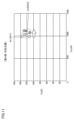
図8は、転削工具50の状態を示すグラフの第1例である。図8に示される第1例のグラフでは、縦軸は外力Fzを示し、横軸は外力Fxyを示す。図8には、プロットN11~N18が示されている。各プロットN11~N18は、図2~図6にて説明した方法にて算出する特定のタイミングにおける外力Fzと外力Fxyとを示している。
FIG. 8 is a first example of a graph showing the state of the
プロットN11~N18の各々は、モータ20によって転削工具50が回転しワークを切削する期間内において検出された値であり、プロットN11~N18の順番で検出されている。プロットN11は最も早い時間に検出された値であり、プロットN18は最も遅い時間に検出された値である。すなわち、プロットN18が検出されたタイミングは、他のプロットが検出されたタイミングと比較して、切削回数および切削時間が最も多い。そのため、プロットN18が検出されたタイミングでは、他のプロットが検出されたタイミングよりも転削工具50の摩耗が進行している。
Each of plots N11 to N18 is a value detected during a period in which the
図8のプロットN11~N18に示されるように、切削回数、切削時間が多くなると、転削工具50の摩耗が進み、外力Fzおよび外力Fxyは、共に増加傾向を示す。図7の状態St2に示されるように、摩耗が進行すれば、ワーク60と転削工具50との接触面積が増加する。接触面積が増加すると、転削工具50がワーク60との接触時間、摩擦力が増加することから外力Fzおよび外力Fxyも増加する。
As shown by plots N11 to N18 in FIG. 8, as the number of times of cutting and the cutting time increase, the wear of the
つまり、各プロットは、摩耗進行とともにグラフ上を右上方向に向かって移動する。切削面積は、刃先の状態と関係なく独立して定められる。また、刃部はワーク60と繰り返して接触するため、切削面積の大きさが刃部とワーク60との接触ごとにばらつくことがある。そのため、刃先の摩耗が進行した状態であっても切削面積の大きさによっては、外力Fzおよび外力Fxyは減少する場合がある。しかしながら、プロットN11からプロットN18までの移動の傾向を全体として把握すれば、各プロットは、グラフ上を右上方向に移動する。
That is, each plot moves upward and to the right on the graph as the wear progresses. The cutting area is determined independently regardless of the state of the cutting edge. In addition, since the blade contacts the
このことから、ユーザは、図8に示されるグラフのプロットの移動する方向および移動量に基づいて、摩耗の進行度合いを推測することができる。すなわち、状態検出システムは、転削工具50の状態を示す摩耗の進行度合いをユーザに対して視覚的に表示することができる。すなわち、本実施の形態における状態検出システム100では、プロットの移動方向の傾向および、移動量に基づいて転削工具50の摩耗の状態をユーザに認識させることができる。これにより、ユーザは、転削工具50の交換時期を容易に予測することができる。
From this, the user can estimate the progress of wear based on the direction and amount of movement of the graph plot shown in FIG. That is, the state detection system can visually display the degree of progress of wear indicating the state of the
図9は、転削工具50の状態を示すグラフの第2例である。図9に示される第2例のグラフでは、縦軸は外力Fxyを示し、横軸は負荷トルクMzを示す。図9には、プロットN21~N28が示されている。プロットN21~N28は、プロットN11~N18と同様に、プロットN21~N28の順番で検出されている。すなわち、プロットN21~N28のうち、プロットN28が検出されたタイミングが、最も摩耗が進行しているタイミングである。
FIG. 9 is a second example of a graph showing the state of the
図9のプロットN21~N28に示されるように、切削回数、切削時間が多くなると、転削工具50の摩耗が進み、外力Fxyおよび負荷トルクMzは、共に増加傾向を示す。図7の状態St2に示されるように、摩耗が進行すれば、ワークと転削工具50との接触面積が増加する。接触面積が増加すると、摩擦力が増加するため、転削工具50の回転を妨げる方向に作用する負荷トルクも増加する。したがって、図9に示されるように、摩耗が進行すれば、負荷トルクMzも増加し、図9における各プロットも、グラフ上を右上方向に移動する傾向にある。
As shown by plots N21 to N28 in FIG. 9, as the number of times of cutting and the cutting time increase, the wear of the
このように、本実施の形態における状態検出システム100では、縦軸が外力Fxyを示し、横軸が負荷トルクMzを示す図9のグラフにおいても、プロットの移動方向の傾向および、移動量に基づいて、転削工具50の摩耗の状態をユーザに認識させることができる。
As described above, in the
図10は、転削工具50の状態を示すグラフの第3例である。図10に示される第3例のグラフでは、縦軸は外力Fzを示し、横軸は負荷トルクMzを示す。図10には、プロットN31~N38が示されている。プロットN31~N38は、プロットN11~N18と同様に、プロットN31~N38の順番で検出されている。すなわち、プロットN31~N38のうち、プロットN38が検出されたタイミングが、最も摩耗が進行しているタイミングである。図10のグラフにおいても、摩耗が進行すると外力Fzおよび負荷トルクMzは増加するため、図10における各プロットもグラフ上を右上方向に移動する傾向を有する。
FIG. 10 is a third example of a graph showing the state of the
このように、本実施の形態における状態検出システム100では、縦軸が外力Fzを示し、横軸が負荷トルクMzを示す図10のグラフにおいても、プロットの移動方向の傾向および、移動量に基づいて、転削工具50の摩耗の状態をユーザに認識させることができる。
As described above, in the
また、状態検出システム100では、予め定めた正常領域ではない範囲にプロットが検出された場合、異常が発生したことを検出して、表示装置40に表示させてもよい。より具体的には、特定の転削工具の形状、特定の加工条件にて試験的な加工を行い、予め図8~図10のグラフにおいて摩耗に伴ってプロットが検出される範囲を取得する。すなわち、状態検出システム100では、正常に摩耗が進行したときのプロットの移動範囲を予め取得する。その後、新たな転削工具であって同一の形状の転削工具を用いて、同一の加工条件にて新たに加工を開始する場合、当該新たな転削工具において検出されるプロットが、予め取得した正常に摩耗が進行したときのプロットの移動範囲を越えるか否かを判定する。正常に摩耗が進行したときのプロットの移動範囲と異なる範囲にプロットが検出された場合、管理装置10は、異常が発生していると判断して、表示装置40に異常が発生している旨を表示させる。
Moreover, in the
図8~図10のグラフは、いずれも、外力Fz、外力Fxy、および負荷トルクMzのうち少なくとも2つの関係性を示している。より具体的には、図8のグラフは、外力Fzと外力Fxyとの関係性を示し、図9のグラフは、外力Fxyと負荷トルクMzとの関係性を示し、図8のグラフは、外力Fzと負荷トルクMzとの関係性を示す。図8~図10のグラフとして示される情報は、本開示における「第1情報」の一例である。 Graphs of FIGS. 8 to 10 all show the relationship of at least two of the external force Fz, the external force Fxy, and the load torque Mz. More specifically, the graph in FIG. 8 shows the relationship between the external force Fz and the external force Fxy, the graph in FIG. 9 shows the relationship between the external force Fxy and the load torque Mz, and the graph in FIG. 2 shows the relationship between Fz and load torque Mz. Information shown as graphs in FIGS. 8 to 10 is an example of “first information” in the present disclosure.
本実施の形態の状態検出システム100では、図8~図10のグラフのうち、1つのグラフだけを表示するのではなく、図8~図10のグラフのうちの2つのグラフを同時に表示させてもよい。すなわち、管理装置10は、図8のグラフと図9のグラフとを表示装置40に表示させ得る。また、管理装置10は、図9のグラフと図10のグラフとを表示装置40に表示させ得る。あるいは、管理装置10は、図8のグラフと図10のグラフとを表示装置40に表示させ得る。これによって、表示装置40には、外力Fz、外力Fxy、および負荷トルクMzの全ての情報を含むグラフが表示され、状態検出システム100では、より正確な転削工具50の状態を示す情報をユーザ対して表示することができる。このように2つのグラフが表示される場合、一方のグラフは「第1情報」の一例であり、他方のグラフは「第2情報」の一例である。なお、状態検出システム100では、図8~10の3つのグラフの全てを表示させてもよい。
In the
本実施の形態においては、外力Fz、外力Fxy、および負荷トルクMzの関係性をグラフとして表示する例について説明したが、たとえば、外力Fz、外力Fxy、および負荷トルクMzの大きさを表形式にて単に数値として表示してもよい。また、上述の例では、二次元のグラフとしてユーザに表示する例を説明したが、ある局面において状態検出システム100は、外力Fz、外力Fxy、および負荷トルクMzの3つの関係性を3次元の立体的なグラフを用いて表示してもよい。このような立体的なグラフでは、たとえば、X軸は外力Fzを示し、Y軸は外力Fxyを示し、Z軸は負荷トルクMzを示す。 In the present embodiment, an example of displaying the relationship between the external force Fz, the external force Fxy, and the load torque Mz as a graph has been described. can be simply displayed as a number. Further, in the above example, an example of displaying the graph to the user as a two-dimensional graph has been described. You may display using a three-dimensional graph. In such a three-dimensional graph, for example, the X axis indicates the external force Fz, the Y axis indicates the external force Fxy, and the Z axis indicates the load torque Mz.
<刃先欠損の実験例>
以下では、図11~図13を用いて転削工具50の刃先欠損の状態を検出する実験例を示す。図11~図13において、下記の加工条件にて行われた実験結果を示す。ワークの材質は、ステンレス鋼(SUS304)である。転削工具50は、4枚刃のエンドミルである。工具径はφ16mmである。切削速度は、80m/minである。1つの刃部あたりの送り量は、0.10mm/t(tooth)である。軸方向の切り込み量は、2mmである。径方向の切り込み量は、10mmである。<Experimental example of cutting edge fracture>
11 to 13, an experimental example for detecting the chipped cutting edge of the
図11は、転削工具50の状態を示すグラフの第4例である。図11に示される第4例のグラフでは、縦軸は外力Fzを示し、横軸は外力Fxyを示す。図11には、領域Ar1に含まれるプロット群Ns1と領域Ar2に含まれるプロット群Ns2とが示されている。プロット群Ns1は、刃先に欠損が生じていない状態で検出された値である。プロット群Ns2は、刃先に欠損が生じた状態で検出された値である。
FIG. 11 is a fourth example of a graph showing the state of the
図11のプロット群Ns1,Ns2に示されるように、刃先欠損によって、外力Fxyが増加している。つまり、プロットされる領域は、刃先が欠損したことに基づいてグラフ上を右方向に移動している。刃先欠損は、工具摩耗のように経時的に進行せず、突発的に破損が発生する。そのため、刃先欠損が生じた前後において、プロットされる領域は領域Ar1から領域Ar2へと移動する。 As indicated by the plot groups Ns1 and Ns2 in FIG. 11, the external force Fxy increases due to the chipping of the cutting edge. That is, the plotted area moves rightward on the graph based on the loss of the cutting edge. Chipping of the cutting edge does not progress over time like tool wear, and breakage occurs suddenly. Therefore, the plotted area moves from the area Ar1 to the area Ar2 before and after the chipping of the cutting edge occurs.
このように、本実施の形態における状態検出システム100では、プロットされる領域Ar1が他の領域Ar2に変化したことに基づいて、転削工具50に刃先の欠損が生じたか否かをユーザに認識させることができる。これにより、ユーザは、転削工具50を修理する必要があるか否かを判断することができる。
As described above, in the
刃先欠損の例では、刃先の欠損の位置、形状に応じて、各プロットが移動する方向が異なるため、各プロットの移動方向には傾向がない。そのため、本実施の形態の状態検出システム100では、刃先の欠損のない状態においてプロットされる領域Ar1から異なる領域にプロットされたか否かを、たとえばk近傍法を用いて判断する。すなわち、管理装置10は、新たにプロットされた値が過去のプロットと異なる範囲内にクラスタリングされる場合、刃先に破損が発生したと判断し、その旨を表示装置40に表示させる。これにより、状態検出システム100では、刃先の欠損状態を検出し、検出結果をユーザに表示させることができる。後述するように、管理装置10は、工具形状および加工条件を用いた計算、もしくは、事前に実施した試験によって得られた正常領域との比較によって、刃先の異常の有無を判断してもよい。
In the example of cutting edge chipping, the direction in which each plot moves differs depending on the position and shape of the cutting edge chipping, so there is no tendency in the moving direction of each plot. Therefore, the
図12は、転削工具50の状態を示すグラフの第5例である。図12に示される第5例のグラフでは、縦軸は外力Fxyを示し、横軸は負荷トルクMzを示す。図12には、領域Ar3に含まれるプロット群Ns3と領域Ar4に含まれるプロット群Ns4とが示されている。プロット群Ns3は、刃先に欠損が生じていない状態で検出された値である。プロット群Ns4は、刃先に欠損が生じた状態で検出された値である。
FIG. 12 is a fifth example of a graph showing the state of the
図12のプロット群Ns3,Ns4に示されるように、図12の例における欠損した刃先の位置、形状の影響によって、外力Fxyが増加し負荷トルクMzが減少する。つまり、プロットされる領域は、刃先が欠損したことに基づいてグラフ上を左上方向に移動している。このように、本実施の形態における状態検出システム100では、縦軸が外力Fxyを示し、横軸が負荷トルクMzを示す図12のグラフにおいても、プロットされる領域Ar3が他の領域Ar4に変化したことに基づいて、転削工具50に刃先の欠損が生じたか否かをユーザに認識させることができる。
As shown by plot groups Ns3 and Ns4 in FIG. 12, the external force Fxy increases and the load torque Mz decreases due to the influence of the position and shape of the chipped cutting edge in the example of FIG. That is, the plotted area moves to the upper left on the graph based on the loss of the cutting edge. Thus, in the
図13は、転削工具50の状態を示すグラフの第6例である。図13に示される第6例のグラフでは、縦軸は外力Fzを示し、横軸は負荷トルクMzを示す。図13には、領域Ar5に含まれるプロット群Ns5と領域Ar6に含まれるプロット群Ns6とが示されている。プロット群Ns5は、刃先に欠損が生じていない状態で検出された値である。プロット群Ns6は、刃先に欠損が生じた状態で検出された値である。
FIG. 13 is a sixth example of a graph showing the state of the
図13のプロット群Ns5,Ns6に示されるように、図12の例における欠損した刃先の位置、形状の影響によって、負荷トルクMzが減少する。つまり、各プロットは、刃先が欠損したことに基づいてグラフ上を左方向に移動している。このように、本実施の形態における状態検出システム100では、縦軸が外力Fzを示し、横軸が負荷トルクMzを示す図13のグラフにおいても、プロットされる領域Ar5が他の領域Ar6に変化したことに基づいて、転削工具50に刃先の欠損が生じたか否かをユーザに認識させることができる。
As shown by the plot groups Ns5 and Ns6 in FIG. 13, the load torque Mz decreases due to the influence of the position and shape of the chipped cutting edge in the example of FIG. In other words, each plot moves leftward on the graph based on the fact that the cutting edge is chipped. Thus, in the
<切削面積の影響の排除>
図14は、外力と比切削抵抗と切削面積との関係を説明するための図である。上述したように、刃部はワーク60と繰り返して接触するため、切削面積の大きさにばらつきが発生し得る。工具摩耗または刃先欠損が生じることによって比切削抵抗Kが変化しても、切削面積の大きさにばらつきが発生すれば、外力Fx,Fy,Fz,および負荷トルクMzは、見かけ上、比切削抵抗Kが変化していないように相殺されてしまう可能性がある。そこで、以下では、切削面積の影響の排除する手法について説明する。<Elimination of the effect of cutting area>
FIG. 14 is a diagram for explaining the relationship between external force, specific cutting resistance, and cutting area. As described above, since the blade repeatedly contacts the
図14には、状態St4,St5,St6の刃部6Aがそれぞれ示されている。状態St4,St5は、刃部6Aに問題が生じておらず切削を適切に行うことが可能な状態である。状態St6は、刃部6Aの刃先に摩耗が生じている状態である。
FIG. 14 shows the
状態St4,St6において、刃部6Aの切り込み深さapは距離D2である。状態St5において、刃部6Aの切り込み深さapは距離D3である。距離D3は、距離D2よりも長い。また、状態St4,St5,St6の全ての状態における送り量fzは同一の値である。
In states St4 and St6, the cutting depth ap of the
図7にて説明したように、外力Fxは、刃部の状態を示す比切削抵抗Kxと切り込み深さapと送り量fzとを乗じた値である。比切削抵抗Kxは、切り込み深さapと送り量fzにかかわらず、刃部の状態に応じて定まる。一方で、切り込み深さapと送り量fzは、刃部の状態にかかわらず、刃部とワーク60との接触状況によって変化する。
As explained with reference to FIG. 7, the external force Fx is a value obtained by multiplying the specific cutting force Kx, which indicates the state of the cutting edge, the depth of cut ap, and the feed amount fz. The specific cutting force Kx is determined according to the state of the cutting edge regardless of the depth of cut ap and the feed amount fz. On the other hand, the depth of cut ap and the feed amount fz change depending on the contact state between the blade and the
状態St4では、外力Fxは、刃部に摩耗も欠損も生じていない適切な状態を示す比切削抵抗Kxと、距離D2の深さだけ切り込むときの切り込み深さapD2と、送り量fzとに基づいて定まる。状態St5では、外力Fxは、刃部に摩耗も欠損も生じていない適切な状態を示す比切削抵抗Kxと、距離D3の深さだけ切り込むときの切り込み深さapD3と、送り量fzとに基づいて定まる。状態St6では、外力Fxは、刃部に摩耗が生じている比切削抵抗Kxfと、距離D2の深さだけ切り込むときの切り込み深さapD2と、送り量fzとに基づいて定まる。図14に示されるように、各状態における外力Fy,Fzについても、外力Fxと同様に定められる。 In the state St4, the external force Fx is based on the specific cutting resistance Kx, which indicates an appropriate state in which neither wear nor chipping occurs in the blade, the depth of cut apD2 when cutting only the depth of the distance D2, and the feed amount fz. determined by In the state St5, the external force Fx is based on the specific cutting resistance Kx, which indicates an appropriate state in which neither wear nor chipping occurs in the blade, the cutting depth apD3 when cutting by the depth of the distance D3, and the feed amount fz. determined by In the state St6, the external force Fx is determined based on the specific cutting resistance Kxf at which the cutting edge is worn, the depth of cut apD2 when cutting to the depth of the distance D2, and the feed amount fz. As shown in FIG. 14, the external forces Fy and Fz in each state are determined similarly to the external force Fx.
図14の状態St4の下部に示されるように、状態St4において外力Fzに対する外力Fxの割合は、比切削抵抗Kzに対する比切削抵抗Kxの割合となる。すなわち、外力Fzおよび外力Fxの各々に切り込み深さapD2と送り量fzが含まれているため、外力Fzに対して外力Fxを除算したとき、切り込み深さapD2と送り量fzとの影響が取り除かれる。したがって、外力Fzに対する外力Fxの割合は、切り込み深さapD2と送り量fzの影響が排除されて、比切削抵抗Kzに対する比切削抵抗Kxの割合となる。状態St4において、外力Fzに対する外力Fyの割合も、同様に切り込み深さapD2と送り量fzとの影響が取り除かれ、比切削抵抗Kzに対する比切削抵抗Kyの割合となる。 As shown in the lower part of state St4 in FIG. 14, the ratio of external force Fx to external force Fz in state St4 is the ratio of specific cutting resistance Kx to specific cutting resistance Kz. That is, since the depth of cut apD2 and the feed amount fz are included in each of the external force Fz and the external force Fx, when the external force Fx is divided by the external force Fz, the effects of the depth of cut apD2 and the feed amount fz are removed. be Therefore, the ratio of the external force Fx to the external force Fz becomes the ratio of the specific cutting force Kx to the specific cutting force Kz after eliminating the effects of the cutting depth apD2 and the feed amount fz. In the state St4, the ratio of the external force Fy to the external force Fz also becomes the ratio of the specific cutting force Ky to the specific cutting force Kz after removing the effects of the cutting depth apD2 and the feed amount fz.
図14の状態St5の下部に示されるように、状態St5における外力Fzに対する外力Fxの割合も、状態St4と同様に、比切削抵抗Kzに対する比切削抵抗Kxの割合となる。すなわち、除算によって切り込み深さapD3と送り量fzとの影響が取り除かれる。そのため、状態St5における外力Fzに対する外力Fxの割合と、状態St4における外力Fzに対する外力Fyの割合は同じ値となる。 As shown in the lower part of state St5 in FIG. 14, the ratio of external force Fx to external force Fz in state St5 is also the ratio of specific cutting force Kx to specific cutting force Kz, as in state St4. That is, the division removes the influence of the cutting depth apD3 and the feed amount fz. Therefore, the ratio of the external force Fx to the external force Fz in the state St5 is the same as the ratio of the external force Fy to the external force Fz in the state St4.
一方で、図14の状態St6の下部に示されるように、状態St6において外力Fzに対する外力Fxの割合は、比切削抵抗Kzfに対する比切削抵抗Kxfの割合となる。除算によって切り込み深さapD2と送り量fzとの影響が取り除かれるが、刃部の摩耗によって比切削抵抗Kxf,Kzfが状態St4,St5の比切削抵抗Kx,Kzと異なる。そのため、状態St6における外力Fzに対する外力Fxの割合と、状態St4,St5の外力Fzに対する外力Fyの割合と異なる値になる。 On the other hand, as shown in the lower part of state St6 in FIG. 14, the ratio of external force Fx to external force Fz in state St6 is the ratio of specific cutting force Kxf to specific cutting force Kzf. Although the influence of the depth of cut apD2 and the feed amount fz is removed by division, the specific cutting forces Kxf and Kzf differ from the specific cutting forces Kx and Kz in states St4 and St5 due to wear of the blade. Therefore, the ratio of the external force Fx to the external force Fz in the state St6 differs from the ratio of the external force Fy to the external force Fz in the states St4 and St5.
このように、本実施の形態における状態検出システム100では、外力Fx,Fy,Fzを互いに除算した値を用いることによって、切削面積の影響を排除し、比切削抵抗Kだけの変化に着目可能となる。たとえば、管理装置10は、縦軸は外力Fzに対する外力Fxの割合を示し、横軸は外力Fzに対する外力Fyの割合を示すグラフを表示することによって、切削面積の影響を排除した転削工具50の状態をユーザに表示することができる。なお、切削面積の影響が排除されていれば、外力Fx,Fy,Fzを除算する組合せは他の組合せであってもよい。
As described above, in the
<負荷トルクを用いる切削面積の排除>
図15は、負荷トルクと切削面積との関係を説明するための図である。負荷トルクMzは、回転を妨げる力であり、転削工具50の接線方向に発生する外力Ftに対して転削工具50の半径R1を乗じた値である。上述したように、図6においては、刃部6Aにおける接線方向から延伸する矢印を負荷トルクMzAとして説明したが、実際には図15に示されるように外力FxyAの接線方向における分力である外力Ftに対して、転削工具50の半径R1を乗じた値である。<Exclusion of cutting area using load torque>
FIG. 15 is a diagram for explaining the relationship between load torque and cutting area. The load torque Mz is a force that prevents rotation, and is a value obtained by multiplying the external force Ft generated in the tangential direction of the
外力Ftは、外力Fx,Fy,Fzと同様に、比切削抵抗Ktと切り込み深さapと送り量fzとを乗じた値である。すなわち、負荷トルクMzには、切り込み深さapと送り量fzとが含まれている。そのため、外力Fx,Fy,Fzのいずれかに対して、負荷トルクMzを除算することによって、切削面積の影響を排除することができる。 The external force Ft is a value obtained by multiplying the specific cutting resistance Kt, the cutting depth ap, and the feed amount fz, similarly to the external forces Fx, Fy, and Fz. That is, the load torque Mz includes the cutting depth ap and the feed amount fz. Therefore, by dividing the load torque Mz by any of the external forces Fx, Fy, and Fz, the influence of the cutting area can be eliminated.
図16は、転削工具50の状態を示すグラフの第7例である。図16に示される第7例のグラフでは、縦軸は負荷トルクMzに対する外力Fzの割合を示し、横軸は負荷トルクMzに対する外力Fxyの割合を示す。図16には、プロットN41~N48が示されている。プロットN41~N48は、プロットN11~N18と同様に、プロットN41~N48の順番で検出されている。すなわち、プロットN41~N48のうち、プロットN48が検出されたタイミングが、最も摩耗が進行しているタイミングである。
FIG. 16 is a seventh example of a graph showing the state of the
図16に示されるグラフでは、上述にて説明したように、縦軸、横軸に示される値から切削面積の影響が排除されている。これにより、図16のグラフは、比切削抵抗Kの変化をより正確に表すことができる。 In the graph shown in FIG. 16, as described above, the influence of the cutting area is eliminated from the values shown on the vertical and horizontal axes. As a result, the graph in FIG. 16 can more accurately represent changes in the specific cutting force K. FIG.
図16に示される例では、摩耗が進行すれば、負荷トルクMzに対する外力Fxyの割合が小さくなる。すなわち、摩耗が進行することによる負荷トルクMzの増加率は、外力Fxyの増加率よりも大きい。また、摩耗が進行すれば、負荷トルクMzに対する外力Fxyの割合が大きくなる。摩耗が進行することによる負荷トルクMzの増加率は、外力Fxyの増加率よりも小さい。このため、図16に示されるように、各プロットは、グラフ上を右下方向に移動する傾向にある。 In the example shown in FIG. 16, as the wear progresses, the ratio of the external force Fxy to the load torque Mz decreases. That is, the rate of increase of the load torque Mz due to progress of wear is greater than the rate of increase of the external force Fxy. Further, as the wear progresses, the ratio of the external force Fxy to the load torque Mz increases. The increase rate of the load torque Mz due to progress of wear is smaller than the increase rate of the external force Fxy. Therefore, as shown in FIG. 16, each plot tends to move downward and to the right on the graph.
図17は、転削工具50の状態を示すグラフの第8例である。図17に示される第8例のグラフでは、縦軸は負荷トルクMzに対する外力Fzの割合を示し、横軸は負荷トルクMzに対する外力Fxyの割合を示す。図17には、領域Ar7に含まれるプロット群Ns7と領域Ar8に含まれるプロット群Ns8とが示されている。プロット群Ns7は、刃先に欠損が生じていない状態で検出された値である。プロット群Ns8は、刃先に欠損が生じた状態で検出された値である。
FIG. 17 is an eighth example of a graph showing the state of the
図17のプロット群Ns7,Ns8に示されるように、刃先欠損が生じたことによって、負荷トルクMzに対する外力Fxyの割合は増加する。つまり、プロットされる領域は、刃先が欠損したことに基づいてグラフ上を右方向に移動している。このように、本実施の形態における状態検出システム100では、縦軸が負荷トルクMzに対する外力Fzの割合を示し、横軸が負荷トルクMzに対する外力Fxyの割合を示す図17のグラフにおいても、プロットされる領域Ar7が他の領域Ar8に変化したことに基づいて、転削工具50に刃先の欠損が生じたか否かをユーザに認識させることができる。
As indicated by plot groups Ns7 and Ns8 in FIG. 17, the ratio of the external force Fxy to the load torque Mz increases due to the chipping of the cutting edge. That is, the plotted area moves rightward on the graph based on the loss of the cutting edge. Thus, in the
このように、図16,17において、本実施の形態における状態検出システム100では、縦軸が負荷トルクMzに対する外力Fzを示し、横軸が負荷トルクMzに対する外力Fxyを示す図16,17のグラフにおいても、転削工具50の摩耗の状態および刃先の欠損をユーザに認識させることができる。
16 and 17, in the
また、図6にて説明したように、負荷トルクMzは、回転する転削工具50の刃部がワーク60と接触する限り、常に「0」よりも大きい値となる。一方で、外力Fx,Fy,Fzの各々は、各刃部に発生する外力同士が打ち消し合い、見かけ上「0」になることがある。図16,17に示される例では、縦軸、横軸が示す値の分母は、負荷トルクである。そのため、縦軸、横軸が示す値は「0」で除算されることがなく、縦軸、横軸が示す値が「0」で除算されるため検出できないといった状況が発生することがない。
Further, as described with reference to FIG. 6, the load torque Mz is always greater than "0" as long as the cutting edge of the
なお、歪センサN1~N3,S4は、本開示における「第1歪センサ~第4歪センサ」のそれぞれの一例である。 The strain sensors N1 to N3 and S4 are examples of the "first strain sensor to fourth strain sensor" in the present disclosure.
図18は、本実施形態の処理手順を示すフローチャートである。図18では、図8~図13、図16、17のいずれかのグラフを表示するための処理手順が示されている。図18に示される処理手順は、管理装置10のCPU220によって記憶装置230のプログラムが実行されることによって実現される。
FIG. 18 is a flow chart showing the processing procedure of this embodiment. FIG. 18 shows a processing procedure for displaying one of the graphs of FIGS. The processing procedure shown in FIG. 18 is realized by executing the program in the
管理装置10は、外力Fzを取得する(ステップS100)。続いて、管理装置10は、外力Fxyを取得する(ステップS110)。さらに、管理装置10は、負荷トルクMzを取得する(ステップS120)。より具体的には、ステップS100~ステップS120では管理装置10は、図3,4にて説明したように歪センサN1~N3,S4の検出値を用いて、外力Fz、外力Fxy、および負荷トルクMzを算出する。
The
その後、管理装置10は、外力Fz、外力Fxy、および負荷トルクMzのうちの少なくとも2つにも基づいて作成したグラフを表示する(ステップS130)。すなわち、管理装置は、図8~図13、図16、17のいずれかのグラフを表示する。
Thereafter,
[事前に実施した試験による正常領域の作成方法]
本実施の形態の状態検出システム100において、刃先の欠損のない状態においてプロットされる領域Ar1から異なる領域にプロットされたか否かをk近傍法を用いて判断する構成を説明した。しかしながら、異常が発生したか否かを判定する方法は、k近傍法を用いた方法に限られない。以下では、グラフ上に正常領域を作成する方法について説明する。[Method of creating a normal region by a test conducted in advance]
In the
図19は、正常領域を作成するための試験の測定結果を示す図である。図19には、外力Fz,外力Fxy,および負荷トルクMzの時系列データが示されている。より具体的には、図19には、0~17.5秒までの期間における外力Fz,外力Fxy,および負荷トルクMzの値が示されている。 FIG. 19 shows the measurement results of a test to create a normal region. FIG. 19 shows time-series data of external force Fz, external force Fxy, and load torque Mz. More specifically, FIG. 19 shows values of the external force Fz, the external force Fxy, and the load torque Mz during the period from 0 to 17.5 seconds.
図19では、下記の加工条件にて行われた試験の測定結果が示されている。転削工具50の回転数は、2300回/minである。送り速度は、500mm/minである。半径方向の切り込み量は、10mmである。すなわち、刃部6A~6Cの各々は、0mmから10mmまで徐々に切り込み量を増加させるようにワークを切削する。
FIG. 19 shows the measurement results of tests performed under the following processing conditions. The rotation speed of the
図19に示されるように、外力Fz,外力Fxy,および負荷トルクMzの各々は、時間の経過に伴って変動している。期間Dr1は、切込量が0mm~1mmの期間である。期間Dr2は、切込量が4mm~5mmの期間である。期間Dr3は、切込量が9mm~10mmの期間である。 As shown in FIG. 19, each of external force Fz, external force Fxy, and load torque Mz fluctuates over time. The period Dr1 is a period in which the depth of cut is 0 mm to 1 mm. The period Dr2 is a period in which the depth of cut is 4 mm to 5 mm. The period Dr3 is a period in which the depth of cut is 9 mm to 10 mm.
図20は、図19の測定結果に基づいてグラフを表示した図である。図20には、縦軸が外力Fzであり横軸が負荷トルクMzであるグラフ、縦軸が外力Fxyであり横軸が負荷トルクMzであるグラフ、縦軸が外力Fzであり横軸が外力Fxyであるグラフ、および縦軸が負荷トルクMzに対する外力Fzの割合であり横軸が負荷トルクMzに対する外力Fxyの割合であるグラフの4つのグラフが示されている。 FIG. 20 is a diagram displaying a graph based on the measurement results of FIG. FIG. 20 shows a graph in which the vertical axis is the external force Fz and the horizontal axis is the load torque Mz, a graph in which the vertical axis is the external force Fxy and the horizontal axis is the load torque Mz, and a graph in which the vertical axis is the external force Fz and the horizontal axis is the external force. Four graphs are shown: a graph Fxy, and a graph in which the vertical axis is the ratio of the external force Fz to the load torque Mz and the horizontal axis is the ratio of the external force Fxy to the load torque Mz.
各グラフには、プロットP1、プロットP2、プロットP3の三種類のプロットが表示されている。図20の左上部に示されるように、プロットP1は、図19における期間Dr1におけるプロットである。プロットP2は、図19における期間Dr2におけるプロットである。プロットP3は、図19における期間Dr3におけるプロットである。すなわち、図20では、図19にて示されている外力Fz、外力Fxy、および負荷トルクMzの値が期間ごとにグラフとして表示されている。 Each graph displays three types of plots: plot P1, plot P2, and plot P3. As shown in the upper left part of FIG. 20, plot P1 is plotted during period Dr1 in FIG. A plot P2 is a plot during the period Dr2 in FIG. Plot P3 is a plot in period Dr3 in FIG. That is, in FIG. 20, the values of the external force Fz, the external force Fxy, and the load torque Mz shown in FIG. 19 are displayed as graphs for each period.
図20の例では、図19に示されている外力Fz、外力Fxy、および負荷トルクMzの実測値をプロットとして表示しているのではなく、図19に示されている外力Fz、外力Fxy、および負荷トルクMzの移動平均をプロットとして表示している。これにより、図20に示されるように各プロットは同一の期間内においてグラフ上で所定の範囲内に固まって配置される。また、上述したように、図19では、徐々に切り込み量が増加するような加工条件で試験が行われているため、期間Dr1と、期間Dr2と、期間Dr3とでは、異なる加工条件による試験が行われているといえる。 In the example of FIG. 20, the measured values of the external force Fz, the external force Fxy, and the load torque Mz shown in FIG. 19 are not plotted, but the external force Fz, the external force Fxy, and the moving average of the load torque Mz are plotted. Thereby, as shown in FIG. 20, each plot is clustered within a predetermined range on the graph within the same period. In addition, as described above, in FIG. 19, the test is performed under the machining conditions that gradually increase the depth of cut. Therefore, the test is performed under different machining conditions in the period Dr1, the period Dr2, and the period Dr3. It can be said that it is being done.
図21は、期間Dr2における正常領域を設定する例を示す図である。図21には、図20にて示した4つのグラフと同様のグラフが表示されている。図21には、4つのグラフに重畳する正常領域Cr1,Cr2,Cr3,Cr4がそれぞれ示されている。正常領域Cr1~Cr4は、期間Dr2におけるプロットP2を基準として定められている。正常領域Cr1~Cr4は、たとえば、期間Dr2における全てのプロットP2が包括される領域であって、プロットP2の集合の平均値を中心とする楕円または円形状で示される領域である。正常領域Cr1~Cr4は、管理装置10によって定められる。なお、管理装置10は、プロットP2の集合の平均値を用いずにプロットP2の集合の全てが含まれる最小限の領域を正常領域Cr1~Cr4として定めてもよい。
FIG. 21 is a diagram showing an example of setting a normal region in period Dr2. FIG. 21 shows graphs similar to the four graphs shown in FIG. FIG. 21 shows normal regions Cr1, Cr2, Cr3, and Cr4 superimposed on four graphs, respectively. The normal regions Cr1 to Cr4 are defined with reference to the plot P2 in the period Dr2. The normal regions Cr1 to Cr4 are, for example, regions in which all the plots P2 in the period Dr2 are included, and are regions indicated by ellipses or circles centering on the average value of the set of plots P2. The normal regions Cr1 to Cr4 are defined by the
このように、状態検出システム100は、図19,20にて行われた試験的な加工を行うことによってプロットされるべき領域である正常領域Cr1~Cr4を取得する。その後、期間Dr2に対応する加工条件での加工が行われる場合、新たに検出されるプロットが正常領域Cr1~Cr4内に位置していない場合、異常が発生していると判定できる。すなわち、管理装置10は、正常領域Cr1~Cr4内ではない領域にプロットが検出された場合、異常が発生した旨を表示装置40に表示させることができる。また、管理装置10は、図22に示される4つのグラフと正常領域Cr1~Cr4とを表示装置40にリアルタイムで表示させてもよい。これにより、ユーザは、各プロットが正常領域Cr1~Cr4の範囲内に位置しているかをリアルタイムで視覚的に把握することができる。
Thus, the
図22は、期間Dr2,Dr3における正常領域を設定する例を示す図である。図22には、正常領域Cr5,Cr6,Cr7,Cr8が示されている。正常領域Cr5~Cr8は、期間Dr2におけるプロットP2および期間Dr3におけるプロットP3を基準として定められている。正常領域Cr5~Cr8は、たとえば、全てのプロットP2,P3が包括される領域であって、プロットP2,P3の集合の平均値を中心とする矩形形状の領域である。 FIG. 22 is a diagram showing an example of setting normal regions in periods Dr2 and Dr3. FIG. 22 shows normal regions Cr5, Cr6, Cr7, and Cr8. The normal regions Cr5 to Cr8 are determined with reference to the plot P2 in the period Dr2 and the plot P3 in the period Dr3. The normal regions Cr5 to Cr8 are, for example, regions in which all the plots P2 and P3 are included, and are rectangular regions centered on the average value of the set of the plots P2 and P3.
このように、状態検出システム100は、図19,20にて行われた試験的な加工によって正常領域Cr5~Cr8を取得する。その後、期間Dr2,Dr3に対応する加工条件での加工が行われる場合、新たに検出されるプロットが正常領域Cr5~Cr8内に位置しているかによって異常が発生しているか否かを判定できる。図21,図22に示されるように状態検出システム100では、加工条件ごとに応じた正常領域を作成することができる。
Thus, the
なお、図20の例では、図19における実測値を用いずに移動平均の値を用いる例を説明したが、ある局面における状態検出システム100では、実測値を用いてもよいし、単位時間あたりの平均値、最大値、標準偏差などを用いてもよい。当該単位時間は、転削工具50の回転数に基づいて定められ得る。また、本実施の形態において外力Fx,Fy,Fxyを用いた転削工具の状態検出について説明したが、ある局面における状態検出システム100では、外力Fx,Fy,Fxyの各々に代えて、各軸方向に発生するトルクMx,My,Mxyを用いてもよい。
In the example of FIG. 20, an example of using the moving average value without using the measured value in FIG. 19 has been described. You may use the average value, maximum value, standard deviation, etc. of . The unit time can be determined based on the rotation speed of the
(変形例)
本実施の形態の転削工具50においては、工具ホルダ30を用いてシャフト部106が保持される構成であった。しかしながら、変形例の転削工具50では、本実施の形態の転削工具50のような工具ホルダを用いず、シャフト部106が工作機械70の主軸に直接取り付けられてもよい。この場合、シャフト部106は、ハウジングを備える。(Modification)
In the
歪センサN1~N3,S4は、シャフト部106に設けられたハウジングの内部に格納される。歪センサN1~N3,S4は、本実施の形態の転削工具50と同様に、シャフト部106の周方向に等間隔に配置されている。このように、工具ホルダを用いずに主軸に直接取り付けられる転削工具50においても、シャフト部106のハウジング内に歪センサN1~N3,S4を配置することによって、管理装置10は、転削工具50に発生する外力、負荷トルクを取得できる。
The strain sensors N1 to N3, S4 are housed inside a housing provided on the
また、本実施の形態において管理装置10は、工作機械70と別体である構成について説明した。しかしながら、管理装置10は、工作機械70に含まれてもよい。換言すれば、管理装置10と工作機械70とは一体的に構成されてもよい。
Moreover, in the present embodiment, the configuration in which the
今回開示された実施の形態は、すべての点で例示であって制限的なものではないと考えられるべきである。本開示の範囲は、上記した実施の形態の説明ではなくて請求の範囲によって示され、請求の範囲と均等の意味および範囲内でのすべての変更が含まれることが意図される。 The embodiments disclosed this time should be considered as examples and not restrictive in all respects. The scope of the present disclosure is indicated by the scope of the claims rather than the above-described description of the embodiments, and is intended to include all modifications within the meaning and scope equivalent to the scope of the claims.
6A~6C 刃部、10 管理装置、20 モータ、30 工具ホルダ、40 表示装置、50 転削工具、60 ワーク、70 工作機械、100 状態検出システム、Ag1~Ag3 配置、Ar1~Ar8 領域、Cx 圧縮応力、D1~D3 距離、Dv1~Dv3 検出値、Ft,Fx,Fxy,FxyA~FxyC,Fy,Fz 外力、K,Kt,Kx,Kxf,Ky,Kz,Kzf 比切削抵抗、Mz,MzA~MzC 負荷トルク、N1~N3,S4 歪センサ、N11~N18,N21~N28,N31~N38,N41~N48,P1~P3 プロット、Ns1~Ns8 プロット群、R1 半径、Rd 回転方向、St1~St6 状態、Tx,Ty,Tz 応力、ap,apD2,apD3 切り込み深さ、Cr1~Cr8 正常領域。 6A to 6C blade part, 10 management device, 20 motor, 30 tool holder, 40 display device, 50 milling tool, 60 workpiece, 70 machine tool, 100 state detection system, Ag1 to Ag3 arrangement, Ar1 to Ar8 area, Cx compression Stress, D1 to D3 Distance, Dv1 to Dv3 Detected value, Ft, Fx, Fxy, FxyA to FxyC, Fy, Fz External force, K, Kt, Kx, Kxf, Ky, Kz, Kzf Specific cutting force, Mz, MzA to MzC Load torque, N1 to N3, S4 strain sensor, N11 to N18, N21 to N28, N31 to N38, N41 to N48, P1 to P3 plot, Ns1 to Ns8 plot group, R1 radius, Rd rotation direction, St1 to St6 state, Tx, Ty, Tz stress, ap, apD2, apD3 depth of cut, Cr1 to Cr8 normal region.
Claims (7)
被切削物を切削するための刃部が設けられた第1端部と、工作機械に取り付けられる第2端部とを有するシャフト部を含み、前記シャフト部の回転軸を中心に回転可能な転削工具と、
前記シャフト部に取り付けられ、前記転削工具に作用する外力を検出する複数のセンサと、
表示装置と、
管理装置とを備え、
前記複数のセンサは、前記転削工具に対して、
前記回転軸に沿った第1方向に作用する第1力と、
前記回転軸を法線とする平面に沿った方向に作用する第2力と、
前記転削工具の回転を妨げる方向に作用する負荷トルクとを検出し、
前記管理装置は、前記第1力、前記第2力、および前記負荷トルクのうち少なくとも2つに基づく第1情報を前記表示装置に表示させる、状態検出システム。 A state detection system for a milling tool used for milling,
A roller rotatable about an axis of rotation of the shaft, including a shaft portion having a first end provided with a blade portion for cutting an object to be cut and a second end portion attached to a machine tool. a cutting tool;
a plurality of sensors attached to the shaft portion for detecting an external force acting on the milling tool;
a display device;
a management device,
The plurality of sensors, with respect to the milling tool,
a first force acting in a first direction along the axis of rotation;
a second force acting in a direction along a plane normal to the rotation axis;
detecting a load torque acting in a direction that hinders rotation of the milling tool;
The condition detection system, wherein the management device causes the display device to display first information based on at least two of the first force, the second force, and the load torque.
前記第2情報は、前記第1情報と異なる情報である、請求項1または請求項2に記載の状態検出システム。 The management device causes the display device to display second information based on at least two of the first force, the second force, and the load torque in addition to the first information,
3. The state detection system according to claim 1, wherein said second information is information different from said first information.
前記第1方向の歪みを検出し、前記シャフト部に取り付けられる第1歪センサ、第2歪センサ、および第3歪センサと、
前記シャフト部の周方向の歪みを検出し、前記シャフト部に取り付けられる第4歪センサとを含む、請求項1または請求項2に記載の状態検出システム。 The plurality of sensors are
a first strain sensor, a second strain sensor, and a third strain sensor that detect strain in the first direction and are attached to the shaft;
3. The condition detection system according to claim 1, further comprising a fourth strain sensor attached to said shaft portion for detecting circumferential strain of said shaft portion.
前記転削工具は、被切削物を切削するための刃部が設けられた第1端部と工作機械に取り付けられる第2端部とを有するシャフト部を含み、前記シャフト部の回転軸を中心に回転可能であり、
前記シャフト部には、前記転削工具に作用する外力を検出する複数のセンサが取り付けられ、
前記方法は、
前記複数のセンサの検出値を用いて、前記回転軸に沿った第1方向に作用する第1力を取得するステップと、
前記複数のセンサの検出値を用いて、前記回転軸を法線とする平面に沿った方向に作用する第2力を取得するステップと、
前記複数のセンサの検出値を用いて、前記転削工具の回転を妨げる方向に作用する負荷トルクを取得するステップと、
前記第1力、前記第2力、および前記負荷トルクのうち少なくとも2つに基づく第1情報を表示するステップとを含む、方法。 A method for detecting the state of a milling tool used for milling, comprising:
The milling tool includes a shaft portion having a first end provided with a blade portion for cutting an object to be cut and a second end portion attached to a machine tool, and is centered about the rotation axis of the shaft portion. is rotatable to
A plurality of sensors for detecting an external force acting on the milling tool are attached to the shaft portion,
The method includes:
obtaining a first force acting in a first direction along the rotation axis using the detection values of the plurality of sensors;
obtaining a second force acting in a direction along a plane normal to the rotation axis using the detection values of the plurality of sensors;
obtaining a load torque acting in a direction that hinders rotation of the milling tool using the detection values of the plurality of sensors;
and displaying first information based on at least two of said first force, said second force, and said load torque.
前記転削工具は、被切削物を切削するための刃部が設けられた第1端部と工作機械に取り付けられる第2端部とを有するシャフト部を含み、前記シャフト部の回転軸を中心に回転可能であり、
前記シャフト部には、前記転削工具に作用する外力を検出する複数のセンサが取り付けられ、
コンピュータに、
前記複数のセンサの検出値を用いて、前記回転軸に沿った第1方向に作用する第1力を取得するステップと、
前記回転軸を法線とする平面に沿った方向に作用する第2力を取得するステップと、
前記転削工具の回転を妨げる方向に作用する負荷トルクを取得するステップと、
前記第1力、前記第2力、および前記負荷トルクのうち少なくとも2つに基づく第1情報を表示するステップとを実行させる、プログラム。 A program for detecting the state of a milling tool used for milling,
The milling tool includes a shaft portion having a first end provided with a blade portion for cutting an object to be cut and a second end portion attached to a machine tool, and is centered about the rotation axis of the shaft portion. is rotatable to
A plurality of sensors for detecting an external force acting on the milling tool are attached to the shaft portion,
to the computer,
obtaining a first force acting in a first direction along the rotation axis using the detection values of the plurality of sensors;
obtaining a second force acting in a direction along a plane normal to the axis of rotation;
a step of acquiring a load torque acting in a direction that hinders rotation of the milling tool;
and displaying first information based on at least two of said first force, said second force and said load torque.
Applications Claiming Priority (1)
| Application Number | Priority Date | Filing Date | Title |
|---|---|---|---|
| PCT/JP2022/033385 WO2024052978A1 (en) | 2022-09-06 | 2022-09-06 | State detection system, method, and program |
Publications (1)
| Publication Number | Publication Date |
|---|---|
| JP7243945B1 true JP7243945B1 (en) | 2023-03-22 |
Family
ID=85685007
Family Applications (1)
| Application Number | Title | Priority Date | Filing Date |
|---|---|---|---|
| JP2022575362A Active JP7243945B1 (en) | 2022-09-06 | 2022-09-06 | Condition detection system, method and program |
Country Status (2)
| Country | Link |
|---|---|
| JP (1) | JP7243945B1 (en) |
| WO (1) | WO2024052978A1 (en) |
Citations (5)
| Publication number | Priority date | Publication date | Assignee | Title |
|---|---|---|---|---|
| JPH096432A (en) * | 1995-06-14 | 1997-01-10 | Mitsubishi Electric Corp | Abnormality detector for control system |
| JP2020203356A (en) * | 2019-06-18 | 2020-12-24 | 株式会社ジェイテクト | Abnormality detection device of machining tool |
| JP2021137962A (en) * | 2019-08-09 | 2021-09-16 | 住友電気工業株式会社 | Rotary cutting tool, module, cutting system, processing method, and processing program |
| JP6973689B1 (en) * | 2020-04-13 | 2021-12-01 | 住友電気工業株式会社 | Cutting system, display system, processing equipment, processing method and processing program |
| JP7047979B1 (en) * | 2020-08-07 | 2022-04-05 | 住友電気工業株式会社 | Cutting system, display system, processing equipment, processing method and processing program |
-
2022
- 2022-09-06 WO PCT/JP2022/033385 patent/WO2024052978A1/en unknown
- 2022-09-06 JP JP2022575362A patent/JP7243945B1/en active Active
Patent Citations (5)
| Publication number | Priority date | Publication date | Assignee | Title |
|---|---|---|---|---|
| JPH096432A (en) * | 1995-06-14 | 1997-01-10 | Mitsubishi Electric Corp | Abnormality detector for control system |
| JP2020203356A (en) * | 2019-06-18 | 2020-12-24 | 株式会社ジェイテクト | Abnormality detection device of machining tool |
| JP2021137962A (en) * | 2019-08-09 | 2021-09-16 | 住友電気工業株式会社 | Rotary cutting tool, module, cutting system, processing method, and processing program |
| JP6973689B1 (en) * | 2020-04-13 | 2021-12-01 | 住友電気工業株式会社 | Cutting system, display system, processing equipment, processing method and processing program |
| JP7047979B1 (en) * | 2020-08-07 | 2022-04-05 | 住友電気工業株式会社 | Cutting system, display system, processing equipment, processing method and processing program |
Also Published As
| Publication number | Publication date |
|---|---|
| WO2024052978A1 (en) | 2024-03-14 |
Similar Documents
| Publication | Publication Date | Title |
|---|---|---|
| Ozturk et al. | Investigation of spindle bearing preload on dynamics and stability limit in milling | |
| WO2013150905A1 (en) | Machining system and method | |
| JP4742194B2 (en) | Rotational speed calculation device for machining equipment | |
| EP2821870B1 (en) | Setting method of revolutions per minute on real time of rotating cutting tool, and control device | |
| JP7032244B2 (en) | Cutting system and information processing equipment | |
| JP5411055B2 (en) | Tool life detection method and tool life detection device | |
| JP6722052B2 (en) | Multi-blade tool abnormality detection method | |
| Özşahin et al. | Identification of bearing dynamics under operational conditions for chatter stability prediction in high speed machining operations | |
| JP7468464B2 (en) | Mounting Module | |
| Colpani et al. | Tool wear analysis in micromilling of titanium alloy | |
| Rizal et al. | Design and construction of a strain gauge-based dynamometer for a 3-axis cutting force measurement in turning process | |
| JP5089618B2 (en) | Tool life detection method and tool life detection device | |
| JP7243945B1 (en) | Condition detection system, method and program | |
| Kasim et al. | Cutting tool wear progression index via signal element variance | |
| Jensen et al. | Stability Analysis in Face Milling Operations: Part 2—Experimental Validation and Influencing Factors | |
| Gao et al. | Meso-scale tool breakage prediction based on finite element stress analysis for shoulder milling of hardened steel | |
| WO2021049337A1 (en) | Cutting tool, cutting system, processing method, and processing program | |
| Galanis et al. | Manufacturing of femoral heads from Ti-6Al-4V alloy with high speed machining: 3D finite element modelling and experimental validation | |
| Henderson | Updated force model for milling nickel-based superalloys | |
| WO2024052979A1 (en) | Cutting system and method for determining status of rotating tool | |
| Fata et al. | The effect of the tool geometry and cutting conditions on the tool deflection and cutting forces | |
| WO2021044989A1 (en) | Cutting tool, module, cutting tool unit, and cutting system | |
| Stavropoulos et al. | On the design of a monitoring system for desktop micro-milling machines | |
| Jayaswal et al. | An investigation of tool condition monitoring | |
| JP7313001B2 (en) | Tool life detection device and tool life detection method |
Legal Events
| Date | Code | Title | Description |
|---|---|---|---|
| A521 | Request for written amendment filed |
Free format text: JAPANESE INTERMEDIATE CODE: A523 Effective date: 20221207 |
|
| A621 | Written request for application examination |
Free format text: JAPANESE INTERMEDIATE CODE: A621 Effective date: 20221207 |
|
| A871 | Explanation of circumstances concerning accelerated examination |
Free format text: JAPANESE INTERMEDIATE CODE: A871 Effective date: 20221207 |
|
| TRDD | Decision of grant or rejection written | ||
| A01 | Written decision to grant a patent or to grant a registration (utility model) |
Free format text: JAPANESE INTERMEDIATE CODE: A01 Effective date: 20230207 |
|
| A61 | First payment of annual fees (during grant procedure) |
Free format text: JAPANESE INTERMEDIATE CODE: A61 Effective date: 20230220 |
|
| R150 | Certificate of patent or registration of utility model |
Ref document number: 7243945 Country of ref document: JP Free format text: JAPANESE INTERMEDIATE CODE: R150 |