JP5089618B2 - Tool life detection method and tool life detection device - Google Patents
Tool life detection method and tool life detection device Download PDFInfo
- Publication number
- JP5089618B2 JP5089618B2 JP2009005041A JP2009005041A JP5089618B2 JP 5089618 B2 JP5089618 B2 JP 5089618B2 JP 2009005041 A JP2009005041 A JP 2009005041A JP 2009005041 A JP2009005041 A JP 2009005041A JP 5089618 B2 JP5089618 B2 JP 5089618B2
- Authority
- JP
- Japan
- Prior art keywords
- value
- tool
- life
- stage
- load value
- Prior art date
- Legal status (The legal status is an assumption and is not a legal conclusion. Google has not performed a legal analysis and makes no representation as to the accuracy of the status listed.)
- Expired - Fee Related
Links
Images


Landscapes
- Machine Tool Sensing Apparatuses (AREA)
Description
本発明は、機械加工に使用する工具の寿命を検出するための工具寿命検出方法及び工具寿命検出装置に関する。 The present invention relates to a tool life detection method and a tool life detection device for detecting the life of a tool used for machining.
切削加工において使用される工具は、その個体差により折損までの寿命バラツキが大きい。このため、平均的な寿命を目安として一定の加工数で交換するという従来の寿命管理方法では、平均的な寿命に比して短い工具であった場合は、加工性能の低下により製品不良が発生する場合があった。また、平均的な寿命に比して長い工具であった場合は、寿命到達前に交換してしまうことによるロスコストが問題となる。また、部品加工数1個ずつについて工具の摩耗や欠損の状態観察を行い寿命判定する方法は、生産性の低下につながるため実用的ではない。 Tools used in cutting work have a large variation in life until breakage due to individual differences. For this reason, with the conventional life management method in which replacement is performed with a fixed number of operations using the average life as a guideline, if the tool is shorter than the average life, product defects will occur due to a reduction in processing performance. There was a case. In addition, when the tool is longer than the average life, loss cost due to replacement before reaching the end of the life becomes a problem. In addition, the method of determining the life by observing the state of tool wear or chipping for each part processed is not practical because it leads to a decrease in productivity.
これに対し、工具の摩耗や欠損などを直接観察することなく、工具の寿命を検出する従来の工具寿命検出方法として、主軸モータの電力、動力、トルク、電流値などをリアルタイムで測定し、基準値と比較することで工具寿命を判定する方法がある。例えば特許文献1では、1部品の加工に係る主軸モータの最大消費電力もしくは電力振動振幅値を測定し、基準値と比較して工具の寿命を判定する方法が提示されている。また、特許文献2では、主軸モータにおける1部品の加工に係る累計消費電力量と、基準消費電力量とを比較して、工具の寿命を判定する方法が提示されている。この例では、基準消費電力量として、新品工具で加工した1つ目の部品加工データを使用している。
On the other hand, as a conventional tool life detection method that detects the tool life without directly observing tool wear or chipping, the spindle motor power, power, torque, current value, etc. are measured in real time and There is a method of judging the tool life by comparing with the value. For example, Patent Document 1 proposes a method of measuring the maximum power consumption or power vibration amplitude value of a spindle motor related to machining of one component and determining the tool life by comparing with a reference value. Further,
このように、従来の工具寿命検出方法は、加工による工具への負荷値である主軸モータの累積消費電力量や動力値、電流値のような絶対値に対して一定の基準値を設定し、その値と比較することにより工具の寿命判定を行っていた。しかし、加工機内に発生する突発的な振動、工具の製造バラツキ、温度等の使用環境の変動により、基準値に対する寿命比率が工具によって変わるため、正確な寿命判定が行えないという問題点があった。 Thus, the conventional tool life detection method sets a constant reference value for the absolute value such as the accumulated power consumption, power value, and current value of the spindle motor, which is the load value on the tool due to machining, The tool life was judged by comparing with the value. However, the life ratio with respect to the reference value varies depending on the tool due to sudden vibrations generated in the processing machine, tool manufacturing variation, temperature, etc., and there is a problem that accurate life judgment cannot be performed. .
また、工具による加工中に、リアルタイムでの測定値を基準値と比較した場合、工具寿命とは関係のない突発的な外乱で工具寿命と判定してしまう可能性があり、正確に工具の寿命を判定することができなかった。また、新品工具の初期状態を基準値とすることで工具の製造バラツキは反映できるが、初期状態のみで工具寿命が決定できるものではなく、寿命判定には十分ではなかった。 In addition, if the measured value in real time is compared with the reference value during machining with a tool, it may be judged as a tool life due to a sudden disturbance unrelated to the tool life, and the tool life is accurately determined. Could not be determined. Moreover, although the manufacturing variation of the tool can be reflected by setting the initial state of the new tool as the reference value, the tool life cannot be determined only by the initial state, and it is not sufficient for the life determination.
本発明は、上記のような問題点を解消するためになされたもので、工具の寿命を正確に判定できる信頼性の高い工具寿命検出方法及び工具寿命検出装置を提供することを目的とする。 The present invention has been made to solve the above-described problems, and an object of the present invention is to provide a highly reliable tool life detection method and tool life detection apparatus that can accurately determine the tool life.
本発明に係る工具寿命検出方法は、被加工物を所定単位で順次加工する穴あけ工具について、第1段階及び第2段階からなる劣化状態を経て寿命に達したことを検出する工具寿命検出方法であって、所定単位毎の加工に要する穴あけ工具への負荷値を測定し、新たに測定した負荷値と、それ以前に測定した負荷値の最大値との差分値が、予め定めた第1基準差分値を超えた場合に、穴あけ工具の劣化状態が第1段階から第2段階へ移行したと判定する第1のステップと、第1のステップ後、さらに負荷値を測定し、新たに測定した負荷値と、それ以前に測定し、且つ穴あけ工具の劣化状態が第2段階へ移行した時以降に測定した負荷値の最小値との差分値が、予め定めた第2基準差分値を超えた場合に、穴あけ工具が寿命に達したと判定する第2のステップを含むものである。 The tool life detection method according to the present invention is a tool life detection method for detecting that a drilling tool for sequentially processing a workpiece in a predetermined unit has reached the life through a deterioration state consisting of a first stage and a second stage. Then, the load value to the drilling tool required for machining for each predetermined unit is measured, and the difference value between the newly measured load value and the maximum value of the load value measured before that is a first reference set in advance. A first step for determining that the deterioration state of the drilling tool has shifted from the first stage to the second stage when the difference value is exceeded, and after the first step, the load value is further measured and newly measured. The difference value between the load value and the minimum value of the load value measured before and when the deterioration state of the drilling tool shifts to the second stage exceeds the predetermined second reference difference value. If, it is determined that the drilling tool has reached the end of its life It is intended to include 2 steps.
本発明に係る工具寿命検出装置は、被加工物を所定単位で順次加工する穴あけ工具について、第1段階及び第2段階からなる劣化状態を経て寿命に達したことを検出する工具寿命検出装置であって、所定単位毎の加工に要する穴あけ工具への負荷値を測定する測定部と、測定部にて測定された負荷値を記憶する負荷値記憶部と、負荷値記憶部に新たに記憶された負荷値と、それ以前に記憶された負荷値の最大値との差分値が、予め定めた第1基準差分値を超えた場合に、穴あけ工具の劣化状態が第1段階から第2段階へ移行したと判定し、さらに負荷値記憶部に新たに記憶された負荷値と、それ以前に記憶され、且つ穴あけ工具の劣化状態が第2段階へ移行した時以降に記憶された負荷値の最小値との差分値が、予め定めた第2基準差分値を超えた場合に、穴あけ工具が寿命に達したと判定する比較判定部とを備えたものである。 The tool life detection apparatus according to the present invention is a tool life detection apparatus that detects that a drilling tool that sequentially processes a workpiece in predetermined units has reached the end of its life through a deterioration state consisting of a first stage and a second stage. In addition, a measurement unit that measures a load value on a drilling tool required for machining for each predetermined unit, a load value storage unit that stores a load value measured by the measurement unit, and a load value storage unit are newly stored. When the difference value between the measured load value and the maximum value of the load value stored before that exceeds a predetermined first reference difference value, the deterioration state of the drilling tool is changed from the first stage to the second stage. The load value newly determined in the load value storage unit and the minimum load value stored before and when the deterioration state of the drilling tool is transferred to the second stage are determined to be transferred. The difference value from the value is a predetermined second reference difference value. If was example, in which the drilling tool is a comparison determination unit determines that reached the end of its life.
本発明によれば、所定単位毎の加工に要する穴あけ工具への負荷値が、加工数の増加とともに特有の変化を示す現象を利用することにより、穴あけ工具の寿命を正確に判定できる信頼性の高い工具寿命検出方法及びこれを実施する工具寿命検出装置を提供することが可能である。 According to the present invention, by utilizing the phenomenon that the load value to the drilling tool required for machining for each predetermined unit shows a peculiar change with the increase in the number of machining operations, the reliability of accurately determining the life of the drilling tool is achieved . It is possible to provide a high tool life detection method and a tool life detection device that implements the method.
本発明に係る工具寿命検出方法は、被加工物を所定単位(例えば1部品)で順次加工する工具について、第1段階及び第2段階からなる劣化状態を経て寿命に達したことを検出するものであり、以下に示す第1のステップと第2のステップを含んでいる。 The tool life detection method according to the present invention detects that a tool that sequentially processes a workpiece in a predetermined unit (for example, one part) has reached the end of its life through a deterioration state consisting of a first stage and a second stage. And includes the following first step and second step.
第1のステップでは、所定単位毎の加工に要する工具への負荷値を測定し、新たに測定した負荷値と、その負荷値よりも以前に測定した負荷値の最大値との差分値が、予め定めた第1基準差分値を超えた場合に、工具の劣化状態が第1段階から第2段階へ移行したと判定する。 In the first step, the load value to the tool required for machining for each predetermined unit is measured, and the difference value between the newly measured load value and the maximum value of the load value measured before the load value is When a predetermined first reference difference value is exceeded, it is determined that the tool deterioration state has shifted from the first stage to the second stage.
また、第2のステップでは、第1のステップ後、さらに負荷値を測定し、新たに測定した負荷値と、その負荷値よりも以前に測定し、且つ工具の劣化状態が第2段階へ移行した時以降に測定した負荷値の最小値との差分値が、予め定めた第2基準差分値を超えた場合に、工具が寿命に達したと判定する。 In the second step, after the first step, the load value is further measured, the newly measured load value is measured before the load value, and the tool deterioration state shifts to the second stage. When the difference value with the minimum load value measured after the time exceeds a predetermined second reference difference value, it is determined that the tool has reached the end of its life.
また、本発明に係る工具寿命検出装置は、上記の工具寿命検出方法を実施するものであり、所定単位毎の加工に要する工具への負荷値を測定する測定部と、測定部にて測定された負荷値を記憶する負荷値記憶部と、この負荷値記憶部に記憶された負荷値から工具が寿命に達したことを判定する比較判定部を備えている。 Further, a tool life detection apparatus according to the present invention implements the tool life detection method described above, and is measured by a measurement unit that measures a load value on a tool required for machining for each predetermined unit, and a measurement unit. A load value storage unit that stores the load value, and a comparison determination unit that determines that the tool has reached the end of its life from the load value stored in the load value storage unit.
この比較判定部は、負荷値記憶部に新たに記憶された前記負荷値と、その負荷値よりも以前に記憶された負荷値の最大値との差分値が、予め定めた第1基準差分値を超えた場合に、工具の劣化状態が第1段階から第2段階へ移行したと判定する。さらに、新たに記憶された負荷値と、その負荷値よりも以前に記憶され、且つ工具の劣化状態が第2段階へ移行した時以降に記憶された負荷値の最小値との差分値が、予め定めた第2基準差分値を超えた場合に、工具が寿命に達したと判定する。 The comparison determination unit is configured such that a difference value between the load value newly stored in the load value storage unit and a maximum value of the load value stored before the load value is a predetermined first reference difference value. Is exceeded, it is determined that the deterioration state of the tool has shifted from the first stage to the second stage. Furthermore, the difference value between the newly stored load value and the minimum value of the load value stored before the load value and stored after the tool deterioration state has shifted to the second stage, When the predetermined second reference difference value is exceeded, it is determined that the tool has reached the end of its life.
以下に示す実施の形態1では、本発明における工具寿命検出方法が特に有効である穴あけ工具を対象とし、負荷値として1部品毎の主軸負荷電流値の平均値を用いている。本発
明が穴あけ工具に対し、特に有効である理由について説明する。穴あけ工具は刃部先端のみを使用して被削材を加工するため、先端刃部の摩耗が切削抵抗の変化に与える影響が顕著である。また、切削抵抗はねじりトルクとして主軸に伝播し、ねじりトルクの変動に伴ってインバータから供給される電流値も増減するため、電流値の変化によって切削抵抗の変化を観察することが容易である。
In Embodiment 1 described below, an average value of spindle load current values for each part is used as a load value for a drilling tool for which the tool life detection method of the present invention is particularly effective. The reason why the present invention is particularly effective for the drilling tool will be described. Since the drilling tool processes the workpiece using only the tip of the blade, the influence of the wear of the tip of the blade on the change in cutting resistance is significant. Further, the cutting resistance propagates to the main shaft as torsional torque, and the current value supplied from the inverter increases and decreases as the torsional torque fluctuates. Therefore, it is easy to observe the change in cutting resistance by changing the current value.
穴あけ工具を使用していると、まず工具外周部の摩耗進行に伴って切削抵抗が増加し、電流値が上昇する。次に、工具刃部先端のすくい面の摩耗に伴い一時的に切れ味が上昇して切削抵抗および電流値が減少した後、急激な摩耗が刃部先端の全面に進行して切削抵抗および電流値が上昇し、折損に至る。ただし、穴あけ工具や被削財の種類(材質、形状)、および加工条件によっては電流値が単調に増加して折損に至る場合もあるため、電流値の上限値を設定し、上限値を超えた場合にも工具が寿命であると判定する方法も併用した方がより寿命検出の精度を向上できる。なお、本発明は穴あけ工具の寿命判定に特に有効であるが、穴あけ工具以外の工具についても適用することができる。 When a drilling tool is used, first, the cutting resistance increases with the progress of wear on the outer periphery of the tool, and the current value increases. Next, the sharpness temporarily increases with the wear of the rake face at the tip of the tool blade and the cutting resistance and current value decrease, and then sudden wear progresses over the entire surface of the tip of the cutting edge and the cutting resistance and current value. Rises and breaks. However, depending on the type of drilling tool and work material (material, shape) and machining conditions, the current value may increase monotonously and lead to breakage. Therefore, set an upper limit value for the current value and exceed the upper limit value. In this case, the life detection accuracy can be further improved by using a method for determining that the tool is at the end of its life. In addition, although this invention is especially effective for the lifetime determination of a drilling tool, it can be applied also to tools other than a drilling tool.
なお、負荷値としては、工具を駆動させる主軸モータ(駆動手段)の電流値、電力値、トルク値、動力値、及び回転角速度のいずれか一つまたは複数の測定値を用いることが可能である。さらに、これらの測定値について、所定単位の加工に要する時間全体もしくはその一部における平均値、最大値、分散、及び最大値と最小値との差分値のいずれか一つ又は複数を用いてもよい。この負荷値は、加工方法に応じてそれぞれ適切なものを設定することができる。 As the load value, it is possible to use any one or a plurality of measured values of the current value, power value, torque value, power value, and rotational angular velocity of the spindle motor (driving means) that drives the tool. . Furthermore, for these measured values, any one or more of the average value, maximum value, variance, and difference value between the maximum value and the minimum value over the entire time required for processing in a predetermined unit or a part thereof may be used. Good. This load value can be set appropriately depending on the processing method.
実施の形態1.
以下、本発明の実施の形態1である工具寿命検出方法及びこれを実施するための工具寿命検出装置について、図面に基づいて説明する。図1は、本実施の形態1における工具寿命検出装置、穴あけ工具、及び被加工物の構成を示す図であり、図2は、図1に示す工具寿命検出装置の信号処理装置の構成を示すブロック図である。
Embodiment 1 FIG.
Hereinafter, a tool life detection method and a tool life detection apparatus for carrying out the method according to Embodiment 1 of the present invention will be described with reference to the drawings. FIG. 1 is a diagram illustrating a configuration of a tool life detection device, a drilling tool, and a workpiece in the first embodiment, and FIG. 2 illustrates a configuration of a signal processing device of the tool life detection device illustrated in FIG. It is a block diagram.
まず、本実施の形態1における穴あけ工具の構成及び動作について、図1を用いて説明する。加工機テーブル1には被加工物2が載置される。穴あけ工具3(以下、工具3と略す)は、ホルダ4とベアリング5を介して主軸6に取り付けられている。主軸6は、駆動手段としての主軸モータ7により駆動回転される。主軸モータ7により工具3を駆動回転させながら、図示しない駆動軸によって加工機テーブル1に載置された被加工物2に工具3を接近、接触させ、被加工物2を除去加工する。
First, the configuration and operation of the drilling tool in the first embodiment will be described with reference to FIG. A
次に、本実施の形態1における工具寿命検出装置について、図1を用いて説明する。工具寿命検出装置は、測定部である電流計8と、信号処理装置9から構成されている。電流計8は、主軸モータ7に流れる電流値を、所定単位(ここでは1部品)毎の被加工物2の加工に要する工具3への負荷値として測定する。信号処理装置9は、1部品に対する加工負荷電流値の平均値を算出し、各部品についてその平均値を記憶し、記憶された平均値の最大値もしくは最小値と現在(今回)の平均値との差を基準差分値と比較することで、工具3の寿命判定を行い、工具3の交換信号を出力する。
Next, the tool life detection apparatus according to the first embodiment will be described with reference to FIG. The tool life detecting device is composed of an ammeter 8 as a measuring unit and a
また、本実施の形態1における工具寿命検出装置は、信号処理装置9からの寿命検出の出力信号を受信して工具3を停止させるNC装置10を備えている。なお、NC装置10によって工具3を停止させる構成の他に、信号処理装置9からの出力信号を受けて寿命を検出したことを表示装置に表示する構成、またはアラーム音により作業者に知らせる構成とすることも可能である。
In addition, the tool life detection apparatus according to the first embodiment includes an
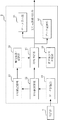
次に、信号処理装置9の構成について図2を用いて説明する。信号処理装置9は、デー
タ記憶部91、平均値演算部92、平均値記憶部93、極値演算/記憶部94、基準差分値記憶部95、比較判定部96、データ記録部97、及びデータ表示部98を備えている。これらは例えば中央処理装置(CPU)、ROM、RAM、不揮発メモリ、入力装置、出力装置、ハードディスク等と、これらを動作させるプログラムソフトにて構成され、電流計8からの電流信号を図示しないA/D変換器で変換されたデジタル信号で演算処理し、工具寿命を検出すると工具交換要求信号を出力する。
Next, the configuration of the
本実施の形態1では、主軸モータ7の電流値について、一つの部品毎の加工に要する時間全体もしくはその一部における平均値を負荷値として用いる(以下、この負荷値のことを平均電流値と称す)。負荷値記憶部であるデータ記憶部91は、電流計8にて測定された電流値の信号を記憶し、平均値演算部92は、一つの部品毎にその平均電流値を演算する。平均値演算部92で求めた平均電流値は、平均値記憶部93に記憶され、さらに極値演算/記憶部94において、これまで記憶された平均電流値の最大値、最小値が演算され記憶される。
In the first embodiment, with respect to the current value of the spindle motor 7, the average value over the entire time required for machining for each part or a part thereof is used as the load value (hereinafter, this load value is referred to as the average current value). Called). The
また、基準差分値記憶部95は、予め定めた基準差分値(この値を超えたら工具が劣化状態の第1段階又は第2段階終了であると判断するための閾値)を記憶する。本実施の形
態1では、工具の劣化状態が第1段階から第2段階へ移行したと判定するための第1基準
差分値と、工具が第2段階の劣化状態から寿命に達したことを判定するための第2基準差分値を記憶している。
Further, the reference difference
また、比較判定部96は、平均値演算部92で新たに演算された平均電流値と、その平均電流値よりも以前に平均値記憶部93に記憶された平均電流値の最大値である極大値Amaxとの差分値が第1基準差分値を超えた場合に、工具3の劣化状態が第1段階から第2段階へ移行したと判定する。さらに、新たに測定され記憶された平均電流値と、その平均電流値よりも以前に測定され、且つ工具3の劣化状態が第2段階へ移行した時以降に測定された平均電流値の最小値である極小値Aminとの差分値が第2基準差分値を超えた場合に、工具3が寿命に達したと判定する。なお、極大値Amax及び極小値Aminについては後に図6を用いて具体的に説明する。
In addition, the
さらに、比較判定部96は、工具3が寿命に達したと判定した場合に、工具3の寿命検出を知らせる信号を出力する出力部(図示せず)を備えている。データ記憶部97は、比較判定部96において判定された結果を記憶し、データ表示部98は、比較判定部96において判定された結果を表示する。
Furthermore, the comparison /
次に、本実施の形態1における工具寿命検出装置を用いて工具寿命を検出する方法について、図3〜図7に基づいて説明する。まず、穴あけ加工における加工時間に対する主軸モータ電流の変化について、図3を用いて説明する。図3は、工具3による穴あけ加工において、電流計8によって測定され信号処理装置9のデータ記憶部91に入力される電流値と、加工時間の関係を示しており、縦軸は主軸モータ電流値、横軸は加工時間である。
Next, a method for detecting the tool life using the tool life detection apparatus according to the first embodiment will be described with reference to FIGS. First, changes in the spindle motor current with respect to the machining time in drilling will be described with reference to FIG. FIG. 3 shows the relationship between the current value measured by the ammeter 8 and input to the
この例における工具3は直径8.3mmの穴あけ工具、被加工物(被削材)2は厚さ100mmの鉄材であり、工具3の回転数は3800rpm、送り速度は600mm/minである。まず、工具3を主軸モータ7により回転させると、主に主軸6とベアリング5の摩擦によって回転数に応じた空転時負荷が発生し、図3に示す電流値A0が出力される。この際、主軸6の回転開始時には慣性力により非常に大きな負荷電流値が出力される場合があるが、これは工具寿命と無関係であるため後述の演算から除外する。
The
次に、被加工物2に対し回転している工具3を一定の送り速度で接近させ、接触させると、切削抵抗により発生するねじりトルクが重畳され電流値は増加する。接触後、工具3
の送り速度を変化させずに加工を進め、穴あけが完了して工具3の移動を停止させると電流値は減少する。
Next, when the
When the machining is proceeded without changing the feed rate, and the drilling is completed and the movement of the
このとき、図3に示すように、被加工物2と工具3が接触する際、予め設定された閾値である加工開始電流値A1を上回った時点を加工開始時刻Tx、加工穴が貫通もしくは工具3の移動停止により加工開始電流値A1を下回った時点を加工終了時刻Tyと定義し、TxからTyの間を加工時間としてその間の平均電流値A(n)を算出し、その値を平均値記憶部93に記憶する。ここで、nは工具交換からの加工部品数を表す。また、加工開始電流値A1は、空転時の電流値よりも大きく、且つ切削加工時(切削に到っていない、部品と工具との初期接触時や、切削後の穴あけ工具抜き去り時を除く加工時)の最小電流値よりも小さい範囲で任意に設定できる。
At this time, as shown in FIG. 3, when the
次に、工具3による加工部品数と平均電流値A(n)の変化について、図4を用いて説明する。図4は、工具3が折損に至るまでの加工部品数と平均電流値との関係を示しており、縦軸は平均電流値A(n)、横軸は加工部品数である。図4に示すように、加工部品数が100個まで(n=1〜100)の場合は、平均電流値は15A程度で安定している
が、100個以上(n>100)になると平均電流値が上昇し始め、201個で極大値を示している。その後、221個まで平均電流値は減少し、再度上昇して250個で折損している。
Next, changes in the number of processed parts and the average current value A (n) by the
図4に示すような平均電流値の変化は、工具摩耗状態と関連している。図5は、本実施の形態において使用した工具3の磨耗状態を示しており、図5(a)は穴あけ工具の外観、図5(b)は新品時の工具先端刃部のすくい面外観、図5(c)は加工部品数181個時点のすくい面外観、図5(d)は221個時点のすくい面外観である。この例では、図5(c)から図5(d)の間、すなわち加工部品数181個から221個の間に、工具先端刃部のすくい面の著しい摩耗が観察されており、これにより一時的に切れ味が向上して電流値が減少し、その後急激な摩耗が工具先端刃部全面に進行して電流値が上昇して折損に至る現象が確認されている。
The change in the average current value as shown in FIG. 4 is related to the tool wear state. FIG. 5 shows the worn state of the
次に、本実施の形態1における工具寿命検出方法の手順について、図6に示すフローチャートを用いて説明する。まず、工具3を新品に交換すると、ステップ1(S1)に示すように、第1基準差分値[ΔAs1]と第2基準差分値[ΔAs2]が、基準差分値記憶部95に設定される。第1基準差分値[ΔAs1]は、工具3の劣化状態が第1段階から第2段階へ移行したことを判定するための閾値であり、本実施の形態では[ΔAs1]=3Aと設定する。また、第2基準差分値[ΔAs2]は工具3が寿命に達したことを判定するための閾値であり、本実施の形態では[ΔAs2]=5Aと設定する。なお、第1基準差分値及び第2基準差分値は、工具3および被加工物2の組み合わせや加工条件により変化するものであり、事前に加工実験によって求めておくことが望ましい。
Next, the procedure of the tool life detection method according to the first embodiment will be described with reference to the flowchart shown in FIG. First, when the
次に、ステップ2(S2)において、部品1個を加工する毎に負荷値としての平均電流値[A(n)]を平均値演算部92において算出し、平均値記憶部93に記憶する。さらに、ステップ3(S3)において、平均値記憶部93に記憶されたデータをもとに、極値演算/記憶部94によって平均電流値の極大値[Amax]を算出する。
Next, in step 2 (S 2), every time one component is processed, an average current value [A (n)] as a load value is calculated by the average
ここで、ステップ4(S4)において、今回の測定値以前に測定された平均電流値の極大値と今回(n個目)の平均電流値の差([Amax]−[A(n)])と、第1基準差分値[ΔAs1]とを比較する。前者の方が大きい場合は、工具3の劣化状態が第2段階へ移行したと判定してステップ5(S5)に進み、第2段階へ移行時の部品数[k]を記憶する。また、後者の方が大きい場合は、工具3の劣化状態が第2段階へ移行していないと判定してステップ2に戻り、次部品の加工を行う。
Here, in step 4 (S4), the difference between the maximum value of the average current value measured before the current measurement value and the current current value (nth) ([Amax] − [A (n)]). And the first reference difference value [ΔAs1]. When the former is larger, it is determined that the deterioration state of the
工具3の劣化状態が第2段階へ移行した後も引き続き、ステップ6(S6)において、部品1個を加工する毎に平均電流値[A(n)]を平均値演算部92において算出し、平
均値記憶部93に記憶する。さらに、ステップ7(S7)において、平均値記憶部93に記憶されたデータをもとに、極値演算/記憶部94によって平均電流値の極小値[Amin]が算出される。なお、極小値[Amin]とは、工具3の劣化状態が第2段階へ移行した時(k個目)以降に測定された平均電流値の最小値である。
Even after the deterioration state of the
ここで、ステップ8(S8)において、今回(n個目)の平均電流値と、今回の測定値以前であって且つk個目以降に測定された平均電流値の極小値の差([A(n)]−[Amin])と、第2基準差分値[ΔAs2]とを比較する。前者の方が大きい場合は、工具が寿命に達したと判定してステップ9(S9)に進み、次部品の加工を行わず工具交換要求又は加工機停止の信号を出力する。また、後者の方が大きい場合は、工具が寿命に達していないと判定してステップ6に戻り、次部品の加工を行う。 Here, in step 8 (S8), the difference between the current (nth) average current value and the minimum value of the average current value measured before the current measurement value and after the kth ([A (N)] − [Amin]) and the second reference difference value [ΔAs2]. If the former is larger, it is determined that the tool has reached the end of its life, and the process proceeds to step 9 (S9) to output a tool change request or a machine stop signal without processing the next part. On the other hand, if the latter is larger, it is determined that the tool has not reached the end of its life, and the process returns to step 6 to process the next part.
以上、図6に示すフローチャートを用いて説明した工具寿命検出方法を、図4に示した主軸モータ電流値に対して適用した場合について、図7を用いて説明する。まず、工具交換後100個加工までは、主軸モータの平均電流値は安定しており、それ以前の平均電流値の極大値[Amax]と平均電流値[A(n)]の差が第1基準差分値(ΔAs1=3A)を超えることはない。また、101個目以降、平均電流値は増加傾向であるため、平均電流値の極大値と新たに測定した平均電流値の差が3Aを超えることはない。 The case where the tool life detection method described with reference to the flowchart shown in FIG. 6 is applied to the spindle motor current value shown in FIG. 4 will be described with reference to FIG. First, the average current value of the spindle motor is stable up to 100 machining after tool change, and the difference between the maximum value [Amax] and the average current value [A (n)] of the average current value before that is the first. The reference difference value (ΔAs1 = 3A) is never exceeded. Further, since the average current value tends to increase after the 101st, the difference between the maximum value of the average current value and the newly measured average current value does not exceed 3A.
201個加工時点での電流値が極大値([Amax]=26.83A)として極値演算/記憶部94に記憶され、その後減少して206個時点で[A(n)]=23.15Aとなるため、平均電流値の極大値と今回の平均電流値の差が第1基準差分値すなわち3Aを超える。これにより、工具3の劣化状態が第1段階から第2段階へ移行したと判定される。
The current value at the time of 201 machining is stored in the extreme value calculation /
次に、221個時点での電流値が極小値([Amin]=22.35A)として極値演算/記憶部94に記憶され、その後増加して243個時点で[A(n)]=28.40Aとなるため、今回の平均電流値とそれ以前の平均電流値の極小値の差が第2基準差分値(ΔAs2=5A)を超える。これにより、工具3が寿命へ到達したと判定され、工具交換要求または加工機停止の信号が出力され、実際に工具3の折損が発生する250個直前での工具交換が可能となる。
Next, the current value at 221 time points is stored as a minimum value ([Amin] = 2.35 A) in the extreme value calculation /
以上のように、本実施の形態1では、加工個数に伴う工具3への負荷値変化という工具加工に特有の現象、すなわち工具外周部の磨耗進行に伴い主軸モータ電流値が上昇し、次に工具刃部先端のすくい面の磨耗進行に伴い一時的に切れ味が向上して電流値が減少した後、急激な磨耗が刃部先端の全面に進行して折損に至る現象を利用して、工具寿命を判定するようにしたものである。この現象は再現性を有しており、外乱の影響よりも顕著に発現するため、高精度な寿命判定が行える。
As described above, in the first embodiment, the spindle motor current value increases as the tool machining phenomenon, that is, a change in the load value on the
また、リアルタイムでの測定値(負荷値)をそのまま基準値と比較するのではなく、今回の測定値とそれ以前の測定値の最大値または最小値との差分値を基準値と比較することにより、加工機内に発生する突発的な振動、工具の製造バラツキ、温度等の使用環境の変動による影響を受けにくく、正確な寿命判定を行うことができる。このように、本実施の形態1によれば、工具3の寿命を正確に判定できる信頼性の高い工具寿命検出方法及びこれを実施する工具寿命検出装置を提供することが可能である。
Also, instead of comparing the measured value (load value) in real time with the reference value as it is, by comparing the difference value between the current measured value and the maximum or minimum value of the previous measured value with the reference value In addition, it is difficult to be influenced by fluctuations in the usage environment such as sudden vibration generated in the processing machine, tool manufacturing variation, temperature, etc., and accurate life determination can be performed. As described above, according to the first embodiment, it is possible to provide a highly reliable tool life detecting method capable of accurately determining the life of the
また、工具3の寿命を正確に判定することができるため、工具3により加工される製品
不具合、例えば、被加工物の欠損、面粗さ不良、形状精度不良等の発生頻度を小さくすることができ、歩留りが向上する。また、工具3を折損の直前まで使用できるため、工具費の削減が可能である。さらに、工具3の交換回数が減り、交換に伴う作業費を削減できるという効果が得られる。
In addition, since the life of the
本発明に係る工具寿命検出方法及び工具寿命検出装置は、機械加工を含む製造ライン等において、工具交換のタイミングを検知するための手段として利用することができる。 The tool life detection method and the tool life detection apparatus according to the present invention can be used as means for detecting the timing of tool replacement in a production line including machining.
1 加工機テーブル、2 被加工物、3 穴あけ工具、4 ホルダ、5 ベアリング、6 主軸、7 主軸モータ、8 電流計、9 信号処理装置、10 NC装置、
91 データ記憶部、92 平均値演算部、93 平均値記憶部、
94 極値演算/記憶部、95 基準差分値記憶部、96 比較判定部、
97 データ記録部、98 データ表示部。
1 processing machine table, 2 workpiece, 3 drilling tool, 4 holder, 5 bearing, 6 spindle, 7 spindle motor, 8 ammeter, 9 signal processing device, 10 NC device,
91 data storage unit, 92 average value calculation unit, 93 average value storage unit,
94 extreme value calculation / storage unit, 95 reference difference value storage unit, 96 comparison determination unit,
97 Data recording part, 98 Data display part.
Claims (5)
前記所定単位毎の加工に要する前記穴あけ工具への負荷値を測定し、新たに測定した前記負荷値と、それ以前に測定した前記負荷値の最大値との差分値が、予め定めた第1基準差分値を超えた場合に、前記穴あけ工具の劣化状態が前記第1段階から前記第2段階へ移行したと判定する第1のステップ、
前記第1のステップ後、さらに前記負荷値を測定し、新たに測定した前記負荷値と、それ以前に測定し、且つ前記穴あけ工具の劣化状態が前記第2段階へ移行した時以降に測定した前記負荷値の最小値との差分値が、予め定めた第2基準差分値を超えた場合に、前記穴あけ工具が寿命に達したと判定する第2のステップを含むことを特徴とする工具寿命検出方法。 A tool life detection method for detecting that a drilling tool that sequentially processes a workpiece in predetermined units has reached the end of its life through a deterioration state consisting of a first stage and a second stage,
A load value applied to the drilling tool required for machining for each predetermined unit is measured, and a difference value between the newly measured load value and the maximum value of the load value measured before is determined in advance. A first step of determining that the deterioration state of the drilling tool has shifted from the first stage to the second stage when a reference difference value is exceeded;
After the first step, the load value is further measured, the load value is newly measured, and the load value is measured before and after the deterioration state of the drilling tool shifts to the second stage. A tool life comprising a second step of determining that the drilling tool has reached the end of its life when a difference value with a minimum value of the load value exceeds a predetermined second reference difference value. Detection method.
前記所定単位毎の加工に要する前記穴あけ工具への負荷値を測定する測定部と、
前記測定部にて測定された前記負荷値を記憶する負荷値記憶部と、
前記負荷値記憶部に新たに記憶された前記負荷値と、それ以前に記憶された前記負荷値の最大値との差分値が、予め定めた第1基準差分値を超えた場合に、前記穴あけ工具の劣化状態が前記第1段階から前記第2段階へ移行したと判定し、さらに前記負荷値記憶部に新たに記憶された前記負荷値と、それ以前に記憶され、且つ前記穴あけ工具の劣化状態が第2段階へ移行した時以降に記憶された前記負荷値の最小値との差分値が、予め定めた第2基準差分値を超えた場合に、前記穴あけ工具が寿命に達したと判定する比較判定部とを備えたことを特徴とする工具寿命検出装置。 A tool life detecting device for detecting that a drilling tool for sequentially processing a workpiece in a predetermined unit has reached the end of its life through a deterioration state consisting of a first stage and a second stage,
A measuring unit for measuring a load value to the drilling tool required for machining for each predetermined unit;
A load value storage unit for storing the load value measured by the measurement unit;
When the difference value between the load value newly stored in the load value storage unit and the maximum value of the load value stored before that exceeds a predetermined first reference difference value, the punching is performed. It is determined that the deterioration state of the tool has shifted from the first stage to the second stage, and further, the load value newly stored in the load value storage unit and the deterioration of the drilling tool stored before that. When the difference value with the minimum value of the load value stored after the state shifts to the second stage exceeds a predetermined second reference difference value, it is determined that the drilling tool has reached the end of its life. A tool life detecting apparatus comprising a comparison / determination unit for performing
Priority Applications (1)
| Application Number | Priority Date | Filing Date | Title |
|---|---|---|---|
| JP2009005041A JP5089618B2 (en) | 2009-01-13 | 2009-01-13 | Tool life detection method and tool life detection device |
Applications Claiming Priority (1)
| Application Number | Priority Date | Filing Date | Title |
|---|---|---|---|
| JP2009005041A JP5089618B2 (en) | 2009-01-13 | 2009-01-13 | Tool life detection method and tool life detection device |
Publications (2)
| Publication Number | Publication Date |
|---|---|
| JP2010162623A JP2010162623A (en) | 2010-07-29 |
| JP5089618B2 true JP5089618B2 (en) | 2012-12-05 |
Family
ID=42579231
Family Applications (1)
| Application Number | Title | Priority Date | Filing Date |
|---|---|---|---|
| JP2009005041A Expired - Fee Related JP5089618B2 (en) | 2009-01-13 | 2009-01-13 | Tool life detection method and tool life detection device |
Country Status (1)
| Country | Link |
|---|---|
| JP (1) | JP5089618B2 (en) |
Cited By (3)
| Publication number | Priority date | Publication date | Assignee | Title |
|---|---|---|---|---|
| CN110948287A (en) * | 2019-12-07 | 2020-04-03 | 上海爱堃智能系统有限公司 | Intelligent cutter management method and system |
| JP2020163493A (en) * | 2019-03-28 | 2020-10-08 | ファナック株式会社 | Tool replacement timing management system |
| WO2021261418A1 (en) * | 2020-06-24 | 2021-12-30 | ファナック株式会社 | Tool diagnostic device and tool diagnostic method |
Families Citing this family (4)
| Publication number | Priority date | Publication date | Assignee | Title |
|---|---|---|---|---|
| JP6541170B2 (en) * | 2014-12-16 | 2019-07-10 | ダイハツ工業株式会社 | Evaluation method and apparatus for cutting tool |
| JP6813517B2 (en) * | 2018-01-08 | 2021-01-13 | 株式会社竹中電機 | Machining abnormality detection device and machining abnormality detection method |
| CN109909804B (en) * | 2018-12-21 | 2021-06-25 | 北京工业大学 | Tool wear damage online monitoring method based on spindle driving current and process steps |
| WO2021045013A1 (en) * | 2019-09-06 | 2021-03-11 | 住友電工焼結合金株式会社 | Machining system, and metal member manufacturing method |
Family Cites Families (3)
| Publication number | Priority date | Publication date | Assignee | Title |
|---|---|---|---|---|
| JP2533971B2 (en) * | 1990-03-26 | 1996-09-11 | エヌティエヌ株式会社 | Tool abnormality detection device |
| JP3256302B2 (en) * | 1992-11-26 | 2002-02-12 | 株式会社日平トヤマ | Tool breakage prevention equipment for processing machines |
| JP5132970B2 (en) * | 2007-04-02 | 2013-01-30 | 三菱電機株式会社 | Machining tool life detection method and machining tool life detection device |
-
2009
- 2009-01-13 JP JP2009005041A patent/JP5089618B2/en not_active Expired - Fee Related
Cited By (5)
| Publication number | Priority date | Publication date | Assignee | Title |
|---|---|---|---|---|
| JP2020163493A (en) * | 2019-03-28 | 2020-10-08 | ファナック株式会社 | Tool replacement timing management system |
| JP7036763B2 (en) | 2019-03-28 | 2022-03-15 | ファナック株式会社 | Tool change timing management system |
| US11376701B2 (en) | 2019-03-28 | 2022-07-05 | Fanuc Corporation | Tool replacement timing management system |
| CN110948287A (en) * | 2019-12-07 | 2020-04-03 | 上海爱堃智能系统有限公司 | Intelligent cutter management method and system |
| WO2021261418A1 (en) * | 2020-06-24 | 2021-12-30 | ファナック株式会社 | Tool diagnostic device and tool diagnostic method |
Also Published As
| Publication number | Publication date |
|---|---|
| JP2010162623A (en) | 2010-07-29 |
Similar Documents
| Publication | Publication Date | Title |
|---|---|---|
| JP5089618B2 (en) | Tool life detection method and tool life detection device | |
| JP5411055B2 (en) | Tool life detection method and tool life detection device | |
| JP4919999B2 (en) | Tool life detection method and tool life detection device | |
| CN109799784B (en) | Tool wear detection device, detection method thereof and tool wear compensation method | |
| US9588512B2 (en) | Setting method of revolutions per minute on real time of spinning cutting tool, and control device | |
| JP5710391B2 (en) | Processing abnormality detection device and processing abnormality detection method for machine tools | |
| JP5955479B1 (en) | Display device | |
| JP5132970B2 (en) | Machining tool life detection method and machining tool life detection device | |
| JP5543890B2 (en) | Tool wear detection method and machine tool | |
| JP2012088967A (en) | Monitoring method and monitoring device for machine tool, and machine tool | |
| JP2005144580A (en) | Machining method and device | |
| JPH07195256A (en) | Control unit and machine tool therewith as well as torque measuring instrument and tool breakage detector | |
| JP2009518705A (en) | Method and control device for determining the period until essential maintenance of machine elements | |
| JPH09174383A (en) | Abnormality detection method and device for rotating tool | |
| JP6040665B2 (en) | Chatter vibration suppressing method and machine tool | |
| JP6808038B2 (en) | Tool life detection device and tool life detection method | |
| JP6545555B2 (en) | Device and method for estimating remaining life of drill | |
| CN112743392B (en) | Device and method for monitoring spindle rotation speed in machine tool, and machine tool | |
| JP3446518B2 (en) | Rotary tool abnormality detection method and device | |
| JP2007283461A (en) | Machine tool, and method for detecting foreign matter | |
| JP2017064860A (en) | Working abnormality monitoring method and nc machine tool with working abnormality monitoring function | |
| JP6314885B2 (en) | Damage prevention system, grinding wheel | |
| JP5666397B2 (en) | Machine Tools | |
| JP7462874B2 (en) | Processing System | |
| JP2014061567A (en) | Machine tool |
Legal Events
| Date | Code | Title | Description |
|---|---|---|---|
| A621 | Written request for application examination |
Free format text: JAPANESE INTERMEDIATE CODE: A621 Effective date: 20100929 |
|
| A977 | Report on retrieval |
Free format text: JAPANESE INTERMEDIATE CODE: A971007 Effective date: 20120720 |
|
| A131 | Notification of reasons for refusal |
Free format text: JAPANESE INTERMEDIATE CODE: A131 Effective date: 20120724 |
|
| A521 | Written amendment |
Free format text: JAPANESE INTERMEDIATE CODE: A523 Effective date: 20120820 |
|
| TRDD | Decision of grant or rejection written | ||
| A01 | Written decision to grant a patent or to grant a registration (utility model) |
Free format text: JAPANESE INTERMEDIATE CODE: A01 Effective date: 20120904 |
|
| A01 | Written decision to grant a patent or to grant a registration (utility model) |
Free format text: JAPANESE INTERMEDIATE CODE: A01 |
|
| A61 | First payment of annual fees (during grant procedure) |
Free format text: JAPANESE INTERMEDIATE CODE: A61 Effective date: 20120911 |
|
| FPAY | Renewal fee payment (event date is renewal date of database) |
Free format text: PAYMENT UNTIL: 20150921 Year of fee payment: 3 |
|
| R151 | Written notification of patent or utility model registration |
Ref document number: 5089618 Country of ref document: JP Free format text: JAPANESE INTERMEDIATE CODE: R151 |
|
| FPAY | Renewal fee payment (event date is renewal date of database) |
Free format text: PAYMENT UNTIL: 20150921 Year of fee payment: 3 |
|
| R250 | Receipt of annual fees |
Free format text: JAPANESE INTERMEDIATE CODE: R250 |
|
| R250 | Receipt of annual fees |
Free format text: JAPANESE INTERMEDIATE CODE: R250 |
|
| R250 | Receipt of annual fees |
Free format text: JAPANESE INTERMEDIATE CODE: R250 |
|
| R250 | Receipt of annual fees |
Free format text: JAPANESE INTERMEDIATE CODE: R250 |
|
| R250 | Receipt of annual fees |
Free format text: JAPANESE INTERMEDIATE CODE: R250 |
|
| LAPS | Cancellation because of no payment of annual fees |