JP7243847B2 - electrical equipment - Google Patents
electrical equipment Download PDFInfo
- Publication number
- JP7243847B2 JP7243847B2 JP2021552021A JP2021552021A JP7243847B2 JP 7243847 B2 JP7243847 B2 JP 7243847B2 JP 2021552021 A JP2021552021 A JP 2021552021A JP 2021552021 A JP2021552021 A JP 2021552021A JP 7243847 B2 JP7243847 B2 JP 7243847B2
- Authority
- JP
- Japan
- Prior art keywords
- connector
- socket
- unit
- electric unit
- distance
- Prior art date
- Legal status (The legal status is an assumption and is not a legal conclusion. Google has not performed a legal analysis and makes no representation as to the accuracy of the status listed.)
- Active
Links
Images


Classifications
-
- H—ELECTRICITY
- H01—ELECTRIC ELEMENTS
- H01R—ELECTRICALLY-CONDUCTIVE CONNECTIONS; STRUCTURAL ASSOCIATIONS OF A PLURALITY OF MUTUALLY-INSULATED ELECTRICAL CONNECTING ELEMENTS; COUPLING DEVICES; CURRENT COLLECTORS
- H01R13/00—Details of coupling devices of the kinds covered by groups H01R12/70 or H01R24/00 - H01R33/00
- H01R13/62—Means for facilitating engagement or disengagement of coupling parts or for holding them in engagement
- H01R13/621—Bolt, set screw or screw clamp
- H01R13/6215—Bolt, set screw or screw clamp using one or more bolts
-
- H—ELECTRICITY
- H05—ELECTRIC TECHNIQUES NOT OTHERWISE PROVIDED FOR
- H05K—PRINTED CIRCUITS; CASINGS OR CONSTRUCTIONAL DETAILS OF ELECTRIC APPARATUS; MANUFACTURE OF ASSEMBLAGES OF ELECTRICAL COMPONENTS
- H05K7/00—Constructional details common to different types of electric apparatus
- H05K7/14—Mounting supporting structure in casing or on frame or rack
- H05K7/1422—Printed circuit boards receptacles, e.g. stacked structures, electronic circuit modules or box like frames
- H05K7/1427—Housings
- H05K7/1432—Housings specially adapted for power drive units or power converters
-
- H—ELECTRICITY
- H01—ELECTRIC ELEMENTS
- H01R—ELECTRICALLY-CONDUCTIVE CONNECTIONS; STRUCTURAL ASSOCIATIONS OF A PLURALITY OF MUTUALLY-INSULATED ELECTRICAL CONNECTING ELEMENTS; COUPLING DEVICES; CURRENT COLLECTORS
- H01R13/00—Details of coupling devices of the kinds covered by groups H01R12/70 or H01R24/00 - H01R33/00
- H01R13/62—Means for facilitating engagement or disengagement of coupling parts or for holding them in engagement
- H01R13/629—Additional means for facilitating engagement or disengagement of coupling parts, e.g. aligning or guiding means, levers, gas pressure electrical locking indicators, manufacturing tolerances
-
- H—ELECTRICITY
- H02—GENERATION; CONVERSION OR DISTRIBUTION OF ELECTRIC POWER
- H02M—APPARATUS FOR CONVERSION BETWEEN AC AND AC, BETWEEN AC AND DC, OR BETWEEN DC AND DC, AND FOR USE WITH MAINS OR SIMILAR POWER SUPPLY SYSTEMS; CONVERSION OF DC OR AC INPUT POWER INTO SURGE OUTPUT POWER; CONTROL OR REGULATION THEREOF
- H02M1/00—Details of apparatus for conversion
-
- H—ELECTRICITY
- H05—ELECTRIC TECHNIQUES NOT OTHERWISE PROVIDED FOR
- H05K—PRINTED CIRCUITS; CASINGS OR CONSTRUCTIONAL DETAILS OF ELECTRIC APPARATUS; MANUFACTURE OF ASSEMBLAGES OF ELECTRICAL COMPONENTS
- H05K7/00—Constructional details common to different types of electric apparatus
- H05K7/02—Arrangements of circuit components or wiring on supporting structure
- H05K7/023—Stackable modules
-
- H—ELECTRICITY
- H05—ELECTRIC TECHNIQUES NOT OTHERWISE PROVIDED FOR
- H05K—PRINTED CIRCUITS; CASINGS OR CONSTRUCTIONAL DETAILS OF ELECTRIC APPARATUS; MANUFACTURE OF ASSEMBLAGES OF ELECTRICAL COMPONENTS
- H05K7/00—Constructional details common to different types of electric apparatus
- H05K7/14—Mounting supporting structure in casing or on frame or rack
- H05K7/1422—Printed circuit boards receptacles, e.g. stacked structures, electronic circuit modules or box like frames
- H05K7/1427—Housings
- H05K7/1432—Housings specially adapted for power drive units or power converters
- H05K7/14324—Housings specially adapted for power drive units or power converters comprising modular units, e.g. DIN rail mounted units
Landscapes
- Engineering & Computer Science (AREA)
- Microelectronics & Electronic Packaging (AREA)
- Power Engineering (AREA)
- Details Of Connecting Devices For Male And Female Coupling (AREA)
- Connector Housings Or Holding Contact Members (AREA)
Description
本明細書が開示する技術は、第1電気ユニットと第2電気ユニットが合体した電気機器に関する。 The technology disclosed in this specification relates to an electric device in which a first electric unit and a second electric unit are combined.
幾つかの電気ユニットを合体させて一つの電気機器を構成する場合がある。特開2005-137116号公報、特開2012-105369号公報に、そのような電気機器が例示されている。 A single electrical device may be configured by combining several electrical units. Such electric devices are exemplified in JP-A-2005-137116 and JP-A-2012-105369.
第1電気ユニットと第2電気ユニットは電気的に接続されるとともに相互に固定される。第1電気ユニットを第2電気ユニットに固定するときに第1電気ユニット(第2電気ユニット)のコネクタが第2電気ユニット(第1電気ユニット)のソケットに嵌合し、両者は電気的に接続される。第1電気ユニットと第2電気ユニットを合体させる際、第1電気ユニットに対して第2電気ユニットの位置がずれていると、コネクタがソケットに嵌合しない。本明細書は、第1電気ユニットと第2電気ユニットを合体させるときにコネクタとソケットを容易に嵌合させることのできる構造を提供する。 The first electrical unit and the second electrical unit are electrically connected and fixed to each other. When the first electric unit is fixed to the second electric unit, the connector of the first electric unit (second electric unit) fits into the socket of the second electric unit (first electric unit), and the two are electrically connected. be done. When combining the first electric unit and the second electric unit, if the position of the second electric unit is shifted with respect to the first electric unit, the connector will not fit into the socket. The present specification provides a structure that allows the connectors and sockets to be easily mated when mating the first and second electrical units.
本明細書が開示する電気機器は、相互に固定される第1電気ユニットと第2電気ユニットを備えている。第1電気ユニットの第1面にコネクタが配置されている。第2電気ユニットの第2面が第1電気ユニットの第1面に対向する。第2面には、コネクタと嵌合するソケットが備えられている。第1電気ユニットと第2電気ユニットの一方に他方に向けて延びているスタッドボルトが備えられており、第1電気ユニットと第2電気ユニットの他方にスタッドボルトが挿通されるボルト孔が設けられている。ボルト孔に挿通されたスタッドボルトにナットを取り付けることで第1電気ユニットと第2電気ユニットが相互に固定される。 The electrical equipment disclosed herein comprises a first electrical unit and a second electrical unit that are secured together. A connector is located on the first side of the first electrical unit. The second surface of the second electrical unit faces the first surface of the first electrical unit. The second surface is provided with a socket for mating with the connector. One of the first electric unit and the second electric unit is provided with a stud bolt extending toward the other, and the other of the first electric unit and the second electric unit is provided with a bolt hole through which the stud bolt is inserted. ing. The first electric unit and the second electric unit are fixed to each other by attaching a nut to the stud bolt inserted through the bolt hole.
本明細書が開示する電気機器では、第1面が第2面に対向している状態を保持しつつ第2電気ユニットを第1電気ユニットから分離したときに、スタッドボルトからボルト孔までの距離(ボルト-孔距離)がコネクタからソケットまでの距離(コネクタ-ソケット距離)よりも短い。すなわち、第1電気ユニットと第2電気ユニットを合体させるとき、コネクタがソケットに入るのに先立ってスタッドボルトがボルト孔に入る。スタッドボルトがボルト孔に入ることでコネクタとソケットが正しい位置に誘導される。スタッドボルトは通常のボルトと異なり、2個のユニットの一方に単独で固定される。本明細書が開示する電気機器は、スタッドボルトとボルト孔をコネクタとソケットの位置を定めるガイドとして用いることで、コネクタとソケットを容易に位置合わせすることができる。 In the electrical equipment disclosed in this specification, when the second electrical unit is separated from the first electrical unit while the first surface faces the second surface, the distance from the stud bolt to the bolt hole is (bolt-hole distance) is shorter than the distance from the connector to the socket (connector-socket distance). That is, when mating the first and second electrical units, the stud bolts enter the bolt holes before the connectors enter the sockets. The connector and socket are guided to the correct position by the stud bolt entering the bolt hole. A stud bolt is fixed independently to one of the two units unlike a normal bolt. The electrical equipment disclosed in this specification can easily align the connector and the socket by using the stud bolts and bolt holes as guides for determining the positions of the connector and the socket.
本明細書が開示する電気機器では、第1電気ユニットと第2電気ユニットの一方に他方に向けて延びている位置決めピンが備えられており、第1電気ユニットと第2電気ユニットの他方に位置決めピンが挿通される位置決め孔が備えられていてもよい。位置決めピンと位置決め孔の間のクリアランス(ピンクリアランス)がスタッドボルトとボルト孔の間のクリアランス(ボルトクリアランス)よりも小さい。第1面が第2面に対向している状態を保持しつつ第2電気ユニットを第1電気ユニットから分離したとき、位置決めピンから位置決め孔までの距離(ピン-孔距離)は、ボルト-孔距離がよりも長く、コネクタ-ソケット距離よりも短い。そのような位置決めピンと位置決め孔を有する電気機器では、第1電気ユニットと第2電気ユニットを合体させるとき、最初にスタッドボルトがボルト孔に入り、コネクタとソケットはボルトクリアランスで位置が調整される。さらに第2電気ユニットを第1電気ユニットに近づけると、位置決めピンが位置決め孔に入る。その結果、コネクタとソケットはピンクリアランスでより正確に位置が調整される。さらに第2電気ユニットを第1電気ユニットに近づけると、コネクタの先端がソケットに達し、コネクタはソケットにスムーズに入る。位置決めピンと位置決め孔を加えることで、コネクタとソケットは2段階で位置が調整される。すなわち、位置決めピンと位置決め孔を加えることで、コネクタとソケットはより円滑に結合することができる。 In the electric device disclosed in this specification, one of the first electric unit and the second electric unit is provided with a positioning pin extending toward the other, and the other of the first electric unit and the second electric unit is positioned. A positioning hole through which the pin is inserted may be provided. The clearance (pin clearance) between the positioning pin and the positioning hole is smaller than the clearance (bolt clearance) between the stud bolt and the bolt hole. When the second electric unit is separated from the first electric unit while the first surface faces the second surface, the distance from the positioning pin to the positioning hole (pin-hole distance) is the bolt-hole distance. distance is longer than the connector-to-socket distance. In an electrical device having such locating pins and locating holes, when the first electric unit and the second electric unit are combined, the stud bolts first enter the bolt holes, and the positions of the connector and the socket are adjusted by the bolt clearance. When the second electric unit is brought closer to the first electric unit, the positioning pin enters the positioning hole. As a result, the connector and socket are more precisely aligned with pin clearance. When the second electric unit is brought closer to the first electric unit, the tip of the connector reaches the socket and the connector smoothly enters the socket. By adding locating pins and locating holes, the connector and socket are aligned in two steps. That is, by adding the positioning pin and the positioning hole, the connector and the socket can be connected more smoothly.
あるいは、本明細書が開示する電気機器は、コネクタが、先端部と、外径が先端部の外径よりも大きい基部を有しているとよい。基部の外径が先端部の外径よりも小さいので、先端部とソケットの内径の間のクリアランス(先端部クリアランス)が基部と内径の間のクリアランス(基部クリアランス)よりも大きくなる。その場合、第1面が第2面に対向している状態を保持しつつ第2電気ユニットを第1電気ユニットから分離したときに、ピン-孔距離が、コネクタ-ソケット距離よりも長く、先端部と基部の境界からソケットまでの距離よりも短いとよい。 Alternatively, in the electrical device disclosed in this specification, the connector may have a tip portion and a base portion having an outer diameter larger than that of the tip portion. Since the outer diameter of the base is smaller than the outer diameter of the tip, the clearance between the tip and the inner diameter of the socket (tip clearance) is greater than the clearance between the base and the inner diameter (base clearance). In that case, when the second electrical unit is separated from the first electrical unit while maintaining the first surface facing the second surface, the pin-hole distance is longer than the connector-socket distance and the tip It should be shorter than the distance from the junction of the base and base to the socket.
上記の構成によれば、コネクタの細い先端部がソケットに達する前に、スタッドボルトがボルト孔に入ってコネクタとソケットの位置が調整される。このとき、位置決めピンは位置決め孔に達していない。コネクタとソケットはボルトクリアランスで位置が調整される。ボルトクリアランスは先端部クリアランスよりも小さいので、コネクタの先端部はソケットにスムーズに入る。 According to the above configuration, the stud bolt enters the bolt hole before the narrow tip of the connector reaches the socket, thereby adjusting the positions of the connector and the socket. At this time, the positioning pin has not reached the positioning hole. The connector and socket are aligned with bolt clearance. Since the bolt clearance is less than the tip clearance, the tip of the connector enters the socket smoothly.
さらに第2電気ユニットを第1電気ユニットに近づけると、基部がソケットに達する前に、位置決めピンが位置決め孔に入り、コネクタとソケットの位置がピンクリアランスで調整される。ピンクリアランスは基部クリアランスよりも小さいので、コネクタの基部はソケットにスムーズに入る。 When the second electric unit is brought closer to the first electric unit, the positioning pin enters the positioning hole before the base reaches the socket, and the positions of the connector and the socket are adjusted by the pin clearance. The pin clearance is less than the base clearance so that the base of the connector enters the socket smoothly.
なお、コネクタに先端部と基部を備える代わりに、ソケットに先端部と基部を備えていてもよい。ソケットの基部の内径が先端部の内径よりも小さい。その結果、先端部とコネクタの外径の間のクリアランスは、基部と外径の間のクリアランスよりも大きくなる。その場合、第1面が第2面に対向している状態を保持しつつ第2電気ユニットを第1電気ユニットから分離したときに、ピン-孔距離が、コネクタ-ソケット距離よりも長く、先端部と基部の境界からコネクタまでの距離よりも短いとよい。そのような構造によっても、コネクタが先端部と基部を有する場合と同様の利点が得られる。 It should be noted that the socket may have a tip and a base instead of the connector having a tip and a base. The inner diameter of the base of the socket is smaller than the inner diameter of the tip. As a result, the clearance between the tip and the outer diameter of the connector is greater than the clearance between the base and the outer diameter. In that case, when the second electrical unit is separated from the first electrical unit while maintaining the first surface facing the second surface, the pin-hole distance is longer than the connector-socket distance and the tip It should be shorter than the distance from the boundary of the base to the base to the connector. Such a construction provides the same advantages as if the connector had a tip and a base.
本明細書が開示する技術の詳細とさらなる改良は以下の「発明を実施するための形態」にて説明する。 Details and further improvements of the technique disclosed in this specification are described in the following "Mode for Carrying Out the Invention".
図面を参照して実施例の電気機器を説明する。実施例の電気機器は、電気自動車に搭載される電力変換器10である。図1に、電力変換器10を含む電気自動車100の電力系の回路図を示す。電力変換器10は、メインバッテリ3の電力を走行用のモータ6の駆動電力に変換する。
An electric device of an embodiment will be described with reference to the drawings. The electrical equipment of the embodiment is a
電力変換器10は、インバータユニット20と電圧コンバータユニット40で構成される。詳しくは後述するが、インバータユニット20と電圧コンバータユニット40は、別々の筐体で構成されているが、それらの筐体は相互に固定されている。
The
電圧コンバータユニット40には、電圧コンバータ回路11が収容されている。電圧コンバータ回路11は、メインバッテリ3に接続されるとともにサブバッテリ4に接続される。メインバッテリ3の出力電圧は100を超えており、サブバッテリ4の出力電圧は20ボルト程度である。電圧コンバータ回路11は、メインバッテリ3の出力電圧を降圧し、電圧の下がった電力をサブバッテリ4に供給する。すなわち、電圧コンバータ回路11は、メインバッテリ3の電力でサブバッテリ4を充電するために備えられている。サブバッテリ4には補機5が接続されている。補機5は、カーステレオ、ルームランプ、ナビゲーション装置など、サブバッテリ4から電力供給を受けて動作する機器の総称である。電圧コンバータ回路11の詳しい説明は割愛する。
The
インバータユニット20にはインバータ回路12が収容されている。インバータ回路12は、メインバッテリ3の直流電力を交流電力に変換し、走行用のモータ6に供給する。
The
電圧コンバータユニット40とインバータユニット20は、コネクタ30とソケット50で電気的に接続される。コネクタ30はインバータユニット20に備えられており、ソケット50は電圧コンバータユニット40に備えられている。ソケット50には一対のソケット端子51が備えられている。一対のソケット端子51は、メインバッテリ3と電圧コンバータ回路11を接続する一対の電力線13に接続されている。コネクタ30には一対のコネクタ端子31が備えられている。一対のコネクタ端子31は、インバータユニット20が内蔵するインバータ回路12に接続されている。コネクタ30がソケット50に嵌合すると、ソケット端子51とコネクタ端子31が接続され、メインバッテリ3の電力がインバータ回路12へ供給可能となる。
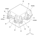
次に、電力変換器10のハードウエアについて説明する。図2に、電力変換器10の斜視図を示す。図3に、電圧コンバータユニット40をインバータユニット20から分離した分解斜視図を示す。説明の便宜上、図中の座標系の+Z方向を「上」と定義する。
Next, the hardware of
図3では、電圧コンバータユニット40を上下逆にして描いてある。図3では、電圧コンバータユニット40とインバータユニット20のそれぞれに座標系を付しており、Z軸の方向が互いに逆を向いていることに留意されたい。
In FIG. 3, the
インバータユニット20は、筐体の側面に複数のフランジ24を備えている。フランジ24には貫通孔29が備えられている。特定のフランジ(フランジ24aとフランジ24b)には、スタッドボルト25と位置決めピン26が設けられている。スタッドボルト25と位置決めピン26は、フランジ24a、24bに固定されている。スタッドボルト25は、インバータユニット20の矩形の上面21の対角の位置に配置されており、位置決めピン26も、上面21の対角の位置に配置されている。位置決めピン(位置決め孔)は、ダウエルピン(ダウエル孔)と呼ばれることがある。
The
インバータユニット20の上面22には、先に述べたコネクタ30が設けられている。コネクタ30の頭頂面にコネクタ端子31が露出している。
The
電圧コンバータユニット40は、筐体の側面に複数の脚44を備えている。脚44には、貫通孔49が備えられている。特定の脚(脚44aと44b)には、脚を貫通するボルト孔45と、位置決め孔46が設けられている。脚44a(44b)のボルト孔45と位置決め孔46は、電圧コンバータユニット40をインバータユニット20に組み合わせるときにフランジ24a(24b)のスタッドボルト25と位置決めピン26に対向する位置に配置されている。
The
電圧コンバータユニット40の下面41には、先に述べたソケット50が配置されている。ソケット50は、電圧コンバータユニット40をインバータユニット20に組み合わせるときにコネクタ30に対向する位置に配置されている。図3では隠れて見えていないが、ソケット50の底に、先に述べたソケット端子51が露出している。
The previously described
図2に示されているように、電圧コンバータユニット40をインバータユニット20に固定するとき、電圧コンバータユニット40の脚44がインバータユニット20のフランジ24に対向する。脚44の貫通孔49とフランジ24の貫通孔29にボルト91が挿通される。貫通孔29、49に挿通されたボルト91に不図示のナットが取り付けられ、脚44とフランジ24、すなわち、電圧コンバータユニット40とインバータユニット20が相互に固定される。
As shown in FIG. 2 ,
フランジ24a(24b)のスタッドボルト25は脚44a(44b)のボルト孔45に挿通された後、ナット92が固定される。フランジ24a(24b)の位置決めピン26は脚44a(44b)の位置決め孔46に挿通される。
After the
電圧コンバータユニット40がインバータユニット20に固定されるとき、ソケット50にコネクタ30が嵌合し、コネクタ端子31がソケット端子51に接続され、電圧コンバータユニット40とインバータユニット20が電気的に接続される。
When
図4に電力変換器10の平面図を示す。図4には、コネクタ30とソケット50を破線で示してある。図4のV-V線でカットした断面を図5に示す。図5は、スタッドボルト25と位置決めピン26とコネクタ30とソケット50を横断する平面でカットした断面を示している。図5では、一対のコネクタ端子31(一対のソケット端子51)の一方のみを示しており、他方の図示は省略した。また、図5では、電圧コンバータユニット40の内部の構造は、ソケット端子51を除いて図示を省略した。同様に、インバータユニット20の内部の構造は、コネクタ端子31を除いて図示を省略した。
FIG. 4 shows a plan view of the
図5を参照して、スタッドボルト25、位置決めピン26、ボルト孔45、位置決め孔46、コネクタ30、ソケット50の幾何学的関係を説明する。なお、図5は、電圧コンバータユニット40の下面41がインバータユニット20の上面21に対向している状態を保持しつつ電圧コンバータユニット40をインバータユニット20から分離したときの断面図を示している。また、図5は、フランジ24aのスタッドボルト25と位置決めピン26、脚44aのボルト孔45と位置決め孔46、コネクタ30、ソケット50の関係を示している。フランジ24bのスタッドボルト25と位置決めピン26、脚44bのボルト孔45と位置決め孔46、コネクタ30、ソケット50の関係も図5の関係と同じである。
The geometrical relationship among the
コネクタ30とソケット0は樹脂で作られている。コネクタ30の内部には、コネクタ端子31が通っている。ソケット50は筒状の構造物であり、その底にソケット端子51が露出している。コネクタ30がソケット50に完全に嵌合すると、コネクタ端子31がソケット端子51に接続される。図示は省略しているが、コネクタ端子31とソケット端子51はネジで共締めされる。
The
スタッドボルト25の先端25aからボルト孔45までの距離(ボルト-孔距離La)は、コネクタ30の先端30aからソケット50の先端50aまでの距離(コネクタ-ソケット距離Lb)よりも短い(La<Lb)。また、位置決めピン26の先端26aから位置決め孔46までの距離(ピン-孔距離Lc)は、ボルト-孔距離Laよりも長く、コネクタ-ソケット距離Lbよりも短い(La<Lc<Lb)。
The distance from the
また、スタッドボルト25とボルト孔45の間のクリアランス(ボルトクリアランスCa)は、コネクタ30とソケット50の間のクリアランス(コネクタクリアランスCc)よりも小さい。さらに、位置決めピン26と位置決め孔46の間のクリアランス(ピンクリアランスCb)は、ボルトクリアランスCaよりも小さい。すなわち、Cb<Ca<Ccの関係が成立する。なお、ボルトクリアランスCaとは、スタッドボルト25の外径とボルト孔45の内径の差を意味する。ピンクリアランスCbとは、位置決めピン26の外径と位置決め孔46の内径の差を意味する。コネクタクリアランスCcとは、コネクタ30の外径とソケット50の内径の差を意味する。
Also, the clearance between the
上記の幾何学的な関係より、電圧コンバータユニット40をインバータユニット20に組み付ける際に、コネクタ30がソケット50にスムーズに嵌合する。すなわち、電圧コンバータユニット40をインバータユニット20に近づけると、コネクタ30がソケット50に達する前に、スタッドボルト25がボルト孔45に挿通される。コネクタ30とソケット50は、水平方向においてボルトクリアランスCa以内の距離で近づく。
Due to the above geometrical relationship, the
さらに電圧コンバータユニット40を近づけると、位置決めピン26が位置決め孔46に挿通される。位置決めピン26が位置決め孔46に達しても、コネクタ30はソケット50に達していない。このとき、コネクタ30とソケット50は、水平方向においてピンクリアランスCb以内の距離で近づく。コネクタクリアランスCcはピンクリアランスCbよりもはるかに大きい。それゆえ、電圧コンバータユニット40をインバータユニット20へさらに近づけると、コネクタ30がソケット50にスムーズに嵌合することができる。実施例の電力変換器10では、電圧コンバータユニット40とインバータユニット20を合体させるときにコネクタ30とソケット50を容易に位置合わせすることができる。
When the
なお、コネクタ30の根本にはガスケット39が配置されている。コネクタ30がソケット50に完全に嵌合すると、ソケット50の先端50aがガスケット39に当接し、コネクタ30とソケット50の間が封止される。
A
(第1変形例)つづいて、図6を参照して第1変形例の電力変換器10aを説明する。図6は、電力変換器10aの断面図である。図6の断面は、図5の断面に対応する。
(First Modification) Next, a
電力変換器10aは、コネクタ130の形状と、位置決めピン126の長さが実施例の電力変換器10と異なる。コネクタ130は、先端部131と基部132に分けられる。基部132は、先端部131よりも外径が大きい。ただし、基部132の外径は、ソケット50の内径よりはわずかに小さい。コネクタ130とソケット50はいずれも樹脂で作られている。
電力変換器10aでは、電圧コンバータユニット40の下面41がインバータユニット20の上面21と対向している状態を保持しつつ電圧コンバータユニット40をインバータユニット20から分離したときに、次の幾何学的関係を有している。
In
スタッドボルト25の先端25aからボルト孔45までの距離(ボルト-孔距離La)は、コネクタ130の先端130aからソケット50の先端50aまでの距離(コネクタ-ソケット距離Lb)よりも短い(La<Lb)。位置決めピン126の先端126aから位置決め孔46までの距離(ピン-孔距離Lc)は、コネクタ-ソケット距離Lbよりも長い(Lb<Lc)。ピン-孔距離Lcは、先端部131と基部132の境界133からソケット50の先端50aまでの距離(境界-ソケット距離Ld)よりも短い。すなわち、La<Lb<Lc<Ldの関係が成立する。
The distance from the
また、スタッドボルト25とボルト孔45の間のクリアランス(ボルトクリアランスCa)は、コネクタ130の先端131とソケット50の間のクリアランス(コネクタ先端クリアランスCc)よりも小さい。ボルトクリアランスCaは、コネクタ130の基部132とソケット50の間のクリアランス(コネクタ基部クリアランスCd)よりは大きい(Cd<Ca)。コネクタ基部クリアランスCdは、位置決めピン26と位置決め孔46の間のクリアランス(ピンクリアランスCb)よりも大きい。すなわち、Cb<Cd<Ca<Ccの関係が成立する。
Also, the clearance between the
上記の幾何学的な関係より、電圧コンバータユニット40をインバータユニット20に組み付ける際に、コネクタ130がソケット50にスムーズに嵌合する。すなわち、電圧コンバータユニット40をインバータユニット20に近づけると、コネクタ130がソケット50に達する前に、スタッドボルト25がボルト孔45に挿通される。コネクタ130とソケット50は、水平方向においてボルトクリアランスCa以内の距離で近づく。電圧コンバータユニット40をさらにインバータユニット20に近づけると、コネクタ130の先端部131がソケット50に達する。このとき、位置決めピン126は位置決め孔46に達していない。しかし、コネクタ130とソケット50は、水平方向においてボルトクリアランスCa以内の距離で近づいているので、先端部131はソケット50にスムーズに入る。
Due to the above geometrical relationship,
ボルトクリアランスCaは、コネクタ基部クリアランスCdよりも大きいので、このままでは、コネクタ130はソケット50にスムーズには入らない。
Since the bolt clearance Ca is larger than the connector base clearance Cd, the
電圧コンバータユニット40をさらにインバータユニット20に近づけると、ソケット50の先端50aがコネクタ130の境界133に達する前に、位置決めピン126が位置決め孔46に達する。位置決めピン126が位置決め孔46に入ると、ソケット50とコネクタ130は水平方向においてピンクリアランスCbの距離以内に近づく。ピンクリアランスCb<コネクタ基部クリアランスCdの関係があるので、電圧コンバータユニット40をさらにインバータユニット20に近づけると、コネクタ130の基部132がソケット50にスムーズに入ることができる。
When
第1変形例の電力変換器10aでは、電圧コンバータユニット40とインバータユニット20を合体させるときにコネクタ30とソケット50をよりスムーズに嵌合させることができる。
In the
なお、コネクタ130の根本にはガスケット39が配置されている。コネクタ130がソケット50に完全に嵌合すると、ソケット50の先端50aがガスケット39に当接し、コネクタ130とソケット50の間が封止される。ガスケットは、コネクタ130の基部132の外周に備えられていてもよい。
A
(第2変形例)次に、図7を参照して第2変形例の電力変換器10bを説明する。図7は、電力変換器10bの断面図である。図7の断面は、図5の断面に対応する。
(Second Modification) Next, a
電力変換器10bは、ソケット150の形状と、位置決めピン226の長さが実施例の電力変換器10と異なる。なお、コネクタ30は実施例の電力変換器10のコネクタ30と同じである。ソケット150は、先端部151と基部152に分けられる。ソケット150は筒状であり、基部152は、先端部151よりも内径が大きい。基部152の内径は、コネクタ30の外径よりもわずかに大きい。コネクタ30とソケット150はいずれも樹脂で作られている。
電力変換器10bでは、電圧コンバータユニット40の下面41がインバータユニット20の上面21と対向している状態を保持しつつ電圧コンバータユニット40をインバータユニット20から分離したときに、次の幾何学的関係を有している。
In
スタッドボルト25の先端25aからボルト孔45までの距離(ボルト-孔距離La)は、コネクタ30の先端30aからソケット150の先端150a(先端部151)までの距離(コネクタ-ソケット距離Lb)よりも短い(La<Lb)。位置決めピン226の先端226aから位置決め孔46までの距離(ピン-孔距離Lc)は、コネクタ-ソケット距離Lbよりも長い(Lb<Lc)。ピン-孔距離Lcは、先端部151と基部152の境界153からコネクタ30の先端30aまでの距離(コネクタ-境界距離Ld)よりも短い。すなわち、La<Lb<Lc<Ldの関係が成立する。
The distance from the
また、スタッドボルト25とボルト孔45の間のクリアランス(ボルトクリアランスCa)は、ソケット150の先端151とコネクタ30との間のクリアランス(ソケット先端クリアランスCc)よりも小さい。ボルトクリアランスCaは、ソケット150の基部152とコネクタ30の間のクリアランス(ソケット基部クリアランスCd)よりは大きい(Cd<Ca)。ソケット基部クリアランスCdは、位置決めピン26と位置決め孔46の間のクリアランス(ピンクリアランスCb)よりも大きい。すなわち、Cb<Cd<Ca<Ccの関係が成立する。
Also, the clearance between the
上記の幾何学的な関係より、電圧コンバータユニット40をインバータユニット20に組み付ける際に、コネクタ30がソケット150にスムーズに嵌合する。すなわち、電圧コンバータユニット40をインバータユニット20に近づけると、コネクタ30がソケット150に達する前に、スタッドボルト25がボルト孔45に挿通される。コネクタ30とソケット150は、水平方向においてボルトクリアランスCa以内の距離で近づく。電圧コンバータユニット40をさらにインバータユニット20に近づけると、ソケット150の先端部151がコネクタ30の先端30aに達する。このとき、位置決めピン126は位置決め孔46に達していない。しかし、コネクタ30とソケット150は、水平方向においてボルトクリアランスCa以内の距離で近づいているので、コネクタ30はソケット150の先端部151にスムーズに入る。
Due to the above geometrical relationship,
ボルトクリアランスCaはソケット基部クリアランスCdよりも大きいので、このままでは、コネクタ30はソケット150の基部152にスムーズには入らない。
Since the bolt clearance Ca is larger than the socket base clearance Cd, the
電圧コンバータユニット40をさらにインバータユニット20に近づけると、コネクタ30の先端30aがソケット150の境界153に達する前に、位置決めピン126が位置決め孔46に達する。位置決めピン126が位置決め孔46に入ると、ソケット150とコネクタ30は水平方向においてピンクリアランスCbの距離以内に近づく。ピンクリアランスCb<ソケット基部クリアランスCdであるため、電圧コンバータユニット40をさらにインバータユニット20に近づけると、コネクタ30はソケット150の基部152にスムーズに入ることができる。
When
第2変形例の電力変換器10bは、第1変形例の電力変換器10aと同様に、電圧コンバータユニット40とインバータユニット20を合体させるときにコネクタ30とソケット50をよりスムーズに嵌合させることができる。
In the
なお、コネクタ30の根本にはガスケット39が配置されている。コネクタ30がソケット150に完全に嵌合すると、ソケット150の先端150aがガスケット39に当接し、コネクタ30とソケット150の間が封止される。ガスケットは、ソケット150の基部152の内周に備えられていてもよい。
A
実施例で説明した技術に関する留意点を述べる。インバータユニット20が第1電気ユニットの一例に相当し、電圧コンバータユニット40が第2電気ユニットの一例に相当する。本明細書が開示する技術は、電圧コンバータユニット40とインバータユニット20以外のデバイスの組み合わせに適用することも好適である。
Points to note regarding the technology described in the embodiment will be described. The
以上、本発明の具体例を詳細に説明したが、これらは例示に過ぎず、請求の範囲を限定するものではない。請求の範囲に記載の技術には、以上に例示した具体例を様々に変形、変更したものが含まれる。本明細書または図面に説明した技術要素は、単独であるいは各種の組合せによって技術的有用性を発揮するものであり、出願時請求項記載の組合せに限定されるものではない。また、本明細書または図面に例示した技術は複数目的を同時に達成し得るものであり、そのうちの一つの目的を達成すること自体で技術的有用性を持つものである。 Although specific examples of the present invention have been described in detail above, these are merely examples and do not limit the scope of the claims. The technology described in the claims includes various modifications and changes of the specific examples illustrated above. The technical elements described in this specification or in the drawings exhibit technical usefulness alone or in various combinations, and are not limited to the combinations described in the claims as of the filing. In addition, the techniques exemplified in this specification or drawings can simultaneously achieve a plurality of purposes, and achieving one of them has technical utility in itself.
Claims (3)
前記第1電気ユニットに固定される第2電気ユニットであり、前記第1面に対向する第2面に前記コネクタと嵌合するソケットが備えられている第2電気ユニットと、
を備えており、
前記第1電気ユニットと前記第2電気ユニットの一方に他方に向けて延びているスタッドボルトが備えられており、前記第1電気ユニットと前記第2電気ユニットの他方に前記スタッドボルトが挿通されるボルト孔が設けられており、
前記第1面が前記第2面に対向している状態を保持しつつ前記第2電気ユニットを前記第1電気ユニットから分離したときに、前記スタッドボルトから前記ボルト孔までの距離(ボルト-孔距離)が前記コネクタから前記ソケットまでの距離(コネクタ-ソケット距離)よりも短く、
前記第1電気ユニットと前記第2電気ユニットの一方に他方に向けて延びている位置決めピンが備えられており、前記第1電気ユニットと前記第2電気ユニットの他方に前記位置決めピンが挿通される位置決め孔が備えられており、
前記位置決めピンと前記位置決め孔の間のクリアランスが前記スタッドボルトと前記ボルト孔の間のクリアランスよりも小さく、
前記第1面が前記第2面に対向している状態を保持しつつ前記第2電気ユニットを前記第1電気ユニットから分離したときに、前記位置決めピンから前記位置決め孔までの距離(ピン-孔距離)は、前記ボルト-孔距離よりも長く、
前記コネクタは、先端部と、外径が前記先端部の外径よりも大きい基部を有しており、
前記第1面が前記第2面に対向している状態を保持しつつ前記第2電気ユニットを前記第1電気ユニットから分離したときに、前記ピン-孔距離が、前記コネクタ-ソケット距離よりも長く、前記先端部と前記基部の境界から前記ソケットまでの距離よりも短い、電気機器。 a first electrical unit provided with a connector on the first surface;
a second electric unit fixed to the first electric unit, the second electric unit having a socket to be fitted with the connector on a second surface opposite to the first surface;
and
One of the first electric unit and the second electric unit is provided with a stud bolt extending toward the other, and the stud bolt is inserted through the other of the first electric unit and the second electric unit. Has bolt holes
When the second electric unit is separated from the first electric unit while the first surface is facing the second surface, the distance from the stud bolt to the bolt hole (bolt-hole distance) is less than the distance from the connector to the socket (connector-socket distance),
One of the first electric unit and the second electric unit is provided with a positioning pin extending toward the other, and the positioning pin is inserted through the other of the first electric unit and the second electric unit. Equipped with positioning holes,
the clearance between the positioning pin and the positioning hole is smaller than the clearance between the stud bolt and the bolt hole;
When the second electric unit is separated from the first electric unit while the first surface faces the second surface, the distance from the positioning pin to the positioning hole (pin-hole distance) is longer than the bolt-hole distance,
The connector has a distal end and a base having an outer diameter larger than the outer diameter of the distal end,
When the second electrical unit is separated from the first electrical unit while maintaining the first surface facing the second surface, the pin-hole distance is greater than the connector-socket distance. An electrical device that is long and shorter than the distance from the border of said tip and said base to said socket .
前記第1電気ユニットに固定される第2電気ユニットであり、前記第1面に対向する第2面に前記コネクタと嵌合するソケットが備えられている第2電気ユニットと、
を備えており、
前記第1電気ユニットと前記第2電気ユニットの一方に他方に向けて延びているスタッドボルトが備えられており、前記第1電気ユニットと前記第2電気ユニットの他方に前記スタッドボルトが挿通されるボルト孔が設けられており、
前記第1面が前記第2面に対向している状態を保持しつつ前記第2電気ユニットを前記第1電気ユニットから分離したときに、前記スタッドボルトから前記ボルト孔までの距離(ボルト-孔距離)が前記コネクタから前記ソケットまでの距離(コネクタ-ソケット距離)よりも短く、
前記第1電気ユニットと前記第2電気ユニットの一方に他方に向けて延びている位置決めピンが備えられており、前記第1電気ユニットと前記第2電気ユニットの他方に前記位置決めピンが挿通される位置決め孔が備えられており、
前記位置決めピンと前記位置決め孔の間のクリアランスが前記スタッドボルトと前記ボルト孔の間のクリアランスよりも小さく、
前記第1面が前記第2面に対向している状態を保持しつつ前記第2電気ユニットを前記第1電気ユニットから分離したときに、前記位置決めピンから前記位置決め孔までの距離(ピン-孔距離)は、前記ボルト-孔距離よりも長く、
前記ソケットは、先端部と、内径が前記先端部の内径よりも小さい基部を有しており、
前記第1面が前記第2面に対向している状態を保持しつつ前記第2電気ユニットを前記第1電気ユニットから分離したときに、前記ピン-孔距離が、前記コネクタ-ソケット距離よりも長く、前記先端部と前記基部の境界から前記コネクタまでの距離よりも短い、電気機器。 a first electrical unit provided with a connector on the first surface;
a second electric unit fixed to the first electric unit, the second electric unit having a socket to be fitted with the connector on a second surface opposite to the first surface;
and
One of the first electric unit and the second electric unit is provided with a stud bolt extending toward the other, and the stud bolt is inserted through the other of the first electric unit and the second electric unit. Has bolt holes
When the second electric unit is separated from the first electric unit while the first surface is facing the second surface, the distance from the stud bolt to the bolt hole (bolt-hole distance) is less than the distance from the connector to the socket (connector-socket distance) ,
One of the first electric unit and the second electric unit is provided with a positioning pin extending toward the other, and the positioning pin is inserted through the other of the first electric unit and the second electric unit. Equipped with positioning holes,
the clearance between the positioning pin and the positioning hole is smaller than the clearance between the stud bolt and the bolt hole;
When the second electric unit is separated from the first electric unit while the first surface faces the second surface, the distance from the positioning pin to the positioning hole (pin-hole distance) is longer than the bolt-hole distance,
The socket has a distal end and a base having an inner diameter smaller than the inner diameter of the distal end,
When the second electrical unit is separated from the first electrical unit while maintaining the first surface facing the second surface, the pin-hole distance is greater than the connector-socket distance. An electrical device that is long and shorter than the distance from the border of the tip and the base to the connector.
Applications Claiming Priority (1)
| Application Number | Priority Date | Filing Date | Title |
|---|---|---|---|
| PCT/JP2019/040520 WO2021074975A1 (en) | 2019-10-15 | 2019-10-15 | Electric device |
Publications (3)
| Publication Number | Publication Date |
|---|---|
| JPWO2021074975A1 JPWO2021074975A1 (en) | 2021-04-22 |
| JPWO2021074975A5 JPWO2021074975A5 (en) | 2022-04-08 |
| JP7243847B2 true JP7243847B2 (en) | 2023-03-22 |
Family
ID=75538716
Family Applications (1)
| Application Number | Title | Priority Date | Filing Date |
|---|---|---|---|
| JP2021552021A Active JP7243847B2 (en) | 2019-10-15 | 2019-10-15 | electrical equipment |
Country Status (4)
| Country | Link |
|---|---|
| US (1) | US12016147B2 (en) |
| JP (1) | JP7243847B2 (en) |
| CN (1) | CN114556713B (en) |
| WO (1) | WO2021074975A1 (en) |
Citations (1)
| Publication number | Priority date | Publication date | Assignee | Title |
|---|---|---|---|---|
| JP2001203042A (en) | 2000-01-17 | 2001-07-27 | Sumitomo Wiring Syst Ltd | Protector |
Family Cites Families (16)
| Publication number | Priority date | Publication date | Assignee | Title |
|---|---|---|---|---|
| JP3027487B2 (en) * | 1992-08-19 | 2000-04-04 | 矢崎総業株式会社 | Locking mechanism for low insertion / extraction connector |
| JPH06140097A (en) * | 1992-10-27 | 1994-05-20 | Fujitsu Ltd | Electronic equipment connecting structure |
| JP3057546B2 (en) * | 1995-02-23 | 2000-06-26 | モレックス インコーポレーテッド | Connector assembly with guide mechanism |
| JP3763613B2 (en) * | 1996-07-16 | 2006-04-05 | 株式会社アイ・エイチ・アイ・エアロスペース | Outer space connector attaching / detaching device |
| JP2005137116A (en) | 2003-10-30 | 2005-05-26 | Toyota Motor Corp | Electrical apparatus |
| JP4277703B2 (en) * | 2004-02-10 | 2009-06-10 | 住友電装株式会社 | Electrical junction box for automobiles |
| US7982332B2 (en) * | 2006-12-08 | 2011-07-19 | Chrysler Group Llc | Power device for a vehicle |
| JP5530312B2 (en) * | 2010-09-03 | 2014-06-25 | 株式会社エンプラス | Socket for electrical parts |
| JP5382874B2 (en) | 2010-11-05 | 2014-01-08 | 本田技研工業株式会社 | Power control unit |
| JP6210736B2 (en) * | 2013-05-29 | 2017-10-11 | 矢崎総業株式会社 | Fuse unit |
| CN204633037U (en) * | 2015-05-13 | 2015-09-09 | 深圳市通茂电子有限公司 | A kind of probe adapter combination |
| DE112018000388T5 (en) * | 2017-03-30 | 2019-09-26 | Hitachi Automotive Systems, Ltd. | POWER CONVERTER |
| JP6992685B2 (en) * | 2018-06-14 | 2022-01-13 | 株式会社オートネットワーク技術研究所 | Waterproof structure of exposed core wire |
| US11276952B1 (en) * | 2020-10-23 | 2022-03-15 | Xinjiang Zou | Quick conductive connector device for Christmas trees |
| EP4096073A4 (en) * | 2021-02-10 | 2023-11-15 | NSK Ltd. | Electric drive apparatus, electric power steering apparatus, and electronic control device manufacturing method |
| US20230074900A1 (en) * | 2021-09-07 | 2023-03-09 | Te Connectivity Solutions Gmbh | Stackable Housing Including Electrical Pin Support |
-
2019
- 2019-10-15 WO PCT/JP2019/040520 patent/WO2021074975A1/en active Application Filing
- 2019-10-15 JP JP2021552021A patent/JP7243847B2/en active Active
- 2019-10-15 US US17/765,586 patent/US12016147B2/en active Active
- 2019-10-15 CN CN201980101365.4A patent/CN114556713B/en active Active
Patent Citations (1)
| Publication number | Priority date | Publication date | Assignee | Title |
|---|---|---|---|---|
| JP2001203042A (en) | 2000-01-17 | 2001-07-27 | Sumitomo Wiring Syst Ltd | Protector |
Also Published As
| Publication number | Publication date |
|---|---|
| US12016147B2 (en) | 2024-06-18 |
| JPWO2021074975A1 (en) | 2021-04-22 |
| WO2021074975A1 (en) | 2021-04-22 |
| US20220338358A1 (en) | 2022-10-20 |
| CN114556713B (en) | 2024-05-28 |
| CN114556713A (en) | 2022-05-27 |
Similar Documents
| Publication | Publication Date | Title |
|---|---|---|
| US9948044B2 (en) | Electrical and mechanical connector | |
| JP6107376B2 (en) | Connector and wire harness | |
| US9247668B2 (en) | Power converter designed to minimize mechanical vibration of converter component | |
| JP2011113942A (en) | Connector | |
| KR20160000989U (en) | Electric cunector | |
| US10177496B2 (en) | Plug connection for coupling high-voltage terminals and a system with such a plug connection | |
| JP7243847B2 (en) | electrical equipment | |
| US10389214B2 (en) | Motor and producing method for motor | |
| CN115458980A (en) | Electric connecting device and electric automobile | |
| JP5293628B2 (en) | connector | |
| JP5308546B2 (en) | connector | |
| CN213027665U (en) | Three-phase wire connection base | |
| CN111987880A (en) | Wire outlet structure of double-stator motor | |
| KR20030092395A (en) | Electromagnetic interference shield connector of electric vehicle | |
| CN217691760U (en) | Electric connecting device and electric automobile | |
| CN112382824B (en) | Universal battery charging and replacing device, battery pack and battery replacing library | |
| JP4905607B1 (en) | connector | |
| CN219780712U (en) | Shell, power distribution integrated module and vehicle | |
| JP7081509B2 (en) | Combine device | |
| US11670881B2 (en) | Low-cost connectors for inverters and converters and methods of manufacturing and using the same | |
| JP3163962B2 (en) | Connector mating structure | |
| JP6499142B2 (en) | Connection device | |
| WO2024041374A1 (en) | Small-power signal screw and quick-lock compatible structure | |
| JP2017103011A (en) | connector | |
| KR20170005992A (en) | Integrated moter-inverter assembly |
Legal Events
| Date | Code | Title | Description |
|---|---|---|---|
| A621 | Written request for application examination |
Free format text: JAPANESE INTERMEDIATE CODE: A621 Effective date: 20220121 |
|
| A521 | Request for written amendment filed |
Free format text: JAPANESE INTERMEDIATE CODE: A523 Effective date: 20220314 |
|
| A131 | Notification of reasons for refusal |
Free format text: JAPANESE INTERMEDIATE CODE: A131 Effective date: 20221025 |
|
| A521 | Request for written amendment filed |
Free format text: JAPANESE INTERMEDIATE CODE: A523 Effective date: 20221031 |
|
| TRDD | Decision of grant or rejection written | ||
| A01 | Written decision to grant a patent or to grant a registration (utility model) |
Free format text: JAPANESE INTERMEDIATE CODE: A01 Effective date: 20230207 |
|
| A61 | First payment of annual fees (during grant procedure) |
Free format text: JAPANESE INTERMEDIATE CODE: A61 Effective date: 20230220 |
|
| R151 | Written notification of patent or utility model registration |
Ref document number: 7243847 Country of ref document: JP Free format text: JAPANESE INTERMEDIATE CODE: R151 |