JP7239784B2 - Blown film manufacturing method with determination of film characteristic quantity profile - Google Patents
Blown film manufacturing method with determination of film characteristic quantity profile Download PDFInfo
- Publication number
- JP7239784B2 JP7239784B2 JP2022530971A JP2022530971A JP7239784B2 JP 7239784 B2 JP7239784 B2 JP 7239784B2 JP 2022530971 A JP2022530971 A JP 2022530971A JP 2022530971 A JP2022530971 A JP 2022530971A JP 7239784 B2 JP7239784 B2 JP 7239784B2
- Authority
- JP
- Japan
- Prior art keywords
- profile
- blown film
- polar
- film
- discretized
- Prior art date
- Legal status (The legal status is an assumption and is not a legal conclusion. Google has not performed a legal analysis and makes no representation as to the accuracy of the status listed.)
- Active
Links
Images


Classifications
-
- B—PERFORMING OPERATIONS; TRANSPORTING
- B29—WORKING OF PLASTICS; WORKING OF SUBSTANCES IN A PLASTIC STATE IN GENERAL
- B29C—SHAPING OR JOINING OF PLASTICS; SHAPING OF MATERIAL IN A PLASTIC STATE, NOT OTHERWISE PROVIDED FOR; AFTER-TREATMENT OF THE SHAPED PRODUCTS, e.g. REPAIRING
- B29C48/00—Extrusion moulding, i.e. expressing the moulding material through a die or nozzle which imparts the desired form; Apparatus therefor
- B29C48/03—Extrusion moulding, i.e. expressing the moulding material through a die or nozzle which imparts the desired form; Apparatus therefor characterised by the shape of the extruded material at extrusion
- B29C48/09—Articles with cross-sections having partially or fully enclosed cavities, e.g. pipes or channels
- B29C48/10—Articles with cross-sections having partially or fully enclosed cavities, e.g. pipes or channels flexible, e.g. blown foils
-
- B—PERFORMING OPERATIONS; TRANSPORTING
- B29—WORKING OF PLASTICS; WORKING OF SUBSTANCES IN A PLASTIC STATE IN GENERAL
- B29C—SHAPING OR JOINING OF PLASTICS; SHAPING OF MATERIAL IN A PLASTIC STATE, NOT OTHERWISE PROVIDED FOR; AFTER-TREATMENT OF THE SHAPED PRODUCTS, e.g. REPAIRING
- B29C48/00—Extrusion moulding, i.e. expressing the moulding material through a die or nozzle which imparts the desired form; Apparatus therefor
- B29C48/03—Extrusion moulding, i.e. expressing the moulding material through a die or nozzle which imparts the desired form; Apparatus therefor characterised by the shape of the extruded material at extrusion
- B29C48/07—Flat, e.g. panels
- B29C48/08—Flat, e.g. panels flexible, e.g. films
-
- B—PERFORMING OPERATIONS; TRANSPORTING
- B29—WORKING OF PLASTICS; WORKING OF SUBSTANCES IN A PLASTIC STATE IN GENERAL
- B29C—SHAPING OR JOINING OF PLASTICS; SHAPING OF MATERIAL IN A PLASTIC STATE, NOT OTHERWISE PROVIDED FOR; AFTER-TREATMENT OF THE SHAPED PRODUCTS, e.g. REPAIRING
- B29C48/00—Extrusion moulding, i.e. expressing the moulding material through a die or nozzle which imparts the desired form; Apparatus therefor
- B29C48/25—Component parts, details or accessories; Auxiliary operations
- B29C48/30—Extrusion nozzles or dies
- B29C48/32—Extrusion nozzles or dies with annular openings, e.g. for forming tubular articles
-
- B—PERFORMING OPERATIONS; TRANSPORTING
- B29—WORKING OF PLASTICS; WORKING OF SUBSTANCES IN A PLASTIC STATE IN GENERAL
- B29C—SHAPING OR JOINING OF PLASTICS; SHAPING OF MATERIAL IN A PLASTIC STATE, NOT OTHERWISE PROVIDED FOR; AFTER-TREATMENT OF THE SHAPED PRODUCTS, e.g. REPAIRING
- B29C48/00—Extrusion moulding, i.e. expressing the moulding material through a die or nozzle which imparts the desired form; Apparatus therefor
- B29C48/25—Component parts, details or accessories; Auxiliary operations
- B29C48/92—Measuring, controlling or regulating
-
- B—PERFORMING OPERATIONS; TRANSPORTING
- B29—WORKING OF PLASTICS; WORKING OF SUBSTANCES IN A PLASTIC STATE IN GENERAL
- B29C—SHAPING OR JOINING OF PLASTICS; SHAPING OF MATERIAL IN A PLASTIC STATE, NOT OTHERWISE PROVIDED FOR; AFTER-TREATMENT OF THE SHAPED PRODUCTS, e.g. REPAIRING
- B29C55/00—Shaping by stretching, e.g. drawing through a die; Apparatus therefor
- B29C55/28—Shaping by stretching, e.g. drawing through a die; Apparatus therefor of blown tubular films, e.g. by inflation
-
- B—PERFORMING OPERATIONS; TRANSPORTING
- B29—WORKING OF PLASTICS; WORKING OF SUBSTANCES IN A PLASTIC STATE IN GENERAL
- B29C—SHAPING OR JOINING OF PLASTICS; SHAPING OF MATERIAL IN A PLASTIC STATE, NOT OTHERWISE PROVIDED FOR; AFTER-TREATMENT OF THE SHAPED PRODUCTS, e.g. REPAIRING
- B29C2948/00—Indexing scheme relating to extrusion moulding
- B29C2948/92—Measuring, controlling or regulating
- B29C2948/92009—Measured parameter
- B29C2948/92114—Dimensions
- B29C2948/92152—Thickness
-
- B—PERFORMING OPERATIONS; TRANSPORTING
- B29—WORKING OF PLASTICS; WORKING OF SUBSTANCES IN A PLASTIC STATE IN GENERAL
- B29C—SHAPING OR JOINING OF PLASTICS; SHAPING OF MATERIAL IN A PLASTIC STATE, NOT OTHERWISE PROVIDED FOR; AFTER-TREATMENT OF THE SHAPED PRODUCTS, e.g. REPAIRING
- B29C2948/00—Indexing scheme relating to extrusion moulding
- B29C2948/92—Measuring, controlling or regulating
- B29C2948/92323—Location or phase of measurement
- B29C2948/92438—Conveying, transporting or storage of articles
-
- B—PERFORMING OPERATIONS; TRANSPORTING
- B29—WORKING OF PLASTICS; WORKING OF SUBSTANCES IN A PLASTIC STATE IN GENERAL
- B29C—SHAPING OR JOINING OF PLASTICS; SHAPING OF MATERIAL IN A PLASTIC STATE, NOT OTHERWISE PROVIDED FOR; AFTER-TREATMENT OF THE SHAPED PRODUCTS, e.g. REPAIRING
- B29C2948/00—Indexing scheme relating to extrusion moulding
- B29C2948/92—Measuring, controlling or regulating
- B29C2948/92323—Location or phase of measurement
- B29C2948/92447—Moulded article
-
- B—PERFORMING OPERATIONS; TRANSPORTING
- B29—WORKING OF PLASTICS; WORKING OF SUBSTANCES IN A PLASTIC STATE IN GENERAL
- B29C—SHAPING OR JOINING OF PLASTICS; SHAPING OF MATERIAL IN A PLASTIC STATE, NOT OTHERWISE PROVIDED FOR; AFTER-TREATMENT OF THE SHAPED PRODUCTS, e.g. REPAIRING
- B29C2948/00—Indexing scheme relating to extrusion moulding
- B29C2948/92—Measuring, controlling or regulating
- B29C2948/92504—Controlled parameter
- B29C2948/92609—Dimensions
- B29C2948/92647—Thickness
-
- B—PERFORMING OPERATIONS; TRANSPORTING
- B29—WORKING OF PLASTICS; WORKING OF SUBSTANCES IN A PLASTIC STATE IN GENERAL
- B29C—SHAPING OR JOINING OF PLASTICS; SHAPING OF MATERIAL IN A PLASTIC STATE, NOT OTHERWISE PROVIDED FOR; AFTER-TREATMENT OF THE SHAPED PRODUCTS, e.g. REPAIRING
- B29C48/00—Extrusion moulding, i.e. expressing the moulding material through a die or nozzle which imparts the desired form; Apparatus therefor
- B29C48/001—Combinations of extrusion moulding with other shaping operations
- B29C48/0018—Combinations of extrusion moulding with other shaping operations combined with shaping by orienting, stretching or shrinking, e.g. film blowing
Description
本発明は、インフレーションフィルムの製造方法であって、製造中にフィルムの特性量プロファイルを測定することを含む方法に関する。 The present invention relates to a method of manufacturing a blown film, the method comprising measuring a property profile of the film during manufacturing.
インフレーションフィルムは、プラスチック材料を環状ダイまたは「押出機リング」を通して押出すことによって製造されるチューブ状(筒状)のフィルムである。 Blown film is a tubular (cylindrical) film produced by extruding a plastic material through an annular die or "extruder ring".
ダイの出口では、ダイの中心から空気を吹き込み、チューブに圧力をかけて伸ばす。チューブはバブルを形成し、その後、バブルの壁の厚さの2倍の平均厚さの2層構造を得るように、折りたたみパネルによって折られる(folded)ことにより、折りたたまれて(collapsed)「扁平化」される。その後、フィルムはロール状に巻き取られる。 At the exit of the die, air is blown from the center of the die to apply pressure and stretch the tube. The tube forms a bubble and is then collapsed "flattened" by being folded by a folding panel so as to obtain a two-layer structure with an average thickness of twice the wall thickness of the bubble. be transformed. The film is then wound into a roll.
ダイの出口を起点とする厚さ欠陥が、膨張中にロールの所定の横方向位置に集積するのを防止するために、環状ダイや折りたたみパネルなどの回転生成部材が回転運動に従って、「折り角度(folding angle)」で特定されるフィルムの折り位置にその回転を付与し、厚さ欠陥をロール上に均一に分布させることができる。 In order to prevent thickness defects originating from the die exit from accumulating at a given lateral position of the roll during expansion, a rotational generating member, such as an annular die or folding panel, follows the rotational movement to a "folding angle." The folding position of the film specified by the "folding angle" can be imparted with that rotation to evenly distribute the thickness defects on the roll.
回転は、連続回転でも、交互回転(一方向に回転した後、他の方向に回転する、周期的な回転)でもよい。 Rotation may be continuous or alternating (periodic rotation, rotating in one direction and then in the other direction).
しかし、得られるフィルムを特徴付けるために、また、必要に応じてフィルムの製造方法に作用することができるように、フィルムの厚さを監視および制御する必要がある。 However, it is necessary to monitor and control the thickness of the film in order to characterize the resulting film and to be able to influence the method of making the film if desired.
実際には、バブルの段階でインフレーションフィルムの厚さを正確に測定することは困難である。システムの幾何学的形状により、センサ素子をバブル内に位置させる必要のある透過法による厚さの測定は不可能であり、後方散乱による測定ソリューションも不正確であるからである。 In practice, it is difficult to accurately measure the thickness of the blown film at the bubble stage. Because the geometry of the system precludes thickness measurements by transmission methods, which require the sensor element to be positioned inside the bubble, and backscattering measurement solutions are also imprecise.
そこで、バブルを扁平化した、すなわち折りたたんだ後のフィルムの厚さを推定する方法が開発されている。このような方法は、扁平化した後のバブルの厚さを測定することに基づいている。 Therefore, methods have been developed to estimate the thickness of the film after the bubble has been flattened or folded. Such methods are based on measuring the bubble thickness after flattening.
例えば、特許出願US2011/0112677は、インフレーションフィルムの厚さプロファイルを測定する方法を開示している。この方法では、フィルムの縦方向に切り分けられた複数の断片(縦断片longitudinal sections)がバブル上で特定され、フィルムの扁平化によって相互に並置される縦断片の組の厚さの合計が測定される。その後、ダイの回転を利用して、バブルの全周にわたってフィルムの厚さプロファイルを再構築する。 For example, patent application US2011/0112677 discloses a method for measuring the thickness profile of a blown film. In this method, longitudinal sections of the film are identified on the bubble and the total thickness of the set of longitudinal sections juxtaposed by flattening of the film is measured. be. Rotation of the die is then used to reconstruct the thickness profile of the film around the bubble.
ダイが回転することによって、扁平化されたフィルムの異なる時点での厚さの測定は、縦断片の異なる組み合わせの厚さの合計に対応する。それによって、フィルムの厚さプロファイルを、その周囲にわたって決定するのに十分な連立方程式を確立することができる。 By rotating the die, the thickness measurements of the flattened film at different times correspond to the total thickness of different combinations of longitudinal sections. A system of equations sufficient to determine the thickness profile of the film over its circumference can thereby be established.
しかし、この種の方法は、「バケット」システムまたは複数のプロファイル断片(profile sections)のリストに基づいており、複数の断片の重なりの程度に関して不確実になり、フィルムが複数の縦断片に分割されることにより厚さプロファイルがスムージングされ、断片ごとに測定した厚さを平均化することでプロファイルの分解能(resolution)が不十分になる。これに加えて、フィルムの端に位置する断片間の結合による測定誤差を避けるために、無視できない割合がプロファイル測定に使用されないようになる。 However, this type of method is based on a "bucket" system or a list of multiple profile sections, which introduces uncertainty as to the degree of overlap of the multiple sections and divides the film into multiple longitudinal sections. This smoothes the thickness profile, and averaging the measured thicknesses for each section results in poor profile resolution. In addition to this, a non-negligible proportion is not used for profile measurements in order to avoid measurement errors due to coupling between pieces located at the edges of the film.
本発明の目的は、インフレーションフィルムの特性量プロファイルの推定を、特に測定の分解能およびそのノイズレベルに関して改善し、それによって、そのフィルムの製造方法に対する監視および制御の改善を実現できるようにすることである。 The object of the present invention is to improve the estimation of the characteristic quantity profile of a blown film, especially with respect to the resolution of the measurement and its noise level, so that improved monitoring and control over the production process of the film can be achieved. be.
この目的のために、本発明は、フィルム成形装置によってインフレーションフィルムを製造する方法を提供する。この方法は、ダイを介した押出しによりインフレーションフィルムを成形する工程と、回転を生成する部材(回転生成部材)の駆動により変化する折り角度で前記インフレーションフィルムを扁平化する工程と、前記インフレーションフィルムの特性量の横方向プロファイルを測定する工程であって、前記特性量は、扁平化された前記インフレーションフィルムの壁の2つの並置部分にわたって合計される、測定工程と、前記横方向プロファイルに基づいて、前記インフレーションフィルムの前記特性量の離散化された極プロファイル(離散化極プロファイル、discretized polar profile)を推定する工程と、前記インフレーションフィルムの前記離散化された極プロファイルの推定に応答して、前記フィルム成形装置を制御する工程と、を含み、前記方法は、測定システムにおいて、前記横方向プロファイルが測定される測定点ごとに、
前記回転を生成する部材の角度位置を取得すること、
前記角度位置に基づいて、前記測定点の横方向位置について、前記横方向位置に位置付けられた、前記扁平化されたインフレーションフィルムの外周の2つの極位置を決定すること、
前記2つの極位置のそれぞれについて、その極位置を挟む2つの離散化角度値を決定すること、
前記離散化角度値に基づいて、前記インフレーションフィルムの極プロファイルと前記離散化された極プロファイルとを関連付ける補間係数を計算すること、
前記補間係数に基づいて、メインカルマンフィルタの観測行列を決定すること、および
前記測定工程で取得された前記横方向プロファイルが前記メインカルマンフィルタに入力され、前記メインカルマンフィルタによって、前記インフレーションフィルムの前記離散化された極プロファイルの前記推定を更新すること、をさらに含む。
To this end, the present invention provides a method of manufacturing a blown film with a film forming apparatus. This method includes the steps of forming a blown film by extrusion through a die, flattening the blown film at a folding angle that varies by driving a member that generates rotation (rotation generating member), and forming the blown film. measuring a lateral profile of a characteristic quantity, said characteristic quantity being summed over two juxtaposed portions of the wall of said flattened blown film; and based on said transverse profile, estimating a discretized polar profile of the characteristic quantity of the blown film; and in response to estimating the discretized polar profile of the blown film, the film and controlling a forming device, the method comprising, in a measurement system, for each measurement point at which the lateral profile is measured:
obtaining an angular position of the member generating the rotation;
determining two polar positions of the perimeter of the flattened blown film positioned at the lateral position for the lateral position of the measurement point based on the angular position;
determining, for each of the two polar locations, two discretized angular values that flank the polar location;
calculating interpolation factors relating the polar profile of the blown film and the discretized polar profile based on the discretized angle values;
determining an observation matrix of a main Kalman filter based on the interpolation coefficients; and inputting the transverse profile obtained in the measuring step into the main Kalman filter and discretizing the blown film by the main Kalman filter. updating the estimate of the polar profile obtained.
本発明のインフレーションフィルムの製造方法は、さらに、扁平化されたインフレーションフィルムに対して逐次測定された前記特性量の横方向プロファイルに基づいて、前記インフレーションフィルムの特性量の極性プロファイルを決定し更新することを含む。この方法によれば、高解像度で信頼性に優れた推定プロファイルの安定した決定に基づき、フィルムの形成を制御するためのフィードバック制御ループが高い反応性を有することが可能になる。 The method for manufacturing a blown film of the present invention further determines and updates the polar profile of the characteristic quantity of the blown film based on the lateral profile of the characteristic quantity sequentially measured for the flattened blown film. Including. This method allows the feedback control loop for controlling film formation to be highly reactive, based on stable determination of a high-resolution, reliable estimated profile.
また、本発明の製造方法は、以下の特徴を有していてもよい。
前記メインカルマンフィルタの1回目の反復(first iteration)のために、前記方法は、第1の測定された横方向プロファイル(第1の測定横方向プロファイル、first measured transverse profile)にわたって合計され平均化された前記特性量の1/2に等しい定数値を有する平坦なプロファイルで、前記離散化された極プロファイルを初期化することをさらに含んでもよい。
前記メインカルマンフィルタの1回目の反復のために、前記方法は、複数の成分(components)のプロファイルによって前記離散化された極プロファイルを初期化することをさらに含んでもよい。前記複数の成分のそれぞれは、その成分の離散(discrete)極位置に最も近い横方向位置で測定された、第1の測定された横方向プロファイルの値の1/2として規定されてもよい。
前記インフレーションフィルムの前記離散化された極プロファイルの前記推定の前記更新に応答して、前記方法は、前記インフレーションフィルムの形成を規制するためのアクチュエータを制御することをさらに含んでもよい。
前記回転は、回転が交互に反対方向に行われる交互回転であってもよい。前記方法は、
前記インフレーションフィルムに対する測定によって取得された前記特性量の複数の横方向プロファイルに基づいて、前記インフレーションフィルムの前記特性量の、各回転方向に対して1つの離散化された極プロファイルである、離散化された2つの極プロファイルを並行して推定することであって、それぞれが前記2つの極プロファイルのうちの1つに専用である2つの補助カルマンフィルタを使用することによって、上記方法を用いて推定すること、
前記2つの極プロファイルの相互相関を表す相互相関曲線を計算すること、
前記相互相関曲線の最大値の位置を決定し、前記位置を1/2にして角度修正シフト(correction angular shift)を得ること、および
前記メインカルマンフィルタに、修正された横方向プロファイルを供給することによって、前記インフレーションフィルムの前記離散化された極プロファイルの前記推定の前記更新を決定すること、をさらに含んでもよい。
前記特性量は厚さであり、前記極プロファイルは前記インフレーションフィルムの厚さの極プロファイルであり、前記離散化された極プロファイルは前記インフレーションフィルムの厚さの離散化された極プロファイルであってもよい。
Moreover, the production method of the present invention may have the following features.
For the first iteration of the main Kalman filter, the method summed and averaged over the first measured transverse profile It may further comprise initializing the discretized polar profile with a flat profile having a constant value equal to 1/2 of the characteristic quantity.
For a first iteration of the main Kalman filter, the method may further comprise initializing the discretized polar profile with a profile of a plurality of components. Each of the plurality of components may be defined as one-half the value of the first measured lateral profile measured at the lateral position closest to the component's discrete pole position.
In response to said updating said estimate of said discretized polar profile of said blown film, said method may further comprise controlling an actuator for regulating formation of said blown film.
Said rotation may be an alternating rotation in which the rotation is alternately performed in opposite directions. The method includes:
discretization, one discretized polar profile for each rotational direction of the characteristic quantity of the blown film, based on a plurality of transverse profiles of the characteristic quantity obtained by measurements on the blown film; estimating in parallel the two polar profiles obtained by using the above method by using two auxiliary Kalman filters, each dedicated to one of said two polar profiles. matter,
calculating a cross-correlation curve representing the cross-correlation of the two polar profiles;
by determining the position of the maximum of said cross-correlation curve and halving said position to obtain a correction angular shift, and feeding said main Kalman filter with a corrected lateral profile. , determining the update of the estimate of the discretized polar profile of the blown film.
The characteristic quantity is the thickness, the polar profile is the polar profile of the blown film thickness, and the discretized polar profile is the discretized polar profile of the blown film thickness. good.
本発明は、非限定的な例として、添付の図面を参照して与えられる実施形態の以下の詳細な説明を読めば、よりよく理解され、他の利点も明らかになり得る。 The invention will be better understood and other advantages may become apparent on reading the following detailed description of embodiments given by way of non-limiting example and with reference to the accompanying drawings.
本発明の方法の第1の実施形態の説明
第1の実施形態では、連続回転ダイ、すなわち同じ方向に連続的に回転するダイによってインフレーションフィルムを製造する方法について検討する。この方法の間には、インフレーションフィルムに付加される特性量、すなわちこの例では厚さが監視され、かつ、制御される。
Description of a First Embodiment of the Method of the Invention In a first embodiment, we consider a method of manufacturing a blown film with a continuously rotating die, ie a die that rotates continuously in the same direction. During this method, a characteristic quantity added to the blown film, ie thickness in this example, is monitored and controlled.
以下の説明の第1部は、インフレーションフィルムの極プロファイルを決定する方法の実施に使用されるデータを収集するためのシステムを説明する。
この例では、極プロファイルは、インフレーションフィルムの厚さを、インフレーションフィルムの外周(periphery)の各点と関連付けるものであり、各点は極位置によって特定される。 In this example, the polar profile associates the thickness of the blown film with each point on the periphery of the blown film, each point being identified by a polar location.
図1は、インフレーションフィルムの形成方法を示す。この方法では、筒状のインフレーションフィルムFは、押出機Exによって、ダイDを通して押し出されることによって形成される。ダイDは、交互に反対方向に回転している、または同じ方向に連続して回転している。ダイDは、圧力下でフィルムに空気を吹き込み、それによってバブルBを形成する送風装置Blowを備える。 FIG. 1 shows a method of forming a blown film. In this method, a tubular blown film F is formed by being extruded through a die D by an extruder Ex. The dies D are alternately rotating in opposite directions or continuously rotating in the same direction. Die D is equipped with a blower Blow that blows air under pressure through the film, thereby forming bubbles B.
この例では、フィルムを形成するポリマーの押し出しは、ダイの固定リップと調整可能リップとの間の推力によって行われる。押し出されたフィルムの厚さは、ダイの外周の調整可能リップに沿って配置された複数のアクチュエータACTによって制御可能である。これらのアクチュエータの動作は個別に調整可能である。 In this example, extrusion of the polymer to form the film is done by thrust between fixed and adjustable lips of the die. The thickness of the extruded film is controllable by a plurality of actuators ACT arranged along adjustable lips on the periphery of the die. The actions of these actuators are individually adjustable.
この他にも、例えば、流量または温度が変化するエアリングを制御するためのアクチュエータ、赤外線放射によってインフレーションフィルムを加熱するパネルを制御するためのアクチュエータなどの、インフレーションフィルムの厚さを規制するための他のアクチュエータに基づいて、フィルムの厚さを制御する方法が存在する。 Other applications for regulating the thickness of the blown film, such as actuators for controlling air rings with variable flow or temperature, actuators for controlling panels that heat the blown film by infrared radiation, etc. Methods exist to control film thickness based on other actuators.
ダイの上方では、ローラRol-1が、フィルムを扁平化、すなわちフィルムを折りたたみ、ローラRol-2が、扁平化されたフィルムを送り、方向転換させて、放射線放出装置Cap-Eと放射線検出装置Cap-Dの間を通過させる。これら2つの装置によって、好ましくは透過式(in transmission)で動作し、フィルムの特性量を測定する厚みセンサCapが構成される。 Above the die, roller Roll-1 flattens the film, i.e. folds the film, and roller Roll-2 feeds and redirects the flattened film to produce a radiation emitting device Cap-E and a radiation detecting device. Pass between Cap-D. These two devices constitute a thickness sensor Cap, which preferably operates in transmission and measures a characteristic quantity of the film.
この特性量は、フィルム全体としての単位面積当たりの質量もしくは「面密度」、フィルムの一成分の面密度、または、フィルムが多層フィルムである場合にはフィルムの一部である1つの層の面密度であり得る。 This characteristic quantity can be the mass per unit area or "areal density" of the film as a whole, the areal density of one component of the film, or the area of one layer that is part of the film if the film is a multilayer film. density.
本実施形態では、当該特性量は、フィルム全体としての面密度から推測される、インフレーションフィルムの壁の厚さ(肉厚、wall thickness)である。 In this embodiment, the characteristic quantity is the wall thickness of the inflation film, which is estimated from the surface density of the film as a whole.
以下、フィルムの「単一厚さ」という用語は、フィルムの単一の壁の厚さを意味し、「合計厚さ」という用語は、扁平化されたフィルムの壁のうち、扁平化によって相互に並置される2つの部分の厚さの合計を意味するために使用される。 Hereinafter, the term "single thickness" of a film means the thickness of a single wall of the film, and the term "total thickness" refers to the thickness of the walls of a flattened film that is used to mean the sum of the thicknesses of the two parts juxtaposed by .
厚みセンサは、フィルムの合計厚さの横方向のプロファイルを測定するように設計されている。厚みセンサは、扁平化されたフィルムへのX線の透過によって面密度を検出することに基づいてもよい。 The thickness sensor is designed to measure the lateral profile of the total thickness of the film. A thickness sensor may be based on detecting areal density by transmission of X-rays through a flattened film.
あるいは、厚みセンサは、ベータ放射の透過または後方散乱に基づくことも可能である。 Alternatively, the thickness sensor can be based on transmission or backscattering of beta radiation.
一般的に、厚さの測定は、電磁波、超音波、もしくは粒子の透過または後方散乱で行われてもよいが、測定精度の理由から、透過による検出が好ましい。 In general, thickness measurements may be made with electromagnetic waves, ultrasound, or particle transmission or backscattering, but transmission detection is preferred for measurement accuracy reasons.
厚みセンサは、コンピュータCALC、コンピュータメモリMEM、スキャナ(図示せず)を備える測定システムMESに統合されている。スキャナは、監視制御システムC/Cから指示を受けて、折りたたまれたフィルムの幅にわたって厚みセンサを走査することが可能である。 The thickness sensor is integrated in a measurement system MES comprising a computer CALC, a computer memory MEM and a scanner (not shown). The scanner can be directed by the supervisory control system C/C to scan the thickness sensor across the width of the folded film.
監視制御システムC/Cは、コンピュータCALCとも機能的に通信しており、送風装置、ダイ、およびアクチュエータを備えるフィルム製造システムを監視および制御するように構成されている。 The supervisory control system C/C is also in operative communication with the computer CALC and is configured to monitor and control the film production system including the blowers, dies and actuators.
測定システムMESは、角度指示器ANGと通信している。角度指示器ANGは、測定システムが角度位置を取得することができるように、各時点において、ダイが回転しているときの当該ダイの角度位置を、測定システムMESに伝達するように設計されている。 The measurement system MES is in communication with the angle indicator ANG. The angle indicator ANG is designed to transmit to the measuring system MES the angular position of the die as it rotates at each instant so that the measuring system can obtain the angular position. there is
ダイの回転により、フィルムの折り位置が回転する。この実施形態では、回転するダイが回転発生部材として作用する。 Rotation of the die rotates the fold position of the film. In this embodiment, a rotating die acts as the rotation generating member.
フィルムの折り位置の回転が折りたたみパネルによって引き起こされる場合、角度位置は、当該パネルが回転しているときのパネルの角度位置となる。 If the rotation of the film fold position is caused by a folding panel, the angular position will be the angular position of the panel when it is being rotated.
測定システムの下流において、フィルムは2つに切断され、切断された2つのフィルムは、2つの巻き取りローラRol-3にそれぞれ巻き取られる。 Downstream of the measuring system, the film is cut in two and the two cut films are respectively wound on two winding rollers Rol-3.
図2Aは、(1)ダイDから出るときのフィルムの断面FD、(2)バブルBの扁平化されている途中の部分におけるフィルムの断面FB、および(3)測定システムMESにおけるフィルムの断面FMESを示す。 FIG. 2A shows (1) the cross-section F D of the film as it exits the die D, (2) the cross-section F B of the film in the middle of the flattening portion of the bubble B, and (3) the cross-section F B of the film at the measurement system MES. Section F shows the MES .
実際には、(3)において、インフレーションフィルムの2つの向かい合う部分が互いに接触し、場合によって残留空気の薄い層によって分離され、それによって、2層構造Biが形成されている。 In fact, in (3) two facing parts of the blown film are in contact with each other, possibly separated by a thin layer of residual air, thereby forming a bilayer structure Bi.
わかりやすくするために、これらの部分は図中では互いに分離して示されている。 For clarity, these parts are shown separated from each other in the figure.
ダイの回転運動は、測定システムを通過する部分を含め、巻き取りローラまでフィルム全体に伝播する。 Rotational motion of the die propagates through the film to the take-up roller, including the portion that passes through the measurement system.
本発明によると、バブルが形成されている間、監視制御装置C/Cの監視制御下で、測定システムは、扁平化されたフィルムの幅にわたって横方向に厚みセンサを走査し、扁平化されたフィルムによって形成された2層構造Biの厚さの横方向プロファイルをコンピュータメモリMEMに連続して記録し、現在の横方向プロファイルにおける、インデックスiによって特定される1つの点で測定された合計厚さCTiを、第1列がインデックス1を示す表の第2列の行iに格納される。
According to the present invention, while the bubble is being formed, under supervisory control of the supervisory controller C/C, the measurement system scans the thickness sensor laterally across the width of the flattened film to determine the thickness of the flattened film. The lateral profile of the thickness of the bilayer structure Bi formed by the film is continuously recorded in the computer memory MEM and the total thickness measured at one point in the current lateral profile identified by the index i CTi is stored in row i of the second column of the table where the first column indicates
並行して、現在の横方向プロファイルの点iにおける2層構造の厚さ測定ごとに、角度検出器は、テーブルの第3列の行iに、当該の現在の横方向プロファイルの点iにおける2層構造の厚さ測定時点のダイの角度位置αiを記録する。 In parallel, for each thickness measurement of the two-layer structure at point i of the current lateral profile, the angle detector fills in the third column, row i of the table with 2 Record the angular position α i of the die at the time the thickness of the layer structure is measured.
図2Bは、ダイの基準角度位置Refとバブルの折点との間の角度に対応する折り角度位置 FIG. 2B shows the folding angular position corresponding to the angle between the reference angular position Ref of the die and the breaking point of the bubble.
![]()
![]()
折り角度位置 folding angle position
![]()
![]()
これらのパラメータは、本方法を実施するために使用される生産ラインの動作パラメータに基づいて測定および/又は推定されてもよい。 These parameters may be measured and/or estimated based on operating parameters of the production line used to implement the method.
実際には、回転方向が一定である連続回転が使用される場合、角度位置αiから、上述の時間遅れおよびダイの回転によって生じる角度シフトαshiftを減算して、折り角度位置 In practice, if continuous rotation with a constant direction of rotation is used, the angular position α i minus the angular shift α shift caused by the above-mentioned time delay and the rotation of the die yields the folding angular position
![]()
![]()
回転方向が周期的に変化する交互回転を用いる場合、時間遅れを補償するように、測定時の回転方向に応じて角度シフトαshiftを加算または減算する。 If alternating rotation with periodically changing direction of rotation is used, an angular shift α shift is added or subtracted depending on the direction of rotation at the time of measurement so as to compensate for the time lag.
図2Bは、測定システムMESにおけるフィルム上の位置の特定も示す。正規化されたx座標によって特定される折りたたまれたフィルムの横方向の位置は、0から1の範囲にあり、これらの極値は、扁平化されたフィルムの折り返された端部に対応している。 FIG. 2B also shows the location on the film in the measurement system MES. The lateral position of the folded film, specified by the normalized x-coordinate, ranges from 0 to 1, with these extrema corresponding to the folded edges of the flattened film. there is
図3Aは、n個の測定点における厚さおよび角度のデータを表TAB1に記録したものを示す。表TAB1では、第1列Col.1に示されるインデックスiによって行が特定されている。第2列Col.2は、2層構造Biの厚さの測定値を示し、第3列Col.3は、厚さ測定時のダイの角度位置を示している。第4列Col.4は、厚みセンサでのそれぞれの厚さ測定時のフィルムの角度位置を示している。 FIG. 3A shows thickness and angle data at n measurement points recorded in Table TAB1. In the table TAB1, the first column Col. A row is identified by an index i indicated by 1. Second column Col. 2 indicates the measured values of the thickness of the bilayer structure Bi, the third column Col. 3 indicates the angular position of the die during the thickness measurement. 4th column Col. 4 indicates the angular position of the film at each thickness measurement at the thickness sensor.
説明の第2部は、フィルムの各角度位置におけるインフレーションフィルムの単一厚さと、扁平化されたフィルムの各横方向位置におけるフィルムの合計厚さの測定値との間に、どのように関係が確立されるかを説明する。 The second part of the description describes how there is a relationship between a single thickness of the blown film at each angular position of the film and a measurement of the total thickness of the film at each lateral position of the flattened film. Describe how it is established.
扁平化されたフィルムの各横方向位置xは、図2Bによって示されるように、フィルムの扁平化によって相互に並置された、折りたたまれたフィルムの上層SUPおよび下層INFのそれぞれにおける、筒状フィルムの外周の2つの極位置αsupおよびαinfに対応する。 Each lateral position x of the flattened film is that of the tubular film in each of the upper layer SUP and the lower layer INF of the folded film juxtaposed to each other by the flattening of the film, as shown by FIG. 2B. Corresponding to the two pole positions α sup and α inf on the circumference.
これら2つの極位置αsup、αinfは、対応する横方向位置xおよび折り角度位置αΓの関数として、式(Eq.1)、(Eq.2)のそれぞれで規定されるように、0°から360°の範囲にある角度で表される。 These two pole positions α sup , α inf are 0 It is expressed as an angle ranging from ° to 360°.

横方向位置xにおける合計厚さは、式(Eq.3)により、対応する2つの極位置αsupおよびαinfの2つの単一厚さの合計で表すことができる。 The total thickness at lateral position x can be expressed by equation (Eq.3) as the sum of two single thicknesses at the corresponding two pole positions α sup and α inf .
![]()
![]()
それを解くことで、測定された合計厚さから所望の単一厚さを導き出すことの可能な連立一次方程式を確立するために、関数flatpfおよびpolpfが離散化される。 The functions flatpf and polpf are discretized in order to establish a system of linear equations that can be solved to derive the desired single thickness from the measured total thickness.
0からm-1の範囲にある整数のインデックスjで特定される極位置の数mを使用する。 We use a number m of pole locations identified by an integer index j ranging from 0 to m−1.
例えば、mを500に設定すると、角度分解能Δαが0.72°の、360°にわたる厚さ極プロファイルが得られる。各離散角(discrete angle)は、そのインデックスjにΔαを乗じた積に等い。 For example, setting m to 500 yields a thickness polar profile over 360° with an angular resolution Δα of 0.72°. Each discrete angle is equal to its index j multiplied by Δα.
したがって、m=500 POLPF[j]=polpf(αj)の関係が成り立つ。離散極位置αjはj×Δαであり、角度分解能Δαは360°/mである。POLPFは、関数polpfを、m点にわたって離散化したものを表わす。 Therefore, the relationship m=500 POLPF[j]=polpf(α j ) holds. The discrete pole position α j is j×Δα and the angular resolution Δα is 360°/m. POLPF represents the function polpf discretized over m points.
測定システムによる平坦化フィルムの合計厚さの測定中に、n個の測定点における関数flatpfの均一なサンプリングFLATPFが得られる。 A uniform sampling FLATPF of the function flatpf at the n measurement points is obtained during the measurement of the total thickness of the flattened film by the measurement system.
離散化POLPFおよびFLATPFのサイズは、それぞれmおよびnで規定される。 The discretized POLPF and FLATPF sizes are defined by m and n, respectively.
FLATPFは、図3Aの表TAB1の列Col.1およびCol.2に示されている。列Col.1およびCol.2は、各測定点に対応するインデックスiおよび合計厚さCTiをそれぞれ示す。 FLATPF is stored in column Col. of table TAB1 of FIG. 3A. 1 and Col. 2. Column Col. 1 and Col. 2 respectively indicate the index i and the total thickness CTi corresponding to each measurement point.
nが例えば2500に設定される場合、n=2500 FLATPF[i]=flatpf(xi)の関係が成り立つ。離散正規化(discrete normalized)横方向位置xiはi×Δxであり、Δxは1/nである。整数インデックスiは0から(n-1)まであり、測定点を示す。 If n is set to 2500, for example, then n=2500 FLATPF[i]=flatpf(x i ). The discrete normalized lateral position x i is i×Δx, where Δx is 1/n. The integer index i runs from 0 to (n-1) and indicates the measurement point.
flatpfのサンプリング値の数nは、polpfのサンプリングの数mよりもはるかに大きくてもよいことに留意されたい。これによって、極プロファイルの決定において、例えば2倍から10倍の範囲、好ましくは4倍から8倍の範囲で、精度および信頼性が向上することが保証される。 Note that the number n of sampling values of flatpf can be much larger than the number m of sampling values of polpf. This ensures an increased accuracy and reliability in the determination of the polar profile, for example in the range of 2 to 10 times, preferably in the range of 4 to 8 times.
関数polpfと関数flatpfとの関係を、離散化POLPFと離散化FLATPFとの関係に変換するためには、正規化横方向位置xiの測定点iごとに、対応する極位置 To convert the relationship between the functions polpf and flatpf to the relationship between the discretized POLPF and the discretized FLATPF, for each measurement point i of the normalized lateral position x i , the corresponding pole position
![]()
![]()
![]()
![]()
同様に、対応する極位置 Similarly, the corresponding pole position
![]()
![]()
![]()
![]()
インデックスpi、qiは0~(m-1)範囲内にある整数であり、直下の2つの離散角と角度位置
The indices p i , q i are integers in the

このように、横方向位置xiに対応する極位置 Thus, the pole position corresponding to the lateral position x i
![]()
![]()
![]()
![]()
![]()
![]()
例えば、1.22°である極位置 For example, a pole position of 1.22°
![]()
![]()
この方法は、極位置 This method uses the pole position
![]()
![]()
本実施形態では、近似は、以下の式(Eq.4)および(Eq.5)に従って、一次線形近似によって行われる。 In this embodiment, the approximation is performed by first-order linear approximation according to the following equations (Eq.4) and (Eq.5).

![]()
![]()

piおよび/またはqiが値(m-1)をとるとき、(pi+1)および/または(qi+1)にはそれぞれ値0が代入される。
When p i and/or q i take the value (m−1), the
この例では、近似は1次線形補間であるが、極位置 In this example, the approximation is first-order linear interpolation, but the pole positions

前式から、POLPF離散化とFLATPF離散化とをn個の一次方程式で関連付けた式(Eq.8)が導かれる。 From the above equation, an equation (Eq.8) in which the POLPF discretization and the FLATPF discretization are related by n linear equations is derived.

このような、測定した合計厚さを所望の単一厚さに関連付ける方法には、さまざまな利点がある。 This method of relating the measured total thickness to the desired single thickness has various advantages.
まず、ダイと測定システムとの間のフィルムの1つの点の経路を正確に決定することが可能であれば、フィルムの幅にわたる厚みセンサの走査中のフィルムの折り角度の変化と同様に、ダイのいかなる動きも考慮することが可能になる。 First, if it is possible to accurately determine the path of a single point on the film between the die and the measurement system, the die It becomes possible to consider any movement of .
そのため、プロファイル断片のリストに基づく方法とは異なり、極プロファイルに対して選択された離散化点の数とは無関係に、したがってその解像度とは無関係に、断片間の重複誤差のリスクなく、測定点と同じ数の方程式を生成することが可能である。 Therefore, unlike methods based on a list of profile fragments, independent of the number of discretization points chosen for the polar profile and thus of its resolution, the measurement points can generate as many equations as
また、この方法により、例えば、結果を歪める可能性のある過度のノイズのために低品質である測定ゾーンを除外することによって、FLATPFの部分集合に対して方程式を規定することも可能である。 The method also allows formulating equations for a subset of FLATPFs, eg, by excluding measurement zones that are of poor quality due to excessive noise that can skew the results.
説明の第3部では、インフレーションフィルムの極プロファイルを決定するためのカルマンフィルタの適用について詳細に説明する。
一般的に、このようなフィルタは、動的線形システムの隠れ状態の推定を、そのシステムの測定値の形でもたらされるシステムの新規の観測値ごとに反復して改良する。したがって、上記フィルタは、システムの変化のモデル化とシステムの観測値のモデル化との組み合わせに基づくものである。 In general, such filters iteratively refine the hidden-state estimate of a dynamic linear system for each new observation of the system, which is provided in the form of measurements of the system. Thus, the filter is based on a combination of modeling changes in the system and modeling observations of the system.
本発明の方法に適用される、行列計算の形で表されたカルマンフィルタの形式では、システムの隠れ状態のベクトルx kは、POLPFに対応する所望の極プロファイルであり、システムの観測ベクトルy kは、観測反復回kにおける、FLATPFに対応する測定された横方向プロファイルを表す。これら2つのベクトルは2つの一般状態方程式(Eq.9)および(Eq.10)のそれぞれを用いて表される。 In the form of the Kalman filter, expressed in terms of matrix computations, applied to the method of the invention, the hidden state vector x k of the system is the desired polar profile corresponding to the POLPF, and the observation vector y k of the system is , represents the measured transverse profile corresponding to FLATPF at observation iteration k. These two vectors are expressed using two general state equations (Eq.9) and (Eq.10) respectively.
したがって、ベクトルx kおよびベクトルy kは、それぞれ、POLPFおよびFLATPFのサイズ、すなわちmおよびnに等しいサイズを有する。 Therefore, vector x k and vector y k have sizes equal to the sizes of POLPF and FLATPF, ie m and n, respectively.
式(Eq.9)は、システムの隠れ状態の変化をモデル化したものである。 Equation (Eq.9) models the change in the hidden state of the system.
![]()
![]()
式(Eq.10)は、システムの観測値をモデル化したものである。 Equation (Eq.10) models the observations of the system.
![]()
![]()
本発明によると、当該システムは、インフレーションフィルム自体だけでなく、インフレーションフィルムを製造し、評価するための装置も含まれる。 According to the invention, the system includes not only the blown film itself, but also the equipment for manufacturing and evaluating the blown film.
ここでは、上記で一般的に説明された特性量は、この実施形態について以下に説明するように、インフレーションフィルムの製造方法に適用される。 Here, the characteristic quantities described generally above apply to the method of manufacturing a blown film, as described below for this embodiment.
隠れ状態x kは、サイズmの所望のベクトルであり、その各座標は、極プロファイルの所定の極位置における筒状のフィルムの単一厚さを示し、関数polpfを表す。 The hidden state x k is a desired vector of size m, each coordinate of which describes a single thickness of the tubular film at a given polar position of the polar profile, representing the function polpf.
本実施形態では、隠れ状態x kは、POLPF離散化に戻される(reduced)。 In this embodiment, the hidden states x k are reduced to the POLPF discretization.
行列Fkは、単位行列(identity matrix)Iである。バブルの極プロファイルは、経時的に安定していると考えられる、すなわち外乱や干渉がない場合、ある反復回から別の反復回まで同一に保存されると考えられるからである。 Matrix F k is the identity matrix I. This is because the polar profile of the bubble is believed to be stable over time, i.e., preserved identically from one iteration to another in the absence of disturbances or interference.
ベクトルu
kは、製造ラインのアクチュエータ(ヒーターボルト、エアリング、赤外線パネルなどのダイ・レギュレータ)に対する作用を表す。ベクトルu
kのサイズは、考慮されるアクチュエータの数、例えば、筒状フィルムの外周にわたるアクチュエータの数に対応する。例えば、バブルが、その周囲にわたって、それぞれがアクチュエータを受ける30のゾーンで規制されている場合、u
kはサイズ30のベクトルとなる。
Vector u k represents the action on the actuators of the production line (heater bolts, air rings, die regulators such as infrared panels). The size of the vector u k corresponds to the number of actuators considered, for example the number of actuators over the circumference of the tubular film. For example, if the bubble is constrained around its perimeter with 30 zones, each receiving an actuator, then u k is a vector of
このベクトルの各共座標は、例えば、エアリングの周りに分布する送風ノズルの開口の割合(開度、開口率)を表してもよい。 Each co-coordinate of this vector may represent, for example, the percentage of openings of the blower nozzles distributed around the air ring.
行列Γkは、極プロファイルに対するアクチュエータゾーンの影響を表し、すなわち、アクチュエータの相互影響(動作の近接性)の効果と、極プロファイルの点に対してアクチュエータが有するアンダーサンプリング効果とを組み合わせた構造の行列である。 The matrix Γ k represents the effect of the actuator zone on the polar profile, i.e. the effect of the actuator mutual influence (proximity of motion) combined with the undersampling effect that the actuator has on the points of the polar profile. matrix.
この行列を構成する要素は、例えば、アクチュエータが送風ノズルの場合、所定のアクチュエータに適用される開口の割合に対応した、極プロファイルの所定の点におけるフィルムの単一厚さの変化を反映して、実験的に決定されてもよい。 The elements that make up this matrix reflect a single thickness change in the film at a given point of the polar profile corresponding to the percentage of aperture applied to a given actuator, for example, if the actuator is a blower nozzle. , may be determined experimentally.
ベクトルw kは、ランダムなベクトルであり、例えば、センタリングされたホワイトノイズである。 Vector w k is a random vector, eg, centered white noise.
行列Gkは、本方法において、単位行列Iで簡略化される。 The matrix G k is simplified with the identity matrix I in the method.
観測値y kは、サイズnのベクトルで、その各座標は、扁平化されたフィルムの所定の横方向位置における2層構造の測定厚さを示し、関数flatpfを表す。 The observations yk are vectors of size n, each coordinate of which represents the measured thickness of the bilayer structure at a given lateral position of the flattened film, and represents the function flatpf.
本実施形態では、観測値y kは、FLATPF離散化に戻される。 In this embodiment, the observations y k are put back into the FLATPF discretization.
行列Hkは、サイズm×nの行列であり、FLATPFをPOLPFの関数として示す式(Eq.8)の連立一次方程式を表す。 The matrix H k is a matrix of size m×n and represents the system of linear equations of equation (Eq.8) that expresses FLATPF as a function of POLPF.
ベクトルv kは、ランダムなベクトルであり、例えば、センタリングされたホワイトノイズである。 The vector v k is a random vector, eg centered white noise.
したがって、本発明のこの実施形態では、システムの状態方程式(Eq.9)、(Eq.10)を、それぞれ、状態方程式(Eq.11)、(Eq.12)に簡略化することができる。 Therefore, in this embodiment of the present invention, the system state equations (Eq.9), (Eq.10) can be simplified to state equations (Eq.11), (Eq.12), respectively.

このシステムを記述する状態方程式(Eq.11)、(Eq.12)にカルマンフィルタを適用することで、当該システムの変化を推定することが可能となり、インフレーションフィルムの厚さ極プロファイルとその変化を決定することができる。 By applying the Kalman filter to the state equations (Eq.11) and (Eq.12) describing this system, it becomes possible to estimate the changes in the system, and determine the thickness polar profile of the blown film and its changes. can do.
そのため、各プロファイル測定の反復の後に、以下の様々な特性量を更新するための計算が行われる。
x
kの推定誤差の共分散行列Pk|k-1
反復回(k-1)の情報が既知であるとき、ランクkのx
kの推定量(estimator)
Therefore, after each profile measurement iteration, calculations are performed to update the various characteristics below.
covariance matrix P k|k−1 of the estimation error of x k
An estimator of x k of rank k when the information for (k−1) iterations is known
![]()
![]()
![]()
![]()
![]()
![]()
![]()
![]()
上記に規定されたシステムにカルマンフィルタを適用すると、以下の式(Eq.13)~(Eq.19)のそれぞれに対応する計算工程が実行される。 Applying the Kalman filter to the system defined above, the computation steps corresponding to each of the following equations (Eq.13)-(Eq.19) are performed.

式(14)において、Qは、極プロファイルの予期せぬ変化w kの共分散行列を表し、評価可能である。例えば、プロファイルの上記変化が一定の標準偏差σwのホワイトノイズを持っているとみなすことによって、Qをσw 2・Im(Imはサイズmの単位行列)に等しいと規定することができる。 In equation (14), Q represents the covariance matrix of the unexpected change w k of the polar profile and can be evaluated. For example, by considering the above changes in profile to have white noise of constant standard deviation σ w , we can define Q to be equal to σ w 2 ·I m (I m is the identity matrix of size m). can.
10マイクロメートル(μm)の単一厚さを有するフィルムのσwの典型的な値は、例えば0.02μmであり、本質的にバブルの安定性の関数として調整される。 A typical value for σ w for a film with a single thickness of 10 micrometers (μm) is, for example, 0.02 μm, essentially adjusted as a function of bubble stability.
式(15)において、Rは測定ノイズv kの共分散行列を表し、評価可能である。例えばノイズを一定の標準偏差σvのホワイトノイズとみなすことにより、Rをσv 2・In(Inはサイズnの単位行列)に等しいと規定することができる。 In equation (15), R represents the covariance matrix of the measurement noise v k and can be evaluated. For example, by considering the noise to be white noise of constant standard deviation σ v , we can define R to be equal to σ v 2 ·I n (where I n is the identity matrix of size n).
10μmの単一厚さを有するフィルムのσvの典型的な値は、例えば、0.2μmである。 A typical value of σ v for a film with a single thickness of 10 μm is, for example, 0.2 μm.
式(17)および Equation (17) and
![]()
![]()
![]()
![]()
式(19)において、x kの共分散行列の推定誤差の共分散行列Pk|kが次の反復回のために更新される。 In equation (19), the covariance matrix Pk |k of the estimation error of the covariance matrix of xk is updated for the next iteration.
上述した反復計算では、必要な初期化値は、第1観測値(最初の観測値)y 0に基づいて、すなわち、第1の測定横方向プロファイル(最初に測定された横方向プロファイル、first measured transverse profile)に基づいて計算される。 In the iterative calculations described above, the required initialization values are based on the first observation y 0 , i.e. the first measured lateral profile (first measured lateral profile, transverse profile).
したがって、第1の反復回(1回目の反復、first iteration)における隠れ状態のベクトルx 0は、それぞれが第1の測定横方向プロファイルの平均合計厚さの1/2に等しい、全て同一のm個の成分のベクトルとして規定される。 Therefore, the hidden state vectors x 0 in the first iteration all have the same m is defined as a vector of components.
言い換えれば、単一厚さプロファイルは、第1の測定横方向プロファイルの平均合計厚さの1/2に等しい一定の厚さを有する平坦なプロファイルによって初期化される。 In other words, the single thickness profile is initialized with a flat profile having a constant thickness equal to 1/2 the average total thickness of the first measured transverse profile.
あるいは、第1の反復回における隠れ状態のベクトルx 0は、それぞれが対応する離散極位置に最も近い横方向位置で測定された第1横方向プロファイルの値の1/2として規定される、m個の成分のベクトルとして規定されることも可能である。 Alternatively, the hidden state vector x 0 in the first iteration is defined as one-half the value of the first lateral profile, each measured at the lateral position closest to the corresponding discrete pole position, m It can also be defined as a vector of components.
このように、ベクトルx 0の各成分jを規定するためには、式8における複数の組 Thus, to define each component j of the vector x0 , multiple sets of
![]()
![]()
また、x kの共分散の初期推定量の共分散行列P0は、サイズmの単位行列に第1観測値y 0の分散の1/2を乗じた積として規定される。 Also, the covariance matrix P 0 of the initial estimate of the covariance of x k is defined as the product of the identity matrix of size m multiplied by 1/2 the variance of the first observation y 0 .
この値P0は、システムの収束速度を条件づけるデータの一部であり、開始プロファイルを統計的に調べることで、より正確な推定が可能である。 This value P 0 is part of the data that conditions the convergence speed of the system and can be estimated more accurately by statistically examining the starting profile.
上記アルゴリズムの第1の反復回は、主に、第1の測定されたプロファイルセット全体にわたって平均化された厚さプロファイルに対応するx kの安定化された推定に向かって収束するのに使用される。 The first iteration of the above algorithm is primarily used to converge towards a stabilized estimate of xk corresponding to the thickness profile averaged over the first set of measured profiles. be.
システムが収束したことを示す判断基準は、以下の通りである。 Criteria indicating that the system has converged are as follows.
統計的標準偏差を、 Let the statistical standard deviation be
![]()
![]()
閾値は、インフレーションフィルム製造システムにカルマンフィルタを適用した過去の事例を考慮した人間のオペレータによって決定される。 The threshold is determined by a human operator considering past instances of Kalman filtering in blown film manufacturing systems.
σ(ε k|k)が上記閾値より小さい場合、残留誤差は、制御不能な変動によって発生する、極プロファイルの時間的な過渡変動によるものと判断する。 If σ( ε k|k ) is less than the above threshold, we conclude that the residual error is due to temporal transient variations in the polar profile caused by uncontrolled variations.
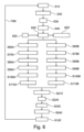
実際には、製造方法の第1の実施形態は、押出されたフィルムの一部分のトラッキングに対応する図4のフローチャート10に示されるように、以下の工程に従う。本方法は連続した方法であり、各工程は、フィルムの他の部分についての他の工程と並行して繰り返されることが理解される。
In practice, a first embodiment of the manufacturing method follows the steps as shown in
第1の工程S10において、インフレーションフィルムFは、筒形状のフィルムが得られるように、ダイDを介して1つ以上のポリマー材料を押し出すことによって形成される。フィルムは、単層フィルムであってもよいし、多層フィルムであってもよい。 In a first step S10, a blown film F is formed by extruding one or more polymeric materials through a die D such that a tubular shaped film is obtained. The film may be a monolayer film or a multilayer film.
第2の工程S20では、送風装置Blowによって筒状のフィルムに圧力下で空気が吹き込まれることによって、バブルが形成され、その後、フィルムは、2層構造を形成するように、工程S30の間にローラRol-1によって扁平化、すなわち、折りたたまれる。 In a second step S20, bubbles are formed by blowing air under pressure through the tubular film by means of a blower Blow, after which the film forms a two-layer structure during step S30. It is flattened, ie folded, by roller Roll-1.
工程S40において、ローラRol-2は、扁平化されたフィルムを測定システムMESに送る。 At step S40, roller Roll-2 feeds the flattened film to the measurement system MES.
工程S50において、測定システムMESは、扁平化されたフィルムによって形成された2層構造Biの厚さの横方向プロファイルを取得すると同時に、正規化された横方向位置xiによって特定される厚さの取得点iごとに、当該ダイが回転しているときのダイの角度位置αiを取得する。 In step S50, the measurement system MES acquires the lateral profile of the thickness of the bilayer structure Bi formed by the flattened film, simultaneously with the thickness specified by the normalized lateral position x i For each acquisition point i, obtain the angular position α i of the die when the die is rotating.
工程S60において、コンピュータCALCは、回転するダイの角度位置αiに基づいて、折り角度位置 In step S60, the computer CALC calculates the folding angular position
![]()
![]()
工程S50、S60で得られたデータは、メモリMEMに記憶され、例えば、図3Aの表TAB1のような形式で表すことができる。 The data obtained in steps S50, S60 are stored in memory MEM and can be represented in a format such as, for example, table TAB1 in FIG. 3A.
厚さの横方向プロファイルは、連続的に取得される。各プロファイルは、それ自身の値の表を有する。各横方向プロファイルは、カルマンフィルタの方法を用いた、厚さの極プロファイルの推定値の更新に使用される。 A transverse profile of thickness is acquired continuously. Each profile has its own table of values. Each transverse profile is used to update the estimate of the thickness polar profile using the Kalman filter method.
動作開始の特定の状況において、カルマンフィルタは、工程S55の間に、上述の原理およびデータを用いて、第1の厚さ横方向プロファイルに基づき初期化される。 In the particular situation of start-up, the Kalman filter is initialized during step S55 based on the first thickness lateral profile using the principles and data described above.
その後の横方向プロファイルは、それぞれフィルタの新しい反復回に使用される。 Each subsequent lateral profile is used for each new iteration of the filter.
工程S70において、厚さプロファイルの各取得点iに対応するダイの角度位置 In step S70, the angular position of the die corresponding to each acquisition point i of the thickness profile
![]()
![]()

工程S80において、コンピュータは、各測定点iについて極位置 In step S80, the computer calculates the polar position for each measurement point i

なお、離散化角度値を決定することは、それらを識別するインデックスpiおよびqiを決定することと等価であり、これらの特性量は、選択された角度分解能によって直接相互に関連付けられる。 Note that determining the discretized angular values is equivalent to determining the indices p i and q i that identify them, and these characteristic quantities are directly correlated by the chosen angular resolution.
工程S90において、コンピュータは、工程S80で得られた離散化角度値に基づいて、かつ、式(Eq.6)および(Eq.7)に基づいて、補間により、極位置 In step S90, the computer calculates the pole position

![]()
![]()
係数 coefficient
![]()
![]()
工程S100において、コンピュータは、式(Eq.8)で規定される連立一次方程式に基づいて、カルマンフィルタの観測行列Hkを決定し、所望の単一厚さの極プロファイルと、工程S50で測定された、扁平化されたフィルムで形成された2層構造の厚さの横方向プロファイルとを関連付ける。 In step S100, the computer determines the observation matrix Hk of the Kalman filter based on the system of linear equations defined in equation (Eq.8), and the desired single-thickness polar profile and the It also relates the lateral profile of the thickness of the bilayer structure formed of the flattened film.
工程S110において、また、既に初期化されているカルマンフィルタの計算を考慮することによって、ベクトルx kの推定値を表す推定量 In step S110, an estimator representing the estimate of the vector xk , also by considering the already initialized Kalman filter computation
![]()
![]()
工程S110の終了時に、最後に得られた(最新の)横方向プロファイルの情報から恩恵を受けるベクトルx kによって表される極プロファイルPOLPFの推定値が得られる。これは、図3Bに示すように、現在の極プロファイルPOLPFを規定する2列を有する表TAB2の形で、メモリMEM内に記憶される。 At the end of step S110, an estimate of the polar profile POLPF is obtained, represented by the vector xk , which benefits from the last obtained (up-to-date) transverse profile information. This is stored in the memory MEM in the form of a table TAB2 with two columns defining the current polar profile POLPF, as shown in FIG. 3B.
TAB2の第1列Col.1は、極プロファイルの当該極位置を特定するインデックスjを示す。 The first column Col. of TAB2. 1 indicates the index j identifying the pole position of interest in the pole profile.
TAB2の第2列Col.2は、インデックスjの極位置におけるフィルムの単一厚さを示し、この厚さは、ベクトルx kのj番目の更新要素x k(j)の値を有する。 The second column of TAB2, Col. 2 denotes the single thickness of the film at the pole position of index j, which has the value of the j-th update element x k (j) of the vector x k .
工程S120において、コンピュータCALCは、現在の極プロファイルPOLPFと、オペレータによって確立されたターゲットプロファイルx targetとの間の比較を行う。この実施形態では、座標のそれぞれについて、x targetとx kとの差を計算することによって、上記比較を行う。 At step S120, the computer CALC performs a comparison between the current polar profile POLPF and the target profile x target established by the operator. In this embodiment, this comparison is done by computing the difference between x target and x k for each of the coordinates.
工程FBKにおいて、監視制御システムC/Cは、上記比較に応答して、フィルム成形用装置を制御する。この制御は、オペレータによって手動で行われる調整、または、監視制御システムをフィルム成形用装置(例えばダイのアクチュエータACT)に連結するフィードバック制御ループによって自動的に行われる調整の後に行われる。 In step FBK, the supervisory control system C/C controls the film forming apparatus in response to the comparison. This control may be followed by adjustments made manually by an operator or automatically by a feedback control loop linking the supervisory control system to the film forming apparatus (eg, die actuator ACT).
アクチュエータの制御は、カルマンフィルタの入口で使用されるベクトルu kに対応する。 The control of the actuator corresponds to the vector u k used at the entrance of the Kalman filter.
このようにして、フィルムの単一厚さは、扁平化されたインフレーションフィルムの合計厚さの測定値に基づいて推定された極プロファイルの関数として、ダイにおいて監視および制御される。 In this way, the single thickness of the film is monitored and controlled at the die as a function of the polar profile estimated based on measurements of the total thickness of the flattened blown film.
この実施形態は、上記フィルムの厚さの監視および制御に基づいてフィルムを形成するための技術的解決策を提供するが、本発明は、当業者によって関連すると考えられる他の代替の特性量に基づく監視および制御にも及ぶ。 Although this embodiment provides a technical solution for forming a film based on the above film thickness monitoring and control, the present invention is not limited to other alternative characteristics considered relevant by those skilled in the art. based monitoring and control.
本発明の方法の第2の実施形態の説明
この第2の実施形態では、交互回転、すなわち一方向およびその反対方向に交互に回転するダイによってインフレーションフィルムを製造する方法について検討する。
Description of a Second Embodiment of the Method of the Invention In this second embodiment, we consider a method of producing a blown film with alternating rotation, ie, a die that rotates alternately in one direction and in the opposite direction.
そこで、ダイの回転方向に加えて、ダイの回転方向が変わるたびに定常状態が確立されるまで発生する周期的な位相シフト現象を考慮する必要がある。 Therefore, in addition to the rotation direction of the die, it is necessary to consider the periodic phase shift phenomenon that occurs every time the rotation direction of the die changes until a steady state is established.
この位相シフトは、バブルの慣性と変形によるもので、バブルの膨張が小さいほど変形が大きくなり、回転方向が変わると、バブルの慣性の影響をモデル化することが困難である。 This phase shift is due to the inertia and deformation of the bubble, and the smaller the expansion of the bubble, the greater the deformation, making it difficult to model the effect of bubble inertia as the direction of rotation changes.
したがって、ダイが交互に回転するときに、適用すべきシフトの値を正確に確立して、各時点の厚さプロファイルを正しく再構築することは困難である。 Therefore, it is difficult to establish precisely the value of the shift to be applied to correctly reconstruct the thickness profile at each point in time as the die alternately rotates.
逆に、上記のようなインフレーションフィルムの厚さプロファイルの測定に基づいて、ダイの回転の交互の態様を利用して、バブルの回転が定常領域であるときに適用するシフトαshiftを正確に決定することが可能である。 Conversely, based on measurements of the blown film thickness profile as described above, alternating modes of die rotation are used to accurately determine the shift α shift to apply when bubble rotation is in the steady region. It is possible to
その原理は、2つの補助カルマンフィルタによって、シフトを導入せずに、「パラレルプロファイル」と呼ばれる厚さ極プロファイルの2つの再構築を並列して行うことである。パラレルプロファイルの一方は、ダイの正の回転方向について得られたデータに基づいて再構築され、他方のパラレルプロファイルは、ダイの負の回転方向について得られたデータに基づいて再構築される。 The principle is to perform two reconstructions of thickness pole profiles in parallel, called "parallel profiles", without introducing shifts, by two auxiliary Kalman filters. One of the parallel profiles is reconstructed based on the data obtained for the positive die rotation direction and the other parallel profile is reconstructed based on the data obtained for the negative die rotation direction.
従って、プロファイルの大きな変動がフィルムに導入されないように十分に短い時間間隔で再構築されたパラレルプロファイルの場合、正および負の回転方向のそれぞれについて、POLPF(+αshift)とPOLPF(-αshift)という2つの類似した極プロファイルが得られる。一方は、これらのシフトを考慮したプロファイルに対して、+αshiftのシフト値で、他方は、-αshiftのシフト値でシフトされている。 Therefore, for parallel profiles reconstructed at sufficiently short time intervals so that no large profile variations are introduced into the film, POLPF(+α shift ) and POLPF(−α shift ) Two similar polar profiles are obtained. One is shifted by a shift value of +α shift and the other by a shift value of −α shift for the profile taking these shifts into account.
図5Aは、2×αshiftの角度値だけ相対的にシフトしていること以外は同様であるパラレルプロファイルを示す。 FIG. 5A shows parallel profiles that are similar except that they are relatively shifted by an angular value of 2×α shift .
図5AのパラレルプロファイルPOLPF(+αshift)とPOLPF(-αshift)との相互相関を表す相互相関曲線ICの最大値を、例えば放物線回帰によって決定することによって、図5Bに示すように、これら2つのプロファイル間の角度シフト2×αshiftを決定することが可能である。
By determining the maximum value of the cross-correlation curve IC representing the cross-correlation between the parallel profiles POLPF(+α shift ) and POLPF(−α shift ) of FIG. 5A, for example by parabolic regression, these two It is possible to determine the
このシフトを1/2にすることにより、角度修正シフトαshiftが得られる。角度修正シフトαshiftは、第1の実施形態において極プロファイルの推定を更新するためにメインカルマンフィルタの入力データに導入可能である。 By halving this shift, the angular correction shift α shift is obtained. An angle correction shift α shift can be introduced into the input data of the main Kalman filter to update the polar profile estimate in the first embodiment.
図6のフローチャート20は、本発明のインフレーションフィルムの製造方法の第2の実施形態を示す。 Flowchart 20 of FIG. 6 illustrates a second embodiment of the blown film manufacturing method of the present invention.
フローチャート10と同じように番号付けされた工程については、第1の実施形態を参照することができる。
For steps numbered the same as in
第2の実施形態は、以下の点で第1の実施形態とは異なっている。 The second embodiment differs from the first embodiment in the following points.
扁平化されたフィルムの合計厚さプロファイルを測定する工程S50’の時に、角度指示器ANGは、角度位置に加えて、ダイの回転方向を示す信号を工程S25の間に測定システムMESに送信し、それによって、フィルムの回転方向を決定することが可能である。 During step S50' of measuring the total thickness profile of the flattened film, the angle indicator ANG sends a signal indicating the rotational direction of the die, in addition to the angular position, to the measurement system MES during step S25. , with which it is possible to determine the direction of rotation of the film.
代わりに、インフレーションフィルムの回転が折りたたみパネルの回転に起因する場合、上記回転方向は、折りたたみパネルの回転方向であり得る。 Alternatively, if the rotation of the blown film results from the rotation of the folding panel, the direction of rotation may be the direction of rotation of the folding panel.
また、代わりに、センサの走査方向と指示角度の変化を調べることに基づいて、(ダイの回転または折りたたみパネルの回転によって発生する)フィルムの回転方向を決定することも可能である。 Alternatively, it is also possible to determine the direction of film rotation (caused by die rotation or folding panel rotation) based on examining changes in sensor scan direction and pointing angle.
フィルムの回転方向を決定することに応答して、測定システムMESは、第1の実施形態の工程S60~S100に相当する工程S60A~S100AおよびS60B~S100Bをそれぞれ含む、2つの補助カルマンフィルタの使用に基づく方法を用いて、取得されたデータを並行して処理する。 In response to determining the direction of rotation of the film, the measurement system MES employs two auxiliary Kalman filters, including steps S60A-S100A and S60B-S100B, respectively, corresponding to steps S60-S100 of the first embodiment. The acquired data are processed in parallel using methods based on
より具体的には、工程S60A~S110Aでは、第1の実施形態と同様に、正方向の回転の期間に得られた横方向プロファイルを、負方向の回転の期間に得られた横方向プロファイルとは独立して処理する。 More specifically, in steps S60A-S110A, as in the first embodiment, the lateral profile obtained during positive rotation is compared with the lateral profile obtained during negative rotation. are processed independently.
同様に、工程S60B~S110Bでは、第1の実施形態と同様に、負方向の回転の期間に得られた横方向プロファイルを、正方向の回転の期間に得られた横方向プロファイルとは独立して処理する。 Similarly, in steps S60B-S110B, as in the first embodiment, the lateral profile obtained during negative rotation is independent of the lateral profile obtained during positive rotation. process.
このように、フィルムの厚さの2つのパラレル極プロファイルが、所望のシフトに関連する修正なしに、交互に更新され、その結果、互いに対して2×αshiftだけ角度的にシフトされる。 In this way, the two parallel polar profiles of film thickness are alternately updated without correction associated with the desired shift, resulting in an angular shift of 2×α shift with respect to each other.
初期化工程S55’は、第1の実施形態の工程S55と同様の方法で、それぞれが2つのパラレルプロファイルのうちの1つの専用である2つの異なるカルマンフィルタを初期化することを含む。 The initialization step S55' comprises initializing two different Kalman filters, each dedicated to one of the two parallel profiles, in a similar manner to step S55 of the first embodiment.
工程S210の間、コンピュータCALCは、2つのパラレル極プロファイルの相互相関曲線を計算する。 During step S210, computer CALC calculates the cross-correlation curve of the two parallel polar profiles.
工程S220の間、コンピュータCALCは、上記相互相関曲線の最大値の位置を決定し、当該位置の角度値を1/2にして角度修正シフトαshiftを取得する。 During step S220, the computer CALC determines the position of the maximum value of the cross-correlation curve and halves the angle value at that position to obtain the angle correction shift α shift .
工程S230の間、コンピュータCALCは、現在の横方向プロファイルに、すなわち最新に取得された横方向プロファイルに、上記角度修正シフトによる修正を適用する。 During step S230, the computer CALC applies the correction due to said angular correction shift to the current lateral profile, i.e. to the last acquired lateral profile.
より具体的には、修正は、工程S220で得られた角度修正シフトに等しい振幅の正または負のシフトを、現在の横方向プロファイルについて、工程S50の厚さ取得点の折り角度に適用することを含む。正の方向の回転中に厚さが得られたフィルムの点の折り角度は-αshiftだけシフトされ、負の方向の回転中に厚さが得られたフィルムの点の折り角度は+αshiftだけシフトされる。 More specifically, the correction applies a positive or negative shift of amplitude equal to the angle correction shift obtained in step S220 to the fold angle of the thickness acquisition point of step S50 for the current lateral profile. including. The fold angles of the film points where the thickness was obtained during rotation in the positive direction are shifted by -α shift , and the fold angles of the film points where the thickness was obtained during the negative direction of rotation are shifted by +α shift . shifted.
上記の修正は、回転生成部材の角度位置に適用され、その後で、修正された位置に基づいて折り角度が決定されてもよい。または、上記の修正は、実際に直接折り角度に適用されてもよい。 The above modifications may be applied to the angular positions of the rotation generating members, and then the fold angle determined based on the modified positions. Alternatively, the above modifications may actually be applied directly to the fold angle.
工程S240の間、コンピュータCALCは、第1の実施形態の工程S50~S110を用いて、フィルムの厚さのメイン極プロファイルを得るために、修正された角度位置の横方向プロファイルと、負の方向の回転中に得られた横方向プロファイルと、正の方向の回転中に得られた横方向プロファイル(回転の反転を含むプロファイルを除く)と、をメインカルマンフィルタに供給する。 During step S240, the computer CALC uses the steps S50-S110 of the first embodiment to obtain the main polar profile of the film thickness, the lateral profile of the modified angular position and the negative direction Lateral profiles obtained during rotation of and lateral profiles obtained during rotation in the positive direction (excluding profiles involving rotation reversals) are fed to the main Kalman filter.
工程S120’において、コンピュータCALCは、第1の実施形態の工程S120における比較と同様の方法で、現在のメイン極プロファイルと、オペレータによって確立されたターゲットプロファイルとの間の比較を行う。 At step S120', the computer CALC performs a comparison between the current main polar profile and the target profile established by the operator in a manner similar to the comparison at step S120 of the first embodiment.
工程FBKにおいて、監視制御システムC/Cは、上記比較に応答して、オペレータによって手動で行われるフィルム成形用装置の調整、または、監視制御システムをフィルム成形用装置(例えばダイのアクチュエータACT)に連結するフィードバック制御ループによって自動的に行われる調整の後に、フィルム成形用装置を制御する。 In step FBK, the supervisory control system C/C either adjusts the film forming device manually by the operator or directs the supervisory control system to the film forming device (e.g. die actuator ACT) in response to the comparison. The film forming apparatus is controlled after adjustments made automatically by an interlocking feedback control loop.
なお、第1の実施形態と同様に、フィルムの折り位置の回転は、折りたたみパネルまたは他の回転発生部材によって発生させてもよい。この場合、考慮すべき角度位置は、回転発生部材の角度位置であってもよい。 As in the first embodiment, the rotation of the folding position of the film may be generated by a folding panel or other rotation generating member. In this case, the angular position to be considered may be the angular position of the rotation generating member.
当然のことながら、本発明は、上述の実施形態に何ら限定されるものではなく、本発明の範囲を超えることなく変更され得る。 Naturally, the invention is in no way limited to the embodiments described above, which may be varied without going beyond the scope of the invention.
Claims (6)
ダイ(D)を介した押出しによりインフレーションフィルムを成形する工程(S10)と、
回転を生成する部材の駆動により変化する折り角度(folding angle)で前記インフレーションフィルムを扁平化する工程(S30)と、
前記インフレーションフィルムの特性量の横方向プロファイルを測定する工程であって、前記特性量は、扁平化されたインフレーションフィルムの壁の2つの並置部分にわたって合計される、測定工程(S50)と、
前記横方向プロファイルに基づいて、前記インフレーションフィルムの前記特性量の離散化された極プロファイル(discretized polar profile)を推定する工程と、
前記インフレーションフィルムの前記離散化された極プロファイルの推定に応答して、前記フィルム成形装置を制御する工程と、を含み、
前記方法は、測定システムにおいて、前記横方向プロファイルが測定される測定点ごとに、
前記回転を生成する部材の角度位置(αi)を取得すること(S50)、
前記角度位置に基づいて、前記測定点の横方向位置(xi)について、前記横方向位置に位置付けられた、前記扁平化されたインフレーションフィルムの外周の2つの極位置
前記2つの極位置のそれぞれについて、その極位置を挟む2つの離散化角度値(discretized angle values)を決定すること(S80)、
前記離散化角度値に基づいて、前記インフレーションフィルムの極プロファイルと前記離散化された極プロファイルとを関連付ける補間係数
前記補間係数に基づいて、メインカルマンフィルタの観測行列を決定すること(S100)、および
前記測定工程(S50)で取得された前記横方向プロファイルが前記メインカルマンフィルタに入力され、前記メインカルマンフィルタによって、前記インフレーションフィルムの前記離散化された極プロファイルの前記推定を更新すること(S110)、
をさらに含むことを特徴とする、インフレーションフィルムの製造方法。 A method for producing a blown film (F) using a film forming apparatus, comprising:
A step (S10) of forming a blown film by extrusion through a die (D);
flattening the blown film at a folding angle that varies by driving a member that produces rotation (S30);
a measuring step (S50) of measuring the transverse profile of the characteristic quantity of said blown film, said characteristic quantity being summed over two juxtaposed portions of the wall of the flattened blown film;
estimating a discretized polar profile of the characteristic quantity of the blown film based on the transverse profile;
controlling the film forming apparatus in response to the estimation of the discretized polar profile of the blown film;
The method comprises, in a measurement system, for each measurement point at which the lateral profile is measured:
obtaining (S50) the angular position (α i ) of the member generating said rotation;
Based on the angular position, for the lateral position (x i ) of the measurement point, two polar positions on the perimeter of the flattened blown film positioned at the lateral position.
determining, for each of the two polar locations, two discretized angle values that flank the polar location (S80);
an interpolation factor that relates the polar profile of the blown film to the discretized polar profile based on the discretized angle values;
determining an observation matrix of a main Kalman filter based on the interpolation coefficients (S100); updating (S110) the estimate of the discretized polar profile of the film;
A method for producing a blown film, further comprising:
前記方法は、
前記インフレーションフィルムに対する測定によって取得された前記特性量の複数の横方向プロファイルに基づいて、前記インフレーションフィルムの前記特性量の、各回転方向に対して1つの離散化された極プロファイルである、離散化された2つの極プロファイルを並行して推定することであって、それぞれが前記2つの極プロファイルのうちの1つに専用である2つの補助カルマンフィルタを使用することによって、請求項1に記載の方法を用いて推定すること、
前記2つの極プロファイルの相互相関を表す相互相関曲線を計算すること(S210)、
前記相互相関曲線の最大値の位置を決定し(S220)、前記位置を1/2にして角度修正シフトを得ること、および
前記メインカルマンフィルタに、修正された横方向プロファイルを供給することによって、前記インフレーションフィルムの前記離散化された極プロファイルの前記推定の前記更新を決定すること(S240)、をさらに含むことを特徴とする、請求項1から4のいずれか1つに記載のインフレーションフィルムの製造方法。 the rotation is alternating rotation in which the rotation is alternately performed in opposite directions;
The method includes:
discretization, one discretized polar profile for each rotational direction of the characteristic quantity of the blown film, based on a plurality of transverse profiles of the characteristic quantity obtained by measurements on the blown film; 2. The method of claim 1 by estimating in parallel two polar profiles obtained by using two auxiliary Kalman filters each dedicated to one of said two polar profiles. estimating using
calculating a cross-correlation curve representing the cross-correlation of the two polar profiles (S210);
by determining (S220) the position of the maximum of the cross-correlation curve, halving the position to obtain an angular correction shift, and supplying the main Kalman filter with a corrected lateral profile. 5. Manufacturing a blown film according to any one of claims 1 to 4, further comprising determining (S240) the update of the estimate of the discretized polar profile of the blown film. Method.
Applications Claiming Priority (3)
| Application Number | Priority Date | Filing Date | Title |
|---|---|---|---|
| FR1913386 | 2019-11-28 | ||
| FR1913386A FR3103728B1 (en) | 2019-11-28 | 2019-11-28 | METHOD OF MANUFACTURING A BLOWN FILM WITH DETERMINATION OF A PROFILE OF A SIZE OF THE FILM |
| PCT/EP2020/081488 WO2021104841A1 (en) | 2019-11-28 | 2020-11-09 | Method for manufacturing a blown film with determination of the profile of a characteristic quantity of the film |
Publications (2)
| Publication Number | Publication Date |
|---|---|
| JP2023504055A JP2023504055A (en) | 2023-02-01 |
| JP7239784B2 true JP7239784B2 (en) | 2023-03-14 |
Family
ID=69811105
Family Applications (1)
| Application Number | Title | Priority Date | Filing Date |
|---|---|---|---|
| JP2022530971A Active JP7239784B2 (en) | 2019-11-28 | 2020-11-09 | Blown film manufacturing method with determination of film characteristic quantity profile |
Country Status (12)
| Country | Link |
|---|---|
| US (1) | US20220388220A1 (en) |
| EP (1) | EP4065333B1 (en) |
| JP (1) | JP7239784B2 (en) |
| KR (1) | KR20220130095A (en) |
| CN (1) | CN114981064A (en) |
| BR (1) | BR112022009220A2 (en) |
| ES (1) | ES2957113T3 (en) |
| FR (1) | FR3103728B1 (en) |
| MX (1) | MX2022006415A (en) |
| TW (1) | TWI765413B (en) |
| WO (1) | WO2021104841A1 (en) |
| ZA (1) | ZA202204475B (en) |
Citations (3)
| Publication number | Priority date | Publication date | Assignee | Title |
|---|---|---|---|---|
| US20110112677A1 (en) | 2009-11-11 | 2011-05-12 | Albert John Franklin | Method for controlling a physical property of a tubular blown film |
| JP4831629B2 (en) | 2005-12-13 | 2011-12-07 | 独立行政法人物質・材料研究機構 | Magnetic artificial superlattice and manufacturing method thereof |
| WO2016189518A2 (en) | 2015-05-27 | 2016-12-01 | I.M.Plast S.R.L. | A blown-film extrusion apparatus and a method for manufacturing a blown film |
Family Cites Families (8)
| Publication number | Priority date | Publication date | Assignee | Title |
|---|---|---|---|---|
| US3474160A (en) * | 1965-04-27 | 1969-10-21 | Industrial Nucleonics Corp | Method and apparatus for controlling blown film extruder |
| DE3014989C2 (en) * | 1980-04-18 | 1991-01-24 | Windmöller & Hölscher, 4540 Lengerich | Method for controlling the film thickness on a blown film extruder |
| EP0307076B1 (en) * | 1987-07-17 | 1992-10-21 | Toray Industries, Inc. | Method for controlling the thickness of a sheet material |
| JPH09225995A (en) * | 1996-02-23 | 1997-09-02 | Tomy Kikai Kogyo Kk | Uneventhickness-adjusting method for resin film in extrusion molding and resin film-molding device |
| JP4103041B2 (en) * | 2002-04-19 | 2008-06-18 | 横河電機株式会社 | Inflation equipment |
| ITMI20071963A1 (en) * | 2007-10-11 | 2009-04-12 | Syncro S R L | METHOD, SYSTEM AND PROGRAM FOR THE MEASUREMENT OF THE THICKNESS OF A TUBULAR FILM |
| JP5510865B2 (en) * | 2009-03-25 | 2014-06-04 | 住友化学株式会社 | Anti-glare treatment method, anti-glare film manufacturing method and mold manufacturing method |
| DE102009033171B4 (en) * | 2009-07-13 | 2016-03-03 | Hosokawa Alpine Ag | Method for controlling the film thickness of stretched tubular films and apparatus for carrying out the method |
-
2019
- 2019-11-28 FR FR1913386A patent/FR3103728B1/en active Active
-
2020
- 2020-11-09 US US17/777,177 patent/US20220388220A1/en active Pending
- 2020-11-09 WO PCT/EP2020/081488 patent/WO2021104841A1/en unknown
- 2020-11-09 ES ES20800947T patent/ES2957113T3/en active Active
- 2020-11-09 CN CN202080081957.7A patent/CN114981064A/en active Pending
- 2020-11-09 JP JP2022530971A patent/JP7239784B2/en active Active
- 2020-11-09 MX MX2022006415A patent/MX2022006415A/en unknown
- 2020-11-09 BR BR112022009220A patent/BR112022009220A2/en unknown
- 2020-11-09 KR KR1020227018211A patent/KR20220130095A/en unknown
- 2020-11-09 EP EP20800947.2A patent/EP4065333B1/en active Active
- 2020-11-16 TW TW109139929A patent/TWI765413B/en active
-
2022
- 2022-04-21 ZA ZA2022/04475A patent/ZA202204475B/en unknown
Patent Citations (3)
| Publication number | Priority date | Publication date | Assignee | Title |
|---|---|---|---|---|
| JP4831629B2 (en) | 2005-12-13 | 2011-12-07 | 独立行政法人物質・材料研究機構 | Magnetic artificial superlattice and manufacturing method thereof |
| US20110112677A1 (en) | 2009-11-11 | 2011-05-12 | Albert John Franklin | Method for controlling a physical property of a tubular blown film |
| WO2016189518A2 (en) | 2015-05-27 | 2016-12-01 | I.M.Plast S.R.L. | A blown-film extrusion apparatus and a method for manufacturing a blown film |
Also Published As
| Publication number | Publication date |
|---|---|
| EP4065333B1 (en) | 2023-07-26 |
| TWI765413B (en) | 2022-05-21 |
| TW202136020A (en) | 2021-10-01 |
| BR112022009220A2 (en) | 2022-08-02 |
| EP4065333C0 (en) | 2023-07-26 |
| CN114981064A (en) | 2022-08-30 |
| FR3103728A1 (en) | 2021-06-04 |
| JP2023504055A (en) | 2023-02-01 |
| WO2021104841A1 (en) | 2021-06-03 |
| US20220388220A1 (en) | 2022-12-08 |
| MX2022006415A (en) | 2022-06-22 |
| KR20220130095A (en) | 2022-09-26 |
| EP4065333A1 (en) | 2022-10-05 |
| ZA202204475B (en) | 2023-04-26 |
| FR3103728B1 (en) | 2021-10-22 |
| ES2957113T3 (en) | 2024-01-11 |
Similar Documents
| Publication | Publication Date | Title |
|---|---|---|
| Li et al. | Prediction of surface roughness in extrusion-based additive manufacturing with machine learning | |
| TW523456B (en) | Method for manufacturing thin sheet, device and method for controlling thickness of the thin sheet, and the thin sheet | |
| JP7133555B2 (en) | Systems and associated control methods for additive manufacturing processes | |
| US3474160A (en) | Method and apparatus for controlling blown film extruder | |
| US7813829B2 (en) | Sheet manufacturing method and sheet manufacturing device | |
| JP7239784B2 (en) | Blown film manufacturing method with determination of film characteristic quantity profile | |
| CN109318609A (en) | For depositing the method and print system of printing fluids on corrugated media sheet material | |
| JP4834946B2 (en) | Sheet manufacturing method and sheet thickness control apparatus | |
| JP4882705B2 (en) | Sheet manufacturing method and sheet manufacturing apparatus | |
| Wellstead et al. | Signal processing and control paradigms for industrial web and sheet manufacturing | |
| JPWO2022270506A5 (en) | ||
| JP2007296673A (en) | Position corresponding device and position corresponding method | |
| JP4419615B2 (en) | Sheet manufacturing method | |
| JP2002086539A (en) | Sheet manufacturing method | |
| KR100942328B1 (en) | One-dimensional modeling of the manufacture of multi-layered material | |
| EP2790893B1 (en) | Blown film scanning method | |
| JP2004122434A (en) | Profile control method for film sheet | |
| JP2528705B2 (en) | Thickness profile control method | |
| JP2007030288A (en) | Method for producing sheet | |
| JP2020203453A (en) | Sheet thickness adjustment system and sheet manufacturing method | |
| JP2023553102A (en) | Slot die position adjustment | |
| Wellstead et al. | Two Dimensional Systems Concepts for Industrial Web Processes | |
| JP2003315169A (en) | Profile measuring device | |
| JP2006255944A (en) | Apparatus for relating actuator and measuring point | |
| JP2003039525A (en) | Sheet and method for manufacturing the sheet |
Legal Events
| Date | Code | Title | Description |
|---|---|---|---|
| A621 | Written request for application examination |
Free format text: JAPANESE INTERMEDIATE CODE: A621 Effective date: 20220609 |
|
| TRDD | Decision of grant or rejection written | ||
| A01 | Written decision to grant a patent or to grant a registration (utility model) |
Free format text: JAPANESE INTERMEDIATE CODE: A01 Effective date: 20230131 |
|
| A61 | First payment of annual fees (during grant procedure) |
Free format text: JAPANESE INTERMEDIATE CODE: A61 Effective date: 20230302 |
|
| R150 | Certificate of patent or registration of utility model |
Ref document number: 7239784 Country of ref document: JP Free format text: JAPANESE INTERMEDIATE CODE: R150 |