JP7239727B2 - Stopper rod and method for providing a uniform gas curtain around the stopper rod - Google Patents
Stopper rod and method for providing a uniform gas curtain around the stopper rod Download PDFInfo
- Publication number
- JP7239727B2 JP7239727B2 JP2021550194A JP2021550194A JP7239727B2 JP 7239727 B2 JP7239727 B2 JP 7239727B2 JP 2021550194 A JP2021550194 A JP 2021550194A JP 2021550194 A JP2021550194 A JP 2021550194A JP 7239727 B2 JP7239727 B2 JP 7239727B2
- Authority
- JP
- Japan
- Prior art keywords
- passageway
- stopper rod
- stopper
- gas
- gas supply
- Prior art date
- Legal status (The legal status is an assumption and is not a legal conclusion. Google has not performed a legal analysis and makes no representation as to the accuracy of the status listed.)
- Active
Links
Images


Classifications
-
- B—PERFORMING OPERATIONS; TRANSPORTING
- B22—CASTING; POWDER METALLURGY
- B22D—CASTING OF METALS; CASTING OF OTHER SUBSTANCES BY THE SAME PROCESSES OR DEVICES
- B22D41/00—Casting melt-holding vessels, e.g. ladles, tundishes, cups or the like
- B22D41/14—Closures
- B22D41/16—Closures stopper-rod type, i.e. a stopper-rod being positioned downwardly through the vessel and the metal therein, for selective registry with the pouring opening
- B22D41/18—Stopper-rods therefor
- B22D41/186—Stopper-rods therefor with means for injecting a fluid into the melt
-
- B—PERFORMING OPERATIONS; TRANSPORTING
- B22—CASTING; POWDER METALLURGY
- B22D—CASTING OF METALS; CASTING OF OTHER SUBSTANCES BY THE SAME PROCESSES OR DEVICES
- B22D41/00—Casting melt-holding vessels, e.g. ladles, tundishes, cups or the like
- B22D41/14—Closures
- B22D41/22—Closures sliding-gate type, i.e. having a fixed plate and a movable plate in sliding contact with each other for selective registry of their openings
- B22D41/42—Features relating to gas injection
-
- B—PERFORMING OPERATIONS; TRANSPORTING
- B22—CASTING; POWDER METALLURGY
- B22D—CASTING OF METALS; CASTING OF OTHER SUBSTANCES BY THE SAME PROCESSES OR DEVICES
- B22D41/00—Casting melt-holding vessels, e.g. ladles, tundishes, cups or the like
- B22D41/50—Pouring-nozzles
- B22D41/58—Pouring-nozzles with gas injecting means
Landscapes
- Engineering & Computer Science (AREA)
- Mechanical Engineering (AREA)
- Casting Support Devices, Ladles, And Melt Control Thereby (AREA)
- Continuous Casting (AREA)
Description
本発明は、ストッパーロッド、並びに、ストッパーロッドの周りに一様なガスカーテンを設けるための方法に関する。 The present invention relates to a stopper rod and a method for providing a uniform gas curtain around the stopper rod.
溶融金属の連続鋳造、詳細には連続鋳造工場における溶融鋼の連続鋳造では、溶融金属は、容器、詳細にはとりべまたはタンディッシュの形態の容器の中に提供される。 In the continuous casting of molten metal, particularly continuous casting of molten steel in a continuous casting plant, molten metal is provided in a vessel, particularly in the form of a ladle or tundish.
出口は、溶融金属が提供される容器の底に設けられており、この出口を介して、容器の中の溶融金属を容器の下方に集合配置されている下流側に注ぐことができる。 An outlet is provided at the bottom of the vessel through which the molten metal is provided, through which outlet the molten metal in the vessel can be poured downstream, which is collectively located below the vessel.
タンディッシュの底には、タンディッシュノズルの形態のこのような出口が設けられている。このようなタンディッシュノズルは、水没入力ノズル(submerged entry nozzle、SEN)または水没入力シュラウド(submerged entry shroud、SES)の形態で提供することができる。タンディッシュからの溶融金属は、タンディッシュノズルを介して型の中に注ぐことができる。ストッパーロッドは、出口、詳細にはタンディッシュノズルを通って流れる溶融金属の量を制御するために設けられている。 The bottom of the tundish is provided with such an outlet in the form of a tundish nozzle. Such a tundish nozzle may be provided in the form of a submerged entry nozzle (SEN) or a submerged entry shroud (SES). Molten metal from the tundish can be poured into the mold through the tundish nozzle. A stopper rod is provided to control the amount of molten metal flowing through the outlet, specifically the tundish nozzle.
これらのストッパーロッドは、棒状のストッパーボディーを有しており、このストッパーボディーは、出口の上方、例えばタンディッシュノズルの上方に、垂直方向に整列されている。ストッパーロッドの上端では、金属ロッドがストッパーロッドに取り付けられており、それにより金属ロッドは、今度は持上げデバイスに接続されており、この持上げデバイスを介してストッパーロッドを垂直方向に上げ下げすることができる。ストッパーロッドの下端では、ストッパーロッドは、「ストッパーノーズ」として同じく知られているノーズを有している。ストッパーロッドを下げることにより、ノーズによって出口を完全に閉じることができ、したがって溶融金属が出口を通って流れることができない方法でノーズを出口に対して案内することができる。 These stopper rods have a rod-like stopper body which is vertically aligned above the outlet, eg above the tundish nozzle. At the upper end of the stopper rod, a metal rod is attached to the stopper rod, whereby the metal rod is in turn connected to a lifting device via which the stopper rod can be vertically raised and lowered. . At the lower end of the stopper rod, the stopper rod has a nose, also known as the "stopper nose". By lowering the stopper rod, the outlet can be completely closed by the nose, thus guiding the nose to the outlet in such a way that molten metal cannot flow through the outlet.
さらに、ストッパーロッドは、出口を開放して溶融金属が出口を通って流れることができるよう、垂直方向に持ち上げることができる。したがって出口、例えばタンディッシュノズルを通る溶融金属の流量は、ストッパーロッドによって制御することができる。 Additionally, the stopper rod can be lifted vertically to open the outlet and allow molten metal to flow through the outlet. The flow rate of molten metal through an outlet, eg a tundish nozzle, can thus be controlled by a stopper rod.
鋳造している間、溶融金属中に存在している粒子が、耐火材料の上、詳細にはストッパーロッド、出口、またはタンディッシュノズルの下流側の浸入ノズルの上に堆積することがある。これらの粒子は、とりわけ、溶融金属中に存在するアルミナ粒子であり得る。この堆積は、「詰まり」として同じく知られている。詰まりを抑制するために、不活性ガス、とりわけアルゴンまたは窒素がストッパーロッドのノーズの領域の溶融金属中に導入され、それにより詰まりを抑制することができることが知られている。 During casting, particles present in the molten metal can deposit on the refractory material, particularly on the stopper rod, the outlet, or the entry nozzle downstream of the tundish nozzle. These particles can be, inter alia, alumina particles present in the molten metal. This buildup is also known as "plugging". In order to suppress plugging, it is known that an inert gas, in particular argon or nitrogen, can be introduced into the molten metal in the region of the nose of the stopper rod, thereby suppressing plugging.
例えばノーズ領域にガス出口を有する一般的なストッパーロッドが欧州特許出願公開第2067549号明細書(特許文献1)、欧州特許出願公開第2189231号明細書(特許文献2)または欧州特許出願公開第2233227号明細書(特許文献3)に記載されている。 For example, typical stopper rods with gas outlets in the nose region are described in EP-A-2067549, EP-A-2189231 or EP-A-2233227. No. 2003/0001001 (Patent Document 3).
しかしながらストッパーロッドのノーズの領域における溶融金属中にガスを導入することは、鋳造している間、方向が交互に変化する、ストッパーロッドの混沌とした非一様な偏向をもたらすことになり得る(以下、「偏向」と呼ばれる)。鋳造中におけるこの偏向は、鋳造金属の品質に対する負の影響を有し得る。 However, introducing gas into the molten metal in the region of the nose of the stopper rod can result in chaotic and non-uniform deflection of the stopper rod during casting, alternating directions ( hereinafter referred to as "deflection"). This deflection during casting can have a negative impact on the quality of the cast metal.
本発明は、溶融金属の流れを制御し、かつ、溶融金属を鋳造している間、供給ガスを供給するためのストッパーロッドを提供する目的に基づいており、最新技術によるストッパーロッドの偏向と比較すると、鋳造プロセスの間、およびストッパーロッドを介してガスを溶融金属中に同時に導入している間、ストッパーロッドの偏向が低減される。 The present invention is based on the object of providing a stopper rod for controlling the flow of molten metal and for supplying feed gas during casting of molten metal, compared with the deflection of stopper rods according to the state of the art. Deflection of the stopper rod is then reduced during the casting process and during simultaneous introduction of gas into the molten metal through the stopper rod.
本発明のさらなる目的は、このようなストッパーロッドを使用するための方法を提供することである。 A further object of the invention is to provide a method for using such a stopper rod.
上記の問題を解決するために、本発明は、溶融金属の流れを制御し、かつ、溶融金属を鋳造している間、ガスを供給するためのストッパーロッドを提供し、前記ストッパーロッドは、
棒状のストッパーボディーであって、縦方向の中心軸に沿って第1の端部から第2の端部まで延びており、前記第2の端部に隣接するノーズを画定し、前記ノーズが外部表面を提供する、棒状のストッパーボディーと、
チャンバーであって、前記縦方向の中心軸に沿って、前記第1の端部から前記第2の端部へ向かって前記ストッパーボディーの中へ延びて、前記第2の端部から一定の距離を置いた手前で終端している、チャンバーと、
通路であって、前記ノーズの前記外部表面に設けられ、前記縦方向の軸の周りを延在している、通路と、
ガス供給手段であって、前記チャンバーから前記棒状のストッパーボディーを通って前記通路に通じている、ガス供給手段と
を備えている。
In order to solve the above problems, the present invention provides a stopper rod for controlling the flow of molten metal and supplying gas during casting the molten metal, said stopper rod comprising:
A rod-shaped stopper body extending along a central longitudinal axis from a first end to a second end and defining a nose adjacent said second end, said nose extending from the exterior. a rod-like stopper body that provides a surface;
a chamber extending into the stopper body along the longitudinal central axis from the first end toward the second end and a distance from the second end; a chamber that terminates before the placement of the
a passageway in the exterior surface of the nose and extending about the longitudinal axis;
gas supply means leading from said chamber through said rod-shaped stopper body to said passageway.
本発明は、鋳造プロセスの間、およびストッパーロッドを介してガスを溶融金属中に同時に供給している間のストッパーロッドの偏向は、ガスがストッパーロッドのノーズから溶融金属中に一様に解放されないことによるものであることの基本的な発見に基づいている。と言うよりも、本発明によれば、最新技術によるストッパーロッドの場合、ストッパーノーズから溶融金属中に導入されるガスは、溶融金属中のストッパーロッドの周りで上に向かって非一様に立ち上がり、したがってストッパーロッドの前記偏向をトリガすることが分かった。 The present invention prevents the deflection of the stopper rod during the casting process and while simultaneously feeding gas into the molten metal through the stopper rod so that the gas is not uniformly released from the nose of the stopper rod into the molten metal. It is based on the basic discovery that it is possible. Rather, according to the invention, in the case of state-of-the-art stopper rods, the gas introduced into the molten metal from the stopper nose rises non-uniformly upwards around the stopper rod in the molten metal. , thus triggering said deflection of the stopper rod.
驚くべきことには、本発明によれば、ストッパーロッドのこの偏向は、ガスをストッパーロッドから溶融金属中に一様に導入することによって著しく小さくすることができることが分かった。詳細には、本発明は、ストッパーロッドの偏向は、ストッパーロッドの周りに一様なガスカーテンが形成される方法でガスをストッパーロッドから溶融金属中に導入することによって著しく小さくすることができることを示した。したがって本発明によれば、ガスをストッパーロッドから溶融金属中に一様に導入することができる手段が本発明によるストッパーロッドの上に提供される。詳細には、ストッパーロッドの周りに一様なガスカーテンを形成することができる手段が設けられる。 Surprisingly, it has been found, according to the invention, that this deflection of the stopper rod can be significantly reduced by uniformly introducing the gas from the stopper rod into the molten metal. Specifically, the present invention finds that stopper rod deflection can be significantly reduced by introducing gas from the stopper rod into the molten metal in such a way that a uniform gas curtain is formed around the stopper rod. Indicated. Thus, according to the invention, means are provided above the stopper rod according to the invention by which gas can be uniformly introduced from the stopper rod into the molten metal. In particular, means are provided with which a uniform gas curtain can be formed around the stopper rod.
したがって本発明によるストッパーロッドの特徴は、ガスを本発明によるストッパーロッドを介して溶融金属中に一様に導入することができる方法で設計されており、詳細には、ストッパーロッドの周りに一様なガスカーテンを設けることができる方法で設計されている。 The characteristic of the stopper rod according to the invention is therefore designed in such a way that the gas can be uniformly introduced into the molten metal through the stopper rod according to the invention, in particular evenly around the stopper rod. It is designed in such a way that it can provide a strong gas curtain.
ガスをストッパーロッドから溶融金属中に一様に導入するためのこれらの手段の本質的な要素は、ノーズの外部表面に提供され、ストッパーボディーの縦方向の軸の周りを走っている、ストッパーロッドの通路である。ガス供給手段を使用して、ガスがストッパーロッドの前記チャンバーから前記通路中に導入される。通路はガス分配チャンバーとしても作用し、ガス供給手段によって通路に導入されたガスをこの中に集めて分配することができる。通路はストッパーノーズの外部表面に配置され、縦方向の軸の周りを完全に走っているため、通路中に集められ、かつ、分配されたガスを、ストッパーノーズの円周表面全体に沿って溶融金属中に一様に導入することができる。この点に関して、通路は、ガスをガス供給から受け取り、かつ、通路全体に一様に分配するように設計されている。 An essential element of these means for uniformly introducing gas from the stopper rod into the molten metal is a stopper rod, provided on the outer surface of the nose and running around the longitudinal axis of the stopper body. is the passage of Gas is introduced into the passageway from the chamber of the stopper rod using a gas supply means. The passageway also acts as a gas distribution chamber into which gas introduced into the passageway by the gas supply means can be collected and distributed. The passages are located on the outer surface of the stopper nose and run completely around the longitudinal axis so that the gas collected and distributed in the passages melts along the entire circumferential surface of the stopper nose. It can be uniformly introduced into the metal. In this regard, the passageway is designed to receive gas from the gas supply and distribute it evenly throughout the passageway.
したがって通路から解放されたガスは、それを溶融金属中に一様に導入することができるだけでなく、ストッパーロッドの周りに一様なガスカーテンを形成することができる。 The gas released from the passage can thus not only be introduced uniformly into the molten metal, but also can form a uniform gas curtain around the stopper rod.
通路の外側に向かう方向、すなわち通路の、ストッパーボディーから見て外側に向いている側では、通路は完全に開いていることが好ましい。これには、ガスを通路の長さ全体にわたって溶融金属中に導入することができ、したがってガスを溶融金属中に極めて一様に導入することができる利点がある。 In the outward direction of the passageway, ie on the side of the passageway facing outwards as seen from the stopper body, the passageway is preferably completely open. This has the advantage that the gas can be introduced into the molten metal over the entire length of the passage and therefore can be introduced very uniformly into the molten metal.
通路は、壁によって境界が定められる(通路の、ストッパーボディーから見て外側に向いている側を除く)。これには、ガス供給手段から通路に導入されたガスを通路に集めることができる利点がある。 The passageway is bounded by walls (except for the side of the passageway facing outwards from the stopper body). This has the advantage that the gas introduced into the passage from the gas supply means can be collected in the passage.
基本的には通路の断面積、すなわち通路の長手方向の進路に対して直角の方向における通路の断面積は、例えば概ね円形の断面積(すなわちC字形断面積)、半円形の通路底部および真っ直ぐな側壁を有する断面積(すなわちU字形断面積)、または平らな通路底部および真っ直ぐな側壁を有する断面積(すなわち正方形、例えば長方形または正方形の断面積)である任意の形を有することができる。 Basically, the cross-sectional area of the passageway, i.e. the cross-sectional area of the passageway in the direction perpendicular to the longitudinal course of the passageway, is, for example, a generally circular cross-sectional area (i.e. C-shaped cross-sectional area), a semi-circular passage bottom and a straight It can have any shape that is a cross-sectional area with flat sidewalls (ie, a U-shaped cross-sectional area) or a cross-sectional area with a flat channel bottom and straight sidewalls (ie, a square, eg, rectangular or square cross-sectional area).
通路はV字形断面積を有していることがとりわけ好ましい。したがって通路は、通路の側壁が共通領域(通路底部を構築している)からノーズの外部表面に向かって(したがって縦方向の軸から離れる1つの方向に)発散し、最終的に側壁がノーズの外部表面中に没入している形を有している。本発明によれば、通路がこのようなV字形断面積を有している場合、ガスを通路からとりわけ一様に溶融金属中に導入することができることが分かった。 It is particularly preferred that the passage has a V-shaped cross-sectional area. Thus, the channels diverge from the common area (forming the channel bottom) to the exterior surface of the nose (thus in one direction away from the longitudinal axis) until the sidewalls eventually diverge from the nose. It has a shape that is immersed in the external surface. According to the invention, it has been found that the gas can be introduced particularly uniformly from the passageway into the molten metal when the passageway has such a V-shaped cross-sectional area.
好ましい実施形態によれば、通路は一様な断面積を有している。したがって通路の断面積は、通路の進路全体にわたって変化しない。これは、ガスを通路の中に極めて一様に集めることができ、したがって通路のこのような一様な断面積には、延いてはガスを通路から極めて一様に解放することができ、また、溶融金属中に導入することができる利点があることを意味している。 According to a preferred embodiment, the channels have a uniform cross-sectional area. The cross-sectional area of the passageway therefore does not change over the course of the passageway. This allows gas to be collected very uniformly in the passageway, and thus such uniform cross-sectional area of the passageway, in turn, allows gas to be released very uniformly from the passageway, and , meaning that there are advantages that can be introduced into the molten metal.
とりわけ好ましい実施形態によれば、通路は連続的に設計されており、すなわち縦方向の軸の周りを連続的に走っている。言い換えると通路は、開始および終わりを有することなく、縦方向の軸の周りを継目なしに、すなわち「無限に」延在している。さらに、通路は、通路に沿ったガスの流れを妨害し得る障害物または中断を有していない。このような連続通路には多くの利点がある。このような連続通路の1つの利点は、通路に沿ったガス圧を平衡させることができ、したがって通路に沿ったガス圧が等しくなり、また、ガスを通路から溶融金属中に同じ圧力で解放することができ、したがって通路の長さ全体にわたって同じ量のガスを解放することができることである。さらに、このような連続通路には、例えばガス供給手段の一部が阻止されることによってガス供給手段の一部を介して通路にガスを供給することができない場合であっても、そのガス供給手段を介して通路にガスを供給することができる利点がある。すべてのこれらの利点は、延いては通路にガスを一様に、かつ、完全に満たすことができ、したがってガスを通路から溶融金属中に一様に導入することができることを意味している。 According to a particularly preferred embodiment, the passage is designed continuously, ie runs continuously around the longitudinal axis. In other words, the passageway extends seamlessly, ie "infinitely", around the longitudinal axis without a beginning and an end. Additionally, the passageway has no obstructions or interruptions that could impede the flow of gas along the passageway. Such a continuous passage has many advantages. One advantage of such a continuous passageway is that the gas pressure along the passageway can be balanced, thus equalizing the gas pressure along the passageway and releasing the gas from the passageway into the molten metal at the same pressure. and thus release the same amount of gas over the length of the passageway. Furthermore, such a continuous passage may be provided with a gas supply even if the passage cannot be supplied with gas via part of the gas supply means, for example due to a part of the gas supply means being blocked. Advantageously, gas can be supplied to the passageway via means. All these advantages in turn mean that the passages can be uniformly and completely filled with gas and therefore introduced uniformly from the passages into the molten metal.
基本的には、通路は、縦方向の軸の周りに例えばジグザグの形または波のような形の任意の進路を有することができる。好ましい実施形態によれば、通路は、リングの形であるか、または円形のリングの形を有するリングを形成している。本発明によれば、このようなリングの形の通路により、ガスを通路から溶融金属中にとりわけ一様に導入することができることが分かった。 Basically, the passage can have any course around the longitudinal axis, for example zig-zag or wave-like. According to a preferred embodiment, the passage is in the shape of a ring or forms a ring having the shape of a circular ring. It has been found according to the invention that such a channel in the form of a ring allows a particularly uniform introduction of the gas from the channel into the molten metal.
とりわけ好ましい実施形態によれば、通路は、とりわけそれがリングの形である場合、縦方向の軸に対して回転対称である。 According to a particularly preferred embodiment, the passage is rotationally symmetrical with respect to the longitudinal axis, especially when it is in the form of a ring.
本発明によれば、驚くべきことには、通路をストッパーボディーの第1の端部に向かって制限している通路の壁がストッパーノーズの外部表面中に没入している領域によって画定される縁(すなわちストッパーの機能位置における通路の「上側の」縁)の形は、ガスが通路から溶融金属中に解放される方法に対して高い影響力を有していることが分かった。この点に関して、本発明によれば、驚くべきことには、とりわけこの縁が可能な限り鋭い場合、ガスを通路から溶融金属中にとりわけ一様な方法で導入することができることが分かった。したがって好ましい実施形態によれば、通路は、前記第1の端部に向かう方向に通路を制限する第1の通路壁を備え、前記第1の通路壁および前記ノーズの前記外部表面は第1の縁を形成し、また、前記第1の縁は鋭い縁の形を有していることが実現される。 Surprisingly, according to the present invention, the rim defined by the area where the wall of the passage limiting the passage towards the first end of the stopper body is recessed into the outer surface of the stopper nose. It has been found that the shape of the passageway (ie the "upper" edge of the passageway in the functional position of the stopper) has a high impact on the way gas is released from the passageway into the molten metal. In this respect, according to the invention it was surprisingly found that the gas can be introduced from the channels into the molten metal in a particularly uniform manner, especially if this edge is as sharp as possible. Thus according to a preferred embodiment the passageway comprises a first passageway wall limiting the passageway in the direction towards said first end, said first passageway wall and said external surface of said nose being in a first It is realized that forming an edge and said first edge has the shape of a sharp edge.
本発明による着想の特殊な実施形態によれば、この第1の縁は1mm以下の半径を有している。第1の縁は0.5mm以下の半径を有していることがより一層好ましい。 According to a special embodiment of the idea according to the invention, this first edge has a radius of 1 mm or less. Even more preferably, the first edge has a radius of 0.5 mm or less.
本発明によれば、ガスが通路から溶融金属中に解放される方法は、通路口の幅、すなわち通路がノーズの外部表面中に没入する領域における通路の幅に同じく依存することが同じく分かった。通路口は、通路(すなわち通路の壁)がノーズの外部表面中に没入する領域では、2mmから30mmまでの範囲の幅を有していることが好ましい。 It has also been found, according to the invention, that the manner in which gas is released from the passageway into the molten metal is also dependent on the width of the passage mouth, i. . The passage mouth preferably has a width in the range from 2 mm to 30 mm in the region where the passage (ie the wall of the passage) sinks into the outer surface of the nose.
この特徴のとりわけ好ましい実施形態によれば、通路は、通路を前記第2の端部に向かう方向に制限している第2の通路壁を備えており、前記第2の通路壁および前記ノーズの前記外部表面は第2の縁を形成しており、また、前記第1の縁と前記第2の縁の間の距離は、2mmから30mmまでの範囲にある。 According to a particularly preferred embodiment of this feature, the passageway comprises a second passageway wall limiting the passageway in a direction towards said second end, said second passageway wall and said nose The outer surface forms a second edge, and the distance between the first edge and the second edge is in the range of 2mm to 30mm.
通路は、その口の領域、すなわち通路がノーズの外部表面中に没入する領域では、一定の幅を有していることが好ましい。この点に関して、この実施形態によれば、第1の縁および第2の縁は、場合によっては互いに平行に走っていることが好ましい。 The passage preferably has a constant width in the area of its mouth, ie the area where the passage sinks into the outer surface of the nose. In this respect, according to this embodiment, the first edge and the second edge possibly run parallel to each other.
本発明によれば、通路の深さも、ガスを通路から溶融金属中に導入することができる方法に対する影響力を同じく有していることが分かった。通路は、4mmから15mmまでの範囲の深さを有していることが好ましい。 In accordance with the present invention, it has been found that the depth of the passageway also has an effect on the manner in which gas can be introduced from the passageway into the molten metal. The passages preferably have a depth ranging from 4 mm to 15 mm.
本発明によれば、通路が4mmから15mmまでの範囲の深さを有している場合、通路からのガスを溶融金属中にとりわけ一様に導入することができることが分かった。通路から溶融金属中へのガス吐出の一様性は、6mmから12mmまでの範囲の深さを有する通路によってさらに増すことができる。通路の「深さ」は、その上端における通路の2つの縁の間(すなわち通路の壁がノーズの外部表面中に没入する通路の2つの縁の間)を延びている仮想平面の最も短い距離、および通路の最も低い点、すなわち通路の底として定義される。 It has been found according to the invention that the gas from the passages can be introduced particularly uniformly into the molten metal if the passages have a depth ranging from 4 mm to 15 mm. The uniformity of gas delivery from the passages into the molten metal can be further enhanced by passages having a depth ranging from 6 mm to 12 mm. The "depth" of a passageway is the shortest distance in an imaginary plane extending between the two edges of the passageway at its upper end (i.e. between the two edges of the passageway where the walls of the passageway are immersed in the outer surface of the nose). , and the lowest point of the passage, ie the bottom of the passage.
さらに、本発明によれば、通路の断面積の広さも、ガスを通路から溶融金属中に導入することができる方法に対する影響力を同じく有していることが分かった。通路は、2mm2から225mm2までの範囲の断面積を有していることが好ましい。本発明によれば、通路がこのような断面積を有している場合、ガスを通路から溶融金属中にとりわけ一様に導入することができることが分かった。通路から溶融金属中へのガスの解放の一様性は、8mm2から70mm2までの範囲の断面積を有する通路によってさらに改善することができる。 Further, in accordance with the present invention, it has been found that the cross-sectional area of the passageway also has an effect on the manner in which gas can be introduced from the passageway into the molten metal. The passages preferably have cross-sectional areas ranging from 2 mm 2 to 225 mm 2 . It has been found according to the invention that when the channels have such a cross-sectional area, the gas can be introduced particularly uniformly from the channels into the molten metal. The uniformity of gas release from the passages into the molten metal can be further improved by passages having cross-sectional areas ranging from 8 mm 2 to 70 mm 2 .
棒状のストッパーボディー、および縦方向の中心軸に沿ってストッパーボディーの中へ延びているチャンバーは、最新技術に従って設計することができる。この点に関して、棒状のストッパーボディーは、場合によっては耐火材料、とりわけセラミック耐火材料でできていることが好ましい。詳細には、棒状のストッパーボディーは、アルミナ(Al2O3)および炭素をベースとする耐火材料、すなわちいわゆるアルミナ-炭素材料で構築することができる。 The bar-shaped stopper body and the chamber extending into the stopper body along the central longitudinal axis can be designed according to the state of the art. In this respect, the rod-shaped stopper body is optionally made of a refractory material, especially a ceramic refractory material. In particular, the rod-shaped stopper body can be constructed of alumina ( Al2O3 ) and carbon-based refractory materials, ie so-called alumina-carbon materials .
棒状のストッパーボディーは、場合によっては、縦方向の中心軸に対して回転対称である外部円周表面を有していることが好ましい。これは、通路から解放されるガスの、ストッパーボディーに沿った一様な流れを促進し、延いてはストッパーロッドの周りの一様なガスカーテンの形成を促進する。 The rod-shaped stopper body optionally has an outer circumferential surface which is rotationally symmetrical with respect to the central longitudinal axis. This promotes a uniform flow of gas released from the passageway along the stopper body, which in turn promotes the formation of a uniform gas curtain around the stopper rod.
ストッパーロッドの機能位置、すなわち縦方向の中心軸が垂直方向に整列する機能位置におけるストッパーボディーの上端を形成する第1の端部の領域では、ストッパーロッドを垂直方向に上げ下げするためのデバイスにストッパーボディーを取り付けることができる手段をストッパーボディーの上に提供することができる。これらの手段は、最新技術に従って設計することができる。例えば雄ねじを有する金属ロッドをねじ込むことができる雌ねじを有するファスナーを提供することができる。この金属ロッド自体は、その金属ロッドを介してストッパーロッドを上げ下げすることができる方法で持上げデバイスと相互作用することができる。 In the functional position of the stopper rod, i.e. in the region of the first end forming the upper end of the stopper body in the functional position in which the longitudinal central axis is vertically aligned, a device for vertically raising and lowering the stopper rod is provided with a stopper. Means can be provided on the stopper body by which the body can be attached. These means can be designed according to the state of the art. For example, an internally threaded fastener can be provided into which an externally threaded metal rod can be screwed. This metal rod itself can interact with the lifting device in such a way that the stopper rod can be raised and lowered via the metal rod.
第1の端部の反対側であり、また、ストッパーロッドの機能位置におけるストッパーボディーの下端であるその第2の端部の領域では、ストッパーボディーの外部表面(すなわち外部輪郭)は、最新技術で知られているノーズすなわちストッパーノーズの形を有している。ノーズの外部表面は、縦方向の軸に対して回転対称であることが好ましい。 In the region of its second end, which is opposite the first end and which is the lower end of the stopper body in the functional position of the stopper rod, the outer surface (i.e. outer contour) of the stopper body is state-of-the-art It has the shape of a known nose or stopper nose. The outer surface of the nose is preferably rotationally symmetrical about the longitudinal axis.
ノーズの外部表面は、第2の端部から第1の端部に向かって広がっていることが好ましい。好ましい実施形態によれば、ノーズの外部表面は、第2の端部から第1の端部に向かう方向に円錐状に広がっているか、あるいは円錐として形成されている。とりわけ好ましい設計によれば、ノーズの外部表面は半球形である。 The outer surface of the nose preferably widens from the second end toward the first end. According to a preferred embodiment, the outer surface of the nose widens conically in the direction from the second end to the first end or is formed as a cone. According to a particularly preferred design, the outer surface of the nose is hemispherical.
通路はノーズの外部表面に設けられる。 A passageway is provided in the outer surface of the nose.
最新技術で知られているように、ストッパーロッドは、縦方向の中心軸に沿って、第1の端部から前記第2の端部に向かって前記ストッパーボディー中へ延びて、第2の端部から一定の距離をおいた手前のストッパーボディーの中で終わっているチャンバーを有している。このチャンバーは、場合によっては縦方向の中心軸に対して回転対称であることが好ましく、例えば円形-円筒状の形を有している。本発明によるストッパーロッドは、前記チャンバーから前記棒状のストッパーボディーを通って前記通路に通じているガス供給手段を備えている。したがってチャンバーの中に導入されたガス、詳細にはアルゴンまたは窒素などの不活性ガスは、ガス供給手段を介して通路中に引き渡すことができる。 As is known in the state of the art, a stopper rod extends along a central longitudinal axis into said stopper body from a first end towards said second end to reach a second end. It has a chamber that ends in a stopper body on the front at a certain distance from the part. This chamber is preferably rotationally symmetrical about a central longitudinal axis, for example having a circular-cylindrical shape. The stopper rod according to the invention comprises gas supply means leading from the chamber through the rod-like stopper body to the passageway. A gas introduced into the chamber, in particular an inert gas such as argon or nitrogen, can thus be delivered into the passageway via the gas supply means.
チャンバーにガスを供給するために、チャンバーをガス供給に接続することができる。このガス供給は、最新技術で知られているように、とりわけストッパーボディーの第1の端部の領域に設けることができる。 The chamber can be connected to a gas supply to supply gas to the chamber. This gas supply can be provided, inter alia, in the region of the first end of the stopper body, as is known in the state of the art.
ガス供給手段は、ガスをチャンバーからストッパーボディーを介して通路中に引き渡すことができる方法で設計される。 The gas supply means are designed in such a way that gas can be delivered from the chamber through the stopper body into the passageway.
一実施形態によれば、ガス供給手段は少なくとも1つの多孔性要素であってもよい。この少なくとも1つの多孔性要素は、ガスを少なくとも1つの多孔性要素を介してチャンバーから通路へ引き渡すことができる多孔性を有している。少なくとも1つの多孔性要素は、例えばとりべの中の溶融金属をガス浄化するための多孔性浄化プラグで知られている多孔性を有することができる。 According to one embodiment, the gas supply means may be at least one porous element. The at least one porous element has a porosity that allows gas to pass through the at least one porous element from the chamber to the passageway. The at least one porous element can have a porosity such as is known from porous purging plugs for gas purifying molten metal in ladles.
とりわけ好ましい実施形態によれば、ガス供給手段は複数のガス供給ラインである。これらのガス供給ラインは自由な断面積を有しており、この断面積を介してガスをチャンバーから通路の中へ導くことができる。 According to a particularly preferred embodiment, the gas supply means are a plurality of gas supply lines. These gas supply lines have a free cross section through which gas can be led from the chamber into the passage.
好ましい実施形態によれば、前記ガス供給手段は複数のガス供給ラインであり、前記ガス供給ラインの各々は、ある領域で前記通路に通じており、前記領域は互いに間隔を隔てていることが実現されている。 According to a preferred embodiment, it is provided that said gas supply means are a plurality of gas supply lines, each of said gas supply lines leading into said passage in a region, said regions being spaced apart from each other. It is
本発明によれば、ガス供給ラインが互いに間隔を隔てた領域でダクトに通じている場合、ガス供給ラインを介したチャンバーからのガスは、とりわけ一様に通路中に導くことができ、また、通路から溶融金属中に解放することができることが分かった。2本から10本の数のガス供給ラインが好ましく、3本から6本のガス供給ラインがより一層好ましい。したがってこれらのガス供給ラインは、互いに間隔を隔てた2個から10個、または3個から6個の領域で通路に通じている。本発明によれば、ガスがこのような数のガス供給ラインを介して通路中に導かれ、これらのガス供給ラインが互いに間隔を隔てた対応する数の領域を有するダクトに通じている場合、ガスはとりわけ一様に通路中に導かれ、また、一様に通路から溶融金属中に導かれることが分かった。 According to the invention, if the gas supply lines lead to the ducts in mutually spaced regions, the gas from the chamber via the gas supply lines can be led particularly uniformly into the passageway, and It has been found that the passage can be released into the molten metal. A number of gas supply lines of 2 to 10 is preferred, and a number of gas supply lines of 3 to 6 is even more preferred. These gas supply lines thus open into the passages in two to ten or three to six regions spaced apart from one another. According to the invention, when gas is led into the passage via such a number of gas supply lines, which lead to ducts having a corresponding number of areas spaced from one another, It has been found that the gas is led particularly uniformly into the channel and also uniformly from the channel into the molten metal.
ガス供給ラインがダクトに通じている領域は、底すなわち通路の最も低い点に配置されることが好ましい。本発明によれば、この設計により、通路中に供給されたガスを、通路に均等に分配される長い時間にわたって通路に留めることができ、次に通路から溶融金属中に一様に導入することができることが分かった。 The area where the gas supply line leads to the duct is preferably located at the bottom or lowest point of the passageway. According to the invention, this design allows the gas fed into the passages to remain in the passages for a long period of time evenly distributed to the passages and then uniformly introduced from the passages into the molten metal. I found that I can do it.
好ましい実施形態によれば、ガス供給ラインが通路に通じている領域は均等に間隔を隔てている。領域は互いに対称的に間隔を隔てていることがとりわけ好ましい。領域は、縦方向の軸に対して対称的に提供されることがより一層好ましい。これには、ガス供給ラインを介してとりわけ一様な方法でガスを通路中に導くことができ、また、通路から溶融金属中に一様に導入することができる利点がある。 According to a preferred embodiment, the areas where the gas supply lines lead to the passages are evenly spaced. It is particularly preferred that the regions are symmetrically spaced from each other. Even more preferably, the regions are provided symmetrically about the longitudinal axis. This has the advantage that the gas can be introduced in a particularly uniform manner into the channels via the gas supply lines and can be introduced uniformly from the channels into the molten metal.
一実施形態によれば、ガス供給手段は、ガス供給ラインと少なくとも1つの多孔性要素の組合せとして設けられる。 According to one embodiment, the gas supply means are provided as a combination of a gas supply line and at least one porous element.
本発明によれば、チャンバーの断面積に対するガス供給ラインの断面積の比率は、ガスがガス供給ラインを介してチャンバーから通路中に導かれる一様性に対する影響力を有している。 According to the invention, the ratio of the cross-sectional area of the gas supply line to the cross-sectional area of the chamber has an effect on the uniformity with which gas is directed from the chamber through the gas supply line into the passageway.
好ましい実施形態によれば、チャンバーは断面積を有しており、ガス供給ラインの各々は断面積を有しており、前記チャンバーの前記断面積は前記ガス供給ラインの前記断面積のすべての総面積より広いことが実現される。チャンバーの断面積は縦方向の中心軸に対して直角に測定され、また、ガス供給ラインの各々の断面積は、それぞれのガス供給ラインの長手方向の軸に対して直角に測定される。チャンバーが可変断面積を有している限り、チャンバーの断面積は有効断面積、すなわち最も狭い断面積であり、ガスをチャンバーを介してガス供給ラインに案内することができる。ガス供給ラインが可変断面積を有している限り、ガス供給ラインの断面積は有効断面積、すなわち最も狭い断面積であり、ガスをガス供給ラインを介して通路に案内することができる。 According to a preferred embodiment, the chamber has a cross-sectional area, each of the gas supply lines has a cross-sectional area, and said cross-sectional area of said chamber is the sum of all said cross-sectional areas of said gas supply lines. Wider than area is realized. The cross-sectional area of the chamber is measured perpendicular to the central longitudinal axis, and the cross-sectional area of each of the gas supply lines is measured perpendicular to the longitudinal axis of the respective gas supply line. As long as the chamber has a variable cross-sectional area, the cross-sectional area of the chamber is the effective cross-sectional area, ie the narrowest cross-sectional area, allowing gas to be guided through the chamber to the gas supply line. As long as the gas supply line has a variable cross-sectional area, the cross-sectional area of the gas supply line is the effective cross-sectional area, ie the narrowest cross-sectional area, allowing gas to be guided to the passage through the gas supply line.
本発明による着想の好ましい特殊な実施形態によれば、チャンバーの断面積は、前記ガス供給ラインの前記領域の断面積のすべての総面積より10倍から400倍の範囲で広く、30倍から200倍の範囲で広いことがより一層好ましい。 According to a preferred special embodiment of the conceived according to the invention, the cross-sectional area of the chamber is in the range of 10 to 400 times greater than the total cross-sectional area of all of the cross-sectional areas of said regions of said gas supply line, 30 to 200 times greater. It is much more preferable to be wide in the double range.
ガス供給ラインは任意の形を有することができる。ガス供給ラインは、真っ直ぐ、すなわち直線であることが好ましい。本発明による着想の特殊な実施形態によれば、ガス供給ラインは、断面積が円形の真っ直ぐな進路を有している。これには、例えばストッパーボディー中にガス供給ラインを穿孔することによって容易にガス供給ラインを製造することができる明確な利点がある。 The gas supply line can have any shape. The gas supply line is preferably straight, ie straight. According to a special embodiment of the idea according to the invention, the gas supply line has a straight course with a circular cross section. This has the distinct advantage that the gas supply line can be easily manufactured, for example by drilling the gas supply line into the stopper body.
好ましい実施形態によれば、ガス供給ラインは、縦方向の中心軸に対して対称に配置される。上で示したように、ストッパーボディーのノーズは、溶融金属のための容器中の出口、詳細にはタンディッシュ中のタンディッシュノズルの形態の出口を閉じることができる方法で設計される。閉じた位置では、すなわちストッパーボディーのノーズによってタンディッシュノズルが閉じられる方法で、ストッパーロッドのノーズがタンディッシュノズルに対して案内されると、ノーズの外部表面のノーズの周りを走っている連続線に沿って、タンディッシュノズルの表面がストッパーボディーのノーズの外部表面に接触する。この仮想線は、「スロットル点」として同じく知られている。本発明によるストッパーロッドの場合、通路が、このスロットル点の下方を完全に走っているノーズの外部表面のこのような領域に提供されることが実現されることが好ましい。言い換えると、通路が提供されるノーズの外部表面の領域は、ストッパーロッドの機能位置におけるスロットル点の下方、すなわちストッパーボディーの第1の端部が頂部に配置され、また、ストッパーボディーの第2の端部(したがって同じくノーズ)が底に配置される、縦方向の中心軸の垂直方向の位置に配置される。閉じた位置におけるスロットル点の下方のノーズは、溶融金属によって囲まれていないため、閉じた位置における通路も溶融金属によって囲まれていない。 According to a preferred embodiment, the gas supply lines are arranged symmetrically with respect to the longitudinal central axis. As indicated above, the nose of the stopper body is designed in such a way that it can close the outlet in the vessel for the molten metal, particularly in the form of a tundish nozzle in the tundish. In the closed position, i.e. in such a way that the tundish nozzle is closed by the nose of the stopper body, when the nose of the stopper rod is guided against the tundish nozzle, a continuous line running around the nose on the external surface of the nose. along which the surface of the tundish nozzle contacts the outer surface of the nose of the stopper body. This virtual line is also known as the "throttle point". In the case of the stopper rod according to the invention it is preferably realized that passages are provided in such regions of the outer surface of the nose running completely below this throttle point. In other words, the area of the outer surface of the nose where the passage is provided is below the throttle point in the functional position of the stopper rod, i.e. the first end of the stopper body is located on top, and the second end of the stopper body It is arranged at a vertical position of the central longitudinal axis, with the end (and thus also the nose) being arranged at the bottom. Since the nose below the throttle point in the closed position is not surrounded by molten metal, neither is the passageway in the closed position.
本発明によるストッパーロッドは、ストッパーロッド生産のための最先端技術を使用して製造することができる。この点に関して、ストッパーロッドは、一体鋳造ストッパーの形態で製造することができる。ストッパーボディーは、最新技術で知られている均衡加圧によって製造されることが好ましい。均衡加圧に加えて、ガス供給ラインは、例えば穿孔によって製造することができる。通路は、例えばノーズの表面から粉砕することができる。 A stopper rod according to the invention can be manufactured using state-of-the-art technology for stopper rod production. In this regard, the stopper rod can be manufactured in the form of a monoblock stopper. The stopper body is preferably manufactured by isostatic pressing, which is known in the state of the art. In addition to isostatic pressurization, gas supply lines can be produced, for example, by drilling. Passages can be milled from the surface of the nose, for example.
本発明の1つの目的は、溶融金属を保持するための容器の準備であり、容器は底を備え、溶融金属を前記容器から吐出するための出口が前記底に設けられており、また、本発明によるストッパーロッドにより、前記出口を通って流れる溶融金属の量が制御される。溶融金属を保持するための容器はタンディッシュであることが好ましく、溶融金属を受け取るためのタンディッシュであることが好ましく、とりわけ連続鋳造工場における溶融鋼を受け取るためのタンディッシュであることがより一層好ましい。出口はタンディッシュノズルであることが好ましい。 One object of the present invention is the provision of a container for holding molten metal, the container comprising a bottom, said bottom being provided with an outlet for discharging molten metal from said container, and the present invention A stopper rod according to the invention controls the amount of molten metal flowing through said outlet. The vessel for holding molten metal is preferably a tundish, preferably a tundish for receiving molten metal, more particularly a tundish for receiving molten steel in a continuous casting plant. preferable. Preferably the outlet is a tundish nozzle.
本発明のさらなる目的は、ストッパーロッドの周りに一様なガスカーテンを設ける方法であり、方法は、
本明細書において開示されるストッパーロッドを提供するステップと、
ガスを前記チャンバーの中に導入するステップと
を含む。
A further object of the present invention is a method of providing a uniform gas curtain around a stopper rod, the method comprising:
providing a stopper rod as disclosed herein;
and introducing a gas into the chamber.
チャンバーの中に導入されたガスは、ガス供給手段を介して通路へ導かれる。本発明による特徴のため、通路は、ガス供給手段を介して通路の中に導かれたガスが通路から一様に解放されて、ストッパーロッドの周りに一様なガスカーテンを形成する方法で設計される。 A gas introduced into the chamber is led to the passage through the gas supply means. Due to the features according to the invention, the passageway is designed in such a way that gas introduced into the passageway via the gas supply means is uniformly released from the passageway to form a uniform gas curtain around the stopper rod. be done.
したがって方法は、ガスを前記チャンバーの中に導入するステップの後に、以下のさらなるステップを含むことができる。
前記チャンバーの中に導入されている前記ガスを前記ガス供給手段によって前記通路に導くステップ。
前記ガスを前記通路から解放するステップであって、それによりストッパーロッドの周りに一様なガスカーテンを形成する、ステップ。
Accordingly, the method may include the following further steps after the step of introducing gas into said chamber.
directing the gas introduced into the chamber into the passageway by the gas supply means;
Releasing the gas from the passage thereby forming a uniform gas curtain around the stopper rod.
溶融金属を鋳造している間、ストッパーロッドの偏向を著しく小さくすることができ、それにより鋳造鋼の品質を改善することができる。 During casting of molten metal, the deflection of the stopper rod can be significantly reduced, thereby improving the quality of the cast steel.
上で言及したように、ガスは、好ましくは最新技術による手段によって、例えば第1の端部でチャンバーの中に導入することができる。 As mentioned above, the gas may preferably be introduced into the chamber at the first end, preferably by state-of-the-art means.
不活性ガス、とりわけアルゴンまたは窒素がチャンバーの中に導入されることが好ましい。 An inert gas, especially argon or nitrogen, is preferably introduced into the chamber.
上で言及したように、ストッパーロッドは、垂直方向に整列されているその縦方向の軸を備え、第1の端部がストッパーボディーの上端であり、また、第2の端部がストッパーボディーの下端である。 As mentioned above, the stopper rod has its longitudinal axis vertically aligned with a first end being the upper end of the stopper body and a second end being the upper end of the stopper body. at the bottom.
本発明のさらなる目的は、溶融金属の流れを制御するため、および溶融金属を鋳造している間、ガスを供給するための方法であり、前記方法は、
溶融金属を保持するための容器を提供するステップであって、前記容器は底を備え、溶融金属を前記容器から吐出するための出口が前記底に設けられる、ステップと、
本明細書において開示されるストッパーロッドを提供するステップであって、縦方向の軸が垂直方向に整列され、第1の端部がストッパーボディーの上端であり、また、第2の端部がストッパーボディーの下端である、ステップと、
第1の位置および第2の位置において、前記ストッパーロッドを前記縦方向の軸に沿って垂直方向に移動させるステップであって、
前記第1の位置では、前記ストッパーロッドによって前記出口が閉じられ、また、前記第2の位置では、前記ストッパーロッドによって前記出口が閉じられない、
ステップと、
ガスを前記チャンバーの中に導入するステップと
を含む。
A further object of the present invention is a method for controlling the flow of molten metal and for supplying gas during casting of molten metal, said method comprising:
providing a container for holding molten metal, said container comprising a bottom, said bottom being provided with an outlet for discharging molten metal from said container;
Providing a stopper rod as disclosed herein, wherein the longitudinal axis is vertically aligned, the first end is the upper end of the stopper body, and the second end is the stopper rod. a step, which is the lower end of the body;
vertically moving the stopper rod along the longitudinal axis in a first position and a second position;
in the first position the outlet is closed by the stopper rod and in the second position the outlet is not closed by the stopper rod;
a step;
and introducing a gas into the chamber.
方法は、前記第1の端部でガスを前記チャンバーの中に導入するステップの後に、以下のさらなるステップを含むことができる。
前記チャンバーの中に導入されている前記ガスを前記ガス供給手段によって前記通路に導くステップ。
ガスを通路から前記溶融金属中に解放するステップであって、それによりストッパーロッドの周りに一様なガスカーテンを形成する、ステップ。
The method can include the following additional steps after introducing gas into the chamber at the first end.
directing the gas introduced into the chamber into the passageway by the gas supply means;
Releasing gas from the passageway into the molten metal, thereby forming a uniform gas curtain around the stopper rod.
この方法は、上で説明したように、ストッパーロッドの周りに一様なガスカーテンを設けるための方法のさらなるステップを含むことができる。 The method may include further method steps for providing a uniform gas curtain around the stopper rod, as described above.
上で説明したように、前記容器はタンディッシュであることが好ましく、前記出口はタンディッシュノズルであることが好ましい。前記タンディッシュは、好ましくは鋼を鋳造するための連続鋳造ラインの一部であることが好ましい。 As explained above, said container is preferably a tundish and said outlet is preferably a tundish nozzle. Said tundish is preferably part of a continuous casting line, preferably for casting steel.
ストッパーロッドは出口の上方に設けられることが好ましく、縦方向の軸は出口を通って走っていることが好ましい。 A stopper rod is preferably provided above the outlet and the longitudinal axis preferably runs through the outlet.
前記第1の位置および第2の位置において前記ストッパーロッドを移動させ、したがって前記出口を閉じ、かつ、開くことにより、前記出口を通る、前記容器からの溶融金属の流れを制御することができる。上で説明したように、第1の位置では、ストッパーロッドのノーズは、出口を閉じる方法で出口に対して案内される。 By moving the stopper rod in the first and second positions, thus closing and opening the outlet, the flow of molten metal from the vessel through the outlet can be controlled. As explained above, in the first position the nose of the stopper rod is guided against the outlet in a manner that closes the outlet.
上で説明したように、ストッパーロッドを垂直方向に移動させるステップは、持上げデバイスによって実施されることが好ましい。したがって前記第1の位置におけるストッパーロッドの移動は、前記持上げデバイスによって、前記縦方向の軸に沿ってストッパーロッドを下げることによって実施され、また、前記第2の位置におけるストッパーロッドの移動は、前記持上げデバイスによって、前記縦方向の軸に沿ってストッパーロッドを持ち上げることによって実施される。 As explained above, the step of moving the stopper rod vertically is preferably performed by a lifting device. Movement of the stopper rod in said first position is thus effected by lowering it along said longitudinal axis by means of said lifting device, and movement of said stopper rod in said second position is effected by said It is carried out by lifting the stopper rod along said longitudinal axis by means of a lifting device.
さらに、上で説明したように、好ましくはストッパーボディーの第1の端部においてガスを前記チャンバーの中に導入するステップにより、このガスは、チャンバーからガス供給手段を介して通路へ導かれ、集められて、通路内に一様に分配され、最後に前記通路から溶融した金属中に導入され、それによりストッパーロッドの周りに一様なガスカーテンを形成する。前記ガスカーテンの一様性により、鋳造中のストッパーロッドの偏向を小さくすることができる。 Further, as explained above, the step of introducing gas into said chamber, preferably at the first end of the stopper body, causes this gas to be directed from the chamber through the gas supply means into the passageway and collected. are uniformly distributed within the passageway and finally introduced from said passageway into the molten metal, thereby forming a uniform gas curtain around the stopper rod. The uniformity of the gas curtain allows less deflection of the stopper rod during casting.
本発明のさらなる特徴は、特許請求の範囲、図ならびに以下の図説明によって明らかになる。 Further features of the invention will become apparent from the claims, the figures and the following figure description.
本発明のすべての特徴は、個別に結合することができ、あるいは組合せて結合することも可能である。 All features of the invention may be combined individually or in combination.
それぞれ極端に図式化されている図は、本発明の例示的実施形態を示したものである。 Each extremely diagrammatic figure depicts an exemplary embodiment of the invention.
図面に示されている実施形態の特徴をより良好に示すために、図面は、実際の実施形態に基づく比率を反映していない。 In order to better illustrate the features of the embodiments shown in the drawings, the drawings do not reflect the proportions based on the actual embodiments.
図1aは、参照符号1によってその全体が識別されているタンディッシュを示したものであり、このタンディッシュは、鋼を鋳造するための連続鋳造工場の一部である。タンディッシュ1は、最新技術で知られているように金属容器3を備えており、その内側は耐火材料5で裏打ちされている。溶融金属は、耐火材料5によって取り囲まれた空間に提供することができる。タンディッシュ1の底7には、水没入力ノズル(SEN)の形態のタンディッシュノズル9が提供されており、このタンディッシュノズル9を介してタンディッシュ1内の溶融金属を型(図示せず)の中に注ぐことができる。垂直方向に整列した縦方向の軸Lは、タンディッシュノズル9を通って走っている。
FIG. 1a shows a tundish, identified in its entirety by
ストッパーロッド100は、縦方向の軸Lに沿ってその機能位置に配置されている。ストッパーロッド100は最新技術の持上げデバイス(図示せず)に接続されており、この持上げデバイスによってストッパーロッド100を縦方向の軸Lに沿って上げ下げすることができる。ストッパーロッド100は、その下端にストッパーノーズ103を画定しているストッパーボディー101を備えている。持上げデバイスにより、図1aに示されている第2の位置の中へストッパーロッド100を持ち上げることができ、この位置ではタンディッシュノズル9が開き、したがってタンディッシュ1内に提供された溶融金属をタンディッシュノズル9を介して水没入力ノズルの中に注ぐことができる。さらにストッパーロッド100は、持上げデバイスによって第1の位置(図1aには示されていない)の中へ下げることができ、この位置ではストッパーノーズ103は、ストッパーロッド100によってストッパーノーズ103が閉じられる方法でタンディッシュノズル9にもたれかかる。したがってタンディッシュノズル9は、ストッパーロッド100によって閉じ、かつ、開くことができ、それによりタンディッシュノズル9を通って流れる溶融金属の量を制御することができる。
The
図1bに示されているタンディッシュ1は、図1aに示されているタンディッシュと概ね全く同じであり、図1aによるタンディッシュ1が図1bによるタンディッシュ1と全く同じである限り、同じ参照符号を使用して示される。図1aによるタンディッシュ1と図1bによるタンディッシュ1の間の唯一の相違は、図1bによるタンディッシュ1の底7には、水没入力シュラウド(SES)の形態のタンディッシュノズル10が提供されていることにある。当技術分野で知られているように、水没入力シュラウド10は、タンディッシュ1の底7に配置された上部部分10.1、および上部部分10.1の下方に取り付けられた下部部分10.2からなっており、下部部分10.2は、上部部分10.1および下部部分10.2が水没入力シュラウド10の縦方向の中心軸に沿った連続チャンバーを形成するように取り付けられている。
The
図2は、図1に示されているストッパーロッド100を上方からの斜視図で示したものである。ストッパーロッド100は、棒状のストッパーボディー101を備えており、ストッパーボディー101の外部円周表面は、ストッパーロッド100の縦方向の中心軸Lに対して回転対称である。図1に示されている例では、縦方向の軸Lおよびストッパーロッド100の縦方向の中心軸Lは、互いに同軸で走っているか、あるいはそれらはそれぞれ全く同じである。ストッパーボディー101は、縦方向の中心軸Lに沿って、図1による機能位置におけるその第1の上端105から、図1による機能位置におけるその第2の下端107まで延びている。ストッパーボディー101は、第2の端部107から始まるノーズ103を画定しており、第2の端部107から始まるノーズ103は半球の形を有している。ノーズ103の外部表面は、縦方向の軸Lに対して回転対称である。
FIG. 2 shows a perspective view from above of the
第1の端部105から延びているストッパーボディー101の外部表面は、縦方向の中心軸Lに対して回転対称である円形円筒状外部輪郭を有している。
The outer surface of the
ストッパーボディー101はチャンバー109を有しており、このチャンバー109は、図3に示されているように縦方向の中心軸Lに沿って、第1の端部105から第2の端部107に向かう方向にストッパーボディー101の中へ延びて、第2の端部107から一定の距離をおいた手前のストッパーボディーの中で終端している。
The
ストッパーボディー101は、アルミナ炭素材料(Al2O3-C材料)の形態の耐火材料でできている。
The
ガス供給(図示せず)は第1の端部105の領域に提供され、このガス供給を介して、アルゴンまたは窒素などの不活性ガスをチャンバー109の中に供給することができる。
A gas supply (not shown) is provided in the region of
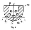
通路111は、ノーズ103の外部表面に配置されている。通路111は、縦方向の軸Lの周りを連続的に走っており、また、縦方向の軸Lに対して回転対称であり、したがって通路111は、全体として円形リングの形を有している。とりわけ図4および図6に示されているように、通路111は、一様である、すなわち通路111の進路に沿って変化しないV字形断面積を有している。通路111は、外側、すなわち通路111の、ストッパーボディー101から見て外側に向いている側に対して完全に開いており、また、そのV字形断面積に従って、通路111の通路底を形成している共通の線形領域117から始まる第1の壁113および第2の壁115によって制限されている。第1の壁および第2の壁113、115は、ノーズ103の外部表面に向かって発散し、最終的にノーズ103の外部表面中に没入している。第1の通路壁113は、通路111を第1の端部105に向かう方向に制限し、また、ノーズ103の外部表面と共に第1の縁119を形成している。第2の通路壁115は、通路111を第2の端部107に向かう方向に制限し、また、ノーズ103の外部表面と共に第2の縁121を形成している。第1の縁119および第2の縁121は、それぞれ半径が優に0.5mm未満の鋭い縁を形成している。
第1の縁および第2の縁119および121は、互いに等間隔で走っており、また、通路111の均一な進路に対応する縦方向の軸Lの周りに回転対称である。第1の縁と第2の縁119、121の間の距離は、通路口の幅、すなわち通路111がノーズ103の外部表面中に没入する領域における通路111の幅を画定しており、実施形態では10mmである。第1の縁と第2の縁119、121の間を延びている仮想平面と、通路111の深さを画定している通路底117の間の最も短い距離は、実施形態では8mmである。これは、通路111の40mm2の断面積をもたらす。
The first and
4本のガス供給ライン123の形態のガス供給手段は、チャンバー109から、ストッパーボディー101の耐火材料を貫通して通路111に通じている。4本のガス供給ライン123は、それぞれ断面積が円形である真っ直ぐな進路を有しており、また、縦方向の軸Lに対して対称に配置され、かつ、互いに一様に間隔を隔てている。したがって4本のガス供給ライン123は、縦方向の軸Lに対して90°の回転角だけ互いに間隔を隔てている。縦方向の軸Lに対するそれらの対称性に従って、ガス供給ライン123は、とりわけ図5から明確に分かるように、縦方向の軸Lに対して90°の回転角で同じく間隔を隔てている4つの一様に間隔を隔てた領域で通路111に通じている。
Gas supply means in the form of four
ガス供給ライン123は、それぞれ長手方向の軸に沿って延びており、ガス供給ライン123の4つの長手方向の軸は、縦方向の軸L上の共通点で交わっている。ガス供給ライン123の4つの長手方向の軸は、それぞれストッパーボディー101の縦方向の中心軸Lに対してほぼ45°の角度で配置されており、この角度は、ガス供給ライン123を通っている、ガス供給ライン123の長手方向の軸の断面と、ストッパーボディー101の第2の端部107を通っているストッパーボディー101の縦方向の中心軸Lの断面の間に含まれている。
The
チャンバー109は1,300mm2の断面積を有しており、また、ガス供給ラインの各々は3mm2の断面積を有している。したがってチャンバー109の断面積は、ガス供給ライン123の断面積の総面積より108倍広い。
The
第1の端部105の領域では、ストッパーボディー101は、ストッパーロッド100を上げ下げするための持上げデバイスにストッパーボディー109を固着するための最新技術のファスナーを有している。
In the region of the
ストッパーロッド100を製造するために、最初に、耐火材料の均衡加圧によってストッパーボディー101が形成され、それによりストッパーボディー101を持上げデバイスに固着するためのファスナーが耐火材料中に形成された(図には示されていない)。次に4本のガス供給ライン123が均衡加圧された耐火材料中に穿孔された。
To manufacture the
ストッパーロッド100は、ストッパーロッド100の周りに一様なガスカーテンを形成するように設計されている。この目的のために、図1に示されているタンディッシュ1の中でストッパーロッド100を使用している間、不活性ガスがガス供給を介してチャンバー109の中に導入され、ストッパーボディー101を通って通路111の中へ、4本のガス供給ライン123を通過する。通路111の中では、ガスを集めて分配し、次に通路111から吐出して、ストッパーロッド100の周りに一様なガスカーテンを形成することができる。これは、タンディッシュ1からの溶融金属を鋳造している間、ストッパーロッド100の偏向を著しく小さくすることができ、したがって鋳造金属の品質を改善することができる。
本発明によるストッパーロッドの通路の設計に依存する偏向低減を決定するために、図1~図6によるストッパーロッド100の偏向、および図1~図6によるストッパーロッドに基づいているが、通路の断面の形がそれぞれ若干異なる2つの代替ストッパーロッドの偏向が、水モデリングによって測定された。通路の2つの代替断面形状は、図7および図8に示されている。
In order to determine the deflection reduction depending on the design of the passage of the stopper rod according to the invention, the deflection of the
図7に示されている通路211の断面形状は、第1の端部105に面している通路の第1の側壁が、鋭い縁の形態ではあるが、約5mmの半径を有する丸い縁の形態であるノーズ103の表面中に没入していない点を除き、通路111の断面形状に対応している。
The cross-sectional shape of the
図8による通路311は、本質的に通路111の形に対応しているが、通路の深さはより浅く、3mmにすぎない。
The
偏向の程度を決定するために、記録された画像シーケンスの光学評価によってストッパーロッドの偏向が決定された。ストッパーロッドが水平方向に移動するとピクセルの色が変化し、この変化から、色が変化したピクセルの数が時間の関数として決定された。当技術分野によるストッパーロッドに対して得られた値に対して100%に正規化された、変化したピクセルの標準偏差値として偏向指数が計算された。この偏向指数に基づいて、図1~図6によるストッパーロッドに対する偏向の程度が測定され、かつ、計算された。 To determine the degree of deflection, the deflection of the stopper rod was determined by optical evaluation of the recorded image sequences. Horizontal movement of the stopper rod changed the color of the pixels, from which the number of pixels that changed color was determined as a function of time. The deflection index was calculated as the standard deviation value of the pixels changed, normalized to 100% with respect to the value obtained for the stopper rod according to the art. Based on this deflection index, the degree of deflection for the stopper rod according to FIGS. 1-6 was measured and calculated.
当技術分野によるストッパーロッドは、図1~図6によるストッパーロッドと概ね全く同じであるが、当技術分野によるストッパーロッドには、通路111およびガス供給ライン123を備える代わりに、欧州特許出願公開第2067549号明細書、欧州特許出願公開第2189231号明細書または欧州特許出願公開第2233227号明細書に記載されているように、縦方向の中心軸に沿ったガス出口をノーズ領域に備えているという相違がある。 The stopper rod according to the state of the art is generally exactly the same as the stopper rod according to FIGS. 2067549, EP-A-2189231 or EP-A-2233227, it is said that the nose region is provided with gas outlets along the central longitudinal axis. there is a difference.
図9は、対応する測定の結果を示したものである。図9では、参照番号1は、当技術分野によるストッパーロッドに対する測定の結果を示しており、偏向指数は、100%に正規化された、変化したピクセルの標準偏差値として計算されている。さらに、参照番号2は、図1~図6によるストッパーロッドに対する測定の結果を示している。
FIG. 9 shows the results of the corresponding measurements. In FIG. 9,
図9から分かるように、図1~図6によるストッパーロッドの偏向は、約45%の偏向指数にすぎず、したがって図1~図6によるストッパーロッドの偏向は、当技術分野によるストッパーロッドの偏向より著しく小さい。 As can be seen from FIG. 9, the deflection of the stopper rod according to FIGS. 1-6 is only about 45% deflection index, so the deflection of the stopper rod according to FIGS. significantly smaller than
1 タンディッシュ
3 金属容器
5 耐火材料
7 タンディッシュ1の底
9 タンディッシュノズル
10 タンディッシュノズル(水没入力シュラウド)
L 縦方向の軸(縦方向の中心軸)
100 ストッパーロッド
101 ストッパーボディー
103 ストッパーノーズ
105 ストッパーボディーの第1の上端(第1の端部)
107 ストッパーボディーの第2の下端(第2の端部)
109 チャンバー
111 通路
113 第1の壁
115 第2の壁
117 共通の線形領域(通路底)
119 第1の縁
121 第2の縁
123 ガス供給ライン
211 通路
311 通路
REFERENCE SIGNS
L longitudinal axis (longitudinal central axis)
100
107 second lower end (second end) of stopper body
109
119
Claims (15)
1.1 棒状のストッパーボディー(101)であって、
1.1.1 縦方向の中心軸(L)に沿って第1の端部(105)から第2の端部(107)まで延びており、
1.1.2 該棒状のストッパーボディー(101)が前記第2の端部(107)に隣接するノーズ(103)を画定し、
1.1.3 前記ノーズ(103)が外部表面を提供する、
棒状のストッパーボディー(101)と、
1.2 チャンバー(109)であって、
1.2.1 前記縦方向の中心軸(L)に沿って、前記第1の端部(105)から前記第2の端部(107)へ向かって前記ストッパーボディー(101)の中へ延びて、前記第2の端部(107)から一定の距離を置いた手前で終端している、
チャンバー(109)と、
1.3 通路(111)であって、
1.3.1 前記ノーズ(103)の前記外部表面に設けられ、
1.3.2 前記縦方向の軸(L)の周りを延在している、
通路(111)と、
1.4 ガス供給手段(123)であって、
1.4.1 前記チャンバー(109)から前記棒状のストッパーボディー(101)を通って前記通路(111)に通じている、
ガス供給手段(123)と
を含んでなることを特徴とする、ストッパーロッド(100)。 In a stopper rod (100) for controlling the flow of molten metal and supplying gas during casting of the molten metal,
1.1 A rod-shaped stopper body (101),
1.1.1 extending along the central longitudinal axis (L) from the first end (105) to the second end (107),
1.1.2 said rod-like stopper body (101) defines a nose (103) adjacent said second end (107);
1.1.3 said nose (103) provides an external surface,
a rod-shaped stopper body (101);
1.2 a chamber (109) comprising:
1.2.1 extending into said stopper body (101) along said longitudinal central axis (L) from said first end (105) towards said second end (107); terminating at a distance short of said second end (107),
a chamber (109);
1.3 A passageway (111),
1.3.1 provided on said outer surface of said nose (103),
1.3.2 extending about said longitudinal axis (L),
a passageway (111);
1.4 A gas supply means (123) comprising:
1.4.1 leading from said chamber (109) through said rod-like stopper body (101) to said passageway (111),
A stopper rod (100), characterized in that it comprises gas supply means (123).
A.請求項1に記載のストッパーロッド(100)を提供するステップと、
B.ガスを前記チャンバー(109)の中に導入するステップと
を含んでなることを特徴とする、方法。 A method for providing a uniform gas curtain around a stopper rod, comprising:
A. providing a stopper rod (100) according to claim 1 ;
B. and introducing a gas into said chamber (109).
Applications Claiming Priority (3)
| Application Number | Priority Date | Filing Date | Title |
|---|---|---|---|
| EP19161721.6 | 2019-03-08 | ||
| EP19161721.6A EP3705204B1 (en) | 2019-03-08 | 2019-03-08 | A stopper rod and a method for providing a uniform gas curtain around a stopper rod |
| PCT/EP2020/052020 WO2020182362A1 (en) | 2019-03-08 | 2020-01-28 | A stopper rod and a method for providing a uniform gas curtain around a stopper rod |
Publications (3)
| Publication Number | Publication Date |
|---|---|
| JP2022522198A JP2022522198A (en) | 2022-04-14 |
| JPWO2020182362A5 JPWO2020182362A5 (en) | 2022-11-22 |
| JP7239727B2 true JP7239727B2 (en) | 2023-03-14 |
Family
ID=65763278
Family Applications (1)
| Application Number | Title | Priority Date | Filing Date |
|---|---|---|---|
| JP2021550194A Active JP7239727B2 (en) | 2019-03-08 | 2020-01-28 | Stopper rod and method for providing a uniform gas curtain around the stopper rod |
Country Status (9)
| Country | Link |
|---|---|
| US (1) | US12005494B2 (en) |
| EP (1) | EP3705204B1 (en) |
| JP (1) | JP7239727B2 (en) |
| KR (1) | KR102768139B1 (en) |
| CN (1) | CN113474105B (en) |
| MX (1) | MX2021010429A (en) |
| PL (1) | PL3705204T3 (en) |
| UA (1) | UA129324C2 (en) |
| WO (1) | WO2020182362A1 (en) |
Families Citing this family (2)
| Publication number | Priority date | Publication date | Assignee | Title |
|---|---|---|---|---|
| PL3705204T3 (en) | 2019-03-08 | 2022-10-17 | Refractory Intellectual Property Gmbh & Co. Kg | A stopper rod and a method for providing a uniform gas curtain around a stopper rod |
| WO2024017662A1 (en) | 2022-07-18 | 2024-01-25 | Refractory Intellectual Property Gmbh & Co. Kg | Stopper rod and method for inducing a rotational flow of a molten metal |
Citations (1)
| Publication number | Priority date | Publication date | Assignee | Title |
|---|---|---|---|---|
| CN106513653A (en) | 2016-11-16 | 2017-03-22 | 攀钢集团攀枝花钢铁研究院有限公司 | Continuous casting stopper rod with ventilation ring |
Family Cites Families (17)
| Publication number | Priority date | Publication date | Assignee | Title |
|---|---|---|---|---|
| AT340620B (en) * | 1975-02-25 | 1977-12-27 | Voest Ag | DEVICE FOR THE TREATMENT OF METAL MELT DURING CONTINUOUS CASTING WITH SPULG GAS |
| FR2650520A1 (en) * | 1989-08-03 | 1991-02-08 | Vesuvius France Sa | KETTLE FOR REGULATING THE FLOW OF A LIQUID COMPRISING A GAS SUPPLIED FREE SPACE |
| JPH0673724B2 (en) * | 1989-09-25 | 1994-09-21 | 明智セラミックス株式会社 | Tundish stopper |
| JP3579568B2 (en) * | 1997-04-28 | 2004-10-20 | 新日本製鐵株式会社 | Stopper rod for continuous casting |
| CN1094400C (en) | 1998-11-20 | 2002-11-20 | 维苏维尤斯·克鲁斯布公司 | Stopper rod |
| KR100472604B1 (en) * | 2002-01-08 | 2005-03-08 | 심용수 | The device for billet forming to using casting semi-continous vertical |
| CN1988972A (en) * | 2004-07-20 | 2007-06-27 | 维苏维尤斯·克鲁斯布公司 | Stopper rod for delivering gas into a molten metal |
| ATE372182T1 (en) | 2005-06-21 | 2007-09-15 | Refractory Intellectual Prop | PLUG ROD |
| ATE461772T1 (en) | 2007-11-24 | 2010-04-15 | Refractory Intellectual Prop | PLUG ROD |
| JP4638932B2 (en) * | 2008-09-25 | 2011-02-23 | 株式会社日本製鋼所 | Stopper |
| PL2189231T3 (en) | 2008-11-19 | 2011-03-31 | Refractory Intellectual Property Gmbh & Co Kg | Stopper body |
| EP2233227B1 (en) | 2009-03-23 | 2011-01-19 | Refractory Intellectual Property GmbH & Co. KG | Flame-retardant ceramic stops |
| PL2572813T3 (en) * | 2011-09-23 | 2013-12-31 | Refractory Intellectual Property Gmbh & Co Kg | Ceramic refractory stopper |
| KR20140082497A (en) * | 2012-12-24 | 2014-07-02 | 주식회사 포스코 | Stopper of continuous casting device |
| KR101584135B1 (en) | 2015-07-09 | 2016-01-11 | 신일인텍 주식회사 | Stopper rod |
| CN106392051B (en) * | 2016-11-16 | 2018-03-06 | 攀钢集团攀枝花钢铁研究院有限公司 | continuous casting stopper rod |
| PL3705204T3 (en) | 2019-03-08 | 2022-10-17 | Refractory Intellectual Property Gmbh & Co. Kg | A stopper rod and a method for providing a uniform gas curtain around a stopper rod |
-
2019
- 2019-03-08 PL PL19161721.6T patent/PL3705204T3/en unknown
- 2019-03-08 EP EP19161721.6A patent/EP3705204B1/en active Active
-
2020
- 2020-01-28 JP JP2021550194A patent/JP7239727B2/en active Active
- 2020-01-28 UA UAA202104718A patent/UA129324C2/en unknown
- 2020-01-28 MX MX2021010429A patent/MX2021010429A/en unknown
- 2020-01-28 US US17/437,016 patent/US12005494B2/en active Active
- 2020-01-28 CN CN202080018621.6A patent/CN113474105B/en active Active
- 2020-01-28 WO PCT/EP2020/052020 patent/WO2020182362A1/en not_active Ceased
- 2020-01-28 KR KR1020217027672A patent/KR102768139B1/en active Active
Patent Citations (1)
| Publication number | Priority date | Publication date | Assignee | Title |
|---|---|---|---|---|
| CN106513653A (en) | 2016-11-16 | 2017-03-22 | 攀钢集团攀枝花钢铁研究院有限公司 | Continuous casting stopper rod with ventilation ring |
Also Published As
| Publication number | Publication date |
|---|---|
| BR112021017125A2 (en) | 2021-11-03 |
| KR102768139B1 (en) | 2025-02-13 |
| JP2022522198A (en) | 2022-04-14 |
| EP3705204A1 (en) | 2020-09-09 |
| CN113474105A (en) | 2021-10-01 |
| MX2021010429A (en) | 2021-09-21 |
| CN113474105B (en) | 2023-03-03 |
| US12005494B2 (en) | 2024-06-11 |
| PL3705204T3 (en) | 2022-10-17 |
| US20220176446A1 (en) | 2022-06-09 |
| KR20210135505A (en) | 2021-11-15 |
| UA129324C2 (en) | 2025-03-19 |
| EP3705204B1 (en) | 2022-08-03 |
| WO2020182362A1 (en) | 2020-09-17 |
Similar Documents
| Publication | Publication Date | Title |
|---|---|---|
| AU2008327689B2 (en) | Stopper rod | |
| JP7239727B2 (en) | Stopper rod and method for providing a uniform gas curtain around the stopper rod | |
| CN108247033B (en) | A swirl upper nozzle for continuous casting tundish | |
| RU2698026C2 (en) | Impact pad, tundish and device containing such impact pad, and method of using same | |
| KR890002116B1 (en) | Molten Metal Discharge Device | |
| AU2003254783B2 (en) | Casting nozzle | |
| EP1687110B1 (en) | Multi-outlet casting nozzle | |
| US20260001123A1 (en) | Stopper rod and method for inducing a rotational flow of a molten metal | |
| RU2802366C2 (en) | Stop rod and method for providing uniform gas screen around the stop rod | |
| KR102228648B1 (en) | Sliding nozzle | |
| CA2745000C (en) | Flow control device | |
| CN102292176B (en) | submerged nozzle | |
| BR112021017125B1 (en) | A buffer rod and a method for providing a uniform gas curtain around a buffer rod. | |
| KR20230002935A (en) | Immersion nozzle with rotatable insert |
Legal Events
| Date | Code | Title | Description |
|---|---|---|---|
| A621 | Written request for application examination |
Free format text: JAPANESE INTERMEDIATE CODE: A621 Effective date: 20210827 |
|
| A977 | Report on retrieval |
Free format text: JAPANESE INTERMEDIATE CODE: A971007 Effective date: 20220831 |
|
| A131 | Notification of reasons for refusal |
Free format text: JAPANESE INTERMEDIATE CODE: A131 Effective date: 20220905 |
|
| A524 | Written submission of copy of amendment under article 19 pct |
Free format text: JAPANESE INTERMEDIATE CODE: A524 Effective date: 20221110 |
|
| TRDD | Decision of grant or rejection written | ||
| A01 | Written decision to grant a patent or to grant a registration (utility model) |
Free format text: JAPANESE INTERMEDIATE CODE: A01 Effective date: 20230206 |
|
| A61 | First payment of annual fees (during grant procedure) |
Free format text: JAPANESE INTERMEDIATE CODE: A61 Effective date: 20230302 |
|
| R150 | Certificate of patent or registration of utility model |
Ref document number: 7239727 Country of ref document: JP Free format text: JAPANESE INTERMEDIATE CODE: R150 |
|
| R250 | Receipt of annual fees |
Free format text: JAPANESE INTERMEDIATE CODE: R250 |