JP7239498B2 - Caliper and support assembly and method for detecting caliper deformation - Google Patents
Caliper and support assembly and method for detecting caliper deformation Download PDFInfo
- Publication number
- JP7239498B2 JP7239498B2 JP2019571934A JP2019571934A JP7239498B2 JP 7239498 B2 JP7239498 B2 JP 7239498B2 JP 2019571934 A JP2019571934 A JP 2019571934A JP 2019571934 A JP2019571934 A JP 2019571934A JP 7239498 B2 JP7239498 B2 JP 7239498B2
- Authority
- JP
- Japan
- Prior art keywords
- caliper
- caliper body
- support element
- disc
- brake
- Prior art date
- Legal status (The legal status is an assumption and is not a legal conclusion. Google has not performed a legal analysis and makes no representation as to the accuracy of the status listed.)
- Active
Links
- 238000000034 method Methods 0.000 title claims description 15
- 230000015572 biosynthetic process Effects 0.000 claims description 4
- 238000001514 detection method Methods 0.000 claims description 4
- 239000000463 material Substances 0.000 claims description 2
- 238000003825 pressing Methods 0.000 description 11
- 238000003780 insertion Methods 0.000 description 10
- 230000037431 insertion Effects 0.000 description 10
- 239000002783 friction material Substances 0.000 description 9
- 239000012530 fluid Substances 0.000 description 8
- 238000005452 bending Methods 0.000 description 7
- 230000005540 biological transmission Effects 0.000 description 7
- 230000033001 locomotion Effects 0.000 description 5
- 230000027455 binding Effects 0.000 description 3
- 238000009739 binding Methods 0.000 description 3
- 238000006073 displacement reaction Methods 0.000 description 3
- 238000005259 measurement Methods 0.000 description 3
- 239000000725 suspension Substances 0.000 description 2
- OKTJSMMVPCPJKN-UHFFFAOYSA-N Carbon Chemical compound [C] OKTJSMMVPCPJKN-UHFFFAOYSA-N 0.000 description 1
- 230000001133 acceleration Effects 0.000 description 1
- 230000006978 adaptation Effects 0.000 description 1
- 229910052799 carbon Inorganic materials 0.000 description 1
- 238000006243 chemical reaction Methods 0.000 description 1
- 238000005520 cutting process Methods 0.000 description 1
- 230000001419 dependent effect Effects 0.000 description 1
- 230000000694 effects Effects 0.000 description 1
- 230000005489 elastic deformation Effects 0.000 description 1
- 230000007613 environmental effect Effects 0.000 description 1
- 238000012840 feeding operation Methods 0.000 description 1
- 239000000446 fuel Substances 0.000 description 1
- 230000002452 interceptive effect Effects 0.000 description 1
- 238000003698 laser cutting Methods 0.000 description 1
- 230000007774 longterm Effects 0.000 description 1
- 238000004519 manufacturing process Methods 0.000 description 1
- 230000002093 peripheral effect Effects 0.000 description 1
- 230000035945 sensitivity Effects 0.000 description 1
- 125000006850 spacer group Chemical group 0.000 description 1
- 238000006467 substitution reaction Methods 0.000 description 1
Images


Classifications
-
- F—MECHANICAL ENGINEERING; LIGHTING; HEATING; WEAPONS; BLASTING
- F16—ENGINEERING ELEMENTS AND UNITS; GENERAL MEASURES FOR PRODUCING AND MAINTAINING EFFECTIVE FUNCTIONING OF MACHINES OR INSTALLATIONS; THERMAL INSULATION IN GENERAL
- F16D—COUPLINGS FOR TRANSMITTING ROTATION; CLUTCHES; BRAKES
- F16D65/00—Parts or details
- F16D65/005—Components of axially engaging brakes not otherwise provided for
- F16D65/0056—Brake supports
-
- F—MECHANICAL ENGINEERING; LIGHTING; HEATING; WEAPONS; BLASTING
- F16—ENGINEERING ELEMENTS AND UNITS; GENERAL MEASURES FOR PRODUCING AND MAINTAINING EFFECTIVE FUNCTIONING OF MACHINES OR INSTALLATIONS; THERMAL INSULATION IN GENERAL
- F16D—COUPLINGS FOR TRANSMITTING ROTATION; CLUTCHES; BRAKES
- F16D65/00—Parts or details
- F16D65/14—Actuating mechanisms for brakes; Means for initiating operation at a predetermined position
- F16D65/16—Actuating mechanisms for brakes; Means for initiating operation at a predetermined position arranged in or on the brake
- F16D65/18—Actuating mechanisms for brakes; Means for initiating operation at a predetermined position arranged in or on the brake adapted for drawing members together, e.g. for disc brakes
- F16D65/183—Actuating mechanisms for brakes; Means for initiating operation at a predetermined position arranged in or on the brake adapted for drawing members together, e.g. for disc brakes with force-transmitting members arranged side by side acting on a spot type force-applying member
-
- B—PERFORMING OPERATIONS; TRANSPORTING
- B60—VEHICLES IN GENERAL
- B60T—VEHICLE BRAKE CONTROL SYSTEMS OR PARTS THEREOF; BRAKE CONTROL SYSTEMS OR PARTS THEREOF, IN GENERAL; ARRANGEMENT OF BRAKING ELEMENTS ON VEHICLES IN GENERAL; PORTABLE DEVICES FOR PREVENTING UNWANTED MOVEMENT OF VEHICLES; VEHICLE MODIFICATIONS TO FACILITATE COOLING OF BRAKES
- B60T17/00—Component parts, details, or accessories of power brake systems not covered by groups B60T8/00, B60T13/00 or B60T15/00, or presenting other characteristic features
- B60T17/18—Safety devices; Monitoring
- B60T17/22—Devices for monitoring or checking brake systems; Signal devices
- B60T17/221—Procedure or apparatus for checking or keeping in a correct functioning condition of brake systems
-
- F—MECHANICAL ENGINEERING; LIGHTING; HEATING; WEAPONS; BLASTING
- F16—ENGINEERING ELEMENTS AND UNITS; GENERAL MEASURES FOR PRODUCING AND MAINTAINING EFFECTIVE FUNCTIONING OF MACHINES OR INSTALLATIONS; THERMAL INSULATION IN GENERAL
- F16D—COUPLINGS FOR TRANSMITTING ROTATION; CLUTCHES; BRAKES
- F16D55/00—Brakes with substantially-radial braking surfaces pressed together in axial direction, e.g. disc brakes
- F16D55/02—Brakes with substantially-radial braking surfaces pressed together in axial direction, e.g. disc brakes with axially-movable discs or pads pressed against axially-located rotating members
- F16D55/22—Brakes with substantially-radial braking surfaces pressed together in axial direction, e.g. disc brakes with axially-movable discs or pads pressed against axially-located rotating members by clamping an axially-located rotating disc between movable braking members, e.g. movable brake discs or brake pads
- F16D55/228—Brakes with substantially-radial braking surfaces pressed together in axial direction, e.g. disc brakes with axially-movable discs or pads pressed against axially-located rotating members by clamping an axially-located rotating disc between movable braking members, e.g. movable brake discs or brake pads with a separate actuating member for each side
-
- F—MECHANICAL ENGINEERING; LIGHTING; HEATING; WEAPONS; BLASTING
- F16—ENGINEERING ELEMENTS AND UNITS; GENERAL MEASURES FOR PRODUCING AND MAINTAINING EFFECTIVE FUNCTIONING OF MACHINES OR INSTALLATIONS; THERMAL INSULATION IN GENERAL
- F16D—COUPLINGS FOR TRANSMITTING ROTATION; CLUTCHES; BRAKES
- F16D65/00—Parts or details
- F16D65/005—Components of axially engaging brakes not otherwise provided for
- F16D65/0068—Brake calipers
-
- F—MECHANICAL ENGINEERING; LIGHTING; HEATING; WEAPONS; BLASTING
- F16—ENGINEERING ELEMENTS AND UNITS; GENERAL MEASURES FOR PRODUCING AND MAINTAINING EFFECTIVE FUNCTIONING OF MACHINES OR INSTALLATIONS; THERMAL INSULATION IN GENERAL
- F16D—COUPLINGS FOR TRANSMITTING ROTATION; CLUTCHES; BRAKES
- F16D66/00—Arrangements for monitoring working conditions, e.g. wear, temperature
-
- B—PERFORMING OPERATIONS; TRANSPORTING
- B60—VEHICLES IN GENERAL
- B60T—VEHICLE BRAKE CONTROL SYSTEMS OR PARTS THEREOF; BRAKE CONTROL SYSTEMS OR PARTS THEREOF, IN GENERAL; ARRANGEMENT OF BRAKING ELEMENTS ON VEHICLES IN GENERAL; PORTABLE DEVICES FOR PREVENTING UNWANTED MOVEMENT OF VEHICLES; VEHICLE MODIFICATIONS TO FACILITATE COOLING OF BRAKES
- B60T1/00—Arrangements of braking elements, i.e. of those parts where braking effect occurs specially for vehicles
- B60T1/02—Arrangements of braking elements, i.e. of those parts where braking effect occurs specially for vehicles acting by retarding wheels
- B60T1/06—Arrangements of braking elements, i.e. of those parts where braking effect occurs specially for vehicles acting by retarding wheels acting otherwise than on tread, e.g. employing rim, drum, disc, or transmission or on double wheels
- B60T1/065—Arrangements of braking elements, i.e. of those parts where braking effect occurs specially for vehicles acting by retarding wheels acting otherwise than on tread, e.g. employing rim, drum, disc, or transmission or on double wheels employing disc
-
- F—MECHANICAL ENGINEERING; LIGHTING; HEATING; WEAPONS; BLASTING
- F16—ENGINEERING ELEMENTS AND UNITS; GENERAL MEASURES FOR PRODUCING AND MAINTAINING EFFECTIVE FUNCTIONING OF MACHINES OR INSTALLATIONS; THERMAL INSULATION IN GENERAL
- F16D—COUPLINGS FOR TRANSMITTING ROTATION; CLUTCHES; BRAKES
- F16D55/00—Brakes with substantially-radial braking surfaces pressed together in axial direction, e.g. disc brakes
- F16D2055/0004—Parts or details of disc brakes
- F16D2055/0008—Brake supports
-
- F—MECHANICAL ENGINEERING; LIGHTING; HEATING; WEAPONS; BLASTING
- F16—ENGINEERING ELEMENTS AND UNITS; GENERAL MEASURES FOR PRODUCING AND MAINTAINING EFFECTIVE FUNCTIONING OF MACHINES OR INSTALLATIONS; THERMAL INSULATION IN GENERAL
- F16D—COUPLINGS FOR TRANSMITTING ROTATION; CLUTCHES; BRAKES
- F16D55/00—Brakes with substantially-radial braking surfaces pressed together in axial direction, e.g. disc brakes
- F16D2055/0004—Parts or details of disc brakes
- F16D2055/0016—Brake calipers
- F16D2055/002—Brake calipers assembled from a plurality of parts
-
- F—MECHANICAL ENGINEERING; LIGHTING; HEATING; WEAPONS; BLASTING
- F16—ENGINEERING ELEMENTS AND UNITS; GENERAL MEASURES FOR PRODUCING AND MAINTAINING EFFECTIVE FUNCTIONING OF MACHINES OR INSTALLATIONS; THERMAL INSULATION IN GENERAL
- F16D—COUPLINGS FOR TRANSMITTING ROTATION; CLUTCHES; BRAKES
- F16D66/00—Arrangements for monitoring working conditions, e.g. wear, temperature
- F16D2066/003—Position, angle or speed
-
- F—MECHANICAL ENGINEERING; LIGHTING; HEATING; WEAPONS; BLASTING
- F16—ENGINEERING ELEMENTS AND UNITS; GENERAL MEASURES FOR PRODUCING AND MAINTAINING EFFECTIVE FUNCTIONING OF MACHINES OR INSTALLATIONS; THERMAL INSULATION IN GENERAL
- F16D—COUPLINGS FOR TRANSMITTING ROTATION; CLUTCHES; BRAKES
- F16D66/00—Arrangements for monitoring working conditions, e.g. wear, temperature
- F16D2066/005—Force, torque, stress or strain
Description
本発明は、ディスクブレーキのためのキャリパ及び支持アセンブリに関する。 The present invention relates to a caliper and support assembly for disc brakes.
特に、本発明は、検知装置を備えるキャリパ及び支持アセンブリに関する。 In particular, the invention relates to a caliper and support assembly with a sensing device.
本発明は、さらに検知方法に関する。 The invention further relates to a sensing method.
ディスクブレーキにおいて、ブレーキキャリパは、一般に回転軸の周りを回転するように構成された、ブレーキディスクの外側周辺マージンをまたいで配置される。ブレーキキャリパは、例えば車両サスペンションの短くなった残りの車軸、または車両車輪ハブ、または自動車のフォークまたはスイングアームなどの、車両車輪に対して静止したままの支持構造に拘束される。ブレーキキャリパは、ブレーキディスクの反対のブレーキ表面に対向するように配置された2つの細長い部分及びお互いに前記2つの細長い部分を接続する、少なくとも1つのブリッジを有するキャリパ本体を備える。 In disc brakes, a brake caliper is generally positioned across the outer peripheral margin of the brake disc, which is configured to rotate about an axis of rotation. The brake caliper is constrained to a support structure that remains stationary relative to the vehicle wheel, such as, for example, the shortened residual axle of the vehicle suspension, or the vehicle wheel hub, or the fork or swingarm of the vehicle. The brake caliper comprises a caliper body having two elongated portions arranged to face opposite braking surfaces of a brake disc and at least one bridge connecting said two elongated portions to each other.
ブレーキパッドは、一般に摩擦材が固定され、ブレーキディスクのブレーキバンドの対向ブレーキ面に対して押しつけるように構成されたパッドを備える。レースの分野の用途ためのブレーキキャリパにおいて、ブレーキパッドは、プレートが摩擦材を備える1つの部品で作られて用いられる。プレートは、聴覚摩耗インジケータを備え、それは、ときどき摩擦材に埋め込まれ、摩擦材が長期間の使用によって軸方向に薄くなったとき、ディスクのブレーキバンドに対してすれることによって音を出す機能を有する。 A brake pad generally comprises a pad to which a friction material is secured and configured to press against an opposing braking surface of a brake band of a brake disc. In brake calipers for applications in the racing field, brake pads are used in which the plates are made in one piece with the friction material. The plate has an audible wear indicator that is sometimes embedded in the friction material and functions to produce a sound by rubbing against the brake band of the disc when the friction material becomes axially thin due to long-term use. have.
固定ディスクと関連する浮遊キャリパ本体において、キャリパ本体の浮遊するまたは滑る部分は、ディスクのブレーキ表面に当接し、対向する摩擦パッドに押しつける動作を与えることができる押しつけ手段を収納するように構成された1つのまたは複数のシリンダを有しながら、浮遊するまたは滑る部分は、ブラケット、またはキャリパの固定された部分を滑り、ブレーキ動作を与えるブレーキディスクに当接する第2のクラッチパッドに作用する。 In a floating caliper body associated with a fixed disc, the floating or sliding portion of the caliper body is configured to contain biasing means capable of abutting the braking surface of the disc and imparting a biasing action to the opposing friction pads. Having one or more cylinders, the floating or sliding portion slides on a bracket or fixed portion of the caliper and acts on a second clutch pad which abuts the brake disc to provide braking action.
固定ディスクに関連するキャリパ本体において、1つまたは複数のシリンダは、対向し、それによりディスクのブレーキ表面に当接する摩擦パッドに押しつける動作を与えることができる、押しつけ手段を収容するためのキャリパ本体の両方の対向する側面に存在する。 In the caliper body associated with the fixed disc, one or more cylinders are opposed to each other and are thereby capable of imparting a pressing action to the friction pads abutting the braking surface of the disc. Present on both opposing sides.
反対に、浮遊ディスクと関連する固定キャリパ本体は、また既知であり、キャリパ本体の細長い部分の1つのみが、ディスクのブレーキ表面に当接し、対向する摩擦パッドに押しつける動作を与えることができる押しつけ手段を収容するように構成された1つまたは複数のシリンダを有し、細長い部分は、その支持体上で軸方向に滑り、対向する摩擦パッドに当接し、ブレーキ動作を与える。 Conversely, stationary caliper bodies associated with floating discs are also known in which only one elongated portion of the caliper body is capable of abutting the braking surface of the disc and imparting a pressing action to the opposing friction pads. Having one or more cylinders configured to house means, the elongated portion slides axially on its support to abut opposing friction pads to impart a braking action.
油圧作動ブレーキシステムにおいて、ブレーキペダルに、車両の運転者によって与えられた圧力は、ブレーキマスタシリンダによって、ブレーキ液圧を与え、ブレーキ液圧は、配管を通って、キャリパ本体の内側に設置された油圧回路に存在するブレーキ液に与えられ、シリンダに到達し、圧力は、ピストンの底面に与えられ、それによりパッドにピストンを押しつけ、ディスクのブレーキ表面に当接する。 In a hydraulically actuated brake system, the pressure applied by the vehicle operator to the brake pedal provides brake fluid pressure by way of the brake master cylinder, which is installed inside the caliper body through piping. Applying to the brake fluid present in the hydraulic circuit and reaching the cylinder, pressure is applied to the bottom surface of the piston, thereby pressing the piston against the pad and abutting the braking surface of the disc.
ブレーキ液の圧力動作は、またシリンダの底部壁に与えられ、それによりキャリパ本体に反作用を引き起こし、キャリパ本体を変形させてディスク表面から離す。この現象は、キャリパの弾性変形または「歪み」として知られ、ブレーキディスクから離れて動くことによって、パッドの押しつけ手段のさらなる付勢を強制し、所望のブレーキ動作を与える。 The pressure action of the brake fluid is also imparted to the bottom wall of the cylinder, thereby causing a reaction on the caliper body, deforming it away from the disc surface. This phenomenon, known as elastic deformation or "distortion" of the caliper, forces further biasing of the pad biasing means by moving away from the brake disc to provide the desired braking action.
ブレーキ動作が終わるとき、その結果ブレーキディスクから離れるキャリパ本体を変形する付勢が終わるとき、キャリパ本体は、その非変形停止形態に戻り、再びブレーキディスクに近づき、その結果ブレーキ表面に対するパッドに近づく。このブレーキディスクに対するパッドの近づきは、また車両の運転者によるブレーキ命令が停止したとき、たとえわずかでも、パッドとディスクの接触を測定し、わずかな連続摩擦及びその結果、残留焼付トルクとして知られるブレーキ動作を測定するため、望ましくない。 When the braking action ceases, and thus the bias that deforms the caliper body away from the brake disc, the caliper body returns to its non-deformed rest configuration, again approaching the brake disc and thus the pads against the braking surface. This proximity of the pad to the brake disc also measures the contact between the pad and the disc, even if only slightly, when the braking command by the vehicle operator ceases, resulting in a small amount of continuous friction and braking known as residual seizure torque. Not desirable as it measures movement.
この残留焼付トルクは、しばしば、たとえわずかでもパッドとディスクブレーキ表面の摩擦動作、パッドとブレーキディスクの望ましくない摩損によって引き越されるノイズを発生するので、望ましくないと考えられ、それらの交換のためのより頻繁なメンテナンスと、最小であってもこの残留トルクを克服するために必要とされるエネルギを備える駆動ユニットを供給するための最小燃料消費を意味する。 This residual seizure torque is often considered undesirable because it produces noise that is driven by the frictional action of the pads and disc brake surfaces, even if only slightly, and undesirable wear and tear of the pads and brake discs. and minimum fuel consumption to supply the drive unit with at least the energy required to overcome this residual torque.
ブレーキ動作の間、摩擦パッドが、例えば、キャリパ本体に提供されるパッドまたは突出した壁を支持するピンなど、キャリパ本体の正接隣接部と当接するまで、ディスクのブレーキバンドに密接された摩擦パッドは、回転の効果により、正接または円周方向に向けられる摩擦によって送り加速度を受ける。 During braking operation, the friction pads are brought into intimate contact with the brake band of the disc until they abut tangentially adjacent portions of the caliper body, such as pads provided on the caliper body or pins supporting a protruding wall. , due to the effect of rotation, are subjected to feed acceleration by tangentially or circumferentially directed friction.
この送り動作は、キャリパ本体上に伝達され、キャリパ本体、特に車両に固定される支持構造へのキャリパ本体の固定要素の間に配置されるキャリパ本体の部分の接線方向の弾性引き延ばし変形を測定する傾向がある。この接線引き延ばし変形は、典型的に、例えば摩擦パッドの横に対向する側面に設置される通常固定ピンまたは軸受け筒など、支持構造にキャリパ本体の束縛要素を提供することによって、束縛され、その結果、通常キャリパ本体の、ジャミング、接線ジャミングまたは「バックリング」現象を発生し、弾性不安定性を発生し、キャリパ本体の曲げの始まりとねじり応力を引き起こす。 This feed motion is transmitted onto the caliper body and measures the tangential elastic stretching deformation of the caliper body, in particular of the portion of the caliper body which is arranged between the fixing elements of the caliper body to the support structure fixed to the vehicle. Tend. This tangential stretching deformation is typically constrained by providing constraining elements of the caliper body to the support structure, for example fixing pins or bushings usually located on laterally opposed sides of the friction pads, resulting in , usually causing jamming, tangential jamming or "buckling" phenomena of the caliper body, creating elastic instabilities and causing onset of bending and torsional stresses in the caliper body.
さらに、通常ハブ側細長い要素のキャリパ側にのみ設置されるキャリパとその支持体の間の束縛のために、さらなる切断及びねじり変形が起き、支持体に束縛されない細長い要素、または車輪側細長い要素をハブ側細長い要素に対して動かし、それにより、お互いにこれらの細長い要素を接続するキャリパブリッジを曲げる。 Furthermore, due to the binding between the caliper and its support, which is usually only located on the caliper side of the hub side elongated element, further cutting and torsional deformations occur, resulting in the elongated element not being constrained to the support or the wheel side elongated element. Move against the hub-side elongated elements, thereby bending the caliper bridges that connect these elongated elements to each other.
さもなければ、ブレーキペダルが油圧回路によってキャリパ押しつけ手段に接続されない、特に高性能車両のためのワイヤによるブレーキタイプにおいて、データ処理ユニットに関連する検知システムは、ブレーキペダル上に車両の運転者によって与えられる動作を測定し、ディスクの対向するブレーキ表面にパッドを当接するために、ブレーキキャリパ押しつけ手段に伝達される対応する力を計算するために存在する。自動車の運転者のために、ワイヤによるブレーキシステムによる、ブレーキ感覚は、油圧作動ブレーキのそれと、特にブレーキペダルによって提供される機械フィードバックに関して根本的に変わり、それにより、運転者に低い感度をもたらし、ブレーキ制御が劣る。 Otherwise the brake pedal is not connected to the caliper biasing means by a hydraulic circuit, especially in the brake by wire type for high performance vehicles, the sensing system associated with the data processing unit is provided by the driver of the vehicle on the brake pedal. It is there to measure the applied motion and calculate the corresponding force transmitted to the brake caliper pressing means to abut the pad against the opposing braking surface of the disc. For the driver of a vehicle, the braking feel with a wire-brake system is radically altered with respect to that of hydraulically actuated brakes and especially the mechanical feedback provided by the brake pedal, thereby resulting in less sensitivity to the driver, Poor brake control.
したがって、ブレーキ動作を定量化する要求が強く感じられる。 Therefore, the need to quantify braking action is felt strongly.
ブレーキトルクの間接測定に基づく浮遊キャリパのブレーキ動作を定量化するいくつかの解決法、すなわち、典型的にブレーキキャリパまたはその支持体の一部の曲げ変形である、ブレーキトルク存在と関連する量の検知に基づくものが示唆される。 Several solutions to quantify the braking action of floating calipers based on indirect measurements of brake torque, i.e., the amount associated with the presence of brake torque, which is typically the bending deformation of a portion of the brake caliper or its support. Sensing-based is suggested.
例えば、文献、独国特許公報102012007118号は、支持構造への浮遊キャリパのキャリパ本体の専用オーバーハング接続ブリッジの曲げ変形を検知するように構成されたセンサシステムを示す。例えば文献、米国特許公報6511135号は、ディスク抜け口またはディスク抜け側を見る、及びブレーキ動作が解放される、キャリパ本体の側面に設置される浮遊キャリパへの支持ブラケットのアームの曲げ変形を検知するように構成された解決法を示す。 For example, document DE 102012007118 shows a sensor system configured to detect bending deformations of a dedicated overhang connecting bridge of the caliper body of the floating caliper to the support structure. For example, the document US Pat. No. 6,511,135 looks at the disc exit or disc exit side and detects the bending deformation of the arm of the support bracket to the floating caliper installed on the side of the caliper body, where the braking action is released. We present a solution structured as follows.
これらの解決法は、いくつかの視点から有利であるが、浮遊キャリパにのみ適用され、例えば、曲げることによって変形されるように構成されたキャリパ本体から張り出して突出する専用機械装置の作製を必要とすることによってなど、作ることが複雑になる。また、例えば、ブレーキトルクを計算するための基礎などの解決法で用いられる、張り出して設置されたキャリパ本体の一部の曲げ変形のように、非線形量の測定は、ブレーキ動作の定量化で、かなりの不確実性を課すことに留意すべきである。 While these solutions are advantageous from several points of view, they apply only to floating calipers and require, for example, the creation of dedicated mechanical devices that overhang and protrude from the caliper body configured to be deformed by bending. By doing so, it becomes complicated to make. Also, the measurement of non-linear quantities, such as the bending deformation of a portion of an overhanging caliper body, which is used in such solutions as the basis for calculating brake torque, is useful in quantifying braking action. It should be noted that it imposes considerable uncertainty.
文献、米国特許公報8146715号は、レーザ切断によって、ブレーキ動作の間発生される、力の流れから除外される張り出し棚を作るために浮遊キャリパの本体に切れ込みを作ることを示す。近接センサは、軸方向のブレーキの間、そのような切れ込みの幅の変動を測定するために用いられる。さらに、文献、米国特許公開公報2012/0198926号は、摩擦パッドが取り付けられるブラケットと、浮遊キャリパ本体の細長い部分の間の軸方向の変位を検知する装置を示す。 The document US Pat. No. 8,146,715 shows making cuts in the body of the floating caliper by laser cutting to create ledges that are excluded from the flow of forces generated during braking. Proximity sensors are used to measure variations in the width of such notches during axial braking. Further, document US2012/0198926 shows a device for sensing axial displacement between a bracket to which the friction pads are attached and an elongated portion of the floating caliper body.
軸方向の変形は、摩擦材の摩損条件、例えばディスクの温度、雨などの環境条件など、動作条件によって、わからない及び変化しやすい摩擦によって、非比例的な方法で、ブレーキトルクと相関するので、そのような解決法は、問題を解決せず、ブレーキキャリパの軸方向の変形の測定は、ブレーキ動作の信頼できる見積もりを提供するように構成されない。 Since axial deformation correlates with braking torque in a non-proportional manner, with friction unknown and variable depending on operating conditions, such as wear conditions of the friction material, e.g. disc temperature, environmental conditions such as rain, etc. Such a solution does not solve the problem and measuring the axial deformation of the brake caliper is not configured to provide a reliable estimate of braking action.
したがって、浮遊タイプ及び固定タイプのブレーキキャリパのブレーキ動作を繰り返し信頼できる方法で定量化する要求が感じられる。 A need is therefore felt to quantify the braking action of floating and fixed type brake calipers in a repeatable and reliable manner.
単純に及び同時に繰り返し及び信頼できる方法で、キャリパ本体の変形を測定する要求が強く感じられる。 The need to measure the deformation of the caliper body in a simple and at the same time repeatable and reliable manner is strongly felt.
従来技術の欠点を解決し、上述の要求へ解決法を提供することが本発明の目的である。 SUMMARY OF THE INVENTION It is an object of the present invention to overcome the drawbacks of the prior art and to provide a solution to the above mentioned needs.
これらの及び他の目的は、請求項1に記載されたアセンブリ及び請求項9に記載された方法によって達成される。
These and other objects are achieved by an assembly as claimed in
いくつかの有利な実施形態は、従属請求項の目的である。 Some advantageous embodiments are the object of the dependent claims.
アセンブリ及び方法のさらなる特徴及び利点は、添付された図を参照しながら、非限定の実施例によって与えられる、その好ましい実施形態の次の説明から明白になるであろう。 Further features and advantages of the assembly and method will become apparent from the following description of preferred embodiments thereof, given by way of non-limiting example, with reference to the attached figures.
一般の実施形態によると、ディスクブレーキ10のためのキャリパ及び支持アセンブリ1は、ブレーキキャリパ3と支持要素4を備える。
According to a general embodiment, a caliper and
当該ディスクブレーキ10において、軸方向X-Xは、ディスクブレーキ10のディスク2の回転軸と一致または平行であり、半径方向R-Rが軸方向X-Xと直交し、及び正接T-Tまたは円周方向T-Tが軸方向X-Xと半径方向R-Rの両方と直交して定義される。
In the
当該ブレーキキャリパ3は、ディスクブレーキ10の関連付けられるディスク2をまたぐように構成された、キャリパ本体5を備える。
The brake caliper 3 comprises a
当該支持要素4は、当該キャリパ本体5に接続される。
The support element 4 is connected to the
実施形態によると、当該支持要素4は、車両サスペンションの少なくとも1つのアームに接続されるように構成される。実施形態によると、当該支持要素4は、当該ディスク2及び車両の車輪に接続できるハブを支持するための軸受を収納するように構成されたハブキャリアである。実施形態によると、当該ハブキャリアは、ハブハウジング9を区切り、当該ディスク2と車両車輪に接続可能なハブを支持するための軸受を収容するように構成される。
According to an embodiment, said support element 4 is configured to be connected to at least one arm of a vehicle suspension. According to an embodiment, said support element 4 is a hub carrier adapted to house a bearing for supporting said
当該キャリパ本体5は、第1の部分7を備える。実施形態によると、当該キャリパ本体5は、当該第1の部分7と一体である。実施形態によると、当該キャリパ本体5及び当該第1の部分7は、お互いに一体に作られる分離した部品で作られる。
The
当該支持要素4は、第2の部分8を備える。実施形態によると、当該支持要素4は、当該第2の部分8と一体化する。実施形態によると、当該キャリパ本体4及び当該第2の部分8は、お互いに一体で作られる分離した部品で作られる。
Said support element 4 comprises a
好ましい実施形態によると、当該第1の部分7は、当該第2の部分8に対向する。好ましい実施形態によると、当該第1の部分7は、当該あらかじめ定められた方向T-Tで当該第2の部分8に対向する。
According to a preferred embodiment, said
ブレーキ動作の間、キャリパ本体5は、少なくとも1つのあらかじめ定められた方向T-Tに準じて弾性変形し、それにより支持要素4の当該第2の部分8に対して、キャリパ本体5の第1の部分7の少なくとも当該あらかじめ定められた方向T-Tにおける変位を測定する。
During braking operation, the
有利に、当該キャリパ及び支持アセンブリ1は、キャリパ本体5の当該第1の部分7と支持要素4の当該第2の部分8の間の当該あらかじめ定められた方向T-Tに少なくとも沿った距離dを検知する少なくとも1つの検知装置6を備える。
Advantageously, the caliper and
この方法において、当該検知装置6は、ブレーキ動作の間、当該あらかじめ定められた方向T-Tに沿ったキャリパ本体5の変形を検知する。
In this manner, the sensing device 6 senses deformation of the
あらかじめ定められた実施形態によると、当該少なくとも1つのあらかじめ定められた方向T-Tは、正接方向T-Tである。 According to a predetermined embodiment, said at least one predetermined direction TT is the tangent direction TT.
この方法において、ブレーキ動作によって引き起こされる当該あらかじめ定められた方向T-Tに沿ったキャリパ本体5の変形は、検知されることができる。
In this way the deformation of the
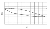
例えば、図5に示されるように、発明者によって実施された分析は、N負荷サイクルにおけるブレーキトルクの関数として検知装置6によって検知されたキャリパ本体5の変形は、ヒステリシスカーブを描き、それぞれの負荷サイクルに関するカーブは、完全に重なった。これは、ブレーキ動作の間の距離dとキャリパ本体の変形の測定は、反復可能であり、したがって信頼できることを支持することを可能とする。さらに、これは、検知装置6の非常に正確な較正を実施することを可能とする。
For example, as shown in FIG. 5, an analysis performed by the inventors has shown that the deformation of the
当該検知装置6を提供することによって、ブレーキ動作に比例する当該距離dを検知することができる。この方法において、ブレーキトルクは、当該検知装置6によって取得される情報に基づいて計算されることができる。 By providing the sensing device 6, the distance d proportional to the braking action can be sensed. In this way the braking torque can be calculated based on the information obtained by the sensing device 6 in question.
そのような検知装置6を提供することによって、正接方向T-Tで評価される距離dは、ディスクが正接方向T-Tにパッドを押す力に比例する。この方法において、キャリパ本体の少なくとも一部の正接方向T-Tの変形を評価することによって、ブレーキ動作を定量化することができる。 By providing such a sensing device 6, the distance d evaluated in the tangential direction TT is proportional to the force with which the disc pushes the pad in the tangential direction TT. In this manner, braking action can be quantified by evaluating the tangential TT deformation of at least a portion of the caliper body.
実施形態によると、当該キャリパ本体5はディスク2の第1のブレーキ表面に少なくとも第1のブレーキパッド31によって、直接または間接に対向するように構成された第1の細長い部分24と、当該第1のブレーキ表面と反対のディスク2の第2のブレーキ表面に、少なくとも第2のブレーキパッド32によって、直接または間接に対向するように構成された対向する第2の細長い部分25を備える。実施形態によると、当該第1の細長い部分24は、当該支持構造4と関連するキャリパ本体5の1つの側面に設置される。実施形態によると、当該第1の細長い部分24は、当該支持構造4によって車両に関連付けられるキャリパ本体5の1つの側面に設置される。
According to an embodiment, said
実施形態によると、当該キャリパ本体5は、当該第1の細長い部分24とディスク2をまたぐ当該第2の細長い部分25を接続する、少なくとも1つのキャリパブリッジ26を備える。
According to an embodiment, said
実施形態によると、当該キャリパ本体5は、ディスク2に対向するように構成された内側キャリパ部27と対向する外側キャリパ部28を備える。当該内側キャリパ部27は、ディスク2の一部を受け入れるように構成されたディスクハウジング9を区切る。
According to an embodiment, said
実施形態によると、少なくとも当該第1の細長い部分24または当該第2の細長い部分25は、ブレーキパッド31、32の背面、好ましくは、関連付けられるブレーキパッド31、32の摩擦材33への支持プレート30の背面に押しつけるように構成された、押しつけ手段15を受け入れるように構成された少なくとも1つの押しつけ手段ハウジング29を区切る。
According to an embodiment, at least said first
実施形態によると、当該ブレーキキャリパ3は、例えばシリンダ-ピストンアセンブリなど、ブレーキパッド31、32を押しつけ、ディスク2のブレーキ表面に対向して密接するように構成された押しつけ手段15を備える。実施形態によると、当該ブレーキキャリパ3は、当該第2の細長い部分25と排他的に関連する押しつけ手段15を備え、それにより当該第1の細長い部分24に関連する押しつけ手段15を提供することを避ける。実施形態によると、当該ブレーキキャリパ3は、当該第1の細長い部分24及び当該第2の細長い部分25と関連する押しつけ手段15を備える。
According to an embodiment, said brake caliper 3 comprises pressing means 15 , for example a cylinder-piston assembly, adapted to press the
実施形態によると、当該ブレーキキャリパ3は、少なくとも2つの対向するブレーキパッド31、32を備え、ブレーキパッドはそれぞれブレーキ動作の間ディスク2の対向するブレーキ表面に押しつけるように構成された摩擦材33を備える。実施形態によると、それぞれのブレーキパッド31、32は、また当該摩擦材33を支持するように構成された支持プレート30を備える。実施形態によると、それぞれのブレーキパッド31、32は、1つの部品、例えばカーボンで作られる。
According to an embodiment, said brake caliper 3 comprises at least two opposing
実施形態によると、当該キャリパ本体は、ディスク差し込み側11及び接線方向T-Tで当該ディスク差し込み側11と対向するディスク抜け側12を備える。車両が前に移動する状態にあるとき、ディスク2は、回転方向Vに回転し、ディスクの与えられた部分は、当該ディスク差し込み側11からキャリパ本体5の当該ディスクハウジング9に入り、当該ディスク抜け側12からディスクハウジング9を出る。
According to an embodiment, the caliper body comprises a
実施形態によると、当該キャリパ及び支持アセンブリ1は、当該あらかじめ定められた方向T-Tに沿って、当該支持要素4に対して当該キャリパ本体5を束縛する少なくとも1つのディスク差し込み側固定装置34を備える。キャリパ本体5の当該ディスク差し込み側11は、当該ディスク差し込み側固定装置34と関連することが好ましい。当該ディスク差し込み側固定装置34を提供することは、局所的に、好ましくは当該あらかじめ定められた方向T-Tに沿って支持要素4に対して、キャリパ本体のディスク差し込み側のキャリパ本体5の変形を防ぐ。
According to an embodiment, the caliper and
実施形態によると、当該キャリパ本体5は、当該支持要素4と連結した接続部18を備え、当該接続部は、キャリパ本体5の当該第1の部分7を備える。
According to an embodiment, the
実施形態によると、キャリパ本体5の当該接続部18は、当該支持要素4と結合し、それにより当該キャリパ本体5と当該支持要素4の間の当該少なくとも1つのあらかじめ定められた方向T-Tに沿った束縛の形成を避ける。この方法において、当該あらかじめ定められた方向T-Tのキャリパ本体5の変形は、キャリパ本体5のピーク負荷によって弾性不安定性の部分を発生することなく、容易になされる。
According to an embodiment, said connecting
実施形態によると、当該支持要素4は、当該キャリパ本体5と結合する接続カウンタ部を備え、当該接続カウンタ部は、支持要素4の当該第2の部分8を備える。
According to an embodiment, said support element 4 comprises a connection counter part associated with said
実施形態によると、キャリパ本体5の当該接続部18は、支持要素4の当該接続カウンタ部と結合し、それにより当該キャリパ本体5と当該支持要素4の間の当該少なくとも1つのあらかじめ定められた方向T-Tに沿った束縛の形成を避ける。
According to an embodiment said connecting
実施形態によると、キャリパ本体5の当該接続部18は、支持要素4の当該接続カウンタ部と協働し、それにより、当該キャリパ本体5と当該支持要素4の間の軸方向X-Xの束縛を形成する。
According to an embodiment, said connecting
実施形態によると、キャリパ本体5の当該接続部は、少なくとも部分的にスロット14を画定する少なくとも1つのスロット壁13を備える。
According to an embodiment, said connecting portion of the
実施形態によると、当該スロット14は、支持要素4の接続装置20を受け入れ、当該あらかじめ定められた方向T-Tにそって引き延ばされた形状のスロット端部プロファイルを描き、それにより当該あらかじめ定められた方向T-Tの当該キャリパ本体5及び当該支持要素4の間の拘束を形成することを避ける。言い換えると、当該接続装置20は、キャリパ本体5に対して当該あらかじめ定められた方向T-Tに沿って動くことによって、スロットの当該少なくとも1つの壁13に当接することを避ける。
According to an embodiment, said
当該スロット14は、キャリパ本体5の当該ディスク抜け側12に配置されることが好ましい。
The
そのようなスロット14を提供することにより、当該キャリパ本体5がキャリパ本体5の一部と当該支持要素4の間の当該あらかじめ定められた方向T-Tに沿って実質的に滑る束縛を形成することができる。
By providing
実施形態によると、当該スロット端部は、実質的に卵形プロファイルを描く。実施形態によると、当該スロット端部は、実質的に楕円形プロファイルを描く。 According to embodiments, the slot ends describe a substantially oval profile. According to embodiments, the slot ends describe a substantially elliptical profile.
実施形態によると、支持要素4の当該接続カウンタ部は、キャリパ本体5の当該スロット14に受け入れられる接続装置20を備える。
According to an embodiment, said connection counter part of the support element 4 comprises a
実施形態によると、当該少なくとも1つのスロット壁13は、キャリパ本体5の当該第1の部分7を備える。
According to an embodiment, said at least one
実施形態によると、当該接続装置20は、支持要素4の当該第2の部分8を備える。
According to an embodiment, said connecting
実施形態によると、支持要素4及びキャリパ本体5の当該スロット14の当該接続装置20は、結合し、それにより当該キャリパ本体5と当該支持要素4の間の当該少なくとも1つのあらかじめ定められた方向T-Tに沿った束縛を形成することを避ける。
According to an embodiment, said
実施形態によると、当該接続装置20は、当該キャリパ本体5と当該支持要素4の間の軸方向X-Xの束縛を形成する当該キャリパ本体5の当該少なくとも1つのスロット壁13と協働する。
According to an embodiment, said connecting
実施形態によると、当該接続装置20は、少なくとも1つの植え込みボルトを備える。
According to embodiments, the
実施形態によると、当該接続装置20は、当該植え込みボルトに適合された少なくとも1つの軸受け筒を備える。この方法において、当該軸受け筒は、ブレーキ動作の間当該少なくとも1つのスロット壁13に反して滑り、それにより例えば滑り摩擦など、摩擦による摩損から当該植え込みボルトを保護する。当該軸受け筒を提供することは、また、キャリパ本体から接続装置20の締め付けナットを分離するためのスペーサの機能を果たし、それにより締め付けナットのヘッドの下の部分によって働く摩擦が、キャリパ本体の変形を妨害するまたは阻むことを、防ぐことを避ける。
According to an embodiment, the
実施形態によると、当該キャリパ本体5の当該ディスク抜け側12は当該第1の部分7を備える。
According to an embodiment, the
好ましい実施形態によると、当該ディスク差し込み側固定装置34は、実質的に当該好ましい方向T-Tに沿って当該接続装置20に一列に並べられる。
According to a preferred embodiment, the disk
ブレーキ動作の間、ディスク2は、好ましくは、当該ブレーキパッド31、32の少なくとも1つの支持プレート30をキャリパ本体5の接線隣接部35と当接させる、ディスク2の回転方向Vと実質的に平行に案内された、送り動作Fをブレーキパッド31、32に適用する。当該送り動作は、当該あらかじめ定められた方向T-Tに沿って案内される。この方法において、送り動作は、当該ディスク差し込み側固定装置34と当該隣接部35の間に入れられたキャリパ本体5の少なくとも一部を当該あらかじめ定められた方向T-Tに沿って弾性変形する。
During braking operation, the
実施形態によると、当該検知装置6は、少なくとも1つのセンサ16を備える。当該センサ16は、渦電流センサであることが好ましい。
According to an embodiment, said sensing device 6 comprises at least one
実施形態によると、当該センサ16はLVDTである。
According to embodiments, the
実施形態によると、当該センサ16は、キャリパ本体5と一体化する。
According to embodiments, the
実施形態によると、当該センサ16は、キャリパ本体5の当該第1の部分7と一体化する。
According to an embodiment, said
実施形態によると、当該センサ16は、キャリパ本体5の当該第1の部分7を備える。
According to an embodiment, said
実施形態によると、当該センサ16は、当該スロット14の当該スロット壁13から当該接続装置20に向かって張り出して突出する張り出しセンサ部17を備える。
According to an embodiment, said
実施形態によると、センサ17の当該張り出し部は、実質的に当該あらかじめ定められた方向T-Tに沿って延在する。
According to an embodiment, said extension of
実施形態によると、当該センサ16は、少なくともデータ伝達配線21と接続するように構成されたセンサ16の出力部19を備える。実施形態によると、当該検知装置6は、ブレーキ動作を定量化する、及び/またはブレーキトルクを見積もる、及び/またはブレーキ力を計算するための、当該正接距離dの情報を受け取るように構成されたデータ処理ユニットと関連する。当該検知装置6は、当該データ伝達配線21によってデータ処理ユニットと関連する。
According to an embodiment, the
実施形態によると、当該ブレーキキャリパ3は、少なくとも1つのブレーキ液供給配管22を備える。当該検知装置6は、当該ブレーキ液供給配管22の近くに位置づけられる。この方法において、当該データ伝達配線21は、当該ブレーキ液供給配線22の隣の車両を有利に通ることができ、それによりデータ伝達配線21に専用の追加のパスを供給することを避ける。
According to an embodiment, said brake caliper 3 comprises at least one brake
実施形態によると、前記キャリパ本体5は、当該あらかじめ定められた方向T-Tに垂直な平面に延在する平坦な表面23を備える。当該平坦な表面23は、ディスク2の反対またはディスク2に対向するために不適切なキャリパ本体5の一部を超えて延在する。実施形態によると、当該外側キャリパ側28は、当該平坦な表面23を備える。
According to an embodiment, said
実施形態によると、キャリパ本体5の当該平坦な表面23は、材料を取り除くことによって作られる。
According to an embodiment, said
実施形態によると、キャリパ本体5の当該接続部18は、当該平坦な表面23を備える。
According to an embodiment, said connecting
実施形態によると、当該検知装置6、好ましくは当該センサ16は、当該平坦な表面23と関連する。実施形態によると、センサ16の当該コンセント部19は、平坦な表面23から張り出して突出する。
According to an embodiment, said sensing device 6 , preferably said
実施形態によると、当該ブレーキキャリパ3は、固定タイプのキャリパである。 According to an embodiment, said brake caliper 3 is a fixed type caliper.
実施形態によると、当該ブレーキキャリパ3は、浮遊タイプのキャリパである。 According to an embodiment, said brake caliper 3 is a floating type caliper.
ブレーキ動作の間キャリパ本体の変形を検知する方法は、以下に記載されるであろう。 A method for sensing deformation of the caliper body during braking will be described below.
あらかじめ定められた方向T-Tに沿ったブレーキ動作の間キャリパ本体の変形を検知する方法は、次のステップを備える。 A method for sensing deformation of the caliper body during braking along a predetermined direction TT comprises the following steps.
-キャリパ及び支持アセンブリ1を提供するステップであって、当該キャリパ及び支持体1のアセンブリは、キャリパ本体5と当該キャリパ本体5に接続された支持要素4を備えるブレーキキャリパを備える、提供するステップ。
- providing a caliper and
-ブレーキ動作の間、支持要素8の第2の部分に対して動くキャリパ本体7の第1の部分を識別するステップ。
- Identifying the first part of the
-キャリパ本体5の当該第1の部分7と支持要素4の当該第2の部分8の間の少なくとも当該あらかじめ定められた方向T-Tに沿った距離dを検知するステップ。
- detecting the distance d between said
可能な動作モードによると、キャリパ本体5の当該第1の部分7と支持要素4の当該第2の部分8の間の少なくとも当該あらかじめ定められた方向T-Tに沿って、距離dを検知するステップは、接線方向に少なくとも沿って当該距離dを検知するステップによって実行される。
According to a possible mode of operation, sensing the distance d between said
動作の可能なモードによると、キャリパ本体5の当該第1の部分7と支持要素4の当該第2の部分8の間の少なくとも当該あらかじめ定められた方向T-Tに沿って距離dを検知するステップは、ブレーキ動作の間及び前に移動する状態の両方で実行される。
According to a possible mode of operation, sensing a distance d between said
動作の可能なモードによると、当該方法は、ブレーキ状態で検知される距離と前に移動する状態で検知される距離を比較する次の追加のステップを備える。 According to a possible mode of operation, the method comprises the following additional step of comparing the distance sensed in braking and the distance sensed in moving forward.
一般の実施形態によると、ディスクブレーキ10のブレーキキャリパ3のためのキャリパ本体5が提供され、軸方向X-Xは、ディスクブレーキのディスク2の回転軸と一致または平行であり、半径方向R-Rは、軸方向X-Xと直交し、接線T-Tまたは方向T-T方向は、軸方向X-X及び半径方向R-Rと直交して定義される。当該キャリパ本体5は、ディスク差し込み側11と接線方向T-Tで当該ディスク差し込み側11と反対のディスク抜け側12を備え、少なくとも当該ディスク差し込み側11または当該ディスク抜け側12、好ましくは当該ディスク抜け側12は、キャリパ本体5と関連付けられる支持要素4の間の接続を形成するための接続装置20を受け入れるように構成された、スロット14を少なくとも部分的に画定する、少なくとも1つのスロット壁13を備える。当該スロット14は、当該接続装置20が当該スロット14に収容されるとき、あらかじめ定められた接線距離dを、当該スロット壁13の少なくとも1つと当該接続装置20の間で画定するように、接続装置20の接線方向T-Tの大きさより大きい、接線方向T-Tの拡張部を有し、それによりブレーキ動作の間、キャリパ本体5の少なくとも一部が接線方向T-Tに弾性変形できる。
According to a general embodiment, a
実施形態によると、スロットの当該壁の少なくとも1つ13は、キャリパ本体5に関連付けられる支持要素4の第2の部分8に対して、接線方向T-Tにブレーキ動作の間動くことができる、少なくとも1つの第1の部分7を備える。
According to an embodiment, at least one said
実施形態によると、当該キャリパ本体5は、当該スロット壁13と当該接続装置20の間で接線距離dを検知するように構成された検知装置6と関連する。
According to an embodiment, said
特定の実施形態において、相互に分離したまたは接合した上記特徴の利点によって、前述の相互に対照する要求と前述の所望の利点を同時に満足するアセンブリと方法を得ることができる。 In certain embodiments, the advantages of the above features, separate or joined together, provide an assembly and method that simultaneously satisfies the aforementioned conflicting needs and the aforementioned desired advantages.
特に、-簡単な反復可能な方法で、キャリパ本体の変形を検知することができる。 In particular - deformation of the caliper body can be detected in a simple and repeatable manner.
-キャリパ本体の変形を検知することに基づいてブレーキ動作を定量化する方法を得ることができ、ブレーキキャリパの全てのタイプに適用できるが、製造が簡単で、同時に既知の方法に対して、信頼性と反復可能性を改善する。 - A method of quantifying braking action based on sensing deformation of the caliper body can be obtained, applicable to all types of brake calipers, yet simple to manufacture and at the same time reliable relative to known methods. improve resilience and repeatability.
-ブレーキトルクに比例する量を検知できる。 - A quantity proportional to the brake torque can be detected.
-キャリパ本体の変形が評価される方向に、実質的に垂直に形成された、キャリパ本体の平坦な表面23に検知装置を設置できる。
- the sensing device can be placed on a
-車両本体の当該データ伝達配線21の通過を容易にするように、すでにブレーキ液供給回路との接続を提供するキャリパ本体の一部に検知装置と関連可能なデータ伝達配線21を配置できる。
- The
当業者は、上記の実施形態に、多くの変化、適応及び置換ができ、要素を添付された請求項の保護の範囲から逸脱することなく、可能な要求を満足するために、機能的に等価な他と置換できる。 Those skilled in the art will be able to make many variations, adaptations and substitutions to the above-described embodiments, finding elements that are functionally equivalent to satisfy possible requirements without departing from the scope of protection of the appended claims. can be replaced with any other.
一般の実施形態によると、ディスクブレーキのためのキャリパ及び支持アセンブリ1は、ブレーキキャリパ3を備える。当該ブレーキキャリパ3は、ディスクブレーキの関連付けられるディスク2をまたぐように構成された、キャリパ本体5を備える。
According to a general embodiment, a caliper and
当該キャリパ及び支持アセンブリ1は、さらに当該キャリパ本体5に接続された支持要素4を備える。
The caliper and
当該キャリパ本体5は、例えば細長い要素24の一部など、第1の部分7を備える。
The
当該支持要素4は、例えば、キャリパ本体24の当該第1の細長い部分に向かって張り出して突出するブラケットなど、第2の部分8を備える。
Said support element 4 comprises a
ブレーキ動作の間、キャリパ本体5は、少なくとも1つのあらかじめ定められた方向T-Tに準じて変形し、それにより支持要素4の当該第2の部分8に対して、キャリパ本体5の第1の部分7の少なくとも当該あらかじめ定められた方向T-Tの変位を測定する。
During braking operation, the
当該キャリパ及び支持アセンブリ1は、細長い要素24の当該第1の部分7に固定された少なくとも1つの検知装置6を備え、キャリパ本体5の当該第1の部分7及び支持要素4の当該第2の部分8の間の当該あらかじめ定められた方向T-Tに少なくとも沿って距離dを検知する。
The caliper and
実施形態によると、検知装置6がキャリパ本体5の細長い要素24の外部に一体に設置され、支持要素4に提供される支持要素4の第2の部分8に対向し、検知装置6に対向するキャリパ本体5に向かって張り出して突出して配置される、ディスクブレーキ10が、提供される。
According to an embodiment, the sensing device 6 is integrally mounted on the outside of the
一般の実施形態によると、ディスクブレーキのためのキャリパ及び支持アセンブリ1は、ブレーキキャリパ3を備える。当該ブレーキキャリパ3は、ディスクブレーキの関連付けられるディスク2をまたぐように構成された、キャリパ本体5を備える。
According to a general embodiment, a caliper and
当該キャリパ及び支持アセンブリ1は、さらに当該キャリパ本体5に接続された支持要素4を備える。
The caliper and
当該キャリパ本体5は、例えば細長い要素部分24、例えば当該支持要素4に向かって張り出して突出するブラケットなど、第1の部分7を備える。
The
当該支持要素4は、第2の部分8を備える。
Said support element 4 comprises a
ブレーキ動作の間、キャリパ本体5は、少なくとも1つのあらかじめ定められた方向T-Tに準じて弾性変形し、それにより支持要素4の当該第2の部分8に対するキャリパ本体5の第1の部分7の少なくとも当該あらかじめ定められた方向T-Tの変位を測定する。
During braking operation, the
当該キャリパ及び支持アセンブリ1は、支持要素4の当該第2の部分8に固定された少なくとも1つの検知装置6を備え、キャリパ本体5の当該第1の部分7と支持要素4の当該第2の部分8の間の当該あらかじめ定められた方向T-Tに少なくとも沿って距離「d」を検知する。
The caliper and
さらなる実施形態によると、検知装置6が支持要素4の外側に堅く接続され、この細長い要素24に張り出して設置されたキャリパ本体5の細長い要素24から延在する第1の部分7に対向し、検知装置6に対向する支持要素4に向かって突出する、ディスクブレーキ10が、提供される。
According to a further embodiment, the sensing device 6 is rigidly connected to the outside of the support element 4 and faces the
1 キャリパ及び支持アセンブリ
2 ディスク
3 ブレーキキャリパ
4 支持要素
5 キャリパ本体
6 検知装置
7 キャリパ本体の第1の部分
8 支持要素の第2の部分
9 ハブキャリア
10 ディスクブレーキ
11 キャリパ本体ディスク差し込み側
12 キャリパ本体ディスク抜け側
13 スロット壁
14 スロット
15 押しつけ手段
16 センサ
17 センサの張り出し部分
18 支持要素へのキャリパ本体の接続部分
19 センサコンセント部
20 支持要素接続装置
21 データ伝達配線
22 ブレーキ液供給配管
23 平坦な表面
24 キャリパ本体第1の細長い部分
25 キャリパ本体第2の細長い部分
26 キャリパブリッジ
27 キャリパ内側
28 キャリパ外側
29 押しつけ手段ハウジング
30 ブレーキパッド支持プレート
31 第1のブレーキパッド
32 第2のブレーキパッド
33 摩擦材
34 固定装置
35 接線隣接部
X-X 軸方向
T-T 接線方向
R-R 半径方向
V ディスクの回転方向
F 送り動作
1 caliper and
Claims (11)
軸方向(X-X)は、前記ディスクブレーキのディスク(2)の回転軸と一致するかまたは平行であり、
半径方向(R-R)が前記軸方向(X-X)に直交し、
正接方向(T-T)または円周方向(T-T)が前記軸方向(X-X)及び前記半径方向(R-R)の両方に直交するように、定義され、
-前記キャリパ及び支持アセンブリ(1)は、ディスクブレーキの関連付けられるディスク(2)をまたぐように構成された、キャリパ本体(5)を備えるブレーキキャリパ(3)を備え、
-前記キャリパ及び支持アセンブリ(1)は、前記キャリパ本体(5)に接続される支持要素(4)を備え、
-前記キャリパ本体(5)は、第1の部分(7)を備え、
-前記支持要素(4)は、第2の部分(8)を備え、
-ブレーキ動作の間、前記キャリパ本体(5)は、前記正接方向(T-T)に弾性変形され、それにより前記支持要素(4)の前記第2の部分(8)に対する前記キャリパ本体(5)の前記第1の部分(7)の前記正接方向(T-T)において変位を決定し、
-前記キャリパ及び支持アセンブリ(1)は、前記キャリパ本体(5)の前記第1の部分(7)と前記支持要素(4)の前記第2の部分(8)の間の前記正接方向(T-T)に沿った距離(d)を検知する少なくとも1つの検知装置(6)を備える、キャリパ及び支持アセンブリ(1)。 A caliper and support assembly (1) for a disc brake, comprising:
the axial direction (XX) is coincident or parallel to the axis of rotation of the disc (2) of said disc brake;
the radial direction (RR) is perpendicular to the axial direction (XX);
defined such that the tangential direction (TT) or the circumferential direction (TT) is orthogonal to both the axial direction (XX) and the radial direction (RR);
- said caliper and support assembly (1) comprises a brake caliper (3) comprising a caliper body (5) configured to straddle an associated disc (2) of a disc brake;
- said caliper and support assembly (1) comprises a support element (4) connected to said caliper body (5);
- said caliper body (5) comprises a first portion (7),
- said support element (4) comprises a second portion (8),
- during braking operation, said caliper body (5) is elastically deformed in said tangential direction (TT), whereby said caliper body (5) relative to said second portion (8) of said support element (4); ) in the tangential direction (TT) of the first portion (7) of
- said caliper and support assembly (1) is aligned in said tangential direction (T - A caliper and support assembly (1) comprising at least one sensing device (6) sensing a distance (d) along T).
前記キャリパ本体(5)は接続部分(18)を備え、 said caliper body (5) comprises a connecting portion (18),
前記接続部分(18)は前記第1の部分(7)を備え、 said connecting portion (18) comprises said first portion (7);
前記支持要素(4)は接続カウンタ部を備え、 said support element (4) comprises a connection counter portion,
前記接続カウンタ部は前記第2の部分(8)を備え、 said connection counter unit comprising said second portion (8);
前記キャリパ本体(5)の前記接続部分(18)は、前記支持要素(4)の前記接続カウンタ部と結合し、それにより前記キャリパ本体(5)と前記支持要素(4)の間の前記正接方向(T-T)に沿った束縛の形成を避ける、請求項1に記載のキャリパ及び支持アセンブリ(1)。 Said connection portion (18) of said caliper body (5) mates with said connection counter portion of said support element (4) so that said tangent between said caliper body (5) and said support element (4) Caliper and support assembly (1) according to claim 1, avoiding the formation of constraints along the direction (TT).
前記支持要素(4)の前記接続カウンタ部は、前記スロット(14)に受け入れられる接続装置(20)を備え、 said connection counter portion of said support element (4) comprises a connection device (20) received in said slot (14);
前記少なくとも1つのスロット壁(13)は、前記キャリパ本体(5)の前記第1の部分(7)を備え、 said at least one slot wall (13) comprises said first portion (7) of said caliper body (5);
前記接続装置(20)は、前記支持要素(4)の前記第2の部分(8)を備え、 said connecting device (20) comprising said second portion (8) of said support element (4);
前記支持要素(4)の前記接続装置(20)は、前記キャリパ本体(5)の前記スロット(14)に結合され、それにより、前記キャリパ本体(5)と前記支持要素(4)の間の前記正接方向(T-T)に沿った束縛の形成を避ける、請求項2に記載のキャリパ及び支持アセンブリ(1)。 Said connection device (20) of said support element (4) is coupled to said slot (14) of said caliper body (5), thereby providing a gap between said caliper body (5) and said support element (4). Caliper and support assembly (1) according to claim 2, avoiding the formation of constraints along the tangential direction (TT).
前記支持要素(4)の前記接続カウンタ部は、前記スロット(14)に受け入れられる接続装置(20)を備え、 said connection counter portion of said support element (4) comprises a connection device (20) received in said slot (14);
前記少なくとも1つのスロット壁(13)は、前記キャリパ本体(5)の前記第1の部分(7)を備え、 said at least one slot wall (13) comprises said first portion (7) of said caliper body (5);
前記接続装置(20)は、前記支持要素(4)の前記第2の部分(8)を備え、 said connecting device (20) comprising said second portion (8) of said support element (4);
前記接続装置(20)は、前記キャリパ本体(5)の前記少なくとも1つのスロット壁(13)と協働し、前記キャリパ本体(5)と前記支持要素(4)との間で前記軸方向(X-X)に沿った前記束縛を形成する、請求項2に記載のキャリパ及び支持アセンブリ(1)。 Said connection device (20) co-operates with said at least one slot wall (13) of said caliper body (5) and is arranged between said caliper body (5) and said support element (4) in said axial direction ( Caliper and support assembly (1) according to claim 2, forming said constraint along XX).
前記センサ(16)は、渦電流センサ及び/またはLVDTセンサで、
前記センサ(16)は、キャリパ本体(5)と一体化され、
前記センサ(16)は、前記キャリパ本体(5)の前記第1の部分(7)と一体化され、
前記センサ(16)は、前記キャリパ本体(5)の前記第1の部分(7)を備え、
前記センサ(16)は、前記センサ(16)の張り出し部を備え、
前記張り出し部は、前記スロット壁(13)から前記接続装置(20)に向かって前記スロット(14)に突出し、前記正接方向(T-T)に沿って延在する、請求項4に記載のキャリパ及び支持アセンブリ(1)。 The sensing device (6) comprises at least one sensor (16),
the sensor (16) is an eddy current sensor and/or an LVDT sensor,
The sensor (16) is integrated with the caliper body (5),
said sensor (16) is integrated with said first portion (7) of said caliper body (5),
said sensor (16) comprising said first portion (7) of said caliper body (5);
said sensor (16) comprising an overhang of said sensor (16);
5. The lug according to claim 4, wherein said lug projects into said slot (14) from said slot wall (13) towards said connecting device (20) and extends along said tangential direction (TT). Caliper and support assembly (1).
前記平坦な表面(23)は、前記ディスク(2)の反対側にある前記キャリパ本体(5)の一部又は前記ディスク(2)に対向しない前記キャリパ本体(5)の一部を超えて延在し、
前記キャリパ本体(5)の前記平坦な表面(23)は、前記キャリパ本体(5)の材料を除去することによって作られ、
前記検知装置(6)は、前記平坦な表面(23)と関連し、
前記センサ(16)のコンセント部(19)は、前記平坦な表面(23)から張り出して突出している、請求項5に記載のキャリパ及び支持アセンブリ(1)。 said caliper body (5) comprises a flat surface (23) extending in a plane perpendicular to said tangential direction (TT);
Said flat surface (23) extends over a part of said caliper body (5) opposite said disc (2) or a part of said caliper body (5) not facing said disc (2). exist ,
said flat surface (23) of said caliper body (5) is made by removing material of said caliper body (5) ,
said sensing device (6) is associated with said planar surface (23),
Caliper and support assembly (1) according to claim 5 , wherein the outlet (19) of the sensor (16) protrudes over and above the flat surface (23).
前記キャリパ本体(5)の細長い要素(24)の外部に一体的に設置され、 integrally mounted on the exterior of the elongated element (24) of said caliper body (5),
前記支持要素(4)に提供される前記支持要素(4)の前記第2の部分(8)に面し、 facing said second portion (8) of said support element (4) provided on said support element (4);
前記検知装置(6)に対向する前記キャリパ本体(5)に向かって張り出して突出して配置されており、 arranged to protrude toward the caliper body (5) facing the detection device (6),
前記検知装置(6)は、 The detection device (6) is
前記支持要素(4)の外部に一体的に設置され、 integrally mounted on the exterior of said support element (4),
細長い要素(24)に張り出して設置され且つ前記検知装置(6)に対向する前記支持要素(4)に向かって突き出た前記キャリパ本体(5)の前記細長い要素(24)から延在する前記第1の部分(7)に対向する、請求項1乃至8のいずれか1項に記載のキャリパ及び支持アセンブリ(1)。 Said caliper body (5) overhangs an elongated element (24) and extends from said elongated element (24) of said caliper body (5) projecting towards said support element (4) facing said sensing device (6). Caliper and support assembly (1) according to any one of the preceding claims, opposite one portion (7).
-キャリパ及び支持アセンブリ(1)を提供するステップを含み、 - providing a caliper and support assembly (1);
前記キャリパ及び支持アセンブリ(1)は、キャリパ本体(5)と、前記キャリパ本体(5)に接続された支持要素(4)とを備えるブレーキキャリパ(3)を有し、Said caliper and support assembly (1) comprises a brake caliper (3) comprising a caliper body (5) and a support element (4) connected to said caliper body (5),
前記キャリパ本体の変形を検知する方法はまた The method for detecting deformation of the caliper body also includes
-前記ブレーキ動作の間、前記支持要素(4)の第2の部分に対して動く前記キャリパ本体(5)の第1の部分(7)を識別するステップと、 - identifying the first part (7) of the caliper body (5) that moves relative to the second part of the support element (4) during the braking operation;
-前記キャリパ本体(5)の前記第1の部分(7)と前記支持要素(4)の前記第2の部分(8)の間の前記正接方向(T-T)に沿った距離(d)を検知するステップと、を備える方法。 - the distance (d) along said tangential direction (TT) between said first portion (7) of said caliper body (5) and said second portion (8) of said support element (4); and detecting.
-前記キャリパ本体(5)の前記第1の部分(7)と前記支持要素(4)の前記第2の部分(8)の間の前記正接方向(T-T)に沿った前記距離(d)を検知するステップと、 - said distance (d) along said tangential direction (TT) between said first portion (7) of said caliper body (5) and said second portion (8) of said support element (4); ), and
-前記ブレーキ動作の間及び前に移動する状態の両方の前記距離(d)を検知するステップと、 - sensing said distance (d) both during said braking action and in a moving forward condition;
-ブレーキ状態で検知された前記距離と前に移動する状態で検知された前記距離とを比較するステップの少なくとも1つを備える請求項10に記載の方法。 11. A method according to claim 10, comprising at least one of the steps of: - comparing the distance sensed in a braking condition with the distance sensed in a moving forward condition.
Applications Claiming Priority (3)
| Application Number | Priority Date | Filing Date | Title |
|---|---|---|---|
| IT102017000075649 | 2017-07-05 | ||
| IT102017000075649A IT201700075649A1 (en) | 2017-07-05 | 2017-07-05 | SET OF CALIPER AND SUPPORT AND METHOD |
| PCT/IB2018/054972 WO2019008534A1 (en) | 2017-07-05 | 2018-07-05 | Caliper and support assembly and caliper deformation detection method |
Publications (3)
| Publication Number | Publication Date |
|---|---|
| JP2020525732A JP2020525732A (en) | 2020-08-27 |
| JP2020525732A5 JP2020525732A5 (en) | 2021-07-29 |
| JP7239498B2 true JP7239498B2 (en) | 2023-03-14 |
Family
ID=60294307
Family Applications (1)
| Application Number | Title | Priority Date | Filing Date |
|---|---|---|---|
| JP2019571934A Active JP7239498B2 (en) | 2017-07-05 | 2018-07-05 | Caliper and support assembly and method for detecting caliper deformation |
Country Status (7)
| Country | Link |
|---|---|
| US (1) | US11209055B2 (en) |
| EP (1) | EP3649366B1 (en) |
| JP (1) | JP7239498B2 (en) |
| CN (1) | CN110832219B (en) |
| ES (1) | ES2875779T3 (en) |
| IT (1) | IT201700075649A1 (en) |
| WO (1) | WO2019008534A1 (en) |
Families Citing this family (2)
| Publication number | Priority date | Publication date | Assignee | Title |
|---|---|---|---|---|
| GB2614226A (en) | 2021-09-14 | 2023-07-05 | Ap Racing Ltd | Braking system |
| IT202100030617A1 (en) | 2021-12-03 | 2023-06-03 | Brembo Spa | Gripper and holder assembly and method |
Citations (8)
| Publication number | Priority date | Publication date | Assignee | Title |
|---|---|---|---|---|
| US20030111305A1 (en) | 2001-12-18 | 2003-06-19 | Delphi Technologies, Inc. | Wheel brake caliper with integral brake pad torque sensing |
| JP2004092770A (en) | 2002-08-30 | 2004-03-25 | Tokico Ltd | Disc brake |
| DE102005013142A1 (en) | 2005-03-22 | 2006-09-28 | Robert Bosch Gmbh | Braking force measuring device for e.g. electromechanical friction brake, has position sensor, which magnetically, inductively, capacitively or optically measures movement of friction brake caused during operation of brake by brake body |
| JP2008076280A (en) | 2006-09-22 | 2008-04-03 | Honda Motor Co Ltd | Braking force sensing device |
| JP2009503395A (en) | 2005-07-25 | 2009-01-29 | ジーメンス ヴィディーオー オートモーティヴ アクチエンゲゼルシャフト | Disc brake with improved device for measuring acting normal force |
| JP2012503162A (en) | 2008-09-23 | 2012-02-02 | ローベルト ボツシユ ゲゼルシヤフト ミツト ベシユレンクテル ハフツング | Brake caliper for disc brake |
| US20120198926A1 (en) | 2009-09-17 | 2012-08-09 | Knorr-Bremse Systeme Fuer Nutzfahrzeuge Gmbh | Measuring Arrangement for Measuring the Application Force of a Disc Brake and a Corresponding Disc Brake |
| JP2014510237A (en) | 2010-11-05 | 2014-04-24 | フレニー ブレンボ ソシエテ ペル アチオニ | Disc brake caliper body and hub bracket assembly |
Family Cites Families (9)
| Publication number | Priority date | Publication date | Assignee | Title |
|---|---|---|---|---|
| JPH0678057B2 (en) * | 1985-04-25 | 1994-10-05 | 富士重工業株式会社 | Breaking device |
| IT1276023B1 (en) * | 1995-03-13 | 1997-10-24 | Freni Brembo Spa | DISC BRAKE |
| US6247560B1 (en) * | 1996-12-12 | 2001-06-19 | Federal-Mogul Technology Limited | Slidable brake disc system |
| US6511135B2 (en) * | 1999-12-14 | 2003-01-28 | Delphi Technologies, Inc. | Disk brake mounting bracket and high gain torque sensor |
| DE102006029978B3 (en) * | 2006-06-29 | 2007-11-08 | Siemens Ag | Disc brake`s e.g. floating caliper-disc brake, operative axial force measuring method for use in motor vehicle, involves receiving shearing movement of part of disc brake by sensor to balance back to actual operative axial force |
| US7813860B2 (en) * | 2006-09-22 | 2010-10-12 | Honda Motor Co., Ltd. | Brake force detecting device |
| DE102012007118B4 (en) * | 2012-04-05 | 2014-08-28 | Audi Ag | Device for measuring residual braking torques of a disc brake of a motor vehicle |
| DE102013213619A1 (en) * | 2013-07-11 | 2015-01-15 | Siemens Aktiengesellschaft | Brake application device for a disc brake device |
| CN106314415B (en) * | 2016-08-29 | 2019-10-22 | 北汽福田汽车股份有限公司 | The detection system and vehicle of service braking device |
-
2017
- 2017-07-05 IT IT102017000075649A patent/IT201700075649A1/en unknown
-
2018
- 2018-07-05 JP JP2019571934A patent/JP7239498B2/en active Active
- 2018-07-05 ES ES18749553T patent/ES2875779T3/en active Active
- 2018-07-05 US US16/625,946 patent/US11209055B2/en active Active
- 2018-07-05 WO PCT/IB2018/054972 patent/WO2019008534A1/en unknown
- 2018-07-05 CN CN201880045102.1A patent/CN110832219B/en active Active
- 2018-07-05 EP EP18749553.6A patent/EP3649366B1/en active Active
Patent Citations (8)
| Publication number | Priority date | Publication date | Assignee | Title |
|---|---|---|---|---|
| US20030111305A1 (en) | 2001-12-18 | 2003-06-19 | Delphi Technologies, Inc. | Wheel brake caliper with integral brake pad torque sensing |
| JP2004092770A (en) | 2002-08-30 | 2004-03-25 | Tokico Ltd | Disc brake |
| DE102005013142A1 (en) | 2005-03-22 | 2006-09-28 | Robert Bosch Gmbh | Braking force measuring device for e.g. electromechanical friction brake, has position sensor, which magnetically, inductively, capacitively or optically measures movement of friction brake caused during operation of brake by brake body |
| JP2009503395A (en) | 2005-07-25 | 2009-01-29 | ジーメンス ヴィディーオー オートモーティヴ アクチエンゲゼルシャフト | Disc brake with improved device for measuring acting normal force |
| JP2008076280A (en) | 2006-09-22 | 2008-04-03 | Honda Motor Co Ltd | Braking force sensing device |
| JP2012503162A (en) | 2008-09-23 | 2012-02-02 | ローベルト ボツシユ ゲゼルシヤフト ミツト ベシユレンクテル ハフツング | Brake caliper for disc brake |
| US20120198926A1 (en) | 2009-09-17 | 2012-08-09 | Knorr-Bremse Systeme Fuer Nutzfahrzeuge Gmbh | Measuring Arrangement for Measuring the Application Force of a Disc Brake and a Corresponding Disc Brake |
| JP2014510237A (en) | 2010-11-05 | 2014-04-24 | フレニー ブレンボ ソシエテ ペル アチオニ | Disc brake caliper body and hub bracket assembly |
Also Published As
| Publication number | Publication date |
|---|---|
| CN110832219A (en) | 2020-02-21 |
| IT201700075649A1 (en) | 2019-01-05 |
| EP3649366B1 (en) | 2021-03-03 |
| WO2019008534A1 (en) | 2019-01-10 |
| JP2020525732A (en) | 2020-08-27 |
| US20200158197A1 (en) | 2020-05-21 |
| CN110832219B (en) | 2022-11-18 |
| US11209055B2 (en) | 2021-12-28 |
| ES2875779T3 (en) | 2021-11-11 |
| EP3649366A1 (en) | 2020-05-13 |
Similar Documents
| Publication | Publication Date | Title |
|---|---|---|
| US20070228815A1 (en) | Brake force detecting apparatus | |
| US7813860B2 (en) | Brake force detecting device | |
| US6511135B2 (en) | Disk brake mounting bracket and high gain torque sensor | |
| JP7239498B2 (en) | Caliper and support assembly and method for detecting caliper deformation | |
| US8000870B2 (en) | Active brake pulsation control | |
| US20220065310A1 (en) | Drum brake | |
| US20080078629A1 (en) | Brake force detecting device | |
| JPH11108089A (en) | Disk brake | |
| JP5253572B2 (en) | Method and system for monitoring disc brake or drum brake lining clearance | |
| US9284999B2 (en) | Guide pin for disc brake assembly, disc brake assembly including such a guide pin and method for producing a disc brake assembly including such a guide pin | |
| JP2020525732A5 (en) | ||
| WO2023100071A1 (en) | "caliper and support assembly, and method" | |
| JP4755559B2 (en) | Brake force detection device | |
| CN113906232A (en) | Brake caliper of disc brake, disc brake system and detection device | |
| JP6730152B2 (en) | Brake pressure distribution measuring method and brake pressure distribution measuring device | |
| JP4620073B2 (en) | Brake force detection device | |
| US20230286486A1 (en) | Device for Direct Force Measurement | |
| TWI664362B (en) | Disc brake | |
| JP2022040742A (en) | Vehicular disk brake | |
| JP2022040741A (en) | Vehicular disk brake | |
| KR20220168278A (en) | Electro-Mechanical Brake | |
| Masood et al. | Effect of lateral run-out on calliper drag in automotive disc brakes | |
| JP2008247051A (en) | Braking force detecting device |
Legal Events
| Date | Code | Title | Description |
|---|---|---|---|
| A521 | Request for written amendment filed |
Free format text: JAPANESE INTERMEDIATE CODE: A523 Effective date: 20210618 |
|
| A621 | Written request for application examination |
Free format text: JAPANESE INTERMEDIATE CODE: A621 Effective date: 20210618 |
|
| A977 | Report on retrieval |
Free format text: JAPANESE INTERMEDIATE CODE: A971007 Effective date: 20220627 |
|
| A131 | Notification of reasons for refusal |
Free format text: JAPANESE INTERMEDIATE CODE: A131 Effective date: 20220712 |
|
| A521 | Request for written amendment filed |
Free format text: JAPANESE INTERMEDIATE CODE: A523 Effective date: 20221012 |
|
| TRDD | Decision of grant or rejection written | ||
| A01 | Written decision to grant a patent or to grant a registration (utility model) |
Free format text: JAPANESE INTERMEDIATE CODE: A01 Effective date: 20230207 |
|
| A61 | First payment of annual fees (during grant procedure) |
Free format text: JAPANESE INTERMEDIATE CODE: A61 Effective date: 20230302 |
|
| R150 | Certificate of patent or registration of utility model |
Ref document number: 7239498 Country of ref document: JP Free format text: JAPANESE INTERMEDIATE CODE: R150 |
|
| S533 | Written request for registration of change of name |
Free format text: JAPANESE INTERMEDIATE CODE: R313533 |
|
| R350 | Written notification of registration of transfer |
Free format text: JAPANESE INTERMEDIATE CODE: R350 |