JP7233248B2 - COMMUNICATION DEVICE, COMMUNICATION DEVICE CONTROL METHOD, AND PROGRAM - Google Patents
COMMUNICATION DEVICE, COMMUNICATION DEVICE CONTROL METHOD, AND PROGRAM Download PDFInfo
- Publication number
- JP7233248B2 JP7233248B2 JP2019033029A JP2019033029A JP7233248B2 JP 7233248 B2 JP7233248 B2 JP 7233248B2 JP 2019033029 A JP2019033029 A JP 2019033029A JP 2019033029 A JP2019033029 A JP 2019033029A JP 7233248 B2 JP7233248 B2 JP 7233248B2
- Authority
- JP
- Japan
- Prior art keywords
- communication
- spatial reuse
- frame
- communication device
- permitted
- Prior art date
- Legal status (The legal status is an assumption and is not a legal conclusion. Google has not performed a legal analysis and makes no representation as to the accuracy of the status listed.)
- Active
Links
Images


Classifications
-
- H—ELECTRICITY
- H04—ELECTRIC COMMUNICATION TECHNIQUE
- H04W—WIRELESS COMMUNICATION NETWORKS
- H04W76/00—Connection management
- H04W76/10—Connection setup
- H04W76/14—Direct-mode setup
-
- H—ELECTRICITY
- H04—ELECTRIC COMMUNICATION TECHNIQUE
- H04L—TRANSMISSION OF DIGITAL INFORMATION, e.g. TELEGRAPHIC COMMUNICATION
- H04L5/00—Arrangements affording multiple use of the transmission path
- H04L5/0001—Arrangements for dividing the transmission path
- H04L5/0003—Two-dimensional division
- H04L5/0005—Time-frequency
- H04L5/0007—Time-frequency the frequencies being orthogonal, e.g. OFDM(A), DMT
-
- H—ELECTRICITY
- H04—ELECTRIC COMMUNICATION TECHNIQUE
- H04B—TRANSMISSION
- H04B7/00—Radio transmission systems, i.e. using radiation field
- H04B7/02—Diversity systems; Multi-antenna system, i.e. transmission or reception using multiple antennas
- H04B7/04—Diversity systems; Multi-antenna system, i.e. transmission or reception using multiple antennas using two or more spaced independent antennas
- H04B7/06—Diversity systems; Multi-antenna system, i.e. transmission or reception using multiple antennas using two or more spaced independent antennas at the transmitting station
- H04B7/0697—Diversity systems; Multi-antenna system, i.e. transmission or reception using multiple antennas using two or more spaced independent antennas at the transmitting station using spatial multiplexing
-
- H—ELECTRICITY
- H04—ELECTRIC COMMUNICATION TECHNIQUE
- H04L—TRANSMISSION OF DIGITAL INFORMATION, e.g. TELEGRAPHIC COMMUNICATION
- H04L5/00—Arrangements affording multiple use of the transmission path
- H04L5/003—Arrangements for allocating sub-channels of the transmission path
- H04L5/0032—Distributed allocation, i.e. involving a plurality of allocating devices, each making partial allocation
- H04L5/0035—Resource allocation in a cooperative multipoint environment
-
- H—ELECTRICITY
- H04—ELECTRIC COMMUNICATION TECHNIQUE
- H04L—TRANSMISSION OF DIGITAL INFORMATION, e.g. TELEGRAPHIC COMMUNICATION
- H04L5/00—Arrangements affording multiple use of the transmission path
- H04L5/003—Arrangements for allocating sub-channels of the transmission path
- H04L5/0037—Inter-user or inter-terminal allocation
-
- H—ELECTRICITY
- H04—ELECTRIC COMMUNICATION TECHNIQUE
- H04L—TRANSMISSION OF DIGITAL INFORMATION, e.g. TELEGRAPHIC COMMUNICATION
- H04L5/00—Arrangements affording multiple use of the transmission path
- H04L5/003—Arrangements for allocating sub-channels of the transmission path
- H04L5/0044—Arrangements for allocating sub-channels of the transmission path allocation of payload
-
- H—ELECTRICITY
- H04—ELECTRIC COMMUNICATION TECHNIQUE
- H04L—TRANSMISSION OF DIGITAL INFORMATION, e.g. TELEGRAPHIC COMMUNICATION
- H04L5/00—Arrangements affording multiple use of the transmission path
- H04L5/0091—Signaling for the administration of the divided path
-
- H—ELECTRICITY
- H04—ELECTRIC COMMUNICATION TECHNIQUE
- H04W—WIRELESS COMMUNICATION NETWORKS
- H04W72/00—Local resource management
- H04W72/04—Wireless resource allocation
- H04W72/044—Wireless resource allocation based on the type of the allocated resource
- H04W72/0453—Resources in frequency domain, e.g. a carrier in FDMA
-
- H—ELECTRICITY
- H04—ELECTRIC COMMUNICATION TECHNIQUE
- H04W—WIRELESS COMMUNICATION NETWORKS
- H04W72/00—Local resource management
- H04W72/20—Control channels or signalling for resource management
- H04W72/21—Control channels or signalling for resource management in the uplink direction of a wireless link, i.e. towards the network
-
- H—ELECTRICITY
- H04—ELECTRIC COMMUNICATION TECHNIQUE
- H04B—TRANSMISSION
- H04B17/00—Monitoring; Testing
- H04B17/30—Monitoring; Testing of propagation channels
- H04B17/309—Measuring or estimating channel quality parameters
- H04B17/318—Received signal strength
-
- H—ELECTRICITY
- H04—ELECTRIC COMMUNICATION TECHNIQUE
- H04W—WIRELESS COMMUNICATION NETWORKS
- H04W52/00—Power management, e.g. TPC [Transmission Power Control], power saving or power classes
- H04W52/04—TPC
- H04W52/18—TPC being performed according to specific parameters
- H04W52/24—TPC being performed according to specific parameters using SIR [Signal to Interference Ratio] or other wireless path parameters
- H04W52/243—TPC being performed according to specific parameters using SIR [Signal to Interference Ratio] or other wireless path parameters taking into account interferences
-
- H—ELECTRICITY
- H04—ELECTRIC COMMUNICATION TECHNIQUE
- H04W—WIRELESS COMMUNICATION NETWORKS
- H04W72/00—Local resource management
- H04W72/20—Control channels or signalling for resource management
- H04W72/23—Control channels or signalling for resource management in the downlink direction of a wireless link, i.e. towards a terminal
-
- H—ELECTRICITY
- H04—ELECTRIC COMMUNICATION TECHNIQUE
- H04W—WIRELESS COMMUNICATION NETWORKS
- H04W76/00—Connection management
- H04W76/10—Connection setup
- H04W76/12—Setup of transport tunnels
-
- Y—GENERAL TAGGING OF NEW TECHNOLOGICAL DEVELOPMENTS; GENERAL TAGGING OF CROSS-SECTIONAL TECHNOLOGIES SPANNING OVER SEVERAL SECTIONS OF THE IPC; TECHNICAL SUBJECTS COVERED BY FORMER USPC CROSS-REFERENCE ART COLLECTIONS [XRACs] AND DIGESTS
- Y02—TECHNOLOGIES OR APPLICATIONS FOR MITIGATION OR ADAPTATION AGAINST CLIMATE CHANGE
- Y02D—CLIMATE CHANGE MITIGATION TECHNOLOGIES IN INFORMATION AND COMMUNICATION TECHNOLOGIES [ICT], I.E. INFORMATION AND COMMUNICATION TECHNOLOGIES AIMING AT THE REDUCTION OF THEIR OWN ENERGY USE
- Y02D30/00—Reducing energy consumption in communication networks
- Y02D30/70—Reducing energy consumption in communication networks in wireless communication networks
Description
本発明は、無線媒体を効率的に使用するための通信技術に関する。 The present invention relates to communication techniques for efficient use of the wireless medium.
近年、多数の通信装置が存在する環境での無線媒体の効率的な利用を目指すIEEE 802.11ax規格が検討されている。この検討においては、複数のBSS(Basic Service Set)における複数の通信装置が無線媒体を有効に使用するために、SRP(Spatial Reuse Parameter)を用いた空間再利用通信の導入が検討されている(特許文献1)。SRPは、1つのBSSを管理するアクセスポイントから送信されるトリガーフレームに含まれる情報である。別のBSSに属する端末が当該情報を受信した場合、当該情報を利用して送信処理を行うことにより、無線媒体の効率的な利用が可能となる。 In recent years, the IEEE 802.11ax standard, which aims at efficient use of the wireless medium in an environment with many communication devices, has been considered. In this study, the introduction of spatial reuse communication using SRP (Spatial Reuse Parameter) is being studied in order for multiple communication devices in multiple BSS (Basic Service Set) to effectively use wireless media ( Patent document 1). SRP is information included in a trigger frame transmitted from an access point managing one BSS. When a terminal belonging to another BSS receives the information, it can perform transmission processing using the information, thereby enabling efficient use of the wireless medium.
前述のSRPを用いた通信方法では、通信の方向性としてアップリンク(Up Link)通信のみが想定されている。すなわち、トリガーフレームによって送信が誘導されるフレームの宛先が、当該トリガーフレームを送信したアクセスポイントであることを前提にしている。そのため、アップリンク以外の通信が想定される場合、例えば、トリガーフレームによって送信が誘導されるフレームの宛先がアクセスポイント以外の場合は、端末により送信されるフレームにより、アクセスポイントにおける受信処理に障害が発生する可能性がある。すなわち、アクセスポイントは、当該アクセスポイント以外の宛先のフレームによって自身宛のフレームが干渉し、当該自身宛のフレームを正しく受信できない可能性がある。 In the above-described communication method using SRP, only uplink communication is assumed as communication directionality. That is, it is premised that the destination of the frame whose transmission is guided by the trigger frame is the access point that transmitted the trigger frame. Therefore, if communication other than uplink is assumed, for example, if the destination of the frame whose transmission is induced by the trigger frame is other than the access point, the reception processing at the access point may be disturbed by the frame transmitted by the terminal. can occur. That is, there is a possibility that an access point cannot correctly receive a frame addressed to itself due to interference with a frame addressed to itself by a frame addressed to a destination other than the access point.
本発明は、上記課題に鑑みてなされたものであり、通信の方向性に応じた通信制御を行うことを目的とする、 The present invention has been made in view of the above problems, and aims to perform communication control according to the direction of communication.
上記目的を達成するための一手段として、本発明の通信装置は以下の構成を有する。すなわち、通信装置であって、OFDMA(直交周波数分割多元接続)による通信のための周波数帯域の割り当て情報を格納できるフィールドを含むフレームを送信する送信手段と、空間再利用通信を許可するかを判定する判定手段と、を有し、前記判定手段により前記空間再利用通信を許可しないと判定された場合に、前記送信手段は、前記フレームに空間再利用通信を許可しないことを示す情報を含めて送信し、前記判定手段は、前記通信装置が属するネットワーク上の2つ以上の端末局による直接通信が行われると判定した場合に、前記空間再利用通信を許可しないと判定することを特徴とする。
As one means for achieving the above object, the communication device of the present invention has the following configuration. That is, a communication device, transmitting means for transmitting a frame including a field capable of storing frequency band allocation information for communication by OFDMA (Orthogonal Frequency Division Multiple Access), and determining whether or not to permit spatial reuse communication. and , when the determining means determines that the spatial reuse communication is not permitted, the transmitting means includes information indicating that the spatial reuse communication is not permitted in the frame. wherein the determining means determines not to permit the spatial reuse communication when determining that direct communication will be performed by two or more terminal stations on the network to which the communication device belongs. .
本発明によれば、通信の方向性に応じた通信制御を行うことにより、無線媒体の効率的利用が促進され、システム全体のスループットが向上する。 According to the present invention, by performing communication control according to the directionality of communication, efficient use of wireless media is promoted, and the throughput of the entire system is improved.
以下、添付図面を参照して実施形態を詳しく説明する。尚、以下の実施形態は特許請求の範囲に係る発明を限定するものでない。実施形態には複数の特徴が記載されているが、これらの複数の特徴の全てが発明に必須のものとは限らず、また、複数の特徴は任意に組み合わせられてもよい。さらに、添付図面においては、同一若しくは同様の構成に同一の参照番号を付し、重複した説明は省略する。 Hereinafter, embodiments will be described in detail with reference to the accompanying drawings. It should be noted that the following embodiments do not limit the invention according to the scope of claims. Although multiple features are described in the embodiments, not all of these multiple features are essential to the invention, and multiple features may be combined arbitrarily. Furthermore, in the accompanying drawings, the same or similar configurations are denoted by the same reference numerals, and redundant description is omitted.
(無線ネットワーク構成)
図1に、本実施形態における無線ネットワーク構成例を示す。図1では、2つのBSS(Basic Service Set)のネットワークとして、ネットワーク100とネットワーク110が示されている。BSSとは、無線ネットワークの基本集合であり、インフラストラクチャモードの場合は、制御装置であるアクセスポイントによって形成・管理される。ネットワーク100は、BSS ID(Identifier値)が1のネットワークであり、ネットワーク110は、BSS IDが2のネットワークである。なお、BSSIDとは、BSSの識別子であり、ここではMAC(Medium Access Control)フレーム構成におけるアクセスポイントのアドレスを用いるが、これに限られない。
(Wireless network configuration)
FIG. 1 shows an example of a wireless network configuration according to this embodiment. In FIG. 1, a
AP(アクセスポイント)101は、ネットワーク100を管理するIEEE802.11ax対応のアクセスポイントである。同様に、AP111は、ネットワーク110を管理するIEEE802.11ax対応のアクセスポイントである。IEEE802.11axでは、OFDMA(直交周波数分割多元接続)により、20MHz幅の周波数帯域の少なくとも一部が、1以上のSTA(ステーション/端末局)に割り当てられ得る。STA102-1~102-3は、ネットワーク100に属する通信端末(端末局)であり、STA112-1は、ネットワーク110に属する通信端末である。
An AP (access point) 101 is an IEEE802.11ax compatible access point that manages the
(APの構成)
図2(a)に、AP101のハードウェア構成の一例を示す。記憶部201はROMやRAM等のメモリにより構成され、後述する各種動作を行うためのプログラムや、無線通信のための通信パラメータ等の各種情報を記憶する。なお、記憶部201として、ROM、RAM等のメモリの他に、フレキシブルディスク、ハードディスク、光ディスク、光磁気ディスク、CD-ROM、CD-R、磁気テープ、不揮発性のメモリカード、DVDなどの記憶媒体を用いてもよい。また、記憶部201が複数のメモリ等を備えていてもよい。
(Configuration of AP)
FIG. 2(a) shows an example of the hardware configuration of the AP 101. As shown in FIG. The
制御部202は、CPUやMPU等の1つ以上のプロセッサにより構成され、記憶部201に記憶されたプログラムを実行することにより、AP101を制御する。なお、制御部202は、記憶部201に記憶されたプログラムとOS(Operating System)との協働により、AP101を制御するようにしてもよい。また、制御部202がマルチコア等の複数のプロセッサから成り、AP101を制御するようにしてもよい。また、制御部202は、機能部203を制御して、アクセスポイント機能、撮像や印刷、投影等の所定の処理を実行し得る。機能部203は、AP101が所定の処理を実行するためのハードウェアである。
The
入力部204は、ユーザからの各種操作の受付を行う。出力部205は、ユーザに対して各種出力を行う。ここで、出力部205による出力とは、画面上への表示や、スピーカによる音声出力、振動出力等の少なくともひとつを含む。なお、タッチパネルのように入力部204と出力部205の両方を1つのモジュールで実現するようにしてもよい。通信部206は、IEEE 802.11シリーズやWi-Fiに準拠した無線通信の制御や、IP(Internet Protocol)通信の制御を行う。例えば、通信部206は、IEEE802.11axに対応する通信または対応しない通信の制御を行うことが可能である。また、通信部206は、アンテナ207を制御して、無線通信のための無線信号の送受信を行うことができる。
The
図2(b)に、AP101の機能構成の一例を示す。送信部211と受信部212はそれぞれ、通信部206を介して、信号の送信処理と受信処理を行う。信号解析部213は、受信部212による処理後の受信信号に対する解析を行う。判定部214は、信号解析部213による解析結果に応じて、AP101が管理するネットワークにおける通信の方向性(通信の相手装置)を判定する。フレーム生成制御部215は、AP101が送信するフレーム(例えばトリガーフレーム)の生成に関する制御を行う。
FIG. 2(b) shows an example of the functional configuration of the AP 101. As shown in FIG. The transmitting
(トリガーフレームの構成)
図3(a)にトリガーフレーム(TF)300の構成を示す。TFは、IEEE 802.11axで規定されるフレームであり、複数のSTAがフレームを送受信するために必要な起動タイミングと無線チャネル(周波数帯域)情報などを示すためのフレームである。Frame Controlフィールド301は、IEEE 802.11シリーズに共通なフィールドであり、本実施形態では、IEEE802.11axのTFであることを示す値が入る。Common Infoフィールド305は、TF300の宛先である複数のSTAに共通な情報を示す。Common Infoフィールド305の詳細は図3(b)を用いて後述する。Per User Infoフィールド306は、TF300の宛先に対する個別情報を示す。Per User Infoフィールド306の詳細は図3(c)を用いて後述する。なお、IEEE 802.11ax規格に準拠する、Duration302、RA(Receiver Address)303、TA(Transmitter Address)304、Padding307、FCS(Frame Check Sequence)308の各フィールドの説明は省略する。
(Configuration of trigger frame)
FIG. 3(a) shows the configuration of the trigger frame (TF) 300. As shown in FIG. TF is a frame defined by IEEE 802.11ax, and is a frame for indicating activation timing and wireless channel (frequency band) information required for multiple STAs to transmit and receive frames. The
図3(b)にCommon Infoフィールド305のサブフィールド構成を示す。Trigger Typeサブフィールド311は、トリガーの種類を示し、TF300がBasic Trigger Frameの場合はこのサブフィールドは0となる。Trigger Type311が0のTFは、複数のSTAにRU(リソースユニット)を割り当て、TFの通信からSIFS(Short Inter Frame Space)時間が経過した後の通信を起動するためのものである。ここで、RUとは、Resource Unitの略であり、OFDMA通信のサブキャリア(周波数帯域)の割り当て単位を示す。Lengthサブフィールド312は、TFによって起動されるフレームの時間(duration)を示す。Lengthサブフィールド312の値は、IEEE 802.11のフレームにおける物理層のL-SIGフィールドに反映される。ここで、L-SIGとは、Legacy SIGNAL、または、non-high-throughput SIGNALの略である。ここでは、Lengthサブフィールド312は、フレームの継続時間を示すものとして設定・使用される。BW(Bandwidth)サブフィールド315は、動作チャネルの帯域が20MHzの場合には0となる。IEEE 802.11ax規格に準拠する、Cascade Indication313(More TFとも称され得る)、CS(Carrier Sense) Required314、GI And LTF Type(Guard Interval And Long Training Field)316、MU-MIMO LTF Mode317、Number of HE LTF Symbols318、STBC(Space Time Block Code)319、LDPC(Low Density Parity Check) Extra Symbol Segment320の各サブフィールドの説明は省略する。なお、MIMOとは、Multiple Input Multiple Outputの略であり、HEとは、High Efficiencyの略で、IEEE802.11ax規格では、高効率を意味する修飾語として用いられる。AP TX Powerサブフィールド321は、TF300の送信電力を20MHz帯域幅で正規化した値であり、その単位はdBmである。UL Spatial Reuse323の詳細は、図4を用いて後述する。Doppler324は、HE-LTFのシンボル数に関連して、0また1の値をとる。IEEE 802.11ax規格に準拠するPacket Extension322、HE-SIG-A Reserved325、Reserved326の各サブフィールドの説明は省略する。なお、HE-SIG-Aという表記は、HE-SIG-A1からHE-SIG-A4までを代表させた表現である。Trigger Dependent Common Infoサブフィールド327は、長さがvariable(可変長)であり、このサブフィールドによって、Trigger Typeサブフィールド311が示す値(TFの種別)に応じた付加情報を示す構成となる。
FIG. 3B shows the subfield configuration of the
図3(c)は、Per User Infoフィールド306のサブフィールド構成を示す。AID(Association IDentifier)12サブフィールド328は、接続した端末(STA)を区別するためにアクセスポイントが付す識別子である。AID12サブフィールド328が示す値と同じAIDの値を持つ端末が、このPer User Infoフィールド306の対象端末となり、後続のRU Allocationサブフィールド329で割り当てられたRUを使うことになる。なお、AIDの値の合致判断は、12 LSBs(Least Significanr Bits)によって行われる。また、サブフィールド328=0の場合、特定の端末宛てではなく、APにアソシエート(接続)している任意の端末宛てであることを示す。また、AID12サブフィールド328=2045の場合は、APにアソシエートしていない任意の端末宛てであることを示す。さらに、AID12サブフィールド328=2046は、RUが未割当てであることを示す。RU Allocationサブフィールド329は、割り当てるRUのインデックスを示す。FEC Coding Typeサブフィールド330は、TFへの応答データの符号化タイプを示す。MCSサブフィールド331は、TFへの応答フレームで使用される符号化方式を示す。なお、MCSとは、Modulation and Coding Schemeの略である。DCMサブフィールド332は、TFへの応答フレームのDual carrier modulationを示す。SS Allocation/RA-RU Informationサブフィールド333は、端末のAIDが0でも2045でもないときは、TFへの応答フレームのspatial streamである。端末のAIDが0または2045のときは、当該サブフィールドは、RA-RU(Random Access Resource Unit)であることを示す。Target RSSI(Receive Signal Strength Indicator)サブフィールド334は、APが期待するTFへの応答フレームのAPにおける受信電力を示す。Reservedサブフィールド335の説明は省略する。Trigger Dependent User Info336サブフィールドは、Trigger Type311に依存して内容が変わるサブフィールドである。
FIG. 3(c) shows the subfield configuration of the Per
図4(a)は、UL Spatial Reuseフィールド323の詳細であり、それぞれ4bitの4つのSpatial Reuse1~4サブフィールド401~404から成る。各Spatial ReuseサブフィールドはSRPの値を示し、図4(b)にSRPの値とその意味を示す。図4(b)に示すように、SRPの値が0(ゼロ)の場合はTFの送信の後に、Spatial Reuseによる送信を許可しないこと(SRP_DISALLOW)を意味する。また、SRPの値が1~14の場合は、それぞれ「APが許容できる受信干渉レベル(受信干渉値)」に「TFの送信電力」を加えた数値(dBm)を意味する。更に、SRPの値が15の場合は、SRP方式とOBSS_PD方式を禁止すること(SRP_AND_NON_SRG_OBSS_PD_PROHIBITED)を意味する。なお、OBSS_PDは、Overlapping BSS Packet Detectionの略であり、ここでは詳細な説明は省略する。
FIG. 4A shows details of the UL
(動作シーケンスの説明)
続いて、図1に示すネットワーク構成における、本実施形態における動作シーケンスを説明する。本実施形態における前提となるSRP(Spatial Reuse Parameter)方式による通信方式(SRPベースの通信方式)は、802.11axの特徴のひとつである空間再利用の通信方式のひとつである。より具体的には、同じ周波数帯の無線空間を複数のBSSが使う環境で、ひとつのBSSに属するアクセスポイントが、許容できる受信干渉レベルに関するパラメータ値(SRPの値)を通知し、他のBSSに属する端末がその値に基づき送信レベルを決定する方式である。この方式によれば、無線媒体を効率的に利用することが可能となる。
(Description of operation sequence)
Next, an operation sequence in this embodiment in the network configuration shown in FIG. 1 will be described. A communication method based on the SRP (Spatial Reuse Parameter) method (SRP-based communication method), which is a premise of the present embodiment, is one of the spatial reuse communication methods, which is one of the features of 802.11ax. More specifically, in an environment where a plurality of BSSs use the same frequency band radio space, an access point belonging to one BSS notifies a parameter value (SRP value) related to an allowable received interference level, and communicates with other BSSs. This is a method in which a terminal belonging to 1 determines the transmission level based on the value. According to this method, it is possible to efficiently use the wireless medium.
<第1の動作シーケンス例:SRP方式を許可する>
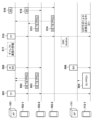
図5に、第1の動作シーケンス例を示す。本動作シーケンスは、TFによって起動されるフレームの宛先がアクセスポイントに限定されている場合(アップリンク通信のみ)である。まず、AP101が、自身が管理するBSSID:1のネットワーク100内でUL MU 動作を起動するために、TF501を送信する。TF501のUL Spatial Reuseフィールド323には、図4(b)に示したようなSRPの値が設定されている。なお、UL MUとは、Up Link Multi Userの略であり、複数のSTAからAPへの同時送信のことである。TF501を受信したSTAは、自身にRUが割り当てられている場合は、SIFS時間経過後にフレームを送信する。図5の例では、STA102-1がHE TB PPDUフレーム502を送信し、STA102-2がHE TB PPDUフレーム503を送信する。HE TB PPDUフレームの時間長は、TF501によって指定されている(図3(b)におけるLengthサブフィールド312)。ここで、TBとは、Trigger Basedの略であり、PPDUとは、Physical layer Protocol Data Unitの略である。つまり、HE TB PPDUフレームとは、IEEE802.11axのTFによって送信誘導されるフレームを指す。なお、図5のHE TB PPDUフレームの縦軸上の位置は、そのフレーム送信のために使用されるRUの周波数帯を模擬したものである。
<First Operation Sequence Example: Permit SRP Method>
FIG. 5 shows a first operation sequence example. This operation sequence is for the case where the destination of the frame activated by the TF is limited to the access point (uplink communication only). First,
BSSID:1のネットワーク100と同じ周波数帯・チャネルを用いるBSSID:2のネットワーク101内にいるSTA112-1も、TF501を受信することができる。TF501のUL Spatial Reuseフィールド323には、図4(b)に示したようなSRPの値が設定されているため、STA112-1は、SRPの値を知ることができる。このとき、SRPの値が1~14であれば、STA112-1は、AP111宛てのSU(Single User) PPDUフレーム504を条件付きの送信電力で送信することができる。すなわち、SRPの値に対応する電力(「APが許容できる受信干渉値(受信干渉レベル)」に「TFの送信電力」を加えた数値(dBm))から、RF501の受信電界強度(RSSI)を減じた値より小さい値の送信電力を用いる。例えば、TF501のUL Spatial Reuseフィールド323のSpatial Reuse1サブフィールド401に含まれるSRPの値が1の場合、図4(b)を参照すると、-80dBmに対応する。STA112-1は、-80dBmからRF501の受信電界強度を減じた値よりも小さい送信電力値で、SU PPDUフレーム504を送信する。
STA 112 - 1 in
このようにすると、SU PPDUフレーム504の送信電力から、AP101とSTA112-1との間の無線媒体の損失(Loss)を減じた値が、許容できる受信干渉値より小さくなる。よって、STA112-1によるSU PPDUフレーム504の送信が、AP101の受信処理に影響を与えず、AP101は自身宛のフレーム(HE TB PPDUフレーム502、503)を正しく受信することが可能となる。これは、図1において、STA112-1からのPPDUフレームの送信(実線)が、AP101におけるSTA102-3からのHE TB PPDUフレームの受信(実線)に影響を与えないことに相当する。
In this way, the value obtained by subtracting the loss of the wireless medium (Loss) between
続いて、HE TB PPDUフレーム502、503を受信したAP101は、応答としてMBAフレーム505を返す。MBAとは、Multi-STA BA(Block Ack)の略で、複数のSTAに対する応答をひとつのフレームで構成したものである。また、SU PPDUフレーム504を受信したAP111は、応答としてBA(Block Ack)フレーム506を返す。このように、SRP方式を利用することにより、BSSID:1とBSSID:2のネットワーク間で無線媒体(空間)を有効利用(再利用)することが可能となる。
After receiving the HE TB PPDU frames 502 and 503, the
<第2の動作シーケンス例:ダイレクト通信の開始を検知しているときにSRP方式を不許可にする>
本動作シーケンスでは、STA102-1とSTA102-2間のダイレクト通信を開始する場合を想定する。第1の動作シーケンスを説明した図5において、AP101とAP111がそれぞれMBAフレーム505とBAフレーム506を送信後に、AP101がSTA102-1とSTA102-2間におけるダイレクト通信の開始(実施)を把握する(動作511)。例えば、AP101は、STA102-1とSTA102-2間でやりとりされるダイレクト通信の開始に関する信号を検知することや、AP101を介したダイレクト通信の開始に関する信号を検知することにより、当該ダイレクト通信の開始を把握することができる。なお、ダイレクト通信とは、APを経由しない直接通信であり、DLS(Direct Link Setup)やTDLS(Tunneld DLS)、Wi-Fiダイレクトによる通信である。続いてAP101はTFを送信する。ここでは、AP101は、TF512におけるSRPの値を0(ゼロ)または15に設定する。図4(b)に示すように、これらのSRPの値は、SRP方式を禁止(disallow)する意味を持つ。更に、AP101は、TF512に、STA102-1とSTA102-2との間のダイレクト通信のためのRUを含める。
<Second Operation Sequence Example: Disallowing the SRP Method When Detecting the Start of Direct Communication>
In this operation sequence, it is assumed that direct communication between STA 102-1 and STA 102-2 is started. In FIG. 5 explaining the first operation sequence, after
TF512を受信したSTA102-2は、TF512においてSTA102-1との通信用のRUが割り当てられていることを認識し、STA102-1宛てにHE TB PPDUフレーム513を送信する。同様に、TF512を受信したSTA102-3は、TF512においてMU UL通信用のRUが割り当てられていることを認識し、AP101宛てにHE TB PPDUフレーム514を送信する。一方、STA112-1は、HE TB PPDUフレーム513、514が送信されている間は、SRP方式によるフレーム送信を行わない。
Upon receiving TF512, STA 102-2 recognizes that RU for communication with STA 102-1 is assigned in
HE TB PPDUフレーム513を受信したSTA102-1は、STA102-2宛てに応答としてBAフレーム515を送信する。同様に、HE TB PPDUフレーム514を受信したAP101は、STA102-3宛てに応答としてBA516フレームを送信する。これらの応答(BAフレーム)は、OFDMA通信方式によるもので、HE TB PPDUフレームが使用したRUと同じRUを利用するものとしている。
STA 102-1 that has received HE
このように、第2の動作シーケンス例は、第1の動作シーケンス例と異なり、STA112-1は、TF受信の後にフレーム送信を行うことができない。これは、TF511において示されるSRPの値が、他のBSSのネットワークにおけるSTAによるSRP方式によるフレーム送信を禁止することを示す値となっているからである。なお、図5ではダイレクト通信(直接通信)として2つのSTA間の通信を例に説明したが、2つ以上のSTA間でダイレクト通信を行う場合も同様に、SRP方式によるフレーム送信を禁止するようにTFを構成してもよい。 Thus, in the second operation sequence example, unlike the first operation sequence example, the STA 112-1 cannot perform frame transmission after TF reception. This is because the SRP value indicated in TF511 is a value that indicates prohibition of frame transmission by the STA in the network of other BSSs by the SRP method. In FIG. 5, communication between two STAs has been described as an example of direct communication (direct communication), but when direct communication is performed between two or more STAs, frame transmission by the SRP method is similarly prohibited. TF may be configured in
<第3の動作シーケンス例:APが全二重通信を行うときにSRP方式を不許可にする>
図6に、第3の動作シーケンス例を示す。AP101は、全二重通信(Full-duplex)を実行可能な状態にある場合、制御部202が通信部206やアンテナ207を制御することにより、全二重通信の準備をおこなう(動作601)。なお、STA102-1~102-3においては、TF受信後にAP101からのフレームを受信可能であることを前提とする。
<Third Operation Sequence Example: Disallow SRP Method When AP Performs Full-Duplex Communication>
FIG. 6 shows a third operation sequence example. When the
動作601後、AP101はTF602を送信する。このときAP101は、上記の第2の動作シーケンス例と同様に、SRPの値を、SRP方式を禁止(disallow)する意味を持つ値に設定する。また、AP101は、TF602に、STA102-1に対して、ダウンリンク(Down Link)通信(AP101からSTA方向の通信)のためのRUを含める。更に、AP101は、TF602に、STA102-2とSTA102-3に対しては、MU UL通信のためのRUを含める。TF602を送信後、AP101は、STA102-1宛てにHE TB PPDUフレーム603を送信する。TF602を受信したSTA102-2は、TF602においてMU UL通信用のRUが割り当てられていることを認識し、AP101宛てにHE TB PPDUフレーム604を送信する。同様に、TF602を受信したSTA102-3は、TF602においてMU UL通信用のRUが割り当てられていることを認識し、AP101宛てにHE TB PPDUフレーム605を送信する。一方、STA112-1は、HE TB PPDUフレーム604、605が送信されている間は、SRP方式によるフレーム送信を行わない。
After
HE TB PPDUフレーム603を受信したSTA102-1は、AP101宛て応答としてBAフレーム606を送信する。また、HE TB PPDUフレーム603、604を受信したAP101は、STA102-2とSTA102-3宛てにそれぞれ応答としてBAフレーム607、608を送信する。なお、図6は、AP101が単一のSTAにHE TB PPDUフレームを送信する構成を示したが、AP101が複数のSTAにデータフレームを送信する場合、HE MU PPDU形式のフレームで送信する。
The STA 102-1 that received the HE
なお、図示しないが、第2と第3の動作シーケンス例を組み合わせた動作シーケンス例として、複数のSTA間でのダイレクト通信が開始され、かつ、AP101が全二重通信を行う場合も、AP101は、SRP方式を不許可するようにTFを構成してもよい。
Although not shown, as an operation sequence example combining the second and third operation sequence examples, when direct communication is started between a plurality of STAs and
また、AP101とSTA102-1~102-3は全二重通信が可能(ULとDLの通信が可能)であることを示す情報(動作能力と動作情報)は、AP101が各STAと接続する際における能力(Capabilities)交換の手順で、互いに把握されてもよい。
In addition, information (operation capability and operation information) indicating that
ところで、図1は、AP101からのTFが、AP111に届かない場合を示している。これは、本実施形態が、他のBSSのネットワークを管理するAP(すなわちAP101)からTFを受信したSTA(すなわちSTA112-1)の動作に関するものだからである。図1において、もし、AP111やネットワーク110におけるSTA(図示せず)が、AP101からのTFを受信した場合は、これらのSTAはSTA112-1と同様に、TFによりSRP方式の使用・不使用が制御され得る。
By the way, FIG. 1 shows a case where the TF from AP101 does not reach AP111. This is because this embodiment relates to the operation of a STA (ie, STA 112-1) that receives a TF from an AP (ie, AP 101) that manages the network of another BSS. In FIG. 1, if STAs (not shown) in
<AP101の処理>
図7に、AP101によるトリガーフレーム送信処理のフローチャートを示す。本フローチャートの処理は、例えばAP101の制御部202が、記憶部201に記憶されたプログラムを実行することによって実現される。
<Processing of
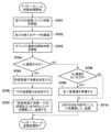
FIG. 7 shows a flowchart of trigger frame transmission processing by the
まず、S701で、AP101は、AP101に接続される各STAの送信バッファ状態を確認する。例えばAP101の受信部212により受信された、各STA102-1~102-3からBSR(バッファ状態情報(Buffer Status Report))を信号解析部213が解析することにより、当該送信バッファ状態を確認することができる。送信バッファ状態は、各STAが送信すべきデータの量、アクセスカテゴリの種類、バッファにおける滞留時間等を含み得る。
First, in S701, the AP101 confirms the transmission buffer status of each STA connected to the AP101. For example, the
次に、S702で、AP101の信号解析部213は、各STA宛てのデータを確認する。例えば、信号解析部213は、ネットワーク100内のSTAからAP101を経由して同じネットワーク100に向けられたデータや、図示してはいないがネットワーク100の外のSTAからネットワーク100内のSTAに向けられたデータの有無を確認する。更に、S703で、AP101は、ネットワーク100において2つ以上のSTA間でダイレクト通信が開始されるかを確認する。この段階で、AP101は、自身が管理するネットワーク100における、通信の相手装置(通信の方向性)を含む通信要求を把握することになる。なお、当該通信の相手装置(通信の方向性)に関する情報はユーザが入力部204を介して設定することにより、AP101が把握するように構成されてもよい。
Next, in S702, the
続いてS704で、AP101の判定部214は、S702およびS703の確認状況に基づいて、ネットワーク100における各STAの各々の通信の相手装置(通信の方向性)を判定し、TFによって誘導(起動)する通信をAP101へのUL通信のみとするかを決定する。AP101へのUL通信のみを行うことが決定されると、処理はS705へ進む。S705では、フレーム生成制御部215は、AP101において許容できる受信干渉値(受信干渉レベル)を決定する。更に、S706で、フレーム生成制御部215は、送信するTFの送信電力の値を決定する。決定された送信電力を用いて通信部206は送信処理を行う。S707では、フレーム生成制御部215は、決定した許容受信干渉値に、決定したTF送信電力を加えた数値を算出し、図4(b)に示す関係表からSRPの値を決定し、当該SRPの値を設定したTFを構築する。その後、送信部211は構築されたTFを送信する。
Subsequently, in S704, the
S704でAP101へのUL通信以外の通信も行うことが決定されると、処理はS708へ進む。S708で、判定部214は、送信されるTFを契機にAP101からの送信を行うか、すなわち、通信の方向性としてAP101からSTAへのダウンリンク通信を含むかを判定する。ダウンリンク通信を行う場合は、処理はS709へ進み、それ以外の場合は、処理はS710へ進む。S709で、制御部202は全二重通信の準備を行う。S710で、フレーム生成制御部215は、SRP方式を不許可にしたTFを構築し、送信部211が構築されたTFを送信する。ここで、不許可にするとは、図4(b)に示したように、SRPの値を0(SRP_DISALLOW)または15(SRP_AND_NON_SRG_OBSS_PD_PROHIBTED)にすることに相当する。
If it is determined in S704 that communication other than UL communication to the
図7に示すフローチャートを上記の第1~第3の動作シーケンス例と対応付けると、第1の動作シーケンス例は、S704からS707以降へ進む処理に対応し、第2の動作シーケンス例は、S708からS710へ進む処理に対応し、第3の動作シーケンス例は、S708からS709以降へ進む処理に対応する。 When the flowchart shown in FIG. 7 is associated with the above-described first to third operation sequence examples, the first operation sequence example corresponds to processing proceeding from S704 to S707 and thereafter, and the second operation sequence example corresponds to processing from S708 to S707. This corresponds to the process of proceeding to S710, and the third operation sequence example corresponds to the process of proceeding from S708 to S709 and beyond.
以上説明したように、APにより管理されるネットワークにおける通信の方向性に、アップリンク以外の通信が含まれる場合、すなわち、TFによって誘導されるフレームの宛先にTFを送信したAP以外の端末(通信装置)が含まれるときに、SRP方式の通信を行わないように制御する。このような動作によって、複数のBSSのネットワークに属するAPとSTAが無線媒体を共用するとときに、SRP方式の使用を適切に制御することが可能になり、無線媒体の効率的利用が促進されるという効果を得ることができる。また、システム全体のスループットが向上する。 As described above, when communication other than uplink is included in the direction of communication in the network managed by the AP, that is, terminals other than the AP that have transmitted the TF to the destination of the frame guided by the TF (communication device) is included, control is performed so that SRP communication is not performed. Such an operation makes it possible to appropriately control the use of the SRP scheme when APs and STAs belonging to a network of multiple BSSs share the wireless medium, promoting efficient use of the wireless medium. effect can be obtained. Also, the throughput of the entire system is improved.
なお、上記の実施形態は、IEEE 802.11axに限定されず、IEEE 802.11 EHT(Extremely/Extreme High Throughput)といったIEEE 802.11シリーズの規格にも同様に適用可能である。 Note that the above-described embodiments are not limited to IEEE 802.11ax, and are similarly applicable to IEEE 802.11 series standards such as IEEE 802.11 EHT (Extremely/Extreme High Throughput).
本発明は、上述の実施形態の1以上の機能を実現するプログラムを、ネットワーク又は記憶媒体を介してシステム又は装置に供給し、そのシステム又は装置のコンピュータにおける1つ以上のプロセッサがプログラムを読出し実行する処理でも実現可能である。また、1以上の機能を実現する回路(例えば、ASIC)によっても実現可能である。 The present invention supplies a program that implements one or more functions of the above-described embodiments to a system or apparatus via a network or a storage medium, and one or more processors in the computer of the system or apparatus reads and executes the program. It can also be realized by processing to It can also be implemented by a circuit (for example, ASIC) that implements one or more functions.
発明は上記実施形態に制限されるものではなく、発明の精神及び範囲から離脱することなく、様々な変更及び変形が可能である。従って、発明の範囲を公にするために請求項を添付する。 The invention is not limited to the embodiments described above, and various modifications and variations are possible without departing from the spirit and scope of the invention. Accordingly, the claims are appended to make public the scope of the invention.
101、111: AP、102-1~4、112-1: STA 101, 111: APs, 102-1 to 4, 112-1: STAs
Claims (10)
OFDMA(直交周波数分割多元接続)による通信のための周波数帯域の割り当て情報を格納できるフィールドを含むフレームを送信する送信手段と、
空間再利用通信を許可するかを判定する判定手段と、を有し、
前記判定手段により前記空間再利用通信を許可しないと判定された場合に、前記送信手段は、前記フレームに空間再利用通信を許可しないことを示す情報を含めて送信し、
前記判定手段は、前記通信装置が属するネットワーク上の2つ以上の端末局による直接通信が行われると判定した場合に、前記空間再利用通信を許可しないと判定することを特徴とする通信装置。 A communication device,
transmitting means for transmitting a frame including a field capable of storing frequency band allocation information for communication by OFDMA (Orthogonal Frequency Division Multiple Access);
determining means for determining whether to permit spatial reuse communication;
if the determination means determines that the spatial reuse communication is not permitted, the transmission means transmits the frame including information indicating that the spatial reuse communication is not permitted;
The communication device, wherein the determining means determines that the spatial reuse communication is not permitted when it determines that two or more terminal stations on the network to which the communication device belongs directly communicate.
前記判定手段は、前記検知手段による信号の検知結果に基づいて、前記通信装置が属するネットワーク上の2つ以上の端末局による直接通信が行われるか否かを判定して、当該判定に基づいて前記空間再利用通信を許可するかを判定することを特徴とする請求項1に記載の通信装置。 further comprising detection means for detecting a signal relating to initiation of direct communication by the two or more terminal stations;
The determination means determines whether or not direct communication is performed by two or more terminal stations on the network to which the communication device belongs, based on the detection result of the signal by the detection means, and based on the determination, 2. The communication device according to claim 1, wherein it is determined whether or not to permit the spatial reuse communication.
OFDMA(直交周波数分割多元接続)による通信のための周波数帯域の割り当て情報を格納できるフィールドを含むフレームを送信する送信工程と、
空間再利用通信を許可するかを判定する判定工程と、を有し、
前記判定工程において前記空間再利用通信を許可しないと判定された場合に、前記送信工程では、前記フレームに空間再利用通信を許可しないことを示す情報を含めて送信し、
前記判定工程では、前記通信装置が属するネットワーク上の2つ以上の端末局による直接通信が行われると判定した場合に、前記空間再利用通信を許可しないと判定することを特徴とする通信装置の制御方法。 A control method for a communication device,
a transmitting step of transmitting a frame including a field capable of storing frequency band allocation information for communication by OFDMA (Orthogonal Frequency Division Multiple Access);
a determining step of determining whether to permit spatial reuse communication;
when it is determined in the determining step that the spatial reuse communication is not permitted, in the transmitting step, the frame includes information indicating that the spatial reuse communication is not permitted, and is transmitted;
In the determining step, when it is determined that two or more terminal stations on a network to which the communication device belongs will perform direct communication, it is determined that the spatial reuse communication is not permitted. control method.
Priority Applications (4)
| Application Number | Priority Date | Filing Date | Title |
|---|---|---|---|
| JP2019033029A JP7233248B2 (en) | 2019-02-26 | 2019-02-26 | COMMUNICATION DEVICE, COMMUNICATION DEVICE CONTROL METHOD, AND PROGRAM |
| US16/781,202 US11323216B2 (en) | 2019-02-26 | 2020-02-04 | Communication apparatus that selectively permits spatial reuse parameter based communication, method of controlling communication apparatus, and non-transitory computer-readable storage medium |
| US17/712,582 US20220224462A1 (en) | 2019-02-26 | 2022-04-04 | Communication apparatus that selectively permits spatial reuse parameter based communication, method of controlling communication apparatus, and non-transitory computer-readable storage medium |
| JP2023025524A JP2023065497A (en) | 2019-02-26 | 2023-02-21 | Communication device, communication device control method, and program |
Applications Claiming Priority (1)
| Application Number | Priority Date | Filing Date | Title |
|---|---|---|---|
| JP2019033029A JP7233248B2 (en) | 2019-02-26 | 2019-02-26 | COMMUNICATION DEVICE, COMMUNICATION DEVICE CONTROL METHOD, AND PROGRAM |
Related Child Applications (1)
| Application Number | Title | Priority Date | Filing Date |
|---|---|---|---|
| JP2023025524A Division JP2023065497A (en) | 2019-02-26 | 2023-02-21 | Communication device, communication device control method, and program |
Publications (3)
| Publication Number | Publication Date |
|---|---|
| JP2020141159A JP2020141159A (en) | 2020-09-03 |
| JP2020141159A5 JP2020141159A5 (en) | 2022-02-17 |
| JP7233248B2 true JP7233248B2 (en) | 2023-03-06 |
Family
ID=72143057
Family Applications (2)
| Application Number | Title | Priority Date | Filing Date |
|---|---|---|---|
| JP2019033029A Active JP7233248B2 (en) | 2019-02-26 | 2019-02-26 | COMMUNICATION DEVICE, COMMUNICATION DEVICE CONTROL METHOD, AND PROGRAM |
| JP2023025524A Pending JP2023065497A (en) | 2019-02-26 | 2023-02-21 | Communication device, communication device control method, and program |
Family Applications After (1)
| Application Number | Title | Priority Date | Filing Date |
|---|---|---|---|
| JP2023025524A Pending JP2023065497A (en) | 2019-02-26 | 2023-02-21 | Communication device, communication device control method, and program |
Country Status (2)
| Country | Link |
|---|---|
| US (2) | US11323216B2 (en) |
| JP (2) | JP7233248B2 (en) |
Families Citing this family (4)
| Publication number | Priority date | Publication date | Assignee | Title |
|---|---|---|---|---|
| JP7297400B2 (en) * | 2016-03-18 | 2023-06-26 | キヤノン株式会社 | Communication device, information processing device, control method, and program |
| JP7233248B2 (en) * | 2019-02-26 | 2023-03-06 | キヤノン株式会社 | COMMUNICATION DEVICE, COMMUNICATION DEVICE CONTROL METHOD, AND PROGRAM |
| CN114641079A (en) * | 2020-12-15 | 2022-06-17 | 华为技术有限公司 | Method and device for indicating spatial multiplexing parameters and determining spatial multiplexing parameter fields |
| WO2022268338A1 (en) * | 2021-06-25 | 2022-12-29 | Telefonaktiebolaget Lm Ericsson (Publ) | Usage of csr resources by non-participating wireless station |
Citations (1)
| Publication number | Priority date | Publication date | Assignee | Title |
|---|---|---|---|---|
| US20180292518A1 (en) | 2017-04-07 | 2018-10-11 | Marvell World Trade Ltd. | Ranging Measurements in Wireless Communication Systems |
Family Cites Families (17)
| Publication number | Priority date | Publication date | Assignee | Title |
|---|---|---|---|---|
| US9894653B2 (en) * | 2015-04-24 | 2018-02-13 | Intel IP Corporation | Apparatus, computer readable medium, and method for multi-user request-to-send and clear-to-send in a high efficiency wireless local-area network |
| US10701730B2 (en) * | 2015-06-05 | 2020-06-30 | Lg Electronics Inc. | Method for transmitting data in wireless communication system and apparatus therefor |
| US20170064644A1 (en) * | 2015-08-24 | 2017-03-02 | Intel IP Corporation | [11ax] conditional spatial reuse |
| CN112491521B (en) * | 2015-10-20 | 2022-08-19 | 华为技术有限公司 | Method and device for transmitting data |
| US10470128B2 (en) * | 2015-11-18 | 2019-11-05 | Newracom, Inc. | Early detection procedure of high-efficiency frame and decision timing for spatial reuse |
| US10171420B2 (en) * | 2015-12-23 | 2019-01-01 | Intel IP Corporation | Spatial reuse for uplink multiuser transmissions |
| EP3398179B1 (en) * | 2015-12-28 | 2020-11-04 | Newracom, Inc. | Multiple network allocation vector operation |
| US10366064B2 (en) * | 2016-01-29 | 2019-07-30 | Intel IP Corporation | Basic service set identifications for using non-default spatial reuse parameters |
| KR102128286B1 (en) * | 2016-04-02 | 2020-06-30 | 주식회사 윌러스표준기술연구소 | Wireless communication method and wireless communication terminal for spatial reuse of nested basic service set |
| KR102598099B1 (en) * | 2016-06-14 | 2023-11-06 | 주식회사 윌러스표준기술연구소 | Wireless communication method and wireless communication terminal for spatial reuse operation |
| US11051297B2 (en) * | 2016-06-30 | 2021-06-29 | Qualcomm Incorporated | Spatial reuse and transmit opportunity duration representation |
| TWI683561B (en) * | 2016-08-11 | 2020-01-21 | 弗勞恩霍夫爾協會 | Scheduling enhancements for latency-constrained and reliable wireless communication systems |
| US20180062805A1 (en) * | 2016-08-25 | 2018-03-01 | Po-Kai Huang | Setting of spatial reuse field for he trigger-based ppdu |
| WO2018057638A1 (en) * | 2016-09-20 | 2018-03-29 | Marvell World Trade Ltd. | Spatial reuse transmissions in wlans |
| CN109245851B (en) * | 2017-07-11 | 2022-11-15 | 中兴通讯股份有限公司 | Wireless frame transmission method and device |
| US20190021007A1 (en) * | 2017-07-12 | 2019-01-17 | Qualcomm Incorporated | Station-aided spatial reuse group detection |
| JP7233248B2 (en) * | 2019-02-26 | 2023-03-06 | キヤノン株式会社 | COMMUNICATION DEVICE, COMMUNICATION DEVICE CONTROL METHOD, AND PROGRAM |
-
2019
- 2019-02-26 JP JP2019033029A patent/JP7233248B2/en active Active
-
2020
- 2020-02-04 US US16/781,202 patent/US11323216B2/en active Active
-
2022
- 2022-04-04 US US17/712,582 patent/US20220224462A1/en active Pending
-
2023
- 2023-02-21 JP JP2023025524A patent/JP2023065497A/en active Pending
Patent Citations (1)
| Publication number | Priority date | Publication date | Assignee | Title |
|---|---|---|---|---|
| US20180292518A1 (en) | 2017-04-07 | 2018-10-11 | Marvell World Trade Ltd. | Ranging Measurements in Wireless Communication Systems |
Non-Patent Citations (1)
| Title |
|---|
| Matthew Fischer (Broadcom Limited),SRP-Based SR for HE Trigger-based PPDU -27.9.3, IEEE 802.11-16/1476r17 ,IEEE, インターネット<URL:https://mentor.ieee.org/802.11/dcn/16/11-16-1476-17-00ax-cr-for-section-25-9-spatial-reuse-operation-for-he-ppdu.docx>,2017年02月23日 |
Also Published As
| Publication number | Publication date |
|---|---|
| US20220224462A1 (en) | 2022-07-14 |
| JP2020141159A (en) | 2020-09-03 |
| US11323216B2 (en) | 2022-05-03 |
| US20200274659A1 (en) | 2020-08-27 |
| JP2023065497A (en) | 2023-05-12 |
Similar Documents
| Publication | Publication Date | Title |
|---|---|---|
| US10938454B2 (en) | Method and apparatus for uplink orthogonal frequency division multiple access | |
| JP7394920B2 (en) | Communication devices, communication methods and integrated circuits | |
| US9876661B2 (en) | Method and apparatus for transmitting a frame in a wireless ran system | |
| JP6402121B2 (en) | Wireless communication apparatus and wireless communication method | |
| JP7233248B2 (en) | COMMUNICATION DEVICE, COMMUNICATION DEVICE CONTROL METHOD, AND PROGRAM | |
| US9974098B2 (en) | Method and apparatus for space division multiple access for wireless local area network system | |
| KR102054052B1 (en) | Wireless communication method and wireless communication terminal | |
| US11844072B2 (en) | Simultaneous data transmission between an access point and a plurality of stations | |
| JP2023518048A (en) | Method and wireless communication terminal for transmitting and receiving data in wireless communication system | |
| JP2019216433A (en) | Wireless communication device and wireless communication method | |
| JP2017055399A (en) | Radio communication device and radio communication method | |
| JP2017055398A (en) | Radio communication device and radio communication method | |
| US20220191870A1 (en) | Methods and apparatus for supporting wireless medium sharing | |
| JP2017055314A (en) | Radio communication system and radio communication method | |
| US20240097859A1 (en) | Communication apparatus and communication method for multi-ap synchronous transmission | |
| JP2017055312A (en) | Wireless communication terminal and wireless communication method | |
| JP2016208316A (en) | Integrated circuit for radio communication | |
| JP2016208317A (en) | Integrated circuit for radio communication | |
| KR20230046238A (en) | Method and apparatus for transmitting synchronization information for non-simultaneous transmit and receive operation in communication system supporting multi-link | |
| JP2023055501A (en) | Communication device, control method, and program | |
| JP2017147509A (en) | Integrated circuit for wireless communication and wireless communication terminal | |
| JP2017055313A (en) | Wireless communication terminal and wireless communication method | |
| JP2017055311A (en) | Integrated circuit for wireless communication | |
| JP2018101820A (en) | Radio terminal and radio communication method |
Legal Events
| Date | Code | Title | Description |
|---|---|---|---|
| RD01 | Notification of change of attorney |
Free format text: JAPANESE INTERMEDIATE CODE: A7421 Effective date: 20210103 |
|
| A521 | Request for written amendment filed |
Free format text: JAPANESE INTERMEDIATE CODE: A523 Effective date: 20210113 |
|
| A521 | Request for written amendment filed |
Free format text: JAPANESE INTERMEDIATE CODE: A523 Effective date: 20220131 |
|
| A621 | Written request for application examination |
Free format text: JAPANESE INTERMEDIATE CODE: A621 Effective date: 20220131 |
|
| A131 | Notification of reasons for refusal |
Free format text: JAPANESE INTERMEDIATE CODE: A131 Effective date: 20221118 |
|
| A977 | Report on retrieval |
Free format text: JAPANESE INTERMEDIATE CODE: A971007 Effective date: 20221130 |
|
| A521 | Request for written amendment filed |
Free format text: JAPANESE INTERMEDIATE CODE: A523 Effective date: 20230116 |
|
| TRDD | Decision of grant or rejection written | ||
| A01 | Written decision to grant a patent or to grant a registration (utility model) |
Free format text: JAPANESE INTERMEDIATE CODE: A01 Effective date: 20230123 |
|
| A61 | First payment of annual fees (during grant procedure) |
Free format text: JAPANESE INTERMEDIATE CODE: A61 Effective date: 20230221 |
|
| R151 | Written notification of patent or utility model registration |
Ref document number: 7233248 Country of ref document: JP Free format text: JAPANESE INTERMEDIATE CODE: R151 |