JP7233162B2 - IMAGING DEVICE AND CONTROL METHOD THEREOF, PROGRAM, STORAGE MEDIUM - Google Patents
IMAGING DEVICE AND CONTROL METHOD THEREOF, PROGRAM, STORAGE MEDIUM Download PDFInfo
- Publication number
- JP7233162B2 JP7233162B2 JP2017254402A JP2017254402A JP7233162B2 JP 7233162 B2 JP7233162 B2 JP 7233162B2 JP 2017254402 A JP2017254402 A JP 2017254402A JP 2017254402 A JP2017254402 A JP 2017254402A JP 7233162 B2 JP7233162 B2 JP 7233162B2
- Authority
- JP
- Japan
- Prior art keywords
- state
- subject
- imaging
- information
- image
- Prior art date
- Legal status (The legal status is an assumption and is not a legal conclusion. Google has not performed a legal analysis and makes no representation as to the accuracy of the status listed.)
- Active
Links
Images


Classifications
-
- G—PHYSICS
- G03—PHOTOGRAPHY; CINEMATOGRAPHY; ANALOGOUS TECHNIQUES USING WAVES OTHER THAN OPTICAL WAVES; ELECTROGRAPHY; HOLOGRAPHY
- G03B—APPARATUS OR ARRANGEMENTS FOR TAKING PHOTOGRAPHS OR FOR PROJECTING OR VIEWING THEM; APPARATUS OR ARRANGEMENTS EMPLOYING ANALOGOUS TECHNIQUES USING WAVES OTHER THAN OPTICAL WAVES; ACCESSORIES THEREFOR
- G03B17/00—Details of cameras or camera bodies; Accessories therefor
- G03B17/56—Accessories
- G03B17/561—Support related camera accessories
-
- G—PHYSICS
- G06—COMPUTING; CALCULATING OR COUNTING
- G06N—COMPUTING ARRANGEMENTS BASED ON SPECIFIC COMPUTATIONAL MODELS
- G06N3/00—Computing arrangements based on biological models
- G06N3/02—Neural networks
- G06N3/08—Learning methods
-
- H—ELECTRICITY
- H04—ELECTRIC COMMUNICATION TECHNIQUE
- H04N—PICTORIAL COMMUNICATION, e.g. TELEVISION
- H04N23/00—Cameras or camera modules comprising electronic image sensors; Control thereof
- H04N23/60—Control of cameras or camera modules
-
- H—ELECTRICITY
- H04—ELECTRIC COMMUNICATION TECHNIQUE
- H04N—PICTORIAL COMMUNICATION, e.g. TELEVISION
- H04N23/00—Cameras or camera modules comprising electronic image sensors; Control thereof
- H04N23/60—Control of cameras or camera modules
- H04N23/61—Control of cameras or camera modules based on recognised objects
-
- H—ELECTRICITY
- H04—ELECTRIC COMMUNICATION TECHNIQUE
- H04N—PICTORIAL COMMUNICATION, e.g. TELEVISION
- H04N23/00—Cameras or camera modules comprising electronic image sensors; Control thereof
- H04N23/60—Control of cameras or camera modules
- H04N23/64—Computer-aided capture of images, e.g. transfer from script file into camera, check of taken image quality, advice or proposal for image composition or decision on when to take image
-
- H—ELECTRICITY
- H04—ELECTRIC COMMUNICATION TECHNIQUE
- H04N—PICTORIAL COMMUNICATION, e.g. TELEVISION
- H04N23/00—Cameras or camera modules comprising electronic image sensors; Control thereof
- H04N23/60—Control of cameras or camera modules
- H04N23/65—Control of camera operation in relation to power supply
- H04N23/651—Control of camera operation in relation to power supply for reducing power consumption by affecting camera operations, e.g. sleep mode, hibernation mode or power off of selective parts of the camera
-
- H—ELECTRICITY
- H04—ELECTRIC COMMUNICATION TECHNIQUE
- H04N—PICTORIAL COMMUNICATION, e.g. TELEVISION
- H04N23/00—Cameras or camera modules comprising electronic image sensors; Control thereof
- H04N23/60—Control of cameras or camera modules
- H04N23/68—Control of cameras or camera modules for stable pick-up of the scene, e.g. compensating for camera body vibrations
- H04N23/681—Motion detection
- H04N23/6812—Motion detection based on additional sensors, e.g. acceleration sensors
-
- H—ELECTRICITY
- H04—ELECTRIC COMMUNICATION TECHNIQUE
- H04N—PICTORIAL COMMUNICATION, e.g. TELEVISION
- H04N23/00—Cameras or camera modules comprising electronic image sensors; Control thereof
- H04N23/60—Control of cameras or camera modules
- H04N23/69—Control of means for changing angle of the field of view, e.g. optical zoom objectives or electronic zooming
-
- H—ELECTRICITY
- H04—ELECTRIC COMMUNICATION TECHNIQUE
- H04N—PICTORIAL COMMUNICATION, e.g. TELEVISION
- H04N23/00—Cameras or camera modules comprising electronic image sensors; Control thereof
- H04N23/60—Control of cameras or camera modules
- H04N23/695—Control of camera direction for changing a field of view, e.g. pan, tilt or based on tracking of objects
Description
本発明は、撮像装置における自動撮影技術に関するものである。 The present invention relates to an automatic photographing technique in an image pickup apparatus.
ユーザが撮影指示を与えることなく定期的および継続的に撮影を行うライフログカメラが知られている(特許文献1)。ライフログカメラは、ストラップ等でユーザの身体に装着された状態で用いられ、ユーザが日常生活で目にする光景を一定時間間隔で映像として記録するものである。ライフログカメラによる撮影は、ユーザがシャッターを切るなどの意図したタイミングで撮影するのではなく、一定の時間間隔で自動的に撮影を行うため、普段撮影しないような不意な瞬間を映像として残すことができる。 There is known a lifelog camera that regularly and continuously takes pictures without the user giving an instruction to take pictures (Patent Document 1). A life log camera is used while being attached to the user's body with a strap or the like, and records scenes the user sees in daily life as images at regular time intervals. Shooting with a lifelog camera does not take pictures at the intended timing, such as when the user releases the shutter, but instead takes pictures automatically at regular time intervals. can be done.
また、特許文献2には、撮像方向を変更可能なように構成された撮像装置において、自動的に被写体を探索し、撮影する技術が開示されている。自動撮影においても、検出した被写体に基づいて撮影する構図を決めることによって、ユーザにとって好ましい画像を記録できる可能性を向上させることができる。 Further, Japanese Patent Application Laid-Open No. 2002-200000 discloses a technique of automatically searching for and photographing a subject in an imaging device configured to be able to change the imaging direction. Even in automatic photography, the possibility of recording an image that is preferable to the user can be improved by determining the composition of photography based on the detected subject.
ライフログを目的とした撮影では、ユーザにとっては面白みに欠ける画像が記録される可能性も高い。そこで、自動でカメラがパン・チルト回転し、周辺の被写体を探索し、検出した被写体を含む画角で撮影することにより、ユーザにとって好ましい画像を記録できる可能性を向上させることができる。 When shooting for the purpose of lifelogging, there is a high possibility that an image lacking in interest for the user will be recorded. Therefore, by automatically panning and tilting the camera, searching for surrounding subjects, and shooting at an angle of view that includes the detected subject, it is possible to improve the possibility of recording an image that is preferable to the user.
しかしながら、撮像装置をユーザが身に着けた状態で被写体探索をする場合、撮像装置自体が移動しているため、探索動作後、撮影のために検出した被写体に再び撮像装置を向けても、既に被写体が見えなくなっている場合がある。また、被写体が遠ざかって小さくなり過ぎてしまい、被写体探索がムダになってしまう場合がある。このような状況が起こると、ユーザにとって好ましい画像を得られないばかりか、被写体探索をやり直すために電池が消費され、撮影可能時間が減少してしまうという問題が発生する。 However, when searching for a subject while the user is wearing the imaging device, the imaging device itself is moving. The subject may disappear. In addition, the subject may become too far away and become too small, resulting in a wasteful search for the subject. If such a situation occurs, not only will the user not be able to obtain a favorable image, but the battery will be consumed to redo the subject search, resulting in a reduction in the available shooting time.
本発明は上述した課題に鑑みてなされたものであり、その目的は、被写体探索のムダを無くし、ユーザの好みの映像を取得できる確率を向上させることである。 SUMMARY OF THE INVENTION The present invention has been made in view of the above-described problems, and its object is to eliminate wasteful subject searches and improve the probability of obtaining a user's favorite video.
本発明に係わる撮像装置は、撮像装置であって、被写体像を撮像する撮像手段と、前記撮像手段により撮像された画像データから被写体を検出する被写体検出手段と、前記撮像装置の保持されている状態を示す、状態情報を検出する状態検出手段と、前記状態検出手段により検出された前記撮像装置の状態情報に基づいて、前記被写体検出手段が被写体を探索するための範囲を制御する制御手段と、を備え、前記状態情報は、手持ち状態、首下げ状態、ウエアラブル状態、机上へ設置した状態、動体に設置した状態のいずれかを少なくとも含む、複数の種類の、前記撮像装置の保持されている状態のうち、現在の状態がいずれであるかを示す情報であり、前記制御手段は、前記状態情報が示す、前記撮像装置の現在の保持されている状態の種類に応じて前記被写体を探索するための範囲を変更し、前記被写体を探索するための範囲は前記撮像手段の向きの変更範囲であることを特徴とする。 An image pickup apparatus according to the present invention is an image pickup apparatus, and includes image pickup means for picking up a subject image, subject detection means for detecting a subject from image data picked up by the image pickup means, and the image pickup apparatus. state detection means for detecting state information indicating a state; and control means for controlling a range for the subject detection means to search for a subject based on the state information of the imaging device detected by the state detection means. , wherein the state information includes at least one of a hand-held state, a hanging state, a wearable state, a state set on a desk, and a state set on a moving object, and the imaging device is held in a plurality of types. information indicating which of the states the current state is, and the control means searches for the subject according to the type of state currently held in the imaging device indicated by the state information. and the range for searching the subject is the range for changing the orientation of the imaging means .
本発明によれば、被写体探索のムダを無くし、ユーザの好みの映像を取得できる確率を向上させることが可能となる。 Advantageous Effects of Invention According to the present invention, it is possible to eliminate waste in subject search and improve the probability of obtaining a user's favorite image.
以下、本発明の実施形態について、添付図面を参照して詳細に説明する。 BEST MODE FOR CARRYING OUT THE INVENTION Hereinafter, embodiments of the present invention will be described in detail with reference to the accompanying drawings.
(第1の実施形態)
<カメラの構成>
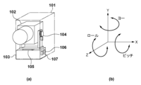
図1は、本発明の撮像装置の第1の実施形態であるカメラの外観を模式的に示す図である。図1(a)に示すカメラ101には、電源スイッチ、カメラ操作を行うことができる操作部材などが設けられている。被写体像の撮像を行う撮像光学系としての撮影レンズ群や撮像素子を一体的に含む鏡筒102は、カメラ101の固定部103に対して移動可能に取り付けられている。具体的には、鏡筒102は、固定部103に対して回転駆動できる機構であるチルト回転ユニット104とパン回転ユニット105とを介して固定部103に取り付けられている。
(First embodiment)
<Camera configuration>
FIG. 1 is a diagram schematically showing the appearance of a camera that is the first embodiment of the imaging device of the present invention. A
チルト回転ユニット104は、鏡筒102を図1(b)に示すピッチ方向に回転駆動することができるモーター駆動機構を備え、パン回転ユニット105は、鏡筒102を図1(b)に示すヨー方向に回転駆動することができるモーター駆動機構を備える。すなわちカメラ101は、鏡筒102を2軸方向に回転駆動する機構を有する。図1(b)に示す各軸は、固定部103の位置に対してそれぞれ定義されている。角速度計106及び加速度計107は、カメラ101の固定部103に配置されている。そして、角速度計106や加速度計107の出力信号に基づいて、カメラ101の振動を検出し、チルト回転ユニット104とパン回転ユニット105を回転駆動することにより、鏡筒102の振れを補正したり、傾きを補正したりすることができる。また、角速度計106や加速度計107は、一定の期間の計測結果に基づいて、カメラの移動検出も行う。
The
図2は本実施形態のカメラ101の全体構成を示すブロック図である。図2において、第1制御部223は、例えばCPU(MPU)、メモリ(DRAM、SRAM)などを備える。そして、不揮発性メモリ(EEPROM)216に記憶されたプログラムに従って、各種処理を実行してカメラ101の各ブロックを制御したり、各ブロック間でのデータ転送を制御したりする。不揮発性メモリ216は、電気的に消去・記録可能なメモリであり、上記のように第1制御部223の動作用の定数、プログラム等が記憶される。
FIG. 2 is a block diagram showing the overall configuration of the
図2において、ズームユニット201は、変倍(結像された被写体像の拡大・縮小)を行うズームレンズを含む。ズーム駆動制御部202は、ズームユニット201を駆動制御するとともに、そのときの焦点距離を検出する。フォーカスユニット203は、ピント調整(焦点調節)を行うフォーカスレンズを含む。フォーカス駆動制御部204は、フォーカスユニット203を駆動制御する。撮像部206は撮像素子を備え、各レンズ群を通して入射する光を受け、その光量に応じた電荷の情報をアナログ画像信号として画像処理部207に出力する。なお、ズームユニット201、フォーカスユニット203、撮像部206は、鏡筒102内に配置されている。
In FIG. 2, a
画像処理部207はアナログ画像信号をA/D変換して得られたデジタル画像データに対して、歪曲補正、ホワイトバランス調整、色補間処理等の画像処理を適用し、適用後のデジタル画像データを出力する。画像処理部207から出力されたデジタル画像データは、画像記録部208でJPEG形式等の記録用フォーマットに変換され、メモリ215に記憶されたり後述する映像出力部217に送信される。
An
鏡筒回転駆動部205は、チルト回転ユニット104、パン回転ユニット105を駆動し、鏡筒102をチルト方向とパン方向に回動させる。装置揺れ検出部209は、カメラ101の3軸方向の角速度を検出する角速度計(ジャイロセンサ)106や、カメラ101の3軸方向の加速度を検出する加速度計(加速度センサ)107を備える。そして、それらのセンサにより検出された信号に基づいて、装置の回転角度や装置のシフト量などが算出される。
A lens barrel
音声入力部213は、カメラ101に設けられたマイクによりカメラ101の周辺の音声信号を取得し、デジタル音声信号に変換して音声処理部214に送信する。音声処理部214は、入力されたデジタル音声信号の適正化処理等の音声に関する処理を行う。そして、音声処理部214で処理された音声信号は、第1制御部223によりメモリ215に送信される。メモリ215は、画像処理部207、音声処理部214により得られた画像信号及び音声信号を一時的に記憶する。
The
画像処理部207及び音声処理部214は、メモリ215に一時的に記憶された画像信号や音声信号を読み出して画像信号の符号化、音声信号の符号化などを行い、圧縮画像信号、圧縮音声信号を生成する。第1制御部223は、これらの圧縮画像信号、圧縮音声信号を、記録再生部220に送信する。
The
記録再生部220は、記録媒体221に対して画像処理部207及び音声処理部214で生成された圧縮画像信号、圧縮音声信号、その他撮影に関する制御データ等を記録する。また、音声信号を圧縮符号化しない場合には、第1制御部223は、音声処理部214により生成された音声信号と画像処理部207により生成された圧縮画像信号とを、記録再生部220に送信し記録媒体221に記録させる。
The recording/reproducing
記録媒体221は、カメラ101に内蔵された記録媒体でも、取外し可能な記録媒体でもよく、カメラ101で生成した圧縮画像信号、圧縮音声信号、音声信号などの各種データを記録することができる。一般的には、記録媒体221には不揮発性メモリ216よりも大容量な媒体が使用される。例えば、記録媒体221は、ハードディスク、光ディスク、光磁気ディスク、CD-R、DVD-R、磁気テープ、不揮発性の半導体メモリ、フラッシュメモリ、などのあらゆる方式の記録媒体を含む。
The
記録再生部220は、記録媒体221に記録された圧縮画像信号、圧縮音声信号、音声信号、各種データ、プログラムを読み出す(再生する)。そして、第1制御部223は、読み出された圧縮画像信号、圧縮音声信号を、画像処理部207及び音声処理部214に送信する。画像処理部207及び音声処理部214は、圧縮画像信号、圧縮音声信号を一時的にメモリ215に記憶させ、所定の手順で復号し、復号した信号を映像出力部217に送信する。
The recording/
音声入力部213には複数のマイクが配置されており、音声処理部214は複数のマイクが設置された平面に対する音の方向を検出することができ、後述する被写体の探索や自動撮影に用いられる。さらに、音声処理部214では、特定の音声コマンドを検出する。音声コマンドは事前に登録されたいくつかのコマンドの他、ユーザが特定音声をカメラに登録できる構成にしてもよい。また、音シーン認識も行う。音シーン認識では、予め大量の音声データに基づいて機械学習により学習させたネットワークにより音シーンの判定を行う。例えば、「歓声が上がっている」、「拍手している」、「声を発している」などの特定シーンを検出するためのネットワークが音声処理部214に設定されており、特定音シーンや特定音声コマンドを検出する。音声処理部214が特定音シーンや特定音声コマンドを検出すると、第1制御部223や第2制御部211に、検出トリガー信号を出力する。
A plurality of microphones are arranged in the
カメラ101のメインシステム全体を制御する第1制御部223とは別に、この第1制御部223の供給電源を制御する第2制御部211が設けられている。第1電源部210と第2電源部212は、第1制御部223と第2制御部211を動作させるための電力をそれぞれ供給する。カメラ101に設けられた電源ボタンの押下により、まず第1制御部223と第2制御部211の両方に電源が供給されるが、後述するように、第1制御部223は、第1電源部210へ自らの電源供給をOFFする制御も行う。第1制御部223が動作していない間も、第2制御部211は動作しており、装置揺れ検出部209や音声処理部214からの情報が入力される。第2制御部211は、各種入力情報に基づいて、第1制御部223を起動するか否かの判定を行い、起動することが判定されると、第1電源部210に第1制御部223へ電力を供給するように指示する。
Aside from the
音声出力部218は、例えば撮影時などにカメラ101に内蔵されたスピーカーから予め設定された音声パターンを出力する。LED制御部224は、例えば撮影時などに、カメラ101に設けられたLEDを、予め設定された点灯パターンや点滅パターンに基づいて点灯させる。映像出力部217は、例えば映像出力端子からなり、接続された外部ディスプレイ等に映像を表示させるために画像信号を出力する。また、音声出力部218、映像出力部217は、結合された1つの端子、例えばHDMI(登録商標:High-Definition Multimedia Interface)端子のような端子であってもよい。
The
通信部222は、カメラ101と外部装置との間で通信を行う部分であり、例えば、音声信号、画像信号、圧縮音声信号、圧縮画像信号などのデータを送信したり受信したりする。また、撮影開始や終了のコマンド、パン・チルト、ズーム駆動等の撮影にかかわる制御信号を受信して、外部装置の指示に基づいてカメラ101を駆動する。また、カメラ101と外部装置との間で、後述する学習処理部219で処理される学習にかかわる各種パラメータなどの情報を送信したり受信したりする。通信部222は、例えば、赤外線通信モジュール、Bluetooth(登録商標)通信モジュール、無線LAN通信モジュール、WirelessUSB(登録商標)、GPS受信機等の無線通信モジュールを備える。
A
環境センサ226は、所定の周期でカメラ101の周辺の環境の状態を検出する。環境センサ226は、カメラ101周辺の温度を検出する温度センサ、カメラ101周辺の気圧の変化を検出する気圧センサ、カメラ101周辺の明るさを検出する照度センサを有する。さらに、カメラ101周辺の湿度を検出する湿度センサ、カメラ101周辺の紫外線量を検出するUVセンサ等も有する。検出した温度情報や気圧情報や明るさ情報や湿度情報やUV情報に加え、検出した各種情報から所定時間間隔での変化率を算出した温度変化量や気圧変化量や明るさ変化量や湿度変化量や紫外線変化量などを後述する自動撮影などの判定に使用する。
The
<外部装置との通信>
図3は、カメラ101と外部装置301との無線通信システムの構成例を示す図である。カメラ101は撮影機能を有するデジタルカメラであり、外部装置301はBluetooth通信モジュール、無線LAN通信モジュールを含むスマートデバイスである。
<Communication with external devices>
FIG. 3 is a diagram showing a configuration example of a wireless communication system between the
カメラ101と外部装置301は、例えばIEEE802.11規格シリーズに準拠した無線LANによる第1の通信302と、例えばBluetooth Low Energy(以下、「BLE」と呼ぶ)などの、制御局と従属局などの主従関係を有する第2の通信303とによって通信可能である。なお、無線LAN及びBLEは通信手法の一例であり、各通信装置は、2つ以上の通信機能を有し、例えば制御局と従属局との関係の中で通信を行う一方の通信機能によって、他方の通信機能の制御を行うことが可能であれば、他の通信手法が用いられてもよい。ただし、無線LANなどの第1の通信302は、BLEなどの第2の通信303より高速な通信が可能であり、また、第2の通信303は、第1の通信302よりも消費電力が少ないか通信可能距離が短いかの少なくともいずれかであるものとする。
The
外部装置301の構成を図4を用いて説明する。外部装置301は、例えば、無線LAN用の無線LAN制御部401、及び、BLE用のBLE制御部402に加え、公衆無線通信用の公衆無線制御部406を有する。また、外部装置301は、パケット送受信部403をさらに有する。無線LAN制御部401は、無線LANのRF制御、通信処理、IEEE802.11規格シリーズに準拠した無線LANによる通信の各種制御を行うドライバ処理や無線LANによる通信に関するプロトコル処理を行う。BLE制御部402は、BLEのRF制御、通信処理、BLEによる通信の各種制御を行うドライバ処理やBLEによる通信に関するプロトコル処理を行う。公衆無線制御部406は、公衆無線通信のRF制御、通信処理、公衆無線通信の各種制御を行うドライバ処理や公衆無線通信関連のプロトコル処理を行う。公衆無線通信は例えばIMT(International Multimedia Telecommunications)規格やLTE(Long Term Evolution)規格などに準拠したものである。パケット送受信部403は、無線LAN並びにBLEによる通信及び公衆無線通信に関するパケットの送信と受信との少なくともいずれかを実行するための処理を行う。なお、本実施形態では、外部装置301は、通信においてパケットの送信と受信との少なくともいずれかを行うものとして説明するが、パケット交換以外に、例えば回線交換など、他の通信形式が用いられてもよい。
The configuration of the
外部装置301は、例えば、制御部411、記憶部404、GPS受信部405、表示部407、操作部408、音声入力音声処理部409、電源部410をさらに有する。制御部411は、例えば、記憶部404に記憶された制御プログラムを実行することにより、外部装置301全体を制御する。記憶部404は、例えば制御部411が実行する制御プログラムと、通信に必要なパラメータ等の各種情報とを記憶する。後述する各種動作は、記憶部404に記憶された制御プログラムを制御部411が実行することにより、実現される。
The
電源部410は、外部装置301に電力を供給する。表示部407は、例えば、LCDやLEDのように視覚で認知可能な情報の出力、又はスピーカー等の音出力が可能な機能を有し、各種情報の表示を行う。操作部408は、例えばユーザによる外部装置301の操作を受け付けるボタン等を含む。なお、表示部407及び操作部408は、例えばタッチパネルなどの共通する部材によって構成されていてもよい。
The
音声入力音声処理部409は、例えば外部装置301に内蔵された汎用的なマイクにより、ユーザが発した音声を取得し、音声認識処理により、ユーザの操作命令を識別する構成にしてもよい。また、外部装置301内の専用のアプリケーションを用いて、ユーザの発音により音声コマンドを取得し、無線LANによる第1の通信302を介して、カメラ101の音声処理部214に認識させるための特定音声コマンドとして登録することもできる。
The speech input
GPS(Global positioning system)受信部405は、衛星から通知されるGPS信号を受信し、GPS信号を解析し、外部装置301の現在位置(経度・緯度情報)を推定する。もしくは、WPS(Wi-Fi Positioning System)等を利用して、周囲に存在する無線ネットワークの情報に基づいて、外部装置301の現在位置を推定するようにしてもよい。取得した現在のGPS位置情報が予め事前に設定されている位置範囲(検出位置を中心といて所定半径の範囲以内)に位置している場合や、GPS位置情報に所定以上の位置変化があった場合に、BLE制御部402を介してカメラ101へ移動情報を通知する。そして、後述する自動撮影や自動編集のためのパラメータとして使用する。
A GPS (Global Positioning System)
上記のようにカメラ101と外部装置301は、無線LAN制御部401、及び、BLE制御部402を用いた通信により、データのやりとりを行う。例えば、音声信号、画像信号、圧縮音声信号、圧縮画像信号などのデータを送信したり受信したりする。また、外部装置301からカメラ101への撮影指示などの送信、音声コマンド登録データの送信、GPS位置情報に基づいた所定位置検出通知の送信、場所移動通知の送信等を行う。また、外部装置301内の専用のアプリケーションを用いての学習用データの送受信も行う。
As described above, the
<アクセサリ類の構成>
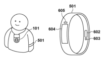
図5は、カメラ101と通信可能である外部装置501の構成例を示す図である。カメラ101は撮影機能を有するデジタルカメラであり、外部装置501は、例えばBluetooth通信モジュールなどによりカメラ101と通信可能である各種センシング部を含むウエアラブルデバイスである。
<Composition of accessories>
FIG. 5 is a diagram showing a configuration example of an
外部装置501は、例えばユーザの腕などに装着できるように構成されており、所定の周期でユーザの脈拍、心拍、血流等の生体情報を検出するセンサやユーザの運動状態を検出できる加速度センサ等が搭載されている。
The
生体情報検出部602は、例えば、脈拍を検出する脈拍センサ、心拍を検出する心拍センサ、血流を検出する血流センサ、導電性高分子を用いた皮膚の接触によって電位の変化を検出するセンサを含む。本実施形態では、生体情報検出部602として心拍センサを用いて説明する。心拍センサは、例えばLED等を用いて皮膚に赤外光を照射し、体組織を透過した赤外光を受光センサで検出して信号処理することによりユーザの心拍を検出する。生体情報検出部602は、検出した生体情報を信号として制御部607(図6参照)へ出力する。
The biological
ユーザの運動状態を検出する揺れ検出部603は、例えば、加速度センサやジャイロセンサを備えており、加速度の情報に基づきユーザが移動しているか、腕を振り回してアクションをしているかなどのモーションを検出することができる。また、ユーザによる外部装置501の操作を受け付ける操作部605や、LCDやLEDのように視覚で認知可能な情報を出力するモニタなどの表示部604が搭載されている。
A
図6は、外部装置501の構成を示す図である。上述したように、外部装置501は、例えば、制御部607、通信部601、生体情報検出部602、揺れ検出部603、表示部604、操作部605、電源部606、記憶部608を有する。
FIG. 6 is a diagram showing the configuration of the
制御部607は、例えば、記憶部608に記憶された制御プログラムを実行することにより、外部装置501全体を制御する。記憶部608は、例えば制御部607が実行する制御プログラムと、通信に必要なパラメータ等の各種情報とを記憶している。後述する各種動作は、例えば記憶部608に記憶された制御プログラムを制御部607が実行することにより、実現される。
The
電源部606は、外部装置501に電力を供給する。表示部604は、例えば、LCDやLEDのように視覚で認知可能な情報の出力部、又はスピーカー等の音出力が可能な出力部を有し、各種情報の表示を行う。操作部605は、例えばユーザによる外部装置501の操作を受け付けるボタン等を備える。なお、表示部604及び操作部605は、例えばタッチパネルなどの共通する部材によって構成されていてもよい。また、操作部605は、例えば外部装置501に内蔵された汎用的なマイクによりユーザが発した音声を取得し、音声認識処理により、ユーザの操作命令を識別するように構成されていてもよい。
A
生体情報検出部602や揺れ検出部603により取得され制御部607で処理された各種検出情報は、通信部601により、カメラ101へ送信される。例えば、ユーザの心拍の変化を検出したタイミングで検出情報をカメラ101に送信したり、歩行移動/走行移動/立ち止まりなどの移動状態(状態情報)の変化のタイミングで検出情報を送信したりすることができる。また、予め設定された腕ふりのモーションを検出したタイミングで検出情報を送信したり、予め設定された距離の移動を検出したタイミングで検出情報を送信したりすることもできる。
Various detection information acquired by the biological
<カメラの動作シーケンス>
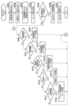
図7は、本実施形態におけるカメラ101の第1制御部223が受け持つ動作の例を説明するフローチャートである。
<Camera operation sequence>
FIG. 7 is a flow chart for explaining an example of the operation of the
ユーザがカメラ101に設けられた電源ボタンを操作すると、第1電源部210から第1制御部223及びカメラ101の各ブロックに電力が供給される。また、同様に、第2電源部212から第2制御部211に電力が供給される。第2制御部211の動作の詳細については、図8のフローチャートを用いて後述する。
When the user operates a power button provided on the
電力が供給されると、図7の処理がスタートする。ステップS701では、起動条件の読み込みが行われる。本実施形態においては、電源が起動される条件には以下の3つの場合がある。
(1)電源ボタンが手動で押下されて電源が起動される
(2)外部装置(例えば外部装置301)から外部通信(例えばBLE通信)により起動指示が送られ、電源が起動される
(3)第2制御部211の指示により、電源が起動される
ここで、(3)の第2制御部211の指示により電源が起動される場合は、第2制御部211内で演算された起動条件が読み込まれることになるが、詳細は図8を用いて後述する。また、ここで読み込まれた起動条件は、被写体探索や自動撮影時の1つのパラメータ要素として用いられるが、それについても後述する。起動条件読み込みが終了するとステップS702に進む。
When power is supplied, the process of FIG. 7 starts. In step S701, a start condition is read. In this embodiment, there are the following three cases for the conditions for starting the power supply.
(1) Power is turned on by manually pressing the power button (2) An external device (eg, external device 301) sends a start-up instruction through external communication (eg, BLE communication), and power is turned on (3) Power is activated by an instruction from the
ステップS702では、各種センサの検出信号の読み込みが行われる。ここで読み込まれるセンサの信号は、1つは、装置揺れ検出部209におけるジャイロセンサや加速度センサなどの振動を検出するセンサの信号である。また、チルト回転ユニット104やパン回転ユニット105の回転位置の信号である。さらには、音声処理部214で検出される音声信号、特定音声認識の検出トリガー信号、音方向検出信号、環境センサ226で検出される環境情報の検出信号などである。ステップS702で各種センサの検出信号の読み込みが行われると、ステップS703に進む。
In step S702, detection signals from various sensors are read. One of the sensor signals read here is a signal from a sensor that detects vibration, such as a gyro sensor or an acceleration sensor in the device
ステップS703では、外部装置から通信指示が送信されているかを検出し、通信指示があった場合、外部装置との通信を行う。例えば、外部装置301からの、無線LANやBLEを介したリモート操作、音声信号、画像信号、圧縮音声信号、圧縮画像信号などの送受信、外部装置301からの撮影などの操作指示、音声コマンド登録データの送信、GPS位置情報に基づいた所定位置検出通知、場所移動通知、学習用データの送受信等の読み込みを行う。また、外部装置501から、ユーザの運動情報、腕のアクション情報、心拍などの生体情報の更新がある場合、BLEを介した情報の読み込みを行う。なお、上述した環境センサ226は、カメラ101に搭載されていてもよいが、外部装置301或いは外部装置501に搭載されていてもよい。その場合、ステップS703では、BLEを介した環境情報の読み込みも行う。ステップS703で外部装置からの通信読み込みが行われると、ステップS704に進む。
In step S703, it is detected whether a communication instruction has been sent from the external device, and if there is a communication instruction, communication with the external device is performed. For example, remote operation via wireless LAN or BLE, transmission/reception of audio signals, image signals, compressed audio signals, compressed image signals, etc. from the
ステップS704では、モード設定判定が行われ、ステップS705に進む。ステップS705ではステップS704で動作モードが低消費電力モードに設定されているか否かを判定する。後述する「自動撮影モード」、「自動編集モード」、「画像自動転送モード」、「学習モード」、「ファイル自動削除モード」、の何れのモードでもない場合は、低消費電力モードになるように判定される。ステップS705で、低消費電力モードであると判定されると、ステップS706に進む。 In step S704, mode setting determination is performed, and the process proceeds to step S705. In step S705, it is determined whether or not the operation mode is set to the low power consumption mode in step S704. If it is not in any of the "automatic shooting mode", "automatic editing mode", "automatic image transfer mode", "learning mode", and "automatic file deletion mode" described later, it will be in low power consumption mode. be judged. If it is determined in step S705 that the mode is the low power consumption mode, the process proceeds to step S706.
ステップS706では、第2制御部211(SubCPU)へ、第2制御部211内で判定する起動要因に係る各種パラメータ(揺れ検出判定用パラメータ、音検出用パラメータ、時間経過検出パラメータ)を通知する。各種パラメータは後述する学習処理で学習されることによって値が変化する。ステップS706の処理を終了すると、ステップS707に進み、第1制御部223(MainCPU)の電源をOFFして、処理を終了する。
In step S706, the second control unit 211 (Sub CPU) is notified of various parameters (shake detection determination parameters, sound detection parameters, and elapsed time detection parameters) related to activation factors determined within the
ステップS705で、低消費電力モードでないと判定されると、ステップS704におけるモード設定が自動撮影モードか否かを判定する。ここで、ステップS704でのモード設定判定の処理について説明する。判定されるモードは、以下の中から選択される。
(1)自動撮影モード
<モード判定条件>
学習設定された各検出情報(画像、音、時間、振動、場所、身体の変化、環境変化)、自動撮影モードに移行してからの経過時間、過去の撮影情報・撮影枚数などの情報から、自動撮影を行うべきと判定されると、自動撮影モードに設定される。
If it is determined in step S705 that the low power consumption mode is not set, it is determined in step S704 whether or not the mode setting is automatic shooting mode. Here, the mode setting determination processing in step S704 will be described. The mode to be determined is selected from among the following.
(1) Automatic shooting mode <Mode determination conditions>
Based on each detection information (image, sound, time, vibration, location, change in body, change in environment) set for learning, elapsed time since switching to automatic shooting mode, past shooting information and number of shots, etc. When it is determined that automatic photographing should be performed, the automatic photographing mode is set.
<モード内処理>
自動撮影モード処理(ステップS710)では、各検出情報(画像、音、時間、振動、場所、体の変化、環境変化)に基づいて、パン・チルトやズームを駆動して被写体を自動探索する。そして、撮影者の好みの撮影が行えるタイミングであると判定されると自動で撮影が行われる。
(2)自動編集モード
<モード判定条件>
前回自動編集を行ってからの経過時間、過去の撮影画像情報から、自動編集を行うべきと判定されると、自動編集モードに設定される。
<In-mode processing>
In the automatic photographing mode process (step S710), based on each detection information (image, sound, time, vibration, location, change in body, change in environment), pan/tilt and zoom are driven to automatically search for the subject. Then, when it is determined that it is the timing at which the photographer's favorite photographing can be performed, the photographing is automatically performed.
(2) Automatic edit mode <Mode judgment condition>
When it is determined that automatic editing should be performed based on the elapsed time since the last automatic editing and information on past captured images, the automatic editing mode is set.
<モード内処理>
自動編集モード処理(ステップS712)では、学習に基づいた静止画像や動画像の選抜処理を行い、学習に基づいて、画像効果や編集後動画の時間などにより、一つの動画にまとめたハイライト動画を作成する自動編集処理が行われる。
(3)画像転送モード
<モード判定条件>
外部装置301内の専用のアプリケーションを用いた指示により、画像自動転送モードに設定されている場合、前回画像転送を行ってからの経過時間と過去の撮影画像情報から、自動転送を行うべきと判定されると、自動画像転送モードに設定される。
<In-mode processing>
In the automatic editing mode processing (step S712), still images and moving images are selected based on the learning, and based on the learning, the highlight video is combined into one video based on the image effect, the time of the edited video, etc. An automatic editing process is performed to create the .
(3) Image transfer mode <Mode determination condition>
If the automatic image transfer mode is set by an instruction using a dedicated application in the
<モード内処理>
画像自動転送モード処理(ステップS714)では、カメラ101は、ユーザの好みに合うであろう画像を自動で抽出し、外部装置301にユーザの好みと思われる画像を自動で転送する。ユーザの好みの画像抽出は、後述する各画像に付加されたユーザの好みを判定したスコアにより行われる。
(4)学習モード
<モード判定条件>
前回学習処理を行ってからの経過時間と、学習に使用することのできる画像に一体となった情報や学習データの数などから、自動学習を行うべきと判定されると、自動学習送モードに設定される。または、外部装置301からの通信を介して学習モードが設定されるように指示があった場合もこのモードに設定される。
<In-mode processing>
In the automatic image transfer mode process (step S714), the
(4) Learning mode <Mode judgment condition>
When it is determined that automatic learning should be performed based on the elapsed time since the previous learning process was performed and the number of information and learning data that can be used for learning, the automatic learning mode is activated. set. Alternatively, when there is an instruction to set the learning mode via communication from the
<モード内処理>
学習モード処理(ステップS716)では、外部装置301での各操作情報(カメラからの画像取得情報、専用アプリケーションを介して手動編集した情報、カメラ内の画像に対してユーザが入力した判定値情報)、外部装置301からの学習情報の通知などに基づいて、ニューラルネットワークを用いて、ユーザの好みに合わせた学習を行う。また、個人認証の登録、音声登録、音シーン登録、一般物体認識登録などの、検出に関する学習や、上述した低消費電力モードの条件などの学習も同時に行われる。
(5)ファイル自動削除モード
<モード判定条件>
前回ファイル自動削除を行ってからの経過時間と、画像を記録している不揮発性メモリ216の残容量とに基づいて、ファイル自動削除を行うべきと判定されると、ファイル自動削除モードに設定される。
<In-mode processing>
In the learning mode process (step S716), each operation information in the external device 301 (image acquisition information from the camera, information manually edited via a dedicated application, judgment value information input by the user for the image in the camera). , based on notification of learning information from the
(5) File automatic deletion mode <Mode judgment condition>
When it is determined that automatic file deletion should be performed based on the elapsed time since the previous automatic file deletion and the remaining capacity of the
<モード内処理>
ファイル自動削除モード処理(ステップS718)では、不揮発性メモリ216内の画像の中から、各画像のタグ情報と撮影された日時などから自動削除されるべきファイルを指定し削除する。
<In-mode processing>
In the automatic file deletion mode process (step S718), files to be automatically deleted are designated and deleted from the images in the
以上の各モードにおける処理の詳細については、後述する。 Details of the processing in each of the above modes will be described later.
図7の説明に戻り、ステップS705で低消費電力モードでないと判定されると、ステップS709に進み、モード設定が自動撮影モードであるか否かを判定する。判定の結果、自動撮影モードであればステップS710に進み、自動撮影モード処理が行われる。処理が終了すると、ステップS702に戻り、処理を繰り返す。ステップS709で、自動撮影モードでないと判定されると、ステップS711に進む。 Returning to the description of FIG. 7, if it is determined in step S705 that the low power consumption mode is not set, the process advances to step S709 to determine whether the mode setting is the automatic shooting mode. As a result of the determination, if it is the automatic shooting mode, the process proceeds to step S710, and automatic shooting mode processing is performed. When the process is completed, the process returns to step S702 and repeats the process. If it is determined in step S709 that the mode is not the automatic shooting mode, the process proceeds to step S711.
ステップS711では、モード設定が自動編集モードであるか否かを判定し、自動編集モードであればステップS712に進み、自動編集モード処理が行われる。処理が終了すると、ステップS702に戻り、処理を繰り返す。ステップS711で、自動編集モードでないと判定されると、ステップS713に進む。なお、自動編集モードは、本発明の主旨に直接関係しないため、詳細な説明は省略する。 At step S711, it is determined whether or not the mode setting is the automatic editing mode. When the process is completed, the process returns to step S702 and repeats the process. If it is determined in step S711 that the automatic editing mode is not set, the process proceeds to step S713. Since the automatic edit mode is not directly related to the gist of the present invention, detailed description thereof will be omitted.
ステップS713では、モード設定が画像自動転送モードであるか否かを判定し、画像自動転送モードであればステップS714に進み、画像自動転送モード処理が行われる。処理が終了すると、ステップS702に戻り、処理を繰り返す。ステップS713で、画像自動転送モードでないと判定されると、ステップS715に進む。なお、画像自動転送モードは、本発明の主旨に直接関係しないため、詳細な説明は省略する。 In step S713, it is determined whether or not the mode setting is the automatic image transfer mode. When the process is completed, the process returns to step S702 and repeats the process. If it is determined in step S713 that the automatic image transfer mode is not set, the process proceeds to step S715. Since the automatic image transfer mode is not directly related to the gist of the present invention, detailed description thereof will be omitted.
ステップS715では、モード設定が学習モードであるか否かを判定し、学習モードであればステップS716に進み、学習モード処理が行われる。処理が終了すると、ステップS702に戻り、処理を繰り返す。ステップS715で、学習モードでないと判定されると、ステップS717に進む。 At step S715, it is determined whether or not the mode setting is the learning mode. When the process is completed, the process returns to step S702 and repeats the process. If it is determined in step S715 that the learning mode is not set, the process proceeds to step S717.
ステップS717では、モード設定がファイル自動削除モードであるか否かを判定し、ファイル自動削除モードであればステップS718に進み、ファイル自動削除モード処理が行われる。処理が終了すると、ステップS702に戻り、処理を繰り返す。ステップS717で、ファイル自動削除モードでないと判定されると、ステップS702に戻り、処理を繰り返す。なお、ファイル自動削除モードは、本発明の主旨に直接関係しないため、詳細な説明は省略する。 At step S717, it is determined whether or not the mode setting is the automatic file deletion mode. When the process is completed, the process returns to step S702 and repeats the process. If it is determined in step S717 that the file automatic deletion mode is not set, the process returns to step S702 to repeat the process. Since the automatic file deletion mode is not directly related to the gist of the present invention, a detailed description thereof will be omitted.
図8は、本実施形態におけるカメラ101の第2制御部211が受け持つ動作の例を説明するフローチャートである。
FIG. 8 is a flow chart for explaining an example of the operation of the
ユーザがカメラ101に設けられた電源ボタンを操作すると、第1電源部210から第1制御部223及びカメラ101の各ブロックに電力が供給される。また、同様に、第2電源部212から第2制御部211に電力が供給される。
When the user operates a power button provided on the
電力が供給されると、第2制御部(SubCPU)211が起動され、図8の処理がスタートする。ステップS801では、所定サンプリング周期が経過したか否かを判定する。所定サンプリング周期は、例えば10msecに設定され、10msec周期で、ステップS802に進む。所定サンプリング周期が経過していないと判定されると、第2制御部211はそのまま待機する。
When power is supplied, the second control unit (SubCPU) 211 is activated, and the process of FIG. 8 starts. In step S801, it is determined whether or not a predetermined sampling period has elapsed. The predetermined sampling period is set to, for example, 10 msec, and the process proceeds to step S802 at the 10 msec period. If it is determined that the predetermined sampling period has not elapsed, the
ステップS802では、学習情報の読み込みが行われる。学習情報は、図7のステップS706での第2制御部211へ情報を通信する際に転送された情報であり、例えば以下の情報が含まれる。
(1)特定揺れ検出の判定(後述するステップS804で用いる)
(2)特定音検出の判定(後述するステップS805で用いる)
(3)時間経過の判定(後述するステップS807で用いる)
ステップS802で学習情報が読み込まれると、ステップS803に進み、揺れ検出値が取得される。揺れ検出値は、装置揺れ検出部209におけるジャイロセンサや加速度センサなどの出力値である。
In step S802, learning information is read. The learning information is information transferred when information is communicated to the
(1) Determination of specific shake detection (used in step S804 described later)
(2) Determination of specific sound detection (used in step S805 described later)
(3) Determination of elapsed time (used in step S807 described later)
After the learning information is read in step S802, the process advances to step S803 to acquire a shake detection value. A shake detection value is an output value of a gyro sensor, an acceleration sensor, or the like in the device
ステップS803で揺れ検出値が取得されると、ステップS804に進み、予め設定された特定の揺れ状態の検出処理を行う。ここでは、ステップS802で読み込まれた学習情報によって、判定処理を変更する。いくつかの例について説明する。 When the shake detection value is obtained in step S803, the process proceeds to step S804 to perform detection processing of a predetermined specific shake state. Here, the determination process is changed according to the learning information read in step S802. Some examples are described.
<タップ検出>
ユーザがカメラ101を例えば指先などで叩いた状態(タップ状態)を、カメラ101に取り付けられた加速度センサ107の出力値から検出することが可能である。3軸の加速度センサ107の出力を、所定サンプリング周期で、特定の周波数領域に設定したバンドパスフィルタ(BPF)に通すことで、タップによる加速度変化の信号領域を抽出することができる。BPFに通した後の加速度信号が、所定時間TimeAの間に、所定閾値ThreshAを超えた回数が、所定回数CountAであるか否かにより、タップ検出を行う。ダブルタップの場合は、CountAは2に設定され、トリプルタップの場合は、CountAは3に設定される。また、TimeAやThreshAについても、学習情報によって変化させることができる。
<Tap detection>
A state in which the user hits the
<揺れ状態の検出>
カメラ101の揺れ状態を、カメラ101に取り付けられたジャイロセンサ106や加速度センサ107の出力値から検出することが可能である。ジャイロセンサ106や加速度センサ107の出力の高周波成分をハイパスフィルタ(HPF)でカットし、低周波成分をローパスフィルタ(LPF)でカットした後、絶対値変換を行う。算出した絶対値が、所定時間TimeBの間に、所定閾値ThreshBを超えた回数が、所定回数CountB以上であるか否かにより、振動検出を行う。これにより、例えばカメラ101を机などに置いたような揺れが小さい状態か、カメラ101をウエアラブルカメラとして体に装着して歩いているような揺れが大きい状態かを判定することが可能である。また、判定閾値や判定のカウント数の条件を複数設けることにより、揺れレベルに応じた細かい揺れ状態を検出することも可能である。TimeBやThreshBやCountBについても、学習情報によって変化させることができる。
<Detection of shaking state>
The shaking state of the
上記では、揺れ検出センサの検出値を判定することにより、特定の揺れ状態を検出する方法について説明した。しかし、所定時間内でサンプリングされた揺れ検出センサのデータから、ニューラルネットワークを用いた揺れ状態判定器に入力することで、学習させたニューラルネットワークにより、事前に登録しておいた特定の揺れ状態を検出することも可能である。その場合、ステップS802での学習情報読み込みはニューラルネットワークの重みパラメータとなる。 In the above description, a method for detecting a specific shaking state by determining the detection value of the shaking detection sensor has been described. However, by inputting the shake detection sensor data sampled within a predetermined period of time to a shake state determiner using a neural network, the trained neural network can detect a specific shake state that has been registered in advance. It is also possible to detect In that case, the learning information read in step S802 becomes the weight parameter of the neural network.
ステップS804で特定の揺れ状態の検出処理が行われると、ステップS805に進み、予め設定された特定の音の検出処理を行う。ここでは、ステップS802で読み込まれた学習情報によって、検出判定処理を変更する。いくつかの例について説明する。 When the detection processing of the specific shaking state is performed in step S804, the process advances to step S805 to perform the detection processing of the preset specific sound. Here, the detection determination process is changed according to the learning information read in step S802. Some examples are described.
<特定音声コマンド検出>
特定の音声コマンドを検出する。音声コマンドは事前に登録されたいくつかのコマンドの他、ユーザが特定音声をカメラに登録できる。
<Specific voice command detection>
Detect specific voice commands. As for voice commands, in addition to some pre-registered commands, users can register specific voices in the camera.
<特定音シーン認識>
予め大量の音声データに基づいて、機械学習により学習させたネットワークにより音シーンの判定を行う。例えば、「歓声が上がっている」、「拍手している」、「声を発している」などの特定シーンを検出する。検出するシーンは学習によって変化する。
<Specific sound scene recognition>
Based on a large amount of audio data in advance, a network learned by machine learning determines the sound scene. For example, specific scenes such as "cheering", "applauding", and "vocalizing" are detected. Scenes to be detected change with learning.
<音レベル判定>
音声レベルの大きさが所定時間の間、所定の大きさを超えているかを判定することよって、音レベルの検出を行う。所定時間や所定の大きさなどが学習によって変化する。
<Sound level judgment>
Sound level detection is performed by determining whether the magnitude of the sound level exceeds a predetermined magnitude for a predetermined period of time. The predetermined time, the predetermined size, and the like change with learning.
<音方向判定>
平面上に配置された複数のマイクにより、所定の大きさの音について、音の方向を検出する。
<Sound direction determination>
A plurality of microphones arranged on a plane detects the direction of sound of a predetermined loudness.
音声処理部214内で上記の判定処理が行われ、事前に学習された各設定により、特定の音の検出がされたかをステップS805で判定する。
The above determination processing is performed in the
ステップS805で特定の音の検出処理が行われると、ステップS806に進み、第1制御部223の電源がOFF状態であるか否かを判定する。第1制御部223(MainCPU)がOFF状態であれば、ステップS807に進み、予め設定された時間の経過検出処理を行う。ここでは、ステップS802で読み込まれた学習情報によって、検出判定処理を変更する。学習情報は、図7で説明したステップS706での第2制御部211へ情報を通信する際に転送された情報である。第1制御部223がONからOFFへ遷移したときからの経過時間が計測され、経過時間が所定の時間TimeC以上であれば、時間が経過したと判定し、TimeCより短かければ、時間が経過していないと判定される。TimeCは、学習情報によって変化するパラメータである。
After the specific sound detection process is performed in step S805, the process advances to step S806 to determine whether or not the
ステップS807で時間経過検出処理が行われると、ステップS808に進み、低消費電力モードを解除する条件が成立したか否かを判定する。低消費電力モード解除は以下の条件によって判定される。
(1)特定の揺れが検出されたこと
(2)特定の音が検出されたこと
(3)所定の時間が経過したこと
(1)については、ステップS804での特定揺れ状態検出処理により、特定の揺れが検出されたか否かが判定されている。(2)については、ステップS805での特定音検出処理により、特定の音が検出されたか否かが判定されている。(3)については、ステップS807での時間経過検出処理により、所定の時間が経過したか否かが判定されている。(1)~(3)の少なくとも1つが成立すれば、低消費電力モード解除を行うように判定される。
After the elapsed time detection process is performed in step S807, the process advances to step S808 to determine whether or not the condition for canceling the low power consumption mode is satisfied. Low power consumption mode cancellation is determined by the following conditions.
(1) detection of a specific shaking state (2) detection of a specific sound (3) elapse of a predetermined period of time is detected. Regarding (2), it is determined whether or not a specific sound is detected by the specific sound detection processing in step S805. As for (3), it is determined whether or not a predetermined time has passed by the time passage detection process in step S807. If at least one of (1) to (3) is established, it is determined to cancel the low power consumption mode.
ステップS808で低消費電力モードの解除が判定されると、ステップS809に進み第1制御部223の電源をONし、ステップS810で、低消費電力モードの解除が判定された条件(揺れ、音、時間のいずれか)を第1制御部223に通知する。そして、ステップS801に戻り処理をループする。ステップS808で何れの解除条件にも当てはまらず、低消費電力モード解除の条件ではないと判定されると、ステップS801に戻り処理をループする。
When it is determined in step S808 that the low power consumption mode is to be canceled, the process proceeds to step S809 to turn on the power of the
一方、ステップS806で、第1制御部223がON状態であると判定された場合、ステップS811に進み、ステップS803~S805までで取得した情報を第1制御部223に通知し、ステップS801に戻り処理をループする。
On the other hand, if it is determined in step S806 that the
本実施形態においては、第1制御部223がON状態である場合でも、揺れ検出や特定音の検出を第2制御部211で行い、検出結果を第1制御部223に通知する構成にしている。しかし、第1制御部223がONの場合は、ステップS803~S805の処理を行わず、第1制御部223内の処理(図7のステップS702)で揺れ検出や特定音の検出を行う構成にしてもよい。
In this embodiment, even when the
上述したように、図7のステップS704~S707や、図8の処理を行うことにより、低消費電力モードに移行する条件や低消費電力モードを解除する条件が、ユーザの操作に基づいて学習される。そして、カメラ101を所有するユーザの使い勝手に合わせたカメラ動作を行うことが可能となる。学習の方法については後述する。
As described above, by performing steps S704 to S707 in FIG. 7 and the processing in FIG. 8, the conditions for shifting to the low power consumption mode and the conditions for canceling the low power consumption mode are learned based on the user's operation. be. Then, it becomes possible to perform a camera operation that matches the usability of the user who owns the
なお、上記において、揺れ検出や音検出や時間経過により低消費電力モードを解除する方法について詳しく説明したが、環境情報により低消費電力モードの解除を行ってもよい。環境情報は、温度、気圧、明るさ、湿度、紫外線量の絶対量や変化量が所定閾値を超えたか否かにより判定することができ、後述する学習により閾値を変化させることもできる。 In the above description, the method of canceling the low power consumption mode based on shake detection, sound detection, or passage of time has been described in detail, but the low power consumption mode may be canceled based on environmental information. Environmental information can be determined based on whether or not the absolute amount or amount of change in the temperature, air pressure, brightness, humidity, and amount of ultraviolet rays exceeds a predetermined threshold, and the threshold can be changed by learning, which will be described later.
また、揺れ検出や音検出や時間経過の検出情報や、各環境情報の絶対値や変化量をニューラルネットワークに基づいて判断し、低消費電力モードを解除する判定をしてもよい。この判定処理は、後述する学習によって、判定条件を変更することができる。 Further, it is also possible to determine whether to cancel the low power consumption mode based on a neural network based on detection information of shake detection, sound detection, time passage detection, and the absolute value and amount of change of each environmental information. In this determination process, the determination conditions can be changed by learning, which will be described later.
<自動撮影モード処理>
図9を用いて、自動撮影モード処理について説明する。まず、ステップS901において、撮像部206により取り込まれた信号に対して、画像処理部207で画像処理を行い、被写体検出用の画像を生成する。生成された画像に対して、人物や物体などを検出する被写体検出処理が行われる。
<Automatic shooting mode processing>
Automatic photographing mode processing will be described with reference to FIG. First, in step S901, the
人物を検出する場合、被写体の顔や人体を検出する。顔検出処理では、人物の顔を判断するためのパターンが予め定められており、撮像された画像内においてそのパターンに一致する箇所を、人物の顔領域として検出することができる。また、被写体の顔としての確からしさを示す信頼度も同時に算出する。信頼度は、例えば画像内における顔領域の大きさや、顔パターンとの一致程度等から算出される。物体認識についても同様に、予め登録されたパターンに一致する物体を認識することができる。 When detecting a person, the face or human body of the subject is detected. In face detection processing, a pattern for determining a person's face is determined in advance, and a portion in the captured image that matches the pattern can be detected as a person's face area. At the same time, it also calculates the degree of reliability that indicates the certainty of the subject as a face. The reliability is calculated from, for example, the size of the face area in the image, the degree of matching with the face pattern, and the like. As for object recognition, similarly, an object matching a pre-registered pattern can be recognized.
また、撮像された画像内の色相や彩度等のヒストグラムを用いて特徴被写体を抽出する方法などもある。撮影画角内に捉えられている被写体の画像に関し、その色相や彩度等のヒストグラムから導出される分布を複数の区間に分け、区間ごとに撮像された画像を分類する処理が実行される。例えば、撮像された画像について複数の色成分のヒストグラムが作成され、その山型の分布範囲で区分けされ、同一の区間の組み合わせに属する領域において撮像された画像が分類され、被写体の画像領域が認識される。認識された被写体の画像領域ごとに評価値を算出することで、その評価値が最も高い被写体の画像領域を主被写体領域として判定することができる。以上の方法で、撮像情報から各被写体情報を得ることができる。 There is also a method of extracting a characteristic subject using a histogram of hue, saturation, etc. in a captured image. Regarding the image of the subject captured within the shooting angle of view, the distribution derived from the histogram of the hue, saturation, etc. is divided into a plurality of sections, and processing is performed to classify the captured image for each section. For example, a histogram of multiple color components is created for the captured image, and the image is divided by the mountain-shaped distribution range, and the captured image in the area belonging to the same combination of sections is classified, and the image area of the subject is recognized. be done. By calculating the evaluation value for each image area of the recognized subject, the image area of the subject with the highest evaluation value can be determined as the main subject area. By the method described above, each object information can be obtained from the imaging information.
ステップS902では、像ブレ補正量の算出を行う。具体的には、まず、装置揺れ検出部209において取得した角速度および加速度情報に基づいてカメラの揺れの絶対角度を算出する。そして、その絶対角度を打ち消す角度方向にチルト回転ユニット104およびパン回転ユニット105を動かして像ブレを補正する角度を求め、像ブレ補正量とする。なお、ここでの像ブレ補正量算出処理は、後述する学習処理によって、算出方法を変更することが出来る。
In step S902, the amount of image blur correction is calculated. Specifically, first, the absolute angle of camera shake is calculated based on the angular velocity and acceleration information acquired by the apparatus
ステップS903では、カメラの(保持)状態判定を行う。角速度情報や加速度情報やGPS位置情報などで検出したカメラ角度やカメラ移動量などにより、現在カメラがどのような振動/動き状態なのかを判定する。例えば、車にカメラ101を装着して撮影する場合、移動された距離によって大きく周りの風景などの被写体情報が変化する。そのため、車などに装着して速い速度で移動している「乗り物移動状態」か否かを判定し、後に説明する自動被写体探索に使用する。また、カメラの角度の変化が大きいか否かを判定し、カメラ101の揺れがほとんどない「置き撮り状態」であるのかを判定する。「置き撮り状態」である場合は、カメラ101自体の位置変化はないと考えてよいので、置き撮り用の被写体探索を行うことができる。また、比較的カメラの角度変化が大きい場合は、「手持ち状態」と判定され、手持ち用の被写体探索を行うことができる。
In step S903, the (holding) state of the camera is determined. The current vibration/movement state of the camera is determined based on the camera angle and camera movement amount detected from angular velocity information, acceleration information, GPS position information, and the like. For example, when the
ステップS904では、被写体探索処理を行う。被写体探索は、以下の処理によって構成される。
(1)エリア分割
(2)エリア毎の重要度レベルの算出
(3)探索対象エリアの決定
以下、各処理について順次説明する。
In step S904, subject search processing is performed. Subject search is configured by the following processes.
(1) Area division (2) Calculation of importance level for each area (3) Determination of search target area Hereinafter, each process will be described in order.
(1)エリア分割
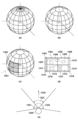
図10を用いて、エリア分割について説明する。図10(a)のようにカメラ(原点Oがカメラ位置とする)位置を中心として、全周囲でエリア分割を行う。図10(a)の例においては、チルト方向、パン方向をそれぞれ22.5度ごとに分割している。図10(a)のように分割すると、チルト方向の角度が0度から離れるにつれて、水平方向の円周が小さくなり、エリア領域が小さくなる。よって、図10(b)のように、チルト角度が45度以上の場合、水平方向のエリア範囲を22.5度よりも大きく設定している。
(1) Area division The area division will be described with reference to FIG. As shown in FIG. 10A, area division is performed around the entire circumference of the position of the camera (where the origin O is the camera position). In the example of FIG. 10A, the tilt direction and the pan direction are each divided by 22.5 degrees. When divided as shown in FIG. 10A, as the angle in the tilt direction moves away from 0 degrees, the circumference in the horizontal direction becomes smaller and the area region becomes smaller. Therefore, as shown in FIG. 10B, when the tilt angle is 45 degrees or more, the horizontal area range is set larger than 22.5 degrees.
図10(c)、10(d)に撮影画角内でのエリア分割された領域の例を示す。軸1301は初期化時のカメラ101の向きであり、この方向を基準位置としてエリア分割が行われる。1302は、撮像されている画像の画角エリアを示しており、そのときの画像例を図10(d)に示す。撮像されている画角の画像内では、エリア分割に基づいて、図10(d)で符号1303~1318で示されるように画像が分割される。
10(c) and 10(d) show examples of areas divided into areas within the shooting angle of view. An
(2)エリア毎の重要度レベルの算出
上記のように分割した各エリアについて、エリア内に存在する被写体の状況やシーンの状況に応じて、探索を行う優先順位を示す重要度レベルを算出する。被写体の状況に基づいた重要度レベルは、例えば、エリア内に存在する人物の数、人物の顔の大きさ、顔の向き、顔検出の確からしさ、人物の表情、人物の個人認証結果等に基づいて算出される。また、シーンの状況に応じた重要度レベルは、例えば、一般物体認識結果、シーン判別結果(青空、逆光、夕景など)、エリアの方向からする音のレベルや音声認識結果、エリア内の動き検知情報等に基づいて算出される。
(2) Calculation of the importance level for each area For each area divided as described above, calculate the importance level indicating the priority of searching according to the situation of the subject existing in the area and the situation of the scene. . The importance level based on the situation of the subject is, for example, the number of people present in the area, the size of the person's face, the orientation of the face, the certainty of face detection, the person's expression, the person's personal authentication result, etc. calculated based on In addition, the level of importance according to the situation of the scene is, for example, general object recognition result, scene discrimination result (blue sky, backlight, evening scene, etc.), sound level and voice recognition result from the direction of the area, motion detection in the area. Calculated based on information, etc.
また、図9のカメラ状態判定(ステップS903)で、カメラの振動が検出されている場合、振動状態に応じても重要度レベルが変化するようにすることもできる。例えば、「置き撮り状態」と判定された場合、顔認証で登録されている中で優先度の高い被写体(例えばカメラの所有者)を中心に被写体探索が行われるように判定される。また、後述する自動撮影も例えばカメラの所有者の顔を優先して行われる。これにより、カメラの所有者がカメラを身に着けて持ち歩き撮影を行っている時間が多くても、カメラを取り外して机の上などに置くことで、所有者が写った画像も多く残すことができる。このときパン・チルトにより顔の探索が可能であることから、カメラの置き角度などを考えなくても、適当に設置するだけで所有者が写った画像やたくさんの顔が写った集合写真などを残すことができる。 Further, when camera vibration is detected in the camera state determination (step S903) in FIG. 9, the importance level can be changed according to the vibration state. For example, when it is determined that the camera is in the “placed shooting state”, it is determined that the subject search is performed centering on high priority subjects (for example, the owner of the camera) among those registered for face authentication. Also, automatic photography, which will be described later, is performed with priority given to, for example, the face of the owner of the camera. As a result, even if the owner of the camera spends a lot of time carrying the camera around and taking pictures, by removing the camera and placing it on a desk, etc., it is possible to leave many images of the owner. can. At this time, since it is possible to search for faces by panning and tilting, you can create an image of the owner or a group photo with many faces by simply setting it appropriately without thinking about the angle of the camera. can be left.
なお、上記の条件だけでは、各エリアに変化がない限りは、最も重要度レベルが高いエリアが同じとなり、その結果探索されるエリアがずっと変わらないことになってしまう。そこで、過去の撮影情報に応じて重要度レベルを変化させる。具体的には、所定時間継続して探索エリアに指定され続けたエリアは重要度レベルを下げたり、後述するステップS910において撮影を行ったエリアでは、所定時間の間重要度レベルを下げてもよい。 With the above conditions alone, the area with the highest level of importance will be the same as long as there is no change in each area, and as a result, the area to be searched will remain the same. Therefore, the importance level is changed according to the past photographing information. Specifically, the importance level of an area that has been continuously designated as a search area for a predetermined period of time may be lowered, or the importance level of an area that has been photographed in step S910, which will be described later, may be lowered for a predetermined period of time. .
さらに、カメラの所有者がカメラを身に着ける場合や、車などに装着した場合など、カメラが移動しているときには、パン・チルトして周辺の被写体探索をしても、撮影するときには既に被写体が見えなくなっている場合がある。あるいは、遠ざかって小さくなり過ぎてしまい、被写体探索がムダになってしまうことがある。そのため、ステップS903で検出したカメラの角速度情報、加速度情報、GPS位置情報、さらには撮影画像中から座標ごとに算出した動きベクトルなどから、カメラの移動方向や移動速度を算出する。そして、それらに基づいて、進行方向から遠いエリアは最初から被写体は無いものとしてもよいし、逆に重要被写体を撮り逃さないために、高速移動中は被写体探索時間間隔を短くするなど、探索時間間隔を移動速度に応じて変化させてもよい。 Furthermore, when the camera is moving, such as when the owner of the camera wears it or attaches it to a car, even if you pan and tilt to search for a subject in the surroundings, the subject will already be there when you shoot. is sometimes invisible. Alternatively, the object may become too small as it moves away, resulting in wasted object search. Therefore, the moving direction and moving speed of the camera are calculated from the camera angular velocity information, acceleration information, GPS position information detected in step S903, and motion vectors calculated for each coordinate from the captured image. Based on these, areas far from the direction of travel may be assumed to have no subject from the beginning. The interval may be changed according to the speed of movement.
具体的に、カメラを首から下げた状態について図10(e)を用いて説明する。図10(e)は上空から人を見降ろした状態を示す模式図である。1320は人(カメラの所有者)、1321はカメラを示し、1322および1323はそれぞれ被写体探索範囲を示している。被写体探索範囲は、例えばカメラの進行方向1324に対してほぼ左右均等な角度範囲に設定される。被写体探索範囲1322は、人が完全に停止している状態での被写体探索範囲を示している。360度探索しないのは、カメラの所有者の体や服が一定領域以上を占める画角にならないように制限して、カメラの所有者の体の写り込みを防ぐためである。
Specifically, the state in which the camera is hung from the neck will be described with reference to FIG. 10(e). FIG. 10(e) is a schematic diagram showing a state in which a person is looked down from the sky. 1320 indicates a person (owner of the camera), 1321 indicates the camera, and 1322 and 1323 indicate subject search ranges. The object search range is set, for example, to a range of angles that are substantially equal to the left and right with respect to the advancing
被写体探索範囲1323は、人が図の上方(進行方向1324)へ移動しているときの探索範囲を示している。このように、被写体探索範囲は、移動速度が早ければ狭く、遅ければ広くするなど、移動速度に応じて変更することで、適応的にムダの無い被写体探索が可能となる。図10(e)は水平方向の被写体探索範囲の変化しか表していないが、垂直方向も同様に行うものとする。また、ここで言う進行方向は、角速度計106や加速度計107の一定の期間の計測結果に基づいて算出している。これにより、不安定な動きであっても頻繁に探索範囲が変化することを防ぐことができる。
さらに進行方向の急激な変化により、被写体探索範囲が不定になることを防止するために、過去の進行方向を考慮して敏感度を下げてもよい。図10(e)は、カメラを首から下げた状態を示しているが、机上に設置したことが判定できれば、移動速度で被写体探索範囲を変える処理は省くことができる。そのため、手持ち状態、首下げ状態、ウエアラブル状態、机上に設置状態、動体に設置した状態などのカメラの状態の変化に応じて、被写体探索処理を変えるようにしてもよい。移動情報に応じて、被写体探索範囲を変えることで、被写体探索のムダを無くし、電池の消費を減らすことにも役立つ。
A
Furthermore, in order to prevent the object search range from becoming unstable due to a sudden change in the direction of travel, the sensitivity may be lowered in consideration of the direction of travel in the past. FIG. 10(e) shows a state in which the camera is hung from the neck, but if it can be determined that the camera is placed on a desk, the process of changing the subject search range based on the moving speed can be omitted. Therefore, subject search processing may be changed according to changes in the state of the camera, such as a hand-held state, a hanging state, a wearable state, a state of being placed on a desk, or a state of being placed on a moving object. By changing the object search range according to the movement information, wasteful object searches are eliminated and battery consumption is also reduced.
(3)探索対象エリアの決定
上記のように各エリアの重要度レベルが算出されたら、重要度レベルが高いエリアを探索対象エリアとして決定する。そして、探索対象エリアを画角に捉えるために必要なパン・チルト探索目標角度を算出する。
(3) Determination of search target area After the importance level of each area is calculated as described above, an area with a high importance level is determined as a search target area. Then, a pan/tilt search target angle necessary for capturing the search target area at the angle of view is calculated.
図9の説明に戻って、ステップS905では、パン・チルト駆動を行う。具体的には、制御サンプリング周波数での、像ブレ補正量と、パン・チルト探索目標角度に基づいた駆動角度とを加算することにより、パン・チルト駆動量を算出する。そして、鏡筒回転駆動部205によって、チルト回転ユニット104、パン回転ユニット105をそれぞれ駆動制御する。
Returning to the description of FIG. 9, in step S905, pan/tilt drive is performed. Specifically, the pan/tilt drive amount is calculated by adding the image blur correction amount at the control sampling frequency and the drive angle based on the pan/tilt search target angle. Then, the
ステップS906ではズームユニット201を制御し、ズーム駆動を行う。具体的には、ステップS904で決定した探索対象被写体の状態に応じてズームを駆動させる。例えば、探索対象被写体が人物の顔である場合、画像上の顔が小さすぎると検出可能な最小サイズを下回ることで検出が出来ず、見失ってしまう恐れがある。そのような場合は、望遠側にズームすることで画像上の顔のサイズが大きくなるように制御する。一方で、画像上の顔が大きすぎる場合、被写体やカメラ自体の動きによって被写体が画角から外れやすくなってしまう。そのような場合は、広角側にズームすることで、画面上の顔のサイズが小さくなるように制御する。このようにズーム制御を行うことで、被写体を追跡するのに適した状態を保つことが出来る。
In step S906, the
ステップS907では、手動による撮影指示があったか否かを判定し、手動撮影指示があった場合、ステップS910に進む。この時、手動による撮影指示は、シャッターボタン押下によるもの、カメラ筺体を指等で軽く叩くこと(タップ)によるもの、音声コマンド入力によるもの、外部装置からの指示によるものなどのいずれでもよい。タップ操作をトリガーとする撮影指示は、ユーザがカメラ筺体をタップした際、装置揺れ検出部209によって短期間に連続した高周波の加速度を検知することにより判定される。音声コマンド入力は、ユーザが所定の撮影を指示する合言葉(例えば「写真とって」等)を発声した場合、音声処理部214で音声を認識し、撮影のトリガーとする撮影指示方法である。外部装置からの指示は、例えばカメラとBlueTooth接続したスマートフォン等から、専用のアプリケーションを用いて送信されたシャッター指示信号をトリガーとする撮影指示方法である。
In step S907, it is determined whether or not there has been a manual imaging instruction, and if there has been a manual imaging instruction, the process proceeds to step S910. At this time, the manual shooting instruction may be any one of pressing the shutter button, lightly tapping the camera housing with a finger or the like, inputting a voice command, or issuing an instruction from an external device. A shooting instruction triggered by a tap operation is determined by detecting high-frequency acceleration that continues in a short period of time by the device
ステップS907で手動による撮影指示がなかった場合には、ステップS908に進み、自動撮影判定を行う。自動撮影判定では、自動撮影を行うか否かの判定と、撮影方法の判定(静止画撮影、動画撮影、連写、パノラマ撮影などの内どれを実行するかの判定)を行う。 If there is no manual shooting instruction in step S907, the process advances to step S908 to perform automatic shooting determination. In automatic shooting determination, determination of whether to perform automatic shooting and determination of shooting method (determination of still image shooting, moving image shooting, continuous shooting, panorama shooting, etc.) are performed.
<自動撮影を行うか否かの判定>
自動撮影を行うか否かの判定は以下のように行われる。具体的には、以下の2つの場合に、自動撮影を実行すると判定する。1つは、ステップS904において得られたエリア別の重要度レベルに基づき、重要度レベルが所定値を超えている場合、自動撮影を実施すると判定する。2つめは、ニューラルネットワークに基づく判定である。
<Determining whether to perform automatic shooting>
Determination of whether or not to perform automatic photographing is performed as follows. Specifically, it is determined to execute automatic shooting in the following two cases. One is based on the level of importance for each area obtained in step S904, and if the level of importance exceeds a predetermined value, it is determined that automatic photographing should be performed. The second is determination based on a neural network.
ニューラルネットワークの一例として、多層パーセプトロンによるネットワークの例を図11に示す。ニューラルネットワークは、入力値から出力値を予測することに使用されるものであり、予め入力値と、その入力に対して模範となる出力値とを学習しておくことで、新たな入力値に対して、学習した模範に倣った出力値を推定することができる。なお、学習の方法は後述する。図11の1201およびその縦に並ぶ丸は入力層のニューロンを示し、1203およびその縦に並ぶ丸は中間層のニューロンを示し、1204は出力層のニューロンを示す。1202で示すような矢印は各ニューロンを繋ぐ結合を示している。ニューラルネットワークに基づく判定では、入力層のニューロンに対して、現在の画角中に写る被写体や、シーンやカメラの状態に基づいた特徴量を入力として与え、多層パーセプトロンの順伝播則に基づく演算を経て出力層から出力された値を得る。そして、出力の値が閾値以上であれば、自動撮影を実施する判定を下す。なお、被写体の特徴としては、現在のズーム倍率、現在の画角における一般物体認識結果、顔検出結果、現在画角に写る顔の数、顔の笑顔度、目瞑り度、顔角度、顔認証ID番号、被写体人物の視線角度、シーン判別結果、前回撮影時からの経過時間、現在時刻、GPS位置情報および前回撮影位置からの変化量、現在の音声レベル、声を発している人物、拍手、歓声が上がっているか否か、振動情報(加速度情報、カメラ状態)、環境情報(温度、気圧、照度、湿度、紫外線量)等を使用する。更に、外部装置501からの情報通知がある場合、通知情報(ユーザの運動情報、腕のアクション情報、心拍などの生体情報など)も特徴として使用する。この特徴を所定の範囲の数値に変換し、特徴量として入力層の各ニューロンに与える。そのため、入力層の各ニューロンは上記使用する特徴量の数だけ必要となる。
As an example of a neural network, FIG. 11 shows an example of a network using multi-layer perceptrons. Neural networks are used to predict output values from input values. On the other hand, it is possible to estimate the output value following the learned model. The learning method will be described later. 1201 and its vertically aligned circles in FIG. 11 indicate input layer neurons, 1203 and its vertically aligned circles indicate intermediate layer neurons, and 1204 indicate output layer neurons. Arrows such as those indicated by 1202 indicate connections connecting each neuron. In the neural network-based judgment, the neurons in the input layer are given the subject in the current angle of view, the scene, and the feature values based on the state of the camera. Get the value output from the output layer through Then, if the output value is equal to or greater than the threshold value, a determination is made to carry out automatic photographing. The features of the subject include the current zoom magnification, general object recognition results at the current angle of view, face detection results, number of faces captured at the current angle of view, degree of smiling face, degree of closed eyes, face angle, and face recognition. ID number, gaze angle of the subject, scene determination result, elapsed time since the previous shooting, current time, GPS position information and amount of change from the previous shooting position, current sound level, person speaking, applause, Whether or not there is cheering, vibration information (acceleration information, camera status), environment information (temperature, air pressure, illuminance, humidity, amount of ultraviolet rays), etc. are used. Furthermore, when there is information notification from the
なお、このニューラルネットワークに基づく判断は、後述する学習処理で各ニューロン間の結合重みを変化させることによって、出力値を変化させることができ、判断の結果を学習結果に適応させることが出来る。 It should be noted that the judgment based on this neural network can change the output value by changing the connection weight between each neuron in the learning process to be described later, and the judgment result can be adapted to the learning result.
また、図7のステップS702で読み込んだ第1制御部223の起動条件によって、自動撮影の判定も変化する。例えば、タップ検出による起動や特定音声コマンドによる起動の場合は、ユーザが現在撮影してほしいための操作である可能性が非常に高い。そこで、撮影頻度が多くなるように設定される。
Further, determination of automatic photographing also changes depending on the activation condition of the
<撮影方法の判定>
撮影方法の判定では、ステップS901~S904において検出した、カメラの状態や周辺の被写体の状態に基づいて、静止画撮影、動画撮影、連写撮影、パノラマ撮影などの内どれを実行するかを判定する。例えば、被写体(人物)が静止している場合は静止画撮影を実行し、被写体が動いている場合は動画撮影または連写撮影を実行する。また、被写体がカメラを取り囲むように複数存在している場合や、前述したGPS情報に基づいて景勝地であるということが判断出来ている場合には、パン・チルトを操作させながら順次撮影した画像を合成してパノラマ画像を生成するパノラマ撮影処理を実行してもよい。なお、<自動撮影を行うか否かの判定>での判定方法と同様に、撮影前に検出した各種情報をニューラルネットワークに基づいて判断し、撮影方法を決定することもできる。また、この判定処理では、後述する学習処理によって、判定条件を変更することも出来る。
<Judgment of shooting method>
In determining the shooting method, it is determined which of still image shooting, moving image shooting, continuous shooting, panorama shooting, etc. is to be performed based on the state of the camera and the state of the surrounding subject detected in steps S901 to S904. do. For example, when the subject (person) is still, still image shooting is performed, and when the subject is moving, moving image shooting or continuous shooting is performed. In addition, when there are multiple subjects surrounding the camera, or when it is possible to determine that it is a scenic spot based on the GPS information described above, images shot sequentially while panning and tilting are operated. may be executed to generate a panorama image. It should be noted that, in the same manner as the determination method in <Determine whether to perform automatic shooting>, various information detected before shooting can be determined based on a neural network, and the shooting method can be determined. Further, in this determination process, the determination condition can be changed by learning process to be described later.
図9の説明に戻って、ステップS909では、ステップS908の自動撮影判定により自動撮影する判定が下された場合、ステップS910に進み、自動撮影する判定が下されなかった場合、自動撮影モード処理を終了する。 Returning to the description of FIG. 9, in step S909, if the automatic shooting determination in step S908 determines that automatic shooting is to be performed, the process advances to step S910. finish.
ステップS910では、自動撮影を開始する。この時、ステップS908において判定された撮影方法による撮影を開始する。その際、フォーカス駆動制御部204によるオートフォーカス制御を行う。また、不図示の絞り制御部およびセンサゲイン制御部、シャッター制御部を用いて、被写体が適切な明るさになるような露出制御を行う。さらに、撮影後には画像処理部207において、オートホワイトバランス処理、ノイズリダクション処理、ガンマ補正処理等、種々の公知の画像処理が行われ、画像が生成される。
In step S910, automatic photographing is started. At this time, shooting is started by the shooting method determined in step S908. At that time, autofocus control is performed by the focus
なお、この撮影の際に、所定の条件を満たした場合、カメラが撮影対象となる人物に対し撮影を行う旨を報知した上で撮影するようにしてもよい。報知の方法として、例えば、音声出力部218からの発音やLED制御部224によるLED点灯等を使用してもよい。所定の条件は、例えば、画角内における顔の数、顔の笑顔度、目瞑り度、被写体人物の視線角度や顔角度、顔認証ID番号、個人認証登録されている人物の数、撮影時の一般物体認識結果、シーン判別結果、前回撮影時からの経過時間、撮影時刻、GPS情報に基づく現在位置が景勝地であるか否か、撮影時の音声レベル、声を発している人物の有無、拍手、歓声が上がっているか否か、振動情報(加速度情報、カメラ状態)、環境情報(温度、気圧、照度、湿度、紫外線量)等である。これらの条件に基づいて報知撮影を行うことによって、重要性が高いシーンにおいて好ましいカメラ目線の画像を残すことが出来る。
It should be noted that when a predetermined condition is satisfied at the time of photographing, the camera may notify the person to be photographed that photographing is to be performed before photographing. As a notification method, for example, sounding from the
このような撮影前の報知についても、撮影画像の情報、或いは撮影前に検出した各種情報をニューラルネットワークに基づいて判断し、報知の方法やタイミングを決定することもできる。また、この判定処理では、後述する学習処理によって、判定条件を変更することも出来る。 As for such notification before photographing, information of the photographed image or various information detected before photographing can be determined based on a neural network to determine the method and timing of notification. Further, in this determination process, the determination condition can be changed by learning process to be described later.
ステップS911では、ステップS910において生成した画像を加工したり、動画に追加したりといった編集処理を行う。画像加工については、具体的には、人物の顔や合焦位置に基づいたトリミング処理、画像の回転処理、HDR(ハイダイナミックレンジ)効果処理、ボケ効果処理、色変換フィルタ効果処理などである。画像加工では、ステップS910において生成した画像に基づいて、上記の処理の組み合わせによって複数の加工画像を生成し、ステップS910において生成した画像とは別に保存するようにしてもよい。また、動画処理については、撮影した動画または静止画を、生成済みの編集動画にスライド、ズーム、フェードの特殊効果処理をつけながら追加するといった処理をしてもよい。ステップS911での編集についても、撮影画像の情報、或いは撮影前に検出した各種情報をニューラルネットワークに基づいて判断し、画像加工の方法を決定することもできる。また、この判定処理では、後述する学習処理によって、判定条件を変更することも出来る。 In step S911, editing processing such as processing the image generated in step S910 or adding it to the moving image is performed. Specifically, image processing includes trimming processing based on a person's face and focus position, image rotation processing, HDR (high dynamic range) effect processing, blur effect processing, color conversion filter effect processing, and the like. In the image processing, a plurality of processed images may be generated by combining the above processes based on the image generated in step S910 and saved separately from the image generated in step S910. As for the moving image processing, a process of adding a captured moving image or a still image to a generated edited moving image while applying special effect processing such as slide, zoom, and fade may be performed. As for the editing in step S911, it is also possible to determine the image processing method by judging the information of the photographed image or various information detected before photographing based on the neural network. Further, in this determination process, the determination condition can be changed by learning process to be described later.
ステップS912では、撮影画像の学習情報生成処理を行う。ここでは、後述する学習処理に使用する情報を生成し、記録する。具体的には、今回の撮影画像における、撮影時のズーム倍率、撮影時の一般物体認識結果、顔検出結果、撮影画像に写る顔の数、顔の笑顔度、目瞑り度、顔角度、顔認証ID番号、被写体人物の視線角度、シーン判別結果、前回撮影時からの経過時間、撮影時刻、GPS位置情報および前回撮影位置からの変化量、撮影時の音声レベル、声を発している人物、拍手、歓声が上がっているか否か、振動情報(加速度情報、カメラ状態)、環境情報(温度、気圧、照度、湿度、紫外線量)、動画撮影時間、手動撮影指示によるものか否か、等である。更にユーザの画像の好みを数値化したニューラルネットワークの出力であるスコアも演算する。これらの情報を生成し、撮影画像ファイルへタグ情報として記録する。あるいは、不揮発性メモリ216へ書き込むか、記録媒体221内に、所謂カタログデータとして各々の撮影画像の情報をリスト化した形式で保存するようにしてもよい。
In step S912, learning information generation processing for a captured image is performed. Here, information used for learning processing, which will be described later, is generated and recorded. Specifically, the zoom ratio at the time of shooting, the result of general object recognition at the time of shooting, the result of face detection, the number of faces in the captured image, the degree of smiling face, the degree of closed eyes, the angle of the face, and the face Authentication ID number, line-of-sight angle of the subject, scene determination result, elapsed time from the previous shooting, shooting time, GPS position information and amount of change from the previous shooting position, sound level at the time of shooting, person speaking, Whether there is applause or cheering, vibration information (acceleration information, camera status), environmental information (temperature, air pressure, illuminance, humidity, amount of ultraviolet rays), video recording time, whether manual shooting instructions are used, etc. be. Furthermore, a score, which is the output of a neural network that quantifies the user's image preferences, is also calculated. These pieces of information are generated and recorded as tag information in the captured image file. Alternatively, it may be written in the
ステップS913では過去の撮影情報の更新を行う。具体的には、ステップS908で説明したエリア毎の撮影枚数、個人認証登録された人物毎の撮影枚数、一般物体認識で認識された被写体毎の撮影枚数、シーン判別のシーン毎の撮影枚数について、今回撮影された画像が該当する枚数のカウントを1つ増やす。 In step S913, the past shooting information is updated. Specifically, regarding the number of shots for each area described in step S908, the number of shots for each person registered for personal authentication, the number of shots for each subject recognized in general object recognition, and the number of shots for each scene in scene discrimination, The count of the number of images corresponding to the image shot this time is incremented by one.
<学習処理>
次に、本実施形態におけるユーザの好みに合わせた学習について説明する。本実施形態では、図11に示すようなニューラルネットワークを用い、機械学習アルゴリズムを使用して、学習処理部219においてユーザの好みに合わせた学習を行う。ニューラルネットワークは、入力値から出力値を予測することに使用されるものであり、予め入力値の実績値と出力値の実績値を学習しておくことで、新たな入力値に対して、出力値を推定することができる。ニューラルネットワークを用いることにより、前述の自動撮影や自動編集、被写体探索に対して、ユーザの好みに合わせた学習を行う。また、ニューラルネットワークに入力する特徴データともなる被写体情報(顔認証や一般物体認識などの結果)の登録や、撮影報知制御や低消費電力モード制御やファイル自動削除を学習により変更する動作も行う。
<Learning processing>
Next, learning according to the user's preference in this embodiment will be described. In this embodiment, a neural network as shown in FIG. 11 is used, and a machine learning algorithm is used to perform learning in accordance with the user's preference in the
本実施形態において、学習処理が適用される動作は、以下の動作である。
(1)自動撮影
(2)自動編集
(3)被写体探索
(4)被写体登録
(5)撮影報知制御
(6)低消費電力モード制御
(7)ファイル自動削除
(8)像ブレ補正
(9)画像自動転送
なお、上記の学習処理が適用される動作のうち、自動編集、ファイル自動削除、画像自動転送については、本発明の主旨と直接関係しないので、説明を省略する。
In this embodiment, the operations to which the learning process is applied are the following operations.
(1) Automatic shooting (2) Automatic editing (3) Subject search (4) Subject registration (5) Shooting notification control (6) Low power consumption mode control (7) Automatic file deletion (8) Image blur correction (9) Image Automatic Transfer Of the operations to which the above-described learning process is applied, automatic editing, automatic file deletion, and automatic image transfer are not directly related to the gist of the present invention, so descriptions thereof will be omitted.
<自動撮影>
自動撮影に対する学習について説明する。自動撮影では、ユーザの好みに合った画像の撮影を自動で行うための学習を行う。図9のフローチャートを用いて説明したように、撮影後(ステップS910の後)に学習用情報生成処理(ステップS912)が行われている。後述する方法により学習させる画像を選択させ、画像に含まれる学習情報に基づいて、ニューラルネットワークの重みを変化させることにより学習を行わせる。
<Auto Shooting>
Learning for automatic shooting will be described. In automatic photographing, learning is performed for automatically photographing an image that matches the user's preference. As described with reference to the flowchart of FIG. 9, the learning information generation process (step S912) is performed after photographing (after step S910). An image to be learned is selected by a method described later, and learning is performed by changing the weight of the neural network based on the learning information contained in the image.
学習は、自動撮影タイミングの判定を行うニューラルネットワークの変更と、撮影方法(静止画撮影、動画撮影、連写、パノラマ撮影など)の判定を行うニューラルネットワークの変更により行われる。 Learning is performed by changing the neural network that determines the timing of automatic shooting and the neural network that determines the shooting method (still image shooting, moving image shooting, continuous shooting, panorama shooting, etc.).
<被写体探索>
被写体探索に対する学習について説明する。被写体探索では、ユーザの好みに合った被写体の探索を自動的に行うための学習を行う。図9のフローチャートを用いて説明したように、被写体探索処理(ステップS904)において、各エリアの重要度レベルを算出し、パン・チルト、ズームを駆動し、被写体探索を行う。学習は撮影画像や探索中の検出情報に基づいて行われ、ニューラルネットワークの重みを変化させることで学習結果として反映される。探索動作中の各種検出情報をニューラルネットワークに入力し、重要度レベルの判定を行うことにより、学習を反映した被写体探索を行う。また、重要度レベルの算出以外にも、例えば、パン・チルト探索方法(速度、動かす頻度)の制御や、カメラの移動速度に応じた被写体探索領域の制御も行う。さらに、前述のカメラの状態毎に異なるニューラルネットワークを持ち、現在のカメラの状態に適したニューラルネットワークを適用することで最適な被写体探索を行う。
<Subject search>
Learning for object search will be described. In the subject search, learning is performed to automatically search for a subject that matches the user's preference. As described with reference to the flowchart of FIG. 9, in the subject search process (step S904), the importance level of each area is calculated, pan/tilt and zoom are driven, and subject search is performed. Learning is performed based on captured images and detection information during search, and is reflected as learning results by changing the weights of the neural network. Various detection information during the search operation is input to the neural network, and the importance level is determined, thereby performing subject search that reflects the learning. In addition to calculating the importance level, for example, control of the pan/tilt search method (speed, frequency of movement) and control of the subject search area according to the movement speed of the camera are also performed. Furthermore, it has a different neural network for each camera state, and applies a neural network suitable for the current camera state to search for an optimum subject.
<被写体登録>
被写体登録に対する学習について説明する。被写体登録では、ユーザの好みに合った被写体の登録やランク付けを自動的に行うための学習を行う。学習として、例えば、顔認証登録や一般物体認識の登録、ジェスチャーや音声認識、音によるシーン認識の登録を行う。人と物体に対する認証登録を行い、画像の取得される回数や頻度、手動撮影される回数や頻度、探索中の被写体の現れる頻度からランク付けの設定を行う。登録された情報は、各ニューラルネットワークを用いた判定のための入力として登録されることになる。
<Subject registration>
Learning for subject registration will be described. In subject registration, learning is performed to automatically register and rank subjects that match the user's preferences. As learning, for example, face authentication registration, registration of general object recognition, registration of gesture and voice recognition, and registration of scene recognition by sound are performed. Authentication registration is performed for people and objects, and ranking is set based on the number and frequency of image acquisition, the number and frequency of manual photography, and the appearance frequency of the subject being searched. The registered information is registered as an input for judgment using each neural network.
<撮影報知制御>
撮影報知に対する学習について説明する。図9のステップS910で説明したように、撮影直前に、所定の条件を満たしたとき、カメラが撮影対象となる人物に対して撮影を行う旨を報知した上で撮影することを行う。例えば、パン・チルトを駆動することにより視覚的に被写体の視線を誘導したり、音声出力部218から発するスピーカー音や、LED制御部224によるLED点灯光を使用して被写体の注意を誘導したりする。上記の報知の直後に、被写体の検出情報(例えば、笑顔度、目線検出、ジェスチャー)が得られたか否かに基づいて、検出情報を学習に使用するかを判定し、ニューラルネットワークの重みを変化させることで学習する。
<Shooting notification control>
Learning for shooting notification will be described. As described in step S910 of FIG. 9, immediately before photographing, when a predetermined condition is satisfied, the camera notifies the person to be photographed that photographing is to be performed, and then photographing is performed. For example, by driving the pan/tilt, the subject's line of sight is visually guided, or the subject's attention is guided by using the speaker sound emitted from the
撮影直前の各検出情報をニューラルネットワークに入力し、報知を行うか否かの判定や、各動作(音(音レベル/音の種類/タイミング)、光(点灯時間、スピード)、カメラの向き(パン・チルトモーション))の判定を行う。 Each detection information just before shooting is input to the neural network, and it is determined whether or not to notify, each action (sound (sound level / type of sound / timing), light (lighting time, speed), camera orientation ( pan/tilt motion))).
<低消費電力モード制御>
図7、図8を用いて、説明したようにMainCPU(第1制御部223)への電源供給をON/OFFする制御を行うが、低消費電力モードからの復帰条件や、低消費電力状態への遷移条件の学習も行う。低消費電力モードを解除する条件の学習について説明する。
<Low power consumption mode control>
As described with reference to FIGS. 7 and 8, control is performed to turn ON/OFF the power supply to the MainCPU (first control unit 223). It also learns the transition conditions of Learning of conditions for canceling the low power consumption mode will be described.
<タップ検出>
上述したとおり、所定時間TimeAや所定閾値ThreshAを学習により変化させる。上記のタップ検出の閾値を下げた状態での仮タップ検出も行っており、タップ検出前に仮タップ検出が判定されていたか否かにより、TimeAやThreshAのパラメータを検出し易いように設定する。また、タップ検出後のカメラ検出情報から、起動要因ではなかったと判定された場合、TimeAやThreshAのパラメータをタップ検出し難いように設定する。
<Tap detection>
As described above, the predetermined time TimeA and the predetermined threshold ThreshA are changed by learning. Temporary tap detection is also performed with the tap detection threshold lowered, and the TimeA and ThreshA parameters are set to facilitate detection depending on whether or not the temporary tap detection was determined before tap detection. Further, when it is determined from the camera detection information after the tap detection that it is not an activation factor, the parameters of TimeA and ThreshA are set so as to make it difficult to detect the tap.
<揺れ状態検出>
上述したとおり、所定時間TimeB、所定閾値ThreshB、所定回数CountBなどを学習により変化させる。揺れ状態の判定結果が起動条件に入った場合、起動を行うが、起動後所定時間の間のカメラ検出情報から、起動要因ではなかったと判定されると、揺れ状態判定により起動し難いように学習する。また、揺れが大きい状態での撮影頻度が高いと判定されると、揺れ状態判定により起動し難いように設定する。
<Shaking state detection>
As described above, the predetermined time TimeB, the predetermined threshold ThreshB, the predetermined number of times CountB, etc. are changed by learning. If the judgment result of shaking state is included in the activation condition, it will be started, but if it is judged that it was not the trigger factor from the camera detection information for a predetermined time after startup, it will learn to make it difficult to start by judging the shaking state. do. Further, when it is determined that the frequency of photographing in a state of large shaking is high, the setting is made so that it is difficult to start by determining the shaking state.
<音検出>
ユーザが特定音声や検出したい特定音シーンや特定音レベルを、例えば外部装置301の専用アプリケーションを用いた通信により、手動で設定することで学習することができる。また、複数の検出方法を音声処理部に予め設定しておき、後述する方法により学習させる画像を選択させ、画像に含まれる前後音情報を学習し、起動要因とする音判定(特定音コマンドや、「歓声」、「拍手」などの音シーン)を設定することで学習することもできる。
<Sound detection>
The user can learn by manually setting a specific sound, a specific sound scene to be detected, and a specific sound level, for example, through communication using a dedicated application of the
<環境情報検出>
ユーザが起動条件としたい環境情報変化を、例えば外部装置301の専用アプリケーションを用いた通信により、手動で設定することで学習することができる。例えば、温度、気圧、明るさ、湿度、紫外線量の絶対量や変化量等の特定条件によって起動させることができる。各環境情報に基づく判定閾値を学習することもできる。環境情報による起動後のカメラ検出情報から、起動要因ではなかったと判定されると、各判定閾値のパラメータを環境変化を検出し難いように設定する。
<Environmental information detection>
It is possible to learn by manually setting changes in the environment information that the user wants to use as activation conditions, for example, through communication using a dedicated application of the
また、上記の各パラメータは、電池の残容量によっても変化する。例えば、電池残量が少ないときは各種判定に入り難くなり、電池残量が多いときは各種判定に入り易くなる。具体的には、ユーザが必ずカメラを起動してほしい要因ではない揺れ状態検出結果や、音シーン検出結果でも、電池残量が多い場合には、カメラを起動すると判定されてしまう場合もある。 Each of the above parameters also changes depending on the remaining capacity of the battery. For example, when the remaining battery power is low, it becomes difficult to enter various determinations, and when the remaining battery power is high, it becomes easy to enter various determinations. Specifically, it may be determined that the camera should be started when the remaining battery level is high, even if the camera is not always desired to be started by the user as a result of detection of a shaking state or a result of sound scene detection.
また、低消費電力モード解除条件の判定は、揺れ検出、音検出、時間経過検出の情報、各環境情報、電池残量等からニューラルネットワークに基づいて行うこともできる。その場合、後述する方法により学習させる画像を選択させ、画像に含まれる学習情報に基づいて、ニューラルネットワークの重みを変化させることにより学習する。 Further, the determination of the condition for canceling the low power consumption mode can also be made based on a neural network based on the information of shake detection, sound detection, time passage detection, environmental information, remaining battery level, and the like. In that case, the image to be learned is selected by a method described later, and learning is performed by changing the weight of the neural network based on the learning information contained in the image.
次に、低消費電力状態への遷移条件の学習について説明する。図7に示したとおり、ステップS704のモード設定判定において、「自動撮影モード」「自動編集モード」「画像自動転送モード」「学習モード」「ファイル自動削除モード」の何れでもないと判定されると、低消費電力モードに入る。各モードの判定条件については、上述したとおりであるが、各モードが判定される条件についても学習によって変化する。 Next, learning of transition conditions to the low power consumption state will be described. As shown in FIG. 7, in the mode setting determination in step S704, if it is determined that none of the "automatic shooting mode", "automatic editing mode", "automatic image transfer mode", "learning mode", and "automatic file deletion mode" is selected, , enter low power mode. The determination conditions for each mode are as described above, but the conditions for determining each mode also change due to learning.
<自動撮影モード>
上述したとおり、エリア毎の重要度レベルを判定し、パン・チルトで被写体探索をしながら自動撮影を行うが、撮影される被写体が存在しないと判定されると、自動撮影モードが解除される。例えば、すべのエリアの重要度レベルや、各エリアの重要度レベルを加算した値が、所定閾値以下になったとき、自動撮影モードを解除する。このとき、自動撮影モードに遷移してからの経過時間によって所定閾値を下げていくことも行われる。自動撮影モードに遷移してからの経過時間が長くなるにつれて低消費電力モードへ移行し易くしている。
<Auto shooting mode>
As described above, the importance level for each area is determined, and automatic photographing is performed while searching for a subject by panning and tilting. If it is determined that there is no subject to be photographed, the automatic photographing mode is canceled. For example, when the importance level of all areas or the value obtained by adding the importance level of each area becomes equal to or less than a predetermined threshold value, the automatic photographing mode is canceled. At this time, the predetermined threshold is also lowered according to the elapsed time after the transition to the automatic shooting mode. The transition to the low power consumption mode is facilitated as the elapsed time from the transition to the automatic shooting mode increases.
また、電池の残容量によって所定閾値を変化させることにより、電池もちを考慮した低消費電力モード制御を行うことができる。例えば、電池残量が少ないときは閾値を大きくして低消費電力モードに移行しやすくし、電池残量が多いときは閾値を小さくして低消費電力モードに移行し難くする。ここで、前回自動撮影モードに遷移してからの経過時間と撮影枚数によって、第2制御部211(SubCPU)に対して、次回の低消費電力モード解除条件のパラメータ(経過時間閾値TimeC)を設定する。上記の各閾値は学習によって変化する。学習は、例えば外部装置301の専用アプリケーションを用いた通信により、手動で撮影頻度や起動頻度などを設定することで行われる。
Further, by changing the predetermined threshold according to the remaining battery capacity, it is possible to perform low power consumption mode control in consideration of battery life. For example, when the remaining battery power is low, the threshold is increased to facilitate transition to the low power consumption mode, and when the remaining battery power is high, the threshold is decreased to make transition to the low power consumption mode difficult. Here, a parameter (elapsed time threshold TimeC) for the condition for canceling the next low power consumption mode is set for the second control unit 211 (SubCPU) based on the elapsed time and the number of shots after the transition to the automatic shooting mode last time. do. Each of the above thresholds changes with learning. Learning is performed by manually setting the shooting frequency, activation frequency, and the like, for example, through communication using a dedicated application of the
また、カメラ101の電源ボタンをONしてから、電源ボタンをOFFするまでの経過時間の平均値や時間帯ごとの分布データを蓄積し、各パラメータを学習する構成にしてもよい。その場合、電源ONからOFFまでの時間が短いユーザに対しては低消費電力モードからの復帰や、低消費電力状態への遷移の時間間隔が短くなり、電源ONからOFFまでの時間が長いユーザに対しては間隔が長くなるように学習される。
Further, the average value of the elapsed time from when the power button of the
また、探索中の検出情報によっても学習される。学習によって設定された重要となる被写体が多いと判断されている間は、低消費電力モードからの復帰や、低消費電力状態への遷移の時間間隔が短くなり、重要となる被写体が少ない間は、間隔が長くなるように学習される。 It is also learned by detection information during searching. While it is determined that there are many important subjects set by learning, the time interval between returning from the low power consumption mode and transition to the low power consumption state is shortened, and while there are few important subjects , is learned with increasing intervals.
<像ブレ補正>
像ブレ補正に対する学習について説明する。像ブレ補正は、図9のステップS902で補正量を算出し、補正量に基づいてステップS905でパン・チルトを駆動することにより行われる。像ブレ補正では、ユーザの揺れの特徴に合わせた補正を行うための学習を行う。撮影画像に対して、例えば、PSF(Point Spread Function)を用いることにより、ブレの方向及び大きさを推定することが可能である。図9のステップS912の学習用情報生成では、推定したブレの方向と大きさが、情報として画像に付加される。
<Image blur correction>
Learning for image blur correction will be described. Image blur correction is performed by calculating the amount of correction in step S902 in FIG. 9 and driving the pan/tilt in step S905 based on the amount of correction. In the image blur correction, learning is performed to perform correction according to the characteristics of user's shake. By using, for example, a PSF (Point Spread Function) for a captured image, it is possible to estimate the direction and magnitude of blurring. In the learning information generation in step S912 of FIG. 9, the estimated blur direction and magnitude are added to the image as information.
図7のステップS716での学習モード処理内で、推定したブレの方向と大きさを出力として、撮影時の各検出情報(撮影前所定時間における画像の動きベクトル情報、検出した被写体(人や物体)の動き情報、振動情報(ジャイロ出力、加速度出力、カメラ状態)を入力として、像ブレ補正用のニューラルネットワークの重みを学習させる。他にも、環境情報(温度、気圧、照度、湿度)、音情報(音シーン判定、特定音声検出、音レベル変化)、時間情報(起動からの経過時間、前回撮影時からの経過時間)、場所情報(GPS位置情報、位置移動変化量)なども入力に加えて判定してもよい。 In the learning mode processing in step S716 of FIG. 7, the direction and magnitude of the estimated blur are output, and each detection information at the time of shooting (image motion vector information at a predetermined time before shooting, detected subject (person or object ) motion information and vibration information (gyro output, acceleration output, camera state) are input to learn the weights of the neural network for image blur correction.In addition, environmental information (temperature, atmospheric pressure, illuminance, humidity), Sound information (sound scene judgment, specific sound detection, sound level change), time information (elapsed time since startup, elapsed time since last shooting), location information (GPS location information, position change amount) etc. can also be input. In addition, you may judge.
ステップS902での像ブレ補正量の算出時において、上記各検出情報をニューラルネットワークに入力することにより、その瞬間撮影したときのブレの大きさを推定することができる。そして、推定したブレの大きさが大きいときは、シャッター速度を速くするなどの制御が可能となる。また、推定したブレの大きさが大きいときはブレ画像になってしまうので撮影を禁止するなどの方法もとることができる。 By inputting each of the above detection information to the neural network when calculating the image blur correction amount in step S902, it is possible to estimate the magnitude of the blur when the image is captured at that moment. Then, when the magnitude of the estimated blur is large, it is possible to perform control such as increasing the shutter speed. In addition, when the magnitude of the estimated blur is large, the image will be blurry, so it is possible to take a method such as prohibiting the photographing.
また、パン・チルト駆動角度には制限があるため、駆動端に到達してしまうとそれ以上補正を行うことができないが、撮影時のブレの大きさと方向を推定することにより、露光中の像ブレを補正するためのパン・チルト駆動に必要な範囲を推定することができる。露光中の可動範囲の余裕がない場合は、像ブレ補正量を算出するフィルタのカットオフ周波数を大きくして、可動範囲を超えないように設定することにより、大きなブレを抑制することもできる。また、可動範囲を超えそうな場合は、露光直前にパン・チルトの角度を可動範囲を超えそうな方向とは逆の方向に回転してから露光開始することにより、可動範囲を確保してブレのない撮影を行うこともできる。これにより、ユーザの撮影時の特徴や使い方に合わせて像ブレ補正を学習することができるので、撮影画像がブレてしまうことを防止できる。 Also, since the pan/tilt drive angle is limited, once it reaches the end of the drive, no further correction can be made. It is possible to estimate the range necessary for pan/tilt drive for correcting blur. If there is no margin in the movable range during exposure, large blurring can be suppressed by increasing the cutoff frequency of the filter for calculating the image blur correction amount and setting it so that the movable range is not exceeded. Also, if the movable range is likely to be exceeded, rotate the pan/tilt angle in the direction opposite to the direction in which the movable range is likely to be exceeded immediately before exposure, and then start exposure to secure the movable range and blur. It is also possible to shoot without As a result, it is possible to learn image blur correction according to the user's characteristics at the time of photographing and how to use it, so that it is possible to prevent blurring of the photographed image.
また、上述した<撮影方法の判定>において、動いている被写体はブレがなく、動いていない背景が流れる撮影を行う、流し撮り撮影を行うか否かを判定してもよい。その場合、撮影前までの検出情報から、被写体をブレなく撮影するためのパン・チルト駆動速度を推定して、被写体ブレ補正を行ってもよい。この時、上記各検出情報を既に学習させているニューラルネットワークに入力することにより、駆動速度を推定することができる。学習は、画像を各ブロックに分割して、各ブロックのPSFを推定することにより、主被写体が位置するブロックでのブレの方向及び大きさを推定し、その情報に基づいて行われる。 Further, in the above-described <determination of photographing method>, it may be determined whether or not panning photographing is to be performed, in which photographing is performed without blurring of a moving subject and with a non-moving background flowing. In this case, the pan/tilt drive speed for shooting the subject without blurring may be estimated from the detection information before shooting, and subject shake correction may be performed. At this time, the drive speed can be estimated by inputting each of the above detection information into the neural network that has already been trained. Learning is performed based on the information obtained by dividing an image into blocks and estimating the PSF of each block to estimate the direction and magnitude of blurring in the block where the main subject is located.
また、ユーザが選択した画像の情報から、背景流し量を学習することもできる。その場合、主被写体が位置しないブロックでのブレの大きさを推定し、その情報に基づいてユーザの好みを学習することができる。学習した好みの背景流し量に基づいて、撮影時のシャッター速度を設定することにより、ユーザの好みにあった流し撮り効果が得られる撮影を自動で行うことができる。 It is also possible to learn the amount of background blur from the information of the image selected by the user. In this case, it is possible to estimate the magnitude of blurring in blocks where the main subject is not located, and learn the user's preferences based on that information. By setting the shutter speed at the time of photographing based on the learned amount of preferred background blurring, it is possible to automatically perform photographing with a panning effect that suits the user's preference.
次に、学習方法について説明する。学習方法としては、「カメラ内の学習」と「通信機器との連携による学習」がある。 Next, the learning method will be explained. As a learning method, there are "learning in the camera" and "learning by linking with a communication device".
カメラ内学習の方法について、以下説明する。本実施形態におけるカメラ内学習には、以下の方法がある。
(1)手動撮影時の検出情報による学習
(2)被写体探索時の検出情報による学習
<手動撮影時の検出情報による学習>
図9のステップS907~ステップS913で説明したとおり、本実施形態においては、カメラ101は、手動撮影と自動撮影の2つの撮影を行うことができる。ステップS907で手動撮影指示があった場合には、ステップS912において、撮影画像は手動で撮影された画像であるとの情報が付加される。また、ステップS909において自動撮影ONと判定されて撮影された場合においては、ステップS912において、撮影画像は自動で撮影された画像であると情報が付加される。
The method of in-camera learning is described below. In-camera learning in this embodiment includes the following methods.
(1) Learning from detection information during manual shooting (2) Learning from detection information during subject search <Learning from detection information during manual shooting>
As described in steps S907 to S913 of FIG. 9, in the present embodiment, the
ここで、手動撮影される場合、ユーザの好みの被写体、好みのシーン、好みの場所や時間間隔に基づいて撮影された可能性が非常に高い。よって、手動撮影時に得られた各特徴データや撮影画像の学習情報を基にした学習が行われるようにする。また、手動撮影時の検出情報から、撮影画像における特徴量の抽出や個人認証の登録、個人ごとの表情の登録、人の組み合わせの登録に関して学習を行う。また、被写体探索時の検出情報からは、例えば、個人登録された被写体の表情から、近くの人や物体の重要度を変更するような学習を行う。また、上述したカメラの状態毎に異なる教師データとニューラルネットワークを持ち、撮影された時のカメラの状態に一致した教師データに追加するようにしてもよい。 Here, in the case of manual shooting, there is a high possibility that the shooting is based on the user's favorite subject, favorite scene, favorite place, or time interval. Therefore, learning is performed based on each feature data obtained during manual photography and learning information of the captured image. In addition, from the information detected during manual photography, it learns about the extraction of features in captured images, the registration of personal authentication, the registration of facial expressions for each individual, and the registration of combinations of people. Also, from the information detected during subject search, for example, learning is performed to change the degree of importance of nearby people and objects based on the expression of a subject that has been personally registered. Also, different teacher data and neural networks may be provided for each camera state described above, and added to the teacher data matching the camera state at the time of photographing.
<被写体探索時の検出情報による学習>
被写体探索動作中において、個人認証登録されている被写体が、どんな人物、物体、シーンと同時に写っているかを判定し、同時に画角内に写っている時間比率を算出しておく。例えば、個人認証登録被写体の人物Aが、個人認証登録被写体の人物Bと同時に写っている時間比率を計算する。そして、人物Aと人物Bが画角内に入る場合は、自動撮影判定の点数が高くなるように、各種検出情報を学習データとして保存して、学習モード処理(ステップS716)で学習する。
<Learning based on detection information during subject search>
During the subject search operation, it is determined what kind of person, object, and scene the subject registered for personal authentication is photographed at the same time, and at the same time, the ratio of time when the subject is photographed within the angle of view is calculated. For example, the ratio of time in which person A, who is a subject for personal authentication registration, is photographed simultaneously with person B, who is a subject for personal authentication registration, is calculated. Then, when person A and person B are within the angle of view, various detection information is saved as learning data and learned in learning mode processing (step S716) so that the score for automatic photographing determination increases.
他の例では、個人認証登録被写体の人物Aが、一般物体認識により判定された被写体「猫」と同時に写っている時間比率を計算する。そして、人物Aと「猫」が画角内に入る場合は、自動撮影判定の点数が高くなるように、各種検出情報を学習データとして保存して、学習モード処理(ステップS716)で学習する。 In another example, the ratio of time in which person A, who is a subject for personal authentication registration, is photographed together with the subject "cat" determined by general object recognition is calculated. When the person A and the "cat" are within the angle of view, the various detection information is saved as learning data and learned in the learning mode process (step S716) so that the automatic photographing determination score increases.
また、個人認証登録被写体の人物Aの高い笑顔度を検出した場合や、「喜び」「驚き」などの表情が検出された場合に、同時に写っている被写体は重要であると学習される。あるいは、「怒り」「真顔」などの表情が検出された場合に、同時に写っている被写体は重要である可能性が低いので学習することはしないなどの処理が行われる。 Also, when a high degree of smile of the person A, who is a subject for personal authentication registration, is detected, or when facial expressions such as "joy" and "surprise" are detected, it is learned that the subjects photographed at the same time are important. Alternatively, when an expression such as "anger" or "straight face" is detected, processing is performed such that learning is not performed because there is a low possibility that the subject photographed at the same time is important.
次に、本実施形態における外部装置との連携による学習について説明する。本実施形態における外部装置との連携による学習には、以下の方法がある。
(1)外部装置で画像を取得したことによる学習
(2)外部装置を介して画像に判定値を入力することによる学習
(3)外部装置内の保存されている画像を解析することによる学習
(4)外部装置でSNSのサーバにアップロードされた情報からの学習
(5)外部装置でカメラパラメータを変更することによる学習
(6)外部装置で画像が手動編集された情報からの学習
<外部装置で画像を取得したことによる学習>
図3で説明したとおり、カメラ101と外部装置301は、第1及び第2の通信302,303を行う通信手段を有している。そして、主に第1の通信302によって画像の送受信が行われ、外部装置301内の専用のアプリケーションを介して、カメラ101内の画像を外部装置301に送信することができる。また、カメラ101内の保存されている画像データのサムネイル画像を外部装置301内の専用のアプリケーションを用いて、閲覧可能である。ユーザは、このサムネイル画像の中から、自分が気に入った画像を選んで、画像確認し、画像取得指示を操作することで外部装置301に画像を送信させることができる。
Next, learning by cooperation with an external device in this embodiment will be described. The following methods are available for learning in cooperation with an external device in this embodiment.
(1) Learning by acquiring an image with an external device (2) Learning by inputting a judgment value to an image via an external device (3) Learning by analyzing an image saved in an external device ( 4) Learning from information uploaded to the SNS server with an external device (5) Learning by changing camera parameters with an external device (6) Learning from information manually edited with an external device Learning by Acquiring Images>
As described with reference to FIG. 3, the
このとき、ユーザが画像を選んで取得しているので、取得された画像はユーザの好みの画像である可能性が非常に高い。よって取得された画像は、学習すべき画像であると判定し、取得された画像の学習情報に基づいて学習することにより、ユーザの好みの各種学習を行うことができる。 At this time, since the user selects and acquires the image, it is very likely that the acquired image is the user's favorite image. Therefore, by determining that the acquired image is an image to be learned and learning based on the learning information of the acquired image, it is possible to perform various kinds of learning that the user likes.
ここで、操作例について説明する。外部装置301の専用のアプリケーションを用いて、カメラ101内の画像を閲覧している例を図12に示す。表示部407にカメラ内に保存されている画像データのサムネイル画像(1604~1609)が表示されており、ユーザは自分が気に入った画像を選択し取得することができる。このとき、表示方法を変更する表示方法変更部を構成するボタン1601,1602,1603が設けられている。
An operation example will now be described. FIG. 12 shows an example of viewing images in the
ボタン1601を押下すると日時優先表示モードに変更され、カメラ101内の画像の撮影日時の順番で表示部407に画像が表示される。例えば、1604で示される位置には日時が新しい画像が表示され、1609で示される位置には日時が古い画像が表示される。
When a
ボタン1602を押下すると、おすすめ画像優先表示モードに変更される。図9のステップS912で演算した各画像に対するユーザの好みを判定したスコアに基づいて、カメラ101内の画像が、スコアの高い順番で表示部407に表示される。例えば、1604で示される位置にはスコアが高い画像が表示され、1609で示される位置にはスコアが低い画像が表示される。
When a
ボタン1603を押下すると、人物や物体被写体を指定でき、続いて特定の人物や物体被写体を指定すると特定の被写体のみを表示することもできる。ボタン1601~1603は同時に設定をONすることもできる。例えばすべての設定がONされている場合、指定された被写体のみを表示し、且つ、撮影日時が新しい画像が優先され、且つ、スコアの高い画像が優先され、表示されることになる。このように、撮影画像に対してもユーザの好みを学習しているため、撮影された大量の画像の中から簡単な確認作業でユーザの好みの画像のみを抽出することが可能である。
By pressing a
<外部装置を介して画像に判定値を入力することによる学習>
上記で説明したとおり、カメラ101と外部装置301は、通信手段を有しており、カメラ101内に保存されている画像を外部装置301内の専用のアプリケーションを用いて、閲覧可能である。ここで、ユーザは、各画像に対して点数付けを行う構成にしてもよい。ユーザが好みと思った画像に対して高い点数(例えば5点)を付けたり、好みでないと思った画像に対して低い点数(例えば1点)を付けることができ、ユーザの操作によって、カメラが学習していくような構成にする。各画像の点数は、カメラ内で学習情報と共に再学習に使用される。指定した画像情報からの特徴データを入力にした、ニューラルネットワークの出力がユーザが指定した点数に近づくように学習される。
<Learning by Inputting Judgment Values to Images via External Device>
As described above, the
本実施形態では、外部装置301を介して、撮影済み画像にユーザが判定値を入力する構成にしたが、カメラ101を操作して、直接、画像に判定値を入力する構成にしてもよい。その場合、例えば、カメラ101にタッチパネルディスプレイを設け、タッチパネルディスプレイの画面表示部に表示されたGUIボタンをユーザが押下して、撮影済み画像を表示するモードに設定する。そして、ユーザは撮影済み画像を確認しながら、各画像に判定値を入力するなどの方法により、同様の学習を行うことができる。
In the present embodiment, the user inputs the judgment value to the captured image via the
<外部装置内の保存されている画像を解析することによる学習>
外部装置301は、記憶部404を有し、記憶部404にはカメラ101で撮影された画像以外の画像も記録される構成とする。このとき、外部装置301内に保存されている画像は、ユーザが閲覧し易く、公衆無線制御部406を介して、共有サーバに画像をアップロードすることも容易なため、ユーザの好みの画像が多く含まれる可能性が非常に高い。
<Learning by analyzing images stored in an external device>
The
外部装置301の制御部411は、専用のアプリケーションを用いて、記憶部404に保存されている画像を、カメラ101内の学習処理部219と同等の能力で処理可能に構成される。そして、処理された学習用データをカメラ101に通信することにより、学習を行う。あるいは、カメラ101に学習させたい画像やデータを送信して、カメラ101内で学習するような構成にしてもよい。また、専用のアプリケーションを用いて、記録部404に保存されている画像の中から、学習させたい画像をユーザが選択して学習する構成にすることもできる。
The
<外部装置でSNSのサーバにアップロードされた情報からの学習>
次に、人と人の繋がりに主眼をおいた社会的なネットワークを構築できるサービスやウェブサイトであるソーシャル・ネットワーキング・サービス(SNS)における情報を学習に使用する方法について説明する。画像をSNSにアップロードする際に、外部装置301から画像に関するタグを入力した上で、画像と共に送信する技術がある。また、他のユーザがアップロードした画像に対して好き嫌いを入力する技術もあり、他のユーザがアップロードした画像が、外部装置301を所有するユーザの好みの写真であるかも判定できる。
<Learning from information uploaded to SNS server by external device>
Next, a method of using information in a social networking service (SNS), which is a service or website for building a social network focused on connections between people, for learning will be described. There is a technique in which, when uploading an image to an SNS, a tag related to the image is input from the
外部装置301内にダウンロードされた専用のSNSアプリケーションで、上記のようにユーザが自らアップロードした画像と画像についての情報を取得することができる。また、ユーザが他のユーザがアップロードした画像に対して好きか否かを入力することにより、ユーザの好みの画像やタグ情報を取得することもできる。それらの画像やタグ情報を解析し、カメラ101内で学習できるようにする。
A dedicated SNS application downloaded into the
外部装置301の制御部411は、上記のようにユーザがアップロードした画像や、ユーザが好きと判定した画像を取得し、カメラ101内の学習処理部219と同等の能力で処理可能に構成される。そして、処理された学習用データをカメラ101に通信することで、学習を行う。あるいは、カメラ101に学習させたい画像を送信して、カメラ101内で学習するような構成にしてもよい。
The
また、タグ情報に設定された被写体情報(例えば、犬、猫などの被写体物体情報、ビーチなどのシーン情報、スマイルなどの表情情報など)から、ユーザが好みであろう被写体情報を推定する。そして、ニューラルネットワークに入力する検出すべき被写体として登録することによる学習を行う。 Also, from the subject information set in the tag information (for example, subject object information such as dogs and cats, scene information such as beaches, facial expression information such as smiles, etc.), subject information likely to be preferred by the user is estimated. Then, learning is performed by registering it as an object to be detected to be input to the neural network.
また、上記SNSでのタグ情報(画像フィルタ情報や被写体情報)の統計値から、世の中で今現在流行っている画像情報を推定し、カメラ101内で学習できる構成にすることもできる。
Further, it is also possible to estimate image information that is currently popular in the world from statistical values of tag information (image filter information and subject information) on the SNS, and to configure the
<外部装置でカメラパラメータを変更することによる学習>
上記で説明したとおり、カメラ101と外部装置301は、通信手段を有している。そして、カメラ101内に現在設定されている学習パラメータ(ニューラルネットワークの重みや、ニューラルネットワークに入力する被写体の選択など)を外部装置301に通信し、外部装置301の記憶部404に保存することができる。また、外部装置301内の専用のアプリケーションを用いて、専用のサーバにセットされた学習パラメータを公衆無線制御部406を介して取得し、カメラ101内の学習パラメータに設定することもできる。これにより、ある時点でのパラメータを外部装置301に保存しておいて、カメラ101に設定することで、学習パラメータを戻すこともできる。また、他のユーザが持つ学習パラメータを、専用のサーバを介して取得し、自身のカメラ101に設定することもできる。
<Learning by changing camera parameters with an external device>
As described above, the
また、外部装置301の専用のアプリケーションを用いて、ユーザが登録した音声コマンドや認証登録、ジェスチャーを登録できるようにしてもよいし、重要な場所を登録してもよい。これらの情報は、自動撮影モード処理(図9)で説明した撮影トリガーや自動撮影判定の入力データとして扱われる。また、撮影頻度や起動間隔、静止画と動画の割合や好みの画像などを設定することができる構成とし、<低消費電力モード制御>で説明した起動間隔などの設定を行ってもよい。
Also, using a dedicated application of the
<外部装置で画像が手動編集された情報からの学習>
外部装置301の専用のアプリケーションにユーザの操作により手動で編集できる機能を持たせ、編集作業の内容を学習にフィードバックすることもできる。例えば、画像効果付与(トリミング処理、回転処理、スライド、ズーム、フェード、色変換フィルタ効果、時間、静止画動画比率、BGM)の編集が可能である。そして、画像の学習情報に対して、手動で編集した画像効果付与が判定されるように、自動編集のニューラルネットワークを学習させる。
<Learning from information manually edited by an external device>
A dedicated application of the
次に、学習処理シーケンスについて説明する。図7のステップS704のモード設定判定において、学習処理を行うべきか否かを判定し、学習処理を行うべきと判定された場合、ステップS716の学習モード処理を行う。 Next, the learning processing sequence will be described. In the mode setting determination of step S704 in FIG. 7, it is determined whether or not the learning process should be performed, and if it is determined that the learning process should be performed, the learning mode process of step S716 is performed.
学習モードの判定条件について説明する。学習モードに移行するか否かは、前回学習処理を行ってからの経過時間と、学習に使用できる情報の数、通信機器を介して学習処理指示があったかなどから判定される。ステップS704のモード設定判定処理内で判定される、学習モードに移行すべきか否かの判定処理フローを図13に示す。 The determination conditions for the learning mode will be described. Whether or not to shift to the learning mode is determined based on the elapsed time since the previous learning process, the number of pieces of information that can be used for learning, and whether or not there is a learning process instruction via a communication device. FIG. 13 shows a processing flow for determining whether or not to shift to the learning mode, which is determined in the mode setting determination processing in step S704.
ステップS704のモード設定判定処理内で学習モード判定が開始指示されると、図13の処理がスタートする。ステップS1401では、外部装置301からの登録指示があるか否かを判定する。ここでの登録は、上記で説明した<外部装置で画像を取得したことによる学習>や、<外部装置を介して画像に判定値を入力することによる学習>や、<外部装置内の保存されている画像を解析することによる学習>などの、学習するための登録指示があったか否かの判定である。
When the learning mode determination start instruction is given in the mode setting determination process of step S704, the process of FIG. 13 starts. In step S1401, it is determined whether there is a registration instruction from the
ステップS1401で、外部装置301からの登録指示があった場合、ステップS1408に進み、学習モード判定をTRUEにして、ステップS716の処理を行うように設定し、学習モード判定処理を終了する。ステップS1401で外部装置からの登録指示がない場合、ステップS1402に進む。
If there is a registration instruction from the
ステップS1402では外部装置からの学習指示があるか否かを判定する。ここでの学習指示は<外部装置でカメラパラメータを変更することによる学習>のように、学習パラメータをセットする指示があったか否かの判定である。ステップS1402で、外部装置からの学習指示があった場合、ステップS1408に進み、学習モード判定をTRUEにして、ステップS716の処理を行うように設定し、学習モード判定処理を終了する。ステップS1402で外部装置からの学習指示がない場合、ステップS1403に進む。 In step S1402, it is determined whether or not there is a learning instruction from an external device. The learning instruction here is a judgment as to whether or not there is an instruction to set a learning parameter, such as <learning by changing camera parameters with an external device>. If there is a learning instruction from the external device in step S1402, the process advances to step S1408 to set the learning mode determination to TRUE, set to perform the processing of step S716, and end the learning mode determination processing. If there is no learning instruction from the external device in step S1402, the process proceeds to step S1403.
ステップS1403では、前回の学習処理(ニューラルネットワークの重みの再計算)が行われてからの経過時間TimeNを取得し、ステップS1404に進む。ステップS1404では、学習する新規のデータ数DN(前回の学習処理が行われてからの経過時間TimeNの間で、学習するように指定された画像の数)を取得し、ステップS1405に進む。ステップS1405では、経過時間TimeNから学習モードに入るか否かを判定する閾値DTを演算する。閾値DTの値が小さいほど学習モードに入りやすく設定されている。例えば、TimeNが所定値よりも小さい場合の閾値DTの値であるDTaが、TimeNが所定値よりも大きい場合の閾値DTの値であるDTbよりも大きく設定されており、時間の経過とともに、閾値が小さくなるように設定されている。これにより、学習データが少ない場合においても、時間経過が大きいと学習モードに入りやすくして、再度学習することで、使用時間に応じてカメラが学習変化し易いようにされている。 In step S1403, the elapsed time TimeN after the previous learning process (recalculation of neural network weights) is obtained, and the process proceeds to step S1404. In step S1404, the number DN of new data to be learned (the number of images designated to be learned during the elapsed time TimeN from the previous learning process) is obtained, and the process proceeds to step S1405. In step S1405, a threshold value DT for determining whether or not to enter the learning mode from the elapsed time TimeN is calculated. The smaller the value of the threshold DT, the easier it is to enter the learning mode. For example, DTa, which is the value of the threshold DT when TimeN is smaller than a predetermined value, is set larger than DTb, which is the value of the threshold DT when TimeN is greater than the predetermined value. is set to be small. As a result, even when the amount of learning data is small, the learning mode can be easily entered when the elapsed time is long, and learning can be performed again, thereby making it easier for the camera to learn and change according to the usage time.
ステップS1405で閾値DTを演算すると、ステップS1406に進み、学習するデータ数DNが、閾値DTよりも大きいか否かを判定する。データ数DNが、閾値DTよりも大きい場合、ステップS1407に進み、DNを0に設定する。その後、ステップS1408に進み、学習モード判定をTRUEにして、ステップS716(図7)の処理を行うように設定し、学習モード判定処理を終了する。 After calculating the threshold DT in step S1405, the process advances to step S1406 to determine whether or not the number DN of data to be learned is greater than the threshold DT. If the data number DN is larger than the threshold DT, the process advances to step S1407 to set DN to zero. Thereafter, the process advances to step S1408 to set the learning mode determination to TRUE, set to perform the processing of step S716 (FIG. 7), and terminate the learning mode determination processing.
ステップS1406でDNが閾値DT以下の場合、ステップS1409に進む。外部装置からの登録指示も、外部装置からの学習指示もなく、且つ学習データ数も所定値以下であるので、学習モード判定をFALSEにし、ステップS716の処理は行わないように設定し、学習モード判定処理を終了する。 If DN is equal to or less than the threshold DT in step S1406, the process proceeds to step S1409. Since there is neither a registration instruction from an external device nor a learning instruction from an external device, and the number of learning data is less than a predetermined value, the learning mode determination is set to FALSE, and the processing of step S716 is set not to be performed, and the learning mode is set. End the determination process.
次に、学習モード処理(ステップS716)内の処理について説明する。学習モード処理の動作を示す詳細なフローチャートを図14に示す。 Next, processing in the learning mode processing (step S716) will be described. A detailed flowchart showing the operation of the learning mode process is shown in FIG.
図7のステップS715で学習モードと判定され、ステップS716に進むと、図14の処理がスタートする。ステップS1501では、外部装置301からの登録指示があるか否かを判定する。ステップS1501で、外部装置301からの登録指示があった場合、ステップS1502に進む。ステップS1502では、各種登録処理を行う。
When the learning mode is determined in step S715 of FIG. 7 and the process proceeds to step S716, the processing of FIG. 14 starts. In step S1501, it is determined whether there is a registration instruction from the
各種登録は、ニューラルネットワークに入力する特徴の登録であり、例えば顔認証の登録や、一般物体認識の登録や、音情報の登録や、場所情報の登録などである。登録処理を終了すると、ステップS1503に進み、ステップS1502で登録された情報から、ニューラルネットワークへ入力する要素を変更する。ステップS1503の処理を終了すると、ステップS1507に進む。 Various registrations are registrations of features to be input to the neural network, such as registration of face authentication, registration of general object recognition, registration of sound information, and registration of location information. After completing the registration process, the process advances to step S1503 to change the elements to be input to the neural network based on the information registered in step S1502. After completing the process of step S1503, the process advances to step S1507.
ステップS1501で外部装置301からの登録指示がない場合、ステップS1504に進み、外部装置301からの学習指示があるか否かを判定する。外部装置301からの学習指示があった場合、ステップS1505に進み、外部装置301から通信された学習パラメータを各判定器(ニューラルネットワークの重みなど)に設定し、ステップS1507に進む。
If there is no registration instruction from the
ステップS1504で外部装置301からの学習指示がない場合、ステップS1506で学習(ニューラルネットワークの重みの再計算)を行う。ステップS1506の処理に入るのは、図13を用いて説明したように、学習するデータ数DNが閾値DTを超えて、各判定器の再学習を行う場合である。誤差逆伝搬法或いは、勾配降下法などの方法を使って再学習させ、ニューラルネットワークの重みを再計算して、各判定器のパラメータを変更する。学習パラメータが設定されると、ステップS1507に進む。
If there is no learning instruction from the
ステップS1507では、ファイル内の画像を再スコア付けする。本実施形態においては、学習結果に基づいてファイル(記録媒体221)内に保存されている全ての撮影画像にスコアを付けておき、付けられたスコアに応じて、自動編集や自動ファイル削除を行う構成となっている。よって、再学習や外部装置からの学習パラメータのセットが行われた場合には、撮影済み画像のスコアも更新を行う必要がある。よって、ステップS1507では、ファイル内に保存されている撮影画像に対して新たなスコアを付ける再計算が行われ、処理が終了すると学習モード処理を終了する。 In step S1507, the images in the file are rescored. In the present embodiment, all captured images stored in a file (recording medium 221) are scored based on the learning result, and automatic editing and automatic file deletion are performed according to the score. It is configured. Therefore, when re-learning or setting of learning parameters from an external device is performed, it is necessary to update the score of the photographed image. Therefore, in step S1507, recalculation is performed to give a new score to the photographed image saved in the file, and when the processing ends, the learning mode processing ends.
本実施形態においては、カメラ101内で学習する構成について説明した。しかし、外部装置301側に学習機能を持ち、学習に必要なデータを外部装置301に通信し、外部装置側でのみ学習を実行する構成でも同様の学習効果を実現可能である。その場合、上記の<外部装置でカメラパラメータを変更することによる学習>で説明したように、外部装置側で学習したニューラルネットワークの重みなどのパラメータをカメラ101に通信により設定することで学習を行う構成にしてもよい。
In this embodiment, the configuration for learning within the
また、カメラ101内と、外部装置301内の両方に、それぞれ学習機能を持つ構成にし、例えばカメラ101内で学習モード処理(ステップS716)が行われるタイミングで外部装置301が持つ学習情報をカメラ101に通信し、学習パラメータをマージすることで学習を行う構成にしてもよい。
Further, both the
(第2の実施形態)
第2の実施形態のカメラの構成は第1の実施形態と同様であり、以下では、第1の実施形態と異なる部分のみについて説明し、同様の構成及び処理の説明は省略する。
(Second embodiment)
The configuration of the camera of the second embodiment is the same as that of the first embodiment, and only the portions different from the first embodiment will be described below, and the description of the similar configuration and processing will be omitted.
本実施形態では、アタッチメント検出部(不図示)によりカメラ101に装着されるアタッチメントの種類を検出することができる。例えば、図15に示すアタッチメント1501~1504から、非接触通信手段などを用いて、カメラ101に、装着されているアタッチメントの種類の情報を送信するなどの方法が用いられる。その他にも、カメラ101とアタッチメント1501~1504にそれぞれ設けられたコネクタにより、情報の送受信を行って検出することもできる。しかし、カメラ101に電池が内包されている場合、アタッチメントに電池用のコネクタを設ける必要が無い場合もある。その場合、あえてコネクタを設けると、接続部分での防滴機能を付加する部品などが必要になり、装置の大型化やコストの増大につながる。そのため、非接触通信手段などを用いることが望ましい。非接触通信手段としては、Bluetooth Low Energy(BLE)を用いてもよいし、NEAR FIELD COMMUNICATION(NFC)BLEを用いてもよいし、他の方法であってもよい。
In this embodiment, the type of attachment attached to the
また、アタッチメント1501~1504における電波発生源は、電源の容量が小さく小型のものでよく、例えばボタン電池や不図示の操作部材を押す力で微量な電力を発生させる手段などを用いてもよい。
Also, the radio wave generating source in the
アタッチメントの種類を検出することにより、アタッチメントの種類に応じてカメラの状態(手持ち状態、首下げ状態、ウエアラブル状態、机上に設置した状態、動体に設置した状態など:状態情報)を限定的に判定することができる。アタッチメント装着の検出は、電圧の変化の検出やIDの検出などのような既存の方法を用いて行うことができる。 By detecting the type of attachment, the camera's state (handheld state, hanging state, wearable state, state installed on a desk, state installed on a moving object, etc.: state information) can be determined according to the type of attachment. can do. Attachment attachment detection can be performed using existing methods such as voltage change detection, ID detection, and the like.
図15は、アタッチメント装着時の使用例を示した図である。図15(a)は手持ち状態、図15(b)は首下げ状態、図15(c)はウエアラブル状態、図15(d)は固定設置状態をそれぞれ示し、カメラ101にそれぞれのアタッチメントが取り付けられている。1501は手持ち用アタッチメント、1502は首下げ用アタッチメント、1503はウエアラブル用アタッチメント、1504は固定設置用アタッチメントの例をそれぞれ示す。ウエアラブル用アタッチメント1503には、ヘッドマウント以外にも肩やベルトに装着できるものなどが考えられる。
FIG. 15 is a diagram showing an example of use when the attachment is attached. 15(a) shows a hand-held state, FIG. 15(b) shows a hanging state, FIG. 15(c) shows a wearable state, and FIG. 15(d) shows a fixed installation state. ing.
このようにアタッチメントを装着すると、カメラの状態が限定される場合があり、カメラの状態判定の精度が上がり、自動撮影のタイミング、被写体探索範囲、低消費電力モードのオンオフのタイミングなどの制御をより適切に行うことができる。 Attaching an attachment in this way may limit the state of the camera, increasing the accuracy of determining the state of the camera. can be done properly.
さらに、アタッチメントの種類によるカメラの状態判定と、被写体情報、カメラの移動情報、振動状態などの組み合わせにより、カメラの状態をより限定してもよい。例えば、手持ち用アタッチメントが検出された場合、手持ち状態で動いているのか静止しているのかによって被写体探索範囲制御、自動撮影制御、低消費電力モード制御を変更する。同様に、固定設置用アタッチメントが検出された場合、机上で静止している状態か、車やドローンに設置されて動いている状態かを、移動情報や振動状態から判定してそれぞれの制御を変更する。 Furthermore, the camera state may be further limited by a combination of camera state determination based on the type of attachment, subject information, camera movement information, vibration state, and the like. For example, when a hand-held attachment is detected, subject search range control, automatic photographing control, and low power consumption mode control are changed depending on whether the camera is moving or stationary in a hand-held state. Similarly, when a fixed installation attachment is detected, it determines whether it is stationary on a desk or is installed in a car or drone and is moving based on movement information and vibration status, and changes control accordingly. do.
具体的に、アタッチメントの種類毎の被写体探索範囲、自動撮影制御、低消費電力モード制御の例をまとめたものが図18である。 Specifically, FIG. 18 summarizes examples of the subject search range, automatic photographing control, and low power consumption mode control for each type of attachment.
まず、図15(a)に示すような手持ち用アタッチメント1501が装着された場合、図16(a)のようにユーザが任意の被写体にカメラを向けている可能性が高いと考えられる。そのため、被写体探索範囲1601を狭い範囲に設定しても被写体1602を見つけることが可能である。手持ち用アタッチメント1501を装着したカメラ101を単体で見た図が図16(b)である。撮影可能範囲1603に対して、被写体探索範囲を被写体探索範囲1604のように狭い領域に設定することができる。このときの自動撮影制御では、ユーザが意図的にカメラを被写体に向けているため、撮影頻度を多くし(撮影頻度決定)、撮影方向をカメラを向けている方向に限定してもよい。また、被写体にカメラが向けられている間は撮影をしたいので、低消費電力モードにする必要はない。この例は、カメラを向けている方向に被写体が存在する場合の例であり、該当しない場合は被写体探索範囲を狭めたり、撮影頻度を多くしたりする必要はない。
First, when the hand-held
次に、図15(b)に示すような首下げ用アタッチメント1502が装着された場合、被写体探索範囲は図10の1322に示すようにユーザの体がなるべく写らない範囲に限定してよい。首下げ時はライフログカメラとしての用途で使う場合が考えられるため、撮影頻度は一定間隔で、撮影方向は正面優先にしてよい。しかし、イベントが起こったときに多く記録できるように、ユーザの動きや音声により周辺環境の変化などを検出し、撮影頻度を増やし、撮影方向の制限を無くすようにしてもよい。また、同一シーンで所定枚数撮影したら、類似した写真ばかり撮影しないように、ユーザが大きく動くなどトリガーがあるまで低消費電力モードに移行させてもよい。
Next, when the neck-hanging
図15(c)に示すようなウエアラブル用アタッチメント1503が装着された場合、使用用途に応じて制御を大きく変更してもよい。図15(c)に示すようなヘッドマウント型のアタッチメントでは、ハイキングや登山で用いる場合、首下げ用アタッチメントの装着時と同様の制御にしてもよい。あるいは、技術者の作業記録などで用いる場合、できるだけ作業者の手元が写るように被写体探索を行い、撮影頻度を多くして記録するように制御してもよい。
When a
図15(d)に示すような固定設置用アタッチメント1504が装着された場合について、図17を用いて説明する。図17(a)は、カメラ101を固定設置用アタッチメント1504を用いて机上に設置した状態を真横から見た様子を示している。撮影可能範囲1701に対して、机(地面、床)ばかりが写らないように被写体探索範囲は1702で示すように少し狭めてもよい。同様に図17(b)はカメラを上方から見下ろした様子を示した図である。この状態では、周囲に特に遮るものも無く、被写体探索範囲1703は全方位となっている。このとき、カメラは動かないため、自動撮影制御では、類似した写真を避けるために撮影する度に撮影頻度を少なくし、新しい人や環境変化などを検出したら頻度が多くなるように制御してもよい。撮影方向も類似写真を避けるために、全方向万遍なく撮影するようにする。また、所定枚数撮影したら、低消費電力モードに移行しやすくしてもよい。
A case where a fixed
さらに、固定設置用アタッチメントを用いて動体に装着された場合、基本的に撮影した被写体に向かって動いていると想定し、被写体探索は正面を優先的に行い、撮影方向も正面を優先するようにしてもよい。その場合、撮影頻度は動体の動きにより変えるようにする。例えば、頻繁に進行方向が変化するのであれば撮影頻度を多くする。また、進行方向に変化がなく、速度も大きく変化しなければ、一定間隔で低消費電力モードに移行するように制御してもよい。 Furthermore, when attached to a moving object using the fixed installation attachment, it is assumed that the camera is basically moving toward the subject being photographed, and priority is given to the front when searching for the subject, and the front as the shooting direction is also prioritized. can be In that case, the shooting frequency should be changed according to the movement of the moving object. For example, if the traveling direction changes frequently, the shooting frequency is increased. Also, if the traveling direction does not change and the speed does not change significantly, control may be performed to shift to the low power consumption mode at regular intervals.
このように、アタッチメント情報を用いることにより、カメラの状態判定を限定でき、より正確な状態判定が可能になる。そのため、探索範囲制御、自動撮影制御、低消費電力モード制御をより正確に行えるので、よりユーザの期待に沿った撮影を行える可能性が高くなる。 By using the attachment information in this way, it is possible to limit the determination of the state of the camera, making it possible to determine the state more accurately. Therefore, since search range control, automatic shooting control, and low power consumption mode control can be performed more accurately, there is a high possibility that shooting can be performed in accordance with the user's expectations.
(他の実施形態)
また本発明は、上述の実施形態の1以上の機能を実現するプログラムを、ネットワーク又は記憶媒体を介してシステム又は装置に供給し、そのシステム又は装置のコンピュータにおける1つ以上のプロセッサーがプログラムを読出し実行する処理でも実現できる。また、1以上の機能を実現する回路(例えば、ASIC)によっても実現できる。
(Other embodiments)
In addition, the present invention supplies a program that implements one or more functions of the above-described embodiments to a system or apparatus via a network or a storage medium, and one or more processors in the computer of the system or apparatus reads the program. It can also be realized by executing processing. It can also be implemented by a circuit (eg, ASIC) that implements one or more functions.
101:カメラ、301:スマートデバイス、501:ウエアラブルデバイス、104:チルト回転ユニット、105:パン回転ユニット 101: camera, 301: smart device, 501: wearable device, 104: tilt rotation unit, 105: pan rotation unit
Claims (14)
被写体像を撮像する撮像手段と、
前記撮像手段により撮像された画像データから被写体を検出する被写体検出手段と、
前記撮像装置の保持されている状態を示す、状態情報を検出する状態検出手段と、
前記状態検出手段により検出された前記撮像装置の状態情報に基づいて、前記被写体検出手段が被写体を探索するための範囲を制御する制御手段と、を備え、
前記状態情報は、手持ち状態、首下げ状態、ウエアラブル状態、机上へ設置した状態、動体に設置した状態のいずれかを少なくとも含む、複数の種類の、前記撮像装置の保持されている状態のうち、現在の状態がいずれであるかを示す情報であり、
前記制御手段は、前記状態情報が示す、前記撮像装置の現在の保持されている状態の種類に応じて前記被写体を探索するための範囲を変更し、前記被写体を探索するための範囲は前記撮像手段の向きの変更範囲であることを特徴とする撮像装置。 An imaging device,
imaging means for imaging a subject image;
subject detection means for detecting a subject from image data captured by the imaging means;
a state detection means for detecting state information indicating a state in which the imaging device is held;
a control means for controlling a range for the subject detection means to search for a subject based on the state information of the imaging device detected by the state detection means;
The state information includes at least one of a hand-held state, a hanging state, a wearable state, a state placed on a desk, and a state placed on a moving object, and among the states in which the imaging device is held, Information indicating the current state,
The control means changes the range for searching for the subject according to the type of the currently held state of the imaging device indicated by the state information, and the range for searching for the subject is changed from the imaging device. An imaging device characterized by being a changeable range of orientation of means .
被写体像を撮像する撮像手段と、
前記撮像手段により撮像された画像データから被写体を検出する被写体検出手段と、
前記撮像装置の保持されている状態に関する情報を検出する状態検出手段と、
前記状態検出手段により検出された前記撮像装置の状態情報に基づいて、前記被写体検出手段が被写体を探索するための範囲を制御する制御手段と、を備え、
前記被写体を探索するための範囲は前記撮像手段の向きの変更範囲であり、
前記状態検出手段は、前記撮像装置に装着されているアタッチメントの種類の情報を検出し、前記制御手段は、装着されたアタッチメントの種類の情報に応じて、前記被写体検出手段が被写体を探索するための範囲を制御することを特徴とする撮像装置。 An imaging device,
imaging means for imaging a subject image;
subject detection means for detecting a subject from image data captured by the imaging means;
a state detection means for detecting information about the state in which the imaging device is held;
a control means for controlling a range for the subject detection means to search for a subject based on the state information of the imaging device detected by the state detection means;
the range for searching the subject is a change range of the orientation of the imaging means;
The state detection means detects information on the type of attachment attached to the imaging device, and the control means causes the subject detection means to search for the subject according to the information on the type of attachment attached. An imaging device characterized by controlling the range of .
前記撮像手段により撮像された画像データから被写体を検出する被写体検出工程と、
前記撮像装置の保持されている状態を示す、状態情報を検出する状態検出工程と、
前記状態検出工程において検出された前記撮像装置の状態情報に基づいて、前記被写体検出工程において被写体を探索するための範囲を制御する制御工程と、を有し、
前記状態情報は、手持ち状態、首下げ状態、ウエアラブル状態、机上へ設置した状態、動体に設置した状態のいずれかを少なくとも含む、複数の種類の、前記撮像装置の保持されている状態のうち、現在の状態がいずれであるかを示す情報であり、
前記制御工程では、前記状態情報が示す、前記撮像装置の現在の保持されている状態の種類に応じて前記被写体を探索するための範囲を変更し、前記被写体を探索するための範囲は前記撮像手段の向きの変更範囲であることを特徴とする撮像装置の制御方法。 A method for controlling an imaging device having imaging means for imaging a subject, comprising:
a subject detection step of detecting a subject from image data captured by the imaging means;
a state detection step of detecting state information indicating a state in which the imaging device is held;
a control step of controlling a range for searching for a subject in the subject detection step based on the state information of the imaging device detected in the state detection step;
The state information includes at least one of a hand-held state, a hanging state, a wearable state, a state placed on a desk, and a state placed on a moving object, and among the states in which the imaging device is held, Information indicating the current state,
In the control step, the range for searching for the subject is changed according to the type of the currently held state of the imaging device indicated by the state information, and the range for searching for the subject is changed from the imaging device. A method of controlling an imaging device , wherein the range is a changeable range of orientation of a means .
Priority Applications (7)
| Application Number | Priority Date | Filing Date | Title |
|---|---|---|---|
| CN201880081863.2A CN111512625B (en) | 2017-12-18 | 2018-12-04 | Image pickup apparatus, control method thereof, and storage medium |
| PCT/JP2018/044548 WO2019124056A1 (en) | 2017-12-18 | 2018-12-04 | Imaging device, method for controlling same, program, and storage medium |
| CN202210385296.8A CN114827458A (en) | 2017-12-18 | 2018-12-04 | Image pickup apparatus, control method thereof, and storage medium |
| EP18893142.2A EP3713216A4 (en) | 2017-12-18 | 2018-12-04 | Imaging device, method for controlling same, program, and storage medium |
| US16/902,602 US11451704B2 (en) | 2017-12-18 | 2020-06-16 | Image capturing apparatus, method for controlling the same, and storage medium |
| US17/876,988 US11729488B2 (en) | 2017-12-18 | 2022-07-29 | Image capturing apparatus, method for controlling the same, and storage medium |
| JP2023023631A JP2023057157A (en) | 2017-12-18 | 2023-02-17 | Image capturing apparatus, method for controlling the same, and program |
Applications Claiming Priority (2)
| Application Number | Priority Date | Filing Date | Title |
|---|---|---|---|
| JP2017242228 | 2017-12-18 | ||
| JP2017242228 | 2017-12-18 |
Related Child Applications (1)
| Application Number | Title | Priority Date | Filing Date |
|---|---|---|---|
| JP2023023631A Division JP2023057157A (en) | 2017-12-18 | 2023-02-17 | Image capturing apparatus, method for controlling the same, and program |
Publications (3)
| Publication Number | Publication Date |
|---|---|
| JP2019110509A JP2019110509A (en) | 2019-07-04 |
| JP2019110509A5 JP2019110509A5 (en) | 2021-02-04 |
| JP7233162B2 true JP7233162B2 (en) | 2023-03-06 |
Family
ID=67180286
Family Applications (1)
| Application Number | Title | Priority Date | Filing Date |
|---|---|---|---|
| JP2017254402A Active JP7233162B2 (en) | 2017-12-18 | 2017-12-28 | IMAGING DEVICE AND CONTROL METHOD THEREOF, PROGRAM, STORAGE MEDIUM |
Country Status (3)
| Country | Link |
|---|---|
| US (1) | US11451704B2 (en) |
| EP (1) | EP3713216A4 (en) |
| JP (1) | JP7233162B2 (en) |
Families Citing this family (7)
| Publication number | Priority date | Publication date | Assignee | Title |
|---|---|---|---|---|
| US11169772B2 (en) * | 2018-03-19 | 2021-11-09 | Gopro, Inc. | Image capture device control using mobile platform voice recognition |
| CN110971895B (en) * | 2019-12-18 | 2022-07-08 | 北京百度网讯科技有限公司 | Video jitter detection method and device |
| JP7451235B2 (en) | 2020-03-06 | 2024-03-18 | キヤノン株式会社 | Imaging device, control method, and program |
| KR20210128736A (en) | 2020-04-17 | 2021-10-27 | 삼성전자주식회사 | Electronic device including multi-cameras and shooting method |
| JPWO2021246107A1 (en) * | 2020-06-05 | 2021-12-09 | ||
| US20220114740A1 (en) * | 2020-10-09 | 2022-04-14 | Sony Group Corporation | Camera motion information based three-dimensional (3d) reconstruction |
| US11893668B2 (en) | 2021-03-31 | 2024-02-06 | Leica Camera Ag | Imaging system and method for generating a final digital image via applying a profile to image information |
Citations (8)
| Publication number | Priority date | Publication date | Assignee | Title |
|---|---|---|---|---|
| JP2007259423A (en) | 2006-02-22 | 2007-10-04 | Sanyo Electric Co Ltd | Electronic camera |
| JP2007288444A (en) | 2006-04-14 | 2007-11-01 | Toyota Motor Corp | On-vehicle camera controller and control method |
| JP2008242207A (en) | 2007-03-28 | 2008-10-09 | Casio Comput Co Ltd | Shake correcting device and imaging apparatus |
| WO2011043006A1 (en) | 2009-10-07 | 2011-04-14 | パナソニック株式会社 | Control device and vehicle surrounding monitoring device |
| JP2011101155A (en) | 2009-11-05 | 2011-05-19 | Olympus Imaging Corp | Imaging apparatus |
| US20120242844A1 (en) | 2003-12-24 | 2012-09-27 | Walker Digital, Llc | Automatic capture and management of images |
| US20140214271A1 (en) | 2013-01-31 | 2014-07-31 | Electronics And Telecommunications Research Institute | Apparatus and method for detecting obstacle adaptively to vehicle speed |
| JP2016046772A (en) | 2014-08-26 | 2016-04-04 | 富士フイルム株式会社 | On-vehicle camera |
Family Cites Families (15)
| Publication number | Priority date | Publication date | Assignee | Title |
|---|---|---|---|---|
| SE520042C2 (en) | 2000-10-26 | 2003-05-13 | Autoliv Dev | Device for improving the night vision of a vehicle such as a car |
| JP4142487B2 (en) * | 2002-05-10 | 2008-09-03 | オリンパス株式会社 | Data processing device |
| US7086165B2 (en) * | 2004-12-27 | 2006-08-08 | Lenovo Pte. Ltd. | System and method for managing power in an electronic device |
| JP5453953B2 (en) | 2009-06-24 | 2014-03-26 | ソニー株式会社 | Movable mechanism control device, movable mechanism control method, program |
| US9113064B2 (en) * | 2009-11-05 | 2015-08-18 | Olympus Corporation | Image pickup apparatus and image acquisition method |
| JP6296801B2 (en) | 2013-07-24 | 2018-03-20 | キヤノン株式会社 | IMAGING DEVICE, IMAGING DEVICE CONTROL METHOD, AND IMAGING DEVICE CONTROL PROGRAM |
| EP3058715B1 (en) | 2013-10-14 | 2021-09-01 | Third Dot AB | Method of operating a wearable lifelogging device |
| KR101533686B1 (en) * | 2014-06-30 | 2015-07-09 | 숭실대학교산학협력단 | Apparatus and method for tracking gaze, recording medium for performing the method |
| JP6395506B2 (en) * | 2014-08-22 | 2018-09-26 | キヤノン株式会社 | Image processing apparatus and method, program, and imaging apparatus |
| KR20160076736A (en) * | 2014-12-23 | 2016-07-01 | 에스엘 주식회사 | Environment monitoring apparatus and method for vehicle |
| JP6436760B2 (en) * | 2014-12-24 | 2018-12-12 | キヤノン株式会社 | Zoom control device, imaging device, control method for zoom control device, and control program for zoom control device |
| JP6598549B2 (en) * | 2015-07-23 | 2019-10-30 | キヤノン株式会社 | Image processing apparatus and control method thereof, imaging apparatus and control method thereof |
| KR20170064242A (en) | 2015-12-01 | 2017-06-09 | 삼성전자주식회사 | Method and Electronic Apparatus for Providing Video Call |
| JP6819042B2 (en) * | 2016-01-14 | 2021-01-27 | ソニー株式会社 | Imaging control device, imaging control method, program |
| CN107231530B (en) | 2017-06-22 | 2019-11-26 | 维沃移动通信有限公司 | A kind of photographic method and mobile terminal |
-
2017
- 2017-12-28 JP JP2017254402A patent/JP7233162B2/en active Active
-
2018
- 2018-12-04 EP EP18893142.2A patent/EP3713216A4/en active Pending
-
2020
- 2020-06-16 US US16/902,602 patent/US11451704B2/en active Active
Patent Citations (8)
| Publication number | Priority date | Publication date | Assignee | Title |
|---|---|---|---|---|
| US20120242844A1 (en) | 2003-12-24 | 2012-09-27 | Walker Digital, Llc | Automatic capture and management of images |
| JP2007259423A (en) | 2006-02-22 | 2007-10-04 | Sanyo Electric Co Ltd | Electronic camera |
| JP2007288444A (en) | 2006-04-14 | 2007-11-01 | Toyota Motor Corp | On-vehicle camera controller and control method |
| JP2008242207A (en) | 2007-03-28 | 2008-10-09 | Casio Comput Co Ltd | Shake correcting device and imaging apparatus |
| WO2011043006A1 (en) | 2009-10-07 | 2011-04-14 | パナソニック株式会社 | Control device and vehicle surrounding monitoring device |
| JP2011101155A (en) | 2009-11-05 | 2011-05-19 | Olympus Imaging Corp | Imaging apparatus |
| US20140214271A1 (en) | 2013-01-31 | 2014-07-31 | Electronics And Telecommunications Research Institute | Apparatus and method for detecting obstacle adaptively to vehicle speed |
| JP2016046772A (en) | 2014-08-26 | 2016-04-04 | 富士フイルム株式会社 | On-vehicle camera |
Also Published As
| Publication number | Publication date |
|---|---|
| JP2019110509A (en) | 2019-07-04 |
| US20200314331A1 (en) | 2020-10-01 |
| EP3713216A4 (en) | 2021-08-11 |
| EP3713216A1 (en) | 2020-09-23 |
| US11451704B2 (en) | 2022-09-20 |
Similar Documents
| Publication | Publication Date | Title |
|---|---|---|
| JP7423685B2 (en) | Image processing device and its control method | |
| JP7233162B2 (en) | IMAGING DEVICE AND CONTROL METHOD THEREOF, PROGRAM, STORAGE MEDIUM | |
| JP7222683B2 (en) | IMAGING DEVICE AND CONTROL METHOD THEREOF, PROGRAM, STORAGE MEDIUM | |
| JP6799660B2 (en) | Image processing device, image processing method, program | |
| WO2019124055A1 (en) | Image capturing device, control method therefor, program, and storage medium | |
| JP2022070684A (en) | Imaging device, control method thereof, and program | |
| JP2023057157A (en) | Image capturing apparatus, method for controlling the same, and program | |
| RU2762998C2 (en) | Image capturing equipment and control method for it | |
| JP7403218B2 (en) | Imaging device, its control method, program, storage medium | |
| CN110557560B (en) | Image pickup apparatus, control method thereof, and storage medium | |
| US11818457B2 (en) | Image capturing apparatus, control method therefor, and storage medium | |
| JP7199808B2 (en) | Imaging device and its control method | |
| JP2020071873A (en) | Information processing device, information processing method, and program | |
| JP2020145556A (en) | Imaging device and control method thereof, program, and storage medium |
Legal Events
| Date | Code | Title | Description |
|---|---|---|---|
| A521 | Request for written amendment filed |
Free format text: JAPANESE INTERMEDIATE CODE: A523 Effective date: 20201216 |
|
| A621 | Written request for application examination |
Free format text: JAPANESE INTERMEDIATE CODE: A621 Effective date: 20201216 |
|
| RD01 | Notification of change of attorney |
Free format text: JAPANESE INTERMEDIATE CODE: A7421 Effective date: 20210103 |
|
| A521 | Request for written amendment filed |
Free format text: JAPANESE INTERMEDIATE CODE: A523 Effective date: 20210113 |
|
| A131 | Notification of reasons for refusal |
Free format text: JAPANESE INTERMEDIATE CODE: A131 Effective date: 20220210 |
|
| A521 | Request for written amendment filed |
Free format text: JAPANESE INTERMEDIATE CODE: A523 Effective date: 20220404 |
|
| A131 | Notification of reasons for refusal |
Free format text: JAPANESE INTERMEDIATE CODE: A131 Effective date: 20220812 |
|
| A521 | Request for written amendment filed |
Free format text: JAPANESE INTERMEDIATE CODE: A523 Effective date: 20221007 |
|
| TRDD | Decision of grant or rejection written | ||
| A01 | Written decision to grant a patent or to grant a registration (utility model) |
Free format text: JAPANESE INTERMEDIATE CODE: A01 Effective date: 20230123 |
|
| A61 | First payment of annual fees (during grant procedure) |
Free format text: JAPANESE INTERMEDIATE CODE: A61 Effective date: 20230221 |
|
| R151 | Written notification of patent or utility model registration |
Ref document number: 7233162 Country of ref document: JP Free format text: JAPANESE INTERMEDIATE CODE: R151 |