JP7232012B2 - drive unit - Google Patents

drive unit Download PDF

Info

Publication number
JP7232012B2
JP7232012B2 JP2018201487A JP2018201487A JP7232012B2 JP 7232012 B2 JP7232012 B2 JP 7232012B2 JP 2018201487 A JP2018201487 A JP 2018201487A JP 2018201487 A JP2018201487 A JP 2018201487A JP 7232012 B2 JP7232012 B2 JP 7232012B2
Authority
JP
Japan
Prior art keywords
drum
cable
opening
closing
diameter
Prior art date
Legal status (The legal status is an assumption and is not a legal conclusion. Google has not performed a legal analysis and makes no representation as to the accuracy of the status listed.)
Active
Application number
JP2018201487A
Other languages
Japanese (ja)
Other versions
JP2020066960A (en
Inventor
吉隆 浦野
譲治 後藤
賢一郎 賀川
敬 深堀
啓司 新宮
Current Assignee (The listed assignees may be inaccurate. Google has not performed a legal analysis and makes no representation or warranty as to the accuracy of the list.)
Honda Motor Co Ltd
Mitsuba Corp
Original Assignee
Honda Motor Co Ltd
Mitsuba Corp
Priority date (The priority date is an assumption and is not a legal conclusion. Google has not performed a legal analysis and makes no representation as to the accuracy of the date listed.)
Filing date
Publication date
Application filed by Honda Motor Co Ltd, Mitsuba Corp filed Critical Honda Motor Co Ltd
Priority to JP2018201487A priority Critical patent/JP7232012B2/en
Publication of JP2020066960A publication Critical patent/JP2020066960A/en
Application granted granted Critical
Publication of JP7232012B2 publication Critical patent/JP7232012B2/en
Active legal-status Critical Current
Anticipated expiration legal-status Critical

Links

Images

Landscapes

  • Power-Operated Mechanisms For Wings (AREA)

Description

本発明は、開口部を開閉する開閉体を駆動する駆動ユニットに関する。 The present invention relates to a drive unit that drives an opening/closing member that opens and closes an opening.

ワンボックス車等の車両の側部には、乗員が乗り降りしたり、荷物を出し入れしたりするための開口部が設けられている。開口部は、比較的大きく開口しており、ローラアッシーを備えたスライドドアにより開閉される。スライドドアは重量が嵩むため、スライドドアを備えた車両には、スライドドアを自動的に開閉し得るスライドドア開閉機構が搭載されている。 2. Description of the Related Art A vehicle such as a one-box vehicle is provided with an opening for getting in and out of a passenger and for loading and unloading luggage. The opening is relatively large and is opened and closed by a slide door provided with a roller assembly. Since the sliding door is heavy, a vehicle equipped with the sliding door is equipped with a sliding door opening/closing mechanism capable of automatically opening and closing the sliding door.

スライドドア開閉機構は、駆動ユニットを備えている。駆動ユニットには、スライドドアを閉方向および開方向に牽引する閉側ケーブルおよび開側ケーブルが設けられている。駆動ユニットは、閉側ケーブルおよび開側ケーブルが互いに逆向きに巻き掛けられたドラムを備え、当該ドラムを正転または逆転させることで、閉側ケーブルまたは開側ケーブルが駆動され、これによりスライドドアが開閉される。 The sliding door opening/closing mechanism has a drive unit. The drive unit is provided with a closing side cable and an opening side cable for pulling the sliding door in the closing direction and the opening direction. The drive unit includes a drum on which the closing cable and the opening cable are wound in opposite directions, and by rotating the drum forward or backward, the closing cable or the opening cable is driven, thereby moving the sliding door. is opened and closed.

このような駆動ユニットが、例えば、特許文献1に記載されている。特許文献1に記載された駆動ユニットは、電動モータと、電動モータにより回転されるドラムと、一対のケーブルに所定の張力を付与する一対のテンショナ機構と、を備えている。テンショナ機構は、スライドドアの移動過程で生じるケーブルのドラムからの送り出し量の変化分を吸収し、ケーブルが弛んでしまうのを防止する。 Such a drive unit is described, for example, in US Pat. A drive unit described in Patent Document 1 includes an electric motor, a drum rotated by the electric motor, and a pair of tensioner mechanisms that apply a predetermined tension to a pair of cables. The tensioner mechanism absorbs changes in the amount of cable sent out from the drum during the movement of the sliding door, and prevents the cable from becoming slack.

特開2009-299344号公報JP 2009-299344 A

しかしながら、上述の特許文献1に記載された駆動ユニットは、ケーブルのドラムからの送り出し量の変化分を吸収するために、一対のテンショナ機構を備えている。テンショナ機構は、テンショナプーリと、テンショナプーリをケーブルの送り出し方向に移動自在に支持するプーリホルダと、プーリホルダの移動を案内するガイド軸と、プーリホルダに所定の張力を付与するスプリングと、を備えている。よって、駆動ユニットを形成する部品の中でも、テンショナ機構は比較的大きな部品となり、駆動ユニットをさらに小型軽量化するのが難しかった。 However, the drive unit described in the above-mentioned Patent Document 1 includes a pair of tensioner mechanisms in order to absorb the change in the amount of cable feed from the drum. The tensioner mechanism includes a tensioner pulley, a pulley holder that movably supports the tensioner pulley in a cable feed-out direction, a guide shaft that guides the movement of the pulley holder, and a spring that applies a predetermined tension to the pulley holder. Therefore, the tensioner mechanism is a relatively large component among the components forming the drive unit, making it difficult to further reduce the size and weight of the drive unit.

本発明の目的は、さらなる小型軽量化を実現可能な駆動ユニットを提供することにある。 SUMMARY OF THE INVENTION An object of the present invention is to provide a drive unit that can be further reduced in size and weight.

本発明の一態様では、開口部を開閉する開閉体を駆動する駆動ユニットであって、前記開閉体を牽引する第1ケーブルおよび第2ケーブルと、前記第1ケーブルが巻き掛けられ、軸方向一側に小径部および軸方向他側に大径部を備えた第1ドラムと、前記第2ケーブルが巻き掛けられ、軸方向一側に大径部および軸方向他側に小径部を備えた第2ドラムと、を有し、前記第1ドラムの軸心と、前記第2ドラムの軸心とは、それぞれ平行に設けられ、前記第1ドラムの小径部の巻き掛け径が、前記開閉体の移動過程で生じる前記第1ケーブルの前記第1ドラムからの送り出し量の変化分を吸収する大きさになっている。 According to one aspect of the present invention, there is provided a drive unit for driving an opening/closing body that opens and closes an opening, wherein a first cable and a second cable for pulling the opening/closing body are wound around the first cable, and are aligned in the axial direction. A first drum having a small-diameter portion on one side and a large-diameter portion on the other axial side, and a second drum around which the second cable is wound and provided with a large-diameter portion on one axial side and a small-diameter portion on the other axial side. 2 drums, wherein the axis of the first drum and the axis of the second drum are provided parallel to each other, and the winding diameter of the small diameter portion of the first drum is equal to the opening and closing body It is sized to absorb a change in the feed amount of the first cable from the first drum that occurs during the moving process.

本発明の他の態様では、前記第1ドラムに巻き掛けられる前記第1ケーブルは、前記開閉体を閉方向に牽引、前記第2ドラムに巻き掛けられる前記第2ケーブルは、前記開閉体を開方向に牽引し、前記第1ケーブルが前記第1ドラムの小径部に巻き掛けられ、かつ前記第2ケーブルが前記第2ドラムの小径部に巻き掛けられた状態では、前記開閉体は前記開口部における所定位置と前記開口部を全閉とする位置との間で移動し、前記第1ケーブルが前記第1ドラムの大径部に巻き掛けられ、かつ前記第2ケーブルが前記第2ドラムの大径部に巻き掛けられた状態では、前記開閉体は前記開口部における所定位置と前記開口部を全開とする位置との間で移動し、前記第1ドラムの小径部の巻き掛け径が、前記開閉体が前記開口部における所定位置と前記開口部を全閉とする位置との間で移動するときの前記第1ケーブルの前記第1ドラムからの送り出し量の変化分を吸収する大きさになっている。 In another aspect of the present invention, the first cable wound around the first drum pulls the opening /closing body in a closing direction, and the second cable wound around the second drum pulls the opening/ closing body. is pulled in the opening direction , the first cable is wound around the small diameter portion of the first drum, and the second cable is wound around the small diameter portion of the second drum. It moves between a predetermined position in the opening and a position in which the opening is fully closed, the first cable is wound around the large-diameter portion of the first drum, and the second cable is wound on the second drum. In the state of being wound around the large-diameter portion of the drum, the opening/closing member moves between a predetermined position in the opening and a position where the opening is fully opened. is large enough to absorb a change in the feed amount of the first cable from the first drum when the opening/closing member moves between a predetermined position in the opening and a position in which the opening is fully closed. It is becoming

本発明の他の態様では、前記開閉体に、車体に設けられかつ車体前方側に車室内に向けて湾曲された湾曲部を有するガイドレールに沿って移動する移動部材が設けられ、前記移動部材の移動方向一側に、前記第1ケーブルが接続され、前記移動部材の移動方向他側に、前記第2ケーブルが接続され、前記第1ドラムの小径部の巻き掛け径が、前記移動部材が前記湾曲部を通るときの前記第1ケーブルの前記第1ドラムからの送り出し量の変化分を吸収する大きさになっている。 In another aspect of the present invention, the opening/closing body is provided with a moving member that moves along a guide rail that is provided on the vehicle body and has a curved portion that curves toward the interior of the vehicle on the front side of the vehicle body, and the moving member The first cable is connected to one side in the moving direction of the moving member, the second cable is connected to the other side in the moving direction of the moving member, and the winding diameter of the small diameter portion of the first drum is set so that the moving member is It is sized to absorb a change in the feed amount of the first cable from the first drum when passing through the curved portion.

本発明の他の態様では、前記第1ドラムの大径部の巻き掛け径および前記第2ドラムの大径部の巻き掛け径は、それぞれ同じ大きさになっており、前記第1ドラムの小径部の巻き掛け径の方が、前記第2ドラムの小径部の巻き掛け径よりも小さくなっている。 In another aspect of the present invention, the winding diameter of the large-diameter portion of the first drum and the winding diameter of the large-diameter portion of the second drum are the same, and the small diameter of the first drum is the same. The winding diameter of the portion is smaller than the winding diameter of the small diameter portion of the second drum.

本発明によれば、開閉体を牽引するケーブルと、ケーブルが巻き掛けられ、軸方向一側に小径部および軸方向他側に大径部を備えたドラムと、を有し、小径部の巻き掛け径が、開閉体の移動過程で生じるケーブルのドラムからの送り出し量の変化分を吸収する大きさになっている。 According to the present invention, the cable for pulling the opening/closing body and the drum around which the cable is wound are provided with a small-diameter portion on one side in the axial direction and a large-diameter portion on the other side in the axial direction. The hanging diameter is sized to absorb the change in the amount of cable sent out from the drum that occurs during the movement of the opening/closing body.

これにより、ドラムの小径部において、開閉体の移動過程で生じるケーブルのドラムからの送り出し量の変化分を吸収することができ、従前のような複数の部品からなる大きなテンショナ機構を廃止することが可能となる。よって、駆動ユニットをより小型軽量化することができる。 As a result, the small-diameter portion of the drum can absorb the change in the amount of cable sent out from the drum that occurs during the movement of the opening/closing member, and the conventional large tensioner mechanism consisting of multiple parts can be eliminated. It becomes possible. Therefore, the drive unit can be made smaller and lighter.

本発明に係る駆動ユニットを搭載した車両の側面図である。1 is a side view of a vehicle equipped with a drive unit according to the present invention; FIG. スライドドアの車体への取り付け構造を説明する平面図である。It is a top view explaining the attachment structure to the vehicle body of a slide door. 図2の駆動ユニットを矢印A方向から見た斜視図(ギヤカバー無)である。FIG. 3 is a perspective view (without a gear cover) of the drive unit of FIG. 2 as seen from the direction of arrow A; 図3のB-B線に沿う断面図(ギヤカバー有)である。4 is a cross-sectional view (with a gear cover) taken along line BB in FIG. 3; FIG. 図3のC-C線に沿う断面図(ギヤカバー有)である。FIG. 4 is a cross-sectional view (with a gear cover) taken along line CC of FIG. 3; (a),(b)は、閉側ドラム,開側ドラムおよび駆動ベルトを説明する斜視図である。(a), (b) is a perspective view explaining a closing side drum, an opening side drum, and a drive belt. 閉側ドラムのケーブル溝を説明する側面図である。It is a side view explaining the cable groove of the closing side drum. 開側ドラムのケーブル溝を説明する側面図である。It is a side view explaining the cable groove of the opening side drum. (a)は開側ドラムに開側ケーブルが巻き掛けられた[全開状態]を示す図、(b)は閉側ドラムに閉側ケーブルが巻き掛けられた[全閉状態]を示す図である。(a) is a diagram showing a [fully open state] in which an opening side cable is wound around an opening side drum, and (b) is a diagram showing a [fully closed state] in which a closing side cable is wound around a closing drum. . ケーブル長の変化を説明する説明図である。It is an explanatory view explaining change of cable length. ケーブル長の変化を説明するグラフである。It is a graph explaining the change of cable length. ドアクローザ機能を説明するグラフである。It is a graph explaining a door closer function.

以下、本発明の一実施の形態について、図面を用いて詳細に説明する。 An embodiment of the present invention will be described in detail below with reference to the drawings.

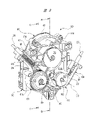
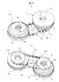
図1は本発明に係る駆動ユニットを搭載した車両の側面図を、図2はスライドドアの車体への取り付け構造を説明する平面図を、図3は図2の駆動ユニットを矢印A方向から見た斜視図(ギヤカバー無)を、図4は図3のB-B線に沿う断面図(ギヤカバー有)を、図5は図3のC-C線に沿う断面図(ギヤカバー有)を、図6(a),(b)は閉側ドラム,開側ドラムおよび駆動ベルトを説明する斜視図を、図7は閉側ドラムのケーブル溝を説明する側面図を、図8は開側ドラムのケーブル溝を説明する側面図をそれぞれ示している。 1 is a side view of a vehicle equipped with a drive unit according to the present invention, FIG. 2 is a plan view for explaining the mounting structure of the sliding door to the vehicle body, and FIG. 3 is the drive unit of FIG. 4 is a cross-sectional view along line BB of FIG. 3 (with gear cover), and FIG. 5 is a cross-sectional view along line CC of FIG. 3 (with gear cover). 6(a) and 6(b) are perspective views explaining the closing drum, the opening drum and the drive belt, FIG. 7 is a side view explaining the cable groove of the closing drum, and FIG. 8 is the cable of the opening drum. 4A and 4B each show a side view illustrating the groove.

図1に示される車両10は、例えば8人乗車が可能なワゴン車であり、車両10の車体11における側部には、比較的大きな開口部12が設けられている。開口部12は、車体11に移動自在に設けられたスライドドア(開閉体)13により開閉される。スライドドア13は、車体11の側部に固定されたガイドレール14に案内され、全閉位置と全開位置との間で車体11の前後方向に移動する。そして、スライドドア13を全開位置(図中二点鎖線)に移動させることで開口部12が大きく開かれて、ひいては乗員の乗降や荷物の積み下ろし等を容易に行えるようになる。 A vehicle 10 shown in FIG. 1 is, for example, a station wagon capable of accommodating eight passengers, and a vehicle body 11 of the vehicle 10 is provided with a relatively large opening 12 at a side portion thereof. The opening 12 is opened and closed by a slide door (opening/closing body) 13 movably provided on the vehicle body 11 . The sliding door 13 is guided by a guide rail 14 fixed to the side of the vehicle body 11 and moves in the longitudinal direction of the vehicle body 11 between a fully closed position and a fully open position. By moving the slide door 13 to the fully open position (two-dot chain line in the figure), the opening 12 is opened wide, thereby facilitating boarding and alighting of passengers and loading and unloading of luggage.

図2に示されるように、スライドドア13の車体後方側で、かつスライドドア13の上下方向中央部には、ローラアッシー(移動部材)15が設けられている。ローラアッシー15は、ガイドレール14の形状に沿ってガイドレール14上を移動し、これによりスライドドア13は、車体11の側部に沿って車体11の前後方向に移動する。 As shown in FIG. 2, a roller assembly (moving member) 15 is provided on the rear side of the sliding door 13 in the vehicle body and at the center of the sliding door 13 in the vertical direction. The roller assembly 15 moves on the guide rail 14 along the shape of the guide rail 14 , so that the slide door 13 moves along the side of the vehicle body 11 in the longitudinal direction of the vehicle body 11 .

ガイドレール14の車体前方側には、車室内側(図中上側)に向けて湾曲された湾曲部14aが設けられている。そして、ローラアッシー15が車体前方側に移動し、湾曲部14aの部分を通って車室内側に移動すると、スライドドア13は閉じられる。具体的には、図中二点鎖線で示されるように、車体11の内側に引き込まれて[全閉状態]となり、車体11の側面に対して略面一となる。 A curved portion 14a is provided on the front side of the vehicle body of the guide rail 14. The curved portion 14a is curved toward the interior side of the vehicle (upper side in the figure). Then, when the roller assembly 15 moves toward the front side of the vehicle body and toward the inside of the passenger compartment through the portion of the curved portion 14a, the slide door 13 is closed. Specifically, as indicated by a two-dot chain line in the figure, it is pulled into the inside of the vehicle body 11 to be in a fully closed state, and is substantially flush with the side surfaces of the vehicle body 11 .

なお、スライドドア13には、ローラアッシー15に加えて、車体前方側でかつ上下部分にもそれぞれローラアッシー(図示せず)が設けられている。また、スライドドア13の上下部分のローラアッシーに対応して、車体11の開口部12の上下部分にもガイドレール(図示せず)がそれぞれ設けられている。つまり、スライドドア13は車体11に対して合計3箇所で支持され、これにより車体11に対して安定した開閉動作が可能となっている。 In addition to the roller assembly 15, the slide door 13 is also provided with roller assemblies (not shown) on the front side of the vehicle body and on the upper and lower portions thereof. Further, guide rails (not shown) are also provided at the upper and lower portions of the opening 12 of the vehicle body 11 so as to correspond to the roller assemblies at the upper and lower portions of the slide door 13, respectively. In other words, the sliding door 13 is supported at a total of three points with respect to the vehicle body 11 , thereby enabling stable opening and closing operations with respect to the vehicle body 11 .

図2に示されるように、車両10の車体11における側部には、スライドドア13を自動的に開閉するスライドドア開閉機構20が設けられている。スライドドア開閉機構20は、駆動ユニット30を備えており、この駆動ユニット30は、車体11を形成する車体パネル(図示せず)に固定され、かつガイドレール14の長手方向中央部に隣接している。 As shown in FIG. 2 , a sliding door opening/closing mechanism 20 for automatically opening/closing the sliding door 13 is provided on the side of the vehicle body 11 of the vehicle 10 . The sliding door opening/closing mechanism 20 includes a drive unit 30 fixed to a vehicle body panel (not shown) forming the vehicle body 11 and adjacent to the longitudinal central portion of the guide rail 14. there is

スライドドア開閉機構20は、ガイドレール14の長手方向両側にそれぞれ配置された一対の反転プーリ21,22と、スライドドア13を閉方向(車体前方)に向けて牽引する閉側ケーブル23と、スライドドア13を開方向(車体後方)に向けて牽引する開側ケーブル24と、を備えている。ここで、閉側ケーブル23は、本発明におけるケーブルおよび第1ケーブルを構成しており、開側ケーブル24は、本発明における第2ケーブルを構成している。 The sliding door opening/closing mechanism 20 includes a pair of reversing pulleys 21 and 22 arranged on both sides in the longitudinal direction of the guide rail 14, a closing cable 23 for pulling the sliding door 13 in the closing direction (front of the vehicle body), and a sliding door. and an opening cable 24 for pulling the door 13 in the opening direction (rear of the vehicle body). Here, the closed side cable 23 constitutes the cable and the first cable in the present invention, and the open side cable 24 constitutes the second cable in the present invention.

そして、閉側ケーブル23および開側ケーブル24の長手方向一側は、それぞれ駆動ユニット30の内部に導かれている。これに対し、閉側ケーブル23および開側ケーブル24の長手方向他側は、一対の反転プーリ21,22を介して、それぞれ車体前方および車体後方からローラアッシー15に接続されている。つまり、閉側ケーブル23は、ローラアッシー15の車体前方側(移動方向一側)に接続され、開側ケーブル24は、ローラアッシー15の車体後方側(移動方向他側)に接続されている。 One longitudinal end of each of the closing cable 23 and the opening cable 24 is guided inside the drive unit 30 . On the other hand, the other longitudinal sides of the closing cable 23 and the opening cable 24 are connected to the roller assembly 15 from the front and rear of the vehicle body via a pair of reversing pulleys 21 and 22, respectively. That is, the closing cable 23 is connected to the roller assembly 15 on the vehicle front side (one side in the moving direction), and the opening cable 24 is connected to the roller assembly 15 on the vehicle rear side (moving direction other side).

これにより、駆動ユニット30を正転駆動させることで、閉側ケーブル23が牽引されてスライドドア13は閉方向に移動される。これに対し、駆動ユニット30を逆転駆動させることで、開側ケーブル24が牽引されてスライドドア13は開方向に駆動される。つまり、駆動ユニット30は、スライドドア13を開閉するようになっている。 As a result, the drive unit 30 is driven in the normal direction, so that the closing cable 23 is pulled and the slide door 13 is moved in the closing direction. On the other hand, by driving the drive unit 30 in reverse, the opening cable 24 is pulled and the slide door 13 is driven in the opening direction. That is, the drive unit 30 opens and closes the slide door 13 .

なお、一対のケーブル23,24の車体11の外部に配置される部分は、ガイドレール14の内部に設けられた案内溝(図示せず)によって隠されている。これにより、一対のケーブル23,24は、外部に露出されることが無い。よって、車両10の見栄えを良好にしつつ、一対のケーブル23,24を雨水や埃等から保護することができる。 The portions of the pair of cables 23 and 24 that are arranged outside the vehicle body 11 are hidden by a guide groove (not shown) provided inside the guide rail 14 . Thereby, the pair of cables 23 and 24 are not exposed to the outside. Therefore, the pair of cables 23 and 24 can be protected from rainwater, dust, etc. while improving the appearance of the vehicle 10 .

また、一対の反転プーリ21,22と駆動ユニット30との間には、一対のケーブル23,24の周囲を覆い、一対のケーブル23,24を摺動自在に保持するアウターケーシング25,26がそれぞれ設けられている。これらのアウターケーシング25,26は可撓性を有しており、その内側には摺動グリース(図示せず)が塗布されている。これにより、一対のケーブル23,24を保護することができ、かつ一対のケーブル23,24が一対のアウターケーシング25,26に対してスムーズに摺動可能となっている。 Between the pair of reversing pulleys 21 and 22 and the drive unit 30, there are outer casings 25 and 26 that cover the pair of cables 23 and 24 and slidably hold the pair of cables 23 and 24, respectively. is provided. These outer casings 25 and 26 are flexible and the inside thereof is coated with sliding grease (not shown). Thereby, the pair of cables 23 and 24 can be protected, and the pair of cables 23 and 24 can slide smoothly with respect to the pair of outer casings 25 and 26 .

図3ないし図5に示されるように、駆動ユニット30は、モータ部40,基板収容部50およびドラム収容部60を備えており、これらは複数の締結部材FN(図示では3つのみ示す)によって互いに一体化されている。また、モータ部40,基板収容部50およびドラム収容部60の中でも、ドラム収容部60が最も大きい部分となっており、ドラム収容部60を回転軸46の軸方向から見たときに、モータ部40および基板収容部50は、それぞれドラム収容部60の投影範囲内に略入り込んでいる。 As shown in FIGS. 3-5, the drive unit 30 includes a motor section 40, a substrate housing section 50 and a drum housing section 60, which are fastened together by a plurality of fastening members FN (only three are shown in the drawings). integrated with each other. Among the motor section 40, the substrate housing section 50, and the drum housing section 60, the drum housing section 60 is the largest portion. 40 and the substrate accommodating portion 50 are substantially within the projection range of the drum accommodating portion 60 respectively.

このように、モータ部40および基板収容部50を、それぞれドラム収容部60の投影範囲内に略入り込むようにし、かつモータ部40および基板収容部50をそれぞれ回転軸46の軸方向と直交する方向に並べることで、駆動ユニット30の回転軸46の軸方向に沿う厚み寸法が厚くなることを抑制している。 In this manner, the motor section 40 and the substrate housing section 50 are arranged to substantially enter the projection range of the drum housing section 60, and the motor section 40 and the substrate housing section 50 are moved in directions perpendicular to the axial direction of the rotation shaft 46, respectively. By arranging them side by side, the thickness dimension along the axial direction of the rotating shaft 46 of the drive unit 30 is suppressed from increasing.

モータ部40は、プラスチック等の樹脂材料よりなるモータハウジング41と、モータハウジング41の開口部41aを閉塞する平板状のモータカバー42と、を備えている。なお、モータカバー42においても、プラスチック等の樹脂材料により形成され、これによりモータ部40の軽量化が図られている。 The motor unit 40 includes a motor housing 41 made of a resin material such as plastic, and a flat motor cover 42 that closes an opening 41 a of the motor housing 41 . The motor cover 42 is also made of a resin material such as plastic, thereby reducing the weight of the motor section 40 .

モータハウジング41は、扁平の略円筒形状に形成され、その内部には扁平形状の電動モータ43が収容されている。電動モータ43は、ブラシレスモータであって、環状に形成されたステータ44と、ステータ44の径方向内側で回転するロータ45と、を備えている。 The motor housing 41 is formed in a flat, substantially cylindrical shape, and accommodates a flat electric motor 43 therein. The electric motor 43 is a brushless motor and includes a stator 44 formed in an annular shape and a rotor 45 that rotates radially inside the stator 44 .

ステータ44は、図示しない固定ねじ等により、モータハウジング41に強固に固定されている。ステータ44は、磁性体よりなる複数の鋼板(図示せず)を積層してなるステータコア44aを備えており、このステータコア44aの径方向内側には、U相,V相,W相のコイル44bが所定の巻き数および巻き方で巻装された複数のティース(図示せず)が設けられている。 The stator 44 is firmly fixed to the motor housing 41 with a fixing screw or the like (not shown). The stator 44 has a stator core 44a formed by laminating a plurality of steel plates (not shown) made of magnetic material, and U-phase, V-phase, and W-phase coils 44b are arranged radially inside the stator core 44a. A plurality of teeth (not shown) wound with a predetermined number of turns and winding method are provided.

ロータ45は、断面が略U字形状に形成されたロータ本体45aを備えている。ロータ本体45aは、鋼板をプレス加工等して形成され、その径方向外側には、複数の永久磁石45bが周方向に並ぶようにして固定されている。一方、ロータ本体45aの径方向内側には、丸鋼棒よりなる回転軸46の軸方向基端部が固定されている。 The rotor 45 includes a rotor body 45a having a substantially U-shaped cross section. The rotor main body 45a is formed by pressing a steel plate or the like, and a plurality of permanent magnets 45b are fixed to the radially outer side of the rotor body 45a so as to be arranged in the circumferential direction. On the other hand, the axial base end portion of a rotating shaft 46 made of a round steel bar is fixed to the radially inner side of the rotor main body 45a.

回転軸46は、軸方向基端部がロータ本体45aの中心に固定された大径軸部46aと、減速機構100を形成するサンギヤ46bと、閉側ドラム70を回転自在に支持する小径軸部46cと、を備えている。そして、回転軸46は、モータハウジング41に回転自在に支持されている。 The rotating shaft 46 has a large-diameter shaft portion 46a whose axial base end portion is fixed to the center of the rotor body 45a, a sun gear 46b forming the speed reduction mechanism 100, and a small-diameter shaft portion rotatably supporting the closing drum 70. 46c and. The rotating shaft 46 is rotatably supported by the motor housing 41 .

具体的には、モータハウジング41の略中心部分には、モータハウジング41の他の部分に比して肉厚となったボス部41bが設けられている。ボス部41bの径方向内側には、一対の大径ボールベアリングB1が装着されている。これらの大径ボールベアリングB1によって、回転軸46の大径軸部46aが回転自在に支持されている。なお、一対の大径ボールベアリングB1は、ボス部41bの軸方向両側に互いに離間して設けられている。これにより回転軸46は、振れること無く安定して高速で回転可能となっている。 Specifically, a boss portion 41 b that is thicker than the other portions of the motor housing 41 is provided at a substantially central portion of the motor housing 41 . A pair of large-diameter ball bearings B1 are mounted on the radially inner side of the boss portion 41b. The large-diameter shaft portion 46a of the rotary shaft 46 is rotatably supported by these large-diameter ball bearings B1. The pair of large-diameter ball bearings B1 are provided on both axial sides of the boss portion 41b so as to be spaced apart from each other. As a result, the rotary shaft 46 can rotate stably at high speed without shaking.

基板収容部50は、モータ部40に近接して設けられ、基板収容部50の内部には、電動モータ43の回転状態を制御する制御基板51が収容されている。制御基板51には、電動モータ43を形成するU相,V相,W相のコイル44bのそれぞれに、次々と高速で駆動電流を供給するスイッチング素子51aが実装されている。 The substrate accommodation portion 50 is provided close to the motor portion 40 , and a control substrate 51 for controlling the rotation state of the electric motor 43 is accommodated inside the substrate accommodation portion 50 . On the control board 51, a switching element 51a is mounted for supplying a drive current at a high speed to each of the U-phase, V-phase, and W-phase coils 44b forming the electric motor 43 one after another.

また、制御基板51には、車両10側の外部コネクタ(図示せず)が接続されるコネクタ接続部51bが電気的に接続されている。これにより、外部コネクタからの駆動電流が駆動ユニット30に供給される。 Further, the control board 51 is electrically connected to a connector connection portion 51b to which an external connector (not shown) on the vehicle 10 side is connected. Thereby, the drive current from the external connector is supplied to the drive unit 30 .

さらに、制御基板51には、電動モータ43の回転状態を検出する複数のホールIC51c(図4では1つのみ示す)が実装されている。具体的には、複数のホールIC51cは、ロータ45に設けられた永久磁石45bに近接配置されている。これにより、ロータ45の回転に伴って、複数のホールIC51cは、所定のタイミングでパルス信号(矩形波信号)を発生する。 Further, the control board 51 is mounted with a plurality of Hall ICs 51c (only one is shown in FIG. 4) for detecting the rotation state of the electric motor 43. As shown in FIG. Specifically, the plurality of Hall ICs 51 c are arranged close to a permanent magnet 45 b provided on the rotor 45 . Accordingly, as the rotor 45 rotates, the plurality of Hall ICs 51c generate pulse signals (rectangular wave signals) at predetermined timings.

また、制御基板51には、複数のホールIC51cからのパルス信号が入力されるCPU(図示せず)が実装されている。これによりCPUは、ロータ45の回転状態(回転速度や回転方向等)を把握し、スイッチング素子51aを最適に制御可能となっている。よって、電動モータ43の回転状態が精度良く制御される。なお、制御基板51には、図5に示されるように、コンデンサ等の他の電子部品EPも実装されている。 Further, the control board 51 is mounted with a CPU (not shown) to which pulse signals are input from the plurality of Hall ICs 51c. This enables the CPU to grasp the rotational state (rotational speed, rotational direction, etc.) of the rotor 45 and optimally control the switching element 51a. Therefore, the rotation state of the electric motor 43 is controlled with high accuracy. Note that other electronic components EP such as capacitors are also mounted on the control board 51, as shown in FIG.

さらに、基板収容部50の外郭を形成する筐体52の一部(詳細図示せず)は、熱伝導率の高いアルミ材料等によって形成されている。これにより、電動モータ43の作動中に高温となるスイッチング素子51aの熱を、外部に素早く放熱できるようにしている。 Further, a part (details not shown) of the housing 52 forming the outer shell of the board accommodating portion 50 is made of an aluminum material or the like having high thermal conductivity. As a result, the heat of the switching element 51a, which becomes hot during operation of the electric motor 43, can be quickly dissipated to the outside.

ドラム収容部60は、プラスチック等の樹脂材料よりなるドラムハウジング61と、ドラムハウジング61の開口部61aを閉塞する平板状のドラムカバー62と、を備えている。なお、ドラムカバー62においても、プラスチック等の樹脂材料により形成され、これによりドラム収容部60の軽量化が図られている。 The drum housing portion 60 includes a drum housing 61 made of a resin material such as plastic, and a flat drum cover 62 that closes an opening 61 a of the drum housing 61 . The drum cover 62 is also made of a resin material such as plastic, thereby reducing the weight of the drum accommodating portion 60 .

ドラムハウジング61は、扁平の略ダルマ形状に形成され、底壁部61bと、当該底壁部61bの周囲に起立して設けられた側壁部61cとを備えている。そして、ドラムハウジング61の内部には、閉側ドラム70,開側ドラム80および方向転換プーリ63が回転自在に収容されている。ここで、閉側ドラム70,開側ドラム80および方向転換プーリ63は、いずれもプラスチック等の樹脂材料により形成され、これによりそれぞれの慣性モーメントの値を小さくしつつ、駆動ユニット30の軽量化を図っている。 The drum housing 61 is formed in a flat, substantially daruma shape, and includes a bottom wall portion 61b and side wall portions 61c provided upright around the bottom wall portion 61b. Inside the drum housing 61, the closing drum 70, the opening drum 80, and the direction changing pulley 63 are rotatably accommodated. Here, the closing drum 70, the opening drum 80, and the direction change pulley 63 are all made of a resin material such as plastic. I am planning.

閉側ドラム70は、モータ部40の回転軸46に対して同軸上に設けられ、ドラムハウジング61の略中央部分でかつモータ部40寄りの部分に配置されている。そして、閉側ドラム70には、スライドドア13(図2参照)を閉方向に牽引する閉側ケーブル23が巻き掛けられるようになっている。 The closing drum 70 is provided coaxially with the rotation shaft 46 of the motor section 40 , and is arranged in a substantially central portion of the drum housing 61 and near the motor section 40 . A closing cable 23 for pulling the slide door 13 (see FIG. 2) in the closing direction is wound around the closing drum 70 .

また、開側ドラム80は、ドラムハウジング61の基板収容部50寄りの部分において、方向転換プーリ63と並んで設けられている。そして、閉側ドラム70の軸心C1(図4参照)と、開側ドラム80の軸心C2(図5参照)と、方向転換プーリ63の軸心C3(図3参照)とは、それぞれ平行となっており、これらの軸心C1,C2,C3を結ぶ線分は、略正三角形となっている。そして、開側ドラム80には、スライドドア13を開方向に牽引する開側ケーブル24が巻き掛けられるようになっている。 Further, the opening-side drum 80 is provided side by side with the direction changing pulley 63 in a portion of the drum housing 61 near the board accommodating portion 50 . The axis C1 of the closing drum 70 (see FIG. 4), the axis C2 of the opening drum 80 (see FIG. 5), and the axis C3 of the direction change pulley 63 (see FIG. 3) are parallel to each other. A line segment connecting these axes C1, C2, and C3 forms a substantially equilateral triangle. An opening cable 24 for pulling the slide door 13 in the opening direction is wound around the opening drum 80 .

図4に示されるように、閉側ドラム70の回転中心には、当該閉側ドラム70を軸方向に貫通する貫通孔71が設けられ、この貫通孔71の軸方向両側には、一対の小径ボールベアリングB2が装着されている。そして、閉側ドラム70の軸方向一側(モータ部40側)の小径ボールベアリングB2は、回転軸46の小径軸部46cに装着されている。一方、閉側ドラム70の軸方向他側(モータ部40側とは反対側)の小径ボールベアリングB2は、ドラムカバー62の内側に一体に設けられた第1支持凸部62aに装着されている。これにより、閉側ドラム70は、軸心C1を中心にスムーズに回動可能となっている。すなわち、閉側ドラム70は、小径軸部46cおよび第1支持凸部62aに回転自在に支持されている。 As shown in FIG. 4, a through hole 71 is provided at the center of rotation of the closing drum 70 and extends through the closing drum 70 in the axial direction. A ball bearing B2 is installed. A small-diameter ball bearing B<b>2 on one axial side (motor unit 40 side) of the closing drum 70 is mounted on the small-diameter shaft portion 46 c of the rotating shaft 46 . On the other hand, the small-diameter ball bearing B2 on the other side of the closing drum 70 in the axial direction (the side opposite to the motor section 40 side) is mounted on a first support projection 62a integrally provided inside the drum cover 62. . As a result, the closing drum 70 can be smoothly rotated around the axis C1. That is, the closing drum 70 is rotatably supported by the small-diameter shaft portion 46c and the first support protrusion 62a.

図5に示されるように、開側ドラム80の回転中心には、当該開側ドラム80を軸方向に貫通する貫通孔81が設けられ、この貫通孔81の軸方向両側には、一対の小径ボールベアリングB3が装着されている。そして、開側ドラム80の軸方向一側(モータ部40側)の小径ボールベアリングB3は、底壁部61bに一体に設けられた第1支持ピンN1に装着されている。一方、閉側ドラム80の軸方向他側(モータ部40側とは反対側)の小径ボールベアリングB3は、ドラムカバー62の内側に一体に設けられた第2支持凸部62bに装着されている。これにより、開側ドラム80は、軸心C2を中心にスムーズに回動可能となっている。すなわち、開側ドラム80は、第1支持ピンN1および第2支持凸部62bに回転自在に支持されている。 As shown in FIG. 5, a through-hole 81 is provided at the center of rotation of the opening-side drum 80 so as to pass through the opening-side drum 80 in the axial direction. A ball bearing B3 is installed. A small-diameter ball bearing B3 on one axial side (motor section 40 side) of the opening drum 80 is mounted on a first support pin N1 integrally provided on the bottom wall section 61b. On the other hand, the small-diameter ball bearing B3 on the other side of the closing drum 80 in the axial direction (the side opposite to the motor section 40 side) is mounted on a second support projection 62b integrally provided inside the drum cover 62. . As a result, the opening-side drum 80 can be smoothly rotated about the axis C2. That is, the opening side drum 80 is rotatably supported by the first support pin N1 and the second support protrusion 62b.

また、図3に示されるように、方向転換プーリ63は、ドラムハウジング61の内部に引き込まれた閉側ケーブル23の方向を、閉側ドラム70に向けて転換するものであって、底壁部61bに一体に設けられた第2支持ピンN2に回動自在に支持されている。なお、閉側ドラム70および開側ドラム80のより詳細な構造や、ドラムハウジング61の内部への配置の状態については、後で詳述する。 As shown in FIG. 3, the direction change pulley 63 changes the direction of the closing cable 23 drawn into the drum housing 61 toward the closing drum 70. It is rotatably supported by a second support pin N2 provided integrally with 61b. A more detailed structure of the closing side drum 70 and the opening side drum 80 and the state of arrangement inside the drum housing 61 will be described in detail later.

図3に示されるように、ドラムハウジング61を形成する側壁部61cには、閉側ケーブル案内部64および開側ケーブル案内部65が一体に設けられている。これらのケーブル案内部64,65は、閉側ケーブル23および開側ケーブル24をドラムハウジング61の内部に案内する機能を有し、それぞれ略箱形状に形成されている。そして、閉側ケーブル案内部64は、方向転換プーリ63の近傍に配置され、閉側ケーブル23をモータ部40側から方向転換プーリ63に向けて誘導している。一方、開側ケーブル案内部65は、開側ドラム80の近傍に配置され、開側ケーブル24をモータ部40側から開側ドラム80に向けて誘導している。 As shown in FIG. 3, a side wall portion 61c forming the drum housing 61 is integrally provided with a closed side cable guide portion 64 and an open side cable guide portion 65. As shown in FIG. These cable guide portions 64 and 65 have the function of guiding the closing side cable 23 and the opening side cable 24 inside the drum housing 61, and are each formed in a substantially box shape. The closing-side cable guide portion 64 is arranged near the direction changing pulley 63 and guides the closing-side cable 23 from the motor portion 40 side toward the direction changing pulley 63 . On the other hand, the opening-side cable guide portion 65 is arranged near the opening-side drum 80 and guides the opening-side cable 24 from the motor portion 40 side toward the opening-side drum 80 .

なお、一対のケーブル案内部64,65の内部には、コイルスプリングSPがそれぞれ収容されている。これらのコイルスプリングSPは、アウターケーシング25,26をドラムハウジング61の外部に向けてそれぞれ付勢している。これにより、経時変化で伸びてしまった一対のケーブル23,24の微小な弛みを、ドラムハウジング61の外部で吸収可能としている。 Coil springs SP are housed inside the pair of cable guides 64 and 65, respectively. These coil springs SP bias the outer casings 25 and 26 toward the outside of the drum housing 61 . As a result, minute slack in the pair of cables 23 and 24 that has stretched over time can be absorbed outside the drum housing 61 .

ここで、スライドドア13(図2参照)を開方向に牽引する開側ケーブル24は、開側ドラム80の駆動力によって開側ドラム80に巻き掛けられる。この場合の開側ドラム80の駆動力は、駆動ベルト90を介して閉側ドラム70から伝達される。なお、駆動ベルト90の詳細な構造についても、後で詳述する。 Here, the opening side cable 24 for pulling the slide door 13 (see FIG. 2) in the opening direction is wound around the opening side drum 80 by the driving force of the opening side drum 80 . The driving force of the opening side drum 80 in this case is transmitted from the closing side drum 70 via the drive belt 90 . A detailed structure of the drive belt 90 will also be described in detail later.

図4に示されるように、閉側ドラム70は、電動モータ43に対して同軸上に配置され、電動モータ43によって大きな回転トルクで駆動される。具体的には、電動モータ43と閉側ドラム70との間には、電動モータ43における回転軸46の回転を減速して閉側ドラム70の回転トルクを大きくする減速機構100が設けられている。 As shown in FIG. 4, the closing drum 70 is arranged coaxially with the electric motor 43 and driven by the electric motor 43 with a large rotational torque. Specifically, a reduction mechanism 100 is provided between the electric motor 43 and the closing drum 70 to reduce the rotation of the rotating shaft 46 of the electric motor 43 to increase the rotational torque of the closing drum 70 . .

減速機構100は、遊星歯車減速機であって、回転軸46に一体に設けられたサンギヤ46bと、サンギヤ46bに噛み合わされてサンギヤ46bの周囲に転動自在に設けられた3つのプラネタリギヤ101(図示では2つのみ示す)と、プラネタリギヤ101の周囲に設けられてプラネタリギヤ101に噛み合わされるアウターギヤ102と、3つのプラネタリギヤ101を保持してプラネタリギヤ101の公転運動に応じて回転される遊星キャリア103と、を備えている。 The speed reduction mechanism 100 is a planetary gear speed reducer, and includes a sun gear 46b provided integrally with the rotating shaft 46, and three planetary gears 101 (illustrated in the figure) meshing with the sun gear 46b and provided to rotate freely around the sun gear 46b. only two are shown), an outer gear 102 provided around the planetary gear 101 and meshed with the planetary gear 101, and a planetary carrier 103 that holds the three planetary gears 101 and rotates according to the orbital motion of the planetary gear 101. , is equipped with

より具体的には、アウターギヤ102は環状に形成され、モータハウジング41とドラムハウジング61との間に挟持されている。つまり、アウターギヤ102は、それぞれのハウジング41,61に対して回転不能に強固に固定されている。また、遊星キャリア103は、閉側ドラム70に回転力を伝達するものであって、遊星キャリア103は、閉側ドラム70に対して一体回転可能に連結されている。 More specifically, the outer gear 102 is annularly formed and sandwiched between the motor housing 41 and the drum housing 61 . That is, the outer gear 102 is firmly fixed to the respective housings 41 and 61 so as not to rotate. Further, the planetary carrier 103 transmits a rotational force to the closing side drum 70, and the planetary carrier 103 is connected to the closing side drum 70 so as to be integrally rotatable.

なお、遊星キャリア103の径方向内側には、小径ボールベアリングB4が装着されており、この小径ボールベアリングB4は、回転軸46の小径軸部46cに装着されている。これにより、遊星キャリア103は、回転軸46に対してスムーズに相対回転可能となっている。 A small-diameter ball bearing B4 is attached to the radially inner side of the planetary carrier 103, and the small-diameter ball bearing B4 is attached to the small-diameter shaft portion 46c of the rotating shaft 46. As shown in FIG. As a result, the planetary carrier 103 can smoothly rotate relative to the rotating shaft 46 .

減速機構100の動作について述べると、まず、電動モータ43の回転軸46が高速で回転される。すると、回転軸46の回転に伴ってサンギヤ46bも高速で回転される。このとき、アウターギヤ102はハウジング41,61に固定されているため、サンギヤ46bの周囲を3つのプラネタリギヤ101が転動しながら公転する。このときのプラネタリギヤ101の公転速度は、サンギヤ46bの回転速度よりも遙かに低速となっている。これにより、プラネタリギヤ101を保持する遊星キャリア103が低速かつ高トルク化された状態で回転され、ひいては、閉側ドラム70が大きな回転トルクで回転される。 To describe the operation of the reduction mechanism 100, first, the rotating shaft 46 of the electric motor 43 is rotated at high speed. Then, the sun gear 46b is also rotated at high speed as the rotating shaft 46 rotates. At this time, since the outer gear 102 is fixed to the housings 41 and 61, the three planetary gears 101 revolve around the sun gear 46b while rolling. At this time, the revolution speed of the planetary gear 101 is much lower than the rotation speed of the sun gear 46b. As a result, the planetary carrier 103 holding the planetary gear 101 is rotated at a low speed with a high torque, and the closing drum 70 is rotated with a large rotational torque.

ドラムハウジング61の内部には、図6に示されるような配置関係で、閉側ドラム70,開側ドラム80および駆動ベルト90が収容されている。なお、図6(a)の図中下側および図6(b)の図中上側が、それぞれのドラム70,80の軸方向一側であって、モータ部40に面する側となっている。一方、図6(a)の図中上側および図6(b)の図中下側が、それぞれのドラム70,80の軸方向他側であって、ドラムカバー62に面する側となっている。 Inside the drum housing 61, the closing side drum 70, the opening side drum 80 and the driving belt 90 are accommodated in the arrangement relationship shown in FIG. 6(a) and the upper side of FIG. 6(b) are the axial sides of the respective drums 70 and 80, which face the motor section 40. . On the other hand, the upper side in FIG. 6A and the lower side in FIG.

閉側ドラム70は、本発明におけるドラムおよび第1ドラムを構成しており、図6および図7に示されるような形状をなしている。閉側ドラム70は、プラスチック等の樹脂材料により略円盤形状に形成され、その回転中心には、一対の小径ボールベアリングB2(図4参照)が装着される貫通孔71が形成されている。 The closing drum 70 constitutes a drum and a first drum in the present invention, and has a shape as shown in FIGS. 6 and 7. FIG. The closing drum 70 is made of a resin material such as plastic and has a substantially disc shape, and a through hole 71 is formed at the center of rotation thereof to receive a pair of small-diameter ball bearings B2 (see FIG. 4).

閉側ドラム70の軸方向一端(図7中下側)には、閉側動力伝達部72が設けられている。閉側動力伝達部72は、閉側ベルト噛合部72aと、3つの係合爪72bと、を備えている。閉側ベルト噛合部72aは、複数の凹凸(詳細図示せず)を備えており、当該閉側ベルト噛合部72aには、駆動ベルト90のゴム歯91が噛み合わされている。 A closing side power transmission portion 72 is provided at one axial end (lower side in FIG. 7) of the closing side drum 70 . The closing-side power transmission portion 72 includes a closing-side belt meshing portion 72a and three engaging claws 72b. The closing-side belt engaging portion 72a has a plurality of irregularities (not shown in detail), and the rubber teeth 91 of the drive belt 90 are engaged with the closing-side belt engaging portion 72a.

また、3つの係合爪72bは、閉側ドラム70の周方向に等間隔(120度間隔)で設けられ、かつ閉側ドラム70の軸方向に突出されている。そして、これらの係合爪72bは、減速機構100の遊星キャリア103(図4参照)に引っ掛けられるようになっている。これにより、遊星キャリア103の回転力が閉側ドラム70に伝達される。 The three engaging claws 72b are provided at regular intervals (at intervals of 120 degrees) in the circumferential direction of the closing drum 70 and protrude in the axial direction of the closing drum 70 . These engaging claws 72b are adapted to be hooked on the planetary carrier 103 (see FIG. 4) of the speed reduction mechanism 100. As shown in FIG. Thereby, the rotational force of the planetary carrier 103 is transmitted to the closing drum 70 .

閉側ドラム70の軸方向一側で、かつ閉側動力伝達部72よりもドラムカバー62側(図7中上側)の部分には、閉側ケーブル23が巻き掛けられる小径部73が設けられている。小径部73には、螺旋状の小径ケーブル溝73aが設けられ、当該小径ケーブル溝73aに巻き掛けられる閉側ケーブル23の巻き掛け径は、閉側動力伝達部72に向けてD1→D2→D3と徐々に小さくなっている(D1>D2>D3)。 A small-diameter portion 73 around which the closing-side cable 23 is wound is provided on one side of the closing-side drum 70 in the axial direction and closer to the drum cover 62 than the closing-side power transmission portion 72 (upper side in FIG. 7). there is A spiral small-diameter cable groove 73 a is provided in the small-diameter portion 73 , and the winding diameter of the closing-side cable 23 wound around the small-diameter cable groove 73 a is D1→D2→D3 toward the closing-side power transmission portion 72 . and gradually decreases (D1>D2>D3).

閉側ドラム70の軸方向他側(ドラムカバー62側)には、閉側ケーブル23が巻き掛けられる大径部74が設けられている。大径部74は小径部73よりも大径となっており、大径部74には、螺旋状の大径ケーブル溝74aが設けられている。そして、大径ケーブル溝74aに巻き掛けられる閉側ケーブル23の巻き掛け径は、大径ケーブル溝74aの全域において一定のD4となっている。 A large-diameter portion 74 around which the closing-side cable 23 is wound is provided on the other axial side (drum cover 62 side) of the closing-side drum 70 . The large-diameter portion 74 has a larger diameter than the small-diameter portion 73, and the large-diameter portion 74 is provided with a spiral large-diameter cable groove 74a. The winding diameter of the closing-side cable 23 wound around the large-diameter cable groove 74a is a constant D4 over the entire area of the large-diameter cable groove 74a.

なお、大径ケーブル溝74aの巻き掛け径D4は、小径ケーブル溝73aの最も大径の部分における巻き掛け径D1よりも大きくなっている(D4>D1)。 The winding diameter D4 of the large-diameter cable groove 74a is larger than the winding diameter D1 at the largest diameter portion of the small-diameter cable groove 73a (D4>D1).

そして、大径ケーブル溝74aは、閉側ドラム70の軸方向に沿う略中央部分において、小径ケーブル溝73aと接続されている。すなわち、大径ケーブル溝74aおよび小径ケーブル溝73aは、連続した1つの螺旋状のケーブル溝となっている。 The large-diameter cable groove 74a is connected to the small-diameter cable groove 73a at a substantially central portion of the closing drum 70 along the axial direction. That is, the large-diameter cable groove 74a and the small-diameter cable groove 73a form one continuous spiral cable groove.

閉側ドラム70に巻き掛けられる閉側ケーブル23の端部は、閉側ドラム70の軸方向他側、つまり大径部74側に固定されている。すなわち、閉側ケーブル23が閉側ドラム70に巻き掛けられていくに連れて、閉側ケーブル23は、大径ケーブル溝74aから小径ケーブル溝73aに徐々に巻かれていくことになる。このとき、閉側ケーブル23の巻き終わり間際(スライドドア13が略全閉の場合)において、閉側ケーブル23は、巻き掛け径が最も小さいD3となった小径ケーブル溝73aの部分に巻き掛けられる。 The end of the closing cable 23 wound around the closing drum 70 is fixed to the other side of the closing drum 70 in the axial direction, that is, to the large diameter portion 74 side. That is, as the closing-side cable 23 is wound around the closing-side drum 70, the closing-side cable 23 is gradually wound from the large-diameter cable groove 74a to the small-diameter cable groove 73a. At this time, just before the end of the winding of the closing side cable 23 (when the sliding door 13 is substantially fully closed), the closing side cable 23 is wound around the portion of the small diameter cable groove 73a where the winding diameter is D3, which is the smallest. .

ここで、大径ケーブル溝74aは、その全域において同じ巻き掛け径D4となっている。これにより、閉側ケーブル23が巻き掛けられても、閉側ケーブル23は大径ケーブル溝74aから脱落し難くなっている。したがって、大径ケーブル溝74aの溝ピッチP1は可能な限り詰められており、これにより閉側ドラム70の軸方向寸法の増大が抑えられている。より具体的には、隣り合う大径ケーブル溝74aの間には、厚み寸法がT1(約1.0mm)程度の隔壁74bが設けられている。 Here, the large-diameter cable groove 74a has the same winding diameter D4 over its entire area. As a result, even if the closing-side cable 23 is wound around, the closing-side cable 23 is less likely to drop out of the large-diameter cable groove 74a. Therefore, the groove pitch P1 of the large-diameter cable groove 74a is reduced as much as possible, thereby suppressing an increase in the axial dimension of the closing side drum 70. As shown in FIG. More specifically, a partition wall 74b having a thickness of about T1 (approximately 1.0 mm) is provided between adjacent large-diameter cable grooves 74a.

これに対し、小径ケーブル溝73aは、閉側動力伝達部72に向かうに連れて、巻き掛け径がD1→D2→D3と徐々に小さくなっている。そのため、大径ケーブル溝74aと同じ溝ピッチP1で、かつ同じ厚み寸法T1の隔壁74bでは、閉側ケーブル23が巻き掛けられていくにしたがって、閉側ケーブル23が小径ケーブル溝73aから脱落する虞がある。 On the other hand, the winding diameter of the small-diameter cable groove 73a gradually decreases in the order of D1→D2→D3 toward the closed-side power transmission portion 72. As shown in FIG. Therefore, in the partition wall 74b having the same groove pitch P1 and the same thickness T1 as the large-diameter cable groove 74a, there is a possibility that the closed-side cable 23 may fall out of the small-diameter cable groove 73a as the closed-side cable 23 is wound thereon. There is

そこで、本実施の形態では、小径ケーブル溝73aの溝ピッチP2を大径ケーブル溝74aの溝ピッチP1よりも大きく設定している(P2>P1)。これにより、隣り合う小径ケーブル溝73aの間には、厚み寸法がT2(約5.0mm)の比較的厚みのある隔壁73bが設けられている(T2>T1)。 Therefore, in the present embodiment, the groove pitch P2 of the small-diameter cable groove 73a is set larger than the groove pitch P1 of the large-diameter cable groove 74a (P2>P1). As a result, a relatively thick partition wall 73b having a thickness of T2 (approximately 5.0 mm) is provided between adjacent small-diameter cable grooves 73a (T2>T1).

このように、隔壁73bの厚み寸法を厚くしてT2とすることで、当該隔壁73bの剛性を十分に高めている。したがって、隔壁73bの高さ寸法Hを大きくする(小径ケーブル溝73aの深さ寸法を大きくする)ことが可能となり、これによっても閉側ケーブル23の小径ケーブル溝73aからの脱落を確実に防止している。 Thus, by increasing the thickness dimension of the partition 73b to T2, the rigidity of the partition 73b is sufficiently enhanced. Therefore, it is possible to increase the height dimension H of the partition wall 73b (increase the depth dimension of the small-diameter cable groove 73a). ing.

さらには、図4に示されるように、閉側ドラム70の周囲に設けられるドラムハウジング61の一部には、閉側ドラム70の小径部73が設けられた部分の外郭形状に倣って傾斜された傾斜部61dが設けられている。この傾斜部61dは、隔壁73bの先端部分に臨んでおり、これによっても閉側ケーブル23の小径ケーブル溝73aからの脱落を確実に防止している。 Furthermore, as shown in FIG. 4, a portion of the drum housing 61 provided around the closing drum 70 is inclined along the contour of the portion of the closing drum 70 where the small diameter portion 73 is provided. An inclined portion 61d is provided. The inclined portion 61d faces the tip portion of the partition wall 73b, which also reliably prevents the closing-side cable 23 from falling out of the small-diameter cable groove 73a.

このように、閉側ドラム70に対する閉側ケーブル23の巻き始めを大径ケーブル溝74aとし、閉側ドラム70に対する閉側ケーブル23の巻き終わりを小径ケーブル溝73aとしている。よって、電動モータ43の回転速度を制御すること無く、スライドドア13を閉じ始めにおいて素早く移動させ、かつスライドドア13を閉じ終わり間際でゆっくりと移動させることが可能となっている。すなわち、スライドドア13の移動速度が電動モータ43の制御に依らず可変となっている。 Thus, the winding start of the closing cable 23 on the closing drum 70 is the large diameter cable groove 74a, and the winding end of the closing cable 23 on the closing drum 70 is the small diameter cable groove 73a. Therefore, without controlling the rotational speed of the electric motor 43, the slide door 13 can be moved quickly at the start of closing and slowly moved just before the end of closing. In other words, the moving speed of the slide door 13 is variable regardless of the control of the electric motor 43 .

開側ドラム80は、本発明における第2ドラムを構成しており、図6および図8に示されるような形状をなしている。開側ドラム80は、プラスチック等の樹脂材料により略円盤形状に形成され、その回転中心には、一対の小径ボールベアリングB3(図5参照)が装着される貫通孔81が形成されている。 The open side drum 80 constitutes the second drum in the present invention and has a shape as shown in FIGS. The open side drum 80 is made of a resin material such as plastic and has a substantially disk shape, and a through hole 81 is formed at the center of rotation thereof to receive a pair of small-diameter ball bearings B3 (see FIG. 5).

開側ドラム80の軸方向一端(図8中下側)には、開側動力伝達部82が設けられている。開側動力伝達部82は、開側ベルト噛合部82aを備えている。開側ベルト噛合部82aは、複数の凹凸(詳細図示せず)を備えており、当該開側ベルト噛合部82aには、駆動ベルト90のゴム歯91が噛み合わされている。なお、開側ドラム80は、駆動ベルト90を介して閉側ドラム70により駆動されるため、閉側ドラム70に設けた係合爪72b(図7参照)を備えていない。 An opening side power transmission portion 82 is provided at one axial end (lower side in FIG. 8) of the opening side drum 80 . The opening-side power transmission portion 82 includes an opening-side belt engaging portion 82a. The open-side belt engaging portion 82a has a plurality of irregularities (not shown in detail), and the rubber teeth 91 of the drive belt 90 are engaged with the open-side belt engaging portion 82a. Since the opening drum 80 is driven by the closing drum 70 via the drive belt 90, it does not have the engaging claws 72b (see FIG. 7) provided on the closing drum 70. As shown in FIG.

開側ドラム80の軸方向一側で、かつ開側動力伝達部82よりもドラムカバー62側(図8中上側)の部分には、開側ケーブル24が巻き掛けられる大径部83が設けられている。大径部83には、螺旋状の大径ケーブル溝83aが設けられ、当該大径ケーブル溝83aに巻き掛けられる開側ケーブル24の巻き掛け径は、大径ケーブル溝83aの全域において、大径部83の外径寸法に略等しいd1で一定となっている。 A large-diameter portion 83 around which the opening-side cable 24 is wound is provided on one side of the opening-side drum 80 in the axial direction and closer to the drum cover 62 than the opening-side power transmission portion 82 (upper side in FIG. 8). ing. A spiral large-diameter cable groove 83a is provided in the large-diameter portion 83, and the winding diameter of the opening-side cable 24 wound around the large-diameter cable groove 83a is large throughout the large-diameter cable groove 83a. It is constant at d1, which is substantially equal to the outer diameter dimension of the portion 83. As shown in FIG.

開側ドラム80の軸方向他側(ドラムカバー62側)には、開側ケーブル24が巻き掛けられる小径部84が設けられている。小径部84は大径部83よりも小径となっており、小径部84には、螺旋状の小径ケーブル溝84aが設けられている。そして、小径ケーブル溝84aに巻き掛けられる開側ケーブル24の巻き掛け径は、開側ドラム80の軸方向他側(図8中上側)に向けてd2→d3→d4と徐々に小さくなっている(d2>d3>d4)。 A small-diameter portion 84 around which the opening-side cable 24 is wound is provided on the other axial side (drum cover 62 side) of the opening-side drum 80 . The small-diameter portion 84 has a diameter smaller than that of the large-diameter portion 83, and the small-diameter portion 84 is provided with a spiral small-diameter cable groove 84a. The winding diameter of the opening-side cable 24 wound around the small-diameter cable groove 84a gradually decreases in the order of d2→d3→d4 toward the other side in the axial direction of the opening-side drum 80 (upper side in FIG. 8). (d2>d3>d4).

なお、大径ケーブル溝83aの巻き掛け径d1は、小径ケーブル溝84aの最も大径の部分における巻き掛け径d2よりも大きくなっている(d1>d2)。 The winding diameter d1 of the large-diameter cable groove 83a is larger than the winding diameter d2 at the largest diameter portion of the small-diameter cable groove 84a (d1>d2).

そして、大径ケーブル溝83aは、開側ドラム80の軸方向に沿う略中央部分において、小径ケーブル溝84aと接続されている。すなわち、大径ケーブル溝83aおよび小径ケーブル溝84aは、連続した1つの螺旋状のケーブル溝となっている。 The large-diameter cable groove 83a is connected to the small-diameter cable groove 84a at a substantially central portion along the axial direction of the opening drum 80. As shown in FIG. That is, the large-diameter cable groove 83a and the small-diameter cable groove 84a form one continuous spiral cable groove.

開側ドラム80に巻き掛けられる開側ケーブル24の端部は、開側ドラム80の軸方向他側、つまり小径部84側に固定されている。すなわち、開側ケーブル24が開側ドラム80に巻き掛けられていくに連れて、開側ケーブル24は、小径ケーブル溝84aから大径ケーブル溝83aに徐々に巻かれていくことになる。このとき、開側ケーブル24の巻き終わり間際(スライドドア13が略全開の場合)において、開側ケーブル24は、巻き掛け径が最も大きいd1となった大径ケーブル溝83aの部分に巻き掛けられる。 The end of the open side cable 24 wound around the open side drum 80 is fixed to the other side of the open side drum 80 in the axial direction, that is, to the small diameter portion 84 side. That is, as the opening-side cable 24 is wound around the opening-side drum 80, the opening-side cable 24 is gradually wound from the small-diameter cable groove 84a to the large-diameter cable groove 83a. At this time, just before the end of the winding of the opening side cable 24 (when the slide door 13 is substantially fully opened), the opening side cable 24 is wound around the portion of the large-diameter cable groove 83a having the largest winding diameter d1. .

ここで、大径ケーブル溝83aは、その全域において同じ巻き掛け径d1となっている。これにより、開側ケーブル24が巻き掛けられても、開側ケーブル24は大径ケーブル溝83aから脱落し難くなっている。したがって、大径ケーブル溝83aの溝ピッチp1は可能な限り詰められており、これにより開側ドラム80の軸方向寸法の増大が抑えられている。より具体的には、隣り合う大径ケーブル溝83aの間には、厚み寸法がt1(約1.0mm)程度の隔壁83bが設けられている。 Here, the large-diameter cable groove 83a has the same winding diameter d1 over its entire area. As a result, even if the opening-side cable 24 is wound around, the opening-side cable 24 is less likely to drop out of the large-diameter cable groove 83a. Therefore, the groove pitch p1 of the large-diameter cable groove 83a is reduced as much as possible, thereby suppressing an increase in the axial dimension of the opening side drum 80. FIG. More specifically, a partition 83b having a thickness of about t1 (approximately 1.0 mm) is provided between adjacent large-diameter cable grooves 83a.

これに対し、小径ケーブル溝84aは、開側ドラム80の軸方向他側に向かうに連れて、巻き掛け径がd2→d3→d4と徐々に小さくなっている。そのため、大径ケーブル溝83aと同じ溝ピッチp1で、かつ同じ厚み寸法t1の隔壁83bでは、開側ケーブル24が巻き掛けられていくにしたがって、開側ケーブル24が小径ケーブル溝84aから脱落する虞がある。 On the other hand, the winding diameter of the small-diameter cable groove 84a gradually decreases in the order of d2→d3→d4 toward the other side of the opening drum 80 in the axial direction. Therefore, in the partition wall 83b having the same groove pitch p1 and the same thickness t1 as the large-diameter cable groove 83a, the opening-side cable 24 may drop out of the small-diameter cable groove 84a as the opening-side cable 24 is wound thereon. There is

そこで、本実施の形態では、小径ケーブル溝84aの溝ピッチp2を大径ケーブル溝83aの溝ピッチp1よりも大きく設定している(p2>p1)。これにより、隣り合う小径ケーブル溝84aの間には、厚み寸法がt2(約5.0mm)の比較的厚みのある隔壁84bが設けられている(t2>t1)。 Therefore, in the present embodiment, the groove pitch p2 of the small-diameter cable groove 84a is set larger than the groove pitch p1 of the large-diameter cable groove 83a (p2>p1). Thus, a relatively thick partition wall 84b having a thickness of t2 (approximately 5.0 mm) is provided between adjacent small-diameter cable grooves 84a (t2>t1).

このように、隔壁84bの厚み寸法を厚くしてt2とすることで、当該隔壁84bの剛性を十分に高めている。したがって、隔壁84bの高さ寸法hを大きくする(小径ケーブル溝84aの深さ寸法を大きくする)ことが可能となり、これによっても開側ケーブル24の小径ケーブル溝84aからの脱落を確実に防止している。 By thus increasing the thickness dimension of the partition 84b to t2, the rigidity of the partition 84b is sufficiently increased. Therefore, it is possible to increase the height dimension h of the partition wall 84b (increase the depth dimension of the small-diameter cable groove 84a). ing.

さらには、図5に示されるように、開側ドラム80を覆うように設けられるドラムカバー62の一部には、開側ドラム80の小径部84が設けられた部分の外郭形状に倣って傾斜された傾斜部62cが設けられている。この傾斜部62cは、隔壁84bの先端部分に臨んでおり、これによっても開側ケーブル24の小径ケーブル溝84aからの脱落を確実に防止している。 Furthermore, as shown in FIG. 5 , a portion of the drum cover 62 provided to cover the opening side drum 80 is inclined along the contour shape of the portion of the opening side drum 80 where the small diameter portion 84 is provided. A sloped portion 62c is provided. The inclined portion 62c faces the tip portion of the partition wall 84b, which also reliably prevents the opening-side cable 24 from falling out of the small-diameter cable groove 84a.

図6の網掛け部分に示されるように、閉側ドラム70と開側ドラム80との間には、閉側ドラム70の駆動力を開側ドラム80に伝達する駆動ベルト90が設けられている。駆動ベルト90は、天然ゴム等の柔軟性を有する弾性材料により環状に形成され、駆動ベルト90の内側には、閉側ベルト噛合部72aおよび開側ベルト噛合部82aの双方に噛み合わされる複数のゴム歯91が一体に設けられている。 As shown in the hatched portion of FIG. 6, a drive belt 90 is provided between the closing drum 70 and the opening drum 80 to transmit the driving force of the closing drum 70 to the opening drum 80. . The drive belt 90 is formed in an annular shape from a flexible elastic material such as natural rubber. Rubber teeth 91 are integrally provided.

ここで、図示はしないが、駆動ベルト90の内部には、高負荷時に駆動ベルト90が伸びてしまうことを防止する補強部材(例えば、ガラス繊維や炭素繊維等)が埋設されている。これにより、閉側ドラム70の駆動力が開側ドラム80に効率良く伝達されて、ひいては閉側ドラム70と開側ドラム80との間で回転差が生じることが防止される。 Here, although not shown, a reinforcing member (for example, glass fiber, carbon fiber, etc.) is embedded inside the drive belt 90 to prevent the drive belt 90 from being stretched under high load. As a result, the driving force of the closing drum 70 is efficiently transmitted to the opening drum 80 , thereby preventing a rotation difference between the closing drum 70 and the opening drum 80 .

また、駆動ベルト90は、閉側ドラム70と開側ドラム80との回転タイミングを合わせるタイミングベルトとしての機能を有している。 The drive belt 90 also functions as a timing belt that matches the rotation timings of the closing drum 70 and the opening drum 80 .

具体的には、閉側ケーブル23(図3参照)が閉側ドラム70の小径部73における小径ケーブル溝73a(図7参照)に巻き掛けられるタイミングで、開側ケーブル24(図3参照)は開側ドラム80の小径部84における小径ケーブル溝84a(図8参照)に巻きかけられる(状態A)。この「状態A」では、スライドドア13は、開口部12に対する所定位置、つまりスライドドア13の全閉位置と全開位置との間の経路の略中央部分と、開口部12を全閉とする位置との間で移動される。 Specifically, at the timing when the closing-side cable 23 (see FIG. 3) is wound around the small-diameter cable groove 73a (see FIG. 7) in the small-diameter portion 73 of the closing-side drum 70, the opening-side cable 24 (see FIG. 3) is It is wound around the small-diameter cable groove 84a (see FIG. 8) in the small-diameter portion 84 of the open side drum 80 (state A). In this "state A", the sliding door 13 is positioned at a predetermined position with respect to the opening 12, that is, at the substantially central portion of the path between the fully closed position and the fully open position of the sliding door 13 and the position at which the opening 12 is fully closed. is moved between

一方、開側ケーブル24が開側ドラム80の大径部83における大径ケーブル溝83a(図8参照)に巻き掛けられるタイミングで、閉側ケーブル23は閉側ドラム70の大径部74における大径ケーブル溝74a(図7参照)に巻きかけられる(状態B)。この「状態B」では、スライドドア13は、開口部12に対する所定位置、つまりスライドドア13の全閉位置と全開位置との間の経路の略中央部分と、開口部12を全開とする位置との間で移動される。 On the other hand, at the timing when the opening side cable 24 is wound around the large diameter cable groove 83 a (see FIG. 8) in the large diameter portion 83 of the opening side drum 80 , the closing side cable 23 is wound in the large diameter portion 74 of the closing side drum 70 . It is wrapped around the diameter cable groove 74a (see FIG. 7) (state B). In this "state B", the sliding door 13 is positioned at a predetermined position with respect to the opening 12, that is, a substantially central portion of the path between the fully closed position and the fully open position of the sliding door 13, and a position at which the opening 12 is fully opened. is moved between

次に、以上のように形成された駆動ユニット30の動作について、図面を用いて詳細に説明する。 Next, the operation of the drive unit 30 formed as described above will be described in detail with reference to the drawings.

図9(a)は開側ドラムに開側ケーブルが巻き掛けられた[全開状態]を示す図、(b)は閉側ドラムに閉側ケーブルが巻き掛けられた[全閉状態]を示す図を、図10はケーブル長の変化を説明する説明図を、図11はケーブル長の変化を説明するグラフを、図12はドアクローザ機能を説明するグラフをそれぞれ示している。 Fig. 9(a) is a diagram showing a [fully open state] in which the opening side cable is wound around the opening side drum, and (b) is a diagram showing a [fully closed state] in which the closing side cable is wound around the closing side drum. 10 is an explanatory diagram explaining the change in the cable length, FIG. 11 is a graph explaining the change in the cable length, and FIG. 12 is a graph explaining the door closer function.

[スライドドアを閉じる場合]
まず、図2の実線で示された状態、つまりスライドドア13が完全に開いている[全開状態]から、スライドドア13が閉じられるときの動作について説明する。
[When closing the sliding door]
First, the operation when the slide door 13 is closed from the state shown by the solid line in FIG.

操作者により操作スイッチ(図示せず)が「閉操作」されると、電動モータ43(図4参照)が正転駆動される。すると、図9(a)に示されるように、閉側ドラム70が、減速機構100(図4参照)を介して、大きな回転トルクで矢印「閉」の方向に回転駆動される。これにより、閉側ケーブル23が、閉側ドラム70の大径ケーブル溝74aから小径ケーブル溝73a(図7参照)に亘って徐々に巻き掛けられていく。よって、ローラアッシー15が車体前方に牽引され、スライドドア13は閉方向に移動していく。 When the operator "closes" an operation switch (not shown), the electric motor 43 (see FIG. 4) is driven to rotate forward. Then, as shown in FIG. 9(a), the closing drum 70 is rotationally driven in the arrow "close" direction with a large rotational torque via the speed reduction mechanism 100 (see FIG. 4). As a result, the closing-side cable 23 is gradually wound from the large-diameter cable groove 74a of the closing-side drum 70 to the small-diameter cable groove 73a (see FIG. 7). Therefore, the roller assembly 15 is pulled forward of the vehicle body, and the sliding door 13 moves in the closing direction.

このとき、開側ケーブル24は、開側ドラム80の小径ケーブル溝84aおよび大径ケーブル溝83a(図8参照)の双方に巻き掛けられた状態から徐々に送り出されていく。具体的には、開側ドラム80は、閉側ドラム70の回転に伴い、駆動ベルト90を介して矢印「閉」の方向に回転駆動される。これにより、開側ケーブル24は、ローラアッシー15により引っ張られることと、開側ドラム80が回転駆動されることから、ドラムハウジング61(図3参照)の外部に送り出される。このとき、開側ケーブル24は、開側ドラム80の大径ケーブル溝83aから先に送り出されて、これに引き続き小径ケーブル溝84aから送り出される。 At this time, the opening-side cable 24 is gradually sent out from a state in which it is wound around both the small-diameter cable groove 84a and the large-diameter cable groove 83a (see FIG. 8) of the opening-side drum 80 . Specifically, as the closing drum 70 rotates, the opening drum 80 is rotationally driven in the direction of the arrow “close” via the drive belt 90 . As a result, the opening-side cable 24 is pulled by the roller assembly 15 and the opening-side drum 80 is rotationally driven, so that it is sent out of the drum housing 61 (see FIG. 3). At this time, the opening-side cable 24 is first sent out from the large-diameter cable groove 83a of the opening-side drum 80, and subsequently sent out from the small-diameter cable groove 84a.

ここで、閉側ケーブル23が閉側ドラム70の大径ケーブル溝74aから小径ケーブル溝73aに亘って巻き掛けられると、開側ケーブル24は開側ドラム80の大径ケーブル溝83aから先に送り出されて、これに引き続き小径ケーブル溝84aから送り出される。これにより、ドラムハウジング61の外部に引き出されているそれぞれのケーブル23,24のトータルの長さ(ケーブル長)は、略一定に保たれる。したがって、それぞれのケーブル23,24は弛むことが無く、スライドドア13のがたつき等が効果的に抑えられる。 Here, when the closing side cable 23 is wound from the large diameter cable groove 74a to the small diameter cable groove 73a of the closing side drum 70, the opening side cable 24 is sent out from the large diameter cable groove 83a of the opening side drum 80 first. It is then sent out from the small-diameter cable groove 84a. As a result, the total length (cable length) of the cables 23 and 24 drawn out of the drum housing 61 is kept substantially constant. Therefore, the cables 23 and 24 are not loosened, and rattling of the sliding door 13 is effectively suppressed.

このように、駆動ユニット30の作動中において、閉側ケーブル23および開側ケーブル24のケーブル長の変化が抑えられるため、駆動ユニット30では、比較的大きな部品であるテンショナ機構を省略している。なお、図3に示されるように、閉側ケーブル案内部64および開側ケーブル案内部65に、それぞれコイルスプリングSPを設けているが、これらのコイルスプリングSPは、経時変化で伸びてしまった一対のケーブル23,24の微小な弛みを取り除くものであって、上述のテンショナ機構に比して十分に小さな部品となっている。 In this way, the change in cable length of the closing side cable 23 and the opening side cable 24 is suppressed during the operation of the drive unit 30, so the drive unit 30 does not have a tensioner mechanism, which is a relatively large component. As shown in FIG. 3, the closed side cable guide portion 64 and the open side cable guide portion 65 are each provided with a coil spring SP. It removes minute slack in the cables 23 and 24, and is a sufficiently small component compared to the tensioner mechanism described above.

ここで、スライドドア13は、その全閉間際において、車体11の内側に引き込まれるようになっている(図2参照)。したがって、スライドドア13を移動させるローラアッシー15は、図10に示されるように、ガイドレール14の湾曲部14aを通る。このとき、ローラアッシー15は、湾曲部14aの最も径方向外側の部分を通るため、特に閉側ケーブル23においては、湾曲部14aの径方向外側に、破線矢印Lのように引っ張られてしまう。すなわち、閉側ケーブル23は、スライドドア13(ローラアッシー15)が全開寄りの位置にある場合(図中破線部分)に比して、スライドドア13(ローラアッシー15)が全閉寄りの位置にある場合(図中実線部分)の方が、ドラムハウジング61の外部に多く送り出された状態となる。 Here, the sliding door 13 is pulled into the vehicle body 11 just before it is fully closed (see FIG. 2). Accordingly, the roller assembly 15 for moving the slide door 13 passes through the curved portion 14a of the guide rail 14, as shown in FIG. At this time, since the roller assembly 15 passes through the radially outermost portion of the curved portion 14a, the closed-side cable 23 in particular is pulled radially outwardly of the curved portion 14a as indicated by the dashed arrow L. That is, the closing-side cable 23 is connected when the slide door 13 (roller assembly 15) is closer to the fully closed position than when the slide door 13 (roller assembly 15) is closer to the fully open position (broken line portion in the figure). In some cases (indicated by the solid line in the figure), more is delivered to the outside of the drum housing 61 .

具体的には、図11に示されるように、スライドドア13が[全開状態]のとき、つまりローラアッシー15がガイドレール14の「1」の位置(車体後方側)にあるときのケーブル長の変化量は、-2mmとなっている。また、スライドドア13が[全閉状態]のとき、つまりローラアッシー15がガイドレール14の「2」の位置(車体前方側)にあるときのケーブル長の変化量は、0mmとなっている。よって、スライドドア13が[全開状態]の場合のケーブル長の変化量(-2mm)程度においては、コイルスプリングSPの機能により十分に吸収可能となっている。 Specifically, as shown in FIG. 11, when the slide door 13 is in the fully open state, that is, when the roller assembly 15 is at position "1" (on the rear side of the vehicle body) of the guide rail 14, the length of the cable is The amount of change is -2 mm. Further, when the slide door 13 is in the fully closed state, that is, when the roller assembly 15 is at position "2" (on the front side of the vehicle body) of the guide rail 14, the amount of change in the cable length is 0 mm. Therefore, when the slide door 13 is fully open, the amount of change in the cable length (-2 mm) can be sufficiently absorbed by the function of the coil spring SP.

これに対し、スライドドア13が全閉寄りの位置で、かつ[全閉状態]から80mm程度車体後方側の位置にあるとき、つまりローラアッシー15がガイドレール14の「3」の位置(湾曲部14aの位置)にあるときのケーブル長の変化量は、最も大きい約12mmとなっている。このときの閉側ケーブル23のケーブル長の変化量(変化分)は比較的大きいため、閉側ケーブル案内部64に設けたコイルスプリングSPの機能のみでは吸収することは不可能である。そこで、閉側ドラム70の小径部73の巻き掛け径をD2およびD3(図7参照)のように小さく設定して、当該部分でケーブル長の変化分を吸収するようにしている。 On the other hand, when the slide door 13 is in the fully closed position and about 80 mm behind the vehicle body from the [fully closed state], that is, when the roller assembly 15 is positioned at "3" of the guide rail 14 (curved portion 14a), the amount of change in the cable length is the largest, about 12 mm. Since the amount of change (variation) in the cable length of the closed side cable 23 at this time is relatively large, it is impossible to absorb it only by the function of the coil spring SP provided in the closed side cable guide portion 64 . Therefore, the winding diameters of the small-diameter portion 73 of the closing drum 70 are set small as D2 and D3 (see FIG. 7) so that the change in the cable length is absorbed at these portions.

より具体的には、閉側ドラム70の小径部73の巻き掛け径(直径寸法)D2,D3の方が、開側ドラム80の小径部84の巻き掛け径(直径寸法)d3,d4(図8参照)よりも小さくなっている(D2<d3,D3<d4)。これに対し、閉側ドラム70の大径部74の巻き掛け径(直径寸法)D4および開側ドラム80の大径部83の巻き掛け径(直径寸法)d1は、それぞれ同じ大きさになっている(D4=d1)。 More specifically, the winding diameters (diameter dimensions) D2 and D3 of the small diameter portion 73 of the closing drum 70 are larger than the winding diameters (diameter dimensions) d3 and d4 (diameter dimensions) of the small diameter portion 84 of the opening drum 80 (Fig. 8) (D2<d3, D3<d4). On the other hand, the winding diameter (diameter dimension) D4 of the large diameter portion 74 of the closing drum 70 and the winding diameter (diameter dimension) d1 of the large diameter portion 83 of the opening drum 80 are the same. (D4=d1).

すなわち、閉側ドラム70の小径部73の巻き掛け径D2,D3は、スライドドア13の移動過程で生じる閉側ケーブル23の閉側ドラム70からの送り出し量の変化分(約12mm増加分)を吸収する大きさになっている。具体的には、小径部73が、閉側ケーブル23の閉側ドラム70からの送り出し量の変化分(約12mm増加分)を吸収するタイミングは、上述した「状態A」となっている場合である。つまり、スライドドア13が全閉位置と全開位置との間の経路の略中央部分と、開口部12を全閉とする位置との間で移動するときに、小径部73は閉側ケーブル23の閉側ドラム70からの送り出し量の変化分(約12mm増加分)を吸収するようになっている。言い換えれば、ローラアッシー15がガイドレール14の湾曲部14aを通るときに、小径部73は閉側ケーブル23の閉側ドラム70からの送り出し量の変化分(約12mm増加分)を吸収するようになっている。 That is, the winding diameters D2 and D3 of the small-diameter portion 73 of the closing drum 70 correspond to the change in the feed amount of the closing cable 23 from the closing drum 70 that occurs during the movement of the sliding door 13 (increase of about 12 mm). Sized to absorb. Specifically, the timing at which the small diameter portion 73 absorbs the change in the feed amount of the closing cable 23 from the closing drum 70 (increase of about 12 mm) is the above-described "state A". be. In other words, when the sliding door 13 moves between the substantially central portion of the path between the fully closed position and the fully open position and the position where the opening 12 is fully closed, the small diameter portion 73 is the closed side cable 23. It is designed to absorb the change in the feed amount from the closing drum 70 (increase of about 12 mm). In other words, when the roller assembly 15 passes through the curved portion 14a of the guide rail 14, the small-diameter portion 73 absorbs the change in the feed amount of the closing-side cable 23 from the closing-side drum 70 (an increase of about 12 mm). It's becoming

これにより、スライドドア13の移動過程で生じる比較的大きなケーブル長の変化分(約12mm増加分)を、閉側ドラム70の小径部73によって吸収することができる。したがって、上述のようなテンショナ機構を特別に設けなくても、スライドドア13が全閉寄りを移動している際に、駆動ユニット30の動作が抵抗増大により鈍くなったり、スライドドア13ががたついたりすることが効果的に抑えられる。 As a result, the small diameter portion 73 of the closing drum 70 can absorb a relatively large change in the cable length (approximately 12 mm increase) that occurs during the movement of the slide door 13 . Therefore, even if the tensioner mechanism as described above is not specially provided, the operation of the drive unit 30 becomes dull due to an increase in resistance when the slide door 13 moves toward the fully closed side, and the slide door 13 rattles. Sticking can be effectively suppressed.

その後、駆動ユニット30の継続的な閉動作に伴い、スライドドア13は、車体11の内側にさらに引き込まれていく。そして、最終的には、スライドドア13に設けられたドアロッカー(図示せず)と、車体11に設けられたドアストライカー(図示せず)とが係合してロック状態となり、スライドドア13は完全に閉じられた[全閉状態]となる。このように、本実施の形態に係る駆動ユニット30は、スライドドア13を開閉させる機能に加えて、スライドドア13を全閉状態でロックするドアクローザ機能も備えている。 After that, as the drive unit 30 continues to close, the slide door 13 is further pulled into the vehicle body 11 . Ultimately, a door locker (not shown) provided on the slide door 13 and a door striker (not shown) provided on the vehicle body 11 are engaged to lock the slide door 13. It becomes a completely closed [fully closed state]. As described above, the drive unit 30 according to the present embodiment has a door closer function of locking the slide door 13 in the fully closed state, in addition to the function of opening and closing the slide door 13 .

ここで、駆動ユニット30は、図12に示されるように、スライドドア13を全閉寄りの位置に移動させる際に、比較的大きなケーブル引き力[N]を発生するようになっている。なお、図12の破線グラフは、比較例の駆動ユニット(図示せず)の特性を示している。また、比較例の駆動ユニットでは、ケーブルの巻き掛け径が全域で同じ大きさのドラム(ケーブルの巻き掛け径が変化しないドラム)を採用している。 Here, as shown in FIG. 12, the drive unit 30 generates a relatively large cable pulling force [N] when moving the slide door 13 to the fully closed position. Note that the dashed line graph in FIG. 12 indicates the characteristics of the drive unit (not shown) of the comparative example. In addition, in the drive unit of the comparative example, a drum in which the cable winding diameter is the same size over the entire range (a drum in which the cable winding diameter does not change) is used.

図12の実線グラフ(本発明)に示されるように、ローラアッシー15が、ガイドレール14上を移動して湾曲部14aに差し掛かる「a」の位置にあるときには、本発明では約600Nもの大きなケーブル引き力を発生している。これは、閉側ドラム70における小径部73の巻き掛け径をD2およびD3(図7参照)のように小径にしたことに起因するものである。 As shown in the solid line graph (invention) of FIG. 12, when the roller assembly 15 moves on the guide rail 14 and is at the position "a" where it reaches the curved portion 14a, the force is as large as about 600 N in the present invention. Generates cable pulling force. This is because the winding diameter of the small-diameter portion 73 of the closing drum 70 is set to a small diameter such as D2 and D3 (see FIG. 7).

ここで、ローラアッシー15が湾曲部14aを通る際には、ガイドレール14の直線部分を通る場合よりも移動抵抗が増大する。本発明では、大きなケーブル引き力(約600N)で閉側ケーブル23を牽引するため、スライドドア13の全閉間際において、スライドドア13をスムーズに移動可能となっている。これに対し、比較例では、本発明よりも小さい約400Nのケーブル引き力でケーブルを牽引するため、スライドドアの全閉間際におけるスムーズな移動に支障を来す虞がある。 Here, when the roller assembly 15 passes through the curved portion 14a, the movement resistance increases more than when the roller assembly 15 passes through the straight portion of the guide rail 14. As shown in FIG. In the present invention, since the closing side cable 23 is pulled by a large cable pulling force (approximately 600 N), the slide door 13 can be moved smoothly just before the slide door 13 is fully closed. On the other hand, in the comparative example, the cable is pulled by a cable pulling force of about 400 N, which is smaller than that of the present invention.

また、ローラアッシー15が、ガイドレール14上を移動して湾曲部14aを通った後の「b」の位置にあるとき、すなわち、スライドドア13がロック状態(ドアロッカーとドアストライカーとが係合した状態)になる位置にあるときにも、本発明では約600Nもの大きなケーブル引き力を発生している。これは、上述と同様に、閉側ドラム70における小径部73の巻き掛け径をD2およびD3(図7参照)のように小径に設定したことに起因するものである。 Further, when the roller assembly 15 moves on the guide rail 14 and is at the position "b" after passing through the curved portion 14a, that is, when the slide door 13 is in the locked state (the door locker and the door striker are engaged). In the present invention, a large cable pulling force of about 600 N is generated even when it is in a position where it is in a state of being closed. This is because, similarly to the above, the winding diameter of the small diameter portion 73 of the closing drum 70 is set to small diameters such as D2 and D3 (see FIG. 7).

したがって、本発明の駆動ユニット30は、大きな駆動力を必要とするドアクローザ機能も備えており、ひいては別途ドアクローザ装置を車体11に設ける必要が無くなる。その一方で、比較例においては、スライドドアがロック状態になる位置にあるときには、本発明よりも小さい約400N程度のケーブル引き力でしかケーブルを牽引することができない。したがって、比較例においては、スライドドアをロック状態にする為の引き力に余裕が無く、ドアクローザとしての機能を果たすことができない。なお、ドアクローザ機能を十分に発揮するには、最低でも400Nのケーブル引き力を安定して出力可能とする工夫が必要となる。 Therefore, the drive unit 30 of the present invention also has a door closer function that requires a large driving force, thus eliminating the need to provide a separate door closer device to the vehicle body 11 . On the other hand, in the comparative example, when the sliding door is in the locked state, the cable can only be pulled with a cable pulling force of about 400N, which is smaller than that of the present invention. Therefore, in the comparative example, there is no margin in the pulling force for locking the sliding door, and the function as the door closer cannot be achieved. In addition, in order to fully demonstrate the door closer function, it is necessary to devise a way to stably output a cable pulling force of at least 400N.

なお、本発明の駆動ユニット30では、閉側ケーブル23のケーブル引き力が約600Nと大きくなっているが、これは、上述したように高トルクで駆動する必要がある閉側ドラム70に対して電動モータ43を同軸上に配置し(図4参照)、当該電動モータ43の駆動トルクを高効率で閉側ドラム70に伝達可能としたことにも起因している。 In the drive unit 30 of the present invention, the cable pulling force of the closing side cable 23 is as large as about 600 N, which is not sufficient for the closing side drum 70 which needs to be driven with high torque as described above. This is also due to the fact that the electric motor 43 is coaxially arranged (see FIG. 4) so that the drive torque of the electric motor 43 can be transmitted to the closing drum 70 with high efficiency.

[スライドドアを開ける場合]
操作者により操作スイッチが「開操作」されると、電動モータ43が逆転駆動される。すると、図9(b)に示されるように、開側ドラム80が駆動ベルト90を介して矢印「開」の方向に回転駆動される。これにより、開側ケーブル24が、開側ドラム80の小径ケーブル溝84aから大径ケーブル溝83a(図8参照)に亘って徐々に巻き掛けられていく。よって、ローラアッシー15(図2参照)が車体後方に牽引され、スライドドア13は開方向に移動していく。
[When opening the sliding door]
When the operator "opens" the operation switch, the electric motor 43 is reversely driven. Then, as shown in FIG. 9(b), the opening drum 80 is rotationally driven in the direction of the arrow "open" via the driving belt 90. As shown in FIG. As a result, the opening-side cable 24 is gradually wound from the small-diameter cable groove 84a of the opening-side drum 80 to the large-diameter cable groove 83a (see FIG. 8). Therefore, the roller assembly 15 (see FIG. 2) is pulled rearward of the vehicle body, and the slide door 13 moves in the opening direction.

このとき、閉側ケーブル23は、閉側ドラム70の小径ケーブル溝73aおよび大径ケーブル溝74a(図7参照)の双方に巻き掛けられた状態から徐々に送り出されていく。具体的には、閉側ドラム70は矢印「開」の方向に回転駆動され、これにより、閉側ケーブル23は、ローラアッシー15により引っ張られることと、閉側ドラム70が回転駆動されることから、ドラムハウジング61の外部に送り出される。このとき、閉側ケーブル23は、閉側ドラム70の小径ケーブル溝73aから先に送り出されて、これに引き続き大径ケーブル溝74aから送り出される。 At this time, the closing-side cable 23 is gradually sent out from a state in which it is wound around both the small-diameter cable groove 73a and the large-diameter cable groove 74a (see FIG. 7) of the closing-side drum 70 . Specifically, the closing drum 70 is rotationally driven in the direction of the arrow "open", whereby the closing cable 23 is pulled by the roller assembly 15 and the closing drum 70 is rotationally driven. , is delivered to the outside of the drum housing 61 . At this time, the closing-side cable 23 is first sent out from the small-diameter cable groove 73a of the closing-side drum 70, and subsequently sent out from the large-diameter cable groove 74a.

このように、スライドドア13を開ける場合においては、上述した[スライドドアを閉める場合]に比して、逆の動作を辿るようになっている。なお、スライドドア13を開ける場合においては、スライドドア13を閉めてロックする場合に比して、大きなケーブル引き力を必要としない。したがって、駆動ベルト90を介しての開側ドラム80の駆動トルクであっても、駆動ベルト90が伸びたり外れたりせずに、スライドドア13を十分に開くことができる。 In this manner, when the slide door 13 is opened, the operation is reversed compared to the above-described [when the slide door is closed]. It should be noted that when the slide door 13 is opened, a large cable pulling force is not required as compared to when the slide door 13 is closed and locked. Therefore, even with the driving torque of the opening side drum 80 via the driving belt 90, the sliding door 13 can be sufficiently opened without the driving belt 90 being stretched or detached.

以上詳述したように、本実施の形態に係る駆動ユニット30によれば、スライドドア13を閉方向に牽引する閉側ケーブル23と、閉側ケーブル23が巻き掛けられ、軸方向一側に小径部73および軸方向他側に大径部74を備えた閉側ドラム70と、を有し、小径部73の巻き掛け径D2,D3が、スライドドア13の移動過程で生じる閉側ケーブル23の閉側ドラム70からの送り出し量の変化分(約12mm増加分)を吸収する大きさになっている。 As described in detail above, according to the drive unit 30 according to the present embodiment, the closing side cable 23 for pulling the sliding door 13 in the closing direction and the closing side cable 23 are wound around, and the small diameter one side in the axial direction is wound. and a closing side drum 70 having a portion 73 and a large diameter portion 74 on the other side in the axial direction. It is sized to absorb the change in the feed amount from the closing drum 70 (increase of about 12 mm).

これにより、閉側ドラム70の小径部73において、スライドドア13の移動過程で生じる閉側ケーブル23の閉側ドラム70からの送り出し量の変化分(約12mm増加分)を吸収することができ、従前のような複数の部品からなる大きなテンショナ機構を廃止することが可能となる。よって、駆動ユニット30をより小型軽量化することができる。 As a result, the small-diameter portion 73 of the closing drum 70 can absorb the change in the feeding amount of the closing cable 23 from the closing drum 70 (increase of about 12 mm) that occurs during the movement of the sliding door 13. It is possible to do away with a conventional large tensioner mechanism consisting of a plurality of parts. Therefore, the drive unit 30 can be made smaller and lighter.

また、本実施の形態に係る駆動ユニット30によれば、閉側ケーブル23が巻き掛けられる閉側ドラム70と、開側ケーブル24が巻き掛けられる開側ドラム80とを設けているので、従前のように1つのドラムに2つのケーブルをそれぞれ巻き掛けるものに比して、ドラムの軸方向寸法を詰めることができる。 Further, according to the drive unit 30 according to the present embodiment, the closing-side drum 70 around which the closing-side cable 23 is wound and the opening-side drum 80 around which the opening-side cable 24 is wound are provided. The axial dimension of the drum can be reduced compared to the case where two cables are respectively wound around one drum.

したがって、閉側,開側ドラム70,80の軸方向に沿う駆動ユニット30の厚み寸法を、従前のものに比してより薄くする(小型化する)ことができる。 Therefore, the thickness dimension of the drive unit 30 along the axial direction of the closing-side and opening-side drums 70, 80 can be made thinner (downsized) than the conventional one.

本発明は上記実施の形態に限定されるものではなく、その要旨を逸脱しない範囲で種々変更可能であることは言うまでもない。例えば、上記実施の形態では、閉側ケーブル23に対応した閉側ドラム70と、開側ケーブル24に対応した開側ドラム80とを、それぞれ個別に設けたものを示したが、本発明はこれに限らず、閉側ケーブル23および開側ケーブル24のそれぞれを、互いに逆向きに1つのドラムに巻き掛けるようにした、従前と同様の駆動ユニットにも採用することができる。 It goes without saying that the present invention is not limited to the above-described embodiments, and various modifications can be made without departing from the gist of the present invention. For example, in the above-described embodiment, the closing drum 70 corresponding to the closing cable 23 and the opening drum 80 corresponding to the opening cable 24 are separately provided, but the present invention is similar to this. However, it is also possible to adopt the same drive unit as before, in which the closing cable 23 and the opening cable 24 are wound around one drum in opposite directions.

また、上記実施の形態では、電動モータ43に、三相のブラシレスモータを採用したものを示したが、本発明はこれに限らず、ブラシ付き電動モータ等、他の仕様の電動モータを採用しても良い。 Further, in the above-described embodiment, the electric motor 43 is a three-phase brushless motor, but the present invention is not limited to this, and an electric motor with other specifications such as an electric motor with a brush may be used. can be

さらに、上記実施の形態では、駆動ベルト90に、天然ゴム等よりなるものを採用したが、本発明はこれに限らず、閉側ドラム70と開側ドラム80との間で動力伝達が可能であれば、金属チェーン等の他の仕様のものを採用しても良い。 Furthermore, in the above-described embodiment, the drive belt 90 is made of natural rubber or the like, but the present invention is not limited to this. If available, other specifications such as a metal chain may be adopted.

その他、上記実施の形態における各構成要素の材質,形状,寸法,数,設置箇所等は、本発明を達成できるものであれば任意であり、上記実施の形態に限定されない。 In addition, the material, shape, size, number, installation location, etc. of each component in the above embodiment are arbitrary as long as the present invention can be achieved, and are not limited to the above embodiment.

10 車両
11 車体
12 開口部
13 スライドドア(開閉体)
14 ガイドレール
14a 湾曲部
15 ローラアッシー(移動部材)
20 スライドドア開閉機構
21,22 反転プーリ
23 閉側ケーブル(ケーブル,第1ケーブル)
24 開側ケーブル(第2ケーブル)
25,26 アウターケーシング
30 駆動ユニット
40 モータ部
41 モータハウジング
41a 開口部
41b ボス部
42 モータカバー
43 電動モータ
44 ステータ
44a ステータコア
44b コイル
45 ロータ
45a ロータ本体
45b 永久磁石
46 回転軸
46a 大径軸部
46b サンギヤ
46c 小径軸部
50 基板収容部
51 制御基板
51a スイッチング素子
51b コネクタ接続部
51c ホールIC
52 筐体
60 ドラム収容部
61 ドラムハウジング
61a 開口部
61b 底壁部
61c 側壁部
61d 傾斜部
62 ドラムカバー
62a 第1支持凸部
62b 第2支持凸部
62c 傾斜部
63 方向転換プーリ
64 閉側ケーブル案内部
65 開側ケーブル案内部
70 閉側ドラム(ドラム,第1ドラム)
71 貫通孔
72 閉側動力伝達部
72a 閉側ベルト噛合部
72b 係合爪
73 小径部
73a 小径ケーブル溝
73b 隔壁
74 大径部
74a 大径ケーブル溝
74b 隔壁
80 開側ドラム(第2ドラム)
81 貫通孔
82 開側動力伝達部
82a 開側ベルト噛合部
83 大径部
83a 大径ケーブル溝
83b 隔壁
84 小径部
84a 小径ケーブル溝
84b 隔壁
90 駆動ベルト
91 ゴム歯
100 減速機構
101 プラネタリギヤ
102 アウターギヤ
103 遊星キャリア
B1 大径ボールベアリング
B2~B4 小径ボールベアリング
EP 電子部品
FN 締結部材
N1 第1支持ピン
N2 第2支持ピン
SP コイルスプリング
10 Vehicle 11 Car Body 12 Opening 13 Slide Door (Opening and Closing Body)
14 guide rail 14a curved portion 15 roller assembly (moving member)
20 slide door opening/closing mechanism 21, 22 reversing pulley 23 closing side cable (cable, first cable)
24 open side cable (second cable)
25, 26 outer casing 30 drive unit 40 motor section 41 motor housing 41a opening 41b boss section 42 motor cover 43 electric motor 44 stator 44a stator core 44b coil 45 rotor 45a rotor main body 45b permanent magnet 46 rotating shaft 46a large diameter shaft section 46b sun gear 46c Small-diameter shaft portion 50 Substrate housing portion 51 Control substrate 51a Switching element 51b Connector connection portion 51c Hall IC
52 housing 60 drum accommodating portion 61 drum housing 61a opening 61b bottom wall portion 61c side wall portion 61d inclined portion 62 drum cover 62a first supporting projection 62b second supporting projection 62c inclined portion 63 direction change pulley 64 closing side cable guide Part 65 Opening side cable guide part 70 Closing side drum (drum, first drum)
71 through hole 72 closing side power transmission portion 72a closing side belt engaging portion 72b engaging claw 73 small diameter portion 73a small diameter cable groove 73b partition wall 74 large diameter portion 74a large diameter cable groove 74b partition wall 80 opening side drum (second drum)
81 through hole 82 open side power transmission portion 82a open side belt engaging portion 83 large diameter portion 83a large diameter cable groove 83b partition wall 84 small diameter portion 84a small diameter cable groove 84b partition wall 90 drive belt 91 rubber tooth 100 reduction mechanism 101 planetary gear 102 outer gear 103 Planetary carrier B1 Large-diameter ball bearing B2-B4 Small-diameter ball bearing EP Electronic component FN Fastening member N1 First support pin N2 Second support pin SP Coil spring

Claims (4)

開口部を開閉する開閉体を駆動する駆動ユニットであって、
前記開閉体を牽引する第1ケーブルおよび第2ケーブルと、
前記第1ケーブルが巻き掛けられ、軸方向一側に小径部および軸方向他側に大径部を備えた第1ドラムと、
前記第2ケーブルが巻き掛けられ、軸方向一側に大径部および軸方向他側に小径部を備えた第2ドラムと、
を有し、
前記第1ドラムの軸心と、前記第2ドラムの軸心とは、それぞれ平行に設けられ、
前記第1ドラムの小径部の巻き掛け径が、前記開閉体の移動過程で生じる前記第1ケーブルの前記第1ドラムからの送り出し量の変化分を吸収する大きさになっている、
駆動ユニット。
A drive unit that drives an opening/closing body that opens and closes an opening,
a first cable and a second cable for pulling the opening/closing body;
a first drum around which the first cable is wound, which has a small diameter portion on one side in the axial direction and a large diameter portion on the other side in the axial direction;
a second drum around which the second cable is wound and which has a large diameter portion on one side in the axial direction and a small diameter portion on the other side in the axial direction;
has
The axis of the first drum and the axis of the second drum are provided parallel to each other,
The winding diameter of the small-diameter portion of the first drum is sized to absorb a change in the feed amount of the first cable from the first drum that occurs during the movement process of the opening/closing body.
drive unit.
請求項1記載の駆動ユニットにおいて、
前記第1ドラムに巻き掛けられる前記第1ケーブルは、前記開閉体を閉方向に牽引
前記第2ドラムに巻き掛けられる前記第2ケーブルは、前記開閉体を開方向に牽引し、
記第1ケーブルが前記第1ドラムの小径部に巻き掛けられ、かつ前記第2ケーブルが前記第2ドラムの小径部に巻き掛けられた状態では、前記開閉体は前記開口部における所定位置と前記開口部を全閉とする位置との間で移動し、
前記第1ケーブルが前記第1ドラムの大径部に巻き掛けられ、かつ前記第2ケーブルが前記第2ドラムの大径部に巻き掛けられた状態では、前記開閉体は前記開口部における所定位置と前記開口部を全開とする位置との間で移動し、
前記第1ドラムの小径部の巻き掛け径が、前記開閉体が前記開口部における所定位置と前記開口部を全閉とする位置との間で移動するときの前記第1ケーブルの前記第1ドラムからの送り出し量の変化分を吸収する大きさになっている、
駆動ユニット。
A drive unit according to claim 1, wherein
The first cable wound around the first drum pulls the opening/closing body in a closing direction,
the second cable wound around the second drum pulls the opening/closing body in the opening direction,
In a state in which the first cable is wound around the small-diameter portion of the first drum and the second cable is wound around the small-diameter portion of the second drum, the opening/closing body is at a predetermined position in the opening. moving between a position where the opening is fully closed;
In a state where the first cable is wound around the large-diameter portion of the first drum and the second cable is wound around the large-diameter portion of the second drum, the opening/closing body is positioned at a predetermined position in the opening. and a position where the opening is fully opened,
The winding diameter of the small-diameter portion of the first drum is the first drum of the first cable when the opening/closing body moves between a predetermined position in the opening and a position in which the opening is fully closed. It is sized to absorb the change in the amount of delivery from
drive unit.
請求項2記載の駆動ユニットにおいて、
前記開閉体に、車体に設けられかつ車体前方側に車室内に向けて湾曲された湾曲部を有するガイドレールに沿って移動する移動部材が設けられ、
前記移動部材の移動方向一側に、前記第1ケーブルが接続され、
前記移動部材の移動方向他側に、前記第2ケーブルが接続され、
前記第1ドラムの小径部の巻き掛け径が、前記移動部材が前記湾曲部を通るときの前記第1ケーブルの前記第1ドラムからの送り出し量の変化分を吸収する大きさになっている、
駆動ユニット。
A drive unit according to claim 2, wherein
The opening and closing body is provided with a moving member that moves along a guide rail that is provided on the vehicle body and has a curved portion that curves toward the interior of the vehicle on the front side of the vehicle body,
The first cable is connected to one side of the moving member in the moving direction,
The second cable is connected to the other side of the moving member in the moving direction,
The winding diameter of the small-diameter portion of the first drum is large enough to absorb a change in the feed amount of the first cable from the first drum when the moving member passes through the curved portion.
drive unit.
請求項2または3記載の駆動ユニットにおいて、
前記第1ドラムの大径部の巻き掛け径および前記第2ドラムの大径部の巻き掛け径は、それぞれ同じ大きさになっており、
前記第1ドラムの小径部の巻き掛け径の方が、前記第2ドラムの小径部の巻き掛け径よりも小さくなっている、
駆動ユニット。
A drive unit according to claim 2 or 3,
The winding diameter of the large diameter portion of the first drum and the winding diameter of the large diameter portion of the second drum are the same size,
The winding diameter of the small diameter portion of the first drum is smaller than the winding diameter of the small diameter portion of the second drum,
drive unit.
JP2018201487A 2018-10-26 2018-10-26 drive unit Active JP7232012B2 (en)

Priority Applications (1)

Application Number Priority Date Filing Date Title
JP2018201487A JP7232012B2 (en) 2018-10-26 2018-10-26 drive unit

Applications Claiming Priority (1)

Application Number Priority Date Filing Date Title
JP2018201487A JP7232012B2 (en) 2018-10-26 2018-10-26 drive unit

Publications (2)

Publication Number Publication Date
JP2020066960A JP2020066960A (en) 2020-04-30
JP7232012B2 true JP7232012B2 (en) 2023-03-02

Family

ID=70389835

Family Applications (1)

Application Number Title Priority Date Filing Date
JP2018201487A Active JP7232012B2 (en) 2018-10-26 2018-10-26 drive unit

Country Status (1)

Country Link
JP (1) JP7232012B2 (en)

Citations (4)

* Cited by examiner, † Cited by third party
Publication number Priority date Publication date Assignee Title
US5069502A (en) 1989-07-10 1991-12-03 Jidosha Denki Kogyo K.K. Sunroof driving apparatus
JP2010105494A (en) 2008-10-29 2010-05-13 Aisin Seiki Co Ltd Door opening/closing device for vehicle
JP6240947B2 (en) 2016-03-03 2017-12-06 株式会社サンセイアールアンドディ Game machine
JP6630955B2 (en) 2017-09-06 2020-01-15 三井金属アクト株式会社 Drive for sliding door

Family Cites Families (3)

* Cited by examiner, † Cited by third party
Publication number Priority date Publication date Assignee Title
US5319881A (en) * 1993-01-25 1994-06-14 General Motors Corporation Sliding door closed loop cable closure system with balanced cable length and varying diameter pulleys
JP2008068643A (en) * 2006-09-12 2008-03-27 Mitsuba Corp Cable winding drum unit
JP5941265B2 (en) * 2011-11-04 2016-06-29 株式会社ミツバ Cable tension adjustment structure for sliding door

Patent Citations (4)

* Cited by examiner, † Cited by third party
Publication number Priority date Publication date Assignee Title
US5069502A (en) 1989-07-10 1991-12-03 Jidosha Denki Kogyo K.K. Sunroof driving apparatus
JP2010105494A (en) 2008-10-29 2010-05-13 Aisin Seiki Co Ltd Door opening/closing device for vehicle
JP6240947B2 (en) 2016-03-03 2017-12-06 株式会社サンセイアールアンドディ Game machine
JP6630955B2 (en) 2017-09-06 2020-01-15 三井金属アクト株式会社 Drive for sliding door

Also Published As

Publication number Publication date
JP2020066960A (en) 2020-04-30

Similar Documents

Publication Publication Date Title
JP6360079B2 (en) Drive unit
JP6630955B2 (en) Drive for sliding door
JP5414860B2 (en) Automatic switchgear for vehicles
WO2012039313A1 (en) Vehicle door driving device
JP7144280B2 (en) drive unit
WO2015115368A1 (en) Motor unit, motor with speed reduction mechanism, and sliding door automatic opening/closing device
JP7232012B2 (en) drive unit
JP2011074657A (en) Automatic opening/closing unit for vehicle
JP2020066958A (en) Drive unit
JPH1191355A (en) Drive device for slide door
JP7161426B2 (en) Drive unit and its mounting method
JP4878560B2 (en) Automatic switchgear for vehicles
JP2009299343A (en) Automatic opening and closing device for vehicle and assembling method thereof
JP6474354B2 (en) Drive unit
JP2008208641A (en) Automatic opening and closing device for vehicle
CN218759439U (en) Drive device for sliding door
JP6854310B2 (en) Power slide device for vehicle slide door
JP2008190125A (en) Automated opening and closing device for vehicle, and its assembling method
JP6434340B2 (en) Power supply mechanism
JP2020148083A (en) Power slide device of vehicle slide door
JP2008190124A (en) Automated opening and closing device for vehicle
JP2009263932A (en) Drive unit of opening and closing device for vehicle
JP2008127950A (en) Driving gear to open/close car door
JP2009299344A (en) Automatic opening and closing device for vehicle

Legal Events

Date Code Title Description
A521 Request for written amendment filed

Free format text: JAPANESE INTERMEDIATE CODE: A523

Effective date: 20190410

A711 Notification of change in applicant

Free format text: JAPANESE INTERMEDIATE CODE: A711

Effective date: 20190410

A521 Request for written amendment filed

Free format text: JAPANESE INTERMEDIATE CODE: A821

Effective date: 20190410

A621 Written request for application examination

Free format text: JAPANESE INTERMEDIATE CODE: A621

Effective date: 20210510

A977 Report on retrieval

Free format text: JAPANESE INTERMEDIATE CODE: A971007

Effective date: 20220224

A131 Notification of reasons for refusal

Free format text: JAPANESE INTERMEDIATE CODE: A131

Effective date: 20220301

A521 Request for written amendment filed

Free format text: JAPANESE INTERMEDIATE CODE: A523

Effective date: 20220426

A131 Notification of reasons for refusal

Free format text: JAPANESE INTERMEDIATE CODE: A131

Effective date: 20220816

A521 Request for written amendment filed

Free format text: JAPANESE INTERMEDIATE CODE: A523

Effective date: 20221007

TRDD Decision of grant or rejection written
A01 Written decision to grant a patent or to grant a registration (utility model)

Free format text: JAPANESE INTERMEDIATE CODE: A01

Effective date: 20230131

A61 First payment of annual fees (during grant procedure)

Free format text: JAPANESE INTERMEDIATE CODE: A61

Effective date: 20230217

R150 Certificate of patent or registration of utility model

Ref document number: 7232012

Country of ref document: JP

Free format text: JAPANESE INTERMEDIATE CODE: R150