JP7231570B2 - scaffold for tissue engineering - Google Patents
scaffold for tissue engineering Download PDFInfo
- Publication number
- JP7231570B2 JP7231570B2 JP2019571105A JP2019571105A JP7231570B2 JP 7231570 B2 JP7231570 B2 JP 7231570B2 JP 2019571105 A JP2019571105 A JP 2019571105A JP 2019571105 A JP2019571105 A JP 2019571105A JP 7231570 B2 JP7231570 B2 JP 7231570B2
- Authority
- JP
- Japan
- Prior art keywords
- walls
- scaffold
- tissue engineering
- outer portion
- inner portion
- Prior art date
- Legal status (The legal status is an assumption and is not a legal conclusion. Google has not performed a legal analysis and makes no representation as to the accuracy of the status listed.)
- Active
Links
Images


Classifications
-
- A—HUMAN NECESSITIES
- A61—MEDICAL OR VETERINARY SCIENCE; HYGIENE
- A61F—FILTERS IMPLANTABLE INTO BLOOD VESSELS; PROSTHESES; DEVICES PROVIDING PATENCY TO, OR PREVENTING COLLAPSING OF, TUBULAR STRUCTURES OF THE BODY, e.g. STENTS; ORTHOPAEDIC, NURSING OR CONTRACEPTIVE DEVICES; FOMENTATION; TREATMENT OR PROTECTION OF EYES OR EARS; BANDAGES, DRESSINGS OR ABSORBENT PADS; FIRST-AID KITS
- A61F2/00—Filters implantable into blood vessels; Prostheses, i.e. artificial substitutes or replacements for parts of the body; Appliances for connecting them with the body; Devices providing patency to, or preventing collapsing of, tubular structures of the body, e.g. stents
- A61F2/02—Prostheses implantable into the body
- A61F2/28—Bones
-
- A—HUMAN NECESSITIES
- A61—MEDICAL OR VETERINARY SCIENCE; HYGIENE
- A61F—FILTERS IMPLANTABLE INTO BLOOD VESSELS; PROSTHESES; DEVICES PROVIDING PATENCY TO, OR PREVENTING COLLAPSING OF, TUBULAR STRUCTURES OF THE BODY, e.g. STENTS; ORTHOPAEDIC, NURSING OR CONTRACEPTIVE DEVICES; FOMENTATION; TREATMENT OR PROTECTION OF EYES OR EARS; BANDAGES, DRESSINGS OR ABSORBENT PADS; FIRST-AID KITS
- A61F2/00—Filters implantable into blood vessels; Prostheses, i.e. artificial substitutes or replacements for parts of the body; Appliances for connecting them with the body; Devices providing patency to, or preventing collapsing of, tubular structures of the body, e.g. stents
- A61F2/02—Prostheses implantable into the body
- A61F2/30—Joints
- A61F2/30756—Cartilage endoprostheses
-
- A—HUMAN NECESSITIES
- A61—MEDICAL OR VETERINARY SCIENCE; HYGIENE
- A61F—FILTERS IMPLANTABLE INTO BLOOD VESSELS; PROSTHESES; DEVICES PROVIDING PATENCY TO, OR PREVENTING COLLAPSING OF, TUBULAR STRUCTURES OF THE BODY, e.g. STENTS; ORTHOPAEDIC, NURSING OR CONTRACEPTIVE DEVICES; FOMENTATION; TREATMENT OR PROTECTION OF EYES OR EARS; BANDAGES, DRESSINGS OR ABSORBENT PADS; FIRST-AID KITS
- A61F2/00—Filters implantable into blood vessels; Prostheses, i.e. artificial substitutes or replacements for parts of the body; Appliances for connecting them with the body; Devices providing patency to, or preventing collapsing of, tubular structures of the body, e.g. stents
- A61F2/02—Prostheses implantable into the body
- A61F2/28—Bones
- A61F2/2846—Support means for bone substitute or for bone graft implants, e.g. membranes or plates for covering bone defects
-
- A—HUMAN NECESSITIES
- A61—MEDICAL OR VETERINARY SCIENCE; HYGIENE
- A61F—FILTERS IMPLANTABLE INTO BLOOD VESSELS; PROSTHESES; DEVICES PROVIDING PATENCY TO, OR PREVENTING COLLAPSING OF, TUBULAR STRUCTURES OF THE BODY, e.g. STENTS; ORTHOPAEDIC, NURSING OR CONTRACEPTIVE DEVICES; FOMENTATION; TREATMENT OR PROTECTION OF EYES OR EARS; BANDAGES, DRESSINGS OR ABSORBENT PADS; FIRST-AID KITS
- A61F2/00—Filters implantable into blood vessels; Prostheses, i.e. artificial substitutes or replacements for parts of the body; Appliances for connecting them with the body; Devices providing patency to, or preventing collapsing of, tubular structures of the body, e.g. stents
- A61F2/02—Prostheses implantable into the body
- A61F2/30—Joints
- A61F2/3094—Designing or manufacturing processes
-
- A—HUMAN NECESSITIES
- A61—MEDICAL OR VETERINARY SCIENCE; HYGIENE
- A61C—DENTISTRY; APPARATUS OR METHODS FOR ORAL OR DENTAL HYGIENE
- A61C8/00—Means to be fixed to the jaw-bone for consolidating natural teeth or for fixing dental prostheses thereon; Dental implants; Implanting tools
- A61C8/0003—Not used, see subgroups
- A61C8/0004—Consolidating natural teeth
- A61C8/0006—Periodontal tissue or bone regeneration
-
- A—HUMAN NECESSITIES
- A61—MEDICAL OR VETERINARY SCIENCE; HYGIENE
- A61F—FILTERS IMPLANTABLE INTO BLOOD VESSELS; PROSTHESES; DEVICES PROVIDING PATENCY TO, OR PREVENTING COLLAPSING OF, TUBULAR STRUCTURES OF THE BODY, e.g. STENTS; ORTHOPAEDIC, NURSING OR CONTRACEPTIVE DEVICES; FOMENTATION; TREATMENT OR PROTECTION OF EYES OR EARS; BANDAGES, DRESSINGS OR ABSORBENT PADS; FIRST-AID KITS
- A61F2/00—Filters implantable into blood vessels; Prostheses, i.e. artificial substitutes or replacements for parts of the body; Appliances for connecting them with the body; Devices providing patency to, or preventing collapsing of, tubular structures of the body, e.g. stents
- A61F2/02—Prostheses implantable into the body
- A61F2/30—Joints
- A61F2/30721—Accessories
- A61F2/30734—Modular inserts, sleeves or augments, e.g. placed on proximal part of stem for fixation purposes or wedges for bridging a bone defect
-
- A—HUMAN NECESSITIES
- A61—MEDICAL OR VETERINARY SCIENCE; HYGIENE
- A61F—FILTERS IMPLANTABLE INTO BLOOD VESSELS; PROSTHESES; DEVICES PROVIDING PATENCY TO, OR PREVENTING COLLAPSING OF, TUBULAR STRUCTURES OF THE BODY, e.g. STENTS; ORTHOPAEDIC, NURSING OR CONTRACEPTIVE DEVICES; FOMENTATION; TREATMENT OR PROTECTION OF EYES OR EARS; BANDAGES, DRESSINGS OR ABSORBENT PADS; FIRST-AID KITS
- A61F2/00—Filters implantable into blood vessels; Prostheses, i.e. artificial substitutes or replacements for parts of the body; Appliances for connecting them with the body; Devices providing patency to, or preventing collapsing of, tubular structures of the body, e.g. stents
- A61F2/02—Prostheses implantable into the body
- A61F2/28—Bones
- A61F2002/2835—Bone graft implants for filling a bony defect or an endoprosthesis cavity, e.g. by synthetic material or biological material
-
- A—HUMAN NECESSITIES
- A61—MEDICAL OR VETERINARY SCIENCE; HYGIENE
- A61F—FILTERS IMPLANTABLE INTO BLOOD VESSELS; PROSTHESES; DEVICES PROVIDING PATENCY TO, OR PREVENTING COLLAPSING OF, TUBULAR STRUCTURES OF THE BODY, e.g. STENTS; ORTHOPAEDIC, NURSING OR CONTRACEPTIVE DEVICES; FOMENTATION; TREATMENT OR PROTECTION OF EYES OR EARS; BANDAGES, DRESSINGS OR ABSORBENT PADS; FIRST-AID KITS
- A61F2/00—Filters implantable into blood vessels; Prostheses, i.e. artificial substitutes or replacements for parts of the body; Appliances for connecting them with the body; Devices providing patency to, or preventing collapsing of, tubular structures of the body, e.g. stents
- A61F2/02—Prostheses implantable into the body
- A61F2/30—Joints
- A61F2002/30001—Additional features of subject-matter classified in A61F2/28, A61F2/30 and subgroups thereof
- A61F2002/30003—Material related properties of the prosthesis or of a coating on the prosthesis
- A61F2002/30004—Material related properties of the prosthesis or of a coating on the prosthesis the prosthesis being made from materials having different values of a given property at different locations within the same prosthesis
- A61F2002/30011—Material related properties of the prosthesis or of a coating on the prosthesis the prosthesis being made from materials having different values of a given property at different locations within the same prosthesis differing in porosity
-
- A—HUMAN NECESSITIES
- A61—MEDICAL OR VETERINARY SCIENCE; HYGIENE
- A61F—FILTERS IMPLANTABLE INTO BLOOD VESSELS; PROSTHESES; DEVICES PROVIDING PATENCY TO, OR PREVENTING COLLAPSING OF, TUBULAR STRUCTURES OF THE BODY, e.g. STENTS; ORTHOPAEDIC, NURSING OR CONTRACEPTIVE DEVICES; FOMENTATION; TREATMENT OR PROTECTION OF EYES OR EARS; BANDAGES, DRESSINGS OR ABSORBENT PADS; FIRST-AID KITS
- A61F2/00—Filters implantable into blood vessels; Prostheses, i.e. artificial substitutes or replacements for parts of the body; Appliances for connecting them with the body; Devices providing patency to, or preventing collapsing of, tubular structures of the body, e.g. stents
- A61F2/02—Prostheses implantable into the body
- A61F2/30—Joints
- A61F2/30756—Cartilage endoprostheses
- A61F2002/30766—Scaffolds for cartilage ingrowth and regeneration
-
- A—HUMAN NECESSITIES
- A61—MEDICAL OR VETERINARY SCIENCE; HYGIENE
- A61F—FILTERS IMPLANTABLE INTO BLOOD VESSELS; PROSTHESES; DEVICES PROVIDING PATENCY TO, OR PREVENTING COLLAPSING OF, TUBULAR STRUCTURES OF THE BODY, e.g. STENTS; ORTHOPAEDIC, NURSING OR CONTRACEPTIVE DEVICES; FOMENTATION; TREATMENT OR PROTECTION OF EYES OR EARS; BANDAGES, DRESSINGS OR ABSORBENT PADS; FIRST-AID KITS
- A61F2/00—Filters implantable into blood vessels; Prostheses, i.e. artificial substitutes or replacements for parts of the body; Appliances for connecting them with the body; Devices providing patency to, or preventing collapsing of, tubular structures of the body, e.g. stents
- A61F2/02—Prostheses implantable into the body
- A61F2/30—Joints
- A61F2/3094—Designing or manufacturing processes
- A61F2/30942—Designing or manufacturing processes for designing or making customized prostheses, e.g. using templates, CT or NMR scans, finite-element analysis or CAD-CAM techniques
- A61F2002/30962—Designing or manufacturing processes for designing or making customized prostheses, e.g. using templates, CT or NMR scans, finite-element analysis or CAD-CAM techniques using stereolithography
-
- A—HUMAN NECESSITIES
- A61—MEDICAL OR VETERINARY SCIENCE; HYGIENE
- A61F—FILTERS IMPLANTABLE INTO BLOOD VESSELS; PROSTHESES; DEVICES PROVIDING PATENCY TO, OR PREVENTING COLLAPSING OF, TUBULAR STRUCTURES OF THE BODY, e.g. STENTS; ORTHOPAEDIC, NURSING OR CONTRACEPTIVE DEVICES; FOMENTATION; TREATMENT OR PROTECTION OF EYES OR EARS; BANDAGES, DRESSINGS OR ABSORBENT PADS; FIRST-AID KITS
- A61F2/00—Filters implantable into blood vessels; Prostheses, i.e. artificial substitutes or replacements for parts of the body; Appliances for connecting them with the body; Devices providing patency to, or preventing collapsing of, tubular structures of the body, e.g. stents
- A61F2/02—Prostheses implantable into the body
- A61F2/30—Joints
- A61F2/3094—Designing or manufacturing processes
- A61F2002/30968—Sintering
-
- A—HUMAN NECESSITIES
- A61—MEDICAL OR VETERINARY SCIENCE; HYGIENE
- A61F—FILTERS IMPLANTABLE INTO BLOOD VESSELS; PROSTHESES; DEVICES PROVIDING PATENCY TO, OR PREVENTING COLLAPSING OF, TUBULAR STRUCTURES OF THE BODY, e.g. STENTS; ORTHOPAEDIC, NURSING OR CONTRACEPTIVE DEVICES; FOMENTATION; TREATMENT OR PROTECTION OF EYES OR EARS; BANDAGES, DRESSINGS OR ABSORBENT PADS; FIRST-AID KITS
- A61F2/00—Filters implantable into blood vessels; Prostheses, i.e. artificial substitutes or replacements for parts of the body; Appliances for connecting them with the body; Devices providing patency to, or preventing collapsing of, tubular structures of the body, e.g. stents
- A61F2/02—Prostheses implantable into the body
- A61F2/30—Joints
- A61F2/3094—Designing or manufacturing processes
- A61F2002/3097—Designing or manufacturing processes using laser
-
- A—HUMAN NECESSITIES
- A61—MEDICAL OR VETERINARY SCIENCE; HYGIENE
- A61F—FILTERS IMPLANTABLE INTO BLOOD VESSELS; PROSTHESES; DEVICES PROVIDING PATENCY TO, OR PREVENTING COLLAPSING OF, TUBULAR STRUCTURES OF THE BODY, e.g. STENTS; ORTHOPAEDIC, NURSING OR CONTRACEPTIVE DEVICES; FOMENTATION; TREATMENT OR PROTECTION OF EYES OR EARS; BANDAGES, DRESSINGS OR ABSORBENT PADS; FIRST-AID KITS
- A61F2/00—Filters implantable into blood vessels; Prostheses, i.e. artificial substitutes or replacements for parts of the body; Appliances for connecting them with the body; Devices providing patency to, or preventing collapsing of, tubular structures of the body, e.g. stents
- A61F2/02—Prostheses implantable into the body
- A61F2/30—Joints
- A61F2/3094—Designing or manufacturing processes
- A61F2002/30971—Laminates, i.e. layered products
-
- A—HUMAN NECESSITIES
- A61—MEDICAL OR VETERINARY SCIENCE; HYGIENE
- A61F—FILTERS IMPLANTABLE INTO BLOOD VESSELS; PROSTHESES; DEVICES PROVIDING PATENCY TO, OR PREVENTING COLLAPSING OF, TUBULAR STRUCTURES OF THE BODY, e.g. STENTS; ORTHOPAEDIC, NURSING OR CONTRACEPTIVE DEVICES; FOMENTATION; TREATMENT OR PROTECTION OF EYES OR EARS; BANDAGES, DRESSINGS OR ABSORBENT PADS; FIRST-AID KITS
- A61F2/00—Filters implantable into blood vessels; Prostheses, i.e. artificial substitutes or replacements for parts of the body; Appliances for connecting them with the body; Devices providing patency to, or preventing collapsing of, tubular structures of the body, e.g. stents
- A61F2/02—Prostheses implantable into the body
- A61F2/30—Joints
- A61F2/3094—Designing or manufacturing processes
- A61F2002/30985—Designing or manufacturing processes using three dimensional printing [3DP]
-
- A—HUMAN NECESSITIES
- A61—MEDICAL OR VETERINARY SCIENCE; HYGIENE
- A61F—FILTERS IMPLANTABLE INTO BLOOD VESSELS; PROSTHESES; DEVICES PROVIDING PATENCY TO, OR PREVENTING COLLAPSING OF, TUBULAR STRUCTURES OF THE BODY, e.g. STENTS; ORTHOPAEDIC, NURSING OR CONTRACEPTIVE DEVICES; FOMENTATION; TREATMENT OR PROTECTION OF EYES OR EARS; BANDAGES, DRESSINGS OR ABSORBENT PADS; FIRST-AID KITS
- A61F2310/00—Prostheses classified in A61F2/28 or A61F2/30 - A61F2/44 being constructed from or coated with a particular material
- A61F2310/00005—The prosthesis being constructed from a particular material
- A61F2310/00353—Bone cement, e.g. polymethylmethacrylate or PMMA
Description
本発明は、スキャフォールドを使用した、生体組織工学用のデバイスおよび方法に関する。 The present invention relates to devices and methods for tissue engineering using scaffolds.
生体組織工学とは、一般に、成長時に支持体としてスキャフォールドを使用し、生体細胞から新しい結合組織または器官を成長させることに関するものである。生体組織工学技術を使用することによって、ドナー・ホストに移植して戻すための臓器または組織移植片を作製できる。生体組織工学では幹細胞が関与する場合が頻繁にあり、適切な場所に幹細胞を移植することによって、骨、腱、および軟骨を生成させることができる。用途としては、皮膚創傷治癒および軟骨、靭帯、または骨の修復が含まれる。 Tissue engineering generally relates to growing new connective tissue or organs from living cells using a scaffold as a support during growth. Tissue engineering techniques can be used to create organ or tissue grafts for transplantation back into a donor host. Tissue engineering often involves stem cells, which can be implanted into appropriate locations to generate bone, tendon, and cartilage. Applications include skin wound healing and cartilage, ligament, or bone repair.
骨の再生や修復には、通常、骨移植片の移植を伴う。ただし、骨移植片の不成功率は高くなりがちである。骨生体組織工学では、3D構造システムにおける幹細胞の骨形成および血管新生の潜在力が、体外および体内で実証されている。典型的な生体組織工学による治療では、合成されたスキャフォールドによって媒介された骨細胞を使用して、治癒手順を加速する。骨再生の環境には、様々な細胞の種類、成長因子、栄養供給、機械的刺激などが含まれ、非常に複雑である。 Bone regeneration and repair usually involve the implantation of bone grafts. However, bone graft failure rates tend to be high. In bone tissue engineering, the osteogenic and angiogenic potential of stem cells in 3D structural systems has been demonstrated in vitro and in vivo. A typical tissue engineering therapy uses bone cells mediated by a synthetic scaffold to accelerate the healing process. The environment of bone regeneration is extremely complex, including various cell types, growth factors, nutrient supply, mechanical stimuli, and the like.
三次元骨移植片スキャフォールドの多孔性は、体内の場合の骨再生に重要な役割を果たすことが判明している。多孔度が大きいほど骨細胞の成長は成功することが多いが、このようにするとスキャフォールドの機械的安定性に悪影響を与える可能性がある。骨や軟骨などの耐荷重性生体組織にとっては、スキャフォールドが生体力学的に安定していることが特に重要である。 The porosity of three-dimensional bone graft scaffolds has been found to play an important role in bone regeneration when in vivo. Osteocyte growth is often more successful with greater porosity, but doing so can adversely affect the mechanical stability of the scaffold. Biomechanically stable scaffolds are particularly important for load-bearing biological tissues such as bone and cartilage.
生体適合性および生分解性を有して、骨形成時における細胞の生存機能性を支援できるスキャフォールドを基に骨移植片を形成することは広く知られている。セラミック、合成ポリマー、金属、またはヒドロゲルから作られたスキャフォールドは、以前から提案されている。例えば、マクロ多孔性ヒドロキシアパタイト(HA)などのセラミック製スキャフォールドを試用して臨床的に一応の成功を収めた例も、これまで存在する。ただし、セラミックは比較的もろい材料であり、そのようなスキャフォールドは割れやすく、さらに、セラミック材料は容易に再吸収されないかもしれない。 It is widely known to form bone grafts based on scaffolds that are biocompatible and biodegradable to support the survival functionality of cells during bone formation. Scaffolds made from ceramics, synthetic polymers, metals, or hydrogels have previously been proposed. For example, ceramic scaffolds such as macroporous hydroxyapatite (HA) have been tried with some clinical success. However, ceramics are relatively brittle materials, such scaffolds are prone to cracking, and ceramic materials may not be easily resorbed.
研究によれば、第一世代の共重合体スキャフォールドは体外および体内の両方で生体適合性があったが、主な欠点は血管新生と骨形成を促進する生物学的手がかりがないことであった。さらに、手動介入が必要なこと、スキャフォールドの再現性の欠如、ある程度機械的な特性が、溶液流延法/粒子溶出法および電界紡糸法などの典型的なスキャフォールド製造技術の欠点である。米国特許第8,702,808号は、多孔性管状スキャフォールドから成るスキャフォールド型インプラントについて記載している。このスキャフォールドは、ポリカプロラクトン(PCL)やPCLセラミック複合メッシュなどの、多孔性で生体吸収性のあるポリマーまたはポリマー複合材料で作られている。このスキャフォールドは、相互接続された細孔を形成するように、マイクロ繊維メッシュから成る各層で作られている。 Studies have shown that first-generation copolymer scaffolds were biocompatible both in vitro and in vivo, but their main drawback was the lack of biological cues to promote angiogenesis and osteogenesis. rice field. Additionally, the need for manual intervention, lack of scaffold reproducibility, and to some extent mechanical properties are drawbacks of typical scaffold fabrication techniques such as solution casting/particle elution and electrospinning. US Pat. No. 8,702,808 describes a scaffold-type implant consisting of a porous tubular scaffold. The scaffold is made of a porous, bioabsorbable polymer or polymer composite such as polycaprolactone (PCL) or PCL ceramic composite mesh. The scaffold is made up of layers of microfiber mesh to form interconnected pores.
多孔性、機械的安定性、および形状に関して望ましい特性を組み合わせた生体組織工学用スキャフォールドの必要性は、依然として残ったままである。 A need remains for tissue engineering scaffolds that combine desirable properties with respect to porosity, mechanical stability, and shape.
本発明の第一の態様によれば、スキャフォールドから成る生体組織工学用デバイスが提供され、前記スキャフォールドは、第一組の一つ以上の壁に囲まれたチャネルを備える内側部と、第二組の一つ以上の壁を備える外側部であって、前記第二組の一つ以上の壁が、前記内側部と前記外側部との間に空洞を画定する間隔を前記第一組の一つ以上の壁と前記第二組の一つ以上の壁との間に空けた状態で、前記第一組の一つ以上の壁を実質的に取り囲むように配置された外側部と、前記内側部および前記外側部をつなぐ基体部と、を備える。 According to a first aspect of the present invention, there is provided a tissue engineering device comprising a scaffold, said scaffold having an inner portion comprising a first set of one or more walled channels; an outer section comprising two sets of one or more walls, wherein the one or more walls of the second set are spaced apart from the first set to define a cavity between the inner section and the outer section; an outer portion disposed substantially surrounding the one or more walls of the first set with space between the one or more walls and the one or more walls of the second set; a base portion connecting the inner portion and the outer portion.
したがって、ラピッドプロトタイピング(RP)や他のコンピューター制御製造技術に特に適していることがわかっている構造を有する三次元(3D)スキャフォールドから成るデバイスが提供される。前記スキャフォールドの3D形状は、コンピュータ支援設計(CAD)用のデータまたはモデルから簡単に再現できる。前記スキャフォールドの形状および/または寸法は、一貫して、比較的狭い許容範囲内で再現できる。これによって、大量生産の品質管理を確実に行うことができる。 Accordingly, devices are provided that consist of three-dimensional (3D) scaffolds with structures that have been found to be particularly suitable for rapid prototyping (RP) and other computer-controlled manufacturing techniques. The 3D shape of the scaffold can be easily reproduced from computer aided design (CAD) data or models. The shape and/or dimensions of the scaffold can be consistently reproduced within relatively narrow tolerances. This ensures quality control of mass production.
さらに、前記スキャフォールドの3D形状は、様々な生体組織工学用途に合わせて容易にカスタマイズできる。例えば、前記3Dスキャフォールドは、生体組織工学プロセスのモデリング用のバイオリアクターに適合するように設計および成形されてもよい。例えば、前記3Dスキャフォールドは、生体外での薬物検査のために自然の骨環境を模倣するように設計および成形されてもよい。前記内側部によって画定されるチャネルを使って、例えば、イオン交換を行ったり、酸素を流したり、スキャフォールドによって支持された培地から拡散されるタンパク質、グルコース、または薬物を輸送したりできる。 Furthermore, the 3D shape of the scaffold can be easily customized for various tissue engineering applications. For example, the 3D scaffold may be designed and shaped to fit a bioreactor for modeling tissue engineering processes. For example, the 3D scaffold may be designed and shaped to mimic the natural bone environment for ex vivo drug testing. Channels defined by the inner portion can be used, for example, to perform ion exchange, to flow oxygen, or to transport proteins, glucose, or drugs that diffuse out of the medium supported by the scaffold.
例えば、移植可能な3Dスキャフォールドは、CTやMRIなどの非侵襲的撮像法を使用して製造用CADモデルを構築し、生対象物の既存の骨に一致するように設計および成形できる。この3Dスキャフォールドは、幹細胞および/または血管の体内成長用の支持体として使用、例えば、移植される。3Dスキャフォールドを作製する以前の試みと比較すると、前記デバイスの利点は、前記内側部と前記外側部が、前記基体部によって一緒につながれる前記スキャフォールドの別々の構成要素であることである。これは、前記内側部と前記外側部がそれぞれ異なる機能に対して最適化されるように、独立した前記内側部と前記外側部の形状、材料、多孔性、機械的強度などの様々な要因を調整できることを意味する。 For example, an implantable 3D scaffold can be designed and molded to match the existing bone of a living subject using non-invasive imaging techniques such as CT and MRI to build a CAD model for manufacturing. This 3D scaffold is used, eg, implanted, as a support for stem cell and/or vascular ingrowth. Compared to previous attempts to create 3D scaffolds, the advantage of the device is that the inner part and the outer part are separate components of the scaffold that are joined together by the base part. This allows various factors such as shape, material, porosity, mechanical strength, etc. of the independent inner and outer parts to be optimized for different functions. It means it can be adjusted.
このようなデバイスを生体組織工学用に使って、骨または他の体組織、例えば軟骨を形成してもよい。本出願人は、骨の自然な解剖学的構造を模倣する形状を有するスキャフォールドの利点を認識するに至った。典型的な骨の解剖学を、図1に関連付けて以下に説明する。内側部の壁によって画定されるチャネルは、髄腔、すなわち、骨髄を保持する(長い、平らな、など)任意の骨の内側にある中心部領域と実質的に一致する大きさおよび/または形状にしてもよい。内側部と外側部との間に画定された空洞は、髄腔を取り囲む海綿骨に実質的に適合する大きさおよび/または形状にしてもよい。外側部の壁(複数でも可)は、任意の骨の外側を形成する緻密質な骨と実質的に一致する大きさおよび/または形状にしてもよい。スキャフォールドの機械的安定性は、内側部および外側部をつなぐ基体部によって確実になる。このようなスキャフォールドを既存の骨の再生のために移植すると、外側部は緻密質な骨に(から)機械的な力を伝えることができ、内側部の内側にあるチャネルは髄腔内の骨髄に(から)運ばれる栄養物用の導管を提供できる。したがって、本明細書に記載のデバイスは、骨再生用に最適化できる。 Such devices may be used for tissue engineering to form bone or other body tissue such as cartilage. Applicants have come to recognize the advantages of a scaffold having a shape that mimics the natural anatomy of bone. A typical bone anatomy is described below in connection with FIG. The channel defined by the inner wall is sized and/or shaped to substantially conform to the medullary canal, i.e., the central region inside any bone (long, flat, etc.) that holds the marrow. can be The cavity defined between the medial and lateral portions may be sized and/or shaped to substantially fit cancellous bone surrounding the medullary canal. The lateral wall(s) may be sized and/or shaped to substantially match the compact bone that forms the exterior of any bone. The mechanical stability of the scaffold is ensured by the base part connecting the inner part and the outer part. When such scaffolds are implanted for regeneration of existing bone, the lateral part can transmit mechanical forces to (and from) the compact bone, while the channels lining the medial part are used for the intramedullary canal. It can provide a conduit for nutrients to be transported to (from) the bone marrow. Accordingly, the devices described herein can be optimized for bone regeneration.
スキャフォールドの3D形状は、主に前記内側部および前記外側部の設計によって決まる。上述のように、前記内側部および前記外側部を互いに独立して設計および製造できることは、前記デバイスの大きな利点である。前記内側部および前記外側部は両方とも、任意の適切な三次元形状を有してもよい。前記第二組の一つ以上の壁は実質的に前記第一組の一つ以上の壁を取り囲むが、前記外側部は必ずしも連続していない。例えば、前記外側部は、間に小さな空隙を挟んだ二つの馬蹄形部か、または間隔を空けた複数の壁部を備えてもよい。ただし、好ましい一組の実施形態では、前記外側部は、連続した第二組の一つ以上の壁を備える。これは、前記内側部と前記外側部との間に画定された前記空洞内の第二組の壁によって、充填材(以下でさらに説明する)を収容できることを意味する。加えて、またはその代わりに、前記内側部は、連続した前記第一組の一つ以上の壁を備えるのが好ましい。これもまた、前記内側部と前記外側部との間に画定された前記空洞内に充填材料を収容するのにも役立つ。好ましい実施形態では、前記外側部および/または前記内側部は、連続した環状壁を備える。もちろん、前記環状壁は、上から見たとき、または断面で見たときに、例えば、円形、長円形、楕円形、三角形、正方形、長方形、多角形など任意の適切なリング状の形状を有してもよく、さらに、前記内側部と前記外側部が実質的に同じ形状を有するか、または、前記内側部と前記外側部が異なる形状を有してもよい。一例では、前記内側部は、前記第一組の壁に囲まれた三角形のチャネルを備えてもよく、前記外側部は、前記三角形のチャネルを取り囲む、言い換えれば両者間の前記間隙によって前記空洞が確定される、円筒壁を備えてもよい。 The 3D shape of the scaffold is mainly determined by the design of the inner part and the outer part. As mentioned above, it is a great advantage of the device that the inner part and the outer part can be designed and manufactured independently of each other. Both the inner portion and the outer portion may have any suitable three-dimensional shape. The one or more walls of the second set substantially surround the one or more walls of the first set, but the outer portion is not necessarily continuous. For example, the outer portion may comprise two horseshoe sections with a small gap in between, or a plurality of spaced walls. However, in a preferred set of embodiments, said outer portion comprises a continuous second set of one or more walls. This means that a second set of walls within the cavity defined between the inner portion and the outer portion can accommodate a filler material (described further below). Additionally or alternatively, said inner portion preferably comprises one or more walls of said first set which are continuous. This also helps contain filler material within the cavity defined between the inner portion and the outer portion. In a preferred embodiment said outer part and/or said inner part comprises a continuous annular wall. Of course, said annular wall may have any suitable ring-like shape when viewed from above or in cross-section, e.g. circular, oval, oval, triangular, square, rectangular, polygonal. Further, said inner portion and said outer portion may have substantially the same shape, or said inner portion and said outer portion may have different shapes. In one example, the inner portion may comprise a triangular channel surrounded by the first set of walls, and the outer portion may surround the triangular channel, in other words the gap between the two may define the cavity. It may comprise a cylindrical wall, which is defined.
前記外側部の前記第二組の壁は、前記内側部の前記第一組の壁の周りに対称的に配置されていなくてもよい。例えば、これにより、前記空洞の周囲に一定でない、つまり様々な間隙が生じてもよい。実際には、そのようなデバイスの方が製造がより難しいかもしれないが、前記スキャフォールドは天然の骨の断面形状に一致する可能性は高いかもしれない。ただし、少なくともいくつかの実施形態では、前記外側部は前記内側部の周りに実質的に対称的に配置される。こうすれば、前記スキャフォールドの製造および/または組立が容易になる。一組の例では、前記スキャフォールドは、前記外側部と前記内側部が回転対称に配置されている。一組の例では、前記第二組の一つ以上の壁は、前記第一組の壁の周りに同心円状に配置される。したがって、前記外側部および前記内側部は、同じ中心軸、例えば前記チャネルによって画定される中心軸の周りに同心円状に配置されてもよい。 The second set of walls of the outer portion may not be arranged symmetrically around the first set of walls of the inner portion. For example, this may result in non-constant or varying gaps around the cavity. In practice, such a device may be more difficult to manufacture, but the scaffold may more likely conform to the cross-sectional shape of natural bone. However, in at least some embodiments, the outer portion is arranged substantially symmetrically about the inner portion. This facilitates manufacture and/or assembly of the scaffold. In one set of examples, the scaffold is arranged with rotational symmetry between the outer portion and the inner portion. In one set of examples, the one or more walls of the second set are arranged concentrically around the walls of the first set. Thus, the outer portion and the inner portion may be concentrically arranged about a same central axis, eg, the central axis defined by the channel.
前記外側部および/または前記内側部の前記一つ以上の壁は、等高線状または階段状であってもよい。一組の実施形態では、前記外側部および/または前記内側部の前記一つ以上の壁は、例えば大腿骨などの長骨のような天然の骨のテーパー形状に一致するようにテーパーを付けてもよい。別の組の実施形態では、前記外側部および/または前記内側部の前記一つ以上の壁は、実質的に直線であってもよい。 The one or more walls of the outer portion and/or the inner portion may be contoured or stepped. In one set of embodiments, the one or more walls of the lateral portion and/or the medial portion are tapered to match the taper of a natural bone, such as a long bone such as a femur. good too. In another set of embodiments, said one or more walls of said outer portion and/or said inner portion may be substantially straight.
前記外側部および/または前記内側部の前記一つ以上の壁は、任意の適切な長さを有することができる。前記内側部の前記第一組の壁は、前記外側部の前記第二組の壁と同じ長さまたは異なる長さを有してもよい。前記第一組の壁と前記第二組の壁のいずれかの組が、他の組よりも長く延びていてもよい。前記スキャフォールドの前記内側部および前記外側部を形成する壁の長さは、前記内側部および/または前記外側部の任意の直径とは無関係に選択してもよい。ただし、少なくともいくつかの実施形態では、前記外側部および/または前記内側部の前記一つ以上の壁は、前記外側部および/または前記内側部の直径よりも短い長さを有する。例えば、前記内側部の前記第一組の一つ以上の壁は、前記内側部の直径よりも短い第一の長さを有する。例えば、前記外側部の前記第二組の一つ以上の壁は、前記外側部の直径よりも短い第二の長さを有する。前記第一の長さは前記第二の長さと同じであってもよい。これは、前記スキャフォールドが細長い形状ではなく、ほぼ平らな形状であることを意味する。前記外側部および/または前記内側部の直径と比較して前記壁の長さを最小化することによって、前記チャネルおよび前記空洞は、デバイスを使用中に前記スキャフォールドを通る、物質(例えば、細胞、栄養物、薬物、タンパク質など)の流れを必要以上に妨げないように、比較的広い状態を保つ。 The one or more walls of the outer portion and/or the inner portion can have any suitable length. The first set of walls of the inner portion may have the same length or a different length than the second set of walls of the outer portion. One of the first set of walls and the second set of walls may extend longer than the other set. The length of the walls forming the inner portion and the outer portion of the scaffold may be selected independently of any diameter of the inner portion and/or the outer portion. However, in at least some embodiments, the one or more walls of the outer portion and/or the inner portion have a length that is less than the diameter of the outer portion and/or the inner portion. For example, the first set of one or more walls of the inner portion have a first length that is less than the diameter of the inner portion. For example, one or more walls of the second set of the outer portion have a second length that is less than the diameter of the outer portion. The first length may be the same as the second length. This means that the scaffold has a substantially flat shape rather than an elongated shape. By minimizing the length of the wall compared to the diameter of the outer portion and/or the inner portion, the channels and the cavities allow the passage of substances (e.g., cells) through the scaffold during use of the device. , nutrients, drugs, proteins, etc.) is kept relatively wide.
例えば前記3Dスキャフォールドがバイオリアクターに適合するように設計および成形される第一組の実施形態では、前記内側部によって画定される前記チャネルは、約3.5mmの直径を有する。このようなスキャフォールドは、動物を使用する生体組織工学用のデバイスにも有用であり得る。 For example, in a first set of embodiments in which the 3D scaffold is designed and shaped to fit a bioreactor, the channel defined by the inner portion has a diameter of about 3.5 mm. Such scaffolds may also be useful in devices for tissue engineering using animals.
好ましい一組の実施形態では、前記内側部によって画定される前記チャネルは、前記デバイスが移植される骨の髄腔の直径に実質的に一致する直径を有する。この直径は、性別、体重、年齢など、各個人間の解剖学的多様性に応じて、変更しカスタマイズできる。人間の骨の平均髄腔は20mmである。少なくともいくつかの例では、前記チャネルの直径は約15、16、17、18、19、20、21、22、23、24、または25mmであってもよい。 In a preferred set of embodiments, the channel defined by the inner portion has a diameter that substantially matches the diameter of the medullary canal of the bone in which the device is implanted. This diameter can be modified and customized according to individual anatomical variability such as gender, weight and age. The average medullary canal of human bones is 20 mm. In at least some examples, the channel may have a diameter of about 15, 16, 17, 18, 19, 20, 21, 22, 23, 24, or 25 mm.
例えば前記3Dスキャフォールドがバイオリアクターに適合するように設計および成形される第一組の実施形態では、前記内側部と前記外側部との間に画定される前記空洞は、約3.5mmの内径および約11.4mmの外径を有してもよい。少なくともいくつかの例では、前記外側部の直径は11.4mmであってもよい。 For example, in a first set of embodiments in which the 3D scaffold is designed and shaped to fit a bioreactor, the cavity defined between the inner portion and the outer portion has an inner diameter of about 3.5 mm. and an outer diameter of about 11.4 mm. In at least some examples, the outer portion may have a diameter of 11.4 mm.
好ましい一組の実施形態では、前記内側部と前記外側部との間に画定される前記空洞は、前記デバイスが移植される骨の海綿状骨の直径に実質的に一致する内径および/または外径を有する。例えば、前記空洞は、約20mmの内径および約25、26、27、28、29、または30mmの外径を有してもよい。これは、個々の解剖学的構造、つまりカスタムメイドのスキャフォールドに応じてやはり変更できる。 In a preferred set of embodiments, the cavity defined between the inner portion and the outer portion has an inner and/or outer diameter substantially matching the cancellous diameter of the bone in which the device is implanted. diameter. For example, the cavity may have an inner diameter of approximately 20 mm and an outer diameter of approximately 25, 26, 27, 28, 29, or 30 mm. This can also vary according to individual anatomy, ie custom made scaffolds.
好ましい一組の実施形態では、前記外側部は、前記デバイスが移植される骨の緻密質の直径に実質的に一致する直径を有する。少なくともいくつかの例では、前記外側部の直径は約26、37、28、29、または30mmであってもよい。例えば、これらの直径は、前記デバイスの移植先の骨であって当該の骨の中や上にその全体や一部を補って前記デバイスが移植される骨の画像から取得した一つ以上の測定値に基づいて選択してもよく、例えばCTスキャンが果たす各測定値に応じて変更してもよい。人間の大腿骨の平均直径は28.4mmである。 In a preferred set of embodiments, the outer portion has a diameter that substantially matches the diameter of the bone compact in which the device is implanted. In at least some examples, the outer portion may have a diameter of about 26, 37, 28, 29, or 30 mm. For example, these diameters may be one or more measurements obtained from images of the bone in which the device is implanted, in or on which the device is implanted, in whole or in part. It may be selected based on values, and may vary for each measurement made by, for example, a CT scan. The average diameter of a human femur is 28.4 mm.
本出願人は、前記スキャフォールドにとって細胞増殖を機能的に支援しつつ、物質が前記空洞および/または前記チャネルに流入する(から流出する)ことができる、十分な多孔性を設けることが重要であり得ると認識するに至った。一つの可能性としては、前記内側部および/または前記外側部を多孔性材料で形成することである。別の可能性としては、前記内側部および/または前記外側部を多孔性構造で形成することである。多孔質構造の一例は、メッシュ層、例えばマイクロ繊維メッシュを備える。ただし、本出願人はさらに、多くの多孔質材料および/または多孔質構造の問題として、細孔サイズが均一ではなく、多孔度が比較的広範囲に亘ってばらつく可能性があり、スキャフォールド間ならびにデバイス間の再現性を確保することが不可能ではないにしても困難であることを認識するに至った。例えば、マイクロ繊維メッシュの層から作られたスキャフォールドは、不均一で再現性のないランダムに相互接続された多孔質構造を有している。したがって、前記内側部を画定する前記第一組の一つ以上の壁は、前記第一組の一つ以上の壁に複数の開口を備える実質的に中実な材料からなることが好ましい。加えて、またはその代わりに、前記外側部は、前記第二組の一つ以上の壁に複数の開口を備える実質的に中実な材料からなることが好ましい。有利な点として、これは、前記内側部および/または前記外側部によって、機械的強度を損なわずに、多孔性を有する前記スキャフォールドを提供できることを意味する。さらに好ましいのは、前記複数の開口は、前記スキャフォールドの作製中に形成されることである。したがって、前記開口の数、分布、大きさ、および/または間隔は、作製処理中に制御することができる。これによって、前記スキャフォールドの多孔性と前記デバイスの再現性をより厳密に制御することができる。 Applicants believe that it is important for the scaffold to provide sufficient porosity to allow materials to flow into (out of) the cavities and/or channels while still functionally supporting cell growth. I have come to realize that it is possible. One possibility is to form the inner part and/or the outer part from a porous material. Another possibility is to form the inner part and/or the outer part with a porous structure. One example of a porous structure comprises a mesh layer, such as a microfiber mesh. However, Applicant further notes that a problem with many porous materials and/or porous structures is that pore sizes are not uniform and porosity can vary over a relatively wide range, between scaffolds and We have come to recognize that it is difficult, if not impossible, to ensure device-to-device reproducibility. For example, scaffolds made from layers of microfiber mesh have a non-uniform, non-reproducible, randomly interconnected porous structure. Accordingly, the one or more walls of said first set defining said inner portion preferably comprise a substantially solid material with a plurality of openings in said one or more walls of said first set. Additionally or alternatively, said outer portion preferably comprises a substantially solid material with a plurality of openings in one or more walls of said second set. Advantageously, this means that the inner part and/or the outer part can provide the scaffold with porosity without compromising its mechanical strength. More preferably, said plurality of openings are formed during fabrication of said scaffold. Accordingly, the number, distribution, size and/or spacing of said openings can be controlled during the fabrication process. This allows for tighter control of the porosity of the scaffold and the reproducibility of the device.
好ましい一組の実施形態では、前記内側部の前記第一組の一つ以上の壁は、前記壁の長さ方向に第一間隔だけ離間して第一組の層に配置された複数の開口を備える。前記層は、前記壁の長さ方向に前記第一間隔だけ均等に離間しているのが好ましい。好ましい一組の実施形態では、前記外側部の前記第二組の一つ以上の壁は、前記壁の長さ方向に第二間隔だけ離間して第二組の層に配置された複数の開口を備える。前記層は、前記壁の長さ方向に前記第二間隔だけ均等に離間しているのが好ましい。前記第二組の層の前記第二間隔は、前記第一組の層の前記第一間隔と同じであってもよい。前記第一組の層は前記第二組の層同士間の間隔と位置が一致するように配置され、前記第二組の層は前記第一組の層同士間の間隔と位置が一致するように配置されるのが、さらに好ましい。言い換えれば、前記内側部の前記開口は、前記外側部の前記開口と交互の層に形成されてもよい。前記スキャフォールドの長さ方向に前記内側部と前記外側部との間の前記開口の軸方向位置を交互に配置することによって、前記壁の前記開口部同士の間に直線経路が決して存在しないので、前記デバイスに脆弱面がない。 In a preferred set of embodiments, said one or more walls of said first set of said inner portion have a plurality of apertures arranged in said first set of layers spaced apart by a first distance along the length of said walls. Prepare. Preferably, said layers are evenly spaced by said first spacing along the length of said wall. In a preferred set of embodiments, said second set of one or more walls of said outer portion has a plurality of apertures arranged in said second set of layers spaced apart by a second distance along the length of said wall. Prepare. Preferably, said layers are evenly spaced by said second spacing along the length of said wall. The second spacing of the second set of layers may be the same as the first spacing of the first set of layers. The first set of layers are arranged with matching spacing and alignment between the second set of layers, and the second set of layers are aligned with matching spacing and alignment between the first set of layers. It is even more preferred that the In other words, the openings of the inner part may be formed in alternating layers with the openings of the outer part. By alternating the axial position of the openings between the inner and outer portions along the length of the scaffold, there is never a straight path between the openings in the walls. , the device has no vulnerable surfaces.
前記第一組および/または前記第二組の開口層の間の間隔は、100~800μmの高さつまり厚さを有してもよい。前記開口以外は中実な前記内側部および/または前記外側部の材料内の前記開口同士の間にかなりの間隔を設けることによって、前記スキャフォールドの機械的強度が過度に弱まることはなくなる。 The spacing between said first set and/or said second set of apertured layers may have a height or thickness of 100-800 μm. By providing significant spacing between the openings in the otherwise solid inner and/or outer material, the mechanical strength of the scaffold is not excessively weakened.
前記内側部および/または前記外側部において、開口を有する各層は、前記開口の高さ以上の間隔で前記壁の長さ方向に離間していてもよい。言い換えれば、各開口の高さは、隣接する前記開口層の間の間隔に等しいか、それよりも小さくしてもよい。例えば、各開口は、100~800μmの範囲の高さを有してもよい。加えて、またはその代わりに、各層は、前記内側部の周囲に(等間隔または不等間隔で)離間している複数の開口を備えることが好ましい。各開口の幅は、同じ層内で隣接する開口同士の間の距離より小さくてもよい。これらの特徴のいずれかまたは両方を有すれば、前記内側部および/または前記外側部が、前記スキャフォールドの前記壁の開口の存在によって過度に弱められないことを確実にするのに役立つ。 In said inner part and/or said outer part, each layer having openings may be spaced apart along the length of said wall by a distance equal to or greater than the height of said openings. In other words, the height of each opening may be equal to or less than the spacing between adjacent said opening layers. For example, each opening may have a height in the range of 100-800 μm. Additionally or alternatively, each layer preferably comprises a plurality of openings spaced (evenly or unevenly) around said inner portion. The width of each opening may be less than the distance between adjacent openings in the same layer. Having either or both of these features helps ensure that the inner portion and/or the outer portion are not unduly weakened by the presence of openings in the walls of the scaffold.
前記内側部の前記第一組の一つ以上の壁は、前記外側部の前記第二組の一つ以上の壁と実質的に同じ厚さを有してもよい。上述した一連の例による、前記内側部と前記外側部の同心円状の配置では、前記第一組および/または第二組の一つ以上の壁の厚さは、同心円上の配置の中心軸から半径方向に測定した前記壁の幅として定義してもよい。ただし、本出願人は、前記第二組の一つ以上の壁が前記第一組の一つ以上の壁よりも厚いのが有益であり得ることを認識するに至った。これによって、前記外側部の方が前記内側部よりも機械的強度または剛性が確実に大きくなる。このことは、前記デバイスを例えば骨移植片を成長させるために生体内に移植つまり使用する場合に、前記外側部がやがて緻密質と整合して既存の骨に(から)荷重力を伝達することが好ましいので、重要になり得る。前記壁が連続して積層される材料層で構築される、3Dプリンティングなどのラピッドプロトタイピング技術による前記デバイスの作製を容易にするために、前記第二組の壁は、前記第一組の一つ以上の壁よりもx倍厚くてもよく、ここでxは整数、例えば2、3、4などである。一組の例では、前記第二組の壁は前記第一組の一つ以上の壁の二倍の厚さである。 The one or more walls of the first set of the inner portion may have substantially the same thickness as the one or more walls of the second set of the outer portion. In the concentric arrangement of the inner portion and the outer portion according to the set of examples described above, the thickness of one or more walls of the first and/or second set is from the central axis of the concentric arrangement. It may be defined as the width of said wall measured in the radial direction. However, applicant has come to appreciate that it may be beneficial for the one or more walls of the second set to be thicker than the one or more walls of the first set. This ensures that the outer portion is mechanically stronger or stiffer than the inner portion. This means that if the device is implanted or used in vivo, for example to grow a bone graft, the outer portion will eventually align with the compact to transfer loading forces to (from) the existing bone. can be important because is preferred. To facilitate fabrication of the device by rapid prototyping techniques, such as 3D printing, in which the walls are constructed of successively stacked layers of material, the second set of walls is one of the first set. It may be x times thicker than one or more walls, where x is an integer, such as 2, 3, 4, and so on. In one set of examples, the second set of walls is twice as thick as the one or more walls of the first set.
以下でより詳細に説明するように、前記内側部の前記第一組の一つ以上の壁は第一材料で形成され、この第一材料は、前記外側部の前記第二組の一つ以上の壁を形成する第二材料と同じでも異なってもよい。 As will be described in more detail below, one or more walls of the first set of inner portions are formed of a first material, which first material comprises one or more walls of the second set of outer portions. may be the same as or different from the second material forming the walls of the
前記基体部は、前記内側部および前記外側部を物理的につなぐように作用する限り、任意の適切な形状または形態を有してもよい。例えば、前記基体部は、前記内側部と前記外側部との間の前記空洞を画定する、前記第一組および前記第二組の一つ以上の壁同士の間の間隔を設定するのに役立ててもよい。前記基体部は、実質的に中実であってもよいし、一つ以上の開口を含んでもよい。例えば、前記基体部は、前記内側部と前記外側部との間でつながり合った不連続なスペーサーを配備することも考えられる。上述した一連の例によれば、前記内側部と前記外側部の同心状配置では、前記基体部は、前記内側部から前記外側部まで半径方向外向きに延設する複数のスポークを備えてもよい。ただし、前記基体部は、前記空洞に含まれる任意の充填材の支持体として作用し得るので、前記基体部は、前記内側部と前記外側部との間では実質的に連続的に延設するのが好ましい。 The base portion may have any suitable shape or form so long as it acts to physically connect the inner portion and the outer portion. For example, the base portion serves to set the spacing between one or more walls of the first and second sets that define the cavity between the inner portion and the outer portion. may The base portion may be substantially solid and may contain one or more apertures. For example, the base portion could be provided with discontinuous spacers interconnected between the inner portion and the outer portion. According to the series of examples above, in the concentric arrangement of the inner portion and the outer portion, the base portion may comprise a plurality of spokes extending radially outward from the inner portion to the outer portion. good. However, since the base portion may act as a support for any filler material contained in the cavity, the base portion extends substantially continuously between the inner portion and the outer portion. is preferred.
加えて、またはその代わりに、前記基体部は、前記内側部および/または前記外側部と実質的に垂直な平面内に延設するのが好ましい。一組の例において、前記基体部は、前記内側部と前記外側部との間に延設するスペーサー板を備える。前記スペーサー板は、例えば、円形、長円形、正方形、長方形、多角形、または不整形な任意の適切な形状を有してもよい。前記スペーサー板の形状は、前記内側部および/または前記外側部の形状と一致してもしなくてもよい。ただし、一例では、スペーサー板は、前記チャネルによって規定される中心軸の周りに実質的に対称的に配置された円形板を備える。前記基体部は、スペーサー板の形態であろうとなかろうと、実質的に平坦であってもよい。したがって、前記内側部と前記外側部は、前記基体部の平面内でつなげられるように位置合わせしてもよい。前記基体部は、スペーサー板の形態であろうとなかろうと、前記外側部の直径よりも大きい直径を有していてもよい。したがって、前記基部は、前記空洞に含まれる充填材だけでなく、前記スキャフォールドの外側の周りに成長する生体組織材料も支持してもよい。加えて、またはその代わりに、前記外側部を越えて延設する前記基体部は、前記スキャフォールドを強化する、および/または取り扱いを容易にするのに役立ててもよい。 加えて、またはその代わりに、前記外側部を越えて延設する前記基体部は、前記デバイスを異なる種類のバイオリアクターに適合させるのに役立ててもよい。例えば、前記基体部は、24ウェルまたは48ウェルのマイクロタイター板を含むバイオリアクターシステムに適合するように、最大15mmの外径を有してもよい。 Additionally or alternatively, said base portion preferably extends in a plane substantially perpendicular to said inner portion and/or said outer portion. In one set of examples, the base portion includes a spacer plate extending between the inner portion and the outer portion. The spacer plates may have any suitable shape, for example circular, oval, square, rectangular, polygonal or irregular. The shape of the spacer plate may or may not match the shape of the inner part and/or the outer part. However, in one example, the spacer plates comprise circular plates arranged substantially symmetrically about a central axis defined by said channel. The base portion, whether in the form of a spacer plate or not, may be substantially flat. Accordingly, the inner portion and the outer portion may be aligned so as to be connected in the plane of the base portion. The base portion, whether in the form of a spacer plate or not, may have a diameter greater than the diameter of the outer portion. Thus, the base may support not only the filling material contained in the cavity, but also tissue material growing around the outside of the scaffold. Additionally or alternatively, the base portion extending beyond the outer portion may serve to strengthen the scaffold and/or facilitate handling. Additionally or alternatively, the base portion extending beyond the outer portion may help adapt the device to different types of bioreactors. For example, the substrate may have an outer diameter of up to 15 mm to accommodate bioreactor systems containing 24-well or 48-well microtiter plates.
上述のように、前記スキャフォールドは自然の骨構造を模倣するように設計するのが好ましく、前記内側部によって画定される前記チャネルは、骨の髄腔を模倣してもよい。前記基体部は、前記チャネルと少なくとも部分的に位置合わせされた窓を備えるのが好ましい。前記窓は、前記基体部の残りの部分よりも多孔性の材料を含むか、または、こちらの方が好ましいが、前記窓は、前記基体部の開口から成ってもよい。したがって、前記窓は、前記基体部を通る流路を提供でき、結果として例えば、血球および栄養物が前記チャネルに沿って流れ、前記内側部から前記スキャフォールドの残りの部分を通って外側に拡散させることができる。少なくともいくつかの例では、前記窓は前記チャネルと位置合わせされて、同じサイズおよび/または形状を有することが好ましい。例えば、前記内側部が三角形のチャネルを備える場合、前記基体部は、それに合う三角形の窓を備えてもよい。 As noted above, the scaffold is preferably designed to mimic natural bone structure, and the channel defined by the inner portion may mimic the medullary canal of bone. Preferably, said base portion comprises a window at least partially aligned with said channel. The window may comprise a more porous material than the remainder of the base, or, preferably, the window may consist of an opening in the base. Thus, the windows can provide flow paths through the base portion such that, for example, blood cells and nutrients flow along the channels and diffuse outward from the inner portion through the rest of the scaffold. can be made Preferably, in at least some instances, the window is aligned with the channel and has the same size and/or shape. For example, if the inner portion comprises triangular channels, the base portion may comprise matching triangular windows.
前記基体部は、任意の適切な材料、例えば、中実、多孔質、または半多孔質の材料で形成されてもよい。上述のように、前記基体部は、前記空洞に含まれる充填材を支持するように作用するのが好ましい。一組の実施形態では、前記基体部は実質的に中実な材料から成る。例えば、前記基体部は、リン酸カルシウム(例えば、リン酸三カルシウム、ヒドロキシアパタイトなど)やバイオガラスなどの一つ以上の材料を含むかまたは当該物から成っていてもよい。その結果として、前記基体部は、必要に応じて、前記内側部および/または前記外側部とともに、前記スキャフォールドの機械的強度および剛性に有利に寄与してもよい。実質的に中実な基体部は、前記デバイスが、例えば薬物検査の目的で、生体内で使用されることを意図している場合に特に適すると思われる。 The base portion may be formed of any suitable material, such as solid, porous, or semi-porous materials. As mentioned above, the base portion preferably acts to support the filler contained in the cavity. In one set of embodiments, the base portion consists of a substantially solid material. For example, the substrate portion may comprise or consist of one or more materials such as calcium phosphate (eg, tricalcium phosphate, hydroxyapatite, etc.) and bioglass. As a result, the base portion may advantageously contribute to the mechanical strength and stiffness of the scaffold together with the inner portion and/or the outer portion, as appropriate. A substantially solid base portion may be particularly suitable if the device is intended to be used in vivo, for example for drug testing purposes.
別の組の実施形態では、前記基体部は実質的に多孔質の材料から成る。例えば、前記基体部は、メッシュを含むか当該物から成っていてもよく、例としては、マイクロ繊維メッシュが挙げられる。このことは、例えば前記デバイスが、骨移植片を支持するために、生体内に移植されることを意図している場合に特に適している。前記基体部の多孔性は、前記スキャフォールドによって支持される生体組織細胞の種類、および支持される細胞への(からの)所望の材料の拡散などの多くの要因に基づいて選択してもよい。 In another set of embodiments, said base portion consists of a substantially porous material. For example, the substrate may comprise or consist of a mesh, an example being a microfiber mesh. This is particularly suitable if the device is intended to be implanted in vivo, for example to support a bone graft. The porosity of the substrate portion may be selected based on a number of factors such as the type of tissue cells to be supported by the scaffold and the desired diffusion of material into (and out of) the cells being supported. .
前記基体部は、前記内側部および/または前記外側部を形成する前記一つ以上の材料と同じまたは異なる材料で形成されてもよい。いくつかの適切な高分子材料について、以下でさらに説明する。 The base portion may be formed of the same or different material as the one or more materials forming the inner portion and/or the outer portion. Some suitable polymeric materials are described further below.
セラミック、ポリマー、金属、ヒドロゲルなど、様々な材料が前記スキャフォールドの作製に適している可能性がある。ただし、上記で概説したように、本発明の目的は、じょうぶで堅牢であって3Dプリンティングなどのラピッドプロトタイピング技術によって形成できるデバイスを提供することである。したがって、前記スキャフォールドは、(ポリマーベースの複合材料を含む)ポリマー材料から形成されることが好ましい。多くの実施形態では、前記スキャフォールドは、一つ以上の生体吸収性および/または生体適合性ポリマーを含むかまたは当該物から成ることが好ましい。このようなポリマーは、天然のものでも合成のものでもよい。そのため、前記スキャフォールドは骨移植片の生成などの生体内用途に適しているが、生体外用途でも、例えばバイオリアクター内で天然の骨環境をモデル化する際に、前記デバイスが生体吸収性および/または生体適合性であることによって恩恵を受け得る。前記スキャフォールドの前記内側部および/または前記外側部は、ポリラクチド、ポリグリコリド、ポリカプロラクトン、ポリ無水物、ポリアミド、ポリウレタン、ポリエステルアミド、ポリオルトエステル、ポリジオキサノン、ポリアセタール、ポリケタール、ポリカーボネート、ポリオルトカーボネート、ポリホスファゼン、ポリヒドロキシブチレート、ポリヒドロキシバレレート、ポリアルキレンシュウ酸塩、ポリアルキレンコハク酸塩、ポリ(リンゴ酸)、ポリ(アミノ酸)、ポリビニルピロリドン、ポリエチレングリコール、ポリヒドロキシセルロース、キチン、キトサン、ポリ(L-乳酸)、ポリ(ラクチド-コ-グリコリド)、ポリ(ヒドロキシブチレート-コ-バレレート)、およびコポリマー、ターポリマー、または上記ポリマー材料の組合わせや混合物を含む一つ以上のポリマー材料から形成されてもよいが、これらに限定されるわけではない。一組の実施形態では、前記内側部および/または前記外側部はポリラクチドから形成される。一組の実施形態では、内側部および/または外側部は、ポリカプロラクトン(PCL)から形成される。 A variety of materials may be suitable for making the scaffold, such as ceramics, polymers, metals, hydrogels. However, as outlined above, it is an object of the present invention to provide a device that is robust and robust and can be formed by rapid prototyping techniques such as 3D printing. Accordingly, said scaffold is preferably formed from polymeric materials (including polymer-based composites). In many embodiments, the scaffold preferably comprises or consists of one or more bioabsorbable and/or biocompatible polymers. Such polymers may be natural or synthetic. As such, the scaffolds are suitable for in vivo applications such as the generation of bone grafts, but also in vitro applications, such as when modeling the natural bone environment in a bioreactor, where the devices are bioabsorbable and /or may benefit from being biocompatible. The inner portion and/or the outer portion of the scaffold may be made of polylactides, polyglycolides, polycaprolactones, polyanhydrides, polyamides, polyurethanes, polyesteramides, polyorthoesters, polydioxanones, polyacetals, polyketals, polycarbonates, polyorthocarbonates, Polyphosphazene, polyhydroxybutyrate, polyhydroxyvalerate, polyalkylene oxalate, polyalkylene succinate, poly(malic acid), poly(amino acid), polyvinylpyrrolidone, polyethylene glycol, polyhydroxycellulose, chitin, chitosan, one or more polymeric materials including poly(L-lactic acid), poly(lactide-co-glycolide), poly(hydroxybutyrate-co-valerate), and copolymers, terpolymers, or combinations or mixtures of the above polymeric materials It may be formed from, but is not limited to. In one set of embodiments, said inner portion and/or said outer portion are formed from polylactide. In one set of embodiments, the inner portion and/or the outer portion are formed from polycaprolactone (PCL).
前記スキャフォールドの前記基体部は、必要に応じて、上述したのと同じ一つ以上のポリマー材料から形成されてもよい。様々な好ましい実施形態によれば、前記内側部および/または前記外側部は、実質的に中実な材料から成り、前記中実な材料に開口が形成されていることが好ましいが、前記基体部は、実質的に多孔質の材料を含むかまたは当該物から成っていてもよい。少なくともいくつかの実施形態では、前記基体部はマイクロ繊維メッシュとして作られている。PCLなどの上述したポリマーの多くは、マイクロ繊維メッシュの形成に適している。 The base portion of the scaffold may optionally be formed from one or more of the same polymeric materials described above. According to various preferred embodiments, said inner part and/or said outer part are made of a substantially solid material, preferably with openings formed in said solid material, but said base part may comprise or consist of a substantially porous material. In at least some embodiments, the base portion is made as a microfiber mesh. Many of the polymers mentioned above, such as PCL, are suitable for forming microfiber meshes.
前記スキャフォールドを形成する前記一つ以上のポリマー材料は、生体適合性、骨伝導性、および/または骨結合性(生物活性)であることが好ましい。これは、前記スキャフォールドを使用して、体外で骨様細胞外マトリックスを形成する未分化な、分化した、骨形成の、または(骨)前駆体の細胞を培養し、その後、前記生体細胞外マトリックスを含む前記ポリマー製スキャフォールドを生着部位に設置つまり移植できることを意味する。本明細書に記載の前記デバイスまたは前記方法のいずれにおいても、前記スキャフォールドは、細胞の生存が機能的であるよう支援するために、生体適合性および/または生分解性であることが好ましい。 The one or more polymeric materials forming the scaffold are preferably biocompatible, osteoconductive and/or osteointegrative (bioactive). This involves culturing undifferentiated, differentiated, osteogenic or (bone) progenitor cells ex vivo using said scaffold to form an osteoid extracellular matrix and then ex vivo This means that the polymeric scaffold containing matrix can be placed or implanted at the engraftment site. In any of the devices or methods described herein, the scaffold is preferably biocompatible and/or biodegradable to support functional cell survival.
本発明によるデバイスには、前記内側部と前記外側部との間に空洞、例えば環状空洞を画定する前記第一組と前記第二組の一つ以上の壁との間に間隔がある。前記第一組および前記第二組の一つ以上の壁は、それらの長さ方向全体に間隔を空けた状態で配置され、例えば連続した空洞を画定することが好ましい。ただし、前記第一組および前記第二組の一つ以上の壁は、何ヵ所かで互いに接触し、例えば、いくつかの中断を伴う空洞を画定してもよいことも想定される。前記空洞は、少なくとも1mm、2mm、3mm、4mm、5mm、6mm、7mm、または8mmの幅を有してもよい。 In the device according to the invention there is a spacing between one or more walls of said first and said second set defining a cavity, eg an annular cavity, between said inner part and said outer part. Preferably, one or more walls of said first set and said second set are spaced apart over their length, eg defining a continuous cavity. However, it is also envisioned that one or more walls of said first set and said second set may contact each other at several points, eg defining cavities with several interruptions. Said cavity may have a width of at least 1 mm, 2 mm, 3 mm, 4 mm, 5 mm, 6 mm, 7 mm or 8 mm.
上述のように、前記スキャフォールドは、一般に解剖学的骨構造を模倣するような形状および/または大きさにしてもよい。前記内側部によって画定されるチャネルは、そのままで血管の代わりに骨髄へ(から)栄養物を拡散させる物理的チャネルを提供してもよい。前記チャネルは、必要に応じて、少なくとも部分的に充填材料で満たされていてもよい。前記デバイスは、前記内側部と前記外側部との間に画定された前記空洞内に充填材料を備えることが好ましい。前記空洞は、少なくとも部分的に多孔性充填材料、例えば海綿骨に類似する多孔性充填材料で充填されていてもよい。いくつかの実施形態では、前記充填材料の多孔性は、目標となる骨構造、例えば人間の骨の海綿骨の多孔性と実質的に一致していてもよい。いくつかの実施形態では、前記充填材料の多孔度は海綿骨の多孔度より高くてもよい。前記充填材料の多孔度は、海綿骨の多孔度の95%以上であるのが好ましい。前記充填材料は、例えば、約100μmを超える平均孔径を有してもよい。 As noted above, the scaffold may be generally shaped and/or sized to mimic bony anatomy. The channel defined by said inner portion may in situ provide a physical channel for diffusion of nutrients to (from) the bone marrow instead of blood vessels. Said channels may optionally be at least partially filled with a filling material. Preferably said device comprises a filling material within said cavity defined between said inner part and said outer part. The cavity may be at least partially filled with a porous filling material, for example a porous filling material similar to cancellous bone. In some embodiments, the porosity of the filler material may substantially match the porosity of the target bone structure, eg, cancellous bone of human bone. In some embodiments, the porosity of the filler material may be higher than that of cancellous bone. Preferably, the porosity of the filling material is at least 95% of the porosity of cancellous bone. The filler material may, for example, have an average pore size greater than about 100 μm.
好ましい一組の実施形態において、前記充填材料は、一つ以上のヒドロゲル材料を含むかまたは当該物から成るのが好ましい。適切なヒドロゲル材料には、無水および水和された天然および合成ヒドロゲルが含まれる。適切なヒドロゲル材料は、ポリ(アクリル酸)、ポリ(ビニルアルコール)、ポリ(ビニルピロリドン)、ポリ(エチレングリコール)、ポリアクリルアミド、ヒアルロン酸、コラーゲン、アルギン酸塩、キトサン、および多糖類を含むポリマー分子を(例えば、架橋剤を使用して)架橋することにより生成されてもよいがこれらに限定されない。一組の実施形態では、前記充填材料は、セルロースナノフィブリル(CNF)ヒドロゲルまたはナノセルロースヒドロゲルを含む。一組の実施形態では、前記充填材料はゼラチンヒドロゲルを含む。例えば、ゼラチンメタクリルアミド(Gel-MA)は、生分解性で生体適合性のあるヒドロゲルである。 In a preferred set of embodiments, the filler material preferably comprises or consists of one or more hydrogel materials. Suitable hydrogel materials include anhydrous and hydrated natural and synthetic hydrogels. Suitable hydrogel materials include polymer molecules including poly(acrylic acid), poly(vinyl alcohol), poly(vinylpyrrolidone), poly(ethylene glycol), polyacrylamide, hyaluronic acid, collagen, alginate, chitosan, and polysaccharides. (eg, using a cross-linking agent). In one set of embodiments, the filler material comprises cellulose nanofibril (CNF) hydrogel or nanocellulose hydrogel. In one set of embodiments, the filler material comprises gelatin hydrogel. For example, gelatin methacrylamide (Gel-MA) is a biodegradable and biocompatible hydrogel.
加えて、またはその代わりに、前記充填材料は、例えば複数の特性に利益をもたらす、粒子または繊維状材料を含むかまたは当該物から成っていてもよい。加えて、またはその代わりに、前記充填材料は、発泡構造を含むかまたは当該物から成っていてもよい。少なくともいくつかの実施形態では、前記充填材料は、エレクトロスピニング、微粒子浸出、溶媒キャスティング、凍結乾燥、熱誘導相分離法、または他の技術によって生成されてもよい。 Additionally or alternatively, the filler material may comprise or consist of a particulate or fibrous material that, for example, benefits multiple properties. Additionally or alternatively, the filler material may comprise or consist of a foam structure. In at least some embodiments, the filler material may be produced by electrospinning, particulate leaching, solvent casting, freeze drying, thermally induced phase separation, or other techniques.
前記充填材料、特に多孔質充填材料は、前記スキャフォールドの前記内側部および/または前記外側部を形成する材料とは明らかに異なることが理解されよう。前記充填材料のほうが、より柔らかく、より多孔性であるのが好ましい。したがって、前記デバイスは、前記充填材を収容および支持するのに必要な機械的強度を提供するのは、前記空洞を画定する第一組および第二組の壁に依存してもよい。 It will be appreciated that the filling material, in particular the porous filling material, is clearly different from the material forming the inner part and/or the outer part of the scaffold. Preferably, the filler material is softer and more porous. Thus, the device may rely on the first and second sets of walls defining the cavity to provide the necessary mechanical strength to contain and support the filler material.
上述のように、本発明に係る生体組織工学デバイスの利点は、前記スキャフォールドを容易に拡張性のある方法で作成できる点にあるので、前記スキャフォールドは広範囲の異なる目標物の特定の骨構造を模倣するように設計および作成できる。少なくともいくつかの実施形態では、前記スキャフォールドは3D繊維積層(3DF)法を使用して作製される。少なくともいくつかの実施形態では、前記スキャフォールドは、ラピッドプロトタイピング(RP)法などのコンピュータ制御製造技術を使用して作製される。適切なRP法には、3Dプリンティング(たとえば、溶融積層モデリング)、選択的レーザー焼結、およびその他の多層化技術が含まれる。このような手法を使用すれば、前記スキャフォールドの設計を(RPマシンの解像度の限度内ではあるが)任意の寸法に拡大または縮小できる。少なくともいくつかの実施形態では、前記スキャフォールドは、コンピュータ支援設計(CAD)モデルに記録された、カスタマイズされた再現可能な設計から作成されたり、当該設計の元となったりする。 As mentioned above, an advantage of the tissue engineered device according to the present invention is that the scaffold can be made in an easily scalable manner, so that the scaffold can be adapted to a wide range of different target specific bone structures. can be designed and constructed to imitate In at least some embodiments, the scaffold is made using a 3D fiber deposition (3DF) method. In at least some embodiments, the scaffold is fabricated using computer controlled manufacturing techniques such as rapid prototyping (RP) methods. Suitable RP methods include 3D printing (eg, fused layer modeling), selective laser sintering, and other layering techniques. Using such an approach, the scaffold design can be scaled up or down to arbitrary dimensions (within the resolution limits of the RP machine). In at least some embodiments, the scaffold is created from or originates from a customized reproducible design recorded in a computer-aided design (CAD) model.
このような技術を使用して本明細書に記載されるようなスキャフォールドを作製するのは、それ自体が新規かつ進歩的であると考えられる。したがって、本発明の別の態様によれば、スキャフォールドを作製する方法が提供されて、前記スキャフォールドは、第一組の一つ以上の壁に囲まれたチャネルを備える内側部と、第二組の一つ以上の壁を備える外側部であって、前記第二組の一つ以上の壁が、前記内側部と前記外側部との間に空洞を画定する間隔を前記第一組の一つ以上の壁と前記第二組の一つ以上の壁との間に空けた状態で、前記第一組の一つ以上の壁を実質的に取り囲むように配置された外側部と、前記内側部および前記外側部をつなぐ基体部と、を備え、前記方法は、3D繊維積層(3DF)、3Dプリンティング、選択的レーザー焼結、およびラピッドプロトタイピング法のその他の多層化技術のうち少なくとも一つを含む。 The use of such techniques to create scaffolds as described herein is itself considered novel and innovative. Thus, according to another aspect of the invention, there is provided a method of making a scaffold, said scaffold comprising an inner portion comprising a first set of one or more walled channels; an outer section comprising a set of one or more walls, wherein one or more walls of the second set are spaced apart from one of the first set to define a cavity between the inner section and the outer section; an outer portion disposed substantially surrounding the one or more walls of the first set with space between the one or more walls and the one or more walls of the second set; and and a base portion connecting said outer portion, said method comprising at least one of 3D fiber deposition (3DF), 3D printing, selective laser sintering, and other multi-layering techniques of rapid prototyping methods. including.
このような、ラピッドプロトタイピングなどのコンピュータ制御による製造技術によれば、前記スキャフォールドを特注品として提供できるという優位性がある。好ましい一組の実施形態では、前記スキャフォールドは、ヒトまたは動物の対象物に存在する特定の骨環境の寸法に一致するようにカスタマイズすることができる。したがって、カスタマイズされたスキャフォールドから成るデバイスは、例えば骨移植片として生体内で、または例えば生体組織工学プロセスを模倣し分析するための、または管理された環境下での薬物放出を分析するための生物学的モデルとして体外で使用してもよい。前記スキャフォールドのカスタム寸法は、CTやMRIなどの非侵襲性撮像技術を使用して決定してもよい。 Such computer-controlled manufacturing techniques, such as rapid prototyping, have the advantage of being able to offer the scaffold as a custom item. In a preferred set of embodiments, the scaffold can be customized to match the dimensions of a particular bony environment present in a human or animal subject. Devices consisting of customized scaffolds can therefore be used in vivo, e.g. as bone grafts, or for e.g. mimicking and analyzing tissue engineering processes, or for analyzing drug release in controlled environments. It may also be used in vitro as a biological model. Custom dimensions of the scaffold may be determined using non-invasive imaging techniques such as CT or MRI.
本明細書に記載したようなスキャフォールドのカスタマイズは、それ自体が新規かつ進歩的であると考えられる。したがって、本発明の別の態様によれば、生体組織工学用のカスタマイズされたスキャフォールドの作製方法が提供されて、前記スキャフォールドは、第一組の一つ以上の壁に囲まれたチャネルを備える内側部と、第二組の一つ以上の壁を備える外側部であって、前記第二組の一つ以上の壁が、前記内側部と前記外側部との間に空洞を画定する間隔を前記第一組の一つ以上の壁と前記第二組の一つ以上の壁との間に空けた状態で、前記第一組の一つ以上の壁を実質的に取り囲むように配置された外側部と、前記内側部および前記外側部をつなぐ基体部と、を備え、前記方法は、ヒトまたは動物の対象物に存在する骨環境を撮像することと、撮像された前記骨環境と実質的に一致する、前記内側部および/または前記外側部の一つ以上の寸法を選択することと、を含む。撮像ステップは、CTやMRIなどの非侵襲性撮像技術を含むのが好ましい。 Scaffold customization as described herein is considered novel and innovative in itself. Thus, according to another aspect of the present invention, there is provided a method of fabricating a customized scaffold for tissue engineering, said scaffold comprising a first set of one or more walled channels. and an outer portion comprising a second set of one or more walls, wherein said second set of one or more walls are spaced apart to define a cavity between said inner portion and said outer portion. spaced between the one or more walls of the first set and the one or more walls of the second set substantially surrounding the one or more walls of the first set and a base portion connecting the medial and lateral portions, the method comprising: imaging a bone environment present in a human or animal subject; selecting one or more dimensions of the inner portion and/or the outer portion to be substantially consistent. The imaging step preferably includes non-invasive imaging techniques such as CT and MRI.
前記内側部および/または前記外側部の一つ以上の寸法を前記撮像された骨環境に一致させることは、少なくとも一つの内径または外径を選択することを含んでもよいことが理解されよう。また、前記チャネルおよび/または前記空洞の幅は、前記撮像された骨環境に実質的に一致してもよい。スキャフォールドの寸法をそのようにカスタマイズすることは、骨生成(再生)環境が非常に複雑(例えば、様々な細胞種類、成長因子、栄養供給、機械的刺激などを含めて)であり、前記スキャフォールドが前記骨環境をより密接に模倣できればできるほど、インプラントによって骨の生成や再生が成功する可能性が高くなるので、インプラントにとって特に重要であり得る。 It will be appreciated that matching one or more dimensions of the medial portion and/or the lateral portion to the imaged bone environment may include selecting at least one inner diameter or outer diameter. Also, the width of the channel and/or the cavity may substantially match the imaged bone environment. Such customization of the dimensions of the scaffold is not feasible given that the osteogenic (regenerative) environment is highly complex (e.g., including various cell types, growth factors, nutrient supply, mechanical stimuli, etc.), and the This can be particularly important for implants, as the more closely the folds can mimic the bony environment, the more likely the implant is to successfully generate or regenerate bone.
上述のように、本明細書に開示される生体組織工学のデバイスおよび方法は、以下を含むがこれらに限定されない様々な用途で使用されてもよい。
・ 生体組織工学用の各種インプラント
・ 生体組織工学プロセスを模倣し分析するための各種の生物学的モデル
・ 管理された環境下での薬物放出を分析するための生化学的モデル
・ スキャフォールドを基にした、各種のバイオリアクター研究
これらの潜在的な用途は、各々が独自のスキャフォールド形状および機械的安定性を活用できる。
As noted above, the tissue engineering devices and methods disclosed herein may be used in a variety of applications including, but not limited to:
Various implants for tissue engineering Various biological models for mimicking and analyzing tissue engineering processes Biochemical models for analyzing drug release in controlled environments Scaffold-based models A variety of bioreactor studies have been developed, each of these potential applications can take advantage of its unique scaffold geometry and mechanical stability.
本発明の別の態様によれば、上記したデバイスを使用する生体組織工学の方法が提供される。このような方法は、前記スキャフォールドの前記内側部と前記外側部との間に画定された前記空洞を充填材料で充填するステップと、前記スキャフォールドに生体組織細胞を播種するステップと、を含んでもよい。前記細胞は、前記充填材料と一緒に、または別々に導入してもよいことが理解されよう。上述のように、前記充填材料は、例えば一つ以上のヒドロゲル材料から形成される多孔性であるのが好ましい。前記空洞を充填するステップは、ヒドロゲル溶液を注入することと、多孔性の前記充填材料を形成するために架橋または凍結乾燥することと、を含むのが好ましい。前記充填材料の多孔性によって、前記スキャフォールド内に骨内部成長が発生するので、骨検体(例えば、体外で実験する場合)と骨インプラント(例えば生体内で生成や再生する場合)の成長が可能になる。このような方法は、必要に応じて、前記チャネルを第二充填材料で充填することをさらに含んでもよい。前記第二充填材料は、前記空洞内の前記充填材料と同じであっても異なっていてもよい。このような実施形態では、前記チャネルの充填は、前記細胞播種ステップの前または後で行ってもよい。 According to another aspect of the invention, a method of tissue engineering using the device described above is provided. Such methods include filling the cavity defined between the inner portion and the outer portion of the scaffold with a filler material; and seeding the scaffold with biological tissue cells. It's okay. It will be appreciated that the cells may be introduced together with the packing material or separately. As mentioned above, the filling material is preferably porous, eg formed from one or more hydrogel materials. The step of filling the cavities preferably includes injecting a hydrogel solution and cross-linking or freeze-drying to form the porous filling material. The porosity of the filling material allows for bone ingrowth within the scaffold, allowing for the growth of bone specimens (e.g., when experimented in vitro) and bone implants (e.g., when generated or regenerated in vivo). become. Such methods may optionally further comprise filling the channels with a second filling material. The second filling material may be the same or different than the filling material within the cavity. In such embodiments, filling of the channels may occur before or after the cell seeding step.
第一組の実施形態では、このような方法は、生体外で前記スキャフォールド上に生体組織を成長させることをさらに含んでもよい。例えば、前記デバイスは、モデリングまたは検査のためにバイオリアクター内に取り付けてもよい。 In a first set of embodiments, such methods may further comprise growing biological tissue ex vivo on said scaffold. For example, the device may be mounted within a bioreactor for modeling or testing.
第二組の実施形態では、このような方法は、生体対象物に前記デバイス(または少なくとも前記デバイスのスキャフォールド)を移植することをさらに含んでもよい。本発明による前記デバイスは、骨の生成や再生が必要な様々な外科的治療に使用することができる。これらには、骨の生成や再生が必要な、整形外科、顎顔面外科、歯科、およびその他の分野におけるすべての骨欠損が含まれる。前記デバイスは、例えば歯科の誘導生体組織再生膜にも使用できる。 In a second set of embodiments, such methods may further comprise implanting said device (or at least a scaffold of said device) in a living subject. The device according to the invention can be used in a variety of surgical procedures requiring bone generation or regeneration. These include all bone defects in orthopedics, maxillofacial surgery, dentistry, and other areas where bone formation or regeneration is required. Said device can also be used, for example, in guided tissue regeneration membranes in dentistry.
本発明の別の態様によれば、骨の生成や再生の方法が提供され、前記方法は、上述したデバイス、できればカスタマイズされたスキャフォールドから成るデバイスを作製することと、前記スキャフォールドの前記内側部と前記外側部の間に画定された前記空洞を充填材で充填することと、前記スキャフォールドに生体組織細胞を播種することと、前記スキャフォールドをヒトまたは動物の患者の骨環境に移植することと、を含む。 According to another aspect of the invention, there is provided a method of bone generation or regeneration, comprising fabricating a device as described above, preferably comprising a customized scaffold; filling the cavity defined between the portion and the outer portion with a filler material; seeding the scaffold with biological tissue cells; and implanting the scaffold in the bone environment of a human or animal patient. including
ここで、ほんの一例として、本発明のいくつかの実施形態を添付図面を参照して説明する。
図1(a)~(c)は、カスタマイズされたスキャフォールドを製造する際に、大腿骨などの長骨をどのようにモデル化できるかの概要を示している。図1(a)の斜視図と図1(b)の断面図で分かるように、骨の基本構造は、外側の緻密質2と、内側の海綿骨4と、骨髄がある中心部の髄腔6と、を含む。この基本構造は、図1(c)に模式的に示すように、概して同心の二組の壁としてモデル化できる。中心部のチャネル8は、髄腔6に一致する寸法に設定できる。ヒトの平均的な骨髄腔は、直径が20mmである。二組の壁の間の空洞10は、海綿骨4に一致するように多孔質材料で充填することができる。このようにモデル化されたスキャフォールドの一例は、図2および3でより詳細に見ることができる。
Figures l(a)-(c) provide an overview of how a long bone such as the femur can be modeled when fabricating a customized scaffold. As can be seen in the perspective view of FIG. 1(a) and the cross-sectional view of FIG. 1(b), the basic structure of the bone consists of the outer
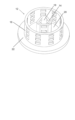
図2は、中心管14の形態の内側部と、輪郭管16の形態の外側部と、を備えるスキャフォールド12を示す。この例では、中心管14は三角形の管として示されているが、内側部は、例えば円筒形などの任意の適切な形状を有するように製造してもよい。また、この例では、輪郭管16は円筒管として示されているが、任意の適切な断面形状を有してもよい。特に、スキャフォールド12が対象となる骨に実質的に一致するようにカスタマイズされた場合、その形状および/または寸法は適切に調整してもよい。また、スキャフォールドは、二つ以上の輪郭管16、例えば、互いに内側に配置された多数の同心円筒を備えてもよい。中心管14の壁は、スキャフォールド12を通って延びる中心部のチャネル18を取り囲んでいる。内側部14と外側部16との間に環状の空洞20が画定される。輪郭管16の主な機能は、空洞20内に収容および/または成長させることができる材料を支持することである。
FIG. 2 shows a
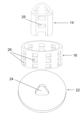
同心管14、16は、基体板22によって接続されている。図3からより明確に分かるように、基体板22は、中心部のチャネル18と一致するように形作られた、中心部の窓24を備える、概して円形のディスクである。この例では、窓24は、基体板22の材料の開口から成っている。したがって、流体は、スキャフォールド12を通って、すなわち窓24を通り中心部のチャネル18に沿って縦方向に流れることができる。基体板22は、例えば、スキャフォールド12を特定のデバイスに組み込むのに、または細胞培養プレートまたはバイオリアクターチャンバなどの意図する容器に適合するのに役立つよう、異なる直径に作製することができる。
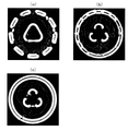
図2および図3の両方で、内管14および外管16の両方に周方向の開口26が設けられていることが分かる。開口26は、交互の層で開口している。例えば、内管14の層1および2に開口26が開口しているが外管16の層1および2は連続しており、外管16の層3および4に開口26が開口しているが内管14の層3および4は連続している。これは、図4(a)~(c)を参照すれば、より明確に理解されるかもしれない。開口26をこのように交互に配置すれば、スキャフォールド12を通した十分な半径方向の拡散が任意の所与の高さで可能であることが確実になる。また、外管16は、内管14と比較して二重壁厚で製造され得ることが図4(a)~(c)から分かる。こうすれば、外管16の機械的強度を高めるのに役立つ。開口26は、内管14および外管16のポリマー材料を積層するのに使用される積層プロセスの中断によって形成されてもよい。したがって、各開口26は、整数の製造層に対応する高さ、例えば3Dプリンタによって積層される二層分の高さを有してもよい。
It can be seen in both FIGS. 2 and 3 that both the
内管14および外管16は両方とも生体適合性ポリマー材料から作られている。内管14および外管16の両方に同じ材料を使用してもよいし、異なる機械的強度を提供するために異なる材料を使用してもよい。基体板22は、ポリマーマイクロ繊維のパターン、例えば漸進的に60度(交互に0/60/120度)の層状パターンから形成される。もちろん、繊維同士の間の角度および/または間隔を制御して、所望の多孔性の度合を設定することができる。したがって、基体板22は、内管14および外管16をつなぐと同時に、空洞20内に充填材料を収容できるメッシュを提供する。
Both
このようなスキャフォールド12において、内側のチャネル18は、血管を規定して栄養物の伝達/拡散を行うことができるので、培養基がスキャフォールド12を貫通できるようになる。内管14と外管16との間の空洞20は、例えば海綿骨を模倣する海綿構造を形成する、一つ以上の多孔性材料で充填することができる。
In such a
なお、スキャフォールド12の上部は、図示のように開いたままにしてもよいし、必要に応じて、基体板22と同様のカバー板で閉じてもよい。
It should be noted that the top of
(製造例)
Solidworks、AutoCAD、ProE、Magicsなどの標準CADソフトウェアを使用してCADモデルに記録された、カスタマイズされ再現可能な設計からスキャフォールドを作成した。この設計は、STereoLithography(STL)ファイル形式で、実際の骨の画像を参照して確認した寸法で記録された。別法として、STereoLithography(STL)ファイル形式ではなく、Addictive Manufacturing File Format(AMF)標準形式またはOBJジオメトリ形式に従って設計を記録することもできたはずである。次に、このSTLファイルを読み取り、3Dスライサーソフトウェア(Sloc3r、Bioplotter RP、Curaなど)に転送して積層構造に分割した。次に、このスライスされた各設計は、3Dプリンターなどのラピッドプロトタイピング(RP)マシンによる製造のためにRPソフトウェアに取り込んだ。
(Manufacturing example)
Scaffolds were created from customized and reproducible designs recorded in CAD models using standard CAD software such as Solidworks, AutoCAD, ProE, Magics. The design was recorded in a STereoLithography (STL) file format with dimensions confirmed by reference to images of the actual bone. Alternatively, the design could have been recorded according to the Addictive Manufacturing File Format (AMF) standard format or the OBJ geometry format rather than the StereoLithography (STL) file format. This STL file was then read and transferred to a 3D slicer software (Sloc3r, Bioplotter RP, Cura, etc.) to split into layered structures. Each sliced design was then imported into RP software for fabrication by a rapid prototyping (RP) machine, such as a 3D printer.
二つのポリエステルを使用してスキャフォールド12を製造した。内側部14は、Purac(登録商標)から注文したポリ(ラクチド-コ-カプロラクトン)のコポリマーから作った。外側部16および基体部22は、ポリラクチドから作った。ポリラクチドは、中心部のチャネル18を画定する内側部14を作るために使用するコポリマーの弾性率よりもはるかに高い弾性率を有するので、スキャフォールド12の主な耐荷重部品用として選択した。内側部14と外側部16との間の空洞20は、ゼラチン/ CNFの注入されたヒドロゲル溶液を凍結乾燥することによって製造されたナノ繊維(TEMPO酸化ナノセルロース)海綿で充填した。修正後工程および洗浄工程によって、細胞播種用のスキャフォールドを準備した。細胞培養のために、L929(線維芽細胞)を凍結乾燥したナノセルロース海綿と混合した。
細胞播種の一日後および三日後に撮影した走査型電子顕微鏡画像は、細胞の明確な付着と増殖活動を示した。図5は、スキャフォールド12での細胞培養の成長を示している。
Scanning electron microscopy images taken one day and three days after cell seeding showed clear attachment and proliferation activity of the cells. FIG. 5 shows cell culture growth on
この例では、スキャフォールド12はバイオリアクターの48ウェル・プレートに適合するように作成された。外側輪郭管16は、1.4mmの外径と5.0mmの高さを有していた。三角形の内管14は、3.5mmの辺の長さと5.0mmの同じ高さを有していた。内管14と外管16の両方の開口26は、1.5mmの長さと、0.34mmの厚さの層二つに対応する(RP機により設定されたように)0.68mmの高さを有していた。基体板22は、三角形の内管14に合うように、辺の長さが3.5mmの三角形状の、中心部の窓24を備えていた。基体板22の外径は11.4mmであった。基体板22は、厚さ0.68mm、すなわち二層分の厚さに作られていた。スキャフォールドは、特定の環境に合わせて拡大または縮小できたことが理解されよう。例えば、外径は、バイオリアクターの24ウェル・プレートに合う15mmに設定できたであろう。
In this example,
Claims (11)
第一組の一つ以上の壁に囲まれたチャネル(18)を備える内側部(14)であって、前記内側部は、実質的に中実な材料からなる無孔な構造から形成されて、前記第一組の一つ以上の壁に形成された複数の開口を備える内側部(14)と、
第二組の一つ以上の壁を備える外側部(16)であって、前記第二組の一つ以上の壁が、前記内側部(14)と前記外側部(16)との間に空洞(20)を画定する間隔を前記第一組の一つ以上の壁と前記第二組の一つ以上の壁との間に空けた状態で、前記第一組の一つ以上の壁を実質的に取り囲むように配置され、前記外側部は、実質的に中実な材料からなる無孔な構造から形成されて、前記第二組の一つ以上の壁に形成された複数の開口を備える外側部(16)と、
前記内側部(14)および前記外側部(16)をつなぎ、マイクロ繊維メッシュで構成された実質的に多孔質の材料から成る基体部(22)と、
前記内側部(14)と前記外側部(16)との間に画定された前記空洞(20)内にあり、海綿骨に類似する多孔性の充填材料と、を備える
ことを特徴とする生体組織工学用デバイス。 A tissue engineering device comprising a scaffold (12), said scaffold comprising:
an inner portion (14) comprising a first set of one or more walled channels (18), said inner portion being formed of a non-porous structure of substantially solid material; an inner portion (14) comprising a plurality of openings formed in one or more walls of said first set;
an outer portion (16) comprising a second set of one or more walls, said second set of one or more walls being hollow between said inner portion (14) and said outer portion (16); (20) between the one or more walls of the first set and the one or more walls of the second set, substantially substantially surrounding, said outer portion being formed of a substantially solid material, imperforate structure, opening a plurality of apertures formed in said second set of one or more walls; an outer portion (16) comprising ;
a base portion (22) connecting said inner portion (14) and said outer portion (16) and comprising a substantially porous material composed of a microfiber mesh;
a porous filler material resembling cancellous bone within the cavity (20) defined between the inner portion (14) and the outer portion (16). engineering device.
ことを特徴とする、請求項1に記載の生体組織工学用デバイス。 The first set of one or more walls of the inner portion (14) comprises a plurality of openings (26) arranged in the first set of layers spaced apart by a first spacing along the length of the wall. and said second set of one or more walls of said outer portion (16) define a plurality of openings (26) arranged in a second set of layers spaced apart by a second distance along the length of said wall. wherein the first set of layers are aligned with the second spacing between the second set of layers, and the second set of layers are aligned with the second spacing between the first set of layers; 2. The tissue engineering device according to claim 1, wherein the device is arranged such that the positions coincide with one interval.
ことを特徴とする、請求項1または2に記載の生体組織工学用デバイス。 The first set of one or more walls of the inner portion (14) comprises a plurality of first openings (26) and the second set of one or more walls of the outer portion (16) includes the 3. A tissue engineering device according to claim 1 or 2, characterized in that it comprises a plurality of second openings (26) formed in layers alternating with said first openings in the outer part.
ことを特徴とする、請求項1乃至請求項3のいずれかに記載の生体組織工学用デバイス。 4. A tissue engineering device according to any of the preceding claims, characterized in that the inner part (14) and the outer part (16) have different shapes.
ことを特徴とする、請求項4に記載の生体組織工学用デバイス。 4. The claim characterized in that said inner part (14) comprises a triangular channel surrounded by said first set of walls and said outer part (16) comprises a cylindrical wall surrounding said triangular channel. 5. The tissue engineering device according to 4.
ことを特徴とする、請求項1乃至請求項5のいずれかに記載の生体組織工学用デバイス。 6. The tissue engineering device of any of claims 1-5, wherein the one or more walls of the second set are thicker than the one or more walls of the first set.
ことを特徴とする、請求項1乃至請求項6のいずれかに記載の生体組織工学用デバイス。 7. Any of claims 1 to 6, characterized in that the base portion (22) extends in a plane substantially perpendicular to the inner portion (14) and/or the outer portion (16). The device for tissue engineering according to .
ことを特徴とする、請求項1乃至請求項7のいずれかに記載の生体組織工学用デバイス。 A tissue engineering device according to any preceding claim, wherein the base portion (22) has a diameter greater than the diameter of the outer portion (16).
ことを特徴とする、請求項1乃至請求項8のいずれかに記載の生体組織工学用デバイス。 9. The method of any of claims 1-8, wherein at least one of the inner portion (14) and the outer portion (16) is formed from polylactide or polycaprolactone (PCL). Devices for tissue engineering.
ことを特徴とする、請求項1乃至請求項9のいずれかに記載の生体組織工学用デバイス。 10. The tissue engineering device according to any one of claims 1 to 9, wherein the filling material comprises or consists of one or more hydrogel materials.
ことを特徴とする、請求項10に記載の生体組織工学用デバイス。 11. The tissue engineering device according to claim 10, wherein the filling material comprises cellulose nanofibril (CNF) hydrogel or nanocellulose hydrogel.
Applications Claiming Priority (3)
| Application Number | Priority Date | Filing Date | Title |
|---|---|---|---|
| GB1703832.4 | 2017-03-10 | ||
| GB1703832.4A GB2560369B (en) | 2017-03-10 | 2017-03-10 | Tissue engineering scaffolds |
| PCT/EP2018/056124 WO2018162764A1 (en) | 2017-03-10 | 2018-03-12 | Tissue engineering scaffolds |
Publications (3)
| Publication Number | Publication Date |
|---|---|
| JP2020511286A JP2020511286A (en) | 2020-04-16 |
| JP2020511286A5 JP2020511286A5 (en) | 2020-11-12 |
| JP7231570B2 true JP7231570B2 (en) | 2023-03-01 |
Family
ID=58605362
Family Applications (1)
| Application Number | Title | Priority Date | Filing Date |
|---|---|---|---|
| JP2019571105A Active JP7231570B2 (en) | 2017-03-10 | 2018-03-12 | scaffold for tissue engineering |
Country Status (9)
| Country | Link |
|---|---|
| US (1) | US11364122B2 (en) |
| EP (1) | EP3592297B1 (en) |
| JP (1) | JP7231570B2 (en) |
| CN (1) | CN110545758B (en) |
| CA (1) | CA3055688A1 (en) |
| DK (1) | DK3592297T3 (en) |
| ES (1) | ES2955779T3 (en) |
| GB (1) | GB2560369B (en) |
| WO (1) | WO2018162764A1 (en) |
Families Citing this family (2)
| Publication number | Priority date | Publication date | Assignee | Title |
|---|---|---|---|---|
| DE202019106375U1 (en) * | 2019-11-15 | 2019-11-25 | Kumovis GmbH | Orthopedic implant |
| GB2600102A (en) | 2020-10-16 | 2022-04-27 | Vestlandets Innovasjonsselskap As | Osteon templates for bone tissue engineering |
Citations (2)
| Publication number | Priority date | Publication date | Assignee | Title |
|---|---|---|---|---|
| US20040225360A1 (en) | 2000-12-14 | 2004-11-11 | Malone David G. | Devices and methods for facilitating controlled bone growth or repair |
| US20150196371A1 (en) | 2014-01-13 | 2015-07-16 | Brock B. WESTOVER | Endosseous dental implant assembly |
Family Cites Families (32)
| Publication number | Priority date | Publication date | Assignee | Title |
|---|---|---|---|---|
| US4466435A (en) * | 1981-09-04 | 1984-08-21 | Murray William M | Bone cement nozzle and method |
| GB8318483D0 (en) * | 1983-07-08 | 1983-08-10 | Zimmer Deloro Surgical Ltd | Skeletal implants |
| US5211664A (en) * | 1992-01-14 | 1993-05-18 | Forschungsinstitut, Davos Laboratorium Fur Experimentelle Chirugie | Shell structure for bone replacement |
| CA2126627C (en) * | 1993-07-06 | 2005-01-25 | Kim C. Bertin | Femoral milling instrumentation for use in total knee arthroplasty with optional cutting guide attachment |
| US5503558A (en) * | 1993-11-12 | 1996-04-02 | Mcgill University | Osseointegration promoting implant composition, implant assembly and method therefor |
| DE19738052C2 (en) * | 1997-09-01 | 2003-12-04 | Pina Vertriebs Ag Neuhausen | Spinal insert body |
| AU1822799A (en) * | 1997-12-18 | 1999-07-05 | Abbeymoor Medical, Inc. | Urethral apparatus with high flow valve and methods of use ther eof |
| EP1053002A1 (en) | 1998-02-10 | 2000-11-22 | Oregon Health Sciences University | Treatment of bony defects with osteoblast precursor cells |
| US6530956B1 (en) * | 1998-09-10 | 2003-03-11 | Kevin A. Mansmann | Resorbable scaffolds to promote cartilage regeneration |
| US20070021697A1 (en) * | 2004-07-26 | 2007-01-25 | Kci Licensing, Inc. | System and method for use of agent in combination with subatmospheric tissue treatment |
| US6866682B1 (en) * | 1999-09-02 | 2005-03-15 | Stryker Spine | Distractable corpectomy device |
| US6730252B1 (en) | 2000-09-20 | 2004-05-04 | Swee Hin Teoh | Methods for fabricating a filament for use in tissue engineering |
| JP2002306518A (en) | 2000-12-21 | 2002-10-22 | Yuichi Mori | Indwelling implement |
| CA2442855A1 (en) | 2001-04-12 | 2002-10-24 | Therics, Inc. | Method and apparatus for engineered regenerative biostructures |
| US6783547B2 (en) * | 2002-04-05 | 2004-08-31 | Howmedica Corp. | Apparatus for fusing adjacent bone structures |
| US8684734B1 (en) * | 2003-02-27 | 2014-04-01 | Philip Scott Lyren | Dental implant with porous body |
| ES2569853T3 (en) | 2003-06-25 | 2016-05-12 | Biedermann Technologies Gmbh & Co. Kg | Tissue integration design for fixing implants without welding |
| DE102005061932A1 (en) | 2005-12-23 | 2007-07-05 | Biedermann Motech Gmbh | Placeholder for implantation to the human vertebrae has three tubular bodies having different lengths and diameters that are inserted and connected to each other by pins so that they project over the edges of the next larger tubular body |
| US9327056B2 (en) | 2006-02-14 | 2016-05-03 | Washington State University | Bone replacement materials |
| US8275594B2 (en) * | 2006-10-30 | 2012-09-25 | The Regents Of The University Of Michigan | Engineered scaffolds for intervertebral disc repair and regeneration and for articulating joint repair and regeneration |
| WO2008106625A2 (en) | 2007-02-28 | 2008-09-04 | University Of Notre Dame Du Lac | Porous composite biomaterials and related methods |
| SG195588A1 (en) * | 2008-10-17 | 2013-12-30 | Univ Singapore | Resorbable scaffolds for bone repair and long bone tissue engineering |
| GB201003656D0 (en) * | 2010-03-05 | 2010-04-21 | Tigenix Ltd | Fabrication process |
| CA2829196A1 (en) * | 2010-03-08 | 2011-09-15 | Conventus Orthopaedics, Inc. | Apparatus and methods for bone repair |
| CN201624812U (en) | 2010-03-12 | 2010-11-10 | 张纯朴 | Segmental bone defect auxiliary bone grafting support |
| US20130029412A1 (en) * | 2010-04-15 | 2013-01-31 | Christian Reis | Cell culture system |
| WO2014144488A1 (en) | 2013-03-15 | 2014-09-18 | The George Washington University, A Congressionally Chartered Not-For-Profit Corporation | 3d biomimetic, bi-phasic key featured scaffold for osteochondral repair |
| JP2015016276A (en) * | 2013-07-10 | 2015-01-29 | 株式会社カタリメディック | Filling jig for artificial bone granule |
| US9925046B2 (en) | 2015-03-31 | 2018-03-27 | DePuy Synthes Products, Inc. | Bone graft cage |
| CN114949368A (en) | 2015-08-17 | 2022-08-30 | 约翰·霍普金斯大学 | Fiber-hydrogel composite surgical mesh for tissue repair |
| CN205181975U (en) * | 2015-12-17 | 2016-04-27 | 王兆军 | Cardiovascular expansion device |
| CN205626200U (en) * | 2016-03-07 | 2016-10-12 | 天津京都贝思达生物技术有限公司 | Ankle joint |
-
2017
- 2017-03-10 GB GB1703832.4A patent/GB2560369B/en active Active
-
2018
- 2018-03-12 US US16/492,504 patent/US11364122B2/en active Active
- 2018-03-12 CA CA3055688A patent/CA3055688A1/en active Pending
- 2018-03-12 CN CN201880026876.XA patent/CN110545758B/en active Active
- 2018-03-12 JP JP2019571105A patent/JP7231570B2/en active Active
- 2018-03-12 ES ES18711088T patent/ES2955779T3/en active Active
- 2018-03-12 DK DK18711088.7T patent/DK3592297T3/en active
- 2018-03-12 WO PCT/EP2018/056124 patent/WO2018162764A1/en active Application Filing
- 2018-03-12 EP EP18711088.7A patent/EP3592297B1/en active Active
Patent Citations (2)
| Publication number | Priority date | Publication date | Assignee | Title |
|---|---|---|---|---|
| US20040225360A1 (en) | 2000-12-14 | 2004-11-11 | Malone David G. | Devices and methods for facilitating controlled bone growth or repair |
| US20150196371A1 (en) | 2014-01-13 | 2015-07-16 | Brock B. WESTOVER | Endosseous dental implant assembly |
Also Published As
| Publication number | Publication date |
|---|---|
| WO2018162764A1 (en) | 2018-09-13 |
| CN110545758A (en) | 2019-12-06 |
| GB2560369B (en) | 2020-04-01 |
| EP3592297B1 (en) | 2023-08-16 |
| US11364122B2 (en) | 2022-06-21 |
| ES2955779T3 (en) | 2023-12-07 |
| GB2560369A (en) | 2018-09-12 |
| CA3055688A1 (en) | 2018-09-13 |
| JP2020511286A (en) | 2020-04-16 |
| GB201703832D0 (en) | 2017-04-26 |
| CN110545758B (en) | 2022-08-09 |
| US20200261230A1 (en) | 2020-08-20 |
| EP3592297A1 (en) | 2020-01-15 |
| DK3592297T3 (en) | 2023-09-25 |
Similar Documents
| Publication | Publication Date | Title |
|---|---|---|
| Kumar et al. | Biocompatibility and mechanical behaviour of three-dimensional scaffolds for biomedical devices: process–structure–property paradigm | |
| Orciani et al. | Biofabrication and bone tissue regeneration: cell source, approaches, and challenges | |
| Giannitelli et al. | Combined additive manufacturing approaches in tissue engineering | |
| Schieker et al. | Biomaterials as scaffold for bone tissue engineering | |
| Mellor et al. | Fabrication and evaluation of electrospun, 3D-bioplotted, and combination of electrospun/3D-bioplotted scaffolds for tissue engineering applications | |
| US7968026B1 (en) | Three-dimensional bioresorbable scaffolds for tissue engineering applications | |
| Das et al. | Freeform fabrication of Nylon‐6 tissue engineering scaffolds | |
| Zhou et al. | Recent advances in additive manufacturing technology for bone tissue engineering scaffolds | |
| Ricci et al. | Three-dimensional printing of bone repair and replacement materials: impact on craniofacial surgery | |
| US20090148489A1 (en) | Bioabsorbable material | |
| Zhang et al. | 3D printing method for bone tissue engineering scaffold | |
| Shaunak et al. | The role of 3D modelling and printing in orthopaedic tissue engineering: a review of the current literature | |
| Masaeli et al. | Challenges in three-dimensional printing of bone substitutes | |
| Ravoor et al. | Comprehensive review on design and manufacturing of bio-scaffolds for bone reconstruction | |
| JP7231570B2 (en) | scaffold for tissue engineering | |
| McMillan et al. | 3D bioprinting in otolaryngology: A review | |
| Lu et al. | Novel structural designs of 3D-printed osteogenic graft for rapid angiogenesis | |
| Altunbek et al. | Design and 3D printing of personalized hybrid and gradient structures for critical size bone defects | |
| Basu et al. | Three dimensional porous scaffolds: mechanical and biocompatibility properties | |
| US20230390462A1 (en) | Osteon templates for bone tissue engineering | |
| Fernandes et al. | Biopolymer‐based scaffolds for bone and tissue engineering | |
| Foerster et al. | Current market for biomedical implants | |
| Sapkall et al. | Rapid prototyping assisted scaffold fabrication for bone tissue regeneration | |
| Raza et al. | 3D Printed Biomaterials and their Scaffolds for Biomedical Engineering | |
| Netti et al. | Multifunctional polymer based structures for human tissues reconstruction |
Legal Events
| Date | Code | Title | Description |
|---|---|---|---|
| A521 | Request for written amendment filed |
Free format text: JAPANESE INTERMEDIATE CODE: A523 Effective date: 20200219 |
|
| A521 | Request for written amendment filed |
Free format text: JAPANESE INTERMEDIATE CODE: A523 Effective date: 20200930 |
|
| A621 | Written request for application examination |
Free format text: JAPANESE INTERMEDIATE CODE: A621 Effective date: 20200930 |
|
| A977 | Report on retrieval |
Free format text: JAPANESE INTERMEDIATE CODE: A971007 Effective date: 20210922 |
|
| A131 | Notification of reasons for refusal |
Free format text: JAPANESE INTERMEDIATE CODE: A131 Effective date: 20211005 |
|
| A601 | Written request for extension of time |
Free format text: JAPANESE INTERMEDIATE CODE: A601 Effective date: 20211223 |
|
| A521 | Request for written amendment filed |
Free format text: JAPANESE INTERMEDIATE CODE: A523 Effective date: 20220302 |
|
| A131 | Notification of reasons for refusal |
Free format text: JAPANESE INTERMEDIATE CODE: A131 Effective date: 20220405 |
|
| A521 | Request for written amendment filed |
Free format text: JAPANESE INTERMEDIATE CODE: A523 Effective date: 20220628 |
|
| A02 | Decision of refusal |
Free format text: JAPANESE INTERMEDIATE CODE: A02 Effective date: 20220816 |
|
| A521 | Request for written amendment filed |
Free format text: JAPANESE INTERMEDIATE CODE: A523 Effective date: 20221214 |
|
| C60 | Trial request (containing other claim documents, opposition documents) |
Free format text: JAPANESE INTERMEDIATE CODE: C60 Effective date: 20221214 |
|
| A521 | Request for written amendment filed |
Free format text: JAPANESE INTERMEDIATE CODE: A523 Effective date: 20221221 |
|
| A911 | Transfer to examiner for re-examination before appeal (zenchi) |
Free format text: JAPANESE INTERMEDIATE CODE: A911 Effective date: 20230117 |
|
| C21 | Notice of transfer of a case for reconsideration by examiners before appeal proceedings |
Free format text: JAPANESE INTERMEDIATE CODE: C21 Effective date: 20230124 |
|
| TRDD | Decision of grant or rejection written | ||
| A01 | Written decision to grant a patent or to grant a registration (utility model) |
Free format text: JAPANESE INTERMEDIATE CODE: A01 Effective date: 20230207 |
|
| A61 | First payment of annual fees (during grant procedure) |
Free format text: JAPANESE INTERMEDIATE CODE: A61 Effective date: 20230216 |
|
| R150 | Certificate of patent or registration of utility model |
Ref document number: 7231570 Country of ref document: JP Free format text: JAPANESE INTERMEDIATE CODE: R150 |