JP7229560B2 - Sensor for automatic door control - Google Patents
Sensor for automatic door control Download PDFInfo
- Publication number
- JP7229560B2 JP7229560B2 JP2020504444A JP2020504444A JP7229560B2 JP 7229560 B2 JP7229560 B2 JP 7229560B2 JP 2020504444 A JP2020504444 A JP 2020504444A JP 2020504444 A JP2020504444 A JP 2020504444A JP 7229560 B2 JP7229560 B2 JP 7229560B2
- Authority
- JP
- Japan
- Prior art keywords
- evaluation
- sensor
- unit
- human body
- information
- Prior art date
- Legal status (The legal status is an assumption and is not a legal conclusion. Google has not performed a legal analysis and makes no representation as to the accuracy of the status listed.)
- Active
Links
- 238000011156 evaluation Methods 0.000 claims description 84
- 238000001514 detection method Methods 0.000 claims description 29
- 238000012545 processing Methods 0.000 claims description 16
- 230000033001 locomotion Effects 0.000 claims description 15
- 238000005259 measurement Methods 0.000 claims description 6
- 238000009825 accumulation Methods 0.000 claims description 4
- 238000000034 method Methods 0.000 description 13
- 230000002123 temporal effect Effects 0.000 description 12
- 238000010586 diagram Methods 0.000 description 8
- 230000005484 gravity Effects 0.000 description 6
- 241000282412 Homo Species 0.000 description 4
- 230000010354 integration Effects 0.000 description 4
- 238000009795 derivation Methods 0.000 description 2
- 238000011161 development Methods 0.000 description 2
- 238000000926 separation method Methods 0.000 description 2
- 230000005540 biological transmission Effects 0.000 description 1
- 230000003592 biomimetic effect Effects 0.000 description 1
- 230000001186 cumulative effect Effects 0.000 description 1
- 238000012544 monitoring process Methods 0.000 description 1
- PICXIOQBANWBIZ-UHFFFAOYSA-N zinc;1-oxidopyridine-2-thione Chemical class [Zn+2].[O-]N1C=CC=CC1=S.[O-]N1C=CC=CC1=S PICXIOQBANWBIZ-UHFFFAOYSA-N 0.000 description 1
Images


Classifications
-
- G—PHYSICS
- G01—MEASURING; TESTING
- G01S—RADIO DIRECTION-FINDING; RADIO NAVIGATION; DETERMINING DISTANCE OR VELOCITY BY USE OF RADIO WAVES; LOCATING OR PRESENCE-DETECTING BY USE OF THE REFLECTION OR RERADIATION OF RADIO WAVES; ANALOGOUS ARRANGEMENTS USING OTHER WAVES
- G01S17/00—Systems using the reflection or reradiation of electromagnetic waves other than radio waves, e.g. lidar systems
- G01S17/02—Systems using the reflection of electromagnetic waves other than radio waves
- G01S17/06—Systems determining position data of a target
- G01S17/42—Simultaneous measurement of distance and other co-ordinates
-
- E—FIXED CONSTRUCTIONS
- E05—LOCKS; KEYS; WINDOW OR DOOR FITTINGS; SAFES
- E05F—DEVICES FOR MOVING WINGS INTO OPEN OR CLOSED POSITION; CHECKS FOR WINGS; WING FITTINGS NOT OTHERWISE PROVIDED FOR, CONCERNED WITH THE FUNCTIONING OF THE WING
- E05F15/00—Power-operated mechanisms for wings
- E05F15/40—Safety devices, e.g. detection of obstructions or end positions
- E05F15/42—Detection using safety edges
- E05F15/43—Detection using safety edges responsive to disruption of energy beams, e.g. light or sound
-
- E—FIXED CONSTRUCTIONS
- E05—LOCKS; KEYS; WINDOW OR DOOR FITTINGS; SAFES
- E05F—DEVICES FOR MOVING WINGS INTO OPEN OR CLOSED POSITION; CHECKS FOR WINGS; WING FITTINGS NOT OTHERWISE PROVIDED FOR, CONCERNED WITH THE FUNCTIONING OF THE WING
- E05F15/00—Power-operated mechanisms for wings
- E05F15/70—Power-operated mechanisms for wings with automatic actuation
- E05F15/73—Power-operated mechanisms for wings with automatic actuation responsive to movement or presence of persons or objects
- E05F15/74—Power-operated mechanisms for wings with automatic actuation responsive to movement or presence of persons or objects using photoelectric cells
-
- G—PHYSICS
- G01—MEASURING; TESTING
- G01S—RADIO DIRECTION-FINDING; RADIO NAVIGATION; DETERMINING DISTANCE OR VELOCITY BY USE OF RADIO WAVES; LOCATING OR PRESENCE-DETECTING BY USE OF THE REFLECTION OR RERADIATION OF RADIO WAVES; ANALOGOUS ARRANGEMENTS USING OTHER WAVES
- G01S17/00—Systems using the reflection or reradiation of electromagnetic waves other than radio waves, e.g. lidar systems
- G01S17/02—Systems using the reflection of electromagnetic waves other than radio waves
- G01S17/50—Systems of measurement based on relative movement of target
- G01S17/58—Velocity or trajectory determination systems; Sense-of-movement determination systems
-
- G—PHYSICS
- G01—MEASURING; TESTING
- G01S—RADIO DIRECTION-FINDING; RADIO NAVIGATION; DETERMINING DISTANCE OR VELOCITY BY USE OF RADIO WAVES; LOCATING OR PRESENCE-DETECTING BY USE OF THE REFLECTION OR RERADIATION OF RADIO WAVES; ANALOGOUS ARRANGEMENTS USING OTHER WAVES
- G01S17/00—Systems using the reflection or reradiation of electromagnetic waves other than radio waves, e.g. lidar systems
- G01S17/88—Lidar systems specially adapted for specific applications
-
- G—PHYSICS
- G01—MEASURING; TESTING
- G01S—RADIO DIRECTION-FINDING; RADIO NAVIGATION; DETERMINING DISTANCE OR VELOCITY BY USE OF RADIO WAVES; LOCATING OR PRESENCE-DETECTING BY USE OF THE REFLECTION OR RERADIATION OF RADIO WAVES; ANALOGOUS ARRANGEMENTS USING OTHER WAVES
- G01S7/00—Details of systems according to groups G01S13/00, G01S15/00, G01S17/00
- G01S7/48—Details of systems according to groups G01S13/00, G01S15/00, G01S17/00 of systems according to group G01S17/00
- G01S7/4802—Details of systems according to groups G01S13/00, G01S15/00, G01S17/00 of systems according to group G01S17/00 using analysis of echo signal for target characterisation; Target signature; Target cross-section
-
- G—PHYSICS
- G01—MEASURING; TESTING
- G01S—RADIO DIRECTION-FINDING; RADIO NAVIGATION; DETERMINING DISTANCE OR VELOCITY BY USE OF RADIO WAVES; LOCATING OR PRESENCE-DETECTING BY USE OF THE REFLECTION OR RERADIATION OF RADIO WAVES; ANALOGOUS ARRANGEMENTS USING OTHER WAVES
- G01S7/00—Details of systems according to groups G01S13/00, G01S15/00, G01S17/00
- G01S7/48—Details of systems according to groups G01S13/00, G01S15/00, G01S17/00 of systems according to group G01S17/00
- G01S7/481—Constructional features, e.g. arrangements of optical elements
- G01S7/4814—Constructional features, e.g. arrangements of optical elements of transmitters alone
-
- E—FIXED CONSTRUCTIONS
- E05—LOCKS; KEYS; WINDOW OR DOOR FITTINGS; SAFES
- E05F—DEVICES FOR MOVING WINGS INTO OPEN OR CLOSED POSITION; CHECKS FOR WINGS; WING FITTINGS NOT OTHERWISE PROVIDED FOR, CONCERNED WITH THE FUNCTIONING OF THE WING
- E05F15/00—Power-operated mechanisms for wings
- E05F15/40—Safety devices, e.g. detection of obstructions or end positions
- E05F15/42—Detection using safety edges
- E05F15/43—Detection using safety edges responsive to disruption of energy beams, e.g. light or sound
- E05F2015/434—Detection using safety edges responsive to disruption of energy beams, e.g. light or sound with cameras or optical sensors
-
- E—FIXED CONSTRUCTIONS
- E05—LOCKS; KEYS; WINDOW OR DOOR FITTINGS; SAFES
- E05F—DEVICES FOR MOVING WINGS INTO OPEN OR CLOSED POSITION; CHECKS FOR WINGS; WING FITTINGS NOT OTHERWISE PROVIDED FOR, CONCERNED WITH THE FUNCTIONING OF THE WING
- E05F15/00—Power-operated mechanisms for wings
- E05F15/70—Power-operated mechanisms for wings with automatic actuation
- E05F15/73—Power-operated mechanisms for wings with automatic actuation responsive to movement or presence of persons or objects
- E05F2015/765—Power-operated mechanisms for wings with automatic actuation responsive to movement or presence of persons or objects using optical sensors
-
- E—FIXED CONSTRUCTIONS
- E05—LOCKS; KEYS; WINDOW OR DOOR FITTINGS; SAFES
- E05Y—INDEXING SCHEME ASSOCIATED WITH SUBCLASSES E05D AND E05F, RELATING TO CONSTRUCTION ELEMENTS, ELECTRIC CONTROL, POWER SUPPLY, POWER SIGNAL OR TRANSMISSION, USER INTERFACES, MOUNTING OR COUPLING, DETAILS, ACCESSORIES, AUXILIARY OPERATIONS NOT OTHERWISE PROVIDED FOR, APPLICATION THEREOF
- E05Y2400/00—Electronic control; Electrical power; Power supply; Power or signal transmission; User interfaces
- E05Y2400/10—Electronic control
- E05Y2400/44—Sensors not directly associated with the wing movement
-
- E—FIXED CONSTRUCTIONS
- E05—LOCKS; KEYS; WINDOW OR DOOR FITTINGS; SAFES
- E05Y—INDEXING SCHEME ASSOCIATED WITH SUBCLASSES E05D AND E05F, RELATING TO CONSTRUCTION ELEMENTS, ELECTRIC CONTROL, POWER SUPPLY, POWER SIGNAL OR TRANSMISSION, USER INTERFACES, MOUNTING OR COUPLING, DETAILS, ACCESSORIES, AUXILIARY OPERATIONS NOT OTHERWISE PROVIDED FOR, APPLICATION THEREOF
- E05Y2900/00—Application of doors, windows, wings or fittings thereof
- E05Y2900/10—Application of doors, windows, wings or fittings thereof for buildings or parts thereof
- E05Y2900/13—Type of wing
- E05Y2900/132—Doors
Landscapes
- Physics & Mathematics (AREA)
- Engineering & Computer Science (AREA)
- Electromagnetism (AREA)
- Computer Networks & Wireless Communication (AREA)
- General Physics & Mathematics (AREA)
- Radar, Positioning & Navigation (AREA)
- Remote Sensing (AREA)
- Optical Radar Systems And Details Thereof (AREA)
- Geophysics And Detection Of Objects (AREA)
- Power-Operated Mechanisms For Wings (AREA)
- Length Measuring Devices By Optical Means (AREA)
Description
本発明は、請求項1の前提部分に記載の自動ドアを制御するためのセンサに関する。
The present invention relates to a sensor for controlling automatic doors according to the preamble of
自動ドアを制御するためのセンサは、そのレーザカーテンの所定の検出領域内の物体の存在を検出するためのレーザスキャナを備えるとともに、存在検出信号が供給される存在検出出力ポートを備える。これは、ドアの安全な動作を可能にする。レーザスキャナは、「飛行時間」技術を用いた距離測定によって反射点を導出する。 A sensor for controlling an automatic door includes a laser scanner for detecting the presence of an object within a predetermined detection area of the laser curtain and includes a presence detection output port to which a presence detection signal is supplied. This allows safe operation of the door. A laser scanner derives the reflection point by distance measurement using a "time of flight" technique.
このようなドアセンサは、通常人間である通過物体の挙動に関して最適化される。 Such door sensors are optimized for the behavior of passing objects, usually humans.
この技術に従って、ニシダダイキ他,“インテリジェント自動ドアシステムの開発”,2004年、ロボットおよび自動化に関するIEEE国際会議,2014年5月31日,第6368~6374頁は、速度と方向の評価を制御決定に含めたインテリジェントドアセンサを開示している。 According to this technology, Nishida Daiki et al., “Development of Intelligent Automatic Door Systems”, 2004, IEEE International Conference on Robots and Automation, May 31, 2014, pp. 6368-6374, proposes that the evaluation of speed and direction be applied to control decisions. discloses an intelligent door sensor that includes:
ドア制御センサに加えて、人を検出するためのセンサ、すなわち検出物体が人であるか否かを判定(評価)するセンサが知られている。 In addition to door control sensors, sensors are known for detecting people, i.e. sensors that determine (evaluate) whether a detected object is a person or not.
アカマツシュンイチ他,“3Dレーザスキャナを用いた人計数システムの開発”,2014年 ロボットおよびバイオミメティックに関するIEEE国際会議,IEEE,2014年12月5日,第1983~1988頁には、単に、人を計数するためのレーザスキャナが開示されている。計数アプリケーションは、自動ドアを制御するための存在検出に供しない人に限定される。 Shunichi Akamatsu et al., "Development of People Counting System Using 3D Laser Scanner", 2014 IEEE International Conference on Robots and Biomimetics, IEEE, December 5, 2014, pp. 1983-1988, simply A laser scanner for counting is disclosed. Counting applications are limited to persons not subject to presence detection to control automatic doors.
また、国際公開第2012/042043号パンフレットは、レーザスキャナに基づくアクセス制御システムを適用するための人検出部を開示している。システムは、例えば、2人以上の人が同時にドアに入ろうとする場合、アクセスを禁止する。 Also, WO2012/042043 discloses a human detector for applying an access control system based on a laser scanner. The system, for example, prohibits access if more than one person attempts to enter the door at the same time.
本発明の目的は、より具体的な挙動を可能にするために、センサの制御可能性を改善することである。 The aim of the invention is to improve the controllability of the sensor in order to allow more specific behavior.
上記課題は、請求項1の特徴によって解決される。
This problem is solved by the features of
公知の方法では、走査フィールドの所定の検出領域内の物体の存在を検出するためのドアセンサは、少なくとも1つのレーザカーテンを用いるレーザスキャナを備える。センサは、飛行時間の算出(評価)によって物体から反射したレーザスキャナのレーザ光の反射点の距離を取得するように構成された距離データ取得部を備える。 In a known manner a door sensor for detecting the presence of an object within a predetermined detection area of the scanning field comprises a laser scanner using at least one laser curtain. The sensor comprises a distance data acquisition unit configured to acquire the distance of the reflection point of the laser light of the laser scanner reflected from the object by calculating (evaluating) the time of flight.
センサは、距離データ取得部の結果としての距離データ情報を受け取る存在検出部をさらに備える。距離データ取得部は、距離データ情報を存在検出部に送出する。存在検出部は、距離データを分析することによって、所定の検出領域内で物体が検出されたかどうかを判定(評価)する。存在検出部は、少なくとも1つのセンサ出力ポートに供給される存在検出情報を生成するように構成される。通常、この信号は、安全目的のためにドアコントローラによって使用される。 The sensor further comprises a presence detector for receiving range data information as a result of the range data acquisition section. The distance data acquisition unit sends distance data information to the presence detection unit. The presence detector determines (evaluates) whether an object has been detected within a predetermined detection area by analyzing the range data. The presence detector is configured to generate presence detection information that is provided to the at least one sensor output port. This signal is typically used by the door controller for safety purposes.
本発明によれば、センサは、人体判定部を含む物体情報部をさらに備える。物体情報部は、距離データを受け取る。人体判定部は、距離データを用いて、検出物体が人体であるかどうかを判定する。物体情報部は、少なくとも1つの出力ポートに供給される物体情報を生成する。 According to the invention, the sensor further comprises an object information part including a human body determination part. The object information unit receives distance data. The human body determination unit uses the distance data to determine whether the detected object is a human body. The object information unit generates object information that is supplied to at least one output port.
好ましくは、存在検出部の信号は、リアルタイムで処理され、人体判定部の結果は、距離データの累積に基づく。例えば、存在検出信号は、90ms未満の応答時間を有することができる。センサは、10cm未満の物体を検出可能である。 Preferably, the signals of the presence detector are processed in real time and the results of the human body determiner are based on accumulation of distance data. For example, the presence detection signal can have a response time of less than 90ms. The sensor is capable of detecting objects less than 10 cm.
収集された追加の情報によれば、ドアコントローラは、人体の存在および非人体の存在を検出することによって、異なって動作することができる。 With the additional information gathered, the door controller can operate differently by detecting the presence of humans and the presence of non-humans.
本発明のさらなる態様によれば、物体情報部は、センサによって検出された人体の数を計数する計数部を備えることができ、その結果、計数情報を出力ポートに提供することができる。 According to a further aspect of the invention, the object information section may comprise a counting section for counting the number of human bodies detected by the sensor so that counting information may be provided to the output port.
自動ドアの制御および/または安全保障のために不可欠な基本情報に加えて、計数情報のようなさらなる追加情報を、ドアを制御するために使用することができる。例えば、ある数の人体が入った後にドアを閉じたままにすることができる。追加の情報は、統計的目的のために導出することができる。 In addition to the essential basic information for automatic door control and/or security, further additional information such as counting information can be used to control the door. For example, the door can be kept closed after a certain number of bodies have entered. Additional information can be derived for statistical purposes.
さらに、レーザスキャナは、複数のレーザカーテンを生成することができる。また、物体情報部は、動きを検出するための、より特定的には、物体の移動方向を判別するための動き検出部を備える。 Additionally, the laser scanner can generate multiple laser curtains. The object information unit also includes a motion detection unit for detecting motion, more particularly for determining the moving direction of the object.
この物体情報は、自動ドアを制御するために使用することができ、例えば、接近する物体が検出されると、ドアを開放することができる。したがって、物体情報は、物体の種類とは無関係に、ある種の接近信号を少なくとも1つの出力ポートに送ることができる。 This object information can be used to control automatic doors, for example, opening a door when an approaching object is detected. Therefore, the object information can send some kind of proximity signal to at least one output port regardless of the type of object.
これに加えて、物体が人体であるかどうかの情報およびその方向の情報を導出することによって、より正確な計数を行うことができる。この場合の選択肢によれば、最終的なカウント値は、特定の方向に定義することができる。 In addition to this, more accurate counting can be performed by deriving information on whether the object is a human body and information on its orientation. According to the option in this case, the final count value can be defined in a specific direction.
本発明の一実施形態によれば、センサは、出力ポートを含み、存在検出情報と物体情報とが、同一の(共通の)少なくとも1つの出力ポートに供給される。CANまたはLONバスは、両方の種類の情報をサポートするための適切な出力ポートであり得る。 According to one embodiment of the invention, the sensor includes output ports, and presence detection information and object information are fed to the same (common) at least one output port. A CAN or LON bus may be suitable output ports to support both types of information.
本発明のさらなる態様では、センサは、少なくとも2つの別個の出力ポートを備える。第1の出力ポートが存在検出情報専用であり、第2の出力ポートが物体情報専用である。第1の出力ポートは、リレー出力を含み、第2の出力ポートは、例えばイーサネット(登録商標)プロトコルに基づくことができる。 In a further aspect of the invention, the sensor comprises at least two separate output ports. A first output port is dedicated to presence detection information and a second output port is dedicated to object information. A first output port includes a relay output and a second output port can be based on the Ethernet protocol, for example.
人体判定部は、マイクロプロセッサなどの処理部において、コンピュータで実行される方法として具現化されてもよい。処理部は、例えば、コンピュータで実行される手順を実行し、更なるユニットであるプログラムの部分を含んでもよい。 The body determiner may be embodied as a computer-implemented method in a processor such as a microprocessor. The processing unit may, for example, carry out computer-implemented procedures and may include parts of programs that are further units.
測定された反射点の距離に基づいて人体を判定する方法は、以下に詳細に説明される。 A method for determining the human body based on the measured distance of the reflection points is described in detail below.
人体判定部は、反射点の距離情報をパルス光の方向と組み合わせて監視領域内の位置を特定する評価部を備える。評価部は、高さに関するZ軸と、Z軸に垂直であってレーザカーテンの横方向における幅に関する幅軸とを有する評価面(評価平面)において、検出物体に帰属する反射点を組み合わせる。 The human body determination unit includes an evaluation unit that combines the distance information of the reflection point with the direction of the pulsed light to specify the position within the monitoring area. The evaluation unit combines the reflection points belonging to the detection object in an evaluation plane (evaluation plane) having a Z axis for the height and a width axis for the lateral width of the laser curtain perpendicular to the Z axis.
本発明に従えば、評価面は、Z軸に沿った反射点の密度分布に基づいて分析(評価)され、分析結果が、評価部によって人体計測パラメータと比較される。 According to the present invention, the evaluation surface is analyzed (evaluated) based on the density distribution of reflection points along the Z-axis, and the analysis results are compared with the anthropometric parameters by the evaluation unit.
監視領域は、レーザカーテンによって画定され、垂直高さ方向と、2つの横方向すなわち奥行き方向および幅方向とを有し、これらはすべて互いに垂直である。単一の垂直レーザカーテンの場合、監視領域の奥行きは、レーザカーテンの奥行きに等しい。 The monitored area is defined by the laser curtain and has a vertical height dimension and two lateral dimensions, depth and width, which are all perpendicular to each other. For a single vertical laser curtain, the depth of the monitored area is equal to the depth of the laser curtain.
評価面は、垂直面の垂直軸に一致するZ軸、および/または、監視領域の幅に一致する評価幅範囲を有していてもよい。なお、Z軸は、例えば、垂直方向に対して傾斜したレーザカーテンに沿って定められてもよいが、この場合であっても、幅は、依然としてレーザカーテンの幅に相当していてもよい。 The evaluation plane may have a Z-axis that coincides with the vertical axis of the vertical plane and/or an evaluation width range that coincides with the width of the monitored area. It should be noted that the Z-axis may, for example, be defined along the laser curtain inclined with respect to the vertical direction, but even then the width may still correspond to the width of the laser curtain.
本発明による人体計測パラメータは、人体計測値および/または人体比率である。 Anthropometric parameters according to the present invention are anthropometric values and/or anthropometry.
人体計測パラメータは、特に、高さ、幅、肩幅、肩高さ、頭部幅、人体の全体高さに関するパラメータである。 Anthropometric parameters are in particular parameters relating to height, width, shoulder width, shoulder height, head width and overall height of the human body.
評価部は、評価面内の密度分布に基づいて、密度分布が人体の密度分布に対応しているか否かを判定する。 The evaluation unit determines whether or not the density distribution corresponds to the density distribution of the human body, based on the density distribution within the evaluation plane.
検出物体が人体であるかどうかを判定するために、検出物体の高さを表すZ軸に沿った密度分布が算出される。人体に対応する密度分布は、2つのピークを含む。1つのピークは、ほぼ頭の頂部にあり、もう一つのピークは、ほぼ肩の頂部にある。 To determine whether the detected object is a human body, a density distribution along the Z-axis representing the height of the detected object is calculated. The density distribution corresponding to the human body contains two peaks. One peak is approximately at the top of the head and the other peak is approximately at the top of the shoulder.
上記判定において、好ましくは、肩高さに対する頭高さの比率を判定(算出)する。頭と肩の高さの比は、全ての人間に対して本質的に等しく、とりわけ絶対的な高さに依存しない人体計測パラメータであるので、密度分布の判定(評価)によって、信頼性高く、人の識別を行うことができる。 In the determination, preferably, the ratio of head height to shoulder height is determined (calculated). Since the head-to-shoulder height ratio is an anthropometric parameter that is essentially equal for all humans and above all independent of absolute height, the determination (evaluation) of the density distribution provides a reliable, A person can be identified.
密度分布に加えて、評価部は、さらなるステップにおいて物体の幅を判定(算出)してもよい。この場合、評価部は、評価面において対象物に帰属し、密度分布のピークの位置にある反射点を分析し、人体の頭部および肩の有効幅を判定する。 In addition to the density distribution, the evaluator may determine (calculate) the width of the object in a further step. In this case, the evaluation unit analyzes reflection points that belong to the object in the evaluation plane and are located at the peaks of the density distribution, and determine the effective width of the head and shoulders of the human body.
この情報を統合することにより、より正確な方法で(人体か否かの)判定を行うことが可能となる。有効な頭部および肩の幅の比率を予め定め、密度分布の判定から導出される結果と一致するかどうかチェックしてもよい。その結果を密度判定の結果と比較することができる。両方の判定が肯定的である場合、検出物体は人体である可能性が非常に高い。 By integrating this information, it becomes possible to make a determination (whether it is a human body or not) in a more accurate manner. A valid head-to-shoulder width ratio may be predetermined and checked for agreement with the results derived from the determination of the density distribution. The results can be compared with the results of the density determination. If both determinations are positive, it is very likely that the detected object is a human body.
また、評価部は、密度分布判定によるピークゾーン内の反射点の数をカウントしてもよい。カウント数が所定の数よりも小さい場合、計測は無視される。 Also, the evaluation unit may count the number of reflection points in the peak zone based on the density distribution determination. If the count number is less than the predetermined number, the measurement is ignored.
人体の移動は、移動方向に行われ、ここで、移動方向は、基本的に、幅および奥行きのベクトルである。特にドア用途では、移動方向は幅方向に垂直であり、したがって、人体の肩の向きは、通常、幅方向に揃えられる。 Movement of the human body takes place in the direction of movement, where the direction of movement is essentially a vector of width and depth. Particularly in door applications, the direction of movement is perpendicular to the width direction, so the shoulder orientation of the human body is usually aligned with the width direction.
本発明によれば、評価面の全ての反射点の中から個々の評価対象物を識別することができる。また、反射点の部分集合(サブセット)が評価対象物ごとに生成され、この部分集合が、密度分布解析に供される。 According to the present invention, individual evaluation objects can be identified among all reflection points on the evaluation surface. Also, a subset of reflection points is generated for each evaluation object, and this subset is subjected to density distribution analysis.
これによって、評価対象物ごとに、それが人体に相当するか否かを判定することが可能となる。その結果、検出センサは、検出物体が人体であるか否かの情報に基づいて、ドアまたは照明を制御することが可能となる。 This makes it possible to determine whether or not each object to be evaluated corresponds to a human body. As a result, the detection sensor can control the door or lighting based on information as to whether the detected object is a human body.
個々の評価対象物の判定は、評価部によって行われる。平面の上部から下部までに位置する隣接ゾーンによって、全ての反射点を含む評価面が分析される。1つまたは複数の反射点が隣接ゾーンに新たに存在すると、隣接ゾーン内のすべての反射点が考慮され、新たに存在する反射点が評価対象物に割り当てられる。隣接ゾーン内において新たに存在する点の上に他の点がない場合には、新たに存在する反射点は、新たな評価対象物に割り当てられる。あるいは(そうでなければ)、その数学的重心との距離が最小となる既存の評価対象物に割り当てられる。 The determination of individual evaluation objects is performed by the evaluation unit. An evaluation surface containing all reflection points is analyzed by neighboring zones located from the top to the bottom of the plane. If one or more reflection points newly exist in the adjacent zone, all reflection points in the adjacent zone are considered and the newly existing reflection point is assigned to the evaluation object. If there are no other points above the newly existing point in the adjacent zone, the newly existing reflection point is assigned to the new evaluation object. Alternatively (otherwise) it is assigned to the existing evaluation object with the smallest distance to its mathematical centroid.
この手順によれば、全ての反射点は、評価対象物に帰属する反射点の部分集合(サブセット)にグループ化される。 According to this procedure, all reflection points are grouped into subsets of reflection points belonging to the evaluation object.
この評価によれば、レーザカーテンを通って平行に歩いている2人以上の人であっても識別することができる。 According to this evaluation, even two or more people walking in parallel through the laser curtain can be identified.
本発明の更なる改良によれば、反射点は、評価面上で時間積分されてもよい。これにより、反射点の密度が高くなるので、評価対象物をより良好に識別することができ、検出物体をより信頼性の高い方法で分類することができる。 According to a further refinement of the invention, the reflection points may be time-integrated on the evaluation surface. This increases the density of the reflection points, so that the evaluation object can be better identified and the detected objects can be classified in a more reliable manner.
時間積分は、検出物体の最初の検出が発生した後、固定の時間間隔に基づいて行うことができる。 Time integration can be based on fixed time intervals after the first detection of the detected object occurs.
本発明のさらなる改良によれば、時間積分は、反射点の部分集合を時間オブジェクトに割り当てる方法で実行される。これは、反射点の高さが無視される幅-時間平面に、反射点を投影することによって行われる。幅軸は、所定の蓄積/積分時間に応じて延びる。 According to a further refinement of the invention, the temporal integration is performed in such a way that a subset of reflection points is assigned to temporal objects. This is done by projecting the reflection points onto the width-time plane where the height of the reflection points is ignored. The width axis extends for a given accumulation/integration time.
時間幅平面に投影された反射点は、時間オブジェクトに帰属する部分集合(サブセット)としてクラスタリングされる。各時間オブジェクトは、評価面を生成するための反射点の主要な集合である。評価面では、反射点の時間成分は無視されるが、その高さが考慮される。 Reflection points projected onto the time width plane are clustered as a subset belonging to the time object. Each temporal object is a principal set of reflection points for generating an evaluation surface. The evaluation aspect ignores the temporal component of the reflection point, but considers its height.
この手順によれば、時間オブジェクトの区切りに関するより正確な判定が可能である。したがって、取得された情報は、連続して通過する人の量に関してより正確である。 This procedure allows for a more accurate determination of the delimitation of time objects. Therefore, the information obtained is more accurate with respect to the amount of people passing continuously.
時間オブジェクトのクラスタリングは、好ましくは、DBSCANアルゴリズムを用いて行われる。 Clustering of temporal objects is preferably performed using the DBSCAN algorithm.
好ましくは、スキャナは、互いに対して傾斜する複数のレーザカーテンを生成する。いくつかのレーザカーテンにより、より正確な像を得ることができ、物体の運動方向を把握することができる。 Preferably, the scanner generates multiple laser curtains that are slanted with respect to each other. Some laser curtains provide a more accurate image and the direction of object motion.
スキャナは、好ましくは、複数のレーザカーテンを連続的に評価および/または生成する。 The scanner preferably continuously evaluates and/or generates multiple laser curtains.
互いに対して傾斜する少なくとも2つのカーテンを考慮する(用いる)ことによって、走査平面の幅に垂直な2つの奥行き位置を判定することができる。2つの平面が連続して走査(スキャン)されることにより、検出物体の移動方向に沿って、走査時間の重心が時間幅図において変化するので、人の移動方向を検出することができる。 By considering (using) at least two curtains that are slanted with respect to each other, two depth positions perpendicular to the width of the scanning plane can be determined. By continuously scanning the two planes, the center of gravity of the scanning time changes in the time width diagram along the moving direction of the detected object, so the moving direction of the person can be detected.
複数のレーザカーテンを用いることによって、時間積分のための所定の蓄積時間は、センサが現在のレーザカーテンを走査するのに必要な時間よりも長くなるか、またはそれに等しくなる。 By using multiple laser curtains, the predetermined accumulation time for time integration is longer than or equal to the time required for the sensor to scan the current laser curtains.
評価部は、背景の影響を明らかに受ける反射点を受け入れないようにしてもよい。これにより、この段階で背景雑音を低減することができる。 The evaluator may reject reflection points that are clearly affected by the background. This allows background noise to be reduced at this stage.
本発明はさらに、監視領域内の物体を分析し、物体が人体であるか否かを判定するための人認識センサに関している。このセンサは、レーザスキャナと、上述の方法を実行可能な評価部とを備える。 The present invention further relates to a human recognition sensor for analyzing an object within a monitored area and determining whether the object is a human body. This sensor comprises a laser scanner and an evaluation unit capable of carrying out the method described above.
本発明のさらなる態様は、垂直軸に対して45°未満に傾斜した少なくとも1つのレーザカーテンを生成するセンサに関する。これにより、頭上走査が可能になるので、人体がセンサの下を通過するときに人体を認識することができる。 A further aspect of the invention relates to a sensor that produces at least one laser curtain that is tilted less than 45° with respect to the vertical axis. This allows overhead scanning so that a human body can be recognized as it passes under the sensor.
人認識センサは、上述の方法を実行する演算部(演算処理部)を含んでもよい。演算部は、好ましくは、評価部がソフトウェアプログラムとして実装されたマイクロプロセッサ、マイクロコントローラ、またはFPGAにより実現される。 The human recognition sensor may include a computation unit (computation processing unit) that performs the above method. The computing part is preferably realized by a microprocessor, microcontroller or FPGA in which the evaluation part is implemented as a software program.
本発明のさらなる利点、特徴、および潜在的な用途は、図面に示される実施形態と併せて、以下の説明から推測される得る。 Further advantages, features and potential applications of the invention can be inferred from the following description in conjunction with the embodiments shown in the drawings.
説明、特許請求の範囲および図面を通して、用語および関連する参照符号は、添付された参照符号のリストから注目すべきものとして使用される。 Throughout the description, claims and drawings, the terminology and associated reference signs are used as noted from the attached list of reference signs.
図1aは、本発明に従ったドアセンサ10の第1の実施形態を示す。ドアセンサ10は、レーザスキャナ12と、処理部(演算処理部)14とを備え、処理部14は、物体が人体であるかどうかを判定する評価部16を含む。処理部14は、レーザスキャナ12に接続されるとともに、出力ポート18a、18bに接続される。物体情報部11の結果が、対象物情報の提供に専用の出力ポート18aに供給される。出力ポート18aには、人認識結果に関する情報を含む情報が送出される。また、存在検出部15の結果に関する情報が、存在検出に専用の出力ポート18bに供給される。さらに、処理部14は、TOFを使用して反射点の距離を判定する距離判定部13を含む。この距離情報は、臨界領域内の物体によって反射点が発生したか否かを判定する存在検出部15に送られる。さらに、処理部14は、人体すなわち物体の運動方向を導出することができる方向判定部17を含む。好ましくは、評価部16および方向判定部17は、両方の情報がマージされ、出力ポート18aに通信されることができるように、物体情報部11においてまとめられる。
FIG. 1a shows a first embodiment of a
図1による実施形態のレーザスキャナは、反射点の導出のために評価(走査)される少なくとも2つのレーザカーテンを用いる。反射点は、光パルスによって導出される(飛行時間(TOF)が測定される)。この飛行時間の測定およびパルス光の方向に応じて、レーザスキャナに対する反射点の位置が導き出される。この導出処理は、処理部14によって行うことができる。処理部14において、反射点が判定され、それらの位置が評価部16に入力される。
The laser scanner of the embodiment according to FIG. 1 uses at least two laser curtains that are evaluated (scanned) for the derivation of reflection points. Reflection points are derived by light pulses (time of flight (TOF) is measured). Depending on this time-of-flight measurement and the direction of the pulsed light, the position of the reflection point relative to the laser scanner is derived. This derivation process can be performed by the
この構成によれば、評価部16は、レーザスキャナに対する反射点のデータを受け取る。
According to this arrangement, the
次に、評価部16は、以下の図面でさらに説明するように、本発明に従って反射点を分析する。そして、その結果、検出物体(検出された物体)が人体であるか否かの情報を含む信号が出力される。
The
図1bは、本発明によるセンサのさらなる実施形態の概略図を示す。 FIG. 1b shows a schematic diagram of a further embodiment of a sensor according to the invention.
図1aの例とは異なり、さらなる実施形態は、存在検出情報ならびに物体情報に共通の出力ポート18を備える。例えば、共通のCAN信号は、処理部14内で生成され、出力ポートに送信される。信号を生成する際には、安全基準に対応するために、存在検出信号が物体情報よりも高い優先度を有することが必須である。
Unlike the example of Figure Ia, a further embodiment comprises a
さらなる違いが図1bに示されており、図1bでは、距離情報が最初に存在検出部15に供給され、次に物体情報部に送信される。これに対し、図1aは、並行な動作原理の一例を示している。
A further difference is illustrated in FIG. 1b, where the distance information is first supplied to the
距離データがどのように送信されるかという送信方法は、共通の出力ポートまたは別個の出力ポートを用いるという解決策とは無関係である。したがって、これらの態様は、要求に応じて組み合わせることができる。 The method of transmission how the distance data is transmitted is independent of the solution of using a common output port or separate output ports. Accordingly, these aspects can be combined as desired.
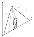
図2は、人認識センサ20が上部位置に取り付けられ、その下方を物体が通過する例示的な用途を示す。人認識センサ20は、垂直方向に1つのレーザカーテンを投影する。レーザカーテンは幅方向Wに長さを有している。ここでは、人Pが、レーザカーテン22を移動方向Mに移動している様子が示されている。通過する人Pは光パルスを反射する。これにより、人認識センサ20のレーザスキャナが、レーザカーテン内の反射点を判定(評価)する。
FIG. 2 shows an exemplary application in which a
センサ20の評価部は、レーザカーテン22と一致する評価面EPを分析(評価)するように構成されている。それゆえに、評価面EPは、レーザカーテン22が有するように、垂直方向に延びるZ軸と、幅軸Wとを有している。
The evaluation part of the
図3は、評価面EPの分析(評価)による人体認識の方法を示している。このケースでは、評価面EPがレーザカーテン22と一致するので、反射点を評価面EPに投影する必要はない。反射点は、それらの位置に従って評価面EPに割り当てられる。評価面EPは、Z軸および幅軸Wを有している。
FIG. 3 shows a method of human body recognition by analysis (evaluation) of the evaluation plane EP. In this case, the evaluation plane EP coincides with the
本発明によれば、評価部16は、評価面EPのZ軸に沿った密度分布を計算する。この密度分布において、2つのピークが検出されることが想定される。
According to the invention, the
例えば、1つのピークのみが存在する場合、計算値は破棄され、評価対象物(物体)は人体として識別されない。 For example, if only one peak exists, the calculated value is discarded and the evaluation object (object) is not identified as a human body.
2つのピーク24、26がある場合、人体を検出可能な場合であり、Z軸上のピークの位置(高さ)H1、H2が特定される。第1のピーク24は、物体の全体高さH1(人体を見たときの頭の高さ)に相当するとみなされる。第2のピーク26は、人の肩の高さH2であるとみなされる。全体高さH1と肩高さH2との比率は、所定の人体比率の範囲と比較される。人体比率は人の年齢と共に変化するので、頭部の高さ(肩高さと全体高さとの間の距離;H1-H2)をさらに考慮してもよい。
When there are two
この方法によれば、検出対象から子供を除外するような最小高さの測定を制限する必要がない。子供についても上述の評価に従って判定(定義)することができるためである。 With this method, there is no need to limit the minimum height measurement to exclude children from detection. This is because children can also be determined (defined) according to the above evaluation.
評価面EP内で、肩幅W2および第2の密度ピーク26の位置(高さ)H2を判定することができる。第1のピーク24の領域において、頭部幅W1を判定することができる。これらのさらなるパラメータにより、人体認識に関し、対象物のより正確な評価を達成することができる。
Within the evaluation plane EP, the shoulder width W2 and the position (height) H2 of the
図4は、複数のレーザカーテン32、34を生成する人認識センサ30の配置を示す。この場合、人認識センサ30は、ドアフレームの上方に取り付けられ、ドアの前方の領域を監視する。レーザカーテン32、34は、垂直軸に対して、また、互いに対して傾斜しており、幅方向Wにおいてドアに平行に延びている。評価面EPはドア平面に平行に設定される。
FIG. 4 shows an arrangement of a
人認識センサ30のレーザスキャナは、レーザスキャナに対する検出物体の反射点の位置を導出し、評価部は、それらを評価対象物として評価面EPに投影する。
The laser scanner of the
取得期間中に、人Pがレーザカーテン32、34を通って移動するときに、反射点が取得(生成)される。
During the acquisition period, reflection points are acquired (generated) as the person P moves through the
図5aに記載されるように、取得期間は約15秒である。記載された例では、4つの検出物体が、レーザカーテンを連続的に通過し、2つの検出物体は、同時にレーザカーテンを通過している。評価部は、取得された反射点を時間幅平面に投影するように構成される。 As depicted in Figure 5a, the acquisition period is approximately 15 seconds. In the example described, four detected objects pass through the laser curtain successively and two detected objects pass through the laser curtain at the same time. The evaluation unit is configured to project the acquired reflection points onto the time width plane.
この時間幅平面において、(現存する)反射点は、時間オブジェクトTO_1、TO_2、TO_3にクラスタリングされる。これは、DBSCANアルゴリズムを使用することによって行われる。 In this time width plane, the (existing) reflection points are clustered into temporal objects TO_1, TO_2, TO_3. This is done by using the DBSCAN algorithm.
このケースでは、取得期間中にレーザカーテンを通過する4つの検出物体によって、3つの時間オブジェクトTO_1、TO_2、TO_3が規定されている。 In this case, three temporal objects TO_1, TO_2, TO_3 are defined by the four detected objects passing through the laser curtain during the acquisition period.
時間オブジェクトTO_2の拡大図に示されるように、時間オブジェクトTO_2内には、より多くの検出物体が存在し得る。 As shown in the magnified view of the time object TO_2, there may be more detected objects within the time object TO_2.
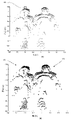
さらに、評価部は、時間オブジェクトごとの反射点を取得するように構成されており、図6aに示すように、それらを評価面EPに投影する。評価面は、垂直軸Zおよび幅軸Wを有する。 Furthermore, the evaluation unit is arranged to obtain the reflection points for each temporal object and project them onto the evaluation plane EP, as shown in FIG. 6a. The evaluation plane has a vertical axis Z and a width axis W.
次の分離ステップにおいて、評価部は、時間オブジェクトTO_1、TO_2、TO_3ごとに反射点を対象物に割り当てる。 In a next separation step, the evaluator assigns reflection points to the objects for each temporal object TO_1, TO_2, TO_3.
これは、評価面EPを上部から下部まで分析し、各点を1つの評価対象物に割り当てることによって行われる。 This is done by analyzing the evaluation plane EP from top to bottom and assigning each point to one evaluation object.
個々の評価対象物O1の判定は、評価部によって行われる。評価面EPは、時間オブジェクトTO_2の全ての反射点を含む。評価面EPは、評価面EPの上部から下部までにある隣接ゾーン40によって分析される。隣接ゾーン40に反射点が新たに存在すると、隣接ゾーン40内の全ての反射点が考慮され、新たに存在する反射点が評価対象物に割り当てられる(例えば、図6bの対象物O2(十字)および対象物O1(円)を参照)。隣接ゾーン内において新たに存在する点の上に他の点がない場合には、新たに存在する反射点は、新たな評価対象物に割り当てられる。あるいは(そうでなければ)、その数学的重心との距離が最小となる既存の評価対象物O1またはO2に割り当てられる。この手順によれば、全ての反射点は、評価対象物O1、O2に帰属する反射点の部分集合にグループ化される。
Determination of each evaluation object O1 is performed by the evaluation unit. The evaluation plane EP includes all reflection points of the temporal object TO_2. The evaluation plane EP is analyzed by
結果として、図6bは、図5bの時間オブジェクトTO_2が2つの評価対象物O1、O2に分離されたことを示す。 As a result, FIG. 6b shows that the time object TO_2 of FIG. 5b has been separated into two evaluation objects O1, O2.
次に、図7aに示す評価面内の各対象物を、図7bに示すように、Z軸に沿った密度分布解析にかける。図7a,7bでは、対象物O1が解析されている。対象物が人体であるか否かを判定するためのさらなる評価は、図3において説明したように、取得した計測値を人体計測データと比較することによって行われる。 Each object in the evaluation plane shown in FIG. 7a is then subjected to density distribution analysis along the Z-axis, as shown in FIG. 7b. In FIGS. 7a and 7b, the object O1 is analyzed. A further evaluation to determine whether the object is a human body is performed by comparing the acquired measurements with anthropometric data, as described in FIG.
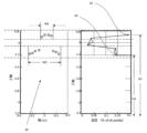
本発明の更なる改良によれば、評価部は、対象物の移動方向を分析することができる。これにより、人認識センサは、対象物情報と共に方向情報を提供することができる。例えば、これは、何人の人が建物に入ったか、または建物から出たかについてのカウントを可能にする。あるいは、カウントだけを行い、単に、出力ポートに最終的なカウント値を提供することを可能にする。 According to a further refinement of the invention, the evaluation unit can analyze the direction of movement of the object. This allows the human recognition sensor to provide direction information along with object information. For example, this allows counting how many people have entered or left a building. Alternatively, it is possible to just count and simply provide the final count value to the output port.
移動方向は、例えば500msの短時間にわたる2つのカーテン32、34の累積反射点を比較することによって分析(判定)される。反射点は、時間幅平面に投影され、この時間幅平面において、存在する反射点の数学的重心がカーテンごとに判定される。
The direction of movement is analyzed (determined) by comparing the cumulative reflection points of the two
図8aおよび図8bに十字で示す重心の移動(シフト)によれば、重心は、まず第1のカーテン32を通過し、次に第2のカーテン34を通過しており、この重心の移動方向が、対象物の移動方向を示している。
According to the movement (shift) of the center of gravity indicated by the crosses in FIGS. 8a and 8b, the center of gravity passes first through the
10 人認識センサ、11 物体情報部、12 レーザスキャナ、13 距離決定部、14 処理部、15 存在検出部、16 評価部、17 方向判定部、18a 出力ポート、18b 出力ポート、20 人認識センサ、22 レーザカーテン、24 ピーク、26 ピーク、30 人認識センサ、32 第1レーザカーテン、34 第2レーザカーテン、44 重心、46 重心、TO_1 時間オブジェクト、TO_2 時間オブジェクト、TO_3 時間オブジェクト、O1 対象物、O2 対象物、EP 評価面、P 人、M 移動方向、Z Z軸、W 幅軸。 10 human recognition sensor, 11 object information unit, 12 laser scanner, 13 distance determination unit, 14 processing unit, 15 presence detection unit, 16 evaluation unit, 17 direction determination unit, 18a output port, 18b output port, 20 human recognition sensor, 22 laser curtain, 24 peak, 26 peak, 30 human recognition sensor, 32 first laser curtain, 34 second laser curtain, 44 center of gravity, 46 center of gravity, TO_1 time object, TO_2 time object, TO_3 time object, O1 object, O2 Object, EP evaluation surface, P person, M moving direction, ZZ axis, W width axis.
Claims (11)
少なくとも1つのレーザカーテン(22、32、34)を用いて走査フィールドの所定の検出エリア内における物体の存在を検出するためのレーザスキャナ(12)と、
前記レーザスキャナに接続された演算処理部(14)と、
前記演算処理部(14)に接続された少なくとも1つの出力ポート(18,18a,18b)とを備え、
前記演算処理部(14)は、飛行時間の算出によって反射信号の反射点の距離を取得するように構成された距離データ取得部(13)と、前記距離データ取得部(13)の結果としての距離データが供給される存在検出部(15)および物体情報部(11)とを含み、
前記存在検出部(15)は、前記距離データをリアルタイムで分析することによって前記所定の検出エリア内で物体が検出されたか否かを判定して、前記少なくとも1つの出力ポート(18、18b)を介して存在検出情報をドアコントローラに供給し、
前記物体情報部(11)は、前記距離データの累積に基づいて検出物体が人体であるか否かを判定する人体判定部(16)を含み、前記人体判定部の判定結果を含む物体情報を生成し、前記少なくとも1つの出力ポート(18、18a)を介して前記物体情報を前記ドアコントローラに供給し、
前記存在検出情報と前記物体情報とが同一の出力ポート(18)に供給され、
前記演算処理部(14)は、前記物体情報よりも前記存在検出情報を優先して前記同一の出力ポート(18)に送信することを特徴とする、センサ。 A sensor (10) for controlling an automatic door, comprising:
a laser scanner (12) for detecting the presence of an object within a predetermined detection area of the scanning field using at least one laser curtain (22, 32, 34);
an arithmetic processing unit (14) connected to the laser scanner;
At least one output port (18, 18a, 18b) connected to the arithmetic processing unit (14),
The arithmetic processing unit (14) includes a distance data acquisition unit (13) configured to acquire the distance of the reflection point of the reflected signal by calculating the time of flight, and a result of the distance data acquisition unit (13) including a presence detection unit (15) and an object information unit (11) supplied with distance data,
The presence detector (15) determines whether an object has been detected within the predetermined detection area by analyzing the distance data in real time to detect the at least one output port (18, 18b). providing presence detection information to the door controller via
The object information unit (11) includes a human body determination unit (16) that determines whether or not the detected object is a human body based on the accumulation of the distance data, and stores object information including the determination result of the human body determination unit. and providing said object information to said door controller via said at least one output port (18, 18a) ;
said presence detection information and said object information are supplied to the same output port (18);
The sensor, wherein the arithmetic processing unit (14) transmits the existence detection information to the same output port (18) with priority over the object information.
前記人体判定部(16)が、
反射点の距離とパルス光の方向との組み合わせにより、監視領域内の所定の検出ゾーン内の位置を特定し、
検出物体について特定された反射点を、高さに関するZ軸と、Z軸に垂直であってレーザカーテン(22、32、34)の横方向における幅に関する幅軸とを有する評価面(EP)に、評価対象物(O1、O2)として投影し、
前記評価面(EP)を、Z軸に沿った反射点の密度分布に基づいて分析し、分析結果を、人体計測パラメータと比較することを特徴とする、請求項1~4のいずれかに記載のセンサ。 The laser scanner (12) directs at least one laser curtain (22, 32, 34) with a plurality of pulsed light to derive the distance of the reflection point to the laser scanner position by pulsed light time-of-flight (TOF) measurements. generate and
The human body determination unit (16)
a combination of the distance of the reflection point and the direction of the pulsed light to locate within a predetermined detection zone within the monitored area;
Reflection points identified on the detected object are placed on an evaluation plane (EP) having a Z-axis for height and a width-axis for the lateral width of the laser curtain (22, 32, 34) perpendicular to the Z-axis. , projected as evaluation objects (O1, O2),
The evaluation surface (EP) according to any one of claims 1 to 4 , characterized in that the evaluation surface (EP) is analyzed based on the density distribution of reflection points along the Z-axis and the analysis results are compared with anthropometric parameters. sensor.
人体計測パラメータは、頭高さ(H1)と肩高さ(H2)との比率であり、この比率を、人体の所定範囲と比較することを特徴とする、請求項6に記載のセンサ。 The human body determination unit analyzes the reflection points belonging to the evaluation object (O1, O2) based on the density distribution over the height, derives the head height (H1) and the shoulder height (H2),
7. Sensor according to claim 6 , characterized in that the anthropometric parameter is the ratio of head height (H1) to shoulder height (H2), which ratio is compared with a predetermined range of the human body.
Applications Claiming Priority (3)
| Application Number | Priority Date | Filing Date | Title |
|---|---|---|---|
| EP17165848.7 | 2017-04-10 | ||
| EP17165848.7A EP3388863A1 (en) | 2017-04-10 | 2017-04-10 | Sensor for controlling an automatic door |
| PCT/EP2018/059187 WO2018189192A1 (en) | 2017-04-10 | 2018-04-10 | Sensor for controlling an automatic door |
Publications (2)
| Publication Number | Publication Date |
|---|---|
| JP2020516911A JP2020516911A (en) | 2020-06-11 |
| JP7229560B2 true JP7229560B2 (en) | 2023-02-28 |
Family
ID=58530478
Family Applications (1)
| Application Number | Title | Priority Date | Filing Date |
|---|---|---|---|
| JP2020504444A Active JP7229560B2 (en) | 2017-04-10 | 2018-04-10 | Sensor for automatic door control |
Country Status (11)
| Country | Link |
|---|---|
| US (1) | US20210011160A1 (en) |
| EP (2) | EP3388863A1 (en) |
| JP (1) | JP7229560B2 (en) |
| KR (1) | KR102577618B1 (en) |
| CN (1) | CN110720051A (en) |
| AU (2) | AU2018253351A1 (en) |
| BE (1) | BE1025335B1 (en) |
| BR (1) | BR112019021181A2 (en) |
| CA (1) | CA3059268A1 (en) |
| SG (1) | SG11201909262SA (en) |
| WO (1) | WO2018189192A1 (en) |
Families Citing this family (6)
| Publication number | Priority date | Publication date | Assignee | Title |
|---|---|---|---|---|
| KR102322890B1 (en) * | 2019-12-17 | 2021-11-11 | 주식회사 센서리움 | Sensing system including one or more laser scanners and method for counting people using the same |
| JP7369025B2 (en) | 2019-12-18 | 2023-10-25 | 三和シヤッター工業株式会社 | Detection device |
| KR102422409B1 (en) | 2021-10-22 | 2022-07-19 | 주식회사 스타일셀러 | System and method of auction linked to Social Network Service |
| KR102409719B1 (en) | 2021-10-22 | 2022-06-16 | 주식회사 스타일셀러 | System and method for managing group purchase |
| CN114383555A (en) * | 2021-12-31 | 2022-04-22 | 西朗门业(苏州)有限公司 | Electric door seal control method and electric door seal control device |
| CN116884250B (en) * | 2023-07-12 | 2024-01-26 | 凉山州交通运输应急指挥中心 | Early warning method based on laser radar and expressway early warning system |
Citations (7)
| Publication number | Priority date | Publication date | Assignee | Title |
|---|---|---|---|---|
| JP2004295798A (en) | 2003-03-28 | 2004-10-21 | Japan Best Rescue System Kk | Security system |
| US20050078297A1 (en) | 2001-12-21 | 2005-04-14 | Gunter Doemens | Device for monitoring spatial areas |
| US20070181786A1 (en) | 2004-09-28 | 2007-08-09 | Siemens Aktiengesellschaft | Device for monitoring spatial areas |
| WO2012042043A1 (en) | 2010-10-01 | 2012-04-05 | Fastcom Technology Sa | System and method for individualizing persons |
| JP2012215555A (en) | 2011-03-30 | 2012-11-08 | Advanced Telecommunication Research Institute International | Measurement device, measurement method, and measurement program |
| JP2014142288A (en) | 2013-01-25 | 2014-08-07 | Hokuyo Automatic Co | Object detector, range-finder, door control device, and automatic door device |
| JP2017014801A (en) | 2015-07-01 | 2017-01-19 | 北陽電機株式会社 | Automatic door control system and ranging device |
Family Cites Families (48)
| Publication number | Priority date | Publication date | Assignee | Title |
|---|---|---|---|---|
| US7042492B2 (en) * | 1999-12-10 | 2006-05-09 | The Stanley Works | Automatic door assembly with video imaging device |
| JP3654360B2 (en) * | 2002-12-02 | 2005-06-02 | ソニー株式会社 | Control system and method, information processing apparatus and method, information processing terminal and method, recording medium, and program |
| ATE387620T1 (en) * | 2004-07-22 | 2008-03-15 | Bea Sa | LIGHT SCANNING DEVICE FOR DETECTION AROUND AUTOMATIC DOORS |
| ES2572772T3 (en) * | 2005-01-21 | 2016-06-02 | Bea S.A. | Sensor for use in automatic doors |
| JP2006285484A (en) * | 2005-03-31 | 2006-10-19 | Brother Ind Ltd | Controller for control equipment, control method for control equipment and control program of control equipment |
| JP2010509653A (en) * | 2006-11-03 | 2010-03-25 | ヨンエ キム | Management of vending machines based on wired and wireless communications, information provision and information acquisition system using the vending machines, and management, information provision and information acquisition methods of vending machines using this system |
| CN101293529A (en) * | 2007-04-29 | 2008-10-29 | 余亚莉 | Intelligent monitoring and early warning system for passenger transportation ability and operation safety of vehicle mounted rail traffic |
| AR065923A1 (en) * | 2007-08-09 | 2009-07-08 | Barros Alejandro Rodriguez | ANTICIPATED NOTICE SYSTEM OF OPENING A DOOR OF MOTOR VEHICLE |
| DE102007050334A1 (en) * | 2007-10-18 | 2009-04-23 | Efaflex Tor- Und Sicherheitssysteme Gmbh & Co. Kg | Method and device for controlling a gate moving vertically or horizontally while protecting the gate closing plane against obstacles |
| JP5359361B2 (en) * | 2008-09-25 | 2013-12-04 | 株式会社デンソー | Vehicle door opening control device |
| JP5381061B2 (en) * | 2008-12-08 | 2014-01-08 | 株式会社デンソー | Vehicle door opening control device |
| JP4819919B2 (en) * | 2009-04-16 | 2011-11-24 | 本田技研工業株式会社 | Vehicle object detection device |
| US20110176000A1 (en) * | 2010-01-21 | 2011-07-21 | Utah State University | System and Method for Counting People |
| US8523667B2 (en) * | 2010-03-29 | 2013-09-03 | Microsoft Corporation | Parental control settings based on body dimensions |
| US8472021B2 (en) * | 2010-04-09 | 2013-06-25 | First Solar, Inc. | Particle detector |
| ATE545042T1 (en) * | 2010-06-11 | 2012-02-15 | Sick Ag | DISTANCE MEASUREMENT LASER SCANNER FOR DETECTING OBJECTS IN A MONITORING AREA |
| JP4907732B1 (en) * | 2010-09-29 | 2012-04-04 | セコム株式会社 | Monitoring sensor |
| JP5661799B2 (en) * | 2010-12-03 | 2015-01-28 | ナブテスコ株式会社 | Automatic door sensor |
| DE102010061382B4 (en) * | 2010-12-21 | 2019-02-14 | Sick Ag | Opto-electronic sensor and method for detection and distance determination of objects |
| CN102214309B (en) * | 2011-06-15 | 2012-12-26 | 北京工业大学 | Special human body recognition method based on head and shoulder model |
| JP2013061273A (en) * | 2011-09-14 | 2013-04-04 | Kyokko Denki Kk | Object detection device using near infrared ray and far infrared ray |
| WO2013056016A1 (en) * | 2011-10-14 | 2013-04-18 | Omron Corporation | A method and apparatus for projective volume monitoring |
| TWI478107B (en) * | 2011-11-29 | 2015-03-21 | Hon Hai Prec Ind Co Ltd | Apparatus and method for controlling gates |
| US9529426B2 (en) * | 2012-02-08 | 2016-12-27 | Microsoft Technology Licensing, Llc | Head pose tracking using a depth camera |
| CN102747919B (en) * | 2012-06-18 | 2014-11-12 | 浙江工业大学 | Omnidirectional computer vision-based safe and energy-saving control device for pedestrian automatic door |
| US9940525B2 (en) * | 2012-11-19 | 2018-04-10 | Mace Wolf | Image capture with privacy protection |
| CN203102401U (en) * | 2012-12-20 | 2013-07-31 | 大连民族学院 | Energy-saving type access monitoring system |
| US9497840B2 (en) * | 2013-09-26 | 2016-11-15 | Asml Netherlands B.V. | System and method for creating and utilizing dual laser curtains from a single laser in an LPP EUV light source |
| US9679144B2 (en) * | 2013-11-15 | 2017-06-13 | Microsoft Technology Licensing, Llc | Protecting privacy in web-based immersive augmented reality |
| CN103632146B (en) * | 2013-12-05 | 2017-01-04 | 南京理工大学 | A kind of based on head and shoulder away from human body detecting method |
| US9799044B2 (en) * | 2013-12-26 | 2017-10-24 | Panasonic Intellectual Property Corporation Of America | Control method, and control system |
| JP6182482B2 (en) * | 2014-03-12 | 2017-08-16 | オムロンオートモーティブエレクトロニクス株式会社 | Control device and control system |
| JP6182483B2 (en) * | 2014-03-12 | 2017-08-16 | オムロンオートモーティブエレクトロニクス株式会社 | Portable machine and control system |
| TWM491232U (en) * | 2014-06-25 | 2014-12-01 | Univ Cheng Shiu | Opening width controllable automatic door structure |
| AU2015203771B2 (en) * | 2014-07-08 | 2020-11-05 | Iomniscient Pty Ltd | A method and apparatus for surveillance |
| DE102014113572B4 (en) * | 2014-09-19 | 2023-01-12 | Bode - Die Tür Gmbh | Door system with sensor unit for boarding aid monitoring |
| CN104234575B (en) * | 2014-09-21 | 2016-06-29 | 大昶门控科技(上海)有限公司 | Automatic door control system and control method |
| DE102015200518A1 (en) * | 2015-01-15 | 2016-07-21 | Strassacker Project GmbH & Co. KG | Safety arrangement for swing gates, gate and swing and method for securing a gate of a swing gate |
| EP3081960B1 (en) * | 2015-04-13 | 2023-03-22 | Rockwell Automation Switzerland GmbH | Time-of-flight safety photoelectric barrier and method of monitoring a protective field |
| WO2016168415A1 (en) * | 2015-04-15 | 2016-10-20 | Lytro, Inc. | Light guided image plane tiled arrays with dense fiber optic bundles for light-field and high resolution image acquisition |
| US10565734B2 (en) * | 2015-04-15 | 2020-02-18 | Google Llc | Video capture, processing, calibration, computational fiber artifact removal, and light-field pipeline |
| US9836117B2 (en) * | 2015-05-28 | 2017-12-05 | Microsoft Technology Licensing, Llc | Autonomous drones for tactile feedback in immersive virtual reality |
| GB201509387D0 (en) * | 2015-06-01 | 2015-07-15 | Apical Ltd | Method and apparatus for image processing (distance detection) |
| DE202015104582U1 (en) * | 2015-08-28 | 2016-12-01 | Gebr. Bode Gmbh & Co. Kg | Drive system with sensor unit for drive control |
| CN205608459U (en) * | 2016-05-03 | 2016-09-28 | 陈威 | Automatic induction door |
| DE102016010373B4 (en) * | 2016-08-26 | 2024-02-01 | Mercedes-Benz Group AG | Method and device for detecting the opening status of a garage door |
| EP3519861A4 (en) * | 2016-10-03 | 2020-09-02 | Sensotech, Inc. | Time of flight (tof) based detecting system for an automatic door |
| US11460337B2 (en) * | 2017-05-30 | 2022-10-04 | Versatile Natures Ltd. | Method for tracking lifting events at a construction site |
-
2017
- 2017-04-10 EP EP17165848.7A patent/EP3388863A1/en active Pending
-
2018
- 2018-04-05 BE BE2018/5229A patent/BE1025335B1/en active IP Right Grant
- 2018-04-10 WO PCT/EP2018/059187 patent/WO2018189192A1/en unknown
- 2018-04-10 SG SG11201909262S patent/SG11201909262SA/en unknown
- 2018-04-10 US US16/604,050 patent/US20210011160A1/en active Pending
- 2018-04-10 CN CN201880038289.2A patent/CN110720051A/en active Pending
- 2018-04-10 BR BR112019021181A patent/BR112019021181A2/en unknown
- 2018-04-10 AU AU2018253351A patent/AU2018253351A1/en not_active Abandoned
- 2018-04-10 KR KR1020197032891A patent/KR102577618B1/en active IP Right Grant
- 2018-04-10 JP JP2020504444A patent/JP7229560B2/en active Active
- 2018-04-10 EP EP18720981.2A patent/EP3610292A1/en active Pending
- 2018-04-10 CA CA3059268A patent/CA3059268A1/en active Pending
-
2023
- 2023-02-09 AU AU2023200723A patent/AU2023200723A1/en active Pending
Patent Citations (8)
| Publication number | Priority date | Publication date | Assignee | Title |
|---|---|---|---|---|
| US20050078297A1 (en) | 2001-12-21 | 2005-04-14 | Gunter Doemens | Device for monitoring spatial areas |
| JP2004295798A (en) | 2003-03-28 | 2004-10-21 | Japan Best Rescue System Kk | Security system |
| US20070181786A1 (en) | 2004-09-28 | 2007-08-09 | Siemens Aktiengesellschaft | Device for monitoring spatial areas |
| JP2008514909A (en) | 2004-09-28 | 2008-05-08 | シーメンス アクチエンゲゼルシヤフト | Spatial area monitoring equipment |
| WO2012042043A1 (en) | 2010-10-01 | 2012-04-05 | Fastcom Technology Sa | System and method for individualizing persons |
| JP2012215555A (en) | 2011-03-30 | 2012-11-08 | Advanced Telecommunication Research Institute International | Measurement device, measurement method, and measurement program |
| JP2014142288A (en) | 2013-01-25 | 2014-08-07 | Hokuyo Automatic Co | Object detector, range-finder, door control device, and automatic door device |
| JP2017014801A (en) | 2015-07-01 | 2017-01-19 | 北陽電機株式会社 | Automatic door control system and ranging device |
Non-Patent Citations (2)
| Title |
|---|
| AKAMATSU, Shun-ichi et al.,Development of a Person Counting System Using a 3D Laser Scanner,2014 IEEE International Conference on Robotics and Biomimetics (ROBIO 2014),米国,IEEE,2015年04月23日,Pages: 1983-1988,インターネット: <URL: https://ieeexplore.ieee.org/stamp/stamp.jsp?tp=&arnumber=7090627><DOI: 10.1109/ROBIO.2014.7090627> |
| NISHIDA, Daiki et al.,Development of Intelligent Automatic Door System,2014 IEEE International Conference on Robotics and Automation (ICRA),米国,IEEE,2014年09月29日,Pages: 6368-6374,インターネット: <URL: https://ieeexplore.ieee.org/stamp/stamp.jsp?tp=&arnumber=6907799><DOI: 10.1109/ICRA.2014.6907799> |
Also Published As
| Publication number | Publication date |
|---|---|
| EP3388863A1 (en) | 2018-10-17 |
| BE1025335A1 (en) | 2019-01-24 |
| SG11201909262SA (en) | 2019-11-28 |
| AU2023200723A1 (en) | 2023-03-09 |
| BE1025335B1 (en) | 2019-01-29 |
| CA3059268A1 (en) | 2018-10-18 |
| US20210011160A1 (en) | 2021-01-14 |
| BR112019021181A2 (en) | 2020-04-28 |
| KR20190133769A (en) | 2019-12-03 |
| WO2018189192A1 (en) | 2018-10-18 |
| CN110720051A (en) | 2020-01-21 |
| EP3610292A1 (en) | 2020-02-19 |
| JP2020516911A (en) | 2020-06-11 |
| AU2018253351A1 (en) | 2019-11-21 |
| KR102577618B1 (en) | 2023-09-12 |
Similar Documents
| Publication | Publication Date | Title |
|---|---|---|
| JP7229560B2 (en) | Sensor for automatic door control | |
| JP6296043B2 (en) | Measuring device, measuring method and measuring program | |
| US9904861B2 (en) | Method for detecting target objects in a surveillance region | |
| AU2023200722A1 (en) | Method of human body recognition and human body recognition sensor | |
| KR101480651B1 (en) | Method for Object Processing and Vehicle supporting the same | |
| US7623674B2 (en) | Method and system for enhanced portal security through stereoscopy | |
| CN102323822B (en) | Method for preventing industrial robot from colliding with worker | |
| CN107662867B (en) | Step roller monitoring and maintenance operator monitoring for passenger conveyors | |
| Boltes et al. | T-junction: Experiments, trajectory collection, and analysis | |
| JP6816836B1 (en) | How to detect the status of the exit of the passenger conveyor | |
| US8873804B2 (en) | Traffic monitoring device | |
| JP5811934B2 (en) | Residence degree detection device and passenger conveyor | |
| US20220024718A1 (en) | Registration of users of a passenger transport system | |
| Lu et al. | Monitoring a wide manufacture field automatically by multiple sensors | |
| RU2021115817A (en) | REGISTRATION OF USERS OF THE PASSENGER TRANSPORTATION SYSTEM |
Legal Events
| Date | Code | Title | Description |
|---|---|---|---|
| A621 | Written request for application examination |
Free format text: JAPANESE INTERMEDIATE CODE: A621 Effective date: 20210315 |
|
| A977 | Report on retrieval |
Free format text: JAPANESE INTERMEDIATE CODE: A971007 Effective date: 20211203 |
|
| A131 | Notification of reasons for refusal |
Free format text: JAPANESE INTERMEDIATE CODE: A131 Effective date: 20220105 |
|
| A601 | Written request for extension of time |
Free format text: JAPANESE INTERMEDIATE CODE: A601 Effective date: 20220331 |
|
| A521 | Request for written amendment filed |
Free format text: JAPANESE INTERMEDIATE CODE: A523 Effective date: 20220531 |
|
| A131 | Notification of reasons for refusal |
Free format text: JAPANESE INTERMEDIATE CODE: A131 Effective date: 20220809 |
|
| A521 | Request for written amendment filed |
Free format text: JAPANESE INTERMEDIATE CODE: A523 Effective date: 20221031 |
|
| TRDD | Decision of grant or rejection written | ||
| A01 | Written decision to grant a patent or to grant a registration (utility model) |
Free format text: JAPANESE INTERMEDIATE CODE: A01 Effective date: 20230124 |
|
| A61 | First payment of annual fees (during grant procedure) |
Free format text: JAPANESE INTERMEDIATE CODE: A61 Effective date: 20230208 |
|
| R150 | Certificate of patent or registration of utility model |
Ref document number: 7229560 Country of ref document: JP Free format text: JAPANESE INTERMEDIATE CODE: R150 |