JP7229155B2 - Sequential registration system and method for image-guided surgery - Google Patents
Sequential registration system and method for image-guided surgery Download PDFInfo
- Publication number
- JP7229155B2 JP7229155B2 JP2019518029A JP2019518029A JP7229155B2 JP 7229155 B2 JP7229155 B2 JP 7229155B2 JP 2019518029 A JP2019518029 A JP 2019518029A JP 2019518029 A JP2019518029 A JP 2019518029A JP 7229155 B2 JP7229155 B2 JP 7229155B2
- Authority
- JP
- Japan
- Prior art keywords
- model
- points
- patient
- measurement points
- catheter
- Prior art date
- Legal status (The legal status is an assumption and is not a legal conclusion. Google has not performed a legal analysis and makes no representation as to the accuracy of the status listed.)
- Active
Links
- 238000000034 method Methods 0.000 title claims description 85
- 238000002675 image-guided surgery Methods 0.000 title description 7
- 238000005259 measurement Methods 0.000 claims description 93
- 230000033001 locomotion Effects 0.000 claims description 58
- 238000003780 insertion Methods 0.000 claims description 40
- 230000037431 insertion Effects 0.000 claims description 40
- 230000000737 periodic effect Effects 0.000 claims description 16
- 239000000835 fiber Substances 0.000 claims description 15
- 230000000007 visual effect Effects 0.000 claims description 12
- 230000029058 respiratory gaseous exchange Effects 0.000 claims description 10
- 230000008859 change Effects 0.000 claims description 9
- 230000035790 physiological processes and functions Effects 0.000 claims description 6
- 238000002059 diagnostic imaging Methods 0.000 claims description 3
- 210000003484 anatomy Anatomy 0.000 description 37
- 210000004072 lung Anatomy 0.000 description 25
- 230000008569 process Effects 0.000 description 23
- 238000001356 surgical procedure Methods 0.000 description 15
- 230000011218 segmentation Effects 0.000 description 14
- 238000003384 imaging method Methods 0.000 description 13
- 230000000875 corresponding effect Effects 0.000 description 12
- 238000006073 displacement reaction Methods 0.000 description 9
- 239000013307 optical fiber Substances 0.000 description 9
- 238000012800 visualization Methods 0.000 description 9
- 239000000523 sample Substances 0.000 description 8
- 238000001574 biopsy Methods 0.000 description 7
- 239000002131 composite material Substances 0.000 description 7
- 238000010586 diagram Methods 0.000 description 7
- 230000007246 mechanism Effects 0.000 description 7
- 238000012545 processing Methods 0.000 description 7
- 230000009466 transformation Effects 0.000 description 7
- 238000002591 computed tomography Methods 0.000 description 6
- 230000001276 controlling effect Effects 0.000 description 6
- 238000012014 optical coherence tomography Methods 0.000 description 6
- 238000001931 thermography Methods 0.000 description 6
- 230000000712 assembly Effects 0.000 description 5
- 238000000429 assembly Methods 0.000 description 5
- 239000012636 effector Substances 0.000 description 5
- 210000000621 bronchi Anatomy 0.000 description 4
- 238000004140 cleaning Methods 0.000 description 4
- 230000006870 function Effects 0.000 description 4
- 230000003287 optical effect Effects 0.000 description 4
- 230000002596 correlated effect Effects 0.000 description 3
- 238000002594 fluoroscopy Methods 0.000 description 3
- 210000002216 heart Anatomy 0.000 description 3
- 238000002595 magnetic resonance imaging Methods 0.000 description 3
- 239000002071 nanotube Substances 0.000 description 3
- 238000009877 rendering Methods 0.000 description 3
- 230000000241 respiratory effect Effects 0.000 description 3
- 239000004065 semiconductor Substances 0.000 description 3
- 230000001225 therapeutic effect Effects 0.000 description 3
- 210000003437 trachea Anatomy 0.000 description 3
- 238000000844 transformation Methods 0.000 description 3
- 238000002604 ultrasonography Methods 0.000 description 3
- 238000004364 calculation method Methods 0.000 description 2
- 210000001072 colon Anatomy 0.000 description 2
- 230000005672 electromagnetic field Effects 0.000 description 2
- 210000000936 intestine Anatomy 0.000 description 2
- 230000002262 irrigation Effects 0.000 description 2
- 238000003973 irrigation Methods 0.000 description 2
- 210000003734 kidney Anatomy 0.000 description 2
- 210000000056 organ Anatomy 0.000 description 2
- 230000008447 perception Effects 0.000 description 2
- 238000001454 recorded image Methods 0.000 description 2
- 230000004044 response Effects 0.000 description 2
- 230000003068 static effect Effects 0.000 description 2
- 238000011282 treatment Methods 0.000 description 2
- 239000011165 3D composite Substances 0.000 description 1
- 206010028980 Neoplasm Diseases 0.000 description 1
- 238000001069 Raman spectroscopy Methods 0.000 description 1
- 206010039897 Sedation Diseases 0.000 description 1
- 208000002847 Surgical Wound Diseases 0.000 description 1
- 230000002411 adverse Effects 0.000 description 1
- 238000005452 bending Methods 0.000 description 1
- 210000004556 brain Anatomy 0.000 description 1
- 238000003759 clinical diagnosis Methods 0.000 description 1
- 238000004891 communication Methods 0.000 description 1
- 238000012937 correction Methods 0.000 description 1
- 230000001186 cumulative effect Effects 0.000 description 1
- 125000004122 cyclic group Chemical group 0.000 description 1
- 238000013500 data storage Methods 0.000 description 1
- 230000007423 decrease Effects 0.000 description 1
- 230000007547 defect Effects 0.000 description 1
- 238000001514 detection method Methods 0.000 description 1
- 238000003745 diagnosis Methods 0.000 description 1
- 230000000694 effects Effects 0.000 description 1
- 238000001839 endoscopy Methods 0.000 description 1
- 239000012530 fluid Substances 0.000 description 1
- 238000007429 general method Methods 0.000 description 1
- 238000005286 illumination Methods 0.000 description 1
- 238000002329 infrared spectrum Methods 0.000 description 1
- 230000000977 initiatory effect Effects 0.000 description 1
- 230000003434 inspiratory effect Effects 0.000 description 1
- 238000000608 laser ablation Methods 0.000 description 1
- 239000000463 material Substances 0.000 description 1
- 238000002324 minimally invasive surgery Methods 0.000 description 1
- 238000012986 modification Methods 0.000 description 1
- 230000004048 modification Effects 0.000 description 1
- 238000012544 monitoring process Methods 0.000 description 1
- 238000010899 nucleation Methods 0.000 description 1
- 230000036316 preload Effects 0.000 description 1
- 238000011084 recovery Methods 0.000 description 1
- 230000036280 sedation Effects 0.000 description 1
- 230000035945 sensitivity Effects 0.000 description 1
- 239000007787 solid Substances 0.000 description 1
- 238000002560 therapeutic procedure Methods 0.000 description 1
- 238000013519 translation Methods 0.000 description 1
- 238000002211 ultraviolet spectrum Methods 0.000 description 1
- 230000002792 vascular Effects 0.000 description 1
- 238000001429 visible spectrum Methods 0.000 description 1
Images


Classifications
-
- A—HUMAN NECESSITIES
- A61—MEDICAL OR VETERINARY SCIENCE; HYGIENE
- A61B—DIAGNOSIS; SURGERY; IDENTIFICATION
- A61B34/00—Computer-aided surgery; Manipulators or robots specially adapted for use in surgery
- A61B34/20—Surgical navigation systems; Devices for tracking or guiding surgical instruments, e.g. for frameless stereotaxis
-
- A—HUMAN NECESSITIES
- A61—MEDICAL OR VETERINARY SCIENCE; HYGIENE
- A61B—DIAGNOSIS; SURGERY; IDENTIFICATION
- A61B34/00—Computer-aided surgery; Manipulators or robots specially adapted for use in surgery
- A61B34/30—Surgical robots
- A61B34/37—Master-slave robots
-
- G—PHYSICS
- G16—INFORMATION AND COMMUNICATION TECHNOLOGY [ICT] SPECIALLY ADAPTED FOR SPECIFIC APPLICATION FIELDS
- G16H—HEALTHCARE INFORMATICS, i.e. INFORMATION AND COMMUNICATION TECHNOLOGY [ICT] SPECIALLY ADAPTED FOR THE HANDLING OR PROCESSING OF MEDICAL OR HEALTHCARE DATA
- G16H40/00—ICT specially adapted for the management or administration of healthcare resources or facilities; ICT specially adapted for the management or operation of medical equipment or devices
- G16H40/60—ICT specially adapted for the management or administration of healthcare resources or facilities; ICT specially adapted for the management or operation of medical equipment or devices for the operation of medical equipment or devices
- G16H40/67—ICT specially adapted for the management or administration of healthcare resources or facilities; ICT specially adapted for the management or operation of medical equipment or devices for the operation of medical equipment or devices for remote operation
-
- A—HUMAN NECESSITIES
- A61—MEDICAL OR VETERINARY SCIENCE; HYGIENE
- A61B—DIAGNOSIS; SURGERY; IDENTIFICATION
- A61B1/00—Instruments for performing medical examinations of the interior of cavities or tubes of the body by visual or photographical inspection, e.g. endoscopes; Illuminating arrangements therefor
- A61B1/00002—Operational features of endoscopes
- A61B1/00004—Operational features of endoscopes characterised by electronic signal processing
- A61B1/00009—Operational features of endoscopes characterised by electronic signal processing of image signals during a use of endoscope
- A61B1/000094—Operational features of endoscopes characterised by electronic signal processing of image signals during a use of endoscope extracting biological structures
-
- A—HUMAN NECESSITIES
- A61—MEDICAL OR VETERINARY SCIENCE; HYGIENE
- A61B—DIAGNOSIS; SURGERY; IDENTIFICATION
- A61B1/00—Instruments for performing medical examinations of the interior of cavities or tubes of the body by visual or photographical inspection, e.g. endoscopes; Illuminating arrangements therefor
- A61B1/00147—Holding or positioning arrangements
-
- A—HUMAN NECESSITIES
- A61—MEDICAL OR VETERINARY SCIENCE; HYGIENE
- A61B—DIAGNOSIS; SURGERY; IDENTIFICATION
- A61B1/00—Instruments for performing medical examinations of the interior of cavities or tubes of the body by visual or photographical inspection, e.g. endoscopes; Illuminating arrangements therefor
- A61B1/267—Instruments for performing medical examinations of the interior of cavities or tubes of the body by visual or photographical inspection, e.g. endoscopes; Illuminating arrangements therefor for the respiratory tract, e.g. laryngoscopes, bronchoscopes
- A61B1/2676—Bronchoscopes
-
- A—HUMAN NECESSITIES
- A61—MEDICAL OR VETERINARY SCIENCE; HYGIENE
- A61B—DIAGNOSIS; SURGERY; IDENTIFICATION
- A61B34/00—Computer-aided surgery; Manipulators or robots specially adapted for use in surgery
- A61B34/10—Computer-aided planning, simulation or modelling of surgical operations
-
- A—HUMAN NECESSITIES
- A61—MEDICAL OR VETERINARY SCIENCE; HYGIENE
- A61B—DIAGNOSIS; SURGERY; IDENTIFICATION
- A61B34/00—Computer-aided surgery; Manipulators or robots specially adapted for use in surgery
- A61B34/25—User interfaces for surgical systems
-
- A—HUMAN NECESSITIES
- A61—MEDICAL OR VETERINARY SCIENCE; HYGIENE
- A61B—DIAGNOSIS; SURGERY; IDENTIFICATION
- A61B34/00—Computer-aided surgery; Manipulators or robots specially adapted for use in surgery
- A61B34/30—Surgical robots
- A61B34/35—Surgical robots for telesurgery
-
- A—HUMAN NECESSITIES
- A61—MEDICAL OR VETERINARY SCIENCE; HYGIENE
- A61B—DIAGNOSIS; SURGERY; IDENTIFICATION
- A61B34/00—Computer-aided surgery; Manipulators or robots specially adapted for use in surgery
- A61B34/70—Manipulators specially adapted for use in surgery
-
- A—HUMAN NECESSITIES
- A61—MEDICAL OR VETERINARY SCIENCE; HYGIENE
- A61B—DIAGNOSIS; SURGERY; IDENTIFICATION
- A61B34/00—Computer-aided surgery; Manipulators or robots specially adapted for use in surgery
- A61B34/70—Manipulators specially adapted for use in surgery
- A61B34/76—Manipulators having means for providing feel, e.g. force or tactile feedback
-
- A—HUMAN NECESSITIES
- A61—MEDICAL OR VETERINARY SCIENCE; HYGIENE
- A61B—DIAGNOSIS; SURGERY; IDENTIFICATION
- A61B90/00—Instruments, implements or accessories specially adapted for surgery or diagnosis and not covered by any of the groups A61B1/00 - A61B50/00, e.g. for luxation treatment or for protecting wound edges
- A61B90/36—Image-producing devices or illumination devices not otherwise provided for
-
- A—HUMAN NECESSITIES
- A61—MEDICAL OR VETERINARY SCIENCE; HYGIENE
- A61M—DEVICES FOR INTRODUCING MEDIA INTO, OR ONTO, THE BODY; DEVICES FOR TRANSDUCING BODY MEDIA OR FOR TAKING MEDIA FROM THE BODY; DEVICES FOR PRODUCING OR ENDING SLEEP OR STUPOR
- A61M25/00—Catheters; Hollow probes
- A61M25/01—Introducing, guiding, advancing, emplacing or holding catheters
- A61M25/0105—Steering means as part of the catheter or advancing means; Markers for positioning
-
- G—PHYSICS
- G06—COMPUTING; CALCULATING OR COUNTING
- G06F—ELECTRIC DIGITAL DATA PROCESSING
- G06F30/00—Computer-aided design [CAD]
- G06F30/20—Design optimisation, verification or simulation
- G06F30/23—Design optimisation, verification or simulation using finite element methods [FEM] or finite difference methods [FDM]
-
- G—PHYSICS
- G06—COMPUTING; CALCULATING OR COUNTING
- G06T—IMAGE DATA PROCESSING OR GENERATION, IN GENERAL
- G06T17/00—Three dimensional [3D] modelling, e.g. data description of 3D objects
- G06T17/20—Finite element generation, e.g. wire-frame surface description, tesselation
-
- G—PHYSICS
- G06—COMPUTING; CALCULATING OR COUNTING
- G06T—IMAGE DATA PROCESSING OR GENERATION, IN GENERAL
- G06T19/00—Manipulating 3D models or images for computer graphics
- G06T19/003—Navigation within 3D models or images
-
- G06T3/14—
-
- G—PHYSICS
- G06—COMPUTING; CALCULATING OR COUNTING
- G06T—IMAGE DATA PROCESSING OR GENERATION, IN GENERAL
- G06T7/00—Image analysis
- G06T7/30—Determination of transform parameters for the alignment of images, i.e. image registration
- G06T7/33—Determination of transform parameters for the alignment of images, i.e. image registration using feature-based methods
- G06T7/344—Determination of transform parameters for the alignment of images, i.e. image registration using feature-based methods involving models
-
- A—HUMAN NECESSITIES
- A61—MEDICAL OR VETERINARY SCIENCE; HYGIENE
- A61B—DIAGNOSIS; SURGERY; IDENTIFICATION
- A61B1/00—Instruments for performing medical examinations of the interior of cavities or tubes of the body by visual or photographical inspection, e.g. endoscopes; Illuminating arrangements therefor
- A61B1/005—Flexible endoscopes
- A61B1/0051—Flexible endoscopes with controlled bending of insertion part
-
- A—HUMAN NECESSITIES
- A61—MEDICAL OR VETERINARY SCIENCE; HYGIENE
- A61B—DIAGNOSIS; SURGERY; IDENTIFICATION
- A61B17/00—Surgical instruments, devices or methods, e.g. tourniquets
- A61B2017/00681—Aspects not otherwise provided for
- A61B2017/00694—Aspects not otherwise provided for with means correcting for movement of or for synchronisation with the body
- A61B2017/00699—Aspects not otherwise provided for with means correcting for movement of or for synchronisation with the body correcting for movement caused by respiration, e.g. by triggering
-
- A—HUMAN NECESSITIES
- A61—MEDICAL OR VETERINARY SCIENCE; HYGIENE
- A61B—DIAGNOSIS; SURGERY; IDENTIFICATION
- A61B34/00—Computer-aided surgery; Manipulators or robots specially adapted for use in surgery
- A61B34/10—Computer-aided planning, simulation or modelling of surgical operations
- A61B2034/101—Computer-aided simulation of surgical operations
- A61B2034/105—Modelling of the patient, e.g. for ligaments or bones
-
- A—HUMAN NECESSITIES
- A61—MEDICAL OR VETERINARY SCIENCE; HYGIENE
- A61B—DIAGNOSIS; SURGERY; IDENTIFICATION
- A61B34/00—Computer-aided surgery; Manipulators or robots specially adapted for use in surgery
- A61B34/10—Computer-aided planning, simulation or modelling of surgical operations
- A61B2034/107—Visualisation of planned trajectories or target regions
-
- A—HUMAN NECESSITIES
- A61—MEDICAL OR VETERINARY SCIENCE; HYGIENE
- A61B—DIAGNOSIS; SURGERY; IDENTIFICATION
- A61B34/00—Computer-aided surgery; Manipulators or robots specially adapted for use in surgery
- A61B34/10—Computer-aided planning, simulation or modelling of surgical operations
- A61B2034/108—Computer aided selection or customisation of medical implants or cutting guides
-
- A—HUMAN NECESSITIES
- A61—MEDICAL OR VETERINARY SCIENCE; HYGIENE
- A61B—DIAGNOSIS; SURGERY; IDENTIFICATION
- A61B34/00—Computer-aided surgery; Manipulators or robots specially adapted for use in surgery
- A61B34/20—Surgical navigation systems; Devices for tracking or guiding surgical instruments, e.g. for frameless stereotaxis
- A61B2034/2046—Tracking techniques
- A61B2034/2051—Electromagnetic tracking systems
-
- A—HUMAN NECESSITIES
- A61—MEDICAL OR VETERINARY SCIENCE; HYGIENE
- A61B—DIAGNOSIS; SURGERY; IDENTIFICATION
- A61B34/00—Computer-aided surgery; Manipulators or robots specially adapted for use in surgery
- A61B34/20—Surgical navigation systems; Devices for tracking or guiding surgical instruments, e.g. for frameless stereotaxis
- A61B2034/2046—Tracking techniques
- A61B2034/2055—Optical tracking systems
-
- A—HUMAN NECESSITIES
- A61—MEDICAL OR VETERINARY SCIENCE; HYGIENE
- A61B—DIAGNOSIS; SURGERY; IDENTIFICATION
- A61B34/00—Computer-aided surgery; Manipulators or robots specially adapted for use in surgery
- A61B34/20—Surgical navigation systems; Devices for tracking or guiding surgical instruments, e.g. for frameless stereotaxis
- A61B2034/2046—Tracking techniques
- A61B2034/2059—Mechanical position encoders
-
- A—HUMAN NECESSITIES
- A61—MEDICAL OR VETERINARY SCIENCE; HYGIENE
- A61B—DIAGNOSIS; SURGERY; IDENTIFICATION
- A61B34/00—Computer-aided surgery; Manipulators or robots specially adapted for use in surgery
- A61B34/20—Surgical navigation systems; Devices for tracking or guiding surgical instruments, e.g. for frameless stereotaxis
- A61B2034/2046—Tracking techniques
- A61B2034/2061—Tracking techniques using shape-sensors, e.g. fiber shape sensors with Bragg gratings
-
- A—HUMAN NECESSITIES
- A61—MEDICAL OR VETERINARY SCIENCE; HYGIENE
- A61B—DIAGNOSIS; SURGERY; IDENTIFICATION
- A61B34/00—Computer-aided surgery; Manipulators or robots specially adapted for use in surgery
- A61B34/20—Surgical navigation systems; Devices for tracking or guiding surgical instruments, e.g. for frameless stereotaxis
- A61B2034/2046—Tracking techniques
- A61B2034/2065—Tracking using image or pattern recognition
-
- A—HUMAN NECESSITIES
- A61—MEDICAL OR VETERINARY SCIENCE; HYGIENE
- A61B—DIAGNOSIS; SURGERY; IDENTIFICATION
- A61B34/00—Computer-aided surgery; Manipulators or robots specially adapted for use in surgery
- A61B34/30—Surgical robots
- A61B2034/301—Surgical robots for introducing or steering flexible instruments inserted into the body, e.g. catheters or endoscopes
-
- A—HUMAN NECESSITIES
- A61—MEDICAL OR VETERINARY SCIENCE; HYGIENE
- A61B—DIAGNOSIS; SURGERY; IDENTIFICATION
- A61B90/00—Instruments, implements or accessories specially adapted for surgery or diagnosis and not covered by any of the groups A61B1/00 - A61B50/00, e.g. for luxation treatment or for protecting wound edges
- A61B90/36—Image-producing devices or illumination devices not otherwise provided for
- A61B2090/364—Correlation of different images or relation of image positions in respect to the body
-
- A—HUMAN NECESSITIES
- A61—MEDICAL OR VETERINARY SCIENCE; HYGIENE
- A61M—DEVICES FOR INTRODUCING MEDIA INTO, OR ONTO, THE BODY; DEVICES FOR TRANSDUCING BODY MEDIA OR FOR TAKING MEDIA FROM THE BODY; DEVICES FOR PRODUCING OR ENDING SLEEP OR STUPOR
- A61M25/00—Catheters; Hollow probes
- A61M25/01—Introducing, guiding, advancing, emplacing or holding catheters
- A61M25/0105—Steering means as part of the catheter or advancing means; Markers for positioning
- A61M2025/0166—Sensors, electrodes or the like for guiding the catheter to a target zone, e.g. image guided or magnetically guided
-
- A—HUMAN NECESSITIES
- A61—MEDICAL OR VETERINARY SCIENCE; HYGIENE
- A61M—DEVICES FOR INTRODUCING MEDIA INTO, OR ONTO, THE BODY; DEVICES FOR TRANSDUCING BODY MEDIA OR FOR TAKING MEDIA FROM THE BODY; DEVICES FOR PRODUCING OR ENDING SLEEP OR STUPOR
- A61M25/00—Catheters; Hollow probes
- A61M25/01—Introducing, guiding, advancing, emplacing or holding catheters
- A61M25/0105—Steering means as part of the catheter or advancing means; Markers for positioning
- A61M25/0113—Mechanical advancing means, e.g. catheter dispensers
-
- G—PHYSICS
- G06—COMPUTING; CALCULATING OR COUNTING
- G06T—IMAGE DATA PROCESSING OR GENERATION, IN GENERAL
- G06T2210/00—Indexing scheme for image generation or computer graphics
- G06T2210/41—Medical
Description
関連出願
本特許出願は、2016年11月2日に出願された、“Systems and Methods of Continuous Registration For Image-Guided
Surgery”という表題の米国仮特許出願第62/416,393号の優先権及びその出願日の利益を主張するものであり、この文献は、その全体が本明細書に参照により組み込まれる。
RELATED APPLICATIONS This patent application is entitled "Systems and Methods of Continuous Registration For Image-Guided
No. 62/416,393, entitled "Surgery," which is hereby incorporated by reference in its entirety.
本開示は、画像誘導処置を行うためのシステム及び方法に関し、より具体的には、患者の解剖学的構造のモデルを医療処置において使用される1つ又は複数の器具に位置合わせするためのシステム及び方法に関する。 FIELD OF THE DISCLOSURE The present disclosure relates to systems and methods for performing image-guided procedures, and more particularly, systems for registering a model of a patient's anatomy to one or more instruments used in a medical procedure. and methods.
低侵襲性医療技術は、医療処置中に損傷を受ける組織の量を減らし、それによって患者の回復時間、不快感、及び有害な副作用を減らすことを目的としている。そのような低侵襲性技術は、患者の解剖学的構造内の自然オリフィスを介して、又は1つ又は複数の外科的切開部を介して行われ得る。これらの自然オリフィス又は切開部を介して、臨床医は、低侵襲性医療器具(手術用器具、診断用器具、治療用器具、又は生検器具を含む)を挿入して、標的組織の位置に到達させることができる。標的組織の位置に到達させるのを補助するために、医療器具の位置及び動きを、患者の解剖学的構造の術前又は術中の画像と相関させてもよい。画像誘導器具が画像と相関しているので、器具は、肺、結腸、腸、腎臓、心臓、循環系等の解剖学系において自然に又は外科的に形成された通路をナビゲートすることができる。臨床的障害を最小限にして画像誘導手術中に使用されるモデルを位置合わせするためのシステム及び方法が必要とされている。 Minimally invasive medical techniques aim to reduce the amount of tissue damaged during medical procedures, thereby reducing patient recovery time, discomfort, and adverse side effects. Such minimally invasive techniques may be performed through natural orifices within the patient's anatomy or through one or more surgical incisions. Through these natural orifices or incisions, clinicians can insert minimally invasive medical instruments (including surgical, diagnostic, therapeutic, or biopsy instruments) to target tissue locations. can be reached. The position and movement of the medical instrument may be correlated with pre- or intra-operative images of the patient's anatomy to aid in reaching the target tissue location. Because the image-guided instrument is correlated with the images, the instrument can navigate naturally or surgically created passageways in anatomical systems such as the lungs, colon, intestine, kidneys, heart, circulatory system, and the like. . What is needed is a system and method for registering models used during image-guided surgery with minimal clinical disturbance.
本発明の実施形態は、詳細な説明の後の特許請求の範囲によって最もよく要約される。 The embodiments of the invention are best summarized by the claims that follow the detailed description.
もっとも、患者の1つ又は複数の解剖学的通路のモデルを患者空間に位置合わせする例示的な方法は、患者の1つ又は複数の解剖学的通路のモデルのモデル空間内のモデル点のセットにアクセスするステップと;患者の1つ又は複数の解剖学的通路内に挿入されたカテーテルの長さに沿って測定点の第1セットを収集するステップであって、測定点は患者空間内のカテーテルの形状によって決定される、収集するステップと;測定点の第1セットの点を測定点の複数の第1サブセットに割り当てるステップと;を含み得る。例示的な方法は、測定点の第1サブセットをモデル点のセットと位置合わせして、第1の複数の位置合せ候補を生成するステップと;位置合せ候補同士を比較して、第1の複数の位置合せ候補のうちの最適な位置合せに関連する最適なサブセットを特定するステップと;最適な位置合せの視覚的表現をディスプレイによって提供されるユーザインターフェイスに表示するステップと;をさらに含み得る。最適な位置合せは、モデル点のセット及び測定点の第1セットのうちの少なくとも1つのサブセットを共通の空間に変換する。 However, an exemplary method of registering a model of one or more anatomical passageways of a patient in patient space is a set of model points in the model space of the model of the one or more anatomical passageways of the patient. and acquiring a first set of measurement points along the length of a catheter inserted within one or more anatomical passageways of the patient, the measurement points being within the patient space. and assigning points of the first set of measurement points to a plurality of first subsets of measurement points, as determined by the geometry of the catheter. An exemplary method comprises aligning a first subset of measurement points with a set of model points to generate a first plurality of candidate alignments; comparing the candidate alignments to generate a first plurality of candidate alignments; identifying the best subset of the alignment candidates associated with the best alignment; and displaying a visual representation of the best alignment on a user interface provided by the display. Optimal registration transforms at least a subset of the set of model points and the first set of measurement points to a common space.
患者の1つ又は複数の解剖学的通路のモデルを患者空間に位置合わせする別の例示的な方法は、患者の1つ又は複数の解剖学的通路のモデルのモデル点のセットにアクセスするステップと;患者の1つ又は複数の解剖学的通路内に挿入されたカテーテルの長さに沿って測定点のセットを収集するステップであって、測定点は患者空間内のカテーテルの形状によって決定される、収集するステップと;測定点のセットのサブセットをモデル点のセットと位置合わせして、複数の位置合せ候補を生成するステップと;を含み得る。例示的な方法は、医療処置を行う際に使用するために、複数の位置合せ候補から位置合せ候補を選択するステップと;選択した位置合せ候補をモデルのモデル点のセットに適用して、モデルを患者空間に位置合わせするステップと;をさらに含み得る。 Another exemplary method of registering a model of one or more anatomical passageways of a patient in patient space comprises accessing a set of model points of the model of the one or more anatomical passageways of the patient. and; acquiring a set of measurement points along the length of a catheter inserted within one or more anatomical passageways of the patient, the measurement points being determined by the geometry of the catheter within the patient space. aligning a subset of the set of measurement points with the set of model points to generate a plurality of candidate alignments. An exemplary method comprises selecting an alignment candidate from a plurality of alignment candidates for use in performing a medical procedure; applying the selected alignment candidate to a set of model points of the model to generate a model in patient space;
例示的な医療撮像システムは、動き検出器と、挿入ステージに沿って移動可能な器具キャリッジに結合された基端部を有する可撓性カテーテルと、可撓性カテーテルの長さに沿って延びる点収集器具とを含み得る。例示的なシステムは、点収集器具によって収集された測定点のセットを1つ又は複数の解剖学的通路のモデルに位置合わせするように構成された追跡システムをさらに含み得る。追跡システムは、モデル空間内のモデル点のセットにアクセスし、患者の1つ又は複数の解剖学的通路内に挿入された可撓性カテーテルの長さに沿って測定点のセットを収集することができ、測定点は患者空間内のカテーテルの形状によって決定される。追跡システムは、動き検出器によって監視される周期的な生理学的機能に従って測定点のセットをサブセットに割り当て、測定点のサブセットに基づいて複数の位置合せ候補から第1の位置合せ候補を選択し、選択した第1の位置合せ候補をモデルのモデル点のセットに適用して、モデルを患者空間に位置合わせすることもできる。
前述した一般的な説明と以下の詳細な説明との両方は、本質的に例示的且つ説明的なものであり、本開示の範囲を限定することなく本開示の理解を与えることを意図していることを理解されたい。その点に関して、本開示の更なる態様、特徴、及び利点は、以下の詳細な説明から当業者に明らかとなるであろう。
An exemplary medical imaging system includes a motion detector, a flexible catheter having a proximal end coupled to an instrument carriage movable along an insertion stage, and points extending along the length of the flexible catheter. a collection device. An exemplary system may further include a tracking system configured to register the set of measurement points collected by the point collection instrument to one or more models of the anatomical passageway. A tracking system accesses a set of model points in model space and acquires a set of measurement points along the length of a flexible catheter inserted within one or more anatomical passageways of a patient. , and the measurement points are determined by the geometry of the catheter in the patient space. a tracking system assigning the set of measurement points to the subsets according to a periodic physiological function monitored by the motion detector, selecting a first alignment candidate from the plurality of alignment candidates based on the subsets of the measurement points; The model may also be registered in patient space by applying the selected first registration candidate to the set of model points of the model.
Both the foregoing general description and the following detailed description are exemplary and explanatory in nature, and are intended to provide an understanding of the disclosure without limiting its scope. It should be understood that In that regard, further aspects, features, and advantages of the present disclosure will become apparent to those skilled in the art from the following detailed description.
本開示の実施形態及びそれらの利点は、以下の詳細な説明を参照することによって最もよく理解される。1つ又は複数の図に示されている同様の要素を識別するために同様の参照符号が使用されていることを理解されたい。また、その図に示されているのは本開示の実施形態を例示する目的のためであり、本開示の実施形態を限定する目的のためではない。 Embodiments of the present disclosure and their advantages are best understood by reference to the following detailed description. It should be understood that like reference numerals are used to identify like elements shown in one or more figures. Also, the figures shown are for the purpose of illustrating embodiments of the present disclosure and not for the purpose of limiting the embodiments of the present disclosure.
以下の説明では、本開示と一致するいくつかの実施形態を説明する特定の詳細が記載される。実施形態の完全な理解を与えるために多数の特定の詳細が記載される。しかしながら、いくつかの実施形態が、これらの具体的な詳細の一部又は全てがなくても実施し得ることは当業者には明らかであろう。本明細書に開示される特定の実施形態は、例示的であり、限定的ではないことを意味する。当業者は、本明細書に具体的に記載されていないが、本開示の範囲及び精神内にある他の要素を理解し得る。さらに、不要な繰返しを避けるために、1つの実施形態に関連して図示及び説明した1つ又は複数の特徴は、特に記載のない限り、或いは1つ又は複数の特徴によって実施形態が機能しなくなる場合を除き、他の実施形態に組み込むことができる。 In the following description, specific details are set forth describing several embodiments consistent with this disclosure. Numerous specific details are set forth to provide a thorough understanding of the embodiments. However, it will be apparent to one skilled in the art that some embodiments may be practiced without some or all of these specific details. The specific embodiments disclosed herein are meant to be illustrative and not limiting. Those skilled in the art will appreciate other elements not specifically described herein but within the scope and spirit of the disclosure. Additionally, to avoid unnecessary repetition, one or more features illustrated and described in connection with an embodiment may be rendered obsolete by one or more features unless specifically stated otherwise. It can be incorporated into other embodiments except for cases.
いくつかの例では、実施形態の態様を不必要に曖昧にしないように、周知の方法、手順、構成要素、及び回路について、詳細に説明していない。 In some instances, well-known methods, procedures, components and circuits have not been described in detail so as not to unnecessarily obscure aspects of the embodiments.
本開示は、様々な器具及び器具の一部を、3次元空間におけるそれら器具及び器具の一部の状態に関して説明する。本明細書で使用される場合に、用語「位置」は、3次元空間(例えば、直交x、y、及びz座標に沿った3つの並進自由度)における物体又は物体の一部の位置を指す。本明細書で使用される場合に、用語「向き(orientation)」は、物体又は物体の一部の回転配置(3つの回転自由度、例えば、ロール、ピッチ、及びヨー)を指す。本明細書で使用される場合に、用語「姿勢(pose)」は、物体又は物体の一部の少なくとも1つの並進自由度における位置、及び物体又は物体の一部の少なくとも1つの回転自由度における向き(最大6つの自由度)を指す。本明細書で使用される場合に、用語「形状」は、物体に沿って測定された姿勢、位置、又は向きのセットを指す。 This disclosure describes various instruments and parts of instruments in terms of their states in three-dimensional space. As used herein, the term "position" refers to the position of an object or part of an object in three-dimensional space (e.g., three translational degrees of freedom along orthogonal x, y, and z coordinates). . As used herein, the term "orientation" refers to the rotational orientation (three rotational degrees of freedom, eg, roll, pitch, and yaw) of an object or part of an object. As used herein, the term "pose" refers to the position of an object or part of an object in at least one translational degree of freedom and the position of an object or part of an object in at least one rotational degree of freedom. Refers to orientation (up to 6 degrees of freedom). As used herein, the term "shape" refers to a set of poses, positions, or orientations measured along an object.
図1は、いくつかの実施形態による遠隔操作医療システム100の概略図である。いくつかの実施形態では、遠隔操作医療システム100は、例えば、手術処置、診断処置、治療処置、又は生検処置の使用に適し得る。図1に示されるように、医療システム100は、一般に、患者Pに対して様々な処置を行う際に医療器具104を操作するための遠隔操作マニピュレータアセンブリ102を含む。遠隔操作マニピュレータアセンブリ102は、手術台T又はその近くに取り付けられる。図1に示されるように、マスターアセンブリ106と呼ばれるオペレータ入力システムによって、オペレータO(例えば、外科医、臨床医、又は医師)が、介入部位を見て、遠隔操作マニピュレータアセンブリ102を制御することができる。
FIG. 1 is a schematic diagram of a
マスターアセンブリ106は、医師コンソールに配置され得、医師コンソールは、通常、患者Pが配置される手術台の側等の、手術台Tと同じ部屋に配置される。しかしながら、オペレータOは、患者Pとは異なる部屋又は全く異なる建物に位置し得ることを理解されたい。マスターアセンブリ106は、一般に、遠隔操作マニピュレータアセンブリ102を制御するための1つ又は複数の制御装置を含む。制御装置は、ジョイスティック、トラックボール、データグローブ、トリガーガン、手動制御装置、音声認識装置、体動センサ又は存在検出センサ等の任意数の様々な入力装置を含み得る。オペレータOに器具104を直接的に制御しているという強い感覚を与えるために、制御装置には、関連する医療器具104と同じ自由度を与えてもよい。この方法では、制御装置は、オペレータOに、テレプレゼンス、つまり制御装置が医療器具104と一体であるという知覚を与える。
The
いくつかの実施形態では、制御装置は、関連する医療器具104よりも多い又は少ない自由度を有してもよく、依然としてオペレータOにテレプレゼンスを与えることができる。いくつかの実施形態では、制御装置は、オプションで、6自由度で動く手動入力装置であり得、この入力装置は、器具を作動させるための(例えば、把持顎部を閉じるための、電極に電位を印加するための、治療を送達するため等の)作動可能なハンドルも含み得る。
In some embodiments, the controller may have more or fewer degrees of freedom than the associated
遠隔操作マニピュレータアセンブリ102は、医療器具104を支持し、且つ1つ又は複数の非サーボ制御式リンク(例えば、手動で位置付けされ所定位置に固定され得る1つ又は複数のリンク、一般にセットアップ構造と呼ばれる)の運動学的構造と、遠隔操作マニピュレータとを含み得る。遠隔操作マニピュレータアセンブリ102は、オプションで、制御システム(例えば、制御システム112)からのコマンドに応答して、医療器具104上の入力部を駆動させる複数のアクチュエータ又はモータを含み得る。アクチュエータは、オプションで、医療器具104に結合されたときに、医療器具104を自然に又は外科的に形成された解剖学的オリフィス内に前進させることができる駆動システムを含み得る。他の駆動システムは、医療器具104の先端部を多自由度で動かすことができ、その自由度は、3自由度の直線運動(例えば、X、Y、Z座標軸に沿った直線運動)及び3自由度の回転運動(例えば、X、Y、Z座標軸周りの回転)を含み得る。さらに、これらのアクチュエータを使用して、生検装置等の顎部において組織を把持するために医療器具104の関節運動可能なエンドエフェクタを作動させることができる。レゾルバ(resolver)、エンコーダ、ポテンショメータ、及び他の機構等のアクチュエータ位置センサは、モータシャフトの回転及び向きを示すセンサデータを医療システム100に提供することができる。この位置センサデータを使用して、アクチュエータによって操縦される物体の動きを決定することができる。
遠隔操作医療システム100は、遠隔操作マニピュレータアセンブリ102の器具に関する情報を受信するための1つ又は複数のサブシステムを有するセンサシステム108を含み得る。このようなサブシステムは、位置/配置センサシステム(例えば、電磁(EM)センサシステム);医療器具104を構成し得る可撓性本体に沿って先端部及び/又は1つ又は複数のセグメントの位置、向き、速さ、速度、姿勢、及び/又は形状を決定するための形状センサシステム;及び/又は医療器具104の先端部から画像を取り込むための視覚化システムを含むことができる。
Teleoperated
遠隔操作医療システム100は、センサシステム108のサブシステムによって生成された手術部位及び医療器具104の画像又は表現を表示させるための表示システム110も含む。表示システム110及びマスターアセンブリ106は、オペレータOがテレプレゼンスの知覚を用いて医療器具104及びマスターアセンブリ106を制御することができるように、向き合せされ得る。
The teleoperated
いくつかの実施形態では、医療器具104は、視覚化システム(以下でさらに詳細に説明する)を有し得、この視覚化システムは、手術部位の同時又はリアルタイム画像を記録し、且つその画像を(表示システム110の1つ又は複数のディスプレイ等の)医療システム100の1つ又は複数のディスプレイを介してオペレータ(つまり、オペレータO)に提供する視野スコープアセンブリを含み得る。同時画像は、例えば、手術部位内に位置付けされた内視鏡によって取り込まれた2次元又は3次元画像とすることができる。いくつかの実施形態では、視覚化システムは、医療器具104に一体的に又は取り外し可能に結合され得る内視鏡要素を含む。しかしながら、いくつかの実施形態では、別個のマニピュレータアセンブリに取り付けられる別個の内視鏡を医療器具104と共に使用して、手術部位を撮像してもよい。いくつかの例では、内視鏡は、内視鏡が出くわす流体及び/又は他の材料によって1つ又は複数のレンズが部分的及び/又は完全に覆い隠されるときに、内視鏡の1つ又は複数のレンズを清掃するための1つ又は複数の機構を含み得る。いくつかの例では、1つ又は複数の清掃機構は、オプションで、一吹きの空気及び/又は他のガスを放出して1つ又は複数のレンズに吹き付けて清掃するために使用可能な空気及び/又は他のガス供給システムを含み得る。1つ又は複数の清掃機構の例は、(2016年8月11日に出願された)国際公開第2016/025465号(“Systems and Methods for Cleaning an Endoscope Instrument”を開示する)により詳細に議論されており、この文献は、その全体が本明細書に参照により組み込まれる。視覚化システムは、(制御システム112のプロセッサを含み得る)1つ又は複数のコンピュータプロセッサと対話するか、そうでなければそのプロセッサによって実行されるハードウェア、ファームウェア、ソフトウェア、又はこれらの組合せとして実装することができる。制御システム112のプロセッサは、本明細書に記載の方法及びオペレータに対応する命令を実行することができる。
In some embodiments,
表示システム110は、視覚化システムによって取り込まれた手術部位及び医療器具の画像を表示することもできる。いくつかの例では、遠隔操作医療システム100は、医療器具の相対位置がオペレータOの目及び手の相対位置と同様になるように、医療器具104及びマスターアセンブリ106の制御を構成し得る。この方法では、オペレータOは、医療器具104及び手コントロールを、あたかも実質的に真の存在下で作業空間を見ているかのように制御する。真の存在とは、画像の提示が、医療器具104を物理的に操縦している医師の視点をシミュレートする真の透視画像であることを意味する。
The
いくつかの例では、表示システム110は、コンピュータ断層撮影法(CT)、磁気共鳴画像法(MRI)、蛍光透視法、サーモグラフィ、超音波、光干渉断層法(OCT)、サーマルイメージング、インピーダンスイメージング、レーザーイメージング、ナノチューブX線イメージング等の画像化技術からの画像データを使用して術前又は術中に記録された手術部位の画像を提示することができる。術前又は術中の画像データは、2次元、3次元、又は4次元(例えば、時間ベース又は速度ベースの情報を含む)画像として、及び/又は術前又は術中の画像データセットから作成されたモデルからの画像として提示することができる。
In some examples, the
いくつかの実施形態では、画像誘導手術処置の目的のために、大抵の場合、表示システム110は、医療器具104の実際の位置が術前画像又は同時画像/モデルと位置合わせされる(すなわち、動的に参照される)仮想ナビゲーション画像を表示し得る。これは、医療器具104の視点から内部手術部位の仮想画像をオペレータOに提示するために行われ得る。いくつかの例では、視点は、医療器具104のチップ(tip)からの視点であり得る。医療器具104のチップの画像及び/又は他のグラフィック又は英数字のインジケータを仮想画像に重ね合わせて、オペレータOが医療器具104を制御するのを補助することができる。いくつかの例では、医療器具104は仮想画像において見えないことがある。
In some embodiments, for the purposes of image-guided surgical procedures, the
いくつかの実施形態では、表示システム110は、医療器具104の実際の位置を術前画像又は同時画像と位置合わせして、外部の視点からの手術部位内の医療器具104の仮想画像をオペレータOに提示する仮想ナビゲーション画像を表示し得る。医療器具104の一部の画像又は他のグラフィック又は英数字のインジケータを仮想画像に重ね合わせて、医療器具104の制御の際にオペレータOを補助することができる。本明細書で説明するように、データ点の視覚表現を表示システム110にレンダリングしてもよい。例えば、測定したデータ点、移動したデータ点、位置合わせしたデータ点、及び本明細書に記載の他のデータ点を、表示システム110上に視覚的表現で表示してもよい。データ点は、表示システム110上の複数の点又はドットによって、或いはデータ点のセットに基づいて作成されたメッシュ又はワイヤモデル等のレンダリングモデルとして、ユーザインターフェイスに視覚的に表すことができる。いくつかの例では、データ点を、それらデータ点が表すデータに従って色分けしてもよい。いくつかの実施形態では、データ点を変更するために各処理動作を実施した後に、視覚的表現を表示システム110でリフレッシュすることができる。いくつかの実施形態では、対応する実際の解剖学的通路に沿って又はその通路を介して挿入される器具の視点からの解剖学的通路のモデルを示す仮想ナビゲーション画像をディスプレイ110に提示してもよい。
In some embodiments, the
遠隔操作医療システム100は、制御システム112も含み得る。制御システム112は、医療器具104と、マスターアセンブリ106と、センサシステム108と、表示システム110との間の制御を行うための少なくとも1つのメモリ及び少なくとも1つのコンピュータプロセッサ(図示せず)を含む。制御システム112は、表示システム110に情報を提供するための命令を含む、本明細書に開示される態様に従って説明される方法の一部又は全てを実施するためのプログラム命令(例えば、命令を記憶する非一時的機械可読媒体)も含む。制御システム112が図1の概略図において単一のブロックとして示されているが、システムは、2つ以上のデータ処理回路を含み得、その処理の一部がオプションで遠隔操作マニピュレータアセンブリ102上又はその近傍で実行され、処理の別の部分がマスターアセンブリ106等で実行される。制御システム112のプロセッサは、本明細書に開示され以下により詳細に説明するプロセスに対応する命令を含む命令を実行することができる。多種多様な集中型又は分散型データ処理アーキテクチャのいずれも使用することができる。同様に、プログラム命令は、複数の別々のプログラム又はサブルーチンとして実装してもよく、又はそれら命令は、本明細書に記載される遠隔操作システムの複数の他の態様に統合してもよい。一実施形態では、制御システム112は、ブルートゥース(登録商標)、IrDA、ホームRF、IEEE802.11、DECT、及び無線テレメトリ等の無線通信プロトコルをサポートする。
Teleoperated
いくつかの実施形態では、制御システム112は、医療器具104から力及び/又はトルクフィードバックを受信し得る。フィードバックに応答して、制御システム112は、マスターアセンブリ106に信号を送信し得る。いくつかの例では、制御システム112は、遠隔操作マニピュレータアセンブリ102の1つ又は複数のアクチュエータに命令する信号を送信して、医療器具104を動かすことができる。医療器具104は、患者Pの身体の開口部を介して患者Pの身体内の内部手術部位内に延びることができる。任意の適切な従来の及び/又は専用のアクチュエータを使用してもよい。いくつかの例では、1つ又は複数のアクチュエータは、遠隔操作マニピュレータアセンブリ102とは別個であるか、又は遠隔操作マニピュレータアセンブリ102と一体化され得る。いくつかの実施形態では、1つ又は複数のアクチュエータ及び遠隔操作マニピュレータアセンブリ102は、患者P及び手術台Tに隣接して位置付けされる遠隔操作カートの一部として提供される。
In some embodiments,
制御システム112は、オプションで、画像誘導手術処置中に医療器具104を制御するときに、オペレータOにナビゲーション支援を与えるための仮想視覚化システムをさらに含み得る。仮想視覚化システムを使用する仮想ナビゲーションは、解剖学的通路の取得した術前又は術中データセットへの参照に基づき得る。仮想視覚化システムは、コンピュータ断層撮影法(CT)、磁気共鳴画像法(MRI)、蛍光透視法、サーモグラフィ、超音波、光干渉断層法(OCT)、サーマルイメージング、インピーダンスイメージング、レーザーイメージング、ナノチューブX線イメージング等の画像化技術を用いて画像化された手術部位の画像を処理する。手動入力と組み合わせて使用され得るソフトウェアを使用して、記録した画像を、部分的又は全体的な解剖学的器官又は解剖学的領域のセグメント化された2次元又は3次元の合成表現に変換する。画像データセットは合成表現に関連付けられる。合成表現及び画像データセットは、通路の様々な位置及び形状並びにそれらの接続性を示す。合成表現を生成するために使用される画像は、臨床診断中に、術前又は術中に記録してもよい。いくつかの実施形態では、仮想視覚化システムは、標準的表現(すなわち、患者固有ではない)又は標準的表現と患者固有のデータとのハイブリッドを使用してもよい。合成表現及びこの合成表現によって生成される任意の仮想画像は、1つ又は複数の運動段階中(例えば、肺の吸気/呼気サイクル中)の変形可能な解剖学的領域の静的姿勢を表すことができる。
仮想ナビゲーション手順の間に、センサシステム108を使用して、患者Pの解剖学的構造に対する医療器具104のおおよその位置を計算することができる。この位置を使用して、患者Pの解剖学的構造のマクロレベル(外部)追跡画像と患者Pの解剖学的構造の仮想内部画像との両方を生成することができる。このシステムは、(公知の仮想視覚化システム等からの)手術前に記録された医療画像と共に医療器具を位置合わせ及び表示するために、1つ又は複数の電磁(EM)センサ、光ファイバーセンサ、及び/又は他のセンサを実装し得る。例えば、(2011年5月13日に出願された)米国特許出願第13/107,562号(“Medical System Providing Dynamic Registration of a Model of an
Anatomic Structure for Image-Guided Surgery”を開示する)がそのような1つのシステムを開示しており、この文献は、その全体が参照により本明細書に組み込まれる。遠隔操作医療システム100は、照明システム、操縦制御システム、洗浄システム、及び/又は吸引システム等のオプションの操作及びサポートシステム(図示せず)をさらに含み得る。いくつかの実施形態では、遠隔操作医療システム100は、2つ以上の遠隔操作マニピュレータアセンブリ及び/又は2つ以上のマスターアセンブリを含み得る。遠隔操作マニピュレータアセンブリの正確な数は、他の要因の中でも、手術処置及び手術室内の空間的制約に左右されるであろう。マスターアセンブリ106は、並置されてもよく、又はそれらアセンブリは別々の位置に位置付けしてもよい。複数のマスターアセンブリによって、2人以上のオペレータが1つ又は複数の遠隔操作マニピュレータアセンブリを様々な組合せで制御するのを可能にする。
During the virtual navigation procedure, the sensor system 108 can be used to calculate the approximate position of the
discloses one such system, which is incorporated herein by reference in its entirety. , a steering control system, an irrigation system, and/or an aspiration system, etc. In some embodiments, the teleoperated
図2Aは、いくつかの実施形態による医療器具システム200の概略図である。いくつかの実施形態では、医療器具システム200は、遠隔操作医療システム100を用いて行われる画像誘導医療処置において医療器具104として使用され得る。いくつかの例では、医療器具システム200は、非遠隔操作診査処置又は内視鏡検査等の従来の手動操作式医療器具に関連する処置に使用され得る。オプションで、医療器具システム200を使用して、患者P等の患者の解剖学的通路内の位置に対応するデータ点のセットを収集(すなわち、測定)することができる。
FIG. 2A is a schematic diagram of a
医療器具システム200は、駆動ユニット204に結合された可撓性カテーテル等の細長い装置202を含む。細長い装置202は、基端部217及び先端部又はチップ部分218を有する可撓性本体216を含む。いくつかの実施形態では、本体216は約3mmの外径を有する。他の可撓性本体の外径は、これより大きくても小さくてもよい。
医療器具システム200は、以下でさらに詳細に説明するように、1つ又は複数のセンサ及び/又は撮像装置を用いて、先端部218及び/又は可撓性本体216に沿った1つ又は複数のセグメント224の位置、向き、速さ、速度、姿勢、及び/又は形状を決定する追跡システム230をさらに含む。先端部218と基端部217との間の可撓性本体216の全長は、複数のセグメント224に効果的に分割され得る。医療器具システム200が遠隔操作医療システム100の医療器具104と一致する場合に、追跡システム230はセンサシステム108の構成要素であってもよい。追跡システム230は、オプションで、(図1の制御システム112のプロセッサを含み得る)1つ又は複数のコンピュータプロセッサと対話するか、そうでなければそれらプロセッサによって実行されるハードウェア、ファームウェア、ソフトウェア、又はこれらの組合せとして実装することができる。
追跡システム230は、オプションで、形状センサ222を使用して先端部218及び/又は1つ又は複数のセグメント224を追跡することができる。形状センサ222は、オプションで、可撓性本体216と整列された(例えば、内部チャネル(図示せず)内に設けられる又は外部に取り付けられる)光ファイバーを含み得る。一実施形態では、光ファイバーは約200μmの直径を有する。他の実施形態では、寸法はこれより大きくても小さくてもよい。形状センサ222の光ファイバーは、可撓性本体216の形状を決定するための光ファイバー曲げセンサを形成する。一代替形態では、ファイバーブラッグ格子(FBGs)を含む光ファイバーを使用して、構造内の1次元以上の歪み測定値を得る。形状センサシステム222の光ファイバーによって、単一の時点で可撓性カテーテル本体216の長さに沿った形状センサ222の様々な部分の位置を表す測定点のセットの同時収集を可能にし得る。光ファイバーの形状及び相対位置を3次元で監視するための様々なシステム及び方法が、(2005年7月13日に出願された)米国特許出願第11/180,389号(“Fiber optic position and shape sensing device and method relating
thereto”を開示する);(2004年7月16日に出願された)米国特許出願第12/047,056号(“Fiber-optic
shape and relative position sensing”を開示する);(1998年6月17日に出願された)米国特許第6,389,187号(“Optical Fibre Bend Sensor”を開示する)に記載されており、これら全ての文献は、その全体が参照により本明細書に組み込まれる。
US Patent Application No. 12/047,056 (filed July 16, 2004) ("Fiber-optic
US Pat. No. 6,389,187 (filed Jun. 17, 1998), which discloses an "Optical Fiber Bend Sensor", which discloses "shape and relative position sensing"); All documents are incorporated herein by reference in their entirety.
いくつかの実施形態におけるセンサは、レイリー散乱、ラマン散乱、ブリルアン散乱、及び蛍光散乱等の他の適切な歪み感知技術を使用することができる。いくつかの実施形態では、細長い装置の形状は他の技術を使用して決定してもよい。例えば、可撓性本体216の先端部の姿勢の履歴を使用して、その期間に亘って可撓性本体216の形状を再構成することができる。いくつかの実施形態では、追跡システム230は、オプションで及び/又は追加的に、位置センサシステム220を使用して先端部218を追跡し得る。位置センサシステム220は、外部で発生する電磁場に曝され得る1つ又は複数の導電コイルを含む位置センサシステム220を有するEMセンサシステムの構成要素であり得る。次に、EMセンサシステム220の各コイルは、外部で発生した電磁場に対するコイルの位置及び向きに依存する特性を有する誘導電気信号を生成する。いくつかの実施形態では、位置センサシステム220は、6つの自由度、例えば3つの位置座標X、Y、Z、及び基点のピッチ、ヨー、及びロールを示す3つの方位角(orientation angle)、又は5つの自由度、例えば3つの位置座標X、Y、Z、及び基点のピッチ及びヨーを示す2つの方位角を測定するように構成及び位置付けされ得る。位置センサシステムの更なる説明は、(1999年8月11日に出願された)米国特許第6,380,732号(“Six-Degree of Freedom Tracking System Having a Passive Transponder
on the Object Being Tracked”を開示する)に提供されており、この文献は、その全体が参照により本明細書に組み込まれる。いくつかの実施形態では、形状センサ222は、(患者の固定座標系(「患者空間」と呼ばれる)において)形状センサ222のベースの位置に関する情報と一緒のセンサ222の形状によって、先端チップを含む形状センサに沿った様々な点の位置を計算することができるので、位置センサとしても機能し得る。
Sensors in some embodiments may use other suitable strain-sensing techniques such as Rayleigh scattering, Raman scattering, Brillouin scattering, and fluorescence scattering. In some embodiments, the shape of the elongated device may be determined using other techniques. For example, the history of the pose of the tip of the
on the Object Being Tracked”, which is incorporated herein by reference in its entirety. Because the shape of
いくつかの実施形態では、追跡システム230は、代替的に及び/又は追加的に、呼吸等の交互運動のサイクルに沿った器具システムの既知の点について記憶した過去の姿勢、位置、又は向きデータに依拠することができる。この記憶したデータを使用して、可撓性本体216に関する形状情報を展開することができる。いくつかの例では、位置センサ220のセンサと同様の電磁(EM)センサ等の一連の位置センサ(図示せず)が、可撓性本体216に沿って位置付けされ、その後形状検知に使用され得る。いくつかの例では、特に解剖学的通路が略静的である場合に、処置中に取得したこれらのセンサのうちの1つ又は複数からのデータの履歴を使用して、細長い装置202の形状を表すことができる。追跡システム230は、先端部218及び器具200に沿った1つ又は複数のセグメント224の位置、向き、速度、姿勢、及び/又は形状を決定するための位置センサシステム220及び形状センサシステム222を含み得る。追跡システム230は、(制御システム116のプロセッサを含み得る)1つ又は複数のコンピュータプロセッサと対話するか、そうでなければそのプロセッサによって実行されるハードウェア、ファームウェア、ソフトウェア、又はこれらの組合せとして実装することができる。
In some embodiments, the
可撓性本体216は、医療器具226を受容するようにサイズ決め及び形状決めされたチャネル221を含む。図2Bは、いくつかの実施形態による伸張状態の医療器具226を含む可撓性本体216の概略図である。いくつかの実施形態では、医療器具226は、手術、生検、焼灼、照明、洗浄、又は吸引等の処置に使用され得る。医療器具226は、可撓性本体216のチャネル221を通して展開され、解剖学的構造内の標的位置で使用され得る。医療器具226は、例えば、画像取込みプローブ、生検器具、レーザー焼灼ファイバー、及び/又は他の手術用ツール、診断用ツール、又は治療用ツールを含み得る。医療用ツールは、メス、ブラント(blunt)ブレード、光ファイバー、電極等の単一の作業部材を有するエンドエフェクタを含み得る。他のエンドエフェクタは、例えば、鉗子、把持器、はさみ、クリップアプライヤ等を含み得る。他のエンドエフェクタは、電気外科用電極、トランスデューサ、センサ等の電気的に起動されるエンドエフェクタをさらに含み得る。様々な実施形態では、医療器具226は生検器具であり、この生検器具は、標的組織の解剖学的位置からサンプル組織又は細胞のサンプルを取り出すために使用され得る。医療器具226は、可撓性本体216内でも画像取込みプローブと共に使用することができる。様々な実施形態では、医療器具226は、可撓性本体216の先端部218に又はその近くに立体カメラ又はモノスコープカメラを有する先端部分を含む画像取込みプローブであり得、そのカメラは、先端部218及び/又は1つ又は複数のセグメント224の追跡をサポートするために追跡システム230に表示及び/又は提供される、視覚化システム231によって処理される画像(ビデオ画像を含む)を取り込む。画像取込みプローブは、取り込んだ画像データを送信するためにカメラに結合されるケーブルを含み得る。いくつかの例では、画像取込み器具は、可視化システム231に結合する、ファイバースコープ等の光ファイバー束であり得る。画像取込み器具は、例えば1つ又は複数の可視、赤外線、紫外線のスペクトルで画像データを取り込む、単一又はマルチスペクトルであり得る。あるいはまた、医療器具226自体が画像取込みプローブであり得る。医療器具226は、処置を行うためにチャネル221の開口部から前進させられ、次に処置が完了したときにチャネル内に引き戻してもよい。医療器具226は、可撓性本体216の基端部217から、又は可撓性本体216に沿って別のオプションの器具ポート(図示せず)から取り外され得る。
医療器具226は、その基端部と先端部との間に延びて医療器具226の湾曲先端部を制御可能にするケーブル、リンク機構、又は他の作動制御装置(図示せず)をさらに収容することができる。操縦可能な器具は、(2005年10月4日に出願された)米国特許第7,516,681号(“Articulated Surgical Instrument for Performing Minimally Invasive
Surgery with Enhanced Dexterity and Sensitivity”を開示する)及び(2008年9月30日に出願された)米国特許出願第12/286,644号(“Passive Preload and Capstan Drive for Surgical Instrument”を開示する)に詳細に記載されており、これらの文献は、その全体が参照により本明細書に組み込まれる。
Surgery with Enhanced Dexterity and Sensitivity") and U.S. Patent Application No. 12/286,644 (filed September 30, 2008), disclosing "Passive Preload and Capstan Drive for Surgical Instrument". are described in detail, and these documents are incorporated herein by reference in their entirety.
可撓性本体216は、駆動ユニット204と先端部218との間に延びて例えば先端部218の破線219によって示されるように先端部218を制御可能に曲げるケーブル、リンク機構、又は他の操縦制御装置(図示せず)を収容することもできる。いくつかの例では、少なくとも4本のケーブルを使用して、先端部218のピッチを制御するための独立した「上下」操縦及び先端部281のヨー運動を制御するための「左右」操縦を提供する。操縦可能な細長い装置が、(2011年10月14日に出願された)米国特許出願第13/274,208号(“Catheter with Removable Vision Probe”を開示する)に詳細に記載されており、この文献は、その全体が参照により本明細書に組み入れられる。医療器具システム200が遠隔操作アセンブリによって作動される実施形態では、駆動ユニット204は、遠隔操作アセンブリのアクチュエータ等の駆動要素に取り外し可能に結合し、その駆動要素から動力を受け取る駆動入力部を含み得る。いくつかの実施形態では、医療器具システム200は、医療器具システム200の動きを手動で制御するための把持機構、手動アクチュエータ、又は他の構成要素を含み得る。細長い装置202は操縦可能であり得、あるいはまた、システムは、先端部218の曲げのオペレータ制御のための一体化機構を含まない非操縦型であり得る。いくつかの例では、それを通して医療器具を標的の手術位置に展開して使用することができる1つ又は複数の管腔が、可撓性本体216の壁に規定される。
いくつかの実施形態では、医療器具システム200は、肺の検査、診断、生検、又は治療に使用するための、気管支鏡又は気管支カテーテル等の可撓性気管支用器具を含み得る。医療器具システム200は、結腸、腸、腎臓及び腎杯、脳、心臓、血管系を含む循環系等を含む様々な解剖学系のいずれかにおいて、自然に又は外科的に形成された接続通路を介した他の組織のナビゲーション及び治療にも適している。
In some embodiments,
追跡システム230からの情報はナビゲーションシステム232に送られ、そこで視覚化システム231及び/又は術前に得られたモデルからの情報と組み合わされて、医師又は他のオペレータにリアルタイムの位置情報を提供することができる。いくつかの例では、リアルタイムの位置情報は、医療器具システム200の制御に使用するために、図1の表示システム110に表示してもよい。いくつかの例では、図1の制御システム116は、医療器具システム200を位置付けするためのフィードバックとして位置情報を利用することができる。光ファイバーセンサを使用して手術用器具を手術用画像と位置合わせして表示するための様々なシステムが、(2011年5月13日に出願された)米国特許出願第13/107,562号(“Medical System Providing Dynamic Registration of a Model of an
Anatomic Structure for Image-Guided Surgery”を開示する)に提供されており、この文献は、その全体が参照により本明細書に組み込まれる。
Information from tracking
Anatomic Structure for Image-Guided Surgery", which is incorporated herein by reference in its entirety.
いくつかの例では、医療器具システム200は、図1の医療システム100内で遠隔操作され得る。いくつかの実施形態では、図1の遠隔操作マニピュレータアセンブリ102は、直接的なオペレータ制御に替えることができる。いくつかの例では、直接的なオペレータ制御は、器具の手持ち式操作のための様々なハンドル及びオペレータインターフェイスを含み得る。
In some examples,
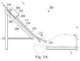
図3A及び図3Bは、いくつかの実施形態による、挿入アセンブリに取り付けられた医療器具を含む患者座標空間の側面図の概略図である。図3A及び図3Bに示されるように、手術環境300には、図1のテーブルT上に位置付けされる患者Pが含まれる。患者Pの総体的な動きが鎮静作用、拘束、及び/又は他の手段によって制限されるという意味で、患者Pは手術環境内で静止し得る。患者が呼吸動作を一時的に中断するように息を止めるように頼まれない限り、患者Pの呼吸及び心臓の動作を含む周期的な解剖学的動作は継続し得る。従って、いくつかの実施形態では、データは、呼吸の特定の段階で収集され、その段階でタグ付けされ識別してもよい。いくつかの実施形態では、データが収集される段階は、患者Pから収集された生理学的情報から推測され得る。手術環境300内では、点収集器具(point gathering instrument)304が、器具キャリッジ306に結合される。いくつかの実施形態では、点収集器具304は、EMセンサ、形状センサ、及び/又は他のセンサモダリティを使用してもよい。器具キャリッジ306は、手術環境300内に固定された挿入ステージ308に取り付けられる。あるいはまた、挿入ステージ308は、手術環境300内で移動可能であるが(例えば、追跡センサ又は他の追跡装置を介して)既知の位置を有し得る。器具キャリッジ306は、遠隔操作マニピュレータアセンブリ(例えば遠隔操作マニピュレータアセンブリ102)の構成要素であり、それは点収集器具304に結合して、挿入動作(すなわち、A軸に沿った動作)及びオプションで細長い装置310の先端部318のヨー、ピッチ、及びロールを含む複数の方向の動作を制御する。器具キャリッジ306又は挿入ステージ308は、挿入ステージ308に沿った器具キャリッジ306の動きを制御するサーボモータ(図示せず)等のアクチュエータを含み得る。
3A and 3B are schematic diagrams of side views of patient coordinate space including a medical device attached to an insertion assembly, according to some embodiments. As shown in FIGS. 3A and 3B,
細長い装置310は、器具本体312に結合される。器具本体312は、器具キャリッジ306に対して結合され固定される。いくつかの実施形態では、光ファイバー形状センサ314は、器具本体312上の基端点316に固定される。いくつかの実施形態では、光ファイバー形状センサ314の基端点316は器具本体312と共に移動可能であり得るが、基端点316の位置は(例えば、追跡センサ又は他の追跡装置によって)既知であり得る。形状センサ314は、基端点316から細長い装置310の先端部318等の別の点までの形状を測定する。点収集器具304は、医療器具システム200と実質的に同様であり得る。
位置測定装置320は、器具本体312が挿入軸線Aに沿って挿入ステージ308上を移動するときの器具本体312の位置に関する情報を提供する。位置測定装置320は、器具キャリッジ306の動き、従って器具本体312の動きを制御するアクチュエータの回転及び/又は向きを決定するレゾルバ、エンコーダ、ポテンショメータ、及び/又は他のセンサを含み得る。いくつかの実施形態では、挿入ステージ308は直線的である。いくつかの実施形態では、挿入ステージ308は、湾曲してもよく、又は湾曲部分と直線部分との組合せを有してもよい。
Position-measuring
図3Aは、挿入ステージ308に沿った後退位置にある器具本体312及び器具キャリッジ306を示す。この後退位置では、基端点316は軸線A上の位置L0にある。挿入ステージ308に沿ったこの位置では、基端点316の位置のA成分は、挿入ステージ308上の器具キャリッジ306の位置、従って基端点316を示すためのベース基準を提供するためにゼロ及び/又は別の基準値に設定され得る。器具本体312及び器具キャリッジ306のこの後退位置では、細長い装置310の先端部318は、患者Pの入口オリフィスのすぐ内側に位置付けされ得る。この位置においても、位置測定装置320は、ゼロ及び/又は別の基準値(例えば、I=0)に設定してよい。図3Bでは、器具本体312及び器具キャリッジ306は挿入ステージ308の直線又は曲線であり得る軌道に沿って前進し、細長い装置310の先端部318は患者P内に前進している。この前進位置では、基端点316は軸線A上の位置L1にある。いくつかの例では、挿入ステージ308に沿った器具キャリッジ306の動きを制御する1つ又は複数のアクチュエータ、及び/又は器具キャリッジ306及び/又は挿入ステージ308に関連する1つ又は複数の位置センサからのエンコーダ及び/又は他の位置データを使用して、位置L0に対する基端点316の位置Lxを決定する。いくつかの例では、位置Lxは、細長い装置310の先端部318が患者Pの解剖学的構造の通路内に挿入される距離又は挿入深さの指標としてさらに使用され得る。挿入中に及び患者Pの解剖学的構造内に挿入されている間に、形状センサ314を使用して、患者Pの解剖学的構造内の測定データ点を収集することができる。
FIG. 3A shows
点収集器具304の実施形態は、EM感知及び形状感知を含む任意数のモダリティを使用して測定点を収集することができる。測定点が患者の解剖学的通路内から収集されると、それら点はメモリ等のデータ記憶装置に記憶される。測定点のセットは、処置中に又は処置の直前に得られた測定点の少なくともいくつかを含むが、全てを含むこともできるデータベースに記憶することができる。測定点のセットは、呼吸等の周期的な生理学的運動の共通の相(phase)又は相の一部の間に取得される等、何らかの方法で関連する測定点のサブセットを生成するために、ビニングされ(binned)、分類され、又はフィルタリングされ得る。メモリに記憶される際に、各点は、(点収集器具304の長さに沿って分布する複数のセンサを使用して、いくつかの点の位置を同時に決定する場合に)その点の座標、タイムスタンプ、及び相対センサ位置又は個々のセンサIDを含むデータによって表され得る。測定点のビニングされたサブセットは、別々のデータ構造及び/又はメモリの別々の部分に記憶することができる。いくつかの実施形態では、各点を表すデータは、その点が収集された患者の呼吸相を示す呼吸相マーカーも含み得る。患者の動き追跡装置322を使用して、患者Pの動きを監視及び検出することができる。この動きは、総体的な動きだけでなく、呼吸等の周期的な生理学的運動を含み得る。従って、動き追跡装置322は、生理的相検出器として機能し得る。動き追跡装置322は、光学式追跡システム又は他の任意の適切なシステムであり得る。他の実施形態では、呼吸は、人工呼吸器又は他の任意の技術によって監視することができる。
Embodiments of
図4A、図4B、図4C、及び図4Dは、図1及び図3の患者Pの肺400の解剖学的通路402を通る図3A及び図3Bのカテーテル310の前進を示す。これらの通路402は、気管及び気管支を含む。キャリッジ306が挿入ステージ308に沿って移動するにつれてカテーテル310が前進すると、外科医Sは、カテーテル310の先端部318を操縦して、解剖学的通路402を通してナビゲートすることができる。解剖学的通路を介してナビゲートする際に、カテーテル310は、カテーテル310内で延びる形状センサ314によって「読み取られ(read)」得る形状を想定する。本明細書で説明するように、可撓性カテーテル310を使用して取得した測定点を、様々な要因に基づいて1つ又は複数のビンに割り当てることができる。例えば、測定点を、呼吸等の周期的な生理学的運動の部分に対応するビンに割り当ててもよい。測定点を、カテーテル310の挿入深さに対応するビンに割り当ててもよく、それにより、気管内の測定点、又は気管支通路の特定の(分岐)世代(generation)は、カテーテル310の先端部318が解剖学的通路402を通って前進する際に、単一のビンにプール又は含められ得る。
4A, 4B, 4C, and 4D illustrate advancement of
図5は、画像誘導手術処置において使用するための一般的な方法500を示すフローチャートである。プロセス502において、術前又は術中の画像データが、コンピュータ断層撮影(CT)、磁気共鳴画像法(MRI)、蛍光透視法、サーモグラフィ、超音波、光干渉断層法(OCT)、サーマルイメージング、インピーダンスイメージング、レーザーイメージング、又はナノチューブX線イメージング等の画像化技術から取得される。術前又は術中の画像データは、2次元、3次元、又は4次元(例えば、時間ベース又は速度ベースの情報を含む)の画像に対応し得る。例えば、画像データは、図4A~図4Dのヒトの肺400を表し得る。プロセス504において、単独で又は手動入力と組み合わせて動作するコンピュータシステムを使用して、記録した画像を、部分的又は全体的な解剖学的器官又は解剖学的領域のセグメント化された2次元又は3次元の合成表現又はモデルに変換する。例えば、図6Aは、図4A~図4Dの肺400のセグメント化モデル600を示す。自然発生的な制限又はオペレータによって設定された制限のために、セグメント化モデル600は、ヒトの肺内に存在する全ての通路を含まないかもしれないが、いくつかの通路601を含む。例えば、肺の相対的に狭い及び/又は先端通路は、セグメント化モデル600に完全に含まれないことがある。セグメント化モデル600は、メッシュモデル又は他の適切なモデル等の、肺の内部管腔又は肺の通路を規定する壁を含む3次元モデルであり得る。一般に、このモデルは、解剖学的領域内の点と解剖学的領域外の点とを区別するための機構又は手段を提供する。合成表現及び画像データセットは、通路の様々な位置及び形状並びにそれらの接続性を示し、且つ術前又は術中の画像データに含まれる解剖学的構造の望ましくない部分を省略することがある。いくつかの実施形態では、モデル600は、疑わしい腫瘍又は関心のある他の組織部分等の特に望ましい特徴を含み得る。
FIG. 5 is a flowchart illustrating a
セグメント化プロセス中に、画像は、色、密度、強度、及びテクスチャ等の特定の特性又は計算された特性を共有するセグメント又は要素(例えば、ピクセル又はボクセル)に分割される。このセグメント化プロセスは、モデル600のように、取得した画像に基づいて標的解剖学的構造のモデルを形成する2次元又は3次元再構成をもたらす。モデルを表すために、セグメント化プロセスは、標的解剖学的構造を表すボクセルのセットを描写し、次にマーチングキューブ関数等の関数を適用して、ボクセルを取り囲む3D表面を生成する。モデルは、メッシュ、ボリューム、又はボクセルマップを生成することによって作成し得る。このモデルは、肺の内部通路等の解剖学的構造を視覚化する際に外科医Sを補助するためにディスプレイ110に示してもよい。
During the segmentation process, the image is divided into segments or elements (eg, pixels or voxels) that share certain properties or computed properties such as color, density, intensity, and texture. This segmentation process results in a two-dimensional or three-dimensional reconstruction that forms a model of the target anatomy, such as
追加的又は代替的に、モデルは、モデル化された通路の中心を通って延びる相互接続された線分又は点のセットを含む中心線モデルを含み得る。図6Bは、モデル600から導出された又は撮像データから直接的に導出された例示的な中心線モデル602を示す。中心線セグメント化モデル602は、セグメント化モデル602に含まれる通路のおおよその中心に対応する3次元直線のセット又は曲線のセットを含むことができる。モデルの解像度が高いほど、直線又は曲線のセットは、より正確に通路の中心に対応するようになる。中心線セグメント化モデル602で肺を表すことによって、(モデル600の通路の壁を表す)セグメント化モデル602のデータセット以外の1つ又は複数のプロセッサ又は処理コアによってより効率的に処理される小さいデータセットを提供することができる。このようにして、制御システム112の機能を改善することができる。
Additionally or alternatively, the model may include a centerline model that includes a set of interconnected line segments or points that extend through the center of the passageway being modeled. FIG. 6B shows an
図6Bに示されるように、中心線セグメント化モデル602はいくつかの分岐点を含み、それら分岐点のいくつかは図6Bにおいて視覚化のために強調されている。分岐点A、B、C、D、及びEは、いくつかの分岐点のそれぞれに示されている。分岐点Aは、気管が左右の主気管支に分割されるモデル内の点を表すことができる。右側主気管支は、分岐点AとBとの間に位置するものとして、中心線分モデル602において識別され得る。同様に、副気管支は、分岐点BとCとによって及び分岐点BとEとの間で識別される。別の世代が分岐点CとDとの間に規定され得る。これらの世代のそれぞれは、対応する通路の管腔の直径の表示と関連付けてもよい。いくつかの実施形態では、モデル602は、各セグメント化世代の平均直径値を含み得る。平均直径値は、患者固有の値又は複数の患者から導出されたより一般的な値であり得る。
As shown in FIG. 6B,
モデルが相互接続された線分のセットを含む中心線モデルを含む場合に、それらの線分は、図6Cの破線によって表されるモデル点と呼ばれる点604のセット又はクラウドに変換される。線分を点に変換することによって、相互接続された線分に対応する所望の量のモデル点を手動又は自動で選択して、位置合せプロセス中に中心線モデル602(従って、モデル600)を表すことができる。データにおいて、モデル点のセット604の各点は、XM、YM、及びZM等の座標のセット、又は3次元モデル空間内の各点の位置を識別する他の座標を含み得る。いくつかの実施形態では、各点は、点がどの通路世代に関連するかを識別する世代識別子、及び/又は中心線セグメント化モデル602のその部分に関連する直径又は半径値を含み得る。いくつかの実施形態では、所与の点に関連する半径又は直径を示す情報は、別々のデータセットの一部として提供してもよい。
If the model contains a centerline model that includes a set of interconnected line segments, those line segments are transformed into a set or cloud of
中心線セグメント化モデル602が生成され、図6Cに示される点604のセットとしてデータとして記憶された後に、モデル点604は、画像誘導手術処置に使用するためにデータ記憶装置から検索することができる。画像誘導手術処置において中心線セグメント化モデル602及びモデル600を使用するために、モデル点604を位置合わせして、モデル600内のモデル化された通路を手術環境に存在する患者の実際の解剖学的構造と関連付けることができる。
After the
図5に戻ると、プロセス506において、図3A~図3B及び図4A~図4Dに示されるように、解剖学的モデルに対応する患者の解剖学的構造から測定点を取得することができる。プロセス508において、解剖学的モデルデータは、患者に対する画像誘導手術処置の前及び/又はその間に患者の解剖学的構造に位置合わせされる。一般に、位置合せは、剛体変換及び/又は非剛体変換の使用による測定点とモデル点とのマッチングを含む。解剖学的構造内のランドマーク、処置中に走査及び追跡される電磁コイル、又は形状センサシステムを使用して測定点を生成することができる。測定点は、ICP(iterative closest point)技法で使用するために生成してもよく、又は本開示の範囲内の位置合せプロセスで別の点セット位置合せ方法も使用してもよい。
Returning to FIG. 5, in
患者の解剖学的構造に対して位置付けされた医療器具を解剖学的モデルに対して表すことができるように解剖学的モデルが患者の解剖学的構造に位置合わせされるプロセス508の後に、患者の解剖学的構造からの測定点の収集は継続し得る。新たな測定点が追加されると、プロセス510において位置合せが更新され得る。位置合せの更新は手術処置を通して連続的に行ってもよい。このようにして、患者の動き(総体的な動きと周期的な生理学的運動との両方)による変化を補償することができる。さらに、測定点は、1つ又は複数の基準によって点の様々なサブセットに割り当てることができ、それによって、患者の解剖学的構造を解剖学的モデルに位置合わせする際にいくつかのサブセット又は特定のサブセットを他のサブセットよりも良好に決定することができる。点には、その点が点の任意のサブセットに正しく割り当てられているという部分的な確率を反映した数値重みを割り当てることもできる。しかしながら、第1の期間に亘って最適な位置合せを与えた可能性があるサブセットは、後の期間では準最適になる可能性がある。測定点のどのサブセットを使用してもその時点で最適な位置合わせを提供するように位置合せを更新することは、モデルと解剖学的構造との間の最良且つ最も有用な関係が維持されることを保証することができる。位置合せの質に統計的に有意な変化が生じると(例えば、位置合せに関連する誤差値に有意な変化があると)、その位置合せに関連する測定点のサブセットは、全ての点の削除によって空にされるか、又はそのサブセットに適用された測定点の重みを有し得る。
After the
画像誘導手術で使用するための他の位置合せ方法は、大抵の場合、電磁気的感知又はインピーダンス感知に基づく技術の使用を伴う。手術環境で使用される金属製の物体や特定の電子装置は、感知したデータの質を損なう障害を引き起こす可能性がある。他の位置合せ方法は、臨床ワークフローを妨げる可能性がある。本明細書に記載のシステム及び方法のいくつかの実施形態は、ICP、又は他の点セット位置合せアルゴリズム、及び光ファイバー形状センサを含む点収集器具の較正された動きに基づいて位置合せを実行し、こうして手術環境における障害を排除又は最小化する。他の位置合せ技術を使用して、測定点のセットを術前モデル又は他のモダリティを使用して得られたモデルに位置合わせすることができる。以下で説明する実施形態では、患者上のEMセンサ及び器具、並びに器具のための光学的追跡システムを除いてもよい。 Other registration methods for use in image-guided surgery often involve the use of techniques based on electromagnetic or impedance sensing. Metallic objects and certain electronic devices used in the surgical environment can cause disturbances that impair the quality of the sensed data. Other registration methods can interfere with clinical workflow. Some embodiments of the systems and methods described herein perform registration based on ICP, or other point set registration algorithms, and calibrated movements of point collection instruments including fiber optic shape sensors. , thus eliminating or minimizing disturbances in the surgical environment. Other registration techniques can be used to register the set of measurement points to a preoperative model or model obtained using other modalities. The embodiments described below may eliminate the EM sensors and instruments on the patient as well as the optical tracking system for the instruments.
図7は、本開示のいくつかの実施形態による、手術環境300内の患者Pに対する画像誘導手術処置において臨床医に誘導を与えるために使用される方法700を示すフローチャートである。方法700は、図7にブロック、ステップ、動作、又はプロセスのセットとして示される。方法700の全ての実施形態では、例示され列挙された動作の全てが行われるわけではない。さらに、図7に明示的に示されていない追加のいくつかの動作が、列挙された動作の前、後、その間に、又はその一部として含まれてもよい。方法700のいくつかの実施形態は、方法700の動作に対応し、且つメモリに記憶された機械可読命令を含み得る。これらの命令は、制御システム112のプロセッサ等のプロセッサによって実行してもよい。
FIG. 7 is a flowchart illustrating a
こうして、方法700のいくつかの実施形態は、動作702で開始することができ、この動作において、測定点のセットが、カテーテル又は他の医療器具の長さに沿って収集される。例えば、カテーテルは、図3A及び図3Bの点収集器具304、又は図2の医療器具システム200であり得る。カテーテルは、カテーテルの形状を表す複数の3次元点を生成するために使用され得る光ファイバー形状センサを含み得る。3次元点は、光ファイバー形状センサの基端部と既知の位置又は検出された位置とを有することによって患者空間に関連され得る。
Thus, some embodiments of
実際には、カテーテル310の先端部318は、形状センサ314からのデータ、カテーテルの先端部の位置データ、及び形状センサの形状に沿った他の点によって記録される、患者Pの解剖学的通路(例えば、患者の肺の気道)を通過し得る。この位置データは、本明細書に記載されるように測定点のセットを含むか、又はこの位置データを処理して、その測定点のセットを取得することができる。より具体的には、カテーテル610の先端チップの動きは、解剖学的通路の一部を調査するために、遠隔操作、手動、又は自動制御(例えば、マスターアセンブリ106を介して)によって制御してもよい。
In practice, the
例えば、遠隔操作制御信号によって、キャリッジ306を軸線Aに沿って移動させ、カテーテルの先端部318を解剖学的通路内で前進又は後退させることができる。それに加えて又はその代わりに、遠隔操作制御信号によって、手術用器具内に延びる制御部材を作動させて、ヨー、ピッチ、及びロールを含む一連の動きで先端部318を動かすことができる。カテーテルが複数の通路内を移動すると、形状センサデータ(及び/又は形状センサを含まない他の実施形態では他の位置データ)が先端チップの複数の位置について収集される。いくつかの実施形態では、カテーテルは、様々な通路の奥深くまで約3つまでの分岐部まで延びることができる。いくつかの実施形態では、カテーテルは、肺の両側にある約3つ以上の分岐世代を通って、又はその中に延びることができる。可撓性カテーテル310の直径が減少するにつれて、及び/又は可撓性カテーテル310の可撓性が増大するにつれて、カテーテル310でアクセス可能な世代の数が増加し得る。
For example, a remote control signal may cause
いくつかの実施形態では、較正手順は、点収集器具304又は他の適切な装置等の位置測定装置を使用して測定点を収集する前に、挿入経路に沿ってセンサ基準点の相対位置及び/又は方向に対して行われ得る。例えば、キャリッジ306が位置L0にある点316の後退位置から位置L1にある点316の前進位置まで動くときに、図3A及び図3Bの点収集器具304を使用して、点316の位置及び向きを決定することができる。較正手順は、位置測定装置320の変化毎に点316の移動方向を決定することができる。例えば、カテーテル310の先端部318は、器具本体が挿入ステージ308に沿って導かれる間に、固定位置に保持することができる。形状センサによって固定点316から収集された位置及び向きデータは、器具本体が挿入ステージに沿って導かれるときに位置測定装置データと相関付けられ、こうして点316の挿入ステージ308の軸線Aに沿った移動を較正する。
In some embodiments, the calibration procedure determines the relative positions of the sensor fiducial points along the insertion path and prior to collecting measurement points using a position-measuring device, such as the point-collecting
オプションで、動作703において、状態入力が制御システム112によって受信され得る。例えば、状態入力は、患者Pの呼吸又は患者Pの心拍を示す周期的な生理学的運動信号であり得る。他の生理学的運動信号が他の実施形態で受信され使用され得る。以下でさらに詳細に説明する図8A及び図8Bは、例示的な周期的な生理学的運動信号800の単一の周期を示す。周期的な生理学的運動信号は、x軸に沿って示される周期Tとy軸に沿って示される振幅とを含む。図8A及び図8Bに示される信号は、本開示の特定の態様をより明確に伝えるために簡略化されている。他の状態入力は、器具の速度、力、加えられた歪み、又は向き等の非生理学的入力を含み得る。他の状態入力は、カメラが検出した(例えば、くもり又は堆積物による)障害物を含み得る。他の状態入力は、特定の解剖学的位置に又は特定の解剖学的通路内に属するものとして指定されるタグ付き測定点を含み得る。そのようなタグ付けされた点は、位置合せ中に「グランドトルース(ground truth)」点として役立ち得る。
Optionally, at operation 703 a status input may be received by
動作704において、測定点を測定点の複数のサブセットに割り当てることができる。いくつかの実施形態では、動作702及び704は実質的に同時に行うことができる。他の実施形態では、動作702は、測定点のセットをメモリ内の点のプール(pool)に記憶することを含み、動作704は、メモリから測定点のセットを取り出し、次に取り出した点を複数のサブセットに割り当てることを含み得る。測定点のサブセットへの割当ては、本明細書では「ビニング(binning)」と呼ばれ得る。測定点はそれぞれ、いくつかのビンのうちの1つに割り当てられ得る。ビンは、データ構造及び/又はメモリの特定の部分であり得る。図8A及び図8Bは、測定点を特定のビンに割り当て得るいくつかの例示的な方法を示す。各点の任意のビンへの割当ては、バイナリ(明示的に指定されたビンの内側又は外側)にすることも、分数の重みで表される任意のビンへのソフトな割当てを含めることもできる。
At
図8Aに示されるように、周期的な生理学的運動信号800を使用して、収集した測定点をビンに入れてもよい。図8Aは、時間ベース又は周期ベースのビニングを示しており、特定の測定点が得られる時間は、その点を割り当てるべきビンを示す。光ファイバー形状センサを使用して測定点を収集するとき、複数の点が一度に収集されることに留意されたい。その時点で光ファイバー形状センサから収集された全ての点は、同じビン又は点のサブセットに割り当てられ得る。例えば、点が0からTの1/8の間の時間に光ファイバーセンサ314から収集される場合に、その点をビンAに割り当ててもよい。点がTの1/8からTの3/8の間の時間に収集される場合に、その点をビンBに割り当ててもよい。点がTの3/8からTの5/8の間の時間に収集される場合に、その点をビンCに割り当ててもよい。点がTの5/8からTの7/8の間に収集される場合に、その点をビンDに割り当ててもよい。点がTの7/8からTの間に収集される場合に、その点をビンAに割り当ててもよい。動作704の他の実施形態は、収集した点をビンに異なるように割り当ててもよい。例えば、測定点は、4以上のビンのうちの1つに割り当ててもよい。ビンは、周期Tの不等部分に関連付けてもよい。ビンのカットオフは、信号800のピーク及びトラフで発生し得る。
As shown in FIG. 8A, a periodic
図8Aに示されるように、周期的な生理学的運動信号800を使用して、信号800の振幅に従って測定点をビンに入れてもよい。図8Bは、測定点を3つのビン、すなわちビンE、ビンF、及びビンGに分類する振幅カットオフを示す。例えば、周期的な生理学的運動信号800の振幅がピーク値の半分より大きい場合に収集される点をビンEに割り当ててもよい。周期的な生理学的運動信号800の振幅が最小値の半分未満である場合に収集された点をビンGに割り当ててもよい。これらの振幅値の間に収集された点をビンFに割り当ててもよい。他の実施形態は、より多いビン又はより少ないビンを含み得る。
A periodic
ここで図9を参照すると、方法700の動作704の例示的な図が示されている。図9は、図3A~図3B及び図4A~図4Dのカテーテル310を示す。カテーテル310内に配置された形状センサ(すなわち、形状センサ314)は、周期T内の4つの別々の時間部分(時点t1、t2、t3、及びt4)の間の点を測定する。時点t1、t2、t3、及びt4は、図9に示されるビンA、B、C、及びDのように、異なるビンに対応する。図9に示されるように、t4におけるカテーテル310の形状及び位置は、時点t1、t2、及びt3におけるカテーテル310の形状及び位置とは異なる。この違いは、解剖学的通路402内へのカテーテル310のより深い挿入によるものではなく、患者Pによる呼吸中の肺400の周期的な生理学的運動によるものであり得る。
Referring now to FIG. 9, an exemplary diagram of
ここで図10A、図10B、図10C、及び図10Dを参照すると、動作704の別の実施形態が示される。測定点のそれぞれを複数のビンのうちの1つに割り当てる際に、この割当ては、点を測定するために使用したカテーテルの挿入深さに基づいて行われ得る。従って、深さ値は、エンコーダ又は他のセンサからのステージ308に対するキャリッジ306の移動に基づいて受信してもよい。深さ同士の間のカットオフは、図6Bのセグメント化された中心線モデル602に基づいて術前に決定することができる。他の実施形態では他の深さを使用してもよい。図10Aに示されるように、カテーテル310によって特定の時間に収集した点を深さビンA及びBに分類又は割り当てることができる。図10Bでは、測定点が収集されるときにカテーテル310はさらに挿入されているので、点は3つの深さビン、すなわち深さビンA、B、及びCに割り当てられる。図10C及び図10Dに示されるように、カテーテル310が肺400の解剖学的通路内により深く挿入されると、測定点は深さビンA、B、C、及びDに割り当てられる。図10A~図10Dに示されるように、カテーテル310の一部がより長い期間に亘って基端側の深さにあったため(その間に点は定期的に収集され得る)、より基端側の深さのビンはより多くの測定点を含み得る。いくつかの実施形態では、新しい点が測定されると最も古い点がそのビンに関連する点のサブセット又はプールから削除されるように、ビン内の点の数を制限することができる。
10A, 10B, 10C, and 10D, another embodiment of
再び図7及び方法700を戻ると、動作705において、モデルからのモデル点のセットが制御システム112によって受信され得る。例えば、モデル点のセットは、肺400のモデルを表す点のセットであり得る。動作705で受信したモデル点のセットは、図6のモデル点604と同様であり得、モデル点のセットは、モデル600に基づく中心線モデル602から導出された点のセットである。モデル点のセット604を使用して、モデル600をカテーテル310を用いて収集された測定点のセットに位置合わせしてもよい。
Returning again to FIG. 7 and
動作704の後に、初期シード(seed)変換を動作706で実行して、測定点をモデル点に対して大まかに配置して、後続の反復位置合せ動作を実行することができる。位置合せプロセスは、患者の手術環境と解剖学的モデルとの間の変位及び向き関係についての既知の情報を種(seeded with)としてもよい。例えば、肺400内の主気管分岐部に関連するランドマークは、解剖学的モデル情報において識別され得る。対応する位置が、ワークフローの一部として測定点に含まれ得る。動作707において、制御システム112は、測定点の各サブセットをモデル点のセットに位置合わせすることができる。位置合せは、動作708~714に記載されるようなICP(iterative closest point)技術等の点セット位置合せアルゴリズムを使用して、又は別の位置合せアルゴリズムの実装によって達成することができる。
After
動作708において、最初の粗いシード変換が実行されて位置合せプロセスが開始された後に、患者P内から収集された測定データ点Dのセットが解剖学的モデル点604とマッチングされる。例えば、測定データ点Dのそれぞれは、解剖学的モデル点604の最近接点とマッチングされる。この実施形態では、解剖学的モデル点604は、3次元解剖学的モデルから生成された中心線に沿った点のセットであり、同様に、セグメント化された中心線モデル602は、図6A及び図6Bのセグメント化モデル600から生成される。位置合せアルゴリズムは、測定したデータ点と解剖学的モデル点604のセットとの最近接点同士の間の一致を識別する。図11Aは、最初のシード処理又は位置合せプロセスが始まった後の測定点1100のセットを含むモデル点604を示している。図11Aに示されるように、測定点1100のセットは、サブセット1102A(黒丸で表される)、サブセット1102B(プラス記号で表される)、サブセット1102C(白丸で表される)、及びサブセット1102D(×で示される)を含む4つのサブセットの測定点を含む。サブセット1102A、1102B、1102C、及び1102Dをまとめてサブセット1102と呼ぶことがある。
In
様々な代替形態では、モデル点604とサブセット1102のそれぞれとの間のマッチングは、力ずく(brute force)技法、KDツリー技法等を使用することによって達成され得る。いくつかのマッチングは、最大距離しきい値計算、最大角度しきい値計算、又はモデルに含めるのに十分信頼できるとみなされない一致を除外するために使用される他のメトリックに基づいて破棄され得る。解剖学的モデル点604は、中心線点、メッシュ点、及び/又はボリューム点を含むいくつかの異なる種類の点のいずれかによって表すことができる。 In various alternatives, matching between model points 604 and each of subsets 1102 may be accomplished by using brute force techniques, KD-tree techniques, or the like. Some matches may be discarded based on maximum distance threshold calculations, maximum angle threshold calculations, or other metrics used to filter out matches that are not considered reliable enough to be included in the model. . Anatomical model points 604 can be represented by any of several different types of points, including centerline points, mesh points, and/or volume points.
図7の方法700を再び参照すると、動作710において、サブセット1102の各サブセットを、一致した解剖学的モデル点604の位置及び向きにマッピングするのに必要な変換が決定される。より具体的には、サブセット1102のそれぞれについて、位置及び向きの全体的な計算オフセットが決定される。いくつかの実施形態では、計算後の修正変換は、特定数の回転角度又は特定数のミリメートルの変位のみがプロセスの1回の繰返しに適用されるように制限され得る。例えば、解剖学的モデル点604の20°の回転又は再向合せが計算されたとしても、医療システムは、向きの変化を10°、5°、又はそれ以下に制限することができる。同様に、いくつかの実施形態では、40mmの変位が計算されたとしても、制御システム112は、1回の反復で利用可能な変位を20mm、10mm、5mm、又はそれ以下に制限することができる。いくつかの実施形態では、制限は、より早い反復よりも遅い反復においてより少ない移動が許容されるように、実行される反復の数に従って変化し得る。
Referring again to
動作712において、各サブセット1102は、計算したオフセットを変位及び向きに適用して特定のサブセット1102内の各点を明確に移動させる剛体(rigid)変換又は非剛体変換を使用して変換してもよい。代替実施形態では、モデル化されたデータ点は、計算したオフセットを変位及び向きに適用してモデル点604のセット内の各点をサブセット1102に向けて移動させる剛体又は非剛体変換を使用することによって変換してもよい。従って、本開示のいくつかの実施形態は、測定点をモデル点に位置合わせし、測定点をモデル点とよりよく一致させるために(測定点の)移動(並進及び/又は向きの変更を含む)させ、それら測定点を共通の空間又は共通の基準フレームに入れる。これらの位置合せは、位置合せ候補として理解され得る。モデル600を測定点1100に位置合わせしてモデル600を患者空間内にもたらすために、最適な位置合せ候補を識別し選択することができる。
At
動作714において、サブセット1102のそれぞれと、一致した解剖学的モデル点604との間の位置合せ誤差が評価される。いくつかの実施形態では、誤差は、各測定点と変換後のその最も近いモデル点との間の累積誤差又は距離として計算することができる。あるいはまた、以前に計算した位置合せからの向き及び変位の変化として表してもよい。これは、各サブセット1102についての向き及び変位の誤差値を含む誤差値の計算を含み得る。換言すれば、向き及び変位の誤差係数は、一致するサブセット1102毎に個別に決定することができる。集計した誤差係数が閾値よりも大きい場合に、位置及び向きの総誤差係数が閾値を下回るまで、追加の繰返し動作708~714を繰り返してもよい。
At
動作716において、各サブセット1102の収束を比較して、どの位置合せ候補が図6Aのモデル600に依拠する手順での使用に最適であるかを判断することができる。換言すれば、サブセット1102A、1102B、1102C、及び1102Dのそれぞれのモデル点604に対する位置合せ候補に関連する総誤差値を比較することができる。総誤差値が最も小さい位置合せ候補を使用して、モデル点604を、点1100が収集される患者空間内にもたらすことができる。モデル点604同士の間の関連付けによって、モデル600を患者空間内に表すことが可能になり得る。いくつかの実施形態では、サブセット毎の収束を決定した後に、収束値を閾値と比較し、収束値が閾値を下回った場合、又は関連する誤差が閾値を超えた場合に、欠陥サブセットのその点まで収集された点は、破棄され得る。例えば、患者Pが総体的な動きをするとき、サブセットのうちの1つ又は複数に関連する位置合せに関する誤差は、著しい誤差を含み得、画像誘導手術に対して位置合せを使用不可能にする。サブセットは患者Pの動きに関連する不良データで「汚染」されているので、そのサブセットは空にされ得、そして点の収集が新たに始まり得る。
At
例えば、動作718において、モデル点604(従って、モデル600)の最適な位置合せの視覚的表現は、図1のディスプレイ110によって提供されるグラフィカルユーザインターフェイスに表示され得る。視覚的表現は、モデル600に関して医療器具システム200を描くことができる。例示的な視覚的表現を図13Aに示す。図13Aは、図6Aの解剖学的モデル600に基づいて、ヒトの肺の解剖学的通路のレンダリングをユーザインターフェイスに表示するディスプレイ1300を示す。図7で上述したようにモデル空間が患者に位置合わせされている状態では、カテーテル310の現在の形状及び先端部318の位置は、通路601A及び601Bを含む通路601のレンダリングと同時に配置及び表示され得る。データ点は、ディスプレイ上の複数の点又はドットによって、又はデータ点のセットに基づいて作成されたメッシュ又はワイヤモデル等のレンダリングモデルとして、ユーザインターフェイスに視覚的に表すことができる。いくつかの実施形態では、データ点を変更するために各処理動作が実施された後に、視覚的表現をディスプレイ110でリフレッシュしてもよい。図13Bは、手術を誘導する際に外科医Sを補助するために提供され得る視覚的表現の別の例示的な表示1350を示す。図13Bは、医療器具200の視点からのモデル600の一部の内部図を示し、且つ通路601A及び601Bのレンダリング後のモデルを描写する。モデル600は、手術の誘導を容易にするために2次元又は3次元でレンダリングしてもよい。
For example, at operation 718 a visual representation of the best alignment of model points 604 (and thus model 600) may be displayed on a graphical user interface provided by
本開示の原理及び実施形態は、患者の解剖学的構造のモデルと手術処置中に患者の解剖学的構造内で操縦される医療器具との間の位置合せを改善することによって画像誘導手術を改善することができる。測定したデータ点のサブセットに基づいて複数の候補位置合せを生成することができ、複数の位置合せを比較して、モデルを患者空間内にもたらすためにモデルに適用すべき最適な位置合せを決定することができる。これらの複数の位置合せ候補は、画像誘導手術での使用のために提供されるように所与の時間に最高の忠実度位置合せを確実にするために、継続的に更新され、互いに及びしきい値と比較され得る。 Principles and embodiments of the present disclosure improve image-guided surgery by improving registration between a model of a patient's anatomy and medical instruments that are maneuvered within the patient's anatomy during a surgical procedure. can be improved. Multiple candidate registrations can be generated based on a subset of the measured data points, and the multiple registrations are compared to determine the optimal registration to apply to the model to bring it into patient space. can do. These multiple registration candidates are continuously updated and aligned with each other to ensure the highest fidelity registration at any given time as provided for use in image-guided surgery. It can be compared with a threshold value.
いくつかの実施形態では、後の位置合せが前の位置合せに置き換わるか、又は前の位置合せが制御システム112によって後の位置合せと置き換え可能であるとみなされるときに、位置合せの変更(例えば、測定点のうちの1つサブセットから別のサブセットへの変更)、又は利用可能な優れた位置合せがあることを示すために、警告がユーザインターフェイスを通して臨床医に提供され得る。いくつかの実施形態では、制御システム112は、優れた位置合せが実施される前に、ユーザインターフェイスを介した臨床医の承認を必要とし得る。例えば、優れた位置合せが識別されると、臨床医が新しい位置合せを承認又は不承認とすることができるボタン又は他のユーザインターフェイス要素と共に、警告をディスプレイ110に与えてもよい。その後、臨床医の決定に応じて新しい位置合せが実施されるかどうかが決まる。
In some embodiments, an alignment change ( For example, a change from one subset of measurement points to another), or an alert may be provided to the clinician through the user interface to indicate that there is a good alignment available. In some embodiments, the
本発明の実施形態の1つ又は複数の要素は、制御システム112等のコンピュータシステムのプロセッサ上で実行するためにソフトウェアで実装することができる。ソフトウェアで実装する場合に、本発明の実施形態の要素は、必要なタスクを実行するための本質的にコードセグメントである。プログラム又はコードセグメントは、光媒体、半導体媒体、及び磁気媒体を含む情報を記憶することができる任意の媒体を含む、非一時的プロセッサ可読記憶媒体又は装置に記憶することができる。プロセッサ可読記憶装置の例は、電子回路;半導体装置、半導体メモリ装置、読出し専用メモリ(ROM)、フラッシュメモリ、消去可能プログラマブル読出し専用メモリ(EPROM);フロッピー(登録商標)ディスケット、CD-ROM、光ディスク、ハードディスク、又は他の記憶装置を含む。コードセグメントは、インターネット、イントラネット等のコンピュータネットワークを介してダウンロードすることができる。本明細書で説明するように、アクセス、収集、割当て、検出、開始、位置合せ、表示、受信、生成、決定、データ点の移動、セグメント化、マッチング等は、制御システム112又はそのプロセッサによって少なくとも部分的に実行され得る。
One or more elements of embodiments of the invention may be implemented in software for execution on a processor of a computer system, such as
提示されたプロセス及び表示は、本質的にいかなる特定のコンピュータ又は他の装置にも関連しないことがあることに留意されたい。これらの様々なシステムに必要な構造は、特許請求の範囲の要素として現れるであろう。さらに、本発明の実施形態は、特定のプログラミング言語を参照して説明していない。本明細書に記載の本発明の教示を実施するために様々なプログラミング言語を使用してもよいこが理解されよう。 Note that the processes and displays presented may not be inherently related to any particular computer or other apparatus. The required structure for a variety of these systems will appear as elements of the claims. Additionally, embodiments of the present invention have not been described with reference to any particular programming language. It will be appreciated that a variety of programming languages may be used to implement the teachings of the invention as described herein.
本発明の特定の例示的な実施形態について添付の図面において説明し示したが、そのような実施形態は単なる例示であり、広範な本発明を限定するものではないこと、及び本発明の実施形態は、他の様々な修正が当業者には想起され得るので、示され説明した特定の構成及び配置に限定されないことを理解されたい。
While specific illustrative embodiments of the invention have been described and illustrated in the accompanying drawings, such embodiments are merely illustrative and not limiting of the broader invention and embodiments of the invention. is to be understood not to be limited to the particular configurations and arrangements shown and described, as various other modifications may occur to those skilled in the art.
Claims (11)
動き検出器と、
挿入ステージに沿って移動可能な器具キャリッジに結合された基端部を有する可撓性カテーテルと、
該可撓性カテーテルの長さに沿って延びる点収集器具と、
該点収集器具によって収集された測定点のセットを1つ又は複数の解剖学的通路のモデルに位置合わせするように構成される追跡システムと、を有しており、
該追跡システムは、
前記モデルのモデル空間に関連付けられるモデル点のセットにアクセスすることと、
患者の前記1つ又は複数の解剖学的通路内に挿入された前記可撓性カテーテルの前記長さに沿って前記測定点のセットを収集することであって、前記測定点は患者空間内の前記カテーテルの形状によって決定される、収集することと、
前記動き検出器によって監視される周期的な生理学的機能に従って、前記測定点のセットを複数のサブセットに割り当てることと、
前記複数のサブセットの各サブセットを前記モデル点のセットと位置合わせすることにより、複数の位置合せ候補を生成することと、
前記複数の位置合せ候補のうちの最適な位置合せを提供する第1の位置合せ候補を示す比較メトリックに基づいて、前記複数の位置合せ候補から前記複数のサブセットのうちの第1のサブセットに関連する前記第1の位置合せ候補を選択することと、
該選択された第1の位置合せ候補を前記モデルの前記モデル点のセットに適用して、前記患者空間を前記モデルに位置合わせすること、を含む動作を行う、
システム。 A medical imaging system, the system comprising:
a motion detector;
a flexible catheter having a proximal end coupled to an instrument carriage movable along an insertion stage;
a point collection device extending along the length of the flexible catheter;
a tracking system configured to register a set of measurement points collected by the point collection instrument to one or more models of anatomical passageways;
The tracking system is
accessing a set of model points associated with a model space of the model;
acquiring the set of measurement points along the length of the flexible catheter inserted into the one or more anatomical passageways of a patient, the measurement points being in patient space; collecting determined by the shape of the catheter;
assigning the set of measurement points to a plurality of subsets according to periodic physiological functions monitored by the motion detector;
generating a plurality of candidate alignments by aligning each subset of the plurality of subsets with the set of model points;
relating to a first of the plurality of subsets from the plurality of alignment candidates based on a comparison metric indicative of the first of the plurality of alignment candidates providing the best alignment; selecting the first candidate alignment to
applying the selected first registration candidate to the set of model points of the model to register the patient space to the model;
system.
前記第1の位置合せ候補を選択するために使用される前記比較メトリックの変化を検出することと、
最適な位置合せを提供する第2の位置合せ候補を示す前記比較メトリックの前記変化に基づいて、前記複数の位置合せ候補から前記第2の位置合せ候補を選択することと、
前記選択された第2の位置合せ候補を適用して、前記患者空間を前記モデルに位置合わせすることと、
測定点を前記複数のサブセットに追加することにより前記複数のサブセットを変更すること、がさらに含まれる、請求項1乃至3のいずれか一項に記載のシステム。 Said operation includes:
detecting changes in the comparison metric used to select the first alignment candidate;
selecting the second candidate alignment from the plurality of candidate alignments based on the change in the comparison metric indicative of the second candidate alignment providing the best alignment;
applying the selected second registration candidate to register the patient space to the model;
4. The system of any one of claims 1-3 , further comprising modifying the plurality of subsets by adding measurement points to the plurality of subsets.
動き検出器と、
挿入ステージに沿って移動可能な器具キャリッジに結合された基端部を有する可撓性カテーテルと、
該可撓性カテーテルの長さに沿って延びる点収集器具と、
該点収集器具によって収集された測定点のセットを1つ又は複数の解剖学的通路のモデルに位置合わせするように構成される追跡システムと、を有しており、
該追跡システムは、
前記モデルのモデル空間に関連付けられるモデル点のセットにアクセスすることと、
患者の前記1つ又は複数の解剖学的通路内に挿入された前記可撓性カテーテルの前記長さに沿って前記測定点のセットを収集することであって、前記測定点は患者空間内の前記カテーテルの形状によって決定される、収集することと、
前記カテーテルの挿入深さを決定することと、
前記測定点に関連する前記カテーテルの一部の前記挿入深さに基づいて、各測定点を複数のサブセットのうちの1つに割り当てることと、
前記複数のサブセットの各サブセットを前記モデル点のセットと位置合わせすることにより、複数の位置合せ候補を生成することと、
前記複数の位置合せ候補のうちの最適な位置合せを提供する第1の位置合せ候補を示す比較メトリックに基づいて、前記複数の位置合せ候補から前記複数のサブセットのうちの第1のサブセットに関連する前記第1の位置合せ候補を選択することと、
該選択された第1の位置合せ候補を前記モデルの前記モデル点のセットに適用して、前記患者空間を前記モデルに位置合わせすること、を含む動作を行う、
システム。 A medical imaging system, the system comprising:
a motion detector;
a flexible catheter having a proximal end coupled to an instrument carriage movable along an insertion stage;
a point collection device extending along the length of the flexible catheter;
a tracking system configured to register a set of measurement points collected by the point collection instrument to one or more models of anatomical passageways;
The tracking system is
accessing a set of model points associated with a model space of the model;
acquiring the set of measurement points along the length of the flexible catheter inserted into the one or more anatomical passageways of a patient, the measurement points being in patient space; collecting determined by the shape of the catheter;
determining an insertion depth of the catheter;
assigning each measurement point to one of a plurality of subsets based on the insertion depth of the portion of the catheter associated with the measurement point ;
generating a plurality of candidate alignments by aligning each subset of the plurality of subsets with the set of model points;
relating to a first of the plurality of subsets from the plurality of alignment candidates based on a comparison metric indicative of the first of the plurality of alignment candidates providing the best alignment; selecting the first candidate alignment to
applying the selected first registration candidate to the set of model points of the model to register the patient space to the model;
system.
Applications Claiming Priority (3)
| Application Number | Priority Date | Filing Date | Title |
|---|---|---|---|
| US201662416393P | 2016-11-02 | 2016-11-02 | |
| US62/416,393 | 2016-11-02 | ||
| PCT/US2017/059358 WO2018085287A1 (en) | 2016-11-02 | 2017-10-31 | Systems and methods of continuous registration for image-guided surgery |
Publications (2)
| Publication Number | Publication Date |
|---|---|
| JP2019531809A JP2019531809A (en) | 2019-11-07 |
| JP7229155B2 true JP7229155B2 (en) | 2023-02-27 |
Family
ID=62077090
Family Applications (1)
| Application Number | Title | Priority Date | Filing Date |
|---|---|---|---|
| JP2019518029A Active JP7229155B2 (en) | 2016-11-02 | 2017-10-31 | Sequential registration system and method for image-guided surgery |
Country Status (6)
| Country | Link |
|---|---|
| US (4) | US11065059B2 (en) |
| EP (2) | EP3534818B1 (en) |
| JP (1) | JP7229155B2 (en) |
| KR (2) | KR20190067917A (en) |
| CN (2) | CN115631843A (en) |
| WO (1) | WO2018085287A1 (en) |
Families Citing this family (64)
| Publication number | Priority date | Publication date | Assignee | Title |
|---|---|---|---|---|
| US8218847B2 (en) | 2008-06-06 | 2012-07-10 | Superdimension, Ltd. | Hybrid registration method |
| US9603668B2 (en) | 2014-07-02 | 2017-03-28 | Covidien Lp | Dynamic 3D lung map view for tool navigation inside the lung |
| US9633431B2 (en) | 2014-07-02 | 2017-04-25 | Covidien Lp | Fluoroscopic pose estimation |
| US9974525B2 (en) | 2014-10-31 | 2018-05-22 | Covidien Lp | Computed tomography enhanced fluoroscopic system, device, and method of utilizing the same |
| EP3062142B1 (en) | 2015-02-26 | 2018-10-03 | Nokia Technologies OY | Apparatus for a near-eye display |
| US10702226B2 (en) | 2015-08-06 | 2020-07-07 | Covidien Lp | System and method for local three dimensional volume reconstruction using a standard fluoroscope |
| US10674982B2 (en) | 2015-08-06 | 2020-06-09 | Covidien Lp | System and method for local three dimensional volume reconstruction using a standard fluoroscope |
| US10716525B2 (en) | 2015-08-06 | 2020-07-21 | Covidien Lp | System and method for navigating to target and performing procedure on target utilizing fluoroscopic-based local three dimensional volume reconstruction |
| CN115631843A (en) | 2016-11-02 | 2023-01-20 | 直观外科手术操作公司 | System and method for continuous registration for image-guided surgery |
| US10650552B2 (en) | 2016-12-29 | 2020-05-12 | Magic Leap, Inc. | Systems and methods for augmented reality |
| EP4300160A2 (en) | 2016-12-30 | 2024-01-03 | Magic Leap, Inc. | Polychromatic light out-coupling apparatus, near-eye displays comprising the same, and method of out-coupling polychromatic light |
| US11793579B2 (en) | 2017-02-22 | 2023-10-24 | Covidien Lp | Integration of multiple data sources for localization and navigation |
| US10699448B2 (en) | 2017-06-29 | 2020-06-30 | Covidien Lp | System and method for identifying, marking and navigating to a target using real time two dimensional fluoroscopic data |
| US10578870B2 (en) | 2017-07-26 | 2020-03-03 | Magic Leap, Inc. | Exit pupil expander |
| US10893843B2 (en) | 2017-10-10 | 2021-01-19 | Covidien Lp | System and method for identifying and marking a target in a fluoroscopic three-dimensional reconstruction |
| US10646284B2 (en) * | 2017-12-05 | 2020-05-12 | Covidien Lp | Multi-rigid registration of magnetic navigation to a computed tomography volume |
| KR20230152180A (en) | 2017-12-10 | 2023-11-02 | 매직 립, 인코포레이티드 | Anti-reflective coatings on optical waveguides |
| US10984585B2 (en) * | 2017-12-13 | 2021-04-20 | Covidien Lp | Systems, methods, and computer-readable media for automatic computed tomography to computed tomography registration |
| KR20200100720A (en) | 2017-12-20 | 2020-08-26 | 매직 립, 인코포레이티드 | Insert for augmented reality viewing device |
| US10930064B2 (en) | 2018-02-08 | 2021-02-23 | Covidien Lp | Imaging reconstruction system and method |
| US11364004B2 (en) | 2018-02-08 | 2022-06-21 | Covidien Lp | System and method for pose estimation of an imaging device and for determining the location of a medical device with respect to a target |
| US10905498B2 (en) | 2018-02-08 | 2021-02-02 | Covidien Lp | System and method for catheter detection in fluoroscopic images and updating displayed position of catheter |
| CN112136152A (en) | 2018-03-15 | 2020-12-25 | 奇跃公司 | Image correction caused by deformation of components of a viewing device |
| JP7319303B2 (en) | 2018-05-31 | 2023-08-01 | マジック リープ, インコーポレイテッド | Radar head pose localization |
| US11856479B2 (en) | 2018-07-03 | 2023-12-26 | Magic Leap, Inc. | Systems and methods for virtual and augmented reality along a route with markers |
| US11071591B2 (en) | 2018-07-26 | 2021-07-27 | Covidien Lp | Modeling a collapsed lung using CT data |
| US11705238B2 (en) | 2018-07-26 | 2023-07-18 | Covidien Lp | Systems and methods for providing assistance during surgery |
| US10795458B2 (en) | 2018-08-03 | 2020-10-06 | Magic Leap, Inc. | Unfused pose-based drift correction of a fused pose of a totem in a user interaction system |
| US20210177370A1 (en) * | 2018-08-22 | 2021-06-17 | Magic Leap, Inc. | Patient viewing system |
| EP3618005A1 (en) * | 2018-08-30 | 2020-03-04 | Koninklijke Philips N.V. | Image processing system and method |
| US11944388B2 (en) | 2018-09-28 | 2024-04-02 | Covidien Lp | Systems and methods for magnetic interference correction |
| US11877806B2 (en) | 2018-12-06 | 2024-01-23 | Covidien Lp | Deformable registration of computer-generated airway models to airway trees |
| US11045075B2 (en) | 2018-12-10 | 2021-06-29 | Covidien Lp | System and method for generating a three-dimensional model of a surgical site |
| US11801113B2 (en) | 2018-12-13 | 2023-10-31 | Covidien Lp | Thoracic imaging, distance measuring, and notification system and method |
| US11617493B2 (en) | 2018-12-13 | 2023-04-04 | Covidien Lp | Thoracic imaging, distance measuring, surgical awareness, and notification system and method |
| US11357593B2 (en) | 2019-01-10 | 2022-06-14 | Covidien Lp | Endoscopic imaging with augmented parallax |
| US11625825B2 (en) | 2019-01-30 | 2023-04-11 | Covidien Lp | Method for displaying tumor location within endoscopic images |
| US11564751B2 (en) | 2019-02-01 | 2023-01-31 | Covidien Lp | Systems and methods for visualizing navigation of medical devices relative to targets |
| US11925333B2 (en) | 2019-02-01 | 2024-03-12 | Covidien Lp | System for fluoroscopic tracking of a catheter to update the relative position of a target and the catheter in a 3D model of a luminal network |
| US11744643B2 (en) | 2019-02-04 | 2023-09-05 | Covidien Lp | Systems and methods facilitating pre-operative prediction of post-operative tissue function |
| EP3930616A1 (en) * | 2019-02-26 | 2022-01-05 | Intuitive Surgical Operations, Inc. | Systems and methods for registration of patient anatomy |
| EP3939030A4 (en) | 2019-03-12 | 2022-11-30 | Magic Leap, Inc. | Registration of local content between first and second augmented reality viewers |
| CN113710145A (en) * | 2019-03-15 | 2021-11-26 | 直观外科手术操作公司 | System for enhanced registration of patient anatomy |
| GB2582795B (en) * | 2019-04-03 | 2021-06-23 | Siemens Healthcare Ltd | A method and apparatus for controlling the generation of a magnetic resonance imaging sequence |
| US11819285B2 (en) | 2019-04-05 | 2023-11-21 | Covidien Lp | Magnetic interference detection systems and methods |
| US11854217B2 (en) * | 2019-05-03 | 2023-12-26 | Koninklijke Philips N.V. | Co-registration of cardiac images |
| US20200375665A1 (en) * | 2019-05-31 | 2020-12-03 | Canon U.S.A., Inc. | Medical continuum robot and methods thereof |
| CN112085797A (en) * | 2019-06-12 | 2020-12-15 | 通用电气精准医疗有限责任公司 | 3D camera-medical imaging device coordinate system calibration system and method and application thereof |
| US11269173B2 (en) | 2019-08-19 | 2022-03-08 | Covidien Lp | Systems and methods for displaying medical video images and/or medical 3D models |
| CN110464462B (en) * | 2019-08-29 | 2020-12-25 | 中国科学技术大学 | Image navigation registration system for abdominal surgical intervention and related device |
| US11864935B2 (en) | 2019-09-09 | 2024-01-09 | Covidien Lp | Systems and methods for pose estimation of a fluoroscopic imaging device and for three-dimensional imaging of body structures |
| US11931111B2 (en) | 2019-09-09 | 2024-03-19 | Covidien Lp | Systems and methods for providing surgical guidance |
| US11627924B2 (en) | 2019-09-24 | 2023-04-18 | Covidien Lp | Systems and methods for image-guided navigation of percutaneously-inserted devices |
| US20220387115A1 (en) * | 2019-11-08 | 2022-12-08 | Intuitive Surgical Operations, Inc. | Systems and methods for registering an instrument to an image using change in instrument position data |
| WO2021097323A1 (en) | 2019-11-15 | 2021-05-20 | Magic Leap, Inc. | A viewing system for use in a surgical environment |
| US20220395332A1 (en) * | 2019-11-26 | 2022-12-15 | Arizona Board Of Regents On Behalf Of Arizona State University | System and method for determining position of a steerable assembly within tissue of an animal body |
| KR102512385B1 (en) | 2020-01-23 | 2023-03-22 | (주)엘메카 | Control Device of Medical Suction Device |
| US11380060B2 (en) | 2020-01-24 | 2022-07-05 | Covidien Lp | System and method for linking a segmentation graph to volumetric data |
| US11847730B2 (en) | 2020-01-24 | 2023-12-19 | Covidien Lp | Orientation detection in fluoroscopic images |
| US11950950B2 (en) | 2020-07-24 | 2024-04-09 | Covidien Lp | Zoom detection and fluoroscope movement detection for target overlay |
| US11544847B1 (en) * | 2020-10-16 | 2023-01-03 | Neutrace, Inc. | System and method for generating point cloud data for electro-anatomical mapping |
| EP4271306A1 (en) * | 2020-12-30 | 2023-11-08 | Intuitive Surgical Operations, Inc. | Systems for updating a graphical user interface based upon intraoperative imaging |
| CN113616333B (en) * | 2021-09-13 | 2023-02-10 | 上海微创微航机器人有限公司 | Catheter movement assistance method, catheter movement assistance system, and readable storage medium |
| CN117017483B (en) * | 2023-08-04 | 2024-03-08 | 中国人民解放军空军军医大学 | PICC tip guiding measurement positioning method based on medical imaging |
Citations (4)
| Publication number | Priority date | Publication date | Assignee | Title |
|---|---|---|---|---|
| JP2007519443A (en) | 2004-01-20 | 2007-07-19 | コーニンクレッカ フィリップス エレクトロニクス エヌ ヴィ | Apparatus and method for navigating a catheter |
| US20150265368A1 (en) | 2014-03-24 | 2015-09-24 | Intuitive Surgical Operations, Inc. | Systems and Methods for Anatomic Motion Compensation |
| WO2016164311A1 (en) | 2015-04-06 | 2016-10-13 | Intuitive Surgical Operations, Inc. | Systems and methods of registration compensation in image guided surgery |
| WO2017030913A2 (en) | 2015-08-14 | 2017-02-23 | Intuitive Surgical Operations, Inc. | Systems and methods of registration for image-guided surgery |
Family Cites Families (26)
| Publication number | Priority date | Publication date | Assignee | Title |
|---|---|---|---|---|
| FR2567149B1 (en) | 1984-07-06 | 1986-12-05 | Solvay | PROCESS FOR THE EXTRACTION OF POLY-BETA-HYDROXYBUTYRATES USING A SOLVENT FROM AN AQUEOUS SUSPENSION OF MICROORGANISMS |
| DE3441593A1 (en) | 1984-11-14 | 1986-05-22 | Ferd. Rüesch AG, St. Gallen | METHOD AND DEVICE FOR PRODUCING SCREEN PRINTING FABRICS FOR SCREEN PRINTING CYLINDERS |
| US5792135A (en) | 1996-05-20 | 1998-08-11 | Intuitive Surgical, Inc. | Articulated surgical instrument for performing minimally invasive surgery with enhanced dexterity and sensitivity |
| AU1616497A (en) | 1997-02-13 | 1998-09-08 | Super Dimension Ltd. | Six-degree tracking system |
| GB9713018D0 (en) | 1997-06-20 | 1997-08-27 | Secr Defence | Optical fibre bend sensor |
| US7697972B2 (en) * | 2002-11-19 | 2010-04-13 | Medtronic Navigation, Inc. | Navigation system for cardiac therapies |
| US7772541B2 (en) | 2004-07-16 | 2010-08-10 | Luna Innnovations Incorporated | Fiber optic position and/or shape sensing based on rayleigh scatter |
| US20060013523A1 (en) | 2004-07-16 | 2006-01-19 | Luna Innovations Incorporated | Fiber optic position and shape sensing device and method relating thereto |
| CA2588002A1 (en) * | 2005-01-18 | 2006-07-27 | Traxtal Inc. | Method and apparatus for guiding an instrument to a target in the lung |
| EP2086399B1 (en) * | 2006-11-10 | 2017-08-09 | Covidien LP | Adaptive navigation technique for navigating a catheter through a body channel or cavity |
| US7957582B2 (en) | 2007-06-21 | 2011-06-07 | General Electric Company | Method and system for correction of fluoroscope image distortion |
| EP2192855B1 (en) | 2007-07-09 | 2020-03-25 | Covidien LP | Patent breathing modeling |
| US8218847B2 (en) | 2008-06-06 | 2012-07-10 | Superdimension, Ltd. | Hybrid registration method |
| US9259274B2 (en) | 2008-09-30 | 2016-02-16 | Intuitive Surgical Operations, Inc. | Passive preload and capstan drive for surgical instruments |
| RU2011120186A (en) * | 2008-10-20 | 2012-11-27 | Конинклейке Филипс Электроникс, Н.В. | METHOD AND SYSTEM OF LOCALIZATION BASED ON IMAGES |
| CN102858229B (en) | 2010-02-18 | 2015-11-25 | 皇家飞利浦电子股份有限公司 | The bronchoscopy followed the tracks of is adopted to carry out the system and method for tumor motion simulation and motion compensation |
| EP3659490A1 (en) * | 2010-08-20 | 2020-06-03 | Veran Medical Technologies, Inc. | Apparatus and method for four dimensional soft tissue navigation |
| EP2670291A4 (en) * | 2011-02-04 | 2015-02-25 | Penn State Res Found | Method and device for determining the location of an endoscope |
| US8900131B2 (en) | 2011-05-13 | 2014-12-02 | Intuitive Surgical Operations, Inc. | Medical system providing dynamic registration of a model of an anatomical structure for image-guided surgery |
| US9452276B2 (en) | 2011-10-14 | 2016-09-27 | Intuitive Surgical Operations, Inc. | Catheter with removable vision probe |
| EP4056111A3 (en) * | 2012-02-22 | 2022-12-07 | Veran Medical Technologies, Inc. | Systems, methods, and devices for four dimensional soft tissue navigation |
| EP3679881A1 (en) * | 2012-08-14 | 2020-07-15 | Intuitive Surgical Operations, Inc. | Systems and methods for registration of multiple vision systems |
| CN107427204A (en) * | 2014-07-02 | 2017-12-01 | 柯惠有限合伙公司 | Real-time autoregistration feedback |
| EP4328856A2 (en) * | 2014-07-28 | 2024-02-28 | Intuitive Surgical Operations, Inc. | Systems and methods for intraoperative segmentation |
| KR102422504B1 (en) | 2014-08-14 | 2022-07-20 | 인튜어티브 서지컬 오퍼레이션즈 인코포레이티드 | Systems and methods for cleaning an endoscopic instrument |
| CN115631843A (en) | 2016-11-02 | 2023-01-20 | 直观外科手术操作公司 | System and method for continuous registration for image-guided surgery |
-
2017
- 2017-10-31 CN CN202211310706.9A patent/CN115631843A/en active Pending
- 2017-10-31 KR KR1020197015413A patent/KR20190067917A/en not_active IP Right Cessation
- 2017-10-31 CN CN201780057821.0A patent/CN109788992B/en active Active
- 2017-10-31 EP EP17868421.3A patent/EP3534818B1/en active Active
- 2017-10-31 JP JP2019518029A patent/JP7229155B2/en active Active
- 2017-10-31 WO PCT/US2017/059358 patent/WO2018085287A1/en unknown
- 2017-10-31 US US16/343,093 patent/US11065059B2/en active Active
- 2017-10-31 EP EP23189294.4A patent/EP4245207A3/en active Pending
- 2017-10-31 KR KR1020237005351A patent/KR20230031371A/en not_active Application Discontinuation
-
2021
- 2021-06-21 US US17/353,322 patent/US11583353B2/en active Active
-
2023
- 2023-01-13 US US18/154,710 patent/US11864856B2/en active Active
- 2023-11-28 US US18/521,863 patent/US20240090963A1/en active Pending
Patent Citations (4)
| Publication number | Priority date | Publication date | Assignee | Title |
|---|---|---|---|---|
| JP2007519443A (en) | 2004-01-20 | 2007-07-19 | コーニンクレッカ フィリップス エレクトロニクス エヌ ヴィ | Apparatus and method for navigating a catheter |
| US20150265368A1 (en) | 2014-03-24 | 2015-09-24 | Intuitive Surgical Operations, Inc. | Systems and Methods for Anatomic Motion Compensation |
| WO2016164311A1 (en) | 2015-04-06 | 2016-10-13 | Intuitive Surgical Operations, Inc. | Systems and methods of registration compensation in image guided surgery |
| WO2017030913A2 (en) | 2015-08-14 | 2017-02-23 | Intuitive Surgical Operations, Inc. | Systems and methods of registration for image-guided surgery |
Also Published As
| Publication number | Publication date |
|---|---|
| US20210307837A1 (en) | 2021-10-07 |
| EP4245207A2 (en) | 2023-09-20 |
| US11583353B2 (en) | 2023-02-21 |
| EP3534818A4 (en) | 2020-06-03 |
| EP3534818B1 (en) | 2023-09-20 |
| EP4245207A3 (en) | 2023-11-22 |
| JP2019531809A (en) | 2019-11-07 |
| CN109788992A (en) | 2019-05-21 |
| KR20230031371A (en) | 2023-03-07 |
| WO2018085287A1 (en) | 2018-05-11 |
| US20200046431A1 (en) | 2020-02-13 |
| US20240090963A1 (en) | 2024-03-21 |
| CN109788992B (en) | 2022-11-11 |
| KR20190067917A (en) | 2019-06-17 |
| CN115631843A (en) | 2023-01-20 |
| US20230149108A1 (en) | 2023-05-18 |
| US11065059B2 (en) | 2021-07-20 |
| US11864856B2 (en) | 2024-01-09 |
| EP3534818A1 (en) | 2019-09-11 |
Similar Documents
| Publication | Publication Date | Title |
|---|---|---|
| US11864856B2 (en) | Systems and methods of continuous registration for image-guided surgery | |
| US11622669B2 (en) | Systems and methods of registration for image guided surgery | |
| US20240041531A1 (en) | Systems and methods for registering elongate devices to three-dimensional images in image-guided procedures | |
| US11423542B2 (en) | Systems and methods of registration for image-guided surgery | |
| US20220071715A1 (en) | Systems and methods of registration for image-guided surgery | |
| US20200229679A1 (en) | Systems and methods of registration for image-guided procedures | |
| US20210259783A1 (en) | Systems and Methods Related to Registration for Image Guided Surgery | |
| US11514591B2 (en) | Systems and methods related to registration for image guided surgery | |
| US20220142714A1 (en) | Systems for enhanced registration of patient anatomy |
Legal Events
| Date | Code | Title | Description |
|---|---|---|---|
| A521 | Request for written amendment filed |
Free format text: JAPANESE INTERMEDIATE CODE: A523 Effective date: 20190619 |
|
| A621 | Written request for application examination |
Free format text: JAPANESE INTERMEDIATE CODE: A621 Effective date: 20201022 |
|
| A977 | Report on retrieval |
Free format text: JAPANESE INTERMEDIATE CODE: A971007 Effective date: 20210827 |
|
| A131 | Notification of reasons for refusal |
Free format text: JAPANESE INTERMEDIATE CODE: A131 Effective date: 20210831 |
|
| A521 | Request for written amendment filed |
Free format text: JAPANESE INTERMEDIATE CODE: A523 Effective date: 20211101 |
|
| A131 | Notification of reasons for refusal |
Free format text: JAPANESE INTERMEDIATE CODE: A131 Effective date: 20220405 |
|
| A521 | Request for written amendment filed |
Free format text: JAPANESE INTERMEDIATE CODE: A523 Effective date: 20220511 |
|
| A131 | Notification of reasons for refusal |
Free format text: JAPANESE INTERMEDIATE CODE: A131 Effective date: 20220920 |
|
| A521 | Request for written amendment filed |
Free format text: JAPANESE INTERMEDIATE CODE: A523 Effective date: 20221101 |
|
| TRDD | Decision of grant or rejection written | ||
| A01 | Written decision to grant a patent or to grant a registration (utility model) |
Free format text: JAPANESE INTERMEDIATE CODE: A01 Effective date: 20230124 |
|
| A61 | First payment of annual fees (during grant procedure) |
Free format text: JAPANESE INTERMEDIATE CODE: A61 Effective date: 20230214 |
|
| R150 | Certificate of patent or registration of utility model |
Ref document number: 7229155 Country of ref document: JP Free format text: JAPANESE INTERMEDIATE CODE: R150 |