JP7228047B2 - Vehicle window with integrated sensor module - Google Patents
Vehicle window with integrated sensor module Download PDFInfo
- Publication number
- JP7228047B2 JP7228047B2 JP2021536794A JP2021536794A JP7228047B2 JP 7228047 B2 JP7228047 B2 JP 7228047B2 JP 2021536794 A JP2021536794 A JP 2021536794A JP 2021536794 A JP2021536794 A JP 2021536794A JP 7228047 B2 JP7228047 B2 JP 7228047B2
- Authority
- JP
- Japan
- Prior art keywords
- pane
- vehicle window
- sensor
- cover
- vehicle
- Prior art date
- Legal status (The legal status is an assumption and is not a legal conclusion. Google has not performed a legal analysis and makes no representation as to the accuracy of the status listed.)
- Active
Links
- 239000000463 material Substances 0.000 claims description 27
- 239000011796 hollow space material Substances 0.000 claims description 19
- 238000004519 manufacturing process Methods 0.000 claims description 8
- 229920001169 thermoplastic Polymers 0.000 claims description 8
- 239000004416 thermosoftening plastic Substances 0.000 claims description 8
- 239000012815 thermoplastic material Substances 0.000 claims description 6
- 230000001419 dependent effect Effects 0.000 claims description 3
- XLYOFNOQVPJJNP-UHFFFAOYSA-N water Substances O XLYOFNOQVPJJNP-UHFFFAOYSA-N 0.000 claims description 3
- 229920000515 polycarbonate Polymers 0.000 description 24
- 239000004417 polycarbonate Substances 0.000 description 24
- -1 polyethylene Polymers 0.000 description 22
- 239000010410 layer Substances 0.000 description 14
- 229920000139 polyethylene terephthalate Polymers 0.000 description 14
- 239000005020 polyethylene terephthalate Substances 0.000 description 14
- 229920003229 poly(methyl methacrylate) Polymers 0.000 description 11
- 239000004926 polymethyl methacrylate Substances 0.000 description 11
- 239000011521 glass Substances 0.000 description 10
- 238000010438 heat treatment Methods 0.000 description 10
- 239000004698 Polyethylene Substances 0.000 description 9
- 239000000853 adhesive Substances 0.000 description 9
- 230000001070 adhesive effect Effects 0.000 description 9
- 239000011324 bead Substances 0.000 description 9
- 239000000203 mixture Substances 0.000 description 9
- 229920000573 polyethylene Polymers 0.000 description 9
- 239000004743 Polypropylene Substances 0.000 description 7
- 239000004676 acrylonitrile butadiene styrene Substances 0.000 description 7
- 230000005540 biological transmission Effects 0.000 description 7
- 238000000034 method Methods 0.000 description 7
- 229920001155 polypropylene Polymers 0.000 description 7
- 239000002131 composite material Substances 0.000 description 6
- 229920001577 copolymer Polymers 0.000 description 6
- 229920003023 plastic Polymers 0.000 description 6
- 229920001707 polybutylene terephthalate Polymers 0.000 description 6
- VYPSYNLAJGMNEJ-UHFFFAOYSA-N Silicium dioxide Chemical compound O=[Si]=O VYPSYNLAJGMNEJ-UHFFFAOYSA-N 0.000 description 5
- 229920001400 block copolymer Polymers 0.000 description 5
- 239000005336 safety glass Substances 0.000 description 5
- 229920006491 ABS+PC Polymers 0.000 description 4
- 239000004952 Polyamide Substances 0.000 description 4
- 239000004793 Polystyrene Substances 0.000 description 4
- GWEVSGVZZGPLCZ-UHFFFAOYSA-N Titan oxide Chemical compound O=[Ti]=O GWEVSGVZZGPLCZ-UHFFFAOYSA-N 0.000 description 4
- XECAHXYUAAWDEL-UHFFFAOYSA-N acrylonitrile butadiene styrene Chemical compound C=CC=C.C=CC#N.C=CC1=CC=CC=C1 XECAHXYUAAWDEL-UHFFFAOYSA-N 0.000 description 4
- 229920000122 acrylonitrile butadiene styrene Polymers 0.000 description 4
- 239000011248 coating agent Substances 0.000 description 4
- 238000000576 coating method Methods 0.000 description 4
- 239000000945 filler Substances 0.000 description 4
- 239000004033 plastic Substances 0.000 description 4
- 229920002037 poly(vinyl butyral) polymer Polymers 0.000 description 4
- 229920000058 polyacrylate Polymers 0.000 description 4
- 229920002647 polyamide Polymers 0.000 description 4
- 229920000728 polyester Polymers 0.000 description 4
- 229920002223 polystyrene Polymers 0.000 description 4
- 239000004814 polyurethane Substances 0.000 description 4
- 229920006644 PBT+PC Polymers 0.000 description 3
- 239000005062 Polybutadiene Substances 0.000 description 3
- 229920001893 acrylonitrile styrene Polymers 0.000 description 3
- 230000002411 adverse Effects 0.000 description 3
- 238000009434 installation Methods 0.000 description 3
- 238000005259 measurement Methods 0.000 description 3
- 238000012544 monitoring process Methods 0.000 description 3
- 229920002857 polybutadiene Polymers 0.000 description 3
- 229920005554 polynitrile Polymers 0.000 description 3
- 229920002635 polyurethane Polymers 0.000 description 3
- 229920000915 polyvinyl chloride Polymers 0.000 description 3
- 239000004800 polyvinyl chloride Substances 0.000 description 3
- 239000005361 soda-lime glass Substances 0.000 description 3
- 230000007704 transition Effects 0.000 description 3
- 238000002834 transmittance Methods 0.000 description 3
- OKTJSMMVPCPJKN-UHFFFAOYSA-N Carbon Chemical compound [C] OKTJSMMVPCPJKN-UHFFFAOYSA-N 0.000 description 2
- 241001074085 Scophthalmus aquosus Species 0.000 description 2
- 238000010521 absorption reaction Methods 0.000 description 2
- 238000004026 adhesive bonding Methods 0.000 description 2
- PNEYBMLMFCGWSK-UHFFFAOYSA-N aluminium oxide Inorganic materials [O-2].[O-2].[O-2].[Al+3].[Al+3] PNEYBMLMFCGWSK-UHFFFAOYSA-N 0.000 description 2
- 229910052799 carbon Inorganic materials 0.000 description 2
- 239000002734 clay mineral Substances 0.000 description 2
- 229910052681 coesite Inorganic materials 0.000 description 2
- 229910052593 corundum Inorganic materials 0.000 description 2
- 229910052906 cristobalite Inorganic materials 0.000 description 2
- 238000013461 design Methods 0.000 description 2
- 239000005038 ethylene vinyl acetate Substances 0.000 description 2
- 239000003365 glass fiber Substances 0.000 description 2
- 238000001746 injection moulding Methods 0.000 description 2
- 239000011256 inorganic filler Substances 0.000 description 2
- 239000002184 metal Substances 0.000 description 2
- 230000003287 optical effect Effects 0.000 description 2
- 239000012766 organic filler Substances 0.000 description 2
- 239000002861 polymer material Substances 0.000 description 2
- 229920001296 polysiloxane Polymers 0.000 description 2
- 239000011347 resin Substances 0.000 description 2
- 229920005989 resin Polymers 0.000 description 2
- 150000004760 silicates Chemical class 0.000 description 2
- 239000000377 silicon dioxide Substances 0.000 description 2
- 235000012239 silicon dioxide Nutrition 0.000 description 2
- 229910052682 stishovite Inorganic materials 0.000 description 2
- 239000011145 styrene acrylonitrile resin Substances 0.000 description 2
- 229920002725 thermoplastic elastomer Polymers 0.000 description 2
- 229910052905 tridymite Inorganic materials 0.000 description 2
- 229910001845 yogo sapphire Inorganic materials 0.000 description 2
- 239000010457 zeolite Substances 0.000 description 2
- 239000004812 Fluorinated ethylene propylene Substances 0.000 description 1
- CERQOIWHTDAKMF-UHFFFAOYSA-M Methacrylate Chemical compound CC(=C)C([O-])=O CERQOIWHTDAKMF-UHFFFAOYSA-M 0.000 description 1
- 229920006834 PC+ABS Polymers 0.000 description 1
- 229920006624 PC+PET Polymers 0.000 description 1
- 150000001252 acrylic acid derivatives Chemical class 0.000 description 1
- 239000005388 borosilicate glass Substances 0.000 description 1
- 238000005266 casting Methods 0.000 description 1
- 230000000295 complement effect Effects 0.000 description 1
- 238000001514 detection method Methods 0.000 description 1
- 238000010586 diagram Methods 0.000 description 1
- 230000000694 effects Effects 0.000 description 1
- 229920000840 ethylene tetrafluoroethylene copolymer Polymers 0.000 description 1
- 238000002474 experimental method Methods 0.000 description 1
- 239000000835 fiber Substances 0.000 description 1
- 239000005357 flat glass Substances 0.000 description 1
- 239000005329 float glass Substances 0.000 description 1
- 238000002513 implantation Methods 0.000 description 1
- 238000002347 injection Methods 0.000 description 1
- 239000007924 injection Substances 0.000 description 1
- 230000010354 integration Effects 0.000 description 1
- 239000011229 interlayer Substances 0.000 description 1
- 230000031700 light absorption Effects 0.000 description 1
- 238000003754 machining Methods 0.000 description 1
- 238000003801 milling Methods 0.000 description 1
- 229920009441 perflouroethylene propylene Polymers 0.000 description 1
- 230000002093 peripheral effect Effects 0.000 description 1
- 230000035699 permeability Effects 0.000 description 1
- 229920000642 polymer Polymers 0.000 description 1
- 239000000843 powder Substances 0.000 description 1
- QQONPFPTGQHPMA-UHFFFAOYSA-N propylene Natural products CC=C QQONPFPTGQHPMA-UHFFFAOYSA-N 0.000 description 1
- 125000004805 propylene group Chemical group [H]C([H])([H])C([H])([*:1])C([H])([H])[*:2] 0.000 description 1
- 230000003678 scratch resistant effect Effects 0.000 description 1
- 230000035945 sensitivity Effects 0.000 description 1
- 239000002356 single layer Substances 0.000 description 1
- 238000005476 soldering Methods 0.000 description 1
- 230000003595 spectral effect Effects 0.000 description 1
- 230000003068 static effect Effects 0.000 description 1
- 230000001502 supplementing effect Effects 0.000 description 1
- 238000007740 vapor deposition Methods 0.000 description 1
- 238000003466 welding Methods 0.000 description 1
Images


Classifications
-
- G—PHYSICS
- G01—MEASURING; TESTING
- G01S—RADIO DIRECTION-FINDING; RADIO NAVIGATION; DETERMINING DISTANCE OR VELOCITY BY USE OF RADIO WAVES; LOCATING OR PRESENCE-DETECTING BY USE OF THE REFLECTION OR RERADIATION OF RADIO WAVES; ANALOGOUS ARRANGEMENTS USING OTHER WAVES
- G01S7/00—Details of systems according to groups G01S13/00, G01S15/00, G01S17/00
- G01S7/48—Details of systems according to groups G01S13/00, G01S15/00, G01S17/00 of systems according to group G01S17/00
- G01S7/481—Constructional features, e.g. arrangements of optical elements
- G01S7/4811—Constructional features, e.g. arrangements of optical elements common to transmitter and receiver
- G01S7/4813—Housing arrangements
-
- B—PERFORMING OPERATIONS; TRANSPORTING
- B60—VEHICLES IN GENERAL
- B60R—VEHICLES, VEHICLE FITTINGS, OR VEHICLE PARTS, NOT OTHERWISE PROVIDED FOR
- B60R11/00—Arrangements for holding or mounting articles, not otherwise provided for
-
- B—PERFORMING OPERATIONS; TRANSPORTING
- B60—VEHICLES IN GENERAL
- B60R—VEHICLES, VEHICLE FITTINGS, OR VEHICLE PARTS, NOT OTHERWISE PROVIDED FOR
- B60R11/00—Arrangements for holding or mounting articles, not otherwise provided for
- B60R11/04—Mounting of cameras operative during drive; Arrangement of controls thereof relative to the vehicle
-
- B—PERFORMING OPERATIONS; TRANSPORTING
- B61—RAILWAYS
- B61D—BODY DETAILS OR KINDS OF RAILWAY VEHICLES
- B61D49/00—Other details
-
- G—PHYSICS
- G01—MEASURING; TESTING
- G01S—RADIO DIRECTION-FINDING; RADIO NAVIGATION; DETERMINING DISTANCE OR VELOCITY BY USE OF RADIO WAVES; LOCATING OR PRESENCE-DETECTING BY USE OF THE REFLECTION OR RERADIATION OF RADIO WAVES; ANALOGOUS ARRANGEMENTS USING OTHER WAVES
- G01S17/00—Systems using the reflection or reradiation of electromagnetic waves other than radio waves, e.g. lidar systems
- G01S17/88—Lidar systems specially adapted for specific applications
- G01S17/93—Lidar systems specially adapted for specific applications for anti-collision purposes
- G01S17/931—Lidar systems specially adapted for specific applications for anti-collision purposes of land vehicles
-
- B—PERFORMING OPERATIONS; TRANSPORTING
- B60—VEHICLES IN GENERAL
- B60R—VEHICLES, VEHICLE FITTINGS, OR VEHICLE PARTS, NOT OTHERWISE PROVIDED FOR
- B60R11/00—Arrangements for holding or mounting articles, not otherwise provided for
- B60R2011/0001—Arrangements for holding or mounting articles, not otherwise provided for characterised by position
- B60R2011/0003—Arrangements for holding or mounting articles, not otherwise provided for characterised by position inside the vehicle
- B60R2011/0026—Windows, e.g. windscreen
Landscapes
- Engineering & Computer Science (AREA)
- Physics & Mathematics (AREA)
- Computer Networks & Wireless Communication (AREA)
- General Physics & Mathematics (AREA)
- Radar, Positioning & Navigation (AREA)
- Remote Sensing (AREA)
- Mechanical Engineering (AREA)
- Electromagnetism (AREA)
- Transportation (AREA)
- Optical Radar Systems And Details Thereof (AREA)
- Window Of Vehicle (AREA)
- Body Structure For Vehicles (AREA)
- Burglar Alarm Systems (AREA)
- Fittings On The Vehicle Exterior For Carrying Loads, And Devices For Holding Or Mounting Articles (AREA)
Description
本発明は、ウインドウ製造の技術分野にあり、統合されているセンサーモジュールを有している乗物ウインドウ及びその製造方法に関する。 The present invention is in the technical field of window manufacturing and relates to a vehicle window having an integrated sensor module and a method for manufacturing the same.
現代の乗物には、通常、交通監視用のためのセンサーが装備されており、センサーは、例えば、道路標識、又は乗物外の物体の位置及び速度を認識し、乗物外の物体は、例えば、他の道路利用者又は道路内の障害物である。現在、主に光学カメラ又はレーダーシステムが、この目的で使用されている。カメラの使用には、物体認識が外部環境の影響、特にそれぞれの場合で、周辺の光と気象条件に大きく影響するという欠点がある。交通監視のためのレーダーシステムの使用は、光及び気象条件の影響を実質的に受けないが、レーダーシステムの精度は、現在、適切な物体認識には不十分である。この点で、LiDaR(光検出及び測距)システムが有利であることが証明されており、LiDaRシステムにおいては、赤外線範囲の波長のレーザーパルスを使用して周囲を点ごとにスキャンし、周囲の画像を作成する。物体までの距離は、LiDaRセンサーによって放出され、物体によって反射されるレーザーパルスの経過時間の測定によって測定される。物体認識の精度が高く、光及び気象条件からの影響が低いため、LiDaRシステムは、既存のセンサーシステムを補完するのに適している。 Modern vehicles are usually equipped with sensors for traffic monitoring, which recognize, for example, road signs, or the position and speed of objects outside the vehicle, which, for example, other road users or obstacles in the road. Currently, mainly optical cameras or radar systems are used for this purpose. The use of cameras has the disadvantage that object recognition is greatly influenced by the influence of the external environment, in particular ambient light and weather conditions in each case. Although the use of radar systems for traffic monitoring is virtually immune to light and weather conditions, the accuracy of radar systems is currently insufficient for proper object recognition. In this respect, LiDaR (Light Detection and Ranging) systems have proven advantageous, in which laser pulses with wavelengths in the infrared range are used to scan point-by-point around the surroundings. Create an image. Distance to an object is measured by measuring the elapsed time of a laser pulse emitted by a LiDaR sensor and reflected by the object. Due to the high accuracy of object recognition and low sensitivity to light and weather conditions, the LiDaR system is well suited to complement existing sensor systems.
典型的には、交通監視のためのセンサーは、乗物の室内、通常はウインドシールドの後方に配置されている。あるいは、センサーを別のセンサーハウジングに収容し、それを外部から乗物に取り付けることも考えられる。しかし、ウインドシールドの後方での室内設置、及び別のセンサーハウジングでの室外取付けのいずれでも、重大な欠点を生じる。このことから、特にLiDaRセンサーでは、道路に対するウインドシールドの傾斜により、レーザーパルスは、非常に平坦な角度でウインドシールドを通過しなければならず、放出及び反射された光子の、比較的高い偏向、散乱、及び吸収をもたらす。無視できない割合の、測定のための光子が失われるため、LiDaRシステムのパフォーマンス及び効率に悪影響が及ぶ。これは外付けのセンサーで回避できるが、乗物の設計に支障をきたす。それは、これまで、センサーハウジングをスムーズかつ目立たないように乗物の外観に統合することができなかったためである。
Typically, sensors for traffic monitoring are located in the interior of the vehicle, usually behind the windshield. Alternatively, it is conceivable to house the sensor in a separate sensor housing and attach it externally to the vehicle. However, both indoor installation behind the windshield and outdoor installation with a separate sensor housing presents significant drawbacks. It follows from this, especially for LiDaR sensors, that the tilt of the windshield with respect to the road forces the laser pulse to pass through the windshield at a very flat angle, resulting in a relatively high deflection of the emitted and reflected photons. Causes scattering and absorption. A non-negligible proportion of the photons for measurement is lost, thus adversely affecting the performance and efficiency of the LiDaR system. This can be circumvented with an external sensor, but it interferes with vehicle design. This is because, until now, it has not been possible to integrate the sensor housing into the exterior of the vehicle in a smooth and unobtrusive manner.
US2017/0274832A1は、切欠きにレーダーウインドウを有しているウインドシールドを開示している。センサーハウジングは、室内取り付けによってウインドシールドの後方に固定されている。US2011/0285576A1は、カバーで閉じられている切欠きを有しているウインドシールドを開示している。センサーは、ウインドシールドの後方のウインドシールド電子モジュールに収容されている。これらの文献は、既製アセンブリーのセンサーモジュールを開示していない。 US2017/0274832A1 discloses a windshield having a radar window in a cutout. The sensor housing is secured behind the windshield by interior mounting. US2011/0285576A1 discloses a windshield having a cutout which is closed by a cover. The sensor is housed in the windshield electronics module behind the windshield. These documents do not disclose off-the-shelf assembly sensor modules.
したがって、本発明の目的は、従来技術の不利な点を回避し、センサー、特にLiDaRセンサーの使用を、それらの性能及び効率並びに乗物の設計に関して実質的な欠点なしに、可能にすることである。これら及び他の目的は、独立請求項の、統合されているセンサーモジュールを有している乗物ウインドウによる、本発明の提案に従って達成される。本発明の有利な実施形態は、従属請求項から明らかである。 It is therefore an object of the present invention to avoid the disadvantages of the prior art and to enable the use of sensors, in particular LiDaR sensors, without substantial drawbacks in terms of their performance and efficiency and vehicle design. . These and other objects are achieved according to the proposal of the invention by the vehicle window with integrated sensor module of the independent claims. Advantageous embodiments of the invention are evident from the dependent claims.
本発明によれば、統合されているセンサーモジュールを備えている乗物ウインドウが提示される。乗物ウインドウは、切欠きを有しているペイン本体を備えている。ペイン本体の切欠きは、エッジに実装されていてもよいし、エッジに実装されていなくても、すなわち、ペイン本体のエッジではないペイン本体の(内側の)領域に実装されていてもよい。乗物ウインドウは、モジュールハウジングを有しているセンサーモジュールをさらに備えており、これは、少なくとも一つのセンサーが収容されている中空スペースを形成している。好ましくは、モジュールハウジングは、閉じられているモジュールハウジングであり、それは、中空スペースを完全に取り囲んでいる。中空スペースを形成しているモジュールハウジングは、ペイン本体の切欠きに挿入されており、ペイン本体に固定されている。モジュールハウジングの外側表面とペイン本体の外側表面が、ともに、乗物ウインドウの外側表面を形成している。センサーモジュールは、中空スペース取り囲んでいるモジュールハウジングを有している既製アセンブリーであり、このアセンブリーはペイン本体に統合されていてよい。したがって、モジュールハウジングは、ペイン本体によっても、乗物ウインドウ以外の乗物の構成要素によっても形成されていない。モジュールハウジングは、中空スペースを直接取り囲んでいるか、中空スペースの境界を直接定めている。センサーモジュールは、既製アセンブリー(すなわち、モジュール)であるため、少なくとも一つのセンサーはまた、ペイン本体にモジュールハウジングを固定することによって、乗物ウインドウに固定されている。モジュールハウジングは、静的耐荷重機能を有しており、また、センサー信号の通過を可能にしている。センサーモジュールは、既製アセンブリーとして乗物ウインドウに独立して取り付けられていてもよく、センサーモジュールは、例えば、ペイン本体にのみ固定されていてよい。また、ペイン本体のみに固定されており、さらに乗物の支持構造、特に乗物のルーフに固定されていることも可能である。いずれの場合も、中空スペースを形成しているモジュールハウジングとモジュール中空スペース内の少なくとも一つのセンサーを備えているセンサーモジュールは、実際には乗物ウインドウに形成されておらず、その代わりに、乗物ウインドウに取り付ける前、あるいは、ペイン本体に取り付ける前に、独立したアセンブリーとして既に存在している。いずれの場合も、少なくとも一つのセンサーが、乗物又は乗物の他の部品に、個別に固定されておらず、その代わりに、乗物ウインドウに少なくとも一つのセンサーを固定することが、既製アセンブリーとして形成されているセンサーモジュールを、ペイン本体(及び、場合によっては、さらに、乗物の支持構造)に固定することによってのみ行われる。 According to the present invention, a vehicle window with an integrated sensor module is presented. A vehicle window includes a pane body having a notch. The notch in the pane body may be implemented in an edge or not implemented in an edge, i.e. in an (inner) region of the pane body that is not an edge of the pane body. The vehicle window further comprises a sensor module having a module housing defining a hollow space in which at least one sensor is housed. Preferably, the module housing is a closed module housing, which completely surrounds the hollow space. A module housing forming a hollow space is inserted into the notch of the pane body and fixed to the pane body. The outer surface of the module housing and the outer surface of the pane body together form the outer surface of the vehicle window. The sensor module is a ready-made assembly having a module housing surrounding the hollow space, which assembly may be integrated into the pane body. Accordingly, the module housing is formed neither by the pane body nor by vehicle components other than the vehicle window. The module housing directly surrounds or directly bounds the hollow space. Since the sensor module is an off-the-shelf assembly (ie, module), at least one sensor is also secured to the vehicle window by securing the module housing to the pane body. The module housing has a static load bearing function and also allows passage of sensor signals. The sensor module may be independently attached to the vehicle window as an off-the-shelf assembly, or the sensor module may be fixed only to the pane body, for example. It is also possible that it is fixed only to the pane body and furthermore to the support structure of the vehicle, in particular to the roof of the vehicle. In either case, the module housing defining the hollow space and the sensor module comprising at least one sensor within the module hollow space are not actually formed in the vehicle window, but instead are formed in the vehicle window. It already exists as an independent assembly before being attached to the panel or attached to the pane body. In any case, the at least one sensor is not separately fixed to the vehicle or other parts of the vehicle, but instead the fixing of the at least one sensor to the vehicle window is formed as a ready-made assembly. This is done only by fixing the sensor modules that are mounted to the pane body (and possibly also the vehicle support structure).
センサーモジュールが乗物ウインドウに統合されているため、本発明の乗物ウインドウは、センサー、特にLiDaRセンサーを、乗物の外観に悪影響を与えることなく高効率で使用することができる。本発明の乗物ウインドウは、乗物内の任意の固定ウインドウであってよい。ウインドシールドとしての使用は特に有利である。 Because the sensor module is integrated into the vehicle window, the vehicle window of the present invention enables highly efficient use of sensors, particularly LiDaR sensors, without adversely affecting the appearance of the vehicle. A vehicle window of the present invention may be any fixed window within a vehicle. Use as a windshield is particularly advantageous.
少なくとも一つのセンサー、特にLiDaRセンサーの、特に高い効率を達成するため、モジュールハウジングは、バルジを有しており、そのバルジ(すなわち、湾曲した非平面領域)は、ハウジングモジュールのハウジングセクションがセンサーの視野(ビーム経路)内に位置するように成形されており、センサー信号(例えば、レーザーパルス)が垂線から最大10°の偏差で衝突する。好ましくは、センサー信号は、センサーの視野内で、モジュールハウジングのハウジングセクションに垂直に衝突する。これにより、冒頭で述べた不利な影響(光子の偏向、散乱、及び吸収)を大幅に低減することができる。モジュールハウジングは、例えば、ペイン本体の平面に垂直に、特にセンサーモジュールが挿入されている切欠きの領域においてペイン本体に接している平面に垂直に膨らんでいる。取り付けられた状態で、バルジは、乗物室内から離れる方向に向けられている。ペイン本体の下端(取り付け状態)からペイン本体の上端までの方向に対して、モジュールハウジングは、ハウジングセクションを有しており、ハウジングセクションは、ペイン本体の平面(可能な限り接平面)から離れる方向に変化しており、同様に、それに隣接して、ハウジングセクションは、ペイン本体の平面に近づく方向に変化している。バルジは、好ましくは、乗物ウインドウの取り付け状態において、センサーの視野(ビーム経路)が乗物の長手方向に平行に(すなわち、乗物の進行方向及び/又はその反対方向に平行に)向けられるように実装されている。バルジは、乗物ウインドウの外側面を形成しているモジュールハウジングのハウジングセクションによって形成されている。バルジの領域では、モジュールハウジングは湾曲しており、すなわち、モジュールハウジングが、複数の部品で構成されている場合、すべての部品は、バルジを形成しており、そのため、すべての部品は、湾曲している。有利には、センサーは、少なくとも部分的にバルジ内に配置されており、それによって、センサーで放出されたセンサー信号は、バルジを形成しているモジュールハウジングのハウジングセクションに直接衝突してもよいし、反射信号をセンサーによって受信してもよい。 In order to achieve a particularly high efficiency of the at least one sensor, in particular of the LiDaR sensor, the module housing has a bulge, i.e. a curved non-planar area, which allows the housing section of the housing module to meet the sensor. It is shaped to lie within the field of view (beam path) where the sensor signal (eg laser pulse) impinges at a maximum deviation of 10° from normal. Preferably, the sensor signal impinges perpendicularly on the housing section of the module housing within the field of view of the sensor. This makes it possible to significantly reduce the adverse effects mentioned at the outset (photon deflection, scattering and absorption). The module housing, for example, bulges perpendicular to the plane of the pane body, in particular perpendicular to the plane tangent to the pane body in the region of the cutout into which the sensor module is inserted. When installed, the bulge faces away from the vehicle compartment. With respect to the direction from the lower edge of the pane body (mounted state) to the upper edge of the pane body, the module housing has a housing section, the housing section pointing away from the plane of the pane body (possibly tangential). , and likewise adjacent thereto, the housing section changes in a direction closer to the plane of the pane body. The bulge is preferably mounted such that, in the mounted state of the vehicle window, the field of view (beam path) of the sensor is oriented parallel to the longitudinal direction of the vehicle (i.e. parallel to the direction of vehicle travel and/or its opposite direction). It is The bulge is formed by a housing section of the module housing that forms the outer surface of the vehicle window. In the region of the bulge the module housing is curved, ie if the module housing consists of several parts, all parts form the bulge and therefore all parts are curved. ing. Advantageously, the sensor is arranged at least partially within the bulge, whereby the sensor signal emitted by the sensor may impinge directly on the housing section of the module housing forming the bulge. , the reflected signal may be received by the sensor.
モジュールハウジングは、一つ又は複数の部品で実装されていてよい。有利には、モジュールハウジングは、複数の部品で実装されており、モジュールハウジングの外側面を形成しているカバーと、カバーに取り付けられているベースを有しており、これらが一緒になって、センサーのための中空スペースの境界を直接定めている。好ましくは、ベースは、カバーにのみ固定されている。好ましくは、ベース及びカバーは、閉じられているモジュールハウジングを形成しており、モジュールハウジングは、中空スペースの境界を完全に(直接)定めている。ベースは、好ましくは、少なくとも一つのセンサーの耐荷重固定に役立っている。ペイン本体の平面、特に切欠きの領域でペイン本体の接平面を通して垂直に見た場合、ベースは、好ましくは、カバーの寸法内に位置しており、すなわち、カバーは、ベースに対して突出しており、したがって、カバーは、オーバーハングを有しており、オーバーハングは、モジュールハウジングをペイン本体に固定するために有利に使用することができる。モジュールハウジングのバルジは、カバーによって形成されている。有利には、カバーは、ワンピースで設計されており、単一の材料でできている。有利には、カバーは、二つの部品で構成され、二つの異なる材料でできている。有利には、ベースは、ワンピースで設計されており、単一の材料でできている。 The module housing may be implemented in one or more pieces. Advantageously, the module housing is implemented in multiple parts and has a cover forming the outer surface of the module housing and a base attached to the cover, which together provide: It directly bounds the hollow space for the sensor. Preferably, the base is fixed only to the cover. Preferably, the base and the cover form a closed module housing, which completely (directly) delimits the hollow space. The base preferably serves for load-bearing fixation of the at least one sensor. When viewed perpendicularly through the plane of the pane body, in particular the tangent plane of the pane body in the region of the cutout, the base is preferably located within the dimensions of the cover, i.e. the cover protrudes relative to the base. The cover therefore has an overhang, which can be advantageously used to secure the module housing to the pane body. The bulge of the module housing is formed by the cover. Advantageously, the cover is designed in one piece and is made of a single material. Advantageously, the cover consists of two parts and is made of two different materials. Advantageously, the base is designed in one piece and is made of a single material.
ペイン本体は、有利にはガラスペイン本体である。一実施形態によれば、ペイン本体は、複合ペインの形態で実装されており、少なくとも一つの熱可塑性中間層を介して互いに固定的に結合されている、少なくとも一つの外側ペイン及び一つの内側ペインを備えている。ウインドシールドは、典型的には複合ペインである。あるいは、ペイン本体は、単一のペイン(単一ペインのセーフティガラス)であってよい。リアウインドウ、ルーフパネル、又はサイドウインドウは、典型的には、単一ペインのセーフティガラス(ESG)として実装されている。乗物ウインドウの用途に応じて、ペイン本体を適切に設計することができる。 The pane body is advantageously a glass pane body. According to one embodiment, the pane bodies are implemented in the form of composite panes, at least one outer pane and one inner pane fixedly connected to each other via at least one thermoplastic intermediate layer. It has Windshields are typically composite panes. Alternatively, the pane body may be a single pane (single pane safety glass). Rear windows, roof panels, or side windows are typically implemented as single-pane safety glass (ESG). The pane body can be appropriately designed according to the application of the vehicle window.
ペイン本体の一つまたは複数のペインは、ガラス、特に好ましくは板ガラス、フロートガラス、石英ガラス、ホウケイ酸塩ガラス、ソーダライムガラス、又は透明プラスチック、好ましくは硬質透明プラスチック、特にポリエチレン、ポリカーボネート、ポリメチルメタクリレート、ポリスチレン、ポリアミド、ポリエステル、ポリビニルクロリド、及び/又はそれらの混合物を含有しているか、これらでできている。ペイン本体は、ガラスでできていることが好ましい。特に、乗物のウインドシールド又はリアウインドウとしての乗物ウインドウの使用、あるいは、高い光透過率が望まれる他の用途では、ペイン本体は、透明であることが好ましい。本発明の意味するところにおいて、「透明」とは、可視スペクトル範囲で、70%を超える透過率を有していることを意味する。運転者の視野内に配置されていない乗物ウインドウ、例えばルーフパネルの場合、透過率は非常に低く、例えば5%超であってよい。ペイン本体は、無色であっても、着色されていてもよい。好ましくは、ペイン本体のペインは、熱強化されているソーダライムガラスでできている。 The pane or panes of the pane body are made of glass, particularly preferably flat glass, float glass, quartz glass, borosilicate glass, soda lime glass, or transparent plastic, preferably rigid transparent plastic, especially polyethylene, polycarbonate, polymethyl Contain or consist of methacrylate, polystyrene, polyamide, polyester, polyvinyl chloride, and/or mixtures thereof. The pane body is preferably made of glass. Particularly in the use of vehicle windows as vehicle windshields or rear windows, or other applications where high light transmission is desired, the pane body is preferably transparent. In the sense of the present invention, "transparent" means having a transmittance of greater than 70% in the visible spectral range. For vehicle windows, such as roof panels, which are not located in the driver's field of view, the transmission may be very low, for example greater than 5%. The pane body may be colorless or colored. Preferably, the panes of the pane body are made of soda-lime glass that is heat-strengthened.
ペイン本体の厚さは、非常に様々な値をとることができ、個々のケースの要件に適合させることができる。好ましくは、1.0mm~25mmの標準厚さを有しているペイン本体が使用されている。ペイン本体のサイズは、非常に様々な値をとることができ、乗物ウインドウの適用サイズによって規定してよい。乗物ウインドウのサイズは、ペイン本体のサイズによって決まる。 The thickness of the pane body can vary widely and can be adapted to individual case requirements. Pane bodies having a standard thickness of 1.0 mm to 25 mm are preferably used. The size of the pane body can vary widely and may be dictated by the application size of the vehicle window. The size of the vehicle window is determined by the size of the pane body.
ペイン本体は、任意の三次元形状を有していてよい。ペイン本体は、平面であるか、一つ以上の空間方向に僅かに又は強く湾曲していてもよい。 The pane body may have any three-dimensional shape. The pane body may be planar or slightly or strongly curved in one or more spatial directions.
複合ペインとして実装されているペイン本体の場合、個々のペインは、少なくとも一つの中間層を介して互いに結合されており、中間層は少なくとも一つの熱可塑性材料、好ましくは、ポリビニルブチラール(PVB)、エチレン酢酸ビニル(EVA)、及び/又はポリエチレンテレフタレート(PET)を含有しているか、それらでできている。しかし、熱可塑性中間層は、例えば、ポリウレタン(PU)、ポリプロピレン(PP)、ポリアクリレート、ポリエチレン(PE)、ポリカーボネート(PC)、ポリメチルメタクリレート、ポリ塩化ビニル、ポリアセテート樹脂、キャスティング樹脂、アクリレート、フッ素化物エチレン-プロピレン、ポリ塩化ビニル、及び/又はエチレンテトラフルオロエチレン、あるいは、それらのコポリマー又は混合物を含有していてもよい。熱可塑性中間層は、上下に配置されている一つ以上の熱可塑性フィルムによって形成されていてよい。 In the case of a pane body implemented as a composite pane, the individual panes are bonded together via at least one intermediate layer, the intermediate layer being made of at least one thermoplastic material, preferably polyvinyl butyral (PVB), Contains or is made of ethylene vinyl acetate (EVA) and/or polyethylene terephthalate (PET). However, thermoplastic interlayers are, for example, polyurethane (PU), polypropylene (PP), polyacrylate, polyethylene (PE), polycarbonate (PC), polymethyl methacrylate, polyvinyl chloride, polyacetate resins, casting resins, acrylates, It may contain fluorinated ethylene-propylene, polyvinyl chloride, and/or ethylenetetrafluoroethylene, or copolymers or mixtures thereof. The thermoplastic intermediate layer may be formed by one or more thermoplastic films arranged one above the other.
モジュールハウジングは、一つ以上のプラスチックを含むか、又はそれらでできている。モジュールハウジングは、好ましくは、ポリカーボネート(PC)、ポリメチルメタクリレート(PMMA)、スチレンアクリロニトリル(SAN)、及び/又はそれらのコポリマー、ブロックコポリマー、又は混合物を含有しているか、それらでできている。したがって、ガラスペイン本体の場合、本発明の乗物ウインドウは、ガラス/プラスチック材料の組み合わせを有している。 The module housing contains or is made of one or more plastics. The module housing preferably contains or is made of polycarbonate (PC), polymethylmethacrylate (PMMA), styrene acrylonitrile (SAN), and/or copolymers, block copolymers or mixtures thereof. Thus, in the case of a glass pane body, the vehicle window of the present invention has a glass/plastic material combination.
本発明の有利な実施形態では、モジュールハウジングのカバーは二つの部分で形成されており、外側部と、外側部の内側ライニングの形態の内側部とを有しており、外側部及び内側部は、互いに異なる材料でできている。また、内側部は、センサーの視野内に位置している開口(アパチャー)を有しており、それは、センサーのセンサー信号のためのウインドウを構成している。この手段の結果、外側と内側の材料を選択することにより、カバーは、その一方では機械的に非常に安定しており、その他方ではセンサー信号に対して高い透過性を有しており、それによって、外側部は、センサー信号に対して高い透過性を有しており、内側部の材料は、カバーに高い機械的安定性を提供している。例えば、内側部と外側部は、それぞれ単一の材料でできている。 In an advantageous embodiment of the invention, the cover of the module housing is formed in two parts and has an outer part and an inner part in the form of an inner lining of the outer part, the outer part and the inner part being , made of different materials. The inner part also has an aperture located within the field of view of the sensor, which constitutes a window for the sensor signal of the sensor. As a result of this measure, by selecting the outer and inner materials, the cover is on the one hand very mechanically stable and on the other hand highly transparent to sensor signals, which Thus the outer part is highly transparent to the sensor signal and the material of the inner part provides the cover with high mechanical stability. For example, the inner part and the outer part are each made of a single material.
例えば、カバーの外側部は、ポリカーボネート(PC)、ポリエチレン(PE)、ポリメチルメタクリレート(PMMA)、プロピレン(PP)、ポリスチレン、ポリブタジエン、ポリニトリル、ポリエステル、ポリウレタン、ポリアクリレート、ポリアミド、ポリエチレンテレフタレート(PET)、ポリブチレンテレフタレート(PBT)、好ましくは、アクリロニトリルブタジエンスチレン(ABS)、アクリロニトリルスチレンアクリレスター(ASA)、アクリロニトリルブタジエンスチレンポリカーボネート(ABS+PC)、PET+PC、PBT+PC、及び/又はそれらのコポリマー、ブロックコポリマー、又は混合物を含有しているか、それらでできている。カバーの内側部は、例えば、ポリカーボネート(PC)、ポリエチレン(PE)、ポリメチルメタクリレート(PMMA)、ポリプロピレン(PP)、ポリスチレン、ポリブタジエン、ポリニトリル、ポリエステル、ポリウレタン、ポリアクリレート、ポリアミド、ポリエチレンテレフタレート(PET)、ポリブチレンテレフタレート(PBT)、好ましくは、アクリロニトリルブタジエンスチレン(ABS)、アクリロニトリルスチレンアクリレスター(ASA)、アクリロニトリルブタジエンスチレンポリカーボネート(ABS+PC)、PET+PC、PBT+PC、及び/又はそれらのコポリマー、ブロックコポリマー、又は混合物を含有しているか、それらでできている。さらに、内側部は、無機又は有機フィラー、好ましくはSiO2、Al2O3、TiO2、粘土鉱物、ケイ酸塩、ゼオライト、ガラス繊維、炭素繊維、ガラスビーズ、有機繊維、及び/又はそれらの混合物を含有していてよい。フィラーは、カバーの安定性をさらに高めることができる。それに加えて、フィラーはポリマー材料の含有量を低減し、センサーモジュールの製造コストを削減することができる。 For example, the outer portion of the cover may be made of polycarbonate (PC), polyethylene (PE), polymethylmethacrylate (PMMA), propylene (PP), polystyrene, polybutadiene, polynitrile, polyester, polyurethane, polyacrylate, polyamide, polyethylene terephthalate (PET). , polybutylene terephthalate (PBT), preferably acrylonitrile butadiene styrene (ABS), acrylonitrile styrene acrylic ester (ASA), acrylonitrile butadiene styrene polycarbonate (ABS+PC), PET+PC, PBT+PC, and/or copolymers, block copolymers or mixtures thereof contain or consist of The inner part of the cover is made of, for example, polycarbonate (PC), polyethylene (PE), polymethylmethacrylate (PMMA), polypropylene (PP), polystyrene, polybutadiene, polynitrile, polyester, polyurethane, polyacrylate, polyamide, polyethylene terephthalate (PET). , polybutylene terephthalate (PBT), preferably acrylonitrile butadiene styrene (ABS), acrylonitrile styrene acrylic ester (ASA), acrylonitrile butadiene styrene polycarbonate (ABS+PC), PET+PC, PBT+PC, and/or copolymers, block copolymers or mixtures thereof contain or consist of Furthermore, the inner part contains inorganic or organic fillers, preferably SiO2 , Al2O3 , TiO2 , clay minerals, silicates, zeolites, glass fibres, carbon fibres, glass beads, organic fibres, and/or their It may contain mixtures. Fillers can further enhance the stability of the cover. In addition, the filler can reduce the content of polymer material and reduce the manufacturing cost of the sensor module.
外側部の材料の厚さは、例えば、2~4mmの範囲、好ましくは2.5~3.5mmである。内側部の材料の厚さは、例えば、1~3mmの範囲、好ましくは1.5~2.5mmである。 The thickness of the material of the outer part is, for example, in the range 2-4 mm, preferably 2.5-3.5 mm. The thickness of the inner part material is, for example, in the range 1-3 mm, preferably 1.5-2.5 mm.
例えば、モジュールハウジングはカバーを備えており、その外側部はポリカーボネート(PC)でできており、内側部はポリマー、例えばアクリロニトリルブタジエンスチレンポリカーボネート(ABS+PC)又はPET+PCでできている。そのようなカバーは、一方で、機械的に非常に安定しており、他方で、センサーの視野領域では、内側部の材料が切り取られており、PCでできている外側部のみが存在する(ウインドウ)ため、LiDaRセンサーのIRレーザーパルスに対して非常に高い透過率を有している。本発明者らによる実験が明らかにしたように、PCは、IRレーザーパルスに対して少なくとも80%の透過率を有している。カバーのPC材料は黒/不透明であることが好ましく、それによって、LiDARセンサーは、光学的に隠されているか、人間の目には見えないが、IRレーザーパルスの波長範囲で動作可能である。 For example, the module housing comprises a cover, the outer part of which is made of polycarbonate (PC) and the inner part of a polymer such as acrylonitrile butadiene styrene polycarbonate (ABS+PC) or PET+PC. Such a cover, on the one hand, is mechanically very stable, and on the other hand, in the field of view of the sensor, the material of the inner part is cut away and only the outer part made of PC is present ( window), it has a very high transmission to the IR laser pulses of the LiDaR sensor. As experiments by the inventors have revealed, PC has a transmittance of at least 80% for IR laser pulses. The PC material of the cover is preferably black/opaque so that the LiDAR sensor is optically hidden or invisible to the human eye, yet operable in the wavelength range of IR laser pulses.
カバーはまた、ワンピースで実装されていてよく、他の部品のために使用される材料を含有するか、又はそのような材料でできていてもよい。センサーが、センサー信号に対する良好な透過率を達成するため、センサーの視野外においてよりも、センサーの視野内において、カバーが、薄い壁厚を有していることが有利であってよい。 The cover may also be implemented in one piece and may contain or be made of materials used for other components. In order for the sensor to achieve good transmission for the sensor signal, it may be advantageous for the cover to have a thinner wall thickness within the sensor's field of view than outside the sensor's field of view.
本発明の乗物ウインドウの別の実施形態では、モジュールハウジングのカバーは、取り付けられた状態で、乗物のルーフ内に延在しているルーフリムの形態で延長及び設計されている。ルーフリムは、例えば、乗物の長手方向の帯形状、又はT字形であってよい。これにより、ウインドウに統合されているセンサーモジュールを、視覚的に非常に好ましく、乗物に組み込むことができる。 In another embodiment of the vehicle window according to the invention, the cover of the module housing is extended and designed in the form of a roof rim which, in the installed state, extends into the roof of the vehicle. The roof rim may, for example, be in the shape of a longitudinal strip of the vehicle or T-shaped. This makes the sensor module integrated in the window visually very pleasing and can be integrated into the vehicle.
複合ペインの形態で実装されているペイン本体の場合、外側ペインが、切欠きに隣接している内側ペインに対して後退しており、それによって、内側ペインが上からアクセス可能な支持面を形成しており、その支持面に、センサーモジュールのモジュールハウジングが固定されている。この方法によって、モジュールハウジングをペイン本体に特にしっかりと接着することができると同時に、センサーモジュールをペイン本体に美的/空気力学的に良好に統合することができる。 In the case of a pane body implemented in the form of a composite pane, the outer pane is recessed relative to the inner pane adjacent to the notch, thereby forming a support surface accessible from above by the inner pane. to the support surface of which the module housing of the sensor module is fixed. This method allows a particularly secure bonding of the module housing to the pane body, while at the same time a good aesthetic/aerodynamic integration of the sensor module into the pane body.
単一ペインの安全ガラスの形態で実装されているペイン本体の場合、モジュールハウジングが、切り欠きに隣接している単一ペインの安全ガラスの内側表面に固定されており、センサーモジュールが、しっかりと、かつ視覚的に好ましく統合することができ、有利である。 For pane bodies implemented in the form of single-pane safety glass, the module housing is fixed to the inner surface of the single-pane safety glass adjacent to the cutout, and the sensor module is securely mounted. , and can be visually favorably integrated.
好ましくは、モジュールハウジングとペイン本体との間に形成されている中間スペースは、少なくとも部分的に、特に完全に、熱可塑性材料、例えば、熱可塑性エラストマーで満たされており、一方で、外部環境に対する良好なシールを達成しており、他方で、気流による望ましくない空気ノイズの大幅な削減を可能にしている。 Preferably, the intermediate space formed between the module housing and the pane body is at least partially, particularly completely, filled with a thermoplastic material, such as a thermoplastic elastomer, while being protected against the external environment. A good seal is achieved while allowing a significant reduction in unwanted air noise due to air currents.
センサーモジュールは、物体認識のための少なくとも一つのセンサーを含んでおり、これは、原則として、任意の方法で設計することができる。例えば、センサーは光学カメラ又はレーダーセンサーである。好ましくは、それは、センサーによって放出され、物体によって反射されるセンサー信号の通過時間を測定することによって、物体までの距離を決定することができるセンサーである。特に好ましくは、それはLiDaRセンサーであり、それによって、乗物の外部環境を、赤外線波長範囲のレーザーパルスを使用してスキャンすることができる。LiDaRセンサーは、レーザーパルスを放射し、物体によって反射されたレーザーパルスを検出する。例えば、レーザーパルスは、850~1100nmの波長範囲の波長を有している。典型的には、ポリカーボネートは、これらの波長に対して80%以上、特に約90%の高い透過率を有している。 The sensor module contains at least one sensor for object recognition, which can in principle be designed in any way. For example, the sensors are optical cameras or radar sensors. Preferably, it is a sensor capable of determining the distance to an object by measuring the transit time of the sensor signal emitted by the sensor and reflected by the object. Particularly preferably, it is a LiDaR sensor, with which the vehicle's external environment can be scanned using laser pulses in the infrared wavelength range. The LiDaR sensor emits laser pulses and detects laser pulses reflected by objects. For example, the laser pulses have wavelengths in the wavelength range of 850-1100 nm. Polycarbonates typically have a high transmission of 80% or more, especially about 90%, for these wavelengths.
センサーモジュールのモジュールハウジング、特にカバー及びベースは、射出成形によって製造されている。 The module housing of the sensor module, in particular the cover and base, are manufactured by injection moulding.
モジュールハウジング、特に乗物ウインドウの外側表面を形成している部分、特にカバーには、加熱装置が提供されていてよく、その加熱装置は、例えば、電気的に加熱可能な加熱ワイヤ又は電気的に加熱可能な加熱層を備えている。カバーを製造するため、加熱ワイヤが適用されたフィルムを射出成形金型に配置し、逆射出することができる。有利なことに、加熱ワイヤを有する側は、カバーの材料(例えば、PC)が射出される側である。したがって、加熱ワイヤは安全に埋め込まれる。あるいは、カバーのための成形部品を最初に製造し、続いて、例えば、超音波埋め込みにより、加熱ワイヤを成形部品の内側に適用してもよい。加熱ワイヤの代わりに、マグネトロン法などを用いて堆積することができる導電性透明層を使用することも可能である。加熱ワイヤは、例えば、対向しているバスバーによって電気的に接触していてもよい。バスバーは、フィルムの逆射出の前又は後に適用することができる。これには、はんだ付け、接着、プラズマアシスト微粉末コーティングを用いた蒸着、ステッチング等、様々な技術を利用することができる。 The module housing, in particular the part forming the outer surface of the vehicle window, in particular the cover, may be provided with a heating device, for example an electrically heatable heating wire or an electrically heating wire. Equipped with a possible heating layer. To manufacture the cover, the film with the heating wire applied can be placed in an injection mold and back-injected. Advantageously, the side with the heating wire is the side from which the cover material (eg PC) is injected. The heating wire is therefore safely embedded. Alternatively, the molded part for the cover may be manufactured first and then the heating wire applied inside the molded part, for example by ultrasonic implantation. Instead of heating wires, it is also possible to use a conductive transparent layer that can be deposited using magnetron methods or the like. The heating wires may be in electrical contact, for example, by opposing busbars. The busbar can be applied before or after backfiring the film. A variety of techniques can be used for this, such as soldering, gluing, vapor deposition with plasma-assisted fine powder coating, stitching, and the like.
外部環境に面しているモジュールハウジング又はカバーの領域には、好ましくは、耐スクラッチ性及び耐候性コーティング(ハードコート)、例えば、単層又は二層の熱硬化ポリシロキサン系又はUV硬化アクリレート系が提供されている。単層ポリシロキサンコーティングの層厚は、好ましくは5μm~20μmの範囲である。二層ポリシロキサンコーティングの層厚は、プライマー:0.5μm~5.0μm、ハードコート:3.5μm~15.0μmであることが好ましい。 The areas of the module housing or cover facing the outside environment preferably have a scratch-resistant and weather-resistant coating (hard coat), e.g. provided. The layer thickness of the single-layer polysiloxane coating is preferably in the range from 5 μm to 20 μm. The layer thickness of the two-layer polysiloxane coating is preferably 0.5 μm to 5.0 μm for the primer and 3.5 μm to 15.0 μm for the hard coat.
本発明は、さらに、統合されたセンサーモジュールを有する、本発明の乗物ウインドウを製造方法に及び、下記の工程を含む:
-切欠きを有するペイン本体を提供すること、
-既製アセンブリーとして設計されているセンサーモジュールを前記切欠きに挿入し、前記センサーモジュールをペイン本体に取り付けること。
The invention further extends to a method of manufacturing a vehicle window of the invention having an integrated sensor module, comprising the steps of:
- providing a pane body with a notch;
- Inserting a sensor module designed as a prefabricated assembly into said cutout and attaching said sensor module to the pane body.
本発明の方法は、乗物ウインドウの供給を可能にし、乗物ウインドウは乗物に設置されており、センサーモジュールが、乗物ウインドウに統合されており、センサーモジュールは、電気的に接続されるだけでよい。 The method of the invention enables the supply of a vehicle window, the vehicle window being installed in the vehicle, the sensor module being integrated in the vehicle window, the sensor module only having to be electrically connected.
本発明はさらに、陸上、空中、又は水上を移動するための輸送手段における、好ましくは、鉄道車両又は自動車のウインドウペインとしての、特に、乗用車のウインドシールド、リアウインドウ、サイドウインドウ、又はルーフパネルとしての本発明の乗物ウインドウの使用に及ぶ。 The invention furthermore relates to a means of transport for traveling by land, air or water, preferably as a windowpane of a rail vehicle or an automobile, in particular as a windshield, rear window, side window or roof panel of a passenger car. to the use of the vehicle window of the present invention.
本発明の様々な実施形態は、個別に、あるいは任意の組み合わせで実施することができる。特に、上記及び以下に説明する特徴は、本発明の範囲から逸脱することなく、示された組み合わせだけでなく、他の組み合わせ又は単独でも用いることができる。また、本発明は、次の態様をとり得る。
《1》統合されているセンサーモジュール(3)を有している乗物ウインドウ(1)であって、
-切欠き(4)を有しているペイン本体(2)
-中空スペース(21)を形成しており、その中空スペース(21)の中に、少なくとも一つのセンサー(22)が収容されているモジュールハウジング(18)を有している既製アセンブリーとして設計されているセンサーモジュール(3)、
を備えており、
前記中空スペース(21)を形成している前記モジュールハウジング(18)が、前記切欠き(4)に挿入されており、かつ前記前記ペイン本体(2)に取り付けされており、前記モジュールハウジング(18)の外側表面(25)と前記ペイン本体(2)の外側表面(I)が、ともに、前記乗物ウインドウ(1)の外側表面(44)を形成している、
乗物ウインドウ(1)。
《2》前記切欠き(4)が、前記ペイン本体(2)のエッジに形成されている、《1》に記載の乗物ウインドウ(1)。
《3》前記切欠き(4)が、前記ペイン本体(2)の内側領域(45)に形成されている、《1》に記載の乗物ウインドウ(1)。
《4》前記モジュールハウジング(18)が、バルジ(35)を有しており、前記バルジ(35)は、ハウジングセクション(33)が前記センサー(22)の視野(30)に位置するように成形されており、前記ハウジングセクション(33)に、前記センサーによって放出された信号が、垂線から最大10°の偏差で衝突する、《1》~《3》項のいずれか一項に記載の乗物ウインドウ(1)。
《5》前記モジュールハウジング(18)が、カバー(20)及び前記カバー(20)に取り付けられているベース(19)を有しており、前記カバー及び前記ベースが、ともに、前記センサー(22)のための前記中空スペース(21)を形成している、《1》~《4》項のいずれか一項に記載の乗物ウインドウ(1)。
《6》前記カバー(20)が、外側部(23)及び前記外側部(23)の内側ライニングの形態で設計されている内側部(24)を備えており、前記外側部(23)及び前記内側部(24)が、異なる材料でできており、かつ、前記内側部が、前記センサー(22)の視野(30)に位置している開口(27)を有している、《5》項に記載の乗物ウインドウ(1)。
《7》前記カバー(20)が、ワンピースで形成されており、前記カバー(20)が、前記センサー(22)の視野(30)において、前記センサー(20)の視野の外側よりも、薄い壁厚を有している、《5》項に記載の乗物ウインドウ(1)。
《8》前記カバー(20)が、ルーフリム(40)の形態で設計されている、請求項3に従属しない《5》~《7》項のいずれか一項に記載の乗物ウインドウ(1)。
《9》前記ペイン本体(2)が、少なくとも一つの外側ペイン(12)及び一つの内側ペイン(11)を備えており、前記外側ペイン(12)及び前記内側ペイン(11)が、少なくとも一つの熱可塑性中間層(13)を介して結合されており、前記切欠き(4)に隣接して、前記外側ペイン(12)が、前記内側ペイン(11)に対して後退しており、その結果、支持面(14)が、前記内側ペイン(11)によって形成されており、前記モジュールハウジング(18)が、前記支持面(14)において前記ペイン本体(2)に取り付けられている、《1》~《8》項のいずれか一項に記載の乗物ウインドウ(1)。
《10》前記ペイン本体(2)が、単一のペインからなり、前記モジュールハウジング(18)が、前記切欠き(4)に隣接している前記単一のペインの内側表面(42)に取り付けられている、《1》~《8》項のいずれか一項に記載の乗物ウインドウ(1)。
《11》前記モジュールハウジング(18)と前記ペイン本体(2)の間に形成されている中間スペース(38)が、少なくとも部分的に熱可塑性材料(33)で満たされている、《1》~《10》項のいずれか一項に記載の乗物ウインドウ(1)。
《12》下記工程を含む、《1》~《11》項のいずれか一項に記載の乗物ウインドウ(1)の製造方法:
-切欠き(4)を有するペイン本体(2)を提供すること、
-前記センサーモジュール(3)を前記切欠き(4)に挿入し、前記センサーモジュール(3)を前記ペイン本体(2)に取り付けること。
《13》《1》~《11》項のいずれか一項に記載の乗物ウインドウ(1)の、陸上、空中、又は水上を移動するための輸送手段の乗物ウインドウとしての、好ましくは、鉄道車両又は自動車のウインドウペインとしての、特に、乗用車の、ウインドシールド、リアウインドウ、サイドウインドウ、又はルーフパネルとしての使用。
Various embodiments of the invention can be implemented individually or in any combination. In particular, the features described above and below can be used not only in the combinations shown, but also in other combinations or alone without departing from the scope of the invention. Moreover, the present invention can take the following aspects.
<<1>> A vehicle window (1) having an integrated sensor module (3),
- a pane body (2) having a notch (4);
- designed as a ready-made assembly with a module housing (18) forming a hollow space (21) in which at least one sensor (22) is accommodated; a sensor module (3) in which
and
The module housing (18) forming the hollow space (21) is inserted into the notch (4) and attached to the pane body (2), the module housing (18) ) and the outer surface (I) of said pane body (2) together form the outer surface (44) of said vehicle window (1);
Vehicle window (1).
<<2>> The vehicle window (1) according to <<1>>, wherein the notch (4) is formed at the edge of the pane body (2).
<<3>> The vehicle window (1) according to <<1>>, wherein the notch (4) is formed in an inner region (45) of the pane body (2).
<<4>> The module housing (18) has a bulge (35), the bulge (35) is shaped such that the housing section (33) is located in the field of view (30) of the sensor (22). A vehicle window according to any one of claims 1 to 3, wherein the housing section (33) is hit by the signal emitted by the sensor with a maximum deviation of 10° from the vertical. (1).
<<5>> The module housing (18) has a cover (20) and a base (19) attached to the cover (20), and the cover and the base together are connected to the sensor (22). Vehicle window (1) according to any one of paragraphs <<1>> to <<4>>, forming said hollow space (21) for.
<<6>> The cover (20) comprises an outer part (23) and an inner part (24) designed in the form of an inner lining of the outer part (23), the outer part (23) and the Clause 5, wherein the inner part (24) is made of a different material and said inner part has an opening (27) located in the field of view (30) of said sensor (22). A vehicle window (1) according to .
<<7>> The cover (20) is formed in one piece, and the cover (20) has a thinner wall in the field of view (30) of the sensor (22) than outside the field of view of the sensor (20). Vehicle window (1) according to paragraph 5, having a thickness.
<<8>> Vehicle window (1) according to any one of claims 5 to 7 not dependent on
<<9>> The pane body (2) comprises at least one outer pane (12) and one inner pane (11), wherein the outer pane (12) and the inner pane (11) comprise at least one Bound via a thermoplastic intermediate layer (13), adjacent to said notch (4), said outer pane (12) is set back with respect to said inner pane (11), so that , a support surface (14) is formed by said inner pane (11), and said module housing (18) is attached to said pane body (2) at said support surface (14), <<1>> A vehicle window (1) according to any one of paragraphs to <<8>>.
<<10>> The pane body (2) consists of a single pane, and the module housing (18) is attached to the inner surface (42) of the single pane adjacent to the notch (4). Vehicle window (1) according to any one of paragraphs <<1>> to <<8>>, wherein the vehicle window (1) is
<<11>> an intermediate space (38) formed between the module housing (18) and the pane body (2) is at least partially filled with a thermoplastic material (33), <<1>>- Vehicle window (1) according to any one of <<10>> items.
<<12>> A method for manufacturing a vehicle window (1) according to any one of <<1>> to <<11>>, including the following steps:
- providing a pane body (2) with a notch (4),
- inserting said sensor module (3) into said notch (4) and attaching said sensor module (3) to said pane body (2);
<<13>> A vehicle window (1) according to any one of paragraphs <<1>> to <<11>> as a vehicle window of a means of transport for traveling on land, air or water, preferably in a railway vehicle or as a windowpane in a motor vehicle, in particular as a windshield, rear window, side window or roof panel of a passenger car.
以下、添付図面を参照して、例示的な実施形態を用いて本発明を詳細に説明する。それらは、縮尺どおりではなく簡略化された表現で示す。 BRIEF DESCRIPTION OF THE DRAWINGS The invention will be explained in greater detail below using exemplary embodiments with reference to the accompanying drawings. They are shown in a simplified representation, not to scale.
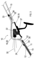
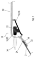
先ず、図1及び図2を参照すると、これらは、統合されたセンサーモジュールを有している本発明の乗物ウインドウの例示的な実施形態を示す。図1は、全体として符号1で参照される乗物ウインドウ1の上面図を示す。図2は、図1の乗物ウインドウ1の切断線A-Aでの断面図であり、自動車における乗物ウインドウ1のルーフ側への取り付けを示している。乗物ウインドウ1と乗物ルーフ9は、ともに、乗物ウインドウアセンブリー10を形成している。
1 and 2, which show an exemplary embodiment of the vehicle window of the present invention having an integrated sensor module. FIG. 1 shows a top view of a vehicle window 1, generally referenced 1. FIG. FIG. 2 is a cross-sectional view of the vehicle window 1 of FIG. 1 taken along section line AA, showing the mounting of the vehicle window 1 on the roof side of an automobile. Vehicle window 1 and
ここで、例えば、乗物ウインドウ1は、自動車のウインドシールドの形態で実施されている。図1に示すように、乗物ウインドウ1は、ペイン本体2を備えており、ペイン本体2には、センサーモジュール3が固定設置によって統合されている。センサーモジュール3は、乗物ウインドウ1のエッジの切欠き4に挿入されている。切欠き4は、乗物ウインドウ1のルーフ側ウインドシールドエッジ6のほぼ中央で、中央視野5の外側に配置されており、切欠き4は、乗物ウインドウ1の取り付け状態で、その上部に配置されている。本実施形態では、切欠き4は長方形であるが、センサーモジュール3の外形に応じて、切欠き4は他の形状であってもよく、例えば半円形の切欠きでもよい。ボトムウインドシールドエッジ7は、ルーフ側ウインドシールドエッジ6の反対側に位置している。二つの側部乗物ウインドウエッジ8は、取り付け状態で、典型的には自動車のAピラーに配置されており、ルーフ側ウインドシールドエッジ6とボトムウインドシールドエッジ7の間に配置されている。乗物ウインドウ1のルーフ側ウインドシールドエッジ6は、ペイン本体2のルーフ側ウインドシールドエッジ6'と、センサーモジュール3のルーフ側ウインドシールドエッジ6''とからなっている。ペイン本体2とセンサーモジュール3は、ともに、乗物ウインドウ1を形成している。センサーモジュール3は、既製アセンブリーとしてペイン本体2に固定されていてよい。
Here, for example, the vehicle window 1 is embodied in the form of a motor vehicle windshield. As shown in FIG. 1, a vehicle window 1 comprises a
図2は、断面図を用いて図1の乗物ウインドウ1を示しており、乗物ウインドウ1のルーフ側の取り付けを描かれており、図1を補足し、自動車(さらに図示せず)の乗物ルーフ9が示されている。破線から分かるように、ペイン本体2及び乗物ルーフ9は、いずれも部分的にしか示されていない。
FIG. 2 shows the vehicle window 1 of FIG. 1 using a cross-sectional view, depicting the roof-side mounting of the vehicle window 1, and supplementing FIG. 9 is shown. As can be seen from the dashed lines, both the
ここで、ペイン本体2は複合ペインであり、熱可塑性中間層13を介して、互いに固着(積層)されている内側ペイン11及び外側ペイン12を備えている。外側ペイン12及び内側ペイン11は、それぞれ、ガラス、好ましくは熱強化ソーダライムガラスでできており、可視光に対して透明である。熱可塑性中間層13は、熱可塑性材料、好ましくはポリビニルブチラール(PVB)、エチレンビニルアセテート(EVA)、及び/又はポリエチレンテレフタレート(PET)でできている。
Here, the
外側ペイン12の外側表面Iは、外部環境に面していると同時に、ペイン本体2の外側表面である。外側ペイン12の内側表面II及び内側ペイン11の外側表面IIIは、それぞれ中間層13に面している。内側ペイン11の内側表面IVは、乗物室内に面していると同時に、ペイン本体2の内側表面である。
The outer surface I of the
図2から分かるように、切欠き4の領域では、外側ペイン12は内側ペイン13に対して後退しており、それによって、内側ペイン11の外側表面IIIは、上からアクセス可能である。外側ペイン12のバックオフセット領域では、内側ペイン13の外側表面IIIは、センサーモジュール3の支持面14として機能している。
As can be seen in FIG. 2, in the area of the
図2で部分的に示されている乗物ルーフ9は、互いに離間した二つの板金部品15を備えており、これらは、例えば溶接又はリベット止めによって、ペインサイドエッジ16で互いに固定されており、ともに、乗物ウインドウ1を支持するためのルーフフランジ17を形成している。センサーモジュールは、ルーフ側エッジ6、6''に隣接している領域で、ルーフフランジ17に当接しており、そこに固定されている。当然のことながら、ペイン本体2は、同様に、ルーフ側エッジ6、6'に隣接している領域で、ルーフフランジ17に当接しており、これに固定されている。
The
センサーモジュール3は、ベース19と、ベース19に接続されているカバー20とからなるモジュールハウジング18を備えている。ベース19及びカバー20は、ともに、少なくとも一つのセンサー22を収容するための、好ましくは閉鎖されている、中空スペース21を形成している。ベース19及びカバー20は、中空スペース21を完全に取り囲んでおり、それによって、中空スペース21を形成するために、さらなる構成要素、特に、乗物ヘッドライナー又は室内ルーフライニング等の、自動車の構成要素を必要としない。ベース19は、ペイン本体2及び乗物ルーフ9のいずれにも延在しておらず、乗物ウインドウ1を通して直角に見たときに、ベース19は、完全にカバー20の寸法内に配置されている。上記の観察では、例えば、ビューは、ペイン本体2の平面(例えば、切欠き4の領域でペイン本体2に接する平面)に対して直角である。その結果、カバー20は、ベース19を越えて(例えば、切欠き4の領域でペイン本体に接する上記平面に対して)延在しており、それによって、カバー20は、ベース19に対して突出しており、センサーモジュール3の固定設置に用いることができるオーバーハング41を形成している。ベース19はカバー20のみに固定(好ましくは取外し可能に)接続されており、ベース19は、乗物ウインドウ1又は自動車の他の構成要素に、それ以上接続されていない。
The
ここで、カバー20は、例えば、二つの部分で組み込まれており、例えば、外側部23及び内側部24からなっており、これらは、例えば、二成分射出成形/ダイレクトゲートによって、互いに固定接続されている。内側部24は、外側部23の内側ライニングの形態であり、センサー22のためのウインドウ31として機能する開口27が設けられている。本実施形態では、内側部24は、突出支持部28を備えており、その上にベース19が固定されている。
Here, the
センサーモジュール3は、モジュールハウジング18によって(特にカバー20によって)、接着で、ペイン本体2と乗物ルーフ9の両方に(排他的に)固定されている。この目的のため、接着剤ビード32が、内側ペイン11の外側表面IIIの支持面14と、外側ペイン12のバックオフセット領域における乗物ルーフ9のルーフフランジ17とに塗布されている。カバー20のオーバーハング41は、周方向に形成されている接着剤ビード32上に配置されており、その結果、モジュールハウジング18は、一方ではペイン本体2に、他方では乗物ルーフに固着されている。ペイン本体2は、同様に、グルービード(図2には示されていない)でルーフフランジ17に接着されており、それによって、ペイン本体2とカバー20の材質(ガラス/プラスチック)に対応して、異なる接着材を選択することができる。
The
カバー20とガラス本体2の間、又はカバー20と乗物ルーフ9の間の中間スペースは、熱可塑性材料(例えば、熱可塑性エラストマー)のオーバーモールド33で満たされており、外部環境に対して良好なシールをもたらしている。
The intermediate space between the
外部環境に面しているカバー20の外側表面(以下「カバーの外側表面25」という)は、ペイン本体2の外側表面12の外面Iとともに、乗物ウインドウ1の外側表面44を形成している。外側ペイン12の外側表面Iは、カバーの外側表面25に、少なくとも実質的に、段差なく移行している。同様に、カバーの外側表面25は、乗物ルーフ9の外側表面(以下、「乗物ルーフの外側表面34」という)に段差なく移行している。オーバーモールド33は、カバー20と外側ペイン12との間、又はカバー20と乗物ルーフ9との間の中間スペースを、段差なく充填している。したがって、非常に優れた空力特性、特に気流による空気騒音を低減するとともに、好ましい外観を得られる。
The outer surface of the
カバー20の内側部24と外側部23は、同じ材料でできていてよい。好ましくは、内側部24と外側部23は、互いに異なる材料でできており、外側部23の材料は、センサー22のセンサー信号に対する良好な透過性を考慮して選択されており、内側部24の材料は、モジュールハウジング18の高い強度を考慮して選択されていることが有利である。例えば、外側部23は、ポリカーボネート(PC)、ポリメチルメタクリレート(PMMA)、スチレンアクリロニトリル(SAN)、及び/又はそれらのコポリマー、ブロックコポリマー、若しくは混合物でできている。内側部24は、例えば、ポリカーボネート(PC)、ポリエチレン(PE)、ポリメチルメタクリレート(PMMA)、ポリプロピレン(PP)、ポリスチレン、ポリブタジエン、ポリニトリル、ポリエステル、ポリウレタン、ポリアクリレート、ポリアミド、ポリエチレンテレフタレート(PET)、ポリブチレンテレフタレート(PBT)、好ましくは、アクリロニトリルブタジエンスチレン(ABS)、アクリロニトリルスチレンアクリルエステル(ASA)、アクリロニトリルブタジエンスチレンポリカーボネート(ABS+PC)、PET+PC、PBT+PC、及び又はそれらのコポリマー、ブロックコポリマー、若しくは混合物でできている。内側部24は、無機又は有機充填剤、好ましくはSiO2、Al2O3、TiO2 、粘土鉱物、ケイ酸塩、ゼオライト、ガラス繊維、炭素繊維、ガラスビーズ、有機繊維、及び/又はそれらの混合物をさらに含有していてよい。充填剤は、カバー20の安定性をさらに高めることができる。また、充填剤は、ポリマー材料の含有量を低減し、センサーモジュール3の製造コストを低減することができる。外側部23の材料厚さは、例えば、2~4mm、好ましくは2.5~3.5mmの範囲である。内側部24の材料厚さは、例えば、1~3mm、好ましくは1.5~2.5mmの範囲である。
The
ここで、ベース19は、例えば、センサー22のためのキャリアとして機能しており、センサー22は、ベース19に固定的に接続されている。図2は、典型的な取り付け位置での乗物ウインドウ1を示しており、典型的な取り付け位置では、センサー22が、位置合わせされており、視野30(ビーム経路)が、ここでは円錐形で、例えば、進行方向の前方に向けられており、視野30(ビーム経路)の中央ビーム29は、乗物の長手方向又は乗物の長手方向の平面に平行である。
Here, the base 19 serves, for example, as a carrier for the
図2に示すように、カバー20は、ペイン本体2の平面(例えば、切欠き4の領域でペイン本体2に接している平面)に垂直で、外部環境に向かっているドーム状のバルジ35を有しており、カバー20は、ウインドウ31の領域で、乗物の長手方向に垂直なカバーセクション36を有している。視野30の中央ビーム29は、カバーセクション36に垂直に衝突する。
As shown in FIG. 2, the
原則として、センサー22は、外部環境中の物体を検出する任意のセンサー(例えば、カメラ、レーダーセンサー)であってよく、センサー信号の通過時間測定を伴っても、伴わなくてもよい。好ましくは、センサー22は、LiDaRセンサーであり、レーザービームパルスを発し、反射されたレーザービームパルスを受け取ることができる。これは、図2では、視野30の領域で、反対方向を指している二つの矢印によって示されている。外側部23がポリカーボネート(PC)でできている場合、IRレーザービームパルスに対して非常に良好な透過率(少なくとも80%)を得ることができる。カバーセクション36で、放出され反射されたレーザーパルスが、垂直に衝突することによって、カバー20において、光の望ましくない反射/散乱及び吸収が大幅に低減されており、センサー測定の効率が大幅に改善されている。好ましくは、外側部23は、黒色PC又は可視範囲で不透明なPCでできており、内側部24は、PC+ABS又はPC+PETでできている。
In principle,
図1及び図2に示されている乗物ウインドウ1では、センサーモジュール3を既製アセンブリーとしてペイン本体2に有利に統合されていてよく、それによって、電気的接続を除いて、センサーモジュール3のための取り付け具を乗物側に必要とせずに、自動車に取り付けるための統合されているセンサーモジュール3を、乗物ウインドウ1に提供することができる。
In the vehicle window 1 shown in FIGS. 1 and 2, the
図2の実施形態では、ベース19の乗物室内側に、バックミラー37が取り付けられている。
In the embodiment of FIG. 2, a
以下、図3~図12を参照して、乗物ウインドウ1又は乗物ウインドウアセンブリー10の様々な他の実施形態について説明する。不必要な繰り返しを避けるために、参照する実施形態との相違点のみを説明し、それ以外の場合は、そこの記述を参照する。
Various other embodiments of the vehicle window 1 or
図3は、類似の断面図を用いて、図2の乗物ウインドウアセンブリー10の変形を示している。図3の実施形態では、カバー20と支持面14との間の領域にオーバーモールド33が配置されておらず、それにより、中間スペース38がそこに残存している。この方法で材料を節約している。
FIG. 3 shows a variation of the
図4は、類似の断面図を用いて、図3の乗物ウインドウアセンブリー10の変形を示している。図4の実施形態では、ペイン本体2は複合ペインではなく、自動車のリアウインドウとして使用されるような単独ペインの安全ガラスである。切欠き4の領域において、モジュールハウジング18は、ペイン本体2の内側表面42に固定されている。ペイン本体側において、カバー20の内側部24は、外側部23を超えてオーバーハング41の領域内に延在している(例えば、切欠き4の領域におけるペイン本体に接する平面に関して)。内側部24は、ペイン本体2の内側に重なっており、接着剤ビード32によって、そこに接着されている。ペイン本体側には、オーバーモールド33がない。ベース19には、バックミラー33が取り付けられていない。
FIG. 4 shows a variation of the
図5は、類似の断面図を用いて、図4の乗物ウインドウアセンブリー10の変形を示している。図5の実施形態では、ペイン本体側に、ペイン本体2とカバー20との間の中間スペースにオーバーモールド33が提供されている。
FIG. 5 shows a variation of the
図6は、類似の断面図を用いて、図5の乗物ウインドウアセンブリー10の変形を示している。図6の実施形態では、乗物ルーフ9はルーフフランジ17を有していないが、モジュールハウジング18又はカバー20(及びペイン本体2)は、乗物ルーフ9の下側43に接着剤ビード32で接着されている。この目的のために、カバー20又はカバー20の外側部23は、乗物ルーフ9と重なっているカバーフランジ39を有している。カバー20と乗物ルーフ9との間の中間スペースは、オーバーモールド33によって満たされており、外部環境に対して良好なシールを形成しているとともに、カバー20と乗物ルーフ9との間で段差のない移行を形成している
FIG. 6 shows a variation of the
図7は、類似の断面図を用いて、図5の乗物ウインドウアセンブリー10の変形を示している。図7の実施形態では、カバー20が延長されており、カバー20がルーフリム40を形成しており、ルーフリム40は、乗物の長手方向に、乗物ルーフ9へ延在しており、ルーフリム40は乗物ルーフ9(図7に示されていない)に取り付けられている。図8A及び図8Bに示すように、それぞれは図7の乗物ウインドウアセンブリー10の実施形態の上面図を示し、ルーフリム40は、例えば、ストリップ形状(図8A)又はT形状で実装されていてよい。
FIG. 7 shows a variation of the
図9は、類似の断面図を用いて、図2の乗物ウインドウアセンブリー10の変形を示している。図9の実施形態では、カバー20はワンピースでできている。ベース19を外側部23に固定するために、外側部23は周支持部28を有している。
FIG. 9 shows a variation of the
図10は、類似の断面図を用いて、図9の乗物ウインドウアセンブリー10の変形を示している。図10の実施形態では、カバー20は、センサー22の視野30の領域において、カバー20の残りの部分よりも薄い材料厚さを有しており、センサー22の信号に対する透過率が改善されたウインドウ31を形成している。
FIG. 10 shows a variation of the
図11及び図12は、図1及び図2に示したように、乗物ウインドウ1又は乗物ウインドウアセンブリー10の別の変形を、それぞれ、上面図(図11)及び断面図(図12)で示している。図11の上面図から分かるように、センサーモジュール3は、ペイン本体2のエッジの切欠き4に挿入されているのではなく、ペイン本体2の非エッジ内側領域45に形成されている切欠き4に挿入されており、その切欠き4は、例えば、フライス加工又はレーザー加工によって形成されている。切欠き4は、もっぱらペイン本体2によって境界が定められており、すなわち、切欠き4を取り囲んでいるエッジは、ペイン本体2によって形成されている。切欠き4は、乗物ウインドウ1のエッジ6、7、8に隣接していない。
11 and 12 show another variation of the vehicle window 1 or
図12の断面図に示すように、ペイン本体2は、周方向に、外側ペイン12のバックオフセットを有しており、それによって、切欠き4を取り囲むモジュールハウジング18のための支持面14が形成されている。接着剤ビード32が、支持面14上で周方向に適用されており、それによって、カバー20又はその内側部24が、内側ペイン11に接着されている。乗物ウインドウ1のこの実施形態は、ペイン本体2での応力発生の点で有利であり得る。また、自動車の乗物ウインドウ1を接着する際に、まったく同じ接着剤又はプライマーを使用することができる。プラスチック専用に設計された材料を使用する必要はない。
As shown in the cross-sectional view of FIG. 12, the
これまでの記述から、本発明は、統合されているセンサーモジュールを有している改良された乗物ウインドウを可能にする。センサーモジュールは、ペイン本体の切欠きに既製のアセンブリーとして取り付けることができ、それによって、統合されているセンサー モジュールを有している乗物ウインドウは、自動車に取り付けることができる。センサーモジュール、特に、センサーのビーム経路領域でのモジュールハウジングの材料及び形状は、センサーの効率に関し、特別に設計することができ、放出され、そして反射されたセンサー信号の垂直衝突と、センサー信号の高い透過率が可能である。本発明は、LiDaRセンサーの使用により、特に有利に用いることができる。 From the foregoing description, the present invention enables improved vehicle windows with integrated sensor modules. The sensor module can be mounted as an off-the-shelf assembly in a cutout in the pane body, whereby the vehicle window with the integrated sensor module can be mounted on the automobile. The material and shape of the sensor module, especially the module housing in the beam path area of the sensor, can be specially designed with respect to the efficiency of the sensor, the vertical impingement of the emitted and reflected sensor signals and the High transmittance is possible. The present invention can be used to particular advantage through the use of LiDaR sensors.
1 乗物ウインドウ
2 ペイン本体
3 センサーモジュール
4 切欠き
5 視野
6、6’、6’’ ルーフ側乗物ウインドウエッジ
7 ボトムウインドウエッジ
8 側部乗物ウインドウエッジ
9 乗物ルーフ
10 乗物ウインドウアセンブリー
11 内側ペイン
12 外側ペイン
13 中間層
14 支持面
15 板金部品
16 ペインサイドエッジ
17 ルーフフランジ
18 モジュールハウジング
19 ベース
20 カバー
21 中空スペース
22 センサー
23 外側部
24 内側部
25 カバーの外側表面
26 カバーの内側表面
27 開口
28 支持部
29 中央ビーム
30 視野
31 ウインドウ
32 接着剤ビード
33 オーバーモールド
34 乗物ルーフの外側表面
35 バルジ
36 カバーセクション
37 バックミラー
38 中間スペース
39 カバーフランジ
40 ルーフリム
41 オーバーハング
42 内側表面
43 下側
44 乗物ウインドウの外側表面
45 内側領域
1
Claims (12)
-切欠き(4)を有しているペイン本体(2)
-中空スペース(21)を形成しており、その中空スペース(21)の中に、少なくとも一つのセンサー(22)が収容されているモジュールハウジング(18)を有している既製アセンブリーとして設計されているセンサーモジュール(3)、
を備えており、
前記中空スペース(21)を形成している前記モジュールハウジング(18)が、前記切欠き(4)に挿入されており、かつ前記ペイン本体(2)に取り付けされており、前記モジュールハウジング(18)の外側表面(25)と前記ペイン本体(2)の外側表面(I)が、ともに、前記乗物ウインドウ(1)の外側表面(44)を形成しており、
前記センサー(22)がLiDaRセンサーであり、
前記モジュールハウジング(18)が、バルジ(35)を有しており、前記バルジ(35)は、ハウジングセクション(33)が前記センサー(22)の視野(30)に位置するように成形されており、前記ハウジングセクション(33)に、前記センサー(22)によって放出された信号が、垂線から最大10°の偏差で衝突する、
乗物ウインドウ(1)。 A vehicle window (1) having an integrated sensor module (3), comprising:
- a pane body (2) having a notch (4);
- designed as a ready-made assembly with a module housing (18) forming a hollow space (21) in which at least one sensor (22) is accommodated; a sensor module (3) in which
and
The module housing (18) forming the hollow space (21) is inserted into the notch (4) and attached to the pane body (2), the module housing ( 18) and the outer surface (I) of said pane body (2) together form the outer surface (44) of said vehicle window (1) ,
said sensor (22) is a LiDaR sensor,
The module housing (18) has a bulge (35) shaped such that the housing section (33) is in the field of view (30) of the sensor (22). , on said housing section (33) the signal emitted by said sensor (22) impinges with a maximum deviation of 10° from the vertical;
Vehicle window (1).
-切欠き(4)を有するペイン本体(2)を提供すること、
-前記センサーモジュール(3)を前記切欠き(4)に挿入し、前記センサーモジュール(3)を前記ペイン本体(2)に取り付けること。 A method of manufacturing a vehicle window (1) according to any one of claims 1 to 10 , comprising the steps of:
- providing a pane body (2) with a notch (4),
- inserting said sensor module (3) into said notch (4) and attaching said sensor module (3) to said pane body (2);
Applications Claiming Priority (3)
| Application Number | Priority Date | Filing Date | Title |
|---|---|---|---|
| EP19151818.2 | 2019-01-15 | ||
| EP19151818 | 2019-01-15 | ||
| PCT/EP2020/050534 WO2020148185A1 (en) | 2019-01-15 | 2020-01-10 | Vehicle window pane having integrated sensor module |
Publications (2)
| Publication Number | Publication Date |
|---|---|
| JP2022515426A JP2022515426A (en) | 2022-02-18 |
| JP7228047B2 true JP7228047B2 (en) | 2023-02-22 |
Family
ID=65030976
Family Applications (1)
| Application Number | Title | Priority Date | Filing Date |
|---|---|---|---|
| JP2021536794A Active JP7228047B2 (en) | 2019-01-15 | 2020-01-10 | Vehicle window with integrated sensor module |
Country Status (10)
| Country | Link |
|---|---|
| US (1) | US20210293933A1 (en) |
| EP (1) | EP3911974A1 (en) |
| JP (1) | JP7228047B2 (en) |
| KR (1) | KR102649667B1 (en) |
| CN (1) | CN111771142B (en) |
| BR (1) | BR112021003738A2 (en) |
| MA (1) | MA54745A (en) |
| MX (1) | MX2021008544A (en) |
| PE (1) | PE20211163A1 (en) |
| WO (1) | WO2020148185A1 (en) |
Families Citing this family (6)
| Publication number | Priority date | Publication date | Assignee | Title |
|---|---|---|---|---|
| JP7356286B2 (en) * | 2019-06-26 | 2023-10-04 | ダイキョーニシカワ株式会社 | Mounting structure of vehicle distance sensor |
| DE102020206549A1 (en) | 2020-05-26 | 2021-12-02 | Siemens Mobility GmbH | Sensor module and rail vehicle with such a sensor module |
| CN116745102A (en) | 2021-12-22 | 2023-09-12 | 法国圣戈班玻璃厂 | Method for producing a cover for a sensor module |
| DE102022124290A1 (en) | 2022-09-21 | 2024-03-21 | Webasto SE | Roof module to form a vehicle roof |
| JP2024111840A (en) * | 2023-02-06 | 2024-08-19 | エージーシー オートモーティヴ アメリカズ カンパニー | Mounting system, window assembly including the mounting system, and method of forming the window assembly - Patents.com |
| DE102023109818B3 (en) | 2023-04-19 | 2024-05-02 | Webasto SE | Sensor module for installation on a motor vehicle |
Citations (6)
| Publication number | Priority date | Publication date | Assignee | Title |
|---|---|---|---|---|
| US20110285576A1 (en) | 2007-01-25 | 2011-11-24 | Lynam Niall R | Forward facing sensing system for a vehicle |
| JP2017181480A (en) | 2016-03-24 | 2017-10-05 | 日本電産エレシス株式会社 | Window shield equipped with on-vehicle radar |
| WO2017188415A1 (en) | 2016-04-27 | 2017-11-02 | 旭硝子株式会社 | Window member and vehicle window glass |
| JP2017196990A (en) | 2016-04-26 | 2017-11-02 | トヨタ自動車株式会社 | Arrangement structure of peripheral information detection sensor |
| WO2018073528A1 (en) | 2016-10-17 | 2018-04-26 | Saint-Gobain Glass France | Windscreen for driving assistance |
| JP2018196012A (en) | 2017-05-18 | 2018-12-06 | 株式会社デンソー | On-vehicle camera |
Family Cites Families (7)
| Publication number | Priority date | Publication date | Assignee | Title |
|---|---|---|---|---|
| CH592801A5 (en) * | 1975-06-02 | 1977-11-15 | Glas Ag Glas Und Spiegelmanufa | U-shaped paned double glazing unit - has insulating transverse sections with supporting and centring faces |
| FR2789382B1 (en) * | 1999-02-05 | 2002-02-08 | Saint Gobain Vitrage | HIGH SHEET GLASS WITH CRASH-TESTS |
| DE10037217A1 (en) * | 2000-07-31 | 2002-02-14 | Volkswagen Ag | Motor vehicle head-lamp with integrated optical sensor, especially for measuring distance to vehicle ahead, has separation device for beam-paths |
| EP2325002B2 (en) * | 2009-11-17 | 2015-04-15 | Saint-Gobain Glass France | Method for producing a laminated glass pane with sensor window |
| FR3034501A1 (en) * | 2015-04-03 | 2016-10-07 | Saint Gobain | LUMINOUS GLAZING FOR BUILDING, FURNITURE, PUBLIC TRANSPORT VEHICLE |
| US20170274832A1 (en) | 2016-03-24 | 2017-09-28 | Nidec Elesys Corporation | Windshield including vehicle-mounted radar |
| US10071773B2 (en) * | 2016-08-04 | 2018-09-11 | Toyota Motor Engineering & Manufacturing North America, Inc. | Vehicle roof structures for concealing one or more sensors |
-
2020
- 2020-01-10 BR BR112021003738-1A patent/BR112021003738A2/en not_active IP Right Cessation
- 2020-01-10 EP EP20700376.5A patent/EP3911974A1/en active Pending
- 2020-01-10 KR KR1020217022421A patent/KR102649667B1/en active IP Right Grant
- 2020-01-10 JP JP2021536794A patent/JP7228047B2/en active Active
- 2020-01-10 WO PCT/EP2020/050534 patent/WO2020148185A1/en unknown
- 2020-01-10 US US17/284,983 patent/US20210293933A1/en active Pending
- 2020-01-10 PE PE2021000752A patent/PE20211163A1/en unknown
- 2020-01-10 MA MA054745A patent/MA54745A/en unknown
- 2020-01-10 CN CN202080000429.4A patent/CN111771142B/en active Active
- 2020-01-10 MX MX2021008544A patent/MX2021008544A/en unknown
Patent Citations (6)
| Publication number | Priority date | Publication date | Assignee | Title |
|---|---|---|---|---|
| US20110285576A1 (en) | 2007-01-25 | 2011-11-24 | Lynam Niall R | Forward facing sensing system for a vehicle |
| JP2017181480A (en) | 2016-03-24 | 2017-10-05 | 日本電産エレシス株式会社 | Window shield equipped with on-vehicle radar |
| JP2017196990A (en) | 2016-04-26 | 2017-11-02 | トヨタ自動車株式会社 | Arrangement structure of peripheral information detection sensor |
| WO2017188415A1 (en) | 2016-04-27 | 2017-11-02 | 旭硝子株式会社 | Window member and vehicle window glass |
| WO2018073528A1 (en) | 2016-10-17 | 2018-04-26 | Saint-Gobain Glass France | Windscreen for driving assistance |
| JP2018196012A (en) | 2017-05-18 | 2018-12-06 | 株式会社デンソー | On-vehicle camera |
Also Published As
| Publication number | Publication date |
|---|---|
| KR102649667B1 (en) | 2024-03-20 |
| KR20210104118A (en) | 2021-08-24 |
| MA54745A (en) | 2022-04-20 |
| PE20211163A1 (en) | 2021-06-28 |
| BR112021003738A2 (en) | 2021-05-18 |
| JP2022515426A (en) | 2022-02-18 |
| WO2020148185A1 (en) | 2020-07-23 |
| MX2021008544A (en) | 2021-08-19 |
| US20210293933A1 (en) | 2021-09-23 |
| CN111771142A (en) | 2020-10-13 |
| CN111771142B (en) | 2024-03-29 |
| EP3911974A1 (en) | 2021-11-24 |
Similar Documents
| Publication | Publication Date | Title |
|---|---|---|
| JP7228047B2 (en) | Vehicle window with integrated sensor module | |
| US9335021B2 (en) | Motor vehicle with turn signal repeater glazing | |
| JP5961053B2 (en) | Vehicle rear panel | |
| US11780379B2 (en) | Add-on part having an integrated camera module | |
| US9857797B2 (en) | Structure disposed with peripheral information detection sensor, and self-driving vehicle | |
| KR20120120949A (en) | Flashing glass panel for a vehicle, and method for manufacturing same | |
| US11597449B2 (en) | Vehicle outer plate panel and method for manufacturing vehicle outer plate panel | |
| CN113167864B (en) | IR transparent sensor and camera system for motor vehicle | |
| US20220373651A1 (en) | Lidar detection device provided with a laminated protective layer | |
| US6768099B1 (en) | Device for detecting a parameter associated with the state of a vehicle, especially an automobile | |
| JP7473563B2 (en) | Automotive LiDAR Assembly with Anti-Reflection Unit | |
| US9676259B2 (en) | Cover for a motor vehicle roof | |
| CN218463585U (en) | Automobile ornament with transparent main body and seamless integrated laser radar | |
| CN113170533A (en) | Exterior panel assembly for vehicle | |
| US20230339545A1 (en) | Vehicle roof having a roof cladding arrangement and environment sensor | |
| CN218463583U (en) | Automobile ornament with coating carrier and seamless integrated laser radar | |
| CN218477479U (en) | Automobile decoration | |
| US12123747B2 (en) | Mounting system, a window assembly including the same, and a method of forming the window assembly | |
| JP7163877B2 (en) | Resin window panel and car body adhesion structure of resin window panel | |
| US20240263975A1 (en) | Mounting system, a window assembly including the same, and a method of forming the window assembly | |
| CN218477477U (en) | Automobile ornament with light filtering ornament body and seamless integrated laser radar | |
| EA044152B1 (en) | LiDAR DETECTION DEVICE EQUIPPED WITH MULTILAYER PROTECTIVE LAYER | |
| JP2024074129A (en) | Electromagnetic wave transmission cover and sensor module | |
| JP2024537081A (en) | Glazing with inserts | |
| CN118103208A (en) | Glazing with insert |
Legal Events
| Date | Code | Title | Description |
|---|---|---|---|
| A621 | Written request for application examination |
Free format text: JAPANESE INTERMEDIATE CODE: A621 Effective date: 20210623 |
|
| A977 | Report on retrieval |
Free format text: JAPANESE INTERMEDIATE CODE: A971007 Effective date: 20220623 |
|
| A131 | Notification of reasons for refusal |
Free format text: JAPANESE INTERMEDIATE CODE: A131 Effective date: 20220705 |
|
| A521 | Request for written amendment filed |
Free format text: JAPANESE INTERMEDIATE CODE: A523 Effective date: 20221003 |
|
| TRDD | Decision of grant or rejection written | ||
| A01 | Written decision to grant a patent or to grant a registration (utility model) |
Free format text: JAPANESE INTERMEDIATE CODE: A01 Effective date: 20230131 |
|
| A61 | First payment of annual fees (during grant procedure) |
Free format text: JAPANESE INTERMEDIATE CODE: A61 Effective date: 20230210 |
|
| R150 | Certificate of patent or registration of utility model |
Ref document number: 7228047 Country of ref document: JP Free format text: JAPANESE INTERMEDIATE CODE: R150 |