JP7218656B2 - reader - Google Patents
reader Download PDFInfo
- Publication number
- JP7218656B2 JP7218656B2 JP2019066634A JP2019066634A JP7218656B2 JP 7218656 B2 JP7218656 B2 JP 7218656B2 JP 2019066634 A JP2019066634 A JP 2019066634A JP 2019066634 A JP2019066634 A JP 2019066634A JP 7218656 B2 JP7218656 B2 JP 7218656B2
- Authority
- JP
- Japan
- Prior art keywords
- scanning direction
- reading
- edge
- sub
- main scanning
- Prior art date
- Legal status (The legal status is an assumption and is not a legal conclusion. Google has not performed a legal analysis and makes no representation as to the accuracy of the status listed.)
- Active
Links
Images


Classifications
-
- H—ELECTRICITY
- H04—ELECTRIC COMMUNICATION TECHNIQUE
- H04N—PICTORIAL COMMUNICATION, e.g. TELEVISION
- H04N1/00—Scanning, transmission or reproduction of documents or the like, e.g. facsimile transmission; Details thereof
- H04N1/00795—Reading arrangements
- H04N1/00798—Circuits or arrangements for the control thereof, e.g. using a programmed control device or according to a measured quantity
- H04N1/00801—Circuits or arrangements for the control thereof, e.g. using a programmed control device or according to a measured quantity according to characteristics of the original
- H04N1/00803—Presence or absence of information
-
- H—ELECTRICITY
- H04—ELECTRIC COMMUNICATION TECHNIQUE
- H04N—PICTORIAL COMMUNICATION, e.g. TELEVISION
- H04N1/00—Scanning, transmission or reproduction of documents or the like, e.g. facsimile transmission; Details thereof
- H04N1/00795—Reading arrangements
- H04N1/00798—Circuits or arrangements for the control thereof, e.g. using a programmed control device or according to a measured quantity
- H04N1/00801—Circuits or arrangements for the control thereof, e.g. using a programmed control device or according to a measured quantity according to characteristics of the original
- H04N1/00809—Orientation
-
- H—ELECTRICITY
- H04—ELECTRIC COMMUNICATION TECHNIQUE
- H04N—PICTORIAL COMMUNICATION, e.g. TELEVISION
- H04N1/00—Scanning, transmission or reproduction of documents or the like, e.g. facsimile transmission; Details thereof
- H04N1/00795—Reading arrangements
- H04N1/00798—Circuits or arrangements for the control thereof, e.g. using a programmed control device or according to a measured quantity
- H04N1/00824—Circuits or arrangements for the control thereof, e.g. using a programmed control device or according to a measured quantity for displaying or indicating, e.g. a condition or state
Description
本発明は、読取装置に関する。 The present invention relates to reading devices.
FB(Flat Bed:フラットベッド)方式による原稿の読み取りが可能な読取装置では、透明な原稿支持板の下側に、主走査方向に沿った1ラインを読み取る読取部が副走査方向に移動可能に設けられている。読取部が副走査方向に移動されつつ、原稿支持板に支持された原稿が読取部に1ラインずつ読み取られる。 In a scanning device that can read documents using the FB (Flat Bed) method, the reading unit that reads one line along the main scanning direction is movable in the sub-scanning direction under the transparent document support plate. is provided. While the reading unit is moved in the sub-scanning direction, the document supported by the document support plate is read line by line by the reading unit.
かかる読取装置では、読取部の原点位置を設定する必要がある。従来の読取装置には、たとえば、読取部に検出子を設け、原稿載置板の周囲を取り囲むFBカバーに検出子の通過を検出するフォトインタラプタを設けて、フォトインタラプタにより検出子の通過を検出したときの読取部の位置から原点位置を設定するものがある。また、特許文献1に記載のように、白基準部と黒基準部とをキャリッジの移動方向である副走査方向に並べて設けて、白基準部および黒基準部をイメージセンサで読み取り、その読み取った白基準部と黒基準部との境界の位置から原点位置を設定するものがある。
In such a reading device, it is necessary to set the origin position of the reading section. In a conventional reading device, for example, a detector is provided in the reading unit, and a photointerrupter for detecting the passage of the detector is provided in the FB cover surrounding the document placing plate, and the passage of the detector is detected by the photointerrupter. In some cases, the origin position is set from the position of the reading unit at that time. Further, as described in
部品コストや取付精度の面から、フォトインタラプタを設ける構成よりも、白基準部及び黒基準部を設ける構成が採用される傾向にある。コスト上の問題から、白基準部および黒基準部は、白領域と黒領域とを有するテープをFBカバーの下面に貼り付けることにより形成される。そのため、白基準部および黒基準部が正規の位置からずれる。 In terms of parts cost and mounting accuracy, there is a tendency to adopt a configuration in which a white reference portion and a black reference portion are provided rather than a configuration in which a photointerrupter is provided. Due to cost considerations, the white reference and black reference are formed by applying a tape having white and black areas to the underside of the FB cover. Therefore, the white reference portion and the black reference portion are shifted from their normal positions.
現状では、そのずれを許容すべく、原稿の先端から数ミリ程度は読み取らない仕様になっている製品が多い。しかし、原稿全体を読み取りたいというユーザの希望も多く、原稿の読取範囲を少しでも広げるべく、原稿載置板における読取範囲の開始位置が原稿の位置決めの基準となる位置の間際に設定されると、テープの貼り付けずれのために原稿の一部を読み取れないという問題が生じる。 At present, many products are designed not to read a few millimeters from the leading edge of the document in order to allow for such misalignment. However, many users want to read the entire document, and in order to widen the reading range of the document as much as possible, the starting position of the reading range on the document placing plate is set just before the position serving as the reference for positioning the document. , there arises a problem that part of the document cannot be read due to misalignment of the tape.
本発明の目的は、読取部により原稿の先端の間際まで読み取ることができる、読取装置を提供することである。 SUMMARY OF THE INVENTION It is an object of the present invention to provide a reading device capable of reading up to just before the leading edge of a document by means of a reading section.
前記の目的を達成するため、本発明に係る読取装置は、原稿を載置する平面を有する原稿載置板と、原稿載置板に対して平面側と反対側に配置され、副走査方向に移動可能に設けられて、副走査方向と直交する主走査方向に延びる1ラインを読み取る読取部と、読取部を副走査方向に移動させる駆動部と、原稿載置板をその周囲を取り囲んで支持するカバーと、制御部と、を備え、カバーには、主走査方向に直線状に延び、原稿の先端が突き当てられる突き当て部、およびカバーの反対側に設けられ、凹凸面と、凹凸面の外縁であり、主走査方向に直線状に延びる第一エッジと、凹凸面の外縁であり、副走査方向に直線状に延びる第二エッジとを有する凸部、が形成され、制御部は、駆動部により読取部を副走査方向に移動させつつ、読取部に凸部を読み取らせて、読取部に読み取られた画像データから、凹凸面を元に、第一エッジおよび第二エッジを検出し、第一エッジおよび第二エッジの位置を元に、原稿載置板における読取部の読取範囲を決定する。 In order to achieve the above object, the reading device according to the present invention includes a document placing plate having a flat surface on which a document is placed, and a document placing plate disposed on the side opposite to the flat side of the document placing plate. A reading unit provided movably to read one line extending in a main scanning direction orthogonal to the sub-scanning direction, a driving unit for moving the reading unit in the sub-scanning direction, and a document placement plate surrounding and supporting the periphery thereof. and a controller, wherein the cover includes an abutting portion that extends linearly in the main scanning direction and against which the leading edge of the original abuts; A convex portion having a first edge that is the outer edge of the uneven surface and extends linearly in the main scanning direction and a second edge that is the outer edge of the uneven surface and extends linearly in the sub-scanning direction is formed. While the reading unit is moved in the sub-scanning direction by the driving unit, the reading unit reads the convex portion, and the first edge and the second edge are detected from the image data read by the reading unit based on the uneven surface. , the position of the first edge and the second edge, the reading range of the reading unit on the document platen is determined.
この構成によれば、原稿載置板を支持するカバーは、突き当て部を有している。突き当て部には、原稿の先端が突き当てられ、原稿は、突き当て部の位置を基準に原稿載置板の平面上に載置される。また、カバーは、凸部を有している。読取部の読取範囲の決定の際には、読取部により凸部が読み取られる。そして、読取部に読み取られた画像データから、主走査方向に直線状に延びる凸部の第一エッジおよび副走査方向に直線状に延びる凸部の第二エッジが検出され、第一エッジおよび第二エッジの位置を元に、読取部の読取範囲が決定される。突き当て部と凸部とが単一のカバーに設けられているので、突き当て部と凸部との位置関係は一定である。そのため、凸部の第一エッジおよび第二エッジの位置を元に読取部の読取範囲が決定されることにより、読取範囲の一端を突き当て部の間際に精度よく設定することができる。その結果、読取部により原稿の先端の間際まで読み取ることができる。 According to this configuration, the cover that supports the document platen has the abutting portion. The front end of the original is abutted against the abutting portion, and the original is placed on the flat surface of the original plate with the position of the abutting portion as a reference. Moreover, the cover has a convex portion. When determining the reading range of the reading unit, the convex portion is read by the reading unit. Then, the first edge of the projection linearly extending in the main scanning direction and the second edge of the projection linearly extending in the sub-scanning direction are detected from the image data read by the reading unit, and the first edge and the second edge are detected. The reading range of the reading unit is determined based on the positions of the two edges. Since the abutting portion and the convex portion are provided on the single cover, the positional relationship between the abutting portion and the convex portion is constant. Therefore, by determining the reading range of the reading unit based on the positions of the first edge and the second edge of the convex portion, one end of the reading range can be accurately set just before the abutting portion. As a result, the reading unit can read the document up to just before the leading edge thereof.
本発明によれば、読取部により原稿の先端の間際まで読み取ることができる。 According to the present invention, it is possible to read up to just before the leading end of the document by the reading section.
以下では、本発明の実施の形態について、添付図面を参照しつつ詳細に説明する。 BEST MODE FOR CARRYING OUT THE INVENTION Below, embodiments of the present invention will be described in detail with reference to the accompanying drawings.
<複合機の構成>
図1に示される複合機(MFP:Multi-Function Peripheral)1は、読取機能および印刷機能など、複数の機能を有する電子機器である。読取機能は、原稿などを読み取って画像データを生成する機能である。印刷機能は、画像データに係る画像を用紙に印刷する機能である。複合機1は、読取機能のための読取装置2と、印刷機能のための印刷装置3とを備えている。
<Configuration of MFP>
A multi-function peripheral (MFP) 1 shown in FIG. 1 is an electronic device having multiple functions such as a reading function and a printing function. The reading function is a function of reading a document or the like and generating image data. The print function is a function of printing an image related to image data on paper. The
読取装置2は、印刷装置3上に積み重ねられている。読取装置2は、筐体4(カバーの一例)および原稿カバー5を備えている。筐体4は、略直方体形状をなしている。原稿カバー5は、開位置と閉位置との間で変位可能に設けられている。原稿カバー5が開位置に位置する状態では、筐体4の上面が露出する。原稿カバー5が閉位置に位置する状態では、原稿カバー5により筐体4の上面が被覆される。
The
筐体4の一側面には、操作パネル6が配置されている。複合機1では、その操作パネル6が配置されている一側面が前面となる。操作パネル6は、たとえば、タッチパネルであり、操作パネル6上にて、各種の設定や読取開始を指示する操作が可能である。
An
なお、以下の説明で使用するため、複合機1をその前面側から見た状態を基準に複合機1の左右を規定する。「上側」及び「下側」については、複合機1が水平面に設置された状態を基準に規定する。
For use in the following description, the left and right sides of the
印刷装置3は、筐体7、給紙トレイ8および排紙トレイ9を備えている。給紙トレイ8は、筐体7に対して前側から抜き差し可能に構成されている。給紙トレイ8は、複数枚の用紙を積み重なった状態で支持可能に構成されている。排紙トレイ9は、筐体7の上面に形成されている。給紙トレイ8から用紙が1枚ずつ送り出され、その送り出された用紙が筐体7内を排紙トレイ9に向けて搬送される。筐体7内には、印刷部(図示せず)が設けられており、用紙が筐体7内を搬送される間に、印刷部により用紙に画像(カラー画像またはモノクロ画像)が形成される。印刷の方式は、電子写真方式であってもよいし、インクジェット方式であってもよい。
The
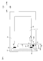
読取装置2の筐体4の上面には、図2に断面で示されるように、前後方向および左右方向に延びる端縁を有する矩形状の開口が形成されている。そして、その上面開口を下側から閉鎖するように、原稿載置板11が設けられている。原稿載置板11は、透明な材料を用いて形成される板状体であり、たとえば、ガラス板である。原稿載置板11の少なくとも上面は、平面に形成されている。原稿載置板11は、筐体4の上面開口の周辺部により、その周囲が取り囲まれて支持されている。
As shown in cross section in FIG. 2, the upper surface of the
原稿載置板11の下側には、CIS(Contact Image Sensor)ユニット12(読取部の一例)及び移動機構13(駆動部の一例)が設けられている。
A CIS (Contact Image Sensor) unit 12 (an example of a reading section) and a moving mechanism 13 (an example of a driving section) are provided below the
CISユニット12には、光源21、ロッドレンズアレイ22及びイメージセンサ23が内蔵されている。光源21は、前後方向に延びるライン状の光を原稿載置板11に向けて出射するように設けられている。イメージセンサ23は、たとえば、複数の受光素子が主走査方向に配列された構成のリニアイメージセンサであり、主走査方向が読取装置2の前後方向と一致するように設けられている。
The CIS
光源21からの光が読取対象物の表面で反射し、その反射光がロッドレンズアレイ22を通過してイメージセンサ23に入射する。イメージセンサ23に光が入射すると、イメージセンサ23の各受光素子から光電変換による電圧が出力される。各受光素子から出力される電圧は、ゲイン調整回路による増幅後、A/D変換回路によりデジタル値である画素値に変換される。A/D変換回路は、たとえば、8ビット(0~255)の分解能を有しており、下限側の基準電圧(下限値)未満の電圧については一律に「0」に変換し、上限側の基準電圧(上限値)を超える電圧については一律に「255」に変換し、下限値から上限値の範囲の電圧についてはその電圧の大小に応じた画素値に変換する。これにより、読取対象物の主走査方向の1ライン分の読み取りが達成される。
Light from the
移動機構13は、CISユニット12を主走査方向と直交する副走査方向に移動させる機構である。移動機構13は、CISユニット12を担持するキャリッジ24と、正逆回転可能なステッピングモータからなるモータ25と、モータ25により回転駆動される駆動プーリ26と、駆動プーリ26と対をなす従動プーリ27と、駆動プーリ26及び従動プーリ27に巻き掛けられたベルト28とを備えている。駆動プーリ26は、筐体4内の右端部に、回転軸線が前後方向に延びるように配置されている。従動プーリ27は、筐体4内の左端部に、回転軸線が駆動プーリ26の回転軸線と同じ高さの位置で前後方向に延びるように配置されている。ベルト28には、キャリッジ24が取り付けられている。駆動プーリ26の回転によりベルト28が走行し、ベルト28の走行に伴って、キャリッジ24が読取装置2の左右方向と一致する副走査方向に移動する。
The moving
原稿の読み取りの際には、原稿カバー5が開位置に配置されて、原稿が原稿載置板11上に載置される。このとき、原稿は、原稿の左端縁が筐体4の上面開口の左端縁(右側に向いた端面)31に当接し、かつ、原稿の後端縁が筐体4の上面開口の後端縁(前側に向いた端面)32に当接した状態に配置される。したがって、筐体4の上面開口の左端縁31は、原稿の先端が突き当てられる突き当て部として機能する。原稿が原稿載置板11上に載置された後、原稿カバー5が開位置から閉位置に変位されて、原稿カバー5により原稿が上側から覆われる。その後、操作パネル6で読取開始を指示する操作が行われると、移動機構13によりCISユニット12が副走査方向に移動されつつ、CISユニット12により原稿における原稿載置板11との接触面が1ラインずつ読み取られていく。
When reading a document, the
また、筐体4内の天面、つまり筐体4における上面開口の周辺部の裏面33には、図3Aに示されるように、原稿載置板11の左側の位置に、白黒基準部34が設けられている。白黒基準部34は、テープとして形成され、主走査方向と一致する前後方向に延びるように裏面33に貼着されている。白黒基準部34は、ほぼ全体が白領域35であり、前後方向の両側の端部における右側の角部に、矩形状の黒領域36を有している。これにより、白黒基準部34の前後方向の両側の端部では、白領域35と黒領域36とが主走査方向および副走査方向に隣接している。
On the top surface of the
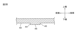
裏面33には、主走査方向における原稿載置板11と白黒基準部34との間の位置に、凸部41が形成されている。凸部41の裏面33からの突出量は、CISユニット12との接触をさけるため、0.1~0.2mm程度の高さとなっている。凸部41は、主走査方向に延びる一対の縦エッジ42,43と副走査方向に延びる一対の横エッジ44,45とを有する矩形状に形成され、縦エッジ42,43および横エッジ44,45を外縁とする内側の領域に、微細な凹凸(たとえば、50~80μm程度の深さの凹凸)を形成した凹凸面46を有している。また、裏面33は、図3Aおよび図3Bに示されるように、少なくとも縦エッジ42,43および横エッジ44,45と間隔を空けて凸部41を取り囲む矩形状の範囲47において平坦なフラット面48(平坦面の一例)に形成されている。
A
また、読取装置2は、図4に示されるように、CPU(Central Processing Unit)51、ROM(Read Only Memory)52およびRAM(Random Access Memory)53を備えている。
The
CPU51(制御部の一例)は、各種の処理のためのプログラムを実行することにより、CISユニット12および移動機構13を含む読取装置2の各部を制御する。
The CPU 51 (an example of a control section) controls each section of the
ROM52は、フラッシュメモリなどの書き換え可能な不揮発性メモリからなる。ROM52には、CPU51によって実行されるプログラムおよび各種のデータなどが記憶されている。
The
RAM53は、DRAM(Dynamic Random Access Memory)などの揮発性メモリであり、CPU51がプログラムを実行する際のワークエリアとして使用される。また、RAM53により、ステップ数カウンタが構成される。ステップ数カウンタは、移動機構13のモータ25が1ステップ駆動される度にステップ数をインクリメント(+1)する。CPU51は、ステップ数カウンタによりカウントされるステップ数に基づいてモータ25の駆動を制御することにより、CISユニット12の位置を制御することができる。
The
<読取範囲決定処理>
読取装置2の白黒基準部34では、図3Aに示されるように、白領域35と黒領域36とが主走査方向および副走査方向に隣接しているので、白黒基準部34は、白領域35と黒領域36との主走査方向の境界(白領域35と黒領域36との間で副走査方向に延びる境界)61と、白領域35と黒領域36との副走査方向の境界(白領域35と黒領域36との間で主走査方向に延びる境界)62とを有している。そして、読取装置2では、白黒基準部34の主走査方向の一方の端部における境界61,62の位置を基準に、原稿載置板11に載置される原稿の読取範囲の開始位置が設定され、その読取範囲の開始位置から読取範囲が設定される。ところが、白黒基準部34は、筐体4の裏面33に人手で貼着されるため、その位置が正規の位置からずれている可能性がある。
<Reading range determination processing>
In the black-and-
そこで、CPU51により原稿の読取範囲を決定するために実行される読取範囲決定処理では、図5に示されるように、白黒基準部34の境界61,62の位置が補正される。
Therefore, in the reading range determination process executed by the
すなわち、読取範囲決定処理では、CPU51は、まず、移動機構13によりCISユニット12を副走査方向に移動させつつ、CISユニット12に白黒基準部34を含む領域を画像として読み取らせる(S11)。そして、CPU51は、CISユニット12に読み取られた画像データから、白領域35と黒領域36との主走査方向の境界61の座標を取得し、また、白領域35と黒領域36との副走査方向の境界62の座標を取得する(S12)。境界61,62の座標は、主走査方向に延びる任意の直線および副走査方向に延びる任意の直線を座標軸とし、それらの直線の交点を原点とする直交座標系における境界61,62の位置を示す。以下、「座標」は、同一の直交座標系における位置を示す。
Specifically, in the reading range determination process, the
次に、CPU51は、筐体4の裏面33の範囲47を含む領域をCISユニット12に読み取らせる(S13)。これにより、凸部41の凹凸面46と範囲47内のフラット面48とがCISユニット12に読み取られる。なお、CISユニット12の副走査方向の移動は、白黒基準部34の読取時から停止せずに継続している。
Next, the
CISユニット12による範囲47の読み取り後、CPU51は、そのCISユニット12に読み取られた凹凸面46の平均明度(画素値の平均)である凹凸面平均明度(凹凸面出力平均値)を演算により取得する(S14)。また、CPU51は、CISユニット12に読み取られたフラット面48の平均明度であるフラット面平均明度(平坦面出力平均値の一例)を演算により取得する(S15)。そして、CPU51は、CISユニット12に読み取られた範囲47の各画素値からフラット面平均明度を減算し、各減算値に凹凸面平均明度の逆数を乗算することにより、CISユニット12に読み取られた範囲47の各画素値を補正する(S16)。
After reading the
その後、CPU51は、凹凸面平均明度とフラット面平均明度との間の値を閾値として、補正した各画素値(補正画像データ)から、主走査方向において画素値が閾値を跨ぐ箇所を横エッジ44(第二エッジの一例)の位置としてその座標を取得し、副走査方向において画素値が閾値を跨ぐ箇所を縦エッジ42(第一エッジの一例)の位置としてその座標を取得する(S17)。
Thereafter, the
そして、CPU51は、境界61の座標と横エッジ44の座標との差を演算し、その座標差を主走査方向差Mddとして算出する(S18)。また、CPU51は、境界62の座標と縦エッジ42の座標との差を演算し、その座標差を副走査方向差Sddとして算出する(S18)。
Then, the
ROM52には、設計値としての理想的な境界61の座標と横エッジ44の座標との差が主走査方向標準差として記憶され、設計値としての理想的な境界62の座標と縦エッジ42の座標との差が副走査方向標準差として記憶されている。CPU51は、主走査方向差Mddから主走査方向標準差を減算し、その減算値を主走査方向ずれ量として算出する。また、CPU51は、副走査方向差Sddから副走査方向標準差を減算し、その減算値を副走査方向ずれ量として算出する(S19)。
The
その後、CPU51は、境界61の座標から主走査方向ずれ量を減算し、その減算値を境界61の補正座標とする(S20)。また、CPU51は、境界62の座標から副走査ずれ量を減算し、その減算値を境界62の補正座標とする(S20)。
After that, the
ROM52には、設計値としての理想的な境界61と筐体4の上面開口の後端縁32との主走査方向の距離Mdが記憶され、設計値としての理想的な境界62と筐体4の上面開口の左端縁31との副走査方向の距離Sdが記憶されている。CPU51は、境界61の補正座標から主走査方向に距離Mdだけ離れ、境界62の補正座標から距離Sdだけ離れた点、言い換えれば、縦エッジ42から副走査方向に第一距離「Sd-Sdd」だけ離れ、横エッジ44から主走査方向に第二距離「Mdd-Md」だけ離れた点を読取範囲の開始位置とし、その開始位置を基準に読取範囲を決定して(S21)、読取範囲決定処理を終了する。
The
<作用効果>
以上のように、原稿載置板11を支持する筐体4は、上面開口を有し、その開口の左端縁31を突き当て部として有している。左端縁31には、原稿の先端が突き当てられ、原稿は、左端縁31の位置を基準に原稿載置板11上に載置される。また、筐体4は、凸部41を有している。CISユニット12の読取範囲の決定の際には、CISユニット12により凸部41が読み取られる。そして、CISユニット12に読み取られた画像データから、主走査方向に直線状に延びる凸部41の縦エッジ42および副走査方向に直線状に延びる凸部41の横エッジ44が検出され、縦エッジ42および横エッジ44の位置を元に、CISユニット12の読取範囲が決定される。左端縁31と凸部41とが単一の筐体4に設けられているので、左端縁31と凸部41との位置関係は一定である。そのため、凸部41の縦エッジ42および横エッジ44の位置を元にCISユニット12の読取範囲が決定されることにより、読取範囲の一端を突き当て部の間際に精度よく設定することができる。その結果、CISユニット12により原稿の先端の間際まで読み取ることができる。
<Effect>
As described above, the
縦エッジ42および横エッジ44の位置(座標)の取得の際には、CISユニット12に読み取られた範囲47の各画素値からフラット面平均明度が減算され、各減算値に凹凸面平均明度の逆数が乗算されることにより、CISユニット12に読み取られた範囲47の各画素値が補正される。この補正により、凸部41の縦エッジ42,43および横エッジ44,45を構成する画素が強調される。その結果、縦エッジ42および横エッジ44の位置をより正確に取得することができる。
When obtaining the positions (coordinates) of the
<変形例>
以上、本発明の一実施形態について説明したが、本発明は、他の形態で実施することもできる。
<Modification>
Although one embodiment of the present invention has been described above, the present invention can also be implemented in other forms.
たとえば、前述の実施形態では、CPU51が読取装置2における各処理を実行する場合について説明した。しかしながら、読取装置2に複数のCPUが設けられて、複数のCPUが協働して各処理を実行してもよい。
For example, in the above-described embodiment, the case where the
また、読取装置2が複合機1に組み込まれた構成を例にとったが、本発明の読取装置は、それ単独の機器として構成されてもよい。
Further, although the configuration in which the
その他、前述の構成には、特許請求の範囲に記載された事項の範囲で種々の設計変更を施すことが可能である。 In addition, various design changes can be made to the above configuration within the scope of the matters described in the claims.
2:読取装置
4:筐体
11:原稿載置板
12:CISユニット
13:移動機構
25:モータ
31:左端縁
32:後端縁
34:白黒基準部
35:白領域
36:黒領域
41:凸部
42:縦エッジ
44:横エッジ
46:凹凸面
48:フラット面
51:CPU
61,62:境界
Mdd:主走査方向差
Sdd:副走査方向差
2: Reader 4: Housing 11: Document Placement Plate 12: CIS Unit 13: Moving Mechanism 25: Motor 31: Left Edge 32: Rear Edge 34: Black and White Reference Part 35: White Area 36: Black Area 41: Convex Part 42: Vertical edge 44: Horizontal edge 46: Concavo-convex surface 48: Flat surface 51: CPU
61, 62: Boundary Mdd: Difference in main scanning direction Sdd: Difference in sub-scanning direction
Claims (8)
前記原稿載置板に対して前記平面側と反対側に配置され、副走査方向に移動可能に設けられて、前記副走査方向と直交する主走査方向に延びる1ラインを読み取る読取部と、
前記読取部を前記副走査方向に移動させる駆動部と、
前記原稿載置板をその周囲を取り囲んで支持するカバーと、
制御部と、を備え、
前記カバーには、
前記主走査方向に直線状に延び、原稿の先端が突き当てられる突き当て部、および
前記カバーの前記反対側に設けられ、凹凸面と、前記凹凸面の外縁であり、前記主走査方向に直線状に延びる第一エッジと、前記凹凸面の外縁であり、前記副走査方向に直線状に延びる第二エッジとを有する凸部、が形成され、
前記制御部は、
前記駆動部により前記読取部を前記副走査方向に移動させつつ、前記読取部に前記凸部を読み取らせて、
前記読取部に読み取られた画像データから、前記凹凸面を元に、前記第一エッジおよび前記第二エッジを検出し、前記第一エッジおよび前記第二エッジの位置を元に、前記原稿載置板における前記読取部の読取範囲を決定する、読取装置。 a document placement plate having a flat surface on which a document is placed;
a reading unit disposed on the side opposite to the plane side with respect to the document placing plate, provided movably in the sub-scanning direction, and reading one line extending in the main scanning direction perpendicular to the sub-scanning direction;
a driving unit that moves the reading unit in the sub-scanning direction;
a cover surrounding and supporting the document placing plate;
a control unit;
The cover includes
an abutting portion, which extends linearly in the main scanning direction and against which the leading edge of the original is abutted; a convex portion having a first edge that extends in a shape and a second edge that is an outer edge of the uneven surface and extends linearly in the sub-scanning direction;
The control unit
causing the reading unit to read the convex portion while moving the reading unit in the sub-scanning direction by the driving unit;
The first edge and the second edge are detected based on the uneven surface from the image data read by the reading unit, and the document is placed based on the positions of the first edge and the second edge. A reading device for determining the reading range of the reading portion on a plate.
前記カバーの前記反対側の面は、前記読取部により前記凸部が読み取られるときの読取対象の範囲における前記凸部以外の部分が平坦面に形成されており、
前記制御部は、
前記読取部が前記凹凸面の読み取りにより出力する値の平均である凹凸面出力平均値と、前記読取部が前記平坦面の読み取りにより出力する値の平均である平坦面出力平均値とをそれぞれ算出する平均処理と、
前記画像データ全体の各画素の値から前記平坦面出力平均値を減算する減算処理と、
前記減算処理後の前記画像データ全体の各画素の値に前記凹凸面出力平均値の逆数を乗算する乗算処理と、を実行して、補正画像データを得る、読取装置。 The reader according to claim 1, wherein
The opposite side surface of the cover is formed with a flat surface at a portion other than the convex portion in a reading target range when the convex portion is read by the reading unit,
The control unit
An uneven surface output average value, which is an average of values output by the reading unit by reading the uneven surface, and a flat surface output average value, which is an average of values output by the reading unit by reading the flat surface, are calculated respectively. averaging process to
a subtraction process of subtracting the flat surface output average value from the value of each pixel in the entire image data;
multiplication processing of multiplying the value of each pixel of the entire image data after the subtraction processing by the reciprocal of the uneven surface output average value to obtain corrected image data.
前記制御部は、前記凹凸面出力平均値と前記平坦面出力平均値との間の値を閾値として、前記補正画像データから前記第一エッジの位置と前記第二エッジの位置とを特定するエッジ位置特定処理を実行する、読取装置。 The reader according to claim 2, wherein
The control unit uses a value between the uneven surface output average value and the flat surface output average value as a threshold to specify the position of the first edge and the position of the second edge from the corrected image data. A reader that performs a localization process.
前記制御部は、前記エッジ位置特定処理で特定された前記第一エッジの位置から前記副走査方向に第一距離だけ離れた位置と、前記エッジ位置特定処理で特定された前記第二エッジの位置から前記主走査方向に第二距離だけ離れた位置とにより定まる点を、前記読取部による前記読取範囲の開始位置に設定する、読取装置。 A reader according to claim 3, wherein
The control unit controls a position a first distance away in the sub-scanning direction from the position of the first edge specified in the edge position specifying process, and a position of the second edge specified in the edge position specifying process. and a position separated by a second distance in the main scanning direction from the position of the reading unit as a starting position of the reading range of the reading unit.
前記読取部による原稿の読み取りの妨げにならない位置に配置され、白領域および黒領域を有し、前記読取部により読み取られる白黒基準部をさらに備える、読取装置。 The reader according to claim 3 or 4,
A reading device further comprising a black-and-white reference section that is arranged at a position that does not interfere with reading of a document by the reading section, has a white area and a black area, and is read by the reading section.
前記白領域および前記黒領域は、前記白黒基準部の前記主走査方向の端部において、前記主走査方向および前記副走査方向に隣接している、読取装置。 A reader according to claim 5, wherein
The reading device, wherein the white area and the black area are adjacent to each other in the main scanning direction and the sub-scanning direction at ends of the black-and-white reference portion in the main scanning direction.
前記制御部は、
前記画像データから、前記白領域と前記黒領域との前記主走査方向の境界位置および前記副走査方向の境界位置を検出する境界位置検出処理と、
前記エッジ位置特定処理で特定された前記第一エッジの位置と前記境界位置検出処理で検出された前記副走査方向の境界位置との差である副走査方向差と、前記エッジ位置特定処理で特定された前記第二エッジの位置と前記境界位置検出処理で検出された前記主走査方向の境界位置との差である主走査方向差とを算出する差算出処理と、
前記差算出処理で算出された前記主走査方向差と予め設定された主走査方向標準差との前記主走査方向のずれ量と、前記差算出処理で算出された前記副走査方向差と予め設定された副走査方向標準差との前記副走査方向のずれ量とを算出するずれ量算出処理と、
前記ずれ量算出処理で算出された前記主走査方向のずれ量および前記副走査方向のずれ量に応じて、前記境界位置検出処理で検出された前記主走査方向の境界位置および前記副走査方向の境界位置を補正する境界位置補正処理と、を実行し、
前記境界位置補正処理で補正された前記主走査方向の境界位置および前記副走査方向の境界位置に基づいて、前記読取範囲を決定する、読取装置。 A reader according to claim 6, wherein
The control unit
a boundary position detection process for detecting a boundary position in the main scanning direction and a boundary position in the sub scanning direction between the white area and the black area from the image data;
A sub-scanning direction difference, which is a difference between the position of the first edge specified by the edge position specifying process and the boundary position in the sub-scanning direction detected by the boundary position detecting process, and a sub-scanning direction difference specified by the edge position specifying process difference calculation processing for calculating a main scanning direction difference, which is the difference between the position of the detected second edge and the boundary position in the main scanning direction detected by the boundary position detection processing;
A deviation amount in the main scanning direction between the main scanning direction difference calculated in the difference calculation process and a preset main scanning direction standard difference, and the sub-scanning direction difference calculated in the difference calculation process and a preset a shift amount calculation process for calculating a shift amount in the sub-scanning direction from the standard difference in the sub-scanning direction;
According to the deviation amount in the main scanning direction and the deviation amount in the sub-scanning direction calculated by the deviation amount calculation process, the boundary position in the main scanning direction and the boundary position in the sub-scanning direction detected by the boundary position detection process Execute a boundary position correction process for correcting the boundary position,
A reading device that determines the reading range based on the boundary position in the main scanning direction and the boundary position in the sub-scanning direction corrected by the boundary position correction process.
前記制御部は、前記境界位置補正処理を実行した後は、前記エッジ位置特定処理を実行することなく、前記境界位置補正処理で補正された前記主走査方向の境界位置および前記副走査方向の境界位置に基づいて、前記読取範囲を決定する、読取装置。 A reader according to claim 7, wherein
After executing the boundary position correction process, the control unit determines the boundary position in the main scanning direction and the boundary in the sub-scanning direction corrected by the boundary position correction process without executing the edge position specifying process. A reading device that determines the reading range based on position.
Priority Applications (2)
| Application Number | Priority Date | Filing Date | Title |
|---|---|---|---|
| JP2019066634A JP7218656B2 (en) | 2019-03-29 | 2019-03-29 | reader |
| US16/808,685 US11095791B2 (en) | 2019-03-29 | 2020-03-04 | Reading apparatus |
Applications Claiming Priority (1)
| Application Number | Priority Date | Filing Date | Title |
|---|---|---|---|
| JP2019066634A JP7218656B2 (en) | 2019-03-29 | 2019-03-29 | reader |
Publications (2)
| Publication Number | Publication Date |
|---|---|
| JP2020167537A JP2020167537A (en) | 2020-10-08 |
| JP7218656B2 true JP7218656B2 (en) | 2023-02-07 |
Family
ID=72605100
Family Applications (1)
| Application Number | Title | Priority Date | Filing Date |
|---|---|---|---|
| JP2019066634A Active JP7218656B2 (en) | 2019-03-29 | 2019-03-29 | reader |
Country Status (2)
| Country | Link |
|---|---|
| US (1) | US11095791B2 (en) |
| JP (1) | JP7218656B2 (en) |
Citations (1)
| Publication number | Priority date | Publication date | Assignee | Title |
|---|---|---|---|---|
| JP2008172467A (en) | 2007-01-11 | 2008-07-24 | Matsushita Electric Ind Co Ltd | Image reader and copier with it |
Family Cites Families (7)
| Publication number | Priority date | Publication date | Assignee | Title |
|---|---|---|---|---|
| JP3048613B2 (en) * | 1990-09-10 | 2000-06-05 | キヤノン株式会社 | Image reading device |
| JPH0494858U (en) | 1991-01-14 | 1992-08-18 | ||
| JP3672671B2 (en) * | 1996-06-18 | 2005-07-20 | 株式会社リコー | Optical reader |
| JP2002354206A (en) | 2001-05-30 | 2002-12-06 | Pfu Ltd | Document reader |
| JP4457976B2 (en) * | 2004-07-27 | 2010-04-28 | ブラザー工業株式会社 | Image reading apparatus and image reading method |
| JP2007221730A (en) | 2006-02-20 | 2007-08-30 | Canon Finetech Inc | Image reader and image forming apparatus |
| JP6869076B2 (en) * | 2017-03-30 | 2021-05-12 | キヤノン株式会社 | Image reader |
-
2019
- 2019-03-29 JP JP2019066634A patent/JP7218656B2/en active Active
-
2020
- 2020-03-04 US US16/808,685 patent/US11095791B2/en active Active
Patent Citations (1)
| Publication number | Priority date | Publication date | Assignee | Title |
|---|---|---|---|---|
| JP2008172467A (en) | 2007-01-11 | 2008-07-24 | Matsushita Electric Ind Co Ltd | Image reader and copier with it |
Also Published As
| Publication number | Publication date |
|---|---|
| US11095791B2 (en) | 2021-08-17 |
| JP2020167537A (en) | 2020-10-08 |
| US20200314277A1 (en) | 2020-10-01 |
Similar Documents
| Publication | Publication Date | Title |
|---|---|---|
| JP4792926B2 (en) | Image reading device | |
| JP4807406B2 (en) | Image reading device | |
| JP6604116B2 (en) | Reader and program | |
| JP2020012888A (en) | Image forming apparatus | |
| JP2020012887A (en) | Image forming apparatus | |
| JP7218656B2 (en) | reader | |
| JP2007065329A (en) | Image reader | |
| JP5742476B2 (en) | Image reading apparatus and read image data correction method | |
| JP7392463B2 (en) | Image reading device | |
| JP6870649B2 (en) | Image reader | |
| US10469707B2 (en) | Method for manufacturing a scanner performing shading correction | |
| JP7159862B2 (en) | Image reader | |
| JP6690597B2 (en) | Image reading apparatus and image forming apparatus | |
| JP6217946B2 (en) | Image reading device | |
| JP7211118B2 (en) | Reading system and reading method | |
| JP2019080092A (en) | Image reader | |
| JP6201531B2 (en) | Image reading device | |
| JP6045538B2 (en) | Image reading apparatus and adjustment method | |
| JP6658667B2 (en) | Image reading device and image forming device | |
| WO2021200465A1 (en) | Reading device | |
| JP2009038429A (en) | Image reader | |
| JP6165092B2 (en) | Image reading device | |
| JP2023110231A (en) | Sheet sensing device, image processing device and signal adjusting method | |
| JP2023110232A (en) | Sheet sensing device, image processing device and signal adjusting method | |
| JP2020120230A (en) | Image reading device |
Legal Events
| Date | Code | Title | Description |
|---|---|---|---|
| A621 | Written request for application examination |
Free format text: JAPANESE INTERMEDIATE CODE: A621 Effective date: 20220325 |
|
| A977 | Report on retrieval |
Free format text: JAPANESE INTERMEDIATE CODE: A971007 Effective date: 20221118 |
|
| TRDD | Decision of grant or rejection written | ||
| A01 | Written decision to grant a patent or to grant a registration (utility model) |
Free format text: JAPANESE INTERMEDIATE CODE: A01 Effective date: 20221227 |
|
| A61 | First payment of annual fees (during grant procedure) |
Free format text: JAPANESE INTERMEDIATE CODE: A61 Effective date: 20230109 |
|
| R150 | Certificate of patent or registration of utility model |
Ref document number: 7218656 Country of ref document: JP Free format text: JAPANESE INTERMEDIATE CODE: R150 |