JP7217078B2 - Infrastructure and management of cellular core and radio access networks in space - Google Patents
Infrastructure and management of cellular core and radio access networks in space Download PDFInfo
- Publication number
- JP7217078B2 JP7217078B2 JP2021512203A JP2021512203A JP7217078B2 JP 7217078 B2 JP7217078 B2 JP 7217078B2 JP 2021512203 A JP2021512203 A JP 2021512203A JP 2021512203 A JP2021512203 A JP 2021512203A JP 7217078 B2 JP7217078 B2 JP 7217078B2
- Authority
- JP
- Japan
- Prior art keywords
- network
- base station
- coverage
- satellite
- space
- Prior art date
- Legal status (The legal status is an assumption and is not a legal conclusion. Google has not performed a legal analysis and makes no representation as to the accuracy of the status listed.)
- Active
Links
- 230000001413 cellular effect Effects 0.000 title claims description 109
- 238000000034 method Methods 0.000 claims description 136
- 230000006870 function Effects 0.000 claims description 115
- 230000003068 static effect Effects 0.000 claims description 95
- 238000007726 management method Methods 0.000 claims description 73
- 238000004891 communication Methods 0.000 claims description 62
- 230000008569 process Effects 0.000 claims description 28
- 230000011664 signaling Effects 0.000 claims description 28
- 238000004088 simulation Methods 0.000 claims description 22
- 230000008859 change Effects 0.000 claims description 18
- 230000005484 gravity Effects 0.000 claims description 14
- 230000004048 modification Effects 0.000 claims description 14
- 238000012986 modification Methods 0.000 claims description 14
- 230000005641 tunneling Effects 0.000 claims description 12
- 238000003860 storage Methods 0.000 claims description 10
- 230000005855 radiation Effects 0.000 claims description 8
- 230000004044 response Effects 0.000 claims description 8
- 239000000446 fuel Substances 0.000 claims description 7
- 230000036541 health Effects 0.000 claims description 7
- 238000004590 computer program Methods 0.000 claims description 3
- 239000000725 suspension Substances 0.000 claims description 2
- 238000013386 optimize process Methods 0.000 claims 1
- 210000004027 cell Anatomy 0.000 description 155
- 239000013598 vector Substances 0.000 description 76
- 238000001228 spectrum Methods 0.000 description 69
- 239000010410 layer Substances 0.000 description 66
- 108091006146 Channels Proteins 0.000 description 55
- 230000005540 biological transmission Effects 0.000 description 27
- 238000012545 processing Methods 0.000 description 23
- 239000011159 matrix material Substances 0.000 description 22
- 238000005516 engineering process Methods 0.000 description 20
- 238000004364 calculation method Methods 0.000 description 18
- 230000032258 transport Effects 0.000 description 18
- 238000004422 calculation algorithm Methods 0.000 description 17
- 230000001133 acceleration Effects 0.000 description 16
- 238000013461 design Methods 0.000 description 15
- 238000012546 transfer Methods 0.000 description 15
- 238000004458 analytical method Methods 0.000 description 14
- 238000005259 measurement Methods 0.000 description 14
- 230000006399 behavior Effects 0.000 description 13
- 238000003491 array Methods 0.000 description 12
- 230000033001 locomotion Effects 0.000 description 11
- 230000001105 regulatory effect Effects 0.000 description 11
- 238000010183 spectrum analysis Methods 0.000 description 10
- 230000008901 benefit Effects 0.000 description 8
- 239000013256 coordination polymer Substances 0.000 description 8
- 238000012423 maintenance Methods 0.000 description 8
- 230000002829 reductive effect Effects 0.000 description 7
- 238000005457 optimization Methods 0.000 description 6
- 230000009467 reduction Effects 0.000 description 6
- 230000003595 spectral effect Effects 0.000 description 6
- 230000001276 controlling effect Effects 0.000 description 5
- 230000000977 initiatory effect Effects 0.000 description 5
- 230000003993 interaction Effects 0.000 description 5
- 230000002452 interceptive effect Effects 0.000 description 5
- CSRZQMIRAZTJOY-UHFFFAOYSA-N trimethylsilyl iodide Substances C[Si](C)(C)I CSRZQMIRAZTJOY-UHFFFAOYSA-N 0.000 description 5
- 241000824719 Conops Species 0.000 description 4
- 208000004605 Persistent Truncus Arteriosus Diseases 0.000 description 4
- 101150096310 SIB1 gene Proteins 0.000 description 4
- 208000037258 Truncus arteriosus Diseases 0.000 description 4
- 238000004519 manufacturing process Methods 0.000 description 4
- 230000006855 networking Effects 0.000 description 4
- 230000001360 synchronised effect Effects 0.000 description 4
- PEDCQBHIVMGVHV-UHFFFAOYSA-N Glycerine Chemical compound OCC(O)CO PEDCQBHIVMGVHV-UHFFFAOYSA-N 0.000 description 3
- 238000013475 authorization Methods 0.000 description 3
- 238000006243 chemical reaction Methods 0.000 description 3
- 230000000295 complement effect Effects 0.000 description 3
- 230000006835 compression Effects 0.000 description 3
- 238000007906 compression Methods 0.000 description 3
- 238000012937 correction Methods 0.000 description 3
- 230000001934 delay Effects 0.000 description 3
- 238000009826 distribution Methods 0.000 description 3
- 238000001914 filtration Methods 0.000 description 3
- 230000001976 improved effect Effects 0.000 description 3
- 230000010354 integration Effects 0.000 description 3
- 238000010295 mobile communication Methods 0.000 description 3
- 230000010363 phase shift Effects 0.000 description 3
- 230000010287 polarization Effects 0.000 description 3
- 238000012360 testing method Methods 0.000 description 3
- 230000007704 transition Effects 0.000 description 3
- 238000012384 transportation and delivery Methods 0.000 description 3
- 108700010388 MIBs Proteins 0.000 description 2
- 108091092878 Microsatellite Proteins 0.000 description 2
- 238000000342 Monte Carlo simulation Methods 0.000 description 2
- 101150039363 SIB2 gene Proteins 0.000 description 2
- 238000007792 addition Methods 0.000 description 2
- 238000013459 approach Methods 0.000 description 2
- 230000003542 behavioural effect Effects 0.000 description 2
- 230000033228 biological regulation Effects 0.000 description 2
- 239000000872 buffer Substances 0.000 description 2
- 239000000969 carrier Substances 0.000 description 2
- 238000010276 construction Methods 0.000 description 2
- 238000011217 control strategy Methods 0.000 description 2
- 230000001419 dependent effect Effects 0.000 description 2
- 238000001514 detection method Methods 0.000 description 2
- 238000010586 diagram Methods 0.000 description 2
- 230000000694 effects Effects 0.000 description 2
- 238000011156 evaluation Methods 0.000 description 2
- 230000006872 improvement Effects 0.000 description 2
- 230000014759 maintenance of location Effects 0.000 description 2
- 238000013507 mapping Methods 0.000 description 2
- 238000012544 monitoring process Methods 0.000 description 2
- 238000012913 prioritisation Methods 0.000 description 2
- 238000011112 process operation Methods 0.000 description 2
- 230000000644 propagated effect Effects 0.000 description 2
- 238000013468 resource allocation Methods 0.000 description 2
- 238000005070 sampling Methods 0.000 description 2
- 238000010187 selection method Methods 0.000 description 2
- 230000008093 supporting effect Effects 0.000 description 2
- 230000002123 temporal effect Effects 0.000 description 2
- 230000001960 triggered effect Effects 0.000 description 2
- 241000255925 Diptera Species 0.000 description 1
- 210000001956 EPC Anatomy 0.000 description 1
- 101710116852 Molybdenum cofactor sulfurase 1 Proteins 0.000 description 1
- 230000002159 abnormal effect Effects 0.000 description 1
- 230000009471 action Effects 0.000 description 1
- 230000004913 activation Effects 0.000 description 1
- 239000008186 active pharmaceutical agent Substances 0.000 description 1
- 230000006978 adaptation Effects 0.000 description 1
- 230000003321 amplification Effects 0.000 description 1
- 230000003466 anti-cipated effect Effects 0.000 description 1
- 230000002238 attenuated effect Effects 0.000 description 1
- 230000009286 beneficial effect Effects 0.000 description 1
- 230000001010 compromised effect Effects 0.000 description 1
- 230000008878 coupling Effects 0.000 description 1
- 238000010168 coupling process Methods 0.000 description 1
- 238000005859 coupling reaction Methods 0.000 description 1
- 230000006837 decompression Effects 0.000 description 1
- 230000003247 decreasing effect Effects 0.000 description 1
- 230000003111 delayed effect Effects 0.000 description 1
- 238000009792 diffusion process Methods 0.000 description 1
- 238000005562 fading Methods 0.000 description 1
- 230000002349 favourable effect Effects 0.000 description 1
- 230000024703 flight behavior Effects 0.000 description 1
- 230000004907 flux Effects 0.000 description 1
- 238000009432 framing Methods 0.000 description 1
- 230000005358 geomagnetic field Effects 0.000 description 1
- 238000003306 harvesting Methods 0.000 description 1
- 230000020169 heat generation Effects 0.000 description 1
- 238000012625 in-situ measurement Methods 0.000 description 1
- 239000003112 inhibitor Substances 0.000 description 1
- 230000001788 irregular Effects 0.000 description 1
- 239000002346 layers by function Substances 0.000 description 1
- 230000007257 malfunction Effects 0.000 description 1
- 230000007246 mechanism Effects 0.000 description 1
- 239000002184 metal Substances 0.000 description 1
- 230000000116 mitigating effect Effects 0.000 description 1
- 238000003199 nucleic acid amplification method Methods 0.000 description 1
- 230000008520 organization Effects 0.000 description 1
- 238000013021 overheating Methods 0.000 description 1
- 230000002093 peripheral effect Effects 0.000 description 1
- 238000002360 preparation method Methods 0.000 description 1
- 238000003825 pressing Methods 0.000 description 1
- 230000001902 propagating effect Effects 0.000 description 1
- 230000008707 rearrangement Effects 0.000 description 1
- 230000003252 repetitive effect Effects 0.000 description 1
- 238000012216 screening Methods 0.000 description 1
- 230000011218 segmentation Effects 0.000 description 1
- 230000007781 signaling event Effects 0.000 description 1
- 210000001057 smooth muscle myoblast Anatomy 0.000 description 1
- 239000007787 solid Substances 0.000 description 1
- 230000007480 spreading Effects 0.000 description 1
- 238000003892 spreading Methods 0.000 description 1
- 238000012795 verification Methods 0.000 description 1
Images


Classifications
-
- H—ELECTRICITY
- H04—ELECTRIC COMMUNICATION TECHNIQUE
- H04B—TRANSMISSION
- H04B7/00—Radio transmission systems, i.e. using radiation field
- H04B7/14—Relay systems
- H04B7/15—Active relay systems
- H04B7/185—Space-based or airborne stations; Stations for satellite systems
- H04B7/18523—Satellite systems for providing broadcast service to terrestrial stations, i.e. broadcast satellite service
- H04B7/18526—Arrangements for data linking, networking or transporting, or for controlling an end to end session
-
- H—ELECTRICITY
- H04—ELECTRIC COMMUNICATION TECHNIQUE
- H04W—WIRELESS COMMUNICATION NETWORKS
- H04W24/00—Supervisory, monitoring or testing arrangements
- H04W24/04—Arrangements for maintaining operational condition
-
- H—ELECTRICITY
- H04—ELECTRIC COMMUNICATION TECHNIQUE
- H04B—TRANSMISSION
- H04B7/00—Radio transmission systems, i.e. using radiation field
- H04B7/14—Relay systems
- H04B7/15—Active relay systems
- H04B7/185—Space-based or airborne stations; Stations for satellite systems
- H04B7/1851—Systems using a satellite or space-based relay
- H04B7/18513—Transmission in a satellite or space-based system
-
- H—ELECTRICITY
- H04—ELECTRIC COMMUNICATION TECHNIQUE
- H04B—TRANSMISSION
- H04B7/00—Radio transmission systems, i.e. using radiation field
- H04B7/14—Relay systems
- H04B7/15—Active relay systems
- H04B7/185—Space-based or airborne stations; Stations for satellite systems
- H04B7/1851—Systems using a satellite or space-based relay
- H04B7/18519—Operations control, administration or maintenance
-
- H—ELECTRICITY
- H04—ELECTRIC COMMUNICATION TECHNIQUE
- H04W—WIRELESS COMMUNICATION NETWORKS
- H04W16/00—Network planning, e.g. coverage or traffic planning tools; Network deployment, e.g. resource partitioning or cells structures
- H04W16/02—Resource partitioning among network components, e.g. reuse partitioning
- H04W16/10—Dynamic resource partitioning
-
- H—ELECTRICITY
- H04—ELECTRIC COMMUNICATION TECHNIQUE
- H04W—WIRELESS COMMUNICATION NETWORKS
- H04W16/00—Network planning, e.g. coverage or traffic planning tools; Network deployment, e.g. resource partitioning or cells structures
- H04W16/14—Spectrum sharing arrangements between different networks
-
- H—ELECTRICITY
- H04—ELECTRIC COMMUNICATION TECHNIQUE
- H04W—WIRELESS COMMUNICATION NETWORKS
- H04W24/00—Supervisory, monitoring or testing arrangements
- H04W24/06—Testing, supervising or monitoring using simulated traffic
-
- H—ELECTRICITY
- H04—ELECTRIC COMMUNICATION TECHNIQUE
- H04W—WIRELESS COMMUNICATION NETWORKS
- H04W4/00—Services specially adapted for wireless communication networks; Facilities therefor
- H04W4/02—Services making use of location information
-
- H—ELECTRICITY
- H04—ELECTRIC COMMUNICATION TECHNIQUE
- H04W—WIRELESS COMMUNICATION NETWORKS
- H04W4/00—Services specially adapted for wireless communication networks; Facilities therefor
- H04W4/02—Services making use of location information
- H04W4/021—Services related to particular areas, e.g. point of interest [POI] services, venue services or geofences
- H04W4/022—Services related to particular areas, e.g. point of interest [POI] services, venue services or geofences with dynamic range variability
-
- H—ELECTRICITY
- H04—ELECTRIC COMMUNICATION TECHNIQUE
- H04W—WIRELESS COMMUNICATION NETWORKS
- H04W84/00—Network topologies
- H04W84/02—Hierarchically pre-organised networks, e.g. paging networks, cellular networks, WLAN [Wireless Local Area Network] or WLL [Wireless Local Loop]
- H04W84/04—Large scale networks; Deep hierarchical networks
- H04W84/06—Airborne or Satellite Networks
-
- H—ELECTRICITY
- H04—ELECTRIC COMMUNICATION TECHNIQUE
- H04B—TRANSMISSION
- H04B7/00—Radio transmission systems, i.e. using radiation field
- H04B7/14—Relay systems
- H04B7/15—Active relay systems
- H04B7/185—Space-based or airborne stations; Stations for satellite systems
- H04B7/18521—Systems of inter linked satellites, i.e. inter satellite service
-
- H—ELECTRICITY
- H04—ELECTRIC COMMUNICATION TECHNIQUE
- H04W—WIRELESS COMMUNICATION NETWORKS
- H04W4/00—Services specially adapted for wireless communication networks; Facilities therefor
- H04W4/02—Services making use of location information
- H04W4/025—Services making use of location information using location based information parameters
- H04W4/027—Services making use of location information using location based information parameters using movement velocity, acceleration information
Description
本開示は、地上モバイルセルラネットワークと共に通信を提供するように動作し得る宇宙通信ネットワークに関する。
[優先権主張出願および関連出願の相互参照]
The present disclosure relates to space communications networks that may operate to provide communications in conjunction with terrestrial mobile cellular networks.
[Cross reference to priority application and related application]
本願は、2018年9月6に出願された「Network Management and Resource Allocation in a Communication Network Having Both Orbital Nodes and Terrestrial Nodes in a Common Network」と題する米国仮特許出願第62/728,015号および2018年9月6日に出願された「Orbital-Based Cellular Network Infrastructure Management System」と題する米国仮特許出願第62/727,972号の優先権を主張すると共に、それらの非仮出願である。 This application is filed on September 6, 2018 in U.S. Provisional Patent Application Nos. 821, 602/7, entitled "Network Management and Resource Allocation in a Communication Network Having Both Orbital Nodes and Terrestrial Nodes in a Common Network". No. 62/727,972, entitled "Orbital-Based Cellular Network Infrastructure Management System," filed September 6, and is a nonprovisional application thereof.
以下の特許/出願が本明細書において参照され得る。 The following patents/applications may be referenced herein.
1)2017年12月28日に出願された「Method and Apparatus for Handling Communications between Spacecraft Operating in an Orbital Environment and Terrestrial Telecommunications Devices That Use Terrestrial Base Station Communications」と題する米国特許出願第15/857,073号(以下、「Speidel I」)。
1)2017
2)2017年3月2日に出願された「Method for Low-Cost and Low-Complexity Inter-Satellite Link Communications within a Satellite Constellation Network for Near Real-Time, Continuous, and Global Connectivity」と題する米国仮特許出願第62/465,945号(以下、「Speidel II」)。 2) U.S. provisional patent application entitled "Method for Low-Cost and Low-Complexity Inter-Satellite Link Communications within a Satellite Constellation Network for Near Real-Time, Continuity," filed Mar. 2, 2017, in Canada, Canada; 62/465,945 (hereinafter "Speidel II").
3)2017年4月26日に出願された「Method for Communications between Base Stations Operating in an Orbital Environment and Ground-Based Telecommunications Devices」と題する米国仮特許出願第62/490,298号(以下、「Speidel III」)。 3) U.S. Provisional Patent Application No. 62/490,298, entitled "Method for Communications between Base Stations Operating in an Orbital Environment and Ground-Based Telecommunications Devices," filed Apr. 26, 2017 (Sep. ”).
上記の特許/出願の開示の全体が、あらゆる目的で、本明細書に完全に記載されているかのように、ここに、参照により組み込まれる。 The entire disclosure of the above patent/application is hereby incorporated by reference for all purposes as if fully set forth herein.
典型的な地上セルラ電気通信ネットワークでは、複数のモバイルデバイスが、複数の電気通信インフラストラクチャ要素と通信する。この電気通信インフラストラクチャは、限定されるわけではないが、タワー、アンテナ、電波、トランシーバ、デジタル信号、プロセッサ、電気キャビネット、サーバ、コンピュータ等を含み得るハードウェアを備え得る。この電気通信インフラストラクチャは、典型的には、機能および接続により共に、サービスを受ける様々なモバイルデバイスの電気通信トラフィック量を管理するための統合システムとして編成される。この統合システムは、1つまたは複数のネットワークを備え得る。これらのネットワーク自体は、典型的には、様々なインタフェースおよびプロトコルを通じて互いに接続するようにも設計される。これらのプロトコルおよびインタフェースのうちのいくつかは、限定されるわけではないが、TCP/IP、ISDN、SS7等を含み得る。地上セルラネットワークおよびそれらの機能は、典型的なLTEセルラネットワークの文脈において用いられ得る。しかしながら、この種のネットワークよりも劣る構造および機能が、GSM(登録商標)、CDMA、EDGE、UMTS等のネットワークなど、他の地上セルラネットワークのために用いられ得る。 In a typical terrestrial cellular telecommunications network, multiple mobile devices communicate with multiple telecommunications infrastructure elements. This telecommunications infrastructure may comprise hardware that may include, but is not limited to, towers, antennas, radio waves, transceivers, digital signals, processors, electrical cabinets, servers, computers, and the like. This telecommunications infrastructure is typically organized as an integrated system for managing the telecommunications traffic volume of the various mobile devices served by the functions and connections together. This integrated system may comprise one or more networks. These networks themselves are also typically designed to connect to each other through various interfaces and protocols. Some of these protocols and interfaces may include, but are not limited to TCP/IP, ISDN, SS7, and the like. Terrestrial cellular networks and their functions may be used in the context of a typical LTE cellular network. However, structures and functions inferior to this type of network can be used for other terrestrial cellular networks, such as GSM, CDMA, EDGE, UMTS, etc. networks.
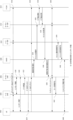
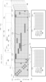
図1は、典型的なLTE地上セルラネットワークの高レベルアーキテクチャを示す。図1における各ノードは、ネットワーク内の動作中の「ノード」を表す。ノードは、いくつかの実施形態において、電子ハードウェアにより実行およびホスティングされるソフトウェアにより実装される。各ノードは、特定の機能または一組の機能にサービスを提供してよく、制御プレーンのシグナリングおよび/またはユーザプレーンのトラフィックルーティングを担ってよく、制御トラフィックまたはユーザトラフィックをルーティングするための、ネットワーク内の他のノードへのインタフェースを有する。訪問ネットワーク102が、無線アクセスネットワーク(RAN)106およびコアネットワーク108をホスティングし得る。訪問ネットワークは、ホームネットワーク104と相互作用し得る。ホームネットワーク104も、訪問ネットワークと同じかまたは同様の種類の無線アクセスネットワークおよびコアネットワークをホスティングする。簡潔さのために、全ての要素が示されていないことがある。ネットワークは、加入者エンドユーザに応じて、ホームネットワークまたは訪問ネットワークであってよい。
FIG. 1 shows the high-level architecture of a typical LTE terrestrial cellular network. Each node in FIG. 1 represents an active "node" within the network. Nodes, in some embodiments, are implemented by software that is executed and hosted by electronic hardware. Each node may serve a particular function or set of functions, may be responsible for control plane signaling and/or user plane traffic routing, and may be responsible for routing control or user traffic within the network. has an interface to other nodes of A visited
無線アクセスネットワークはE-UTRANであってよく、コアネットワークはEPCであってよい。E-UTRANは、エアインタフェース(Uu)を介したUE112との通信を可能にする基地局110を備え得る。基地局は、LTEネットワーク用の基地局であってよい。そのような基地局は、「進化型ノードB」基地局または「UTRANノードB」基地局であってよい。これらは各々、「eNodeB」または「基地局」と称されることが多い。基地局は、携帯電話ネットワークとモバイルハンドセット(UE)とを無線接続するためのハードウェアを含む。
The radio access network may be E-UTRAN and the core network may be EPC. E-UTRAN may comprise
基地局は、X2インタフェースを介して、互いに接続を維持することで制御シグナリングおよびユーザシグナリングを動かし得る。基地局は、制御プレーンおよびユーザプレーン、つまり、S1-CPおよびS1-UPを通じて、EPCに接続する。制御プレーンはMME114にインタフェース接続し、ユーザプレーンインタフェースはS-GW116にインタフェース接続する。MMEは、別の制御インタフェースを通じて、つまり、S11インタフェースを通じてS-GWに接続してよく、S10インタフェースを通じて他のMMEに接続してよく、S6aインタフェースを通じてHSSデータベース122に接続してよい。EPCもP-GW118をホスティングする。P-GWは、ホームネットワーク内のS5インタフェースを通じて、S-GWへの制御プレーンおよびユーザプレーンでの接続をする。同様の接続が、訪問ネットワークのS-GWとホームネットワーク120のP-GWとの間に存在し得る。この接続は、S8インタフェースであり、また、制御プレーンおよびユーザプレーンを含む。P-GWは、PCRF124で制御インタフェースを維持する。P-GWは、SGiインタフェースを通じたPDNサーバ126への接続を維持する。
Base stations may operate control and user signaling by maintaining connections with each other over the X2 interface. The base station connects to the EPC through the control plane and user plane, ie S1-CP and S1-UP. The control plane interfaces to MME 114 and the user plane interface interfaces to S-GW 116 . The MME may connect to the S-GW through another control interface, namely through the S11 interface, to other MMEs through the S10 interface, and to the
図2は、LTEネットワーク内の各インタフェース用の制御プレーンプロトコルスタックを示す。これは、制御トラフィックを渡すための各ノード接続がどのように実装されるかを説明している。制御プレーンインタフェースは、有線式であってもよく、無線式であってもよい。UEスタック202は、アプリケーション層、IP層、PDCP層、RLC層、MAC層およびPHY層を動作させて、LTE-Uuインタフェース212を介して基地局スタック204と通信する。基地局スタックは、アプリケーション層パケットおよびIP層プロトコルパケットを中継するが、PDCP、RLC、MACおよびPHY層を用いてエアインタフェースの相互作用およびチャネル割り当ての変調スキームを調整することにより、HARQ、ARQ等の要件を符号化する。基地局スタックは、S-GWスタック206へのS1-Uインタフェース214を介して、UEからのトラフィックをコアネットワークへルーティングする。基地局とS-GWとの間でIPベースデータパケットを渡すために、トンネリングプロトコル、つまり、GTP-Uが用いられる。S5インタフェースおよびS8インタフェース216は、S1インタフェースとほぼ同一である。しかしながら、S-GWスタックは、IPパケットを中継し、P-GWスタック208は、IPデータパケットを受信する。P-GWは、UEと、エンドUEのためにバックエンドIPサービスを提供しているパケットデータネットワーク(PDN)スタック210との間のSGiインタフェース218を用いて、ルーティングIPトラフィック用のサービングノードとして機能する。UE上のアプリケーション層と互換性があるアプリケーション層は、アプリケーション層サービス(例えば、スマートフォンアプリケーション)を提供するPDN上に存在する。基地局スタック204は、X2-Uインタフェース220を介して互いに通信する。X2-Uインタフェースは、トンネリングプロトコルGTP-UおよびSCTP移送層を用いて、基地局等間のハンドオーバの間、エンドUE用のIPデータパケットをルーティングする。
FIG. 2 shows the control plane protocol stack for each interface in the LTE network. It describes how each node connection is implemented for passing control traffic. The control plane interface may be wired or wireless. UE
図3は、LTEネットワーク内の各インタフェース用のユーザプレーンプロトコルスタックを示す。これは、ユーザトラフィックを渡すための各ノード接続がどのように実装され得るかを説明している。ユーザプレーンインタフェースは、有線式であってもよく、無線式であってもよい。UEスタック302は、LTE-Uuインタフェース316を介して基地局スタック304と通信する。非アクセス層(NAS)は、MMEスタック306とUEスタックとの間のLTE無線遠距離通信プロトコルスタック内の機能層である。NAS層は、ネットワークを通じて動くので、通信セッションの確立を管理するために、かつ、ユーザ機器との連続的な通信を維持するために用いられる。基地局スタックは、MMEとUEとの間のこの層を中継すると共に、PDCPを用いて、無線リソース制御メッセージをUEへ移送する。MMEスタックは、S1-Cインタフェース318を介して基地局スタックと通信する。MMEは、SCTPを用いて、NASシグナリングに基づくS1-APプロトコルセッションを移送する。MMEは、S11インタフェース320を介してS-GWスタック308と通信する。このインタフェースは、トンネリングプロトコルおよびUDPを用いて、IPパケットを移送する。また、S-GWスタックは、S11インタフェースと同様の構造を用いて、S5/S8制御プレーンインタフェース322を介してP-GWスタック310と通信する。UDPを用いてX2-APメッセージを移送する、UEスタック304間のX2-Cインタフェース324など、さらなるインタフェースが存在する。これは、UEハンドオーバ中の基地局間の制御シグナリングのために用いられる。MMEスタック306は、S10インタフェース326を介して通信する。これは、UDPを用いて、トンネリングプロトコルメッセージを移送する。また、MMEスタックは、S6aインタフェース328を介してHSSデータベース312と通信する。このインタフェースは、SCTPを用いて、直径メッセージを移送する。P-GWスタック310をPCRFデータベース314に接続するS7インタフェース330上で、同じスタックが用いられる。
[モバイルハンドセット/デバイス]
FIG. 3 shows the user plane protocol stacks for each interface in the LTE network. It describes how each node connection can be implemented to pass user traffic. The user plane interface may be wired or wireless. UE
[Mobile handset/device]
一般的に、個々のユーザは、ネットワーク上で動作するモバイルデバイスを携帯する。これらのモバイルデバイスは、典型的には、携帯電話またはセルラ式電話であり、より技術的な専門家の間では、ユーザ機器(UE)またはモバイルステーション(MS)と称されることが多い。モバイルデバイスは、マシンツーマシン(M2M)またはモノのインターネット(IoT)のセルラデバイスまたはセルラモジュールも含み得る。この説明において、説明されている、ネットワークの携帯電話またはエンドユーザデバイスは、UEと称され得る。 Typically, individual users carry mobile devices that operate on the network. These mobile devices are typically mobile or cellular phones and are often referred to as User Equipment (UE) or Mobile Stations (MS) among more technical professionals. Mobile devices may also include machine-to-machine (M2M) or Internet of Things (IoT) cellular devices or modules. In this description, the mobile phone or end-user device of the network being described may be referred to as a UE.
UEは、ハードウェアおよびSIMカードを備え得る。ハードウェアは、物理電話またはデバイス自体を含み得る。実際のハードウェアは、デバイスの国際携帯機器識別番号、すなわちIMEIとして知られる一組の数字を含み得る。この数字は、オンであり、かつ、ネットワーク上で物理デバイスが盗まれたとマーキングされているかどうかをチェックするために、また、他の目的で用いられるハードウェアの正確な部品に固有のものである。物理デバイスは、典型的には、エアインタフェースまたはRFインタフェースを介してセルラネットワークとインタフェース接続できるように、トランスミッタおよびレシーバを含む。トランスミッタおよびレシーバと共に、スクリーン/キーボードなどのデジタルインタフェース、またはGPIOピンなどの電気インタフェースが存在し得る。これらのインタフェースは、デバイスがどのようにネットワークにアクセスし、音声、テキストまたはデータペイロード/データパケットを送信および受信するかを制御するために用いられ得る。 A UE may comprise hardware and a SIM card. Hardware may include the physical phone or device itself. The actual hardware may contain a set of digits known as the device's International Mobile Equipment Identity, or IMEI. This number is specific to the exact piece of hardware that is on and used to check if a physical device has been marked as stolen on the network, and for other purposes. . A physical device typically includes a transmitter and receiver so that it can interface with a cellular network over an air or RF interface. There may be a digital interface such as a screen/keyboard, or an electrical interface such as GPIO pins, along with transmitters and receivers. These interfaces can be used to control how the device accesses the network and sends and receives voice, text or data payloads/data packets.
また、UEは、典型的には、ファームウェアと、ユーザが特定の機能にアクセスすることを可能にするアプリケーション層ソフトウェアとを用いてロードされる。これらの機能は、音声通話、SMSメッセージの送信、インターネットのブラウジングまたは他のアプリケーション(例えば、メッセージング、ゲーム、ストリーミング等)の使用であってよい。UEは、モバイルネットワークとのエアインタフェースを介して特定のデータレートを実現するために、特定の信号レベルまたはQoSを必要とし得る。例として、SMSテクスティングは、比較的弱いリンクレベルで(かつ、故に、高符号化間接費率において低次変調スキームで、かつ、故に、低データレートで)正常に動作でき、一方、ビデオストリーミングは、合理的なダウンロード回数および品質のビデオストリームのために、より高いデータレート(かつ、故に、低符号化間接費率において高次変調スキーム、かつ、故に、より高いデータレート)を必要とし得る。典型的には、UEは、様々な可能な帯域(例えば、周波数)およびプロトコル(例えば、GSM、LTE、UMTS、CDMA等)でセルラネットワークにアクセスするように設計される。いくつかのスマートフォンは、「世界電話」と称され得る。なぜなら、それらは、エンドユーザが世界を旅行し、かつ、用いられているセルラプロトコルの違いにかかわらず世界中の様々な位置においてローカルセルラネットワークに接続できる状態のままであることを可能にする帯域およびプロトコルに対応するように設計されているからである。この理由は、LTE、GSM、CDMA等のプロトコルのための典型的なセルラ帯域割り当てが十分に確立されており、地球中の特定の国における特定のMNOに対してライセンスが割り当てられていることである。 UEs are also typically loaded with firmware and application layer software that allows the user to access specific functions. These functions may be making voice calls, sending SMS messages, browsing the Internet or using other applications (eg, messaging, gaming, streaming, etc.). A UE may require a specific signal level or QoS in order to achieve a specific data rate over the air interface with the mobile network. As an example, SMS texting can operate successfully at relatively weak link levels (and therefore with low order modulation schemes at high coding overhead rates and therefore with low data rates), while video streaming may require higher data rates (and therefore higher order modulation schemes and therefore higher data rates at low coding overhead rates) for reasonable download times and quality video streams . Typically, UEs are designed to access cellular networks over a variety of possible bands (eg, frequencies) and protocols (eg, GSM, LTE, UMTS, CDMA, etc.). Some smart phones may be referred to as "world phones." Because they are the bands that allow end-users to travel the world and remain connectable to local cellular networks in various locations around the world regardless of the differences in cellular protocols in use. and protocols. The reason for this is that typical cellular bandwidth allocations for protocols such as LTE, GSM, CDMA are well established and licenses are allocated to specific MNOs in specific countries around the globe. be.
加入者識別情報モジュール、すなわちSIMは、ユーザがネットワークを用いるための加入者識別情報を含む。SIM上に格納される様々な数および情報のうちの1つが、ネットワークの特定の加入者に対応する一意の数である国際移動電話加入者識別番号(IMSI)である。いくつかの電話は、複数のSIMカードを可能にする。これは、単一のデバイスが複数のIMSIを有し得ることを意味する。これにより、エンドユーザは、複数のネットワーク上で「ホーム」ユーザになることを望む場合、複数の国または同じ国においてでさえローカルプランを有することが可能になる。また、SIMカードは、加入者識別情報を変更して異なるネットワークに「ホーム」加入者として接続するために、デバイスの内部および外部でスワップされ得る。この技術は、旅行することが多く、かつ、旅行する度にローミング料金を支払うことを求めないユーザにとって有利であり得る。
[無線アクセスネットワーク]
A subscriber identity module, or SIM, contains subscriber identity information for a user to use the network. One of the various numbers and information stored on the SIM is the International Mobile Subscriber Identity (IMSI), which is a unique number corresponding to a particular subscriber of a network. Some phones allow multiple SIM cards. This means that a single device can have multiple IMSIs. This allows end-users to have local plans in multiple countries or even the same country if they wish to be "home" users on multiple networks. Also, SIM cards can be swapped inside and outside the device to change the subscriber identity and connect to different networks as a "home" subscriber. This technology can be advantageous for users who travel a lot and do not want to pay roaming charges every time they travel.
[Radio access network]
ネットワークにアクセスすべく、UEは、セルラネットワークの無線アクセスネットワーク(RAN)とのエアインタフェースを用いる。RANは、名前が示唆するように、無線周波数通信を用いたアクセスを可能にするネットワークであり得る。RANは、ネットワーク上のモバイルデバイスと電気通信インフラストラクチャ自体のコアネットワークとの間のインタフェースとして機能する。 To access the network, the UE uses the air interface with the radio access network (RAN) of the cellular network. A RAN, as the name suggests, may be a network that allows access using radio frequency communications. The RAN serves as an interface between mobile devices on the network and the core network of the telecommunications infrastructure itself.
LTEアーキテクチャにおいて、RANは、進化型UMTS地上無線アクセスネットワーク(E-UTRAN)と称されることが多い。E-UTRANは、典型的には、UEと共に物理インタフェースまたはUuを実装する機能要素である複数の基地局を備える。物理インタフェースは、タイムスロットおよびリソースブロック(RB)としての時間および周波数内で中断される。RBは、基地局のスケジューラによりUEに割り当てられる。これは、位置、配備構成、カバレッジ要件等に応じてトラフィックフローを最適化する様々なアルゴリズムのうちの1つにより駆動され得る。ネットワーク内の基地局は、X2インタフェースを通じ互いにインタフェース接続する。これにより、UEがネットワークについてモバイル方式で動作するときに基地局から基地局へのハンドオーバを主にサポートするための通話/テキスト/データパケットの転送およびシグナリングが可能になる。また、基地局は、S1インタフェースを通じて、UEをコアネットワーク、またはLTEネットワーク内の進化型パケットコア(EPC)に接続する。
[コアネットワーク]
In the LTE architecture, the RAN is often referred to as the Evolved UMTS Terrestrial Radio Access Network (E-UTRAN). E-UTRAN typically comprises multiple base stations which are functional elements that implement a physical interface or Uu together with a UE. A physical interface is interrupted in time and frequency as time slots and resource blocks (RB). RBs are assigned to UEs by the base station scheduler. This may be driven by one of various algorithms that optimize traffic flow depending on location, deployment configuration, coverage requirements, and so on. The base stations in the network interface with each other through the X2 interface. This enables call/text/data packet transfer and signaling primarily to support base station to base station handovers when the UE operates in a mobile manner with respect to the network. The base station also connects the UE to the core network, or Evolved Packet Core (EPC) in the LTE network, through the S1 interface.
[Core network]
コアネットワークは、LTEアーキテクチャ内の進化型パケットコア(EPC)と呼ばれることが多く、UEが通信する必要があり得る、UEと、ネットワーク、インターネットおよび他のネットワーク/デバイス上の他のUEとの間のインタフェースとして動作するセルラネットワーク内のほとんどの許可機能を保持する。他のネットワークおよびインターネットにアクセスすることにより、加入者は、ホームネットワーク上にいないユーザと通信したり、特定のアプリケーション/サーバのためにインターネットとの間でデータをアップロード/ダウンロードしたりすることが可能になる。UEが同じホームネットワーク上の他のUEとの通信を望む場合でも、EPCは、認証を処理することでUEのアクセスを可能にする。 The Core Network, often referred to as the Evolved Packet Core (EPC) within the LTE architecture, is between the UE and other UEs on the network, the Internet and other networks/devices with which the UE may need to communicate. It holds most of the authorization functions within the cellular network acting as an interface for Access to other networks and the Internet allows subscribers to communicate with users not on their home network and to upload/download data to/from the Internet for specific applications/servers become. Even if the UE wishes to communicate with other UEs on the same home network, the EPC enables UE access by handling authentication.
LTEプロトコルを用いる場合、コアネットワークは、典型的には、モビリティ管理エンティティ(MME)と、サービングゲートウェイ(S-GW)と、パケットデータネットワーク(PDN)ゲートウェイ(P-GW)と、ホーム加入者サーバ(HSS)とを備える。LTEにおいて、MMEは、訪問者位置レジスタ(VLR)をホスティングし、HSSは、ホーム位置レジスタ(HLR)、機器識別情報レジスタ(EIR)および認証センタ(AuC)をホスティングする。HLR、VLR、EIRおよびAuCは、EPCにより管理されるデータベースであり、後でより詳細に説明する。
[モビリティ管理エンティティ(MME)]
With the LTE protocol, the core network typically includes a Mobility Management Entity (MME), a Serving Gateway (S-GW), a Packet Data Network (PDN) Gateway (P-GW), and a Home Subscriber Server. (HSS). In LTE, the MME hosts the Visitor Location Register (VLR) and the HSS hosts the Home Location Register (HLR), Equipment Identity Register (EIR) and Authentication Center (AuC). The HLR, VLR, EIR and AuC are databases managed by the EPC and are described in more detail below.
[Mobility Management Entity (MME)]
EPC内には、いくつかの制御プレーンインタフェースおよびユーザプレーンインタフェースが存在する。E-UTRANは、S1-CPインタフェースと呼ばれるMMEを有する制御プレーンを介してEPCとインタフェース接続する。S1-CPインタフェースは、非アクセス層(NAS)を用いて、通信セッションの確立を管理し、かつ、ユーザ機器が動くときにユーザ機器との連続的な通信を維持する。LTE S1-CPインタフェースは、基地局とMMEとの間のシグナリングプロトコルの配信を担う。S1-CPインタフェースは、IPを介したストリーム制御伝送プロトコル(SCTP)を備え、単一のSCTPアソシエーションを通じて複数のUEをサポートする。それは、保証型データ配信も提供する。アプリケーションシグナリングプロトコルは、S1-AP(アプリケーション)プロトコルである。LTE S1-CPは、進化型パケットシステム(EPS)ベアラセットアップ/解放手順、ハンドオーバシグナリング手順、ページング手順およびNAS移送手順を担う。 Within the EPC there are several control plane and user plane interfaces. The E-UTRAN interfaces with the EPC via a control plane with an MME called the S1-CP interface. The S1-CP interface, with the Non-Access Stratum (NAS), manages the establishment of communication sessions and maintains continuous communication with the user equipment as the user equipment moves. The LTE S1-CP interface is responsible for delivering signaling protocols between the base station and the MME. The S1-CP interface comprises Stream Control Transmission Protocol (SCTP) over IP and supports multiple UEs through a single SCTP association. It also offers guaranteed data delivery. The application signaling protocol is the S1-AP (application) protocol. LTE S1-CP is responsible for Evolved Packet System (EPS) bearer setup/release procedures, handover signaling procedures, paging procedures and NAS transport procedures.
また、MMEは、S10インタフェースを通じた他のMMEとの制御プレーンインタフェースと、S11インタフェースを通じたS-GWと、S6aインタフェースを通じたHSSとを有する。 The MME also has a control plane interface with other MMEs through the S10 interface, the S-GW through the S11 interface, and the HSS through the S6a interface.
MMEとS-GWとの間のS11インタフェースは通常、多対多インタフェースである。これは、独自のS11インタフェースを各々が有する複数のS-GWを単一のMMEが処理できることを意味する。これらの接続は、EPC内のSAEベアラの確立を調整するために用いられ得る。SAEベアラセットアップは、MME(デフォルトSAEベアラ)またはP-GWにより開始され得る。S11インタフェースを用いることで、MMEノードは、IPセッションの生成または削除、デフォルトベアラの生成または削除、専用ベアラの生成または削除、専用ベアラを生成または修正/更新するためのルールの追加、UEハンドオーバの実行、S-GW再配置でのX2ベースUEハンドオーバの実行、S-GW再配置でのS1ベースUEハンドオーバの実行をできる。
[サービングゲートウェイ(S-GW)]
The S11 interface between MME and S-GW is typically a many-to-many interface. This means that a single MME can handle multiple S-GWs each with its own S11 interface. These connections may be used to coordinate the establishment of SAE bearers within the EPC. SAE bearer setup can be initiated by the MME (default SAE bearer) or the P-GW. By using the S11 interface, the MME node can create or delete IP sessions, create or delete default bearers, create or delete dedicated bearers, add rules to create or modify/update dedicated bearers, perform UE handover. perform X2-based UE handover on S-GW relocation; perform S1-based UE handover on S-GW relocation;
[Serving Gateway (S-GW)]
E-UTRANは、S1-UPインタフェースと呼ばれるS-GWを有するユーザプレーンを介してEPCとインタフェース接続する。S1-UPインタフェースは、基地局とS-GWとの間のLTEユーザプレーンプロトコルデータユニット(PDU)の非保証型データ配信を提供する。移送ネットワーク層は、IP移送およびGTP-U上に構築される。UDP/IPは、基地局とS-GWとの間のユーザプレーンPDUを保持する。無線ベアラ1個当たりのGTPトンネルは、ユーザトラフィックを保持する。S1-UPインタフェースは、基地局とS-GWとの間のユーザデータの配信を担う。IP差別化サービスコードポイント(DSCP)マーキングは、無線ベアラ1個当たりのQoSのためにサポートされる。 The E-UTRAN interfaces with the EPC via the user plane with the S-GW called the S1-UP interface. The S1-UP interface provides non-guaranteed data delivery of LTE User Plane Protocol Data Units (PDUs) between the base station and the S-GW. The transport network layer is built on IP transport and GTP-U. UDP/IP carries user plane PDUs between the base station and the S-GW. A GTP tunnel per radio bearer holds user traffic. The S1-UP interface is responsible for delivering user data between the base station and the S-GW. IP Differentiated Services Code Point (DSCP) marking is supported for QoS per radio bearer.
S-GWは、S5インタフェースまたはS8インタフェースを介してP-GWと接続することにより、GPRトンネリングプロトコル(GTP)を用いて、UEおよびコアネットワークとの間のパケット用のIPルーティングサービスを提供する。S5インタフェースが単一の(ホーム)ネットワークの内部で用いられるが、異なる事業者間でローミングする場合にS8インタフェースが用いられることを除き、原則的に、S5およびS8は、同じインタフェースである。非ローミングの場合、S-GWおよびP-GWの機能は、1つの物理ノード内で実行され得る。 S-GW provides IP routing service for packets between UE and core network using GPR Tunneling Protocol (GTP) by connecting with P-GW via S5 or S8 interface. In principle S5 and S8 are the same interface, except that the S5 interface is used inside a single (home) network, whereas the S8 interface is used when roaming between different operators. For non-roaming, the S-GW and P-GW functions may be performed within one physical node.
S5/S8は、多対多インタフェースであり、ユーザプレーントンネリング、およびサービングGWとPDN GWとの間のトンネル管理を提供する。S8インタフェースは、UEのモビリティに起因するサービングGWの再配置のために、また、必要とされるPDN接続のために非併置PDN GWにサービングGWが接続する必要がある場合に用いられる。S5インタフェースは、VPLMN内のサービングGWとHPLMN内のPDN GWとの間のユーザプレーンおよび制御プレーンを提供するPLMN間基準点である。S8は、S5のPLMN間変形形態である。
[パケットデータネットワークゲートウェイ(P-GW)]
S5/S8 are many-to-many interfaces and provide user plane tunneling and tunnel management between Serving GW and PDN GW. The S8 interface is used for Serving GW relocation due to UE mobility and when the Serving GW needs to connect to a non-collocated PDN GW for required PDN connectivity. The S5 interface is an inter-PLMN reference point that provides the user plane and control plane between the Serving GW in the VPLMN and the PDN GW in the HPLMN. S8 is the inter-PLMN variant of S5.
[Packet data network gateway (P-GW)]
P-GWは、SGiインタフェースをPDNに向かって終端させるノードである。UEが複数のPDNにアクセスしている場合、そのUE用の1つよりも多くのP-GWが存在し得る。P-GWは、そのUEのトラフィックの出口ポイントおよび入口ポイントになることにより、外部パケットデータネットワークへの接続をUEに提供する。UEは、複数のPDNにアクセスするために1つよりも多くのP-GWとの同時接続を有し得る。P-GWは、ポリシの実施と、各ユーザのためのパケットのフィルタリングと、充電サポートと、合法的なインターセプトおよびパケットスクリーニングとを実行する。この基準点は、P-GWとパケットデータネットワークとの間の接続を提供する。SGiインタフェースは、外部パブリックまたはプライベートPDNおよび/または内部IMSサービス提供ネットワークを含む様々なネットワーク種類へのアクセスを提供できる。
[セルラネットワークデータベース]
The P-GW is the node that terminates the SGi interface towards the PDN. If a UE is accessing multiple PDNs, there may be more than one P-GW for that UE. The P-GW provides the UE with connectivity to external packet data networks by being the egress and ingress points for the UE's traffic. A UE may have simultaneous connections with more than one P-GW to access multiple PDNs. The P-GW performs policy enforcement, packet filtering for each user, charging support, lawful interception and packet screening. This reference point provides connectivity between the P-GW and the packet data network. The SGi interface can provide access to various network types including external public or private PDNs and/or internal IMS serving networks.
[Cellular network database]
LTEネットワークは、UEのモビリティを管理するための動作中のクエリのためにだけでなく、認証、課金、ポリシ管理等のためにも用いられる一連のデータベースを管理し得る。HSSは、ネットワークを用いることができる各加入者についての管理レベル情報を含むデータベースであるHLRのホームである。また、HLRは、ネットワーク内の加入者が最後に確認された位置をトラッキングするフィールドを含む。この情報は、通話、メッセージまたはデータがルーティングされる必要がある場合にデバイスを配置するためのものであり得る。ユーザが携帯電話またはモバイルデバイスを切り替えた場合、もしくは、それらがネットワーク内の別の位置エリアコード(LAC)へ移動した場合、または、おそらくいくつかの規則的な周期にわたって、モバイルデバイスは、HLRが最新の位置を常に把握するように、それらの位置を更新し得る。典型的には、デバイスの位置は、デバイスの実際の緯度位置/経度位置ではなく、ネットワークの文脈(例えば、デバイスがどの基地局にキャンプオンされているか)において保持される。典型的には、任意のネットワーク内にマスタHLRが1個だけ存在する。しかしながら、そのコピーが、動作効率の向上のために、様々なコアネットワークノードにわたって分配され得る。 The LTE network may manage a set of databases that are used not only for active queries to manage UE mobility, but also for authentication, charging, policy management, etc. The HSS is home to the HLR, a database containing administrative level information about each subscriber that can use the network. The HLR also contains fields that track the subscriber's last known location within the network. This information may be for locating the device when a call, message or data needs to be routed. When a user switches cell phones or mobile devices, or when they move to a different Location Area Code (LAC) in the network, or perhaps over some regular period, the mobile device Their positions can be updated to keep track of the latest positions. Typically, the location of the device is kept in the context of the network (eg, which base station the device is camped on) rather than the actual latitude/longitude location of the device. Typically, there is only one master HLR in any network. However, the copies may be distributed across various core network nodes for improved operational efficiency.
HSSは、HLRとAuCとが連結されたものであり、プリIMS 2G/GSMネットワークおよび3G/UMTSネットワーク内に2つの機能が既に存在している。HSSのHLR部分は、ユーザの識別およびアドレス指定(これは、IMSI(国際移動電話加入者識別番号)およびMSISDN(モバイル加入者ISDN番号)または携帯電話番号に対応する)と、ユーザプロファイル情報(これは、サービス加入状態およびユーザ加入サービス品質情報(最大許容ビットレートまたは最大許容トラフィッククラスなど)を含む)とを含む(列挙は非包括的である)ユーザ加入情報を含むデータベースの格納および更新を必要な場合に担う。 HSS is a concatenation of HLR and AuC, two functions already exist in pre-IMS 2G/GSM and 3G/UMTS networks. The HLR part of the HSS contains user identification and addressing (which corresponds to IMSI (International Mobile Subscriber Identity) and MSISDN (Mobile Subscriber ISDN Number) or mobile phone number) and user profile information (which corresponds to requires storing and updating a database containing user subscription information (list is non-exhaustive), including service subscription status and user subscription quality of service information (such as maximum allowed bitrate or maximum allowed traffic class) in case of
HSSのAuC部分は、ユーザ識別キーからのセキュリティ情報の生成を担う。このセキュリティ情報は、HLRに提供され、さらに、ネットワーク内の他のエンティティに伝達される。セキュリティ情報は、ネットワークと端末との間で伝送されるデータおよびシグナリングが盗聴も変更もされないことを保証するためのネットワーク-端末の相互認証ならびに無線経路の暗号化および完全性保護のために用いられ得る。 The AuC part of the HSS is responsible for generating security information from user identification keys. This security information is provided to the HLR and further communicated to other entities in the network. Security information is used for network-terminal mutual authentication and for encryption and integrity protection of the radio path to ensure that data and signaling transmitted between network and terminal cannot be intercepted or altered. obtain.
VLRは、いくつかの態様のHLRのより小さい一時的なバージョンであり、HLRからの選択情報を含む。任意の「訪問者」、または、ホームネットワークの一部ではないEPCにより制御される基地局上でローミングするUEが、訪問ネットワークのVLR上に配置される。UEは通常、一度に1つのVLR内にのみ存在し得る。これは、そのUEへのトラフィックのネットワークルーティングにとって非常に重要であり得る。VLRに格納されたデータは、ユーザのホームネットワークHLRから収集されるか、または基地局を通じてUE自体から直接収集される。VLRは、トラフィックルーティングが別個のネットワーク間で完了され得るように、加入者の更新された位置のホームHSSをHLRに通知するために用いられる。ユーザは、典型的には正確に、設定された期間(各ネットワークについて構成され/設定され得る期間)にわたって加入者が非アクティブになった時、UEが新しいVLRドメイン位置エリアへローミングした時、または、ユーザがホームネットワーク上へ移行した時に、VLRから除外される。 A VLR is a smaller temporal version of the HLR in some aspects and contains selection information from the HLR. Any "visitor" or UE roaming on an EPC controlled base station that is not part of the home network is placed on the visited network's VLR. A UE can typically only be in one VLR at a time. This can be very important for network routing of traffic to that UE. The data stored in the VLR are collected either from the user's home network HLR or directly from the UE itself through the base station. The VLR is used to inform the HLR of the home HSS of the subscriber's updated location so that traffic routing can be completed between separate networks. The user will typically have to specify exactly when the subscriber has been inactive for a set period of time (which can be configured/configured for each network), when the UE roams to a new VLR domain location area, or , is removed from the VLR when the user migrates onto the home network.
VLRは、ホームネットワークの外部のローミング動作中に一時的な加入者識別情報として効果的に機能するTMSIを含む各IMSIのフィールド値の部分を含み得る。 The VLR may contain a field value portion of each IMSI, including the TMSI, which effectively serves as a temporary subscriber identity during roaming operations outside the home network.
EIRは、ネットワークに接続され得るか、またはネットワークへの接続を試み得る特定のハンドセットもしくはモバイル機器またはデバイスの情報を保持するデータベースである。このデータベースは、IMEIを用いて、ネットワークにアクセスする権限をデバイスが有しているか否かを判断する。典型的には、電話が盗まれたと報告された場合、デバイスのIMEIは、盗まれたデバイスとしてそれを関連付けるEIR内のリストに置かれる。そのように、デバイスがネットワークへの登録を試みた場合、ネットワークは、電話の潜在的な窃盗犯による不適切な使用を防ぐために、そのアクセスを拒否できる。 An EIR is a database that holds information about specific handsets or mobile equipment or devices that may be connected to a network or attempting to connect to a network. This database uses the IMEI to determine if the device is authorized to access the network. Typically, when a phone is reported stolen, the device's IMEI is placed on a list in the EIR associating it as a stolen device. That way, if a device attempts to register with the network, the network can deny its access to prevent improper use by potential thieves of the phone.
最終的に、AuCは、ネットワークに対するデバイス認証に関連する情報を含むデータベースである。AuCは通常、HLRにインタフェース接続され、ネットワーク上の特定のIMSI用の重要なキーを保持する。これらのキーも、UE SIM上に常駐している。これらのキーをマッチングすることにより、エアインタフェースチャネルを介したデバイスの認証および暗号化(または暗号化)の両方が可能になる。ローミングシナリオにおいて、この認証キー/情報は、ホームHLRからクエリされる。
[ネットワークオペレーションセンタ]
Ultimately, the AuC is a database containing information related to device authentication to the network. The AuC is typically interfaced to the HLR and holds critical keys for specific IMSIs on the network. These keys also reside on the UE SIM. Matching these keys allows both authentication and encryption (or encryption) of the device over the air interface channel. In a roaming scenario, this authentication key/information is queried from the home HLR.
[Network Operation Center]
地上セルラネットワークの上で説明したコンポーネントは自律的に動作するが、典型的には、あるレベルのヒューマンインタラクションも実装される。ネットワークオペレーションセンタ、すなわちNOC(動作管理センタ、すなわちOMCとしても知られることがある)は、ネットワークインフラストラクチャの動作およびステータスの制御およびモニタリングを可能にするネットワークのコンポーネントである。ネットワーク内のこのノードは、図1に示されていないが、ネットワーク内の各要素への接続を維持するであろう。例えば、このノードは、基地局/E-UTRANサブシステムにおけるトラフィック負荷を制御することにさえ用いられ得る。NOCは、典型的には、LTEネットワーク内の各々の基地局、MMEノード、S-GWノード、P-GWノードへの接続を有する。
[A. ネットワーク手順の例]
Although the above-described components of terrestrial cellular networks operate autonomously, some level of human interaction is also typically implemented. A Network Operations Center or NOC (sometimes known as an Operations Management Center or OMC) is a component of a network that enables control and monitoring of the operation and status of the network infrastructure. This node in the network will maintain connections to each element in the network, not shown in FIG. For example, this node can even be used to control the traffic load in the base station/E-UTRAN subsystem. A NOC typically has connections to each base station, MME node, S-GW node, P-GW node in the LTE network.
[A. Example of network procedure]
ネットワークは、手順の長いリストを実装し得るが、特定の具体的な手順が、ほとんどの場合に用いられ、かつ、例えば、モビリティ管理、スペクトル使用等のネットワーク機能にとって重要であり得る。
[A.1 認証手順]
Networks may implement a long list of procedures, but certain specific procedures are most often used and may be important for network functions such as mobility management, spectrum usage, and the like.
[A. 1 Authentication procedure]
LTEネットワーク内の認証手順は、ユーザの識別番号の認証(例えば、それらの加入者番号の検証)およびネットワークへのアクセスの許可または禁止の両方のために用いられる。認証では、HSSに格納される一意のキーを活用し、ネットワークのUE側およびMME側に対する処理を実行することで、値を計算し、結果を比較して認証を検証する。非アクセススペクトル(NAS)(例えば、ネットワークルート上の信号/パケット)およびアクセススペクトル(AS)(例えば、UEと基地局との間のRFインタフェース上の信号/パケット)の暗号化(encryption)および暗号化(ciphering)には、同様の手順が用いられる。 Authentication procedures within the LTE network are used both to authenticate users' identification numbers (eg, to verify their subscriber numbers) and to allow or disallow access to the network. Authentication leverages the unique key stored in the HSS and performs processing on the UE and MME sides of the network to compute values and compare the results to verify authentication. Encryption and ciphering of the non-access spectrum (NAS) (e.g. signals/packets on the network route) and the access spectrum (AS) (e.g. signals/packets on the RF interface between the UE and the base station) A similar procedure is used for ciphering.
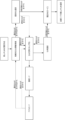
図4は、LTEネットワーク内でのUE認証のための典型的な処理を示す。この処理は、UE402、基地局404、MME406およびHSS408を伴う。UEは、ネットワーク410へのアタッチの要求をMMEへ送信する。この要求で、UEは、UEとのエアインタフェースの認証および管理のためにネットワークが必要とし得るIMSIとUEハンドセット機能についての他の情報とを送信する。MMEは、ホームネットワークHSSへの認証データ要求412を行う。このメッセージは、応答のためにHSSが必要とするいくつかの他の情報と共に認証を必要とするIMSIのリストを含み得る。HSSは、認証ベクトルと呼ばれるものと共に、MME414への応答を提供する。
FIG. 4 shows an exemplary process for UE authentication within an LTE network. This process involves
各認証ベクトルは、EPS AKAアルゴリズムと呼ばれるアルゴリズムの実行から得られる出力に関連するAUTN値、XRE値、KSAME値およびRAND値を含む。MMEは、基地局416を通じてRAND値およびAUTN値をUEに渡す。UEは、この情報を用いてEPS AKAアルゴリズムを実行し、次に、RES値を含む、MME418への応答を提供する。RES値は、HSSにより計算されてMMEに提供されるXRE値に等しくなるべきである。MMEは、420においてこれが当てはまることをチェックし、当てはまる場合には、UEは、ネットワークに対して認証される。
Each authentication vector contains AUTN, XRE, KSAME and RAND values associated with the output from execution of an algorithm called the EPS AKA algorithm. The MME passes the RAND and AUTN values to the UE through
次に、MMEおよびUEは、さらなる手順段階422を実行して、UEとネットワークとの間のAS(RFインタフェース)セッションおよびNAS(ネットワーク制御インタフェース)セッションの暗号化(ciphering)および暗号化(encryption)を達成し得る。これらの手順は、UEノードおよび/または基地局ノードがアルゴリズムを実行して、ノード間のトラフィックを暗号化するために用いられる前にチェックおよび検証される一意のキーを計算し得るという点で、認証と同様の性質のものである。これらの手順が完了した後に、MMEは、UE424から元のアタッチ要求を受け入れてよく、ネットワークに正式にアタッチされ、トラフィックを動かすことができるようになってよい。
The MME and the UE then perform a further
UEが最初にネットワークへのアクセスを要求した場合に認証がトリガされる。
[A.2 位置更新手順]
Authentication is triggered when the UE first requests access to the network.
[A. 2 Position update procedure]
古典的なモバイルネットワークでは、ネットワークが情報を配信したりされたりする必要があるUEにどのように接触するかをネットワークが把握できるように、各デバイスの位置がトラッキングされ得る。ネットワークが用いる様々なトラッキングパラメータについては、本明細書の他の箇所で説明する。ネットワーク上でのUEの位置は、HSS内のマスタデータベースからトラッキングされる。UEの位置が変化した場合、それはHSSに反映される。UEが、その独自のホームネットワークではないネットワークに接続された場合、UEの位置は、HSSおよびVLRの両方によりトラッキングされる。VLRは、加入者認証情報と、そのネットワーク内でのUEの位置とを一時的に格納する。UEの位置が変化した場合、VLRは、HSSがUEのための位置の変化を管理できるように、位置更新の要求をHSSに対して行い得る。 In classical mobile networks, the location of each device can be tracked so that the network knows how to contact UEs to which information needs to be delivered or received. Various tracking parameters used by the network are described elsewhere herein. The UE's location on the network is tracked from a master database in the HSS. If the UE's location changes, it will be reflected in the HSS. When a UE is attached to a network other than its own home network, the UE's location is tracked by both the HSS and the VLR. The VLR temporarily stores subscriber authentication information and the location of the UE within its network. If the UE's location changes, the VLR may make a location update request to the HSS so that the HSS can manage the location change for the UE.
特定のローミング条件下で、加入者が位置するMMEおよびVLRの物理位置は、認証のためにデバイスが必要とする重要な管理情報を保持するHSSから遠く離れていてよい。SS7、または様々な地上ネットワークをインタフェース接続する別の媒体を通じて、クエリがルーティングされ得る場合、認証が数分間にわたって行われることがあり得る。特にネットワーク手順に対して、トラフィック負荷が高く、かつ、データベースが遠く離れて位置する場合、これらのネットワーク間相互作用が減速し得る。結果として、外部ネットワークへの最初のアクセスが遅れることがあり得る。しかしながら、ひとたびアクセスが提供されると、典型的には、セルラサービスに関連して典型的なスピードが再開する。 Under certain roaming conditions, the physical location of the MME and VLR where the subscriber is located may be far from the HSS, which holds important management information required by the device for authentication. If the query can be routed through SS7, or another medium interfacing the various terrestrial networks, the authentication can take several minutes. Especially for network procedures, if the traffic load is high and the databases are located far away, these inter-network interactions can slow down. As a result, initial access to external networks can be delayed. However, once access is provided, the typical speeds typically associated with cellular service resume.
UEが位置更新手順を開始し得る場合のトリガの例が表1に列挙される。

図5は、典型的な位置更新またはトラッキングエリア更新の手順を示す。示されている伴われるノードは、UE502、基地局504、新しいMME(例えば、新しいトラッキングエリア)506、古いMME(例えば、古いトラッキングエリア)508、S-GW510およびHSS512である。基地局とUEとの間でRRC接続セットアップが行われた後に、UEは、トラッキング更新要求を開始し得る(514)。基地局は、要求を新しいMMEへルーティングし得る(516)。新しいMMEは、UEとの認証/セキュリティ手順を実行するために用いる古いMMEからのコンテキスト要求を介して情報を要求し得る(518)。古いMMEは、それが要求した情報と共に新しいMMEに応答(520)し得る。次に、新しいMMEは、UEを認証する(522)。認証が成功した後に、新しいMMEは、古いMMEからの要求コンテキストに確認応答し得る(524)。次に、新しいMMEは、S-GWからのベアラ修正を要求し得る(526)。新しいMMEからのベアラ修正要求は、応答され(528)、新しいMMEは、HSSからの位置更新を直ちに要求する(530)。HSSは、古いMME上で保持されている現在の位置をキャンセルする(532)。キャンセルが古いMMEにより確認応答された(534)後に、536において、HSSは、新しいMMEからの位置更新要求に確認応答する。次に、新しいMMEは、UEのTAU要求538を受け入れ、UEは、位置更新手順の完了に確認応答する(540)。
[A.3 ハンドオーバ手順]
FIG. 5 shows a typical location update or tracking area update procedure. The accompanying nodes shown are
[A. 3 Handover procedure]
UEモビリティ中は、UEがネットワーク内の1つのセルから別のセルへ遷移する必要がある不可避な例がある。各セルが1つのeNBによりサービスを提供されてよく、複数のeNBが1つのS-GWおよび/またはMMEによりサービスを提供されてよい。eNBのハンドオーバのみが行われる必要があるシナリオが存在し、S-GWがハンドオーバされる必要がある他のシナリオも存在する。いくつかの例では、P-GWのハンドオーバさえ必要になり得る。 During UE mobility there are unavoidable instances where a UE needs to transition from one cell to another within the network. Each cell may be served by one eNB, and multiple eNBs may be served by one S-GW and/or MME. There are scenarios where only the eNB handover needs to take place, and other scenarios where the S-GW needs to be handed over. In some instances, even a P-GW handover may be required.
図6は、ハンドオーバが従来どのようにeNBとS-GWとの間で行われ得るかを示す。ハンドオーバ手順において、伴われる要素は、UE602、ソースeNB604、ターゲットeNB606、MME608、ソースS-GW610、ターゲットS-GW612およびP-GW614である。ハンドオーバは、ソースeNBおよびソースS-GWを通じてUEとP-GWとの間でIPセッションが既に確立された後に行われ得る(616)。UEからソースeNBへの測定制御メッセージにより、それとターゲットeNBとの間のハンドオーバの準備がトリガされ得る(618)。ターゲットeNBおよびソースeNBは、X2インタフェースを介してハンドオーバを実行できる(620)。ソースeNBは、データをUEへダウンリンクできるように(624)、ターゲットeNBへのデータの転送を始める(622)。この時点で、アップリンクデータは、ターゲットeNBを通過し、ソースS-GWを通過し、P-GWへ戻っている(626)。ダウンリンクは、UEに到達する前に、同じS-GWを通じてであるが、ソースeNBを通じてターゲットeNBに(X2インタフェースを通じて)提供される。ターゲットeNBは、ターゲットS-GWへのIPパケットの経路を切り替えるために、MMEに対して経路切り替え要求を行う(628)。
FIG. 6 shows how a handover can conventionally take place between an eNB and an S-GW. In the handover procedure, the elements involved are
MMEは、ターゲットS-GWに対してセッション生成要求を行う(630)。ターゲットS-GWは、P-GWがUE用のベアラを修正することを要求する(632)。P-GWは、修正ベアラ応答を提供し、ターゲットS-GWへのベアラを修正する(634)。ターゲットS-GWは、ターゲットeNBを通じてUEからのIPトラフィックを搬送する準備ができていることを示すために、セッション生成応答でMMEに応答する(646)。MMEは、ターゲットeNBからの元の経路切り替え要求に確認応答し(638)、アップリンクデータおよびダウンリンクデータは、UEからターゲットeNBへ、ターゲットS-GWへ、P-GWへと流れる(640)。これはS-GWハンドオーバの完了を示すので、ソースeNBから転送されるためにダウンリンクデータが用いられるリンクは解放される(642)。MMEは、元のソースS-GWにより提供されるセッションを削除し(644)、ソースS-GWは、セッションを閉じた後に応答する(646)。S-GWハンドオーバの後に、UEは、トラッキングエリアを更新する必要があることがあり、MMEと共にそのようにする(648)。
[A.4 マスタ情報ブロック(MIB)およびシステム情報ブロック(SIB)伝送手順]
The MME makes a session creation request to the target S-GW (630). The target S-GW requests (632) the P-GW to modify the bearers for the UE. The P-GW provides a Modify Bearer Response to modify the bearers to the target S-GW (634). The target S-GW responds 646 to the MME with a session creation response to indicate its readiness to carry IP traffic from the UE through the target eNB. The MME acknowledges the original path switch request from the target eNB (638) and uplink and downlink data flow from the UE to the target eNB to the target S-GW to the P-GW (640). . As this indicates completion of the S-GW handover, the link over which downlink data is used to be transferred from the source eNB is released (642). The MME deletes the session provided by the original source S-GW (644) and the source S-GW responds after closing the session (646). After S-GW handover, the UE may need to update its tracking area and does so with the MME (648).
[A. 4 Master Information Block (MIB) and System Information Block (SIB) Transmission Procedure]
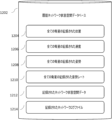
MIB、すなわちマスタ情報ブロックは、任意のユーザが存在しているかどうかにかかわらずLTE基地局によりブロードキャストされるメッセージまたは情報である。MIBは、やはり基地局によりブロードキャストされる他のシステム情報ブロックまたはSIBの中でも最初のものである。 The MIB, Master Information Block, is the message or information broadcast by the LTE base station whether or not any users are present. The MIB is the first among other system information blocks or SIBs also broadcast by the base station.
MIBは、PBCH、すなわちダウンリンク上の物理ブロードキャストチャネルと呼ばれる物理層チャネルを用いて伝送される。MIBは、表2に示されるようにエンコードされる24ビット値である。

ペイロード内の情報とは別に、MIB CRCは、基地局により用いられる伝送アンテナの数も伝える。MIB CRCは、アンテナ固有のマスクを用いてスクランブルまたはXORされる。 Apart from the information in the payload, the MIB CRC also conveys the number of transmit antennas used by the base station. The MIB CRC is scrambled or XORed with antenna specific masks.
各々がある周期で伝送され、かつ、ネットワークアクセスについての重要な情報を含む複数のシステム情報ブロックが存在し得る。例として、SIB1ブロックは、表3に記載される変数のうちの1つまたは複数を含み得る。

LTEネットワークは、IPパケット内の全てのユーザトラフィックを配信し、「常時オンIP接続」をユーザに提供するという点で、全てがIPネットワークであることが多い。UEがLTEネットワークに参加する場合、パケットデータネットワーク(PDN)アドレス(すなわち、PDN内で用いられ得るもの)が、PDNへの接続のためにUEに割り当てられ、デフォルトベアラが、LTEネットワーク内に(すなわち、UEとP-GWとの間に)確立される。このデフォルトベアラは、UEがLTEネットワークからデタッチされるまで、接続されたままである(すなわち、最初のアタッチの間にUEに割り当てられたIPアドレスは、有効なままである)。デフォルトベアラは、ユーザが有する各APN(アクセスポイント名)について確立され、故に、一意のIPアドレスが各APNに割り当てられる。IPアドレスは、IPv4タイプ、IPv6タイプまたはIPv4/IPv6タイプであってよい。 LTE networks are often all-IP networks in that they deliver all user traffic in IP packets, providing users with an “always-on IP connection”. When a UE joins an LTE network, a packet data network (PDN) address (i.e., one that can be used within the PDN) is assigned to the UE for connection to the PDN, and a default bearer is assigned within the LTE network ( between the UE and the P-GW). This default bearer remains connected (ie the IP address assigned to the UE during initial attach remains valid) until the UE is detached from the LTE network. A default bearer is established for each APN (Access Point Name) a user has, so a unique IP address is assigned to each APN. The IP address may be of IPv4 type, IPv6 type or IPv4/IPv6 type.
UEは、最初にLTEネットワークにアタッチする場合、PDN接続を要求する。次に、P-GWが、UEによりPDNについて用いられるIPアドレス(すなわち、PDNアドレス)を割り当てると共に、それら2者を接続中のデフォルトベアラが確立されている間、それをUEへ転送する。このIPアドレスで、UEは、PDNを通じて提供されるサービスを利用できる。 A UE requests a PDN connection when it first attaches to the LTE network. The P-GW then allocates the IP address used by the UE for the PDN (ie the PDN address) and forwards it to the UE while the default bearer connecting the two is established. With this IP address, the UE can use the services provided through the PDN.
IPアドレスは、LTEアーキテクチャ内で、静的に、または動的に割り当てられ得る。典型的には、IPアドレスは、各P-GW内のIPプールが限定されていることが原因で、動的に割り当てられる。IPアドレスの可用性が限定されていることは、典型的にはIPv4システムに関連するが、IPv6システムでは問題になることがより少ない。 IP addresses may be assigned statically or dynamically within the LTE architecture. Typically, IP addresses are dynamically assigned due to the limited IP pool within each P-GW. Limited availability of IP addresses is typically associated with IPv4 systems, but is less of an issue in IPv6 systems.
動的IP割り当ての場合、ネットワーク(例えば、P-GW)は、UEのIPアドレスを自動的に選択する。ネットワーク事業者は、P-GWにおいて前もって供給されるIPプールを有する。その後、次に、UEがLTEネットワークへ最初にアタッチする場合、P-GWは、UEにIPアドレスを動的に割り当てる。したがって、新しい動的IPアドレスは、典型的には、あるUEがネットワークへ最初にアタッチする度に、その同じUEに割り当てられる。 In case of dynamic IP allocation, the network (eg P-GW) automatically selects the UE's IP address. The network operator has an IP pool pre-provisioned at the P-GW. After that, next time the UE attaches to the LTE network for the first time, the P-GW dynamically assigns an IP address to the UE. Therefore, a new dynamic IP address is typically assigned to the same UE each time it attaches to the network for the first time.
静的IP割り当ての場合、ネットワーク事業者は各UEがネットワークに加入すると、それらに永久IPアドレスを割り当てる。事業者は、他の加入情報と共に、ネットワーク(HSS)内でUEのために供給される割り当てられた静的IPアドレスを有する。その後、次に、UEがLTEネットワークへ最初にアタッチする場合、P-GWは、HSSから静的IPアドレスを取得してUEへ転送する。したがって、UEがそれ以降最初にアタッチする度に、この特定のIPアドレスがUEに割り当てられる。
[C. セルラネットワークのナンバリングおよびアドレス指定]
With static IP assignment, the network operator assigns each UE a permanent IP address as they join the network. The operator has an assigned static IP address provided for the UE within the network (HSS) along with other subscription information. After that, next time the UE attaches to the LTE network for the first time, the P-GW obtains a static IP address from the HSS and forwards it to the UE. Therefore, every time the UE attaches for the first time from then on, this particular IP address is assigned to the UE.
[C. Cellular network numbering and addressing]
モバイルネットワークは、典型的にはモバイルデバイスを管理しており、故に、異なるネットワークEPCノードにより管理されるネットワーク内の基地局にUEがアタッチしたり当該基地局からデタッチしたりするときに適切に機能すべく、異なる種類の地理的エリアおよびアドレスを実装し得る。
[C.1 地理的エリア]
A mobile network typically manages mobile devices and thus functions properly when a UE attaches to and detaches from base stations in networks managed by different network EPC nodes. Different types of geographic areas and addresses may be implemented for this purpose.
[C. 1 Geographic Area]
MMEプールエリアは、特定のMMEまたは一組のMMEにより制御されるかまたはサービスを提供される地理的エリアである。MMEエリアは、モバイルデバイスにサービスを提供しているMMEが変更され得る前に当該モバイルデバイスが動作できる物理地域である。S-GWトラッキングエリアは、特定のS-GWまたは一組のS-GWにより制御されるかまたはサービスを提供される地理的エリアである。この地理的エリア内で、UEは、サービスを提供しているS-GWを変更することなく動作できる。 An MME pool area is a geographical area controlled or served by a particular MME or set of MMEs. An MME area is a physical area in which a mobile device can operate before the MME serving the mobile device can be changed. An S-GW tracking area is a geographical area controlled or served by a particular S-GW or set of S-GWs. Within this geographical area, the UE can operate without changing the serving S-GW.
トラッキングエリアは、ネットワークにより用いられる最も小さい地理的エリアを指す。MMEプールエリアは、S-GWトラッキングエリアを含む。S-GWトラッキングエリアは、それら自体がこれらの小さいトラッキングエリアを含む。トラッキングエリアは、特定のセルタワーセルまたはセルタワーセルのグループくらい小さくてよい(おそらく、半径数kmから最大で半径100kmにわたるある半径の円により厳密に表される地理的範囲)。これらのトラッキングエリアは、GSM内で用いられる位置エリアコード(LAC)またはUMTS内で用いられるトラッキングエリアと同様であり、名前が示唆するように、スタンバイされている(例えば、ネットワークに接続されており、かつ、トラフィックを移動または受信する準備ができている)、ネットワーク上でのモバイル機器の位置をトラッキングするために用いられる。 A tracking area refers to the smallest geographical area used by a network. The MME pool area includes the S-GW tracking area. The S-GW tracking areas themselves contain these smaller tracking areas. A tracking area can be as small as a particular cell tower cell or group of cell tower cells (perhaps a geographic area strictly represented by a circle of some radius ranging from a few kilometers up to a radius of 100 km). These Tracking Areas are similar to the Location Area Code (LAC) used in GSM or the Tracking Areas used in UMTS and, as the name suggests, are on standby (e.g. connected to the network). , and ready to move or receive traffic), used to track the location of the mobile device on the network.
したがって、LTEネットワークは、多くのMMEエリア、さらにより多くのS-GWトラッキングエリアおよびさらにより多くのトラッキングエリアを含む。
[C.2 ネットワーク識別]
Therefore, the LTE network includes many MME areas, even more S-GW tracking areas and even more tracking areas.
[C. 2 network identification]
また、ネットワークは、ネットワークレベルアドレスとして用いられる数値識別子のホストを管理する。ネットワークIDは、ネットワーク自体を定義するために用いられる。ネットワークは、モバイル国コード(MCC)およびモバイルネットワークコード(MNC)という2つの一意の識別子の組み合わせまたは連結である公衆陸上移動体ネットワーク(PLMN)コードを用いて識別される。MCCは3桁コードであり、MNCは2桁または3桁コードなので、それら2つが連結される場合、PLMNは、5桁または6桁コードになる。 The network also maintains a host of numeric identifiers that are used as network level addresses. A network ID is used to define the network itself. A network is identified using a public land mobile network (PLMN) code, which is a combination or concatenation of two unique identifiers, the mobile country code (MCC) and the mobile network code (MNC). Since the MCC is a 3 digit code and the MNC is a 2 or 3 digit code, when the two are concatenated the PLMN becomes a 5 or 6 digit code.
ネットワーク内の各MMEには、MMEコード、すなわちMMECとして知られる一意の識別子が提供される。この識別子は、ネットワークMMEプールの各々における特定のMMEを識別する。同じMMEトラッキングエリア内でグループ化されるMMEには、MMEグループ識別情報、すなわちMMEGIと呼ばれるグループレベルコードが与えられる。ネットワーク内の各MMEについては、MMECおよびMMEGIを連結してMME識別子、すなわちMMEIを生成する別の識別子が用いられる。この識別子は、ネットワーク全体における特定のMMEを識別する。最終的に、PLMNおよびMMEIが連結され、グローバル一意MME識別子、すなわちGUMMEIが生成される。この識別子は、全世界のどこでも特定のMMEを識別する。 Each MME in the network is provided with a unique identifier known as an MME Code or MMEC. This identifier identifies a specific MME in each of the network MME pools. MMEs that are grouped within the same MME Tracking Area are given a group level code called MME Group Identity, or MMEGI. For each MME in the network, a separate identifier is used that concatenates MMEC and MMEI to generate the MME identifier, MMEI. This identifier identifies a particular MME throughout the network. Finally, the PLMN and MMEI are concatenated to generate a Globally Unique MME Identifier, or GUMMEI. This identifier identifies a specific MME anywhere in the world.
トラッキングエリアも、同様の方式のコードで識別される。トラッキングエリアコード、すなわちTACは、特定のネットワーク内の特定のトラッキングエリアを識別するために用いられる。この番号がPLMNに連結され、グローバル一意トラッキングエリア識別情報、すなわちTAIが生成される。この識別情報は、地球全体にわたって一意のトラッキングエリアを識別する。 Tracking areas are also identified by codes in a similar fashion. A Tracking Area Code, or TAC, is used to identify a particular tracking area within a particular network. This number is concatenated to the PLMN to generate a Globally Unique Tracking Area Identity or TAI. This identification information identifies unique tracking areas across the globe.
また、UEと通信する必要がある特定のタワーが把握およびトラッキングされるように、ネットワーク内の各セルには、セルIDが提供される。このセルIDは、E-UTRANセル識別子、すなわちECIと称されることが多い。この値は、特定のネットワーク内のセルを一意に識別する。E-UTRANセルグローバル識別子、すなわちECGIも存在する。この識別子は、この惑星のどこでも一意のセルを識別する。典型的には0から503までの間の数値であり、かつ、近傍の地域内の近接するセルを自らと区別するために用いられるタワーの物理セルIDも存在する。 Each cell in the network is also provided with a cell ID so that the specific tower with which the UE needs to communicate is known and tracked. This cell ID is often referred to as the E-UTRAN Cell Identifier, or ECI. This value uniquely identifies a cell within a particular network. There is also an E-UTRAN Cell Global Identifier, ECGI. This identifier uniquely identifies a cell anywhere on this planet. There is also the physical cell ID of the tower, which is typically a number between 0 and 503 and is used to distinguish itself from neighboring cells in the neighborhood.
特定のUEハードウェアをそれがネットワーク上で動作するときにトラッキングするためのモバイル機器識別子が存在する。前に言及したように、各UEは、1つがハードウェア用で1つがSIM用である2つの一意の識別子を有する。国際携帯機器識別番号(すなわちIMEI)は、一意のハンドセットハードウェアを識別するために用いられる。国際移動電話加入者識別番号(すなわちIMSI)は、ネットワーク上の一意の加入者(例えば、SIM)を識別するために用いられる。サービングMMEに対して特定のUEを識別するために用いられるM型一時的移動体加入者識別情報(すなわちM-TMSI)も存在する。M-TMSIコードをMMECに連結することにより、ネットワークは、サービングMMEプールトラッキングエリアに対して特定のUEを識別するために用いられるS型一時的移動体加入者識別情報(すなわちS-TMSI)を生成する。最終的に、PLMN、MMEGIおよびS-TMSIを連結することにより、グローバル一意一時的識別情報、すなわちGUTIが生成される。GUTIは、この惑星のどこでも一意のUEおよびその一時的アドレスを識別する。
[D. 無線プロトコルアーキテクチャ]
A mobile device identifier exists for tracking specific UE hardware as it operates on the network. As mentioned before, each UE has two unique identifiers, one for the hardware and one for the SIM. International Mobile Equipment Identity (or IMEI) is used to uniquely identify handset hardware. International Mobile Subscriber Identity (or IMSI) is used to identify a unique subscriber (eg SIM) on a network. There is also a Type M Temporary Mobile Subscriber Identity (ie M-TMSI) that is used to identify a particular UE to the serving MME. By concatenating the M-TMSI code to the MMEC, the network provides the S-type Temporary Mobile Subscriber Identity (i.e., S-TMSI) used to identify a particular UE to the Serving MME Pool Tracking Area. Generate. Finally, by concatenating PLMN, MMEGI and S-TMSI, a Globally Unique Temporary Identity or GUTI is generated. GUTI identifies a unique UE and its temporary address anywhere on the planet.
[D. Wireless protocol architecture]
無線プロトコルアーキテクチャは、制御プレーンおよびユーザプレーンという2つの別個のプレーンにより定義され得る。ネットワーク内の各ノードインタフェースは、制御プレーン、ユーザプレーン、またはその両方を実装し得る。制御プレーンは、ネットワーク内の様々なノードの間でネットワークシグナリングがパッケージ化および移送される場所である。制御プレーンでは、典型的には無線リソース制御(すなわちRRC)プロトコルが、UEとセルラネットワークとの間で情報がどのように渡されるかを制御するシグナリングメッセージを生成する。これらのシグナリングメッセージは、適切なシグナリングベアラを用いて移送される。 A radio protocol architecture can be defined by two distinct planes: the control plane and the user plane. Each node interface in the network may implement a control plane, a user plane, or both. The control plane is where network signaling is packaged and transported between various nodes in the network. In the control plane, typically a radio resource control (or RRC) protocol generates signaling messages that control how information is passed between the UE and the cellular network. These signaling messages are transported using appropriate signaling bearers.
ユーザプレーンは、実際のデータまたは電気通信ペイロードがUE間かつネットワーク全体にわたって移送される場所である。典型的には、アプリケーションが、TCP、UDPまたはIPなどのプロトコルにより処理されるデータパケットを生成する。制御プレーンおよびユーザプレーンの両方について、情報またはシグナリングパケットが、ネットワークに接続されているUEへの無線伝送のために最終的に物理層、すなわちRF層に渡される前に、パケットデータ収束プロトコル、すなわちPDCP、無線リンク制御プロトコル、すなわちRLC、および媒体アクセス制御プロトコル、すなわちMACにより処理される。 The user plane is where the actual data or telecommunications payload is transported between UEs and throughout the network. Typically, applications generate data packets that are processed by protocols such as TCP, UDP or IP. For both the control plane and the user plane, a packet data convergence protocol, i.e. It is handled by PDCP, the Radio Link Control Protocol or RLC, and the Medium Access Control Protocol or MAC.
図7は、基地局無線プロトコルスタックアーキテクチャを示す。基地局706が、必要とされる制御トラフィックおよびユーザトラフィックをそれぞれ移動させるために、MME704およびS-GW702とのインタフェースを維持する。基地局706は、MMEとの通信を処理する無線リソース制御機能(RRC)708を有する。無線リソース制御機能は、プロトコルスタック内の下位層へ送信される制御メッセージに関連するさらなる情報を提供するために用いられる、あるサポートスケジューリング機能を含み得る。PDCP710、RLC712、MAC714およびPHY716は共に、ネットワーク内のUEと適切な制御プレーンおよびユーザプレーンとの間でユーザトラフィックおよび制御トラフィックを移送する。PDCPは、移送層として機能し、ユーザメッセージおよび制御メッセージを受け取って共通移送チャンネルを生成する。無線リンク制御層は、ユーザ情報および制御情報をパケットへとパケット化する。
FIG. 7 shows the base station radio protocol stack architecture.
PHY716は、エアインタフェースを介してMAC移送チャンネルからの情報を保持し、リンク適合AMCと、電力制御と、最初の同期およびハンドオーバを目的としたセル検索と、LTEシステム内部およびRRC層用のシステム間での他の測定とに対処する。
The
MAC714層は、論理チャネルと移送チャンネルとの間のマッピングと、1つのまたは異なる論理チャネルから、移送チャンネル上で物理層に配信される移送ブロックTB上への、MAC SDUの多重化と、移送チャンネル上で物理層から配信される移送ブロックTBからの1つのまたは異なる論理チャネルからのMAC SDUの逆多重化と、情報報告のスケジューリングと、HARQを通じた誤り訂正と、動的スケジューリングによるUE間の優先順位付け処理と、1つのUEの論理チャネル間の優先順位付け処理と、論理チャネルの優先順位付けとを担う。
The
RLC712は、透明モード(TM)、未確認応答モード(UM)および確認応答モード(AM)という3つの動作モードで動作する。RLC層は、上位層PDUの転送、ARQを通じた誤り訂正(AMデータ転送についてのみ)、ならびにRLC SDUの連結、セグメント化および再アセンブリ(UMデータ転送およびAMデータ転送についてのみ)を担う。また、RLCは、RLCデータPDUの再セグメント化(AMデータ転送のみ)と、RLCデータPDUの再注文(UMデータ転送およびAMデータ転送についてのみ)と、複製検出(UMデータ転送およびAMデータ転送についてのみ)と、RLC SDUの破棄(UMデータ転送およびAMデータ転送についてのみ)と、RLCの再確立と、プロトコル誤差検出(AMデータ転送についてのみ)とを担う。
PDCP710層は、IPデータのヘッダの圧縮および圧縮解除と、データの転送(ユーザプレーンまたは制御プレーン)と、PDCPシーケンス番号SNの維持と、下位層の再確立時の上位層PDUのシーケンス内配信と、RLC AMでマッピングされる無線ベアラについての下位層の再確立時の下位層SDUの複製除去と、ユーザプレーンデータおよび制御プレーンデータの暗号化および解読と、制御プレーンデータの完全性の保護および完全性の検証と、タイマベースの破棄、複製破棄とを担う。PDCPは、DCCHタイプおよびDTCHタイプの論理チャネル上でマッピングされるSRBおよびDRBのために用いられる。
The
無線リソース制御機能(RRC)708のサブ層のサービスおよび機能は、非アクセス層 NASに関連するシステム情報のブロードキャストと、アクセス層ASに関連するシステム情報のブロードキャストと、UEとE-UTRANとの間のRRC接続のページング、確立、維持および解放と、ポイントツーポイント無線ベアラのキーの管理、確立、構成、維持および解放を含むセキュリティ機能とを含む。 Radio Resource Control Function (RRC) 708 sub-layer services and functions are responsible for the broadcast of system information related to non-access stratum NAS, broadcast of system information related to access stratum AS and security functions including paging, establishment, maintenance and release of RRC connections and management, establishment, configuration, maintenance and release of keys for point-to-point radio bearers.
MME704およびUEにより用いられる非アクセス層 NASプロトコルは、ユーザ機器UEとMMEとの間の制御プレーンの層を形成する。NASプロトコルは、UEとP-GWとの間のIP接続を確立および維持するために、UEのモビリティと、セッション管理手順とをサポートする。
[D.1 ユーザプレーン]
Non-Access Stratum Used by
[D. 1 user plane]
基地局とUEとの間のプロトコルスタックは、PDCP、RLC、MACおよびPHY層を含む。ユーザプレーン内では、パケットが、特定のEPCプロトコルにおけるコアネットワーク内でパッケージ化され、S-GWおよび基地局を通じてP-GWとUEとの間でトンネリングされる。このプロトコルは、例として、IPプロトコルであってよい。
[D.2 制御プレーン]
A protocol stack between the base station and the UE includes PDCP, RLC, MAC and PHY layers. In the user plane, packets are packaged in the core network in a specific EPC protocol and tunneled between the P-GW and the UE through the S-GW and base stations. This protocol may be, by way of example, an IP protocol.
[D. 2 control plane]
制御プレーンは、無線リソース制御(すなわちRRC)層に加えて、ユーザプレーン内の層の各々を含む。RRC層は、プロトコルの下位層(PDCP層、RLC層およびMAC層)の構成および制御を担う。ユーザプレーンとは異なり、制御プレーンは、セルラネットワーク内のUEとRANとの間のエアインタフェース固有の機能を処理する。基地局は通常、RRCと、基地局が制御下の各UEのためにRB、タイムスロット、MCS等をどのように割り当てるかとを駆動するスケジューラアルゴリズムを使用する。典型的には、これらのスケジューラアルゴリズムは、PDCP層からRRCへの制御トラフィックフィードバックからだけ知らされる。これらのアルゴリズムは通常、所与の基地局セルにわたるスループットの最適化を試みる。 The control plane includes each of the layers in the user plane in addition to the radio resource control (or RRC) layer. The RRC layer is responsible for configuring and controlling the lower layers of the protocol (PDCP, RLC and MAC layers). Unlike the user plane, the control plane handles air interface specific functions between the UE and the RAN in the cellular network. A base station typically uses RRC and a scheduler algorithm that drives how the base station allocates RBs, time slots, MCS, etc. for each UE under its control. Typically, these scheduler algorithms are only known from control traffic feedback from the PDCP layer to RRC. These algorithms typically attempt to optimize throughput over a given base station cell.
特定のUEの状態に応じて、セルラネットワークは、アイドルモードまたは接続モードという特定のモードでUEと相互作用し得る。 Depending on the state of a particular UE, the cellular network may interact with the UE in particular modes, idle mode or connected mode.
アイドルモードは、UEがセルに「キャンプ」オンするように言われる場合のものである。UEは、セルを選択した後にそのセルにキャンプオンできる。UEは、無線リンクの品質と、セルのステータスと、無線アクセス技術とを含む多くの要因に基づいてセルを選択する。アイドルモードでセルにキャンプオンしている間、UEは、ページングチャネルまたは制御チャネルをモニタリングして、着信を検出したり、重要なシステム情報を獲得したりし得る。このモードにおいて、制御プレーンプロトコルは、セルの選択および再選択の手順を含む。 Idle mode is when the UE is told to "camp" on a cell. After selecting a cell, the UE can camp on that cell. The UE selects a cell based on many factors including radio link quality, cell status, and radio access technology. While camped on a cell in idle mode, the UE may monitor paging or control channels to detect incoming calls or obtain important system information. In this mode, the control plane protocol includes cell selection and reselection procedures.
接続モードは、UEがそれ自体とセルラネットワークとの間のトラフィックをアクティブに移動させている場合(例えば、通話中、またはインターネット接続セッション実行中等)のものである。このモードの間、UEは、現在選択されているセルおよび近接セルの情報のために、ダウンリンクチャネルの品質をRAN(例えば、E-UTRAN)に報告し得る。これにより、RANは、UEが利用するのに最も適切なセルを選択することが可能になる。この場合、制御プロトコルは、モバイルネットワーク側でのハンドオーバおよびモバイルセル選択性管理を最終的に行うRLCプロトコルを含む。 Connected mode is when the UE is actively moving traffic between itself and the cellular network (eg, during a call, or during an Internet connection session, etc.). While in this mode, the UE may report downlink channel quality to the RAN (eg, E-UTRAN) for the currently selected cell and neighbor cell information. This allows the RAN to select the most suitable cell for the UE to serve. In this case, the control protocol includes the RLC protocol that ultimately performs handover and mobile cell selectivity management on the mobile network side.
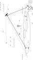
図8は、モバイルデバイスがネットワーク上およびネットワーク間で動作している場合に用い得る典型的なセル検索手順を示す。
[D.3 セルの同期および選択手順]
FIG. 8 illustrates a typical cell search procedure that mobile devices may use when operating on and between networks.
[D. 3 Cell Synchronization and Selection Procedure]
セルの同期は、UEが任意のセル上でのキャンプオンを望む場合のまさしく最初の段階である。このことから、UEは、物理セルID(PCI)、タイムスロットおよびフレーム同期を獲得する。これにより、UEは、特定のネットワークからシステム情報ブロックを読み取ることが可能になり得る。 Cell synchronization is the very first step when a UE wishes to camp on any cell. From this, the UE obtains the physical cell ID (PCI), timeslot and frame synchronization. This may allow the UE to read system information blocks from specific networks.
UEは、自らがどの帯域をサポートしているかに応じて異なる周波数チャネルへと調整することにより、自らの電波を調整し得る。UEは、特定の帯域/チャネルへと現在調整されていると仮定すると、最初に、一次同期信号(PSS)を見つける。PSSは、無線フレームの最初のサブフレーム(サブフレーム0)の最初のタイムスロットの最後のOFDMシンボル内に位置する。これにより、UEは、あるサブフレームレベルで同期されることが可能になる。PSSは、サブフレーム5で繰り返される。これは、各サブフレームが1msなので、UEが5msベースで同期されることを意味する。PSSから、UEは、物理層識別情報(0から2)の取得もできる。
A UE may tune its airwaves by tuning to different frequency channels depending on which bands it supports. Assuming the UE is currently tuned to a particular band/channel, it first finds the Primary Synchronization Signal (PSS). The PSS is located in the last OFDM symbol of the first time slot of the first subframe (subframe 0) of the radio frame. This allows the UE to be synchronized at a certain subframe level. The PSS is repeated in
次の段階において、UEは、二次同期信号(SSS)を見つける。SSSシンボルは、やはりPSSの同じサブフレーム内ではあるが、PSSの前のシンボル内に位置する。SSSから、UEは、物理層セル識別情報グループ番号(0から167)を取得できる。 In the next step, the UE finds the Secondary Synchronization Signal (SSS). The SSS symbol is located within the previous symbol of the PSS, but still within the same subframe of the PSS. From the SSS, the UE can obtain the physical layer cell identity group number (0 to 167).
物理層識別情報およびセル識別グループ番号を用いることにより、UEは、自らのセルのPCIを把握する。LTE504では、物理層セル識別情報(PCI)が許容され、一意の168個のセル層識別情報グループへ分割される。各グループは、3つの物理層識別情報を含む。先述のように、UEは、PSSから物理層識別情報を検出し、SSSから物理層セル識別情報グループを検出する。物理層識別情報=1であり、セル識別グループ=2であると仮定すると、所与のセルのPCIは、PCI=3×(物理層セル識別情報グループ)+物理層識別情報=3×2+1=7である。
By using the physical layer identity and the cell identity group number, the UE knows the PCI of its cell. In
UEは、所与のセルのPCIをひとたび把握すると、セル基準信号の位置も把握する。基準信号は、チャネルの推定、セルの選択/再選択およびハンドオーバ手順において用いられる。 Once the UE knows the PCI of a given cell, it also knows the location of the cell reference signal. The reference signal is used in channel estimation, cell selection/reselection and handover procedures.
PCIの結果として、UEは、同じスペクトルブロック配備を用いて、他の基地局からターゲット基地局を識別できる。これにより、ほとんどの場合において、1つのネットワーク周波数再使用スキームが可能になる。セル同期手順の後に、UEは、マスタ情報ブロック(MIB)およびシステム情報ブロック(SIB)の読み取りに進み得る。MIBおよびSIBは、ダウンリンク制御チャネル上で伝送される情報ブロックである。この情報ブロックは、UEがエアインタフェースを介してネットワークに適切にアクセスするために必要とされる情報を含む。
[E. セルラネットワーク無線アクセス技術PHY]
As a result of PCI, a UE can identify a target base station from other base stations using the same spectrum block deployment. This allows one network frequency reuse scheme in most cases. After the cell synchronization procedure, the UE may proceed to read the Master Information Block (MIB) and System Information Block (SIB). MIBs and SIBs are information blocks transmitted on downlink control channels. This information block contains the information required for the UE to properly access the network over the air interface.
[E. Cellular network radio access technology PHY]
説明してきたように、セルラネットワークは、RANを用いて、ネットワーク上のUEをインターネットまたは他のネットワークに接続するためのエアインタフェースまたはRFインタフェースを実装する。エアインタフェースリンク要件が満たされており、かつ、メンバーシップ要件が満たされているものと仮定すると、例えば、ネットワーク、またはネットワークが用いるサービスが、UEは、権限を有するグループのメンバである、またはそうでなければ、ネットワークにより提供されるサービスを利用する権限を有している、と判断するような方式でUEがそれ自体をネットワークに対して識別済みであると仮定すると、UEとRANとの間の通信用のプロトコルは、任意の標準的なUEが任意のRANと通信できるようにそれらが標準化されるようなものであってよい。エアインタフェースは通常、特定の無線アクセス技術(RAT)と称されることが多い特定のプロトコルを実装する。 As explained, cellular networks use the RAN to implement an air or RF interface for connecting UEs on the network to the Internet or other networks. Assuming the air interface link requirements are met and the membership requirements are met, e.g. Otherwise, between the UE and the RAN, assuming that the UE has identified itself to the network in such a way that it determines that it is authorized to use the services offered by the network. The protocols for communication may be such that they are standardized so that any standard UE can communicate with any RAN. The air interface typically implements a specific protocol, often referred to as a specific Radio Access Technology (RAT).
いくつかの例示的なRATプロトコルは、2Gまたは「第2世代」ネットワークプロトコルと称されることがあるGSMプロトコルを含む。他の例は、GPR(汎用パケット無線サービス)プロトコル、EDGE(GSM進化型高速データレートまたはEGPRS)プロトコル、3G(3GPP機関により発展された第3世代3G UMTS規格)プロトコルまたは第4世代(4G)LTEアドバンストプロトコルを含む。 Some example RAT protocols include the GSM protocol, sometimes referred to as 2G or "second generation" network protocol. Other examples are the GPR (General Packet Radio Service) protocol, the EDGE (GSM Evolved High Data Rate or EGPRS) protocol, the 3G (3rd Generation 3G UMTS standard developed by the 3GPP organization) protocol or the Fourth Generation (4G) Includes LTE Advanced Protocol.
これらのプロトコルには、スペクトル帯域の使用、タイミング、符号化およびコンフリクト解決についてのルールが存在する。基地局が同時に多くのUEと通信しなければならい可能性があるので、利用可能な無線通信経路は、プロトコルに従って分割される。所与のプロトコルが、周波数毎、時間毎、コード毎またはそれらのうちの1つよりも多くのもの毎に分割される利用可能な無線通信経路を有し得る。これにより、複数のユーザが同じ無線通信経路を共有することが可能になる。
[F. RFエアインタフェースリンクバジェット]
These protocols have rules for spectral band usage, timing, encoding and conflict resolution. Since the base station may have to communicate with many UEs at the same time, the available radio communication paths are divided according to the protocol. A given protocol may have available wireless communication paths that are divided by frequency, by time, by code, or by more than one of these. This allows multiple users to share the same wireless communication path.
[F. RF air interface link budget]
UEとRANとの間のRFエアインタフェースは、UEとモバイルネットワークとの間の接続の品質を駆動し得るものである。RFエアインタフェース接続の信号品質が上がるので、このリンクが十分なビット誤り率で維持され得るデータレートも上がる。UEおよび基地局は、LTEプロトコルの制御プレーンを用いて、リンク接続の品質についての情報を互いにやり取りし得る。この情報を用いて、基地局は、変調および符号化スキーム(MCS)ならびにデバイス伝送電力などのリンク条件を管理することで、ビット誤り率が特定の閾値を超えないことを保証できる。所望されるサービスの種類に応じて、ビット誤り率閾値は、10^-2と10^-8との間またはそれより良い値のどこにでも変わり得る。SMSメッセージング、SMSブロードキャストまたは制御チャネルシグナリングなどのアプリケーションは、最も高いビット誤り閾値で動作してよく、高精細度ビデオストリーミングなどのアプリケーションは、最も低いビット誤り閾値で動作してよい。特定のビット誤り率(BER)を維持するために、基地局は、エアインタフェースを介して当該基地局が通信する各UEにどの変調および符号化スキーム(MCS)が用いられるかを管理し得る。 The RF air interface between UE and RAN can drive the quality of the connection between UE and mobile network. As the signal quality of the RF air interface connection increases, so does the data rate at which this link can be maintained with a sufficient bit error rate. The UE and base station may communicate information about the quality of the link connection to each other using the control plane of the LTE protocol. With this information, the base station can manage link conditions such as modulation and coding scheme (MCS) and device transmit power to ensure that the bit error rate does not exceed a certain threshold. Depending on the type of service desired, the bit error rate threshold can vary anywhere between 10^-2 and 10^-8 or better. Applications such as SMS messaging, SMS broadcasting or control channel signaling may operate with the highest bit error threshold, and applications such as high definition video streaming may operate with the lowest bit error threshold. To maintain a particular bit error rate (BER), a base station may manage which modulation and coding scheme (MCS) is used for each UE with which it communicates over the air interface.
各MCSは、エアインタフェースを介して特定のデータレートを提供するが、より高いデータレートを可能にするMCSは、エアインタフェースを介して受信されているRF信号の品質についての異なる要件を有する。所与の変調スキームおよび符号化スキームを用いるエアインタフェースを介して明瞭に表現される波形は、対象信号の信号対干渉およびノイズ比、すなわちSINRの関数としての異なるビット誤り率を有し得る。SINRは、対象信号のエネルギーと、ノイズおよび干渉の組み合わせのエネルギーとの間の差の、dbで表される測定値である。QPSKなどの特定の変調スキームは、低SINRレベルで良好なビット誤り率を提供する。しかしながら、QPSK変調は、変調シンボル1個当たり2ビットのみ、および高次変調スキームよりも低いデータレートを用いる。64QAMなどの高次変調スキームは、非常に高いSINRレベルでのみ、良好なビット誤り率を提供する。しかしながら、64QAMは、変調済みシンボル1個当たり6ビット、および低次変調スキームと比較してより高いデータレートを提供する。 Each MCS provides a specific data rate over the air interface, but MCSs capable of higher data rates have different requirements for the quality of the RF signal being received over the air interface. Waveforms articulated over the air interface using a given modulation and coding scheme may have different bit error rates as a function of the signal-to-interference-and-noise ratio, or SINR, of the signal of interest. SINR is a measure, expressed in db, of the difference between the energy of the signal of interest and the energy of the combined noise and interference. Certain modulation schemes, such as QPSK, offer good bit error rates at low SINR levels. However, QPSK modulation uses only 2 bits per modulation symbol and a lower data rate than higher order modulation schemes. Higher order modulation schemes such as 64QAM provide good bit error rates only at very high SINR levels. However, 64QAM provides 6 bits per modulated symbol and a higher data rate compared to lower order modulation schemes.
高次変調スキームは、シンボル1個当たりのビットを増やすために、位相変調に加え、振幅変調を活用する。しかしながら、これは、より精密な信号復調についての要件を駆動するものであり、結果として、特定のビット誤り率での十分な復調のために必要とされる信号エネルギーが増す。 Higher order modulation schemes exploit amplitude modulation in addition to phase modulation to increase the bits per symbol. However, this drives the requirement for more precise signal demodulation, resulting in more signal energy required for adequate demodulation at a particular bit error rate.
表4は、信号エネルギー対ノイズ要件が変調スキームおよび符号化レートと共に変わり得ることを説明する。

地上モバイルコミュニケーションネットワークにおいて、基地局の配備は、ネットワークのカバレッジ地域を駆動する。ほとんどの場合、基地局無線機器は、収益が生み出され得る高人口密度の地理的エリアをカバーするために、タワー上に配置される。基地局機器をホスティングする典型的なタワーは、設置するのに、また、それがカバーする各平方マイルの関数として動作させるのに、特定の金額がかかり得る。コストは、電力、ユーティリティ、バックホール、メンテナンス、セキュリティ等を含んでよく、サイト、領域等の関数として変わり得る。基地局を配備する意味があるようにするためには、動作させるのに1平方マイルのカバレッジ当たりにかかるよりも、1平方マイル当たり少なくともより多くの収益を生み出す必要があるであろう。 In a terrestrial mobile communications network, the deployment of base stations drives the coverage area of the network. In most cases, base station radios are placed on towers to cover densely populated geographic areas where revenue can be generated. A typical tower hosting base station equipment can cost a certain amount of money to install and operate as a function of each square mile it covers. Costs may include power, utilities, backhaul, maintenance, security, etc., and may vary as a function of site, area, etc. For a base station to be meaningful to deploy, it would need to generate at least more revenue per square mile than it costs per square mile of coverage to operate.
人口密度が減少し、故にモバイルネットワーク事業者の潜在的な収益密度も減少する、世界の地方地域および遠隔地域では、基地局が配備されないことが多い。これらの遠隔地域および地方地域にサービスを有益に提供すべく、十分な人口にわたってスペクトルを拡散させる必要がある。基地局は、上空で動作する高高度プラットフォーム上に配備され得る。しかしながら、これらの解決手段は、技術的な課題があり、プラットフォームの制御が難しくなって動作が非効率的で整合性がないものになってしまう厳しい大気条件の対象となることが多い。追加的に、高高度プラットフォームは、依然として、真にグローバルなカバレッジ解決手段を自ら提供することができない。なぜなら、それらも、その量のカバレッジのためのコストが法外に高過ぎるであろうからである。 Base stations are often not deployed in rural and remote areas of the world where population densities are decreasing and therefore potential revenue densities for mobile network operators. Spectrum needs to be spread over a sufficient population to beneficially serve these remote and rural areas. Base stations may be deployed on high altitude platforms that operate in the air. However, these solutions present technical challenges and are often subject to severe atmospheric conditions that make the platform difficult to control, resulting in inefficient and inconsistent operation. Additionally, high altitude platforms still cannot themselves provide a truly global coverage solution. Because they too would be prohibitively expensive for that amount of coverage.
モバイルネットワークまたはセルラネットワークとしての地上方式で使用するために配備され得る軌道基地局を有するモバイルネットワークを動作させる方法を説明する。典型的な地上RANおよびコアネットワークは、建物およびタワーなどの地上インフラストラクチャの上部または内部に配備されたソフトウェアと、電波と、モデムと、コンピュータと、ラックと、ケーブルと、サーバ等とを備え得る。モバイルネットワークの変形形態では、RANおよびコアネットワークの機器/ソフトウェアが、既存の地上RANおよびコアネットワーク対応物ならびにインターネットにインタフェース接続するために地上機器によりサポートされる、軌道上の衛星に配備される。特定のネットワーク要素がLEO軌道、MEO軌道またはGEO軌道上に配置されることで、自宅から宇宙ネットワークまたは他の古典的な地上ネットワークのいずれかへのUE、G-MSC、P-GWなどの特定の地上インフラストラクチャが動作し得る地球上の戦略的な位置にわたる適切なネットワーキングリンクおよび配置が容易になり得る。 A method of operating a mobile network having orbital base stations that may be deployed for use in a terrestrial manner as a mobile network or a cellular network is described. A typical terrestrial RAN and core network may comprise software, airwaves, modems, computers, racks, cables, servers, etc. deployed on top of or within terrestrial infrastructure such as buildings and towers. . In the mobile network variant, the RAN and core network equipment/software are deployed on satellites in orbit supported by ground equipment to interface to existing terrestrial RAN and core network counterparts and the Internet. Specific network elements are placed on LEO, MEO or GEO orbits to identify UEs, G-MSCs, P-GWs etc. from home to either space networks or other classical terrestrial networks Appropriate networking links and placements across strategic locations on the globe where terrestrial infrastructure can operate can be facilitated.
宇宙ネットワークは、一連の拡張を典型的なLTEアーキテクチャに実装し得る。EPCおよびE-UTRANは両方とも、基地局スタック、MMEスタック、P-GWスタックおよびHSSスタックにより使用される機能などで拡張される。LTE、EPCおよびE-UTRANの拡張により、標準的なUEハンドセットが地上ネットワークおよび宇宙ネットワークの両方と互換性があるであろうように、標準的なLTE-Uuインタフェースの連続的な機能が可能になり得る。 Space networks may implement a series of extensions to the typical LTE architecture. Both EPC and E-UTRAN are enhanced with functions such as those used by the base station stack, MME stack, P-GW stack and HSS stack. LTE, EPC and E-UTRAN extensions allow continuous functionality of the standard LTE-Uu interface so that standard UE handsets will be compatible with both terrestrial and space networks. can be.
また、実施形態は、UEスタックの拡張を実装することで、特に、カバレッジが間欠的であり、かつ、連続的ではない位相において、宇宙ベースセルラネットワークのより最適な使用を容易にし得る。これらのUEの拡張は、UEスタック上のユーザプレーンのアプリケーション層またはUEスタック丈男制御プレーンの非アクセス層レイヤにおいて定着し得る。 Embodiments may also implement enhancements to the UE stack to facilitate more optimal use of space-based cellular networks, especially in phases where coverage is intermittent and non-continuous. These UE extensions may reside in the application layer of the user plane on the UE stack or the non-access stratum layer of the UE stack control plane.
EPCおよびE-UTRANの拡張に加え、コアネットワーク内の拡張をサポートするためのさらなるデータベースが含まれ得る。これらのデータベースは、地上もしくは軌道上またはその両方で1回または複数回格納されてよく、ネットワークの将来の状態の予測を可能にする、MMEの(位置、速度、姿勢、IP接続、カバレッジエリア等に関しての)拡張をサポートし得る。この将来の状態空間予測関数は、軌道周回ネットワークインフラストラクチャの将来の慣性状態ベクトルを決定するための、既知の物理学ならびにネットワークハードウェアの特性およびその動作制約の関数であってよい。慣性状態ベクトルは、位置、速度、加速度、姿勢および姿勢レートであってよい。熱、電力、慣性または質量など、他の状態ベクトルまたは行列/テンソルが含まれ得る。そのようなベクトルの計算は、ネットワーク管理コンピュータシステムにより実行されてよく、結果は、基地局およびUEに分配されてよい。 In addition to EPC and E-UTRAN extensions, additional databases may be included to support extensions within the core network. These databases may be stored one or more times on the ground or on orbit or both and allow prediction of the future state of the network (position, velocity, attitude, IP connectivity, coverage area, etc.) of the MME. ) extensions. This future state-space prediction function may be a function of the known physics and properties of the network hardware and its operational constraints to determine the future inertial state vector of the orbiting network infrastructure. Inertial state vectors may be position, velocity, acceleration, attitude and attitude rate. Other state vectors or matrices/tensors may be included, such as heat, power, inertia or mass. Calculation of such vectors may be performed by a network management computer system and the results distributed to base stations and UEs.
ネットワーク管理コンピュータシステムは、軌道周回インフラストラクチャについての姿勢および軌道の制御法則の仮定を用いて、ネットワークの将来の状態空間予測値を計算し得る。この情報は、データベースに格納されてよく、各周回軌道衛星の機能と、それがオンボードでホスティングするアクチュエータと、その意図される軌道上動作とに応じて、宇宙機固有であってよい。故に、異なるアクチュエータ、能力、設計等を有する同じネットワーク内に異なる宇宙機が存在し得る。重力モデル、大気モデルおよび数値積分スキームを用いて、ネットワーク管理コンピュータシステムは、LEOにおける衛星軌跡の予測を、かなり正確に、将来の多くの時間、日またはさらには週に行い得る。軌道周回ネットワークインフラストラクチャは、将来のネットワーク接続状態への将来の慣性状態ベクトルについての洞察を取得するためにそのデータを用いてよく、将来の最適なネットワーク動作を予測してよく、地上ネットワーク配備と前もって調整してよい。これは、ハンドオーバのようなもの用の無線リソース制御(RRC)機能、非アクセス層(NAS)レイヤ機能、ネットワークIPルーティングテーブル、モビリティ管理機能、およびシグナリングトリガ/タイマ等を含み得る。 The network management computer system may use attitude and orbital control law assumptions for the orbiting infrastructure to compute future state-space predictions of the network. This information may be stored in a database and may be spacecraft-specific, depending on the capabilities of each orbiting satellite, the actuators it hosts on-board, and its intended on-orbit operations. Thus, there may be different spacecraft within the same network with different actuators, capabilities, designs, etc. Using gravity models, atmospheric models and numerical integration schemes, a network management computer system can make predictions of satellite trajectories at LEO with considerable accuracy many hours, days or even weeks into the future. The orbiting network infrastructure may use the data to gain insight into future inertial state vectors to future network connectivity states, may predict optimal future network behavior, and may be used in terrestrial network deployments and You can arrange it in advance. This may include radio resource control (RRC) functions for things like handovers, non-access stratum (NAS) layer functions, network IP routing tables, mobility management functions, signaling triggers/timers, etc.
軌道周回ネットワーク全体についての慣性状態ベクトルに基づいて、様々なネットワークノード接続が可能であってよい。各周回軌道衛星は、地上のUE、ネットワーク内の他の衛星または地上の地上局ゲートウェイと通信するために割り当てるための有限数のビームを有し得る。利用可能なビームの数ならびにネットワーク内のノードの相対位置、速度および姿勢に応じて、個別の時点の各々についての一連の接続シナリオが生成され得る。一組の動作ルール、制約および/またはサービス要件が、一連の接続シナリオを評価することで、最も理想的な1つまたは複数を導出し、故に、ネットワーク接続のための動作の理想的な概念を生成するためのフィルタとして課され得る。この動作概念は、軌道操作/維持の行程だけでなく、将来のある時期にある程度の時間にわたって存在するものと予測されるノード接続と、それらの接続の特性(例えば、待ち時間、データレート、周波数、変調スキーム、符号化等)がどのようなものであり得るかとを示すネットワークマップのタイムラインを含み得る。ネットワークプロセッサは、ネットワークマップ予測とネットワークノード接続とに基づいて予測ルーティングテーブルを生成してよく、それらの予測ルーティングテーブルをデータ構造としてネットワーク内のノードのいくつかまたは全てに分配してよい。それらの位置および速度の保存されたデータベースが与えられると、MAC層またはPHY層における動作は、UEの予想されるオーバーパス回数に基づいて予測され得る。 Various network node connections may be possible based on the inertial state vector for the entire orbiting network. Each orbiting satellite may have a finite number of beams to assign to communicate with UEs on the ground, other satellites in the network, or ground station gateways on the ground. Depending on the number of beams available and the relative positions, velocities and attitudes of the nodes in the network, a series of connectivity scenarios can be generated for each discrete time instant. A set of behavioral rules, constraints and/or service requirements evaluates a series of connection scenarios to derive the most ideal one or more, thus an ideal conception of behavior for network connectivity. It can be imposed as a filter to generate. This concept of operation applies not only to the course of orbit maneuvering/maintenance, but also to node connections that are expected to exist for some time at some future time, and the characteristics of those connections (e.g., latency, data rate, frequency). , modulation schemes, coding, etc.) may be included. A network processor may generate predictive routing tables based on network map predictions and network node connections, and may distribute those predictive routing tables as data structures to some or all of the nodes in the network. Given a stored database of their positions and velocities, the behavior at the MAC or PHY layer can be predicted based on the expected number of overpasses of the UE.
軌道周回モバイルインフラストラクチャからの説明したサービスは、動的(例えば、地表に対して動く)または静的(例えば、動かない)のいずれかである、惑星の周囲のセルに配備され得る。ネットワーク内の様々な対象ポイントの位置を表すポイントのデータベースを管理するために、技術が実装され得る。例として、衛星基地局、地上基地局、衛星地上局またはゲートウェイ、UEの各々の位置、地上のいくつかのメッシュポイントのデータベース、および、地球上の地理空間的ポリゴンの縁、中心またはその両方のいずれかを表すポイントのデータベースが、中央データベースに維持される対象ポイントのリスト中にあってよい。リンクバジェットは、スペクトル、最適カバレッジ統計情報の将来の最適な使用を容易にし、衛星からの伝送を制御し、かつ、軌道周回インフラストラクチャと地上インフラストラクチャとの間で共有するスペクトルを調整するために、同様のまたは同じ周波数を用いている衛星とこれらの対象ポイントとの間のリンクについて経時的にモデル化され得る。 The described services from the orbiting mobile infrastructure can be deployed in cells around the planet that are either dynamic (eg, moving relative to the surface) or static (eg, not moving). Techniques may be implemented to manage a database of points representing the locations of various points of interest within the network. Examples include satellite base stations, terrestrial base stations, satellite ground stations or gateways, the location of each of the UEs, a database of several mesh points on the ground, and the edges and/or centers of geospatial polygons on the globe. A database of points representing either may be in a list of points of interest maintained in a central database. The link budget facilitates optimal future use of spectrum, best coverage statistics, controls transmission from satellites, and regulates spectrum sharing between orbiting and terrestrial infrastructure. , can be modeled over time for links between satellites using similar or same frequencies and these points of interest.
将来のリンクバジェット特性がこれらの様々なポイントにおいて予測され得るので、最適なネットワークルートおよび経路も、これらのポイントにサービスを提供するために、かつ、具体的にどの衛星がどの時点でサービスを行い得るかと、ハンドオーバが、存在する場合、地上の特定の位置へのサービス提供の制御を交換する2つの衛星の間でいつ計画されるであろうかとについて、予測され得る。これにより、コアネットワークシグナリング要件の予期と、トラフィックフローを最適化するためのルーティングとが可能になるであろう。 Since future link budget characteristics can be predicted at these various points, the optimal network routes and paths will also be determined to serve these points and specifically which satellites will serve at what time. It can be predicted when and if a handover, if any, will be planned between two satellites exchanging control of servicing a particular location on the ground. This will allow anticipation of core network signaling requirements and routing to optimize traffic flows.
状態空間予測関数は、例えば、MME、S-GW、P-GW、HSS、PCRF等の典型的な地上セルラインフラストラクチャが値を取る古典的な関数の拡張として、宇宙または地上のハードウェア/ソフトウェアに埋め込まれ得る。状態空間予測関数の結果は、ネットワークの将来の状態についてのインテリジェンスを生成するために用いられ得る。このインテリジェンスは、モバイルネットワーク内で用いられるユーザプレーンおよび制御プレーンの使用を最適化するために用いられ得る無線リソース管理、モビリティ管理、トラッキングエリア管理、S-GW間のロードバランシング等についての将来の要件を通知するために、ネットワーク内の各ノードに分配され得る。 The state-space prediction functions are e.g. can be embedded in The results of the state-space prediction function can be used to generate intelligence about the future state of the network. Future requirements for radio resource management, mobility management, tracking area management, load balancing between S-GWs, etc. This intelligence can be used to optimize the use of the user plane and control plane used within the mobile network. can be distributed to each node in the network to notify the
宇宙ネットワークは、例えば、Speidel Iにおいて説明されているGSM、LTE、EDGE、CDMA等、モバイルプロトコル用の3GPP規格により指定されるものと同様のRFインタフェースを実装し得る。Speidel Iは、衛星と地表上のUEなどのデバイスとの間の軌道リンクに関連するドップラーシフトおよび伝搬遅延を処理する方法を詳述している。この方法を実装することにより、モバイルコミュニケーションネットワーク用のインフラストラクチャを構築するにはコストがかかり過ぎるか、またはそのようなインフラストラクチャを構築しても有益なインセンティブが単にない様々な種類の宇宙ネットワークが、世界の遠隔エリアおよび地方エリアにおける惑星の周囲での接続上の課題を解決し得る。 Space networks may implement RF interfaces similar to those specified by the 3GPP standards for mobile protocols, such as GSM, LTE, EDGE, CDMA as described in Speidel I, for example. Speidel I details how to handle Doppler shifts and propagation delays associated with orbital links between satellites and devices such as UEs on the ground. By implementing this method, various kinds of space networks that are either too costly to build infrastructure for mobile communication networks or simply do not have useful incentives to build such infrastructure. , can solve connectivity challenges around the planet in remote and rural areas of the world.
添付図面と共に以下の詳細な説明が、本発明の性質および利点についてのより良い理解を提供するであろう。 The following detailed description together with the accompanying drawings will provide a better understanding of the nature and advantages of the invention.
図を参照して、本開示による様々な実施形態を説明し得る。 Various embodiments according to the present disclosure may be described with reference to the figures.
本明細書において説明する実施形態では、宇宙通信ネットワークが、地上モバイルセルラネットワークと共に通信を提供するように動作する。地上モバイルセルラネットワークと同様に、宇宙ネットワークは、地上ネットワークに対する相補的な宇宙コンポーネントとしてのRANおよびコアネットワーク機能を動作させる。地上ネットワークの拡張または補完として、宇宙コンポーネントは、宇宙モバイルRANおよび地上モバイルRANとの間でのモバイルデバイスの適切な認証およびハンドオフを可能にするコアネットワーク機能およびRAN機能を使用する。 In the embodiments described herein, a space communications network operates to provide communications in conjunction with a terrestrial mobile cellular network. Similar to terrestrial mobile cellular networks, space networks operate the RAN and core network functions as complementary space components to terrestrial networks. As an extension or complement to the terrestrial network, the space component uses core network functions and RAN functions that enable proper authentication and handoff of mobile devices to and from the space mobile RAN and the terrestrial mobile RAN.
以下の説明では、様々な実施形態を説明する。説明の目的で、実施形態についての完全な理解を提供すべく、特定の構成および詳細を記載する。しかしながら、当業者には、実施形態が具体的な詳細なしで実施され得ることも明らかになろう。さらに、説明する実施形態を不明瞭にしないよう、周知の特徴が省略または簡略化され得る。 The following description describes various embodiments. For purposes of explanation, specific configurations and details are set forth in order to provide a thorough understanding of the embodiments. However, it will also be apparent to one skilled in the art that the embodiments may be practiced without the specific details. Moreover, well-known features may be omitted or simplified so as not to obscure the described embodiments.
人口密度が減り、故にモバイルネットワーク事業者の潜在的な収益密度が減る、世界の地方地域および遠隔地域では、基地局が配備されていないことが多い。大きい陸上帯状地帯にわたる標準的なUEデバイスへのリンクを閉じることにより専門クライアント機器の必要性を無くすための解決手段に、宇宙ベースモバイルコミュニケーションプラットフォームがなり得る。宇宙ベースLTEネットワーク用の標準的なUuインタフェースは、Speidel Iにおいて説明される開示内容と共に用いられ得る。Speidel Iでは、基地局、特にeNBを操作することにより、LTE-Uuインタフェース上での基地局とUEとの間の軌道リンクのドップラーシフトおよび伝搬遅延に対応するように基地局が拡張され得る方法を説明している。これを行う際、宇宙ベースインフラストラクチャは、地上モバイルネットワークを用いる既存のUEをサポートする電気通信ネットワーク用に用いられ得る。 Base stations are often not deployed in rural and remote areas of the world where population densities and thus potential revenue densities for mobile network operators are reduced. A space-based mobile communications platform could be the solution to eliminate the need for specialized client equipment by closing the link to standard UE devices across large land swaths. A standard Uu interface for space-based LTE networks may be used with the disclosure described in Speidel I. In Speidel I, how by manipulating base stations, particularly eNBs, they can be enhanced to accommodate Doppler shifts and propagation delays of orbital links between base stations and UEs over the LTE-Uu interface. explains. In doing this, space-based infrastructure can be used for telecommunications networks that support existing UEs that use terrestrial mobile networks.
基地局の宇宙ベースモバイルネットワークおよび他の古典的に地上モバイルネットワークインフラストラクチャを動作させることには、いくつかの課題がある。これらの課題は主に、ネットワーク内の基地局無線インタフェースリンクに地球低軌道を用いる必要があることに由来する。課題の1つが、トランスミッタとレシーバとの間のリンクを近付けることである。リンクを閉じることは、伝搬される信号が、レシーバにおいて十分なビット誤り率で正常に復調され得るように、トランスミッタとレシーバとの間の距離を横断し、かつ、ノイズフロアを上回る十分な信号エネルギーレベルを持っていくらか距離的に離れてレシーバに到達するように、トランスミッタからの信号を十分な電力で伝送することを伴う。 Operating base station space-based mobile networks and other classically terrestrial mobile network infrastructures presents several challenges. These challenges primarily stem from the need to use low earth orbit for the base station radio interface links within the network. One of the challenges is getting the link between the transmitter and receiver close together. Closing the link requires sufficient signal energy across the distance between the transmitter and receiver and above the noise floor so that the propagated signal can be successfully demodulated at the receiver with a sufficient bit error rate. It involves transmitting the signal from the transmitter with sufficient power so that it reaches the receiver some distance away with a level.
軌道周回基地局とUEとの間のサービス接続用の所望のデータレートに応じて、特定の信号対ノイズ比要件が存在し得る。アップリンクバジェットは主に、地上のUEの伝送電力により駆動され得る。LTEプロトコルでは、これは200mW(23dBm)であってよく、GSMプロトコルでは、これは2W(33dBm)であってよい。 There may be specific signal-to-noise ratio requirements depending on the desired data rate for the service connection between the orbiting base station and the UE. The uplink budget may be primarily driven by the terrestrial UE's transmit power. For LTE protocol this may be 200 mW (23 dBm) and for GSM protocol this may be 2 W (33 dBm).
地表上の200mWのデバイスを用いてリンクバジェットを閉鎖するために、かつ、1つの衛星セル/衛星ビームに過度のトラフィックが流入することを回避するために、基地局トランスミッタ/基地局レシーバを有する衛星は、指向性アンテナ技術を用いて地球低軌道で動作し得る。大型アンテナ技術により、軌道基地局の高度が、1000kmまたは同等程度に達し得る。サブ1GHzセルラスペクトルの使用は、伝搬特性について有利になり得ると共に、より有利な実施形態において用いられ得る。しかしながら、より小型のアンテナアレイは、ネットワークコストを減らすことで、いくつかの衛星をわずか300kmに配置し得る(基地局をホスティングする宇宙機に搭載されたスラスタシステムにより軌道が維持され得る場合)。 Satellites with base station transmitters/base station receivers to close the link budget with 200mW devices on the ground and to avoid influencing too much traffic into one satellite cell/satellite beam can operate in low earth orbit using directional antenna technology. With large antenna technology, the altitude of an orbital base station can reach 1000 km or so. Use of the sub-1 GHz cellular spectrum can be advantageous for propagation characteristics and can be used in more advantageous embodiments. However, smaller antenna arrays can place some satellites as little as 300 km (if orbit can be maintained by a thruster system onboard the spacecraft hosting the base station) at reduced network costs.
地球低軌道が必要であることが原因で、軌道基地局を有する惑星のユビキタスカバレッジの実現には、数千個の衛星が伴い得るが、これは依然として、同様のカバレッジに必要とされる地上基地局の数よりも少ない。それにもかかわらず、数千個の衛星を完全に配備するにはしばらくかかることがあり、本明細書において想定されるいくつかの実施形態において、衛星コンスタレーション事業者は、収益を生み出し始めることができ、かつ、惑星全体の連続的なカバレッジを提供し得ないが、惑星にわたる間欠的な基地局オーバーパスを提供し得る、より小さい衛星集団を含む地上の有意義なサービスを提供できる早期段階のネットワーク設計を使用し得る。より単純な設計を用いる第1の衛星集団を、それらが安価に発展され得るように、かつ、より迅速に配備され得るように作ることができるようになることは、有利であり得る。例えば、アンテナの選択は、衛星の差し迫った設計上の検討事項であり得る。検討事項の1つが、限定された範囲を有し、かつ、宇宙機の姿勢に基づいてのみ向けられ得る単一のアンテナであり得る。このオプションは、ビームが宇宙機の姿勢とは無関係に任意の方向に向けられ得るように、ビームフォーミング機能を有するフェーズドアレイアンテナなどの代替的な実施形態よりも設計、発展、構築および試験が単純であり得る。より単純なアンテナ技術が利用される場合、各基地局は、リンクバジェットの仰角に応じて、迅速なオーバーパス/セッションの機会(例えば、30~60分毎に2分間の接続)を有し得る。 Due to the need for low earth orbit, achieving ubiquitous coverage of a planet with orbital base stations may involve thousands of satellites, which still require ground bases for similar coverage. less than the number of stations. Nevertheless, fully deploying thousands of satellites can take some time, and in some embodiments contemplated herein, satellite constellation operators can begin to generate revenue. An early-stage network capable of providing meaningful terrestrial service, including smaller satellite constellations, capable of providing continuous coverage over the entire planet, but not capable of providing intermittent base station overpassing across the planet. design can be used. It would be advantageous to be able to create a first constellation of satellites using simpler designs so that they could be developed inexpensively and deployed more quickly. For example, antenna selection may be a pressing design consideration for satellites. One consideration may be a single antenna that has a limited range and can only be aimed based on the spacecraft's attitude. This option is simpler to design, develop, build and test than alternative embodiments such as phased array antennas with beamforming capability so that the beam can be directed in any direction regardless of spacecraft attitude. can be If simpler antenna technology is utilized, each base station may have a quick overpass/session opportunity (eg, 2 minute connection every 30-60 minutes) depending on the elevation angle of the link budget. .
アンテナの検討事項に加え、質量および電力に関する検討事項も存在し得る。最初の使用事例およびマーケットは、最初の衛星集団に対する電力要件を減らすために、意図的に選択され得る。例として、世界中の選択的な数の国における遠隔IoT/M2Mデバイスおよび携帯電話の中でも単純なSMSメッセージング用途のための間欠的なセルラサービスが、宇宙機の技術的要件の緩和を提供し得る。例として、最初の間欠的なサービスがオーストラリア、ニュージーランドおよびフィリピンという国で提供されている場合、これは、衛星が軌道上での時間のうちの5~10%でビームを伝送することのみを必要とし得る。結果として、宇宙機の動作用の最も高い電力モードは、5~10%でデューティサイクルされ得る。低データレート用途(例えば、(電気通信サービスについて密な都市エリアと比較して)比較的疎なユーザ用のSMS)にサービスを提供することにより、軌道周回基地局は、データトラフィック用の単一のLTEリソースブロックにわたって、またはさらに単一の200kHz幅のGSMキャリアにわたって伝送するだけでよい。各キャリアの伝送電力は、20から30Wでありさえすればよい。ペイロード用の電力増幅器は、宇宙機の電力バジェットを駆動し得る。容易に利用可能なクラスAまたはABの電力増幅器を用いることにより、P1dB(増幅器の線形性が1dBだけ低下する電力出力)で40~50%の効率が可能になり得る。結果として、増幅器からの消費電力は、75Wピーク電力以下であってよい。したがって、宇宙機の「ペイロード」は、100~125W(電力が無線、コンピュータ処理等に含まれた後)のピーク消費電力および10~12.5W以下の軌道平均電力を有し得る。軌道平均電力のこの範囲は、超小型衛星クラスのバス用にうまくサイズが合わされおり、長さ、幅および深さ数十センチメートル(例えば、6U超小型衛星は、約20cm×30cm×10cmであろう)のフォームファクタであってよい。このサイズの衛星は十分に、配備された太陽電池アレイから50~60Wの軌道平均電力を生成でき、かつ、高電力モードが必要とされている間は放電され得る電池にそのエネルギーを貯蔵できる。 In addition to antenna considerations, there may also be mass and power considerations. Initial use cases and markets may be deliberately selected to reduce power requirements for the initial satellite constellation. As an example, intermittent cellular service for simple SMS messaging applications among remote IoT/M2M devices and cell phones in a select number of countries around the world could provide relaxation of spacecraft technical requirements. . As an example, if the first intermittent service is offered in the countries of Australia, New Zealand and the Philippines, this would only require the satellite to transmit the beam 5-10% of the time in orbit. can be As a result, the highest power mode for spacecraft operation can be duty cycled at 5-10%. By serving low data rate applications (e.g., SMS for relatively sparse users (compared to metropolitan areas that are dense for telecommunication services)), orbiting base stations can provide single LTE resource blocks, or even over a single 200 kHz wide GSM carrier. The transmission power of each carrier need only be 20 to 30W. A power amplifier for the payload can drive the power budget of the spacecraft. Using readily available class A or AB power amplifiers, efficiencies of 40-50% at P1 dB (power output where the linearity of the amplifier is degraded by 1 dB) may be possible. As a result, the power consumption from the amplifier may be less than 75W peak power. Thus, a spacecraft "payload" may have a peak power consumption of 100-125 W (after power is included for radio, computing, etc.) and an orbit average power of 10-12.5 W or less. This range of orbit average powers is well sized for a microsatellite class bus and is several tens of centimeters in length, width and depth (e.g. a 6U microsatellite is approximately 20 cm x 30 cm x 10 cm). wax) form factor. A satellite of this size is sufficient to generate 50-60 W of orbit average power from deployed solar arrays and store that energy in batteries that can be discharged while high power mode is needed.
基地局の軌道周回コンスタレーション用のサービスセット/製品ラインにさらなる使用事例およびサービスエリアが追加されるので、より多いスペクトル、より多くのユーザ、より高いデータレートおよびより多くの用途等にサービスを提供するためのより大きいサイズ、電力および機能を有する拡張型宇宙器が、所定の位置に配置され得る。これらの拡張型宇宙器は、商業的に実行可能なままであり得る最初のより限定された宇宙機集団と共存し得る。いくつかの実施形態において、基地局のコンスタレーションは、異なる宇宙機を備え得る。それらが対応できる異なる能力およびサービス(ならびにおそらく、どのような時間量またはどの特定の国)は単に、動作上の制約を考慮に入れて、限定された時間量のためのカバレッジを提供するためにサイズ設定され得る。 Additional use cases and coverage areas are added to the service set/product line for base station orbiting constellations to serve more spectrum, more users, higher data rates and more applications, etc. An extended spacecraft with greater size, power and capability to do so may be placed in place. These extended spacecraft may coexist with an initial, more limited fleet of spacecraft that may remain commercially viable. In some embodiments, a constellation of base stations may comprise different spacecraft. The different capabilities and services they are capable of (and perhaps what amount of time or which particular country) are simply to provide coverage for a limited amount of time, taking operational constraints into account. can be sized.
地球低軌道上での動作の別の結果は、セルは、地球に対して小さい(かつ故に、多くの衛星を必要とする)が、地上セルラネットワークに対してかなり大きいということである。典型的な地上セルは、20~30km以下の半径を有し得るが、周回軌道衛星は、300kmを上回るビーム半径を有し得る。結果として、軌道周回基地局と同時に動作し得る数百個の基地局セルが、地上に存在し得る。スペクトルが宇宙ネットワークだけに割り当てられるシナリオでは、このことは、いかなる課題も示し得ない。なぜなら、宇宙ネットワークと地上ネットワークとの間の周波数帯域が異なることで、干渉が防がれるからである。しかしながら、宇宙ネットワークが既存の地上ネットワークの拡張型として機能し、同様のまたは同じスペクトルを用いるいくつかの実施形態が存在し得る。これは、電気通信サービス用の専用スペクトルを獲得するのに財務およびビジネス上の困難があるいくつかの例において好ましいことがある。既存の地上ネットワーク事業者が所有し動作させるスペクトルのサブライセンスの使用は、より単純であり得る。本実施形態は、潜在的なセル間干渉を排除するために既存のセルラネットワークにより用いられるものに加え、いくつかのスペクトル管理技術を用い得る。 Another consequence of operation in low earth orbit is that cells are small relative to the earth (and therefore require many satellites), but fairly large relative to terrestrial cellular networks. A typical terrestrial cell may have a radius of 20-30 km or less, while an orbiting satellite may have a beam radius of over 300 km. As a result, there may be hundreds of base station cells on the ground that may operate simultaneously with orbiting base stations. In scenarios where spectrum is allocated only to space networks, this may not present any challenges. This is because different frequency bands between the space network and the terrestrial network prevent interference. However, there may be some embodiments where the space network acts as an extension of the existing terrestrial network and uses similar or the same spectrum. This may be preferable in some instances where there are financial and business difficulties in obtaining dedicated spectrum for telecommunication services. The use of spectrum sublicenses owned and operated by existing terrestrial network operators may be simpler. The present embodiments may use several spectrum management techniques in addition to those used by existing cellular networks to eliminate potential inter-cell interference.
しかしながら、既存の地上ネットワークの動的な修正を含まない宇宙基地局と地上基地局との間のスペクトルを共有する代替的な実施形態と、既存のMNOネットワークインフラストラクチャの拡張型を用いない実施形態とが存在し得る。衛星が地上ネットワークに対して動くので、この管理技術は、スペクトルの配備が経時的に動的に管理される時間的な特徴を伴い得る。 However, alternative embodiments that share spectrum between space base stations and terrestrial base stations that do not involve dynamic modification of existing terrestrial networks and embodiments that do not use extensions of existing MNO network infrastructure. and can exist. As satellites move relative to the terrestrial network, this management technique may involve temporal features in which spectrum deployment is dynamically managed over time.
地球低軌道上を動きつつカバレッジをUEに提供する衛星の場合、それらは、地上のUEよりもかなり速く(~7-7.8km/s)動く。結果として、ネットワークインフラストラクチャは、効果的にモバイルであり、地上のUEは、(それらがゆっくり動いている場合でも)静的であるとみなされ得る。宇宙ネットワークの観点からすると、所与の分、時間またはさらに日におけるUEの動きは、衛星が地上セルからのカバレッジを既に有していない場合、衛星が所与の時間において、いつおよびどのようなカバレッジを提供中であり得るかに関して、比較的取るに足らないものですらある。この特徴は、有利なことに、いくつかのネットワーキング解決手段において用いられ得る。 For satellites that provide coverage to UEs while moving in low earth orbit, they move much faster (~7-7.8 km/s) than terrestrial UEs. As a result, the network infrastructure is effectively mobile and UEs on the ground can be considered static (even if they are moving slowly). From the perspective of the space network, the movement of a UE in a given minute, hour, or even day will determine when and what the satellite does at a given time, if the satellite does not already have coverage from a terrestrial cell. Even relatively trivial as to what coverage may be on offer. This feature can be used advantageously in some networking solutions.
本開示は、基地局、S-GW、MMEおよび/またはP-GWの機能をホスティングする一組の軌道周回インフラストラクチャを管理するための実施形態を説明する。軌道周回コンスタレーションの動的な動きによってモビリティ管理がより複雑になるが、より独自の要件があれば、軌道ダイナミクスの予測可能性を活用して将来の状態空間をネットワークに通知でき、結果として、多くの機能について制御プレーンの動作を通知/予期できる。ネットワークレベルでは、待ち時間、ルーティングおよび理想的なカバレッジパターン/動作を理解することは、はるかに複雑な計算である。なぜなら、これらのものは、典型的には、地上モバイルネットワーク配備において静的または一定だからである。ネットワークIPトラフィックルーティングは、動的であってよく、軌道周回インフラストラクチャおよび地上インフラストラクチャが互いに相対的に動くにつれて、間欠的に接続および切断してよい。 This disclosure describes embodiments for managing a set of orbiting infrastructures hosting the functions of a base station, S-GW, MME and/or P-GW. The dynamic behavior of the orbiting constellation makes mobility management more complex, but with more unique requirements, the predictability of the orbital dynamics can be exploited to inform the network of future state spaces, resulting in Can inform/anticipate control plane behavior for many functions. At the network level, understanding latency, routing and ideal coverage patterns/behavior are much more complex calculations. This is because these things are typically static or constant in terrestrial mobile network deployments. Network IP traffic routing may be dynamic, connecting and disconnecting intermittently as the orbiting and ground infrastructure move relative to each other.
モビリティ管理の課題に加え、基地局には、RAN配備の課題もある。地上RAN配備が直面する典型的な課題を別にすれば、各衛星の動きは本質的に、各衛星が任意の時点で地球上の全てのポイントをカバー中であり得ることを意味する。結果として、基地局は、軌道上の異なるポイントにおける異なる地上ネットワークの拡張型として動作し得る。地球の周囲で異なるように特定の周波数がライセンスされてよく、MCC、MNC、マスタ情報ブロックおよびシステム情報ブロックが変更され得る。用いられる特定の技術(2G、4G等)が変更され得る。結果として、これらの要件の記録、および、基地局がサービスを提供中である特定の位置に対応するように基地局の設定を動的に再構成するためのコントローラも存在し得る。 In addition to mobility management challenges, base stations also have RAN deployment challenges. Aside from the typical challenges faced by terrestrial RAN deployments, the motion of each satellite inherently means that every point on the globe can be covered at any given time. As a result, a base station can act as an extension of different terrestrial networks at different points in orbit. Certain frequencies may be licensed differently around the globe, and the MCC, MNC, Master Information Blocks and System Information Blocks may change. The particular technology used (2G, 4G, etc.) may vary. As a result, there may also be a record of these requirements and a controller to dynamically reconfigure the settings of the base stations to correspond to the particular locations they are serving.
ユーザにとって任意の所与の衛星または利用可能な無線インタフェースが離れるわずか数分前に利用可能になり、別の異なるエアインタフェースが利用可能になり得ることにより、宇宙ベース電気通信ネットワークについて、ネットワーキングシグナリング待ち時間の他の課題も生じる。 Networking signaling wait for space-based telecommunications networks by allowing any given satellite or available air interface to be available to the user only minutes before leaving, and another different air interface may be available Other time challenges also arise.
良い例が認証の課題である。ネットワークへの接続を試みる任意のデバイスは、理想的には、衛星オーバーパス時間よりも短い時間枠内にネットワークに対して認証することを望み得る。そうでなければ、当該デバイスは、ネットワークに対して決して認証できない可能性がある。典型的には、ローミングネットワーク上での、またはホームネットワーク認証データベース(宇宙におけるネットワークなど)から遠く離れて動作するネットワーク上での認証には、衛星オーバーパスの時間量を凌ぎ得る時間量がかかり得る。ネットワークは、オーバーパス時間を増やすように設計され得るが、軌道周回電気通信インフラストラクチャのネットワークを考慮する場合には、急速な認証手順を可能にすること、または遅い認証に対処することが重要になる。 A good example is the issue of authentication. Any device attempting to connect to the network would ideally wish to authenticate to the network within a timeframe less than the satellite overpass time. Otherwise, the device may never authenticate to the network. Typically, authentication on roaming networks or on networks operating far from the home network authentication database (such as networks in space) can take an amount of time that can exceed the amount of time for satellite overpass. . Networks can be designed to increase overpass times, but when considering networks of orbiting telecommunications infrastructure, it is important to allow rapid authentication procedures or to deal with slow authentication. Become.
別の例は、(ローミングプロバイダとしての)宇宙ネットワークと(ホームネットワークとしての)地上ネットワークとの間の相互作用であり得る。衛星が数分毎に飛行するので、ネットワークは、衛星の各々のトラッキングエリアコードをどのように伝送するかを管理する必要があり得る。なぜなら、UEは、TACの変更を経る度に、または異なるVLR/MMEによりサービスを提供される度に、自らの位置を自動的に更新し得るからである。これは、ホームネットワークでのHSS更新を必要とし得ると共に、全てのユーザがそれらの位置を数分毎に更新する必要があり、かつ、グローバルネットワーク上のユーザの数が世界の大部分の地域にわたる典型的な電気通信加入者総数(数億人または場合によっては数十億人の加入者)を表す場合、実質的なネットワークオーバヘッドをもたらし得る。 Another example could be the interaction between a space network (as roaming provider) and a terrestrial network (as home network). Since satellites fly by every few minutes, the network may need to manage how to transmit the tracking area code for each of the satellites. This is because the UE may automatically update its location each time it undergoes a TAC change or is served by a different VLR/MME. This may require HSS updates in the home network, all users needing to update their location every few minutes, and the number of users on the global network is spread over most parts of the world. When representing typical telecommunications subscriber counts (hundreds of millions or even billions of subscribers), this can result in substantial network overhead.
最終的に、電気通信トラフィックのハンドオーバは、宇宙ベース電気通信ネットワーク内で複雑になり得る。各衛星が数分間から10分間、所与のエリアにわたってオーバーパスを有し得るのみなので、配備された軌道およびアンテナに応じて、カバレッジの変化に各衛星が対応するために、衛星ネットワーク内で永久的なハンドオーバシグナリングが行われる必要があり得る。UE間のハンドオーバに加え、衛星の位置の状態の変化および故にネットワーク待ち時間の状態のばらつきならびに軌道周回インフラストラクチャと、地上モバイルネットワーク、インターネット等へのゲートウェイとして機能する地上のインフラストラクチャとからのルートに基づく衛星間リンク内のハンドオーバに伴う課題が存在し得る。これらは、本明細書において説明する方法および装置を用いて対処し得る。
[ネットワーク設計の検討事項/概念]
Finally, handover of telecommunications traffic can be complicated within space-based telecommunications networks. Since each satellite can only have an overpass over a given area for a few minutes to 10 minutes, there is a permanent need in the satellite network for each satellite to respond to changes in coverage, depending on the orbit and antenna deployed. specific handover signaling may need to take place. In addition to handovers between UEs, variations in satellite location conditions and hence network latency conditions and routes from orbital infrastructure and terrestrial infrastructure acting as a gateway to terrestrial mobile networks, the Internet, etc. There may be challenges with handovers within inter-satellite links based on . These can be addressed using the methods and apparatus described herein.
[Network design considerations/concepts]
可能にするために宇宙機セルラネットワークが求めるサービスのレベルと、どれくらいのユーザを対象とするかとに応じて、宇宙ネットワークRANのRFフロントエンドは、異なる構成で設計され得る。データレート要件が低く、かつ、デバイスが遠隔エリア内で疎に分散され得るIoTデバイスまたはM2Mデバイスなどのデバイスに関連するサービス用途では、所望の量のサービススペクトルに対するEIRP要件の低減が行われ得る。サービススペクトルの量は、衛星ネットワークがどれくらいのユーザにサービスを提供する必要があるかにより駆動され得る。特に、スペクトルは、衛星ネットワークを用いる必要がある単一のスポットビーム内の同時に存在するユーザの数に合うようにサイズ設定される必要がある。 Depending on the level of service the spacecraft cellular network seeks to enable and how many users it is intended to serve, the RF front end of the space network RAN can be designed in different configurations. For service applications involving devices such as IoT or M2M devices, where data rate requirements are low and devices may be sparsely distributed in remote areas, a reduction in EIRP requirements for the desired amount of service spectrum may be made. The amount of service spectrum can be driven by how many users the satellite network needs to serve. In particular, the spectrum needs to be sized to match the number of simultaneous users in a single spot beam that need to use the satellite network.
衛星ベースモバイルネットワークは、下方の地上モバイルネットワークと連携して動作するように、したがって、十分なスペクトルのみを配備して、本明細書において説明する地上モバイルネットワークのギャップを埋めるように構成/設計され得る。この構成において、依然としてカバレッジがない低人口密度エリアのカバレッジ用の宇宙ネットワークに小さなスペクトルスライバーが割り当てられ得るが、大部分は、(地上セルがより小さい)地上ネットワークに割り当てられてよく、高人口密度領域内のカバレッジ用のスペクトルをより密に再使用できる。そのような構成は安価に購入され得る遠隔セルラベースIoTデバイス(例えば、GSMベースまたはLTEベース)向けのサービスのために採用され得る。IoTの使用事例では、信号レベル要件が低いことにより、ダウンリンクを所望のデータレートで閉じるためのリンクの衛星端でのより低いEIRPが可能になる。より低いEIRPにより、衛星Txの電力要件とアンテナのサイズとの間のトレードオフのある程度の低減が可能になる。アンテナのサイズは、アンテナ指向性およびビーム幅、ならびに故にスポットビームサイズなど、ネットワーク内の他の設計要因を駆動し得る。これにより、スペクトルがどれくらいの頻度で宇宙ネットワークにより再使用され得るかも駆動される。これは、惑星のユビキタスで連続的なカバレッジを実現すべく、より多くの衛星、または軌道からカバレッジを提供する衛星1個当たりより多くのスポットビームをトレードしたことによるものである。複数個のスポットビームが装備された各衛星は、スポットビームにより画定される地球の合計面積に対して、カバレッジエリアまたはカバレッジフットプリントと称されるカバレッジを提供する。
[A.1 衛星の最適数の決定]
Satellite-based mobile networks are constructed/designed to work in conjunction with the terrestrial mobile networks below, and thus only deploy sufficient spectrum to fill the gaps in the terrestrial mobile networks described herein. obtain. In this configuration, a small spectrum sliver may be allocated to the space network for coverage of low population density areas that still have no coverage, but the majority may be allocated to the terrestrial network (with smaller terrestrial cells) and high population density. Spectra for coverage within a region can be reused more closely. Such a configuration can be employed for service to remote cellular-based IoT devices (eg, GSM-based or LTE-based) that can be purchased inexpensively. In IoT use cases, lower signal level requirements allow lower EIRPs at the satellite end of the link to close the downlink at the desired data rate. A lower EIRP allows some reduction in the trade-off between satellite Tx power requirements and antenna size. Antenna size can drive other design factors in the network, such as antenna directivity and beamwidth, and hence spot beam size. This also drives how often spectrum can be reused by the space network. This is due to the trading of more satellites, or more spot beams per satellite providing coverage from orbit, to achieve ubiquitous and continuous coverage of the planet. Each satellite, equipped with multiple spot beams, provides coverage, referred to as a coverage area or coverage footprint, for the total area of the Earth defined by the spot beams.
[A.1 Determining the optimal number of satellites]
衛星ネットワークは、各々がいくつかのカバレッジフットプリントを有する複数個の衛星と、各衛星用の複数個の潜在的なスポットビームとで設計され得る。衛星の数が限定されている場合にはカバレッジフットプリントが重複せず、地上のサービスは、間欠的になり得る。これは、地上カバレッジが存在しない世界の遠隔エリアにおける特定の使用事例にとって有用であり得る。衛星軌道およびフットプリントサイズ(ならびにフットプリント内のビームがどのように動作させられるか)に応じて、ネットワーク内の所与の衛星からの1分から15分のカバレッジ時間がどこにでも存在し得る。衛星の数と衛星が存在する軌道の数に応じて、12時間毎、6時間毎、1時間毎、30分毎、10分毎、1分毎等に1回、このレベルの接続が行われ得る。より多くの衛星がネットワークに追加されるので、接続の間欠がより少なくなり得る。 A satellite network may be designed with multiple satellites, each with several coverage footprints, and multiple potential spot beams for each satellite. With a limited number of satellites, coverage footprints do not overlap and terrestrial service can be intermittent. This can be useful for certain use cases in remote areas of the world where terrestrial coverage does not exist. Depending on the satellite orbit and footprint size (and how the beam within the footprint is operated), there can be anywhere from 1 minute to 15 minutes of coverage time from a given satellite in the network. Depending on the number of satellites and the number of orbits in which they reside, connections at this level are made once every 12 hours, 6 hours, 1 hour, 30 minutes, 10 minutes, 1 minute, etc. obtain. As more satellites are added to the network, fewer intermittent connections can occur.
例として、以下の表5は、オーバーパスの数、接続分数およびオーバーパス間の時が衛星の数の関数としてどのように見積もられ得るかを説明し得る。この特定の例では、地球の周囲の503kmの円形軌道上にある、赤道に対して51.6度傾斜した衛星を解析する。衛星は、3つの一意の繰り返す地上トラッキング内で、地球の周囲で等間隔になっているであろう。この解析において、衛星基地局は、衛星フットプリントを表すおおよそ45度の最小仰角を有するものと想定されている。表5内の各行および各列の値の範囲は、赤道およびそれよりも高い所(または低い緯度)におけるサービスのバリエーションに対応し得る。特に、この場合、より良いサービス数(より多くのオーバーパス、より長い接続時間およびより短い間欠間隔)は、およそ北緯51.6度または南緯51.6度における全ての経度に対応する。より悪い2つの数は、赤道に対する全ての経度に対応する。

宇宙ベースインフラストラクチャは、おそらくGEO軌道、MEO軌道またはLEO軌道といった様々な異なる軌道に位置し得る。GEO軌道は、円形形状であってよく、地表から約35,786kmの高度で動作し得る。GEO軌道は、地球の所望のカバレッジダイナミクスまたはそれよりも下の他の軌道周回宇宙機に応じて、赤道上に存在してもよく、傾斜していてもよい。MEO軌道も、円形であり得ると共に、LEOの上縁(約高度2,000km)とGEOの上縁(約高度35,000km)との間の高度で赤道に対して何度か傾斜していてよい。LEO軌道も、カバレッジ要件に応じて傾斜していてよく、約250kmから2000kmの間の高度で動作し得る。高度450kmよりも下では、大気抵抗が、宇宙機推進力要件のかなりの促進要因である。 Space-based infrastructure may be located in a variety of different orbits, perhaps GEO, MEO or LEO orbits. A GEO orbit may be circular in shape and operate at an altitude of approximately 35,786 km above the surface. The GEO orbit may be equatorial or inclined, depending on the desired coverage dynamics of the Earth or other orbiting spacecraft below. The MEO orbit can also be circular and have some inclination to the equator at altitudes between the upper edge of LEO (about 2,000 km altitude) and the upper edge of GEO (about 35,000 km altitude). good. LEO orbits may also be inclined depending on coverage requirements and may operate at altitudes between about 250 km and 2000 km. Below 450 km altitude, atmospheric drag is a significant driver of spacecraft thrust requirements.
一般的に、傾斜角度は、所望の緯度カバレッジに対応する。極(90度傾斜)軌道は、南北緯度90度間の全ての経度(例えば、惑星全体)にカバレッジを提供できる。例として51.6度の傾斜などの中度傾斜軌道(国際宇宙ステーションの傾斜)は、南北緯度51.6度(加えて、そのカバレッジフットプリントの角半径または「半地球角度」)間の全ての経度にカバレッジを提供する。赤道上の軌道は、南北緯度の度単位でカバレッジフットプリントの地球角度の1/2の間の全ての経度にカバレッジを提供する。 In general, the tilt angle corresponds to the desired latitude coverage. A polar (90 degree tilt) orbit can provide coverage for all longitudes (eg, the entire planet) between 90 degrees north and south latitudes. A moderately inclined orbit (inclination of the International Space Station), such as 51.6 degrees inclination as an example, would be all provides coverage for the longitude of An equatorial orbit provides coverage for all longitudes between 1/2 the Earth angle of the coverage footprint in degrees north-south latitude.
ネットワーク内の特定の地域またはより低い軌道の反復的であるが拡張されたカバレッジを提供するために、非常に離心した軌道が用いられ得る。非常に離心した軌道は、軌道のより高い高度部分では、ゆっくりした移動速度を提供し(拡張された、またはより長引くカバレッジを提供し)、軌道のより低い高度部分では、より速い移動速度を提供する。離心軌道における地球のより高い高度部分の位置は、地球または所望のカバレッジエリアに対して動き得る。非常に離心した軌道は、近地点の引数の歳差運動により影響を受ける。しかしながら、赤道に対して63.4度だけ傾斜している場合には、この永年歳差運動がなくなる。そのような軌道は、モルニヤ軌道として知られてよく、地球上の特定の領域にわたる、またはより低い軌道(LEOなど)における軌道滞留時間を固定するために用いられ得る。 Highly eccentric orbits can be used to provide repetitive but extended coverage of specific regions or lower orbits within the network. A highly eccentric trajectory provides slower travel speeds (provides extended or longer coverage) in the higher altitude parts of the trajectory and faster travel speeds in the lower altitude parts of the trajectory. do. The position of the higher altitude portion of the Earth in the eccentric orbit may move relative to the Earth or the desired coverage area. Highly eccentric orbits are affected by the precession of the perigee argument. However, when tilted to the equator by 63.4 degrees, this secular precession disappears. Such orbits may be known as Molniya orbits and may be used to fix orbital dwell times over specific regions of the Earth or in lower orbits (such as LEO).
同じUE加入者プールにサービスを行い、かつ、モビリティ管理を提供しつつ地上ネットワークと通信する宇宙ネットワーク用のISLおよび地上局を通じてGEO、MEOおよびLEOまたはそれらのいくつかの組み合わせが様々なネットワーク要素をホスティングするコンスタレーションでは、様々な軌道が用いられ得る。
[A.3 宇宙ネットワーク配備の位相/スタイル]
GEO, MEO and LEO or some combination thereof through ISLs and ground stations for space networks serving the same UE subscriber pool and communicating with terrestrial networks while providing mobility management through various network elements. Various orbitals can be used in the hosting constellation.
[A. 3 Phases/Styles of Space Network Deployment]
宇宙ベースRANは、独自のスペクトル資産を有するその独自のネットワークとして配備され得る。これにより、特に、少数の衛星を用いる場合に、そのRAN周波数ライセンスの配備が比較的単純になる。 A space-based RAN may be deployed as its own network with its own spectrum assets. This makes deployment of the RAN frequency license relatively simple, especially when using a small number of satellites.
代替的に、宇宙ベースRANは、MNOとの合意で、既存の地上MNOスペクトルの使用のためのサブライセンスが存在するグローバル共有ローミングネットワークとして配備され得る。この場合において、宇宙コンポーネントにスペクトルが厳密に割り当てられないときは、スペクトルの配備には、地上MNOネットワークとの動的調整が必要となり得る。これは、宇宙コンポーネントからのカバレッジがLEO基地局によってのみ、数分毎、例えば、15分毎、30分毎、60分毎、120分毎または360分毎に利用可能になり得る間欠的コンスタレーションの場合、望ましいことではないことがある。 Alternatively, the space-based RAN could be deployed as a global shared roaming network with sub-licensing for use of the existing terrestrial MNO spectrum, in agreement with the MNOs. In this case, spectrum deployment may require dynamic coordination with the terrestrial MNO network when space components are not strictly allocated spectrum. This is an intermittent constellation where coverage from space components may only be available by LEO base stations every few minutes, e.g., every 15, 30, 60, 120 or 360 minutes. , which may not be desirable.
宇宙ネットワークが動作中ではない時間の間、地上ネットワークは、スペクトルを利用でき得るが、そうでなければ、軌道よりも上にいる間、動作するであろう。結果として、特定の衛星が、いつ、より下のネットワーク内の既存の地上セルと重複するカバレッジ上にあり、かつ、当該カバレッジを提供できるかを把握しておくのが望ましいことがある。 During times when the space network is not in operation, the spectrum may be available to the terrestrial network, which would otherwise operate while above orbit. As a result, it may be desirable to know when a particular satellite is on and can provide coverage that overlaps with an existing terrestrial cell in the network below.
本明細書において説明する基地局のコンスタレーションの位相調整の進歩の点に加えて、ビームフォーミングアンテナがない衛星基地局とビームフォーミングアンテナがある衛星基地局とを備え得る衛星ネットワークの理想的な動作手順/行程を計算するために、新規な方法が用いられ得る。衛星は、典型的には、地上での規制によって課される要件に準拠するように、また、互いの干渉および他の地上セルとの干渉を回避するように制約を受ける。さらに、コンスタレーション(またはおそらくさらには、衛星の選択「集団」または「生産運転」)内の各衛星は、異なる技術的能力を有し得る。例には、最大消費電力要件、軌道平均電力取り入れ、電池容量、それが配備できるスペクトル帯域幅、ペイロード/基地局デューティサイクル要件、推力、姿勢制御、メモリ、処理能力等が含まれ得る。 In addition to the advances in base station constellation phasing described herein, the ideal operation of a satellite network that may comprise satellite base stations without beamforming antennas and satellite base stations with beamforming antennas. A novel method can be used to calculate the steps/journeys. Satellites are typically constrained to comply with requirements imposed by terrestrial regulations and to avoid interfering with each other and with other terrestrial cells. Further, each satellite within a constellation (or perhaps even a selected "coalition" or "production run" of satellites) may have different technical capabilities. Examples may include maximum power consumption requirements, orbit average power intake, battery capacity, spectral bandwidth it can deploy, payload/base station duty cycle requirements, thrust, attitude control, memory, processing power, and the like.
共有通信ネットワーク内の宇宙機の間の技術的機能のばらつきは、これらの技術を用いて処理され得る。これは、コンスタレーションが構築フェーズにある場合に有用であり得る。数千個の衛星のコンスタレーションを発射するには数年かかることがあり、その間、衛星の小集団を開発して特定の使用事例用の最初のサービスを提供することが収益を生み出すベンチャー事業になり得る。特定の例は、間欠的かつ整合性がない方式での遠隔エリアにおける接続から恩恵を受け得るIoT/M2Mの使用事例であってよい。間欠的なサービスには、ハンドセットからのメッセージングの格納および転送SMSなど、他の使用事例も存在し得る。 Variations in technical capabilities between spacecraft in a shared communications network can be handled using these techniques. This can be useful when the constellation is in the construction phase. Launching a constellation of thousands of satellites can take years, during which time developing small constellations of satellites to provide initial services for specific use cases can turn into revenue-generating ventures. can be. A particular example may be IoT/M2M use cases that may benefit from connectivity in remote areas in an intermittent and inconsistent manner. There may also be other use cases for intermittent services, such as storing and forwarding SMS messaging from handsets.
早期の使用事例では、より少なく、かつ、より能力が低い衛星が望ましいことがある。なぜなら、それにより資金投資コストが減り得るからである。そのような例は、時間もうまく開発するための金もかかり得るビームフォーミングアレイであり得る。結果として、12個または24個の非ビームフォーミング衛星で構成される最初のコンスタレーションが、最初のサービスのためのLEOへ配備され得る。経時的に新しい衛星が開発および発射され得るが、古い設計でも動作し続け得る。最初の新しい衛星のソフトウェア互換性(またはアップグレード性)を、それらのソフトウェアが共に共生的に動作できるように保証するために、設計上の検討事項が取り入れられ得る。 For early use cases, fewer and less capable satellites may be desirable. This is because it can reduce capital investment costs. Such an example could be beamforming arrays, which can be time consuming and expensive to develop successfully. As a result, an initial constellation consisting of 12 or 24 non-beamforming satellites can be deployed to the LEO for the initial service. New satellites may be developed and launched over time, while older designs may continue to operate. Design considerations can be taken to ensure software compatibility (or upgradeability) of the first new satellites so that their software can work together symbiotically.
経時的に、新しい衛星が段階的に導入および廃止されるので、それらの能力は、本開示により活用され後で説明されるデータベースに個々に記録され得る。この情報が追加および更新されるので、本明細書において説明するように実行される計算は、動作の変化に対応できる。
[A.4 ネットワークアーキテクチャの例]
Over time, as new satellites are phased in and retired, their capabilities may be individually recorded in the databases utilized by this disclosure and described below. As this information is added and updated, the calculations performed as described herein can respond to changes in operation.
[A. 4 Example of network architecture]
宇宙ネットワークは、地上LTEネットワークと同様の構造を有するが、いくつかの拡張がなされ、EPCおよびE-UTRANの主に内部のさらなる要素を有するアーキテクチャを使用し得る。拡張により宇宙ベースセルラネットワークの最適な機能が可能になるが、それらは、任意の修正を必ずしも必要とすることなく、地球上の標準的な地上ネットワークと通信する機能を維持する。しかしながら、宇宙ベースネットワークと同様に、より洗練されたスペクトル共有技術との互換性を有するように地上モバイルネットワークも拡張される実施形態が、例として存在し得る。さらに、宇宙ベースセルラネットワークの拡張を念頭に置いてエンドユーザハンドセットが修正される別の実施形態では、拡張型UEが存在し得る。例として、それらは、EPC(地上または宇宙のいずれか)を通じて提供され得る。制御プレーンまたはユーザプレーン(例えば、ハンドセットアプリケーション)を用いて、宇宙ネットワークによる予想可能なオーバーパス機会これは、宇宙ネットワークへの接続を容易にするためのネットワークスキャン手順を、それが利用可能になり得ることをUEが把握している場合に最適化することに対して有利であり得る。 The space network has a similar structure to the terrestrial LTE network, but with some extensions, and may use an architecture with additional elements mainly internal to EPC and E-UTRAN. While the extensions allow for optimal functioning of space-based cellular networks, they retain the ability to communicate with standard terrestrial networks on Earth without necessarily requiring any modifications. However, there may be exemplary embodiments in which terrestrial mobile networks are extended to be compatible with more sophisticated spectrum sharing technologies as well as space-based networks. Additionally, in another embodiment where end-user handsets are modified with the expansion of space-based cellular networks in mind, there may be enhanced UEs. As an example, they may be provided through EPC (either ground or space). Predictable overpassing opportunities by the space network using the control plane or user plane (e.g., handset applications). It may be advantageous to optimize if the UE knows that.
一実施形態におけるネットワークアーキテクチャの拡張は、MME、基地局、HSS、および場合によってはUEを伴い得る。本実施形態における宇宙ネットワークアーキテクチャには、宇宙ベースインフラストラクチャ内のネットワークノードの動作に直接影響を与えるか、または当該動作により影響を受けるさらなる要素が追加され得る。これらのさらなる要素は、ネットワークデータベース(ネットDB)と、ネットワークテレメトリ、トラッキング、制御、コマンドおよびデータ処理(TTCC&DH)機能と、宇宙機飛行ソフトウェアシステムとを含み得る。宇宙ネットワーク内のさらなる要素は、拡張型MMEにインタフェース接続され得る。このインタフェース接続は、ソフトウェア内で行われ得る。 Expansion of the network architecture in one embodiment may involve the MME, base stations, HSS, and possibly UEs. Additional elements may be added to the space network architecture in this embodiment that directly affect or are affected by the operation of network nodes within the space-based infrastructure. These additional elements may include network databases (netDB), network telemetry, tracking, control, command and data processing (TTCC&DH) functions, and spacecraft flight software systems. Additional elements within the space network may interface to the enhanced MME. This interfacing can be done in software.
宇宙ネットワークは、地球の周囲の衛星および地上局上の一組の分散インフラストラクチャコンポーネントとして動作し得る。各宇宙機は、衛星上の衛星間リンク無線および地上局無線にそれらが利用可能である場合にアクセスできるネットワークスイッチへインタフェース接続し得る飛行コンピュータまたは一組のコンピュータをホスティングし得る。各飛行コンピュータが、特定のネットワークノード機能(例えば、拡張型MME、S-GW、P-GW等)に対して割り当てられ得るか、または、単一の飛行コンピュータが、それらの機能を「ネットワークインボックス」として1つのパッケージで使用し得る。単一のコンピュータが、基地局(場合によっては複数の基地局)、拡張型MME、拡張型HSS、S-GW、P-GW等の仮想例を動作させることができ得る。別のコンピュータが、ガイド、ナビゲーションおよび制御(GNC)等のような機能のためのTTCC&DHソフトウェアおよび飛行ソフトウェアをホスティングし得る。 A space network may operate as a set of distributed infrastructure components on satellites and ground stations around the earth. Each spacecraft may host a flight computer or set of computers that may interface to a network switch that provides access to intersatellite link radios on satellites and ground station radios when they are available. Each flight computer may be assigned to specific network node functions (e.g., enhanced MME, S-GW, P-GW, etc.), or a single flight computer may serve those functions as a "network interface". Can be used in one package as a "box". A single computer may be able to operate hypothetical instances of a base station (possibly multiple base stations), enhanced MME, enhanced HSS, S-GW, P-GW, and so on. A separate computer may host the TTCC&DH software and flight software for functions such as guide, navigation and control (GNC) and the like.
本明細書において説明するLTEアーキテクチャの拡張は、ネットワークのいくつかのノード上で実行されるソフトウェアとして、および特に、APIまたはソフトウェアライブラリとして実装され得る。これは、既存の製造/商用品質のLTEスタックソフトウェアの使用を伴い得る。よく試験された既存の製造コードの直接の修正の代わりに、拡張は、製造LTEスタック実装への既存のインタフェースの構成、制御または当該インタフェースとの通信により所望の拡張を実装するために用いられ得る別個のソフトウェアアプリケーション、ソフトウェアライブラリまたはコードレポジトリ内で動作し得る。したがって、本開示は、LTEスタックノードの拡張を説明するが、これは、いくつかの既存のコンポーネントまたは全く新しいコンポーネントを用いて行われ得ることを理解されたい。いくつかの実装は、既存のLTEスタック内の各ソフトウェアノードまたは機能を文字通りに修正することを必要としないことがある。これはまた、任意の3GPPスタック(例えば、2G GSM/GPR、3G CDMA/UMTS等)に関連する。 The extensions to the LTE architecture described herein can be implemented as software running on some nodes of the network, and in particular as APIs or software libraries. This may involve using existing production/commercial quality LTE stack software. Instead of direct modification of existing well-tested manufacturing code, extensions can be used to implement desired extensions by configuring, controlling, or communicating with existing interfaces to manufacturing LTE stack implementations. It may operate within a separate software application, software library or code repository. Thus, while this disclosure describes expansion of LTE stack nodes, it should be understood that this may be done with some existing components or entirely new components. Some implementations may not require literally modifying each software node or function in the existing LTE stack. This is also relevant for any 3GPP stack (eg 2G GSM/GPR, 3G CDMA/UMTS, etc.).
ネットワークは、ネットワーク内の各衛星および各地上局上で、各コンピュータの静的IPアドレスを有効にするIPv6ネットワークとして動作し得る。衛星間リンク(ISL)および地上局リンク(GSL)は、軌道上の物理インフラストラクチャと地上の物理インフラストラクチャとの間の絶えずリンクされるIPトンネルとして動作し得る。地上では、電気通信ネットワークインボックスの例がIPv4/IPv6を介してインターネットおよび他の電気通信ネットワークとインタフェース接続するであろう。 The network may operate as an IPv6 network enabling static IP addresses for each computer on each satellite and each ground station in the network. Inter-satellite links (ISL) and ground station links (GSL) may operate as continuously linked IP tunnels between the physical infrastructure on orbit and the physical infrastructure on the ground. On the ground, an example telecommunications network inbox would interface with the Internet and other telecommunications networks via IPv4/IPv6.
各ISLおよび各GSLトンネルは、実際には、複数のベアラを備え得る。そのうちの1つまたはいくつかは、ネットワーク制御プレーントラフィック、ネットワークユーザプレーントラフィック、飛行コンピュータテレメトリ、トラッキング、コマンド等の専用のものであってよい。ベアラは、優先順位に基づいて重み付けされた方式で確立され得ると共に、いかなるデータレートリンクもエアインタフェースのために確立され得る利用可能な帯域幅を与えられ得る。ネットワーク内の地上局および他の衛星に対して動く、地球の周囲の衛星軌道として、トンネルが、再確立されたノードとベアラとの間でハンドオーバされ得る。各宇宙機は、例として、インターネットに対するサービングアクセスポイント名(APN)への完全なトンネル接続におけるギャップで不完全なハンドオーバに対応するためのある程度のメモリバッファを有し得る。 Each ISL and each GSL tunnel may actually comprise multiple bearers. One or several of them may be dedicated to network control plane traffic, network user plane traffic, flight computer telemetry, tracking, commands, and the like. Bearers may be established in a weighted fashion based on priority and given available bandwidth over which any data rate link may be established for the air interface. Tunnels can be handed over between re-established nodes and bearers as the satellite orbits around the earth moving relative to the ground stations and other satellites in the network. Each spacecraft may, as an example, have some memory buffer to accommodate imperfect handovers in gaps in a full tunnel connection to the Serving Access Point Name (APN) to the Internet.
図9は、例示的なネットワークアーキテクチャを示す。拡張型LTEネットワーク902は、標準的な地上ネットワーク904および標準的な地上ネットワークUE924との互換性を維持できる一組の機能ノードを動作させ得る。拡張型ネットワークは、拡張型基地局926を備える拡張型E-UTRAN914を動作させ得る。拡張型EPC906は、地上EPCと同様の要素をホスティングし得るが、拡張型MME916、拡張型HSS910、状態空間データベース(SSDB)928、拡張型S-GW932、拡張型P-GW934、PCRF936、TTCC&DHシステム918および宇宙機飛行ソフトウェア908を用い得る。拡張型EPCは、標準的なEPCがPDNサーバ930に対して有する接続とは異なり得る、PDNサーバ938との独自の接続を維持し得る。拡張型MMEは、ホーム地上ネットワーク内の標準的なHSS920へのS6a接続を維持し得る。拡張型S-GWは、ホームネットワークPCRFデータベース922との標準的なインタフェースを管理し得る標準的なP-GW940との標準的なS8インタフェースを維持するであろう。拡張型UE912も、ネットワーク内で用いられ得る。
FIG. 9 shows an exemplary network architecture.
図10は、ハードウェアに関する宇宙ネットワークアーキテクチャを示す。ハードウェアは、宇宙ネットワークアーキテクチャをホスティング中であり得る。ネットワーク内の衛星1012および1014ならびにネットワーク内の地上局1016が存在し得る。衛星は、一実施形態においてIPv6ベアラトンネルであってよいISL1002を通じて互いに接続され得る。これらのトンネルには、異なる機能向けのベアラにわたって分割される特定の帯域幅が割り当てられ得る。そうでなければ従来技術の地上ネットワーク内で処理され得る、各インタフェース用の各衛星間リンクトンネル内のベアラが存在し得る。特に、(X2-CP、S11、S10、S6a、S5、さらなる制御インタフェース等を備える)ネットワーク制御プレーン1006、(X2-UP、S1-UP、S5、さらなる制御インタフェース等を備える)ネットワークユーザプレーン1008および(1つまたは複数のネットワークインタフェースを備える)TTCC&DHプレーン1010のためのベアラが存在し得る。衛星は、GSL1004を通じて地上局に接続され得る。
FIG. 10 shows the space network architecture in terms of hardware. The hardware may be hosting space network architecture. There may be
これらのGSLは、IPv6ベアラトンネルであってよく、特定のネットワークプレーン用のベアラにより分割されてもよい。接続を生成してこれらのトンネルを確立するために、各衛星には、無線機器および他の機器が装備される。ISL電波1018およびGSL電波1044は、他の衛星および地上局とそれぞれ通信するために、かつ、ISLおよびGSLのためのPHYプロトコルまたはL1プロトコルを実装するために用いられる。各衛星は、特定の機能を実装するソフトウェアを動作させるネットワークコンピュータ1022または飛行コンピュータ1038など、他のコンピュータを含み得る。例えば、ネットワークコンピュータは、状態空間データベース1024、拡張型HSSデータベース1026、拡張型S-GWおよびP-GW1028、拡張型MME1030ならびに拡張型基地局1032を実装し得る。拡張型基地局1032は、LTE-Uuインタフェースリンク1034用のPHYを実装し、かつ、既存の標準体なUE1036と互換性がある電波を制御するであろう。飛行コンピュータは、宇宙機上でホスティングされている様々なサブシステムを制御するために、TTCC&DH機能1040および飛行ソフトウェア1042を実装し得る(例えば、姿勢制御、スラスタ制御、アクチュエータ制御、電力システム制御、熱制御等)。宇宙セグメント衛星内の各コンピュータは、一実施形態においてIPv6スイッチであってよいネットワークスイッチ1020とインタフェース接続し得る。地上局は、基地局機能をネイティブで提供せず、かつ、場合によっては宇宙機上でホスティングされる飛行ソフトウェアパッケージ全体をホスティングしないネットワークコンピュータおよび飛行コンピュータを実装し得る。いくつかの実施形態において、地上局は、飛行ソフトウェアを実装し得る。
[A.5 モバイルネットワークインフラストラクチャをホスティングする衛星プラットフォーム]
These GSLs may be IPv6 bearer tunnels and may be separated by bearers for specific network planes. To create connections and establish these tunnels, each satellite is equipped with radio equipment and other equipment.
[A. 5 Satellite Platforms Hosting Mobile Network Infrastructure]
説明したモバイルネットワーク用のインフラストラクチャを提供する軌道上の宇宙機は、例えばコンピュータ、電波、プロセッサ、メモリ、ワイヤ、ケーブル、アクチュエータ等の電子機器を収容するいくつかの構造を備え得る。宇宙機は、オペレーティングシステム上で動作する、処理およびメモリのためのオンボードコンピュータを用い得る。オペレーティングシステムは、衛星上で様々な機能を動作させるよう意図されるソフトウェアプログラムをホスティングし得る。これらのソフトウェアプログラムのうちの1つは、コンピュータに接続された無線インタフェースを制御する、(RANおよび/またはコアネットワークを実装するための)仮想化された電気通信ソフトウェアスタックであってよい。オペレーティングシステムは、センサからの、またはソフトウェア内で計算されたテレメトリおよびデータを収集し、かつ、内部フィードバック制御ループ(または地上で動作させられ得る外部フィードバック制御ループ)に基づいて自律的に実行されるか、または地上制御センタから手動で実行されるコマンドを処理する宇宙機上のコマンドおよびデータ処理システムを同時に制御するソフトウェアもホスティングし得る。宇宙機ソフトウェアは、その姿勢を管理するアクチュエータ(リアクションホイール、磁気トルク等)と、軌道上でのその速度/軌跡を管理するアクチュエータ(例えば、スラスタ)を制御するために用いられ得る。アクチュエータは、宇宙機上の配備可能な構造を拡張するかまたは後退させるためにも用いられ得る。 A spacecraft in orbit that provides the infrastructure for the mobile networks described may comprise a number of structures housing electronic equipment such as computers, radios, processors, memory, wires, cables, actuators, and the like. A spacecraft may use an on-board computer for processing and memory, running on an operating system. An operating system may host software programs intended to perform various functions on the satellite. One of these software programs may be a virtualized telecommunications software stack (to implement the RAN and/or core network) that controls the radio interface connected to the computer. The operating system collects telemetry and data from sensors or computed in software and runs autonomously based on an inner feedback control loop (or an outer feedback control loop that can be run on the ground). Alternatively, it may also host software that simultaneously controls command and data processing systems on the spacecraft that process commands manually executed from the ground control center. Spacecraft software can be used to control actuators that manage its attitude (reaction wheels, magnetic torques, etc.) and actuators that manage its velocity/trajectory on orbit (eg, thrusters). Actuators may also be used to extend or retract deployable structures on spacecraft.
宇宙機は、太陽光パネルを有し得る。太陽光パネルは、太陽光電力を収集して、電池を充電し、宇宙機が動作に必要とする宇宙機内の様々なコンポーネントに必要なエネルギーを分配する。宇宙機は、ソフトウェアを動作させて、様々なテレメトリ読み取り値をモニタリングおよびトラッキングし、かつ、それらをメモリに格納するプロセッサを有し得る。これらのテレメトリ読み取り値は、位置、速度、加速度、向き、電池容量、アレイからの電力、質量、燃料の質量、慣性行列、コンポーネント健全性/テレメトリ読み取り値等を含む。 Spacecraft may have solar panels. The solar panel collects solar power to charge the batteries and distribute the necessary energy to the various components within the spacecraft that the spacecraft needs for its operation. The spacecraft may have a processor that runs software to monitor and track various telemetry readings and store them in memory. These telemetry readings include position, velocity, acceleration, orientation, battery capacity, power from array, mass, mass of fuel, matrix of inertia, component health/telemetry readings, and the like.
宇宙機は、その速度、位置および加速度をトラッキングおよび計算するためのオンボードGPSレシーバをホスティングし得る。GPSが利用可能ではない場合(例えば、衛星がGEO上にあるか、または場合によっては、MEO上で高過ぎるとき)、宇宙機の位置データおよび速度データをその内部コンピュータに提供するために、特定の位置の既知の地上局での信号測距およびドップラー測定など、他の技術が実装され得る。例えば、地球中心慣性など、特定の座標系における宇宙機の向きを計算するために、スタートラッカ、IMU、カメラ、水平センサ、ジャイロスコープ等のオンボードセンサが用いられ得る。追加的に、これらのオンボードセンサは、宇宙器が慣性空間内で回転するときの宇宙機の角速度を計算でき得る。 A spacecraft may host an onboard GPS receiver for tracking and calculating its velocity, position and acceleration. If GPS is not available (e.g., when satellites are on GEO or, in some cases, too high on MEO), a specific Other techniques may be implemented, such as signal ranging and Doppler measurements at ground stations with known positions of . For example, on-board sensors such as star trackers, IMUs, cameras, horizontal sensors, gyroscopes, etc. may be used to calculate the orientation of the spacecraft in a particular coordinate system, such as geocentric inertia. Additionally, these onboard sensors may be able to calculate the angular velocity of the spacecraft as it rotates in inertial space.
宇宙機には、例えば、回転、慣性の保持(例えば、慣性空間内での一定の向きの維持)、天底/天頂ポインティングの保持等、ポインティングに関連する特定のタスクを実行するようにプログラミングされ得る制御システムが装備され得る。追加的に、この制御システムは、飛行中の最適な操作を決定するための状態空間予測エンジンの出力におそらく基づいて、軌道の位置および維持の制御を実装し得る。この制御システムは、状態測定を改善するためにカルマンフィルタを実装してよく、PIDコントローラにより実装されるものなど、制御法に基づいて、特定の操作を特定の期間にわたって行ってよい。 Spacecraft are programmed to perform specific tasks related to pointing, e.g., rotation, inertia retention (e.g., maintaining a constant orientation in inertial space), nadir/zenith pointing retention, etc. can be equipped with a control system that Additionally, the control system may implement trajectory position and maintenance control, possibly based on the output of the state-space prediction engine to determine optimal in-flight maneuvers. The control system may implement a Kalman filter to improve state measurements, and may perform certain operations over a certain period of time based on the control strategy, such as that implemented by a PID controller.
宇宙機には、宇宙機の機体座標系におけるそのポインティングベクトル
![]()
![]()
![]()
![]()
宇宙機プラットフォームは、テレメトリまたは健全性データの格納を事業者が所望し得る多数のシステムを有し得る。宇宙機のテレメトリは、例えば、電圧測定値、電流測定値、温度読み取り値、電力指標、電池充電、太陽光電力取り入れ、消費電力、動作モード、ソフトウェアアプリケーションのステータス等、宇宙機の正確な測定値として格納され得る。宇宙機からのテレメトリは、衛星の機能と、故障の結果としてのあらゆる動作制約を決定するために処理され得る。特に、衛星または地上システムは、テレメトリインテリジェンスを用いて、他の衛星、地上ゲートウェイまたはUEとの接続を生成するという宇宙機の能力をなくし得るか、または妨げ得る。これは、衛星からのテレメトリダウンリンクに基づいてネットワーク状態予測エンジンにおけるノード接続機会のオンおよびオフを自動的にトグルするロジックを生成するために用いられ得る。
[B. 拡張型モビリティ管理エンティティ(MME)]
A spacecraft platform may have a number of systems in which an operator may desire to store telemetry or health data. Spacecraft telemetry provides accurate measurements of the spacecraft, e.g. voltage readings, current readings, temperature readings, power metrics, battery charge, solar power harvest, power consumption, operational modes, software application status, etc. can be stored as Telemetry from the spacecraft can be processed to determine satellite capabilities and any operational constraints as a result of failures. In particular, a satellite or ground system may disable or impede the spacecraft's ability to use telemetry intelligence to create connections with other satellites, ground gateways or UEs. This can be used to generate logic to automatically toggle node connection opportunities on and off in the network condition prediction engine based on telemetry downlinks from the satellite.
[B. Enhanced Mobility Management Entity (MME)]
セルラネットワークにおいて、UEがセルラネットワークインフラストラクチャへの接続を期待し得るカバレッジエリアは、セルへ分割されるカバレッジエリアであってよく、いくつかのセルは、他のセルおよびカバレッジエリアと重複し、場合によっては、いかなるセルカバレッジも有しないいくつかのエリアを囲む。典型的には、カバレッジエリア内のセルが静的とみなされ得るのは、セルのカバレッジが固定位置および固定能力を有する固定タワーまたは固定トランシーバの存在に由来する場合などである。そのようなトランシーバは、典型的には、カバレッジが予想される場所、および/または、それらのセル内に多数のUEが存在することが予想されると仮定して費用対効果が高い場所に配置される。 In a cellular network, the coverage area in which a UE may expect to connect to the cellular network infrastructure may be a coverage area divided into cells, some cells overlapping other cells and coverage areas, Some surround some areas that do not have any cell coverage. Typically, a cell within a coverage area can be considered static, such as when the coverage of the cell results from the presence of fixed towers or fixed transceivers with fixed locations and fixed capabilities. Such transceivers are typically placed where coverage is expected and/or where it is cost effective given the expected large number of UEs in those cells. be done.
軌道ステーションによりサービスが提供される無線ネットワークにおいて、カバレッジエリアは、GEOよりも地表に近い衛星が地表に対して動いているとき、短い期間にわたって変化するものと予想され得る。地上ベースセルラネットワークノードと軌道ベースセルラネットワークノードとの異なる特性は、異なる周波数帯域、異なる符号化等を用いて干渉の重複を回避することにより2つのネットワークが共存し得るという点で、それらが別個のプロトコルおよび通信規格を用いている場合、懸念とする必要はない。しかしながら、地上ネットワークノードとのリンクを閉じるためにUEが用いるものと同じプロトコルおよび通信規格を用いてUEが軌道ネットワークノードとのリンクをシームレスに閉じることを可能にするように、地上ネットワークノードおよび軌道ネットワークノードが同じプロトコルおよび通信規格を用いる場合、調整および共存は、軌道ネットワークノードの軌道が動くことに起因して、部分的により複雑になる。本明細書において説明するように、これは、ネットワークノード間の調整で解決され得る。 In wireless networks served by orbital stations, coverage areas can be expected to change over short periods of time as satellites closer to the surface than GEO are moving relative to the surface. The different characteristics of ground-based cellular network nodes and track-based cellular network nodes make them distinct in that the two networks can coexist by using different frequency bands, different coding, etc. to avoid overlapping interference. protocol and communication standard, this should not be a concern. However, the terrestrial network node and the orbital network node and the orbital network node are configured to allow the UE to seamlessly close the link with the orbital network node using the same protocols and communication standards that the UE uses to close the link with the terrestrial network node. If network nodes use the same protocols and communication standards, coordination and coexistence become more complicated, in part due to the moving orbits of the orbital network nodes. As described herein, this can be resolved with coordination between network nodes.
エアネットワーク用のカバレッジエリアであって、そのカバレッジエリア内に存在するUE用の無線カバレッジを提供する、カバレッジエリアは、複数のポリゴンにより論理的に表され得る。ポリゴンについて参照が行われるが、本明細書において説明する方法および装置は、楕円、円、およびいくつかの曲がった境界といくつかの直線境界とを有する不規則形状など、厳密にはポリゴンではない閉じた形状で等しくよく機能するであろうことを理解されたい。いくつかの例において、カバレッジエリアのいくつかのポリゴンは、地上セルラネットワークセルに対応する。カバレッジエリアまたはカバレッジエリアのうちの少なくとも一部をポリゴンでカバーすることは、予測される使用の関数、特定のポリゴン(例えば、特定の国の一部をカバーするポリゴン、法的管轄権自体を有しない外洋をカバーするポリゴン等)に適用可能な管轄権、および/またはカバレッジの実現可能性であってよい。 A coverage area for an air network that provides radio coverage for UEs residing within the coverage area may be logically represented by multiple polygons. Although reference is made to polygons, the methods and apparatus described herein are not strictly polygons, such as ellipses, circles, and irregular shapes with some curved boundaries and some straight boundaries. It should be understood that a closed geometry would work equally well. In some examples, some polygons of the coverage area correspond to terrestrial cellular network cells. Covering a coverage area or at least part of a coverage area with a polygon can be a function of the anticipated use, a particular polygon (e.g., a polygon covering part of a particular country, the jurisdiction itself). applicable jurisdiction and/or feasibility of coverage.
いくつかの実施形態において、カバレッジエリアはまず、一組のメッシュポイントにより特徴付けられ、それらのメッシュポイントは、ポリゴンへ集約される。一方で、他の実施形態では、ポリゴンは、必ずしもメッシュポイントを参照することなく画定される。一組のポリゴンを表すデータベースにおいて、ポリゴンベースの記録は、ポリゴンの境界と、ポリゴン内で適用可能な法的管轄権と、そのポリゴン内で無線リンクを確立する場合に用いられるプロトコルおよび規格と、そのポリゴンについての他の情報とに関する詳細を含み得る。メッシュは、地球または一組のポリゴンの有限の要素モデル等を仮想的に表すグリッドまたはある他の方式を備え得る。カバレッジデータベースは、メッシュポイントとポリゴンカバレッジエリア備え得る。ポリゴンカバレッジエリアは、それぞれの基地局についてカバレッジデータベース内で参照され、それぞれの基地局は、少なくともいくつかの静的カバレッジ地上基地局と、ビームフォーミングを用いる少なくともいくつかの静的カバレッジ軌道基地局と、少なくともいくつかの動的カバレッジ軌道基地局であって、少なくともいくつかの動的カバレッジ軌道基地局がそれぞれの軌道上で移動するときにカバレッジエリアにわたって動く動的ビームを用いる、少なくともいくつかの動的カバレッジ軌道基地局とを含む。 In some embodiments, a coverage area is first characterized by a set of mesh points, which are aggregated into polygons. However, in other embodiments, polygons are defined without necessarily referencing mesh points. In a database representing a set of polygons, polygon-based records include the boundaries of the polygon, the applicable legal jurisdiction within the polygon, the protocols and standards used in establishing wireless links within the polygon, It may contain details about other information about the polygon. A mesh may comprise a grid or some other scheme that virtually represents such as a finite element model of the Earth or a set of polygons. A coverage database may comprise mesh points and polygon coverage areas. The polygon coverage area is referenced in a coverage database for each base station, each base station having at least some static coverage terrestrial base stations and at least some static coverage orbital base stations using beamforming. , at least some dynamic coverage orbit base stations using dynamic beams that move across the coverage area as the at least some dynamic coverage orbit base stations move on their respective orbits. and a target coverage orbital base station.
カバレッジエリアが地上ネットワークノードおよび軌道ネットワークノードの両方によりサポートされる場合、これらのノードは、調整され得る。例において、地上ネットワークノードは、セルラネットワークブロードキャストタワーの一部であるトランシーバであり、軌道ネットワークノードは、衛星の一部であるトランシーバである。タワーは、複数のノードをサポートしてよく、衛星は、複数のノードをサポートしてよい。調整は、モビリティ管理エンティティにより行われ得る。モビリティ管理エンティティは、ソフトウェアを実行し、かつ、モビリティ管理エンティティがノードから情報を取得して情報をノードへ送信することを可能にする通信チャネルを有するコンピュータシステムの形態であってよい。1つのアプローチにおいて、モビリティ管理エンティティ(MME)は、特定の期間にわたってカバレッジエリア用の一組のポリゴンを計算すると共に、これをその期間の前に行うことができる。これにより、その情報を必要とする前にその情報を用いるであろうノードに伝搬される一組のポリゴンの詳細のための十分な時間が可能になる。 If the coverage area is supported by both terrestrial and orbital network nodes, these nodes may be coordinated. In an example, a terrestrial network node is a transceiver that is part of a cellular network broadcast tower and an orbital network node is a transceiver that is part of a satellite. A tower may support multiple nodes, and a satellite may support multiple nodes. Coordination may be performed by a mobility management entity. The mobility management entity may be in the form of a computer system executing software and having communication channels that enable the mobility management entity to obtain information from and transmit information to the nodes. In one approach, a Mobility Management Entity (MME) can compute a set of polygons for a coverage area over a particular time period and do this in advance of that time period. This allows ample time for the set of polygon details to be propagated to nodes that will use the information before they need it.
一組のポリゴンは、本明細書の他の箇所において説明する処理に従って計算され得るが、衛星上のノードの予測される状態(例えば、位置、電力、向き、ノード自体が宇宙を通じて動くときに、ノードがカバレッジエリア内の一定のビームを維持できるかどうか等)を考慮し得る。本明細書において説明するように、ノードが動くので、一組のポリゴンは、変化することがあり、特定のポリゴン内のリンクニーズをカバーするために割り当てられるノードも変化することがある。ポリゴン内のリンクニーズをカバーするために第1のノードが割り当てられ、第2のノードがそのように割り当てられないが、第2のノードが第1のノードと同じプロトコル、チャネルおよび規格を用いて伝送できる場合、第2のノードは、それらのリンクニーズをカバーするために第1のノードが割り当てられている期間中はそれらのプロトコル、チャネルおよび規格を延期し、使用しないようにプログラミングされ得る。 The set of polygons can be computed according to the processes described elsewhere herein, but the expected state of the node on the satellite (e.g. position, power, orientation, as the node itself moves through space, whether a node can maintain a constant beam within its coverage area, etc.). As nodes move, as described herein, the set of polygons may change, and the nodes assigned to cover link needs within a particular polygon may also change. A first node is assigned to cover the link needs within the polygon and a second node is not so assigned, but the second node uses the same protocol, channel and standard as the first node. If so, the second node may be programmed to defer and not use those protocols, channels and standards during the period the first node is assigned to cover their link needs.
ノードは、時分割多重化フレーム内のある期間、ある周波数チャネル、あるタイムスロット等で動作しないように、一組のポリゴンと、MMEが利用可能な他のデータとを考慮してスケジューリングされ得る。あるノードが軌道ノードである場合(またおそらく、これは地上ノードにも当てはまり得る)、当該ノードは、ノードが利用可能な電力またはその欠如と、ノードにおける発熱と、カバレッジエリアについて利用可能なノードの動作状態を考慮した他の検討事項とに基づいて、特定の時間にわたって非アクティブであるようにスケジューリングされ得る。 Nodes may be scheduled considering a set of polygons and other data available to the MME so that they do not operate on certain periods, certain frequency channels, certain time slots, etc. within a time division multiplexed frame. If a node is an orbital node (and perhaps this could also be the case for ground nodes), then the node is subject to the power available or lack thereof, the heat generation at the node, and the node's available coverage area. It may be scheduled to be inactive for a certain amount of time based on operating conditions and other considerations.
いくつかの軌道ノードは、ある期間にわたってビームが地表のあるエリア上に留まることを可能にするビームフォーミングアンテナを有し得る。一方で、他の軌道ノードは、衛星に対して一定であるビームに限定され得る。したがって、ビームは、地表のあるエリア上に留まるのではなく、地表上を動く。軌道ノードのビームが特定のポリゴンのカバレッジをカバーしているか、またはそれに近づいている場合、軌道ノードは、その特定のポリゴン内のUEのリンクニーズを処理するために割り当てられ得るが、その特定のポリゴンに到達し得る地上ノードは、軌道ノードにより用いられるエアリソースを延期し、使用しないよう命令される。重複するカバレッジを有する隣接するノードが同時に動作するが、それらが完全に破壊的に干渉しないよう、別個の周波数、コード、タイムスロット等で動作するように、延期の完了に加え、いくつかの調整が、ノード間で行われ得る。 Some orbital nodes may have beamforming antennas that allow the beam to stay over an area of the earth's surface for a period of time. On the other hand, other orbital nodes may be restricted to beams that are constant with respect to the satellite. Therefore, the beam moves over the surface of the earth rather than staying on an area of the surface. If a trajectory node's beam covers or approaches the coverage of a particular polygon, the trajectory node may be assigned to handle the link needs of UEs within that particular polygon, but not within that particular polygon. Ground nodes that can reach the polygon are instructed to defer and not use air resources used by orbital nodes. Defer completion plus some adjustments so that neighboring nodes with overlapping coverage operate simultaneously, but on separate frequencies, codes, time slots, etc. so that they do not interfere completely destructively. may take place between the nodes.
MMEが状態情報を取得し、割り当てを計算し、それらの割り当てを前もって伝達することにより、セルラネットワークは、ネットワークのノードのうちのいくつかが、いくつかが軌道ノードよりもはるかにUEに近いことがある地上ノードに対して迅速に動きながら、かつ地上ノードと重複しながら軌道上にある場合でも、効率的に動作できる。いくつかの場合、例えば、ドローン、バルーン等、いくつかの動いている地上ノードが存在し得るが、それらは、軌道ノードに対して静止しているものとして扱われ得る。 The MME obtains state information, calculates assignments, and communicates those assignments in advance so that the cellular network can ensure that some of the network's nodes are much closer to the UE than some are orbital nodes. It can operate efficiently even if it is in orbit while moving rapidly relative to and overlapping a ground node. In some cases, there may be some moving ground nodes, eg drones, balloons, etc., but they may be treated as stationary with respect to the orbital nodes.
MMEのより具体的な拡張をここで説明する。 A more specific extension of the MME is now described.
ネットワークの将来の状態に関する実行可能知能を生成すべく、MMEの拡張は、一連のデータベースを用いて軌道ダイナミクスの仮想シミュレーションを通知する状態空間予測エンジンと、衛星のナビゲーション、ガイドおよび制御と、ペイロード動作と、別個のネットワークノード間のRFリンクバジェット等とを含む。この実行可能知能は、シミュレーションから推論され、時間ベースで格納されたコマンドのようなものへパッケージ化され得る。コマンドのようなものは、MME内、基地局内、またはさらにはUE内のネットワークシグナリングイベントを起動またはトリガする。これにより、ネットワークルーティング、ネットワークノードの接続、ネットワークインフラストラクチャの消費電力、スペクトルリソース割り当て、基地局の動作、宇宙機の動作等が最適化され得る。所望の最適化アルゴリズムは、データベースとして格納され得る。このデータベースは、時間で変わり得ると共に、緊急事態/災害などの外部の変化/影響に応じて(例えば、NOCにより)アクセスおよび再構成され得るように可読かつ書き込み可能であり得る。 To generate actionable intelligence about the future state of the network, extensions to the MME include a state-space prediction engine that uses a set of databases to inform virtual simulations of orbital dynamics, satellite navigation, guidance and control, and payload behavior. and RF link budgets between separate network nodes, etc. This executable intelligence can be inferred from simulations and packaged into things like stored commands on a time basis. Such commands initiate or trigger network signaling events within the MME, the base station or even the UE. This may optimize network routing, network node connectivity, network infrastructure power consumption, spectrum resource allocation, base station operation, spacecraft operation, and the like. Desired optimization algorithms can be stored as a database. This database may change over time and may be readable and writable so that it may be accessed and reconfigured (eg, by the NOC) in response to external changes/impacts such as emergencies/disasters.
MMEの拡張は、MMEと同じコンピュータ上で、またはおそらく別個のプロセッサ上で動作する周辺アプリケーションの形態を取り得る。拡張は、4個の、場合によっては別個のデータベースを利用する。データベースは、宇宙ネットワーク内のNOCまたはTTCC&DHシステムにより通知を受け得る。 Extensions to the MME may take the form of peripheral applications that run on the same computer as the MME, or perhaps on separate processors. The extension makes use of four possibly separate databases. The database may be notified by the NOC or TTCC&DH system within the space network.
履歴ネットワーク状態空間(HNSS)データベースは、衛星の位置と、速度と、姿勢と、姿勢レートと、ネットワーク動作/状態と、ネットワークログファイルとを含む履歴データを含み得る。HNSSデータベースは、衛星がそれらのテレメトリデータをダウンリンクしたか、または衛星テレメトリデータが収集された場合、TTCC&DHシステムにより通知を受ける。 A historical network state space (HNSS) database may contain historical data including satellite positions, velocities, attitudes, attitude rates, network operations/states, and network log files. The HNSS database is notified by the TTCC&DH system when satellites downlink their telemetry data or when satellite telemetry data is collected.
ネットワークモデル(NM)データベースは、シミュレーションされる必要がある環境と、ネットワーク内の衛星の各々の動作能力/動作特性とを特徴付けるデータを含み得る。衛星がネットワークに追加され、衛星が機能不全になるか、または駄目になったとき、NOC、またはTTCC&DHシステムからの異常テレメトリにより、各宇宙機の動作特性のステータスが変更され得る。 A network model (NM) database may contain data characterizing the environment that needs to be simulated and the operating capabilities/characteristics of each of the satellites in the network. As satellites are added to the network and satellites malfunction or fail, abnormal telemetry from the NOC, or TTCC&DH system, can change the status of each spacecraft's operating characteristics.
コンスタレーションロケーションレジスタ(CLR)データベースは、HLR特徴との宇宙ベースの対応関係であり、UEとネットワーク関連対象ポイントとについての位置情報を格納する。UEの位置情報は、各UE用の記録されたトラッキングデータにより更新され得る。トラッキングデータは、CLRおよびHSSの両方へ送信されるために格納される。NOCは、ネットワーク動作の関連する対象ポイントを更新、削除または追加し得る。 A Constellation Location Register (CLR) database is a space-based correspondence with HLR features and stores location information for UEs and network-related points of interest. UE location information may be updated with recorded tracking data for each UE. Tracking data is stored for transmission to both the CLR and HSS. The NOC may update, delete or add relevant points of interest for network operations.
コンスタレーションポリシおよびルール(CPR)データベースは、ネットワーク空間ハードウェア用の飛行動作ルールについての情報、ならびにネットワーク用の関連する仮想対象ポイントについてのポリシおよびQoS要件を格納する。CPRは、NOCにより更新され得る。 The Constellation Policy and Rules (CPR) database stores information about flight behavior rules for network space hardware, as well as policies and QoS requirements for associated virtual points of interest for networks. CPR may be updated by the NOC.
これら4つのデータベースは、ネットワーク状態空間予測エンジンにより用いられる情報を含む。ネットワーク状態空間予測エンジンは、軌道ダイナミクス処理、宇宙機姿勢ダイナミクス/制御処理およびリンクバジェット/RFシステム処理を用いて、将来の時間内における宇宙ベースネットワークの状態を正確にシミュレーションおよび予測する。ネットワーク状態空間予測エンジンは、データベース内のポリシ、ルール等に基づいてネットワーク動作を最適化するいくつかの最適化処理を活用し得る。 These four databases contain information used by the network state space prediction engine. The network state space prediction engine uses orbital dynamics processing, spacecraft attitude dynamics/control processing and link budget/RF system processing to accurately simulate and predict the state of the space-based network in future time. The network state space prediction engine may utilize several optimization processes that optimize network behavior based on policies, rules, etc. in the database.
ネットワーク状態空間予測エンジンは、宇宙ネットワーク内の様々な要素のための一連の行程を生成し得る。一実施形態において、3つの別個の行程のセットが存在し得る。1つは、宇宙ネットワーク内の飛行ソフトウェアによる使用向けであり得る宇宙機行程であってよい。別のものは、各衛星内の拡張型MME機能への配信向けであり得るコアネットワーク行程であってよい。最終的に、衛星ネットワーク内の基地局による使用向けであろうRAN行程が存在し得る。各宇宙機がEPCおよび/または基地局のホストなので、これらの行程は、状態空間(SS)データベースと呼ばれる共通のデータベースへパッケージ化され得る。このデータベースは、宇宙機の各々による使用のために、ネットワーク全体にわたって分散され得る。 A network state-space prediction engine may generate a set of iterations for various elements in the space network. In one embodiment, there may be three separate sets of journeys. One may be a spacecraft journey that may be for use by flight software within a space network. Another may be a core network leg that may be for distribution to enhanced MME functions within each satellite. Finally, there may be a RAN leg that would be for use by base stations in satellite networks. Since each spacecraft hosts an EPC and/or base station, these itineraries can be packaged into a common database called the State Space (SS) database. This database can be distributed throughout the network for use by each of the spacecraft.
図11は、拡張型MMEにより用いられるさらなる特徴として実装され得る手順を説明するフロー図を示す。拡張型MMEは、ネットワークの将来の状態空間を予測する処理を用いてモビリティを管理し得る。これを行うために、拡張型MMEは、4つのデータベース、すなわち、履歴ネットワーク状態空間データベース1102、ネットワークモデルデータベース1104、コンスタレーションロケーションレジスタ1106ならびにコンスタレーションポリシおよびルールデータベース1108を活用し得る。これらのMMEは、TTCC&DHシステムまたはNOCのいずれかから情報を受信し、その情報をそれらのデータベースに格納し得る。これらのMMEは、ネットワーク状態空間予測エンジン1110へ情報を供給し得る。ネットワーク状態空間予測エンジン1110は、軌道メカニクスおよび姿勢ダイナミクスならびにリンクバジェット予測ソフトウェアを用いて、(基地局、ISL、GSL等についての)可能なネットワーク接続シナリオを解析するであろう。この解析から、ネットワーク状態空間予測エンジンは、行程、すなわち、宇宙機行程1112、E-UTRAN行程1114およびEPC行程1116を生成するであろう。これらの行程は、TTCC&DH制御プレーン、EPC制御プレーンおよびE-UTRAN制御プレーンにおいてどのように管理し/動作させるかについての関連情報(例えば、時間ベース制御プレーンシグナリングコマンド)を含み得る。これらの行程は、拡張型MMEをサポートするために構築される1つの共通の状態空間データベース1118へと組み合わされ得る。なぜなら、将来のある程度の時間のための宇宙ベースインフラストラクチャ用のネットワーク動作情報を含むからである。
[B.1 履歴ネットワーク状態空間(HNSS)データベース]
FIG. 11 shows a flow diagram describing procedures that may be implemented as additional features for use by the Enhanced MME. Enhanced MME may manage mobility using processes that predict the future state space of the network. To do this, the Enhanced MME may leverage four databases: historical network
[B. 1 Historical Network State Space (HNSS) Database]
図12は、履歴ネットワーク状態空間データベース1202の例示である。データベース1202は、ネットワーク衛星の記録された位置1204、ネットワーク衛星の記録された速度1206、ネットワーク衛星の記録された姿勢/向き1208、ネットワーク衛星の記録された姿勢レート1210、記録されたネットワーク状態空間データ1212および記録されたネットワークログファイル1214を含み得る。
[B2. 基地局、UEおよびGSの位置および速度のデータベース]
FIG. 12 is an illustration of historical network
[B2. Base station, UE and GS position and velocity databases]
図13は、トラッキングされてよく、かつ、それらの状態空間が格納されてよいネットワーク内の様々なプラットフォームのシナリオを示す。軌道周回基地局1302は、例えばGSM、EDGE、CDMA、LTE等のある3GPPプロトコルを利用する標準的なUE1330への通信リンクを閉じ得る通信システム(例えば、アンテナおよびRFフロントエンド)を利用してある軌道高度1324で地球の軌道を周回し得る。軌道周回基地局は、インターネットおよび他のMNOプロバイダネットワークへのアクセスのために、地上局IPスイッチ1328を介した地上への接続を維持し得る。軌道周回基地局は、位置
![]()
![]()
![]()
![]()
![]()
![]()
![]()
![]()
ネットワークコンピュータまたは軌道周回基地局は、式1に示されるように、3次元座標系における衛星の位置を表すためにおそらくサイズ3×1のベクトルとして表される慣性空間内での軌道周回物体の位置の表示を維持し得る。

ネットワークコンピュータまたは軌道周回基地局は、軌道周回物体の速度の表示を維持してよく、加速度は、式2および式3に示されるものと同様の方式で格納され得る。


様々なコンポーネントが位置、速度、加速度等の表示を格納できる。1つの格納方法は、3次元座標系における剛体の向きを格納することである。1つの表示は、回転基準座標系または固定基準座標系で表される3つの軸を中心とした度単位の回転を表す3×1ベクトルで格納される3つの角度であるオイラー角度を用いる。1つの表示は、回転している物体の機体座標系におけるz軸を中心とした軸回転、次に、機体座標系のy軸および最終的に機体座標系のx軸を表すロール、ピッチおよびヨーを用いる(z-y'-x''回転として示されることが多い)。別の表示は、固定座標系のz軸、次にx軸、および次に再びz軸(z-x-z)を中心とした軸回転を表す章動、歳差運動およびスピンを用いる。さらに別の表示は、回転軸および角度を表す4×1ベクトルである4元数としての向き情報または姿勢情報を格納する。オイラー角度として格納される軌道周回物体の向きベクトルは、式4に示される形態を取り得る。

軌道周回物体は、典型的には、3次元空間内での自らの向きを決定し、次に(宇宙機剛体へのトルクを提供するためのアクチュエータを用いて)制御し得る姿勢決定および制御システム(ADCS)をホスティングし得る。このシステムを用いて、姿勢再配向操作が計画されてよく、基地局の角速度
![]()
![]()
軌道周回基地局は、地上のあるカバレッジフットプリント1326の範囲内のUEにカバレッジを提供し得る。このカバレッジフットプリントは、十分なRFカバレッジを提供するために複数の開口、フェーズドアレイ等の技術を利用する単一または複数のスポットビームを含み得る。
An orbiting base station may provide coverage to UEs within a
軌道周回基地局より下には、慣性空間内またはおそらく地球固定座標系におけるある位置、速度、加速度および向きをやはり有するドローン1308、バルーン1306またはタワー1304上で動作する他の基地局が存在し得る。軌道周回基地局と同様に、それらも、複数のアンテナまたはアレイにより生成されるカバレッジエリアをおそらく含むカバレッジフットプリントを有するであろう。基地局に加え、座標系における位置、速度、加速度および向きをやはり有するUE1330も存在し得る。
Below the orbiting base station, there may be other base stations operating on
各基地局の位置および速度が把握されるので、ネットワーク内の各基地局の互いに対する位置および速度を定義するベクトルについて計算が行われ得る。同様に、各UEの位置および速度が把握されていることで、軌道周回基地局に対するUEの相対位置および相対速度を表すベクトルについての計算が可能になる。例えば、軌道周回eNBとUEとの間の関係を表すこれらのベクトルは、相対位置1318、相対速度1320および相対加速度1322であり得る。
Since the position and velocity of each base station is known, calculations can be made for vectors defining the position and velocity of each base station in the network relative to each other. Similarly, knowing the position and velocity of each UE allows computation of vectors representing the relative position and relative velocity of the UE with respect to the orbiting base station. For example, these vectors representing the relationship between the orbiting eNB and the UE can be
現在のセルラアーキテクチャでは、三角測量を介した相対配置により既知の座標系に基づく特定の位置結果が生成され得るように、トランスミッタタワーのGPS位置が記録および格納されることが多い。UEの位置は、あるネットワークレベルでトラッキングされるが、特定のサービングタワーまたはサービングトランスミッタまたはサービング基地局を識別するネットワーク位置コードおよびネットワーク位置IDよりも正確ではない。トラッキングは、サービングMMEだけに限定されることがあり、その場合には、そのMMEによる制御下にある基地局のいずれかによりカバーされる特定の地域または領域のみが指定され得る。結果として、典型的な地上ネットワークは、RFエアインタフェースおよび制御プレーンを介してUEの位置および速度についての知識を有しない。いくつかのアプリケーションは、GPS位置をログし、サーバを介したバックエンドトラッキングを可能にし得る。しかしながら、これらのシナリオでは、ユーザは、デバイスに関するGPS読み取りをトラッキングしている適切なIPサーバへの接続を有している場合に限り、トラッキングされ得る。 In current cellular architectures, GPS positions of transmitter towers are often recorded and stored such that relative positioning via triangulation can produce specific position results based on a known coordinate system. UE location is tracked at some network level, but is less accurate than network location codes and network location IDs that identify specific serving towers or serving transmitters or serving base stations. Tracking may be limited to the serving MME only, in which case only certain regions or regions covered by any of the base stations under control by that MME may be specified. As a result, typical terrestrial networks have no knowledge of the UE's position and velocity over the RF air interface and control plane. Some applications may log GPS locations and enable backend tracking via a server. However, in these scenarios the user can only be tracked if he has a connection to the appropriate IP server tracking GPS readings for the device.
Speidel Iにおいて説明されているように、提案されている軌道周回モバイルネットワークは、RACH上のUEからのRF信号に基づくエアインタフェース測定(例えば、ハンドセットGPSは必要とされない)を実装することで、格納するために十分正確に位置および速度を測定でき、モビリティ管理に用いられ得る、これらの状態ベクトルのデータベースを維持できる。これについては、本明細書においてより詳細に説明する。 As described in Speidel I, the proposed orbiting mobile network implements air interface measurements based on RF signals from UEs on the RACH (e.g., no handset GPS is required) to store A database of these state vectors can be maintained that can measure position and velocity accurately enough to be used for mobility management. This will be explained in more detail herein.
軌道周回基地局を用いた提案されているアーキテクチャは、絶えずかつ非常に迅速に動いているネットワークインフラストラクチャを用いてネットワーク通信およびトラフィックルーティングを管理する必要があるという課題を示している。しかしながら、軌道メカニクス、およびテレメトリ測定と組み合わされた十分なモデル化により、軌道周回基地局集団全体についての将来の状態ベクトルの正確な予測が可能になり得る。 The proposed architecture with orbiting base stations presents the challenge of the need to manage network communications and traffic routing with a constantly and very rapidly moving network infrastructure. However, orbital mechanics, and sufficient modeling combined with telemetry measurements, may allow accurate prediction of future state vectors for the entire orbiting base station population.
ネットワーク要素の位置および速度のデータベースは、衛星ネットワークにサービスを提供している多くの地上局の位置および住所も含み得る。データベースは、アンテナが向いている方向を衛星がトラッキングされている座標系に関連付ける、ある座標系におけるゲートウェイの向きさえ格納し得る。
[C. ネットワークモデル(NM)データベースの説明]
The network element's position and velocity database may also include the positions and addresses of many ground stations serving the satellite network. The database may even store the orientation of the gateway in some coordinate system, relating the direction the antenna is pointing to the coordinate system in which the satellites are being tracked.
[C. Description of network model (NM) database]
図14は、ネットワークモデルデータベース1402を示す。データベースは、地球の重力モデル1404と、地球の大気密度のモデル1406と、地球の磁場のモデル1408と、宇宙機バスシステムのモデル1410と、例えばスラスタ、姿勢制御等の宇宙機アクチュエータのモデル1412と、主にリンクバジェットのアンテナ放射パターンである、各宇宙機上のネットワーク内の各アンテナのモデル1414と、太陽、月、惑星等の位置を含む太陽系のモデル1416とを含み得る。
[C.1 地球の重力モデル]
FIG. 14 shows
[C. 1 Gravitational Model of the Earth]
地球の重力場モデルのデータベースは、衛星に対する地球の重力からの力が衛星の存在と将来の位置とに基づき得るように利用され得る。地球の重力モデルは、様々な形態を取り得る。そのうちのいくつかは、計算の精度と適時性との間のトレードオフを提供する。例えば、地球の単純な球状重力モデルが実装されてよく、地球のWGS-84楕円重力モデルが実装されてよく、または、地球の帯域調和重力場を説明する係数を用いた項のn次の総和が、実装されてよい(例えば、J4を通じた高調波は、十分に正確であり得る)。様々なオプションが、加速度の計算の様々な忠実度および適時性を提供する。ECEF座標系に対する衛星の位置の関数としての加速度を計算するために関数が呼び出され得るように、多くのモデルが格納され得る。 A database of Earth's gravitational field models can be utilized so that forces from Earth's gravity on the satellite can be based on the presence and future position of the satellite. The Earth's gravity model can take many forms. Some of them offer a trade-off between accuracy and timeliness of computation. For example, a simple spherical gravity model of the Earth may be implemented, a WGS-84 elliptical gravity model of the Earth may be implemented, or an nth order summation of terms with coefficients describing the Earth's band harmonic gravitational field. may be implemented (eg, harmonics through J4 may be accurate enough). Different options provide different fidelity and timeliness of acceleration calculations. A number of models can be stored such that functions can be called to calculate the acceleration as a function of the satellite's position relative to the ECEF coordinate system.
衛星に対する重力勾配力から生じるトルクは、衛星に作用する重力と、衛星の重力中心に対する衛星の質量中心の位置を表すベクトルとのクロス乗積と同等であってよい。式5でのように、重力は、衛星の重力中心を通じて作用し、衛星は、その質量中心を中心として回転する。
![]()
![]()
ドラッグに起因する軌道摂動および姿勢摂動の計算を支援するために、地球の大気モデルも格納され得る。例えばNRLMSISE-00、Jacchia、JB2008等、実装される大気モデルは、1つであってもよく、多くてもよい。状態空間予測を支援するためのこれらのモデルの出力は、密度および温度であってよい。これらは、衛星に対する大気抵抗力を駆動する大気特性である。大気密度に加え、衛星の弾道係数も大気抵抗の計算を駆動する。 A model of the Earth's atmosphere may also be stored to assist in calculating orbital and attitude perturbations due to drag. One or more atmospheric models may be implemented, eg NRLMSISE-00, Jacchia, JB2008. The outputs of these models to aid state-space prediction may be density and temperature. These are the atmospheric properties that drive the atmospheric drag forces on the satellite. In addition to atmospheric density, the satellite's ballistic coefficient also drives the calculation of atmospheric drag.
式6でのように、衛星に対するドラッグ力は、衛星の軌道上での位置、軌道上での速度、日/時(モデルに応じて)、用いられる大気モデルおよび衛星の向きの関数として計算され得る。
![]()
![]()
衛星に対する大気抵抗力から生じるトルクは、衛星に作用するドラッグ力と、衛星の圧力中心に対する衛星の質量中心の位置を表すベクトルとのクロス乗積と同等であってよい。式7でのように、ドラッグ力は、衛星の圧力中心を通じて作用し、衛星は、その質量中心を中心として回転する。
![]()
![]()
地球の磁場もモデル化され得る。このモデルは、姿勢の決定および制御のために宇宙機に対して磁気が用いられる場合に有用であり得る。これは、LEO軌道上で特に有用である。LEO軌道では、地球の磁場は、オンボード磁気トルクを用た測定および押し付けの両方が容易な絶対値である磁場モデルは、地球の重力モデルと同様に、様々な形態を取り得る。このモデルにより、衛星の位置における
![]()
![]()
![]()
![]()
式9でのように、衛星に対する磁力から生じるトルクは、宇宙機の磁気ダイポール(磁気アクチュエータにより意図的に引き起こされるが、衛星に搭載される電子機器等によっても意図せずに引き起こされる)にその時点での衛星の周囲の磁場を乗じたクロス乗積と同等であってよい。
![]()
![]()
宇宙機バスモデルは、宇宙機のサブシステムの仕様に関するデータを含み得る。宇宙機の技術的な特性および性能について格納され得るデータの量はとてつもないが、以下では、適用可能な実施形態において有用であり得るのいくつかのデータの列挙を説明する。宇宙機バスモデルは、TTCC&DHシステムにより通知を受けるであろう。なぜなら、テレメトリが、動作中に宇宙機から取得されるからである。しかしながら、耐用期間の開始時点では、このモデルは、例として、地上試験の後の最初の性能に基づいて確立され得る。 The spacecraft bus model may include data regarding the specifications of the spacecraft subsystems. Although the amount of data that can be stored about the technical characteristics and performance of a spacecraft is staggering, the following provides an enumeration of some data that may be useful in applicable embodiments. The spacecraft bus model will be notified by the TTCC&DH system. This is because telemetry is obtained from the spacecraft during operation. However, at the beginning of service life, the model can be established, for example, based on initial performance after ground testing.
データベース内の宇宙機についての構造情報/質量情報が存在し得る。宇宙機バスモデルは、宇宙機の乾燥質量、湿潤質量、現在質量、慣性モーメント行列等を格納し得る。これは、宇宙機上で利用可能な燃料の現在質量も含み得る。このデータは、宇宙機上のテレメトリ読み取り値からのものであり得ると共に、経時的に更新され得る。慣性状態行列は、宇宙機におけるオンボード測定値により改善され得る。なぜなら、慣性状態行列では、バスに印加される既知のトルクからの姿勢レート値を測定するからである。操作が行われるので、衛星の角回転速度のモデル化された変更(外乱トルクを測定するために用いられ得る)および/または慣性状態行列の変更には、誤差が測定され得る。質量値に加え、宇宙機の慣性テンソルも格納され得る。これは、宇宙機の慣性モーメントを表す3×3アレイであってよい。宇宙機の厚さおよび構造サイズならびにその付属項目についての構造情報がさらに存在し得る。拡張型MMEにおける電力および熱のシミュレーションが、有限要素解析シミュレーションにおいてParasolidを活用するためのものであった場合には、各宇宙機のParasolidモデルさえ格納され得る。 There may be structural/mass information for the spacecraft in the database. The spacecraft bus model may store spacecraft dry mass, wet mass, current mass, moment of inertia matrix, and the like. This may also include the current mass of fuel available on board the spacecraft. This data may come from telemetry readings on the spacecraft and may be updated over time. The inertial state matrix can be improved by on-board measurements on the spacecraft. This is because the inertia state matrix measures attitude rate values from known torques applied to the bus. As maneuvers are performed, errors can be measured in modeled changes in the satellite's angular rate of rotation (which can be used to measure disturbance torques) and/or changes in the inertial state matrix. In addition to mass values, spacecraft inertia tensors may also be stored. This may be a 3x3 array representing the moment of inertia of the spacecraft. There may also be structural information about the thickness and structural size of the spacecraft and its ancillaries. Even a Parasolid model for each spacecraft could be stored if the power and thermal simulations in the Extended MME were to exploit Parasolid in finite element analysis simulations.
質量情報に関連して、衛星の弾道係数などのドラッグ特性も格納され得る。衛星のドラッグ係数は、衛星の速度ベクトルに対する迎角または向きの関数として変わり得る。ドラッグ係数のデータベースは、行および列が速度からの角度オフセット(仰角および方位角)を示す行列として格納され得る。同様に、衛星の太陽光反射率は、向き(この場合を除き、衛星に対する太陽の位置に対する向き)の関数として変わり得る。式10でのように、弾道係数は、状態空間予測関数からのモデル化された軌跡上で測定された誤差に基づき、軌道に関して経時的に較正および/または改善され得る。
![]()
![]()
同様の方式で、データベースは、衛星の圧力中心および重力中心が宇宙機の向き(地球に対するもの、およびその速度ベクトル)の関数としてどのように変わるかも格納し得る。 In a similar fashion, the database may also store how the satellite's center of pressure and gravity varies as a function of the spacecraft's orientation (relative to the earth and its velocity vector).
データベースは、宇宙機についての熱情報も格納し得る。これは、各面の吸収率値および放射率値を保持する宇宙機の各面の全く単純なベクトルであってよい。宇宙機全体にわたる熱導電性経路を表す他のベクトルも存在し得る。 The database may also store thermal information about the spacecraft. This can be a fairly simple vector for each facet of the spacecraft holding the absorptivity and emissivity values for each facet. There may also be other vectors representing thermally conductive paths throughout the spacecraft.
電力システムもモデル化され得る。ここでは、特定のモードで動作している場合に、またはどのコンポーネントが電力分配を受けているかの関数として、宇宙機の消費電力が定量化される。電池もモデル化され得る。ここでは、試験での充電および放電の率および曲線が記録される(また、軌道上での動作後のテレメトリから更新される)。この情報は、消費電力および記憶容量に関する制限外で動作するようネットワーク状態空間予測子が衛星にコマンドしないことを保証するために、電力シミュレーションにおいて用いられ得る。
[C.5 宇宙機アクチュエータモデル]
Power systems can also be modeled. Here the power consumption of the spacecraft is quantified when operating in a particular mode or as a function of which components receive power distribution. Batteries can also be modeled. Here, the test charge and discharge rates and curves are recorded (and updated from telemetry after on-orbit operation). This information can be used in power simulations to ensure that the network state space predictor does not command the satellite to operate outside its limits on power consumption and storage capacity.
[C. 5 Spacecraft Actuator Model]
アクチュエータモデルを格納するデータベースは、スラスタの性能、アクチュエータの姿勢制御等を定量化できる。アンテナおよび太陽光アレイのような他のシステムの配備のためのアクチュエータについて格納されるデータも存在し得る。 A database that stores actuator models can quantify thruster performance, actuator attitude control, and so on. There may also be data stored about actuators for deployment of other systems such as antennas and solar arrays.
推進システムでは、データベースは、スラスタにより提供されるベクトルの起動についての機械的情報を含み得る。これは、宇宙機の機体座標系におけるベクトルであってよい。また、推進システムは、例えば推力、Isp、質量流量等の性能を、場合によっては動作レジーム(例えば、圧力、温度、電力入力等)の関数として有し得る。燃料量は、飛行中にモニタリングされ、起動時の性能からの推力、電力等の測定された変化に基づいてモデルを通知/更新するであろう。 In a propulsion system, the database may contain mechanical information about the activation of vectors provided by the thrusters. This may be a vector in the spacecraft body coordinate system. Also, the propulsion system may have performance such as thrust, Isp, mass flow rate, etc., possibly as a function of the operating regime (eg, pressure, temperature, power input, etc.). Fuel quantity will be monitored during flight and inform/update the model based on measured changes in thrust, power, etc. from start-up performance.
姿勢制御システムでは、データベースは、姿勢制御システムの機械的レイアウトを示す一連のベクトルであってよい。リアクションホイールでは、これらのベクトルは、宇宙機の機体座標系における車輪に対する正常なベクトルであってよい。トルクコイルでは、これは、コイルの面であってよい。動作レジーム(例えば、アクチュエータに印加される電流等)の関数として印加され得るトルクなど、システムについての他の情報が格納され得る。
[C.6 ネットワークアンテナの向きのデータベース]
In an attitude control system, the database may be a set of vectors representing the mechanical layout of the attitude control system. For reaction wheels, these vectors may be the normal vectors for the wheels in the spacecraft body coordinate system. For torque coils, this may be the face of the coil. Other information about the system can be stored, such as the torque that can be applied as a function of the operating regime (eg, the current applied to the actuator, etc.).
[C. 6 Network Antenna Orientation Database]
宇宙ネットワーク用に用いられる宇宙機は、地上の基地局とUEとの間の通信、ISL(ISL)を介した軌道上の基地局と他の基地局(またはおそらく、軌道上のMME)との間の通信、および/または、軌道基地局/MMEとさらなるMME、P-GWまたはS-GWとして機能する地上ゲートウェイアンテナとの間の通信のための一連のアンテナをホスティングし得る。宇宙機が設計される場合、これらのアンテナの位置の選択は通常、既知であり、文書化されており、個々の宇宙機設計特性が保存されるであろうデータベースへ保存され得る。 A spacecraft used for space networks will provide communication between base stations on the ground and UEs, base stations in orbit and other base stations (or possibly MMEs in orbit) via ISL (ISL). and/or communication between an orbital base station/MME and a terrestrial gateway antenna acting as a further MME, P-GW or S-GW. When a spacecraft is designed, these antenna location choices are typically known and documented, and may be stored in a database where individual spacecraft design characteristics may be stored.
宇宙機上のアンテナは、様々な種類または1つの種類のものであってよい。アナログアンテナ技術により、アンテナを特定の方向へ物理的に向けることで、指向性またはゲインを表すRFの放射パターンを、アンテナのボアサイトに対する向き/角度(典型的には、その方向/向き)の関数として生成することが可能になる。このように挙動するアンテナは、放物型アンテナ、ホーンアンテナ、らせんアンテナ、4線巻アンテナまたはパッチアンテナであってよい。デジタル方式でステアリングされるアンテナアレイも用いられ得る。デジタル方式でステアリングされるアンテナ、すなわちフェーズドアレイは、アレイ状に配置された、らせん、パッチ、ダイポール等のような複数のアナログ要素を備え得る。これにより、特定の使用帯域幅に対する特定のゲイン要件に対応するためのスペーシングが可能になる。フェーズドアレイは、ボアサイトを画定する機械的に固定された向きを有し得るが、ビームは、フェーズドアレイ内の各要素を通じて伝送される信号の位相をオフセットすることにより、そのボアサイトベクトルからデジタル方式でステアリングオフされ得る。故に、フェーズドアレイは、1つの
![]()
![]()
![]()
![]()
![]()
![]()
宇宙機に搭載されるアンテナの性能特性は、飛行前に地上で測定および較正され得る。アンテナのゲイン、指向性、VSWR等を
![]()
![]()
![]()
![]()
特定の実施形態において、ペイロードアンテナは、サブの1GHzの範囲のセルラ帯域でUEと通信し得る。単一のアンテナと、RFフロントエンドフィルタ/LNAバンクとは、600MHzと960MHzとの間の多くのセルラ帯域に対応するように設計され得る。衛星間リンクアンテナおよび地上局リンクアンテナは、S帯域、X帯域、Ku帯域、Ka帯域、V帯域またはW帯域など、より高い周波数を利用し得る。S帯域、X帯域、Ku帯域、Ka帯域との互換性を有するハードウェア、RFコンポーネントおよび地上局が有り余るほど普及していることが、これらの伝送リンクについての設計上の判断を駆動し得る。 In certain embodiments, the payload antenna may communicate with the UE in the sub-1 GHz range of cellular bands. A single antenna and RF front-end filter/LNA bank can be designed to accommodate many cellular bands between 600 MHz and 960 MHz. Inter-satellite link antennas and ground station link antennas may utilize higher frequencies such as the S-band, X-band, Ku-band, Ka-band, V-band or W-band. The plethora of S-band, X-band, Ku-band, Ka-band compatible hardware, RF components and ground station prevalence can drive design decisions for these transmission links.
図15は、使用対象の様々なアンテナビームを宇宙機1502がどのようにホスティングして、ISL接続、GSL接続またはUEへの接続を生成し得るかを示す。宇宙機の機体基準座標系1506は、地球中心座標系、地球固定(ECEF)座標系など、ある他の基準座標系1504に対して配向され得る。様々な通信経路をサポートするアンテナは、宇宙機の本体上の物理的な向きを有し得る。これらのアンテナは、特定の向きにある場合、例として、
![]()
![]()
![]()
![]()
![]()
![]()
![]()
![]()
![]()
![]()
![]()
![]()
アンテナポインティングベクトルに対するビームベクトルの関係は、宇宙機の機体座標系に対するある軸および角度に対応するある回転行列として定義され得る。それは、アンテナの後方のRFネットワークのある位相シフトにも対応するであろう。これにより、ビームフォーミングが可能になる。アンテナ開口ベクトルからの位相シフトとビームオフセットとの間の関係は、あるデータベースに保存され得る。 The relationship of the beam vector to the antenna pointing vector can be defined as some rotation matrix corresponding to some axis and angle with respect to the spacecraft body coordinate system. It will also accommodate some phase shift in the RF network behind the antenna. This enables beamforming. The relationship between the phase shift from the antenna aperture vector and the beam offset can be stored in some database.
各ビームおよび各アンテナは、一意の指向性、ゲイン、VSWR等を、リンクバジェットジオメトリに対する向きの関数(例えば、
![]()
![]()
![]()
![]()
この情報は、宇宙機上を飛行するアンテナのゲイン放射パターンとして、データベースに数値的に保存され得る。これは、行と列とで表されるdBの行列であってよい。ここで、行は、EフィールドおよびHフィールドにおける角度オフセットを示す。データベースは、宇宙機の機体座標系におけるアンテナの位置および向きについての情報も含み得る。これにより、アンテナの向きは、任意の姿勢を仮定して、慣性空間内で計算され得る。 This information can be numerically stored in a database as the gain radiation pattern of the antennas flying on the spacecraft. This may be a matrix of dB represented by rows and columns. Here the rows indicate the angular offsets in the E and H fields. The database may also contain information about the position and orientation of the antenna in the spacecraft's body coordinate system. This allows the antenna orientation to be calculated in inertial space, assuming arbitrary poses.
フェーズドアレイアンテナの場合、放射パターンは、行、列およびレーンで表される、dB値の3次元行列として保存され得る。ここで、行および列は、アレイにより形成されているビームの方向に対する、EフィールドおよびHフィールドにおける角度オフセットを示し、レーンは、ボアサイトからの特定の角度でのビームフォーミングのための所与の位相オフセットでの放射パターンを示す。 For phased array antennas, the radiation pattern can be stored as a three-dimensional matrix of dB values, represented by rows, columns and lanes. where the rows and columns indicate the angular offsets in the E and H fields with respect to the direction of the beam being formed by the array, and the lanes indicate the given angle for beamforming at a particular angle from boresight. Radiation patterns at phase offsets are shown.
式11でのように、特定の方向への、例えば、UEに向かうビームにより提供されるゲインは、衛星の向きと、アンテナの向きと、ビームの向きと、アンテナに対するUEの位置を表すベクトルとを用いて関数が呼ばれ得るように、前に説明した3次元行列によりモデル化され得る。
![]()
![]()
必ずしも衛星の軌道ダイナミクスを駆動しないが、状態空間予測の精度のためにモデル化されるべき測定可能な軌跡偏差を生成できる軌道摂動の計算を支援するために、さらなるデータベースが格納され得る。この種のデータベースの例は、太陽系(太陽および地球の月を含む)における惑星の位置のマップであってよい。式12でのように、太陽の周囲のそれらの軌道上の惑星の位置は、所望の日時に基づいて将来の惑星の位置を計算できる単純な多項式を用いてモデル化され得る。
![]()
![]()
コンスタレーションロケーションレジスタは、状態空間予測エンジンがネットワーク基地局のトランスミッタのカバレッジダイナミクスを解析するために必要とされる多くの情報を保持するデータベースである。このデータベースは、ネットワークの対象である地表に対する位置のリストとして実装され得る。 The constellation location register is a database that holds much of the information needed by the state-space prediction engine to analyze the coverage dynamics of a network base station's transmitter. This database can be implemented as a list of locations relative to the surface of the earth covered by the network.
図16は、コンスタレーションロケーションレジスタ1602を示す。このデータベースは、地球の周囲のメッシュポイント1604と、宇宙ベース基地局の位置1606と、地上基地局のカバレッジポリゴンの位置1608と、宇宙ネットワーク基地局用の「静的」カバレッジポリゴンの位置1610と、宇宙ネットワークからの動的カバレッジポリゴンの位置1612と、UEの位置(例えば、GPS座標)1614とを含み得る。
[D.1 メッシュポイントのデータベース]
FIG. 16 shows constellation location registers 1602 . This database includes mesh points around the
[D. 1 mesh point database]
宇宙ベースネットワークのコンポーネントは、地球のモデルを開発する。これは、ポイントのメッシュとして行われてよい。これらのコンポーネントは、これをデータベースに格納し得る。このポイントのメッシュは、ランダムに、おそらく1回または繰り返しそのように生成され得る。代替的に、このメッシュは、地球の周囲の構造化グリッドを表し得る。例えば、地球の周囲に等間隔に存在する100万個のポイントのメッシュは、約500平方kmグリッド(約22km×22kmの平方)の地理空間的忠実度を提供し得る。 A component of the space-based network develops a model of the Earth. This may be done as a mesh of points. These components can store this in a database. This mesh of points may be so generated randomly, perhaps once or repeatedly. Alternatively, this mesh may represent a structured grid around the earth. For example, a mesh of 1 million points equally spaced around the earth may provide geospatial fidelity of about a 500 square km grid (about 22 km by 22 km square).
特定の実施形態において、メッシュは、セルがより小さく、かつ、よりきつく詰め込まれる人口密度に基づいて重み付けされ得る。また、メッシュは、特定の地理的位置におけるネットワーク性能の解析の特定の改善のために作成されてよく、故に、メッシュは、特定の地域では高密度化される。 In certain embodiments, the mesh may be weighted based on population density where the cells are smaller and more tightly packed. Also, meshes may be created for specific improvements in the analysis of network performance at specific geographic locations, so the mesh is densified in specific regions.
別の実施形態では、多くのメッシュが、種類(例えば、海路のみ、特定の国のみ、特定の州のみ等)に基づいて作成およびフィルタリングされ得る。 In another embodiment, many meshes may be created and filtered based on type (eg, sea routes only, specific countries only, specific states only, etc.).
任意の所与の時点におけるデータベース内の各メッシュポイントについて、メッシュ内のそのポイントについてのルールまたはポリシのリストが存在し得る。メッシュ内の特定のポイントの各々は、ルールを有しなくてもよく、どの周波数がそこで用いられ得るか、または、どれくらいの信号エネルギーが所与の周波数で特定の帯域幅にわたってメッシュ内のそのポイントに対して放射され得るかなど、多くのルールを有してもよい。これらのルールの各々は、ポリゴンにより定義されてよく、メッシュ内の各ポイントは、複数のポリゴンにカバーされている結果として、複数のルールを有してよい。このデータは、他のポリシ/動作要件または制約と共に、コンスタレーションポリシおよびルール(CPR)データベースと呼ばれる別個のデータベースに格納され得る。
[D.2 基地局ポリゴンのデータベース]
For each mesh point in the database at any given time, there may be a list of rules or policies for that point in the mesh. Each particular point in the mesh may have no rules about which frequencies can be used there or how much signal energy is at that point in the mesh at a given frequency over a particular bandwidth. It may have many rules, such as whether it can be emitted to Each of these rules may be defined by a polygon, and each point in the mesh may have multiple rules as a result of being covered by multiple polygons. This data, along with other policy/operational requirements or constraints, may be stored in a separate database called the Constellation Policy and Rules (CPR) database.
[D. 2 Base station polygon database]
一実施形態において、地上基地局セル縁を表す中心ポイントにより説明される地上セルを表すポリゴンのデータベースが存在し得る。例えば、セルID、MCC、MNC、S-GW、P-GW、およびおそらく、カバレッジのプロトコル(例えば、GSM、LTE)、周波数、アンテナゲイン、ポリゴンの内側/上部の各ポイントにおけるセルおよび近接セルからのRSSIなどのカバレッジ情報等、ポリゴンについてのさらなる情報も格納され得る。 In one embodiment, there may be a database of polygons representing terrestrial cells described by center points representing terrestrial base station cell edges. For example, cell ID, MCC, MNC, S-GW, P-GW, and possibly protocol of coverage (eg, GSM, LTE), frequency, antenna gain, from cell and neighboring cells at each point inside/above the polygon Additional information about the polygon may also be stored, such as coverage information such as the RSSI of the polygon.
宇宙ネットワーク用のターゲットカバレッジセルを表すさらなるポリゴンがこのデータベースに格納され得る(例えば、ネットワークプロバイダが同意済みの特定の地理的領域が、そのエリア内に配備され得る。なぜなら、そこでは、他のタワーがスペクトルを配備していないからである)。これらのカバレッジセルは、地表上で静的であってよく、かつ、軌道周回基地局上の一組のアンテナがその周波数でカバーできるサイズ(例えば、軌道の高さ、ゲイン、およびビーム幅)に直径が対応していてよい。これらのポリゴンは、特定の緯度座標、経度座標、高度座標を有する中心ポイントおよび縁ポイントならびに一連のさらなるデータポイントと共に格納され得る。これらのデータポイントの各々について、どの周波数がその位置での宇宙ネットワークによる使用に対してライセンスされ得るか、その位置についての帯域幅要件(例えば、MCS、帯域幅、データレート等)、おおよその加入者密度、宇宙ネットワークからの最小RSSI、宇宙ネットワークからの最大RSSI、近接セル、近接セルのRSSI、MCC、MNC、LAC等が存在し得る。共通のカバレッジ要件(例えば、周波数等)地理的エリアであってよいカバレッジエリアを示すための特定のポリゴンがデータベース内に生成され得る。各ポリゴンは、自らがメッシュ内のどのポイントをカバーするかまたは含むかを定義するために、中心ポイントおよび縁ポイントにより説明され得る。中心ポイントについての格納されたデータは、ポリゴンの縁におけるポイントについて格納されたデータとは異なり得る(例えば、中心におけるRSSIは、縁におけるRSSIとは異なり得る)。 Additional polygons representing target coverage cells for the space network may be stored in this database (e.g., a specific geographic area agreed upon by the network provider may be deployed within that area, where other towers does not deploy spectrum). These coverage cells may be static on the earth's surface and sized (e.g., orbital height, gain, and beamwidth) to allow the set of antennas on the orbiting base station to cover that frequency. The diameters may correspond. These polygons can be stored with center and edge points having specific latitude, longitude, altitude coordinates and a series of additional data points. For each of these data points, which frequencies can be licensed for use by the space network at that location, the bandwidth requirements (e.g., MCS, bandwidth, data rate, etc.) for that location, the approximate subscription There may be people density, minimum RSSI from space network, maximum RSSI from space network, neighboring cells, RSSI of neighboring cells, MCC, MNC, LAC, and so on. Specific polygons may be generated in the database to indicate coverage areas, which may be geographic areas with common coverage requirements (eg, frequencies, etc.). Each polygon can be described by a center point and edge points to define which points in the mesh it covers or contains. The data stored for center points may differ from the data stored for points at the edges of the polygon (eg, RSSI at the center may differ from RSSI at the edges).
図17は、ポイントのメッシュデータベースがどのように実装され得るかを示す。示されているのは、メッシュ内のポイントであってよい一連のポイントである。各ポイントは、ECEF座標系における位置ベクトルを示す3つの値を有するベクトルとして格納され得る。ビームステアリング機能を有する、軌道上のいくつかの衛星1722が存在し得る。また、ビームステアリング機能がない他の衛星1724が存在し得る。ビームステアリングアレイは、ポリゴンの1712の内側に含まれ、かつ、縁1708上にある、メッシュの一連のポイントとして説明され得る、地上の静的ポリゴン基地局セル1710に向いていてよい。ビームステアリングがないアレイは、動く地球に対してスポットビームを使用し得る。これらは、データベースにおいて、動的ポリゴン基地局セルとして説明され得る。同様に、静的セルには、動的セル1714の内側に含まれ、かつ、いくつかがセル1716の縁上に含まれる、メッシュのポイントが存在し得る。地上基地局ポリゴンは、保存されてよく1706、それらも、それら1704の内側と、縁1702とにメッシュポイントを有してよい。いくつかの実施形態において、UE1720の位置もメッシュ内に含まれ得る。メッシュは、惑星の表面全体をカバーしてよく、いくつかのメッシュポイント1718が既存のポリゴン(地上またはその他)の外側で含まれることが可能である。
[D.3 ポリゴンの位置および速度のデータベース]
FIG. 17 shows how a mesh database of points can be implemented. Shown is a series of points, which may be points in a mesh. Each point can be stored as a vector with three values indicating the position vector in the ECEF coordinate system. There may be
[D. 3 Polygon Position and Velocity Database]
軌道周回モバイルネットワークは、いくらか重要である地表上の特定のポリゴンまたはサービスエリアについての情報を含むデータベースを利用し得る。例として、地表上の静的ポリゴンは、周回軌道衛星ネットワークにより用いられる特定の周波数に対するライセンス領域を表し得る。代替的に、軌道周回トランスミッタからその地域に対して有意義にサービスを提供すべく、特定のレベルのサービス(例えば、データレート、1平方km当たりデータレート等)を必要とする特定のサービスエリアを画定するポリゴンが存在し得る。データベース内のいくつかのポリゴンは、動いていてよく、したがって、位置および速度は、時間と共に変化している。これは、例として、別の衛星カバレッジフットプリントであってよい。
[D.4 静的セルカバレッジゾーン]
Orbiting mobile networks may utilize databases containing information about particular polygons or service areas on the surface of the earth that are of some interest. As an example, a static polygon on the Earth's surface may represent a licensed area for a particular frequency used by an orbiting satellite network. Alternatively, define a specific coverage area that requires a specific level of service (e.g., data rate, data rate per square km, etc.) to meaningfully serve that area from the orbiting transmitter. There can be polygons that Some polygons in the database may be in motion, so their positions and velocities are changing over time. This may be another satellite coverage footprint, as an example.
[D. 4 Static cell coverage zone]
衛星用のカバレッジエリアは、地表上の特定の緯度経度ポリゴンとして予め定義され得る。これらのポリゴンは、衛星からの利用可能なスペクトルと、所望のカバレッジエリアの人口密度とに基づくいくつかの要件に基づいて、大きくてもよく、小さくてもよい。地上で画定されるポリゴンに対してビームがうまく合い得るように、ポリゴンは、軌道上にいる間の様々な姿勢での開口のいくつかの既知の放射パターンに基づく形状であることが理想的であろう。ポリゴンは、重複していてもよく、重複していなくてもよい。隣接セルの干渉緩和制御が十分であれば、地表に対する信号エネルギー放射の1dBまたは2dB程度のわずかな誤差は、ネットワークの問題を示さないはずである。代替的に、開口は、スポットビームがアンテナの正常なベクトルに対してある角度だけボアサイトからずれて明瞭に表現されることを可能にするであろうフェーズドアレイを利用し得る。これらのポリゴンは、規制要件、無線伝送ライセンス境界、サービスエリア要件および/または衛星コンスタレーション設計によっても駆動され得る。ポリゴンは、ある特性(例えば、あるピーク信号、次にセル縁へと低下する)を有する個々のスポットビームくらい、または、ある国の国境くらい、もしくは、宇宙ネットワークからの信号の要件が一定(広拡散)かつ最小(低信号エネルギー)である、惑星全体の大きい領域/帯状地帯くらい、小さくてよい。 A coverage area for a satellite may be predefined as a particular latitude-longitude polygon on the Earth's surface. These polygons may be large or small based on a number of requirements based on the spectrum available from the satellites and the population density of the desired coverage area. Ideally, the polygon is shaped based on some known radiation pattern of the aperture at various poses while in orbit so that the beam can be well matched to the polygon defined on the ground. be. Polygons may or may not overlap. If neighbor cell interference mitigation control is adequate, a small error of the order of 1 or 2 dB in signal energy radiated to the ground should not indicate a network problem. Alternatively, the aperture may utilize a phased array that would allow the spot beam to be articulated off boresight by an angle relative to the normal vector of the antenna. These polygons may also be driven by regulatory requirements, radio transmission license boundaries, coverage requirements and/or satellite constellation design. Polygons can be as small as individual spot beams with certain characteristics (e.g. some peak signal, then drop off to the cell edge), or as large as certain country borders, or as long as the signal requirements from the space network are constant (breadth). diffusion) and minimal (low signal energy), large regions/bands across the planet.
静的セルカバレッジゾーンは各々、例えば、位置中心、位置形状(例えば、ある半径の円、ある長さまたは幅の矩形等)、および/または測地緯度、経度および高度などのある座標系でポリゴンの境界を表すベクトルといったある程度の情報を有するデータベース内でポリゴンとして定義され得る。ポリゴン情報も、そのセル内でのサービスの仕様と共に格納され得る。これは、セルのターゲットカバレッジ統計情報を通知するためのピーク電力、最小電力またはある他の信号エネルギーもしくはサービス品質特性、および、衛星がオーバーパスの間に(姿勢の観点またはTx電力の観点およびビームフォーミングの観点のいずれかから)どのように挙動し得るかを含み得る。静的セルがネットワークについて予め定義されるので、それらは、衛星ネットワーク内または地上ネットワーク内のいずれかのデータベースに格納されてよく、衛星ネットワークによりアクセスされ得る。個々の静的セルカバレッジゾーンには、カバレッジのためのネットワーク内の特定の衛星が割り当てられ得る。静的カバレッジゾーンをカバーする衛星は、静的セルにカバレッジを提供し得る場合に特定の衛星番号が所与のタイムスタンプについて格納されるタイムラインに格納され得る。所与の静的セルは、一度に2つの衛星によりカバレッジを提供されることができ得る。ソフトウェアは、オーバーパス中にどの衛星(ソフトウェアがそれを用いてカバレッジを提供して可能な競合を解決できるもの)が静的セルラゾーンを伝送およびカバーすべきかを地上ネットワーク上または宇宙ネットワーク内で計算するために実行され得る。このソフトウェアは、各衛星のための惑星上の各ポリゴンの各中心における予測されるリンクバジェット条件を用い得る。どの衛星がその時点でセルとの最善のリンクバジェットを有していても、そのセル用のカバレッジを維持し得る。このソフトウェアは、どの衛星が電力使用量に基づいてカバレッジを提供しているかについてのデータも提供し得る。おそらく、特定の電池容量が各衛星に対して所望され、より多くの電池容量を有するものが先行する。 Each static cell coverage zone can be, for example, a location center, a location shape (e.g., a circle of some radius, a rectangle of some length or width, etc.), and/or a polygon in some coordinate system, such as geodetic latitude, longitude and altitude. It can be defined as a polygon in a database with some information such as vectors representing boundaries. Polygon information may also be stored with the specification of the service within that cell. This is the peak power, minimum power or some other signal energy or quality of service characteristic to inform the cell's target coverage statistics, and during satellite overpass (attitude point of view or Tx power point of view and beam from a forming point of view). Since static cells are predefined for the network, they may be stored in databases either in the satellite network or in the terrestrial network and accessed by the satellite network. Each static cell coverage zone may be assigned a specific satellite within the network for coverage. Satellites covering a static coverage zone may be stored in a timeline where a particular satellite number is stored for a given timestamp when it can provide coverage for the static cell. A given static cell may be covered by two satellites at a time. The software calculates which satellites (with which the software can provide coverage and resolve possible conflicts) should transmit and cover the static cellular zone during overpass, either on the ground network or in the space network. can be implemented for This software can use the predicted link budget requirements at each center of each polygon on the planet for each satellite. Whichever satellite has the best link budget with a cell at that time can maintain coverage for that cell. The software may also provide data on which satellites are providing coverage based on power usage. Presumably, a specific battery capacity is desired for each satellite, with those with more battery capacity taking precedence.
特定の中心点を有する特定の形状としてカバレッジゾーンがデータベース内で定義されるので、これは、カバレッジをどのように最適化すべきかを通知するために、リンクの衛星端上で用いられ得る。各カバレッジゾーンは、定義されたレベルのサービス(例えば、衛星によるサービスのために、そのセルにおいて、少なくともどの信号レベルが所望されるか)を受け得る。定義されたサービスレベルと、ポリゴンにより定義されるカバレッジエリアが原因で、ネットワーク内の各衛星は、カバレッジをポリゴンに提供するような装備を有しないことがあり、ポリゴンを無視して、カバレッジを提供するよう意図されている(かつ、カバレッジを提供するよう設計されている)他のエリアにカバレッジを提供するであろう。ポリゴンにカバレッジを提供できる衛星が、データベース内で文書化されてよく、おそらくさらには、所望される最小カバレッジ要件を提供するためにその衛星が必要とする構成(例えば、カバレッジのために必要なビームの数)も同様である。特に、スポットビームが中心に来る必要があるであろう正確な位置が、データベース内で指定され得る(例えば、ポリゴンYをカバーするために、第1のスポットビームは、特定の座標に向けられてよく、第2のスポットビームは、他の座標に向けられてよい)。 Since coverage zones are defined in the database as specific shapes with specific center points, this can be used on the satellite ends of the links to inform how coverage should be optimized. Each coverage zone may receive a defined level of service (eg, at least what signal level is desired in that cell for satellite service). Due to defined service levels and coverage areas defined by polygons, each satellite in the network may not be equipped to provide coverage to the polygons and may ignore the polygons to provide coverage. It will provide coverage to other areas it is intended to (and designed to provide coverage for). The satellites that can provide coverage for the polygon may be documented in the database, and possibly even the configurations that satellites require to provide the desired minimum coverage requirements (e.g., the beams required for coverage). number) is the same. In particular, the exact position at which the spot beam would need to be centered can be specified in the database (e.g., to cover polygon Y, the first spot beam is directed at specific coordinates Well, the second spot beam may be directed to other coordinates).
地上の特定の位置におけるアンテナを回転させて向きを変えるために姿勢決定システムが用いられた場合、セルカバレッジに対する回転角により、衛星フットプリントまたはカバレッジエリア用のカバレッジの面積が拡大するであろう。地球上で画定されるカバレッジポリゴンに応じて、カバレッジは、この拡大に対応してよく、故に、おそらく地表上で楕円の形態を取り得る。
[D.5 動的セルカバレッジゾーン]
If the attitude determination system were used to rotate and orient the antenna at a particular location on the ground, the rotation angle for cell coverage would increase the area of coverage for the satellite footprint or coverage area. Depending on the coverage polygon defined on the earth, the coverage may accommodate this expansion and thus possibly take the form of an ellipse on the earth's surface.
[D. 5 dynamic cell coverage zone]
ビームフォーミング能力がない衛星は、地表上の静的ポリゴンにビームを容易に向けることができないことがある。代わりに、当該衛星は、宇宙機の機体座標系に対して常に同じ方向を向いたビームを開口から伝送し得る。アンテナを天底に向けるように衛星が制御されるシナリオでは、これは、通過するような動きで地表を横断するスポットビームをもたらすであろう。したがって、経時的に、衛星トランスミッタによりカバーされているポリゴンの位置は、地球を表すメッシュに対して動的であり、ポリゴンの縁および中心は、異なる時点において、データベース内の異なるメッシュ位置であり得る。 Satellites without beamforming capabilities may not be able to easily aim beams at static polygons on the surface of the earth. Alternatively, the satellite may transmit from the aperture a beam that is always oriented in the same direction with respect to the spacecraft's body coordinate system. In a scenario where the satellite is controlled to point the antenna nadir, this would result in a spot beam that traverses the earth's surface in transit-like motion. Thus, over time, the position of the polygon covered by the satellite transmitter is dynamic with respect to the mesh representing the Earth, and the edges and center of the polygon can be different mesh positions in the database at different times. .
動的セルが地球に対して動くので、動的ポリゴンは、可変的なポリシ要件等で地表上のメッシュポイントの上方を移動中であろう。例として、大西洋の中央と太平洋の中央との間の総面積を画定する大きいメッシュ帯状地帯が存在してよく、それらのポリゴン内のメッシュポイントは、動的セルが地球の大きい帯状地帯を通過するときに用い得る1つのスペクトルスライバーについて同じポリシ要件を有し得る。言い換えると、ネットワークスペクトル割り当ては、地球を通過中の動的セルに対応するために、かつ、静的ポリゴンにより多いスペクトルをより厳密に割り当てるために、広い帯状地帯にわたってより緩やかなルールで分配され得る。静的ポリゴンがサービスを受けることができない場合、それを含むメッシュは依然として、特定の時点においてそれを偶然通過している動的セルを用いてサービスを受けることができる。 As dynamic cells move relative to the earth, dynamic polygons may be moving over mesh points on the ground, such as with variable policy requirements. As an example, there may be a large mesh swath that defines the total area between the central Atlantic and the central Pacific, and the mesh points within those polygons are such that the dynamic cell passes through the large swath of the Earth. You may have the same policy requirements for one spectral sliver that may be used from time to time. In other words, network spectrum allocations can be distributed with looser rules across wide swaths to accommodate dynamic cells transiting the Earth and more strictly allocating more spectrum to static polygons. . If a static polygon cannot be served, the containing mesh can still be served with a dynamic cell that happens to pass through it at a particular point in time.
軌道周回基地局は、衛星カバレッジエリアにより定義されるリンクバジェット条件のために選択されたアンテナが十分に対応できるある範囲内の任意のLTE帯域で伝送できるように、ソフトウェア定義型無線機能を有する宇宙機として構成され得る。このようにして、軌道周回基地局は、地上基地局と機能が同等であるものとしてUEに扱われ得る。 The orbiting base station is in space with software-defined radio capabilities so that it can transmit on any LTE band within a certain range that the selected antenna can adequately accommodate for the link budget requirements defined by the satellite coverage area. machine. In this way, orbiting base stations can be treated by UEs as functionally equivalent to terrestrial base stations.
カバレッジセルが地球を通過中であり得る場合、伝搬データを含むデータベースは、衛星からのセルラカバレッジが所与の位置においていつ利用可能になり得るかを予測するために用いられ得る。そのように、宇宙ネットワークと協働してスペクトルの利用を調整する必要がある、ネットワークに近接する地上のセルの位置が、静的セルカバレッジゾーンと同様にデータベースに格納され得る。 As coverage cells may be transiting the earth, databases containing propagation data may be used to predict when cellular coverage from satellites may become available at a given location. As such, the locations of terrestrial cells in close proximity to the network that need to cooperate with the space network to coordinate spectrum usage can be stored in the database as well as static cell coverage zones.
タワーの位置を用いて、そのタワーのセルに退位する入射信号エネルギーが計算され得る。タワーがUEとの通信のために同じスペクトルチャネルを共有している場合に地上セルと衛星との間のタワー信号がいつコンフリクトして干渉を生じ得るかを判断するために、特定の時間が計算され得る。この時点で、ネットワークは、その時に偶然にも領空侵犯になる宇宙ネットワークオーバヘッド中に衛星により用いられている特定の周波数帯域、チャネル等の制御を自動的に解放するようにプログラミングされていることがある。そのようにする際、スペクトルは、時間的に共有されてよく、最適化されたカバレッジ条件状態を仮定すると、より効果的に用いられ得る。故に、所与のチャネルを介した制御または優先順位は、軌道基地局がどこに存在するかに基づいて、経時的に変化し得る。 Using the location of the tower, the incident signal energy declining to the cells of that tower can be calculated. Specific times are calculated to determine when tower signals between ground cells and satellites can conflict and cause interference if the towers share the same spectral channel for communication with UEs can be At this point, the network may be programmed to automatically release control of the particular frequency band, channel, etc. used by the satellite during space network overhead which happens to be an airspace violation at that time. be. In doing so, the spectrum may be shared in time and may be used more effectively given optimized coverage conditions. Thus, control or priority over a given channel may change over time based on where the orbital base stations are located.
どれに優先順位があるかなどのサービス指標が含まれるデータベースにいくつかのポリゴンが追加されてよく、通信がほとんどそれらの地理的エリアによって必要とされる緊急事態の場合、これらは、動的に追加されてよい。優先順位は、時間の関数としてさえ設定され得る。したがって、ネットワークは、近づきつつある緊急事態に対して前もって準備し得る。優先順位が将来に存在する場合、ネットワークは、必要としているポリゴン/ネットワーク使用量の増加をもたらす可能性がある気象または他の緊急事態による影響を受けているポリゴンにより多くのスペクトル利用を割り当てるための電力を保持でき得る。いくつかの実施形態において、ポリゴンは、厳密にはポリゴンではなく、いくつかの曲がった境界を有し得るが、一般的には、ある有限の面積を有する閉鎖形状として扱われ得る。 A number of polygons may be added to the database containing service indicators such as which are prioritized, and in the case of emergencies where communication is mostly required by those geographical areas, these can be dynamically may be added. Priorities can even be set as a function of time. Thus, the network can prepare in advance for an approaching emergency. If a priority exists in the future, the network may wish to allocate more spectrum utilization to polygons in need/polygons affected by weather or other emergencies that may result in increased network usage. can hold power. In some embodiments, a polygon is not strictly a polygon and may have some curved boundaries, but generally can be treated as a closed shape with some finite area.
図18は、動的および静的ポリゴンスキームがどのように見え得るかを示す。衛星は、ある地上トラッキング1820を有する軌道1802上で動作する。ある最初の時点t0 1804と、ある後の時点t1 1806とにおける、ビームフォーミングアンテナS1がない衛星が、図18に示される。S1は、最初の時点t0で、動的ポリゴン1822に対してカバレッジを提供し得る。軌道上で移動した後、S1は、地球に対してカバレッジの提供を続けてよく、時点t1で動的ポリゴン1812に対してカバレッジを提供している。
Figure 18 shows what the dynamic and static polygon schemes might look like. The satellite operates in
ある最初の時点t0 1808と、後の時点t1 1810とにおける、ビームフォーミングアンテナS2を有する別の衛星が、この図に示される。S2は、最初の時点t0で、静的ポリゴン1816に対してカバレッジを提供してよく、軌道上で移動した後、S2は、地球に対するカバレッジの提供を続けてよく、時点t1で、同じ静的ポリゴン1816に対してカバレッジを提供してよい。示されるように、ビームフォーミング衛星は、複数の静的ポリゴンにカバレッジを提供し得る。
Another satellite with beamforming antenna S2 is shown in this figure at some
他の静的ポリゴン1818が、データベース内に存在することがあり、時々、カバレッジを取得しないことがある。これは、拡張型MME内の状態空間予測エンジンのタイミングおよび結果に依存し得る。視認性を維持するためにこの図には示されていないのが、地表にわたって示され得る微細なメッシュである。各ポリゴンは、いくつかのメッシュポイントをカバーしてよく、いくつかの特定のメッシュポイントは、描写されているポリゴンの中心および縁である。やはり静的であるが、既存の地上基地局からのカバレッジポリゴンである他のポリゴン1814が存在し得る。
[E. コンスタレーションポリシおよびルール(CPR)データベース]
Other
[E. Constellation Policy and Rules (CPR) Database]
上で言及したように、CPRは、宇宙ベースセルラネットワークトランスミッタを位置にわたって動作させるか、またはこれらのルールがマッピングされているポリゴンを動作させるためのルール、規制、ポリシ等を記載した一組のデータを含み得る。ネットワークに対する対象位置を表すメッシュについてのこれらのルールは、規制関連のもの(例えば、周波数、電力レベル等)およびサービス品質関連のもの(例えば、データレート、技術要件等)であってよい。 As mentioned above, CPR is a set of data describing rules, regulations, policies, etc. for operating space-based cellular network transmitters across locations or polygons to which these rules are mapped. can include These rules for the mesh representing the location of interest to the network may be regulatory related (eg, frequency, power level, etc.) and quality of service related (eg, data rate, technical requirements, etc.).
追加的に、CPRは、そこでの軌道、姿勢、熱および電力に関するどの制約が軌道上の個々の宇宙機の各々を動作させるためものであるかについての情報のデータベースを保持し得る。 Additionally, the CPR may maintain a database of information about what orbital, attitude, thermal and power constraints therein are for operating each individual spacecraft in orbit.
図19は、コンスタレーションポリシデータベース1902およびそのコンテンツを示す。データベースは、宇宙機の姿勢および軌道制御システムについての動作飛行ルールのデータベース1904と、宇宙機の熱の要件/制約についての動作飛行ルールのデータベース1906と、宇宙機の電力/電池要件/制約についての動作飛行ルールのデータベース1908と、ネットワーク内の位置/ポリゴン/メッシュポイントについての規則のデータベース1910と、ネットワーク内の位置/ポリゴン/メッシュポイントについてのサービス品質ルールのデータベース1912と、軌道から取得されるスペクトル解析/干渉データのデータベース1914とを含み得る。
[E.1 姿勢および軌道制御飛行ルールのデータベース]
FIG. 19 shows the
[E. 1 Database of Attitude and Trajectory Control Flight Rules]
姿勢および軌道制御飛行ルールは、様々な形態でデータベースに格納されてよく、ここで説明される。 Attitude and maneuver flight rules may be stored in the database in various forms and are described herein.
力モデルと宇宙機特性を用いる予測エンジンをサポートするために、計画された将来のスラスタ操作を推力の行程またはデルタ-Vの行程のいずれかとして格納するデータベースが存在し得る。これらの計画された操作は、ベクトルとして格納され得る。各ベクトル要素は、スラスト状態を時間内に表す。ベクトルは、スラスタの可能なアクチュエータについてどの制御レベルが用いられるかを示す、電圧値または電流値についてのものでさえあり得る。将来の推力およびデルタVの計算は、衛星の軌跡と、特定の軌道上での、または軌道上の制御ボックス内での衛星の動作を保持するために必要とされる補正とに基づいて予測され得る。例として、この制御ボックスは、動的であってよく、ネットワーク制御NOCによるコマンドに基づいて変化する。これは、NOCコマンド1個当たりの正しい軌道位置を実現するためのデルタV操作の再計算をもたらし得る。その時点で、飛行操作用のデータベースは、更新されるであろう。 To support a prediction engine that uses force models and spacecraft properties, there may be a database that stores planned future thruster operations as either thrust strokes or delta-V strokes. These planned operations can be stored as vectors. Each vector element represents a thrust state in time. The vectors can even be in terms of voltage or current values indicating which control levels are used for the thruster's possible actuators. Future thrust and delta-V calculations are predicted based on the satellite trajectory and the corrections required to keep the satellite motion on a particular orbit or within an on-orbit control box. obtain. By way of example, this control box may be dynamic, changing based on commands by the network controlling NOC. This may result in a recalculation of the DeltaV maneuvers to achieve the correct orbital position per NOC command. At that time, the database for flight operations will be updated.
デルタV操作と同様に、宇宙機姿勢制御システムを利用するためのCONOP要件が存在し得る。宇宙機は、実行される必要があるトルクベクトルを表すベクトル、または衛星の軌跡にわたる慣性空間内で将来に位置合わせするためのポインティングベクトルをデータベースに格納し得る。例は、衛星が、その本体の特定の面を地球に向け、別の面をその前方の衛星に向け、かつ、別の面をそれら2つのベクトルに垂直な方向に向けることを求めるということであり得る。デルタV要件が将来に予測され得ると同様に、姿勢制御法も予測され得る。これは、剛体ダイナミクスシミュレーションを用いて行われてよく、これらは、テレメトリが宇宙機姿勢および制御システムに関して報告されるときに、結果を補正するために反復的に行われてよい。 Similar to DeltaV maneuvers, there may be CONOP requirements for utilizing spacecraft attitude control systems. The spacecraft may store in a database a vector representing the torque vector that needs to be performed, or a pointing vector for future alignment in inertial space over the satellite's trajectory. An example is that a satellite seeks to point a particular side of its body toward the earth, another side toward the satellite in front of it, and another side perpendicular to those two vectors. could be. Just as DeltaV requirements can be predicted into the future, so can attitude control strategies. This may be done using rigid body dynamics simulations, which may be done iteratively to correct the results as telemetry is reported for the spacecraft attitude and control system.
姿勢ダイナミクスシミュレーションは、典型的には、長い時間スケールにわたってシミュレーションするのが軌道機構よりもはるかに難しく、結果として、状態空間予測子のボトルネックになり得る。適格な「姿勢モード」に基づく姿勢(例えば、天底を向いている、天頂を向いている等)を単に仮定するために、技術が実装され得る。このように、将来の姿勢は、計算(または数値積分法)を必要とすることなく推論されてよく、軌道メカニクスシミュレーションからの宇宙機の状態空間位置(例えば、位置、速度、軌道角モメンタムベクトル等)が、宇宙機本体についてのポインティングベクトルを推論するために用いられ得る。
[E.2 熱要件のデータベース]
Attitude dynamics simulations are typically much more difficult than orbital mechanics to simulate over long timescales and can result in bottlenecks for state-space predictors. Techniques may be implemented to simply assume an attitude (eg, nadir facing, zenith facing, etc.) based on eligible "attitude modes". In this way, the future attitude may be inferred without the need for computation (or numerical integration methods), and the state-space positions of the spacecraft from orbital mechanics simulations (e.g., position, velocity, orbital angular momentum vectors, etc.) ) can be used to infer the Poynting vector for the spacecraft body.
[E. 2 Thermal requirements database]
熱要件のデータベースが、単に各宇宙機内の各コンポーネントについての熱動作閾値のリストとして維持され得る。(宇宙機バスデータベース内の)各宇宙機の機械的/導電特性を表す一組のデータと、軌道メカニクスシミュレーションと、姿勢シミュレーションと、動作レジーム(例えば、軌道上の各ポイントにおいてどのコンポーネントの電源がオンになっているか)とに基づいて、宇宙ベースネットワークのコンポーネントは、宇宙機の熱特性を経時的にシミュレーションでき、軌道上に何らの過熱もない(または寒過ぎない)ことを保証できる。 A database of thermal requirements may be maintained simply as a list of thermal operating thresholds for each component in each spacecraft. A set of data representing the mechanical/conductive properties of each spacecraft (in the spacecraft bus database), orbital mechanics simulations, attitude simulations, and operating regimes (e.g., which components are powered at each point on orbit). is on), the components of the space-based network can simulate the thermal properties of the spacecraft over time and ensure that there is no overheating (or too cold) in orbit.
このデータベースに格納され、その状態空間予測エンジンに通知するために用いられ得るさらなる熱管理要件が存在し得る。
[E.3 電力管理要件のデータベース]
There may be additional thermal management requirements that may be stored in this database and used to inform its state space prediction engine.
[E. 3 Database of power management requirements]
熱要件と同様に、電力管理要件は、特定の電池容量閾値についての閾値のリストとして現れ得る。おそらく、軌道上で電力システムを健全に保持するために、これらの閾値は、その電池が特定の容量で動作している場合にどの動作モードが宇宙機にとって許容可能であるかを示す特定のモード(おそらく各々、複数のモード)に割り当てられ得る。 Similar to thermal requirements, power management requirements can appear as a list of thresholds for a particular battery capacity threshold. Presumably, in order to keep the power system healthy in orbit, these thresholds are set to a specific mode that indicates what operating modes are acceptable for the spacecraft when its battery is operating at a specific capacity. (possibly multiple modes each).
このデータベースに格納され、その状態空間予測エンジンに通知するために用いられ得るさらなる電力管理要件が存在し得る。
[E.4 メッシュ/ポリゴンについての規則のデータベース]
There may be additional power management requirements that may be stored in this database and used to inform its state space prediction engine.
[E. 4 Database of Rules for Meshes/Polygons]
前に説明したように、対象エリアまたは対象位置についてのカバレッジ統計情報を決定するために地表上の仮想位置および地域を定義するメッシュまたはポリゴンのデータベースが存在し得る。 As previously explained, there may be a database of meshes or polygons defining virtual locations and regions on the surface of the earth for determining coverage statistics for an area or location of interest.
これらのポリゴンおよび位置は当然、地球の周囲に存在してよく、異なる規制要件を有してよい。例として、特定のポリゴンのみが、特定の帯域を用いてサービスを受けることができ得る。これは、リソースブロックのリスト、ARFCN等として格納されてよく、宇宙ネットワークに割り当てられ得る(かつおそらく、地上ネットワークのみにどのスペクトルも割り当てられるかも格納される)。周波数要件に加え、伝送電力要件が存在し得る。メッシュ内の各ポイントは、宇宙ネットワークがそのサービスを提供するために使用を許容されているリソースブロック、および、宇宙ネットワークがサービスの提供を許容されていないリソースブロックの両方についての伝送電力要件(例えば、RSSI、電力束密度、電力スペクトル密度等)を有し得る。このように、宇宙機が1つのポリゴンに割り当てられたリソースブロック上の位置に対して伝送する場合、隣接するポリゴン(および対応するメッシュ位置)は、他のポリゴンへの伝送が隣接するポリゴン/メッシュについての規制要件に違反しないことを保証するように評価され得る。 These polygons and locations may of course exist around the globe and may have different regulatory requirements. As an example, only certain polygons may be served using certain bands. This may be stored as a list of resource blocks, ARFCN, etc., which may be assigned to the space network (and possibly also which spectrum is assigned to the terrestrial network only). In addition to frequency requirements, there may be transmit power requirements. Each point in the mesh has transmit power requirements (e.g., , RSSI, power flux density, power spectral density, etc.). In this way, when a spacecraft transmits to a location on a resource block assigned to one polygon, adjacent polygons (and corresponding mesh locations) will be transferred to adjacent polygons/meshes for transmissions to other polygons. can be evaluated to ensure that it does not violate regulatory requirements for
伝送電力および周波数の要件に加え、特定のポリゴンについのて他の優先順位要件も存在し得る。例として、データベースに格納されるいくつかのポリゴンは、既存の地上基地局ポリゴンであってよい。災害の場合または災害が予測される場合(例えば、ハリケーンの場合)、倒れたか、または倒れると予想されるタワーに関連するポリゴンには、必要とされる時間中にこれらのポリゴンのカバレッジをサポートする必要があることを宇宙ネットワークが前もって、またはリアルタイムで把握することを可能にする指標が提供され得る。これらのカバレッジエリアが衛星ビームに対して小さい可能性があるので、それらは、大きいポリゴンへ集約され得る。これにより、それらの全てが倒れた場合、衛星は、それらの合計カバレッジエリアの全てを画定するポリゴンをカバーする。規制データベースは、そのような時に優先順位を提供されるべき特定の第1のレスポンダIMSI、および、衛星がそのセルのカバレッジの間にどれくらいのスペクトルを用いる必要があり得るかを含み得る。 In addition to transmit power and frequency requirements, there may also be other priority requirements for a particular polygon. As an example, some polygons stored in the database may be existing terrestrial base station polygons. In the event of a disaster or predicted disaster (e.g., in the case of a hurricane), the polygons associated with the towers that have fallen or are expected to collapse should include support coverage for these polygons during the required time. Indicators can be provided that allow the space network to know in advance or in real time what is needed. Since these coverage areas can be small for satellite beams, they can be aggregated into large polygons. Thus, when all of them fall, the satellites will cover a polygon that defines all of their total coverage area. The regulatory database may include specific first responder IMSIs to be given priority at such times, and how much spectrum the satellite may need to use during its cell's coverage.
災害など、必要とされる時間中、電力および熱の制限/制約要件が更新されるか、または緩められることにより、衛星の動作を、それらが必要なエリアへのカバレッジを提供する必要がある短時間にわたって引き延ばすことが可能になり得る。 During times of need, such as disasters, power and thermal limit/constraint requirements may be updated or relaxed to reduce the operation of satellites for short periods of time when they are required to provide coverage to areas where they are needed. It may be possible to stretch over time.
このデータベースに格納され、その状態空間予測エンジンに通知するために用いられ得るさらなる規則/要件が存在し得る。
[E.5 メッシュ/ポリゴンについてのQoSルールのデータベース]
There may be additional rules/requirements that may be stored in this database and used to inform its state-space prediction engine.
[E. 5 Database of QoS rules for meshes/polygons]
各メッシュ/ポリゴンについての規制要件と同様に、QoS要件も存在し得る。これらの要件は、特定の地域におけるマーケットの要求、特定のポリゴン内の人口密度により駆動されてよく、日の時刻等によって変わり得る。結果として、各メッシュ/ポリゴンは、地球の特定の領域内の人口または加入者、密度を示すデータのような「センサス」を含み得る。国、およびおそらく、その国の価格データに基づいて、各ポリゴンの収益密度も計算され得る。 There may be QoS requirements as well as regulatory requirements for each mesh/polygon. These requirements may be driven by market demands in a particular region, population density within a particular polygon, may vary by time of day, and the like. As a result, each mesh/polygon may contain a "census" such as data indicating population or subscriber density within a particular region of the earth. A revenue density for each polygon may also be calculated based on the country, and perhaps price data for that country.
サービス品質要件は、配備に必要とされる帯域幅の量と、(おそらくアップリンクおよびダウンリンク上で)必要とされる正味スループットと、セル内の必要とされる最小MCSと、地上PDNまたはAPNへの必要とされる待ち時間と、セルにサービスを提供するためにどの種類の無線アクセス技術(例えば、GSM、LTE等)が用いられ得るかと、複数である場合には、どちらが好ましいかとを含み得る。 The quality of service requirements are the amount of bandwidth required for the deployment, the net throughput required (possibly on the uplink and downlink), the required minimum MCS in the cell, and the terrestrial PDN or APN. and what kind of radio access technology (e.g., GSM, LTE, etc.) may be used to serve the cell, and if more than one, which is preferred. obtain.
商業的な観点から、各ポリゴンは、優先順位等級も有し得る。これは、ビームステアリング衛星が、例えば、1つよりも多くのポリゴンに対してカバレッジを十分に提供できるが、1つに対してのみカバレッジを提供でき、かつ、どの1つのポリゴンかを選択し得る場合、コンフリクトを調整するために、状態空間予測エンジン内で用いられ得る。これは、衛星コンスタレーションが部分的に充填されており、間欠的なカバレッジを提供している場合に行われ得る。優先順位等級のための連結の場合、連結は、そのオーバーパスに関するサービスを受けるポリゴンを選択するために(例えば、どのポリゴンも最善のサービスを受ける)、ネットワーク内の内部連結遮断器により遮断され得る。このデータベースは、最後の24時間、48時間、72時間等にポリゴンが受信したカバレッジの量を示す値を含み得る。このデータベースは、ネットワークカバレッジを決定する際に連結遮断器を評価するための有用な情報であり得る、最後のオーバーパス以降の時間を示す値も有し得る。収益密度などの商業的な促進要因が、カバレッジを決定するためのアルゴリズムにおいて用いられ得る。 From a commercial point of view, each polygon can also have a priority grade. This means that a beam steering satellite can, for example, fully provide coverage for more than one polygon, but can only provide coverage for one and can choose which one polygon. If so, it can be used within the state-space prediction engine to reconcile conflicts. This can be done when the satellite constellation is partially filled and provides intermittent coverage. In the case of connections for priority classes, connections can be broken by internal connection breakers in the network to select polygons to be served for that overpass (e.g., any polygon receives the best service). . This database may contain values indicating the amount of coverage received by the polygon in the last 24, 48, 72, etc. hours. This database may also have values indicating the time since the last overpass, which can be useful information for evaluating coupling breakers in determining network coverage. Commercial drivers such as revenue density can be used in algorithms to determine coverage.
このデータベースに格納され、かつ、その状態空間予測エンジンに通知するために用いられ得るさらなるQoS要件が存在し得る。
[E.6 スペクトル解析/干渉データのデータベース]
There may be additional QoS requirements that are stored in this database and that can be used to inform the state-space prediction engine.
[E. 6 Spectral Analysis/Interference Data Database]
基地局スタックの拡張は、本明細書における他の箇所で実装をより詳細に説明し得るスペクトル解析機能を使用し得る。このスペクトル解析機能の出力は、拡張型基地局スタックから収集される生データの信号解析処理結果の行列またはベクトルであってよい。スペクトル解析器は、軌道上にいる間、特定のRF帯域をリッスンし、レシーバから生のIデータおよびQデータを記録し得る。フーリエ変換(FFT)およびおそらく他のデジタル信号処理技術を用いて、ネットワークは、どのリソースブロック、ARFCN等が軌道上の位置の関数としてより干渉傾向があり得るかを判断できる。この情報は、将来の基地局について予測されるリンクバジェットにおける干渉マージン要件を予測する際に有用であり得る。 Extensions to the base station stack may use spectrum analysis functions whose implementation may be described in more detail elsewhere herein. The output of this spectrum analysis function may be a matrix or vector of signal analysis processing results of raw data collected from the enhanced base station stack. A spectrum analyzer may listen to specific RF bands while in orbit and record raw I and Q data from the receiver. Using Fourier transform (FFT) and possibly other digital signal processing techniques, the network can determine which resource blocks, ARFCNs, etc., may be more prone to interference as a function of on-orbit position. This information can be useful in predicting interference margin requirements in projected link budgets for future base stations.
干渉データベースは、本開示の実施形態毎に複雑性が異なり得る。いくつかの場合、静的であり、時々更新される干渉レベルが、サービスを提供している衛星の軌道上での位置に基づき、各メッシュまたは各ポリゴンについて格納され得る。より複雑な実施形態において、干渉情報は、空間、周波数および時間の関数として格納され得る(例えば、これにより、リンクバジェット性能のばらつきと干渉とが日にわたって、場合によっては週にわたって予測され得る)。干渉環境は、予想されるノイズフロアを上回るdbの値として格納され得る。 Interference databases may vary in complexity for different embodiments of the present disclosure. In some cases, a static, occasionally updated interference level may be stored for each mesh or polygon based on the orbital position of the serving satellite. In a more complex embodiment, interference information may be stored as a function of space, frequency and time (e.g., it may predict link budget performance variations and interference over days, even weeks). The interference environment may be stored as the value of db above the expected noise floor.
このデータベースに格納され、その状態空間予測エンジンに通知するために用いられ得るさらなるRF信号インテリジェンス、処理等のデータが存在し得る。
[F. ネットワーク状態空間予測エンジン]
There may be additional RF signal intelligence, processing, etc. data stored in this database that may be used to inform its state space prediction engine.
[F. Network State Space Prediction Engine]
ネットワーク状態空間予測エンジンは、モビリティ管理エンティティ(MME)の拡張の一部である。ネットワーク状態空間予測エンジンは、将来の衛星の軌道ダイナミクスシミュレーションを計算するための一連の段階を実行する。これらのシミュレーションは、信頼できる部分である。なぜなら、それらは、飛行全体にわたって比較的整合性がある、宇宙機の位置、速度および質量(例えば、弾道係数)について、かなり頻繁にプレディケートされるからである。軌道ダイナミクスが解決された後に、これは、姿勢ダイナミクスおよび制御シミュレーションを用いて補完され得る。各衛星の姿勢維持のためのいくつかの予め定義される一組の制約に基づいて、経時的な向きが計算され得る。 The network state space prediction engine is part of the Mobility Management Entity (MME) extension. The network state-space prediction engine performs a series of steps to compute orbital dynamics simulations for future satellites. These simulations are the reliable part. This is because they are fairly often predicated on the spacecraft's position, velocity and mass (eg ballistic coefficient) which are relatively consistent throughout the flight. After the trajectory dynamics are resolved, it can be complemented with attitude dynamics and control simulations. Based on some pre-defined set of constraints for the attitude maintenance of each satellite, the orientation over time can be calculated.
位置と、速度と、向きと、トランシーバ/アンテナの動作についてのいくつかの仮定とに基づいて、ネットワーク内の仮定リンク間のリンクバジェットは、リンクバジェット予測を介して計算され得る。リンクバジェット予測結果に基づいて、ネットワーク状態空間予測エンジンは、最適なネットワーク状態空間を予測し得る。これは、動作温度または電力限界を超える衛星を用いるという選択が行われた場合、フィードバックが提供され、解析が再び実行され得るように、各衛星についてのCPRデータベース内の電力および熱の要件または制約に関するチェックを伴い得る。ネットワーク状態空間予測エンジンの出力は、衛星と、地上局と、UEとの間で実装され得る選択された無線インタフェースの行列により表され得るネットワーク状態空間予測テーブルである(例えば、どの基地局がアクティブであるか、どのISLがアクティブであるか、およびどのGSLがアクティブであるか)。 Based on location, velocity, orientation, and some assumptions about transceiver/antenna behavior, link budgets between hypothetical links in the network can be calculated via link budget prediction. Based on the link budget prediction results, a network state space prediction engine may predict an optimal network state space. This is based on the power and thermal requirements or constraints in the CPR database for each satellite so that if a choice is made to use a satellite that exceeds its operating temperature or power limits, feedback can be provided and the analysis performed again. may involve checking for The output of the network state-space prediction engine is a network state-space prediction table that can be represented by a matrix of selected radio interfaces that can be implemented between satellites, ground stations, and UEs (e.g., which base stations are active which ISL is active and which GSL is active).
図20は、一実施形態におけるネットワーク状態空間予測エンジン2002のコンポーネントを示す。最初に、ネットワーク状態空間予測エンジンは、上で説明したデータベースからの情報をネットワーク内の衛星の動き(および相対的な動き)を正確に予測するために用い得る軌道伝搬関数2004を実装し得る。次に、上で説明したサポート用データベースからの情報をコンスタレーション内の各衛星の姿勢および姿勢レートを経時的に計算するためにやはり用い得る姿勢伝搬関数2006が実行され得る。この関数は、計算上多用されてよく、いくつかの実施形態において、「想定される」姿勢CONOP(例としての軌道伝搬関数からの結果に基づく)を用いて簡略化されてよい。これにより、計算強度の低減およびモデル精度の維持が可能になるであろう。
Figure 20 illustrates the components of the network state
宇宙ネットワークの軌道および姿勢を伝搬した後に、ネットワークリンクバジェット予測関数2008が実装され得る。この関数は、軌道および姿勢シミュレーションの結果を取得して、ネットワークが全ての時点で利用可能であり得る可能なISL伝送リンク、GSL伝送リンクおよび基地局伝送リンクの解析結果を生成し得る。リンクバジェット予測の結果は、ネットワーク状態空間予測関数2010に渡され得る。ネットワーク状態空間予測関数2010は、(基地局、ISLおよびGSLのために)どのリンクがネットワーク内に生成されるべきかを選択するアルゴリズムまたはアルゴリズムを活用し得る。これらのアルゴリズムは、ルール、ポリシ、制約等についての、また、メッシュ、ポリゴン、衛星等についての、上で説明したデータベースに格納されたデータを活用し得る。これらの処理の結果により、どのリンクが作成されてどのリンクが作成されないかについての決定を編成するために用いられ得るネットワーク状態空間予測行列2012が提供され得る。この状態空間予測行列は、ネットワーク動作を通知するために用いられる行程の状態空間予測データベースを生成するために用いられ得る。
[F.1 軌道伝搬関数:位置および速度の伝搬]
After propagating the orbit and attitude of the space network, a network link
[F. 1 Trajectory Propagator: Propagation of Position and Velocity]
各宇宙機は、その独自の位置および速度を把握するように装備されているので、この情報を内部コンピュータ上で用い、および/または、トラッキング、履歴ログまたは地上のコンピュータでの使用のために、これを地上ネットワークに報告することもできる。 Since each spacecraft is equipped to know its own position and velocity, this information can be used on internal computers and/or for tracking, history logging or use on ground computers. It can also report this to the terrestrial network.
所与の時点での宇宙機の位置、速度および向きが与えられると、これは、将来の宇宙機の位置を正確に予測するために用いられ得る。軌道メカニクスにより、軌道上の宇宙機の動きが制御され、最初の条件である位置および速度が与えられると、加速度を計算でき、数値積分法により、ある時間スパンにわたって将来の位置および速度を伝搬することが可能になり得る。ネットワークのより正確な状態空間予測を生成すすべく、前に説明したデータベースが用いられ得る。 Given the spacecraft's position, velocity and orientation at a given time, this can be used to accurately predict future spacecraft positions. Orbital mechanics control the motion of a spacecraft in orbit, and given the initial conditions of position and velocity, acceleration can be calculated, and numerical integration methods propagate future positions and velocities over a time span. can become possible. The previously described database can be used to generate a more accurate state-space prediction of the network.
宇宙の軌道周回物体の加速度は、当該物体に作用する力の和を当該物体の質量で除算したものとして定義され得る。式13は、特定の時点における特定の位置および速度での軌道周回物体の加速度を正確に説明し得る。

重力モデル、大気モデル、惑星モデルおよび宇宙機ドラッグ特性についての情報をデータベースが格納しているので、式13は、経時的に計算された宇宙機の位置および速度を得るためのルンゲークッタ法またはシンプレクティック積分器などの技術を用いて、数値的に積分され得る。状態空間予測子のこの要素は、利用されるモデルの忠実度に応じて、宇宙機の位置および速度を時間、日または週にわたってかなりのレベルの精度で正確に予測し得る。 Since the database stores information about gravity models, atmospheric models, planetary models, and spacecraft drag characteristics, Equation 13 can be applied to the Runge-Kutta method or simplex method to obtain spacecraft position and velocity computed over time. It can be numerically integrated using techniques such as tick integrators. This element of the state-space predictor can accurately predict spacecraft position and velocity over hours, days, or weeks to a significant level of accuracy, depending on the fidelity of the model utilized.
宇宙機が推力を提供する場合、その推力の結果として与えられたトルクも存在し得る。このトルクは、姿勢伝搬関数におけるモデルにとって貴重であり得る。所与の推力の場合、宇宙機に対して与えられるトルクは、推力と、推力ベクトルが宇宙機に押しかかる点に対する宇宙機の質量中心の位置(例えば、推力ノズル自体の位置)を表すベクトルとのクロス乗積であってよい。これは、式14において説明される。
![]()
![]()
燃料がスラスタから用いられるので、これは、項
![]()
![]()
[F.2 姿勢伝搬関数:経時的な宇宙機姿勢の伝搬]
Since the fuel is taken from the thrusters, this is the term
![]()
![]()
[F. 2 Attitude Propagation Function: Propagation of Spacecraft Attitude Over Time]
向きまたは角度位置および角速度は、宇宙機により測定され、将来の宇宙機の向きの状態ベクトルを計算するために用いられ得る。宇宙機の慣性状態ベクトルおよびそれが燃料の使用等と共に経時的にどのように変化し得るかならびに制御法則に基づく計画されたトルク操作または所望のポインティングベクトルについての知識を用いて、宇宙機の将来の向きが予測され得る。 The orientation or angular position and angular velocity are measured by the spacecraft and can be used to calculate the future spacecraft orientation state vector. Using knowledge of the spacecraft's inertial state vector and how it may change over time with fuel usage, etc., and the planned torque manipulation or desired pointing vector based on the control law, the future of the spacecraft can be predicted.
剛体ダイナミクスを制御する法則は、式15に示されるようにモデル化され得る。
![]()
![]()
式15におけるトルク法則の項についての所望のベクトルを計算することがより適切であり得る。宇宙機の回転角速度
![]()
![]()
![]()
![]()
![]()
![]()
![]()
![]()
一実施形態において、姿勢ダイナミクスにより宇宙機の機体座標系がその軌道および地球に対して特定の方向に向けられるものと想定される場合、姿勢ダイナミクスは、より急速にモデル化され得る。例えば、衛星は、下方の天底に向いた1つの本体軸、またはある既知の角度オフセット天底、おそらく(例えば、潜在的な近接する衛星と同一平面内の)その速度方向を向いた別の本体軸で飛行するものと想定され得る。3番目の軸は、直交本体軸座標系を生成するために、慣性空間内の最初の2つに垂直であろう。
[F.3 リンクバジェット予測:宇宙機の位置と地上局の位置との間のリンクバジェット]
In one embodiment, attitude dynamics can be modeled more rapidly if the attitude dynamics assumes that the spacecraft's body coordinate system is oriented in a particular direction relative to its orbit and the Earth. For example, a satellite may have one body axis oriented downward nadir, or some known angular offset nadir, perhaps another It can be assumed to fly on the body axis. The third axis would be perpendicular to the first two in inertial space to create an orthogonal body axis coordinate system.
[F. 3 Link Budget Prediction: Link Budget Between Spacecraft Position and Ground Station Position]
慣性空間内での軌道周回基地局の位置、速度および向きに基づいて、基地局と慣性空間内(例えば、地上または軌道上)の任意の位置との間のリンクバジェット(アップリンクおよびダウンリンク)が計算され得る。さらに、リンクバジェットは、衛星間の潜在的なリンクおよび地上局と衛星との間のリンクについても計算され得る。 Link budget (uplink and downlink) between the base station and any location in inertial space (e.g., on the ground or in orbit) based on the position, velocity and orientation of the orbiting base station in inertial space can be calculated. In addition, link budgets may also be calculated for potential links between satellites and links between ground stations and satellites.
一実施形態において、リンクバジェット予測は、同じフォーマットを用いて、全てのリンクについてのリンクバジェット計算を実装し得る。例として、式16および式17が、基地局とUEとの間の接続を表すリンクバジェットを説明する。


式16および式17において、EIRPは、信号のアンテナゲインおよび伝送電力のデシベル表示を指す。基地局の場合、これは、リンク内で用いられている周波数と、その特定の基地局宇宙プラットフォームの伝送電力との関数であってよい。UEについてはこれが同様に当てはまり得るが、一実施形態では、これはやはり、特定のプロトコル(例えば、GSMは、MSアップリンク電力を200kHz帯域幅当たり2Wに制限しており、LTEは、UEアップリンク電力を180kHz帯域幅当たり200mWに制限している)について、特定のデバイスの想定される定数として十分正確にモデル化され得る。式16および式17において、Gは、リンクの端部における受信アンテナのゲインである。これは、同様に、周波数または定数の関数であってよい。 In Equations 16 and 17, EIRP refers to the antenna gain and transmit power of the signal in decibels. For base stations, this may be a function of the frequency used in the link and the transmit power of that particular base station space platform. For the UE, this may be true as well, but in one embodiment, this again depends on specific protocols (e.g., GSM limits MS uplink power to 2W per 200 kHz bandwidth, LTE limits the UE uplink power is limited to 200 mW per 180 kHz bandwidth) can be modeled sufficiently accurately as an assumed constant for a particular device. In Equations 16 and 17, G is the receive antenna gain at the end of the link. This can likewise be a function of frequency or a constant.
残りの項は、リンク内の損失、ノイズおよび干渉である。ポインティング損失
![]()
![]()
![]()
![]()
![]()
![]()
![]()
![]()
![]()
![]()
![]()
![]()
![]()
![]()
大気損失
![]()
![]()
![]()
![]()
![]()
![]()
![]()
![]()
式16および式17における残りの項は、熱ノイズフロア、レシーバのノイズフィギュア、およびリンク内の干渉である。熱ノイズフロアは、リンクの帯域幅と、受信アンテナが「見ている」ものの温度とに基づいて推定され得る。一実施形態において、この値は、290~300Kの間のどこかで一定であるものと想定され得る。レシーバのノイズフィギュアは、周波数毎に異なり得るか、または定数として表され得る。UEデバイスの典型的な仕様は、最悪でも7dBのノイズフィギュアを必要とする。サブ1GHz帯域における適切に設計された衛星レシーバは、2dBのノイズフィギュアを有し得る。リンク内の干渉は、リンク周波数ならびにレシーバの位置および向きの関数であってよい。この値は、アップリンクの計算においてより重要であってよく、拡張型基地局により提供されるスペクトル解析データにより知らされ得る。ダウンリンク上では、干渉は、その場における測定値により知らされても知らされなくてもよく、既知の地上eNBからの信号についてデータベースに格納された値であってもそうでなくてもよい(衛星と地上カバレッジセルとが重複する場合)。いずれの場合も、干渉は、一定としてモデル化されてもよく、全くモデル化されなくてもよい。この式における干渉は、リンクに干渉が加わる熱ノイズフロアを上回るデシベルの数を表す複数個のデシベルであろう。 The remaining terms in Equations 16 and 17 are the thermal noise floor, receiver noise figure, and interference in the link. The thermal noise floor can be estimated based on the bandwidth of the link and the temperature of what the receiving antenna "sees." In one embodiment, this value can be assumed to be constant somewhere between 290-300K. The noise figure of the receiver can vary from frequency to frequency or can be expressed as a constant. Typical specifications for UE devices require a noise figure of 7 dB at worst. A properly designed satellite receiver in the sub-1 GHz band can have a noise figure of 2 dB. Interference in the link may be a function of link frequency and receiver position and orientation. This value may be more important in uplink calculations and may be informed by spectral analysis data provided by the eXtended base station. On the downlink, interference may or may not be signaled by in-situ measurements, and may or may not be values stored in a database for signals from known terrestrial eNBs ( satellite and terrestrial coverage cells overlap). In either case, the interference may be modeled as constant or not modeled at all. The interference in this formula will be in multiples of decibels representing the number of decibels above the thermal noise floor that the interference imposes on the link.
式16および式17は、所与のリンクのSINRを計算するために用いられ得る。さらなるリンクバジェットパラメータも計算され得る。LTEプロトコルおよびGSMプロトコルのビットレートがプロトコル変調および符号化スキームテーブルに基づいて指定されるので、これに対応して、EbN0、およびビットの予測ビット誤り率も計算され得る。PHY層制御を通知するために、ドップラーシフトおよび伝搬遅延などのさらなる物理層品質が予測および活用され得る。 Equations 16 and 17 can be used to calculate the SINR of a given link. Additional link budget parameters may also be calculated. Since the bitrates of the LTE and GSM protocols are specified based on the protocol modulation and coding scheme table, EbN0 and the expected bit error rate of the bits can also be calculated correspondingly. Additional physical layer qualities such as Doppler shift and propagation delay can be predicted and exploited to inform PHY layer control.
将来の宇宙インフラストラクチャの位置、速度および向きを予測する能力を用いて、軌道上および地上の特定のノード間の可能な将来のリンクバジェットが計算され得る。これは、一組の動作制約(例えば、リンクの最大距離)、ルール(例えば、最大ドップラーシフト)等に基づいてネットワーク全体の動作を正確に予測および最適化するための機会を提示する。 With the ability to predict the position, velocity and orientation of future space infrastructure, possible future link budgets between particular nodes on orbit and on the ground can be calculated. This presents an opportunity to accurately predict and optimize the behavior of the entire network based on a set of behavioral constraints (eg, maximum link distance), rules (eg, maximum Doppler shift), and so on.
図21は、可能な基地局リンク2122、GSL2116およびISL2104のリンクバジェットジオメトリを示す。基地局リンク2122は、基地局衛星2114およびUE2138に基づいて評価される。衛星基地局アンテナボアサイト2120は、ボアサイトからずれたある角度2124だけアンテナビーム方向2118とは異なり得る。リンクジオメトリにより、対応するポイントまたは対象UEのアンテナゲインおよびEIRPを計算するために用いられ得るポインティングオフセット2112が生成され得る。UEも、その向きに基づくビーム方向2128を有し得る。基地局リンクは、地上のメッシュにわたって評価されることで、計算可能になるスポットビーム2130の輪郭、およびそのビーム2134の外側の他のメッシュポイントをもたらし得る。いくつかの地上タワー2132は、ビームエネルギー内であってよく、干渉は、地上基地局ポリゴンを表すメッシュ2136において評価されてよい。
FIG. 21 shows link budget geometries for possible
衛星間リンク2104は、2つの基地局衛星2114および2108の間で評価され得る。ISLアンテナ2106および2102のビーム方向(基地局アレイのようにやはりボアサイトからずれて向き得るが、簡潔さのために、ここでは示されていない)を用いて、そのリンク上での通信のためのそれらのアンテナビームの向きを表すベクトル2126および2110を有する基地局衛星2108と地上局2140との間で、GSL2116が評価され得る。
An
図21には示されていないが、リンク内での損失は、本開示において前に説明したジオメトリに基づく周波数、経路損失、ポインティングオフセット、偏光オフセット、線損失、本体損失等に基づいて計算され得る。
[F.4 リンクバジェット予測子およびネットワーク状態空間予測子の手順]
Although not shown in FIG. 21, losses within the link may be calculated based on frequency, path loss, pointing offset, polarization offset, line loss, body loss, etc. based on the geometry previously described in this disclosure. .
[F. 4 Link Budget Predictor and Network State Space Predictor Procedures]
リンクバジェットエンジンは、RAN(例えば、基地局)カバレッジ配備およびコアネットワークトンネリング接続の両方を予測するために用いられる。これを行うために、リンクバジェットエンジンは、各対象ポリゴン内の様々なポイントおよび地球全体のメッシュ内の各ポイントでの様々な可能な衛星ビーム用の可能な(理にかなった)リンクバジェットを計算し得る。一実施形態において、メッシュ全体または複数のメッシュは、対象ポリゴンであってよい(例えば、リンクバジェットが、格納されるポイントにわたって計算される)。さらに、ISL用のビームとGSリンクビームとが、同様の手順を経てよい。この解析の結果により、ある種のモンテカルロシミュレーションとみなされ得る一組のリンクバジェットシナリオが生成される。モンテカルロシミュレーションにより、相互に排他的(例えば、各ビームが一度に1つのポリゴンのみにサービスを提供できる)であってよく、かつ、ソフトウェアにより評価されてよい一組のシナリオが生成される。
[F.5 ビームフォーミング衛星および静的ポリゴンについてのネットワーク状態空間予測]
A link budget engine is used to predict both RAN (eg, base station) coverage deployment and core network tunneling connections. To do this, the link budget engine computes possible (reasonable) link budgets for various possible satellite beams at various points within each polygon of interest and at each point within the global mesh. can. In one embodiment, the entire mesh or multiple meshes may be target polygons (eg, link budgets are calculated over the stored points). Further, the ISL and GS link beams may undergo similar procedures. The results of this analysis produce a set of link budget scenarios that can be viewed as a kind of Monte Carlo simulation. Monte Carlo simulations generate a set of scenarios that may be mutually exclusive (eg, each beam can only service one polygon at a time) and evaluated by software.
[F. 5 Network State Space Prediction for Beamforming Satellites and Static Polygons]
リンクバジェット予測子および状態空間予測子は、いくつかの実施形態においてネットワークコンポーネントにより実行される反復段階において連続して実装され得る。説明した実施形態において、この手順は、ビームフォーミング衛星による静的カバレッジエリアの基地局カバレッジについてのシナリオを評価する最初の反復ステージを有し得る。リンクバジェットは、ビームトランスミッタの距離内の各ポリゴンについて、軌道/姿勢シミュレーションにおける各時間ステップで、各ビームについて計算され得る。各ビームの想定されるビーム方向が、評価中の静的ポリゴンに最適化されたカバレッジを提供するように作られ得る。この手順は、それが急速に計算され得るようにベクトル化され得る。基地局リンクバジェットが、ビームフォーミング衛星について、様々な時間ステップで、範囲内の静的ポリゴンについてひとたび計算されると、衛星セット内の各ビームがカバレッジを提供し得る特定のポリゴンが、各時点で選択される。 The link budget predictor and state space predictor may be implemented sequentially in iterative stages performed by network components in some embodiments. In the described embodiment, the procedure may have an initial iterative stage that evaluates scenarios for base station coverage of static coverage areas by beamforming satellites. A link budget may be calculated for each beam at each time step in the trajectory/attitude simulation for each polygon within range of the beam transmitter. The assumed beam direction of each beam can be made to provide optimized coverage for the static polygon under evaluation. This procedure can be vectorized so that it can be computed rapidly. Once the base station link budget has been calculated for the beamforming satellites, at various time steps, and for static polygons in range, the specific polygons to which each beam in the satellite set can provide coverage are calculated at each instant. selected.
図22は、開示される実施形態における説明した最初の反復ステージにより実装され得る手順を示す。手順は、ソフトウェアとして実装されてよく、手順フローは、その文脈において説明される。手順は、forループと計算の反復とを含む。しかしながら、ソフトウェアは、例えば、ベクトル化された方式で命令を実行してハードウェアデプロイ上で計算を急速に行うプログラムへコンパイルされ得る。 FIG. 22 illustrates a procedure that may be implemented by the first iteration stage described in the disclosed embodiment. Procedures may be implemented as software, and procedure flows are described in that context. The procedure includes for loops and computational iterations. However, the software can be compiled into programs that, for example, execute instructions in a vectorized fashion to perform computations rapidly on hardware deployments.
段階1 2202は、基地局とビームフォーミングアンテナ技術とを有するネットワーク内の衛星に対するforループの開始であってよい。
段階2 2204は、ループスルーされている衛星上の利用可能なビームに対するforループの開始であってよい。
段階3 2206は、CLR内の静的ポリゴンに対するforループの開始であってよい。
段階4 2208は、衛星の軌道ダイナミクスおよび姿勢ダイナミクスのシミュレーションをステップスルーするためのforループの開始であってよい。
段階5 2210は、選択された時点での選択されたビームと選択された静的ポリゴンとが合理的なリンクバジェットを可能にする互いからの距離内にあることを保証するためのソフトウェア内でのチェックであってよい。この距離閾値は、動的に設定されてよく、過度の計算を回避するために用いられてよい。距離のチェックが満たされない場合、ソフトウェアは、ループを出て、次の時間ステップに向かい得る。
段階6 2212は、その時間ステップにおける静的ポリゴンに対応するためのビームのビーム方向を判断することであってよい。これは、慣性空間内または宇宙機の機体座標系におけるベクトルであって、ビームをどのように方向付け得るかについてのコマンドを通知するためのベクトルであり得る。
段階7 2214は、サービスを提供されている静的ポリゴンが利用可能なリソースブロックをステップスルーするためのforループを開始し得る。
段階8 2216は、アップリンク方向およびダウンリンク方向におけるリンクバジェットを計算することで、その時間ステップにおける衛星の距離閾値内にあるCLRデータベース内のメッシュ全体にわたって信号電力を決定し得る(例えば、ビーム方向を仮定した後に、ポリゴンだけでなく、メッシュ全体にわたってリンクバジェットを計算し得る)。リンクバジェットは、SINR、SNR、EbN0、ドップラーシフト、待ち時間/遅延等を含む様々な変数を計算し得る。これらの変数の多くは、基地局の性能だけでなく、干渉されないはずであるメッシュのエリア内でのその潜在的な干渉の評価において用いられ得る。リンクバジェットを計算するために、衛星の伝送電力について、いくつかの仮定が行われる必要があり得る。各衛星は、デフォルト伝送電力を有し得る。
段階9 2218は、リンクバジェットの結果を取得し、それらをポリシデータベース内のルールに対してチェックまたは解析し得る。特定のポリシに対する違反があったことを解析結果が示唆している場合、伝送スキームは、ダウンリンクチャネル上のより低いEIRPでリンクバジェットを再評価することにより、補正され得る。これにより、フットプリントのブリードオーバが減少し、前のリンク伝送スキームからの可能な規制侵害が解決され得る。規則を満たすことができない場合、ループから出てよく、次のリソースブロックが反復される。 Stage 9 2218 may obtain the link budget results and check or parse them against the rules in the policy database. If the analysis suggests that a particular policy has been violated, the transmission scheme can be corrected by re-evaluating the link budget at a lower EIRP on the downlink channel. This may reduce footprint bleedover and resolve possible regulatory violations from previous link transmission schemes. If the rule cannot be satisfied, the loop may be exited and the next resource block will be repeated.
段階10 2220は、規制要件と、ポリゴンについてのサービス品質要件に対するチェックとに合格しているというリンクバジェット結果を取得し得る。 Stage ten 2220 may obtain link budget results that pass regulatory requirements and checks against quality of service requirements for polygons.
段階11 2222では、QoSが満たされている場合、伝送が保存される。それらが満たされておらず、かつ、QoS要件が堅固ではない場合(例えば、任意のカバレッジが他のものよりも良くない場合)、それらは、ともかく同様に保存され得る。QoS要件が厳密であるシナリオでは、リンクバジェットは、(SNR、SINR、EbN0等の関数である)所望のデータレート、MCS等を提供できない場合、破棄され得る。 In step eleven 2222, the transmission is saved if the QoS is met. If they are not met and the QoS requirements are not robust (eg if some coverage is not better than others), they can be preserved anyway as well. In scenarios where QoS requirements are stringent, the link budget may be discarded if it cannot provide the desired data rate, MCS, etc. (which is a function of SNR, SINR, EbN0, etc.).
段階12から段階16(2224、2226、2228、2230および2232)は、各衛星、各ビーム、各ポリゴンおよび各時間ステップを通じてループを閉じる。
段階17 2234は、静的ポリゴンカバレッジオプティマイザを動作させる。静的ポリゴンカバレッジオプティマイザは、静的ポリゴンおよびビームフォーミング基地局のための状態空間予測子であり、段階1から段階16の結果を用いて、ビームフォーミング衛星からのどのビームが当該静的ポリゴンにカバレッジを提供できるかを判断するソフトウェア機能であってよい。このソフトウェア機能は、各時間ステップを漸進的にステップスルーし、各時間ステップにおける任意の静的ポリゴンが利用可能なビームの数が1よりも大きいかどうかをチェックし得る。そうである場合、このソフトウェア機能は、ある最適な条件を満たすポリゴンをカバーし得る、これらのビームのうちの1つを選択し得る(例えば、各セルは、衛星を用いて最も長いカバレッジを今後提供し、それができなくなるまで、カバレッジを提供する)。所与の時間ステップにわたってポリゴンのためのビームが存在しなかった場合、ポリゴンは、カバレッジを受信しない。特定のポリゴンを他のポリゴンに対して優先するポリシ検討事項が存在し得る。また、ポリシ検討事項は、そのポリゴンについてのトラフィック推定値に基づき時間内に変動することがあり、またはおそらく、そのポリゴンは、宇宙ネットワークによるサービスのために最近追加されている。なぜなら、地上タワーが、地上で倒れてしまっており、元に戻ろうと試みている間、そのサービスをバックアップするための衛星を必要としているからである。ステップスルー時間により、どの衛星がどのポリゴンにカバレッジを提供し得るかが識別され、複数個のバックアップ衛星が示される(現在と将来との間で衛星が故障した場合)。これにより、他の衛星が十分なサービスを提供するというその能力を超えている場合、ハンドオーバ衛星について、静的ポリゴンへのサービス提供を最終的に再開し得る者を理解することも可能になり得る。いくつかの場合、静的ポリゴンおよびビームが、特定の時間ステップ中、互いに割り当てられないことがある。これらの時間ステップは、リンクバジェット予測子と状態空間予測子との間の手順の次の反復について留意され得る。
[F.6 残りのビームフォーミング衛星および残りの静的ポリゴンならびに非ビームフォーミング衛星および残りのメッシュ/動的ポリゴンについてのネットワーク状態空間予測]
Step seventeen 2234 runs the static polygon coverage optimizer. The static polygon coverage optimizer is a state-space predictor for static polygons and beamforming base stations that uses the results of
[F. 6 Network State Space Predictions for Remaining Beamforming Satellites and Remaining Static Polygons and Non-Beamforming Satellites and Remaining Mesh/Dynamic Polygons]
2番目の反復ステージにおいて、ネットワーク状態空間予測子は、残りの静的カバレッジエリア(前に説明した反復における特定の時点においてサービスが割り当てられていない静的カバレッジエリアに関して)および動的カバレッジエリアの両方の、残りの基地局カバレッジについてのシナリオを評価し得る。ビームフォーミング型であり、かつ、以前に割り当てられていない衛星ビームだけでなく、非ビームフォーミング型である衛星ビームが、この反復において、カバレッジについて評価される。2番目の反復は、衛星ビームを通時的に反復するという点で、最初のものと同様である。しかしながら、この場合、ビームは、既知の静的ポリゴンによってガイドされない(各時間ステップにおいてビームフォーミング衛星によりカバーされ得る静的ポリゴンが、前の反復において考慮される)。結果として、ビームは、あるポインティング方向を有するものと想定される。これは、衛星の姿勢により、または残りのビームフォーミングビームの場合における遠隔エリア内の人口密度などのいくつかの他の促進要因により駆動され得る。 In the second iteration stage, the network state-space predictor computes both the remaining static coverage area (for static coverage areas that have no service assigned at a particular point in the iterations described previously) and the dynamic coverage area , the scenario for the remaining base station coverage may be evaluated. Non-beamforming satellite beams, as well as beamforming and previously unassigned satellite beams, are evaluated for coverage in this iteration. The second iteration is similar to the first in that it repeats the satellite beams diachronically. However, in this case the beam is not guided by a known static polygon (the static polygon that can be covered by the beamforming satellite at each time step is considered in the previous iteration). As a result, the beam is assumed to have a certain pointing direction. This may be driven by satellite attitude or by some other driving factor such as population density in remote areas in the case of residual beamforming beams.
想定されたビーム方向が作られた後に、リンクバジェットが計算されてよく、ポリシ要件およびQoS要件に関する同様のチェックが、リンク構成(この場合、可能であるときは、おそらく、ビーム方向)に関する反復の前に行われ、次に、リンクバジェットが保存されるか、または保存されない。反復ループの終了時に、伝送し得る残りのビームが、各時間ステップについて決定される。特定の時点においてビームが伝送していると判断された後に、利用されているスペクトルを調和する必要があり得る。同じ周波数帯域内のどの周波数帯域またはリソースブロックが各基地局に割り当てられているかを判断するために、関数が用いられ得る。ひとたびこれが確立されると、各時間ステップにおける各基地局についてのさらなる基地局動作要件、例えば、どのMIB、SIB、TAC等をそれらが基地局制御として実装する必要があり得るか等が、決定され得る。 After the assumed beam directions have been made, the link budget may be calculated, and similar checks on policy and QoS requirements are repeated on the link configuration (in this case, possibly beam directions when possible). Done before, then the link budget is saved or not. At the end of the iteration loop, the remaining beams that can be transmitted are determined for each time step. After determining that a beam is transmitting at a particular time, it may be necessary to harmonize the spectrum being utilized. A function may be used to determine which frequency bands or resource blocks within the same frequency band are assigned to each base station. Once this is established, further base station operational requirements for each base station at each time step, such as which MIBs, SIBs, TACs, etc. they may need to implement as base station controls, etc., are determined. obtain.
図23は、開示される実施形態における説明した2番目の反復ステージにより実装され得る手順を示す。手順は、ソフトウェアとして実装されてよく、故に、手順フローは、その文脈において説明される。手順は、ソフトウェアとして実装されてよく、forループと計算の反復とを含む。しかしながら、ソフトウェアは、ベクトル化された方式で命令を実行してハードウェアデプロイ上で計算を急速に行うプログラムへコンパイルされ得る。 FIG. 23 shows a procedure that may be implemented by the described second iteration stage in the disclosed embodiment. Procedures may be implemented as software, and therefore procedure flows are described in that context. The procedure may be implemented as software and includes for loops and computational iterations. However, the software can be compiled into programs that execute instructions in a vectorized fashion to perform computations rapidly on hardware deployments.
段階1 2302は、割り当てられなかったか、またはまだ割り当てられていないビームフォーミングビームを有する基地局を各々が有するネットワーク内の衛星だけでなく、ビームフォーミングビームがない基地局を有するネットワーク内の全ての衛星に対するforループの開始であってよい。
段階2 2304は、ループスルーされている衛星上で利用可能なビームに対するforループの開始であってよい。
段階3 2306は、各衛星の軌道ダイナミクスおよび姿勢ダイナミクスのシミュレーションにおける時間ステップをステップスルーするためのforループの開始であってよい。
段階4 2308は、評価中のビームの方向を判断するソフトウェア機能を実装し得る。これは、ビームステアリングビーム用である場合、静的ポリゴンの最も近い部分、またはおそらく、地上基地局により接続されていない加入者の人口密度が高い遠隔メッシュポイントに基づいて、方向を評価し得る。ビームがステアリングしていない場合、方向は、単に、その時点での宇宙機の姿勢から導出され得る。
段階5 2310は、その時間ステップにおける衛星の視野内にある、メッシュが利用可能なリソースブロックをステップスルーするためのforループを開始し得る。
段階6 2312は、アップリンク方向およびダウンリンク方向におけるリンクバジェットを計算することで、その時間ステップにおける衛星の距離閾値内にあるCLRデータベース内のメッシュ全体にわたって信号電力を決定し得る(例えば、ビーム方向を仮定した後に、ポリゴンだけでなく、メッシュ全体にわたってリンクバジェットを計算し得る)。リンクバジェットを計算することは、SINR、SNR、EbN0、ドップラーシフト、待ち時間/遅延等を含む様々な変数を計算することを含み得る。これらの変数の多くは、基地局の性能だけでなく、干渉されないはずであるメッシュのエリア内でのその潜在的な干渉の評価において用いられ得る。リンクバジェットを計算するために、衛星の伝送電力について、いくつかの仮定が行われる必要があり得る。各衛星は、デフォルト伝送電力を有し得る。
段階7 2314は、リンクバジェットの結果を取得し、それらをポリシデータベース内のルールに対してチェックまたは解析し得る。特定のポリシに対する違反があったことを解析結果が示唆している場合、伝送スキームは、ダウンリンクチャネル上のより低いEIRPでリンクバジェットを再評価することにより、補正され得る。これにより、フットプリントのブリードオーバが減少し、前のリンク伝送スキームからの可能な規制侵害が解決され得る。伝送電力を減らしても規則を満たすことができない場合、ソフトウェアは、ビーム方向に関して反復し(可能な場合)、リンクバジェット計算のための処理を繰り返し得る。これが依然として失敗する場合、ループを出て、次のリソースブロックが反復され得る。ビーム方向に関する反復は、計算時間を保存する目的のものに限定され得る。
段階8 2316は、規制要件と、下方の地上のメッシュポイントについてのサービス品質要件に対するチェックとに合格しているというリンクバジェット結果を取得し得る。この段階は、スキップされてもよく、非ビームフォーミングアレイについてのQoS要件が低減されてもよい。
段階9 2318では、QoSが満たされている場合、伝送が保存される。それらが満たされておらず、かつ、QoS要件が堅固ではない場合(例えば、任意のカバレッジが他のものよりも良くない場合)、それらは、ともかく同様に保存され得る。QoS要件が厳密であるシナリオでは、リンクバジェットは、(SNR、SINR、EbN0等の関数である)所望のデータレート、MCS等を提供できない場合、破棄され得る。リンクバジェットが保存される場合、カバレッジポリゴンの縁(周波数毎に異なり得る)を決定するために、伝送結果が用いられ得る。これは、動的ポリゴンカバレッジエリアの縁を計算するために用いられ得る。一実施形態において、これは、それぞれの技術、つまり、GSM(例えば、200kHz当たり-105dBm)およびLTE(例えば、180kHz当たり-115dBm)のための、地上のセル縁用に用いられる信号レベルであってよい。セル縁またはセル中心にあるメッシュ内のポイントが、各時間ステップにおいて示され得る。 In step nine 2318, the transmission is saved if the QoS is met. If they are not met and the QoS requirements are not robust (eg, if some coverage is not better than others), they can be preserved anyway as well. In scenarios where QoS requirements are stringent, the link budget may be discarded if it cannot provide the desired data rate, MCS, etc. (which is a function of SNR, SINR, EbN0, etc.). If the link budget is saved, the transmission results can be used to determine the edges of the coverage polygon (which can differ for each frequency). This can be used to compute the edges of the dynamic polygon coverage area. In one embodiment, this is the signal level used for the terrestrial cell edge for each technology: GSM (eg, −105 dBm per 200 kHz) and LTE (eg, −115 dBm per 180 kHz). good. Points in the mesh at cell edges or cell centers can be indicated at each time step.
段階10から段階13(2320、2322、2324および2326)は、各衛星、各ビーム、時間ステップおよび各リソースブロックを通じてループを閉じる。
段階11 2328は、動的ポリゴンカバレッジオプティマイザを動作させる。動的ポリゴンカバレッジオプティマイザは、残りのビームフォーミング基地局および非ビームフォーミング基地局を通じて実装される動的ポリゴン用の状態空間予測子である。この関数は、段階1から段階10からの結果を用いて、残りのビームフォーミング衛星および非ビームフォーミング衛星からのどのビームが地球に対して(それらの特定の動的ポリゴンにわたって)カバレッジを提供できるかを判断するソフトウェアであってよい。このソフトウェアは、例として、各時間ステップにおけるカバレッジシナリオの可能な並べ替えの計算を含み、かつ、どの衛星が電力使用量を最小化しつつカバレッジを最大化するために伝送を必要としているかを判断するグローバル最適化アルゴリズムを実装し得る。別の実施形態は、スペクトル割り当てに伴う干渉の課題を回避するために、セルの重複の最小化を保証し得る。異なる変数が最適化のために選択され得る。
Step eleven 2328 runs the dynamic polygon coverage optimizer. The dynamic polygon coverage optimizer is a state-space predictor for dynamic polygons implemented through the remaining beamforming and non-beamforming base stations. This function uses the results from
段階12 2330は、ネットワーク内の各衛星基地局およびまた可能な地上基地局にどのリソースブロックが割り当てられたかを判断するために用いられるソフトウェア機能であってよいスペクトル使用予測子を実装し得る。このソフトウェアは、各静的セルにおける非ビームフォーミング衛星用のリンクバジェットを評価し得る(地上でサービスを提供される静的ポリゴン基地局の位置および軌道上でサービスを提供される静的ポリゴン基地局の位置の両方)。このソフトウェアは、ビームフォーミング衛星から、地上基地局だけである静的セル上へのリンクバジェットも決定し得る。宇宙軌道周回無線インフラストラクチャからの信号レベルが、地上タワー、リソースブロックまたは周波数キャリアにより用いられるものに等しいか、またはそれらよりも高い場合、共有が必要であり得る。
衛星からの信号レベルがいつ高過ぎになり得るかが把握され、かつ、厳密にどのRBでこれが起こり得るかが把握されるので、宇宙ネットワークは、影響を受け得る地上セルを用いて、これを地上ネットワーク内のMMEに伝達し得る。これに基づいて、地上セルは、それらの伝送電力を一時的に増やすか、または、それらのスペクトル配備のいくつかの使用を一時的になくし得る。各時間ステップについてトランスミッタ(および場合によっては、各時間ステップについて一組のバックアップ)が確立された後に、ネットワークは、どのリソースブロックをどのトランスミッタに割り当てるべきかを決定し得る。割り当てテーブルと、各基地局ビームにおける伝送についてのRBルールとに基づいて、適切なRB分割が実装され得る。これは、RBと衛星ネットワーク内の各伝送基地局との適切な比を割り当てるべく、人口密度カバレッジ、既知の遠隔UEカバレッジ、予想されるトラフィックモデル等により最適化され得る。技術的に、衛星ダウンリンクは、ほとんどの地上タワーダウンリンクよりも弱いであろう。各基地局でのリンクバジェットのための計算結果は、リソースブロックを共有するのにリンクバジェットが適切だったかどうかを判断するために計算され得る。技術的に、地上基地局は、そのカバレッジセル内の衛星ダウンリンクに対して0dB超のSINRを有するダウンリンク信号を生成できる必要があるであろう。これにより、0.33符号化レートでQPSKを用いて、少なくとも最も低い次数のLTE MCSテーブル設定であるMCS-1が可能になるであろう。 Knowing when signal levels from satellites can get too high, and knowing exactly in which RB this can happen, the space network can detect this using potentially affected ground cells. It may be communicated to the MME in the terrestrial network. Based on this, terrestrial cells may temporarily increase their transmit power or temporarily eliminate the use of some of their spectrum deployments. After the transmitters are established for each time step (and possibly a set of backups for each time step), the network can decide which resource blocks to assign to which transmitters. Appropriate RB splitting can be implemented based on the allocation table and RB rules for transmission in each base station beam. This can be optimized according to population density coverage, known remote UE coverage, expected traffic model, etc. to allocate the appropriate ratio of RBs to each transmitting base station in the satellite network. Technically, satellite downlinks will be weaker than most terrestrial tower downlinks. A computation result for the link budget at each base station may be computed to determine whether the link budget was appropriate for sharing resource blocks. Technically, a terrestrial base station would need to be able to generate downlink signals with SINR greater than 0 dB for satellite downlinks within its coverage cell. This would enable at least the lowest order LTE MCS table setting, MCS-1, with QPSK at the 0.33 coding rate.
段階13 2332。手順における最後の段階により、衛星についての基地局制御要件が完結され得る。各トランスミッタ用の周波数ドメインがひとたび把握されると、将来の予測される各基地局にも、領域ベースネットワーク特性について、それらが必要とされる場合には、その情報リソースブロック(例えば、MIB、SIB等)上で伝送しているはずである、どのようにそれ自体を(例えば、どのMCC、MNC、TAC等を)構成するかに関する一組の情報が提供され得る。 Step thirteen 2332. A final step in the procedure may complete the base station control requirements for the satellite. Once the frequency domain for each transmitter is known, each prospective base station also has its information resource blocks (e.g. MIB, SIB etc.), a set of information can be provided regarding how to configure itself (eg, which MCC, MNC, TAC, etc.) it should be transmitting over.
図24は、データ構造2428を示す。データ構造2428は、各時点において対象として伝送するよう衛星基地局が命令される、リンクバジェット予測子および選択手順を表す行列、行列のセルアレイ、または行列の行列であってよい。メッシュ2402は、個々のメッシュポイント2414へ分解される。各メッシュポイントは、地球上の3軸座標を表し得る。ポリゴンは、複数のメッシュポイントを備えてよく、ポリゴンは、地上静的基地局2408、宇宙静的基地局2406または宇宙動的基地局2404からの基地局カバレッジを表してよい。リンクバジェットは、メッシュポイントならびに基地局ビームフォーミングビーム2410(例として、b1、2412)および基地局非ビームフォーミングビーム2424(例として、b10、2422)について評価される。リンクバジェットは、基地局衛星の位置、速度および向きが既知である個別の時点2416において評価され得る。各時点における各メッシュポイント用のリンクバジェット2426は、リソースブロック2432にわたって、性能変数2430の所望のリストについて評価され得る。これらの計算の結果として、ネットワーク状態空間予測子は、どのビームフォーミング衛星が各時間ステップ2418において宇宙静的基地局にカバレッジを提供しているかだけでなく、どの非ビームフォーミング衛星が宇宙動的基地局2420にカバレッジを提供しているかを判断し得る。
FIG. 24 shows
典型的なLTE基地局は、1MHz、4MHz,5MHz、10MHzまたは20MHzのブロックを使用し得る。これらのブロックの各々は、帯域幅の広さが180kHzであり、かつ、帯域幅が15kHzである12個の直交サブキャリアを自ら含む複数個のリソースブロック(RB)を含み得る。リンクのダウンリンク部分において、基地局は、任意の1つの時点で、多くのRBにわたって通信し得る。しかしながら、各モバイルデバイスには、その特定のデバイス用の単一のRBのみが割り当てられ得る。結果として、デバイスは、単一の180kHzのアップリンクRBのみを基地局へ伝送する。 A typical LTE base station may use blocks of 1 MHz, 4 MHz, 5 MHz, 10 MHz or 20 MHz. Each of these blocks is 180 kHz wide and may include multiple resource blocks (RBs) that themselves contain 12 orthogonal subcarriers with a bandwidth of 15 kHz. In the downlink portion of the link, a base station may communicate over many RBs at any one time. However, each mobile device may only be assigned a single RB for that particular device. As a result, the device transmits only a single 180 kHz uplink RB to the base station.
宇宙ベースLTE通信システムを動作させる場合、10MHz、5MHzまたはさらには1.4MHzのブロック全体を宇宙ネットワークに割り当てることは不便であり得る。ほとんどの電気通信トラフィックは、地上の地上基地局を通過し得る。結果として、宇宙ネットワークに割り当てられるスペクトルの量は、それが移動するものと予想するトラフィックに比例するはずである。 When operating space-based LTE communication systems, it can be inconvenient to allocate entire blocks of 10 MHz, 5 MHz or even 1.4 MHz to space networks. Most telecommunications traffic may pass through ground-based terrestrial base stations. As a result, the amount of spectrum allocated to the space network should be proportional to the traffic it expects to travel.
地上ネットワークおよび宇宙ネットワークは、宇宙ネットワークのみがLTEキャリア帯域内の特定のリソースブロックを利用する実装を決定できる。例えば、地上のセルラタワーは、5MHzのLTEキャリア帯域を使用し得るが、そのキャリア帯域幅内のリソースブロック(RB)のうちのアップリンクリソースブロックを、例えば1、2または3ではそのモバイルデバイスのいずれにも割り当てるべきではないことを把握している。なぜなら、相補的な宇宙ネットワークがそれらのリソースブロックの利用を求めるからである。これらのRBは、周波数、量および時間内で、宇宙ネットワークに動的に割り当てられ得る。世界の特定のエリアにわたって、宇宙ネットワークの処分時には、より多くのリソースブロック(RB)が存在し得る。また、宇宙ネットワーク用に確保されているこれらのリソースブロックにわたる特定の時間スロットのみが存在し得る。 The terrestrial network and the space network can decide on an implementation where only the space network utilizes certain resource blocks within the LTE carrier bands. For example, a terrestrial cellular tower may use the 5 MHz LTE carrier band, but the uplink resource blocks of the resource blocks (RBs) within that carrier band are allocated to any of its mobile devices, e.g., 1, 2 or 3. It knows that it should not be assigned to . This is because complementary space networks require utilization of those resource blocks. These RBs can be dynamically allocated to the space network in frequency, quantity and time. Over a particular area of the world, there may be more resource blocks (RBs) at disposal of the space network. Also, there may only be certain time slots across these resource blocks that are reserved for the space network.
この実装は、地上ネットワークが電気通信トラフィックモデル(またはおそらく他のもの)に基づいて特定の位置における特定のリソースブロックまたは時間スロットの割り当てを阻止するように定義されるソフトウェアである「スペクトルテーブル」としてのソフトウェア内で行われ得る。自らの軌道軌跡からのエフェメリスを用いる宇宙ネットワークは、世界の任意の特定の部分に対するアクセスを有していることを把握しているRBまたはタイムスロットにわたって通信トラフィックを管理するためのソフトウェア定義型の無線および飛行コンピュータを再構成できる。これは、衛星オンボードで、内部マップとしてメモリに格納され得る。このマップは、アップデート可能かつ再構成可能なように設計されるであろう。なぜなら、地上の電気通信トラフィックが、日、月、年または10年等のいずれかにわたって減衰し、流れるからである。 This implementation is known as a "spectrum table", which is software defined to block the allocation of specific resource blocks or time slots at specific locations by terrestrial networks based on telecommunications traffic models (or perhaps others). software. A space network using ephemeris from its orbital trajectory knows it has access to any particular part of the world Software defined radios to manage communication traffic across RBs or time slots and can reconfigure the flight computer. This can be stored in memory as an internal map onboard the satellite. This map will be designed to be updatable and reconfigurable. This is because terrestrial telecommunications traffic decays and flows over either days, months, years or decades.
図25は、図24において説明したシナリオがそれ自体をどのように現実の座標系に出現させ得るかと、おそらく特定の基地局への特定のスペクトルスライスをおそらく特定の時点で(または、別の実施形態では永続的に)可能にするためにLTEブロックが「スライス」される方式で、リソースブロックがその時間ステップについて宇宙ネットワークにどのように動的に割り当てられ得るかとを示す。図25において、各基地局カバレッジポリゴンは、「eNB」として示され得るが、以下の説明では、単に「基地局」と称される(例えば、基地局5は、eNB5である)。各衛星2502には各々、1つのビーム2518が装備され得る。宇宙でカバーされる基地局5から基地局8が互いに伝送しているように示されるだけでなく、地上でカバーされる基地局1から基地局4も示されている。各基地局カバレッジポリゴンには、あるビームによるカバレッジが提供される(例えば、ビームb1は、静的ポリゴン基地局5にカバレッジを提供するために用いられる)。
FIG. 25 illustrates how the scenario described in FIG. 24 could manifest itself in a real-world coordinate system, perhaps with a particular slice of spectrum to a particular base station, perhaps at a particular point in time (or another implementation). It shows how resource blocks can be dynamically allocated to the space network for that time step, in a manner in which LTE blocks are "sliced" to enable (permanent in form). Each base station coverage polygon may be indicated as an "eNB" in FIG. 25, but will be simply referred to as a "base station" in the following description (eg,
各基地局カバレッジポリゴン内には、対応するメッシュポイントが存在し得る(例えば、基地局1のカバレッジポリゴンは、メッシュポイントm1およびm2を含み、基地局5のカバレッジポリゴンは、メッシュポイントm10~m13およびm28~m39を含む)。スペクトルのブロック2510は、5MHzのLTEブロック内の非干渉トラフィックチャネルの経時的な分割割り当てを必要とし得る(例として。だが、ブロックは、LTEが許容するような幅であってよい)。軌道周回基地局および地上基地局は、中心の6個のリソースブロックを制御チャネル用に共有してよく、ダウンリンク制御チャネルの区別可能な使用のためにPCIコードの動的割り当てを用いてよい。宇宙ネットワークと地上ネットワークとの間のPRACHプリアンブルの数の動的な割り当てが行われ得る。宇宙ネットワークと地上ネットワークとの間で割り当てられるのは、使用済みのリソースブロック2512、制御リソースブロック2514および未使用のリソースブロック2516である。これらのリソースブロックは、様々な態様で割り当てられ得るが、重複するカバレッジゾーン、ビーム等を有する基地局間に重複するリソースブロックがないように行われ得る。周波数リソースは、時間の関数としてさえ割り当てられ得る。ここでは、どこかに特定のリソースブロックおよびタイムスロットが割り当てられる。宇宙ネットワークは、GPSを用いて実装されてよく、故に、タイムスロットが各基地局時分割多元アクセス実装に対して含まれる場合を理解するように同期され得る。これは、重複する衛星カバレッジゾーンが、衛星間で特定のタイムスロットをそのリソースブロック上で割り当てることにより、同じリソースブロックを同時に共有できることを意味する。
[F.7 ISLおよびGSLについてのネットワーク状態空間予測]
Within each base station coverage polygon, there may be a corresponding mesh point (eg, the coverage polygon for base station 1 includes mesh points m1 and m2 , and the coverage polygon for base station 5 includes mesh point m10 ~m 13 and m 28 ~m 39 ). A block of
[F. 7 Network State Space Prediction for ISL and GSL]
ネットワーク状態空間予測関数は、ISLおよびGSLのためのリンクバジェットを評価し得る。ISLおよびGSLのためのリンクバジェット結果に基づいて、ネットワークは、各時間ステップにおいてどの接続を実行するのが最善であるかを判断できる。いくつかの衛星は、ISLまたはさらにはGSを介して複数のリンクをサポートするように設計され得る。どのネットワークに優先順位があるかに応じて、ネットワーク接続は、様々な基準(例えば、最も長い可能なリンクデータレート、待ち時間等)に基づいて選択され得る。おそらく、各時点においてネットワークに接続されると予測される各UEについてのネットワーク待ち時間の二乗平均平方根を低減すべく、ネットワークリンクが選択される。最も理想的なリンクおよびリンク代替物がひとたび時点について決定されると、ネットワークは、IPシグナリングおよびネットワーク制御シグナリングを動かすためにどのトンネリング/ルーティングリンクが利用可能であるかを判断できる。追加的に、ネットワーク内のIPトラフィック接続の切断を回避すべく、ネットワークは、これを用いて、トンネリングルートがいつハンドオーバされる必要があるかを予測できる。 A network state space prediction function may estimate the link budget for ISL and GSL. Based on the link budget results for ISL and GSL, the network can decide which connection is best to run at each time step. Some satellites may be designed to support multiple links via ISL or even GS. Depending on which networks have priority, network connections may be selected based on various criteria (eg, longest possible link data rate, latency, etc.). Perhaps the network link is chosen to reduce the root-mean-square network latency for each UE expected to be connected to the network at each instant. Once the most ideal links and link alternatives have been determined for a point in time, the network can determine which tunneling/routing links are available to move IP signaling and network control signaling. Additionally, the network can use this to predict when a tunneling route needs to be handed over, in order to avoid breaking IP traffic connectivity within the network.
図26は、ネットワーク状態空間予測エンジンがどのようにISLおよびGSLを評価し得るかを示す。 FIG. 26 shows how the network state space prediction engine can evaluate ISL and GSL.
段階1 2602は、ネットワーク内の衛星に対するforループの開始であってよい。
段階2 2604はネットワーク内の地上局だけでなく、段階1においてループされていないかまたはループスルー済みのネットワーク内の他の衛星に対するforループの開始であってよい。
段階3 2606は、衛星の軌道ダイナミクスおよび姿勢ダイナミクスのシミュレーションにおける時間ステップをステップスルーするためのforループの開始であってよい。
段階4 2608は、複数の衛星または1つの衛星および地上局がリンクバジェット計算に値する合理的な十分な距離内に存在していることを保証するために、距離のチェックを実装し得る。
段階5 2610。リンク距離が計算に値するものとみなされた場合、1つの衛星または複数の衛星および複数の地上局のビーム方向が決定され得る。地上局は、ディッシュまたはフェーズドアレイビームステアリング技術を用い得る。衛星は、ビームステアリングアレイ、機械的にステアリングされた開口または静的な機械的に取り付けられたアンテナ開口をISLのために用い得る。
段階6 2612は、ISLおよびGSLについてのアップリンク方向およびダウンリンク方向におけるリンクバジェットを計算し得る。リンクバジェットジオメトリおよび伝送電力を仮定すると、リンクバジェットは、ネットワーク内の多くの衛星および地上局において両方の方向で評価され得る。リンクは、各リンクに割り当てられた個別の周波数チャネルにわたって評価され得る。これは基地局リンクバジェットがどのようにリソースブロックにわたって評価されるかと同様であってよい。この情報は、どのレベルの干渉が特定のISL内に存在し得るかを判断するために用いられ得る。これにより、伝送電力の低減、帯域幅/スペクトル分割の適切な動的割り当てまたは干渉があるリンクの使用の完全な拒絶がトリガされ得る。
段階7 2614は、リンクバジェットの結果を取得してよく、許容できない可能性があり、かつ、リンクの再構成(おそらく、ジオメトリまたは電力の変更を含む)を必要とし得る他の衛星との干渉について、それらをチェックまたは解析し得る。必要な場合、段階は、再構成されたリンクパラメータに基づくリンク計算に戻る。
段階8 2616が、図24に示されるものと同様に、リンクバジェットをリンク状態空間へ保存する。 Step eight 2616 saves the link budget to the link state space, similar to that shown in FIG.
段階9からを段階11(2618、2620、2622)は、各伝送衛星、各受信衛星および/または各地上局および時間ステップを通じてループを閉じる。 Steps 9 through 11 (2618, 2620, 2622) close the loop through each transmitting satellite, each receiving satellite and/or each ground station and time step.
段階12 2624は、リンク状態空間行列結果を用いて、どのリンクが用いられるべきかをネットワークルーティング最適化アルゴリズムに基づいて判断する。ネットワークは、例として、パケットを遠隔UEから地上局へ移動させるために、二乗平均平方根時間/待ち時間を最小化することを所望し得る。選択されているリンクの各々について、同様または近傍の周波数を用いて、他のリンクへの近接度に基づき、所与の周波数帯域幅が決定されるべきである。各衛星の周波数機能と、どの周波数を他の衛星と共に用いるかとを説明するスペクトル戦略がデータベースに実装され得る。または、プレーンを共有している周波数は、衛星コンスタレーション設計において固有であり得る(例えば、全ての他のISLが周波数の使用を繰り返す)。
段階13 2626は、ネットワーク内のノード間の制御トラフィック、ユーザトラフィックおよびTTCC&DHトラフィックを移動するIPベアラ用の各トンネルについて、どの帯域幅割り当てが存在しているかを判断し得る。これは、予測ロードに基づき、一定または動的であってよい。 Stage thirteen 2626 may determine what bandwidth allocation exists for each tunnel for IP bearers that carry control traffic, user traffic and TTCC & DH traffic between nodes in the network. This can be constant or dynamic based on the expected load.
図27は、基地局ならびにISLおよびGSリンクの決定のリンク状態空間行列のグラフィカルな実施形態を示す。この図において、各基地局カバレッジポリゴンは、「eNB」として示され得るが、以下の説明では、単に「基地局」と称される(例えば、基地局5は、eNB5である)。上述のように、メッシュ2704は、静的基地局2770および動的基地局2706を構成するポイント2718を備え得る(簡潔さのために、図27では、地上ベース基地局または宇宙ベース基地局のいずれかに簡略化されている)。メッシュは、ネットワーク2712の加入者である特定のUEの地球上での位置を表すポイント2720も備え得る。地球上のポイントのメッシュと同様に、地上局の位置2708を表す他のポイント2716と、衛星の位置2710を表すポイント2714とを備える一組のネットワークノード2702が存在し得る。この状態空間は、ビームフォーミング衛星2742および非ビームフォーミング衛星2756という2つのグループへ分割され得る衛星2744間のリンクバジェットシナリオを表すであろう。この特定の実施形態において、本開示の説明の簡潔さを維持するために、各衛星は、1つのビームのみを有し得る。各ビームフォーミング衛星は、地球上の静的ポリゴンにカバレッジを提供するように選択され(2746)得る。ここに示すように、衛星S4は、静的カバレッジポリゴンであり得る基地局3にカバレッジを提供している。また、非ビームフォーミング衛星は、動的基地局にカバレッジ2748を提供するように選択される。ここに示されるように、衛星S5は、基地局5にサービスを提供するように、時間ステップt0 2740において選択される。同様に、各地上局は、衛星と通信してよく、それらのリンク2754が選択されてよい。そこに示されるように、S9は、時間ステップt0において、GS1およびGS3の両方と通信している。同様に、ISLも、各タイムスロットについて選択され(2752)得る。2750へのカバレッジを提供されているUEも、リンク状態空間行列において計算され得る。図27において、例えば、UE1およびUE2は、静的ポリゴンである基地局1内のビームフォーミング衛星であるS1によりカバレッジを提供されている。各メッシュ2758についての各基地局リンクバジェット予測は、リソースブロックRB1 2760からRBn 2768までの任意の帯域幅に及び得る。同様に、ISLおよびGSリンクバジェット2762は、各リンク2764から2766について、可能な周波数に及び得る。ISL、GSLおよび基地局リンクは、SINR、RSSI、データレート、待ち時間、ドップラーシフト等について評価され得る。
FIG. 27 shows a graphical embodiment of the link state-space matrices of the base station and ISL and GS link determination. In this figure, each base station coverage polygon may be denoted as an "eNB", but will be referred to simply as a "base station" in the following description (eg,
図28は、図27のリンク状態空間行列がどのように地球の座標系における宇宙ネットワークに現れ得るかを示す。この図において、各基地局カバレッジポリゴンは、「eNB」として示され得るが、以下の説明では、単に「基地局」と称される(例えば、基地局5は、eNB5である)。S10 2804は、GEO軌道2802上に存在してよく、S9 2814は、MEO軌道2806上に存在してよい。UEにカバレッジを提供している基地局は、LEO軌道2822上に存在し得る。S1 2816は、ビームフォーミング衛星として、UE1 2818およびUE2にサービスを提供している基地局1を介して、ハワイ島にカバレッジを提供していてよい。S5 2808は、西カナダにおける基地局5を介してUE3およびUE4にカバレッジを提供している非ビームフォーミング衛星であってよい。ISL 2810および2820ならびにGSL 2812は、LEO、MEOおよびGEOならびにGS 2824の間に存在し得る。結果として、トラフィックは、このシナリオでは、UE1からS1へ、そしてS2へ、そしてS3へ、そしてS4へ、そしてS5へ、そしてS10へ、そしてGS2へ、そしてインターネットを通じてGS1へ、そしてS9へ、そしてS8へ、そしてUE5へとルーティングされ得る。
[G. 状態空間データベース]
FIG. 28 shows how the link state-space matrix of FIG. 27 can appear in a space network in the Earth's coordinate system. In this figure, each base station coverage polygon may be denoted as an "eNB", but will be referred to simply as a "base station" in the following description (eg,
[G. state space database]
ネットワーク状態空間予測エンジンは、どのトランスミッタおよびレシーバが将来の各時点における一次ルートで互いに話しているかと、どのトランスミッタおよびレシーバが将来の時点における一次ルートへのバックアップとして互いに話しているであろうかとを効果的に定義する行列/ベクトルの3次元セルアレイまたは論理的同等物を生成する。この結果に基づいて、IPルーティングテーブル生成処理が、各時点についてトラフィックをネットワーク内の1つのノードから別のノードへルーティングするために用いられ得る。基地局リンク、ISLおよびGSLにわたるトランスミッタとレシーバとの間の接続がハンドオーバされて変化するので、IPルーティングテーブル処理により、更新された最適なルーティングが生成され得る。 The network state space prediction engine effectively determines which transmitters and receivers will be talking to each other on the primary route at each future point in time, and which transmitters and receivers will be talking to each other as backups to the primary route at future points in time. Generate a 3-D cell array or logical equivalent of matrices/vectors defined explicitly. Based on this result, an IP routing table generation process can be used to route traffic from one node in the network to another node at each instant. As connections between transmitters and receivers across base station links, ISL and GSL are handed over and changed, IP routing table processing can generate updated optimal routing.
ネットワーク状態空間予測エンジンにより生成される所望のネットワーク状態空間を実現するために、シミュレーションの他に最適化されたものを適切に起動すべく個々の衛星の各々が時間内に取得し得るコマンドまたは時間ベースで格納される動作行程を定義する行列/ベクトルの別のセルアレイが生成され得る。この新しい3次元セルアレイは、状態空間データベースとして格納され得る。 A command or time that each individual satellite can obtain in time to properly activate the simulation plus the optimization to achieve the desired network state space generated by the network state space prediction engine. Another cell array of matrices/vectors defining the motion steps stored in the base can be generated. This new 3D cell array can be stored as a state-space database.
状態空間(SS)データベースは、ネットワーク状態/動作条件についての動作またはインテリジェンスを反映する一組の行程を含む。行程のうちの1番目は、宇宙機行程であってよい。これは、宇宙機ビームの動作(例えば、ビームフォーミング方向等)、スラスタの利用(例えば、軌道維持のためのスラスタ操作)、姿勢制御およびポインティング(例えば、宇宙機の向きの経時的な制御または操作)および/または動作電力モードを表すベクトルまたは行列の3次元セルアレイであってよい。各宇宙機上のコアネットワークおよび基地局についての行程も存在し得る。これらの行程は、ネットワーク動的IPルーティングテーブルと、衛星と地上局との間のトンネルを通じて確立されるIPベアラ用のネットワークレベルハンドオーバと、基地局フロントエンド構成(例えば、どの帯域が用いられているか)と、電力制御(例えば、どのEIRP限界か)と、動的マスタ情報ブロックおよびシステム情報ブロック情報構成と、基地局ハンドオーバと、スペクトル解析器の制御と、デジタル信号処理解析とを含み得る。 A State Space (SS) database contains a set of processes that reflect behavior or intelligence about network state/operating conditions. A first of the trips may be a spacecraft trip. This includes spacecraft beam motion (e.g., beamforming direction, etc.), thruster utilization (e.g., thruster manipulation for orbital maintenance), attitude control and pointing (e.g., control or manipulation of spacecraft orientation over time). ) and/or a three-dimensional cell array of vectors or matrices representing operating power modes. There may also be journeys for core networks and base stations on each spacecraft. These steps include network dynamic IP routing tables, network-level handovers for IP bearers established through tunnels between satellites and ground stations, and base station front-end configuration (e.g. which band is being used). ), power control (eg, which EIRP limits), dynamic master information block and system information block information configuration, base station handover, spectrum analyzer control, and digital signal processing analysis.
状態空間データベースは、状態空間データベースのネットワーク分散向けの特定のベアラ上の衛星間リンクトンネルおよび地上局リンクトンネルを介してネットワークを通じて分散され得る。このベアラは、TTCC&DHトンネルベアラの一部であってよい。IPv6ネットワークとして、衛星に割り当てられる各静的IPアドレスは、状態空間データベースからの必要な情報を含む一意のパケットを送信するために用いられ得る。これは、その独自の状態空間データベーススライバー、および、将来にそれとリンクすることを意図するか、または予測時点と発生時点との間のネットワーク衛星の異常事態もしくは故障の場合に将来のリンクのためにバックアップされる(おそらくさらには、バックアップのバックアップ)衛星の状態空間データベーススライバーだけであり得る。状態空間予測エンジンのための自動フィードバックを提供するために、宇宙機の健全性および操作性のテレメトリモニタリングがTTCC&DHシステムに実装される。衛星の位置、速度、姿勢についての新しい情報が入って来ると共に、他の不可欠なシステム機能情報(例えば、スラスタ、電池、トランスミッタ、コンピュータ等)が宇宙ネットワークから、多くの計算を行っている地上ノードへ降りて来る。予測子は、将来のネットワーク状態空間を更新し、新しい状態空間ベクトルを送出できる。 The state-space database may be distributed throughout the network via inter-satellite link tunnels and ground station link tunnels on specific bearers for network distribution of the state-space database. This bearer may be part of the TTCC&DH tunnel bearer. As an IPv6 network, each static IP address assigned to a satellite can be used to send a unique packet containing the necessary information from the state space database. It has its own state-space database sliver and is intended to be linked to it in the future or for future links in the event of network satellite anomalies or failures between the predicted and occurring times. It may only be the satellite state-space database sliver that is backed up (and perhaps even a backup of a backup). Telemetry monitoring of spacecraft health and maneuverability is implemented in the TTCC&DH system to provide automatic feedback for the state-space prediction engine. New information about the satellite's position, velocity, and attitude, as well as other essential system function information (e.g. thrusters, batteries, transmitters, computers, etc.) come in from the space network to ground nodes that do a lot of the calculations. come down to A predictor can update the future network state space and deliver a new state space vector.
リアルタイムで、行程において計画された接続またはハンドオーバの実行を試みて失敗している各衛星は、ネットワーク内の2番目の優先順位のリンクを、1番目のものが機能していない場合にチェックするようにプログラミングされ得る。このように、状態空間データベースの更新には、ネットワークが負の影響を受ける前に、ある遅延が生じ得る。 In real-time, each satellite attempting and failing to perform a planned connection or handover in transit will check the second priority link in the network if the first is not working. can be programmed to Thus, updating the state-space database may experience some delay before the network is negatively affected.
図29は、3つの行程セットを含み得るネットワーク状態空間データベースを示す。宇宙機行程2902は、宇宙機ビーム動作2904と、スラスタ利用/動作2906と、姿勢CONOPおよび制御2908と、動作電力モード2910とを含み得る。コア行程2912も存在し得る。コア行程は、ネットワーク動的IPルーティングテーブル2914と、スポットビームと、衛星と、地上ゲートウェイと、UEハンドオーバ2916とを含み得る。追加的に、無線アクセスネットワーク行程2918が存在し得る。これらは、基地局フロントエンド/電力構成2920と、基地局無線リソース制御2922と、ダウンリンク制御チャネル構成2924と、基地局ハンドオーバ2926と、スペクトル解析器制御2928とを含み得る。
FIG. 29 shows a network state space database that may contain three journey sets.
状態空間予測エンジンにより生成される行程は、シミュレーション環境が正確にモデル化できる任意の実現可能なタイムラインにわたって生成され得る。特に、軌道メカニクスおよび姿勢ダイナミクスのモデル化は、ネットワーク状態空間予測の忠実度を(例えば、位置、速度、姿勢および姿勢レートに関して)駆動でき、これは、より精密な力モデル(例えば、重力、大気、磁気等)がシミュレーションにおいて用いられるときのようにより精密である。地球低軌道軌跡は、リミッタであってよいが、依然として、将来の1時間、12時間、24時間、数日、または場合によってはさらに1週間、正確に予測され得る。これは、ネットワーク状態空間も将来にこれだけ長く予測され得ることを意味する。 The journeys generated by the state-space prediction engine can be generated over any feasible timeline for which the simulation environment can be accurately modeled. In particular, modeling of trajectory mechanics and attitude dynamics can drive the fidelity of network state-space predictions (e.g., in terms of position, velocity, attitude and attitude rate), which can lead to more precise force models (e.g., gravity, atmospheric , magnetic, etc.) are more precise when used in the simulation. A low earth orbit trajectory may be a limiter, but still can be accurately predicted one hour, twelve hours, twenty-four hours, days, or possibly even a week into the future. This means that the network state space can also be predicted this long into the future.
急速な低コスト起動および宇宙へのアクセスがノルムである世界には、ロケットの起動機会およびその後数週間をネットワーク状態空間予測結果に基づいて解析するコントローラを実装する用法が存在してよく、例として、さらなる宇宙資産を軌道へ発射して、高まる要求を支援することが要求され得る。
[H. ネットワークハンドオーバ]
In a world where rapid low-cost launches and access to space are the norm, there may be uses to implement a controller that analyzes a rocket's launch opportunity and subsequent weeks based on network state-space prediction results, e.g. , may be required to launch additional space assets into orbit to support the growing demand.
[H. network handover]
ネットワーク状態空間予測エンジンは、ネットワーク内の軌道周回飛行体の各々についてのハンドオーバ行程を生成し得る。これらのハンドオーバ行程は、ISLトンネルおよびGSトンネルの両方ならびに基地局カバレッジポリゴンの所有権の移転をシグナリングするためのタイマによりトリガされ得る。ハンドオーバのタイミングは、拡張型MME内のリンク状態空間予測子により決定され得る。ハンドオーバは、特定の時刻で指定されてよく、ビームの伝送電力をゆっくり構築するための、または伝送電力をゆっくり低下させるための行程が付随してもよい。 A network state-space prediction engine may generate a handover itinerary for each orbiting vehicle in the network. These handover steps may be triggered by timers to signal the transfer of ownership of both ISL and GS tunnels and base station coverage polygons. Handover timing may be determined by a link state space predictor in the enhanced MME. Handovers may be designated at specific times and may be accompanied by steps to slowly build up the transmit power of the beam or to slowly lower the transmit power.
ネットワークは、いくつかハンドオーバをある程度従来の方式で実装し得る。これは、個々の衛星が一組の基地局として動作する場合、特定の用途のものであってよく、したがって、同じUEにカバレッジを内部的に提供することにより、同じ衛星上で共有されるビーム間の急速かつシームレスなハンドオーバが行われ得る。これらのハンドオーバは、同じコンピュータにおけるソフトウェア内で、または基地局ソフトウェアを動作させている同じ衛星内の2つのコンピュータ間で行われ得る。しかしながら、衛星間では、ハンドオーバはより複雑であり得る。ビームフォーミングアレイがない衛星が重複するビームを有する場合、それらは、UEがハンドオーバされるエリアとして、重複部分を用い得る。これは、基地局に戻される典型的なUE信号測定報告で行われてもよく、既知の経時的なネットワークの動きと、ハンドオーバ時点でのGPS座標におけるUEの既知の位置とに基づき、自動的に行われてもよい。 A network may implement some handovers in a somewhat conventional manner. This may be of particular application where individual satellites act as a set of base stations, thus providing coverage internally to the same UEs, thus providing shared beams on the same satellites. A rapid and seamless handover between These handovers can be done within software on the same computer or between two computers within the same satellite running base station software. However, between satellites, handover can be more complicated. If satellites without beamforming arrays have overlapping beams, they may use the overlap as the area to which the UE is handed over. This may be done with a typical UE signal measurement report returned to the base station, and based on known network movement over time and the known position of the UE in GPS coordinates at the time of handover, automatically may be performed.
図30は、CLR内のメッシュで表される静的基地局ポリゴンのカバレッジをネットワークがどのようにハンドオーバし得るかを示す。第1の衛星3004は、UE1、UE2およびUE3(3010、3012および3014)にカバレッジを提供中であり得る。カバレッジは、場合によっては、ビームカバー静的基地局ポリゴン3016により提供される。静的基地局ポリゴンに向かって軌道周回中である、第2の後を追うまたは近傍の衛星3002が存在し得る。ある時間の後に、第1の衛星は、セルを第2の衛星へハンドオーバする必要があり得る。おそらく、ISLまたはある他のネットワークトンネルルートを通じて(例えば、GSを通じて)、第2の衛星は、第1の衛星によりカバーされている静的セルを介して伝送を始め得る。この第2の衛星は、ビーム3006を生成し得るが、第1の衛星は、そのビーム3008の伝送電力を減らし始める。第1の衛星は、そのビームサイズ3022を低減するので、静的ポリゴンの中心から最も遠いUE(例えば、図30におけるUE1)で開始し、そのスポットビーム内の各UEを第2の衛星ビーム3020に対して漸進的にハンドオーバできる。これにより、第1の衛星は、よりスムーズな、場合によってはネットワークシグナリングトラフィックの課題を減らす遷移/ハンドオーバをもたらし得る態様でUEを第2の衛星へハンドオーバすることが可能になる。静的基地局セルの別のハンドオーバの準備をし得る第2の衛星に続く第3の衛星3018が存在し得る。最終的に、第2の衛星は、カバレッジビームをもはや有さなくてよく、静的基地局カバレッジセル3024の制御を再開する。第2の衛星は、同様に、ハンドオーバを行う準備をする。
FIG. 30 shows how the network can handover coverage of static base station polygons represented by meshes in the CLR. A
図30において説明した実施形態は、S1、S2およびS3の全てが同じ6個の中心RBをダウンリンク制御チャネル用に利用し、かつ、UEがセルIDに基づいて衛星基地局を区別する場合、特に有用であり得る。UEは、別の基地局よりも低い信号エネルギーレベルで動いている1つの基地局からの相対信号エネルギーレベルの変化を検出した場合、相手として現在通信している基地局にこれを報告する。これにより、さらにより良い信号を有する次の基地局へハンドオーバを送り出す。また、この処理は、ハンドオーバを行わなければならない最初の衛星により、自動的に開始され得る。静的ポリゴン上の第1の衛星の電力の低減は、衛星におけるトランスミッタでのアクティブな電力制御が原因ではなく、静的ポリゴンからより遠く離れて動いたことの自然な結果であり得る。 The embodiment described in FIG. 30 allows S 1 , S 2 and S 3 all to utilize the same 6 central RBs for the downlink control channel, and for the UE to distinguish between satellite base stations based on cell ID. It can be particularly useful when If a UE detects a relative signal energy level change from one base station operating at a lower signal energy level than another base station, it reports this to the base station with which it is currently communicating. This will send the handover to the next base station that has an even better signal. Also, this process can be automatically initiated by the first satellite that has to handover. The reduction in power of the first satellite over the static polygon may not be due to active power control at the transmitter at the satellite, but may be the natural result of moving further away from the static polygon.
図31は、ビームフォーミング基地局アンテナ技術を有する衛星とビームフォーミング基地局アンテナ技術を有しない衛星との間でハンドオーバがどのように行われ得るかを示す。この技術は、有益であろう。なぜなら、宇宙ネットワークは、非ビームフォーミング衛星を有する衛星からビームフォーミングアレイを有するものへ漸進的にアップグレードされるからである。結果として、両方が存在する。第1のビームフォーミング衛星3104は、ビーム3108を用いて、UE1、UE2およびUE3(3110, 3112, 3114)にカバレッジを提供し得る。第2の非ビームフォーミング衛星3102は、第1の衛星の後を追っていてもよく、ビーム3106を伝送するその静的基地局カバレッジポリゴンに向かって動いていてもよい。ある時間の後に、第2の衛星ビーム3116は、静的基地局カバレッジポリゴン3120と重複し始じめることがある。第1の衛星は、これをISL接続から、または状態空間予測子から把握でき、自らの伝送電力を低減し、ビーム3118を(状態空間データベースが原因で自らが知識を有しているであろう)第2の衛星ビームから離れたフロント縁へシフトさせる。第1の衛星は、静的基地局ポリゴン3128の上方にい続けるとき、ゆっくりと、ビーム電力3126を低減し、UEを第2の衛星ビーム3124へハンドオーバする。この図では、UE3が最初にハンドオーバされる。ビームが低減するので、それは、漸進的にシフトし続けることで、必要とするUEのカバレッジを、ハンドオーバが行われるまで保持し得る。
FIG. 31 illustrates how a handover can occur between a satellite with beamforming base station antenna technology and a satellite without beamforming base station antenna technology. This technique would be beneficial. This is because space networks are progressively upgraded from satellites with non-beamforming satellites to those with beamforming arrays. As a result, both exist. A
追加的に、第2の衛星の後方に第3の衛星3122(ビームフォーミング型)が存在し得る。最終的に、第1のビームフォーミング衛星のビームは、無くなり、第2の衛星は、動的ビーム3134を用いて、静的ポリゴン3132のほぼ完全なカバレッジを有する。しかしながら、第3の衛星は、ビーム3130の伝送を始め得る。伝送は、第2の衛星ビームのバックエンドで始まり、静的基地局ポリゴンカバレッジゾーンへとゆっくり増大するように、かつ、UEのカバーの制御を引き継ぐように計画される。
Additionally, there may be a third satellite 3122 (beamforming type) behind the second satellite. Eventually, the first beamforming satellite's beam is exhausted and the second satellite has nearly complete coverage of
図32は、ネットワークが所与のライセンス地域におけるスペクトルの使用をどのように遷移させ得るかを示す。これらの非ビームフォーミング衛星3202は、動的ポリゴンをカバーするビーム3204を生成し得る。衛星が特定の周波数を介して伝送できない、接近中の境界線3206が存在し得る。最終的に、衛星スポットビームは、境界3208に到達する。衛星は、動き続けるので、境界にわたって干渉エネルギーを放射しないことを保証するために、ビーム3212の伝送電力を低減する。正常な電力を放射している場合、ビームは、境界3210を越えてカバレッジを提供し得る。衛星が境界にさらに接近するので、スポットビーム3214は、境界の近接により衛星による伝送が完全に防止されるまで、さらに低減される。
FIG. 32 illustrates how a network may transition spectrum usage in a given licensed region. These
別の実施形態において、衛星は、戻るために、また、境界の正しい側のカバレッジを提供し続けるために、姿勢を回転させ得る。姿勢もしくは伝送電力またはいくつかの他の方法を介して境界縁に対応するためにスポットビームが修正されるあらゆる実施形態が、本発明に関連する。
[I. 拡張型基地局]
In another embodiment, the satellite may rotate attitude to return and continue to provide coverage on the correct side of the boundary. Any embodiment in which the spot beam is modified to accommodate the boundary edge via attitude or transmit power or some other method is relevant to the present invention.
[I. Expandable base station]
拡張型基地局は、宇宙ネットワークの一部としての宇宙におけるより最適な動作を可能にするいくつかの改良を標準的な基地局に対して提供し得る。 Enhanced base stations may offer several improvements over standard base stations that enable more optimal operation in space as part of a space network.
図33は、拡張型基地局3306の実施形態を示す。拡張型MME3304は、標準的なS1-CPインタフェースを通じて基地局とインタフェース接続し得る。しかしながら、基地局は、基地局状態空間コントローラ3308と呼ばれるさらなる機能を動作させ得る。状態空間コントローラは、基地局スタックを適切に動作させるべく、拡張型MMEから命令および行程動作を受信し得る。特に、基地局状態空間コントローラは、特定のMACおよびPHY制御信号3334をRRCに渡し得る。エアインタフェースがUEへの基地局LTE-Uuリンクを介してドップラーシフトおよび伝搬遅延を管理できるように、RRCは、拡張型MAC制御3322および拡張型PHY制御3324を可能にするよう拡張され得る。拡張型基地局スタックは、拡張されたコマンドを受信するための拡張型PHY3318と、拡張型MAC3316と、無線リンク制御層3314と、パケットデータ収束制御層3312と、標準的なS-GW3302へのユーザプレーンとの接続とを含み得る。基地局状態空間コントローラは、RFフロントエンド/ビームフォーマ3320を動的に制御する(3330)ようプログラミングされてもよい。これは、基地局が世界のその位置上で動作している所望の周波数帯域で伝送および受信すべく、オーバーパス中にビームをステアリングすること、および/または様々なフィルタバンク、LNAステージおよび増幅器ステージへ切り換えることを伴い得る。
FIG. 33 shows an embodiment of an enhanced
また、基地局状態空間コントローラは、DSP機能を制御し得る(3326)。拡張型MME基地局は、スペクトル解析機能を支援するためのレシーバ専用フロントエンド3332を含み得る。所望のRFをフィルタリングまたはサンプリングするために用いられる層1信号処理ブロック3328も存在し得る。サンプリングの結果により、RFサンプルからのIおよびQが生成され、DSPブロック3310に渡され得る。DSPブロックは、基地局状態空間コントローラにより制御されてよく、解析の結果は、DSPブロックからそれに戻され得る。この情報は、ネットワークモビリティ管理機能(ドップラーシフトと遅延測定値とに基づく、UEのトラッキングなど)のために、拡張型MMEに戻され得る。基地局状態空間コントローラは、基地局用のスタンドインスケジューラとして機能してもよく、状態空間予測エンジンの出力に基づく、衛星および地上セルのスペクトルスライスおよびスペクトル共有の量に必要な動的制御を効果的に実装する。
[I.1 拡張型MACおよび拡張型PHY]
The base station state space controller may also control DSP functions (3326). The enhanced MME base station may include a receiver-only front-
[I. 1 Enhanced MAC and Enhanced PHY]
典型的な3GPP基地局プロトコルを修正する拡張型MAC層および拡張型PHY層は、Speidel Iにおいて説明されているとおりであってよい。そこで説明されている拡張は、衛星プラットフォームの動作にとって一般的であり得るが、衛星の視野のどの部分がカバレッジを提供されているかに応じて、構成上の違いを有し得る。周波数(および故に、動作領域に応じて異なるドップラーセル輪郭)およびビームフォーミングアンテナ(および故に、最も近いターゲットと最も遠いターゲットとの間の動的測距ならびにスポットビームにわたる絶対ドップラーシフト)の動的な変更が、MAC制御およびPHY制御の拡張のために実装され得る。 Enhanced MAC and enhanced PHY layers that modify typical 3GPP base station protocols may be as described in Speidel I. The extensions described therein may be general to the operation of satellite platforms, but may have architectural differences depending on which portion of the satellite's field of view is being provided coverage. Dynamics of frequency (and hence Doppler cell contours that differ depending on the operating area) and beamforming antennas (and thus dynamic ranging between nearest and farthest targets and absolute Doppler shift across the spot beam) Modifications may be implemented for MAC control and PHY control enhancements.
拡張型MMEから生じる状態空間予測と行程とに基づいて、基地局は、Speidel Iにおいて説明されているものの動的制御を受け入れ得る。この動的構成は、効果的に基地局スケジューラとして機能する基地局状態空間コントローラにより制御され得る。 Based on the state-space predictions and journeys resulting from enhanced MME, the base station may accept dynamic control of that described in Speidel I. This dynamic configuration can be controlled by the base station state space controller, which effectively acts as a base station scheduler.
Speidel Iにおいて定義されているように、UEから軌道周回基地局への信号のドップラーシフトは、UEの機能の特定の実装なしに、ドップラーシフトおよび伝搬遅延についてモニタリングされ得る。ドップラーシフトおよび伝搬遅延は、PHYにおいて測定され、基地局状態空間コントローラに戻され得る。これにより、衛星は、衛星のフットプリント全体の内側の2つの小さいグリッドのうちの1つの内側にUEを配置することが可能になる。これらのグリッドの位置は、衛星の速度ベクトルを定義するベクトルを中心として互いに対称であってよい。ドップラーシフトおよび伝搬遅延の測定がますます正確になっているので、このグリッドのサイズは、2つの単一のポイントに収束し得る。衛星フットプリントが1つよりも多くのスポットビームを含む場合、デバイスとの通信を行うために用いられたスポットビームは、UEがおおよそのGPS位置に存在している場所の連結を遮断するための情報として用いられ得る。これは計算され得る。なぜなら、軌道上の基地局のGPS位置は既知であってよく、衛星速度ベクトルに対するユーザの位置を表すベクトルは既知であるからである。この情報を用いて、デバイスのGPS位置は計算され得る。このGPS位置は、宇宙ベースネットワーク内のMMEにより用いられるVLRまたはHSS内のさらなる要素として格納され得る。 As defined in Speidel I, the Doppler shift of the signal from the UE to the orbiting base station can be monitored for Doppler shift and propagation delay without a specific implementation of the UE functionality. Doppler shift and propagation delay can be measured at the PHY and returned to the base station state space controller. This allows the satellite to place the UE inside one of two small grids inside the entire satellite footprint. The positions of these grids may be symmetrical to each other about a vector that defines the velocity vector of the satellite. As Doppler shift and propagation delay measurements are becoming more and more accurate, the size of this grid can converge to two single points. If the satellite footprint contains more than one spot beam, the spot beam used to communicate with the device may be used to break the link where the UE is at the approximate GPS location. It can be used as information. This can be calculated. This is because the GPS position of the orbiting base station may be known, and the vector representing the user's position relative to the satellite velocity vector is known. Using this information, the GPS position of the device can be calculated. This GPS position can be stored as a further element in the VLR or HSS used by the MME in the space-based network.
衛星フットプリントが1つのスポットビームを含む場合、本明細書において説明するように、わずかに異なるジオメトリ内のUEの上方で軌道周回している別の衛星からの第2のドップラー伝搬遅延サンプルに基づいて、正確な位置が計算され得る。
[I.2 スペクトル解析機能]
If the satellite footprint includes one spot beam, then based on a second Doppler propagation delay sample from another satellite orbiting above the UE in a slightly different geometry, as described herein. , the exact position can be calculated.
[I. 2 spectrum analysis function]
拡張型基地局上のスペクトル解析機能は、さらなる要素DSP3310、層1信号処理3328およびレシーバフロントエンド3332を含む。これらの要素は共に、リンクバジェット計算のための干渉テーブル1914を通知するために基地局状態空間コントローラを通じて拡張型MMEへ戻され得るデータセットを生成するように構成され得る。レシーバフロントエンドは、特定の対象帯域に集中するように構成可能であってよく、基地局PHYにより用いられるフロントエンドと同様であってよい。フロントエンドは、いくつかの対象リソースブロックにわたる信号のフィルタリングおよび低ノイズ増幅を担い得る。層1信号処理は、信号のA/D変換およびデジタルフィルタリングを実行し得る。これは、基地局状態空間コントローラにより再プログラミングまたは再構成され得るFPGAを伴い得る。
The spectrum analysis function on the enhanced base station includes
デジタル方式でフィルタリングされた信号は、層1信号処理から得られるRFサンプルからのIおよびQであってよく、さらなる処理のためにDSPブロックへ戻され得る。20MHzブロックのスペクトルに達するスペクトルからのIおよびQを16ビットの解像度においてデジタル方式でサンプリングするためにスペクトル解析器フロントエンドが用いられる場合、スペクトル解析器フロントエンドは、帯域幅の少なくとも2倍またはより高いレート(例えば、40MHz)でサンプリングする必要があり得る。データが必ずしもあるビットレートで復調される必要がないので、スペクトル解析を行う場合、サンプリングレートは、いくつかの実施形態において低減され得る。このレートで、20MHzのLTEアップリンクブロックの10msのサンプル(例えば、1LTE無線時間枠)は、任意のパケットオーバヘッド手順またはパケット圧縮手順の前に、1.6メガバイト(MB)を生成することになる。連続的にサンプリングするように放置された場合、スペクトル解析器は、1.28ギガビットのレートでデータを生成し得る。これは、メモリ、データバッファ等を満たす前に、データをサンプリングおよび記録できるよりも速いレートで生データをダウンリンクする、という宇宙機の能力を超えてもよく、超えなくてもよい。結果として、コンスタレーション配備の特に早期段階において、スペクトル解析データのサイズを管理すべく、デジタル信号処理および圧縮アルゴリズムが所望され得るか、または必要とさえなり得る。これは、DSPブロックの理由である。
The digitally filtered signal may be the I and Q from the RF samples obtained from
このブロックは、状態空間予測エンジン内の実行可能知能として用いられるあるより小さいサイズの数値データセットを生成する計算または処理を行うことにより収集されるデータのサイズを低減するためのアルゴリズムを実装し得る。例えば、DSPブロックは、特定のリソースブロックに対してタイムスロットにわたってFFTを実行してよく、180kHzのリソースブロックにおいて予想されるノイズフロアを上回る干渉マージン(dBで表される)を評価してよい。干渉は、時間ウィンドウおよびリソースブロックにわたって評価されてよく、特定の時点における特定の周波数チャネル上の干渉環境を表す数の行列として戻され得るようにタイムタギングされてよい。 This block may implement algorithms to reduce the size of the collected data by performing calculations or processing that produce numerical data sets of some smaller size that are used as executable intelligence within the state-space prediction engine. . For example, the DSP block may perform an FFT over time slots for a particular resource block and evaluate the interference margin (expressed in dB) above the expected noise floor at the 180 kHz resource block. Interference may be evaluated over time windows and resource blocks and time-tagged so that it can be returned as a matrix of numbers representing the interference environment on a particular frequency channel at a particular point in time.
スペクトル解析機能は、ネットワーク上でのUEの配置のためのサポート機能としても用いられ得る。状態空間予測エンジンの動作中、ビームを方向付け、かつ、別の基地局(ビームフォーミング型または非ビームフォーミング型のいずれか)によりカバーされている静的ポリゴンだけのためのレシーバとして機能することを要求する基地局のために生成される行程が存在し得る。 The spectrum analysis function can also be used as a support function for UE deployment on the network. During operation, the state-space prediction engine steers beams and serves as a receiver only for static polygons covered by another base station (either beamforming or non-beamforming). There may be a process generated for the requesting base station.
第1の基地局は、静的ポリゴンにカバレッジを提供するようにスケジューリングされたものであってよい。このカバレッジ中、第1の基地局は、正常な軌道周回基地局能力として、LTE-Uuインタフェースを介してUEと通信することになる。第2の基地局は、静的ポリゴンに対して受信専用動作を実行するようにスケジューリングされたものであってよい。第1の基地局および第2の受信専用基地局は、異なる軌道上で、またはおそらく同じ軌道プレーンにおいて互いに後方で、動作し得る。これら2つの基地局は、ISLを通じて、またはGSLを通じて互いに接続を有し得る。これらのリンクは、どこで周波数をスキャンすべきかと、制御チャネルまたはトラフィックチャネル、第1の基地局向けのUEからの信号をいつ受信すべきかとを第2の基地局が把握できるように、第1の基地局がフレーミング/タイミング情報を第2の基地局に伝達するために用いられ得る。衛星間リンクまたは地上局リンクが存在しない場合、第2の受信専用基地局は、行程を有し得る。当該行程では、ある時間枠を介してRFスペクトルを受信し、タイムスタンプである生のIおよびQを、第1の基地局においてUEからの(例えば、履歴ネットワーク状態空間データベースに格納されるログファイルからの)アップリンク信号のタイムスタンプが把握されてから後で後処理され得るように記録する。両方の衛星において受信されたUEからのRFに基づいて、各測定時点での各基地局のドップラーシフト、伝搬遅延(またはそれらの間のばらつき)およびGPS位置が、GPS座標におけるUEの位置を計算するために用いられ得る。
[I.3 基地局状態空間コントローラ]
The first base station may have been scheduled to provide coverage for the static polygon. During this coverage, the first base station will communicate with the UE over the LTE-Uu interface as normal orbiting base station capability. The second base station may be scheduled to perform receive-only operations on the static polygon. The first base station and the second receive-only base station may operate on different orbits, or perhaps behind each other in the same orbit plane. These two base stations may have connections to each other through ISL or through GSL. These links are routed to the first base station so that the second base station knows where to scan frequencies and when to receive control or traffic channels, signals from the UE destined for the first base station. base station may be used to convey framing/timing information to a second base station. If no inter-satellite link or ground station link exists, the second receive-only base station may have a leg. The process involves receiving the RF spectrum over a time window and time-stamped raw I and Q from the UE at a first base station (e.g., a log file stored in a historical network state space database). (from) is known and recorded so that it can be later post-processed. Based on the RF from the UE received on both satellites, the Doppler shift, propagation delay (or variation between them) and GPS position of each base station at each measurement instant computes the UE's position in GPS coordinates. can be used to
[I. 3 Base Station State Space Controller]
基地局状態空間コントローラは、基地局の拡張のための中央オーケストレータである。基地局状態空間コントローラは、拡張型MMEからRAN行程についての情報を受信し、この情報を用いて、基地局eNB間の動作を調整する。これは、基地局フロントエンド/電力制御および構成と、基地局無線リソース制御と、ダウンリンク制御チャネル構成と、衛星上のeNBと他の衛星上のeNBとの間のハンドオーバと、スペクトル解析器制御とを含み得る。行程データの受信に加え、基地局状態空間コントローラはまた、位置が計算され得るように、ドップラーシフトに関するデータ、UEの伝搬遅延測定値を拡張型MMEに折り返し報告する。基地局状態空間コントローラは、干渉データベース1914に通知するために、DSP解析の結果に関しても折り返し報告する。
[I.3.a PSS、SSSおよびセルID]
The base station state space controller is the central orchestrator for base station extensions. The base station state space controller receives information about the RAN journey from the enhanced MME and uses this information to coordinate operations between base stations eNBs. This includes base station front end/power control and configuration, base station radio resource control, downlink control channel configuration, handovers between eNBs on satellites and eNBs on other satellites, and spectrum analyzer control. and In addition to receiving the journey data, the base station state space controller also reports back to the enhanced MME data on Doppler shift, UE propagation delay measurements, so that the position can be calculated. The base station state space controller also reports back on the results of the DSP analysis to inform the
[I. 3. a PSS, SSS and Cell ID]
UEによる基地局への最初のアクセスはまず、ダウンリンク制御チャネル上で基地局により伝送される同期信号を用いた、ダウンリンク基地局のスロットおよびフレームタイミングへの同期で開始する。一次無線フレーム同期チャネル(P-SCH)および二次シンボル同期チャネル(S-SCH)は、一次同期信号(PSS)および二次同期信号(SSS)の伝送専用の周波数帯域(1.08MHz)内の6個の中央リソースブロックを5ms毎に用いる。PSSは、UEが把握している一組の3個のlength-62Zadoff-Chuシーケンス(1つはDCにおけるゼロサブキャリア)のうちの1つである。1つの時点でのみ、UEセル検索器/同期信号相関器は、周期的にシフトされたシーケンスがPSSタイミング基準信号と正しく同期されていることを示す。SSSは、論理的かつ正常に物理的なセルIDを共に形成するセルグループID[0,...,167]およびセクタID[0,1,2]に従って、既知のm個シーケンスオフセットのペアから生成される。結果として、合計で168×3=504個の一意のセルIDが存在し得る。また、これらの同期信号は、周波数帯域内のこの中心的な6個のRBを共有している他のセルの中からあるセルをUEが識別するのに役立つ。4G LTEの専門用語では、9ビットのセルIDは、無線ネットワーク内のセルを識別し、同期信号を形成するコードシーケンス内でエンコードされる。 Initial access to a base station by a UE first begins with synchronization to the downlink base station's slot and frame timing using a synchronization signal transmitted by the base station on the downlink control channel. The Primary Radio Frame Synchronization Channel (P-SCH) and the Secondary Symbol Synchronization Channel (S-SCH) are within the frequency band (1.08 MHz) dedicated to the transmission of the Primary Synchronization Signal (PSS) and the Secondary Synchronization Signal (SSS). Six central resource blocks are used every 5 ms. The PSS is one of a set of 3 length-62 Zadoff-Chu sequences (one at the zero subcarrier at DC) known to the UE. Only at one point does the UE cell searcher/synchronization signal correlator indicate that the cyclically shifted sequence is correctly synchronized with the PSS timing reference signal. The SSS is logically and normally derived from pairs of known m-sequence offsets according to cell group ID [0,...,167] and sector ID [0,1,2], which together form the physical cell ID. generated. As a result, there can be a total of 168×3=504 unique cell IDs. These synchronization signals also help the UE to identify a cell among other cells sharing this central 6 RBs in the frequency band. In 4G LTE terminology, a 9-bit cell ID identifies a cell within the wireless network and is encoded within the code sequence that forms the synchronization signal.
UEは最終的に、基準信号を用いてダウンリンク制御情報およびCRCチェックを決定することで、物理ブロードキャスト制御チャネル(PBCCH)などの他のダウンリンク制御チャネル上でUEに提供される情報を復号する。この復号された情報は、マスタ情報ブロック(MIB)、SIB1およびSIB2である。SIB1は、SIB2の復号について同一である。これにより、UEは、最初のアップリンク伝送位置がどこであるか(例えば、周波数ブロックおよびタイミング)を通知される。 The UE ultimately uses the reference signal to determine downlink control information and CRC checks to decode information provided to the UE on other downlink control channels such as the physical broadcast control channel (PBCCH). . This decoded information is the Master Information Block (MIB), SIB1 and SIB2. SIB1 is the same for decoding SIB2. This tells the UE where the first uplink transmission location is (eg frequency block and timing).
1つまたは複数のUEは、ダウンリンクチャネルと同期した後に、物理ランダムアクセスチャネル(PRACH)上でプリアンブルを送信する。PRACH手順は、同じタイムスロット内でのUEによる同一のプリアンブルの伝送間で衝突がある場合の競合解決手順を含む。 One or more UEs transmit a preamble on a Physical Random Access Channel (PRACH) after synchronizing with the downlink channel. The PRACH procedure includes contention resolution procedures in case of collisions between transmissions of the same preamble by UEs in the same timeslot.
地上ネットワークとスペクトルを共有するが、地上のeNBタワーセルと同じ中心的な6個のRBまたは1.08MHzの周波数を用いること。宇宙基地局は、どのリソースブロックが制御ブロックとして扱われ、どの他のリソースブロックが制御ブロックとして用いられ得ないかについての既存の知識を有し得る。さらに、ネットワーク内に504個のセルIDオプションが存在するので、宇宙ネットワークには、理想的には4よりも大きいある有限数だけそれらが割り当てられ得る。これにより、周波数再使用パターンが非ビームフォーミング衛星カバレッジエリア間で用いられ得る。重複があまり一般的ではない、より少ない衛星が存在する場合、より少ないセルIDが宇宙ネットワークい割り当てられ得る。これらのセルIDは、場合によっては、軌道上で経時的に動的であってよく、行程は、基地局内の状態空間コントローラにより実装されるであろう。 Share the spectrum with the terrestrial network, but use the same central 6 RBs or 1.08 MHz frequency as the terrestrial eNB tower cell. The space base station may have existing knowledge of which resource blocks are treated as control blocks and which other resource blocks cannot be used as control blocks. Furthermore, since there are 504 Cell ID options in the network, the space network can be allocated some finite number of them, ideally greater than four. This allows frequency reuse patterns to be employed between non-beamforming satellite coverage areas. Fewer cell IDs can be assigned to the space network if there are fewer satellites where overlap is less common. These cell IDs may possibly be dynamic over time on the trajectory and the journey would be implemented by the state space controller within the base station.
追加的に、ネットワークは、衛星ネットワークと地上ネットワークとの間のスペクトルスライスにより、特定のリソースブロックのみを割り当てるであろう。このように、衛星基地局には、特定のリソースブロック、タイムスロット、またはリソースブロックおよびタイムスロットの帯状地帯が割り当てられ、地上の地上タワーは、それらのリソースブロックまたはリソースブロックの帯状地帯の使用が妨げられるか、または、地上eNBとの干渉を生じる距離内で宇宙基地局がそれらを動作させている場合にそれらを共有するようプログラミング/制御される。 Additionally, the network will allocate only certain resource blocks due to spectrum slicing between satellite and terrestrial networks. Thus, satellite base stations are assigned specific resource blocks, timeslots, or swaths of resource blocks and timeslots, and ground towers on the ground determine their use of those resource blocks or swaths of resource blocks. They are programmed/controlled to share them when the Space Base Stations are operating them within a distance that is hampered or interferes with terrestrial eNBs.
本開示で説明する宇宙ベース通信システムは、既存のモバイル地上ネットワークの拡張型として最も良く実装され得る。それらのコア要素およびRAN要素の例が、それらの地上カバレッジを拡張するために宇宙ベースインフラストラクチャ上でホスティングされるが、同じデバイスについてそれらの地上カバレッジと同じスペクトルを用いてそのようにすることにより、それが既存の地上のスペクトル/波形配備と共に適切に挙動することを可能にする場合。このシナリオでは、これらnリソースブロックおよびPSS/SSS信号またはセルIDは、地上のMNOと共に調整される必要があり得る。それらは、動的に調整され得る。MNOは、メッシュの一部であり得るポリゴンについてのポリシ、QoS等の要件の変更について、宇宙ネットワークNOCにデジタル方式で通知できる。結果として、これは、将来の状態空間予測および行程の世代用に拡張型MMEに実装されるであろう。また、それに応じて、基地局は、基地局内の状態空間コントローラを用いて、エアインタフェースを介して通信を行うであろう。
[I.3.b トラッキングエリアコード]
The space-based communication system described in this disclosure can best be implemented as an extension of existing mobile terrestrial networks. Examples of their core and RAN elements are hosted on space-based infrastructure to extend their terrestrial coverage, but by doing so for the same devices using the same spectrum as their terrestrial coverage , if it allows it to behave well with existing terrestrial spectrum/waveform deployments. In this scenario, these n resource blocks and PSS/SSS signals or cell IDs may need to be coordinated with the terrestrial MNO. They can be dynamically adjusted. The MNO can digitally notify the Space Network NOC of changes in policy, QoS, etc. requirements for polygons that may be part of the mesh. As a result, this will be implemented in the enhanced MME for future generations of state-space prediction and travel. And accordingly, the base station will communicate over the air interface using a state space controller within the base station.
[I. 3. b Tracking Area Code]
RAN行程の最も重要な要素のうちの1つがダウンリンク制御チャネル構成である。なぜなら、これは、ネットワークが特定の態様での制御を望み得る、UEにおける特定の挙動をトリガするために用いられ得るからである。重要なダウンリンク制御チャネル構成の特定の例がトラッキングエリアコードである。 One of the most important elements of the RAN journey is downlink control channel configuration. This is because it can be used to trigger certain behaviors in the UE that the network may wish to control in certain ways. A particular example of an important downlink control channel configuration is the tracking area code.
宇宙のネットワークにおいて、基地局は、LEO上で動作してよく、衛星とUEとの間の迅速なオーバーパスウィンドウを経てよい。典型的には、セルラネットワークでは、UEの位置は、HSSにログされたトラッキングエリアに基づいて追跡される。一般的に、HSSにログされた位置は、特定のトラッキングエリアのアドレスであり、特定の基地局または一組の基地局によるカバレッジが提供される。したがって、セルラネットワークは、ネットワーク内で動作している場合、ユーザが存在する特定のセルのみをトラッキングし、正確な位置を有しない(ユーザは、大きい35kmのセルまたは35kmのセルのグループ内のどこにでも存在し得る)。セルラネットワークは、州、郡よりも良い忠実度内にユーザを配置できないことがある。 In space networks, base stations may operate on LEO and may experience rapid overpass windows between satellites and UEs. Typically, in cellular networks, the UE's position is tracked based on the tracking area logged in the HSS. Generally, the location logged in the HSS is the address of a particular tracking area, provided coverage by a particular base station or set of base stations. Therefore, a cellular network, when operating within the network, only tracks the specific cell a user is in and does not have an exact location (where the user is within a large 35km cell or group of 35km cells). may exist). Cellular networks may not be able to place users within better fidelity than states, counties.
衛星ネットワークは、それらの軌道上での衛星の相対位置に応じて数分(おそらく、1分、5分、10分、30分または60分)毎にUEをオーバーパスする衛星を有し得る。ネットワーク内の全ての衛星が、ネットワークインボックスとして動作させられ、かつ、独自のMMEおよびS-GWによりホスティングされる場合、UEは新しい衛星がオーバーパスを提供する度に、ネットワークトラッキングエリアの変化を感知するであろう。結果として、UEは、単一のオーバーパス毎に(例えば、数分毎に)、HSSに対して自らの位置を更新するであろう。これにより、ネットワークにとって多くの比較的無用な制御シグナリングオーバヘッドが生成されるであろう。なぜなら、ネットワークの観点からだと、デバイスは本当に、ほとんど、またはさらには全く動いていないからである。 A satellite network may have satellites that overpass the UE every few minutes (perhaps 1, 5, 10, 30 or 60 minutes) depending on the relative positions of the satellites in their orbits. If all satellites in the network are operated as network inboxes and hosted by their own MMEs and S-GWs, the UE will experience network tracking area changes each time a new satellite provides overpass. will perceive. As a result, the UE will update its position to the HSS every single overpass (eg, every few minutes). This would create a lot of relatively useless control signaling overhead for the network. This is because, from a network perspective, the device is really, little, or even not moving at all.
結果として、衛星は、地上に対するネットワーク整合性のある様相を維持する必要があり得る。地上のユーザが動いていないので、宇宙ネットワークは、余分である場合には更新要求が行われないように、自らの位置を変更していないことをユーザに伝えるであろう。 As a result, satellites may need to maintain a network compatible appearance to the ground. Since the user on the ground is not moving, the space network will tell the user that it has not changed its position so that no update request is made if it is superfluous.
基地局がダウンリンク制御チャネル上で伝送する場合、基地局は、UEが受信し、かつ、そのトラッキングエリアが変更されているか否かと、トラッキングエリア更新を行う必要があるか否かとを把握するために用いるSIB1でトラッキングエリアコードを伝送する。ネットワーク上でのトラッキングエリア更新手順をトリガする、前に上述した他のトリガが存在する。これは、新しい衛星がUEにサービスを提供するために低空飛行する度に、新しいMMEと通信していたとしてもネットワーク上のトラッキングエリアを変更していないとUEが思うようにスプーフィングするために用いられ得る。 When the base station transmits on the downlink control channel, the base station receives the UE and knows if its tracking area has changed and if it needs to perform a tracking area update. A tracking area code is transmitted in SIB1 used for . There are other triggers mentioned above that trigger the tracking area update procedure on the network. This is used to spoof the UE into thinking that it has not changed its tracking area on the network even though it is communicating with the new MME every time a new satellite flies low to serve the UE. can be
上で説明したように、拡張型MMEの内部には、ネットワーク状態を予測し、予測された状態に基づいてネットワーク動作の行程を開発したソフトウェアが存在し得る。このネットワークは、IPv6ネットワークとして、ネットワーク内の各飛行コンピュータおよび各衛星をその独自の(おそらくさらには静的な)IPアドレスとして動作させ得る。結果として、それは、MME内での違い、および、どのMME(または衛星)が各時点において各UEにカバレッジを提供しているかを区別できる。衛星の位置(および場合によっては、任意の時点でどの静的ポリゴンにカバレッジを提供しているか)に応じて、MIB情報およびSIB情報は、異なり得る。これは、地球の周囲のトラッキングエリア設計実装と整合するSIB情報およびMIB情報と共にメッシュが通知されるCLRに格納され得る。 As explained above, inside the Enhanced MME there may be software that has predicted network conditions and developed a course of network operation based on the predicted conditions. As an IPv6 network, this network may operate with each flight computer and each satellite in the network as its own (perhaps even static) IP address. As a result, it can distinguish between differences within the MME and which MME (or satellite) is providing coverage to each UE at each instant. Depending on the satellite's position (and possibly which static polygons it is providing coverage at any given time), the MIB and SIB information may differ. This can be stored in the CLR where the mesh is signaled along with SIB and MIB information consistent with tracking area design implementations around the earth.
一実施形態において、全ての単一の衛星が、衛星コンスタレーションネットワーク内の基地局と共に、SIB-1ブロックに関する同じ16ビットのトラッキングエリアコードをダウンリンク制御チャネル上で伝送し得る。各衛星基地局は、異なるセルIDおよび他のダウンリンク制御情報を有し得るが、このようにして、UEは、衛星オーバーパス毎に位置の変化を感知しないであろうし、ネットワークにアクセスしてHSSと共にトラッキングエリア更新を行うためにアップリンク上で(地上もしくは当該衛星またはある衛星のいずれかで)スペクトルを用いないであろう。地上のHSSの観点からだと、場合によってはUEホームネットワークからの観点だと、デバイスの位置を「宇宙ネットワーク上」として感知できるので、UEにアクセスする必要がある場合、どの衛星がトラフィックを送信すべきかを管理する必要がない。代わりに、「宇宙ネットワーク」として感知するMME上にUEがあることを把握するだけであり、トラフィックは、中央/ホーム地上局に対応する宇宙ネットワーク内のMMEにルーティングされるであろう。このノードには、拡張型HSSおよび拡張型MMEが存在するであろう。これらは共に、ネットワーク内のUEの実際の位置(例えば、どの衛星がそれにカバレッジを提供する予定であるか)を現在および将来の両方において予測、管理および格納し得る。結果として、宇宙ネットワークは、どの衛星基地局がトラフィックを配信する適切な衛星になり得るかと、厳密にどのルートがトラフィックをそこへ到達させるのに最適な経路であるか(例えば、ネットワークの周囲で最も速いルート、最もバランスが取れたトラフィック負荷等)とをインテリジェントに判断し得る。
[I.3.c モバイル国コードおよびモバイルネットワークコード]
In one embodiment, every single satellite, along with the base stations in the satellite constellation network, may transmit the same 16-bit tracking area code for the SIB-1 block on the downlink control channel. Each satellite base station may have a different cell ID and other downlink control information, but in this way the UE will not perceive a change in position on each satellite overpass and will not be able to access the network. It will not use spectrum on the uplink (either on the ground or on the satellite or on a satellite) to do tracking area updates with HSS. From the point of view of the HSS on the ground, and possibly from the point of view of the UE home network, the location of the device can be perceived as "on the space network", so when the UE needs to be accessed, it knows which satellite should send the traffic. There is no need to manage Instead, it just knows that the UE is on an MME that it perceives as the "space network" and the traffic will be routed to the MME in the space network corresponding to the central/home ground station. At this node there will be an enhanced HSS and an enhanced MME. Together they can predict, manage and store the actual location of the UE within the network (eg which satellites are going to provide it with coverage) both now and in the future. As a result, the space network will have to decide which satellite base stations are likely to be the appropriate satellites to deliver traffic to, and exactly which route is the best route for traffic to get there (e.g. fastest route, most balanced traffic load, etc.).
[I. 3. c mobile country code and mobile network code]
宇宙ネットワークは、パートナになっている事業者のモバイル国コードまたはモバイルネットワークコードをブロードキャストするために実装され得る。代替的に、宇宙ネットワークには、地球全体にわたって用いる独自の一意のモバイル国コードおよびモバイルネットワークコードが割り当てられ得る。
[J. 拡張型HSS]
The space network may be implemented to broadcast the mobile country code or mobile network code of partnering operators. Alternatively, the space network may be assigned its own unique mobile country code and mobile network code for use across the globe.
[J. Extended HSS]
宇宙ネットワーク内のデータベース管理の手順および機能は、ネットワークが軌道上で動作するように構成される場合に特に重要になり得る。例えば、HSSは、ユーザの配置、ユーザの認証、ユーザへの請求、ユーザへのサービス等の提供のために用いられ、古典的には、地上ネットワーク内のBTS機能およびBSC機能から離れた所に位置する。多くの場合、HLRの存在は、ネットワーク内の少数の位置のみに限定される。なぜなら、その「状態」の妥当性は、適切なネットワーク機能のために非常に重要だからである。サービス提供および課金は、軌道上で完了され得るが、これらの機能は、必ずしも必要ではなく、古典的な実装では、地上に残されたままである可能性があり得る。しかしながら、宇宙ネットワークがLEO衛星を備え得るので、モバイルデバイスと、宇宙ネットワーク内でそれが通信している特定の基地局との間の相互作用時間は、非常に短時間のウィンドウに限定され得る(おそらく、衛星の軌道構成、リンクバジェットおよびカバレッジフットプリント設計に応じて数分または1分未満のことがあり、UEはスポットビーム等に含まれる。)。 Database management procedures and functions within a space network can be particularly important when the network is configured to operate in orbit. For example, the HSS is used for user location, user authentication, user billing, user service provision, etc., and is classically located away from the BTS and BSC functions in the terrestrial network. To position. In many cases, the presence of HLRs is limited to only a few locations within the network. This is because the validity of that "state" is very important for proper network functioning. Service provisioning and billing may be completed on-orbit, but these functions are not necessary and may remain on the ground in classical implementations. However, as the space network may comprise LEO satellites, the interaction time between a mobile device and the particular base station with which it is communicating within the space network may be limited to very short windows ( Possibly minutes or less depending on satellite orbital configuration, link budget and coverage footprint design, UE included in spot beams, etc.).
Speidel Iにおいて定義されたように、かつ、本明細書において簡潔に説明したように、UEから軌道周回基地局への信号は、UEのGPS位置を決定するために、ドップラーシフトおよび伝搬遅延についてモニタリングされ得る。結果として、状態空間予測エンジンは、厳密にどの衛星の厳密にどのビームが将来UEにカバレッジを提供するように計画されているのかを容易に判断できる。この情報は、状態空間データベースの拡張としてHSSに保存され得る。標準的なHSSは、自らへのクエリが当然に行われ得るように保存され得る。しかしながら、クロックおよび最新の状態空間データベースをネットワークのためにチェックして、その提供下で各IMSIのHSS内のフィールドを更新する別個の機能が存在し得る。このHSSデータベースは、宇宙ネットワークの内部にあってよく、ネットワークがそのUEに特にアクセスする必要がある場合、マスタとしてではなく、単に例についての「チェック」として扱われてよい。UE用のマスタHSSが、地上で保持されてよく、そのUEの各クエリが最初に向けられるマスタHSSとして扱われてよい。「宇宙ネットワーク」がUEにサービスを提供中であるか、または最後にサービスを提供されたと判断されると、トラフィックは、「宇宙ネットワーク」内の地上ノードにルーティングされ得る。次に、それは、トラッキングエリアコードのこの内部専用ネットワークマッピングに経時的に基づくネットワークトラフィックをどの衛星がルーティングするかを決定し得る。
[J.1 認証戦略]
As defined in Speidel I and briefly described herein, the signal from the UE to the orbiting base station is monitored for Doppler shift and propagation delay to determine the GPS position of the UE. can be As a result, the state-space prediction engine can easily determine exactly which satellites and exactly which beams are planned to provide coverage for the UE in the future. This information can be stored in the HSS as an extension of the state space database. A standard HSS can be stored so that it can be queried of course. However, there may be a separate function that checks the clock and the latest state space database for the network and updates the fields in the HSS of each IMSI under its provision. This HSS database may be internal to the space network and may not be treated as a master, but merely as a "check" for instance when the network specifically needs access to that UE. A master HSS for a UE may be maintained on the ground and treated as the master HSS to which each query for that UE is initially directed. Once it is determined that the Space Network is serving the UE or was last served, traffic may be routed to ground nodes within the Space Network. It can then determine which satellites route network traffic based on this internal private network mapping of tracking area codes over time.
[J. 1 Authentication Strategy]
認証手順およびネットワークアクセス許可手順がISLを通じて行われ、次に、地上ホームネットワーク上のHSSに対するクエリをバウンスするために地上へ戻され得る場合、処理は、いかなる単一のオーバーパス時間よりも長く拡張し得る。コンスタレーションがユビキタスカバレッジ用に設計される場合、応答手順は、それをオーバーパスする次の衛星を通じて、地上のユーザへ戻り得る。オーバーパス周期よりも長い時間が認証にかかる場合、ネットワークは、ネットワーク内のどの衛星が次に利用可能な衛星であり得るかを計算して、認証手順を完了できる。これにより、デバイスを用いて認証手順を管理するための認証中のハンドオーバが、当該手順が完了する前にそれが異なる衛星との接続セッションから接続セッションへと移動する間、可能になり得る。
[J.1.a 急速な認証をサポートするための集中型ISL用の軌道上中継器]
If the authentication and network access authorization procedures go through the ISL and then can be sent back to the ground to bounce queries to the HSS on the ground home network, the process extends beyond any single overpass time. can. If the constellation is designed for ubiquitous coverage, the response procedure may return to the user on the ground through the next satellite that overpasses it. If authentication takes longer than the overpass period, the network can calculate which satellite in the network could be the next available satellite and complete the authentication procedure. This may allow handover during authentication to manage the authentication procedure with the device while it moves from connection session to connection session with different satellites before the procedure is completed.
[J. 1. a On-orbit repeater for centralized ISL to support rapid authentication]
完全にユビキタスなシステムの場合に、また、分散セルラノードの小集団の場合に、以下の技術が用いられ得る。
[J.1.a(i) P-GW拡張型としてのGEO中継器、MEO中継器およびLEO中継器]
For a fully ubiquitous system, and for a small population of distributed cellular nodes, the following techniques can be used.
[J. 1. a(i) GEO, MEO and LEO repeaters as P-GW extensions]
LEO上の衛星から(または地上のUEへのエアインタフェースを提供して)地上ネットワーク内のP-GWへの「常時単方向」衛星間リンクとして、軌道中継器が用いられ得る。各衛星「ネットワークインボックス」と通信する軌道中継器P-GW(または単に、地上のP-GWへの曲げられたパイプまたは中継器であってよい)。この場合、P-GWは、より高い軌道、おそらくLEO、MEOもしくはGEOまたはそれより遠くで動作し得る。さらなる衛星中継器を用いると、より多くの地上の視認が可能になり、中継器のグローバルカバレッジのために必要とされ得る地上局がより少なくなる。この技術を用いると、LEOネットワーク内の全ての衛星が、最長で250msの待ち時間通信リンクを介して、地上局ゲートウェイへの、そしてそこから地上セルラネットワークへのアクセスを有するであろう(250msは、LEO衛星からGEO衛星への、そして地上局への下りの軽度の待ち時間のスピードである)。 An orbital repeater may be used as a “permanent unidirectional” inter-satellite link from the satellites on the LEO (or providing the air interface to the UEs on the ground) to the P-GW in the terrestrial network. An orbital repeater P-GW that communicates with each satellite "network inbox" (or may simply be a bent pipe or repeater to a ground-based P-GW). In this case, the P-GW could operate in a higher orbit, possibly LEO, MEO or GEO or farther. With additional satellite repeaters, more ground visibility is possible and fewer ground stations may be required for the global coverage of the repeaters. Using this technology, all satellites in the LEO network would have access to the ground station gateway and from there to the terrestrial cellular network via latency communication links of up to 250 ms (250 ms is , the downlink light latency speed from the LEO satellite to the GEO satellite and to the ground station).
単方向200~300msという音声待ち時間要件がこの中継リンクに損なわれ得る。なぜなら、この計算は、地上局に当たった後、および、地上の地上コアネットワークへ送信される前の地上ネットワークを通じた処理時間または待ち時間を含んでいないからである。しかしながら、これらの待ち時間要件は、メッセージングサービスおよびデータサービスについて満足できる以上のものである。 Voice latency requirements of 200-300ms one-way can be compromised on this relay link. Because this calculation does not include processing time or latency through the terrestrial network after hitting the terrestrial station and before being transmitted to the terrestrial terrestrial core network. However, these latency requirements are more than satisfactory for messaging and data services.
GEOを用いた地上への連続的な接続では、軌道中継器は、4個のP-GWノード、すなわちP-GW中継器をGEO軌道上で用い得る。
[J.1.a(ii) ネットワーク用のMME/S-GWとしての中継器]
For continuous connection to the ground using GEO, an orbital repeater may use four P-GW nodes, ie P-GW repeaters, on the GEO orbit.
[J. 1. a(ii) repeater as MME/S-GW for network]
代替的に、軌道中継器は、コアネットワーク全体を収容してよく、LEOシステム全体用の(VLRおよびHSSを保持する)MME/S-GWノードとして機能してよく、その場合、基地局衛星を備えるであろう。これにより、LEO内の多くの衛星の複雑性が低減され得ると共に、より重いコアネットワーク機能が、より高い軌道上の、より少なく、能力がより高く、耐用期間がより長い衛星へとシフトされ得る。 Alternatively, the orbital repeater may house the entire core network and act as the MME/S-GW node (carrying the VLR and HSS) for the entire LEO system, where the base station satellites are will be ready. This may reduce the complexity of many satellites in LEO and shift heavier core network functions to fewer, more capable, longer-lived satellites in higher orbits. .
軌道中継器を用いる両方の場合において、地上局の位置は、様々なローミングパートナネットワークのHSSデータベースと非常に近い近接度で、または当該HSSデータベースと同じ位置で選択され得る。具体的に言うと、様々なローミングパートナのHSSデータベースは、任意の衛星から容易に格納およびアクセスできるように、高軌道衛星に格納され得る。これは、宇宙ベースネットワークから、それらの地上ネットワークが到達しないそれらの遠隔エリア内の加入者へのより多くの最適なサービスをMNOが有するようにするためにさえ、サービスとして提供され得る。中継リンクについてダウンリンク位置が地上に近いことで、認証クエリがより迅速に完了され、例えばSS7等のより低速な接続を通じたリンクが回避され得る。
[J.1.b HSS認証キャッシュ]
In both cases with orbital repeaters, ground station locations may be selected in close proximity or at the same location as the HSS databases of the various roaming partner networks. Specifically, the HSS databases of various roaming partners can be stored on high-orbit satellites for easy storage and access from any satellite. This can even be offered as a service so that MNOs have more optimal service from space-based networks to subscribers in those remote areas not reached by their terrestrial networks. With the downlink location closer to the ground for the relay link, authentication queries can be completed more quickly and links over slower connections such as SS7 can be avoided.
[J. 1. b HSS Authentication Cache]
以下は、軌道構成について一般的である。言い換えると、この実装は、唯一のLEOネットワークを介して、またはさらなる中継衛星を有するネットワーク内で用いられ得る。軌道上のHSSおよび/またはVLRを備える宇宙ベースセルラネットワークが関連し得る。 The following are general for track configurations. In other words, this implementation can be used over a single LEO network or in a network with additional satellite relays. A space-based cellular network with an on-orbit HSS and/or VLR may be relevant.
典型的なローミング認証は、UEが認証し得る度に、必要な認証情報を集めることをホームネットワークHSSにクエリする訪問ネットワークを伴う。一般的に、これは、訪問加入者がその独自のものではないネットワーク上にローミングする度に行われる。理論上、訪問ネットワークは、クエリの結果をホームHSSにキャッシュし、データベース内のそのIMSIのために認証情報を保存し得る。認証情報がキャッシュされるので、ホームネットワークHSSに対する認証手順が最初に成功した後、それから、格納された衛星HSSを介して、軌道上で認証が起こり得る。このように、ハンドオーバ技術は、地上を通じた最初の認証手順を通じてIMSIを取得するために最初に用いられ得る。その先の2番目の試みは、急速な認証のための軌道上のデータベースに依存し得る。 A typical roaming authentication involves the visiting network querying the home network HSS to collect the required authentication information each time the UE can authenticate. Typically, this is done each time a visiting subscriber roams onto a network that is not its own. In theory, the visited network could cache the results of the query in its home HSS and save the authentication information for that IMSI in the database. Since the authentication information is cached, authentication can then occur on-orbit via the stored satellite HSS after an initial successful authentication procedure to the home network HSS. Thus, the handover technique can be used initially to obtain the IMSI through the first authentication procedure over the ground. A second attempt beyond that may rely on an on-orbit database for rapid authentication.
衛星ネットワークを使用する権限を有するIMSIが前もって把握されているか、または経時的に把握された場合、認証の手順は、デバイスからの最初のクエリの前に、ホームネットワークHSSに対してスプーフィングされ得る。このように、クエリの結果(「認証ベクトル」)は、最初の認証手順が行われる前に、軌道上のHSSおよびAuCデータベースにキャッシュおよび保存され得る。このように、全ての認証手順は、必要なAuC情報の格納されたHSS-AuCを介して、軌道上で行われ得る。
[J.1.c 認証スプーフィング]
If the IMSI with authorization to use the satellite network is known in advance or over time, the authentication procedure can be spoofed against the home network HSS before the first query from the device. In this way, the results of the query (the "authentication vector") can be cached and saved in the on-orbit HSS and AuC databases before the first authentication procedure is performed. In this way, all authentication procedures can be performed on-orbit via the HSS-AuC with the necessary AuC information stored.
[J. 1. c authentication spoofing]
地上への接続セッションを全体的に回避する場合、ネットワークは、認証処理もスプーフィングし得る。言い換えると、ネットワークに対する認証を試みる多くのユーザは、基地局と共に認証手順を完遂する。しかしながら、宇宙ネットワークは、計算または格納された「ダミー」認証ベクトル値を(HSSからクエリされたかのように)用いてよく、それらをUEに渡してよい。これらの認証ベクトル値を用いた認証手順の結果により、ネットワークに対するデバイスの認証が可能になり得ると共に、ネットワークは、IMSIに基づいてユーザの認証を可能にするために把握するだけである。
[J.1.d 軌道上認証]
When avoiding ground connection sessions altogether, the network may also spoof the authentication process. In other words, many users attempting to authenticate to the network complete the authentication procedure with the base station. However, the space network may use calculated or stored "dummy" authentication vector values (as if queried from the HSS) and pass them to the UE. The results of the authentication procedure using these authentication vector values may allow authentication of the device to the network, and the network only knows to allow authentication of the user based on the IMSI.
[J. 1. d On-orbit authentication]
宇宙ネットワークは、各衛星に搭載されたそのサービスを用いるよう供給されるユーザのための完全なHSSデータベースを使用し得る。この構成において、宇宙ネットワークは、実際には、ホームネットワークであってよく、UEキーを実際に格納してよい。このように、ユーザがネットワークに対する認証を試みる場合、衛星は、衛星間リンクまたは地上へのフィーダリンクを用いなければならないわけではなく、(AuCからの)必要な認証ベクトルを集めることを軌道上データベース内で単にクエリし、急速な方式(数秒以下)で、かつ、ユーザ用の所与のオーバーパスの時間内に、認証を完了できる。
[K. 衛星に搭載されるアプリケーションサーバ/IMSコア]
The space network may use a complete HSS database for users provisioned to use that service onboard each satellite. In this configuration, the space network may actually be the home network and may actually store the UE key. In this way, when a user attempts to authenticate to the network, the satellite does not have to use an inter-satellite link or a feeder link to the ground, but uses an on-orbit database to collect the necessary authentication vectors (from the AuC). , and authentication can be completed in a rapid manner (seconds or less) and within the given overpass time for the user.
[K. Application server/IMS core installed on satellite]
PDNサーバ内のアプリケーション層の2つの例の間のIPパケットの格納および転送のための急速なIPベアラ生成として機能するように衛星に搭載されるアプリケーションサーバの例を動作させることについての説明。 Description of operating an example application server onboard a satellite to act as a rapid IP bearer creation for storage and transfer of IP packets between two instances of the application layer in the PDN server.
前に説明したコンスタレーション構成のいくつかのフェーズには、間欠的な接続が存在し得る。この接続では、遠隔UEが衛星基地局と通信するためのアクセスを有するが、その衛星基地局は、アプリケーションサーバまたはIMSサーバにアクセスできる場所である地上ネットワークへのアクセスをまだ有していない。結果として、アプリケーションサーバとモバイルデバイスとの間でIPトラフィックを移動させることが困難または不可能になることにより、インターネットへのアクセスまたはバックエンドサポートを必要とするアプリケーションの使用の可能性がなくなり得る。衛星が地上へのアクセスを有しないシナリオにおいてでさえ、それは、瞬間的であり得るか、または、UEと対象PDNサーバとの間のデータの有用な伝送のためには十分ではない、UEと当該PDNサーバとの間の待ち時間を必要とし得る。 Intermittent connections may exist in some phases of the constellation construction described earlier. In this connection, the remote UE has access to communicate with the satellite base station, but the satellite base station does not yet have access to the terrestrial network where the application server or IMS server can be accessed. As a result, the difficulty or impossibility of moving IP traffic between application servers and mobile devices can eliminate the possibility of using applications that require access to the Internet or back-end support. Even in scenarios where the satellite does not have terrestrial access, it may be instantaneous or not sufficient for useful transmission of data between the UE and the target PDN server. It may require latency to and from the PDN server.
この問題の解決手段は、コンスタレーションネットワーク内の衛星であって、サーバ側のコードのライトバージョンをホスティングすることにより、UEがアプリケーションのロードに一時的に十分な状態で通信が処理され得ると共に、タイムアウトまたはアプリケーションのロードの失敗なしにデータがサーバから要求されることが可能になり得る、衛星であろう。衛星コンスタレーションは、ユーザがインターネット上でアクセスする「普及している」サーバの仮想化コピー、キャッシュまたはミラーを使用するために、コンピュータおよびメモリをホスティングし得る。コンピュータおよびメモリは、この機能専用のものでさえあってよく、ウェブサイトまたはアプリケーションを管理しており、世界中のユーザに対してそれらのサービスまたはウェブサイトの使用またはアクセスの促進を望む企業に販売または賃貸されてよい。例として、1つの国におけるサーバを動作させる、普及しているウェブサイトは、他の国における需要の高まりを見ている。非常にそうなので、ネットワークのボトルネックを緩和し、ホームサーバ上のDNSトラフィックを緩和させるには、サーバのより多くのローカルな例が必要とされる。それらのキャッシュされたコピーを軌道上に配置することにより、世界中でのそれらの物理伝搬によって、元のサーバから遠く離れた遠隔ユーザが必要とするデータへのより容易に利用可能なアクセスが可能になる。元のサーバのこれらのキャッシュされたコピーまたはミラーコピーは、元のサーバが「マスタ」として機能し、かつ、当該サーバの「スレーブ」コピーの更新をプッシュする「スレーブ」コピーとして機能し得る。結果として、軌道上のサーバは、わずかに「遅延」しているか、または古いデータを有し得る。 The solution to this problem is satellites in the constellation network, hosting a lite version of the server-side code so that the UE can handle communications temporarily enough to load the application and It would be a satellite that could allow data to be requested from the server without timeouts or application load failures. A satellite constellation may host computers and memory to use virtualized copies, caches, or mirrors of "popular" servers that users access on the Internet. Computers and memory, which may even be dedicated to this function, are sold to companies that maintain websites or applications and wish to facilitate the use or access of those services or websites to users worldwide. or may be rented. As an example, a popular website running servers in one country is seeing increased demand in other countries. So much so that more local instances of servers are needed to ease network bottlenecks and slow down DNS traffic on home servers. By placing their cached copies in orbit, their physical propagation around the world allows more readily available access to data needed by remote users far from the originating server. become. These cached or mirror copies of the original server may act as 'slave' copies, with the original server acting as the 'master' and pushing updates to the server's 'slave' copies. As a result, the on-orbit server may be slightly "lagged" or have outdated data.
さらに、アプリケーションサーバまたはウェブサイトサーバのライトバージョンが、デバイスからの(例えば、遠隔UEからのWhatsAppメッセージとしての)IPパケットの受け入れを処理できる軌道上で用いられ得る。IPパケットは、データパケットが受信され、かつ、メッセージが意図された受信者のためにアンパックされる適切な地上アプリケーションサーバに格納および転送され得る。メッセージは、ひとたびサーバに到達すると、正常な地上シナリオに存在し得るのと同様に、適切な受信者UEにルーティングされ得る。サーバのライトバージョンを動作させることにより、それは、比較的単純なプロセッサと少量のメモリとを有するシングルボードコンピュータと同程度に小型かつ低電力(「マスタ」コピーをホスティングする実際のサーバと比較して)のハードウェア上に仮想化できるようになり得る。 Additionally, a lite version of an application server or website server can be used on-orbit that can handle accepting IP packets from devices (eg, as WhatsApp messages from remote UEs). IP packets may be stored and forwarded to the appropriate ground application server where the data packets are received and the message is unpacked for the intended recipient. Once the message reaches the server, it can be routed to the appropriate recipient UE, just as it can be in a normal terrestrial scenario. By running a lite version of the server, it can be as small and low-powered as a single-board computer with a relatively simple processor and little memory (compared to the actual server hosting the "master" copy). ) can be virtualized on hardware.
同様の技術がIMSコアと共に使用されることにより、拡張されたライト方式で、最先端式に動作するRCSなどのIMSベースサービスが可能になり得る。
[L. 拡張型ユーザ機器(UE)] [L.1 拡張型ネットワークオーバーパス予測]
A similar technology can be used with the IMS core to enable advanced lite, state-of-the-art IMS-based services such as RCS.
[L. Enhanced User Equipment (UE)] [L. 1 Enhanced Network Overpass Prediction]
宇宙ベースセルラネットワークで機能をサポートするために、ユーザ機器は、わずかな拡張から恩恵を受け得る。UEは、場合によっては、拡張型MMEにより計算されるリンク状態空間のメッシュ内のポイントであり得る。結果として、ネットワーク上のハンドセットの行程も生成され得る。 User equipment may benefit from minor enhancements to support functionality in space-based cellular networks. A UE may possibly be a point within a mesh of the link state space computed by the enhanced MME. As a result, the handset's journey on the network can also be generated.
主に、単独のGPS位置に基づいて、UEは、独自の状態空間予測エンジンを用いて、衛星からの次の一組のオーバーパスを計算するようにプログラミングされ得る。同様に、地上の拡張型MMEにより開発される宇宙機、無線アクセスおよびコアネットワークの行程は、現在のUEのGPS位置に対するカバレッジの例をUEが計算するであろう一組のカバレッジを定義し得る。宇宙ネットワーク用の状態空間データベース(またはデバイスの位置に基づくその部品)は、インターネット/サーバへの接続およびアクセスの外部にある場合に格納および使用され得るようにUEへプッシュされ得る。また、UEは、ハンドセット上のネットワーク状態空間伝搬関数をホスティングして、縁でも計算を行い得る。典型的な地上セルのカバレッジの外部にある場合、UEは、そのセル検索基準を修正し得ると共に、オーバーパスしている衛星が自らを通り過ぎ、次の5秒間、10分間、30分間等にカバレッジを自らに提供している可能性があることを把握し得るに過ぎない。 Primarily based on the GPS position alone, the UE can be programmed to calculate the next set of overpasses from the satellites using its own state-space prediction engine. Similarly, the spacecraft, radio access and core network process developed by the terrestrial enhanced MME may define a set of coverages that the UE will calculate coverage instances for the current UE GPS location. . The state-space database for the space network (or parts thereof based on device location) can be pushed to the UE so that it can be stored and used when outside connection and access to the Internet/servers. The UE may also host the network state space transfer function on the handset to perform computations at the edges as well. If outside the coverage of a typical terrestrial cell, the UE may modify its cell search criteria so that the overpassing satellite passes it and is in coverage for the next 5 seconds, 10 minutes, 30 minutes, etc. It is only possible to grasp that there is a possibility that they are providing themselves with
衛星オーバーパスの予測は、ユーザインタフェース側(例えば、スマートフォンアプリ)のアプリケーション層において実装され得る。これにより、アプリケーションは、衛星オーバーパスを予測し、メッセージアプリケーションにおける電話間で送信されるデータ/メッセージ/SMSの格納および転送を容易にすることが可能になり得る。アプリケーションは、そのメッセージを特定の時点で送信するよう試みることを把握しているであろうし、ソフトウェアアプリケーションは、それを行うよう電話にコマンドし得る。追加的に、ソフトウェアアプリケーションは、スマートフォンの機内モードをトグルし得る。これにより、利用可能なネットワークを見つけるために、電話が即座にスキャンモードへ移行する(例えば、デバイスの電源を効果的にオンおよびオフする)であろう。 Satellite overpass prediction can be implemented at the application layer on the user interface side (eg, smartphone app). This may allow applications to anticipate satellite overpass and facilitate storage and forwarding of data/messages/SMS sent between phones in messaging applications. The application would know to attempt to send that message at a particular time, and the software application could command the phone to do so. Additionally, the software application may toggle airplane mode on the smartphone. This will cause the phone to immediately go into scanning mode (eg, effectively powering the device on and off) to find available networks.
衛星オーバーパスの予測は、UEとネットワークとの間の制御プレーンに同様に通知する行程により提供され得る。例として、モバイルデバイスUE用の典型的な検索手順は、オーバーパス用の提供された行程に対する時刻をチェックするタイマを含むように修正され得る。タイマに基づいて、UEは、例えば、その時点で他の地上基地局または軌道基地局が利用可能ではない場合、特定のLTE ARFCN帯域幅について軌道基地局からのPLMNコードおよび/またはセルIDコードをスキャンするための手順を実装し得る。典型的には地上カバレッジの外部にある場合、これにより、デバイス上の電池の電力を容易に節約し得る。なぜなら、それは、軌道周回基地局からの新しく利用可能なネットワークアクセスのためにスキャンを厳密にいつ始めるべきかを把握しているからである。さらに、軌道周回基地局に接続した後に、UEがその衛星をどのくらいの期間だけ利用可能であるかについての既存の知識が存在し得る。この期間に基づいて、UEは、どの双方向通信が実現可能であるかと、おそらく、所与のオーバーパスに対してどの優先順位を付けるべきかとを判断し得る。さらに、この時点までに、行程は、無線アクセス技術(例えば、GSMまたはLTE)、データレート期待値等に関しての所与のオーバーパスのためのサービスレベルについての情報を含み得る。この情報は、どのアプリケーション/データをネットワークとの間で要求し/移動させるべきかについてのデバイスの判断を駆動し得る(例えば、デバイスにとって、GSM上では、デバイスが移動を求めるSMS/低データレートトラフィックが有利であり得るが、LTE上では、より高いデータレート要件等を有するアプリケーションが有利であり得る)。 Prediction of satellite overpass can be provided by the process of signaling the control plane between the UE and the network as well. As an example, a typical search procedure for mobile device UE may be modified to include a timer that checks the time of day for the provided journey for overpass. Based on the timer, the UE may, for example, retrieve the PLMN code and/or cell ID code from the orbital base station for a particular LTE ARFCN bandwidth if no other terrestrial or orbital base station is available at that time. A procedure for scanning may be implemented. This can easily save battery power on the device, which is typically outside of terrestrial coverage. Because it knows exactly when to start scanning for newly available network access from orbiting base stations. Additionally, there may be pre-existing knowledge of how long the UE will be able to use the satellite after connecting to the orbiting base station. Based on this period, the UE can determine which two-way communication is feasible and possibly which should be prioritized for a given overpass. Additionally, by this point, the itinerary may include information about the service level for a given overpass with respect to the radio access technology (eg, GSM or LTE), data rate expectations, and so on. This information can drive the device's decision about what applications/data to request/move to/from the network (e.g., for the device, on GSM, SMS/low data rate the device wants to move). traffic may benefit, but applications with higher data rate requirements, etc. may benefit over LTE).
拡張型MMEにより提供される行程は、UEがネットワークまたはバックエンドサーバ/PDNサーバとの接続セッションを行う必要がある場合に宇宙基地局ネットワークへのアクセスをUEがいつ要求すべきかについての特定のタイムスタンプを含み得る。上で説明したタイミングは、UEの計画されたネットワークアクセス要求信号が互いに離れてタイムデュプレックスされることで、即時PRACHアクティビティおよぎUE間での競合という潜在的な課題が改善されるように、UEに提供され得る。行程は、どのPRACHチャネルを特定のUEまたはさらには一組のUEが利用可能であるかを含み得る。さらなる制御チャネルシグナリングが、UEおよびトラッキングエリア更新、認証などについても予測または自動化され得る。
[L.2 拡張型伝送電力]
The procedures provided by the enhanced MME specify specific times for when the UE should request access to the space base station network if the UE needs to conduct a connection session with the network or backend server/PDN server. May contain stamps. The timing described above allows UEs to have their planned network access request signals time-duplexed away from each other to ameliorate potential issues of immediate PRACH activity and contention between UEs. can be provided. The itinerary may include which PRACH channels are available to a particular UE or even a set of UEs. Additional control channel signaling may also be predicted or automated for UE and tracking area updates, authentication, etc.
[L. 2 Extended transmission power]
UEは、基地局へのアップリンクのための伝送電力の増大を含むようにも拡張され得る。本開示の利益は、UEが、典型的な地上セル位置では標準的な伝送電力を用い得るが、干渉するタワーがない遠隔エリアでは、LTEについては200mW(かつGSMについては2W)よりも高い電力で衛星へアップリンクし得ることであり得る。 The UE may also be enhanced to include increased transmit power for the uplink to the base station. A benefit of the present disclosure is that the UE may use standard transmit power in typical terrestrial cell locations, but in remote areas with no interfering towers powers higher than 200mW for LTE (and 2W for GSM). It may be possible to uplink to a satellite at .
アップリンクでの伝送電力は、ネットワークのMCCおよびMNCコードのような特定の基準に基づいてより高くなるように(例えば、ネットワークが宇宙ベースネットワークである場合には、アップリンクの閉鎖をサポートするためにより高い伝送電力を可能にするように)トリガされ得る。SIBブロックおよびMIBブロックは、どの最大伝送電力がそのセルに対して許容されるかをUEに示すために用いられることが多い。宇宙ネットワーク基地局は、UEが理解および対応するよう拡張され得る、地上セルよりも高い値の送信を許容され得る。 Transmit power on the uplink may be higher based on certain criteria such as the network's MCC and MNC codes (e.g., if the network is a space-based network, to support uplink closure). (to allow higher transmit power). SIB and MIB blocks are often used to indicate to the UE what maximum transmit power is allowed for that cell. Space network base stations may be allowed to transmit higher values than terrestrial cells, which UEs may be enhanced to understand and support.
既存のUEは、GSMプロトコルおよびLTEプロトコルとの互換性があり得る。そのように、LTE通信で用いられることがGSMにおいて許容される2Wのピーク伝送電力を活用できる既存の構成設定が存在し得る。 Existing UEs may be compatible with GSM and LTE protocols. As such, there may be existing configuration settings that can take advantage of the 2W peak transmit power allowed in GSM to be used in LTE communications.
これにより、高減衰環境でリンクを閉じることが可能になり得る。デバイスが一時的に電力をサージして上方の衛星へのリンクの閉鎖のサポートを望み得る場合である災害中は、これに対するニーズがプロトコルに存在し得る。
[L.3 アンテナの拡張]
This may allow the link to be closed in high attenuation environments. There may be a need for this in the protocol during disasters, when devices may temporarily surge power to support closure of links to satellites above.
[L. 3 Antenna extension]
衛星でのリンクバジェット条件の向上に加えて、円偏波アンテナが拡張型UEに用いられ得る。円形偏波衛星信号を用いることで、円偏波アンテナは、リンクマージンの3dBの増大(3dBから)0dBへの偏光損失の減少)を可能にし得る。これは、(環状に偏波された)GPSアンテナを活用することにより行われ得る。モバイルデバイス内の既存のGPSアンテナは、GPS L帯域周波数の外側では、調整されないか、またはうまく一致しないことがあるが、GPS L帯域チャネルおよび近帯域セルラ周波数(例えば、700MHz、800MHz、900MHz、1.8GHz、1.9GHz等)の両方と互換性がある新しいアンテナは、設置され得る。 In addition to improving link budget requirements at satellites, circularly polarized antennas can be used for enhanced UEs. Using circularly polarized satellite signals, a circularly polarized antenna may allow a 3 dB increase in link margin (3 dB to 0 dB reduction in polarization loss). This can be done by exploiting a (circularly polarized) GPS antenna. Existing GPS antennas in mobile devices may not be aligned or well-matched outside of the GPS L-band frequencies, but are compatible with GPS L-band channels and near-band cellular frequencies (e.g., 700MHz, 800MHz, 900MHz, 1 .8 GHz, 1.9 GHz, etc.) can be installed.
円形偏光アンテナ特徴の追加は、もはや受信アンテナと同じ偏光をもたらさない1回の反射が信号バウンスにより生じ得るので、環状に偏波した信号がマルチパス効果により劣化し得ることにもかかわらず、機能し得る。結果として、1回の反射を容易に受信できず、視線が欠如するので、通信がかなりのリンクインヒビタになり得る。地上通信におけるマルチパスは、おそらく複数の線形化角度で線形的に偏波した信号に、これらの信号のうちの1つのオフ角偏光受信をサポートするために依拠していることがある。 The addition of the circularly polarized antenna feature works despite the fact that circularly polarized signals can be degraded by multipath effects, as signal bounces can cause a single reflection that no longer results in the same polarization as the receive antenna. can. As a result, communication can be a significant link inhibitor because a single reflection cannot be easily received and the lack of line of sight. Multipath in terrestrial communications may rely on linearly polarized signals, possibly at multiple linearization angles, to support off-angle polarized reception of one of these signals.
地上システムでは古典的に、タワーに対するリンクの水平ジオメトリが原因で、リンクに対して視線が利用可能ではなく、故に、リンクは、(バウンス信号がリンクに対して優位である)レイリーフェージングを用いたリンクとしてモデル化され得る。衛星通信では、視線がリンクに対して優位であることが多くてよく、円偏波アンテナが特に有用になり得る。一実施形態において、UE内の円偏波アンテナは、衛星との通信のために有効化されてよく、そうでなければ無効化されてよい。しかしながら、このアンテナは、線形信号を受信でき得る。
[L.4 UE-基地局エアインタフェースプロトコルの拡張]
Classically in terrestrial systems, due to the horizontal geometry of the link to the tower, line-of-sight is not available to the link, so the link used Rayleigh fading (where the bounce signal dominates the link). can be modeled as a link. In satellite communications, the line of sight may often dominate the link, and circularly polarized antennas can be particularly useful. In one embodiment, a circularly polarized antenna within the UE may be enabled for communication with the satellites and disabled otherwise. However, this antenna may be able to receive linear signals.
[L. 4 UE-Base Station Air Interface Protocol Extensions]
地表上のUEと軌道上の衛星基地局との間の通信のカバレッジの増大をサポートするためにより有利なリンクバジェットプロトコルが用いられ得るセルラネットワーク上で用いられるUEのさらなる拡張が存在し得る。これは、衛星と、建物内または屋根の下、金属コンテナの中等にあるUEとの間の通信をサポートするためにも行われ得る。これは、地上タワーとの通信の距離の増加のためにも用いられ得る。これらのプロトコルの中心は、拡張または修正された波形であろう。当該波形は、UEと衛星基地局との間で用いられ、アップリンク上の信号の電力スペクトル密度を増大させるか、伝送ダイバーシティのいくつかの要素(例えば、周波数ダイバーシティまたはコードダイバーシティ)を活用するか、またはおそらく、UEおよび基地局からの信号をノイズフロアから取得するためにあるさらなる信号処理ゲインを活用する。 There may be further extensions of UEs used on cellular networks where more favorable link budget protocols may be used to support increased coverage of communications between UEs on the ground and satellite base stations in orbit. This may also be done to support communication between satellites and UEs in buildings or under roofs, in metal containers, and the like. This can also be used to increase the distance of communication with ground towers. Central to these protocols will be extended or modified waveforms. The waveform is used between the UE and the satellite base station to either increase the power spectral density of the signal on the uplink or exploit some element of transmit diversity (e.g. frequency diversity or code diversity). , or perhaps exploit some additional signal processing gain to get the signals from the UE and base station off the noise floor.
軌道周回基地局では、UEと軌道周回基地局との間のNB-IoTを用いることで、LTEプロトコル上の単一の15kHzのサブキャリアのみにわたって200mWの信号電力をUEが伝送するのを可能にすることにより、リンクバジェットの20dBの増加を提供し得る。既存のLTEリソースブロック構造を用いることにより、UEからのNB-IoTをサポートするために、ベースバンド波形を実装する既存のUEハードウェアの修正が実装され得る。 At the orbiting base station, NB-IoT between the UE and the orbiting base station enables the UE to transmit 200mW of signal power over only a single 15kHz subcarrier on the LTE protocol may provide a 20 dB increase in link budget. By using the existing LTE resource block structure, modifications of existing UE hardware implementing baseband waveforms can be implemented to support NB-IoT from UEs.
NB-IoTプロトコルが衛星ネットワーク上でのみ用いられる実施形態が存在し得る。代替的に、NB-IoTプロトコルが衛星へのアップリンク上でのみ用いられるが、ダウンリンク上で通信するためにLTEなどの異なるRFインタフェースが用いられる(かつ、リンクをその方向にのみ閉じるために、十分により多くの電力がダウンリンク上で用いられる)実施形態が存在し得る。 There may be embodiments in which the NB-IoT protocol is used only on satellite networks. Alternatively, the NB-IoT protocol is used only on the uplink to the satellite, but a different RF interface such as LTE is used to communicate on the downlink (and to close the link in that direction only). , in which significantly more power is used on the downlink) may exist.
ある帯域幅を介して低データレート信号を拡散させて、かなり制限された通信リンク下にある(例えば、地下、建物内、かなりのRF干渉があるエリア内にある)UEと通信するためのメカニズムを提供するためにいくつかの符号化または周波数ホップされた信号を用いて通信するために既存のセルラ帯域、WiFi帯域(2.4GHz)またはISM帯域(902~928MHz)のいずれかを活用するあるプロトコルによりUEが拡張されるさらなる実施形態が存在し得る。
[M. 代替的な拡張の説明]
A mechanism for spreading a low data rate signal over a bandwidth to communicate with UEs that are under very limited communication links (e.g., underground, inside buildings, in areas with significant RF interference) some utilize either the existing cellular band, the WiFi band (2.4 GHz) or the ISM band (902-928 MHz) to communicate using some coded or frequency hopped signals to provide There may be further embodiments in which the protocol extends the UE.
[M. Description of Alternative Extensions]
上で説明したネットワークの拡張型についての実施形態が存在し得る。この実施形態では、UEは、5G NRエアインタフェース用にKa帯域またはKu帯域で割り当てられている、より高い周波数で通信するように装備される。これらの周波数では、特に、軌道から地上への衛星通信を用いる場合、アンテナは非常に小型になり得るが、経路損失は大きくなり過ぎることがある。 There may be embodiments for extensions of the network described above. In this embodiment, the UE is equipped to communicate on the higher frequencies allocated in the Ka-band or Ku-band for the 5G NR air interface. At these frequencies, especially when using orbit-to-ground satellite communications, the antenna can be very small, but the path loss can be too great.
このようなシナリオでは、伝送電力が限定されており、かつ、デバイス上のアンテナゲインが低減されていると、UEは、アップリンク上のリンクを閉じることができない可能性がある。しかしながら、衛星は、(実質的により多くの伝送電力、および場合によってはビームフォーミング機能をUEに備え付けることなく)他の方向ではなく、軌道からUEへと下るKu帯域またはKa帯域での通信ができ得るのに十分に足るサイズであってよい。 In such a scenario, with limited transmit power and reduced antenna gain on the device, the UE may not be able to close the link on the uplink. However, satellites can communicate in the Ku or Ka bands down from orbit to the UE rather than in the other direction (without equipping the UE with substantially more transmit power and possibly beamforming capabilities). It may be of sufficient size to obtain
この例では、本開示における通信ネットワークは、周波数が非同期の通信動作を実装し得る。低周波数セルラ帯域により、UEから直接的に軌道周回eNBへ接近するための低データレートアップリンクが可能になる。アップリンク上で、デバイスは、高データレートダウンリンクサービス(シームレスな映画ストリーミング、またはインターネットからダウンロードする大きいデータセットなど)へのアクセスを要求し得る。衛星ネットワーク内のeNBは、低周波数セルラ帯域でUEと双方向で通信でき得るが、高電力を提供する能力、場合によってはUEへのダウンリンク信号をビームフォーミングする能力を用いて一組のダウンリンクリソースブロック、キャリア、時間スロット等を直交周波数帯域(Ka帯域またはKu帯域など)内で割り当てて、サービスが要求する高データレート要件を提供するようにやはり拡張され得る。 In this example, the communication network in the present disclosure may implement frequency asynchronous communication operations. The low frequency cellular band enables a low data rate uplink to access the orbiting eNB directly from the UE. On the uplink, devices may request access to high data rate downlink services, such as seamless movie streaming or large data sets downloaded from the Internet. An eNB in a satellite network may be able to bi-directionally communicate with the UE on the low frequency cellular band, but with the ability to provide high power and possibly beamforming downlink signals to the UE for a set of downlinks. Allocating link resource blocks, carriers, time slots, etc. within orthogonal frequency bands (such as Ka-band or Ku-band) can also be extended to provide service demanding high data rate requirements.
ダウンリンク衛星は、UEアップリンク信号を受信した衛星基地局とは異なる宇宙機でさえあってよい。ダウンリンク宇宙機は、リンクバジェットと、所望のデータレートでの閉鎖についての要件との特性に応じて、LEO、MEOまたはGEOに配置され得る。 The downlink satellite may even be a different spacecraft than the satellite base station that received the UE uplink signal. Downlink spacecraft may be placed in LEO, MEO or GEO depending on the characteristics of the link budget and requirements for closing at the desired data rate.
大きいダウンリンクチャネルを可能にするために薄型アップリンクチャネルが必要とされる使用事例のために配備されるセルラ宇宙ネットワークについての実施形態が存在し得る。例として、車のような車両上のGEOからハイスループット衛星ダウンリンクデータ(エンターテイメント用)を受信できるデバイスが存在し得る。しかしながら、車両は、バックアップをGEO衛星に伝達してダウンリンクを制御するための態様を有していないことがある。薄型アップリンクに車を接続して、GEOからの特定のハイスループットダウンリンクを実行するためのコマンドを送信すべく、セルラモデムが用いられ得る。 There may be embodiments for cellular space networks deployed for use cases where thin uplink channels are required to allow large downlink channels. As an example, there may be devices capable of receiving high-throughput satellite downlink data (for entertainment) from GEO on vehicles such as cars. However, the vehicle may not have the means to communicate backup to the GEO satellites and control the downlink. A cellular modem can be used to connect the car to the thin uplink and send commands to perform specific high-throughput downlinks from GEO.
一実施形態によれば、本明細書において説明した技術は、ファームウェア、メモリ、他のストレージまたはそれらの組み合わせにおけるプログラム命令に従って当該技術を実行するようプログラミングされた1つのまたは一般化されたコンピューティングシステムにより実装される。デスクトップコンピュータシステム、ポータブルコンピュータシステム、ハンドヘルドデバイス、ネットワーキングデバイス、またはハードワイヤードロジックおよび/またはプログラムロジックを統合して当該技術を地球ベースプラットフォームまたは軌道プラットフォームに実装する任意の他のデバイスなど、専用コンピューティングデバイスが用いられ得る。実行のためのプロセッサへの1つまたは複数の命令の1つまたは複数のシーケンスの搬送には、様々な形態の媒体が伴われ得る。例えば、命令は最初に、遠隔コンピュータの磁気ディスクまたはソリッドステートドライブで搬送され得る。遠隔コンピュータは、命令をその動的メモリへロードし、ネットワーク接続を介して命令を送信できる。 According to one embodiment, the techniques described herein are implemented in one or a generalized computing system programmed to perform the techniques according to program instructions in firmware, memory, other storage, or combinations thereof. Implemented by Dedicated computing devices, such as desktop computer systems, portable computer systems, handheld devices, networking devices, or any other device that integrates hardwired and/or program logic to implement such technology on earth-based or orbital platforms; can be used. Various forms of media may be involved in carrying one or more sequences of one or more instructions to a processor for execution. For example, the instructions may initially be carried on a magnetic disk or solid state drive of the remote computer. A remote computer can load instructions into its dynamic memory and send the instructions over a network connection.
本明細書に別段の記載がない限り、または文脈上別途明確に矛盾しない限り、本明細書において説明した処理の動作は、任意の適切な順序で実行され得る。本明細書において説明した処理(またはそれらの変形および/または組み合わせ)は、実行可能命令と共に構成された1つまたは複数のコンピュータシステムの制御下で実行されてよく、ハードウェアまたはそれらの組み合わせにより1つまたは複数のプロセッサ上でまとめて実行されるコード(例えば、実行可能命令、1つまたは複数のコンピュータプログラムまたは1つまたは複数のアプリケーション)として実装されてよい。コードは、例えば、1つまたは複数のプロセッサにより実行可能な複数の命令を含むコンピュータプログラムの形態で、コンピュータ可読記憶媒体に格納され得る。コンピュータ可読記憶媒体は、非一時的なものであってよい。 Unless otherwise indicated herein or otherwise clearly contradicted by context, the process operations described herein may be performed in any suitable order. The processes described herein (or variations and/or combinations thereof) may be executed under the control of one or more computer systems configured with executable instructions, hardware, or combinations thereof. It may be implemented as code (eg, executable instructions, one or more computer programs, or one or more applications) that collectively executes on one or more processors. The code may be stored on a computer-readable storage medium, for example, in the form of a computer program comprising instructions executable by one or more processors. A computer-readable storage medium may be non-transitory.
別段の記載がない限り、または文脈上別途明確に矛盾しない限り、「A、BおよびCのうちの少なくとも1つ」または「A、BおよびCのうちの少なくとも1つ」という形式の語句などの接続文言は、そうでなければ、項目、用語等がAまたはBまたはCであってもよく、AおよびBおよびCのセットの任意の空白ではないサブセットであってもよいことを示すように一般的に用いられる文脈で理解される。例えば、3つのメンバを有するセットの例示において、「A、BおよびCのうちの少なくとも1つ」および「A、BおよびCのうちの少なくとも1つ」という接続語句は、{A}、{B}、{C}、{A、B}、{A、C}、{B、C}、{A、B、C}というセットのいずれかを指す。故に、そのような接続文言は一般的に、Aのうちの少なくとも1つ、Bのうちの少なくとも1つ、およびCのうちの少なくとも1つの各々が存在することを必要とする特定の実施形態を黙示するようには意図されていない。 Unless stated otherwise, or unless the context clearly contradicts otherwise, phrases such as "at least one of A, B and C" or "at least one of A, B and C" The connecting language is otherwise general to indicate that the item, term, etc. may be A or B or C, or any non-empty subset of the set of A and B and C. understood in the context in which it is used For example, in an illustration of a set with three members, the conjunctions "at least one of A, B and C" and "at least one of A, B and C" are {A}, {B }, {C}, {A, B}, {A, C}, {B, C}, {A, B, C}. Thus, such connecting language generally refers to certain embodiments requiring that each of at least one of A, at least one of B, and at least one of C be present. not intended to be implied.
本明細書において提供されるあらゆる例または例示的な文言(例えば、「など」)の使用は、本発明の実施形態をより良く解明するよう意図されているに過ぎず、別段の主張がない限り、本発明の範囲に対する限定を課すものではない。本明細書における文言は、特許請求されていない要素がいずれも本発明の実施に不可欠であることを示すものと解釈されるべきではない。 Use of any examples or exemplary language (e.g., "such as") provided herein is merely intended to better elucidate embodiments of the invention, unless stated otherwise. , do not impose limitations on the scope of the invention. No language in the specification should be construed as indicating any non-claimed element as essential to the practice of the invention.
前述の明細書では、実装毎に異なり得る多数の具体的な詳細を参照して、本発明の実施形態を説明した。したがって、本明細書および図面は、限定的な意味ではなく例示的なものとみなされるべきである。本発明の範囲の唯一かつ排他的な指標と、本発明の範囲になることを出願人が意図するものとは、あらゆる後続の補正を含む、そのような特許請求の範囲が生じる特定の形式の、本願から生じる一組の特許請求の範囲の文字通りかつ同等の範囲である。 In the foregoing specification, embodiments of the invention have been described with reference to numerous specific details that may vary from implementation to implementation. The specification and drawings are, accordingly, to be regarded in an illustrative rather than a restrictive sense. The sole and exclusive indication of the scope of the invention, and what applicant intends to be the scope of the invention, is the particular form in which such claims arise, including any subsequent amendments. , the literal and equivalent scope of the set of claims issuing from this application.
当業者には、本開示を読了した後にさらなる実施形態が想定され得る。他の実施形態において、上で開示された発明の組み合わせまたは部分的組み合わせが有利に行われ得る。コンポーネントの例示的な配置は、例示の目的で示されており、組み合わせ、追加および再配列等が本発明の代替的な実施形態において想定されていることを理解されたい。故に、例示的な実施形態に関して本発明を説明したが、当業者であれば、多数の修正が可能であることを認識するであろう。 Further embodiments may be envisioned to one skilled in the art after reading this disclosure. In other embodiments, combinations or subcombinations of the above-disclosed inventions may be advantageously made. It should be understood that exemplary arrangements of components are shown for purposes of illustration and that combinations, additions, rearrangements, etc. are contemplated in alternative embodiments of the invention. Thus, while the invention has been described with respect to illustrative embodiments, those skilled in the art will recognize that many modifications are possible.
例えば、本明細書において説明した処理は、ハードウェアコンポーネント、ソフトウェアコンポーネントおよび/またはそれらの任意の組み合わせを用いて実装され得る。したがって、本明細書および図面は、限定的な意味ではなく、例示的なものとみなされるべきである。しかしながら、特許請求の範囲に記載される本発明のより広い趣旨および範囲から逸脱することなく様々な修正および変更がそれらに対して行われてよく、本発明が以下の特許請求の範囲内の全ての修正および均等物を包含するよう意図されていることが明らかになるであろう。
[例示的な項目]
For example, the processes described herein may be implemented using hardware components, software components and/or any combination thereof. The specification and drawings are, accordingly, to be regarded in an illustrative rather than a restrictive sense. However, various modifications and changes may be made thereto without departing from the broader spirit and scope of the invention as set forth in the claims, and the present invention lies within the scope of the following claims. It will be clear that it is intended to include modifications and equivalents of
[Illustrative Item]
本開示の実施形態は、以下の項目を考慮して説明し得る。 Embodiments of the present disclosure may be described in view of the following items.
[項目1]
第1のノードレコードの第1のデータベーステーブルであって、第1のノードレコードは、地上基地局を表し、上記第1のノードレコードは、上記地上基地局の動作詳細を含む、第1のデータベーステーブルと、第2のノードレコードの第2のデータベーステーブルであって、第2のノードレコードは、軌道基地局を表し、上記第2のノードレコードは、上記軌道基地局の動作詳細を含む、第2のデータベーステーブルと、上記第1のデータベーステーブル内に表される基地局と上記第2のデータベーステーブル内に表される基地局とへの接続のためのリンクバジェットを計算してネットワーク使用データセットを形成する状態空間予測コンピュータと、少なくともいくつかが上記ネットワーク使用データセットから導出される複数の状態空間レコードを有する状態空間データベースであって、上記複数の状態空間レコードのうちのある状態空間レコードは、カバレッジエリア内の複数のメッシュポイントについて、どのアクティブ基地局が上記カバレッジエリア内でリンクサービスを提供しているか、および、どの延期基地局が共有プロトコルと上記アクティブ基地局により共有される共有周波数帯域とのそれらによる使用を一時停止しているかを示す、状態空間データベースとを備えるセルラネットワーク管理システム。
[Item 1]
A first database table of first node records, the first node record representing a terrestrial base station, the first node record including operational details of the terrestrial base station. and a second database table of second node records, the second node record representing an orbital base station, the second node record including operational details of the orbital base station. 2 database tables and calculating link budgets for connections to base stations represented in said first database table and base stations represented in said second database table to set a network usage data set; and a state-space database having a plurality of state-space records, at least some of which are derived from the network usage data set, wherein a state-space record of the plurality of state-space records is , for multiple mesh points within a coverage area, which active base station is providing link service within said coverage area, and which deferred base station has a shared protocol and a shared frequency band shared by said active base station. A cellular network management system comprising a state space database indicating whether to suspend use by those with.
[項目2]
上記延期基地局は、ネットワークリソースの割り当てに基づいて、上記共有プロトコルのそれらの使用を一時停止し、上記ネットワークリソースの割り当ては、軌道基地局に割り当てられた、割り当てられたネットワークリソースを除外することにより、上記延期基地局が、一時停止要求を認識させるために上記延期基地局をプログラミングする必要なく、それらによる使用を一時停止するようにする、項目1に記載のセルラネットワーク管理システム。
[Item 2]
The deferred base stations suspending their use of the shared protocol based on allocation of network resources, the allocation of network resources excluding allocated network resources allocated to orbital base stations. 2. The cellular network management system of
[項目3]
上記アクティブ基地局は、少なくとも1つのアクティブ軌道基地局を含み、上記延期基地局は、少なくとも1つのパッシブ地上基地局を含み、上記少なくとも1つのパッシブ地上基地局は、上記少なくとも1つのアクティブ軌道基地局が上記カバレッジエリア用のカバレッジを提供するものと予測される場合、上記ネットワーク使用データセットに基づくパッシブ状態にある、項目1または2に記載のセルラネットワーク管理システム。
[Item 3]
The active base station comprises at least one active orbital base station, the deferred base station comprises at least one passive terrestrial base station, and the at least one passive terrestrial base station comprises the at least one active orbital base station. 3. A cellular network management system according to
[項目4]
上記空間予測コンピュータは、上記軌道基地局の将来のカバレッジの予測において地球重力モデル、地球大気密度モデル、磁場モデル、宇宙機機能モデルおよび/またはアンテナ放射パターンモデルを考慮するためのロジックを有する、項目1から3のいずれかに記載のセルラネットワーク管理システム。
[Item 4]
said spatial prediction computer having logic for considering an earth gravity model, an earth atmosphere density model, a magnetic field model, a spacecraft function model and/or an antenna radiation pattern model in predicting future coverage of said orbital base station; 4. A cellular network management system according to any one of 1 to 3.
[項目5]
メッシュポイントとポリゴンカバレッジエリアとを有するカバレッジデータベースをさらに備え、ポリゴンカバレッジエリアは、それぞれの基地局について上記カバレッジデータベース内で参照され、上記それぞれの基地局は、少なくともいくつかの静的カバレッジ地上基地局と、ビームフォーミングを用いる少なくともいくつかの静的カバレッジ軌道基地局と、少なくともいくつかの動的カバレッジ軌道基地局であって、上記少なくともいくつかの動的カバレッジ軌道基地局がそれぞれの軌道上で移動するときに上記カバレッジエリアにわたって動く動的ビームを用いる、少なくともいくつかの動的カバレッジ軌道基地局とを含む、項目1から4のいずれかに記載のセルラネットワーク管理システム。
[Item 5]
a coverage database having mesh points and polygon coverage areas, the polygon coverage areas being referenced in the coverage database for each base station, each base station having at least some static coverage terrestrial base stations; and at least some static coverage orbit base stations using beamforming and at least some dynamic coverage orbit base stations, wherein the at least some dynamic coverage orbit base stations move on their respective orbits. 5. A cellular network management system according to any one of
[項目6]
上記状態空間データベースは、緊急事態であって、軌道基地局によるカバレッジが上記緊急事態に基づいて変わるであろう、緊急事態を含むカバレッジダイナミクスを考慮する、項目1から5のいずれかに記載のセルラネットワーク管理システム。
[Item 6]
6. The cellular system of any of items 1-5, wherein the state-space database considers coverage dynamics including an emergency, wherein coverage by an orbital base station will change based on the emergency. Network management system.
[項目7]
上記緊急事態は、予測される自然災害を含み、上記カバレッジダイナミクスは、上記予測される自然災害により影響を受けるエリア内での容量の増加を含む、項目6に記載のセルラネットワーク管理システム。
[Item 7]
7. The cellular network management system of
[項目8]
上記緊急事態は、予測される自然災害を含み、上記カバレッジダイナミクスは、第1のレスポンダにより提供される入力データに基づく、エリア内での容量の増加を含む、項目6に記載のセルラネットワーク管理システム。
[Item 8]
7. The cellular network management system of
[項目9]
地上ネットワークハンドオーバプロトコルと整合する信号を用いて第1の軌道基地局から第2の軌道基地局へのリンクの差し迫ったハンドオーバをユーザ機器にシグナリングするハンドオーバロジックをさらに備える、項目1から8のいずれかに記載のセルラネットワーク管理システム。
[Item 9]
9. Any of items 1-8, further comprising handover logic for signaling to the user equipment an imminent handover of the link from the first orbital base station to the second orbital base station using signals consistent with a terrestrial network handover protocol. A cellular network management system as described in .
[項目10]
地上ネットワークハンドオーバプロトコルと整合する信号を用いて第1の軌道基地局から第2の軌道基地局へのトンネリングリンクへの接続の差し迫ったハンドオーバをユーザ機器にシグナリングすることにより、上記ユーザ機器と上記セルラネットワーク管理システムにより管理されるセルラネットワークから離れたコンピュータシステムとの間のトンネリングデータリンクを維持するハンドオーバロジックをさらに備える、項目1から9のいずれかに記載のセルラネットワーク管理システム。
[Item 10]
signaling to the user equipment an impending handover of a connection to the tunneling link from the first orbital base station to the second orbital base station using signals consistent with a terrestrial network handover protocol; 10. A cellular network management system according to any preceding item, further comprising handover logic for maintaining tunneling data links to and from computer systems remote from the cellular network managed by the network management system.
[項目11]
地上ネットワークハンドオーバプロトコルと整合する信号を用いて、ユーザ機器(UE)デバイスをセルラネットワークに対して認証し、かつ、第1の軌道基地局から第2の軌道基地局へのリンクのハンドオーバにわたって上記UEデバイスの認証を維持する認証ロジックをさらに備える、項目1から10のいずれかに記載のセルラネットワーク管理システム。
[Item 11]
Authenticating a user equipment (UE) device to a cellular network using signals consistent with a terrestrial network handover protocol and across handover of a link from a first orbital base station to a second orbital base station. 11. A cellular network management system according to any preceding item, further comprising authentication logic to maintain authentication of the device.
[項目12]
上記認証ロジックは、認証軌道基地局に実装され、認証は、上記第1の軌道基地局および/または上記第2の軌道基地局における使用のためにキャッシュされる、項目11に記載のセルラネットワーク管理システム。
[Item 12]
12. Cellular network management according to
[項目13]
少なくとも1つが地上基地局であり、かつ、少なくとも1つが軌道基地局である複数の基地局を有するセルラネットワークにおいて用いるための行程生成器であって、宇宙機行程を生成するための第1の生成器と、衛星機能行程を生成するための第2の生成器と、上記宇宙機行程および上記衛星機能行程を格納する状態空間データベースと、上記状態空間データベースに基づいて、基地局の静的位置を格納し、かつ、どの軌道基地局がカバレッジエリア内のどの領域に対してカバレッジを提供しているかを示すカバレッジ表示を出力するネットワークプランナコンピュータと、上記状態空間データベースのコピーを複数の宇宙機ネットワークノードの各々に分配するデータベースディストリビュータとを備える、行程生成器。
[Item 13]
A journey generator for use in a cellular network having a plurality of base stations, at least one of which is a terrestrial base station and at least one of which is an orbital base station, the first generation for generating a spacecraft journey a second generator for generating a satellite function stroke; a state space database storing said spacecraft stroke and said satellite function stroke; and determining a static position of a base station based on said state space database. a network planner computer for storing and outputting a coverage display indicating which orbital base station provides coverage to which area within the coverage area; and copies of the state space database to a plurality of spacecraft network nodes. and a database distributor that distributes to each of the itinerary generators.
[項目14]
上記ネットワークプランナコンピュータと通信するコマンドおよび制御システムであって、状態の変化に応答して上記状態空間データベースを調節するために使用可能である、軌道基地局の状態を管理するめのロジックを有する、コマンドおよび制御システムをさらに備える、項目13に記載の行程生成器。
[Item 14]
A command and control system in communication with the network planner computer, the command having logic for managing the state of a trajectory base station operable to adjust the state space database in response to changing conditions. and a control system.
[項目15]
上記軌道基地局の状態は、温度、電力レベル、燃料レベル、プロセッサ健全性および/または電波健全性のうちの1つまたは複数を含み、行程が上記状態に基づいて調節される、項目14に記載の行程生成器。
[Item 15]
15. The method of claim 14, wherein the orbital base station conditions include one or more of temperature, power level, fuel level, processor health and/or radio health, and the course is adjusted based on the conditions. 's itinerary generator.
[項目16]
上記状態空間データベースは、以前に生成された衛星機能行程の使用を状態条件が除外している場合に用いるための少なくとも1つのバックアップ行程を有する、項目13から15のいずれかに記載の行程生成器。
[Item 16]
16. The journey generator of any of items 13-15, wherein the state-space database has at least one backup journey for use when state conditions preclude use of previously generated satellite function journeys. .
[項目17]
上記状態空間データベースは、一組のルールまたはサービス品質要件のうちの1つまたは複数に基づいて最適化された行程を有する、項目13から16のいずれかに記載の行程生成器。
[Item 17]
17. The journey generator of any of items 13-16, wherein the state space database has optimized journeys based on one or more of a set of rules or quality of service requirements.
[項目18]
上記状態空間データベースは、上記ネットワーク内の地上局または軌道要素について計算された行程を有する、項目13から17のいずれかに記載の行程生成器。
[Item 18]
18. The journey generator of any of items 13-17, wherein the state-space database comprises calculated journeys for ground stations or orbital elements in the network.
[項目19]
セルラネットワーク用のカバレッジを決定する方法であって、複数のメッシュポイントのデータベースを格納する段階であって、各メッシュポイントは、カバレッジエリア内の位置とそのメッシュポイントにおけるサービスについてのメタデータとを有する、格納する段階と、有限エリアを各々が有し、かつ、ポリゴン境界を少なくともいくつかが有する複数のカバレッジ領域のデータベースを格納する段階と、上記複数のメッシュポイントを割り当て時間にわたってカバレッジ領域に割り当てる段階であって、カバレッジ領域は、軌道基地局の軌道に基づいて、経時的に変わる、割り当てる段階と、カバレッジを、割り当てられた割り当て時間にわたって、割り当てられたカバレッジ領域に提供するように基地局を制御する段階とを備える、方法。
[Item 19]
A method of determining coverage for a cellular network comprising storing a database of a plurality of mesh points, each mesh point having a location within a coverage area and metadata about services at that mesh point. , storing a database of a plurality of coverage areas each having a finite area and at least some having polygon boundaries, and assigning said plurality of mesh points to coverage areas over an allotted time. wherein the coverage area varies over time based on the trajectory of the orbital base station; assigning and controlling the base station to provide coverage to the assigned coverage area for the assigned assigned time. A method comprising:
[項目20]
モビリティ管理エンティティを制御する方法であって、軌道メカニクス、姿勢ダイナミクスおよびリンクバジェットについて物理シミュレーションを実行して、上記モビリティ管理エンティティにより管理されるネットワークの一組の将来のリンク状態を導出する段階と、上記一組の将来のリンク状態に基づいて、宇宙機動作と、無線アクセスネットワーク動作と、コアネットワーク動作とのための行程を決定する段階とを備える、方法。
[Item 20]
A method of controlling a mobility management entity, performing physical simulations on trajectory mechanics, attitude dynamics and link budgets to derive a set of future link states of a network managed by said mobility management entity; determining course for spacecraft operation, radio access network operation, and core network operation based on the set of future link conditions.
[項目21]
セルラネットワークのユーザ機器(UE)デバイスと通信する複数の軌道基地局を管理する方法であって、上記複数の軌道基地局のうちの第1の軌道基地局用の第1のカバレッジエリアを決定する段階と、上記複数の軌道基地局のうちの第2の軌道基地局用の第2のカバレッジエリアを決定する段階と、上記第1のカバレッジエリアと上記第2のカバレッジエリアとが重複する場合のための上記第2の軌道基地局からの信号の修正を決定する段階であって、上記修正は、固定基地局間の信号強度の損失と解釈することにより上記第1の軌道基地局へのハンドオフの要求をトリガするようUEデバイスがプログラミングされる上記信号の変更を含む、決定する段階とを備える、方法。
[Item 21]
A method of managing a plurality of orbital base stations communicating with user equipment (UE) devices of a cellular network, comprising determining a first coverage area for a first of the plurality of orbital base stations. determining a second coverage area for a second one of the plurality of orbital base stations; and when the first coverage area and the second coverage area overlap. determining a modification of the signal from the second orbital base station for handoff to the first orbital base station by interpreting the modification as a loss of signal strength between fixed base stations. and determining a change in said signal that the UE device is programmed to trigger a request for.
[項目22]
カバレッジエリア全体における位置を各々が表す複数のメッシュポイントを生成する段階と、上記複数のメッシュポイントをカバーする複数のポリゴンを生成する段階と、上記複数のメッシュポイントのうちの所与のメッシュポイントについてリンクバジェットを決定する段階と、上記所与のメッシュポイントについて一組の適用可能な無線通信制約を決定する段階と、上記所与のメッシュポイントのカバレッジを有する特定のポリゴンと一致する複数の基地局ビームの各々について、上記特定のポリゴン内の上記所与のメッシュポイントに対する上記一組の適用可能な無線通信制約に基づいてビームパラメータを決定する段階とをさらに備える、項目21に記載の方法。
[Item 22]
generating a plurality of mesh points each representing a position over a coverage area; generating a plurality of polygons covering said plurality of mesh points; and for a given mesh point of said plurality of mesh points. determining a link budget; determining a set of applicable wireless communication constraints for said given mesh point; and a plurality of base stations coinciding with a particular polygon having coverage of said given mesh point. and determining, for each beam, beam parameters based on said set of applicable wireless communication constraints for said given mesh point within said particular polygon.
[項目23]
計算およびモバイル無線通信が可能なユーザ機器(UE)デバイスであって、オペレーティングシステムと、アプリケーションプログラムコードとノード可用性テーブルとを格納するためのメモリであって、上記ノード可用性テーブルは、軌道プラットフォームに実装されるノード用の軌道ダイナミクスに少なくとも部分的に基づいて決定される将来の予め計算された期間において利用可能であると予測される、無線ネットワークのノードを示す、メモリと、
上記アプリケーションプログラムコードを実行するための、かつ、上記ノード可用性テーブルにより示されるノード可用性と合わせるための上記アプリケーションプログラムコードのタイミング通信処理のためのプロセッサと、上記ノード可用性テーブルの少なくとも表示を受信するために、かつ、上記無線ネットワークと通信するために使用可能な通信回路とを備える、UEデバイス。
[Item 23]
A user equipment (UE) device capable of computing and mobile wireless communication, the memory for storing an operating system, application program code and a node availability table, the node availability table being implemented on the orbital platform. a memory indicating nodes of a wireless network that are expected to be available in a future pre-computed period of time determined based at least in part on trajectory dynamics for the node to be selected;
a processor for executing the application program code and for timing communication processing of the application program code to match the node availability indicated by the node availability table; and for receiving at least an indication of the node availability table. and communication circuitry operable to communicate with the wireless network.
[項目24]
上記ノード可用性テーブルは、上記軌道プラットフォームに実装されるノード用のリンクバジェット計算によりさらに決定される上記将来の予め計算された期間において利用可能であると予測される、上記無線ネットワークのノードを示す、項目23に記載のユーザ機器(UE)デバイス。
[Item 24]
The node availability table indicates nodes of the wireless network that are expected to be available in the future pre-computed time period further determined by link budget calculations for nodes implemented on the orbital platform. 24. A user equipment (UE) device according to item 23.
Claims (24)
複数の第2のノードレコードの第2のデータベーステーブルであって、前記複数の第2のノードレコードのうちのある第2のノードレコードは、軌道基地局を表し、前記第2のノードレコードは、前記軌道基地局の動作詳細を含む、第2のデータベーステーブルと、
前記第1のデータベーステーブル内に表される基地局と前記第2のデータベーステーブル内に表される基地局とへの接続のためのリンクバジェットを計算してネットワーク使用データセットを形成する状態空間予測コンピュータと、
少なくともいくつかが前記ネットワーク使用データセットから導出される複数の状態空間レコードを有する状態空間データベースであって、前記複数の状態空間レコードのうちのある状態空間レコードは、カバレッジエリア内の複数のメッシュポイントについて、どのアクティブ基地局が前記カバレッジエリア内でリンクサービスを提供しているか、および、どの延期基地局が共有プロトコルと前記アクティブ基地局により共有される共有周波数帯域とのそれらによる使用を一時停止しているかを示す、状態空間データベースと
を備えるセルラネットワーク管理システム。 A first database table of a plurality of first node records, wherein a first node record of said plurality of first node records represents a terrestrial base station, said first node record , a first database table containing operational details of the terrestrial base station ;
A second database table of a plurality of second node records, wherein a second node record of said plurality of second node records represents an orbital base station, said second node record , a second database table containing operational details of the orbital base station;
A state space prediction that calculates link budgets for connections to base stations represented in the first database table and base stations represented in the second database table to form a network usage data set. a computer;
A state-space database having a plurality of state-space records, at least some of which are derived from the network usage data set, wherein a state-space record of the plurality of state-space records is a plurality of mesh points within a coverage area. which active base stations are providing link service within said coverage area, and which deferred base stations have suspended their use of shared protocols and shared frequency bands shared by said active base stations, A cellular network management system comprising a state space database and
前記状態空間データベースに格納される前記宇宙機行程を生成するための第1の生成器と、
前記状態空間データベースに格納される前記衛星機能行程を生成するための第2の生成器と、
前記状態空間データベースに基づいて、基地局の静的位置を格納し、かつ、どの軌道基地局がカバレッジエリア内のどの領域に対してカバレッジを提供しているかを示すカバレッジ表示を出力するネットワークプランナコンピュータと、
前記状態空間データベースのコピーを複数の宇宙機ネットワークノードの各々に分配するデータベースディストリビュータと
をさらに備える、請求項1から12のいずれか一項に記載のセルラネットワーク管理システム。 The state-space database includes storage for spacecraft trajectories and satellite functional trajectories, and the cellular network management system comprises:
a first generator for generating the spacecraft strokes stored in the state-space database ;
a second generator for generating the satellite functional journeys stored in the state-space database ;
A network planner that, based on the state-space database, stores the static positions of base stations and outputs coverage indications indicating which orbital base stations provide coverage to which regions within a coverage area. a computer;
a database distributor that distributes a copy of the state space database to each of a plurality of spacecraft network nodes;
13. The cellular network management system of any one of claims 1-12, further comprising :
複数のメッシュポイントのデータベースを格納する段階であって、各メッシュポイントは、カバレッジエリア内の位置とそのメッシュポイントにおけるサービスについてのメタデータとを有する、格納する段階と、
有限エリアを各々が有し、かつ、ポリゴン境界を少なくともいくつかが有する複数のカバレッジ領域のデータベースを格納する段階と、
前記複数のメッシュポイントを割り当て時間にわたってカバレッジ領域に割り当てる段階であって、前記カバレッジ領域は、軌道基地局の軌道に基づいて、経時的に変わる、割り当てる段階と、
前記カバレッジ領域のデータベースに少なくとも基づいて、どのアクティブ基地局が前記割り当てられたカバレッジ領域内でリンクサービスを提供しているか、および、どの延期基地局が共有プロトコルと前記割り当てられたカバレッジ領域内で前記アクティブ基地局により共有される共有周波数帯域とのそれらの使用を一時停止しているかを少なくとも示すことにより、カバレッジを、割り当てられた割り当て時間にわたって、割り当てられたカバレッジ領域に提供するように基地局を制御する段階と
を備える、方法。 A method of determining coverage for a cellular network, comprising:
storing a database of a plurality of mesh points, each mesh point having a location within a coverage area and metadata about services at that mesh point;
storing a database of a plurality of coverage areas each having a finite area and at least some having polygon boundaries;
assigning the plurality of mesh points to coverage areas over an assigned time period, wherein the coverage areas vary over time based on orbital base station trajectories ;
which active base stations are providing link service within the assigned coverage area based at least on the database of coverage areas and which deferred base stations are serving a shared protocol and within the assigned coverage area; Base stations to provide coverage to their assigned coverage areas for their assigned allocated time by at least indicating whether they have suspended their use with the shared frequency band shared by the active base stations. A method comprising: controlling
指定されたカバレッジ領域のリンクニーズをカバーするために第1の基地局を割り当てる段階と、assigning a first base station to cover the link needs of a designated coverage area;
前記指定されたカバレッジ領域内で、第2の基地局が前記第1の基地局と同じプロトコル、チャネルおよび規格を用いて伝送できる場合、それらのリンクニーズをカバーするために前記第1の基地局が割り当てられている期間中はそれらのプロトコル、チャネルおよび規格を延期し、使用しないことを前記第2の基地局に示す段階とwithin the designated coverage area, the first base station to cover those link needs if the second base station can transmit using the same protocol, channel and standard as the first base station; indicating to said second base station that it will defer and not use those protocols, channels and standards during the period during which the
を有する、請求項19に記載の方法。20. The method of claim 19, comprising:
前記一組の将来のリンク状態に基づいて、宇宙機動作と、無線アクセスネットワーク動作と、コアネットワーク動作とのための行程を決定する段階と
をさらに備える、請求項19または20に記載の方法。 performing physical simulations for trajectory mechanics, attitude dynamics and link budgets to derive a set of future link states for a network managed by a mobility management entity;
determining a course for spacecraft operation, radio access network operation, and core network operation based on the set of future link conditions;
21. The method of claim 19 or 20, further comprising :
前記複数の軌道基地局のうちの第2の軌道基地局用の第2のカバレッジエリアを決定する段階と、
前記第1のカバレッジエリアと前記第2のカバレッジエリアとが重複する場合のための前記第2の軌道基地局からの信号の修正を決定する段階であって、前記修正は、固定基地局間の信号強度の損失と解釈することにより前記第1の軌道基地局へのハンドオフの要求をトリガするようユーザ機器デバイスがプログラミングされる前記信号の変更を含む、決定する段階と
をさらに備える、請求項19から21のいずれか一項に記載の方法。 determining a first coverage area for a first one of the plurality of orbital base stations;
determining a second coverage area for a second one of the plurality of orbital base stations;
determining a modification of the signal from the second orbital base station for cases where the first coverage area and the second coverage area overlap, the modification being between fixed base stations; determining a change in said signal in which a user equipment device is programmed to trigger a handoff request to said first orbital base station by interpreting it as a loss of signal strength;
22. The method of any one of claims 19-21, further comprising :
前記複数のメッシュポイントをカバーする複数のポリゴンを生成する段階と、
前記複数のメッシュポイントのうちの所与のメッシュポイントについてリンクバジェットを決定する段階と、
前記所与のメッシュポイントについて一組の適用可能な無線通信制約を決定する段階と、
前記所与のメッシュポイントのカバレッジを有する特定のポリゴンと一致する複数の基地局ビームの各々について、前記特定のポリゴン内の前記所与のメッシュポイントに対する前記一組の適用可能な無線通信制約に基づいてビームパラメータを決定する段階と
をさらに備える、請求項22に記載の方法。 generating a plurality of mesh points each representing a position in the overall coverage area;
generating a plurality of polygons covering the plurality of mesh points;
determining a link budget for a given mesh point of the plurality of mesh points;
determining a set of applicable wireless communication constraints for the given mesh point;
for each of a plurality of base station beams coinciding with a particular polygon having coverage of the given mesh point, based on the set of applicable wireless communication constraints for the given mesh point within the particular polygon; 23. The method of claim 22, further comprising: determining beam parameters with.
Priority Applications (1)
| Application Number | Priority Date | Filing Date | Title |
|---|---|---|---|
| JP2023006371A JP2023075073A (en) | 2018-09-06 | 2023-01-19 | Cellular core network and radio access network infrastructure and management in space |
Applications Claiming Priority (5)
| Application Number | Priority Date | Filing Date | Title |
|---|---|---|---|
| US201862727972P | 2018-09-06 | 2018-09-06 | |
| US201862728015P | 2018-09-06 | 2018-09-06 | |
| US62/728,015 | 2018-09-06 | ||
| US62/727,972 | 2018-09-06 | ||
| PCT/US2019/050030 WO2020051508A1 (en) | 2018-09-06 | 2019-09-06 | Cellular core network and radio access network infrastructure and management in space |
Related Child Applications (1)
| Application Number | Title | Priority Date | Filing Date |
|---|---|---|---|
| JP2023006371A Division JP2023075073A (en) | 2018-09-06 | 2023-01-19 | Cellular core network and radio access network infrastructure and management in space |
Publications (2)
| Publication Number | Publication Date |
|---|---|
| JP2021536696A JP2021536696A (en) | 2021-12-27 |
| JP7217078B2 true JP7217078B2 (en) | 2023-02-02 |
Family
ID=69722761
Family Applications (2)
| Application Number | Title | Priority Date | Filing Date |
|---|---|---|---|
| JP2021512203A Active JP7217078B2 (en) | 2018-09-06 | 2019-09-06 | Infrastructure and management of cellular core and radio access networks in space |
| JP2023006371A Pending JP2023075073A (en) | 2018-09-06 | 2023-01-19 | Cellular core network and radio access network infrastructure and management in space |
Family Applications After (1)
| Application Number | Title | Priority Date | Filing Date |
|---|---|---|---|
| JP2023006371A Pending JP2023075073A (en) | 2018-09-06 | 2023-01-19 | Cellular core network and radio access network infrastructure and management in space |
Country Status (6)
| Country | Link |
|---|---|
| US (1) | US20220052753A1 (en) |
| EP (1) | EP3830980A4 (en) |
| JP (2) | JP7217078B2 (en) |
| KR (2) | KR20230113412A (en) |
| CN (2) | CN116366130A (en) |
| WO (1) | WO2020051508A1 (en) |
Families Citing this family (40)
| Publication number | Priority date | Publication date | Assignee | Title |
|---|---|---|---|---|
| US11689280B2 (en) * | 2018-10-30 | 2023-06-27 | Interdigital Patent Holdings, Inc. | Idle/inactive mobility and reachability in moving networks |
| EP3925097A4 (en) * | 2019-02-14 | 2022-03-23 | Telefonaktiebolaget Lm Ericsson (Publ) | Network nodes and methods therein for enabling a switch between feeder links for an airbourne or orbital communication node in a non-terrestrial communications network |
| CN111586582B (en) * | 2019-02-15 | 2021-08-27 | 华为技术有限公司 | Method for determining tracking area, terminal equipment and core network equipment |
| US20200377234A1 (en) * | 2019-05-30 | 2020-12-03 | Launch On Demand Corporation | Launch on demand |
| US20210094703A1 (en) * | 2019-05-30 | 2021-04-01 | Launch On Demand Corporation | Launch on demand |
| US20210127347A1 (en) * | 2019-10-23 | 2021-04-29 | Qualcomm Incorporated | Enhanced reporting of positioning-related states |
| JP7334132B2 (en) * | 2020-03-26 | 2023-08-28 | Kddi株式会社 | Mobile base station, program and method for determining progress speed for mobile terminal search |
| US11800539B2 (en) * | 2020-05-18 | 2023-10-24 | Lynk Global, Inc. | Messaging from an orbital base station to cellular user equipment applications with message processing via a card operating system |
| CN111800182B (en) * | 2020-06-17 | 2021-05-18 | 北京理工大学 | Design method for realizing flexible coverage of global communication constellation |
| CN112042134B (en) * | 2020-07-09 | 2022-10-18 | 北京小米移动软件有限公司 | Satellite communication method and device, core network element and storage medium |
| US11817935B2 (en) | 2020-07-10 | 2023-11-14 | Skystream LLC | Automatic dependent surveillance-broadcast (ADS-B) device having coarse and fine accuracy flight position data and associated methods |
| US11546726B2 (en) | 2020-07-28 | 2023-01-03 | Lynk Global, Inc. | Receiver-based computation of transmitter parameters and state for communications beyond design ranges of a cellular network protocol |
| US20220046425A1 (en) * | 2020-08-04 | 2022-02-10 | Qualcomm Incorporated | Systems and methods for supporting location and country determination for 5g satellite access |
| US20220046504A1 (en) * | 2020-08-06 | 2022-02-10 | Qualcomm Incorporated | Switching satellites in fixed radio cell |
| US11956629B2 (en) * | 2020-10-06 | 2024-04-09 | Lynk Global, Inc. | Method and system for providing authentication of a wireless device and cell broadcast service between wireless mobile devices and a satellite network |
| FR3115938B1 (en) * | 2020-11-03 | 2022-09-30 | Continental Automotive | Automotive vehicle satellite communication module |
| US11722393B2 (en) * | 2020-12-15 | 2023-08-08 | Caterpillar Inc. | Systems and methods for managing on-site communications for latency-dependent applications |
| CN112595328B (en) * | 2020-12-18 | 2024-02-09 | 西安空间无线电技术研究所 | Moon navigation positioning method for vision-aided sparse radio measurement |
| CN112672423B (en) * | 2020-12-24 | 2022-05-03 | 电子科技大学 | Low-orbit satellite multi-beam coverage area dividing method |
| US11515936B2 (en) | 2021-02-01 | 2022-11-29 | Amazon Technologies, Inc. | System for distributed transfer of uplink state data |
| US20220303916A1 (en) * | 2021-03-17 | 2022-09-22 | Hughes Network Systems | Power spectral density limits for regions of a coverage area in a satellite communication system |
| US20220302987A1 (en) * | 2021-03-18 | 2022-09-22 | Hughes Network Systems | Use of polygons to specify beam service areas in a satellite communication system |
| US11799571B2 (en) * | 2021-05-05 | 2023-10-24 | At&T Intellectual Property I, L.P. | System for satellite discovery and decommission of orbital obstructions |
| CN117223389A (en) * | 2021-05-07 | 2023-12-12 | Oppo广东移动通信有限公司 | DRX parameter determining method and device and terminal equipment |
| CN113347674B (en) * | 2021-06-04 | 2022-03-18 | 广州爱浦路网络技术有限公司 | Ground and satellite integrated link switching method and system |
| CN113722876B (en) * | 2021-07-02 | 2023-06-02 | 上海工程技术大学 | Self-adaptive iterative honeycomb gridding calculation method for three-dimensional model |
| US20230034556A1 (en) * | 2021-07-30 | 2023-02-02 | Samsung Electronics Co., Ltd. | Apparatus and method for n1-n2 bitmap generation for cellular communication system |
| US20230163838A1 (en) * | 2021-11-19 | 2023-05-25 | Huawei Technologies Co., Ltd. | Method and apparatus for radio access side response to predictable satellite backhaul outages |
| CN114124198B (en) * | 2021-11-29 | 2022-11-15 | 爱浦路网络技术(北京)有限公司 | Satellite access method, system, device and storage medium based on 5G |
| TWI828014B (en) * | 2021-11-30 | 2024-01-01 | 財團法人工業技術研究院 | Satellite communication system and method for managing radio resource of non-terrestrial network |
| US11728885B1 (en) * | 2022-01-14 | 2023-08-15 | Rovial SAS | Dynamic selection of satellite attitude based on utilization or availability of terrestrial wireless communication network |
| CN114727300A (en) * | 2022-02-08 | 2022-07-08 | 北京邮电大学 | Gateway station deployment method based on gravity model and related equipment |
| EP4250591A1 (en) * | 2022-03-23 | 2023-09-27 | Siemens Aktiengesellschaft | A priori communication system adaptation |
| CN114710194B (en) * | 2022-03-25 | 2023-05-09 | 成都飞机工业(集团)有限责任公司 | Aviation ground-air voice communication comparison method and system |
| US20230345341A1 (en) * | 2022-04-22 | 2023-10-26 | Lynk Global, Inc. | Orbital or Other Non-Terrestrial Base Station Preemption and/or Replacement Upon Terrestrial Base Station Incapacity or Failure |
| CN115314905B (en) * | 2022-06-24 | 2023-11-07 | 桂林电子科技大学 | Sensor optimal deployment method considering flammable gas diffusion rule |
| EP4300844A1 (en) * | 2022-06-29 | 2024-01-03 | Deutsche Telekom AG | Method for enabling communication between a user equipment and a mobile communication network being or having a non-terrestrial network, user equipment, antenna entity or functionality, system or mobile communication network, program and computer-readable medium |
| CN117716640A (en) * | 2022-07-15 | 2024-03-15 | 北京小米移动软件有限公司 | Asynchronous communication method, device, communication equipment and storage medium |
| CN116232414B (en) * | 2022-07-26 | 2023-10-13 | 中国科学院国家空间科学中心 | Interference avoidance wave control strategy simulation method for satellite-borne phased array antenna |
| US20240045079A1 (en) * | 2022-08-08 | 2024-02-08 | Qualcomm Incorporated | Satellite positioning for satellite-based communications |
Citations (3)
| Publication number | Priority date | Publication date | Assignee | Title |
|---|---|---|---|---|
| JP2003526959A (en) | 1998-08-04 | 2003-09-09 | アイシーオー・サーヴィシーズ・リミテッド | Congestion control for each area |
| JP2013526227A (en) | 2010-05-07 | 2013-06-20 | センタ・ナショナル・デチュード・スパティアレ | High-capacity hybrid terrestrial / satellite cellular radio communication system |
| JP2017168898A (en) | 2016-03-14 | 2017-09-21 | ソフトバンク株式会社 | Communication terminal device, satellite base station, base station control device and mobile communication system |
Family Cites Families (23)
| Publication number | Priority date | Publication date | Assignee | Title |
|---|---|---|---|---|
| US5867765A (en) * | 1995-03-31 | 1999-02-02 | Telefonaktiebolaget Lm Ericsson | Non-geostationary satellite mobile communication system integration with network principles for terrestrial cellular |
| WO1997007601A1 (en) * | 1995-08-15 | 1997-02-27 | Amsc Subsidiary Corporation | Improved mobile earth terminal |
| JPH10190543A (en) * | 1996-12-28 | 1998-07-21 | Casio Comput Co Ltd | Communication terminal equipment |
| JPH10256974A (en) * | 1997-03-14 | 1998-09-25 | Mitsubishi Electric Corp | Satellite communication system for mobile object |
| US6396819B1 (en) * | 1998-03-21 | 2002-05-28 | Richard D. Fleeter | Low-cost satellite communication system |
| US7697477B2 (en) * | 2002-11-07 | 2010-04-13 | Northrop Grumman Corporation | Communications protocol to facilitate handover in a wireless communications network |
| EP1704656A4 (en) * | 2003-12-29 | 2011-08-17 | Peersat Llc | Inter-satellite crosslink communications system, apparatus, method and computer program product |
| JP5347443B2 (en) | 2008-11-11 | 2013-11-20 | セイコーエプソン株式会社 | Position calculation method and position calculation apparatus |
| US8761829B2 (en) * | 2009-10-09 | 2014-06-24 | Broadcom Corporation | Method and apparatus for power and handover management in a multiple wireless technology communication device |
| US8914536B2 (en) * | 2012-01-31 | 2014-12-16 | Comtech Ef Data Corp. | Method and system for performing multi-layer, multi-dimensional link budget analysis (LBA) using real-time network, weather, satellite ephemeras and ionospheric information |
| JP6277199B2 (en) * | 2012-11-16 | 2018-02-07 | クアルコム,インコーポレイテッド | Use of geolocation and centralized spectrum management database to enable seamless channel-based handover and geofencing |
| EP3120467B1 (en) | 2014-03-19 | 2019-02-20 | Hughes Network Systems, LLC | Apparatus and method for efficient handover for low earth orbit (leo) satellite systems |
| US20180183511A1 (en) * | 2014-03-31 | 2018-06-28 | Mitsubishi Electric Corporation | Frequency-sharing radio communication system and satellite terminal |
| US10691698B2 (en) * | 2014-11-06 | 2020-06-23 | International Business Machines Corporation | Automatic near-real-time prediction, classification, and notification of events in natural language systems |
| US10057391B2 (en) * | 2014-12-27 | 2018-08-21 | Hughes Network Systems, Llc | Acceleration of GTP traffic flows, over a satellite link, in a terrestrial wireless mobile communications system |
| WO2016112288A2 (en) * | 2015-01-09 | 2016-07-14 | Massachusetts Institute Of Technology | Ground terminal design for high rate direct to earth optical communications |
| CA3003597C (en) | 2015-10-31 | 2022-08-23 | Parallel Wireless, Inc. | Elastic scheduling |
| US9813969B2 (en) * | 2015-11-03 | 2017-11-07 | Telefonaktiebolaget Lm Ericsson (Publ) | In-flight cellular communications system coverage of mobile communications equipment located in aircraft |
| EP3182613A1 (en) | 2015-12-18 | 2017-06-21 | Airbus Defence and Space Limited | Communications link simulation |
| US20170215121A1 (en) * | 2016-01-21 | 2017-07-27 | Veniam, Inc. | Systems and methods for managing and triggering handovers of mobile access points in a network of moving things, for example including a network of autonomous vehicles |
| CA2927217A1 (en) * | 2016-04-14 | 2017-10-14 | Telesat Canada | Dual leo satellite system and method for global coverage |
| EP3449583A1 (en) * | 2016-04-28 | 2019-03-06 | Qualcomm Incorporated | Handoff for satellite communication |
| US9651946B1 (en) | 2016-06-29 | 2017-05-16 | Planet Labs Inc. | Automated schedule calculation for controlling a constellation of satellites |
-
2019
- 2019-09-06 JP JP2021512203A patent/JP7217078B2/en active Active
- 2019-09-06 WO PCT/US2019/050030 patent/WO2020051508A1/en unknown
- 2019-09-06 EP EP19858031.8A patent/EP3830980A4/en active Pending
- 2019-09-06 CN CN202310266491.3A patent/CN116366130A/en active Pending
- 2019-09-06 KR KR1020237024802A patent/KR20230113412A/en not_active Application Discontinuation
- 2019-09-06 KR KR1020217010252A patent/KR102559125B1/en active Application Filing
- 2019-09-06 CN CN201980072701.7A patent/CN113056877B/en active Active
- 2019-09-06 US US17/274,374 patent/US20220052753A1/en active Pending
-
2023
- 2023-01-19 JP JP2023006371A patent/JP2023075073A/en active Pending
Patent Citations (3)
| Publication number | Priority date | Publication date | Assignee | Title |
|---|---|---|---|---|
| JP2003526959A (en) | 1998-08-04 | 2003-09-09 | アイシーオー・サーヴィシーズ・リミテッド | Congestion control for each area |
| JP2013526227A (en) | 2010-05-07 | 2013-06-20 | センタ・ナショナル・デチュード・スパティアレ | High-capacity hybrid terrestrial / satellite cellular radio communication system |
| JP2017168898A (en) | 2016-03-14 | 2017-09-21 | ソフトバンク株式会社 | Communication terminal device, satellite base station, base station control device and mobile communication system |
Also Published As
| Publication number | Publication date |
|---|---|
| KR102559125B1 (en) | 2023-07-26 |
| KR20210056392A (en) | 2021-05-18 |
| JP2021536696A (en) | 2021-12-27 |
| KR20230113412A (en) | 2023-07-28 |
| EP3830980A4 (en) | 2022-08-31 |
| CN113056877B (en) | 2023-04-04 |
| WO2020051508A1 (en) | 2020-03-12 |
| CN113056877A (en) | 2021-06-29 |
| JP2023075073A (en) | 2023-05-30 |
| EP3830980A1 (en) | 2021-06-09 |
| US20220052753A1 (en) | 2022-02-17 |
| CN116366130A (en) | 2023-06-30 |
Similar Documents
| Publication | Publication Date | Title |
|---|---|---|
| JP7217078B2 (en) | Infrastructure and management of cellular core and radio access networks in space | |
| US11876601B2 (en) | Method and apparatus for handling communications between spacecraft operating in an orbital environment and terrestrial telecommunications devices that use terrestrial base station communications | |
| EP3793102B1 (en) | Dynamic geographical spectrum sharing | |
| JP7029478B2 (en) | Methods and equipment for handling communications between spacecraft operating in orbital environments and terrestrial telecommunications devices. | |
| EP4075685A1 (en) | Method and system for non-terrestrial cellular wireless communication networks | |
| US11641680B2 (en) | Methods and systems for handling user equipment associated information | |
| US10742309B2 (en) | Spatial router with dynamic queues | |
| US10972177B2 (en) | Efficient resource sharing across diverse networks | |
| CN116325994A (en) | GNSS validity period transmission method, device, equipment and storage medium | |
| Yun et al. | Main features of 5G new radio for non-terrestrial networks | |
| RU2787012C2 (en) | Satellite communication system, device, and method | |
| WO2024026640A1 (en) | Apparatus, method, and computer program | |
| WO2023115297A1 (en) | Initial access for message relaying using air-to-ground connections | |
| Paul | Communication platform for inter-satellite links in distributed satellite systems | |
| WO2023075948A1 (en) | Radio resource control signaling enhancement in non-terrestrial network | |
| EP4352892A1 (en) | Adaptive phase-changing devices for non-terrestrial networks | |
| JP2024054144A (en) | Method and apparatus for handling communications between a spacecraft operating in an on-orbit environment and a ground based telecommunications device - Patents.com | |
| WO2020074745A1 (en) | Satellite internet-of-things system | |
| WO2018231215A1 (en) | A spatial router with dynamic queues |
Legal Events
| Date | Code | Title | Description |
|---|---|---|---|
| A621 | Written request for application examination |
Free format text: JAPANESE INTERMEDIATE CODE: A621 Effective date: 20210430 |
|
| A977 | Report on retrieval |
Free format text: JAPANESE INTERMEDIATE CODE: A971007 Effective date: 20220422 |
|
| A131 | Notification of reasons for refusal |
Free format text: JAPANESE INTERMEDIATE CODE: A131 Effective date: 20220426 |
|
| A601 | Written request for extension of time |
Free format text: JAPANESE INTERMEDIATE CODE: A601 Effective date: 20220714 |
|
| A601 | Written request for extension of time |
Free format text: JAPANESE INTERMEDIATE CODE: A601 Effective date: 20220926 |
|
| A521 | Request for written amendment filed |
Free format text: JAPANESE INTERMEDIATE CODE: A523 Effective date: 20221006 |
|
| TRDD | Decision of grant or rejection written | ||
| A01 | Written decision to grant a patent or to grant a registration (utility model) |
Free format text: JAPANESE INTERMEDIATE CODE: A01 Effective date: 20221122 |
|
| A601 | Written request for extension of time |
Free format text: JAPANESE INTERMEDIATE CODE: A601 Effective date: 20221213 |
|
| A61 | First payment of annual fees (during grant procedure) |
Free format text: JAPANESE INTERMEDIATE CODE: A61 Effective date: 20230119 |
|
| R150 | Certificate of patent or registration of utility model |
Ref document number: 7217078 Country of ref document: JP Free format text: JAPANESE INTERMEDIATE CODE: R150 |