JP7215375B2 - thermal analyzer - Google Patents
thermal analyzer Download PDFInfo
- Publication number
- JP7215375B2 JP7215375B2 JP2019162113A JP2019162113A JP7215375B2 JP 7215375 B2 JP7215375 B2 JP 7215375B2 JP 2019162113 A JP2019162113 A JP 2019162113A JP 2019162113 A JP2019162113 A JP 2019162113A JP 7215375 B2 JP7215375 B2 JP 7215375B2
- Authority
- JP
- Japan
- Prior art keywords
- measurement
- gas
- atmosphere
- replacement
- heating furnace
- Prior art date
- Legal status (The legal status is an assumption and is not a legal conclusion. Google has not performed a legal analysis and makes no representation as to the accuracy of the status listed.)
- Active
Links
Images

Description
本発明は、示差熱分析装置(DTA)、熱重量測定装置(TGA)、熱機械的分析装置(TMA)、示差走査熱量分析装置(DSC)、などの熱分析装置に関する。 The present invention relates to thermal analysis equipment such as differential thermal analyzer (DTA), thermogravimetric analyzer (TGA), thermomechanical analyzer (TMA), differential scanning calorimeter (DSC), and the like.
熱分析には、示差熱分析、熱重量測定、熱機械的分析、示差走査熱量分析など、様々な手法がある。例えば示差熱分析は、試料及び基準物質の温度を一定のプログラムに従って変化させながら、該試料と基準物質との温度差を温度の関数として測定する方法であり、例えば、転移、融解、反応等の吸発熱を伴う現象が測定の対象である。また、熱重量測定は、試料を一定のレートで加熱若しくは冷却したときの、又は一定温度に保持したときの該試料の重量の変化を測定する方法であり、例えば、蒸発、分解、酸化、還元、吸着等の温度に対する重量変化を伴う化学的又は物理的な変化が測定の対象である。例えば非特許文献1には、示差熱分析と熱重量測定との両方の機能を有し、両測定を同時に実行することが可能である装置が開示されている。
Thermal analysis includes various techniques such as differential thermal analysis, thermogravimetry, thermomechanical analysis, and differential scanning calorimetry. For example, differential thermal analysis is a method of measuring the temperature difference between a sample and a reference substance as a function of temperature while changing the temperatures of the sample and the reference substance according to a certain program. Phenomena that accompany endothermic and exothermic phenomena are the objects of measurement. In addition, thermogravimetry is a method of measuring the change in weight of a sample when the sample is heated or cooled at a constant rate, or when the sample is kept at a constant temperature. A chemical or physical change that accompanies a weight change with temperature, such as adsorption, is the object of measurement. For example, Non-Patent
いずれの手法にしても、こうした熱分析装置では、試料を加熱炉の内部に収容して所定温度(例えば1500℃程度)まで加熱したり、逆に高温の状態から冷却を行ったりして、該試料に生じる熱変化を分析する。こうした温度変化に伴う分析を行うために、従来の熱分析装置では、装置に接続されたパーソナルコンピュータを用いて、時間経過に伴う温度変化を示す温度プロファイルを含む測定プログラムを予めユーザが設定しておき、ユーザが測定開始を指示すると、設定されている測定プログラムに従って自動的に加熱又は冷却が実行されるようになっている。 Regardless of the method, in such a thermal analysis apparatus, the sample is stored in a heating furnace and heated to a predetermined temperature (for example, about 1500° C.), or conversely, cooled from a high temperature state, and the sample is cooled. Analyze the heat change that occurs in the sample. In order to perform analysis accompanying such temperature changes, in a conventional thermal analysis apparatus, a user presets a measurement program including a temperature profile showing temperature changes over time using a personal computer connected to the apparatus. Then, when the user gives an instruction to start measurement, heating or cooling is automatically performed according to the set measurement program.
こうした熱分析装置において、試料を酸化させずに測定を行う場合、加熱炉内の酸素等の酸化性ガスを除去するために、測定開始前に加熱炉の内部のガスを窒素等の不活性ガスで置換する作業を行う必要がある(特許文献1等参照)。この雰囲気置換の際に使用されるガスとしては、測定目的に応じて、窒素などのほかに、ヘリウム、アルゴンなどが用いられる場合もある。
In such a thermal analysis apparatus, when measurements are performed without oxidizing the sample, in order to remove oxidizing gases such as oxygen in the heating furnace, the gas inside the heating furnace is expelled with an inert gas such as nitrogen before starting the measurement. (see
従来の熱分析装置では、測定自体は測定プログラムに従って自動的に行われるものの、その測定前の雰囲気置換の作業はユーザが手動で行う必要がある。そのため、作業者が不活性ガスを供給するための流量バルブ等の操作を行わなければならないだけでなく、加熱炉内の雰囲気が不活性ガスで十分に置換されるまで待って、それから測定開始のための操作を行う必要がある。こうした作業に作業者が関わることは測定効率を低下させることになるし、また雰囲気の置換が不十分であるにも拘わらず測定を開始してしまうといった作業者のミスを引き起こすおそれもある。 In the conventional thermal analysis apparatus, the measurement itself is automatically performed according to the measurement program, but the user has to manually replace the atmosphere before the measurement. Therefore, not only must the operator operate the flow valve to supply the inert gas, but also wait until the atmosphere in the heating furnace is sufficiently replaced with the inert gas before starting measurement. It is necessary to perform an operation for If an operator is involved in such work, the efficiency of measurement will be lowered, and there is a possibility that the operator will make a mistake such as starting the measurement even though the replacement of the atmosphere is insufficient.
本発明は上記課題を解決するために成されたものであり、その主たる目的とするところは、測定に際しての作業者(ユーザ)の負担を軽減し、測定作業の効率の改善及び作業ミスによる不適切な測定の実行防止を図ることができる熱分析装置を提供することである。 The present invention has been made to solve the above problems, and its main purpose is to reduce the burden on the operator (user) during measurement, improve the efficiency of the measurement work, and reduce the inconvenience caused by work mistakes. An object of the present invention is to provide a thermal analysis apparatus capable of preventing the execution of appropriate measurements.
上記課題を解決するためになされた本発明の一態様による熱分析装置は、測定対象である試料がその内部に収容される加熱炉と、前記加熱炉の加熱を制御する加熱制御部と、前記加熱炉の内部に所定のガスを供給するガス供給部と、を具備する熱分析装置であって、
時間経過と温度との関係を示す温度プロファイルを含む測定条件をユーザに設定させる測定条件設定部と、
測定に先立って実施される雰囲気置換時における、使用するガスの種類、ガスの流量、置換時間、及び、安定化待ち時間を含む雰囲気置換条件をユーザに設定させる雰囲気置換条件設定部と、
ユーザの指示を受けて、前記雰囲気置換条件設定部により設定されている雰囲気置換条件に従って前記ガス供給部を制御することで前記加熱炉内の雰囲気を置換したあと、引き続いて、前記測定条件設定部により設定されている測定条件に従って前記ガス供給部及び前記加熱制御部を制御して前記試料に対する測定を実行する制御部と、
を備えるものである。
A thermal analysis apparatus according to one aspect of the present invention, which has been made to solve the above problems, includes a heating furnace in which a sample to be measured is accommodated, a heating control unit that controls heating of the heating furnace, and A thermal analysis apparatus comprising a gas supply unit for supplying a predetermined gas to the inside of the heating furnace,
a measurement condition setting unit that allows a user to set measurement conditions including a temperature profile that indicates the relationship between the passage of time and temperature;
an atmosphere replacement condition setting unit that allows a user to set atmosphere replacement conditions including the type of gas to be used, gas flow rate, replacement time, and stabilization waiting time when the atmosphere is replaced prior to measurement;
After receiving a user's instruction and replacing the atmosphere in the heating furnace by controlling the gas supply unit according to the atmosphere replacement conditions set by the atmosphere replacement condition setting unit, subsequently, the measurement condition setting unit a control unit that controls the gas supply unit and the heating control unit according to the measurement conditions set by the
is provided.
なお、測定条件設定部による測定条件の設定と雰囲気置換条件設定部による雰囲気置換条件の設定とは実質的に同時に(つまり併せて)実行できるようにしてもよいし、個別に実行できるようにしてもよい。 The setting of the measurement conditions by the measurement condition setting unit and the setting of the atmosphere replacement conditions by the atmosphere replacement condition setting unit may be performed substantially simultaneously (that is, together), or may be performed separately. good too.
本発明の上記態様の熱分析装置では、ユーザが予め測定条件と雰囲気置換条件とを適宜に設定しておくことにより、例えば測定開始の指示を行うだけで、加熱炉内の雰囲気置換動作と測定動作とを一連で自動的に実行させることができる。それにより、作業者は雰囲気置換のためのガス流量バルブの操作を行う必要はなく、また雰囲気置換が終了するまで待機する必要もない。本発明の上記態様の熱分析装置によれば、測定に際しての作業者の負担を軽減し、測定作業の効率を改善することができるとともに、作業ミスによる不適切な測定の実行を防止することもできる。 In the thermal analysis apparatus of the above-described aspect of the present invention, the user sets the measurement conditions and the atmosphere replacement conditions appropriately in advance. A series of actions can be automatically executed. As a result, the operator does not need to operate the gas flow valve for atmosphere replacement, nor does it need to wait until the atmosphere replacement is completed. According to the thermal analysis apparatus of the above aspect of the present invention, the burden on the operator during measurement can be reduced, the efficiency of the measurement work can be improved, and inappropriate measurement due to work mistakes can be prevented. can.
以下、本発明の一実施形態である示差熱分析装置について、添付図面を参照して説明する。
図1は、本実施形態の示差熱分析装置の要部の構成図である。
A differential thermal analysis apparatus according to an embodiment of the present invention will be described below with reference to the accompanying drawings.
FIG. 1 is a configuration diagram of the main part of the differential thermal analysis apparatus of this embodiment.
本実施形態の示差熱分析装置は、加熱部1、雰囲気ガス供給部2、加熱制御部3、分析制御部4、制御部5、入力部6、表示部7、を含む。加熱部1は、試料Sと基準物質Rとが収容される略円筒形状の加熱炉10と、加熱炉10を包囲する輻射シールド11と、輻射シールド11を包囲する断熱カバー12と、を含む。加熱炉10は耐熱性を有する材料、典型的にはセラミック製である。この加熱炉10にはヒータ線10aが巻回されており、加熱制御部3から該ヒータ線10aに加熱電流が供給されることで加熱炉10は加熱される。また、加熱炉10にはその内部に所定のガスを導入するためのガス導入管14が接続されている。
The differential thermal analysis apparatus of this embodiment includes a
なお、試料Sと基準物質Rのそれぞれの重量は図示しない重量測定部により測定される。また、試料Sと基準物質Rとの温度差も図示しない熱電対などにより検出される。 The weights of the sample S and the reference material R are measured by a weight measuring unit (not shown). A temperature difference between the sample S and the reference material R is also detected by a thermocouple (not shown) or the like.
雰囲気ガス供給部2は、ユーザにより用意され、二つのガス供給ポート22、23にそれぞれ接続される二つのガス供給源(ガスボンベなど)20、21と、各ガスの流量を調整する二つのオートフローコントローラ(AFC)24、25を含む。制御部5は、測定条件設定部50、雰囲気置換条件設定部51、測定プログラム記憶部52、雰囲気置換条件記憶部53、を含む。
The atmospheric
なお、分析制御部4は加熱部1、加熱制御部3などと一体であり、CPU、ROM、RAM、タイマなどを含むマイクロコンピュータを中心に構成される。これに対し、制御部5の実体は汎用のパーソナルコンピュータ(PC)であり、PCにインストールされた制御・処理用のソフトウェアを該PC上で動作させることで上記各機能が実現されるようにすることができる。
The
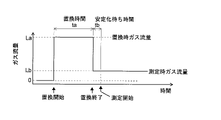
次に本実施形態の示差熱分析装置を用いて測定を行う際の、ユーザによる操作・作業と装置の動作について説明する。図2はガス流量の時間変化の一例を示す図である。
測定対象である試料S及び基準物質Rは、図示しない機構により加熱炉10が上昇された状態で、ディテクタ13の上部の載置皿にそれぞれ載置される。試料S及び基準物質Rがセットされると加熱炉10は降下され、その内部に試料Sと基準物質Rが収容された状態となる。
Next, the user's operation/work and the operation of the apparatus when performing measurement using the differential thermal analysis apparatus of this embodiment will be described. FIG. 2 is a diagram showing an example of change in gas flow rate over time.
The sample S and the reference material R to be measured are respectively placed on the mounting trays above the
作業者が入力部6で所定の操作を行うと、雰囲気置換条件設定部51はまず初期的な環境設定として、二つのガス供給ポート22、23に接続されたガスの種類を作業者に入力させる。通常、雰囲気置換の目的に限らず、熱分析に利用されるガスの種類は決まっているから、ガスの種類を選択する選択肢を用意しておき、各ガス供給ポート22、23にそれぞれ接続されたガスの種類を作業者に選択させればよい。なお、ガス供給ポート22、23に接続されるガスの種類を変更しない場合には、この設定処理は省略することができる。
When the operator performs a predetermined operation on the
作業者がさらに入力部6で所定の操作を行うと、雰囲気置換条件設定部51は所定の様式の雰囲気置換条件設定画面を表示部7に表示し、作業者に雰囲気置換条件を入力させる。雰囲気置換条件は、雰囲気置換に使用するガスの種類、ガスの流量La、置換時間ta、装置安定待ち時間tbなどを含む。
When the operator further performs a predetermined operation on the
ガスの種類はガス供給ポート22、23に接続されている2種類のガスからのみ選択可能であるため、先の環境設定において設定されている2種類のガスを選択肢として作業者に提示し、そのいずれかを作業者に選択させればよい。ガス流量Laは、雰囲気置換時に加熱炉10内に導入するガスの流量であり、作業者に数値で入力させればよい。置換時間taは、雰囲気置換時に上記ガス流量Laのガスを加熱炉10内に導入し続ける時間であり、作業者に数値で入力させればよい。また、装置安定待ち時間tbは、上記置換時間taの終了後に加熱炉10内に導入するガスの流量を測定時のガス流量に変更した状態で、装置が安定状態になるのを待つ時間であり、これも作業者に数値で入力させればよい。
Since the type of gas can only be selected from the two types of gas connected to the
一般的には、雰囲気置換のためのガスとしては窒素が広く利用されているが、ヘリウム、アルゴンなどの他の不活性ガスでもよい。また、ガス流量等の数値は加熱炉10のサイズなどによって異なるが、非特許文献1に記載の熱分析装置における典型的な例としては、ガス流量を300mL/min、置換時間を30min、装置安定化待ち時間を3min程度とすることができる。
雰囲気置換条件設定部51は雰囲気置換条件の入力設定が確定すると、設定された雰囲気値置換条件をファイルとして雰囲気置換条件記憶部53に一旦保存する。
Nitrogen is generally widely used as the gas for atmosphere replacement, but other inert gases such as helium and argon may also be used. In addition, numerical values such as the gas flow rate vary depending on the size of the
When the input setting of the atmosphere replacement condition is confirmed, the atmosphere replacement
作業者がまた入力部6で別の所定の操作を行うと、測定条件設定部50は所定の様式の測定条件設定画面を表示部7に表示し、作業者に測定換条件を入力させる。測定条件は、経過時間と温度との関係を示す温度プロファイル、測定時に使用するガスの種類(但し、1種類とは限らず、測定途中でガスの種類を切り替える場合もあり)、ガスの流量Laなどを含む。雰囲気置換時と同様に、ガスの種類はガス供給ポート22、23に接続されている2種類のガスからのみ選択可能であるため、先の環境設定において設定されている2種類のガスを選択肢として作業者に提示し、そのいずれかを作業者に選択させればよい。ガス流量Lbは、測定時に加熱炉10内に導入するガスの流量であり、作業者に数値で入力させればよい。例えば上述したように雰囲気置換時のガス流量が300mL/minである場合、測定時のガス流量は50mL/min程度である。
When the operator performs another predetermined operation on the
測定条件設定部50は、測定条件の入力設定が確定すると、設定された測定条件をファイルとして測定プログラム記憶部52に一旦保存する。
なお、雰囲気置換条件と測定条件とは同一の設定画面で入力設定できるようにしてもよい。また、両条件を一体として扱い、一つのファイルに格納して保存するようにしてもよい。
When the input setting of the measurement conditions is confirmed, the measurement
It should be noted that the atmosphere replacement conditions and the measurement conditions may be input and set on the same setting screen. Alternatively, both conditions may be treated as one and stored in one file.
また、測定条件及び雰囲気置換条件を変更せずに異なる試料についての測定を繰り返す場合もあるが、そうした場合には、測定プログラム記憶部52及び雰囲気置換条件記憶部53に保存してある測定条件及び雰囲気置換条件を呼び出してきて使用することができる。これにより、測定条件や雰囲気置換条件を変更しない場合や過去に使用したことがある測定条件や雰囲気置換条件を再度使用する場合には、パラメータ等の入力設定の手間を省くことができる。 In some cases, measurements are repeated for different samples without changing the measurement conditions and atmosphere replacement conditions. Atmosphere replacement conditions can be called and used. As a result, when the measurement conditions and atmosphere replacement conditions are not changed, or when the measurement conditions and atmosphere replacement conditions that have been used in the past are used again, it is possible to save the trouble of inputting and setting parameters and the like.
使用する測定条件及び雰囲気置換条件が確定した状態で、作業者が入力部6で測定開始を指示すると、これを受けて制御部5は、確定している測定条件及び雰囲気置換条件を分析制御部4に送る。分析制御部4はまず、雰囲気置換条件におけるガス種類及びガス流量Laの情報に基づいて、雰囲気ガス供給部2におけるオートフローコントローラ24、25の動作を制御し、ガス導入管14を通した加熱炉10へのガスの供給を開始する。即ち、設定されているガス種類に応じて、二つのオートフローコントローラ24又は25のいずれかを選択し、選択した側のオートフローコントローラ24又は25で流量を調整したガスを流す。これにより、図2中に示すように、置換開始時点からガス流量Laで所定のガスが加熱炉10内に供給され、それ以前に加熱炉10内に残っていたガス(空気)が外部へ排出され始める。
When the operator instructs the start of measurement with the
分析制御部4は置換開始時点からタイマによる計時を行い置換時間taが経過した時点で、ガスの流量を測定条件として設定されている測定時のガス流量Lbに減少させる。分析制御部4は置換終了時点からタイマによる計時を行い装置安定化時間tbが経過した時点で、測定プログラムに従った測定を開始する。通常、置換時間taが経過した時点で加熱炉10内の残留ガスは完全に雰囲気ガスに置換されており、装置安定化時間tbは、ガスの流量を測定時と同じ状態にすることで加熱炉10内のガスの流れ等の状態を安定化させるための期間である。
The
測定が開始されると、分析制御部4は加熱制御部3を制御し、例えば昇温分析であればヒータ線10aに加熱電流を供給して、指定されている温度プロファイルに従って加熱炉10の温度を上昇させる。その昇温の過程で、試料Sに生じる熱変化を試料Sと基準物質Rとの温度差として検出する。そして、測定プログラムに従った測定が終了すると、加熱を停止し、図示しないファンを駆動させて加熱炉10を冷却する。
When the measurement is started, the
以上のようにして本実施形態の示差熱分析装置では、作業者が測定開始の指示を行ったあと、雰囲気置換開始から測定終了までの一連の動作が作業者の操作や作業無しに自動的に実行される。また、予め雰囲気置換条件として設定した内容に従って雰囲気置換が自動的に実行されるので、入力設定さえ適切に行えば、例えば雰囲気の置換が不足する等の不具合の発生も防止できる。 As described above, in the differential thermal analysis apparatus of the present embodiment, after the operator gives an instruction to start measurement, a series of operations from the start of atmosphere replacement to the end of measurement are automatically performed without any operation or work by the operator. executed. In addition, atmosphere replacement is automatically performed in accordance with the contents set in advance as the atmosphere replacement conditions, so if the input settings are made appropriately, problems such as insufficient atmosphere replacement can be prevented from occurring.
なお、上記実施形態の説明では、制御部5は測定開始時点で雰囲気置換条件と測定条件とを共に分析制御部4に送り、それ以降は分析制御部4が各部の動作を制御していたが、雰囲気置換時の動作、つまりは雰囲気ガス供給部2におけるガス供給量の調整動作は制御部5が直接制御する構成としてもよい。
In the description of the above embodiment, the
また、通常、加熱炉10の内容積は既知であり、雰囲気置換時のガス流量が決まれば加熱炉10内のガスを置換するための大凡の所要時間は計算により算出可能である。そこで、作業者が置換時間taを入力する際に、入力された数値が自動的に計算される大凡の置換所要時間に比べて小さすぎる場合には、置換不足の可能性があるとの警告を表示するようにしてもよい。また、自動的に計算される大凡の置換所要時間に基づいて、作業者が入力可能な数値の範囲を制限するようにしてもよい。これにより、作業者による誤った入力操作を防止することができる。
In addition, the internal volume of the
また、上記実施形態は示差熱分析装置であるが、それ以外の熱重量測定装置、熱機械的分析装置、示差走査熱量分析装置などの他の熱分析装置にも本発明を適用可能であることは明らかである。 In addition, although the above embodiment is a differential thermal analysis device, the present invention can also be applied to other thermal analysis devices such as a thermogravimetry device, a thermomechanical analysis device, and a differential scanning calorimetry device. is clear.
また、上記実施形態は本発明の一例であって、本発明の趣旨の範囲でさらに適宜修正、変更、追加を行っても本願特許請求の範囲に包含されることは明らかである。 Moreover, the above-described embodiment is an example of the present invention, and it is obvious that any further modifications, changes, and additions within the scope of the present invention are included in the scope of the claims of the present application.
[種々の態様]
上述した例示的な実施形態が以下の態様の具体例であることは、当業者には明らかである。
[Various aspects]
Those skilled in the art will appreciate that the exemplary embodiments described above are specific examples of the following aspects.
(第1項)本発明に係る熱分析装置の一態様は、測定対象である試料がその内部に収容される加熱炉と、前記加熱炉の加熱を制御する加熱制御部と、前記加熱炉の内部に所定のガスを供給するガス供給部と、を具備する熱分析装置であって、
時間経過と温度との関係を示す温度プロファイルを含む測定条件をユーザに設定させる測定条件設定部と、
測定に先立って実施される雰囲気置換時における、使用するガスの種類、ガスの流量、置換時間、及び、安定化待ち時間を含む雰囲気置換条件をユーザに設定させる雰囲気置換条件設定部と、
ユーザの指示を受けて、前記雰囲気置換条件設定部により設定されている雰囲気置換条件に従って前記ガス供給部を制御することで前記加熱炉内の雰囲気を置換したあと、引き続いて、前記測定条件設定部により設定されている測定条件に従って前記ガス供給部及び前記加熱制御部を制御して前記試料に対する測定を実行する制御部と、
を備えるものである。
(Section 1) One aspect of the thermal analysis apparatus according to the present invention includes a heating furnace in which a sample to be measured is accommodated, a heating control unit that controls heating of the heating furnace, and the heating furnace. A thermal analysis apparatus comprising a gas supply unit that supplies a predetermined gas to the inside,
a measurement condition setting unit that allows a user to set measurement conditions including a temperature profile that indicates the relationship between the passage of time and temperature;
an atmosphere replacement condition setting unit that allows a user to set atmosphere replacement conditions including the type of gas to be used, gas flow rate, replacement time, and stabilization waiting time when the atmosphere is replaced prior to measurement;
After receiving a user's instruction and replacing the atmosphere in the heating furnace by controlling the gas supply unit according to the atmosphere replacement conditions set by the atmosphere replacement condition setting unit, subsequently, the measurement condition setting unit a control unit that controls the gas supply unit and the heating control unit according to the measurement conditions set by the
is provided.
第1項に記載の熱分析装置によれば、例えばユーザが測定開始の指示を行うだけで、加熱炉内の雰囲気置換動作と測定動作とを一連で自動的に実行させることができる。それにより、作業者は雰囲気置換のためのガス流量バルブの操作を行う必要はなく、また雰囲気置換が終了するまで待機する必要もない。このようにして、測定に際しての作業者の負担を軽減し、測定作業の効率を改善することができるとともに、作業ミスによる不適切な測定の実行を防止することもできる。
According to the thermal analysis apparatus of
(第2項)第1項に記載の熱分析装置では、前記測定条件設定部により設定された測定条件を記憶する測定条件記憶部をさらに備え、前記測定条件設定部は、ユーザに測定条件を設定させる際に、前記測定条件記憶部に既に記憶されている測定条件を提示し、該測定条件をそのまま次の測定条件として使用可能としたものとすることができる。
(Section 2) The thermal analysis apparatus described in
第2項に記載の熱分析装置によれば、以前に使用した測定条件を再度使用して分析を行う場合に、ユーザは測定条件を入力設定する必要がなく、測定作業の効率を改善することができる。
According to the thermal analysis apparatus described in
(第3項)第1項又は第2項に記載の熱分析装置では、前記ガス供給部に用意した1又は複数のガスの種類をユーザに設定させるガス種類設定部、をさらに備え、前記雰囲気置換条件設定部及び/又は前記測定条件設定部は、前記ガス種類設定部により設定されたガスの種類を、使用可能なガスの種類としてユーザに提示するものとすることができる。
(Item 3) The thermal analysis apparatus according to
第3項に記載の熱分析装置によれば、使用可能なガスの種類のみをユーザに提示することができるので、ユーザによる不適切なガスの種類の設定を防止することができる。 According to the thermal analysis apparatus of the third aspect, only usable gas types can be presented to the user, so it is possible to prevent the user from setting an inappropriate gas type.
(第4項)第1項~第3項のいずれか一つに記載の熱分析装置において、前記制御部は、前記雰囲気置換条件として設定されているガスの種類、ガスの流量、及び置換時間に従って、前記加熱炉内の雰囲気を所定のガスで置換したあと、ガスの流量を前記測定条件として設定されているガス流量に変更したうえで前記雰囲気置換条件として設定されている安定化待ち時間だけ待って、それに引き続いて測定を実行するものとすることができる。
(Item 4) In the thermal analysis apparatus according to any one of
第4項に記載の熱分析装置によれば、加熱炉内のガスの流れ等が安定した状態になってから測定を実行することができるので、測定の際に不安定なガスの流れの影響を排除でき、精度の高い測定を行うことができる。
According to the thermal analysis apparatus described in
1…加熱部
10…加熱炉
10a…ヒータ線
11…輻射シールド
12…断熱カバー
14…ガス導入管
2…雰囲気ガス供給部
3…加熱制御部
4…分析制御部
5…制御部
50…測定条件設定部
51…雰囲気置換条件設定部
52…測定プログラム記憶部
53…雰囲気置換条件記憶部
6…入力部
7…表示部
DESCRIPTION OF
Claims (4)
時間経過と温度との関係を示す温度プロファイルを含む測定条件をユーザに設定させる測定条件設定部と、
測定に先立って実施される雰囲気置換時における、使用するガスの種類、ガスの流量、置換時間、及び、安定化待ち時間を含む雰囲気置換条件をユーザに設定させる雰囲気置換条件設定部と、
ユーザの指示を受けて、前記雰囲気置換条件設定部により設定されている雰囲気置換条件に従って前記ガス供給部を制御することで前記加熱炉内の雰囲気を置換したあと、引き続いて、前記測定条件設定部により設定されている測定条件に従って前記ガス供給部及び前記加熱制御部を制御して前記試料に対する測定を実行する制御部と、
を備える熱分析装置。 Heater comprising a heating furnace in which a sample to be measured is accommodated, a heating control section for controlling heating of the heating furnace, and a gas supply section for supplying a predetermined gas to the interior of the heating furnace. an analytical device,
a measurement condition setting unit that allows a user to set measurement conditions including a temperature profile that indicates the relationship between the passage of time and temperature;
an atmosphere replacement condition setting unit that allows a user to set atmosphere replacement conditions including the type of gas to be used, gas flow rate, replacement time, and stabilization waiting time when the atmosphere is replaced prior to measurement;
After receiving a user's instruction and replacing the atmosphere in the heating furnace by controlling the gas supply unit according to the atmosphere replacement conditions set by the atmosphere replacement condition setting unit, subsequently, the measurement condition setting unit a control unit that controls the gas supply unit and the heating control unit according to the measurement conditions set by the
A thermal analysis device comprising a
A measurement condition storage unit for storing the measurement conditions set by the measurement condition setting unit is further provided , and the measurement condition setting unit stores the measurement conditions already stored in the measurement condition storage unit when allowing the user to set the measurement conditions. 2. The thermal analysis apparatus according to claim 1, wherein a current measurement condition is presented, and the measurement condition can be used as the next measurement condition as it is.
Priority Applications (1)
| Application Number | Priority Date | Filing Date | Title |
|---|---|---|---|
| JP2019162113A JP7215375B2 (en) | 2019-09-05 | 2019-09-05 | thermal analyzer |
Applications Claiming Priority (1)
| Application Number | Priority Date | Filing Date | Title |
|---|---|---|---|
| JP2019162113A JP7215375B2 (en) | 2019-09-05 | 2019-09-05 | thermal analyzer |
Publications (3)
| Publication Number | Publication Date |
|---|---|
| JP2021039062A JP2021039062A (en) | 2021-03-11 |
| JP2021039062A5 JP2021039062A5 (en) | 2022-02-07 |
| JP7215375B2 true JP7215375B2 (en) | 2023-01-31 |
Family
ID=74847010
Family Applications (1)
| Application Number | Title | Priority Date | Filing Date |
|---|---|---|---|
| JP2019162113A Active JP7215375B2 (en) | 2019-09-05 | 2019-09-05 | thermal analyzer |
Country Status (1)
| Country | Link |
|---|---|
| JP (1) | JP7215375B2 (en) |
Citations (1)
| Publication number | Priority date | Publication date | Assignee | Title |
|---|---|---|---|---|
| JP2002243674A (en) | 2001-02-22 | 2002-08-28 | Ricoh Co Ltd | Thermal analyzer |
Family Cites Families (4)
| Publication number | Priority date | Publication date | Assignee | Title |
|---|---|---|---|---|
| JP2818215B2 (en) * | 1989-09-08 | 1998-10-30 | 理学電機株式会社 | Gas supply device for thermal analyzer |
| JP2964140B1 (en) * | 1998-05-18 | 1999-10-18 | セイコーインスツルメンツ株式会社 | Thermal analyzer |
| JP4812017B2 (en) * | 2006-07-26 | 2011-11-09 | エスアイアイ・ナノテクノロジー株式会社 | Thermal analysis apparatus and drying method thereof |
| JP2017096812A (en) * | 2015-11-25 | 2017-06-01 | 国立大学法人京都大学 | Thermal analysis device |
-
2019
- 2019-09-05 JP JP2019162113A patent/JP7215375B2/en active Active
Patent Citations (1)
| Publication number | Priority date | Publication date | Assignee | Title |
|---|---|---|---|---|
| JP2002243674A (en) | 2001-02-22 | 2002-08-28 | Ricoh Co Ltd | Thermal analyzer |
Also Published As
| Publication number | Publication date |
|---|---|
| JP2021039062A (en) | 2021-03-11 |
Similar Documents
| Publication | Publication Date | Title |
|---|---|---|
| JP4285759B2 (en) | Substrate processing apparatus and substrate processing method | |
| TWI704347B (en) | Generated gas analysis method and generated gas analysis device | |
| CN108570659B (en) | Gas control system, film forming apparatus, storage medium, and gas control method | |
| JP6428793B2 (en) | Gas chromatograph | |
| US6612154B1 (en) | Systems and methods for monitoring or controlling the ratio of hydrogen to water vapor in metal heat treating atmospheres | |
| JP2000304751A (en) | Automatic analyzer | |
| JP7215375B2 (en) | thermal analyzer | |
| JP2014185953A (en) | Gas chromatography device | |
| US7781703B2 (en) | Thermal analyzer | |
| JP5096264B2 (en) | Sample vaporizer | |
| US7140231B2 (en) | Evolved gas analyzing method and apparatus | |
| JP2964140B1 (en) | Thermal analyzer | |
| JPH02105046A (en) | Analyzing device | |
| WO2018110689A1 (en) | Element analysis device and element analysis method | |
| JP2009192416A (en) | Thermal analyzer | |
| JP7293984B2 (en) | thermal analyzer | |
| JP5033851B2 (en) | Heating device | |
| JP2017096812A (en) | Thermal analysis device | |
| JP3204106B2 (en) | measuring device | |
| JP2536494B2 (en) | Sample-only heat flux type differential scanning calorimeter | |
| US20230152281A1 (en) | Gas chromatograph device | |
| JP7324901B1 (en) | Thermal analysis system and thermal analysis method | |
| JP3156584U (en) | Thermal analyzer | |
| JP2019132622A (en) | Analyzer | |
| JP5784885B2 (en) | Oxygen partial pressure control heat treatment equipment |
Legal Events
| Date | Code | Title | Description |
|---|---|---|---|
| A521 | Request for written amendment filed |
Free format text: JAPANESE INTERMEDIATE CODE: A523 Effective date: 20220121 |
|
| A621 | Written request for application examination |
Free format text: JAPANESE INTERMEDIATE CODE: A621 Effective date: 20220121 |
|
| A977 | Report on retrieval |
Free format text: JAPANESE INTERMEDIATE CODE: A971007 Effective date: 20221205 |
|
| TRDD | Decision of grant or rejection written | ||
| A01 | Written decision to grant a patent or to grant a registration (utility model) |
Free format text: JAPANESE INTERMEDIATE CODE: A01 Effective date: 20221220 |
|
| A61 | First payment of annual fees (during grant procedure) |
Free format text: JAPANESE INTERMEDIATE CODE: A61 Effective date: 20230102 |
|
| R151 | Written notification of patent or utility model registration |
Ref document number: 7215375 Country of ref document: JP Free format text: JAPANESE INTERMEDIATE CODE: R151 |