JP7214330B2 - Inkjet recording method and inkjet recording apparatus - Google Patents
Inkjet recording method and inkjet recording apparatus Download PDFInfo
- Publication number
- JP7214330B2 JP7214330B2 JP2016182694A JP2016182694A JP7214330B2 JP 7214330 B2 JP7214330 B2 JP 7214330B2 JP 2016182694 A JP2016182694 A JP 2016182694A JP 2016182694 A JP2016182694 A JP 2016182694A JP 7214330 B2 JP7214330 B2 JP 7214330B2
- Authority
- JP
- Japan
- Prior art keywords
- ink
- water
- tube
- inkjet recording
- recording method
- Prior art date
- Legal status (The legal status is an assumption and is not a legal conclusion. Google has not performed a legal analysis and makes no representation as to the accuracy of the status listed.)
- Active
Links
Images
Classifications
-
- B—PERFORMING OPERATIONS; TRANSPORTING
- B41—PRINTING; LINING MACHINES; TYPEWRITERS; STAMPS
- B41J—TYPEWRITERS; SELECTIVE PRINTING MECHANISMS, i.e. MECHANISMS PRINTING OTHERWISE THAN FROM A FORME; CORRECTION OF TYPOGRAPHICAL ERRORS
- B41J2/00—Typewriters or selective printing mechanisms characterised by the printing or marking process for which they are designed
- B41J2/005—Typewriters or selective printing mechanisms characterised by the printing or marking process for which they are designed characterised by bringing liquid or particles selectively into contact with a printing material
- B41J2/01—Ink jet
- B41J2/17—Ink jet characterised by ink handling
- B41J2/175—Ink supply systems ; Circuit parts therefor
-
- B—PERFORMING OPERATIONS; TRANSPORTING
- B41—PRINTING; LINING MACHINES; TYPEWRITERS; STAMPS
- B41J—TYPEWRITERS; SELECTIVE PRINTING MECHANISMS, i.e. MECHANISMS PRINTING OTHERWISE THAN FROM A FORME; CORRECTION OF TYPOGRAPHICAL ERRORS
- B41J2/00—Typewriters or selective printing mechanisms characterised by the printing or marking process for which they are designed
- B41J2/005—Typewriters or selective printing mechanisms characterised by the printing or marking process for which they are designed characterised by bringing liquid or particles selectively into contact with a printing material
- B41J2/01—Ink jet
- B41J2/135—Nozzles
- B41J2/14—Structure thereof only for on-demand ink jet heads
- B41J2/14016—Structure of bubble jet print heads
-
- B—PERFORMING OPERATIONS; TRANSPORTING
- B41—PRINTING; LINING MACHINES; TYPEWRITERS; STAMPS
- B41J—TYPEWRITERS; SELECTIVE PRINTING MECHANISMS, i.e. MECHANISMS PRINTING OTHERWISE THAN FROM A FORME; CORRECTION OF TYPOGRAPHICAL ERRORS
- B41J2/00—Typewriters or selective printing mechanisms characterised by the printing or marking process for which they are designed
- B41J2/005—Typewriters or selective printing mechanisms characterised by the printing or marking process for which they are designed characterised by bringing liquid or particles selectively into contact with a printing material
- B41J2/01—Ink jet
- B41J2/17—Ink jet characterised by ink handling
- B41J2/175—Ink supply systems ; Circuit parts therefor
- B41J2/17503—Ink cartridges
- B41J2/17506—Refilling of the cartridge
- B41J2/17509—Whilst mounted in the printer
-
- B—PERFORMING OPERATIONS; TRANSPORTING
- B41—PRINTING; LINING MACHINES; TYPEWRITERS; STAMPS
- B41J—TYPEWRITERS; SELECTIVE PRINTING MECHANISMS, i.e. MECHANISMS PRINTING OTHERWISE THAN FROM A FORME; CORRECTION OF TYPOGRAPHICAL ERRORS
- B41J2/00—Typewriters or selective printing mechanisms characterised by the printing or marking process for which they are designed
- B41J2/005—Typewriters or selective printing mechanisms characterised by the printing or marking process for which they are designed characterised by bringing liquid or particles selectively into contact with a printing material
- B41J2/01—Ink jet
- B41J2/21—Ink jet for multi-colour printing
-
- B—PERFORMING OPERATIONS; TRANSPORTING
- B41—PRINTING; LINING MACHINES; TYPEWRITERS; STAMPS
- B41J—TYPEWRITERS; SELECTIVE PRINTING MECHANISMS, i.e. MECHANISMS PRINTING OTHERWISE THAN FROM A FORME; CORRECTION OF TYPOGRAPHICAL ERRORS
- B41J2/00—Typewriters or selective printing mechanisms characterised by the printing or marking process for which they are designed
- B41J2/005—Typewriters or selective printing mechanisms characterised by the printing or marking process for which they are designed characterised by bringing liquid or particles selectively into contact with a printing material
- B41J2/01—Ink jet
- B41J2/17—Ink jet characterised by ink handling
- B41J2/175—Ink supply systems ; Circuit parts therefor
- B41J2/17503—Ink cartridges
- B41J2/1752—Mounting within the printer
-
- C—CHEMISTRY; METALLURGY
- C09—DYES; PAINTS; POLISHES; NATURAL RESINS; ADHESIVES; COMPOSITIONS NOT OTHERWISE PROVIDED FOR; APPLICATIONS OF MATERIALS NOT OTHERWISE PROVIDED FOR
- C09D—COATING COMPOSITIONS, e.g. PAINTS, VARNISHES OR LACQUERS; FILLING PASTES; CHEMICAL PAINT OR INK REMOVERS; INKS; CORRECTING FLUIDS; WOODSTAINS; PASTES OR SOLIDS FOR COLOURING OR PRINTING; USE OF MATERIALS THEREFOR
- C09D11/00—Inks
- C09D11/30—Inkjet printing inks
- C09D11/38—Inkjet printing inks characterised by non-macromolecular additives other than solvents, pigments or dyes
Description
本発明は、インクジェット記録方法、及びインクジェット記録装置に関する。 The present invention relates to an inkjet recording method and an inkjet recording apparatus.
インクジェット記録方法によれば、様々な記録媒体へ画像を記録することができる。そして、より良好な画像を得るため、例えば、光沢紙などに写真画質の画像を記録するのに適したインクや、普通紙などに文書を記録するのに適したインクなど、目的に応じた種々のインクが提案されている。 According to the inkjet recording method, images can be recorded on various recording media. In order to obtain better images, for example, inks suitable for recording photographic-quality images on glossy paper, inks suitable for recording documents on plain paper, etc., are used. ink has been proposed.
近年では、記録媒体として普通紙などを用い、文字や図表などを含むビジネス文書などの記録にもインクジェット記録方法が利用されており、このような用途への使用頻度が格段に高まってきている。また、インクジェット記録方法の技術の発展に伴い、長期間の使用に耐えるべく、インクジェット記録装置の耐久性や信頼性を高めるとともに、記録可能枚数を多くして高い生産性を実現することが要求されるようになっている。このような要求に対し、例えば、記録ヘッドの吐出口からインクを吸引して不吐出を改善する、いわゆるパージ回復性を高めた、表面張力が高く、溶存酸素量が少ないインクジェット用のインクが提案されている(特許文献1)。 In recent years, plain paper or the like is used as a recording medium, and the inkjet recording method is also used for recording business documents including characters, charts, and the like, and the frequency of use for such applications has increased remarkably. In addition, along with the development of the technology of the inkjet recording method, it is required to improve the durability and reliability of the inkjet recording apparatus in order to endure long-term use, and to realize high productivity by increasing the number of sheets that can be recorded. It has become so. In response to such demands, for example, inkjet inks with high surface tension and low dissolved oxygen content have been proposed that improve non-ejection by sucking ink from the ejection ports of the print head, that is, with enhanced purge recovery properties. (Patent Document 1).
本発明者らは、生産性を高めるべく、インク収容部としてメインタンク及びサブタンクを設け、収容されるインクの量を増大させたインクジェット記録装置について検討した。そして、特許文献1で提案された溶存酸素量が少ないインクを用いた場合に、信頼性が高まる傾向にあることを確認した。しかし、上記のインクジェット記録装置を使用し、長期間にわたってインクを吐出させて記録すると、溶存酸素量の少ないインクを用いた場合であっても画像に徐々に乱れが生じやすくなるという別の課題が生ずることが判明した。さらに、長期間にわたって上記のインクジェット記録装置を使用した場合、シアンインク、マゼンタインク、及びイエローインクの重ね合わせにより記録されるグレーラインの画像の色調が変化しやすくなることがわかった。 In order to improve productivity, the present inventors have studied an ink jet recording apparatus in which a main tank and a sub-tank are provided as an ink containing portion to increase the amount of contained ink. Then, it was confirmed that the reliability tends to increase when the ink with a small amount of dissolved oxygen proposed in Patent Document 1 is used. However, when the above-mentioned inkjet recording apparatus is used to eject ink for a long period of time to record, there is another problem that the image tends to be gradually disturbed even when ink with a small amount of dissolved oxygen is used. turned out to occur. Furthermore, it has been found that when the above ink jet recording apparatus is used for a long period of time, the color tone of gray line images recorded by superimposing cyan ink, magenta ink, and yellow ink tends to change.
したがって、本発明の目的は、メインタンク及びサブタンクをインク収容部として備えたインクジェット記録装置を長期間にわたって使用した場合に生ずる課題を解決することにある。すなわち、上記のインクジェット記録装置を長期間にわたって使用しても、インクの吐出安定性が良好な状態で維持されるとともに、色調変化が抑制された画像を記録することができるインクジェット記録方法を提供することにある。また、本発明の別の目的は、前記インクジェット記録方法に用いられるインクジェット記録装置を提供することにある。 SUMMARY OF THE INVENTION Accordingly, it is an object of the present invention to solve problems that occur when an inkjet recording apparatus having a main tank and a sub-tank as an ink reservoir is used for a long period of time. That is, the present invention provides an inkjet recording method capable of recording an image in which the ink ejection stability is maintained in a good state and color tone change is suppressed even when the above-described inkjet recording apparatus is used for a long period of time. That's what it is. Another object of the present invention is to provide an inkjet recording apparatus for use in the inkjet recording method.
上記の目的は以下の本発明によって達成される。すなわち、本発明によれば、シアンインク、マゼンタインク、及びイエローインクを含む複数の水性インクと、大気連通部を有する第1インク収容部と、第2インク収容部と、熱エネルギーの作用により前記水性インクを吐出する記録ヘッドと、前記第1インク収容部から前記第2インク収容部へと前記水性インクを供給するチューブと、を備え、前記第2インク収容部が、熱可塑性樹脂で形成された筺体であるとともに、他の部材を介在させることなく前記記録ヘッドが貼り合わされており、前記チューブが、前記水性インクのそれぞれに対応する第1チューブ、第2チューブ、及び第3チューブを含むとともに、前記第2チューブが前記第1チューブと前記第3チューブで挟まれる位置で接合された部分を有するインクジェット記録装置を使用し、前記水性インクを前記記録ヘッドから吐出して記録媒体に画像を記録するインクジェット記録方法であって、前記シアンインク、前記マゼンタインク、及び前記イエローインクの水のモル分率(%)の最大値と最小値の差が、1.0%以下であり、前記マゼンタインクに対応するチューブが、前記第2チューブであり、前記シアンインク、前記マゼンタインク、及び前記イエローインクが、いずれも染料を含有し、前記シアンインク、前記マゼンタインク、及び前記イエローインクの水のモル分率(%)が、いずれも94.1%以上であることを特徴とするインクジェット記録方法が提供される。 The above objects are achieved by the present invention described below. That is, according to the present invention, a plurality of water-based inks including cyan ink, magenta ink, and yellow ink, a first ink containing portion having an air communication portion, a second ink containing portion, and the action of thermal energy cause the above-mentioned a recording head that ejects water-based ink; and a tube that supplies the water-based ink from the first ink reservoir to the second ink reservoir, wherein the second ink reservoir is made of a thermoplastic resin. and the recording head is attached without intervening other members, and the tubes include a first tube, a second tube, and a third tube corresponding to each of the water-based inks. and recording an image on a recording medium by ejecting the water-based ink from the recording head using an inkjet recording apparatus having a portion where the second tube is joined at a position sandwiched between the first tube and the third tube. wherein the difference between the maximum value and the minimum value of the molar fraction (%) of water in the cyan ink, the magenta ink, and the yellow ink is 1.0% or less, and the magenta ink is the second tube, the cyan ink, the magenta ink, and the yellow ink all contain dyes , and the moles of water in the cyan ink, the magenta ink, and the yellow ink There is provided an ink jet recording method characterized in that each fraction (%) is 94.1% or more .
本発明によれば、メインタンク及びサブタンクをインク収容部として備えたインクジェット記録装置を長期間にわたって使用した場合に生ずる課題を解決することができる。すなわち、上記のインクジェット記録装置を長期間にわたって使用しても、インクの吐出安定性が良好な状態で維持されるとともに、色調変化が抑制された画像を記録することができるインクジェット記録方法を提供することができる。また、本発明によれば、このインクジェット記録方法に用いられるインクジェット記録装置を提供することができる。 According to the present invention, it is possible to solve the problem that occurs when an inkjet recording apparatus having a main tank and a sub-tank as an ink reservoir is used for a long period of time. That is, the present invention provides an inkjet recording method capable of recording an image in which the ink ejection stability is maintained in a good state and color tone change is suppressed even when the above-described inkjet recording apparatus is used for a long period of time. be able to. Further, according to the present invention, it is possible to provide an inkjet recording apparatus for use in this inkjet recording method.
以下に、好ましい実施の形態を挙げて、さらに本発明を詳細に説明する。なお、以下、インクジェット用の水性インクのことを「インク」、第1インク収容部のことを「メインタンク」、第2インク収容部のことを「サブタンク」と記載することがある。また、物性値は、特に断りのない限り、常温(25℃)における値とする。 The present invention will be further described in detail below with reference to preferred embodiments. Hereinafter, the water-based ink for inkjet may be referred to as "ink", the first ink reservoir as "main tank", and the second ink reservoir as "sub-tank". Unless otherwise specified, physical property values are values at room temperature (25° C.).
まず、本発明者らは、大気連通部を有するメインタンク及びサブタンクを有するインクジェット記録装置を使用し、長期間にわたってインクを吐出させた場合に生ずる画像の乱れの原因について検討した。その結果、記録ヘッドからインクを吐出して多くの画像を記録する過程で、記録ヘッドのインク流路に気泡が侵入しやすくなり、侵入した気泡によってインクの正常な吐出が妨げられ、画像が乱れるようになることがわかった。次に、本発明者らは、上記のような現象が生ずる理由について詳細に調べた。その結果、メインタンクにおいて溶存ガス量が増加したインクが、サブタンクを経由して記録ヘッドへと供給されていくために、記録ヘッドのインク流路に気泡が付着し、インクの正常な吐出が妨げられることがわかった。以下、これらの現象について説明する。 First, the present inventors used an inkjet recording apparatus having a main tank and a sub-tank having air communication portions, and investigated the cause of image distortion that occurs when ink is ejected over a long period of time. As a result, during the process of ejecting ink from the print head to print many images, air bubbles tend to enter the ink flow path of the print head. It turned out to be Next, the inventors investigated in detail the reason why the above phenomenon occurs. As a result, ink with an increased amount of dissolved gas in the main tank is supplied to the print head via the sub-tank, causing air bubbles to adhere to the ink flow path of the print head and prevent normal ink ejection. It was found that These phenomena will be described below.
生産性を高めるべく、容量の大きなメインタンクを設けたインクジェット記録装置を用いる場合を想定する。また、このメインタンクは大気連通部を有する。このようなインクジェット記録装置を使用し、長期間にわたって記録ヘッドからインクを吐出してインクを消費させると以下のような現象が起こる。すなわち、インクの消費に伴い、メインタンク内のインクの液面が低くなるとともに、大気連通部を通じてメインタンク内に空気が導入される。容量の大きなメインタンクの場合、多くの空気を取り込んで液面が徐々に低下するが、インクが収容されている期間が長い。したがって一般的な容量のタンクを設けた従来のインクジェット記録装置と比べて、容量の大きなメインタンクを設けたインクジェット記録装置の場合、インクが空気と接触する期間が顕著に長くなる。このため、インクに空気が溶け込みやすく、インク中の溶存ガス量は徐々に増加する。 A case is assumed in which an inkjet recording apparatus provided with a large-capacity main tank is used in order to improve productivity. Also, this main tank has an atmosphere communicating portion. When such an ink jet recording apparatus is used and ink is consumed by ejecting ink from the recording head for a long period of time, the following phenomenon occurs. That is, as the ink is consumed, the liquid level of the ink in the main tank becomes lower, and air is introduced into the main tank through the atmosphere communicating portion. In the case of a large-capacity main tank, a large amount of air is taken in and the liquid level gradually decreases, but the period in which the ink is stored is long. Therefore, in the case of an inkjet recording apparatus provided with a large-capacity main tank, the period during which the ink is in contact with the air is remarkably longer than in a conventional inkjet recording apparatus provided with a tank of a general capacity. Therefore, air easily dissolves in the ink, and the amount of dissolved gas in the ink gradually increases.
メインタンク内で溶存ガス量が増加したインクがサブタンクを経由して記録ヘッドへと供給されていく過程では、以下のような現象が生ずると考えられる。インク供給系は、インク供給チューブ、サブタンク、及び記録ヘッドのインク流路など、様々な流路径を有する部材で構成されている。そして、流路径の変化によりインクの流れが急激に変化するポイントが存在する。溶存ガス量が多いインクの場合、このようなポイントの付近でインクの流れが急激に変化すると、気泡が形成されやすくなる。形成された気泡はインクの供給に伴い記録ヘッドに到達し、インク流路に付着するため、インクの正常な吐出が妨げられると考えられる。 It is considered that the following phenomenon occurs in the process in which the ink with an increased amount of dissolved gas in the main tank is supplied to the print head via the sub-tank. The ink supply system is composed of members having various channel diameters, such as an ink supply tube, a sub-tank, and an ink channel of the print head. There is a point where the flow of ink changes abruptly due to the change in the diameter of the flow path. In the case of ink with a large amount of dissolved gas, if the ink flow suddenly changes near such a point, air bubbles are likely to be formed. As the ink is supplied, the formed air bubbles reach the print head and adhere to the ink flow path.
本発明者らは、インク中の溶存ガス量が増加しやすい状況下であっても、インク流路への気泡の侵入を抑制し、インクの吐出安定性を良好な状態で維持するための手法について検討した。その結果、インク流路への気泡の侵入は、発生した気泡をインク流路から遠ざかる方向に移動しやすくすることで抑制されることを見出した。そして、気泡をインク流路から遠ざかる方向に移動しやすくするための構成について、本発明者らはさらに検討した。その結果、サブタンクが熱可塑性樹脂で形成された筐体であること、及びこのサブタンク(筐体)に、放熱板などの他の部材を介在させることなく記録ヘッド(記録素子基板)が貼り合わされた構成のものを用いることが有効であることを見出した。このような構成のサブタンクを設けることで、インク流路への気泡の侵入が抑制され、長期間にわたってインクを吐出させた場合であってもインクの吐出安定性が良好な状態で維持されるメカニズムは、以下のように推測される。すなわち、放熱板などの熱を逃がす手段が存在しないため、インクの吐出のために記録ヘッドに付与される熱エネルギーがサブタンク中のインクにも伝わり、インクの温度が上昇する。インクの温度上昇に伴い、気泡が膨張して密度が小さくなるため、重力方向(インクの流れ方向)と逆の方向に気泡が移動しやすくなると推測される。 The inventors of the present invention have developed a technique for suppressing the entry of air bubbles into the ink flow path and maintaining good ink ejection stability even under conditions where the amount of dissolved gas in the ink tends to increase. was considered. As a result, it was found that the intrusion of air bubbles into the ink flow path is suppressed by facilitating movement of the generated air bubbles in a direction away from the ink flow path. The present inventors further studied a configuration for facilitating the movement of air bubbles in a direction away from the ink flow path. As a result, the sub-tank is a housing made of thermoplastic resin, and the recording head (printing element substrate) is bonded to this sub-tank (body) without any other member such as a heat sink. It has been found that it is effective to use the configuration. By providing a sub-tank with such a structure, the intrusion of air bubbles into the ink flow path is suppressed, and the ink ejection stability is maintained in a favorable state even when the ink is ejected for a long period of time. is estimated as follows. That is, since there is no means for radiating heat such as a radiator plate, the thermal energy applied to the print head for ejecting ink is transmitted to the ink in the sub-tank, increasing the temperature of the ink. As the temperature of the ink rises, the bubbles expand and the density decreases, so it is presumed that the bubbles tend to move in the direction opposite to the gravity direction (ink flow direction).
容量の大きいメインタンクを設けたインクジェット記録装置の場合、装置の構成部材、特にインク供給チューブからインクが蒸発しやすい。そして、各チューブが同等の材質で形成される場合、インク間の蒸発率の違いにより、シアンインク、マゼンタインク、及びイエローインクの重ね合わせにより記録されるグレーラインの画像に色調変化が生ずることが判明した。特に、インク供給チューブが、インクのそれぞれに対応する第1チューブ、第2チューブ、及び第3チューブを含むとともに、第2チューブが第1チューブと第3チューブで挟まれる位置で接合された部分を有する場合、インクの蒸発率に差が生じやすくなる。これは、第1チューブ及び第3チューブと、第2チューブとでは、チューブの表面積、すなわち空気との接触面積が異なるためであると考えられる。 In the case of an inkjet recording apparatus provided with a large-capacity main tank, ink tends to evaporate from the constituent members of the apparatus, particularly the ink supply tube. When each tube is made of the same material, the difference in evaporation rate between inks can cause color tone changes in gray line images recorded by superimposing cyan, magenta, and yellow inks. found. In particular, the ink supply tube includes a first tube, a second tube, and a third tube corresponding to each of the inks, and a portion where the second tube is sandwiched between the first tube and the third tube. In this case, a difference in ink evaporation rate is likely to occur. It is believed that this is because the surface area of the tubes, that is, the contact area with the air, differs between the first and third tubes and the second tube.
また、マゼンタインクに対応するチューブが、第1チューブ又は第3チューブである場合と、第2チューブである場合とを比較すると、後者の方が色調変化の程度が軽微であることがわかった。一般的に、グレーラインの画像に生ずる色調変化のうち、赤み方向への色調変化は特に敏感に感知されやすいためであると考えられる。マゼンタインクに対応するチューブが第1チューブ又は第3チューブであると、マゼンタインクの蒸発率がシアンインク及びイエローインクの蒸発率よりも高くなる。このため、水分の蒸発によってマゼンタインク中の色材の濃度が上昇し、初期に設計していた各インク間の発色性の関係が崩れやすくなる。したがって、シアンインク、マゼンタインク、及びイエローインクの重ね合わせにより記録されるグレーラインの画像の赤味が強く感じられる。以上より、本発明者らは、グレーラインの画像に生ずる色調変化を有効に抑制するには、マゼンタインクに対応するチューブを第2チューブとする必要があることを見出した。しかし、このようにチューブを割り当てた場合であっても、グレーラインの画像に生ずる色調変化の抑制は必ずしも十分であるとは言えないことがわかった。 Further, when comparing the case where the tube corresponding to magenta ink is the first tube or the third tube and the case where the tube is the second tube, it was found that the latter causes a slight change in color tone. This is probably because, among the color tone changes that occur in gray line images, color tone changes in the direction of reddishness are generally perceived with particular sensitivity. If the tube corresponding to magenta ink is the first tube or the third tube, the evaporation rate of magenta ink will be higher than the evaporation rates of cyan ink and yellow ink. For this reason, the concentration of the coloring material in the magenta ink increases due to the evaporation of the water content, and the initially designed relationship of color development properties between the inks tends to collapse. Therefore, the gray line image printed by superimposing cyan ink, magenta ink, and yellow ink has a strong reddish tint. In view of the above, the inventors of the present invention have found that it is necessary to use the second tube as the tube for magenta ink in order to effectively suppress the color tone change that occurs in the gray line image. However, it has been found that even when the tubes are assigned in this way, it cannot be said that the suppression of the color tone change occurring in the gray line image is necessarily sufficient.
インク流路への気泡の侵入を抑制してインクの吐出安定性を良好な状態に維持すべく、以下の構成を採用することを想定する。すなわち、熱可塑性樹脂で形成された筐体をサブタンクとし、このサブタンクに、放熱板などの他の部材を介在させることなく記録ヘッド(記録素子基板)を貼り合わせた構成のものを用いる場合を想定する。この場合、放熱板などの熱を逃がす手段が存在しないため、記録ヘッドのインク流路において温度ムラが生じやすくなり、各インクの水分の蒸発しやすさにも差が生ずるようになる。そこで、本発明者らは、各インクの水分蒸発の進みやすさを揃えるべく、各インクの「水のモル分率」に着目してさらに検討した。 In order to suppress the entry of air bubbles into the ink flow path and maintain good ink ejection stability, the following configuration is assumed. That is, it is assumed that a housing made of thermoplastic resin is used as a sub-tank, and a print head (printing element substrate) is attached to the sub-tank without any other member such as a heat sink. do. In this case, since there is no means for releasing heat such as a heat sink, temperature unevenness tends to occur in the ink flow path of the print head, and the easiness of evaporation of water from each ink also varies. Therefore, the present inventors focused on the "molar fraction of water" of each ink and further studied in order to equalize the progress of water evaporation in each ink.
シアン、マゼンタ、及びイエローの各インクの吐出口列が1の記録素子基板に設けられている記録ヘッドは、通常、吐出口列をひとつの覆い部材(キャップ)でまとめてキャップすることで、吐出口からの水の蒸発を抑制するように構成されている。吐出口列がキャップされている場合、キャップ内部はほぼ密閉されているため、吐出口からの水の蒸発によって、水の蒸気圧が飽和した状態となっている。キャップ内部の湿度を実際に測定するのは困難である。但し、各インクからの水分蒸発の進みやすさが異なっていたとしても、釣り合いが取れて平均的な状態になっていると考えられる。すなわち、キャップ内部においては、各インクとキャップ内部で水の蒸発が平衡状態となっていると考えられる。ここで、各インクの「水のモル分率」が大きく違う場合を想定する。この場合、水のモル分率が高いインクから優先的に水の蒸発が進む。このため、水のモル分率が高いインクの吐出口近傍では、水以外のインクの構成成分が濃縮された状態となる。一方、水のモル分率が低いインクには、水蒸気が水として吸収される。このため、水のモル分率が低いインクの吐出口近傍では、インクの構成成分が希釈された状態となる。このような現象のバランスによって、吐出口近傍においては、各インクの水のモル分率が平均化されるように水の移動が生じていると考えられる。 A print head in which ejection port arrays for each of cyan, magenta, and yellow inks are provided on a printing element substrate is generally capped by collectively covering the ejection port arrays with a single cover member (cap). It is configured to inhibit evaporation of water from the outlet. When the ejection port array is capped, the inside of the cap is substantially sealed, and the vapor pressure of water is saturated due to the evaporation of water from the ejection ports. It is difficult to actually measure the humidity inside the cap. However, even if the rate at which water evaporates from each ink differs, it is considered that the state is balanced and average. That is, inside the cap, it is considered that the evaporation of each ink and the water inside the cap are in equilibrium. Here, it is assumed that the "molar fraction of water" of each ink is significantly different. In this case, the evaporation of water proceeds preferentially from the ink with a higher molar fraction of water. For this reason, in the vicinity of the ejection port for the ink having a high molar fraction of water, the constituent components of the ink other than water are concentrated. On the other hand, ink with a low molar fraction of water absorbs water vapor as water. For this reason, in the vicinity of the ejection port for the ink having a low molar fraction of water, the constituent components of the ink are in a diluted state. It is considered that the balance of such phenomena causes the movement of water in the vicinity of the ejection port such that the mole fraction of water in each ink is averaged.
上記のような水の移動は、キャップ内部だけでなく、例えば、非キャップ時、すなわち、吐出口列が大気に開放された状態などにおいても生ずる。但し、水のモル分率が異なる複数のインクがひとつのキャップでまとめてキャップされているという状況は、水のモル分率の変化量という観点からは、特に厳しい状況であるといえる。これは、水の蒸気圧が飽和した状態になる過程で、水のモル分率が高いインクは水のモル分率が低下し、水のモル分率が低いインクは水のモル分率が上昇する、といった現象が生ずるためである。 The movement of water as described above occurs not only inside the cap, but also, for example, when the cap is off, that is, when the ejection port array is open to the atmosphere. However, the situation in which a plurality of inks with different water mole fractions are collectively capped with one cap is a particularly severe situation from the viewpoint of the amount of change in the water mole fraction. This is because the water vapor pressure becomes saturated, and the water mole fraction decreases in inks with high water mole fractions, and increases in inks with low water mole fractions. This is because a phenomenon such as
以上の内容を考慮し、本発明者らがさらに検討した結果、上述の構造部分を有するインク供給チューブを用いる場合、以下に示す(i)及び(ii)の要件を満たすことが重要であることを見出した。
(i)シアンインク、マゼンタインク、及びイエローインクの水のモル分率(%)の最大値と最小値の差が、5.0%以下である。
(ii)マゼンタインクに対応するチューブが、第2チューブである。
In view of the above, the inventors of the present invention made further studies and found that it is important to satisfy the following requirements (i) and (ii) when using an ink supply tube having the above-described structural portion. I found
(i) The difference between the maximum and minimum water mole fractions (%) of cyan ink, magenta ink, and yellow ink is 5.0% or less.
(ii) The tube corresponding to magenta ink is the second tube.
上記(i)及び(ii)の要件を満たすことで、マゼンタインク中の色材濃度の極端な上昇が抑制されるとともに、インク間の水の移動も低減される。このため、シアンインク、マゼンタインク、及びイエローインクの重ね合わせにより記録されるグレーラインの画像の色調変化を抑制することができる。画像の色調変化をより有効に抑制するには、シアンインク、マゼンタインク、及びイエローインクの水のモル分率(%)の最大値と最小値の差が、3.0%以下であることが好ましく、1.0%以下であることがさらに好ましい。なお、シアンインク、マゼンタインク、及びイエローインクの水のモル分率(%)の最大値と最小値の差は、0.0%であってもよい。 By satisfying the above requirements (i) and (ii), an extreme increase in the colorant concentration in the magenta ink is suppressed, and the movement of water between inks is also reduced. Therefore, it is possible to suppress the color tone change of the gray line image recorded by superimposing the cyan ink, the magenta ink, and the yellow ink. In order to more effectively suppress changes in the color tone of an image, the difference between the maximum and minimum molar fractions (%) of water in cyan ink, magenta ink, and yellow ink should be 3.0% or less. It is preferably 1.0% or less, more preferably 1.0% or less. The difference between the maximum and minimum water mole fractions (%) of cyan ink, magenta ink, and yellow ink may be 0.0%.
本発明における「水のモル分率」は、「分子量が300以下」であるとともに、「水性インク中に存在する含有量で水に溶解する」化合物のみを対象に算出した値とする。「分子量が300以下」の化合物のみを水のモル分率を算出する対象の化合物とするのは、水と比較して分子量が十分に大きい化合物は、水性インク中の通常の含有量では、水のモル分率に実質的に影響を与えないためである。また、「水に溶解する」化合物のみを水のモル分率を算出する対象の化合物とするのは、金属などの成分は分子量が300以下であっても明らかに水に溶解しない物質を考慮する必要がないためである。そして、顔料や樹脂粒子などの水に溶解しない化合物は水と比較して分子量がはるかに大きく、水性インク中の通常の含有量ではモル数は極めて小さくなるために考慮する必要がない。さらに、インク中の水に溶解する化合物のうち、含有量が1.0質量%以上である化合物を考慮すれば、実質的に、本発明の効果を具現化するための条件としては十分である。上記の定義に合致する化合物には、実質的には、後述するような水溶性有機溶剤(固体の物質も含む)を挙げることができる。 The "mole fraction of water" in the present invention is a value calculated only for compounds that "have a molecular weight of 300 or less" and "dissolve in water at the content present in the water-based ink". The reason why only compounds with “a molecular weight of 300 or less” are the target compounds for calculating the mole fraction of water is that a compound with a sufficiently large molecular weight compared to water does not contain water at a normal content in water-based ink. This is because it does not substantially affect the molar fraction of In addition, the reason why only compounds that "dissolve in water" are the target compounds for calculating the mole fraction of water is that substances such as metals that clearly do not dissolve in water are considered even if their molecular weight is 300 or less. This is because it is not necessary. Compounds that do not dissolve in water, such as pigments and resin particles, have much larger molecular weights than water, and the number of moles is extremely small in a normal content in water-based ink, so there is no need to consider them. Furthermore, among the water-soluble compounds in the ink, if the content of the compound is 1.0% by mass or more, it is substantially sufficient as a condition for embodying the effects of the present invention. . Compounds meeting the above definition include water-soluble organic solvents (including solid substances) substantially as described below.
「水のモル分率」は、[(水のモル数)/(水のモル数+分子量が300以下の水溶性化合物のモル数)]×100(%)の式にしたがって算出する。後述する実施例で調製したインクM1を例に挙げて水のモル分率を算出する過程を説明する。括弧内の数値は分子量であり、水は染料水溶液中の水を含む合計の含有量であり、各成分のモル数はインク100g当たりの値である。染料、及び界面活性剤(アセチレノールE100)は、水溶性化合物ではあるが、分子量が300超であるため、計算対象とはしない。
・グリセリン(92.094):10.0質量%、0.109モル
・2-ピロリドン(85.106):5.0質量%、0.059モル
・トリエチレングリコール(150.176):6.5質量%、0.043モル
・水(18.016):74.0質量%、4.107モル
「水のモル分率」=[4.107/(4.107+0.109+0.059+0.043)]×100=95.1%
The “molar fraction of water” is calculated according to the formula [(moles of water)/(moles of water+moles of water-soluble compound having a molecular weight of 300 or less)]×100 (%). The process of calculating the molar fraction of water will be described using the ink M1 prepared in the example described later as an example. The numbers in parentheses are molecular weights, water is the total content including water in the dye aqueous solution, and the number of moles of each component is the value per 100 g of ink. Dyes and surfactants (acetylenol E100) are water-soluble compounds, but their molecular weights are over 300, so they are not included in the calculation.
· Glycerin (92.094): 10.0% by mass, 0.109 mol · 2-pyrrolidone (85.106): 5.0% by mass, 0.059 mol · Triethylene glycol (150.176): 6. 5% by mass, 0.043 mol Water (18.016): 74.0% by mass, 4.107 mol "Mole fraction of water" = [4.107 / (4.107 + 0.109 + 0.059 + 0.043) ]×100=95.1%
以下、本発明のインクジェット記録方法、このインクジェット記録方法で好適に用いることができるインクジェット記録装置、記録ヘッド、及び水性インクなどについてそれぞれ説明する。 Hereinafter, the inkjet recording method of the present invention, the inkjet recording apparatus, the recording head, and the water-based ink that can be preferably used in this inkjet recording method will be described.
<インクジェット記録装置の概略構成>
本発明のインクジェット記録方法は、複数の水性インク、大気連通部を有する第1インク収容部、第2インク収容部、記録ヘッド、及びインク供給チューブを備えたインクジェット記録装置を使用する記録方法である。インク供給チューブは、第1インク収容部から第2インク収容部へと水性インクを供給するチューブである。以下、本発明のインクジェット記録方法及びそれに用いるインクジェット記録装置の詳細について、図面を参照しつつ説明する。
<Schematic Configuration of Inkjet Recording Apparatus>
The inkjet recording method of the present invention is a recording method using an inkjet recording apparatus equipped with a plurality of water-based inks, a first ink containing section having an atmosphere communication section, a second ink containing section, a recording head, and an ink supply tube. . The ink supply tube is a tube that supplies aqueous ink from the first ink reservoir to the second ink reservoir. Hereinafter, the details of the inkjet recording method of the present invention and the inkjet recording apparatus used therefor will be described with reference to the drawings.
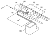
図1は、本発明のインクジェット記録装置の一実施形態を模式的に示す斜視図である。図1に示す実施形態のインクジェット記録装置は、X方向(主走査方向)に記録ヘッドを往復走査させて記録動作を行う、いわゆるシリアル方式のインクジェット記録装置である。記録媒体101は、搬送ローラ107によってY方向(副走査方向)へと間欠的に搬送される。キャリッジ103に搭載された記録ユニット102は、記録媒体101の搬送方向であるY方向と直交するX方向(主走査方向)に往復走査される。そして、記録媒体101のY方向への搬送と、記録ユニット102のX方向への往復走査によって、記録動作が行われる。
FIG. 1 is a perspective view schematically showing one embodiment of the inkjet recording apparatus of the present invention. The inkjet printing apparatus of the embodiment shown in FIG. 1 is a so-called serial type inkjet printing apparatus that performs a printing operation by reciprocally scanning a printing head in the X direction (main scanning direction). The
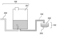
図2は、インク供給系の一例を示す模式図である。図2に示すように、記録ユニット102は、供給されるインクを複数の吐出口から吐出するインクジェット方式の記録ヘッド203と、第2インク収容部としてのサブタンク202とで構成されている。この記録ユニット102は、図1に示すようにキャリッジ103に搭載されている。キャリッジ103は、X方向に沿って配置されたガイドレール105に沿って移動可能に支持されており、ガイドレール105と並行に移動する無端ベルト106に固定されている。無端ベルト106は、モータの駆動力によって往復運動する。無端ベルト106の往復運動によって、キャリッジ103がX方向に往復走査される。
FIG. 2 is a schematic diagram showing an example of an ink supply system. As shown in FIG. 2, the
メインタンク収容部108の内部には、第1インク収容部としてのメインタンク201(図2)が収納される。メインタンク収容部108に収納されたメインタンク201と、記録ユニット102のサブタンク202とは、インク供給チューブ104によって接続される。インクは、メインタンク201からインク供給チューブ104を介してサブタンク202に供給された後、記録ヘッド203の吐出口から吐出されるが、これらの部材はインクの種類に対応した数で設けることができる。
A main tank 201 (FIG. 2) as a first ink containing portion is accommodated inside the main
メインタンク201内に収容されたインク(ハッチングで示す)は、インク供給チューブ104を介してサブタンク202に供給された後、記録ヘッド203へと供給される。メインタンク201には、大気連通部としての気体導入チューブ204が接続されている。画像記録によってインクが消費されると、メインタンク201からサブタンク202へとインクが供給され、メインタンク201内のインクが減少する。そして、メインタンク201内のインクの減少に伴い、その一端が大気に開放されている気体導入チューブ204からメインタンク201内に空気が導入されることにより、インク供給系においてインクを保持するための負圧が略一定に保たれる。
Ink contained in the main tank 201 (indicated by hatching) is supplied to the sub-tank 202 through the
第1インク収容部及び第2インク収容部(筺体)は、ポリエステル、ポリカーボネート、ポリプロピレン、ポリエチレン、ポリスチレン、ポリフェニレンエーテルなどの熱可塑性樹脂;これらの熱可塑性樹脂の混合物や改質物などで形成することができる。筺体の内部には、インクを保持するための負圧を発生しうるインク吸収体を配設してもよい。インク吸収体としては、ポリプロピレンやポリウレタンなどの樹脂製の繊維を圧縮したものが好ましい。また、筐体の内部にインク吸収体を配設せず、筺体の内部にインクを収容してもよい。 The first ink containing portion and the second ink containing portion (housing) can be formed of thermoplastic resins such as polyester, polycarbonate, polypropylene, polyethylene, polystyrene, and polyphenylene ether; mixtures and modified materials of these thermoplastic resins. can. An ink absorber capable of generating a negative pressure for retaining ink may be disposed inside the housing. As the ink absorber, a compressed resin fiber such as polypropylene or polyurethane is preferable. Further, the ink may be stored inside the housing without arranging the ink absorber inside the housing.
メインタンク201は、タンク交換やインク充填の頻度を低減したり、記録可能枚数を多くすることで高い生産性を実現したりするためには、インク最大収容量V1(mL)を多くすることが好ましい。具体的には、メインタンク201のインク最大収容量V1(mL)は、60mL以上200mL以下であることが好ましく、60mL以上150mL以下であることがさらに好ましい。また、メインタンク201の初期のインク充填量は、インク最大収容量を基準として、95%程度までとすることが好ましい。
The
サブタンク202も、メインタンク201からのインク供給の頻度を低減したり、記録ヘッド203へのインク供給を安定に行ったりするためには、インク最大収容量V2(mL)を多くすることが好ましい。但し、例えば、図1に示すようなシリアル方式として、キャリッジ103にサブタンク202を搭載する形態を想定すると、サブタンク202のインク最大収容量V2(mL)は多くし過ぎないことが好ましい。すなわち、あまりに多くのインクがサブタンク202に収容された場合、記録ユニット102の大型化を招き、キャリッジ103の移動速度が低下したり、キャリッジ103を移動させる無端ベルト106やモータの強度を高めたりする必要が生じる。したがって、サブタンク202のインク最大収容量V2(mL)は、1mL以上35mL以下であることが好ましく、2mL以上20mL以下であることがさらに好ましく、5mL以上15mL以下であることが特に好ましい。
In order to reduce the frequency of ink supply from the
図2に示す実施形態の記録ユニット102は、記録ヘッド203とサブタンク202で構成されている。サブタンクが装着され、かつ、記録ヘッドが組み込まれたヘッドカートリッジである記録ユニットがキャリッジに装着されていてもよい。また、サブタンクと記録ヘッドが一体的に構成された記録ユニットがキャリッジに装着されていてもよい。本発明においては、図1及び2に示すように、第2インク収容部であるサブタンク202が熱可塑性樹脂で形成された筐体であるとともに、放熱板などの他の部材を介在させることなく記録ヘッド(記録素子基板)203が直接貼り合わされている。なお、筺体と記録素子基板とを貼り合わせるための接着剤などの存在を除外するものではない。また、記録ヘッド203のインク吐出方式は、熱エネルギーをインクに付与して吐出する方式である。
The
第2インク収容部であるサブタンク202に収容された水性インクの温度T2(℃)と、第1インク収容部であるメインタンク201に収容された水性インクの温度T1(℃)の差は、5℃以上であることが好ましい。温度T2(℃)と温度T1(℃)の差を5℃以上とすることで、インクの吐出安定性をさらに向上させることができる。温度T2(℃)と温度T1(℃)の差は、40℃以下であることが好ましく、30℃以下であることがさらに好ましく、20℃以下であることが特に好ましい。メインタンク201に収容されたインクの温度T1(℃)は、5℃以上40℃以下であることが好ましく、10℃以上35℃以下がさらに好ましく、15℃以上30℃以下が特に好ましい。また、サブタンク202に収容されたインクの温度T2(℃)は、10℃以上50℃以下であることが好ましく、15℃以上45℃以下がさらに好ましく、20℃以上40℃以下が特に好ましい。
The difference between the temperature T 2 (°C) of the aqueous ink contained in the sub-tank 202 which is the second ink containing portion and the temperature T 1 (°C) of the aqueous ink contained in the
メインタンク201及びサブタンク202のそれぞれに収容されたインクの温度を調整する手段は特に限定されない。例えば、タンクの外部又は内部にインク温度調整ユニットを設けることができる。インク温度調整ユニットとしては、インクを冷却するユニット、加熱するユニット、また、一定の温度に調整しておくユニットなどを挙げることができる。本発明においては、メインタンク201にはインク温度調整ユニットを設けず、サブタンク202に収容されたインクの温度を調整することによって、温度T2(℃)と温度T1(℃)の差を調整することが好ましい。
Means for adjusting the temperature of the ink contained in each of the
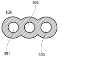
図3は、インク供給チューブの一例を模式的に示す断面図である。図3に示すように、インク供給チューブ104は、水性インクのそれぞれに対応する第1チューブ301、第2チューブ302、及び第3チューブ303を含む。また、第2チューブ302が、第1チューブ301と第3チューブ303で挟まれる位置で接合された部分を有する。そして、マゼンタインクに対応するチューブが、第2チューブ302である。シアンインク及びイエローインクに対応するチューブは、第1チューブ301及び第3チューブ303のいずれであってもよい。なお、インク供給チューブには、シアン、マゼンタ、及びイエローの各インクに対応するチューブの他に、例えばブラックインクに対応するチューブがさらに接合されていてもよい。これは、ブラックインクに対応するチューブがさらに接合されていたとしても、マゼンタインクに対応するチューブが他のチューブに挟まれる位置にあることは変わらないからである。
FIG. 3 is a cross-sectional view schematically showing an example of an ink supply tube. As shown in FIG. 3, the
インク供給チューブの水蒸気透過量は、5.0g/(m2・24h)以下であることが好ましい。インク供給チューブの水蒸気透過量が5.0g/(m2・24h)超であると、インクの吐出安定性がやや低下する場合がある。インク供給チューブの水蒸気透過量は、JIS K 7129の規定に準拠し、厚さ0.5mmのシート状材料を用いて温度23℃で測定される。インク供給チューブの水蒸気透過量は、1.5g/(m2・24h)以上であることが好ましく、3.0g/(m2・24h)以上であることがさらに好ましい。 The water vapor permeation amount of the ink supply tube is preferably 5.0 g/(m 2 ·24 h) or less. If the water vapor permeation amount of the ink supply tube exceeds 5.0 g/(m 2 ·24 h), the ejection stability of the ink may slightly decrease. The water vapor permeation amount of the ink supply tube is measured at a temperature of 23° C. using a sheet-like material with a thickness of 0.5 mm in compliance with JIS K 7129. The water vapor permeation amount of the ink supply tube is preferably 1.5 g/(m 2 ·24 h) or more, more preferably 3.0 g/(m 2 ·24 h) or more.
インク供給チューブは、樹脂材料を管状に成形した部材である。チューブを構成する樹脂材料は、単一の樹脂材料であっても、2種以上の樹脂材料の組み合わせであってもよい。また、各種の添加剤を配合した樹脂材料であってもよい。チューブの構造は、単層構造であっても積層構造であってもよい。樹脂材料としては、成形性、ゴム弾性、及び柔軟性に優れることから熱可塑性エラストマーが好ましい。熱可塑性エラストマーとしては、オレフィン系、ウレタン系、エステル系、スチレン系、塩化ビニル系などの樹脂を挙げることができる。なかでも、柔軟性及びゴム弾性に特に優れているため、スチレン系熱可塑性エラストマーが好ましい。樹脂材料に配合される添加剤としては、例えば、軟化剤、滑剤、界面活性剤、酸化防止剤、老化防止剤、接着付与剤、顔料などを挙げることができる。 The ink supply tube is a tubular member made of a resin material. The resin material forming the tube may be a single resin material or a combination of two or more resin materials. Moreover, the resin material which mix|blended various additives may be used. The structure of the tube may be a single layer structure or a laminated structure. As the resin material, a thermoplastic elastomer is preferable because it is excellent in moldability, rubber elasticity, and flexibility. Examples of thermoplastic elastomers include olefin-based, urethane-based, ester-based, styrene-based, and vinyl chloride-based resins. Of these, styrene-based thermoplastic elastomers are preferred because they are particularly excellent in flexibility and rubber elasticity. Additives to be added to the resin material include, for example, softeners, lubricants, surfactants, antioxidants, anti-aging agents, tackifiers, and pigments.
チューブの内径や肉厚は、成形などの生産性、記録装置内で引き回される際の曲げ剛性、インク供給性、ガスバリア性などの観点から適宜に設定することができる。例えば、チューブの内径は1mm以上5mm以下であることが好ましく、1mm以上3mm以下であることがさらに好ましい。また、チューブの肉厚は0.5mm以上5mm以下であることが好ましく、0.5mm以上3mm以下であることがさらに好ましい。第2チューブは第1チューブと第3チューブに挟まれた位置で接合されているため、その断面は円形とはならないが、第2チューブの肉厚は最長径の円相当径として考えるものとする。 The inner diameter and wall thickness of the tube can be appropriately set from the viewpoints of productivity such as molding, flexural rigidity when being drawn around in a recording apparatus, ink supply properties, gas barrier properties, and the like. For example, the inner diameter of the tube is preferably 1 mm or more and 5 mm or less, more preferably 1 mm or more and 3 mm or less. The wall thickness of the tube is preferably 0.5 mm or more and 5 mm or less, more preferably 0.5 mm or more and 3 mm or less. Since the second tube is joined between the first tube and the third tube, its cross section does not have a circular shape, but the wall thickness of the second tube is assumed to be the diameter equivalent to the longest diameter of a circle. .
<水性インク>
本発明のインクジェット記録方法では、シアンインク、マゼンタインク、及びイエローインクを含む複数の水性インクを備えたインクジェット記録装置を使用する。そして、このインクジェット記録装置を使用し、水性インクを熱エネルギーの作用により記録ヘッドから吐出して記録媒体に画像を記録する。本発明のインクジェット記録方法においては、水性インクに接触した際に反応や増粘を生じる液体と併用する必要はない。以下、シアンインク、マゼンタインク、及びイエローインクを含む複数の水性インクの詳細について説明する。
<Aqueous ink>
The inkjet recording method of the present invention uses an inkjet recording apparatus equipped with a plurality of water-based inks including cyan ink, magenta ink, and yellow ink. Then, using this inkjet recording apparatus, an image is recorded on a recording medium by ejecting water-based ink from a recording head by the action of thermal energy. In the ink jet recording method of the present invention, it is not necessary to use a liquid that reacts or thickens when in contact with the water-based ink. Details of a plurality of water-based inks including cyan ink, magenta ink, and yellow ink are described below.
(色材)
色材としては、顔料や染料を用いることができる。水性インク中の色材の含有量(質量%)は、インク全質量を基準として、0.1質量%以上15.0質量%以下であることが好ましく、1.0質量%以上10.0質量%以下であることがさらに好ましい。
(colorant)
A pigment or a dye can be used as the coloring material. The content (% by mass) of the coloring material in the water-based ink is preferably 0.1% by mass or more and 15.0% by mass or less, and 1.0% by mass or more and 10.0% by mass, based on the total mass of the ink. % or less.
色材として顔料を用いる場合、顔料の分散方式は特に限定されない。例えば、樹脂分散剤により分散させた樹脂分散顔料、界面活性剤により分散させた顔料、及び顔料の粒子表面の少なくとも一部を樹脂などで被覆したマイクロカプセル顔料などを用いることができる。また、顔料の粒子表面にアニオン性基などの親水性基を含む官能基を結合させた自己分散顔料や、顔料の粒子表面に高分子を含む有機基を化学的に結合させた顔料(樹脂結合型の自己分散顔料)などを用いることもできる。勿論、分散方式の異なる顔料を組み合わせて使用することも可能である。 When a pigment is used as the colorant, the method of dispersing the pigment is not particularly limited. For example, a resin-dispersed pigment dispersed with a resin dispersant, a pigment dispersed with a surfactant, and a microcapsule pigment in which at least a part of the particle surface of the pigment is coated with a resin or the like can be used. In addition, there are self-dispersing pigments in which functional groups including hydrophilic groups such as anionic groups are bonded to the surface of pigment particles, and pigments in which organic groups including macromolecules are chemically bonded to the surface of pigment particles (resin bonding). type self-dispersing pigment) can also be used. Of course, it is also possible to use a combination of pigments with different dispersion methods.
色材として用いることができる顔料の種類は特に限定されない。顔料の具体例としては、カーボンブラックなどの無機顔料;アゾ、フタロシアニン、キナクリドン、イソインドリノン、イミダゾロン、ジケトピロロピロール、ジオキサジンなどの有機顔料を挙げることができる。これらの顔料は、必要に応じて1種又は2種以上を用いることができる。 The type of pigment that can be used as a coloring material is not particularly limited. Specific examples of pigments include inorganic pigments such as carbon black; and organic pigments such as azo, phthalocyanine, quinacridone, isoindolinone, imidazolone, diketopyrrolopyrrole, and dioxazine. One or more of these pigments may be used as necessary.
色材として用いることができる染料の種類は特に限定されない。染料の具体例としては、直接染料、酸性染料、塩基性染料、分散染料、食用染料などを挙げることができる。なかでも、アニオン性基を有する染料を用いることが好ましい。染料骨格の具体例としては、アゾ、トリフェニルメタン、フタロシアニン、アザフタロシアニン、キサンテン、アントラピリドンなどを挙げることができる。 The type of dye that can be used as the coloring material is not particularly limited. Specific examples of dyes include direct dyes, acid dyes, basic dyes, disperse dyes, and food dyes. Among them, it is preferable to use a dye having an anionic group. Specific examples of dye skeletons include azo, triphenylmethane, phthalocyanine, azaphthalocyanine, xanthene, and anthrapyridone.
3種のインク(シアンインク、マゼンタインク、及びイエローインク)は、いずれも色材として染料を含有することが好ましい。水性インク中に粒子が分散した状態で存在する顔料と異なり、染料は水性インク中に溶解した状態で存在している。このため、サブタンク内のインク中に生じた気泡が粒子に邪魔されることなく、重力の反対方向へと移動しやすく、インクの吐出安定性をより高めることができる。一方、3種のインクが色材として顔料を含有する場合、気泡の移動が粒子に邪魔されやすいとともに、顔料に吸着した気泡が顔料とともにインク流路に侵入しやすくなる。このため、インクの吐出安定性がやや低下する場合がある。 All of the three inks (cyan ink, magenta ink, and yellow ink) preferably contain a dye as a coloring material. Unlike pigments, which exist as dispersed particles in water-based inks, dyes exist as dissolved in water-based inks. Therefore, the air bubbles generated in the ink in the sub-tank can easily move in the direction opposite to the gravity without being disturbed by the particles, and the ejection stability of the ink can be further improved. On the other hand, when the three types of ink contain pigments as colorants, movement of air bubbles is likely to be hindered by particles, and air bubbles adsorbed to the pigments are likely to enter the ink flow path together with the pigments. Therefore, the ejection stability of the ink may be slightly lowered.
(水性媒体)
水性インクには、水及び水溶性有機溶剤の混合溶媒である水性媒体を含有させることができる。水溶性有機溶剤としては、アルコール類、(ポリ)アルキレングリコール類、グリコールエーテル類、その他の含窒素化合物類、含硫黄化合物類などのインクジェット用のインクに使用可能なものを挙げることができる。これらの水溶性有機溶剤は、1種又は2種以上を用いることができる。通常「水溶性有機溶剤」とは液体を意味するが、本発明においては、25℃(常温)で固体であるものも水溶性有機溶剤に含めることとする。インクに汎用であり、25℃で固体である水溶性有機溶剤の具体例としては、1,6-ヘキサンジオール、トリメチロールプロパン、エチレン尿素、尿素、数平均分子量1,000のポリエチレングリコールなどを挙げることができる。水性インク中の水溶性有機溶剤の含有量(質量%)は、インク全質量を基準として、3.0質量%以上50.0質量%以下であることが好ましい。また、水としては、脱イオン水やイオン交換水を用いることが好ましい。水性インク中の水の含有量(質量%)は、インク全質量を基準として、50.0質量%以上95.0質量%以下であることが好ましい。
(aqueous medium)
The aqueous ink can contain an aqueous medium, which is a mixed solvent of water and a water-soluble organic solvent. Examples of water-soluble organic solvents include alcohols, (poly)alkylene glycols, glycol ethers, other nitrogen-containing compounds, and sulfur-containing compounds that can be used in inkjet inks. One or more of these water-soluble organic solvents can be used. Generally, the term "water-soluble organic solvent" means a liquid, but in the present invention, a water-soluble organic solvent that is solid at 25°C (normal temperature) is also included in the water-soluble organic solvent. Specific examples of water-soluble organic solvents that are commonly used in inks and are solid at 25° C. include 1,6-hexanediol, trimethylolpropane, ethylene urea, urea, and polyethylene glycol having a number average molecular weight of 1,000. be able to. The content (% by mass) of the water-soluble organic solvent in the water-based ink is preferably 3.0% by mass or more and 50.0% by mass or less based on the total mass of the ink. As water, it is preferable to use deionized water or ion-exchanged water. The water content (% by mass) in the water-based ink is preferably 50.0% by mass or more and 95.0% by mass or less based on the total mass of the ink.
各インクの水のモル分率は、分子量300以下の水溶性有機溶剤の種類や含有量により調整することができる。例えば、水溶性有機溶剤の含有量を揃えて、種類を変更する場合を考えると、分子量が小さい水溶性有機溶剤を用いると水のモル分率は小さくなり、分子量が大きい水溶性有機溶剤を用いると水のモル分率は大きくなる。各インクの水のモル分率(%)は、80.0%以上99.5%以下であることが好ましく、90.0%以上98.0%以下であることがさらに好ましい。 The molar fraction of water in each ink can be adjusted by the type and content of the water-soluble organic solvent having a molecular weight of 300 or less. For example, considering the case where the content of the water-soluble organic solvent is uniform and the type is changed, if a water-soluble organic solvent with a small molecular weight is used, the mole fraction of water will be small, and a water-soluble organic solvent with a large molecular weight will be used. and the molar fraction of water increases. The molar fraction (%) of water in each ink is preferably 80.0% or more and 99.5% or less, more preferably 90.0% or more and 98.0% or less.
(その他の成分)
水性インクには、必要に応じて、界面活性剤、消泡剤、pH調整剤、防腐剤、防黴剤、酸化防止剤、還元防止剤などの種々の添加剤を含有させてもよい。
(other ingredients)
The water-based ink may contain various additives such as surfactants, antifoaming agents, pH adjusters, preservatives, antifungal agents, antioxidants and anti-reduction agents, if necessary.
(インクの物性)
水性インクの25℃での粘度は、1.0mPa・s以上5.0mPa・s以下であることが好ましく、1.0mPa・s以上3.0mPa・s以下であることがさらに好ましい。インクの25℃での静的表面張力は、25.0mN/m以上45.0mN/m以下であることが好ましく、30.0mN/m以上40.0mN/m以下であることがさらに好ましい。また、インクの25℃でのpHは、5以上9以下であることが好ましい。
(Physical properties of ink)
The viscosity of the aqueous ink at 25° C. is preferably 1.0 mPa·s or more and 5.0 mPa·s or less, more preferably 1.0 mPa·s or more and 3.0 mPa·s or less. The static surface tension of the ink at 25° C. is preferably 25.0 mN/m or more and 45.0 mN/m or less, more preferably 30.0 mN/m or more and 40.0 mN/m or less. Further, the pH of the ink at 25° C. is preferably 5 or more and 9 or less.
以下、実施例及び比較例を挙げて本発明をさらに詳細に説明するが、本発明は、その要旨を超えない限り、下記の実施例によって何ら限定されるものではない。なお、成分量に関して「部」及び「%」と記載しているものは特に断らない限り質量基準である。 EXAMPLES The present invention will be described in more detail below with reference to examples and comparative examples, but the present invention is not limited by the following examples as long as the gist thereof is not exceeded. Note that "parts" and "%" regarding component amounts are based on mass unless otherwise specified.
<色材を含む液体の調製>
(染料水溶液1)
染料(C.I.ダイレクトブルー199)をイオン交換水に溶解させた後、酸を添加して染料を析出させた。析出した染料をろ過して分取し、遊離酸型の染料のウェットケーキを得た。得られたウェットケーキをイオン交換水に加え、染料のアニオン性基と当量の水酸化ナトリウムの水溶液を添加し、アニオン性基を全て中和して染料を溶解させた。さらに適量のイオン交換水を加えて、染料の含有量が10.0%である染料水溶液1を得た。
<Preparation of liquid containing coloring material>
(Dye aqueous solution 1)
After dissolving a dye (CI Direct Blue 199) in ion-exchanged water, an acid was added to precipitate the dye. The precipitated dye was collected by filtration to obtain a wet cake of free acid dye. The resulting wet cake was added to deionized water, and an aqueous solution of sodium hydroxide equivalent to the anionic groups of the dye was added to neutralize all the anionic groups and dissolve the dye. Further, an appropriate amount of ion-exchanged water was added to obtain an aqueous dye solution 1 having a dye content of 10.0%.
(染料水溶液2)
染料をC.I.アシッドブルー9に代えたこと以外は染料水溶液1と同様の手順で、染料の含有量が10.0%である染料水溶液2を得た。
(Dye aqueous solution 2)
C.I. I. An aqueous dye solution 2 having a dye content of 10.0% was obtained in the same manner as the aqueous dye solution 1, except that Acid Blue 9 was used.
(染料水溶液3)
染料をC.I.アシッドレッド289に代えたこと以外は染料水溶液1と同様の手順で、染料の含有量が10.0%である染料水溶液3を得た。
(Dye aqueous solution 3)
C.I. I. An aqueous dye solution 3 having a dye content of 10.0% was obtained in the same manner as the aqueous dye solution 1, except that Acid Red 289 was used.
(染料水溶液4)
染料をC.I.アシッドレッド249に代えたこと以外は染料水溶液1と同様の手順で、染料の含有量が10.0%である染料水溶液4を得た。
(Dye aqueous solution 4)
C.I. I. An aqueous dye solution 4 having a dye content of 10.0% was obtained in the same manner as the aqueous dye solution 1, except that Acid Red 249 was used.
(染料水溶液5)
染料をC.I.ダイレクトイエロー132に代えたこと以外は染料水溶液1と同様の手順で、染料の含有量が10.0%である染料水溶液5を得た。
(Dye aqueous solution 5)
C.I. I. An aqueous dye solution 5 having a dye content of 10.0% was obtained in the same manner as the aqueous dye solution 1, except that Direct Yellow 132 was used.
(染料水溶液6)
染料をC.I.ダイレクトイエロー86に代えたこと以外は染料水溶液1と同様の手順で、染料の含有量が10.0%である染料水溶液6を得た。
(Dye aqueous solution 6)
C.I. I. Dye aqueous solution 6 having a dye content of 10.0% was obtained in the same manner as dye aqueous solution 1, except that Direct Yellow 86 was used.
(顔料分散液1)
自己分散顔料(シアン顔料)を含む市販の顔料分散液(商品名「CAB-O-JET250C」、キャボット製)を顔料分散液1として用いた。顔料分散液1中の顔料の含有量は15.0%であった。
(Pigment dispersion liquid 1)
A commercially available pigment dispersion containing a self-dispersing pigment (cyan pigment) (trade name “CAB-O-JET250C” manufactured by Cabot) was used as pigment dispersion 1. The pigment content in pigment dispersion 1 was 15.0%.
(顔料分散液2)
自己分散顔料(マゼンタ顔料)を含む市販の顔料分散液(商品名「CAB-O-JET265M」、キャボット製)を顔料分散液2として用いた。顔料分散液2中の顔料の含有量は15.0%であった。
(Pigment dispersion liquid 2)
A commercially available pigment dispersion containing a self-dispersing pigment (magenta pigment) (trade name “CAB-O-JET265M” manufactured by Cabot) was used as the pigment dispersion 2. The pigment content in pigment dispersion 2 was 15.0%.
(顔料分散液3)
自己分散顔料(イエロー顔料)を含む市販の顔料分散液(商品名「CAB-O-JET270Y」、キャボット製)を顔料分散液3として用いた。顔料分散液3中の顔料の含有量は15.0%であった。
(Pigment dispersion liquid 3)
A commercially available pigment dispersion containing a self-dispersing pigment (yellow pigment) (trade name “CAB-O-JET270Y” manufactured by Cabot) was used as pigment dispersion 3. The pigment content in Pigment Dispersion 3 was 15.0%.
<インクの調製>
表1-1~1-3の上段に示す各成分(単位:%)を混合して十分に撹拌した後、ポアサイズ3.0μmのミクロフィルター(富士フイルム製)にて加圧ろ過を行い、各インクを調製した。水溶性有機溶剤(分子量300以下の水溶性化合物)、及び水(イオン交換水)については、括弧内に分子量を示した。表1-1~1-3中の「アセチレノールE100」は、川研ファインケミカル製の界面活性剤(アセチレングリコールのエチレンオキサイド〔10モル〕付加物)の商品名である。アセチレノールE100は、川研ファインケミカル製の界面活性剤(アセチレングリコールのエチレンオキサイド〔10モル〕付加物)の商品名である。また、表1-1~1-3の下段には、水の含有量(%)、水のモル数、分子量300以下の水溶性化合物のモル数、及び水のモル分率(%)を示した。インク調製時の溶存ガスの影響を除外して評価するために、汎用の脱気モジュールを使用して溶存酸素量が2mg/L以下となるまでインクを脱気した。溶存酸素量は、溶存酸素計(商品名「ポータブル型溶存酸素計OM-71-L1」、HORIBA製)を使用して測定した。
<Ink preparation>
After mixing and sufficiently stirring each component (unit: %) shown in the upper row of Tables 1-1 to 1-3, pressure filtration was performed with a microfilter (manufactured by Fujifilm) with a pore size of 3.0 μm. Inks were prepared. Molecular weights of water-soluble organic solvents (water-soluble compounds having a molecular weight of 300 or less) and water (ion-exchanged water) are shown in parentheses. "Acetylenol E100" in Tables 1-1 to 1-3 is a trade name of a surfactant (ethylene oxide [10 mol] adduct of acetylene glycol) manufactured by Kawaken Fine Chemicals. Acetyleneol E100 is a trade name of a surfactant (ethylene oxide [10 mol] adduct of acetylene glycol) manufactured by Kawaken Fine Chemicals. In addition, the lower part of Tables 1-1 to 1-3 shows the water content (%), the number of moles of water, the number of moles of water-soluble compounds having a molecular weight of 300 or less, and the mole fraction of water (%). rice field. In order to exclude the influence of dissolved gas during ink preparation and evaluation, the ink was degassed using a general-purpose degassing module until the dissolved oxygen content became 2 mg/L or less. The dissolved oxygen content was measured using a dissolved oxygen meter (trade name “Portable Dissolved Oxygen Meter OM-71-L1” manufactured by HORIBA).


<評価>
図1に示す主要部の構成を有するとともに、図2に示す構成のインク供給系を組み込んだインクジェット記録装置を用意した。インク供給チューブとしては、単層の樹脂材料で形成されるとともに、図3に示す形状を有するものを用いた。各インクに対応するメインタンク及びサブタンクのインク最大収容量は、メインタンクのインク最大収容量を80mL、サブタンクのインク最大収容量を12mLとした。各インクの水のモル分率、及び水のモル分率の差(最大値と最小値の差)を表2-1に示し、チューブの水蒸気透過量を表2-2に示す。さらに、表2-2に示す各チューブに対応するインクを、インク最大収容量を基準として95%となるように各メインタンクから注入し、インク供給系にインクを満たした。実施例及び比較例で使用したサブタンクの構成を以下に示す。
<Evaluation>
An ink jet recording apparatus having the configuration of the main part shown in FIG. 1 and incorporating an ink supply system having the configuration shown in FIG. 2 was prepared. As the ink supply tube, one made of a single-layer resin material and having the shape shown in FIG. 3 was used. The maximum ink capacity of the main tank and sub-tank corresponding to each ink is 80 mL for the main tank and 12 mL for the sub-tank. Table 2-1 shows the molar fraction of water in each ink and the difference in the molar fraction of water (difference between the maximum value and the minimum value), and Table 2-2 shows the water vapor permeation amount of the tube. Further, ink corresponding to each tube shown in Table 2-2 was injected from each main tank so as to fill 95% of the maximum ink capacity based on the standard, and the ink supply system was filled with ink. The configuration of the sub-tank used in Examples and Comparative Examples is shown below.
[実施例1、2、4、5、7、9、16~19、参考例3、6、8、10~15、20及び比較例4~6]
熱可塑性樹脂で形成された筺体に、熱エネルギーを付与してインクを吐出する記録ヘッドを備えた記録素子基板を貼り合わせた形態とした。
[比較例1及び2]
熱可塑性樹脂で形成された筺体に、アルミナで形成された放熱板を介して、熱エネルギーを付与してインクを吐出する記録ヘッドを備えた記録素子基板を貼り合わせた形態とした。
[比較例3]
熱可塑性樹脂で形成された筺体に、力学的エネルギーをピエゾ素子により付与してインクを吐出する記録ヘッドを備えた記録素子基板を貼り合わせた形態とした。
[Examples 1 , 2, 4, 5, 7, 9, 16-19, Reference Examples 3, 6, 8, 10-15, 20 and Comparative Examples 4-6]
A printing element substrate having a printing head that applies thermal energy to eject ink is attached to a housing made of a thermoplastic resin.
[Comparative Examples 1 and 2]
A printing element substrate having a printing head that applies thermal energy to eject ink is attached to a housing made of a thermoplastic resin through a radiator plate made of alumina.
[Comparative Example 3]
A printing element substrate having a printing head that ejects ink by applying mechanical energy from a piezo element is attached to a housing made of a thermoplastic resin.
メインタンクに収容されたインクの温度T1(℃)及びサブタンクに収容されたインクの温度T2(℃)を表2-2に示す。インクの温度は以下のようにして調整した。メインタンクに収容されたインクの温度は、評価を行う環境の温度設定により調整した。サブタンクに収容されたインクの温度は、サブタンクの外部に設けた温度調整ユニットを利用して調整した。但し、T2=T1の場合は、メインタンクと同様に評価を行う環境の温度設定により調整した。本実施例においては、1/600インチ×1/600インチの単位領域に、1滴当たりの質量が5.5ngであるインク滴を2滴付与する条件で記録したベタ画像の記録デューティを100%と定義した。本発明においては、以下に示す評価基準で、「AA」、「A」及び「B」を許容できるレベルとし、「C」を許容できないレベルとした。評価結果を表3に示す。 Table 2-2 shows the temperature T 1 (°C) of the ink contained in the main tank and the temperature T 2 (°C) of the ink contained in the sub-tank. The ink temperature was adjusted as follows. The temperature of the ink contained in the main tank was adjusted by setting the temperature of the evaluation environment. The temperature of the ink contained in the sub-tank was adjusted using a temperature control unit provided outside the sub-tank. However, when T 2 =T 1 , adjustment was made by setting the temperature of the environment for evaluation in the same manner as the main tank. In this embodiment, the printing duty of a solid image printed under the condition that two ink droplets each having a mass of 5.5 ng are applied to a unit area of 1/600 inch×1/600 inch is set to 100%. defined as In the present invention, in the following evaluation criteria, "AA", "A" and "B" were defined as acceptable levels, and "C" was defined as an unacceptable level. Table 3 shows the evaluation results.
(吐出安定性)
A4サイズのPPC用紙の全面に、3種のインクの各記録デューティが2%(合計6%)であるベタ画像を20枚分記録した後、1時間記録を休止し、その後ノズルチェックパターンを1枚記録する、というサイクルを繰り返した。PPC用紙としては、商品名「GF-500」(キヤノン製)を使用した。そして、所定枚数のベタ画像を記録した後のノズルチェックパターンを目視で確認し、以下に示す評価基準にしたがって吐出安定性を評価した。
(Ejection stability)
After printing 20 sheets of solid images on the entire surface of A4 size PPC paper with 2% printing duty for each of the three types of ink (6% in total), printing was paused for 1 hour, and then a nozzle check pattern was printed for 1 hour. I repeated the cycle of recording. As the PPC paper, the product name "GF-500" (manufactured by Canon) was used. Then, the nozzle check pattern after recording a predetermined number of solid images was visually confirmed, and ejection stability was evaluated according to the following evaluation criteria.
本評価では、記録枚数を多くすることで評価開始からの経過時間を長くしている。これは、メインタンク内でインクと空気が接触する時間を長くして、メインタンク内のインク中の溶存ガス量が増加しやすい条件とするためである。所定枚数を記録した後のインク中の溶存酸素量を測定したところ、いずれも5~7mg/Lの範囲内であり、初期の溶存酸素量(2mg/L以下)よりも増加していることが確認された。そして、累積記録枚数が多くなってもノズルチェックパターンに乱れ生じなければ、気泡に起因する吐出安定性の低下が抑制されたことを意味する。一方、ノズルチェックパターンに乱れが生じた場合、増加したインク中の溶存ガスに起因する気泡が記録ヘッドのインク流路にまで侵入し、インクの正常な吐出が妨げられたことを意味する。
AA:ベタ画像を7,000枚分記録した後のノズルチェックパターンに殆ど乱れがなかった。
A:ベタ画像を6,000枚分記録した後のノズルチェックパターンに若干の乱れがあった。
B:ベタ画像を5,000枚分記録した後のノズルチェックパターンに若干の乱れがあった。
C:ベタ画像を3,000枚分記録した後のノズルチェックパターンに若干の乱れがあった。
In this evaluation, the elapsed time from the start of the evaluation is lengthened by increasing the number of recorded sheets. The reason for this is to lengthen the contact time between the ink and the air in the main tank so that the amount of dissolved gas in the ink in the main tank is likely to increase. When the amount of dissolved oxygen in the ink after printing a predetermined number of sheets was measured, all of them were within the range of 5 to 7 mg/L, which was higher than the initial amount of dissolved oxygen (2 mg/L or less). confirmed. If the nozzle check pattern does not become disturbed even when the cumulative number of printed sheets increases, it means that deterioration in ejection stability due to air bubbles has been suppressed. On the other hand, if the nozzle check pattern is disturbed, it means that the bubbles caused by the increased dissolved gas in the ink have penetrated the ink flow path of the print head and prevented the normal ejection of the ink.
AA: There was almost no disturbance in the nozzle check pattern after recording 7,000 solid images.
A: There was some disturbance in the nozzle check pattern after recording 6,000 solid images.
B: The nozzle check pattern after recording 5,000 solid images was slightly disturbed.
C: The nozzle check pattern after recording 3,000 solid images was slightly disturbed.
(色調変化)
上記のインクジェット記録装置を使用し、3種のインクの合計の記録デューティを10%から100%まで10%刻みとした10種類のベタ画像(5cm×5cm)を記録媒体に記録した。記録媒体としては、光沢紙(商品名「キヤノン写真用紙・光沢 プロ[プラチナグレード]」、キヤノン製)を用いた。また、各記録デューティのベタ画像における3種のインクの付与量を3等分とすることで、淡グレー~ブラックのグレーラインのベタ画像を記録した。記録したベタ画像の色調を目視で確認し、以下に示す評価基準にしたがって色調変化を評価した。グレーラインの画像における色調は、中間調(記録デューティとして50%付近)において最も赤味方向への変化が目につきやすい。したがって、中間調付近のベタ画像について、赤味方向への色調の変化が生じていなければ、色調変化が有効に抑制されていると言える。
AA:いずれの記録デューティのベタ画像においても、色調が赤味に変化していなかった。
A:記録デューティが40~60%のベタ画像において、色調が僅かに赤味に変化していた。
B:記録デューティが30~70%のベタ画像において、色調が僅かに赤味に変化していた。
C:いずれの記録デューティのベタ画像においても、色調が赤味に変化した。
(color change)
Using the ink jet recording apparatus described above, 10 types of solid images (5 cm×5 cm) were recorded on the recording medium with the total recording duty of the three types of ink ranging from 10% to 100% in increments of 10%. Glossy paper (trade name “Canon Photo Paper/Gloss Pro [Platinum Grade]” manufactured by Canon) was used as the recording medium. In addition, a solid image of light gray to black gray lines was recorded by equally dividing the amount of the three types of ink applied in the solid image of each recording duty. The color tone of the recorded solid image was visually confirmed, and the change in color tone was evaluated according to the following evaluation criteria. As for the color tone of the gray line image, the change in the reddish direction is most noticeable in the intermediate tone (around 50% as the recording duty). Therefore, it can be said that the color tone change is effectively suppressed if the color tone does not change in the reddish direction for a solid image near the halftone.
AA: The color tone did not change to reddish in any solid image of any recording duty.
A: The solid image with a recording duty of 40 to 60% had a slightly reddish color tone.
B: The solid image with a recording duty of 30 to 70% has a slightly reddish color tone.
C: The color tone changed to reddish in the solid image of any recording duty.


Claims (12)
前記第2インク収容部が、熱可塑性樹脂で形成された筺体であるとともに、他の部材を介在させることなく前記記録ヘッドが貼り合わされており、
前記チューブが、前記水性インクのそれぞれに対応する第1チューブ、第2チューブ、及び第3チューブを含むとともに、前記第2チューブが前記第1チューブと前記第3チューブで挟まれる位置で接合された部分を有するインクジェット記録装置を使用し、
前記水性インクを前記記録ヘッドから吐出して記録媒体に画像を記録するインクジェット記録方法であって、
前記シアンインク、前記マゼンタインク、及び前記イエローインクの水のモル分率(%)の最大値と最小値の差が、1.0%以下であり、
前記マゼンタインクに対応するチューブが、前記第2チューブであり、
前記シアンインク、前記マゼンタインク、及び前記イエローインクが、いずれも染料を含有し、
前記シアンインク、前記マゼンタインク、及び前記イエローインクの水のモル分率(%)が、いずれも94.1%以上であることを特徴とするインクジェット記録方法。 a plurality of water-based inks including cyan ink, magenta ink, and yellow ink, a first ink storage section having an atmospheric communication section, a second ink storage section, and a recording head that ejects the water-based ink by the action of thermal energy. , a tube for supplying the water-based ink from the first ink containing portion to the second ink containing portion;
wherein the second ink containing portion is a housing made of a thermoplastic resin, and the recording head is attached without intervening other members;
The tubes include a first tube, a second tube, and a third tube corresponding to each of the water-based inks, and the second tube is joined at a position sandwiched between the first tube and the third tube. Using an inkjet recording device having a part,
An inkjet recording method for recording an image on a recording medium by ejecting the water-based ink from the recording head,
the difference between the maximum and minimum water mole fractions (%) of the cyan ink, the magenta ink, and the yellow ink is 1.0% or less;
the tube corresponding to the magenta ink is the second tube;
the cyan ink, the magenta ink, and the yellow ink all contain a dye,
An inkjet recording method , wherein the cyan ink, the magenta ink, and the yellow ink each have a molar fraction (%) of water of 94.1% or more .
シアンインク、マゼンタインク、及びイエローインクを含む複数の水性インクと、大気連通部を有する第1インク収容部と、第2インク収容部と、熱エネルギーの作用により前記水性インクを吐出する記録ヘッドと、前記第1インク収容部から前記第2インク収容部へと前記水性インクを供給するチューブと、を備え、
前記第2インク収容部が、熱可塑性樹脂で形成された筺体であるとともに、他の部材を介在させることなく前記記録ヘッドが貼り合わされており、
前記チューブが、前記水性インクのそれぞれに対応する第1チューブ、第2チューブ、及び第3チューブを含むとともに、前記第2チューブが前記第1チューブと前記第3チューブで挟まれる位置で接合された部分を有し、
前記シアンインク、前記マゼンタインク、及び前記イエローインクの水のモル分率(%)の最大値と最小値の差が、1.0%以下であり、
前記マゼンタインクに対応するチューブが、前記第2チューブであり、
前記シアンインク、前記マゼンタインク、及び前記イエローインクが、いずれも染料を含有し、
前記シアンインク、前記マゼンタインク、及び前記イエローインクの水のモル分率(%)が、いずれも94.1%以上であることを特徴とするインクジェット記録装置。 An inkjet recording apparatus used in the inkjet recording method according to any one of claims 1 to 11 ,
a plurality of water-based inks including cyan ink, magenta ink, and yellow ink, a first ink storage section having an atmospheric communication section, a second ink storage section, and a recording head that ejects the water-based ink by the action of thermal energy. , a tube for supplying the water-based ink from the first ink containing portion to the second ink containing portion;
wherein the second ink containing portion is a housing made of a thermoplastic resin, and the recording head is attached without intervening other members;
The tubes include a first tube, a second tube, and a third tube corresponding to each of the water-based inks, and the second tube is joined at a position sandwiched between the first tube and the third tube. has a part
the difference between the maximum and minimum water mole fractions (%) of the cyan ink, the magenta ink, and the yellow ink is 1.0% or less;
the tube corresponding to the magenta ink is the second tube;
the cyan ink, the magenta ink, and the yellow ink all contain a dye,
An inkjet recording apparatus , wherein each of the cyan ink, the magenta ink, and the yellow ink has a molar fraction (%) of water of 94.1% or more .
Applications Claiming Priority (2)
| Application Number | Priority Date | Filing Date | Title |
|---|---|---|---|
| JP2015213663 | 2015-10-30 | ||
| JP2015213663 | 2015-10-30 |
Publications (3)
| Publication Number | Publication Date |
|---|---|
| JP2017081154A JP2017081154A (en) | 2017-05-18 |
| JP2017081154A5 JP2017081154A5 (en) | 2020-02-27 |
| JP7214330B2 true JP7214330B2 (en) | 2023-01-30 |
Family
ID=58638198
Family Applications (1)
| Application Number | Title | Priority Date | Filing Date |
|---|---|---|---|
| JP2016182694A Active JP7214330B2 (en) | 2015-10-30 | 2016-09-20 | Inkjet recording method and inkjet recording apparatus |
Country Status (2)
| Country | Link |
|---|---|
| US (1) | US9944084B2 (en) |
| JP (1) | JP7214330B2 (en) |
Families Citing this family (2)
| Publication number | Priority date | Publication date | Assignee | Title |
|---|---|---|---|---|
| US10851256B2 (en) * | 2016-12-14 | 2020-12-01 | Canon Kabushiki Kaisha | Inkjet printing method and inkjet printing apparatus |
| US11833838B2 (en) * | 2020-07-22 | 2023-12-05 | Canon Kabushiki Kaisha | Ink jet recording method and ink jet recording apparatus |
Citations (3)
| Publication number | Priority date | Publication date | Assignee | Title |
|---|---|---|---|---|
| JP2002234180A (en) | 2001-02-09 | 2002-08-20 | Canon Inc | Ink feed unit, ink feed mechanism and ink jet recorder |
| JP2007196466A (en) | 2006-01-25 | 2007-08-09 | Ricoh Co Ltd | Ink-jet recorder and ink-jet recording method |
| JP2011230316A (en) | 2010-04-26 | 2011-11-17 | Seiko Epson Corp | Filter, manufacturing method of filter, fluid jetting head and fluid jetting apparatus |
Family Cites Families (10)
| Publication number | Priority date | Publication date | Assignee | Title |
|---|---|---|---|---|
| US5988801A (en) * | 1996-09-30 | 1999-11-23 | Hewlett-Packard Company | High performance tubing for inkjet printing systems with off-board ink supply |
| JP2001026119A (en) * | 1999-07-13 | 2001-01-30 | Canon Inc | Ink jet recorder |
| WO2004018211A1 (en) * | 2002-06-24 | 2004-03-04 | Ricoh Company, Ltd. | Ink-jet recording apparatus and ink-jet recording method |
| JP2004083621A (en) | 2002-08-22 | 2004-03-18 | Brother Ind Ltd | Water-based ink for ink-jet recording |
| JP4324138B2 (en) * | 2004-08-04 | 2009-09-02 | キヤノン株式会社 | Ink set, ink jet recording method, recording unit, and ink jet recording apparatus |
| EP1820828B1 (en) * | 2006-02-15 | 2012-01-04 | Canon Kabushiki Kaisha | Aqueous ink, ink-jet recording method, ink cartridge, recording unit and ink jet recording apparatus |
| US8310511B2 (en) * | 2009-05-08 | 2012-11-13 | Rohm Co., Ltd. | Thermal printhead |
| EP2415609B1 (en) * | 2010-08-03 | 2018-09-26 | Canon Kabushiki Kaisha | Resin composition for ink supply tubes and ink supply tube |
| JP5888892B2 (en) * | 2011-07-23 | 2016-03-22 | キヤノン株式会社 | Inkjet recording device |
| JP6163753B2 (en) * | 2012-12-27 | 2017-07-19 | セイコーエプソン株式会社 | Liquid chamber forming body and liquid ejecting apparatus |
-
2016
- 2016-09-20 JP JP2016182694A patent/JP7214330B2/en active Active
- 2016-10-06 US US15/286,959 patent/US9944084B2/en active Active
Patent Citations (3)
| Publication number | Priority date | Publication date | Assignee | Title |
|---|---|---|---|---|
| JP2002234180A (en) | 2001-02-09 | 2002-08-20 | Canon Inc | Ink feed unit, ink feed mechanism and ink jet recorder |
| JP2007196466A (en) | 2006-01-25 | 2007-08-09 | Ricoh Co Ltd | Ink-jet recorder and ink-jet recording method |
| JP2011230316A (en) | 2010-04-26 | 2011-11-17 | Seiko Epson Corp | Filter, manufacturing method of filter, fluid jetting head and fluid jetting apparatus |
Also Published As
| Publication number | Publication date |
|---|---|
| US9944084B2 (en) | 2018-04-17 |
| US20170120601A1 (en) | 2017-05-04 |
| JP2017081154A (en) | 2017-05-18 |
Similar Documents
| Publication | Publication Date | Title |
|---|---|---|
| WO2013161410A1 (en) | Ink composition for ink-jet recording, ink supply system, and ink-jet recording device | |
| JP6827747B2 (en) | Inkjet recording method and inkjet recorder | |
| JP2000198956A (en) | Ink set, ink jet recording process, ink jet recorder, and method for alleviating formation of solid in common restoring unit | |
| JP6812138B2 (en) | Inkjet recording method and inkjet recorder | |
| JP7214330B2 (en) | Inkjet recording method and inkjet recording apparatus | |
| JP2018069652A (en) | Ink jet recording method | |
| JP6860315B2 (en) | Inkjet recording method and inkjet recording device | |
| US11827033B2 (en) | Ink jet recording method and ink jet recording apparatus | |
| JP2017209785A (en) | Inkjet recording method and inkjet recording device | |
| JP2017087717A (en) | Inkjet recording method and inkjet recording apparatus | |
| JP5920572B2 (en) | Ink supply system and inkjet recording apparatus | |
| JP2017081057A (en) | Inkjet recording method and inkjet recording apparatus | |
| JP6818480B2 (en) | Inkjet recording method and inkjet recorder | |
| CN114619762B (en) | Ink jet recording method and ink jet recording apparatus | |
| US10828897B2 (en) | Ink jet recording method and ink jet recording apparatus | |
| JP6260935B2 (en) | Liquid discharge recording apparatus and liquid recovery method | |
| JP2022092577A (en) | Inkjet recording method and inkjet recording device | |
| JP2017081056A (en) | Inkjet recording method and inkjet recording device | |
| JP7433988B2 (en) | Inkjet recording method and inkjet recording device | |
| JP2017081058A (en) | Inkjet recording method and inkjet recording apparatus | |
| JP5866322B2 (en) | Inkjet recording recording head, inkjet recording apparatus, and inkjet recording method | |
| JP2004331751A (en) | Ink-jet ink | |
| JP2022022108A (en) | Inkjet recording method and inkjet recording device | |
| JP2005074884A (en) | Recording head, head cartridge using the same, and recorder | |
| JP2022022109A (en) | Ink jet recording method and ink jet recording apparatus |
Legal Events
| Date | Code | Title | Description |
|---|---|---|---|
| A621 | Written request for application examination |
Free format text: JAPANESE INTERMEDIATE CODE: A621 Effective date: 20190911 |
|
| A521 | Request for written amendment filed |
Free format text: JAPANESE INTERMEDIATE CODE: A523 Effective date: 20200115 |
|
| RD03 | Notification of appointment of power of attorney |
Free format text: JAPANESE INTERMEDIATE CODE: A7423 Effective date: 20200221 |
|
| A977 | Report on retrieval |
Free format text: JAPANESE INTERMEDIATE CODE: A971007 Effective date: 20200708 |
|
| A131 | Notification of reasons for refusal |
Free format text: JAPANESE INTERMEDIATE CODE: A131 Effective date: 20200714 |
|
| A521 | Request for written amendment filed |
Free format text: JAPANESE INTERMEDIATE CODE: A523 Effective date: 20200908 |
|
| A02 | Decision of refusal |
Free format text: JAPANESE INTERMEDIATE CODE: A02 Effective date: 20210302 |
|
| A521 | Request for written amendment filed |
Free format text: JAPANESE INTERMEDIATE CODE: A523 Effective date: 20210602 |
|
| C60 | Trial request (containing other claim documents, opposition documents) |
Free format text: JAPANESE INTERMEDIATE CODE: C60 Effective date: 20210602 |
|
| C11 | Written invitation by the commissioner to file amendments |
Free format text: JAPANESE INTERMEDIATE CODE: C11 Effective date: 20210615 |
|
| A911 | Transfer to examiner for re-examination before appeal (zenchi) |
Free format text: JAPANESE INTERMEDIATE CODE: A911 Effective date: 20210817 |
|
| C21 | Notice of transfer of a case for reconsideration by examiners before appeal proceedings |
Free format text: JAPANESE INTERMEDIATE CODE: C21 Effective date: 20210824 |
|
| A912 | Re-examination (zenchi) completed and case transferred to appeal board |
Free format text: JAPANESE INTERMEDIATE CODE: A912 Effective date: 20211001 |
|
| C211 | Notice of termination of reconsideration by examiners before appeal proceedings |
Free format text: JAPANESE INTERMEDIATE CODE: C211 Effective date: 20211005 |
|
| C22 | Notice of designation (change) of administrative judge |
Free format text: JAPANESE INTERMEDIATE CODE: C22 Effective date: 20211102 |
|
| C22 | Notice of designation (change) of administrative judge |
Free format text: JAPANESE INTERMEDIATE CODE: C22 Effective date: 20220412 |
|
| C22 | Notice of designation (change) of administrative judge |
Free format text: JAPANESE INTERMEDIATE CODE: C22 Effective date: 20220809 |
|
| C13 | Notice of reasons for refusal |
Free format text: JAPANESE INTERMEDIATE CODE: C13 Effective date: 20220906 |
|
| C22 | Notice of designation (change) of administrative judge |
Free format text: JAPANESE INTERMEDIATE CODE: C22 Effective date: 20221011 |
|
| A521 | Request for written amendment filed |
Free format text: JAPANESE INTERMEDIATE CODE: A523 Effective date: 20221104 |
|
| C30 | Protocol of an oral hearing |
Free format text: JAPANESE INTERMEDIATE CODE: C30 Effective date: 20221115 |
|
| C302 | Record of communication |
Free format text: JAPANESE INTERMEDIATE CODE: C302 Effective date: 20221115 |
|
| C23 | Notice of termination of proceedings |
Free format text: JAPANESE INTERMEDIATE CODE: C23 Effective date: 20221122 |
|
| C03 | Trial/appeal decision taken |
Free format text: JAPANESE INTERMEDIATE CODE: C03 Effective date: 20221220 |
|
| C30A | Notification sent |
Free format text: JAPANESE INTERMEDIATE CODE: C3012 Effective date: 20221220 |
|
| A61 | First payment of annual fees (during grant procedure) |
Free format text: JAPANESE INTERMEDIATE CODE: A61 Effective date: 20230118 |
|
| R151 | Written notification of patent or utility model registration |
Ref document number: 7214330 Country of ref document: JP Free format text: JAPANESE INTERMEDIATE CODE: R151 |