JP7213392B2 - Collimation calibration device and collimation calibration method - Google Patents
Collimation calibration device and collimation calibration method Download PDFInfo
- Publication number
- JP7213392B2 JP7213392B2 JP2022503062A JP2022503062A JP7213392B2 JP 7213392 B2 JP7213392 B2 JP 7213392B2 JP 2022503062 A JP2022503062 A JP 2022503062A JP 2022503062 A JP2022503062 A JP 2022503062A JP 7213392 B2 JP7213392 B2 JP 7213392B2
- Authority
- JP
- Japan
- Prior art keywords
- laser
- sighting
- optical axis
- collimation
- collimation calibration
- Prior art date
- Legal status (The legal status is an assumption and is not a legal conclusion. Google has not performed a legal analysis and makes no representation as to the accuracy of the status listed.)
- Active
Links
Images


Classifications
-
- F—MECHANICAL ENGINEERING; LIGHTING; HEATING; WEAPONS; BLASTING
- F41—WEAPONS
- F41G—WEAPON SIGHTS; AIMING
- F41G3/00—Aiming or laying means
- F41G3/26—Teaching or practice apparatus for gun-aiming or gun-laying
-
- F—MECHANICAL ENGINEERING; LIGHTING; HEATING; WEAPONS; BLASTING
- F41—WEAPONS
- F41G—WEAPON SIGHTS; AIMING
- F41G3/00—Aiming or laying means
- F41G3/32—Devices for testing or checking
Description
本開示は、視準校正装置および視準校正方法に関する。 The present disclosure relates to a collimation calibration device and a collimation calibration method.
従来、非可視光であるレーザ光を送信するレーザ送信器を有する射撃装置に照準眼鏡を装着し、該照準眼鏡によりレーザ送信器の照準方向を合わせてレーザ光を照射するようにした射撃訓練装置がある。このような射撃訓練装置では、射撃訓練を実施する前に照準眼鏡が正しく照準されているかどうかの確認および調整(照準校正という)を行う。 Conventionally, a shooting training apparatus in which sighting glasses are attached to a shooting apparatus having a laser transmitter that transmits laser light, which is invisible light, and laser light is emitted by aligning the aiming direction of the laser transmitter with the sighting glasses. There is In such shooting training devices, confirmation and adjustment of whether or not the sighting glasses are aimed correctly (referred to as aiming calibration) are carried out before conducting shooting training.
照準校正に関連する先行技術文献としては、例えば、特開2010-117090号公報、特開2011-58932号公報がある。 Prior art documents related to aiming calibration include, for example, Japanese Patent Application Laid-Open No. 2010-117090 and Japanese Patent Application Laid-Open No. 2011-58932.
特許文献1では、目に見えないレーザ光の光軸を、照準望遠鏡もしくは可視光レーザ送信ユニットを介して間接的に視準校正を行うため、照準望遠鏡の光軸調整誤差および照準望遠鏡の装着誤差が生じてしまう場合がある。
In
特許文献2では、複数のレーザ受光素子を狭ピッチで視準校正板に配置する必要があるため、視準校正板の構成が複雑であり、また、視準校正板が高価となる。 In Patent Document 2, since it is necessary to arrange a plurality of laser light receiving elements on the collimation calibration plate at a narrow pitch, the configuration of the collimation calibration plate is complicated and the collimation calibration plate is expensive.
本開示の課題は、目に見えない非可視レーザ光線の光軸を高精度、容易かつ短時間に可視化できる視準校正装置を提供することにある。 An object of the present disclosure is to provide a collimation calibration device that can visualize the optical axis of an invisible laser beam with high accuracy, easily, and in a short period of time.
その他の課題と新規な特徴は、本明細書の記述および添付図面から明らかになるであろう。 Other problems and novel features will become apparent from the description of the specification and the accompanying drawings.
本開示のうち代表的なものの概要を簡単に説明すれば下記の通りである。 A brief outline of a representative one of the present disclosure is as follows.
一実施の形態に係る視準校正装置は、発射装置に装着され、非可視レーザ光を照射するレーザ送信装置と、前記レーザ送信装置に装着される方向調整機構と、前記レーザ送信装置から所定距離離されて設置される視準校正板と、前記視準校正板に照射された前記非可視レーザ光を撮影する撮像装置と、前記撮像装置の撮影した撮影画像を表示する表示装置と、を含む。前記視準校正板は、レーザ光軸用レチクルを含み、前記撮影画像に表示された前記非可視レーザ光の前記光軸に基づいて、前記方向調整機構を調整して、前記非可視レーザ光の前記光軸を前記レーザ光軸用レチクルに一致させる。 A collimation calibration device according to one embodiment includes a laser transmitter that is attached to a launcher and emits invisible laser light, a direction adjustment mechanism that is attached to the laser transmitter, and a predetermined distance from the laser transmitter. A collimation calibration plate installed separately, an imaging device that captures the invisible laser light irradiated to the collimation calibration plate, and a display device that displays the captured image captured by the imaging device. . The collimation calibration plate includes a reticle for a laser optical axis, and adjusts the direction adjustment mechanism based on the optical axis of the invisible laser beam displayed in the captured image to adjust the direction of the invisible laser beam. The optical axis is aligned with the laser optical axis reticle.
上記視準校正装置によれば、目に見えない非可視レーザ光線の光軸を高精度、容易かつ短時間に可視化できる。 According to the collimation calibration device, the optical axis of an invisible laser beam can be visualized with high precision, easily and in a short time.
以下、実施例について、図面を用いて説明する。ただし、以下の説明において、同一構成要素には同一符号を付し繰り返しの説明を省略することがある。なお、図面は説明をより明確にするため、実際の態様に比べ、模式的に表される場合があるが、あくまで一例であって、本発明の解釈を限定するものではない。 Examples will be described below with reference to the drawings. However, in the following description, the same components may be denoted by the same reference numerals, and repeated descriptions may be omitted. In addition, in order to clarify the description, the drawings may be represented schematically as compared with actual embodiments, but they are only examples and do not limit the interpretation of the present invention.
以下、図面を参照して実施例について詳細に説明する。 Hereinafter, embodiments will be described in detail with reference to the drawings.
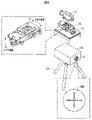
図1は、実施例に係る視準校正装置の概略構成例を示す図である。図2は、レーザ送信装置、視準眼鏡および発射装置の分解図である。図3は、レーザ光線の波長を示すグラフである。図4は、撮像装置の感度特性を示す特性図である。図5は、視準校正方法を示すフロー図である。図6は、視準校正時の表示装置の表示画面を説明する図である。図7は、レーザ光線を用いたワイヤレスデータ伝送の概要を説明する図である。 FIG. 1 is a diagram showing a schematic configuration example of a collimation calibration device according to an embodiment. FIG. 2 is an exploded view of the laser transmitter, collimation glasses and launcher. FIG. 3 is a graph showing wavelengths of laser beams. FIG. 4 is a characteristic diagram showing sensitivity characteristics of the imaging device. FIG. 5 is a flow diagram showing a collimation calibration method. FIG. 6 is a diagram for explaining the display screen of the display device during collimation calibration. FIG. 7 is a diagram explaining an overview of wireless data transmission using a laser beam.
(視準校正装置の全体構成)
図1に示す様に、視準校正装置1は、レーザ送信装置10、照準装置20、視準校正板30、撮像装置40、表示装置50等から構成されている。(Overall configuration of collimation calibration device)
As shown in FIG. 1, the
レーザ送信装置10は、非可視のレーザ光線(非可視レーザ光)12を照射することが可能なプロジェクタによって構成する。レーザ送信装置10は、後述する図7に示す様に、必要なデータが付与されたレーザ光線12を、ワイヤレスでレーザ光線12を受光するレーザ受光器80に送信することで、ワイヤレスでデータをレーザ受光器80に伝送することが可能である。
The
図2に示す様に、レーザ送信装置10には、方向調整機構(以下、調整機構という)15が装着されている。調整機構15は、視準校正のための誤差を基にレーザ光線12のレーザ光軸11の向きを上下方向および左右方向に調整し、レーザ光軸11を視準校正する。調整機構15は、固定部13によって照準装置20に固定されている。
As shown in FIG. 2, the
固定部13は、例えば、取り付け用の金具で構成される。固定部13は、照準装置20に対応する形状を有している。照準装置20は、発射装置60に装着される。発射装置60は、一つのある特定の装置ではなく、形状や性能が異なるさまざまな装置を想定しており、図1および図2の発射装置60は、一例を示すものである。発射装置60は、たとえば、訓練用の射撃装置(火器)とすることができる。火器にレーザ送信装置10および照準装置20を装着するので、火器は訓練者(人員)が保持する小火器よりも固定して使用する小火器や重火器の方が好ましい。
The
照準装置20は、人員が狙いを定めるために利用される照準器(以下、照準眼鏡と言う)21を有している。照準眼鏡21は覗き込みが可能な望遠光学レンズである。図2に示すように、照準眼鏡21には、上述したように、レーザ光線12の照準を設定するための例えば十字の指標である照準眼鏡用レチクル20aが配設されている。照準眼鏡用レチクル20aは、照準眼鏡21の照準軸22の位置を示すものである。照準眼鏡21の望遠倍率は、発射装置60により異なるが、たとえば、5倍~10倍の倍率を有している。
The
視準校正板30は、レーザ送信装置10のレーザ光軸11の視準校正のために、レーザ光軸用レチクル31と照準校正用レチクル(照準軸用レチクルともいう)32とを備える。視準校正板30は、レーザ送信装置10と照準装置20とから、レーザ光線12が発射される側に所望な距離離れて設置されている。この所望な距離は、照準眼鏡21の望遠倍率に影響するが、照準眼鏡21を覗き込んだ際に、視準校正板30における照準校正用レチクル32を人員が肉眼によって視認できる距離とするのが好ましい。所望な距離は、例えば、20m~30m程度である。
The
撮像装置40は、視準校正板30に照射されたレーザ送信装置10からのレーザ光線を撮影するための撮影カメラである。撮像装置40は、赤外線を撮影することが可能な赤外線カメラ、または、近赤外線を撮影することが可能な近赤外線カメラにより構成される。以下の説明では、撮像装置40を近赤外線カメラ40として説明する。
The image capturing
表示装置50は、近赤外線カメラ40と有線または無線で接続され、近赤外線カメラ40の撮影した撮影画像をリアルタイムに映し出す画像モニタ装置である。表示装置50は、たとえば、パーソナルコンピュータで構成される。
The
レーザ送信装置10から照射されるレーザ光線12は、非可視のレーザ光であり、目で見えないため、レーザ送信装置10から照射されるレーザ光線12のレーザ光軸11を直接的にレーザ光軸用レチクル31に合わせることが不可能である。また、照準眼鏡21をレーザ送信装置10に内蔵させることができれば、レーザ光軸11と照準軸22との視準校正が不要にできる可能性も有るが、照準眼鏡21をレーザ送信装置10に内蔵させることは極めて難しい。レーザ送信装置10には、レーザ光線を送信するための電子回路を含むレーザ送信モジュールと、レーザ光線を遠距離まで送達させ、かつ、レーザ光線12の照射範囲12a(図7参照)を広げる光学系モジュールとが内蔵されている。そのため、レーザ送信装置10の小型化を考慮すると、レーザ送信装置10に照準眼鏡21を追加するのは、物理的に難しいからである。
The
本実施例では、レーザ送信装置10から送信されるレーザ光線12を視準校正板30に照射、投影させ、その投影されたレーザ光線12の照射範囲を近赤外線カメラ40で撮影し、近赤外線カメラ40で撮影した撮影画像を表示装置50の表示画面に表示する。これにより、表示装置50の表示画面に、レーザ光軸11を可視化することができる。そして、可視化されたレーザ光軸11を視準校正板30上のレーザ光軸用レチクル31に合わせることにより、レーザ光軸11の視準校正を行うものである。
In this embodiment, the
ここで、レーザ光線12の波長と近赤外線カメラ40の感度特性について説明する。
Here, the wavelength of the
図3には、レーザ光線12を発光するレーザダイオード(不図示)の波長のグラフが示されている。レーザ光線12の波長のピークは、この例では、905nmを示している。
FIG. 3 shows a graph of the wavelength of a laser diode (not shown) emitting
図4には、近赤外線カメラ40の波長に対する感度特性が示されており、905nmの波長も近赤外線カメラ40の撮影可能な感度範囲に含まれていることが読み取れる。したがって、905nmに波長のピークを有するレーザ光線は、近赤外線カメラ40で撮影することができる。どのような波長のレーザ光線を使用するかは、使用目的、到達距離等により選定することができる。この場合、撮像装置40は、選定されたレーザ光線の波長が撮像装置40の感度範囲に含まれる様な撮像装置を選択することになる。
FIG. 4 shows the sensitivity characteristics of the near-
(視準校正方法)
次に、図5および図6を用いて、視準校正方法を説明する。(Collimation calibration method)
Next, a collimation calibration method will be described with reference to FIGS. 5 and 6. FIG.
視準校正方法には、ある設定距離で、照準眼鏡21の照準軸22とレーザ光軸11が一致するように校正する「一点ボアサイト方式」と、理論上はどの距離においても照準眼鏡21の照準軸22とレーザ光軸11が平行となるように視準校正する「平行ボアサイト方式」が有る。本実施例は、どちらの方式にも使用出来るが、以下の説明では、「平行ボアサイト方式」を前提に、視準校正方法を説明する。
The collimation calibration method includes a "single-point boresight method" in which calibration is performed so that the
視準校正では、照準軸22と視準校正板30上に表示した照準校正用レチクル32と一致、又レーザ光軸11が視準校正板30上に表示したレーザ光軸用レチクル31と一致するように各々調整する必要が有る。
In collimation calibration, the
(ステップS1)
まず、図1に示す様に、視準校正板30を発射装置60に装着されたレーザ送信装置10から所定の距離離した位置に配置し、視準校正の準備を行う。視準校正板30には、発射装置60の照準眼鏡21の中心である照準軸22とレーザ送信装置10から送信されるレーザ光軸11の理論上の位置が、レーザ光軸用レチクル31と照準校正用レチクル32とで表示されている。(Step S1)
First, as shown in FIG. 1, the
(ステップS2)
次に、視準校正板30にレーザ送信装置10からレーザ光線12を照射、投影させる。(Step S2)
Next, the
(ステップS3)
次に、照準眼鏡21には人員が狙いを定める為の照準眼鏡用レチクル20aが設けられているので、照準眼鏡21を使用して、照準眼鏡21の照準軸22を照準校正用レチクル32に一致させる。つまり、照準眼鏡用レチクル20aと照準校正用レチクル32と一致させることで、照準眼鏡21の照準軸22を照準校正用レチクル32に一致させることができる。(Step S3)
Next, since the
(ステップS4)
次に、視準校正板30に投影されたレーザ光線12の照射範囲12bを近赤外線カメラ40で撮影し、近赤外線カメラ40で撮影した撮影画像を表示装置50に表示する。これにより、表示装置50の表示画面にレーザ光軸11を可視化することができる。なお、ここでは、レーザ光軸11は、レーザ光線12の円形の照射範囲12bの中心点に位置するものとする。図6では、レーザ光線12の照射範囲12bを円形で示しているが、照射範囲12bは、視準校正板30とレーザ送信装置10との距離が比較的近距離とされると、レーザ光軸11と一致する場合もある。(Step S4)
Next, the
図6には、表示装置50の表示画面に表示された近赤外線カメラ40の撮影画像の一例が示されている。図5において、状態Aは、視準校正前のレーザ光線12の照射範囲12bの位置を示し、状態Bは視準校正後のレーザ光線12の照射範囲12bの位置を示している。状態Bは、レーザ光軸11が視準校正板30上に設けたレーザ光軸用レチクル31と一致した状態を示している。
FIG. 6 shows an example of an image captured by the near-
(ステップS5)
次に、レーザ光軸11が視準校正板30に設けた表示したレーザ光軸用レチクル31と一致するように、調整機構15を上下方向および左右方向に調整し、レーザ光軸11の方向を調整する。つまり、図6において、状態Aにおけるレーザ光軸11の位置が矢印Cに示す様に移動されて、状態Bにおけるレーザ光軸11の位置にされる。これにより、レーザ光軸11が視準校正される。(Step S5)
Next, the
(ワイヤレスデータ伝送)
次に、ワイヤレスデータ伝送について図7を用いて説明する。(wireless data transmission)
Next, wireless data transmission will be described with reference to FIG.
ワイヤレスデータ伝送は、上記視準校正方法によって視準校正されたレーザ送信装置10とレーザ受光器80との間で行われる。視準校正済みのレーザ送信装置10は、必要なデータを付与したレーザ光線12を送信する。レーザ受光器80は、レーザ送信装置10から送信されたレーザ光線12を受光し、データを受信する事が出来るように構成されている。
Wireless data transmission is performed between the
ワイヤレスデータ伝送は比較的遠距離間で行う。レーザ送信装置10とレーザ受光器80との間の距離Lは、たとえば、1000m程度であるが、これ以上の距離とされても良い。
Wireless data transmission occurs over relatively long distances. A distance L between the
ワイヤレスデータ伝送では、レーザ送信装置10から距離L離れて配置されたレーザ受光器80にレーザ光線12を命中させる必要が有る。レーザ光線12は照射距離に比例しレーザ光線12の照射範囲12aが広がる特性を有している。ここで、命中とは、レーザ受光器80が配置された位置において、レーザ光線12の照射範囲12aの範囲内にレーザ受光器80が位置し、レーザ受光器80が正しくデータを受信することを言う。
Wireless data transmission requires the
図7において、発射装置60を、たとえば、射撃訓練の模擬銃60へ変更した場合を説明する。
In FIG. 7, a case where the
レーザ送信装置10、調整機構15、および、照準眼鏡21を含む照準装置20は、模擬銃60に装着され、レーザ光線12をレーザ受光器80が取り付けられた標的に向けて発射する。レーザ送信装置10からレーザ光線12を発射することにより、弾丸の発射を模擬して射撃訓練を行う。また、模擬銃60には引金(図示せず)が取り付けられ、この引金に連動して、レーザ送信装置10からレーザ光線12を発射するようになっている。引金が操作されて、レーザ送信装置10を駆動制御し、例えば特定情報(移動情報を含む各種情報(時刻情報、状況情報等))が含まれるレーザ光線12を発射させる。照準眼鏡21は、本来、銃口から発射される弾丸の発射方向を目標物に照準するものであるが、本実施例では、レーザ送信装置10から照射されるレーザ光線12を標的のレーザ受光器80に照準するために用いる。
実施例によれば、以下の1または複数の効果を得ることができる。 According to the embodiment, one or more of the following effects can be obtained.
1)レーザ送信装置10から照射された非可視のレーザ光線12を撮像装置40で撮影し可視化しているので、レーザ光軸11を捉えることができ、高精度な視準校正が可能である。
1) Since the
2)間接的にレーザ光軸を可視化する必要が無い為、従来必要とされていた視準校正を行う為の照準望遠鏡もしくは可視光レーザ送信ユニット等が不要となる。その為、実施例においては、照準望遠鏡もしくは可視光レーザ送信ユニットの物理的な勘合機構が不要であり、その着脱による誤差が生じないので、高精度な視準校正を提供することが可能である。 2) Since there is no need to indirectly visualize the laser optical axis, there is no need for a sighting telescope or a visible light laser transmission unit for performing collimation calibration, which has conventionally been required. Therefore, in the embodiment, there is no need for a physical fitting mechanism for the sighting telescope or the visible light laser transmission unit. .
3)従来必要とされていた照準望遠鏡もしくは可視光レーザ送信ユニット等が不要となる。このため、実施例においては、経済性に優れた視準校正を提供することが可能である。また、実施例では、予めの軸調整も不要となる為、実施例に係る視準校正装置の製造段階においても、経済性に優れている。 3) A sighting telescope, a visible light laser transmission unit, etc., which were conventionally required, are no longer required. Therefore, in the embodiment, it is possible to provide economical collimation calibration. In addition, since the embodiment does not require any axial adjustment in advance, the manufacturing stage of the collimation calibrating device according to the embodiment is also economical.
4)視準校正装置1は、レーザ光線12の撮像を撮影する撮像装置(近赤外線カメラ)40と、その撮影画像を映し出す表示装置50、及び、視準校正板30で構成される為、視準校正の準備も容易かつ短時間で行え、また、視準校正作業も容易かつ短時間に行うことができる。
4) The
5)視準校正板30は、レーザ光軸用レチクル31と照準校正用レチクル32とを備えるだけであり、複数のレーザ受光素子を狭ピッチに配置した視準校正板と比較して、安価である。
5) The
以上、本発明者によってなされた発明を実施例に基づき具体的に説明したが、本発明は、上記実施形態および実施例に限定されるものではなく、種々変更可能であることはいうまでもない。 Although the invention made by the present inventor has been specifically described above based on the examples, it goes without saying that the invention is not limited to the above-described embodiments and examples, and can be variously modified. .
視準校正板30は、たとえば、非可視のレーザ光線(非可視レーザ光)12を反射しやすい素材とするのが良い。また、視準校正板30は、可視光を偏光させる様な素材とするのが良い。また、全ての光を吸収する暗黒シートに、十字等の形を切り抜いてレーザ光軸用レチクル31と照準校正用レチクル32とを形成し、視準校正板30または標的に張り付けても良い。
The
1:視準校正装置
10:レーザ送信装置
11:レーザ光軸
12:レーザ光線
15:方向調整機構
20:照準装置
20a:照準眼鏡用レチクル
21:照準器(照準眼鏡)
22:照準軸
30:視準校正板
31:レーザ光軸用レチクル
32:照準校正用レチクル
40:撮像装置(近赤外線カメラ)
50:表示装置(画像モニタ装置)
60:発射装置(火器)
80:レーザ受光器Reference Signs List 1: collimation calibration device 10: laser transmission device 11: laser optical axis 12: laser beam 15: direction adjustment mechanism 20:
22: Aiming axis 30: Collimation calibration plate 31: Laser optical axis reticle 32: Aiming calibration reticle 40: Imaging device (near-infrared camera)
50: Display device (image monitor device)
60: Launcher (firearms)
80: Laser receiver
Claims (7)
前記レーザ送信装置に装着される方向調整機構と、
前記レーザ送信装置から所定の距離離されて設置される視準校正板と、
前記視準校正板に照射された前記非可視レーザ光を撮影する撮像装置と、
前記撮像装置の撮影した撮影画像を表示する表示装置と、を含み、
前記視準校正板は、レーザ光軸用レチクルを含み、
前記撮影画像に表示された前記非可視レーザ光の光軸のみに基づいて、前記方向調整機構を調整して、前記非可視レーザ光の前記光軸を前記レーザ光軸用レチクルに一致させる、
視準校正装置。 a laser transmitter mounted on a launcher for emitting invisible laser light;
a direction adjustment mechanism attached to the laser transmitter;
a collimation calibration plate installed at a predetermined distance from the laser transmitter;
an imaging device that captures the invisible laser beam irradiated on the collimation calibration plate;
a display device that displays the captured image captured by the imaging device,
The collimation calibration plate includes a reticle for a laser optical axis,
adjusting the direction adjustment mechanism based only on the optical axis of the invisible laser light displayed in the captured image to match the optical axis of the invisible laser light with the laser light axis reticle;
Collimation calibration device.
前記視準校正板は、前記照準器の照準軸を一致させるための照準校正用レチクルを含み、
前記照準器の照準軸を前記照準校正用レチクルに一致させた状態で、前記撮影画像に表示された前記非可視レーザ光の前記光軸に基づいて、前記方向調整機構を調整して、前記非可視レーザ光の前記光軸を前記レーザ光軸用レチクルに一致させる、請求項1に記載の視準校正装置。 including a sight provided on the launcher;
the sighting calibration plate includes a sighting calibration reticle for matching the sighting axis of the sighting device;
With the sighting axis of the sighting device aligned with the sighting calibration reticle, the direction adjusting mechanism is adjusted based on the optical axis of the invisible laser beam displayed in the captured image to 2. A collimation calibration device according to claim 1, wherein said optical axis of visible laser light is aligned with said laser optical axis reticle.
前記撮像装置の感度範囲は、905nmの波長を含む、請求項1または請求項2に記載の視準校正装置。 The invisible laser light has a wavelength peak at 905 nm,
3. A collimation calibration device according to claim 1 or 2, wherein the sensitivity range of the imaging device includes a wavelength of 905 nm.
前記視準校正板に前記レーザ送信装置から非可視のレーザ光線を照射、投影させるステップと、
前記発射装置に装着した照準眼鏡の照準眼鏡用レチクルを前記視準校正板に設けた照準校正用レチクルに一致させるステップと、
前記視準校正板に投影された前記非可視のレーザ光線の照射範囲を撮像装置で撮影し、前記撮像装置で撮影した撮影画像を表示装置に表示し、前記非可視のレーザ光線のレーザ光軸を可視化するステップと、
前記非可視のレーザ光のレーザ光軸のみに基づいて、前記非可視のレーザ光の前記レーザ光軸が前記視準校正板に設けたレーザ光軸用レチクルと一致するように、前記レーザ送信装置に装着した方向調整機構を調整して前記レーザ光軸の方向を調整するステップと、を含む、
視準校正方法。 positioning a collimation calibration plate at a predetermined distance from a laser transmitter mounted on the launcher;
irradiating and projecting an invisible laser beam from the laser transmitter onto the collimation calibration plate;
aligning a sighting glass reticle of the sighting glasses attached to the launcher with a sighting calibration reticle provided on the sighting calibration plate;
photographing an irradiation range of the invisible laser beam projected onto the collimation calibration plate with an imaging device, displaying the photographed image photographed with the imaging device on a display device, and a laser optical axis of the invisible laser beam; and visualizing
The laser transmission device is arranged so that the laser optical axis of the invisible laser light coincides with a laser optical axis reticle provided on the collimation calibration plate based only on the laser optical axis of the invisible laser light. adjusting the direction of the laser optical axis by adjusting a direction adjustment mechanism attached to the
collimation calibration method.
前記撮像装置の感度範囲は、905nmの波長を含む、請求項6に記載の視準校正方法。 The laser beam has a wavelength peak at 905 nm,
7. A collimation calibration method according to claim 6, wherein the sensitivity range of said imaging device includes a wavelength of 905 nm.
Applications Claiming Priority (1)
| Application Number | Priority Date | Filing Date | Title |
|---|---|---|---|
| PCT/JP2020/008550 WO2021171630A1 (en) | 2020-02-28 | 2020-02-28 | Collimator calibration apparatus and collimator calibration system |
Publications (3)
| Publication Number | Publication Date |
|---|---|
| JPWO2021171630A1 JPWO2021171630A1 (en) | 2021-09-02 |
| JPWO2021171630A5 JPWO2021171630A5 (en) | 2022-09-08 |
| JP7213392B2 true JP7213392B2 (en) | 2023-01-26 |
Family
ID=77490866
Family Applications (1)
| Application Number | Title | Priority Date | Filing Date |
|---|---|---|---|
| JP2022503062A Active JP7213392B2 (en) | 2020-02-28 | 2020-02-28 | Collimation calibration device and collimation calibration method |
Country Status (2)
| Country | Link |
|---|---|
| JP (1) | JP7213392B2 (en) |
| WO (1) | WO2021171630A1 (en) |
Families Citing this family (2)
| Publication number | Priority date | Publication date | Assignee | Title |
|---|---|---|---|---|
| CN114046965B (en) * | 2021-11-23 | 2023-09-05 | 中国航空工业集团公司洛阳电光设备研究所 | Device and method for calibrating optical axis of multi-type avionics equipment of airplane |
| CN116009231B (en) * | 2022-12-15 | 2023-09-22 | 江苏缪斯光电科技有限公司 | Calibrating device for laser optical sighting telescope |
Citations (6)
| Publication number | Priority date | Publication date | Assignee | Title |
|---|---|---|---|---|
| JP2010117090A (en) | 2008-11-13 | 2010-05-27 | Hitachi Kokusai Electric Inc | Sight adjustment device for laser transmitter |
| JP2010216679A (en) | 2009-03-13 | 2010-09-30 | Hitachi Kokusai Electric Inc | Optical axis calibrator |
| JP2011058932A (en) | 2009-09-09 | 2011-03-24 | Hitachi Kokusai Electric Inc | Laser collimation calibration system |
| US20120030985A1 (en) | 2010-08-04 | 2012-02-09 | Trijicon, Inc. | Fused optic |
| US20120171643A1 (en) | 2011-01-03 | 2012-07-05 | Lockheed Martin Corporation | Optical alignment device for a weapon simulator using an optical simulation beam |
| WO2018163772A1 (en) | 2017-03-10 | 2018-09-13 | 株式会社日立国際電気 | Collimator calibration apparatus and collimator calibration system |
Family Cites Families (1)
| Publication number | Priority date | Publication date | Assignee | Title |
|---|---|---|---|---|
| JPS57164703A (en) * | 1981-04-03 | 1982-10-09 | Nec Corp | Adjusting method for bore sight |
-
2020
- 2020-02-28 JP JP2022503062A patent/JP7213392B2/en active Active
- 2020-02-28 WO PCT/JP2020/008550 patent/WO2021171630A1/en active Application Filing
Patent Citations (6)
| Publication number | Priority date | Publication date | Assignee | Title |
|---|---|---|---|---|
| JP2010117090A (en) | 2008-11-13 | 2010-05-27 | Hitachi Kokusai Electric Inc | Sight adjustment device for laser transmitter |
| JP2010216679A (en) | 2009-03-13 | 2010-09-30 | Hitachi Kokusai Electric Inc | Optical axis calibrator |
| JP2011058932A (en) | 2009-09-09 | 2011-03-24 | Hitachi Kokusai Electric Inc | Laser collimation calibration system |
| US20120030985A1 (en) | 2010-08-04 | 2012-02-09 | Trijicon, Inc. | Fused optic |
| US20120171643A1 (en) | 2011-01-03 | 2012-07-05 | Lockheed Martin Corporation | Optical alignment device for a weapon simulator using an optical simulation beam |
| WO2018163772A1 (en) | 2017-03-10 | 2018-09-13 | 株式会社日立国際電気 | Collimator calibration apparatus and collimator calibration system |
Also Published As
| Publication number | Publication date |
|---|---|
| JPWO2021171630A1 (en) | 2021-09-02 |
| WO2021171630A1 (en) | 2021-09-02 |
Similar Documents
| Publication | Publication Date | Title |
|---|---|---|
| US9372051B2 (en) | System for automatically aligning a rifle scope to a rifle | |
| US9121671B2 (en) | System and method for projecting registered imagery into a telescope | |
| CA2188544C (en) | Laser alignment system for small arms | |
| US20220373298A1 (en) | Methods systems circuits components apparatus devices assemblies and computer-executable code for aiming a firearm | |
| US11480410B2 (en) | Direct enhanced view optic | |
| KR101345028B1 (en) | Display type optical sight device | |
| EP1617164B1 (en) | Method and device for the alignment of a weapon with a weapon simulator mounted on the weapon | |
| JP7213392B2 (en) | Collimation calibration device and collimation calibration method | |
| EP2676098B1 (en) | Fire-control system | |
| SE516902C2 (en) | Two single devices and a firing simulator procedure | |
| RU2464601C1 (en) | Aiming device with laser range finder | |
| JP2010117090A (en) | Sight adjustment device for laser transmitter | |
| US8449298B2 (en) | Optical alignment device for a weapon simulator using an optical simulation beam | |
| JPWO2021171630A5 (en) | ||
| EP0330886B1 (en) | Shooting simulator device | |
| JPWO2020106340A5 (en) | ||
| SE516884C2 (en) | System for the uniforming of a sliding simulator and a unit for this | |
| WO2022021250A1 (en) | Shooting device, sighting apparatus and imaging distance measurement apparatus thereof, and adjustment method | |
| JP2010071593A (en) | Sighting device of laser transmitter | |
| US20140150326A1 (en) | Process to Optically Align Optical Systems on a Weapon | |
| KR101975009B1 (en) | Sight device providing variable reticle for measuring distance | |
| KR101975015B1 (en) | Distance measuring method using variable reticle | |
| CN116538853A (en) | Newton laser transmitter optical axis calibration device | |
| RU34763U1 (en) | Sight - guidance device | |
| IL291964B1 (en) | methods systems circuits components apparatus devices assemblies and computer executable code for aiming a firearm |
Legal Events
| Date | Code | Title | Description |
|---|---|---|---|
| A521 | Request for written amendment filed |
Free format text: JAPANESE INTERMEDIATE CODE: A523 Effective date: 20220707 |
|
| A621 | Written request for application examination |
Free format text: JAPANESE INTERMEDIATE CODE: A621 Effective date: 20220707 |
|
| TRDD | Decision of grant or rejection written | ||
| A01 | Written decision to grant a patent or to grant a registration (utility model) |
Free format text: JAPANESE INTERMEDIATE CODE: A01 Effective date: 20230110 |
|
| A61 | First payment of annual fees (during grant procedure) |
Free format text: JAPANESE INTERMEDIATE CODE: A61 Effective date: 20230116 |
|
| R150 | Certificate of patent or registration of utility model |
Ref document number: 7213392 Country of ref document: JP Free format text: JAPANESE INTERMEDIATE CODE: R150 |