JP7211714B2 - Intraocular lens fixation device - Google Patents
Intraocular lens fixation device Download PDFInfo
- Publication number
- JP7211714B2 JP7211714B2 JP2018085885A JP2018085885A JP7211714B2 JP 7211714 B2 JP7211714 B2 JP 7211714B2 JP 2018085885 A JP2018085885 A JP 2018085885A JP 2018085885 A JP2018085885 A JP 2018085885A JP 7211714 B2 JP7211714 B2 JP 7211714B2
- Authority
- JP
- Japan
- Prior art keywords
- haptic
- intraocular lens
- eyeball
- fixing device
- holding portion
- Prior art date
- Legal status (The legal status is an assumption and is not a legal conclusion. Google has not performed a legal analysis and makes no representation as to the accuracy of the status listed.)
- Active
Links
Images


Classifications
-
- A—HUMAN NECESSITIES
- A61—MEDICAL OR VETERINARY SCIENCE; HYGIENE
- A61F—FILTERS IMPLANTABLE INTO BLOOD VESSELS; PROSTHESES; DEVICES PROVIDING PATENCY TO, OR PREVENTING COLLAPSING OF, TUBULAR STRUCTURES OF THE BODY, e.g. STENTS; ORTHOPAEDIC, NURSING OR CONTRACEPTIVE DEVICES; FOMENTATION; TREATMENT OR PROTECTION OF EYES OR EARS; BANDAGES, DRESSINGS OR ABSORBENT PADS; FIRST-AID KITS
- A61F2/00—Filters implantable into blood vessels; Prostheses, i.e. artificial substitutes or replacements for parts of the body; Appliances for connecting them with the body; Devices providing patency to, or preventing collapsing of, tubular structures of the body, e.g. stents
- A61F2/02—Prostheses implantable into the body
- A61F2/14—Eye parts, e.g. lenses, corneal implants; Implanting instruments specially adapted therefor; Artificial eyes
- A61F2/16—Intraocular lenses
- A61F2/1602—Corrective lenses for use in addition to the natural lenses of the eyes or for pseudo-phakic eyes
- A61F2/161—Posterior chamber lenses for use in addition to the natural lenses of the eyes
-
- A—HUMAN NECESSITIES
- A61—MEDICAL OR VETERINARY SCIENCE; HYGIENE
- A61F—FILTERS IMPLANTABLE INTO BLOOD VESSELS; PROSTHESES; DEVICES PROVIDING PATENCY TO, OR PREVENTING COLLAPSING OF, TUBULAR STRUCTURES OF THE BODY, e.g. STENTS; ORTHOPAEDIC, NURSING OR CONTRACEPTIVE DEVICES; FOMENTATION; TREATMENT OR PROTECTION OF EYES OR EARS; BANDAGES, DRESSINGS OR ABSORBENT PADS; FIRST-AID KITS
- A61F2/00—Filters implantable into blood vessels; Prostheses, i.e. artificial substitutes or replacements for parts of the body; Appliances for connecting them with the body; Devices providing patency to, or preventing collapsing of, tubular structures of the body, e.g. stents
- A61F2/02—Prostheses implantable into the body
- A61F2/14—Eye parts, e.g. lenses, corneal implants; Implanting instruments specially adapted therefor; Artificial eyes
- A61F2/16—Intraocular lenses
- A61F2002/1681—Intraocular lenses having supporting structure for lens, e.g. haptics
- A61F2002/169—Surrounding optic
Landscapes
- Health & Medical Sciences (AREA)
- Ophthalmology & Optometry (AREA)
- Cardiology (AREA)
- Oral & Maxillofacial Surgery (AREA)
- Transplantation (AREA)
- Engineering & Computer Science (AREA)
- Biomedical Technology (AREA)
- Heart & Thoracic Surgery (AREA)
- Vascular Medicine (AREA)
- Life Sciences & Earth Sciences (AREA)
- Animal Behavior & Ethology (AREA)
- General Health & Medical Sciences (AREA)
- Public Health (AREA)
- Veterinary Medicine (AREA)
- Prostheses (AREA)
Description
本発明は、眼内レンズの固定に用いられる眼内レンズ固定用器具等に関する。 TECHNICAL FIELD The present invention relates to an intraocular lens fixing device and the like used for fixing an intraocular lens.
眼内レンズ(Intraocular lens、以下「IOL」という場合がある。)を用いた水晶体再建術が、白内障手術として広く行われている。水晶体再建術では、超音波乳化吸引術によって水晶体が吸引されて空隙化した水晶体嚢の中に、眼内レンズが固定される。しかし、水晶体再建術において水晶体嚢が破損又は消失する場合がある。このような場合、眼内レンズ強膜内固定術、又は、眼内レンズ毛様溝縫着術といった手術法によって眼内レンズを固定できるが、これらの手術法は難易度が高い手術手技が必要である。 Reconstructive lens surgery using an intraocular lens (hereinafter sometimes referred to as "IOL") is widely performed as cataract surgery. In phacoemulsification, an intraocular lens is fixed in the lens capsule that has been aspirated and made void by phacoemulsification. However, the lens capsule may be damaged or lost during lens reconstruction surgery. In such cases, surgical methods such as intraocular lens intrascleral fixation or intraocular lens ciliary sulcus suturing can be used to fix the intraocular lens, but these surgical methods require highly difficult surgical techniques. is.
特許文献1には、眼内レンズを縫着することなく安定して固定できる眼内固定用補助具が記載されている。この眼内固定用補助具は、毛様体溝に円周状に固定される第1の保持部と、眼内レンズを受け且つ保持するための第2の保持部と、第1の保持部と第2の保持部とを一体的に結合する結合部とからなる。
また、特許文献2には、調節IOLを支持するための支持具が記載されている。支持具は、調節IOLを収容する枠部と、毛様溝から挿入されて強膜の外表面に掛止される屈曲部が設けられた脚部とを備える。調節IOLは、複数のレンズの連結部が枠部から側方に突出して毛様体に当接した状態で支持される。 Further, Patent Document 2 describes a support for supporting an adjustable IOL. The support includes a frame that accommodates the accommodating IOL and legs with bends that are inserted through the ciliary sulcus and hooked to the outer surface of the sclera. The adjustable IOL is supported in a state in which connecting portions of a plurality of lenses protrude laterally from the frame portion and are in contact with the ciliary body.
しかし、従来の眼内レンズ固定用器具は、眼内レンズを保持する部材が比較的大きく、眼球内に導入することが容易ではない。 However, the conventional intraocular lens fixing device has a relatively large member for holding the intraocular lens, and it is not easy to introduce it into the eyeball.
本発明は、このような事情に鑑みてなされたものであり、眼内レンズを保持する部材を眼球内に容易に導入できる眼内レンズ固定用器具を提供することを目的とする。 SUMMARY OF THE INVENTION It is an object of the present invention to provide an instrument for fixing an intraocular lens that can easily introduce a member for holding an intraocular lens into the eyeball.
上述の課題を解決するべく、第1の発明は、複数のハプティックを有する眼内レンズを眼球内に固定するための眼内レンズ固定用器具であって、眼球内に張られる線状部材と、複数のハプティックの各々に対応して設けられ、それぞれがハプティックを保持して、線状部材によって眼球内の空間に支持される複数のハプティック保持部とを備え、複数のハプティック保持部の各々には、線状部材が固定されるとともに、可撓性を有する素材が用いられている、眼内レンズ固定用器具である。 In order to solve the above-mentioned problems, a first invention is an intraocular lens fixing instrument for fixing an intraocular lens having a plurality of haptics in an eyeball, comprising a linear member stretched in the eyeball; a plurality of haptic holders provided corresponding to each of the plurality of haptics, each holding the haptic and supported in the space in the eyeball by the linear member, each of the plurality of haptic holders having 1. An intraocular lens fixing device in which a linear member is fixed and a material having flexibility is used.
第2の発明は、第1の発明において、ハプティック保持部は、ハプティックを挿入する入口が形成された袋状の部材である。 In a second aspect based on the first aspect, the haptic holding portion is a bag-like member having an opening for inserting the haptic.
第3の発明は、第2の発明において、ハプティック保持部には、袋内と袋外とを連通させる連通孔が形成されている。 In a third aspect based on the second aspect, the haptic holding portion is formed with a communication hole for communicating between the inside of the bag and the outside of the bag.
第4の発明は、第1又は第2の発明において、ハプティック保持部は、網状の部材により形成されている。 In a fourth aspect based on the first or second aspect, the haptic holding portion is formed of a mesh member.
第5の発明は、第1乃至第4の何れか1つの発明において、ハプティック保持部の外面には、位置調節用のマークが設けられている。 In a fifth invention according to any one of the first to fourth inventions, a mark for position adjustment is provided on the outer surface of the haptic holder.
第6の発明は、第1乃至第5の何れか1つの発明において、複数のハプティック保持部の各々は、針が取り付けられた線状部材が固定されている。 According to a sixth invention, in any one of the first to fifth inventions, each of the plurality of haptic holders has a linear member to which a needle is attached.
本発明では、針部材が接続された線状部材を眼球の強膜に通していくと、線状部材に固定されて引っ張られたハプティック保持部が、線状部材が通る針孔に差し掛かる。ここで、可撓性を有するハプティック保持部は、強膜の針孔を通過可能に形成することが可能であり、それにより針孔を通して眼球内に導入することが可能である。この時の線状部材を引っ張る作業は容易である。本発明によれば、眼内レンズを保持するハプティック保持部を眼球内に容易に導入できる眼内レンズ固定用器具を提供することができる。 In the present invention, when the linear member to which the needle member is connected is passed through the sclera of the eyeball, the haptic holder fixed to the linear member and pulled reaches the needle hole through which the linear member passes. Here, the flexible haptic holder can be formed so as to be able to pass through a needle hole in the sclera, so that it can be introduced into the eyeball through the needle hole. The work of pulling the linear member at this time is easy. ADVANTAGE OF THE INVENTION According to this invention, the instrument for intraocular lens fixation which can introduce|transduce easily the haptic holding|maintenance part which hold|maintains an intraocular lens in an eyeball can be provided.
以下、図1-図13を参照しながら、本発明の実施形態を詳細に説明する。なお、以下の実施形態は、本発明の一例であって、本発明、その適用物、あるいはその用途の範囲を制限することを意図するものではない。 Embodiments of the present invention will be described in detail below with reference to FIGS. 1 to 13. FIG. The following embodiments are examples of the present invention, and are not intended to limit the scope of the present invention, its applications, or its uses.
[眼内レンズ固定用器具の構成]
眼内レンズ固定用器具10は、例えば、水晶体再建術において水晶体嚢が破損又は消失した場合に眼内レンズ20を固定するために用いられる器具である。眼内レンズ固定用器具10は、レンズ部21に対し複数のハプティック22が設けられた眼内レンズ20に適用することができる。本実施形態に係る眼内レンズ20では、2つのハプティック22がレンズ部21の外周面から外側に突出している(図2参照)。2つのハプティック22は、レンズ部21の中心に対し点対称に設けられている。
[Structure of Intraocular Lens Fixing Device]
The intraocular
眼内レンズ固定用器具10は、図1に示すように、それぞれがハプティック保持部14を有する一対のレンズ支持部12により構成されている。各ハプティック保持部14は、眼内レンズ20の一対のハプティック22にそれぞれ対応している。眼内レンズ固定用器具10は、図2に示すように、眼球30内において一対のハプティック保持部14の入口15が互いに対向するように配置される。そして、眼内レンズ固定用器具10は、一対のハプティック保持部14によって一対のハプティック22をそれぞれ保持することで、眼球30内に眼内レンズ20を固定する。なお、図2は、眼球30の正面から見た図であるが眼球30内を実線で示している。また、各ハプティック保持部14にはハッチングを付けている。
The intraocular
また、前後方向の位置(深度)について、図3に示すように、一対のハプティック保持部14は眼球30内における虹彩の少し後ろ側の位置に配置され、眼内レンズ20は毛様体の内側の位置で固定される。以下、眼内レンズ固定用器具10について詳述する。
As for the position (depth) in the front-back direction, as shown in FIG. position. The intraocular
各レンズ支持部12は、上述のハプティック保持部14に加え、図1に示すように、一端部がハプティック保持部14に接続されて他端部が針部材16a,16bに接続された2本の線状部材18を備えている。線状部材18としては糸(張力糸)が用いられている。一方の線状部材18の針部材16aは、線状部材18及びハプティック保持部14を眼球30内に導入するための針(貫通用の直針)であり、先端部が少し曲がった針(例えば、太さが0.4~0.6mm程度で長さが15mm程度の針)が用いられる。他方の線状部材18の針部材16bは、縫合のみに用いられる針であり、例えば、湾曲した手術用(眼科用)縫合針(例えば、太さが0.4~0.6mm程度の縫合針)が用いられている。また、2本の線状部材18は、眼球30内に張られて眼球30内に導入されたハプティック保持部14を浮いた状態で支持する。
In addition to the
一対のハプティック保持部14は、水晶体嚢に代わって眼内レンズ20のハプティック22を保持して眼内レンズ20の動きを拘束するための部材である。各ハプティック保持部14は、ハプティック22を挿入するための入口15が形成された袋状部材(具体的には、ハンモック状部材)である。なお、以下では、各ハプティック保持部14について、入口15となる内側部分の延伸方向を「長さ方向」と言い、その延伸方向に直交する方向を「幅方向」と言う。
The pair of
各ハプティック保持部14の外周形状は、平面視において、入口15となる略直線状の内側部分と、その内側部分の両端間を延びて外側に膨らむ曲線状の外側部分とにより構成されている。なお、内側部分は、例えば外側部分より曲率が小さい曲線状であってもよい。また、各ハプティック保持部14は、同一形状の2枚のシート14a,14bを備え、入口15の形成箇所を除いて2枚のシート14a,14bの外周部を互いに接合することによって形成されている。
The outer peripheral shape of each haptic holding
具体的に、各ハプティック保持部14は、図2に示すように、平面視において三日月状に形成されている。各ハプティック保持部14は、三日月状の2枚のシート14a,14bの外周部が円弧に沿って互いに接合されることによって形成されている。2枚のシート14a,14bの接合は、例えば熱溶着によって行われているが、他の接合手法を採用してもよい。各ハプティック保持部14は、円弧に沿う部分以外の外周部が未接合であり、その未接合の箇所が入口15となっている。
Specifically, as shown in FIG. 2, each haptic holding
各ハプティック保持部14の寸法について、例えば、長さ方向の寸法(入口15の長さ)は約8mmであり、幅方向の寸法は約2mmである。また、各ハプティック保持部14の円弧の直径は、約10mmである。なお、各ハプティック保持部14の寸法は、この段落の数値に限定されない。各ハプティック保持部14の寸法は、眼内レンズ20を固定する状態の一対のハプティック保持部14の円弧部分が水晶体嚢と同程度の大きさとなるように設計されている。
Regarding the dimensions of each
各ハプティック保持部14における各シート14a,14bには、薄くて柔軟性がある素材(可撓性を有する素材の一例)が用いられている。例えば各シート14a,14bは樹脂製である。各シート14a,14bには、例えば、厚さ4μmのプロピレン膜が用いられている。針部材16aを通過させる強膜31の針孔17に対し、各ハプティック保持部14は変形して通過可能に形成されている。
A thin and flexible material (an example of a flexible material) is used for each of the
また、各ハプティック保持部14では、図1に示すように、長さ方向の両端部にそれぞれ線状部材18の一端部が接合されている。線状部材18の接合は、例えば熱溶着によって行われているが、他の接合手法を採用してもよい。各線状部材18には、細い手術用縫合糸(例えば、0.02~0.4mmの樹脂製の縫合糸)が用いられている。各線状部材18の材料には、例えばポリプロピレン(例えば、9-0ポリプロピレン)、ポリエステル、PGA、又はナイロンなどを用いることができる。各線状部材18の他端部は、針部材16a,16bの根元に取り付けられている。
In each haptic holding
また、各ハプティック保持部14には、眼球30内における位置調節用のマーク13(センターマーク)が形成されている。マーク13は、シート14aにおいて内側に窪む凹部により形成されている(図1の楕円内の断面図参照)。マーク13を凹部としたのは、マーク13が虹彩に当たることを避けるためである。マーク13は、凹部以外に、貫通孔(穴)、ノッチ、凸部又はインク印刷により形成することができる。眼球30の外側から見る手術者にとって、ハプティック保持部14は部分的に虹彩に隠れて見えにくくなる虞がある。マーク13は、眼球30の外側から、眼球30内におけるハプティック保持部14の位置を把握しやすいように設けられている。マーク13は、ハプティック保持部14の外周より内側の領域に配置される。図2では、マーク13は、例えば、円形であり、ハプティック保持部14の入口15近傍の中央(長さ方向の中央)に設けられている。なお、ハプティック保持部14において、別の位置にマーク13を設けてもよいし、マーク13を省略してもよい。
A mark 13 (center mark) for position adjustment within the
[眼内レンズ固定用器具の使用方法]
図4~図6を参照しながら、眼内レンズ固定用器具10の使用方法について説明する。なお、本実施形態に係る眼内レンズ固定用器具10は、眼球30内に眼内レンズ20が落下した場合(眼内レンズ脱臼の場合)又は眼球30内に眼内レンズ20を眼外から挿入する場合の何れにも適用することができる。以下では、前者についてシングルピース多焦点IOL20が落下した場合を例にして説明を行う。
[How to use the intraocular lens fixing device]
A method of using the intraocular
なお、以下では、一対のレンズ支持部12の一方を第1レンズ支持部12と言い、他方を第2レンズ支持部12と言う。また、図面について、図4-6は、眼球の正面から見た図であるが、図4は眼球30外を実線で示し且つ眼球30内を波線で示し、図5-6は眼球30外を波線で示し且つ眼球30内を実線で示している。また、本使用方法による水晶体再建術では、眼内レンズ固定用器具10の設置に先立って、硝子体茎の切除と、眼内レンズ20に付着する組織の切除とが順番に行われている。
One of the pair of
まず、手術者は、第1レンズ支持部12についてハプティック保持部14を眼球30内に導入する作業を行う。具体的に、手術者は、対面通糸法を用いて、図4(a)に示すように、眼球30に対し針部材16aを通していく。対面通糸法について説明すると、手術者は、眼球30の外側から内側に針部材16aを通す。次に、その針部材16aを通した位置と左右対称の位置から眼球30の外側から内側に通した迎え針(図示省略)に対し、針部材16aを内側に挿入する。迎え針は中空構造である。そして、針部材16aと共に迎え針を外側に引き抜くことで、容易に所望の位置から針部材16aを眼球30の内側から外側に出すことができる。針部材16aを通した2箇所には、針孔17がそれぞれ形成される。
First, the operator performs an operation of introducing the haptic holding
なお、針部材16aを通す位置は、固定後の眼内レンズ20のレンズ部21にハプティック保持部14が重ならないように決められる。例えば、レンズ部21の直径が6mm~7mmの場合、針部材16aは、眼球30の中心から3~4mm上側で、左右ともに眼球30の強膜31における角膜32の少し外側の位置(例えば角膜32の外周から1.5mm~2mmの位置)に通される。
The position through which the
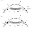
そして、手術者が針部材16aを引っ張っていくと、図4(b)に示すように、ハプティック保持部14が、端部から収縮(変形)して細くなって針孔17(左側の針孔17)に入り、針孔17を通過する。作業者は、眼球30における左右方向の略真ん中にハプティック保持部14が到達するまで針部材16aを右側に引っ張る。これにより、第1レンズ支持部12は、図4(c)に示すように、眼球30内において、2箇所の針孔17の間に架け渡された2本の線状部材18によって、ハプティック保持部14が吊られた状態に設けられる。そして、この状態で作業者は、ハプティック保持部14の内側に入口15から水を入れてハプティック保持部14を広げる。なお、水の代わりに、ヒアルロン酸などを含むゲル状の流体を用いることもできる。
Then, when the operator pulls the
次に、手術者は、第2レンズ支持部12についてハプティック保持部14を眼球30内に導入する作業を行う。第2レンズ支持部12は、第1レンズ支持部12と同様の手順で、眼球30の中心に対し第1レンズ支持部12に上下対称に設けられる。第2レンズ支持部12は、図5(a)に示すように、眼球30内において、眼球30の中心より3~4mm下側の2箇所の針孔17の間に架け渡された2本の線状部材18によって、ハプティック保持部14が吊り下げられた状態に設けられる。第2レンズ支持部12は、第1レンズ支持部12に対し略平行に設けることが好ましい。
Next, the operator performs an operation of introducing the haptic holding
次に、手術者は、眼球30の強膜31に形成した切開口を通して眼球30内に入れた眼内鉗子(図示省略)によって、眼球30内に落下した眼内レンズ20を拾い上げる。そして、手術者は、図5(b)に示すように、一方のハプティック22を一方のハプティック保持部14に対し入口15から挿入していく。その際、ハプティック保持部14はハプティック22によって押し広げられる。さらに、図5(c)に示すように、他方のハプティック22を他方のハプティック保持部14に対し入口15から挿入していく。同様に、他方のハプティック保持部14は押し広げられる。
Next, the operator picks up the
次に、眼球30の中心に対し眼内レンズ20の中心がずれている場合に、手術者は、眼球30の中心に対し眼内レンズ20の中心が略一致するように、眼内レンズ20を動かして位置調整をする。図6(a)は、眼内レンズ20の位置調整後の状態を示す。
Next, when the center of the
最後に、手術者は、眼球30の外側において、各針孔17のすぐ外側の位置の強膜31に線状部材18を縫着して結び目19(図6(b)参照)を作成し、その結び目19から外側の線状部材18を切断する。これにより、各ハプティック保持部14の位置が固定され、各ハプティック保持部14によって眼内レンズ20の位置は保持される。さらに、手術者は、ピンセットの挿入口として用いた切開口を縫合する。以上により、水晶体再建術は終了する。
Finally, the operator sews the
[実施形態の効果等]
本実施形態では、眼内レンズ20のハプティック22を保持するハプティック保持部14が、柔軟な素材を用いた袋状の部材であり、ハプティック保持部14に固定された線状部材18が通る針孔17を通すことができ、その針孔17から眼球30内に導入することができる。そのため、切開創を形成することなく、線状部材18を引っ張るだけで容易にハプティック保持部14を眼球30内に導入することができる。
[Effects of the embodiment, etc.]
In this embodiment, the haptic holding
また、本実施形態では、線状部材18を引っ張るだけで、各ハプティック保持部14の位置調節を行うことができる。特に、各ハプティック保持部14に設けられたマーク13が、手術者から視認できる位置に設けられているため、手術者はマーク13の位置を見ながら、各ハプティック保持部14を水晶体嚢と略同じ位置に設けることができる。これにより、眼内レンズ20は所定の位置に保持される。
Further, in the present embodiment, the position of each haptic holding
また、本実施形態では、眼内レンズ20の各ハプティック22が袋状のハプティック保持部14によってソフトに保持される。各ハプティック22が眼内組織に接触しない。ここで、シングルピース多焦点IOL20は、ハプティック22が太く炎症を惹起させやすい。また、ハプティック22は、軟らかい素材(例えば軟性アクリルゲル)が用いられており、縫合糸を直接的に結び付けると断裂する虞がある。すなわち、シングルピース多焦点IOL20は、眼内レンズ強膜内固定術、又は、眼内レンズ毛様溝縫着術の何れにも向いていない。これらの手法は、固定できる眼内レンズ20の種類が限定される。それに対し、本実施形態では、このようなシングルピース多焦点IOL20について、これらの手術法を採用せずに、各ハプティック20が眼内組織に接触しない新たな手術法(平行棒(平行糸)縫着法)を採用している。そのため、眼内組織の炎症を抑制することができる。また、本実施形態によれば、シングルピース多焦点IOL20を含めて様々な種類の眼内レンズ20に適用することができる。
Further, in this embodiment, each haptic 22 of the
また、本実施形態では、強膜31において針部材16aを通す位置に応じて、前後方向において一対のハプティック保持部14の設置位置(深度)を決めることができる。ここで、特許文献1や特許文献2に記載の器具では、眼内レンズの保持部の設置位置が限定され、眼内レンズの深度が限定される。それに対し、本実施形態では、任意の深度に眼内レンズ20を固定することができる。
Further, in the present embodiment, the installation position (depth) of the pair of
また、本実施形態では、眼球30内に眼内レンズ20を外側から挿入する場合だけでなく、眼球30内に落下した眼内レンズ20を摘出せずに固定することができる。すなわち、眼内操作だけで眼内レンズ20の整復を完結させることができる。
Moreover, in this embodiment, not only can the
[変形例1]
本変形例では、図7に示すように、各ハプティック保持部14の各シート14a,14bに、袋内と袋外とを連通させる連通孔24が形成されている。連通孔24は複数個設けられている。各連通孔24は、ハプティック22の先端側の横断面よりも小さく、ハプティック22が通過できない大きさに形成されている。本変形例によれば、連通孔24によって各ハプティック保持部14が盲端構造ではなくなるため、各ハプティック保持部14内において細菌が繁殖しにくい。また、抗生剤等の薬剤を各ハプティック保持部14内に効率よく供給することができる。なお、連通孔24は、円弧上の外周部寄りの位置に少なくとも形成すればよく、入口15寄りの位置にも形成してもよい。
[Modification 1]
In this modification, as shown in FIG. 7, communication holes 24 are formed in the
[変形例2]
本変形例では、図8に示すように、各ハプティック保持部14が、網状で袋状の部材により形成されている。各ハプティック保持部14の網目は、ハプティック22の先端側の横断面よりも小さく、ハプティック22が通過できない大きさである。本変形例によれば、各ハプティック保持部14内において細菌が繁殖しにくい。また、抗生剤等の薬剤を各ハプティック保持部14内に効率よく供給することができる。
[Modification 2]
In this modified example, as shown in FIG. 8, each
[変形例3]
本変形例では、一対のハプティック保持部14が、図9に示すように、線状部材18によって互いに接続されて一体化されている。つまり、2つのハプティック保持部14が、2つの針部材16a,16b間の1本の糸状体に設けられている。この場合、各針部材16a,16bを先頭にして各ハプティック保持部14を眼球30内に導入することができる。それにより、片側の強膜縫合が不要となる。
[Modification 3]
In this modification, a pair of
[変形例4]
本変形例では、各ハプティック保持部14が、袋状以外の形状の部材により形成されている。図10に示すように、各ハプティック保持部14は、ハプティック22の引っ掛ける複数個の輪状部により構成されている。具体的に、各ハプティック保持部14は、縫合糸を結ぶことで作成された8の字状部分(可撓性を有する部分)である。ハプティック22は、2つの輪状部によって保持される。なお、図10は、眼球30の正面から見た図であり眼球30内を実線で示している。
[Modification 4]
In this modified example, each haptic holding
[変形例5]
本変形例では、線状部材18が、各ハプティック保持部14の入口15の縁に沿って取り付けられている。例えば、各ハプティック保持部14では、図11に示すように、各シート14a,14bにおける入口15の縁に細穴15aが形成されている。細穴15aは、例えばシート14a,14bを折り返すことによって形成されている。線状部材18は、ハプティック保持部14の一端部で2本に分かれて、それぞれが別々のシート14a,14bの細穴15aに通されて、ハプティック保持部14の他端部で合わさっている。線状部材18は、ハプティック保持部14に固定されている。
[Modification 5]
In this modification, a
なお、線状部材18は、両方のシート14a,14bの入口15に沿って設ける必要はなく、片方のシート14aの入口15に沿って設けて固定してもよい。この場合は、線状部材18は、ハプティック保持部14の両端間で分かれない。また、シート14aに細穴15aを形成せずに、シート14aの入口15に沿って線状部材18を固定してもよい。
The
[変形例6]
本変形例では、線状部材18が、樹脂製又は金属製などの細い棒状部材に形成されている。また、図12に示すように、ハプティック保持部14に対し、線状部材18を固定する縁部材25(例えば、樹脂製の部材)を取り付けてもよい。縁部材25は、入口15に沿って全周囲に設けられる。なお、縁部材25を用いずに、ハプティック保持部14に線状部材18(棒状部材)を固定してもよい。また、線状部材18として上述の実施形態のように糸状部材を用いる場合に、ハプティック保持部14に縁部材25を取り付けてもよい。
[Modification 6]
In this modification, the
ここで、線状部材18として棒状部材を用いる場合、眼球30の内側にレンズ支持部12を架け渡してハプティック保持部14の位置調節を行った後に、図13(a)に示す加熱用器具26を用いて線状部材18を加熱し、図13(b)に示す止め部19を形成する加熱端処理を施してもよい。これにより、ハプティック保持部14の位置を容易に固定することができる。なお、加熱端処理は、線状部材18が棒状部材の場合に限定されず、線状部材18が糸状部材の場合にも適用することができる。
Here, when a rod-shaped member is used as the
[変形例7]
上記実施形態では、眼内レンズ固定用器具10において線状部材18に針部材16a,16bが取り付けられていたが、製品としては針部材16a,16bが取り付けられていない状態で、手術者などによって針部材16a,16bが後付けされてもよい。
[Modification 7]
In the above-described embodiment, the
本発明は、眼内レンズの固定に用いられる眼内レンズ固定用器具等に適用可能である。 INDUSTRIAL APPLICABILITY The present invention can be applied to an intraocular lens fixation device or the like used to fix an intraocular lens.
10 眼内レンズ固定用器具
12 レンズ支持部
14 ハプティック保持部
16a,16b 針部材
18 線状部材
20 眼内レンズ
21 レンズ部
22 ハプティック
REFERENCE SIGNS
Claims (6)
前記複数のハプティックの各々に対応して設けられ、それぞれが、前記ハプティックが挿入される開口を有し、該開口に挿入された前記ハプティックを保持する複数のハプティック保持部と、
前記複数のハプティック保持部の各々に対し固定された線状部材とを備え、
前記ハプティック保持部の各々は、前記線状部材が2本接続され、該2本の線状部材が眼球内に張られることで、眼球内で浮いた状態で支持され、
前記ハプティック保持部の各々には、可撓性を有する素材が用いられ、
前記ハプティック保持部は、前記ハプティックを引っ掛ける複数の輪状部により構成され、前記開口に相当する該輪状部の内側に挿入された前記ハプティックを保持する、眼内レンズ固定用器具。 An intraocular lens fixing device for fixing an intraocular lens having a plurality of haptics in an eyeball,
a plurality of haptic holders provided corresponding to each of the plurality of haptics, each having an opening into which the haptic is inserted, and holding the haptic inserted into the opening;
a linear member fixed to each of the plurality of haptic holders,
Each of the haptic holding parts is supported in a floating state in the eyeball by connecting two of the linear members and stretching the two linear members in the eyeball ,
A flexible material is used for each of the haptic holders,
An intraocular lens fixing device , wherein the haptic holding part is composed of a plurality of ring-shaped parts for hooking the haptics, and holds the haptics inserted inside the ring-shaped parts corresponding to the openings .
前記眼球内に張られる線状部材と、
前記複数のハプティックの各々に対応して設けられ、それぞれが前記ハプティックを保持して、前記線状部材によって前記眼球内の空間に支持される複数のハプティック保持部とを備え、
前記複数のハプティック保持部の各々には、前記線状部材が固定され、
前記ハプティック保持部の各々には、可撓性を有する素材が用いられ、
前記ハプティック保持部は、前記ハプティックが挿入される開口を有し、該開口に挿入されたハプティックを保持し、
前記ハプティック保持部は、前記ハプティックを挿入する入口が前記開口として形成された袋状の部材である、眼内レンズ固定用器具。 An intraocular lens fixing device for fixing an intraocular lens having a plurality of haptics in an eyeball,
a linear member stretched inside the eyeball;
a plurality of haptic holders provided corresponding to each of the plurality of haptics, each holding the haptic and supported by the linear member in the space within the eyeball;
The linear member is fixed to each of the plurality of haptic holders,
A flexible material is used for each of the haptic holders,
the haptic holder has an opening into which the haptic is inserted, and holds the haptic inserted into the opening;
The intraocular lens fixing device, wherein the haptic holding part is a bag-shaped member in which an entrance for inserting the haptic is formed as the opening.
Priority Applications (3)
| Application Number | Priority Date | Filing Date | Title |
|---|---|---|---|
| JP2018085885A JP7211714B2 (en) | 2018-04-26 | 2018-04-26 | Intraocular lens fixation device |
| PCT/JP2019/017825 WO2019208746A1 (en) | 2018-04-26 | 2019-04-25 | Intraocular lens fixing tool |
| US17/079,139 US11850145B2 (en) | 2018-04-26 | 2020-10-23 | Intraocular lens fixing device |
Applications Claiming Priority (1)
| Application Number | Priority Date | Filing Date | Title |
|---|---|---|---|
| JP2018085885A JP7211714B2 (en) | 2018-04-26 | 2018-04-26 | Intraocular lens fixation device |
Publications (3)
| Publication Number | Publication Date |
|---|---|
| JP2019187949A JP2019187949A (en) | 2019-10-31 |
| JP2019187949A5 JP2019187949A5 (en) | 2021-07-26 |
| JP7211714B2 true JP7211714B2 (en) | 2023-01-24 |
Family
ID=68293653
Family Applications (1)
| Application Number | Title | Priority Date | Filing Date |
|---|---|---|---|
| JP2018085885A Active JP7211714B2 (en) | 2018-04-26 | 2018-04-26 | Intraocular lens fixation device |
Country Status (3)
| Country | Link |
|---|---|
| US (1) | US11850145B2 (en) |
| JP (1) | JP7211714B2 (en) |
| WO (1) | WO2019208746A1 (en) |
Families Citing this family (1)
| Publication number | Priority date | Publication date | Assignee | Title |
|---|---|---|---|---|
| WO2022154136A1 (en) | 2021-01-13 | 2022-07-21 | 김대윤 | Support structure for artificial eye lens |
Citations (4)
| Publication number | Priority date | Publication date | Assignee | Title |
|---|---|---|---|---|
| JP2003533271A (en) | 2000-05-15 | 2003-11-11 | ボシュ・アンド・ロム・インコーポレイテッド | Injectable fixed iris intraocular lens |
| JP2007029727A (en) | 2005-07-26 | 2007-02-08 | Visioncare Ophthalmic Technologies Inc | Intraocular device, and members for supporting intraocular device |
| US20120130389A1 (en) | 2010-10-08 | 2012-05-24 | Prywes Arnold S | Apparatus and method for performing ocular surgery |
| WO2017134056A1 (en) | 2016-02-02 | 2017-08-10 | Fundación Tekniker | Supporting device for the insertion of an intraocular lens, use of the device and intraocular lens insertion method |
Family Cites Families (7)
| Publication number | Priority date | Publication date | Assignee | Title |
|---|---|---|---|---|
| US4253199A (en) * | 1978-09-25 | 1981-03-03 | Surgical Design Corporation | Surgical method and apparatus for implants for the eye |
| JP3040101B1 (en) * | 1999-02-12 | 2000-05-08 | 毅 杉浦 | Ciliary sulcus pad in posterior chamber lens transciliary scleral stitch of the eyeball |
| JP2000245755A (en) | 1999-03-02 | 2000-09-12 | Menicon Co Ltd | Intraocular fixing auxiliary tool |
| US6352542B1 (en) * | 2000-03-08 | 2002-03-05 | Michael E. Snyder | Intraocular lens with improved haptic and method of implanting same |
| DE102012016892A1 (en) * | 2012-08-24 | 2014-02-27 | Be Innovative Gmbh | Intraocular lens, in particular ciliary intraocular lens |
| JP5816335B1 (en) | 2014-05-28 | 2015-11-18 | 株式会社中京メディカル | Support |
| US10111746B2 (en) * | 2016-10-21 | 2018-10-30 | Omega Ophthalmics Llc | Prosthetic capsular devices, systems, and methods |
-
2018
- 2018-04-26 JP JP2018085885A patent/JP7211714B2/en active Active
-
2019
- 2019-04-25 WO PCT/JP2019/017825 patent/WO2019208746A1/en active Application Filing
-
2020
- 2020-10-23 US US17/079,139 patent/US11850145B2/en active Active
Patent Citations (4)
| Publication number | Priority date | Publication date | Assignee | Title |
|---|---|---|---|---|
| JP2003533271A (en) | 2000-05-15 | 2003-11-11 | ボシュ・アンド・ロム・インコーポレイテッド | Injectable fixed iris intraocular lens |
| JP2007029727A (en) | 2005-07-26 | 2007-02-08 | Visioncare Ophthalmic Technologies Inc | Intraocular device, and members for supporting intraocular device |
| US20120130389A1 (en) | 2010-10-08 | 2012-05-24 | Prywes Arnold S | Apparatus and method for performing ocular surgery |
| WO2017134056A1 (en) | 2016-02-02 | 2017-08-10 | Fundación Tekniker | Supporting device for the insertion of an intraocular lens, use of the device and intraocular lens insertion method |
Also Published As
| Publication number | Publication date |
|---|---|
| JP2019187949A (en) | 2019-10-31 |
| US20210038368A1 (en) | 2021-02-11 |
| WO2019208746A1 (en) | 2019-10-31 |
| US11850145B2 (en) | 2023-12-26 |
Similar Documents
| Publication | Publication Date | Title |
|---|---|---|
| US6352542B1 (en) | Intraocular lens with improved haptic and method of implanting same | |
| JP4370371B2 (en) | Lens capsule retainer | |
| US4687484A (en) | Anterior chamber intraocular lens | |
| ES2234522T3 (en) | INSERTION DEVICE OF AN INTRAOCULAR LENS. | |
| US20070093892A1 (en) | Maintaining preoperative position of the posterior lens capsule after cataract surgery | |
| EP1295579B1 (en) | Holder of contact lens for vitreous body operation as well as holding part and connection part of contact lens for vitreous body operation | |
| US20050177229A1 (en) | Ophthalmological zonular stretch segment for treating presbyopia | |
| US5336262A (en) | Intraocular lens with haptics for scleral fixation and method for using it | |
| US9510814B1 (en) | Surgical apparatus and method of use thereof | |
| US20090018650A1 (en) | Ophthalmological zonular stretch segment for treating presbyopia | |
| JP7211714B2 (en) | Intraocular lens fixation device | |
| KR102251842B1 (en) | Support Structure for Artificial Eyes Lens | |
| JP5398092B1 (en) | Intraocular lens | |
| US20190000609A1 (en) | Capsular clip for correcting zonular weakness post-cataract surgery | |
| RU2475211C1 (en) | Intraocular lens | |
| RU2665182C1 (en) | Method of implantation and sututre fixation of s-shaped intraocular lens to iris | |
| JP6501608B2 (en) | Intraocular ring | |
| JP2020005979A (en) | Ophthalmic surgical instrument | |
| JP2010012184A (en) | Suture thread with medical suture needle | |
| KR102259590B1 (en) | Apparatus for fixing intraocular lens including supporting part in which suture thread is wound and provided to be slidable | |
| CN210170229U (en) | Sclera fixed artificial lens and its lock catch | |
| ES2965113T3 (en) | Intraocular lens that includes coupling portion in the sclera | |
| JP2007021147A (en) | Lens capsule equator retaining appliance | |
| WO2017212352A1 (en) | An intra-ocular implant to properly hold an artificial intra-ocular lens in an eye | |
| JP7518999B2 (en) | Support structure for artificial lens |
Legal Events
| Date | Code | Title | Description |
|---|---|---|---|
| A621 | Written request for application examination |
Free format text: JAPANESE INTERMEDIATE CODE: A621 Effective date: 20210423 |
|
| A521 | Request for written amendment filed |
Free format text: JAPANESE INTERMEDIATE CODE: A523 Effective date: 20210601 |
|
| A131 | Notification of reasons for refusal |
Free format text: JAPANESE INTERMEDIATE CODE: A131 Effective date: 20220425 |
|
| A521 | Request for written amendment filed |
Free format text: JAPANESE INTERMEDIATE CODE: A523 Effective date: 20220614 |
|
| A131 | Notification of reasons for refusal |
Free format text: JAPANESE INTERMEDIATE CODE: A131 Effective date: 20220817 |
|
| A601 | Written request for extension of time |
Free format text: JAPANESE INTERMEDIATE CODE: A601 Effective date: 20220928 |
|
| A711 | Notification of change in applicant |
Free format text: JAPANESE INTERMEDIATE CODE: A711 Effective date: 20221027 |
|
| A521 | Request for written amendment filed |
Free format text: JAPANESE INTERMEDIATE CODE: A821 Effective date: 20221027 |
|
| A521 | Request for written amendment filed |
Free format text: JAPANESE INTERMEDIATE CODE: A523 Effective date: 20221128 |
|
| TRDD | Decision of grant or rejection written | ||
| A01 | Written decision to grant a patent or to grant a registration (utility model) |
Free format text: JAPANESE INTERMEDIATE CODE: A01 Effective date: 20230105 |
|
| A61 | First payment of annual fees (during grant procedure) |
Free format text: JAPANESE INTERMEDIATE CODE: A61 Effective date: 20230112 |
|
| R150 | Certificate of patent or registration of utility model |
Ref document number: 7211714 Country of ref document: JP Free format text: JAPANESE INTERMEDIATE CODE: R150 |