JP7208897B2 - Pressure sensing device and extracorporeal circulation device - Google Patents
Pressure sensing device and extracorporeal circulation device Download PDFInfo
- Publication number
- JP7208897B2 JP7208897B2 JP2019529094A JP2019529094A JP7208897B2 JP 7208897 B2 JP7208897 B2 JP 7208897B2 JP 2019529094 A JP2019529094 A JP 2019529094A JP 2019529094 A JP2019529094 A JP 2019529094A JP 7208897 B2 JP7208897 B2 JP 7208897B2
- Authority
- JP
- Japan
- Prior art keywords
- pressure
- tube
- medium
- image information
- control unit
- Prior art date
- Legal status (The legal status is an assumption and is not a legal conclusion. Google has not performed a legal analysis and makes no representation as to the accuracy of the status listed.)
- Active
Links
- 230000004087 circulation Effects 0.000 title claims description 77
- 238000001514 detection method Methods 0.000 claims description 78
- 239000008280 blood Substances 0.000 description 82
- 210000004369 blood Anatomy 0.000 description 82
- 239000007788 liquid Substances 0.000 description 30
- 238000012545 processing Methods 0.000 description 15
- 238000010586 diagram Methods 0.000 description 14
- 238000000034 method Methods 0.000 description 10
- 239000000463 material Substances 0.000 description 9
- 230000017531 blood circulation Effects 0.000 description 7
- 230000036770 blood supply Effects 0.000 description 7
- 238000012546 transfer Methods 0.000 description 7
- 239000007789 gas Substances 0.000 description 6
- CURLTUGMZLYLDI-UHFFFAOYSA-N Carbon dioxide Chemical compound O=C=O CURLTUGMZLYLDI-UHFFFAOYSA-N 0.000 description 4
- 210000004072 lung Anatomy 0.000 description 4
- 238000012986 modification Methods 0.000 description 4
- 230000004048 modification Effects 0.000 description 4
- 229920003023 plastic Polymers 0.000 description 4
- -1 polybutylene terephthalate Polymers 0.000 description 4
- 229920001707 polybutylene terephthalate Polymers 0.000 description 4
- 229920000139 polyethylene terephthalate Polymers 0.000 description 4
- 239000005020 polyethylene terephthalate Substances 0.000 description 4
- 229920006324 polyoxymethylene Polymers 0.000 description 4
- 210000003462 vein Anatomy 0.000 description 4
- MYMOFIZGZYHOMD-UHFFFAOYSA-N Dioxygen Chemical compound O=O MYMOFIZGZYHOMD-UHFFFAOYSA-N 0.000 description 3
- 206010061216 Infarction Diseases 0.000 description 3
- 210000001367 artery Anatomy 0.000 description 3
- 229910001882 dioxygen Inorganic materials 0.000 description 3
- 230000000694 effects Effects 0.000 description 3
- 230000007574 infarction Effects 0.000 description 3
- 238000006213 oxygenation reaction Methods 0.000 description 3
- 239000004033 plastic Substances 0.000 description 3
- 238000001356 surgical procedure Methods 0.000 description 3
- 229930182556 Polyacetal Natural products 0.000 description 2
- 208000007536 Thrombosis Diseases 0.000 description 2
- BZHJMEDXRYGGRV-UHFFFAOYSA-N Vinyl chloride Chemical compound ClC=C BZHJMEDXRYGGRV-UHFFFAOYSA-N 0.000 description 2
- 229910002092 carbon dioxide Inorganic materials 0.000 description 2
- 239000001569 carbon dioxide Substances 0.000 description 2
- 239000012528 membrane Substances 0.000 description 2
- 239000002184 metal Substances 0.000 description 2
- 229910052751 metal Inorganic materials 0.000 description 2
- 229920005989 resin Polymers 0.000 description 2
- 239000011347 resin Substances 0.000 description 2
- 229920002379 silicone rubber Polymers 0.000 description 2
- 239000004945 silicone rubber Substances 0.000 description 2
- 229920003002 synthetic resin Polymers 0.000 description 2
- 239000000057 synthetic resin Substances 0.000 description 2
- 229910052782 aluminium Inorganic materials 0.000 description 1
- XAGFODPZIPBFFR-UHFFFAOYSA-N aluminium Chemical compound [Al] XAGFODPZIPBFFR-UHFFFAOYSA-N 0.000 description 1
- 238000007675 cardiac surgery Methods 0.000 description 1
- 238000006243 chemical reaction Methods 0.000 description 1
- 230000000295 complement effect Effects 0.000 description 1
- 239000000470 constituent Substances 0.000 description 1
- 230000008602 contraction Effects 0.000 description 1
- 229920001971 elastomer Polymers 0.000 description 1
- 210000001105 femoral artery Anatomy 0.000 description 1
- 210000003191 femoral vein Anatomy 0.000 description 1
- 239000012510 hollow fiber Substances 0.000 description 1
- 238000003780 insertion Methods 0.000 description 1
- 230000037431 insertion Effects 0.000 description 1
- 239000004973 liquid crystal related substance Substances 0.000 description 1
- 230000007257 malfunction Effects 0.000 description 1
- 229910044991 metal oxide Inorganic materials 0.000 description 1
- 150000004706 metal oxides Chemical class 0.000 description 1
- 150000002739 metals Chemical class 0.000 description 1
- 210000005245 right atrium Anatomy 0.000 description 1
- 239000004065 semiconductor Substances 0.000 description 1
- 229910001220 stainless steel Inorganic materials 0.000 description 1
- 239000010935 stainless steel Substances 0.000 description 1
Images


Classifications
-
- G—PHYSICS
- G01—MEASURING; TESTING
- G01L—MEASURING FORCE, STRESS, TORQUE, WORK, MECHANICAL POWER, MECHANICAL EFFICIENCY, OR FLUID PRESSURE
- G01L11/00—Measuring steady or quasi-steady pressure of a fluid or a fluent solid material by means not provided for in group G01L7/00 or G01L9/00
- G01L11/02—Measuring steady or quasi-steady pressure of a fluid or a fluent solid material by means not provided for in group G01L7/00 or G01L9/00 by optical means
-
- A—HUMAN NECESSITIES
- A61—MEDICAL OR VETERINARY SCIENCE; HYGIENE
- A61B—DIAGNOSIS; SURGERY; IDENTIFICATION
- A61B5/00—Measuring for diagnostic purposes; Identification of persons
- A61B5/02—Detecting, measuring or recording pulse, heart rate, blood pressure or blood flow; Combined pulse/heart-rate/blood pressure determination; Evaluating a cardiovascular condition not otherwise provided for, e.g. using combinations of techniques provided for in this group with electrocardiography or electroauscultation; Heart catheters for measuring blood pressure
- A61B5/021—Measuring pressure in heart or blood vessels
- A61B5/02141—Details of apparatus construction, e.g. pump units or housings therefor, cuff pressurising systems, arrangements of fluid conduits or circuits
-
- A—HUMAN NECESSITIES
- A61—MEDICAL OR VETERINARY SCIENCE; HYGIENE
- A61B—DIAGNOSIS; SURGERY; IDENTIFICATION
- A61B5/00—Measuring for diagnostic purposes; Identification of persons
- A61B5/02—Detecting, measuring or recording pulse, heart rate, blood pressure or blood flow; Combined pulse/heart-rate/blood pressure determination; Evaluating a cardiovascular condition not otherwise provided for, e.g. using combinations of techniques provided for in this group with electrocardiography or electroauscultation; Heart catheters for measuring blood pressure
- A61B5/021—Measuring pressure in heart or blood vessels
- A61B5/0215—Measuring pressure in heart or blood vessels by means inserted into the body
-
- A—HUMAN NECESSITIES
- A61—MEDICAL OR VETERINARY SCIENCE; HYGIENE
- A61M—DEVICES FOR INTRODUCING MEDIA INTO, OR ONTO, THE BODY; DEVICES FOR TRANSDUCING BODY MEDIA OR FOR TAKING MEDIA FROM THE BODY; DEVICES FOR PRODUCING OR ENDING SLEEP OR STUPOR
- A61M1/00—Suction or pumping devices for medical purposes; Devices for carrying-off, for treatment of, or for carrying-over, body-liquids; Drainage systems
- A61M1/14—Dialysis systems; Artificial kidneys; Blood oxygenators ; Reciprocating systems for treatment of body fluids, e.g. single needle systems for hemofiltration or pheresis
- A61M1/16—Dialysis systems; Artificial kidneys; Blood oxygenators ; Reciprocating systems for treatment of body fluids, e.g. single needle systems for hemofiltration or pheresis with membranes
- A61M1/1698—Blood oxygenators with or without heat-exchangers
-
- A—HUMAN NECESSITIES
- A61—MEDICAL OR VETERINARY SCIENCE; HYGIENE
- A61M—DEVICES FOR INTRODUCING MEDIA INTO, OR ONTO, THE BODY; DEVICES FOR TRANSDUCING BODY MEDIA OR FOR TAKING MEDIA FROM THE BODY; DEVICES FOR PRODUCING OR ENDING SLEEP OR STUPOR
- A61M1/00—Suction or pumping devices for medical purposes; Devices for carrying-off, for treatment of, or for carrying-over, body-liquids; Drainage systems
- A61M1/36—Other treatment of blood in a by-pass of the natural circulatory system, e.g. temperature adaptation, irradiation ; Extra-corporeal blood circuits
- A61M1/3621—Extra-corporeal blood circuits
- A61M1/3626—Gas bubble detectors
-
- A—HUMAN NECESSITIES
- A61—MEDICAL OR VETERINARY SCIENCE; HYGIENE
- A61M—DEVICES FOR INTRODUCING MEDIA INTO, OR ONTO, THE BODY; DEVICES FOR TRANSDUCING BODY MEDIA OR FOR TAKING MEDIA FROM THE BODY; DEVICES FOR PRODUCING OR ENDING SLEEP OR STUPOR
- A61M1/00—Suction or pumping devices for medical purposes; Devices for carrying-off, for treatment of, or for carrying-over, body-liquids; Drainage systems
- A61M1/36—Other treatment of blood in a by-pass of the natural circulatory system, e.g. temperature adaptation, irradiation ; Extra-corporeal blood circuits
- A61M1/3621—Extra-corporeal blood circuits
- A61M1/3639—Blood pressure control, pressure transducers specially adapted therefor
-
- G—PHYSICS
- G01—MEASURING; TESTING
- G01L—MEASURING FORCE, STRESS, TORQUE, WORK, MECHANICAL POWER, MECHANICAL EFFICIENCY, OR FLUID PRESSURE
- G01L9/00—Measuring steady of quasi-steady pressure of fluid or fluent solid material by electric or magnetic pressure-sensitive elements; Transmitting or indicating the displacement of mechanical pressure-sensitive elements, used to measure the steady or quasi-steady pressure of a fluid or fluent solid material, by electric or magnetic means
- G01L9/0026—Transmitting or indicating the displacement of flexible, deformable tubes by electric, electromechanical, magnetic or electromagnetic means
-
- G—PHYSICS
- G06—COMPUTING; CALCULATING OR COUNTING
- G06T—IMAGE DATA PROCESSING OR GENERATION, IN GENERAL
- G06T7/00—Image analysis
- G06T7/0002—Inspection of images, e.g. flaw detection
- G06T7/0012—Biomedical image inspection
- G06T7/0014—Biomedical image inspection using an image reference approach
-
- G—PHYSICS
- G06—COMPUTING; CALCULATING OR COUNTING
- G06V—IMAGE OR VIDEO RECOGNITION OR UNDERSTANDING
- G06V10/00—Arrangements for image or video recognition or understanding
- G06V10/20—Image preprocessing
- G06V10/28—Quantising the image, e.g. histogram thresholding for discrimination between background and foreground patterns
-
- G—PHYSICS
- G06—COMPUTING; CALCULATING OR COUNTING
- G06V—IMAGE OR VIDEO RECOGNITION OR UNDERSTANDING
- G06V10/00—Arrangements for image or video recognition or understanding
- G06V10/70—Arrangements for image or video recognition or understanding using pattern recognition or machine learning
- G06V10/74—Image or video pattern matching; Proximity measures in feature spaces
- G06V10/75—Organisation of the matching processes, e.g. simultaneous or sequential comparisons of image or video features; Coarse-fine approaches, e.g. multi-scale approaches; using context analysis; Selection of dictionaries
- G06V10/751—Comparing pixel values or logical combinations thereof, or feature values having positional relevance, e.g. template matching
-
- A—HUMAN NECESSITIES
- A61—MEDICAL OR VETERINARY SCIENCE; HYGIENE
- A61M—DEVICES FOR INTRODUCING MEDIA INTO, OR ONTO, THE BODY; DEVICES FOR TRANSDUCING BODY MEDIA OR FOR TAKING MEDIA FROM THE BODY; DEVICES FOR PRODUCING OR ENDING SLEEP OR STUPOR
- A61M1/00—Suction or pumping devices for medical purposes; Devices for carrying-off, for treatment of, or for carrying-over, body-liquids; Drainage systems
- A61M1/36—Other treatment of blood in a by-pass of the natural circulatory system, e.g. temperature adaptation, irradiation ; Extra-corporeal blood circuits
- A61M1/3621—Extra-corporeal blood circuits
- A61M1/3666—Cardiac or cardiopulmonary bypass, e.g. heart-lung machines
-
- A—HUMAN NECESSITIES
- A61—MEDICAL OR VETERINARY SCIENCE; HYGIENE
- A61M—DEVICES FOR INTRODUCING MEDIA INTO, OR ONTO, THE BODY; DEVICES FOR TRANSDUCING BODY MEDIA OR FOR TAKING MEDIA FROM THE BODY; DEVICES FOR PRODUCING OR ENDING SLEEP OR STUPOR
- A61M2205/00—General characteristics of the apparatus
- A61M2205/33—Controlling, regulating or measuring
- A61M2205/3306—Optical measuring means
-
- A—HUMAN NECESSITIES
- A61—MEDICAL OR VETERINARY SCIENCE; HYGIENE
- A61M—DEVICES FOR INTRODUCING MEDIA INTO, OR ONTO, THE BODY; DEVICES FOR TRANSDUCING BODY MEDIA OR FOR TAKING MEDIA FROM THE BODY; DEVICES FOR PRODUCING OR ENDING SLEEP OR STUPOR
- A61M2205/00—General characteristics of the apparatus
- A61M2205/33—Controlling, regulating or measuring
- A61M2205/3375—Acoustical, e.g. ultrasonic, measuring means
-
- A—HUMAN NECESSITIES
- A61—MEDICAL OR VETERINARY SCIENCE; HYGIENE
- A61M—DEVICES FOR INTRODUCING MEDIA INTO, OR ONTO, THE BODY; DEVICES FOR TRANSDUCING BODY MEDIA OR FOR TAKING MEDIA FROM THE BODY; DEVICES FOR PRODUCING OR ENDING SLEEP OR STUPOR
- A61M2205/00—General characteristics of the apparatus
- A61M2205/50—General characteristics of the apparatus with microprocessors or computers
- A61M2205/52—General characteristics of the apparatus with microprocessors or computers with memories providing a history of measured variating parameters of apparatus or patient
-
- G—PHYSICS
- G06—COMPUTING; CALCULATING OR COUNTING
- G06T—IMAGE DATA PROCESSING OR GENERATION, IN GENERAL
- G06T2207/00—Indexing scheme for image analysis or image enhancement
- G06T2207/30—Subject of image; Context of image processing
- G06T2207/30004—Biomedical image processing
- G06T2207/30101—Blood vessel; Artery; Vein; Vascular
- G06T2207/30104—Vascular flow; Blood flow; Perfusion
-
- G—PHYSICS
- G06—COMPUTING; CALCULATING OR COUNTING
- G06V—IMAGE OR VIDEO RECOGNITION OR UNDERSTANDING
- G06V2201/00—Indexing scheme relating to image or video recognition or understanding
- G06V2201/03—Recognition of patterns in medical or anatomical images
- G06V2201/034—Recognition of patterns in medical or anatomical images of medical instruments
Landscapes
- Health & Medical Sciences (AREA)
- Engineering & Computer Science (AREA)
- Heart & Thoracic Surgery (AREA)
- Physics & Mathematics (AREA)
- Life Sciences & Earth Sciences (AREA)
- Vascular Medicine (AREA)
- General Health & Medical Sciences (AREA)
- General Physics & Mathematics (AREA)
- Cardiology (AREA)
- Theoretical Computer Science (AREA)
- Biomedical Technology (AREA)
- Animal Behavior & Ethology (AREA)
- Veterinary Medicine (AREA)
- Public Health (AREA)
- Computer Vision & Pattern Recognition (AREA)
- Medical Informatics (AREA)
- Hematology (AREA)
- Anesthesiology (AREA)
- Multimedia (AREA)
- Urology & Nephrology (AREA)
- Emergency Medicine (AREA)
- Biophysics (AREA)
- Evolutionary Computation (AREA)
- Molecular Biology (AREA)
- Pathology (AREA)
- Artificial Intelligence (AREA)
- Computing Systems (AREA)
- Databases & Information Systems (AREA)
- Surgery (AREA)
- Software Systems (AREA)
- Physiology (AREA)
- Nuclear Medicine, Radiotherapy & Molecular Imaging (AREA)
- Radiology & Medical Imaging (AREA)
- Quality & Reliability (AREA)
- Electromagnetism (AREA)
- External Artificial Organs (AREA)
- Measuring Fluid Pressure (AREA)
Description
本発明は、血液等の媒体を通すチューブに装着され、チューブ内における媒体の圧力を検知する圧力検知装置および体外循環装置に関する。 TECHNICAL FIELD The present invention relates to a pressure detection device and an extracorporeal circulation device which are attached to a tube through which a medium such as blood passes and which detects the pressure of the medium in the tube.
例えば患者の心臓外科手術が行われる場合には、体外循環装置が使用される。体外循環装置では、ポンプが作動して患者の静脈よりチューブを介して脱血し、人工肺により血液中のガス交換や体温調整が行われた後に、患者の動脈もしくは静脈にチューブを介して血液を再び戻す体外血液循環や補助循環等が行われる。体外血液循環や補助循環が適切に行われるために、圧力検知装置を用いて体外循環装置のチューブの回路内の圧力を測定することが必要である。 Extracorporeal circulation devices are used, for example, when heart surgery is performed on a patient. In an extracorporeal circulation device, a pump operates to remove blood from the patient's veins through a tube, and after gas exchange and temperature control in the blood are performed by an artificial lung, the blood is delivered to the patient's arteries or veins through a tube. Extracorporeal blood circulation, assisted circulation, etc. are performed to return the For proper extracorporeal blood circulation or assisted circulation, it is necessary to measure the pressure in the tubing circuit of the extracorporeal circulation device using a pressure sensing device.
特許文献1には、体外循環回路の圧力センサが開示されている。特許文献1の図1に示されている圧力センサは、液体室6と、圧力測定手段7と、液体流路8と、を有する。液体流路8は、体外循環回路のチューブの一部から分岐した分岐部として形成され、液体室6の液体流入口40に液密に接続されている。チューブ内を通る液体が、液体流路8から液体室6内に導入され、液体室6の第1の接続面11の側面内周に沿って流入する。液体室6は、液体流路内圧力によって少なくとも一部が変形する変形面20を有している。圧力測定手段7は、変形面20の変形量を測定することで、液体室6内の圧力を測定する。
特許文献1に記載された液体室6は、体外循環回路内の圧力によっては変形しない基準面10と、基準面10に対して離隔配置されて体外循環回路内の圧力によって少なくとも一部が変形する変形面20と、を有する。液体室6は、基準面10と変形面20とを連結していることで、内部には閉鎖された液密な空間を形成している。これにより、液体室6内に液体が流入すると、圧力測定手段7として設けられたロードセル45またはひずみゲージ46は、変形面20の変形より、体外循環回路内の液体の圧力を検知する。
The liquid chamber 6 described in
ところが、特許文献1に記載の体外循環回路の圧力センサでは、操作者は、体外循環や補助循環を行っている際に、体外循環回路のチューブの途中において、分岐部である液体流路8を形成して液体室6を接続する。そして、操作者は、液体流路8内と液体室6内とに、液体(血液)を充填する作業が必要である。このように、チューブを通る液体(血液)の回路内の圧力を測定するには、操作者は、治療現場や手術現場において、液体流路8内と液体室6内とに液体を充填する作業を必要とする。そのため、体外循環や補助循環を行っている際に、チューブを通る液体(血液)の回路内の圧力を従来の圧力センサを用いて測定する作業は、容易ではない。また、操作者は、上述したように分岐部である液体流路8をチューブの途中に形成する必要がある。そのため、チューブや液体流路8において、血液の梗塞部分や血栓が生ずるおそれがある。
However, in the extracorporeal circulation circuit pressure sensor described in
これに対して、血液等の媒体を移送するチューブの途中に着脱可能に装着される着脱式圧力検知装置が検討されている。このような着脱式圧力検知装置は、例えば、本体部と、本体部に配置された荷重検知素子と、を備える。本体部は、チューブの途中に着脱可能に装着され、チューブを弾性変形させて平坦な面を形成する。荷重検知素子の検知先端部は、チューブに形成された平坦な面に当てられる。これにより、荷重検知素子は、チューブが検知先端部を押し返す力(反発力)を測定することで、媒体が循環される際の回路内圧を媒体に触れることなく測定することができる。 On the other hand, a detachable pressure sensing device that is detachably mounted in the middle of a tube for transferring a medium such as blood is being studied. Such a detachable pressure sensing device includes, for example, a main body and a load sensing element arranged on the main body. The main body part is detachably mounted in the middle of the tube, and elastically deforms the tube to form a flat surface. A sensing tip of the load sensing element is applied to a flat surface formed on the tube. As a result, the load detection element can measure the internal pressure of the circuit when the medium is circulated without touching the medium by measuring the force (repulsive force) with which the tube pushes back the detection tip.
しかし、チューブと接触しチューブの反発力を測定する荷重検知素子を有する圧力検知装置は、故障することがある。圧力検知装置が故障すると、回路内の圧力を誤検知するおそれがある。すなわち、圧力検知装置が故障すると、圧力検知装置により測定された回路内の圧力が、実際の回路内の圧力とは異なることがある。 However, pressure sensing devices that have a load sensing element that contacts the tube and measures the repulsive force of the tube can fail. If the pressure sensing device fails, it may erroneously sense the pressure in the circuit. That is, if the pressure sensing device fails, the pressure in the circuit as measured by the pressure sensing device may differ from the actual pressure in the circuit.
本発明は、前記課題を解決するためになされたものであり、チューブ内における媒体の圧力の誤検知を抑えることができる圧力検知装置および体外循環装置を提供することを目的とする。 The present invention has been made to solve the above problems, and an object of the present invention is to provide a pressure detection device and an extracorporeal circulation device that can suppress erroneous detection of medium pressure in a tube.
前記課題は、本発明によれば、媒体を移送するチューブに設置可能とされ前記チューブ内における前記媒体の圧力を検知する圧力検知装置であって、前記チューブの外径部に装着可能とされた本体部と、前記本体部に設けられ、前記圧力を受けて変形する受圧部の画像情報を取得する画像取得部と、前記画像取得部により取得された前記画像情報を前記圧力に関する圧力情報に変換する制御部と、を備えたことを特徴とする圧力検知装置により解決される。
According to the present invention, there is provided a pressure detection device that can be installed in a tube for transferring a medium and detects the pressure of the medium in the tube, and that can be attached to the outer diameter portion of the tube. a body portion, an image acquisition portion provided in the body portion for acquiring image information of a pressure-receiving portion that deforms under the pressure, and converting the image information acquired by the image acquisition portion into pressure information relating to the pressure. The pressure detection device is characterized by comprising a control unit that
前記構成によれば、圧力検知装置は、圧力を受けて変形する受圧部の画像情報を取得する画像取得部を備える。そして、制御部は、画像取得部により取得された画像情報をチューブ内における媒体の圧力に関する圧力情報に変換する。つまり、圧力検知装置は、チューブと接触しチューブの反発力を測定する荷重検知素子ではなく、圧力を受けて変形する受圧部の画像情報を取得し圧力情報に変換することにより、チューブ内における媒体の圧力を検知する。そのため、圧力検知装置が故障した場合には、画像の取得エラーや読み取りエラーが発生し、チューブ内における媒体の圧力は表示されない。すなわち、実際の媒体の圧力とは異なる誤った圧力が表示されることを抑えることができる。これにより、チューブ内における媒体の圧力の誤検知を抑えることができる。 According to the above configuration, the pressure detection device includes an image acquisition section that acquires image information of the pressure receiving section that deforms under pressure. The control unit converts the image information acquired by the image acquisition unit into pressure information regarding the pressure of the medium inside the tube. In other words, the pressure detection device is not a load detection element that contacts the tube and measures the repulsive force of the tube, but rather acquires image information of the pressure receiving part that deforms under pressure and converts it into pressure information to detect the medium inside the tube. pressure is detected. Therefore, if the pressure sensing device fails, an image acquisition or reading error will occur and the pressure of the medium in the tube will not be displayed. That is, it is possible to suppress the display of an erroneous pressure different from the actual medium pressure. As a result, erroneous detection of the pressure of the medium inside the tube can be suppressed.
また、圧力検知装置は、チューブ内を流れる媒体に接触することなくチューブ内における媒体の圧力を検知する。これにより、例えば血液の梗塞部分や血栓がチューブ内に生ずることを抑えることができる。また、チューブ内から気泡を除去する作業(気泡抜き作業)が簡潔になる。 Also, the pressure sensing device senses the pressure of the medium inside the tube without contacting the medium flowing inside the tube. This can prevent, for example, blood infarcts and thrombi from forming in the tube. In addition, the work of removing air bubbles from the inside of the tube (bubble removal work) becomes simple.
好ましくは、前記制御部は、前記画像情報と前記圧力情報との関係を示す基準画像情報を格納した記憶部を有し、前記記憶部に格納された前記基準画像情報に基づいて前記画像情報を前記圧力情報に変換することを特徴とする。 Preferably, the control unit has a storage unit storing reference image information indicating the relationship between the image information and the pressure information, and stores the image information based on the reference image information stored in the storage unit. It is characterized by converting into the pressure information.
前記構成によれば、制御部は、画像情報と圧力情報との関係を示す基準画像情報に基づいて画像情報を圧力情報に変換する。そのため、圧力検知装置は、チューブ内における媒体の圧力を算出する処理を簡易化することができ、チューブ内における媒体の圧力をより短時間で正確に検知することができる。 According to the above configuration, the control unit converts the image information into pressure information based on the reference image information indicating the relationship between the image information and the pressure information. Therefore, the pressure detection device can simplify the process of calculating the pressure of the medium inside the tube, and can accurately detect the pressure of the medium inside the tube in a shorter time.
好ましくは、前記受圧部は、前記チューブの外径部であり、前記制御部は、前記画像取得部の軸に対して交差した平面に投影された前記外径部の面積の変動に応じて前記圧力情報を算出することを特徴とする。 Preferably, the pressure receiving portion is an outer diameter portion of the tube, and the control portion adjusts the It is characterized by calculating pressure information.
前記構成によれば、制御部は、画像取得部の軸に対して交差した平面に投影されたチューブの外径部の面積の変動に応じて圧力情報を算出する。そのため、圧力検知装置は、チューブの外径部の形状変化を捉えるという比較的簡易的な方法によりチューブ内における媒体の圧力を検知することができる。 According to the configuration, the control section calculates the pressure information according to the change in the area of the outer diameter portion of the tube projected onto the plane intersecting the axis of the image acquisition section. Therefore, the pressure detection device can detect the pressure of the medium inside the tube by a relatively simple method of detecting the shape change of the outer diameter portion of the tube.
好ましくは、前記受圧部は、前記チューブの表面に設けられた所定の模様を有する模様部であり、前記制御部は、前記模様を認識し前記模様の変形に応じて前記圧力情報を算出することを特徴とする。 Preferably, the pressure receiving portion is a pattern portion having a predetermined pattern provided on the surface of the tube, and the control portion recognizes the pattern and calculates the pressure information according to deformation of the pattern. characterized by
前記構成によれば、制御部は、チューブの表面に設けられた模様部の模様を認識し模様の変形に応じて圧力情報を算出する。そのため、圧力検知装置は、模様部の模様の変形を捉えるという比較的簡易的な方法によりチューブ内における媒体の圧力を検知することができる。 According to the above configuration, the control unit recognizes the pattern of the pattern provided on the surface of the tube and calculates the pressure information according to the deformation of the pattern. Therefore, the pressure detection device can detect the pressure of the medium inside the tube by a relatively simple method of detecting the deformation of the pattern of the pattern portion.
好ましくは、本発明に係る圧力検知装置は、前記本体部と前記チューブとに接続され、前記チューブの変形に基づく外力を受けて変形する前記受圧部としての感圧媒介をさらに備え、前記制御部は、前記画像取得部の軸に対して交差した平面に投影された前記感圧媒介の面積の変動に応じて前記圧力情報を算出することを特徴とする。 Preferably, the pressure sensing device according to the present invention further includes a pressure sensing medium as the pressure receiving section that is connected to the main body section and the tube and deformed by receiving an external force based on deformation of the tube, and the control section is characterized in that the pressure information is calculated according to a change in the area of the pressure-sensitive medium projected onto a plane intersecting the axis of the image acquisition unit.
前記構成によれば、圧力検知装置は、チューブの変形に基づく外力を受けて変形する受圧部としての感圧媒介をさらに備える。そして、制御部は、画像取得部の軸に対して交差した平面に投影された感圧媒介の面積の変動に応じて圧力情報を算出する。そのため、圧力検知装置は、本体部とチューブとに接続された感圧媒介の形状変化を捉えるという比較的簡易的な方法によりチューブ内における媒体の圧力を検知することができる。 According to the above configuration, the pressure detection device further includes a pressure-sensitive medium as a pressure-receiving portion that deforms by receiving an external force based on deformation of the tube. Then, the control unit calculates pressure information according to a change in the area of the pressure-sensitive medium projected on the plane intersecting the axis of the image acquisition unit. Therefore, the pressure detection device can detect the pressure of the medium inside the tube by a relatively simple method of capturing the shape change of the pressure-sensitive medium connected to the main body and the tube.
好ましくは、前記本体部は、前記本体部に装着された前記チューブの部分が前記チューブの軸方向に伸びることを抑制する滑り止めを有することを特徴とする。 Preferably, the main body has a non-slip that prevents the portion of the tube attached to the main body from extending in the axial direction of the tube.
前記構成によれば、チューブ内における媒体の圧力が変動した場合であっても、本体部が有する滑り止めは、本体部に装着されたチューブの部分がチューブの軸方向に伸びたり移動したりすることを抑制する。そのため、圧力検知装置は、回路を循環中の媒体のチューブ内における圧力をより正確に、より安定的に検知することができる。 According to the above configuration, even when the pressure of the medium in the tube fluctuates, the non-slip portion of the main body portion allows the portion of the tube attached to the main body portion to extend or move in the axial direction of the tube. suppress Therefore, the pressure sensing device can more accurately and stably sense the pressure in the tube of the medium circulating in the circuit.
前記課題は、本発明によれば、媒体を体外循環させる際に用いられる体外循環装置であって、前記媒体を移送するチューブと、前記チューブに設けられ前記チューブ内における前記媒体の圧力を検知する上記いずれかの圧力検知装置と、を備えたことを特徴とする体外循環装置により解決される。 According to the present invention, the above object is an extracorporeal circulation device used for extracorporeal circulation of a medium, comprising: a tube for transferring the medium; and a pressure of the medium in the tube provided in the tube. The problem is solved by an extracorporeal circulation device comprising any one of the above pressure detection devices.
前記構成によれば、体外循環装置が備える圧力検知装置は、圧力を受けて変形する受圧部の画像情報を取得する画像取得部を有する。そして、制御部は、画像取得部により取得された画像情報をチューブ内における媒体の圧力に関する圧力情報に変換する。つまり、圧力検知装置は、チューブと接触しチューブの反発力を測定する荷重検知素子ではなく、圧力を受けて変形する受圧部の画像情報を取得し圧力情報に変換することにより、チューブ内における媒体の圧力を検知する。そのため、圧力検知装置が故障した場合には、画像の取得エラーや読み取りエラーが発生し、チューブ内における媒体の圧力は表示されない。すなわち、実際の媒体の圧力とは異なる誤った圧力が表示されることを抑えることができる。これにより、チューブ内における媒体の圧力の誤検知を抑えることができる。 According to the above configuration, the pressure detection device included in the extracorporeal circulation device has the image acquisition section that acquires image information of the pressure receiving section that deforms under pressure. The control unit converts the image information acquired by the image acquisition unit into pressure information regarding the pressure of the medium inside the tube. In other words, the pressure detection device is not a load detection element that contacts the tube and measures the repulsive force of the tube, but rather acquires image information of the pressure receiving part that deforms under pressure and converts it into pressure information to detect the medium inside the tube. pressure is detected. Therefore, if the pressure sensing device fails, an image acquisition or reading error will occur and the pressure of the medium in the tube will not be displayed. That is, it is possible to suppress the display of an erroneous pressure different from the actual medium pressure. As a result, erroneous detection of the pressure of the medium inside the tube can be suppressed.
また、体外循環装置が備える圧力検知装置は、チューブ内を流れる媒体に接触することなくチューブ内における媒体の圧力を検知する。これにより、例えば血液の梗塞部分や血栓がチューブ内に生ずることを抑えることができる。また、チューブ内から気泡を除去する作業(気泡抜き作業)が簡潔になる。 Further, the pressure detection device provided in the extracorporeal circulation device detects the pressure of the medium inside the tube without coming into contact with the medium flowing inside the tube. This can prevent, for example, blood infarcts and thrombi from forming in the tube. In addition, the work of removing air bubbles from the inside of the tube (bubble removal work) becomes simple.
本発明によれば、回路を循環中の媒体のチューブ内における圧力の誤検知を抑えることができる圧力検知装置および体外循環装置を提供することができる。 ADVANTAGE OF THE INVENTION According to this invention, the pressure detection apparatus and extracorporeal circulation apparatus which can suppress the false detection of the pressure in the tube of the medium circulating through a circuit can be provided.
以下に、本発明の好ましい実施形態を、図面を参照して詳しく説明する。
なお、以下に説明する実施形態は、本発明の好適な具体例であるから、技術的に好ましい種々の限定が付されているが、本発明の範囲は、以下の説明において特に本発明を限定する旨の記載がない限り、これらの態様に限られるものではない。また、各図面中、同様の構成要素には同一の符号を付して詳細な説明は適宜省略する。Preferred embodiments of the invention are described in detail below with reference to the drawings.
Since the embodiments described below are preferred specific examples of the present invention, various technically preferable limitations are applied. Unless otherwise stated, the invention is not limited to these modes. Further, in each drawing, the same constituent elements are denoted by the same reference numerals, and detailed description thereof will be omitted as appropriate.
図1は、本発明の実施形態に係る体外循環装置を表す系統図である。
図1に示す体外循環装置1が行う「体外循環」には、「体外循環動作」と、「補助循環動作」と、が含まれる。体外循環装置1は、「体外循環動作」と「補助循環動作」とのいずれも行うことができる。FIG. 1 is a system diagram showing an extracorporeal circulation device according to an embodiment of the present invention.
"Extracorporeal circulation" performed by the
「体外循環動作」とは、例えば心臓外科手術によって一時的に心臓における血液循環が停止されるような場合に、血液の循環動作と、血液に対するガス交換動作(酸素付加および/または二酸化炭素除去)と、が体外循環装置1により行われることをいう。
また、「補助循環動作」とは、体外循環装置1の適用対象である患者Pの心臓が十分な機能を果たせない場合や、肺によるガス交換が十分に行えないような状態において、血液の循環動作と、血液に対するガス交換動作と、が体外循環装置1によっても行われることをいう。"Extracorporeal circulation operation" means blood circulation operation and gas exchange operation for blood (oxygenation and/or carbon dioxide removal) when blood circulation in the heart is temporarily stopped, for example, due to cardiac surgery. and are performed by the
In addition, the "assisted circulation operation" means that the blood is circulated when the heart of the patient P, to whom the
図1に示す体外循環装置1は、例えば患者の心臓外科手術を行う場合において、体外循環装置1のポンプを作動して患者の静脈から脱血して、人工肺により血液中のガス交換を行って血液の酸素化を行った後に、酸素化が行われた血液を再び患者の動脈もしくは静脈に戻す人工肺体外血液循環を行うことができる。体外循環装置1は、心臓と肺の代行を行う装置である。
The
図1に示すように、体外循環装置1は、血液を循環させる循環回路1Rを有している。循環回路1Rは、人工肺2と、遠心ポンプ3と、遠心ポンプ3を駆動するドライブモータ(駆動手段)4と、静脈側カテーテル(脱血側カテーテル)5と、動脈側カテーテル(送血側カテーテル)6と、制御部100を有するコントローラ10と、を有している。また、体外循環装置1は、圧力検知装置30を備える。圧力検知装置30は、本発明の第1実施形態に係る圧力検知装置に相当する。
As shown in FIG. 1, the
図1に示すように、静脈側カテーテル(脱血側カテーテル)5は、大腿静脈より挿入され、静脈側カテーテル5の先端が右心房に留置される。動脈側カテーテル(送血側カテーテル)6は、大腿動脈より挿入される。静脈側カテーテル5は、脱血チューブ(脱血ラインともいう)11を介して遠心ポンプ3に接続されている。脱血チューブ11は、血液を送る管路である。
As shown in FIG. 1, a venous catheter (blood removal catheter) 5 is inserted from the femoral vein, and the tip of the venous catheter 5 is placed in the right atrium. An arterial side catheter (blood feeding side catheter) 6 is inserted from the femoral artery. The venous catheter 5 is connected to the
ドライブモータ4がコントローラ10の指令SGに基づいて遠心ポンプ3の動作を開始すると、遠心ポンプ3は、脱血チューブ11から脱血して血液を人工肺2に通した後に、送血チューブ12(送血ラインともいう)を介して患者Pに血液を戻すことができる。
When the
人工肺2は、遠心ポンプ3と送血チューブ12との間に配置されている。人工肺2は、血液に対するガス交換動作(酸素付加および/または二酸化炭素除去)を行う。人工肺2は、例えば膜型人工肺であるが、特に好ましくは中空糸膜型人工肺である。人工肺2には、酸素ガスが酸素ガス供給部13からチューブ14を通じて供給される。送血チューブ12は、人工肺2と動脈側カテーテル6とを接続している管路である。脱血チューブ11および送血チューブ12としては、例えば塩化ビニル樹脂やシリコーンゴム等の透明性の高い、弾性変形可能な可撓性を有する合成樹脂製の管路が使用される。液体である血液は、脱血チューブ11内ではV方向に流れ、送血チューブ12内ではW方向に流れる。
図1に示す循環回路1Rの例では、超音波気泡検出センサ20が、脱血チューブ11の途中において脱血チューブ11の外側に配置されている。また、ファストクランプ17が、送血チューブ12の途中において送血チューブ12の外側に配置されている。超音波気泡検出センサ20は、脱血チューブ11内に送られている血液中に気泡が存在することを検出した場合には、コントローラ10に気泡を検出した検出信号を送る。これにより、ファストクランプ17は、コントローラ10の指令に基づいて、血液が患者P側に送られることを阻止するために送血チューブ12を緊急に閉塞する。
In the example of the
超音波気泡検出センサ20は、血液循環動作中に三方活栓18の誤操作や三方活栓18に接続されたチューブ19の破損等により回路内に気泡が混入された場合に、混入された気泡を検出することができる。超音波気泡検出センサ20が気泡を検出すると、図1のコントローラ10は、アラームによる警報を報知したり、遠心ポンプ3の回転数を低くしたり、あるいは遠心ポンプ3を停止するとともにファストクランプ17に指令を送信しファストクランプ17により送血チューブ12を直ちに閉塞したりして、気泡が患者Pの体内に送られることを阻止する。これにより、コントローラ10は、体外循環装置1の循環回路1Rにおける血液の循環動作の一時停止を行って、気泡が患者Pの人体に混入することを防止する。
The ultrasonic air
本実施形態に係る圧力検知装置30は、図1に示す体外循環装置1の循環回路1Rのチューブ11(12,15)の任意の箇所に装着可能とされている。これにより、体外循環装置1が患者Pに対して体外循環動作や補助循環動作を行う際に、圧力検知装置30は、チューブ11(12,15)内を通る血液等の媒体の循環中の回路内圧を媒体に触れることなく測定することができる。
The
本実施形態に係る圧力検知装置30が装着される循環回路1Rのチューブの任意の箇所は、例えば次の通りである。
図1に例示するように、圧力検知装置30は、循環回路1Rの脱血チューブ11の途中における装着位置W1、循環回路1Rの送血チューブ12の途中における装着位置W2、および、遠心ポンプ3と人工肺2とを接続する接続チューブ15の途中における装着位置W3の少なくともいずれかに装着可能とされている。An arbitrary portion of the tube of the
As illustrated in FIG. 1, the
圧力検知装置30は、循環回路1Rの脱血チューブ11の途中における装着位置W1に装着されると、体外循環動作や補助循環動作の際に、脱血チューブ11内を通る血液の循環中の脱血回路内圧を血液に触れることなく測定可能である。これにより、コントローラ10は、脱血チューブ11を介して患者Pから脱血している際に、脱血チューブ11における患者Pの脱血状態の変化のトレンド(圧力の変化の傾向)を把握できる。
When the
また、圧力検知装置30は、循環回路1Rの送血チューブ12の途中における装着位置W2に装着されると、体外循環動作や補助循環動作の際に、送血チューブ12内を通る血液の循環中の送血回路内圧を血液に触れることなく測定可能である。これにより、コントローラ10は、送血チューブ12を介して患者Pへ送血している際に、人工肺2の不調や、送血チューブ12における患者Pの送血状態の変化のトレンド(圧力の変化の傾向)を把握できる。
Further, when the
さらに、圧力検知装置30は、接続チューブ15の途中における装着位置W3に装着されると、体外循環動作や補助循環動作の際に、接続チューブ15を介して遠心ポンプ3により送血されているときの接続チューブ15内を通る血液の循環中の送血回路内圧を血液に触れることなく測定可能である。これにより、コントローラ10は、循環回路1Rにおける遠心ポンプ3の動作の変化のトレンド(圧力の変化の傾向)を検知することができる。
Furthermore, when the
このように、圧力検知装置30は、循環回路1Rの装着位置W1、W2、W3等の任意の位置に対して装着可能とされている。コントローラ10の制御部100は、圧力検知装置30により取得された画像情報に関する信号SSを圧力検知装置30から受信することにより、循環回路1Rを構成している脱血チューブ11(送血チューブ12、接続チューブ15)における血液等の媒体の回路内圧力の変化のトレンド(圧力の変化の傾向)を検知できる。
In this manner, the
本実施形態に係る圧力検知装置30は、例えば図1に示す循環回路1Rの脱血チューブ11の途中における装着位置W1、循環回路1Rの送血チューブ12の途中における装着位置W2、および遠心ポンプ3と人工肺2とを接続する接続チューブ15の途中における装着位置W3のいずれの位置においても、同じ要領でチューブ11(12,15)に装着可能な構造を有する。以下の説明では、本実施形態に係る圧力検知装置30が循環回路1Rの脱血チューブ11の途中における装着位置W1に設けられた場合を例に挙げる。また、説明の便宜上、脱血チューブ11を単に「チューブ11」と称することがある。
The
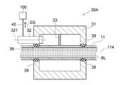
図2は、本発明の第1実施形態に係る圧力検知装置を表す断面図である。
図3は、コントローラと圧力検知装置との電気的な接続を表すブロック図である。FIG. 2 is a cross-sectional view showing the pressure sensing device according to the first embodiment of the invention.
FIG. 3 is a block diagram showing electrical connections between the controller and the pressure sensing device.
図2に表したように、本実施形態に係る圧力検知装置30は、ハウジングとしての本体部31と、画像取得部32と、コントローラ10に設けられた制御部100と、を有する。なお、制御部100は、コントローラ10ではなく本体部31に設けられていてもよい。
As shown in FIG. 2 , the
本体部31は、例えば直方体や円筒などの形状を呈し、チューブ11(12,15)が内部を貫通可能な構造を有する。本体部31の材料は、脱血チューブ11、送血チューブ12、および接続チューブ15を保持したり、嵌め込んだ状態で弾性変形させたりすることができる剛性を有する材料であればよく、特には限定されない。本体部31の材料としては、例えば金属あるいはプラスチックなどが挙げられる。具体的には、本体部31の材料は、例えばアルミニウムやステンレス等の金属を含む。あるいは、本体部31の材料は、ポリアセタール(POM)や、ポリブチレンテレフタレート(PBT)や、ポリエチレンテレフタレート(PET)等のプラスチックを含む。なお、本体部31の材料が透明なプラスチックである場合には、脱血チューブ11、送血チューブ12、および接続チューブ15が本体部31に保持された状態あるいは嵌め込まれた状態を、操作者は、本体部31を通して目視で確認できる。
The
本体部31は、例えばゴムにより形成されたOリングなどの滑り止め39を有する。滑り止め39は、チューブ11が通る本体部31の挿入孔の内側に固定され、本体部31に装着されたチューブ11の部分がチューブ11の軸114方向に伸びたり移動したりすることを抑制する。これにより、圧力検知装置30は、チューブ11内における血液等の媒体BLの圧力が変動した場合であっても、回路を循環中の媒体BLのチューブ11内における圧力をより正確に、より安定的に検知することができる。
The
画像取得部32は、本体部31に設けられている。図2に表した例では、画像取得部32は、画像取得部32の軸321がチューブ11の軸114と交差(具体的には直交)する状態で本体部31に固定されている。画像取得部32は、チューブ11内における媒体BLの圧力を受けて変形する受圧部の画像情報を取得する。受圧部の詳細については、後述する。画像取得部32としては、例えば、CCD(Charge-Coupled Device)イメージセンサやCMOS(Complementary Metal Oxide Semiconductor)イメージセンサなどが用いられたカメラが挙げられる。
The
図3に表したように、画像取得部32は、信号線42を介してコントローラ10の制御部100に電気的に接続されている。画像取得部32が取得(撮像)した画像情報に関する信号SSは、信号線42を介して制御部100に送信される。コントローラ10は、液晶表示装置等の表示部10Sを有する。表示部10Sは、回路内圧表示部10Gを有する。回路内圧は、コントローラ10の回路内圧表示部10Gに表示される。
As shown in FIG. 3 , the
制御部100は、記憶部101を有する。記憶部101は、基準画像情報102を記憶(格納)している。基準画像情報102は、画像取得部32により取得された画像情報をチューブ11内における媒体BLの圧力に関する圧力情報に変換するための情報である。すなわち、基準画像情報102は、画像取得部32により取得された画像情報と、チューブ11内における媒体BLの圧力に関する圧力情報と、の関係を示す相関データである。例えば、基準画像情報102は、画像情報を圧力情報に変換するテーブルであってもよい。あるいは、基準画像情報102は、画像情報と圧力情報との関係を示すグラフに基づいた数式であってもよい。
The
制御部100は、画像取得部32により取得された画像情報をチューブ11内における媒体BLの圧力に関する圧力情報に変換する。つまり、制御部100は、画像取得部32により取得された画像情報に基づいてチューブ11内における媒体BLの圧力を算出する。具体的には、制御部100は、記憶部101に格納された基準画像情報102に基づいて、画像取得部32により取得された画像情報をチューブ11内における媒体BLの圧力に関する圧力情報に変換する。制御部100の変換処理について、図面を参照してさらに説明する。
The
図4および図5は、本実施形態の画像取得部が取得した画像情報を表す図である。
なお、図4(a)は、チューブ内の圧力が陽圧である場合において、本実施形態の画像取得部が取得した画像情報を表す平面図である。図4(b)は、本実施形態の制御部が図4(a)に表した画像情報に基づいて実行した二値化処理により得られた二値画像の一例を例示する図である。図5(a)は、チューブ内の圧力が陰圧である場合において、本実施形態の画像取得部が取得した画像情報を表す平面図である。図5(b)は、本実施形態の制御部が図5(a)に表した画像情報に基づいて実行した二値化処理により得られた二値画像の一例を例示する図である。4 and 5 are diagrams showing image information acquired by the image acquiring unit of the present embodiment.
Note that FIG. 4A is a plan view showing image information acquired by the image acquiring unit of the present embodiment when the pressure inside the tube is positive. FIG. 4(b) is a diagram illustrating an example of a binary image obtained by the binarization process executed by the control unit of the present embodiment based on the image information shown in FIG. 4(a). FIG. 5A is a plan view showing image information acquired by the image acquisition unit of the present embodiment when the pressure inside the tube is negative. FIG. 5(b) is a diagram illustrating an example of a binary image obtained by the binarization process executed by the control unit of the present embodiment based on the image information shown in FIG. 5(a).
図4(a)に表したように、媒体BLがチューブ11内を流れていないときのチューブ11内の圧力を基準圧力(ゼロ圧力)とした場合において、チューブ11を通る媒体BLの回路内の圧力が陽圧になると、チューブ11の外径は、回路内の圧力が基準圧力のときの外径よりも大きくなる。一方で、図5(a)に表したように、チューブ11を通る媒体BLの回路内の圧力が陰圧になると、チューブ11の外径は、回路内の圧力が基準圧力のときの外径よりも小さくなる。本実施形態に係る圧力検知装置30は、このようなチューブ11の外径部111の形状変化を捉え圧力情報を算出する。つまり、図4(a)~図5(b)に表した例では、チューブ11の外径部111は、本発明の「受圧部」に相当する。
As shown in FIG. 4A, when the pressure inside the
具体的に説明すると、制御部100は、画像取得部32により取得された画像情報の二値化処理を実行する。つまり、制御部100は、画像取得部32から信号線42を介して受信した画像情報に関する信号SSに基づいて、画像情報の二値化処理を実行する。図4(a)に表した画像情報の二値化処理により得られた二値画像は、図4(b)に表した通りである。図5(a)に表した画像情報の二値化処理により得られた二値画像は、図5(b)に表した通りである。
Specifically, the
続いて、制御部100は、画像取得部32の軸321に対して交差(具体的には直交)した平面に投影されたチューブ11の外径部111の面積を算出する。言い換えれば、図4(b)および図5(b)に表した二値画像において、制御部100は、画像取得部32が取得した画像情報の二値化処理により得られた二値画像の黒色部分の面積を算出する。
Subsequently, the
一方で、記憶部101に記憶された基準画像情報102は、回路内の圧力が基準圧力(ゼロ圧力)のときの画像情報の二値化処理により得られた二値画像の黒色部分の面積を含む。そこで、制御部100は、回路内の圧力が陽圧および陰圧の少なくともいずれかのときの画像情報の二値化処理により得られた二値画像の黒色部分の面積と、回路内の圧力が基準圧力のときの画像情報の二値化処理により得られた二値画像の黒色部分の面積と、を比較する。そして、制御部100は、画像取得部32が取得した画像情報の二値化処理により得られた二値画像の黒色部分の面積の変動値と、チューブ11内における媒体BLの圧力に関する圧力情報と、の関係を示す相関データとしての基準画像情報102に基づいて圧力情報を算出する。つまり、制御部100は、画像取得部32の軸321に対して交差した平面に投影されたチューブ11の外径部111の面積の変動に応じて圧力情報を算出する。
On the other hand, the
本実施形態に係る圧力検知装置30によれば、制御部100は、画像取得部32により取得された画像情報をチューブ11内における媒体BLの圧力に関する圧力情報に変換する。つまり、圧力検知装置30は、チューブと接触しチューブの反発力を測定する荷重検知素子ではなく、圧力を受けて変形する受圧部(本実施形態ではチューブ11の外径部111)の画像情報を取得し圧力情報に変換することにより、チューブ11内における媒体BLの圧力を検知する。そのため、圧力検知装置30が故障した場合には、画像の取得エラーや読み取りエラーが発生し、チューブ11内における媒体BLの圧力は、回路内圧表示部10Gには表示されない。すなわち、実際の媒体BLの圧力とは異なる誤った圧力が回路内圧表示部10Gに表示されることを抑えることができる。これにより、チューブ11内における媒体BLの圧力の誤検知を抑えることができる。
According to the
また、圧力検知装置30は、チューブ11内を流れる媒体BLに接触することなくチューブ11内における媒体BLの圧力を検知する。これにより、例えば血液の梗塞部分や血栓がチューブ11内に生ずることを抑えることができる。また、チューブ11内から気泡を除去する作業(気泡抜き作業)が簡潔になる。
Further, the
また、制御部100は、画像情報と圧力情報との関係を示す基準画像情報102に基づいて画像情報を圧力情報に変換する。そのため、圧力検知装置30は、チューブ11内における媒体BLの圧力を算出する処理を簡易化することができ、チューブ11内における媒体BLの圧力をより短時間で正確に検知することができる。
Also, the
さらに、制御部100は、画像取得部32の軸321に対して交差した平面に投影されたチューブ11の外径部111の面積の変動に応じて圧力情報を算出する。そのため、圧力検知装置30は、チューブ11の外径部111の形状変化を捉えるという比較的簡易的な方法によりチューブ11内における媒体BLの圧力を検知することができる。
Furthermore, the
次に、本実施形態の受圧部の変形例を、図面を参照して説明する。
図6および図7は、本実施形態の変形例において、画像取得部が取得した画像情報を表す図である。
なお、図6は、チューブ内の圧力が陽圧である場合において、画像取得部が取得した画像情報を表す平面図である。図7は、チューブ内の圧力が陰圧である場合において、画像取得部が取得した画像情報を表す平面図である。Next, a modification of the pressure receiving portion of this embodiment will be described with reference to the drawings.
6 and 7 are diagrams showing image information acquired by the image acquiring unit in the modified example of the present embodiment.
Note that FIG. 6 is a plan view showing image information acquired by the image acquiring unit when the pressure inside the tube is positive. FIG. 7 is a plan view showing image information acquired by the image acquiring unit when the pressure inside the tube is negative pressure.
本変形例のチューブ11Aは、チューブ11Aの表面に所定の模様113が設けられた模様部112を有する。回路内の圧力が基準圧力のときに画像取得部32により取得された画像情報では、模様113は、例えば円形である。但し、模様113の形状は、円形だけには限定されず、例えば四角形や三角形などであってもよい。図4(a)~図5(b)に関して前述したように、チューブ11を通る媒体BLの回路内の圧力が陽圧になると、チューブ11の外径は、回路内の圧力が基準圧力のときの外径よりも大きくなる。そのため、図6に表したように、回路内の圧力が陽圧のときの模様113の径D1、D2は、回路内の圧力が基準圧力のときの模様113の径よりも大きい。例えば、径D1、D2は、チューブ11Aの軸114に対して直交する方向の模様113の径である。一方で、チューブ11を通る媒体BLの回路内の圧力が陰圧になると、チューブ11の外径は、回路内の圧力が基準圧力のときの外径よりも小さくなる。そのため、図7に表したように、回路内の圧力が陰圧のときの模様113の径D3、D4は、回路内の圧力が基準圧力のときの模様113の径よりも小さい。例えば、径D3、D4は、チューブ11Aの軸114に対して直交する方向の模様113の径である。本変形例では、圧力検知装置30は、このような模様部112の模様113の変形を捉え圧力情報を算出する。つまり、本変形例では、チューブ11Aの模様部112は、本発明の「受圧部」に相当する。
The
具体的に説明すると、制御部100は、画像取得部32により取得された画像情報に基づいて、チューブ11Aの軸114に対して直交する方向の模様113の径を算出する。一方で、記憶部101に記憶された基準画像情報102は、回路内の圧力が基準圧力(ゼロ圧力)のときのチューブ11Aの軸114に対して直交する方向の模様113の径を含む。制御部100は、回路内の圧力が陽圧および陰圧の少なくともいずれかのときの模様113の径と、回路内の圧力が基準圧力のときの模様113の径と、を比較する。そして、制御部100は、画像取得部32が取得した画像情報に基づいて算出した模様113の径の変動値と、チューブ11内における媒体BLの圧力に関する圧力情報と、の関係を示す相関データとしての基準画像情報102に基づいて圧力情報を算出する。つまり、制御部100は、模様部112の模様113を認識し、模様113の変形に応じて圧力情報を算出する。
Specifically, based on the image information acquired by the
なお、制御部100は、必ずしも、模様113の外側の径D1、D3および模様113の内側の径D2、D4の両方を算出しなくともよく、模様113の外側の径D1、D3および模様113の内側の径D2、D4のいずれか一方を算出してもよい。あるいは、制御部100は、模様部112の模様113の径ではなく、模様部112の模様113で囲まれた領域の面積を算出してもよい。そして、制御部100は、画像取得部32が取得した画像情報に基づいて算出した模様113の面積の変動値と、チューブ11内における媒体BLの圧力に関する圧力情報と、の関係を示す相関データとしての基準画像情報102に基づいて圧力情報を算出してもよい。
Note that the
本変形例によれば、制御部100は、模様部112の模様113を認識し、模様113の変形に応じて圧力情報を算出する。そのため、圧力検知装置30は、模様部112の模様113の変形を捉えるという比較的簡易的な方法によりチューブ11A内における媒体BLの圧力を検知することができる。また、図1~図5(b)に関して前述した効果と同様の効果が得られる。
According to this modification, the
次に、本発明の第2実施形態について説明する。
なお、第2実施形態に係る圧力検知装置30Aの構成要素が、図1~図7に関して前述した第1実施形態に係る圧力検知装置30の構成要素と同様である場合には、重複する説明は適宜省略し、以下、相違点を中心に説明する。Next, a second embodiment of the invention will be described.
Note that if the components of the
図8は、本発明の第2実施形態に係る圧力検知装置を表す断面図である。
図9は、チューブ内の圧力が陽圧であるときの二値画像の一例を例示する図である。
図10は、チューブ内の圧力が陰圧であるときの二値画像の一例を例示する図である。FIG. 8 is a cross-sectional view showing a pressure sensing device according to a second embodiment of the invention.
FIG. 9 is a diagram illustrating an example of a binary image when the pressure inside the tube is positive.
FIG. 10 is a diagram illustrating an example of a binary image when the pressure inside the tube is negative pressure.
図8に表したように、本実施形態に係る圧力検知装置30Aは、ハウジングとしての本体部31と、画像取得部32と、感圧媒介(受圧部)33と、コントローラ10に設けられた制御部100と、を有する。本実施形態の感圧媒介33は、本発明の「受圧部」に相当する。画像取得部32は、画像取得部32の軸321がチューブ11の軸114と平行な状態で本体部31に固定されている。圧力検知装置30Aが感圧媒介33を備える点、および画像取得部32の軸321がチューブ11の軸114と平行である点において、本実施形態に係る圧力検知装置30Aは、第1実施形態に係る圧力検知装置30とは異なる。その他の構造は、第1実施形態に係る圧力検知装置30の構造と同様である。
As shown in FIG. 8, the
感圧媒介33は、本体部31とチューブ11とに接続されている。例えば、感圧媒介33は、本体部31に接着されたり、融着されたり、嵌合されたりすることで、本体部31に固定されている。また、感圧媒介33は、チューブ11に接着されたり、融着されたりすることで、チューブ11に固定されている。感圧媒介33は、チューブ11の変形に基づく外力を受けて変形する。感圧媒介33の材料は、感圧媒介33がチューブ11の変形に基づく外力を受けて変形する限りにおいて特には限定されない。感圧媒介33の材料としては、例えば、ポリアセタール(POM)や、ポリブチレンテレフタレート(PBT)や、ポリエチレンテレフタレート(PET)等のプラスチックが挙げられる。あるいは、感圧媒介33の材料は、チューブ11と同様の弾性変形可能な可撓性を有する合成樹脂(例えば塩化ビニル樹脂やシリコーンゴム等)であってもよい。
A pressure-
図4(a)~図5(b)に関して前述したように、チューブ11を通る媒体BLの回路内の圧力が陽圧になると、チューブ11の外径は、回路内の圧力が基準圧力のときの外径よりも大きくなる。そうすると、本体部31とチューブ11との間の空間は、回路内の圧力が基準圧力のときの空間よりも狭くなる。そのため、感圧媒介33は、チューブ11の膨張変形に基づく外力を受けて圧縮変形する。そして、制御部100は、画像取得部32から信号線42を介して受信した画像情報に関する信号SSに基づいて、画像情報の二値化処理を実行する。このときに画像情報の二値化処理により得られた二値画像は、図9に表した通りである。
4(a)-5(b), when the pressure in the circuit of the medium BL passing through the
一方で、チューブ11を通る媒体BLの回路内の圧力が陰圧になると、チューブ11の外径は、回路内の圧力が基準圧力のときの外径よりも小さくなる。そうすると、本体部31とチューブ11との間の空間は、回路内の圧力が基準圧力のときの空間よりも広くなる。そのため、感圧媒介33は、チューブ11の収縮変形に基づく外力を受けて伸張変形する。そして、制御部100は、画像取得部32から信号線42を介して受信した画像情報に関する信号SSに基づいて、画像情報の二値化処理を実行する。このときに画像情報の二値化処理により得られた二値画像は、図10に表した通りである。
On the other hand, when the pressure in the circuit of the medium BL passing through the
続いて、制御部100は、画像取得部32の軸321に対して交差(具体的には直交)した平面に投影された感圧媒介33の面積を算出する。言い換えれば、図9および図10に表した二値画像において、制御部100は、画像取得部32が取得した画像情報の二値化処理により得られた二値画像の黒色部分の面積を算出する。
Subsequently, the
一方で、記憶部101に記憶された基準画像情報102は、回路内の圧力が基準圧力(ゼロ圧力)のときの画像情報の二値化処理により得られた二値画像の黒色部分の面積を含む。そこで、制御部100は、回路内の圧力が陽圧および陰圧の少なくともいずれかのときの画像情報の二値化処理により得られた二値画像の黒色部分の面積と、回路内の圧力が基準圧力のときの画像情報の二値化処理により得られた二値画像の黒色部分の面積と、を比較する。そして、制御部100は、画像取得部32が取得した画像情報の二値化処理により得られた二値画像の黒色部分の面積の変動値と、チューブ11内における媒体BLの圧力に関する圧力情報と、の関係を示す相関データとしての基準画像情報102に基づいて圧力情報を算出する。つまり、制御部100は、画像取得部32の軸321に対して交差した平面に投影された感圧媒介33の面積の変動に応じて圧力情報を算出する。
On the other hand, the
本実施形態によれば、圧力検知装置30Aは、本体部31とチューブ11とに接続された感圧媒介33の形状変化を捉えるという比較的簡易的な方法によりチューブ11内における媒体BLの圧力を検知することができる。
According to this embodiment, the
以上説明したように、第1実施形態に係る圧力検知装置30および第2実施形態に係る圧力検知装置30Aにおいて、制御部100は、画像取得部32により取得された画像情報をチューブ11、11A内における媒体BLの圧力に関する圧力情報に変換する。そのため、圧力検知装置30、30Aが故障した場合には、画像の取得エラーや読み取りエラーが発生し、チューブ11、11A内における媒体BLの圧力は、回路内圧表示部10Gには表示されない。すなわち、実際の媒体BLの圧力とは異なる誤った圧力が回路内圧表示部10Gに表示されることを抑えることができる。これにより、チューブ11、11A内における媒体BLの圧力の誤検知を抑えることができる。
As described above, in the
また、本実施形態に係る体外循環装置1は、媒体BLを移送するチューブ11(12、15)と、チューブ11(12、15)に設けられチューブ11(12、15)内における媒体BLの圧力を検知する圧力検知装置30(30A)と、を備える。これにより、本実施形態に係る圧力検知装置30(30A)に関して前述した効果と同様の効果が得られる。
Further, the
以上、本発明の実施形態について説明した。しかし、本発明は、上記実施形態に限定されず、特許請求の範囲を逸脱しない範囲で種々の変更を行うことができる。上記実施形態の構成は、その一部を省略したり、上記とは異なるように任意に組み合わせたりすることができる。本実施形態では、圧力検知装置30、30Aが循環回路1Rの脱血チューブ11の途中における装着位置W1に設けられた場合を例に挙げた。本実施形態に関して前述した効果は、圧力検知装置30、30Aが循環回路1Rの送血チューブ12の途中における装着位置W2、および遠心ポンプ3と人工肺2とを接続する接続チューブ15の途中における装着位置W3のいずれの位置に設けられた場合であっても、同様に得られる。
The embodiments of the present invention have been described above. However, the present invention is not limited to the above embodiments, and various modifications can be made without departing from the scope of the claims. Some of the configurations of the above embodiments may be omitted, or may be arbitrarily combined in a manner different from the above. In this embodiment, the case where the
1・・・体外循環装置、 1R・・・循環回路、 2・・・人工肺、 3・・・遠心ポンプ、 4・・・ドライブモータ、 5・・・静脈側カテーテル、 6・・・動脈側カテーテル、 10・・・コントローラ、 10G・・・回路内圧表示部、 10S・・・表示部、 11、11A・・・脱血チューブ、 12・・・送血チューブ、 13・・・酸素ガス供給部、 14・・・チューブ、 15・・・接続チューブ、 17・・・ファストクランプ、 18・・・三方活栓、 19・・・チューブ、 20・・・超音波気泡検出センサ、 30、30A・・・圧力検知装置、 31・・・本体部、 32・・・画像取得部、 33・・・感圧媒介、 39・・・滑り止め、 42・・・信号線、 100・・・制御部、 101・・・記憶部、 102・・・基準画像情報、 111・・・外径部、 112・・・模様部、 113・・・模様、 114、321・・・軸、 BL・・・媒体、 P・・・患者、 SG・・・指令、 SS・・・信号、 W1、W2、W3・・・装着位置
DESCRIPTION OF
Claims (7)
前記チューブの外径部に装着可能とされた本体部と、
前記本体部に設けられ、前記圧力を受けて変形する受圧部の画像情報を取得する画像取得部と、
前記画像取得部により取得された前記画像情報を前記圧力に関する圧力情報に変換する制御部と、
を備えたことを特徴とする圧力検知装置。 A pressure detection device that can be installed in a tube that conveys a medium and detects the pressure of the medium in the tube,
a body portion that can be attached to the outer diameter portion of the tube;
an image acquisition unit that is provided in the main body and acquires image information of the pressure receiving unit that deforms under the pressure;
a control unit that converts the image information acquired by the image acquisition unit into pressure information about the pressure;
A pressure detection device comprising:
前記制御部は、前記画像取得部の軸に対して交差した平面に投影された前記外径部の面積の変動に応じて前記圧力情報を算出することを特徴とする請求項1または2に記載の圧力検知装置。 The pressure receiving portion is an outer diameter portion of the tube,
3. The control unit according to claim 1, wherein the control unit calculates the pressure information according to a change in the area of the outer diameter portion projected onto a plane intersecting the axis of the image acquisition unit. pressure sensing device.
前記制御部は、前記模様を認識し前記模様の変形に応じて前記圧力情報を算出することを特徴とする請求項1または2に記載の圧力検知装置。 The pressure receiving portion is a pattern portion having a predetermined pattern provided on the surface of the tube,
3. The pressure detection device according to claim 1, wherein the control unit recognizes the pattern and calculates the pressure information according to deformation of the pattern.
前記制御部は、前記画像取得部の軸に対して交差した平面に投影された前記感圧媒介の面積の変動に応じて前記圧力情報を算出することを特徴とする請求項1または2に記載の圧力検知装置。 further comprising a pressure-sensitive medium as the pressure-receiving portion connected to the main body portion and the tube and deformed by receiving an external force based on deformation of the tube;
3. The control unit according to claim 1, wherein the control unit calculates the pressure information according to a change in an area of the pressure-sensitive medium projected onto a plane intersecting an axis of the image acquisition unit. pressure sensing device.
前記媒体を移送するチューブと、
前記チューブに設けられ前記チューブ内における前記媒体の圧力を検知する請求項1~6のいずれか1項に記載の圧力検知装置と、
を備えたことを特徴とする体外循環装置。 An extracorporeal circulation device used for extracorporeal circulation of a medium,
a tube for transporting the medium;
The pressure detection device according to any one of claims 1 to 6, which is provided in the tube and detects the pressure of the medium in the tube;
An extracorporeal circulation device comprising:
Applications Claiming Priority (3)
| Application Number | Priority Date | Filing Date | Title |
|---|---|---|---|
| JP2017134750 | 2017-07-10 | ||
| JP2017134750 | 2017-07-10 | ||
| PCT/JP2018/025494 WO2019013089A1 (en) | 2017-07-10 | 2018-07-05 | Pressure detection device and extracorporeal circulation device |
Publications (2)
| Publication Number | Publication Date |
|---|---|
| JPWO2019013089A1 JPWO2019013089A1 (en) | 2020-07-16 |
| JP7208897B2 true JP7208897B2 (en) | 2023-01-19 |
Family
ID=65001982
Family Applications (1)
| Application Number | Title | Priority Date | Filing Date |
|---|---|---|---|
| JP2019529094A Active JP7208897B2 (en) | 2017-07-10 | 2018-07-05 | Pressure sensing device and extracorporeal circulation device |
Country Status (5)
| Country | Link |
|---|---|
| US (1) | US11278656B2 (en) |
| EP (1) | EP3654007A4 (en) |
| JP (1) | JP7208897B2 (en) |
| CN (1) | CN110234971A (en) |
| WO (1) | WO2019013089A1 (en) |
Families Citing this family (5)
| Publication number | Priority date | Publication date | Assignee | Title |
|---|---|---|---|---|
| JP2020039020A (en) * | 2018-09-03 | 2020-03-12 | ソニーセミコンダクタソリューションズ株式会社 | Image processing apparatus and image processing method |
| CN111166490B (en) * | 2020-02-25 | 2020-11-27 | 青岛大学附属医院 | Medical robot pressure detection method and medical robot |
| CN111282060A (en) * | 2020-03-18 | 2020-06-16 | 上海市东方医院(同济大学附属东方医院) | Extracorporeal membrane oxygenation device |
| CN112382377A (en) * | 2020-11-09 | 2021-02-19 | 深圳市赛恒尔医疗科技有限公司 | Extracorporeal circulation machine and auxiliary parameter adjusting method and system |
| CN113804248B (en) * | 2021-08-24 | 2023-09-22 | 中国石油大学(华东) | Nondestructive ground stress testing device and method using digital speckle and finite element technology |
Citations (4)
| Publication number | Priority date | Publication date | Assignee | Title |
|---|---|---|---|---|
| US20090009764A1 (en) | 2007-07-05 | 2009-01-08 | Baxter International Inc. | Method and apparatus for measuring the presence and concentration of pharmaceutical substances in a medical fluid administered by a medication delivery system |
| US20120065596A1 (en) | 2006-02-13 | 2012-03-15 | Roche Diagnostics International Ag | Method and device for identifying a change in pressure in the liquid path of a microdosing device |
| US20130036824A1 (en) | 2011-08-12 | 2013-02-14 | Fenwal, Inc. | Pressure sensor |
| WO2017104158A1 (en) | 2015-12-14 | 2017-06-22 | テルモ株式会社 | Removable pressure sensor and extracorporeal circulation device provided with removable pressure sensor |
Family Cites Families (23)
| Publication number | Priority date | Publication date | Assignee | Title |
|---|---|---|---|---|
| JPS5728347U (en) * | 1980-07-23 | 1982-02-15 | ||
| US4911015A (en) * | 1988-11-14 | 1990-03-27 | Asea Brown Boveri Inc. | Non-electrical monitoring of a physical condition |
| US5186046A (en) | 1990-08-20 | 1993-02-16 | Board Of Regents Of The University Of Washington | Surface pressure measurement by oxygen quenching of luminescence |
| JPH0523393A (en) * | 1991-07-18 | 1993-02-02 | Joji Oshima | Blood pressure measuring device |
| JP4252411B2 (en) * | 2002-09-26 | 2009-04-08 | ユニバーサル製缶株式会社 | Sealed can inspection method and inspection apparatus, and sealed can case |
| CN1265201C (en) * | 2003-03-21 | 2006-07-19 | 中国科学院过程工程研究所 | Device for on line measuring high temperatare fused body surface temsion, contact angle and density |
| CN1249414C (en) * | 2004-03-25 | 2006-04-05 | 上海交通大学 | Torque dynamic measurer of low speed spindle base on visual sense |
| JP2005283204A (en) * | 2004-03-29 | 2005-10-13 | Terumo Corp | Sliding material application inspection method in syringe external cylinder, and sliding material application inspection device in syringe external cylinder |
| ES2544955T3 (en) | 2006-04-19 | 2015-09-07 | Asahi Kasei Medical Co., Ltd. | Pressure sensor for extracorporeal circulation circuit |
| EP1892001A1 (en) * | 2006-08-23 | 2008-02-27 | B. Braun Medizintechnologie GmbH | Medical device for extracorporeal blood treatment |
| AU2009235064A1 (en) * | 2008-04-09 | 2009-10-15 | F.Hoffmann-La Roche Ag | Modular skin-adherable system for medical fluid delivery |
| DE102009001901A1 (en) * | 2009-03-26 | 2010-09-30 | Robert Bosch Gmbh | Blood treatment device |
| US9677555B2 (en) * | 2011-12-21 | 2017-06-13 | Deka Products Limited Partnership | System, method, and apparatus for infusing fluid |
| US9320842B2 (en) * | 2011-04-29 | 2016-04-26 | Medtronic, Inc. | Multimodal dialysis system |
| US10463259B2 (en) * | 2011-10-28 | 2019-11-05 | Three Rivers Cardiovascular Systems Inc. | System and apparatus comprising a multi-sensor catheter for right heart and pulmonary artery catheterization |
| US9186470B2 (en) * | 2012-02-08 | 2015-11-17 | Apple Inc. | Shape reflector and surface contour mapping |
| KR101348109B1 (en) * | 2012-06-18 | 2014-01-16 | 포항공과대학교 산학협력단 | Apparatus for extracorporeal blood circulation, and vascular diseases diagnostic method |
| US9510766B2 (en) * | 2013-03-13 | 2016-12-06 | Mississippi State University (Msu) | Insertable probe |
| DE102013012469A1 (en) * | 2013-07-09 | 2015-01-15 | Fresenius Medical Care Deutschland Gmbh | Method for measuring the course of pressure pulse waves in an extracorporeal blood treatment and apparatus for carrying out the method |
| JPWO2015141622A1 (en) * | 2014-03-17 | 2017-04-06 | テルモ株式会社 | Alarm device, extracorporeal circulation device, and control method of alarm device |
| CN103994724B (en) * | 2014-05-13 | 2019-07-02 | 滕军 | Structure two-dimension displacement and strain monitoring method based on digital image processing techniques |
| EP3231461B1 (en) * | 2014-12-12 | 2019-08-14 | Terumo Kabushiki Kaisha | Extracorporeal circulation device |
| BR112019012214A8 (en) * | 2016-12-15 | 2023-03-28 | Baxter Int | SYSTEM AND METHOD FOR MONITORING AND DETERMINING PATIENT PARAMETERS FROM DETECTED VENOUS WAVEFORM |
-
2018
- 2018-07-05 JP JP2019529094A patent/JP7208897B2/en active Active
- 2018-07-05 CN CN201880009449.0A patent/CN110234971A/en active Pending
- 2018-07-05 WO PCT/JP2018/025494 patent/WO2019013089A1/en unknown
- 2018-07-05 EP EP18832040.2A patent/EP3654007A4/en not_active Withdrawn
-
2019
- 2019-12-04 US US16/702,792 patent/US11278656B2/en active Active
Patent Citations (4)
| Publication number | Priority date | Publication date | Assignee | Title |
|---|---|---|---|---|
| US20120065596A1 (en) | 2006-02-13 | 2012-03-15 | Roche Diagnostics International Ag | Method and device for identifying a change in pressure in the liquid path of a microdosing device |
| US20090009764A1 (en) | 2007-07-05 | 2009-01-08 | Baxter International Inc. | Method and apparatus for measuring the presence and concentration of pharmaceutical substances in a medical fluid administered by a medication delivery system |
| US20130036824A1 (en) | 2011-08-12 | 2013-02-14 | Fenwal, Inc. | Pressure sensor |
| WO2017104158A1 (en) | 2015-12-14 | 2017-06-22 | テルモ株式会社 | Removable pressure sensor and extracorporeal circulation device provided with removable pressure sensor |
Also Published As
| Publication number | Publication date |
|---|---|
| US20200101215A1 (en) | 2020-04-02 |
| CN110234971A (en) | 2019-09-13 |
| EP3654007A1 (en) | 2020-05-20 |
| EP3654007A4 (en) | 2021-03-31 |
| JPWO2019013089A1 (en) | 2020-07-16 |
| WO2019013089A1 (en) | 2019-01-17 |
| US11278656B2 (en) | 2022-03-22 |
Similar Documents
| Publication | Publication Date | Title |
|---|---|---|
| JP7208897B2 (en) | Pressure sensing device and extracorporeal circulation device | |
| JP7208896B2 (en) | Pressure sensing device and extracorporeal circulation device | |
| JP7035250B2 (en) | Pressure sensor and extracorporeal circulation device | |
| JP2011501804A (en) | Non-contact multifunction sensor system | |
| US20110105846A1 (en) | Actuator system and endoscope apparatus | |
| US20180272055A1 (en) | Removable pressure sensor and extracorporeal circulator provided with removable pressure sensor | |
| CN108367111B (en) | Intermediate element for a medical extracorporeal fluid line and medical extracorporeal fluid system | |
| JP6569271B2 (en) | Optical connector for medical equipment | |
| JP6296815B2 (en) | Extracorporeal circulation device and control method for extracorporeal circulation device | |
| JP6847134B2 (en) | Pressure sensor and extracorporeal circulation device | |
| US20200016318A1 (en) | Medico-technical measuring device and measuring method | |
| JP2014188081A (en) | Insertion device | |
| WO2016063861A1 (en) | Medical pressure gauge | |
| JP2011055882A (en) | Monitoring device of puncture part and blood purifier provided with the same | |
| JP6396738B2 (en) | Indwelling needle | |
| JP6550726B2 (en) | Balloon catheter | |
| JP6630794B2 (en) | Extracorporeal circulation device | |
| US20240115779A1 (en) | Apparatus for extracorporeal blood treatment | |
| JP6554312B2 (en) | Balloon catheter system | |
| JP3712821B2 (en) | Endoscope pipe unit connection device | |
| JP2016059744A (en) | Extracorporeal circulation apparatus |
Legal Events
| Date | Code | Title | Description |
|---|---|---|---|
| A621 | Written request for application examination |
Free format text: JAPANESE INTERMEDIATE CODE: A621 Effective date: 20210412 |
|
| A131 | Notification of reasons for refusal |
Free format text: JAPANESE INTERMEDIATE CODE: A131 Effective date: 20220601 |
|
| A601 | Written request for extension of time |
Free format text: JAPANESE INTERMEDIATE CODE: A601 Effective date: 20220729 |
|
| A521 | Request for written amendment filed |
Free format text: JAPANESE INTERMEDIATE CODE: A523 Effective date: 20220829 |
|
| TRDD | Decision of grant or rejection written | ||
| A01 | Written decision to grant a patent or to grant a registration (utility model) |
Free format text: JAPANESE INTERMEDIATE CODE: A01 Effective date: 20221208 |
|
| A61 | First payment of annual fees (during grant procedure) |
Free format text: JAPANESE INTERMEDIATE CODE: A61 Effective date: 20230106 |
|
| R150 | Certificate of patent or registration of utility model |
Ref document number: 7208897 Country of ref document: JP Free format text: JAPANESE INTERMEDIATE CODE: R150 |