JP7208091B2 - Substrate processing method and substrate processing apparatus - Google Patents
Substrate processing method and substrate processing apparatus Download PDFInfo
- Publication number
- JP7208091B2 JP7208091B2 JP2019079465A JP2019079465A JP7208091B2 JP 7208091 B2 JP7208091 B2 JP 7208091B2 JP 2019079465 A JP2019079465 A JP 2019079465A JP 2019079465 A JP2019079465 A JP 2019079465A JP 7208091 B2 JP7208091 B2 JP 7208091B2
- Authority
- JP
- Japan
- Prior art keywords
- liquid
- substrate
- film
- liquid film
- rinse
- Prior art date
- Legal status (The legal status is an assumption and is not a legal conclusion. Google has not performed a legal analysis and makes no representation as to the accuracy of the status listed.)
- Active
Links
Images


Classifications
-
- H—ELECTRICITY
- H01—ELECTRIC ELEMENTS
- H01L—SEMICONDUCTOR DEVICES NOT COVERED BY CLASS H10
- H01L21/00—Processes or apparatus adapted for the manufacture or treatment of semiconductor or solid state devices or of parts thereof
- H01L21/02—Manufacture or treatment of semiconductor devices or of parts thereof
- H01L21/02041—Cleaning
- H01L21/02057—Cleaning during device manufacture
-
- H—ELECTRICITY
- H01—ELECTRIC ELEMENTS
- H01L—SEMICONDUCTOR DEVICES NOT COVERED BY CLASS H10
- H01L21/00—Processes or apparatus adapted for the manufacture or treatment of semiconductor or solid state devices or of parts thereof
- H01L21/02—Manufacture or treatment of semiconductor devices or of parts thereof
- H01L21/04—Manufacture or treatment of semiconductor devices or of parts thereof the devices having at least one potential-jump barrier or surface barrier, e.g. PN junction, depletion layer or carrier concentration layer
- H01L21/18—Manufacture or treatment of semiconductor devices or of parts thereof the devices having at least one potential-jump barrier or surface barrier, e.g. PN junction, depletion layer or carrier concentration layer the devices having semiconductor bodies comprising elements of Group IV of the Periodic System or AIIIBV compounds with or without impurities, e.g. doping materials
- H01L21/30—Treatment of semiconductor bodies using processes or apparatus not provided for in groups H01L21/20 - H01L21/26
- H01L21/302—Treatment of semiconductor bodies using processes or apparatus not provided for in groups H01L21/20 - H01L21/26 to change their surface-physical characteristics or shape, e.g. etching, polishing, cutting
- H01L21/304—Mechanical treatment, e.g. grinding, polishing, cutting
-
- H—ELECTRICITY
- H01—ELECTRIC ELEMENTS
- H01L—SEMICONDUCTOR DEVICES NOT COVERED BY CLASS H10
- H01L21/00—Processes or apparatus adapted for the manufacture or treatment of semiconductor or solid state devices or of parts thereof
- H01L21/67—Apparatus specially adapted for handling semiconductor or electric solid state devices during manufacture or treatment thereof; Apparatus specially adapted for handling wafers during manufacture or treatment of semiconductor or electric solid state devices or components ; Apparatus not specifically provided for elsewhere
- H01L21/67005—Apparatus not specifically provided for elsewhere
- H01L21/67011—Apparatus for manufacture or treatment
- H01L21/67017—Apparatus for fluid treatment
- H01L21/67028—Apparatus for fluid treatment for cleaning followed by drying, rinsing, stripping, blasting or the like
- H01L21/67034—Apparatus for fluid treatment for cleaning followed by drying, rinsing, stripping, blasting or the like for drying
-
- H—ELECTRICITY
- H01—ELECTRIC ELEMENTS
- H01L—SEMICONDUCTOR DEVICES NOT COVERED BY CLASS H10
- H01L21/00—Processes or apparatus adapted for the manufacture or treatment of semiconductor or solid state devices or of parts thereof
- H01L21/67—Apparatus specially adapted for handling semiconductor or electric solid state devices during manufacture or treatment thereof; Apparatus specially adapted for handling wafers during manufacture or treatment of semiconductor or electric solid state devices or components ; Apparatus not specifically provided for elsewhere
- H01L21/67005—Apparatus not specifically provided for elsewhere
- H01L21/67011—Apparatus for manufacture or treatment
- H01L21/67017—Apparatus for fluid treatment
- H01L21/67028—Apparatus for fluid treatment for cleaning followed by drying, rinsing, stripping, blasting or the like
- H01L21/6704—Apparatus for fluid treatment for cleaning followed by drying, rinsing, stripping, blasting or the like for wet cleaning or washing
- H01L21/67051—Apparatus for fluid treatment for cleaning followed by drying, rinsing, stripping, blasting or the like for wet cleaning or washing using mainly spraying means, e.g. nozzles
Description
本発明は、基板を乾燥させる基板処理方法および基板処理装置に関する。基板には、たとえば、半導体ウエハ、液晶表示装置や有機EL(electroluminescence)表示装置などのFPD(Flat Panel Display)用基板、光ディスク用基板、磁気ディスク用基板、光磁気ディスク用基板、フォトマスク用基板、セラミック基板、太陽電池用基板などが含まれる。 The present invention relates to a substrate processing method and substrate processing apparatus for drying a substrate. Substrates include, for example, semiconductor wafers, FPD (Flat Panel Display) substrates such as liquid crystal display devices and organic EL (electroluminescence) display devices, optical disk substrates, magnetic disk substrates, magneto-optical disk substrates, and photomask substrates. , ceramic substrates, and substrates for solar cells.
半導体装置やFPDなどの製造工程では、半導体ウエハやFPD用ガラス基板などの基板に対して必要に応じた処理が行われる。このような処理には、薬液やリンス液などの処理液を基板に供給することが含まれる。処理液が供給された後は、処理液を基板から除去し、基板を乾燥させる。特許文献1および特許文献2には、薬液、純水、IPA(イソプロピルアルコール)、およびHFE(ハイドロフルオロエーテル)を、この順番で基板に供給し、その後、基板を乾燥させることが開示されている。
In the manufacturing process of semiconductor devices, FPDs, etc., substrates such as semiconductor wafers and glass substrates for FPDs are processed as necessary. Such processing includes supplying a processing liquid such as a chemical liquid or a rinse liquid to the substrate. After the processing liquid is supplied, the processing liquid is removed from the substrate and the substrate is dried.
特許文献1の段落0021には、「「HFE液」として例えば住友スリーエム株式会社製の商品名ノベック(登録商標)シリーズのHFEを用いることができる。具体的には、HFEとして、例えばノベック7100/7100DL(化学式:C4F9OCH3)、ノベック7200(化学式:C4F9OC2H5)、ノベック7300(化学式:C6F13OCH3)などを用いることができる。」と記載されている。特許文献1の段落0059には、「例えば住友スリーエム株式会社製の商品名ノベック(登録商標)シリーズのHFE71IPA(ハイドロフルオロエーテル共沸様混合物)を用いてもよい」と記載されている。特許文献2では、HFEの種類が特定されていない。
In paragraph 0021 of
乾燥する直前の基板に付着している液体を短時間で除去することは、パターンの倒壊を抑制する上で極めて重要である。短時間で液体を基板から除去すれば、パターンを倒壊させる倒壊力がパターンに加わる時間を短縮できるからである。特許文献1に記載されているノベック7100の沸点は、61℃であり、比較的低い。しかしながら、本発明者らの研究によると、このような沸点の液体を用いたとしても、パターンの強度によっては、十分にパターンの倒壊を抑制できないことが分かった。
It is extremely important to remove the liquid adhering to the substrate immediately before drying in a short period of time in order to prevent the pattern from collapsing. This is because if the liquid is removed from the substrate in a short period of time, the time for which the pattern is subjected to the collapsing force that causes the pattern to collapse can be shortened. The boiling point of Novec 7100 described in
そこで、本発明の目的の一つは、パターンの倒壊を抑制しながら、基板を乾燥させることができる基板処理方法および基板処理装置を提供することである。 SUMMARY OF THE INVENTION Accordingly, it is an object of the present invention to provide a substrate processing method and a substrate processing apparatus capable of drying a substrate while suppressing pattern collapse.
前記目的を達成するための請求項1に記載の発明は、基板を水平に保持しながら前記基板を乾燥させる方法であって、水を含有するリンス液を前記基板の上面に供給するリンス液供給工程と、第1液体を前記基板の上面に供給することにより、前記基板の上面上の前記リンス液を前記第1液体に置換する第1置換工程と、第2液体を前記基板の上面に供給することにより、前記基板の上面上の前記第1液体を前記第2液体に置換する第2置換工程と、前記基板の上面上の前記第2液体を除去することにより、前記基板を乾燥させる乾燥工程と、を含み、水に対する前記第2液体の溶解度は、水に対する前記第1液体の溶解度よりも小さく、前記第2液体の表面張力は、前記第1液体の表面張力よりも低く、前記第2液体の比重は、前記第1液体の比重よりも大きく、前記第2液体の沸点(1気圧における沸点。以下同様。)は、室温以上であり、前記第2液体の沸点から前記室温を引いた値は、前記室温以下であり、前記第2置換工程は、前記第1液体の液膜の全てが前記基板の上面からなくなる前に前記基板への前記第2液体の供給を停止して、前記基板の上面上の一部の前記第1液体だけを前記第2液体に置換することにより、前記第2液体の液膜と、前記第2液体の液膜を取り囲む前記第1液体の液膜とが、前記基板の上面に保持された状態を維持する部分置換工程を含む、基板処理方法である。 A first aspect of the invention for achieving the object is a method for drying a substrate while holding the substrate horizontally, the method comprising: supplying a rinse solution containing water to the upper surface of the substrate; a first replacement step of supplying a first liquid to the top surface of the substrate to replace the rinse liquid on the top surface of the substrate with the first liquid; and supplying a second liquid to the top surface of the substrate. a second replacing step of replacing the first liquid on the upper surface of the substrate with the second liquid; and a drying step of drying the substrate by removing the second liquid on the upper surface of the substrate. wherein the solubility of the second liquid in water is lower than the solubility of the first liquid in water, the surface tension of the second liquid is lower than the surface tension of the first liquid, and The specific gravity of the two liquids is higher than the specific gravity of the first liquid, the boiling point of the second liquid (boiling point at 1 atmosphere; hereinafter the same) is higher than room temperature, and the room temperature is subtracted from the boiling point of the second liquid. The second replacement step includes stopping the supply of the second liquid to the substrate before the entire liquid film of the first liquid disappears from the upper surface of the substrate. and a liquid film of the second liquid and a liquid film of the first liquid surrounding the liquid film of the second liquid, by replacing only a part of the first liquid on the upper surface of the substrate with the second liquid. and a partial replacement step of maintaining a state in which the film is held on the upper surface of the substrate.
この方法によれば、水を含有するリンス液を、水平に保持されている基板の上面に供給する。その後、水平に保持されている基板の上面に第1液体を供給する。これにより、基板の上面上のリンス液が、第1液体に置換される。その後、水平に保持されている基板の上面に第2液体を供給する。これにより、基板の上面上の第1液体が、第2液体に置換される。したがって、リンス液は、段階的に第2液体に置換される。その後、第2液体を基板の上面から除去し、基板を乾燥させる。 According to this method, a rinse liquid containing water is supplied to the upper surface of the substrate held horizontally. After that, the first liquid is supplied to the upper surface of the horizontally held substrate. Thereby, the rinse liquid on the upper surface of the substrate is replaced with the first liquid. After that, the second liquid is supplied to the upper surface of the substrate held horizontally. Thereby, the first liquid on the upper surface of the substrate is replaced with the second liquid. Therefore, the rinse liquid is gradually replaced with the second liquid. The second liquid is then removed from the top surface of the substrate and the substrate is dried.
基板上のリンス液は、直接、第2液体に置換されるのではなく、第1液体に置換された後、第2液体に置換される。水に対する第2液体の溶解度は、水に対する第1液体の溶解度よりも小さい。つまり、第2液体は、第1液体と比べて水に対する親和性が低い。リンス液が保持されている基板の上面に第2液体を供給すると、リンス液が基板の上面に残る場合がある。表面張力が高い水を含有するリンス液の残量が多いと、基板を乾燥させたときに、パターンの倒壊が発生し易い。水に対する親和性が相対的に高い第1液体でリンス液を置換すれば、乾燥する直前の基板に残留するリンス液を減らすことができる。 The rinse liquid on the substrate is not directly replaced with the second liquid, but replaced with the first liquid and then replaced with the second liquid. The solubility of the second liquid in water is less than the solubility of the first liquid in water. That is, the second liquid has a lower affinity for water than the first liquid. When the second liquid is supplied to the upper surface of the substrate holding the rinse liquid, the rinse liquid may remain on the upper surface of the substrate. If the remaining amount of the rinse liquid containing water with high surface tension is large, the pattern tends to collapse when the substrate is dried. By replacing the rinse liquid with the first liquid having a relatively high affinity for water, the rinse liquid remaining on the substrate immediately before drying can be reduced.
また、第2液体の比重は、第1液体の比重よりも大きい。そのため、第1液体と第2液体との界面では、第2液体が重力で基板の上面側に移動し、第1液体が第2液体の上に移動する。つまり、比重差によって第2液体が第1液体と基板との間に入り込む。さらに、第2液体の表面張力が低く、第2液体の比重が大きいので、第2液体がパターンの間に進入し、パターンの間にある第1液体が第2液体で置換される。このような表面張力が低い第2液体がパターンの間に入るので、基板を乾燥させるときに、第2液体の表面がパターンの間に形成されたとしても、パターンの倒壊を減らすことができる。 Also, the specific gravity of the second liquid is greater than the specific gravity of the first liquid. Therefore, at the interface between the first liquid and the second liquid, the second liquid moves toward the upper surface of the substrate due to gravity, and the first liquid moves above the second liquid. That is, the second liquid enters between the first liquid and the substrate due to the difference in specific gravity. Furthermore, since the surface tension of the second liquid is low and the specific gravity of the second liquid is high, the second liquid enters between the patterns and replaces the first liquid between the patterns with the second liquid. Since the second liquid having such a low surface tension enters between the patterns, even if the surface of the second liquid is formed between the patterns when the substrate is dried, collapse of the patterns can be reduced.
第2液体の沸点は、室温以上である。したがって、室温の環境下で第2液体を用いる場合、第2液体を液体に維持するために第2液体を冷却しなくてもよい。さらに、第2液体の沸点から室温を引いた値は、室温以下である。つまり、第2液体の沸点は、室温から室温を2倍した値までの範囲内の値であり、室温に対して比較的低い。第2液体の沸点が低いと、基板の乾燥中に第2液体が基板からなくなる速度が上昇するので、パターンを倒壊させる倒壊力がパターンに加わる時間を短縮できる。これにより、パターンの倒壊を減らすことができ、乾燥後の基板の品質を高めることができる。
さらに、基板の上面上の一部の第1液体だけを第2液体に置換する。これにより、リング状の第1液膜が、少なくとも基板の上面の外周部に残り、第2液体が、第1液膜の内側に溜まる。第2液体の表面張力が低いので、基板の上面上の全ての第1液体を第2液体に置換すると、薄い第2液膜が基板の上面に形成される。さらに、第2液体の沸点が低いので、新たな第2液体の供給を停止すると、基板上の第2液体が直ぐに蒸発し、基板の上面の一部が短時間で第2液膜から露出するかもしれない。
これに対して、第1液体の表面張力が第2液体の表面張力よりも高いので、基板の上面の外周部に残る第1液膜の厚みは、第2液膜の厚みよりも大きい。基板の上面に供給された第2液体は、リング状の第1液膜の内側に溜まる。したがって、基板の上面上の全ての第1液体を第2液体に置換する場合に比べて厚い第2液膜が第1液膜の内側に形成される。これにより、基板の上面の一部が短時間で第2液膜から露出することを防止できる。
The boiling point of the second liquid is room temperature or higher. Therefore, if the second liquid is used in a room temperature environment, it is not necessary to cool the second liquid to keep it liquid. Furthermore, the value obtained by subtracting room temperature from the boiling point of the second liquid is below room temperature. That is, the boiling point of the second liquid is a value within the range from room temperature to twice the room temperature, which is relatively low relative to room temperature. If the boiling point of the second liquid is low, the speed at which the second liquid disappears from the substrate during drying of the substrate increases, so that the time for which the pattern collapses is applied to the pattern can be shortened. As a result, pattern collapse can be reduced, and the quality of the substrate after drying can be improved.
Furthermore, only part of the first liquid on the upper surface of the substrate is replaced with the second liquid. As a result, the ring-shaped first liquid film remains at least on the outer peripheral portion of the upper surface of the substrate, and the second liquid accumulates inside the first liquid film. Due to the low surface tension of the second liquid, when all the first liquid on the upper surface of the substrate is replaced with the second liquid, a thin second liquid film is formed on the upper surface of the substrate. Furthermore, since the boiling point of the second liquid is low, when the supply of new second liquid is stopped, the second liquid on the substrate immediately evaporates, and part of the upper surface of the substrate is exposed from the second liquid film in a short period of time. Maybe.
On the other hand, since the surface tension of the first liquid is higher than that of the second liquid, the thickness of the first liquid film remaining on the outer periphery of the top surface of the substrate is greater than the thickness of the second liquid film. The second liquid supplied to the upper surface of the substrate accumulates inside the ring-shaped first liquid film. Therefore, a thicker second liquid film is formed inside the first liquid film than when all the first liquid on the upper surface of the substrate is replaced with the second liquid. This can prevent a part of the upper surface of the substrate from being exposed from the second liquid film in a short period of time.
リンス液は、純水などの水であってもよいし、水を主成分とする水溶液(たとえば、水の体積パーセント濃度が50vol%以上の水溶液)であってもよい。
請求項2に記載の発明は、前記リンス液供給工程は、リンス液供給速度で前記基板を回転させながら、前記リンス液を前記基板の上面に供給する工程を含み、前記第2置換工程は、前記リンス液供給速度よりも小さい第2置換速度で前記基板を回転させながら、前記第2液体を前記基板の上面に供給する工程を含む、請求項1に記載の基板処理方法である。
The rinse liquid may be water such as pure water, or an aqueous solution containing water as a main component (for example, an aqueous solution having a volume percent concentration of water of 50 vol % or more).
According to a second aspect of the present invention, the rinse liquid supplying step includes supplying the rinse liquid to the top surface of the substrate while rotating the substrate at a rinse liquid supply speed, and the second replacing step comprises: 2. The substrate processing method according to
この方法によれば、基板を低速で回転させながら、基板の上面上の第1液体を第2液体に置換する。第2液体の供給を開始すると、基板の上面は、ほぼ円形の第2液体の液膜(「第2液膜」ともいう。)と、第2液膜を取り囲むリング状の第1液体の液膜(「第1液膜」ともいう。)とに覆われる。その後、第2液膜の外周は、ほぼ円形のまま、基板の上面の外周に向かって徐々に広がる。第1液体および第2液体の性質の違いが大きい場合、基板を高速で回転させると、第2液膜の外周がほぼ円形のまま広がらず、第1液体が確実に置換されないおそれがある。基板を低速で回転させれば、このような現象を未然に回避できる。 According to this method, the first liquid on the upper surface of the substrate is replaced with the second liquid while rotating the substrate at a low speed. When the supply of the second liquid is started, a substantially circular liquid film of the second liquid (also referred to as a “second liquid film”) and a ring-shaped liquid film of the first liquid surrounding the second liquid film are formed on the upper surface of the substrate. film (also referred to as “first liquid film”). After that, the outer circumference of the second liquid film gradually widens toward the outer circumference of the upper surface of the substrate while maintaining a substantially circular shape. If the properties of the first liquid and the second liquid are significantly different from each other, if the substrate is rotated at high speed, the outer periphery of the second liquid film may not spread while maintaining a substantially circular shape, and the first liquid may not be reliably replaced. Such a phenomenon can be avoided by rotating the substrate at a low speed.
請求項3に記載の発明は、前記基板処理方法は、前記乾燥工程の前に、前記第2液体の液膜を前記基板の上面から排出する液体排出工程をさらに含み、前記液体排出工程は、前記基板の上面の一部だけを露出させる露出穴を前記第2液体の液膜に形成する穴形成工程と、前記露出穴の外縁を前記基板の上面の外周まで広げる穴拡大工程と、を含む、請求項1~2のいずれか一項に記載の基板処理方法である。
According to a third aspect of the present invention, the substrate processing method further includes, before the drying step, a liquid discharging step of discharging the liquid film of the second liquid from the upper surface of the substrate, the liquid discharging step comprising: a hole forming step of forming, in the liquid film of the second liquid, an exposure hole that exposes only a portion of the top surface of the substrate; and a hole enlarging step of widening the outer edge of the exposure hole to the outer periphery of the top surface of the substrate. , a substrate processing method according to any one of
この方法によれば、第2液膜が基板の上面に保持された状態で、基板の上面の一部だけを露出させる露出穴を第2液膜に形成する。その後、露出穴の外縁を基板の上面の外周まで広げる。これにより、目視できる大きさの液滴が基板の上面からなくなり、基板の上面全域が露出する。つまり、第2液膜の形をコントロールしながら、第2液膜を基板の上面から排出する。したがって、第2液膜を無秩序に排出する場合に比べて、乾燥後の基板の品質を安定させることができる。 According to this method, while the second liquid film is held on the upper surface of the substrate, an exposure hole is formed in the second liquid film to expose only a portion of the upper surface of the substrate. The outer edge of the exposure hole is then extended to the outer perimeter of the top surface of the substrate. This removes visible droplets from the top surface of the substrate, exposing the entire top surface of the substrate. That is, the second liquid film is discharged from the upper surface of the substrate while controlling the shape of the second liquid film. Therefore, the quality of the substrate after drying can be stabilized compared to the case where the second liquid film is discharged randomly.
請求項4に記載の発明は、前記リンス液供給工程は、リンス液供給速度で前記基板を回転させながら、前記リンス液を前記基板の上面に供給する工程を含み、前記穴拡大工程は、前記リンス液供給速度よりも小さい液体排出速度で前記基板を回転させながら、前記露出穴の外縁を前記基板の上面の外周まで広げる工程を含む、請求項3に記載の基板処理方法である。
According to a fourth aspect of the invention, the rinsing liquid supply step includes supplying the rinsing liquid to the top surface of the substrate while rotating the substrate at a rinsing liquid supply speed, and the
この方法によれば、基板を低速で回転させながら、露出穴が形成されたリング状の第2液膜の内径および外径と、第2液膜を取り囲むリング状の第1液膜の内径と、を増加させる。第1液体および第2液体の性質の違いが大きい場合、基板を高速で回転させると、第2液膜の外周がほぼ円形のまま基板の上面の外周まで広がらず、第1液体が基板の上面の外周部に残るおそれがある。基板を低速で回転させれば、このような現象を未然に回避できる。 According to this method, while rotating the substrate at a low speed, the inner and outer diameters of the ring-shaped second liquid film in which the exposure hole is formed and the inner diameter of the ring-shaped first liquid film surrounding the second liquid film are adjusted. , to increase When the properties of the first liquid and the second liquid are significantly different from each other, when the substrate is rotated at a high speed, the outer periphery of the second liquid film remains substantially circular and does not spread to the outer periphery of the upper surface of the substrate. may remain on the periphery of the Such a phenomenon can be avoided by rotating the substrate at a low speed.
請求項5に記載の発明は、基板を水平に保持しながら前記基板を乾燥させる方法であって、水を含有するリンス液を前記基板の上面に供給するリンス液供給工程と、第1液体を前記基板の上面に供給することにより、前記基板の上面上の前記リンス液を前記第1液体に置換する第1置換工程と、第2液体を前記基板の上面に供給することにより、前記基板の上面上の前記第1液体を前記第2液体に置換する第2置換工程と、前記基板の上面上の前記第2液体を除去することにより、前記基板を乾燥させる乾燥工程と、前記乾燥工程の前に、前記第2液体の液膜を前記基板の上面から排出する液体排出工程とを含み、水に対する前記第2液体の溶解度は、水に対する前記第1液体の溶解度よりも小さく、前記第2液体の表面張力は、前記第1液体の表面張力よりも低く、前記第2液体の比重は、前記第1液体の比重よりも大きく、前記第2液体の沸点は、室温以上であり、前記第2液体の沸点から前記室温を引いた値は、前記室温以下であり、前記液体排出工程は、前記基板の上面の一部だけを露出させる露出穴を前記第2液体の液膜に形成する穴形成工程と、前記露出穴の外縁を前記基板の上面の外周まで広げる穴拡大工程と、を含み、前記穴拡大工程は、0を超える50rpm以下の回転速度で前記基板を回転させながら、前記露出穴の外縁を前記基板の上面の外周まで広げる工程を含む、基板処理方法である。
この方法によれば、0を超える50rpm以下の回転速度で基板を回転させながら、露出穴が形成されたリング状の第2液膜の内径および外径と、第2液膜を取り囲むリング状の第1液膜の内径と、を増加させる。第2液体に加わる遠心力が小さいので、第2液膜の内周および外周はゆっくりと広がる。これにより、第2液膜の外周をほぼ円形のまま基板の上面の外周まで広げることができ、基板の上面の外周部に残留する第1液体の量を零または零付近まで減らすことができる。
According to a fifth aspect of the invention, there is provided a method for drying the substrate while holding the substrate horizontally, comprising: a rinse liquid supplying step of supplying a rinse liquid containing water to the upper surface of the substrate; a first replacing step of replacing the rinsing liquid on the upper surface of the substrate with the first liquid by supplying the upper surface of the substrate; a second replacement step of replacing the first liquid on the upper surface with the second liquid; a drying step of drying the substrate by removing the second liquid on the upper surface of the substrate; and the drying step. A liquid discharging step of discharging the liquid film of the second liquid from the upper surface of the substrate, wherein the solubility of the second liquid in water is lower than the solubility of the first liquid in water, and the The surface tension of the liquid is lower than the surface tension of the first liquid, the specific gravity of the second liquid is higher than the specific gravity of the first liquid, the boiling point of the second liquid is room temperature or higher, and the A value obtained by subtracting the room temperature from the boiling points of the two liquids is equal to or lower than the room temperature, and the liquid discharging step includes forming an exposure hole in the liquid film of the second liquid to expose only a part of the upper surface of the substrate. and a hole enlarging step of enlarging the outer edge of the exposure hole to the outer periphery of the upper surface of the substrate, wherein the hole enlarging step rotates the substrate at a rotational speed of more than 0 to 50 rpm or less while rotating the exposure hole. The substrate processing method includes the step of widening the outer edge of the hole to the outer periphery of the upper surface of the substrate.
According to this method, the inner and outer diameters of the ring-shaped second liquid film having the exposure holes formed therein and the ring-shaped liquid film surrounding the second liquid film are rotated while rotating the substrate at a rotation speed of 50 rpm or less. increasing the inner diameter of the first liquid film; Since the centrifugal force applied to the second liquid is small, the inner circumference and the outer circumference of the second liquid film spread slowly. As a result, the outer periphery of the second liquid film can be extended to the outer periphery of the upper surface of the substrate while maintaining a substantially circular shape, and the amount of the first liquid remaining on the outer peripheral portion of the upper surface of the substrate can be reduced to zero or near zero.
請求項6に記載の発明は、前記穴形成工程は、前記室温よりも高温の加熱流体を、前記基板の下面の一部だけに向けて吐出する加熱流体供給工程を含む、請求項3~5のいずれか一項に記載の基板処理方法である。
この方法によれば、室温よりも高温の加熱流体を、基板の下面の一部だけに向けて吐出する。加熱流体は、基板の下面に衝突した後、基板の下面に沿って広がる。基板は、加熱流体によって加熱される。第2液体は、基板によって加熱される。単位時間当たりの第2液体の蒸発量は、加熱流体が基板の下面に衝突した位置の反対側で最も大きい。したがって、露出穴が形成される位置をコントロールできる。
According to a sixth aspect of the present invention , the hole forming step includes a heated fluid supply step of discharging the heated fluid having a temperature higher than room temperature toward only a part of the lower surface of the substrate. The substrate processing method according to any one of .
According to this method, a heated fluid having a temperature higher than room temperature is ejected toward only a portion of the lower surface of the substrate. The heated fluid spreads along the bottom surface of the substrate after impinging on the bottom surface of the substrate. A substrate is heated by a heating fluid. The second liquid is heated by the substrate. The amount of evaporation of the second liquid per unit time is greatest on the opposite side of the position where the heated fluid collides with the lower surface of the substrate. Therefore, the position at which the exposure hole is formed can be controlled.
加熱流体は、室温よりも高温の液体または気体であってもよいし、液体および気体を含む室温よりも高温の混合流体であってもよい。加熱流体の温度は、第2液体の沸点よりも高い温度であってもよい。加熱流体の温度が第2液体の沸点よりも高い場合、加熱流体が基板の下面に衝突した位置の反対側で第2液体が気化し、多数の小さな気泡が第2液体と基板の上面との間に介在する。これにより、第2液体が基板の上面から離れる。この場合、第2液体の蒸気を含む蒸気層の厚みがパターンの高さより大きいと、パターンの間から全ての第2液体がなくなる。そのため、パターンの倒壊を防止しながら、第2液膜を基板から排出できる。 The heated fluid may be a liquid or gas above room temperature, or a mixed fluid containing liquid and gas above room temperature. The temperature of the heating fluid may be higher than the boiling point of the second liquid. If the temperature of the heating fluid is higher than the boiling point of the second liquid, the second liquid will vaporize on the opposite side of where the heating fluid hits the bottom surface of the substrate, and many small bubbles will form between the second liquid and the top surface of the substrate. Intervene in between. This separates the second liquid from the upper surface of the substrate. In this case, if the thickness of the vapor layer containing the vapor of the second liquid is greater than the height of the pattern, all the second liquid is removed from between the patterns. Therefore, the second liquid film can be discharged from the substrate while preventing the pattern from collapsing.
請求項7に記載の発明は、前記穴形成工程は、平面視で前記基板に重なるように前記基板の下方に配置されたヒータを発熱させる均一加熱工程を含む、請求項3~5のいずれか一項に記載の基板処理方法である。
この方法によれば、平面視で基板に重なるように基板の下方に配置されたヒータを発熱させる。基板は、ヒータによって加熱される。第2液体は、基板によって加熱される。これにより、第2液膜を貫通する露出穴を形成できる。さらに、ヒータは、室温よりも高温の加熱流体を基板の下面の一部だけに向けて吐出する場合に比べて広い範囲を直接加熱できる。これにより、基板および第2液膜を均一に加熱できる。
The invention according to
According to this method, a heater arranged under the substrate so as to overlap the substrate in a plan view is heated. The substrate is heated by a heater. The second liquid is heated by the substrate. Thereby, an exposure hole penetrating the second liquid film can be formed. Furthermore, the heater can directly heat a wider area than when a heated fluid having a temperature higher than room temperature is discharged toward only a portion of the lower surface of the substrate. Thereby, the substrate and the second liquid film can be heated uniformly.
ヒータの温度は、第2液体の沸点以上であってもよい。基板の上面(パターンが形成されている場合は、パターンの表面を含む)の温度が、第2液体の沸点以上であると、第2液体が第2液膜と基板との界面で気化し、多数の小さな気泡が第2液体と基板の上面との間に介在する。第2液体が第2液膜と基板との界面のあらゆる場所で気化すると、第2液体の蒸気を含む蒸気層が第2液膜と基板との間に形成される。これにより、第2液体が基板の上面から離れ、第2液膜が基板の上面から浮上する。このとき、基板上の第2液膜に働く摩擦抵抗は、零と見なせるほど小さい。したがって、小さな力で第2液膜を基板の上面から排出できる。 The temperature of the heater may be equal to or higher than the boiling point of the second liquid. When the temperature of the upper surface of the substrate (including the surface of the pattern when a pattern is formed) is equal to or higher than the boiling point of the second liquid, the second liquid evaporates at the interface between the second liquid film and the substrate, A large number of small air bubbles are interposed between the second liquid and the top surface of the substrate. As the second liquid evaporates everywhere at the interface between the second liquid film and the substrate, a vapor layer containing vapor of the second liquid forms between the second liquid film and the substrate. As a result, the second liquid is separated from the upper surface of the substrate, and the second liquid film floats from the upper surface of the substrate. At this time, the frictional resistance acting on the second liquid film on the substrate is so small that it can be considered zero. Therefore, the second liquid film can be discharged from the upper surface of the substrate with a small force.
請求項8に記載の発明は、前記穴形成工程は、前記基板の上面の中央部を通る鉛直な回転軸線まわりに前記基板を回転させると共に、前記第2液体を前記基板の上面に向けて吐出しながら、前記第2液体が前記基板の上面に衝突する位置を、前記基板の上面の中央部から前記基板の上面の外周側に移動させるスキャン工程を含む、請求項3~7のいずれか一項に記載の基板処理方法である。
According to an eighth aspect of the invention, in the hole forming step, the substrate is rotated around a vertical rotation axis passing through the center of the upper surface of the substrate, and the second liquid is discharged toward the upper surface of the substrate. 8. The scanning step of moving the position at which the second liquid collides with the upper surface of the substrate from the central portion of the upper surface of the substrate to the outer peripheral side of the upper surface of the substrate while moving the second liquid from the center of the upper surface of the substrate. 3. A substrate processing method according to
この方法によれば、基板を回転させながら第2液体ノズルに第2液体を吐出させる。さらに、第2液体ノズルから吐出された第2液体が基板の上面に衝突する位置を、基板の上面の中央部から基板の上面の外周側に移動させる。第2液体ノズルを移動させた後は、基板の上面の中央部に対する新たな第2液体の供給が停止される。さらに、第2液体は、基板の上面の中央部上で蒸発すると共に、遠心力で基板の上面の中央部から外方に移動する。したがって、第2液体ノズルを外側に移動させるだけで、露出穴を基板の上面の中央部に形成できる。 According to this method, the second liquid is ejected from the second liquid nozzle while rotating the substrate. Furthermore, the position at which the second liquid ejected from the second liquid nozzle collides with the upper surface of the substrate is moved from the central portion of the upper surface of the substrate to the outer peripheral side of the upper surface of the substrate. After moving the second liquid nozzle, the supply of new second liquid to the central portion of the upper surface of the substrate is stopped. Furthermore, the second liquid evaporates on the central portion of the top surface of the substrate and moves outward from the central portion of the top surface of the substrate due to centrifugal force. Therefore, the exposure hole can be formed in the central portion of the upper surface of the substrate simply by moving the second liquid nozzle outward.
前記穴形成工程は、前記基板の上面上の前記第2液体の液膜に向けてガスを吐出するガス供給工程を含んでいてもよい。ガスの温度は、室温であってもよいし、室温より高くてもよい。前記穴形成工程は、前記基板の上方に配置されたヒータに発熱させる発熱工程を含んでいてもよい。前記ガス供給工程は、前記加熱流体供給工程、均一加熱工程、またはスキャン工程と並行して行われてもよい。前記発熱工程は、前記加熱流体供給工程、均一加熱工程、スキャン工程、またはガス供給工程と並行して行われてもよい。前記ヒータは、ホットプレートまたはランプであってもよいし、これら以外であってもよい。前記ランプは、赤外線(たとえば、近赤外線)を発する赤外線ランプ、または、発光ダイオードを含むLEDランプであってもよいし、これら以外であってもよい。 The hole forming step may include a gas supply step of discharging gas toward the liquid film of the second liquid on the upper surface of the substrate. The temperature of the gas may be room temperature or higher than room temperature. The hole forming step may include a heating step of causing a heater arranged above the substrate to generate heat. The gas supplying step may be performed in parallel with the heating fluid supplying step, the uniform heating step, or the scanning step. The heating process may be performed in parallel with the heating fluid supplying process, the uniform heating process, the scanning process, or the gas supplying process. The heater may be a hot plate, a lamp, or otherwise. The lamp may be an infrared lamp that emits infrared rays (for example, near-infrared rays), or an LED lamp that includes a light-emitting diode, or may be other than these.
ガスが第2液膜に吹き付けられると、第2液膜に含まれる第2液体がガスの圧力で外方に押し退けられる。さらに、ガスの供給によって第2液体の蒸発が促進される。特に、ガスの温度が室温より高いと、単位時間当たりの第2液体の蒸発量が増加する。これにより、第2液膜の厚みが減少し、露出穴が第2液膜に形成される。さらに、第2液体を外方に移動させる力が第2液膜の表面に沿って外方に流れるガスから基板上の第2液体に加わり、第2液体が基板の上面に沿って外方に流れる。これにより、露出穴の外縁を基板の上面の外周の方に広げることができる。 When the gas is blown onto the second liquid film, the second liquid contained in the second liquid film is pushed outward by the pressure of the gas. Furthermore, the supply of gas facilitates evaporation of the second liquid. In particular, when the temperature of the gas is higher than room temperature, the amount of evaporation of the second liquid per unit time increases. This reduces the thickness of the second liquid film and forms an exposure hole in the second liquid film. Further, a force to move the second liquid outward is applied to the second liquid on the substrate from the gas flowing outward along the surface of the second liquid film, causing the second liquid to move outward along the upper surface of the substrate. flow. Thereby, the outer edge of the exposure hole can be widened toward the outer periphery of the upper surface of the substrate.
前記乾燥工程が前記リンス液供給速度よりも大きい高回転速度で前記基板を回転させることにより、前記基板の上面上の前記第2液体を除去する工程である場合、前記穴形成工程は、前記基板の上面への新たな前記第2液体の供給を停止しながら、前記基板の上面の中央部を通る鉛直な回転軸線まわりに前記高回転速度よりも小さい液体排出速度で前記基板を回転させる回転穴形成工程を含んでいてもよい。前記回転穴形成工程は、前記加熱流体供給工程、均一加熱工程、スキャン工程、ガス供給工程、または発熱工程と並行して行われてもよいし、単独で行われてもよい。 When the drying step is a step of removing the second liquid on the upper surface of the substrate by rotating the substrate at a high rotation speed higher than the supply speed of the rinse liquid, the hole forming step rotation hole for rotating the substrate about a vertical rotation axis passing through the center of the top surface of the substrate at a liquid discharge speed lower than the high rotation speed while stopping the supply of the second liquid to the top surface of the A forming step may be included. The rotating hole forming step may be performed in parallel with the heating fluid supplying step, the uniform heating step, the scanning step, the gas supplying step, or the heating step, or may be performed independently.
第2液体の沸点が低いので、基板の上面への新たな第2液体の供給が停止されると、第2液体が蒸発し、第2液膜の厚みが徐々に減少する。さらに、基板を回転させると、遠心力が第2液体に加わり、第2液体が基板の上面に沿って外方に流れる。基板の上面における中央部以外の位置にはその内側から第2液体が流れてくるものの、基板の上面の中央部には第2液体が流れてこない。したがって、第2液体の供給を停止してから暫く経つと、第2液膜を貫通する露出穴が形成される。これにより、基板を回転させるだけで露出穴を形成できる。 Since the boiling point of the second liquid is low, when the supply of new second liquid to the upper surface of the substrate is stopped, the second liquid evaporates and the thickness of the second liquid film gradually decreases. Further, when the substrate is rotated, centrifugal force is applied to the second liquid causing the second liquid to flow outward along the upper surface of the substrate. Although the second liquid flows from the inside to positions other than the central portion of the upper surface of the substrate, the second liquid does not flow to the central portion of the upper surface of the substrate. Therefore, after a while from the stop of the supply of the second liquid, an exposure hole penetrating the second liquid film is formed. Thereby, the exposure hole can be formed simply by rotating the substrate.
請求項9に記載の発明は、前記液体排出工程と並行して、前記基板の上面の温度を前記第2液体の露点温度より高い値に維持する結露防止工程を含む、請求項3~8のいずれか一項に記載の基板処理方法。
この方法によれば、露出穴を第2液膜に形成するときや、露出穴の外縁を基板の上面の外周側に広げるときに、基板の上面の温度を第2液体の露点温度より高い値に維持する。露出穴が形成された後は、基板の上面の少なくとも一部が露出している上に、第2液体の蒸気が基板の上面付近を漂う。したがって、基板の上面の温度を第2液体の露点温度より高い値に維持することにより、基板の上面において第2液膜から露出した露出部分に第2液体の液滴が発生することを防止できる。これにより、露出部分でのパターンの倒壊やパーティクルの発生を減らすことができる。
According to a ninth aspect of the present invention, in parallel with the liquid discharge step, a dew condensation prevention step of maintaining the temperature of the upper surface of the substrate at a value higher than the dew point temperature of the second liquid is included. The substrate processing method according to any one of the items.
According to this method, when the exposure holes are formed in the second liquid film or when the outer edges of the exposure holes are extended to the outer peripheral side of the upper surface of the substrate, the temperature of the upper surface of the substrate is set to a value higher than the dew point temperature of the second liquid. to maintain. After the exposure hole is formed, at least a portion of the top surface of the substrate is exposed and vapor of the second liquid floats near the top surface of the substrate. Therefore, by maintaining the temperature of the upper surface of the substrate at a value higher than the dew point temperature of the second liquid, it is possible to prevent droplets of the second liquid from being generated on the exposed portion of the upper surface of the substrate exposed from the second liquid film. . This can reduce pattern collapse and particle generation in the exposed portion.
前記結露防止工程は、前記露点温度よりも高温の結露防止流体を前記基板の上面および下面の少なくとも一方に向けて吐出する流体供給工程と、前記基板の上方または下方に配置されたヒータに発熱させる発熱工程と、の少なくとも一つを含んでいてもよい。第2液体の露点温度が室温よりも低い場合、結露防止流体は、室温の液体または気体であってもよいし、液体および気体を含む室温の混合流体であってもよい。結露防止流体は、前記加熱流体であってもよいし、前記ガス供給工程で前記基板の上面上の前記第2液膜に向けて吐出される前記ガスであってもよい。前記ヒータは、ホットプレートまたはランプであってもよいし、これら以外であってもよい。前記ランプは、赤外線(たとえば、近赤外線)を発する赤外線ランプ、または、発光ダイオードを含むLEDランプであってもよいし、これら以外であってもよい。 The dew condensation prevention step includes a fluid supply step of discharging a dew condensation prevention fluid having a temperature higher than the dew point temperature toward at least one of the upper surface and the lower surface of the substrate, and a heater disposed above or below the substrate to generate heat. and at least one of the exothermic step. When the dew point temperature of the second liquid is lower than room temperature, the anti-condensation fluid may be room temperature liquid or gas, or room temperature mixed fluid containing liquid and gas. The anti-condensation fluid may be the heating fluid, or the gas discharged toward the second liquid film on the upper surface of the substrate in the gas supply step. The heater may be a hot plate, a lamp, or otherwise. The lamp may be an infrared lamp that emits infrared rays (for example, near-infrared rays), or an LED lamp that includes a light-emitting diode, or may be other than these.
請求項10に記載の発明は、基板を水平に保持しながら前記基板を乾燥させる方法であって、水を含有するリンス液を前記基板の上面に供給するリンス液供給工程と、第1液体を前記基板の上面に供給することにより、前記基板の上面上の前記リンス液を前記第1液体に置換する第1置換工程と、第2液体を前記基板の上面に供給することにより、前記基板の上面上の前記第1液体を前記第2液体に置換する第2置換工程と、前記基板の上面上の前記第2液体を除去することにより、前記基板を乾燥させる乾燥工程と、を含み、前記第2液体の表面張力は、前記第1液体の表面張力よりも低く、前記第2液体の比重は、前記第1液体の比重よりも大きく、前記第2置換工程は、前記第1液体の液膜の全てが前記基板の上面からなくなる前に前記基板への前記第2液体の供給を停止して、前記基板の上面上の一部の前記第1液体だけを前記第2液体に置換することにより、前記第2液体の液膜と、前記第2液体の液膜を取り囲む前記第1液体の液膜とが、前記基板の上面に保持された状態を維持する部分置換工程を含む、基板処理方法である。
請求項11に記載の発明は、基板を水平に保持する基板保持手段と、前記基板保持手段に保持されている前記基板の上面に、水を含有するリンス液を供給するリンス液供給手段と、前記基板保持手段に保持されている前記基板の上面に、第1液体を供給することにより、前記基板の上面上の前記リンス液を前記第1液体に置換する第1置換手段と、前記基板保持手段に保持されている前記基板の上面に、第2液体を供給することにより、前記基板の上面上の前記第1液体を前記第2液体に置換する第2置換手段と、前記基板保持手段に保持されている前記基板の上面上の前記第2液体を除去することにより、前記基板を乾燥させる乾燥手段と、を備え、水に対する前記第2液体の溶解度は、水に対する前記第1液体の溶解度よりも小さく、前記第2液体の表面張力は、前記第1液体の表面張力よりも低く、前記第2液体の比重は、前記第1液体の比重よりも大きく、前記第2液体の沸点は、室温以上であり、前記第2液体の沸点から前記室温を引いた値は、前記室温以下であり、前記第2置換手段は、前記第1液体の液膜の全てが前記基板の上面からなくなる前に前記基板への前記第2液体の供給を停止して、前記基板の上面上の一部の前記第1液体だけを前記第2液体に置換することにより、前記第2液体の液膜と、前記第2液体の液膜を取り囲む前記第1液体の液膜とが、前記基板の上面に保持された状態を維持する部分置換手段を含む、基板処理装置である。この構成によれば、前述の効果と同様な効果を奏することができる。
According to a tenth aspect of the invention, there is provided a method for drying the substrate while holding the substrate horizontally, comprising: a rinse liquid supply step of supplying a rinse liquid containing water to the upper surface of the substrate; a first replacing step of replacing the rinsing liquid on the upper surface of the substrate with the first liquid by supplying the upper surface of the substrate; a second replacement step of replacing the first liquid on the upper surface with the second liquid; and a drying step of drying the substrate by removing the second liquid on the upper surface of the substrate, The surface tension of the second liquid is lower than the surface tension of the first liquid, the specific gravity of the second liquid is higher than the specific gravity of the first liquid, and the second replacing step comprises: Stopping the supply of the second liquid to the substrate before the entire film disappears from the upper surface of the substrate, and replacing only a portion of the first liquid on the upper surface of the substrate with the second liquid. a partial replacement step of maintaining a state in which the liquid film of the second liquid and the liquid film of the first liquid surrounding the liquid film of the second liquid are held on the upper surface of the substrate. The method.
According to an eleventh aspect of the invention, substrate holding means for horizontally holding a substrate; rinse liquid supply means for supplying a rinse liquid containing water to the upper surface of the substrate held by the substrate holding means; first replacement means for replacing the rinse liquid on the upper surface of the substrate with the first liquid by supplying a first liquid to the upper surface of the substrate held by the substrate holding means; second replacing means for replacing the first liquid on the upper surface of the substrate with the second liquid by supplying a second liquid to the upper surface of the substrate held by the means; drying means for drying the substrate by removing the second liquid on the upper surface of the held substrate, wherein the solubility of the second liquid in water is equal to the solubility of the first liquid in water. wherein the surface tension of the second liquid is less than the surface tension of the first liquid, the specific gravity of the second liquid is greater than the specific gravity of the first liquid, and the boiling point of the second liquid is It is above room temperature, the value obtained by subtracting the room temperature from the boiling point of the second liquid is below the room temperature, and the second replacing means removes all of the liquid film of the first liquid from the upper surface of the substrate. stopping the supply of the second liquid to the substrate before and replacing only a part of the first liquid on the upper surface of the substrate with the second liquid, thereby forming a liquid film of the second liquid; and a partial replacement means for maintaining a state in which the liquid film of the first liquid surrounding the liquid film of the second liquid is held on the upper surface of the substrate. According to this configuration, the same effects as those described above can be obtained.
前記リンス液供給手段は、前記リンス液を吐出するリンス液ノズルを含んでいてもよい。前記第1置換手段は、前記第1液体を吐出する第1液体ノズルを含んでいてもよい。前記第2置換手段は、前記第2液体を吐出する第2液体ノズルを含んでいてもよい。前記第1液体ノズルは、前記リンス液ノズルであってもよいし、前記リンス液ノズルとは異なるノズルであってもよい。前記第2液体ノズルは、前記リンス液ノズルまたは第1液体ノズルであってもよいし、前記リンス液ノズルおよび第1液体ノズルとは異なるノズルであってもよい。前記乾燥手段は、前記基板の上面の中央部を通る鉛直な回転軸線まわりに前記基板を回転させるスピンモータを含んでいてもよい。
請求項12に記載の発明は、基板を水平に保持する基板保持手段と、前記基板保持手段に保持されている前記基板の上面に、水を含有するリンス液を供給するリンス液供給手段と、前記基板保持手段に保持されている前記基板の上面に、第1液体を供給することにより、前記基板の上面上の前記リンス液を前記第1液体に置換する第1置換手段と、前記基板保持手段に保持されている前記基板の上面に、第2液体を供給することにより、前記基板の上面上の前記第1液体を前記第2液体に置換する第2置換手段と、前記基板保持手段に保持されている前記基板の上面上の前記第2液体を除去することにより、前記基板を乾燥させる乾燥手段と、を備え、前記第2液体の表面張力は、前記第1液体の表面張力よりも低く、前記第2液体の比重は、前記第1液体の比重よりも大きく、前記第2置換手段は、前記第1液体の液膜の全てが前記基板の上面からなくなる前に前記基板への前記第2液体の供給を停止して、前記基板の上面上の一部の前記第1液体だけを前記第2液体に置換することにより、前記第2液体の液膜と、前記第2液体の液膜を取り囲む前記第1液体の液膜とが、前記基板の上面に保持された状態を維持する部分置換手段を含む、基板処理装置である。
The rinse liquid supply means may include a rinse liquid nozzle that discharges the rinse liquid. The first replacing means may include a first liquid nozzle that ejects the first liquid. The second replacing means may include a second liquid nozzle that ejects the second liquid. The first liquid nozzle may be the rinse liquid nozzle, or may be a nozzle different from the rinse liquid nozzle. The second liquid nozzle may be the rinse liquid nozzle or the first liquid nozzle, or may be a nozzle different from the rinse liquid nozzle and the first liquid nozzle. The drying means may include a spin motor for rotating the substrate around a vertical rotation axis passing through the center of the upper surface of the substrate.
According to a twelfth aspect of the present invention, substrate holding means for horizontally holding a substrate; rinse liquid supply means for supplying a rinse liquid containing water to the upper surface of the substrate held by the substrate holding means; first replacement means for replacing the rinse liquid on the upper surface of the substrate with the first liquid by supplying a first liquid to the upper surface of the substrate held by the substrate holding means; second replacing means for replacing the first liquid on the upper surface of the substrate with the second liquid by supplying a second liquid to the upper surface of the substrate held by the means; drying means for drying the substrate by removing the second liquid on the upper surface of the held substrate, wherein the surface tension of the second liquid is higher than the surface tension of the first liquid. The specific gravity of the second liquid is lower than the specific gravity of the first liquid, and the second replacement means is adapted to transfer the liquid to the substrate before all of the liquid film of the first liquid disappears from the upper surface of the substrate. By stopping the supply of the second liquid and replacing only a portion of the first liquid on the upper surface of the substrate with the second liquid, the liquid film of the second liquid and the liquid of the second liquid are formed. In the substrate processing apparatus, the liquid film of the first liquid surrounding the film includes partial replacement means for maintaining a state in which the liquid film is held on the upper surface of the substrate.
以下では、本発明の実施形態を、添付図面を参照して詳細に説明する。
図1Aは、本発明の第1実施形態に係る基板処理装置1を上から見た模式図である。図1Bは、基板処理装置1を側方から見た模式図である。
図1Aに示すように、基板処理装置1は、半導体ウエハなどの円板状の基板Wを1枚ずつ処理する枚葉式の装置である。基板処理装置1は、基板Wを収容するキャリアCAを保持するロードポートLPと、ロードポートLP上のキャリアCAから搬送された基板Wを処理液や処理ガスなどの処理流体で処理する複数の処理ユニット2と、ロードポートLP上のキャリアCAと処理ユニット2との間で基板Wを搬送する搬送ロボットと、基板処理装置1を制御する制御装置3とを備えている。
Embodiments of the present invention will now be described in detail with reference to the accompanying drawings.
FIG. 1A is a schematic top view of a
As shown in FIG. 1A, the
搬送ロボットは、ロードポートLP上のキャリアCAに対して基板Wの搬入および搬出を行うインデクサロボットIRと、複数の処理ユニット2に対して基板Wの搬入および搬出を行うセンターロボットCRとを含む。インデクサロボットIRは、ロードポートLPとセンターロボットCRとの間で基板Wを搬送し、センターロボットCRは、インデクサロボットIRと処理ユニット2との間で基板Wを搬送する。センターロボットCRは、基板Wを支持するハンドH1を含み、インデクサロボットIRは、基板Wを支持するハンドH2を含む。
The transport robots include an indexer robot IR that loads and unloads substrates W into and out of carriers CA on load port LP, and a center robot CR that loads and unloads substrates W into and out of a plurality of
複数の処理ユニット2は、平面視でセンターロボットCRのまわりに配置された複数のタワーTWを形成している。図1Aは、4つのタワーTWが形成されている例を示している。センターロボットCRは、いずれのタワーTWにもアクセス可能である。図1Bに示すように、各タワーTWは、上下に積層された複数(たとえば3つ)の処理ユニット2を含む。
The plurality of
図2は、基板処理装置1に備えられた処理ユニット2の内部を水平に見た模式図である。
処理ユニット2は、基板Wに処理液を供給するウェット処理ユニットである。処理ユニット2は、内部空間を有する箱型のチャンバー4と、チャンバー4内で1枚の基板Wを水平に保持しながら基板Wの中央部を通る鉛直な回転軸線A1まわりに回転させるスピンチャック10と、回転軸線A1まわりにスピンチャック10を取り囲む筒状の処理カップ21とを含む。
FIG. 2 is a schematic horizontal view of the inside of the
The
チャンバー4は、基板Wが通過する搬入搬出口5bが設けられた箱型の隔壁5と、搬入搬出口5bを開閉するシャッター7とを含む。FFU6(ファン・フィルター・ユニット)は、隔壁5の上部に設けられた送風口5aの上に配置されている。FFU6は、クリーンエアー(フィルターによってろ過された空気)を送風口5aからチャンバー4内に常時供給する。チャンバー4内の気体は、処理カップ21の底部に接続された排気ダクト8を通じてチャンバー4から排出される。これにより、クリーンエアーのダウンフローがチャンバー4内に常時形成される。排気ダクト8に排出される排気の流量は、排気ダクト8内に配置された排気バルブ9の開度に応じて変更される。
The
スピンチャック10は、水平な姿勢で保持された円板状のスピンベース12と、スピンベース12の上方で基板Wを水平な姿勢で保持する複数のチャックピン11と、スピンベース12の中央部から下方に延びるスピン軸13と、スピン軸13を回転させることによりスピンベース12および複数のチャックピン11を回転させるスピンモータ14とを含む。スピンチャック10は、複数のチャックピン11を基板Wの外周面に接触させる挟持式のチャックに限らず、非デバイス形成面である基板Wの裏面(下面)をスピンベース12の上面12uに吸着させることにより基板Wを水平に保持するバキューム式のチャックであってもよい。
The
処理カップ21は、基板Wから外方に排出された処理液を受け止める複数のガード24と、複数のガード24によって下方に案内された処理液を受け止める複数のカップ23と、複数のガード24および複数のカップ23を取り囲む円筒状の外壁部材22とを含む。図2は、4つのガード24と3つのカップ23とが設けられており、最も外側のカップ23が上から3番目のガード24と一体である例を示している。
The
ガード24は、スピンチャック10を取り囲む円筒部25と、円筒部25の上端部から回転軸線A1に向かって斜め上に延びる円環状の天井部26とを含む。複数の天井部26は、上下に重なっており、複数の円筒部25は、同心円状に配置されている。天井部26の円環状の上端は、平面視で基板Wおよびスピンベース12を取り囲むガード24の上端24uに相当する。複数のカップ23は、それぞれ、複数の円筒部25の下方に配置されている。カップ23は、ガード24によって下方に案内された処理液を受け止める環状の受液溝を形成している。
The
処理ユニット2は、複数のガード24を個別に昇降させるガード昇降ユニット27を含む。ガード昇降ユニット27は、上位置から下位置までの任意の位置にガード24を位置させる。図2は、2つのガード24が上位置に配置されており、残り2つのガード24が下位置に配置されている状態を示している。上位置は、ガード24の上端24uがスピンチャック10に保持されている基板Wが配置される保持位置よりも上方に配置される位置である。下位置は、ガード24の上端24uが保持位置よりも下方に配置される位置である。
The
回転している基板Wに処理液を供給するときは、少なくとも一つのガード24が上位置に配置される。この状態で、処理液が基板Wに供給されると、処理液は、基板Wから外方に振り切られる。振り切られた処理液は、基板Wに水平に対向するガード24の内面に衝突し、このガード24に対応するカップ23に案内される。これにより、基板Wから排出された処理液がカップ23に集められる。
At least one
処理ユニット2は、スピンチャック10に保持されている基板Wに向けて処理液を吐出する複数のノズルを含む。複数のノズルは、基板Wの上面に向けて薬液を吐出する薬液ノズル31と、基板Wの上面に向けてリンス液を吐出するリンス液ノズル35と、基板Wの上面に向けて第1液体を吐出する第1液体ノズル39と、基板Wの上面に向けて第2液体を吐出する第2液体ノズル43とを含む。
The
薬液ノズル31は、チャンバー4内で水平に移動可能なスキャンノズルであってもよいし、チャンバー4の隔壁5に対して固定された固定ノズルであってもよい。リンス液ノズル35、第1液体ノズル39、および第2液体ノズル43についても同様である。図2は、薬液ノズル31、リンス液ノズル35、第1液体ノズル39、および第2液体ノズル43が、スキャンノズルであり、これら4つのノズルにそれぞれ対応する4つのノズル移動ユニットが設けられている例を示している。
The chemical
薬液ノズル31は、薬液ノズル31に薬液を案内する薬液配管32に接続されている。薬液配管32に介装された薬液バルブ33が開かれると、薬液が、薬液ノズル31の吐出口から下方に連続的に吐出される。薬液ノズル31から吐出される薬液は、硫酸、硝酸、塩酸、フッ酸、リン酸、酢酸、アンモニア水、過酸化水素水、有機酸(たとえばクエン酸、蓚酸など)、有機アルカリ(たとえば、TMAH:テトラメチルアンモニウムハイドロオキサイドなど)、界面活性剤、および腐食防止剤の少なくとも1つを含む液であってもよいし、これ以外の液体であってもよい。
The
図示はしないが、薬液バルブ33は、薬液が通過する環状の弁座が設けられたバルブボディと、弁座に対して移動可能な弁体と、弁体が弁座に接触する閉位置と弁体が弁座から離れた開位置との間で弁体を移動させるアクチュエータとを含む。他のバルブについても同様である。アクチュエータは、空圧アクチュエータまたは電動アクチュエータであってもよいし、これら以外のアクチュエータであってもよい。制御装置3は、アクチュエータを制御することにより、薬液バルブ33を開閉させる。
Although not shown, the
薬液ノズル31は、鉛直方向および水平方向の少なくとも一方に薬液ノズル31を移動させるノズル移動ユニット34に接続されている。ノズル移動ユニット34は、薬液ノズル31から吐出された薬液が基板Wの上面に供給される処理位置と、薬液ノズル31が平面視で処理カップ21のまわりに位置する待機位置と、の間で薬液ノズル31を水平に移動させる。
The chemical
リンス液ノズル35は、リンス液ノズル35にリンス液を案内するリンス液配管36に接続されている。リンス液配管36に介装されたリンス液バルブ37が開かれると、リンス液が、リンス液ノズル35の吐出口から下方に連続的に吐出される。リンス液ノズル35から吐出されるリンス液は、たとえば、純水(脱イオン水:DIW(Deionized Water))である。リンス液は、炭酸水、電解イオン水、水素水、オゾン水、希釈濃度(たとえば、10~100ppm程度)の塩酸水、および希釈濃度(たとえば、10~100ppm程度)のアンモニア水のいずれかであってもよい。
The rinse
リンス液ノズル35は、鉛直方向および水平方向の少なくとも一方にリンス液ノズル35を移動させるノズル移動ユニット38に接続されている。ノズル移動ユニット38は、リンス液ノズル35から吐出されたリンス液が基板Wの上面に供給される処理位置と、リンス液ノズル35が平面視で処理カップ21のまわりに位置する待機位置と、の間でリンス液ノズル35を水平に移動させる。
The rinse
第1液体ノズル39は、第1液体ノズル39に第1液体を案内する第1液体配管40に接続されている。第1液体配管40に介装された第1液体バルブ41が開かれると、第1液体が、第1液体ノズル39の吐出口から下方に連続的に吐出される。第1液体ノズル39は、鉛直方向および水平方向の少なくとも一方に第1液体ノズル39を移動させるノズル移動ユニット42に接続されている。ノズル移動ユニット42は、第1液体ノズル39から吐出された第1液体が基板Wの上面に供給される処理位置と、第1液体ノズル39が平面視で処理カップ21のまわりに位置する待機位置と、の間で第1液体ノズル39を水平に移動させる。
The first
第2液体ノズル43は、第2液体ノズル43に第2液体を案内する第2液体配管44に接続されている。第2液体配管44に介装された第2液体バルブ45が開かれると、第2液体が、第2液体ノズル43の吐出口から下方に連続的に吐出される。第2液体ノズル43は、鉛直方向および水平方向の少なくとも一方に第2液体ノズル43を移動させるノズル移動ユニット46に接続されている。ノズル移動ユニット46は、第2液体ノズル43から吐出された第2液体が基板Wの上面に供給される処理位置と、第2液体ノズル43が平面視で処理カップ21のまわりに位置する待機位置と、の間で第2液体ノズル43を水平に移動させる。
The second
水に対する第2液体の溶解度は、水に対する第1液体の溶解度よりも小さい。第2液体の表面張力は、第1液体の表面張力よりも低い。第2液体の比重は、第1液体の比重よりも大きい。第2液体の沸点は、室温(たとえば、20~25℃)以上である。第2液体の沸点から室温を引いた値は、室温以下である。第2液体の沸点から室温を引いた値は、室温を超えていてもよい。第2液体の沸点は、水の沸点より低くてもよい。同様に、第1液体の沸点は、水の沸点より低くてもよい。第2液体の沸点は、室温以上、50℃未満であってもよいし、50℃以上であってもよい。第2液体の蒸気圧は、第1液体の蒸気圧より高くてもよい。第1液体の表面張力は、水の表面張力より低くてもよい。 The solubility of the second liquid in water is less than the solubility of the first liquid in water. The surface tension of the second liquid is lower than the surface tension of the first liquid. The specific gravity of the second liquid is greater than the specific gravity of the first liquid. The boiling point of the second liquid is room temperature (eg, 20-25° C.) or higher. The value obtained by subtracting room temperature from the boiling point of the second liquid is below room temperature. The value obtained by subtracting room temperature from the boiling point of the second liquid may be above room temperature. The boiling point of the second liquid may be lower than the boiling point of water. Similarly, the boiling point of the first liquid may be lower than the boiling point of water. The boiling point of the second liquid may be room temperature or higher and lower than 50°C, or may be 50°C or higher. The vapor pressure of the second liquid may be higher than the vapor pressure of the first liquid. The surface tension of the first liquid may be lower than that of water.
以下では、第1液体がIPAの液体(単にIPAともいう。)であり、第2液体がNovec(登録商標)7000の液体(単にNovec7000ともいう。)である例について説明する。Novec7000は、HFEの一種である。第2液体は、Novec7000以外のHFEの液体であってもよいし、HFE以外のフッ素系溶剤の液体であってもよいし、フッ素系溶剤以外の液体であってもよい。第1液体は、プロパノールやメタノールなどのIPA以外のアルコールの液体であってもよい。 An example in which the first liquid is an IPA liquid (also simply referred to as IPA) and the second liquid is a Novec (registered trademark) 7000 liquid (also simply referred to as Novec 7000) will be described below. Novec7000 is a type of HFE. The second liquid may be HFE liquid other than Novec 7000, fluorine-based solvent liquid other than HFE, or liquid other than fluorine-based solvent. The first liquid may be an alcoholic liquid other than IPA, such as propanol or methanol.
水に対するNovec7000の溶解度は、水に対するIPAの溶解度よりも小さい。Novec7000の表面張力は、IPAの表面張力よりも低い。Novec7000の比重は、IPAの比重よりも大きい。Novec7000の沸点は、34℃である。Novec7000の沸点は、室温以上である。室温が23℃である場合、Novec7000の沸点から室温を引いた値は、11であり、室温以下である。Novec7000の沸点は、IPAの沸点よりも低い。Novec7000の蒸気圧は、IPAの蒸気圧より高い。 The solubility of Novec 7000 in water is less than that of IPA in water. The surface tension of Novec 7000 is lower than that of IPA. The specific gravity of Novec 7000 is higher than that of IPA. The boiling point of Novec 7000 is 34°C. The boiling point of Novec 7000 is above room temperature. If the room temperature is 23° C., the boiling point of Novec 7000 minus room temperature is 11, which is below room temperature. The boiling point of Novec 7000 is lower than that of IPA. The vapor pressure of Novec 7000 is higher than that of IPA.
処理ユニット2は、スピンチャック10の上方に配置された遮断部材51を含む。図2は、遮断部材51が円板状の遮断板である例を示している。遮断部材51は、スピンチャック10の上方に水平に配置された円板部52を含む。遮断部材51は、円板部52の中央部から上方に延びる筒状の支軸53によって水平に支持されている。円板部52の中心線は、基板Wの回転軸線A1上に配置されている。円板部52の下面は、遮断部材51の下面51Lに相当する。遮断部材51の下面51Lは、基板Wの上面に対向する対向面である。遮断部材51の下面51Lは、基板Wの上面と平行であり、基板Wの直径以上の外径を有している。
The
遮断部材51は、遮断部材51を鉛直に昇降させる遮断部材昇降ユニット54に接続されている。遮断部材昇降ユニット54は、上位置(図2に示す位置)から下位置までの任意の位置に遮断部材51を位置させる。下位置は、薬液ノズル31などのスキャンノズルが基板Wと遮断部材51との間に進入できない高さまで遮断部材51の下面51Lが基板Wの上面に近接する近接位置である。上位置は、スキャンノズルが遮断部材51と基板Wとの間に進入可能な高さまで遮断部材51が退避した離間位置である。
The blocking
複数のノズルは、遮断部材51の下面51Lの中央部で開口する上中央開口61を介して処理液や処理ガスなどの処理流体を下方に吐出する中心ノズル55を含む。中心ノズル55は、回転軸線A1に沿って上下に延びている。中心ノズル55は、遮断部材51の中央部を上下に貫通する貫通穴内に配置されている。遮断部材51の内周面は、径方向(回転軸線A1に直交する方向)に間隔を空けて中心ノズル55の外周面を取り囲んでいる。中心ノズル55は、遮断部材51と共に昇降する。処理流体を吐出する中心ノズル55の吐出口は、遮断部材51の上中央開口61の上方に配置されている。
The plurality of nozzles includes a
中心ノズル55は、中心ノズル55に不活性ガスを案内する上気体配管56に接続されている。基板処理装置1は、中心ノズル55から吐出される不活性ガスを加熱するヒータ59を備えていてもよい。上気体配管56に介装された上気体バルブ57が開かれると、不活性ガスの流量を変更する流量調整バルブ58の開度に対応する流量で、不活性ガスが、中心ノズル55の吐出口から下方に連続的に吐出される。中心ノズル55から吐出される不活性ガスは、窒素ガスである。不活性ガスは、ヘリウムガスやアルゴンガスなどの窒素ガス以外のガスであってもよい。
The
遮断部材51の内周面と中心ノズル55の外周面は、上下に延びる筒状の上気体流路62を形成している。上気体流路62は、不活性ガスを遮断部材51の上中央開口61に導く上気体配管63に接続されている。上気体配管63に介装された上気体バルブ64が開かれると、不活性ガスの流量を変更する流量調整バルブ65の開度に対応する流量で、不活性ガスが、遮断部材51の上中央開口61から下方に連続的に吐出される。遮断部材51の上中央開口61から吐出される不活性ガスは、窒素ガスである。不活性ガスは、ヘリウムガスやアルゴンガスなどの窒素ガス以外のガスであってもよい。
The inner peripheral surface of the blocking
複数のノズルは、基板Wの下面中央部に向けて処理液を吐出する下面ノズル71を含む。下面ノズル71は、スピンベース12の上面12uと基板Wの下面との間に配置されたノズル円板部と、ノズル円板部から下方に延びるノズル筒状部とを含む。下面ノズル71の吐出口は、ノズル円板部の上面中央部で開口している。基板Wがスピンチャック10に保持されているときは、下面ノズル71の吐出口が、基板Wの下面中央部に上下に対向する。
The plurality of nozzles includes a
下面ノズル71は、加熱流体の一例である温水(室温よりも高温の純水)を下面ノズル71に案内する加熱流体配管72に接続されている。下面ノズル71に供給される純水は、加熱流体配管72に介装されたヒータ75によって加熱される。加熱流体配管72に介装された加熱流体バルブ73が開かれると、温水の流量を変更する流量調整バルブ74の開度に対応する流量で、温水が、下面ノズル71の吐出口から上方に連続的に吐出される。これにより、温水が基板Wの下面に供給される。
The
下面ノズル71の外周面とスピンベース12の内周面は、上下に延びる筒状の下気体流路82を形成している。下気体流路82は、スピンベース12の上面12uの中央部で開口する下中央開口81を含む。下気体流路82は、不活性ガスをスピンベース12の下中央開口81に導く下気体配管83に接続されている。下気体配管83に介装された下気体バルブ84が開かれると、不活性ガスの流量を変更する流量調整バルブ85の開度に対応する流量で、不活性ガスが、スピンベース12の下中央開口81から上方に連続的に吐出される。
The outer peripheral surface of the
スピンベース12の下中央開口81から吐出される不活性ガスは、窒素ガスである。不活性ガスは、ヘリウムガスやアルゴンガスなどの窒素ガス以外のガスであってもよい。基板Wがスピンチャック10に保持されているときに、スピンベース12の下中央開口81が窒素ガスを吐出すると、窒素ガスは、基板Wの下面とスピンベース12の上面12uとの間を放射状に流れる。これにより、基板Wとスピンベース12との間の空間が窒素ガスで満たされる。
The inert gas discharged from the lower central opening 81 of the
図3は、制御装置3のハードウェアを示すブロック図である。
制御装置3は、コンピュータ本体3aと、コンピュータ本体3aに接続された周辺装置3dとを含む、コンピュータである。コンピュータ本体3aは、各種の命令を実行するCPU3b(central processing unit:中央処理装置)と、情報を記憶する主記憶装置3cとを含む。周辺装置3dは、プログラムP等の情報を記憶する補助記憶装置3eと、リムーバブルメディアRMから情報を読み取る読取装置3fと、ホストコンピュータHC等の他の装置と通信する通信装置3gとを含む。
FIG. 3 is a block diagram showing the hardware of the
The
制御装置3は、入力装置および表示装置に接続されている。入力装置は、ユーザーやメンテナンス担当者などの操作者が基板処理装置1に情報を入力するときに操作される。情報は、表示装置の画面に表示される。入力装置は、キーボード、ポインティングデバイス、およびタッチパネルのいずれかであってもよいし、これら以外の装置であってもよい。入力装置および表示装置を兼ねるタッチパネルディスプレイが基板処理装置1に設けられてもよい。
The
CPU3bは、補助記憶装置3eに記憶されたプログラムPを実行する。補助記憶装置3e内のプログラムPは、制御装置3に予めインストールされたものであってもよいし、読取装置3fを通じてリムーバブルメディアRMから補助記憶装置3eに送られたものであってもよいし、ホストコンピュータHCなどの外部装置から通信装置3gを通じて補助記憶装置3eに送られたものであってもよい。
The
補助記憶装置3eおよびリムーバブルメディアRMは、電力が供給されていなくても記憶を保持する不揮発性メモリーである。補助記憶装置3eは、たとえば、ハードディスクドライブ等の磁気記憶装置である。リムーバブルメディアRMは、たとえば、コンパクトディスクなどの光ディスクまたはメモリーカードなどの半導体メモリーである。リムーバブルメディアRMは、プログラムPが記録されたコンピュータ読取可能な記録媒体の一例である。リムーバブルメディアRMは、一時的ではない有形の記録媒体である。 The auxiliary storage device 3e and removable media RM are non-volatile memories that retain data even when power is not supplied. The auxiliary storage device 3e is, for example, a magnetic storage device such as a hard disk drive. The removable medium RM is, for example, an optical disk such as a compact disk or a semiconductor memory such as a memory card. The removable medium RM is an example of a computer-readable recording medium on which the program P is recorded. The removable medium RM is a tangible recording medium that is not temporary.
補助記憶装置3eは、複数のレシピを記憶している。レシピは、基板Wの処理内容、処理条件、および処理手順を規定する情報である。複数のレシピは、基板Wの処理内容、処理条件、および処理手順の少なくとも一つにおいて互いに異なる。制御装置3は、ホストコンピュータHCによって指定されたレシピにしたがって基板Wが処理されるように基板処理装置1を制御する。制御装置3は、以下の各工程を実行するようにプログラムされている。
The auxiliary storage device 3e stores a plurality of recipes. The recipe is information that defines the processing content, processing conditions, and processing procedure of the substrate W. FIG. The plurality of recipes differ from each other in at least one of the processing content of the substrate W, the processing conditions, and the processing procedure. The
次に、第1実施例について説明する。
図4は、基板処理装置1によって行われる基板Wの処理の一例(第1実施例)について説明するための工程図である。図5A~図5Cは、第1実施例が行われているときの基板Wの状態を示す模式図である。以下では、図2および図4を参照する。図5A~図5Cについては適宜参照する。
Next, a first embodiment will be described.
FIG. 4 is a process chart for explaining an example (first embodiment) of processing the substrate W performed by the
処理される基板Wは、たとえば、シリコンウエハなどの半導体ウエハである。基板Wの表面は、トランジスタやキャパシタ等のデバイスが形成されるデバイス形成面に相当する。基板Wは、パターン形成面である基板Wの表面にパターンP1(図14A参照)が形成された基板Wであってもよいし、基板Wの表面にパターンP1が形成されていない基板Wであってもよい。後者の場合、後述する薬液供給工程でパターンP1が形成されてもよい。 The substrate W to be processed is, for example, a semiconductor wafer such as a silicon wafer. The surface of the substrate W corresponds to a device forming surface on which devices such as transistors and capacitors are formed. The substrate W may be the substrate W having the pattern P1 (see FIG. 14A) formed on the surface of the substrate W, which is the pattern forming surface, or the substrate W having no pattern P1 formed on the surface of the substrate W. may In the latter case, the pattern P1 may be formed in the chemical solution supply step, which will be described later.
基板処理装置1によって基板Wが処理されるときは、チャンバー4内に基板Wを搬入する搬入工程(図4のステップS1)が行われる。
具体的には、遮断部材51が上位置に位置しており、全てのガード24が下位置に位置しており、全てのスキャンノズルが待機位置に位置している状態で、センターロボットCR(図1A参照)が、基板WをハンドH1で支持しながら、ハンドH1をチャンバー4内に進入させる。そして、センターロボットCRは、基板Wの表面が上に向けられた状態でハンドH1上の基板Wを複数のチャックピン11の上に置く。その後、複数のチャックピン11が基板Wの外周面に押し付けられ、基板Wが把持される。センターロボットCRは、基板Wをスピンチャック10の上に置いた後、ハンドH1をチャンバー4の内部から退避させる。
When the substrate W is processed by the
Specifically, the center robot CR (Fig. 1A) moves the hand H1 into the
次に、上気体バルブ64および下気体バルブ84が開かれ、遮断部材51の上中央開口61およびスピンベース12の下中央開口81が窒素ガスの吐出を開始する。これにより、基板Wと遮断部材51との間の空間が窒素ガスで満たされる。同様に、基板Wとスピンベース12との間の空間が窒素ガスで満たされる。その一方で、ガード昇降ユニット27が少なくとも一つのガード24を下位置から上位置に上昇させる。その後、スピンモータ14が駆動され、基板Wの回転が開始される(図4のステップS2)。これにより、基板Wが薬液供給速度(100rpm以上、1000rpm未満)で回転する。
Next, the
次に、薬液を基板Wの上面に供給し、基板Wの上面全域を覆う薬液の液膜を形成する薬液供給工程(図4のステップS3)が行われる。
具体的には、遮断部材51が上位置に位置しており、少なくとも一つのガード24が上位置に位置している状態で、ノズル移動ユニット34が薬液ノズル31を待機位置から処理位置に移動させる。その後、薬液バルブ33が開かれ、薬液ノズル31が薬液の吐出を開始する。薬液バルブ33が開かれてから所定時間が経過すると、薬液バルブ33が閉じられ、薬液の吐出が停止される。その後、ノズル移動ユニット34が、薬液ノズル31を待機位置に移動させる。
Next, a chemical liquid supply step (step S3 in FIG. 4) is performed for supplying the chemical liquid to the upper surface of the substrate W to form a liquid film of the chemical liquid covering the entire upper surface of the substrate W. FIG.
Specifically, the
薬液ノズル31から吐出された薬液は、薬液供給速度で回転している基板Wの上面に衝突した後、遠心力によって基板Wの上面に沿って外方に流れる。そのため、薬液が基板Wの上面全域に供給され、基板Wの上面全域を覆う薬液の液膜が形成される。薬液ノズル31が薬液を吐出しているとき、ノズル移動ユニット34は、基板Wの上面に対する薬液の着液位置が中央部と外周部とを通るように着液位置を移動させてもよいし、中央部で着液位置を静止させてもよい。
The chemical solution discharged from the
次に、リンス液の一例である純水を基板Wの上面に供給して、基板W上の薬液を洗い流すリンス液供給工程(図4のステップS4)が行われる。
具体的には、遮断部材51が上位置に位置しており、少なくとも一つのガード24が上位置に位置している状態で、ノズル移動ユニット38がリンス液ノズル35を待機位置から処理位置に移動させる。その後、リンス液バルブ37が開かれ、リンス液ノズル35がリンス液の吐出を開始する。純水の吐出が開始される前に、ガード昇降ユニット27は、基板Wから排出された液体を受け止めるガード24を切り替えるために、少なくとも一つのガード24を鉛直に移動させてもよい。リンス液バルブ37が開かれてから所定時間が経過すると、リンス液バルブ37が閉じられ、リンス液の吐出が停止される。その後、ノズル移動ユニット38が、リンス液ノズル35を待機位置に移動させる。
Next, a rinse liquid supply step (step S4 in FIG. 4) is performed in which pure water, which is an example of a rinse liquid, is supplied to the upper surface of the substrate W to wash away the chemical liquid on the substrate W. FIG.
Specifically, the
リンス液ノズル35から吐出された純水は、リンス液供給速度(100rpm以上、1000rpm未満)で回転している基板Wの上面に衝突した後、遠心力によって基板Wの上面に沿って外方に流れる。基板W上の薬液は、リンス液ノズル35から吐出された純水に置換される。これにより、基板Wの上面全域を覆う純水の液膜が形成される。リンス液ノズル35が純水を吐出しているとき、ノズル移動ユニット38は、基板Wの上面に対する純水の着液位置が中央部と外周部とを通るように着液位置を移動させてもよいし、中央部で着液位置を静止させてもよい。
After colliding with the upper surface of the substrate W rotating at the rinse liquid supply speed (100 rpm or more and less than 1000 rpm), the pure water discharged from the rinse
次に、第1液体を基板Wの上面に供給して、基板Wの上面上のリンス液を第1液体に置換する第1置換工程(図4のステップS5)が行われる。
具体的には、遮断部材51が上位置に位置しており、少なくとも一つのガード24が上位置に位置している状態で、ノズル移動ユニット42が第1液体ノズル39を待機位置から処理位置に移動させる。その後、スピンチャック10が基板Wを第1置換速度で回転させる。第1置換速度は、リンス液供給速度と等しくてもよいし、異なっていてもよい。第1液体ノズル39が基板Wの上方に位置している状態で、第1液体バルブ41が開かれ、第1液体ノズル39が第1液体の吐出を開始する。第1液体の吐出が開始される前に、ガード昇降ユニット27は、基板Wから排出された液体を受け止めるガード24を切り替えるために、少なくとも一つのガード24を鉛直に移動させてもよい。
Next, a first replacement step (step S5 in FIG. 4) is performed in which the first liquid is supplied to the upper surface of the substrate W to replace the rinse liquid on the upper surface of the substrate W with the first liquid.
Specifically, the
第1液体ノズル39から吐出された第1液体は、第1置換速度で回転している基板Wの上面に衝突した後、基板Wの上面に沿って外方に流れる。基板W上の純水は、第1液体ノズル39から吐出された第1液体に置換される。これにより、基板Wの上面全域を覆う第1液膜F1(第1液体の液膜。以下同様。)が形成される。第1液体ノズル39が第1液体を吐出しているとき、ノズル移動ユニット42は、基板Wの上面に対する第1液体の着液位置が中央部と外周部とを通るように着液位置を移動させてもよいし、中央部で着液位置を静止させてもよい。
The first liquid ejected from the first
純水の液膜が第1液膜F1に置換された後は、第1液体の吐出を停止しながら、第1液膜F1を基板Wの上面上に保持する第1パドル工程(図4のステップS6)が行われる。
具体的には、第1液体ノズル39から吐出された第1液体が基板Wの上面の中央部に衝突する中央処理位置で第1液体ノズル39が静止しているときに、スピンチャック10が基板Wの回転速度を第1置換速度から第1パドル速度に低下させる。第1パドル速度は、たとえば、0を超える50rpm以下の速度である。基板Wの回転速度が第1パドル速度に低下した後、第1液体バルブ41が閉じられ、第1液体の吐出が停止される。その後、ノズル移動ユニット42が、第1液体ノズル39を中央処理位置から待機位置に移動させる。
After the pure water liquid film is replaced with the first liquid film F1, the first puddle step (see FIG. 4) holds the first liquid film F1 on the upper surface of the substrate W while stopping the discharge of the first liquid. Step S6) is performed.
Specifically, when the first
基板Wの回転速度が第1パドル速度に低下すると、基板W上の第1液体に加わる遠心力が弱まる。そのため、第1液体は、基板Wの上面から排出されない、もしくは、微量しか排出されない。したがって、第1液体の吐出が停止された後も、基板Wの上面全域を覆う第1液膜F1が基板W上に保持される。純水の液膜を第1液膜F1に置換した後に、微量の純水がパターンP1(図14A参照)の間に残っていたとしても、この純水は、第1液体に溶け込み、第1液体中に拡散する。これにより、パターンP1の間に残留する純水を減らすことができる。 When the rotation speed of the substrate W is reduced to the first paddle speed, the centrifugal force applied to the first liquid on the substrate W is weakened. Therefore, the first liquid is not discharged from the upper surface of the substrate W, or only a very small amount is discharged. Therefore, the first liquid film F1 covering the entire upper surface of the substrate W is held on the substrate W even after the ejection of the first liquid is stopped. Even if a small amount of pure water remains between the patterns P1 (see FIG. 14A) after the pure water liquid film is replaced with the first liquid film F1, this pure water dissolves in the first liquid and forms the first liquid film F1. Diffuse in liquids. As a result, pure water remaining between the patterns P1 can be reduced.
次に、第2液体を基板Wの上面に供給して、基板Wの上面上の第1液体を第2液体に置換する第2置換工程(図4のステップS7-1)が行われる。
具体的には、遮断部材51が上位置に位置しており、少なくとも一つのガード24が上位置に位置している状態で、ノズル移動ユニット46が第2液体ノズル43を待機位置から処理位置に移動させる。その後、スピンチャック10が基板Wを第2置換速度で回転させる。第2置換速度は、リンス液供給速度と等しくてもよいし、異なっていてもよい。第2置換速度は、第1置換速度と等しくてもよいし、異なっていてもよい。第2液体ノズル43が基板Wの上方に位置している状態で、第2液体バルブ45が開かれ、第2液体ノズル43が第2液体の吐出を開始する。第2液体の吐出が開始される前に、ガード昇降ユニット27は、基板Wから排出された液体を受け止めるガード24を切り替えるために、少なくとも一つのガード24を鉛直に移動させてもよい。
Next, a second replacement step (step S7-1 in FIG. 4) of supplying the second liquid to the upper surface of the substrate W to replace the first liquid on the upper surface of the substrate W with the second liquid is performed.
Specifically, the
第2液体ノズル43から吐出された第2液体は、第2置換速度で回転している基板Wの上面に衝突した後、基板Wの上面に沿って外方に流れる。第2液体ノズル43が第2液体を吐出しているとき、ノズル移動ユニット46は、基板Wの上面に対する第2液体の着液位置が中央部と外周部とを通るように着液位置を移動させてもよいし、中央部で着液位置を静止させてもよい。この例では、ノズル移動ユニット46は、第2液体ノズル43から吐出された第2液体が基板Wの上面の中央部に衝突する中央処理位置で第2液体ノズル43を静止させる。
The second liquid discharged from the second
第2液体ノズル43が基板Wの上面の中央部に向けて第2液体を吐出すると、第2液体ノズル43から吐出された第2液体は、基板Wの上面の中央部で第1液膜F1に衝突する。第2液体は、第1液膜F1を貫通し、基板Wの上面の中央部に衝突する。基板Wの上面の中央部にあった第1液体は、第2液体の供給によって、基板Wの上面に沿って外方に押し流される。基板Wの上面の中央部に衝突した第2液体は、基板Wの上面の中央部から基板Wの上面に沿ってあらゆる方向に外方に流れる。これにより、図5Aに示すように、基板Wの上面の中央部を覆うほぼ円形の第2液膜F2(第2液体の液膜。以下同様。)と、第2液膜F2を取り囲むリング状の第1液膜F1とが、基板Wの上面に形成される。
When the second
第2液体の比重は、第1液体の比重よりも大きい。そのため、第1液体と第2液体との界面では、第2液体が重力で基板Wの上面側に移動し、第1液体が第2液体の上に移動する。つまり、比重差によって第2液体が第1液体と基板Wとの間に入り込む(図5A参照)。第2液体の吐出が継続されると、このような界面が基板Wの上面に沿って外方に移動する。したがって、第2液体と基板Wとの間に残留する第1液体を減らすことができ、第1液体を確実に第2液体に置換できる。これにより、パターンP1(図14A参照)の間に残留する第1液体を減らすことができる。 The specific gravity of the second liquid is greater than the specific gravity of the first liquid. Therefore, at the interface between the first liquid and the second liquid, the second liquid moves toward the upper surface of the substrate W due to gravity, and the first liquid moves above the second liquid. That is, the second liquid enters between the first liquid and the substrate W due to the difference in specific gravity (see FIG. 5A). Such an interface moves outward along the upper surface of the substrate W as the ejection of the second liquid continues. Therefore, the first liquid remaining between the second liquid and the substrate W can be reduced, and the first liquid can be reliably replaced with the second liquid. Thereby, the first liquid remaining between the patterns P1 (see FIG. 14A) can be reduced.
第2液体の吐出が継続されると、第2液膜F2の外径が徐々に増加すると共に、リング状の第1液膜F1の幅(第1液膜F1の内周から基板Wの外周面までの径方向の長さ)が徐々に減少する。第2液体の吐出が開始されてから所定時間が経過すると、第2液膜F2の外周が基板Wの上面の外周まで広がり、全てまたは殆ど全ての第1液体が第2液体で置換される。これにより、図5Bに示すように、基板Wの上面全域を覆う第2液膜F2が形成される。その後、第2液体バルブ45が閉じられ、第2液体の吐出が停止される。
As the ejection of the second liquid continues, the outer diameter of the second liquid film F2 gradually increases, and the width of the ring-shaped first liquid film F1 (from the inner periphery of the first liquid film F1 to the outer periphery of the substrate W increases). radial length to face) gradually decreases. After a predetermined time has passed since the ejection of the second liquid is started, the outer periphery of the second liquid film F2 spreads to the outer periphery of the upper surface of the substrate W, and all or almost all of the first liquid is replaced with the second liquid. As a result, a second liquid film F2 covering the entire upper surface of the substrate W is formed as shown in FIG. 5B. After that, the second
第2液体は、第2置換速度で回転している基板Wの上面に供給される。この例では、第2置換速度は、リンス液供給速度よりも小さく、第1パドル速度(たとえば、0を超える50rpm以下の速度)と等しい。つまり、第2液体は、低速で回転している基板Wの上面に向けて吐出される。前述のように、第2液体の吐出が継続されると、第2液膜F2の外径が徐々に増加する。低速で回転している基板Wの上面に向けて第2液体を吐出し続けると、第2液膜F2の外周は、ほぼ円形のまま基板Wの上面の外周まで広がる。 A second liquid is supplied to the top surface of the substrate W rotating at a second displacement speed. In this example, the second displacement speed is less than the rinse liquid supply speed and equal to the first paddle speed (eg, speed greater than 0 and less than or equal to 50 rpm). That is, the second liquid is discharged toward the upper surface of the substrate W rotating at a low speed. As described above, when the ejection of the second liquid is continued, the outer diameter of the second liquid film F2 gradually increases. If the second liquid is continuously discharged toward the upper surface of the substrate W rotating at a low speed, the outer circumference of the second liquid film F2 spreads to the outer circumference of the upper surface of the substrate W while maintaining a substantially circular shape.
これに対して、第1液体および第2液体の性質の違いが大きい場合、高速で回転している基板Wの上面に向けて第2液体を吐出し続けると、第1液体が基板Wの上面の外周部に残るおそれがある。たとえば、第2液膜F2の外周が平面視において基板Wの上面の外周部でぎざぎざになり、第1液体が第2液膜F2のぎざぎざの外周の間に残るおそれがある。このような懸念がある場合は、前記のように、低速で回転している基板Wの上面に向けて第2液体を吐出し続けてもよい。 On the other hand, when the difference in properties between the first liquid and the second liquid is large, if the second liquid is continuously discharged toward the upper surface of the substrate W rotating at high speed, the first liquid may remain on the periphery of the For example, the outer circumference of the second liquid film F2 may be jagged at the outer circumference of the upper surface of the substrate W in plan view, and the first liquid may remain between the jagged outer circumferences of the second liquid film F2. If there is such a concern, as described above, the second liquid may be continuously discharged toward the upper surface of the substrate W rotating at a low speed.
スピンチャック10は、第2液体の吐出が停止された状態で、基板Wの上面全域を覆う第2液膜F2を保持する基板Wを第2置換速度で回転させる。前述のように、この例では、第2置換速度は、第1パドル速度と等しい。第2置換速度が第1パドル速度と等しい場合、第2液体は、基板Wの上面から排出されない、もしくは、微量しか排出されない。したがって、第2液体の吐出が停止された状態で、基板Wの上面全域を覆う第2液膜F2が基板Wの上面上に保持される(第2パドル工程(図4のステップS8-1))。
The
第1液膜F1を第2液膜F2に置換した後に、微量の第1液体が第2液膜F2と基板Wとの間に残っていたとしても、この第1液体は、第2液体に溶け込み、第2液体中に拡散する。これにより、第2液膜F2と基板Wとの間に残留する第1液体を減らすことができる。第2液体の吐出が停止された後も、第2液膜F2を基板Wの上面に保持すれば、第1液体を第2液体に溶け込ませる時間を延ばすことができ、より多くの第1液体を第2液体中に溶け込ませることができる。 Even if a small amount of the first liquid remains between the second liquid film F2 and the substrate W after the first liquid film F1 is replaced with the second liquid film F2, the first liquid does not become the second liquid. It dissolves and diffuses into the second liquid. Thereby, the first liquid remaining between the second liquid film F2 and the substrate W can be reduced. By keeping the second liquid film F2 on the upper surface of the substrate W even after the ejection of the second liquid is stopped, it is possible to extend the time for the first liquid to dissolve in the second liquid, thereby increasing the amount of the first liquid. can be dissolved in the second liquid.
次に、基板Wの高速回転によって基板Wを乾燥させる乾燥工程(図4のステップS11)が行われる。
具体的には、遮断部材昇降ユニット54が遮断部材51を上位置から下位置に下降させる。この状態で、スピンチャック10がリンス液供給速度よりも大きい高回転速度(たとえば数千rpm)で基板Wを回転させる。基板Wの上面上の第2液体は、無秩序に基板Wの上面に沿って外方に流れる。これにより、図5Cに示すように、第2液体が基板Wから除去され、基板Wが乾燥する。基板Wの高速回転が開始されてから所定時間が経過すると、スピンチャック10が回転を停止する。これにより、基板Wの回転が停止される(図4のステップS12)。
Next, a drying step (step S11 in FIG. 4) is performed to dry the substrate W by rotating the substrate W at high speed.
Specifically, the blocking
次に、基板Wをチャンバー4から搬出する搬出工程(図4のステップS13)が行われる。
具体的には、遮断部材昇降ユニット54が遮断部材51を上位置まで上昇させ、ガード昇降ユニット27が全てのガード24を下位置まで下降させる。さらに、上気体バルブ64および下気体バルブ84が閉じられ、遮断部材51の上中央開口61とスピンベース12の下中央開口81とが窒素ガスの吐出を停止する。その後、センターロボットCRが、ハンドH1をチャンバー4内に進入させる。センターロボットCRは、複数のチャックピン11が基板Wの把持を解除した後、スピンチャック10上の基板WをハンドH1で支持する。その後、センターロボットCRは、基板WをハンドH1で支持しながら、ハンドH1をチャンバー4の内部から退避させる。これにより、処理済みの基板Wがチャンバー4から搬出される。
Next, an unloading step (step S13 in FIG. 4) of unloading the substrate W from the
Specifically, the blocking
次に、第2実施例について説明する。
搬入工程(図6のステップS1)から第1パドル工程(図6のステップS6)までの第2実施例の流れは、第1実施例と同様であるので、以下では、第2置換工程以降の流れについて説明する。
図6は、基板処理装置1によって行われる基板Wの処理の他の例(第2実施例)について説明するための工程図である。図7A~図7Fは、第2実施例が行われているときの基板Wの状態を示す模式図である。以下では、図2および図6を参照する。図7A~図7Fについては適宜参照する。
Next, a second embodiment will be described.
Since the flow of the second embodiment from the carrying-in process (step S1 in FIG. 6) to the first paddle process (step S6 in FIG. 6) is the same as that of the first embodiment, the steps after the second replacement process will be described below. Explain the flow.
FIG. 6 is a process diagram for explaining another example (second embodiment) of processing the substrate W performed by the
第1液膜F1が形成された後は、第2液体を基板Wの上面に供給して、基板Wの上面上の第1液体を第2液体に置換する第2置換工程(図6のステップS7-2)が行われる。
具体的には、遮断部材51が上位置に位置しており、少なくとも一つのガード24が上位置に位置している状態で、ノズル移動ユニット46が第2液体ノズル43を待機位置から処理位置に移動させる。その後、スピンチャック10が基板Wを第2置換速度で回転させる。第2置換速度は、リンス液供給速度と等しくてもよいし、異なっていてもよい。第2置換速度は、第1置換速度と等しくてもよいし、異なっていてもよい。第2液体ノズル43が基板Wの上方に位置している状態で、第2液体バルブ45が開かれ、第2液体ノズル43が第2液体の吐出を開始する。
After the first liquid film F1 is formed, the second liquid is supplied to the upper surface of the substrate W to replace the first liquid on the upper surface of the substrate W with the second liquid (the step in FIG. 6). S7-2) is performed.
Specifically, the
第2液体の吐出が開始される前に、ガード昇降ユニット27は、基板Wから排出された液体を受け止めるガード24を切り替えるために、少なくとも一つのガード24を鉛直に移動させてもよい。第2液体ノズル43が第2液体を吐出しているとき、ノズル移動ユニット46は、基板Wの上面に対する第2液体の着液位置が中央部と外周部とを通るように着液位置を移動させてもよいし、中央部で着液位置を静止させてもよい。この例では、ノズル移動ユニット46は、第2液体ノズル43から吐出された第2液体が基板Wの上面の中央部に衝突する中央処理位置で第2液体ノズル43を静止させる。
The
図7Aに示すように、第2液体が基板Wの上面の中央部に向けて吐出されると、基板Wの上面の中央部を覆うほぼ円形の第2液膜F2と、第2液膜F2を取り囲むリング状の第1液膜F1とが、基板Wの上面に形成される。第2液体の吐出が継続されると、第2液膜F2の外径が徐々に増加すると共に、リング状の第1液膜F1の幅が徐々に減少する。第2液体バルブ45は、第1液膜F1が基板Wの上面からなくなる前に閉じられる。図7Bに示すように、たとえば、第1液膜F1が基板Wの上面の外周部だけに残るように、第2液体ノズル43から吐出される第2液体の総量が制御される。第1液膜F1の幅は、第2液膜F2の半径よりも小さい。
As shown in FIG. 7A, when the second liquid is discharged toward the central portion of the upper surface of the substrate W, a substantially circular second liquid film F2 covering the central portion of the upper surface of the substrate W and the second liquid film F2 A ring-shaped first liquid film F1 surrounding is formed on the upper surface of the substrate W. As shown in FIG. As the ejection of the second liquid continues, the outer diameter of the second liquid film F2 gradually increases and the width of the ring-shaped first liquid film F1 gradually decreases. The second
スピンチャック10は、第2液体の吐出が停止された状態で、ほぼ円形の第2液膜F2とリング状の第1液膜F1とを保持する基板Wを第2置換速度で回転させる。第2置換速度は、第1パドル速度(たとえば、0を超える50rpm以下の速度)と等しくてもよい。第2置換速度が第1パドル速度と等しい場合、第1液体は、基板Wの上面から排出されない、もしくは、微量しか排出されない。したがって、図7Bに示すように、第2液体の吐出が停止された状態で、ほぼ円形の第2液膜F2とリング状の第1液膜F1とが基板Wの上面上に保持される(第2パドル工程(図6のステップS8-2))。
The
基板Wの上面の外周部にリング状の第1液膜F1を残さずに、第2液膜F2の外周を基板Wの上面の外周まで広げると、薄い第2液膜F2が基板Wの上面に形成される。これは、第2液体の表面張力が低いからである。さらに、第2液膜F2が薄いことに加え、第2液体の揮発性が高いので、第2液体の吐出を停止すると、基板W上の第2液体が直ぐに蒸発し、基板Wの上面の一部が短時間で第2液膜F2から露出するかもしれない。 When the outer periphery of the second liquid film F2 is extended to the outer periphery of the upper surface of the substrate W without leaving the ring-shaped first liquid film F1 on the outer periphery of the upper surface of the substrate W, the thin second liquid film F2 is formed on the upper surface of the substrate W. formed in This is because the surface tension of the second liquid is low. Furthermore, since the second liquid film F2 is thin and the second liquid is highly volatile, when the ejection of the second liquid is stopped, the second liquid on the substrate W immediately evaporates, and the upper surface of the substrate W is partially exposed. A portion may be exposed from the second liquid film F2 in a short time.
これに対して、第1液体の表面張力が第2液体の表面張力よりも高いので、基板Wの上面の外周部に残る第1液膜F1の厚みは、第2液膜F2の厚みよりも大きい。基板Wの上面に供給された第2液体は、リング状の第1液膜F1の内側に溜まる。したがって、第2液膜F2の外周を基板Wの上面の外周まで広げた場合に比べて厚い第2液膜F2が第1液膜F1の内側に形成される。これにより、基板Wの上面の一部が短時間で第2液膜F2から露出することを防止できる。 On the other hand, since the surface tension of the first liquid is higher than that of the second liquid, the thickness of the first liquid film F1 remaining on the outer periphery of the upper surface of the substrate W is greater than the thickness of the second liquid film F2. big. The second liquid supplied to the upper surface of the substrate W accumulates inside the ring-shaped first liquid film F1. Therefore, a thicker second liquid film F2 is formed inside the first liquid film F1 than when the outer periphery of the second liquid film F2 is extended to the outer periphery of the upper surface of the substrate W. This can prevent a part of the upper surface of the substrate W from being exposed from the second liquid film F2 in a short period of time.
次に、基板Wの上面の中央部を第2液膜F2から露出させる露出穴Hを第2液膜F2に形成し、この露出穴Hの外縁を基板Wの上面の外周まで広げる液体排出工程が行われる。
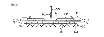
具体的には、遮断部材51が上位置に位置しており、少なくとも一つのガード24が上位置に位置している状態で、加熱流体バルブ73が開かれ、下面ノズル71が加熱流体の一例である温水(たとえば、45~60℃)の吐出を開始する。温水の吐出は、第2液体が基板Wの上面に供給される前または後に開始されてもよいし、第2液体が基板Wの上面に供給されるのと同時に開示されてもよい。温水の吐出は、露出穴Hの外縁が基板Wの上面の外周まで広がった後に停止される。露出穴Hが形成された後であれば、温水の吐出は、露出穴Hの外縁が基板Wの上面の外周まで広がる前に停止されてもよい。
Next, an exposure hole H is formed in the second liquid film F2 to expose the central portion of the upper surface of the substrate W from the second liquid film F2, and the outer edge of the exposure hole H is extended to the outer periphery of the upper surface of the substrate W. is done.
Specifically, with the blocking
また、スピンチャック10は、基板Wを液体排出速度で回転させる。液体排出速度は、第1パドル速度よりも大きい。液体排出速度は、第2置換速度と等しくてもよいし、異なっていてもよい。この例では、液体排出速度は、第1パドル速度よりも大きく、リンス液供給速度よりも小さい速度である。液体排出速度が第2置換速度と異なる場合、基板Wの回転速度は、温水の吐出が開始される前または後に変更されてもよいし、温水の吐出が開始されるのと同時に変更されてもよい。また、温水の吐出が開始される前に、ガード昇降ユニット27は、基板Wから排出された液体を受け止めるガード24を切り替えるために、少なくとも一つのガード24を鉛直に移動させてもよい。
Also, the
図7Cに示すように、下面ノズル71は、基板Wへの第2液体の吐出が停止されており、ほぼ円形の第2液膜F2とリング状の第1液膜F1とが基板Wの上面に保持されている状態で、基板Wの下面の中央部に向けて温水を吐出する。下面ノズル71から上方に吐出された温水は、基板Wの下面中央部に衝突した後、回転している基板Wの下面に沿って外方に流れる。これにより、温水が基板Wの下面全域に供給され、基板Wの全域が加熱される。基板Wの上面上の第1液体および第2液体は、基板Wを介して間接的に加熱される。
As shown in FIG. 7C, the
第1液体および第2液体の加熱によって第1液体および第2液体の蒸発が促進される。下面ノズル71から吐出された温水が基板Wの下面の中央部に最初に衝突するので、温水から基板Wに伝達される熱量は、基板Wの下面の中央部に近づくにしたがって増加する。第2液体の蒸発速度は、基板Wの上面の中央部で最も大きい。そのため、図7Dに示すように、第2液膜F2の中央部を貫通するほぼ円形の露出穴Hが形成され(穴形成工程(図6のステップ9-2))、第2液膜F2がリング状に変化する。これにより、基板Wの上面の中央部が第2液膜F2から露出する。
Heating the first and second liquids promotes evaporation of the first and second liquids. Since the hot water discharged from the
露出穴Hが第2液膜F2の中央部に形成された後は、リング状の第2液膜F2の内周を形成する第2液体が蒸発する。これにより、露出穴Hの直径に相当する第2液膜F2の内径が広がる。加えて、基板Wの上面上の第2液体が遠心力によって基板Wの上面に沿って外方に流れ、第2液膜F2の内径および外径が広がる。基板Wの上面の外周部上の第1液体は、第2液体によって外方に押され、基板Wから排出される。これにより、図7Eに示すように、第1液膜F1が基板Wから排出される。その後、図7Fに示すように、第2液膜F2の内周が基板Wの上面の外周まで広がり(穴拡大工程(図6のステップ10-2))、第2液膜F2が基板Wから排出される。これにより、目視できる大きさの液滴が基板Wの上面からなくなり、基板Wの上面全域が露出する。 After the exposure hole H is formed in the central portion of the second liquid film F2, the second liquid forming the inner circumference of the ring-shaped second liquid film F2 evaporates. As a result, the inner diameter of the second liquid film F2 corresponding to the diameter of the exposure hole H is widened. In addition, the second liquid on the upper surface of the substrate W flows outward along the upper surface of the substrate W due to centrifugal force, and the inner and outer diameters of the second liquid film F2 expand. The first liquid on the outer periphery of the upper surface of the substrate W is pushed outward by the second liquid and discharged from the substrate W. FIG. As a result, the first liquid film F1 is discharged from the substrate W as shown in FIG. 7E. After that, as shown in FIG. 7F, the inner circumference of the second liquid film F2 spreads to the outer circumference of the upper surface of the substrate W (the hole enlarging step (step 10-2 in FIG. 6)), and the second liquid film F2 spreads from the substrate W. Ejected. As a result, droplets of a visible size disappear from the upper surface of the substrate W, and the entire upper surface of the substrate W is exposed.
室温よりも高く、水の沸点以下の値であれば、温水の温度は、どのような値であってもよい。温水の温度は、第2液体の沸点以上であってもよい。たとえば、温水の温度は、第2液体の沸点よりも少し高い温度であってもよい。具体的には、温水の温度から第2液体の沸点を引いた値は、室温以下であってもよい。温水の温度が第2液体の沸点以上である場合、少なくとも基板Wの上面の中央部は、第2液体の沸点以上の温度まで加熱される。 The temperature of the hot water may be any value as long as it is higher than room temperature and equal to or lower than the boiling point of water. The temperature of the hot water may be equal to or higher than the boiling point of the second liquid. For example, the temperature of hot water may be slightly higher than the boiling point of the second liquid. Specifically, the value obtained by subtracting the boiling point of the second liquid from the temperature of the hot water may be room temperature or lower. When the temperature of the hot water is equal to or higher than the boiling point of the second liquid, at least the central portion of the upper surface of the substrate W is heated to a temperature equal to or higher than the boiling point of the second liquid.
温水の温度が第2液体の沸点よりも少し高い場合、第2液体が少なくとも基板Wの上面の中央部で気化し、多数の小さな気泡が第2液体と基板Wの上面との間に介在する。第2液体の供給が開始される前から温水の吐出が開始される場合、第2液体は、比重差で第1液体と基板Wとの間に入り込み、基板Wに供給された直後(たとえば基板Wに供給されてから5秒以内に)基板Wの上面上で気化する。 When the temperature of the hot water is slightly higher than the boiling point of the second liquid, the second liquid vaporizes at least at the central portion of the top surface of the substrate W, and many small bubbles are interposed between the second liquid and the top surface of the substrate W. . If hot water discharge is started before the supply of the second liquid is started, the second liquid enters between the first liquid and the substrate W due to the difference in specific gravity, and immediately after being supplied to the substrate W (for example, the substrate W). Vaporizes on the top surface of the substrate W) within 5 seconds after being supplied to W).
第2液体が第2液膜F2と基板Wとの界面で気化すると、第2液体の蒸気を含む蒸気層(図14A参照)が第2液膜F2と基板Wとの間に形成され、第2液体が基板Wの上面から離れる。この場合、蒸気層の厚みがパターンP1の高さより大きいと、パターンP1の間から全ての第2液体がなくなる。そのため、パターンP1の倒壊を防止しながら、第2液膜F2を基板Wから排出できる。 When the second liquid is vaporized at the interface between the second liquid film F2 and the substrate W, a vapor layer (see FIG. 14A) containing the vapor of the second liquid is formed between the second liquid film F2 and the substrate W. 2 liquid leaves the upper surface of the substrate W; In this case, if the thickness of the vapor layer is greater than the height of the pattern P1, all the second liquid will be removed from between the patterns P1. Therefore, the second liquid film F2 can be discharged from the substrate W while preventing the pattern P1 from collapsing.
次に、基板Wの高速回転によって基板Wを乾燥させる乾燥工程(図6のステップS11)が行われる。
具体的には、遮断部材昇降ユニット54が遮断部材51を上位置から下位置に下降させる。この状態で、スピンチャック10がリンス液供給速度よりも大きい高回転速度(たとえば数千rpm)で基板Wを回転させる。目視できない大きさの液滴が基板Wの上面(たとえば、パターンP1の間)に残っていたとしても、このような液滴は、基板Wが高速で回転している間に蒸発する。これにより、基板Wが乾燥する。基板Wの高速回転が開始されてから所定時間が経過すると、スピンチャック10が回転を停止する。これにより、基板Wの回転が停止される(図6のステップS12)。
Next, a drying step (step S11 in FIG. 6) is performed to dry the substrate W by rotating the substrate W at high speed.
Specifically, the blocking
次に、基板Wをチャンバー4から搬出する搬出工程(図6のステップS13)が行われる。
具体的には、遮断部材昇降ユニット54が遮断部材51を上位置まで上昇させ、ガード昇降ユニット27が全てのガード24を下位置まで下降させる。さらに、上気体バルブ64および下気体バルブ84が閉じられ、遮断部材51の上中央開口61とスピンベース12の下中央開口81とが窒素ガスの吐出を停止する。その後、センターロボットCRが、ハンドH1をチャンバー4内に進入させる。センターロボットCRは、複数のチャックピン11が基板Wの把持を解除した後、スピンチャック10上の基板WをハンドH1で支持する。その後、センターロボットCRは、基板WをハンドH1で支持しながら、ハンドH1をチャンバー4の内部から退避させる。これにより、処理済みの基板Wがチャンバー4から搬出される。
Next, an unloading step (step S13 in FIG. 6) of unloading the substrate W from the
Specifically, the blocking
次に、第3実施例について説明する。
搬入工程(図8のステップS1)から第1パドル工程(図8のステップS6)までの第3実施例の流れは、第1実施例と同様であるので、以下では、第2置換工程以降の流れについて説明する。
図8は、基板処理装置1によって行われる基板Wの処理のさらに他の例(第3実施例)について説明するための工程図である。図9A~図9Cは、第3実施例が行われているときの基板Wの状態を示す模式図である。以下では、図2および図8を参照する。図9A~図9Cについては適宜参照する。
Next, a third embodiment will be described.
Since the flow of the third embodiment from the carrying-in process (step S1 in FIG. 8) to the first paddle process (step S6 in FIG. 8) is the same as that of the first embodiment, the steps after the second replacement process will be described below. Explain the flow.
FIG. 8 is a process chart for explaining still another example (third embodiment) of processing the substrate W performed by the
第1液膜F1が形成された後は、第2液体を基板Wの上面に供給して、基板Wの上面上の第1液体を第2液体に置換する第2置換工程(図8のステップS7-3)が行われる。
具体的には、遮断部材51が上位置に位置しており、少なくとも一つのガード24が上位置に位置している状態で、ノズル移動ユニット46が第2液体ノズル43を待機位置から処理位置に移動させる。その後、スピンチャック10が基板Wを第2置換速度で回転させる。第2置換速度は、リンス液供給速度と等しくてもよいし、異なっていてもよい。第2置換速度は、第1置換速度と等しくてもよいし、異なっていてもよい。第2液体ノズル43が基板Wの上方に位置している状態で、第2液体バルブ45が開かれ、第2液体ノズル43が第2液体の吐出を開始する。
After the first liquid film F1 is formed, a second replacement step (the step in FIG. 8) of supplying the second liquid to the upper surface of the substrate W to replace the first liquid on the upper surface of the substrate W with the second liquid. S7-3) is performed.
Specifically, the
第2液体の吐出が開始される前に、ガード昇降ユニット27は、基板Wから排出された液体を受け止めるガード24を切り替えるために、少なくとも一つのガード24を鉛直に移動させてもよい。第2液体ノズル43が第2液体を吐出しているとき、ノズル移動ユニット46は、基板Wの上面に対する第2液体の着液位置が中央部と外周部とを通るように着液位置を移動させてもよいし、中央部で着液位置を静止させてもよい。この例では、ノズル移動ユニット46は、第2液体ノズル43から吐出された第2液体が基板Wの上面の中央部に衝突する中央処理位置で第2液体ノズル43を静止させる。
The
第2液体が基板Wの上面の中央部に向けて吐出されると、基板Wの上面の中央部を覆うほぼ円形の第2液膜F2と、第2液膜F2を取り囲むリング状の第1液膜F1とが、基板Wの上面に形成される。第2液体の吐出が継続されると、第2液膜F2の外径が徐々に増加すると共に、リング状の第1液膜F1の幅が徐々に減少する。第2液体バルブ45が開かれてから所定時間が経過すると、第2液膜F2の外周が基板Wの上面の外周まで広がり、全てまたは殆ど全ての第1液体が第2液体で置換される。
When the second liquid is discharged toward the central portion of the upper surface of the substrate W, a substantially circular second liquid film F2 covering the central portion of the upper surface of the substrate W and a ring-shaped first liquid film F2 surrounding the second liquid film F2 are formed. A liquid film F1 is formed on the upper surface of the substrate W. As shown in FIG. As the ejection of the second liquid continues, the outer diameter of the second liquid film F2 gradually increases and the width of the ring-shaped first liquid film F1 gradually decreases. After a predetermined time has passed since the second
基板Wの上面の中央部が第2液膜F2で覆われた後は、基板Wの上面の中央部を第2液膜F2から露出させる露出穴Hを第2液膜F2に形成し、この露出穴Hの外縁を基板Wの上面の外周まで広げる液体排出工程が行われる。
具体的には、第2液体ノズル43が第2液体を吐出している状態で、ノズル移動ユニット46が、第2液体ノズル43を中央処理位置から外周処理位置まで移動させる。中央処理位置は、第2液体ノズル43から吐出された第2液体が基板Wの上面の中央部に衝突する位置である。外周処理位置は、第2液体ノズル43から吐出された第2液体が基板Wの上面の外周部に衝突する外周処理位置である。
After the central portion of the upper surface of the substrate W is covered with the second liquid film F2, an exposure hole H is formed in the second liquid film F2 to expose the central portion of the upper surface of the substrate W from the second liquid film F2. A liquid discharging process is performed to widen the outer edge of the exposure hole H to the outer periphery of the upper surface of the substrate W. FIG.
Specifically, while the second
ノズル移動ユニット46は、一定の速度で第2液体ノズル43を中央処理位置から外周処理位置に移動させてもよいし、第2液体ノズル43の移動速度を変化させながら第2液体ノズル43を中央処理位置から外周処理位置に移動させてもよい。また、第2液体ノズル43の移動は、第2液膜F2の外周が基板Wの上面の外周まで広がる前または後に開始されてもよいし、第2液膜F2の外周が基板Wの上面の外周まで広がるのと同時に開始されてもよい。図9Aは、第2液膜F2の外周が基板Wの上面の外周まで広がる前に、第2液体ノズル43が中央処理位置から移動した例を示している。
The
スピンチャック10は、基板Wを液体排出速度で回転させる。液体排出速度は、第1パドル速度よりも大きい。液体排出速度は、第2置換速度と等しくてもよいし、異なっていてもよい。この例では、液体排出速度は、第1パドル速度よりも大きく、リンス液供給速度よりも小さい速度である。液体排出速度が第2置換速度と異なる場合、基板Wの回転速度は、第2液体ノズル43の移動が開始される前または後に変更されてもよいし、第2液体ノズル43の移動が開始されるのと同時に変更されてもよい。
The
第2液体ノズル43が中央処理位置から離れた後は、第2液体ノズル43から吐出された第2液体が基板Wの上面の中央部に供給されない。つまり、基板Wの上面の中央部に新たな第2液体が供給されない。基板Wの上面の中央部にある既存の第2液体は蒸発する。したがって、図9Bに示すように、第2液体ノズル43が中央処理位置から離れてから暫く経つと、第2液膜F2の中央部を貫通するほぼ円形の露出穴Hが形成され(穴形成工程(図8のステップ9-3))、第2液膜F2がリング状に変化する。これにより、基板Wの上面の中央部が第2液膜F2から露出する。
The second liquid ejected from the second
図9Bおよび図9Cを比較すると分かるように、露出穴Hの直径に相当する第2液膜F2の内径は、第2液体ノズル43が中央処理位置から離れるにしたがって増加する。第2液膜F2のまわりにリング状の第1液膜F1がある場合、第1液膜F1の幅は、第2液体ノズル43が中央処理位置から離れるにしたがって減少する。第1液膜F1を構成する全ての第1液体は、第2液体ノズル43が外周処理位置に達する前に基板Wから排出される。
As can be seen by comparing FIGS. 9B and 9C, the inner diameter of the second liquid film F2, which corresponds to the diameter of the exposure hole H, increases as the second
また、第2液体ノズル43が外周処理位置に達すると、第2液体バルブ45が閉じられ、第2液体の吐出が停止される。その後、ノズル移動ユニット46は、第2液体ノズル43を待機位置に移動させる。第2液体の吐出が停止された後は、リング状の第2液膜F2が基板Wの上面の外周部に残り、基板Wの上面の外周部だけが第2液体で覆われる。第2液体の吐出が停止された後に基板Wの上面に残ったリング状の第2液膜F2は、遠心力によって基板Wの上面から排出される(穴拡大工程(図8のステップ10-3))。これにより、目視できる大きさの液滴が基板Wの上面からなくなり、基板Wの上面全域が露出する。
Further, when the second
次に、基板Wの高速回転によって基板Wを乾燥させる乾燥工程(図8のステップS11)が行われる。
具体的には、遮断部材昇降ユニット54が遮断部材51を上位置から下位置に下降させる。この状態で、スピンチャック10がリンス液供給速度よりも大きい高回転速度(たとえば数千rpm)で基板Wを回転させる。目視できない大きさの液滴が基板Wの上面(たとえば、パターンP1の間)に残っていたとしても、このような液滴は、基板Wが高速で回転している間に蒸発する。これにより、基板Wが乾燥する。基板Wの高速回転が開始されてから所定時間が経過すると、スピンチャック10が回転を停止する。これにより、基板Wの回転が停止される(図8のステップS12)。
Next, a drying step (step S11 in FIG. 8) is performed to dry the substrate W by rotating the substrate W at high speed.
Specifically, the blocking
次に、基板Wをチャンバー4から搬出する搬出工程(図8のステップS13)が行われる。
具体的には、遮断部材昇降ユニット54が遮断部材51を上位置まで上昇させ、ガード昇降ユニット27が全てのガード24を下位置まで下降させる。さらに、上気体バルブ64および下気体バルブ84が閉じられ、遮断部材51の上中央開口61とスピンベース12の下中央開口81とが窒素ガスの吐出を停止する。その後、センターロボットCRが、ハンドH1をチャンバー4内に進入させる。センターロボットCRは、複数のチャックピン11が基板Wの把持を解除した後、スピンチャック10上の基板WをハンドH1で支持する。その後、センターロボットCRは、基板WをハンドH1で支持しながら、ハンドH1をチャンバー4の内部から退避させる。これにより、処理済みの基板Wがチャンバー4から搬出される。
Next, an unloading step (step S13 in FIG. 8) of unloading the substrate W from the
Specifically, the blocking
次に、第4実施例について説明する。
搬入工程(図10のステップS1)から第2パドル工程(図10のステップS8-3)までの第4実施例の流れは、第3実施例と同様であるので、以下では、液体排出工程以降の流れについて説明する。
図10は、基板処理装置1によって行われる基板Wの処理のさらに他の例(第4実施例)について説明するための工程図である。図11A~図11Cは、第4実施例が行われているときの基板Wの状態を示す模式図である。以下では、図2および図10を参照する。図11A~図11Cについては適宜参照する。
Next, a fourth embodiment will be described.
Since the flow of the fourth embodiment from the carrying-in process (step S1 in FIG. 10) to the second paddle process (step S8-3 in FIG. 10) is the same as in the third embodiment, the following description will be made after the liquid discharge process. I will explain the flow of
FIG. 10 is a process chart for explaining still another example (fourth embodiment) of processing the substrate W performed by the
基板Wの上面の中央部が第2液膜F2で覆われた後は、基板Wの上面の中央部を第2液膜F2から露出させる露出穴Hを第2液膜F2に形成し、この露出穴Hの外縁を基板Wの上面の外周まで広げる液体排出工程が行われる。
具体的には、遮断部材51が上位置に位置しており、少なくとも一つのガード24が上位置に位置している状態で、上気体バルブ64が開かれ、中心ノズル55が窒素ガスの吐出を開始する(図11A参照)。中心ノズル55から吐出される窒素ガスの温度は、室温であってもよいし、室温を超えていてもよい。窒素ガスの吐出は、第2液膜F2の外周が基板Wの上面の外周に広がる前または後に開始されてもよいし、第2液膜F2の外周が基板Wの上面の外周に広がるのと同時に開始されてもよい。図11Aは、第2液膜F2の外周が基板Wの上面の外周に広がる前に、窒素ガスの吐出が開始される例を示している。
After the central portion of the upper surface of the substrate W is covered with the second liquid film F2, an exposure hole H is formed in the second liquid film F2 to expose the central portion of the upper surface of the substrate W from the second liquid film F2. A liquid discharging process is performed to widen the outer edge of the exposure hole H to the outer periphery of the upper surface of the substrate W. FIG.
Specifically, with the blocking
遮断部材昇降ユニット54は、窒素ガスの吐出が開始される前または後に遮断部材51を下位置に位置させてもよいし、窒素ガスの吐出が開始されるのと同時に遮断部材51を下位置に位置させてもよい。中心ノズル55が窒素ガスを吐出しているとき、スピンチャック10は、基板Wを液体排出速度で回転させてもよいし、基板Wを静止させてもよい。液体排出速度は、第1パドル速度よりも大きい。液体排出速度は、第2置換速度と等しくてもよいし、異なっていてもよい。この例では、液体排出速度は、第1パドル速度よりも大きく、リンス液供給速度よりも小さい速度である。液体排出速度が第2置換速度と異なる場合、基板Wの回転速度は、窒素ガスの吐出が開始される前または後に変更されてもよいし、窒素ガスの吐出が開始されるのと同時に変更されてもよい。
The blocking
中心ノズル55から吐出された窒素ガスは、基板Wの上面の中央部で第2液膜F2に衝突した後、第2液膜F2の表面に沿ってあらゆる方向に外方に流れる。これにより、基板Wの上面の中央部からあらゆる方向に外方に流れる気流が形成される。窒素ガスが第2液膜F2の中央部に吹き付けられると、第2液膜F2に含まれる第2液体が窒素ガスの圧力で外方に押し退けられる。さらに、窒素ガスの供給によって第2液体の蒸発が促進される。これにより、図11Bに示すように、第2液膜F2の中央部の厚みが減少し、ほぼ円形の露出穴Hが第2液膜F2の中央部に形成される(穴形成工程(図10のステップ9-4))。
The nitrogen gas discharged from the
さらに、第2液体を外方に移動させる力が第2液膜F2の表面に沿って外方に流れる窒素ガスから基板W上の第2液体に加わり、第2液体が基板Wの上面に沿って外方に流れる。スピンチャック10が基板Wを回転させる場合は、遠心力も基板W上の第2液体に加わる。図11Cに示すように、リング状の第2液膜F2の内径および外径は、第2液体が基板Wの上面に沿って外方に流れるにしたがって増加する。
Further, a force to move the second liquid outward is applied to the second liquid on the substrate W from the nitrogen gas flowing outward along the surface of the second liquid film F2, and the second liquid moves along the upper surface of the substrate W. flow outward. Centrifugal force is also applied to the second liquid on the substrate W when the
基板Wの上面の外周部上にリング状の第1液膜F1が残っている場合、基板Wの上面の外周部上の第1液体は、第2液体によって外方に押され、基板Wから排出される。これにより、第1液膜F1が基板Wから排出される。その後、第2液膜F2の内周が基板Wの上面の外周まで広がる(穴拡大工程(図10のステップ10-4))。基板Wの上面の外周部上にリング状の第1液膜F1が残っていない場合も、第2液膜F2の内周が基板Wの上面の外周まで広がる。これにより、目視できる大きさの液滴が基板Wの上面からなくなり、基板Wの上面全域が露出する。 When the ring-shaped first liquid film F1 remains on the outer peripheral portion of the upper surface of the substrate W, the first liquid on the outer peripheral portion of the upper surface of the substrate W is pushed outward by the second liquid and separated from the substrate W. Ejected. As a result, the first liquid film F1 is discharged from the substrate W. As shown in FIG. After that, the inner circumference of the second liquid film F2 spreads to the outer circumference of the upper surface of the substrate W (hole enlarging step (step 10-4 in FIG. 10)). Even when the ring-shaped first liquid film F1 does not remain on the outer periphery of the upper surface of the substrate W, the inner periphery of the second liquid film F2 spreads to the outer periphery of the upper surface of the substrate W. As a result, droplets of a visible size disappear from the upper surface of the substrate W, and the entire upper surface of the substrate W is exposed.
次に、基板Wの高速回転によって基板Wを乾燥させる乾燥工程(図10のステップS11)が行われる。
具体的には、遮断部材51が上位置に位置している場合は、遮断部材昇降ユニット54が遮断部材51を上位置から下位置に下降させる。この状態で、スピンチャック10がリンス液供給速度よりも大きい高回転速度(たとえば数千rpm)で基板Wを回転させる。目視できない大きさの液滴が基板Wの上面(たとえば、パターンP1の間)に残っていたとしても、このような液滴は、基板Wが高速で回転している間に蒸発する。これにより、基板Wが乾燥する。基板Wの高速回転が開始されてから所定時間が経過すると、スピンチャック10が回転を停止する。これにより、基板Wの回転が停止される(図10のステップS12)。
Next, a drying step (step S11 in FIG. 10) is performed to dry the substrate W by rotating the substrate W at high speed.
Specifically, when the blocking
次に、基板Wをチャンバー4から搬出する搬出工程(図10のステップS13)が行われる。
具体的には、遮断部材昇降ユニット54が遮断部材51を上位置まで上昇させ、ガード昇降ユニット27が全てのガード24を下位置まで下降させる。さらに、上気体バルブ64および下気体バルブ84が閉じられ、遮断部材51の上中央開口61とスピンベース12の下中央開口81とが窒素ガスの吐出を停止する。その後、センターロボットCRが、ハンドH1をチャンバー4内に進入させる。センターロボットCRは、複数のチャックピン11が基板Wの把持を解除した後、スピンチャック10上の基板WをハンドH1で支持する。その後、センターロボットCRは、基板WをハンドH1で支持しながら、ハンドH1をチャンバー4の内部から退避させる。これにより、処理済みの基板Wがチャンバー4から搬出される。
Next, an unloading step (step S13 in FIG. 10) of unloading the substrate W from the
Specifically, the blocking
以上のように第1実施例~第4実施例では、水を含有するリンス液を、水平に保持されている基板Wの上面に供給する。その後、水平に保持されている基板Wの上面に第1液体を供給する。これにより、基板Wの上面上のリンス液が、第1液体に置換される。その後、水平に保持されている基板Wの上面に第2液体を供給する。これにより、基板Wの上面上の第1液体が、第2液体に置換される。したがって、リンス液は、段階的に第2液体に置換される。その後、第2液体を基板Wの上面から除去し、基板Wを乾燥させる。 As described above, in the first to fourth embodiments, the rinse liquid containing water is supplied to the upper surface of the substrate W held horizontally. After that, the first liquid is supplied to the upper surface of the substrate W held horizontally. As a result, the rinse liquid on the upper surface of the substrate W is replaced with the first liquid. After that, the second liquid is supplied to the upper surface of the substrate W held horizontally. As a result, the first liquid on the upper surface of the substrate W is replaced with the second liquid. Therefore, the rinse liquid is gradually replaced with the second liquid. After that, the second liquid is removed from the upper surface of the substrate W, and the substrate W is dried.
基板W上のリンス液は、直接、第2液体に置換されるのではなく、第1液体に置換された後、第2液体に置換される。水に対する第2液体の溶解度は、水に対する第1液体の溶解度よりも小さい。つまり、第2液体は、第1液体と比べて水に対する親和性が低い。リンス液が保持されている基板Wの上面に第2液体を供給すると、リンス液が基板Wの上面に残る場合がある。表面張力が高い水を含有するリンス液の残量が多いと、基板Wを乾燥させたときに、パターンP1(図14A参照)の倒壊が発生し易い。水に対する親和性が相対的に高い第1液体でリンス液を置換すれば、乾燥する直前の基板Wに残留するリンス液を減らすことができる。 The rinse liquid on the substrate W is not directly replaced with the second liquid, but replaced with the first liquid and then replaced with the second liquid. The solubility of the second liquid in water is less than the solubility of the first liquid in water. That is, the second liquid has a lower affinity for water than the first liquid. When the second liquid is supplied to the upper surface of the substrate W holding the rinse liquid, the rinse liquid may remain on the upper surface of the substrate W. If the remaining amount of the rinse liquid containing water with high surface tension is large, the pattern P1 (see FIG. 14A) tends to collapse when the substrate W is dried. By replacing the rinse liquid with the first liquid having a relatively high affinity for water, the rinse liquid remaining on the substrate W immediately before drying can be reduced.
また、第2液体の比重は、第1液体の比重よりも大きい。そのため、第1液体と第2液体との界面では、第2液体が重力で基板Wの上面側に移動し、第1液体が第2液体の上に移動する。つまり、比重差によって第2液体が第1液体と基板Wとの間に入り込む。さらに、第2液体の表面張力が低く、第2液体の比重が大きいので、第2液体がパターンP1の間に進入し、パターンP1の間にある第1液体が第2液体で置換される。このような表面張力が低い第2液体がパターンP1の間に入るので、基板Wを乾燥させるときに、第2液体の表面がパターンP1の間に形成されたとしても、パターンP1の倒壊を減らすことができる。 Also, the specific gravity of the second liquid is greater than the specific gravity of the first liquid. Therefore, at the interface between the first liquid and the second liquid, the second liquid moves toward the upper surface of the substrate W due to gravity, and the first liquid moves above the second liquid. That is, the second liquid enters between the first liquid and the substrate W due to the difference in specific gravity. Furthermore, since the second liquid has a low surface tension and a high specific gravity, the second liquid enters between the patterns P1 and replaces the first liquid between the patterns P1 with the second liquid. Since the second liquid with such a low surface tension enters between the patterns P1, even if the surface of the second liquid is formed between the patterns P1 when the substrate W is dried, the collapse of the patterns P1 is reduced. be able to.
第2液体の沸点は、室温以上である。したがって、室温の環境下で第2液体を用いる場合、第2液体を液体に維持するために第2液体を冷却しなくてもよい。さらに、第2液体の沸点から室温を引いた値は、室温以下である。つまり、第2液体の沸点は、室温から室温を2倍した値までの範囲内の値であり、室温に対して比較的低い。第2液体の沸点が低いと、基板Wの乾燥中に第2液体が基板Wからなくなる速度が上昇するので、パターンP1を倒壊させる倒壊力がパターンP1に加わる時間を短縮できる。これにより、パターンP1の倒壊を減らすことができ、乾燥後の基板Wの品質を高めることができる。 The boiling point of the second liquid is room temperature or higher. Therefore, if the second liquid is used in a room temperature environment, it is not necessary to cool the second liquid to keep it liquid. Furthermore, the value obtained by subtracting room temperature from the boiling point of the second liquid is below room temperature. That is, the boiling point of the second liquid is a value within the range from room temperature to twice the room temperature, which is relatively low relative to room temperature. When the boiling point of the second liquid is low, the speed at which the second liquid disappears from the substrate W during the drying of the substrate W increases, so that the time for which the pattern P1 is subjected to the collapsing force that collapses the pattern P1 can be shortened. Thereby, collapse of the pattern P1 can be reduced, and the quality of the substrate W after drying can be improved.
第1実施例~第4実施例では、基板Wを低速で回転させながら、基板Wの上面上の第1液体を第2液体に置換する。第2液体の供給を開始すると、基板Wの上面は、ほぼ円形の第2液膜F2と、第2液膜F2を取り囲むリング状の第1液膜F1とに覆われる。その後、第2液膜F2の外周は、ほぼ円形のまま、基板Wの上面の外周に向かって徐々に広がる。第1液体および第2液体の性質の違いが大きい場合、基板Wを高速で回転させると、第2液膜F2の外周がほぼ円形のまま広がらず、第1液体が確実に置換されないおそれがある。基板Wを低速で回転させれば、このような現象を未然に回避できる。 In the first to fourth embodiments, the first liquid on the upper surface of the substrate W is replaced with the second liquid while rotating the substrate W at a low speed. When the supply of the second liquid is started, the upper surface of the substrate W is covered with the substantially circular second liquid film F2 and the ring-shaped first liquid film F1 surrounding the second liquid film F2. After that, the outer circumference of the second liquid film F2 gradually widens toward the outer circumference of the upper surface of the substrate W while remaining substantially circular. If the properties of the first liquid and the second liquid are significantly different, and the substrate W is rotated at a high speed, the outer periphery of the second liquid film F2 may not spread while remaining substantially circular, and the first liquid may not be reliably replaced. . Such a phenomenon can be avoided by rotating the substrate W at a low speed.
第2実施例~第4実施例では、基板Wの上面上の一部の第1液体だけを第2液体に置換する。これにより、リング状の第1液膜F1が、少なくとも基板Wの上面の外周部に残り、第2液体が、第1液膜F1の内側に溜まる。第2液体の表面張力が低いので、基板Wの上面上の全ての第1液体を第2液体に置換すると、薄い第2液膜F2が基板Wの上面に形成される。さらに、第2液体の沸点が低いので、新たな第2液体の供給を停止すると、基板W上の第2液体が直ぐに蒸発し、基板Wの上面の一部が短時間で第2液膜F2から露出するかもしれない。 In the second to fourth embodiments, only part of the first liquid on the upper surface of the substrate W is replaced with the second liquid. As a result, the ring-shaped first liquid film F1 remains at least on the outer peripheral portion of the upper surface of the substrate W, and the second liquid is accumulated inside the first liquid film F1. Since the surface tension of the second liquid is low, a thin second liquid film F2 is formed on the top surface of the substrate W when all the first liquid on the top surface of the substrate W is replaced with the second liquid. Furthermore, since the boiling point of the second liquid is low, when the supply of new second liquid is stopped, the second liquid on the substrate W immediately evaporates, and part of the upper surface of the substrate W forms the second liquid film F2 in a short period of time. may be exposed from
これに対して、第1液体の表面張力が第2液体の表面張力よりも高いので、基板Wの上面の外周部に残る第1液膜F1の厚みは、第2液膜F2の厚みよりも大きい。基板Wの上面に供給された第2液体は、リング状の第1液膜F1の内側に溜まる。したがって、基板Wの上面上の全ての第1液体を第2液体に置換する場合に比べて厚い第2液膜F2が第1液膜F1の内側に形成される。これにより、基板Wの上面の一部が短時間で第2液膜F2から露出することを防止できる。 On the other hand, since the surface tension of the first liquid is higher than that of the second liquid, the thickness of the first liquid film F1 remaining on the outer periphery of the upper surface of the substrate W is greater than the thickness of the second liquid film F2. big. The second liquid supplied to the upper surface of the substrate W accumulates inside the ring-shaped first liquid film F1. Therefore, a thicker second liquid film F2 is formed inside the first liquid film F1 than when all the first liquid on the upper surface of the substrate W is replaced with the second liquid. This can prevent a part of the upper surface of the substrate W from being exposed from the second liquid film F2 in a short period of time.
第2実施例~第4実施例では、第2液膜F2が基板Wの上面に保持された状態で、基板Wの上面の一部だけを露出させる露出穴Hを第2液膜F2に形成する。その後、露出穴Hの外縁を基板Wの上面の外周まで広げる。これにより、目視できる大きさの液滴が基板Wの上面からなくなり、基板Wの上面全域が露出する。つまり、第2液膜F2の形をコントロールしながら、第2液膜F2を基板Wの上面から排出する。したがって、第2液膜F2を無秩序に排出する場合に比べて、乾燥後の基板Wの品質を安定させることができる。 In the second to fourth embodiments, an exposure hole H is formed in the second liquid film F2 to expose only a part of the upper surface of the substrate W while the second liquid film F2 is held on the upper surface of the substrate W. do. After that, the outer edge of the exposure hole H is widened to the outer periphery of the upper surface of the substrate W. As shown in FIG. As a result, droplets of a visible size disappear from the upper surface of the substrate W, and the entire upper surface of the substrate W is exposed. That is, the second liquid film F2 is discharged from the upper surface of the substrate W while controlling the shape of the second liquid film F2. Therefore, the quality of the substrate W after drying can be stabilized compared to the case where the second liquid film F2 is discharged randomly.
第2実施例~第4実施例では、基板Wを低速で回転させながら、露出穴Hが形成されたリング状の第2液膜F2の内径および外径と、第2液膜F2を取り囲むリング状の第1液膜F1の内径と、を増加させる。第1液体および第2液体の性質の違いが大きい場合、基板Wを高速で回転させると、第2液膜F2の外周がほぼ円形のまま基板Wの上面の外周まで広がらず、第1液体が基板Wの上面の外周部に残るおそれがある。基板Wを低速で回転させれば、このような現象を未然に回避できる。 In the second to fourth embodiments, while rotating the substrate W at a low speed, the inner and outer diameters of the ring-shaped second liquid film F2 in which the exposure hole H is formed, and the ring surrounding the second liquid film F2 are measured. and the inner diameter of the first liquid film F1 having the shape of . When the first liquid and the second liquid differ greatly in properties, when the substrate W is rotated at high speed, the outer periphery of the second liquid film F2 remains substantially circular and does not spread to the outer periphery of the upper surface of the substrate W. There is a possibility that it will remain on the outer peripheral portion of the upper surface of the substrate W. Such a phenomenon can be avoided by rotating the substrate W at a low speed.
第2実施例~第4実施例では、0を超える50rpm以下の回転速度で基板Wを回転させながら、露出穴Hが形成されたリング状の第2液膜F2の内径および外径と、第2液膜F2を取り囲むリング状の第1液膜F1の内径と、を増加させる。第2液体に加わる遠心力が小さいので、第2液膜F2の内周および外周はゆっくりと広がる。これにより、第2液膜F2の外周をほぼ円形のまま基板Wの上面の外周まで広げることができ、基板Wの上面の外周部に残留する第1液体の量を零または零付近まで減らすことができる。 In the second to fourth embodiments, the inner and outer diameters of the ring-shaped second liquid film F2 in which the exposure hole H is formed, and The inner diameter of the ring-shaped first liquid film F1 surrounding the two-liquid film F2 is increased. Since the centrifugal force applied to the second liquid is small, the inner circumference and outer circumference of the second liquid film F2 spread slowly. As a result, the outer periphery of the second liquid film F2 can be extended to the outer periphery of the upper surface of the substrate W while maintaining a substantially circular shape, and the amount of the first liquid remaining on the outer peripheral portion of the upper surface of the substrate W can be reduced to zero or near zero. can be done.
第2実施例では、室温よりも高温の加熱流体の一例である温水(室温よりも高温の純水)を、基板Wの下面の一部だけに向けて吐出する。温水は、基板Wの下面に衝突した後、基板Wの下面に沿って広がる。基板Wは、温水によって加熱される。第2液体は、基板Wによって加熱される。単位時間当たりの第2液体の蒸発量は、温水が基板Wの下面に衝突した位置の反対側で最も大きい。したがって、露出穴Hが形成される位置をコントロールできる。 In the second embodiment, hot water (pure water having a temperature higher than room temperature), which is an example of a heating fluid having a temperature higher than room temperature, is discharged toward only a part of the lower surface of the substrate W. As shown in FIG. The hot water spreads along the bottom surface of the substrate W after colliding with the bottom surface of the substrate W. As shown in FIG. The substrate W is heated by hot water. The second liquid is heated by the substrate W. As shown in FIG. The amount of evaporation of the second liquid per unit time is the largest on the side opposite to the position where the hot water collided with the lower surface of the substrate W. FIG. Therefore, the position where the exposure hole H is formed can be controlled.
第2実施例では、露出穴Hを第2液膜F2に形成するときや、露出穴Hの外縁を基板Wの上面の外周側に広げるときに、結露防止流体の一例である温水を基板Wの下面に供給して、基板Wの上面の温度を第2液体の露点温度より高い値に維持する。露出穴Hが形成された後は、基板Wの上面の少なくとも一部が露出している上に、第2液体の蒸気が基板Wの上面付近を漂う。したがって、基板Wの上面の温度を第2液体の露点温度より高い値に維持することにより、基板Wの上面において第2液膜F2から露出した露出部分に第2液体の液滴が発生することを防止できる。これにより、露出部分でのパターンの倒壊やパーティクルの発生を減らすことができる。 In the second embodiment, when the exposure holes H are formed in the second liquid film F2 and when the outer edges of the exposure holes H are extended to the outer peripheral side of the upper surface of the substrate W, warm water, which is an example of the anti-condensation fluid, is applied to the substrate W. to maintain the temperature of the upper surface of the substrate W at a value higher than the dew point temperature of the second liquid. After the exposure hole H is formed, at least a portion of the upper surface of the substrate W is exposed, and vapor of the second liquid floats around the upper surface of the substrate W. FIG. Therefore, by maintaining the temperature of the upper surface of the substrate W at a value higher than the dew point temperature of the second liquid, droplets of the second liquid are generated on the exposed portion of the upper surface of the substrate W exposed from the second liquid film F2. can be prevented. This can reduce pattern collapse and particle generation in the exposed portion.
第3実施例では、基板Wを回転させながら第2液体ノズル43に第2液体を吐出させる。さらに、第2液体ノズル43から吐出された第2液体が基板Wの上面に衝突する位置を、基板Wの上面の中央部から基板Wの上面の外周側に移動させる。第2液体ノズル43を移動させた後は、基板Wの上面の中央部に対する新たな第2液体の供給が停止される。さらに、第2液体は、基板Wの上面の中央部上で蒸発すると共に、遠心力で基板Wの上面の中央部から外方に移動する。したがって、第2液体ノズル43を外側に移動させるだけで、露出穴Hを基板Wの上面の中央部に形成できる。
In the third embodiment, the second liquid is ejected from the second
次に、第2実施形態について説明する。
第1実施形態に対する第2実施形態の主要な相違点は、下面ノズル71の代わりにホットプレート92が設けられていることである。
以下の図12A、図12B、図13、および図14A~図14Cにおいて、図1~図11Cに示された構成と同等の構成については、図1等と同一の参照符号を付してその説明を省略する。
Next, a second embodiment will be described.
A major difference of the second embodiment from the first embodiment is that a
12A, 12B, 13, and 14A to 14C, the same reference numerals as in FIG. omitted.
図12Aは、本発明の第2実施形態に係るスピンチャック10、遮断部材51、およびホットプレート92を水平に見た模式図である。図12Bは、スピンチャック10およびホットプレート92を上から見た模式図である。図12Aは、遮断部材51が上位置に位置している状態を示している。
図12Aに示すように、ホットプレート92は、基板Wとスピンベース12との間に配置される。ホットプレート92は、通電によりジュール熱を発生する発熱体93と、発熱体93を収容するアウターケース94とを含む。発熱体93およびアウターケース94は、基板Wの下方に配置される。発熱体93は、発熱体93に電力を供給する配線(図示せず)に接続されている。発熱体93の温度は、制御装置3によって変更される。制御装置3が発熱体93を発熱させると、基板Wの全体が均一に加熱される。
FIG. 12A is a schematic horizontal view of the
As shown in FIG. 12A,
ホットプレート92のアウターケース94は、基板Wの下方に配置される円板状のベース部95と、ベース部95の上面から上方に突出する複数の半球状の突出部96とを含む。ベース部95の上面は、基板Wの下面と平行であり、基板Wの直径より小さい外径を有している。複数の突出部96は、ベース部95の上面から上方に離れた位置で基板Wの下面に接触する。複数の突出部96は、基板Wが水平に支持されるように、ベース部95の上面内の複数の位置に配置されている。基板Wは、基板Wの下面がベース部95の上面から上方に離れた状態で水平に支持される。
An
図12Bに示すように、複数のチャックピン11は、ホットプレート92のまわりに配置されている。ホットプレート92の中心線は、基板Wの回転軸線A1上に配置されている。スピンチャック10が回転しても、ホットプレート92は回転しない。ホットプレート92の外径は、基板Wの直径よりも小さい。ホットプレート92の外径と基板Wの直径との差は、チャックピン11の高さ(図12A参照。スピンベース12の上面12uからチャックピン11の上端までの上下方向の長さ)よりも小さい。
As shown in FIG. 12B, multiple chuck pins 11 are arranged around the
図12Aに示すように、ホットプレート92は、ホットプレート92の中央部から下方に延びる支軸97によって水平に支持されている。ホットプレート92は、スピンベース12に対して上下に移動可能である。ホットプレート92は、支軸97を介してプレート昇降ユニット98に接続されている。プレート昇降ユニット98は、上位置(図12Aにおいて実線で示す位置)と下位置(図12Aにおいて二点鎖線で示す位置)との間でホットプレート92を鉛直に昇降させる。上位置は、ホットプレート92が基板Wの下面に接触する接触位置である。下位置は、ホットプレート92が基板Wから離れた状態で基板Wの下面とスピンベース12の上面12uとの間に配置される近接位置である。
As shown in FIG. 12A, the
プレート昇降ユニット98は、上位置から下位置までの任意の位置にホットプレート92を位置させる。基板Wが複数のチャックピン11に支持されており、基板Wの把持が解除されている状態で、ホットプレート92が上位置まで上昇すると、ホットプレート92の複数の突出部96が基板Wに下面に接触し、基板Wがホットプレート92に支持される。その後、基板Wは、ホットプレート92によって持ち上げられ、複数のチャックピン11から上方に離れる。この状態で、ホットプレート92が下位置まで下降すると、ホットプレート92上の基板Wが複数のチャックピン11の上に置かれ、ホットプレート92が基板Wから下方に離れる。このようにして、基板Wは、複数のチャックピン11とホットプレート92との間で受け渡される。
The
次に、第5実施例について説明する。
搬入工程(図13のステップS1)から第2パドル工程(図13のステップS8-2)までの第5実施例の流れは、第2実施例と同様であるので、以下では、液体排出工程以降の流れについて説明する。
図13は、基板処理装置1によって行われる基板Wの処理のさらに他の例(第5実施例)について説明するための工程図である。図14A~図14Cは、第5実施例が行われているときの基板Wの状態を示す模式図である。以下では、図12A、図12B、および図13を参照する。図14A~図14Cについては適宜参照する。
Next, a fifth embodiment will be described.
Since the flow of the fifth embodiment from the carrying-in process (step S1 in FIG. 13) to the second paddle process (step S8-2 in FIG. 13) is the same as that of the second embodiment, the liquid discharge process and subsequent steps will be described below. I will explain the flow of
FIG. 13 is a process chart for explaining still another example (fifth embodiment) of the processing of the substrate W performed by the
基板Wの上面の中央部を覆うほぼ円形の第2液膜F2と、第2液膜F2を取り囲むリング状の第1液膜F1とが、基板Wの上面に形成された後は、基板Wの上面の中央部を第2液膜F2から露出させる露出穴Hを第2液膜F2に形成し、この露出穴Hの外縁を基板Wの上面の外周まで広げる液体排出工程が行われる。
具体的には、遮断部材51が上位置に位置しており、少なくとも一つのガード24が上位置に位置している状態で、ホットプレート92が発熱し、基板Wの加熱を開始する。ホットプレート92の発熱は、第2液体が基板Wに供給される前または後に開始されてもよいし、第2液体が基板Wに供給されるのと同時に開始されてもよい。ホットプレート92は、基板Wの下面に接した状態で基板Wを加熱してもよいし、基板Wの下面から離れた状態で基板Wを加熱してもよい。基板Wの温度は、ホットプレート92の温度を変更することにより変更されてもよいし、基板Wとホットプレート92との間隔を変更することにより変更されてもよい。
After the substantially circular second liquid film F2 covering the central portion of the upper surface of the substrate W and the ring-shaped first liquid film F1 surrounding the second liquid film F2 are formed on the upper surface of the substrate W, the substrate W is An exposure hole H is formed in the second liquid film F2 to expose the central portion of the upper surface of the substrate W from the second liquid film F2, and the outer edge of the exposure hole H is extended to the outer periphery of the upper surface of the substrate W.
Specifically, the
ホットプレート92が基板Wの下面に接した状態で基板Wを加熱する場合、基板Wは、ホットプレート92の上で静止する。ホットプレート92が基板Wの下面から離れた状態で基板Wを加熱する場合、スピンチャック10は、基板Wを液体排出速度で回転させる。液体排出速度は、第1パドル速度よりも大きい。液体排出速度は、第2置換速度と等しくてもよいし、異なっていてもよい。この例では、液体排出速度は、第1パドル速度よりも大きく、リンス液供給速度よりも小さい速度である。液体排出速度が第2置換速度と異なる場合、基板Wの回転速度は、基板Wの加熱が開始される前または後に変更されてもよいし、基板Wの加熱が開始されるのと同時に変更されてもよい。
When the substrate W is heated while the
図14Aに示すように、ホットプレート92が基板Wを加熱すると、基板Wの上面上の第1液体および第2液体は、基板Wを介して加熱される。これにより、第1液体および第2液体の蒸発が促進される。上気体バルブ64(図2参照)は、ホットプレート92が基板Wの加熱を開始した後に開かれる。これにより、図14Bに示すように、中心ノズル55が窒素ガスの吐出を開始する。中心ノズル55から吐出される窒素ガスの温度は、室温であってもよいし、室温を超えていてもよい。中心ノズル55から吐出された窒素ガスは、基板Wの上面の中央部で第2液膜F2に衝突した後、第2液膜F2の表面に沿ってあらゆる方向に外方に流れる。これにより、基板Wの上面の中央部からあらゆる方向に外方に流れる気流が形成される。
As shown in FIG. 14A, when the
窒素ガスが第2液膜F2の中央部に吹き付けられると、第2液膜F2に含まれる第2液体が窒素ガスの圧力で外方に押し退けられる。さらに、窒素ガスの供給によって第2液体の蒸発が促進される。これにより、図14Bに示すように、第2液膜F2の中央部の厚みが減少し、ほぼ円形の露出穴Hが第2液膜F2の中央部に形成される(穴形成工程(図13のステップ9-5))。さらに、第2液体を外方に移動させる力が第2液膜F2の表面に沿って外方に流れる窒素ガスから基板W上の第2液体に加わり、第2液体が基板Wの上面に沿って外方に流れる。スピンチャック10が基板Wを回転させる場合は、遠心力も基板W上の第2液体に加わる。
When the nitrogen gas is blown onto the central portion of the second liquid film F2, the second liquid contained in the second liquid film F2 is pushed outward by the pressure of the nitrogen gas. Furthermore, the supply of nitrogen gas promotes evaporation of the second liquid. As a result, as shown in FIG. 14B, the thickness of the central portion of the second liquid film F2 is reduced, and a substantially circular exposure hole H is formed in the central portion of the second liquid film F2 (hole forming step (see FIG. 13). step 9-5)). Further, a force to move the second liquid outward is applied to the second liquid on the substrate W from the nitrogen gas flowing outward along the surface of the second liquid film F2, and the second liquid moves along the upper surface of the substrate W. flow outward. Centrifugal force is also applied to the second liquid on the substrate W when the
リング状の第2液膜F2の内径および外径は、第2液体が基板Wの上面に沿って外方に流れるにしたがって増加する。基板Wの上面の外周部上の第1液体は、第2液体によって外方に押され、基板Wから排出される。これにより、図14Cに示すように、第1液膜F1が基板Wから排出される。その後、第2液膜F2の内周が基板Wの上面の外周まで広がる(穴拡大工程(図13のステップ10-5))。これにより、目視できる大きさの液滴が基板Wの上面からなくなり、基板Wの上面全域が露出する。 The inner and outer diameters of the ring-shaped second liquid film F2 increase as the second liquid flows outward along the upper surface of the substrate W. As shown in FIG. The first liquid on the outer periphery of the upper surface of the substrate W is pushed outward by the second liquid and discharged from the substrate W. FIG. As a result, the first liquid film F1 is discharged from the substrate W as shown in FIG. 14C. After that, the inner periphery of the second liquid film F2 spreads to the outer periphery of the upper surface of the substrate W (hole enlarging step (step 10-5 in FIG. 13)). As a result, droplets of a visible size disappear from the upper surface of the substrate W, and the entire upper surface of the substrate W is exposed.
ホットプレート92への電力の供給が開始されると、ホットプレート92の上面の全域またはほぼ全域が発熱する。したがって、温水などの加熱流体を基板Wの下面の中央部に向けて吐出する場合に比べて、基板Wを均一に加熱できる。室温よりも高い温度であれば、基板Wを加熱するときのホットプレート92の温度は、どのような値であってもよい。ホットプレート92の温度は、第2液体の沸点以上であってもよい。ホットプレート92の温度から第2液体の沸点を引いた値は、室温以下であってもよい。
When power supply to the
基板Wの上面(パターンP1が形成されている場合は、パターンP1の表面を含む)の温度が、第2液体の沸点以上であると、第2液体が第2液膜F2と基板Wとの界面で気化し、多数の小さな気泡が第2液体と基板Wの上面との間に介在する。第2液体が第2液膜F2と基板Wとの界面のあらゆる場所で気化すると、第2液体の蒸気を含む蒸気層(図14A参照)が第2液膜F2と基板Wとの間に形成される。これにより、第2液体が基板Wの上面から離れ、第2液膜F2が基板Wの上面から浮上する。このとき、基板W上の第2液膜F2に働く摩擦抵抗は、零と見なせるほど小さい。したがって、小さな力で第2液膜F2を基板Wの上面から排出できる。 When the temperature of the upper surface of the substrate W (including the surface of the pattern P1 when the pattern P1 is formed) is equal to or higher than the boiling point of the second liquid, the second liquid causes the second liquid film F2 and the substrate W to It evaporates at the interface and many small bubbles are interposed between the second liquid and the upper surface of the substrate W. As the second liquid evaporates everywhere at the interface between the second liquid film F2 and the substrate W, a vapor layer (see FIG. 14A) containing vapor of the second liquid forms between the second liquid film F2 and the substrate W. be done. As a result, the second liquid is separated from the upper surface of the substrate W, and the second liquid film F2 floats from the upper surface of the substrate W. As shown in FIG. At this time, the frictional resistance acting on the second liquid film F2 on the substrate W is so small that it can be regarded as zero. Therefore, the second liquid film F2 can be discharged from the upper surface of the substrate W with a small force.
次に、基板Wの高速回転によって基板Wを乾燥させる乾燥工程(図13のステップS11)が行われる。
具体的には、ホットプレート92が基板Wの下面を支持している場合は、基板Wがホットプレート92から複数のチャックピン11に渡され、複数のチャックピン11が基板Wを把持する。さらに、遮断部材昇降ユニット54が遮断部材51を上位置から下位置に下降させる。この状態で、スピンチャック10がリンス液供給速度よりも大きい高回転速度(たとえば数千rpm)で基板Wを回転させる。目視できない大きさの液滴が基板Wの上面(たとえば、パターンP1の間)に残っていたとしても、このような液滴は、基板Wが高速で回転している間に蒸発する。これにより、基板Wが乾燥する。基板Wが高速で回転している間、ホットプレート92は、液滴の蒸発を促進するために発熱していてもよい。基板Wの高速回転が開始されてから所定時間が経過すると、スピンチャック10が回転を停止する。これにより、基板Wの回転が停止される(図13のステップS12)。
Next, a drying step (step S11 in FIG. 13) is performed to dry the substrate W by rotating the substrate W at high speed.
Specifically, when the
次に、基板Wをチャンバー4から搬出する搬出工程(図13のステップS13)が行われる。
具体的には、遮断部材昇降ユニット54が遮断部材51を上位置まで上昇させ、ガード昇降ユニット27が全てのガード24を下位置まで下降させる。さらに、上気体バルブ64および下気体バルブ84が閉じられ、遮断部材51の上中央開口61とスピンベース12の下中央開口81とが窒素ガスの吐出を停止する。その後、センターロボットCRが、ハンドH1をチャンバー4内に進入させる。センターロボットCRは、複数のチャックピン11が基板Wの把持を解除した後、スピンチャック10上の基板WをハンドH1で支持する。その後、センターロボットCRは、基板WをハンドH1で支持しながら、ハンドH1をチャンバー4の内部から退避させる。これにより、処理済みの基板Wがチャンバー4から搬出される。
Next, the unloading step (step S13 in FIG. 13) of unloading the substrate W from the
Specifically, the blocking
第2実施形態では、第1実施形態に係る効果に加えて、次の効果を奏することができる。具体的には、第5実施例では、平面視で基板Wに重なるように基板Wの下方に配置されたヒータの一例であるホットプレート92を発熱させる。基板Wは、ホットプレート92によって加熱される。第2液体は、基板Wによって加熱される。これにより、第2液膜F2を貫通する露出穴Hを形成できる。さらに、ホットプレート92は、室温よりも高温の加熱流体を基板Wの下面の一部だけに向けて吐出する場合に比べて広い範囲を直接加熱できる。これにより、基板Wおよび第2液膜F2を均一に加熱できる。
In the second embodiment, the following effects can be obtained in addition to the effects of the first embodiment. Specifically, in the fifth embodiment, a
第5実施例では、露出穴Hを第2液膜F2に形成するときや、露出穴Hの外縁を基板Wの上面の外周側に広げるときに、ホットプレート92で基板Wを加熱し、基板Wの上面の温度を第2液体の露点温度より高い値に維持する。露出穴Hが形成された後は、基板Wの上面の少なくとも一部が露出している上に、第2液体の蒸気が基板Wの上面付近を漂う。したがって、基板Wの上面の温度を第2液体の露点温度より高い値に維持することにより、基板Wの上面において第2液膜F2から露出した露出部分に第2液体の液滴が発生することを防止できる。これにより、露出部分でのパターンP1の倒壊やパーティクルの発生を減らすことができる。
In the fifth embodiment, when forming the exposure hole H in the second liquid film F2 or when expanding the outer edge of the exposure hole H to the outer peripheral side of the upper surface of the substrate W, the substrate W is heated by the
他の実施形態
本発明は、前述の実施形態の内容に限定されるものではなく、種々の変更が可能である。
たとえば、第1実施例~第5実施例において、第1パドル工程および第2パドル工程の少なくとも一方を省略してもよい。
Other Embodiments The present invention is not limited to the contents of the above-described embodiments, and various modifications are possible.
For example, in the first to fifth embodiments, at least one of the first paddle process and the second paddle process may be omitted.
第1実施例~第5実施例において、基板Wを静止させたまま基板Wの上面上の第1液体を第2液体に置換してもよい。
第2実施例~第5実施例において、穴形成工程および穴拡大工程を省略してもよい。つまり、第1液膜F1および第2液膜F2が基板Wの上面上に保持された後に、露出穴Hを形成せずに、乾燥工程を実施してもよい。
In the first to fifth embodiments, the first liquid on the upper surface of the substrate W may be replaced with the second liquid while the substrate W is kept stationary.
In the second to fifth embodiments, the hole forming process and the hole enlarging process may be omitted. That is, the drying process may be performed without forming the exposure hole H after the first liquid film F1 and the second liquid film F2 are held on the upper surface of the substrate W.
第2実施例において、温水などの加熱流体を基板Wの下面に供給せずに、露出穴Hを形成し、露出穴Hの外縁を基板Wの上面の外周まで広げてもよい。基板Wの上面への新たな第2液体の供給を停止したまま基板Wを回転させると、第2液膜F2の厚みが徐々に減少する。さらに、基板Wの上面における中央部以外の位置にはその内側から第2液体が流れてくるものの、基板Wの上面の中央部には第2液体が流れてこない。したがって、第2液体の供給を停止してから暫く経つと、第2液膜F2を貫通する露出穴Hが形成される。これにより、基板Wを回転させるだけで露出穴Hを形成できる。 In the second embodiment, the exposure hole H may be formed without supplying a heating fluid such as hot water to the bottom surface of the substrate W, and the outer edge of the exposure hole H may extend to the outer periphery of the top surface of the substrate W. FIG. When the substrate W is rotated while the supply of new second liquid to the upper surface of the substrate W is stopped, the thickness of the second liquid film F2 gradually decreases. Furthermore, although the second liquid flows from the inside to positions other than the central portion of the upper surface of the substrate W, the second liquid does not flow to the central portion of the upper surface of the substrate W. Therefore, after a while from the stop of the supply of the second liquid, the exposure hole H penetrating the second liquid film F2 is formed. Thereby, the exposure hole H can be formed only by rotating the substrate W. FIG.
第4実施例において、窒素ガスの供給によって露出穴Hが第2液膜F2に形成された後に、窒素ガスが基板Wの上面に衝突する位置を、基板Wの上面の中央部から基板Wの上面の外周部まで移動させてもよい。この場合、遮断部材51の中央部に配置された中心ノズル55ではなく、チャンバー4内で水平に移動可能なスキャンノズルに窒素ガスを吐出させればよい。
In the fourth embodiment, after the exposure hole H is formed in the second liquid film F2 by supplying the nitrogen gas, the position where the nitrogen gas collides with the upper surface of the substrate W is changed from the central portion of the upper surface of the substrate W to the upper surface of the substrate W. You may move to the outer peripheral part of an upper surface. In this case, the nitrogen gas may be discharged not from the
第2実施例および第5実施例以外の実施例において、露出穴Hを第2液膜F2に形成するときや、露出穴Hの外縁を基板Wの上面の外周側に広げるときに、基板Wの上面の温度を第2液体の露点温度より高い値に維持してもよい。この場合、基板Wの上面の温度が第2液体の露点温度より高い値に維持されるのであれば、室温の流体(たとえば、室温の純水)を基板Wの下面に供給してもよい。 In the embodiments other than the second embodiment and the fifth embodiment, the substrate W is may be maintained at a value above the dew point temperature of the second liquid. In this case, room temperature fluid (for example, room temperature pure water) may be supplied to the bottom surface of the substrate W as long as the temperature of the top surface of the substrate W is maintained at a value higher than the dew point temperature of the second liquid.
第2実施形態において、ホットプレート92以外のヒータを基板Wの下方に配置してもよい。ヒータは、ランプであってもよいし、ホットプレート92およびランプ以外であってもよい。ランプは、赤外線(たとえば、近赤外線)を発する赤外線ランプ、または、発光ダイオードを含むLEDランプであってもよいし、これら以外であってもよい。
遮断部材51は、円板部52に加えて、円板部52の外周部から下方に延びる筒状部を含んでいてもよい。この場合、遮断部材51が下位置に配置されると、スピンチャック10に保持されている基板Wは、円筒部に取り囲まれる。
In the second embodiment, heaters other than the
The blocking
遮断部材51は、スピンチャック10と共に回転軸線A1まわりに回転してもよい。たとえば、遮断部材51が基板Wに接触しないようにスピンベース12上に置かれてもよい。この場合、遮断部材51がスピンベース12に連結されるので、遮断部材51は、スピンベース12と同じ方向に同じ速度で回転する。
遮断部材51が省略されてもよい。ただし、基板Wの下面に純水などの液体を供給する場合は、遮断部材51が設けられていることが好ましい。基板Wの外周面を伝って基板Wの下面から基板Wの上面に回り込んだ液滴や、処理カップ21から内側に跳ね返った液滴を遮断部材51で遮断できるからである。
The blocking
The blocking
基板処理装置1は、円板状の基板Wを処理する装置に限らず、多角形の基板Wを処理する装置であってもよい。
前述の全ての構成のうちの2つ以上が組み合わされてもよい。前述の全ての工程のうちの2つ以上が組み合わされてもよい。
複数のチャックピン11は、基板保持手段の一例である。リンス液ノズル35は、リンス液供給手段の一例である。第1液体ノズル39は、第1置換手段の一例である。第2液体ノズル43は、第2置換手段の一例である。スピンモータ14は、乾燥手段の一例である。
The
Two or more of all the configurations described above may be combined. Two or more of all the steps described above may be combined.
The multiple chuck pins 11 are an example of substrate holding means. The rinse
その他、特許請求の範囲に記載された事項の範囲で種々の設計変更を施すことが可能である。 In addition, various design changes can be made within the scope of the matters described in the claims.
1 :基板処理装置
10 :スピンチャック
11 :チャックピン
14 :スピンモータ
35 :リンス液ノズル
39 :第1液体ノズル
43 :第2液体ノズル
55 :中心ノズル
71 :下面ノズル
73 :加熱流体バルブ
75 :ヒータ
92 :ホットプレート
A1 :回転軸線
F1 :第1液膜
F2 :第2液膜
H :露出穴
P1 :パターン
W :基板
Reference Signs List 1: substrate processing apparatus 10: spin chuck 11: chuck pin 14: spin motor 35: rinse liquid nozzle 39: first liquid nozzle 43: second liquid nozzle 55: center nozzle 71: bottom nozzle 73: heating fluid valve 75: heater 92: hot plate A1: rotation axis F1: first liquid film F2: second liquid film H: exposure hole P1: pattern W: substrate
Claims (12)
水を含有するリンス液を前記基板の上面に供給するリンス液供給工程と、
第1液体を前記基板の上面に供給することにより、前記基板の上面上の前記リンス液を前記第1液体に置換する第1置換工程と、
第2液体を前記基板の上面に供給することにより、前記基板の上面上の前記第1液体を前記第2液体に置換する第2置換工程と、
前記基板の上面上の前記第2液体を除去することにより、前記基板を乾燥させる乾燥工程と、を含み、
水に対する前記第2液体の溶解度は、水に対する前記第1液体の溶解度よりも小さく、
前記第2液体の表面張力は、前記第1液体の表面張力よりも低く、
前記第2液体の比重は、前記第1液体の比重よりも大きく、
前記第2液体の沸点は、室温以上であり、前記第2液体の沸点から前記室温を引いた値は、前記室温以下であり、
前記第2置換工程は、前記第1液体の液膜の全てが前記基板の上面からなくなる前に前記基板への前記第2液体の供給を停止して、前記基板の上面上の一部の前記第1液体だけを前記第2液体に置換することにより、前記第2液体の液膜と、前記第2液体の液膜を取り囲む前記第1液体の液膜とが、前記基板の上面に保持された状態を維持する部分置換工程を含む、基板処理方法。 A method for drying a substrate while holding the substrate horizontally, comprising:
a rinse liquid supply step of supplying a rinse liquid containing water to the upper surface of the substrate;
a first replacement step of replacing the rinse liquid on the upper surface of the substrate with the first liquid by supplying the first liquid to the upper surface of the substrate;
a second replacement step of replacing the first liquid on the upper surface of the substrate with the second liquid by supplying the second liquid to the upper surface of the substrate;
a drying step of drying the substrate by removing the second liquid on the top surface of the substrate;
the solubility of the second liquid in water is lower than the solubility of the first liquid in water;
the surface tension of the second liquid is lower than the surface tension of the first liquid,
the specific gravity of the second liquid is greater than the specific gravity of the first liquid,
The boiling point of the second liquid is room temperature or higher, and the value obtained by subtracting the room temperature from the boiling point of the second liquid is the room temperature or lower ,
In the second replacement step, the supply of the second liquid to the substrate is stopped before the entire liquid film of the first liquid disappears from the upper surface of the substrate, and the part of the upper surface of the substrate is covered with the liquid film. By replacing only the first liquid with the second liquid, the liquid film of the second liquid and the liquid film of the first liquid surrounding the liquid film of the second liquid are held on the upper surface of the substrate. A method of processing a substrate , comprising a partial replacement step for maintaining the state of the substrate.
前記第2置換工程は、前記リンス液供給速度よりも小さい第2置換速度で前記基板を回転させながら、前記第2液体を前記基板の上面に供給する工程を含む、請求項1に記載の基板処理方法。 The rinsing liquid supply step includes supplying the rinsing liquid to the upper surface of the substrate while rotating the substrate at a rinsing liquid supply speed,
2. The substrate according to claim 1, wherein said second replacement step includes supplying said second liquid to the upper surface of said substrate while rotating said substrate at a second replacement speed lower than said rinse liquid supply speed. Processing method.
前記液体排出工程は、前記基板の上面の一部だけを露出させる露出穴を前記第2液体の液膜に形成する穴形成工程と、前記露出穴の外縁を前記基板の上面の外周まで広げる穴拡大工程と、を含む、請求項1~2のいずれか一項に記載の基板処理方法。 The substrate processing method further includes a liquid discharging step of discharging the liquid film of the second liquid from the upper surface of the substrate before the drying step,
The liquid discharge step includes a hole forming step of forming an exposure hole exposing only a part of the upper surface of the substrate in the liquid film of the second liquid, and a hole extending the outer edge of the exposure hole to the outer periphery of the upper surface of the substrate. 3. The substrate processing method according to claim 1, comprising an enlarging step.
前記穴拡大工程は、前記リンス液供給速度よりも小さい液体排出速度で前記基板を回転させながら、前記露出穴の外縁を前記基板の上面の外周まで広げる工程を含む、請求項3に記載の基板処理方法。 The rinsing liquid supply step includes supplying the rinsing liquid to the upper surface of the substrate while rotating the substrate at a rinsing liquid supply speed,
4. The substrate according to claim 3 , wherein said hole enlarging step includes a step of widening the outer edge of said exposure hole to the outer periphery of the upper surface of said substrate while rotating said substrate at a liquid discharge speed lower than said rinse liquid supply speed. Processing method.
水を含有するリンス液を前記基板の上面に供給するリンス液供給工程と、
第1液体を前記基板の上面に供給することにより、前記基板の上面上の前記リンス液を前記第1液体に置換する第1置換工程と、
第2液体を前記基板の上面に供給することにより、前記基板の上面上の前記第1液体を前記第2液体に置換する第2置換工程と、
前記基板の上面上の前記第2液体を除去することにより、前記基板を乾燥させる乾燥工程と、
前記乾燥工程の前に、前記第2液体の液膜を前記基板の上面から排出する液体排出工程とを含み、
水に対する前記第2液体の溶解度は、水に対する前記第1液体の溶解度よりも小さく、
前記第2液体の表面張力は、前記第1液体の表面張力よりも低く、
前記第2液体の比重は、前記第1液体の比重よりも大きく、
前記第2液体の沸点は、室温以上であり、前記第2液体の沸点から前記室温を引いた値は、前記室温以下であり、
前記液体排出工程は、前記基板の上面の一部だけを露出させる露出穴を前記第2液体の液膜に形成する穴形成工程と、前記露出穴の外縁を前記基板の上面の外周まで広げる穴拡大工程と、を含み、
前記穴拡大工程は、0を超える50rpm以下の回転速度で前記基板を回転させながら、前記露出穴の外縁を前記基板の上面の外周まで広げる工程を含む、基板処理方法。 A method for drying a substrate while holding the substrate horizontally, comprising:
a rinse liquid supply step of supplying a rinse liquid containing water to the upper surface of the substrate;
a first replacement step of replacing the rinse liquid on the upper surface of the substrate with the first liquid by supplying the first liquid to the upper surface of the substrate;
a second replacement step of replacing the first liquid on the upper surface of the substrate with the second liquid by supplying the second liquid to the upper surface of the substrate;
a drying step of drying the substrate by removing the second liquid on the upper surface of the substrate;
a liquid discharging step of discharging the liquid film of the second liquid from the upper surface of the substrate before the drying step;
the solubility of the second liquid in water is lower than the solubility of the first liquid in water;
the surface tension of the second liquid is lower than the surface tension of the first liquid,
the specific gravity of the second liquid is greater than the specific gravity of the first liquid,
The boiling point of the second liquid is room temperature or higher, and the value obtained by subtracting the room temperature from the boiling point of the second liquid is the room temperature or lower,
The liquid discharge step includes a hole forming step of forming an exposure hole exposing only a part of the upper surface of the substrate in the liquid film of the second liquid, and a hole extending the outer edge of the exposure hole to the outer periphery of the upper surface of the substrate. an enlarging step;
The hole enlarging step includes the step of widening the outer edge of the exposure hole to the outer periphery of the upper surface of the substrate while rotating the substrate at a rotational speed exceeding 0 and 50 rpm or less.
水を含有するリンス液を前記基板の上面に供給するリンス液供給工程と、 a rinse liquid supply step of supplying a rinse liquid containing water to the upper surface of the substrate;
第1液体を前記基板の上面に供給することにより、前記基板の上面上の前記リンス液を前記第1液体に置換する第1置換工程と、 a first replacement step of replacing the rinse liquid on the upper surface of the substrate with the first liquid by supplying the first liquid to the upper surface of the substrate;
第2液体を前記基板の上面に供給することにより、前記基板の上面上の前記第1液体を前記第2液体に置換する第2置換工程と、 a second replacement step of replacing the first liquid on the upper surface of the substrate with the second liquid by supplying the second liquid to the upper surface of the substrate;
前記基板の上面上の前記第2液体を除去することにより、前記基板を乾燥させる乾燥工程と、を含み、 a drying step of drying the substrate by removing the second liquid on the top surface of the substrate;
前記第2液体の表面張力は、前記第1液体の表面張力よりも低く、 the surface tension of the second liquid is lower than the surface tension of the first liquid,
前記第2液体の比重は、前記第1液体の比重よりも大きく、 the specific gravity of the second liquid is greater than the specific gravity of the first liquid,
前記第2置換工程は、前記第1液体の液膜の全てが前記基板の上面からなくなる前に前記基板への前記第2液体の供給を停止して、前記基板の上面上の一部の前記第1液体だけを前記第2液体に置換することにより、前記第2液体の液膜と、前記第2液体の液膜を取り囲む前記第1液体の液膜とが、前記基板の上面に保持された状態を維持する部分置換工程を含む、基板処理方法。 In the second replacement step, the supply of the second liquid to the substrate is stopped before the entire liquid film of the first liquid disappears from the upper surface of the substrate, and the part of the upper surface of the substrate is covered with the liquid film. By replacing only the first liquid with the second liquid, the liquid film of the second liquid and the liquid film of the first liquid surrounding the liquid film of the second liquid are held on the upper surface of the substrate. A method of processing a substrate, comprising a partial replacement step for maintaining the state of the substrate.
前記基板保持手段に保持されている前記基板の上面に、水を含有するリンス液を供給するリンス液供給手段と、
前記基板保持手段に保持されている前記基板の上面に、第1液体を供給することにより、前記基板の上面上の前記リンス液を前記第1液体に置換する第1置換手段と、
前記基板保持手段に保持されている前記基板の上面に、第2液体を供給することにより、前記基板の上面上の前記第1液体を前記第2液体に置換する第2置換手段と、
前記基板保持手段に保持されている前記基板の上面上の前記第2液体を除去することにより、前記基板を乾燥させる乾燥手段と、を備え、
水に対する前記第2液体の溶解度は、水に対する前記第1液体の溶解度よりも小さく、
前記第2液体の表面張力は、前記第1液体の表面張力よりも低く、
前記第2液体の比重は、前記第1液体の比重よりも大きく、
前記第2液体の沸点は、室温以上であり、前記第2液体の沸点から前記室温を引いた値は、前記室温以下であり、
前記第2置換手段は、前記第1液体の液膜の全てが前記基板の上面からなくなる前に前記基板への前記第2液体の供給を停止して、前記基板の上面上の一部の前記第1液体だけを前記第2液体に置換することにより、前記第2液体の液膜と、前記第2液体の液膜を取り囲む前記第1液体の液膜とが、前記基板の上面に保持された状態を維持する部分置換手段を含む、基板処理装置。 a substrate holding means for horizontally holding the substrate;
a rinse liquid supplying means for supplying a rinse liquid containing water to the upper surface of the substrate held by the substrate holding means;
a first replacing means for replacing the rinse liquid on the upper surface of the substrate with the first liquid by supplying a first liquid to the upper surface of the substrate held by the substrate holding means;
a second replacing means for replacing the first liquid on the upper surface of the substrate with the second liquid by supplying a second liquid to the upper surface of the substrate held by the substrate holding means;
drying means for drying the substrate by removing the second liquid on the upper surface of the substrate held by the substrate holding means;
the solubility of the second liquid in water is lower than the solubility of the first liquid in water;
the surface tension of the second liquid is lower than the surface tension of the first liquid,
the specific gravity of the second liquid is greater than the specific gravity of the first liquid,
The boiling point of the second liquid is room temperature or higher, and the value obtained by subtracting the room temperature from the boiling point of the second liquid is the room temperature or lower ,
The second replacing means stops the supply of the second liquid to the substrate before all of the liquid film of the first liquid disappears from the upper surface of the substrate, and replaces part of the upper surface of the substrate with the liquid film. By replacing only the first liquid with the second liquid, the liquid film of the second liquid and the liquid film of the first liquid surrounding the liquid film of the second liquid are held on the upper surface of the substrate. substrate processing apparatus , including partial replacement means for maintaining the state of the substrate.
前記基板保持手段に保持されている前記基板の上面に、水を含有するリンス液を供給するリンス液供給手段と、 a rinse liquid supplying means for supplying a rinse liquid containing water to the upper surface of the substrate held by the substrate holding means;
前記基板保持手段に保持されている前記基板の上面に、第1液体を供給することにより、前記基板の上面上の前記リンス液を前記第1液体に置換する第1置換手段と、 a first replacing means for replacing the rinse liquid on the upper surface of the substrate with the first liquid by supplying a first liquid to the upper surface of the substrate held by the substrate holding means;
前記基板保持手段に保持されている前記基板の上面に、第2液体を供給することにより、前記基板の上面上の前記第1液体を前記第2液体に置換する第2置換手段と、 a second replacing means for replacing the first liquid on the upper surface of the substrate with the second liquid by supplying a second liquid to the upper surface of the substrate held by the substrate holding means;
前記基板保持手段に保持されている前記基板の上面上の前記第2液体を除去することにより、前記基板を乾燥させる乾燥手段と、を備え、 drying means for drying the substrate by removing the second liquid on the upper surface of the substrate held by the substrate holding means;
前記第2液体の表面張力は、前記第1液体の表面張力よりも低く、 the surface tension of the second liquid is lower than the surface tension of the first liquid,
前記第2液体の比重は、前記第1液体の比重よりも大きく、 the specific gravity of the second liquid is greater than the specific gravity of the first liquid,
前記第2置換手段は、前記第1液体の液膜の全てが前記基板の上面からなくなる前に前記基板への前記第2液体の供給を停止して、前記基板の上面上の一部の前記第1液体だけを前記第2液体に置換することにより、前記第2液体の液膜と、前記第2液体の液膜を取り囲む前記第1液体の液膜とが、前記基板の上面に保持された状態を維持する部分置換手段を含む、基板処理装置。 The second replacing means stops the supply of the second liquid to the substrate before all of the liquid film of the first liquid disappears from the upper surface of the substrate, and replaces part of the upper surface of the substrate with the liquid film. By replacing only the first liquid with the second liquid, the liquid film of the second liquid and the liquid film of the first liquid surrounding the liquid film of the second liquid are held on the upper surface of the substrate. substrate processing apparatus, including partial replacement means for maintaining the state of the substrate.
Priority Applications (5)
| Application Number | Priority Date | Filing Date | Title |
|---|---|---|---|
| JP2019079465A JP7208091B2 (en) | 2019-04-18 | 2019-04-18 | Substrate processing method and substrate processing apparatus |
| CN202080028876.0A CN113728416A (en) | 2019-04-18 | 2020-04-07 | Substrate processing method and substrate processing apparatus |
| KR1020217033017A KR102638814B1 (en) | 2019-04-18 | 2020-04-07 | Substrate processing method and substrate processing device |
| PCT/JP2020/015689 WO2020213481A1 (en) | 2019-04-18 | 2020-04-07 | Substrate processing method and substrate processing device |
| TW109112893A TWI799695B (en) | 2019-04-18 | 2020-04-17 | Substrate processing method and substrate processing device |
Applications Claiming Priority (1)
| Application Number | Priority Date | Filing Date | Title |
|---|---|---|---|
| JP2019079465A JP7208091B2 (en) | 2019-04-18 | 2019-04-18 | Substrate processing method and substrate processing apparatus |
Publications (2)
| Publication Number | Publication Date |
|---|---|
| JP2020178046A JP2020178046A (en) | 2020-10-29 |
| JP7208091B2 true JP7208091B2 (en) | 2023-01-18 |
Family
ID=72837785
Family Applications (1)
| Application Number | Title | Priority Date | Filing Date |
|---|---|---|---|
| JP2019079465A Active JP7208091B2 (en) | 2019-04-18 | 2019-04-18 | Substrate processing method and substrate processing apparatus |
Country Status (5)
| Country | Link |
|---|---|
| JP (1) | JP7208091B2 (en) |
| KR (1) | KR102638814B1 (en) |
| CN (1) | CN113728416A (en) |
| TW (1) | TWI799695B (en) |
| WO (1) | WO2020213481A1 (en) |
Families Citing this family (2)
| Publication number | Priority date | Publication date | Assignee | Title |
|---|---|---|---|---|
| JP7301662B2 (en) | 2019-07-29 | 2023-07-03 | 株式会社Screenホールディングス | Substrate processing method and substrate processing apparatus |
| JP2022178469A (en) * | 2021-05-20 | 2022-12-02 | 株式会社Screenホールディングス | Substrate processing method and substrate processing device |
Citations (4)
| Publication number | Priority date | Publication date | Assignee | Title |
|---|---|---|---|---|
| JP2010050143A (en) | 2008-08-19 | 2010-03-04 | Dainippon Screen Mfg Co Ltd | Substrate processing method, and substrate processing apparatus |
| JP2017117954A (en) | 2015-12-24 | 2017-06-29 | 株式会社Screenホールディングス | Substrate processing apparatus and substrate processing method |
| JP2018026402A (en) | 2016-08-08 | 2018-02-15 | 東京エレクトロン株式会社 | Liquid processing method, substrate processing apparatus, and storage medium |
| US20180144954A1 (en) | 2016-11-18 | 2018-05-24 | Applied Materials, Inc. | Drying high aspect ratio features |
Family Cites Families (5)
| Publication number | Priority date | Publication date | Assignee | Title |
|---|---|---|---|---|
| JP4767767B2 (en) * | 2006-06-19 | 2011-09-07 | 大日本スクリーン製造株式会社 | Substrate processing method and substrate processing apparatus |
| JP4763563B2 (en) * | 2006-09-20 | 2011-08-31 | 大日本スクリーン製造株式会社 | Substrate processing method |
| JP5043406B2 (en) | 2006-11-21 | 2012-10-10 | 大日本スクリーン製造株式会社 | Substrate drying method and substrate drying apparatus |
| JP6521242B2 (en) * | 2015-06-16 | 2019-05-29 | 株式会社Screenホールディングス | Substrate processing method and substrate processing apparatus |
| JP6818607B2 (en) * | 2017-03-27 | 2021-01-20 | 株式会社Screenホールディングス | Substrate processing method and substrate processing equipment |
-
2019
- 2019-04-18 JP JP2019079465A patent/JP7208091B2/en active Active
-
2020
- 2020-04-07 WO PCT/JP2020/015689 patent/WO2020213481A1/en active Application Filing
- 2020-04-07 KR KR1020217033017A patent/KR102638814B1/en active IP Right Grant
- 2020-04-07 CN CN202080028876.0A patent/CN113728416A/en active Pending
- 2020-04-17 TW TW109112893A patent/TWI799695B/en active
Patent Citations (4)
| Publication number | Priority date | Publication date | Assignee | Title |
|---|---|---|---|---|
| JP2010050143A (en) | 2008-08-19 | 2010-03-04 | Dainippon Screen Mfg Co Ltd | Substrate processing method, and substrate processing apparatus |
| JP2017117954A (en) | 2015-12-24 | 2017-06-29 | 株式会社Screenホールディングス | Substrate processing apparatus and substrate processing method |
| JP2018026402A (en) | 2016-08-08 | 2018-02-15 | 東京エレクトロン株式会社 | Liquid processing method, substrate processing apparatus, and storage medium |
| US20180144954A1 (en) | 2016-11-18 | 2018-05-24 | Applied Materials, Inc. | Drying high aspect ratio features |
Also Published As
| Publication number | Publication date |
|---|---|
| WO2020213481A1 (en) | 2020-10-22 |
| TW202102314A (en) | 2021-01-16 |
| JP2020178046A (en) | 2020-10-29 |
| KR20210137182A (en) | 2021-11-17 |
| TWI799695B (en) | 2023-04-21 |
| KR102638814B1 (en) | 2024-02-20 |
| CN113728416A (en) | 2021-11-30 |
Similar Documents
| Publication | Publication Date | Title |
|---|---|---|
| JP7286359B2 (en) | Substrate processing method, substrate processing apparatus, and pre-drying treatment liquid | |
| WO2020241022A1 (en) | Method for producing liquid containing sublimable substance, substrate drying method, and substrate processing apparatus | |
| TWI740095B (en) | Substrate processing method and substrate processing apparatus | |
| US20200001333A1 (en) | Substrate processing method and substrate processing apparatus | |
| US20210197224A1 (en) | Substrate processing method and substrate processing apparatus | |
| JP2020077826A (en) | Substrate drying method and substrate processing apparatus | |
| JP7208091B2 (en) | Substrate processing method and substrate processing apparatus | |
| TWI708339B (en) | Substrate processing method and substrate processing device | |
| CN108666237B (en) | Substrate processing method and substrate processing apparatus | |
| JP7301662B2 (en) | Substrate processing method and substrate processing apparatus | |
| TW202019564A (en) | Substrate processing method and substrate processing device | |
| JP7286534B2 (en) | Substrate processing method and substrate processing apparatus | |
| JP7232583B2 (en) | Substrate processing method and substrate processing apparatus | |
| TW201842981A (en) | Substrate processing method and substrate processing apparatus | |
| JP7122251B2 (en) | Substrate processing method and substrate processing apparatus | |
| JP2016143873A (en) | Substrate processing method and substrate processing device |
Legal Events
| Date | Code | Title | Description |
|---|---|---|---|
| A621 | Written request for application examination |
Free format text: JAPANESE INTERMEDIATE CODE: A621 Effective date: 20211223 |
|
| A131 | Notification of reasons for refusal |
Free format text: JAPANESE INTERMEDIATE CODE: A131 Effective date: 20220915 |
|
| A521 | Request for written amendment filed |
Free format text: JAPANESE INTERMEDIATE CODE: A523 Effective date: 20221110 |
|
| TRDD | Decision of grant or rejection written | ||
| A01 | Written decision to grant a patent or to grant a registration (utility model) |
Free format text: JAPANESE INTERMEDIATE CODE: A01 Effective date: 20221208 |
|
| A61 | First payment of annual fees (during grant procedure) |
Free format text: JAPANESE INTERMEDIATE CODE: A61 Effective date: 20230105 |
|
| R150 | Certificate of patent or registration of utility model |
Ref document number: 7208091 Country of ref document: JP Free format text: JAPANESE INTERMEDIATE CODE: R150 |