JP7207934B2 - image forming device - Google Patents
image forming device Download PDFInfo
- Publication number
- JP7207934B2 JP7207934B2 JP2018194692A JP2018194692A JP7207934B2 JP 7207934 B2 JP7207934 B2 JP 7207934B2 JP 2018194692 A JP2018194692 A JP 2018194692A JP 2018194692 A JP2018194692 A JP 2018194692A JP 7207934 B2 JP7207934 B2 JP 7207934B2
- Authority
- JP
- Japan
- Prior art keywords
- current
- secondary transfer
- recording material
- voltage
- transfer
- Prior art date
- Legal status (The legal status is an assumption and is not a legal conclusion. Google has not performed a legal analysis and makes no representation as to the accuracy of the status listed.)
- Active
Links
Images


Landscapes
- Electrostatic Charge, Transfer And Separation In Electrography (AREA)
- Control Or Security For Electrophotography (AREA)
Description
本発明は、電子写真方式や静電記録方式を用いた複写機、プリンタ、ファクシミ装置などの画像形成装置に関するものである。 The present invention relates to an image forming apparatus such as a copying machine, a printer, and a facsimile machine using an electrophotographic method or an electrostatic recording method.
従来、電子写真方式などを用いた画像形成装置では、感光体や中間転写体などの像担持体から紙などの記録材へトナー像を静電的に転写することが行われる。この転写は、像担持体と当接して転写部を形成する転写ローラなどの転写部材に転写電圧が印加されることで行われることが多い。転写電圧が低すぎると、転写が十分に行われずに所望の画像濃度が得られない「画像濃度薄」が発生することがあることがある。また、転写電圧が高すぎると、転写部で放電が発生し、その放電の影響でトナー像のトナーの電荷の極性が反転するなどして、トナー像が部分的に転写されない「白抜け」が発生することがある。そのため、高品質の画像を形成するためには、転写部材に適切な転写電圧を印加することが求められる。 2. Description of the Related Art Conventionally, in an image forming apparatus using an electrophotographic method or the like, a toner image is electrostatically transferred from an image bearing member such as a photosensitive member or an intermediate transfer member to a recording material such as paper. This transfer is often performed by applying a transfer voltage to a transfer member such as a transfer roller that forms a transfer portion in contact with the image bearing member. If the transfer voltage is too low, insufficient transfer may occur, resulting in "low image density" in which a desired image density cannot be obtained. Also, if the transfer voltage is too high, discharge occurs at the transfer section, and the polarity of the toner charge in the toner image is reversed due to the effects of the discharge, resulting in "blank spots" in which the toner image is partially not transferred. may occur. Therefore, in order to form a high-quality image, it is required to apply an appropriate transfer voltage to the transfer member.
転写に必要な電荷量は記録材のサイズやトナー像の面積率によって様々に変動する。そのため、転写電圧は、所定の電流密度に対応した一定の電圧を印加する定電圧制御で印加されることが多い。転写電圧が定電圧制御で印加される場合には、記録材の外側や記録材上のトナー像が無い部分を流れる電流とは無関係に、目的のトナー像を転写する部分に所定の電圧に応じた転写電流を確保しやすいからである。しかし、転写部を構成する転写部材の電気抵抗は、製品のばらつき、部材温度、累積使用時間などに応じて変化し、転写部を通過する記録材の電気抵抗も、記録材の種類、周囲環境(温度・湿度)に応じて変化する。そのため、転写電圧を定電圧制御する場合、転写部材や記録材の電気抵抗の変動に対応して転写電圧を調整することが必要になる。 The charge amount required for transfer varies depending on the size of the recording material and the area ratio of the toner image. Therefore, the transfer voltage is often applied under constant voltage control in which a constant voltage corresponding to a predetermined current density is applied. When the transfer voltage is applied under constant voltage control, a predetermined voltage is applied to the portion where the desired toner image is to be transferred, regardless of the current flowing through the outside of the recording material and the portion where there is no toner image on the recording material. This is because it is easy to secure a sufficient transfer current. However, the electrical resistance of the transfer member that makes up the transfer section changes depending on product variations, member temperature, cumulative usage time, etc. It changes according to (temperature and humidity). Therefore, when the transfer voltage is controlled to be a constant voltage, it is necessary to adjust the transfer voltage according to variations in the electrical resistance of the transfer member and the recording material.
特許文献1では、転写部材に定電圧制御で転写電圧を印加して転写を行う構成における、次のような転写電圧の制御が開示されている。連続画像形成の開始直前に記録材が無い状態の転写部に所定の電圧を印加して電流値を検知し、所定の目標電流が得られる電圧値を求める。そして、この電圧値に記録材の種類に応じた記録材分担電圧を加算して、転写時に定電圧制御で印加する転写電圧値を設定する。 Japanese Patent Application Laid-Open No. 2002-200000 discloses the following transfer voltage control in a configuration in which transfer is performed by applying a transfer voltage to a transfer member under constant voltage control. Immediately before the start of continuous image formation, a predetermined voltage is applied to the transfer portion where there is no recording material, the current value is detected, and the voltage value at which a predetermined target current is obtained is obtained. Then, a recording material allotted voltage corresponding to the type of recording material is added to this voltage value to set a transfer voltage value to be applied under constant voltage control during transfer.
ここで、記録材の種類には、例えば、上質紙、コート紙のような記録材の表面の平滑性の違いによる種類や、薄紙、厚紙のような記録材の厚さの違いによる種類がある。記録材分担電圧は、例えばこのような記録材の種類に応じて予め求めておくことができる。しかし、流通している記録材の種類が非常に多いこと、あるいは記録材の電気抵抗は環境(温度・湿度)が同じでも環境に置かれた時間などによって変動することなどから、記録材分担電圧を予め精度よく求めることは困難であることが多い。記録材の電気抵抗の変動分も含めて転写電圧が適切な値でないと、上述のように画像濃度薄、白抜けといった画像不良が発生することがある。 Here, the types of recording materials include, for example, types based on the difference in surface smoothness of the recording materials, such as high-quality paper and coated paper, and types based on differences in the thickness of the recording materials, such as thin paper and thick paper. . The recording material allotted voltage can be obtained in advance according to the type of recording material, for example. However, because there are so many types of recording materials on the market, and even if the environment (temperature and humidity) is the same, the electrical resistance of recording materials fluctuates depending on the time they are left in the environment. It is often difficult to determine in advance with high accuracy. If the transfer voltage is not an appropriate value including the variation in the electric resistance of the recording material, image defects such as low image density and white spots may occur as described above.
このような課題に対し、特許文献2、特許文献3では、転写部を記録材が通過している際に転写電圧を定電圧制御で印加する構成において、転写部に供給される電流の上限値及び下限値を設けることが提案されている。このような制御により、転写部を記録材が通過している際に転写部に供給される電流を所定の範囲の値とすることができるため、転写電流の不足又は過剰による画像不良の発生を抑制することができる。特許文献2では、上限値を環境情報に基づいて求めている。特許文献3では、環境以外に記録材の表裏、記録材の種類、記録材のサイズによって上限値及び下限値を求めている。 In order to solve such a problem, Japanese Patent Application Laid-Open Nos. 2003-300002 and 2004-200020 disclose an upper limit value of the current supplied to the transfer portion in a configuration in which the transfer voltage is applied under constant voltage control while the recording material is passing through the transfer portion. and a lower limit have been proposed. With such control, the current supplied to the transfer portion while the recording material is passing through the transfer portion can be set to a value within a predetermined range. can be suppressed. In Patent Literature 2, the upper limit is obtained based on environmental information. In Japanese Patent Application Laid-Open No. 2002-200001, the upper limit and lower limit are obtained according to the front and back sides of the recording material, the type of the recording material, and the size of the recording material, in addition to the environment.
上述のように、転写部を記録材が通過している際に転写部に流れる電流を検知して、この電流が所定の範囲内(上限値以下、下限値以上)になるように転写電圧を制御する方法がある。この方法で転写電圧を制御する場合、電流が所定の範囲から外れたことが検知されてから、その電流が所定の範囲内になるように転写電圧の変更が完了するまでにはタイムラグが生じる。そのため、転写電圧の変更が完了するまでの間に転写部を通過する記録材の領域においては、転写電流が適切な範囲から外れているため、図16に示すような転写電流の過不足による濃度低下などの画像不良が発生することがある。 As described above, the current flowing through the transfer portion is detected while the recording material is passing through the transfer portion, and the transfer voltage is adjusted so that the current is within a predetermined range (upper limit value or lower, lower limit value or higher). There are ways to control it. When the transfer voltage is controlled by this method, there is a time lag between when the current is detected to be out of the predetermined range and when the transfer voltage is changed so that the current is within the predetermined range. As a result, the transfer current is out of the appropriate range in the area of the recording material that passes through the transfer portion until the change in transfer voltage is completed. Image defects such as deterioration may occur.
この現象を抑制するためには、単位時間当たりの転写電圧の変動幅を大きくすることが考えられる。しかし、単位時間当たりの転写電圧の変動幅を大きくしてしまうと、転写部材の電気抵抗が小さい場合には単位時間当たりの電流の変化量が大きくなりすぎてしまう場合がある。単位時間当たりの電流の変化量が大きくなりすぎると電流が適切な範囲を超えて不足状態と過剰状態とを繰り返すことがある。そのため、濃度薄などの濃度段差や、放電現象による白抜けなどの局所的な画像不良が生じることがある。 In order to suppress this phenomenon, it is conceivable to increase the fluctuation range of the transfer voltage per unit time. However, if the fluctuation width of the transfer voltage per unit time is increased, the amount of change in current per unit time may become too large if the electrical resistance of the transfer member is small. If the amount of change in current per unit time becomes too large, the current may exceed an appropriate range and alternate between an insufficient state and an excessive state. As a result, density steps such as low density and local image defects such as white spots due to discharge phenomenon may occur.
したがって、本発明の目的は、転写部を記録材が通過している際の電流の検知結果に基づいて転写電圧を制御する構成において、転写部材の電気抵抗の変動に応じて、転写電圧を変更する際の変更幅を変更可能な画像形成装置を提供することである。 SUMMARY OF THE INVENTION Accordingly, an object of the present invention is to provide a configuration in which the transfer voltage is controlled based on the detection result of the electric current when the recording material is passing through the transfer portion, and the transfer voltage is changed according to the variation in the electrical resistance of the transfer member. To provide an image forming apparatus capable of changing the width of change when changing.
上記目的は本発明に係る画像形成装置にて達成される。要約すれば、本発明は、トナー像を形成する画像形成部と、前記画像形成部が形成したトナー像が転写される中間転写ベルトと、前記中間転写ベルトの内面に接触する内ローラと、前記中間転写ベルトから記録材にトナー像を転写する転写部を前記内ローラと協働して形成する転写部材と、前記転写部に電圧を印加する電源と、前記転写部に流れる電流を検知する電流検知部と、前記電源を制御する制御部と、を有し、前記制御部は、前記転写部を記録材が通過する間において、前記電流検知部によって検知された検知結果が、記録材の種類に基づいて決定される所定範囲内である場合は、前記電源から印加される電圧が目標電圧となるように定電圧制御を実行するように構成され、かつ、前記転写部を記録材が通過する間において、前記電流検知部によって検知された検知結果が、前記所定範囲から外れた場合、前記電流検知部によって検知された検知結果が、前記所定範囲内となるように前記目標電圧を調整するとともに、調整された前記目標電圧で前記定電圧制御を実行するように構成された画像形成装置において、前記制御部は、前記転写部を記録材が通過する間において、前記電流検知部によって検知された検知結果が、前記所定範囲から外れた場合、前記目標電圧の調整を所定の変動幅ごとに行うように構成され、かつ、前記転写部に記録材が無い状態で前記転写部に電圧を印加したときに前記電流検知部で検知される検知結果に基づいて、前記変動幅を変更するように構成されており、前記制御部は、前記転写部に記録材が無い状態で前記転写部に所定電圧を印加したときに前記転写部に流れる電流値が第1電流値である場合は、前記変動幅を第1変動幅に設定し、前記転写部に流れる電流値が前記第1電流値よりも小さい第2電流値である場合は、前記変動幅を前記第1変動幅よりも大きい第2変動幅に変更することを特徴とする画像形成装置である。
本発明の他の態様によると、トナー像を形成する画像形成部と、前記画像形成部が形成したトナー像が転写される中間転写ベルトと、前記中間転写ベルトの内面に接触する内ローラと、前記中間転写ベルトから記録材にトナー像を転写する転写部を前記内ローラと協働して形成する転写部材と、前記転写部に電圧を印加する電源と、前記転写部に流れる電流を検知する電流検知部と、前記電源を制御する制御部と、を有し、前記制御部は、前記転写部を記録材が通過する間において、前記電流検知部によって検知された検知結果が、記録材の種類に基づいて決定される所定範囲内である場合は、前記電源から印加される電圧が目標電圧となるように定電圧制御を実行するように構成され、かつ、前記転写部を記録材が通過する間において、前記電流検知部によって検知された検知結果が、前記所定範囲から外れた場合、前記電流検知部によって検知された検知結果が、前記所定範囲内となるように前記目標電圧を調整するとともに、調整された前記目標電圧で前記定電圧制御を実行するように構成された画像形成装置において、前記制御部は、前記転写部を記録材が通過する間において、前記電流検知部によって検知された検知結果が、前記所定範囲から外れた場合、前記目標電圧の調整を所定の変動幅ごとに行うように構成され、かつ、前記転写部に記録材が無い状態で前記転写部に電圧を印加したときに前記電流検知部で検知される検知結果に基づいて、前記変動幅を変更するように構成されており、前記制御部は、前記変動幅を、前記所定範囲の上限値と下限値の差分に基づいて変更することを特徴とする画像形成装置が提供される。
The above objects are achieved by an image forming apparatus according to the present invention. In summary, the present invention provides an image forming section that forms a toner image, an intermediate transfer belt onto which the toner image formed by the image forming section is transferred, an inner roller that contacts the inner surface of the intermediate transfer belt, and the A transfer member that cooperates with the inner roller to form a transfer portion that transfers the toner image from the intermediate transfer belt to the recording material, a power source that applies a voltage to the transfer portion, and a current that detects the current flowing through the transfer portion. A detection unit and a control unit that controls the power source, and the control unit detects the type of the recording material based on the detection result detected by the current detection unit while the recording material passes through the transfer unit. is within a predetermined range determined based on the above, constant voltage control is performed so that the voltage applied from the power supply becomes the target voltage, and the recording material passes through the transfer unit and adjusting the target voltage so that the detection result detected by the current detection unit is within the predetermined range when the detection result detected by the current detection unit is out of the predetermined range between In the image forming apparatus configured to perform the constant voltage control with the adjusted target voltage, the control section controls the current detected by the current detection section while the recording material passes through the transfer section. When the detection result deviates from the predetermined range, the target voltage is adjusted for each predetermined variation width , and the voltage is applied to the transfer portion in a state where there is no recording material in the transfer portion. The variation width is changed based on the detection result detected by the current detection unit at times , and the control unit applies a predetermined voltage to the transfer unit when there is no recording material in the transfer unit. is the first current value, the variation width is set to the first variation width, and the current value flowing in the transfer portion is smaller than the first current value. In the image forming apparatus, the variation width is changed to a second variation width larger than the first variation width when the current value is the second current value .
According to another aspect of the present invention, an image forming unit that forms a toner image, an intermediate transfer belt onto which the toner image formed by the image forming unit is transferred, an inner roller that contacts an inner surface of the intermediate transfer belt, A transfer member that cooperates with the inner roller to form a transfer portion that transfers the toner image from the intermediate transfer belt to the recording material, a power supply that applies a voltage to the transfer portion, and a current that flows through the transfer portion are detected. A current detection section and a control section for controlling the power supply are provided, and the control section detects a detection result detected by the current detection section while the recording material passes through the transfer section. When within a predetermined range determined based on the type, constant voltage control is performed so that the voltage applied from the power supply becomes a target voltage, and the recording material passes through the transfer unit. When the detection result detected by the current detection unit is out of the predetermined range during the period, the target voltage is adjusted so that the detection result detected by the current detection unit is within the predetermined range. In addition, in the image forming apparatus configured to perform the constant voltage control with the adjusted target voltage, the control section detects current detected by the current detection section while the recording material passes through the transfer section. When the detected result is out of the predetermined range, the target voltage is adjusted for each predetermined fluctuation range, and the voltage is applied to the transfer section in a state where there is no recording material in the transfer section. The variation width is changed based on the detection result detected by the current detection unit when the current detection unit detects the current when Provided is an image forming apparatus characterized in that the change is made based on the difference.
本発明によれば、転写部を記録材が通過している際の電流の検知結果に基づいて転写電圧を制御する構成において、転写部材の電気抵抗の変動に応じて、転写電圧を変更する際の変更幅を変更可能となる。 According to the present invention, in the configuration in which the transfer voltage is controlled based on the detection result of the current when the recording material is passing through the transfer portion, when the transfer voltage is changed according to the variation in the electrical resistance of the transfer member, It becomes possible to change the change width of .
以下、本発明に係る画像形成装置を図面に則して更に詳しく説明する。 Hereinafter, the image forming apparatus according to the present invention will be described in more detail with reference to the drawings.
[実施例1]
1.画像形成装置の全体的な構成及び動作
図1は、本実施例の画像形成装置100の概略構成図である。本実施例の画像形成装置100は、電子写真方式を用いてフルカラー画像を形成することが可能な、中間転写方式を採用したタンデム型の複合機(複写機、プリンタ、ファクシミリ装置の機能を有する。)である。
[Example 1]
1. Overall Configuration and Operation of Image Forming Apparatus FIG. 1 is a schematic configuration diagram of an
画像形成装置100は、複数の画像形成部(ステーション)として、それぞれイエロー、マゼンタ、シアン、ブラックの各色の画像を形成する第1、第2、第3、第4の画像形成部SY、SM、SC、SKを有する。各画像形成部SY、SM、SC、SKにおける同一又は対応する機能あるいは構成を有する要素については、いずれかの色用の要素であることを示す符号の末尾のY、M、C、Kを省略して総括的に説明することがある。本実施例では、画像形成部Sは、後述する感光ドラム1、帯電ローラ2、露光装置3、現像装置4、1次転写ローラ5、ドラムクリーニング装置6を有して構成される。
画像形成部Sは、トナー像を担持する第1の像担持体としての、回転可能なドラム型(円筒形)の感光体(電子写真感光体)である感光ドラム1を有する。感光ドラム1は、図中矢印R1方向(反時計回り)に回転駆動される。回転する感光ドラム1の表面は、帯電手段としてのローラ型の帯電部材である帯電ローラ2によって、所定の極性(本実施例では負極性)の所定の電位に一様に帯電処理される。帯電処理された感光ドラム1の表面は、画像情報に基づいて露光手段としての露光装置(レーザースキャナー装置)3によって走査露光され、感光ドラム1上に静電像(静電潜像)が形成される。
The image forming section S has a
感光ドラム1上に形成された静電像は、現像手段としての現像装置4によって現像剤としてのトナーが供給されて現像(可視化)され、感光ドラム1上にトナー像が形成される。本実施例では、一様に帯電処理された後に露光されることで電位の絶対値が低下した感光ドラム1上の露光部(イメージ部)に、感光ドラム1の帯電極性と同極性に帯電したトナーが付着する(反転現像方式)。本実施例では、現像時のトナーの帯電極性であるトナーの正規の帯電極性は負極性である。露光装置3によって形成される静電像は、小さいドット画像の集合体となっており、ドット画像の密度を変化させることで感光ドラム1上に形成するトナー像の濃度を変化させることができる。本実施例では、各色のトナー像は、それぞれ最大濃度が1.5~1.7程度となっており、最大濃度の時のトナーの載り量は0.4~0.6mg/cm2程度となっている。
The electrostatic image formed on the
4個の感光ドラム1の表面に当接可能なように、トナー像を担持する第2の像担持体としての、無端状のベルトで構成された中間転写体である中間転写ベルト7が配置されている。中間転写ベルト7は、複数の張架ローラとしての駆動ローラ71、テンションローラ72、及び2次転写対向ローラ73に張架されている。駆動ローラ71は、中間転写ベルト7に駆動力を伝達する。テンションローラ72は、中間転写ベルト7の張力を一定に制御する。2次転写対向ローラ73は、後述する2次転写ローラ8の対向部材(対向電極)として機能する。中間転写ベルト7は、駆動ローラ71が回転駆動されることで、図中矢印R2方向(時計回り)に300~500mm/sec程度の搬送速度(周速度)で回転(周回移動)する。テンションローラ72は、付勢手段としてのばねの力によって、中間転写ベルト7を内周面側から外周面側へ押し出すような力が加えられており、この力によって中間転写ベルト7の搬送方向へは2~5kg程度のテンションがかけられている。中間転写ベルト7の内周面側には、各感光ドラム1に対応して、1次転写手段としてのローラ型の1次転写部材である1次転写ローラ5が配置されている。1次転写ローラ5は、中間転写ベルト7を介して感光ドラム1に向けて押圧されて、感光ドラム1と中間転写ベルト7とが接触する1次転写部(1次転写ニップ)N1を形成する。感光ドラム1上に形成されたトナー像は、1次転写部N1において、1次転写ローラ5の作用によって、回転している中間転写ベルト7上に静電的に転写(一次転写)される。1次転写工程時に、1次転写ローラ5には、1次転写電源(図示せず)から、トナーの正規の帯電極性とは逆極性の直流電圧である1次転写電圧(1次転写バイアス)が印加される。例えばフルカラー画像の形成時には、各感光ドラム1上に形成されたイエロー、マゼンタ、シアン、ブラックの各色のトナー像が、中間転写ベルト7上に重ね合わされるようにして順次転写される。
An
中間転写ベルト7の外周面側において、2次転写対向ローラ73に対向する位置には、2次転写手段としてのローラ型の2次転写部材である2次転写ローラ8が配置されている。2次転写ローラ8は、中間転写ベルト7を介して2次転写対向ローラ73に向けて押圧されて、中間転写ベルト7と2次転写ローラ8とが接触する2次転写部(2次転写ニップ)N2を形成する。中間転写ベルト7上に形成されたトナー像は、2次転写部N2において、2次転写ローラ8の作用によって、中間転写ベルト7と2次転写ローラ8とに挟持されて搬送されている紙(用紙)などの記録材(シート、転写材)Pに静電的に転写(2次転写)される。2次転写工程時に、2次転写ローラ8には、2次転写電源(高圧電源回路)20から、トナーの正規の帯電極性とは逆極性の直流電圧である2次転写電圧(2次転写バイアス)が印加される。記録材Pは、記録材カセット(図示せず)などに収容されており、給送ローラ(図示せず)などによって記録材カセットから1枚ずつ給送され、レジストローラ9へと送られる。この記録材Pは、レジストローラ9によって一旦停止させられた後、中間転写ベルト7上のトナー像とタイミングが合わされて2次転写部N2へと供給される。
A
トナー像が転写された記録材Pは、搬送部材などによって定着手段としての定着装置10へと搬送される。定着装置10は、未定着のトナー像を担持した記録材Pを加熱及び加圧することで、記録材Pにトナー像を定着(溶融、固着)させる。その後、記録材Pは、画像形成装置100の装置本体の外部に排出(出力)される。
The recording material P onto which the toner image has been transferred is conveyed to a fixing
また、1次転写工程後に感光ドラム1の表面に残留したトナー(1次転写残トナー)は、感光体クリーニング手段としてのドラムクリーニング装置6によって感光ドラム1の表面から除去されて回収される。また、2次転写工程後に中間転写ベルト7の表面に残留したトナー(2次転写残トナー)や紙粉などの付着物は、中間転写体クリーニング手段としてのベルトクリーニング装置74によって中間転写ベルト7の表面から除去されて回収される。
Toner remaining on the surface of the
ここで、本実施例では、中間転写ベルト7は、内周面側から外周面側に樹脂層、弾性層、表層の3層構造を有する無端状のベルトである。樹脂層を構成する樹脂材料としては、ポリイミド、ポリカーボネートなどを用いることができる。樹脂層の厚さは、70~100μmが好適である。また、弾性層を構成する弾性材料としては、ウレタンゴム、クロロプレンゴムなどを用いることができる。弾性層の厚さは、200~250μmが好適である。また、表層の材料としては、中間転写ベルト7の表面へのトナーの付着力を小さくして、2次転写部N2においてトナーを記録材Pへ転写しやすくする材料が望ましい。例えば、ポリウレタン、ポリエステル、エポキシ樹脂などのうちの1種類又は2種類以上の樹脂材料を使用することができる。あるいは、弾性材料(弾性材ゴム、エラストマー)、ブチルゴムなどの弾性材料のうちの1種類又は2種類以上を使用することができる。また、これらの材料に、表面エネルギーを小さくし潤滑性を高める材料、例えばフッ素樹脂などの粉体、粒子を1種類又は2種類以上、あるいはこれらの粉体、粒子のうち1種類又は2種類以上の粒径を異ならせたものを分散させて使用することができる。なお、表層の厚さは、5~10μmが好適である。中間転写ベルト7は、カーボンブラックなどの電気抵抗調整用の導電剤が添加されて電気抵抗が調整され、好ましくは体積抵抗率が1×109~1×1014Ω・cmとされている。
Here, in this embodiment, the
また、本実施例では、2次転写ローラ8は、芯金(基材)と、芯金の周囲にイオン導電系発泡ゴム(NBRゴム)で形成された弾性層と、を有して構成される。本実施例では、2次転写ローラ8の外径は24mm、2次転写ローラ8の表面粗さRzは6.0~12.0(μm)である。また、本実施例では、2次転写ローラ8の電気抵抗値はN/N(23℃、50%RH)において2kVを印加して測定した場合1×105~1×107Ω、弾性層の硬度はAsker-C硬度で30~40°程度である。また、本実施例では、2次転写ローラ8の長手方向(回転軸線方向)の幅(記録材Pの搬送方向と略直交する方向の長さ)は310~340mm程度である。本実施例では、2次転写ローラ8の長手方向の幅は、画像形成装置100が搬送を保証する記録材Pの幅(搬送方向と略直交する方向の長さ)のうちの最大の幅(最大幅)より長い。本実施例では、記録材Pは2次転写ローラ8の長手方向の中央を基準として搬送されるため、画像形成装置100が搬送を保証する記録材Pは全て2次転写ローラ8の長手方向の長さ範囲内を通過する。これにより、様々なサイズの記録材Pを安定して搬送し、また様々なサイズの記録材Pにトナー像を安定して転写することが可能とされている。
Further, in this embodiment, the
図2は、2次転写に関する構成の模式図である。2次転写ローラ8は中間転写ベルト7を介して2次転写対向ローラ73と当接することで2次転写部N2を形成している。2次転写ローラ8には、出力電圧値が可変の2次転写電源20が接続されている。2次転写対向ローラ73は、電気的に接地(グランドに接続)されている。2次転写部N2を記録材Pが通過している際に、2次転写ローラ8にトナーの正規の帯電極性とは逆極性の直流電圧である2次転写電圧が印加され、2次転写部N2に2次転写電流が供給されることで、中間転写ベルト7上のトナー像が記録材P上へ転写される。本実施例では、2次転写時に2次転写部N2には、例えば+20~+80μAの2次転写電流が流される。
FIG. 2 is a schematic diagram of a configuration relating to secondary transfer. The
本実施例では、各種の情報に基づいて、2次転写部N2を記録材Pが通過している際の2次転写電流の上限値及び下限値(「2次転写電流範囲」)が決められる。詳しくは後述するように、この各種の情報は、次の各情報を含む。まず、画像形成装置100の装置本体に設けられた操作部31(図3)や画像形成装置100と通信可能に接続されたパーソナルコンピュータなどの外部装置200(図3)で指定された条件に関する情報である。また、環境センサ32(図3)の検知結果に関する情報である。また、2次転写部N2に記録材Pが到達する前に検知される2次転写部N2の電気抵抗に関する情報である。そして、2次転写部N2を記録材Pが通過している際に、2次転写部N2に流れる2次転写電流を検知しながら、該2次転写電流が上記2次転写電流範囲の値となるように、2次転写電源20から定電圧制御で出力される2次転写電圧が制御される。ここで、特に、本実施例では、2次転写電流範囲は、2次転写部N2を通過する記録材Pの厚さ、記録材Pの幅に関する情報に基づいて変化させられる。なお、本実施例では、操作部31や外部装置200から入力される情報に基づいて記録材Pの厚さ及び記録材Pの幅に関する情報が取得される。ただし、画像形成装置100内に記録材Pの厚さや幅を検知する検知手段を設けて、この検知手段によって取得される情報に基づいて制御を行うことも可能である。
In this embodiment, the upper limit value and lower limit value (“secondary transfer current range”) of the secondary transfer current when the recording material P is passing through the secondary transfer portion N2 are determined based on various kinds of information. . As will be described later in detail, these various types of information include the following information. First, information about conditions specified by an external device 200 (FIG. 3) such as an operation unit 31 (FIG. 3) provided in the device main body of the
本実施例では、このような制御を行うために、2次転写電源20には、2次転写部N2(2次転写電源20)に流れる電流(2次転写電流)を検知する電流検知手段(検知部)としての電流検知回路21が接続されている。また、2次転写電源20には、2次転写電源20が出力する電圧(転写電圧)を検知する電圧検知手段(検知部)としての電圧検知回路22が接続されている。本実施例では、2次転写電源20と、電流検知回路21と、電圧検知回路22とは、同一の高圧基板内に設けられている。
In this embodiment, in order to perform such control, the secondary
2.制御態様
図3は、本実施例の画像形成装置100の要部の制御態様を示す概略ブロック図である。制御部(制御回路)50は、演算処理を行う中心的素子である制御手段としてのCPU51、記憶手段としてのRAM52、ROM53などのメモリ(記憶媒体)などを有して構成される。書き換え可能なメモリであるRAM52には、制御部50に入力された情報、検知された情報、演算結果などが格納され、ROM53には制御プログラム、予め求められたデータテーブルなどが格納されている。CPU51とRAM52、ROM53などのメモリとは互いにデータの転送や読込みが可能となっている。
2. Control Mode FIG. 3 is a schematic block diagram showing a control mode of the main part of the
制御部50には、画像形成装置100に設けられた画像読取り装置(図示せず)やパーソナルコンピュータなどの外部装置200が接続されている。また、制御部50には、画像形成装置100に設けられた操作部(操作パネル)31が接続されている。操作部31は、制御部50の制御によりユーザーやサービス担当者などの操作者に各種情報を表示する表示部と、操作者が画像形成に関する各種設定などを制御部50に入力するための入力部と、を有して構成される。また、制御部50には、2次転写電源20と、電流検知回路21と、電圧検知回路22と、が接続されている。本実施例では、2次転写電源20は、2次転写ローラ8に定電圧制御された直流電圧である2次転写電圧を印加する。また、制御部50には、環境センサ32が接続されている。本実施例では、環境センサ32は、画像形成装置100の筐体内の温度及び湿度を検知する。環境センサ32により検知された温度及び湿度の情報は、制御部50に入力される。環境センサ32は、画像形成装置100の内部又は外部の少なくとも一方の温度又は湿度の少なくとも一方を検知する環境検知手段の一例である。制御部50は、画像読み取り装置や外部装置200からの画像情報、操作部31や外部装置200からの制御指令に基づき、画像形成装置100の各部を統括的に制御して、画像形成動作を実行させる。
An
ここで、画像形成装置100は、一の開始指示(プリント指示)により開始される、単一又は複数の記録材Pに画像を形成して出力する一連の動作であるジョブ(プリント動作)を実行する。ジョブは、一般に、画像形成工程、前回転工程、複数の記録材Pに画像を形成する場合の紙間工程、及び後回転工程を有する。画像形成工程は、実際に記録材Pに形成して出力する画像の静電像の形成、トナー像の形成、トナー像の1次転写、2次転写を行う期間であり、画像形成時(画像形成期間)とはこの期間のことをいう。より詳細には、これら静電像の形成、トナー像の形成、トナー像の1次転写、2次転写の各工程を行う位置で、画像形成時のタイミングは異なる。前回転工程は、開始指示が入力されてから実際に画像を形成し始めるまでの、画像形成工程の前の準備動作を行う期間である。紙間工程は、複数の記録材Pに対する画像形成を連続して行う際(連続画像形成)の記録材Pと記録材Pとの間に対応する期間である。後回転工程は、画像形成工程の後の整理動作(準備動作)を行う期間である。非画像形成時(非画像形成期間)とは、画像形成時以外の期間であって、上記前回転工程、紙間工程、後回転工程、更には画像形成装置100の電源投入時又はスリープ状態からの復帰時の準備動作である前多回転工程などが含まれる。本実施例では、非画像形成時に、2次転写電流の上限値及び下限値(「2次転写電流範囲」)を決定する制御が実行される。
Here, the
3.オーバーシュートの影響
紙などの記録材の電気抵抗の変化の要因として、記録材中に含まれる水分量の変化がある。記録材が製造工程でパック詰めされたときの環境と、ユーザーが画像形成装置を使用する際の画像形成装置が置かれている環境と、の差分が大きい程、記録材の水分量の変化は大きくなる。例えば、記録材の製造時の水分量が5.0~6.0%であったのに対して、記録材の使用時の環境が低湿環境(例えば、温度23℃、5%RH)の場合、記録材の水分量は3.0%以下になることがある。また、記録材の水分量の変化が同じである場合、記録材の厚さが大きいほど記録材の電気抵抗の変化が大きく、転写電流を適切な範囲に調整するための転写電圧の変化量が大きくなる。例えば、坪量が300g/m2以上の厚紙が、上述のように水分量が5.0~6.0%の状態から3.0%以下の状態に変化すると、転写電流を適切な範囲に調整するために必要な転写電圧の変化量が1000V以上にもなることがある。このとき、転写中に転写電圧を一挙に変えようとすると、転写電圧が一度大きく狙いを超えた値まで上昇し、その後狙いの値まで落ちていくオーバーシュート現象が顕著に表れる(図17参照)。この転写電圧のオーバーシュート現象が発生すると、転写電圧を印加することで流れる電流にもオーバーシュート現象が発生する。ここで、電流に発生するオーバーシュート現象の程度を示すオーバーシュート電流の大きさを、次のように定義する。つまり、図17に示すように、転写電圧の変更(切り替え)が終了してから所定の時間が経過し、電流が定常状態に収束した際の電流の値(絶対値)と、転写電圧の変更動作中に一時的に大きくなる電流のピーク値(絶対値の最大値)と、の差分として定義する。
3. Effect of Overshoot A change in the amount of water contained in the recording material is one factor that causes a change in the electrical resistance of the recording material such as paper. The greater the difference between the environment in which the recording material is packed in the manufacturing process and the environment in which the image forming apparatus is placed when the user uses the image forming apparatus, the more the change in the water content of the recording material is. growing. For example, when the water content of the recording material is 5.0 to 6.0% at the time of manufacture, and the environment at the time of use of the recording material is a low humidity environment (for example, temperature 23° C., 5% RH). , the water content of the recording material may be 3.0% or less. Further, when the change in the water content of the recording material is the same, the greater the thickness of the recording material, the greater the change in electrical resistance of the recording material, and the amount of change in the transfer voltage for adjusting the transfer current to an appropriate range. growing. For example, when the moisture content of cardboard with a basis weight of 300 g/m 2 or more changes from 5.0 to 6.0% to 3.0% or less as described above, the transfer current is adjusted to an appropriate range. The amount of change in the transfer voltage required for adjustment may be as large as 1000V or more. At this time, if the transfer voltage is changed all at once during transfer, an overshoot phenomenon in which the transfer voltage once greatly exceeds the target value and then drops to the target value appears remarkably (see FIG. 17). . When the overshoot phenomenon of the transfer voltage occurs, the overshoot phenomenon also occurs in the current that flows due to the application of the transfer voltage. Here, the magnitude of the overshoot current, which indicates the degree of the overshoot phenomenon occurring in the current, is defined as follows. That is, as shown in FIG. 17, the value (absolute value) of the current when the current converges to a steady state after a predetermined time has passed since the change (switching) of the transfer voltage is completed, and the change of the transfer voltage It is defined as the difference between the peak value (maximum absolute value) of the current that temporarily increases during operation.
例えば、試験を行った一例の構成では、転写電圧が1000V変動した場合のオーバーシュート電流は、数10μAにもなることがあった。一方、その同じ構成において、適切な転写電流の範囲は、記録材の幅がA4サイズ相当の場合、15~20μAであった。つまり、この構成の場合、上述のように低湿環境に置かれた記録材を使用とすると、転写電流を適切な範囲に収めるためには、転写電圧が1000Vも不足することがあった。そして、上記不足分だけ転写電圧を一挙に上げる動作を行ったところ、上述のように数10μAものオーバーシュート電流が発生した。 For example, in one tested configuration, the overshoot current could be several tens of microamperes when the transfer voltage fluctuated by 1000V. On the other hand, in the same configuration, the appropriate transfer current range was 15 to 20 μA when the width of the recording material was equivalent to A4 size. That is, in the case of this configuration, if the recording material placed in the low-humidity environment is used as described above, the transfer voltage may be insufficient by as much as 1000 V in order to keep the transfer current within an appropriate range. Then, when the transfer voltage was increased at once by the amount corresponding to the shortage, an overshoot current of several tens of μA was generated as described above.
記録材が転写部を通過している際の電流が検知されて、転写電圧が制御される場合、典型的には、図17に示すようにして電流の検知と転写電圧の変更とが行われる。つまり、転写部に流れる電流の検知を行う検知時間(第1期間)と、検知時間における電流の検知結果に基づいて転写電圧を変更する信号が出力されてからその応答を待つ応答時間(第2期間)と、が繰り返される。上述のように数10μAものオーバーシュート電流が発生すると、応答時間内でオーバーシュート電流が定常状態に収束せず、次の検知時間で上限値より高い電流が流れていると判断されてしまうことがある。この場合、次の応答時間で転写電圧を下げるような動作が行われてしまう。そのため、定常状態では適切な電流になるはずであったのに転写電圧を下げるような動作が行われたた結果、かえって電流が不足して濃度薄(濃度段差)などの画像不良が発生してしまう。また、転写電圧のオーバーシュート現象は、転写電圧を上げるときだけでなく、下げるときにも発生する。そのため、次の検知時間で上記とは逆に下限値より低い電流が流れていると判断されてしまうことがある。この場合、次の応答時間で転写電圧を上げるような動作が行われてしまう。そのため、定常状態では適切な電流になるはずであったのに転写電圧を上げるような動作が行われた結果、かえって電流が過剰となって、放電現象による白抜けなどの局所的な画像不良が発生してしまう。そして、次の検知時間で再度上限値より高い電流が流れていると判断されてしまい、その後上記同様の電流が不足した状態と過剰な状態とが繰り返されてしまい、転写電圧の制御動作が収束しないことが起きることがある。このように転写電流の過不足が繰り返されると、濃度薄などの濃度段差や放電現象による局所的な画像不良の発生が繰り返されることになり、画質の低下につながる。 When the current is detected while the recording material is passing through the transfer portion and the transfer voltage is controlled, typically, the current is detected and the transfer voltage is changed as shown in FIG. . That is, a detection time (first period) for detecting the current flowing through the transfer section, and a response time (second period) for waiting for a response after a signal for changing the transfer voltage is output based on the detection result of the current during the detection time. period) and are repeated. As described above, when an overshoot current of several tens of μA occurs, the overshoot current does not converge to a steady state within the response time, and it may be determined that the current higher than the upper limit value is flowing at the next detection time. be. In this case, an operation is performed to lower the transfer voltage in the next response time. As a result, an operation was performed to lower the transfer voltage, which should have been an appropriate current in the steady state. put away. Moreover, the overshoot phenomenon of the transfer voltage occurs not only when the transfer voltage is increased but also when it is decreased. Therefore, in the next detection time, contrary to the above, it may be determined that a current lower than the lower limit value is flowing. In this case, an operation is performed to increase the transfer voltage in the next response time. Therefore, although the current should have been appropriate in the steady state, as a result of an operation that increased the transfer voltage, the current instead became excessive, causing local image defects such as white spots due to the discharge phenomenon. occur. Then, in the next detection time, it is determined that a current higher than the upper limit value is flowing, and after that, the state of insufficient current and the state of excessive current are repeated, and the control operation of the transfer voltage converges. Sometimes things happen that you don't. When the excess and deficiency of the transfer current are repeated in this way, localized image defects due to uneven density such as low density and discharge phenomenon are repeatedly generated, leading to deterioration of image quality.
4.非通紙部電流の変動による適切な2次転写電流範囲の変化
ところで、転写部を記録材が通過している際に転写部に流れる電流としては、「通紙部電流(通過部電流)」と、「非通紙部電流(非通過部電流)」と、がある。通紙部電流は、記録材の搬送方向と略直交する方向における転写部の記録材が通過する領域(「通紙部分(通過領域)」)に流れる電流である。また、非通紙部電流は、記録材の搬送方向と略直交する方向における転写部の記録材が通過しない領域(「非通紙部分(非通過領域)」)に流れる電流である。非通紙部分が生じるのは、転写ローラなどの転写部材は、様々なサイズの記録材に対して安定して搬送及びトナー像の転写を行うために、その長手方向の長さが画像形成装置で保証している記録材の最大幅より大きくされるからである。
4. Appropriate secondary transfer current range change due to fluctuation of non-paper-passing current and "non-sheet passing portion current (non-passing portion current)". The paper-passing portion current is a current that flows in a region (“paper-passing portion (passing region)”) of the transfer portion through which the recording material passes in a direction substantially perpendicular to the conveying direction of the recording material. The non-paper-passing portion current is a current that flows in a region (“non-paper-passing portion (non-passing region)”) of the transfer portion in a direction substantially orthogonal to the conveying direction of the recording material. The non-paper-passing portion occurs because the transfer member, such as the transfer roller, stably conveys and transfers the toner image to recording media of various sizes. This is because it is made larger than the maximum width of the recording material guaranteed by .
図13を参照して更に説明する。2次転写部N2を記録材Pが通過している際に2次転写部N2に流れる電流としては、通紙部電流(I_通紙部)と、非通紙部電流(I_非通紙部)と、がある。2次転写部N2を記録材Pが通過している際に検知できる電流は通紙部電流と非通紙部電流との和である。前述の画像濃度薄、白抜けといった画像不良を抑制するためには、通紙部電流が適切な範囲の値になっていることが重要であるが、通紙部電流だけを検知することはできない。そこで、記録材Pのサイズごとに適切な2次転写電流の上限値及び下限値(「2次転写電流範囲」)を予め求めておき、記録材Pのサイズに応じて2次転写部N2を記録材Pが通過中の2次転写電流をその2次転写電流範囲の値に制御することが考えられる。しかし、予め適切な2次転写電流範囲を決めても、非通紙部分を形成する2次転写ローラ8の電気抵抗は様々な条件で変動する。この様々な条件としては、製品のばらつき、環境(温度・湿度)、部材の温度・吸湿度、累積使用時間(画像形成装置の稼働状況や繰り返し使用量状況)などが挙げられる。そのため、2次転写ローラ8の電気抵抗の変動によって適切な2次転写電流範囲が変化してしまう。
Further description will be made with reference to FIG. The current flowing through the secondary transfer portion N2 while the recording material P is passing through the secondary transfer portion N2 is the current at the paper passing portion (I_paper passing portion) and the current at the non-paper passing portion (I_non-paper passing portion ) and there is. The current that can be detected while the recording material P is passing through the secondary transfer portion N2 is the sum of the paper-passing portion current and the non-sheet-passing portion current. In order to suppress image defects such as low image density and white spots mentioned above, it is important that the current in the paper-passage area is within an appropriate range, but it is not possible to detect the current in the paper-passage area alone. . Therefore, the appropriate upper and lower limits of the secondary transfer current (“secondary transfer current range”) are obtained in advance for each size of the recording material P, and the secondary transfer portion N2 is adjusted according to the size of the recording material P. It is conceivable to control the secondary transfer current during passage of the recording material P to a value within the secondary transfer current range. However, even if an appropriate secondary transfer current range is determined in advance, the electrical resistance of the
図14(a)は、予め実験などによって決めた記録材Pのサイズごとの2次転写電流範囲を示している。画像不良を十分に抑制するために、2次転写部N2を記録材Pが通過している際に通紙部分に流してよい電流の範囲は、A4サイズ相当の幅(297mm)の記録材P(紙)であれば15~20μAであった。また、A5Rサイズ相当の幅(148.5mm)の記録材P(紙)であれば、A4サイズよりも幅が短くなった分小さくなり7.5~10μAであった。この通紙部電流の範囲を決めた装置の2次転写ローラ8の長手方向の幅は338mmであった。そして、2次転写部N2を記録材Pが通過している際に非通紙部分に流れた電流の範囲は、A4サイズであれば3.6~4.4μA、A5Rサイズであれば16.6~20.3μAであった。したがって、2次転写部N2を記録材Pが通過している際に2次転写部N2に流してよい電流の範囲(「2次転写電流範囲」)は、A4サイズであれば18.6~24.4μA、A5Rサイズであれば24.1~30.3μAと設定した。
FIG. 14A shows the secondary transfer current range for each size of the recording material P determined in advance by experiment or the like. In order to sufficiently suppress image defects, the range of the current that can be applied to the sheet passing portion when the recording material P is passing through the secondary transfer portion N2 is the recording material P having a width (297 mm) corresponding to A4 size. (Paper) was 15 to 20 μA. Also, if the recording material P (paper) has a width (148.5 mm) corresponding to the A5R size, the width is shorter than that of the A4 size, which is 7.5 to 10 μA. The width in the longitudinal direction of the
しかし、例えば2次転写部N2(本実施例では主に2次転写ローラ8)の電気抵抗が低くなった場合には、非通紙部分に流れる電流は増える。図14(b)は、図14(a)に示す2次転写電流範囲を決めた際の状態よりも2次転写部N2の電気抵抗が低くなった場合の適切な2次転写電流範囲の一例を示す。2次転写部N2の電気抵抗が低くなっても、通紙部分に流してよい電流の範囲は変わらない。しかし、2次転写部N2の電気抵抗が低くなると、通紙部電流と非通紙部電流との和である2次転写電流は、非通紙部電流が増えたことにより、その上限値及び下限値のいずれもが高めにシフトする。例えば、A5Rサイズの記録材Pが2次転写部N2を通過している際の2次転写電流が24.5μAである場合を考える。この場合、2次転写ローラ8の電気抵抗が図14(a)に示す2次転写電流範囲を決めた際の状態と同じであれば、2次転写電流は適切な2次転写電流範囲の値であるため、通紙部分に適切な電流が流れる。しかし、2次転写ローラ8の電気抵抗が、図14(b)に示す2次転写電流範囲が適切である状態と同程度に低くなっている場合は、2次転写電流が24.5μAのままでは、2次転写電流が適切な2次転写電流範囲の下限値(26.9μA)よりも小さい。そのため、通紙部分に流れる電流が不足して、画像不良が発生してしまうことがある。
However, for example, when the electrical resistance of the secondary transfer portion N2 (mainly the
つまり、非通紙部分の電気抵抗がある値の場合の下限値付近の2次転写電流値の場合、その非通紙部分の電気抵抗の状態であれば問題なくても、非通紙部分の電気抵抗が低くなった状態では通紙部分の電流が画像不良を抑制できる下限値から外れてしまう。逆に、2次転写部N2の電気抵抗が高くなった場合には、非通紙部分に流れる電流は減る。この場合、2次転写電流の上限値及び下限値のいずれもが低めにシフトする。そのため、非通紙部分の電気抵抗がある値の場合の上限値付近の2次転写電流値の場合、その非通紙部分の電気抵抗の状態であれば問題なくても、非通紙部分の電気抵抗が高くなった状態では通紙部分の電流が画像不良を抑制できる上限値から外れてしまう。 In other words, if the secondary transfer current value is near the lower limit of the electrical resistance of the non-paper-passing portion, even if there is no problem as long as the electrical resistance of the non-paper-passing portion is When the electrical resistance is low, the current in the paper-passing portion deviates from the lower limit at which image defects can be suppressed. Conversely, when the electrical resistance of the secondary transfer portion N2 increases, the current flowing through the non-sheet passing portion decreases. In this case, both the upper limit value and the lower limit value of the secondary transfer current are shifted lower. Therefore, in the case of a secondary transfer current value near the upper limit when the electrical resistance of the non-paper-passing portion is a certain value, even if there is no problem as long as the electrical resistance of the non-paper-passing portion is When the electrical resistance is high, the current in the paper-passing portion deviates from the upper limit for suppressing image defects.
また、画像形成に使用する記録材が厚紙などの比較的厚さが大きい記録材である場合などには、記録材の厚みによって非通紙部分の圧力が下がるため、実際の非通紙部電流が、記録材が転写部に到達する前に予測した値に対してずれることがある。 In addition, when the recording material used for image formation is a relatively thick recording material such as thick paper, the pressure at the non-paper-passing portion decreases depending on the thickness of the recording material. However, the recording material may deviate from the predicted value before it reaches the transfer portion.
図15は、この記録材Pが通過することで生じる、記録材Pの搬送方向と略直交する方向における2次転写部N2の圧力分布の変化を示すグラフ図である。図15に示す例では、記録材Pの幅は300mmである。図15中に破線で示すプロットが、記録材Pが2次転写部N2に存在しないときの2次転写部N2の圧力分布を測定した結果である。一方、図15中の実線で示すプロットが、その2次転写部N2の記録材Pの搬送方向と略直交する方向の中央付近を、坪量300g/m2、幅105mmの記録材Pが通過しているときの2次転写部N2の圧力分布を測定した結果である。2次転写部N2に記録材Pが存在しないときの2次転写部N2の圧力分布(図15中の破線)は、記録材Pの搬送方向と略直交する方向にほぼ均一である。しかし、2次転写部N2に記録材Pが存在するときは、通紙部分の圧力(図15中の実線の中央付近)は、記録材Pが存在しないときに比べて高くなっている。これに対して、非通紙部分の圧力(図15中の実線の中央以外の領域)は、記録材Pが存在しないときに比べて低くなっている。2次転写部N2の圧力が低いほど、記録材Pの搬送方向における中間転写ベルト7と2次転写ローラ8との接触領域が小さくなるため、同じ2次転写電圧を印加しても流れる電流が小さくなってしまう。この現象を考慮せずに、記録材Pが2次転写部N2に到達する前に検知した2次転写部N2の電気抵抗から予測した非通紙部電流に基づいて転写電流範囲を決定すると、転写電流範囲が必要以上に高めになることがある。その結果、転写電流が大きくなりすぎた場合には、放電現象による画像不良が発生しやすくなる。
FIG. 15 is a graph showing changes in the pressure distribution of the secondary transfer portion N2 in the direction substantially orthogonal to the conveying direction of the recording material P caused by the passage of the recording material P. FIG. In the example shown in FIG. 15, the width of the recording material P is 300 mm. A plot indicated by a dashed line in FIG. 15 is the result of measuring the pressure distribution at the secondary transfer portion N2 when the recording material P is not present at the secondary transfer portion N2. On the other hand, the plot indicated by the solid line in FIG. 15 indicates that the recording material P having a basis weight of 300 g/m 2 and a width of 105 mm passes through the vicinity of the center of the secondary transfer portion N2 in the direction substantially perpendicular to the conveying direction of the recording material P. This is the result of measuring the pressure distribution of the secondary transfer portion N2 when The pressure distribution (broken line in FIG. 15) at the secondary transfer portion N2 when the recording material P does not exist at the secondary transfer portion N2 is substantially uniform in the direction substantially orthogonal to the recording material P conveying direction. However, when the recording material P exists in the secondary transfer portion N2, the pressure of the paper passing portion (near the center of the solid line in FIG. 15) is higher than when the recording material P does not exist. On the other hand, the pressure in the non-sheet passing portion (region other than the center of the solid line in FIG. 15) is lower than when the recording material P is not present. The lower the pressure of the secondary transfer portion N2, the smaller the contact area between the
5.2次転写電圧制御
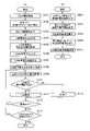
次に、本実施例における2次転写電圧の制御について説明する。図4は、本実施例における2次転写電圧の制御の手順の概略を示すフローチャート図である。図4には、ジョブを実行する際に制御部50が実行する制御のうち2次転写電圧の制御に関する手順を簡略化して示しており、ジョブを実行する際の他の多くの制御の図示は省略されている。
5. Secondary Transfer Voltage Control Next, control of the secondary transfer voltage in this embodiment will be described. FIG. 4 is a flow chart showing an outline of the procedure for controlling the secondary transfer voltage in this embodiment. FIG. 4 shows a simplified procedure for controlling the secondary transfer voltage among the controls executed by the
図4(a)を参照して、まず、制御部50は、操作部31又は外部装置200からのジョブの情報を取得すると、ジョブの動作を開始させる(S101)。本実施例では、このジョブの情報には、操作者が指定する画像情報、画像を形成する記録材Pのサイズ(幅、長さ)、記録材Pの厚さと関連のある情報(厚さ又は坪量)、記録材Pがコート紙であるか否かといった記録材Pの表面性に関連のある情報が含まれる。つまり、紙サイズ(幅、長さ)と紙種カテゴリー(普通紙、厚紙など(厚さと関連のある情報を含む))の情報が含まれる。制御部50は、このジョブの情報をRAM52に書き込む(S102)。
Referring to FIG. 4A, first, when the
次に、制御部50は、環境センサ32により検知される環境情報を取得する(S103)。また、ROM53には、環境情報と、中間転写ベルト7上のトナー像を記録材P上へ転写させるための目標電流Itargetと、の相関関係を示す情報が格納されている。制御部50は、S103で読み取った環境情報に基づいて、上記環境情報と目標電流Itargetとの関係を示す情報から、環境に対応した目標電流Itargetを求め、これをRAM52に書き込む(S104)。
Next, the
なお、環境情報に応じて目標電流Itargetを変えるのは、環境によってトナーの電荷量が変化するからである。上記環境情報と目標電流Itargetとの関係を示す情報は、予め実験などによって求めたものである。ここで、トナーの電荷量は、環境以外にも、現像装置4にトナーを補給するタイミング、現像装置4から出ていくトナー量といった使用履歴によっても影響を受けることがある。画像形成装置100は、これらの影響を抑制するために、現像装置4内のトナーの電荷量がある一定範囲内の値となるように構成されている。しかし、環境情報以外にも、中間転写ベルト7上のトナーの電荷量を左右する要因が分かっていれば、その情報によっても目標電流Itargetを変えてよい。また、画像形成装置100にトナーの電荷量を測定する測定手段を設け、この測定手段によって得られたトナーの電荷量の情報に基づいて目標電流Itargetを変えてもよい。
The reason why the target current Itarget is changed according to the environmental information is that the charge amount of the toner changes depending on the environment. The information indicating the relationship between the environmental information and the target current Itarget is obtained in advance through experiments or the like. In addition to the environment, the toner charge amount may be affected by usage history such as the timing of supplying toner to the developing device 4 and the amount of toner discharged from the developing device 4 . In order to suppress these effects, the
次に、制御部50は、中間転写ベルト7上のトナー像、及びトナー像が転写される記録材Pが2次転写部N2に到達する前に、2次転写部N2の電気抵抗に関する情報を取得する(S105)。本実施例では、ATVC制御(Active Transfer Voltage Control)により2次転写部N2(本実施例では主に2次転写ローラ8)の電気抵抗に関する情報を取得する。つまり、2次転写ローラ8と中間転写ベルト7とが接触させられた状態で、2次転写電源20から2次転写ローラ8に所定の電圧又は電流を供給する。そして、所定の電圧を供給している際の電流値、又は所定の電流を供給している際の電圧値を検知して、電圧と電流との関係(電圧・電流特性)を取得する。この電圧と電流との関係は、2次転写部N2(本実施例では主に2次転写ローラ8)の電気抵抗に応じて変化する。本実施例の構成では、上記電圧と電流との関係は、電流が電圧に対して線形に変化(比例)するものではなく、図5に示すように電流が電圧の2次以上の多項式で表されるように変化するものである。そのため、本実施例では、上記電圧と電流との関係を多項式で表すことができるように、2次転写部N2の電気抵抗に関する情報を取得する際に供給する所定の電圧又は電流は、3点以上の多段階とした。
Next, before the toner image on the
次に、制御部50は、2次転写電源20から2次転写ローラ8に印加すべき電圧値を求める(S106)。つまり、制御部50は、S104でRAM52に書き込まれた目標電流Itargetと、S105で求めた電圧と電流との関係と、に基づいて、2次転写部N2に記録材Pが無い状態で目標電流Itargetを流すために必要な電圧値Vbを求める。この電圧値Vbは、2次転写部分担電圧に相当する。また、ROM53には、図6に示すような、記録材分担電圧Vpを求めるための情報が格納されている。本実施例では、この情報は、記録材Pの坪量の区分ごとの、雰囲気の水分量と記録材分担電圧Vpとの関係を示す、テーブルデータとして設定されている。なお、制御部50は、環境センサ32により検知される環境情報(温度・湿度)に基づいて雰囲気の水分量を求めることができる。制御部50は、S102で取得したジョブの情報の中に含まれる記録材Pの坪量の情報と、S103で取得した環境情報と、に基づいて、上記テーブルデータから記録材分担電圧Vpを求める。そして、制御部50は、2次転写部N2を記録材Pが通過している際に2次転写電源20から2次転写ローラ8に印加する2次転写電圧Vtrの初期値として、上記VbとVpとを足し合わせたVb+Vpを求め、これをRAM52に書き込む。本実施例では、記録材Pが2次転写部N2に到達するまでに、2次転写電圧Vtrの初期値を求め、記録材Pが2次転写部N2に到達するタイミングに備える。
Next, the
なお、図6に示すような記録材分担電圧Vpを求めるためのテーブルデータは、予め実験などによって求められたものである。ここで、記録材分担電圧(記録材Pの電気抵抗分の転写電圧)Vpは、記録材Pの厚さと関連のある情報(坪量)以外にも、記録材Pの表面性によっても変化することがある。そのため、上記テーブルデータは、記録材Pの表面性と関連のある情報によっても記録材分担電圧Vpが変わるように設定されていてよい。また、本実施例では、記録材Pの厚さと関連のある情報(更には記録材Pの表面性と関連のある情報)は、S101で取得されるジョブの情報の中に含まれている。しかし、画像形成装置100に記録材Pの厚さや記録材Pの表面性を検知する測定手段を設け、この測定手段によって得られた情報に基づいて記録材分担電圧Vpを求めるようにしてもよい。
Note that the table data for obtaining the recording material apportionment voltage Vp as shown in FIG. 6 is obtained in advance by experiments or the like. Here, the recording material assigned voltage (the transfer voltage corresponding to the electric resistance of the recording material P) Vp changes depending on the surface properties of the recording material P in addition to information related to the thickness of the recording material P (basis weight). Sometimes. Therefore, the table data may be set so that the recording material apportionment voltage Vp is also changed by information related to the surface property of the recording material P. FIG. In this embodiment, information related to the thickness of the recording material P (further information related to the surface properties of the recording material P) is included in the job information acquired in S101. However, the
次に、制御部50は、2次転写部N2を記録材Pが通過している際の2次転写電流の上限値及び下限値(「2次転写電流範囲」)を決定する処理を行う(S107)。図4(b)は、図4(a)のS107における2次転写電流範囲を決定する処理の手順を示している。ROM53には、図7に示すような、画像不良を抑制する観点から2次転写部N2を記録材Pが通過している際に通紙部分に流してよい電流の範囲(「通紙部電流範囲(通過部電流範囲)」)を求めるための情報が格納されている。本実施例では、この情報は、雰囲気の水分量と、通紙部分に流してよい電流の上限値及び下限値と、の関係を示すテーブルデータとして設定されている。なお、このテーブルデータは、予め実験などによって求められたものである。図4(b)を参照して、制御部50は、S103で取得した環境情報に基づいて、上記テーブルデータから通紙部分に流してよい電流の範囲を求める(S201)。
Next, the
なお、通紙部分に流してよい電流の範囲は、記録材Pの幅によって変化する。本実施例では、上記テーブルデータは、A4サイズ相当の幅(297mm)の記録材Pを想定して設定されている。ここで、画像不良を抑制する観点から通紙部分に流してよい電流の範囲は、環境情報以外にも、記録材Pの厚さ、表面性によっても変化することがある。そのため、上記テーブルデータは、記録材Pの厚さと関連のある情報(坪量)、記録材Pの表面性と関連のある情報によっても電流の範囲が変化するように設定されていてよい。通紙部分に流してよい電流の範囲は、計算式として設定されていてもよい。また、通紙部分に流してよい電流の範囲は、記録材Pのサイズごとに複数のテーブルデータや計算式として設定されていてもよい。 It should be noted that the range of the current that can be passed through the sheet-passing portion varies depending on the width of the recording material P. FIG. In this embodiment, the table data is set assuming a recording material P having a width (297 mm) corresponding to A4 size. Here, from the viewpoint of suppressing image defects, the range of current that can be passed through the paper-passing portion may change depending on the thickness and surface properties of the recording material P, in addition to the environmental information. Therefore, the table data may be set so that the range of electric current changes depending on information (basis weight) related to the thickness of the recording material P and information related to the surface properties of the recording material P. The range of current that can be passed through the paper-passing portion may be set as a calculation formula. In addition, the range of electric current that can be applied to the paper-passing portion may be set as a plurality of table data or calculation formulas for each recording material P size.
次に、制御部50は、S102で取得したジョブの情報の中に含まれる記録材Pの幅の情報に基づいて、S201で取得した通紙部分に流してよい電流の範囲を補正する(S202)。S201で求めた電流の範囲はA4サイズ相当の幅(297mm)に対応したものである。例えば実際に画像形成に使用する記録材Pの幅がA5縦送り相当の幅(148.5mm)、つまりA4サイズ相当の幅の半分の幅である場合は、S201で取得した上限値及び下限値がそれぞれ半分になるように、記録材Pの幅に比例した電流の範囲に補正する。すなわち、図7のテーブルデータから求まる補正前の通紙部電流の上限値をIp_max、下限値をIp_min、図7のテーブルデータを決めた際の記録材Pの幅をLp_basとする。また、実際に搬送される記録材Pの幅をLp、補正後の通紙部電流の上限値をIp_max_aft、下限値をIp_min_aftとする。このとき、補正後の通紙部電流の上限値、下限値は、それぞれ下記式1、式2により求めることができる。
Ip_max_aft=Lp/Lp_bas*Ip_max ・・・(式1)
Ip_min_aft=Lp/Lp_bas*Ip_min ・・・(式2)
Next, the
Ip_max_aft=Lp/Lp_bas*Ip_max (Formula 1)
Ip_min_aft=Lp/Lp_bas*Ip_min (Formula 2)
次に、制御部50は、次の各情報に基づいて、非通紙部分に流れる電流を求める(S203)。S102で取得したジョブの情報の中に含まれる記録材Pの幅の情報、S105で求めた2次転写部N2に記録材Pが無い状態での2次転写部N2の電圧と電流との関係の情報、及びS106で求めた2次転写電圧Vtrの情報である。例えば、2次転写ローラ8の幅が338mmであり、S102で取得した記録材Pの幅がA5縦送り相当の幅(148.5mm)である場合、非通紙部分の幅は2次転写ローラ8の幅から記録材Pの幅を差し引いた189.5mmとなる。そして、S106で求めた2次転写電圧Vtrが例えば1000Vであり、S105で求めた電圧と電流との関係から、該2次転写電圧Vtrに対応する電流が40μAであるものとする。この場合、上記2次転写電圧Vtrに対応して非通紙部分に流れる電流は、次の比例計算、
40μA×189.5mm/338mm=22.4μA
から求めることができる。つまり、上記2次転写電圧Vtrに対応する電流40μAを、2次転写ローラ8の幅338mmに対する非通紙部分の幅189.5mmの割合分だけ小さくする比例計算によって、非通紙部分に流れる電流を求めることができる。
Next, the
40 μA×189.5 mm/338 mm=22.4 μA
can be obtained from That is, the current 40 μA corresponding to the secondary transfer voltage Vtr is reduced by the ratio of the width of the non-paper passing portion of 189.5 mm to the width of the
記録材Pの厚さが比較的小さい場合は、S203で求めた値を非通紙部電流として用いることが可能である。しかし、記録材Pの厚さが大きくなるほど、2次転写部N2に記録材Pが存在する時の非通紙部分の圧力が減少し、これによって非通紙部電流が小さくなる。そこで、本実施例では、制御部50は、記録材Pの厚さに応じて非通紙部電流を補正する制御を行う(S204)。S203で求めた補正前の非通部電流をInp_bef、補正後の非通紙部電流をInp_aft、補正係数をe(%)とする。このとき、補正後の非通紙部電流は、下記式3により求めることができる。
Inp_aft=e*Inp_bef ・・・(式3)
If the thickness of the recording material P is relatively small, the value obtained in S203 can be used as the non-sheet passing portion current. However, as the thickness of the recording material P increases, the pressure on the non-paper passing portion when the recording material P is present in the secondary transfer portion N2 decreases, thereby reducing the non-paper passing portion current. Therefore, in this embodiment, the
Inp_aft=e*Inp_bef (Formula 3)
ここで、本実施例では、上記式3中の補正係数eは、予め実験などにより求められてROM53に記憶された、図8に示すような、記録材Pの坪量の区分ごとの、記録材Pの幅と補正係数eとの関係を示すテーブルデータに基づいて決定される。制御部50は、S102で取得したジョブの情報の中に含まれる記録材Pの幅と記録材Pの坪量の情報に基づき、図8に示すテーブルデータを参照して、補正係数eを決定する。記録材Pの厚さが大きいほど、非通紙部分の圧力が低くなる。このことを考慮して、記録材Pの厚さが大きいほど、補正後の非通紙部電流が小さくなるように補正係数eが設定されている。また、記録材Pの幅が大きいほど、非通紙部分の中間転写ベルト7と2次転写ローラ8とが接触しにくく、非通紙部分の圧力が低くなる。このことを考慮して、記録材Pの幅が大きいほど、補正後の非通紙部電流が小さくなるように補正係数eが設定されている。例えば、記録材Pの幅がA5縦送り相当(148.5mm)で、記録材Pの坪量が350g/m2の場合には、補正前の非通紙部電流Inp_befを85%にしたものが補正後の非通紙部電流Inp_aftになる。これに対して、例えば、記録材Pの幅が上記と同様のA5縦送り相当(148.5mm)で、記録材Pの坪量が52g/m2の場合には、補正前の非通紙部電流Inp_befを100%のまま維持したものが補正後の非通紙部電流Inp_aftとなる。
Here, in the present embodiment, the correction coefficient e in the above equation 3 is obtained in advance by experiment or the like and stored in the
次に、制御部50は、次のようにして、2次転写部N2を記録材Pが通過している際の2次転写電流の上限値及び下限値(「2次転写電流範囲」)を求め、求めた2次転写電流範囲をRAM52に記憶させる(S205)。つまり、制御部50は、S202で求めた通紙部電流の上限値及び下限値のそれぞれにS204で求めた補正後の非通紙部電流を足し合わせ、2次転写部N2を記録材Pが通過している際の2次転写電流の上限値及び下限値(「2次転写電流範囲」)を求める。すなわち、2次転写部N2を記録材Pが通過している際の2次転写電流の上限値をI_max、下限値をI_minとする。このとき、2次転写電流の上限値、下限値は、それぞれ下記式4、式5により求めることができる。
I_max=Ip_max_aft+Inp_aft ・・・(式4)
I_min=Ip_min_aft+Inp_aft ・・・(式5)
Next, the
I_max=Ip_max_aft+Inp_aft (Formula 4)
I_min=Ip_min_aft+Inp_aft (Formula 5)
例えば、S201で取得したA4サイズ相当の幅に対応する通紙部分に流してよい電流の範囲の上限値が20μA、下限値が15μAの場合について考える。この場合、実際に画像形成に使用する記録材Pの幅がA5縦送り相当の幅であるときは、通紙部分に流してよい電流の範囲の上限値は10μA、下限値は7.5μAとなる。そして、S203で求めた非通紙部分に流れる電流が上記例のように22.4μAであるときに、記録材Pが坪量350g/m2相当の厚紙である場合には、上記22.4μAを85%に補正した19μAが補正後の非通紙部電流となる。この場合は、2次転写電流範囲の上限値は29μA、下限値は26.5μAとなる。一方、S203で求めた非通紙部分に流れる電流が上記同様22.4μAであるときに、記録材Pが坪量52g/m2の紙の場合には、補正後の非通紙部電流は補正前の非通紙部電流である22.4μAに維持される。そのため、この場合は、2次転写電流範囲の上限値は32.4μA、下限値は29.9μAとなる。 For example, consider a case where the upper limit value of the range of current that may be passed through the sheet passing portion corresponding to the A4 size width acquired in S201 is 20 μA and the lower limit value is 15 μA. In this case, when the width of the recording material P actually used for image formation is equivalent to the width of A5 longitudinal feed, the upper limit of the range of current that can be passed through the paper passing portion is 10 μA, and the lower limit is 7.5 μA. Become. Then, when the current flowing through the non-sheet passing portion obtained in S203 is 22.4 μA as in the above example, if the recording material P is thick paper with a basis weight of 350 g/m 2 , the above 22.4 μA is corrected to 85%, and 19 μA is the corrected non-sheet passing portion current. In this case, the secondary transfer current range has an upper limit of 29 μA and a lower limit of 26.5 μA. On the other hand, when the current flowing through the non-paper-passing portion obtained in S203 is 22.4 μA as described above, and the recording material P is paper with a basis weight of 52 g/m 2 , the corrected non-paper-passing portion current is It is maintained at 22.4 μA, which is the non-sheet passing portion current before correction. Therefore, in this case, the upper limit value of the secondary transfer current range is 32.4 μA and the lower limit value is 29.9 μA.
図4(a)を参照して、次に、制御部50は、2次転写中の2次転写電圧の変動幅ΔVを決定する処理を行う(S108)。本実施例では、2次転写部N2を記録材Pが通過している際に、電流検知回路21により検知された電流が2次転写電流範囲から外れている場合は、その検知される電流が2次転写電流範囲の値になるように2次転写電圧を変更していく。この動作は、図17に示すように、所定の検知時間(第1期間)において電流を検知し、この検知期間に続く所定の応答時間(第2期間)においてその検知結果に基づいて2次転写電圧を変更する動作を繰り返すことで行う。この動作は、制御部50が、検知期間に電流検知回路21から入力された電流の検知結果を示す信号に基づいて、2次転写電源20に対して電圧出力を変更する信号を出力することで行われる。検知時間、応答時間は、できる限り短い方が、2次転写電流が2次転写電流範囲から外れて画像不良が発生する可能性のある時間(領域)を低減できるため好ましい。高圧基板の性能によるが、検知時間、応答時間は、それぞれ10msec以下程度にするのが好ましい。本実施例では、検知時間、応答時間は、それぞれ8msecとした。しかし、前述のように、応答時間において2次転写電圧を変更した際のオーバーシュート電流が大きいと、その応答時間の次の検知時間で定常状態より大きく外れた電流が検知されてしまい、2次転写電圧の制御が正常に収束しない場合がある。
Referring to FIG. 4A, next,
そこで、本実施例では、2次転写部N2に記録材Pが到達する前に検知される2次転写部N2の電気抵抗に関する情報に基づいて、2次転写中の応答時間における2次転写電圧の変動幅ΔVを変更する。概略、その2次転写部N2の電気抵抗が相対的に大きい場合に、相対的に小さい場合と比較して、2次転写電圧の変動幅ΔVが大きくなるようにする。これにより、2次転写部N2の電気抵抗に応じてオーバーシュート電流を適正な範囲に抑えることができる。更に、本実施例では、2次転写中に2次転写部N2に供給する電流の範囲(上限値と下限値との差分)に基づいて、2次転写中の応答時間における2次転写電圧の変動幅ΔVを変更する。概略、その電流の範囲が相対的に大きい場合に、相対的に小さい場合と比較して、2次転写電圧の変動幅ΔVが大きくなるようにする。これにより、オーバーシュート電流が過度に大きくなることを抑えながら、2次転写電圧の変動幅ΔVを十分に大きくして、2次転写電圧の変更により2次転写電流を適正な範囲の値とするのにかかる時間を低減することができる。具体的には、本実施例では、制御部50は、S105で求めた2次転写部N2に記録材Pが無い状態での2次転写部N2の電圧と電流との関係の情報と、S201で求めた電流の範囲と、に基づき、応答時間での2次転写電圧の変動幅ΔVを決める(S108)。つまり、本実施例では、2次転写電圧の変動幅ΔVは、下記式6によりで求める。
ΔV=A*(Ip_max-Ip_min)*Vb/Itarget ・・・(式6)
Therefore, in this embodiment, the secondary transfer voltage during the response time during the secondary transfer is calculated based on the information regarding the electrical resistance of the secondary transfer portion N2 detected before the recording material P reaches the secondary transfer portion N2. to change the variation width ΔV. Generally speaking, when the electrical resistance of the secondary transfer portion N2 is relatively large, the fluctuation width ΔV of the secondary transfer voltage is made larger than when it is relatively small. As a result, the overshoot current can be suppressed within an appropriate range according to the electrical resistance of the secondary transfer portion N2. Further, in the present embodiment, the secondary transfer voltage during the response time during secondary transfer is determined based on the range of current supplied to the secondary transfer portion N2 (the difference between the upper limit value and the lower limit value) during secondary transfer. Change the fluctuation width ΔV. Generally speaking, when the range of the current is relatively large, the fluctuation width ΔV of the secondary transfer voltage is made larger than when it is relatively small. As a result, the fluctuation width ΔV of the secondary transfer voltage is sufficiently increased while suppressing the overshoot current from becoming excessively large, and the secondary transfer current is adjusted to a value in the appropriate range by changing the secondary transfer voltage. can reduce the time required for Specifically, in this embodiment, the
ΔV=A*(Ip_max−Ip_min)*Vb/Itarget (Formula 6)
上記式6において、VbはS105で求められた2次転写部分担電圧、ItargetはS104で求められた目標電流であり、Vb/Itargetは2次転写部N2に記録材Pが無い状態での2次転写部N2の電気抵抗に相当する。また、上記式6において、Ip_max、Ip_minは、それぞれS201で求められたA4サイズ相当の幅(297mm)での通紙部電流範囲の上限値、下限値である。また、上記式6において、Aは、図17に示すような2次転写電圧の変更時に発生するオーバーシュート電流を、2次転写中に2次転写部N2に供給する電流の上限値と下限値との差分以下に抑えるための補正係数である。この補正係数Aは、予め実験などによって求められている。本実施例では、応答時間が8msecであるのに対して、補正係数Aは1~2程度に設定している。これにより、本実施例では、2次転写電圧の変更時に、電流が下限値を下回っている状態から上限値を上回る状態になる、逆に上限値を上回っている状態から下限値を下回る状態になるといったことを抑制することができる。本実施例では、目標電流Itargetは15~20μA程度であるのに対して、2次転写電圧の変動幅ΔVは、上記式6によって2次転写部N2の電気抵抗によって変わるが、凡そ20~100V程度の値になる。また、2次転写中に2次転写部N2に供給する電流の範囲(上限値と下限値との差分)は、記録材Pの種類が同じである場合は、記録材Pの幅が狭いほど大きい。このため、2次転写電圧の変動幅ΔVを記録材の幅で変更してもよい。 In the above equation 6, Vb is the secondary transfer portion bearing voltage obtained in S105, Itarget is the target current obtained in S104, and Vb/Itarget is the voltage obtained when there is no recording material P at the secondary transfer portion N2. It corresponds to the electrical resistance of the next transfer portion N2. Also, in Equation 6, Ip_max and Ip_min are the upper limit and lower limit of the current range of the sheet passing portion at the width (297 mm) corresponding to the A4 size obtained in S201, respectively. Further, in the above equation 6, A is the upper limit value and the lower limit value of the current supplied to the secondary transfer portion N2 during the secondary transfer, which is the overshoot current generated when the secondary transfer voltage is changed as shown in FIG. This is a correction coefficient for suppressing to the difference between and below. This correction coefficient A is obtained in advance by experiments or the like. In this embodiment, the response time is 8 msec, while the correction coefficient A is set to about 1-2. As a result, in this embodiment, when the secondary transfer voltage is changed, the current is changed from being below the lower limit to being above the upper limit, and conversely, from being above the upper limit to being below the lower limit. You can prevent it from happening. In this embodiment, the target current Itarget is about 15 to 20 μA, while the secondary transfer voltage fluctuation range ΔV varies depending on the electrical resistance of the secondary transfer portion N2 according to the above equation 6, but is about 20 to 100 V. It becomes a value of degree. Further, the range of the current supplied to the secondary transfer portion N2 during the secondary transfer (the difference between the upper limit value and the lower limit value) increases as the width of the recording material P becomes narrower when the type of the recording material P is the same. big. Therefore, the fluctuation width ΔV of the secondary transfer voltage may be changed according to the width of the recording material.
次に、制御部50は、2次転写部N2に記録材Pが到達してから2次転写部N2に記録材Pが存在する間、2次転写電圧Vtrを印加した際の2次転写電流を電流検知回路21により検知する(S109)。また、制御部50は、検知した2次転写電流値と、S107で求めた2次転写電流範囲とを比較し、2次転写電源20が出力する2次転写電圧Vtrを必要に応じて補正する(S110、S111、S112)。前述のように、本実施例では、この2次転写電圧の変更動作は、検知時間を8msec、応答時間を8msecとして、2次転写中にこれら検知時間と応答時間とを交互に繰り返すことで行う。つまり、制御部50は、検知時間に検知した2次転写電流値がS107で求めた2次転写電流範囲の値(下限値以上かつ上限値以下)の場合は、2次転写電源20が出力している2次転写電圧Vtrを変えずにそのまま維持する(S111)。一方、制御部50は、検知時間に検知した2次転写電流値がS107で求めた2次転写電流範囲から外れている(下限値未満又は上限値を超える)場合は、応答時間に2次転写電圧Vtrを変更する(S112)。本実施例では、検知した2次転写電流値が下限値を下回っている場合は、2次転写電圧Vtrを変動幅ΔVだけ増加させ、逆に上限値を上回っている場合は、2次転写電圧Vtrを変動幅ΔVだけ減少させる。このとき、2次転写電圧の変動幅ΔVとして、S108で求めた変動幅ΔVを使用する。そして、制御部50は、応答時間が経過し、2次転写部N2を記録材Pが通過中である場合には(S113)、処理をS109に戻し、2次転写電流の検知(検知時間)と、必要に応じた2次転写電圧の変更(応答時間)と、を行う(S109~S112)。この検知時間と応答時間とを2次転写部N2に記録材Pがある間(より詳細には記録材Pの画像形成領域が2次転写部N2を通過している間)繰り返し行う。これにより、2次転写部N2を記録材Pが通過している際に検知される2次転写電流がS107で求めた2次転写電流範囲に収まるように、2次転写電圧Vtrが補正されていく。
Next, the
また、制御部50は、ジョブの全ての画像を記録材Pに転写して出力し終えるまで、S109~S113の処理を繰り返す(S114)。
Further, the
本実施例の制御を行うことによる2次転写電流範囲の変化について更に説明する。記録材Pが2次転写部N2に到達する前に2次転写部N2の電気抵抗を検知した結果が同程度であり、2次転写時に必要な2転電圧が同程度である場合について考える。このとき、最大幅の記録材Pを使用する場合の2次転写電流範囲に対して、最大幅よりも幅の小さい記録材Pを使用する場合の2次転写電流範囲は高めに(電流の絶対値が大きくなるように)シフトする。しかし、このシフト量は、記録材Pの厚さが大きくなるほど小さくなる。 A change in the secondary transfer current range due to the control of this embodiment will be further described. Consider a case where the results of detecting the electric resistance of the secondary transfer portion N2 before the recording material P reaches the secondary transfer portion N2 are approximately the same, and the secondary transfer voltage required for the secondary transfer is approximately the same. At this time, the secondary transfer current range in the case of using a recording material P with a width smaller than the maximum width is higher than the secondary transfer current range in the case of using the recording material P with the maximum width (absolute current (to increase the value). However, this shift amount decreases as the thickness of the recording material P increases.
例えば、記録材Pとして坪量52g/m2の紙(薄紙)と、坪量350g/m2の紙(厚紙)と、をそれぞれ使用する場合について考える。また、記録材Pが2次転写部N2に到達する前に2次転写部N2の電気抵抗を検知した結果はいずれの場合も同程度であり、1000V印加で30μAの電流が流れたものとする。このとき、坪量52g/m2の紙では、A4サイズ(幅297mm)の場合の2次転写電流範囲は24.9~19.9μAであるが、A5縦送りサイズ(幅148.5mm)の場合の2次転写電流範囲は32.3~29.8μAとなる。つまり、坪量52g/m2の紙では、記録材Pの幅が小さくなると、2次転写電流範囲が全体的に高めにシフトし、下限値で約10μA高くなる。一方、坪量350g/m2の紙では、A4サイズ(幅297mm)の場合の2次転写電流範囲は24.1~19.1μAであるが、A5縦送りサイズ(幅148.5mm)の場合は29~26.5μAとなる。つまり、坪量350g/m2の紙では、記録材Pの幅が小さくなると、2次転写電流範囲が全体的に高めにシフトするが、下限値で約6.5μAしか高くならず、坪量52g/m2の紙の場合に比べてシフト量は小さくなる。
For example, consider a case where a paper (thin paper) with a basis weight of 52 g/m 2 and a paper (thick paper) with a basis weight of 350 g/m 2 are used as the recording material P, respectively. Also, the results of detecting the electric resistance of the secondary transfer portion N2 before the recording material P reaches the secondary transfer portion N2 are almost the same in both cases, and it is assumed that a current of 30 μA flows when 1000 V is applied. . At this time, with paper having a basis weight of 52 g/m 2 , the secondary transfer current range for A4 size (
実際には、図6に示すように、厚さが大きい記録材Pほど、電気抵抗が高くなりやすく、2次転写時に必要な2次転写電圧Vtrは高くなりやすい。そのため、厚紙を使用する場合と薄紙を使用する場合とでは、厚紙を使用する場合の方が2次転写時に必要な2次転写電圧Vtrは大きくなる。2次転写電圧Vtrが大きいと、2次転写部N2に記録材Pが無い時の2次転写電流も大きく、記録材Pのサイズが変化した場合の2次転写電流範囲の変化量も大きくなる。図9は、本実施例の構成において、図4(a)のS106で決定される初期の2次転写電圧Vtrが変化した場合の、A5縦送りサイズの場合の2次転写電流範囲の下限値と、A4サイズの場合の2次転写電流範囲の下限値との差をプロットしたグラフ図である。図9中の破線は坪量52g/m2の紙の場合のプロット、実線は坪量350g/m2の紙の場合のプロットである。記録材Pの厚さが違うと初期の2次転写電圧Vtrは変化する。しかし、2次転写電圧Vtrを何水準か変化させて、記録材Pの幅の違いによる2次転写電流範囲の下限値の差をプロットしていくと、次のようになっている。つまり、ある2次転写電圧Vtrの場合の記録材Pの幅の違いによる2次転写電流範囲の下限値の差は、図9に示すように厚さが大きい記録材Pの方が小さくなっている。 Actually, as shown in FIG. 6, the thicker the recording material P, the higher the electric resistance, and the higher the secondary transfer voltage Vtr required for secondary transfer. Therefore, when using thick paper and when using thin paper, the secondary transfer voltage Vtr required for the secondary transfer is higher when using thick paper. When the secondary transfer voltage Vtr is large, the secondary transfer current is also large when there is no recording material P at the secondary transfer portion N2, and the amount of change in the secondary transfer current range when the size of the recording material P changes is also large. . FIG. 9 shows the lower limit value of the secondary transfer current range for A5 longitudinal feed size when the initial secondary transfer voltage Vtr determined in S106 of FIG. 4A changes in the configuration of this embodiment. and the lower limit value of the secondary transfer current range for A4 size. The dashed line in FIG. 9 is the plot for paper with a basis weight of 52 g/m 2 , and the solid line is the plot for paper with a basis weight of 350 g/m 2 . If the thickness of the recording material P is different, the initial secondary transfer voltage Vtr changes. However, when the secondary transfer voltage Vtr is changed by several levels and the difference in the lower limit value of the secondary transfer current range due to the difference in the width of the recording material P is plotted, the following results are obtained. That is, the difference in the lower limit value of the secondary transfer current range due to the difference in the width of the recording material P for a certain secondary transfer voltage Vtr is smaller for the thicker recording material P as shown in FIG. there is
なお、本実施例では、2次転写部N2に記録材Pが無い状態での2次転写部N2の電気抵抗に関する情報を、実際に2次転写部に電圧を印加した際に流れる電流を検知することで取得した。しかし、本発明はこれに限定されるものではなく、例えば、予め環境センサ32の出力値と2次転写部N2の電気抵抗との関係など、環境情報から2次転写部N2の電気抵抗を求めるための情報をテーブルデータなどとして作成しておくことができる。そして、環境センサ32の出力値に基づいて、上記テーブルデータなどを参照して、2次転写部N2の電気抵抗を求めることができる。
In the present embodiment, the current that flows when the voltage is actually applied to the secondary transfer portion N2 is detected as the information about the electrical resistance of the secondary transfer portion N2 when there is no recording material P in the secondary transfer portion N2. obtained by doing However, the present invention is not limited to this. For example, the electrical resistance of the secondary transfer portion N2 is obtained from environmental information such as the relationship between the output value of the
このように、本実施例の画像形成装置100は、転写部材8に流れる電流を検知する検知部21と、転写部N2を記録材Pが通過している際に転写部材8に所定電圧が印加されるように転写部材8に印加する電圧の定電圧制御を行う制御部50と、を有する。この制御部50は、転写時に転写部材8に流れる電流が上記所定範囲内となるように転写部材8に印加する転写電圧を変更可能である。そして、この制御部50は、転写時に転写部材8に流れる電流が上記所定範囲内となるように転写部材8に印加する転写電圧を変更する場合において、転写電圧の変更を転写電圧の所定の変動幅ごとに行うようになっている。また、この制御部50は、上記変動幅を、転写部N2に記録材Pが無い状態で転写部材8に電圧を印加したときに検知部21で検知される検知結果に基づいて変更する。本実施例では、制御部50は、転写部N2に記録材Pが無い状態で転写部材8に所定電圧を印加したときに転写部材8に流れる電流値が第1電流値である場合は、上記変動幅を第1変動幅に設定し、転写部材8に流れる電流値が第1電流値よりも小さい第2電流値である場合は、上記変動幅を第1変動幅よりも大きい第2変動幅に変更する。上記電流の変化量の所定値は、予め設定された一定値であってもよい。本実施例では、制御部50は、一の転写電圧の変更の後かつ次の転写電圧の変更の前の転写部材8に流れる電流の絶対値の最大値と、上記一の転写電圧の変更の後かつ次の転写電圧の変更の前に定常状態になった転写部材8に流れる電流の絶対値と、の差分が、上記所定範囲の上限値と下限値との差分より小さくなるように、上記変動幅を変更する。また、制御部50は、上記変動幅を、上記所定範囲の上限値と下限値の差分に基づいて変更することができる。また、制御部50は、上記変動幅を、記録材Pの幅に基づいて変更することができる。
As described above, the
以上説明したように、本実施例では、2次転写中に2次転写電圧を変更する際の変動幅ΔVを、2次転写部N2に記録材Pが無い状態で検知した2次転写部N2の電気抵抗に関する情報に基づいて変更することで、変動幅ΔVを適切な値に調整する。なお、目標電流Itargetや、それに応じた適切な2次転写電流範囲は、記録材Pの種類、画像形成条件(搬送速度、画像濃度)によって変更した方が望ましい場合がある。その場合は、目標電流Itargetや適切な2次転写電流範囲に対応して2次転写電圧の変動幅ΔVを変更することが望ましい。このように2次転写電圧の変動幅ΔVを変更することで、2次転写電圧の変更による2次転写部N2に流れる電流の変化量を所定値以下に抑えるようにすることができる。これにより、2次転写中に2次転写部N2に流れる電流が適切な範囲を超えて過剰に変化することを抑制して、濃度薄などの濃度段差や放電現象による白抜けなどの局所的な画像不良の発生を抑制することが可能になる。 As described above, in this embodiment, the variation width ΔV when changing the secondary transfer voltage during secondary transfer is detected at the secondary transfer portion N2 when there is no recording material P at the secondary transfer portion N2. By changing based on the information on the electrical resistance of , the variation width ΔV is adjusted to an appropriate value. In some cases, it is desirable to change the target current Itarget and the appropriate secondary transfer current range according to the type of recording material P and the image forming conditions (conveyance speed, image density). In that case, it is desirable to change the fluctuation width ΔV of the secondary transfer voltage according to the target current Itarget and an appropriate secondary transfer current range. By changing the fluctuation width ΔV of the secondary transfer voltage in this manner, the amount of change in the current flowing through the secondary transfer portion N2 due to the change in the secondary transfer voltage can be suppressed to a predetermined value or less. As a result, the current flowing through the secondary transfer portion N2 during the secondary transfer is prevented from changing excessively beyond an appropriate range, and localized images such as density steps such as low density and white spots due to discharge phenomenon are suppressed. It becomes possible to suppress the occurrence of image defects.
また、本実施例では、2次転写部N2を記録材Pが通過している際に非通紙部分に流れる電流を、記録材Pが2次転写部N2に到達する前に2次転写部N2の電気抵抗に関する情報を取得することで予測する。このとき、上記非通紙部分に流れる電流の予測値を、記録材Pの幅に関する情報に基づいて変化させると共に、その予測値を記録材Pの厚さに関する情報に基づいて補正する。より詳細には、記録材Pの厚さが大きくなるほど上記非通紙部分に流れる電流が小さくなるように補正を行う。これにより、上記非通紙部分に流れる電流を、より正確に予測することが可能となる。そして、予測した非通紙部分に流れる電流と、画像不良を抑制する観点から通紙部分に流してよい電流の範囲と、を足し合わせることで、2次転写部N2を記録材Pが通過している際の2次転写電流範囲を決める。また、その2次転写電流範囲の値となるように、2次転写部N2を記録材Pが通過している際の2次転写電圧を制御する。これにより、厚紙などの比較的厚さが大きい記録材Pを用いる場合であっても、様々な状況で変動する2次転写部N2(本実施例では主に2次転写ローラ8)及び記録材Pの電気抵抗にかかわらず、適切な画像を出力することが可能になる。
Further, in this embodiment, the current flowing through the non-sheet-passing portion while the recording material P is passing through the secondary transfer portion N2 is changed to the secondary transfer portion before the recording material P reaches the secondary transfer portion N2. Prediction is made by obtaining information on the electrical resistance of N2. At this time, the predicted value of the current flowing through the non-sheet passing portion is changed based on the information about the width of the recording material P, and the predicted value is corrected based on the information about the thickness of the recording material P. More specifically, the correction is performed so that the current flowing through the non-sheet passing portion decreases as the thickness of the recording material P increases. This makes it possible to more accurately predict the current flowing through the non-sheet passing portion. Then, by adding the predicted current flowing through the non-sheet-passing portion and the range of current that can be passed through the sheet-passing portion from the viewpoint of suppressing image defects, the recording material P passes through the secondary transfer portion N2. Determines the secondary transfer current range when Further, the secondary transfer voltage when the recording material P is passing through the secondary transfer portion N2 is controlled so that the value falls within the secondary transfer current range. As a result, even when a relatively thick recording material P such as thick paper is used, the secondary transfer portion N2 (mainly the
[実施例2]
次に、本発明の他の実施例について説明する。本実施例の画像形成装置の基本的な構成及び動作は、実施例1の画像形成装置のものと同じである。したがって、本実施例の画像形成装置において、実施例1の画像形成装置のものと同一又は対応する機能あるいは構成を有する要素については、実施例1と同一の符号を付して、詳しい説明は省略する。
[Example 2]
Another embodiment of the present invention will now be described. The basic configuration and operation of the image forming apparatus of this embodiment are the same as those of the image forming apparatus of the first embodiment. Accordingly, in the image forming apparatus of the present embodiment, elements having the same or corresponding functions or configurations as those of the image forming apparatus of the first embodiment are denoted by the same reference numerals as those of the first embodiment, and detailed description thereof is omitted. do.
実施例1では、2次転写部N2を記録材Pが通過している際に通紙部分に流してよい電流の範囲(「通紙部電流範囲」)と、非通紙部電流の予測値(記録材Pの厚さによる補正後)と、を足し合わせた2次転写電流範囲を求めた。そして、2次転写時に測定した2次転写電流がその2次転写電流範囲の値となるように、2次転写電圧を制御した。これに対して、2次転写時に測定した2次転写電流から、非通紙部電流の予測値(記録材Pの厚さによる補正後)を差し引くことで通紙部電流を求め、求めた通紙部電流が所定の通紙部電流範囲の値になるように2次転写電圧を制御してもよい。 In the first embodiment, the range of current that can be passed through the sheet passing portion when the recording material P is passing through the secondary transfer portion N2 (“sheet passing portion current range”) and the predicted value of the non-sheet passing portion current (after correction based on the thickness of the recording material P), and the secondary transfer current range was obtained. Then, the secondary transfer voltage was controlled so that the secondary transfer current measured during the secondary transfer was within the range of the secondary transfer current. On the other hand, by subtracting the predicted value of the non-paper passing portion current (after correction based on the thickness of the recording material P) from the secondary transfer current measured during the secondary transfer, the paper passing portion current is obtained. The secondary transfer voltage may be controlled so that the paper section current falls within a predetermined range of the paper section current.
図10は、本実施例における2次転写電圧の制御の手順の概略を示すフローチャート図である。図10のS301~S306の処理は、それぞれ実施例1における図4(a)のS101~S106の処理と同様である。また、図10のS307の処理は、実施例1における図4(b)のS201の処理と同様である。さらに、図10のS308の処理は、実施例1における図4(a)のS108の処理と同様である。以下、特に実施例1と異なる点について説明し、実施例1と同様の処理についての説明は省略する。 FIG. 10 is a flow chart showing an outline of the procedure for controlling the secondary transfer voltage in this embodiment. The processes of S301 to S306 of FIG. 10 are the same as the processes of S101 to S106 of FIG. 4A in the first embodiment. Further, the processing of S307 in FIG. 10 is the same as the processing of S201 in FIG. 4B in the first embodiment. Furthermore, the process of S308 in FIG. 10 is the same as the process of S108 in FIG. 4A in the first embodiment. In the following, differences from the first embodiment will be described, and descriptions of the same processes as in the first embodiment will be omitted.
制御部50は、S308で2次転写電圧の変動幅ΔVを求めた後、2次転写部N2に記録材Pが到達してから2次転写部N2に記録材Pが存在する間、2次転写電圧Vtrを印加した際の2次転写電流を電流検知回路21により検知する(S309)。
After obtaining the fluctuation width ΔV of the secondary transfer voltage in S308, the
そして、制御部50は、次の各情報に基づいて、非通紙部分に流れる電流を求める(S310)。S302で取得したジョブの情報の中に含まれる記録材Pの幅の情報、S305で求めた2次転写部N2に記録材Pが無い状態での2次転写部N2の電圧と電流との関係の情報、及び現在印加している2次転写電圧Vtrの情報である。S310における非通紙部電流を求める処理は、実施例1における図4(b)のS203の処理と同様である。ただし、S310では、2次転写電圧Vtrとして、現在印加している2次転写電圧(初期値はS306で求めたもの。)を用いる。つまり、S310で非通紙部に流れる電流を求めるために用いる2次転写電圧Vtrは、ジョブの最初の記録材Pが2次転写部N2に突入したタイミングでは、S306で求めた初期値である。その後、下記のフローで2次転写電圧Vtrを変更した場合は、変更した2次転写電圧Vtrを用いて非通紙部に流れる電流を求めるようにする。
Then, the
次に、制御部50は、実施例1における図4(b)のS204の処理と同様にして、記録材Pの厚さに応じて非通紙部電流を補正する制御を行う(S311)。S310で求めた補正前の非通紙部電流をInp_bef、補正後の非通紙部電流をInp_aft、補正係数をe(%)とする。このとき、補正後の非通紙部電流は、実施例1と同様の下記式3により求めることができる。
Inp_aft=e*Inp_bef ・・・(式3)
Next, the
Inp_aft=e*Inp_bef (Formula 3)
ここで、本実施例では、上記式3中の補正係数eは、実施例1と同様の図8に示すようなテーブルデータに基づいて決定される。 Here, in this embodiment, the correction coefficient e in the above equation 3 is determined based on the table data as shown in FIG. 8 similar to the first embodiment.
次に、制御部50は、S309で検知した2次転写電流からS311で求めた補正後の非通紙部電流を差し引いた電流を通紙部電流として算出する(S312)。すなわち、2次転写電流をItr、通紙部電流をIpとすると、通紙部電流は、下記式8により求めることができる。
Ip=Itr-Inp_aft ・・・(式7)
Next, the
Ip=Itr-Inp_aft (Formula 7)
上記式7で求めた通紙部電流Ipは、実際に搬送される記録材Pの幅に対応する電流値であるのに対して、S307で求めた通紙部電流範囲は、基準となる記録材Pのサイズ(本実施例ではA4サイズ)相当の幅に対応するものとなっている。そのため、本実施例では、制御部50は、上記式7で求めた通紙部電流Ipを基準となる記録材Pのサイズ相当の幅に対応する電流値に換算する処理を行う(S313)。図7のテーブルデータを決めた際の記録材Pの幅をLp_bas、実際に搬送される記録材Pの幅をLp、換算後の通紙部電流をIp_aftとする。このとき、換算後の通紙部電流は、下記式8により求めることができる。
Ip_aft=Lp_bas/Lp*Ip ・・・(式8)
The sheet-passing-portion current Ip obtained by the
Ip_aft=Lp_bas/Lp*Ip (Formula 8)
次に、制御部50は、S512で求めた換算後の通紙部電流Ip_aftをS307で求めた通紙部電流範囲と比較する(S314)。そして、制御部50は、2次転写電源20が出力する2次転写電圧Vtrを必要に応じて補正する(S315、S316)。前述のように、本実施例では、この2次転写電圧の変更動作は、検知時間を8msec、応答時間を8msecとして、2次転写中にこれら検知時間と応答時間とを交互に繰り返すことで行う。つまり、制御部50は、換算後の通紙部電流Ip_aftがS307で求めた通紙部電流範囲の値(下限値以上かつ上限値以下)の場合は、2次転写電源20が出力している2次転写電圧Vtrを変えずにそのまま維持する(S315)。一方、制御部50は、換算後の通紙部電流Ip_aftがS307で求めた通紙部電流範囲から外れている(下限値未満又は上限値を超える)場合は、該通紙部電流範囲の値となるように2次転写電源20が出力する2次転写電圧Vtrを補正する(S316)。本実施例では、換算後の通紙部電流Ip_aftが通紙部電流範囲の下限値を下回っている場合は、2次転写電圧Vtrを変動幅ΔVだけ増加させ、逆に上限値を上回っている場合は、2次転写電圧Vtrを変動幅ΔVだけ減少させる。このとき、2次転写電圧の変動幅ΔVとして、S308で求めた変動幅ΔVを使用する。そして、制御部50は、応答時間が経過し、2次転写部N2を記録材Pが通過中である場合には(S317)、処理をS309に戻し、2次転写電流の検知(検知時間)と、必要に応じた2次転写電圧の変更(応答時間)と、を行う(S309~S316)。なお、2次転写電圧Vtrを変更した場合は、変化させた2次転写電圧Vtrに対して換算後の通紙部電流Ip_aftを求めるフロー(S309~S513)を行う。この検知時間と応答時間とを2次転写部N2に記録材Pがある間(より詳細には記録材Pの画像形成領域が2次転写部N2を通過している間)繰り返し行う。これにより、2次転写部N2を記録材Pが通過している際に検知される2次転写電流に基づく通紙部電流がS307で求めた通紙部電流範囲に収まるように、2次転写電圧Vtrが補正されてく。
Next, the
また、制御部50は、ジョブの全ての画像を記録材Pに転写して出力し終えるまで、S309~S317の処理を繰り返す(S318)。
Further, the
以上説明したように、本実施例では、予測した非通紙部分に流れる電流を、測定した2次転写電流から差し引くことで、制御すべき通紙部電流を正確に求めることができる。また、この通紙部電流の値を所定の通紙部電流範囲の値になるように、2次転写部N2を記録材Pが通過している際の2次転写電圧を制御する。このような方法によっても、実施例1と同様の効果が得られる。 As described above, in the present embodiment, by subtracting the predicted current flowing through the non-paper passing portion from the measured secondary transfer current, the paper passing portion current to be controlled can be obtained accurately. Further, the secondary transfer voltage when the recording material P is passing through the secondary transfer portion N2 is controlled so that the value of the sheet passing portion current falls within a predetermined range of the sheet passing portion current. The same effects as those of the first embodiment can be obtained by such a method as well.
[実施例3]
次に、本発明の他の実施例について説明する。本実施例の画像形成装置の基本的な構成及び動作は、実施例1の画像形成装置のものと同じである。したがって、本実施例の画像形成装置において、実施例1の画像形成装置のものと同一又は対応する機能あるいは構成を有する要素については、実施例1と同一の符号を付して、詳しい説明は省略する。
[Example 3]
Another embodiment of the present invention will now be described. The basic configuration and operation of the image forming apparatus of this embodiment are the same as those of the image forming apparatus of the first embodiment. Accordingly, in the image forming apparatus of the present embodiment, elements having the same or corresponding functions or configurations as those of the image forming apparatus of the first embodiment are denoted by the same reference numerals as those of the first embodiment, and detailed description thereof is omitted. do.
実施例1及び実施例2では、2次転写電流のうち通紙部電流がどの程度の大きさになるかを考慮して2次転写電圧を制御した。一方、本実施例では、非通紙部分に流れる電流が2次転写電流に占める割合が十分に小さいものとして扱い、2次転写電流を所定の範囲内となるように制御している。 In Example 1 and Example 2, the secondary transfer voltage was controlled in consideration of how large the paper-passing portion current in the secondary transfer current is. On the other hand, in the present embodiment, the ratio of the current flowing through the non-sheet passing portion to the secondary transfer current is treated as sufficiently small, and the secondary transfer current is controlled to be within a predetermined range.
図11は、本実施例における2次転写電圧の制御の手順の概略を示すフローチャート図である。図11のS401~S406の処理は、それぞれ実施例1における図4(a)のS101~S106の処理と同様である。また、図11のS409~S414の処理は、実施例1における図4(a)のS109~S114の処理と同様である。以下、特に実施例1と異なる点について説明し、実施例1と同様の処理についての説明は省略する。 FIG. 11 is a flow chart showing an outline of the procedure for controlling the secondary transfer voltage in this embodiment. The processing of S401 to S406 in FIG. 11 is the same as the processing of S101 to S106 in FIG. 4A in the first embodiment. Further, the processing of S409 to S414 in FIG. 11 is the same as the processing of S109 to S114 in FIG. In the following, differences from the first embodiment will be described, and descriptions of the same processes as in the first embodiment will be omitted.
制御部50は、S406で2次転写電圧Vtrを求めた後、2次転写部N2を記録材Pが通過している際の2次転写電流の上限値及び下限値(「2次転写電流範囲」)を決定する処理を行う(S407)。本実施例では、ROM53には、図12に示すような、画像不良を抑制する観点から2次転写部N2を記録材Pが通過している際に2次転写部N2に流してよい電流の範囲(「2次転写部電流範囲」)を求めるための情報が格納されている。本実施例では、この情報は、雰囲気の水分量と、2次転写部N2に流してよい電流の上限値及び下限値と、の関係を示すテーブルデータとして設定されている。なお、このテーブルデータは、予め実験などによって求められたものである。制御部50は、S403で取得した環境情報に基づいて、上記テーブルデータから2次転写部N2に流してよい電流の範囲を求める。
After obtaining the secondary transfer voltage Vtr in S406, the
なお、2次転写電流のうち、制御することが望まれるのは通紙部電流である。本実施例では、非通紙部分に流れる電流が2次転写電流に占める割合が十分に小さいものとして扱い、2次転写電流を所定の範囲に制御すれば通紙部電流を適切な範囲に制御できるものとしている。ここで、画像不良を抑制する観点から2次転写部N2に流してよい電流の範囲は、環境情報以外にも、記録材Pの厚さ、表面性によっても変化することがある。そのため、上記テーブルデータは、記録材Pの厚さと関連のある情報(坪量)、記録材Pの表面性と関連のある情報によっても電流の範囲が変化するように設定されていてよい。2次転写部N2に流してよい電流の範囲は、計算式として設定されていてもよい。また、2次転写部N2に流してよい電流の範囲は、記録材Pのサイズごとに複数のテーブルデータや計算式として設定されていてもよい。 Of the secondary transfer currents, it is desirable to control the sheet passing portion current. In this embodiment, it is assumed that the ratio of the current flowing in the non-paper passing portion to the secondary transfer current is sufficiently small, and if the secondary transfer current is controlled within a predetermined range, the paper passing portion current is controlled within an appropriate range. It is possible. Here, from the viewpoint of suppressing image defects, the range of current that can be passed through the secondary transfer portion N2 may change depending on the thickness and surface properties of the recording material P in addition to environmental information. Therefore, the table data may be set so that the range of electric current changes depending on information (basis weight) related to the thickness of the recording material P and information related to the surface properties of the recording material P. The range of current that can be passed through the secondary transfer portion N2 may be set as a calculation formula. Also, the range of the current that can be supplied to the secondary transfer portion N2 may be set for each size of the recording material P as a plurality of table data or calculation formulas.
次に、制御部50は、2次転写中の2次転写電圧の変動幅ΔVを決定する処理を行う(S408)。S408の処理は、実施例1における図4(a)のS108と同様である。ただし、本実施例では、実施例1で用いた式6に代えて下記式9を用いる。
ΔV=A*(Ip_max’-Ip_min’)*Vb/Itarget ・・(式9)
Next, the
ΔV=A*(Ip_max′−Ip_min′)*Vb/Itarget (Formula 9)
上記式9において、VbはS405で求められた2次転写部分担電圧、ItargetはS404で求められた目標電流であり、Vb/Itargetは2次転写部N2に記録材Pが無い状態での2次転写部N2の電気抵抗に相当する。また、上記式9において、Ip_max’、Ip_min’は、それぞれS407で求められた2次転写電流範囲の上限値、下限値である。また、上記式9において、Aは、実施例1における式6の場合と同様、図17に示すような2次転写電圧の変更時に発生するオーバーシュート電流を、2次転写中に2次転写部N2に供給する電流の上限値と下限値との差分以下に抑えるための補正係数である。この補正係数Aは、予め実験などによって求められており、本実施例では、実施例1と同様に、応答時間が8msecであるのに対して、補正係数Aは1~2程度に設定している。これにより、本実施例では、2次転写電圧の変更時に、電流が下限値を下回っている状態から上限値を上回る状態になる、逆に上限値を上回っている状態から下限値を下回る状態になるといったことを抑制することができる。本実施例では、目標電流Itargetは15~20μA程度であるのに対して、2次転写電圧の変動幅ΔVは、上記式6によって2次転写部N2の電気抵抗によって変わるが、凡そ20~100V程度の値になる。 In the above equation 9, Vb is the secondary transfer portion bearing voltage obtained in S405, Itarget is the target current obtained in S404, and Vb/Itarget is 2/2 when there is no recording material P at the secondary transfer portion N2. It corresponds to the electrical resistance of the next transfer portion N2. Also, in Equation 9, Ip_max' and Ip_min' are the upper limit and lower limit of the secondary transfer current range obtained in S407, respectively. In Equation 9, A is the overshoot current that occurs when the secondary transfer voltage is changed as shown in FIG. This is a correction coefficient for suppressing the difference between the upper limit value and the lower limit value of the current supplied to N2. This correction coefficient A is obtained in advance by experiments or the like. In this embodiment, the response time is 8 msec as in the first embodiment, whereas the correction coefficient A is set to about 1 to 2. there is As a result, in this embodiment, when the secondary transfer voltage is changed, the current is changed from being below the lower limit to being above the upper limit, and conversely, from being above the upper limit to being below the lower limit. You can prevent it from happening. In this embodiment, the target current Itarget is about 15 to 20 μA, while the secondary transfer voltage fluctuation range ΔV varies depending on the electrical resistance of the secondary transfer portion N2 according to the above equation 6, but is about 20 to 100 V. It becomes a value of degree.
その後、制御部50は、S408で求めた2次転写電圧の変動幅ΔVを用いて、実施例1における実施例1における図4(a)のS109~S114と同様の処理を行う(S409~S414)。
After that, the
以上説明したように、本実施例によれば、実施例1と同様の効果が得られると共に、制御の簡易化を図ることができる。 As described above, according to this embodiment, the same effects as those of the first embodiment can be obtained, and the control can be simplified.
[その他]
以上、本発明を具体的な実施例に即して説明したが、本発明は上述の実施例に限定されるものではない。
[others]
Although the present invention has been described with reference to specific examples, the present invention is not limited to the above-described examples.
上述の実施例では、記録材は、搬送方向と略直交する方向における転写部材の中央を基準として搬送されたが、これに限定されるものではなく、例えば一方の端部側を基準として搬送される構成とされていてもよく、本発明を等しく適用することができる。 In the above-described embodiments, the recording material is conveyed with reference to the center of the transfer member in the direction substantially perpendicular to the conveying direction. and the present invention can be equally applied.
また、本発明は、画像形成部を一つだけ有するモノクロ画像形成装置にも等しく適用することができる。この場合、本発明は、感光ドラムなどとされる像担持体から記録材にトナー像が転写される転写部に関して適用されることになる。 Also, the present invention is equally applicable to a monochrome image forming apparatus having only one image forming station. In this case, the present invention is applied to a transfer portion where a toner image is transferred from an image bearing member such as a photosensitive drum onto a recording material.
7 中間転写ベルト
8 2次転写ローラ
20 2次転写電源
21 電流検知回路
22 電圧検知回路
50 制御部
7
Claims (3)
前記画像形成部が形成したトナー像が転写される中間転写ベルトと、
前記中間転写ベルトの内面に接触する内ローラと、
前記中間転写ベルトから記録材にトナー像を転写する転写部を前記内ローラと協働して形成する転写部材と、
前記転写部に電圧を印加する電源と、
前記転写部に流れる電流を検知する電流検知部と、
前記電源を制御する制御部と、を有し、
前記制御部は、前記転写部を記録材が通過する間において、前記電流検知部によって検知された検知結果が、記録材の種類に基づいて決定される所定範囲内である場合は、前記電源から印加される電圧が目標電圧となるように定電圧制御を実行するように構成され、かつ、前記転写部を記録材が通過する間において、前記電流検知部によって検知された検知結果が、前記所定範囲から外れた場合、前記電流検知部によって検知された検知結果が、前記所定範囲内となるように前記目標電圧を調整するとともに、調整された前記目標電圧で前記定電圧制御を実行するように構成された画像形成装置において、
前記制御部は、前記転写部を記録材が通過する間において、前記電流検知部によって検知された検知結果が、前記所定範囲から外れた場合、前記目標電圧の調整を所定の変動幅ごとに行うように構成され、かつ、前記転写部に記録材が無い状態で前記転写部に電圧を印加したときに前記電流検知部で検知される検知結果に基づいて、前記変動幅を変更するように構成されており、
前記制御部は、前記転写部に記録材が無い状態で前記転写部に所定電圧を印加したときに前記転写部に流れる電流値が第1電流値である場合は、前記変動幅を第1変動幅に設定し、前記転写部に流れる電流値が前記第1電流値よりも小さい第2電流値である場合は、前記変動幅を前記第1変動幅よりも大きい第2変動幅に変更することを特徴とする画像形成装置。 an image forming unit that forms a toner image;
an intermediate transfer belt onto which the toner image formed by the image forming unit is transferred;
an inner roller that contacts the inner surface of the intermediate transfer belt;
a transfer member that cooperates with the inner roller to form a transfer portion that transfers the toner image from the intermediate transfer belt to the recording material;
a power supply that applies a voltage to the transfer unit;
a current detection unit that detects current flowing through the transfer unit;
and a control unit that controls the power supply,
When the detection result detected by the current detection unit is within a predetermined range determined based on the type of the recording material while the recording material is passing through the transfer unit, the control unit controls the power supply to Constant voltage control is performed so that the applied voltage becomes a target voltage, and the detection result detected by the current detection unit while the recording material is passing through the transfer unit is the predetermined voltage. When it is out of the range, the target voltage is adjusted so that the detection result detected by the current detection unit is within the predetermined range, and the constant voltage control is performed with the adjusted target voltage. In the configured image forming apparatus,
The control unit adjusts the target voltage for each predetermined variation width when the detection result detected by the current detection unit is out of the predetermined range while the recording material passes through the transfer unit. and configured to change the variation width based on the detection result detected by the current detection section when a voltage is applied to the transfer section in a state where there is no recording material in the transfer section. has been
When a current value flowing through the transfer portion when a predetermined voltage is applied to the transfer portion with no recording material in the transfer portion is a first current value, the control portion sets the variation width to a first variation. and when the current value flowing through the transfer portion is a second current value smaller than the first current value, the variation width is changed to a second variation width larger than the first variation width. An image forming apparatus characterized by:
前記画像形成部が形成したトナー像が転写される中間転写ベルトと、
前記中間転写ベルトの内面に接触する内ローラと、
前記中間転写ベルトから記録材にトナー像を転写する転写部を前記内ローラと協働して形成する転写部材と、
前記転写部に電圧を印加する電源と、
前記転写部に流れる電流を検知する電流検知部と、
前記電源を制御する制御部と、を有し、
前記制御部は、前記転写部を記録材が通過する間において、前記電流検知部によって検知された検知結果が、記録材の種類に基づいて決定される所定範囲内である場合は、前記電源から印加される電圧が目標電圧となるように定電圧制御を実行するように構成され、かつ、前記転写部を記録材が通過する間において、前記電流検知部によって検知された検知結果が、前記所定範囲から外れた場合、前記電流検知部によって検知された検知結果が、前記所定範囲内となるように前記目標電圧を調整するとともに、調整された前記目標電圧で前記定電圧制御を実行するように構成された画像形成装置において、
前記制御部は、前記転写部を記録材が通過する間において、前記電流検知部によって検知された検知結果が、前記所定範囲から外れた場合、前記目標電圧の調整を所定の変動幅ごとに行うように構成され、かつ、前記転写部に記録材が無い状態で前記転写部に電圧を印加したときに前記電流検知部で検知される検知結果に基づいて、前記変動幅を変更するように構成されており、
前記制御部は、前記変動幅を、前記所定範囲の上限値と下限値の差分に基づいて変更することを特徴とする画像形成装置。 an image forming unit that forms a toner image;
an intermediate transfer belt onto which the toner image formed by the image forming unit is transferred;
an inner roller that contacts the inner surface of the intermediate transfer belt;
a transfer member that cooperates with the inner roller to form a transfer portion that transfers the toner image from the intermediate transfer belt to the recording material;
a power supply that applies a voltage to the transfer unit;
a current detection unit that detects current flowing through the transfer unit;
and a control unit that controls the power supply,
When the detection result detected by the current detection unit is within a predetermined range determined based on the type of the recording material while the recording material is passing through the transfer unit, the control unit controls the power supply to Constant voltage control is performed so that the applied voltage becomes a target voltage, and the detection result detected by the current detection unit while the recording material is passing through the transfer unit is the predetermined voltage. When it is out of the range, the target voltage is adjusted so that the detection result detected by the current detection unit is within the predetermined range, and the constant voltage control is performed with the adjusted target voltage. In the configured image forming apparatus,
The control unit adjusts the target voltage for each predetermined variation width when the detection result detected by the current detection unit is out of the predetermined range while the recording material passes through the transfer unit. and configured to change the variation width based on the detection result detected by the current detection section when a voltage is applied to the transfer section in a state where there is no recording material in the transfer section. has been
The image forming apparatus, wherein the control unit changes the fluctuation range based on a difference between an upper limit value and a lower limit value of the predetermined range.
Priority Applications (1)
| Application Number | Priority Date | Filing Date | Title |
|---|---|---|---|
| JP2018194692A JP7207934B2 (en) | 2018-10-15 | 2018-10-15 | image forming device |
Applications Claiming Priority (1)
| Application Number | Priority Date | Filing Date | Title |
|---|---|---|---|
| JP2018194692A JP7207934B2 (en) | 2018-10-15 | 2018-10-15 | image forming device |
Publications (3)
| Publication Number | Publication Date |
|---|---|
| JP2020064125A JP2020064125A (en) | 2020-04-23 |
| JP2020064125A5 JP2020064125A5 (en) | 2022-01-20 |
| JP7207934B2 true JP7207934B2 (en) | 2023-01-18 |
Family
ID=70387163
Family Applications (1)
| Application Number | Title | Priority Date | Filing Date |
|---|---|---|---|
| JP2018194692A Active JP7207934B2 (en) | 2018-10-15 | 2018-10-15 | image forming device |
Country Status (1)
| Country | Link |
|---|---|
| JP (1) | JP7207934B2 (en) |
Citations (2)
| Publication number | Priority date | Publication date | Assignee | Title |
|---|---|---|---|---|
| JP2001282012A (en) | 2000-03-31 | 2001-10-12 | Canon Inc | Image forming device |
| JP2017116591A (en) | 2015-12-21 | 2017-06-29 | コニカミノルタ株式会社 | Image formation apparatus, control method and control program |
-
2018
- 2018-10-15 JP JP2018194692A patent/JP7207934B2/en active Active
Patent Citations (2)
| Publication number | Priority date | Publication date | Assignee | Title |
|---|---|---|---|---|
| JP2001282012A (en) | 2000-03-31 | 2001-10-12 | Canon Inc | Image forming device |
| JP2017116591A (en) | 2015-12-21 | 2017-06-29 | コニカミノルタ株式会社 | Image formation apparatus, control method and control program |
Also Published As
| Publication number | Publication date |
|---|---|
| JP2020064125A (en) | 2020-04-23 |
Similar Documents
| Publication | Publication Date | Title |
|---|---|---|
| US11709443B2 (en) | Image forming apparatus | |
| JP7350538B2 (en) | Image forming device | |
| JP7237580B2 (en) | image forming device | |
| US11747760B2 (en) | Image forming apparatus | |
| JP7383458B2 (en) | image forming device | |
| US20200050133A1 (en) | Image forming apparatus | |
| US11099504B2 (en) | Image forming apparatus | |
| JP7353856B2 (en) | Image forming device | |
| JP7207934B2 (en) | image forming device | |
| JP2020027144A (en) | Image forming apparatus | |
| JP7250469B2 (en) | image forming device | |
| JP7224867B2 (en) | image forming device | |
| JP7350537B2 (en) | Image forming device | |
| US10996591B2 (en) | Image forming apparatus | |
| JP2021182060A (en) | Image forming apparatus | |
| JP2010164748A (en) | Image forming apparatus and image forming method |
Legal Events
| Date | Code | Title | Description |
|---|---|---|---|
| A621 | Written request for application examination |
Free format text: JAPANESE INTERMEDIATE CODE: A621 Effective date: 20211014 |
|
| A521 | Request for written amendment filed |
Free format text: JAPANESE INTERMEDIATE CODE: A523 Effective date: 20220112 |
|
| A977 | Report on retrieval |
Free format text: JAPANESE INTERMEDIATE CODE: A971007 Effective date: 20220826 |
|
| A131 | Notification of reasons for refusal |
Free format text: JAPANESE INTERMEDIATE CODE: A131 Effective date: 20220830 |
|
| A521 | Request for written amendment filed |
Free format text: JAPANESE INTERMEDIATE CODE: A523 Effective date: 20221028 |
|
| TRDD | Decision of grant or rejection written | ||
| A01 | Written decision to grant a patent or to grant a registration (utility model) |
Free format text: JAPANESE INTERMEDIATE CODE: A01 Effective date: 20221206 |
|
| A61 | First payment of annual fees (during grant procedure) |
Free format text: JAPANESE INTERMEDIATE CODE: A61 Effective date: 20230105 |
|
| R151 | Written notification of patent or utility model registration |
Ref document number: 7207934 Country of ref document: JP Free format text: JAPANESE INTERMEDIATE CODE: R151 |