JP7207355B2 - wireless power transmission system - Google Patents
wireless power transmission system Download PDFInfo
- Publication number
- JP7207355B2 JP7207355B2 JP2020044614A JP2020044614A JP7207355B2 JP 7207355 B2 JP7207355 B2 JP 7207355B2 JP 2020044614 A JP2020044614 A JP 2020044614A JP 2020044614 A JP2020044614 A JP 2020044614A JP 7207355 B2 JP7207355 B2 JP 7207355B2
- Authority
- JP
- Japan
- Prior art keywords
- relay
- power transmission
- housing
- antenna
- wireless power
- Prior art date
- Legal status (The legal status is an assumption and is not a legal conclusion. Google has not performed a legal analysis and makes no representation as to the accuracy of the status listed.)
- Active
Links
Images


Description
本発明は、電力を無線送電する無線送電システムに関する。特に、筐体内で電磁波により送電するものに関する。 The present invention relates to a wireless power transmission system for wireless power transmission. In particular, the present invention relates to power transmission by electromagnetic waves within a housing.
筐体内に送信アンテナ、受信アンテナを設け、筐体内に共振モードを形成し、その共振周波数で電磁波を送信することにより電力を伝送する技術が知られている。 2. Description of the Related Art A technique is known in which power is transmitted by providing a transmission antenna and a reception antenna within a housing, forming a resonance mode within the housing, and transmitting electromagnetic waves at the resonance frequency.
特許文献1には、送電部と受電部を電磁波反射材からなる筐体で全面覆い、筐体内部に共振モードを形成し、その共振周波数を送電周波数に設定することで、筐体内での送電を実現する無線電力伝送システムが記載されている。また、筐体の内壁面に棒状、ヘリカル状などの形状であってリアクタンス可変なインピーダンス可変プローブを設け、送電部と受電部との間のインピーダンス整合を図ることが記載されている。
特許文献2には、閉空間内に共振器を設けて共振モードを形成し、その共振周波数で電力伝送を行うシステムが記載されている。
特許文献3には、導波管の内側に突出する同調ネジを設け、その同調ネジを回して突出量を調整することで導波管の共振周波数を調整することが記載されている。
非特許文献1には、一面が開放された直方体の箱状の金属筐体内に送信アンテナと受信アンテナを設け、マイクロ波による電力伝送を行うことが記載され、受信アンテナを2本用いることで効率が向上することが記載されている。
Non-Patent
特許文献1~3、非特許文献1では、筐体内に共振モードを形成する必要がある。しかし、筐体の大きさや形状などによっては共振モードを形成できない場合があった。また、共振モードを形成できたとしても、形成した共振モードの共振周波数と送受電の電磁波の周波数を一致させる必要がある。しかし、筐体の大きさや形状、筐体内の導電部材の存在などによって共振周波数の調整範囲は限られ、所望の周波数の電磁波で送電することは困難であった。
In
そこで本発明の目的は、筐体の形状や大きさを問わず、所望の周波数で送電可能な無線送電システムを実現することである。 SUMMARY OF THE INVENTION Accordingly, an object of the present invention is to realize a wireless power transmission system capable of transmitting power at a desired frequency regardless of the shape and size of the housing.
本発明は、所定周波数の電磁波を送信する送信アンテナと、送信アンテナからの電磁波を受信する受信アンテナと、送信アンテナから受信アンテナへと電力を中継する中継体と、内部空間を有し、内部空間に送信アンテナ、受信アンテナ、および中継体が配置された筐体とを有し、送信アンテナと中継体、および中継体と受信アンテナが電磁界結合されていて、中継体と筐体とで分布定数回路を形成し、中継体は電磁波を伝搬させて中継することを特徴とする無線送電システムである。 The present invention has a transmitting antenna for transmitting electromagnetic waves of a predetermined frequency, a receiving antenna for receiving electromagnetic waves from the transmitting antenna, a relay for relaying power from the transmitting antenna to the receiving antenna, and an internal space. a transmitting antenna, a receiving antenna, and a housing in which a relay is arranged, the transmitting antenna and the relay, and the relay and the receiving antenna are electromagnetically coupled, and the relay and the housing have a distributed constant It is a wireless power transmission system characterized by forming a circuit and transmitting and relaying an electromagnetic wave through a relay .
筐体は、内部空間を送信アンテナが配置された側と受信アンテナが配置された側とに分離する隔壁を有し、隔壁は、その隔壁を貫通する貫通孔を有し、中継体は、貫通孔を介して送信アンテナが配置された側の内部空間から受信アンテナが配置された側の内部空間にわたって配置されていてもよい。 The housing has a partition that separates the internal space into a side on which the transmitting antenna is arranged and a side on which the receiving antenna is arranged, the partition has a through hole penetrating the partition, and the relay penetrates It may be arranged through the hole from the internal space on the side where the transmitting antenna is arranged to the internal space on the side where the receiving antenna is arranged.
筐体の内壁面と中継体との距離は5mm以上であってもよい。 The distance between the inner wall surface of the housing and the relay may be 5 mm or more.
中継体は、2以上の部分に分離されていてもよい。 The intermediary may be separated into two or more parts.
筐体の内部空間には、導体からなる物体が配置されており、物体と中継体との距離は5mm以上であってもよい。 An object made of a conductor is arranged in the internal space of the housing, and the distance between the object and the relay may be 5 mm or more.
本発明の無線送電システムによれば、任意の形状、大きさの筐体内において、所望の周波数で送電することができる。 According to the wireless power transmission system of the present invention, power can be transmitted at a desired frequency within a housing of any shape and size.
以下、本発明の具体的な実施例について図を参照に説明するが、本発明は実施例に限定されるものではない。 Specific examples of the present invention will be described below with reference to the drawings, but the present invention is not limited to the examples.
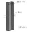
図1は、実施例1の無線送電システムの構成を示した図である。図1のように、実施例1の無線送電システムは、送信アンテナ10と、受信アンテナ11と、中継体12と、筐体13と、によって構成されている。
FIG. 1 is a diagram showing the configuration of a wireless power transmission system according to a first embodiment. As shown in FIG. 1 , the wireless power transmission system of Example 1 includes a transmitting
送信アンテナ10は、所定周波数の電磁波を放射するアンテナであり、受信アンテナ11は所定周波数の電磁波を受信するアンテナである。送信アンテナ10および受信アンテナ11により電磁波を送受することにより、無線で電力を伝送する。送信アンテナ10や受信アンテナ11は任意の形状のアンテナでよく、ダイポールアンテナやモノポールアンテナなどの線状アンテナや、板状アンテナ、スロットアンテナなどであってもよい。また、ループアンテナなどの磁界アンテナでもよい。
The transmitting
中継体12は、送信アンテナ10から受信アンテナ11へと電磁波を中継するものである。中継体12は線状の導体であり、一端は送信アンテナ10の近傍に離間して配置され、他端は受信アンテナ11の近傍に離間して配置されている。このような配置とするために、中継体12は適宜曲げられていてもよい。送信アンテナ10と中継体12、および中継体12と受信アンテナ11は電磁界接合しており、これにより送信アンテナ10から受信アンテナ11へと高効率に電力伝送が可能となっている。ここで、電磁界結合は、電界結合、磁界結合、電界と磁界の複合的な結合のいずれも意味するものとする。中継体12を送信アンテナ10や受信アンテナ11と電磁界接合させるためには、送信アンテナ10および受信アンテナ11のインダクタンスやキャパシタンスを調整すればよい。たとえば、送信アンテナ10や受信アンテナ11のアンテナ形状を変形したり、集中定数素子を付加するなどによって調整することができる。
The
なお、実施例1では中継体12の形状を線状としているが、送信アンテナ10や受信アンテナ11と電磁界接合できるのであれば任意の形状でよく、たとえば平板状、円筒状としてもよい。ただし、送信アンテナ10や受信アンテナ11を磁界アンテナとしている場合には、中継体12の形状をループ状とすればよい。
Although the shape of the
また、中継体12と送信アンテナ10の離間距離は、中継体12と送信アンテナ10とが電磁界結合可能な範囲であれば任意の距離でよい。中継体12と受信アンテナ11の離間距離についても同様である。
Also, the distance between the
また、中継体12は1本の導体で構成されている必要はなく、複数に分離していてもよい。その場合も、それらの中継体12同士が電磁界結合していれば、それら複数の中継体12間で電力を中継して、送信アンテナ10から受信アンテナ11へと送電が可能である。中継体12を複数に分離して構成することで、筐体13内において送信アンテナ10から受信アンテナ11までの経路に制約がある場合や、中継体12の位置、大きさなどに制約がある場合においても、電力の中継が可能となる。また、中継体12を複数に分離することで、個々の中継体12の形状を単純化できる。図2には、中継体12を2つに分離した中継体12A、12Bで構成した例を示す。中継体12A、Bは直線状の導体であり、所定距離を空けて平行に配置されている。
Further, the
また、中継体12の材料は導体である必要はなく、送信アンテナ10や受信アンテナ11と電磁界結合可能であれば任意の材料でよい。たとえば樹脂材料で構成されていてもよい。
Further, the material of the
筐体13は、導体からなり、中空の直方体状である。筐体13の内部には送信アンテナ10、受信アンテナ11、および中継体12が配置されている。
The
筐体13の内壁面と中継体12との距離は、5mm以上であることが好ましい。その理由は次の通りである。筐体13と中継体12は分布定数回路を形成し、その構造はマイクロストリップラインと近似できる。その特性インピーダンスZ0は図3のグラフのようになる。ここで、筐体13の内壁面から中継体12までの距離をh、中継体12の厚さをt、幅をwとする。また、筐体13の内壁面と中継体12の間の空間は比誘電率εr=1とする。また、w=t=0.5、1、2mmとする。
The distance between the inner wall surface of
図3のように、特性インピーダンスZ0は、h=0~5mmでは急峻に増加するが、hが5mm以上ではゆるやかに増加する。つまり、hが5mm以上であれば、hに多少の変動があっても特性インピーダンスZ0の変動は小さい。そのため、中継体12の位置、姿勢などに多少の変動があっても安定した高効率の無線送電が可能となる。もちろん、送信アンテナ10と受信アンテナ11間でインピーダンス整合が取れていれば、hは5mm未満でもよく、筐体13の内壁面と中継体12とが接していてもよい。
As shown in FIG. 3, the characteristic impedance Z0 sharply increases when h=0 to 5 mm, but gently increases when h is 5 mm or more. In other words, if h is 5 mm or more, even if there is some variation in h, variation in the characteristic impedance Z0 is small. Therefore, stable and highly efficient wireless power transmission is possible even if there is some variation in the position, attitude, etc. of the
なお、実施例1では筐体13を導体としているが、一部ないし全部が絶縁体で構成されていてもよい。たとえば樹脂材料で構成されていてもよい。また、筐体13の形状も直方体状である必要はなく、送信アンテナ10、受信アンテナ11、および中継体12を内包可能な内部空間を有した形状であれば任意の形状でよい。
In addition, although the
また、筐体13内に導体からなる隔壁14が設けられ、内部空間が送信アンテナ10が配置されている側と受信アンテナ11が配置されている側とで分離されていてもよい。このような場合、その隔壁14に貫通孔15を設け、その貫通孔15に中継体12を通し、中継体12が送信側の内部空間と受信側の内部空間の両方に位置するように配置すればよい(図4参照)。送信側と受信側が隔てられていたとしても、中継体12を介して送信アンテナ10から受信アンテナ11へと送電が可能となる。中継体12は、隔壁14や貫通孔15側面と接触していてもよい。接触している場合であっても、送信アンテナ10と受信アンテナ11間でインピーダンス整合が取れていればよい。
Further, a
また、筐体13内には送信アンテナ10、受信アンテナ11、および中継体12以外の導体からなる物体16が内包されていてもよい(図5参照)。物体16の形状、大きさは、筐体13に内包可能であって、物体16と中継体12との距離を十分に離すことが可能な範囲で任意に設定することができる。物体16と中継体12との距離が十分に離れていれば、中継体12の特性インピーダンスZ0の変動は小さいので、物体16が内包されていても安定した高効率の無線送電が可能である。物体16と中継体12との距離は5mm以上とすることが好ましい。
Further, an
なお、物体16と中継体12とが十分に離れていない場合や物体16と中継体12とが接している場合であっても、送信アンテナ10や受信アンテナ11のキャパシタンスやインダクタンスを調整してインピーダンス整合を取ることにより、高効率な送電が可能である。
Note that even when the
以上、実施例1の無線送電システムでは、中継体12が送信アンテナ10および受信アンテナ11と電磁界結合しているので、高効率な送電が可能である。また、実施例1の無線送電システムは、従来のような筐体13内の共振モードの形成を利用するものではないので、筐体13の形状や大きさに影響を受けず所望の周波数で送電することができる。
As described above, in the wireless power transmission system of the first embodiment, since the
次に、実施例1の無線送電システムに関する各種シミュレーション結果について、図を参照に説明する。 Next, various simulation results regarding the wireless power transmission system of Example 1 will be described with reference to the drawings.
図6は、実施例1の無線送電システムの簡易モデルであり、図7はその等価回路である。図6、7のように、筐体13を平板の筐体壁に簡易化し、その筐体壁上に送信アンテナ10と受信アンテナ11を設け、さらに送信アンテナ10と受信アンテナ11上に直線状の中継体12を設けたモデルとした。送信アンテナ10と受信アンテナ11は浮遊容量C’で中継体12と結合しているものとし、送信アンテナ10および受信アンテナ11のインダクタンスをL、キャパシタンスをCとし、中継体12と筐体壁で構成される分布定数回路の特性インピーダンスをZ0とした。また、送信アンテナ10の入力ポート1からその入力側を見たインピーダンスをZ1、受信アンテナ11の出力ポート2からその出力側を見たインピーダンスをZ2とした。
FIG. 6 is a simplified model of the wireless power transmission system of Example 1, and FIG. 7 is its equivalent circuit. As shown in FIGS. 6 and 7, the
図8は、図7の等価回路において、伝送効率|S21|をシミュレーションにより算出した結果を示したグラフである。ここで、送電周波数を3.5GHzに設定し、C=0.1pF、L=15nH、C’=0.07pF、中継体12の長さをλ(3.5GHz換算で約70mm)、Z1=Z2=50Ωとした。また、Z0は50、200、400Ωと変化させた。図8(a)はZ0=50Ω、図8(b)はZ0=200Ω、図8(c)はZ0=400Ωである。図8の結果、3.5GHzではZ0を200~400Ωの範囲で変化させても高効率を維持できることがわかった。
FIG. 8 is a graph showing the result of calculation of the transmission efficiency |S21| by simulation in the equivalent circuit of FIG. Here, the power transmission frequency is set to 3.5 GHz, C = 0.1 pF, L = 15 nH, C' = 0.07 pF, the length of the
図9は、図7の等価回路において、伝送効率|S21|をシミュレーションにより算出した結果を示したグラフである。Z0を300Ωとし、中継体12の長さを0.5λ、λ、2λ(3.5GHz換算で約35、70、140mm)と変化させた場合である。図9(a)が中継体12の長さ0.5λ、図9(b)がλ、図9(c)が2λの場合である。その他の設定は図8と同様とした。図9のように、中継体12の長さを変えることで共振周波数は変化しているが、中継体12がいずれの長さの場合であっても、インピーダンス整合を行った送電周波数3.5GHzでは高効率を維持できていることがわかった。これは、中継体12の特性インピーダンスZ0が中継体12の長さによらず、変化しないためである。また、図8、9の結果から、中継体12の位置や姿勢などに多少の変動があったとしても、高効率な送電が可能であることがわかった。
FIG. 9 is a graph showing the result of calculating the transmission efficiency |S21| by simulation in the equivalent circuit of FIG. Z0 is set to 300Ω, and the length of the
次に、無線送電システムのより具体的なモデルについて解析を行った。図10は、比較例の無線送電システムの解析モデルである。比較例の無線送電システムは、実施例1の無線送電システムから中継体12を省いたものである。図10のように、筐体13は43×18×152mmの直方体の箱状の導体とした。また、送信アンテナ10および受信アンテナ11は長さ19mmのL型モノポールアンテナとし、送信アンテナ10と受信アンテナ11の離間距離は140mmとした。送信アンテナ10および受信アンテナ11の線路方向は筐体13の長軸方向とした。
Next, we analyzed a more concrete model of the wireless power transmission system. FIG. 10 is an analytical model of a wireless power transmission system of a comparative example. The wireless power transmission system of the comparative example is obtained by omitting the
図11は、図10に示した比較例の無線送電システムの伝送効率|S21|をシミュレーションにより算出した結果を示したグラフである。図11のように、中継体12を設けていない場合、伝送効率|S21|は低く、3.5GHzでは-90dBであった。
FIG. 11 is a graph showing the result of calculating the transmission efficiency |S21| of the wireless power transmission system of the comparative example shown in FIG. 10 by simulation. As shown in FIG. 11, when the
次に、図12に示すように、図10の解析モデルに中継体12を付加して実施例1の無線送電システムの解析モデルとした。中継体12は直線状の導体であり、長さは40、80、140mmとした。インピーダンス整合は3.5GHzで行った。
Next, as shown in FIG. 12, an analysis model of the wireless power transmission system of Example 1 is obtained by adding the
図13は、図12に示した実施例1の無線送電システムの伝送効率|S21|をシミュレーションにより算出した結果を示したグラフである。図13(a)は中継体12の長さを40mm、図13(b)は80mm、図13(c)は140mmとした場合である。図13のように、中継体12が長くなると共振周波数が変化し、中継体12が長くなるほど共振ピークが増えていくが、送電周波数の3.5GHzにおいては中継体12の長さによらず伝送効率|S21|が高かった。この結果、中継体12を設けることで高効率な送電が可能であることがわかった。また、中継体12の特性インピーダンスZ0はその線路長によらないため、線路長が変わっても3.5GHzにおける伝送効率|S21|は高かった。
FIG. 13 is a graph showing the result of calculating the transmission efficiency |S21| of the wireless power transmission system of Example 1 shown in FIG. 12 by simulation. Fig. 13(a) shows a case where the length of the
次に、図14に示すように、図10の解析モデルにおいて、筐体13内部に導体からなる直方体状の物体16を挿入した。物体16の大きさは20×14×100mmとした。また、この物体16と中継体12との距離は7.5mmとした。このようなモデルについて伝送効率|S21|を算出した。図15は、伝送効率|S21|を算出した結果を示したグラフである。図15のように、送電周波数の3.5GHzにおいて高い伝送効率|S21|を有していた。この結果、物体16と中継体12とが十分に離れていれば、筐体13内部に物体16を挿入したとしても中継体12の特性インピーダンスZ0の変動は小さく、高効率な送電が可能であることがわかった。
Next, as shown in FIG. 14, in the analytical model of FIG. The size of the
次に、図16に示すように、図10の解析モデルにおいて、筐体13内部の中間位置に隔壁14を設け、内部空間を送信アンテナ10側と受信アンテナ11側とで2つに分離した。隔壁14には貫通孔15を設けて中継体12を通し、送信側の内部空間から受信側の内部空間にわたって中継体12を配置した。このようなモデルについて伝送効率|S21|を算出した。図17は、伝送効率|S21|を算出した結果を示したグラフである。図17のように、送電周波数の3.5GHzにおいて高い伝送効率|S21|を有していることがわかった。この結果、隔壁14により内部空間が送信側と受信側とで分離されている場合であっても、中継体12を介して高効率の無線送電が可能であることがわかった。
Next, as shown in FIG. 16, in the analysis model of FIG. 10, a
次に、図18に示すように、図10の解析モデルにおいて、中継体12を1本の直線状の導体から、2本の直線状の導体へと替えた。2本の導体の長さは80mmとし、間隔を空けて平行に配置した。このようなモデルについて伝送効率|S21|を算出した。図19は、伝送効率|S21|を算出した結果を示したグラフである。図19のように、送電周波数の3.5GHzにおいて高い伝送効率|S21|を有していることがわかった。この結果、中継体12を2つに分離しても、中継体12同士が浮遊容量を介して電磁界結合していれば、中継体12を介して無線送電が可能であることがわかった。
Next, as shown in FIG. 18, in the analysis model of FIG. 10, the
図21は、実施例2の無線送電システムの構成を示した図である。実施例2の無線送電システムは、図4の無線送電システムにおいて、送信アンテナ10、受信アンテナ11、中継体12をヘリカル状としたものである。ただし、中継体12のうち中央部(隔壁14の貫通孔15に通す部分)は直線状のままとし、貫通孔15の直径が小さくても通せるようにしている。貫通孔15の直径が十分に大きければ、中継体12全体をヘリカル状としてもよい。
FIG. 21 is a diagram showing the configuration of the wireless power transmission system of the second embodiment. In the wireless power transmission system of the second embodiment, the
実施例2のように、送信アンテナ10、受信アンテナ11、および中継体12をヘリカル状とすることにより、それらを小型にすることができる。そのため、筐体13の内部空間の体積が、送信アンテナ10、受信アンテナ11、および中継体12によって圧迫されるのを低減することができる。
By making the transmitting
(変形例)
本発明の無線送電システムでは、送電周波数は任意の周波数に設定できるが、特に1GHz以上の送電周波数において好適である。筐体内に共振モードを形成する従来の方法では1GHz以上で効率的に無線送電することは難しかったが、本発明ではこのような周波数であっても高効率な送電が可能である。
(Modification)
In the wireless power transmission system of the present invention, the power transmission frequency can be set to any frequency, but a power transmission frequency of 1 GHz or higher is particularly suitable. Although it was difficult to efficiently transmit power wirelessly at 1 GHz or higher with the conventional method of forming a resonance mode in the housing, the present invention enables highly efficient power transmission even at such a frequency.
実施例1、2では送信アンテナ10、受信アンテナ11をそれぞれ1つとして1対1の送電を行うものとしたが、1対多、多対1、多対多の送電であってもよい。
In the first and second embodiments, one transmitting
本発明の無線送電システムは、電子機器の筐体内部においてセンサなどへの無線給電を行う場合に好適である。図20は、本発明の無線送電システムを電子機器に適用した例を示している。図20(a)は、電子機器の筐体13に入れる各種部品を示し、図20(b)は各種部品を筐体13に入れた状態を示している。
INDUSTRIAL APPLICABILITY The wireless power transmission system of the present invention is suitable for wireless power supply to a sensor or the like inside the housing of an electronic device. FIG. 20 shows an example in which the wireless power transmission system of the present invention is applied to electronic equipment. FIG. 20(a) shows various parts to be put into the
図20のように、受信アンテナ11は基板100上に設けられている。この基板100を筐体13内の底面に配置する。次に、筐体13内には導体からなる複数の物体16を配置する。次に、筐体13の側面にコの字型の線状の導体からなる中継体12Aを張り付け、中継体12Aを受信アンテナ11の近傍に配置する。次に、筐体13内に隔壁14を入れ、隔壁14下方の受信アンテナ11側の空間と隔壁14上方の空間とを分離する。隔壁14には貫通孔15が設けられており、その貫通孔15にはコの字型の線状の導体からなる中継体12Bを通す。これにより中継体12Aの近傍に中継体12Bを配置する。さらに、隔壁14上に基板101を配置する。基板上には送信アンテナ10が設けられている。これにより、中継体12Bの近傍に送信アンテナ10を配置する。その後、筐体13に封をする。ここで、送信アンテナ10と中継体12Bとが電磁界結合し、中継体12Bと中継体12Aとが電磁界結合し、中継体12Aと受信アンテナ11とが電磁界結合するように、インピーダンス整合を行う。
As shown in FIG. 20, the receiving
以上により、複数の物体16や隔壁14が存在する複雑な内部空間を有した電子機器の筐体13内においても、送信アンテナ10から受信アンテナ11へと中継体12A、12Bを介して送電することができる。また、中継体12を中継体12A、12Bの2つに分離しているので、筐体13内部空間が複雑でも容易に電力を中継でき、また、それぞれの形状をコの字型の線状に単純化できる。
As described above, power can be transmitted from the transmitting
本発明は、電子機器などの筐体内での無線送電などに利用することができる。 INDUSTRIAL APPLICABILITY The present invention can be used for wireless power transmission within a housing of an electronic device or the like.
10:送信アンテナ
11:受信アンテナ
12:中継体
13:筐体
14:隔壁
15:貫通孔
16:物体
10: Transmitting Antenna 11: Receiving Antenna 12: Relay 13: Housing 14: Partition Wall 15: Through Hole 16: Object
Claims (5)
前記送信アンテナからの電磁波を受信する受信アンテナと、
前記送信アンテナから前記受信アンテナへと電力を中継する中継体と、
内部空間を有し、前記内部空間に前記送信アンテナ、前記受信アンテナ、および前記中継体が配置された筐体と、
を有し、
前記送信アンテナと前記中継体、および前記中継体と前記受信アンテナが電磁界結合されていて、
前記中継体と前記筐体とで分布定数回路を形成し、前記中継体は電磁波を伝搬させて中継する、
ことを特徴とする無線送電システム。 a transmission antenna for transmitting electromagnetic waves of a predetermined frequency;
a receiving antenna for receiving electromagnetic waves from the transmitting antenna;
a relay that relays power from the transmitting antenna to the receiving antenna;
a housing having an internal space in which the transmitting antenna, the receiving antenna, and the relay are arranged;
has
The transmitting antenna and the relay, and the relay and the receiving antenna are electromagnetically coupled,
The relay and the housing form a distributed constant circuit, and the relay propagates and relays an electromagnetic wave.
A wireless power transmission system characterized by:
前記隔壁は、その隔壁を貫通する貫通孔を有し、
前記中継体は、前記貫通孔を介して前記送信アンテナが配置された側の前記内部空間から前記受信アンテナが配置された側の前記内部空間にわたって配置されている、
ことを特徴とする請求項1に記載の無線送電システム。 The housing has a partition that separates the internal space into a side on which the transmitting antenna is arranged and a side on which the receiving antenna is arranged,
The partition has a through hole penetrating through the partition,
The relay is arranged through the through hole from the internal space on the side where the transmitting antenna is arranged to the internal space on the side where the receiving antenna is arranged,
The wireless power transmission system according to claim 1, characterized in that:
前記物体と前記中継体との距離は5mm以上であることを特徴とする請求項1ないし請求項4のいずれか1項に記載の無線送電システム。 An object made of a conductor is arranged in the internal space of the housing,
5. The wireless power transmission system according to any one of claims 1 to 4, wherein the distance between the object and the relay is 5 mm or more.
Priority Applications (1)
| Application Number | Priority Date | Filing Date | Title |
|---|---|---|---|
| JP2020044614A JP7207355B2 (en) | 2020-03-13 | 2020-03-13 | wireless power transmission system |
Applications Claiming Priority (1)
| Application Number | Priority Date | Filing Date | Title |
|---|---|---|---|
| JP2020044614A JP7207355B2 (en) | 2020-03-13 | 2020-03-13 | wireless power transmission system |
Publications (2)
| Publication Number | Publication Date |
|---|---|
| JP2021145535A JP2021145535A (en) | 2021-09-24 |
| JP7207355B2 true JP7207355B2 (en) | 2023-01-18 |
Family
ID=77767451
Family Applications (1)
| Application Number | Title | Priority Date | Filing Date |
|---|---|---|---|
| JP2020044614A Active JP7207355B2 (en) | 2020-03-13 | 2020-03-13 | wireless power transmission system |
Country Status (1)
| Country | Link |
|---|---|
| JP (1) | JP7207355B2 (en) |
Families Citing this family (1)
| Publication number | Priority date | Publication date | Assignee | Title |
|---|---|---|---|---|
| WO2023162695A1 (en) * | 2022-02-25 | 2023-08-31 | パナソニックIpマネジメント株式会社 | Power combiner and power distributor |
Citations (12)
| Publication number | Priority date | Publication date | Assignee | Title |
|---|---|---|---|---|
| US2402599A (en) | 1942-10-20 | 1946-06-25 | Standard Telephones Cables Ltd | Inductive coupling |
| JP2006246372A (en) | 2005-03-07 | 2006-09-14 | Fuji Xerox Co Ltd | Relay antenna for rfid and rfid system |
| US20070001809A1 (en) | 2005-05-02 | 2007-01-04 | Intermec Ip Corp. | Method and system for reading objects having radio frequency identification (RFID) tags inside enclosures |
| JP2007259442A (en) | 2006-03-23 | 2007-10-04 | Xerox Corp | Rfid bridge antenna |
| JP2008099235A (en) | 2006-09-11 | 2008-04-24 | Sony Corp | Communication system and communication device |
| WO2009003457A1 (en) | 2007-07-04 | 2009-01-08 | Conti Temic Microelectronic Gmbh | Magnetoresonant energy transmission and information transmission in a motor vehicle |
| JP2013513187A (en) | 2009-12-07 | 2013-04-18 | エムイーピーエス、リアル‐タイム、インコーポレイテッド | System and method for identifying tagged articles |
| JP2015082907A (en) | 2013-10-23 | 2015-04-27 | 矢崎総業株式会社 | Power supply device |
| US20170099094A1 (en) | 2014-03-12 | 2017-04-06 | Schaeffler Technologies AG & Co. KG | Passive repeater for forwarding radio signals, and use of such a passive repeater |
| JP2017158073A (en) | 2016-03-03 | 2017-09-07 | 株式会社フェニックスソリューション | Waveguide |
| US20180097402A1 (en) | 2016-10-03 | 2018-04-05 | Disney Enterprises, Inc. | Wireless power transmission |
| JP2019041529A (en) | 2017-08-28 | 2019-03-14 | 国立大学法人豊橋技術科学大学 | Radio power transmission system |
Family Cites Families (1)
| Publication number | Priority date | Publication date | Assignee | Title |
|---|---|---|---|---|
| IT1264648B1 (en) * | 1993-07-02 | 1996-10-04 | Sits Soc It Telecom Siemens | TUNABLE RESONATOR FOR OSCILLATORS AND MICROWAVE FILTERS |
-
2020
- 2020-03-13 JP JP2020044614A patent/JP7207355B2/en active Active
Patent Citations (12)
| Publication number | Priority date | Publication date | Assignee | Title |
|---|---|---|---|---|
| US2402599A (en) | 1942-10-20 | 1946-06-25 | Standard Telephones Cables Ltd | Inductive coupling |
| JP2006246372A (en) | 2005-03-07 | 2006-09-14 | Fuji Xerox Co Ltd | Relay antenna for rfid and rfid system |
| US20070001809A1 (en) | 2005-05-02 | 2007-01-04 | Intermec Ip Corp. | Method and system for reading objects having radio frequency identification (RFID) tags inside enclosures |
| JP2007259442A (en) | 2006-03-23 | 2007-10-04 | Xerox Corp | Rfid bridge antenna |
| JP2008099235A (en) | 2006-09-11 | 2008-04-24 | Sony Corp | Communication system and communication device |
| WO2009003457A1 (en) | 2007-07-04 | 2009-01-08 | Conti Temic Microelectronic Gmbh | Magnetoresonant energy transmission and information transmission in a motor vehicle |
| JP2013513187A (en) | 2009-12-07 | 2013-04-18 | エムイーピーエス、リアル‐タイム、インコーポレイテッド | System and method for identifying tagged articles |
| JP2015082907A (en) | 2013-10-23 | 2015-04-27 | 矢崎総業株式会社 | Power supply device |
| US20170099094A1 (en) | 2014-03-12 | 2017-04-06 | Schaeffler Technologies AG & Co. KG | Passive repeater for forwarding radio signals, and use of such a passive repeater |
| JP2017158073A (en) | 2016-03-03 | 2017-09-07 | 株式会社フェニックスソリューション | Waveguide |
| US20180097402A1 (en) | 2016-10-03 | 2018-04-05 | Disney Enterprises, Inc. | Wireless power transmission |
| JP2019041529A (en) | 2017-08-28 | 2019-03-14 | 国立大学法人豊橋技術科学大学 | Radio power transmission system |
Non-Patent Citations (1)
| Title |
|---|
| 池田拓磨, 田中勇気,枷場亮祐,金井一輝,谷博之,梶原正一,金属閉空間内におけるマイクロ波無線電力伝送の受信ダイバーシチによる効率向上に関する検討,電子情報通信学会2019年通信ソサイエティ大会講演論文集1,日本,電子情報通信学会,2019年08月27日,p.401,B-20-21 |
Also Published As
| Publication number | Publication date |
|---|---|
| JP2021145535A (en) | 2021-09-24 |
Similar Documents
| Publication | Publication Date | Title |
|---|---|---|
| Haraz et al. | Dense dielectric patch array antenna with improved radiation characteristics using EBG ground structure and dielectric superstrate for future 5G cellular networks | |
| US7423591B2 (en) | Antenna system | |
| CN110574234B (en) | Antenna and MIMO antenna | |
| TWI657620B (en) | Antenna directivity control system and wireless device including the same | |
| US10622716B1 (en) | Balanced antenna | |
| Chakravarthy et al. | Comparative study on different feeding techniques of rectangular patch antenna | |
| Iqbal et al. | Wideband substrate integrated waveguide antenna for full-duplex systems | |
| JP7207355B2 (en) | wireless power transmission system | |
| CN102474012A (en) | Antenna | |
| Daghari et al. | Radiation performance enhancement of an ultra wide band antenna using metamaterial band-pass filter. | |
| US20120056788A1 (en) | Multiband and broadband antenna using metamaterials, and communication apparatus comprising the same | |
| US20110001579A1 (en) | Tunable ridge waveguide delay line | |
| JP6305353B2 (en) | Microstrip device, reflectarray, microstrip antenna and microstrip array antenna | |
| JP2008219627A (en) | Microstrip antenna | |
| KR20100096380A (en) | Open-ended folded slot antenna | |
| Iqbal et al. | Highly Miniaturized Eighth-Mode Substrate Integrated Waveguide Self-Quadruplexing Antenna | |
| Wu et al. | A low-loss unidirectional dielectric radiator (UDR) for antenna and space power combining circuits | |
| Kumar et al. | SIW resonator fed horn mounted compact DRA with enhanced gain for multiband applications | |
| WO2018180877A1 (en) | Dual polarized wave transmission/reception antenna | |
| Panigrahi et al. | H-shaped slot coupled dual-polarized dielectric resonator antenna for C-band applications | |
| Abdullah et al. | Performance of Two-Port Dielectric Resonator Antenna Used for 5G mm-wave Applications | |
| JP7049328B2 (en) | Antenna with wound and coupled ferromagnetic rods | |
| KR101056860B1 (en) | Micro antenna with stripline and slotted feed | |
| KR101727859B1 (en) | Multi-band antenna for energy harvesting | |
| Maity | Hybrid triangular dielectric resonator antenna (DRA) for WLAN/ISM application |
Legal Events
| Date | Code | Title | Description |
|---|---|---|---|
| A621 | Written request for application examination |
Free format text: JAPANESE INTERMEDIATE CODE: A621 Effective date: 20210721 |
|
| A977 | Report on retrieval |
Free format text: JAPANESE INTERMEDIATE CODE: A971007 Effective date: 20220623 |
|
| RD02 | Notification of acceptance of power of attorney |
Free format text: JAPANESE INTERMEDIATE CODE: A7422 Effective date: 20220701 |
|
| A131 | Notification of reasons for refusal |
Free format text: JAPANESE INTERMEDIATE CODE: A131 Effective date: 20220705 |
|
| A521 | Request for written amendment filed |
Free format text: JAPANESE INTERMEDIATE CODE: A523 Effective date: 20220801 |
|
| TRDD | Decision of grant or rejection written | ||
| A01 | Written decision to grant a patent or to grant a registration (utility model) |
Free format text: JAPANESE INTERMEDIATE CODE: A01 Effective date: 20221206 |
|
| A61 | First payment of annual fees (during grant procedure) |
Free format text: JAPANESE INTERMEDIATE CODE: A61 Effective date: 20221219 |
|
| R150 | Certificate of patent or registration of utility model |
Ref document number: 7207355 Country of ref document: JP Free format text: JAPANESE INTERMEDIATE CODE: R150 |